Embed Size (px)
Citation preview

Networking Basics

Defining components of the network
homeoffice
internet
mobileusers
Branch officeMain Office

Network Structure Defined by Hierarchy
CoreLayer
AccessLayer
DistributionLayer

Access Layer Characteristics
AccessLayer
End Station entry point to the network
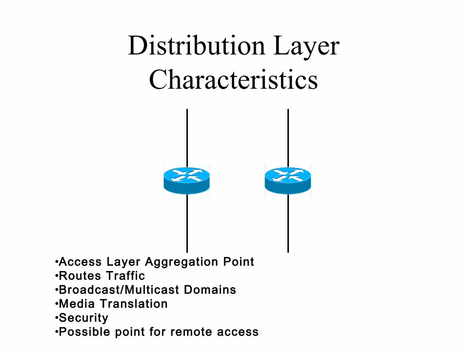
Distribution Layer Characteristics
•Access Layer Aggregation Point•Routes Traff ic•Broadcast/Mult icast Domains•Media Translat ion•Security•Possible point for remote access

Core Layer Characteristics
•Fast Transport to enterprise services•No packet manipulat ion

TCP/IP Protocol Layers
Physical
Data Link
Network
Transport
Session
Presentation
Application
OSI Reference Model
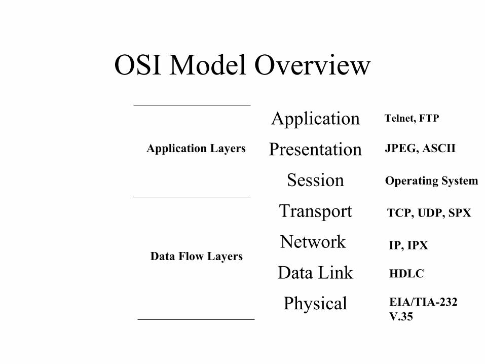
OSI Model Overview
Application
Presentation
Session
Transport
Network
Data Link
Physical
Data Flow Layers
Application Layers
Telnet, FTP
JPEG, ASCII
Operating System
TCP, UDP, SPX
IP, IPX
EIA/TIA-232V.35
HDLC

Encapsulating/Decapsulating Data
Application
Presentation
Session
Transport
Network
Data Link
Physical
Data Flow Layers
Application Layers
PDU
PDU
PDU
Segment
Packet
Bits
Frame
Physical Layer FunctionsDefines: Media type
Connector TypeSignaling type
• Only one station on a shared Ethernet segment can send a frame at one time but allStations receive and look at the frame to determine if it is for them• All end stations on a segment that hear all the traffic on the wire are in the same collision domain.• Station that are in the same collision domain are always in the same broadcast domain

Hubs Operate at Physical Layer
• All devices in the same collision domain• All devices in the same broadcast domain• Devices share the same bandwidth
HUBS ARE USED TO EXTEND THE PHYSICAL MEDIA
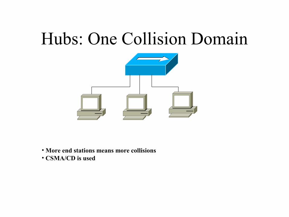
Hubs: One Collision Domain
• More end stations means more collisions• CSMA/CD is used

LAN Physical Layer
Physical Layer Implementations VaryMODULE TYPE HALF/FULL DUPLEX
Ethernet 10base2 185m maxCoax (802.3) 10base5 500m maxCat 3,4,5(2-pair) 10BaseT 100/100mCat 5 (2-pair)-802.3u 100BaseTX 100/100m
Mult imode Fiber 10BaseFL 2/2Km-802.3u- 100BaseFX 400/2Km
Single Mode Fiber-802.3u-100BaseFX 10/10Km
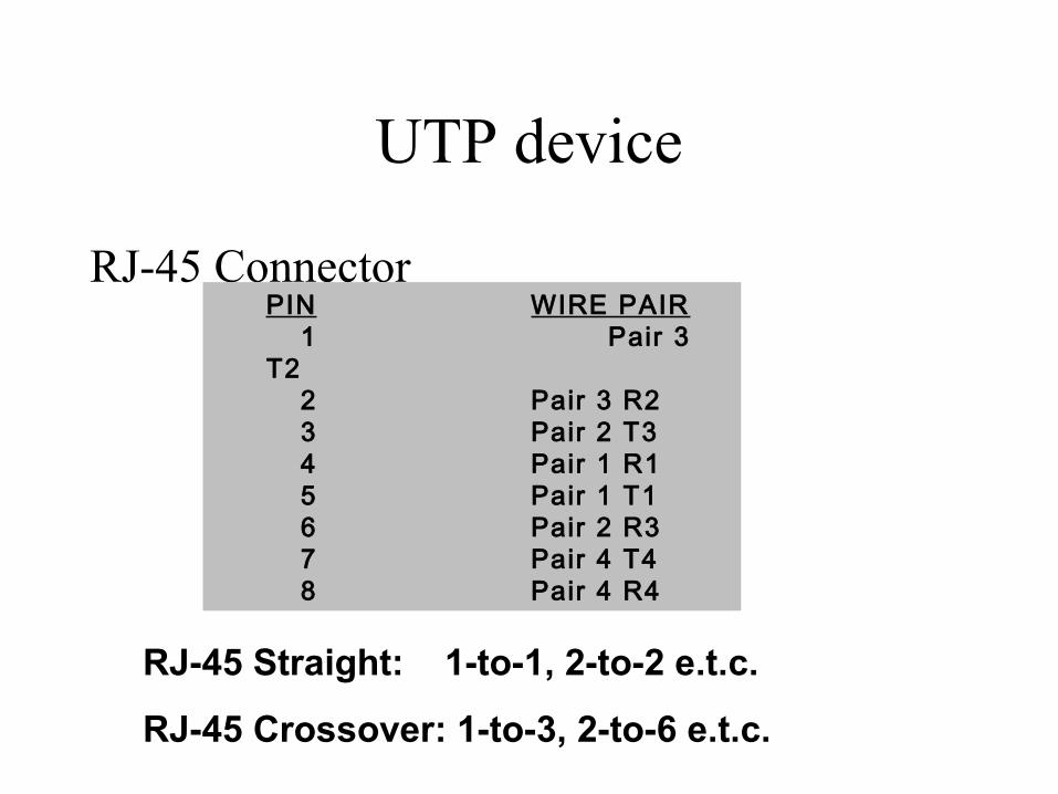
UTP device
RJ-45 ConnectorPIN WIRE PAIR
1 Pair 3 T2
2 Pair 3 R2 3 Pair 2 T3 4 Pair 1 R1 5 Pair 1 T1 6 Pair 2 R3 7 Pair 4 T4 8 Pair 4 R4
RJ-45 Straight: 1-to-1, 2-to-2 e.t.c.
RJ-45 Crossover: 1-to-3, 2-to-6 e.t.c.

WAN Physical Layer
Physical Layer Implementations VaryHDLC PPP FRAME RELAY ISDN BRI (WITH PPP)
EIA/TIA-232 RJ-45 EIA/TIA-449 (greater distance than 232,for same bit rate) Note: Pinouts are
X.21 V.24 V.35 HSSI dif ferent than LAN RJ-45 DTE (Router’s interface)
• End of user’s device on the WAN link (Router’s interface)
DCE (e.g. modem)• End of the WAN provider’s
side of the communication facil i ty
• DCE is responsible for clocking
Data Link Layer FunctionsDEFINES:
• Physical source and destination addresses• Network topology• Frame sequencing• Flow Control• Connection-oriented or Connectionless

Data Link Layer Functions (continued)
Preamble Destinat Address
Source Address
Length Data FCS
8 6 6 2 Variable 4
0000.0C XX.XX.XX
IEEE assigned Vendor assigned
MAC ADDRESS

MAC Address

Switches and Bridges Operating at Layer 2
• Each segment (port) has its own collision domain• ALL segments are in the same broadcast domain• Layer-2 switching is hardware-based bridging (ASIC)• Layer-2 bridging is software-based• Bridges can have up to 16 ports• One STP/BRIDGE, many STP/switch• All segments must use the same data link implementation (Ethernet or token ring for example) otherwise need router for translation• One device/segment can send frames at the same time

Internet Layer Overview
OSI network layer corresponds tothe TCP/IP internet layer
Internet Protocol (IP)
Internet Control MessageProtocol (ICMP)
Address ResolutionProtocol (ARP)
Reverse AddressResolution Protocol(RARP)
Physical
Data Link
Internet
Transport
Application

Network Layer FunctionsIP Header Source
AddressDestination
AddressData
Logical Address 172.15.1.1
Two types of Network Layer Packets
• Network Layer Data Packets- Include upper layer control/user data• Route Discovery/Update Packets- Sent between routers (include information about e.g. distance between two networks, information for how to reach this network)• Need to know addressing which usually provide hierarchy in the network

Network Layer Functions (continued)
1.11.2
1.0
2.1 2.2
3.0
3.23.1
Network Interface Metric
1 E0 0
2 S0 0
4 S0 1
Network Interface Metric
1 S0 1
2 S0 0
4 E0 0
Routing Table Routing Table

Introduction to TCP/IP Addresses
172.18.0.1
172.18.0.2
172.16.0.1
172.17.0.1
172.17.0.2
172.16.0.2
192.168.1.010.13.0.010.13.0.1
192.168.1.1
HDR SA DA DATA

IP Addressing
10101100 00010000 01111010 11001100
Address Mask 172.16.122.204 255.255.0.0
NETWORK HOST
11111111 11111111 00000000 00000000

IP Addressing

IP Address Classes

IP Address Classses

IP Address Classes

Determining Available Host Addresses

Subnet Addressing
172.16.2.200
172.16.2.2
172.16.2.160
172.16.2.1
172.16.3.1E0
E1
172.16.3.5
172.16.3.100
172.16.3.150
172.16 . 2 . 160Network Subnet Host

Subnet Mask

Decimal Equivalents of Bit Patterns
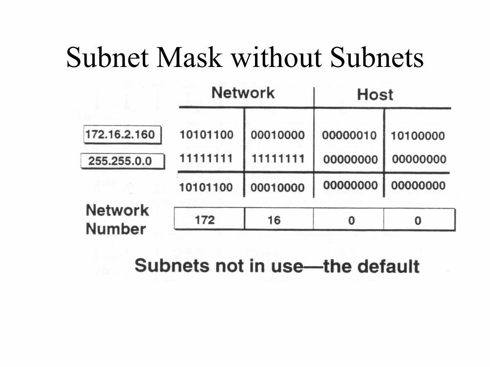
Subnet Mask without Subnets

Subnet Mask with subnets
• Network Extended by Eight Bits

Subnet Mask with Subnets
• Network Number extended by ten bits

Broadcast Addresses
172.16.1.0
172.16.3.0
172.16.2.0
172.16.4.0
172.16.3.255(Directed Broadcast)
255.255.255.255(Local Network broadcast)
172.16.255.255(all subnets broadcast)

ExerciseADDRESS CLASS NETWORK HOST
10.2.2.1
128.63.2.100
201.222.5.64
192.6.141.2
256.241.201.10
130.113.64.16

Exercise Subnet MaskADDRESS CLASS NETWORK HOST
172.16.2.10 255.255.255.0
10.6.24.20 255.255.240.0
10.30.36.12 255.255.255.0
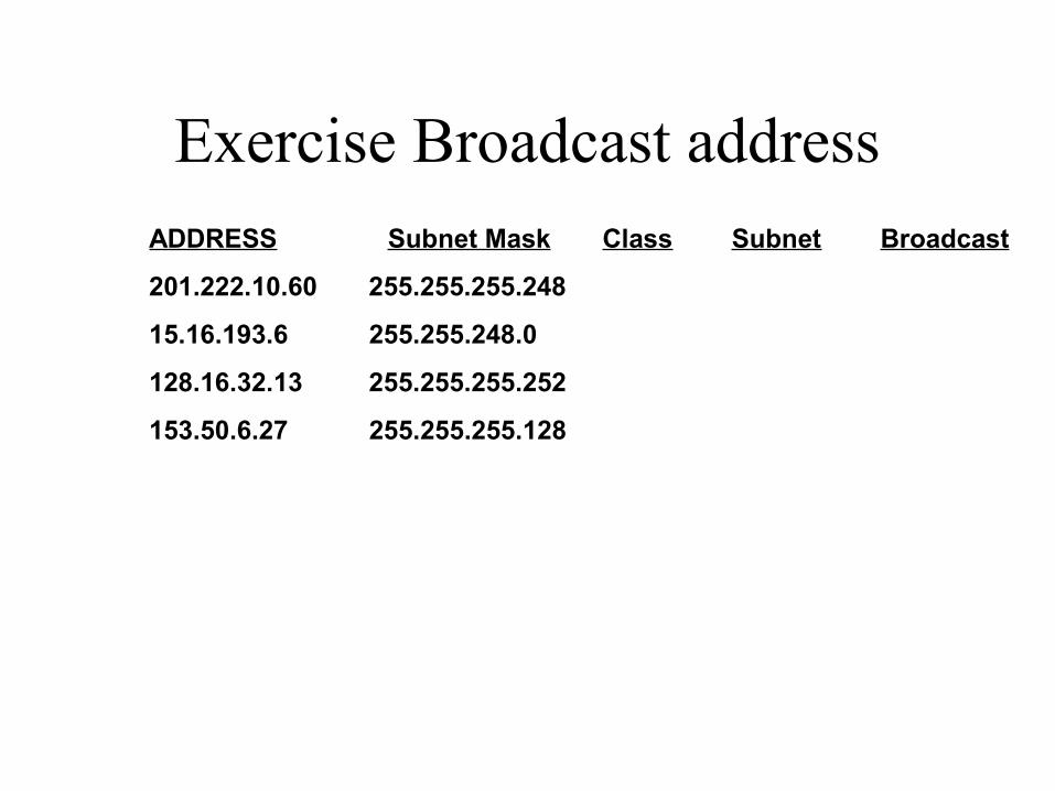
Exercise Broadcast addressADDRESS Subnet Mask Class Subnet Broadcast
201.222.10.60 255.255.255.248
15.16.193.6 255.255.248.0
128.16.32.13 255.255.255.252
153.50.6.27 255.255.255.128

Finding the IP address of the LAN

Address Resolution Protocol
IP: 172.16.3.2 = ???
Map IP MAC
IP: 172.16.3.2Ethernet: 080A.0B20.118C
I need the Ethernetaddress of 176.16.3.2
Local ARP
172.16.3.1 172.16.3.2
I heard thatbroadcast. The
message is for me.Here is my Ethernet
address
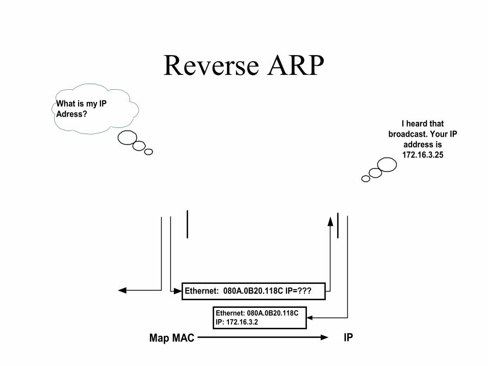
Reverse ARP
Ethernet: 080A.0B20.118C IP=???
Map MAC IP
Ethernet: 080A.0B20.118CIP: 172.16.3.2
What is my IPAdress?
I heard thatbroadcast. Your IP
address is172.16.3.25

What is a Variable-Length Subnet Mask?
172.16.14.32/27
A
172.16.14.64/27B
172.16.14.96/27C
172.16.14.136/30
172.16.14.132/30
172.16.14.140/30
172.16.1.0/24
172.16.2.0/24
172.16.0.0/16HQ

Calculating VLSMs
172.16.32.0/26
172.16.32.64/26
172.16.32.128/26
172.16.33.4/30
172.16.33.0/30
172.16.33.8/30
HQ
172.16.32.192/26172.16.33.12/30
Derived from the172.16.33.0/26 subnet
30-bit mask(2 hosts)
26-bit mask(62 hosts)
Derived from the 172.16.32.0/20 Subnet

Exercise: Calculating VLSMs
25 users
25 Users
25 users
HQ
25 users
Using VLSMs, define appropriate subnets for addressing the networks using 192.168.49.0/24
25 users
A
B
C
D
E
HQ
Address for WAN links
A Serial______________B Serial______________C Serial______________D Serial______________E Serial______________
A
B
C
D
E

What is Route Summarisation?
• Routing protocols can summarize addresses of several networks into one address
172.16.25.0/24
172.16.26.0/24
172.16.27.0/24Routing Table172.16.25.0/24172.16.26.0/24172.16.27.0/24
A B
Routing Table172.16.0.0/16
I can route to thw172.16.0.0/16
network

Summarizing within an Octet

Summarizing Addresses in a VLSM -Designed Network
172.16.128.0/20
B
172.16.14.64/26
C
172.16.64.0/20D
A
172.16.14.128/26
172.16.32.0/24
172.16.128.0/20
172.16.64.0/20
172.16.0.0/16
CorporateNetwork
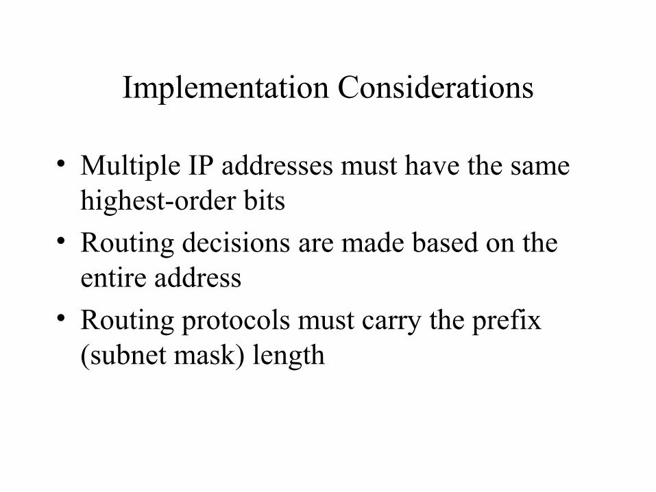
Implementation Considerations
• Multiple IP addresses must have the same highest-order bits
• Routing decisions are made based on the entire address
• Routing protocols must carry the prefix (subnet mask) length

Route Summarization Operation in Cisco Routers
172.16.5.33 /33 Host
172.16.5.32 /27 Subnet
172.16.5.0 /24 Network
172.16.0.0 /16 Block of Networks
0.0.0.0 /0 Default
• Supports host-specific routes, blocks of networks, default routes• Routers use the longest path

Routers: Operate at the Network Layer
• Broadcast control• Multicast control• Optimal Path Determination• Traffic Management• Logical Addressing• Connects WAN services

Transport Layer Functions
• Distinguishes between upper layer applications• Establishes end-to-end connectivity between applications• Defines flow control• Provides reliable/unreliable services for data transfer
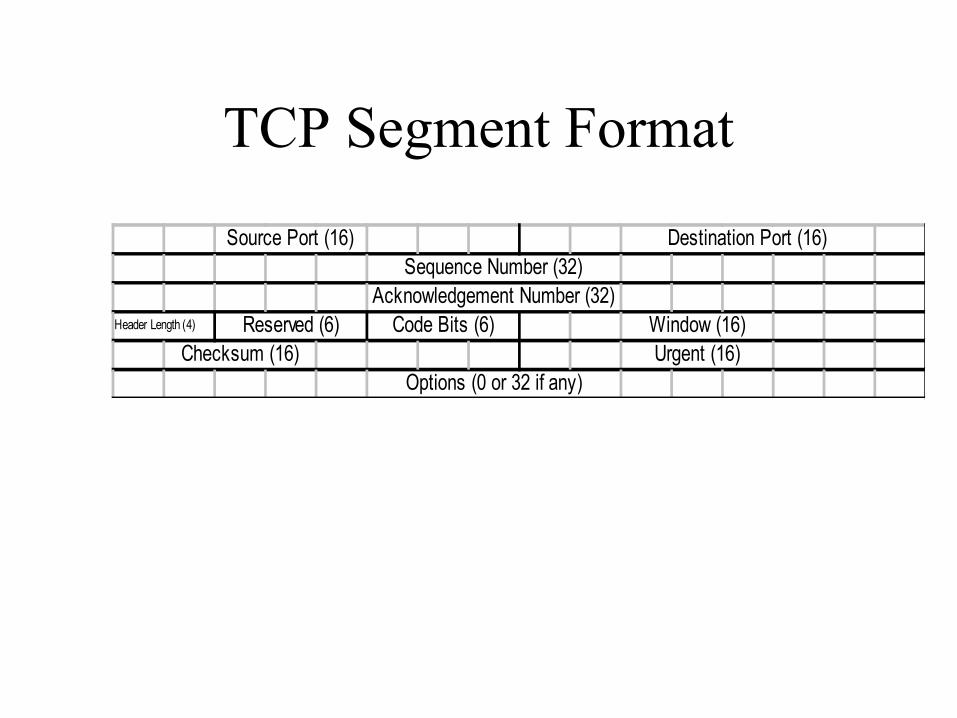
TCP Segment Format
Source Port (16) Destination Port (16)Sequence Number (32)
Acknowledgement Number (32)Header Length (4) Reserved (6) Code Bits (6) Window (16)
Checksum (16) Urgent (16)Options (0 or 32 if any)

Port Numbers
FTP
TELNET
SMTP
DNS
TFTP
SNMP
R I P
21 23 25 53 69 161 520
TCP UDP

TCP Port Numbers
1028 23 ...
SP DP
Host A Host Z
Source Port Dest Port ...Telnet Z
Dest. port = 23.Send packet to
my Telnetapplication

TCP Three way Handshake/Open Connection
Host A
Send SYN (seq=100 ctl=SYN)
SYN received
Established (seq=101ack=301 ctl=ack)
SYN received
Send SYN, ACK (seq=300ack=101 ctl=syn, ack)
Host B
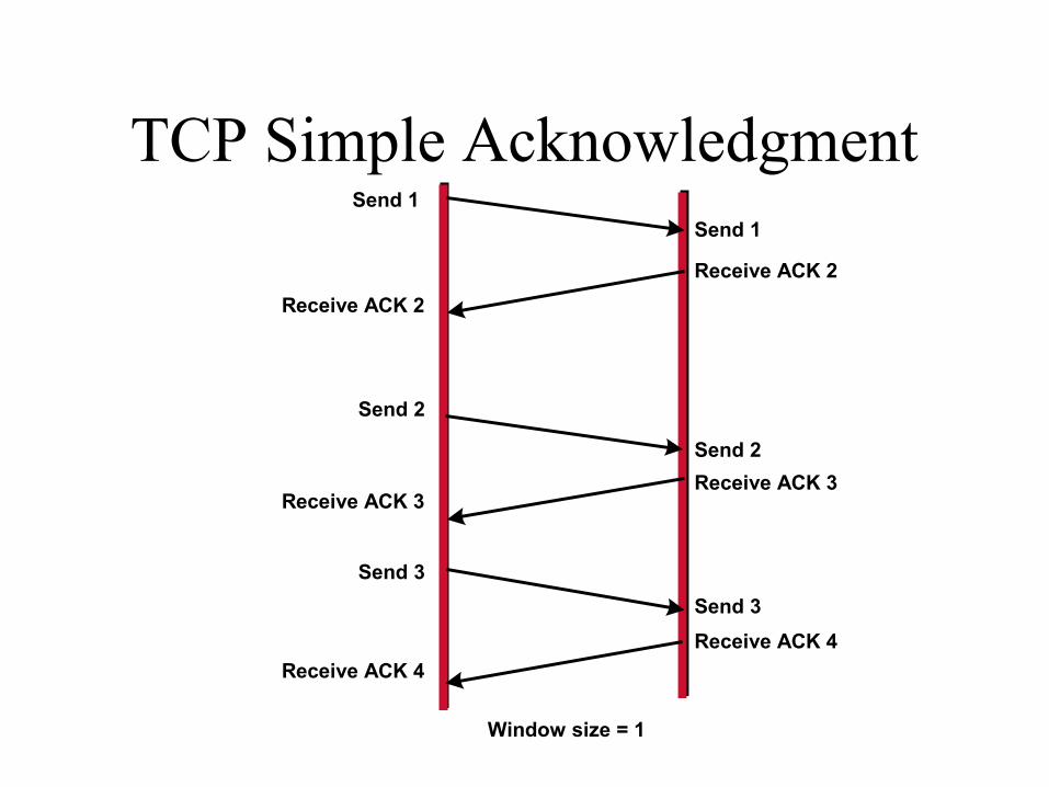
TCP Simple AcknowledgmentSend 1
Receive ACK 2
Send 2
Receive ACK 3
Send 3
Receive ACK 4
Send 1
Receive ACK 2
Send 2
Receive ACK 3
Send 3
Receive ACK 4
Window size = 1

TCP Sequence and Acknowledgment Numbers
Source Port Dest Port Sequence #
I justsent #11
I just got #11,now I need #12
Acknowledgment # ...
1028 23 10 100
Source Dest. Ack.Seq.
1028 23 11 101
Source Dest. Ack.Seq.1028 23 100 11
Source Dest. Ack.Seq.
1028 23 101 12
Source Dest. Ack.Seq.

TCP Windowing
Window size = 3Send 1
Window size = 3Send 2
Window size = 3Send 3
Window size = 3Send 3
Window size = 3Send 4
Window size = 3
ACK 3Window size = 2
ACK 5Window size = 2
Receiver
Packet 3 is dropped
Sender

UDP Segment Format
No sequence or acknowledgment fields
Source port (16) Destination Point
Length (16) Checksum (16)
Data (if any)