Embed Size (px)
Citation preview

CHAPTER-1INTRODUCTION
Page 1
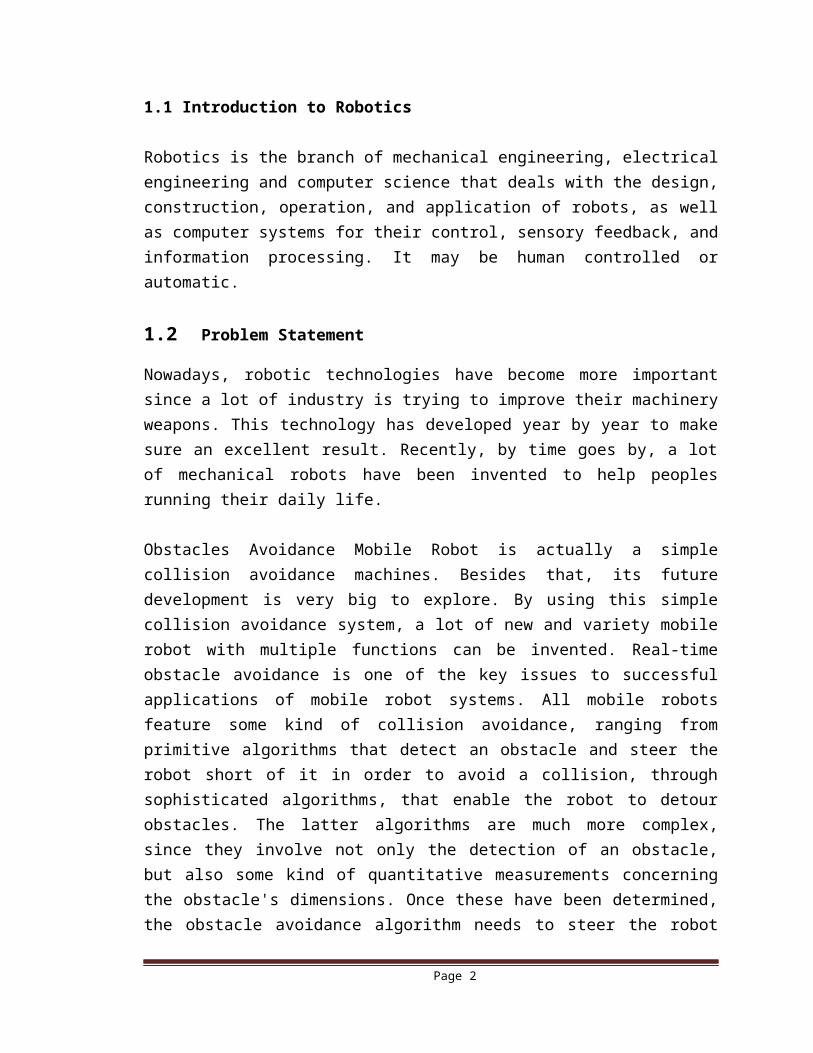
1.1 Introduction to Robotics
Robotics is the branch of mechanical engineering, electrical engineering and computer science that deals with the design, construction, operation, and application of robots, as well as computer systems for their control, sensory feedback, and information processing. It may be human controlled or automatic.
1.2 Problem Statement
Nowadays, robotic technologies have become more important since a lot of industry is trying to improve their machinery weapons. This technology has developed year by year to make sure an excellent result. Recently, by time goes by, a lot of mechanical robots have been invented to help peoples running their daily life.
Obstacles Avoidance Mobile Robot is actually a simple collision avoidance machines. Besides that, its future development is very big to explore. By using this simple collision avoidance system, a lot of new and variety mobile robot with multiple functions can be invented. Real-time obstacle avoidance is one of the key issues to successful applications of mobile robot systems. All mobile robots feature some kind of collision avoidance, ranging from primitive algorithms that detect an obstacle and steer the robot short of it in order to avoid a collision, through sophisticated algorithms, that enable the robot to detour obstacles. The latter algorithms are much more complex, since they involve not only the detection of an obstacle, but also some kind of quantitative measurements concerning the obstacle's dimensions. Once these have been determined, the obstacle avoidance algorithm needs to steer the robot around the obstacle and resume motion toward the original target.
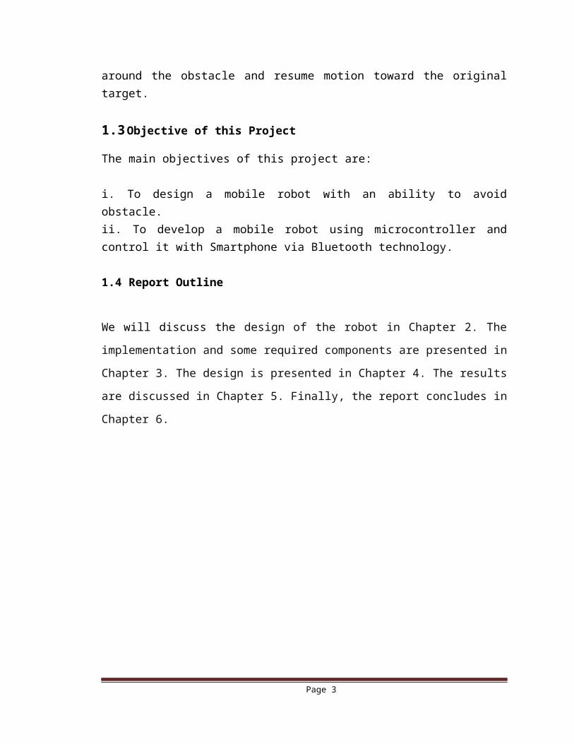
1.3 Objective of this Project
The main objectives of this project are:
i. To design a mobile robot with an ability to avoid obstacle.ii. To develop a mobile robot using microcontroller and control it with Smartphone via Bluetooth technology.
1.4 Report Outline
We will discuss the design of the robot in Chapter 2. The implementation and some
required components are presented in Chapter 3. The design is presented in Chapter 4.
The results are discussed in Chapter 5. Finally, the report concludes in Chapter 6.
Page 2
CHAPTER-2DESIGN OF THE ROBOT
Page 3
2.1 Introduction
Robotics is becoming a very important part of our lives. The design process is changing rapidly as the demand increases. So in this chapter we will describe the robotics design, block diagram, Algorithm and its component’s description.
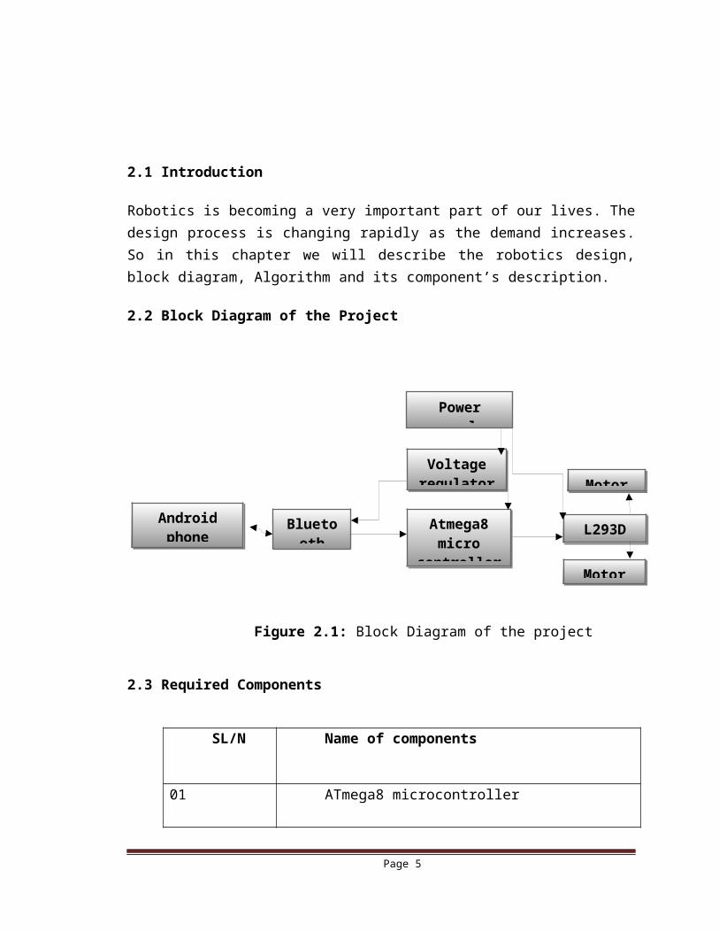
2.2 Block Diagram of the Project
Figure 2.1: Block Diagram of the project
2.3 Required Components
SL/N Name of components
01 ATmega8 microcontroller
02 L293D (Motor Driver IC)
03 Voltage regulator 7805 IC
04 Heat sink
05 Battery
06 HC-05 Bluetooth module
07 LED
Page 4
Android phone with app
Bluetooth
Power supply
Voltage regulator
Atmega8 micro
controller
Motor
L293D IC
Motor
08 Resistor
09 Switch
10 Capacitor
11 2 DC Motor
12 2 wheel
13 PCB board
14 Connecting Wire
15 Crystal
2.4 7805 Voltage Regulator IC
A voltage regulator is designed to automatically maintain a constant voltage level. A voltage regulator may be a simple "feed-forward" design or may include negative feedback control loops. It may use an electromechanical mechanism, or electronic components
Figure 2.2: Typical Voltage Regulator IC
Referring to the figure 2.2, voltage regulator is used to provide regulated 5V to power the PIC16F877A microcontroller. This is very essential since the microcontroller will blow if the voltage supplied to it is exceeding its voltage rating.
Page 5
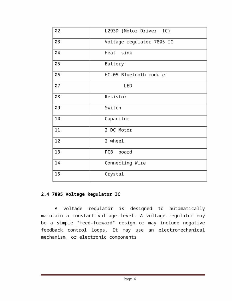
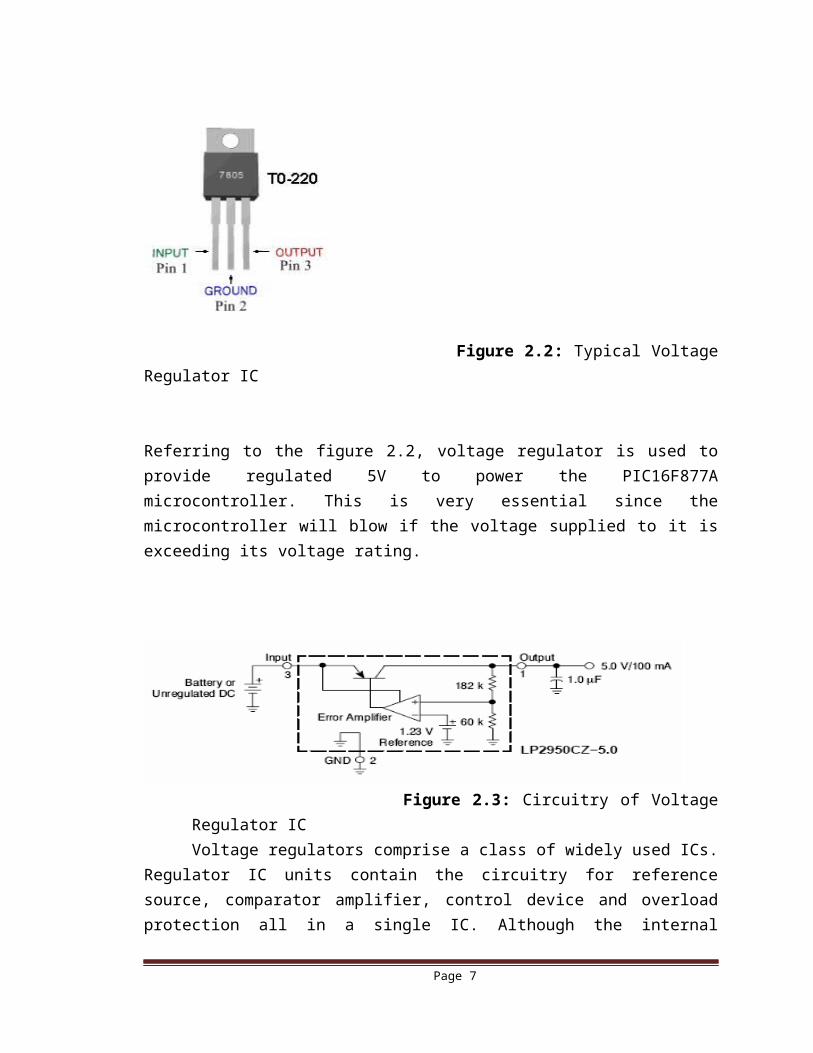
Figure 2.3: Circuitry of Voltage Regulator IC
Voltage regulators comprise a class of widely used ICs. Regulator IC units contain the circuitry for reference source, comparator amplifier, control device and overload protection all in a single IC. Although the internal construction of the IC is somewhat different from that described for discrete voltage regulator circuits, the external operation is much the same. IC unit provide regulation of a fixed positive voltage, a fixed negative voltage or an adjustably set voltage. A power supply can be built using a transformer connected to the ac supply line to step the ac voltage to desired amplitude, then rectifying that ac voltage, filtering with a capacitor and RC filter, if desired, and finally regulating the dc voltage using an IC regulator. The regulators can be selected for operation with load currents from hundreds of mill-amperes to tens of amperes, corresponding to power
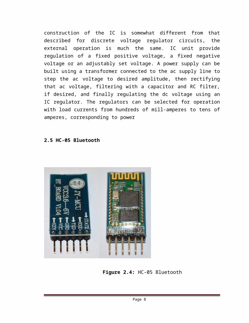
2.5 HC-05 Bluetooth
Figure 2.4: HC-05 Bluetooth
Page 6
2.5.1 Overview
HC‐05 module is an easy to use Bluetooth SPP (Serial Port Protocol) module, designed for transparent wireless serial connection setup. Serial port Bluetooth module is fully qualified Bluetooth V2.0+ EDR (Enhanced Data Rate) 3Mbps Modulation with complete 2.4GHz radio transceiver and baseband. It uses CSR Blue core 04 External single chip Bluetooth systems with CMOS technology and with AFH (Adaptive Frequency Hopping Feature). It has the footprint as small as 12.7mmx27mm. Hope it will simplify your overall design/development cycle.
2.5.2 Specifications:
2.5.2.1 Hardware features
Typical ‐80dBm sensitivity. Up to +4dBm RF transmits power. Low Power 1.8V Operation, 3.3 to 5 V I/O. PIO control. UART interface with programmable baud rate. With integrated antenna. With edge connector.
2.5.2.2 Software features
Slave default Baud rate: 9600, Data bits: 8, Stop bit: 1, Parity: No parity. PIO9 and PIO8 can be connected to red and blue led separately. When
Master and slave are paired, red and blue led blinks 1time/2s in interval, while disconnected only blue led blinks 2times/s.
Auto‐connect to the last device on power as default. Permit pairing device to connect as default. Auto‐pairing PINCODE:”1234” as default. Auto‐reconnect in 30 min when disconnected as a result of beyond the range of
connection.
Page 7
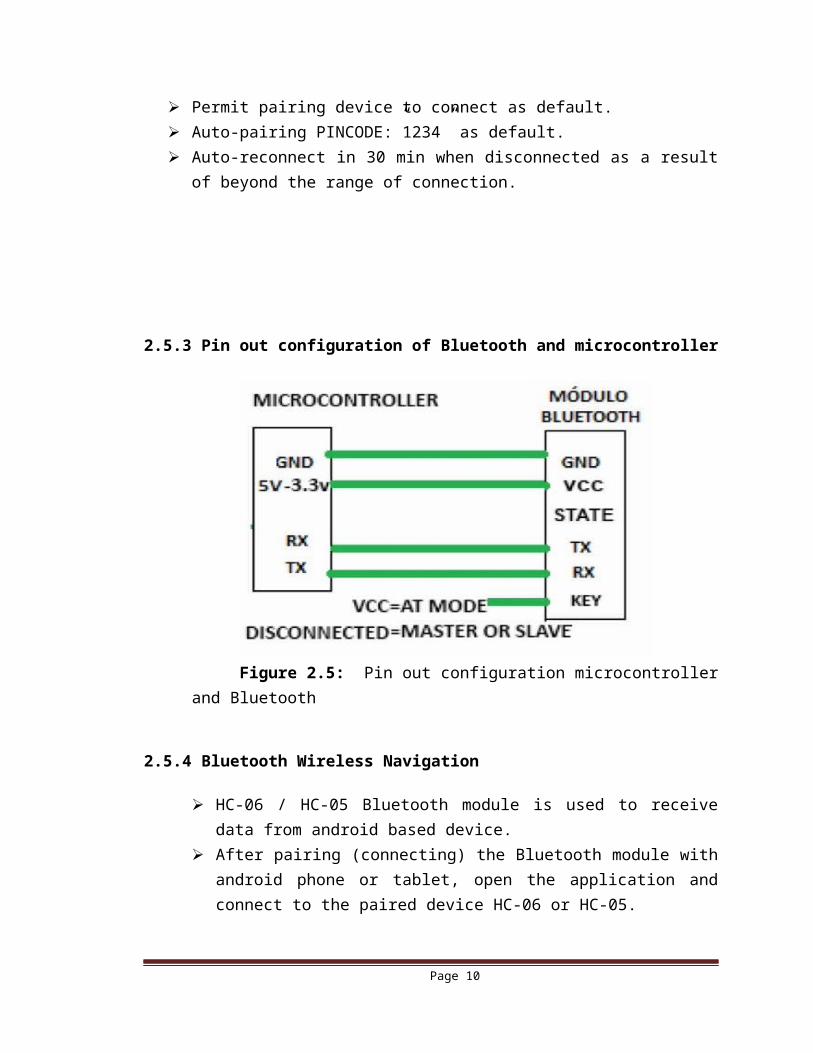
2.5.3 Pin out configuration of Bluetooth and microcontroller
Figure 2.5: Pin out configuration microcontroller and Bluetooth
2.5.4 Bluetooth Wireless Navigation
HC-06 / HC-05 Bluetooth module is used to receive data from android based device.
After pairing (connecting) the Bluetooth module with android phone or tablet, open the application and connect to the paired device HC-06 or HC-05.
Android application will send letters ‘F’, ‘B’, ‘R’ and ‘L’ to move robot forward, backward, right and left respectively.
These are received by the Bluetooth receiver; those letters are available in TX pin of HC-06.
TX pin of Bluetooth module is connected to RX pin (26) of PIC microcontroller, which receives information from the Bluetooth module.
That information is used as an interrupt to switch between user defined functions that we have specified.
We have written different functions to perform assigned tasks viz Move forward, backward, turn left and right. These functions will change the values of pins RC0, RC1, RC2 and RC3. Wheel rotations are controlled by these pins.
Here we are using IC L293D to drive wheel motor, which is capable of driving 2 motors at a time.
Page 8
2.6 L293D Motor Driver IC
L293D is a typical Motor driver or Motor Driver IC which allows DC motor to drive on either direction. L293D is a 16-pin IC which can control a set of two DC motors simultaneously in any direction. It means that you can control two DC motor with a single L293D IC. Dual H-bridge Motor Driver integrated circuit(IC).
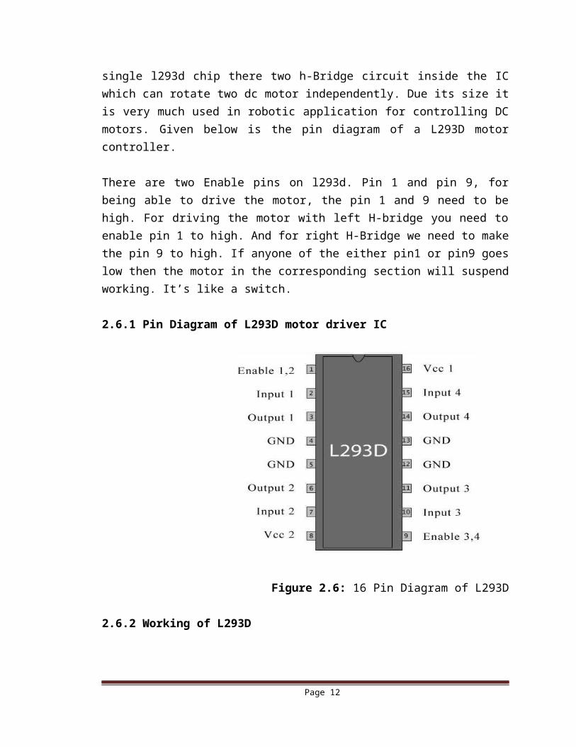
It works on the concept of H-bridge. H-bridge is a circuit which allows the voltage to be flown in either direction. As we know voltage need to change its direction for being able to rotate the motor in clockwise or anticlockwise direction, hence H-bridge IC are ideal for driving a DC motor. In a single l293d chip there two h-Bridge circuit inside the IC which can rotate two dc motor independently. Due its size it is very much used in robotic application for controlling DC motors. Given below is the pin diagram of a L293D motor controller.
There are two Enable pins on l293d. Pin 1 and pin 9, for being able to drive the motor, the pin 1 and 9 need to be high. For driving the motor with left H-bridge you need to enable pin 1 to high. And for right H-Bridge we need to make the pin 9 to high. If anyone of the either pin1 or pin9 goes low then the motor in the corresponding section will suspend working. It’s like a switch.
2.6.1 Pin Diagram of L293D motor driver IC
Figure 2.6: 16 Pin Diagram of L293D
Page 9
2.6.2 Working of L293D
Here 4 input pins for this l293d, pin 2, 7 on the left and pin 15, 10 on the right as shown on the pin diagram. Left input pins will regulate the rotation of motor connected across left side and right input for motor on the right hand side. The motors are rotated on the basis of the inputs provided across the input pins as LOGIC 0 or LOGIC 1.In simple we need to provide Logic 0 or 1 across the input pins for rotating the motor.
2.6.3 L293D Logic Table
Let’s consider a Motor connected on left side output pins (pin 3, 6). For rotating the motor in clockwise direction the input pins has to be provided with Logic 1 and Logic 0. • Pin 2 = Logic 1 and Pin 7 = Logic 0 | Clockwise Direction• Pin 2 = Logic 0 and Pin 7 = Logic 1 | Anticlockwise Direction• Pin 2 = Logic 0 and Pin 7 = Logic 0 | Idle [No rotation] [Hi-Impedance state]• Pin 2 = Logic 1 and Pin 7 = Logic 1 | Idle [No rotation]In a very similar way the motor can also operated across input pin 15, 10 for motor on the right hand side.
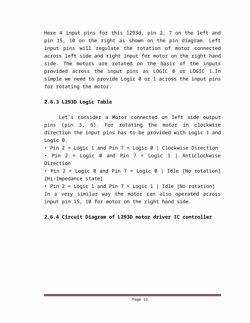
2.6.4 Circuit Diagram of L293D motor driver IC controller
Figure: 2.7: Circuit Diagram of L293D
Page 10
2.6.5 Voltage Specification
VCC is the voltage that it needs for its own internal operation 5v; L293D will not use this voltage for driving the motor. For driving the motors it has a separate provision to provide motor supply VSS (V supply). L293d will use this to drive the motor. It means if you want to operate a motor at 9V then you need to provide a Supply of 9V across VSS Motor supply.
The maximum voltage for VSS motor supply is 36V. It can supply a max current of 600mA per channel. Since it can drive motors Up to 36v hence you can drive pretty big motors with this L293D.
VCC pin 16 is the voltage for its own internal Operation. The maximum voltage ranges from 5v and up to 36v.
2.7 Capacitor
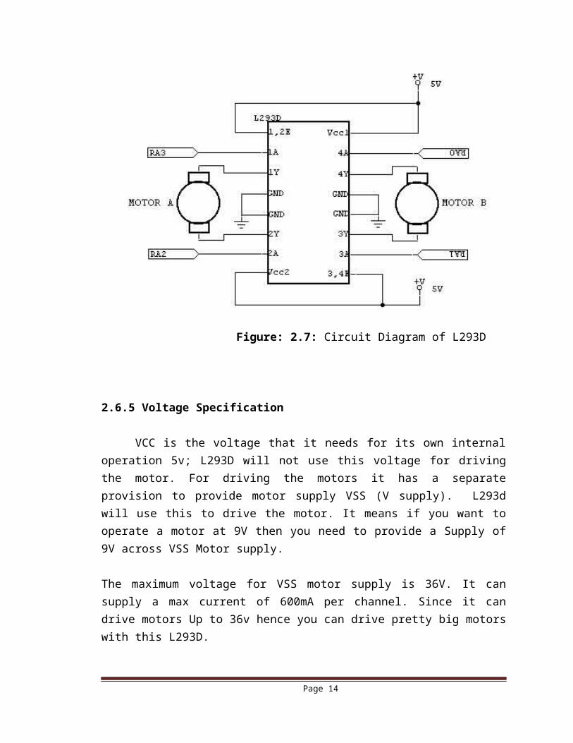
A capacitor is a passive two-terminal electrical component used to store energy electro statically in an electric field. The forms of practical capacitors vary widely, but all contain at least two electrical conductors separated by a dielectric (insulator). Capacitors are widely used as parts of electrical circuits in many common electrical devices.
Figure 2.8: Physical View of Capacitor
When there is a potential difference across the conductors, an electric field develops across the dielectric, causing positive charge to collect on one plate and negative charge on the other plate. Energy is stored in the electrostatic field. An ideal capacitor is characterized by a single constant value, capacitance. This is the ratio of the electric charge on each conductor to the potential difference between them. The SI unit of capacitance is the farad, which is equal to one coulomb per volt.
The capacitance is greatest when there is a narrow separation between large areas of conductor; hence capacitor conductors are often called plates, referring to an early
Page 11
means of construction. In practice, the dielectric between the plates passes a small amount of leakage current and also has an electric field strength limit, the breakdown voltage. The conductors and leads introduce an undesired inductance and resistance.
A capacitor consists of two conductors separated by a non-conductive region. The non-conductive region is called the dielectric. In simpler terms, the dielectric is just an electrical insulator. Examples of dielectric media are glass, air, paper, vacuum, and even a semiconductor depletion region chemically identical to the conductors. A capacitor is assumed to be self-contained and isolated, with no net electric charge and no influence from any external electric field. The conductors thus hold equal and opposite charges on their facing surfaces, and the dielectric develops an electric field. In SI units, a capacitance of one farad means that one coulomb of charge on each conductor causes a voltage of one volt across the device.
An ideal capacitor is wholly characterized by a constant capacitance C, defined as the ratio of charge ±Q on each conductor to the voltage V between them. C = Q/V, where C is the capacitance in farad (F), Q is the electric charge in coulombs (C) and V is the voltage between the capacitor’s plates in volts (V).
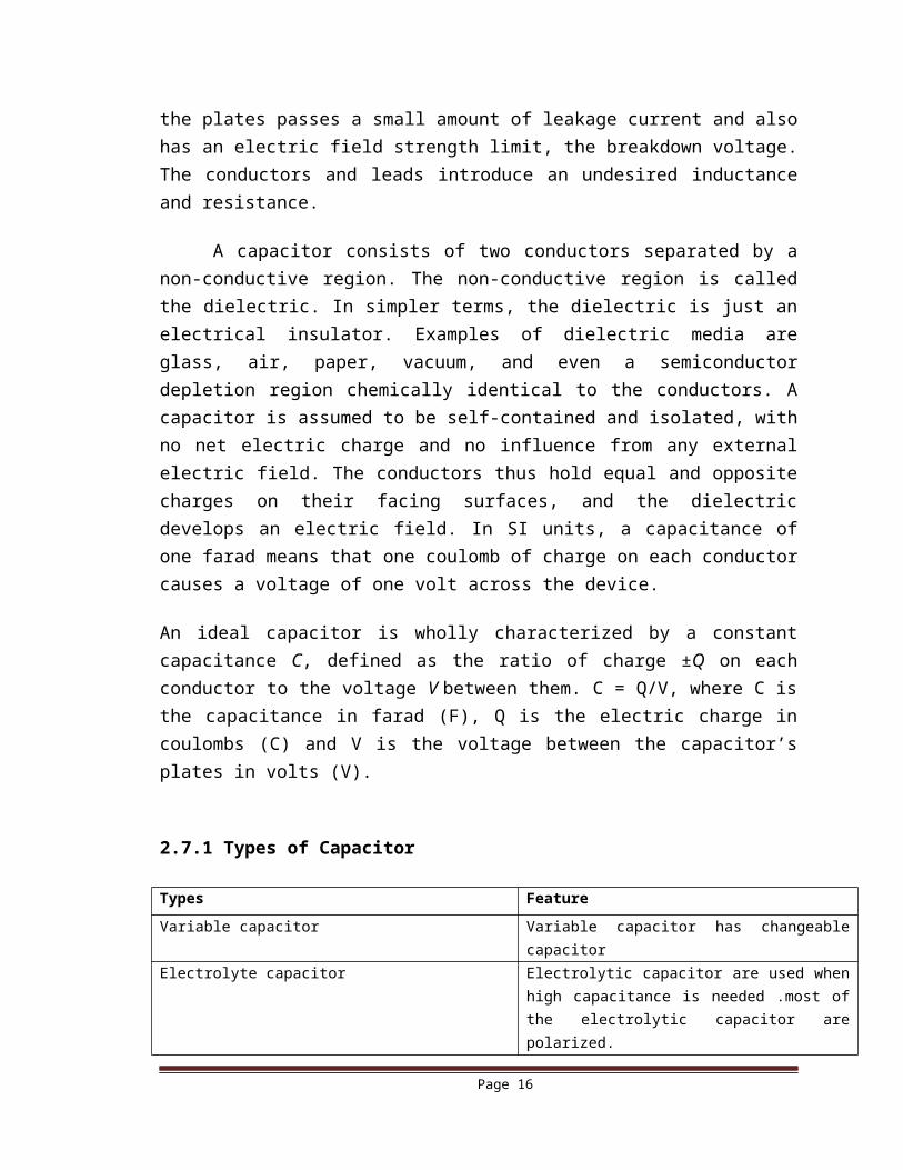
2.7.1 Types of Capacitor
Types Feature
Variable capacitor Variable capacitor has changeable capacitor
Electrolyte capacitor Electrolytic capacitor are used when high capacitance is needed .most of the electrolytic capacitor are polarized.
Ceramic capacitor Ceramic capacitor has ceramic dielectric material .has high voltage functionality.
Tantalum capacitor Tantalum oxide dielectric material. Has high capacitance.
Spherical capacitor Spherical capacitor has a sphere shape.Power capacitor Power capacitors are used in high voltage power
system.Mica capacitor High accuracy capacitors.Paper capacitor Paper dielectric material
2.7.2 Capacitor Voltage Reference
Page 12
Type J – Dipped Tantalum Capacitors. Type K – Mica Capacitors. Type L – Polyester/Polystyrene Capacitors Type M – Electrolytic 4 Band Capacitors Type N – Electrolytic 3 Band Capacitors.
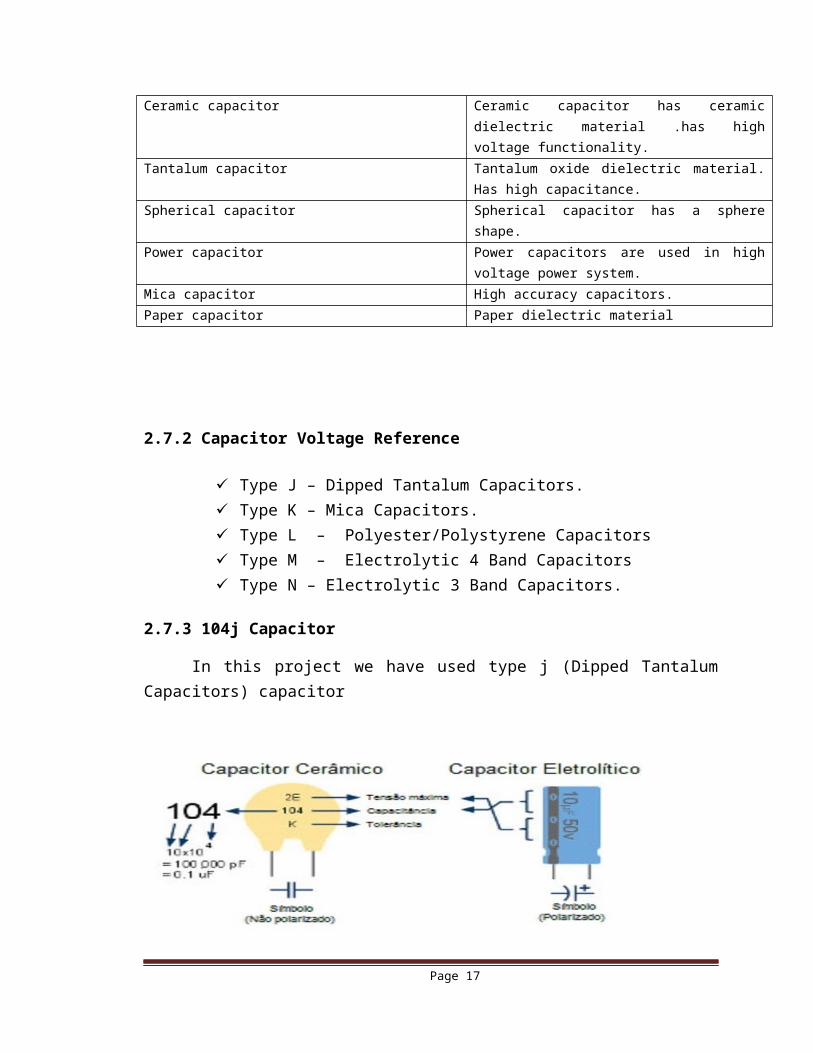
2.7.3 104j Capacitor
In this project we have used type j (Dipped Tantalum Capacitors) capacitor
Figure 2.9: 104j Capacitor
2.7.4 Specification of 104j Capacitor
Page 13
2.8 Crystal oscillator
A crystal oscillator is an electronic oscillator circuit that uses the mechanical resonance of a vibrating crystal of piezoelectric material to create an electrical signal with a very precise frequency. This frequency is commonly used to keep track of time (as in quartz wristwatches), to provide a stable clock signal for digital integrated circuits, and to stabilize frequencies for radio transmitters and receivers. The most common type of piezoelectric resonator used is the quartz crystal, so oscillator circuits incorporating them became known as crystal oscillators, but other piezoelectric materials including polycrystalline ceramics are used in similar circuits.
Quartz crystals are manufactured for frequencies from a few tens of kilohertz to hundreds of megahertz. More than two billion crystals are manufactured annually. Most are used for consumer devices such as wristwatches, clocks, radios, computers, and cell phones. Quartz crystals are also found inside test and measurement equipment, such as counters, signal generators, and oscilloscopes.
Here we used a crystal of 12 MHz as clock oscillator for Microcontroller.
Figure 2.10: Crystal oscillator
2.9 Heat sink
In electronic systems, a heat sink is a passive heat exchanger that cools a device by dissipating heat into the surrounding medium. In computers, heat sinks are used to cool central processing units or graphics processors.
Page 14
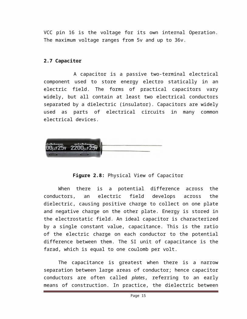
Figure 2.11: Heat sink
2.10 Resistor
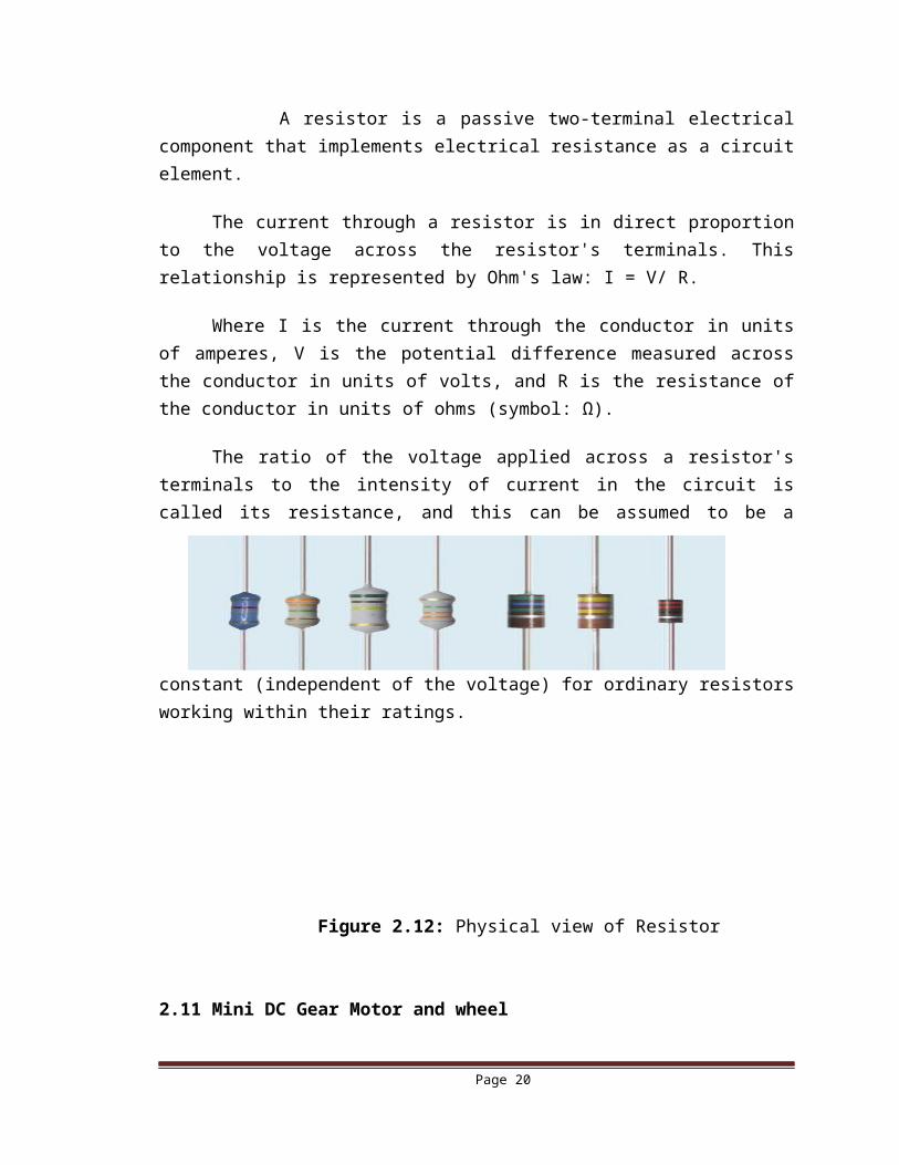
A resistor is a passive two-terminal electrical component that implements electrical resistance as a circuit element.
The current through a resistor is in direct proportion to the voltage across the resistor's terminals. This relationship is represented by Ohm's law: I = V/ R.
Where I is the current through the conductor in units of amperes, V is the potential difference measured across the conductor in units of volts, and R is the resistance of the conductor in units of ohms (symbol: Ω).
The ratio of the voltage applied across a resistor's terminals to the intensity of current in the circuit is called its resistance, and this can be assumed to be a constant (independent of the voltage) for ordinary resistors working within their ratings.
Figure 2.12: Physical view of Resistor
2.11 Mini DC Gear Motor and wheel
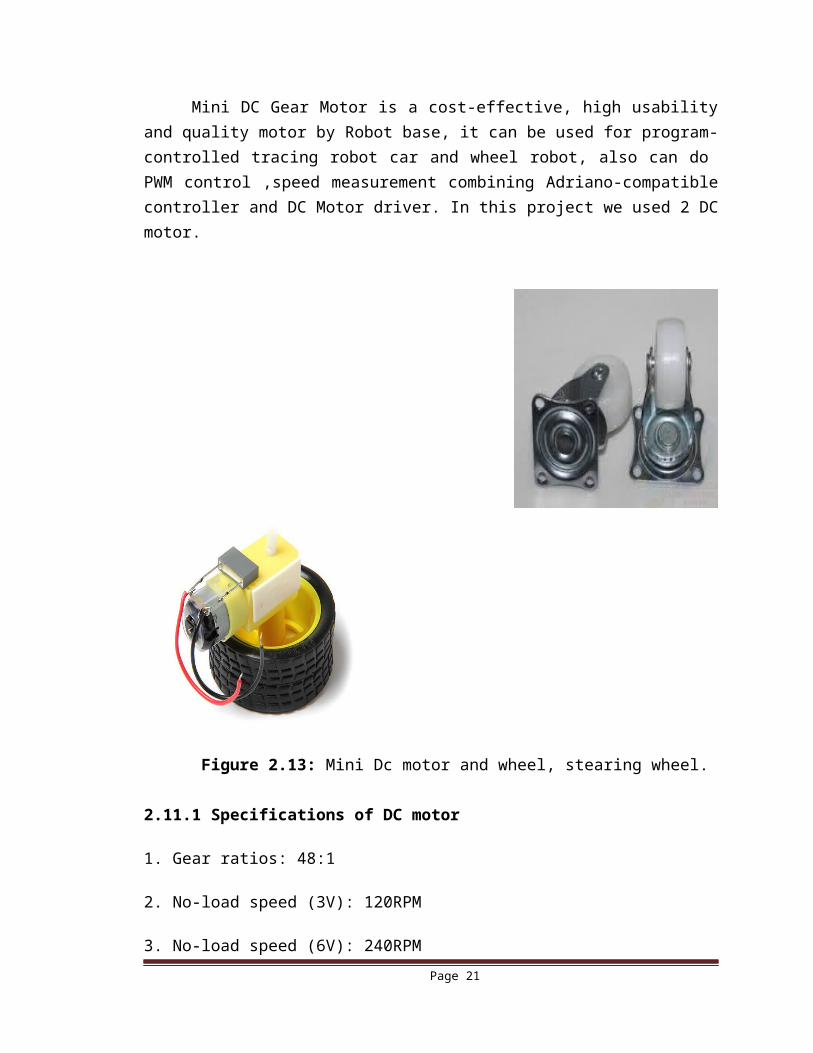
Mini DC Gear Motor is a cost-effective, high usability and quality motor by Robot base, it can be used for program-controlled tracing robot car and wheel robot, also
Page 15
can do PWM control ,speed measurement combining Adriano-compatible controller and DC Motor driver. In this project we used 2 DC motor.
Figure 2.13: Mini Dc motor and wheel, stearing wheel.
2.11.1 Specifications of DC motor
1. Gear ratios: 48:1
2. No-load speed (3V): 120RPM
3. No-load speed (6V): 240RPM
4. No-load current (3V): 40mA
5. No-load current (6V): 70mA
6. Block running current (3V): 390mA
7. Block running current (3V): 680mA
8. Torque size (3V): 3200mg * cm
9. Torque size (6V): 5500mg * cm
10. Size: 70.50 mm x 27.00 mm x 23.00 mm
11. Weight: about 40g
Page 16
2.12 LED
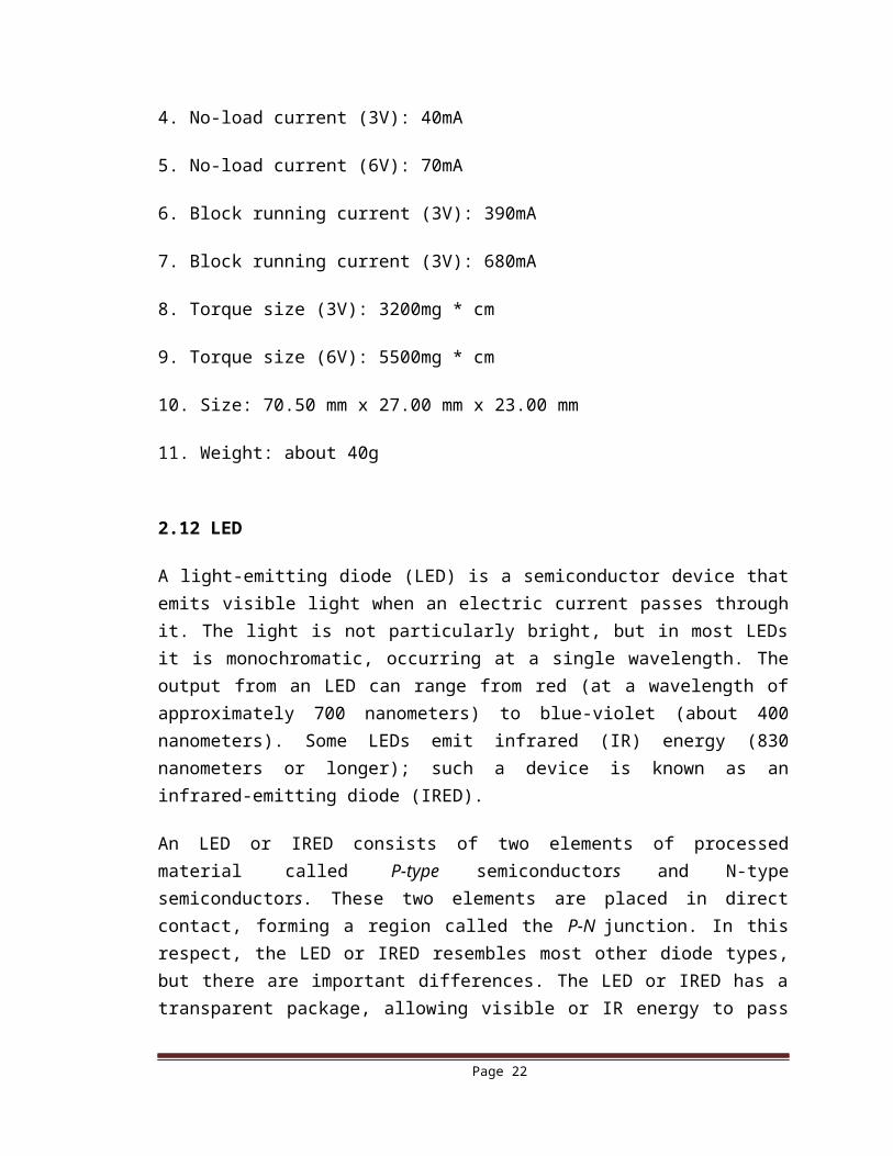
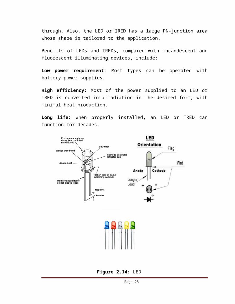
A light-emitting diode (LED) is a semiconductor device that emits visible light when an electric current passes through it. The light is not particularly bright, but in most LEDs it is monochromatic, occurring at a single wavelength. The output from an LED can range from red (at a wavelength of approximately 700 nanometers) to blue-violet (about 400 nanometers). Some LEDs emit infrared (IR) energy (830 nanometers or longer); such a device is known as an infrared-emitting diode (IRED).
An LED or IRED consists of two elements of processed material called P-type semiconductors and N-type semiconductors. These two elements are placed in direct contact, forming a region called the P-N junction. In this respect, the LED or IRED resembles most other diode types, but there are important differences. The LED or IRED has a transparent package, allowing visible or IR energy to pass through. Also, the LED or IRED has a large PN-junction area whose shape is tailored to the application.
Benefits of LEDs and IREDs, compared with incandescent and fluorescent illuminating devices, include:
Low power requirement: Most types can be operated with battery power supplies.
High efficiency: Most of the power supplied to an LED or IRED is converted into radiation in the desired form, with minimal heat production.
Long life: When properly installed, an LED or IRED can function for decades.
Page 17
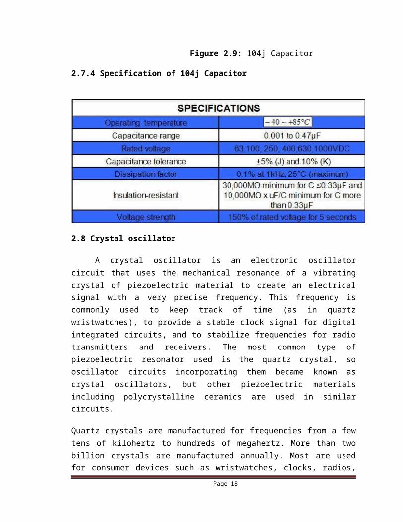
Figure 2.14: LED
2.13 Diode
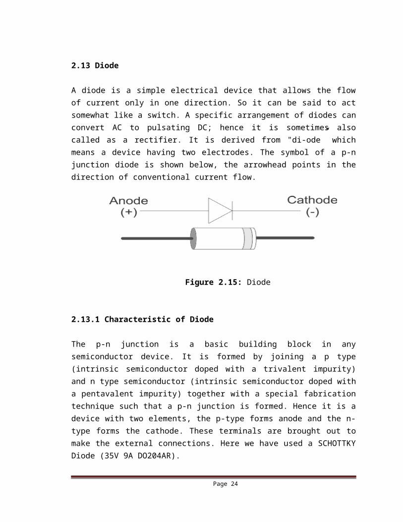
A diode is a simple electrical device that allows the flow of current only in one direction. So it can be said to act somewhat like a switch. A specific arrangement of diodes can convert AC to pulsating DC; hence it is sometimes also called as a rectifier. It is derived from "di-ode” which means a device having two electrodes. The symbol of a p-n junction diode is shown below, the arrowhead points in the direction of conventional current flow.
Figure 2.15: Diode
2.13.1 Characteristic of Diode
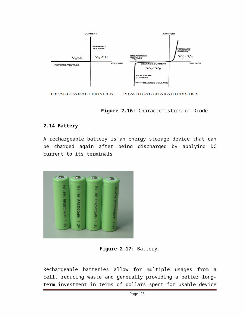
The p-n junction is a basic building block in any semiconductor device. It is formed by joining a p type (intrinsic semiconductor doped with a trivalent impurity) and n type semiconductor (intrinsic semiconductor doped with a pentavalent impurity) together with a special fabrication technique such that a p-n junction is formed. Hence it is a device with two elements, the p-type forms anode and the n-type forms the cathode. These terminals are brought out to make the external connections. Here we have used a SCHOTTKY Diode (35V 9A DO204AR).
Page 18
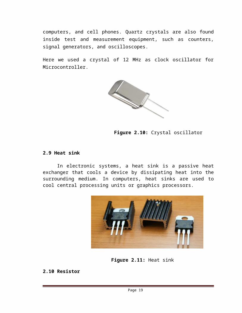
Figure 2.16: Characteristics of Diode
2.14 Battery
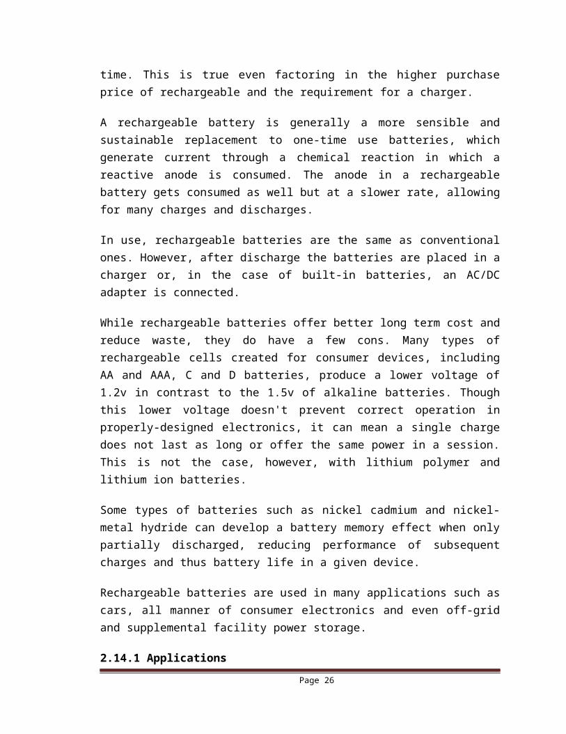
A rechargeable battery is an energy storage device that can be charged again after being discharged by applying DC current to its terminals
Figure 2.17: Battery.
Rechargeable batteries allow for multiple usages from a cell, reducing waste and generally providing a better long-term investment in terms of dollars spent for usable device time. This is true even factoring in the higher purchase price of rechargeable and the requirement for a charger.
A rechargeable battery is generally a more sensible and sustainable replacement to one-time use batteries, which generate current through a chemical reaction in which a reactive
Page 19
anode is consumed. The anode in a rechargeable battery gets consumed as well but at a slower rate, allowing for many charges and discharges.
In use, rechargeable batteries are the same as conventional ones. However, after discharge the batteries are placed in a charger or, in the case of built-in batteries, an AC/DC adapter is connected.
While rechargeable batteries offer better long term cost and reduce waste, they do have a few cons. Many types of rechargeable cells created for consumer devices, including AA and AAA, C and D batteries, produce a lower voltage of 1.2v in contrast to the 1.5v of alkaline batteries. Though this lower voltage doesn't prevent correct operation in properly-designed electronics, it can mean a single charge does not last as long or offer the same power in a session. This is not the case, however, with lithium polymer and lithium ion batteries.
Some types of batteries such as nickel cadmium and nickel-metal hydride can develop a battery memory effect when only partially discharged, reducing performance of subsequent charges and thus battery life in a given device.
Rechargeable batteries are used in many applications such as cars, all manner of consumer electronics and even off-grid and supplemental facility power storage.
2.14.1 Applications
Suitable to cordless phone, solar lighting, electrical drill, shaver, emergency lighting, back-up power, cordless tool, power tool, flashlight, torch, Robot etc
2.15 Summary
In this chapter we have described design of the project and various components description which has been used in the project.
In the next chapter we will describe implementation of the project.
Page 20
CHAPTER-3IMPLEMENTATION
Page 21
3.1 Introduction
In this chapter we will describe about Microcontroller IC, circuit diagram, circuit construction and its working procedure, PCB layout and microcontroller programming.
3.2 Microcontroller
A microcontroller (sometimes abbreviated µC, uC or MCU) is a small computer on a single integrated circuit containing a processor core, memory, and programmable input/output peripherals.
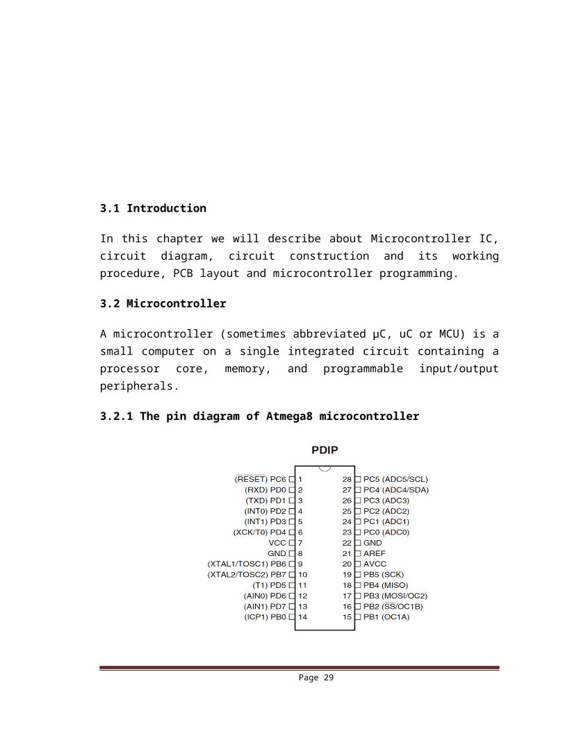
3.2.1 The pin diagram of Atmega8 microcontroller
Figure 3.1: Pin diagram of ATmega8
3.2.2 ATmega8 Microcontroller IC
This is the main controller of the robot. When the robot is turned on, the main controller is ready to receive an instruction from Android phone via Bluetooth. It is 28 pin of microcontroller.
Page 22
3.2.3 Features
3.2.3.1 Advanced RISC Architecture
– 130 Powerful Instructions – Most Single-clock Cycle Execution
– 32 × 8 General Purpose Working Registers
– Fully Static Operation
– Up to 16MIPS Throughput at 16MHz
– On-chip 2-cycle Multiplier
3.2.3.2 High Endurance Non-volatile Memory segments
– 8Kbytes of In-System Self-programmable Flash program memory
– 512Bytes EEPROM, 1Kbyte Internal SRAM
– Write/Erase Cycles: 10,000 Flash/100,000 EEPROM
– Data retention: 20 years at 85°C/100 years at 25°C (1)
– Optional Boot Code Section with Independent Lock Bits In-System Programming by
on-chip Boot Program True Read-While-Write Operation
– Programming Lock for Software Security
3.2.3.3 Peripheral Features
– Two 8-bit Timer/Counters with Separate Prescaler, one Compare Mode
– One 16-bit Timer/Counter with Separate Prescaler, Compare Mode, and Capture Mode
– Real Time Counter with Separate Oscillator
– Three PWM Channels
– 8-channel ADC in TQFP and QFN/MLF package Eight Channels 10 -bit Accuracy
– 6-channel ADC in PDIP package
- Six Channels 10 -bit Accuracy
– Byte-oriented Two-wire Serial Interface
– Programmable Serial USART
– Master/Slave SPI Serial Interface
– Programmable Watchdog Timer with Separate On-chip Oscillator
– On-chip Analog Comparator
3.2.3.4 Special Microcontroller Features
– Power-on Reset and Programmable Brown-out Detection
– Internal Calibrated RC Oscillator
Page 23
– External and Internal Interrupt Sources
– Five Sleep Modes: Idle, ADC Noise Reduction, Power-save, Power-down, and
Standby
3.2.3.5 I/O and Packages
– 23 Programmable I/O Lines
– 28-lead PDIP, 32-lead TQFP, and 32-pad QFN/MLF
3.2.3.6 Operating Voltages
– 2.7V - 5.5V (ATmega8L)
– 4.5V - 5.5V (ATmega8)
3.2.3.7 Speed Grades
– 0 - 8MHz (ATmega8L)
– 0 - 16MHz (ATmega8)
3.2.3.8 Power Consumption
--at 4 MHz, 3V, 25C
– Active: 3.6mA
– Idle Mode: 1.0mA
– Power-down Mode: 0.5μA
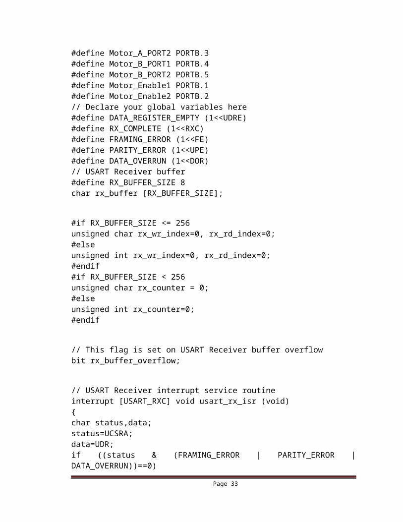
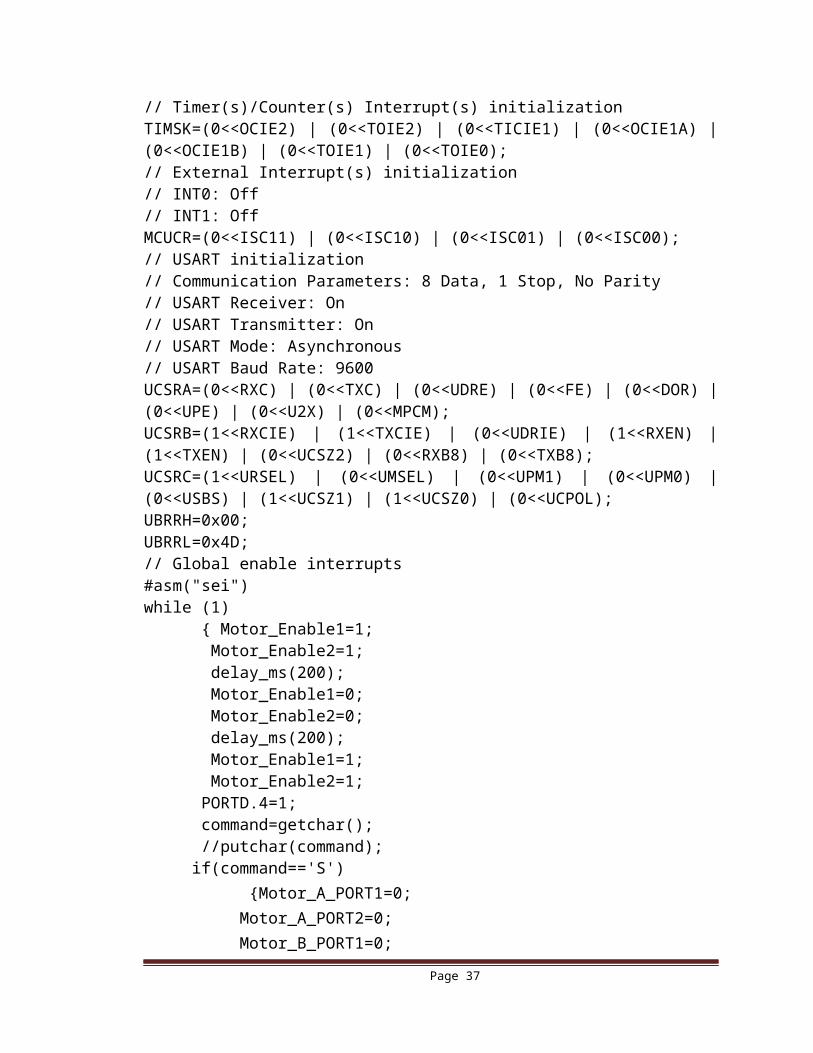
3.3 Microcontroller Program
//program for microcontroller ……………………/*******************************************************This program was created by theCodeWizardAVR V3.12 AdvancedAutomatic Program Generator©Copyright 1998-2014 Pavel Haiduc, HP InfoTech s.r.l.http://www.hpinfotech.comChip type : ATmega8Program type : ApplicationAVR Core Clock frequency: 12.000000 MHzMemory model : SmallData Stack size : 256/*******************************************************/#include <mega8.h>#include <stdio.h>#include <delay.h>#define Motor_A_PORT1 PORTB.0#define Motor_A_PORT2 PORTB.3
Page 24
#define Motor_B_PORT1 PORTB.4#define Motor_B_PORT2 PORTB.5#define Motor_Enable1 PORTB.1#define Motor_Enable2 PORTB.2// Declare your global variables here#define DATA_REGISTER_EMPTY (1<<UDRE)#define RX_COMPLETE (1<<RXC)#define FRAMING_ERROR (1<<FE)#define PARITY_ERROR (1<<UPE)#define DATA_OVERRUN (1<<DOR)// USART Receiver buffer#define RX_BUFFER_SIZE 8char rx_buffer [RX_BUFFER_SIZE];
#if RX_BUFFER_SIZE <= 256unsigned char rx_wr_index=0, rx_rd_index=0;#elseunsigned int rx_wr_index=0, rx_rd_index=0;#endif#if RX_BUFFER_SIZE < 256unsigned char rx_counter = 0;#elseunsigned int rx_counter=0;#endif
// This flag is set on USART Receiver buffer overflowbit rx_buffer_overflow;
// USART Receiver interrupt service routineinterrupt [USART_RXC] void usart_rx_isr (void){char status,data;status=UCSRA;data=UDR;if ((status & (FRAMING_ERROR | PARITY_ERROR | DATA_OVERRUN))==0) { rx_buffer[rx_wr_index++]=data;#if RX_BUFFER_SIZE == 256 // special case for receiver buffer size=256 if (++rx_counter == 0) rx_buffer_overflow=1;#else if (rx_wr_index == RX_BUFFER_SIZE) rx_wr_index=0; if (++rx_counter == RX_BUFFER_SIZE) {
Page 25
rx_counter=0; rx_buffer_overflow=1; }#endif }
}
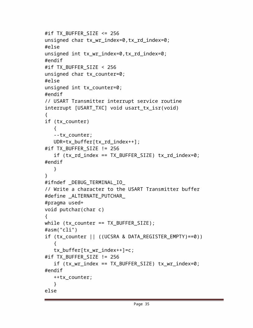
#ifndef _DEBUG_TERMINAL_IO_// Get a character from the USART Receiver buffer#define _ALTERNATE_GETCHAR_#pragma used+///char getchar (void){char data;while (rx_counter==0);data=rx_buffer[rx_rd_index++];#if RX_BUFFER_SIZE != 256if (rx_rd_index == RX_BUFFER_SIZE) rx_rd_index=0;#endif#asm("cli")--rx_counter;#asm("sei")return data;}#pragma used-#endif// USART Transmitter buffer#define TX_BUFFER_SIZE 8char tx_buffer[TX_BUFFER_SIZE];#if TX_BUFFER_SIZE <= 256unsigned char tx_wr_index=0,tx_rd_index=0;#elseunsigned int tx_wr_index=0,tx_rd_index=0;#endif#if TX_BUFFER_SIZE < 256unsigned char tx_counter=0;#elseunsigned int tx_counter=0;#endif// USART Transmitter interrupt service routineinterrupt [USART_TXC] void usart_tx_isr(void){if (tx_counter) { --tx_counter; UDR=tx_buffer[tx_rd_index++];
Page 26
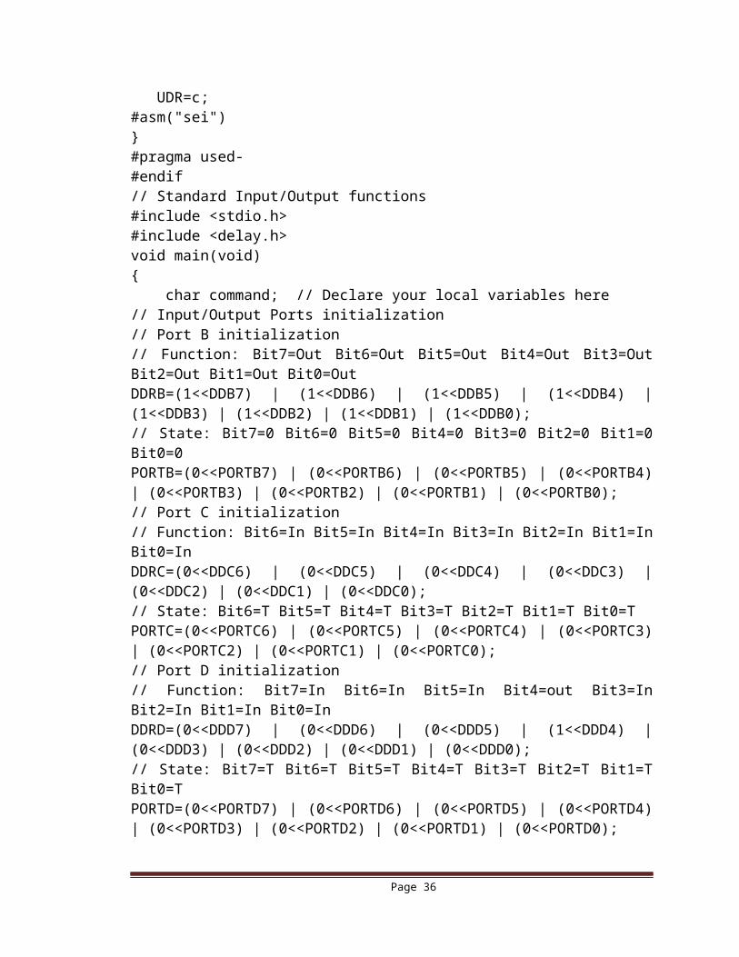
#if TX_BUFFER_SIZE != 256 if (tx_rd_index == TX_BUFFER_SIZE) tx_rd_index=0;#endif }}#ifndef _DEBUG_TERMINAL_IO_// Write a character to the USART Transmitter buffer#define _ALTERNATE_PUTCHAR_#pragma used+void putchar(char c){while (tx_counter == TX_BUFFER_SIZE);#asm("cli")if (tx_counter || ((UCSRA & DATA_REGISTER_EMPTY)==0)) { tx_buffer[tx_wr_index++]=c;#if TX_BUFFER_SIZE != 256 if (tx_wr_index == TX_BUFFER_SIZE) tx_wr_index=0;#endif ++tx_counter; }else UDR=c;#asm("sei")}#pragma used-#endif// Standard Input/Output functions#include <stdio.h>#include <delay.h>void main(void){ char command; // Declare your local variables here// Input/Output Ports initialization// Port B initialization// Function: Bit7=Out Bit6=Out Bit5=Out Bit4=Out Bit3=Out Bit2=Out Bit1=Out Bit0=Out DDRB=(1<<DDB7) | (1<<DDB6) | (1<<DDB5) | (1<<DDB4) | (1<<DDB3) | (1<<DDB2) | (1<<DDB1) | (1<<DDB0);// State: Bit7=0 Bit6=0 Bit5=0 Bit4=0 Bit3=0 Bit2=0 Bit1=0 Bit0=0 PORTB=(0<<PORTB7) | (0<<PORTB6) | (0<<PORTB5) | (0<<PORTB4) | (0<<PORTB3) | (0<<PORTB2) | (0<<PORTB1) | (0<<PORTB0);// Port C initialization// Function: Bit6=In Bit5=In Bit4=In Bit3=In Bit2=In Bit1=In Bit0=In DDRC=(0<<DDC6) | (0<<DDC5) | (0<<DDC4) | (0<<DDC3) | (0<<DDC2) | (0<<DDC1) | (0<<DDC0);
Page 27
// State: Bit6=T Bit5=T Bit4=T Bit3=T Bit2=T Bit1=T Bit0=T PORTC=(0<<PORTC6) | (0<<PORTC5) | (0<<PORTC4) | (0<<PORTC3) | (0<<PORTC2) | (0<<PORTC1) | (0<<PORTC0);// Port D initialization// Function: Bit7=In Bit6=In Bit5=In Bit4=out Bit3=In Bit2=In Bit1=In Bit0=In DDRD=(0<<DDD7) | (0<<DDD6) | (0<<DDD5) | (1<<DDD4) | (0<<DDD3) | (0<<DDD2) | (0<<DDD1) | (0<<DDD0);// State: Bit7=T Bit6=T Bit5=T Bit4=T Bit3=T Bit2=T Bit1=T Bit0=T PORTD=(0<<PORTD7) | (0<<PORTD6) | (0<<PORTD5) | (0<<PORTD4) | (0<<PORTD3) | (0<<PORTD2) | (0<<PORTD1) | (0<<PORTD0);
// Timer(s)/Counter(s) Interrupt(s) initializationTIMSK=(0<<OCIE2) | (0<<TOIE2) | (0<<TICIE1) | (0<<OCIE1A) | (0<<OCIE1B) | (0<<TOIE1) | (0<<TOIE0);// External Interrupt(s) initialization// INT0: Off// INT1: OffMCUCR=(0<<ISC11) | (0<<ISC10) | (0<<ISC01) | (0<<ISC00);// USART initialization// Communication Parameters: 8 Data, 1 Stop, No Parity// USART Receiver: On// USART Transmitter: On// USART Mode: Asynchronous// USART Baud Rate: 9600UCSRA=(0<<RXC) | (0<<TXC) | (0<<UDRE) | (0<<FE) | (0<<DOR) | (0<<UPE) | (0<<U2X) | (0<<MPCM);UCSRB=(1<<RXCIE) | (1<<TXCIE) | (0<<UDRIE) | (1<<RXEN) | (1<<TXEN) | (0<<UCSZ2) | (0<<RXB8) | (0<<TXB8);UCSRC=(1<<URSEL) | (0<<UMSEL) | (0<<UPM1) | (0<<UPM0) | (0<<USBS) | (1<<UCSZ1) | (1<<UCSZ0) | (0<<UCPOL);UBRRH=0x00;UBRRL=0x4D;// Global enable interrupts#asm("sei")while (1) { Motor_Enable1=1; Motor_Enable2=1; delay_ms(200); Motor_Enable1=0; Motor_Enable2=0; delay_ms(200); Motor_Enable1=1; Motor_Enable2=1; PORTD.4=1; command=getchar(); //putchar(command);
Page 28
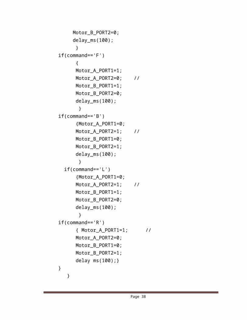
if(command=='S') {Motor_A_PORT1=0; Motor_A_PORT2=0; Motor_B_PORT1=0; Motor_B_PORT2=0; delay_ms(100); }if(command=='F') { Motor_A_PORT1=1; Motor_A_PORT2=0; // Motor_B_PORT1=1; Motor_B_PORT2=0; delay_ms(100); }if(command=='B') {Motor_A_PORT1=0; Motor_A_PORT2=1; // Motor_B_PORT1=0; Motor_B_PORT2=1; delay_ms(100); } if(command=='L') {Motor_A_PORT1=0; Motor_A_PORT2=1; // Motor_B_PORT1=1; Motor_B_PORT2=0; delay_ms(100); }if(command=='R') { Motor_A_PORT1=1; // Motor_A_PORT2=0; Motor_B_PORT1=0; Motor_B_PORT2=1; delay ms(100);}} }
Page 29
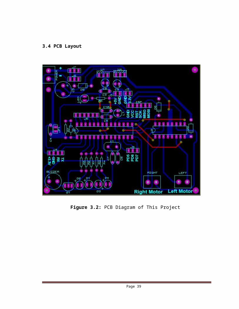
3.4 PCB Layout
Figure 3.2: PCB Diagram of This Project
Page 30
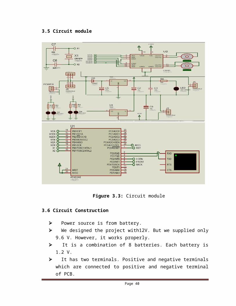
3.5 Circuit module
Figure 3.3: Circuit module
3.6 Circuit Construction
Power source is from battery. We designed the project with12V. But we supplied only 9.6 V. However, it
works properly. It is a combination of 8 batteries. Each battery is 1.2 V. It has two terminals. Positive and negative terminals which are connected to
positive and negative terminal of PCB. Then we see a capacitor. It is the filter capacitor. It eliminates the ripple. Ripple
is very harmful for system. Although battery is pure DC. Other capacitors are also used to eliminate the ripple.
Page 31
Microcontroller is needed a minimum of 5 volt. Otherwise it does not work properly.
For this case we used a 7805 voltage regulator IC which holds 5v. Pin 8 of L293D IC is connected with the source. For motor rotation it requires a minimum of 7.5 volt, otherwise motor will not
rotate. Pin 16 is connected to the output of 7805 IC for biasing. We used a Bluetooth. For Bluetooth 5v is needed. It is connected with 5v positive
and ground. TX, RX pins of microcontroller and Bluetooth are connected. It is used to
communicate with the microcontroller.
3.7 Android application Development
Android is an open source operating system based on the Linux kernel, and designed primarily for touch screen mobile devices such as smart phones and tablets.
For this application, we used MIT App Inventor site, where can be developed Android apps.
3.7.1 What is MIT App inventor?
App Inventor is a cloud-based tool, which means that you can build apps right in your web browser. This website offers all of the support that you’ll need as you learns how to build your own apps. The App Inventor software or "service" is at ai2.appinventor.mit.edu. You can get there by clicking the orange "Create" button from any page on this website.
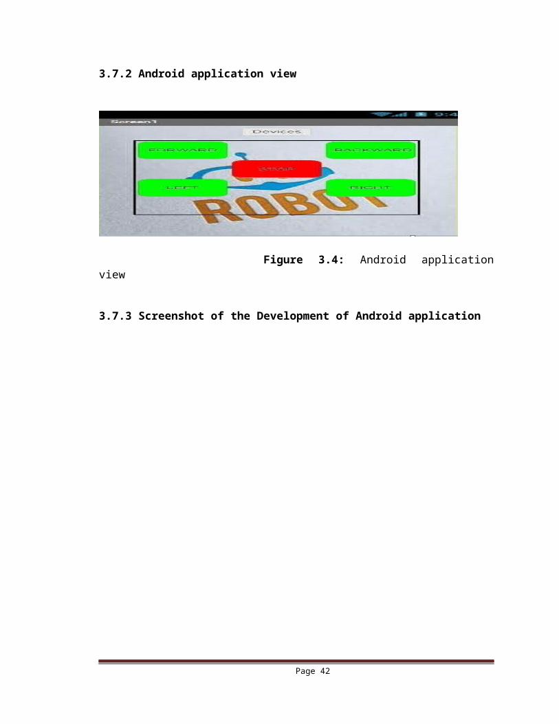
3.7.2 Android application view
Figure 3.4: Android application view
Page 32
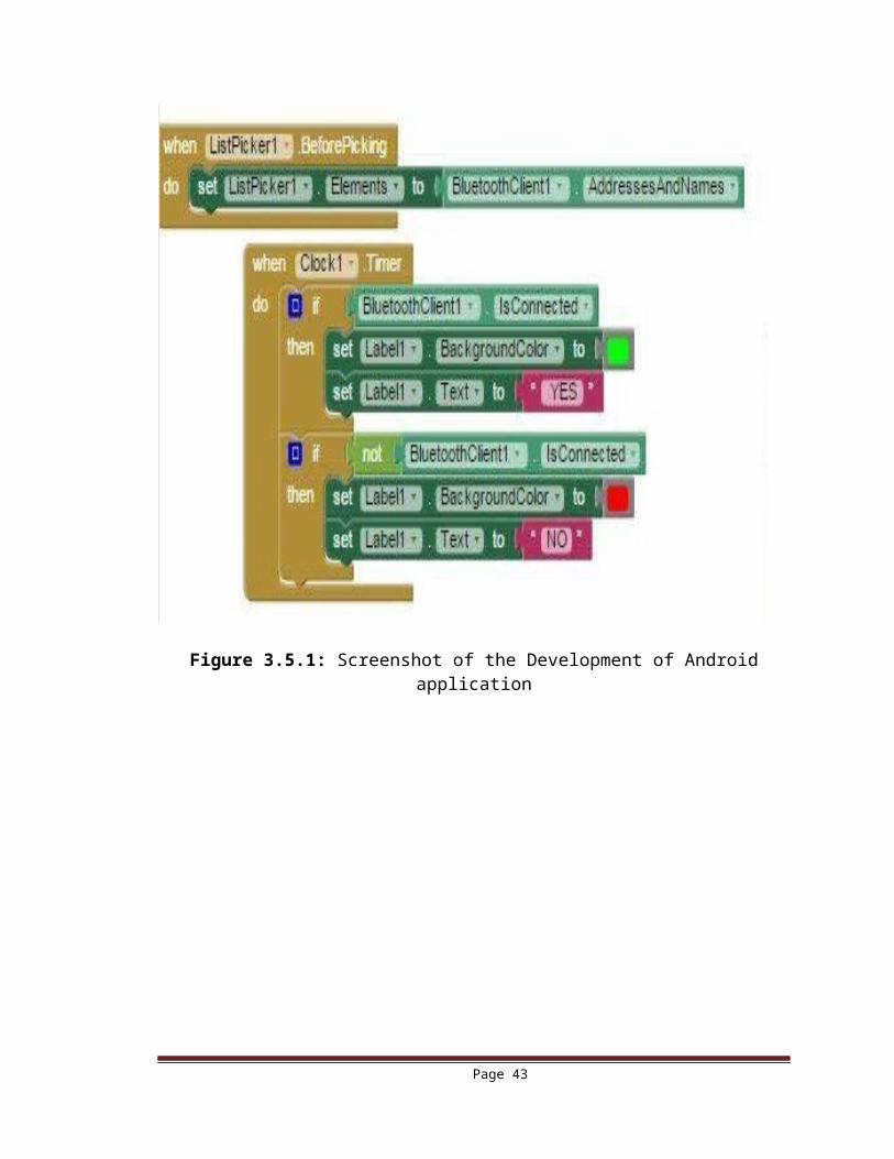
3.7.3 Screenshot of the Development of Android application
Figure 3.5.1: Screenshot of the Development of Android application
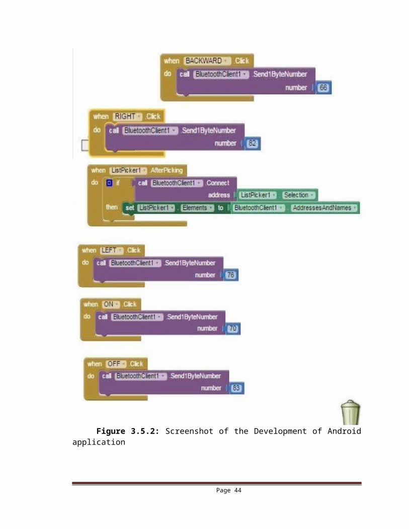
Page 33

Figure 3.5.2: Screenshot of the Development of Android application
Page 34
3.8 Working procedure
At First we on the power switch and circuit gets power which is indicated by LED. Then we have to connect Bluetooth module with the Android phone. At Smartphone app, Bluetooth device is searched. If found with name "HC-05"
device, the connection is made with a pass code “1234”. It must be paired. According to program:
When we press forward button it goes ahead. If we press stop it stops. If we press Backward it goes to backward. If we press left it goes to left. It means it moves to left, and vice versa.
By this we can avoid the obstacle using command by application.
3.9 Software’s Used
3.9.1 Proteus 8Proteus 8 is best simulation software for various designs with microcontroller. It
is mainly popular because of availability of almost all microcontrollers in it. So it is a handy tool to test programs and embedded designs for electronics hobbyist. We can simulate our programming of microcontroller in Proteus 8 Simulation Software.After simulating circuit in Proteus 8 Software we can directly make PCB design with it.
3.9.2 Code vision AVR
Integrated Development Environment for the 8-bit Atmel AVR and XMEGA Microcontrollers.
Application that runs under Windows® XP, Vista, Windows 7 and Windows 8, 32-bit and 64-bit
Easy to use Integrated Development Environment and ANSI C compatible Compiler
Editor with auto indentation, syntax highlighting for both C and AVR assembler, function parameters and structure/union members auto complete
Supported data types: bit, bool, char, int, short, long, 64-bit long. Fast floating point library with hardware multiplier and enhanced core
instructions support for all the new ATmega chips AVR specific extensions for: Transparent, easy accessing of the EEPROM & FLASH memory areas, without
the need of special functions like in other AVR compilers Bit level access to I/O registers Interrupt support
Page 35
Support for placing bit variables in the General Purpose I/O Registers (GPIOR) available in the new chips (ATtiny2313, ATmega48/88/168, ATmega165/169/325/3250/329/3290/645/6450/649/6490, ATmega1280/1281/2560/2561/640, ATmega406 and others)
Compiler optimizations: Peephole optimizer Advanced variables to register allocator, allows very efficient use of the AVR
architecture Common Block Subroutine packing (what our competition calls “Code
Compressor”), replaces repetitive code sequences with calls to subroutines. This optimizer is available as Standard in CodeVisionAVR, at no additional costs, not like in our competitor’s products.
Common sub-expression elimination Loop optimization Branch optimization Subroutine call optimization Cross-jumping optimization Constant folding Constant literal strings merging Store-copy optimization Dead code removing optimization 4 memory models: tiny (8 bit data pointers for chips with up to 256 bytes of
RAM), small (16 bit data pointers for chips with more than 256 bytes of ram), medium (for chips with 128k of flash) and large (for chips with 256k or more flash).
3.10 Summary
In this chapter we have described about microcontroller IC, circuit diagram, circuit construction, working procedure, PCB layout, microcontroller programming and designing software.
In the next chapter we will describe the application and limitation of the project.
Page 36
CHAPTER 4PROJECT OUTLOOK, APPLICATION
AND LIMITATIONS
Page 37
4.1 IntroductionIn Previous chapter we have described design and implementation of the project. In this chapter we will describe outer look of the project, its application and limitation.
4.2 Project Outlook
Figure 4.1: Outer look of the robot
4.3 Application of this project
The robot can be used for reconnaissance or surveillance. Like, if there is any hidden bomb under anything.
It can be ensured and notified through the robot. The robot is small in size so can be used for spying. This Project uses Bluetooth technology and in the future switched to wife. After using camera it can be used as a photographer. This types of robot used as toy’s kids.
Page 38
4.4 Limitation
It is use for short distance only.
Rapidly power reduced.
Bluetooth too low-bandwidth.
4.5 Summary
In this chapter we have described application and limitation of the project.In the next chapter we will describe about price and discussion of the project.
Page 39
CHAPTER 5DISCUSSION
Page 40
5.1 Introduction
In this chapter we will discuss about this project.
5.2 Price
The components are used in this project is very chip. Such as ATmgega8 microcontroller IC, 7805 Voltage regulator IC, L293D Motor Driver IC, HC-05 Bluetooth, Crystal, Hit sink, Battery, Steering wheel, wheel, DC motor. LED, Switch Capacitor, Resistor, PCB, and connecting wires. All of these are available in our local market.
5.3 Discussion
We tried to control the robot by the smart phone, and avoid the obstacle. That is why we designed an android app which communicates with microcontroller via Bluetooth module. In this project, we have gained the concept of embedded C, designing app, Java environment which are important for future development.
We kept some additional parts such as buzzer, resistor, LED, and rail connector/ bus bars in PCB. They are designed for the future use.
5.4 Advantages
Portable and Easy To Use. Easy to control. Simple in Construction. Easy To Maintain And Repair. Efficient and Low Cost Design. Low Power Consumption. The programming of the microcontroller is easy.
5.5 Disadvantages
It is time consuming project. It is use for short distance only. Rapidly power reduced. Bluetooth too low-bandwidth.
Page 41
5.6 Summary
In this chapter we have discussed price comparison, discussion, advantages and disadvantages of the project.
In the next chapter the report will be formally concluded.
Page 42
CHAPTER 6FUTURE EXTENSIONS AND
CONCLUSION
Page 43
6.1 Future Extensions
Obstacle avoidance
Install Ultra sonic sensor.
Vision
Use camera to transmit frames back to android application for display to user.
Bluetooth too low-bandwidth, switch to Wi-Fi.
6.2 Conclusion
Our objective was to design a mobile controlled robot, which can avoid the obstacle. For designing and development of the project, we have used various components like microcontroller, Smartphone, Bluetooth, DC motor and others components. We have also used MIT app inventor site for developing software and designing software for PCB layout.
In this case we faced in some challenges like software developing, microcontroller programming and layout designing, components assembling etc. Actually it was very difficult for us. After all we overcome these challenges by hard work and eventually we have been succeeded by the grace of Almighty Allah. This is a milestone for the future development, the latter of which will be made us better.
Page 44
References
1.2.3.4.5.6.7.8.9.10.11.12.13.14.15.16.
17. Robot making. [http://roboticsbd.com/index.php/robot-making-bangla] 18. Datasheet atmega8. [http://www.atmel.com/images/atmel-2486-8-bit-avr-
microcontroller-atmega8_l_datasheet.pdf]19. Resistor. Wikipedia. [http://en.wikipedia.org/wiki/Resistor] 20. Color Code. Wikipedia. [http://en.wikipedia.org/wiki/Electonic_color_code] 21. Resistor. Capacitor. Diode. LED.
[http://www.embeddedadventures.com/Tutorials/tutorials_detail/121]22. Switch. Wikipedia. [http://en.wikipedia.org/wiki/Switch] 23. app invention. [http://ai2.appinventor.mit.edu/] 24. Voltage-Regulator. Wikipedia. [http://en.wikipedia.org/wiki/78xx] 25. L293D H Driver IC. [http://www.ti.com/product/l293D] 26. L293D H Driver IC. [http://www.engineersgarage.com/electronic-components/l293d-
motor-driver-ic]27. Atmega8. [https://www.futurlec.com/Atmel/ATMEGA8L.shtml] 28. HC-05 Bluetooth. https://developer.mbed.org/users/edodm85/notebook/HC-05-
bluetooth/]29. All IC's Data Sheet. [http://www.alldatasheet.com/]
Page 45
30. Power management. [https://www.fairchildsemi.com/] 31. Obstacle avoiding robot. [https://www.youtube.com/results?
search_query=obstacle+avoiding+robot+with+android]32. Rechargeable Battery. [https://en.wikipedia.org/wiki/Rechargeable_battery] 33. Heat sink. Wikipedia. [https://en.wikipedia.org/wiki/Heat_sink]
Page 46