Embed Size (px)
Citation preview
PLASMA ANTENNA
DEPARTMENT OF ELECTRONICS ENGINEERING
PONDICHERRY UNIVERSITY
SUBMITEED BY:
RIGVENDRA KUMAR VARDHAN
M.TECH ECE 1ST YEAR
REG. NO: 14304022
OUTLINE
What is Plasma.
What is Antenna.
Plasma Antenna Technology.
Features of Plasma Antenna
Characteristics of Plasma
Antenna
Plasma antenna Vs
traditional antenna
Types of Plasma Antenna
How Plasma Antenna
Works.
Why we use Plasma
Antenna.
Working Principle
Advantages
Applications
Disadvantages
Conclusion
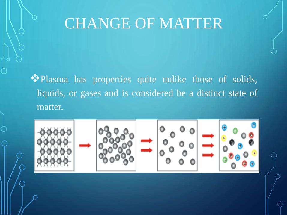
CHANGE OF MATTER
Plasma has properties quite unlike those of solids,
liquids, or gases and is considered be a distinct state of
matter.
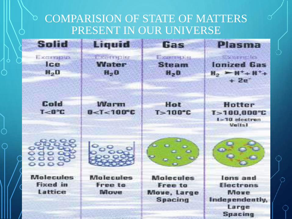
COMPARISION OF STATE OF MATTERS PRESENT IN OUR UNIVERSE
WHAT IS PLASMA?
Sir William Crookes, identified a matter, called plasma, in 1879.
According to Markland’s technology, plasmas are conductive assemblies of
charged and neutral particles and fields that exhibit collective effects.
By supplying energy the states of matter changes: from solid to liquid and from
liquid to gas. If further energy is added to a gas it becomes ionized and passes
over into the Plasma state – a fourth state of matter.
Plasma is a state of matter similar to gas in which a certain portion of the
particles are ionized. Heating a gas may ionize its molecules or atoms, thus
turning it into a plasma, which contains charged particles: positive ions and
negative electrons. Ionization can be induced by other means, such as strong
electromagnetic field applied with a laser or microwave generator, and is
accompanied by the dissociation of molecular bonds, if present.
Plasmas carry electrical currents and generate magnetic fields.
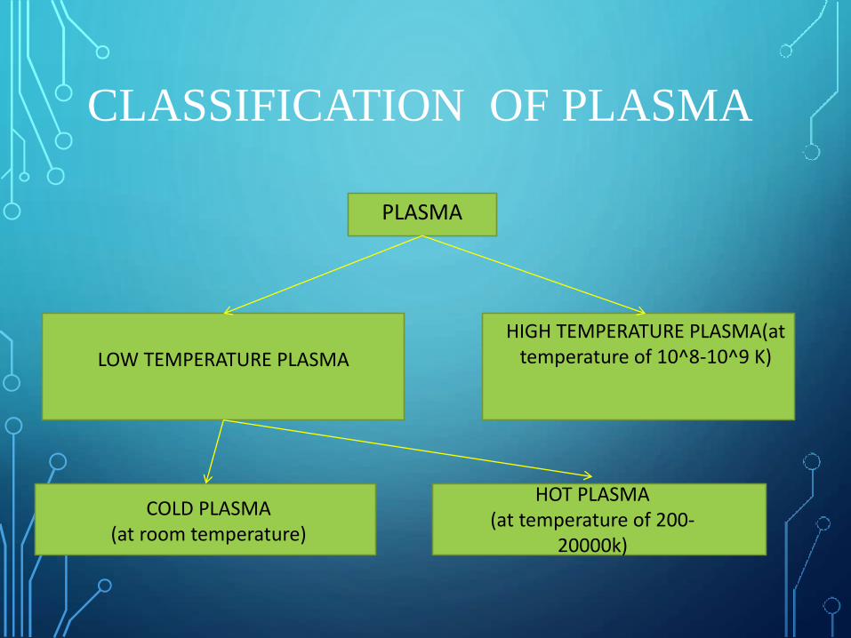
CLASSIFICATION OF PLASMA
PLASMA
COLD PLASMA(at room temperature)
LOW TEMPERATURE PLASMA
HIGH TEMPERATURE PLASMA(at temperature of 10^8-10^9 K)
HOT PLASMA(at temperature of 200-
20000k)
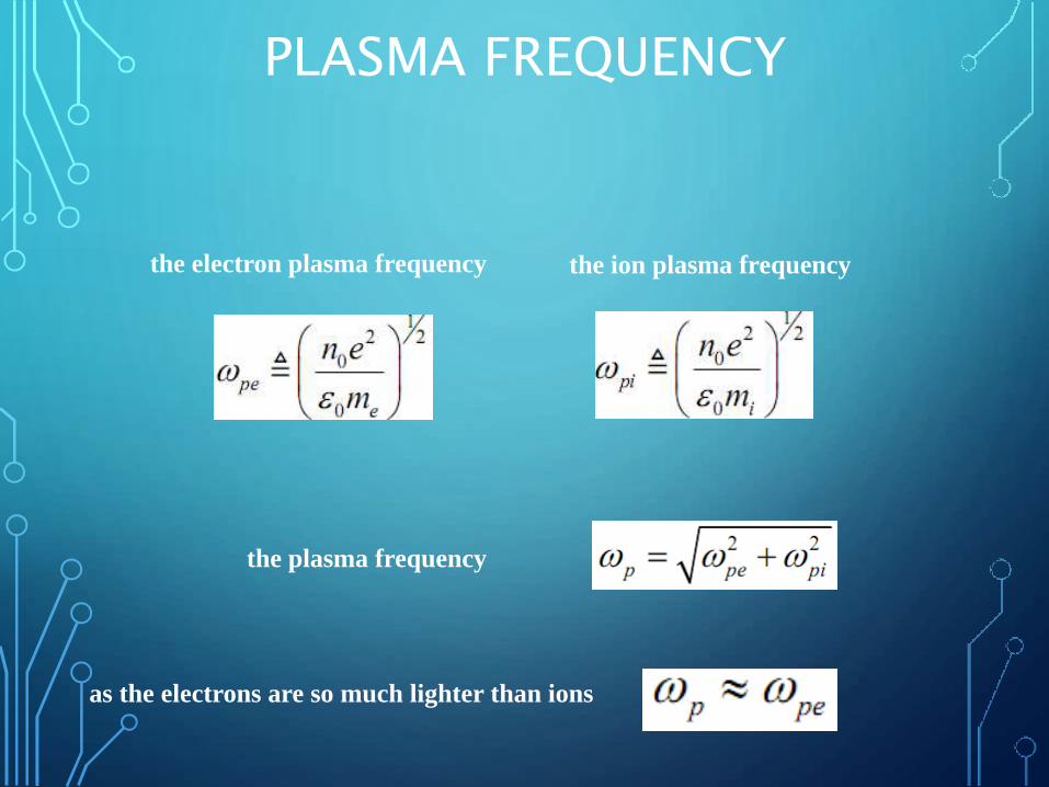
PLASMA FREQUENCY
the electron plasma frequency the ion plasma frequency
the plasma frequency
as the electrons are so much lighter than ions
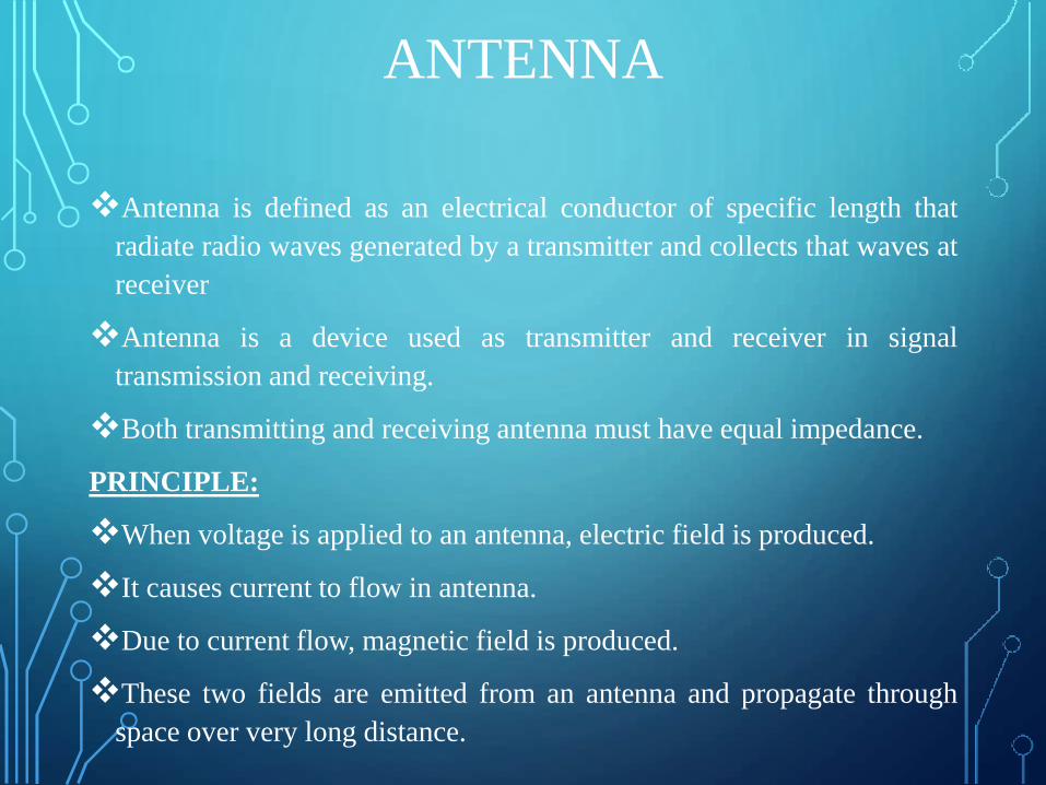
ANTENNA
Antenna is defined as an electrical conductor of specific length that
radiate radio waves generated by a transmitter and collects that waves at
receiver
Antenna is a device used as transmitter and receiver in signal
transmission and receiving.
Both transmitting and receiving antenna must have equal impedance.
PRINCIPLE:
When voltage is applied to an antenna, electric field is produced.
It causes current to flow in antenna.
Due to current flow, magnetic field is produced.
These two fields are emitted from an antenna and propagate through
space over very long distance.
PLASMA ANTENNAS
Plasma Antennas is a type of radio antenna currently under development.
Plasma is used instead of metal for conduction i.e. plasma discharge
tubes are used as the antenna element.
Plasma antenna are Radio frequency antenna that employ plasma as a
guiding medium for electromagnetic radiation.
It uses ionized gas instead of metal conducting element of conventional
antenna to transmit and receive signals, decreasing interference and
boosting the functionality.
When the gas of plasma tube is electrically charged or ionized ,it
becomes conductive and allowing radio frequency signals to be
transmitted or received.
When gas is not ionized, the antenna element ceases to exit.
PLASMA ANTENNAS
Ionized gas is an efficient conducting element with a number of
important advantages. Since the gas is ionized only for the time of
transmission or reception," ringing" and associated effects of solid wire
antenna design are eliminated.
The design allows for extremely short pulses, important to many forms
of digital communication and radars.
It is compact and dynamically reconfigured for frequency, direction,
bandwidth, gain and beam width.
This technology enable to design antenna that are efficient, low in weight
and smaller in size .
WHY WE USE PLASMA ANTENNA?
Plasma devices are fully steerable.
Are a low cost replacement for both mechanically steered antennas.
No antenna ringing provides an improved signal to noise ratio
comparison to traditional antennas.
A airborne Plasma antenna provides stealth technology to it.
Plasma Antennas leads the world in developing low cost plas76
antennas across the band 1 GHz to 300 GHz.
A circular scan can be performed electronically with no moving parts at
a higher speed than traditional mechanical antenna structures.
KEY FEATURES
High directional gain: concentrates RF power to increase link budget,
dramatically enhancing network coverage and capacity.
Low side lobes reduce interference, enabling improved frequency re-
use and substantially higher utilization.
Wide bandwidth supports simultaneous multi-band or UWB operation
from a single compact antenna.
High speed beam switching enables spatial time division multiplexing
to boost spectral efficiency and throughput.
Compact and lightweight form factor reduces site and mast costs,
simplifies installation and minimizes environmental impact.
Maintenance free - auto-aligning with no moving parts and requires
no calibration, minimizing total cost.
CHARACTERISTICS OF A PLASMA ANTENNA
Plasma antenna can operate up to 90 GHz.
Plasma antenna can transmit and receive from the same aperture
provided the frequencies are widely separated.
A single dynamic antenna structure can use time multiplexing so that
many RF subsystems can share one antenna resource.
Changes in the ion density can result in instantaneous changes in
bandwidth over wide dynamic ranges.
In Plasma Antenna ,Gas ionizing process can manipulate resistance and
when deionised, the gas has infinite resistance and doesn’t interact with
RF radiation.
Reduces computer signal processing requirements.
Ability to focus a single beam.
WORKING PRINCIPLE
A Plasma antenna technology employs ionized gas enclosed in a tube as
a conducting element of an antenna.
When supply is given to the tube, the gas inside it gets ionized to
plasma. When plasma is highly energized, it behaves as a conductor
that allowing radio frequency (RF) signals to be transmitted or received.
A plasma antenna generates localized concentrations of plasma to form
a plasma mirror which deflects an RF beam launched from a central
feed located at the focus of the mirror.
The plasma can be freely moved to the desired geometry of the
reflector by plasma diodes which enables the beam to be steered
quickly without the need for mechanical motion.
WORKING PRINCIPLE
An ionized region, or solid state plasma, can be generated in silicon
using electronically controlled devices (plasma diodes) that are
positioned between closely spaced metalized surfaces which constrain
the beam.
When the gas is not ionized or a plasma antenna is turned off - it is
transparent and allowing other adjacent antennas to transmit or receive
without interference.
In some realizations, the silicon disc (i.e. Si wafer) act as a cylindrical
lens, to form a lens/reflector system that enables the RF energy to be
collimated.
In order for plasma to have significant effect on an electromagnetic
wave, the electronic density must be increased by several orders of
magnitude.
WORKING PRINCIPLE
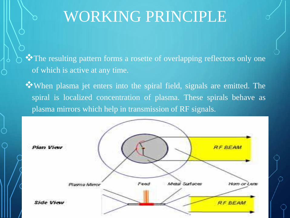
The resulting pattern forms a rosette of overlapping reflectors only one
of which is active at any time.
When plasma jet enters into the spiral field, signals are emitted. The
spiral is localized concentration of plasma. These spirals behave as
plasma mirrors which help in transmission of RF signals.
TYPES OF PLASMA ANTENNAS
Laser Induced Antenna
Plasma Antennas Using Tube Structures
Explosively Formed Plasma Dielectric
Antennas
LASER INDUCED ANTENNA
The transmission was realized along a plasma channel that was created
by the atmosphere breakdown.
The atmosphere breakdown was created by the focused laser emission.
The laser is used to designate the path of the antenna while an
electrical discharge is employed to create and sustain the plasma.
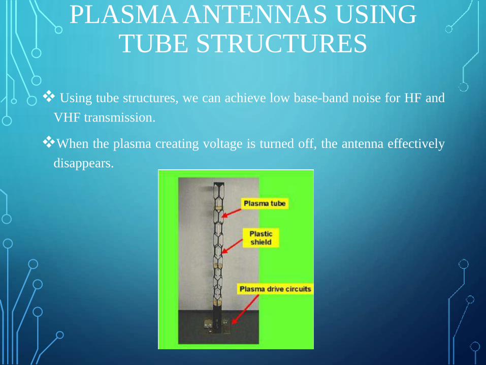
PLASMA ANTENNAS USING TUBE STRUCTURES
Using tube structures, we can achieve low base-band noise for HF and
VHF transmission.
When the plasma creating voltage is turned off, the antenna effectively
disappears.
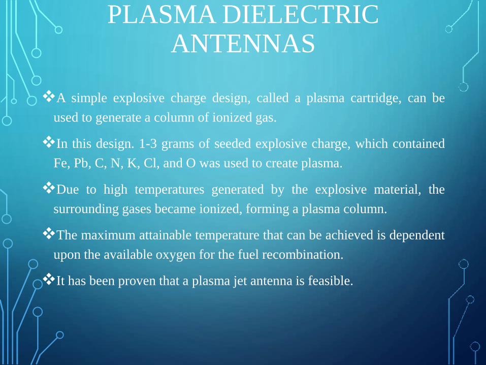
PLASMA DIELECTRIC ANTENNAS
A simple explosive charge design, called a plasma cartridge, can be
used to generate a column of ionized gas.
In this design. 1-3 grams of seeded explosive charge, which contained
Fe, Pb, C, N, K, Cl, and O was used to create plasma.
Due to high temperatures generated by the explosive material, the
surrounding gases became ionized, forming a plasma column.
The maximum attainable temperature that can be achieved is dependent
upon the available oxygen for the fuel recombination.
It has been proven that a plasma jet antenna is feasible.
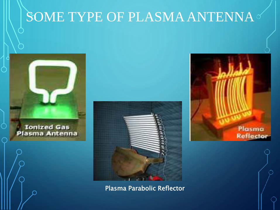
SOME TYPE OF PLASMA ANTENNA
Plasma Parabolic Reflector
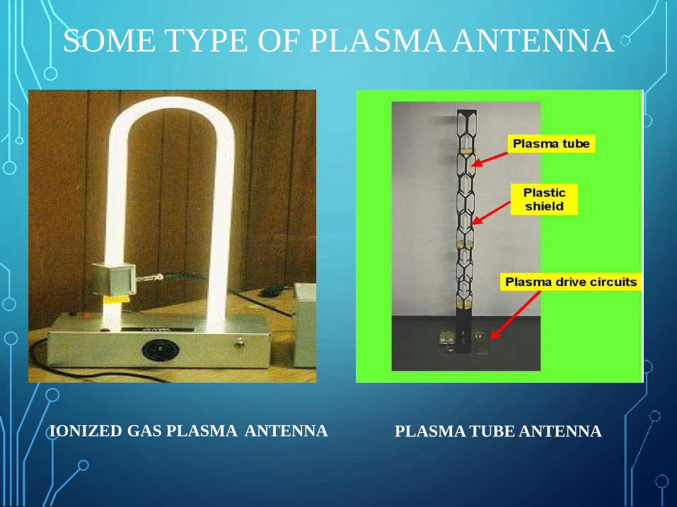
SOME TYPE OF PLASMA ANTENNA
IONIZED GAS PLASMA ANTENNA PLASMA TUBE ANTENNA
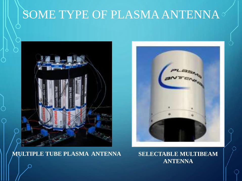
SOME TYPE OF PLASMA ANTENNA
MULTIPLE TUBE PLASMA ANTENNA SELECTABLE MULTIBEAM
ANTENNA
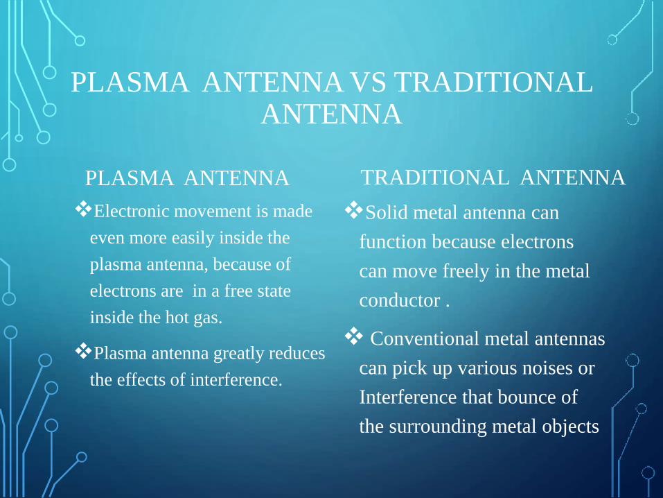
PLASMA ANTENNA VS TRADITIONAL ANTENNA
PLASMA ANTENNA
Electronic movement is made
even more easily inside the
plasma antenna, because of
electrons are in a free state
inside the hot gas.
Plasma antenna greatly reduces
the effects of interference.
TRADITIONAL ANTENNA
Solid metal antenna can
function because electrons
can move freely in the metal
conductor .
Conventional metal antennas
can pick up various noises or
Interference that bounce of
the surrounding metal objects
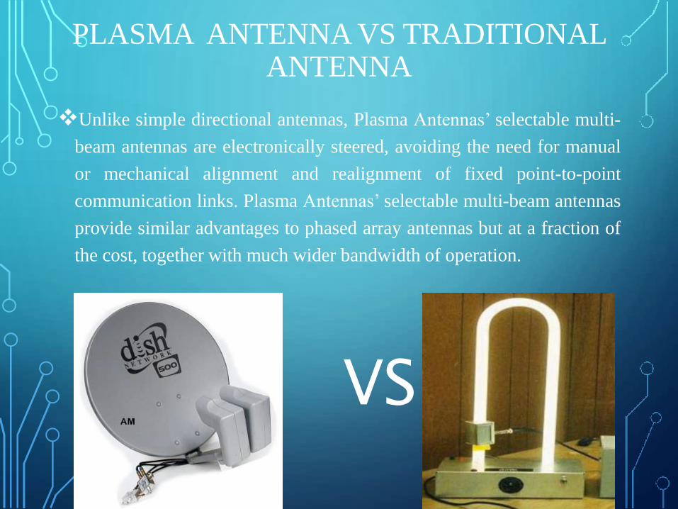
PLASMA ANTENNA VS TRADITIONAL ANTENNA
Unlike simple directional antennas, Plasma Antennas’ selectable multi-
beam antennas are electronically steered, avoiding the need for manual
or mechanical alignment and realignment of fixed point-to-point
communication links. Plasma Antennas’ selectable multi-beam antennas
provide similar advantages to phased array antennas but at a fraction of
the cost, together with much wider bandwidth of operation.
VS
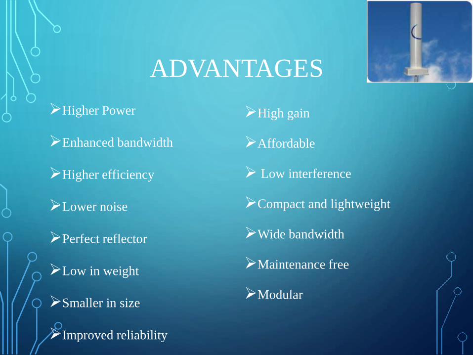
ADVANTAGES
Higher Power
Enhanced bandwidth
Higher efficiency
Lower noise
Perfect reflector
Low in weight
Smaller in size
Improved reliability
High gain
Affordable
Low interference
Compact and lightweight
Wide bandwidth
Maintenance free
Modular
DISADVANTAGES
Ionizer adds weight and volume .
Ionizer increases power consumption .
Stable and repeatable plasma volumes: Not all of the gas is ionized to
become plasma, some parts remain unionized. Thus the volume of the
plasma formed during each time should be same to generate stable
electromagnetic waves. This can be achieved by keeping the current
flowing through it constant, which will excite the same amount of
particles
APPLICATION
MILLITARY APPLICATIONS
Shipboard/submarine antenna
replacements.
Unmanned air vehicle sensor
antennas.
land-based vehicle antennas.
Stealth aircraft antenna
replacements.
Defense, Space and Homeland Security.
Military applications for its stealth,
weight and easily reconfiguration.
Detection and tracking of ballistic
missiles.
COMMERCIAL APPLICATIONS
Telemetry & broad-band
communications.
Ground penetrating radar.
Navigation.
Weather radar and wind shear detection.
Collision avoidance .
Network Equipment Providers and
Systems Integrators
High-speed data communication.
In radio antenna.
Used for transmission and modulation techniques(PM,AM,FM).
CONCLUSION
Plasma antenna is a wide band width and capable of any
communication systems
The light weight of antenna system provide easy usage.
Multidirectional antenna in microwave communication
It is more advantageous than other antenna due to ionized gas.
Its action has many general with the dielectric antenna action.
It helps in pulse operation.

REFERENCES
www.wikipedia.org
www.seminaron.in
www.seminarelectronicstopic.com
www.techalone.com
www.authorstream.com

THANK YOU

QUERIES


![Plasma TelwinEnterprise Plasma 160 HF[1]](https://img.pdfslide.net/doc/110x75/55cf9702550346d0338f3edd/plasma-telwinenterprise-plasma-160-hf1.jpg)