Embed Size (px)
Citation preview
IOSR Journal of Mechanical and Civil Engineering (IOSR-JMCE)
e-ISSN: 2278-1684,p-ISSN: 2320-334X, Volume 9, Issue 2 (Sep. - Oct. 2013), PP 70-80 www.iosrjournals.org
www.iosrjournals.org 70 | Page
Post-buckling analysis of a simply supported compound beams
made of two symmetrically distributed materials under uniform
thermal loading
V. Sridhar Patnaik1, G. Venkateswara Rao
2 and A.V.S.S.K.S. Gupta
3
Associate Professor, Department of Mechanical Engineering, VITAM college of Engineering, Visakhapatnam
– 531 173, India
Research Professor, Department of Mechanical Engineering, Vardhaman College of Engineering, Shamshabad
, Hyderabad – 501 218, India.
Professor, Department of Mechanical Engineering, Jawaharlal Nehru Technological University, Hyderabad –
500 085, India
Abstract: Thermal post buckling analysis of axi symmetric compound stepped beams, made of two different
materials with axially immovable ends, for simply supported conditions, and was studied numerically. The
analysis was performed by using the energy principle. The compound beam is made of two different materials,
with the end segments of equal lengths of the same material with a higher, and the central segment of a different
length of another material with lower coefficients of linear thermal expansion. Similarly, the Young’s modulus of
the material of the middle segment is higher than that of the symmetrically placed end segments. The buckling
and post buckling strength of stepped compound beam is predicted by examining the influence of inertia, length
and deflection ratios. As mentioned in the title of the present work, importance is given for predicting the non
dimensional post buckling parameters for the two different material combinations such as steel-aluminum,
titanium-aluminum and copper-aluminum as these combinations of materials finds a major applications in the
fields of aerospace, electronic, power generation and automobile industry where high strength and low weight
are desirable. For post buckling analysis, the accuracy and efficiency of the present method for a isotropic uniform beam with
simply supported and fixed-fixed boundary conditions, have shown a good agreement with that of obtained by
finite element method.
Key words: compound beam, copper-aluminum, steel-aluminum, titanium-aluminum, and post buckling
I. Introduction The emergence of large variety of structural members made of two different materials, in the interest of
restoration and economy, has inspired researchers to evaluate the contribution of the engineering materials to the
structural strength at elevated temperatures. This study has been undertaken for the purpose of identifying the
behavior of stepped beams, made of two different materials such as steel-aluminum, titanium-aluminum and
copper-aluminum. The previous analytical and numerical studies on the post buckling behavior of isotropic
uniform beams for simply supported and fixed-fixed end conditions are used to confirm the validity of results
obtained by present method for different materials.
Fundamental principles of structural members under the influence of thermal and mechanical loads are
reported in the work of Usmani et al [1]. The fundamental principles presented in this paper provide a means of
estimating forces and displacements in real structures with appropriate idealizations.Raju and Rao [2-6] have
studied the thermal post buckling of uniform and tapered columns with immovable ends, using Rayleigh-Ritz
and the finite element methods. In this study an exact mathematical model thermal post buckling behavior of uniformly heated elastic rods has also been developed. Thermal post buckling behavior of heated elastic rods
has also been predicted in this study. A simple intuitive method to predict the thermal post buckling behavior of
uniform columns has been presented by Rao and Raju. Different types of boundary conditions for the columns
have been presented in this study. Li and Batra [7] employed a numerical method, such as shooting method, in
the study and analysis of deformations of homogenous and isotropic Euler–Bernoulli beams with simply
supported and fixed-fixed end conditions, heated uniformly into the post buckling regime.
The concept of a stepped compound beam is introduced in the present authors‟ research work [8, 9] to
obtain a near optimum (minimum mass) configuration with respect to critical buckling temperature of the
stepped symmetric compound beam for different boundary conditions and different material combinations. The
nonlinear ordinary differential equations deals with post buckling behavior of beams subject to compressive
loads have analyzed either numerically or analytically in the work of [10-12].Jeket [13] has studied deformations of a thermally buckled beam made of nonlinear thermo elastic material.
Post-buckling analysis of a simply supported compound beams made of two symmetrically distributed
www.iosrjournals.org 71 | Page
Sherbourne,A.N. [14] and Pandy and Sherbourne[15] have reported the buckling and post buckling of
composite beams and plates by using differential quadrature multiplier principle, DQM. Li and Balachandran
[16] have analyzed the thermal buckling and free vibrations of composite micro electromechanical resonators
modeled as stepped composite Euler-Bernoulli beam.Thermal buckling strength of axially restrained composite
structure is investigated by Kardomates et al [17]. The pinned-fixed beam resting on elastic foundation is
investigated by Xisong and Shimrong Li [18].Post buckling behavior of columns subjected to mechanical loads
was discussed by Dym [19] and Thompson and Hunt [20] using differential approach.Buckling and vibration analysis of beams and plates for a wide range of anisotropic materials are addressed by Laszlo P. kollar and
George S.Springer [22].
Postbuckling deformations of perfect and geometrically imperfect columns resting on elastic
foundations have been analysed by Koundis et al [23]. It was observed that the critical state of a perfect column
is a stable symmetric bifurcation point.One of the major problems faced in realizing the compound beams is the
joining of different materials efficiently and effectively performed by the modern techniques, especially friction
welding, friction stir welding developed by the researchers reported in Refs. [24-25].
In the present work, energy principle is used to predict the thermal post buckling behavior of uniform
and stepped beams with simply supported boundary conditions, made of single or two different materials
combinations.
II. Mathematical Formulation 2.1 Evaluation of Thermal Buckling Load
In this present method, concept leads only one single undetermined constant which can be solved by
the principle of conservation of total energy.
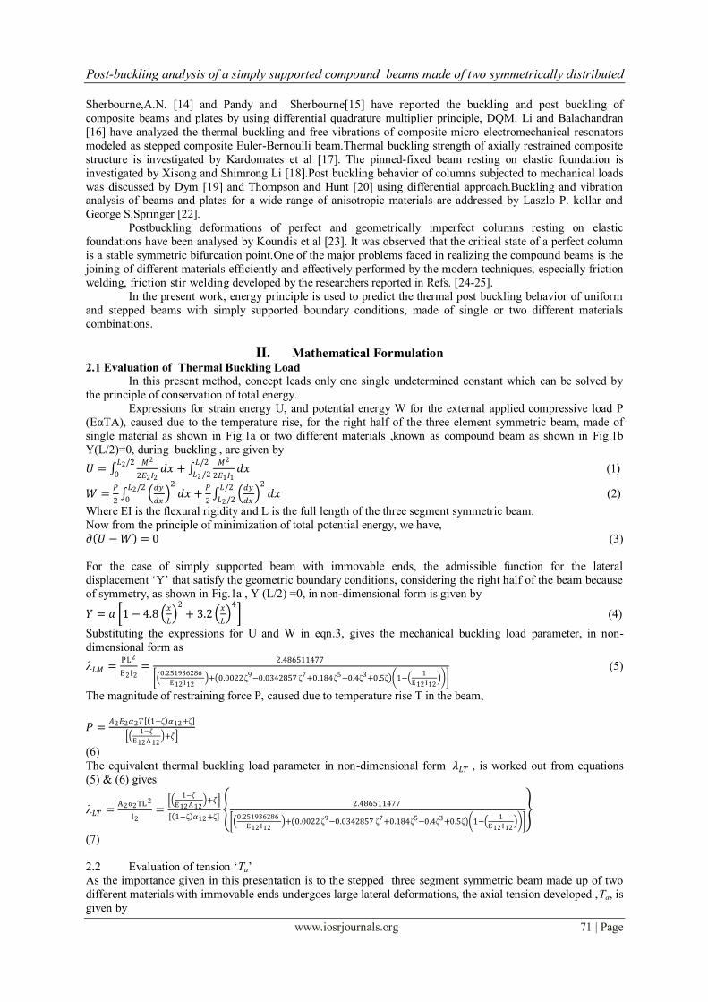
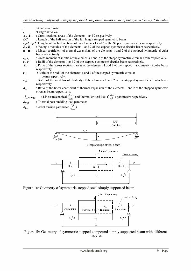
Expressions for strain energy U, and potential energy W for the external applied compressive load P
(EαTA), caused due to the temperature rise, for the right half of the three element symmetric beam, made of
single material as shown in Fig.1a or two different materials ,known as compound beam as shown in Fig.1b
Y(L/2)=0, during buckling , are given by
𝑈 = 𝑀2
2𝐸2𝐼2
𝐿2/2
0𝑑𝑥 +
𝑀2
2𝐸1𝐼1
𝐿/2
𝐿2 /2𝑑𝑥 (1)
𝑊 =𝑃
2
𝑑𝑦
𝑑𝑥
2𝐿2/2
0𝑑𝑥 +
𝑃
2
𝑑𝑦
𝑑𝑥
2𝐿/2
𝐿2 /2𝑑𝑥 (2)
Where EI is the flexural rigidity and L is the full length of the three segment symmetric beam.
Now from the principle of minimization of total potential energy, we have,
𝜕 𝑈 −𝑊 = 0 (3)
For the case of simply supported beam with immovable ends, the admissible function for the lateral
displacement „Y‟ that satisfy the geometric boundary conditions, considering the right half of the beam because
of symmetry, as shown in Fig.1a , Y (L/2) =0, in non-dimensional form is given by
𝑌 = 𝑎 1 − 4.8 𝑥
𝐿
2
+ 3.2 𝑥
𝐿
4
(4)
Substituting the expressions for U and W in eqn.3, gives the mechanical buckling load parameter, in non-
dimensional form as
𝜆𝐿𝑀 =PL2
E2I2=
2.486511477
0.251936286
E12 I12 + 0.0022 ζ9−0.0342857 ζ7+0.184ζ5−0.4ζ3+0.5ζ 1−
1
E12 I12
(5)
The magnitude of restraining force P, caused due to temperature rise T in the beam,
𝑃 =𝐴2𝐸2𝛼2𝑇 1−ζ 𝛼12 +ζ
1−𝜁
E12 A 12 +𝜁
(6)
The equivalent thermal buckling load parameter in non-dimensional form 𝜆𝐿𝑇 , is worked out from equations
(5) & (6) gives
𝜆𝐿𝑇 =A2α2TL 2
I2=
1−𝜁
E12 A 12 +𝜁
1−ζ 𝛼12 +ζ
2.486511477
0.251936286
E12 I12 + 0.0022 ζ9−0.0342857 ζ7+0.184ζ5−0.4ζ3+0.5ζ 1−
1
E12 I12
(7)
2.2 Evaluation of tension „Ta‟
As the importance given in this presentation is to the stepped three segment symmetric beam made up of two
different materials with immovable ends undergoes large lateral deformations, the axial tension developed ,Ta, is
given by

Post-buckling analysis of a simply supported compound beams made of two symmetrically distributed
www.iosrjournals.org 72 | Page
𝑇𝑎 =𝐸2𝐼2
𝑟22𝐿2
𝑑𝑦
𝑑𝑥
2𝐿2/2
0𝑑𝑥 +
𝐸1𝐼1
𝑟12𝐿1
𝑑𝑦
𝑑𝑥
2𝐿/2
𝐿2/2𝑑𝑥
(8) And in the non dimensional form is given by
λTa=
Ta L2
E2I2=
a2
r22
2.486511477 E12 I12
r122 1−ζ
+ 0.182857ζ7 − 1.536ζ
5 + 3.84ζ3 − 0.000345523
1
ζ−
E12 I12
r122 1−ζ
(9)
The compressive force developed in the column, due to temperature raises T from the stress free condition under
equilibrium conditions (linear elastic forces), reaches a critical value, known as the linear critical thermal
load 𝜆𝐿𝑇 . However, in the post buckling range, the compressive force developed also has to balance the axial tension
developed due to large deformations in addition to the linear elastic forces. Thus the thermal post buckling load
in the non-dimensional form is expressed as
𝜆𝑁𝐿𝑇 = 𝜆𝐿𝑇 + λTa
(10)
Once the tension developed in the beam due to large deflections is known, the thermal post-buckling behavior of
the column in terms of 𝜆𝑁𝐿𝑇
𝜆𝐿𝑇= 1 +
λTa
𝜆𝐿𝑇
(11)
Equation (11) gives the values of the ratio of thermal post buckling load parameter to buckling load parameter, 𝜆𝑁𝐿𝑇
𝜆𝐿𝑇 of a simply supported beam for specified values of ratios of a/r2, ζ and I12.
Apart from the theoretical analysis, a detailed Finite Element Analysis is also carried out to capture the thermal
post-buckling path of stepped beam using commercially available software ANSYS. The stepped beam is
discretized with 100 beam elements (BEAM 4 of ANSYS 11.0). Initial geometric imperfection of 1/100th of beam radius is given at the middle length of the beam(line of symmetry). The thermal load is applied in
temperature increments (0.1 deg) from initial stress free temperature. Newton-Raphson procedure is used to
solve the non-linear finite element system of equations. The analysis is carried out for the beam simply
supported at both ends: translational dof at two ends are zero
III. Numerical Results And Discussion The material properties, namely, the Young‟s modulus, density and linear coefficient of thermal
expansion of aluminum, copper, steel and titanium, considered in this work are presented in Table 1. Tables 2 to 7 show the values of the ratios of the thermal post buckling load to thermal buckling load in the non dimensional
form (𝜆𝑁𝐿𝑇
𝜆𝐿𝑇) for the isotropic simply supported boundary conditions of uniform and stepped beams, obtained
from the present theoretical analysis using energy principle and finite element analysis through software
ANSYS for several values of central deflection parameter a/r2, length ratio, ζ and moment of inertia ratio, I12. The maximum difference in results of present theoretical analysis shown outside the bracket and ANSYS,
values shown inside the bracket, is around 4%. The values of these ratios are decreasing with the increasing of
length ratio and increasing with the increase of central deflection ratio and moment of inertia ratio.
Also it is observed from the table 2 that the present theoretical analysis and ANSYS values for a uniform simply
supported and isotropic beam have shown good agreement with a difference of 0.001% and 4% with that of
from Ref. [5]. Beyond this value of the difference goes on increasing with increasing of a/r2 and a maximum of
0.535% for a/r2 =3.This difference is not very high for all practical purposes.
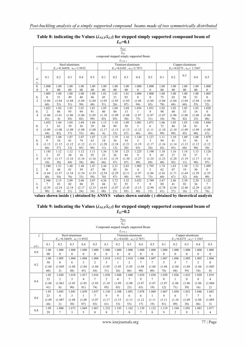
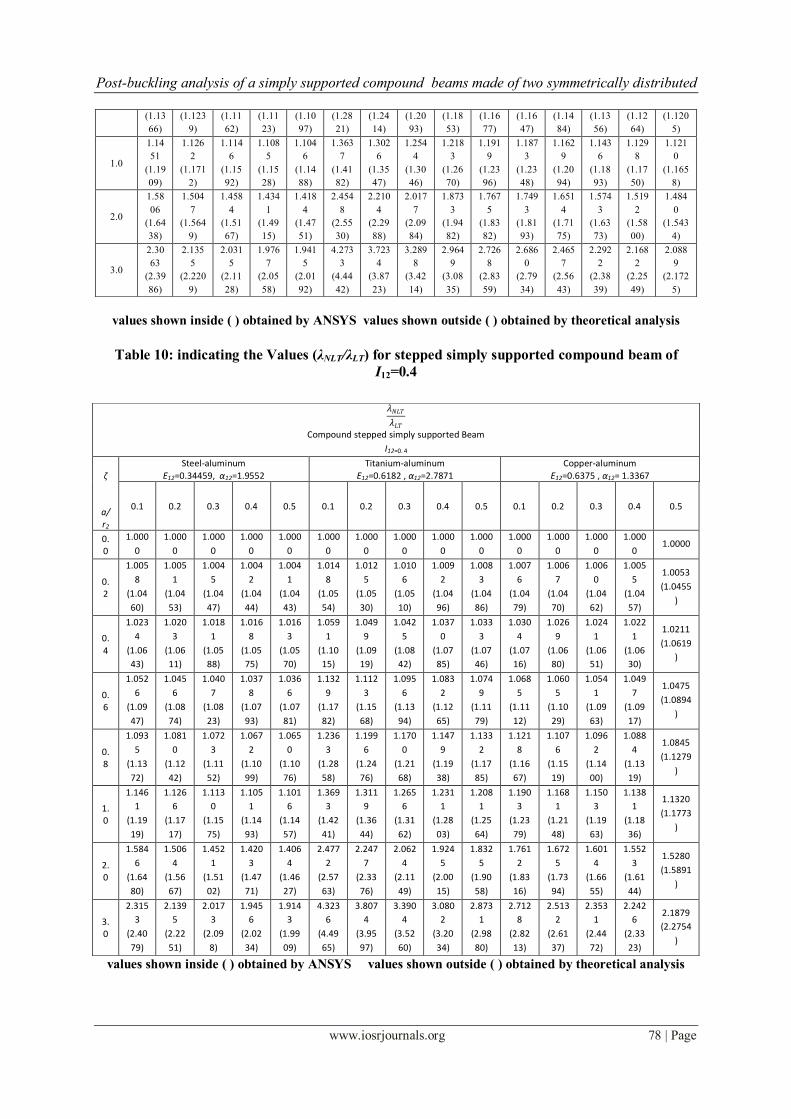
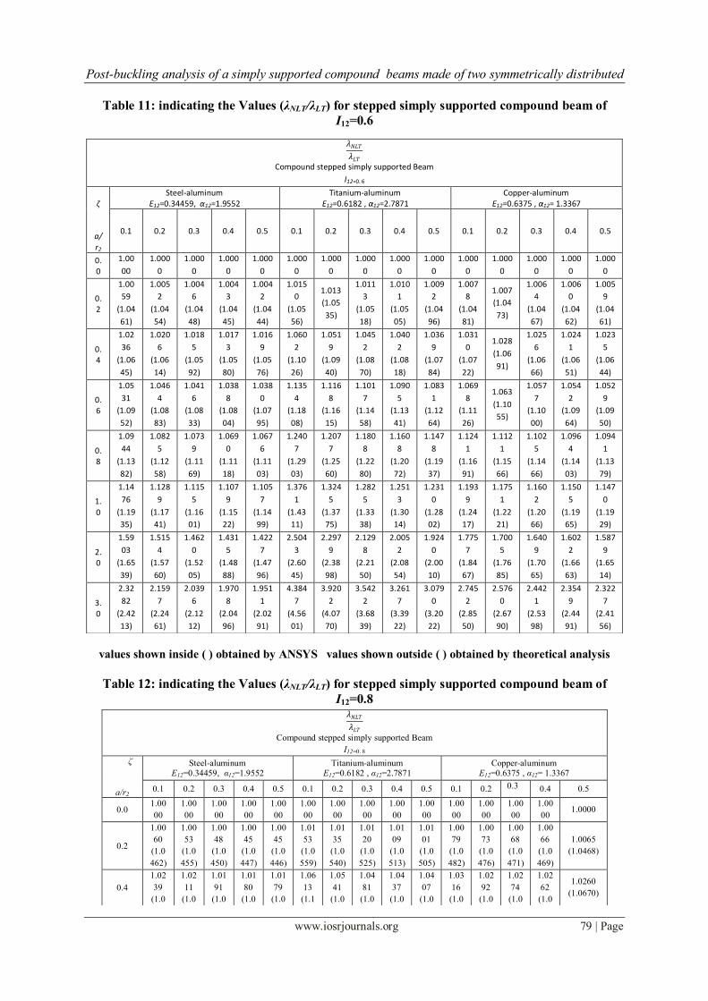
Tables 8 to 12 presenting the values of the ratios of the thermal post buckling load to thermal buckling
load in the non dimensional form (𝜆𝑁𝐿𝑇
𝜆𝐿𝑇) for the simply supported boundary conditions of stepped compound
beams, obtained from the present theoretical analysis using energy principle and finite element analysis through
software ANSYS for several values of central deflection parameter a/r2, length ratio, ζ and moment of inertia
ratio, I12.The results have shown the same trend as it is seen in results of the isotropic beam. Also observed that
these values are higher for the material combination of titanium and aluminum due to larger value of thermal
expansion ratio when compared with that from other material combinations of copper-aluminum and steel-
aluminum. It has been observed the ratios of (𝜆𝑁𝐿𝑇
𝜆𝐿𝑇) for the compound beams are lower than that of isotropic
beams at higher values of length ratio but more significant at lower values of length ratio. This can be clearly
observed in the compound beam of titanium-aluminum combination existed with larger value of thermal
expansion ratio and moderate value of modulus ratio. The same authors already presented in the previous
research publications [8-9], the effectiveness and advantage of a compound beam with respect to mass and critical buckling temperature.
Post-buckling analysis of a simply supported compound beams made of two symmetrically distributed
www.iosrjournals.org 73 | Page
IV. Conclusions Thermal post buckling analysis of stepped ,symmetric beams ,made of single material and
combinations of different materials for simply supported boundary conditions with immovable ends, is investigated using energy principle by considering the dimensionless form of 4th order algebraic function and by
using ANSYS. Accuracy of these results for a compound beam is verified with those obtained from the finite
element method through software ANSYS and can be seen a good agreement. The present study on post
buckling of stepped compound beams serve as a reference for predicting the post buckling response of
compound beam and its significance in applications.
Acknowledgment The authors gratefully acknowledge the managements of the respective Institutes for their constant
encouragement during the course of this work.
References [1] J.M. Usmani, Rotter, Lamont, S,.Sanad,A.M., and M.Gillie, “Fundamental Principles of Structural Behavior Under Thermal
Effects”, Fire Safety Jl. 2001, Vol. 36, pp 721–744.
[2] G. V. Rao, and K. K. Raju , “Thermal Post Buckling of Columns,”AIAA Journal, Vol. 22, No. 6, 1984, pp. 850–851.
[3] G. V. Rao, , and K. K. Raju, , “Thermal Post Buckling of Tapered Columns,” AIAA Journal, Vol. 22, No. 10, 1984, pp. 1499–1501.
[4] K. K. Raju, and G. V. Rao , “Thermal Post Buckling of Uniform Columns on Elastic Foundation,” Journal of Engineering
Mechanics,Vol. 119, No. 3, 1993, pp. 626–629.
[5] G. V. Rao, and K. K. Raju, “Thermal Post Buckling of Uniform Columns: A Simple Intuitive Method,” AIAA Journal, Vol. 40,
No. 10, 2002, pp. 2138–2140.
[6] G. V. Rao, and K. K. Raju, “Thermal Post Buckling of Uniform Columns on Elastic Foundation: Intuitive Solution,” Journal of
Engineering Mechanics, Vol. 129, No. 11, 2003, pp. 1351–1354.
[7] S.R.Li, and R.C. Batra, „Thermal Buckling and Post buckling of Euler-Bernoulli beamsSupported on non linear elastic foundations‟,
AIAA journal, vol.45, No.3, March 2007, pp.713-720.
[8] V.Sridhar Patnaik , G. V. Rao, , and A .V .S. S . Kumaraswamy Gupta, “Optimum configuration of stepped simply supported
beam with respect to buckling temperature” journal of structural engineering, Vol. 39, No. 2, June-July 2012 pp. 178-183.
[9] V.Sridhar Patnaik , G. V. Rao, , and A .V .S. S . Kumaraswamy Gupta, “Near Optimum Configuration of Stepped Hinged
Beams with Buckling Load Constraint” journal of structural engineering, Vol. 40, No. 2, June-July 2013 pp. 105-114.
[10] T. Stemple, “Extensional Beam–Columns: An Exact Theory, “International Journal of Non-Linear Mechanics, Vol. 25, No. 6, 1990,
pp. 615–623.
[11] C. Y. Wang, “Postbuckling of a Clamped-Simply Supported Elastica,”International Journal of Non-Linear Mechanics, Vol. 32, No.
6, 1997, pp. 1115–1122.
[12] C. P.Filipich, and M. B. Rosales, “A Further Study on the Postbuckling of Extensible Elastic Rods,” International Journal of Non-
Linear Mechanics, Vol. 35, No. 6, 2000, pp. 997–1022.
[13] T.Jekot, “Nonlinear Problems of Thermal Buckling of a Beam,”Journal of Thermal Stresses, Vol. l9, No. 4, 1996, pp. 359–369.
[14] A.N. Sherbourne, and M.D. Pandey, , (1991) Differential Quadrature Method in the Buckling Analysis of Beams and Composite
Plates, Computers & Structures, vol.40, pp.903-913.
[15] M.D. Pandey, and A.N. Sherbourne, (1991) Buckling of Anisotropic Composite Plates Under Stress Gradient,ASCE Journal of
Engineering Mechanics, vol. 1 17, pp. 260-275.
[16] H.Li, and B. Balachandran, “Buckling and Free Oscillations of composite Micro resonators,” Journal of Microelectromechanical
Systems, Vol. 15, No. 1, 2005, pp. 42–51.
[17] L. Liu, G.A. Kardomateas, J.M Birman, Holmes, and G.J. Simitses, “Thermal Buckling, of a heat-exposed, axially restrained
composite column” Fire behavior of Composites, Vol. 37, July 2006, pp 972–980.
[18] Xi Song and Shi-Rong Li, “Thermal buckling and post-buckling of pinned-fixed Euler-Bernoulli beams on an elastic foundation”
Mech. Res. Communications, Vol. 34, No. 2, March 2007, pp 164–171.
[19] C.L. Dym, , “Stability theory and its applications to structural mechanics”, NoordhoffInternational.Leyden, The Netherlands, 1974.
[20] J.M.T.Thompson, and G.W. Hunt , “A general theory of elastic stability, Wiley”, London, 1973.
[21] S.P Timeshenko, and J.M. Gere, Theorey of elastic stability, McGraw Hill, New York,1961.
[22] P. Laszlo P. kollar and S. Springer George,”Mechanics of composite structures”, CambridgeUniversity press
[23] A.N. Kounadis, J. Mallis, and A. Sbarounis, “Post buckling Analysis of Columns Resting On an Elastic Foundation,” Archive of
Applied Mechanics, Vol. 75, No. 6–7, 2006, pp. 395–404.
[24] E. Taban, J.E. Gould, and J.C Lippold,“ Dissimilar friction welding of 6061-T6 aluminum and AISI 1018 steel: Properties and
micro structural characterization,” Materials & Design”, Vol. 31, 2010, pp. 2305-2311.
[25] H. Seli, H. Izani, M. Ismail, E. Rachman, and Z.A.Ahmad , “Mechanical evaluation and thermal modeling of friction welding of
mild steel and aluminum,” Journal of Materials Processing Technology, Vol. 210, 2010, pp. 1209-1216.
Notations: L : Full length of the stepped symmetric beam
a : Central lateral deflection of the full length stepped symmetric beam.
T : Temperature rise
P : External applied compressive load (𝐴2𝐸2𝛼2𝑇)
Ta : Axial tension developed in the beam
U : Strain energy as given by eqn. (1)
W : work done by the thermal load due to temperature rise T
Y : Lateral displacement
Post-buckling analysis of a simply supported compound beams made of two symmetrically distributed
www.iosrjournals.org 74 | Page
x :Axial coordinate
ζ :Length ratio x/L,
A1, A2 : Cross sectional areas of the elements 1 and 2 respectively
L/2 : Length of the half section of the full length stepped symmetric beam
L1/2, L2/2 : Lengths of the half sections of the elements 1 and 2 of the Stepped symmetric beam respectively.
E1, E2 : Young‟s modulus of the elements 1 and 2 of the stepped symmetric circular beam respectively.
𝜶𝟏,𝜶𝟐 : Linear coefficient of thermal expansions of the elements 1 and 2 of the stepped symmetric circular beam respectively.
I1, I2 : Areas moment of inertia of the elements 1 and 2 of the steppe symmetric circular beam respectively.
r1, r2 : Radii of the elements 1 and 2 of the stepped symmetric circular beam respectively.
A12 : Ratio of the across sectional areas of the elements 1 and 2 of the stepped symmetric circular beam
respectively.
r12 : Ratio of the radii of the elements 1 and 2 of the stepped symmetric circular
beam respectively.
E12 : Ratio of the modulus of elasticity of the elements 1 and 2 of the stepped symmetric circular beam
respectively.
12 : Ratio of the linear coefficient of thermal expansion of the elements 1 and 2 of the stepped symmetric circular beam respectively.
𝝀𝑳𝑴,𝝀𝑳𝑻 : Linear mechanical (𝑃𝐿2
𝐸2𝐼2) and thermal critical load (
𝛼2𝑇𝐿2
𝑟22 ) parameters respectively
𝝀𝑵𝑳𝑻 : Thermal post buckling load parameter
𝝀𝑻𝒂 : Axial tension parameter (𝑇𝑎𝐿
2
𝐸2𝐼2)
Figure 1a: Geometry of symmetric stepped steel simply supported beam
Figure 1b: Geometry of symmetric stepped compound simply supported beam with different
materials

Post-buckling analysis of a simply supported compound beams made of two symmetrically distributed
www.iosrjournals.org 75 | Page
Table 1: Thermo-Mechanical properties of aluminum, steel, copper and titanium
Table 2: indicating the Values (λNLT/λLT) for uniform simply supported isotropic beam
* Rao. G. V. and Raju. K. K [5] values shown inside ( ) obtained by ANSYS
Values shown outside ( ) obtained by theoretical analysis
Table 3: indicating the Values (λNLT/λLT) for stepped simply supported isotropic beam of I12=0.1
values shown inside ( ) obtained by ANSYS values shown outside ( ) obtained by theoretical analysis
Material
Young‟s Modulus
GPa
Density
3m
Kg
Linear coefficient of thermal expansion
Aluminum 69 2780 23X10-6
Steel 204 7750 11.76X10⁻⁶
Copper 110 8940 17.21X10⁻⁶
Titanium 115 4429 8.25X10⁻⁶
ζ
a/r2
𝜆𝑁𝐿𝑇
𝜆𝐿𝑇
Uniform simply supported isotropic Beam
I12=1
0.1 0.2 0.3 0.4 0.5
0.0 1.0000 1.0000 1.0000 1.0000 1.0000
0.2 1.0101 (1.0505)
1.0100*
1.0101 (1.0505)
1.0100*
1.0101 (1.0505)
1.0100*
1.0101 (1.0505)
1.0100*
1.0101 (1.0505)
1.0100*
0.4 1.0403 (1.0819)
1.0400*
1.0403 (1.0819)
1.0400*
1.0403 (1.0819)
1.0400*
1.0403 (1.0819)
1.0400*
1.0403 (1.0819)
1.0400*
0.6 1.0907 (1.1343)
1.0900*
1.0907 (1.1343)
1.0900*
1.0907 (1.1343)
1.0900*
1.0907 (1.1343)
1.0900*
1.0907 (1.1343)
1.0900*
0.8 1.1612 (1.2076)
1.1600*
1.1612 (1.2076)
1.1600*
1.1612 (1.2076)
1.1600*
1.1612 (1.2076)
1.1600*
1.1612 (1.2076)
1.1600*
1.0 1.2519 (1.3020)
1.2500*
1.2519 (1.3020)
1.2500*
1.2519 (1.3020)
1.2500*
1.2519 (1.3020)
1.2500*
1.2519 (1.3020)
1.2500*
2.0 2.0077 (2.0880)
2.0000*
2.0077 (2.0880)
2.0000*
2.0077 (2.0880)
2.0000*
2.0077 (2.0880)
2.0000*
2.0077 (2.0880)
2.0000*
3.0 3.2674 (3.3981)
3.2500*
3.2674 (3.3981)
3.2500*
3.2674 (3.3981)
3.2500*
3.2674 (3.3981)
3.2500*
3.2674 (3.3981)
3.2500*
ζ
a/r2
𝜆𝑁𝐿𝑇
𝜆𝐿𝑇
Isotropic Stepped simply supported Beam
I12=0.1
0.1 0.2 0.3 0.4 0.5
0.0 1.0000 1.0000 1.0000 1.0000 1.0000
0.2 1.0089 (1.0493) 1.0078 (1.0481) 1.0069 (1.0472) 1.0062 (1.0464) 1.0056 (1.0458)
0.4 1.0357 (1.0771) 1.0313 (1.0726) 1.0276 (1.0687) 1.0247 (1.0657) 1.0224 (1.0633)
0.6 1.0803 (1.1235) 1.0705 (1.1133) 1.0621 (1.1046) 1.0555 (1.0977) 1.0505 (1.0925)
0.8 1.1428 (1.1885) 1.1253 (1.1703) 1.1105 (1.1549) 1.0987 (1.1426) 1.0897 (1.1333)
1.0 1.2232 (1.2721) 1.1958 (1.2436) 1.1726 (1.2195) 1.1542 (1.2004) 1.1401 (1.1857)
2.0 1.8927 (1.9684) 1.7833 (1.8546) 1.6904 (1.7580) 1.6166 (1.6813) 1.5606 (1.6230)
3.0 3.0086 (3.1289) 2.7624 (2.8729) 2.5535 (2.6556) 2.3874 (2.4829) 2.2613 (2.3518)

Post-buckling analysis of a simply supported compound beams made of two symmetrically distributed
www.iosrjournals.org 76 | Page
Table 4: indicating the Values (λNLT/λLT) for stepped simply supported isotropic beam of I12=0.2
values shown inside ( ) obtained by ANSYS values shown outside ( ) obtained by theoretical analysis
Table 5: indicating the Values (λNLT/λLT) for stepped simply supported isotropic beam of I12=0.4
values shown inside ( ) obtained by ANSYS values shown outside ( ) obtained by theoretical analysis
Table 6: indicating the Values (λNLT/λLT) for stepped simply supported isotropic beam of I12=0.6
values shown inside ( ) obtained by ANSYS values shown outside ( ) obtained by theoretical analysis
Table 7: indicating the Values (λNLT/λLT) for stepped simply supported isotropic beam of I12=0.8
values shown inside ( ) obtained by ANSYS values shown outside ( ) obtained by theoretical analysis
ζ
a/r2
𝜆𝑁𝐿𝑇
𝜆𝐿𝑇
Isotropic Stepped simply supported Beam
I12=0.2
0.1 0.2 0.3 0.4 0.5
0.0 1.0000 1.0000 1.0000 1.0000 1.0000
0.2 1.0090 (1.0494) 1.0080 (1.0483) 1.0071 (1.0474) 1.0063 (1.0466) 1.0059 (1.0461)
0.4 1.0360 (1.0774) 1.0318 (1.0731) 1.0282 (1.0693) 1.0254 (1.0664) 1.0235 (1.0664)
0.6 1.0810 (1.1242) 1.0717 (1.1146) 1.0635 (1.1060) 1.0571 (1.0994) 1.0529 (1.0950)
0.8 1.1440 (1.1898) 1.1274 (1.1725) 1.1129 (1.1574) 1.1016 (1.1457) 1.0941 (1.1379)
1.0 1.2251 (1.2741) 1.1990 (1.2470) 1.1764 (1.2235) 1.1587 (1.2050) 1.1470 (1.1929)
2.0 1.9003 (3.9763) 1.7962 (1.8680) 1.7057 (1.7739) 1.6350 (1.7004) 1.5881 (1.6516)
3.0 3.0256 (3.1466) 2.7914 (2.9031) 2.5879 (2.6914) 2.4286 (2.5257) 2.3233 (2.4162)
ζ
a/r2
𝜆𝑁𝐿𝑇
𝜆𝐿𝑇
Isotropic Stepped simply supported Beam
I12=0.4
0.1 0.2 0.3 0.4 0.5
0.0 1.0000 1.0000 1.0000 1.0000 1.0000
0.2 1.0092 (1.0496) 1.0084 (1.0487) 1.0077 (1.0480) 1.0072 (1.0475) 1.0069 (1.0472)
0.4 1.0369 (1.0784) 1.0337 (1.0750) 1.0309 (1.0721) 1.0289 (1.0701) 1.0278 (1.0689)
0.6 1.0831 (1.1264) 1.0758 (1.1188) 1.0696 (1.1124) 1.0650 (1.1076) 1.0625 (1.1050)
0.8 1.1477 (1.1936) 1.1348 (1.1802) 1.1238 (1.1688) 1.1156 (1.1602) 1.1111 (1.1555)
1.0 1.2308 (1.2800) 1.2107 (1.2591) 1.1934 (1.2411) 1.1806 (1.2278) 1.1736 (1.2205)
2.0 1.9234 (2.0003) 1.8426 (1.9163) 1.7736 (1.8445) 1.7224 (1.7913) 1.6942 (1.7620)
3.0 3.0776 (3.2007) 2.8959 (3.0117) 2.7405 (2.8501) 2.6255 (2.7305) 2.5621 (2.6646)
ζ
a/r2
𝜆𝑁𝐿𝑇
𝜆𝐿𝑇
Isotropic Stepped simply supported Beam
I12=0.6
0.1 0.2 0.3 0.4 0.5
0.0 1.0000 1.0000 1.0000 1.0000 1.0000
0.2 1.0095 (1.0499) 1.0090 (1.0494) 1.0085 (1.0488) 1.0082 (1.0485) 1.0080 (1.0483)
0.4 1.0380 (1.0795) 1.0358 (1.0772) 1.0340 (1.0754) 1.0328 (1.0741) 1.0322 (1.0735)
0.6 1.0855 (1.1289) 1.0807 (1.1239) 1.0766 (1.1197) 1.0737 (1.1166) 1.0724 (1.1153)
0.8 1.1520 (1.1981) 1.1434 (1.1891) 1.1362 (1.1816) 1.1311 (1.1763) 1.1286 (1.1737)
1.0 1.2375 (1.2870) 1.2240 (1.2730) 1.2128 (1.2613) 1.2048 (1.2530) 1.2010 (1.2490)
2.0 1.9502 (2.0282) 1.8962 (1.9720) 1.8510 (1.9250) 1.8192 (1.8920) 1.8040 (1.8762)
3.0 3.1379 (3.2634) 3.0163 (3.1370) 2.9148 (3.0314) 2.8431 (2.9568) 2.8090 (2.9214)
ζ
a/r2
𝜆𝑁𝐿𝑇
𝜆𝐿𝑇
Isotropic Stepped simply supported Beam
I12=0.8
0.1 0.2 0.3 0.4 0.5
0.0 1.0000 1.0000 1.0000 1.0000 1.0000
0.2 1.0098 (1.0502) 1.0095 (1.0499) 1.0093 (1.0497) 1.0091 (1.0495) 1.0091 (1.0495)
0.4 1.0391 (1.0807) 1.0381 (1.0796) 1.0372 (1.0787) 1.0366 (1.0781) 1.0363 (1.0778)
0.6 1.0881 (1.1316) 1.0857 (1.1291) 1.0837 (1.1270) 1.0823 (1.1256) 1.0818 (1.1251)
0.8 1.1566 (1.2029) 1.1523 (1.1984) 1.1488 (1.1948) 1.1464 (1.1923) 1.1454 (1.1912)
1.0 1.2446 (1.2944) 1.2379 (1.2874) 1.2324 (1.2817) 1.2287 (1.2778) 1.2272 (1.2763)
2.0 1.9786 (2.0577) 1.9517 (2.0298) 1.9297 (2.0069) 1.9149 (1.9915) 1.9087 (1.9850)
3.0 3.2017 (3.3298) 3.1413 (3.2670) 3.0919 (3.2156) 3.0584 (3.1807) 3.0445 (3.1663)
Post-buckling analysis of a simply supported compound beams made of two symmetrically distributed
www.iosrjournals.org 77 | Page
Table 8: indicating the Values (λNLT/λLT) for stepped simply supported compound beam of
I12=0.1
values shown inside ( ) obtained by ANSYS values shown outside ( ) obtained by theoretical analysis
Table 9: indicating the Values (λNLT/λLT) for stepped simply supported compound beam of
I12=0.2
𝜆𝑁𝐿𝑇𝜆𝐿𝑇
compound stepped simply supported Beam
I12=0. 1
ζ
a/
r2
Steel-aluminum
E12=0.34459, α12=1.9552
Titanium-aluminum
E12=0.6182 , α12=2.7871
Copper-aluminum
E12=0.6375 , α12= 1.3367
0.1 0.2 0.3 0.4 0.5 0.1 0.2 0.3 0.4 0.5 0.1 0.2
0.3 0.4 0.5
0.
0
1.000
0
1.00
00
1.00
00
1.00
00
1.00
00
1.00
00
1.00
00
1.00
00
1.000
0
1.000
0
1.00
00
1.00
00
1.00
00
1.00
00
1.000
0
0.
2
1.005
8
(1.04
60)
1.00
51
(1.04
53)
1.00
49
(1.04
51)
1.00
48
(1.04
50)
1.00
46
(1.04
48)
1.01
45
(1.05
51)
1.01
21
(1.05
26)
1.01
03
(1.05
07)
1.009
0
(1.04
94)
1.008
0
(1.04
83)
1.00
75
(1.04
78)
1.00
65
(1.04
68)
1.00
58
(1.04
60)
1.00
53
(1.04
55)
1.005
0
(1.04
52)
0.
4
1.0232
(1.06
41)
1.0206
(1.61
4)
1.0195
(1.06
03)
1.0194
(1.06
02)
1.0191
(1.05
99)
1.0580
(1.10
03)
1.0484
(1.09
03)
1.0413
(1.08
30)
1.0361
(1.07
75)
1.0318
(1.07
31)
1.0298
(1.07
10)
1.0260
(1.06
70)
1.0233
(1.06
42)
1.0214
(1.06
23)
1.0200
(1.06
08)
0.
6
1.052
3
(1.09
44)
1.04
63
(1.08
82)
1.04
39
(1.08
57)
1.04
36
(1.08
53)
1.04
29
(1.08
46)
1.13
04
(1.17
6)
1.10
89
(1.15
33)
1.09
30
(1.13
67)
1.081
3
(1.12
46)
1.071
6
(1.11
45)
1.06
72
(1.10
99)
1.05
86
(1.10
09)
1.05
24
(1.09
45)
1.04
81
(1.09
00)
1.044
9
(1.08
67)
0.
8
1.092
9
(1.13
66)
1.08
24
(1.12
57)
1.07
81
(1.12
12)
1.07
74
(1.12
05)
1.07
63
(1.11
94)
1.23
18
(1.28
11)
1.19
36
(1.24
13)
1.16
54
(1.21
20)
1.144
5
(1.19
03)
1.127
3
(1.17
24)
1.11
94
(1.16
42)
1.10
41
(1.14
83)
1.09
31
(1.13
68)
1.08
56
(1.12
90)
1.079
8
(1.12
30)
1.
0
1.145
2
(1.19
10)
1.12
87
(1.17
38)
1.12
20
(1.16
69)
1.12
10
(1.16
58)
1.11
92
(1.16
40)
1.36
23
(1.41
68)
1.30
26
(1.35
47)
1.25
84
(1.30
87)
1.225
9
(1.27
49)
1.198
9
(1.24
69)
1.18
65
(1.23
40)
1.16
27
(1.20
92)
1.14
55
(1.19
13)
1.13
37
(1.17
90)
1.124
7
(1.16
97)
2.
0
1.580
8
(1.64
40)
1.51
48
(1.57
54)
1.48
81
(1.54
76)
1.48
39
(1.54
33)
1.47
67
(1.53
58)
2.44
90
(2.54
70)
2.21
03
(2.29
87)
2.03
36
(2.11
49)
1.903
4
(1.97
95)
1.795
5
(1.86
73)
1.74
62
(1.81
60)
1.65
07
(1.71
67)
1.58
19
(1.64
52)
1.53
50
(1.59
64)
1.499
0
(1.55
90)
3.
0
2.306
7
(2.3990)
2.15
83
(2.2446)
2.09
82
(2.1821)
2.08
88
(2.1724)
2.07
25
(2.1554)
4.26
04
(4.4308)
3.72
32
(3.8721)
3.32
55
(3.4585)
3.032
7
(3.1540)
2.789
9
(2.9015)
2.67
89
(2.7861)
2.46
41
(2.5627)
2.30
92
(2.4016)
2.20
36
(2.2917)
2.122
7
(2.2076)
𝜆𝑁𝐿𝑇𝜆𝐿𝑇
Compound stepped simply supported Beam
I12=0. 2
ζ
a/r2
Steel-aluminum
E12=0.34459, α12=1.9552
Titanium-aluminum
E12=0.6182 , α12=2.7871
Copper-aluminum
E12=0.6375 , α12= 1.3367
0.1 0.2 0.3 0.4 0.5 0.1 0.2 0.3 0.4 0.5 0.1 0.2 0.3 0.4 0.5
0.0 1.00
00
1.000
0
1.000
0
1.000
0
1.000
0
1.000
0
1.000
0
1.000
0
1.000
0
1.000
0
1.000
0
1.000
0
1.000
0
1.000
0
1.000
0
0.2
1.00
58
(1.04
60)
1.005
0
(1.045
2)
1.004
6
(1.04
48)
1.004
3
(1.04
45)
1.004
2
(1.04
44)
1.014
5
(1.05
51)
1.012
1
(1.05
26)
1.010
2
(1.05
06)
1.008
7
(1.04
90)
1.007
7
(1.04
80)
1.007
5
(1.04
78)
1.006
5
(1.04
68)
1.005
7
(1.04
59)
1.005
2
(1.04
54)
1.004
8
(1.045
0)
0.4
1.02
32
(1.06
41)
1.020
2
(1.061
0)
1.018
3
(1.05
90)
1.017
4
(1.05
81)
1.016
7
(1.05
74)
1.058
2
(1.10
05)
1.048
4
(1.09
03)
1.040
7
(1.08
23)
1.034
9
(1.07
63)
1.030
7
(1.07
19)
1.030
0
(1.07
12)
1.026
1
(1.06
71)
1.023
0
(1.06
39)
1.020
8
(1.06
16)
1.019
4
(1.060
2)
0.6
1.05
23
(1.09
44)
1.045
4
(1.087
2)
1.041
3
(1.08
30)
1.039
1
(1.08
07)
1.037
7
(1.07
92)
1.130
9
(1.17
61)
1.108
9
(1.15
33)
1.091
6
(1.13
53)
1.078
6
(1.12
17)
1.069
1
(1.11
19)
1.067
4
(1.11
01)
1.058
6
(1.10
09)
1.051
7
(1.09
38)
1.046
7
(1.08
86)
1.043
6
(1.085
3)
0.8 1.09
29
1.080
7
1.073
3
1.069
5
1.067
0
1.232
8
1.193
7
1.162
8
1.139
7
1.122
8
1.119
9
1.104
2
1.091
9
1.083
1
1.077
4
Post-buckling analysis of a simply supported compound beams made of two symmetrically distributed
www.iosrjournals.org 78 | Page
values shown inside ( ) obtained by ANSYS values shown outside ( ) obtained by theoretical analysis
Table 10: indicating the Values (λNLT/λLT) for stepped simply supported compound beam of
I12=0.4
values shown inside ( ) obtained by ANSYS values shown outside ( ) obtained by theoretical analysis
(1.13
66)
(1.123
9)
(1.11
62)
(1.11
23)
(1.10
97)
(1.28
21)
(1.24
14)
(1.20
93)
(1.18
53)
(1.16
77)
(1.16
47)
(1.14
84)
(1.13
56)
(1.12
64)
(1.120
5)
1.0
1.14
51
(1.19
09)
1.126
2
(1.171
2)
1.114
6
(1.15
92)
1.108
5
(1.15
28)
1.104
6
(1.14
88)
1.363
7
(1.41
82)
1.302
6
(1.35
47)
1.254
4
(1.30
46)
1.218
3
(1.26
70)
1.191
9
(1.23
96)
1.187
3
(1.23
48)
1.162
9
(1.20
94)
1.143
6
(1.18
93)
1.129
8
(1.17
50)
1.121
0
(1.165
8)
2.0
1.58
06
(1.64
38)
1.504
7
(1.564
9)
1.458
4
(1.51
67)
1.434
1
(1.49
15)
1.418
4
(1.47
51)
2.454
8
(2.55
30)
2.210
4
(2.29
88)
2.017
7
(2.09
84)
1.873
3
(1.94
82)
1.767
5
(1.83
82)
1.749
3
(1.81
93)
1.651
4
(1.71
75)
1.574
3
(1.63
73)
1.519
2
(1.58
00)
1.484
0
(1.543
4)
3.0
2.30
63
(2.39
86)
2.135
5
(2.220
9)
2.031
5
(2.11
28)
1.976
7
(2.05
58)
1.941
5
(2.01
92)
4.273
3
(4.44
42)
3.723
4
(3.87
23)
3.289
8
(3.42
14)
2.964
9
(3.08
35)
2.726
8
(2.83
59)
2.686
0
(2.79
34)
2.465
7
(2.56
43)
2.292
2
(2.38
39)
2.168
2
(2.25
49)
2.088
9
(2.172
5)
𝜆𝑁𝐿𝑇𝜆𝐿𝑇
Compound stepped simply supported Beam
I12=0. 4
ζ
a/r2
Steel-aluminum
E12=0.34459, α12=1.9552
Titanium-aluminum
E12=0.6182 , α12=2.7871
Copper-aluminum
E12=0.6375 , α12= 1.3367
0.1 0.2 0.3 0.4 0.5 0.1 0.2 0.3 0.4 0.5 0.1 0.2 0.3 0.4 0.5
0.0
1.000
0
1.000
0
1.000
0
1.000
0
1.000
0
1.000
0
1.000
0
1.000
0
1.000
0
1.000
0
1.000
0
1.000
0
1.000
0
1.000
0 1.0000
0.2
1.005
8
(1.04
60)
1.005
1
(1.04
53)
1.004
5
(1.04
47)
1.004
2
(1.04
44)
1.004
1
(1.04
43)
1.014
8
(1.05
54)
1.012
5
(1.05
30)
1.010
6
(1.05
10)
1.009
2
(1.04
96)
1.008
3
(1.04
86)
1.007
6
(1.04
79)
1.006
7
(1.04
70)
1.006
0
(1.04
62)
1.005
5
(1.04
57)
1.0053
(1.0455
)
0.
4
1.023
4
(1.06
43)
1.020
3
(1.06
11)
1.018
1
(1.05
88)
1.016
8
(1.05
75)
1.016
3
(1.05
70)
1.059
1
(1.10
15)
1.049
9
(1.09
19)
1.042
5
(1.08
42)
1.037
0
(1.07
85)
1.033
3
(1.07
46)
1.030
4
(1.07
16)
1.026
9
(1.06
80)
1.024
1
(1.06
51)
1.022
1
(1.06
30)
1.0211
(1.0619
)
0.6
1.052
6
(1.09
47)
1.045
6
(1.08
74)
1.040
7
(1.08
23)
1.037
8
(1.07
93)
1.036
6
(1.07
81)
1.132
9
(1.17
82)
1.112
3
(1.15
68)
1.095
6
(1.13
94)
1.083
2
(1.12
65)
1.074
9
(1.11
79)
1.068
5
(1.11
12)
1.060
5
(1.10
29)
1.054
1
(1.09
63)
1.049
7
(1.09
17)
1.0475
(1.0894
)
0.8
1.093
5
(1.13
72)
1.081
0
(1.12
42)
1.072
3
(1.11
52)
1.067
2
(1.10
99)
1.065
0
(1.10
76)
1.236
3
(1.28
58)
1.199
6
(1.24
76)
1.170
0
(1.21
68)
1.147
9
(1.19
38)
1.133
2
(1.17
85)
1.121
8
(1.16
67)
1.107
6
(1.15
19)
1.096
2
(1.14
00)
1.088
4
(1.13
19)
1.0845
(1.1279
)
1.0
1.146
1
(1.19
19)
1.126
6
(1.17
17)
1.113
0
(1.15
75)
1.105
1
(1.14
93)
1.101
6
(1.14
57)
1.369
3
(1.42
41)
1.311
9
(1.36
44)
1.265
6
(1.31
62)
1.231
1
(1.28
03)
1.208
1
(1.25
64)
1.190
3
(1.23
79)
1.168
1
(1.21
48)
1.150
3
(1.19
63)
1.138
1
(1.18
36)
1.1320
(1.1773
)
2.0
1.584
6
(1.64
80)
1.506
4
(1.56
67)
1.452
1
(1.51
02)
1.420
3
(1.47
71)
1.406
4
(1.46
27)
2.477
2
(2.57
63)
2.247
7
(2.33
76)
2.062
4
(2.11
49)
1.924
5
(2.00
15)
1.832
5
(1.90
58)
1.761
2
(1.83
16)
1.672
5
(1.73
94)
1.601
4
(1.66
55)
1.552
3
(1.61
44)
1.5280
(1.5891
)
3.0
2.315
3
(2.40
79)
2.139
5
(2.22
51)
2.017
3
(2.09
8)
1.945
6
(2.02
34)
1.914
3
(1.99
09)
4.323
6
(4.49
65)
3.807
4
(3.95
97)
3.390
4
(3.52
60)
3.080
2
(3.20
34)
2.873
1
(2.98
80)
2.712
8
(2.82
13)
2.513
2
(2.61
37)
2.353
1
(2.44
72)
2.242
6
(2.33
23)
2.1879
(2.2754
)
Post-buckling analysis of a simply supported compound beams made of two symmetrically distributed
www.iosrjournals.org 79 | Page
Table 11: indicating the Values (λNLT/λLT) for stepped simply supported compound beam of
I12=0.6
values shown inside ( ) obtained by ANSYS values shown outside ( ) obtained by theoretical analysis
Table 12: indicating the Values (λNLT/λLT) for stepped simply supported compound beam of
I12=0.8
𝜆𝑁𝐿𝑇𝜆𝐿𝑇
Compound stepped simply supported Beam
I12=0. 6
ζ
a/
r2
Steel-aluminum E12=0.34459, α12=1.9552
Titanium-aluminum E12=0.6182 , α12=2.7871
Copper-aluminum E12=0.6375 , α12= 1.3367
0.1 0.2 0.3 0.4 0.5 0.1 0.2 0.3 0.4 0.5 0.1 0.2 0.3 0.4 0.5
0.0
1.00
00
1.000
0
1.000
0
1.000
0
1.000
0
1.000
0
1.000
0
1.000
0
1.000
0
1.000
0
1.000
0
1.000
0
1.000
0
1.000
0
1.000
0
0.2
1.00
59
(1.04
61)
1.005
2
(1.04
54)
1.004
6
(1.04
48)
1.004
3
(1.04
45)
1.004
2
(1.04
44)
1.015
0
(1.05
56)
1.013
(1.05
35)
1.011
3
(1.05
18)
1.010
1
(1.05
05)
1.009
2
(1.04
96)
1.007
8
(1.04
81)
1.007
(1.04
73)
1.006
4
(1.04
67)
1.006
0
(1.04
62)
1.005
9
(1.04
61)
0.4
1.02
36
(1.06
45)
1.020
6
(1.06
14)
1.018
5
(1.05
92)
1.017
3
(1.05
80)
1.016
9
(1.05
76)
1.060
2
(1.10
26)
1.051
9
(1.09
40)
1.045
2
(1.08
70)
1.040
2
(1.08
18)
1.036
9
(1.07
84)
1.031
0
(1.07
22)
1.028
(1.06
91)
1.025
6
(1.06
66)
1.024
1
(1.06
51)
1.023
5
(1.06
44)
0.6
1.05
31
(1.09
52)
1.046
4
(1.08
83)
1.041
6
(1.08
33)
1.038
8
(1.08
04)
1.038
0
(1.07
95)
1.135
4
(1.18
08)
1.116
8
(1.16
15)
1.101
7
(1.14
58)
1.090
5
(1.13
41)
1.083
1
(1.12
64)
1.069
8
(1.11
26)
1.063
(1.10
55)
1.057
7
(1.10
00)
1.054
2
(1.09
64)
1.052
9
(1.09
50)
0.8
1.09
44
(1.13
82)
1.082
5
(1.12
58)
1.073
9
(1.11
69)
1.069
0
(1.11
18)
1.067
6
(1.11
03)
1.240
7
(1.29
03)
1.207
7
(1.25
60)
1.180
8
(1.22
80)
1.160
8
(1.20
72)
1.147
8
(1.19
37)
1.124
1
(1.16
91)
1.112
1
(1.15
66)
1.102
5
(1.14
66)
1.096
4
(1.14
03)
1.094
1
(1.13
79)
1.
0
1.14
76
(1.19
35)
1.128
9
(1.17
41)
1.115
5
(1.16
01)
1.107
9
(1.15
22)
1.105
7
(1.14
99)
1.376
1
(1.43
11)
1.324
5
(1.37
75)
1.282
5
(1.33
38)
1.251
3
(1.30
14)
1.231
0
(1.28
02)
1.193
9
(1.24
17)
1.175
1
(1.22
21)
1.160
2
(1.20
66)
1.150
5
(1.19
65)
1.147
0
(1.19
29)
2.0
1.59
03
(1.65
39)
1.515
4
(1.57
60)
1.462
0
(1.52
05)
1.431
5
(1.48
88)
1.422
7
(1.47
96)
2.504
3
(2.60
45)
2.297
9
(2.38
98)
2.129
8
(2.21
50)
2.005
2
(2.08
54)
1.924
0
(2.00
10)
1.775
7
(1.84
67)
1.700
5
(1.76
85)
1.640
9
(1.70
65)
1.602
2
(1.66
63)
1.587
9
(1.65
14)
3.0
2.32
82
(2.42
13)
2.159
7
(2.24
61)
2.039
6
(2.12
12)
1.970
8
(2.04
96)
1.951
1
(2.02
91)
4.384
7
(4.56
01)
3.920
2
(4.07
70)
3.542
2
(3.68
39)
3.261
7
(3.39
22)
3.079
0
(3.20
22)
2.745
2
(2.85
50)
2.576
0
(2.67
90)
2.442
1
(2.53
98)
2.354
9
(2.44
91)
2.322
7
(2.41
56)
𝜆𝑁𝐿𝑇𝜆𝐿𝑇
Compound stepped simply supported Beam
I12=0. 8
ζ
a/r2
Steel-aluminum E12=0.34459, α12=1.9552
Titanium-aluminum E12=0.6182 , α12=2.7871
Copper-aluminum E12=0.6375 , α12= 1.3367
0.1 0.2 0.3 0.4 0.5 0.1 0.2 0.3 0.4 0.5 0.1 0.2 0.3 0.4 0.5
0.0 1.00
00
1.00
00
1.00
00
1.00
00
1.00
00
1.00
00
1.00
00
1.00
00
1.00
00
1.00
00
1.00
00
1.00
00
1.00
00
1.00
00 1.0000
0.2
1.00
60
(1.0
462)
1.00
53
(1.0
455)
1.00
48
(1.0
450)
1.00
45
(1.0
447)
1.00
45
(1.0
446)
1.01
53
(1.0
559)
1.01
35
(1.0
540)
1.01
20
(1.0
525)
1.01
09
(1.0
513)
1.01
01
(1.0
505)
1.00
79
(1.0
482)
1.00
73
(1.0
476)
1.00
68
(1.0
471)
1.00
66
(1.0
469)
1.0065
(1.0468)
0.4
1.02
39
(1.0
1.02
11
(1.0
1.01
91
(1.0
1.01
80
(1.0
1.01
79
(1.0
1.06
13
(1.1
1.05
41
(1.0
1.04
81
(1.0
1.04
37
(1.0
1.04
07
(1.0
1.03
16
(1.0
1.02
92
(1.0
1.02
74
(1.0
1.02
62
(1.0
1.0260
(1.0670)

Post-buckling analysis of a simply supported compound beams made of two symmetrically distributed
www.iosrjournals.org 80 | Page
values shown inside ( ) obtained by ANSYS
values shown outside ( ) obtained by theoretical analysis
649) 619) 599) 587) 586) 038) 963) 900) 854) 823) 729) 704) 685) 672)
0.6
1.05
37
(1.0
958)
1.04
74
(1.0
893)
1.04
29
(1.0
846)
1.04
05
(1.0
821)
1.04
02
(1.0
818)
1.13
80
(1.1
835)
1.12
17
(1.1
666)
1.10
83
(1.1
526)
1.09
83
(1.1
422)
1.09
16
(1.1
353)
1.07
12
(1.1
14)
1.06
58
(1.1
084)
1.06
16
(1.1
041)
1.05
90
(1.1
014)
1.0584
(1.1007)
0.8
1.09
55
(1.1
393)
1.08
43
(1.1
277)
1.07
63
(1.1
194)
1.07
20
(1.1
149)
1.07
14
(1.1
143)
1.24
54
(1.2
952)
1.21
64
(1.2
651)
1.19
26
(1.2
403)
1.17
48
(1.2
218)
1.16
29
(1.2
094)
1.12
66
(1.1
717)
1.11
69
(1.1
616)
1.10
94
(1.1
538)
1.10
49
(1.1
491)
1.1039
(1.1481)
1.0
1.14
92
(1.1
952)
1.13
17
(1.1
770)
1.11
93
(1.1
641)
1.11
25
(1.1
570)
1.11
16
(1.1
561)
1.38
34
(1.4
387)
1.33
81
(1.3
916)
1.30
09
(1.3
529)
1.27
31
(1.3
240)
1.25
46
(1.3
048)
1.19
78
(1.2
457)
1.18
27
(1.2
300)
1.17
10
(1.2
178)
1.16
39
(1.2
105)
1.1623
(1.2088)
2.0
1.59
67
(1.6
606)
1.52
68
(1.5
879)
1.47
70
(1.5
361)
1.45
00
(1.5
080)
1.44
65
(1.5
044)
2.53
35
(2.6
348)
2.35
23
(2.4
464)
2.20
36
(2.2
917)
2.09
23
(2.1
760)
2.01
86
(2.0
993)
1.79
12
(1.8
628)
1.73
07
(1.7
999)
1.68
39
(1.7
513)
1.65
56
(1.7
218)
1.6493
(1.7153)
3.0
2.34
26
(2.4
363)
2.18
54
(2.2
728)
2.07
33
(2.1
562)
2.01
24
(2.0
929)
2.00
46
(2.0
848)
4.45
04
(4.6
284)
4.04
27
(4.2
044)
3.70
81
(3.8
564)
3.45
77
(3.5
960)
3.29
20
(3.4
237)
2.78
01
(2.8
913)
2.64
40
(2.7
498)
2.53
88
(2.6
404)
2.47
52
(2.5
742)
2.4609
(2.5593)