Embed Size (px)
Citation preview

District Energy / Fourth Quarter 2015 7© 2015 International District Energy Association. ALL RIGHTS RESERVED.
FEATURE Putrajaya Core Island Plant 4:Malaysia’s first remotely charged chilled-water storage system Arul Hisham Abdul Rahim, Principal, AHAR Consultants; and Rosli Mohamed, Partner, AHAR Consultants
Since 1999, Malaysia has had a new federal administrative center: Putrajaya, a 5,000-acre planned city that is one of
Southeast Asia’s largest construction projects. Still in development some 15 miles south of Kuala Lumpur, it was established as part of the Malay-sian government’s plan to move its agencies and ministries out of “KL” to alleviate traffic congestion and preserve that city’s status as a major commercial and financial hub. Putrajaya is gearing up to one day accommodate a resident population of 350,000; it currently has around 72,000 inhabitants. The federal, com-mercial and residential buildings rising up across the city stand amid lush green parks, botanical gardens, wetlands and a 1,600-acre manmade lake – forming a landscape that planners have called an “intelligent garden city.” Putrajaya is divided into 20 “precincts,” with a concentra-tion of employment and commercial development in the four precincts on Putrajaya Core Island. Gas District Cooling (Putrajaya) Sdn Bhd (GDCP) supplies the chilled water to air condition approximately 13 million sq ft of space in Putrajaya. The company is a subsidiary of Malay-sia’s largest district cooling provider, Gas District Cooling (M) Sdn Bhd (part of the PETRONAS group of compa-
nies), which currently owns, manages and operates six cogeneration/district cooling plants in Putrajaya. GDCP’s newest district cooling facility in the city, Plant 4, was com-pleted in early 2013 on Putrajaya Core Island. It was built in anticipation of new office buildings in the island’s Precincts 3 and 4. GDCP sought the optimal solution to accommodate the corresponding expected increase in cooling demand – and the result was a chilled-water storage system that is the first of its kind in Malaysia.
PLANNING FOR THE FUTURE Putrajaya was conceived to be an integrated development that would take into consideration all the administrative and technology needs of its residents and tenants. The infrastructure services – elec-trical, domestic water, telecom-munications and chilled water – for buildings in Precincts 2, 3 and 4 on Putrajaya Core Island are connected through the Putrajaya Combined Utility Tunnel along the island’s main boulevard.
The Seri Gemilang Bridge, a Putrajaya landmark, serves as the main entrance to the Core Island from the south.
Courtesy © CEphoto, Uwe Aranas/CC-BY-SA-3.0.
GDCP’s Plant 4, commissioned in March 2013, includes a 100,000-ton-hr thermal energy storage system that utilizes chilled water produced during off-peak periods at Plant 2.
Courtesy AHAR Consultants.
8 District Energy / Fourth Quarter 2015 © 2015 International District Energy Association. ALL RIGHTS RESERVED.
In most commercial and govern-ment offices in Malaysia, air condi-tioning accounts for more than 60 percent of total building energy use. Prior to the completion of Plant 4, the island’s Precinct 2, 3 and 4 building air-conditioning needs were served solely by GDCP Plant 2, located at Precinct 2. Built in 1998, Plant 2 is a cogeneration facility utilizing natu-ral gas to provide energy for steam absorption chillers, direct-fired chill-ers and electricity generation for its own use. The plant is also connected to the grid of Tenaga Nasional Berhad (TNB), Malaysia’s national electric utility, for access to standby and top-up (peaking) power when needed. In 2009, the city’s master develop-er Putrajaya Holdings Sdn Bhd under-took a strategic planning study of the future chilled-water supply needed to meet the cooling needs of Core Island buildings. At the time, the cooling demand from Precinct 3 and 4 build-ings was anticipated to exceed the generating capacity of Plant 2 by 2013. As the city’s buildings are mainly offices, 95 percent of the cooling load occurs during the day. Due to this, Plant 2 equipment had to be turned on and off daily depending on the load demand. This imposed operational stresses on the equipment, especially the gas turbines, shortening their life expectancy. In addition, the Plant 2 site was already fully developed and could not be expanded further.
THE COOLING DEMAND FROM PRECINCT 3 AND 4 BUILDINGS WAS ANTICIPATED TO EXCEED THE GENERATING CAPACITY OF PLANT 2 BY 2013.
Installing a new chiller plant could address the need for additional new cooling load demand. However, the energy cost would also increase correspondingly: With the price of gas, electricity and water expected to rise in the future, the generating cost for chilled-water supply would also go up. Another option studied was
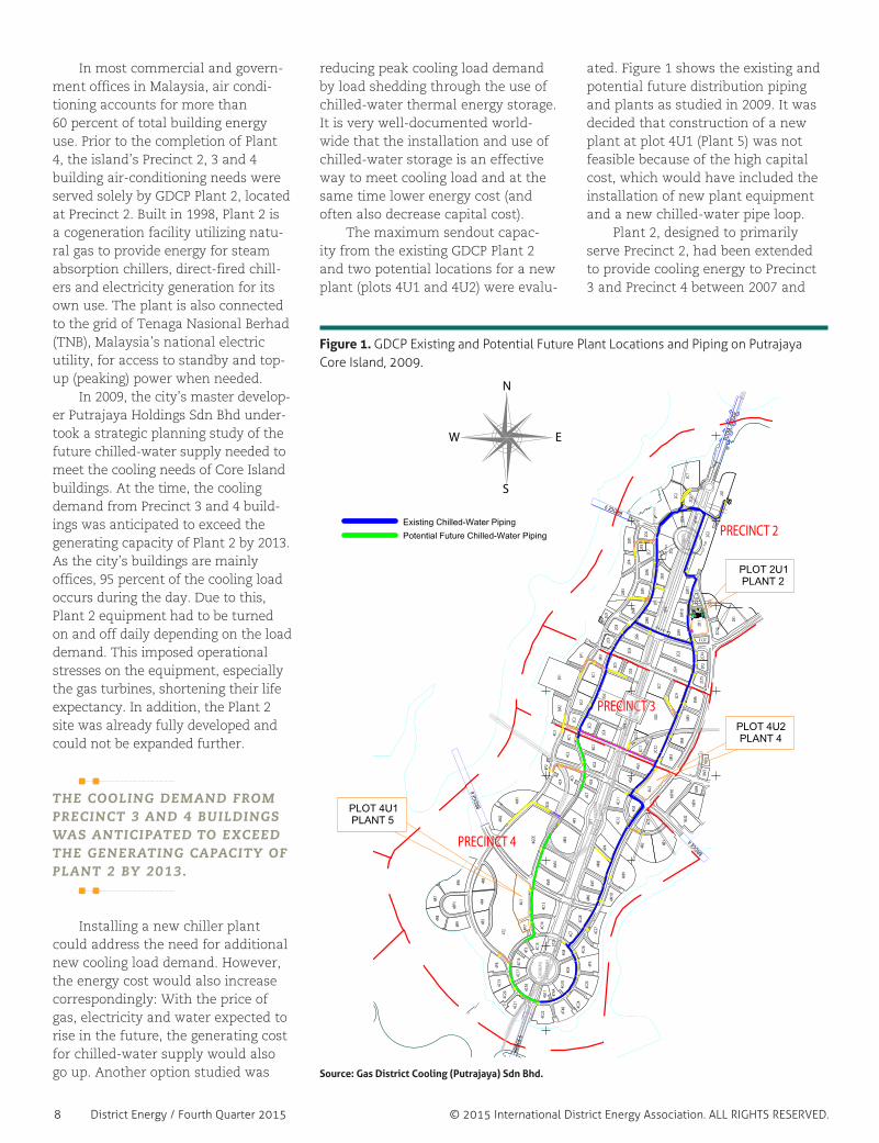
reducing peak cooling load demand by load shedding through the use of chilled-water thermal energy storage. It is very well-documented world-wide that the installation and use of chilled-water storage is an effective way to meet cooling load and at the same time lower energy cost (and often also decrease capital cost). The maximum sendout capac-ity from the existing GDCP Plant 2 and two potential locations for a new plant (plots 4U1 and 4U2) were evalu-
ated. Figure 1 shows the existing and potential future distribution piping and plants as studied in 2009. It was decided that construction of a new plant at plot 4U1 (Plant 5) was not feasible because of the high capital cost, which would have included the installation of new plant equipment and a new chilled-water pipe loop. Plant 2, designed to primarily serve Precinct 2, had been extended to provide cooling energy to Precinct 3 and Precinct 4 between 2007 and
Figure 1. GDCP Existing and Potential Future Plant Locations and Piping on Putrajaya Core Island, 2009.
Source: Gas District Cooling (Putrajaya) Sdn Bhd.
ST10
ST9
ST8
ST7
ST20
BRID
GE 6
BRIDGE 4
BRIDGE 9
BRID
GE 8
PUTR
A BR
IDGE
PRECINCT 4
PRECINCT 3
PRECINCT 2
DATA
RAN
DATA
RAN
WAW
ASAN
DATA
RAN
PUTR
AJAY
A
RAKY
AT
KHAZ
ANAH
DATA
RAN
PROM
ENAD
E
18U2
18V2
18P9
4GDE
4C8
18P1
0
3V1
3P1
3M2
3C2
3M1
3G2
3G3
3C11
3C7
3M6
3M5
3M4
3M3
3C3
3C1
3G1
3C4
3C6
2C3 2G
1
2C1
2G2
2C4
2C5
2M10
2M5
2M6
2C7
2C6
2M1
2P4
2M3
2M4
2M9
2C12
2C10
2C8 2M
8
2U1
2C9
2C15
2M11
2C2
2M7
2C14
2G6
2G3
2G4
2C11
2R1
2G5
2C13
2P2
2P3
3C9
3C10
3C12
4M9
4C27
4C22
4C21
4C20
4P6
4C19
4C18
4C17
4C16
4C15
4G11
4G10
4G9
4G8
4C24
4C25
4P5
4C26
4G7
4C28
4C14
4C13
4P7
4U1
4R3
4R4
4R5
4PP1
4R94R
84R
7
4R6
4P4
4M6
4M7
4M5
4M4
4M8
4R1
4R2
4C9
4M3
4P34M
2
4M1
4C4
4P2
4C12
4G5
4U2
4G3
4G4
4C11
4C64C
5
4G2
4G1
4C2
4C1
2P1
4C3
4C7
3C5
4M10
18V3
18P8
2U5
2U6
2U8
4T2
4T4B
4T3
4T4A
CUT P2C
CUT
P2A
CUT
P2B
DN
DN
DN
DN
DN
DNDN
ND
DN
DN
DN
DN
MM
M
M
M
M
M
M
M
M
M
MM
M
M
M
M
M
M
M M
M
M
M
M
M
M
M
M
MM
M
M
M
M
M
MM
M
M
MM
M
M
M
M
M
M
M
M
M
M
M
M
M
M
M
M
M
M
M
M
M
M
M
M
M
M
M
M M
M
M
MM
M
M
M
M
MM
M
M
M
M
M
M
M
M
M
M
M
M
M
M
M
M
M
M
M
M
M
M
M
MM
M
M
MM
M
M
M
M
M
M
M
M
M
M
M
M
M
M
M
M
M
M
M
M
M
M
M
M
M
M
MSLSHMSLSH MSLSH MSLSH MSLSH MSLSH MSLSHMSLSH MSLSH MSLSH MSLSHMSLSH MSLSH MSLSH MSLSHS MSLH MSLSHM SLS H MSLSHMSLSHMSLSHMSLSH
MSLSH MSLSH MSLSH MSLSH MSLSHMSLSH MSLSH MSLSH MSLSH MSLSHMSLSH MSLSH MSLSH MSLSH MSLSH MSLSHSM LS HSM LSH
SM LS H SM LSH SM LS HSMLS H SM L SH SMLSH
SM LS HSM L SHSM L SH
SM L SHSM LSH
SMLSH SML SH SM LSH SM LSH SM L SH SM LSH SM LSH SMLS H SML SH SMLS H SM LSH SM LS H SM LSH SM LSH SML SH SM LSH SML S H SMLS H SMLS H SM LSH SM LS H SM LSH SM LSH SM LS H
TRANSLOCAL CEMENT RENDERPAVER
DOTTED LINE TO SHOW WALL
CEMENT RENDER
CEMENT RENDERCAPACITOR CEMENT RENDER
CEMENT RENDER
CAPACITOR
( 50 TONNE )TRANSFORMER 2
N.E.R
PPU
MSLSHMSLSHMSLSHMSLSHMSLSHMSLSHMSLSHMSLSHMSLSHMSLSHMSLSH MSLSHMSLSHMSLSHMSLSHMSLSHMSLSHMSLSHMSLSHMSLSHMSLSHMSLSHMSLSHMSLSHMSLSHMSLSHMSLSHMSLSHMSLSHMSLSHMSLSHMSLSHMSLSHMSLSHMSLSHMSLSHMSLSHMSLSHMSLSHMSLSHMSLSHMSLSHMSLSHMSLSHMSLSHMSLSHMSLSHMSLSHMSLSHMSLSHMSLSHMSLSHMSLSHMSLSHMSLSHMSLSHMSLSHMSLSHMSLSHMSLSHMSLSHMSLSHMSLSHMSLSHMSLSHMSLSHMSLSHMSLSHMSLSHMSLSHMSLSHMSLSHMSLSHMSLSHMSLSHMSLSHMSLSHMSLSHMSLSHMSLSHMSLSHMSLSHMSLSHMSLSHMSLSHMSLSHMSLSHMSLSHMSLSHMSLSHMSLSHMSLSHMSLSHMSLSHMSLSHMSLSHMSLSHMSLSHMSLSHMSLSHMSLSHMSLSHMSLSHMSLSHMSLSHMSLSHMSLSHMSLSHMSLSHMSLSHMSLSHMSLSHMSLSHMSLSHMSLSHMSLSHMSLSHMSLSHMSLSHMSLSHMSLSHMSLSHMSLSHMSLSHMSLSHMSLSHMSLSHMSLSHMSLSHMSLSHMSLSHMSLSHMSLSHMSLSHMSLSHMSLSHMSLSHMSLSHMSLSHMSLSHMSLSHMSLSHMSLSHMSLSHMSLSHMSLSHMSLSHMSLSHMSLSHMSLSHMSLSHMSLSHMSLSHMSLSHMSLSHMSLSHMSLSHMSLSHMSLSHMSLSHMSLSHMSLSHMSLSHMSLSHMSLSHMSLSHMSLSHMSLSHMSLSHMSLSHMSLSHMSLSHMSLSHMSLSHMSLSHMSLSHMSLSHMSLSHMSLSHMSLSHMSLSHMSLSHMSLSHMSLSHMSLSHMSLSHMSLSHMSLSHMSLSHMSLSHMSLSHMSLSHMSLSHMSLSHMSLSHMSLSHMSLSHMSLSHMSLSHMSLSHMSLSHMSLSHMSLSHMSLSHMSLSHMSLSHMSLSHMSLSHMSLSHMSLSHMSLSHMSLSHMSLSHMSLSHMSLSHMSLSHMSLSHMSLSHMSLSHMSLSHMSLSHMSLSHMSLSHMSLSHMSLSHMSLSHMSLSHMSLSHMSLSHMSLSHMSLSH MSLSHMSLSH MSLSHMSLSH MSLSHMSLSH MSLSHMSLSH MSLSH MSLSH MSLSH MSLSH MSLSH
MS SL HMSLSHMSLSH MSLSHMSLSH MSL
SH MSLSH MSLSH MSLSH MSLSH MSLSH MSLSH MSLSH MSLSH MSLSH MSLSH MSLSH MSLSH MSLSH MSLSH MSLSH MSLSH MSLSH MSLSH MSLSH MSLSH MSLSH MSLSH MSLSH MSLSH MSLSH MSLSH MSLSH MSLSH MSLSH MSLSH MSLSH MSLSH MSLSH MSLSH MSLSH MSLSH MSLSH MSLSH MSLSH MSLSH MSLSH MSLSH MSLSH MSLSH MSLSH MSLSH MSLSH MSLSH MSLSH MSLSH MSLSH MSLSH MSLSH MSLSH MSLSH MSLSH MSLSH MSLSH MSLSH MSLSH MSLSH
MS SL HMS SL HMS SL HMS SL HMS SL HMS SL HMS SL H
MSLSH MSLSH MSLSH MSLSH MSLSH MSLSH MSLSH MSLSH MSLSH MSLSH MSLSH MSLSH MSLSH MSLSH MSLSH MSLSH MSLSH MSLSH MSLSH MSLSH MSLSH MSLSH MSLSH MSLSH MSLSH MSLSH MSLSH MS LSHMSL SHMSLSHMSLSHM SL SHMSLSHM SLS HMS LSHMSL SHM SLS HM S LSHMSLS HM SLS HMSL SHM SL S HMS LSHM SL SHMS LSHMSLSHM SLSHMS LSHMSL SHMSLS HMSLSHMSLSHMSLSHMSLSHMSLSHMSLSHMSLSHMSLSHMSLSHMSLSHMSLSHMSLSHMSLSHMSLSH
MSLSHMSLSH
MSLSH
MSLSH
MSLSHMSLSHMSLSH
MSLSHMSLSHMSLSHMSLSHMSLSHMSLSHMSLSH
MSLSHMSLSHMSLSHMSLSHMSLSHMSLSHMSLSHMSLSHMSLSHMSLSHMSLSHMSLSHMSLSHMSLSHMSLSHMSLSHMSLSHMSLSHMSLSHMSLSHMSLSHMSLSHMSLSHMSLSHMSLSHMSLSHMSLSHMSLSHMSLSHMSLSHMSLSHMSLSHMSLSHMSLSHMSLSHMSLSHMSLSH
MSLSHMSLSH
MSLSHMSLSHMSLSHMSLSH
MSLSHMSLSHMSLSHMSLSHMSLSHMSLSH
MSLSH MSLSH
MSLSHMSLSHMSLSH
MSLSH MSLSH MSLSH MSLSH MSLSH MSLSH
MS SL HMS SL HMS SL HMS SL HMS SL HMS SL HMS SL HMS SL HMS SL HMS SL HMS SL HMS SL HMS SL HMS SL HMS SL HMS SL HMS SL H
MSLSHMSLSHMSLSH
MSLSHMSLSHMSLSHMSLSHMSLSHMSLSHMSLSHMSLSHMSLSHMSLSHMSLSHMSLSHMSLSH
GAS MAL
AYSIA
DISTRICT
METERIN
G
GDC CON
SUMER
GAS MET
ERING ST
ATION
MSLSH MSLSH MSLSH MSLSH MSLSH MSLSH MSLSH MSLSHMSLSH MSLSH MSLSH MSLSH MSLSH MSLSH MSLSH MSLSH MSLSH MSLSHMSLSHMSLSH MSLSH
SM LSH SML SH SM LS HSM LSH SM LS HSMLS H
MSLSH
CEMENT RENDER( 50 TONNE )TRANSFORMER 2
CEMENT RENDER( 50 TONNE )TRANSFORMER 2
STATION
PLOT 2U1PLANT 2
PLOT 4U2PLANT 4
PLOT 4U1PLANT 5
N
S
EW
Existing Chilled-Water Piping
Potential Future Chilled-Water Piping

District Energy / Fourth Quarter 2015 9© 2015 International District Energy Association. ALL RIGHTS RESERVED.
2009, in order to cater to the new development at the middle and southern end of Core Island. Plant 2 chilled-water production consisted (and still consists) of a series of steam absorption chillers, direct-fired chill-ers and electric centrifugal chillers. It also produced (and continues to produce) around 9 MW electricity for its ancillary equipment and approxi-mately 24,000 tons of maximum cool-ing capacity after taking into consid-eration equipment degradation and standby capacity. In light of the remote locations of some prospective development plots, particularly those located at the Core Island’s southernmost tip, the site for Plant 4 was chosen because of its
· close proximity to existing cooling load demand and near-term customers;
· reasonable proximity to existing Plant 2, which would make remote thermal energy storage tank charging from Plant 2 a possibility; and
· availability of existing utilities infrastructure (electricity, water, chilled-water pipes and gas).
With a charging capacity at Plant 2 of 20,000 tons operating for 10 hours a day, it was theoretically possible to produce up to 200,000 ton-hr for stor-age. Chilled-water generation by Plant 2 with thermal energy storage at Plant 4 was determined to be able to serve all existing and under-construction loads during daytime peak periods.
TYPICAL LOAD PROFILE In a typical day in 2009, the peak load at Plant 2 (fig. 2) occurred between 6 a.m. and 9 a.m. when the plant experienced pulldown load from the buildings. From 10 a.m. on, the load profile was relatively constant until 5 p.m. when the offices were closed. Based on the foregoing, the following conclusions were derived:1. Plant peak load was approximately
25 percent of the average plant sendout load.
2. The coincident building peak loads of 20,000 tons occurred during this same 6-9 a.m. period due to the similarity of building type (i.e., pri-marily office buildings).
3. Demand-side management such as precooling of the buildings during nighttime was not practiced by the buildings’ operators to reduce this peaking pulldown load demand.
4. The buildings’ load profile of around 16,000 tons was generally quite con-stant from 10 a.m. until 5 p.m.
5. There was hardly any night load.6. In addition to the anticipated
higher cooling load demand in the future, higher peaking load occur-ring early in the morning also necessitated that more chillers be run to meet the cooling load.
PLANT 4 DESIGN GOALS The capacity and options study was completed at the end of 2009. Subsequently, the design team, led by AHAR Consultants together with
the architect, cost surveyor, civil and structural engineers, proceeded with the design and construction of Plant 4. The design goals for Plant 4 were to
· accommodate the increase in new customers’ chilled-water demand;
· optimize asset utilization of Plant 2;
· increase Plant 2 in-house electricity generation efficiency and reduce electricity import from TNB;
· reduce frequent start-stop opera-tion of gas turbines at Plant 2, improving their life span;
· mitigate the peaking load while using the existing chillers at Plant 2; and
· provide better control of chilled-water supply temperature.
Plant 4 was designed as a hybrid plant consisting of chilled-water stor-age and electric-driven chillers. The construction of the whole plant was phased as follows:
· Phase 1 – one thermal energy storage tank of nominal rated capacity of 100,000 ton-hr charged from Plant 2 with associated thermal energy stor-age and secondary booster pumps
· Phase 2 – a second thermal energy storage tank of nominal rated capacity of 100,000 ton-hr charged from Plant 2 with associated thermal energy storage and secondary booster pumps
· Phase 3 – electric-driven centrifugal chillers with 12,000-ton installed capacity and associated condenser water pumps, chiller pumps and associated secondary booster pumps
Bids for the engineering, procure-ment, construction and commission-ing for Phase 1 were called in the second quarter of 2010, with work completed in early 2013. Construction of Phases 2 and 3 is expected to com-mence in 2017 and 2020, respectively, depending on the actual load growth of the Core Island. At full buildout this three-phase design will allow for charging the thermal energy storage tanks with the 6.1 C (43 F) supply water from Plant 2, with the ability to peak this water down to 3.9 C (39 F) using the Plant 4 chillers while maintaining the ability to produce chilled water from
Figure 2. Screenshot of Typical Load Profile, GDCP Plant 2, 2009.
Source: Gas District Cooling (Putrajaya) Sdn Bhd.
Buildings Start Operation
High Peaking Load
Low Night Load

10 District Energy / Fourth Quarter 2015 © 2015 International District Energy Association. ALL RIGHTS RESERVED.
a highly efficient series-counterflow configuration. This will allow for significantly larger production stor-age capacity to be achieved from the same-sized tanks. These objectives will be achieved with a relatively simple piping and valving configuration and with no more pumps than would be required for a traditional primary-secondary pumping arrangement. CHALLENGES OF REMOTELY CHARGING The design team had to consider numerous challenges involved in remotely charging the two chilled-water storage tanks. From the hydraulic point of view, the top water level of each of these atmospheric tanks had to be at the highest point of the entire system. Plant 2, which at 39.2 m (128.6 ft) above sea level is higher than the 33.6 m (110 ft) above sea level where the Plant 4 tanks will be, requires a minimum return pressure of 3 bar (43.5 psi). Given the tanks’ height of 32 m (105 ft), the resultant system’s pressure is more than adequate to provide sufficient return pressure to Plant 2. Another issue of concern was the system pressure generated during dis-charge. The combined tank static head and Plant 4 pump discharge pressure had to be lower than the existing sys-tem’s design pressure rating of 16 bar (232 psi). Numerous simulations using hydraulic software were conducted to determine the maximum Plant 4 pump discharge pressure to ensure that the designed pressure rating was not exceeded. The ability of existing pumps at Plant 2 to move a huge amount of chilled water through the existing 900-mm (35.4-inch) pipe during charging was also evaluated. This was a major concern especially in Phase 2 when the two tanks will require charging, as the most likely path of the chilled water would be the short distance between Plant 2 and Plant 4 (see fig. 1). It was determined that the Plant 2 pump head was adequate to move charging and discharging chilled-water flow up
to a certain stage. However, if the load growth of Precinct 3 and 4 concentrates mainly at the south end of the Core Island, Plant 2 pumps will have to be upgraded depending on the plant send-out ratio between Plant 2 and Plant 4.
TANK SPECIFICATIONS The performance specifications for each of the two chilled-water storage tank and diffuser systems to be installed at Plant 4 are shown in table 1. Based on the capacity, the speci-fied tank dimensions were 45 m (147.6 ft) diameter and 32 m (105.0 ft) high, with a 700-mm- (27.6-inch-) thick concrete wall. It is believed that, with its particular capacity and dimen-sions, the first of these tanks, com-pleted in 2013, is the largest water-retaining structure in Malaysia. Prestressed concrete was used to reduce the tank wall thickness. Con-crete was chosen because it offered better cost benefit to the owner com-pared to steel. As Malaysia is not a steel producer, the cost to import steel plates would have made this size of tank uneconomical. A concrete tank of this size also posed concerns to the local authorities about its potential for sabotage as well as leakage. Although
Malaysia is a relatively terrorism-free country, the authorities insisted that a risk impact analysis be conducted. The study concluded that the con-crete tank is less likely a terrorist target than the ministry buildings in Putrajaya. To mitigate any possibility of leakage, the design team decided to use two layers of 2-mm (0.078-inch) and 3-mm (0.118-inch) spray poly-urea waterproofing membrane, with 50 mm (1.97 inches) of polyurethane thermal insulation sandwiched in between. Rigorous inspections and quality control checks were conducted during construction to ensure water-tightness requirements were met. The storage tank has an internal stratification diffuser inlet and outlet header design arranged to distribute the flow for proper efficient opera-tion during charging and discharging modes. The diffuser header design utilizes a directed flow-splitting approach to evenly distribute the water to the nozzles. The nozzles are distributed radially around the area centroid of the tank, and the directed flow-dividing elements of the system assure that each nozzle is fed with the same volume of water. The flow velocity is gradually reduced in the header system from 1.5 m/s (4.9 ft/s)
55,399 cu m (14.6 million gal)
100,000 ton-hr @ 6.5 C (11.7 F) delta T
4,610 cmh (20,300 gpm)
More than 90% including thermocline,
freeboard and diffuser volume
13.3 C (56 F)
6.1 C (43 F)
6.1 C (43 F)
Maximum 2,000
Less than 2
3.05 m (10 ft) water gauge
2% of rated thermal energy storage
capacity at 3.9 C (39 F)
Spray polyurethane
Spray polyurea
Water Volume
Rated Cooling Storage Capacity
Rated Tank Discharge Flow Rate Capacity Per Hour
Usable Discharge Capacity
Design Inlet Temperature During Discharging Cycle
Design Outlet Temperature During Discharging Cycle
Design Inlet Temperature During Charging Cycle
Reynolds Number
Froude Number
Maximum Pressure Loss Between Inlet and Outlet Flange
Maximum Heat Gain Over 24 Hours
Tank Insulation Material
Tank Waterproof Material
Source: AHAR Consultants.
Table 1. Performance Specifications for GDCP Plant 4 Chilled-Water Storage Tank and Diffuser System.

District Energy / Fourth Quarter 2015 11© 2015 International District Energy Association. ALL RIGHTS RESERVED.
in the feeder pipe to 0.1 m/s (0.33 ft/s) at the nozzle exit. The large circular nozzles expel the water parallel to the water surface or tank base, induc-ing secondary water movement only in a parallel layer. Warm water is withdrawn from the top of the tank, cooled and reinserted at the bottom of the tank during the charging cycle. Cold water is withdrawn from the bottom of the tank and dispatched to the buildings, where it is warmed and returned to the top of the tank during the discharging cycle.
PHASE 1 PERFORMANCE After construction of Plant 4 (Phase 1) was completed in early
2013, it was successfully commis-sioned in March 2013. A typical five-day charging and discharging cycle in February 2013 is shown in figure 3. Figure 3 shows that the load profile increased to 25,000 tons peak load early in the morning and aver-aged around 22,000 ton-hr. (Figure 3 also reflects current load and sendout capacity.) With the new configura-tion, this peak load is taken up by the chilled-water storage discharge instead of additional chillers run at Plant 2. Fewer chillers are required to satisfy daily load, thus enhancing system availability. There is also a reduction of 4 MW of electrical power imported from the electricity compa-
ny. This has significantly reduced the electrical maximum demand charge incurred during peak periods, cor-respondingly lowering the unit util-ity cost of chilled-water production. Plant 2 electricity generation effi-ciency has also improved by having constant loading of the turbine gen-erators day and night. The generators are able to be fully loaded and oper-ate at optimum efficiency with cooler nighttime ambient temperatures. Thermal energy storage tank dis-charge capacity averaging between 88,000 and 92,000 ton-hr is obtained daily, with a maximum instantaneous discharge capacity of 13,000 tons. With the steam chillers maintaining a constant output of 14,500 tons day and night, the gas turbines are able to be operated 24 hours per day, result-ing in better utilization and avoidance of start-stop operations. The performance of the diffuser system was also analyzed during the commissioning period from January to March 2013. Most of the significant performance parameters exceeded the design criteria, as shown in table 2. Most significant is the thermocline thickness averaging 0.8 m (2.62 ft). This thin thermocline thickness indi-cates that the diffusers were working properly, with the cold and warm water bodies being properly stratified in the tank. A screenshot of thermocline thickness is shown in figure 4. The x-axis refers to time, while the y-axis is the temperature. Various colored lines represent individual tempera-ture sensors installed at 0.5-m (1.64-ft) intervals vertically inside the tank. By calculating the water volume and the time spread at each pair of sensors, the thermocline averages 0.87 m (2.85 ft) thick. In comparison, thermocline thicknesses of 1-2 m (3.28-6.56 ft) are not uncommon in other chilled-water tank installations worldwide.1
The significance of a thin ther-mocline is that it yields better storage efficiency. The diffuser design using three double-ring octagonal pipes with drilled 8-mm (0.31-inch) nozzles spray-
Figure 3. Putrajaya Core Island Plants 2 and 4 Load Profile and Sendouts, February 2013.
Source: Gas District Cooling (Putrajaya) Sdn Bhd.
109,012 ton-hr @ 6.5 C (11.7 F) delta T
78,433 ton-hr @ 4.32 C (39.8 F) delta T
72,585 ton-hr @ 4.32 C (39.8 F) delta T
0.6-1.0 m (1.97-3.28 ft)
1,991
0.09
92.54%
2.25 m (7.38 ft) water gauge
0.57% of rated thermal energy storage capacity
Rated Storage Capacity
Charging Storage Capacity
Discharge Storage Capacity
Thermocline Thickness
Reynolds Number
Froude Number
Usable Tank Volume
Maximum Pressure Loss
Maximum Heat Gain Over 24 Hours
Source: AHAR Consultants.
Table 2. Tested Performance of GDCP Plant 4 Chilled-Water Storage Tank and Diffuser System (Jan. 17, 2013).
1 Bahnfleth, William P., and Amy Musser, “Thermal Performance of a Full-Scale Stratified Chilled-Water Thermal Storage Tank,” ASHRAE Conference proceeding, Toronto 1998.
Average Plant 2 Sendout Capacity – 14,500 Tons
Chiller Discharge Charging —— Plant Sendout

12 District Energy / Fourth Quarter 2015 © 2015 International District Energy Association. ALL RIGHTS RESERVED.
ing at a 120-degree angle in the vertical plane proved that the actual perfor-mance exceeded specifications. A total of 91,500 nozzles ensure that the water is evenly distributed and diffused. At this juncture, the objective for better chilled-water supply tempera-ture control has not yet been accom-plished, as Plant 4 is still dependent on Plant 2 for its chilled water. It is envisaged that when the electric chillers are installed at Plant 4 in the ultimate phase – where the chillers can be operated either in parallel or in series-counterflow configurations with the storage tank – this design intent can also be achieved.
MEETING EXPECTATIONS Plant 4 has been in operation to supply chilled water to Precincts 3 and 4 in Putrajaya Core Island since January 2013. Initial results have shown that the operation of this chilled-water storage system has met the expectations of the client and design team. Currently, Plants 2 and 4 are operating in tandem during the daytime to supply chilled water. The installation of chilled-water storage in a district cooling system is an excellent tool in demand-side management. This technology enables a plant owner to reduce energy cost by decreasing electric-
ity maximum demand during peak periods. Thermal energy storage also increases the load supply capability during the high peak period and enhances district cooling system reli-ability and availability. By incorporating thermal energy storage, GDCP has improved system redundancy, as fewer chillers are required during the peak period. The company is also better able to utilize the assets at Plant 2 by running the gas turbines 24/7. Daily start-stop operation of the gas turbines has been avoided, improving equipment life expectancy. Furthermore, the use of chilled-water storage has reduced net capital expenses by 40 percent compared to installation of an equiv-alent capacity of conventional chiller plant equipment. The chilled-water production unit cost remains similar to the pre-Plant 4 period, despite the operation of both plants. In addition to these operational and financial advantages, GDCP is also seeing reduced greenhouse gas emis-sions. The use of thermal energy stor-age at Plant 4 with chilled-water gener-ation from Plant 2 offers a significantly decreased carbon footprint – lower by 445 metric tons of carbon dioxide per week, or 20.7 percent – compared to that of a grid-connected conventional chiller Plant 4 and the existing Plant 2.
While providing these numerous benefits, GDCP Plant 4 has also, sig-nificantly, made history as the first remotely charged satellite chilled-water storage system in Malaysia and has the biggest reinforced concrete chilled-water tank in the country, as well as in Asia.
Authors’ Note: We acknowledge the assistance provided to AHAR Consul-tants during the evaluation, design and implementation of the Plant 4 thermal energy storage project, in particular by our engineering team members Mark Spurr and Bryan Kleist of FVB Energy Inc., Min-neapolis, Minn., and John S. Andrepont of The Cool Solutions Co., Lisle, Ill. We also thank John Andrepont (with whom one of the authors collaborated on the first large chilled-water thermal energy storage proj-ect in Malaysia in the mid-1990s) for his contributions to the content and writing of this article.
Arul Hisham Abdul Rahim, principal with AHAR Consultants, has a wide range of experience in thermal storage and district cooling with more than 20 years of practice. A regis-
tered engineer with the Board of Engineers Malaysia, he is a member of ASHRAE and a fellow with the Institution of Engineers Malaysia. He holds a degree in mechanical engineering from The University of Texas at El Paso. Hisham can be contacted at [email protected].
Rosli Mohamed, partner with AHAR Consultants, graduated from the University of North Carolina at Charlotte in mechanical engineering. Prior to joining the firm, he
worked in various capacities with Tenaga Nasional Berhad, Malaysia’s national elec-tricity company. He is a fellow with the Institution of Engineers Malaysia and a registered engineer with the Board of Engineers Malaysia. He can be reached at [email protected].
Figure 4. Screenshot of GDCP Plant 4 Thermal Energy Storage Tank Temperature Sensor Readings.
Source: AHAR Consultants.