Embed Size (px)
Citation preview
Outline Objective Approach Circuit Diagram Components Required for Circuit Working of Circuit Result Futuristic use of Instrument References
A minor project onRemote Control for Home Appliances
Shelja KhushwahaSonal BansalAnkit Agarwal
under the guidance of
Ms Mridula Yadav
Electronics and Communication Engineering DepartmentMaharaja Agarsain Institute of Technology Ghaziabad
India
10th November 2014
Shelja Khushwaha Sonal Bansal Ankit Agarwal MAIT Ghaziabad 1 14
Remote Control for Home Appliances
Outline Objective Approach Circuit Diagram Components Required for Circuit Working of Circuit Result Futuristic use of Instrument References
Table of Contents
1 Objective
2 Approach
3 Circuit Diagram
4 Components Required for Circuit
5 Working of CircuitTheoryBreadboard ImplementationPCB Implementation
6 Result
7 Futuristic use of Instrument
8 References
Shelja Khushwaha Sonal Bansal Ankit Agarwal MAIT Ghaziabad 2 14
Remote Control for Home Appliances
Outline Objective Approach Circuit Diagram Components Required for Circuit Working of Circuit Result Futuristic use of Instrument References
Objective
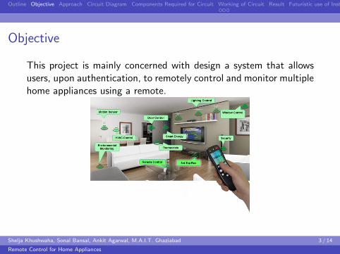
This project is mainly concerned with design a system that allowsusers upon authentication to remotely control and monitor multiplehome appliances using a remote
Shelja Khushwaha Sonal Bansal Ankit Agarwal MAIT Ghaziabad 3 14
Remote Control for Home Appliances
Outline Objective Approach Circuit Diagram Components Required for Circuit Working of Circuit Result Futuristic use of Instrument References
Approach
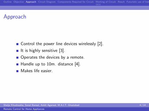
Control the power line devices wirelessly [2]
It is highly sensitive [3]
Operates the devices by a remote
Handle up to 10m distance [4]
Makes life easier
Shelja Khushwaha Sonal Bansal Ankit Agarwal MAIT Ghaziabad 4 14
Remote Control for Home Appliances
Outline Objective Approach Circuit Diagram Components Required for Circuit Working of Circuit Result Futuristic use of Instrument References
Circuit Diagram
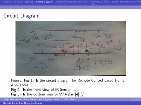
Figure Fig 1- Is the circuit diagram for Remote Control based HomeAppliancesFig 2- Is the front view of IR SensorFig 3- Is the bottom view of 5V Relay [4] [5]
Shelja Khushwaha Sonal Bansal Ankit Agarwal MAIT Ghaziabad 5 14
Remote Control for Home Appliances
Outline Objective Approach Circuit Diagram Components Required for Circuit Working of Circuit Result Futuristic use of Instrument References
Components Required for CircuitComponents
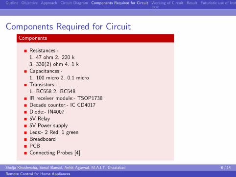
Resistances-1 47 ohm 2 220 k3 330(2) ohm 4 1 kCapacitances-1 100 micro 2 01 microTransistors-1 BC558 2 BC548IR receiver module- TSOP1738Decade counter- IC CD4017Diode- IN40075V Relay5V Power supplyLeds- 2 Red 1 greenBreadboardPCBConnecting Probes [4]
Shelja Khushwaha Sonal Bansal Ankit Agarwal MAIT Ghaziabad 6 14
Remote Control for Home Appliances
Outline Objective Approach Circuit Diagram Components Required for Circuit Working of Circuit Result Futuristic use of Instrument References
Theory
Theory
Figure
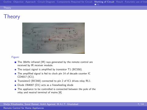
The 38kHz infrared (IR) rays generated by the remote control arereceived by IR receiver module
The output signal is amplified by transistor T1 (BC558)
The amplified signal is fed to clock pin 14 of decade counter ICCD4017 (IC1)
Transistor2 (BC548) connected to pin 2 of IC1 drives relay RL1
Diode 1N4007 (D1) acts as a freewheeling diode
The appliance to be controlled is connected between the pole of therelay and neutral terminal of mains [4]
Shelja Khushwaha Sonal Bansal Ankit Agarwal MAIT Ghaziabad 7 14
Remote Control for Home Appliances
Outline Objective Approach Circuit Diagram Components Required for Circuit Working of Circuit Result Futuristic use of Instrument References
Breadboard Implementation
Breadboard Implementation
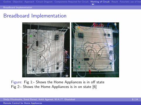
Figure Fig 1- Shows the Home Appliances is in off stateFig 2- Shows the Home Appliances is in on state [6]
Shelja Khushwaha Sonal Bansal Ankit Agarwal MAIT Ghaziabad 8 14
Remote Control for Home Appliances
Outline Objective Approach Circuit Diagram Components Required for Circuit Working of Circuit Result Futuristic use of Instrument References
PCB Implementation
PCB Implementation
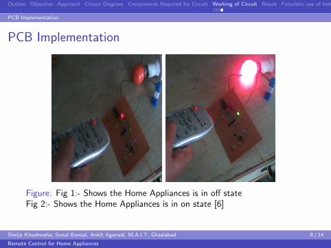
Figure Fig 1- Shows the Home Appliances is in off stateFig 2- Shows the Home Appliances is in on state [6]
Shelja Khushwaha Sonal Bansal Ankit Agarwal MAIT Ghaziabad 9 14
Remote Control for Home Appliances
Outline Objective Approach Circuit Diagram Components Required for Circuit Working of Circuit Result Futuristic use of Instrument References
Result
To control the home appliances system connected with thereceiver system wirelessly is designed and implementedsuccessfully for devices and worked well for the transmissionand receiving approximately 10 meters range with theoperating frequency of 38KHz
The instrument is designed and implemented successfully inphysical existence and ready to use
Shelja Khushwaha Sonal Bansal Ankit Agarwal MAIT Ghaziabad 10 14
Remote Control for Home Appliances
Outline Objective Approach Circuit Diagram Components Required for Circuit Working of Circuit Result Futuristic use of Instrument References
Futuristic use of Instrument
Areas where instruments need to be automated and controlledas per the human need
Regulate and overcome all the obstacles for control over theinstrument
Operating range can be increase
Shelja Khushwaha Sonal Bansal Ankit Agarwal MAIT Ghaziabad 11 14
Remote Control for Home Appliances
Outline Objective Approach Circuit Diagram Components Required for Circuit Working of Circuit Result Futuristic use of Instrument References
References I
Prashant Chakole Dr Pradip B Dahikar ldquoRF RemoteControl of Power Line Devices Usingrdquo International Journal ofEngineering Science and Innovative Technology (IJESIT) 3May 2013
Slidesharehttpwwwslidesharenetpremteja
radio-frequencybasedremoteindustrialappliancescontrolsystem
electronicsforuhttpwwwelectronicsforucomelectronicsforu
circuitarchivesview_articleaspsno=235amparticle_
type=1ampid=352amptt=unhotampb_type=newVF9VwCV3QYw
Shelja Khushwaha Sonal Bansal Ankit Agarwal MAIT Ghaziabad 12 14
Remote Control for Home Appliances
Outline Objective Approach Circuit Diagram Components Required for Circuit Working of Circuit Result Futuristic use of Instrument References
References II
EngineersGarageDPDTRelaySwitch|
DoublePoleDoubleThrowRelay-EngineersGarage
Electrical lab mait ghaziabad November 2014
Shelja Khushwaha Sonal Bansal Ankit Agarwal MAIT Ghaziabad 13 14
Remote Control for Home Appliances
Outline Objective Approach Circuit Diagram Components Required for Circuit Working of Circuit Result Futuristic use of Instrument References
Thankyou
Shelja Khushwaha Sonal Bansal Ankit Agarwal MAIT Ghaziabad 14 14
Remote Control for Home Appliances
Outline Objective Approach Circuit Diagram Components Required for Circuit Working of Circuit Result Futuristic use of Instrument References
Table of Contents
1 Objective
2 Approach
3 Circuit Diagram
4 Components Required for Circuit
5 Working of CircuitTheoryBreadboard ImplementationPCB Implementation
6 Result
7 Futuristic use of Instrument
8 References
Shelja Khushwaha Sonal Bansal Ankit Agarwal MAIT Ghaziabad 2 14
Remote Control for Home Appliances
Outline Objective Approach Circuit Diagram Components Required for Circuit Working of Circuit Result Futuristic use of Instrument References
Objective
This project is mainly concerned with design a system that allowsusers upon authentication to remotely control and monitor multiplehome appliances using a remote
Shelja Khushwaha Sonal Bansal Ankit Agarwal MAIT Ghaziabad 3 14
Remote Control for Home Appliances
Outline Objective Approach Circuit Diagram Components Required for Circuit Working of Circuit Result Futuristic use of Instrument References
Approach
Control the power line devices wirelessly [2]
It is highly sensitive [3]
Operates the devices by a remote
Handle up to 10m distance [4]
Makes life easier
Shelja Khushwaha Sonal Bansal Ankit Agarwal MAIT Ghaziabad 4 14
Remote Control for Home Appliances
Outline Objective Approach Circuit Diagram Components Required for Circuit Working of Circuit Result Futuristic use of Instrument References
Circuit Diagram
Figure Fig 1- Is the circuit diagram for Remote Control based HomeAppliancesFig 2- Is the front view of IR SensorFig 3- Is the bottom view of 5V Relay [4] [5]
Shelja Khushwaha Sonal Bansal Ankit Agarwal MAIT Ghaziabad 5 14
Remote Control for Home Appliances
Outline Objective Approach Circuit Diagram Components Required for Circuit Working of Circuit Result Futuristic use of Instrument References
Components Required for CircuitComponents
Resistances-1 47 ohm 2 220 k3 330(2) ohm 4 1 kCapacitances-1 100 micro 2 01 microTransistors-1 BC558 2 BC548IR receiver module- TSOP1738Decade counter- IC CD4017Diode- IN40075V Relay5V Power supplyLeds- 2 Red 1 greenBreadboardPCBConnecting Probes [4]
Shelja Khushwaha Sonal Bansal Ankit Agarwal MAIT Ghaziabad 6 14
Remote Control for Home Appliances
Outline Objective Approach Circuit Diagram Components Required for Circuit Working of Circuit Result Futuristic use of Instrument References
Theory
Theory
Figure
The 38kHz infrared (IR) rays generated by the remote control arereceived by IR receiver module
The output signal is amplified by transistor T1 (BC558)
The amplified signal is fed to clock pin 14 of decade counter ICCD4017 (IC1)
Transistor2 (BC548) connected to pin 2 of IC1 drives relay RL1
Diode 1N4007 (D1) acts as a freewheeling diode
The appliance to be controlled is connected between the pole of therelay and neutral terminal of mains [4]
Shelja Khushwaha Sonal Bansal Ankit Agarwal MAIT Ghaziabad 7 14
Remote Control for Home Appliances
Outline Objective Approach Circuit Diagram Components Required for Circuit Working of Circuit Result Futuristic use of Instrument References
Breadboard Implementation
Breadboard Implementation
Figure Fig 1- Shows the Home Appliances is in off stateFig 2- Shows the Home Appliances is in on state [6]
Shelja Khushwaha Sonal Bansal Ankit Agarwal MAIT Ghaziabad 8 14
Remote Control for Home Appliances
Outline Objective Approach Circuit Diagram Components Required for Circuit Working of Circuit Result Futuristic use of Instrument References
PCB Implementation
PCB Implementation
Figure Fig 1- Shows the Home Appliances is in off stateFig 2- Shows the Home Appliances is in on state [6]
Shelja Khushwaha Sonal Bansal Ankit Agarwal MAIT Ghaziabad 9 14
Remote Control for Home Appliances
Outline Objective Approach Circuit Diagram Components Required for Circuit Working of Circuit Result Futuristic use of Instrument References
Result
To control the home appliances system connected with thereceiver system wirelessly is designed and implementedsuccessfully for devices and worked well for the transmissionand receiving approximately 10 meters range with theoperating frequency of 38KHz
The instrument is designed and implemented successfully inphysical existence and ready to use
Shelja Khushwaha Sonal Bansal Ankit Agarwal MAIT Ghaziabad 10 14
Remote Control for Home Appliances
Outline Objective Approach Circuit Diagram Components Required for Circuit Working of Circuit Result Futuristic use of Instrument References
Futuristic use of Instrument
Areas where instruments need to be automated and controlledas per the human need
Regulate and overcome all the obstacles for control over theinstrument
Operating range can be increase
Shelja Khushwaha Sonal Bansal Ankit Agarwal MAIT Ghaziabad 11 14
Remote Control for Home Appliances
Outline Objective Approach Circuit Diagram Components Required for Circuit Working of Circuit Result Futuristic use of Instrument References
References I
Prashant Chakole Dr Pradip B Dahikar ldquoRF RemoteControl of Power Line Devices Usingrdquo International Journal ofEngineering Science and Innovative Technology (IJESIT) 3May 2013
Slidesharehttpwwwslidesharenetpremteja
radio-frequencybasedremoteindustrialappliancescontrolsystem
electronicsforuhttpwwwelectronicsforucomelectronicsforu
circuitarchivesview_articleaspsno=235amparticle_
type=1ampid=352amptt=unhotampb_type=newVF9VwCV3QYw
Shelja Khushwaha Sonal Bansal Ankit Agarwal MAIT Ghaziabad 12 14
Remote Control for Home Appliances
Outline Objective Approach Circuit Diagram Components Required for Circuit Working of Circuit Result Futuristic use of Instrument References
References II
EngineersGarageDPDTRelaySwitch|
DoublePoleDoubleThrowRelay-EngineersGarage
Electrical lab mait ghaziabad November 2014
Shelja Khushwaha Sonal Bansal Ankit Agarwal MAIT Ghaziabad 13 14
Remote Control for Home Appliances
Outline Objective Approach Circuit Diagram Components Required for Circuit Working of Circuit Result Futuristic use of Instrument References
Thankyou
Shelja Khushwaha Sonal Bansal Ankit Agarwal MAIT Ghaziabad 14 14
Remote Control for Home Appliances
Outline Objective Approach Circuit Diagram Components Required for Circuit Working of Circuit Result Futuristic use of Instrument References
Theory
Theory
Figure
The 38kHz infrared (IR) rays generated by the remote control arereceived by IR receiver module
The output signal is amplified by transistor T1 (BC558)
The amplified signal is fed to clock pin 14 of decade counter ICCD4017 (IC1)
Transistor2 (BC548) connected to pin 2 of IC1 drives relay RL1
Diode 1N4007 (D1) acts as a freewheeling diode
The appliance to be controlled is connected between the pole of therelay and neutral terminal of mains [4]
Shelja Khushwaha Sonal Bansal Ankit Agarwal MAIT Ghaziabad 7 14
Remote Control for Home Appliances
Outline Objective Approach Circuit Diagram Components Required for Circuit Working of Circuit Result Futuristic use of Instrument References
Breadboard Implementation
Breadboard Implementation
Figure Fig 1- Shows the Home Appliances is in off stateFig 2- Shows the Home Appliances is in on state [6]
Shelja Khushwaha Sonal Bansal Ankit Agarwal MAIT Ghaziabad 8 14
Remote Control for Home Appliances
Outline Objective Approach Circuit Diagram Components Required for Circuit Working of Circuit Result Futuristic use of Instrument References
PCB Implementation
PCB Implementation
Figure Fig 1- Shows the Home Appliances is in off stateFig 2- Shows the Home Appliances is in on state [6]
Shelja Khushwaha Sonal Bansal Ankit Agarwal MAIT Ghaziabad 9 14
Remote Control for Home Appliances
Outline Objective Approach Circuit Diagram Components Required for Circuit Working of Circuit Result Futuristic use of Instrument References
Result
To control the home appliances system connected with thereceiver system wirelessly is designed and implementedsuccessfully for devices and worked well for the transmissionand receiving approximately 10 meters range with theoperating frequency of 38KHz
The instrument is designed and implemented successfully inphysical existence and ready to use
Shelja Khushwaha Sonal Bansal Ankit Agarwal MAIT Ghaziabad 10 14
Remote Control for Home Appliances
Outline Objective Approach Circuit Diagram Components Required for Circuit Working of Circuit Result Futuristic use of Instrument References
Futuristic use of Instrument
Areas where instruments need to be automated and controlledas per the human need
Regulate and overcome all the obstacles for control over theinstrument
Operating range can be increase
Shelja Khushwaha Sonal Bansal Ankit Agarwal MAIT Ghaziabad 11 14
Remote Control for Home Appliances
Outline Objective Approach Circuit Diagram Components Required for Circuit Working of Circuit Result Futuristic use of Instrument References
References I
Prashant Chakole Dr Pradip B Dahikar ldquoRF RemoteControl of Power Line Devices Usingrdquo International Journal ofEngineering Science and Innovative Technology (IJESIT) 3May 2013
Slidesharehttpwwwslidesharenetpremteja
radio-frequencybasedremoteindustrialappliancescontrolsystem
electronicsforuhttpwwwelectronicsforucomelectronicsforu
circuitarchivesview_articleaspsno=235amparticle_
type=1ampid=352amptt=unhotampb_type=newVF9VwCV3QYw
Shelja Khushwaha Sonal Bansal Ankit Agarwal MAIT Ghaziabad 12 14
Remote Control for Home Appliances
Outline Objective Approach Circuit Diagram Components Required for Circuit Working of Circuit Result Futuristic use of Instrument References
References II
EngineersGarageDPDTRelaySwitch|
DoublePoleDoubleThrowRelay-EngineersGarage
Electrical lab mait ghaziabad November 2014
Shelja Khushwaha Sonal Bansal Ankit Agarwal MAIT Ghaziabad 13 14
Remote Control for Home Appliances
Outline Objective Approach Circuit Diagram Components Required for Circuit Working of Circuit Result Futuristic use of Instrument References
Thankyou
Shelja Khushwaha Sonal Bansal Ankit Agarwal MAIT Ghaziabad 14 14
Remote Control for Home Appliances
Outline Objective Approach Circuit Diagram Components Required for Circuit Working of Circuit Result Futuristic use of Instrument References
Breadboard Implementation
Breadboard Implementation
Figure Fig 1- Shows the Home Appliances is in off stateFig 2- Shows the Home Appliances is in on state [6]
Shelja Khushwaha Sonal Bansal Ankit Agarwal MAIT Ghaziabad 8 14
Remote Control for Home Appliances
Outline Objective Approach Circuit Diagram Components Required for Circuit Working of Circuit Result Futuristic use of Instrument References
PCB Implementation
PCB Implementation
Figure Fig 1- Shows the Home Appliances is in off stateFig 2- Shows the Home Appliances is in on state [6]
Shelja Khushwaha Sonal Bansal Ankit Agarwal MAIT Ghaziabad 9 14
Remote Control for Home Appliances
Outline Objective Approach Circuit Diagram Components Required for Circuit Working of Circuit Result Futuristic use of Instrument References
Result
To control the home appliances system connected with thereceiver system wirelessly is designed and implementedsuccessfully for devices and worked well for the transmissionand receiving approximately 10 meters range with theoperating frequency of 38KHz
The instrument is designed and implemented successfully inphysical existence and ready to use
Shelja Khushwaha Sonal Bansal Ankit Agarwal MAIT Ghaziabad 10 14
Remote Control for Home Appliances
Outline Objective Approach Circuit Diagram Components Required for Circuit Working of Circuit Result Futuristic use of Instrument References
Futuristic use of Instrument
Areas where instruments need to be automated and controlledas per the human need
Regulate and overcome all the obstacles for control over theinstrument
Operating range can be increase
Shelja Khushwaha Sonal Bansal Ankit Agarwal MAIT Ghaziabad 11 14
Remote Control for Home Appliances
Outline Objective Approach Circuit Diagram Components Required for Circuit Working of Circuit Result Futuristic use of Instrument References
References I
Prashant Chakole Dr Pradip B Dahikar ldquoRF RemoteControl of Power Line Devices Usingrdquo International Journal ofEngineering Science and Innovative Technology (IJESIT) 3May 2013
Slidesharehttpwwwslidesharenetpremteja
radio-frequencybasedremoteindustrialappliancescontrolsystem
electronicsforuhttpwwwelectronicsforucomelectronicsforu
circuitarchivesview_articleaspsno=235amparticle_
type=1ampid=352amptt=unhotampb_type=newVF9VwCV3QYw
Shelja Khushwaha Sonal Bansal Ankit Agarwal MAIT Ghaziabad 12 14
Remote Control for Home Appliances
Outline Objective Approach Circuit Diagram Components Required for Circuit Working of Circuit Result Futuristic use of Instrument References
References II
EngineersGarageDPDTRelaySwitch|
DoublePoleDoubleThrowRelay-EngineersGarage
Electrical lab mait ghaziabad November 2014
Shelja Khushwaha Sonal Bansal Ankit Agarwal MAIT Ghaziabad 13 14
Remote Control for Home Appliances
Outline Objective Approach Circuit Diagram Components Required for Circuit Working of Circuit Result Futuristic use of Instrument References
Thankyou
Shelja Khushwaha Sonal Bansal Ankit Agarwal MAIT Ghaziabad 14 14
Remote Control for Home Appliances
Outline Objective Approach Circuit Diagram Components Required for Circuit Working of Circuit Result Futuristic use of Instrument References
PCB Implementation
PCB Implementation
Figure Fig 1- Shows the Home Appliances is in off stateFig 2- Shows the Home Appliances is in on state [6]
Shelja Khushwaha Sonal Bansal Ankit Agarwal MAIT Ghaziabad 9 14
Remote Control for Home Appliances
Outline Objective Approach Circuit Diagram Components Required for Circuit Working of Circuit Result Futuristic use of Instrument References
Result
To control the home appliances system connected with thereceiver system wirelessly is designed and implementedsuccessfully for devices and worked well for the transmissionand receiving approximately 10 meters range with theoperating frequency of 38KHz
The instrument is designed and implemented successfully inphysical existence and ready to use
Shelja Khushwaha Sonal Bansal Ankit Agarwal MAIT Ghaziabad 10 14
Remote Control for Home Appliances
Outline Objective Approach Circuit Diagram Components Required for Circuit Working of Circuit Result Futuristic use of Instrument References
Futuristic use of Instrument
Areas where instruments need to be automated and controlledas per the human need
Regulate and overcome all the obstacles for control over theinstrument
Operating range can be increase
Shelja Khushwaha Sonal Bansal Ankit Agarwal MAIT Ghaziabad 11 14
Remote Control for Home Appliances
Outline Objective Approach Circuit Diagram Components Required for Circuit Working of Circuit Result Futuristic use of Instrument References
References I
Prashant Chakole Dr Pradip B Dahikar ldquoRF RemoteControl of Power Line Devices Usingrdquo International Journal ofEngineering Science and Innovative Technology (IJESIT) 3May 2013
Slidesharehttpwwwslidesharenetpremteja
radio-frequencybasedremoteindustrialappliancescontrolsystem
electronicsforuhttpwwwelectronicsforucomelectronicsforu
circuitarchivesview_articleaspsno=235amparticle_
type=1ampid=352amptt=unhotampb_type=newVF9VwCV3QYw
Shelja Khushwaha Sonal Bansal Ankit Agarwal MAIT Ghaziabad 12 14
Remote Control for Home Appliances
Outline Objective Approach Circuit Diagram Components Required for Circuit Working of Circuit Result Futuristic use of Instrument References
References II
EngineersGarageDPDTRelaySwitch|
DoublePoleDoubleThrowRelay-EngineersGarage
Electrical lab mait ghaziabad November 2014
Shelja Khushwaha Sonal Bansal Ankit Agarwal MAIT Ghaziabad 13 14
Remote Control for Home Appliances
Outline Objective Approach Circuit Diagram Components Required for Circuit Working of Circuit Result Futuristic use of Instrument References
Thankyou
Shelja Khushwaha Sonal Bansal Ankit Agarwal MAIT Ghaziabad 14 14
Remote Control for Home Appliances
Outline Objective Approach Circuit Diagram Components Required for Circuit Working of Circuit Result Futuristic use of Instrument References
Thankyou
Shelja Khushwaha Sonal Bansal Ankit Agarwal MAIT Ghaziabad 14 14
Remote Control for Home Appliances