Embed Size (px)
Citation preview

ENERGY HARVESTING THROUGH
ENERGY HARVESTING THROUGH MECHANICAL VIBRATION
SHAMBHU KUMAR
R
(M.Tech 3
DEPARTMENT OF MECHANICAL ENGINEERING
MOTILAL NEHRU NATIONAL INSTITUTE OF
ALLAHABAD, U.P
SEPTEMBER 3
SUBMITTED TO: - COLLOQUIUM TEAM
ENERGY HARVESTING THROUGH MECHANICAL VIBRATION
COLLOQUIUM
ENERGY HARVESTING THROUGH MECHANICAL VIBRATION
By
SHAMBHU KUMAR
Reg. No. 2014DN06
(M.Tech 3rd semester- Design)
DEPARTMENT OF MECHANICAL ENGINEERING
NEHRU NATIONAL INSTITUTE OFTECHNOLOGY
ALLAHABAD, U.P – 211004 SEPTEMBER 30, 2015
Committee in charge
Prof. A.
Dr. R.
Dr. J. C.
ENERGY HARVESTING THROUGH MECHANICAL VIBRATION
DEPARTMENT OF MECHANICAL ENGINEERING
TECHNOLOGY
Committee in charge A. D. Bhatt
K. Patel
C. Mohanta

ENERGY HARVESTING THROUGH MECHANICAL VIBRATION
ii

ENERGY HARVESTING THROUGH MECHANICAL VIBRATION
iii
DECLARATION
I Shambhu Kumar hereby declare that this Colloquium report is wholly my own work and
has not been submitted anywhere else for academic credit, either by myself or another
person.
I understand what plagiarism implies and declare that this report embodies my own ideas,
words, phrases, arguments, graphics, figures, results and organization except where reference
is explicitly made to another work.
I understand further that any unethical academic behaviour, which includes plagiarism, is
seen in a serious light by MNNIT Allahabad and is punishable by disciplinary action as
stipulated by the institute’s rules and regulations.
Name –Shambhu Kumar
Registration number-2014DN06
Signature:................................
Date:..................................

ENERGY HARVESTING THROUGH MECHANICAL VIBRATION
iv
ACKNOWLEDGEMENTS
I take this opportunity to express my deep sense of gratitude to my thesis supervisor,
Dr. R.K. Patel, Assistant Professor, in the Department of Mechanical Engineering, Motilal
Nehru National Institute of Technology, Allahabad for his constant guidance and help during
the course of work. I shall always cherish my association with them for their constant
encouragement and freedom to thought and action that rendered to me throughout the
Colloquium.
I would also like to acknowledge the useful resources of the MNNIT Central Library.
Shambhu Kumar
ENERGY HARVESTING THROUGH MECHANICAL VIBRATION
v
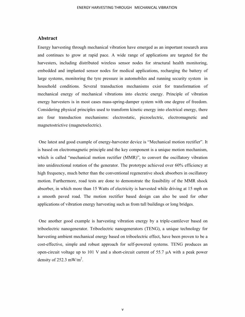
Abstract
Energy harvesting through mechanical vibration have emerged as an important research area
and continues to grow at rapid pace. A wide range of applications are targeted for the
harvesters, including distributed wireless sensor nodes for structural health monitoring,
embedded and implanted sensor nodes for medical applications, recharging the battery of
large systems, monitoring the tyre pressure in automobiles and running security system in
household conditions. Several transduction mechanisms exist for transformation of
mechanical energy of mechanical vibrations into electric energy. Principle of vibration
energy harvesters is in most cases mass-spring-damper system with one degree of freedom.
Considering physical principles used to transform kinetic energy into electrical energy, there
are four transduction mechanisms: electrostatic, piezoelectric, electromagnetic and
magnetostrictive (magnetoelectric).
One latest and good example of energy-harvester device is “Mechanical motion rectifier”. It
is based on electromagnetic principle and the key component is a unique motion mechanism,
which is called “mechanical motion rectifier (MMR)”, to convert the oscillatory vibration
into unidirectional rotation of the generator. The prototype achieved over 60% efficiency at
high frequency, much better than the conventional regenerative shock absorbers in oscillatory
motion. Furthermore, road tests are done to demonstrate the feasibility of the MMR shock
absorber, in which more than 15 Watts of electricity is harvested while driving at 15 mph on
a smooth paved road. The motion rectifier based design can also be used for other
applications of vibration energy harvesting such as from tall buildings or long bridges.
One another good example is harvesting vibration energy by a triple-cantilever based on
triboelectric nanogenerator. Triboelectric nanogenerators (TENG), a unique technology for
harvesting ambient mechanical energy based on triboelectric effect, have been proven to be a
cost-effective, simple and robust approach for self-powered systems. TENG produces an
open-circuit voltage up to 101 V and a short-circuit current of 55.7 μA with a peak power
density of 252.3 mW/m2.

ENERGY HARVESTING THROUGH MECHANICAL VIBRATION
vi
TABLE OF CONTENTS:-
ABSTRACT ………………………………………………………………………………… ii
DECLARATION …………………………………………………………………………… iii
ACKNOWLEDGEMENTS ………………………………………………………………. IV
TABLE OF CONTENT ……………………………………………………………………. VI
LIST OF FIGURE ………………………………………………………………………… VII
1. CHAPTER 1: Introduction
1.1 General ………………………………………………………………. 1
1.2 Necessity of energy harvesting ………………………………… 1
1.3 Source of vibrational energy harvester ………………………. 2
2. CHAPTER 2: Common vibration energy harvesting technique
2.1 Common technique ……………………………………. 5
2.2 Electromagnetic Harvesters ……………………………. 6
2.3 Electrostatic Harvesters ……………………………. 9
2.4 Piezoelectric Harvesters ……………………………….. 13
2.5 Magnetostrictive Harvesters …………………………… 17
2.6 Comparisons of different transduction mechanisms of kinetic energy
harvesters ………………………………………………………… 19
3. CHAPTER 3: Mechanical Motion Rectifier
3.1 Introduction of MMR …………………………………….. 20
3.2 Principle of MMR ……………………………………….. 22
3.3 Design of Highly-Compact Motion Rectifier Based Harvester …. 24
3.4 Experiment and Results ……………………………….. 26

ENERGY HARVESTING THROUGH MECHANICAL VIBRATION
vii
3.5 Conclusion of MMR ……………….. ………. 27
4. CHAPTER 4: Harvesting vibration energy by a triple-cantilever based
triboelectric Nanogenerator(TENG)
4.1 Introduction of TENG ……………………………28
4.2 Design & characterization of TENG ………….. 29
4.3 Design & characterization of TENG ………….. 30
5. CHAPTER 5: Conclusion and Future Work
5.1 Conclusion ……………………………….. ….. 32
5.2 Future Work ………………………………….. 32
REFRENCES ………………………………………………………. 33

ENERGY HARVESTING THROUGH MECHANICAL VIBRATION
viii
LIST OF FIGURES
Figure 2.1: Schematic diagram of electromagnetic energy harvester .................................6
Figure 2.2: Electromagnetic induction Faraday’s law .................................................7
Figure 2.3:Circuit Representation of Electromagnetic generator ..........................................8
Figure 2.4: Circuit representation for an electrostatic generator......................................11
Figure 2.5: Electrostatic generators: (a) in-plane overlap; (b) in-plane gap closing; and (c)
out-of plane gap closing………………………………………………………. 12
Figure 2.6: Piezoelectric Generator (a) mode 33 (b) mode 31 ……………………………………………….14
Figure 2.7: Circuit representation for an piezoelectric generator………………………. 15
Figure 2.8: Magnetostrictive Model …………………………………………………….17
Figure 2.8: Magnetostrictive Model …………………………………………………….18
Figure 3.1: MMR Setup in vehicle Chevrolet Suburban SUV.................................................. 21
Figure 3.2: Traditional design of a rack-pinion based regenerative shock absorber...................23
Figure 3.3: Principle of “motion rectifier” for oscillating motion............................................. 23
Figure 3.4: Electrical analogy for “motion rectifier” …………………………… .......................24
Figure 3.5: sample and 3D view of MMR........................................................................... 25
Figure 3.6: components of MMR .......................................................................................... 25
Figure 3.7: Damping loops for different external electrical loads under vibration input of 1.5 Hz and
5mm amplitude…………………………………………………………………………………………………………………………….26
Figure 3.8:Damping loops for different input frequencies with electrical load Ri +Re= 106.6 Ω .. 26
Figure 4.1 triboelectric Nanogenerator (TANG)………………………………………… 28
Figure 4.2 Photograph of typical cantilever beam ……………………………………… 29
Figure 4.3 A cycle of electricity generation process for illustrating the mechanism of the
Triple-cantilever based TENG ……………………………………………………………………………….. 30
Figure 4.3 Open-circuit voltage (VOC) at vibration frequencies of 3.5 Hz (a), 3.7 Hz (b), and 4.0 Hz
(c) and rectified short-circuit current (ISC) at vibration frequencies of 3.5 Hz (d), 3.7 Hz (e), and 4.0 Hz
(f). The insets of (c) and (f) are enlarged views of half cycles of the VOC and ISC at 4.0 Hz,
respectively ………………………………………………………………………………………………………………………… 31

ENERGY HARVESTING THROUGH MECHANICAL VIBRATION
ix

ENERGY HARVESTING THROUGH MECHANICAL VIBRATION
1
CHAPTER 1: Introduction
1.1 General “Top Problems of Humanity for Next 50 Years will be energy” –by Richard Smalley
(Noble laureate)
Energy harvesting is an active field of research aimed at powering low power wireless systems,
self-powered sensors and micro-systems and recharging existing batteries. Renewable energy
can be harvested by generating electrical energy from solar, thermal or kinetic energy present
within or around the system. Solar cells are excellent energy harvester under direct sunlight, but
are limited in application under dim day light condition, in the night and where light has no
access, such as in embedded systems. Thermal energy can be converted into electrical energy
using seeback effect, but this approach produces energy in the range of a few µW only. Kinetic
energy harvester converts kinetic energy present in the environment into electrical energy. It has
already been demonstrated by several groups that the ambient kinetic energy can be easily
converted into electrical energy in the µW range. Kinetic energy is typically present in the form
of vibration, random displacement of forces and is typically converted into electrical energy
using electromagnetic, electrostatic and piezoelectric energy transduction method.
1.2 Necessity of energy harvesting
Among many other advantages the primary reasons for the use of energy harvesting are:
Convenience: Nowadays energy harvesting is essential because of the future scarcity of the
natural mineral resources. Energy harvesting is done from those natural resources which are
inexhaustible. So that it is more convenient than wall plugs and batteries which are costly and
need replacements.

ENERGY HARVESTING THROUGH MECHANICAL VIBRATION
2
Back up energy source: It can also be used as the backup of the primary sources. Therefore, it
will increase the system’s reliability and prevent power interruption. Moreover, this energy
sources are considered as free form of energy in comparison with fossil fuel. If the energy
harvester is designed and installed properly then it will be available throughout the lifetime of
the application.
Mobility: Advanced low power VLSI design and CMOS fabrication have reduced power
requirement for wireless sensor nodes to the point that the self powered nodded are feasible.
Harvesting energy form ambient vibrations, wind, heat or light could enable smart device to be
functional for an indefinite period.
Environmentally Friendly: Energy harvesting aims to eliminate the dependence on batteries
which contains heavy metals that are toxic to living organisms. Furthermore, this technology
promises to reduce the dependence on nonrenewable energy sources.
Production cost: Business costs for consumers would be reduced in terms of the
packaging, development, disposal, longevity, and reuse of those products. For
instance, in the use of a cell phone, the cost of a chemical battery and charger would be saved
by replacing energy harvester device.
1.3 Source of Vibrational Energy Harvester
Vibration energy available in a wide variety of sources can be conveniently used for potential
powering of wireless sensors and low power devices. Such as escalators, bridges, rotor blades,
windmill blades, pumps and one of great resources are automobiles.
According to “Indian Motor Vehicles knowIndia.net” following data are given:-
India was the sixth largest motor vehicle/car manufacturer in the world in 2013.Indian auto
manufacturers produced a record 23.4 million motor vehicles in 201 41 5 (Apr Mar).3.22
million passenger vehicles rolled out from Indian auto plants in 201 41 5.

ENERGY HARVESTING THROUGH MECHANICAL VIBRATION
3
Table –I: Motor vehicle available in INDIA year wise.
Domestic Motor Vehicle Sales
2014-15 (In Millions)
Passenger Vehicles
2.60
Commercial Vehicles
.61
Two -wheelers
16.0
Three-wheelers
.53
Total 3.74 + 16.0 = 19.00
Year
Total numbers of Vehicle sales (In Millions
2013-14
3 + 14.36 = 17.36
2010-11
1.49+5.016 = 6.506
2009-10
1.211+4.123=5.334
2008-09
4.36+5.25 =9.61
“On the basis of above observation more than 19 million vehicles (Passenger Vehicle ,
Commercial Vehicle , Three wheeler) running on the road and suppose average 100 W electricity
produce by each vehicle that means it is equivalent to 1900 MW electricity will be produce ,
which is great energy”.
ENERGY HARVESTING THROUGH MECHANICAL VIBRATION
4
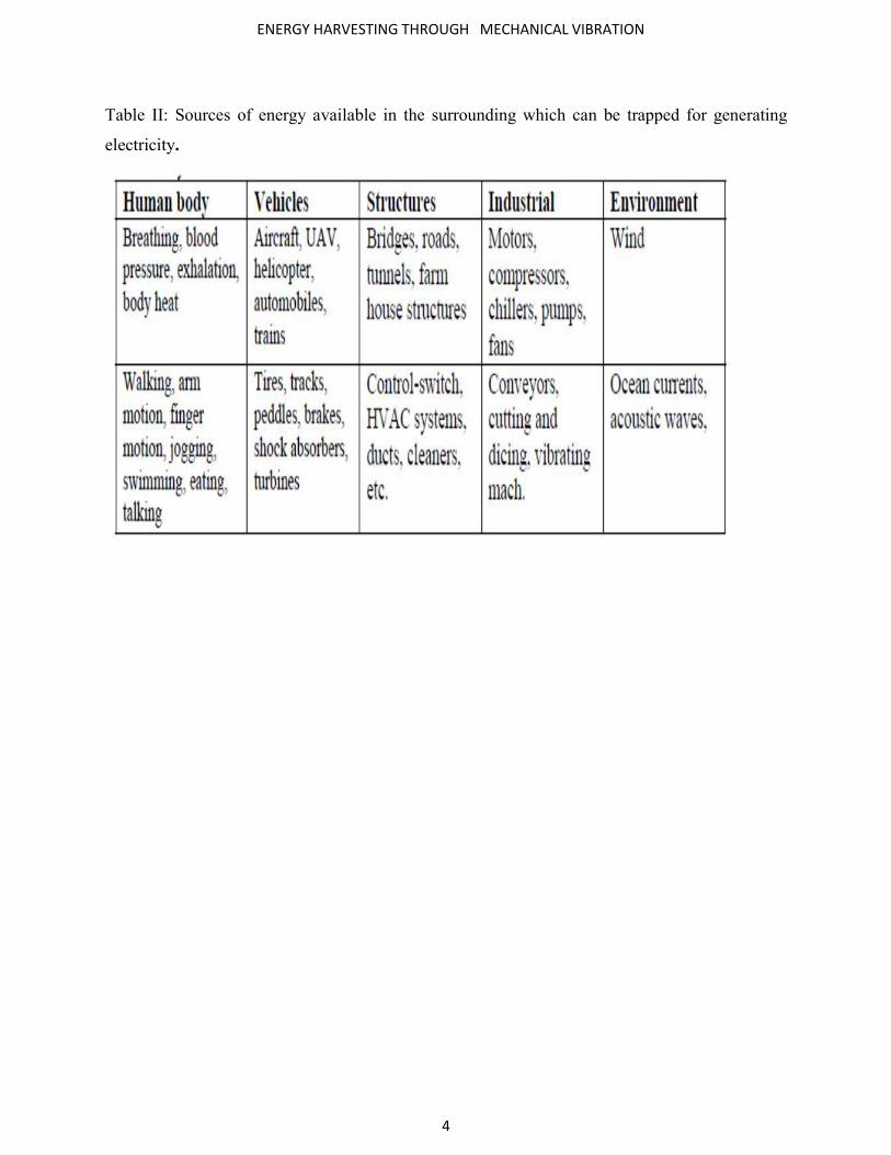
Table II: Sources of energy available in the surrounding which can be trapped for generating
electricity.
ENERGY HARVESTING THROUGH MECHANICAL VIBRATION
5
CHAPTER 2: Common vibration energy harvesting
techniques
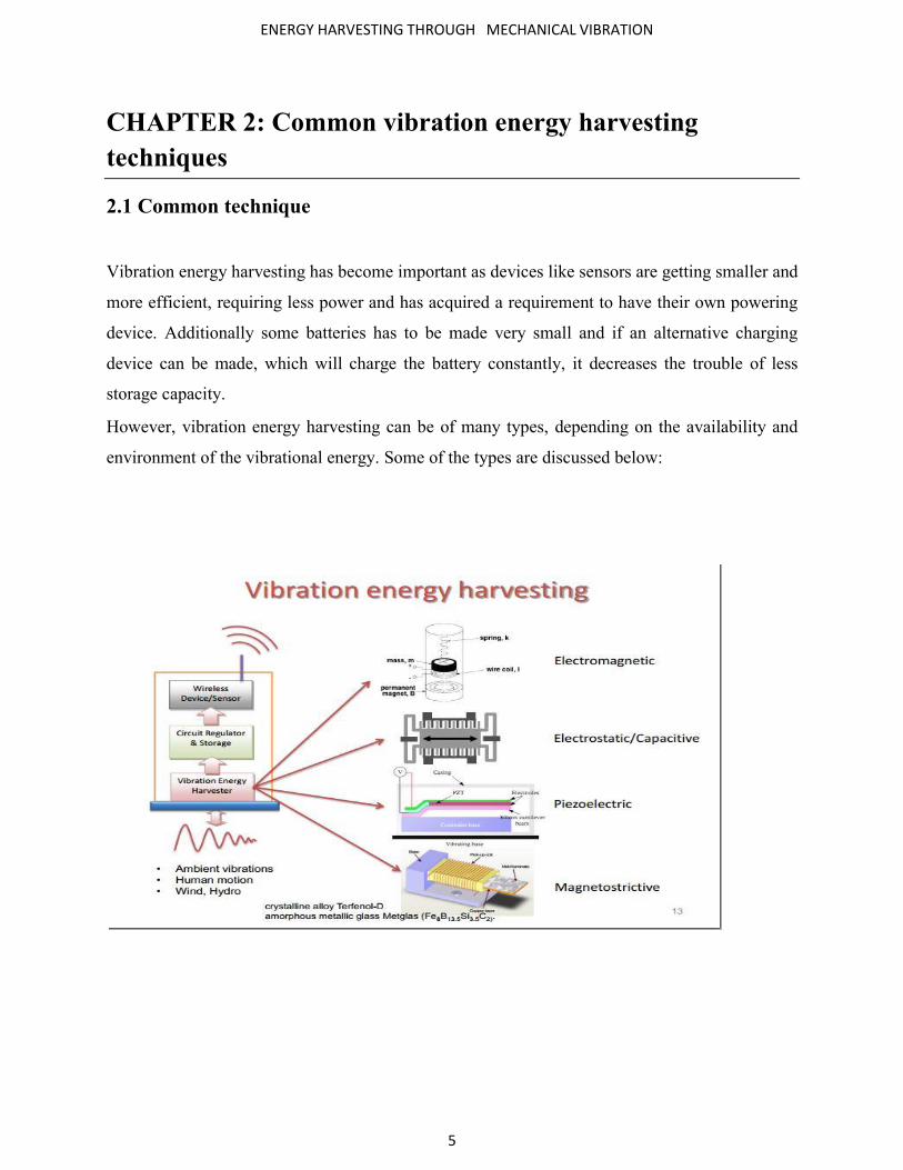
2.1 Common technique
Vibration energy harvesting has become important as devices like sensors are getting smaller and
more efficient, requiring less power and has acquired a requirement to have their own powering
device. Additionally some batteries has to be made very small and if an alternative charging
device can be made, which will charge the battery constantly, it decreases the trouble of less
storage capacity.
However, vibration energy harvesting can be of many types, depending on the availability and
environment of the vibrational energy. Some of the types are discussed below:

ENERGY HARVESTING THROUGH MECHANICAL VIBRATION
6
2.2 Electromagnetic Harvesters
Fig. 2.1: Schematic diagram of electromagnetic energy harvester
It is based on Faraday’s law of electromagnetic induction. Electromagnetic induction was
discovered by Michael Faraday in 1831. Faraday’s law state that an electrical current will be
induced in any closed circuit when the magnetic flux through a surface bonded by the conductor
change. This applied whether the field itself changes in strength or the conductor is move
through it. In an electromagnetic generator, permanent magnets are use to produce strong
magnetic field or the coil is used as a conductor. Either the permanent magnet or the coil is fixed
to the frame while the other is attached to the inertial mass. The relative displacement caused by
the vibration makes the transduction mechanism work and generate the mechanical energy. The
induced voltage is also known as electromotive force (e.m.f), across the coil is proportional to
the strength of magnetic field, the velocity of relative motion and number of turns of the coil. An
electromagnetic generator is characterized by high output current level at expenses of low
voltage.
ENERGY HARVESTING THROUGH MECHANICAL VIBRATION
7
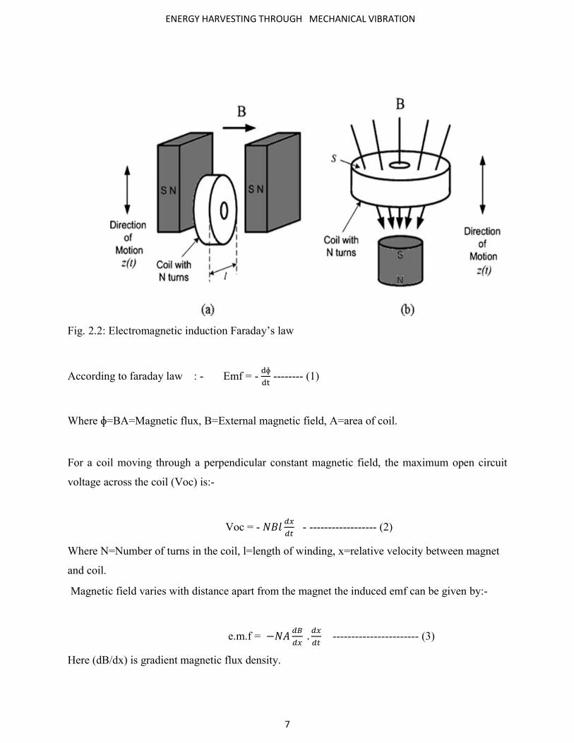
Fig. 2.2: Electromagnetic induction Faraday’s law
According to faraday law : - Emf = - ɸ
-------- (1)
Where ɸ=BA=Magnetic flux, B=External magnetic field, A=area of coil.
For a coil moving through a perpendicular constant magnetic field, the maximum open circuit
voltage across the coil (Voc) is:-
Voc = -
- ------------------ (2)
Where N=Number of turns in the coil, l=length of winding, x=relative velocity between magnet
and coil.
Magnetic field varies with distance apart from the magnet the induced emf can be given by:-
e.m.f = −
.
----------------------- (3)
Here (dB/dx) is gradient magnetic flux density.

ENERGY HARVESTING THROUGH MECHANICAL VIBRATION
8
Both expression (2) & (3) can be expressed as
e.m.f =
----------------------------------------------- (4)
= Electromagnetic coupling factor = − = -NA
Circuit representation of electromagnetic generator:-
Applying Kirchhoff’s voltage law in above circuit, we get:-
e.m.f + i. (RL +Rc) + Lc
=0 --------------------------------------------- (5)
Comparison from dynamic model, we get damping coefficient induced from electromagnetic
transduction, be:-
be =
( ) -------------------------------- (6)
Fig. 2.3

ENERGY HARVESTING THROUGH MECHANICAL VIBRATION
9
For micro-generator that works at low resonant frequencies ,the inductive impedance of coil
much lower than its resistive impedance .Hence inductive impedance can be ignored and written
as :-
be =
( ) ------------------------------------------- (7)
Electrically induced damping factor given as:
ζe =
( ) --------------------------------------------- (8)
One of the most effective ways of achieving this for energy harvesting by use of permanent
magnet and coil.
Well suited for micro-generator that works at resonant frequency.
Do not require smart materials.
No need external voltage source to start generating.
Output voltage is low ~0.1v.
Difficult to manufacture in micro scale.
Difficult to integrate with MEMS (Micro-Electro-Mechanical system) fabrication process.
Bulky size.
2.2 Electrostatic Harvesters
The basis of electrostatic generator is the variable capacitor. According to “Roundy Model”
variation in capacitance causes either voltage or charge increases. The variable capacitance

ENERGY HARVESTING THROUGH MECHANICAL VIBRATION
10
structure is driven by mechanical vibrations. The capacitance varies between maximum and
minimum values. If the charge on the capacitor is constrained, charge will move from the
capacitor to a storage device or to the load as the capacitance decreases. Thus, mechanical
energy is converted to electrical energy.
The electrostatic energy stored within the capacitor is given by:-
E=1/2 *Q*V = 1/2 * C * V2 = (1/2C)*Q2 ------------------------------------------------------- (9)
Where Q= Charged stored, V= Voltage across the capacitor, C=Capacitance)
C = εr. εo.
----------------------------------------------- (10)
εr = Relative permittivity of dielectric between the plates,
εo = Permittivity of free space .
Circuit representation of electrostatic generator: -
A simplified circuit for an electrostatic generator using charge-constrained conversion is shown
in Fig. 4. Vin is a pre-charged reservoir, which could be a capacitor or a rechargeable battery.
Cv is a variable capacitor, which is one of the three types mentioned above. Cpar is the parasitic
capacitance associated with the variable capacitor structure and any interconnections, which
limits the maximum voltage. CL is the storage capacitor or any kind of load.

ENERGY HARVESTING THROUGH
Fig. 2.4:- Circuit representation for an electrostatic generator
The maximum voltage across the load is given by:
Electrostatic generators can be classified into three types, i.e. in
varies the overlap area between electrode fingers, in
gap between electrode fingers and out
two large electrode plates.
ENERGY HARVESTING THROUGH MECHANICAL VIBRATION
11
Circuit representation for an electrostatic generator
The maximum voltage across the load is given by:
Electrostatic generators can be classified into three types, i.e. in-plane overlap (Fig.
varies the overlap area between electrode fingers, in-plane gap closing (Fig. b) which varies the
gap between electrode fingers and out-of-plane gap closing (Fig. c) which varies the gap between
plane overlap (Fig. a) which
) which varies the
) which varies the gap between

ENERGY HARVESTING THROUGH MECHANICAL VIBRATION
12
Fig. 2.5- Electrostatic generators: (a) in-plane overlap; (b) in-plane gap closing; and (c) out-of
plane gap closing

ENERGY HARVESTING THROUGH MECHANICAL VIBRATION
13
These three types can be operated either in charge-constrained or voltage constrained cycles.
Generally, generators working in voltage-constrained cycles provide more energy than
generators in charge-constrained cycles. However, by incorporating a capacitor in parallel with
the energy harvesting capacitor, the energy from the charge-constrained system can approach
that of the voltage-constrained system as the parallel capacitance approaches infinity. This
parallel capacitor effectively constrains the voltage on the energy harvesting capacitor.
An electrostatic generator can be easily realized in MEMS version. Since the fabrication process
of electrostatic generators is similar to that of VLSI, electrostatic generators can be assembled
with VLSI without difficulties. Unfortunately, electrostatic generators require an initial
polarizing voltage or charge. The output impedance of the devices is often very high, which
makes them less suitable as a power supply. However, they can be used to charge a battery, in
which case, electrostatic generators can use electrets to provide the initial charge.
2.3 Piezoelectric Harvesters
Piezoelectric materials are generating electric charge when a mechanical load is applied.
Mechanical energy is in the form of pressure or force into electric energy and vice versa.
The constitutive equation for a piezoelectric material is given by-
D = ε. E + d. σ ------------------------------------- (Direct effect) ---------- (11)
€ = (σ/Y) + d. E -------------------------------------- (Converse effect) -------- (12)
ENERGY HARVESTING THROUGH MECHANICAL VIBRATION
14
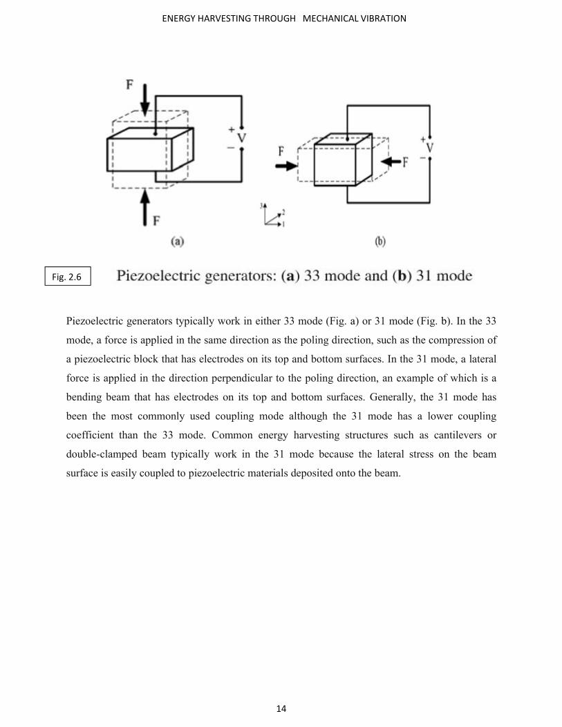
Piezoelectric generators typically work in either 33 mode (Fig. a) or 31 mode (Fig. b). In the 33
mode, a force is applied in the same direction as the poling direction, such as the compression of
a piezoelectric block that has electrodes on its top and bottom surfaces. In the 31 mode, a lateral
force is applied in the direction perpendicular to the poling direction, an example of which is a
bending beam that has electrodes on its top and bottom surfaces. Generally, the 31 mode has
been the most commonly used coupling mode although the 31 mode has a lower coupling
coefficient than the 33 mode. Common energy harvesting structures such as cantilevers or
double-clamped beam typically work in the 31 mode because the lateral stress on the beam
surface is easily coupled to piezoelectric materials deposited onto the beam.
Fig. 2.6

ENERGY HARVESTING THROUGH MECHANICAL VIBRATION
15
Circuit representation of Piezoelectric generator: -
Figure .7 shows a circuit representation of a piezoelectric generator with a resistive load, RL. C is
the capacitance between two electrodes and Rs is the resistance of the piezoelectric material. The
voltage source, VOC, is the open circuit voltage resulting from Eq. (12) when the electrical
displacement is zero. It is given by
Voc = -
ε. . --------------------------------- (13)
Here t is the thickness of the piezoelectric material.
An expression for the piezoelectric damping coefficient is ,[2]
Fig . 7

ENERGY HARVESTING THROUGH MECHANICAL VIBRATION
16
Energy harvesting device employing piezoelectric conversion mechanism typically consist of
cantilever beam coated with piezoelectric material and mass placed on the tip of beam.
Piezoelectric require no external voltage source.
Compact dimension allow for MEMS integration.
Voltage relatively high (2-10V).
Poor mechanical properties.
Poor coupling in piezo thin film.
Piezoelectric materials -
a.) Naturally occurring crystal – Berlinite (AlPO4), Cane sugar, Quartz, Rochelle salt
b.) Man-made ceramics - Barium titanate (BaTiO3), Lead titanate (PbTiO3), Lead
Zirconium titanate (PZT) , Lithium niobate (LiNbO3)

ENERGY HARVESTING THROUGH MECHANICAL VIBRATION
17
c.) Polymer - Polyvinyledene fluoride (PVDF)
2.4 Magnetostrictive Harvesters
Magnetostrictive materials are also used to extract electrical energy from ambient vibration.
These materials deform when placed in a magnetic field and it can induce changes in magnetic
field when it is strained. Magnetostrictive materials are generally used in piezoelectric-
magnetostrictive composites. Such composites were originally used in magnetic field sensors and
have recently been adopted in energy harvesting. Magnetostrictive energy harvesters use the
“Villari effect of Magnetostrictive materials” such as Metglas 2605SC reported Wang and Yuan
[46]. Huang et al.[45] reported two energy harvesting devices based on a
TerfenolD/PZT/Terfenol-D composite. Their device produced 1.2 mW of power when excited at
5 m s−2 at 30 Hz.

ENERGY HARVESTING THROUGH MECHANICAL VIBRATION
18
Fig. No- 8
Fig. no- 9
B = dm .σ + μ . H …………………….(Villari effect)……………………… (14)
S =
+ dm . H ………………….(Joule effect) ……………………… (15)
The magnetic field strength, H, could calculate -
H = . ...……………………………………………….. (16)
Here, B=Magnetic displacement /flux density , dm-Magnetostrictive constant , σ – Stress , Permeability ,
H – Magnetic field strength, S – Strain ,E-Young’s modulus, I= Current ,N=Number of coil turns.
ENERGY HARVESTING THROUGH MECHANICAL VIBRATION
19
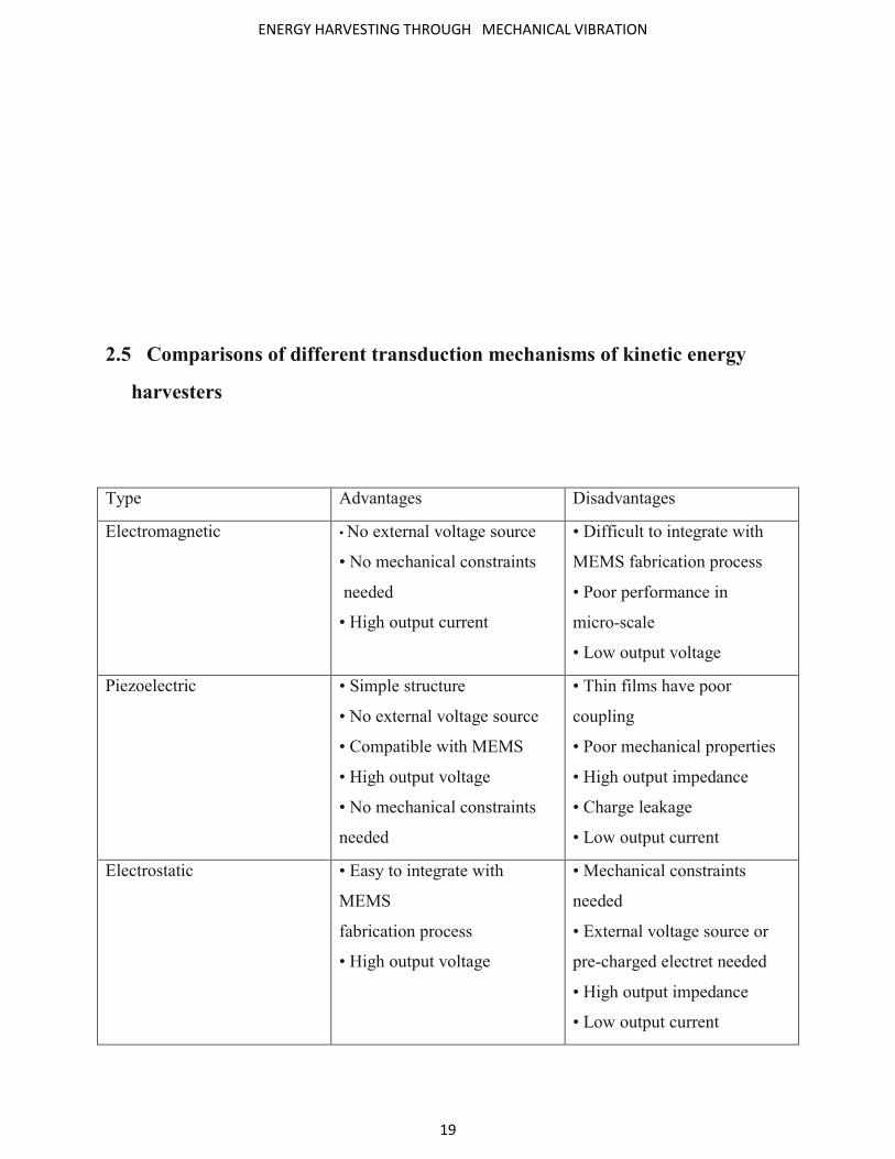
2.5 Comparisons of different transduction mechanisms of kinetic energy
harvesters
Type Advantages Disadvantages
Electromagnetic • No external voltage source
• No mechanical constraints
needed
• High output current
• Difficult to integrate with
MEMS fabrication process
• Poor performance in
micro-scale
• Low output voltage
Piezoelectric • Simple structure
• No external voltage source
• Compatible with MEMS
• High output voltage
• No mechanical constraints
needed
• Thin films have poor
coupling
• Poor mechanical properties
• High output impedance
• Charge leakage
• Low output current
Electrostatic • Easy to integrate with
MEMS
fabrication process
• High output voltage
• Mechanical constraints
needed
• External voltage source or
pre-charged electret needed
• High output impedance
• Low output current

ENERGY HARVESTING THROUGH MECHANICAL VIBRATION
20
Magnetostrictive • Ultra-high coupling
coefficient
• High flexibility
• Non-linear effect
• May need bias magnets
• Difficult to integrate with
MEMS fabrication process
ENERGY HARVESTING THROUGH MECHANICAL VIBRATION
21
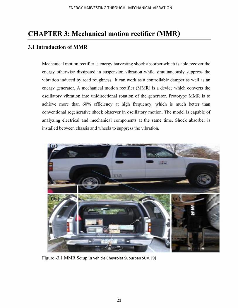
CHAPTER 3: Mechanical motion rectifier (MMR)
3.1 Introduction of MMR
Mechanical motion rectifier is energy harvesting shock absorber which is able recover the
energy otherwise dissipated in suspension vibration while simultaneously suppress the
vibration induced by road roughness. It can work as a controllable damper as well as an
energy generator. A mechanical motion rectifier (MMR) is a device which converts the
oscillatory vibration into unidirectional rotation of the generator. Prototype MMR is to
achieve more than 60% efficiency at high frequency, which is much better than
conventional regenerative shock observer in oscillatory motion. The model is capable of
analyzing electrical and mechanical components at the same time. Shock absorber is
installed between chassis and wheels to suppress the vibration.
Figure -3.1 MMR Setup in vehicle Chevrolet Suburban SUV. [9]
ENERGY HARVESTING THROUGH MECHANICAL VIBRATION
22
The road test is done to demonstrate the feasibility of the MMR shock observer and it is
observed that more than 15 watts of electricity which harvested while driving at 15 mph
on a smooth road. Zuo and Zhang et.al,[1] observe that 100 to 400 watts of energy
harvesting potential exist in the suspension of typical passenger vehicle travelling 60 mph
on the good roads and more energy available for trucks or on the rough roads. The
motion rectifier based design can also be used for other application of vibration energy
harvesting such as from tall building, long bridge or ocean vehicles. It can significantly
improve the reliability by reducing impact forces and increase efficiency by decreasing
the influence of friction. he main contribution of this paper is an innovative concept of
“mechanical motion rectifier”, which can convert bidirectional motion into unidirectional
motion. It is not a substitute of electrical voltage rectifier. It can significantly improve the
reliability by reducing impact forces and increase efficiency by decreasing the influences of
friction. It also enables the electrical generator to rotate unidirectional at relative steady speed
with higher energy efficiency. The second contribution is a circuit based modeling to analyze the
system’s dynamic properties both in electrical domain and mechanical domains. The third
contribution of this paper is simulation, lab experiments, and road tests to verify the concept
and advantages of mechanical motion rectifier based vibration energy harvester.
3.2 Principle of MMR
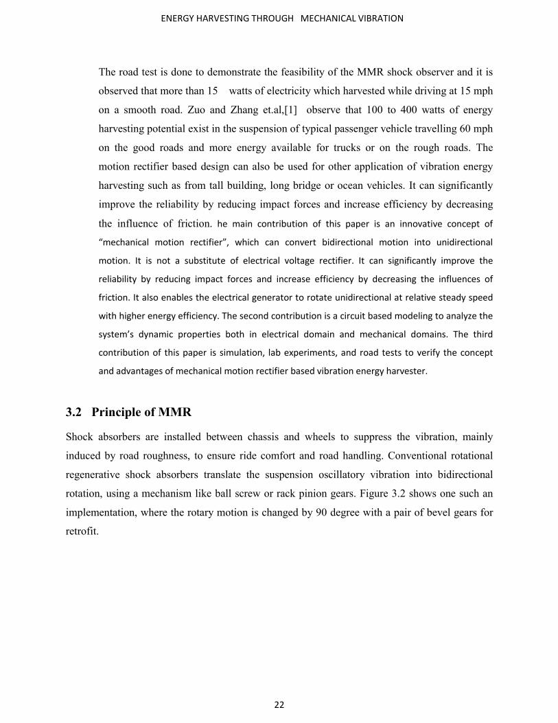
Shock absorbers are installed between chassis and wheels to suppress the vibration, mainly
induced by road roughness, to ensure ride comfort and road handling. Conventional rotational
regenerative shock absorbers translate the suspension oscillatory vibration into bidirectional
rotation, using a mechanism like ball screw or rack pinion gears. Figure 3.2 shows one such an
implementation, where the rotary motion is changed by 90 degree with a pair of bevel gears for
retrofit.
ENERGY HARVESTING THROUGH MECHANICAL VIBRATION
23
Fig. 3.2 - Traditional design of a rack-pinion based regenerative shock absorber [9]
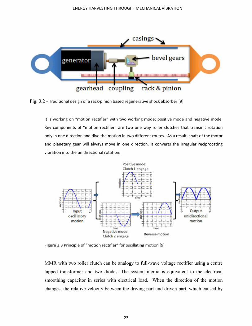
It is working on “motion rectifier” with two working mode: positive mode and negative mode. Key components of “motion rectifier” are two one way roller clutches that transmit rotation
only in one direction and dive the motion in two different routes. As a result, shaft of the motor
and planetary gear will always move in one direction. It converts the irregular reciprocating
vibration into the unidirectional rotation.
Figure 3.3 Principle of “motion rectifier” for oscillating motion [9]
MMR with two roller clutch can be analogy to full-wave voltage rectifier using a centre
tapped transformer and two diodes. The system inertia is equivalent to the electrical
smoothing capacitor in series with electrical load. When the direction of the motion
changes, the relative velocity between the driving part and driven part, which caused by

ENERGY HARVESTING THROUGH MECHANICAL VIBRATION
24
backlash, would be much smaller so that the impact forces would be much smaller ,in this
way reliability would be improved.
Figure 3.4 Electrical analogy for “motion rectifier” [9]
3.3 Design of Highly-Compact Motion Rectifier Based Harvester
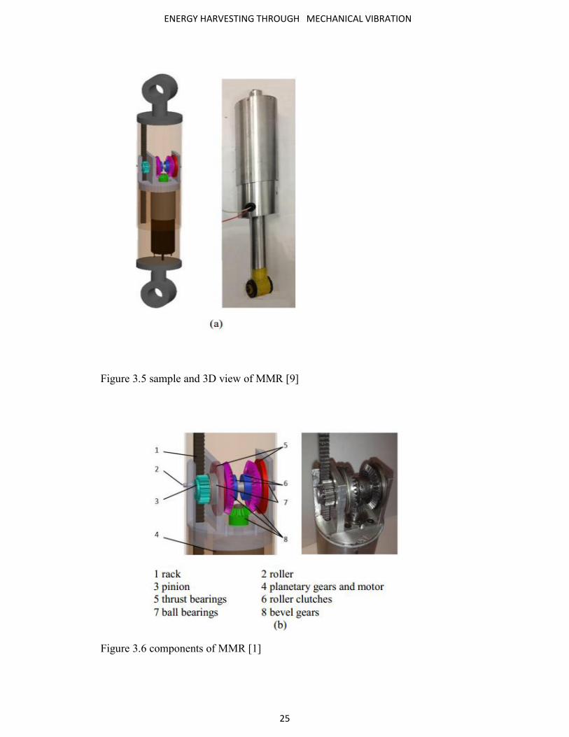
Design of MMR is very compact in comparison of existing other design. In this design
they using pair of rack and pinion, one shaft and three bevel gears .Two roller clutches
are mounted between the shaft and the two larger bevel gears, which are always engaged
with the small bevel gear .When rack moves up and down, the pinion and shaft rotate
clock wise and counterclockwise directions. Due to the engagement of one-way roller
clutches at instant time only one large bevel gear will be engaged and be driven by the
shaft; another large bevel gear disengaged with from the shaft by the roller clutch. The
assembly of the pinion, shaft, and bevel gears will be mounted to one cylinder, and
another cylinder covers outside and to guide the linear motion. Similar as roller bearings,
the roller clutches can’t hold large thrust in the axial direction, so two thrust bearings are
designed to support the thrust forces on the two larger bevel gears. In order to reduce the
friction between the inner and outer cylinders, we insert Teflon rings between the two
cylinders. The rack is preloaded and guided by a roller in the place opposite to the pinion.
The enclosed construction of the shock absorber prevents dirt from hurting gears inside.
ENERGY HARVESTING THROUGH MECHANICAL VIBRATION
25
Figure 3.5 sample and 3D view of MMR [9]
Figure 3.6 components of MMR [1]

ENERGY HARVESTING THROUGH MECHANICAL VIBRATION
26
3.4 Experiment and Results
Experiment Setup –
5.1. Experiment Setup The prototype was tested with the MTS 858 Mini Bionix II
testing system and a dynamic signal analyzer (Hewlett Packard Model 35670A).
Figure 3.7 Damping loops for different external electrical loads under vibration input of 1.5 Hz and
5mm amplitude.
Figure 3.8 Damping loops for different input frequencies with electrical load Ri +Re= 106.6 Ω

ENERGY HARVESTING THROUGH MECHANICAL VIBRATION
27
3.5 Conclusion of MMR
“Motion rectifier” based design of electromagnetic energy harvester for enhanced
efficiency and reliability for potential application of vibration energy harvesting from vehicle
suspensions. “Motion rectifier” can transfer the oscillatory motion of vehicle suspension into
unidirectional motion of the electrical generator, thus enabling the generator operating in a
relatively steady speed with higher efficiency. In such a design, the motion inertia will act as a
filtering capacitor to temporarily storage the energy and smooth the rotation, which can decrease
the influences of backlash impact and static friction.
ENERGY HARVESTING THROUGH MECHANICAL VIBRATION
28
CHAPTER 4: Harvesting vibration energy by a triple-
cantilever based triboelectric Nanogenerator (TENG)
4.1 Introduction of TENG
Figure 4.1 triboelectric Nanogenerator (TANG) [7]
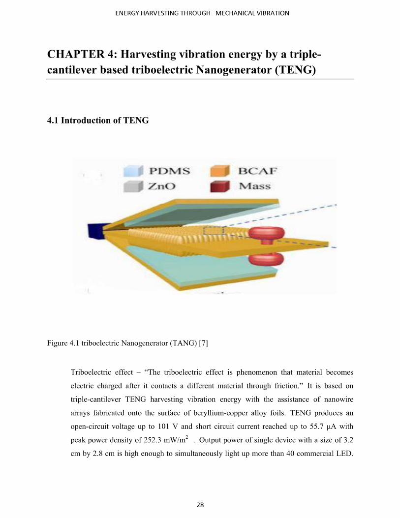
Triboelectric effect – “The triboelectric effect is phenomenon that material becomes
electric charged after it contacts a different material through friction.” It is based on
triple-cantilever TENG harvesting vibration energy with the assistance of nanowire
arrays fabricated onto the surface of beryllium-copper alloy foils. TENG produces an
open-circuit voltage up to 101 V and short circuit current reached up to 55.7 μA with
peak power density of 252.3 mW/m2 . Output power of single device with a size of 3.2
cm by 2.8 cm is high enough to simultaneously light up more than 40 commercial LED.

ENERGY HARVESTING THROUGH MECHANICAL VIBRATION
29
Unambiguously demonstrating its feasibility of power portable electronics. Using as
sensor for environmental and infrastructure monitoring security.
4.2 Design & characterization of TENG
Figure 4.2 Photograph of typical cantilever beam
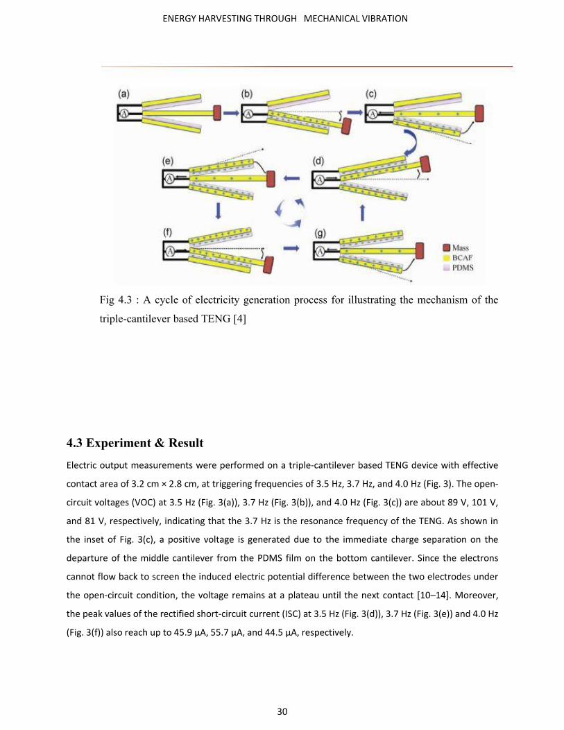
The bottom surface of top cantilever and top surface of bottom cantilever are coated with
polydimethylsiloxane (PDMS) films and middle cantilever are covered by ZnO nanowire
array which layer copper will deposited. A mass is attached at end of its effectiveness of
vibration. Middle cantilever has two chances the contact the top and bottom cantilever in
each cycle of vibration. PDMS film can easily deformed to increase the effectiveness
contact area and nanowire array can deeply inserted into PDMS to increase the effective
contact area and thus leading to substantially higher electric output. A cycle of
electricity generation process illustrating mechanism of the TENG can be explained by
coupling between triboelectric effect and electrostatic effect.
ENERGY HARVESTING THROUGH MECHANICAL VIBRATION
30
Fig 4.3 : A cycle of electricity generation process for illustrating the mechanism of the
triple-cantilever based TENG [4]
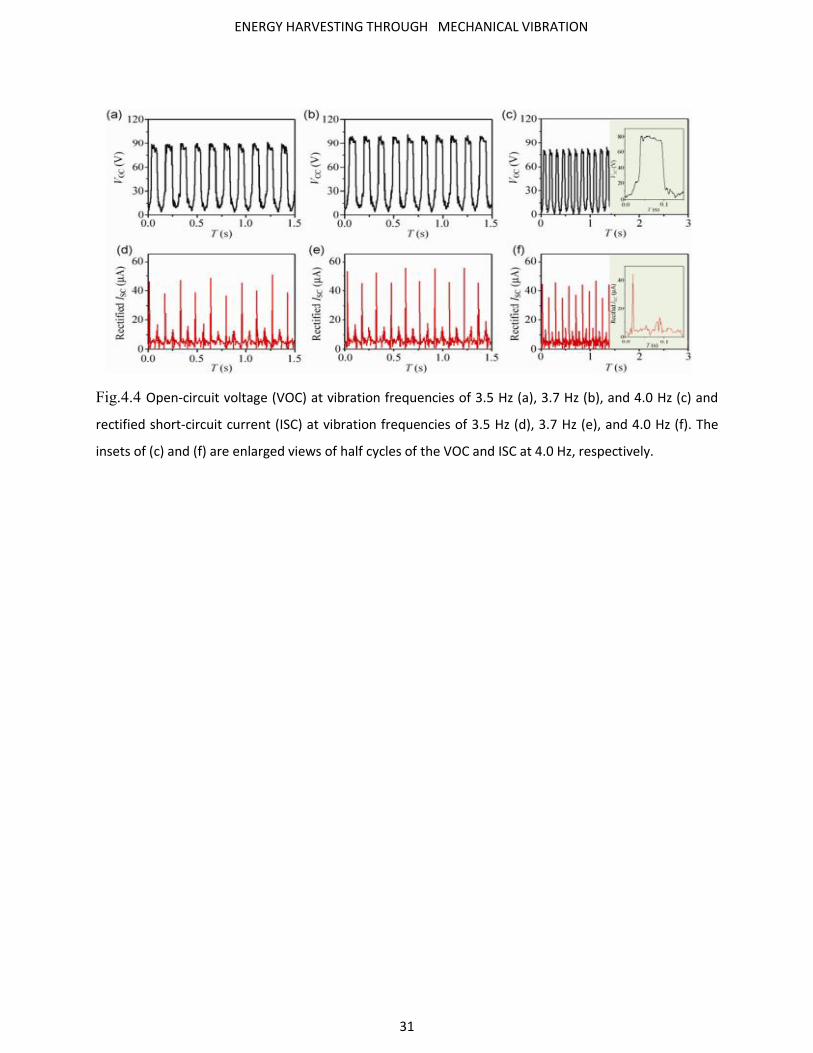
4.3 Experiment & Result
Electric output measurements were performed on a triple-cantilever based TENG device with effective
contact area of 3.2 cm × 2.8 cm, at triggering frequencies of 3.5 Hz, 3.7 Hz, and 4.0 Hz (Fig. 3). The open-
circuit voltages (VOC) at 3.5 Hz (Fig. 3(a)), 3.7 Hz (Fig. 3(b)), and 4.0 Hz (Fig. 3(c)) are about 89 V, 101 V,
and 81 V, respectively, indicating that the 3.7 Hz is the resonance frequency of the TENG. As shown in
the inset of Fig. 3(c), a positive voltage is generated due to the immediate charge separation on the
departure of the middle cantilever from the PDMS film on the bottom cantilever. Since the electrons
cannot flow back to screen the induced electric potential difference between the two electrodes under
the open-circuit condition, the voltage remains at a plateau until the next contact [10–14]. Moreover,
the peak values of the rectified short-circuit current (ISC) at 3.5 Hz (Fig. 3(d)), 3.7 Hz (Fig. 3(e)) and 4.0 Hz
(Fig. 3(f)) also reach up to 45.9 μA, 55.7 μA, and 44.5 μA, respectively.
ENERGY HARVESTING THROUGH MECHANICAL VIBRATION
31
Fig.4.4 Open-circuit voltage (VOC) at vibration frequencies of 3.5 Hz (a), 3.7 Hz (b), and 4.0 Hz (c) and
rectified short-circuit current (ISC) at vibration frequencies of 3.5 Hz (d), 3.7 Hz (e), and 4.0 Hz (f). The
insets of (c) and (f) are enlarged views of half cycles of the VOC and ISC at 4.0 Hz, respectively.

ENERGY HARVESTING THROUGH MECHANICAL VIBRATION
32
CHAPTER 5: Conclusion and Future Work
5.1 Conclusion
An overview of sources of ambient energy available for harvesting was presented. Description
of four vibration energy harvesting mechanisms was proposed with respect to pros and cons of
each technique. The aim of this technique is to make the energy harvester produce maximum
power output in the most effective way. “Motion rectifier” based design of electromagnetic
energy harvester for enhanced efficiency and reliability for potential application of vibration
energy harvesting from vehicle suspensions. The “motion rectifier” based design achieved a
mechanical efficiency of over 60% and no obvious backlash effect. It also harvested average
powers 40.4 Watts and 25.6 Watts on 30 and 93.4 external resistive loads under vibration of
RMS velocity 0.047m/s and we have also seen triple-cantilever based TENG for harvesting
vibration energy in ambient environments. This innovative structure provides the middle cantilever
with two chances to contact the top and bottom cantilevers in each cycle of the vibration, doubling the
vibration energy conversion efficiency.
5.2 Future Work
Mechanical vibration is great source of energy harvesting, we have seen at present time more
than 19 million automobiles are available in INDIA and it will be very large data in future.
Improvement is possible in efficiency as well as reliability. We can save 10-14% fuel by
recharging car battery and small electronics device. We can make more robust and regular
unidirectional rotational design.

ENERGY HARVESTING THROUGH MECHANICAL VIBRATION
33
REFERENCES
[1]. Energy Harvesting Technique by Shashank Priya. Daniel J. Inman.
[2]. Harvesting the Vibration Energy by Marek Matak*, Peter Šolek Institute of applied
mechanics and mechatronics, Slovak University of Technology, Bratislava, Slovakia.
[3.] Energy Harvesting Systems by Tom J. K a ´zmierski · Steve Beeby
[4.] Introduction to Vibration Energy Harvesting NiPS Energy Harvesting Summer School
August 1-5, 2011
[5.] http://iopscience.iop.org/0964-1726/19/10/105012
[6.] Electromagnetic energy harvesting from vibrations of multiple frequencies
Bin Yang1, Chengkuo Lee1 ,2, Wenfeng Xiang2, Jin Xie1, Johnny Han He1,Rama Krishna
Kotlanka1, Siew Ping Low2, 3 and Hanhua Feng.
[7.] Vibration Energy Harvesting: Machinery Vibration, Human Movement and Flow Induced
Vibration Dibin Zhu University of Southampton, UK.
[8.] Magnetoelastic Energy Harvesting: M o d e l i n g a n d E xp e r i m e n t s Daniele Davino,
Alessand ro Giustiniani and Ciro Visone.
[9.] Energy-Harvesting Shock Absorber with a Mechanical Motion Rectifier Zhongjie Li, Lei
Zuo*, Jian Kuang, and George Luhrs, Department of Mechanical Engineering, State
University of New York at Stony Brook Stony Brook, NY, 11794.
[10.] Harvesting vibration energy by a triple-cantilever based triboelectric Nanogenerator
Weiqing Yang1,2,†, Jun Chen1,†, Guang Zhu1 , Xiaonan Wen1 , Peng Bai1 , Yuanjie Su1,2,
Yuan Lin2 , and Zhonglin Wang1,3


![Vibration Energy Harvesting: Machinery Vibration, …...Vibration Energy Harvesting: Machinery Vibration, Human Move ment and Flow Induced Vibration 27 r ma P 4]Z 2 (3) where a Y Z2](https://img.pdfslide.net/doc/110x75/5e7c70af07fbe24a6e769fc0/vibration-energy-harvesting-machinery-vibration-vibration-energy-harvesting.jpg)