Embed Size (px)
Citation preview

Satellite System Installation

©Copyright Global Technology Group, LLC
Break Room
Restrooms
DesignatedSmoking Area
fire exits
Suite 100
Suite 100 Evacuation Area AFence Area of Rear Parking Lot

©Copyright Global Technology Group, LLC
OBJECTIVES
Enhance Field Personnel knowledge of Satellite Communications Technology to meet or exceed Customer needs and to complete Satellite Installations without rework.
Satellite System Installation

©Copyright Global Technology Group, LLC
•Analog to Digital Conversion •PCM (DS-0)
•Voice Compression •ADPCM•ACELP•LCP
Digital Communications Overview
Satellite System Installation

©Copyright Global Technology Group, LLC
•ORBITS•SPACE SEGMENT•MODULATION TECHNIQUES•FORWARD ERROR CORRECTION•ACCESS METHODS
SATELLITE COMMUNICATIONS FUNDAMENTALS
Satellite System Installation

©Copyright Global Technology Group, LLC
- Filtering- Sampling (PAM)
– Nyquist sampling rate: twice thehighestfrequency
– 8000 samples persecond
- Quantizing– 256 discrete amplitude levels (companded)
- PCM– Encode quantized sample using an 8 bit word– 8 x 8000 = 64,000 bits per second
Digitizing Analog Signals

©Copyright Global Technology Group, LLC
Voice Compression Algorithms
MusicSpeechOriginal Music File
(64Kbps PCM)Original Speech (64Kbps PCM)
ADPCM (32Kbps)
CSACLEP(8Kbps)
CELP (4.8Kbps)
LPC (2.4Kbps)
CELP (12Kbps)
LPC (5Kbps)

©Copyright Global Technology Group, LLC
The Main Objective Of A Communications System Is To Provide Satisfactory Communications Service Between
USERS
COMMUNICATIONS SYSTEMS

©Copyright Global Technology Group, LLC
Frame Relay Interfaces
•User to Network•Network to Network

©Copyright Global Technology Group, LLC
Terrestrial Service to Customer
HUB - Houston
PSTN InterfaceFrame Relay Access
Device
Customer LocationRadio Modem
Multiplexer
Telephone/Fax
Workstation
Router
Customer LocationRadio Modem
Multiplexer
Telephone/Fax
Workstation
Router
Customer LocationRadio Modem
Multiplexer
Telephone/Fax
Workstation
Router
Customer LocationRadio Modem
Multiplexer
Telephone/Fax
Workstation
Router

©Copyright Global Technology Group, LLC
Satellite System Components
HUB - Houston
PSTN InterfaceHUB Frame Relay AccessDevice
Telstar 11
Customer LocationModem
Multiplexer
Telephone/Fax
Workstation
Router
Customer LocationModem
Multiplexer
Telephone/Fax
Workstation
Router
Customer LocationModem
Multiplexer
Telephone/Fax
Workstation
Router
Customer LocationModem
Multiplexer
Telephone/Fax
Workstation
Router
UPLINK (Earth Station Transmit)
DOWNLINK (Earth Station Receive)

©Copyright Global Technology Group, LLC
SATELLITE ORBITS

©Copyright Global Technology Group, LLC
Low Earth Orbit

©Copyright Global Technology Group, LLC
Medium Earth Orbit
©Copyright Global Technology Group, LLC
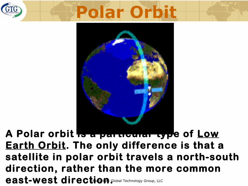
Polar Orbit
A Polar orbit is a particular type of Low Earth Orbit. The only difference is that a satellite in polar orbit travels a north-south direction, rather than the more common east-west direction.

©Copyright Global Technology Group, LLC
Why use a Polar Orbit?

©Copyright Global Technology Group, LLC
Iridium

©Copyright Global Technology Group, LLC
Iridium System

©Copyright Global Technology Group, LLC
Globalstar

©Copyright Global Technology Group, LLC
Geosynchronous Equatorial Orbit
(from Geo = Earth + synchronous = moving at
the same rate)
©Copyright Global Technology Group, LLC
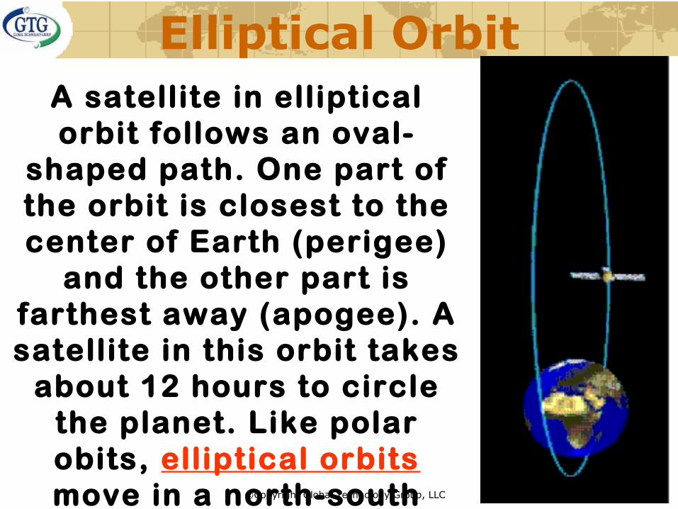
Elliptical OrbitA satellite in elliptical orbit follows an oval-
shaped path. One part of the orbit is closest to the center of Earth (perigee)
and the other part is farthest away (apogee). A satellite in this orbit takes
about 12 hours to circle the planet. Like polar obits, elliptical orbits move in a north-south
direction.

©Copyright Global Technology Group, LLC
The GEO (Clarke) Belt
©Copyright Global Technology Group, LLC
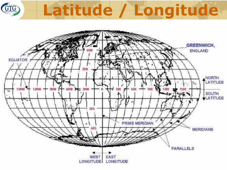
Latitude / Longitude

©Copyright Global Technology Group, LLC
Satellite Spacing

©Copyright Global Technology Group, LLC
Inclinations

©Copyright Global Technology Group, LLC
Polar Coverage

©Copyright Global Technology Group, LLC
Footprints

©Copyright Global Technology Group, LLC
AMC-6 Footprint
©Copyright Global Technology Group, LLC
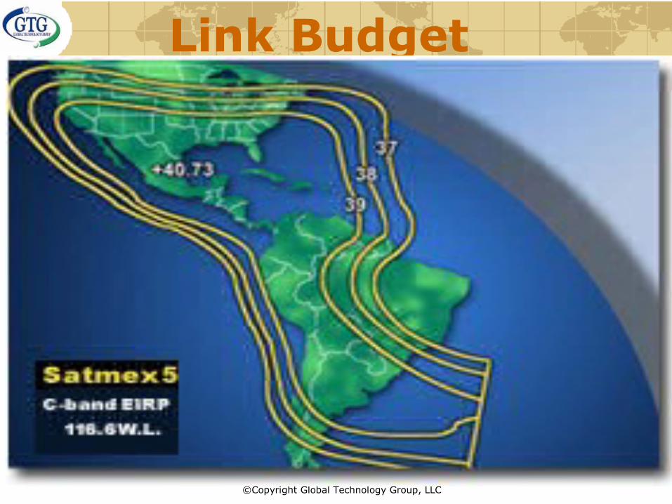
Link Budget

©Copyright Global Technology Group, LLC
AMC-6 Link Budget

©Copyright Global Technology Group, LLC
Link Budget Analysis
UPLINK
UPLINK
DOWNLINK
DOWNLINK

©Copyright Global Technology Group, LLC
Signal To Noise Ratio10-1
10-2
10-3
10-4
10-5
10-6
10-7
10-8
0 1 2 3 4 5 6 7 8 9 101112 dB
Bit
-err
or
rate
, B
ER
Eb
No

©Copyright Global Technology Group, LLC
Analyzing Link Budget Reports
Satellite Parameters
Earth Station Parameters
Circuit Requirements
Network Availability
Atmospheric Effects
Analysis:
Antenna Sizing
Transmitter Sizing
Bandwidth Requirements
Power (EIRP) Requirements Power =/> Bandwidth
Interference Potential
What they tell you:

©Copyright Global Technology Group, LLC
Link Budget Report
TELSTAR 11 FREQUENCY ASSIGNMENT
Date:
Subject:
Carrier Xpdr Info. Mod.
ID # Site Ant Frequency L-Band IF Pol Site Ant Frequency Pol Rate Type Rate Type(m) (MHz) (MHz) (MHz) (m) (MHz) (kbps)
BNewNEW 16870 21
Houston, TX, USA
5.6 14,210.250 1,160.250 54.250 VST 316,
Gulf_of_Mexico1.2 11,910.250 H 2000 QPSK 1/2
Turbo
BNewNEW 16964 21
ST 316, Gulf_of_Mexico
1.2 14,217.395 1,167.395 61.395 VHouston, TX,
USA5.6 11,917.395 H 128 QPSK 3/4
Turbo
NOTEs:
May 7, 2003
Frequency Assignment for CapRock's New 128k return circuit betw een ST 316, Gulf_of_Mexico and Houston, TX, USA. Outbound Carrier is 16870.
The frequency assignments and carrier configuration parameters are as follow s:
When contacting the satellite vendors, please identify this netw ork as CapRock Services.
Most satellite vendors require that advance notice be given to their Operations Center at least 24 hours before activation/crosspole of a carrier.
Uplink Dow nlink Coding
Loral Skynet 1-800-631-3562 or 1-570-226-6622
SATMEX 1-877-728-6391
GE 1-800-772-2363 Option 6
CODING 1 = NO R-S,Viterbi 204/188 = Reed-Solomon
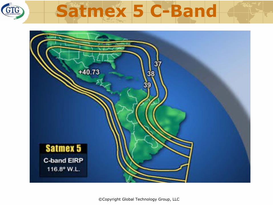
SATMEX 5 T18 116.8 W 14360 MHZ -H-/12060 MHZ-V-
GE 6 T 3 72 W 14060 MHZ-H-/11760 MHZ-V-
TELESTAR 11 T30 37.5 W 14226 MHZ-H-/11926 MHZ-V-
TELESTAR 11 T21 37.5 W 14226 MHZ-V-/11926 MHZ-H-

©Copyright Global Technology Group, LLC
Link Budget ReportCUSTOMER CapRock
SERVICE SCPCFull Duplex
SI NumberCross-Pol Feeds
NOTES Any In-Band Frequency
Carrier ID Number 16870Tracking Sub-Number 6XA 6YYCalculation Target % or dB 12.87 30.6
COVERAGE Satellite T11 T11Transponder K21 K21
INFORMATION Information Data Rate kbps 2134 128BW Spacing Factor 1.4 1.4
UPTransmit City, Country Houston, TX, USA ST 316,
Gulf_of_MexicoLINK Transmit Antenna Size meter 5.6 1.2
Uplink Power Control dB 3 0
DOWNReceive City, Country ST 316,
Gulf_of_MexicoHouston, TX, USA
LINK Receive Antenna Size meter 1.2 5.6LNA or LNB Temperature ºK 90 90Modulation Type QPSK QPSK
MODEM FEC Rate 1/2 3/4Reed Solomon 1 1Receive Threshold Eb/No dB 3.2 4.1Coding Type Turbo TurboEquipment Generic C3/4T
HPA Waveguide Loss 0 012.87 12.87
HPA Power (0dB OBO) Watt 1.34 0.67Uplink Power Density dBW/4kHz -26.8 -15.8Uplink EIRP dB 57.8 41.4
MAIN Estimated Availability % 99.41 99.69RESULTS Bandwidth (BW) kHz 2,990 120
Power Equivalent BW kHz 5,830 100Carrier Output Backoff dB 12.87 30.60
C/N (Thermal)
C/I (Interference)
C/N and C/I
UP DOWN
C/N and C/I
UP DOWN

©Copyright Global Technology Group, LLC
Link Budget ReportClear Sky Margin, ΔOBO dB 5.51 6.77Clear Sky EbNo dB 8.21 10.37Uplink Availability % 99.75 99.75Downlink Availability % 99.66 99.94
TOTAL Up / Down Elevation < 10 º NO / NO NO / NOLINK Simultaneous Rain Fade NO NO
Overall Carrier C/(N+I) dB 8.4 12.3Overall Carrier C/N dB 9.9 16.9Overall Carrier C/I dB 13.9 14.2Symbol Bandwidth kHz 2134 85
BANDWIDTH Noise Bandwidth kHz 2561 102Mod Index 2 2
Track ing Number rjg 041002095409rjg 041002095409rjg
SATELLITE TRANSPONDERSatellite Longitude º East -37.5 -37.5Input Back-Off dB 3.0 3.0Output Back-Off dB 3.2 3.2
SATELLITE SFD Constant dBW/m2 -74.30 -74.30Gain or -Pad dB 10 10Adjusted Constant dB -84.30 -84.30Bandwidth MHz 54 54

©Copyright Global Technology Group, LLC
Link Budget ReportUPLINK PARAMETERSBand Ku Ku
TRANSPONDER Center Frequency kHz 14,217 14,217Polarization V VG/T Saturated dB/K 11.2 6.7Latitude º North 29.75 28.07Longitude º East -95.42 -90.72
EARTH Azimuth º 107.3 109.4STATION Elevation º 19.3 24.0
Antenna Diameter meter 5.6 1.2Antenna Efficiency % 0.65 0.65Antenna Gain dB 56.6 43.2Range km 39,694 39,236
PATH Spread Loss dB -163.0 -162.9Area of Isotropic Antenna dB -44.5 -44.5Zone N N
RAIN Outage Probability (%) % 0.25 0.25Attenuation @ 99.99 Avail dB 22.93 22.50Rain Loss dB 8.41 6.68
C/N C/N dB 23.0 19.3Xpol C/I dB 27.6 23.8
C/I ASI C/I dB 22.8 23.5Overall C/I dB 21.5 20.6

©Copyright Global Technology Group, LLC
Link Budget ReportDOWNLINK PARAMETERSBand Ku Ku
TRANSPONDER Frequency kHz 11,917 11,917Polarization H HEIRP Saturated dB/K 44.8 45.8Latitude º North 28.07 29.75Longitude º East -90.72 -95.42Azimuth º 109.4 107.3Elevation º 24.0 19.3
EARTH Antenna Diameter meter 1.2 5.6STATION Antenna Efficiency % 0.65 0.65
Antenna Gain dB 41.6 55.0Earth Station G/T dB/K 19.9 33.3Range km 39,236 39,694
PATH Spread Loss dB -162.9 -163.0Area of Isotropic Antenna dB -43.0 -43.0Zone N N
RAIN Outage Probability (%) % 0.34 0.06Attenuation @ 99.99 Avail dB 15.74 16.11Rain Loss + Delta T dB 6.68 14.00
C/N C/N dB 10.1 20.5Xpol C/I dB 30.6 26.8
C/I ASI C/I dB 16.6 27.0InterMod C/I dB 19.8 16.0Overall C/I dB 14.8 15.4

©Copyright Global Technology Group, LLC
AMC 9 Ku-Band

©Copyright Global Technology Group, LLC
AMC 9 Ku-Band

©Copyright Global Technology Group, LLC
Satmex 5 Ku-Band
©Copyright Global Technology Group, LLC
Satmex 5 C-Band

©Copyright Global Technology Group, LLC
Telstar 11 Ku Band

©Copyright Global Technology Group, LLC
Frequency Bands

©Copyright Global Technology Group, LLC
Satellite Anatomy

©Copyright Global Technology Group, LLC
FREQUENCY (RE)USE
36 MHz B/W + 4 MHz Guard band X 12 Transponders = 500 MHz total B/W on one C-Band Satellite

©Copyright Global Technology Group, LLC
AMC-6 C-Band Frequency Allocation

©Copyright Global Technology Group, LLC
AMC-6 Ku-Band Frequency Allocation
11700 MHz - 12200 MHz = 500 MHz
Horizontal Beacon = 12198 MHz

©Copyright Global Technology Group, LLC

©Copyright Global Technology Group, LLC
LINEAR POLARIZATION

©Copyright Global Technology Group, LLC
CIRCULAR POLARIZATION
©Copyright Global Technology Group, LLC
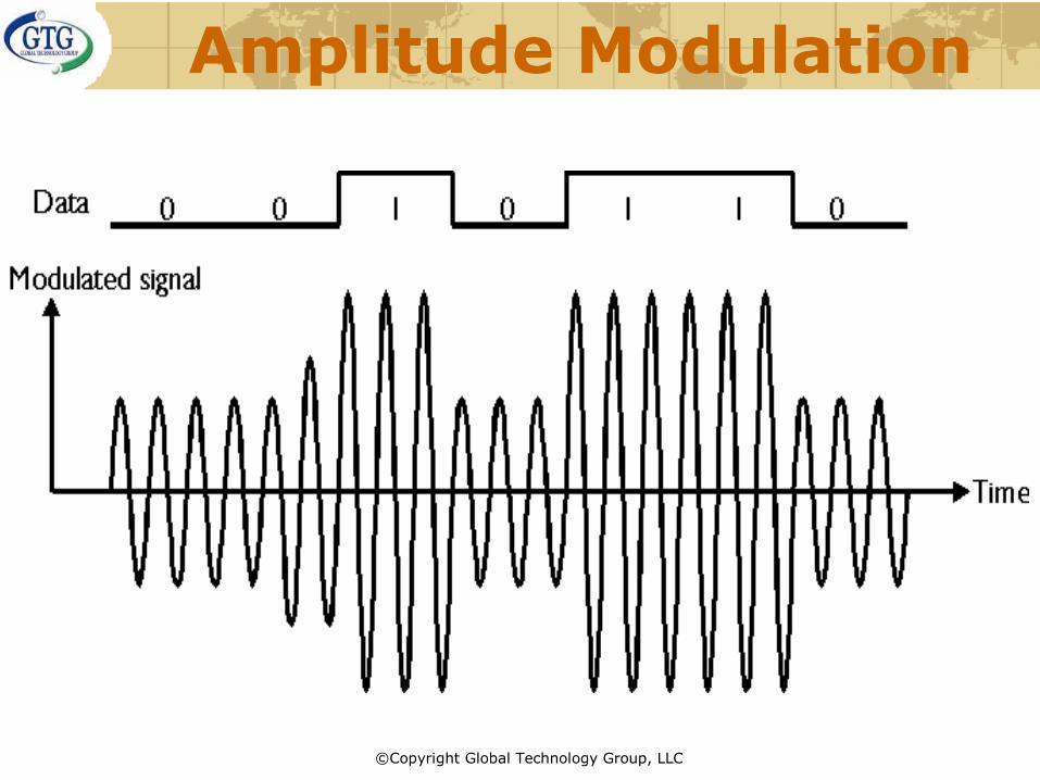
Amplitude Modulation

©Copyright Global Technology Group, LLC
Frequency Modulation (FSK)

©Copyright Global Technology Group, LLC
Phase Modulation (BPSK)

©Copyright Global Technology Group, LLC
Differential Phase (QPSK)

©Copyright Global Technology Group, LLC
Error Control Coding
Forward Error Correction
Interleaving
Convolutional Codes (Viterbi)
Concatenated Codes

©Copyright Global Technology Group, LLC
CODEC
Encoding refers to the process of adding coding bits to the uncoded bit stream.
Decoding refers to the process of recovering the original (uncoded) bit stream from the coded bit stream.Both processes are usually combined in one unit termed a CODEC.

©Copyright Global Technology Group, LLC
Forward Error Correction
Adds redundant data to the data streamDoes not require acknowledgementCorrects errors detected to accurately reproduce original data
Decreases the effective data throughput
Does not ensure error-free data

©Copyright Global Technology Group, LLC
Interleaving

©Copyright Global Technology Group, LLC
Error Control Coding Concatenated Codes

©Copyright Global Technology Group, LLC
Bandwidth, Data Rate and Modulation

©Copyright Global Technology Group, LLC
ERROR CONTROL CODING GAIN

©Copyright Global Technology Group, LLC
(FDMA) Frequency Division Multiple
Access

©Copyright Global Technology Group, LLC
(TDMA) Time Division Multiple Access

©Copyright Global Technology Group, LLC
(DAMA) Demand Assigned Multiple
Access
Transponder bandwidth divided into channelsEach channel (or number of channels) are assign according to demandEfficient overall use of bandwidth

©Copyright Global Technology Group, LLC
Single Channel Per Carrier (SCPC)

©Copyright Global Technology Group, LLC
HUB UPLINK =TDMA / SCPC
Satellite System Access
Hub - Houston
PSTN IntefaceHUBFrame Relay Access
Device
Telstar 11
Customer LocationModem
Multiplexer
Telephone/Fax
Workstation
Router
Customer LocationModem
Multiplexer
Telephone/Fax
Workstation
Router
Customer LocationModem
Multiplexer
Telephone/Fax
Workstation
Router
Customer LocationModem
Multiplexer
Telephone/Fax
Workstation
Router
Remote DOWNLINK=TDMA / SCPC

©Copyright Global Technology Group, LLC
Satellite System Access
Hub - Houston
PSTN InterfaceHUBFrame Relay Access
Device
Telstar 11
Customer LocationModem
Multiplexer
Telephone/Fax
Workstation
Router
Customer LocationModem
Multiplexer
Telephone/Fax
Workstation
Router
Customer LocationModem
Multiplexer
Telephone/Fax
Workstation
Router
Customer LocationModem
Multiplexer
Telephone/Fax
Workstation
Router
HUB DOWNLINK =SCPCL band freq.+ 10.75Ghz
REMOTE UPLINK= SCPCL band freq + 13.05Ghz

©Copyright Global Technology Group, LLC
Atmospheric Attenuation and Absorption

©Copyright Global Technology Group, LLC
Solar Outage

©Copyright Global Technology Group, LLC
Parabolic Curve

©Copyright Global Technology Group, LLC
Deep vs. Shallow

©Copyright Global Technology Group, LLC
Prime Focus Antennas

©Copyright Global Technology Group, LLC
Prime Focus Antennas
©Copyright Global Technology Group, LLC
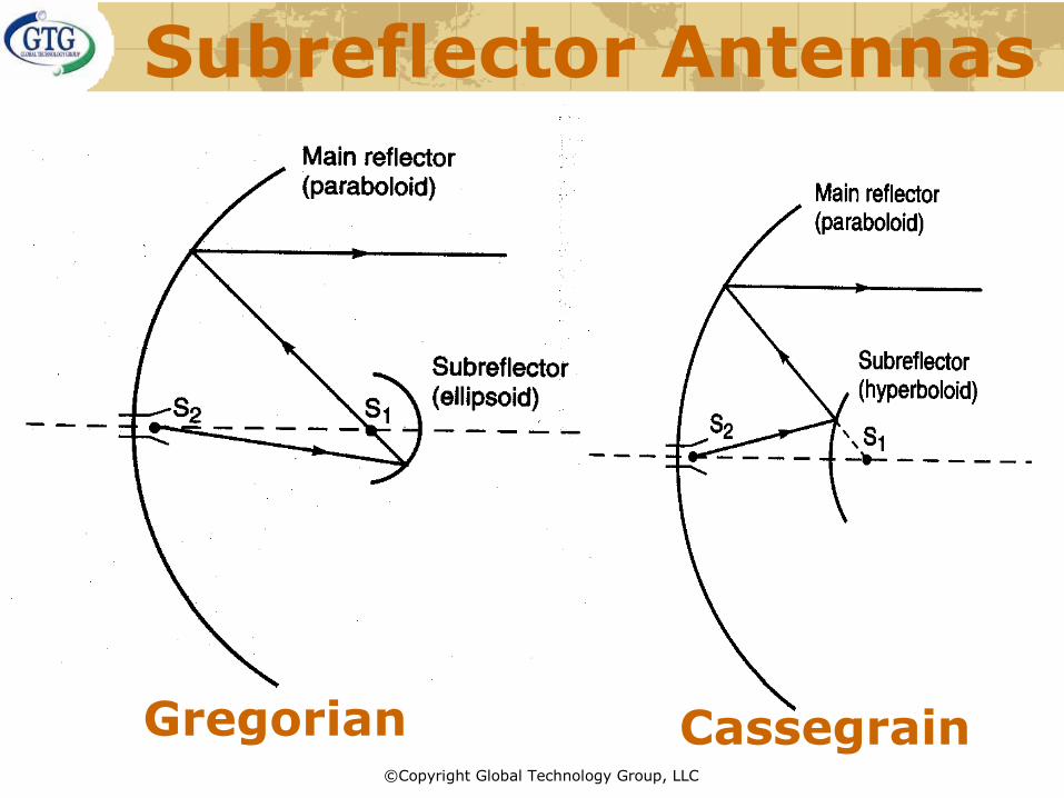
Subreflector Antennas
Gregorian Cassegrain

©Copyright Global Technology Group, LLC
CassegrainAntenna
•Small sub-reflector located at the front and center of the dish
•Higher in efficiencies because feedhorn looks up at the “cold” sky
•Most often used at uplink earth stations and cable TV head end

©Copyright Global Technology Group, LLC
Gregorian Antenna
©Copyright Global Technology Group, LLC
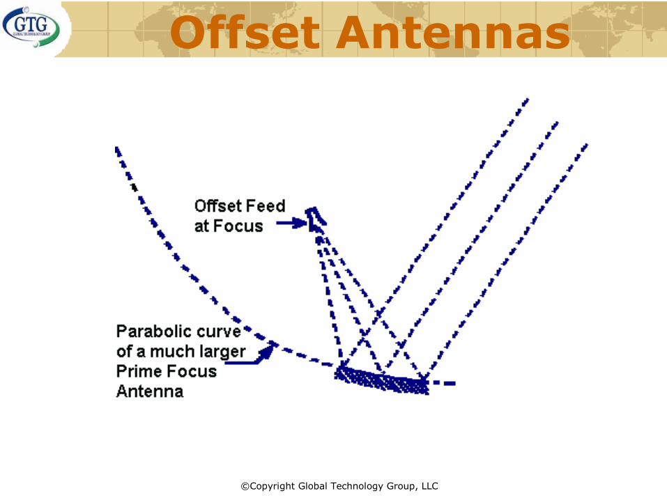
Offset Antennas

©Copyright Global Technology Group, LLC
Offset Antennas

©Copyright Global Technology Group, LLC
Offset Antennas

©Copyright Global Technology Group, LLC
Offset Gregorian

©Copyright Global Technology Group, LLC
Offset Antenna Feeds

©Copyright Global Technology Group, LLC
AZ/EL Antenna Mount

©Copyright Global Technology Group, LLC
Antenna Beamwidth

©Copyright Global Technology Group, LLC
Offset Antenna Feeds

©Copyright Global Technology Group, LLC
LNB - Low Noise Block {Down}Converter

©Copyright Global Technology Group, LLC
Optimum LNB noise
performance

©Copyright Global Technology Group, LLC
OMT - Orthogonal Mode Transducer

©Copyright Global Technology Group, LLC
BUC - Block Up Converter

©Copyright Global Technology Group, LLC
Ku Band Feedhorn
TX FILTER
LNB
OMT
SCALER HORN
FLEXIBLE WAVEGUIDE TO
BUC

©Copyright Global Technology Group, LLC
L-Band Modem“IP Express”

©Copyright Global Technology Group, LLC
Assembling ODU to IDU
Title:
Ku-Band VSAT Station DetailPath/Filename:
FXS Telephony
Transmit RF
Receive RF
Composite Serial Data
10BaseT LAN
Key
Block UpconverterChannel MasterModel 124 or 183
Outdoor EquipmentRF Subsystem
L Band Tx (950 - 1450 MHz)
Ku-Band Tx
L-Band Rx (950-1450 MHz) LNBKu-Band Rx
RG-214 Coax Cable
N-Connector
OMTLinear Feed
(Antenna mount)
CISCO 2600 Router
ComStream SDM-300LSatellite Modem
Indoor EquipmentIF Subsystem
"IP Express"
N- Connector
EIA-449 InterfaceDB-37 SerialConnector
10BaseTInterface
RJ-45 RJ-11
ToCustomerEthernet
Hub
ToCustomerTelephone
FXS Interface
Block Down converter
BUCRG-214 Coax Cable
L-Band Modem

©Copyright Global Technology Group, LLC
L-Band (ODU)
BUC
Flexible Waveguide
OMT
LNB
SCALER HORN

©Copyright Global Technology Group, LLC
ComStream Satellite Modem (IDU)
CM701

©Copyright Global Technology Group, LLC
Transceiver (ODU)

©Copyright Global Technology Group, LLC
Assembling ODU to IDU
Title:
Ku-Band VSAT Station DetailPath/Filename:
FXS Telephony
Transmit RF
Receive RF
Composite Serial Data
10BaseT LAN
Key
CODAN Ku-BandTransciever
Channel MasterModel 124 or 183
Outdoor Unit (ODU)RF Subsystem
Tx IF (70 MHz)
Receive IF (70 MHz)Ku-Band
L-Band Rx (950-1450 MHz)
LNCKu-Band Rx
N-Connector
N-Connector
RG-11CoaxCable
FlexibleWaveguide
OMTLinear Feed
(Antenna mount)
NUERA Multiplexer
ComStream CM-701Satellite Modem
Indoor Unit (IDU)IF Subsystem
OffshoreDedicated Digital
System"ODDS"
N-Connector
EIA-449Interface
DB-37 SerialConnector
10BaseTInterface
RJ-45RJ-11
ToCustomerEthernet
Hub
ToCustomerTelephone
FXS InterfaceRouter
V.35
SSPA
PowerSupply
Unit
AC In
DC Pwr
Pwr & Control
Line Con-ditioner ACPwr
ACIn
70 MHz Transceiver

©Copyright Global Technology Group, LLC
Transceiver (ODU)
LNB
SSPA
OMT
SCALER HORN
Transceiver

©Copyright Global Technology Group, LLC
Transceiver (ODU)

©Copyright Global Technology Group, LLC
Installation PracticesProper Grounding
Generator Power Distribution (Part of the Rig or Platform)
STEEL HULL
Grounded-Nuetral Low-Voltage Distribution
Distribution Panel(Breaker Box)
Ground Bus
Step-Down
Transformer
LOAD
Chassis
BranchCircuit
Normal Current Conductors
Black Wire (Line)
White Wire
(Neutral)
GreenWire
Don't confuse this step-down transformer with theIsolation transformers that Cprk sometimes provides
Generator
Plant
Green Wire
(Equip Ground)
Neutral-GroundConnection

©Copyright Global Technology Group, LLC
Installation Practices
Proper Weatherproofing
“One drop of water in a VSAT System will ruin your day” GJM

©Copyright Global Technology Group, LLC
Installation PracticesProper Weatherproofing

©Copyright Global Technology Group, LLC
COMMISSIONING•Peak Antenna, verify RX Lock
•Call NOC for cross-pol and adjacent carrier check
•Identify Satellite and Transponder
•Give Uplink frequency & data rate
•Transmit CW upon request
•NOC will ask to skew feedhorn
•Be ready to modulate upon request


![Satellite communications[1]](https://img.pdfslide.net/doc/110x75/588ae6481a28abab6c8b6391/satellite-communications1.jpg)