Embed Size (px)
Citation preview

1
ASSIGNMENT-1
NAME:-KOTURI BHARGAVA
REG NO:-15MIS0252
SUBMITED TO:-TAMIL PRIYA .D
CODE:-SWE 20007

2
Assignment Questions:-
1. Construction life cycle models
2. Construction Design
3. Construction Tools
4. Construction languages
5. Construction Testing
1) Construction life cycle models
They are mainly six types of the model
They are:-
The Waterfall Model
V-Model Model
RAD Model
Incremental Model
Evolutionary Models: Prototyping model
The Spiral model

3
The Waterfall Model
Most widely used, though no longer state-of-the-art
Each step results in documentation
May be suitable for well-understood developments using
familiar technology
Not suited to new, different systems because of specification
uncertainty
Difficulty in accommodating change after the process has
started
Can accommodate iteration but indirectly
Working version not available till late in process
Often get blocking states
Waterfall process:-
Advantages:-
This model is simple and easy to understand and use.
It is easy to manage due to the rigidity of the model – each
phase has specific deliverables and a review process.
In this model phases are processed and completed one at a
time. Phases do not overlap.
Communicat ion
Planning
Modeling
Const ruct ionDeployment
analysis
designcode
t est
project init iat ion
requirement gat hering estimating
scheduling
tracking
delivery
support
f eedback

4
Waterfall model works well for smaller projects where
requirements are very well understood.
Disadvantages:-
Once an application is in the testing stage, it is very difficult to
go back and change something that was not well-thought out
in the concept stage.
No working software is produced until late during the life
cycle.
High amounts of risk and uncertainty.
Not a good model for complex and object-oriented projects.
Poor model for long and ongoing projects.
Not suitable for the projects where requirements are at a
moderate to high risk of changing.
When to use:-
This model is used only when the requirements are very well
known, clear and fixed.
Product definition is stable.
Technology is understood.
There are no ambiguous requirements
Ample resources with required expertise are available freely
The project is short.
The V-Model
Real project rarely follow the sequential flow that the model
proposes.
It is often difficult for the customer to state all requirements.
The customer must have patience.

5
V- model means Verification and Validation model. Just like the waterfall model, the V-Shaped life cycle is a sequential path of execution of processes.
Each phase must be completed before the next phase begins-model is one of the models. Testing of the product is planned in parallel with a corresponding phase of development in v-model.
V_MODEL DIAGRAM:-
Advantages:-
Simple and easy to use.

6
Testing activities like planning, test designing happens well
before coding. This saves a lot of time. Hence higher chance of
success over the waterfall model.
Proactive defect tracking – that is defects are found at early
stage.
Avoids the downward flow of the defects.
Works well for small projects where requirements are easily
understood.
Disadvantages
Very rigid and least flexible.
Software is developed during the implementation phase, so no
early prototypes of the software are produced.
If any changes happen in midway, then the test documents
along with requirement documents has to be updated.
When to use
The V-shaped model should be used for small to medium
sized projects where requirements are clearly defined and
fixed.
The V-Shaped model should be chosen when ample technical
resources are available with needed technical expertise.
RAD Model:-
RAD model is Rapid Application Development model. It is a
type of incremental model.
In RAD model the components or functions are developed in
parallel as if they were mini projects.
The developments are time boxed, delivered and then
assembled into a working prototype.

7
This can quickly give the customer something to see and use
and to provide feedback regarding the delivery and their
requirements.
RAD MODEL DIAGRAM:-
Advantages
Reduced development time.
Increases reusability of components
Quick initial reviews occur
Encourages customer feedback
Integration from very beginning solves a lot of integration
issues.
8
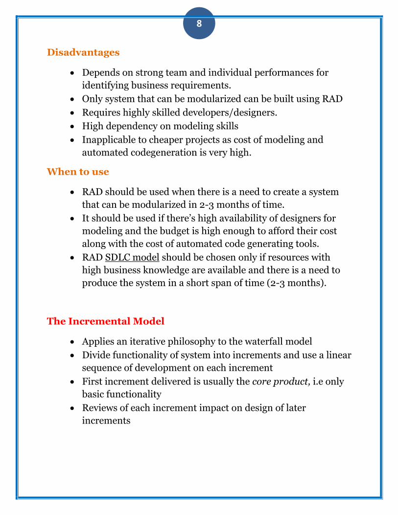
Disadvantages
Depends on strong team and individual performances for
identifying business requirements.
Only system that can be modularized can be built using RAD
Requires highly skilled developers/designers.
High dependency on modeling skills
Inapplicable to cheaper projects as cost of modeling and
automated codegeneration is very high.
When to use
RAD should be used when there is a need to create a system
that can be modularized in 2-3 months of time.
It should be used if there’s high availability of designers for
modeling and the budget is high enough to afford their cost
along with the cost of automated code generating tools.
RAD SDLC model should be chosen only if resources with
high business knowledge are available and there is a need to
produce the system in a short span of time (2-3 months).
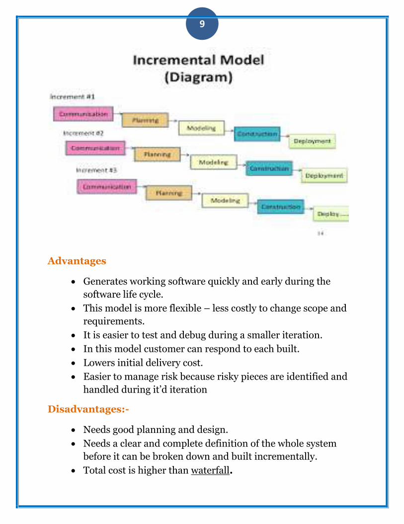
The Incremental Model
Applies an iterative philosophy to the waterfall model
Divide functionality of system into increments and use a linear
sequence of development on each increment
First increment delivered is usually the core product, i.e only
basic functionality
Reviews of each increment impact on design of later
increments
9
Advantages
Generates working software quickly and early during the
software life cycle.
This model is more flexible – less costly to change scope and
requirements.
It is easier to test and debug during a smaller iteration.
In this model customer can respond to each built.
Lowers initial delivery cost.
Easier to manage risk because risky pieces are identified and
handled during it’d iteration
Disadvantages:-
Needs good planning and design.
Needs a clear and complete definition of the whole system
before it can be broken down and built incrementally.
Total cost is higher than waterfall.

10
When to use:-
This model can be used when the requirements of the
complete system are clearly defined and understood.
Major requirements must be defined; however, some details
can evolve with time.
There is a need to get a product to the market early.
A new technology is being used
Resources with needed skill set are not available
There are some high risk features and goals.
Evolutionary Models: Prototyping
Ideally mock-up serves as mechanism for identifying
requirements
Users like the method, get a feeling for the actual system
Less ideally may be the basis for completed product
1) prototypes often ignore
quality/performance/maintenance issues
2) may create pressure from users on deliver earlier
3) may use a less-than-ideal platform to deliver e.g
Visual Basic - excellent for prototyping, may not be
as effective in actual operation
DIAGRAM:-

11
Not a silver bullet, but considered to be one of the best
approaches
Is a realistic approach to the problems of large scale software
development
Can use prototyping during any phase in the evolution of
product
Requires excellent management and risk assessment skills
Advantages
Users are actively involved in the development

12
Since in this methodology a working model of the system is
provided, the users get a better understanding of the system
being developed.
Errors can be detected much earlier.
Quicker user feedback is available leading to better solutions.
Missing functionality can be identified easily
Confusing or difficult functions can be identified
Requirements validation, Quick implementation of,
incomplete, but functional, application.
Disadvantages
Leads to implementing and then repairing way of building
systems.
Practically, this methodology may increase the complexity of
the system as scope of the system may expand beyond original
plans.
Incomplete application may cause application not to be used
as the
full system was designed
Incomplete or inadequate problem analysis.
When to use
Prototype model should be used when the desired system
needs to have a lot of interaction with the end users.
Typically, online systems, web interfaces have a very high
amount of interaction with end users, are best suited for
Prototype model. It might take a while for a system to be built
that allows ease of use and needs minimal training for the end
user.
Prototyping ensures that the end users constantly work with
the system and provide a feedback which is incorporated in

13
the prototype to result in a useable system. They are excellent
for designing good human computer interface systems.
Evolutionary Models: The Spiral
Development cycles through multiple (3-6) task regions (6
stage version)
1) customer communication
2) planning
3) risk analysis
4) engineering
5) construction and release
6) customer evaluation
Incremental releases
7) early releases may be paper or prototypes
8) later releases become more complicated
Models software until it is no longer used
Advantages:-
High amount of risk analysis hence, avoidance of Risk is
enhanced.
Good for large and mission-critical projects.
Strong approval and documentation control.
Additional Functionality can be added at a later date.
Software is produced early in the software life cycle.

14
Spiral model diagram:-
Disadvantages
Can be a costly model to use.
Risk analysis requires highly specific expertise.
Project’s success is highly dependent on the risk analysis
phase.
Doesn’t work well for smaller projects.
When we can use:-
When costs and risk evaluation is important
For medium to high-risk projects
Long-term project commitment unwise because of potential
changes to economic priorities
Users are unsure of their needs
Requirements are complex
Significant changes are expected (research and exploration)
communication
planning
modeling
constructiondeployment
delivery
feedback
start
analysis
design
code
test
estimation
scheduling
risk analysis

15
2. Construction Design
The elements are like components which can be associated in
different ways to make complete UML pictures which is known as
diagram. So it is very important to understand the different diagrams
to implement the knowledge in real life systems.
Any complex system is best understood by making some kind of
diagrams or pictures. These diagrams have a better impact on our
understanding. So if we look around then we will realize that the
diagrams are not a new concept but it is used widely in different form
in different industries.
We prepare UML diagrams to understand a system in better and
simple way. A single diagram is not enough to cover all aspects of the
system. So UML defines various kinds of diagrams to cover most of
the aspects of a system.
There are two broad categories of diagrams and then are again
divided into sub-categories:
Structural Diagrams
Behavioral Diagrams
Structural Diagrams:
The structural diagrams represent the static aspect of the system.
These static aspects represent those parts of a diagram which forms
the main structure and therefore stable.
These static parts are represents by classes, interfaces, objects,
components and nodes. The four structural diagrams are:

16
Class diagram:-
Class diagrams are the most common diagrams used in UML.
Class diagram consists of classes, interfaces, associations and
collaboration.
Class diagrams basically represent the object oriented view of a
system which is static in nature.Active class is used in a class
diagram to represent the concurrency of the system.
Class diagram represents the object orientation of a system. So it
is generally used for development purpose. This is the most
widely used diagram at the time of system construction.
Whey use class diagram:-
The class diagram describes the attributes and operations of
a class and also the constraints imposed on the system.

17
The class diagrams are widely used in the modelling of object
oriented systems because they are the only UMLdiagrams which
can be mapped directly with object oriented languages.
Object diagram
Object diagrams can be described as an instance of class
diagram. So these diagrams are more close to real life scenarios
where we implement a system.
Object diagrams are a set of objects and their relationships just
like class diagrams and also represent the static view of the
system.
The usage of object diagrams is similar to class diagrams but
they are used to build prototype of a system from practical
perspective.
When use:-
In early UML specifications the object diagram is described as: "An object diagram is a graph of instances, includingobjects and data values.

18
A static object diagram is an instance of a class diagram; it shows a snapshot of the detailed state of a system at a point in time.
Component diagram
Component diagrams represent a set of components and their
relationships. These components consist of classes, interfaces or
collaborations. So Component diagrams represent the
implementation view of a system.
During design phase software artifacts (classes, interfaces etc) of
a system are arranged in different groups depending upon their
relationship. Now these groups are known as components.
Finally, component diagrams are used to visualize the
implementation.

19
Uses of component diagram:-
Component diagram is a special kind ofdiagram in UML. ... It does not describe the functionality of the system
it describes thecomponents used to make those functionalities. So from that point component diagrams are used to visualize the physical components in a system.
Deployment diagram
Deployment diagrams are a set of nodes and their relationships.
These nodes are physical entities where the components are
deployed.
Deployment diagrams are used for visualizing deployment view
of a system. This is generally used by the deployment team

20
Uses of deployment diagram:-
Component diagrams are used to describe the components and deployment diagrams shows how they are deployed in hardware.
UML is mainly designed to focus on software artifacts of a system. But these two diagrams are special diagrams used to focus on software components and hardware components.
Behavioral Diagrams:
Any system can have two aspects, static and dynamic. So a model is
considered as complete when both the aspects are covered fully.
Behavioral diagrams basically capture the dynamic aspect of a system.
Dynamic aspect can be further described as the changing/moving
parts of a system.
UML has the following five types of behavioral diagrams:
Use case diagram
Use case diagrams are a set of use cases, actors and their
relationships. They represent the use case view of a system.
A use case represents a particular functionality of a system.
So use case diagram is used to describe the relationships among
the functionalities and their internal/external controllers. These
controllers are known as actors
Uses of use case:-
A use case diagram is a graphic depiction of the interactions among
the elements of a system. A use case is a methodology used in system

21
analysis to identify, clarify, and organize system requirements. ... The
relationships between and among the actors and the use cases.
Sequence diagram
A sequence diagram is an interaction diagram. From the name it
is clear that the diagram deals with some sequences, which are
the sequence of messages flowing from one object to another.
Interaction among the components of a system is very important
from implementation and execution perspective.
So Sequence diagram is used to visualize the sequence of calls in
a system to perform a specific functionality.
Uses of sequence diagram:-
A sequence diagram shows object interactions arranged in time sequence. It depicts the objects and classes involved in the scenario
the sequence of messages exchanged between the objects needed to carry out the functionality of the scenario. ... Sequence diagrams are sometimes called event diagrams
22
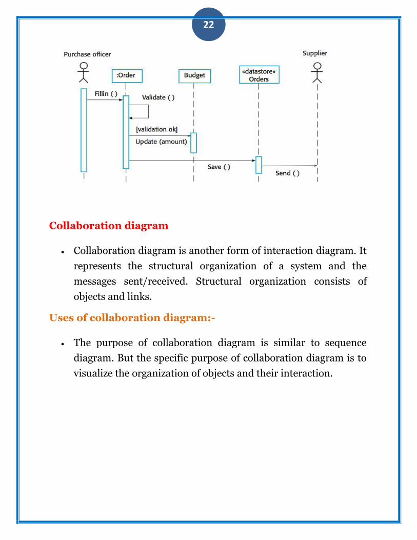
Collaboration diagram
Collaboration diagram is another form of interaction diagram. It
represents the structural organization of a system and the
messages sent/received. Structural organization consists of
objects and links.
Uses of collaboration diagram:-
The purpose of collaboration diagram is similar to sequence
diagram. But the specific purpose of collaboration diagram is to
visualize the organization of objects and their interaction.

23
Design Concepts
Abstraction—data, procedure
Architecture—the overall structure of the software
Patterns—conveys the essence‖ of a proven design solution
Separation of concerns—any complex problem can be more easily handled if it is subdivided into pieces
Modularity—compartmentalization of data and function
Hiding—controlled interfaces
Functional independence—single-minded function and low coupling
Refinement—elaboration of detail for all abstractions
Aspects—a mechanism for understanding how global requirements affect design
Design Classes—provide design detail that will enable analysis classes to be implemented

24
3)Construction tools
These tools are used to produce and translate program representation
(for instance, source code) which is sufficiently detailed and explicit to
enable machine execution.
ByteMyCode ByteMyCode is a project that
allows sharing, searching,
annotating and revising source
code fragments between the user
community and it sends these
fragments between users when
they have no means to do so.
Check Style CheckStyle is a static code
analysis tool used in software development to check if a Java source code complies with coding rules.
Collab VS This is a Microsoft research tool
which introduces collaborative
aspects into Visual Studio to
support distributed software
development.
COPPER COPPER (COllaborative Pair Programing EditoR) is a system to support distributed pair programming that includes features such as viewing which piece of code a partner is editing or independently scrolling.

25
Google Code This web tool is mainly a central code repository which includes developer resources such as APIs or coding toolkits.
ICI This tool is a collaborative IDE
integrated inside the CVE virtual
environment. Moomba Moomba is a collaborative tool
that allows collegues to view and modify different parts of shared files simultaneously.
Saros Saros is an Eclipse plugin for collaborative text editing that can support arbitrarily many participants at once. All members of a session have an identical copy of an Eclipse project and Saros keeps these copies in sync as editing progresses.
Share Share is a tool designed to support and encourage loosely bound cooperation between individuals within communities of practice through the sharing of code.
Syde Syde is a tool infrastructure to reestablish team awareness by sharing change and conflict information across developer's workspaces.
4. Construction languages

26
Construction languages include all forms of communication by which a human can specify an executable problem solution to a problem. Construction languages and their implementations (for example, compilers) can affect software quality attributes of performance, reliability, portability, and so forth.
They can be serious contributors to security vulnerabilities. The simplest type of construction language is a configuration language, in which software engineers choose from a limited set of predefined options to create new or custom software installations.
The text-based configuration files used in both the Windows and Unix operating systems are examples of this, and the menu-style selection lists of some program generators constitute another example of a configuration language
Scripting languages are commonly used kinds of application programming languages. In some scripting languages, scripts are called batch files or macros.Programming languages are the most flexible type of construction languages.
They also contain the least amount of information about specific application areas and development processes therefore, they require the most training and skill to use effectively.
The choice of programming language can have a large effect on the likelihood of vulnerabilities being introduced during coding—for example, uncritical usage of C and C++ are questionable choices from a security viewpoint. There are three general kinds of notation used for programming languages, namely
linguistic (e.g., C/C++, Java) formal (e.g., Event-B) visual (e.g., MatLab).
LINGUISTIC (E.G., C/C++, JAVA):-
Linguistic notations are distinguished in particular by the use of textual strings to represent complex software constructions. The combination of textual strings into patterns may have a sentence-like

27
syntax. Properly used, each such string should have a strong semantic connotation providing an immediate intuitive understanding of what will happen when the software construction is executed.
FORMAL (e.g., Event-B)
Formal notations rely less on intuitive, everyday meanings of words and text strings and more on definitions backed up by precise, unambiguous, and formal (or mathematical) definitions. Formal construction notations and formal methods are at the semantic base of most forms of system programming notations, where accuracy, time behavior, and testability are more important than ease of mapping into natural language. Formal constructions also use precisely defined ways of combining symbols that avoid the ambiguity of many natural language constructions.
VISUAL (E.G., MATLAB).
Visual notations rely much less on the textual notations of linguistic and formal construction and instead rely on direct visual interpretation and placement of visual entities that represent the underlying software. Visual construction tends to be somewhat limited by the difficulty of making “complex” statements using only the arrangement of icons on a display. However, these icons can be powerful tools in cases where the primary programming task is simply to build and "adjust" a visual interface to a program, the detailed behavior of which as an underlying definition
5. Construction Testing
They are two types of the testing they are

28
Unit testing
Integration testing
Unit testing:-
What is Unit Testing
Unit testing, a testing technique using which individual modules are
tested to determine if there are any issues by the developer himself. It
is concerned with functional correctness of the standalone modules
The main aim is to isolate each unit of the system to identify, analyze
and fix the defects.
Unit Testing - Advantages:
Reduces Defects in the Newly developed features or reduces
bugs when changing the existing functionality.
Reduces Cost of Testing as defects are captured in very early
phase.
Improves design and allows better refactoring of code.
Unit Tests, when integrated with build gives the quality of the
build as well.
Unit Testing LifeCyle:

29
Where we can use Unit Testing Techniques:
Black Box Testing - Using which the user interface, input and
output are tested.
White Box Testing - used to test each one of those functions
behaviour is tested.
Gray Box Testing - Used to execute tests, risks and
assessment methods.
Uses of unit testing:-
It is used for the error handling paths It s used for the independent paths It is used for the boundary conditions It is used for the local data structures It is used for the interface of the given project
Integration testing

30
What is Integration Testing?
Upon completion of unit testing, the units or modules are to be
integrated which gives raise to integration testing. The purpose of
integration testing is to verify the functional, performance, and
reliability between the modules that are integrated.
1) the “big bang” approach
2) an incremental construction strategy
Where we can use integration testing:-
Big-Bang Integration
Big Bang Integration Testing is an integration testing strategy wherein all units are linked at once, resulting in a complete system. When this type of testing strategy is adopted, it is difficult to isolate any errors found, because attention is not paid to verifying the interfaces across individual units.
31
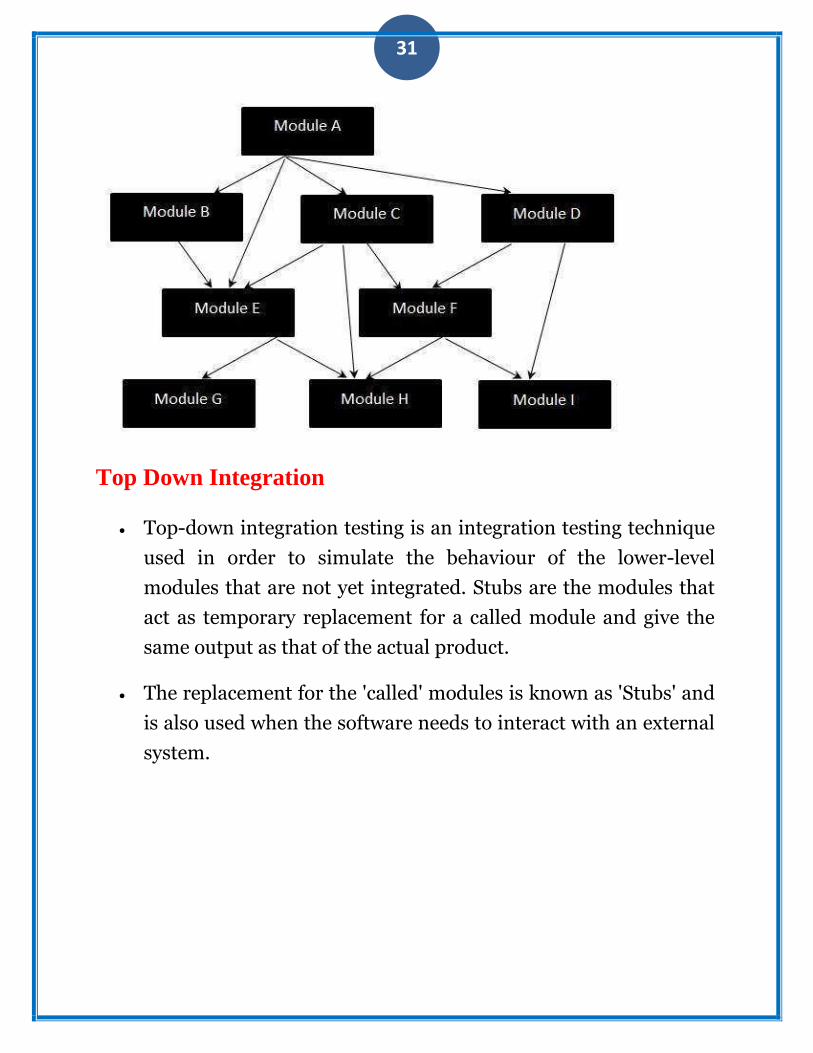
Top Down Integration
Top-down integration testing is an integration testing technique
used in order to simulate the behaviour of the lower-level
modules that are not yet integrated. Stubs are the modules that
act as temporary replacement for a called module and give the
same output as that of the actual product.
The replacement for the 'called' modules is known as 'Stubs' and
is also used when the software needs to interact with an external
system.

32
Bottom Up Integration
Each component at lower hierarchy is tested individually and then the components that rely upon these components are tested
Though Top level components are the most important, yet tested last using this strategy. In Bottom-up approach, the Components 2 and 3 are replaced by drivers while testing components 4,5,6,7. They are generally more complex than stubs.
Hybrid Integration
the communication between each one of those modules are tested.
There are two popular approaches for Integration testing which is
Top down Integration Testing and Bottom up Integration Testing.In

33
Hybrid Integration Testing, we exploit the advantages of Top-down
and Bottom-up approaches. As the name suggests, we make use of
both the Integration techniques.
Uses of integration testing:-
Integration risk is minimized.
The quality of the end product is improved
Error diagnosis and correction are simplified
Progress is easier to assess