Embed Size (px)
Citation preview
TABLE OF CONTENTS
Acknowledgement i
Abstract ii
1. OVERVIEW
1.1 About Simplex Infrastructures Ltd. 1
1.2 About Silveroak Estate 4
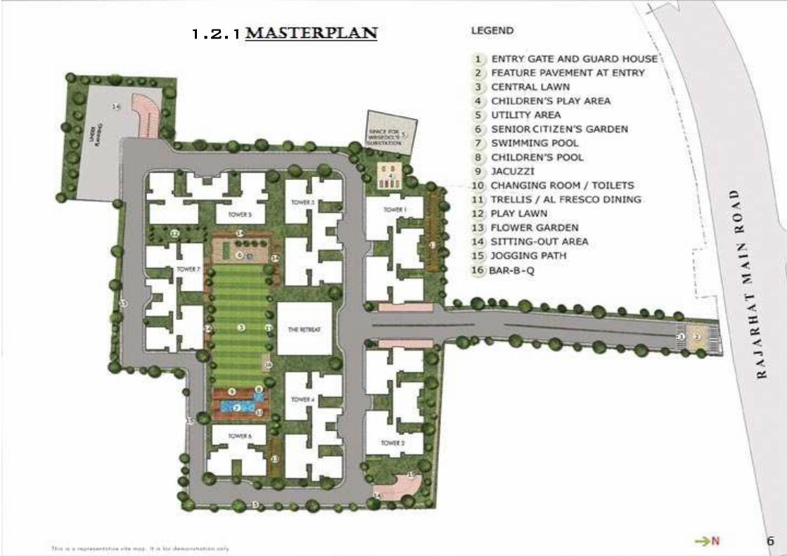
1.2.1 Master Plan 6
1.2.2 Proposed Logistics 7
1.2.3 Floor Plan of Towers 8
2. RESIDENTIAL BUILDING CONSTRUCTION
2.1 Introduction 10
2.2 Safety Practices 12
2.2.1 Fire Safety 14
2.2.2 Electrical Safety 16
2.2.3 Organization Chart 18
2.2.4 Personal Protective Equipment (PPE) 19
2.3 Construction Equipments 21
2.4 Construction Materials 25
2.5 Planning 35
2.6 Surveying 37
2.7 Quality Control 41
2.8 Reinforcement 51
2.9 Brickwork, Plastering and Finishing 53
2.10 Foundation: Pile Work 58

2.11 Shuttering and Scaffolding 61
2.12 General Notes 65
2.13 Store Management 69
2.14 Conclusion 72
References 73
i
ACKNOWLEDGEMENT:
The success and the final outcome of this training required a lot of guidance and assistance
from a lot of people and I am extremely fortunate to get this all along the due course of my
training. First of all I feel greatly indebted to Mr. S.K. Maity (Technical Director, Simplex
Infrastructures Ltd.) and Mr. Susanta Bhattacharjee (Project Manager, Silveroak Estate
Project), who provided us the golden opportunity to undergo training in this valuable project
of Simplex Infrastructures Ltd. A special thanks to Mr. Subhajeet Ganguly, for his constant
support, cooperation, and motivation provided to me during the training.
I am also deeply grateful to Mr. Debanjan Basu, Mr. Puspajit Sarkar, Mr. Milan Kumar Basu,
Mr. Janardan Mundhra, Mr. Pradip Maity, Mr. Pratap Kumar Das, and Mr. Pinaki
Choudhury, to name a few, from Simplex Infrastructures Ltd. for the supervision and support
provided by them during the training.
I would like to thank all my fellow trainees, without whose company this project would never
have ended in a fruitful way.
Finally, I would like to thank the entire team of both Simplex Infrastructures Ltd. and
Salarpuria Group related to the Silveroak Estate project for making this project a success.
ii
ABSTRACT
This report is an account of a month long industrial training received at Simplex
Infrastructures Ltd.’s residential project in collaboration with Salarpuria group, the Silveroak
Estate at Rajarhat. During the course of the training, a lot of exposure was received on the
practical works done in the construction site. The various departments of the site, which
worked together as one unit, which included the departments of Safety, Planning, Surveying,
Construction, Quality Control, Mechanical, Electrical and Store, was visited and thorough
knowledge was received about the method of functioning of these units and the technical
details. All the insights received during the industrial training are hereby accounted in the
report.

1. OVERVIEW
1
1.1 ABOUT SIMPLEX INFRASTRUCTURES LTD.
Simplex Infrastructures Limited, an ISO 9001:2008 certified company is one of the largest
infrastructure solution providers in India since 1924. As the first name in ground engineering,
Simplex has played a part in the construction of many historical buildings and structures of India.
The company was incorporated on 19th December 1924 under the control of H.P. Lancaster of the
United Kingdom, and later the company was taken over by the Kolkata-based Mundra family after
the Indian independence. SIL provides the services in the areas of Ground Engineering, Power,
Industrial, Urban Utilities, Building & Houses, Roads, Railways, Bridges and Marine. The Company
has diversified geographical presence across India and overseas also. The year of inception itself,
SIL had introduced cast-in-situ driven piles in Asia, at Kolkata. Then, the company had started
construction of major Steel Plants during the year 1935 and had built King George Docs, Mumbai in
1940. SIL had entered into the civil & structural construction of Industrial Projects during the year
1952 and further forayed into Housing and Building segment in the period of 1955. In 1958, the
company was designed and constructed the first ever RCC framed structure in Asia; the 17- storied
National Tower at Kolkata. During the year 1960, SIL made a foray into the civil & structural
construction of Thermal Power Plants and has been associated with over 80% of Thermal Power
Plants across India ranging from 10 MW to 1000 MW Turbo Generators. Urban Utilities segment
was added to the company's activities in the year 1965, by the way of water treatment plant at
Howrah for HIT. After three years, in 1968, took up the Marine Construction and now associated
with all the major ports in India. The overseas presence was made by the company in the year 1982
itself, opened the first overseas office for the execution of projects in Sri Lanka and also in the same
year of 1982, SIL made its foray into Roads, Bridges and Railways segment. Started piling jobs in
UAE, Abu Dhabi in the year 1990 and in 1991 SIL developed indigenous technique for jointed pre-
cast concrete piles upto 150 meters depth at Ernakulam. The Company successfully built an
international class hotel at Tashkent, Uzbekistan during the year 1992 and SIL went to public in the
year of 1993. During the year 1998, the company entered into an innovative LIG/MIG sourcing on
turnkey basis. Also SIL made its foray into turnkey coding towards construction in the identical
period of 1998. The Company had started the event of civil & structural construction of Nuclear
Power Plants since the year 2002. During 2003, SIL undertakes the civil & structural construction of
Hydro Power Plants and also established presence in the Middle East Countries. An ISO 9001:2000

2
certification was handed over to the company in 2004 and in 2005, the company had changed its
name from Simplex Concrete Piles (India) Limited to Simplex Infrastructures Limited for a more
holistic representation of the company. In the same year, SIL secured contract for an irrigation canal
in Hyderabad. During the year 2006, the company secured contract for doubling of railway tracks on
South-Central Railway line in Guntakal - Raichur railway, AP. Also obtained several piling and civil
contracts in Middle East Countries. In 2007, the company bagged Rs 4.52 billion order in industrial
structures segment, Rs 1.78 billion in urban utilities, Rs 1.12 billion in piling and Rs 600 million in
marine structures segment. Also, SIL secured a contract from DP World for Rs 5,800 million for
ICTT Kochi Phase 1A in November 2007. The Rig and Real Estate Development business was
added to the company's business in the year 2008. SIL bagged new orders worth Rs 6.53 billion from
different sectors including an order from Ritz Carlton Hotel, Bangalore, for the construction of a
cement plant, sewerage system and thermal power plant in March 2008.
• Ranked among Top 5 India's Fastest Growing Large Companies by Business Today, June 15, 2008.
• Titled as "Overall Best Managed Company" by Asia Money in 2005.
• Twice nominated as "Most Admired Infrastructure Company" by NDTV Profit in 2006 & 2008.
• Over 7700 employees as on March 31, 2010 with more than 80% being technically qualified.
• The company enjoys an uninterrupted profit track record since inception.
• The Company reported a turnover of Rs. 45524 million and profit after tax of Rs. 1225 million for
the year 2009 - 2010.
• The Company's shares are listed on the National Stock Exchange, Bombay Stock Exchange and
Calcutta Stock Exchange enjoying a market capitalization of Rs. 25000 million (as on 31st July
2010).
3
CORPORATE POLICIES
H.S.E. POLICY QUALITY POLICY
ISO 9001:2008
4
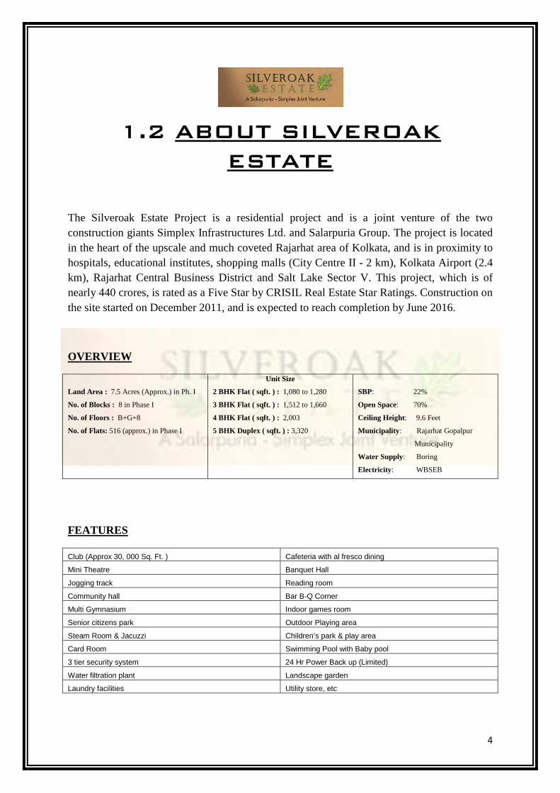
1.2 ABOUT SILVEROAK
ESTATE
The Silveroak Estate Project is a residential project and is a joint venture of the two construction giants Simplex Infrastructures Ltd. and Salarpuria Group. The project is located in the heart of the upscale and much coveted Rajarhat area of Kolkata, and is in proximity to hospitals, educational institutes, shopping malls (City Centre II - 2 km), Kolkata Airport (2.4 km), Rajarhat Central Business District and Salt Lake Sector V. This project, which is of nearly 440 crores, is rated as a Five Star by CRISIL Real Estate Star Ratings. Construction on the site started on December 2011, and is expected to reach completion by June 2016.
OVERVIEW
Land Area : 7.5 Acres (Approx.) in Ph. I
No. of Blocks : 8 in Phase I
No. of Floors : B+G+8
No. of Flats: 516 (approx.) in Phase I
Unit Size
2 BHK Flat ( sqft. ) : 1,080 to 1,280
3 BHK Flat ( sqft. ) : 1,512 to 1,660
4 BHK Flat ( sqft. ) : 2,003
5 BHK Duplex ( sqft. ) : 3,320
SBP: 22%
Open Space: 70%
Ceiling Height: 9.6 Feet
Municipality: Rajarhat Gopalpur
Municipality
Water Supply: Boring
Electricity: WBSEB
FEATURES
Club (Approx 30, 000 Sq. Ft. ) Cafeteria with al fresco dining
Mini Theatre Banquet Hall
Jogging track Reading room
Community hall Bar B-Q Corner
Multi Gymnasium Indoor games room
Senior citizens park Outdoor Playing area
Steam Room & Jacuzzi Children’s park & play area
Card Room Swimming Pool with Baby pool
3 tier security system 24 Hr Power Back up (Limited)
Water filtration plant Landscape garden
Laundry facilities Utility store, etc
5
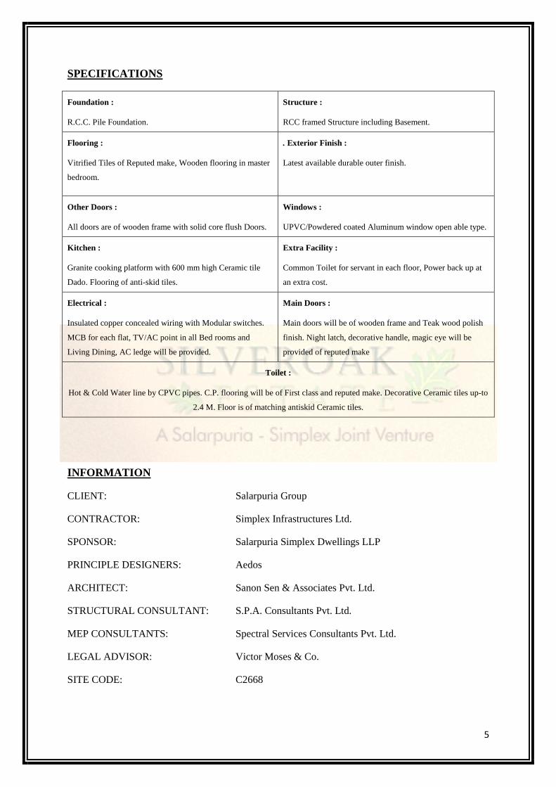
SPECIFICATIONS
Foundation :
R.C.C. Pile Foundation.
Structure :
RCC framed Structure including Basement.
Flooring :
Vitrified Tiles of Reputed make, Wooden flooring in master
bedroom.
. Exterior Finish :
Latest available durable outer finish.
Other Doors :
All doors are of wooden frame with solid core flush Doors.
Windows :
UPVC/Powdered coated Aluminum window open able type.
Kitchen :
Granite cooking platform with 600 mm high Ceramic tile
Dado. Flooring of anti-skid tiles.
Extra Facility :
Common Toilet for servant in each floor, Power back up at
an extra cost.
Electrical :
Insulated copper concealed wiring with Modular switches.
MCB for each flat, TV/AC point in all Bed rooms and
Living Dining, AC ledge will be provided.
Main Doors :
Main doors will be of wooden frame and Teak wood polish
finish. Night latch, decorative handle, magic eye will be
provided of reputed make
Toilet :
Hot & Cold Water line by CPVC pipes. C.P. flooring will be of First class and reputed make. Decorative Ceramic tiles up-to
2.4 M. Floor is of matching antiskid Ceramic tiles.
INFORMATION
CLIENT: Salarpuria Group
CONTRACTOR: Simplex Infrastructures Ltd.
SPONSOR: Salarpuria Simplex Dwellings LLP
PRINCIPLE DESIGNERS: Aedos
ARCHITECT: Sanon Sen & Associates Pvt. Ltd.
STRUCTURAL CONSULTANT: S.P.A. Consultants Pvt. Ltd.
MEP CONSULTANTS: Spectral Services Consultants Pvt. Ltd.
LEGAL ADVISOR: Victor Moses & Co.
SITE CODE: C2668
1.2.1
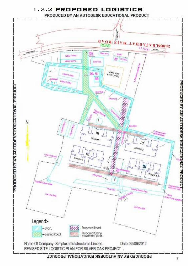
1.2.2
8
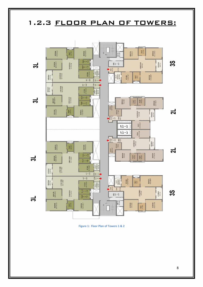
1.2.3 FLOOR PLAN OF TOWERS:
Figure 1: Floor Plan of Towers 1 & 2
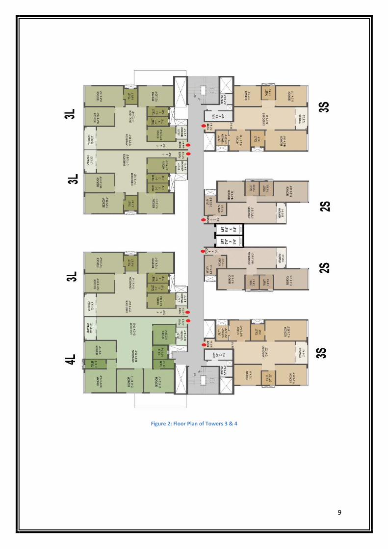
9
Figure 2: Floor Plan of Towers 3 & 4
2. RESIDENTIAL BUILDING
CONSTRUCTION
10
2.1 INTRODUCTION:
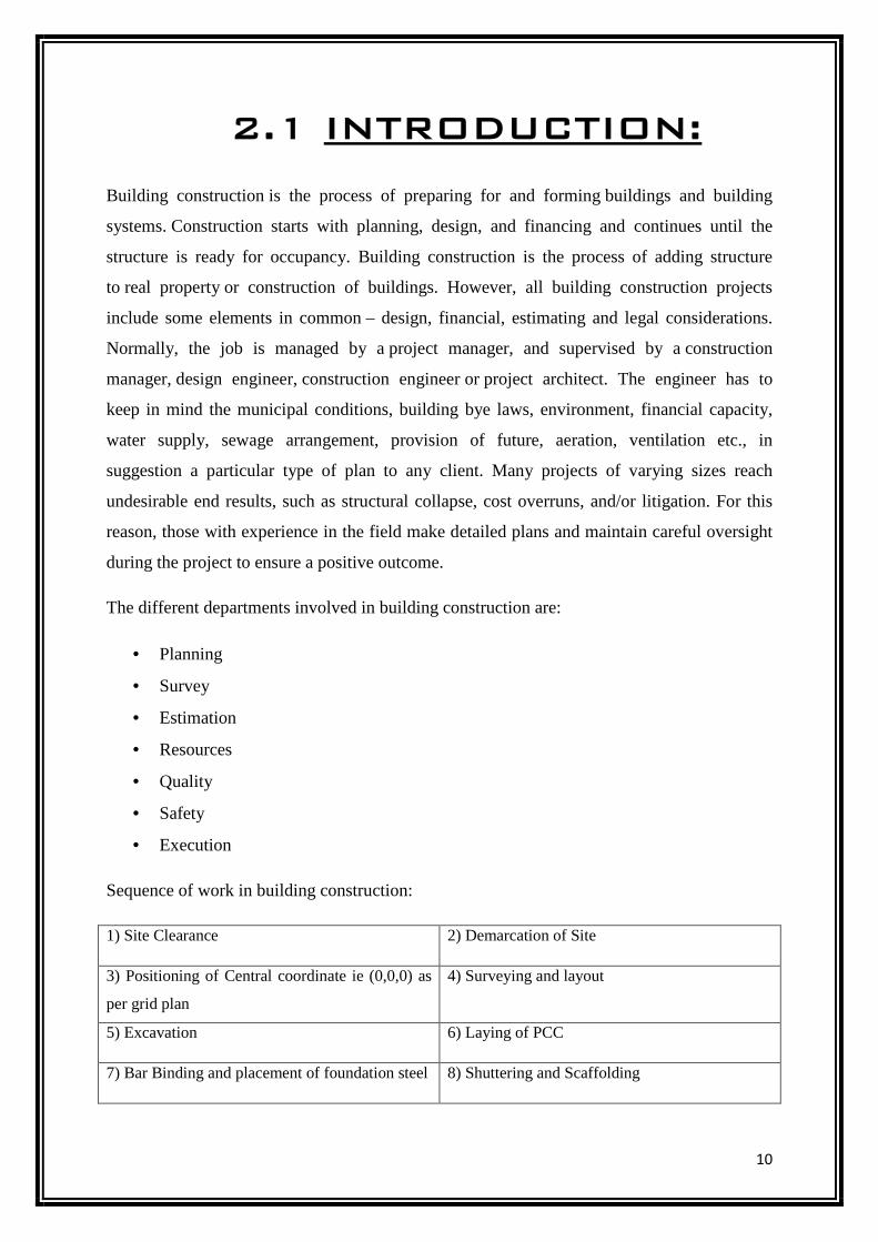
Building construction is the process of preparing for and forming buildings and building
systems. Construction starts with planning, design, and financing and continues until the
structure is ready for occupancy. Building construction is the process of adding structure
to real property or construction of buildings. However, all building construction projects
include some elements in common – design, financial, estimating and legal considerations.
Normally, the job is managed by a project manager, and supervised by a construction
manager, design engineer, construction engineer or project architect. The engineer has to
keep in mind the municipal conditions, building bye laws, environment, financial capacity,
water supply, sewage arrangement, provision of future, aeration, ventilation etc., in
suggestion a particular type of plan to any client. Many projects of varying sizes reach
undesirable end results, such as structural collapse, cost overruns, and/or litigation. For this
reason, those with experience in the field make detailed plans and maintain careful oversight
during the project to ensure a positive outcome.
The different departments involved in building construction are:
• Planning
• Survey
• Estimation
• Resources
• Quality
• Safety
• Execution
Sequence of work in building construction:
1) Site Clearance 2) Demarcation of Site
3) Positioning of Central coordinate ie (0,0,0) as
per grid plan
4) Surveying and layout
5) Excavation 6) Laying of PCC
7) Bar Binding and placement of foundation steel 8) Shuttering and Scaffolding
11
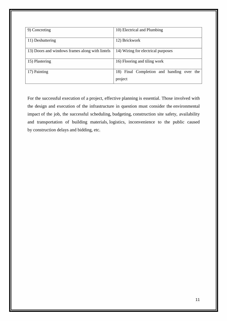
9) Concreting 10) Electrical and Plumbing
11) Deshuttering 12) Brickwork
13) Doors and windows frames along with lintels 14) Wiring for electrical purposes
15) Plastering 16) Flooring and tiling work
17) Painting 18) Final Completion and handing over the
project
For the successful execution of a project, effective planning is essential. Those involved with
the design and execution of the infrastructure in question must consider the environmental
impact of the job, the successful scheduling, budgeting, construction site safety, availability
and transportation of building materials, logistics, inconvenience to the public caused
by construction delays and bidding, etc.
12
2.2 SAFETY PRACTICES
Safety practices are adopted at workplace to protect human life and property of the company in a safe and secure manner. Workplace safety is about preventing injury and illness to employees and volunteers in the workplace. Therefore, it's about protecting the company's most valuable asset: its workers. By protecting the employees’ well-being, the company reduces the amount of money paid out in health insurance benefits, workers' compensation benefits and the cost of wages for temporary help. Also factor in saving the cost of lost-work hours (days away from work or restricted hours or job transfer), time spent in orienting temporary help, and the programs and services that may suffer due to fewer service providers, stress on those providers who are picking up the absent workers' share or, worse case, having to suspend or shut down a program due to lack or providers.
SAFETY AT CONSTRUCTION SITE
The leading safety hazards on site are falls from height, motor vehicle crashes, excavation accidents, electrocution, machines, and being struck by falling objects. Some of the main health hazards on site are asbestos, solvents, noise, and manual handling activities.
Falls from heights are the leading cause of injury in the construction industry. Fall protection is needed in areas and activities that include, but are not limited to: ramps, runways, and other walkways; excavations; hoist areas; holes; formwork; leading edge work; unprotected sides and edges; overhand bricklaying and related work; roofing; precast erection; wall openings; residential construction; and other walking/working surfaces. The height limit where fall protection is required is not defined. It used to be 2 metres in the previous issue of Work at Height Regulations. It is any height that may result in injury from a fall. Protection is also required when the employee is at risk to falling onto dangerous equipment. Fall protection can be provided by guardrail systems, safety net systems, personal fall arrest systems, positioning device systems, and warning line systems. All employees should be trained to understand the proper way to use these systems and to identify hazards. The employee or employer will be responsible for providing fall protection systems and to ensure the use of these systems. Employees on construction sites also need to be aware of dangers on the ground. The hazards of cables running across roadways were often seen, until cable ramp equipment was invented to protect hoses and other equipment which had to be laid out.
The safety guidelines as briefed by the Safety Department personals should be followed thoroughly. Toolbox meetings should be conducted and the safety details as laid down by the Safety personals should be followed by the Engineer or Supervisor, Lack of safety causes accidents, which further causes:
• Loss of life at work • Loss of company as compensation has to be paid to the injured party • Damage to property • Damages the reputation of the company
• Causes panic within the workers
13
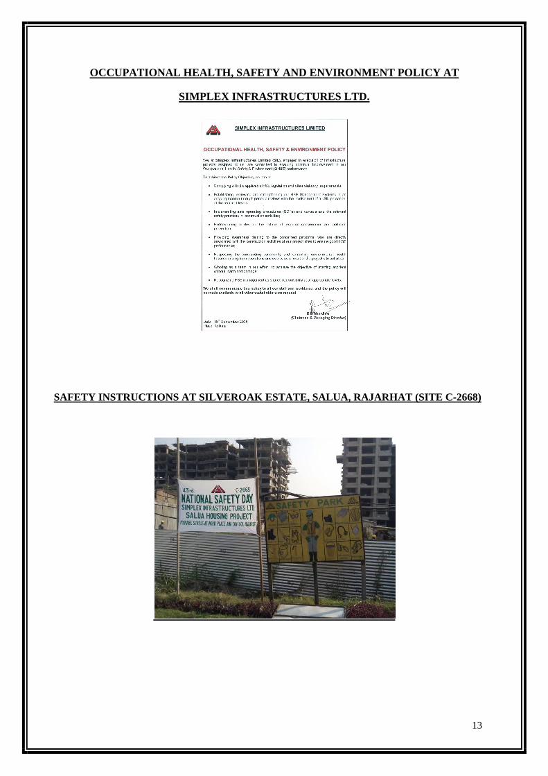
OCCUPATIONAL HEALTH, SAFETY AND ENVIRONMENT POLICY AT
SIMPLEX INFRASTRUCTURES LTD.
SAFETY INSTRUCTIONS AT SILVEROAK ESTATE, SALUA, RAJARHAT (SITE C-2668)
14
2.2.1 FIRE SAFETY Each year there are hundreds of fires on construction sites, potentially putting the lives of workers and members of the public at risk. Fire safety in construction is about preventing fires from starting and ensuring people's safety if they do. The various steps to be taken for ensuring safety against fire at the site are:
• Risk assessment:
1. Identify hazards: Consider how a fire could start and what could burn;
2. People at risk: Employees, contractors, visitors and anyone who is vulnerable, e.g. disabled;
3. Evaluation and action: Consider the hazards and people identified in 1 and 2 and act to remove
and reduce risk to protect people and premises;
4. Record, plan and train: Keep a record of the risks and action taken. Make a clear plan for fire
safety and ensure that people understand what they need to do in the event of a fire; and
5. Review: Your assessment regularly and check it takes account of any changes on site.
• Means of escape:
1. Routes: Your risk assessment should determine the escape routes required, which must be kept
available and unobstructed;
2. Alternatives: Well-separated alternative ways to ground level should be provided where possible;
3. Protection: routes can be protected by installing permanent fire separation and fire doors as soon as
possible;
4. Assembly: Make sure escape routes give access to a safe place where people can assemble and be
accounted for. On a small site the pavement outside may be adequate; and
5. Signs: Will be needed if people are not familiar with the escape routes. Lighting should be
provided for enclosed escape routes and emergency lighting may be required.
• Means of giving warning: Set up a system to alert people on site. This may be temporary or permanent mains operated fire alarm (tested regularly), a klaxon, an air horn or a whistle, depending on the size and complexity of the site. The warning needs to be distinctive, audible above other noise and recognizable by everyone. • Means of fighting fire: Fire extinguishers should be located at identified fire points around the site. The extinguishers should be appropriate to the nature of the potential fire.
15
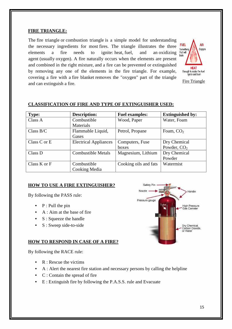
FIRE TRIANGLE:
CLASSIFICATION OF FIRE AND TYPE OF EXTINGUISHER USED:
Type: Description: Fuel examples: Extinguished by: Class A Combustible
Materials Wood, Paper Water, Foam
Class B/C Flammable Liquid, Gases
Petrol, Propane Foam, CO2
Class C or E Electrical Appliances Computers, Fuse boxes
Dry Chemical Powder, CO2
Class D Combustible Metals
Magnesium, Lithium Dry Chemical Powder
Class K or F Combustible Cooking Media
Cooking oils and fats Watermist
HOW TO USE A FIRE EXTINGUISHER?
By following the PASS rule:
• P : Pull the pin • A : Aim at the base of fire
• S : Squeeze the handle • S : Sweep side-to-side
HOW TO RESPOND IN CASE OF A FIRE?
By following the RACE rule:
• R : Rescue the victims
• A : Alert the nearest fire station and necessary persons by calling the helpline • C : Contain the spread of fire
• E : Extinguish fire by following the P.A.S.S. rule and Evacuate
Fire Triangle
The fire triangle or combustion triangle is a simple model for understanding the necessary ingredients for most fires. The triangle illustrates the three elements a fire needs to ignite: heat, fuel, and an oxidizing agent (usually oxygen). A fire naturally occurs when the elements are present and combined in the right mixture, and a fire can be prevented or extinguished by removing any one of the elements in the fire triangle. For example, covering a fire with a fire blanket removes the "oxygen" part of the triangle and can extinguish a fire.
16
2.2.2 ELECTRICAL SAFETY
In worksites alone, electricity can be indispensable. It is used to drill holes, transport devices, weld metals, process food and heat chemicals. But with its efficiency comes great danger. Many times electrical hazards have become the cause of injuries and fatalities in the workplace. It’s actually one of the leading causes of accidents in construction sites. Like other serious hazards, electrical shock is not inevitable. What sets it apart, though, from other workplace perils is that it is often the beginning of a series of accidents. Its final injury may be a burn, cut, broken bone or a fall. The most common among these is burn and it may come in the form of electrical burns, arc burns, and thermal contact burns. The first step towards electrical safety is controlling or eliminating factors in your workplace that pose electrical hazards. Ground fault electrical shock happens to be the most common electrical hazard in construction sites. At the construction site of Silveroak Estate, the following electrical safety equipments are used:
• Miniature Circuit Breakers (MCBs): It is an automatically operated electrical switch designed to protect an electrical circuit from damage caused by overload or short circuit. Its basic function is to detect a fault condition and interrupt current flow. A circuit breaker can be reset (either manually or automatically) to resume normal operation.
• Earth Leakage Circuit Breakers (ELCBs): It is a safety device used in electrical installations with high earth impedance to prevent shock. It detects small stray voltages on the metal enclosures of electrical equipment, and interrupts the circuit if a dangerous voltage is detected.
• Residential Current Breaking Overload (RCBO): It is installed at a place where there is a need to prevent overload on a particular circuit at the same time as preventing anyone getting a shock that has the potential to kill them.
• Residual Current Circuit Breakers (RCCBs): It is an electrical wiring device that disconnects a circuit whenever it detects that the electric current is not balanced between the energized conductor and the return neutral conductor. Such an imbalance may indicate current leakage through the body of a person who is grounded and accidentally touching the energized part of the circuit, causing lethal shocks. RCCBs are designed to disconnect quickly enough to prevent injury caused by such shocks. The RCCBs at the site were rated I/P 63 A and O/P 30 mA.
Workers play a big part in eliminating and controlling electrical hazards at workplace. It should be made sure that they are given copies of safety meetings and emergency plans for electrical hazards. High voltages, grounding, electric current, arcing and the lack of guarding are among the inherent hazards of electricity which the “qualified” persons should be familiar with. Electrical protective equipment should always be used every time they work where there are potential electrical hazards. Specialized PPE may consist of rubber insulating gloves, sleeves, hoods, matting, line hose, blankets, and industrial protective helmets. Electrical extension cords are numerous on construction sites and
17
become damaged because of the rough conditions in which they are used. Inspect to ensure:
• All extension cords are three-wire cords; • The ground pin is on a male plug;
• There is no unbroken insulation on the cord; • End appliances (plug and receptacle) are gripped to insulation; • All wires are continuous and unbroken;
• All cords are protected from damage, likely to occur when passing through a door or window;
• Metal boxes with knockouts are not used on extension cords; • Plugs are dead-front (molded or screwed in place); • Romex (non-metallic sheathed cable) is not used as flexible cord;
• Cords are not stapled or hung from nails; • Bushing is passing through holes in covers or outlet boxes.
Also, check these items:
• Temporary lights are not supported by cords; • Bulb guards are used on temporary lights; • Electrical power tools with non-dead man switches have a magnetic restart (when
injury to the operator might result if motors were to restart following power failures); • Provisions are made to prevent machines from automatically restarting upon
restoration of power in place;
• Outlets do not have reversed polarity; • Power tools are double insulated or have a ground pin;
Guard all of exposed electric of more than 50 volts so no one can come in contact (receptacles, light-bulb sockets, bare wires, load center, switches). Guard by:
• Using approved enclosures; • Locating them in a room, vault or similar enclosure accessible only to qualified
persons;
• Arranging suitable permanent, substantial partitions or screens so only qualified persons have access to the space within reach of live parts;
• Locating them on a suitable balcony or platform that is elevated and arranged to exclude unqualified persons;
• Elevating them 8 feet or more above the working surface.
It's important to take the time prior to beginning work at construction sites each day. The fluid nature of the activities, along with the changing environment and high potential for damage can let these items become a hazard quickly.
18
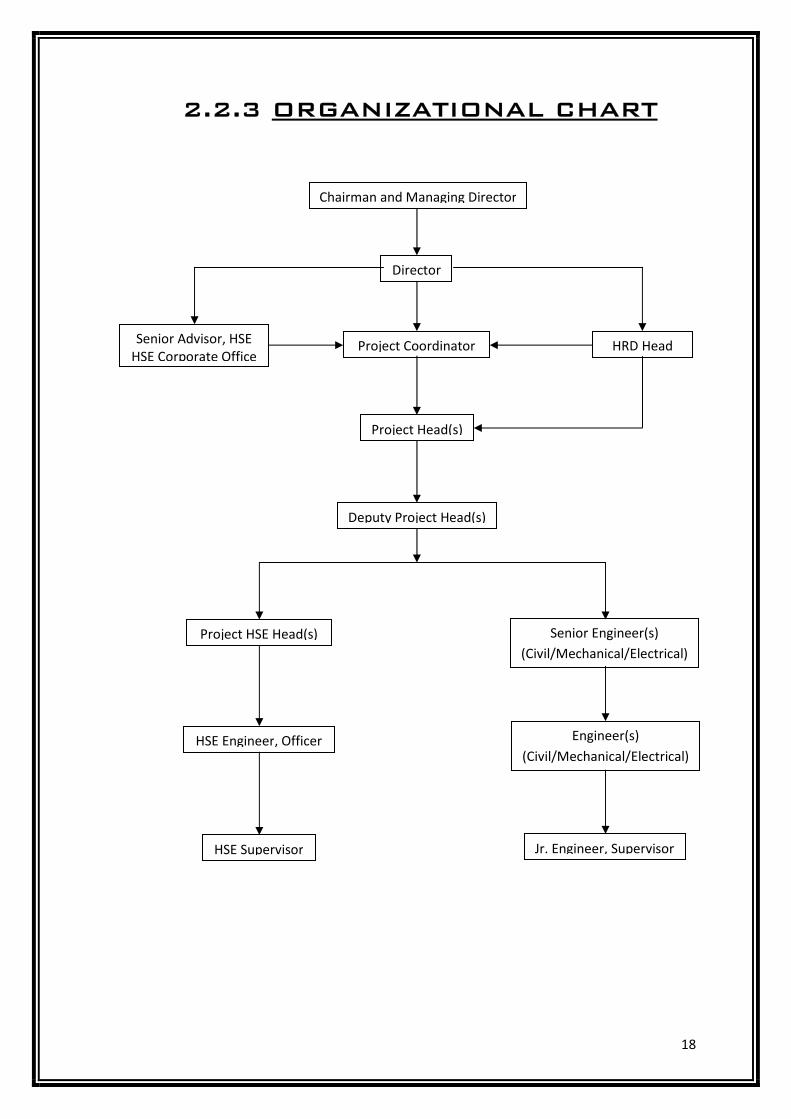
2.2.3 ORGANIZATIONAL CHART
Chairman and Managing Director
Director
Project Coordinator Senior Advisor, HSE
HSE Corporate Office HRD Head
Project Head(s)
Deputy Project Head(s)
Project HSE Head(s) Senior Engineer(s)
(Civil/Mechanical/Electrical)
Engineer(s)
(Civil/Mechanical/Electrical) HSE Engineer, Officer
HSE Supervisor Jr. Engineer, Supervisor
19
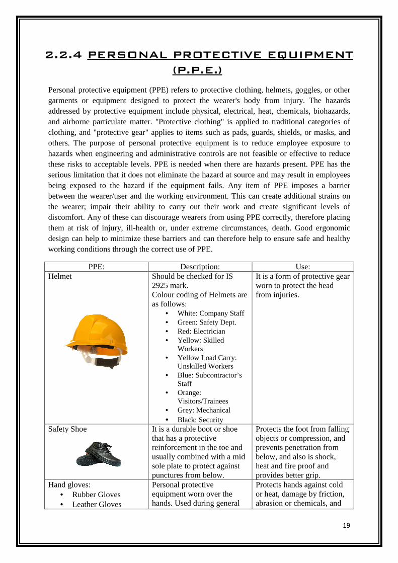
2.2.4 PERSONAL PROTECTIVE EQUIPMENT
(P.P.E.)
Personal protective equipment (PPE) refers to protective clothing, helmets, goggles, or other garments or equipment designed to protect the wearer's body from injury. The hazards addressed by protective equipment include physical, electrical, heat, chemicals, biohazards, and airborne particulate matter. "Protective clothing" is applied to traditional categories of clothing, and "protective gear" applies to items such as pads, guards, shields, or masks, and others. The purpose of personal protective equipment is to reduce employee exposure to hazards when engineering and administrative controls are not feasible or effective to reduce these risks to acceptable levels. PPE is needed when there are hazards present. PPE has the serious limitation that it does not eliminate the hazard at source and may result in employees being exposed to the hazard if the equipment fails. Any item of PPE imposes a barrier between the wearer/user and the working environment. This can create additional strains on the wearer; impair their ability to carry out their work and create significant levels of discomfort. Any of these can discourage wearers from using PPE correctly, therefore placing them at risk of injury, ill-health or, under extreme circumstances, death. Good ergonomic design can help to minimize these barriers and can therefore help to ensure safe and healthy working conditions through the correct use of PPE.
PPE: Description: Use: Helmet Should be checked for IS
2925 mark. Colour coding of Helmets are as follows:
• White: Company Staff • Green: Safety Dept. • Red: Electrician • Yellow: Skilled
Workers • Yellow Load Carry:
Unskilled Workers • Blue: Subcontractor’s
Staff • Orange:
Visitors/Trainees • Grey: Mechanical • Black: Security
It is a form of protective gear worn to protect the head from injuries.
Safety Shoe It is a durable boot or shoe that has a protective reinforcement in the toe and usually combined with a mid sole plate to protect against punctures from below.
Protects the foot from falling objects or compression, and prevents penetration from below, and also is shock, heat and fire proof and provides better grip.
Hand gloves: • Rubber Gloves • Leather Gloves
Personal protective equipment worn over the hands. Used during general
Protects hands against cold or heat, damage by friction, abrasion or chemicals, and
20
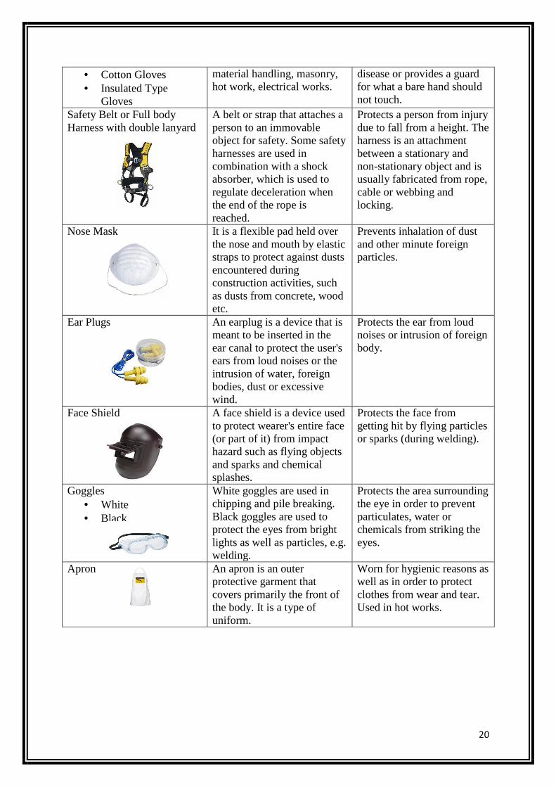
• Cotton Gloves • Insulated Type
Gloves
material handling, masonry, hot work, electrical works.
disease or provides a guard for what a bare hand should not touch.
Safety Belt or Full body Harness with double lanyard
A belt or strap that attaches a person to an immovable object for safety. Some safety harnesses are used in combination with a shock absorber, which is used to regulate deceleration when the end of the rope is reached.
Protects a person from injury due to fall from a height. The harness is an attachment between a stationary and non-stationary object and is usually fabricated from rope, cable or webbing and locking.
Nose Mask It is a flexible pad held over the nose and mouth by elastic straps to protect against dusts encountered during construction activities, such as dusts from concrete, wood etc.
Prevents inhalation of dust and other minute foreign particles.
Ear Plugs An earplug is a device that is meant to be inserted in the ear canal to protect the user's ears from loud noises or the intrusion of water, foreign bodies, dust or excessive wind.
Protects the ear from loud noises or intrusion of foreign body.
Face Shield A face shield is a device used to protect wearer's entire face (or part of it) from impact hazard such as flying objects and sparks and chemical splashes.
Protects the face from getting hit by flying particles or sparks (during welding).
Goggles • White • Black
White goggles are used in chipping and pile breaking. Black goggles are used to protect the eyes from bright lights as well as particles, e.g. welding.
Protects the area surrounding the eye in order to prevent particulates, water or chemicals from striking the eyes.
Apron An apron is an outer protective garment that covers primarily the front of the body. It is a type of uniform.
Worn for hygienic reasons as well as in order to protect clothes from wear and tear. Used in hot works.
21
2.3 CONSTRUCTION EQUIPMENTS
Construction equipments can be further classified into:
• Electrical Equipments, and • Mechanical Equipments
Electrical Equipments:
Electrical equipment at construction site includes Vibrators, Welding Machines, Diesel Generators etc.
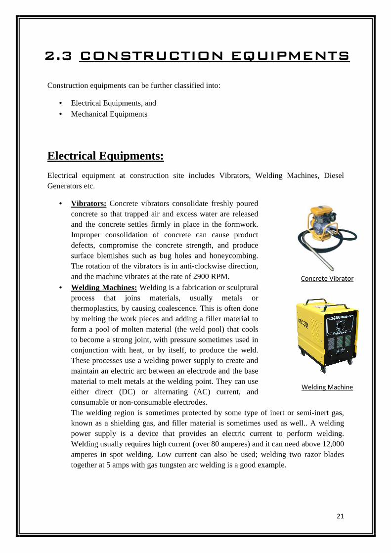
• Vibrators: Concrete vibrators consolidate freshly poured concrete so that trapped air and excess water are released and the concrete settles firmly in place in the formwork. Improper consolidation of concrete can cause product defects, compromise the concrete strength, and produce surface blemishes such as bug holes and honeycombing. The rotation of the vibrators is in anti-clockwise direction, and the machine vibrates at the rate of 2900 RPM.
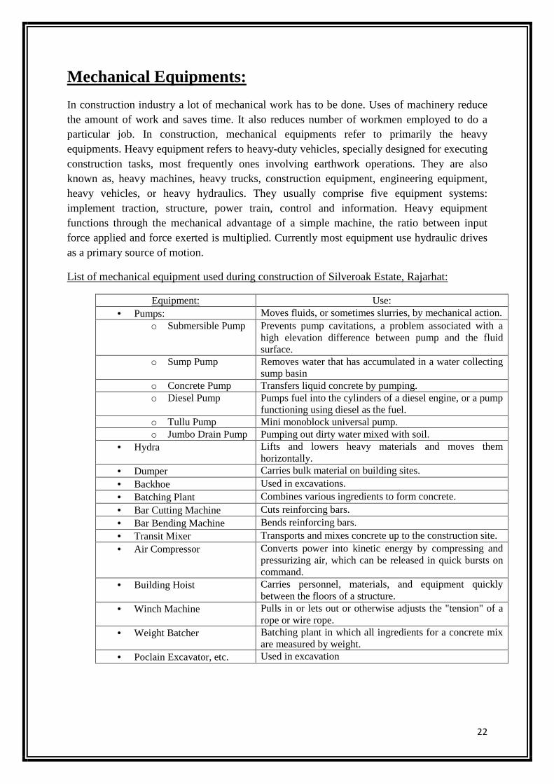
• Welding Machines: Welding is a fabrication or sculptural process that joins materials, usually metals or thermoplastics, by causing coalescence. This is often done by melting the work pieces and adding a filler material to form a pool of molten material (the weld pool) that cools to become a strong joint, with pressure sometimes used in conjunction with heat, or by itself, to produce the weld. These processes use a welding power supply to create and maintain an electric arc between an electrode and the base material to melt metals at the welding point. They can use either direct (DC) or alternating (AC) current, and consumable or non-consumable electrodes. The welding region is sometimes protected by some type of inert or semi-inert gas, known as a shielding gas, and filler material is sometimes used as well.. A welding power supply is a device that provides an electric current to perform welding. Welding usually requires high current (over 80 amperes) and it can need above 12,000 amperes in spot welding. Low current can also be used; welding two razor blades together at 5 amps with gas tungsten arc welding is a good example.
Concrete Vibrator
Welding Machine
22
Mechanical Equipments:
In construction industry a lot of mechanical work has to be done. Uses of machinery reduce the amount of work and saves time. It also reduces number of workmen employed to do a particular job. In construction, mechanical equipments refer to primarily the heavy equipments. Heavy equipment refers to heavy-duty vehicles, specially designed for executing construction tasks, most frequently ones involving earthwork operations. They are also known as, heavy machines, heavy trucks, construction equipment, engineering equipment, heavy vehicles, or heavy hydraulics. They usually comprise five equipment systems: implement traction, structure, power train, control and information. Heavy equipment functions through the mechanical advantage of a simple machine, the ratio between input force applied and force exerted is multiplied. Currently most equipment use hydraulic drives as a primary source of motion.
List of mechanical equipment used during construction of Silveroak Estate, Rajarhat:
Equipment: Use: • Pumps: Moves fluids, or sometimes slurries, by mechanical action.
o Submersible Pump Prevents pump cavitations, a problem associated with a high elevation difference between pump and the fluid surface.
o Sump Pump Removes water that has accumulated in a water collecting sump basin
o Concrete Pump Transfers liquid concrete by pumping. o Diesel Pump Pumps fuel into the cylinders of a diesel engine, or a pump
functioning using diesel as the fuel. o Tullu Pump Mini monoblock universal pump. o Jumbo Drain Pump Pumping out dirty water mixed with soil.
• Hydra Lifts and lowers heavy materials and moves them horizontally.
• Dumper Carries bulk material on building sites. • Backhoe Used in excavations. • Batching Plant Combines various ingredients to form concrete. • Bar Cutting Machine Cuts reinforcing bars. • Bar Bending Machine Bends reinforcing bars. • Transit Mixer Transports and mixes concrete up to the construction site. • Air Compressor Converts power into kinetic energy by compressing and
pressurizing air, which can be released in quick bursts on command.
• Building Hoist Carries personnel, materials, and equipment quickly between the floors of a structure.
• Winch Machine Pulls in or lets out or otherwise adjusts the "tension" of a rope or wire rope.
• Weight Batcher Batching plant in which all ingredients for a concrete mix are measured by weight.
• Poclain Excavator, etc. Used in excavation
23
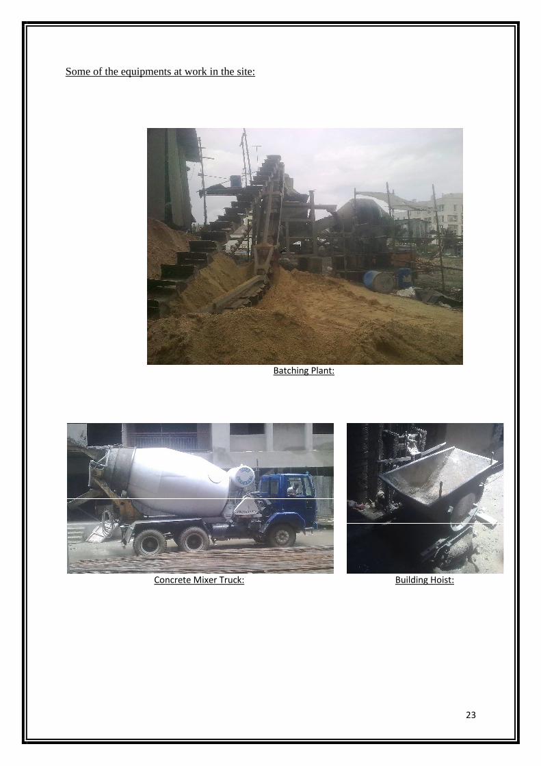
Some of the equipments at work in the site:
Concrete Mixer Truck:
Batching Plant:
Building Hoist:
24
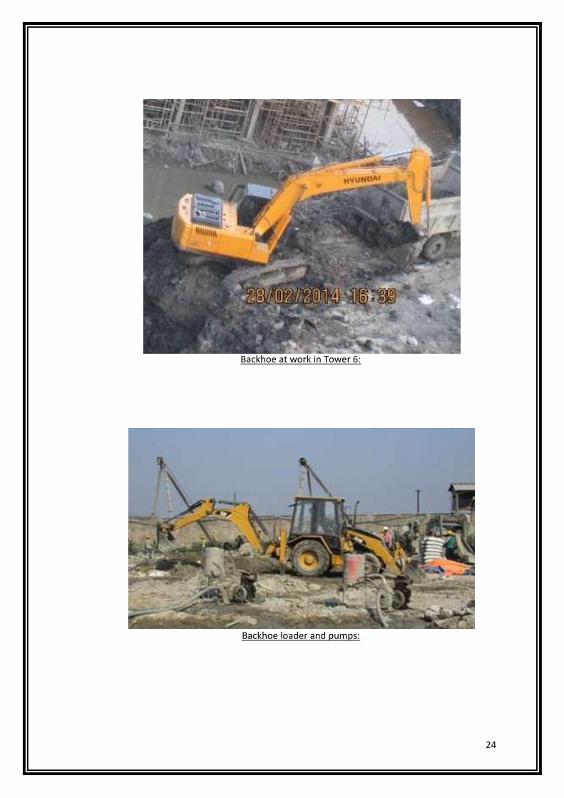
Backhoe at work in Tower 6:
Backhoe loader and pumps:
25
2.4 CONSTRUCTION MATERIALS:
CONCRETE:
Concrete is a mixture of cement, sand, stone aggregates and water. A cage of steel rods used
together with the concrete mix leads to the formation of Reinforced Cement Concrete
popularly known as RCC.
Concrete has two main stages
1) Fresh Concrete
2) Hardened Concrete
Fresh Concrete should be stable and should not segregate or bleed during transportation and
placing when it is subjected to forces during handling operations of limited nature. The mix
should be cohesive and mobile enough to be placed in the form around the reinforcement and
should be able to cast into the required shape without loosing continuity or homogeneity
under the available techniques of placing the concrete at a particular job. The mix should be
amenable to proper and through compaction into a dense, compact concrete with minimum
voids under the existing facilities of compaction at the site. A best mix from the point of view
of campactibility should achieve a 99 percent elimination of the original voids present. The
stability of a concrete mix requires that it should not segregate and bleed during the
transportation and placing. Segregation can be defined as separating out of the ingredients of
a concrete mix, so that the mix is no longer in a homogeneous condition. Only the stable
homogeneous mix can be fully compacted. The segregation depends upon the handling and
placing operations. The tendency to segregate, amount of coarse aggregate, and with the
increased slump. The tendency to segregate can be minimized by:
• Reducing the height of drop by concrete.
• Not using the vibration as a means of spreading a heap of of concrete into a level
mass over a large area.
• Reducing the continued vibration over a longer time, as the coarse aggregate tends to
settle to the bottom and the scum would rise to the surface.
• Adding small quantity of water which improves cohesion of the mix.
Bleeding is due to the rise of water in the mix to the surface because of the inability of the
solid particles in the mix to hold all the mixing water during settling of particles under the
26
effect of compaction. The bleeding causes formation of a porous, weak and non durable
concrete layer at the top of placed concrete. In case of lean mixes bleeding may create
capillary channels increasing the permeability of the concrete. When the concrete is placed in
different layers and each layer is compacted after allowing certain time to lapse before the
next layer is laid, the bleeding may cause a plane of weakness between two layers. Any
laitance formed should be removed by brushing and washing before a new layer is added.
Over compacting the surface should be avoided.
Hardened Concrete One of the most important properties of the hardened concrete is its
strength which represents the ability if concrete to resist forces. If the nature of the force is to
produce compression, the strength is termed compressive strength. The compressive strength
of hardened concrete is generally considered to be the most important property and is often
taken as the index of the overall quality of concrete. The strength can indirectly give an idea
of the most of the other properties of concrete which are related directly to the structure of
hardened cement paste. A stronger concrete is dense, compact, impermeable and resistant to
weathering and to some chemicals. However, a stronger concrete may exhibit higher drying
shrinkage with consequent cracking, due to the presence of higher cement content. Some of
the other desirable properties like shear and tensile strengths, modulus of elasticity, bond,
impact and durability etc. are generally related to compressive strength. As the compressive
strength can be measured easily on standard sized cube or cylindrical specimens, it can be
specified as a criterion for studying the effect of any variable on the quality of concrete.
However, the concrete gives different values of any property under different testing
conditions. Hence method of testing, size of specimen and the rate of loading etc. are
stipulated while testing the concrete to minimize the variations in test results. The statistical
methods are commonly used for specifying the quantitative value of any particular property
of hardened concrete.
Compressive strength of concrete is defined as the load which causes the failure of specimen,
per unit area of cross-section in uniaxial compression under given rate of loading. The
strength of concrete is expressed as N/mm2. The compressive strength at 28 days after
casting is taken as a criterion for specifying the quality of concrete. This is termed as grade of
concrete. IS 456 – 2000 stipulates the use of 150 mm cubes. Tensile strength of concrete is
low; it ranges from 8-12 per cent of its compressive strength. An average value of 10 per cent
is generally adopted. Shear strength is generally 12-13 per cent of its compressive strength.
The concrete subjected to bending and shear stress is accompanied by tensile and
27
compressive stresses. The shear failures are due to resulting diagonal tension. Bond strength
is taken as 10 per cent of its compressive strength. The resistance of concrete to the slipping
of reinforcing bars embedded in concrete is called bond strength. The bond strength is
provided by adhesion of hardened cement paste, and by the friction of concrete and steel. It is
also affected by shrinkage of concrete relative to steel.
Facts about Cement and Concrete
1) Water required by 1 bag of cement is something in the range of 25-28 litres
2) Quality of concrete has nothing to do with its color.
3) The mortar / concrete should be consumed as early as possible after addition of water to it.
The hydration of cement starts the moment water is added to it. As the hydration progresses
the cement paste starts stiffening and loses its plasticity. The concrete should not be disturbed
after this. Normally, this is about 45 – 50 minutes.
4) MPa is abbreviated form of mega Pascal, which is a unit of pressure. 1 MPa is equivalent
to a pressure of 10Kg /cm2. The strength of concrete & cement is expressed in terms of
pressure a standard cube can withstand. The Ordinary Portland Cement, commonly called
OPC is available in three grades namely 33, 43 & 53 grades. Thus, for 43 grade cement
standard cement & sand mortar cube would give a minimum strength of 43 MPa or 430 Kg
/cm2 when tested under standard curing conditions for 28 days. Compressive Strength of
Concrete depends on following factors:
w/c ratio Characteristics of cement Characteristics of aggregates
Time of mixing Degree of compaction Temperature and period of curing
Age of concrete Air entertainment Conditions of testing
Precautions for water to be used in concrete
It is good to use potable quality of water, and
seawater isn’t recommended.
It should be free from impurities and harmful
ingredients.
The water fit for mixing is fit for curing too Ensure that water is measured and added.
Low water to cement ratio is essential for good
performance of the structure in the long run.
Use of too much or too little water for mixing, or
water carelessly added during mixing
28
Using concrete which has already begun to set. Inadequate compaction of concrete
Too much troweling of the concrete surface. Incomplete mixing of aggregate with cement
Use of dirty aggregate or water containing earthy
matter, clay or lime.
Common Reasons for lack of quality in concrete
work
Improper grading of aggregates resulting in
segregation or bleeding of concrete.
Placing of concrete on a dry foundation without
properly wetting it with water.
Use of minimum quantity of mixing water,
consistent with the degree of workability
required to enable easy placing and compaction
of concrete, is advisable.
Leaving the finished concrete surface exposed to
sun and wind during the first ten days after
placing without protecting it and keeping it damp
by proper methods of curing.
CONCRETING AT CONSTRUCTION SITE:
Construction joints are the joints provided between successive pours of concrete that have
been carried out after a time lag. As far as possible the construction joints should be avoided
and every care should be taken to keep their numbers minimal. Since, presence of these joints
creates a plane of weakness within the concrete body, these joints should be preplanned and
their location should be such that they are at places where they are subjected to minimum
bending moment and minimum shear force.
POURING AND CONSOLIDATION: Concrete (M20) was used for all works in column,
beams and slabs. It was well consolidated by vibrating using portable mechanical vibrators.
Care was taken to ensure that concrete is not over vibrated so as to cause segregation. The
layers of concrete are so placed that the bottom layer does not finally set before the top layer
is placed. The vibrators maintain the whole of concrete under treatment in an adequate state
of agitation, such that deaeration and effective compaction is attained at a state commensurate
with the supply of concrete from the mixers. The vibrator continue during the whole period
occupied by placing of concrete, the vibrators being adjusted so that the centre vibrations
approximate to the centre of the mass being compacted at the time of placing. Shaking of
reinforcement for the purpose of compaction should be avoided. Compaction shall be
completed before initial setting starts i.e. within thirty minute of addition of water to the dry
mixture. The concrete was deposited in its final position in a manner to preclude segregation
of ingredients. In case of column and walls, the shuttering was so adjusted that the vertical
29
drop of concrete is not more than 1.5 m at a time. In case of concreting of slabs and beams,
the pipe from the batching plant was directly taken to the closest point.
Method of Concreting:
Concrete mix design for different structure should be as per notes in the specific approved
drawing. For design mix concrete, the mix shall be designed to provide the grade of concrete
having the required strength, workability & durability requirements given in IS 456 for each
grade of concrete taking into account the type of cement, minimum cement content and
maximum W/C ratio conforming to exposure conditions as per tender specifications. Mix
design and preliminary tests are not necessary for nominal mix concrete (M5, M7.5, M10,
M15, M20 as Specified in IS 456 - Table 9). However works tests shall be carried out as per
IS 456. No concreting shall be done without the approval of engineer. Prior notice shall be
given before start of concreting. Cement shall be measured by weight in weigh batching
machines of an approved type; aggregate shall be measured by volume/weight. The machines
shall be kept clean and in good condition and shall be checked and adjusted for accuracy at
regular intervals when required by the engineer. Material shall be weighed within 2.5%
tolerances, inclusive of scale and operating errors. The weigh batching machines shall
discharge efficiently so that no materials are retained. Concrete shall be mixed in mechanical
mixers of an approved type. In no case shall the mixing of each batch of concrete continue for
less than 2 minutes. The water to be added in concrete shall be adjusted based on moisture
contents in fine and coarse aggregates. During hot and cold weather, suitable methods to
reduce the loss of water by evaporation in hot weather and heat loss in cold weather will be
adopted as per procedure set out in IS: 786. The compaction of concrete will be done by
immersion type needle vibrator which shall be inserted into concrete in vertical position not
more than 450 mm apart. Vibration will be applied systematically to cover all areas
immediately after placing concrete and will be stopped when the concrete flattens and takes
up a glistening appearance, or rise of entrapped air ceases or coarse aggregate blends into the
surface but does not completely disappear. The vibrator shall be slowly withdrawn to ensure
closing of the hole resulting from insertion. Unless otherwise approved, continuous
concreting shall be done to the full thickness of foundation rafts, slabs, beams & similar
members. For placing on slope, concreting will be started at the bottom and moved upwards.
Concrete shall not fall from a height of more than 1m to avoid segregation. Special care shall
be taken to guarantee the finish and water-tightness of concrete for liquid retaining structures,
underground structures and those if specifically mentioned. The minimum level of surface
30
finish for liquid retaining structures shall be Type F-2 and it shall be hydrotested to approved
procedure. Any leakage during hydrotest or subsequently during defect liability period, if
occurred shall be effectively stopped either by cement /epoxy pressure grouting or any other
approved method. Curing of concrete with approved water shall start after completion of
initial setting time of concrete and in hot weather after 3 hours. Concrete will be cured for a
minimum period of seven days when OPC with high water cement ratio is used, curing for
minimum 10 days in hot weather or low water cement ratio is used and where mineral
admixture used minimum curing period is 14 days. Freshly laid concrete shall be protected
from rain by suitable covering. Curing shall be done by continuous sprays or ponded water or
continuously saturated coverings of sacking canvas, hessian or other absorbent material for
the period of complete hydration with a minimum of 7 days. Curing shall also be done by
covering the surface with an impermeable material such as Polyethylene, which shall be well
sealed and fastened. Alternatively curing compound of approved make can be applied
immediately after stripping of formwork. The workability of concrete shall be checked by the
site engineer. The prepared surface shall be inspected and certified in pour card. Staining or
discoloration shall be washed out. If surface is not upto the acceptable standard, as per IS
456, cement wash is to be provided on exposed concrete surface of foundation, beam,
column, wall etc. All blemishes and defect if any shall be rectified immediately after the
removal of formwork. For each sample of concrete pour 150mm cubes shall be prepared and
cured. 3 nos shall be crushed at 7days and other 3 nos at 28 days. Record shall be made for
each test in enclosed formats as per ITP. PVC water stoppers shall be provided in
construction joints as per AFC drawing confirming to IS-12200. Prior approval shall be taken
for location & material. Alternatively G.I. sheet of 200 mm wide and 18 gauge thick shall
also be used for the same with the approval of Engineer.
CEMENT:
Portland cement is composed of calcium silicates and aluminate and aluminoferrite It is
obtained by blending predetermined proportions limestone clay and other minerals in small
quantities which is pulverized and heated at high temperature – around 1500 deg centigrade
to produce ‘clinker’. The clinker is then ground with small quantities of gypsum to produce a
fine powder called Ordinary Portland Cement (OPC). When mixed with water, sand and
stone, it combines slowly with the water to form a hard mass called concrete. Cement is a
hygroscopic material meaning that it absorbs moisture In presence of moisture it undergoes
31
chemical reaction termed as hydration. Therefore cement remains in good condition as long
as it does not come in contact with moisture. If cement is more than three months old then it
should be tested for its strength before being taken into use. The Bureau of Indian Standards
(BIS) has classified OPC in three different grades The classification is mainly based on the
compressive strength of cement-sand mortar cubes of face area 50 cm2 composed of 1 part of
cement to 3 parts of standard sand by weight with a water-cement ratio arrived at by a
specified procedure. The grades are
(i) 33 grade
(ii) 43 grade
(iii) 53 grade
The grade number indicates the minimum compressive strength of cement sand mortar in
N/mm2 at 28 days, as tested by above mentioned procedure. Portland Pozzolana Cement
(PPC) is obtained by either intergrinding a pozzolanic material with clinker and gypsum, or
by blending ground pozzolana with Portland cement. Nowadays good quality fly ash is
available from Thermal Power Plants, which are processed and used in manufacturing of
PPC.
Advantages of using Portland pozzolana cement over OPC: Pozzolana combines with lime
and alkali in cement when water is added and forms compounds which contribute to strength,
impermeability and sulphate resistance. It also contributes to workability, reduced bleeding
and controls destructive expansion from alkali-aggregate reaction. It reduces heat of
hydration thereby controlling temperature differentials, which causes thermal strain and
resultant cracking n mass concrete structures like dams. The colour of PPC comes from the
colour of the pozzolanic material used. PPC containing fly ash as a pozzolana will invariably
be slightly different colour than the OPC.One thing should be kept in mind that is the quality
of cement depends upon the raw materials used and the quality control measures adopted
during its manufacture, and not on the shade of the cement. The cement gets its colour from
the nature and colour of raw materials used, which will be different from factory to factory,
and may even differ in the different batches of cement produced in a factory. Further, the
colour of the finished concrete is affected also by the colour of the aggregates, and to a lesser
extent by the colour of the cement. Preference for any cement on the basis of colour alone is
technically misplaced.
32
Setting of Cement: When water is mixed with cement, the paste so formed remains pliable
and plastic for a short time. During this period it is possible to disturb the paste and remit it
without any deleterious effects. As the reaction between water and cement continues, the
paste loses its plasticity. This early period in the hardening of cement is referred to as
‘setting’ of cement. Initial set is when the cement paste loses its plasticity and stiffens
considerably. Final set is the point when the paste hardens and can sustain some minor load.
Both are arbitrary points and these are determined by Vicat needle penetration resistance.
Slow or fast setting normally depends on the nature of cement. It could also be due to
extraneous factors not related to the cement. The ambient conditions play an important role.
In hot weather, the setting is faster, in cold weather, setting is delayed Some types of salts,
chemicals, clay, etc if inadvertently get mixed with the sand, aggregate and water could
accelerate or delay the setting of concrete.
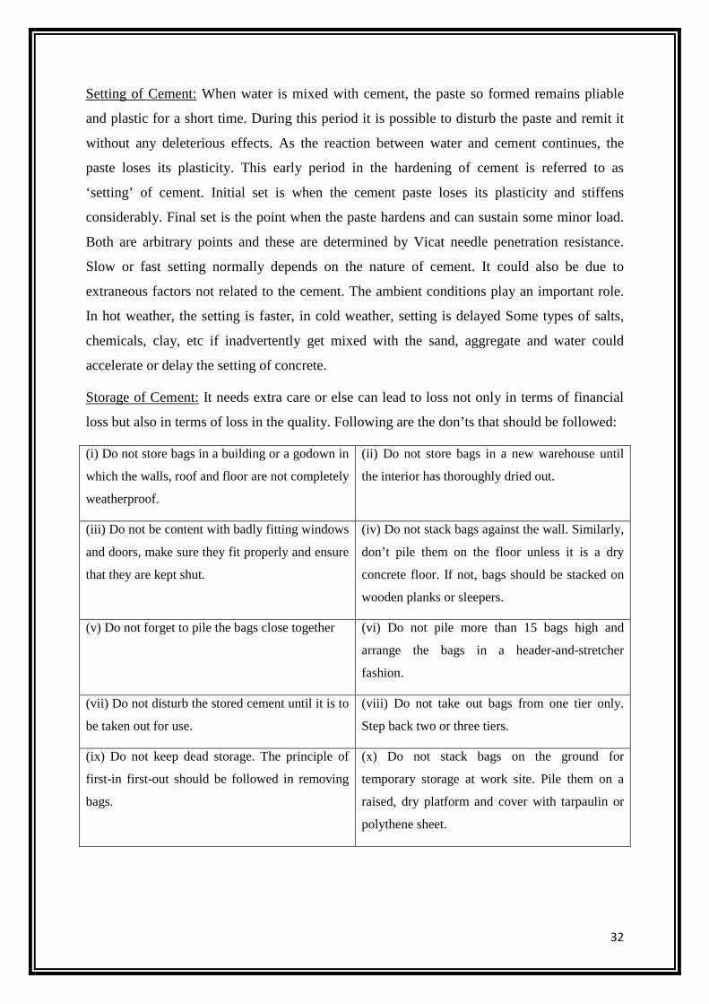
Storage of Cement: It needs extra care or else can lead to loss not only in terms of financial
loss but also in terms of loss in the quality. Following are the don’ts that should be followed:
(i) Do not store bags in a building or a godown in
which the walls, roof and floor are not completely
weatherproof.
(ii) Do not store bags in a new warehouse until
the interior has thoroughly dried out.
(iii) Do not be content with badly fitting windows
and doors, make sure they fit properly and ensure
that they are kept shut.
(iv) Do not stack bags against the wall. Similarly,
don’t pile them on the floor unless it is a dry
concrete floor. If not, bags should be stacked on
wooden planks or sleepers.
(v) Do not forget to pile the bags close together (vi) Do not pile more than 15 bags high and
arrange the bags in a header-and-stretcher
fashion.
(vii) Do not disturb the stored cement until it is to
be taken out for use.
(viii) Do not take out bags from one tier only.
Step back two or three tiers.
(ix) Do not keep dead storage. The principle of
first-in first-out should be followed in removing
bags.
(x) Do not stack bags on the ground for
temporary storage at work site. Pile them on a
raised, dry platform and cover with tarpaulin or
polythene sheet.
33
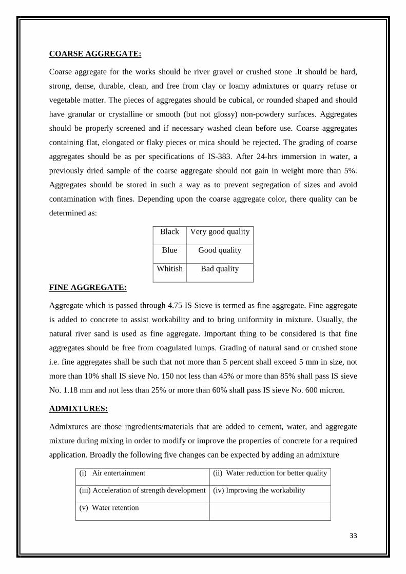
COARSE AGGREGATE:
Coarse aggregate for the works should be river gravel or crushed stone .It should be hard,
strong, dense, durable, clean, and free from clay or loamy admixtures or quarry refuse or
vegetable matter. The pieces of aggregates should be cubical, or rounded shaped and should
have granular or crystalline or smooth (but not glossy) non-powdery surfaces. Aggregates
should be properly screened and if necessary washed clean before use. Coarse aggregates
containing flat, elongated or flaky pieces or mica should be rejected. The grading of coarse
aggregates should be as per specifications of IS-383. After 24-hrs immersion in water, a
previously dried sample of the coarse aggregate should not gain in weight more than 5%.
Aggregates should be stored in such a way as to prevent segregation of sizes and avoid
contamination with fines. Depending upon the coarse aggregate color, there quality can be
determined as:
Black Very good quality
Blue Good quality
Whitish Bad quality
FINE AGGREGATE:
Aggregate which is passed through 4.75 IS Sieve is termed as fine aggregate. Fine aggregate
is added to concrete to assist workability and to bring uniformity in mixture. Usually, the
natural river sand is used as fine aggregate. Important thing to be considered is that fine
aggregates should be free from coagulated lumps. Grading of natural sand or crushed stone
i.e. fine aggregates shall be such that not more than 5 percent shall exceed 5 mm in size, not
more than 10% shall IS sieve No. 150 not less than 45% or more than 85% shall pass IS sieve
No. 1.18 mm and not less than 25% or more than 60% shall pass IS sieve No. 600 micron.
ADMIXTURES:
Admixtures are those ingredients/materials that are added to cement, water, and aggregate
mixture during mixing in order to modify or improve the properties of concrete for a required
application. Broadly the following five changes can be expected by adding an admixture
(i) Air entertainment (ii) Water reduction for better quality
(iii) Acceleration of strength development (iv) Improving the workability
(v) Water retention
34
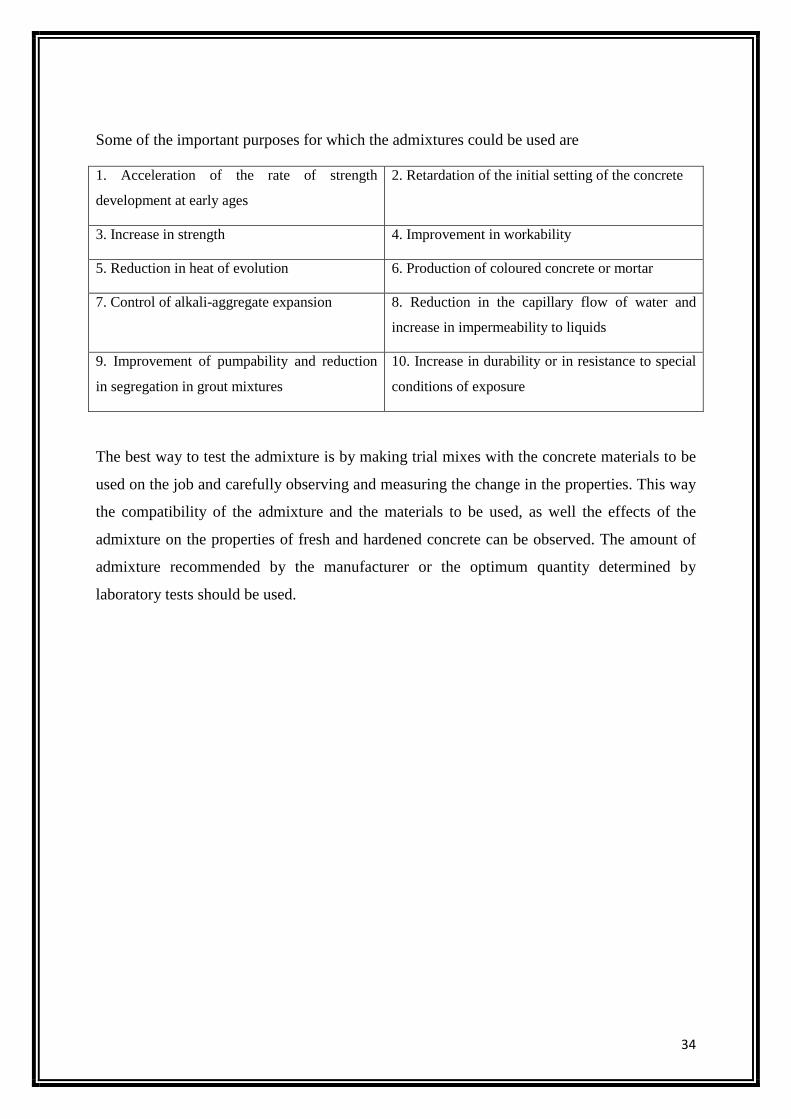
Some of the important purposes for which the admixtures could be used are
1. Acceleration of the rate of strength
development at early ages
2. Retardation of the initial setting of the concrete
3. Increase in strength 4. Improvement in workability
5. Reduction in heat of evolution 6. Production of coloured concrete or mortar
7. Control of alkali-aggregate expansion 8. Reduction in the capillary flow of water and
increase in impermeability to liquids
9. Improvement of pumpability and reduction
in segregation in grout mixtures
10. Increase in durability or in resistance to special
conditions of exposure
The best way to test the admixture is by making trial mixes with the concrete materials to be
used on the job and carefully observing and measuring the change in the properties. This way
the compatibility of the admixture and the materials to be used, as well the effects of the
admixture on the properties of fresh and hardened concrete can be observed. The amount of
admixture recommended by the manufacturer or the optimum quantity determined by
laboratory tests should be used.

35
2.5 PLANNING:
Construction planning is a fundamental and challenging activity in the management and
execution of construction projects. It involves the choice of technology, the definition of
work tasks, the estimation of the required resources and durations for individual tasks, and
the identification of any interactions among the different work tasks. A good construction
plan is the basis for developing the budget and the schedule for work. Developing the
construction plan is a critical task in the management of construction, even if the plan is not
written or otherwise formally recorded. In addition to these technical aspects of construction
planning, it may also be necessary to make organizational decisions about the relationships
between project participants and even which organizations to include in a project. For
example, the extent to which sub-contractors will be used on a project is often determined
during construction planning. The following tasks are done in construction planning:
• Choice of Technology and Construction Method: As in the development of
appropriate alternatives for facility design, choices of appropriate technology and
methods for construction are often ill-structured yet critical ingredients in the success
of the project. For example, a decision whether to pump or to transport concrete in
buckets will directly affect the cost and duration of tasks involved in building
construction. A decision between these two alternatives should consider the relative
costs, reliabilities, and availability of equipment for the two transport methods.
• Defining Work Tasks: At the same time that the choice of technology and general
method are considered, a parallel step in the planning process is to define the various
work tasks that must be accomplished. These work tasks represent the necessary
framework to permit scheduling of construction activities, along with estimating the
resources required by the individual work tasks and any necessary precedence or
required sequence among the tasks. The terms work "tasks" or "activities" are often
used interchangeably in construction plans to refer to specific, defined items of work.
• Defining Precedence Relationships among Activities: Once work activities have been
defined, the relationships among the activities can be specified. Precedence relations
between activities signify that the activities must take place in a particular sequence.
Numerous natural sequences exist for construction activities due to requirements for
36
structural integrity, regulations, and other technical requirements. For example, design
drawings cannot be checked before they are drawn.
• Estimating Activity Durations: In most scheduling procedures, each work activity has
associated time duration. These durations are used extensively in preparing a
schedule. A straightforward approach to the estimation of activity durations is to keep
historical records of particular activities and rely on the average durations from this
experience in making new duration estimates. Since the scopes of activities are
unlikely to be identical between different projects, unit productivity rates are typically
employed for this purpose.
• Estimating Resource Requirements for Work Activities: In addition to precedence
relationships and time durations, resource requirements are usually estimated for each
activity. Since the work activities defined for a project are comprehensive, the total
resources required for the project are the sum of the resources required for the various
activities. By making resource requirement estimates for each activity, the
requirements for particular resources during the course of the project can be
identified. Potential bottlenecks can thus be identified, and schedule, resource
allocation or technology changes made to avoid problems.
• Coding Systems: One objective in many construction planning efforts is to define the
plan within the constraints of a universal coding system for identifying activities.
Each activity defined for a project would be identified by a pre-defined code specific
to that activity. The use of a common nomenclature or identification system is
basically motivated by the desire for better integration of organizational efforts and
improved information flow. In particular, coding systems are adopted to provide a
numbering system to replace verbal descriptions of items. These codes reduce the
length or complexity of the information to be recorded. A common coding system
within an organization also aids consistency in definitions and categories between
projects and among the various parties involved in a project. Common coding systems
also aid in the retrieval of historical records of cost, productivity and duration on
particular activities. Finally, electronic data storage and retrieval operations are much
more efficient with standard coding systems.
37
2.6 SURVEYING Surveying or land surveying is the technique, profession, and science of accurately determining the
terrestrial or three-dimensional position of points and the distances and angles between them,
commonly practiced by licensed surveyors, and members of various building professions. These
points are usually on the surface of the Earth, and they are often used to establish land maps and
boundaries for ownership, locations (building corners, surface location of subsurface features) or
other governmentally required or civil law purposes (property sales). Surveyors determine the
position of objects by measuring angles and distances, along with various factors that can affect the
accuracy of their observations. From this information, they can calculate more advanced constructs
such as vectors, bearings, co-ordinates, elevations, areas, volumes, plans and maps. Measurements
are also often split into horizontal and vertical components to simplify calculation. Most surveys
points are measured relative to previously measured points. This forms a reference or control
network where each point can be used by a surveyor to determine their own position when beginning
a new survey. Survey points are usually marked on the earth's surface by an object ranging from
small nails driven into the ground to large beacons that can be seen from long distances. The
surveyor can set up their instruments on this position and measure to nearby objects. Sometimes a
tall, distinctive feature such as a steeple or radio aerial has its position calculated a reference point
that angles can be measured against.
METHODS OF SURVEYING:
Triangulation is a method where a surveyor first needs to know the horizontal distance between two
of the objects, known as the baseline. Then the height, distances and angular position of other objects
can be derived, as long as they are visible from one of the original objects. High-accuracy transits or
theodolites were used for this work, and angles between objects were measured repeatedly for
increased accuracy.
Offsetting is an alternate method of determining position of objects, and was often used to measure
imprecise features such as riverbanks. The surveyor would mark and measure two known positions
on the ground roughly parallel to the feature, and mark out a baseline between them. At regular
intervals, a distance was measured at right angles from the first line to the feature. The measurements
could then be plotted on a plan or map, and the points at the ends of the offset lines could be joined
to show the feature.
38
Traversing is a common method of surveying smaller areas. Starting from an old reference mark or
known position, the surveyor creates a network of reference marks covering the area to be surveyed.
They then measure bearings and distances between the reference marks, and to the features to be
surveyed. Most traverses form a loop pattern or link between two prior reference marks to allow the
surveyor to check their measurements are correct.
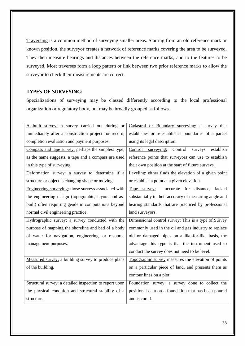
TYPES OF SURVEYING:
Specializations of surveying may be classed differently according to the local professional
organization or regulatory body, but may be broadly grouped as follows.
As-built survey: a survey carried out during or
immediately after a construction project for record,
completion evaluation and payment purposes.
Cadastral or Boundary surveying: a survey that
establishes or re-establishes boundaries of a parcel
using its legal description.
Compass and tape survey: perhaps the simplest type,
as the name suggests, a tape and a compass are used
in this type of surveying.
Control surveying: Control surveys establish
reference points that surveyors can use to establish
their own position at the start of future surveys.
Deformation survey: a survey to determine if a
structure or object is changing shape or moving.
Leveling: either finds the elevation of a given point
or establish a point at a given elevation.
Engineering surveying: those surveys associated with
the engineering design (topographic, layout and as-
built) often requiring geodetic computations beyond
normal civil engineering practice.
Tape survey: accurate for distance, lacked
substantially in their accuracy of measuring angle and
bearing standards that are practiced by professional
land surveyors.
Hydrographic survey: a survey conducted with the
purpose of mapping the shoreline and bed of a body
of water for navigation, engineering, or resource
management purposes.
Dimensional control survey: This is a type of Survey
commonly used in the oil and gas industry to replace
old or damaged pipes on a like-for-like basis, the
advantage this type is that the instrument used to
conduct the survey does not need to be level.
Measured survey: a building survey to produce plans
of the building.
Topographic survey measures the elevation of points
on a particular piece of land, and presents them as
contour lines on a plot.
Structural survey: a detailed inspection to report upon
the physical condition and structural stability of a
structure.
Foundation survey: a survey done to collect the
positional data on a foundation that has been poured
and is cured.
39
MODERN SURVEYING INSTRUMENTS:
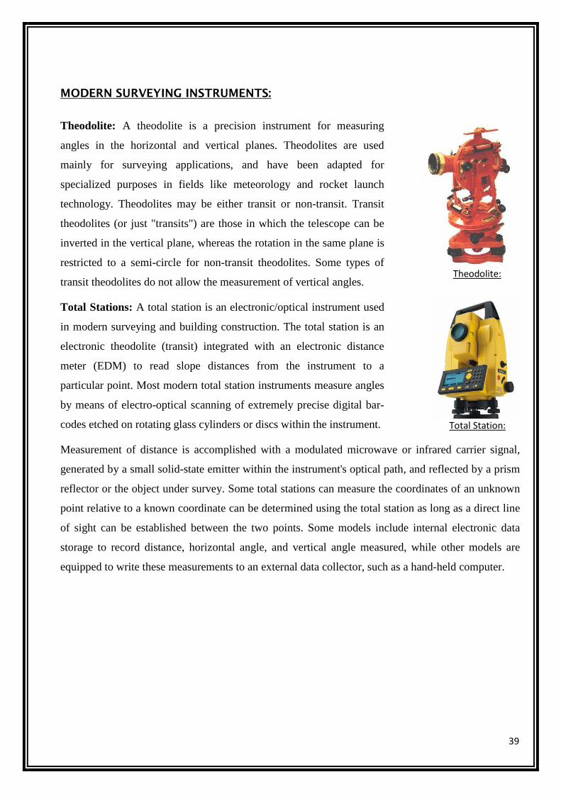
Theodolite: A theodolite is a precision instrument for measuring
angles in the horizontal and vertical planes. Theodolites are used
mainly for surveying applications, and have been adapted for
specialized purposes in fields like meteorology and rocket launch
technology. Theodolites may be either transit or non-transit. Transit
theodolites (or just "transits") are those in which the telescope can be
inverted in the vertical plane, whereas the rotation in the same plane is
restricted to a semi-circle for non-transit theodolites. Some types of
transit theodolites do not allow the measurement of vertical angles.
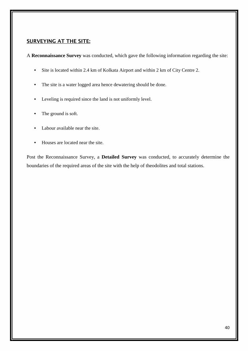
Total Stations: A total station is an electronic/optical instrument used
in modern surveying and building construction. The total station is an
electronic theodolite (transit) integrated with an electronic distance
meter (EDM) to read slope distances from the instrument to a
particular point. Most modern total station instruments measure angles
by means of electro-optical scanning of extremely precise digital bar-
codes etched on rotating glass cylinders or discs within the instrument.
Measurement of distance is accomplished with a modulated microwave or infrared carrier signal,
generated by a small solid-state emitter within the instrument's optical path, and reflected by a prism
reflector or the object under survey. Some total stations can measure the coordinates of an unknown
point relative to a known coordinate can be determined using the total station as long as a direct line
of sight can be established between the two points. Some models include internal electronic data
storage to record distance, horizontal angle, and vertical angle measured, while other models are
equipped to write these measurements to an external data collector, such as a hand-held computer.
Theodolite:
Total Station:
40
SURVEYING AT THE SITE:
A Reconnaissance Survey was conducted, which gave the following information regarding the site:
• Site is located within 2.4 km of Kolkata Airport and within 2 km of City Centre 2.
• The site is a water logged area hence dewatering should be done.
• Leveling is required since the land is not uniformly level.
• The ground is soft.
• Labour available near the site.
• Houses are located near the site.
Post the Reconnaissance Survey, a Detailed Survey was conducted, to accurately determine the
boundaries of the required areas of the site with the help of theodolites and total stations.
41
2.7 QUALITY CONTROL
Utility systems need infrastructure to last as long as possible. One way to ensure longevity is
through quality control. To have good quality control in construction projects is to perform
good inspections. Remember, you can inspect it now or fix it later. Quality control is
critically important to a successful construction project and should be adhered to throughout a
project from conception and design to construction and installation. Inspection during
construction will prevent costly repairs after the project is completed. The inspector,
engineer, contractor, funding agency, permit agency, and system personnel must work
together to inspect, document, and correct deficiencies.
What is Quality Control?
For construction projects, quality control means making sure things are done according to the
plans, specifications, and permit requirements. One of the best ways to assure good
construction projects is to use an inspector. The first step an inspector should take is to
become familiar with the plans, specification, and permit requirements and, equally
important, to have some common sense. Quality control during all construction phases needs
to be better, and the utility system needs to know what is being installed while the work is
being done.
Roles and functions of various departments of Quality Management
Quality Assurance: The primary function of quality assurance is to obtain completed
construction that meets all contract requirements. Assurance is defined as a degree of
certainty. Quality assurance personnel continually assure--or make certain--that the
contractor's work complies with contract requirements.
Quality Assurance Personnel: The role of quality assurance personnel is to assure that the
CQC system is functioning properly. To do this, QA personnel:
• Examine the quality control methods being used to determine if the contractor is properly
controlling design activities in design-build contracts.
• Examine the quality control methods being used to determine if the contractor is properly
controlling construction activities.
• Make certain that the necessary changes are made in the contractor's QC system, if
excessive construction deficiencies occur.

42
• Assist the contractor in understanding and implementing the contract requirements.
• Examine ongoing and completed work.
• Review QC documentation to assure adequacy.
Contractor Quality Control: The primary function of CQC is the successful execution of a
realistic plan to ensure that the required standards of quality construction will be met. In
CQC, the contractor defines procedures to manage and control his own, designer of record,
consultant, architect-engineer, all subcontractor and all supplier activities so that the
completed project complies with contract requirements. The design QC plan shall be
managed by a Design QC Manager who has verifiable engineering or architectural design
experience or is a registered engineer or architect. The Design QC Manager is under the
supervision of the QC Manager.
Quality Control Personnel: CQC or Contractor Quality Control is a contractor responsibility.
This includes:
• Produce the quality specified in the plans and specifications and for design-build contracts
in the Request for Proposal, as well as the contractor's accepted proposal,
• Develop and maintain an effective CQC system,
• Perform all control activities and tests, and
• Prepare acceptable documentation of CQC activities.
The contractor also is required to place a competent representative onsite to oversee the CQC
system. He must have full authority to act for the contractor on CQC matters. His
responsibilities include workmanship, methods, and techniques to ensure that all work is
performed properly by qualified and careful craftsmen. For design-build contracts,
responsibility also includes design quality and the performance of constructability,
operability and environmental review of the design. At our site, Simplex Infrastructures Ltd.
being the contractor, the quality control was done by them.
43
Test conducted on site for quality control
TESTS ON CONCRETE:
SLUMP TEST
Slump test is used to determine the workability of fresh concrete. Slump test as per IS: 1199 –
1959 is followed.The apparatus used for Slump Test are Slump Cone and Tamping Rod.
• APPARATUS:
Abram’s Cone (Top diameter: 10 cm, Bottom Diameter: 20 cm, Height: 30 cm)
Tamping Rod (Diameter: 16 mm)
• PROCEDURE:
i) The internal surface of the mould is thoroughly cleaned and applied with a light
coat of oil.
ii) The mould is placed on a smooth, horizontal, rigid and nonabsorbent surface.
iii) The mould is then filled in four layers with freshly mixed concrete, each
approximately to one-fourth of the height of the mould.
iv) Each layer is tamped 25 times by the rounded end of the tamping rod (strokes are
distributed evenly over the cross section).
v) After the top layer is rodded, the concrete is struck off the level with a trowel. Once
the cone is filled and topped off [ excessive concrete from top is cleared ] raise the
cone within 5-10 seconds.
vi) The mould is removed from the concrete immediately by raising it slowly in the
vertical direction.
vii) The difference in level between the height of the mould and that of the highest
point of the subsided concrete is measured.
viii) This difference in height in mm is the slump of the concrete.
• REPORTING OF RESULTS:
The slump measured should be recorded in mm of subsidence of the specimen during
the test. Any slump specimen, which collapses or shears off laterally gives incorrect
result and if this occurs, the test should be repeated with another sample. If, in the
repeat test also, the specimen shears, the slump should be measured and the fact that
the specimen sheared, should be recorded. In case of a dry sample, slump will be in
the range of 25-50 mm that is 1-2 inches. But in case of a wet concrete, the slump
may vary from 150-175 mm or say 6-7 inches. So the value of slump is specifically
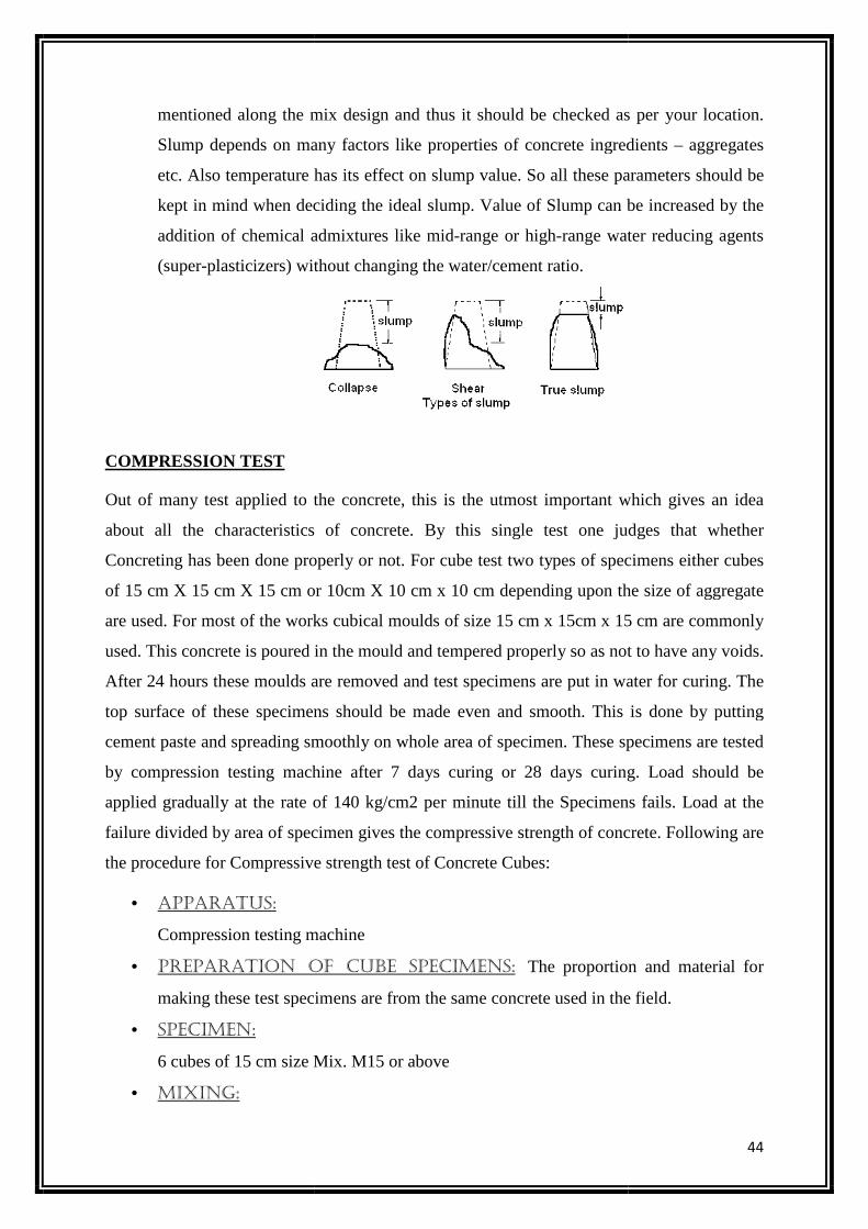
mentioned along the mix design and thus it should be checked as per your location.
Slump depends on many factors like properties of concrete ingredients
etc. Also temperature has its effect on slump value. So all these para
kept in mind when deciding the ideal slump. Value of Slump can be increased by the
addition of chemical admixtures like mid
(super-plasticizers) without changing the water/cement ratio.
COMPRESSION TEST
Out of many test applied to the concrete, this is the utmost important which gives an idea
about all the characteristics of concrete. By this single test one judges that whether
Concreting has been done properly or not. For cube test two t
of 15 cm X 15 cm X 15 cm or 10cm X 10 cm x 10 cm depending upon the size of aggregate
are used. For most of the works cubical moulds of size 15 cm x 15cm x 15 cm are commonly
used. This concrete is poured in the mould and tem
After 24 hours these moulds are removed and test specimens are put in water for curing. The
top surface of these specimens should be made even and smooth. This is done by putting
cement paste and spreading smooth
by compression testing machine after 7 days curing or 28 days curing. Load should be
applied gradually at the rate of 140 kg/cm2 per minute till the Specimens fails. Load at the
failure divided by area of specimen gives the compressive strength of concrete.
the procedure for Compressive strength test of Concrete Cubes:
• APPARATUS:
Compression testing machine
• PREPARATION OF CUBE SPECIMENS:
making these test specimens are from the same concrete used in the field.
• SPECIMEN:
6 cubes of 15 cm size Mix. M15 or above
• MIXING:
mentioned along the mix design and thus it should be checked as per your location.
Slump depends on many factors like properties of concrete ingredients
etc. Also temperature has its effect on slump value. So all these para
kept in mind when deciding the ideal slump. Value of Slump can be increased by the
addition of chemical admixtures like mid-range or high-range water reducing agents
plasticizers) without changing the water/cement ratio.
Out of many test applied to the concrete, this is the utmost important which gives an idea
about all the characteristics of concrete. By this single test one judges that whether
Concreting has been done properly or not. For cube test two types of specimens either cubes
of 15 cm X 15 cm X 15 cm or 10cm X 10 cm x 10 cm depending upon the size of aggregate
are used. For most of the works cubical moulds of size 15 cm x 15cm x 15 cm are commonly
used. This concrete is poured in the mould and tempered properly so as not to have any voids.
After 24 hours these moulds are removed and test specimens are put in water for curing. The
top surface of these specimens should be made even and smooth. This is done by putting
cement paste and spreading smoothly on whole area of specimen. These specimens are tested
by compression testing machine after 7 days curing or 28 days curing. Load should be
applied gradually at the rate of 140 kg/cm2 per minute till the Specimens fails. Load at the
ea of specimen gives the compressive strength of concrete.
the procedure for Compressive strength test of Concrete Cubes:
Compression testing machine
PREPARATION OF CUBE SPECIMENS: The proportion and material for
specimens are from the same concrete used in the field.
6 cubes of 15 cm size Mix. M15 or above
44
mentioned along the mix design and thus it should be checked as per your location.
Slump depends on many factors like properties of concrete ingredients – aggregates
etc. Also temperature has its effect on slump value. So all these parameters should be
kept in mind when deciding the ideal slump. Value of Slump can be increased by the
range water reducing agents
Out of many test applied to the concrete, this is the utmost important which gives an idea
about all the characteristics of concrete. By this single test one judges that whether
ypes of specimens either cubes
of 15 cm X 15 cm X 15 cm or 10cm X 10 cm x 10 cm depending upon the size of aggregate
are used. For most of the works cubical moulds of size 15 cm x 15cm x 15 cm are commonly
pered properly so as not to have any voids.
After 24 hours these moulds are removed and test specimens are put in water for curing. The
top surface of these specimens should be made even and smooth. This is done by putting
ly on whole area of specimen. These specimens are tested
by compression testing machine after 7 days curing or 28 days curing. Load should be
applied gradually at the rate of 140 kg/cm2 per minute till the Specimens fails. Load at the
ea of specimen gives the compressive strength of concrete. Following are
The proportion and material for
specimens are from the same concrete used in the field.
45
Mix the concrete either by hand or in a laboratory batch mixer
• HAND MIXING:
(i) Mix the cement and fine aggregate on a water tight none-absorbent platform until
the mixture is thoroughly blended and is of uniform color.
(ii) Add the coarse aggregate and mix with cement and fine aggregate until the coarse
aggregate is uniformly distributed throughout the batch.
(iii) Add water and mix it until the concrete appears to be homogeneous and of the
desired consistency
• SAMPLING:
(i) Clean the mounds and apply oil
(ii) Fill the concrete in the molds in layers approximately 5cm thick
(iii) Compact each layer with not less than 35strokes per layer using a tamping rod
(steel bar 16mm diameter and 60cm long, bullet pointed at lower end)
(iv) Level the top surface and smoothen it with a trowel
• CURING:
The test specimens are stored in moist air for 24hours and after this period the
specimens are marked and removed from the molds and kept submerged in clear fresh
water until taken out prior to test.
• PRECAUTIONS:
The water for curing should be tested every 7days and the temperature of water must
be at 27±2oC.
• PROCEDURE:
(I) Remove the specimen from water after specified curing time and wipe out excess
water from the surface.
(II) Take the dimension of the specimen to the nearest 0.2m
(III) Clean the bearing surface of the testing machine
(IV) Place the specimen in the machine in such a manner that the load shall be applied
to the opposite sides of the cube cast.
(V) Align the specimen centrally on the base plate of the machine.
(VI) Rotate the movable portion gently by hand so that it touches the top surface of
the specimen.
(VII) Apply the load gradually without shock and continuously at the rate of
140kg/cm2/minute till the specimen fails
46
(VIII) Record the maximum load and note any unusual features in the type of failure.
• NOTE:
Minimum three specimens should be tested at each selected age. If strength of any
specimen varies by more than 15 per cent of average strength, results of such
specimen should be rejected. Average of three specimens gives the crushing strength
of concrete.
• CALCULATIONS:
Size of the cube= 15cm x15cm x15cm
Area of the specimen (calculated from the mean size of the specimen)= 225cm2
Characteristic compressive strength (fck) at 7 days =
Expected maximum load =fck x Area x fs
Range to be selected is …………………..
Similar calculation should be done for 28 day compressive strength
Maximum load applied =……….tones = ………….N
Compressive strength = (Load in N/ Area in mm2)=……………N/mm2
• REPORT:
a) Identification mark
b) Date of test
c) Age of specimen
d) Curing conditions, including date of manufacture of specimen
e) Appearance of fractured faces of concrete and the type of fracture if they are
unusual
• RESULT:
Average compressive strength of the concrete cube = ………….N/ mm2 (at 7 days)
Average compressive strength of the concrete cube =………. N/mm2 (at 28 days)
Percentage strength of concrete at various ages:
The compressive strength of concrete increases with its age. Table shows the strength of
concrete at different ages in comparison with the strength at 28 days after casting.
Age: Strength %:
1 day 16%
3 days 40%
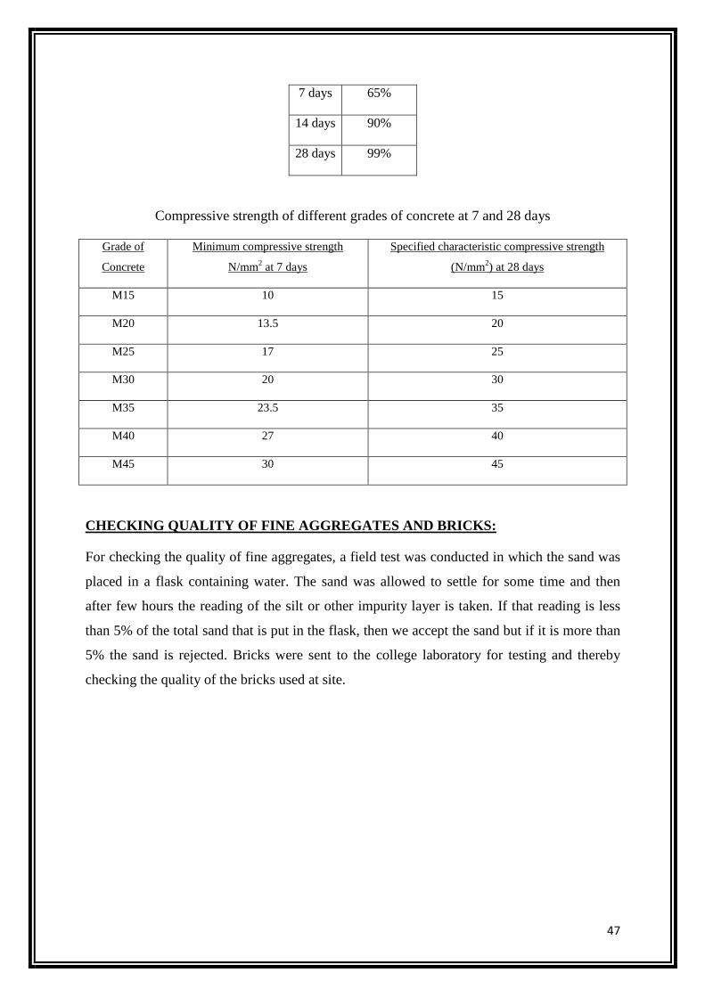
47
7 days 65%
14 days 90%
28 days 99%
Compressive strength of different grades of concrete at 7 and 28 days
Grade of
Concrete
Minimum compressive strength
N/mm2 at 7 days
Specified characteristic compressive strength
(N/mm2) at 28 days
M15 10 15
M20 13.5 20
M25 17 25
M30 20 30
M35 23.5 35
M40 27 40
M45 30 45
CHECKING QUALITY OF FINE AGGREGATES AND BRICKS:
For checking the quality of fine aggregates, a field test was conducted in which the sand was
placed in a flask containing water. The sand was allowed to settle for some time and then
after few hours the reading of the silt or other impurity layer is taken. If that reading is less
than 5% of the total sand that is put in the flask, then we accept the sand but if it is more than
5% the sand is rejected. Bricks were sent to the college laboratory for testing and thereby
checking the quality of the bricks used at site.
48
TESTS ON CEMENT:
INITIAL AND FINAL SETTING TIME
We need to calculate the initial and final setting time as per IS: 4031 (Part 5) – 1988. To do
so we need Vicat apparatus conforming to IS: 5513 – 1976, Balance, whose permissible
variation at a load of 1000g should be +1.0g, Gauging trowel conforming to IS: 10086 –
1982.
• PROCEDURE:
i) Prepare a cement paste by gauging the cement with 0.85 times the water required to
give a paste of standard consistency.
ii) Start a stop-watch, the moment water is added to the cement.
iii) Fill the Vicat mould completely with the cement paste gauged as above, the mould
resting on a non-porous plate and smooth off the surface of the paste making it level
with the top of the mould. The cement block thus prepared in the mould is the test
block.
• INITIAL SETTING TIME:
Place the test block under the rod bearing the needle. Lower the needle gently in order
to make contact with the surface of the cement paste and release quickly, allowing it
to penetrate the test block. Repeat the procedure till the needle fails to pierce the test
block to a point 5.0 ± 0.5mm measured from the bottom of the mould.The time period
elapsing between the time, water is added to the cement and the time, the needle fails
to pierce the test block by 5.0 ± 0.5mm measured from the bottom of the mould, is the
initial setting time.
• FINAL SETTING TIME:
Replace the above needle by the one with an annular attachment. The cement should
be considered as finally set when, upon applying the needle gently to the surface of
the test block, the needle makes an impression therein, while the attachment fails to
do so. The period elapsing between the time, water is added to the cement and the
time, the needle makes an impression on the surface of the test block, while the
attachment fails to do so, is the final setting time.
49
CONSISTENCY TEST:
The basic aim is to find out the water content required to produce a cement paste of standard
consistency as specified by the IS: 4031 (Part 4) – 1988. The principle is that standard
consistency of cement is that consistency at which the Vicat plunger penetrates to a point 5-
7mm from the bottom of Vicat mould.
• APPARATUS: Vicat apparatus conforming to IS: 5513 – 1976, Balance, whose
permissible variation at a load of 1000g should be +1.0g, Gauging trowel conforming
to IS: 10086 – 1982.
• PROCEDURE:
i) Weigh approximately 400g of cement and mix it with a weighed quantity of water.
The time of gauging should be between 3 to 5 minutes.
ii) Fill the Vicat mould with paste and level it with a trowel.
iii) Lower the plunger gently till it touches the cement surface.
iv) Release the plunger allowing it to sink into the paste.
v) Note the reading on the gauge.
vi) Repeat the above procedure taking fresh samples of cement and different
quantities of water until the reading on the gauge is 5 to 7mm.
• REPORTING OF RESULTS:
Express the amount of water as a percentage of the weight of dry cement to the first
place of decimal.
50
TESTS ON AGGREGATES:
FINE AGGREGATES:
SIEVE ANALYSIS
Sieve analysis helps to determine the particle size distribution of the coarse and fine
aggregates. This is done by sieving the aggregates as per IS: 2386 (Part I) – 1963. In this we
use different sieves as standardized by the IS code and then pass aggregates through them and
thus collect different sized particles left over different sieves.
COARSE AGGREGATES:
AGGREGATE CRUSHING VALUE
This test helps to determine the aggregate crushing value of coarse aggregates as per IS: 2386
(Part IV) – 1963. The apparatus used is cylindrical measure and plunger, Compression testing
machine, IS Sieves of sizes – 12.5mm, 10mm and 2.36mm.
• PROCEDURE:
i) The aggregates passing through 12.5mm and retained on 10mm IS Sieve are oven-
dried at a temperature of 100 to 110oC for 3 to 4hrs.
ii) The cylinder of the apparatus is filled in 3 layers, each layer tamped with 25
strokes of a tamping rod.
iii) The weight of aggregates is measured (Weight ‘A’).
iv) The surface of the aggregates is then leveled and the plunger inserted. The
apparatus is then placed in the compression testing machine and loaded at a uniform
rate so as to achieve 40t load in 10 minutes. After this, the load is released.
v) The sample is then sieved through a 2.36mm IS Sieve and the fraction passing
through the sieve is weighed (Weight ‘B’).
vi) Two tests should be conducted.
• RESULT:
Aggregate crushing value = (B/A) x 100%.
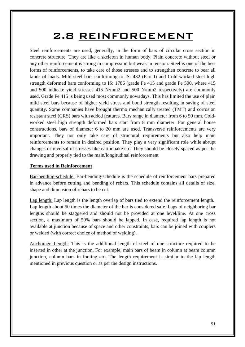
51
2.8 REINFORCEMENT
Steel reinforcements are used, generally, in the form of bars of circular cross section in concrete structure. They are like a skeleton in human body. Plain concrete without steel or any other reinforcement is strong in compression but weak in tension. Steel is one of the best forms of reinforcements, to take care of those stresses and to strengthen concrete to bear all kinds of loads. Mild steel bars conforming to IS: 432 (Part I) and Cold-worked steel high strength deformed bars conforming to IS: 1786 (grade Fe 415 and grade Fe 500, where 415 and 500 indicate yield stresses 415 N/mm2 and 500 N/mm2 respectively) are commonly used. Grade Fe 415 is being used most commonly nowadays. This has limited the use of plain mild steel bars because of higher yield stress and bond strength resulting in saving of steel quantity. Some companies have brought thermo mechanically treated (TMT) and corrosion resistant steel (CRS) bars with added features. Bars range in diameter from 6 to 50 mm. Cold-worked steel high strength deformed bars start from 8 mm diameter. For general house constructions, bars of diameter 6 to 20 mm are used. Transverse reinforcements are very important. They not only take care of structural requirements but also help main reinforcements to remain in desired position. They play a very significant role while abrupt changes or reversal of stresses like earthquake etc. They should be closely spaced as per the drawing and properly tied to the main/longitudinal reinforcement
Terms used in Reinforcement
Bar-bending-schedule: Bar-bending-schedule is the schedule of reinforcement bars prepared in advance before cutting and bending of rebars. This schedule contains all details of size, shape and dimension of rebars to be cut.
Lap length: Lap length is the length overlap of bars tied to extend the reinforcement length.. Lap length about 50 times the diameter of the bar is considered safe. Laps of neighboring bar lengths should be staggered and should not be provided at one level/line. At one cross section, a maximum of 50% bars should be lapped. In case, required lap length is not available at junction because of space and other constraints, bars can be joined with couplers or welded (with correct choice of method of welding).
Anchorage Length: This is the additional length of steel of one structure required to be inserted in other at the junction. For example, main bars of beam in column at beam column junction, column bars in footing etc. The length requirement is similar to the lap length mentioned in previous question or as per the design instructions.
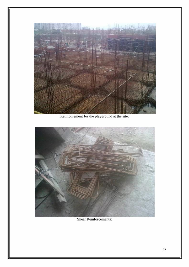
52
Reinforcement for the playground at the site:
Shear Reinforcements:
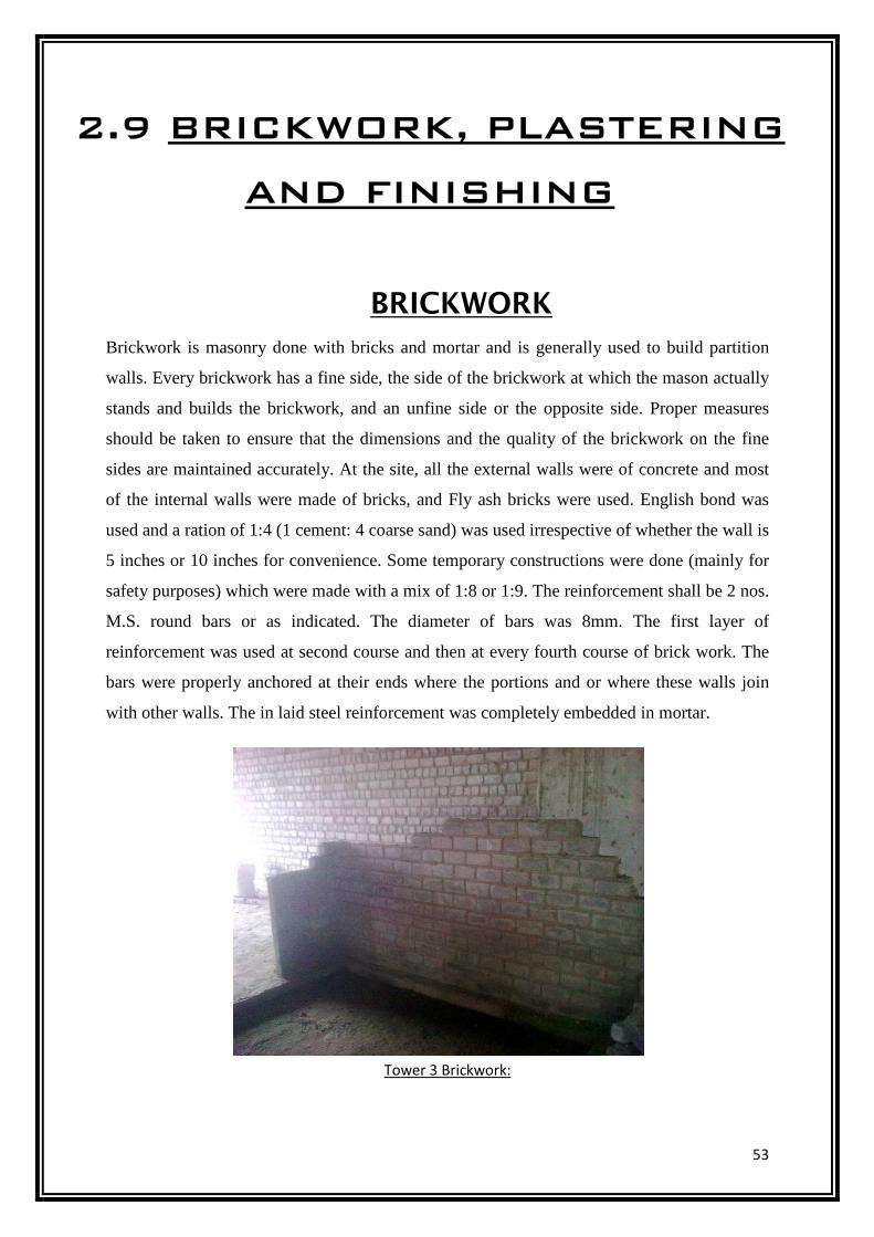
53
2.9 BRICKWORK, PLASTERING
AND FINISHING
BRICKWORK
Brickwork is masonry done with bricks and mortar and is generally used to build partition
walls. Every brickwork has a fine side, the side of the brickwork at which the mason actually
stands and builds the brickwork, and an unfine side or the opposite side. Proper measures
should be taken to ensure that the dimensions and the quality of the brickwork on the fine
sides are maintained accurately. At the site, all the external walls were of concrete and most
of the internal walls were made of bricks, and Fly ash bricks were used. English bond was
used and a ration of 1:4 (1 cement: 4 coarse sand) was used irrespective of whether the wall is
5 inches or 10 inches for convenience. Some temporary constructions were done (mainly for
safety purposes) which were made with a mix of 1:8 or 1:9. The reinforcement shall be 2 nos.
M.S. round bars or as indicated. The diameter of bars was 8mm. The first layer of
reinforcement was used at second course and then at every fourth course of brick work. The
bars were properly anchored at their ends where the portions and or where these walls join
with other walls. The in laid steel reinforcement was completely embedded in mortar.
Tower 3 Brickwork:
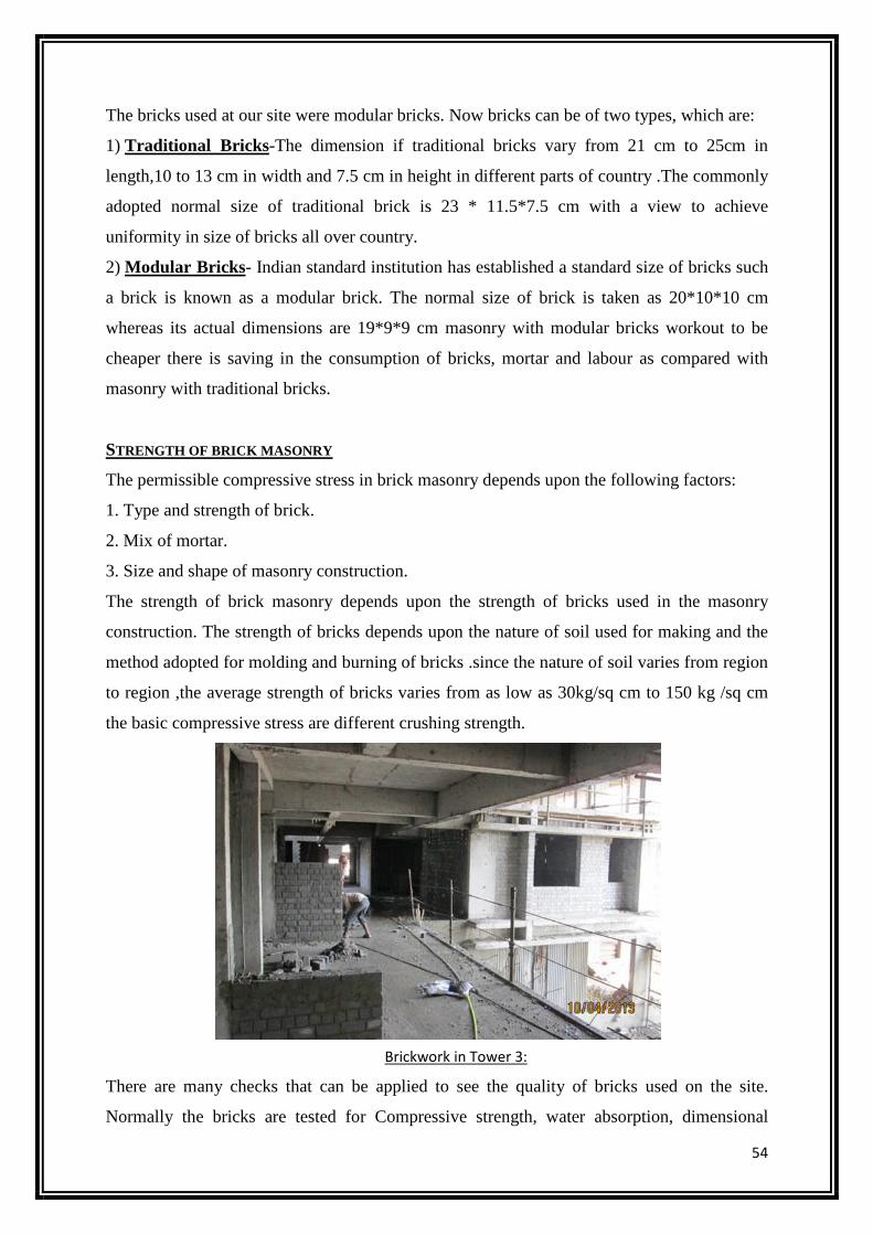
54
The bricks used at our site were modular bricks. Now bricks can be of two types, which are:
1) Traditional Bricks-The dimension if traditional bricks vary from 21 cm to 25cm in
length,10 to 13 cm in width and 7.5 cm in height in different parts of country .The commonly
adopted normal size of traditional brick is 23 * 11.5*7.5 cm with a view to achieve
uniformity in size of bricks all over country.
2) Modular Bricks- Indian standard institution has established a standard size of bricks such
a brick is known as a modular brick. The normal size of brick is taken as 20*10*10 cm
whereas its actual dimensions are 19*9*9 cm masonry with modular bricks workout to be
cheaper there is saving in the consumption of bricks, mortar and labour as compared with
masonry with traditional bricks.
STRENGTH OF BRICK MASONRY
The permissible compressive stress in brick masonry depends upon the following factors:
1. Type and strength of brick.
2. Mix of mortar.
3. Size and shape of masonry construction.
The strength of brick masonry depends upon the strength of bricks used in the masonry
construction. The strength of bricks depends upon the nature of soil used for making and the
method adopted for molding and burning of bricks .since the nature of soil varies from region
to region ,the average strength of bricks varies from as low as 30kg/sq cm to 150 kg /sq cm
the basic compressive stress are different crushing strength.
There are many checks that can be applied to see the quality of bricks used on the site.
Normally the bricks are tested for Compressive strength, water absorption, dimensional
Brickwork in Tower 3:
55
tolerances and efflorescence. However at small construction sites the quality of bricks can be
assessed based on following, which is prevalent in many sites.
• Visual check – Bricks should be well burnt and of uniform size and color.
• Striking of two bricks together should produce a metallic ringing sound.
• It should have surface so hard that can’t be scratched by the fingernails.
• A good brick should not break if dropped in standing position from one metre above ground
level.
• A good brick shouldn’t absorb moisture of more than 15-20% by weight, when soaked in
water
For example; a good brick of 2 kg shouldn’t weigh more than 2.3 to 2.4 kg if immersed in
water
for 24 hours.
PRECAUTIONS TO BE TAKEN IN BRICK MASONRY WORK
• Bricks should be soaked in water for adequate period so that the water penetrates to its full
thickness. Normally 6 to 8 hours of wetting is sufficient.
• A systematic bond must be maintained throughout the brickwork. Vertical joints shouldn’t
be
continuous but staggered.
• The joint thickness shouldn’t exceed 1 cm. It should be thoroughly filled with the cement
mortar 1:4 to 1:6 (Cement: Sand by volume)
• All bricks should be placed on their bed with frogs on top (depression on top of the brick for
providing bond with mortar).
• Thread, plumb bob and spirit level should be used for alignment, verticality and
horizontality of construction.
• Joints should be raked and properly finished with trowel or float, to provide good bond.
• A maximum of one metre wall height should be constructed in a day.
• Brickwork should be properly cured for at least 10 days.
56
PLASTERING
Sand-cement plaster is used extensively in building work as a decorative or protective
coating to concrete and masonry walls and concrete ceilings. We know that in general
plastering purposes we use a mix of 1:6 on the walls and 1:4 on the ceiling, however at the
site a mixture of 1:4 is applied throughout for convenience. The thickness of the plaster is
kept at 6-8 mm in the ceiling, 10-12 mm in the walls and 20-25 mm at the external surface.
Before plastering, a layer of cement slurry is applied on the surface for better bonding of the
plaster with the substrate. In various parts of the constructions, especially at the joints in
brickwork, during plastering chicken wire mesh is used to hold cement or plaster, thus
increasing the bonding strength between the plaster and the substrate, in a process known
as stuccoing. It is provided either horizontally or vertically, and in the case of brickwork, it is
provided after a vertical gap of 2-3 layers of bricks. Concrete reinforced with chicken
wire yields ferrocement, a versatile construction material. If the mesh is not provided
properly, then surface cracks will develop. Plaster has important requirements in the fresh
and hardened states. In the fresh state plaster must be workable, cohesive and plastic, and
have good water retention. The properties of fresh plaster depend on the materials used,
especially the sand, and on mix proportions. In the hardened state, plaster must be: strong
enough to hold paint and withstand local impact and abrasion; free of unsightly cracking;
well bonded to the substrate; have an acceptable surface texture; and have acceptable surface
accuracy (with reference to a plane or curved surface). The properties of hardened plaster
depend on the properties of the fresh plaster and the substrate, and on workmanship. For
accurate work, apply screed strips before the wall is plastered. These are narrow strips of
plaster along the perimeter of the wall, or at suitable intervals on the wall, that act as guides
for the striker board. Using a rectangular plasterer’s trowel, push plaster onto the wall or
ceiling using heavy pressure to compact the plaster and ensure full contact with the substrate.
The plaster should be slightly proud of the intended surface. Once the plaster starts to stiffen,
it should be struck off to a plane (or curved) surface using a light striker board or as it is
locally known as “funty”. Material removed in this way should be discarded. If plaster is to
be applied in more than one coat, the undercoat(s) should be scored with roughly parallel
lines about 20 mm apart and 5 mm deep. The purpose of scoring is two-fold; to provide a key
for the next coat and to distribute cracking so that it is less noticeable.
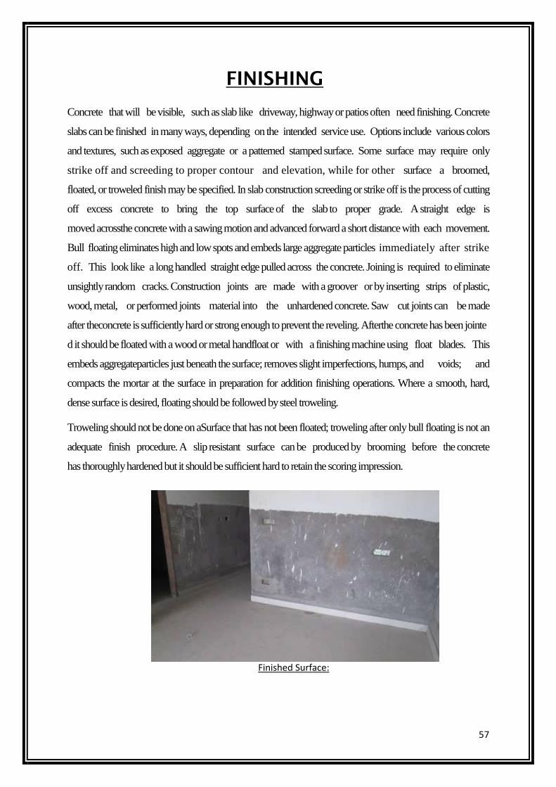
57
FINISHING
Concrete that will be visible, such as slab like driveway, highway or patios often need finishing. Concrete
slabs can be finished in many ways, depending on the intended service use. Options include various colors
and textures, such as exposed aggregate or a patterned stamped surface. Some surface may require only
strike off and screeding to proper contour and elevation, while for other surface a broomed,
floated, or troweled finish may be specified. In slab construction screeding or strike off is the process of cutting
off excess concrete to bring the top surface of the slab to proper grade. A straight edge is
moved acrossthe concrete with a sawing motion and advanced forward a short distance with each movement.
Bull floating eliminates high and low spots and embeds large aggregate particles immediately after strike
off. This look like a long handled straight edge pulled across the concrete. Joining is required to eliminate
unsightly random cracks. Construction joints are made with a groover or by inserting strips of plastic,
wood, metal, or performed joints material into the unhardened concrete. Saw cut joints can be made
after theconcrete is sufficiently hard or strong enough to prevent the reveling. Afterthe concrete has been jointe
d it should be floated with a wood or metal handfloat or with a finishing machine using float blades. This
embeds aggregateparticles just beneath the surface; removes slight imperfections, humps, and voids; and
compacts the mortar at the surface in preparation for addition finishing operations. Where a smooth, hard,
dense surface is desired, floating should be followed by steel troweling.
Troweling should not be done on aSurface that has not been floated; troweling after only bull floating is not an
adequate finish procedure. A slip resistant surface can be produced by brooming before the concrete
has thoroughly hardened but it should be sufficient hard to retain the scoring impression.
Finished Surface:
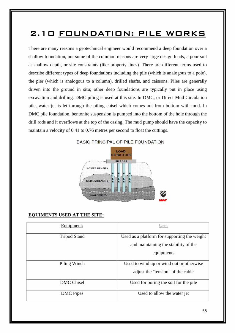
58
2.10 FOUNDATION: PILE WORKS
There are many reasons a geotechnical engineer would recommend a deep foundation over a
shallow foundation, but some of the common reasons are very large design loads, a poor soil
at shallow depth, or site constraints (like property lines). There are different terms used to
describe different types of deep foundations including the pile (which is analogous to a pole),
the pier (which is analogous to a column), drilled shafts, and caissons. Piles are generally
driven into the ground in situ; other deep foundations are typically put in place using
excavation and drilling. DMC piling is used at this site. In DMC, or Direct Mud Circulation
pile, water jet is let through the piling chisel which comes out from bottom with mud. In
DMC pile foundation, bentonite suspension is pumped into the bottom of the hole through the
drill rods and it overflows at the top of the casing. The mud pump should have the capacity to
maintain a velocity of 0.41 to 0.76 metres per second to float the cuttings.
EQUIMENTS USED AT THE SITE:
Equipment: Use:
Tripod Stand Used as a platform for supporting the weight
and maintaining the stability of the
equipments
Piling Winch Used to wind up or wind out or otherwise
adjust the "tension" of the cable
DMC Chisel Used for boring the soil for the pile
DMC Pipes Used to allow the water jet
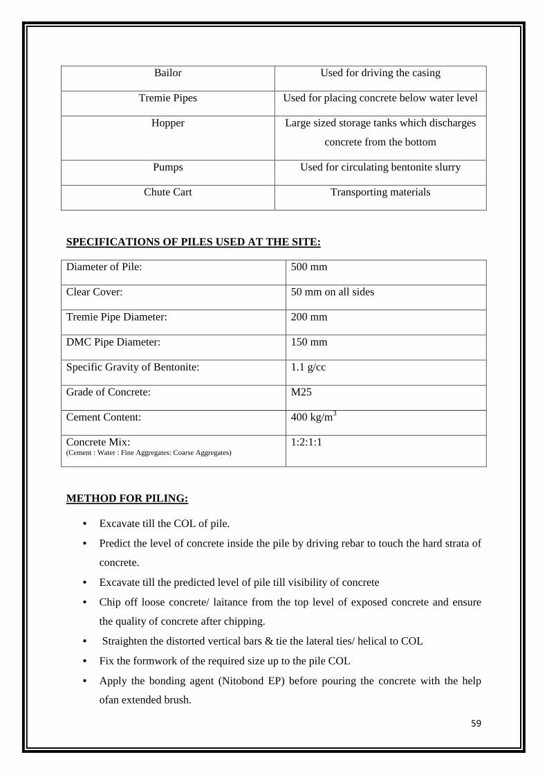
59
Bailor Used for driving the casing
Tremie Pipes Used for placing concrete below water level
Hopper Large sized storage tanks which discharges
concrete from the bottom
Pumps Used for circulating bentonite slurry
Chute Cart Transporting materials
SPECIFICATIONS OF PILES USED AT THE SITE:
Diameter of Pile: 500 mm
Clear Cover: 50 mm on all sides
Tremie Pipe Diameter: 200 mm
DMC Pipe Diameter: 150 mm
Specific Gravity of Bentonite: 1.1 g/cc
Grade of Concrete: M25
Cement Content: 400 kg/m3
Concrete Mix: (Cement : Water : Fine Aggregates: Coarse Aggregates)
1:2:1:1
METHOD FOR PILING:
• Excavate till the COL of pile.
• Predict the level of concrete inside the pile by driving rebar to touch the hard strata of
concrete.
• Excavate till the predicted level of pile till visibility of concrete
• Chip off loose concrete/ laitance from the top level of exposed concrete and ensure
the quality of concrete after chipping.
• Straighten the distorted vertical bars & tie the lateral ties/ helical to COL
• Fix the formwork of the required size up to the pile COL
• Apply the bonding agent (Nitobond EP) before pouring the concrete with the help
ofan extended brush.
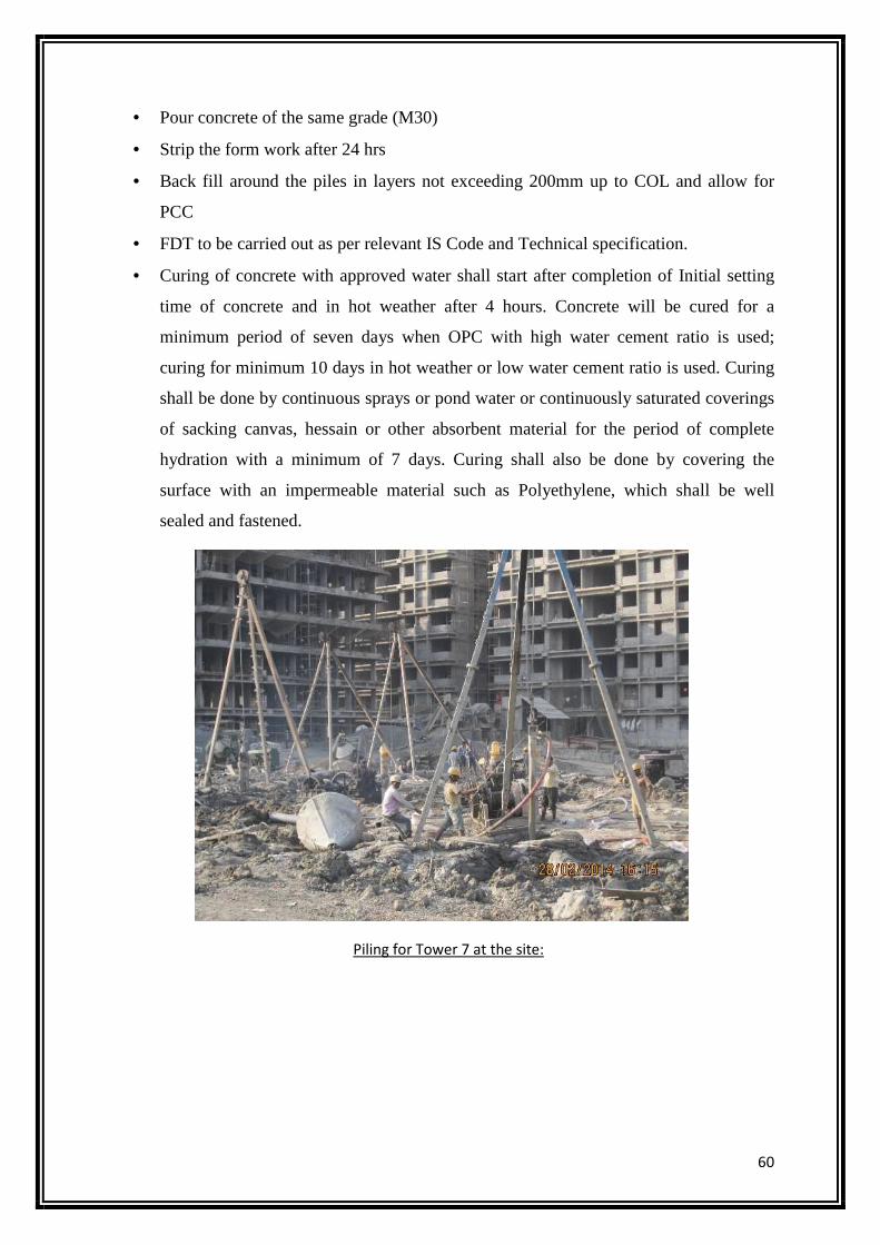
60
• Pour concrete of the same grade (M30)
• Strip the form work after 24 hrs
• Back fill around the piles in layers not exceeding 200mm up to COL and allow for
PCC
• FDT to be carried out as per relevant IS Code and Technical specification.
• Curing of concrete with approved water shall start after completion of Initial setting
time of concrete and in hot weather after 4 hours. Concrete will be cured for a
minimum period of seven days when OPC with high water cement ratio is used;
curing for minimum 10 days in hot weather or low water cement ratio is used. Curing
shall be done by continuous sprays or pond water or continuously saturated coverings
of sacking canvas, hessain or other absorbent material for the period of complete
hydration with a minimum of 7 days. Curing shall also be done by covering the
surface with an impermeable material such as Polyethylene, which shall be well
sealed and fastened.
Piling for Tower 7 at the site:
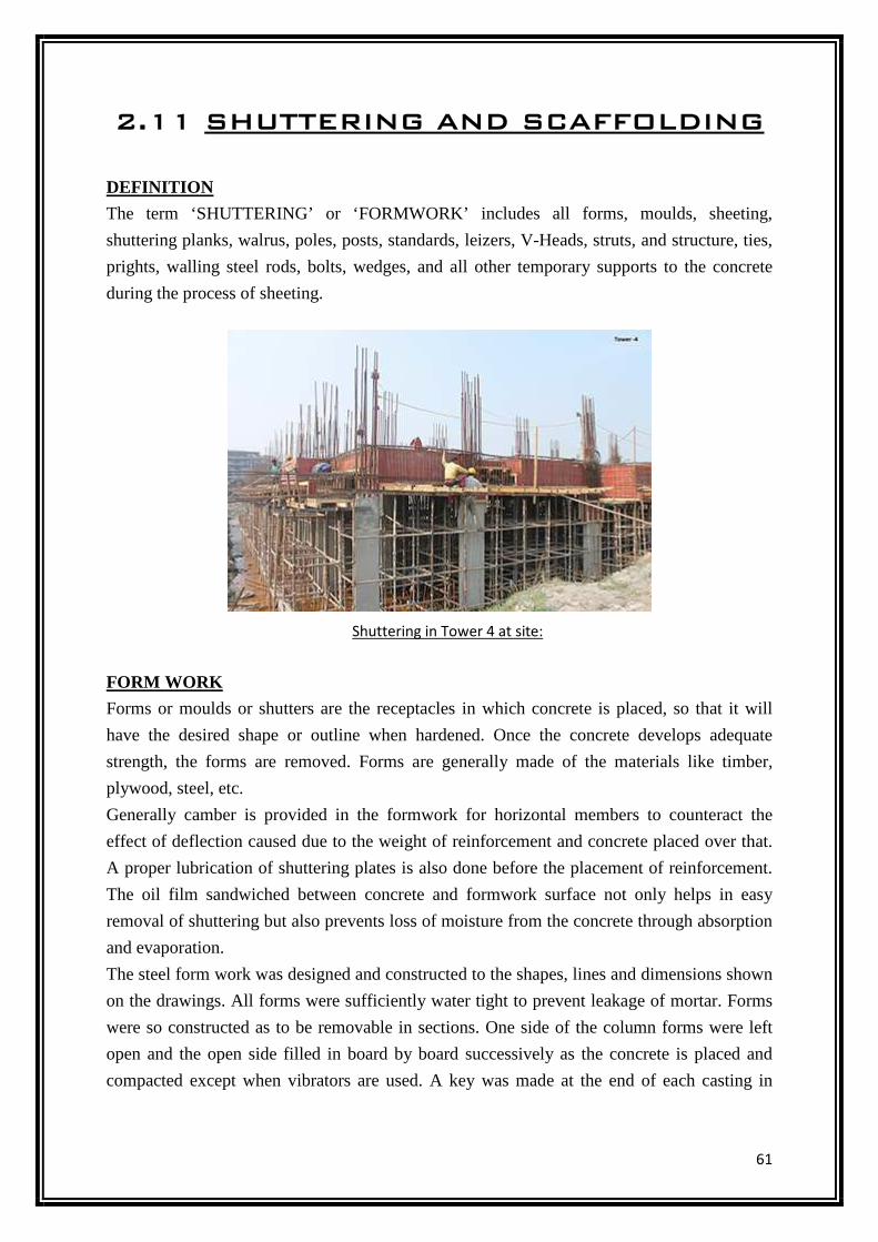
61
2.11 SHUTTERING AND SCAFFOLDING
DEFINITION
The term ‘SHUTTERING’ or ‘FORMWORK’ includes all forms, moulds, sheeting,
shuttering planks, walrus, poles, posts, standards, leizers, V-Heads, struts, and structure, ties,
prights, walling steel rods, bolts, wedges, and all other temporary supports to the concrete
during the process of sheeting.
FORM WORK
Forms or moulds or shutters are the receptacles in which concrete is placed, so that it will
have the desired shape or outline when hardened. Once the concrete develops adequate
strength, the forms are removed. Forms are generally made of the materials like timber,
plywood, steel, etc.
Generally camber is provided in the formwork for horizontal members to counteract the
effect of deflection caused due to the weight of reinforcement and concrete placed over that.
A proper lubrication of shuttering plates is also done before the placement of reinforcement.
The oil film sandwiched between concrete and formwork surface not only helps in easy
removal of shuttering but also prevents loss of moisture from the concrete through absorption
and evaporation.
The steel form work was designed and constructed to the shapes, lines and dimensions shown
on the drawings. All forms were sufficiently water tight to prevent leakage of mortar. Forms
were so constructed as to be removable in sections. One side of the column forms were left
open and the open side filled in board by board successively as the concrete is placed and
compacted except when vibrators are used. A key was made at the end of each casting in
Shuttering in Tower 4 at site:
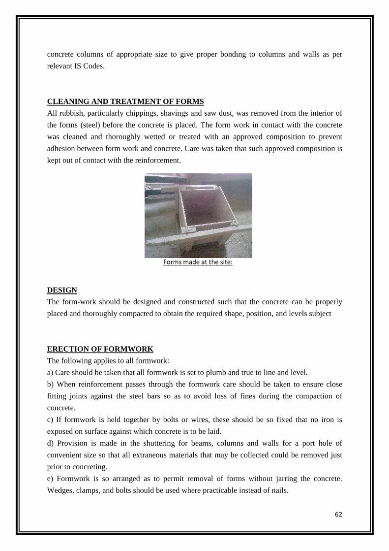
62
concrete columns of appropriate size to give proper bonding to columns and walls as per
relevant IS Codes.
CLEANING AND TREATMENT OF FORMS
All rubbish, particularly chippings, shavings and saw dust, was removed from the interior of
the forms (steel) before the concrete is placed. The form work in contact with the concrete
was cleaned and thoroughly wetted or treated with an approved composition to prevent
adhesion between form work and concrete. Care was taken that such approved composition is
kept out of contact with the reinforcement.
]
DESIGN
The form-work should be designed and constructed such that the concrete can be properly
placed and thoroughly compacted to obtain the required shape, position, and levels subject
ERECTION OF FORMWORK
The following applies to all formwork:
a) Care should be taken that all formwork is set to plumb and true to line and level.
b) When reinforcement passes through the formwork care should be taken to ensure close
fitting joints against the steel bars so as to avoid loss of fines during the compaction of
concrete.
c) If formwork is held together by bolts or wires, these should be so fixed that no iron is
exposed on surface against which concrete is to be laid.
d) Provision is made in the shuttering for beams, columns and walls for a port hole of
convenient size so that all extraneous materials that may be collected could be removed just
prior to concreting.
e) Formwork is so arranged as to permit removal of forms without jarring the concrete.
Wedges, clamps, and bolts should be used where practicable instead of nails.
Forms made at the site:
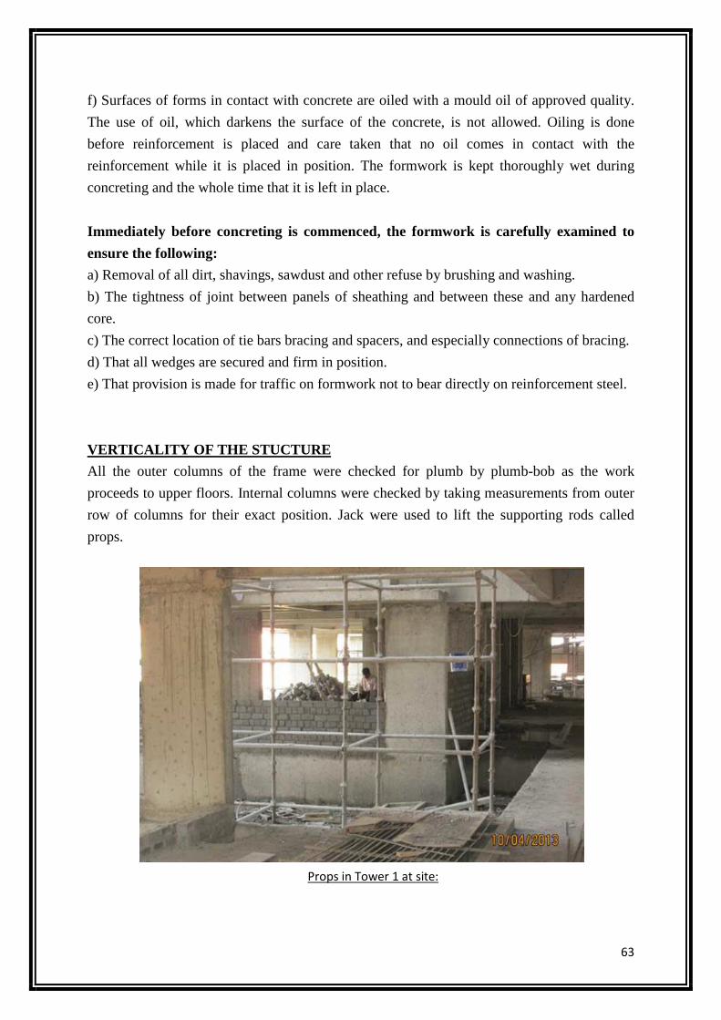
63
f) Surfaces of forms in contact with concrete are oiled with a mould oil of approved quality.
The use of oil, which darkens the surface of the concrete, is not allowed. Oiling is done
before reinforcement is placed and care taken that no oil comes in contact with the
reinforcement while it is placed in position. The formwork is kept thoroughly wet during
concreting and the whole time that it is left in place.
Immediately before concreting is commenced, the formwork is carefully examined to
ensure the following:
a) Removal of all dirt, shavings, sawdust and other refuse by brushing and washing.
b) The tightness of joint between panels of sheathing and between these and any hardened
core.
c) The correct location of tie bars bracing and spacers, and especially connections of bracing.
d) That all wedges are secured and firm in position.
e) That provision is made for traffic on formwork not to bear directly on reinforcement steel.
VERTICALITY OF THE STUCTURE
All the outer columns of the frame were checked for plumb by plumb-bob as the work
proceeds to upper floors. Internal columns were checked by taking measurements from outer
row of columns for their exact position. Jack were used to lift the supporting rods called
props.
Props in Tower 1 at site:
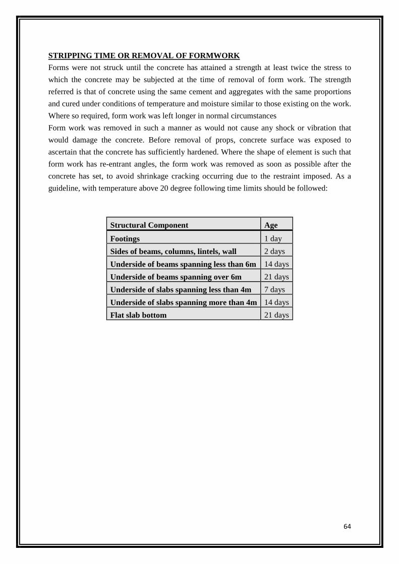
64
STRIPPING TIME OR REMOVAL OF FORMWORK
Forms were not struck until the concrete has attained a strength at least twice the stress to
which the concrete may be subjected at the time of removal of form work. The strength
referred is that of concrete using the same cement and aggregates with the same proportions
and cured under conditions of temperature and moisture similar to those existing on the work.
Where so required, form work was left longer in normal circumstances
Form work was removed in such a manner as would not cause any shock or vibration that
would damage the concrete. Before removal of props, concrete surface was exposed to
ascertain that the concrete has sufficiently hardened. Where the shape of element is such that
form work has re-entrant angles, the form work was removed as soon as possible after the
concrete has set, to avoid shrinkage cracking occurring due to the restraint imposed. As a
guideline, with temperature above 20 degree following time limits should be followed:
Structural Component Age
Footings 1 day
Sides of beams, columns, lintels, wall 2 days
Underside of beams spanning less than 6m 14 days
Underside of beams spanning over 6m 21 days
Underside of slabs spanning less than 4m 7 days
Underside of slabs spanning more than 4m 14 days
Flat slab bottom 21 days
65
2.12 GENERAL NOTES
The general notes specify the quantities and quantities of materials, the proportion of the
mortar, workmanship, the method of preparation and execution, and the methods of the
measurement. The company prepares the general notes of various items of work, and gets
them printed in the book from under the name of general notes. Some of the general notes are
given below related to Building Construction.
1. Earthwork in excavation in foundation:
• Excavation: Foundation trenches shall be dug out to the exact width of the foundation
concrete and the sides shall be vertical. If the soil is not good and does not permit
vertical sides, the sides should be sloped back or protected with timber shoring.
• Finish and Trench: The bottom of the foundation trenches shall be perfectly leveled
both longitudinally and transversally and the sides of the trench shall be dressed
perfectly vertical from bottom up to least thickness of lose concrete may be laid to the
exact width as per design. The bed of the trench shall be tightly watered and well
rammed. Soft or defective spots shall be dug out excess digging if done through
mistake shall be filled with concrete.
• Measurement: The measurement of the excavation shall be taken in cu m as for
rectangular trench, bottom width of concrete multiplied by the vertical depth of the
foundation from ground level and multiplied by the length of the trench.
2. Foundation: The foundation of the building should be so planned and the lay out of the
foundation should be on the ground should be correct in the measurement.
• Should not place the concrete in the foundation before checked by the Engineer-in
charge.
• If building has the basement more than two raft foundations should be provided.
• In the P.C.C. it should be in the ratio of 1:4:8 and 75 mm thick 75 mm projected
beyond raft foundation.
• The concrete provided in the raft foundation should be M-25 grade conforming to IS
456.
• The design and thickness of the raft foundation provided by the soil testing.
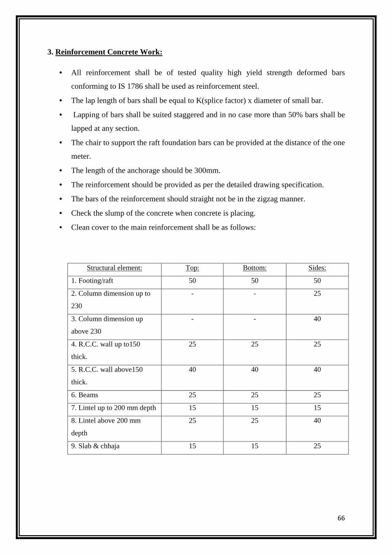
66
3. Reinforcement Concrete Work:
• All reinforcement shall be of tested quality high yield strength deformed bars
conforming to IS 1786 shall be used as reinforcement steel.
• The lap length of bars shall be equal to K(splice factor) x diameter of small bar.
• Lapping of bars shall be suited staggered and in no case more than 50% bars shall be
lapped at any section.
• The chair to support the raft foundation bars can be provided at the distance of the one
meter.
• The length of the anchorage should be 300mm.
• The reinforcement should be provided as per the detailed drawing specification.
• The bars of the reinforcement should straight not be in the zigzag manner.
• Check the slump of the concrete when concrete is placing.
• Clean cover to the main reinforcement shall be as follows:
Structural element: Top: Bottom: Sides:
1. Footing/raft 50 50 50
2. Column dimension up to
230
- - 25
3. Column dimension up
above 230
- - 40
4. R.C.C. wall up to150
thick.
25 25 25
5. R.C.C. wall above150
thick.
40 40 40
6. Beams 25 25 25
7. Lintel up to 200 mm depth 15 15 15
8. Lintel above 200 mm
depth
25 25 40
9. Slab & chhaja 15 15 25
67
4. Plastering:
• The joints of the brick work shall raked out to a depth of 12 mm and the surface of the
wall washed and clean and kept wet for the two days before plastering. The material
of mortar should be of standard specification.
• The thickness of the plastering shall be of 12mm to ensure uniform thickness of
plaster; patches of 15 cm shall be applied first at about 2 m apart to act as guide. First
mortar shall be dashed and pressed over the surface and then brought to a true smooth
and uniform surface by means of float and trowel.
• Wall plastering shall be started from top and worked down towards floor. Ceiling
plastering shall be completed before starting of wall plaster.
• All corner and edge shall be rounded. The plastered surface shall be kept wet for
10days the surface should be protected from rain, sun, frost, etc.
• For wall plastering 1:6 cement mortar and for ceiling plastering 1:4 cement mortar
with coarse sand is used.
5. 25 cm Cement Concrete floor:
• The cement concrete shall be of proportion 1:2:4 cement shall be fresh Portland
cement of standard specification. The coarse aggregate shall be hard and tough of
3cm gauge, well graded and free from dust, dirt, etc. the sand shall be coarse of 5
mm maximum size and down, well graded, clean and free from dust, direct and
organic matters.
• The floor shall be leveled and divided into panels or bays of maximums size or
1.2mx1.2m and the sides of the panels shall be bounded with teak wood battens 2.
cm thick and 5 cm wide or flat iron of same thickness and fixed with weak mortar, or
with nails or hooks. Required camber or slope should be given in floor for draining
wash water.
• Mixing of concrete shall be down by measuring with boxes to have the required
proportion as specified.
o First cement and sand mixed dry and the dry mix of cement and sand mixed
with ballast dry, and the mixed by adding water slowly and gradually to the
required quantity, and mixed thoroughly to have a uniform plastic mix.
68
o Base: In ground floor the c.c. floor shall be laid on a 7.5cm base of weak
cement concrete as per standard specifications.
6. White Washing: Fresh white lime slaked at site of work should be mixed with sufficient
water to make a thin cream. It shall then be screened through a coarse cloth, and gum in
proportion of 100 gms of gums to 16 liters of wash shall be added. The surface should be dry
and thoroughly cleaned from dust and dirt. The wash shall be applied with Moonj or jute
brush, vertically and horizontally. And the wash kept stirred in container while using. Two or
three coats shall be applied as specified, and each coat shall perfectly dry before the
succeeding coat is applied over it. Dry before the succeeding coat shall be applied as
specified, and each coat shall be perfectly dry before the succeeding coatis applied as
specified, and each coat shall be perfectly dry before the succeeding coat is applied over it.
After finishing the surface shall be of uniform color. In old surface, the surface should be
cleaned and repaired with cement mortar where necessary and allowed to dry before white
wash is applied.

69
20. CONCLUSION:
It was a wonderful learning experience at the site of Simplex Infrastructure Ltd.’s project
Silveroak Estate, for a month in Rajarhat. I gained a lot of insight regarding almost every
aspect of the construction site. I was given exposure in almost all the departments at the site,
and was elucidated about the various intricate details by the personals present on the site,
which helped me in increasing my knowledge about the basic & advanced techniques of
building construction. I learnt that as a Civil Engineer, one should possess good knowledge
about how the things are done practically at the construction site. Theoretical knowledge
alone is insufficient for a Civil Engineer, or as an Engineer as a whole. Besides, this training
program makes me realized the value of working together as a team and as a new experience
in working environment, which imposes challenges to us in every minute. I was exposed to
the various challenges which a civil engineer had to face during construction i.e. labour
problems, cost management, environmental challenges etc. The friendly welcome from all the
employees was really appreciative, sharing their experience and giving their piece of wisdom,
gained by them in their long line of work. The experience will surely help me in my future
and also in shaping my career further as a Civil Engineer.

70
REFERENCES
The various books, codes and journals used as a reference for this report are:
• IS 456:2000
• IS 800:2007 • N.N. Basak (1994), Surveying and Levelling; Project Surveys: Project on Township;
pg 468-69 • M.S. Shetty, Concrete Technology, Types of Cement and their tests, pg 27-65 • Dr. B.C. Punmia, Ashok Kumar Jain, Arun Kumar Jain (1993), Building
Construction; Masonry-2: Brick Masonry, Plastering and Pointing, Form-work; pg 241-304, 595-609, 711-19
• B.A. Gilly, A. Touran, and T. Asai, "Quality Control Circles in Construction", ASCE Journal of Construction Engineering and Management, Vol. 113, No. 3, 1987, pg 432
• Hinze, Jimmie W., Construction Safety, Prentice-Hall; 1997. • Improving Construction Safety Performance, Report A-3, The Business Roundtable,
New York, January 1982.
The various websites used as a reference for this report are:
• www.simplexinfra.com • www.silveroakestate.com
• www.nkrealtors.com • www.en.wikipedia.org • www.google.co.in
• www.scribd.com • www.understandconstruction.com