Embed Size (px)
Citation preview

Revit Architecture 2009 Families Guide
Imperial Tutorials
April 2008

© 2008 Autodesk, Inc. All Rights Reserved. Except as otherwise permitted by Autodesk, Inc., this publication, or parts thereof, may not bereproduced in any form, by any method, for any purpose.
Certain materials included in this publication are reprinted with the permission of the copyright holder.
DisclaimerTHIS PUBLICATION AND THE INFORMATION CONTAINED HEREIN IS MADE AVAILABLE BY AUTODESK, INC. "AS IS." AUTODESK, INC. DISCLAIMSALL WARRANTIES, EITHER EXPRESS OR IMPLIED, INCLUDING BUT NOT LIMITED TO ANY IMPLIED WARRANTIES OF MERCHANTABILITY ORFITNESS FOR A PARTICULAR PURPOSE REGARDING THESE MATERIALS.
TrademarksThe following are registered trademarks or trademarks of Autodesk, Inc., in the USA and other countries: 3DEC (design/logo), 3December,3December.com, 3ds Max, ActiveShapes, Actrix, ADI, Alias, Alias (swirl design/logo), AliasStudio, Alias|Wavefront (design/logo), ATC, AUGI,AutoCAD, AutoCAD Learning Assistance, AutoCAD LT, AutoCAD Simulator, AutoCAD SQL Extension, AutoCAD SQL Interface, Autodesk, AutodeskEnvision, Autodesk Insight, Autodesk Intent, Autodesk Inventor, Autodesk Map, Autodesk MapGuide, Autodesk Streamline, AutoLISP, AutoSnap,AutoSketch, AutoTrack, Backdraft, Built with ObjectARX (logo), Burn, Buzzsaw, CAiCE, Can You Imagine, Character Studio, Cinestream, Civil3D, Cleaner, Cleaner Central, ClearScale, Colour Warper, Combustion, Communication Specification, Constructware, Content Explorer,Create>what's>Next> (design/logo), Dancing Baby (image), DesignCenter, Design Doctor, Designer's Toolkit, DesignKids, DesignProf, DesignServer,DesignStudio, Design|Studio (design/logo), Design Your World, Design Your World (design/logo), DWF, DWG, DWG (logo), DWG TrueConvert,DWG TrueView, DXF, EditDV, Education by Design, Exposure, Extending the Design Team, FBX, Filmbox, FMDesktop, Freewheel, GDX Driver,Gmax, Heads-up Design, Heidi, HOOPS, HumanIK, i-drop, iMOUT, Incinerator, IntroDV, Inventor, Inventor LT, Kaydara, Kaydara (design/logo),LocationLogic, Lustre, Maya, Mechanical Desktop, MotionBuilder, Mudbox, NavisWorks, ObjectARX, ObjectDBX, Open Reality, Opticore,Opticore Opus, PolarSnap, PortfolioWall, Powered with Autodesk Technology, Productstream, ProjectPoint, ProMaterials, Reactor, RealDWG,Real-time Roto, Recognize, Render Queue, Reveal, Revit, Showcase, ShowMotion, SketchBook, SteeringWheels, StudioTools, Topobase, Toxik,ViewCube, Visual, Visual Bridge, Visual Construction, Visual Drainage, Visual Hydro, Visual Landscape, Visual Roads, Visual Survey, Visual Syllabus,Visual Toolbox, Visual Tugboat, Visual LISP, Voice Reality, Volo, Wiretap, and WiretapCentral
The following are registered trademarks or trademarks of Autodesk Canada Co. in the USA and/or Canada and other countries: Backburner,Discreet, Fire, Flame, Flint, Frost, Inferno, Multi-Master Editing, River, Smoke, Sparks, Stone, and Wire
All other brand names, product names or trademarks belong to their respective holders.
Third Party Software Program CreditsACIS Copyright© 1989-2001 Spatial Corp. Portions Copyright© 2002 Autodesk, Inc.Flash ® is a registered trademark of Macromedia, Inc. in the United States and/or other countries.International CorrectSpell™ Spelling Correction System© 1995 by Lernout & Hauspie Speech Products, N.V. All rights reserved.InstallShield™ 3.0. Copyright© 1997 InstallShield Software Corporation. All rights reserved.PANTONE® Colors displayed in the software application or in the user documentation may not match PANTONE-identified standards. Consultcurrent PANTONE Color Publications for accurate color. PANTONE Color Data and/or Software shall not be copied onto another disk or intomemory unless as part of the execution of this Autodesk software product.Portions Copyright© 1991-1996 Arthur D. Applegate. All rights reserved.Portions of this software are based on the work of the Independent JPEG Group.RAL DESIGN© RAL, Sankt Augustin, 2002RAL CLASSIC© RAL, Sankt Augustin, 2002Representation of the RAL Colors is done with the approval of RAL Deutsches Institut für Gütesicherung und Kennzeichnung e.V. (RAL GermanInstitute for Quality Assurance and Certification, re. Assoc.), D-53757 Sankt Augustin.Typefaces from the Bitstream® typeface library copyright 1992.Typefaces from Payne Loving Trust© 1996. All rights reserved.Printed manual and help produced with Idiom WorldServer™.WindowBlinds: DirectSkin™ OCX © Stardock®
AnswerWorks 4.0 ©; 1997-2003 WexTech Systems, Inc. Portions of this software © Vantage-Knexys. All rights reserved.The Director General of the Geographic Survey Institute has issued the approval for the coordinates exchange numbered TKY2JGD for JapanGeodetic Datum 2000, also known as technical information No H1-N0.2 of the Geographic Survey Institute, to be installed and used withinthis software product (Approval No.: 646 issued by GSI, April 8, 2002).Portions of this computer program are copyright © 1995-1999 LizardTech, Inc. All rights reserved. MrSID is protected by U.S. Patent No.5,710,835. Foreign Patents Pending.Portions of this computer program are Copyright ©; 2000 Earth Resource Mapping, Inc.OSTN97 © Crown Copyright 1997. All rights reserved.OSTN02 © Crown copyright 2002. All rights reserved.OSGM02 © Crown copyright 2002, © Ordnance Survey Ireland, 2002.FME Objects Engine © 2005 SAFE Software. All rights reserved.ETABS is a registered trademark of Computers and Structures, Inc. ETABS © copyright 1984-2005 Computers and Structures, Inc. All rightsreserved.RISA is a trademark of RISA Technologies. RISA-3D copyright © 1993-2005 RISA Technologies. All rights reserved.

Portions relating to JPEG © Copyright 1991-1998 Thomas G. Lane. All rights reserved. This software is based in part on the work of the IndependentJPEG Group.Portions relating to TIFF © Copyright 1997-1998 Sam Leffler. © Copyright 1991-1997 Silicon Graphics, Inc. All rights reserved. The Tiff portionsof this software are provided by the copyright holders and contributors “as is” and any express or implied warranties, including, but not limitedto, the implied warranties or merchantability and fitness for a particular purpose are disclaimed. In no event shall the copyright owner orcontributors of the TIFF portions be liable for any direct, indirect, incidental, special, exemplary, or consequential damages (including, but notlimited to, procurement of substitute goods or services; loss of use, data, or profits; or business interruption) however caused and on any theoryof liability, whether in contract, strict liability, or tort (including negligence or otherwise) arising in any way out of the use of the TIFF portionsof this software, even if advised of the possibility of such damage. Portions of Libtiff 3.5.7 Copyright © 1988-1997 Sam Leffler. Copyright ©1991-1997 Silicon Graphics, Inc. Permission to use, copy, modify, distribute, and sell this software and its documentation for any purpose ishereby granted without fee, provided that (i) the above copyright notices and this permission notice appear in all copies of the software andrelated documentation, and (ii) the names of Sam Leffler and Silicon Graphics may not be used in any advertising or publicity relating to thesoftware without the specific, prior written permission of Sam Leffler and Silicon Graphics.Portions of Libxml2 2.6.4 Copyright © 1998-2003 Daniel Veillard. All Rights Reserved. Permission is hereby granted, free of charge, to any personobtaining a copy of this software and associated documentation files (the “Software”), to deal in the Software without restriction, includingwithout limitation the rights to use, copy, modify, merge, publish, distribute, sublicense, and/or sell copies of the Software, and to permitpersons to whom the Software is furnished to do so, subject to the following conditions: The above copyright notices and this permission noticeshall be included in all copies or substantial portions of the Software.
Government UseUse, duplication, or disclosure by the U.S. Government is subject to restrictions as set forth in FAR 12.212 (Commercial ComputerSoftware-Restricted Rights) and DFAR 227.7202 (Rights in Technical Data and Computer Software), as applicable.

Contents
Chapter 1 Introduction . . . . . . . . . . . . . . . . . . . . . . . . . . . . . . . . . . . . . . . . . . . 1
Chapter 2 Understanding Revit Architecture Families . . . . . . . . . . . . . . . . . . . . . . . . . . . 3What Are Families? . . . . . . . . . . . . . . . . . . . . . . . . . . . . . . . . . . . . . . . . . . . . . 3
Example: Creating a Furniture Element with a Family and Type . . . . . . . . . . . . . . . . . . 3Role of Families in Your Building Models . . . . . . . . . . . . . . . . . . . . . . . . . . . . . . 8
Different Kinds of Families . . . . . . . . . . . . . . . . . . . . . . . . . . . . . . . . . . . . . . . . . 8System Families . . . . . . . . . . . . . . . . . . . . . . . . . . . . . . . . . . . . . . . . . . . . 9Standard Component Families . . . . . . . . . . . . . . . . . . . . . . . . . . . . . . . . . . . . 9In-Place Families . . . . . . . . . . . . . . . . . . . . . . . . . . . . . . . . . . . . . . . . . . . 9
Design Environment for Creating Families . . . . . . . . . . . . . . . . . . . . . . . . . . . . . . . . 11Managing Families . . . . . . . . . . . . . . . . . . . . . . . . . . . . . . . . . . . . . . . . . . . . . 11Getting Started with Families . . . . . . . . . . . . . . . . . . . . . . . . . . . . . . . . . . . . . . . 12
System Families . . . . . . . . . . . . . . . . . . . . . . . . . . . . . . . . . . . . . . . . . 13
Chapter 3 System Families Overview . . . . . . . . . . . . . . . . . . . . . . . . . . . . . . . . . . . 15Revit Architecture System Families and Settings . . . . . . . . . . . . . . . . . . . . . . . . . . . . . 15Viewing System Families in a Project or Template . . . . . . . . . . . . . . . . . . . . . . . . . . . . 17Viewing Elements with System Family Types in a Project . . . . . . . . . . . . . . . . . . . . . . . . 19Creating and Modifying Elements with System Family Types . . . . . . . . . . . . . . . . . . . . . . 20
Creating an Element with a System Family Type . . . . . . . . . . . . . . . . . . . . . . . . . . 20Creating an Element with a System Family Type from an Element in the Project . . . . . . . . . 21Changing the System Family Type of an Element . . . . . . . . . . . . . . . . . . . . . . . . . 21
Creating and Modifying System Family Types . . . . . . . . . . . . . . . . . . . . . . . . . . . . . . 23Modifying a System Family Type . . . . . . . . . . . . . . . . . . . . . . . . . . . . . . . . . . 23Duplicating a System Family Type to Create a New Type . . . . . . . . . . . . . . . . . . . . . . 24Deleting System Family Types . . . . . . . . . . . . . . . . . . . . . . . . . . . . . . . . . . . . 25
Loading System Family Types into a Project or Template . . . . . . . . . . . . . . . . . . . . . . . . . 26Copying System Family Types Between Projects or Templates . . . . . . . . . . . . . . . . . . . 26
v
Transferring System Family Types between Projects or Templates . . . . . . . . . . . . . . . . . 26
Chapter 4 Tutorial: Working with System Families . . . . . . . . . . . . . . . . . . . . . . . . . . . . 29Creating Custom Wall Materials . . . . . . . . . . . . . . . . . . . . . . . . . . . . . . . . . . . . . . 30Creating a Custom Wall Type . . . . . . . . . . . . . . . . . . . . . . . . . . . . . . . . . . . . . . . 35Adding Reveals to the Custom Wall Type . . . . . . . . . . . . . . . . . . . . . . . . . . . . . . . . . 39Creating a Custom Stacked Wall Type . . . . . . . . . . . . . . . . . . . . . . . . . . . . . . . . . . . 43Creating a Custom Floor Type . . . . . . . . . . . . . . . . . . . . . . . . . . . . . . . . . . . . . . . 46Creating a Custom Roof Type . . . . . . . . . . . . . . . . . . . . . . . . . . . . . . . . . . . . . . . 49Transferring System Families Between Projects . . . . . . . . . . . . . . . . . . . . . . . . . . . . . . 51
Standard Component Families . . . . . . . . . . . . . . . . . . . . . . . . . . . . . . . . . 55
Chapter 5 Standard Component Families Overview . . . . . . . . . . . . . . . . . . . . . . . . . . . 57Revit Architecture Standard Component Families . . . . . . . . . . . . . . . . . . . . . . . . . . . . 57Workflow: Using Component Families in Your Projects . . . . . . . . . . . . . . . . . . . . . . . . . 58Using Existing Component Families . . . . . . . . . . . . . . . . . . . . . . . . . . . . . . . . . . . 59
Viewing Component Families in a Project or Template . . . . . . . . . . . . . . . . . . . . . . . 59Viewing Elements with Component Family Types in a Project . . . . . . . . . . . . . . . . . . . 60Finding and Loading Component Families . . . . . . . . . . . . . . . . . . . . . . . . . . . . . 61Creating Elements with Component Family Types . . . . . . . . . . . . . . . . . . . . . . . . . 67Deleting Component Families and Types . . . . . . . . . . . . . . . . . . . . . . . . . . . . . . 68
Creating Component Families . . . . . . . . . . . . . . . . . . . . . . . . . . . . . . . . . . . . . . . 69Understanding the Family Editor . . . . . . . . . . . . . . . . . . . . . . . . . . . . . . . . . . 70Creating a Standard Component Family . . . . . . . . . . . . . . . . . . . . . . . . . . . . . . 72Advanced Component Family Techniques . . . . . . . . . . . . . . . . . . . . . . . . . . . . 131
Modifying Component Families . . . . . . . . . . . . . . . . . . . . . . . . . . . . . . . . . . . . . 145Modifying Component Family Types . . . . . . . . . . . . . . . . . . . . . . . . . . . . . . . 146Modifying a Family . . . . . . . . . . . . . . . . . . . . . . . . . . . . . . . . . . . . . . . . . 147Modifying a Family to Create a New Family . . . . . . . . . . . . . . . . . . . . . . . . . . . . 148Modifying Families in a Project (or Nested Family) . . . . . . . . . . . . . . . . . . . . . . . . 148
Tutorials: 2D Component Families . . . . . . . . . . . . . . . . . . . . . . . . . . . . . . 151
Chapter 6 Creating a Room Tag . . . . . . . . . . . . . . . . . . . . . . . . . . . . . . . . . . . . . 153Specifying Room Tag Parameters . . . . . . . . . . . . . . . . . . . . . . . . . . . . . . . . . . . . . 153
Chapter 7 Creating a Titleblock Family . . . . . . . . . . . . . . . . . . . . . . . . . . . . . . . . . 157Drawing Linework for a Titleblock Sheet . . . . . . . . . . . . . . . . . . . . . . . . . . . . . . . . 158Adding Graphics and Text to a Titleblock . . . . . . . . . . . . . . . . . . . . . . . . . . . . . . . . 160Adding the Titleblock to a New Project . . . . . . . . . . . . . . . . . . . . . . . . . . . . . . . . . 170
Chapter 8 Creating a Keyplan - Generic Annotation Family . . . . . . . . . . . . . . . . . . . . . . . 173Creating the Keyplan Geometry . . . . . . . . . . . . . . . . . . . . . . . . . . . . . . . . . . . . . 174Add Parameters to Control Keyplan Visibility . . . . . . . . . . . . . . . . . . . . . . . . . . . . . . 186
Chapter 9 Creating Detail Component Families . . . . . . . . . . . . . . . . . . . . . . . . . . . . . 191Creating a Window Sill Detail Component Family from a DWG . . . . . . . . . . . . . . . . . . . . 193Creating a Full Window Detail Component Family . . . . . . . . . . . . . . . . . . . . . . . . . . . 201Adding the Full Window Detail Component to a Window Family . . . . . . . . . . . . . . . . . . . 215
Chapter 10 Creating Planting Families . . . . . . . . . . . . . . . . . . . . . . . . . . . . . . . . . . 225Creating the Existing Plant Base Family . . . . . . . . . . . . . . . . . . . . . . . . . . . . . . . . . 226Creating a Species Base Family . . . . . . . . . . . . . . . . . . . . . . . . . . . . . . . . . . . . . . 231
vi | Contents
Creating a Planting Symbol Family . . . . . . . . . . . . . . . . . . . . . . . . . . . . . . . . . . . 233Testing Your Planting Families . . . . . . . . . . . . . . . . . . . . . . . . . . . . . . . . . . . . . . 236
Tutorials: 3D Component Families . . . . . . . . . . . . . . . . . . . . . . . . . . . . . . 239
Chapter 11 Creating a Window Family . . . . . . . . . . . . . . . . . . . . . . . . . . . . . . . . . . 241Specifying the New Window Parameters . . . . . . . . . . . . . . . . . . . . . . . . . . . . . . . . . 242Creating the Window Frame Solid Geometry . . . . . . . . . . . . . . . . . . . . . . . . . . . . . . 243Creating the Window Sash Solid Geometry . . . . . . . . . . . . . . . . . . . . . . . . . . . . . . . 249Creating the Window Glass Solid Geometry . . . . . . . . . . . . . . . . . . . . . . . . . . . . . . . 252Creating the Window Mullion Solid Geometry . . . . . . . . . . . . . . . . . . . . . . . . . . . . . 257Assigning Materials to the Window Components . . . . . . . . . . . . . . . . . . . . . . . . . . . . 269Defining New Window Types . . . . . . . . . . . . . . . . . . . . . . . . . . . . . . . . . . . . . . 273
Chapter 12 Creating a Door Family . . . . . . . . . . . . . . . . . . . . . . . . . . . . . . . . . . . . 279Drawing the Door Plan View Components . . . . . . . . . . . . . . . . . . . . . . . . . . . . . . . 280Creating the Door Panel Solid Geometry . . . . . . . . . . . . . . . . . . . . . . . . . . . . . . . . 286Assigning Materials to the Door Components . . . . . . . . . . . . . . . . . . . . . . . . . . . . . . 292Defining New Door Types . . . . . . . . . . . . . . . . . . . . . . . . . . . . . . . . . . . . . . . . 294
Chapter 13 Creating a Baluster Family . . . . . . . . . . . . . . . . . . . . . . . . . . . . . . . . . . 299Creating a Baluster Family . . . . . . . . . . . . . . . . . . . . . . . . . . . . . . . . . . . . . . . . 301
Chapter 14 Creating a Basic Column Family . . . . . . . . . . . . . . . . . . . . . . . . . . . . . . . 331Creating the Column Base . . . . . . . . . . . . . . . . . . . . . . . . . . . . . . . . . . . . . . . . 332Creating the Upper Column . . . . . . . . . . . . . . . . . . . . . . . . . . . . . . . . . . . . . . . 342Adding Symbolic Lines for Plan Representation . . . . . . . . . . . . . . . . . . . . . . . . . . . . . 357
Chapter 15 Creating a Bookcase (Furniture) Family . . . . . . . . . . . . . . . . . . . . . . . . . . . 365Creating the New Bookcase Family . . . . . . . . . . . . . . . . . . . . . . . . . . . . . . . . . . . 365Creating the Family Skeleton . . . . . . . . . . . . . . . . . . . . . . . . . . . . . . . . . . . . . . . 366Creating Family Parameters and Types . . . . . . . . . . . . . . . . . . . . . . . . . . . . . . . . . . 370Creating Panels . . . . . . . . . . . . . . . . . . . . . . . . . . . . . . . . . . . . . . . . . . . . . . 378Creating the Base Plate . . . . . . . . . . . . . . . . . . . . . . . . . . . . . . . . . . . . . . . . . . 388Adding a Top Shelf . . . . . . . . . . . . . . . . . . . . . . . . . . . . . . . . . . . . . . . . . . . . 395Changing the Shape of the Side Panels . . . . . . . . . . . . . . . . . . . . . . . . . . . . . . . . . 403Creating and Assigning Subcategories . . . . . . . . . . . . . . . . . . . . . . . . . . . . . . . . . . 406Adding Shelves . . . . . . . . . . . . . . . . . . . . . . . . . . . . . . . . . . . . . . . . . . . . . . 407Adding an Enclosure Panel . . . . . . . . . . . . . . . . . . . . . . . . . . . . . . . . . . . . . . . . 413Adding a Door . . . . . . . . . . . . . . . . . . . . . . . . . . . . . . . . . . . . . . . . . . . . . . 421Managing Visibility . . . . . . . . . . . . . . . . . . . . . . . . . . . . . . . . . . . . . . . . . . . . 429Adding a Masking Region . . . . . . . . . . . . . . . . . . . . . . . . . . . . . . . . . . . . . . . . 431Creating and Assigning Materials . . . . . . . . . . . . . . . . . . . . . . . . . . . . . . . . . . . . 432Creating a Material Parameter . . . . . . . . . . . . . . . . . . . . . . . . . . . . . . . . . . . . . . 437Controlling the Door Visibility . . . . . . . . . . . . . . . . . . . . . . . . . . . . . . . . . . . . . . 441Creating a Type Catalog . . . . . . . . . . . . . . . . . . . . . . . . . . . . . . . . . . . . . . . . . 444
Chapter 16 Using Reference Lines in Families . . . . . . . . . . . . . . . . . . . . . . . . . . . . . . . 447Creating a Bookcase Door with a Reference Line . . . . . . . . . . . . . . . . . . . . . . . . . . . . 448Creating an Angled Chair Back with a Reference Line . . . . . . . . . . . . . . . . . . . . . . . . . 472
Tutorials: Advanced Standard Component Families . . . . . . . . . . . . . . . . . . . . . 491
Chapter 17 Creating Shared Families . . . . . . . . . . . . . . . . . . . . . . . . . . . . . . . . . . . 493
Contents | vii

Creating a Window Family with Nested Windows . . . . . . . . . . . . . . . . . . . . . . . . . . . 493Using a Shared Family in a Project . . . . . . . . . . . . . . . . . . . . . . . . . . . . . . . . . . . . 498
Creating a Complex Window Family . . . . . . . . . . . . . . . . . . . . . . . . . . . . . 503
Chapter 18 Creating a Complex Window Family . . . . . . . . . . . . . . . . . . . . . . . . . . . . . 505
Chapter 19 Creating the Window Geometry . . . . . . . . . . . . . . . . . . . . . . . . . . . . . . . 529
Chapter 20 Nesting Sill Families into the Window Family . . . . . . . . . . . . . . . . . . . . . . . . 561
Creating a Solar Shade Family . . . . . . . . . . . . . . . . . . . . . . . . . . . . . . . . 571
Chapter 21 Creating a Solar Shade Family . . . . . . . . . . . . . . . . . . . . . . . . . . . . . . . . 573
Chapter 22 Adding the Shade Support to the Solar Shade Family . . . . . . . . . . . . . . . . . . . . 605
Chapter 23 Creating the Louver for the Solar Shade . . . . . . . . . . . . . . . . . . . . . . . . . . . 627
Chapter 24 Finishing the Solar Shade . . . . . . . . . . . . . . . . . . . . . . . . . . . . . . . . . . . 645
Troubleshooting Families . . . . . . . . . . . . . . . . . . . . . . . . . . . . . . . . . . . 665
Chapter 25 Troubleshooting Families . . . . . . . . . . . . . . . . . . . . . . . . . . . . . . . . . . . 667Troubleshooting Window Families . . . . . . . . . . . . . . . . . . . . . . . . . . . . . . . . . . . . 668Troubleshooting an Awning Family . . . . . . . . . . . . . . . . . . . . . . . . . . . . . . . . . . . 680
In-Place Families . . . . . . . . . . . . . . . . . . . . . . . . . . . . . . . . . . . . . . . . 717
Chapter 26 In-Place Families Overview . . . . . . . . . . . . . . . . . . . . . . . . . . . . . . . . . . 719Viewing In-Place Families in a Project . . . . . . . . . . . . . . . . . . . . . . . . . . . . . . . . . . 720Creating and Modifying In-Place Families . . . . . . . . . . . . . . . . . . . . . . . . . . . . . . . . 722
Creating an In-Place Family . . . . . . . . . . . . . . . . . . . . . . . . . . . . . . . . . . . . 722Modifying an In-Place Family . . . . . . . . . . . . . . . . . . . . . . . . . . . . . . . . . . . 723Copying In-Place Families . . . . . . . . . . . . . . . . . . . . . . . . . . . . . . . . . . . . . 723Deleting In-Place Families . . . . . . . . . . . . . . . . . . . . . . . . . . . . . . . . . . . . . 723
Using In-Place Families in Other Projects . . . . . . . . . . . . . . . . . . . . . . . . . . . . . . . . 724Copying an In-Place Family Between Projects . . . . . . . . . . . . . . . . . . . . . . . . . . . 724Loading an In-Place Family into a Project as a Group . . . . . . . . . . . . . . . . . . . . . . . 725
Chapter 27 Tutorial: Creating an In-Place Family . . . . . . . . . . . . . . . . . . . . . . . . . . . . . 727Creating the 3D Geometry for the Information Counter . . . . . . . . . . . . . . . . . . . . . . . . 728Creating a 2D Representation of the Information Counter . . . . . . . . . . . . . . . . . . . . . . . 744
Appendices . . . . . . . . . . . . . . . . . . . . . . . . . . . . . . . . . . . . . . . . . . 751
Chapter 28 Appendix A: Revit System Families and Settings . . . . . . . . . . . . . . . . . . . . . . . 753
Chapter 29 Appendix B: Exploring Family Templates . . . . . . . . . . . . . . . . . . . . . . . . . . . 759
viii | Contents

Exploring Family Templates . . . . . . . . . . . . . . . . . . . . . . . . . . . . . . . . . . . . . . . 759Model Family Templates . . . . . . . . . . . . . . . . . . . . . . . . . . . . . . . . . . . . . . 759Annotation Family Templates . . . . . . . . . . . . . . . . . . . . . . . . . . . . . . . . . . . 782Titleblock Family Templates . . . . . . . . . . . . . . . . . . . . . . . . . . . . . . . . . . . . 784
Chapter 30 Appendix C : Best Practices for Creating Revit Architecture Families . . . . . . . . . . . . 787Best Practices for Creating Revit Architecture Families . . . . . . . . . . . . . . . . . . . . . . . . . 787
Chapter 31 Glossary . . . . . . . . . . . . . . . . . . . . . . . . . . . . . . . . . . . . . . . . . . . . 793Glossary Terms . . . . . . . . . . . . . . . . . . . . . . . . . . . . . . . . . . . . . . . . . . . . . . 793
Contents | ix

x

Introduction
Welcome to the Revit Architecture 2009 Families Guide! Families are an integral part of working in Revit Architecture,and key to creating custom content.
In this guide, you learn:
■ how to use families in your projects
■ concepts of parametric design and family creation
■ best practices to use when creating your own families
To better help you understand how to work with families, this guide contains conceptual explanations, hands-on tutorials,and reference information.
Audience and Prerequisites
This guide is intended for the beginning, intermediate, and advanced Revit Architecture families user. Although anysketching and 2D or 3D modeling experience is helpful to understand how to work with families, before you begin towork with this guide, you should have a basic understanding of Revit Architecture. If you do not, it is recommended thatyou use the tutorials included in the software. Access the tutorials by clicking Help ➤ Tutorials.
Training Files
The hands-on tutorials included in this guide use templates and family files that you download fromhttp://www.autodesk.com/revitarchitecture-documentation. Most of these files have an .rfa, .rte, or .rvt extension, and areextracted by default to folders in C:\Documents and Settings\All Users\Application Data\Autodesk\RAC 2009\Training.
1
1

2

Understanding RevitArchitecture Families
All of the elements that you add to your Revit Architecture projects – from the structural members, walls, roofs, windows,and doors that you use to assemble a building model to the callouts, fixtures, tags, and detail components that you useto document it – are created with families.
By using predefined families and creating new ones in Revit Architecture, you can add both standard and custom elementsto your building models. Families also provide a level of control over elements that are similar in use and behavior, allowingyou to easily make design changes and manage your projects more efficiently.
What Are Families?A family is a group of elements with a common set of properties, called parameters, and a related graphicalrepresentation. Different elements belonging to a family may have different values for some or all of theirparameters, but the set of parameters (their names and meanings) is the same. These variations within thefamily are called family types or types.
For example, the Furniture family includes families and family types that you can use to create differentpieces of furniture, like desks, chairs, and cabinets. Although these families serve different purposes and arecomposed of different materials, they have a related use. Each type in the family has a related graphicalrepresentation and an identical set of parameters, called the family type parameters.
When you create an element in a project with a specific family and family type, you create an instance ofthe element. Each element instance has a set of properties, in which you can change some element parametersindependent of the family type parameters. These changes apply only to the instance of the element, thesingle element in the project. If you make any changes to the family type parameters, the changes apply toall element instances that you created with that type.
Example: Creating a Furniture Element with a Family and Type
When you create an element in a project, that element is organized within the project first by elementcategory, then by family, family type, and by instance. All 4 levels provide a different level of control of theelement in your project. The following example demonstrates how you can create and control a bookcasein a project.
2
3

Determining the Element Category
All families that are in use or are available in your projects (and templates) are visible in the Project Browserunder Families, grouped by element category.
The category defines a top level of identification and behavior for the element. When you start the commandto create a piece of furniture, you automatically determine that the element will belong to the Furniturecategory. The category sets the basic role of the element within the building model, determines whichelements it will interact with, and specifies that when tagged, it will be included in any furniture schedulesthat you create.
Selecting the Family
By expanding the Furniture category, you can see that it includes a number of different furniture families.All the furniture that you create in this project (unless it is specialized or you load other families), will belongto one of these families.
By itself, a family usually does not provide enough information to create a desired element in your project.While the family narrows the definition of the element you are creating in terms of its basic characteristicsand graphic representation, it does not specify the size, material, or other specific characteristics of theelement. For this reason, families include family types.
Specifying the Family Type
Family types are variations on the kind of element the family represents, and are shown under the furniturefamilies shown below. For any of the types listed below, the family provides you with the kind of furnitureyou want to create (a bookcase, cabinet, chair, or desk), while the family type specifies the dimensions,material, and a few other characteristics of the element that you can create.
4 | Chapter 2 Understanding Revit Architecture Families

Creating an Instance
To add any of the furniture types in the Bookcase family to a project, start the Component command. TheType Selector lists the available Furniture family types in the project, listed first by family, then by name.You select the type that you want (in this case, a bookcase type), and add it to the project.
When you create an element in your project, you create what is called an instance of the family type. If youcreate one bookcase element, you have one instance of the type in your project.
If you create 4 bookcases, you have 4 instances of the type in your project.
Example: Creating a Furniture Element with a Family and Type | 5

Making Modifications
After you create an element in your project, you can make a number of changes to it. If you select one ormore instances of the bookcase in the previous example, and then right-click and click Element Properties,you display the Element Properties of the bookcase or bookcases. This is a location where you can make anumber of changes to the element and its parameters.
Changing Instance Parameters
In the Element Properties dialog, under Instance Parameters, scroll down to view the all of the instanceparameters of the bookcase. You can change any of these values for the instance or instances of the bookcase
6 | Chapter 2 Understanding Revit Architecture Families

that you selected. The changes will not be applied to all the bookcases of that type, only the instance orinstances of the bookcase that you selected.
This family contains an instance parameter that determines whether or not the bookcase includes a door.In the above illustration, this DoorIncluded parameter is selected. If you clear the DoorIncluded parameterin the Element Properties dialog for one of the bookcase instances, that bookcase will no longer display adoor.
Changing Type Parameters
In the Element Properties dialog, click Edit/New to view the Type Parameters of the bookcase type.
These parameters are shared by all bookcases in the project of the same family type. Any changes that youmake to these parameters are applied to all bookcases of the same family type in the project, regardless ofwhether or not you selected them.
Example: Creating a Furniture Element with a Family and Type | 7

Changing the Family or Family Type
You can also change the family type, or family and family type of the bookcase element in the ElementProperties dialog.
To change the family, at the top of the dialog, for Family, select a new family. In this example, you couldchange the bookcase to family to one that creates a different style bookcase or you could change the bookcaseto a completely different piece of furniture, like a cabinet.
To change the family type, for Type, select a different type. After you exit the dialog, the instance or instancesthat you selected will reflect any changes that you made to the family or family type.
Role of Families in Your Building Models
Now that you have seen the control that you have over elements that you create with families and familytypes, you can imagine the flexibility that families, family types, and family parameters provide whencreating and documenting your building models. Families, family types, and type and instance parametersallow for variation and change in the elements that you create, which is the basis of parametric modelingin Revit Architecture.
In addition to making the changes that were demonstrated in the previous section, you can use families,family types, and family parameters to:
■ Add family types to existing families.
■ Create your own family, and by adding family types, create a number of the same elements in a differentsize or that feature a different material, without having to draw the component more than once.
■ Create family type parameters in a family that provide optional element geometry or material.
■ Control the visibility and detail level of an element in different types of drawing views.
All families can be two-dimensional, three-dimensional, or both, but not all families have to be parametric.Elements created with families that do not need more than one size or type may remain non-parametric.
Wall, door, and window families are examples of 3D families, which display accordingly in isometric andplan views. Annotation detail families are examples of 2D families that do not require 3D representations.A furniture family is an example of a family that might need separate 3D and 2D representations: a 3Drepresentation to display in isometric views and a simplified 2D outline to display in a plan view.
NOTE Two- and three-dimensional content from other software packages that you import into Revit Architectureis not parametric, unless you recreate it as such.
Different Kinds of FamiliesThere are 3 kinds of families in Revit Architecture:
■ system families
■ standard component (component) families
■ in-place families
Most elements that you create in your projects are system or component families. Standard componentfamilies can be combined to create nested and shared component families. Non-standard or custom elementsare created using in-place families.
8 | Chapter 2 Understanding Revit Architecture Families

System Families
System families create basic building elements such as walls, roofs, ceilings, floors, and other elements thatyou would assemble on a construction site. System settings, which affect the project environment andinclude types for levels, grids, drawing sheets, and viewports, are also system families.
System families are predefined in Revit Architecture. You do not load them into your projects from externalfiles, nor do you save them in locations external to the project. If you cannot find the system family typethat you need in a project, you can create a new one by changing the properties of an existing type, byduplicating (copying) a family type and changing its properties, or by copying and pasting one from anotherproject. Any types that you modify are saved in your project.
For example, you may want to add a wood floor with a specific finish to a project. However, the only similarfloor family type features smaller joists and a different finish. You would duplicate the system family typein your project, change its name to reflect the characteristics of the new floor, and edit its properties tofeature the new size and finish. System families usually do not require you to model any new geometry.
Because system families are predefined, they are the least customizable of the 3 kinds of families, but theyinclude more intelligent behavior than the other standard component families and in-place families. A wallthat you create in a project automatically resizes to accommodate windows and doors that you place in it.There is no need to cut openings in the wall for the windows and doors before you place them.
Standard Component Families
Standard component families are families used to create both building components and some annotationelements. Component families create the building components that would usually be purchased, delivered,and installed in and around a building, such as windows, doors, casework, fixtures, furniture, and planting.They also include some annotation elements that are routinely customized, such as symbols and titleblocks.
Because of their highly customizable nature, component families are the families that you most commonlycreate and modify in Revit Architecture. Unlike system families, component families are created in external.rfa files and imported, or loaded, in your projects. For component families that contain many types, youcan create and use type catalogs, which allow you load only the types that you need for a project.
When you create a standard component family, you begin with a template that is supplied in the softwareand contains information about the family that you are creating. You sketch the geometry of the family,create parameters for the family, create the variations or family types that it includes, determine its visibilityand detail level in different views, and test it before using it to create elements in your projects.
Revit Architecture includes a library of content in which you can both access component families that aresupplied by the software and save the component families that you create. You can also access componentfamilies from manufacturers’ websites and from an online Revit Web Content Library.
Nesting and Sharing Component Families
You can load instances of component families in other component families to create new families. By nestingexisting families inside other component families, you can save yourself modelling time.
Depending on how you want instances of these families to act when you add them to your projects (as singleelement or as individual elements), you can specify whether the nested families are shared or not shared.
In-Place Families
In-place families are unique families that you create when you need to create a unique component that isspecific to the current project. You can create in-place family geometry so that it references other project
System Families | 9

geometry, resizing or adjusting accordingly if the referenced geometry changes. Examples of in-place familiesare:
■ battered or tapered walls
■ unique or unusual geometry, such as a non-standard roof
■ a custom component that you do not plan reuse
An custom information counter created as anin-place family
■ geometry that must reference other geometry in your project
Wall caps created on a spiral staircase as in-placefamilies
■ a family that does not require multiple family types
10 | Chapter 2 Understanding Revit Architecture Families

In-place families are created similarly to component families, but like system families, are not loaded fromor saved to external files. They are created in the context of the current project, and are not intended to beused in other projects. They can be 2D or 3D, and by selecting a category in which to create them, can beincluded in schedules. Unlike both system and component families, you cannot create multiple types ofin-place system families, as they are intended for limited use in your projects.
Although it may seem easier to create all your components as in-place families, the best practice is to usethem only when necessary. Many in-place families in a project can increase your project file size and impedeyour system performance.
Design Environment for Creating FamiliesThe Family Editor is a graphical editing mode in Revit Architecture that lets you create and modify thefamilies that you use in your projects. The Family Editor has the same look and feel as the Revit Architectureproject environment, but features a single Family Design Bar tab with different commands.
A window family open in the Family Editor
The Family Editor is not a separate application. You access the Family Editor when you create or modify thegeometry of a component family or an in-place family.
Unlike system families, which are predefined, component and in-place families are always created in theFamily Editor. However, system families may contain component families that are modifiable in the FamilyEditor, for example, a wall system families may include profile component family geometry to create caps,moulding, or reveals.
Managing FamiliesWhen you begin to modify and create your own families, learning to manage them is important. Mostfamilies can be used in more than one project. Depending on the type of family (system, standard component,and in-place) you are working with, you may be able to load them in projects and templates, save them tolibraries, or copy them between projects.
Design Environment for Creating Families | 11

System Families
Because system families are predefined in Revit Architecture, they are saved in projects and templates, andnot in external files. You can share only system family types between projects. To do this, you can loadsystem family types in project templates, copy and paste them between projects, or use a Transfer ProjectStandards command to transfer them between projects.
Standard Component Families
Standard component families are saved in external .rfa files and loaded in your projects. Both an imperialand metric standard component library that contains predefined component families is included in RevitArchitecture. You can store standard component families that you create in these libraries, or you can savethem to any location on your system or on a network. Like system families, you can also copy and pastestandard component family types between projects
You can load a standard component family in a project, and create additional family types, but those typeswill be saved only in the project, and not in the family file where they can be loaded into other projects.
In-Place Families
Because in-place families are families that you create in the context of a specific project, they are not intendedfor use in other projects. If necessary, you can copy and paste them into other projects, or save and loadthem as groups in other projects. Use both methods sparingly, as both copied and grouped in-place familiescan increase your file size and slow your system performance.
Getting Started with FamiliesBefore you start to modify and create your own families, take some time to learn how to work with eachdifferent type of family (system, component, and in-place):
■ Review each family-specific section of this guide to understand which types of elements can be createdwith each type of family and for what purpose.
■ Perform the exercises in the tutorials that are included in each chapter, as hands-on practice is vital forlearning how to create and work with families.
■ Before you modify or create your own families or family types, make sure the families and types do notalready exist.If you can find a family or family type that is similar to the one that you need, copy and modify it tosave yourself time.
■ As you create and work with your own families, use the information included in the appendices forreference.
12 | Chapter 2 Understanding Revit Architecture Families

System Families
13

14

System FamiliesOverview
System families contain family types that you use to create basic building elements such as walls, floors, ceilings, andstairs in your building models. System families also include project and system settings, which affect the project environmentand include types for elements such as levels, grids, drawing sheets, and viewports. For specific information on projectand system settings, see Customizing Project Settings and Templates in the Revit Architecture 2009 Tutorials.
System families are predefined in Revit Architecture and saved in templates and projects, not loaded into templates andprojects from external files. You cannot create copy, modify, or delete system families, but you can duplicate (copy) andmodify the types within system families to create your own custom system family types. You can delete all but one systemfamily type in a system family, as you need at least one type per family to create new system family types.
Although you cannot load system families into templates and projects, you can copy and paste or transfer system familytypes between projects and templates. You can copy and paste any number of individual types, or use a command totransfer all types in the system families which you specify.
System families can also host other kinds of families, usually standard component families. For example, a wall systemfamily may host a standard component door/window assembly.
Revit Architecture System Families and Settings
Revit Architecture includes the following system families and project and system settings.
To view a list of system families included in all Revit products, see Appendix A: Revit System Families andSettings on page 753.
System Families:
■ Ceilings
■ Curtain Systems
■ Curtain Wall Mullions
■ Detail Items
■ Floors
■ Fluids (a Revit®MEP-specific family)
■ Model Text
3
15

■ Railings
■ Ramps
■ Roofs
■ Site (Pad)
■ Stairs
■ Structural Colums
■ Structural Foundations
■ Structural Framing
■ Walls
Project/System Settings:
■ Area and Volume Calculations
■ Arrowheads
■ Color Fill Schemes
■ Detail Level
■ Dimensions
■ Drawing Sheets
■ Elevations
■ Filled Regions/Fill Patterns
■ Filters
■ Grids
■ Keynoting
■ Levels
■ Lines
■ Load Types
■ Match Lines
■ Materials
■ Model Text
■ Object Styles
■ Phases
■ Project Browser Organization
■ Project Units
■ Sections
■ Site Settings
■ Spot Dimensions
16 | Chapter 3 System Families Overview

■ Snaps
■ Structural Settings
■ Sun and Shadow
■ Temporary Dimensions
■ Text
■ Viewports
■ View Tags (Callout, Elevation, and Section Tags)
■ View Templates
Viewing System Families in a Project or Template
You can use the Project Browser to view the system families and system family types in a project or template.They display in the appropriate element category under Families in the Project Browser.
Some system families types may display in the Project Browser, even though they are not used with elementsin the current project. To view the system family types that are in use, see Viewing Elements with ComponentFamily Types in a Project on page 60.
1 Open a project or a template.
2 In the Project Browser, expand Families.
A list of all families in the project/template, organized by element category, displays. Eachexpandable category in the list includes the system families, as well as any standard componentand in-place families that may be in the project/template.
NOTE Some system families and types, like a Site family and Pad type, do not display in the ProjectBrowser until you create them in a project.
Viewing System Families in a Project or Template | 17

Families in the defaulttemplate
3 Expand the category that contains the system families and types that you want to view.
In most cases, one or more system families display under the category.
4 Expand the system family to view the system family types.
You can use these types to create elements, or you can duplicate and modify them to create newsystem family types.
18 | Chapter 3 System Families Overview

Viewing Elements with System Family Types in a Project
You can highlight all the elements in a project that use a family type that you specify.
1 Open a project view.
2 In the Project Browser, expand Families.
3 Expand the category and system family that contains the type that you want to highlight.
4 Select the type, right-click, and click Select All Instances.
NOTE If the current project does not contain any elements that use that system family type, theSelect All Instances command is unavailable.
All elements in the current view that use the family type display as red.
In the lower right of your screen, the total number of selected elements in all project viewsdisplays.
IMPORTANT If the element that uses the selected family type is not visible in the current view, butis in the project, you will not see it.
Viewing Elements with System Family Types in a Project | 19

5 Open other project views.
Any of the elements that use the family type display as red.
6 Press ESC to restore the original display of the elements.
Creating and Modifying Elements with System Family Types
You can begin to create elements in your building models with system family types that are provided in theRevit Architecture templates or in templates that your office may provide. After you create an element witha system family type, you can change the system family type of the element. You can also change theindividual properties of each element at any time, by right-clicking the element and selecting ElementProperties.
If you need to modify the properties of a system family type, or create a new system family, see Creatingand Modifying System Family Types on page 23.
Creating an Element with a System Family Type
1 Do one of the following:
■ On the Design Bar, click the command for the element that you want to create.
■ Select the family type in the Project Browser, and drag it to the drawing area.
■ Select the family type in the Project Browser, right-click, and click Create Instance.
2 In the Type Selector, select the type of element that you want to create.
The Type Selector displays the available system family types alphabetically: listing them first byfamily, and then after a colon, by type.
20 | Chapter 3 System Families Overview

3 On the Options Bar, specify any necessary values or selections.
4 In the drawing area, create the element(s).
Creating an Element with a System Family Type from an Element in the Project
1 Select an element in the project, right-click, and click Create Similar.
2 On the Options Bar, specify any necessary values or selections.
3 In the drawing area, create the element.
Changing the System Family Type of an Element
You can use 3 different methods to change the system family type of an element in a current project. Whenyou change the type, you can select a type in the same family, or a type in another family in the sameelement category. All 3 methods let you change the family type of more than one element at a time.
Method 1: Using the Type Selector
1 In the drawing area, select the element.
Creating an Element with a System Family Type from an Element in the Project | 21

TIP To select more than one element, press and hold CTRL while selecting the elements.
2 In the Type Selector, do either of the following:
■ Select a new type in the same system family.
■ Select a new type in a different system family in the same element category.
Method 2: Changing the Element Properties
1 In the drawing area, select the element, right-click, and click Element Properties.
TIP To select more than one element, press and hold CTRL while selecting the elements.
2 In the Element Properties dialog, do either of the following:
■ To select a type in the same family, for Type, select a different type.
■ To select a type in a different family in the same element category, for Family and Type,select a different family and type.
3 Click OK.
Method 3: Using the Match command
1 In the Project Browser, expand Families.
2 Expand the family that contains the type that you want to match.
3 Select the family type, right-click, and click Match.
4 Move the cursor to the drawing area, and notice that it displays as an eyedropper.
5 Select the element that you want to match to the family type that you selected in the ProjectBrowser.
22 | Chapter 3 System Families Overview

6 Continue to select elements in the project to match to the selected type, or press ESC.
Creating and Modifying System Family Types
To create your own custom system families, you can do either of the following:
■ modify the properties of a system family type
■ duplicate (copy) a system family type, rename it, and modify its type properties
Any system family types that you do not use in a project or template can be deleted.
Modifying a System Family Type
You can access the properties of a system family type in the Project Browser or from an element that hasbeen created with it in the current project.
1 Do either of the following:
■ In the Project Browser, under Families, right-click the system family type, and click Properties.
■ Select an element in the project, right-click, and click Element Properties. In the ElementProperties dialog, click Edit/New.
2 In the Type Properties dialog:
■ Under Type Parameters, change any of the parameters that display.The parameters that display vary depending on the system family type that you are modifying.
Creating and Modifying System Family Types | 23

The type properties for a wall system family type
■ If you change the type so that it is no longer accurately described by its name (for example,dimensions, material, or other properties have changed), in the upper left of the dialog, clickRename, and type a new name.
3 Click OK to exit all dialogs.
If you are modifying a system family type in a project, any instances of elements with systemfamily type in the project update to reflect your modifications.
Duplicating a System Family Type to Create a New Type
1 In the Project Browser, expand Families.
2 Expand the category and family that contains the system family type that you want to duplicate.
BEST PRACTICE To minimize type property editing, select the system family type that most resemblesthe type that you want to create.
3 Select the system family type, right-click, and click Duplicate.
The new type displays in the Project Browser, with the same name and a 2 appended to it.
4 In the Project Browser, select the duplicate family, right-click, and click Rename.
5 Type a new name, and press ENTER.
6 Modify the system family type. See Modifying a System Family Type on page 23.
24 | Chapter 3 System Families Overview

Deleting System Family Types
Although you cannot delete system families from your projects and templates, you can delete unused systemfamily types. To delete the types, you can use 2 different methods: you can select and delete them in theProject Browser, or you can run the Purge Unused command. Whichever method you use, the followingrules apply:
■ A single system family type must remain in each family so that you can duplicate it to create any newsystem family types you may need.
■ Any system family types that have dependencies (such as those that host other families) cannot bedeleted.
■ When you use the Purge Unused command, no system family types that are in use in the current projector template will be deleted.
Method 1: Selecting and deleting types in the Project Browser
1 In the Project Browser, expand Families.
2 Expand the category and family that contains the type that you want to delete.
3 Select a system family type or types.
TIP To select more than one system family type, press and hold CTRL while selecting the types.
4 Do either of the following:
■ Right-click, and click Delete.
■ Press DELETE.
The system family type is deleted from the project or template.
If you are deleting a system family type from a project, and there an instance of the type in theproject, a warning displays.
5 In the alert dialog, click OK to delete the instance(s) of the type, or click Cancel.
6 If you click Cancel, change the type of the instance(s) and redelete the type.
Method 2: Using the Purge Unused command
If the project is workset-enabled, all worksets must be open to use this command.
1 Click File menu ➤ Purge Unused.
The Purge unused dialog lists all the families and family types that you can unload from theproject, including standard component and in-place families. By default, all unused families areselected for purging.
2 Do either of the following:
■ To purge all unused family types, click OK.
NOTE If there are no used family types in a system family, at least one of the types will be retainedwhen you purge them.
■ To purge only the types that you select, click Check None, expand the families and subfamiliesthat contain the types that you want to purge, select the types, and click OK.
Deleting System Family Types | 25

Loading System Family Types into a Project or Template
Because system families are predefined in Revit Architecture, you can load only system family types inprojects or templates.
To load system family types, you can:
■ copy and paste one or more selected types from one project or template to another
■ transfer all system family types of a selected system family or families from one project to another
Copy and paste system family types when you have only have a few system family types that you need toload between projects or templates.
Transfer system family types when you are creating a new template or project, or anytime that you need totransfer all the types of a system family or families.
NOTE When you transfer system family types, you use the Transfer Project Standards command. You can alsotransfer system settings with this command.
Copying System Family Types Between Projects or Templates
Use this method when you have only a few system family types that you need to load into a project ortemplate.
1 Open the project or template that contains the system family type(s) to copy.
2 Open the project into which you want to paste the type(s).
3 Click the Window menu, and click a view in the project that contains the family type that youwant to copy.
4 In the Project Browser, expand Families, and expand the category and system family that containsthe type that you want to copy.
5 Select the type(s) to copy.
TIP To select multiple family types, press and hold CTRL while selecting the types.
6 Do either of the following:
■ Click Edit menu ➤ Copy to Clipboard.
■ Press CTRL + C.
7 Click the Window menu, and click a view in the project into which you want to paste the familytypes.
8 Do either of the following:
■ Click Edit menu ➤ Paste from Clipboard.
■ Press CTRL + V.
The system family type is added to the project, and displays in the Project Browser.
Transferring System Family Types between Projects or Templates
Use this method when you have a number of system family types or system settings to transfer, such aswhen you need to create a new template.
26 | Chapter 3 System Families Overview
1 Open the project from which you want to transfer system family types.
2 With the project open, do either of the following:
■ Create and save a new project.
■ Open the project in which you want to transfer system family types.
3 In the project that you want to transfer system family types to, click File menu ➤ TransferProject Standards.
4 In the Select Items to Copy dialog, for Copy from, select the name of the project that you wantto transfer the family types from.
A dialog lists all the system family types that you can transfer from the project. By default, alltypes are selected for transfer.
5 Do either of the following:
■ To transfer all system family types, click OK.
■ To transfer only the types that you select, click Check None, select only the types that youwant to transfer, and click OK.
If any of the types that you transfer exist in the project into which you are transferring them,a Duplicate Types dialog displays.
6 Do either of the following:
■ Click Overwrite to replace the duplicate types with the transferred types.
■ Click New Only to transfer only new types from the to the project.
7 In the Project Browser, under Families, expand the system families to which you transferredtypes and confirm that the types display.
8 Save the project to which you transferred the types, and close the other project.
Transferring System Family Types between Projects or Templates | 27

28

Tutorial:Working withSystem Families
In this tutorial, you create a number of system family types for the design of a small log cabin. System families exist onlyin the Revit Architecture project environment, and cannot be loaded or created externally, like standard componentfamilies.
Exterior 3D view of the cabin
System families are predefined in Revit Architecture, and although you cannot create system families, you can createsystem family types. To create system family types, you duplicate (copy) types that are in a project, rename them, andchange their properties.
In this tutorial, you create a custom wall type that displays stacked logs and cladding on both the interior and exteriorlayers of the cabin walls, a stacked wall type with a concrete stem wall, a custom floor type, and a roof type.
4
29

Custom walls and floor in an interior rendered view
After you create the system family types, you learn how to use them in other projects, by copying or transferring them.
Skills used in this tutorial:
■ Duplicating system families to create system family types
■ Creating and applying materials to families
■ Creating custom wall, roof, and floor types
■ Transferring system family types between projects
Creating Custom Wall Materials
In this exercise, you create 2 materials for the custom system family wall type that you create in the nextexercise. You create the materials by duplicating (copying) existing materials, and then renaming andmodifying the properties of the duplicated materials.
The first material that you create is an insulation material used between the exterior and interior wall layers.You define a granular fill pattern for the insulation material used in a detailed display.
30 | Chapter 4 Tutorial:Working with System Families

Insulation (gray) in a section view of an exterior cabin wall
The second material that you create is a wood log material that you apply later in this tutorial to the interiorand exterior wood layers of the custom wall. In this exercise, you create the new material, add a wood color,and apply surface and cut patterns to the material to ensure a wood cladding effect when you display thecabin walls in model and section views.
Wood material applied to the exterior wall layers
Creating Custom Wall Materials | 31

Wood material applied to the interior wall layers
You begin this exercise by creating a project in which you create the materials. In the next exercise, you usethe same project to create the custom wall family type.
Create a custom wall project
1 Click File menu ➤ New ➤ Project.
2 In the New Project dialog:
■ Under Create new, verify Project is selected.
■ Under Template File, verify the second option is selected, and click Browse.
3 In the Choose Template dialog:
■ In the left pane, click Training Files.
■ Open Imperial\Templates, select default.rte, and click Open.
4 Click OK.
5 Save the project:
■ Click File menu ➤ Save As.
■ In the Save As dialog, navigate to Training Files\Imperial.
■ For File Name, enter i_System_Families.
■ Click Save.
Next, create the insulation material to use in the walls of the cabin. You select an existinginsulation material, copy it, and then modify it as necessary to create the new material.
Duplicate and modify an existing material to create the insulation
6 Click Settings menu ➤ Materials.
The Materials dialog displays a list of all the available materials in the project.
32 | Chapter 4 Tutorial:Working with System Families

7 In the left pane of the Materials dialog:
■ Select Insulation / Thermal Barriers - Semi-rigid Insulation.
■ Click (Duplicate).
8 In the Duplicate Revit Material dialog:
■ For Name, enter Insulation/Thermal Barriers - Proprietary, Log Wall.
■ Click OK.
The real-world insulation is a granular material, so you want the insulation material to displaywith a granular pattern in section views. Next, you assign a granular fill pattern to the cut patternof the Proprietary Insulation material.
9 In the right pane of the Materials dialog, on the Graphics tab, under Cut Pattern, for Pattern,
click .
10 In the Fill Patterns dialog:
■ Under Pattern Type, verify Drafting is selected.
■ Under Name, select Sand - Dense.Drafting patterns, like this Sand pattern, depict materials in symbolic form. The density ofdrafting patterns is fixed with respect to the drawing sheet on which an associated elementis placed.
Creating Custom Wall Materials | 33

■ Click OK.
Next, you create a log material to assign to the exterior walls of the cabin.
Create the log material
11 In the Materials dialog, with the Proprietary Insulation material selected, click .
12 In the Duplicate Revit Material dialog:
■ For Name, enter Finishes - Exterior - Proprietary, Log.
■ Click OK.
Next, assign a realistic wood color to the Proprietary Finish material.
13 In the Materials dialog, on the Graphics tab, under Shading click the color swatch.
14 In the Color dialog, click PANTONE.
15 In the Pantone® Color Picker dialog:
■ Click OK to accept the disclaimer.
■ For Find Color, enter 161, and press ENTER.
16 Click OK twice.
Now that you have assigned a wood color, you create and add a surface pattern to the materialto produce a wood effect when it is applied to the custom wall type.
17 In the Materials dialog, under Surface Pattern, click .
18 In the Fill Patterns dialog:
■ Under Pattern Type, select Model.Model patterns represent the actual appearance of an element on a building, such as brickcoursing or, in this case, wood cladding. Model patterns are fixed with respect to the model,meaning that they scale as the model scales.
■ Click New.
19 In the Add Surface Pattern dialog:
■ For Name, enter 8'' Parallel.
■ Under Simple, for Line angle, enter 0.
34 | Chapter 4 Tutorial:Working with System Families

■ For Line spacing 1, enter 8".
■ Verify Parallel Lines is selected.
20 Click OK twice.
Next, you add a cut pattern to the log material so that when you apply the material, the affectedwalls display realistically when cut.
21 In the Materials dialog, under Cut Pattern, for Pattern, click .
22 In the Fill Patterns dialog:
■ Under Pattern Type, verify Drafting is selected.
■ Under Name, select Wood 2.
23 Click OK twice.
In the next exercise, you assign both materials to a custom wall type. When you view the walltype in shaded or section views, the materials produce a realistic view of the walls.
24 Click File menu ➤ Save, but do not close the project.
25 Proceed to the next exercise, Creating a Custom Wall Type on page 35.
Creating a Custom Wall Type
In this exercise, you duplicate (copy) a system family wall type to create a custom system family wall typefor the cabin walls. After you duplicate the wall type, you modify the wall assembly, assigning the materialsthat you created in the previous exercise to the different wall layers.
You begin by creating a wall from an existing system family type, and then note the changes to the wallinstance as you duplicate and modify the wall type.
Initial wall type - planview
Custom wall type - plan view
The custom cabin wall type features exterior and interior layers that display the Proprietary Finish material,while the middle layer displays the Proprietary Insulation material. In plan view (shown above), the woodand insulation patterns display for each wall layer. In a 3D view, the model pattern assigned to the exteriorlayer of the wall displays, creating the wood cladding.
Creating a Custom Wall Type | 35

Custom wall type- 3D view
View the wall families in the current project
1 In the Project Browser, expand Families ➤ Walls.
There are 3 wall system families in Revit Architecture: Basic Wall, Curtain Wall, and StackedWall.
2 Expand Basic Wall.
The list of available Basic Wall types displays. You can modify the properties of any of theexisting types or duplicate, rename, and modify them to create new types.
Add a wall with an existing type to the project
3 Under Basic Wall, select Exterior - Brick on CMU, and drag it to the drawing area.
NOTE The exact wall type selection is not important. When creating a system family type, it is thebest practice to select a system family type that is similar to the one that you want to create.
36 | Chapter 4 Tutorial:Working with System Families

4 Add a 3' wall:
■ Select a wall start point.
■ Move the cursor 3' to the right, and click to complete the wall.
■ On the Design Bar, click Modify.
View the wall in greater detail
5 Zoom in on the wall.
6 On the View toolbar, click (Thin Lines).
7 On the View Control Bar:
■ Click Detail Level ➤ Fine.
■ Click Model Graphics Style ➤ Shading with Edges.All the separate wall layers display with appropriate materials, such as the diagonal hatchfor the brick layer. In the next steps, you duplicate the wall type, and then modify the walllayers to create a new wall type.
Duplicate and modify the wall type to create a new wall type
8 On the Design Bar, click Modify.
9 Select the wall, and on the Options Bar, click (Properties).
10 In the Element Properties dialog, click Edit/New.
11 In the Type Properties dialog, click Duplicate.
12 In the Name dialog, enter Exterior - Log and Cladding, and click OK.
13 In the Type Properties dialog, under Construction, for Structure, click Edit.
14 In the Edit Assembly dialog, under Layers, view the current wall layers.
A number of the layers that display are not needed in the new wall type. Notice that the dialoglists the wall layers in numerical order, from the exterior to the interior of the wall.
15 Delete the extra wall layers, leaving one each of the following layers, as shown:
■ Exterior Finish
■ Thermal/Air
■ Core
Creating a Custom Wall Type | 37

You do not need to keep interior finish layers. To delete a layer, select the layer number, andclick Delete.
16 Add new materials and parameters to the remaining wall layers:
■ For layer 1, Finish 1[4], click in the Material field, and click .
■ In the Materials dialog, under Name, select Finishes - Exterior - Proprietary, Log, and clickOK.
■ Click in the Thickness field, and enter 1-3/4''.
■ Clear Wraps.
■ For layer 4, Structure [1], click in the Material field, and click .
■ In the Materials dialog, under Name, select Finishes - Exterior - Proprietary, Log, and clickOK.
■ For Thickness, enter 3 3/4''.
■ For layer 2, Thermal/Air Layer [3], click in the Material field, and click .
■ In the Material dialog, under Name, select Insulation/Thermal Barriers - Proprietary, LogWall, and click OK.
■ For Thickness, enter 4''.The Layers list now features only the layers that you need for the custom wall.
17 Click OK 3 times.
18 On the Design Bar, click Modify.
The wall in the project now features the new wall type. Wood and insulation patterns show inplan for each wall component.
38 | Chapter 4 Tutorial:Working with System Families

View the wall in 3D
19 On the View toolbar, click (Default 3D View).
20 On the View Control Bar:
■ Click Detail Level ➤ Fine.
■ Click Model Graphics Style ➤ Shading with Edges.
The proprietary finish material displays the 8" parallel line surface pattern on the exterior of thewall. For most design situations, this surface pattern is an adequate representation of the stackedlogs. You could model the wall components rather than applying a finish material, althoughthis would increase both file regeneration time and project size.
If you require an accurate 3D model, you can add 3D features to the wall layers. In the nextexercise, you add angled recesses that represent the stacked logs and cladding to both the exteriorand interior of the wall.
21 Save the project, but do not close it.
22 Proceed to the next exercise, Adding Reveals to the Custom Wall Type on page 39.
Adding Reveals to the Custom Wall Type
In this exercise, you add angled reveals to create the appearance of stacked logs on the exterior and interiorlayers of the cabin walls.
Adding Reveals to the Custom Wall Type | 39

Custom wall type with reveals
To create the reveals, you place profiles at 8" intervals along the interior and exterior sides of the customwall.
Profiles on thecustom wall type
When the wall is complete, the reveal profiles cut into the wall, creating the angled recesses.
View the wall structure
1 Select the wall, and on the Options Bar, click (Properties).
2 In the Element Properties dialog, click Edit/New.
3 In the Type Properties dialog, under Construction, for Structure, click Edit.
4 In the Edit Assembly dialog:
■ Click Preview.
■ In the lower left pane, for View, select Section: Modify type attributes.The wall displays in section view in the preview. In the example shown, under Layers, layer1 is selected. Notice that the corresponding layer displays as red in the preview.
40 | Chapter 4 Tutorial:Working with System Families

■ Hold down the CTRL key, and click (SteeringWheels) to zoom to the bottom of the wall.
NOTE You must display the wall section in the preview image with enough height to include thereveals. If you do not, a warning displays, informing you that the reveals occur outside of the wall.
Create wall reveals
5 Under Modify Vertical Structure (Section Preview only), click Reveals.
6 Position the Reveals dialog on your screen so that you can view both the dialog and the previewimage in the Edit Assembly dialog.
7 In the Reveals dialog, add the first reveal profile:
■ Click Load Profile.
■ In the Open dialog, browse to Training Files\Imperial\Families\Profiles, selectLog_Angled_Reveal.rfa, and click Open.
■ In the Reveals dialog, click Add.
■ Click in the Profile field, and select Log_Angled_Reveal: angled 45.
8 Add another reveal:
■ In the Reveals dialog, click 1 to select the first reveal.
■ Click Duplicate.
■ For reveal 2, click in the Side field, and select Interior.
■ Click Apply.The preview image displays an internal and an external reveal at the bottom of the wall.
Adding Reveals to the Custom Wall Type | 41

9 Add 2 additional reveals:
■ In the Reveals dialog, click 1 to select the first reveal.
■ Click Duplicate twice.The reveal in row 1 is moved to the bottom of the list in the Reveals dialog.
■ For reveal 2, click in the Side field, and select Exterior.
■ For reveals 1 and 2, click in the Distance field, and enter 8''.
■ Click Apply, and view the preview image in the Edit Assembly dialog to visually confirm theplacement.
10 Add the remaining reveals:
■ In the Reveals dialog, click 1 to select the first reveal.
■ Click Duplicate twice.
■ For reveal 2, click in the Side field, and select Exterior.
■ For reveals 1 and 2, click in the Distance field, and enter 1' 4''.
■ Click Apply.
42 | Chapter 4 Tutorial:Working with System Families

■ Click OK 4 times.
View the wall with reveals
11 On the Design Bar, click Modify.
12 Zoom in to the bottom of the wall.
The reveal profiles cut into the wall, creating angular recesses that give the appearance of stackedlogs. If this level of detail is required for a project, you would continue to add reveals to the wallheight. When using reveals, the surface pattern of the wall should be turned off.
13 Save the project, but do not close it.
14 Proceed to the next exercise, Creating a Custom Stacked Wall Type on page 43.
Creating a Custom Stacked Wall Type
In this exercise, you create a stacked wall by stacking 2 existing wall family types, including the Exterior -Log and Cladding wall type that you created in a previous exercise.
Stackedwall in
Creating a Custom Stacked Wall Type | 43

sectionview
You begin by duplicating an existing wall type to create a new stacked wall type. You then stack the Exterior- Log and Cladding wall type on top of a foundation wall within the new stacked wall type. You use offsetoptions to define the vertical relationship between both wall types.
Add a stacked wall with an existing type to the project
1 In the Project Browser, under Floor Plans, double-click Level 1.
2 In the Project Browser, expand Families ➤ Walls ➤ Stacked Wall.
3 Drag Exterior - Brick over CMU w Metal Stud into the drawing area.
4 Add a 3' wall:
■ Select a wall start point.
■ Move the cursor 3' to the right, and click to complete the wall.
■ On the Design Bar, click Modify.
Create a new stacked wall
5 Select the wall, and on the Options Bar, click (Properties).
6 In the Element Properties dialog, click Edit/New.
7 In the Type Properties dialog:
■ Click Duplicate.
■ In the Name dialog, enter Exterior - Log and Cladding on Concrete.
■ Click OK.
44 | Chapter 4 Tutorial:Working with System Families
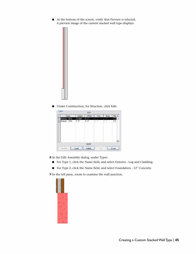
■ At the bottom of the screen, verify that Preview is selected.A preview image of the current stacked wall type displays.
■ Under Construction, for Structure, click Edit.
8 In the Edit Assembly dialog, under Types:
■ For Type 1, click the Name field, and select Exterior - Log and Cladding.
■ For Type 2, click the Name field, and select Foundation - 12'' Concrete.
9 In the left pane, zoom to examine the wall junction.
Creating a Custom Stacked Wall Type | 45

10 In the Edit Assembly dialog, for Offset, select Wall Centerline.
11 Click OK 3 times.
12 Save the project, but do not close it.
13 Proceed to the next exercise, Creating a Custom Floor Type on page 46.
Creating a Custom Floor Type
In this exercise, you create a custom wood floor for the cabin by duplicating a Basic Floor system familytype. The new floor type features 12'' joists and a custom wood floor finish (blue-green stain) on both thetop and bottom of each joist.
Custom floor type in a rendered view of the cabin
Duplicate a floor type
1 In the Project Browser, expand Families ➤ Floors ➤ Floor.
2 Under Floor, select Wood Joist 10" - Wood Finish, and drag it to the drawing area.
46 | Chapter 4 Tutorial:Working with System Families

3 Sketch the floor:
■ On the Design Bar, click Lines.
■ On the Options Bar, click (Rectangle).
■ Sketch a 15' x 15' rectangular floor.
■ On the Design Bar, click Finish Sketch.
Create a custom material for the new floor type
4 On the Design Bar, click Modify.
5 Click Settings menu ➤ Materials.
6 In the left pane of the Materials dialog:
■ Select Wood - Flooring.
■ Click .
7 In the Duplicate Revit Material dialog:
■ For Name, enter Wood Flooring - Proprietary.
■ Click OK.
8 In the right pane of the Materials dialog, click the Render Appearance tab.
9 Click Replace.
10 In the Render Appearance Library dialog, enter Hardwood Flooring Wild Cherry Natural 1.
11 Click OK twice.
Create the custom wood floor type
12 Select the floor, and on the Options Bar, click (Properties).
13 In the Element Properties dialog, click Edit / New.
14 In the Type Properties dialog, click Duplicate.
15 In the Name dialog:
■ For Name, enter Proprietary Wood Joist 12" - Wood Finish.
■ Click OK.
16 In the Type Properties dialog, under Construction, for Structure, click Edit.
17 In the Edit Assembly dialog, verify that Preview is selected.
Creating a Custom Floor Type | 47

A preview image of the duplicated floor displays.
Modify the floor assembly
18 In the Edit Assembly dialog, under Layers:
■ For layer 4, click in the Thickness field, and enter 11 3/4''.
■ For layer 1, click in the Material field, and click .
■ In the left pane of the Materials dialog, select Wood Flooring - Proprietary, and click OK.
19 Add a new layer to the floor assembly:
■ At the bottom of the Layers pane, click Insert.
■ With the new layer selected, click Down until the new layer is located at the bottom of thelist, below the Core Boundary.
■ For the new layer 6, click in the Function field, and select Finish 1 [4].
■ Click in the Thickness field, and enter 3/4''.
■ Click the Material field, and click .
■ In the left pane of the Materials dialog, select Wood Flooring - Proprietary.
■ Click OK 4 times.
20 On the Design Bar, click Modify.
48 | Chapter 4 Tutorial:Working with System Families
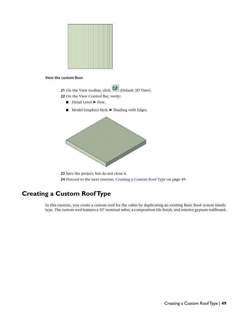
View the custom floor
21 On the View toolbar, click (Default 3D View).
22 On the View Control Bar, verify:
■ Detail Level ➤ Fine.
■ Model Graphics Style ➤ Shading with Edges.
23 Save the project, but do not close it.
24 Proceed to the next exercise, Creating a Custom Roof Type on page 49.
Creating a Custom Roof Type
In this exercise, you create a custom roof for the cabin by duplicating an existing Basic Roof system familytype. The custom roof features a 10" nominal rafter, a composition tile finish, and interior gypsum wallboard.
Creating a Custom Roof Type | 49

3D view of the cabin roof
Create the roof finish material
1 Click Settings menu ➤ Materials.
2 In the left pane of the Materials dialog:
■ Select Roofing - Asphalt Shingle.
■ Click .
3 In the Duplicate Revit Material dialog:
■ For Name, enter Roofing - Composition Shingle, Proprietary.
■ Click OK.
4 In the right pane of the Materials dialog, click the Render Appearance tab.
5 Click Replace.
6 In the Render Appearance Library dialog, enter Roofing Composition Shingle Dark Gray.
7 Click OK twice.
Duplicate a roof type
8 In the Project Browser, expand Families ➤ Roofs ➤ Basic Roof.
Select the closest match to your desired roof type.
9 Select Wood Rafter 8" - Asphalt Shingle - Insulated, and on the Options Bar, click (Properties).
10 In the Type Properties dialog, click Duplicate.
11 In the Name dialog:
■ For Name, enter Proprietary Wood Rafter - Composition Shingle - Insulated.
■ Click OK.
12 In the Type Properties dialog, under Construction, for Structure, click Edit.
13 In the Edit Assembly dialog, verify that Preview is selected.
50 | Chapter 4 Tutorial:Working with System Families

A preview image of the duplicated roof type displays.
Modify the roof type assembly
14 In the Edit Assembly dialog, under Layers:
■ For layer 4, Structure [1], click in the Thickness field, and enter 9 3/4".
■ For layer 1, Finish 1 [4], click in the Material field, and click .
■ In the left pane of the Materials dialog, select Roofing - Composition Shingle, Proprietary,and click OK.
15 Add a new layer to the roof assembly:
■ At the bottom of the Layers pane, click Insert.
■ With the new layer selected, click Down until the layer is located at the bottom of the list,below the Core Boundary.
■ For the new layer 6, click in the Function field, and select Finish 1 [4].
■ Click in the Material field, and click .
■ In the left pane of the Materials dialog, select Gypsum Wall Board.
■ Click OK.
■ For layer 6, click in the Thickness field, and enter 5/8''.
■ Click in any of the fields to update the preview.
■ Click OK twice.
16 Save and close the project.
17 Proceed to the next exercise, Transferring System Families Between Projects on page 51.
Transferring System Families Between Projects
In this exercise, you learn 2 different methods of transferring system family types from one project to another.
Using the first method, you copy a single wall type from one project and paste it into another, where youapply it to a wall. Use this method when you need to transfer only a few specific types from project to project.
Transferring System Families Between Projects | 51

Using the second method, you copy all the wall types from one project to another using the Transfer ProjectStandards command. The command transfers all object types, so use this method when you have a numberof system family types and other project-related settings to transfer between projects.
Method 1: Copy and paste a single system family type
1 Open the project that contains the type to copy:
■ Click File menu ➤ Open.
■ In the left pane of the Open dialog, click Training Files ➤ Common.
■ Open Imperial, select i_System_Families, and click Open.
2 Open the project into which you want to paste the family type:
■ Click File menu ➤ Open.
■ In the left pane of the Open dialog, click Training Files.
■ Open Common, select cabin.rvt, and click Open.
3 Copy a family type:
■ Click Window menu, and select a view in i_System_Families.
■ In the Project Browser, under Families, expand Walls ➤ Basic Wall.
■ Select Exterior - Log and Cladding.
TIP To select multiple family types, press and hold CTRL, then select the family types that youwant to copy.
■ Click Edit menu ➤ Copy to Clipboard.
4 Paste the Log and Cladding type in the cabin project:
■ Click Window menu ➤ cabin.rvt, and open a plan view of the project.
■ Click Edit menu ➤ Paste from Clipboard.The system family type is added to the project.
■ In the Project Browser, expand Families ➤ Walls ➤ Basic Wall, and confirm that ExteriorLog and Cladding displays in the list of Basic Wall types.
5 Assign the new wall type to the exterior walls in the cabin project:
■ In the Project Browser, under 3D Views, double-click {3D}.
■ Move the cursor over an exterior wall, press TAB until the chain of walls is selected, and clickto select the chain.
52 | Chapter 4 Tutorial:Working with System Families

■ On the Options Bar, in the Type Selector, select Basic Wall : Exterior - Log and Cladding.
■ On the Design Bar, click Modify.
6 Confirm that the proprietary finish material assigned to the copied family type is available inthe project:
■ Click Settings menu ➤ Materials.
■ In the left pane of the Materials dialog, under Name, verify that Finishes - Exterior -Proprietary, Log material displays in the materials list.
■ Click Cancel.
7 Close cabin.rvt, but leave i_System_Families open.
Method 2: Use the Transfer Project Standards command to copy system family types
8 With i_System_Families still open, create a new project:
■ Click File menu ➤ New ➤ Project.
Transferring System Families Between Projects | 53

■ In the New Project dialog, under Create new, verify Project is selected.
■ Under Template file, verify the second option is selected, and click Browse.
■ In the left pane of the Choose Template dialog, click Training Files.
■ Open Imperial\Templates, select default.rte, and click Open.
■ In the New Project dialog, click OK.
9 Save the project:
■ Click File menu ➤ Save As.
■ In the Save As dialog, navigate to Training Files\Imperial.
■ For File Name, enter transfer_project.
■ Click Save.
10 View the Basic Wall family types in the transfer standards project:
■ In the Project Browser, confirm that Exterior - Log and Cladding does not display underFamilies ➤ Walls ➤ Basic Wall.
■ Expand Walls ➤ Stacked Wall to confirm that Exterior - Log and Cladding on Concrete doesnot display.
11 Transfer the wall type:
■ Click in the drawing area.
■ In transfer_project.rvt, click File menu ➤ Transfer Project Standards.
■ In the Select Items To Copy dialog, for Copy from, select i_System_Families.rvt.
■ Click Check None.
■ In the list of items to copy, select Floor Types, Roof Types, and Wall Types.
■ Click OK.
■ In the Project Browser, under Families ➤ Walls ➤ Basic Wall, confirm that Exterior - Log andCladding now displays.
■ Confirm that the stacked wall, roof, and floor types you created display as well.
12 Save and close both projects.
54 | Chapter 4 Tutorial:Working with System Families

Standard ComponentFamilies
55

56

Standard ComponentFamilies Overview
Standard component families are families used to create both building components and some annotation elements.Component families create the building components that would usually be purchased, delivered, and installed in andaround a building, such as windows, doors, casework, fixtures, furniture, and planting. They also include some annotationelements that are routinely customized, such as symbols and titleblocks.
Because of their highly customizable nature, component families are the families that you most commonly create andmodify in Revit Architecture. Unlike system families, component families are created in external .rfa files and imported(loaded) in your projects. For component families that contain many types, you can create and use type catalogs, whichallow you load only the types that you need for a project.
When you create a standard component family, you begin with a template that is supplied in the software and containsinformation about the family that you are creating. You sketch the geometry of the family, use parameters to establishrelationships between family components, create the variations or family types that it includes, and determine its visibilityand detail level in different views. When you finish the family, you test it in a sample project before using it to createelements in your projects.
Revit Architecture includes a library of content in which you can both access component families that are supplied bythe software and save the component families that you create. You can also access component families from manufacturers’websites and from an online Revit Web Content Library.
Nesting and Sharing Component Families
You can load instances of component families in other component families to create new families. By nesting existingfamilies inside other component families, you can save yourself modelling time.
Depending on how you want instances of these families to act when you add them to your projects (as single element oras individual elements), you can specify whether the nested families are shared or not shared.
Revit Architecture Standard Component Families
Revit Architecture includes the following standard component families:
■ Annotations
■ Balusters
■ Casework
5
57

■ Columns
■ Curtain Wall Panels
■ Detail Components
■ Doors
■ Electrical Fixtures
■ Entourage
■ Furniture
■ Furniture Systems
■ Lighting Fixtures
■ Mass
■ Mechanical Equipment
■ Planting
■ Plumbing Fixtures
■ Profiles
■ Site
■ Specialty Equipment
■ Structural
■ Sustainable Design
■ Titleblocks
■ Windows
Workflow: Using Component Families in Your Projects
Component families are the most extensive and customizable families in Revit Architecture. You can createyour own custom families, but a number of families are ready for use in the family library and on the web.Before you begin a project, use the workflow that follows to determine whether you can use existing families,or whether you need to create your own custom families.
1 Determine the component families that your project requires.
2 Search existing component families and determine if you can find the component families thatyou need in the library, on the web, or in Revit Architecture templates or in your office templates.
See Finding and Loading Component Families on page 61.
3 If you find an appropriate family, but not the specific type that you need, create a new type.
See Adding a Type to a Component Family on page 146.
4 If you can find component families that are similar to the families that you need, save designtime by modifying existing families to your needs.
See the topics in Modifying Component Families on page 145.
5 If you cannot find the component families that you need or modify similar families to yourneeds, create your own component families.
58 | Chapter 5 Standard Component Families Overview

See Creating Component Families on page 69.
Using Existing Component Families
Revit Architecture includes a number of predefined component families. Some of these families are preloadedin templates, while others can be accessed from the Revit Architecture imperial and metric libraries, whichare included in the software or accessible on the web. You can load and use these families and their typesin your projects.
Viewing Component Families in a Project or Template
You can use the Project Browser to view the component families and family types in a project or template.
Some component families types may display in the Project Browser, but are not used with elements in thecurrent project. To view the component family types that are in use, see Viewing Elements with ComponentFamily Types in a Project on page 60.
1 Open a project or a template.
2 In the Project Browser, expand Families.
A list of all families in the project/template displays. The list includes the component families,as well as any system and in-place families that may be in the project/template.
NOTE Some component families and types do not display in the Project Browser until you createthem in a project.
Using Existing Component Families | 59

3 Expand the component family category that contains the types that you want to view.
In most cases, one or more families display under the component family.
4 Expand the family to view the component family types.
You can use these types to create elements, or you can duplicate and modify them to create newcomponent family types.
Viewing Elements with Component Family Types in a Project
You can highlight all the elements in a project that use a component family type that you specify.
1 Open a project view.
2 In the Project Browser, expand Families.
3 Expand the component category and family that contains the type that you want to select.
4 Select the desired type, right-click, and click Select All Instances.
NOTE If the current project does not contain any elements that use that component family type, theSelect All Instances command is unavailable.
All elements in the view that use the family type display as red (default color).
In the lower-right corner of your screen, the number of selected elements in the project displays.
5 Open other project views.
Any of the elements that use the family type display as red.
6 Press ESC to restore the original display of the elements.
60 | Chapter 5 Standard Component Families Overview

Finding and Loading Component Families
To use component families in your projects or templates, you must load (import) them with the Load fromLibrary ➤ Load Family command. After you load a family into a project, it is saved with that project.
Some component families are preloaded in the templates that are included with Revit Architecture. Anyprojects that you create with these templates include the component families loaded in the template.
You can find, preview, and load other families from the following sources:
■ the Revit Architecture library that is installed with the software
■ other local or networked libraries
■ the Revit Web Content Library
■ manufacturers’ websites
■ other third-party websites
Most of the families that you load from the Revit Architecture library and Revit Web Content Library arefully editable.
When loading large families that contain many types into a project, you can use a type catalog to load onlythe types that you need. Type catalogs are easy to create, and by allowing you to load only selected familytypes, they help to keep your project sizes from growing needlessly large.
Loading Component Families
When you load component families into a project, the Revit Architecture imperial or metric family library(located in C:\Documents and Settings\All Users\Application Data\Autodesk\RAC 2009\Imperial or MetricLibrary) is accessed by default.
If your office is using a different library of content in another location, your system may access that libraryby default. Contact your CAD Manager for more information.
To change the library that is accessed by default, see Setting Shortcuts to Other Family Libraries on page 62.
1 Click File menu ➤ Load from Library ➤ Load Family.
Depending on the current drawing units (imperial or metric), the Load Family dialog lists thefamily categories in either the Imperial or Metric Library.
2 In the Load Family dialog, double-click the category of the family that you want to load.
3 Preview any of the families (.rfa) in the category:
■ To preview a single family, select it in the list.At the top right of the dialog, under Preview, a thumbnail image of the family displays.
■ To display a thumbnail image in the list for all the families in the category, at the top rightcorner of the dialog, click Views ➤ Thumbnails.
4 Select the family that you want to load, and click Open.
The family type is now available to place in the project, and displays in the appropriatecomponent category under Families in the Project Browser.
Finding and Loading Component Families | 61

Setting Shortcuts to Other Family Libraries
Although you can browse to any library of content when you use the Load Family command, you can specifythe location of the library that you want to access by default.
1 Click Settings menu ➤ Options.
2 In the Options dialog, click the File Locations tab.
3 Click Places.
4 In the Places dialog, for the Imperial or Metric Library, click in the Library Path field, and click
.
5 In the Browse for Folder dialog, navigate to the location that you would like to access, and clickOpen.
6 Click OK twice.
7 Click File menu ➤ Load from Library ➤ Load Family.
The new library location opens.
Downloading Component Families from the Revit Web ContentLibrary
The Revit Web Content Library contains different types of component families, including manufacturerfamilies, that you can download and use in your projects. It also contains Ketiv Modern Medium contentthat has been converted to Revit Architecture families for use in your projects. Some restrictions apply; seeWorking with Modern Medium Families on page 63.
You can download and use families from previous releases of Revit Architecture. Download these families,and upgrade them by opening and saving them in your current version of the software.
NOTE After you upgrade a family to a more current release, it cannot be used in the previous release.
1 Do either of the following:
■ On the right side of the Revit Architecture opening screen, click Revit Web Content Library.
■ In your web browser, navigate to http://revit.autodesk.com/library/html/.
2 On the left side of the library dialog, click the family library that you want to access.
The Revit Web Content Library contains different types of families, including manufacturerfamilies and families created from Ketiv’s Modern Medium content.
3 Expand the list of families in the library.
4 Select each family to preview it in the right pane of the Web Library.
5 To download a single family:
■ In the right pane, double-click the family, and in the File Download dialog, click Save.
■ Navigate to the library of your choice (the Revit Architecture library is located by default inC:\Documents and Settings\All Users\Application Data\Autodesk\RAC 2009\Imperial orMetric Library), and click Save.
62 | Chapter 5 Standard Component Families Overview

6 To download all the families in a directory:
■ In the left pane, select the directory that contains the families, and in the top right corner
of the Revit Web Content Library, click (download directory).
■ In the File Download dialog, click Save, and save the extractable file to a location that youspecify.
■ Navigate to the location where you saved the file, and double-click it.
■ Specify the location in which you want to extract the families, either the appropriate categoryin the Revit Architecture Imperial or Metric Library, or to another library that you specify.
7 Load the families that you downloaded from the library into a project or template.
See Loading Component Families on page 61.
Working with Modern Medium Families
Ketiv's Modern Medium Library has been converted into Revit Architecture families and made available inthe Revit Web Content Library on the Web. Modern Medium families cannot be altered structurally withinRevit Architecture. You can, however, change the appearance of a Modern Medium family type by changingthe render appearance of the material linked to its object style.
NOTE Loading a large number of families from the Modern Medium Library can substantially increase the projectfile size and impede system performance.
For example, you could download and load a Modern Medium piano so the family displays underFamilies\Specialty Equipment in the Project Browser. To change the color to natural wood, you can createa new material called Piano, and then select the color and texture desired. The appearance of the piano willchange after you apply the new material to the object style of the piano.
To apply a different render appearance to a Modern Medium family
1 Download Modern Medium families from the Revit Web Content Library, and add them to aproject.
See Downloading Component Families from the Revit Web Content Library on page 62.
2 Click Settings menu ➤ Object Styles, and click the Imported Objects tab.
3 Under the Category heading, select the layer name of the Modern Medium family.
4 Click in the Material Field, and click .
5 In the Materials dialog, select a material, and click OK twice.
See Materials in the Revit Architecture 2009 Help.
6 Save the family.
Copying Family Types Between Project
You can copy family types from one project into another. If the family does not exist in the target project,Revit Architecture loads it when you paste the type.
Finding and Loading Component Families | 63
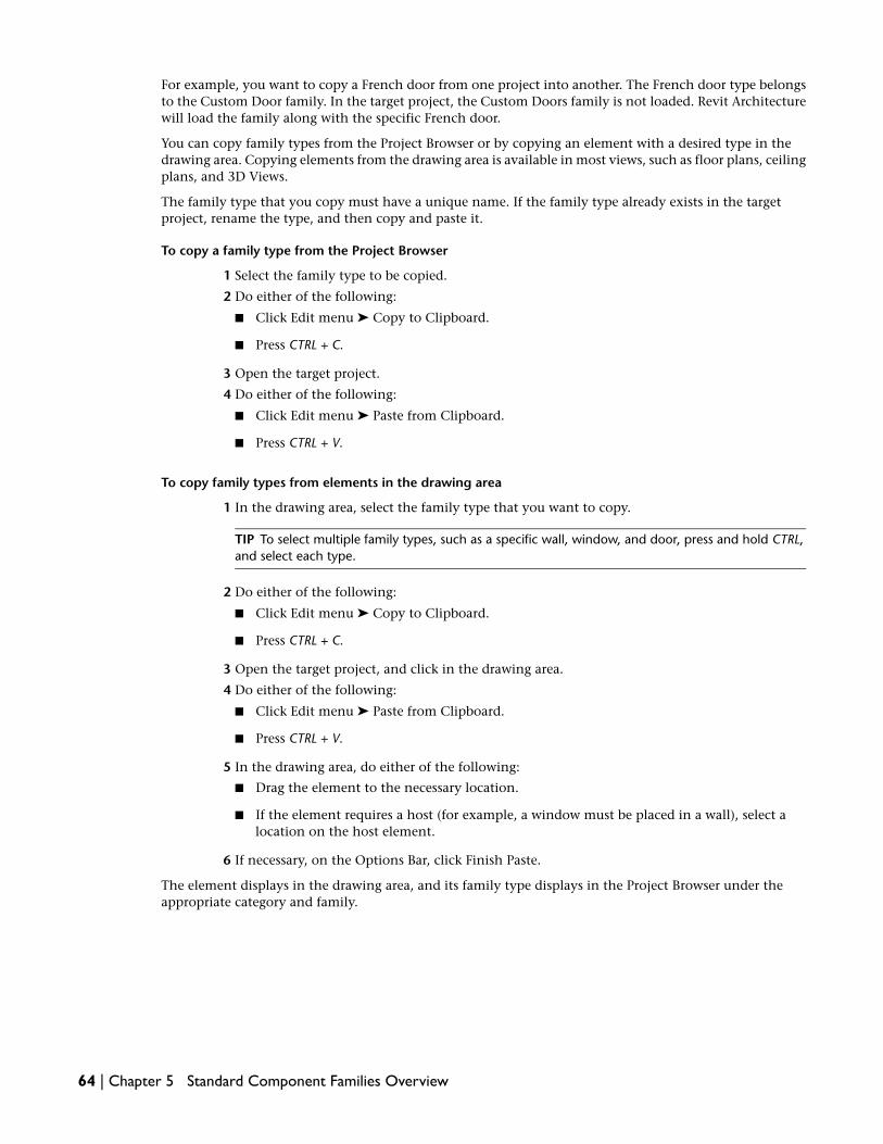
For example, you want to copy a French door from one project into another. The French door type belongsto the Custom Door family. In the target project, the Custom Doors family is not loaded. Revit Architecturewill load the family along with the specific French door.
You can copy family types from the Project Browser or by copying an element with a desired type in thedrawing area. Copying elements from the drawing area is available in most views, such as floor plans, ceilingplans, and 3D Views.
The family type that you copy must have a unique name. If the family type already exists in the targetproject, rename the type, and then copy and paste it.
To copy a family type from the Project Browser
1 Select the family type to be copied.
2 Do either of the following:
■ Click Edit menu ➤ Copy to Clipboard.
■ Press CTRL + C.
3 Open the target project.
4 Do either of the following:
■ Click Edit menu ➤ Paste from Clipboard.
■ Press CTRL + V.
To copy family types from elements in the drawing area
1 In the drawing area, select the family type that you want to copy.
TIP To select multiple family types, such as a specific wall, window, and door, press and hold CTRL,and select each type.
2 Do either of the following:
■ Click Edit menu ➤ Copy to Clipboard.
■ Press CTRL + C.
3 Open the target project, and click in the drawing area.
4 Do either of the following:
■ Click Edit menu ➤ Paste from Clipboard.
■ Press CTRL + V.
5 In the drawing area, do either of the following:
■ Drag the element to the necessary location.
■ If the element requires a host (for example, a window must be placed in a wall), select alocation on the host element.
6 If necessary, on the Options Bar, click Finish Paste.
The element displays in the drawing area, and its family type displays in the Project Browser under theappropriate category and family.
64 | Chapter 5 Standard Component Families Overview

Using Type Catalogs to Load Large Component Families
When you load a family with many types into a project, using a type catalog allows you to select and loadonly those types that you need. The type catalog provides a dialog that lists the available family types thatyou can sort through and select before you load types into a project.
Type catalogs are most useful when used with large families that contain many types. By loading only thetypes that you need, you prevent your project size from growing needlessly larger and you minimize thenumber of types that display in the Type Selector list.
BEST PRACTICE Create type catalogs for families that contain more than 6 types.
Although Revit Architecture includes a type catalog you can use when loading structural families, you cancreate type catalogs for any existing or user-created families. See Creating a Type Catalog on page 65.
Creating a Type Catalog
A type catalog is an external text file (TXT) that contains the parameters and their values that create thedifferent types in a specific family.
Following is a sample type catalog TXT file:
,Manufacturer##other##,Length##length##centimeters,Width##length##centi
meters,Height##length##centimeters
MA36x30,Revit,36.5,2.75,30
MA40x24,Revit,40.5,3.25,24
When loading the corresponding family, you would see the following type catalog:
HeightWidthLengthManufac-turer
Type
30cm2.75cm36.5cmRevitMA36x30
24cm3.25cm40.5cmRevitMA40x24
There are several ways to create a comma-delimited .txt file. You can type it in using a text editor like Notepad,or you can use database or spreadsheet software to automate the process.
You can export your project to a database using ODBC, and then download the element type tables incomma-delimited format. See Exporting to ODBC in the Revit Architecture 2009 Help.
Finding and Loading Component Families | 65

As you create the type catalog, follow these rules:
■ Save the type catalog file name with a .txt extension; the file must have the same name and same directorypath as the Revit Architecture family, for example, Doors/door.rfa and Doors/door.txt.
■ The left column lists types.
■ The top row of the file is for parameter declaration. Format is columnname##type##unit.
■ Use decimals.
■ Parameter names are case sensitive.
■ You can use single or double quotes. If you are using double quotes, you need to enter "" for RevitArchitecture to understand it as double quotes.
■ Valid unit types are length, area, volume, angle, force, and linear force.
■ Valid units: Valid units and suffixes:
■ For length: inches ("), feet ('), millimeters (mm), centimeters (cm), or meters (m).
■ For area: square_feet (SF), square_inches (in2), square_meters (m2), square_centimeters (cm2),square_millimeters (mm2), acres, or hectares.
■ For volume: cubic_yards (CY), cubic_feet (CF), cubic_inches (in3), cubic_centimeters (cm3),cubic_millimeters (mm3), liters (L), gallons (gal).
■ For angle: decimal_degrees (°), minutes ('), seconds (").
■ For force: newtons (N), decanewtons (daN), kilonewtons (kN), meganewtons (MN), kips (kip),kilograms_force (kgf), tonnes_force (Tf), and pounds (P).
■ For linear force: newtons_per_meter (N/m), decanewtons_per_meter (dan/m), kilonewtons_per_meter(kN/m), meganewtons_per_meter (MN/m), kips_per_foot (kip/ft), kilograms_force_per_meter (kgf/m),tonnes_force_per_meter (Tf/m), pounds_per_foot (P/ft).
■ You can enter a value for parameters of type Family Type. To declare the Family Type parameter in theparameter declaration, you would enter column-name##other##. The column name is the same as theFamily Type parameter name. In the type catalog file, enter values as Family Name : Family Type. Be surethere are spaces before and after the colon. So for a family file called Chair-Executive.rfa with a typecalled Big Boss, you would enter Chair-Executive : Big Boss. If the family file has only one type, and it isthe same name as the family, you do not need to include the Family Name.
■ Revit Architecture applies project unit settings to type catalogs when loading a family.
Loading a Family with a Type Catalog
After you create a type catalog for a family, you can use it to load only the family types that you need intoyour projects and templates.
1 Create and place the type catalog in the same location (directory) as the family that you wantto load.
2 In a Revit Architectureproject or template, click File menu ➤ Load from Library ➤ Load Family.
3 Navigate to the directory containing the family you want to open.
4 Select the family (.rfa file) that you want to load.
The Type Catalog displays.
5 In the Type column of the Type Catalog, select the family type or types to load.
66 | Chapter 5 Standard Component Families Overview

You can select multiple types by pressing CTRL during selection. You can also narrow the rangeof search items by selecting specific parameters from the list at the top of each column.
6 Click Open.
Saving Loaded Component Families
You can save a family that is loaded in the current project or template as an .rfa file in a location that youspecify. You can save the family to a location on your system or to a network location. All family types aresaved with the family.
1 Do either of the following:
■ Click File menu ➤ Save to Library ➤ Save Family.
■ Right-click a family in the Project Browser, and click Save.
2 In the Save Family dialog:
■ If you are using Save to Library ➤ Save Family, for Family to save, select the family from alist of families loaded in the project.
■ For Save in, navigate to the location in which you want to save the family.
■ Specify the name and file type for the family, and click Save.
Creating Elements with Component Family Types
You can begin to create elements in your building models with component family types that are providedin the Revit Architecture templates or in templates that your office or firm may provide, and loaded fromlibraries. Some elements that you create with component family types are host-based, which means theyrequire another element to be added to a project (for example, a window or a door must be inserted in awall).
After you create an element with a component family type, you can change the component family type ofthe element. You can also change the individual properties of any element at any time, by right-clickingthe element and selecting Element Properties.
If you find that you need to modify the properties of a component family type, or if you need to create anew component family, see Modifying Component Families on page 145 or Creating Component Familieson page 69.
Creating an Element with a Component Family Type
1 On the Design Bar, click the command for the element that you want to create.
2 In the Type Selector, select the type of element that you want to create.
The Type Selector displays the available component family types first by family or subfamilyand then by type, separated by a colon.
3 On the Options Bar, specify any necessary values or selections.
4 In the drawing area, create the element.
5 Create another element, or on the Design Bar, click Modify.
Creating Elements with Component Family Types | 67

Creating an Element with a Component Family Type from an Elementin the Project
1 Do one of the following:
■ Select an element in the project, right-click, and click Create Similar.
■ In the Project Browser, under Families, right-click the component family type, and clickCreate Instance.
2 On the Options Bar, specify any necessary values or selections.
3 In the drawing area, create the element or elements.
Changing the Component Family Type of an Element
You can use 3 different methods to change the component family type of an element in a current project.The third method, the Match command method, lets you change the type of more than one element at atime.
Method 1: Using the Type Selector
1 In the drawing area, select the element.
2 In the Type Selector, select a new type.
Method 2: Changing the Type Properties
1 In the drawing area, select the element, right-click, and click Element Properties.
2 In the Element Properties dialog, for Type, select a new type.
3 Click OK.
Method 3: Using the Match command
1 In the Project Browser, expand Families.
2 Expand the family that contains the new type that you want to use.
3 Select the family type, right-click, and click Match.
4 Move the cursor to the drawing area.
Notice that it displays as an eyedropper.
5 Select the element that you want to match to the family type that is selected in the ProjectBrowser.
6 Continue to select elements in the project to match to the selected type, or press ESC.
Deleting Component Families and Types
You can delete unused component families or unused family types from your projects and templates usingeither of 2 methods: you can select and delete the families and types in the Project Browser, or you can runthe Purge Unused command.
Select and delete families and types when you have only a few families or types that you need to delete. Runthe Purge Unused command when you need to ''clean up'' your projects. Removing all of the unused familiesand types usually decreases the project file size.
68 | Chapter 5 Standard Component Families Overview

Whichever method you use, you cannot delete:
■ any component family types that have dependencies (such as those that host other families).
■ component families with types that are in use in the current project or template.
Method 1: Selecting and deleting families and types in the Project Browser
1 In the Project Browser, expand Families.
2 Expand the category that contains the family or type that you want to delete.
3 If you want to delete a component family type, expand the family.
4 Select the component family or type that you want to delete.
TIP To select more than one component family or type, press and hold CTRL while selecting.
5 Do either of the following:
■ Right-click, and click Delete.
■ Press DELETE.
The component family or type is deleted from the project or template.
If you are deleting a component family or type from a project, and there is one or more instancesof a type in the project, a warning displays.
6 In the alert dialog:
■ Click OK to delete any instances of the type.
■ Click Cancel, change the type, and repeat the previous step.
Method 2: Using the Purge Unused command
1 Click File menu ➤ Purge Unused.
The Purge unused dialog lists all the families and family types that you can unload from theproject, including system and in-place families. By default, all unused families are selected forpurging.
IMPORTANT If the project is workset-enabled, all worksets must be open to use this command.
2 Do either of the following:
■ To purge all unused family types, click OK.
■ To purge only the types that you select, click Check None, expand the families and subfamiliesthat contain the types that you want to purge, select the types, and click OK.
Creating Component Families
If you need to create families for a project, Revit Architecture gives you that facility. Creating a new familyis easy, because Revit Architecture provides many templates, including templates for doors, structuralmembers, windows, furniture, and electrical fixtures, and lets you graphically draw the new family. Thetemplates contain much of the information that you need to start creating the family and that RevitArchitecture needs to place the family in projects.
Creating Component Families | 69

Understanding the Family Editor
The Family Editor is a graphical editing mode in Revit Architecture that allows you to create families toinclude in your project. When you start creating a family, you open a template to use in the Family Editor.The template can include multiple views, such as plan and elevation views. The Family Editor has the samelook and feel as the project environment in Revit Architecture, but features different commands located ona single Design Bar tab.
You can access the Family Editor by:
■ Opening or creating a new family (.rfa) file.
■ Selecting an element created by a component or in-place family type, and clicking Edit Family on theOptions Bar.
Family Editor Commands
■ The Family Types command opens the Family Types dialog. You can create new family types or newinstance and type parameters. See Creating Family Types on page 89.
■ The Dimension command adds permanent dimensions to the family, in addition to ones that RevitArchitecture automatically creates as you sketch the geometry. This is important if you wish to createdifferent sizes of the family.
■ The Model Lines command lets you sketch two-dimensional geometry for when you do not need to showsolid geometry. For example, you could sketch door panels and hardware as 2D rather than sketch solidextrusions. Model lines are always visible in 3D views. You can control their visibility in plan and elevationviews by selecting the lines and clicking Visibility from the Options Bar.
70 | Chapter 5 Standard Component Families Overview
■ The Symbolic Lines command lets you sketch lines that are meant for symbolic purposes only. Forexample, you might sketch symbolic lines in an elevation view to represent a door swing. Symbolic linesare not part of the actual geometry of the family. Symbolic lines are visible parallel to the view in whichyou sketch them.You can control symbolic line visibility on cut instances. Select the symbolic line and click Visibilityfrom the Options Bar. Select Show only if instance is cut.
In this dialog, you can also control the visibility of lines based on the detail level of the view. For example,if you select Coarse, that means that when you load the family into a project and place it in a view atthe Coarse detail level, the symbolic lines are visible.
TIP Use this dialog to control visibility of generic annotations loaded into model families. See Loading GenericAnnotations into Model Families on page 142.
■ The Lines command sketches lines to define the geometry of the family.
■ The Opening command is available in host-based family templates only, for example, wall-based orceiling-based. You create an opening by sketching its shape to the reference planes and then modifyingits dimensions. After creating an opening, you can select it and set it to display as transparent in 3Dand/or elevation views when loaded into the project. From the Options Bar, select the 3D and/or Elevationcheck boxes next to Transparent in.
NOTE The Opening command is also available in the project environment.
■ The Ref Plane command creates a reference plane, an infinite plane which serves as a guide for sketchinglines and geometry.
■ The Reference Lines command creates a line similar to a reference plane, but that has logical start andend points.
■ The Control command lets you place arrows to rotate and mirror the geometry of the family, after youadd it to your design. In the Options Bar, choose from a Vertical or Horizontal arrow, or from aDouble-Vertical or Double-Horizontal arrow. You can also select more than one choice.Revit Architecture rotates or mirrors the geometry about the origin. With 2 opposite-facing arrows, youcan mirror back and forth horizontally or vertically.
You can place the controls anywhere in the view. It is best to place them where it is obvious what theycontrol.
TIP Controls are useful when creating a door family. The double-horizontal control arrows change which sidethe door is hinged. The double-vertical control arrows change the swing of the door from inside-out tooutside-in.
■ The Text command allows you to add text notes to the family. This is typically used in an annotationfamily. The text is simply a text note.
■ The Model Text command can be used to add signage on a building or letters on a wall.
■ The Section command allows you to create a section view.
■ The Components command selects the type of component to be inserted into the Family Editor. Afterclicking this command, the Type Selector becomes active and you can select the component.
■ The Symbol command allows you to place 2D annotation drawing symbols.
■ The Detail Component command allows you to place a detail component.
■ The Masking Region command allows you to apply a mask to a region of the family. The masking regionwill obscure model elements when the family is used to create an element in a project. See MaskingRegions in the Revit Architecture 2009 Help.
Understanding the Family Editor | 71

■ The Filled Region command allows you to apply fill to a region of the family.
■ The Solid Form command provides access to tools that let you create solid geometry in the family.
■ The Void Form command provides access to tools that let you cut solid geometry in the family.
■ The Label command allows you to place intelligent text in the family. This text actually represents afamily property. When the property value is specified it will show up in the family.
NOTE This command is available for annotation symbols only.
■ The Load into Projects command allows you to load a family directly into any open project or family.
Creating a Standard Component Family
Typically, the standard component families that you need to create are standard sizes and configurationsof common components and symbols used in a building design.
To create a component family, you define the geometry and size of the family using a family template thatis provided in the Revit Architecture. You can then save the family as a separate Revit family file (.rfa file)and load it into any project you want.
Depending on the complexity of the family, the creation process can be time-consuming. If you can identifya family that is similar to the one you want to create, you can save time and effort by copying, renaming,and modifying the family to create the new family. See Modifying a Family to Create a New Family on page148.
The topics in this section apply to the creation of model (3D) families, but some are relevant to 2D families,including titleblocks, annotation symbols, and detail components. For specific information on 2D familycreation, see Tutorials: 2D Component Families on page 151.
TIP It is recommended that you complete 3D standard component family tutorials included in this section beforecreating your own model families. See Tutorials: 3D Component Families on page 239.
Workflow: Creating a Standard Component Family
For best results when creating a component family, follow the workflow below.
1 Before beginning family creation, plan your family.
See Planning the Component Family on page 73.
2 Create a new family file (.rfa) with the appropriate family template.
See Choosing a Family Template on page 74.
3 Define subcategories for the family to help control the visibility of the family geometry.
See Creating Family Subcategories on page 78.
4 Create the family skeleton, or framework:
■ Define the origin (the insertion point) of the family.See Defining the Family Origin on page 80.
■ Lay out reference planes and reference lines to aid in sketching component geometry.See Laying Out Reference Planes on page 81 and Using Reference Lines on page 83.
■ Add dimensions to specify parametric relationships.See Dimensioning Reference Planes and Lines on page 87.
72 | Chapter 5 Standard Component Families Overview

■ Label dimensions to create type or instance parameters or 2D representation.See Labeling Dimensions to Create Parameters on page 87.
■ Test, or flex, the skeleton.See Flexing the Family Skeleton on page 88.
5 Define family type variations by specifying different parameters.
See Creating Family Types on page 89.
6 Add a single level of geometry in solids and voids, and constrain the geometry to referenceplanes.
See Creating Family Geometry on page 91.
7 Flex the new model (types and hosts) to verify correct component behavior.
See Flexing the Family on page 90.
8 Repeat previous steps until the family geometry is complete.
9 Specify 2D and 3D geometry display characteristics with subcategory and entity visibility settings.
See Managing the Family Visibility and Detail Level on page 127.
10 Save the newly defined family, and then load it into a project for testing.
See Testing a Family in a Project on page 130.
11 For large families that include many types, create a type catalog.
See Creating a Type Catalog on page 65.
Planning the Component Family
If you consider this list of requirements before creating your family, you will have an easier time creatingit. Of course, there are bound to be changes as you create families. The Family Editor is flexible enough toallow you to make those changes without having to start over.
■ Will the family need to accommodate multiple sizes?For a window that is available in several preset sizes, or a bookshelf that can be built in any length, createa standard component family. However, if you need to create a custom piece of furniture that only comesin one configuration, you may want to create it as an in-place family, instead of a component family.See
Size variability and the degree of complexity of the object determine whether you create a standardcomponent family an in-place family.
■ How should the family display in different views?The way the object should display in views determines the 3D and 2D geometry that you need to create,as well as how to define the visibility settings. Determine whether the object should display in a planview, elevation view, and/or sectional views.
■ Does this family require a host?For objects typically hosted by other components, such as a window or light fixture, start with a host-basedtemplate. How the family is hosted (or what it does or does not attach to) determines which templatefile should be used to create the family.
■ How much detail should be modeled?In some cases, you may not need 3D geometry. You may only need to sketch a 2D shape to representyour family. Also, you may simplify the 3D geometry of your model to save time in creating the family.For example, less detail is required for a wall outlet that will only be seen in interior elevations from adistance, than for a door with raised panels and a sidelight that will be seen in an interior rendering.
Creating a Standard Component Family | 73

■ What is the origin point of this family?For example, the insertion point for a column family could be the center of the circular base. The insertionpoint for an accessible toilet may be 18 inches off the adjacent wall to meet code. Determining theappropriate insertion point will help users place the family in a project.
Choosing a Family Template
After you plan your new family, your next step is to choose the template that you will use to create the newfamily. When you create a new family, you are prompted to select a family template that corresponds tothe type of element that your family will create.
The template serves as a building block, containing the information that you need to start creating thefamily and that Revit Architecture needs to place the family in projects.
For a list and description of the family templates included in Revit Architecture, see Appendix B: ExploringFamily Templates on page 759.
What is in the Family Templates?
Family templates have .rft extensions and are available in the software, organized by element category(Annotation, Door, Wall, etc.). The category determines the category of the element that the family willcreate, and is used to control the visibility and scheduling of elements created with the family.
Depending on the template, it can also include:
■ Subcategories (or categories within the object category) that you can use to control the visibility andmaterial of individual pieces of geometry within the family.For example, a door family that you create with the Door template contains the subcategories Panel,Opening, Frame/Mullion, Glass, Hidden Lines, and Swing.
■ Views in which you create the geometry of your family.For example, a furniture family that you create with the Furniture template contains plan views, elevationviews, and a 3D view that you can use to create a furniture family.
■ Reference planes and predefined parameters.Reference planes are 3D planes that you use as a references or work planes when you create familygeometry. They do not display when you create an element with the family.
■ Line types with predefined visibility settings.For example, if you create a door family with the Door template, a number of line types are available foryou to sketch the different representation of each door component.
■ If the family is a host-based object, host geometry.For example, if you create a window family with the Window template, wall segments in which to createthe window are provided by the template. Host-based geometry does not display when you create anelement with the family.
■ Controls that allow you to change the position of geometry that you use to create your family.For example, a door family that you create with the Door template includes controls to reverse both theswing and hinge side of the door.
■ Embedded text notes.Door and window families that you create with the Door and Window templates contain wall segmentsthat include text notes to define the interior and exterior of the wall host. Text notes do not displaywhen you create an element with the family.
74 | Chapter 5 Standard Component Families Overview

Different Kinds of Family Templates
While most of the family templates are named according to the type of element family that you use themto create, there are a number of templates that include one of the following descriptors after the familyname:
■ wall-based
■ ceiling-based
■ floor-based
■ roof-based
■ line-based
■ face-based
Wall-based, ceiling-based, floor-based, and roof-based templates are known as host-based templates. Ahost-based family can only be placed in a project if an element of its host type is present.
Review the following descriptions of the different types of templates to determine which one best suits yourneeds.
Wall-based Templates
Use the wall-based templates to create components that will be inserted into walls. Wall components caninclude openings, such that when you place the component on a wall, it also cuts an opening in the wall.Some examples of wall-based components include doors, windows, and lighting fixtures. Each templateincludes a wall; the wall is necessary for showing how the component fits in a wall.
Ceiling-based Templates
Use the ceiling-based templates to create components that will be inserted into ceilings. Ceiling componentscan include openings, so that when you place the component on a ceiling, it also cuts an opening in theceiling. Examples of ceiling-based families include sprinklers and recessed lighting fixtures.
Floor-based Template
Use the floor-based template for components that will be inserted into floors. Floor components can includeopenings, so that when you place the component on a floor, it also cuts an opening in the floor. An exampleof a floor-based family is a heating register.
Roof-based Template
Use the roof-based template for components that will be inserted into roofs. Roof components can includeopenings, so that when you place the component on a roof, it also cuts an opening in the roof. Examplesof roof-based families include soffits and fans.
Standalone Template
Use the standalone template for components that are not host-dependent. A standalone component canappear anywhere in a model and can be dimensioned to other standalone or host-based components.Examples of standalone families include columns, furniture, and appliances.
Creating a Standard Component Family | 75

Line-based Template
Use the line-based templates to create detail and model families that use 2-pick placement similar to structuralbeams.
Face-based Template
Use the face-based template to create work plane-based families that can modify their hosts. Families createdfrom the template can make complex cuts in hosts. Instances of these families can be placed on any surface,regardless of its orientation. See Creating Work Plane-based and Face-based Families on page 144.
Where to Find Family Templates
When you create a new family, you are prompted to select a family template from a list of available templates.You usually do not need to access the templates directly unless you need to modify them. They are installedby default in:
C:\Documents and Settings\All Users\Application Data\Autodesk\RAC 2009\Imperial Templates or MetricTemplates
The Imperial or Metric folder contains templates for creating model elements, as well as 2 folders that containtemplates to create titleblocks and annotation families.
NOTE If you cannot locate the family templates, they may have been installed in another location. Contact yourCAD Manager for more information.
Creating a New Family with a Template
To create a new component family, you select a family template, and then name and save the family file.Name the family so it adequately describes the element that it is intended to create. Later, when the familyis complete and you load it into a project, the family name displays in both the Project Navigator and TypeSelector.
Predefined imperial and metric component families are installed by default in library folders located in:
C:\Documents and Settings\All Users\Application Data\Autodesk\RAC 2009\Imperial Library or MetricLibrary.
You can save your families in the folders in these libraries, or you can save them to any local or networklocation. After you create families, you can use the Copy and Paste commands in Microsoft® WindowsExplorer to move your families to different locations.
BEST PRACTICE Do not save the family to a location where others can access it until you complete and test thefamily.
To create a family with a template
1 Click File menu ➤ New ➤ Family.
NOTE If you are creating an annotation or titleblock family, click File menu ➤ New ➤ AnnotationSymbol or Titleblock.
Depending on the current drawing units, the New Family - Select Template File dialog displaysthe available imperial or metric family templates that are installed on your system inC:\Documents and Settings\All Users\Application Data\Autodesk\RAC 2009\Imperial Templatesor Metric Templates.
76 | Chapter 5 Standard Component Families Overview

NOTE Depending on your software installation or office standards, your family templates may beinstalled in another location, either locally or on a network. Contact your CAD Manager for moreinformation.
2 Optionally, to preview a template, select it.
The template preview image displays in the upper-right corner of the dialog.
3 Select the family template that you want to use, and click Open.
The new family opens in the Family Editor. For most families, 2 or more dashed green linesdisplay. These are reference planes, or the working planes that you will use when you create thefamily geometry.
If you are creating a host-based family, such as a window family, host geometry may also display.
4 In the Project Browser, view the family views.
The family views vary depending on the type of family that you create. If necessary, you cancreate additional views by duplicating and renaming the existing views.
5 Click File menu ➤ Save As.
6 In the Save dialog, navigate to the location in which you want to save the family, enter a namefor the family, and click OK.
Creating a Standard Component Family | 77

BEST PRACTICE Use title case for the family name.
Creating Family Subcategories
When you create a family, the template assigns it to a category that you can use to define the line weight,line color, line pattern, and material assignment of the family geometry. To assign different line weights,line colors, line patterns, and material assignments to different geometric components of the family, youneed to create subcategories within the category. Later, when you create the family geometry, you assignthe appropriate components to the subcategories.
For example, in a window family, you could assign the frame, sash, and mullions to one subcategory andthe glass to another. You could then assign different materials (wood and glass) to each subcategory toachieve the following effect.
Revit Architecture features some predefined subcategories for different categories of families. Other familieshave no subcategories, which means that you can define your own. The Object Styles dialog lists familycategories and subcategories. It also displays the line weight, line color, line pattern, and material assignedto each category and subcategory.
TIP You can apply a drafting pattern to a family. When you create and define a subcategory to apply to the family,you can set its surface and cut pattern materials to have a drafting pattern. You cannot apply a model pattern toa family. Only flat or cylindrical surfaces can have drafting patterns. See Fill Patterns in the Revit Architecture 2009Help.
1 With the family open, click Settings menu ➤ Object Styles.
2 On the Model Objects tab, under Category, select the family category.
3 Under Modify Subcategories, click New.
4 In the New Subcategory dialog, for Name, enter a new name.
Revit Architecture automatically selects the appropriate category in the Subcategory of list.
78 | Chapter 5 Standard Component Families Overview

5 Click OK.
Although you will not immediately create and assign the family geometry the subcategory, youcan specify the line weight, line color, line pattern, and material for the subcategory.
6 Set values for line weight, line color, line pattern, and material:
■ Click in the Projection and Cut fields for Line Weight, and select values from the lists.
■ Click the button in the Line Color field, and select a color from the Color dialog. If desired,define a custom color.
■ Click the Line Pattern field, and select a line pattern from the list. If desired, define a newline pattern for the line display.
■ Click in the Material field, and specify a material, cut pattern, surface pattern, or renderappearance.See Materials in the Revit Architecture 2009 Help.
7 To define additional subcategories, repeat steps 3 - 6.
8 Click OK.
Creating the Family Skeleton
After you plan your family, your next step is to create the family skeleton. The skeleton is a framework oflines and parameters in which you later create the family geometry. It also defines the origin (insertionpoint) of elements that you create with the family.
To create the family skeleton, you begin by defining the family origin. You then build the skeleton withelements called reference planes and reference lines. After you have and define family parameters. Theparameters that you define at this stage usually control the size (length, width, height) of the element, andallow you to add family types.
A view of a furniture family skeleton
When the skeleton is complete, you test it by changing the parameter values and ensuring that the referenceplanes resize. By creating solid skeletons from the information that you gather in your planning stage beforeyou create the family geometry, you ensure the stability of the families that you create.
Creating a Standard Component Family | 79

Defining the Family Origin
After you create a new component family, define the family origin and pin (lock) it in place. Later, whenyou create an element with the finished family, the family origin specifies the element insertion point.
The intersection of 2 reference planes in a view defines the origin of a family. You can control which referenceplanes define the origin by selecting them and changing their properties. Many family templates createfamilies with predefined origins, but you may need to set the origin of some families. For example, anaccessible toilet family that creates toilet elements that must always be placed a certain distance from anadjacent wall to meet code, would need an origin located at the specified distance from the wall.
To define the family origin
1 Verify whether an origin has been defined for the family by selecting the reference planes.
If a pin displays on 2 of the reference planes, the origin is defined for the family, and you canskip the remaining steps.
2 On the Family Editor Design Bar, click Ref Plane.
3 Sketch the reference plane.
4 Click Modify and select the reference plane.
80 | Chapter 5 Standard Component Families Overview

5 Click (Element Properties).
6 In the Element Properties dialog, select Defines Origin.
7 Create or open a family.
8 In a plan view, while pressing CTRL, select both reference planes.
9 On the Edit toolbar, click (Pin).
10 With the reference planes still selected, click .
11 In the Element Properties dialog, under Other, select Defines Origin.
The intersection of these reference planes now defines the origin/ insertion point of the family.By pinning the planes, you ensure that you do not accidentally move them, changing the familyinsertion point.
Laying Out Reference Planes
Sketch reference planes before creating any family geometry to define the family skeleton. You can then usethe reference planes as you create geometry, snapping sketches and geometry to them.
■ Position new reference planes so that they align with the major axes of the planned geometry.
■ Name reference planes so that you can assign it to be the current work plane. Without a name, you mustbe able to see the reference plane so you can select it to use as a work plane.
■ Specify the Is Reference property for reference planes that will be dimensioned to when the family isplaced in a project.
A bookcase family created within a framework of reference planes
To layout reference planes
1 On the Family Editor Design Bar, click Ref Plane.
2 Specify a start and end point for the reference plane.
3 Name the reference plane so that you can identify it in when you open other views:
■ Select the reference plane, and on the Options Bar, click (Element Properties).
■ In the Element Properties dialog, under Identity Data, for Name, enter a name for the referenceplane.
■ Click OK.
Creating a Standard Component Family | 81

Defining Priorities for Reference Planes
Reference planes have a property called Is Reference. By setting this property, you specify that the referenceplane can be dimensioned to when you place a family into a project. Only a reference plane defined as anorigin or as Is Reference can be dimensioned to when the family is placed in a project. For example, if youcreate a table family and want to dimension the edges of the table, create the table by creating referenceplanes at the table's edges and set the Is Reference property for the reference planes. When you createdimensions for the table, you can then select either the origin or the table's edges or both.
Is Reference also sets a reference point for dimensions when you use the Align command. Setting Is Referenceallows you to select different lines of aligned components for dimensioning.
When you set Is Reference for a reference plane, you have several choices for its value. They are
■ Not a reference
■ Strong reference. See Setting Strong and Weak References on page 82.
■ Weak reference. See Setting Strong and Weak References on page 82.
■ Left
■ Center (Left/Right)
■ Right
■ Front
■ Center (Front/Back)
■ Back
■ Bottom
■ Center (Elevation)
■ Top
When you give Is Reference a name from the list, if you ever swap a family member out of a project andreplace it with another family member, any dimensions automatically switch to the new family member, ifyou create the same property name in the second family.
For example, you could create 2 families, a table and a chair family, and set the left side reference planeproperty value to Left for both of them and then place the table in a building and dimension it from thewall to the left side of the table. If you decide to replace the table with the chair, the dimension to the leftside would remain to the left side of the chair, because they both had a property value of Left.
Setting Strong and Weak References
To dimension families placed in a project, you need to define family geometry references in the FamilyEditor. You set geometry references as either strong references or weak references.
A strong reference has the highest priority for dimensioning and snapping. For example, you create a windowfamily and place it into a project. As you are placing the family, temporary dimensions snap to any strongreferences in the family. When you select the family in the project, temporary dimensions appear at thestrong references. If you place a permanent dimension, the strong references in the window geometryhighlight first. A strong reference takes precedence over a wall reference point, such as its centerline.
82 | Chapter 5 Standard Component Families Overview
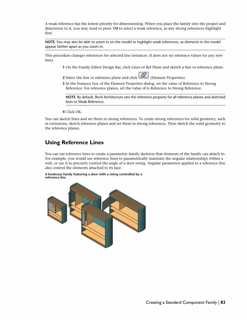
A weak reference has the lowest priority for dimensioning. When you place the family into the project anddimension to it, you may need to press TAB to select a weak reference, as any strong references highlightfirst.
NOTE You may also be able to zoom in on the model to highlight weak references, as elements in the modelappear farther apart as you zoom in.
This procedure changes references for selected line instances. It does not set reference values for any newlines.
1 On the Family Editor Design Bar, click Lines or Ref Plane and sketch a line or reference plane.
2 Select the line or reference plane and click (Element Properties).
3 In the Instance box of the Element Properties dialog, set the value of Reference to StrongReference. For reference planes, set the value of Is Reference to Strong Reference.
NOTE By default, Revit Architecture sets the reference property for all reference planes and sketchedlines to Weak Reference.
4 Click OK.
You can sketch lines and set them to strong references. To create strong references for solid geometry, suchas extrusions, sketch reference planes and set them to strong references. Then sketch the solid geometry tothe reference planes.
Using Reference Lines
You can use reference lines to create a parametric family skeleton that elements of the family can attach to.For example, you would use reference lines to parametrically maintain the angular relationships within aweb, or use it to precisely control the angle of a door swing. Angular parameters applied to a reference linealso control the elements attached to its face.
A bookcase family featuring a door with a swing controlled by areference line
Creating a Standard Component Family | 83

In both look and behavior, reference lines are very similar to model lines. However, there are significantdifferences between model lines and reference lines. For example, reference lines are annotation objectswith their own category. When selected, they display dual faces. When printing, their visibility is affectedby the Hide ref/work planes option.
Straight reference lines provide 2 planes for you to sketch on. One plane is parallel to the work plane of theline itself; the second plane is perpendicular to that plane. Both planes go through the reference line. Theplanes display when the reference line is selected, when the reference line is highlighted, or when using theWork Plane tool. When selecting a work plane, you can place the cursor over a reference line and use theTab key to switch between the 2 faces. The plane in which the line was sketched always displays first. Youcan also create arc reference lines, however, they do not define any planes.
Reference Line Behavior in the Project
Once a family is loaded into a project, the behavior of Reference Lines is identical to that of Reference Planes.Reference Lines have no visibility property, they are generally invisible in a project and do not highlightwhen the instance is selected. They highlight and generate shape handles in the same contexts as ReferencePlanes currently do, depending on their Reference property.
Selected reference in multiple views
84 | Chapter 5 Standard Component Families Overview

Adding a Reference Line
While in the Family Editor, you can add a reference line in any view and use the same drawing tools andtechniques used when adding model lines. When you sketch a reference line, it displays as a single line.
In a view where the model graphics are set to hidden line or wireframe, the sketched line displays as a solidline and the plane extents display with dashed lines.
To add a reference line
1 On the Design Bar, click Reference Lines.
2 Using the drawing tools on the Options Bar, sketch the line.
The line displays as a solitary solid line until selected or when highlighted during preselection.
Example of reference linessketched as a polygon
When selected or highlighted, the associated planes display according to the active view.
Example of reference line chain highlighted in a 3D view
To use reference lines and linear dimensions to control model geometry
3 Align the face of a model element to the reference line and lock it.
4 Add a dimension line referring to the reference line and label it as an instance or type parameter.
5 Flex the model by changing and applying a new value within the Family Types dialog.
Creating a Standard Component Family | 85

Controlling Angular Dimensions with Reference Lines
The preferred method to control the angular dimensions of a family is to apply a labelled angular dimensionto a reference line. Unlike reference planes which have infinite extents, a reference line has a specific startand end point which allows it to control the angular constraints within components such as a web truss ora door with a instance door swing.
Loaded door family with an angular dimensioned reference line
To add and dimension a reference line
1 In the drawing area, add a reference line with the point of origin located at the point of expectedrotation.
2 Add an angular dimension referring to the reference line.
3 Label the dimension.
4 On the Design Bar, click Family Types.
5 Change the angular value for the labelled dimension and click Apply.
This is known as flexing the model. It is important to make sure the reference line adjusts asexpected before adding model geometry to it.
To add and align model geometry to a reference line
6 Set the current work plane to one of the faces of the reference line and add the model geometrythat you intend to have controlled by the angular dimension.
The geometry moves with the reference line as the angle changes.
7 Flex the model to make sure the design works as expected.
Modifying Reference Line Properties
1 In the drawing area, select the reference line, and click (Element Properties).
2 In the Element Properties dialog, specify the following:
■ Work Plane: This is read-only and reports the work plane that the reference line resides on.To change this, click Edit Work Plane on the Options Bar when the reference line is selected.
■ Visible: Select this setting if you want the reference line to be visible when the family isloaded into a project.
■ Length: This is read-only and reports the length of the line. To control the line length, dragthe shape handles in the drawing area or add a labelled dimension to the reference line.
■ Reference: Specify Not a reference, Strong Reference, or Weak Reference.
3 Click OK.
86 | Chapter 5 Standard Component Families Overview

Adding Parameters to the Family Skeleton
Although you have not yet created any family geometry, you can define the main parametric relationshipsin the family. The parameters that you define at this stage usually control the size (length, width, height)of the element. To create a parameter, you place dimensions between the reference planes of the skeletonand label them.
IMPORTANT Families in Revit Architecture are not parametric until you explicitly add labeled dimensions to them.
Dimensioning Reference Planes and Lines
The first step to creating family parameters is to place dimensions between the reference planes and linesof the skeleton to mark the parametric relationships that you intend to create. Dimensions alone do notcreate the parameters; you must label them to create parameters.
1 Identify the reference planes of the skeleton that you want to dimension to create parameters.
2 On the Family Editor Design Bar, click Dimension.
3 On the Options Bar, select the desired dimension options.
4 Place the dimensions between reference planes, or on reference lines.
5 Continue to dimension reference planes until all the parametric relationships have beendimensioned.
TIP You may need to open the different views in the family to create some of the dimensions.
Labeling Dimensions to Create Parameters
After you dimension the family skeleton, you label the dimensions to create parameters. For example, thedimensions below have been labeled with length and width parameters.
If the parameters already exist in the family, you can simply select them as a label. If not, you must createthe parameter, specifying its type and whether it is an instance or type parameter.
Creating a Standard Component Family | 87

To label dimensions and create parameters
1 On the Family Editor Design Bar, click Modify, and highlight the dimension value.
2 Right-click the dimension, and click Edit Label.
3 Select a predefined parameter from the drop-down list, or choose <Add parameter...>, and createa new parameter.
See Creating Parameters on page 117.
TIP You can add formulas to parameters. A simple example would be a width parameter set to equaltwice the height of an object. See Using Formulas for Numerical Parameters on page 121.
Alternate procedure for labeling
1 Click Modify, and select the dimension value.
2 On the Options Bar, from the Label list, choose a predefined parameter, or create a new parameter.See Creating Parameters on page 117.
3 If desired, select Leader to create a leader line for the dimension.
Flexing the Family Skeleton
You can flex, or test, the parameters that you have applied to the family skeleton. To flex the skeleton, youadjust the parameter values, making sure that the reference planes to which you applied the parameterchange accordingly. Flexing is a way to test the integrity of the parametric relationships. Flexing early andoften in the creation of your families ensures the stability of your families.
To flex the skeleton
1 On the Family Editor Design Bar, click Family Types.
The Family Types dialog displays. Although you have not defined any family types yet, thedialog lists the parameters that you created.
2 Reposition the Family Types dialog on the screen, so you can view the skeleton.
3 In the Family Types dialog, under Parameters, locate the parameters that you created previously,and enter different values in their corresponding Value field.
88 | Chapter 5 Standard Component Families Overview

4 Click Apply.
The family skeleton should adjust to reflect the parameter values that you specified in the FamilyTypes dialog.
5 Continue to flex the skeleton by specifying different parameter values.
The more extensively you test the parameters, the more likely you are to create a stable family.
6 When you finish flexing the skeleton, click OK.
Creating Family Types
Creating family types allows you to create a single family and create many types (sizes) for it. To do this youneed to have labeled the dimensions and created the parameters that are going to vary.
A bookcase family that creates 4 different bookcase types (sizes)
The Family Types command available in the Family Editor sets up new types. Each new type has a set ofproperties (parameters) that include the labeled dimensions and their values. You can also add additionalvalues for standard parameters of the family, such as Material, Model, Manufacturer, Type Mark, and others.
Creating a Standard Component Family | 89

To create family types
1 On the Family Editor Design Bar, click Family Types.
2 In the Family Types dialog, click New Type.
3 Enter new family name, and click OK.
4 In the Family Types dialog, enter the new values for the type parameters.
5 Click OK.
Flexing the Family
After you create family types, you can flex, or test, the family. To flex the family, you switch between familydifferent types, ensuring that the family adjusts properly on your screen. You can flex the family before andafter you create the family geometry, to make sure the family types and parameters are working correctly.Flexing early and often in the creation of your families ensures the stability of your families.
To flex the family
1 On the Family Editor Design Bar, click Family Types.
The Family Types dialog displays.
2 Reposition the Family Types dialog on the screen, so you can view the family skeleton.
3 At the top of the dialog, select a family type, and click Apply.
The family should adjust to reflect the parameter values specified in the family type.
90 | Chapter 5 Standard Component Families Overview

4 Continue to flex the family by selecting each type in the family.
The more thoroughly you test the family, the more likely you are to create a stable family.
5 When you finish flexing the family, click OK.
Creating Family Geometry
You can use both two- and three-dimensional geometry to create families. Create solid geometric shapes tocreate the solid geometry of the element that the family is intended to create. Sketch 2D linework to adddetail to solid geometry in certain views or to create a symbolic plan representation of an element.
As you create the family geometry, you can set the visibility, material, and optional subcategory of thegeometry. These settings determine how and when the specific geometric components of the family display.
To ensure the stability of your parametric families, build the family geometry incrementally, testing (flexing)the parametric relationships in each increment.
Creating Solid (3D) Geometry
To create solid family geometry, you use three-dimensional solid and void forms. Solid forms are 3D shapesthat you sketch to represent the solid geometry of your family.
Creating a Standard Component Family | 91

Sample polygonal concreteisolated foundation extrusion
Void forms are 3D shapes that you create and use to cut volume from solid forms, allowing you to createcomplex solid forms. You can sketch void forms at the location where you want them to cut solid forms, oryou can move them after you create them and use the Cut Geometry command to perform the cut.
You can also use the Join Geometry command on the Tools toolbar to join solid geometry to create complexforms.
The Family Editor provides you with tools that you can use to create solid and void forms. Access these toolsfrom the Family Design Bar by clicking Solid Form or Void Form. The tools offer 5 different methods thatyou can use to create both solid and void geometry. These methods include creating both solid and voidextrusions, blends, revolves, sweeps, and swept blends. Both sweeps and swept blend use profiles that swept
92 | Chapter 5 Standard Component Families Overview

along a path; to create profile families that you can load and use, see Creating and Using Profile Families onpage 108.
NOTE You can also create extrusions, blends, revolves, sweeps, and swept blends as mass families. See ConceptualDesign with Massing Studies in the Revit Architecture 2009 Help.
When you create your geometry, you can determine how it displays in the family. You can:
■ Set the visibility and detail level of the geometry.See Managing the Family Visibility and Detail Level on page 127.
■ Assign a material to the geometry.See Material in the Revit Architecture 2009 Help.
■ Assign the geometry to a subcategory.See Creating Family Subcategories on page 78 and Assigning Family Geometry to Subcategories on page126.
Creating an Extrusion
A solid or void extrusion is the easiest form to create. You sketch a 2D profile of the form on a work plane,and then extrude that profile perpendicular to the plane on which you sketched it.
Sample polygonal concreteisolated foundation extrusion
Before you extrude the shape, you can specify its start and end points to increase or decrease the depth ofthe form. By default, the extrusion start point is 0. The work plane does not need to be either the start orend point of the extrusion – you only use it to sketch on and to set the extrusion direction.
The following procedure is a general method for creating a solid or void extrusion. Steps may vary dependingon your design intent.
To create a solid or void extrusion
1 On the Family Editor Design Bar, click Solid Form ➤ Solid Extrusion or Void Form ➤ VoidExtrusion.
NOTE If necessary, set the work plane before you sketch the extrusion. Click Tools menu ➤ Set WorkPlane, or on the Design Bar, click Set Work Plane.
Creating a Standard Component Family | 93

2 Use the sketching tools to sketch the extrusion profile:
■ To create a single solid form, sketch a closed loop.
■ To create more than one form, sketch multiple, non-intersecting, closed loops.
3 To extrude the profile from the default start point of 0, on the Options Bar, for Depth, enter apositive or negative extrusion depth.
This value changes the endpoint of the extrusion.
NOTE The extrusion depth is not retained after you create the extrusion. If you need to make multipleextrusions with the same endpoint, sketch the extrusions, select them, and then apply the endpoint.
4 Specify the extrusion properties:
■ On the Design Bar, click Extrusion Properties.
■ To extrude the extrusion from a different start point, under Constraints, for Extrusion Start,enter a new point.
■ To set the visibility of a solid extrusion, under Graphics, for Visibility/Graphics Overrides,click Edit, and specify the visibility settings.See Managing the Family Visibility and Detail Level on page 127.
■ To apply a material to a solid extrusion by category, under Materials and Finishes, click in
the Material field, click , and specify a material.See Materials in the Revit Architecture 2009 Help.
■ To assign a solid extrusion to a subcategory, under Identity Data, for Subcategory, select asubcategory.See Assigning Family Geometry to Subcategories on page 126.
■ Click OK.
5 On the Design Bar, click Finish Sketch.
Revit Architecture completes the extrusion and returns you to the view in which you startedthe extrusion.
6 To view the extrusion, open a 3D view.
7 To resize the extrusion in the 3D view, select and use grips to edit it.
Editing an Extrusion
You can modify an extrusion after creating it.
To edit an extrusion
1 In the drawing area, select the extrusion.
2 If you are in the project environment:
a On the Options Bar, click Edit Family.
b Click Yes to open the family for editing.
c In the Family Editor, select the extrusion in the drawing area again.
3 On the Options Bar, click Edit.
4 If desired, modify the extrusion profile.
94 | Chapter 5 Standard Component Families Overview

5 To edit the extrusion properties, on the Design Bar, click Extrusion Properties, and change thevisibility, material, or subcategory of the extrusion.
6 To change the extrusion to a solid or a void, under Identity Data, for Solid/Void, select Solid orVoid.
7 Click OK.
8 On the Design Bar, click Finish Sketch.
Creating a Blend
The Blend command blends 2 profiles together. For example, if you sketch a large rectangle and a smallerrectangle on top of it, Revit Architecture blends the 2 shapes together.
Sample base and top profiles for ablend.
Finished blend
NOTE If you want to dimension a solid blend after you create it, you can dimension from lines at the top of theblend to lines at the base of the blend. You cannot dimension from lines at the base of the blend to lines at thetop of the blend.
To create a solid or void blend
1 On the Family Editor Design Bar, click Solid Form ➤ Solid Blend or Void Form ➤ Void Blend.
NOTE If necessary, set the work plane before you sketch the extrusion. Click Tools menu ➤ Set WorkPlane, or on the Design Bar, click Set Work Plane.
2 Use the sketching tools to sketch the base profile of the blend, for example sketch a square.
Creating a Standard Component Family | 95

3 To specify the depth of the blend, do either of the following:
■ To specify a depth that is calculated from a default start point of 0, on the Options Bar, forDepth, enter a value.
■ To specify a depth that is calculated from a start point other than 0, on the Design Bar, clickBlend Properties. Under Constraints, enter new Second End and First End values.
NOTE If specified, Revit Architecture does not retain the end point value during creation of theblend. If you need to make multiple blends with the same end point, first sketch the blends, thenselect them, and then apply the end point.
4 When finished with the base profile, on the Design Bar, click Edit Top.
5 Sketch a profile for the top of the blend, for example another square.
6 If necessary, edit the vertex connections to control the amount of twist in the blend:
■ On the Design Bar, click Vertex connect.
■ Vertex points become available on one of the blend sketches.
The dotted lines with blue open-dot controls are suggested connections. Each control is aswitch between adding and removing connections.
■ To display the vertex points on the other blend sketch, on the Options Bar, for Controls onloop, select 1 or 2 (whichever option is currently unselected).
■ Click a control, and the line becomes a solid connection. A filled blue control displays onthe connection.
■ Click a solid control to remove a connection; the line reverts to a dashed line with an opendot control.
96 | Chapter 5 Standard Component Families Overview

■ As you click the controls, some possible edges disappear and other ones appear.
■ On the Options Bar, click Twist >> or Twist << to twist the selected blend profile in a clockwiseor counter-clockwise direction.
7 Specify the blend properties:
■ On the Design Bar, click Blend Properties.
■ To set the visibility of a solid blend, under Graphics, for Visibility/Graphics Overrides, clickEdit, and specify the visibility settings.See Managing the Family Visibility and Detail Level on page 127.
■ To apply a material to a solid blend by category, under Materials and Finishes, click in the
Material field, click , and specify a material.See Materials in the Revit Architecture 2009 Help.
■ To assign a solid blend to a subcategory, under Identity Data, for Subcategory, select asubcategory.See Assigning Family Geometry to Subcategories on page 126.
■ Click OK.
8 Click Finish Sketch.
9 To view the blend, open a 3D view.
10 To resize the extrusion in the 3D view, select and use grips to edit it.
Editing a Blend
1 In the drawing area, select the blend.
2 If you are in the project environment:
a On the Options Bar, click Edit Family.
b Click Yes to open the family for editing.
c In the Family Editor, select the blend in the drawing area again.
3 On the Options Bar, select an editing option:
■ Enter a value in the Depth text box to change depth of the blend.
■ Click Edit Top to edit the top profile of the blend.
■ Click Edit Base to edit the base profile of the blend.
4 To edit other blend properties, on the Design Bar, click Blend Properties, and change the visibility,material, or subcategory of the blend.
5 To change the blend to a solid or a void, under Identity Data, for Solid/Void, select Solid orVoid.
6 Click OK.
7 Click Vertex connect, and edit the blend vertexes.
8 On the Design Bar, click Finish Sketch.
Creating a Standard Component Family | 97
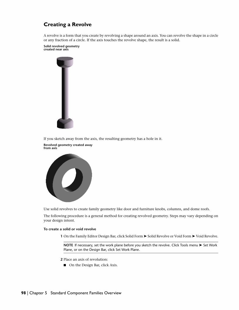
Creating a Revolve
A revolve is a form that you create by revolving a shape around an axis. You can revolve the shape in a circleor any fraction of a circle. If the axis touches the revolve shape, the result is a solid.
Solid revolved geometrycreated near axis
If you sketch away from the axis, the resulting geometry has a hole in it.
Revolved geometry created awayfrom axis
Use solid revolves to create family geometry like door and furniture knobs, columns, and dome roofs.
The following procedure is a general method for creating revolved geometry. Steps may vary depending onyour design intent.
To create a solid or void revolve
1 On the Family Editor Design Bar, click Solid Form ➤ Solid Revolve or Void Form ➤ Void Revolve.
NOTE If necessary, set the work plane before you sketch the revolve. Click Tools menu ➤ Set WorkPlane, or on the Design Bar, click Set Work Plane.
2 Place an axis of revolution:
■ On the Design Bar, click Axis.
98 | Chapter 5 Standard Component Families Overview

■ Specify the start and endpoint of the axis at the desired orientation.
3 Use the sketching tools to sketch a shape to revolve around the axis:
■ To create a single revolve, sketch a closed loop.
■ To create more than one revolve, sketch multiple, non-intersecting, closed loops.
IMPORTANT If the axis touches the revolve shape, the result is a solid. If the axis does not touch therevolve shape, the revolve will have a hole in it.
4 Change the revolution properties:
■ On the Design Bar, click Revolution Properties.
■ To change the start and end points of the geometry to revolve, enter a new Start and EndAngle.
■ To set the visibility of a solid revolve, under Graphics, for Visibility/Graphics Overrides, clickEdit.See Managing the Family Visibility and Detail Level on page 127.
■ To apply a material to a solid revolve by category, under Materials and Finishes, click in the
Material field, and click to specify a material.See Materials in the Revit Architecture 2009 Help.
■ To assign a solid revolve to a subcategory, under Identity Data, for Subcategory, select asubcategory.See Assigning Family Geometry to Subcategories on page 126.
■ Click OK.
5 Click Finish Sketch.
6 To view the revolve, open a 3D view.
7 To resize the revolve in the 3D view, select and use grips to edit it.
NOTE You cannot drag the start and end faces of a 360-degree revolution.
Editing a Revolve
1 In the drawing area, select the revolve.
2 If you are in the project environment:
a On the Options Bar click Edit Family.
b Click Yes to open the family for editing.
c In the Family Editor, select the revolve in the drawing area again.
3 On the Options Bar, click Edit.
4 If desired, modify the revolve sketch.
5 To edit other revolve properties, on Design Bar, click Revolution Properties, and change the startand end points, visibility, material, or subcategory.
6 To change the revolve to a solid or a void, under Identity Data, for Solid/Void, select Solid orVoid.
7 Click OK.
Creating a Standard Component Family | 99

8 On the Design Bar, click Finish Sketch.
Creating a Sweep
A sweep is a tool for creating families that requires you to sketch or apply a profile (shape) and extrude thatprofile along a path. You might use a sweep to create moldings, railings, or simple pipes.
The following procedure is a general method for creating a sweep. Steps may vary depending on your designintent.
To create a solid or void sweep
1 On the Family Editor Design Bar, click Solid Form ➤ Solid Sweep or Void Form ➤ Void Sweep.
NOTE If necessary, set the work plane before you sketch the revolve. Click Tools menu ➤ Set WorkPlane, or on the Design Bar, click Set Work Plane.
2 Specify the sweep path:
■ To sketch a new path for the sweep, click Sketch 2D Path.The path can either be a single closed or single open path. You cannot have multiple paths.The path can be a combination of straight lines and arcs, or it can be a circle. If you choosethe Pick option while sketching the path, the path is confined to one work plane.
■ To select an existing line for the sweep, click Pick Path.You can select edges of other solid geometry, such as extrusions or blends, or you can pickexisting sketch lines. Watch the status bar to know what you are picking. This method ofpicking automatically locks the sketch lines to the geometry you are picking. Also, using thePick Path method allows you to sketch the path in multiple work planes, hence allowing fora 3D path. If you click existing sketch lines, you actually delete them.
3 Sketch or pick the path, and then click Finish Path.
4 Load or sketch a profile:
■ To load a profile:
a On the Options Bar, select a profile from the list.
If the profile you need is not already loaded in the project, click Load profiles to loadthe profile.
b Use the X, Y, Angle, and Flip options to adjust the position of the profile.Enter values for X and Y to specify the offset for the profile.
Enter a value for Angle to specify the angle of the profile. The angle rotates the profilearound the profile origin. You can enter negative values to rotate in the oppositedirection.
Click Flip to flip the profile.
c Click Apply.
d Select the path, and zoom in to see the profile.
100 | Chapter 5 Standard Component Families Overview

■ To sketch a profile:
a On the Options Bar, verify <By Sketch> is displayed, and click Edit.
b In the Go To View dialog, select the view where you want to sketch the profile, andclick OK.For example, if you sketched the path in a plan view, you would choose an elevationview to sketch the profile. The profile sketch can be a single-closed loop or multipleclosed loops that do not intersect. Sketch the profile near the intersection of the profileplane and the path.
c Sketch the profile. Profiles must be closed loops.
d Click Finish Profile.
5 Specify the sweep properties:
■ On the Design Bar, click Sweep Properties.
■ To set the visibility of a solid sweep, under Graphics, for Visibility/Graphics Overrides, clickEdit, and specify the visibility settings.See Managing the Family Visibility and Detail Level on page 127.
■ To apply a material to a solid sweep by category, under Materials and Finishes, click in the
Material field, click , and specify a material.See Materials in the Revit Architecture 2009 Help.
■ To assign a solid sweep to a subcategory, under Identity Data, for Subcategory, select asubcategory.See Assigning Family Geometry to Subcategories on page 126.
■ Click OK.
6 Click Finish Sweep.
Creating a Segmented Sweep
Segmented sweeps are useful for creating mechanical duct work elbows. You create a segmented sweep bysetting 2 sweep parameters and sketching a path with arcs. The parameters affect only arcs in the path. Theminimum number of segments for a sweep is 2.
1 Follow the steps in Creating a Sweep on page 100 to access the sweep tool.
2 On the Sketch Design Bar, click Sweep Properties.
3 Select the check box for Trajectory Segmentation.
4 Enter a value for Maximum Segment Angle. Valid values are between 0 and 360 degrees.
5 Sketch or pick a path with arcs.
6 Click Finish Path to complete the path.
7 Create a profile or use a pre-loaded profile, and select the sweep path.
8 Click Finish Sweep to complete the sketch of the sweep.
Creating a Standard Component Family | 101

Sample segmented sweep with 30 degreeMaximum Segment Angle.
TIP You can change a segmented sweep to a non-segmented sweep by clearing the check box for TrajectorySegmentation.
Editing a Sweep
1 In the drawing area, select the sweep.
2 If you are in the project environment:
a On the Options Bar click Edit Family.
b Click Yes to open the family for editing.
c In the Family Editor, select the sweep in the drawing area again.
3 On the Options Bar, click Edit Sweep.
4 To modify the sweep path:
■ Select the sweep, and on the Options Bar, click Edit.
■ Grip-edit the sweep path.
■ Click Finish Path.
5 To modify the sweep profile:
■ On the Design Bar, click Profile.
■ On the Options Bar, use the commands that display to select a new sweep profile or changethe sweep profile location.
6 To edit other sweep properties, on the Design Bar, click Sweep Properties, and change thevisibility, material, segmentation, or subcategory of the sweep.
7 To change the sweep to a solid or a void, under Identity Data, for Solid/Void, select Solid orVoid.
8 Click OK.
9 On the Design Bar, click Finish Sweep.
102 | Chapter 5 Standard Component Families Overview

Sweep Tips
When creating a sweep with a tangent arc in the path, be sure the profile is small enough to sweep aroundthe arc without the resulting geometry intersecting itself. An error occurs if the geometry intersects. SeeError Handling in the Revit Architecture 2009 Help.
If you create a sweep path by using the Pick Path command, you can drag the end points of the path linesas you are sketching it.
Creating a Swept Blend
The Swept Blend tool allows you to create a blend that has 2 different profiles and then sweep it along apath. The shape of a swept blend is determined by the 2D path you either sketch or pick and the 2 profilesyou either sketch or load.
The following procedure is a general method for creating a swept blend. Steps may vary depending on yourdesign intent.
To create a solid or void swept blend
1 In the Family Editor, click Solid Form ➤ Solid Swept Blend or Void Form ➤ Void Swept Blendon the Family tab of the Design Bar.
2 Specify the path for the swept blend. Do one of the following on the Sketch tab of the DesignBar:
■ Click Sketch 2D Path to sketch a new path for the swept blend.
Creating a Standard Component Family | 103

■ Click Pick Path to pick an existing line for the swept blend.
NOTE If necessary, set the work plane before you sketch or pick the path for the swept blend. ClickTools menu ➤ Set Work Plane, or on the Design Bar, click Set Work Plane.
3 Sketch or pick the path, and then click Finish Path.
NOTE A swept blend path can only have one segment.
4 Load or sketch Profile 1.
■ To load a profile:
a On the Design Bar, click Profile 1.
b In the drawing area click the end point for Profile 1 on the swept blend path.
c On the Options Bar, select a profile from the list.
If the profile you need is not already loaded in the project, click Load profiles to loadthe profile.
d Zoom in to see the profile.
e Use the X, Y, Angle, and Flip options to adjust the position of the profile.
104 | Chapter 5 Standard Component Families Overview

Enter values for X and Y to specify the offset for the profile.
Enter a value for Angle to specify the angle of the profile. The angle rotates the profilearound the profile origin. You can enter negative values to rotate in the oppositedirection.
Click Flip to flip the profile.
f Click Apply.
■ To sketch a profile:
a On the Design Bar, click Profile 1.Alternatively, in the drawing area click the end point for Profile 1 on the swept blendpath, select <By Sketch> from the list on the Options Bar, and click Edit.
b If the Go To View dialog displays, select the view where you want to sketch the profile,and click OK.
c Sketch the profile. Profiles must be closed loops.
d Click Finish Profile.
5 Load or sketch Profile 2 using the steps above.
6 Optionally, edit the vertex connections. By editing vertex connections, you control the amountof twist in the swept blend. You can edit vertex connections in plan or 3D views.
a On the Sketch tab of the Design Bar, click Vertex Connect.
b On the Options Bar, select Controls on Loop 1 or Loop 2.
c In the drawing area, click the blue controls to move the vertex connections.
d On the Options Bar, click the Twist buttons to twist the swept blend.
7 Specify the swept blend properties:
■ On the Design Bar, click Swept Blend Properties.
■ To set the visibility of a solid swept blend, under Graphics, for Visibility/Graphics Overrides,click Edit, and specify the visibility settings.See Managing the Family Visibility and Detail Level on page 127.
■ To apply a material to a solid swept blend, under Materials and Finishes, click in the Material
field, click , and specify a material.See Materials in the Revit Architecture 2009 Help.
■ To assign a solid swept blend to a subcategory, under Identity Data, for Subcategory, selecta subcategory.See Assigning Family Geometry to Subcategories on page 126.
■ Click OK.
8 When finished, click Finish Swept Blend.
Editing a Swept Blend
1 In the drawing area, select the swept blend.
Creating a Standard Component Family | 105

2 If you are in the project environment:
a On the Options Bar click Edit Family.
b Click Yes to open the family for editing.
c In the Family Editor, select the swept blend in the drawing area again.
3 On the Options Bar, click Edit Swept Blend.
4 To edit the path:
a In the drawing area, select the path and click Edit on the Options Bar.
b Make the necessary modifications to the path, and click Finish Path.
5 To edit the profiles:
a In the drawing area, select the profile you want to edit.
b On the Options Bar, select a different loaded profile from the drop down list, or select <BySketch> from the list to sketch a new profile.
c If you selected <By Sketch>, click Sketch Profile 1 or Sketch Profile 2 on the Design Bar.
d Sketch the path and then click Finish Path.
6 To edit other swept blend properties, on the Design Bar, click Sweep Properties, and change thevisibility, material, or subcategory of the sweep.
7 To change the swept blend to a solid or a void, under Identity Data, for Solid/Void, select Solidor Void.
8 Click OK.
9 On the Design Bar, click Finish Swept Blend.
Cut Geometry
With the Cut Geometry command, you can pick and choose which geometry gets cut and which does not,regardless of when you created the geometry.
NOTE While this command and the Don’t Cut Geometry command are primarily for families, you can use themto embed curtain walls. See Embedded Walls in the Revit Architecture 2009 Help.
1 Create solid geometry; it can be a single primitive or some joined primitives.
2 Create a void through the solid geometry.
106 | Chapter 5 Standard Component Families Overview

3 Create another solid geometry shape and join it to the existing geometry. See Joining Geometryin the Revit Architecture 2009 Help.
4 Click Tools menu ➤ Cut Geometry and select the void you created.
Notice the cursor changes shape.
5 Select the geometry you created in Step 3.
Revit Architecture cuts the selected geometry.
Creating a Standard Component Family | 107

Don't Cut Geometry
1 Click Tools menu ➤ Don't Cut Geometry.
2 Select the void.
3 Select the appropriate solid primitives that you do not want to cut.
NOTE If you select all geometry to not be cut, then the void appears at all times in the view.
Creating 2D Geometry
To create 2D family geometry, you use the Revit Architecture Model and Symbolic lines commands that areavailable in the Family Editor.
The Model Lines command lets you sketch two-dimensional geometry for when you do not need to showsolid geometry. For example, you could sketch door panels and hardware as 2D rather than sketch solidextrusions. Model lines are always visible in 3D views. You can control their visibility in plan and elevationviews by selecting the lines and clicking Visibility from the Options Bar.
The Symbolic Lines command lets you sketch lines that are meant for symbolic purposes only. For example,you might sketch symbolic lines in an elevation view to represent a door swing. Symbolic lines are not partof the actual geometry of the family. Symbolic lines are visible parallel to the view in which you sketchthem.
You can control symbolic line visibility on cut instances. Select the symbolic line and click Visibility fromthe Options Bar. Select Show only if instance is cut.
In this dialog, you can also control the visibility of lines based on the detail level of the view. For example,if you select Coarse, that means that when you load the family into a project and place it in a view at theCoarse detail level, the symbolic lines are visible.
Creating and Using Profile Families
A profile family contains a two-dimensional loop shape that you can load into your project and apply tocertain building elements. For example, you can sketch the profile loop for a railing and then use that shapeon a railing in your project.
108 | Chapter 5 Standard Component Families Overview

Rail profile
Stair rails with profile applied
Elements for which you can define profiles include wall sweeps, reveals, railings, mullions, stair treads, andsweep profiles. When you define one profile family, you can reuse it multiple times on building elementsin the project. Loaded profiles display in the Project Browser under Families.
Create profile families using family templates supplied with Revit Architecture. These templates are Profile.rft,Profile-Rail.rft, Profile-Reveal.rft, Profile-Stair Nosing.rft, and Wall Sweep Profile.rft.
Creating a Profile Family
To create a profile family, open a new family, and sketch a profile using lines, dimensions, and referenceplanes. After you save the profile family, you can load and apply it to solid geometry in the project.
This procedure describes creating a generic profile shape that is available to multiple building elements inthe project. Your specific building and design intentions may differ.
To create a profile
1 Click File menu ➤ New ➤ Family.
Creating a Standard Component Family | 109

2 In the Open dialog, select a profile template, and click Open.
The Family Editor opens a plan view that includes 2 reference planes. There are no other viewsavailable in which to sketch geometry.
3 If necessary, sketch reference planes for constraining the lines in the profile.
4 Click Lines and sketch the profile loop.
For more information about the sketching tools, see Sketching in the Revit Architecture 2009Help.
5 If necessary, click Detail Component to place a detail component into the profile family.
TIP You can change the sorting order of any detail components in the family by using the detailcomponent draw order commands. See Sorting Element Draw Order in the Revit Architecture 2009Help.
6 To set the detail at which the profile family displays in the project, select any of the lines of theprofile sketch, and click Visibility on the Options Bar.
7 Select the desired detail levels, Fine, Medium, or Coarse, and click OK.
TIP You can also set the detail level for detail components using the same methods.
Next, define the profile usage.
8 Click Settings menu ➤ Family Category and Parameters.
9 Under Family Parameters, for Profile Usage, click in the Value field, and select the profile type.
For example, if you are creating a mullion profile, select Mullion.
TIP This setting ensures that only relevant profiles are listed when using profiles within a project. Forexample, when selecting a mullion profile, stair nosing profiles do not display.
10 Add any dimensions required.
Sample profile sketch
11 Save the family.
110 | Chapter 5 Standard Component Families Overview

Loading a Profile Family into a Project
1 Click File menu ➤ Load From Library ➤ Load Family.
2 Navigate to the profile family file you created, select it and click Open.
3 In the Project Browser, expand Families, and expand Profiles.
The family that you created and loaded displays under Profiles.
You can now apply the profile to building elements in the project.
Using the Profile Family with a Building Element
This procedure provides an example of a way to apply the profile to an element.
1 Click File menu ➤ New ➤ Family, and select the Profile-Rail family template.
2 Create a new profile-rail family by sketching the shape you want for the rail.
Make sure that the sketched shape is a single closed loop of lines.
3 Save the new profile-rail family.
4 Open the project in which you want to use the new profile-rail family.
5 Click File menu ➤ Load from Library ➤ Load Family, select the profile family that you created,and click Open.
6 Click Modelling menu ➤ Stairs, or on the Modelling tab of the Design Bar, click Stairs.
7 Sketch a run of stairs.
8 Open a 3D view, and select the default railing.
9 Click , and then click Edit/New in the Element Properties dialog.
10 Next to the Rail Structure parameter, click Edit.
11 In the Edit Rails dialog, in the Profile column, click the current profile family name.
12 Select the profile family name, and click OK three times.
Revit Architecture applies the new profile shape to the railing.
Stair rails with profile created from procedure above
Creating a Standard Component Family | 111

Host Sweep Profiles with Nested Detail Components
You can nest a detail component within a host sweep profile family and use the visibility controls to specifywhen the detail component displays within a project. Examples of host sweeps are wall sweeps, roof fascia,gutters, and slab edges. When the sweep is cut in the project, the detail component displays depending onthe visibility settings you specified within the host sweep family file. You can also have multiple detailcomponents display at particular visibility levels for a specific view cut host sweep.
Example of curtain mullion withnested detail component
TIP You can also import a detail, such as a DWG file, and apply the same visibility controls to it.
See also Nesting and Sharing Component Families on page 132.
To load a detail component
1 Open or create a host sweep family.
2 On the Design Bar, click Detail Component.
3 On the Options Bar, click Load.
4 Select a detail component family, and click open.
To add the detail component to the host sweep
5 Add the detail component to the host sweep family.
6 If necessary, use alignments or dimensions to constrain the location of the detail component.
To specify detail component visibility
7 Select the nested detail component.
8 On the Options Bar, click Visibility.
9 Specify the detail level when the detail displays, and click OK.
Once loaded in a project, the host sweep detail displays when cut and at the detail level youspecified.
112 | Chapter 5 Standard Component Families Overview

Dimensioning Family Geometry
As you create the geometry of your component families, you place dimensions to define the geometricrelationships that you want to control with parameters. By labeling the dimensions that you place, youcreate a parameter that you can control.
To add dimensions, you can use the Dimension command on the Family Editor Design Bar, or you can turnon automatic dimensions. Revit Architecture creates automatic dimensions to help control your designintent. These automatic dimensions are not displayed by default.
Automatic Sketch Dimensions
Revit Architecture creates automatic dimensions to help control your design intent. These automaticdimensions are not displayed by default.
To turn them on, check Automatic Sketch Dimensions in the Visibility dialog. You can then modify thesedimensions or create your own dimensions using the Dimension command. You can also lock dimensionsto keep a distance constant. This is very useful if you plan to have several sizes of the family and want tokeep certain dimensions constant while the family changes size.
Effects of Automatic Dimensions on Your Geometry
Until you are aware of automatic sketch dimensions and that they are constraining your geometry to referenceplanes, you may see some unexpected behavior. The automatic sketch dimensions are Revit Architecture'sway of solving how to grow or shrink your geometry based on changes in value of a family parameter.
For example, you have added a rectangular window to a fire door that has a labeled dimension for the width,but you have not dimensioned the window.
You decide to change the width of the door, but you want the window width to stay the same. You expectits position not to change; however, observe what happens when you increase the width of the door throughthe Family Types command.
Creating a Standard Component Family | 113

In this example, the window is constrained to the centerline of the door and the right side of the door panel.Both the centerline and the right side of the panel are represented by reference planes. The window's positionremains fixed relative to those reference planes.
To see the automatic sketch dimensions, edit the sketch of the window and turn on the visibility of thedimensions. You will see how the vertical sketch lines of the window are dimensioned to the center andright reference planes.
Image legend:
1 Auto sketch dimension to right reference plane.
2 Auto sketch dimension to center reference plane.
114 | Chapter 5 Standard Component Families Overview

To achieve the desired results with your geometry, add locked dimensions. For example, you could add alocked dimension to represent the width of the window and a locked dimension from the window to theright reference plane.
Visibility of Automatic Sketch Dimensions in the Family Editor
Automatic sketch dimensions are turned off by default in a view. They appear if there is at least one labeleddimension in the family.
Notice in this next image that there is a dimension added to this geometry, but the dimension has no label.
No automatic sketch dimensions are visible.
To turn on visibility of automatic sketch dimensions:
1 While you are in sketch mode, click View menu ➤ Visibility/Graphics, or press VG on yourkeyboard.
2 Click the Annotation Categories tab.
3 Expand the Dimensions category, and select Automatic Sketch Dimensions below it.
4 Click OK.
5 Place and label a dimension.
The automatic sketch dimensions display.
Revit Architecture now knows where each line of this geometry exists with respect to reference planes orother sketch lines.
Creating a Standard Component Family | 115

As you explicitly add locked dimensions, the automatic sketch dimensions go away in favor of the dimensions.
In the next image, explicit dimensions appear with locked padlocks.
Dimensioning with Families
Families in Revit Architecture are not parametric until you explicitly add labeled dimensions to them. Byadding labeled dimensions, you are creating new parameters for the family.
Labeling Dimensions
1 Click Modify, and highlight the dimension text.
2 Right-click the dimension, and click Edit Label.
3 Select a label name from the drop-down list, or choose <Add parameter...> and create a newparameter.
Alternate procedure for labeling
1 Click Modify, and select the dimension text.
2 On the Options Bar, choose a name from the Label list, or create a new parameter. See x.
3 If desired, select Leader to create a leader line for the dimension.
116 | Chapter 5 Standard Component Families Overview

Dimensioning Families Tips
■ You cannot type text as a label when you select a dimension. You can only select from a list of familyparameters that are of the correct type, or you can create a new parameter.
■ Labeled dimensions become modifiable parameters for families. You can modify their values using theFamily Types command. See X. When the family is loaded into a project, you can also modify themthrough the Element Properties dialog.
■ Values for labeled parameters can be calculated using formulas. You create the formulas in the FamilyTypes dialog. See Using Formulas for Numerical Parameters on page 121.
■ An array number can be a parameter for a family. After you create the array, select it and then label it.The array number becomes a parameter for the family. You can then modify the parameter value andincrease or decrease the number of members in the array. See Creating an Array in the Revit Architecture2009 Help.
Adding Family Parameters
You can create new instance or type parameters for any family type. By adding new parameters, you havemore control over the information contained in each family instance or type. You can create dynamic familytypes for increased flexibility within the model.
Example 1: A table with different finishes
Create a table family with 2 material parameters called table top finish and table leg finish. Assign a materialto the parameters and load the family into your project. Now you can change materials in the project. Tabletops come in 3 different finishes, Oak, Pine, and Beech. Table legs are painted and offered in Teal, NavyBlue, and Black. Rather than make 9 different family types, you can make one family type and add an instanceparameter for the tabletop finish and another instance parameter for the table legs finish. This allows youto alter the appearance for each table instance within your model.
Example 2: Trying different paints on a window
In this model, the customer wants to instantly view different color paints on the installed window frames.Within the window family, create a new type parameter named Paint, and assign the parameter to thewindow frames. Save the family and load it into the project. Create 2 new materials: Window Paint-Whiteand Window Paint-Brown. You can now apply either the white or brown paint to the Paint type parameter,and view the changes to the entire model instantly.
Creating Parameters
1 Click Settings menu ➤ Family Types, or click Family Types on the Design Bar.
2 In the Family Types dialog, click New, and enter a name for the new type.
This creates a new family type that will be available in the Type Selector when you load it intoa project.
3 Under Parameters, click Add.
4 In the Parameter Properties dialog, under Parameter Type, select Family Parameter.
5 Type a name for the parameter.
6 Select a Discipline: Common or Structural.
7 On the Type of Parameter menu, click the appropriate parameter type.
Creating a Standard Component Family | 117

Choices are:
DescriptionName
Completely customizable. Can be used to collect unique data.Text
A value that is always expressed as an integer.Integer
Used to collect miscellaneous numeric data. Can be defined by a formula. Can alsohave real numbers.
Number
Can be used to establish the length of an element or subcomponent. Can be definedby a formula.
Length
Can be used to establish the area of an element or subcomponent. Formulas canbe used in this field.
Area
Can be used to establish the length of an element or subcomponent. Formulas canbe used in this field.
Volume
Can be used to establish the angle of an element or subcomponent. Formulas canbe used in this field.
Angle
Can be used to create parameters that define slope.Slope
Can be used to create currency parameters.Currency
Provides web link to user defined url.URL
Establishes parameters in which a specific material can be assigned.Material
Used most often for instance properties when the parameter is defined with eithera Yes or No.
Yes/No
Used with nested components and allows you to swap components after the familyis loaded into a project.
Family Type
8 For Group parameter under, select a value.
After the family is loaded into a project, this value determines which group header the parameterdisplays under in the Element Properties dialog.
9 Select either Instance or Type. This defines whether the parameter is an Instance or Typeparameter.
10 Click OK.
NOTE To assign a material to a family element, save the family and load it into a project. Place the
family in the project and select it. Click (Element Properties) and set a value for the materialparameter.
118 | Chapter 5 Standard Component Families Overview

Modifying Family Parameters
Select the desired parameter and click Modify in the Family Types dialog. You can rename the parameterand change whether it is a type or instance parameter. You can also replace it with a shared parameter.
Instance Parameters and Shape Handles
As you create families, you can set labeled dimensions as instance parameters; the parameters are modifiablewhen the family instance is placed in the project. Labeled dimensions set as instance parameters can alsohave shape handles that appear when the family is loaded into a project.
Creating Instance Parameters
1 Sketch family geometry using Family Editor tools.
2 Create dimensions for the family geometry.
3 Label the dimensions. See Labeling Dimensions to Create Parameters on page 87.
4 Select the dimensions and, on the Options Bar, click Instance Parameter.
NOTE If you label dimensions by selecting a label on the Options Bar, you can check the InstanceParameter option without re-selecting the dimensions.
5 On the Design Bar, click Family Types.
In the Family Types dialog, notice the new instance parameter. The (default) label indicates thevalue for the instance parameter when you place the family in the project. For example, if youcreate an instance parameter called length with a default value of 3000 mm, the family instancewill have a length of 3000 mm when placed in the project.
6 Save changes and load the family into a project and click (Element Properties). Forinformation about loading a family, see Finding and Loading Component Families on page 61.
Notice that the labeled dimensions appear as parameters in the Instance pane of the ElementProperties dialog. You can change the values in the dialog.
Adding Shape Handles to a Component Family
You can add shape handles to a component family that display when loaded into a project. The shapehandles allow you to resize the component in the project, which means you can make many different sizedinstances in the project without the need to create multiple types beforehand in the Family Editor. SeeControls and Shape Handles in the Revit Architecture 2009 Help.
Creating a Standard Component Family | 119

Example of a generic component in plan and 3D views with shape handlesadded
To add shape handles to a component family, you must do the following:
■ Add reference lines or reference planes to the family.
■ Align the reference lines or reference planes to the edge of the component where you want the shapehandle to display.
■ Add a dimension to the reference lines or reference planes.
■ Label the dimension as an instance parameter.
■ Save the family and load it into a project. When you select the component, shape handles display wherethe reference lines are aligned and dimensioned.
To add shape handles:
1 Within the Family Editor, add reference planes or reference lines parallel to where you want theshape handles to display.
In the following image, a generic component with a simple extrusion is shown in plan and 3Dviews. Reference lines have been added parallel to the left and right edges.
2 Select each of the reference lines or reference planes, and click . Verify that the Is Referenceparameter is a value other than Not a Reference.
120 | Chapter 5 Standard Component Families Overview

3 Align and lock the reference lines or reference planes to the parallel edges of the component.When loaded into a project, the shape handles will display at this location.
Generic component family with reference lines aligned and lockedto the extrusion edges
4 Add a dimension between the reference lines or reference planes that you aligned in the previousstep.
5 Select the dimension.
6 On the Options Bar, select a label from the Label list, or click Add Parameter and create a newparameter for the dimension.
See Adding Family Parameters on page 117.
7 On the Options Bar, select Instance Parameter.
NOTE When adding a new parameter, you can select Instance for the type in the Parameter Propertiesdialog.
8 Save changes and load the family into a project.
See Finding and Loading Component Families on page 61.
After the family is loaded into the project, select the component. Shape handles display and allow you toresize the family without the need for creating new sizes in the Family Editor.
Using Formulas for Numerical Parameters
Formulas allow you to create parameters that depend on other parameters for their values. A simple examplewould be a width parameter set to equal twice the height of an object. In practice, formulas can be used inmany ways, both simple and sophisticated. Typical uses include embedding design relationships, relating anumber of instances to a variable length, and setting up angular relationships. For example, formulas canbe used to
■ Calculate area or volume of geometry
Creating a Standard Component Family | 121

■ Create a clearance dimension parameter controlled by element size
■ Convert continuously variable values into integer values
■ Add shelves as the height of casework increases
■ Add diagonals in an open web joist as the length increases
Adding a Formula to a Parameter
1 In the Family Editor, lay out reference planes.
2 Add dimensions, as required.
3 Label the dimensions. See Labeling Dimensions to Create Parameters on page 87.
4 Add the geometry, and lock the geometry to the reference planes.
5 On the Design Bar, click Family Types.
6 In the Family Types dialog, in the Formula column next to the appropriate parameter, type theformula for the parameter. For more information about entering formulas, see Valid FormulaSyntax and Abbreviations on page 122.
Valid Formula Syntax and Abbreviations
Formulas support the following arithmetic operations: addition, subtraction, multiplication, division,exponentiation, logarithms, and square roots. Formulas also support the following trigonometric functions:sine, cosine, tangent, arcsine, arccosine, and arctangent.
The valid formula abbreviations for arithmetic operations and trigonometric functions are
■ Addition— +
■ Subtraction— -
■ Multiplication—*
■ Division—/
■ Exponentiation—^: x^y, x raised to the power of y
■ Logarithm—log
■ Square root—sqrt: sqrt(16)
■ Sine—sin
■ Cosine—cos
■ Tangent—tan
■ Arcsine—asin
■ Arccosine—acos
■ Arctangent—atan
■ e raised to an x power—exp
■ Absolute Value—abs
122 | Chapter 5 Standard Component Families Overview

You can enter integers, decimals, and fractional values in formulas, using normal mathematical syntax, asshown in the examples below:
■ Length = Height + Width + sqrt(Height*Width)
■ Length = Wall 1 (11000mm)+ Wall 2 (15000mm)
■ Area = Length (500mm) * Width (300mm)
■ Volume = Length (500mm) * Width (300mm) * Height (800 mm)
■ Width = 100m * cos(angle)
■ x = 2*abs(a) + abs(b/2)
■ ArrayNum = Length/Spacing
Parameter names in formulas are case sensitive. For example, if a parameter name begins with a capital letter,such as Width, you must enter it in the formula with an initial capital letter. If you enter it in a formulausing lower-case letters instead, for example, width * 2, the software will not recognize the formula.
Conditional Statements in Formulas
You can use conditional statements in formulas to define actions in a family that depend on the state ofother parameters. With conditional statements, the software enters values for a parameter based on whethera specified condition is satisfied. Conditional statements are useful in certain circumstances; however, theymake families more complex and should be used only when necessary.
For most type parameters, conditional statements are unnecessary because the type parameter itself is likea conditional statement: If this is the type, then set this parameter to a specified value. Instance parametersare a more productive place to use conditional statements, particularly when they are used to set a parameterthat does not vary continuously.
Syntax for Conditional Statements
A conditional statement uses this structure: IF (<condition>, <result-if-true>, <result-if-false>)
This means that the values entered for the parameter depend on whether the condition is satisfied (true) ornot satisfied (false). If the condition is true, the software returns the true value. If the condition is false, itreturns the false value.
Conditional statements can contain numeric values, numeric parameter names, and Yes/No parameters.You can use the following comparisons in a condition: <, >, =. You can also use Boolean operators with aconditional statement: AND, OR, NOT. Currently, <= and >= are not implemented. To express such acomparison, you can use a logical NOT. For example, a<=b can be entered as NOT(a>b).
The following are sample formulas that use conditional statements.
Simple IF: =IF (Length < 3000mm, 200mm, 300mm)
IF with a text parameter: =IF (Length > 35', “String1”, “String2”)
IF with logical AND: =IF ( AND (x = 1 , y = 2), 8 , 3 )
IF with logical OR: =IF ( OR ( A = 1 , B = 3 ) , 8 , 3 )
Embedded IF statements: =IF ( Length < 35' , 2' 6" , IF ( Length < 45' , 3' , IF ( Length < 55' , 5' , 8' ) ) )
IF with Yes/No condition: =Length > 40 (Note that both the condition and the results are implied.)
Creating a Standard Component Family | 123

Examples of Conditional Statement Usage
Typical uses for conditional statements in formulas include calculating array values and controlling anelement’s visibility based on a parameter value. For example, you can use conditional statements to
■ Prevent an array parameter from taking a value less than 2.In Revit Architecture, arrays can only have an integer value of 2 or greater. In some situations, it may beuseful to create a conditional formula that maintains an array parameter of 2 even if the calculated valueis 1 or 0. With such a formula, if the calculated array value is 2 or greater, the formula retains the value.However, if the calculated value is 1 or 0, the formula changes the value to 2.
Formula: Array number = IF (Arrayparam < 2, 2, Arrayparam)
■ Make muntins visible only when the number of window lights is greater than 1.For example, if you have a Lights parameter that you want to use to control the visibility of muntingeometry, you can create a Yes/No parameter like MuntinVis, and assign it to the Visible parameter inthe Element Properties dialog of the muntin geometry. Because the MuntinVis parameter is a Yes/No (orBoolean) operation, both the condition (IF) and the results are implied. In this example, when thecondition is met (true), the MuntinVis parameter value is selected, and the muntin geometry is visible.Conversely, when the condition is not met (false), the MuntinVis parameter is cleared, and the muntingeometry is not visible.
Formula: MuntinVis = Lights > 1
Duplicating Parameterized Elements
When creating a component in the Family Editor, you often need to create identical elements that arecontrolled by the same parameters, such as labelled dimensions or visibility parameters. For example, if youcreate a window family with muntins controlled by a visibility parameter, you can create the first muntin,apply the visibility parameter to it, and then copy, array, or mirror the muntin. The visibility parameter ofthe original muntin is applied to the duplicated muntins.
If you copy, array, or group a parameterized element, the parameters that control that element are alsocopied.
In the example shown below, a generic family was created with 2 extrusions. The bottom of both extrusionsare aligned to the horizontal reference plane. The height of the large extrusion on the left is controlled bythe labelled dimension, H. The height of the smaller extrusion on the right is controlled by the labelleddimension, (H/2). In the Family Types dialog, a formula was added to the (H/2) parameter to make it equalto Height/2. In addition, a visibility parameter was created and applied to the small extrusion. The smallerextrusion also has a split and painted face.
124 | Chapter 5 Standard Component Families Overview
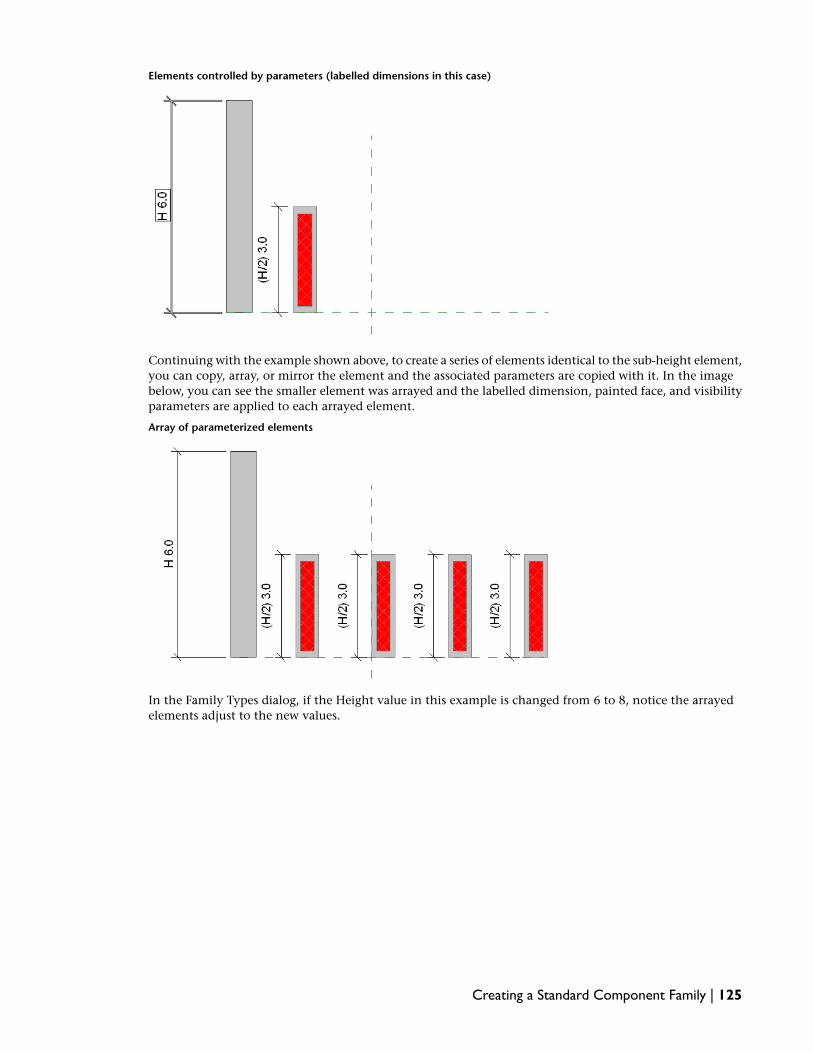
Elements controlled by parameters (labelled dimensions in this case)
Continuing with the example shown above, to create a series of elements identical to the sub-height element,you can copy, array, or mirror the element and the associated parameters are copied with it. In the imagebelow, you can see the smaller element was arrayed and the labelled dimension, painted face, and visibilityparameters are applied to each arrayed element.
Array of parameterized elements
In the Family Types dialog, if the Height value in this example is changed from 6 to 8, notice the arrayedelements adjust to the new values.
Creating a Standard Component Family | 125

Arrayed elements adapt to changed parameter values
Assigning Family Geometry to Subcategories
You can assign different pieces of your family geometry to subcategories within the family category. Asubcategory controls the line weight, line color, line pattern, and material assignment of the geometryassigned to it, independent of the family category settings. By assigning portions of the family geometry todifferent subcatgories, you can display it with different line weights, line colors, line patterns, and materialassignments.
For example, in a window family, you could assign the frame, sash, and mullions to one subcategory andthe glass to another. You could then assign different materials (wood and glass) to each subcategory toachieve the following effect.
126 | Chapter 5 Standard Component Families Overview

If you haven’t created subcategories or your family does not contain them by default, you can create themat any time. See Creating Family Subcategories on page 78.
To assign family geometry to a subcategory
1 On the Family Editor Design Bar, click Modify.
2 Select the family geometry that you want to assign to the subcategory, and click (ElementProperties).
3 In the Element Properties dialog, for Subcategory, select a subcategory.
4 Click OK.
Managing the Family Visibility and Detail Level
Visibility of a family determines in which view the family displays and what it looks like in that view.Typically, when an element is created by a family, the geometry of the element will change, depending onthe current view. In a plan view, you may want to see a 2D representation of the element. In a 3D or elevationview, you may want a fully detailed 3D representation of the element. You have the flexibility to displaydifferent levels of geometry.
For example, you could create a door frame and use lines to represent it. Or you could extrude the doorframe, so it has a 3D representation.
Detail Level determines the visibility of elements at different levels of detail. For example, you might createa door with certain embellishments. You then may decide that the embellishments should only appear ata certain detail level.You control the detail level in a project view with the Detail Level option on the ViewControl Bar.
You can set the visibility and detail level of any 2D and 3D geometry in the family before or after you createit.
Creating a Standard Component Family | 127

1 Do either of the following:
■ To set the visibility before you sketch the geometry, click the command that you want touse to create the geometry, and click Visibility.
■ If you have already created the geometry, select it, and on the Options Bar, click Visibility.
2 On the Options Bar, click Visibility.
3 In the Family Element Visibility Settings, select the views in which you want the geometry todisplay:
■ Plan/RCP
■ Front/Back
■ Left/Right
NOTE All geometry automatically displays in 3D views.
4 If desired, select When cut in Plan/RCP (if category permits).
If you select this option, the geometry appears cut if it is intersected by the cut plane of theview. See View Range in the Revit Architecture 2009 Help. If the element is cut by a sectionview, it also shows if you select this option. See Cuttable Families on page 129 to determine ifyou can show a family category as cut in plan or RCP views.
5 Select the detail levels at which you want the geometry to display in a project:
■ Coarse
■ Medium
■ Fine
Detail levels are dependent upon view scale. See Detail Level in the Revit Architecture 2009 Helpfor more information.
NOTE The Family Element Visibility Settings dialog is different for profile and detail componentfamilies. For these families, you can set only the detail level.
6 Click OK.
TIP You can set family elements to be visible or not visible in the project by associating the Visibleparameter of solid geometry tools with a family parameter for that element. The Visible parameteris available for solid and void geometry tools (blends, sweeps, swept blends, revolves, and extrusions).This lets you create one family type with optionally visible geometry on it. For example, you mightcreate a door and have a coat hook or kick plate on that door be optional. Note that the familygeometry still exists in the project, it is just invisible. For example, it may still be involved when youjoin geometry in the project.
7 If you set the visibility before you created the geometry, create the geometry.
Cuttable and Non-Cuttable Family Categories
Revit Architecture families are either cuttable or non-cuttable. If a family is cuttable, the family displays ascut when the cut plane of a plan view intersects that family in all types of views. If the family is non-cuttable,it displays in projection, regardless of whether it is intersected by the cut plane.
You can determine if a family category is cuttable in the Object Styles dialog (click Settings menu ➤ ObjectStyles). If the Line Weight Cut column is disabled, the category is non-cuttable.
128 | Chapter 5 Standard Component Families Overview

Setting the Visibility of Imported Geometry
1 Import the geometry.
2 Select it, and on the Options Bar, click Visibility.
3 Specify the views and detail levels in which the imported geometry should appear, for example,plan and 3D views and coarse and medium detail levels.
When you load the family into a project and place an instance of it, the imported geometrydisplays based on the settings you specify.
Cuttable Families
If a family is cuttable, the family displays as cut when the cut plane of a view intersects that family in alltypes of views.
In the Family Element Visibility Settings dialog, there is an option called When cut in Plan/RCP. This optiondetermines if family geometry is shown when the cut plane intersects that family. For example, in doorfamilies, the geometry for plan swing is set to be shown when the door is cut in plan views and not shownwhen the door is not cut.
This option is never made available and is never selected for non-cuttable families. For some cuttable families,the option is made available, and you can select it. For other cuttable families, the option is never madeavailable, but it is always selected.
The following table lists cuttable families and whether the option is made available for that family.
NOTE Not Applicable means the category is a system family that cannot be made from a family template.
Option Made AvailableFamily Category
YesCasework
Not ApplicableCeilings
YesColumns
NoCurtain Wall Panels
YesDoors
Not ApplicableFloors
NoGeneric Models
Not ApplicableRoofs
YesSite
YesStructural Columns
YesStructural Foundations
Creating a Standard Component Family | 129

Option Made AvailableFamily Category
YesStructural Framing
NoTopography
Not ApplicableWalls
YesWindows
Non-Cuttable Families
The following families are not cuttable and are always shown in projection in views:
■ Balusters
■ Detail Items
■ Electrical Equipment
■ Electrical Fixtures
■ Entourage
■ Furniture
■ Furniture Systems
■ Lighting Fixtures
■ Mechanical Equipment
■ Parking
■ Planting
■ Plumbing Fixtures
■ Specialty Equipment
Adding a Website Link to a Family
You can add a website link to the Type or Instance properties of a family in both the Family Editor and inthe project environment. Selecting the URL opens the default web browser to the selected location. Forexample, if you are creating a manufacturer-specific window family, you could add the URL and providethe user with a direct link to the manufacturer's website.
Testing a Family in a Project
After you have finished a family, load it in at least one project, and create elements with the family typesto ensure it works correctly. Make sure you select a test project that contains any geometry with which thefamily must interact. For example, if the family is a host-based family like a window, ensure that the testproject contains the host elements, in this case, walls.
130 | Chapter 5 Standard Component Families Overview

BEST PRACTICE Until you successfully test the family, do not save it in a library where it is accessible to others.
To test a family in a project
1 Open a test project.
NOTE Imperial and metric testing projects are available in the Training Files folder. Click File ➤ Open,click Training Files in the left pane of the Open dialog, and open Imperial or Metric. Open Imperial_Family_Testing_Template.rvt or Metric_Family_Testing_Template.rvt.
2 To load the family in the project, do either of the following:
■ With the project and the family open, on the Family Design Bar, click Load into Projects.
■ In the project, click File menu ➤ Load from Library ➤ Load Family, navigate to the locationof the family, select it, and click Open.
3 In the project, on the appropriate tab of the Design Bar, start a command to create an elementfrom one of the new family types.
4 In the Type Selector, select a type in the new family.
5 Add the element to a view in the project.
If the element is host-based, place it in a host element.
6 In the current view, test the element:
■ On the View Control Bar, change the Detail Level and/or Model Graphics style to ensurethat visibility settings work correctly.
■ Change the current scale to ensure the element resizes.
■ Click View ➤ Visibility/Graphics and change the visibility for the element by category and,if applicable, by subcategories.
■ Select the element, right-click, click Element Properties, change any of the instance parameters,and click OK to view and verify the changes.
■ If the family contains multiple types, select the element, and in the Type Selector, select adifferent family type.
7 Open additional project views, and repeat step 6.
8 If the family contains more than one type, repeat steps 3-6 to test other types in the family.
9 If you find any errors in the family, edit the family, and retest it in a project.
10 When you finish testing the family, save it in the imperial or metric Revit Architecture libraryor in another location of your choice.
Advanced Component Family Techniques
After you understand the basics of creating parametric component families, there are more complex techniquesthat you can use when you create families. These techniques include:
■ Nesting and sharing families to combine the geometry of two or more families
■ Linking family parameters
■ Creating face- and workplane-based families
The concepts in this section are demonstrated in the advanced tutorials in this guide. See Tutorials: AdvancedStandard Component Families on page 491.
Advanced Component Family Techniques | 131

Nesting and Sharing Component Families
You can nest (insert) families within other families to create new families that contain the combined familygeometry.
For example, rather than model a combination window family from scratch, you can create thecombination-window family below by loading the Double Hung and Instance - Fixed families into a newwindow family. Place the fixed window instance in the center with a double hung window on each side.
Whether or not you share families before you nest them determines the behavior of the nested geometryin elements that you create with the family.
■ If you nest a family that is not shared, components created by the nested family act with the rest of theelement as a single unit. You cannot select (edit), tag, or schedule the components separately.In the sample window family shown above, an instance of the nested and unshared family would haveonly one window tag and would schedule as a single unit.
■ If you nest a shared family, you can select, tag, and schedule the components separately.In an instance of the shared window family, the 3 windows would tag and schedule separately, eventhough the nested family would behave has a single component within the building model.
132 | Chapter 5 Standard Component Families Overview
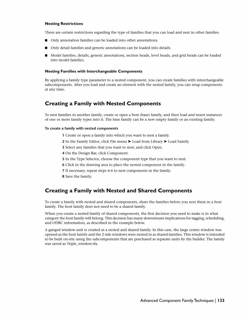
Nesting Restrictions
There are certain restrictions regarding the type of families that you can load and nest in other families.
■ Only annotation families can be loaded into other annotations.
■ Only detail families and generic annotations can be loaded into details.
■ Model families, details, generic annotations, section heads, level heads, and grid heads can be loadedinto model families.
Nesting Families with Interchangeable Components
By applying a family type parameter to a nested component, you can create families with interchangeablesubcomponents. After you load and create an element with the nested family, you can swap componentsat any time.
Creating a Family with Nested Components
To nest families in another family, create or open a host (base) family, and then load and insert instancesof one or more family types into it. The base family can be a new empty family or an existing family.
To create a family with nested components
1 Create or open a family into which you want to nest a family.
2 In the Family Editor, click File menu ➤ Load from Library ➤ Load Family.
3 Select any families that you want to nest, and click Open.
4 On the Design Bar, click Component.
5 In the Type Selector, choose the component type that you want to nest.
6 Click in the drawing area to place the nested component in the family.
7 If necessary, repeat steps 4-6 to nest components in the family.
8 Save the family.
Creating a Family with Nested and Shared Components
To create a family with nested and shared components, share the families before you nest them in a hostfamily. The host family does not need to be a shared family.
When you create a nested family of shared components, the first decision you need to make is in whatcategory the host family will belong. This decision has many downstream implications for tagging, scheduling,and ODBC information, as described in the example below.
A ganged window unit is created as a nested and shared family. In this case, the large center window wasopened as the host family and the 2 side windows were nested in as shared families. This window is intendedto be built on-site using the subcomponents that are purchased as separate units by the builder. The familywas saved as Triple_window.rfa.
Advanced Component Family Techniques | 133

Nested windows
When the ganged unit shown above is loaded into a project, tagged, and scheduled, the result is as follows:
134 | Chapter 5 Standard Component Families Overview

Nested and shared families loaded into a project
Notice that each window is tagged and scheduled separately. However, notice the ganged window name,Triple Window, is listed with the subcomponents. This window also represents the main window of the 3window set.
In the example shown below, the same triple window family was created, but with a new window familyused as the host family and both the fixed window and the double-hung windows loaded as shared families.Notice the difference in the tagging and scheduling.
Ganged window family started as a new family
Advanced Component Family Techniques | 135

In the example shown above, notice the host family schedules with each of the 3 subcomponent windows.If this is not your design intent, you should follow the previous example, where one of the subcomponentsis the host family.
To share a family before nesting it
1 Open a family to be shared, and click Settings menu ➤ Family Category and Parameters.
IMPORTANT Annotation, profile, and in-place families cannot be shared families.
2 In the Family Categories and Parameters dialog, under Family Parameters, select Shared.
Although you can set most families as shared families, it only becomes relevant when the familyis nested into another family and loaded into a project.
3 Click OK.
4 Save and close the family.
To nest shared families in a host family
1 Open the host family or start a new family.
2 Open the families that you want to nest and share them.
3 Load and place a nested component within the host family.
4 Repeat this process for each nested component.
5 Save the family.
Loading Families with Shared Components into a Project
You load families that contain nested or nested and shared families into a project using the same methodsas any other family. When you load a family comprised of nested or nested and shared components into aproject, the following rules apply:
■ The host family, along with all nested and shared components, is loaded into the project. Each nestedcomponent is available within the Project Browser under its respective family category.
■ A nested component family can exist within a project and be shared by more than one host family.
■ When loading shared families, if a version of one of the families already exists within the project, youhave the option to use the version from the project or from the family you are loading.
IMPORTANT Once a shared family is loaded into a project, you cannot reload an unshared version of the samefamily and overwrite it. You must delete the family and reload it.
1 Do either of the following:
■ Within the project, you can click File menu ➤ Load from Library ➤ Load Family.
■ Within the family, you can select Load into Projects on the Design Bar.
2 Add instances of the family to your projects.
Working with Shared Components in a Project
A family that contains nested and shared families works as any other family within a project. However, youcan use the TAB key to toggle to the nested and shared components.
136 | Chapter 5 Standard Component Families Overview

Selecting sub-instances of a shared family
If you select a nested instance, you can do the following:
■ Click and in the Element Properties dialog, modify some instance properties, such as Mark andComments.
■ Modify type properties. When you do this, all instances of that type also update to reflect the changes.
If you select a nested instance, you cannot do the following:
■ Select and delete a nested instance.
■ Mirror, copy, move, or array a nested instance.If you do this, the entire host family adapts, not just the nested instance.
■ Modify the position, the size, or shape of a nested instance.
Scheduling Shared Components
To create a schedule containing shared families, you use the same method as any other schedule. See ScheduleViews in the Revit Architecture 2009 Help.
The biggest advantage to nesting and sharing families is the ability to schedule shared families as individualinstances. A family comprised of shared and nested families allows each instance of a nested family scheduleseparately. Within the schedule, you can renumber each instance of a nested family.
Advanced Component Family Techniques | 137

Family comprised of 2 shared window families loaded into a project
If a nested family is comprised of multiple categories, each instance of a nested family displays in its respectiveschedule and all components will display on a multi-category schedule.
In contrast, in a family where none of the nested families are shared, instances of the nested families scheduleonly as one instance.
Creating a Nested Family with Interchangeable Components
You can create families that feature interchangeable nested components when added to your projects. Tocontrol the type of family within a nested family, you create a family type parameter that can be either aninstance or type parameter. After you label a nested component as a family type parameter, subsequentlyloaded families of the same type automatically become interchangeable without any further work.
For example, if you add 2 transoms to a door family shown below, you only have to position one of thetransoms, label it as a family type parameter, and the other transom becomes part of the list of availabletransoms. If you load 5 more transom types, they are all available for selection.
138 | Chapter 5 Standard Component Families Overview

Door family with multiple nested transoms assigned to a familytype parameter
If you need the nested family components to tag and schedule individually, make sure each family that youload into the host family is shared.
1 Open or start a new family.
2 Load the components that you want to nest within the family. For example, if you are in a doorfamily, load several transom types.
3 On the Design Bar, click Component and place the first component at its desired location.
NOTE In the door family example, you would also want to tie the width of the transoms to the widthof the door. Depending on your specific circumstances, you may want to consider a similar action.This ensures that as components swap, they remain in the same position and the same size.
4 Select the nested component.
5 On the Options Bar, in the Label drop-down list, select Add Parameter.
NOTE When adding a parameter in the Family Types dialog, click Add Parameter, select Family Typeas the Category, and select the category from the Select Category dialog. When you add the parameterusing the Options Bar, the parameter is automatically assigned to Family Type and the respectivefamily category is assigned.
6 Select Family Parameter.
7 Enter a name for the Parameter, and select either Instance or Type parameter.
8 Select a value for Group Parameter under.
This designates under which group the parameter displays in the Element Properties dialog.
9 Click OK.
10 Save the file and load it into a project.
11 Add the component to the building model, select it, and click .
12 Locate the family type parameter and select a different component from the list.
Advanced Component Family Techniques | 139

Controlling the Visibility of Families with Nested and SharedComponents
You can control the visibility of nested family instances in the host family. See Managing the Family Visibilityand Detail Level on page 127.
1 In the host family, select the nested family.
2 On the Options Bar, click Visibility.
3 In the Family Element Visibility Settings dialog, set the View Specific Display and Detail Levelsettings.
NOTE In nested families, you cannot set the When cut in Plan/RCP visibility option.
4 Click OK.
Linking Family Parameters
By linking family parameters, you can control the parameters of families nested inside host families fromwithin a project view. You can control either instance or type parameters.
To link parameters, they have to be the same type. For example, link a text parameter in the host family toa text parameter in the nested family.
You can link a host-family parameter to more than one nested family parameter of the same type. Also, youcan link this parameter to multiple nested families.
Creating Family Parameter Links
1 Create a family with either instance or type parameters of the available types.
See Creating Parameters on page 117.
2 Save the family and load it into a host family.
See Finding and Loading Component Families on page 61.
3 With the new family open, click Component on the Design Bar and place as many instances ofthe loaded family as desired.
4 Click Settings menu ➤ Family Types, or click Family Types on the Design Bar.
5 Under Parameters, click Add.
6 Follow the steps for creating a new parameter of the same type as the parameter you wish tocontrol in the nested family.
See Creating Parameters on page 117.
7 Click OK to close the Family Types dialog.
8 Select an instance of the loaded family in the host family and click .
There is a column for both instance and type properties that has an equal sign (=) in the columnheading. There are also gray buttons next to certain parameters, indicating that they can belinked to other parameters.
140 | Chapter 5 Standard Component Families Overview

9 Click the button next to a parameter, either instance or type, that is of the same type as the oneyou created in Step 6. For example, if you created a text parameter, you must select a textparameter here.
10 In the dialog that appears, select the parameter you created in Step 6 to associate it with thecurrent parameter, and click OK.
NOTE When you associate 2 parameters, an equal sign appears on the button:
11 Click OK to close either the Type and Element properties dialogs, or both.
12 Continue creating the host family and save it.
13 Load the family into a project and place a few instances of it.
14 Select an instance of the family and click .
15 Locate the type or instance property you created.
16 Set it to the desired value and click OK.
The nested family changes according to the value you entered.
Creating Parameter Links for Model Text
If you place model text into a family, it acts like a nested family. You can create parameters in the hostfamily to control the text and depth of the model text in the project.
To control text
1 Place some model text in the host family.
2 On the Design Bar, click Family Types and add a family parameter that is of type text. This willbe the parameter that controls the text of the model text in the project.
3 Enter some text in the Value box for the new parameter. For example, if you created a parametercalled Mtext, you might enter "default" in the Value box next to this new parameter. Click OKto close the Family Types dialog.
NOTE Do not leave the Value box empty. If you do, Revit Architecture issues a warning.
4 Select an instance of model text in the family and click .
5 Click next to the parameter Text.
6 In the dialog that appears, select the parameter you created to link to the model text parameter.
7 Click OK twice.
8 Continue creating the host family and save it.
9 Load that family into a project and place a few instances of it.
10 Select an instance of the family and click .
11 Edit the model text parameter.
The model text updates to the new value. If you created an instance parameter, just the oneinstance changes. If you created a type parameter, all current and future instances of the modeltext change.
Advanced Component Family Techniques | 141

To control depth
Controlling model text depth is similar to controlling text, only you create a family parameter that is oftype length. Follow the above procedure to link parameters for model text depth.
Loading Generic Annotations into Model Families
You can nest generic annotation families inside host model families, so that the annotations appear in theproject. This is useful if you want to include a label with a model family and display that label in the project.
Generic annotations hosted by model families scale with the view when they are loaded into the project.When you place these generic annotations on a sheet, they appear at the same size, regardless of view scale.For example, a 3/32" text label in a model family always prints at that size on a sheet, even if that labelappears on the sheet in a view with a 1/8" = 1'0" scale or a view with a 1/4" = 1'0" scale.
You can also control their visibility in the project separately from the host model family.
Adding a Generic Annotation
You can create your own generic annotation family or load one from the available annotation families inthe Revit Architecture library. This procedure uses an existing annotation family.
NOTE Though this procedure uses specific family files, the steps are common to any generic annotation you maywant to add to a model family.
1 Open the microwave.rfa family from the Specialty Equipment\Domestic folder in the Imperiallibrary. The microwave from the Metric library is in the same folder and is calledM_microwave.rfa.
2 Click File menu ➤ Load From Library ➤ Load Family.
3 Navigate to the Annotations folder and select the Label Annotation 3-32.rfa family. For metric,choose the M_Label Annotation.rfa family.
4 Open a floor plan view in the microwave.rfa file. You can place a generic annotation in planonly.
5 Click Symbol on the Design Bar and place an instance of the label at the intersection of the 2reference planes in the center of the microwave.
Label snapping to intersection ofreference planes
Now you need to associate this label with a parameter in the host family.
6 On the Design Bar, click Family Types.
7 In the Family Types dialog, click Add under Parameters.
8 In the Parameter Properties dialog, select Family parameter.
142 | Chapter 5 Standard Component Families Overview

9 Type a name for the parameter. In this case, type Label.
10 From the Type menu, choose Text and click OK. This parameter will be stored by type.
New family parameter appears in Family type dialog
11 Click OK to close the Family Types dialog.
12 Select the label instance you placed on the microwave and click .
13 Click Edit/New and locate the Label parameter.
14 Click the button under the equal sign (=) column next to the Label parameter.
15 In the Associate Family Parameter dialog, select the parameter Label. This is the parameter youcreated in steps 6-10.
16 Click OK to close the dialog.
17 Click OK to close the Type Properties dialog.
18 If desired, you can set at which detail level the label appears in a project. Click the Edit buttonnext to the Visibility instance parameter. Select coarse, medium, or fine detail levels. If you donot select a detail level, the label does not show in a project view set at the same detail level.
19 Save the microwave.rfa family and load it into your project.
For information about loading a family, see Loading Component Families on page 61.
20 Click Component on the Design Bar and place the microwave in a plan view.
21 Click , and in the Element Properties dialog enter MW for the value of the Label parameter.
22 Click OK.
You see the microwave now has this label in the view.
23 If desired, change the detail level of the view to change the visibility of the label.
See Managing the Family Visibility and Detail Level on page 127.
NOTE You can also change the visibility of the label by turning off Generic Annotations in theAnnotation Categories tab of the Visibility/Graphics dialog.
Advanced Component Family Techniques | 143

Creating Work Plane-based and Face-based Families
You can create a family that is hosted by the active work plane. This can be very useful both in a projectenvironment and within a nested family where you may need a nested sub-component to reside on aparticular plane. You can make any non-hosted family a work plane-based family. For example, a genericcomponent, a furniture component, and a site component can all be work plane-based families because theyare not required to be hosted by another component. Doors and windows cannot be work plane-basedbecause they are wall-hosted components.
Example of generic component family nesting a work plane-based component. On theleft, the work plane is selected; on the right, the work plane-based component wasadded.
Another way to create components that can be placed with any orientation is to use face-based families. Aface-based family must be created from the Generic Model face based.rft template. A face-based componentcan be placed on any surface, including walls, floors, roofs, stairs, reference planes, and other components.If the family contains a void cutting the host, the component will cut its host, but only if the host is a wall,floor, roof, or ceiling. When a component with a void is placed on any other host, it will not cut.
Creating a Work Plane-based Family
1 Open or create a non-hosted family.
NOTE Only non-hosted components can become work plane-based families. Doors and windows,for instance, are hosted by walls and cannot become work plane-based components.
2 In the Family Editor, click Settings menu ➤ Family Category and Parameters.
3 In the Family Category and Parameters dialog, under Family Parameters, select Work Plane-Based.
4 Click OK.
NOTE You can make a family both work plane-based and always vertical. Examples of both are shownbelow.
In the nested family below, the rectangular extrusion is a work plane-based component.On the left, the extrusion is work plane-based but not always vertical. On the right,
144 | Chapter 5 Standard Component Families Overview

the same extrusion was reloaded into the family after designating it work plane-basedand always vertical.
Creating Vertical Families
You can create vertical or non-vertical families. This option pertains only to families hosted by walls, floors,ceilings, roofs, and site surfaces. You can set a family component, such as a tree or a chandelier, to AlwaysVertical; once loaded into a project, the component remains vertical regardless of the slope of the host. Inthe case of a car or a park bench, you can set the Always Vertical option to No; this allows the car and thepark bench to adapt to the slope of the host.
NOTE The Always Vertical parameter does not apply to families created in non host-based templates.
Example of Vertical and Non-Vertical Families; 3 trees are set to AlwaysVertical, 2 trees are not.
To set the always vertical parameter for a family
1 In the Family Editor, click Settings menu ➤ Family Category and Parameters.
2 Select the check box to enable the Always Vertical parameter.
3 Click OK.
Modifying Component Families
You can modify component families that are loaded in your projects or saved in libraries. When you decidethat you need to modify a family, determine whether you can simply add or modify a family type to meet
Modifying Component Families | 145

your needs. If not, you can modify a family or copy and modify a family to create a new family. If youmodify and save a family that is in use in a project, you need to reload the family.
Modifying Component Family Types
To customize component families, you can:
■ add family types to a family
■ modify the properties of a component family type
You can modify family types in the project environment, or you can modify them in the Family Editor.
Adding a Type to a Component Family
After loading a family into a project, you can create different family types from within the project. You canalso open a family in the Family Editor, and add a type.
To add a type to a family in the project environment
1 In the Project Browser, expand Families.
2 Expand the family category.
3 Expand the family.
4 Do either of the following:
5 Select the family, right-click, and click New Type.■
■ Select a type, right-click, and click Duplicate.
BEST PRACTICE To minimize type property editing, duplicate the family type that most resemblesthe type that you want to create.
6 Enter a new name for the type, and press ENTER.
7 Select the type, right-click, and click Properties.
8 In the Type Properties dialog, enter new parameter values, and click OK.
To add a type to a family in the Family Editor
1 Open the family (.rfa file) to which you want to a type.
2 On the Family Editor Design Bar, click Family Types.
3 In the Family Types dialog, under Family Types, click New.
4 Enter a name for the type, and click OK.
5 In the Family Types dialog, enter new values for the type parameters.
6 Click OK.
7 Save and close the family.
Modifying a Component Family Type
You can access the properties of a component family type in the Project Browser or from an element thatuses that type in a current project.
146 | Chapter 5 Standard Component Families Overview

To modify a type in the project environment
1 Do one of the following:
■ In the Project Browser, under Families, right-click the component family type, and clickProperties.
■ Select an element in the project, right-click and click Element Properties. In the ElementProperties dialog, click Edit/New.
2 In the Type Properties dialog:
■ Under Type Parameters, change parameter values as desired.The parameters that display vary depending on the component family type that you aremodifying.
■ If desired, in the upper-left corner, click Rename, and type a new name.
3 Click OK to exit all dialogs.
4 If you are modifying a component family type in a project, any instances of elements withcomponent family type in the project update to reflect your modifications.
To modify a type in the Family Editor
1 Open the family (.rfa file) that contains the type that you want to modify.
2 On the Family Editor Design Bar, click Family Types.
3 In the Family Types dialog, enter new values for the type parameters.
4 Click OK.
5 Save and close the family.
Modifying a Family
You can modify a family by opening it in the Family Editor and editing it. After you modify it, you can loadit from the Family Editor into any open projects.
To modify a family in the Family Editor
1 Click File menu ➤ Open.
2 Open the family that you want to modify.
3 In the Family Editor, modify the family:
■ Create or modify family types.See Creating Family Types on page 89.
■ Modify or add geometry to the family.Creating Family Geometry on page 91.
■ Change the visibility settings, detail level, materials, and subcategory of the family.See Managing the Family Visibility and Detail Level on page 127 and Assigning FamilyGeometry to Subcategories on page 126.
■ Add or modify parameters.Adding Family Parameters on page 117.
4 When you finish modifying the family, save it.
5 To load the family into any open projects, on the Options Bar, click Load into Projects.
6 In the Load into Projects dialog, select the projects in which you want to load the family, andclick OK.
Modifying a Family | 147

If the family is already loaded into the project, the Reload Family dialog displays the following:
Then the dialog informs you...If...
that the family is already loaded in theproject, although it is not currently in use.
the family already exists within the projectand has not been used in the buildingmodel
that the family is already in use in the pro-ject.
the family already exists within the projectand is being used in the building model
You are asked if you want to overwrite the existing version of the family. In addition, you havethe option to override the parameter values of the existing types. If you select the overrideoption, the parameter values of the existing family are overridden by the parameter values ofthe family you are loading.
IMPORTANT If the family is in use within the building model and you override the parameter valuesof existing types, the family will update throughout the project with the new values.
■ Click Yes to overwrite the existing version of the family.
■ Click No to end the load process.
TIP When reloading multiple families, you can click Yes to All.
Modifying a Family to Create a New Family
If you can identify a family that is similar to the one that you want to create, you can save time and effortby copying, renaming, and modifying the family to create the new family.
1 Do one of the following to copy a family:
■ In Windows Explorer, navigate to location of the family (a.rfa file), and copy and renameit.
■ In the Family Editor, click File menu ➤ Save to Library ➤ Save Family.
■ In a project, right-click the family in the Project Browser, and click Save.
2 If necessary, in the Save Family dialog, specify the name and file type for the family.
3 Open the family in the Family Editor, and modify it.
See Modifying a Family on page 147.
4 Save and close the family.
Modifying Families in a Project (or Nested Family)
Within a project or family, you can edit a loaded family and reload it into the same project or any otheropen projects or families. Before or after reloading the family into the project, you can save the family to alibrary with the same or a new name.
1 In the drawing area, select the component family that you want to edit.
148 | Chapter 5 Standard Component Families Overview

2 Do either of the following:
■ On the Options Bar, click Edit Family.
■ In the drawing area or Project Browser, right-click the family, and click Edit.
3 In the alert dialog, click Yes to edit the family.
The family opens in the Family Editor. The original project is still open in the background.
4 Modify the family.
5 If you want to save a copy of the modified family, click File menu ➤ Save.
6 To load the family into any open projects, on the Options Bar, click Load into Projects.
7 In the Load into Projects dialog, select the projects in which you want to load the family, andclick OK.
If the family is already loaded into the project, the Reload Family dialog displays the following:
Then the dialog informs you...If...
that the family is already loaded in theproject, although it is not currently in use.
the family already exists within the projectand has not been used in the buildingmodel
that the family is already in use in the pro-ject.
the family already exists within the projectand is being used in the building model
You are asked if you want to overwrite the existing version of the family. In addition, you havethe option to override the parameter values of the existing types. If you select the overrideoption, the parameter values of the existing family are overridden by the parameter values ofthe family you are loading.
IMPORTANT If the family is in use within the building model and you override the parameter valuesof existing types, the family will update throughout the project with the new values.
■ Click Yes to overwrite the existing version of the family.
■ Click No to end the load process.
TIP When reloading multiple families, you can click Yes to All.
8 Close the family file.
Modifying Families in a Project (or Nested Family) | 149

150

Tutorials: 2DComponent Families
151

152

Creating a Room Tag
In this tutorial, you create a room tag that displays various label parameters: room name, floor and ceiling finish, andarea.
Specifying Room Tag Parameters
In this exercise, you specify the room tag parameters.
Create a tag based on the default room tag template
1 Click File menu ➤ New ➤ Annotation Symbol.
2 In the left pane of the New dialog, click Training Files, and open Imperial\Templates\RoomTag.rft.
3 Click View menu ➤ Zoom ➤ Zoom All to Fit.
The reference planes that display are part of the default room tag template.
Edit the 1/8'' label
4 On the Design Bar, click Label.
5 On the Options Bar, click (Element Properties).
6 In the Element Properties dialog, click Edit/New.
7 In the Type Properties dialog, select the Underline check box, and click OK.
Add a 3/32'' label
8 In the Element Properties dialog, click Edit/New.
6
153

9 In the Type Properties dialog, click Duplicate.
10 In the Name dialog, for Name, enter 3/32'', and click OK.
11 In the Type Properties dialog, under Text, for Text Size, enter 3/32''.
12 Clear Underline.
13 Click OK twice.
Combine labels into a room tag
14 In the Type Selector, select Label : 1/8''.
15 On the Options Bar, verify that (Center) and (Middle) are selected.
16 Specify the location for the first label as shown.
The intersection of the reference planes is used as the insertion point of the tag.
17 In the Edit Label dialog, under Category Parameters, select Name, click Add parameter(s) tolabel, and click OK.
18 Zoom in to the label.
The name label displays with the text underlined.
19 In the Type Selector, select Label : 3/32''.
20 Specify a point below the Name label for the next label location.
21 Select Floor Finish, click Add parameter(s) to label and click OK.
22 Specify a point below the Floor Finish label for the next label location.
23 Select Ceiling Finish, click Add parameter(s) to label and click OK.
154 | Chapter 6 Creating a Room Tag

24 Specify a point below the Ceiling Finish label for the last label location.
25 Select Area, and click Add parameter(s) to label.
26 Under Label Parameters and Sample Value, enter Area.
The Area label is a text placeholder. When the room tag is placed in a project, the project settingsdetermine the units for the area calculation (for example, square feet or square meters).
27 Save the new room tag with the name Finish Area Tag.rfa.
The new room tag is now ready for use in a project.
Specifying Room Tag Parameters | 155

156

Creating a TitleblockFamily
In this tutorial, you create a custom titleblock sheet based on the D-size titleblock template.
The titleblock has linework, text, and labels. You customize the titleblock with a new text style, graphics, and your projectdata.
Skills used in this tutorial:
■ Drawing lines for a titleblock
■ Adding a graphic to a titleblock
■ Adding text boxes to a titleblock
■ Adding labels to a titleblock
■ Adding a titleblock to a new project
7
157

Drawing Linework for a Titleblock Sheet
In this exercise, you draw all of the linework necessary to create a custom D-size sheet.
Open a titleblock template
1 Click File menu ➤ New ➤ Titleblock.
2 In the left pane of the New dialog, click Training Files, and open Imperial\Templates\D - 36x24.rft.
The default titleblock template consists of 4 border lines. The lines in the blank template representthe edges of the paper. Custom page sizes can be created by changing the dimensions of theselines.
Sketch the inside border
3 On the Design Bar, click Lines.
4 On the Options Bar, click , and for Offset, enter -1/2''.
5 Click the upper left corner of the sheet to specify the first rectangle corner, and click the lowerright corner of the sheet to specify the second corner of the rectangle.
Add vertical and horizontal lines
6 On the Options Bar, click , and for Offset, enter 4 1/2''.
7 Move the cursor over the right inside border line, and click to draw a new vertical line.
158 | Chapter 7 Creating a Titleblock Family

8 On the Options Bar, click , and click .
9 On the Options Bar, clear Chain.
10 For Offset, enter 0.
11 Draw a horizontal line 4'' below the upper inside border, as shown.
12 Draw a horizontal line 3'' below the last horizontal line, as shown.
13 Draw a horizontal line 3'' above the lower inside border as shown.
14 On the Design Bar, click Modify, press CTRL, and select the second and third horizontal lines.
15 In the Type Selector, select Wide Lines.
NOTE The wide line style is not visible until the titleblock is loaded into a new project.
16 Zoom in to the lower-right corner of the sheet.
17 On the Design Bar, click Lines.
Drawing Linework for a Titleblock Sheet | 159

18 In the Type Selector, select Title Blocks.
19 On the Options Bar, click , and for Offset, enter 0' 1/2''.
20 Move the cursor over the third horizontal line that you originally drew, and click to draw a newhorizontal line 1/2'' below the existing line.
21 Using the same method, add 2 more horizontal lines below the existing lines, as shown.
22 On the Options Bar, for Offset, enter 3/4''.
23 Move the cursor over the third horizontal line, and click to draw a new horizontal line 3/4''above the existing line.
24 Using the same method, add 2 more horizontal lines above the existing lines, as shown.
25 On the Design Bar, click Modify.
26 Zoom out to view the entire sheet.
The titleblock linework is now complete.
Adding Graphics and Text to a Titleblock
In this exercise, you add a company logo, text notes, and labels to your titleblock.
Add a company logo
1 Click File menu ➤ Import/Link ➤ Image.
2 In the left pane of the Open dialog, click Training Files, and open Common\CorporateLogo.jpg.
160 | Chapter 7 Creating a Titleblock Family

3 Place the image in the upper right corner of the sheet, and use the drag handles to resize theimage, as shown.
4 Zoom in to the logo.
Create a 3/8'' text style
5 On the Design Bar, click Text.
6 On the Options Bar, click .
7 In the Element Properties dialog, click Edit/New.
8 In the Type Properties dialog, click Duplicate.
9 In the Name dialog, for Name, enter 3/8'' Bold, and click OK.
10 In the Type Properties dialog, under Text, for Text Size, enter 3/8'', and select Bold.
11 Click OK twice.
Add company name text
12 Draw a text box under the first horizontal line, as shown.
Adding Graphics and Text to a Titleblock | 161

13 Enter Arch Design Inc. in the text box.
14 Click outside of the text box to complete the text.
Add address and phone number
15 In the Type Selector, select Text : Text Note 1.
16 Draw a text box below the company name, and add an address and phone number, as shown.
Press ENTER to add each new line of text and click outside of the text box to complete the text.
162 | Chapter 7 Creating a Titleblock Family

17 On the Design Bar, click Modify, and select the last text note.
18 Select the drag handle, and drag the text note down, as shown.
19 Click outside the text box to complete the modification.
Add consultant information
20 On the Design Bar, click Text.
21 Draw a text box below the second horizontal line, and enter the following text:
■ Consultant:
■ Address:
■ Address:
■ Telephone:
22 On the Design Bar, click Modify, and select the consultant text note.
23 On the Edit toolbar, click (Copy).
24 On the Options Bar, verify Copy is selected, select Constrain and Multiple.
25 Click inside the Consultant text group.
Adding Graphics and Text to a Titleblock | 163

26 Move the cursor down 4'', and click to specify the first copied text note position.
27 Move the cursor down another 4'', and click to specify the second copied text note location.
164 | Chapter 7 Creating a Titleblock Family

Create a 3/16'' text style
28 On the Design Bar, click Text.
29 On the Options Bar, click .
30 In the Element Properties dialog, click Edit/New.
31 In the Type Properties dialog, click Duplicate.
32 In the Name dialog, for Name, enter 3/16'', and click OK.
33 In the Type Properties dialog, under Text, for Text Size, enter 3/16''.
34 Click OK twice.
Add drawing data text
35 In the Type Selector, select Text : 3/16''.
36 Draw a text box in the lower right space of the titleblock, and enter Sheet Number:.
37 Using the same method, add the remaining text, as shown.
Adding Graphics and Text to a Titleblock | 165

Add drawing data labels
38 On the Design Bar, click Label.
39 On the Options Bar, select (Right) and (Bottom).
40 Place the cursor at the lower right corner of the Date field, and click to specify the label location.
41 In the Select Parameter dialog, select Project Issue Date, click the green arrow to add it to thelabel, and click OK.
The label displays a default value wrapped to 2 lines.
42 Select the left drag handle on the label, and drag to the left until the label displays on one line.
NOTE Move the label if necessary (using arrow keys) to line it up properly with the existing text.
166 | Chapter 7 Creating a Titleblock Family

43 Place the cursor at the lower right corner of the Drawn By field, and click to specify the labellocation.
44 In the Edit Label dialog, under Category Parameters, select Drawn By, and click the green arrowto add it to the label.
45 Click OK.
46 Place the cursor at the lower right corner of the Checked By field, and click to specify the labellocation.
47 In the Edit Label dialog, under Category Parameters, select Checked By, click the green arrowto add it to the label, and click OK.
Create a 3/8'' label style
48 On the Design Bar, click Label.
49 On the Options Bar, click .
50 In the Element Properties dialog, click Edit/New.
51 In the Type Properties dialog, click Duplicate.
52 In the Name dialog, for Name, enter 3/8'' Label, and click OK.
53 In the Type Properties dialog, under Text, for Text Size, enter 3/8''.
54 Click OK twice.
Add sheet number and project data labels
55 In the Type Selector, select Label : 3/8'' Label.
56 Place the cursor at the lower right corner of the Sheet Number field, and click to specify thelabel location.
57 In the Edit Label dialog, select Sheet Number, click the green arrow to add it to the label, andclick OK.
Adding Graphics and Text to a Titleblock | 167

58 On the Options Bar, click (Center) and (Middle).
59 Place the cursor near the center of the field above the Date field, and click to specify the labellocation.
60 In the Edit Label dialog, select Project Number, and click OK.
61 Select the left drag handle on the label, and drag to the left until the label displays on one line.
62 Place the cursor near the center of the field above the Project Number field, and click to specifythe label location.
63 In the Edit Label dialog, select Project Name, and click OK.
64 Place the cursor near the center of the field above the Project Name field, and click to specifythe label location.
65 In the Edit Label dialog, select Client Name, and click OK.
168 | Chapter 7 Creating a Titleblock Family

Click Modify, and using arrow keys, move any labels that need to be aligned.
NOTE You can also create custom project parameters and sheet parameters. For more information,see the Construction Documents section in the Revit Architecture 2009 Online Help.
Create a 1/16” label style
66 On the Design Bar, click Label.
67 On the Options Bar, click .
68 In the Element Properties dialog, click Edit/New.
69 In the Type Properties dialog, click Duplicate.
70 In the Name dialog, for Name, enter 1/16” Label, and click OK.
71 In the Type Properties dialog, under Text, for Text Size, enter 1/16”.
72 Click OK twice.
Add Project Path label
73 In the Type Selector, select Label : 1/16” Label.
74 On the Options Bar, click (Left) and (Middle).
75 Place the cursor in the border area below the Sheet Number field, and click to specify the labellocation. (Left-align the label with the Sheet Number field.)
76 In the Edit Label dialog, select File Path, and click OK.
77 On the Design Bar, click Modify, and then adjust the width of the File Path field so that it isapproximately equal to the width of the Sheet Number field.
Adding Graphics and Text to a Titleblock | 169

78 Save the new titleblock family with the name Training D-Size Titleblock.rfa.
The titleblock graphics, text, and labels are now complete.
Adding the Titleblock to a New Project
In this exercise, you add the titleblock that you created to a new project.
Load the titleblock family into a project
1 Click File menu ➤ New ➤ Project.
2 In the New Project dialog, under Template file, click Browse.
3 In the left pane of the Choose Template dialog, click Training Files, and openImperial\Templates\default.rte.
4 Under Create new, verify that Project is selected, and click OK.
5 On the View tab of the Design Bar, click Sheet.
6 In the Select a Titleblock dialog, click Load.
7 In the Open dialog, navigate to the location of Training D-Size Titleblock.rfa file, select it, andclick Open.
8 In the Select a Titleblock dialog, select Training D-Size Titleblock, and click OK.
Modify titleblock properties
9 On the Design Bar, click Modify, and select the titleblock.
10 On the Options Bar, click .
11 In the Element Properties dialog, under Other, for Drawn By, enter Name, and click OK.
12 Zoom in to the lower-right corner of the sheet.
170 | Chapter 7 Creating a Titleblock Family

13 Click Settings menu ➤ Project Information.
14 In the Element Properties dialog:
■ For Project Issue Date, enter January 1, 2008.
■ For Project Status, enter In Progress.
■ For Client Name, enter Jane Smith.
■ For Project Name, enter Office Building.
■ For Project Number, enter 2008-01.
15 Click OK.
16 Zoom to fit the titlesheet in the view.
17 Close the project with or without saving it.
This completes the Creating a Titleblock Family lesson.
Adding the Titleblock to a New Project | 171

172

Creating a Keyplan -Generic AnnotationFamily
In this tutorial, you use a generic annotation family to create a keyplan symbol that can be used on multiple sheets in aproject.
You export a building plan to use as the basis for the keyplan geometry.
You create a keyplan annotation with 2 family types. Depending on the type selected, the corresponding wing is shadedand labeled in the annotation, as shown:
8
173

Skills used in this tutorial:
■ Exporting a building plan as a DWG file
■ Importing a DWG file to use as the basis for a keyplan annotation
■ Creating annotation geometry
■ Defining object styles
■ Adding filled regions
■ Adding parameters to control keyplan shading and labelling
■ Adding the keyplan to a project sheet
Creating the Keyplan Geometry
In this exercise, you create the geometry for the keyplan by importing a DWG file and tracing the outlineof the building plan. You add object styles to the family, and create filled regions to shade the 2 sections ofthe keyplan.
Export the plan of the building to a DWG file
1 Click File menu ➤ Open.
2 In the left pane of the Open dialog, click Training Files, and openImperial\i_Dependent_Views.rvt.
174 | Chapter 8 Creating a Keyplan - Generic Annotation Family

3 Zoom to fit (ZF) the Level 2 floor plan in the window.
4 Click File menu ➤ Export ➤ CAD Formats.
5 In the left pane of the Export dialog, click Desktop, accept the default file name, and click Save.
You trace this DWG file to define the keyplan geometry.
Create a family from a generic annotation family template
6 Click File menu ➤ New ➤ Family.
7 In the left pane of the New dialog, click Training Files, and open Imperial\Templates\GenericAnnotation.rft.
8 Click File menu ➤ Import/Link ➤ CAD Formats.
You import the DWG file that you exported in the previous steps.
9 In the left pane of the Import/Link dialog, click Desktop, click i_Dependent_Views.dwg, andclick Open.
A message displays that there are no paper space objects to import.
10 Click Yes to import the model space objects.
11 Zoom to fit the plan in the view.
NOTE You may not see the plan until you zoom to fit the view.
There are 2 buildings in the plan view of this bird sanctuary: the aviary and observation area inthe upper-left and the lab building in the lower-right. In this tutorial, the aviary is referred toas Wing A and the lab building as Wing B.
Creating the Keyplan Geometry | 175

12 Click File menu ➤ Save As.
13 In the left pane of the Save As dialog use the scroll button, click Training Files, and save the fileas \Imperial\Families\Annotations\Keyplan.
The family file is saved automatically with the .rfa extension.
Resize the plan for a keyplan
You use the Resize tool to make the plan the required size (printed size) for the keyplan. The keyplan willbe used on sheets in Revit Architecture projects, so it will have no scaling applied.
14 In the drawing area, select the imported geometry.
15 On the Edit toolbar, click (Resize).
16 Zoom in to the far right area of Wing A (near where the wings connect).
176 | Chapter 8 Creating a Keyplan - Generic Annotation Family

17 Click the center (intersection) point defined by the reference planes.
18 Zoom out if necessary, and click near the right edge of the imported geometry; the exact positionis not critical.
Creating the Keyplan Geometry | 177

19 Enter 2'', and press ENTER.
Because you are resizing from the center point, this value is 1/2 the size of the desired printingsize of 4''. The imported geometry will be approximately 4'' from the left extents of the geometryto the right extents of the geometry.
20 Zoom to fit the geometry into the view.
178 | Chapter 8 Creating a Keyplan - Generic Annotation Family

Trace the outline of the plan
21 Zoom in to the intersection of the reference planes.
22 On the View toolbar, click (toggles Thin Lines).
23 Zoom in to the upper-left corner of the model, as shown:
24 On the Design Bar, click Lines.
25 On the Options Bar, click (Draw), and select Chain.
Creating the Keyplan Geometry | 179

26 Select the upper endpoint.
27 Select the lower-left endpoint.
28 Continue to draw lines counterclockwise to trace the outline of the plan. (Zoom out as needed.)
29 On the Design Bar, click Modify.
After you trace the outline of the plan, you can delete the imported DWG geometry.
30 Select the imported DWG, and press DELETE.
180 | Chapter 8 Creating a Keyplan - Generic Annotation Family

31 On the Tools toolbar, click (Trim/Extend).
32 Extend the outline between the buildings:
■ Select the left line of the lab building.
■ Select the top line of the lab building.
The division between Wing A and Wing B is clear.
Creating the Keyplan Geometry | 181

Add object styles to the family for lineweights/linetypes
33 Click Settings menu ➤ Objects Styles.
34 Define a dashed line for the match line:
■ In the Object Styles dialog, under Modify Subcategories, click New.
■ In the New Subcategory dialog, for Name, enter Dashed Line, and click OK.
■ For Dashed Line, under Line Weight Projection, select 4, and for Line Pattern, select Dash.
35 Define a thick line for the keyplan outline:
■ In the Object Styles dialog, under Modify Subcategories, click New.
■ In the New Subcategory dialog, for Name, enter Thick Line, and click OK.
■ For Thick Line, under Line Weight Projection, select 5.
36 Click OK.
Draw lines representing the match line of the plan
37 On the Design Bar, click Lines.
38 In the Type Selector, select Dashed Line.
39 Sketch the match line, as shown:
■ Select the 5 points as shown to create a matchline around the corner of Wing B.
NOTE Even with Chain selected on the Options Bar, you must select a start point and endpointfor each segment of the matchline.
182 | Chapter 8 Creating a Keyplan - Generic Annotation Family

40 On the Design Bar, click Modify.
Create filled regions to shade the keyplan sections
41 On the Design Bar, click Filled Region.
42 On the Design Bar, click Region Properties.
43 Modify the region properties to use a gray background rather than the harsh black. (This userpreference for the keyplan can be tailored to match office standards.)
■ In the Element Properties dialog, click Edit/New.
■ In the Type Properties dialog, click Rename.
■ In the Rename dialog, for New, enter Shaded, and click OK.
■ In the Type Properties dialog, under Graphics, click the value for Color.
■ In the Color dialog, click the light gray swatch.
■ Click OK 3 times.
44 In the Type Selector, select Thick Line, and click (Pick Lines).
You use the Thick Line object style to create filled regions to shade the 2 sections of the keyplan.
NOTE These thick lines appear oversized in the family file. However, when loaded into the project,the lines are the correct thickness.
45 Create the filled region for Wing A:
■ Select the lines for the outline for Wing A. There is no need to lock the filled region.
Creating the Keyplan Geometry | 183

■ On the Tools toolbar, click (Trim/Extend), and trim the lines to clean up the outline,as shown:
■ On the Design Bar, click Finish Sketch. Click as needed to manage display of the lines.
184 | Chapter 8 Creating a Keyplan - Generic Annotation Family

46 Create the filled region for Wing B:
■ On the Design Bar, click Filled Region.
■ On the Options Bar, click (Pick Lines).
■ Select the outline for Wing B, as shown:
■ On the Design Bar, click Finish Sketch.
Creating the Keyplan Geometry | 185

47 Click File menu ➤ Save.
48 Proceed to the next exercise, Add Parameters to Control Keyplan Visibility on page 186.
Add Parameters to Control Keyplan Visibility
In this exercise, you create 2 family types: 1 type shows wing A shaded and labeled; the other type showswing B shaded and labeled. You then create a sheet in a Revit Architecture project, and add the 2 keyplantypes to the sheet.
Define 2 family types
1 On the Design Bar, click Family Types.
2 In the Family Types dialog, under Family Types, click New.
3 In the Name dialog, enter Wing A, and click OK.
4 Using the same method, create a family type named Wing B.
Create Yes/No parameters for Wing A and Wing B
5 In the Family Types dialog, under Parameters, click Add.
You create a Yes/No parameter for each wing. You then associate these parameters with thevisibility of the filled regions and the text labels.
6 In the Parameter Properties dialog, under Parameter Data, for Name, enter Wing A, for Type ofParameter, select Yes/No, and click OK.
7 Using the same method, create a yes/no parameter for Wing B.
Specify the visibility for each type
8 In the Family Types dialog, for Name, verify that family type Wing B is selected.
9 Under Other, clear the Value for Wing A.
10 Under Name, select Wing A, and clear the Value for Wing B.
11 Click OK.
Assign the yes/no parameter to the visibility of the filled regions
12 In the drawing area, select Wing A, and click (Element Properties).
13 In the Element Properties dialog, for Visible, click .
14 In the Associate Family Parameter dialog, select Wing A, and click OK twice.
186 | Chapter 8 Creating a Keyplan - Generic Annotation Family

15 Using the same method, assign the Wing B parameter to the visibility for Wing B.
16 On the Design Bar, click Modify.
Create a text label for the keyplan
17 On the Design Bar, click Text, and click (Element Properties).
18 In the Element Properties dialog, click Edit/New.
You create a text type. The size of the text label for a keyplan is typically determined by officestandard text sizes/fonts.
19 In the Type Properties dialog, click Duplicate.
20 For Name, enter 1/8", and click OK.
21 In the Type Properties dialog, under Text, for Text Size, enter 1/8".
22 Click OK twice.
23 Click in the lower left area of the drawing area, and enter Key Plan -.
24 On the Design Bar, click Modify.
25 In the drawing area, select the new text box.
Add Parameters to Control Keyplan Visibility | 187

26 On the Edit toolbar, click (Move Copies).
27 Click the bottom left corner of the text box for the start point, and click to the right of theexisting text box to place the copy.
This second text box will be connected to the visibility parameters and will contain text specificto each family type (that is, Wing A or Wing B). You create 2 copies of the second text box, onecopy for each of the 2 family types.
28 Edit the second text box to read Wing A.
29 On the Design Bar, click Modify.
30 Select the Wing A text, and click (Element Properties).
31 In the Element Properties dialog, for Visible, click .
32 In the Associate Family Parameter dialog, select Wing A.
33 Click OK twice.
34 Create a Wing B text box:
■ Create a copy of the Wing A text box.
■ Select the copy, and change the text to Wing B.
■ With the Wing B text box still selected, click (Element Properties).
■ In the Element Properties dialog, for Visible, click .Notice that = displays on the button because the visibility is already associated with WingA.
■ In the Associate Family Parameter dialog, select Wing B.
■ Click OK twice.
■ Drag the Wing B text box so that it is positioned directly over the Wing A text box.
35 On the Design Bar, click Modify.
36 Select the notes in the template file, and press DELETE.
188 | Chapter 8 Creating a Keyplan - Generic Annotation Family

37 Click File menu ➤ Save.
38 On the Design Bar, click Load into Projects.
39 If necessary, in the Load into Projects dialog, select i_Dependent_Views.rvt, and click OK.
The i_Dependent_Views project opens and the keyplan family is loaded into the project.
Create a sheet for the keyplan
40 In the Project Browser, right-click Sheets (all), and click New Sheet.
41 In the Select a Titleblock dialog, select the default titleblock, and click OK.
Add the generic annotation to the sheet
42 On the Drafting tab of the Design Bar, click Symbol.
43 Click in the upper-right corner of the sheet.
44 Click to place a second instance of the annotation below the first so the 2 types can be testedand compared.
45 On the Design Bar, click Modify.
46 Select the second instance of the annotation, and in the Type Selector, select Keyplan : WingB.
Add Parameters to Control Keyplan Visibility | 189

47 On the Design Bar, click Modify.
48 Zoom in to see the keyplans.
The appropriate wing is shaded and labeled in each annotation.
49 Close the project with or without saving it.
190 | Chapter 8 Creating a Keyplan - Generic Annotation Family

Creating DetailComponent Families
In this tutorial, you learn how to create detail component families and nest them in other families.
You begin the tutorial by creating a window sill detail component family from an existing DWG detail.
Complete RevitArchitecture sill detail
After you create the sill detail, you combine it with an existing head detail and create a full window detail componentfamily by sketching additional detail geometry.
9
191

Full window detail
When the full window detail component family is complete, you nest it in a window family. You specify visibility optionsto display the detail component only in cut views and in fine detail. Then, by adding a window type from the new windowfamily to a project, you test the visibility of the detail component.
Section view of the windowdisplaying the detailcomponent in fine detail
192 | Chapter 9 Creating Detail Component Families

Skills used in this tutorial include:
■ Importing a DWG file to create new detail component families
■ Implementing best practices when importing geometry
■ Nesting detail components within other families
■ Testing the family in a project
Creating a Window Sill Detail Component Family from a DWG
In this exercise, you create a window sill detail by importing an existing detail drawn in DWG format.
Complete RevitArchitecture sill detail
You begin by creating a new detail component family into which you import the existing detail. All theDWG objects (including any blocks or external references) are imported as a single Revit Architecture elementcalled an import symbol. When the DWG is imported, the DWG layers create object styles in the importsymbol.
After you import the DWG detail, you explode the import symbol and convert its components to RevitArchitecture objects. You then remove the unused object styles created from the import of the DWG layersfrom the new family.
Create a detail component family
1 Click File menu ➤ New ➤ Family.
2 In the left pane of the New dialog, click Training Files, and open Imperial\Templates\DetailComponent.rft.
The new family opens in the Family Editor.
3 Save the detail component family:
■ Click File menu ➤ Save As.
■ In the Save As dialog, for File name, enter Window_Sill, and click Save.The new family is saved as an RFA file.
Import a detail from a DWG file
4 Click View menu ➤ Zoom ➤ Zoom All to Fit.
Creating a Window Sill Detail Component Family from a DWG | 193

5 Click File menu ➤ Import/Link ➤ CAD Formats.
6 In the Import/Link dialog:
■ Navigate to Training Files\Imperial.
■ Select Wood_Window_Details_Sill.dwg.A preview image of the detail displays on the right side of the dialog.
■ For Colors, select Preserve.Later, you replace the AutoCAD colored linework with Revit lines.
■ Verify the following:
■ For Layers, All is selected.
■ For Import units, Auto-Detect is selected.
■ For Positioning, Auto - Center to Center is selected.
■ For Place at, Ref. Level is selected.
■ Orient to View is selected.
■ Click Open.The DWG detail is imported into the family as a single import symbol. It is the correct size(life-size). Later, you change the scale, which does not affect the detail size (full-size), butlets you manage the display of lineweights and the size of dimensions.
194 | Chapter 9 Creating Detail Component Families
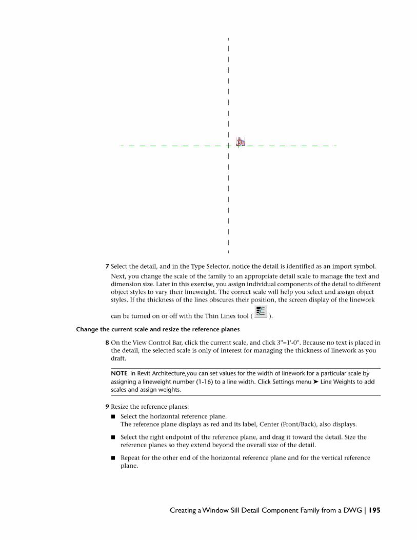
7 Select the detail, and in the Type Selector, notice the detail is identified as an import symbol.
Next, you change the scale of the family to an appropriate detail scale to manage the text anddimension size. Later in this exercise, you assign individual components of the detail to differentobject styles to vary their lineweight. The correct scale will help you select and assign objectstyles. If the thickness of the lines obscures their position, the screen display of the linework
can be turned on or off with the Thin Lines tool ( ).
Change the current scale and resize the reference planes
8 On the View Control Bar, click the current scale, and click 3''=1'-0''. Because no text is placed inthe detail, the selected scale is only of interest for managing the thickness of linework as youdraft.
NOTE In Revit Architecture,you can set values for the width of linework for a particular scale byassigning a lineweight number (1-16) to a line width. Click Settings menu ➤ Line Weights to addscales and assign weights.
9 Resize the reference planes:
■ Select the horizontal reference plane.The reference plane displays as red and its label, Center (Front/Back), also displays.
■ Select the right endpoint of the reference plane, and drag it toward the detail. Size thereference planes so they extend beyond the overall size of the detail.
■ Repeat for the other end of the horizontal reference plane and for the vertical referenceplane.
Creating a Window Sill Detail Component Family from a DWG | 195

■ Click View menu ➤ Zoom ➤ Zoom All to Fit.
Next, you position the detail so that the intended insertion point of the detail aligns with theintersection (0,0) of the reference planes. When you later insert the detail in a view, the referenceplane intersection defines its origin. When you place a detail, the cursor position is attached tothe detail origin.
Align the imported detail with the reference planes
10 On the Tools toolbar, click (Align).
11 Select the Center (Front/Back) reference plane.
12 Select the lower horizontal edge of the sill, as shown.
196 | Chapter 9 Creating Detail Component Families

13 Select the Center (Left/Right) reference plane.
14 Select the right edge of the wall fastener plate, as shown.
The detail now aligns with both reference planes. In this case, you aligned the components withthe reference planes to move them to the correct location.
Creating a Window Sill Detail Component Family from a DWG | 197
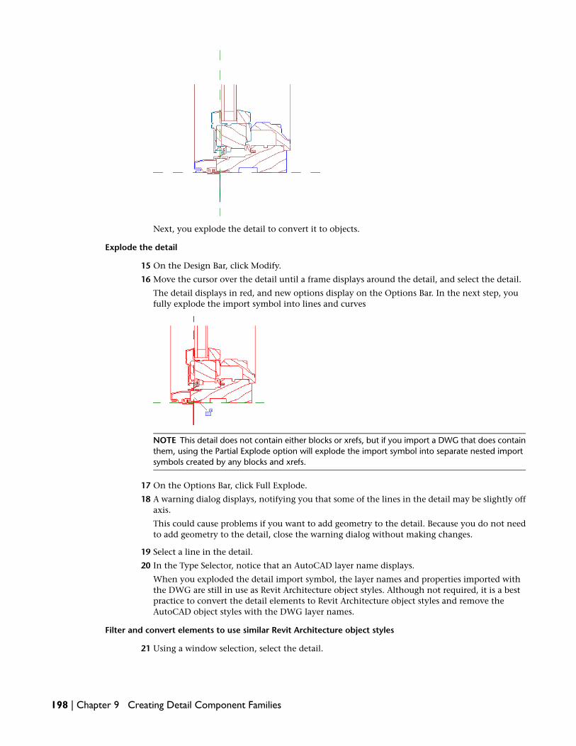
Next, you explode the detail to convert it to objects.
Explode the detail
15 On the Design Bar, click Modify.
16 Move the cursor over the detail until a frame displays around the detail, and select the detail.
The detail displays in red, and new options display on the Options Bar. In the next step, youfully explode the import symbol into lines and curves
NOTE This detail does not contain either blocks or xrefs, but if you import a DWG that does containthem, using the Partial Explode option will explode the import symbol into separate nested importsymbols created by any blocks and xrefs.
17 On the Options Bar, click Full Explode.
18 A warning dialog displays, notifying you that some of the lines in the detail may be slightly offaxis.
This could cause problems if you want to add geometry to the detail. Because you do not needto add geometry to the detail, close the warning dialog without making changes.
19 Select a line in the detail.
20 In the Type Selector, notice that an AutoCAD layer name displays.
When you exploded the detail import symbol, the layer names and properties imported withthe DWG are still in use as Revit Architecture object styles. Although not required, it is a bestpractice to convert the detail elements to Revit Architecture object styles and remove theAutoCAD object styles with the DWG layer names.
Filter and convert elements to use similar Revit Architecture object styles
21 Using a window selection, select the detail.
198 | Chapter 9 Creating Detail Component Families
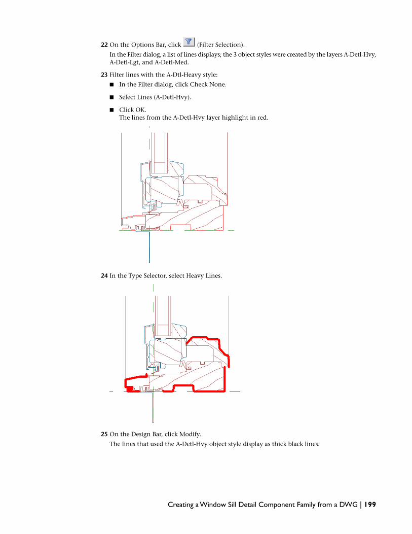
22 On the Options Bar, click (Filter Selection).
In the Filter dialog, a list of lines displays; the 3 object styles were created by the layers A-Detl-Hvy,A-Detl-Lgt, and A-Detl-Med.
23 Filter lines with the A-Dtl-Heavy style:
■ In the Filter dialog, click Check None.
■ Select Lines (A-Detl-Hvy).
■ Click OK.The lines from the A-Detl-Hvy layer highlight in red.
24 In the Type Selector, select Heavy Lines.
25 On the Design Bar, click Modify.
The lines that used the A-Detl-Hvy object style display as thick black lines.
Creating a Window Sill Detail Component Family from a DWG | 199

26 Using the same method, filter and convert the remaining lines to use the Light Lines and MediumLines object styles.
Next, you remove the unused object styles from the family. Deleting these from the familybefore saving and using the family in a project is not required, but is a best practice. If you donot delete unused styles, they can degrade the performance of projects into which you add thedetail component family.
Remove unused object styles from the family
27 Click Settings menu ➤ Object Styles.
28 In the Object Styles dialog, on the Model Objects tab:
■ Under Category ➤ Detail Items, select A-Detl-Hvy.
■ At the bottom right of the dialog, under Modify Subcategories, click Delete.
■ In the Revit dialog, click Yes.
■ Using the same method, remove the A-Detl-Lgt and A-Detl-Med object styles.
200 | Chapter 9 Creating Detail Component Families