Embed Size (px)
Citation preview

TOOL DESIGN PARAMETERS
FOR
NON-CONVENTIONAL MACHINIG
PROCESSES
1
INTRODUCTON TO NCM PROCESSES
Remove material by various techniques such as Chemical, Electrical,
Mechanical, Thermal energy or combination of these energies.
Does not use sharp cutting tools.
Material removal may occur with chip formation or even no chip
formation may take place. ex: AJM and ECM.
There may not be a physical tool present. ex: LBM
The tool need not be harder than the work piece material. ex: EDM
2

3
ULTRA SONIC MACHINING (USM)

4
Abrasive - Boron carbide, aluminium oxide and
silicon carbide
Grit size(d0) - 15 – 150 µm
Frequency of vibration (f) -19 – 25 kHz
Amplitude of vibration (a) -15 - 50 µm
Tool material - Soft steel titanium alloy
Wear ratio - Tungsten 1.5:1 and glass 100:1
Gap overcut - 0.02-0.1 mm
PHYSICAL PARAMETERS

5
The tool material employed in USM should be tough and ductile. Low-carbon steel
and stainless steels give superior performance.
However, metals like aluminium, give very short life.
Metal have high fatigue strengths and low acoustic losses and they should be easily
brazed or soldered.
The metal used to construct horn are titanium, stainless steel, heat treated steel and
Aluminium.
The tool which attached to the end of the horn is exact inverse replica of object to
be manufactured.
TOOL MATERIALS

6
In USM instead of tool the horn plays an important role. Hence the design of horn
must be correct so, it can transfer the vibration to tool.
HORN DESIGN FOR USM
Exponential shape Stepped shapeConical shape

7
a) To amplify the vibration of the tool to the level
required for effective machining.
b) Mean of transmitting the vibrational energy
from the transducer to the workpiece.
c) Important aspect of horn design is the
calculation of the resonant length which should
be in multiple
of half the wave length of the system.
PRINCIPAL FUNCTION
This is a waveguide focussing device with a cross-sectional area which
decreases from the input (transducer) end to the output (tool) end.

8
Literature Reviews
There has been various research in Horn and tool designing of UCM Process on various aspect of
the tool such as Tool material, tool shape and size etc. Here Some research paper has been
discussed regarding tool design.
Paper 1 Author Objective Conclusion
Ultrasonic horn design
for ultrasonic
machining
technologies
M. Nad’a To find dynamical
properties of different
geometrical shapes of
ultrasonic horns are
presented in this
paper.
The dynamical analysis of the
various geometrical shapes of
Sonotrode or Horn as one of the most
important elements of the Ultrasonic
machining system .
The main dynamic characteristics i:e
Natural Frequency and Amplification
factors of Horn in the Resonant state
were depend on Slenderness ratio,
shape parameter function, shape
function. Which are found by the use
of Finite Element Method.

9

10
Paper 2 Author Objective Conclusion
Design of tool holders
for ultrasonic
machining
using FEM
K.H.W. Seah,
Y.S. Wong and
L.C. Lee
To find the Length of
the Horn Using FEM
Method.
Through this research paper the
length of various types of horn
can be obtained. The length of
the Horn is most Important thing
in USM.
1. Exponential shape
L=𝑐
𝑓[1 +
𝑙𝑛𝑁
2𝜋²
C= (𝐸
𝑑)
*C, wave speed. F, Natural frequency. E, young’s modulus
N, diameter ratio D1/D2 (D1 input end, D2 output end)
d. Density of horn material
2. Stepped shape
L= c/2f
Amplitude ratio = (D1/D2)²
3. Conical shape
L= Exponential shape * 1.1
Horn length calculation

11
Paper 3 Author Objective Conclusion
Development of
Design and
Manufacturing Support
Tool for
Optimization of
Ultrasonic Machining
(USM) and Rotary
USM
Morteza Sadegh
Amalnik,
Mohammad
Rasoul Najafi
The concept and
development of an
expert system (ES)
for hard and
brittle material
manufacturing tools.
The design of tool and horn play an
important role in providing a
resonance state in USM and
MRR.
By the development of an Expert
System i:e derived from Artificial
Intelligence (AI), it is easy to design
a tool of required shape and size. By
entering required data in the expert
system.
It can further improved by joining
Expert System with CNC Machine.
Expert system is developed to
estimate machining time and cost,
penetration rate and productivity for
different design hole on different
materials such as glass, composite,
stone,
graphite and ceramic for USM and

12
Paper 3 Author Objective Conclusion
Expert system is developed to
estimate machining time and cost,
penetration rate and productivity for
different design hole on different
materials such as glass, composite,
stone,
graphite and ceramic for USM and
RUSM with less than 30 seconds
Contd…

13
ELECTRO-CHEMICAL MACHINING (ECM)
14
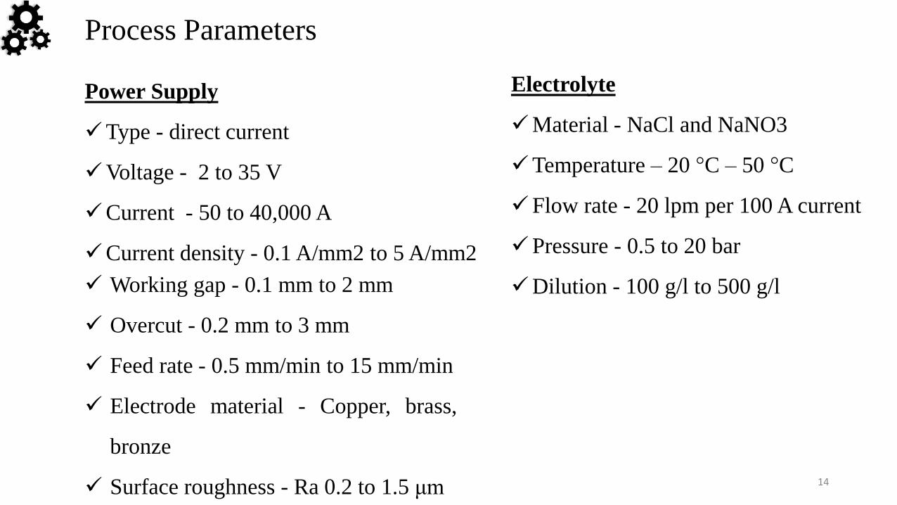
Working gap - 0.1 mm to 2 mm
Overcut - 0.2 mm to 3 mm
Feed rate - 0.5 mm/min to 15 mm/min
Electrode material - Copper, brass,
bronze
Surface roughness - Ra 0.2 to 1.5 μm
Process Parameters
Power Supply
Type - direct current
Voltage - 2 to 35 V
Current - 50 to 40,000 A
Current density - 0.1 A/mm2 to 5 A/mm2
Electrolyte
Material - NaCl and NaNO3
Temperature – 20 °C – 50 °C
Flow rate - 20 lpm per 100 A current
Pressure - 0.5 to 20 bar
Dilution - 100 g/l to 500 g/l

15
TOOL AND TOOL FEED SYSTEM
Use of anti-corrosive material for tool and fixtures, for a
long period of time to Operate in Corrosive environment
of electrolyte.
High thermal conductivity and high electrical
conductivity of tool material.
Easy machining of the tool material.
Tool material, Aluminium, Brass, Bronze, Copper,
carbon, stainless steel and monel.
Area on the tool with no action must be insulated.
Use of non-corrosive and electrically non-conducting
material for making fixtures is recommended.

16
Paper 1 Author Objective Conclusion
Design of ECM Tool
Electrode with
Controlled
Conductive Area
Ratio for Holes with
Complex Internal
Features
Dahai Mi Wataru
Natsu
To design
Electrochemical
machining (ECM)
tool electrode with
controlled
conductive area for
the machining of
holes with given
complex internal
features.
(1) When tool electrode with
uniformly distributed helical
conductive area is considered, it is
found that the machining depth
increases rapidly with the increase of
conductive area ratio when its value
is lower than 20%, while the
machining depth reaches the
maximum and remains almost no
change in accordance with the
conductive area ratio when it’s over
50%.
Literature Reviews

17
Paper 1 Author Objective Conclusion
(2)Since the machining capability of tool electrode is
determined by conductive area ratio distribution and
conductive area ratio can be mathematically
determined by the pitch of the conductive area, the
desired inner feature of the hole can be shaped by
controlling the pitch distribution along tool electrode
surface.
(3) A prototype of tool electrode was designed and
fabricated for a given internal feature, and the
verification experiment was carried out. The results
show that the simulation and experimental results are
generally in well accordance with the given complex
internal feature. Therefore, it is proved that for a hole
with given internal feature, a corresponding tool
electrode can be designed using proposed method.

18
Paper 2 Author Objective Conclusion
An integrated
approach for tool
design in ECM
V.K. Jain
K. P. Rajurkar
To design the ECM
Tool by different
methods such as ,
cos 𝜃 method, complex
variable approach,
empirical and
homographic
approach, finite
difference method,
finite element
technique,
(1) The use of the finite element
technique in predicting the anode
shape obtained, metal removal,
current density, temperature etc. in
ecru using simple and complex
shaped tools. The correlation
between limited amount of
experimental data and theoretical
results is quite good.
(2) cos 𝜃 method is not recommended, especially when complex shaped workpieces are to be analysed.
(3) complex variable approach is not advisable for use when a high degree of precision is desired. Since, its accuracy depends on the skill of the operatorand

19
Paper 2 Author Objective Conclusion
(2) cos 𝜃 method is not
recommended, especially when
complex shaped workpieces are to be
analysed.
(3) complex variable approach is not
advisable for use when a high degree
of precision is desired. Since, its
accuracy depends on the skill of the
operator
and

20
References
[1]. Nptel.ac.in
[2]. K.H.W. Seah, Y.S. Wong and L.C. Lee, Design of tool holders for ultrasonic machining
using FEM, Journal of Materials Processing Technology, 37 (1993) 801 816.
[3]. M. Nad’a, Ultrasonic horn design for ultrasonic machining technologies,
Applied and Computational Mechanics 4 (2010) 79–88.
[4]. Morteza Sadegh Amalnik, Mohammad Rasoul Najafi, Development of Design and Manufacturing
Support Tool for Optimization of Ultrasonic Machining (USM) and Rotary USM, Journal of Modern
Processes in Manufacturing and Production, Vol. 3, No. 2, Spring 2014
[5]. V.K. Jain and P.C. Pandey, Finite element approach to the two dimensional analysis of electrochemical
machining, PRECISION ENGINEERING (1980) 23-27.
[6]. V.K. Jain and P.C. Pandey, Tooling design for ECM, PRECISION ENGINEERING (1980) 195-203.
[7]. V. K. Jain and K. P. Rajurkar, An integrated approach for tool design in ECM, Butterworth-Heinemann
APRIL 1991 VOL 13 NO 2, 111-123.