Embed Size (px)
Citation preview
DC Machine And Transformer(2130904)
Active Learning Assignment
on
Types of DC GeneratorPrepared By:
Patel RajalKumar H.
Guided By :
Prof. Hitesh T. Mannai
Gandhinagar Institute of Technology
Electrical Department
Batch-B3
2
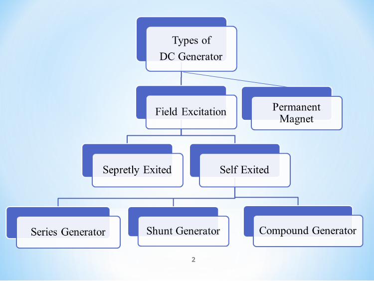
Separately Excited DC Generator
3
Ia = Armature current
IL = Load current
V = Terminal voltage
Eg = Generated emf
Voltage drop in the armature = Ia × Ra (R/sub>a is the
armature Resistance)
Let, Ia = IL = I (say)
Then, Voltage across the load, V = IRa
Power generated, Pg = Eg×I
Power delivered to the external load, PL = V×I.
These are the generators whose field magnets are energized by the
current supplied by themselves.
In these type of machines field coils are internally connected with
the armature. Due to residual magnetism some flux is always present
in the poles.
When the armature is rotated some emf is induced. Hence some
induced current is produced. This small current flows through the
field coil as well as the load and thereby strengthening the pole flux.
Self Exited DC Generator
4
As the pole flux strengthened, it will produce more armature emf,
which cause further increase of current through the field. This
increased field current further raises armature emf and this cumulative
phenomenon continues until the excitation reaches to the rated value.
5
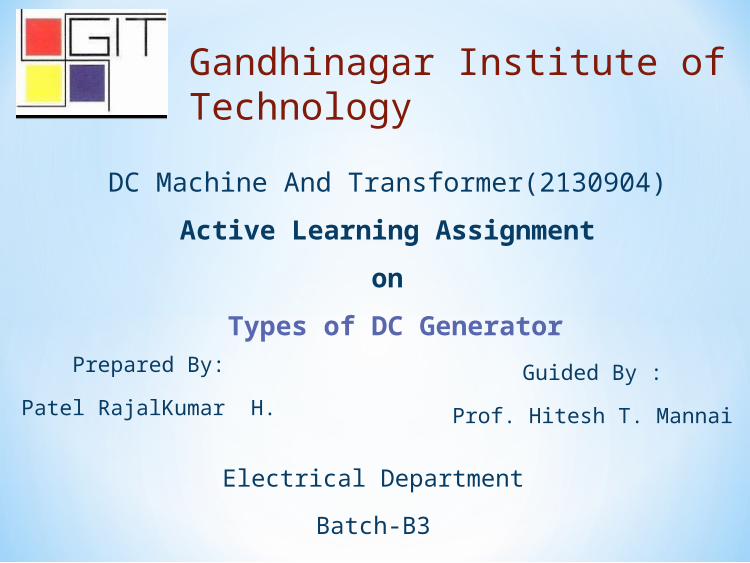
According To The Position Of The Field Coil DC
Generator Has A Three Type
1)Series Generator
2)Shunt Generator
3)Compound Generator
6
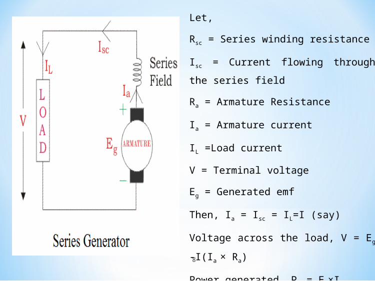
Series Generator
In these type of generators, the field windings are connected in series
with armature conductors.
So, whole current flows through the field coils as well as the load.
As series field winding carries full load current it is designed with
relatively few turns of thick wire.
The Electrical resistance of series field winding is therefore very low
(nearly 0.5Ω ).
7
8
Let,
Rsc = Series winding resistance
Isc = Current flowing through the series field
Ra = Armature Resistance
Ia = Armature current
IL =Load current
V = Terminal voltage
Eg = Generated emf
Then, Ia = Isc = IL=I (say)
Voltage across the load, V = Eg -I(Ia × Ra)
Power generated, Pg = Eg×I
Power delivered to the load, PL = V×I
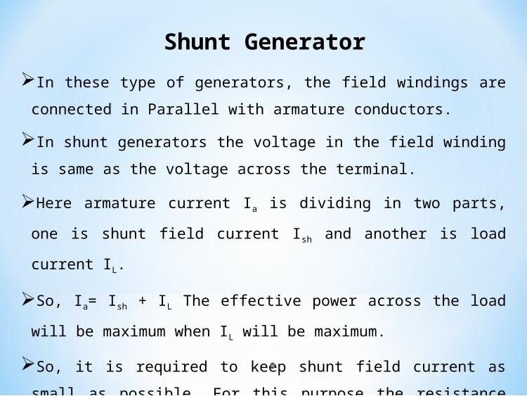
Shunt GeneratorIn these type of generators, the field windings are connected in Parallel with
armature conductors.
In shunt generators the voltage in the field winding is same as the voltage
across the terminal.
Here armature current Ia is dividing in two parts, one is shunt field current Ish
and another is load current IL.
So, Ia= Ish + IL The effective power across the load will be maximum when IL
will be maximum.
So, it is required to keep shunt field current as small as possible. For this
purpose the resistance of the shunt field winding generally kept high (100 Ω)
and large no of turns are used for the desired emf.9
10
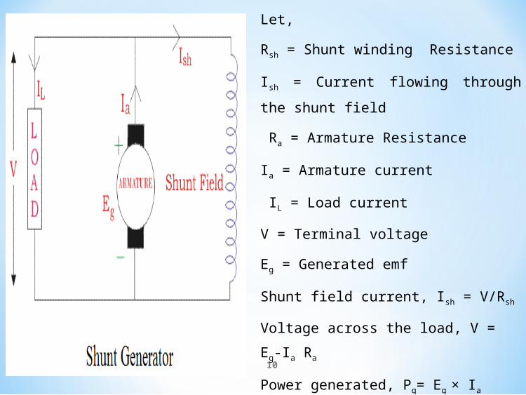
Let,
Rsh = Shunt winding Resistance
Ish = Current flowing through the shunt field
Ra = Armature Resistance
Ia = Armature current
IL = Load current
V = Terminal voltage
Eg = Generated emf
Shunt field current, Ish = V/Rsh
Voltage across the load, V = Eg-Ia Ra
Power generated, Pg= Eg × Ia
Power delivered to the load, PL = V×IL
Compound DC Generator
In series wound generators, the output voltage is directly
proportional with load current. In shunt wound generators, output
voltage is inversely proportional with load current. A combination of
these two types of generators can overcome the disadvantages of
both. This combination of windings is called compound wound DC
generator.
Compound wound generators have both series field winding and
shunt field winding.
One winding is placed in series with the armature and the other is
placed in parallel with the armature.11
Compound Generator Has A two Type1)Short Shunt2)Long shunt
12
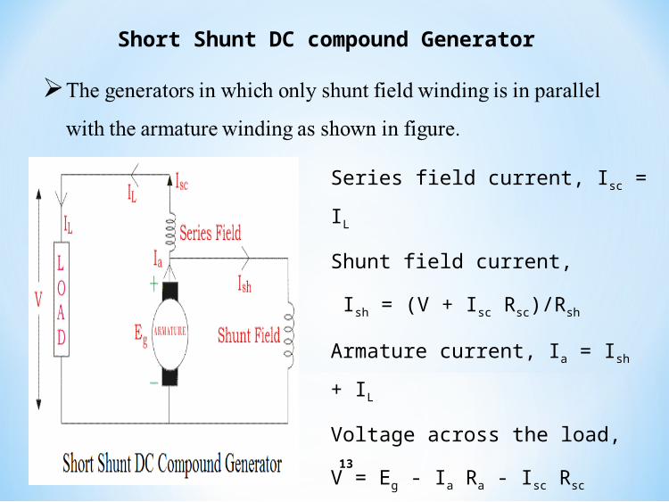
Short Shunt DC compound Generator
13
Series field current, Isc = IL
Shunt field current,
Ish = (V + Isc Rsc)/Rsh
Armature current, Ia = Ish + IL
Voltage across the load,
V = Eg - Ia Ra - Isc Rsc
Power generated, Pg = Eg × Ia
Power delivered to the load, PL=V×IL
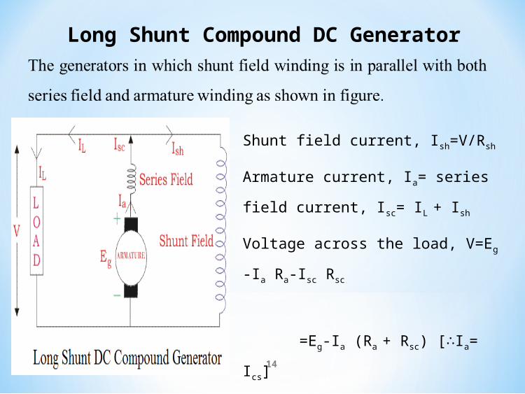
Long Shunt Compound DC Generator
14
Shunt field current, Ish=V/Rsh
Armature current, Ia= series field current,
Isc= IL + Ish
Voltage across the load, V=Eg -Ia Ra-Isc Rsc
=Eg-Ia (Ra + Rsc)
[ I∴ a= Ics]
Power generated, Pg= Eg × Ia
Power delivered to the load, PL=V×IL
In a compound generator, the shunt field is stronger than the
series field. When the series field assists the shunt field,
generator is said to be commutatively compound generator.
On the other hand if series field opposes the shunt field, the
generator is said to be differentially compound generator.
15

Thank You…
16