Embed Size (px)
Citation preview

Sardar Vallabhbhai Patel Institute Of Technology, Vasad
Subject:-MECHANICS OF SOLIDS Subject:-MECHANICS OF SOLIDS (2130003)(2130003)
Prepered byMilan Patel
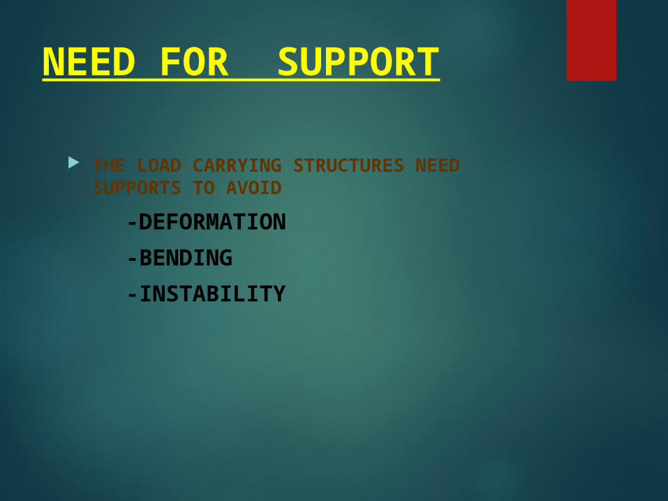
NEED FOR SUPPORT
THE LOAD CARRYING STRUCTURES NEED SUPPORTS TO AVOID
-DEFORMATION-BENDING-INSTABILITY
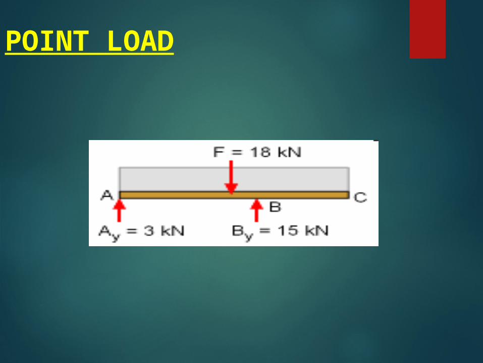
POINT LOAD
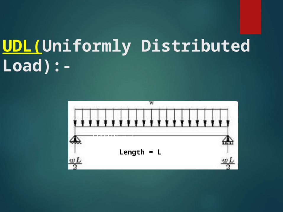
UDL(Uniformly Distributed Load):-
Length = l
Length = L

UNIFORMLY VARYING LOAD

COMBINED UDL AND UVL
=
W= 1500N/m
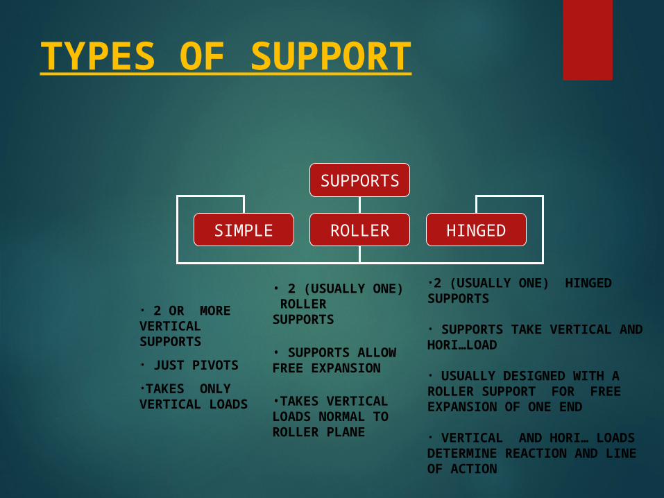
TYPES OF SUPPORT
SUPPORTS
SIMPLE ROLLER HINGED
• 2 (USUALLY ONE) ROLLER SUPPORTS
• SUPPORTS ALLOW FREE EXPANSION
•TAKES VERTICAL LOADS NORMAL TO ROLLER PLANE
• 2 OR MORE VERTICAL SUPPORTS• JUST PIVOTS•TAKES ONLY VERTICAL LOADS
•2 (USUALLY ONE) HINGED SUPPORTS
• SUPPORTS TAKE VERTICAL AND HORI…LOAD
• USUALLY DESIGNED WITH A ROLLER SUPPORT FOR FREE EXPANSION OF ONE END
• VERTICAL AND HORI… LOADS DETERMINE REACTION AND LINE OF ACTION
Types of Support
In order for loaded parts to remain in equilibrium, the balancing forces are the reaction forces at the supports
Most real life products have support geometries which differ from the idealized case
Designer must select the conservative case
Types of Support
Guided is support at the end of the beams that prevent rotation, but permits longitudinal and transverse displacement
Free or unsupported is when the beam is totally free to rotate in any direction
Held is support at the end of the beam that prevents longitudinal and transverse displacement but permits rotation

Types of Support
Simply Supported is support at the end of the beam that prevents transverse displacement, but permits rotation and longitudinal displacement
Fixed is support at the ends of the beam that prevents rotation and transverse displacement, but permits longitudinal displacement

Idealized Supports

Idealized Supports
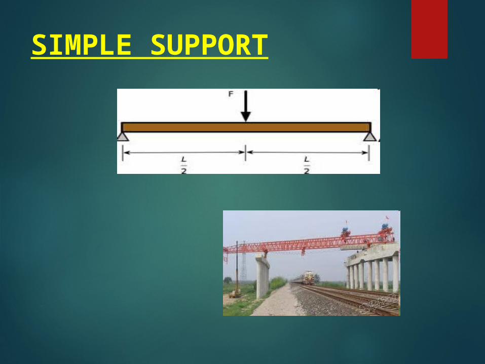
SIMPLE SUPPORT

ROLLER SUPPORT
LOCATION OF ROLLER BEARING TO SUPPORT JET ENGINE ROTOR

HINGED SUPPORT
KNEE HINGE
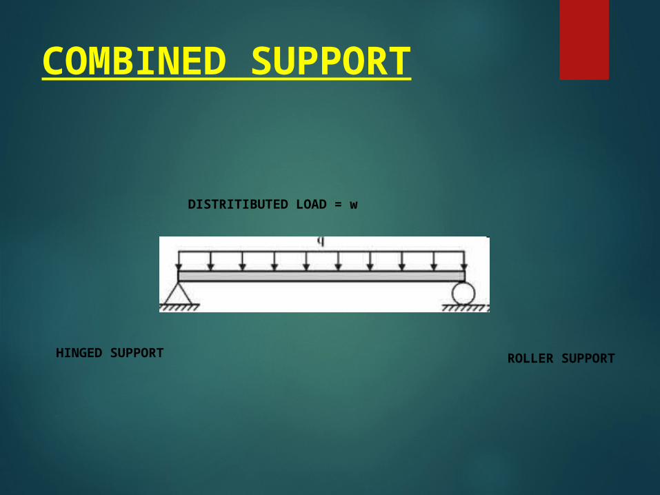
COMBINED SUPPORT
HINGED SUPPORT ROLLER SUPPORT
DISTRITIBUTED LOAD = w
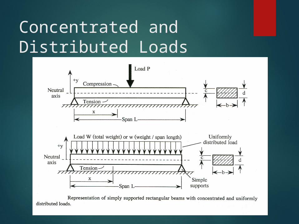
Concentrated and Distributed Loads
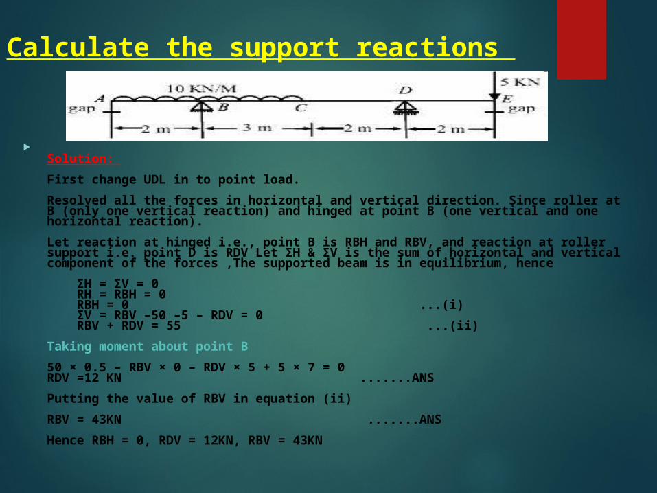
Calculate the support reactions
Solution: First change UDL in to point load.Resolved all the forces in horizontal and vertical direction. Since roller at B (only one vertical reaction) and hinged at point B (one vertical and one horizontal reaction).Let reaction at hinged i.e., point B is RBH and RBV, and reaction at roller support i.e. point D is RDV Let ΣH & ΣV is the sum of horizontal and vertical component of the forces ,The supported beam is in equilibrium, hence ΣH = ΣV = 0 RH = RBH = 0 RBH = 0 ...(i) ΣV = RBV –50 –5 – RDV = 0 RBV + RDV = 55 ...(ii)Taking moment about point B50 × 0.5 – RBV × 0 – RDV × 5 + 5 × 7 = 0RDV =12 KN .......ANSPutting the value of RBV in equation (ii)RBV = 43KN .......ANSHence RBH = 0, RDV = 12KN, RBV = 43KN
Types of loads
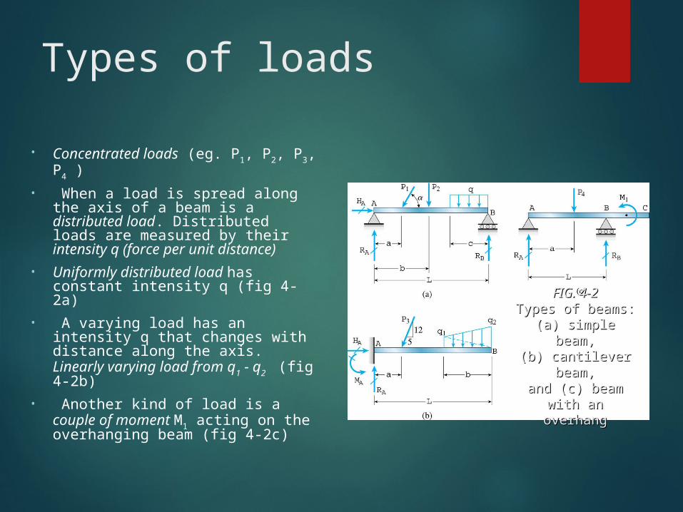
• Concentrated loads (eg. P1, P2, P3, P4 )• When a load is spread along the
axis of a beam is a distributed load. Distributed loads are measured by their intensity q (force per unit distance)
• Uniformly distributed load has constant intensity q (fig 4-2a)
• A varying load has an intensity q that changes with distance along the axis. Linearly varying load from q1 - q2 (fig 4-2b)
• Another kind of load is a couple of moment M1 acting on the overhanging beam (fig 4-2c)
FIG. 4-2FIG. 4-2Types of beams:Types of beams:(a) simple beam,(a) simple beam,
(b) cantilever (b) cantilever beam,beam,
and (c) beam with and (c) beam with an overhangan overhang
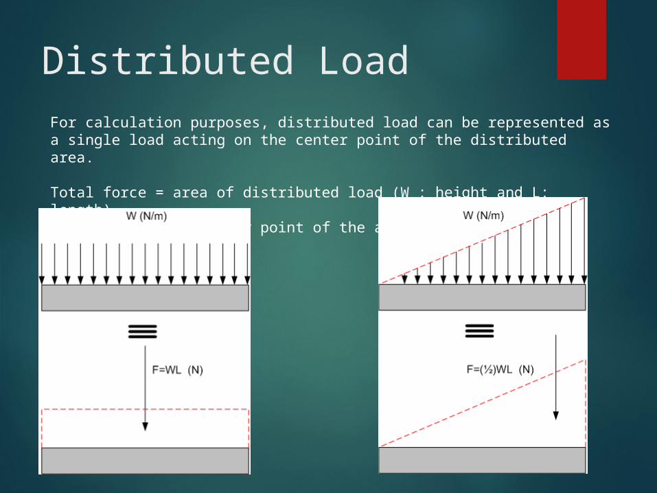
Distributed LoadFor calculation purposes, distributed load can be represented as a single load acting on the center point of the distributed area.
Total force = area of distributed load (W : height and L: length)Point of action: center point of the area
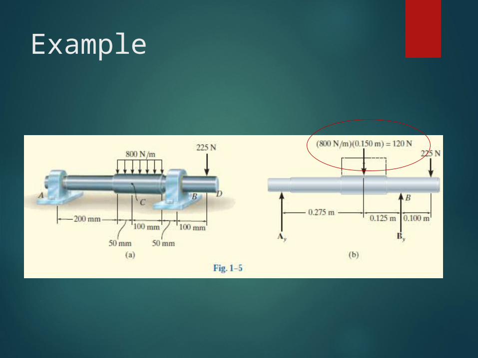
Example

Example
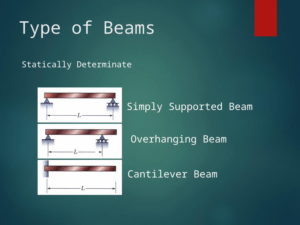
Type of BeamsStatically Determinate
Simply Supported Beam
Overhanging Beam
Cantilever Beam

Type of BeamsStatically Indeterminate
Continuous Beam
Propped Cantilever Beam
Fixed Beam

Example 1
Equilibrium equation for 0 x 3m:
A B
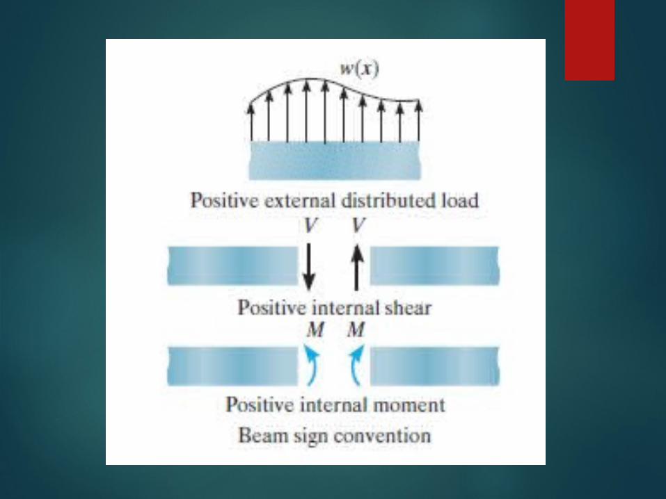
* internal V and M should be assumed +ve
kNVVF
Fy
90
0
)(90
0
kNmxMMVx
M
M
VF
x

THANK YOU