Embed Size (px)
Citation preview

CECW-ED
Engineer Manual1110-2-1911
Department of the ArmyU.S. Army Corps of Engineers
Washington, DC 20314-1000
EM 1110-2-1911
30 September 1995
Engineering and Design
CONSTRUCTION CONTROL FOR EARTHAND ROCK-FILL DAMS
Distribution Restriction StatementApproved for public release; distribution is
unlimited.

EM 1110-2-191130 September 1995
US Army Corpsof Engineers
ENGINEERING AND DESIGN
Construction Control for Earthand Rock-Fill Dams
ENGINEER MANUAL

AVAILABILITY
Copies of this and other U.S. Army Corps of Engineerspublications are available from National Technical InformationService, 5285 Port Royal Road, Springfield, VA 22161. Phone(703)487-4650.
Government agencies can order directlyu from the U.S. ArmyCorps of Engineers Publications Depot, 2803 52nd Avenue,Hyattsville, MD 20781-1102. Phone (301)436-2065. U.S.Army Corps of Engineers personnel should use Engineer Form0-1687.
UPDATES
For a list of all U.S. Army Corps of Engineers publications andtheir most recent publication dates, refer to Engineer Pamphlet25-1-1, Index of Publications, Forms and Reports.
DEPARTMENT OF THE ARMY EM 1110-2-1911U.S. Army Corps of Engineers
CECW-ED Washington, DC 20314-1000
ManualNo. 1110-2-1911 30 September 1995
Engineering and DesignCONSTRUCTION CONTROL FOR EARTH AND ROCK-FILL DAMS
1. Purpose. The purpose of this manual is to present principles and methods for constructioncontrol of earth and rock-fill dams.
2. Applicability. This manual applies to all Corps of Engineers divisions and districts havingresponsibility for construction of earth and rock-fill dams.
3. General. This manual is a guide to construction and inspection of earth and rock-fill dams inthose aspects that pertain to safe and satisfactory performance.
FOR THE COMMANDER:
ROBERT H. GRIFFINColonel, Corps of EngineersChief of Staff
This manual supersedes EM 1110-2-1911, dated 17 January 1977.
DEPARTMENT OF THE ARMY EM 1110-2-1911U.S. Army Corps of Engineers
CECW-ED Washington, DC 20314-1000
ManualNo. 1110-2-1911 30 September 1995
Engineering and DesignCONSTRUCTION CONTROL FOR EARTH AND ROCK-FILL DAMS
Table of Contents
Subject Paragraph Page Subject Paragraph Page
Chapter 1IntroductionReferences . . . . . . . . . . . . . . . . . . . . . . 1-1 1-1General Considerations. . . . . . . . . . . . . . 1-2 1-1
Chapter 2Field Organization andResponsibilityResident Inspection Force. . . . . . . . . . . . 2-1 2-1Field Laboratory . . . . . . . . . . . . . . . . . . 2-2 2-3Assistance by Higher Echelon. . . . . . . . . 2-3 2-4Records and Reports. . . . . . . . . . . . . . . 2-4 2-4
Chapter 3Foundation and AbutmentTreatmentGeneral. . . . . . . . . . . . . . . . . . . . . . . . . 3-1 3-1Clearing, Grubbing, Stripping, and
Cleaning . . . . . . . . . . . . . . . . . . . . . 3-2 3-1Seepage Control. . . . . . . . . . . . . . . . . . 3-3 3-3Treatment of Unfavorable Conditions. . . . 3-4 3-6Dewatering and Drainage of
Excavated Areas. . . . . . . . . . . . . . . . 3-5 3-10
Chapter 4Borrow Areas and Quarries
Section IEarth FillExcavation, Handling, and
Hauling Equipment. . . . . . . . . . . . . . 4-1 4-1
Borrow Area Operation . . . . . . . . . . . . . 4-2 4-5
Section IIQuarries and Rock ExcavationGeneral. . . . . . . . . . . . . . . . . . . . . . . . . 4-3 4-8Equipment . . . . . . . . . . . . . . . . . . . . . . 4-4 4-8Test Quarries. . . . . . . . . . . . . . . . . . . . . 4-5 4-9Obtaining Specified Rock Fill. . . . . . . . . 4-6 4-10
Section IIIFinal Condition of Borrow Areas,Quarries, and Spoil AreasBorrow Areas . . . . . . . . . . . . . . . . . . . . 4-7 4-11Quarries . . . . . . . . . . . . . . . . . . . . . . . . 4-8 4-11Spoil or Waste Areas. . . . . . . . . . . . . . . 4-9 4-11
Chapter 5Earth-Fill and Rock-FillConstruction
Section IFill Processing and CompactionEquipmentHeavy Compaction Equipment. . . . . . . . 5-1 5-1Hand-Operated Compaction Equipment . . 5-2 5-1Spreading and Processing Equipment. . . . 5-3 5-1
Section IITest FillsRock Test Fills . . . . . . . . . . . . . . . . . . . 5-4 5-1Earth Test Fills . . . . . . . . . . . . . . . . . . . 5-5 5-5
i
EM 1110-2-191130 Sep 95
Subject Paragraph Page Subject Paragraph Page
Section IIIImpervious and Semipervious FillDefinitions . . . . . . . . . . . . . . . . . . . . . . 5-6 5-5Compaction Fundamentals. . . . . . . . . . . 5-7 5-6Compaction Specifications. . . . . . . . . . . 5-8 5-6Simple Control Procedures. . . . . . . . . . . 5-9 5-7Field Control Testing and Sampling. . . . . 5-10 5-8Operations in Adverse Weather. . . . . . . . 5-11 5-15Compaction in Confined Areas. . . . . . . . 5-12 5-16
Section IVPervious FillDefinition . . . . . . . . . . . . . . . . . . . . . . .5-13 5-17Compaction Equipment. . . . . . . . . . . . . . 5-14 5-17Material Gradations. . . . . . . . . . . . . . . .5-15 5-18Water Content Control. . . . . . . . . . . . . . 5-16 5-18Lift Thicknesses and Number of
Passes or Coverages. . . . . . . . . . . . . 5-17 5-18Density Requirements. . . . . . . . . . . . . . .5-18 5-19Construction Control . . . . . . . . . . . . . . .5-19 5-19Test Results and Actions to be Taken. . . . 5-20 5-20
Section VRock FillGeneral. . . . . . . . . . . . . . . . . . . . . . . . .5-21 5-21Hard Rock . . . . . . . . . . . . . . . . . . . . . .5-22 5-21Soft Rock . . . . . . . . . . . . . . . . . . . . . . .5-23 5-22
Section VISemicompacted Earth FillsUses . . . . . . . . . . . . . . . . . . . . . . . . . . .5-24 5-22Specifications . . . . . . . . . . . . . . . . . . . .5-25 5-22Construction Control . . . . . . . . . . . . . . .5-26 5-22
Section VIISequence of Placement andMeasurement of QuantitiesSchedule of Construction. . . . . . . . . . . . 5-27 5-22Placement Sequence. . . . . . . . . . . . . . . .5-28 5-22Measurement of Quantities. . . . . . . . . . . 5-29 5-23
Section VIIISlope ProtectionAreas to be Protected. . . . . . . . . . . . . . .5-30 5-23Upstream Slope Protection. . . . . . . . . . . 5-31 5-23Downstream Slope Protection. . . . . . . . . 5-32 5-25
Chapter 6Miscellaneous ConstructionFeaturesRiver Diversion . . . . . . . . . . . . . . . . . . . 6-1 6-1Stage Construction. . . . . . . . . . . . . . . . . 6-2 6-3Surface Drainage Facilities. . . . . . . . . . . 6-3 6-3Service Bridge Pier Foundations. . . . . . . 6-4 6-3Instrumentation . . . . . . . . . . . . . . . . . . . 6-5 6-3Haul Roads, Maintenance Roads,
and Public Roads. . . . . . . . . . . . . . . 6-6 6-4
Chapter 7Records and ReportsDaily Reports . . . . . . . . . . . . . . . . . . . . 7-1 7-1Compaction Control Reports. . . . . . . . . . 7-2 7-1Instrumentation Observations. . . . . . . . . . 7-3 7-1Construction Foundation Report. . . . . . . . 7-4 7-6Final Construction Report. . . . . . . . . . . . 7-5 7-6
Appendix AReferences
Appendix BMethods of Relating Field DensityData to Desired or SpecifiedValues
Appendix CField Compaction Control Formsand Supplemental Instructions
Appendix DInstructions for Preparing PeriodicSummaries of Field CompactionControl Data on Earth andRock-Fill Dams
Appendix EDescription and Use of InstrumentsDuring Earth and Rock-Fill DamConstruction
Index
ii
EM 1110-2-191130 Sep 95
Chapter 1Introduction
1-1. References
References pertaining to this manual are listed inAppendix A. Additional reference materials pertaining tothe subject matter addressed in this manual are also includedin Appendix A.
1-2. General Considerations
The safety and satisfactory performance of earth and rock-fill dams require competent and adequate supervision,careful inspection, and control testing. It is the responsi-bility of the Resident Engineer to bring to the attention ofthe Engineering Division any design or construction detailnot adequately covered by the plans and specifications. TheResident Engineer must provide the field supervision andcontrol required to accomplish the intent of the plans andspecifications. The resident engineer must also coordinatethe work with design engineers and provide guidance to thecontractor if unexpected conditions are discovered duringconstruction.
a. Importance of construction control.Many earth androck-fill dams have shown signs of distress or experiencedpartial failure (necessitating expensive remedial measures)from causes traceable to poor construction practices or tounexpected adverse conditions. Close observations by soilsengineers and geologists of foundation and abutmentpreparation, excavation, fill operations, movements anddeformations of fill and foundation, and seepage can oftenenable early detection and correction of undesirableconditions. Construction control should ensure that:
(1) Necessary actions are taken to remedy or allow forunexpected conditions. Frequent and careful observationsby inspectors, geologists, and field engineers, who arefamiliar with conditions assumed for design, are essentialduring stripping of the foundation, opening of borrow areas,and excavating operations. Immediate reporting of unex-pected conditions will enable the Resident Engineer to
coordinate and plan, with design engineers, any additionalinvestigations needed to establish design modifications.
(2) Equipment and procedures are adequate to satisfac-torily accomplish the work. Review of the contractor’splans for quality control, dewatering and draining workareas, and haul roads, together with inspections of the actualoperations, is an important aspect of construction control.
(3) The completed structure meets the requirements andintent of the plans and specifications. This involves con-tinuous inspection of foundation and abutment preparation,material processing, and embankment construction, and acomprehensive control testing program to ensure propermaterial placement and compaction.
(4) Adequate construction records are maintained.Preparation of completion reports of construction operationsand maintenance of records of test results are essentialaspects of field control. Such reports and records are oftenrequired to evaluate claims by the contractor and todetermine possible causes of distress that might later occurin portions of the completed work. These documents shouldinclude as many detailed photographs as necessary. Videophotography may also be included in the methods todocument and record construction procedure and methods.
b. Relation of construction and design.The design ofan earth or rock-fill dam is not finished until construction iscomplete, the reservoir has been filled, and the dam isfunctioning satisfactorily. During construction, designengineers should frequently reassess design concepts andassumed conditions in light of actual conditions observed inthe field. This involves frequent visits to the project toobserve actual conditions and construction procedures.Consultation with specialists may be required to evaluateunusual problems or foundation conditions. Design eval-uation must include analyses of compaction control results.It may also require reanalysis of stability conditions basedon results of laboratory tests on record samples andadditional foundation samples and field observations of porewater pressures, settlements, and lateral displacements. Ahigh degree of coordination between design and constructionengineers is mandatory.
1-1
EM 1110-2-191130 Sep 95
Chapter 2Field Organization andResponsibility
2-1. Resident Inspection Force
Each levee, earth or rock-fill dam, or other embankmentmust be adequately inspected to ensure that plans andspecifications are observed and followed by the contractor.This requirement applies to all divisions and districts havingresponsibility for design and construction of civil worksprojects. The size and composition of the residentinspection force for foundation and earthwork controloperations should be adequate to provide for continuousinspection of construction activities, field testing andsampling, observation of field instrumentation, laboratorytesting, data compilation, maintenance of records, andpreparation of reports. On large projects, the contractor mayoperate as many as three shifts, and materials-handling forfill operations may be highly mechanized to obtain highproduction. The inspection force must be so staffed andorganized that inspectors and technicians are available forcontinuous inspection of the contractor’s operations. Indiscussing contractor quality control, ER 1180-1-6 states,“The Government is responsible for all phases of the con-struction project, including the activities necessary to assurethat the contractor has complied with the requirements ofthe contract plans and specifications...” and “In contrast tothe Contractor’s quality control the government is re-sponsible for quality assurance. This includes checks,inspections, and tests of the products which comprise theconstruction, the processes used in the work and the finishedwork for the purpose of determining whether the Con-tractor’s quality control is effective and he is meeting therequirements of the contract. These activities are to assurethat defective work or materials are not incorporated in theconstruction.”
a. Technical responsibilities.The Resident Engineer isresponsible for constructing the embankment and relatedappurtenances in compliance with plans and specifications.On large projects, resident geologists and soils engineersprovide technical assistance. Assisting the Resident Engi-neer are office and field engineering staffs. The officeengineering staff is responsible for preparing fieldmodifications to the plans and specifications in accordancewith applicable district regulations, reviewing planssubmitted by the contractor such as those for quality controland dewatering, evaluating results of construction controltests, and compiling instrumentation data to send to theEngineering Division for evaluation. The field engineer incharge of field supervision and inspection is responsible for
planning, executing, and coordinating all field inspection andtesting to ensure compliance with established standards anddetail drawings and specifications. The field engineer isassisted by one or more chief construction inspectors oneach shift who coordinate the activities of subordinateinspectors, and by a materials testing or soils engineer whosupervises a number of technicians in obtaining samples andperforming required field and laboratory tests. Detailedtechnical and organizational responsibilities may differ inthe various districts and divisions; however, constructionprojects are to be staffed with the number of experiencedGovernment laboratory technicians needed to performGovernment acceptance testing on compacted fill, includingfilter and drainage fills. Acceptance testing should beperformed immediately after placement and compaction ofthe lift material to be sampled and tested. Attention shouldbe given to selection of samples for acceptance testing sothat all materials of generally different descriptions beingplaced in the same compacted zone of the embankment willbe tested.
b. Preconstruction training. Every earth or rock-filldam is designed for specific foundation conditions and toutilize locally available materials. Unique features areinherent in each project, and a wide variety of constructionmethods may be utilized. Therefore, good communicationbetween design and construction personnel is essential. Theconstruction staff should be familiar with the designmemoranda pertinent to the work. Preconstruction in-structions and training should be given to field inspectionpersonnel to acquaint them with the design concepts and toprovide them with a clear understanding of expectedconditions, methods of construction, and the scope of plansand specifications. This may be done by training sessions,preferably with design personnel present, using a manual ofwritten instructions prepared especially for field personnel,to discuss engineering considerations involved and toexplain control procedures and required results. Inspectionpersonnel should be familiar with the plans and specifi-cations; excavation boundaries; types of materials to beexcavated; temporary and permanent drainage and seepagecontrol measures; approved sources of borrow materials;procedures and equipment most suitable for excavating,processing, and hauling borrow materials; characteristics offill materials and compaction requirements; capabilities ofvarious types of compaction equipment; and proceduresrequired to obtain desired or specified compaction. Closelysupervised on-the-job training should be given to inspectorsand materials testing personnel during initial stages ofconstruction to increase their proficiency in recognizingsigns of inadequate compaction, in using expedient methodsof checking water content and density of fill materials, inusing selected methods for field density measurements and
2-1
EM 1110-2-191130 Sep 95
laboratory compaction, and in detecting inadequate con-struction procedures and unsafe conditions.
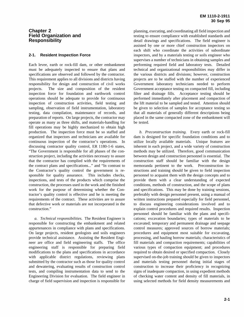
c. Number of personnel and skills required.Ex-perienced construction engineers, inspectors, and techniciansare required for construction control operations on earth androck-fill dams. The Resident Engineer, the field engineer incharge of supervision and inspection, chief inspector,materials engineer or chief soil technician, and geologistsshould have been associated with the project from the timeof any preliminary construction operations such as test fills,quarry blasting and rock production tests, and excavationsof tunneling made to inspect subsurface conditions.Augmentation of this cadre with less experienced inspectorsand technicians will provide a sufficiently capable inspectionforce. An example of a resident inspection force organi-zation for a large earth and rock-fill dam is shown inFigure 2-1. Additional inspectors and technicians may be
Figure 2-1. Example of resident engineer’s staff organization for large earth dam project
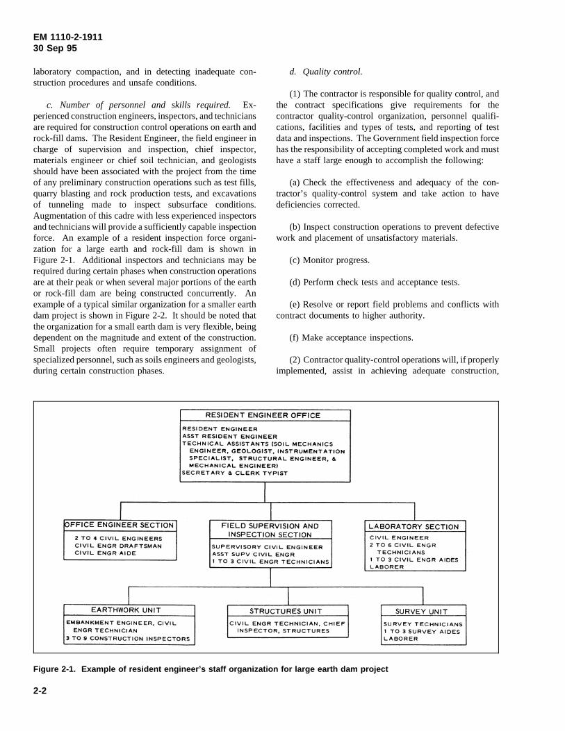
required during certain phases when construction operationsare at their peak or when several major portions of the earthor rock-fill dam are being constructed concurrently. Anexample of a typical similar organization for a smaller earthdam project is shown in Figure 2-2. It should be noted thatthe organization for a small earth dam is very flexible, beingdependent on the magnitude and extent of the construction.Small projects often require temporary assignment ofspecialized personnel, such as soils engineers and geologists,during certain construction phases.
d. Quality control.
(1) The contractor is responsible for quality control, andthe contract specifications give requirements for thecontractor quality-control organization, personnel qualifi-cations, facilities and types of tests, and reporting of testdata and inspections. The Government field inspection forcehas the responsibility of accepting completed work and musthave a staff large enough to accomplish the following:
(a) Check the effectiveness and adequacy of the con-tractor’s quality-control system and take action to havedeficiencies corrected.
(b) Inspect construction operations to prevent defectivework and placement of unsatisfactory materials.
(c) Monitor progress.
(d) Perform check tests and acceptance tests.
(e) Resolve or report field problems and conflicts withcontract documents to higher authority.
(f) Make acceptance inspections.
(2) Contractor quality-control operations will, if properlyimplemented, assist in achieving adequate construction,
2-2
EM 1110-2-191130 Sep 95
particularly on those operations where specifications contain
Figure 2-2. Example of resident engineer’s staff for small earth dam project
product requirements such as water content limits andgradation of filter material. However, Government fieldinspectors must be present to witness operations for whichconstruction procedures are specified and to conduct tests toensure that results obtained are those required by design.Several important considerations are listed below:
(a) The contractor is not required to conduct tests on thequality or durability of materials used for pervious fill, filterzones, bedding, spalls, or rip-rap. The Government isresponsible for determining such properties in approvingsources of natural or processed (blasted, ripped, or crushed)pervious materials for use in embankments.
(b) The contractor is not required to provide tests oncompaction characteristics when fill placement procedure isspecified. Government inspection forces are responsible forinspecting the contractor’s specified construction activitiesand for testing embankment or slope materials to establishthat excavation and fill placement procedures result in anexcavated slope or fill that conforms to properties assumedin the design.
e. Relationship with contractor.Mutual understandingbetween the Resident Engineer and his staff and thecontractor of the requirements of the contract specificationsis necessary to obtain desired construction quality. Thequality of the work must never be compromised. Un-necessary requirements and restrictions should not beimposed over and above the specification requirements.Firmness by Resident Engineers and inspectors who areefficient and know their job will gain the respect andcooperation of the contractor.
2-2. Field Laboratory
Foundation and earth-fill materials are tested in the fieldlaboratory to determine gradation, water content, in situdensity, compaction, relative density, and Atterberg limits.The data obtained serve as a basis for ensuring compliancewith specifications and design requirements, for guidancetoward maximum utilization of available materials, and forproviding a record of the properties of materials placed inall parts of the project.
a. Size. The size of the field laboratory and satellitetesting units depends on the magnitude and areal extent ofconstruction operations. Remote borrow areas, dikes, orrelocation fills may require a central laboratory, supple-mented by one or more skid- or wheel-mounted portableunits. An existing structure, a prefabricated structure, ortrailer may be specified. For relatively large projects, about500 to 1,500 sq ft may be required for a laboratory space.The laboratory should have a sound floor, necessaryworktables, benches, storage cabinets, equipment pedestals(for compaction mold base and sieve shakers), service sinks,and utilities. Additionally, it may be very advantageous tohave an awning-covered work slab with an area of from 500to 1,000 sq ft to serve as a work space on which to dry andwork large samples, to perform coarse aggregate gradations,etc.
b. Types of tests and facilities required.The majorportion of testing in the field laboratory is for acceptancetesting of compacted fill. These tests must be conducted ina manner that will yield results of a quality comparable tothe initial laboratory tests upon which the design was based.
2-3
EM 1110-2-191130 Sep 95
Discrepancies resulting from variations in testing equipmentand techniques should be carefully avoided. Water content,compaction, relative density gradation, and Atterberg limitstests are the most common tests conducted. Water contentand compaction tests are used for control of cohesive soilsin impervious and random fills. Atterberg limits tests maybe used for control of fills of fine-grained cohesive soilswhere good correlations of optimum water content andmaximum dry density with the Atterberg limits have beenestablished. Gradation and relative density tests are used forcontrol of pervious fills. Gradation tests are also used forcontrol of rock fill. Field density tests are performed on thefill, but compaction tests on the material and water contentdeterminations may be made either in the central laboratoryor in the field. The central laboratory must have equipmentfor these tests, but supplemental portable units may beadvisable for gradation, compaction, and water contenttesting at remote locations. Panel pickup trucks are oftenused to transport equipment for field density testing,undisturbed (record) sampling in the fill, and sampling inborrow areas. Specially equipped pickup trucks with asmall hoist may be required where large-scale field densitytests are to be performed on material such as rock fill orsoils with a high percentage of large gravel sizes.
2-3. Assistance by Higher Echelon
Unusual conditions encountered during constructiongenerally require special attention. The advice of specialistsin soil and rock mechanics, geology, and instrumentation ofearth and rock-fill dams, and additional evaluation by designengineers are often required to obtain effective solution tounusual problems and conditions.
a. Geologists and soils engineers.Specialists withexperience in soil and rock mechanics, geology, and in-strumentation are found in division and district offices, atHeadquarters, U.S. Army Corps of Engineers (HQUSACE),Waterways Experiment Station (WES), and on Corps ofEngineers boards of consultants. The services of soil androck mechanics engineers and geologists are particularlyvaluable during early stages of construction when the foun-dation, abutment, and any diversion tunnels or excavations(such as for spillway foundations) expose existing condi-tions. At this time, it is vital that actual conditions beevaluated to determine if they are consistent with conditionsassumed for design. In addition, it is necessary to recognizeany unusual conditions that may affect construction. Theadvice of specialists in soil mechanics and rock mechanicsis also valuable in establishing, from observed field con-ditions, modifications that may significantly improve thedesign without increasing the cost of the project.
b. Design engineers.The engineer who designs the
earth or rock-fill dam should visit the project duringconstruction and assist field personnel in interpreting plansand specifications and observe problems that may not havebeen fully evaluated in the design. Visits should also bemade whenever unexpected conditions are encountered thatmay require changes in the plans or specifications. Acooperative attitude must be maintained between designengineers and construction personnel so that mutualunderstanding is reached on existing problems and feasiblesolutions are developed. In some cases, conferences at theconstruction site may be necessary between constructionpersonnel, designers, and specialists to review conditionsand determine if design modifications are required. Aregular schedule of visits should be set up so that designpersonnel and representatives from the division office andHQUSACE can inspect field conditions at critical con-struction stages.
c. Instrumentation.Instrumentation of earth and rock-fill dams is becoming increasingly important. The mainreasons are that many higher earth and rock-fill dams arebeing constructed, sites having unfavorable foundation con-ditions must be used more frequently, interest is increasingin obtaining meaningful data for evaluating dam behavior,and continually increasing downstream land development isincreasing the consequences of failure on property damageand loss of life. Monitoring of pore water pressure, settle-ments, and deformations of the foundation and embankmentis necessary to check the safety of the dam during con-struction and to control the rate of construction. Theinstrumentation must be of the proper type, placed in criticallocations, and installed properly. Valid readings depend ontechniques and procedures used in installing and observingthe instrumentation. For this reason, specialists experiencedin field instrumentation should plan and supervise the fieldinstallations. These specialists can be from the districtand/or division office, from WES, or from firms specializingin installations of instrumentation of earth and rock-filldams. This applies whether the instrumentation is furnishedand installed by the Government or furnished and installedby the contractor. Because proper interpretation of in-strumentation data is vital to the safety of the dam, theresponsibility for collecting and reporting data to the Engi-neering Division should be carefully delegated. Installationand observations of instrumentation are discussed in para-graph 6-5; the general use of instrumentation is described inAppendix E and by Dunnicliff (1988).
2-4. Records and Reports
Construction records and reports are needed to documentresults of tests made to verify specification requirements andaction taken to correct deficiencies and to provide a recorddescribing the field conditions, modifications to plans and
2-4
EM 1110-2-191130 Sep 95
specifications, construction procedures, sequence of opera-tions, and the location and as-built dimensions of importantfeatures. These are necessary to evaluate claims made bythe contractor based on changed conditions, or claims by theContracting Officer that work performed does not meetcontract requirements. Progress reports are also needed forthe district office and to provide a basis for payments to thecontractor for work accomplished. Inspectors must maintaina daily inspection report (or log), and a master diary mustbe kept by the Resident Engineer. The required content ofthese documents is outlined in EM 415-1-302, “Inspectionand Work Records.” Details of specific construction controlrecords and reports are described in Chapter 7.
a. Construction records.These records provide usefuldata for designing future alterations and additions to thestructure, determining causes of later undesirable movementor seepage, or interpreting piezometric data. As-builtdrawings, construction photographs, descriptions of foun-dation conditions encountered and various treatments,compaction data, and test data on record samples should beincluded in the records.
b. Construction reports.The construction foundationreport should include details such as dip and strike of rock,
faults, artesian and other groundwater conditions, and othercharacteristics or conditions of foundation materials. Acomplete history of the project in narrative form should bewritten, giving the schedule of starting and completingvarious phases of the work, describing construction methodsand equipment used, summarizing quantities of materialsinvolved, and including other pertinent data. Foundationreports should be supplemented by photographs that clearlydepict foundation conditions. Routine photographs shouldbe taken at regular intervals, and additional pictures shouldbe taken of items of specific interest, such as the preparationof foundations and dam abutments. For these items, coloredphotographs should be taken to provide a better depiction ofconstruction conditions. The captions of all photographsshould contain the name of the project, the date on whichthe photograph was taken, the identity of the feature beingreported, and the location of the camera. In reportscontaining a number of photographs, an alternative would bean index map with a circle indicating the location of thecamera with an arrow pointing in the direction the camerawas pointing, with each location keyed to the numbers onthe accompanying photographs. Details concerning the useand preparation of construction foundation reports arepresented in ER 1110-1-1801.
2-5
EM 1110-2-191130 Sep 95
Chapter 3Foundation and AbutmentTreatment
3-1. General
The preparation of the foundation and abutments for anearth or rock-fill dam is a most difficult and important phaseof construction; the thoroughness with which it is done isreflected in the performance of the completed structure. Itis often difficult or sometimes impossible to correctfoundation and abutment deficiencies that show up afterconstruction is well underway or completed. The primarypurpose of foundation and abutment treatment is to obtainpositive control of under seepage, prepare surfaces toachieve satisfactory contact with overlying compacted fill,and minimize differential settlements and thereby preventcracking in the fill. Inspection of the work must ensure thatthe foundation and abutments are stripped to depthssufficient to remove soft, organic, fractured, weathered, orotherwise undesirable materials; depressions and joints inrock surfaces are cleaned and adequately filled; rocksurfaces are made relatively smooth and uniform by shapingand filling; subsurface cavities are detected and grouted; andcutoffs extend to suitable impervious materials. During thisphase of construction, close liaison must be maintainedbetween construction and design personnel since mostdiscrepancies between design and field construction occur inthis portion of the work. Few dams are constructed withoutencountering some undesirable foundation conditions thatwere not discovered in exploration for design, such as zonesof weathered or fractured rock, cavities, soft soil areas,abandoned pipes or drains, or abandoned stream channelsfilled with sand and gravel. This is the reason thatinspection trenches are generally required beneath theimpervious zone of a dam when cutoff trenches are notspecified. These inspection trenches provide the means forcareful examination of the foundation along the entire lengthof the dam to ensure that undesirable foundation conditionsare detected.
3-2. Clearing, Grubbing, Stripping, and Cleaning
Clearing, grubbing, stripping, and cleaning of areas uponwhich a compacted earth or rock-fill dam will lie arerequired to remove those materials having undesirableengineering qualities such as low shear strength, high com-pressibility, undesirable permeability, or other characteristicswhich would interfere with compaction operations; andprovide a surface favorable for a good bond with theoverlying fill. Specifications should provide adequate timefor inspection by the Contracting Officer’s representative ofexposed foundation and abutments. In some cases where
abutments will require special treatment, a separate contractfor such work is awarded.
a. Soil foundation and abutments.
(1) Clearing consists of removal of all abovegroundobstructions, including trees, vegetation, felled timber, brush,abandoned structures, local dams, bridges, and debris.Grubbing includes removal of all objectionable below-ground obstructions or material including stumps, roots,logs, drain tiles, and buried structures or debris. Foundationor abutment soils disturbed during clearing and grubbingoperations must be removed. Blasting should be avoided ifpossible; if unavoidable, explosive charges should be keptas small as possible.
(2) Foundation and abutment stripping generally followclearing and grubbing operations. Stripping consists of theremoval of sod, topsoil, boulders, and organic or foreignmaterials. Stripping beneath closure sections should beperformed in the dry after diversion of the river. Necessaryor inadvertent deviation from stripping limits identified inthe plans and specifications should be reported to the designoffice so that effects of the changes can be evaluated.Personnel inspecting stripping operations should be able toidentify the materials to be removed. Inspectors should lookfor soft pockets as well as old sloughs or river meandersthat may not have been found during design investigations;the resident geologist can assist in locating such features.Several passes of a heavy roller should be made over thestripped surface to “proof test” the area to reveal anyunsuitable materials overlooked during stripping.
(3) The sides of holes and depressions left by grubbingand stripping should be flattened and scarified and thedepressions filled with material of the same type andcompacted to a density at least equal to that of the surround-ing foundation material by the specified method andequipment. Where areal dimensions of depressions aresmall, power hand tampers are required to compact fill.Final preparation of the foundation surface, immediatelyprior to placing embankment fill, should include adjustingsoil water contents as near optimum as possible, compactingas prescribed for the overlying fill, and scarifying thecompacted surface to receive the initial embankment lift.
(4) Compaction of some types of saturated soils in wetfoundation areas may do more harm than good. When it isnot feasible to dry such areas out, it may be necessary toplace a thick initial lift to permit compaction equipment tooperate without remolding and disturbing the foundationsoil. Also, the weight of compacting equipment operatingon the initial lift might be reduced and progressivelyincreased as more lifts are placed. However, this should not
3-1
EM 1110-2-191130 Sep 95
be done for foundation areas under the embankment unlessspecifically permitted by the plans and specifications orapproved by the design office, as the effects of a lightlycompacted layer at the base of the dam could adverselyaffect stability.
(5) Preparation of soil abutments prior to fill placementshould be the same as that for soil foundations. To ensurebonding of the embankment to the natural soil of theabutments, it is necessary to remove some of the abutmentsurface soil. Inspection should confirm that all loose, wet,or soft soils are removed. In addition, abutment slopesshould be smooth and as flat as economically feasible atcontact with the embankment to improve compaction of fillagainst the abutment and to minimize the probability ofdifferential settlement causing cracking (paragraph 3-4a(5)).Depressions should be filled with concrete or soil compactedat proper water contents to densities equal to or greater thanthose of the materials to be placed above them in theembankment fill. See paragraph 3-4a(2) for discussion oftreatment of abutment slopes of clay shales.
b. Rock foundations and abutments.
(1) After all rough excavations of overburden and/orweathered rock have been completed, all grouting iscompleted, and the surface of the rock foundation isexposed, shaping and cleaning operations should begin.Shaping and cleaning a rough rock foundation are necessaryto provide a smooth, uniform, and clean surface againstwhich fill can be compacted. The procedure generallyconsists of removing large loose rocks, overhangs, andprojecting knobs by scaling, handpicking and wedging, andlight blasting pressure washing followed by some form of“dental treatment” to fill all holes, cracks, joints, crevices,and depressions. Dental treatment involves cleaning thecavities and backfilling them with concrete, and is discussedin more detail in paragraph 3-4b(3). The resident geologistor embankment engineer should inspect and approve thisphase of the work.
(2) The final preparation of almost all rock foundationsrequires hand labor. The use of heavy or tracked vehicleson the final foundation should be avoided, especially if therock is thinly bedded or badly jointed. Blasting to removeknobs or overhangs may prove more harmful than helpful,and extreme caution must be exercised to prevent theopening of cracks or actual displacement of blocks or rocksthat would otherwise provide adequate bearing. It isgenerally desirable to place concrete fill beneath or aroundprojections if, by so doing, blasting can be avoided. Whereconcrete fill is used, materials and procedures should bedirected towards ensuring good concrete/rock bond;
subsequent fill operations should avoid dislocating theconcrete. Hand methods involve removal of all loose or“drummy” rock (rock that sounds hollow when struck witha steel hammer or bar), and the scaling down of slopedsurfaces to provide an even, uniform slope.
(3) Washing the hard rock foundation surface with waterunder high pressure and dry brooming to remove looseresidue are generally the last step in foundation preparation.This is done to clean the surface to the maximum extentpossible and to remove fines that may have worked intoseams. All seams or cracks should be cleaned to a depth ofat least twice their width. Removal of these fines willfacilitate complete filling of seams in subsequent operations(such as dental treatment) taken to prevent seepage.Pressure washing also serves to detect rock projectionsoverlooked during hand excavation which might otherwisework loose during compaction of the first lift or lifts of fill.Washing should be performed to clean from higherelevations to lower elevations.
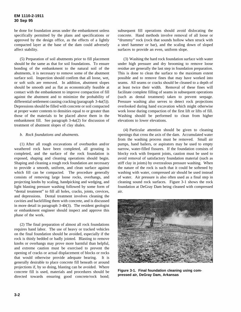
(4) Particular attention should be given to cleaningopenings that cross the axis of the dam. Accumulated waterfrom the washing process must be removed. Small airpumps, hand bailers, or aspirators may be used to emptynarrow, water-filled fissures. If the foundation consists ofblocky rock with frequent joints, caution must be used toavoid removal of satisfactory foundation material (such asstiff clay in joints) by overzealous pressure washing. Whenthe nature of the rock is such that it could be softened bywashing with water, compressed air should be used insteadof water. Air pressure is also often used as a final step incleaning sound rock surfaces. Figure 3-1 shows the rockfoundation at DeGray Dam being cleaned with compressedair.
Figure 3-1. Final foundation cleaning using com-pressed air, DeGray Dam, Arkansas
3-2
EM 1110-2-191130 Sep 95
(5) Where rough and irregular surfaces remain after handexcavation, troughs, pits, and other depressions are filledwith concrete to provide a more even surface on which thefirst layer of the embankment may be compacted. Aspreviously noted, this procedure is termed dental treatmentand is discussed further in paragraph 3-4b(3). If foundationgrouting has been performed, cleanup operations shouldinclude removal of any spilled or washed grout that mightotherwise conceal surface imperfections and pockets ofundesirable material.
(6) Before placing the first layer of embankmentmaterial, the cleaned and prepared rock surface should bemoistened, but no standing water should be permitted.Moistening the rock surface is recommended instead ofusing overly wet soil in the first lift to obtain good contact.Use of heavy pneumatic equipment (preferably a rubber-tired roller) is recommended for compacting the first lift onrock surfaces. This will enable the rock surface to be keptintact, especially where the rock surface is irregular orcomposed of thin beds of alternating hard and soft rock.
(7) Foundations consisting of compaction-type shales andslaking tuffs should be protected from disintegration causedby drying due to exposure to air. The handling of clayshales is discussed in paragraph 3-4a(2).
(8) The same degree of care should be exercised inabutment treatment as in foundation treatment. A goodbond between the embankment and the abutment is criticallyimportant. Areas to be cleaned at rock abutments shouldinclude not only those beneath the embankment core butalso those beneath transition or filter zones. Within theseareas, all irregularities should be removed or trimmed backto form a reasonably uniform slope on the entire abutmentwith vertical surfaces no higher than 5 ft. Benches betweennear-vertical surfaces should be of such width as to providea stepped slope comparable to the slope on adjacent areasbut not steeper than 1V on 1H. Overhangs should not bepermitted at any locations. Methods of overhang removalare discussed in paragraph 3-4b(4).
(9) The treatment of cracks, fissures, and otherundesirable conditions in rock foundations and abutments isdiscussed in paragraph 3-4b(2).
3-3. Seepage Control
a. Cutoffs.Foundation cutoffs or core trenches serve asbarriers to underseepage. The design of foundation cutoffsis based largely on borings made during field investigationsfor design. Therefore, the open excavation of a cutofftrench provides the first real look at actual foundationconditions; frequent inspections, particularly by the field
geologist and embankment engineer, should be made. Somecommon types of cutoffs are discussed in the followingparagraphs.
(1) Compacted backfill trenches. Backfill compactedinto a seepage cutoff trench is one of the most effectiveconstruction devices for blocking foundation seepage.Material and compaction requirements are the same as forthe impervious section of the embankment. When requiredby contract specifications, the trench must fully penetrate thepervious foundation and extend a specified distance intounweathered and relatively impervious foundation soil orrock. Treatment (as described in paragraph 3-2a) of theexposed surface in the bottom and sides of the trench isessential to ensure firm contact between foundation andbackfill. The trench excavation must be kept dry to preventsloughing of the side slopes and to permit proper backfillplacement and compaction. When the water table is nearthe ground surface, dewatering the excavation is requiredand is frequently a major expense in cutoff construction.Dewatering and drainage methods are discussed in para-graph 3-5. In any trenching operation, a qualified geo-technical engineer should inspect the construction at regularintervals to monitor stability of the side slopes.
(2) Slurry trenches.
(a) The slurry trench method of constructing a seepagecutoff involves excavating a relatively narrow trench withnear-vertical walls, keeping the trench filled with a bentoniteslurry to support the walls and prevent inflow of water, andthen backfilling with a plastic impervious mixture of well-graded clayey gravel to protect against piping, to reduceseepage, and to minimize consolidation of the backfillmaterial.
(b) The backfill should be a mixture of imperviousborrow, sand, gravel, and bentonite slurry (U.S. ArmyEngineer District, Savannah 1968). The backfill may be amixture of material excavated from the cutoff trench andother material to provide an acceptable blend.
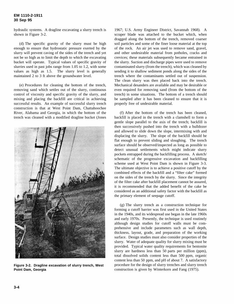
(c) Depending on the required depth, the excavation maybe accomplished with a dragline, backhoe, clamshell, ortrenching machine. A trenching machine is limited todepths less than about 40 ft, provided no cobbles exist.Unmodified backhoes are limited to depths less than about45 ft but with special modification can reach depths of 55to 60 ft; their main advantage is that they can be used inareas where cobbles exist. Maximum depths of about 100 fthave been achieved with a dragline. Required equipmentmodifications for excavation to a great depth (with a drag-line) include weighting the bucket to overcome the buoyanteffect of the slurry and providing heavy-duty bearings and
3-3
EM 1110-2-191130 Sep 95
hydraulic systems. A dragline excavating a slurry trench isshown in Figure 3-2.
Figure 3-2. Dragline excavation of slurry trench, WestPoint Dam, Georgia
(d) The specific gravity of the slurry must be highenough to ensure that hydrostatic pressure exerted by theslurry will prevent caving of the sides of the trench and yetnot be so high as to limit the depth to which the excavatingbucket will operate. Typical values of specific gravity ofslurries used in past jobs range from 1.05 to 1.2, with somevalues as high as 1.5. The slurry level is generallymaintained 2 to 3 ft above the groundwater level.
(e) Procedures for cleaning the bottom of the trench,removing sand which settles out of the slurry, continuouscontrol of viscosity and specific gravity of the slurry, andmixing and placing the backfill are critical in achievingsuccessful results. An example of successful slurry trenchconstruction is that at West Point Dam, ChattahoocheeRiver, Alabama and Georgia, in which the bottom of thetrench was cleaned with a modified dragline bucket (Jones
1967; U.S. Army Engineer District, Savannah 1968). Ascraper blade was attached to the bucket which, whendragged along the bottom of the trench, removed coarsersoil particles and some of the finer loose material at the topof the rock. An air jet was used to remove sand, gravel,and other undesirable material from potholes, cracks andcrevices; these materials subsequently became entrained inthe slurry. Suction and discharge pipes were used to removecontaminated slurry (from the trench), which was cleaned bysending it to shallow sediment ponds along the sides of thetrench where the contaminants settled out of suspension.The clean slurry was then placed back into the trench.Mechanical desanders are available and may be desirable oreven required for removing sand (from the bottom of thetrench) in some situations. The bottom of a trench shouldbe sampled after it has been cleaned to ensure that it isproperly free of undesirable material.
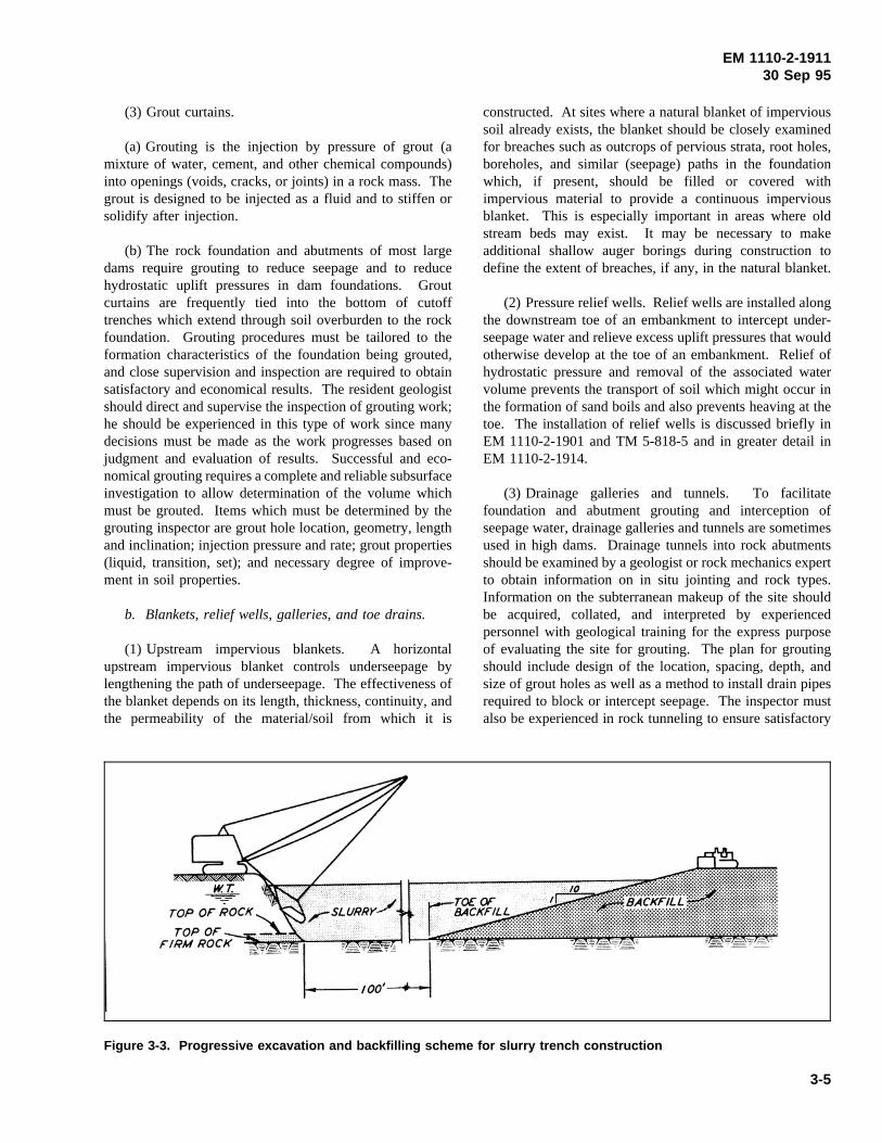
(f) After the bottom of the trench has been cleaned,backfill is placed in the trench with a clamshell to form agentle slope parallel to the axis of the trench; backfill isthen successively pushed into the trench with a bulldozerand allowed to slide down the slope, intermixing with anddisplacing the slurry. The slope of the backfill should beflat enough to prevent sliding and sloughing. The trenchsurface should be observed/inspected as long as possible todetect unusual settlements which might indicate slurrypockets entrapped during the backfilling process. A sketch/schematic of the progressive excavation and backfillingscheme used at West Point Dam is shown in Figure 3-3.The ultimate objective is to achieve a positive cutoff by thecombined effects of the backfill and a “filter cake” formedon the sides of the trench by the slurry. Since the integrityof the filter cake after backfill placement cannot be assured,it is recommended that the added benefit of the cake beconsidered as an additional safety factor with the backfill asthe primary element of seepage cutoff.
(g) The slurry trench as a construction technique forforming a cutoff barrier was first used in the United Statesin the 1940s, and its widespread use began in the late 1960sand early 1970s. Presently, the technique is used routinelyalthough design studies for cutoff walls must be com-prehensive and include parameters such as wall depth,thickness, layout, grade, and preparation of the workingsurface. Design studies must also consider properties of theslurry. Water of adequate quality for slurry mixing must beprovided. Typical water quality requirements for bentoniteslurry are hardness less than 50 parts per million (ppm),total dissolved solids content less than 500 ppm, organiccontent less than 50 ppm, and pH of about 7. A satisfactoryprocedure for the design of slurry trenches and slurry trenchconstruction is given by Winterkorn and Fang (1975).
3-4
EM 1110-2-191130 Sep 95
(3) Grout curtains.
Figure 3-3. Progressive excavation and backfilling scheme for slurry trench construction
(a) Grouting is the injection by pressure of grout (amixture of water, cement, and other chemical compounds)into openings (voids, cracks, or joints) in a rock mass. Thegrout is designed to be injected as a fluid and to stiffen orsolidify after injection.
(b) The rock foundation and abutments of most largedams require grouting to reduce seepage and to reducehydrostatic uplift pressures in dam foundations. Groutcurtains are frequently tied into the bottom of cutofftrenches which extend through soil overburden to the rockfoundation. Grouting procedures must be tailored to theformation characteristics of the foundation being grouted,and close supervision and inspection are required to obtainsatisfactory and economical results. The resident geologistshould direct and supervise the inspection of grouting work;he should be experienced in this type of work since manydecisions must be made as the work progresses based onjudgment and evaluation of results. Successful and eco-nomical grouting requires a complete and reliable subsurfaceinvestigation to allow determination of the volume whichmust be grouted. Items which must be determined by thegrouting inspector are grout hole location, geometry, lengthand inclination; injection pressure and rate; grout properties(liquid, transition, set); and necessary degree of improve-ment in soil properties.
b. Blankets, relief wells, galleries, and toe drains.
(1) Upstream impervious blankets. A horizontalupstream impervious blanket controls underseepage bylengthening the path of underseepage. The effectiveness ofthe blanket depends on its length, thickness, continuity, andthe permeability of the material/soil from which it is
constructed. At sites where a natural blanket of impervioussoil already exists, the blanket should be closely examinedfor breaches such as outcrops of pervious strata, root holes,boreholes, and similar (seepage) paths in the foundationwhich, if present, should be filled or covered withimpervious material to provide a continuous imperviousblanket. This is especially important in areas where oldstream beds may exist. It may be necessary to makeadditional shallow auger borings during construction todefine the extent of breaches, if any, in the natural blanket.
(2) Pressure relief wells. Relief wells are installed alongthe downstream toe of an embankment to intercept under-seepage water and relieve excess uplift pressures that wouldotherwise develop at the toe of an embankment. Relief ofhydrostatic pressure and removal of the associated watervolume prevents the transport of soil which might occur inthe formation of sand boils and also prevents heaving at thetoe. The installation of relief wells is discussed briefly inEM 1110-2-1901 and TM 5-818-5 and in greater detail inEM 1110-2-1914.
(3) Drainage galleries and tunnels. To facilitatefoundation and abutment grouting and interception ofseepage water, drainage galleries and tunnels are sometimesused in high dams. Drainage tunnels into rock abutmentsshould be examined by a geologist or rock mechanics expertto obtain information on in situ jointing and rock types.Information on the subterranean makeup of the site shouldbe acquired, collated, and interpreted by experiencedpersonnel with geological training for the express purposeof evaluating the site for grouting. The plan for groutingshould include design of the location, spacing, depth, andsize of grout holes as well as a method to install drain pipesrequired to block or intercept seepage. The inspector mustalso be experienced in rock tunneling to ensure satisfactory
3-5
EM 1110-2-191130 Sep 95
installation of rock bolts and other structural supportfeatures by plans and specifications. Drainage galleries atthe base of a dam or in an abutment of soil or weatheredrock are usually concrete-lined tunnels. Inspection ofconcrete-lined tunnels requires knowledge of concreteplacement and backfill practices around concrete structuresin addition to knowledge of grouting and seepage control inpervious soils. Inspection of concrete, including properplacement techniques, is thoroughly discussed in theACIManual of Concrete Inspection(1967). EM 1110-2-2000also contains information related to the inspection ofconcrete placement.
(4) Toe drains.
(a) Toe drains collect and facilitate removal of seepagewater at the downstream toe of the dam to prevent form-ation of soft boggy areas and/or boils. Toe drains aregenerally connected to the horizontal drainage blanket andsometimes to the relief well system to collect and removeseepage water in thin pervious strata in the upper foundationthat the deeper relief wells cannot drain.
(b) Toe drains generally consist of a trench containing aperforated collector pipe surrounded by filter gravel with theremainder of the trench backfilled with sand. Particular caremust be exercised in placement of the backfill. Unless thesides of the trench are approximately sloped at the angle ofrepose of the filter material, a wood or steel form must beused to keep the filter layers separated as the backfill isbrought up. Additionally, filter materials must be protectedfrom contamination which could result from inwash duringa rainstorm. Construction (backfilling) of toe drains in shortsections could minimize contamination.
(c) The same control procedures are used for toe drainsas those that are used in construction of impervious fill inthe main embankment; these are described in Section IV ofChapter 5. Gradation tests on filter materials should be runat least twice each day during placement operations. Stock-piled as well as in-place filter material should be tested.Handling and compaction of the filter material must beclosely controlled to avoid segregation and particlebreakage.
3-4. Treatment of Unfavorable Conditions
Unexpected unfavorable conditions are frequently discoveredduring early construction, and may range from undesirabledeposits of material not detected in exploratory drilling toadverse seepage conditions that were impossible to predict.Very often, when undesirable materials are found, additionalexploration by test pits, borings, or calyx holes is necessaryto define the extent of the unexpected deposits and their
characteristics. In this way, the impact of a problem depositcan be properly evaluated in relation to the original design.Some common undesirable conditions are discussed in thefollowing paragraphs.
a. Unfavorable soil conditions.
(1) Highly compressible and low strength soils. Organicsoils exhibit high compressibility and low shear strength andare generally recognized by their dark color, the presence oforganic particles, and often a distinctive “organic” odor.Inorganic clays with high water content also exhibit highcompressibility and low shear strength. If an embankmentis constructed on a deposit of either highly organic soil orhighly compressible inorganic soil, excessive differentialsettlement could cause cracking of the embankment, orshear failure might occur; if significant deposits of either ofthese materials are discovered during early construction,their extent should be established and, if it is feasible, theyshould be removed and replaced with acceptable compactedbackfill. If extensive and/or deep deposits of such materialsare found, engineering personnel should be consulted todetermine if design modifications (such as flatteningembankment slopes or adding berms) are required.
(2) Clay shales.
(a) Clay shales are among the most troublesome andunpredictable soils. They are often termed “compaction” or“soil-like” shales if they have been highly overconsolidatedby great thicknesses of overlying sediment and have noappreciable cementation. Clay shales tend to slake rapidlywhen subjected to cycles of wetting and drying; someexhibit very high dry strength, but upon wetting swell andslake profusely, losing strength rapidly. They vary in colorfrom brown to green to black and are often slickensided (aslickenside is a smooth, shiny, striated, discontinuoussurface that shows evidence of movement). Problem clayshales can be identified on the basis of slickensides foundby breaking undisturbed blocks or chunks apart, and fromthe speed of slaking during cycles of wetting and drying.Clay shales that are slickensided may be unstable even inrelatively flat slopes. Rapidly slaking shales will deteriorateinto soft clays with low strength upon exposure to air andwater and require protection of exposed surfaces prior to fillplacement. Stability in deposits of problem clay shales isfurther compounded if they are highly fractured or jointedor show evidence of faulting.
(b) Some clay shales also tend to swell or expandconsiderably when unloaded by excavating overlyingmaterial. Expansion may progress deeper into the clay shaledeposit with time and cause nonuniform rebound acrossexcavation surfaces. This is caused by stored strain energy
3-6
EM 1110-2-191130 Sep 95
that is released with time after overlying materials areremoved. Therefore, excavating in clay shales should becompleted and backfilled without delay. The last foot or soof excavation into a slaking clay shale should be deferreduntil just prior to backfill operations in order to minimizethe time of exposure of the final clay shale surface. Duringwinter, the depth of cover should be no less than the frostpenetration depth; operating in this manner will provide afresh surface to compact the fill against and eliminate thechance of a soft stratum between the unweathered shale andthe fill. This is generally a costly procedure for steepslopes, but becomes more economical for slopes flat enoughfor equipment to work on.
(c) Only rubber-tired equipment should be used in finalexcavation, cleanup, and initial fill placement on clay shalesto minimize disturbance. Final clay shale surfaces shouldnot be scarified prior to covering with fill. If pressurecleaning is required, only air pressure (i.e, no water) shouldbe used.
(d) Various types of coatings have been applied toprotect exposed clay-shale surfaces; they include gunite,sprayed asphalt, and other bituminous materials and resinemulsions. Gunite is reliable when reinforced and anchoredto the shale, but particular care must be exercised to avoida drummy condition. This type of protection was success-fully used at Waco and Proctor Dams in Texas. Althoughbituminous coatings and resins have been used successfully,they do not always provide adequate protection for the clayshale. At Waco Dam, an asphalt emulsion membrane usedon near-vertical cuts was not always adequate, even withmultiple application. Evidence of its inadequacy was thatthe shale surfaces spalled and slaked. Concrete slabs,whether placed specifically for protective purposes or asslabs for an overlying structure, provide good protection.Exposed surfaces may also be protected by wet mats.Burlap has proven to be an unsatisfactory mat because it istoo porous to retain water for any length of time. Maxi-mum allowable exposure time can vary from a few minutesto several hours depending on the characteristics of the shaleand the prevailing weather conditions.
(3) Collapsible soils.
(a) “Collapsible” soils are generally soils of low densityand plasticity which are susceptible to large decreases inbulk volume when they are exposed to water. Collapsiblesoils are characterized by bulky grains (in the silt-to-fine-sand grain size) along with some clay. Collapse results fromsoftening of clay binder between larger particles or the lossof particle-to-particle cementation due to wetting. Volumechange from collapse occurs rapidly (relative to consoli-dation) and can be very significant especially if the soil is
under high stress. If an embankment is founded on acollapsible soil which is subjected to wetting for the firsttime, substantial settlement and possibly cracking in theoverlying embankment could result. Therefore, unalteredcollapsible soils should not be allowed in a dam foundation.If it is not practicable to remove such deposits, they shouldbe treated to break down their structure prior toconstruction.
(b) Prewetting has been used as a treatment for collapsi-ble soils; the deposits are flooded with water in flat areaswhere ponding is possible, or by continuous sprinkling onslopes where ponding is not possible. Later, as the embank-ment is constructed, its weight compresses the foundationsoil, causing primary consolidation to take place duringconstruction rather than a sudden and possibly catastrophicfoundation collapse when the reservoir is filled for the firsttime.
(4) Loose granular soils. Loose, water-saturated sandsand silts of low plasticity may have adequate shear strengthunder static loading conditions; however, if such materialsare subjected to vibratory loading, they may lose strength tothe point where they flow like a fluid. The process inwhich susceptible soils become unstable and flow whenshocked by vibratory loading is called liquefaction, and itcan be produced by vibration from blasting operations,earthquakes, or reciprocating machinery. In very loose andunstable deposits, liquefaction can occur as the result ofdisturbances so small that they are unidentifiable. Loose siltand sand deposits have been compacted by blasting(Layman 1942), vibroflotation, and driving compactionpiles; however, the effectiveness of these procedures fordeposit densification is not predictable. Vibroflotation hasbeen successfully used in treating limited areas, but it isvery expensive. Blasting is generally not effective indensifying loose granular deposits because the vibratoryenergy produced is of such high frequency.
(5) Steep abutment slopes. Steep abutment slopes ofearth tend to increase the possibility of transverse cracksdeveloping in the embankment after construction. Duringconstruction, they may become unstable and endangerconstruction personnel. Slides can occur in clays, sands,and gravel, particularly in slopes subjected to seepage.Slides may damage completed works and require costlyrepairs. In many cases, it may be necessary to bench theslopes to provide safety against sloughing material andsliding. Frequent inspection should be made by the residentgeologist or other experienced personnel to determinewhether flattening of specified slopes is required.
(6) Old river channels. Old abandoned river channelsfilled with pervious or impervious materials are often
3-7
EM 1110-2-191130 Sep 95
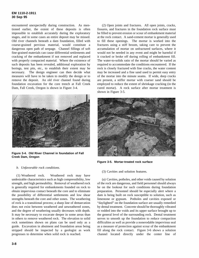
encountered unexpectedly during construction. As men-tioned earlier, the extent of these deposits is oftenimpossible to establish accurately during the exploratorystages, and in some cases an entire deposit may be missed.Old river channels beneath a dam foundation, filled withcourse-grained pervious material, would constitute adangerous open path of seepage. Channel fillings of softfine-grained materials can cause differential settlements andcracking of the embankment if not removed and replacedwith properly compacted material. Where the existence ofsuch deposits has been revealed, additional exploration byborings, test pits, etc., to establish their extent may benecessary. The design engineer can then decide whatmeasures will have to be taken to modify the design or toremove the deposit. An old river channel found duringfoundation excavation for the core trench at Fall CreekDam, Fall Creek, Oregon is shown in Figure 3-4.
Figure 3-4. Old River Channel in foundation of FallCreek Dam, Oregon
b. Unfavorable rock conditions.
(1) Weathered rock. Weathered rock may haveundesirable characteristics such as high compressibility, lowstrength, and high permeability. Removal of weathered rockis generally required for embankments founded on rock toobtain impervious contact beneath the core and to eliminatethe possibility of differential settlements and low shearstrengths beneath the core and other zones. The weatheringof rock is a transitional process; a sharp line of demarcationdoes not exist between weathered and unweathered zones,and the degree of weathering usually decreases with depth.It may be necessary to excavate deeper in some areas thanin others to remove weathered rock. The elevation to solidrock sometimes shown on plans can be used only as aguide. Excavation in abutment and foundation areas beingstripped should be inspected by a geologist as workprogresses to determine when solid rock is reached.
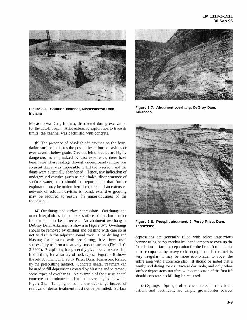
(2) Open joints and fractures. All open joints, cracks,fissures, and fractures in the foundation rock surface mustbe filled to prevent erosion or scour of embankment materialat the rock contact. A sand-cement mortar is generally usedto fill these openings. The mortar is worked into thefractures using a stiff broom, taking care to prevent theaccumulation of mortar on unfractured surfaces, where itwould not be needed in any event and might be harmful ifit cracked or broke off during rolling of embankment fill.The water-to-solids ratio of the mortar should be varied asrequired to accommodate the conditions encountered. If therock is closely fractured with fine cracks, the water contentmay be increased and a fine sand used to permit easy entryof the mortar into the minute seams. If wide, deep cracksare present, a stiffer mortar with coarser sand should beemployed to reduce the extent of shrinkage cracking (in thecured mortar). A rock surface after mortar treatment isshown in Figure 3-5.
Figure 3-5. Mortar-treated rock surface
(3) Cavities and solution features.
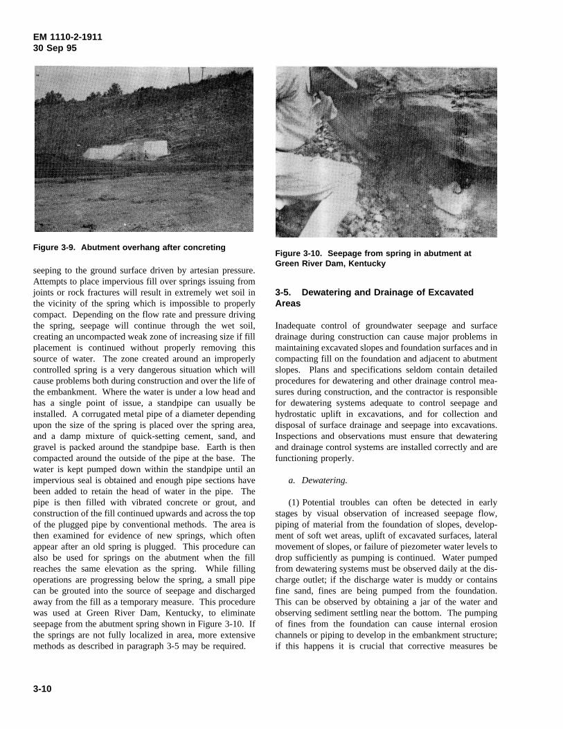
(a) Cavities, potholes, and other voids caused by solutionof the rock are dangerous, and field personnel should alwaysbe on the lookout for such conditions during foundationpreparation. Personnel should be especially alert where adam is being built on rock susceptible to solution, such aslimestone or gypsum. Potholes and cavities exposed or“daylighted” on the foundation surface are usually remediedby dental treatment. Concrete should be thoroughly vibratedor rodded into the voids and its upper surface brought up tothe general level of the surrounding rock. Dental treatmentserves to smooth up the foundation to reduce compactiondifficulties as well as provide a nonerodable impervious sealas a measure of protection against scour of the embankmentfill along the rock contact. Figure 3-6 shows a solutionchannel located directly under the center line of
3-8
EM 1110-2-191130 Sep 95
Mississinewa Dam, Indiana, discovered during excavation
Figure 3-6. Solution channel, Mississinewa Dam,Indiana
for the cutoff trench. After extensive exploration to trace itslimits, the channel was backfilled with concrete.
(b) The presence of “daylighted” cavities on the foun-dation surface indicates the possibility of buried cavities oreven caverns below grade. Cavities left untreated are highlydangerous, as emphasized by past experience; there havebeen cases where leakage through underground cavities wasso great that it was impossible to fill the reservoir and thedams were eventually abandoned. Hence, any indication ofunderground cavities (such as sink holes, disappearance ofsurface water, etc.) should be reported so that furtherexploration may be undertaken if required. If an extensivenetwork of solution cavities is found, extensive groutingmay be required to ensure the imperviousness of thefoundation.
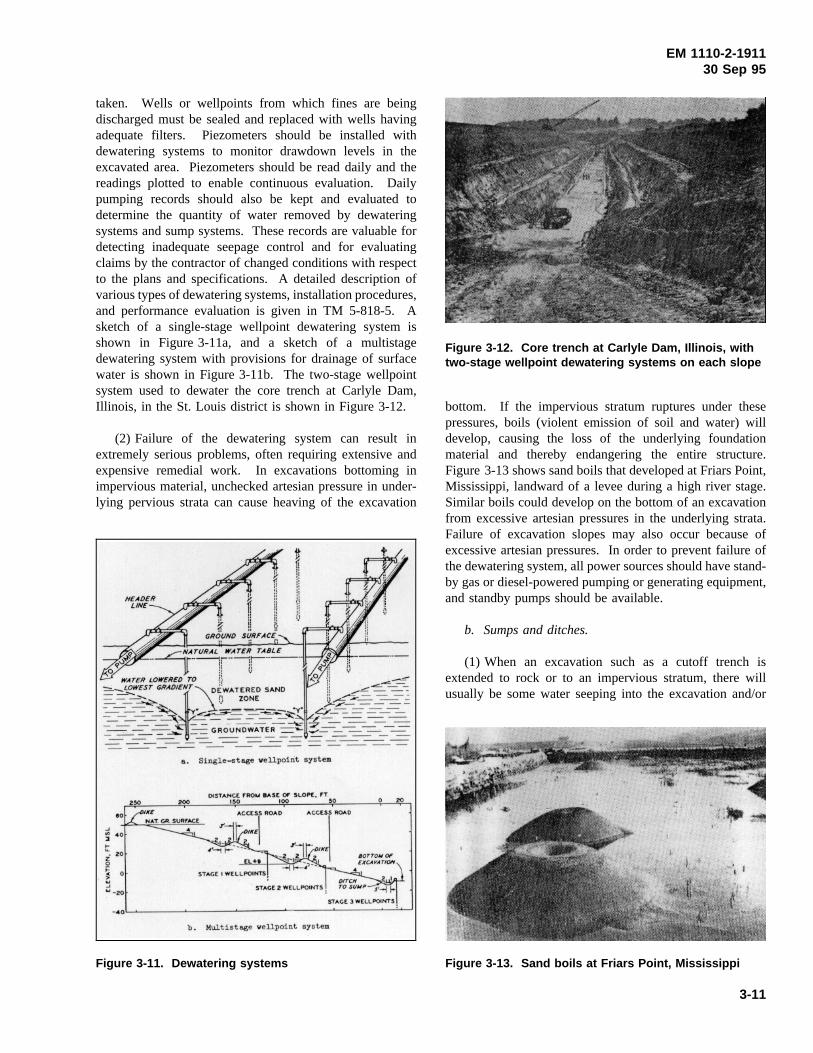
(4) Overhangs and surface depressions. Overhangs andother irregularities in the rock surface of an abutment orfoundation must be corrected. An abutment overhang atDeGray Dam, Arkansas, is shown in Figure 3-7. Overhangsshould be removed by drilling and blasting with care so asnot to disturb the adjacent sound rock. Line drilling andblasting (or blasting with presplitting) have been usedsuccessfully to form a relatively smooth surface (EM 1110-2-3800). Presplitting has generally given better results thanline drilling for a variety of rock types. Figure 3-8 showsthe left abutment at J. Percy Priest Dam, Tennessee, formedby the presplitting method. Concrete dental treatment canbe used to fill depressions created by blasting and to remedysome types of overhangs. An example of the use of dentalconcrete to eliminate an abutment overhang is shown inFigure 3-9. Tamping of soil under overhangs instead ofremoval or dental treatment must not be permitted. Surface
Figure 3-7. Abutment overhang, DeGray Dam,Arkansas
depressions are generally filled with select impervious
Figure 3-8. Presplit abutment, J. Percy Priest Dam,Tennessee
borrow using heavy mechanical hand tampers to even up thefoundation surface in preparation for the first lift of materialto be compacted by heavy roller equipment. If the rock isvery irregular, it may be more economical to cover theentire area with a concrete slab. It should be noted that agently undulating rock surface is desirable, and only whensurface depressions interfere with compaction of the first liftshould concrete backfilling be required.
(5) Springs. Springs, often encountered in rock foun-dations and abutments, are simply groundwater sources
3-9
EM 1110-2-191130 Sep 95
seeping to the ground surface driven by artesian pressure.
Figure 3-9. Abutment overhang after concreting
Attempts to place impervious fill over springs issuing fromjoints or rock fractures will result in extremely wet soil inthe vicinity of the spring which is impossible to properlycompact. Depending on the flow rate and pressure drivingthe spring, seepage will continue through the wet soil,creating an uncompacted weak zone of increasing size if fillplacement is continued without properly removing thissource of water. The zone created around an improperlycontrolled spring is a very dangerous situation which willcause problems both during construction and over the life ofthe embankment. Where the water is under a low head andhas a single point of issue, a standpipe can usually beinstalled. A corrugated metal pipe of a diameter dependingupon the size of the spring is placed over the spring area,and a damp mixture of quick-setting cement, sand, andgravel is packed around the standpipe base. Earth is thencompacted around the outside of the pipe at the base. Thewater is kept pumped down within the standpipe until animpervious seal is obtained and enough pipe sections havebeen added to retain the head of water in the pipe. Thepipe is then filled with vibrated concrete or grout, andconstruction of the fill continued upwards and across the topof the plugged pipe by conventional methods. The area isthen examined for evidence of new springs, which oftenappear after an old spring is plugged. This procedure canalso be used for springs on the abutment when the fillreaches the same elevation as the spring. While fillingoperations are progressing below the spring, a small pipecan be grouted into the source of seepage and dischargedaway from the fill as a temporary measure. This procedurewas used at Green River Dam, Kentucky, to eliminateseepage from the abutment spring shown in Figure 3-10. Ifthe springs are not fully localized in area, more extensivemethods as described in paragraph 3-5 may be required.
3-5. Dewatering and Drainage of Excavated
Figure 3-10. Seepage from spring in abutment atGreen River Dam, Kentucky
Areas
Inadequate control of groundwater seepage and surfacedrainage during construction can cause major problems inmaintaining excavated slopes and foundation surfaces and incompacting fill on the foundation and adjacent to abutmentslopes. Plans and specifications seldom contain detailedprocedures for dewatering and other drainage control mea-sures during construction, and the contractor is responsiblefor dewatering systems adequate to control seepage andhydrostatic uplift in excavations, and for collection anddisposal of surface drainage and seepage into excavations.Inspections and observations must ensure that dewateringand drainage control systems are installed correctly and arefunctioning properly.
a. Dewatering.
(1) Potential troubles can often be detected in earlystages by visual observation of increased seepage flow,piping of material from the foundation of slopes, develop-ment of soft wet areas, uplift of excavated surfaces, lateralmovement of slopes, or failure of piezometer water levels todrop sufficiently as pumping is continued. Water pumpedfrom dewatering systems must be observed daily at the dis-charge outlet; if the discharge water is muddy or containsfine sand, fines are being pumped from the foundation.This can be observed by obtaining a jar of the water andobserving sediment settling near the bottom. The pumpingof fines from the foundation can cause internal erosionchannels or piping to develop in the embankment structure;if this happens it is crucial that corrective measures be
3-10
EM 1110-2-191130 Sep 95
taken. Wells or wellpoints from which fines are beingdischarged must be sealed and replaced with wells havingadequate filters. Piezometers should be installed withdewatering systems to monitor drawdown levels in theexcavated area. Piezometers should be read daily and thereadings plotted to enable continuous evaluation. Dailypumping records should also be kept and evaluated todetermine the quantity of water removed by dewateringsystems and sump systems. These records are valuable fordetecting inadequate seepage control and for evaluatingclaims by the contractor of changed conditions with respectto the plans and specifications. A detailed description ofvarious types of dewatering systems, installation procedures,and performance evaluation is given in TM 5-818-5. Asketch of a single-stage wellpoint dewatering system isshown in Figure 3-11a, and a sketch of a multistage
Figure 3-11. Dewatering systems
dewatering system with provisions for drainage of surfacewater is shown in Figure 3-11b. The two-stage wellpointsystem used to dewater the core trench at Carlyle Dam,Illinois, in the St. Louis district is shown in Figure 3-12.
(2) Failure of the dewatering system can result inextremely serious problems, often requiring extensive andexpensive remedial work. In excavations bottoming inimpervious material, unchecked artesian pressure in under-lying pervious strata can cause heaving of the excavation
bottom. If the impervious stratum ruptures under these
Figure 3-12. Core trench at Carlyle Dam, Illinois, withtwo-stage wellpoint dewatering systems on each slope
pressures, boils (violent emission of soil and water) willdevelop, causing the loss of the underlying foundationmaterial and thereby endangering the entire structure.Figure 3-13 shows sand boils that developed at Friars Point,Mississippi, landward of a levee during a high river stage.Similar boils could develop on the bottom of an excavationfrom excessive artesian pressures in the underlying strata.Failure of excavation slopes may also occur because ofexcessive artesian pressures. In order to prevent failure ofthe dewatering system, all power sources should have stand-by gas or diesel-powered pumping or generating equipment,and standby pumps should be available.
Figure 3-13. Sand boils at Friars Point, Mississippi
b. Sumps and ditches.
(1) When an excavation such as a cutoff trench isextended to rock or to an impervious stratum, there willusually be some water seeping into the excavation and/or
3-11
EM 1110-2-191130 Sep 95
“wet spots” in the bottom of the excavation, even with deepwells or wellpoint systems in operation. Water seeping intothe excavation from the upstream and downstream slopes ofa long cutoff trench can usually be captured by excavatingnarrow longitudinal ditches or drainage trenches at theintersection of the slopes and the bottom of the excavation(see Figure 3-11b), or by forming such trenches with sand-bags, with sumps located as necessary for pumping thewater out. If the bottom of the excavation will still not dryout, smaller ditches can be cut through the problem areasand sloped to drain to the side trenches.
(2) To keep the bottom of the cutoff trench dry whileplacing backfill, the drainage ditch system can be filled withgravel so that the system can continue to function even afterbeing covered with soil. These gravel-filled ditches shouldconstitute only a very small portion of the overall area beingdrained to preclude the necessity of later grouting largeportions of the bottom of the cutoff trench containing gravel.The surface of the gravel can be covered with a layer ofheavy felt paper, burlap, or plastic sheeting, or by a layer ofstiff concrete to prevent migration of fines from the fillmaterial. The ditches are blocked at the ends of the excava-tion by means of concrete plugs. Riser pipes are brought upfrom each sump (low point in the ditch) with the result thatwater can be pumped from one or more of the riser pipes asnecessary, with the remaining riser pipes serving as ventpipes.
(3) After the backfill is brought to a height that willcounteract the hydraulic head, the gravel-filled ditches aregrouted. Cement grout is introduced under gravity throughone riser pipe with the vent pipes serving as an escape forair and water in the gravel. When grout issues from thevent pipes, the vent pipes are shut off and a slight pressureis maintained in the system until the grout has set. Aftergrouting, normal fill placement operations are continued. Ifonly one sump is used in the drainage system, a vent pipewill have to be installed at an appropriate location beforebackfilling starts.
(4) Figures 3-14a and 3-14b show the drainage systemsuccessfully used at Laurel Dam, Kentucky, to removelocalized flow cracks in the shale. The system provided adry foundation for impervious material. Figure 3-14a showsa trench dug along a water-producing crack in the shale. Aperforated collector pipe was placed in the trench with avent hose and grout pipe attached. The collector pipe wassurrounded with stone and the remaining portion of thetrench filled with concrete. Water volume from variouscollector pipes discharged into a collection box from whicha single pipe carried the water to a pump located in a 60-in.corrugated metal pipe (CMP) sump (see Figure 3-14b). Thevent hoses, grout, pipes, and CMP were extended as the fillwas brought up. After 20 to 30 ft of embankment fill had
been placed, the collector pipes were grouted and the CMP
Figure 3-14. Foundation drainage system at LaurelDam, Kentucky
was filled with -3-in. stone and grouted.
(5) In many cases where a dewatering system is beingused, a 4- to 5-ft-high impervious blanket placed at the toeof the slope will prevent the minor seepage flow thatotherwise might occur and will therefore provide a drybottom.
c. Surface erosion. Surface erosion may presentproblems on slopes cut in silts, fine sands, and lean clays.
3-12
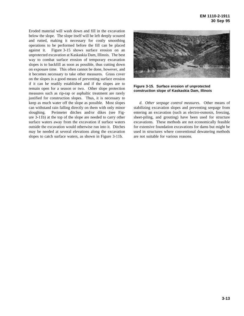
EM 1110-2-191130 Sep 95
Eroded material will wash down and fill in the excavationbelow the slope. The slope itself will be left deeply scouredand rutted, making it necessary for costly smoothingoperations to be performed before the fill can be placedagainst it. Figure 3-15 shows surface erosion on anunprotected excavation at Kaskaskia Dam, Illinois. The bestway to combat surface erosion of temporary excavationslopes is to backfill as soon as possible, thus cutting downon exposure time. This often cannot be done, however, andit becomes necessary to take other measures. Grass coveron the slopes is a good means of preventing surface erosionif it can be readily established and if the slopes are toremain open for a season or two. Other slope protectionmeasures such as rip-rap or asphaltic treatment are rarelyjustified for construction slopes. Thus, it is necessary tokeep as much water off the slope as possible. Most slopescan withstand rain falling directly on them with only minorsloughing. Perimeter ditches and/or dikes (see Fig-ure 3-11b) at the top of the slope are needed to carry othersurface waters away from the excavation if surface watersoutside the excavation would otherwise run into it. Ditchesmay be needed at several elevations along the excavationslopes to catch surface waters, as shown in Figure 3-11b.
d. Other seepage control measures.Other means of
Figure 3-15. Surface erosion of unprotectedconstruction slope of Kaskaskia Dam, Illinois
stabilizing excavation slopes and preventing seepage fromentering an excavation (such as electro-osmosis, freezing,sheet-piling, and grouting) have been used for structureexcavations. These methods are not economically feasiblefor extensive foundation excavations for dams but might beused in structures where conventional dewatering methodsare not suitable for various reasons.
3-13
EM 1110-2-191130 Sep 95
Chapter 4Borrow Areas and Quarries
Section IEarth Fill
4-1. Excavation, Handling, and HaulingEquipment
Over the past several decades, significant improvements inearth-moving equipment have been made at an increasingrate, and there is no indication that this trend will slow.While the basic types of equipment have remained virtuallythe same, speed, power, and capacity have continuouslyincreased. Some of the basic principles of the morecommon units are discussed in the following paragraphs.
a. Excavation equipment.
(1) Power shovels, draglines, elevating graders, wheelexcavators, and scrapers. Excavation is usually accom-plished with power shovels, draglines, scrapers, wheelexcavators, or side-delivery loaders. Each offers certainadvantages and has certain disadvantages; therefore, severaltypes are often used on the same job. Discussion of thefour major types of excavation units is given in Figures 4-1through 4-3.
(2) Dredges. Dredging is sometimes employed to movematerial from borrow areas to the damsite. Dredges areparticularly suitable for use when large quantities of materialare to be obtained from borrow areas submerged in rivers,lakes, etc. The two basic types of dredges are the bucketdredge and the hydraulic dredge.
(a) Bucket dredge. A limiting disadvantage of bucketdredges is that the discharge is alongside the place ofexcavation. They can best be used for localized dredging orwhere the borrow area is located so that the material can beeconomically transported by trucks or barges to the site.There are three types of bucket dredges: grab dredges,dipper dredges, and ladder dredges. The grab dredge isessentially a grab bucket operated from a derrick mountedon a flat-topped barge. The dipper dredge is simply apower shovel operating from a barge. The ladder dredgeexcavates with a continuous chain of buckets supported onan inclined ladder. Bucket dredges have the advantage thatthey can excavate in most any material. Dredging depthsgreater than 100 ft are not uncommon for grab dredges.Digging depths of the dipper dredge are limited by thelength of the boom (65 ft is about the maximum, althoughgreater lengths are available for special projects) while thedigging depth of the ladder dredge is limited by the length
of the ladder (usually around 40 ft, but lengths greater than75 ft are not uncommon).
(b) Hydraulic dredges. All hydraulic dredges basicallyconsist of a centrifugal pump and a suction line throughwhich the pump is supplied with material, but differentmeans are used to loosen and pick up material. Hydraulicdredges can transport material without rehandling for prac-tically unlimited distance if booster pumps are used; thisfeature is particularly useful in the construction of temporarydikes and permanent structures by the hydraulic fill method.However, it must be mentioned that material placed by thehydraulic fill method will be loose, essentially water-saturated, and probably susceptible to liquefaction ifsufficiently disturbed by the mechanisms specified inparagraph 3-4a(4). The most common dredge in current useis the cutterhead dredge, which excavates material with arotating cutterhead then removes it by suction. The cutteris attached to the forward end of a ladder or to the suctionpipe itself; rotation of the cutter agitates soft material and/orcuts hard material. Various types of cutters are available,and the type to be used depends on the hardness of thematerial to be excavated. Some cutters can cut into soundrock. The maximum suction available at the pump is about28 ft of water; therefore, head losses must be kept to aminimum in order to provide adequate suction.
b. Hauling, handling, and separating equipment.Borrow material excavated by scrapers or by dredging isusually taken directly to its point of deposition on theembankment under construction. However, when most otherexcavation procedures and equipment are used, additionalhauling and handling are required. Regardless of theequipment used, borrow material may require sorting and/orseparation according to size or material type. Some of theequipment used for hauling, handling, and separating borrowmaterials is discussed in the following paragraphs.
(1) Trucks. Trucks of many types are used to transportembankment material from the borrow pit to the dam,capacities of up to 50 tons being common. They can becategorized according to method of unloading as bottomdump, end dump, or side dump.
(2) Belt conveyors. Belt conveyors (Figure 4-4) areused to transport material from the borrow area to thedamsite when very large quantities of material must bemoved under difficult conditions. Belt conveyors are mostsuitable for moving large quantities of material over roughterrain where there are large differences in elevationbetween the borrow pit and the dam, and where the cost ofbuilding and maintaining haul roads would be high. Con-veyor systems are adaptable to different types of automatedprocessing procedures: screening plants, crushing plants,
4-1
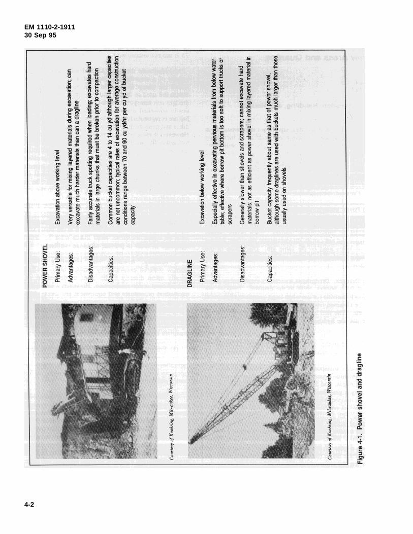
EM 1110-2-191130 Sep 95
4-2
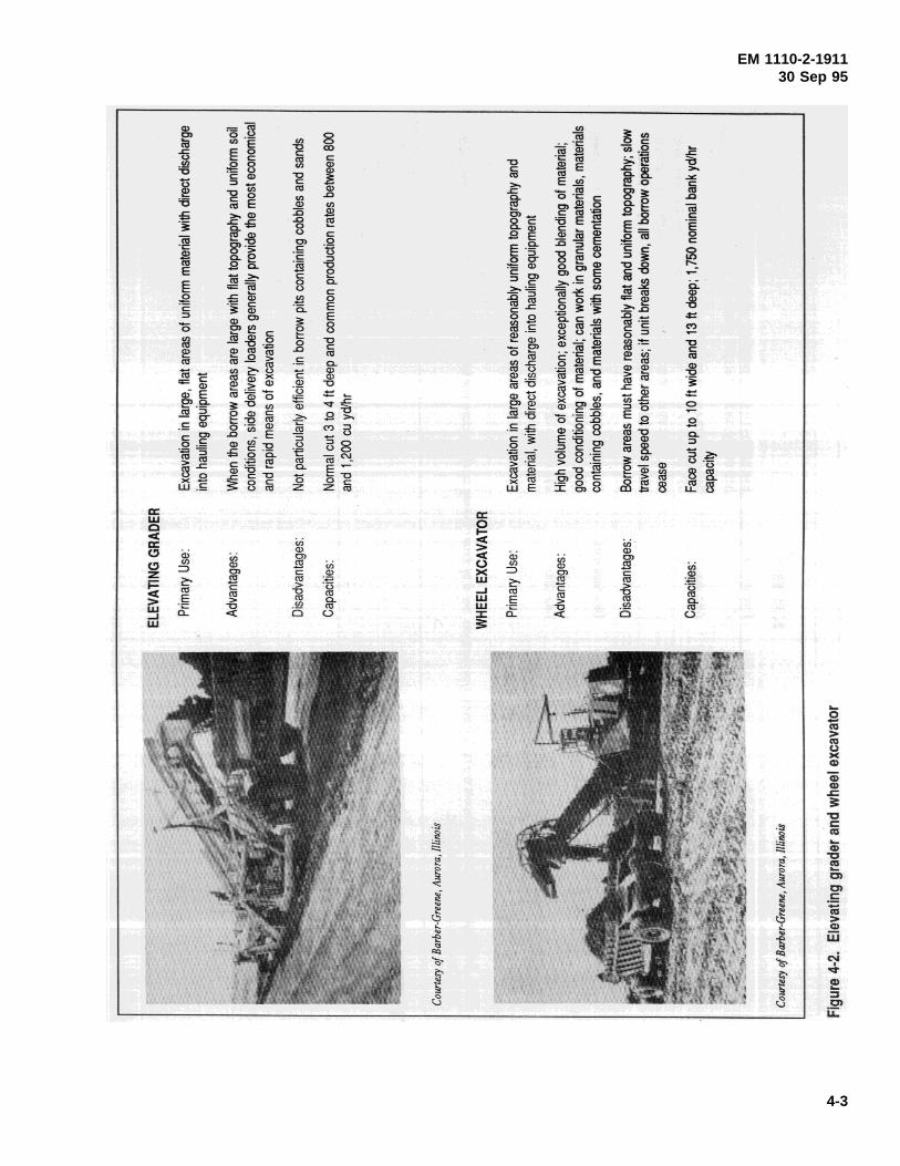
EM 1110-2-191130 Sep 95
4-3
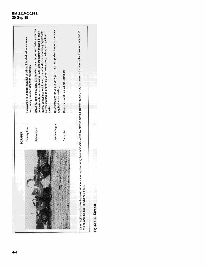
EM 1110-2-191130 Sep 95
4-4
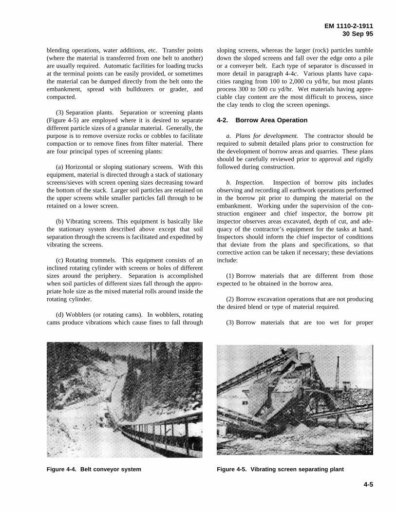
EM 1110-2-191130 Sep 95
blending operations, water additions, etc. Transfer points
Figure 4-4. Belt conveyor system Figure 4-5. Vibrating screen separating plant
(where the material is transferred from one belt to another)are usually required. Automatic facilities for loading trucksat the terminal points can be easily provided, or sometimesthe material can be dumped directly from the belt onto theembankment, spread with bulldozers or grader, andcompacted.
(3) Separation plants. Separation or screening plants(Figure 4-5) are employed where it is desired to separatedifferent particle sizes of a granular material. Generally, thepurpose is to remove oversize rocks or cobbles to facilitatecompaction or to remove fines from filter material. Thereare four principal types of screening plants:
(a) Horizontal or sloping stationary screens. With thisequipment, material is directed through a stack of stationaryscreens/sieves with screen opening sizes decreasing towardthe bottom of the stack. Larger soil particles are retained onthe upper screens while smaller particles fall through to beretained on a lower screen.
(b) Vibrating screens. This equipment is basically likethe stationary system described above except that soilseparation through the screens is facilitated and expedited byvibrating the screens.
(c) Rotating trommels. This equipment consists of aninclined rotating cylinder with screens or holes of differentsizes around the periphery. Separation is accomplishedwhen soil particles of different sizes fall through the appro-priate hole size as the mixed material rolls around inside therotating cylinder.
(d) Wobblers (or rotating cams). In wobblers, rotatingcams produce vibrations which cause fines to fall through
sloping screens, whereas the larger (rock) particles tumbledown the sloped screens and fall over the edge onto a pileor a conveyer belt. Each type of separator is discussed inmore detail in paragraph 4-4c. Various plants have capa-cities ranging from 100 to 2,000 cu yd/hr, but most plantsprocess 300 to 500 cu yd/hr. Wet materials having appre-ciable clay content are the most difficult to process, sincethe clay tends to clog the screen openings.
4-2. Borrow Area Operation
a. Plans for development.The contractor should berequired to submit detailed plans prior to construction forthe development of borrow areas and quarries. These plansshould be carefully reviewed prior to approval and rigidlyfollowed during construction.
b. Inspection. Inspection of borrow pits includesobserving and recording all earthwork operations performedin the borrow pit prior to dumping the material on theembankment. Working under the supervision of the con-struction engineer and chief inspector, the borrow pitinspector observes areas excavated, depth of cut, and ade-quacy of the contractor’s equipment for the tasks at hand.Inspectors should inform the chief inspector of conditionsthat deviate from the plans and specifications, so thatcorrective action can be taken if necessary; these deviationsinclude:
(1) Borrow materials that are different from thoseexpected to be obtained in the borrow area.
(2) Borrow excavation operations that are not producingthe desired blend or type of material required.
(3) Borrow materials that are too wet for proper
4-5
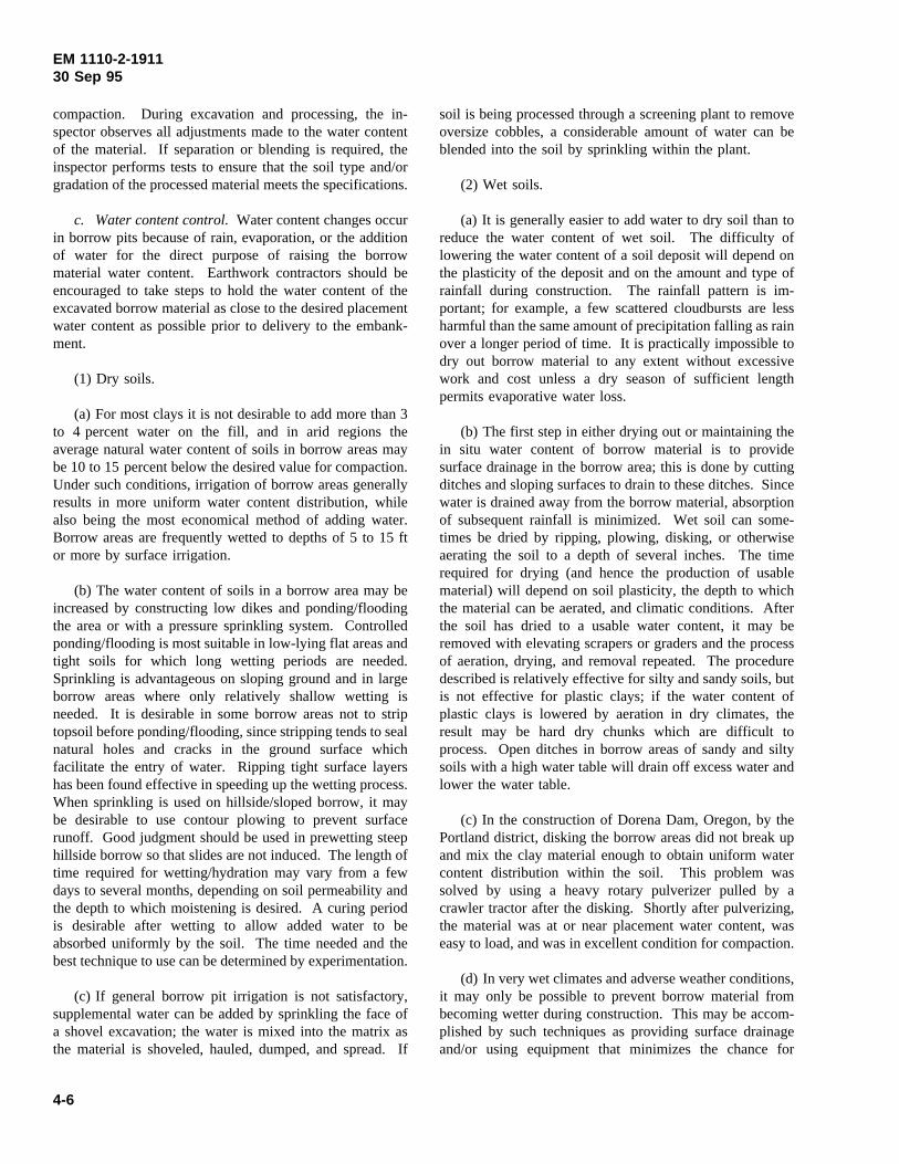
EM 1110-2-191130 Sep 95
compaction. During excavation and processing, the in-spector observes all adjustments made to the water contentof the material. If separation or blending is required, theinspector performs tests to ensure that the soil type and/orgradation of the processed material meets the specifications.
c. Water content control.Water content changes occurin borrow pits because of rain, evaporation, or the additionof water for the direct purpose of raising the borrowmaterial water content. Earthwork contractors should beencouraged to take steps to hold the water content of theexcavated borrow material as close to the desired placementwater content as possible prior to delivery to the embank-ment.
(1) Dry soils.
(a) For most clays it is not desirable to add more than 3to 4 percent water on the fill, and in arid regions theaverage natural water content of soils in borrow areas maybe 10 to 15 percent below the desired value for compaction.Under such conditions, irrigation of borrow areas generallyresults in more uniform water content distribution, whilealso being the most economical method of adding water.Borrow areas are frequently wetted to depths of 5 to 15 ftor more by surface irrigation.
(b) The water content of soils in a borrow area may beincreased by constructing low dikes and ponding/floodingthe area or with a pressure sprinkling system. Controlledponding/flooding is most suitable in low-lying flat areas andtight soils for which long wetting periods are needed.Sprinkling is advantageous on sloping ground and in largeborrow areas where only relatively shallow wetting isneeded. It is desirable in some borrow areas not to striptopsoil before ponding/flooding, since stripping tends to sealnatural holes and cracks in the ground surface whichfacilitate the entry of water. Ripping tight surface layershas been found effective in speeding up the wetting process.When sprinkling is used on hillside/sloped borrow, it maybe desirable to use contour plowing to prevent surfacerunoff. Good judgment should be used in prewetting steephillside borrow so that slides are not induced. The length oftime required for wetting/hydration may vary from a fewdays to several months, depending on soil permeability andthe depth to which moistening is desired. A curing periodis desirable after wetting to allow added water to beabsorbed uniformly by the soil. The time needed and thebest technique to use can be determined by experimentation.
(c) If general borrow pit irrigation is not satisfactory,supplemental water can be added by sprinkling the face ofa shovel excavation; the water is mixed into the matrix asthe material is shoveled, hauled, dumped, and spread. If
soil is being processed through a screening plant to removeoversize cobbles, a considerable amount of water can beblended into the soil by sprinkling within the plant.
(2) Wet soils.
(a) It is generally easier to add water to dry soil than toreduce the water content of wet soil. The difficulty oflowering the water content of a soil deposit will depend onthe plasticity of the deposit and on the amount and type ofrainfall during construction. The rainfall pattern is im-portant; for example, a few scattered cloudbursts are lessharmful than the same amount of precipitation falling as rainover a longer period of time. It is practically impossible todry out borrow material to any extent without excessivework and cost unless a dry season of sufficient lengthpermits evaporative water loss.
(b) The first step in either drying out or maintaining thein situ water content of borrow material is to providesurface drainage in the borrow area; this is done by cuttingditches and sloping surfaces to drain to these ditches. Sincewater is drained away from the borrow material, absorptionof subsequent rainfall is minimized. Wet soil can some-times be dried by ripping, plowing, disking, or otherwiseaerating the soil to a depth of several inches. The timerequired for drying (and hence the production of usablematerial) will depend on soil plasticity, the depth to whichthe material can be aerated, and climatic conditions. Afterthe soil has dried to a usable water content, it may beremoved with elevating scrapers or graders and the processof aeration, drying, and removal repeated. The proceduredescribed is relatively effective for silty and sandy soils, butis not effective for plastic clays; if the water content ofplastic clays is lowered by aeration in dry climates, theresult may be hard dry chunks which are difficult toprocess. Open ditches in borrow areas of sandy and siltysoils with a high water table will drain off excess water andlower the water table.
(c) In the construction of Dorena Dam, Oregon, by thePortland district, disking the borrow areas did not break upand mix the clay material enough to obtain uniform watercontent distribution within the soil. This problem wassolved by using a heavy rotary pulverizer pulled by acrawler tractor after the disking. Shortly after pulverizing,the material was at or near placement water content, waseasy to load, and was in excellent condition for compaction.
(d) In very wet climates and adverse weather conditions,it may only be possible to prevent borrow material frombecoming wetter during construction. This may be accom-plished by such techniques as providing surface drainageand/or using equipment that minimizes the chance for
4-6
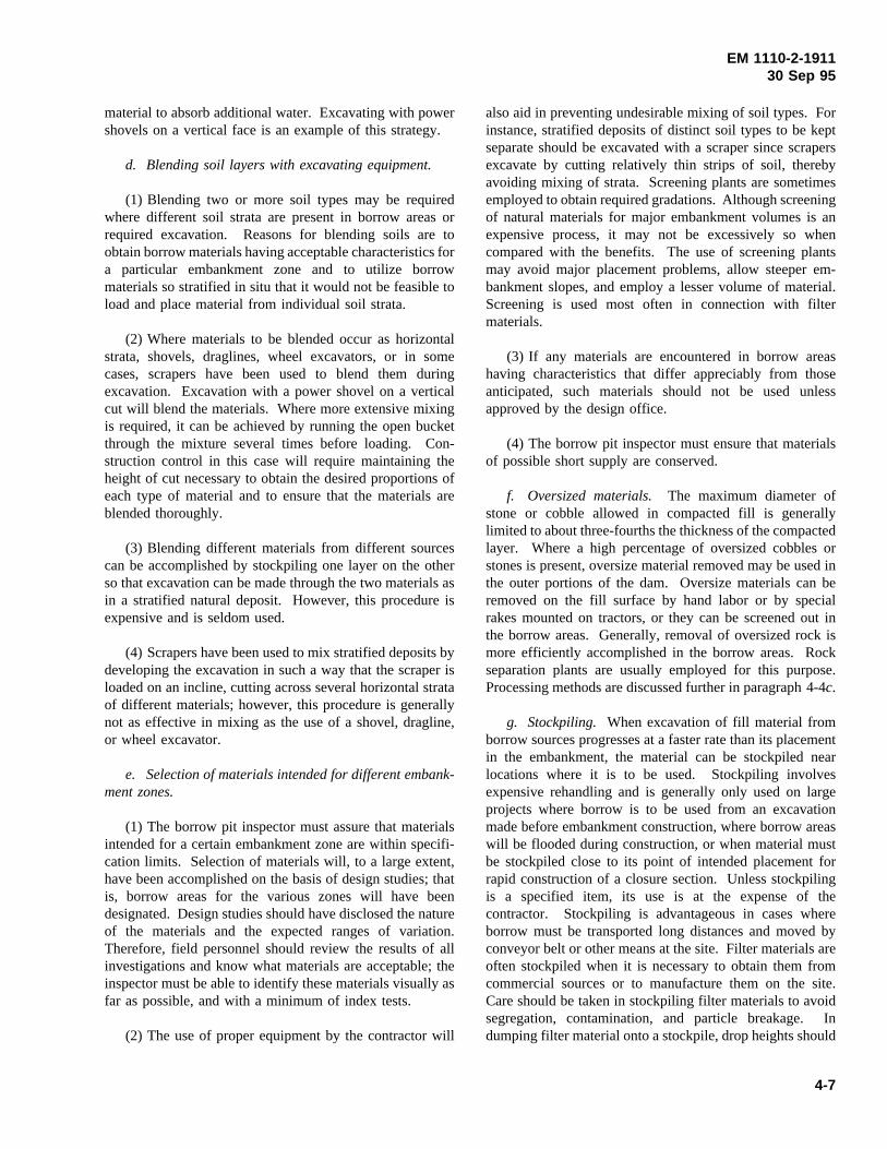
EM 1110-2-191130 Sep 95
material to absorb additional water. Excavating with powershovels on a vertical face is an example of this strategy.
d. Blending soil layers with excavating equipment.
(1) Blending two or more soil types may be requiredwhere different soil strata are present in borrow areas orrequired excavation. Reasons for blending soils are toobtain borrow materials having acceptable characteristics fora particular embankment zone and to utilize borrowmaterials so stratified in situ that it would not be feasible toload and place material from individual soil strata.
(2) Where materials to be blended occur as horizontalstrata, shovels, draglines, wheel excavators, or in somecases, scrapers have been used to blend them duringexcavation. Excavation with a power shovel on a verticalcut will blend the materials. Where more extensive mixingis required, it can be achieved by running the open bucketthrough the mixture several times before loading. Con-struction control in this case will require maintaining theheight of cut necessary to obtain the desired proportions ofeach type of material and to ensure that the materials areblended thoroughly.
(3) Blending different materials from different sourcescan be accomplished by stockpiling one layer on the otherso that excavation can be made through the two materials asin a stratified natural deposit. However, this procedure isexpensive and is seldom used.
(4) Scrapers have been used to mix stratified deposits bydeveloping the excavation in such a way that the scraper isloaded on an incline, cutting across several horizontal strataof different materials; however, this procedure is generallynot as effective in mixing as the use of a shovel, dragline,or wheel excavator.
e. Selection of materials intended for different embank-ment zones.
(1) The borrow pit inspector must assure that materialsintended for a certain embankment zone are within specifi-cation limits. Selection of materials will, to a large extent,have been accomplished on the basis of design studies; thatis, borrow areas for the various zones will have beendesignated. Design studies should have disclosed the natureof the materials and the expected ranges of variation.Therefore, field personnel should review the results of allinvestigations and know what materials are acceptable; theinspector must be able to identify these materials visually asfar as possible, and with a minimum of index tests.
(2) The use of proper equipment by the contractor will
also aid in preventing undesirable mixing of soil types. Forinstance, stratified deposits of distinct soil types to be keptseparate should be excavated with a scraper since scrapersexcavate by cutting relatively thin strips of soil, therebyavoiding mixing of strata. Screening plants are sometimesemployed to obtain required gradations. Although screeningof natural materials for major embankment volumes is anexpensive process, it may not be excessively so whencompared with the benefits. The use of screening plantsmay avoid major placement problems, allow steeper em-bankment slopes, and employ a lesser volume of material.Screening is used most often in connection with filtermaterials.
(3) If any materials are encountered in borrow areashaving characteristics that differ appreciably from thoseanticipated, such materials should not be used unlessapproved by the design office.
(4) The borrow pit inspector must ensure that materialsof possible short supply are conserved.
f. Oversized materials. The maximum diameter ofstone or cobble allowed in compacted fill is generallylimited to about three-fourths the thickness of the compactedlayer. Where a high percentage of oversized cobbles orstones is present, oversize material removed may be used inthe outer portions of the dam. Oversize materials can beremoved on the fill surface by hand labor or by specialrakes mounted on tractors, or they can be screened out inthe borrow areas. Generally, removal of oversized rock ismore efficiently accomplished in the borrow areas. Rockseparation plants are usually employed for this purpose.Processing methods are discussed further in paragraph 4-4c.
g. Stockpiling. When excavation of fill material fromborrow sources progresses at a faster rate than its placementin the embankment, the material can be stockpiled nearlocations where it is to be used. Stockpiling involvesexpensive rehandling and is generally only used on largeprojects where borrow is to be used from an excavationmade before embankment construction, where borrow areaswill be flooded during construction, or when material mustbe stockpiled close to its point of intended placement forrapid construction of a closure section. Unless stockpilingis a specified item, its use is at the expense of thecontractor. Stockpiling is advantageous in cases whereborrow must be transported long distances and moved byconveyor belt or other means at the site. Filter materials areoften stockpiled when it is necessary to obtain them fromcommercial sources or to manufacture them on the site.Care should be taken in stockpiling filter materials to avoidsegregation, contamination, and particle breakage. Indumping filter material onto a stockpile, drop heights should
4-7
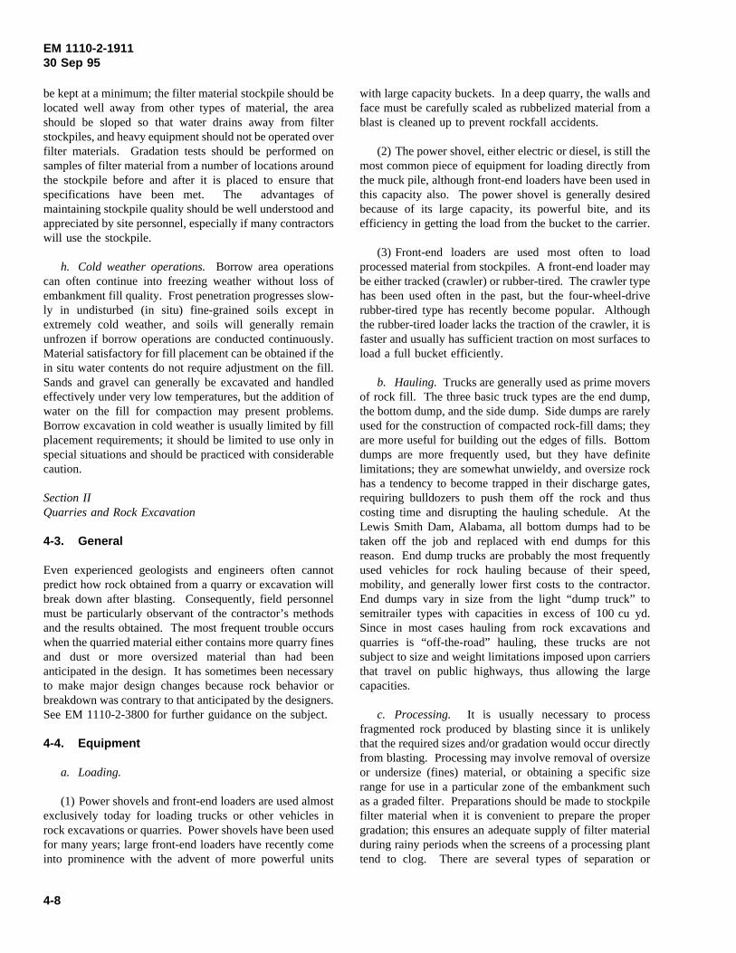
EM 1110-2-191130 Sep 95
be kept at a minimum; the filter material stockpile should belocated well away from other types of material, the areashould be sloped so that water drains away from filterstockpiles, and heavy equipment should not be operated overfilter materials. Gradation tests should be performed onsamples of filter material from a number of locations aroundthe stockpile before and after it is placed to ensure thatspecifications have been met. The advantages ofmaintaining stockpile quality should be well understood andappreciated by site personnel, especially if many contractorswill use the stockpile.
h. Cold weather operations.Borrow area operationscan often continue into freezing weather without loss ofembankment fill quality. Frost penetration progresses slow-ly in undisturbed (in situ) fine-grained soils except inextremely cold weather, and soils will generally remainunfrozen if borrow operations are conducted continuously.Material satisfactory for fill placement can be obtained if thein situ water contents do not require adjustment on the fill.Sands and gravel can generally be excavated and handledeffectively under very low temperatures, but the addition ofwater on the fill for compaction may present problems.Borrow excavation in cold weather is usually limited by fillplacement requirements; it should be limited to use only inspecial situations and should be practiced with considerablecaution.
Section IIQuarries and Rock Excavation
4-3. General
Even experienced geologists and engineers often cannotpredict how rock obtained from a quarry or excavation willbreak down after blasting. Consequently, field personnelmust be particularly observant of the contractor’s methodsand the results obtained. The most frequent trouble occurswhen the quarried material either contains more quarry finesand dust or more oversized material than had beenanticipated in the design. It has sometimes been necessaryto make major design changes because rock behavior orbreakdown was contrary to that anticipated by the designers.See EM 1110-2-3800 for further guidance on the subject.
4-4. Equipment
a. Loading.
(1) Power shovels and front-end loaders are used almostexclusively today for loading trucks or other vehicles inrock excavations or quarries. Power shovels have been usedfor many years; large front-end loaders have recently comeinto prominence with the advent of more powerful units
with large capacity buckets. In a deep quarry, the walls andface must be carefully scaled as rubbelized material from ablast is cleaned up to prevent rockfall accidents.
(2) The power shovel, either electric or diesel, is still themost common piece of equipment for loading directly fromthe muck pile, although front-end loaders have been used inthis capacity also. The power shovel is generally desiredbecause of its large capacity, its powerful bite, and itsefficiency in getting the load from the bucket to the carrier.
(3) Front-end loaders are used most often to loadprocessed material from stockpiles. A front-end loader maybe either tracked (crawler) or rubber-tired. The crawler typehas been used often in the past, but the four-wheel-driverubber-tired type has recently become popular. Althoughthe rubber-tired loader lacks the traction of the crawler, it isfaster and usually has sufficient traction on most surfaces toload a full bucket efficiently.
b. Hauling. Trucks are generally used as prime moversof rock fill. The three basic truck types are the end dump,the bottom dump, and the side dump. Side dumps are rarelyused for the construction of compacted rock-fill dams; theyare more useful for building out the edges of fills. Bottomdumps are more frequently used, but they have definitelimitations; they are somewhat unwieldy, and oversize rockhas a tendency to become trapped in their discharge gates,requiring bulldozers to push them off the rock and thuscosting time and disrupting the hauling schedule. At theLewis Smith Dam, Alabama, all bottom dumps had to betaken off the job and replaced with end dumps for thisreason. End dump trucks are probably the most frequentlyused vehicles for rock hauling because of their speed,mobility, and generally lower first costs to the contractor.End dumps vary in size from the light “dump truck” tosemitrailer types with capacities in excess of 100 cu yd.Since in most cases hauling from rock excavations andquarries is “off-the-road” hauling, these trucks are notsubject to size and weight limitations imposed upon carriersthat travel on public highways, thus allowing the largecapacities.
c. Processing. It is usually necessary to processfragmented rock produced by blasting since it is unlikelythat the required sizes and/or gradation would occur directlyfrom blasting. Processing may involve removal of oversizeor undersize (fines) material, or obtaining a specific sizerange for use in a particular zone of the embankment suchas a graded filter. Preparations should be made to stockpilefilter material when it is convenient to prepare the propergradation; this ensures an adequate supply of filter materialduring rainy periods when the screens of a processing planttend to clog. There are several types of separation or
4-8
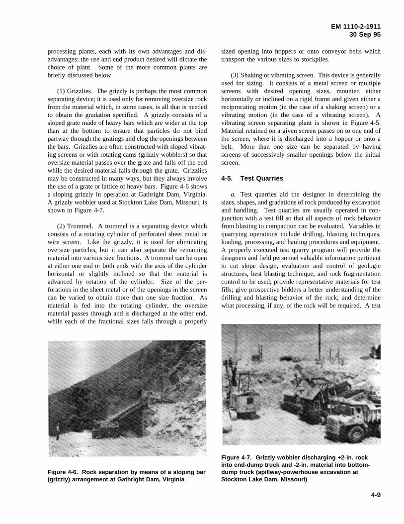
EM 1110-2-191130 Sep 95
processing plants, each with its own advantages and dis-advantages; the use and end product desired will dictate thechoice of plant. Some of the more common plants arebriefly discussed below.
(1) Grizzlies. The grizzly is perhaps the most commonseparating device; it is used only for removing oversize rockfrom the material which, in some cases, is all that is neededto obtain the gradation specified. A grizzly consists of asloped grate made of heavy bars which are wider at the topthan at the bottom to ensure that particles do not bindpartway through the gratings and clog the openings betweenthe bars. Grizzlies are often constructed with sloped vibrat-ing screens or with rotating cams (grizzly wobblers) so thatoversize material passes over the grate and falls off the endwhile the desired material falls through the grate. Grizzliesmay be constructed in many ways, but they always involvethe use of a grate or lattice of heavy bars. Figure 4-6 showsa sloping grizzly in operation at Gathright Dam, Virginia.A grizzly wobbler used at Stockton Lake Dam, Missouri, isshown in Figure 4-7.
Figure 4-6. Rock separation by means of a sloping bar(grizzly) arrangement at Gathright Dam, Virginia
Figure 4-7. Grizzly wobbler discharging +2-in. rockinto end-dump truck and -2-in. material into bottom-dump truck (spillway-powerhouse excavation atStockton Lake Dam, Missouri)
(2) Trommel. A trommel is a separating device whichconsists of a rotating cylinder of perforated sheet metal orwire screen. Like the grizzly, it is used for eliminatingoversize particles, but it can also separate the remainingmaterial into various size fractions. A trommel can be openat either one end or both ends with the axis of the cylinderhorizontal or slightly inclined so that the material isadvanced by rotation of the cylinder. Size of the per-forations in the sheet metal or of the openings in the screencan be varied to obtain more than one size fraction. Asmaterial is fed into the rotating cylinder, the oversizematerial passes through and is discharged at the other end,while each of the fractional sizes falls through a properly
sized opening into hoppers or onto conveyor belts whichtransport the various sizes to stockpiles.
(3) Shaking or vibrating screen. This device is generallyused for sizing. It consists of a metal screen or multiplescreens with desired opening sizes, mounted eitherhorizontally or inclined on a rigid frame and given either areciprocating motion (in the case of a shaking screen) or avibrating motion (in the case of a vibrating screen). Avibrating screen separating plant is shown in Figure 4-5.Material retained on a given screen passes on to one end ofthe screen, where it is discharged into a hopper or onto abelt. More than one size can be separated by havingscreens of successively smaller openings below the initialscreen.
4-5. Test Quarries
a. Test quarries aid the designer in determining thesizes, shapes, and gradations of rock produced by excavationand handling. Test quarries are usually operated in con-junction with a test fill so that all aspects of rock behaviorfrom blasting to compaction can be evaluated. Variables inquarrying operations include drilling, blasting techniques,loading, processing, and hauling procedures and equipment.A properly executed test quarry program will provide thedesigners and field personnel valuable information pertinentto cut slope design, evaluation and control of geologicstructures, best blasting technique, and rock fragmentationcontrol to be used; provide representative materials for testfills; give prospective bidders a better understanding of thedrilling and blasting behavior of the rock; and determinewhat processing, if any, of the rock will be required. A test
4-9
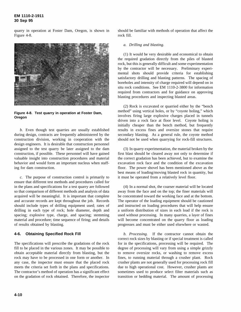
EM 1110-2-191130 Sep 95
quarry in operation at Foster Dam, Oregon, is shown inFigure 4-8.
b. Even though test quarries are usually established
Figure 4-8. Test quarry in operation at Foster Dam,Oregon
during design, contracts are frequently administered by theconstruction division, working in cooperation with thedesign engineers. It is desirable that construction personnelassigned to the test quarry be later assigned to the damconstruction, if possible. These personnel will have gainedvaluable insight into construction procedures and materialbehavior and would form an important nucleus when staff-ing for dam construction.
c. The purpose of construction control is primarily toensure that different test methods and procedures called forin the plans and specifications for a test quarry are followedso that comparison of different methods and analysis of dataacquired will be meaningful. It is important that completeand accurate records are kept throughout the job. Recordsshould include types of drilling equipment used; rates ofdrilling in each type of rock; hole diameter, depth andspacing; explosive type, charge, and spacing; stemmingmaterial and procedure; time sequence of firing; and detailsof results obtained by blasting.
4-6. Obtaining Specified Rock Fill
The specifications will prescribe the gradations of the rockfill to be placed in the various zones. It may be possible toobtain acceptable material directly from blasting, but therock may have to be processed in one form or another. Inany case, the inspector must ensure that the placed rockmeets the criteria set forth in the plans and specifications.The contractor’s method of operation has a significant effecton the gradation of rock obtained. Therefore, the inspector
should be familiar with methods of operation that affect therock fill.
a. Drilling and blasting.
(1) It would be very desirable and economical to obtainthe required gradation directly from the piles of blastedrock, but this is generally difficult and some experimentationby the contractor will be necessary. Preliminary experi-mental shots should provide criteria for establishingsatisfactory drilling and blasting patterns. The spacing ofboreholes and intensity of charge required will depend on insitu rock conditions. See EM 1110-2-3800 for informationrequired from contractors and for guidance on approvingblasting procedures and inspecting blasted areas.
(2) Rock is excavated or quarried either by the “benchmethod” using vertical holes, or by “coyote holing,” whichinvolves firing large explosive charges placed in tunnelsdriven into a rock face at floor level. Coyote holing isinitially cheaper than the bench method, but frequentlyresults in excess fines and oversize stones that requiresecondary blasting. As a general rule, the coyote methodshould not be used when quarrying for rock-fill structures.
(3) In quarry experimentation, the material broken by thefirst blast should be cleared away not only to determine ifthe correct gradation has been achieved, but to examine theexcavation rock face and the condition of the excavationfloor. The power shovel has been mentioned above as thebest means of loading/moving blasted rock in quantity, butit must be operated from a relatively level floor.
(4) In a normal shot, the coarser material will be locatedaway from the face and on the top; the finer materials willbe concentrated toward the working face and at the bottom.The operator of the loading equipment should be cautionedand instructed on loading procedures that will help ensurea uniform distribution of sizes in each load if the rock isused without processing. In many quarries, a layer of fineswill become concentrated on the quarry floor as loadingprogresses and must be either used elsewhere or wasted.
b. Processing. If the contractor cannot obtain thecorrect rock sizes by blasting or if special treatment is calledfor in the specifications, processing will be required. Thedegree of processing will vary from using a simple grizzlyto remove oversize rocks, or washing to remove excessfines, to running material through a crusher plant. Rockcrusher plants are not generally used for processing rock filldue to high operational cost. However, crusher plants aresometimes used to produce select filter materials such astransition or bedding material. The amount of processing
4-10
EM 1110-2-191130 Sep 95
required will depend on the results of the blasting unlessspecial processing is expressly called for in the specifi-cations. Different types of separation equipment and theirutilization have been described above.
Section IIIFinal Condition of Borrow Areas, Quarries, and Spoil Areas
4-7. Borrow Areas
Generally, no treatment is required for reservoir-side borrowareas located below minimum operating pool elevation.However, for reservoir-side borrow areas located above thiselevation and land-side borrow areas, some treatment isgenerally required to eliminate what would otherwise beunsightly scars. Treatment of these borrow areas usuallybegins with the contractor stockpiling topsoil when firstopening the borrow pit. After all usable borrow has beenremoved (the contractor should not be allowed to excavateto bedrock, but should be required to leave a foot or two ofsoil over rock), the previously stockpiled topsoil should bespread back over the borrow area and graded to a smooth,uniform surface, sloped to drain. On steep slopes, benchesor terraces may have to be specified to help control erosion.As a final step, the entire area should be fertilized andseeded. These procedures are intended to prevent erosionand bring the borrow area to a pleasing aesthetic appearanceand possibly make it available for future use.
4-8. Quarries
Abandoned quarries are unsightly and may be a safetyhazard. As far as practicable, old quarries should be drainedand provisions made to prevent any further ponding of water
in them. All slopes should be scales and trimmed to elimi-nate the probability of falling rocks and debris. All areasthat can support vegetation should be seeded. In somecases, fencing may be needed to restrict free access.
4-9. Spoil or Waste Areas
Specific areas must be provided for the disposal of waste orspoil materials. These areas should be clearly shown onspecification drawings. Material which is unsuitable forother purposes is usually used to fill and shape depressionssuch as ditches, sloughs, etc., located outside the limits ofthe embankment. Waste material in excess of that requiredto fill these depressions may be used upstream to reinforceseepage blankets or used as berms to add to the stability ofthe structure. Waste areas located downstream of theembankment must be carefully selected to avoid interferencewith any component of the structure or creation ofundesirable areas requiring excessive maintenance orremedial work. Waste materials should never be permittedto block seepage from drains, pervious zones, or rock toes.Additionally, disposal areas should not be located such thatthey could possibly cause contamination of naturalgroundwater. Generally, no compaction of material in wasteareas is needed other than that produced by haulingequipment except on the finished outside slopes. Surfacesshould be left reasonably smooth and sloped to providedrainage away from the embankment and constructionactivities. Outside slopes of waste areas composed of easilyerodible materials should be compacted or track-walked toprevent erosion. If possible, the areas should be fertilizedand seeded to improve their appearance and prevent erosion,thus possibly making them suitable for recreationalpurposes.
4-11
EM 1110-2-191130 Sep 95
Chapter 5Earth-Fill and Rock-Fill Construction
Section IFill Processing and Compaction Equipment
5-1. Heavy Compaction Equipment
The three principal types of heavy equipment used tocompact embankment fill are the tamping roller (sheeps-foot), the rubber-tired roller, and the vibratory steel-wheelroller. Corps of Engineers specifications, uses, advantages,and disadvantages of each roller are summarized inFigures 5-1, 5-2, and 5-3. Other general-purpose equipmentsometimes used to compact fill are the fill hauling andspreading equipment itself, which is routed over fill to besemicompacted (paragraph 5-25), and crawler tractors,which sometimes can produce adequate compaction ofpervious cohesionless materials.
5-2. Hand-Operated Compaction Equipment
For compaction in restricted areas such as those immediatelyadjacent to concrete walls, around conduits, or in depres-sions in rock surfaces, hand-operated power tampers orvibrated plate compactors are used. Power tampers shouldweigh at least 100 lb, and vibrated plate compactors areeffective only in clean cohesionless backfill.
5-3. Spreading and Processing Equipment
Spreading and processing equipment commonly used on em-bankment fills is as follows.
a. Crawler and rubber-tired tractors and bulldozers.This equipment is used to tow compactors, plows, harrows,etc., with bulldozer blades to move and spread material andto remove oversize stones from embankment fill.
b. Motor graders (road patrols).Graders are used tospread and mix material, dress up boundaries betweendifferent zones (such as core, transition and filter), work outoversize stones, and scarify surfaces of previously com-pacted lifts.
c. Disks. Disks are typically towed by rubber-tired orcrawler tractors (Figure 5-4) and used to scarify surfaces ofpreviously compacted lifts or to aerate and blend water intouncompacted lifts before compaction.
Section IITest Fills
5-4. Rock Test Fills
a. In the design of rock-fill dams, the construction oftest embankments can often be of considerable value, and insome cases it is absolutely necessary. Design engineersshould manage the test fill program, although constructionpersonnel may administer the contract under which testingis performed. Test fills aid the designer by defining theeffects of variables which would otherwise remain unknown.A properly executed test fill program should determine themost effective type of compaction equipment, the liftthickness, and the number of passes; maximum rock sizes;amount of degradation or segregation occurring duringrolling; and physical properties of the in-place fill, such asdensity and grain-size distribution. The knowledgedeveloped and the consequent improvement of design cansignificantly influence the cost of the structure. Hammerand Torrey (1973) provide guidance on the design andconstruction of test fills.
b. Test fills are often operated in conjunction with testquarries. This practice not only provides information aboutrock behavior during quarrying procedures, but also ensuresthat material used in the test fill is representative of materialthat will be produced by the proposed excavation. As intest quarries, test fill programs are often administered byboth construction and design personnel, and it is advisable,when possible, to assign construction personnel involved inthe test fill program to actual dam construction.
c. Construction of a test fill should be very strict,otherwise data obtained may be of questionable value.Plans and specifications for the test fill are prepared by thedesign engineer to evaluate construction procedures andmaterial behavior so that results of the test fill can be usedin design and construction of the prototype; therefore,changes or additions should not be made without approvalof the design engineer.
d. Records and data required should be established bythe design office; records should be kept up to date, anddata plotted daily, as changes in the test program may benecessary to obtain desired information. It is important torecord any and all observations made by field personnel, nomatter how insignificant they may seem at the time.Photographs and notes or visual observations are extremelyimportant, as they often provide answers to perplexingquestions that would otherwise go unanswered.
5-1
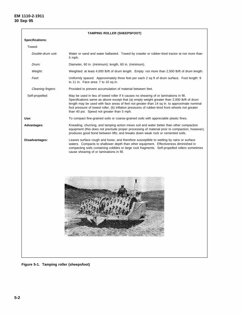
EM 1110-2-191130 Sep 95
Figure 5-1. Tamping roller (sheepsfoot)
TAMPING ROLLER (SHEEPSFOOT)
Specifications:
Towed:
Double-drum unit: Water or sand and water ballasted. Towed by crawler or rubber-tired tractor at not more than5 mph.
Drum: Diameter, 60 in. (minimum); length, 60 in. (minimum).
Weight: Weighted: at least 4,000 lb/ft of drum length. Empty: not more than 2,500 lb/ft of drum length.
Feet: Uniformly spaced. Approximately three feet per each 2 sq ft of drum surface. Foot length: 9to 11 in. Face area: 7 to 10 sq in.
Cleaning fingers: Provided to prevent accumulation of material between feet.
Self-propelled: May be used in lieu of towed roller if it causes no shearing of or laminations in fill.Specifications same as above except that (a) empty weight greater than 2,000 lb/ft of drumlength may be used with face areas of feet not greater than 14 sq in. to approximate nominalfoot pressure of towed roller, (b) inflation pressures of rubber-tired front wheels not greaterthan 40 psi. Speed not greater than 5 mph.
Use: To compact fine-grained soils or coarse-grained soils with appreciable plastic fines.
Advantages: Kneading, churning, and tamping action mixes soil and water better than other compactionequipment (this does not preclude proper processing of material prior to compaction, however);produces good bond between lifts; and breaks down weak rock or cemented soils.
Disadvantages: Leaves surface rough and loose, and therefore susceptible to wetting by rains or surfacewaters. Compacts to shallower depth than other equipment. Effectiveness diminished incompacting soils containing cobbles or large rock fragments. Self-propelled rollers sometimescause shearing of or laminations in fill.
5-2
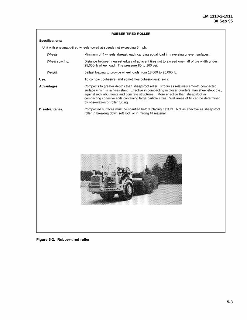
EM 1110-2-191130 Sep 95
Figure 5-2. Rubber-tired roller
RUBBER-TIRED ROLLER
Specifications:
Unit with pneumatic-tired wheels towed at speeds not exceeding 5 mph.
Wheels: Minimum of 4 wheels abreast, each carrying equal load in traversing uneven surfaces.
Wheel spacing: Distance between nearest edges of adjacent tires not to exceed one-half of tire width under25,000-lb wheel load. Tire pressure 80 to 100 psi.
Weight: Ballast loading to provide wheel loads from 18,000 to 25,000 lb.
Use: To compact cohesive (and sometimes cohesionless) soils.
Advantages: Compacts to greater depths than sheepsfoot roller. Produces relatively smooth compactedsurface which is rain-resistant. Effective in compacting in closer quarters than sheepsfoot (i.e.,against rock abutments and concrete structures). More effective than sheepsfoot incompacting cohesive soils containing large particle sizes. Wet areas of fill can be determinedby observation of roller rutting.
Disadvantages: Compacted surfaces must be scarified before placing next lift. Not as effective as sheepsfootroller in breaking down soft rock or in mixing fill material.
5-3
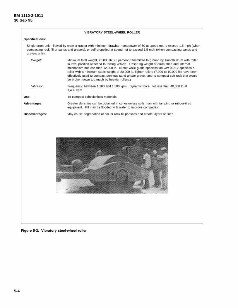
EM 1110-2-191130 Sep 95
Figure 5-3. Vibratory steel-wheel roller
VIBRATORY STEEL-WHEEL ROLLER
Specifications:
Single drum unit. Towed by crawler tractor with minimum drawbar horsepower of 50 at speed not to exceed 1.5 mph (whencompacting rock fill or sands and gravels), or self-propelled at speed not to exceed 1.5 mph (when compacting sands andgravels only).
Weight: Minimum total weight, 20,000 lb; 90 percent transmitted to ground by smooth drum with rollerin level position attached to towing vehicle. Unsprung weight of drum shaft and internalmechanism not less than 12,000 lb. (Note: while guide specification CW 02212 specifies aroller with a minimum static weight of 20,000 lb, lighter rollers (7,000 to 10,000 lb) have beeneffectively used to compact pervious sand and/or gravel, and to compact soft rock that wouldbe broken down too much by heavier rollers.)
Vibration: Frequency: between 1,100 and 1,500 vpm. Dynamic force: not less than 40,000 lb at1,400 vpm.
Use: To compact cohesionless materials.
Advantages: Greater densities can be obtained in cohesionless soils than with tamping or rubber-tiredequipment. Fill may be flooded with water to improve compaction.
Disadvantages: May cause degradation of soil or rock-fill particles and create layers of fines.
5-4
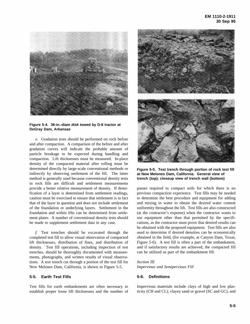
EM 1110-2-191130 Sep 95
e. Gradation tests should be performed on rock before
Figure 5-4. 36-in.-diam disk towed by D-8 tractor atDeGray Dam, Arkansas
and after compaction. A comparison of the before and aftergradation curves will indicate the probable amount ofparticle breakage to be expected during handling andcompaction. Lift thicknesses must be measured. In-placedensity of the compacted material after rolling must bedetermined directly by large-scale conventional methods orindirectly by observing settlement of the fill. The lattermethod is generally used because conventional density testsin rock fills are difficult and settlement measurementsprovide a better relative measurement of density. If densi-fication of a layer is determined from settlement readings,caution must be exercised to ensure that settlement is in factthat of the layer in question and does not include settlementof the foundation or underlying layers. Settlement in thefoundation and within lifts can be determined from settle-ment plates. A number of conventional density tests shouldbe made to supplement settlement data in any case.
f. Test trenches should be excavated through thecompleted test fill to allow visual observation of compactedlift thicknesses, distribution of fines, and distribution ofdensity. Test fill operations, including inspection of testtrenches, should be thoroughly documented with measure-ments, photographs, and written results of visual observa-tions. A test trench cut through a portion of the test fill forNew Melones Dam, California, is shown in Figure 5-5.
5-5. Earth Test Fills
Test fills for earth embankments are often necessary toestablish proper loose lift thicknesses and the number of
passes required to compact soils for which there is no
Figure 5-5. Test trench through portion of rock test fillat New Melones Dam, California. General view oftrench (top); closeup view of trench wall (bottom)
previous compaction experience. Test fills may be neededto determine the best procedure and equipment for addingand mixing in water to obtain the desired water contentuniformity throughout the lift. Test fills are also constructed(at the contractor’s expense) when the contractor wants touse equipment other than that permitted by the specifi-cations, as the contractor must prove that desired results canbe obtained with the proposed equipment. Test fills are alsoused to determine if desired densities can be economicallyobtained in the field, (for example, at Canyon Dam, Texas,Figure 5-6). A test fill is often a part of the embankment,and if satisfactory results are achieved, the compacted fillcan be utilized as part of the embankment fill.
Section IIIImpervious and Semipervious Fill
5-6. Definitions
Impervious materials include clays of high and low plas-ticity (CH and CL), clayey sand or gravel (SC and GC), and
5-5
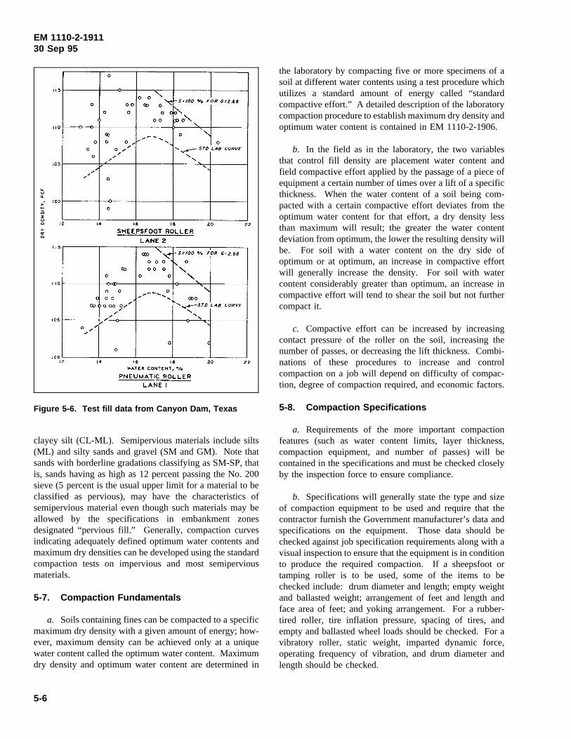
EM 1110-2-191130 Sep 95
clayey silt (CL-ML). Semipervious materials include silts
Figure 5-6. Test fill data from Canyon Dam, Texas
(ML) and silty sands and gravel (SM and GM). Note thatsands with borderline gradations classifying as SM-SP, thatis, sands having as high as 12 percent passing the No. 200sieve (5 percent is the usual upper limit for a material to beclassified as pervious), may have the characteristics ofsemipervious material even though such materials may beallowed by the specifications in embankment zonesdesignated “pervious fill.” Generally, compaction curvesindicating adequately defined optimum water contents andmaximum dry densities can be developed using the standardcompaction tests on impervious and most semiperviousmaterials.
5-7. Compaction Fundamentals
a. Soils containing fines can be compacted to a specificmaximum dry density with a given amount of energy; how-ever, maximum density can be achieved only at a uniquewater content called the optimum water content. Maximumdry density and optimum water content are determined in
the laboratory by compacting five or more specimens of asoil at different water contents using a test procedure whichutilizes a standard amount of energy called “standardcompactive effort.” A detailed description of the laboratorycompaction procedure to establish maximum dry density andoptimum water content is contained in EM 1110-2-1906.
b. In the field as in the laboratory, the two variablesthat control fill density are placement water content andfield compactive effort applied by the passage of a piece ofequipment a certain number of times over a lift of a specificthickness. When the water content of a soil being com-pacted with a certain compactive effort deviates from theoptimum water content for that effort, a dry density lessthan maximum will result; the greater the water contentdeviation from optimum, the lower the resulting density willbe. For soil with a water content on the dry side ofoptimum or at optimum, an increase in compactive effortwill generally increase the density. For soil with watercontent considerably greater than optimum, an increase incompactive effort will tend to shear the soil but not furthercompact it.
c. Compactive effort can be increased by increasingcontact pressure of the roller on the soil, increasing thenumber of passes, or decreasing the lift thickness. Combi-nations of these procedures to increase and controlcompaction on a job will depend on difficulty of compac-tion, degree of compaction required, and economic factors.
5-8. Compaction Specifications
a. Requirements of the more important compactionfeatures (such as water content limits, layer thickness,compaction equipment, and number of passes) will becontained in the specifications and must be checked closelyby the inspection force to ensure compliance.
b. Specifications will generally state the type and sizeof compaction equipment to be used and require that thecontractor furnish the Government manufacturer’s data andspecifications on the equipment. Those data should bechecked against job specification requirements along with avisual inspection to ensure that the equipment is in conditionto produce the required compaction. If a sheepsfoot ortamping roller is to be used, some of the items to bechecked include: drum diameter and length; empty weightand ballasted weight; arrangement of feet and length andface area of feet; and yoking arrangement. For a rubber-tired roller, tire inflation pressure, spacing of tires, andempty and ballasted wheel loads should be checked. For avibratory roller, static weight, imparted dynamic force,operating frequency of vibration, and drum diameter andlength should be checked.
5-6
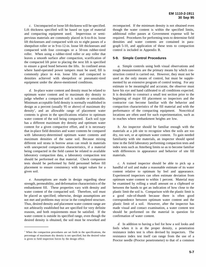
EM 1110-2-191130 Sep 95
c. Uncompacted or loose lift thickness will be specified.Lift thickness specified will be based on type of materialand compacting equipment used. Impervious or semi-pervious materials are commonly placed in 6-to-8-in. looselift thicknesses and compacted with six to eight passes of asheepsfoot roller or in 9-to-12-in. loose lift thicknesses andcompacted with four coverages or a 50-ton rubber-tiredroller. When using a rubber-tired roller or any roller thatleaves a smooth surface after compaction, scarification ofthe compacted lift prior to placing the next lift is specifiedto ensure a good bond between the lifts. In confined areaswhere hand-operated power tampers must be used, fill iscommonly place in 4-in. loose lifts and compacted todensities achieved with sheepsfoot or pneumatic-tiredequipment under the above-mentioned conditions.
d. In-place water content and density must be related tooptimum water content and to maximum dry density tojudge whether a compacted soil is suitable or unsuitable.Minimum acceptable field density is normally established indesign as a percent (usually 95 or above) of maximum drydensity1, and an allowable range of placement watercontents is given in the specifications relative to optimumwater content of the soil being compacted. Each soil typehas a different maximum dry density and optimum watercontent for a given compactive effort, and it is necessarythat in-place field densities and water contents be comparedwith laboratory-determined optimum water contents andmaximum densities of the same soil. Because mixingdifferent soil strata in borrow areas can result in materialswith unexpected compaction characteristics, if a materialbeing compacted in the field cannot be related to availablelaboratory compaction data, a laboratory compaction testshould be performed on that material. Check companiontests should be performed by field personnel before fillplacement to ensure consistency with target values for agiven soil.
e. Assumptions are made in design regarding shearstrength, permeability, and deformation characteristics of theembankment fill. These properties vary with density andwater content of the compacted soil. Therefore, soil mustbe placed as specified; otherwise, design assumptions arenot met and problems may occur in the completed structure.Thus, desired density and placement water content range arenot arbitrarily established but are specified for very definitereasons, and both requirements must be satisfied. If thewater content is outside its specified range, even though thedesired density is obtained, the soil must be reworked and
1 When the compaction procedures are set forth in the specifications, thepercentage of maximum dry density is not specified, but the desired valueis given to field inspection forces by the design office.
recompacted. If the minimum density is not obtained eventhough the water content is within the specified limits,additional roller passes at Government expense will berequired. Procedures for performing tests to determine fielddensities and water contents are contained in para-graph 5-10, and application of these tests to compactioncontrol is included in Appendix B.
5-9. Simple Control Procedures
a. Simple controls using both visual observations andrough measurements are the primary means by which con-struction control is carried out. However, they must not beused as the only means of control, but must be supple-mented by an extensive program of control testing. For anyestimate to be meaningful and accurate, the observer musthave his eye and hand calibrated to all conditions expected.It is desirable to construct a small test section prior to thebeginning of major fill placement so inspectors and thecontractor can become familiar with the behavior andcompaction characteristics of the fill material and with theperformance of the compacting equipment. Noncriticallocations are often used for such experimentation, such asin reaches where embankment heights are low.
b. An inspector should be familiar enough with thematerials at a job site to recognize when the soils are toodry, too wet, or at optimum water content. To gain neededfamiliarity with site materials, an inspector should spendtime in the field laboratory performing compaction tests andindex tests such as Atterberg limits so as to become familiarwith differences in appearance and behavior of site fillmaterials.
c. A trained inspector should be able to pick up ahandful of soil and make a reasonable estimate of its watercontent relative to optimum by feel and appearance.Experienced inspectors can often estimate deviation fromoptimum water content to within 1 percent. Material maybe examined by rolling a small amount on a clipboard orbetween the hands to get an indication of how close to theplastic limit the soil is. Comparison with the plastic limit isa good rule-of-thumb because there is often goodcorrespondence between optimum water content and theplastic limit of a soil. However, after the inspector hasmade visual and contact examination, a water content testshould be performed on the material in question forconfirmation of water content.
d. In addition to having a feel for how a soil looks andfeels when it is at the proper density, a penetrationresistance index test is often devised by inspectors. Theresistance index test itself can range from the use of aProctor needle (Proctor penetrometer) to that of a common
5-7
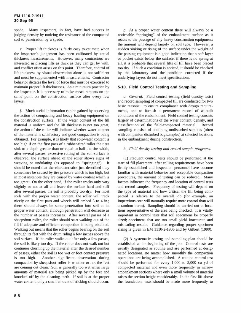
EM 1110-2-191130 Sep 95
spade. Many inspectors, in fact, have had success injudging density by noticing the resistance of the compactedsoil to penetration by a spade.
e. Proper lift thickness is fairly easy to estimate whenthe inspector’s judgement has been calibrated by actualthickness measurements. However, many contractors areinterested in placing lifts as thick as they can get by with,and conflict often arises on this point. Therefore, control oflift thickness by visual observation alone is not sufficientand must be supplemented with measurements. Contractorbehavior dictates the level of force that must be exercised tomaintain proper lift thicknesses. As a minimum practice bythe inspector, it is necessary to make measurements on thesame point on the construction surface after every fewlayers.
f. Much useful information can be gained by observingthe action of compacting and heavy hauling equipment onthe construction surface. If the water content of the fillmaterial is uniform and the lift thickness is not too great,the action of the roller will indicate whether water contentof the material is satisfactory and good compaction is beingobtained. For example, it is likely that soil-water content istoo high if on the first pass of a rubber-tired roller the tiressink to a depth greater than or equal to half the tire width,after several passes, excessive rutting of the soil surface isobserved, the surface ahead of the roller shows signs ofweaving or undulating (as opposed to “springing”). Itshould be noted that the characteristics just described maysometimes be caused by tire pressure which is too high, butin most instances they are caused by water content which istoo great. On the other hand, if the roller tracks only varyslightly or not at all and leave the surface hard and stiffafter several passes, the soil is probably too dry. For mostsoils with the proper water content, the roller will tracknicely on the first pass and wheels will embed 3 to 4 in.;there should always be some penetration into soil at itsproper water content, although penetration will decrease asthe number of passes increases. After several passes of asheepsfoot roller, the roller should start walking out of thefill if adequate and efficient compaction is being obtained.Walking out means that the roller begins bearing on the soilthrough its feet with the drum riding a few inches above thesoil surface. If the roller walks out after only a few passes,the soil is likely too dry. If the roller does not walk out butcontinues churning up the material after the desired numberof passes, either the soil is too wet or foot contact pressureis too high. Another significant observation duringcompaction by sheepsfoot roller is whether or not the feetare coming out clean. Soil is generally too wet when largeamounts of material are being picked up by the feet andknocked off by the cleaning teeth. If soil is at the properwater content, only a small amount of sticking should occur.
g. At a proper water content there will always be anoticeable “springing” of the embankment surface as itreacts to the passage of any heavy construction equipment;the amount will depend largely on soil type. However, asudden sinking or rising of the surface under the weight ofthe passing equipment is a good indication that a soft layeror pocket exists below the surface; if there is no spring atall, it is probable that several lifts of fill have been placedtoo dry. If such a condition is noticed, it should be checkedby the laboratory and the condition corrected if theunderlying layers do not meet specifications.
5-10. Field Control Testing and Sampling
a. General. Field control testing (field density tests)and record sampling of compacted fill are conducted for twobasic reasons: to ensure compliance with design require-ments, and to furnish a permanent record of as-builtconditions of the embankment. Field control testing consistslargely of determinations of the water content, density, andclassification of the field-compacted material. Recordsampling consists of obtaining undisturbed samples (oftenwith companion disturbed bag samples) at selected locationsin the embankment during construction.
b. Field density testing and record sample programs.
(1) Frequent control tests should be performed at thestart of fill placement; after rolling requirements have beenfirmly established and inspection personnel have becomefamiliar with material behavior and acceptable compactionprocedures, the amount of testing can be reduced. Manyfactors influence the frequency and location of control testsand record samples. Frequency of testing will depend onthe type of material and how critical the fill being com-pacted is relative to the overall job (for example, animpervious core will naturally require more control than willa random berm). Sampling should be carried out at loca-tions representative of the area being checked. It is vitallyimportant in control tests that soil specimens be properlysized; specimens that are too small yield inaccurate andmisleading results. Guidance regarding proper specimensizing is given in EM 1110-2-1906 and by Gilbert (1990).
(2) A systematic testing and sampling plan should beestablished at the beginning of the job. Control tests areusually designated as routine and are performed at desig-nated locations, no matter how smoothly the compactionoperations are being accomplished. A routine control testshould be performed for every 1,000 to 3,000 cu yd ofcompacted material and even more frequently in narrowembankment sections where only a small volume of materialraises the section height considerably. In the first lift abovethe foundation, tests should be made more frequently to
5-8
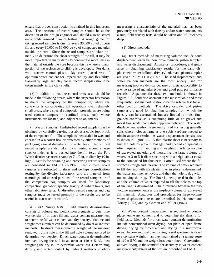
EM 1110-2-191130 Sep 95
ensure that proper construction is attained in this importantarea. The locations of record samples should be at thediscretion of the design engineer and should also be statedon a predetermined plan of testing. A rough guide fortaking record samples is one for every 30,000 cu yd of corefill and every 30,000 to 50,000 cu yd of compacted materialoutside the core. Since the record samples are taken pri-marily to determine the shear strength of the fill, it may bemore important in many dams to concentrate more tests inthe material outside the core because this is where a majorportion of the resistance to sliding is developed. For damswith narrow central plastic clay cores placed wet ofoptimum water content for impermeability and flexibility,flanked by large lean clay zones, record samples should betaken mainly in the clay shells.
(3) In addition to routine control tests, tests should bemade in the following areas: where the inspector has reasonto doubt the adequacy of the compaction, where thecontractor is concentrating fill operations over relativelysmall areas, where special compaction procedures are beingused (power tampers in confined areas, etc.), whereinstruments are located, and adjacent to abutments.
c. Record samples.Undisturbed record samples may beobtained by carefully carving out about a cubic foot blockof the compacted fill. The sample is then sealed in wax andencased in a wooden box or protected by other methods ofpackaging against disturbance or water loss. Undisturbedrecord samples are also taken by trimming around a largesteel cylinder as it is pushed into the fill (e.g., the FortWorth district has used a sampler 7-1/2 in. in diam by 10 in.high). Details for obtaining and preserving record samplesare described in EM 1110-2-1907. Undisturbed recordsamples are subjected to shear and perhaps consolidationtesting by the division laboratory, and the material fromtrimmings and unused portions of the record samples or ofthe companion bag samples are used for laboratorycompaction, gradation, specific gravity, Atterberg limits, andother laboratory tests. Undisturbed record samples and bagsamples must be tested promptly if the results are to beuseful in construction control.
d. Field density tests. Field density determinationconsists of volume and weight measurements to determinewet density of in-place fill and water content measurementto determine fill water content and dry density. Volume andweight measurement can be determined by direct or indirectmethods. In direct measurements, weight of the materialremoved from a hole in the fill and hole volume are used todetermine wet density. Direct water content determinationinvolves drying the soil in an oven at 110 ± 5 °C, thenweighing the dry soil to determine water loss. Determiningdensity and water content by indirect methods involves
measuring a characteristic of the material that has beenpreviously correlated with density and/or water content. Asa rule, field density tests should be taken one lift thicknessdeep.
(1) Direct methods.
(a) Direct methods of measuring volume include sanddisplacement, water balloon, drive cylinder, piston sampler,and water displacement. Apparatus, procedures, and guid-ance in obtaining satisfactory results for the sand dis-placement, water balloon, drive cylinder, and piston samplerare given in EM 1110-2-1907. The sand displacement andwater balloon methods are the most widely used formeasuring in-place density because of their applicability toa wide range of material types and good past performancerecords. Apparatus for these two methods is shown inFigure 5-7. Sand displacement is the most reliable and mostfrequently used method; it should be the referee test for allother control methods. The drive cylinder and pistonsampler are good for obtaining samples from which thedensity can be ascertained, but are limited to moist fine-grained cohesive soils containing little or no gravel andmoist fine sands that exhibit apparent cohesion. The waterdisplacement method is generally used for testing gravellysoils where holes as large as one cubic yard are needed toobtain accurate results. A water-displacement density testis shown in Figure 5-8. A thin plastic sheet is necessary toline the hole to prevent leakage, and special equipment isoften required for handling and weighing the large volumeof excavated material and measuring the large volume ofwater. A 3-to-5-ft-diam steel ring with a height about equalto the compacted lift thickness is often used where the fillsurface is rough and uneven. The volume of water requiredto fill the ring with the plastic liner in place is determined,the water and liner removed, and then the hole is dug with-out moving the ring. The liner is then placed in the hole,and the volume of water required to fill the hole to the topof the ring is determined. The difference between the twovolume measurements is the in-place volume of excavatedfill material. Apparatus and procedures for large volumewater displacement tests are described by Hammer andTorrey (1973) and by Gordon and Miller (1966).
(b) Water content measurement is required to controlplacement water content and to determine dry density forfield tests. Methods for direct water content determinationinclude conventional oven drying, hot plate or open flamedrying, drying by forced air, and drying in a microwaveoven. In conventional oven drying, a soil specimen is driedto a constant weight in an oven maintained at a temperatureof 110 ± 5 °C and theweight loss determined. Convention-al oven drying is the standard for accuracy in water contentmeasurement; details of the test are described in EM 1110-
5-9
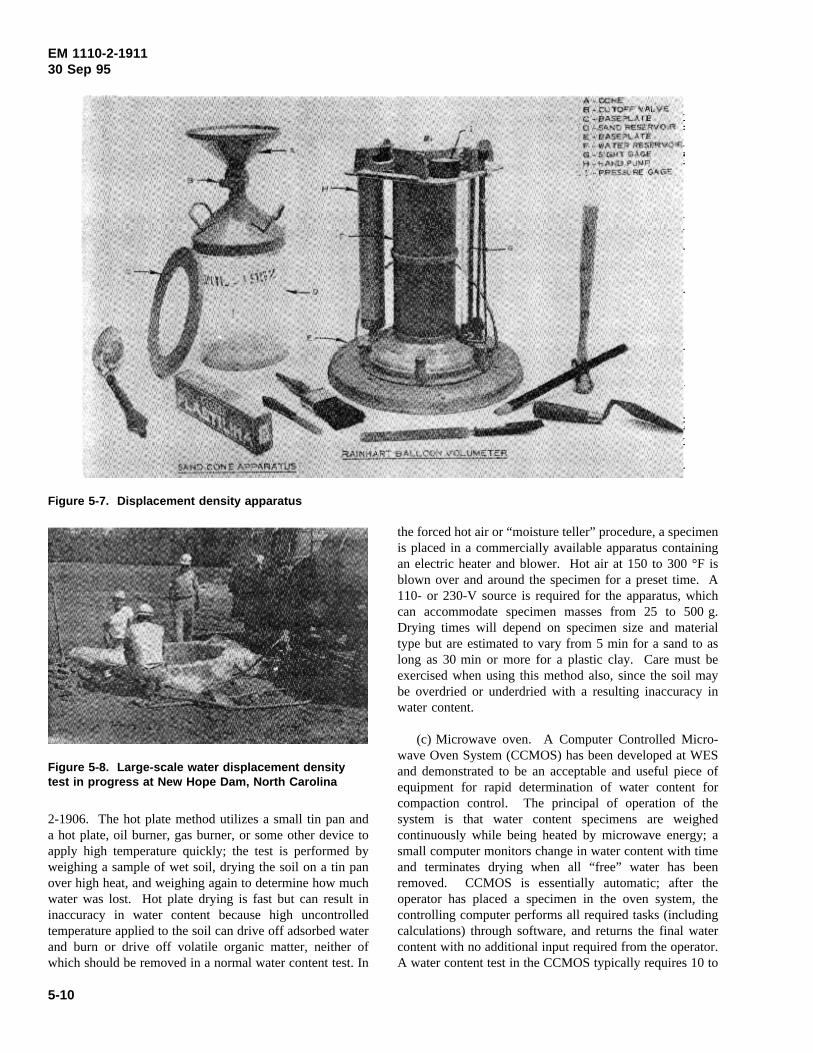
EM 1110-2-191130 Sep 95
2-1906. The hot plate method utilizes a small tin pan and
Figure 5-7. Displacement density apparatus
Figure 5-8. Large-scale water displacement densitytest in progress at New Hope Dam, North Carolina
a hot plate, oil burner, gas burner, or some other device toapply high temperature quickly; the test is performed byweighing a sample of wet soil, drying the soil on a tin panover high heat, and weighing again to determine how muchwater was lost. Hot plate drying is fast but can result ininaccuracy in water content because high uncontrolledtemperature applied to the soil can drive off adsorbed waterand burn or drive off volatile organic matter, neither ofwhich should be removed in a normal water content test. In
the forced hot air or “moisture teller” procedure, a specimenis placed in a commercially available apparatus containingan electric heater and blower. Hot air at 150 to 300 °F isblown over and around the specimen for a preset time. A110- or 230-V source is required for the apparatus, whichcan accommodate specimen masses from 25 to 500 g.Drying times will depend on specimen size and materialtype but are estimated to vary from 5 min for a sand to aslong as 30 min or more for a plastic clay. Care must beexercised when using this method also, since the soil maybe overdried or underdried with a resulting inaccuracy inwater content.
(c) Microwave oven. A Computer Controlled Micro-wave Oven System (CCMOS) has been developed at WESand demonstrated to be an acceptable and useful piece ofequipment for rapid determination of water content forcompaction control. The principal of operation of thesystem is that water content specimens are weighedcontinuously while being heated by microwave energy; asmall computer monitors change in water content with timeand terminates drying when all “free” water has beenremoved. CCMOS is essentially automatic; after theoperator has placed a specimen in the oven system, thecontrolling computer performs all required tasks (includingcalculations) through software, and returns the final watercontent with no additional input required from the operator.A water content test in the CCMOS typically requires 10 to
5-10
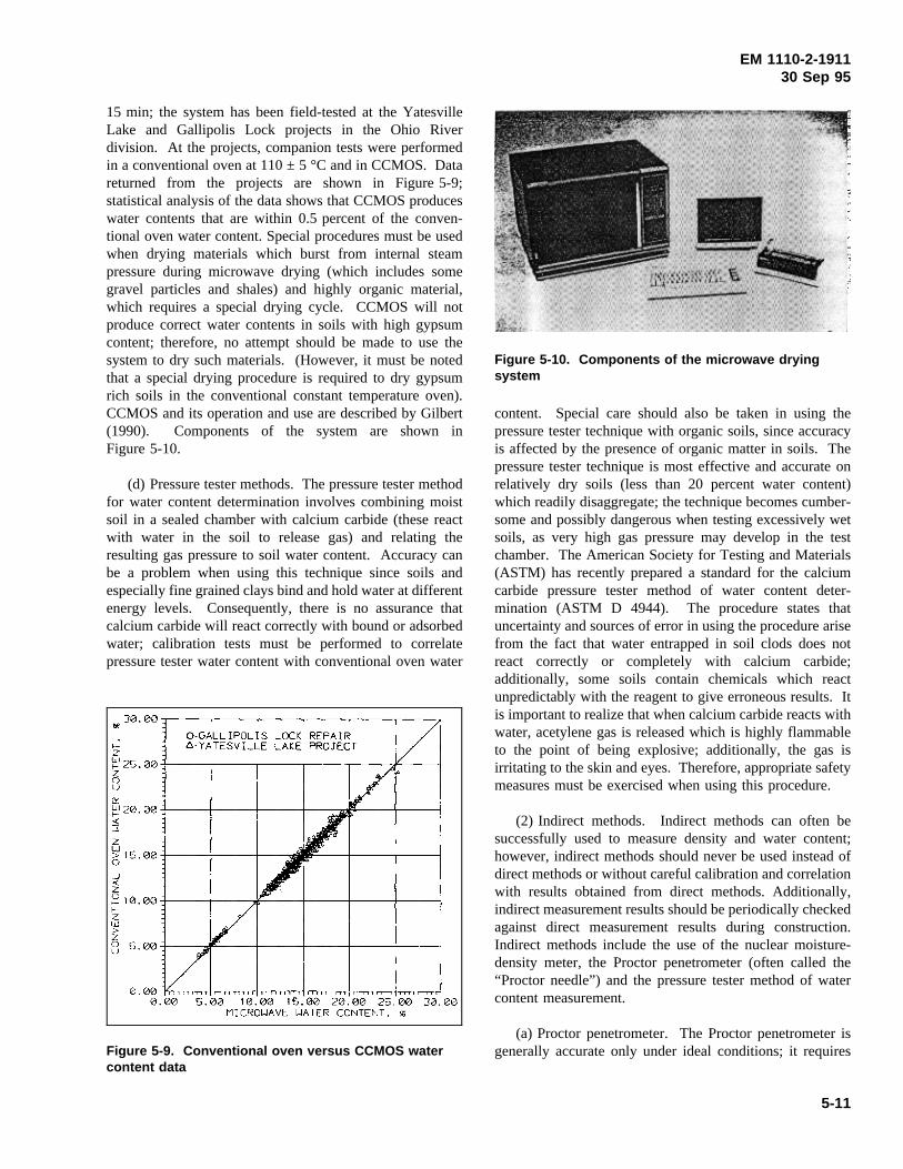
EM 1110-2-191130 Sep 95
15 min; the system has been field-tested at the YatesvilleLake and Gallipolis Lock projects in the Ohio Riverdivision. At the projects, companion tests were performedin a conventional oven at 110 ± 5 °C and inCCMOS. Datareturned from the projects are shown in Figure 5-9;statistical analysis of the data shows that CCMOS produceswater contents that are within 0.5 percent of the conven-tional oven water content. Special procedures must be usedwhen drying materials which burst from internal steampressure during microwave drying (which includes somegravel particles and shales) and highly organic material,which requires a special drying cycle. CCMOS will notproduce correct water contents in soils with high gypsumcontent; therefore, no attempt should be made to use thesystem to dry such materials. (However, it must be notedthat a special drying procedure is required to dry gypsumrich soils in the conventional constant temperature oven).CCMOS and its operation and use are described by Gilbert(1990). Components of the system are shown inFigure 5-10.
(d) Pressure tester methods. The pressure tester method
Figure 5-9. Conventional oven versus CCMOS watercontent data
for water content determination involves combining moistsoil in a sealed chamber with calcium carbide (these reactwith water in the soil to release gas) and relating theresulting gas pressure to soil water content. Accuracy canbe a problem when using this technique since soils andespecially fine grained clays bind and hold water at differentenergy levels. Consequently, there is no assurance thatcalcium carbide will react correctly with bound or adsorbedwater; calibration tests must be performed to correlatepressure tester water content with conventional oven water
content. Special care should also be taken in using the
Figure 5-10. Components of the microwave dryingsystem
pressure tester technique with organic soils, since accuracyis affected by the presence of organic matter in soils. Thepressure tester technique is most effective and accurate onrelatively dry soils (less than 20 percent water content)which readily disaggregate; the technique becomes cumber-some and possibly dangerous when testing excessively wetsoils, as very high gas pressure may develop in the testchamber. The American Society for Testing and Materials(ASTM) has recently prepared a standard for the calciumcarbide pressure tester method of water content deter-mination (ASTM D 4944). The procedure states thatuncertainty and sources of error in using the procedure arisefrom the fact that water entrapped in soil clods does notreact correctly or completely with calcium carbide;additionally, some soils contain chemicals which reactunpredictably with the reagent to give erroneous results. Itis important to realize that when calcium carbide reacts withwater, acetylene gas is released which is highly flammableto the point of being explosive; additionally, the gas isirritating to the skin and eyes. Therefore, appropriate safetymeasures must be exercised when using this procedure.
(2) Indirect methods. Indirect methods can often besuccessfully used to measure density and water content;however, indirect methods should never be used instead ofdirect methods or without careful calibration and correlationwith results obtained from direct methods. Additionally,indirect measurement results should be periodically checkedagainst direct measurement results during construction.Indirect methods include the use of the nuclear moisture-density meter, the Proctor penetrometer (often called the“Proctor needle”) and the pressure tester method of watercontent measurement.
(a) Proctor penetrometer. The Proctor penetrometer isgenerally accurate only under ideal conditions; it requires
5-11
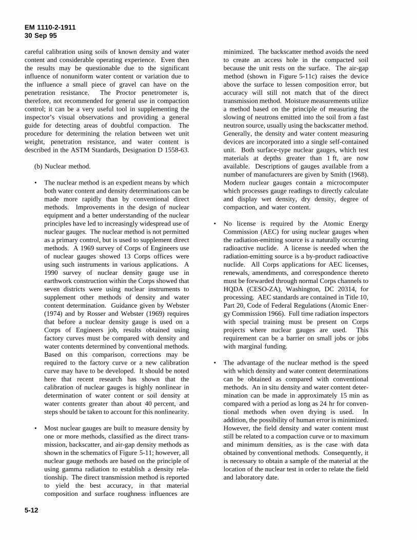
EM 1110-2-191130 Sep 95
careful calibration using soils of known density and watercontent and considerable operating experience. Even thenthe results may be questionable due to the significantinfluence of nonuniform water content or variation due tothe influence a small piece of gravel can have on thepenetration resistance. The Proctor penetrometer is,therefore, not recommended for general use in compactioncontrol; it can be a very useful tool in supplementing theinspector’s visual observations and providing a generalguide for detecting areas of doubtful compaction. Theprocedure for determining the relation between wet unitweight, penetration resistance, and water content isdescribed in the ASTM Standards, Designation D 1558-63.
(b) Nuclear method.
• The nuclear method is an expedient means by whichboth water content and density determinations can bemade more rapidly than by conventional directmethods. Improvements in the design of nuclearequipment and a better understanding of the nuclearprinciples have led to increasingly widespread use ofnuclear gauges. The nuclear method is not permittedas a primary control, but is used to supplement directmethods. A 1969 survey of Corps of Engineers useof nuclear gauges showed 13 Corps offices wereusing such instruments in various applications. A1990 survey of nuclear density gauge use inearthwork construction within the Corps showed thatseven districts were using nuclear instruments tosupplement other methods of density and watercontent determination. Guidance given by Webster(1974) and by Rosser and Webster (1969) requiresthat before a nuclear density gauge is used on aCorps of Engineers job, results obtained usingfactory curves must be compared with density andwater contents determined by conventional methods.Based on this comparison, corrections may berequired to the factory curve or a new calibrationcurve may have to be developed. It should be notedhere that recent research has shown that thecalibration of nuclear gauges is highly nonlinear indetermination of water content or soil density atwater contents greater than about 40 percent, andsteps should be taken to account for this nonlinearity.
• Most nuclear gauges are built to measure density byone or more methods, classified as the direct trans-mission, backscatter, and air-gap density methods asshown in the schematics of Figure 5-11; however, allnuclear gauge methods are based on the principle ofusing gamma radiation to establish a density rela-tionship. The direct transmission method is reportedto yield the best accuracy, in that materialcomposition and surface roughness influences are
minimized. The backscatter method avoids the needto create an access hole in the compacted soilbecause the unit rests on the surface. The air-gapmethod (shown in Figure 5-11c) raises the deviceabove the surface to lessen composition error, butaccuracy will still not match that of the directtransmission method. Moisture measurements utilizea method based on the principle of measuring theslowing of neutrons emitted into the soil from a fastneutron source, usually using the backscatter method.Generally, the density and water content measuringdevices are incorporated into a single self-containedunit. Both surface-type nuclear gauges, which testmaterials at depths greater than 1 ft, are nowavailable. Descriptions of gauges available from anumber of manufacturers are given by Smith (1968).Modern nuclear gauges contain a microcomputerwhich processes gauge readings to directly calculateand display wet density, dry density, degree ofcompaction, and water content.
• No license is required by the Atomic EnergyCommission (AEC) for using nuclear gauges whenthe radiation-emitting source is a naturally occurringradioactive nuclide. A license is needed when theradiation-emitting source is a by-product radioactivenuclide. All Corps applications for AEC licenses,renewals, amendments, and correspondence theretomust be forwarded through normal Corps channels toHQDA (CESO-ZA), Washington, DC 20314, forprocessing. AEC standards are contained in Title 10,Part 20, Code of Federal Regulations (Atomic Ener-gy Commission 1966). Full time radiation inspectorswith special training must be present on Corpsprojects where nuclear gauges are used. Thisrequirement can be a barrier on small jobs or jobswith marginal funding.
• The advantage of the nuclear method is the speedwith which density and water content determinationscan be obtained as compared with conventionalmethods. An in situ density and water content deter-mination can be made in approximately 15 min ascompared with a period as long as 24 hr for conven-tional methods when oven drying is used. Inaddition, the possibility of human error is minimized.However, the field density and water content muststill be related to a compaction curve or to maximumand minimum densities, as is the case with dataobtained by conventional methods. Consequently, itis necessary to obtain a sample of the material at thelocation of the nuclear test in order to relate the fieldand laboratory date.
5-12
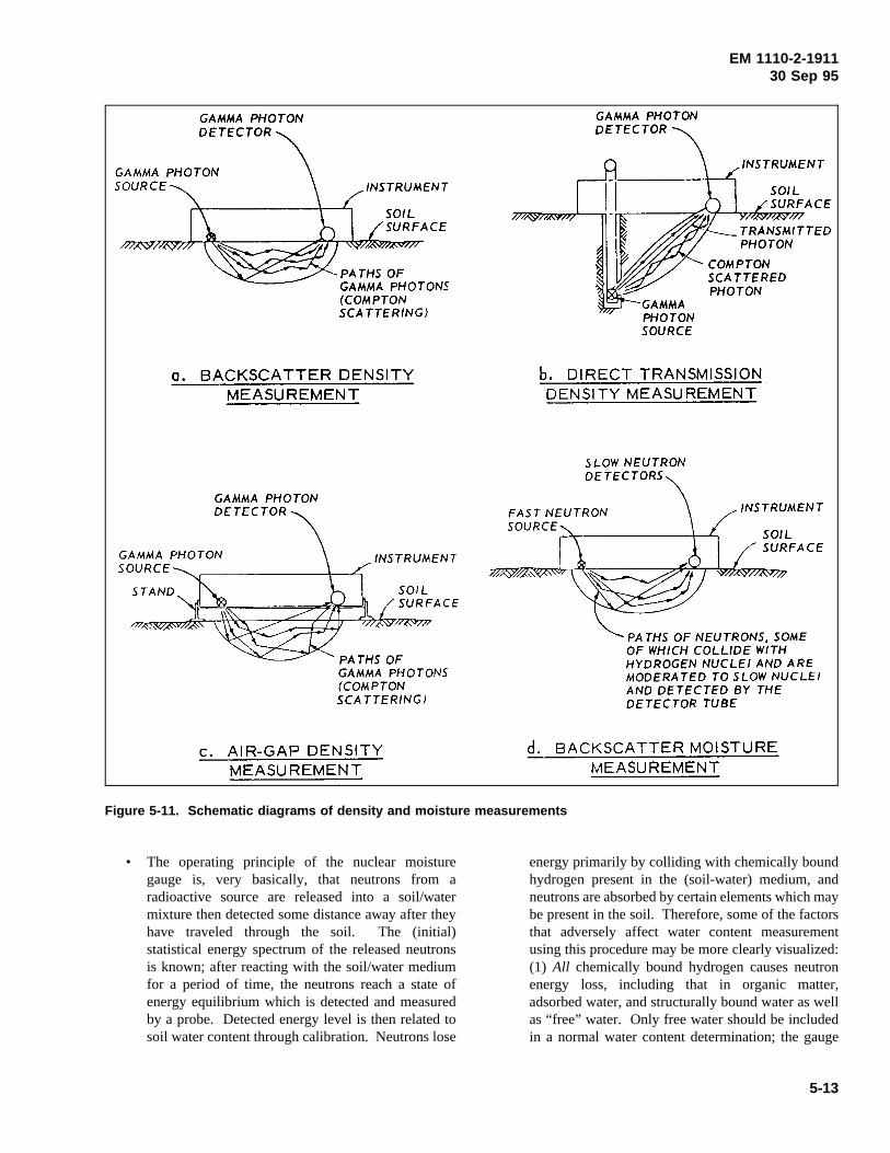
EM 1110-2-191130 Sep 95
• The operating principle of the nuclear moisture
Figure 5-11. Schematic diagrams of density and moisture measurements
gauge is, very basically, that neutrons from aradioactive source are released into a soil/watermixture then detected some distance away after theyhave traveled through the soil. The (initial)statistical energy spectrum of the released neutronsis known; after reacting with the soil/water mediumfor a period of time, the neutrons reach a state ofenergy equilibrium which is detected and measuredby a probe. Detected energy level is then related tosoil water content through calibration. Neutrons lose
energy primarily by colliding with chemically boundhydrogen present in the (soil-water) medium, andneutrons are absorbed by certain elements which maybe present in the soil. Therefore, some of the factorsthat adversely affect water content measurementusing this procedure may be more clearly visualized:(1) All chemically bound hydrogen causes neutronenergy loss, including that in organic matter,adsorbed water, and structurally bound water as wellas “free” water. Only free water should be includedin a normal water content determination; the gauge
5-13
EM 1110-2-191130 Sep 95
cannot discriminate between hydrogen in free waterand hydrogen in other sources. (2) Certain elements(such as iron, potassium, manganese, boron, andchlorine) are highly absorptive of neutrons. Thepresence of these elements in soils will causeerroneous water content determination using anuclear gauge. Because of the possible presence ofgenerally unknown quantities of organic matter,adsorbed water, structurally bound water, and highlyabsorptive elements, water content measured by thenuclear gauge must be frequently checked againstthat determined in the conventional oven to accountfor the factors which are known to influence nucleargauge results. In addition, nuclear gauges react withand are affected by other nuclear gauges in closeproximity; therefore, a nuclear gauge should not beused within 30 to 40 ft of another nuclear gauge inuse in the field. A major disadvantage of nucleargauges is that specimen size is unknown and cannever be established with certainty; the volume“probed” by a nuclear gauge is determined by watercontent, soil mineralogy, grain-size distribution, andgeometry of the test configuration (for example,results determined in a narrow utility trench may bein considerable error relative to results obtained ona flat, obstruction-free soil surface).
• Additional disadvantages of nuclear methods fordetermining field densities and water contents aregeneral lack of understanding of the method as wellas factors affecting the results and, consequently,lack of confidence in the results; calibration curvesmust be developed and/or verified by field tests foreach instrument; and although the proper use ofnuclear gauges presents no health hazards, rigidsafety regulations and documentation requirementsmust be met. For this last reason, field parties aresometimes reluctant to use nuclear equipment.
e. Test pits.It is sometimes desirable to excavate deeptest pits to determine the overall condition of the compactedembankment. Field density tests can be made and un-disturbed record samples can be obtained at variouselevations as the pit is being dug, and the degree ofuniformity or water content with depth can be obtained bytesting samples at frequent depths. An important advantageof the test pit is that it allows a visual inspection of thecompacted fill; soft spots can be detected, and it can bedetermined whether or not successful bonding of the fill liftshas been accomplished. Large-diameter bucket auger holes(30 to 36 in.) can also be utilized effectively for thispurpose. All tests and visual observations should bethoroughly documented, including numerous photographs.Test pits must be backfilled with properly compacted soil.
f. Methods of relating fill density and water content tomaximum density and optimum water content.
(1) The fill density and water content must be related tolaboratory values of maximum density and optimum watercontent of the same material in terms of percent compactionand variation of fill water content from optimum. For thiscomparison to be meaningful, valid laboratory values mustbe selected.
(2) Performance of the standard five-point compactiontest on the field density test material is ideal, as it gives thecorrect values of maximum dry density and optimum watercontent directly. However, the five-point test is time-consuming and generally not possible on material from eachfield density test.
(3) There are other, less time-consuming methods basedon identification of the field density material with one of thesoils on which standard compaction tests have been per-formed in connection with design studies and duringconstruction. The means of identification are as follows:
(a) Two-point compaction test.
(b) One-point compaction test.
(c) U.S. Bureau of Reclamation (USBR) rapidcompaction control.
(d) Atterberg limits correlations.
(e) Grain-size distribution correlation (sometimes usedfor coarse-grained soils).
(f) Visual comparison.
These methods are discussed in detail in Appendix B. Thetwo-point and one-point methods follow essentially the sameprocedure as the five-point method, but are quicker sincefewer points need to be run. It should be noted that thefive-point method requires wetted soil cured overnight priorto compaction to allow uniform distribution of added water.In the one- and two-point methods, whether adding water toor drying back the fill material, thorough mixing is requiredto obtain valid results. Water contents and dry densitiesfrom the one- and two-point methods are plotted on thesame plot as the five-point laboratory compaction curvesused for control. The curve best fitting the plotted points isselected, and the field values are compared with themaximum density and optimum water content of that curve.Atterberg limits correlations are based on correlations ofliquid limit, plastic limit, or plasticity index with optimumwater content and maximum dry density. In the USBR
5-14
EM 1110-2-191130 Sep 95
rapid method, a wet density compaction curve is developedfrom three wet density compaction points, and the percentof maximum dry density and deviation from optimum watercontent are computed without having to perform watercontent tests. The visual method consists of establishing byvisual examination that the field density material is the sameas one of the materials on which laboratory compactioncurves were developed. It is a frequently used method, butis the least desirable because materials that look very muchalike and have the same soil classification can have widelyvarying compaction characteristics.
g. Procedures for gravelly soils.Results of the five-point, two-point, one-point, and visual methods are usuallycorrelated directly with field density test results ifappropriately sized compaction molds are used (seeEM 1110-2-1906). However, the Atterberg limits correla-tions and USBR rapid methods are based on the minusNo. 4 sieve fraction; consequently, the field density testresults must be corrected to obtain the water content anddensity of the minus No. 4 fraction. Corrections must alsobe applied to the field results if the laboratory compactioncurve is based on a scalped material (corrections would notbe made if particles larger than 2 in. are replaced with anequal weight of particles from 2 in. to the No. 4 sieve andtested in the laboratory in a 12-in. compaction mold). Theequations necessary to make these corrections and proce-dures for applying them are given in Appendix B.
h. Evaluation of test results and subsequent actions tobe taken. As soon as field test results are obtained, theymust be compared to appropriate values of maximum drydensity and optimum water content to determine if specifi-cation requirements have been met. If measured valuesmatch or exceed specification requirements, the next lift canbe added. If test results show that specifications have notbeen met, corrective measures must be taken immediately.A lift must be rejected if the material is too wet or too dry.If density is too low but water content is acceptable, addi-tional rolling is all that is required. If, however, watercontent is outside specifications, the entire lift should bereworked and rerolled. A lift that is too wet should beworked by disking until the water content is lowered to anacceptable value and then recompacted. A lift that is toodry should be disked, sprinkled, and redisked until theadditional water is uniformly distributed, then recompacted.It is important when reworking a rejected lift that the fulllift depth be reworked, not just the upper portion. Allreworked lifts should be retested for density and watercontent. It is desirable to determine the reason(s) for anunsatisfactory lift in either borrow or fill operations, so thatconditions causing the problem may be corrected on futurelifts.
5-11. Operations in Adverse Weather
a. Cold weather.
(1) Research (Sherards et al. 1963) has shown that goodcompaction is not obtained on frozen soil or on soil attemperatures near freezing. Contractors will often want tokeep working as long as possible in cold weather, and theResident Engineer may be faced with a difficult problem indeciding exactly when it becomes too cold for further fillplacement. There are no definite criteria for establishing thetemperature below which satisfactory work is impossible.The rate at which unfrozen soil loses heat and freezesdepends on the size of the construction surface and the rateof fill placement. In cold weather it is important to keepthe construction surface “active,” i.e., fill placement mustcontinue without lengthy interruptions. Work has beencontinued at some dam sites in 20 to 30 °F weather 24 hr aday, 7 days a week to keep the construction surface active.Work must be terminated whenever water in the soil freezesquickly and equipment operation becomes awkward. Under-water dumping in water with floating ice should not beallowed because of the possibility of entrapping ice in thefill. Construction in cold weather must be limited to specialsituations and always performed under close observationwith extreme care.
(2) Protecting the construction surface during the winterwhen operations are shut down is another problem. Thedegree of protection required depends on the severity of thewinter. In most parts of the United States, it is notnecessary to use any protection if the embankment surfacehas been properly seal-rolled; the worst damage is a heavingand loosening of the upper few inches of the embankmentfill by frost action. Before construction starts again in thespring, the surface material should be excavated to a depthbelow the line of frost action. The depth at which toexcavate is best determined by visual examination ofshallow test holes. In colder climates where the embank-ment freezes to a depth of several feet, it may be desirableto protect the construction surface during winter with severalfeet of loose material. Other methods of protection havebeen used in extremely cold areas, such as ponding waterover the construction surface and even using some type ofheating coils on foundations for structures (spillway, outletworks tower, etc.).
b. Wet weather.
(1) Maintaining proper water content during periods ofhigh precipitation is always a problem. Imperviousmaterials should never be placed on embankments duringrain, although construction operations can often be continued
5-15
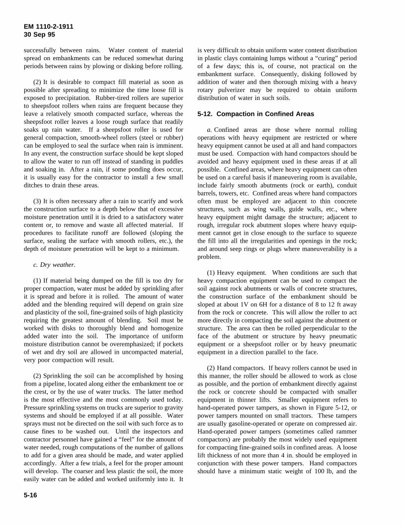
EM 1110-2-191130 Sep 95
successfully between rains. Water content of materialspread on embankments can be reduced somewhat duringperiods between rains by plowing or disking before rolling.
(2) It is desirable to compact fill material as soon aspossible after spreading to minimize the time loose fill isexposed to precipitation. Rubber-tired rollers are superiorto sheepsfoot rollers when rains are frequent because theyleave a relatively smooth compacted surface, whereas thesheepsfoot roller leaves a loose rough surface that readilysoaks up rain water. If a sheepsfoot roller is used forgeneral compaction, smooth-wheel rollers (steel or rubber)can be employed to seal the surface when rain is imminent.In any event, the construction surface should be kept slopedto allow the water to run off instead of standing in puddlesand soaking in. After a rain, if some ponding does occur,it is usually easy for the contractor to install a few smallditches to drain these areas.
(3) It is often necessary after a rain to scarify and workthe construction surface to a depth below that of excessivemoisture penetration until it is dried to a satisfactory watercontent or, to remove and waste all affected material. Ifprocedures to facilitate runoff are followed (sloping thesurface, sealing the surface with smooth rollers, etc.), thedepth of moisture penetration will be kept to a minimum.
c. Dry weather.
(1) If material being dumped on the fill is too dry forproper compaction, water must be added by sprinkling afterit is spread and before it is rolled. The amount of wateradded and the blending required will depend on grain sizeand plasticity of the soil, fine-grained soils of high plasticityrequiring the greatest amount of blending. Soil must beworked with disks to thoroughly blend and homogenizeadded water into the soil. The importance of uniformmoisture distribution cannot be overemphasized; if pocketsof wet and dry soil are allowed in uncompacted material,very poor compaction will result.
(2) Sprinkling the soil can be accomplished by hosingfrom a pipeline, located along either the embankment toe orthe crest, or by the use of water trucks. The latter methodis the most effective and the most commonly used today.Pressure sprinkling systems on trucks are superior to gravitysystems and should be employed if at all possible. Watersprays must not be directed on the soil with such force as tocause fines to be washed out. Until the inspectors andcontractor personnel have gained a “feel” for the amount ofwater needed, rough computations of the number of gallonsto add for a given area should be made, and water appliedaccordingly. After a few trials, a feel for the proper amountwill develop. The coarser and less plastic the soil, the moreeasily water can be added and worked uniformly into it. It
is very difficult to obtain uniform water content distributionin plastic clays containing lumps without a “curing” periodof a few days; this is, of course, not practical on theembankment surface. Consequently, disking followed byaddition of water and then thorough mixing with a heavyrotary pulverizer may be required to obtain uniformdistribution of water in such soils.
5-12. Compaction in Confined Areas
a. Confined areas are those where normal rollingoperations with heavy equipment are restricted or whereheavy equipment cannot be used at all and hand compactorsmust be used. Compaction with hand compactors should beavoided and heavy equipment used in these areas if at allpossible. Confined areas, where heavy equipment can oftenbe used on a careful basis if maneuvering room is available,include fairly smooth abutments (rock or earth), conduitbarrels, towers, etc. Confined areas where hand compactorsoften must be employed are adjacent to thin concretestructures, such as wing walls, guide walls, etc., whereheavy equipment might damage the structure; adjacent torough, irregular rock abutment slopes where heavy equip-ment cannot get in close enough to the surface to squeezethe fill into all the irregularities and openings in the rock;and around seep rings or plugs where maneuverability is aproblem.
(1) Heavy equipment. When conditions are such thatheavy compaction equipment can be used to compact thesoil against rock abutments or walls of concrete structures,the construction surface of the embankment should besloped at about 1V on 6H for a distance of 8 to 12 ft awayfrom the rock or concrete. This will allow the roller to actmore directly in compacting the soil against the abutment orstructure. The area can then be rolled perpendicular to theface of the abutment or structure by heavy pneumaticequipment or a sheepsfoot roller or by heavy pneumaticequipment in a direction parallel to the face.
(2) Hand compactors. If heavy rollers cannot be used inthis manner, the roller should be allowed to work as closeas possible, and the portion of embankment directly againstthe rock or concrete should be compacted with smallerequipment in thinner lifts. Smaller equipment refers tohand-operated power tampers, as shown in Figure 5-12, orpower tampers mounted on small tractors. These tampersare usually gasoline-operated or operate on compressed air.Hand-operated power tampers (sometimes called rammercompactors) are probably the most widely used equipmentfor compacting fine-grained soils in confined areas. A looselift thickness of not more than 4 in. should be employed inconjunction with these power tampers. Hand compactorsshould have a minimum static weight of 100 lb, and the
5-16
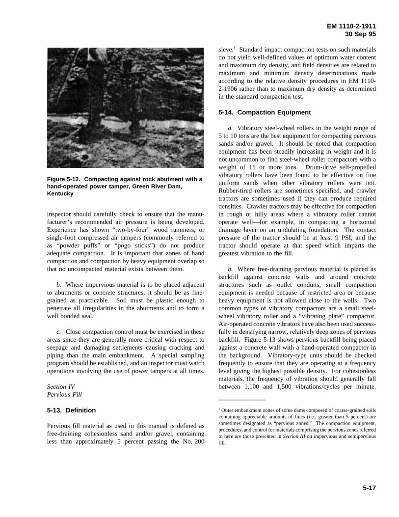
EM 1110-2-191130 Sep 95
inspector should carefully check to ensure that the manu-
Figure 5-12. Compacting against rock abutment with ahand-operated power tamper, Green River Dam,Kentucky
facturer’s recommended air pressure is being developed.Experience has shown “two-by-four” wood rammers, orsingle-foot compressed air tampers (commonly referred toas “powder puffs” or “pogo sticks”) do not produceadequate compaction. It is important that zones of handcompaction and compaction by heavy equipment overlap sothat no uncompacted material exists between them.
b. Where impervious material is to be placed adjacentto abutments or concrete structures, it should be as fine-grained as practicable. Soil must be plastic enough topenetrate all irregularities in the abutments and to form awell bonded seal.
c. Close compaction control must be exercised in theseareas since they are generally more critical with respect toseepage and damaging settlements causing cracking andpiping than the main embankment. A special samplingprogram should be established, and an inspector must watchoperations involving the use of power tampers at all times.
Section IVPervious Fill
5-13. Definition
Pervious fill material as used in this manual is defined asfree-draining cohesionless sand and/or gravel, containingless than approximately 5 percent passing the No. 200
sieve.1 Standard impact compaction tests on such materialsdo not yield well-defined values of optimum water contentand maximum dry density, and field densities are related tomaximum and minimum density determinations madeaccording to the relative density procedures in EM 1110-2-1906 rather than to maximum dry density as determinedin the standard compaction test.
5-14. Compaction Equipment
a. Vibratory steel-wheel rollers in the weight range of5 to 10 tons are the best equipment for compacting pervioussands and/or gravel. It should be noted that compactionequipment has been steadily increasing in weight and it isnot uncommon to find steel-wheel roller compactors with aweight of 15 or more tons. Drum-drive self-propelledvibratory rollers have been found to be effective on fineuniform sands when other vibratory rollers were not.Rubber-tired rollers are sometimes specified, and crawlertractors are sometimes used if they can produce requireddensities. Crawler tractors may be effective for compactionin rough or hilly areas where a vibratory roller cannotoperate well—for example, in compacting a horizontaldrainage layer on an undulating foundation. The contactpressure of the tractor should be at least 9 PSI, and thetractor should operate at that speed which imparts thegreatest vibration to the fill.
b. Where free-draining pervious material is placed asbackfill against concrete walls and around concretestructures such as outlet conduits, small compactionequipment is needed because of restricted area or becauseheavy equipment is not allowed close to the walls. Twocommon types of vibratory compactors are a small steel-wheel vibratory roller and a “vibrating plate” compactor.Air-operated concrete vibrators have also been used success-fully in densifying narrow, relatively deep zones of perviousbackfill. Figure 5-13 shows pervious backfill being placedagainst a concrete wall with a hand-operated compactor inthe background. Vibratory-type units should be checkedfrequently to ensure that they are operating at a frequencylevel giving the highest possible density. For cohesionlessmaterials, the frequency of vibration should generally fallbetween 1,100 and 1,500 vibrations/cycles per minute.
1 Outer embankment zones of some dams composed of coarse-grained soilscontaining appreciable amounts of fines (i.e., greater than 5 percent) aresometimes designated as “pervious zones.” The compaction equipment,procedures, and control for materials comprising the pervious zones referredto here are those presented inSection IIIon impervious and semiperviousfill.
5-17
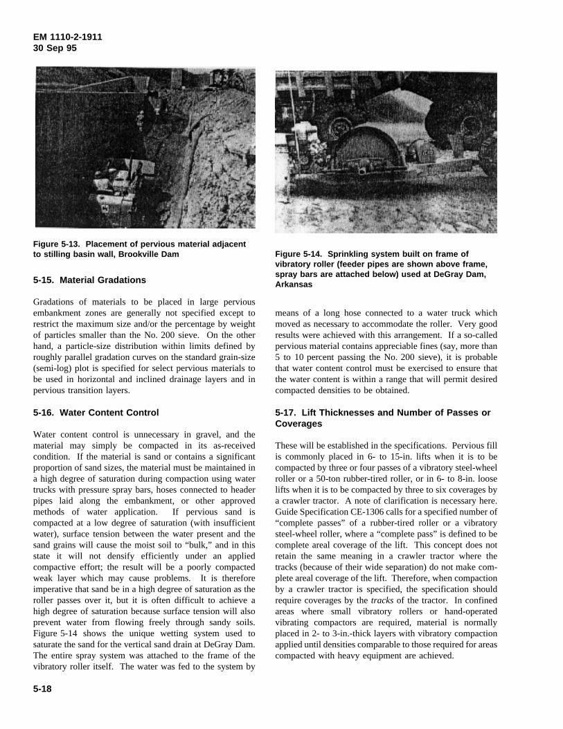
EM 1110-2-191130 Sep 95
5-15. Material Gradations
Figure 5-13. Placement of pervious material adjacentto stilling basin wall, Brookville Dam
Gradations of materials to be placed in large perviousembankment zones are generally not specified except torestrict the maximum size and/or the percentage by weightof particles smaller than the No. 200 sieve. On the otherhand, a particle-size distribution within limits defined byroughly parallel gradation curves on the standard grain-size(semi-log) plot is specified for select pervious materials tobe used in horizontal and inclined drainage layers and inpervious transition layers.
5-16. Water Content Control
Water content control is unnecessary in gravel, and thematerial may simply be compacted in its as-receivedcondition. If the material is sand or contains a significantproportion of sand sizes, the material must be maintained ina high degree of saturation during compaction using watertrucks with pressure spray bars, hoses connected to headerpipes laid along the embankment, or other approvedmethods of water application. If pervious sand iscompacted at a low degree of saturation (with insufficientwater), surface tension between the water present and thesand grains will cause the moist soil to “bulk,” and in thisstate it will not densify efficiently under an appliedcompactive effort; the result will be a poorly compactedweak layer which may cause problems. It is thereforeimperative that sand be in a high degree of saturation as theroller passes over it, but it is often difficult to achieve ahigh degree of saturation because surface tension will alsoprevent water from flowing freely through sandy soils.Figure 5-14 shows the unique wetting system used tosaturate the sand for the vertical sand drain at DeGray Dam.The entire spray system was attached to the frame of thevibratory roller itself. The water was fed to the system by
means of a long hose connected to a water truck which
Figure 5-14. Sprinkling system built on frame ofvibratory roller (feeder pipes are shown above frame,spray bars are attached below) used at DeGray Dam,Arkansas
moved as necessary to accommodate the roller. Very goodresults were achieved with this arrangement. If a so-calledpervious material contains appreciable fines (say, more than5 to 10 percent passing the No. 200 sieve), it is probablethat water content control must be exercised to ensure thatthe water content is within a range that will permit desiredcompacted densities to be obtained.
5-17. Lift Thicknesses and Number of Passes orCoverages
These will be established in the specifications. Pervious fillis commonly placed in 6- to 15-in. lifts when it is to becompacted by three or four passes of a vibratory steel-wheelroller or a 50-ton rubber-tired roller, or in 6- to 8-in. looselifts when it is to be compacted by three to six coverages bya crawler tractor. A note of clarification is necessary here.Guide Specification CE-1306 calls for a specified number of“complete passes” of a rubber-tired roller or a vibratorysteel-wheel roller, where a “complete pass” is defined to becomplete areal coverage of the lift. This concept does notretain the same meaning in a crawler tractor where thetracks (because of their wide separation) do not make com-plete areal coverage of the lift. Therefore, when compactionby a crawler tractor is specified, the specification shouldrequire coverages by thetracksof the tractor. In confinedareas where small vibratory rollers or hand-operatedvibrating compactors are required, material is normallyplaced in 2- to 3-in.-thick layers with vibratory compactionapplied until densities comparable to those required for areascompacted with heavy equipment are achieved.
5-18
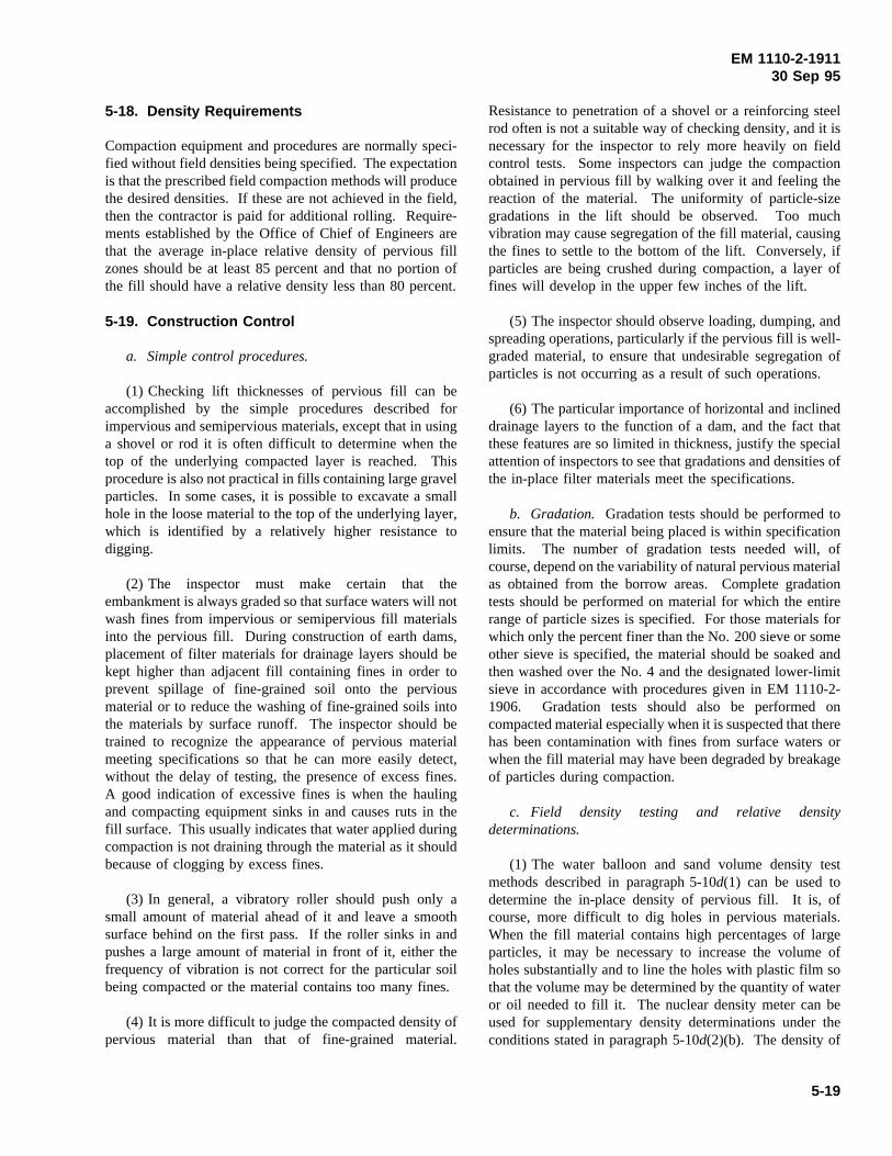
EM 1110-2-191130 Sep 95
5-18. Density Requirements
Compaction equipment and procedures are normally speci-fied without field densities being specified. The expectationis that the prescribed field compaction methods will producethe desired densities. If these are not achieved in the field,then the contractor is paid for additional rolling. Require-ments established by the Office of Chief of Engineers arethat the average in-place relative density of pervious fillzones should be at least 85 percent and that no portion ofthe fill should have a relative density less than 80 percent.
5-19. Construction Control
a. Simple control procedures.
(1) Checking lift thicknesses of pervious fill can beaccomplished by the simple procedures described forimpervious and semipervious materials, except that in usinga shovel or rod it is often difficult to determine when thetop of the underlying compacted layer is reached. Thisprocedure is also not practical in fills containing large gravelparticles. In some cases, it is possible to excavate a smallhole in the loose material to the top of the underlying layer,which is identified by a relatively higher resistance todigging.
(2) The inspector must make certain that theembankment is always graded so that surface waters will notwash fines from impervious or semipervious fill materialsinto the pervious fill. During construction of earth dams,placement of filter materials for drainage layers should bekept higher than adjacent fill containing fines in order toprevent spillage of fine-grained soil onto the perviousmaterial or to reduce the washing of fine-grained soils intothe materials by surface runoff. The inspector should betrained to recognize the appearance of pervious materialmeeting specifications so that he can more easily detect,without the delay of testing, the presence of excess fines.A good indication of excessive fines is when the haulingand compacting equipment sinks in and causes ruts in thefill surface. This usually indicates that water applied duringcompaction is not draining through the material as it shouldbecause of clogging by excess fines.
(3) In general, a vibratory roller should push only asmall amount of material ahead of it and leave a smoothsurface behind on the first pass. If the roller sinks in andpushes a large amount of material in front of it, either thefrequency of vibration is not correct for the particular soilbeing compacted or the material contains too many fines.
(4) It is more difficult to judge the compacted density ofpervious material than that of fine-grained material.
Resistance to penetration of a shovel or a reinforcing steelrod often is not a suitable way of checking density, and it isnecessary for the inspector to rely more heavily on fieldcontrol tests. Some inspectors can judge the compactionobtained in pervious fill by walking over it and feeling thereaction of the material. The uniformity of particle-sizegradations in the lift should be observed. Too muchvibration may cause segregation of the fill material, causingthe fines to settle to the bottom of the lift. Conversely, ifparticles are being crushed during compaction, a layer offines will develop in the upper few inches of the lift.
(5) The inspector should observe loading, dumping, andspreading operations, particularly if the pervious fill is well-graded material, to ensure that undesirable segregation ofparticles is not occurring as a result of such operations.
(6) The particular importance of horizontal and inclineddrainage layers to the function of a dam, and the fact thatthese features are so limited in thickness, justify the specialattention of inspectors to see that gradations and densities ofthe in-place filter materials meet the specifications.
b. Gradation. Gradation tests should be performed toensure that the material being placed is within specificationlimits. The number of gradation tests needed will, ofcourse, depend on the variability of natural pervious materialas obtained from the borrow areas. Complete gradationtests should be performed on material for which the entirerange of particle sizes is specified. For those materials forwhich only the percent finer than the No. 200 sieve or someother sieve is specified, the material should be soaked andthen washed over the No. 4 and the designated lower-limitsieve in accordance with procedures given in EM 1110-2-1906. Gradation tests should also be performed oncompacted material especially when it is suspected that therehas been contamination with fines from surface waters orwhen the fill material may have been degraded by breakageof particles during compaction.
c. Field density testing and relative densitydeterminations.
(1) The water balloon and sand volume density testmethods described in paragraph 5-10d(1) can be used todetermine the in-place density of pervious fill. It is, ofcourse, more difficult to dig holes in pervious materials.When the fill material contains high percentages of largeparticles, it may be necessary to increase the volume ofholes substantially and to line the holes with plastic film sothat the volume may be determined by the quantity of wateror oil needed to fill it. The nuclear density meter can beused for supplementary density determinations under theconditions stated in paragraph 5-10d(2)(b). The density of
5-19
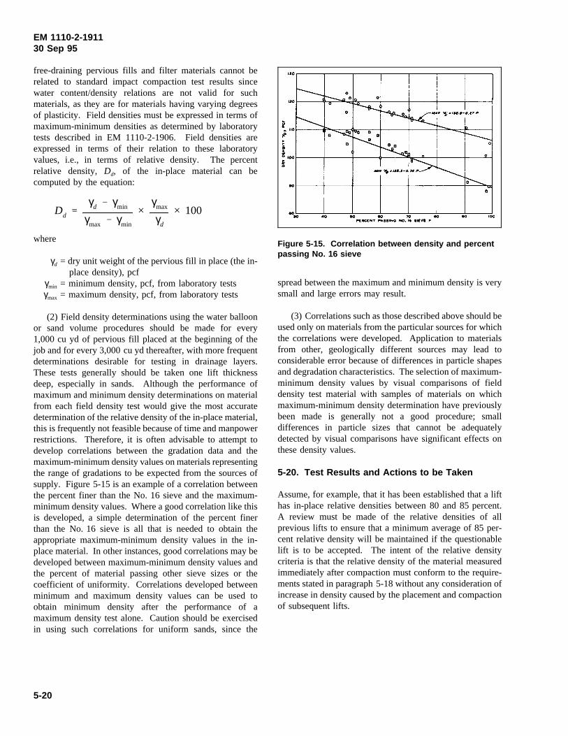
EM 1110-2-191130 Sep 95
free-draining pervious fills and filter materials cannot berelated to standard impact compaction test results sincewater content/density relations are not valid for suchmaterials, as they are for materials having varying degreesof plasticity. Field densities must be expressed in terms ofmaximum-minimum densities as determined by laboratorytests described in EM 1110-2-1906. Field densities areexpressed in terms of their relation to these laboratoryvalues, i.e., in terms of relative density. The percentrelative density, Dd, of the in-place material can becomputed by the equation:
Dd
γd γmin
γmax γmin
×γmax
γd
× 100
where
γd = dry unit weight of the pervious fill in place (the in-place density), pcf
γmin = minimum density, pcf, from laboratory testsγmax = maximum density, pcf, from laboratory tests
(2) Field density determinations using the water balloonor sand volume procedures should be made for every1,000 cu yd of pervious fill placed at the beginning of thejob and for every 3,000 cu yd thereafter, with more frequentdeterminations desirable for testing in drainage layers.These tests generally should be taken one lift thicknessdeep, especially in sands. Although the performance ofmaximum and minimum density determinations on materialfrom each field density test would give the most accuratedetermination of the relative density of the in-place material,this is frequently not feasible because of time and manpowerrestrictions. Therefore, it is often advisable to attempt todevelop correlations between the gradation data and themaximum-minimum density values on materials representingthe range of gradations to be expected from the sources ofsupply. Figure 5-15 is an example of a correlation betweenthe percent finer than the No. 16 sieve and the maximum-minimum density values. Where a good correlation like thisis developed, a simple determination of the percent finerthan the No. 16 sieve is all that is needed to obtain theappropriate maximum-minimum density values in the in-place material. In other instances, good correlations may bedeveloped between maximum-minimum density values andthe percent of material passing other sieve sizes or thecoefficient of uniformity. Correlations developed betweenminimum and maximum density values can be used toobtain minimum density after the performance of amaximum density test alone. Caution should be exercisedin using such correlations for uniform sands, since the
spread between the maximum and minimum density is very
Figure 5-15. Correlation between density and percentpassing No. 16 sieve
small and large errors may result.
(3) Correlations such as those described above should beused only on materials from the particular sources for whichthe correlations were developed. Application to materialsfrom other, geologically different sources may lead toconsiderable error because of differences in particle shapesand degradation characteristics. The selection of maximum-minimum density values by visual comparisons of fielddensity test material with samples of materials on whichmaximum-minimum density determination have previouslybeen made is generally not a good procedure; smalldifferences in particle sizes that cannot be adequatelydetected by visual comparisons have significant effects onthese density values.
5-20. Test Results and Actions to be Taken
Assume, for example, that it has been established that a lifthas in-place relative densities between 80 and 85 percent.A review must be made of the relative densities of allprevious lifts to ensure that a minimum average of 85 per-cent relative density will be maintained if the questionablelift is to be accepted. The intent of the relative densitycriteria is that the relative density of the material measuredimmediately after compaction must conform to the require-ments stated in paragraph 5-18 without any consideration ofincrease in density caused by the placement and compactionof subsequent lifts.
5-20
EM 1110-2-191130 Sep 95
Section VRock Fill
5-21. General
a. Embankments with large rock-fill zones arebecoming more common. This is primarily due to thenecessity of using sites where rock foundation conditions areunsuitable for concrete dams, the suitability of modernconstruction equipment to handle rock, the increasinglyhigher dams being constructed, and the economic benefitobtained by the maximum use of rock from requiredexcavation.
b. Rock for construction purposes falls into twocategories, soft rock and hard rock. Soft rocks such asshales, mudstones, siltstones, claystones, chalk, earthylimestones, weakly cemented sandstones, and badlyweathered igneous and metamorphic rocks break down invarying degrees during compaction, some into tight compactmasses similar to impervious soils. Soft rocks are generallysusceptible to further softening by exposure to air and water.Conversely, hard rocks do not readily break down duringhandling and compaction, and their use results in a perviousto very pervious fill depending on the amount of finespresent.
c. There are no well-established criteria for constructionmethods best suited to either type of rock. The breakdownof most types of rock is very unpredictable, and this fact hasled to the widespread use of test quarries and test fills forlarge rock-fill dams.
5-22. Hard Rock
a. Specifications.The specifications for pervious rock-fill sections generally require that the rock be sound, wellgraded, and free draining. Gradation is not usuallyspecified, but the maximum permissible size is normallyspecified together with lift thickness. Rock fill is usuallyrequired to be placed by dumping from trucks, withbulldozers spreading the material to the desired liftthickness. The required placement and spreading operationsshould be that segregation of rock sizes is avoided. This isdiscussed in more detail in the following paragraphs. Thetype of roller, lift thickness, and number of passes will bespecified, preferably based on results of test fills.
b. Placement operations.
(1) When rock is dumped on the fill surface and pushedinto place by a bulldozer, the fines are moved into the upperpart of the lift, thereby creating a smoother working surface
for the compacting equipment. If, however, a layer of finesof such a thickness as to choke the upper part of the lift andprevent distribution of the fines throughout the lift isproduced, it is necessary to specify that the rock be dumpeddirectly in place.
(2) All oversized rock must be removed prior tocompaction. This is usually done with bulldozers, crawlertractors fitted with special “rock rakes,” or cranes.Oversized rocks are often pushed into a specified zone inthe outer slopes. Excessively large rocks are sometimeshauled off to be dumped elsewhere, or they are broken upwith a drop weight or explosives and used in the rock fill orriprap zone. Oversized rocks should never be pushed toaccumulate along the contact slope of a closure section.
(3) Close inspection is also required to ensure that thematerial does not contain excessive fines, which can causeexcessive post-construction settlements when the reservoiris filled. It is difficult to define a limiting amount of finesin the specifications and, consequently, this is rarely done.However, the design office should provide some guidanceto field personnel, based on results of rock tests and fillstudies, which will aid in determining when excessive finesare present. The inspector must be alert for materialvariations that could result in undesirable changes ingradation of the material being brought to the embankment.Such changes should be called to the attention of thecontractor so that quarrying techniques can be changed.
c. Compaction.
(1) With the introduction of smooth steel-wheel vibratoryrollers to this country in the last 20 years, current practiceis to compact all sound rock fill, using these rollers, incomparatively thin lifts of unsluiced rock. Vibratory rollershaving static weights of 5, 10, and 15 tons have been usedto construct several Corps rock-fill dams.
(2) The lift thickness specified is dependent on the sizeand type of rock and the type of compaction equipment tobe used, and is usually determined from results obtainedduring construction of a test fill. Generally, specified liftthickness will be no thicker than 24 in. unless test fills showthat adequate compaction can be obtained using thicker lifts.Maximum size rock should not exceed 0.9 of the lift thick-ness.
(3) Scarification of compacted lift surfaces is notnecessary and should not be allowed because it disturbs thecompacted mass.
5-21
EM 1110-2-191130 Sep 95
5-23. Soft Rock
a. The use of soft rocks in the past has been dictated bytheir availability in large quantities from requiredexcavations. The main concern about these materials istheir tendency to weather and soften with time whenexposed to air and water. However, cases in which largeportions of embankments were composed of soft rocks haveshown that they can be used satisfactorily in random andsemipervious zones, attaining adequate shear strength andexperiencing no appreciable softening after placement.Where soft rocks will constitute a significant structuralportion of a fill, their properties and the best methods ofcompaction should be determined by means of a testembankment constructed during the design studies.
b. Some types of soft rock have been compacted byfirst rolling over the loose lift with a heavy tamping rollerequipped with long spike or chisel-type teeth (“shellbreaker”), and then compacting the lift with conventionaltamping or rubber-tired rollers. A summary of thistechnique is given by Bennett (1958).
Section VISemicompacted Earth Fills
5-24. Uses
Spoil berms, channel fillings, and low levees to protectfarmlands are often constructed of semicompacted fills.
5-25. Specifications
Semicompacted fills are those specified to be compacted bythe routing of hauling and spreading equipment over thespread layer. Lift thickness is specified, but the range ofplacement water contents is either not specified or permittedto vary widely.
5-26. Construction Control
Inspection of semicompacted fill is usually entirely visual,although a few density tests may be made for recordpurposes. The primary concern of the inspector is to ensurethat the specified lift thickness is not exceeded, suitablematerials are being used, and hauling and spreadingequipment covers the fill uniformly.
Section VIISequence of Placement and Measurement of Quantities
5-27. Schedule of Construction
The schedule for construction of an earth or rock-fill dam
may require stage (or phase) construction. In a wide flatvalley, the embankment on one side of the river may beconstructed to the full height under one contract, withsubsequent portions constructed during following years.Where foundations are soft, the embankment may beconstructed to a specified elevation and further fillplacement deferred for a year or more to permit dissipationof foundation pore pressures or to achieve an adequatedegree of consolidation. In a narrow steep valley with rockfoundations, the entire embankment may have to becompleted to a stipulated elevation by a certain date toprevent overtopping during the flood season. Theconstruction schedule is developed to make maximum useof available borrow and excavation materials, consideringriver diversion requirements, foundation conditions, andseasonal weather conditions. The contractor is responsiblefor constructing the particular stage or section ofembankment within the time limit specified. The inspectionforce is responsible for determining that each stage orsection of embankment is being built in proper sequence andalso that each stage or section is constructed using properplacement sequence. Changes in sequence or timing ofstages should not be made without approval of the designengineer.
5-28. Placement Sequence
a. It is usually required that the embankment be broughtup fairly uniformly over the entire width and length of thesection under construction. Interim embankment crestsshould be crowned slightly to provide surface drainageduring wet weather. Specified transverse slopes of interimcrests may range from 1 to 5 percent. During periods ofdry weather, the fill heights of central impervious zones aresometimes allowed to exceed the heights of adjacentpervious zones by as much as 5 ft to permit continuousplacement of impervious material. However, specialprecautions such as sloping the impervious fill materialaway from the pervious zone are required to keepimpervious material out of inclined filter zones.
b. Placing material in a cutoff trench should beaccomplished by dumping and spreading the first lift of thedownstream filter zone material (if such a filter is requiredat the downstream trench slope) and then dumping andspreading the first lift of impervious material. This shouldbe followed by compaction of both zones concurrently, withseparate equipment being used on each zone. Dumping andspreading filter layers first will help to maintain thespecified width of the filter zone. A downstream horizontaldrainage zone should be completely placed and covered bytwo lifts of downstream shell materials as soon as possibleto prevent contamination of the blanket by exposure tosurface waters carrying fines.
5-22
EM 1110-2-191130 Sep 95
5-29. Measurement of Quantities
Measurement of excavated materials is usually based oncross-section surveys of the area before and afterexcavation, using the average end area method forcomputing quantities. For embankment fill, a cross-sectionsurvey of the outer boundaries and average end area methodare used in computing quantities. For separate zones withinan embankment, the theoretical quantities are computedfrom the lines and grades shown in the constructiondrawings. Inspection personnel should be completelyfamiliar with provisions of the specifications and lines andgrades shown on construction drawings so that instances ofoverexcavation or fill placement outside contract lines andgrades are recorded. This will assist in preventing possibleerrors in measurement and certification of payment forquantities in excess of contract provisions.
Section VIIISlope Protection
5-30. Areas to be Protected
Slope protection is required to protect upstream slopesagainst damage from wave erosion, weathering, ice damage,and damage from floating debris. Upstream slope protectionof earth dams usually consists of riprap, although soilcement, concrete paving, and asphalt paving have beenoccasionally used when riprap was not economicallyjustified. Dams with outer shells of sound, durable, largerock may not require further protection. Downstream slopeprotection is required to protect against damage from surfaceerosion by wind and rain. Downstream slope protectionincludes gravel for dry climates, turf in humid climates,riprap where tailwater may create wave action, and wasterock. Proper field construction procedures and enforcementof specifications are particularly important in obtaining slopeprotection that will remain in place and in minimizingmaintenance during the life of the dam.
5-31. Upstream Slope Protection
Placement of upstream slope protection may be accom-plished either as the embankment is being built or after theembankment is completed. This depends on the elevationlimits of slope protection, the schedule for impoundingreservoir water, and the type of slope protection. The bestprocedure is to require that the slope protection constructionnot lag behind earth-fill construction more than 10 ft inelevation.
a. Riprap. Riprap is the most commonly specified typeof upstream slope protection. Properly graded riprap, placedto provide a well-integrated mass with minimum void spaces
so that underlying bedding cannot be washed out, providesexcellent slope protection. Two primary factors governsuccessful construction and are discussed below.
(1) Loading from the quarry to provide a good mixtureof different sizes within the required gradation in each load.Proper loading from the quarry requires that blastingoperations produce proper sizes and that the inspector beexperienced in inspecting the loading operations.
(2) Placing loads on the slope to provide uniformdistribution of different sizes without segregation andrearrangement of individual rocks to provide a rock masswithout large voids. A gradation test (performed by weigh-ing a sufficient quantity) should be made for each 10,000 cuyd of placed riprap. Two ENG forms for plotting grada-tions curves are available. These forms are ENG Form4055 dated April 1967, “Riprap Gradation Curves” andENG Form 4056 dated April 1967, “Gradation Curves forRiprap, Filter, and Bedding”. Placement should beaccomplished by placing loads along the slope againstpreviously placed riprap; this will reduce segregation ofsizes that would otherwise occur if loads were dumped inseparated piles. The best method of placement to avoidsegregation is to use a skip as shown in Figure 5-16a.Dumping rock at the top of the slope into a chute shouldnever be allowed since this will result in segregation. Ifdumping is done from trucks, it is usually necessary towinch load haulers down the slope to the placementlocation. Dumping should proceed along horizontal rowsand progress up the slope; loads should not be dumped toform rows up the slope. If very large (4 to 5 ft diam) rockis specified, a crane with an orange peel attachment(Figure 5-16b) operating on a platform built up on the slopecan be used. Other equipment such as Gradalls, cranes withclamshell buckets, and rubber-tired front end loaders, can beused to place riprap. These are preferable to dumping fromhaulers. Close visual inspection after dumping and spread-ing is required to determine the degree of uniformdistribution of different sizes and close-knit arrangement ofindividual pieces. Reworking, generally by hand, willalmost always be required; however, reworking can be keptto a minimum if care is taken when loading to ensure thateach individual load has the proper amount of each sizerock (i.e., the proper gradation). Supplemental gradationchecks might be made by the photogrid method, describedby Curry (1964), in which a 10-ft-by-10-ft aluminum pipeform containing a 1-ft-by-1-ft grid or rope is placed on theriprap and photographed. From the photograph, the numberand size of stones visible at the surface are determined.However, for materials that have been selectively arranged,as by hand, this may not provide an accurate determinationof size distribution. Firm enforcement of specifications isrequired, especially during early stages of riprap placement
5-23
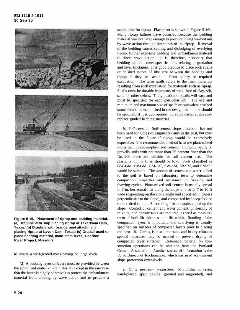
EM 1110-2-191130 Sep 95
Figure 5-16. Placement of riprap and bedding material.(a) Dragline with skip placing riprap at Texarkana Dam,Texas; (b) Dragline with orange peel attachmentplacing riprap at Lavon Dam, Texas; (c) Gradall used toplace bedding material, main stem levee, CharitonRiver Project, Missouri
to ensure a well-graded mass having no large voids.
(3) A bedding layer or layers must be provided betweenthe riprap and embankment material (except in the rare casethat the latter is highly cohesive) to protect the embankmentmaterial from eroding by wave action and to provide a
stable base for riprap. Placement is shown in Figure 5-16c.Many riprap failures have occurred because the beddingmaterial was not large enough to preclude being washed outby wave action through interstices of the riprap. Removalof the bedding causes settling and dislodging of overlyingriprap, further exposing bedding and embankment materialto direct wave action. It is, therefore, necessary thatbedding material meet specifications relating to gradationand layer thickness. It is good practice to place rock spallsor crushed stones of like size between the bedding andriprap if they are available from quarry or requiredexcavation. The term spalls refers to the finer materialsresulting from rock excavation for materials such as riprap.Spalls must be durable fragments of rock, free of clay, silt,sand, or other debris. The gradation of spalls will vary andmust be specified for each particular job. The use andminimum and maximum size of spalls or equivalent crushedstone should be established in the design memo and shouldbe specified if it is appropriate. In some cases, spalls mayreplace graded bedding material.
b. Soil cement. Soil-cement slope protection has notbeen used for Corps of Engineers dams in the past, but maybe used in the future if riprap would be excessivelyexpensive. The recommended method is to use plant-mixedrather than mixed-in-place soil cement. Inorganic sandy orgravelly soils with not more than 35 percent finer than theNo. 200 sieve are suitable for soil cement use. Theplasticity of the fines should be low. Soils classified asGW-GM, GP-GM, GM-GC, SW-SM, SP-SM, and SM-SCwould be suitable. The amount of cement and water addedto the soil is based on laboratory tests to determinecompaction properties and resistance to freezing andthawing cycles. Plant-mixed soil cement is usually spreadin 6-in. horizontal lifts along the slope in a strip, 7 to 10 ftwide (depending on the slope angle and specified thicknessperpendicular to the slope), and compacted by sheepsfoot orrubber-tired rollers. Succeeding lifts are stairstepped up theslope. Control of cement and water content, uniformity ofmixture, and density tests are required, as well as measure-ment of both lift thickness and lift width. Bonding of thecompacted layers is important, and scarifying is usuallyspecified on surfaces of compacted layers prior to placingthe next lift. Curing is also important, and in dry climatesspecial measures may be needed to prevent drying ofcompacted layer surfaces. Reference material on con-struction operations can be obtained from the PortlandCement Association. Another source of information is theU. S. Bureau of Reclamation, which has used soil-cementslope protection extensively.
c. Other upstream protection.Monolithic concrete,hand-placed riprip paving (grouted and ungrouted), and
5-24
EM 1110-2-191130 Sep 95
asphalt paving are other methods of protection for upstreamslopes. These methods have been used infrequently, if atall, for Corps of Engineers dams in the past.
5-32. Downstream Slope Protection
a. Grass turf. Grass turf for protection of downstreamslopes is usually specified in humid climates for earthembankments. Where the downstream embankment zone iscomposed of pervious material, sufficient fine-grained soilor topsoil must be placed to support vegetation growth. Themethod usually specified consists of clearing the slope ofany roots and stones, tilling to a depth of at least 4 in.,fertilizing, seeding or sprigging, compacting, watering, andmaintaining as required to establish the turf. Temporary orpermanent protection should be established on completedportions of the embankment as soon as possible. The usualpractice of waiting until near the end of construction andtrimming slopes by filling erosion channels with loosematerial and then fertilizing and seeding has resulted incontinuing maintenance problems at several projects.Specifications usually provide detailed instructions withwhich inspection personnel should be familiar. Frequentinspection should be made to ensure the following:
(1) That the soil is properly tilled and not allowed tomigrate down the slope during tilling, which might createdepressions or undulations.
(2) That the specified type, quality, and quantity offertilizer and seed are used.
(3) That turfing operations are conducted during goodweather conditions, and necessary interim precautions aretaken to prevent erosion, such as mulching with hay orburlap for a protective covering.
b. Riprap. Riprap placed on the lower downstreamslope to protect against wave action from tailwater shouldbe controlled in the same manner as upstream riprap.Above the elevation needing such protection, dumped rock(usually waste rock) is used only when readily availablefrom required excavation or stripping operations. (Controlshould conform with specification requirements).
c. Gravel. Gravel or rock spalls (depending onavailable material) are sometimes used for downstream slopeprotection. Where the outer downstream shell containsrandom granular materials, it is often specified that cobblesand rocks be pushed out to the edge and used in the slopeprotection. In this case, it is desirable that placement ofdownstream slope protection be kept 5 to 10 ft behindembankment placement. The gravel or spalls are usuallydumped and spread horizontally along the outer slope todepths of at least 1 ft measured perpendicular to the surface.
5-25
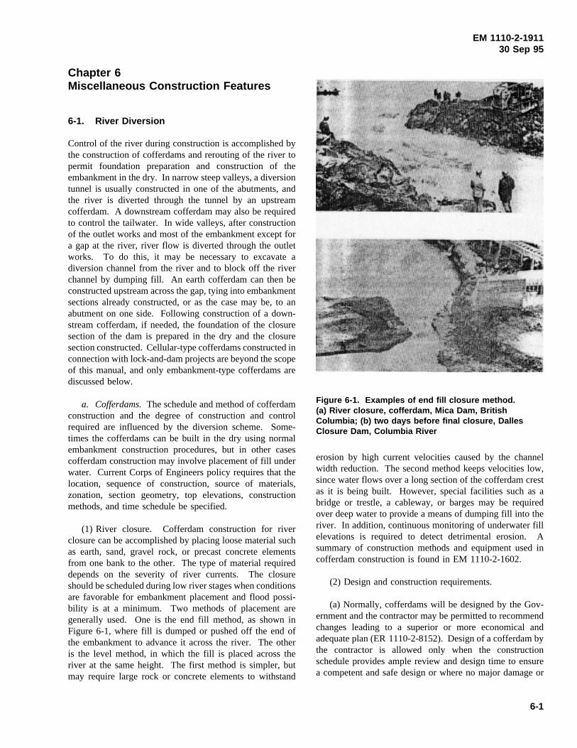
EM 1110-2-191130 Sep 95
Chapter 6Miscellaneous Construction Features
6-1. River Diversion
Control of the river during construction is accomplished bythe construction of cofferdams and rerouting of the river topermit foundation preparation and construction of theembankment in the dry. In narrow steep valleys, a diversiontunnel is usually constructed in one of the abutments, andthe river is diverted through the tunnel by an upstreamcofferdam. A downstream cofferdam may also be requiredto control the tailwater. In wide valleys, after constructionof the outlet works and most of the embankment except fora gap at the river, river flow is diverted through the outletworks. To do this, it may be necessary to excavate adiversion channel from the river and to block off the riverchannel by dumping fill. An earth cofferdam can then beconstructed upstream across the gap, tying into embankmentsections already constructed, or as the case may be, to anabutment on one side. Following construction of a down-stream cofferdam, if needed, the foundation of the closuresection of the dam is prepared in the dry and the closuresection constructed. Cellular-type cofferdams constructed inconnection with lock-and-dam projects are beyond the scopeof this manual, and only embankment-type cofferdams arediscussed below.
a. Cofferdams.The schedule and method of cofferdamconstruction and the degree of construction and controlrequired are influenced by the diversion scheme. Some-times the cofferdams can be built in the dry using normalembankment construction procedures, but in other casescofferdam construction may involve placement of fill underwater. Current Corps of Engineers policy requires that thelocation, sequence of construction, source of materials,zonation, section geometry, top elevations, constructionmethods, and time schedule be specified.
(1) River closure. Cofferdam construction for riverclosure can be accomplished by placing loose material suchas earth, sand, gravel rock, or precast concrete elementsfrom one bank to the other. The type of material requireddepends on the severity of river currents. The closureshould be scheduled during low river stages when conditionsare favorable for embankment placement and flood possi-bility is at a minimum. Two methods of placement aregenerally used. One is the end fill method, as shown inFigure 6-1, where fill is dumped or pushed off the end ofthe embankment to advance it across the river. The otheris the level method, in which the fill is placed across theriver at the same height. The first method is simpler, butmay require large rock or concrete elements to withstand
erosion by high current velocities caused by the channel
Figure 6-1. Examples of end fill closure method.(a) River closure, cofferdam, Mica Dam, BritishColumbia; (b) two days before final closure, DallesClosure Dam, Columbia River
width reduction. The second method keeps velocities low,since water flows over a long section of the cofferdam crestas it is being built. However, special facilities such as abridge or trestle, a cableway, or barges may be requiredover deep water to provide a means of dumping fill into theriver. In addition, continuous monitoring of underwater fillelevations is required to detect detrimental erosion. Asummary of construction methods and equipment used incofferdam construction is found in EM 1110-2-1602.
(2) Design and construction requirements.
(a) Normally, cofferdams will be designed by the Gov-ernment and the contractor may be permitted to recommendchanges leading to a superior or more economical andadequate plan (ER 1110-2-8152). Design of a cofferdam bythe contractor is allowed only when the constructionschedule provides ample review and design time to ensurea competent and safe design or where no major damage or
6-1
EM 1110-2-191130 Sep 95
significant delays would occur from a failure. Compactionprocedures as well as other pertinent construction aspects,including construction and surveillance requirements, wouldbe covered in the contract plans and specifications. In-spection and control testing, as outlined in Chapter 5, arerequired especially for cofferdams which will become partof the dam to ensure compliance with specifications or todetermine when specified procedures need to be modified.The safety of cofferdams depends to a large extent oncompetent construction. Intensive inspection is required toensure compliance with design requirements and safeconstruction practices. A contract requirement for qualitycontrol by the contractor does not relieve resident inspectionforces from performing necessary and adequate inspectionand surveillance.
(b) Slopes of temporary cofferdams depend on the typeof material used, degree of compaction, and their height.Cofferdams are often designed on the basis of past experi-ence. If the contractor is permitted to design a cofferdam,it should be required that an analysis of slope stability withplans for construction be furnished. Slopes of cofferdamsdesigned by the Government are specified in the contractdrawings.
(c) Seepage under cofferdams and through uncompactedrock-fill cofferdams can be a serious problem unless seepagecontrol provisions such as a cutoff and/or an upstreamimpervious zone are included. For cofferdams designed bythe Government the plans provide necessary measures forcontrolling underseepage and through-seepage. However,particular attention should be given to any contractor’s plansfor temporary cofferdams to ensure that adequate seepagecontrol measures are included. It is also important thatwhere thin upstream blankets are placed against rock-fill orcoarse gravel, careful attention be given to providingproperly graded transitions between the impervious andcoarser materials.
(3) Slope protection. Slope protection against waveaction is usually not required for cofferdams. However,where a river is restricted to a channel by temporarycofferdams prior to diversion, slope protection againstcurrent action may be required. EM 1110-2-1601 should bereferred to for guidance on rock weights required to resistvarious current velocities.
b. Closure sections.After portions of the dam havebeen constructed with the river confined to a natural orconstructed channel, cofferdams are constructed to divert theriver through the outlet works so that the closure section canbe constructed in the dry. This may cause flooding ofupstream borrow areas, in which case alternate borrow areas
or stockpiling of borrow materials for the closure sectionshould be considered prior to river diversion.
(1) Foundation preparation and fill compaction.Clearing, stripping, and cleaning of the foundation area inthe closure section must be carefully inspected to ensure anadequate foundation. The closure section is generally thehighest section of the dam and is constructed to final gradein a much shorter time than the rest of the embankment;consequently, special emphasis on inspection and controltesting is justified to ensure that proper materials are placedat the specified water contents and compacted to the desiredor specified densities.
(2) Cleaning of adjacent embankment slopes. Riprapplaced on the end slopes of completed embankment sectionsto prevent stream erosion must be removed prior to placingfill for the closure section. In addition, the end slopes mustbe cut back as necessary to provide unweathered andadequately compacted material adjacent to the closuresection fill.
(3) Observations during construction. Because of therapid construction, the following problems may occur inearth-fill closure sections:
(a) High excess pore water pressures in imperviouszones of the embankment and in impervious foundations.
(b) Transverse cracking between the closure section andpreviously completed embankment sections caused bydifferential settlement.
(c) Bulging of outer slopes of largely impervious sec-tions from the use of material which is too wet.
The procedures for construction and criteria for compactionstipulated in the plans and specifications for minimizingthese problems may include drainage layers in theembankment and at the contact between embankment andfoundation (but never under or through an impervious core)to help dissipate pore pressures, flattening of slopes, and fillwater contents wet of optimum to provide a more plastic fillto minimize cracking. The use of higher fill water contentsmay, however, accentuate problems of bulging and highpore water pressures. If potential problems are indicated,surface movements data and piezometer readings must beobtained daily and continuous plots maintained so that thedevelopment of excessive pore water pressures and/orbulging can be detected early and corrective action taken.Corrective measures taken after consultation with the designoffice may include slowing down fill placement, removal of
6-2
EM 1110-2-191130 Sep 95
fill, flattening slopes, addition of stability berms, orinstallation of drains.
6-2. Stage Construction
a. Stage construction refers here to construction of anembankment in stages with substantial intervals of timeduring which little or no fill is placed. This may be neces-sitated by environmental conditions which make theconstruction season very short or because fill placementmust be restricted or even stopped to allow excess porewater pressure in the foundation and/or fill to dissipate.
b. Important features of construction control for stageconstruction include the following:
(1) Review of contractor’s plans of operation as requiredby specifications to establish the adequacy of methods andprocedures, and field inspection to ensure that approved timeschedules and construction methods and procedures arefollowed.
(2) Inspection to ensure that the surfaces of completedsections of embankment on which additional fill will not beplaced for several months are sealed and/or shaped to drainreadily to prevent saturation and adequately protectedagainst erosion.
(3) Inspection to ensure that outside slopes of stage-constructed embankments that will eventually form the finalslopes of the dam are within specified tolerances.
(4) Observation and evaluation of piezometer andsettlement data for soft foundations and consultation withthe design office to determine when fill placement can besafely resumed. The design office has the responsibility todetermine when fill placement can be resumed.
(5) Inspection to ensure that protective materials such asriprap, grass sodding, and trash or other debris are removedfrom previously completed embankment surfaces prior toresuming fill placement.
(6) Inspection of completed embankment surfaces priorto resuming fill placement to determine the need forremoval of pervious surfaces materials which have becomecontaminated with fines or recompaction of surface materi-als where water content and density are unsatisfactory.Field density and water content tests should be performed tocheck visual observations.
6-3. Surface Drainage Facilities
Temporary surface drainage facilities are required to keepsurface runoff and slope seepage out of excavations, toprevent contamination of filter zones by muddy runoff, toprevent saturation of loose fill before and during compac-tion, and to prevent ponding of water on compacted fill.Surface drainage is the responsibility of the contractor, asthe specifications require certain phases of foundationpreparation and embankment construction to be performedin the dry. Past field experience has shown that theprovision and maintenance of adequate drainage havefrequently been neglected, and more attention needs to begiven to them by the inspection force. Grading to directsurface water away from excavations, ditching to interceptwater before it reaches an excavation or work area, provi-sion of sumps to collect seepage water, and pumping fromthe sumps are common means of handling surface drainage.The extent of needed facilities is dependent on thefrequency, intensity, and seasonal distribution of precipi-tation. For permanent drainage facilities for roads and otherfeatures, reference should be made to TM 5-820-4.
6-4. Service Bridge Pier Foundations
Piers for service bridges to intake structures are sometimesconstructed during early stages of embankment construction.At several dams, lateral deformations of the embankmentunder the stresses imposed by fill placed after pierconstruction have caused significant upstream movements ofthe piers. Therefore, construction of piers should be delayeduntil the embankment has been carried to near its finalheight. After construction of the piers, surveys should bemade at regular intervals to monitor any movement of thepiers no matter what steps are taken to prevent movement.
6-5. Instrumentation
Instrumentation of earth and rock-fill dams includespiezometers, slope indicators, settlement devices, surfacemovement monuments, internal vertical and horizontalmovement indicators, and seismic movement devices (seeparagraph 7-3 for required records). Seismic movementdevices are described in detail in ER 1110-2-103. Varioustypes of instrumentation devices, procedures for installation,observation and maintenance, frequency of observations,collection, recording, analysis, and reporting of data, andpossible causes of malfunctions are discussed in EM 1110-2-1908. The basic description and operating mechanism ofinstruments generally installed in embankment dams are
6-3
EM 1110-2-191130 Sep 95
given in Appendix E. A comprehensive reference on geo-technical instrumentation for monitoring field performanceincluding calibration, use, installation, and maintenance isgiven in EM 1110-2-1908.
a. Installation. Installation of instrumentation devices,particularly electronic types, should be supervised, if notactually done, by experienced personnel from within theCorps of Engineers or by firms specializing in instrumen-tation installation. The Resident Engineer staff must befamiliar with the planned locations of all instruments andappurtenant apparatus or structures (such as trenches forpiezometer lines and terminal house, etc.) so that necessaryarrangements and a schedule for installation can be madewith the contractor and/or with the office or firm that willinstall the devices. Inspectors should inspect settlementgauges furnished and installed by the contractor. Recordsmust be made of exact locations and procedures used forinstallation and initial observations. Riser pipes, tubes, orleads extending above the embankment surface must beprotected from damage by earth mounds, guard posts, orother means. Inspectors should ensure that necessary ex-tensions are added as the fill is constructed to higherelevations. This feature of construction generally occurs ata time when the contractor is anxious to begin or accelerateembankment construction. Therefore, patience, cooperation,and understanding must be exercised by the contractor andthe Resident Staff.
b. Observations. Schedules for observations duringconstruction are generally established by the design office.Pore pressure piezometers are observed frequently duringconstruction to provide data for use in slope stability checksand to control, if necessary, the rate of fill construction onsoft foundations. Initial observations should be checked toensure their validity and accuracy, since these readingsusually form the basis to which subsequent observations arerelated. Observations should be plotted immediately aftereach set of readings is taken and evaluated for reason-ableness against the previous set of readings. In this way,it is often possible to detect errors in readings and to obtaincheck readings before significant changes in field conditionsoccur. On large projects all records should immediately beprocessed by computers. This will generally result in thequickest results with a minimum amount of effort. Possiblesources of errors other than erroneous readings are discussedin EM 1110-2-1908. ER 1110-2-1925 prescribes the forms
for recording instrumentation data and instructions forreporting them.
6-6. Haul Roads, Maintenance Roads, andPublic Roads
Haul roads are temporary roads built by the contractor foraccess to work areas. Maintenance roads (or service roads)are temporary or permanent roads for access by Governmentforces to facilities requiring maintenance. Public roadsinclude relocated permanent roads and roads for access topublic-use facilities at the site.
a. Haul roads.Haul roads, although usually not shownon the plans, should be discussed in the specifications ingeneral terms. The contractor should be required to submitdetailed plans for all haul road layouts including grades,widths, locations, and post-construction obliteration andcleanup. Construction control consists generally of seeingthat the contractor maintains and operates on the haul roadsin accordance with sound safety practices, and enforcesadequate traffic control where public-use roads are crossed.Haul roads should not be located near the edge of excavatedslopes where the weight of road fill and/or heavy equipmentor ponding of water could endanger the stability of slopes.Haul roads up embankment slopes should be scabbed on theoutside or final embankment slope and relocated periodicallywhere highly compacted zones could develop in theembankment under the road which could lead to cracking.The contractor should be required to remove haul roads thatwould endanger slope stability. The practice of placingpervious material across impervious zones to support heavyhauling equipment should be discouraged. If allowed, allpervious material must be carefully removed. Lastly, it isimportant that environmental considerations be made inconnection with haul roads so that no permanent scars in theproject aesthetics remain.
b. Maintenance and public roads.Construction controlof maintenance or surface roads and public roads is requiredto ensure compliance with specifications relating to fill,filter, base coarse, and pavement materials; compaction offills, subgrades, base course, and wearing course; andinstallation of drainage structures. Field compaction controlis similar to that required for earth fill as discussed inChapter 5.
6-4
EM 1110-2-191130 Sep 95
Chapter 7Records and Reports
7-1. Daily Reports
Daily reports or logs are prepared by inspection personnelcovering their assigned areas of work. The reports are pre-pared on ENG Forms 2538-1-R (MILITARY) and 2538-2-R(CIVIL), “Daily Log of Construction” (Figures 7-1, 7-2,7-3, 7-4). Similar locally prepared forms or books may alsobe used. The importance of daily reports should be stressedat all levels of the Resident Engineer’s force, since dailyreports form a part of official Government records and mayby used as evidence in court or in other legal action. Thereports are also valuable in determining possible causes ofdistress, unusual seepage, or other potentially critical condi-tions during and after construction is completed. Inspectors’reports are not personal records and should be carefullycontrolled and accounted for as official records. The dailyreports must be thorough, accurate, neat, and legible. De-tailed information on the following items should be includedas outlined in ER 1180-1-6:
a. Contract number and contractor’s name.
b. Description and location of the work.
c. Date.
d. Weather.
e. Items of equipment and procedures used.
f. Type and amount of work performed.
g. Type and number of field control tests performed bythe contractor and by Government forces, and brief com-ments on results obtained.
h. Progress of work, delays, causes of delays, andextent of delays.
i. Instructions given to contractor, including name ofcontractor representative talked to, and resulting actionstaken by contractor.
j. Details of any controversial matters.
k. Visitors to the inspector’s area of responsibility.
l. Safety infractions/violations observed and correctiveactions taken.
Daily reports are often included in a weekly progress reportto the District Construction Division. The weekly reportalso contains information on overall progress on unusualconditions, and on instructions and directions given to thecontractor by the Resident Engineer to attain desired resultsin accordance with plans and specifications.
7-2. Compaction Control Reports
Records of compaction control are required to document theprocedure used and the adequacy of results obtained. Therecords also provide information for evaluation of com-paction control and for use in determining causes of distressor unusual conditions that may develop during or afterconstruction. Forms for use in tabulating daily field controldata are contained in Appendix C, together with instructionsfor their preparation and additional information requiredwhen submitting the forms to higher echelons. These formscan also be used in submitting monthly reports of data, asrequired by ER 1110-2-1925. Evaluation of compactioncontrol is necessary to ensure that the method and proce-dures are producing the quality of in-place fill required bythe specifications. Summaries of compaction control datadescribed in Appendix D provide a convenient means ofevaluating the adequacy of compaction. These summariesare required to be submitted by the district office for reviewby higher echelons (ER 1110-2-1925).
7-3. Instrumentation Observations
a. Records of instrumentation observations are im-portant in determining changes in pore water pressure,deformations, and settlements. The data, when summarizedand evaluated, are useful in substantiating design assump-tions and thus in verifying stability during construction,designing modifications, and additions to structures, ordetermining causes of operating difficulties. Standard formsand instructions for recording the following types ofinstrumentation readings are contained in Appendix E.
(1) Closed-system piezometer data.
(2) Open-system piezometer data.
(3) Subsurface settlement plate data.
(4) Surface reference point data.
b. For guidance on recording of data not covered byAppendix E, frequency of observations, and evaluatinginstrumentation data, see EM 1110-2-1908. Instructions forsubmission of data to a higher echelon are contained inER 1110-2-1925.
7-1

EM 1110-2-191130 Sep 95
Figure 7-1. Front of ENG FORM 2538-1
7-2

EM 1110-2-191130 Sep 95
Figure 7-2. Back of ENG FORM 2538-1
7-3
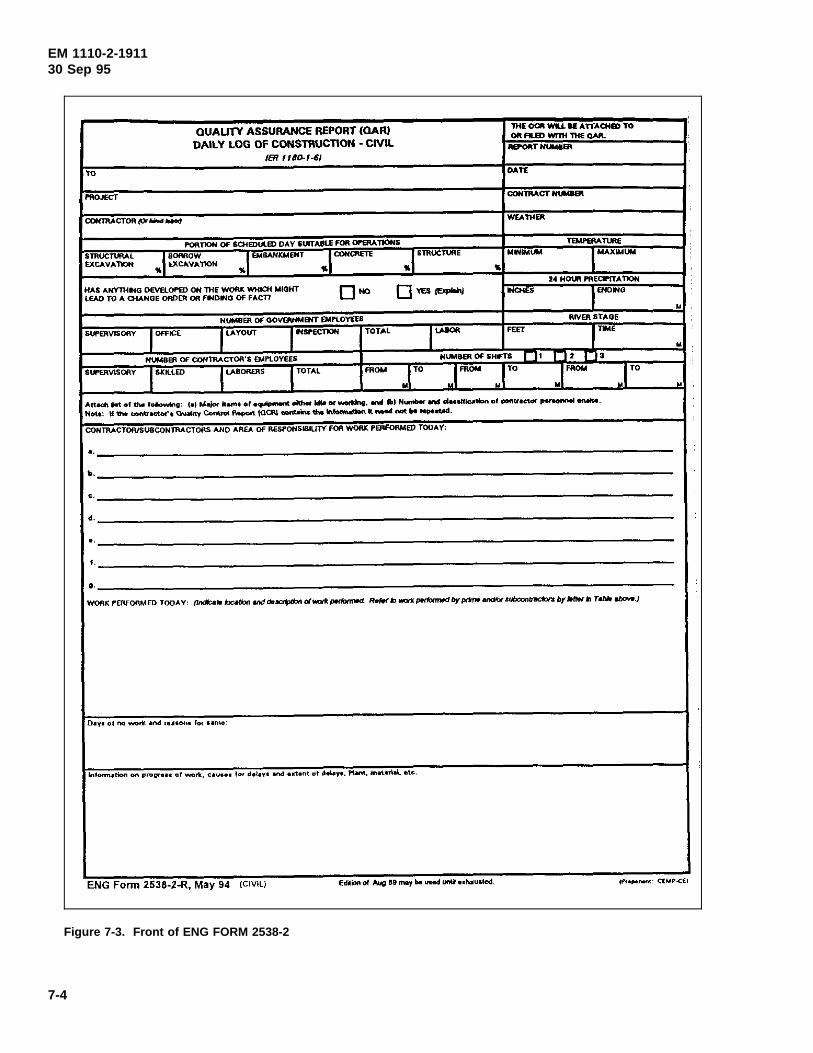
EM 1110-2-191130 Sep 95
Figure 7-3. Front of ENG FORM 2538-2
7-4
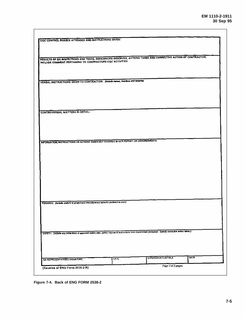
EM 1110-2-191130 Sep 95
Figure 7-4. Back of ENG FORM 2538-2
7-5
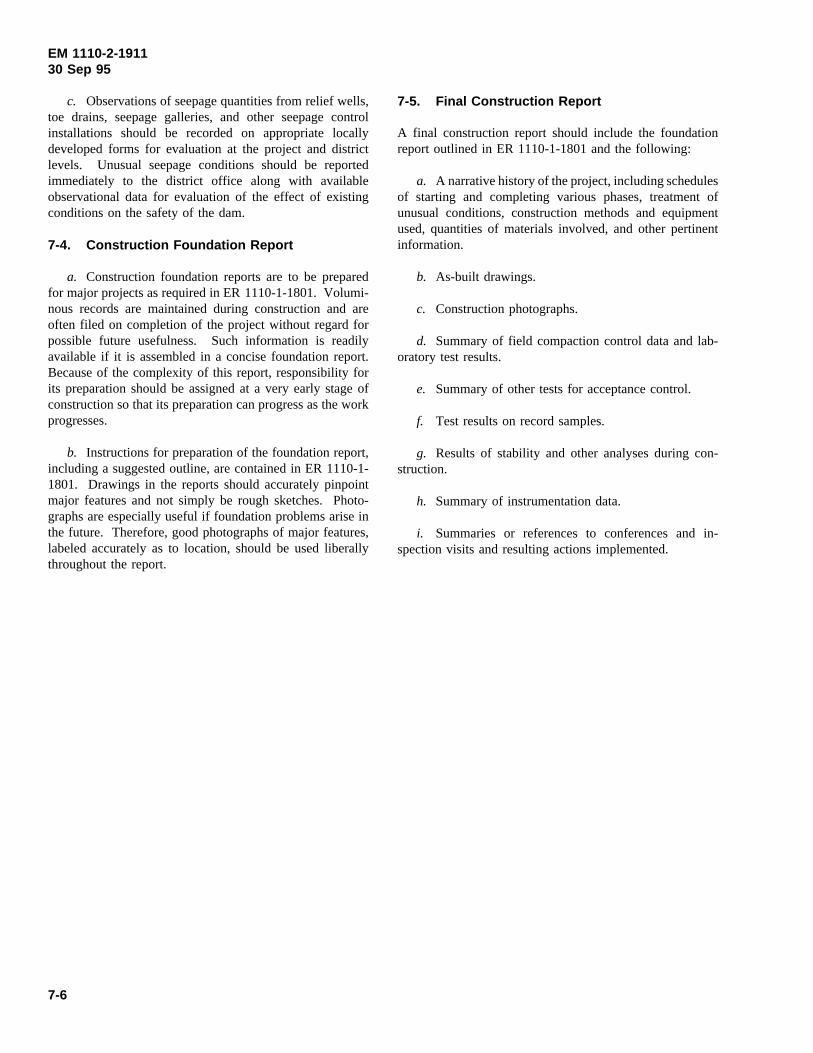
EM 1110-2-191130 Sep 95
c. Observations of seepage quantities from relief wells,toe drains, seepage galleries, and other seepage controlinstallations should be recorded on appropriate locallydeveloped forms for evaluation at the project and districtlevels. Unusual seepage conditions should be reportedimmediately to the district office along with availableobservational data for evaluation of the effect of existingconditions on the safety of the dam.
7-4. Construction Foundation Report
a. Construction foundation reports are to be preparedfor major projects as required in ER 1110-1-1801. Volumi-nous records are maintained during construction and areoften filed on completion of the project without regard forpossible future usefulness. Such information is readilyavailable if it is assembled in a concise foundation report.Because of the complexity of this report, responsibility forits preparation should be assigned at a very early stage ofconstruction so that its preparation can progress as the workprogresses.
b. Instructions for preparation of the foundation report,including a suggested outline, are contained in ER 1110-1-1801. Drawings in the reports should accurately pinpointmajor features and not simply be rough sketches. Photo-graphs are especially useful if foundation problems arise inthe future. Therefore, good photographs of major features,labeled accurately as to location, should be used liberallythroughout the report.
7-5. Final Construction Report
A final construction report should include the foundationreport outlined in ER 1110-1-1801 and the following:
a. A narrative history of the project, including schedulesof starting and completing various phases, treatment ofunusual conditions, construction methods and equipmentused, quantities of materials involved, and other pertinentinformation.
b. As-built drawings.
c. Construction photographs.
d. Summary of field compaction control data and lab-oratory test results.
e. Summary of other tests for acceptance control.
f. Test results on record samples.
g. Results of stability and other analyses during con-struction.
h. Summary of instrumentation data.
i. Summaries or references to conferences and in-spection visits and resulting actions implemented.
7-6

EM 1110-2-191130 Sep 95
Appendix AReferences
A-1. Required Publications
TM 5-818-5Dewatering and Ground Water Control
TM 5-820-4Drainage for Areas Other Than Airfields
ER 1110-1-1801Construction Foundation Report
ER 1110-2-103Strong Motion Instrument for Recording EarthquakeMotions on Dams
ER 1110-2-1925Field Control Data for Earth and Rockfill Dams
ER 1110-2-8152Planning and Design of Temporary Cofferdams and BracedExcavations
ER 1180-1-6Construction Quality Management
EM 1110-2-1601Hydraulic Design of Flood Control Channels
EM 1110-2-1602Hydraulic Design of Reservoir Outlet Works
EM 1110-2-1901Seepage Analysis and Control for Dams
EM 1110-2-1906Laboratory Soils Testing
EM 1110-2-1907Soil Sampling
EM 1110-2-1908Instrumentation of Earth and Rock-Fill Dams
EM 1110-2-1914Design, Construction and Maintenance of Relief Wells
EM 1110-2-3800Systematic Drilling and Blasting for Surface Excavations
U. S. Army Engineer District, Savannah 1968U. S. Army Engineer District, Savannah. 1968. “WestPoint Project, Chattahoochee River, Alabama and Georgia;Construction of Slurry Trench Cutoff,” Savannah, GA.
A-2. Related Publications
American Concrete Institute 1967American Concrete Institute. 1967.ACI Manual ofConcrete Inspection, Publication SP-2, Detroit, MI.
American Society for Testing and Materials 1973American Society for Testing and Materials. 1973. “Varia-bility of Laboratory Relative Density Test Results,” SpecialTechnical Publication 523,Evaluation of Relative Densityand its Roll in Geotechnical Projects Involving CohesionlessSoils, E. T. Selig and R. S. Ladd, ed., Philadelphia, PA.
Atomic Energy Commission 1966Atomic Energy Commission. 1966. “Standard ProtectionAgainst Radiation,”Code of Federal Regulations, Title 10,Part 20, 9, Government Printing Office, Washington, DC.
Bennett 1958Bennett, P. T. 1958. “Materials and Compaction Methods,Missouri Basin Dams,”Transactions, Sixth InternationalCongress on Large Dams, New York, Vol III, pp 299-315.
Curry 1964Curry, R. L. 1964. “Investigation of the Feasibility ofManufacturing Aggregate by Nuclear Methods,” Miscella-neous Paper No. 6-643, U.S. Army Engineer WaterwaysExperiment Station, Vicksburg, MS.
Dunnicliff 1988Dunnicliff, J. 1988. Geotechnical Instrumentation forMonitoring Field Performance, Wiley, New York.
Edris 1991Edris, E. V., Strohm, W. E., and Woo, K, G. 1991.“Microcomputer Geotechnical Quality Assurance of Com-pacted Earth Fill Data Package: User’s Guide,” InstructionReport GL-91-2, U.S. Army Engineer Waterways Experi-ment Station, Vicksburg, MS.
Gilbert 1990Gilbert, P. A. 1990. “Computer-Controlled MicrowaveDrying of Potentially Difficult Organic and Inorganic Soils,”Technical Report GL-90-26, U.S. Army Engineer Water-ways Experiment Station, Vicksburg, MS.
A-1

EM 1110-2-191130 Sep 95
Gordon 1966Gordon, B. B., and Miller, R. K. 1966 (May). “Control ofEarth and Rock-Fill for Oroville Dam,”Journal, SoilMechanics and Foundations Division American Society ofCivil Engineers, Vol 92, No SM3, pp 1-23.
Hammer 1973Hammer, D. P., and Torrey, V. H., III. 1973. “Test Fillsfor Rock Fill Dams,” Miscellaneous Paper S-73-7, U.S.Army Engineer Waterways Experiment Station, Vicksburg,MS.
Layman 1942Layman, A. K. B. 1942. “Compaction of CohesionlessFoundation Soils by Explosives,”Transactions, AmericanSociety of Civil Engineers, New York, Vol 107, Paper No.2160, pp 1330-1341.
Rosser 1969Rosser, T. B., III, and Webster, S. L. 1969. “Evaluation ofNuclear Methods of Determining Surface in Situ Soil WaterContent and Density,” Miscellaneous Paper S-69-15, U.S.Army Engineer Waterways Experiment Station, Vicksburg,MS.
Sherards 1963Sherards, J. L., et al. 1963.Earth and Earth-Rock Dams,Wiley, New York.
Smith 1968Smith, P. C. 1968. “The Use of Nuclear Meters in SoilsInvestigations: A Summary of Worldwide Research andPractice,” Special Technical Publication No. 412, AmericanSociety for Testing and Materials, Philadelphia, PA.
Torrey 1970Torrey, V. H., III. 1970. “Analysis of Field CompactionControl Data; Perry Dam, Delaware River, Kansas,” Miscel-laneous Paper S-70-13, Report 1, U.S. Army EngineerWaterways Experiment Station, Vicksburg, MS.
Torrey 1991Torrey, V. H., III, and Donaghe, R. T. 1991. “CompactionControl of Earth-Rock Mixtures,” Technical Report GL-91-16, U.S. Army Engineer Waterways Experiment Station,Vicksburg, MS.
Tokue 1976Tokue, T. 1976. “Characteristics and Mechanisms of Vi-bratory Densification of Sand and the Role of Acceleration,”Soil and Foundations, Vol 16, No. 3.
U.S. Bureau of Reclamation 1963U.S. Bureau of Reclamation. 1963.Earth Manual, Denver,CO.
Webster 1974Webster, S. L. 1974. “Determination of In-Place Moistureby Nuclear Methods,” Instruction Report S-74-1, U.S. ArmyEngineer Waterways Experiment Station, Vicksburg, MS.
Winterkorn 1975Winterkorn, H. F., and Fang, H. Y., ed. 1975.FoundationEngineering Handbook, Van Nostrand Reinhold Company,New York.
A-3. Selected Bibliography
TM 5-331aUtilization of Engineer Construction Equipment; Volume A:Earthmoving, Compaction, Grading, and Ditching Equip-ment
TM 5-332Pits and Quarries
TM 5-818-4Backfill for Subsurface Structures
TM 5-818-6Grouting Methods and Equipment
TM 5-852-2Arctic and Subarctic Construction
ER 1110-2-100Periodic Inspection and Continuing Evaluation of CompletedCivil Works Structures
ER 1110-2-101Reporting of Evidence of Distress of Civil Works Structures
ER 1110-2-1200Plans and Specifications for Civil Works Projects
ER 1110-2-1901Embankment Criteria and Performance Report
EM 1110-2-1902Stability of Earth and Rock Fill Dams
EM 1110-2-1909Calibration of Laboratory Soils Testing Equipment
A-2

EM 1110-2-191130 Sep 95
EM 1110-2-2000Standard Practice for Concrete for Civil Works Structures
EM 1110-2-2300Earth and Rock-Fill Dams, General Design and ConstructionConsiderations
CE-1201Subsurface Drilling, Sampling and Testing
CE-1305.01Foundation Drilling and Grouting
CE-1306Embankment (for Earth Dams)
CE-1307Relief Wells
CE-1308Stone Protection (Slopes and Channels)
Bertram 1963Bertram, G. E. 1963. “Rock-Fill Compaction by VibratoryRollers,” Proceedings, Second Panamerican Conference onSoil Mechanics and Foundation Engineering, Brazil, Vol 1,pp 441-455.
Cedergren 1967Cedergren, H. R. 1967.Seepage, Drains and Flow Nets,Wiley, New York.
Fang 1991Fang, Hsai-Yang, ed. 1991.Foundation EngineeringHandbook, Van Nostrand Reinhold, New York.
Huston 1970Huston, J. 1970.Hydraulic Dredging: Theoretical andApplied, Cornell Maritime Press, Cambridge, MD.
Jones 1967Jones, J. C. 1967. “Deep Cut-offs in Pervious Alluvium,Combining Slurry Trenches and Grouting,”Transactions,Ninth International Congress on Large Dams, Istanbul, VolI, pp 509-524.
Leonards 1962Leonards, G. A., ed. 1962. Foundation Engineering,McGraw-Hill, New York.
Robeson 1966Robeson, F. A., and Crisp, R. L., Jr. 1966 (Sept).“Rockfill Design—Carters Dam,”Journal of the Con-struction Division, Proceedings of the American Society ofCivil Engineers, Vol 92, CO3, pp 51-74.
Terzaghi 1967Terzaghi, K., and Peck, R. B. 1967.Soil Mechanics inEngineering Practice, 2d ed., Wiley, New York.
Tschebotarioff 1951Tschebotarioff, G. 1951.Soil Mechanics, Foundations, andEarth Structures, McGraw-Hill, New York.
Turnbull 1958 and 1959Turnbull, W. J., and Shockley, W. G. 1958 and 1959.“Compaction of Earth Dams in the Corps of Engineers, U.S.Army,” Transactions, Sixth International Congress on LargeDams, New York, Paris, Vol. 3, pp. 317-331.
U.S. Bureau of Reclamation 1973U.S. Bureau of Reclamation. 1973.Design of Small Dams,2d ed., U. S. Government Printing Office, Washington, DC.
U.S. Army Engineer District, Rock Island 1965U.S. Army Engineer District, Rock Island. 1965.“Engineering Investigation and Design Studies for Under-seepage Control (Slurry Trench Cutoff) for Taylorville Dam,Des Moines River, Iowa,” Design Memorandum, HarzaEngineering Co., Rock Island, IL.
Wilson 1969Wilson, D. S., and Squier, R. 1969. “Earth and RockfillDams,” State-of-the-Art Volume,Seventh InternationalConference on Soil Mechanics and Foundation Engineering,Mexico, pp 137-223.
A-3
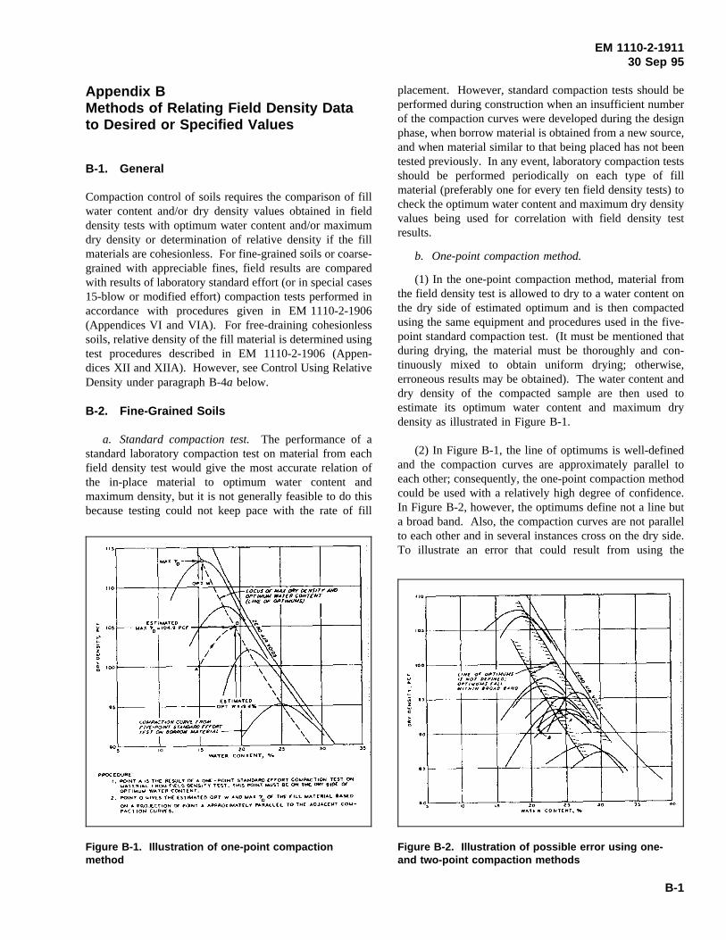
EM 1110-2-191130 Sep 95
Appendix BMethods of Relating Field Density Datato Desired or Specified Values
B-1. General
Figure B-1. Illustration of one-point compactionmethod
Compaction control of soils requires the comparison of fillwater content and/or dry density values obtained in fielddensity tests with optimum water content and/or maximumdry density or determination of relative density if the fillmaterials are cohesionless. For fine-grained soils or coarse-grained with appreciable fines, field results are comparedwith results of laboratory standard effort (or in special cases15-blow or modified effort) compaction tests performed inaccordance with procedures given in EM 1110-2-1906(Appendices VI and VIA). For free-draining cohesionlesssoils, relative density of the fill material is determined usingtest procedures described in EM 1110-2-1906 (Appen-dices XII and XIIA). However, see Control Using RelativeDensity under paragraph B-4a below.
B-2. Fine-Grained Soils
a. Standard compaction test.The performance of astandard laboratory compaction test on material from eachfield density test would give the most accurate relation ofthe in-place material to optimum water content andmaximum density, but it is not generally feasible to do thisbecause testing could not keep pace with the rate of fill
placement. However, standard compaction tests should be
Figure B-2. Illustration of possible error using one-and two-point compaction methods
performed during construction when an insufficient numberof the compaction curves were developed during the designphase, when borrow material is obtained from a new source,and when material similar to that being placed has not beentested previously. In any event, laboratory compaction testsshould be performed periodically on each type of fillmaterial (preferably one for every ten field density tests) tocheck the optimum water content and maximum dry densityvalues being used for correlation with field density testresults.
b. One-point compaction method.
(1) In the one-point compaction method, material fromthe field density test is allowed to dry to a water content onthe dry side of estimated optimum and is then compactedusing the same equipment and procedures used in the five-point standard compaction test. (It must be mentioned thatduring drying, the material must be thoroughly and con-tinuously mixed to obtain uniform drying; otherwise,erroneous results may be obtained). The water content anddry density of the compacted sample are then used toestimate its optimum water content and maximum drydensity as illustrated in Figure B-1.
(2) In Figure B-1, the line of optimums is well-definedand the compaction curves are approximately parallel toeach other; consequently, the one-point compaction methodcould be used with a relatively high degree of confidence.In Figure B-2, however, the optimums define not a line buta broad band. Also, the compaction curves are not parallelto each other and in several instances cross on the dry side.To illustrate an error that could result from using the
B-1
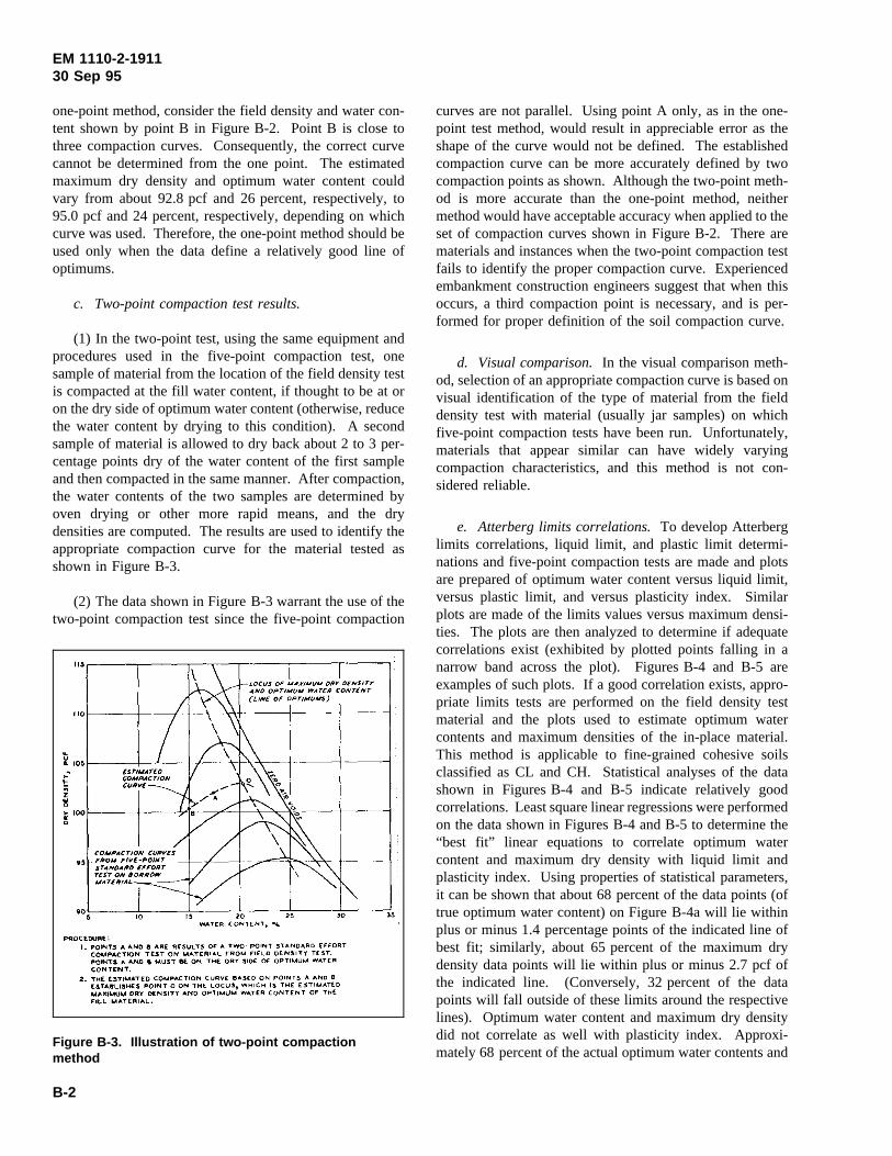
EM 1110-2-191130 Sep 95
one-point method, consider the field density and water con-tent shown by point B in Figure B-2. Point B is close tothree compaction curves. Consequently, the correct curvecannot be determined from the one point. The estimatedmaximum dry density and optimum water content couldvary from about 92.8 pcf and 26 percent, respectively, to95.0 pcf and 24 percent, respectively, depending on whichcurve was used. Therefore, the one-point method should beused only when the data define a relatively good line ofoptimums.
c. Two-point compaction test results.
(1) In the two-point test, using the same equipment andprocedures used in the five-point compaction test, onesample of material from the location of the field density testis compacted at the fill water content, if thought to be at oron the dry side of optimum water content (otherwise, reducethe water content by drying to this condition). A secondsample of material is allowed to dry back about 2 to 3 per-centage points dry of the water content of the first sampleand then compacted in the same manner. After compaction,the water contents of the two samples are determined byoven drying or other more rapid means, and the drydensities are computed. The results are used to identify theappropriate compaction curve for the material tested asshown in Figure B-3.
Figure B-3. Illustration of two-point compactionmethod
(2) The data shown in Figure B-3 warrant the use of thetwo-point compaction test since the five-point compaction
curves are not parallel. Using point A only, as in the one-point test method, would result in appreciable error as theshape of the curve would not be defined. The establishedcompaction curve can be more accurately defined by twocompaction points as shown. Although the two-point meth-od is more accurate than the one-point method, neithermethod would have acceptable accuracy when applied to theset of compaction curves shown in Figure B-2. There arematerials and instances when the two-point compaction testfails to identify the proper compaction curve. Experiencedembankment construction engineers suggest that when thisoccurs, a third compaction point is necessary, and is per-formed for proper definition of the soil compaction curve.
d. Visual comparison.In the visual comparison meth-od, selection of an appropriate compaction curve is based onvisual identification of the type of material from the fielddensity test with material (usually jar samples) on whichfive-point compaction tests have been run. Unfortunately,materials that appear similar can have widely varyingcompaction characteristics, and this method is not con-sidered reliable.
e. Atterberg limits correlations.To develop Atterberglimits correlations, liquid limit, and plastic limit determi-nations and five-point compaction tests are made and plotsare prepared of optimum water content versus liquid limit,versus plastic limit, and versus plasticity index. Similarplots are made of the limits values versus maximum densi-ties. The plots are then analyzed to determine if adequatecorrelations exist (exhibited by plotted points falling in anarrow band across the plot). Figures B-4 and B-5 areexamples of such plots. If a good correlation exists, appro-priate limits tests are performed on the field density testmaterial and the plots used to estimate optimum watercontents and maximum densities of the in-place material.This method is applicable to fine-grained cohesive soilsclassified as CL and CH. Statistical analyses of the datashown in Figures B-4 and B-5 indicate relatively goodcorrelations. Least square linear regressions were performedon the data shown in Figures B-4 and B-5 to determine the“best fit” linear equations to correlate optimum watercontent and maximum dry density with liquid limit andplasticity index. Using properties of statistical parameters,it can be shown that about 68 percent of the data points (oftrue optimum water content) on Figure B-4a will lie withinplus or minus 1.4 percentage points of the indicated line ofbest fit; similarly, about 65 percent of the maximum drydensity data points will lie within plus or minus 2.7 pcf ofthe indicated line. (Conversely, 32 percent of the datapoints will fall outside of these limits around the respectivelines). Optimum water content and maximum dry densitydid not correlate as well with plasticity index. Approxi-mately 68 percent of the actual optimum water contents and
B-2
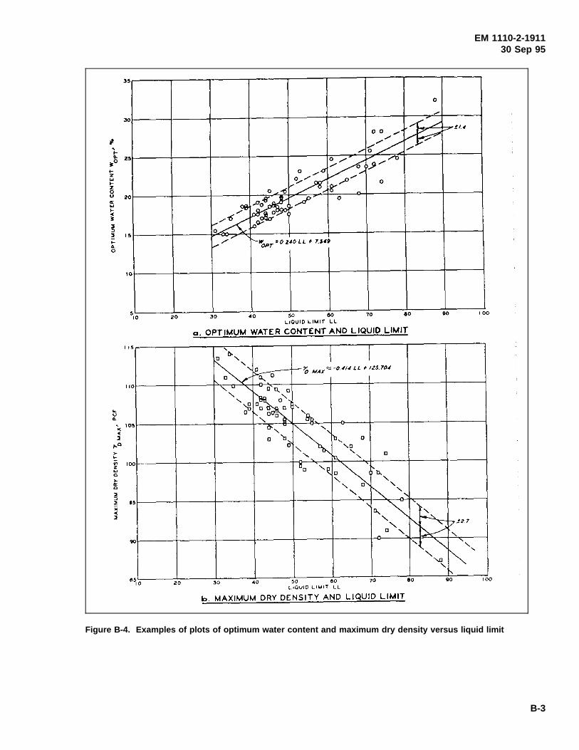
EM 1110-2-191130 Sep 95
Figure B-4. Examples of plots of optimum water content and maximum dry density versus liquid limit
B-3
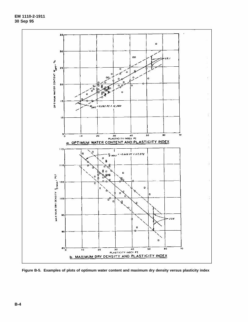
EM 1110-2-191130 Sep 95
Figure B-5. Examples of plots of optimum water content and maximum dry density versus plasticity index
B-4
EM 1110-2-191130 Sep 95
dry densities will be within ± 2.1 percent and 3.6 pcf,respectively, of those indicated by the lines of best fit.Therefore, when this method is used, it is very importantthat additional five-point compaction tests and Atterberglimits tests be performed to check the correlation and toextend the correlation for new borrow material for mixturesnot previously tested. The Atterberg limits correlationmethod includes more variables than the two-point methodand thus can be less accurate, depending on how carefullythe particular method is used. However, the limitscorrelation method has the advantage of providing the exactclassification of the soil, and of providing data that can becorrelated with design strength studies.
f. Analysis of Atterberg limits correlations.A dis-cussion of Atterberg limits correlations and comparison ofresults with the one-point method are given in by Torrey(1970). However, additional discussion of the method isdeemed appropriate here to point out mathematical weak-nesses in the procedure. In order to determine a mathe-matical relationship between the variables of interest (that isliquid limit, plastic limit, optimum water content, maximumdry density) using the methods of statistics, it is necessaryto assume a frequency distribution between the variables.It was assumed that there is a normal or Gaussian distri-bution between the variables. A normal distribution has avery specific mathematical definition and, although theassumption of normal distribution is reasonable, it must bepointed out that there is no insurance that the assumption isvalid. Additionally, it was assumed that the relationshipbetween the variables of interest is linear; again, there is noevidence to support such an assumption; in fact, it is verylikely that there is a curvilinear relationship between thevariables of interest. Analysis of the data presented in Fig-ures B-4 and B-5. showed that the linear correlations be-tween optimum water content and liquid limit (shown inFigure B-4a) and maximum density and liquid limit (shownin Figure B-4b) explain only 77.6 percent and 76.3 percent,respectively, of variation between the regression line and thedata points. This means that unidentified mechanismsexplain about one quarter of the variation between theregression line and the points. Similarly, the linear corre-lations between optimum water content and plasticity index(shown in Figure B-5a) and maximum dry density andplasticity index (shown in Figure B-5b) explain only57.8 percent and 55.7 percent of the variation, respectively;about 43 percent of the observed variation is unexplained bythe mathematical model chosen. In this light, the correlationbetween the variables appears less sound, especially con-sidering that there is no mathematical assurance that arelationship exists between these variables; the mathematicalcurve-fit procedure used in the analysis ensures only that themathematical expressions given are the best possible linearfits. The numbers defining the error bands of the regression
lines of Figures B-4 and B-5 are called the standard error ofthe estimate. Again, if the data are normally distributedabout this line, theory predicts that about 68 percent of thepoints lie between the (error band) lines. However, this alsoindicates that 32 percent (about one-third) of the points willstatistically lie outside the band. For example, since thestandard error between maximum dry density and liquidlimit is 2.7 pcf, if maximum dry density were estimatedbased on a determination of liquid limit of a soil sampletaken from the area, chances are about one in three that theerror in maximum density would be greater than 2.7 pcf. Inthis light, the use of this procedure to estimate eithermaximum dry density or optimum water content appears tobe unsound and inappropriate. The use of one- and two-point compaction test results appears to be much moresound, especially considering that the results of a one-pointcompaction test may be obtained in about 40 min usingmicrowave drying techniques outlined in paragraph 5-10d(1)(c). Conversely, the time required to obtain the results ofa liquid and/or plastic limit test may be prohibitive in aconstruction environment where large volume rates of earthare being placed.
g. USBR rapid compaction control method.Details ofthis method are described in the U.S. Bureau of ReclamationEarth Manual (1963). The test is applicable to fine-grained(100 percent minus No. 4 sieve) cohesive soils with liquidlimits less than 50. The method, however, is applicable tosoils containing oversize particles providing the propercorrections, as stated in Torrey (1970) or in the EarthManual (1963), are applied. It is a faster method than thestandard compaction test, and is often more accurate thanother methods. The method usually requires adding waterto or drying back sampled fill material, and thorough mixingis required to obtain uniform drying or distribution of addedwater. Otherwise, the results may be erroneous, especiallyfor highly plastic clays. In highly plastic (and probablydifficult) clays, it is likely to be inaccurate because of thelack of sufficient curing time of the specimens.
B-3. Cohesive Soils
a. Oversize particles.The term “oversize particles” asused in this work refers to those particles larger than themaximum size allowed when using a given mold (i.e., No. 4for a 4-in. mold, 3/4-in. for a 6-in. mold, 2-in. for a 12-in.mold). The term “fine fraction” refers to that part of thesoil composed of particles equal to and smaller than themaximum size allowed for a given mold. Results of fielddensity tests made in fill material containing oversizeparticles must sometimes be related to results of compactiontests made on materials from which oversize particles havebeen scalped, if the USBR rapid compaction control methodis used, or if it has not been possible to perform compaction
B-5
EM 1110-2-191130 Sep 95
tests using molds of sufficient size to accommodate thelarge particles.
b. Correction of field density test results.When theproportion of oversize material is not greater than about35 percent, the dry density of the fine fraction can becalculated with reasonable accuracy from the followingequation which associates all voids with the fine fraction:
(B-1)γf
fγtγwGm
γwGm cγt
where
γf = dry density of fine fraction, pcff = proportion of fine fraction by weight expressed
as a decimal fractionγt = dry density of total field sample, pcfγw = unit weight of water, 62.4 pcf
Gm = bulk specific gravity of oversize particles (drymethod), dimensionless
c = proportion of oversize particles by weightexpressed as a decimal fraction
The water content of the fine fraction can be calculatedfrom the following equation:
(B-2)wf
wt cwc
f× 100
where
wf = water content of fine fraction, percentwt = water content of the total field density sample,
expressed as a decimal fractionwc = water content of oversize fraction, expressed as a
decimal fraction
At the beginning of construction, charts can be prepared formaterials having oversize particles relating dry densities andwater contents of total samples to dry densities and watercontents of fine fractions (Figures B-6a and B-6b) if it isdesired to use the original Ziegler equation. Different chartsare required for materials having oversize particles withsignificantly different bulk specific gravity and/or absorptionvalues. In field density testing, the appropriate chart isentered using the percent oversize particles and the watercontent or dry density determined on the total sample toobtain the water content, dry density, and wet density of thefine fraction. Corrections for oversize particles will be sub-ject to large errors if the percent of oversize particles isgreater than about 35; in such cases, compaction control
should be based on laboratory compaction tests performedin molds of appropriate sizes.
c. Modified Ziegler equation to estimate maximum den-sity. A procedure to compute dry density of earth-rock mix-tures has been determined as an extension of the Zieglerprocedure and is discussed by Torrey and Donaghe (1991);the procedure is a modification of the development whichresulted in Equation B-1. The modified equation accountsfor the actual percent compaction of the gravel fractionwhen the total material (gravel and fines) is at its maximumdensity. This is done by incorporating the effect of a factorcalled the density interference coefficient, which is definedas
(B-3)Ic
Rc
PgGm
where
Rc = decimal fraction of the percent compaction ofthe minus No. 4 or -3/4-in. fraction
Pg = decimal fraction of percent gravel in the totalmaterial
Gm = bulk specific gravity of the gravel
To determine the maximum dry density corresponding to thegradation of the total fill sample, use the equation
(B-4)γtmax
PgIcγfmaxγwGm
fγw PgcIcγfmax
where
γtmax = maximum dry density of the gradation of thetotal fill
γfmax = maximum dry density of the finer fractiondetermined at its optimum water content,Wfopt,by the one- or two-point compaction method
It should be noted thatγfmax may be determined based ongravel content defined as either the -3/4-in. or the minusNo. 4 sieve fraction of the total material to be placed in thefill. However, it is more efficient to use the minus No. 4fraction because percent oversize particles (c) and percentgravel in the total material (Pg) are the same number. Thiswill eliminate an extra sieving operation which would berequired if γfmax and Wfopt are used for the -3/4-in. fraction,since both the percent oversize (+3/4-in. material) and thepercent gravel in the total material would have to bedetermined. To facilitate its numerical evaluation,Equation B-4 may be rewritten in the form
B-6
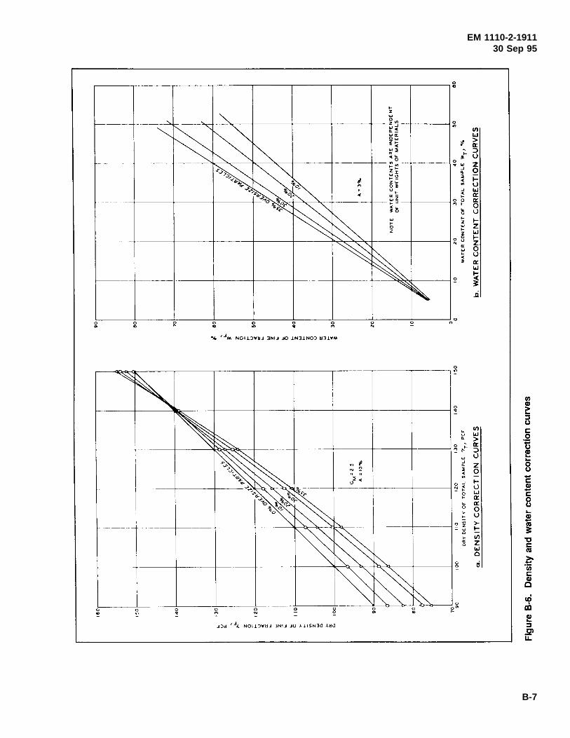
EM 1110-2-191130 Sep 95
B-7
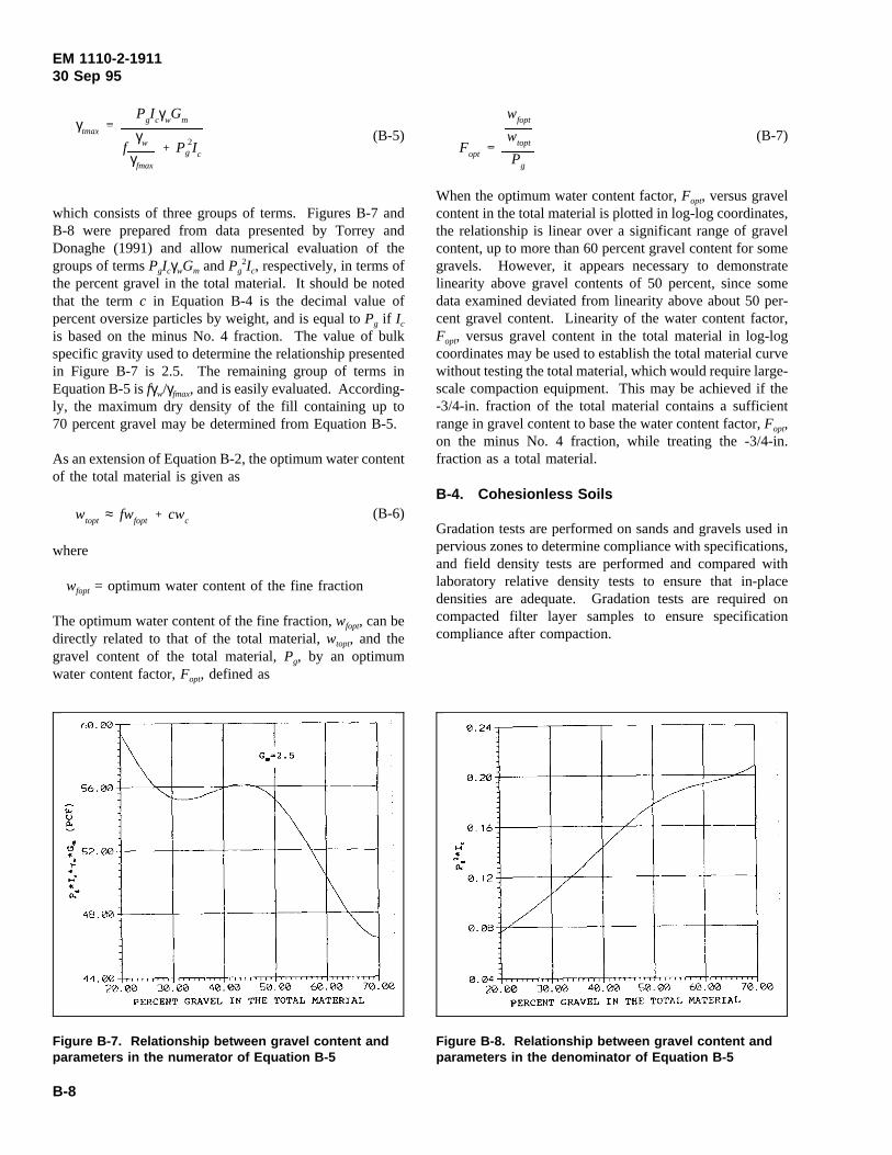
EM 1110-2-191130 Sep 95
(B-5)γtmax
PgIcγwGm
fγw
γfmax
P 2g Ic
Figure B-7. Relationship between gravel content andparameters in the numerator of Equation B-5
Figure B-8. Relationship between gravel content andparameters in the denominator of Equation B-5
which consists of three groups of terms. Figures B-7 andB-8 were prepared from data presented by Torrey andDonaghe (1991) and allow numerical evaluation of thegroups of termsPgIcγwGm andPg
2Ic, respectively, in terms ofthe percent gravel in the total material. It should be notedthat the termc in Equation B-4 is the decimal value ofpercent oversize particles by weight, and is equal toPg if Ic
is based on the minus No. 4 fraction. The value of bulkspecific gravity used to determine the relationship presentedin Figure B-7 is 2.5. The remaining group of terms inEquation B-5 isfγw/γfmax, and is easily evaluated. According-ly, the maximum dry density of the fill containing up to70 percent gravel may be determined from Equation B-5.
As an extension of Equation B-2, the optimum water contentof the total material is given as
(B-6)wtopt ≈ fwfopt cwc
where
wfopt = optimum water content of the fine fraction
The optimum water content of the fine fraction,wfopt, can bedirectly related to that of the total material,wtopt, and thegravel content of the total material,Pg, by an optimumwater content factor,Fopt, defined as
(B-7)Fopt
wfopt
wtopt
Pg
When the optimum water content factor,Fopt, versus gravelcontent in the total material is plotted in log-log coordinates,the relationship is linear over a significant range of gravelcontent, up to more than 60 percent gravel content for somegravels. However, it appears necessary to demonstratelinearity above gravel contents of 50 percent, since somedata examined deviated from linearity above about 50 per-cent gravel content. Linearity of the water content factor,Fopt, versus gravel content in the total material in log-logcoordinates may be used to establish the total material curvewithout testing the total material, which would require large-scale compaction equipment. This may be achieved if the-3/4-in. fraction of the total material contains a sufficientrange in gravel content to base the water content factor,Fopt,on the minus No. 4 fraction, while treating the -3/4-in.fraction as a total material.
B-4. Cohesionless Soils
Gradation tests are performed on sands and gravels used inpervious zones to determine compliance with specifications,and field density tests are performed and compared withlaboratory relative density tests to ensure that in-placedensities are adequate. Gradation tests are required oncompacted filter layer samples to ensure specificationcompliance after compaction.
B-8
EM 1110-2-191130 Sep 95
a. Control using relative density. Where materialsavailable for cohesionless fill vary significantly in gradation,maximum-minimum density tests should be performed onmaterial from each field density test at least in the initialconstruction stages. Where cohesionless materials can begrouped into categories with relatively constant gradations,relative density tests and gradation tests can be performedon each different material. Gradation tests on material fromfield density tests can then make it possible to match fielddensities with appropriate relative density test results.However, it is necessary to point out that relative density iscomputed from maximum and minimum densities deter-mined on the material in question, using the procedureoutlined in EM 1110-2-1906. It was concluded by ASTM(1973) that the maximum density of cohesionless materialsas determined on the “vibratory table” (as described inEM 1110-2-1906) is subject to considerable uncertainty.Further, the conclusions are that vibratory tables cannot, ingeneral, be successfully calibrated for repeatable energyapplication to the soil specimen, large local densityvariations exist throughout the vibrated soil specimen, anddensity results obtained with the vibratory table aregenerally not repeatable from laboratory to laboratory.Therefore, control of the gradation and density ofcohesionless fill using the method of relative density may beunacceptable, especially if the procedure involvescoordinated effort and testing between two laboratories. Anexample is given by ASTM (1973) in which the standarddeviation in maximum density of one sand tested by14 laboratories is greater than 6 pcf. It is specified inEM 1110-2-1906 that minimum density tests be repeateduntil densities from two successive runs agree within±1 percent. Maximum density is then obtained by placinga minimum density specimen on the vibratory table; onlyone maximum density test is required. Variation and uncer-tainty in laboratory-measured values of maximum densitycan cause serious problems in the construction of cohesion-less fill and graded filters. Basic laboratory research isneeded to resolve difficulties with the shaking table test formaximum density. Until research is performed and the
source of uncertainty identified and resolved, particular careand caution should be used in determining maximumdensity. One method of minimizing uncertainty is to per-form several maximum density tests to determine and ensurethat large variations in maximum density are not beingobserved. A control criterion for maximum density speci-mens similar to that for minimum density specimens may beused—that is, agreement between two successive specimenswithin ±1 percent.
b. Alternative maximum density procedure.In light ofthe difficulty of obtaining duplicate results of maximumdensity on the vibratory table, consideration must be givento eliminating the test. A possible alternative procedure formaximum density determination is the Modified ProvidenceVibrated Density Test as described in EM 1110-2-1906. Inthis test, a sample of oven-dried soil is placed in a heavysteel mold, compressed under a surcharge, and vibrated toa maximum density by repeatedly striking the side of themold with a hammer. Research presented by Tokue (1976)suggests that the level of shear strain, not acceleration, isdirectly related to densification of cohesionless soil. Manyof the unknown uncertainties associated with the vibratorytable may be avoided by use of this relatively simpleprocedure.
c. Materials with +3-in. particles. Relative densitytests described in EM 1110-2-1906 are performed on cohe-sionless soils with particle sizes not greater than 3 in. Ifcohesionless soils contain a large amount of +3-in. material,large-scale field density tests would be needed forcomparison with results of field density tests performedduring construction of test fills to develop adequate com-paction procedures. When no field density test results areavailable, control is achieved by careful inspection to ensurethat the specified gradation is being met and that thespecified compaction procedures are followed. Visual in-spection of the sides of a test pit dug in the compacted fillcan provide qualitative indications of the denseness of thematerial and of the existence of any significant voids.
B-9
EM 1110-2-191130 Sep 95
Appendix CField Compaction Control Forms andSupplemental Instructions
C-1. General
ENG Form 4080 (Figure C-1) is for use where water con-tent control is required to obtain adequate compaction; thetitle of this form is “Summary of Field Compaction Controlof Impervious or Semipervious Soils for Civil WorksProjects.” ENG Form 4081 (Figure C-2) is for use whenwater content control (other than complete saturation) is notrequired; the title of this form is “Summary of Field Com-paction Control of Pervious Soils and Rockfill for CivilWorks Projects.” Use of these forms is described inER 1110-2-1925.
a. A database package utilizing the commerciallyavailable software routine dBase III Plus (Trademark ofAshton-Tate) was developed around the information requiredfor ENG Forms 4080 and 4081; the system uses the micro-computer to analyze data for use in the quality assurance(QA) program. Specially prepared Computer Applicationsin Geotechnical Engineering (CAGE) software interacts withthe database to reduce data, perform statistical analysis, andgenerate ENG Forms 4080 and 4081 with the informationrequired for reporting. Data from field notes is entered intoa microcomputer in a dBase III-driven format; for datamanipulation, the system is menu driven and user inter-active. CAGE is designed to store, retrieve, and displayearthwork construction control data as well as providesummaries of required construction parameters. Hard copiesof any of the summaries, reports, and graphs generated maybe printed by the system along with computer-generatedcopies of ENG Forms 4080 and 4081 if they are required inhard copy form. The use and operation of the CAGEsystem is described by Edris, Strohm, and Woo (1991).
b. If construction control data are recorded manually onENG Forms 4080 and 4081, information at the top of eachform could be placed on a master sheet from which repro-ducible copies could be made for recording data and formaking subsequent copies for submission.
c. Explanation of any abbreviations used which are notexplained in the forms, should be furnished with the firstreport submitted on a project.
d. Lower lines of the forms may be used for necessaryremarks.
C-2. Additional Information
Information on items below, as appropriate, should be sub-mitted with the initial reports and also whenever changes aremade.
a. Borrow sources and operations.
(1) Description of borrow materials (each borrow or ex-cavation area).
(2) Natural water content.
(3) Method of adding water in pit.
(4) Method of reducing water content in pit.
(5) Method of excavating and mixing (describe equip-ment used).
(6) Equipment used for loading and transporting mate-rial.
b. Compaction equipment.Describe in detail.
(1) Sheepsfoot roller.
(a) Make, model, and whether self-propelled or towed.
(b) State size (diameter and length) and number ofdrums.
(c) Describe tamping feet: number of rows, feet perrow, and total number of feet per drum; length, shape andbase area of foot.
(d) Give weight of roller empty, weight as used, type ofballast, and unit pressure (weight of roller divided by totalcontact areas of tamping feet).
(e) Specify type of frame (rigid or oscillating), speed oftravel during compaction, and if cleaners are used.
(2) Rubber-tired roller.
(a) Make and model.
(b) Number of boxes or sections, rolling width, overallwidth and length.
(c) Number of tires, tire size, ply rating and spacing.
C-1
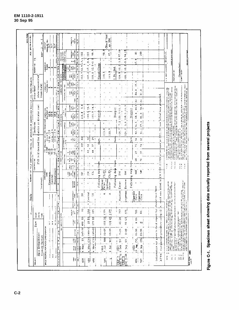
EM 1110-2-191130 Sep 95
C-2
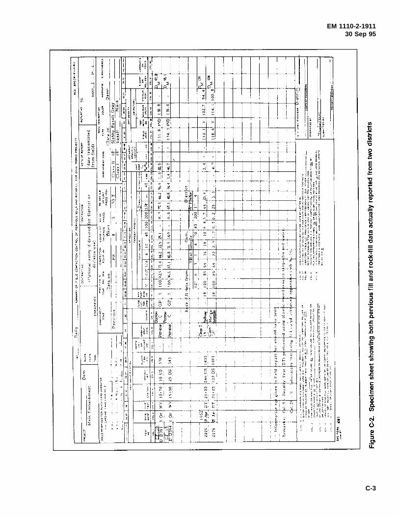
EM 1110-2-191130 Sep 95
C-3

EM 1110-2-191130 Sep 95
(d) Weight empty and as used, type of ballast, tirepressure, and load per tire as used.
(e) Speed of travel during compaction.
(3) Vibratory roller.
(a) Make and model.
(b) State size (diameter and length) and number ofdrums.
(c) Give weight of roller empty, static weight per rollerused, dynamic ground pressure exerted, type of ballast, andvibrating frequency.
(d) Speed of travel during compaction.
c. Embankment operations.
(1) Type of equipment used in spreading and mixing thematerial.
(2) Method of removing oversize rock fragments.
(3) Method of adding water on the fill.
(4) Method of reducing water content of the fill.
d. Compaction control methods.
(1) For impervious or semipervious fill: Describe themethods used to determine in-place density and water con-tent. Also report method of correcting for oversize particlesand for correlating field density and water content formaterial with oversize particles with laboratory density andwater content. Submit a copy of any reference curves usedfor correlating the field data with the laboratory data.
(2) For pervious fill or rock fill: Describe in detailmethods used in determining laboratory maximum and mini-mum densities (if different from those specified inEM 1110-2-1906) and in determining field densities ofpervious soils and rock fill. Also include details of methodsused for correlating field and laboratory densities indetermining percent compaction or relative density anddetails of methods used in correcting for oversize particles.
C-4
EM 1110-2-191130 Sep 95
Appendix DInstructions for Preparing PeriodicSummaries of Field Compaction ControlData on Earth and Rock-Fill Dams
D-1. Compaction Control Data Summary Forms
Summaries of compaction control data are prepared at leastmonthly, using tabular summary form, ENG Form 4287, andone or both of two summary plots: ENG Form 4287A forsoils requiring control of both water content and density andENG Form 4287B for soils requiring only density control.
D-2. Separate Summary Forms and Plots
Separate summary forms and plots should be prepared for(a) significantly different materials (impervious, random,pervious, etc.) used in different zones of the embankmentand (b) materials compacted by different equipment (e.g.,impervious fill compacted by towed rollers and imperviousbackfill compacted by hand-operated power tampers).
D-3. Example Summary Forms and Plots
Examples of prepared summary forms and plots are shownin Figures D-1 through D-4. Examples of appropriate en-tries for tabular summaries are given in Table D-1.
D-4. Summary Plot for Materials RequiringWater Content and Density Control
A summary plot for materials requiring water content anddensity control is illustrated in Figure D-2. Two vertical
lines are first drawn on the plot to show the limiting valuesof water content in percentage points wet or dry of standardoptimum. A horizontal line is drawn to show the desired orspecified minimum percent of maximum standard and drydensity. The top margin and right side margin of the plotare marked to show the limiting values illustrated inFigure D-2. The data are then plotted using symbols shownon the legend. Should an area be reworked more than onceor reworked and tested more than once, only the last testresult or last set of test results should be plotted. The testresults are summarized in the tabulation form on the rightside of the plot in Figure D-2. Total number of tests is thetotal number of plotted data points excluding retests andcheck tests. Check tests should not be included in thenumber retested.
D-5. Summary Plot for Materials Requiring OnlyDensity Control
Use of the summary plot for material requiring only densitycontrol is illustrated in Figure D-4. Inappropriate labels atthe top and bottom of the plot are lined out. If control isbased on maximum density determined using a vibratoryprocedure, “STD” should also be lined out. Suitable scalesare added to the plot, and a vertical line is drawn to indicatethe minimum value of relative density, minimum percent ofmaximum standard dry density, or minimum percent ofmaximum dry density by a vibratory procedure, whicheverapplies.
D-1
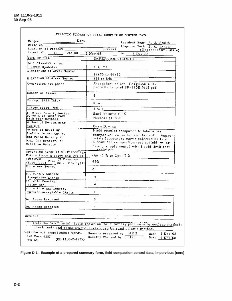
EM 1110-2-191130 Sep 95
Figure D-1. Example of a prepared summary form, field compaction control data, impervious (core)
D-2
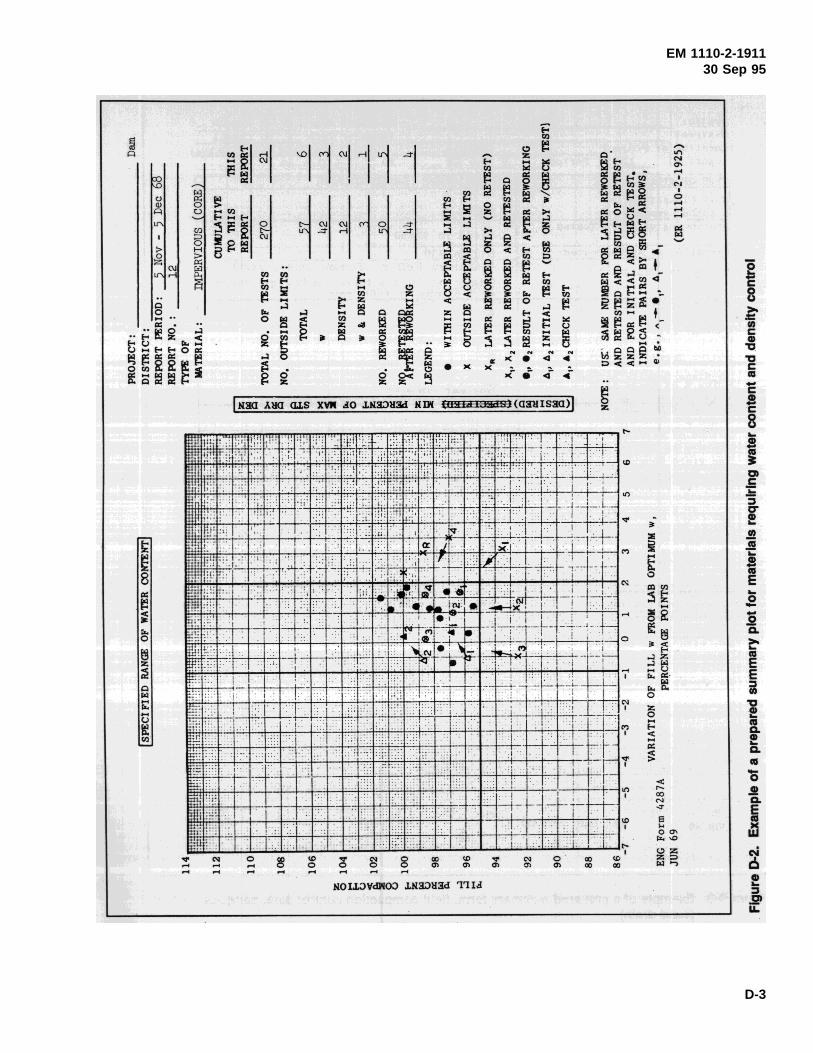
EM 1110-2-191130 Sep 95
D-3
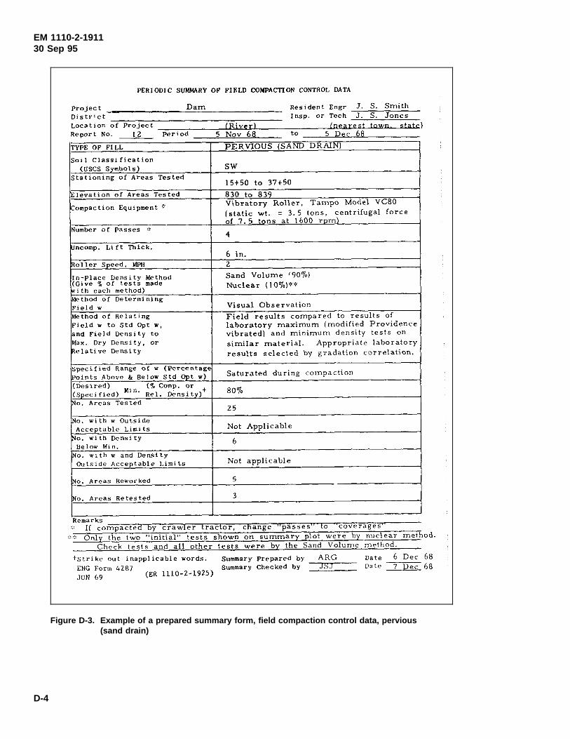
EM 1110-2-191130 Sep 95
Figure D-3. Example of a prepared summary form, field compaction control data, pervious(sand drain)
D-4
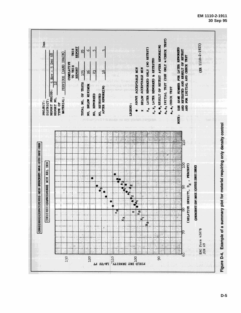
EM 1110-2-191130 Sep 95
D-5
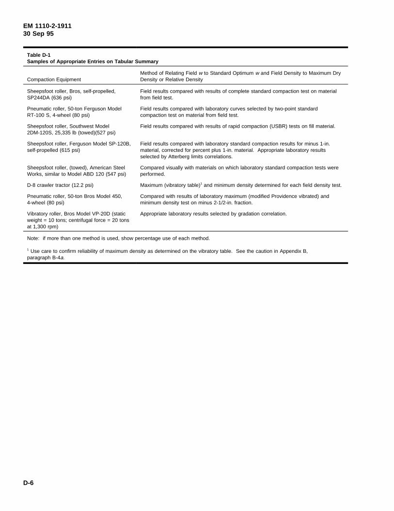
EM 1110-2-191130 Sep 95
Table D-1Samples of Appropriate Entries on Tabular Summary
Compaction EquipmentMethod of Relating Field w to Standard Optimum w and Field Density to Maximum DryDensity or Relative Density
Sheepsfoot roller, Bros, self-propelled,SP244DA (636 psi)
Field results compared with results of complete standard compaction test on materialfrom field test.
Pneumatic roller, 50-ton Ferguson ModelRT-100 S, 4-wheel (80 psi)
Field results compared with laboratory curves selected by two-point standardcompaction test on material from field test.
Sheepsfoot roller, Southwest Model2DM-120S, 25,335 lb (towed)(527 psi)
Field results compared with results of rapid compaction (USBR) tests on fill material.
Sheepsfoot roller, Ferguson Model SP-120B,self-propelled (615 psi)
Field results compared with laboratory standard compaction results for minus 1-in.material, corrected for percent plus 1-in. material. Appropriate laboratory resultsselected by Atterberg limits correlations.
Sheepsfoot roller, (towed), American SteelWorks, similar to Model ABD 120 (547 psi)
Compared visually with materials on which laboratory standard compaction tests wereperformed.
D-8 crawler tractor (12.2 psi) Maximum (vibratory table)1 and minimum density determined for each field density test.
Pneumatic roller, 50-ton Bros Model 450,4-wheel (80 psi)
Compared with results of laboratory maximum (modified Providence vibrated) andminimum density test on minus 2-1/2-in. fraction.
Vibratory roller, Bros Model VP-20D (staticweight = 10 tons; centrifugal force = 20 tonsat 1,300 rpm)
Appropriate laboratory results selected by gradation correlation.
Note: if more than one method is used, show percentage use of each method.
1 Use care to confirm reliability of maximum density as determined on the vibratory table. See the caution in Appendix B,paragraph B-4a.
D-6
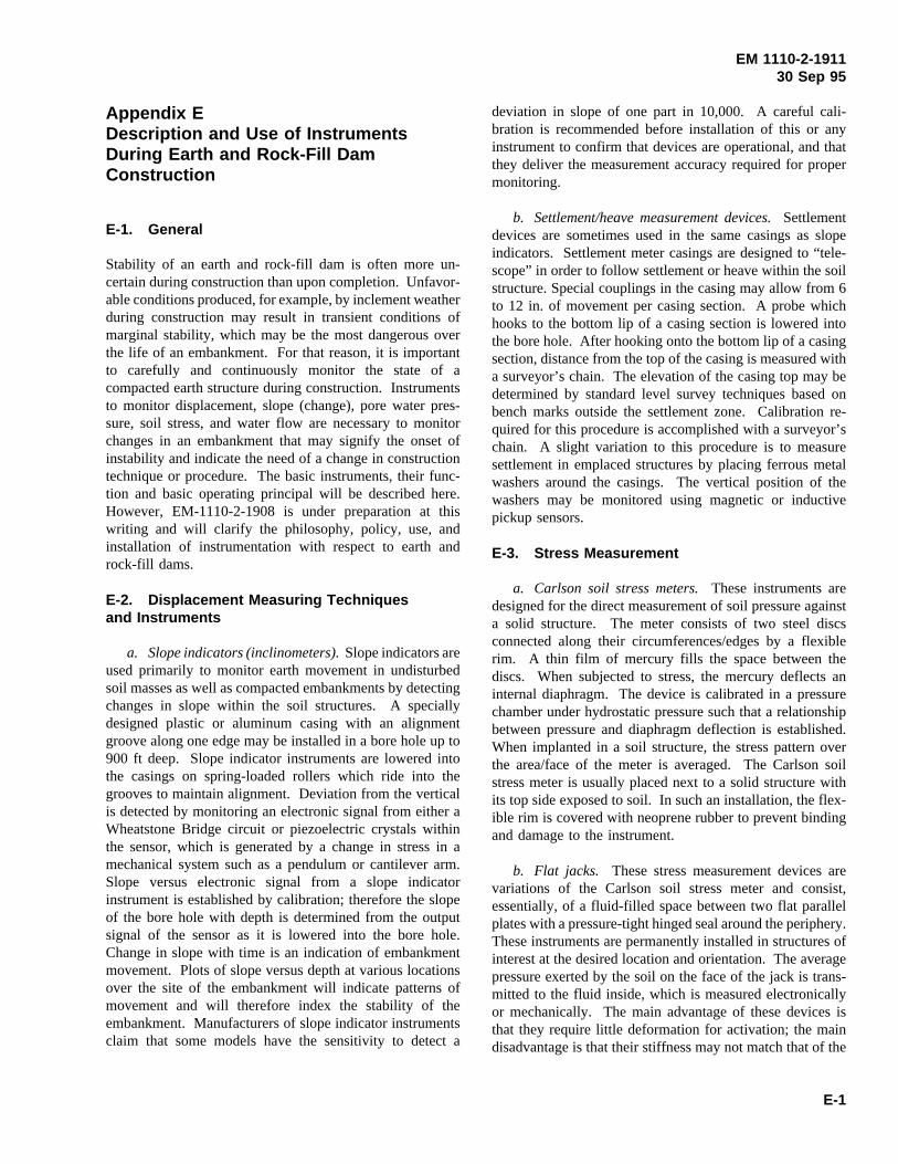
EM 1110-2-191130 Sep 95
Appendix EDescription and Use of InstrumentsDuring Earth and Rock-Fill DamConstruction
E-1. General
Stability of an earth and rock-fill dam is often more un-certain during construction than upon completion. Unfavor-able conditions produced, for example, by inclement weatherduring construction may result in transient conditions ofmarginal stability, which may be the most dangerous overthe life of an embankment. For that reason, it is importantto carefully and continuously monitor the state of acompacted earth structure during construction. Instrumentsto monitor displacement, slope (change), pore water pres-sure, soil stress, and water flow are necessary to monitorchanges in an embankment that may signify the onset ofinstability and indicate the need of a change in constructiontechnique or procedure. The basic instruments, their func-tion and basic operating principal will be described here.However, EM-1110-2-1908 is under preparation at thiswriting and will clarify the philosophy, policy, use, andinstallation of instrumentation with respect to earth androck-fill dams.
E-2. Displacement Measuring Techniquesand Instruments
a. Slope indicators (inclinometers).Slope indicators areused primarily to monitor earth movement in undisturbedsoil masses as well as compacted embankments by detectingchanges in slope within the soil structures. A speciallydesigned plastic or aluminum casing with an alignmentgroove along one edge may be installed in a bore hole up to900 ft deep. Slope indicator instruments are lowered intothe casings on spring-loaded rollers which ride into thegrooves to maintain alignment. Deviation from the verticalis detected by monitoring an electronic signal from either aWheatstone Bridge circuit or piezoelectric crystals withinthe sensor, which is generated by a change in stress in amechanical system such as a pendulum or cantilever arm.Slope versus electronic signal from a slope indicatorinstrument is established by calibration; therefore the slopeof the bore hole with depth is determined from the outputsignal of the sensor as it is lowered into the bore hole.Change in slope with time is an indication of embankmentmovement. Plots of slope versus depth at various locationsover the site of the embankment will indicate patterns ofmovement and will therefore index the stability of theembankment. Manufacturers of slope indicator instrumentsclaim that some models have the sensitivity to detect a
deviation in slope of one part in 10,000. A careful cali-bration is recommended before installation of this or anyinstrument to confirm that devices are operational, and thatthey deliver the measurement accuracy required for propermonitoring.
b. Settlement/heave measurement devices.Settlementdevices are sometimes used in the same casings as slopeindicators. Settlement meter casings are designed to “tele-scope” in order to follow settlement or heave within the soilstructure. Special couplings in the casing may allow from 6to 12 in. of movement per casing section. A probe whichhooks to the bottom lip of a casing section is lowered intothe bore hole. After hooking onto the bottom lip of a casingsection, distance from the top of the casing is measured witha surveyor’s chain. The elevation of the casing top may bedetermined by standard level survey techniques based onbench marks outside the settlement zone. Calibration re-quired for this procedure is accomplished with a surveyor’schain. A slight variation to this procedure is to measuresettlement in emplaced structures by placing ferrous metalwashers around the casings. The vertical position of thewashers may be monitored using magnetic or inductivepickup sensors.
E-3. Stress Measurement
a. Carlson soil stress meters.These instruments aredesigned for the direct measurement of soil pressure againsta solid structure. The meter consists of two steel discsconnected along their circumferences/edges by a flexiblerim. A thin film of mercury fills the space between thediscs. When subjected to stress, the mercury deflects aninternal diaphragm. The device is calibrated in a pressurechamber under hydrostatic pressure such that a relationshipbetween pressure and diaphragm deflection is established.When implanted in a soil structure, the stress pattern overthe area/face of the meter is averaged. The Carlson soilstress meter is usually placed next to a solid structure withits top side exposed to soil. In such an installation, the flex-ible rim is covered with neoprene rubber to prevent bindingand damage to the instrument.
b. Flat jacks. These stress measurement devices arevariations of the Carlson soil stress meter and consist,essentially, of a fluid-filled space between two flat parallelplates with a pressure-tight hinged seal around the periphery.These instruments are permanently installed in structures ofinterest at the desired location and orientation. The averagepressure exerted by the soil on the face of the jack is trans-mitted to the fluid inside, which is measured electronicallyor mechanically. The main advantage of these devices isthat they require little deformation for activation; the maindisadvantage is that their stiffness may not match that of the
E-1
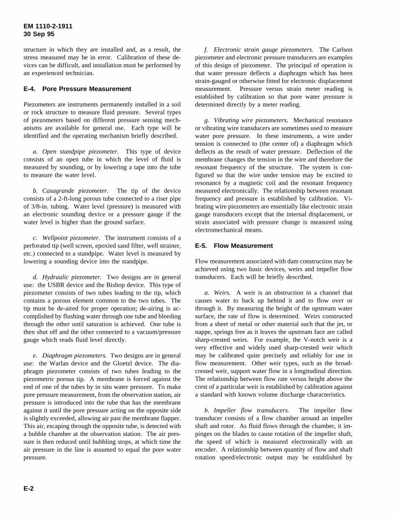
EM 1110-2-191130 Sep 95
structure in which they are installed and, as a result, thestress measured may be in error. Calibration of these de-vices can be difficult, and installation must be performed byan experienced technician.
E-4. Pore Pressure Measurement
Piezometers are instruments permanently installed in a soilor rock structure to measure fluid pressure. Several typesof piezometers based on different pressure sensing mech-anisms are available for general use. Each type will beidentified and the operating mechanism briefly described.
a. Open standpipe piezometer.This type of deviceconsists of an open tube in which the level of fluid ismeasured by sounding, or by lowering a tape into the tubeto measure the water level.
b. Casagrande piezometer.The tip of the deviceconsists of a 2-ft-long porous tube connected to a riser pipeof 3/8-in. tubing. Water level (pressure) is measured withan electronic sounding device or a pressure gauge if thewater level is higher than the ground surface.
c. Wellpoint piezometer.The instrument consists of aperforated tip (well screen, epoxied sand filter, well strainer,etc.) connected to a standpipe. Water level is measured bylowering a sounding device into the standpipe.
d. Hydraulic piezometer.Two designs are in generaluse: the USBR device and the Bishop device. This type ofpiezometer consists of two tubes leading to the tip, whichcontains a porous element common to the two tubes. Thetip must be de-aired for proper operation; de-airing is ac-complished by flushing water through one tube and bleedingthrough the other until saturation is achieved. One tube isthen shut off and the other connected to a vacuum/pressuregauge which reads fluid level directly.
e. Diaphragm piezometers.Two designs are in generaluse: the Warlan device and the Gloetzl device. The dia-phragm piezometer consists of two tubes leading to thepiezometric porous tip. A membrane is forced against theend of one of the tubes by in situ water pressure. To makepore pressure measurement, from the observation station, airpressure is introduced into the tube that has the membraneagainst it until the pore pressure acting on the opposite sideis slightly exceeded, allowing air past the membrane flapper.This air, escaping through the opposite tube, is detected witha bubble chamber at the observation station. The air pres-sure is then reduced until bubbling stops, at which time theair pressure in the line is assumed to equal the pore waterpressure.
f. Electronic strain gauge piezometers.The Carlsonpiezometer and electronic pressure transducers are examplesof this design of piezometer. The principal of operation isthat water pressure deflects a diaphragm which has beenstrain-gauged or otherwise fitted for electronic displacementmeasurement. Pressure versus strain meter reading isestablished by calibration so that pore water pressure isdetermined directly by a meter reading.
g. Vibrating wire piezometers.Mechanical resonanceor vibrating wire transducers are sometimes used to measurewater pore pressure. In these instruments, a wire undertension is connected to (the center of) a diaphragm whichdeflects as the result of water pressure. Deflection of themembrane changes the tension in the wire and therefore theresonant frequency of the structure. The system is con-figured so that the wire under tension may be excited toresonance by a magnetic coil and the resonant frequencymeasured electronically. The relationship between resonantfrequency and pressure is established by calibration. Vi-brating wire piezometers are essentially like electronic straingauge transducers except that the internal displacement, orstrain associated with pressure change is measured usingelectromechanical means.
E-5. Flow Measurement
Flow measurement associated with dam construction may beachieved using two basic devices, weirs and impeller flowtransducers. Each will be briefly described.
a. Weirs. A weir is an obstruction in a channel thatcauses water to back up behind it and to flow over orthrough it. By measuring the height of the upstream watersurface, the rate of flow is determined. Weirs constructedfrom a sheet of metal or other material such that the jet, ornappe, springs free as it leaves the upstream face are calledsharp-crested weirs. For example, the V-notch weir is avery effective and widely used sharp-crested weir whichmay be calibrated quite precisely and reliably for use inflow measurement. Other weir types, such as the broad-crested weir, support water flow in a longitudinal direction.The relationship between flow rate versus height above thecrest of a particular weir is established by calibration againsta standard with known volume discharge characteristics.
b. Impeller flow transducers. The impeller flowtransducer consists of a flow chamber around an impellershaft and rotor. As fluid flows through the chamber, it im-pinges on the blades to cause rotation of the impeller shaft,the speed of which is measured electronically with anencoder. A relationship between quantity of flow and shaftrotation speed/electronic output may be established by
E-2
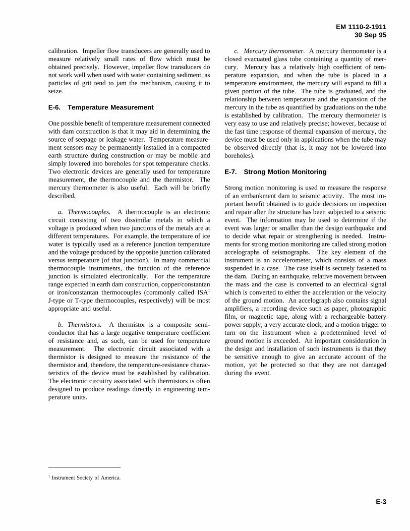
EM 1110-2-191130 Sep 95
calibration. Impeller flow transducers are generally used tomeasure relatively small rates of flow which must beobtained precisely. However, impeller flow transducers donot work well when used with water containing sediment, asparticles of grit tend to jam the mechanism, causing it toseize.
E-6. Temperature Measurement
One possible benefit of temperature measurement connectedwith dam construction is that it may aid in determining thesource of seepage or leakage water. Temperature measure-ment sensors may be permanently installed in a compactedearth structure during construction or may be mobile andsimply lowered into boreholes for spot temperature checks.Two electronic devices are generally used for temperaturemeasurement, the thermocouple and the thermistor. Themercury thermometer is also useful. Each will be brieflydescribed.
a. Thermocouples. A thermocouple is an electroniccircuit consisting of two dissimilar metals in which avoltage is produced when two junctions of the metals are atdifferent temperatures. For example, the temperature of icewater is typically used as a reference junction temperatureand the voltage produced by the opposite junction calibratedversus temperature (of that junction). In many commercialthermocouple instruments, the function of the referencejunction is simulated electronically. For the temperaturerange expected in earth dam construction, copper/constantanor iron/constantan thermocouples (commonly called ISA1
J-type or T-type thermocouples, respectively) will be mostappropriate and useful.
b. Thermistors. A thermistor is a composite semi-conductor that has a large negative temperature coefficientof resistance and, as such, can be used for temperaturemeasurement. The electronic circuit associated with athermistor is designed to measure the resistance of thethermistor and, therefore, the temperature-resistance charac-teristics of the device must be established by calibration.The electronic circuitry associated with thermistors is oftendesigned to produce readings directly in engineering tem-perature units.
1 Instrument Society of America.
c. Mercury thermometer.A mercury thermometer is aclosed evacuated glass tube containing a quantity of mer-cury. Mercury has a relatively high coefficient of tem-perature expansion, and when the tube is placed in atemperature environment, the mercury will expand to fill agiven portion of the tube. The tube is graduated, and therelationship between temperature and the expansion of themercury in the tube as quantified by graduations on the tubeis established by calibration. The mercury thermometer isvery easy to use and relatively precise; however, because ofthe fast time response of thermal expansion of mercury, thedevice must be used only in applications when the tube maybe observed directly (that is, it may not be lowered intoboreholes).
E-7. Strong Motion Monitoring
Strong motion monitoring is used to measure the responseof an embankment dam to seismic activity. The most im-portant benefit obtained is to guide decisions on inspectionand repair after the structure has been subjected to a seismicevent. The information may be used to determine if theevent was larger or smaller than the design earthquake andto decide what repair or strengthening is needed. Instru-ments for strong motion monitoring are called strong motionaccelographs of seismographs. The key element of theinstrument is an accelerometer, which consists of a masssuspended in a case. The case itself is securely fastened tothe dam. During an earthquake, relative movement betweenthe mass and the case is converted to an electrical signalwhich is converted to either the acceleration or the velocityof the ground motion. An accelograph also contains signalamplifiers, a recording device such as paper, photographicfilm, or magnetic tape, along with a rechargeable batterypower supply, a very accurate clock, and a motion trigger toturn on the instrument when a predetermined level ofground motion is exceeded. An important consideration inthe design and installation of such instruments is that theybe sensitive enough to give an accurate account of themotion, yet be protected so that they are not damagedduring the event.
E-3
EM 1110-2-191130 Sep 95
Index
Subject Page
Blending soil layers (See Borrowarea operations - Water contentcontrol.)
Borrow area and quarries. . . . . . . . . . . . . . . . . . . 4-1Earth fill (See Equipment,
earth-fill and rock-fill andBorrow area operations.)
Final conditions . . . . . . . . . . . . . . . . . . . . . .4-11Borrow areas. . . . . . . . . . . . . . . . . . . . .4-11Quarries . . . . . . . . . . . . . . . . . . . . . . . .4-11Spoil areas. . . . . . . . . . . . . . . . . . . . . . .4-11
Obtaining rock fill (SeeRock-fill, obtaining.)
Rock excavation (See Equip-ment, rock excavation.)
Test quarries (See Quarries,test.)
Borrow area operations. . . . . . . . . . . . . . . . . . . . . 4-5Blending soil layers . . . . . . . . . . . . . . . . . . . 4-7
Equipment . . . . . . . . . . . . . . . . . . . . . . . 4-7Methods . . . . . . . . . . . . . . . . . . . . . . . . 4-7Reasons for. . . . . . . . . . . . . . . . . . . . . . 4-7
Cold weather. . . . . . . . . . . . . . . . . . . . . . . . 4-8Deviations . . . . . . . . . . . . . . . . . . . . . . . . . . 4-5Inspection . . . . . . . . . . . . . . . . . . . . . . . . . . 4-5Materials . . . . . . . . . . . . . . . . . . . . . . . . . . . 4-7Plans. . . . . . . . . . . . . . . . . . . . . . . . . . . . . . 4-5Stockpiling . . . . . . . . . . . . . . . . . . . . . . . . . 4-7Water content control. . . . . . . . . . . . . . . . . . 4-6
Dry soil . . . . . . . . . . . . . . . . . . . . . . . . . 4-6Wet soil . . . . . . . . . . . . . . . . . . . . . . . . 4-6
Cleaning . . . . . . . . . . . . . . . . . . . . . . . . . . . . . . . 3-1Clay shales . . . . . . . . . . . . . . . . . . . . . . . . . 3-6Foundations and abutments,
rock . . . . . . . . . . . . . . . . . . . . . . . . . . . . 3-2Slurry trench . . . . . . . . . . . . . . . . . . . . . . . . 3-4
Compaction, impervious and semi-pervious fill . . . . . . . . . . . . . . . . . . . . . . . . . . . 5-6
Adverse weather. . . . . . . . . . . . . . . . . . . . . .5-15Confined areas. . . . . . . . . . . . . . . . . . . . . . .5-16Density . . . . . . . . . . . . . . . . . . . . . . . . .5-6, 5-7Field compaction effort. . . . . . . . . . . . . . . . . 5-6Fundamentals. . . . . . . . . . . . . . . . . . . . . . . . 5-6Lift thickness . . . . . . . . . . . . . . . . . . . . .5-7, 5-8
Inspection . . . . . . . . . . . . . . . . . . . . . . . 5-8Specifications. . . . . . . . . . . . . . . . . . . . . 5-7
Placement water content. . . . . . . . . . . . . 5-6, 5-7Specifications. . . . . . . . . . . . . . . . . . . . . . . . 5-6Standard compaction effort. . . . . . . . . . . . . . 5-6Water content . . . . . . . . . . . . . . . . . . . . 5-7, 5-8
Subject Page
Construction controlFill . . . . . . . . . . . . . . . . . . . . . . . . . . 5-19, 5-22
Pervious . . . . . . . . . . . . . . . . . . . . . . . .5-19Semipervious earth. . . . . . . . . . . . . . . . .5-22
Importance of . . . . . . . . . . . . . . . . . . . . . . . 1-1Inspection . . . . . . . . . . . . . . . . . . . . . . . . . . 1-1Personnel. . . . . . . . . . . . . . . . . . . . . . . . . . . 2-2Procedures. . . . . . . . . . . . . . . . . . . . . . . . . . 5-7Purpose of. . . . . . . . . . . . . . . . . . . . . . . . . . 1-1Relation to design. . . . . . . . . . . . . . . . . . . . . 1-1Test fill . . . . . . . . . . . . . . . . . . . . . . . . . . . . 5-1Test quarries . . . . . . . . . . . . . . . . . . . . . . . .4-10Verification of requirements. . . . . . . . . . . . . . 2-4
Construction, earth-fill and rock-fill. . . . . . . . . . . . 5-1Earth test fills (See Test fills,
earth.)Equipment (See Equipment,
earth-fill and rock fill.)Impervious fills (See Fill,
impervious and semipervious.)Pervious fills (see Fill,
pervious.)Placement sequence. . . . . . . . . . . . . . . . . . .5-22Quantity measurement. . . . . . . . . . . . . . . . . .5-23Rock fill (See Fill, rock.)Rock test fills (See Test fills, rock.)Semipervious fills (See Fill,
impervious and semipervious.)Slope protection. . . . . . . . . . . . . . . . . . . . . .5-23
Placement of protection. . . . . . . . . 5-23, 5-25Reasons for. . . . . . . . . . . . . . . . . . . . . .5-23Types of damage. . . . . . . . . . . . . . . . . .5-23Types of protection. . . . . . . . . . . . 5-23, 5-25
Construction features, miscellaneous. . . . . . . . . . . 6-1Drainage, surface. . . . . . . . . . . . . . . . . . . . . 6-3
Necessity. . . . . . . . . . . . . . . . . . . . . . . . 6-3Methods . . . . . . . . . . . . . . . . . . . . . . . . 6-3
Instrumentation . . . . . . . . . . . . . . . . . . . . . . 6-3River diversion. . . . . . . . . . . . . . . . . . . . . . . 6-1
Closure section. . . . . . . . . . . . . . . . . . . . 6-1Cofferdams, embankment-type. . . . . . . . . 6-1
Roads . . . . . . . . . . . . . . . . . . . . . . . . . . . . . 6-4Haul . . . . . . . . . . . . . . . . . . . . . . . . . . . 6-4Maintenance. . . . . . . . . . . . . . . . . . . . . . 6-4Public . . . . . . . . . . . . . . . . . . . . . . . . . . 6-4
Service bridge pier foundations. . . . . . . . . . . 6-3Stage construction. . . . . . . . . . . . . . . . . . . . 6-3
Features. . . . . . . . . . . . . . . . . . . . . . . . . 6-3Necessity. . . . . . . . . . . . . . . . . . . . . . . . 6-3
Construction records (See Records andreports, construction.)
ContractorRelations with resident engineer. . . . . . . . . . . 2-3
Index-1
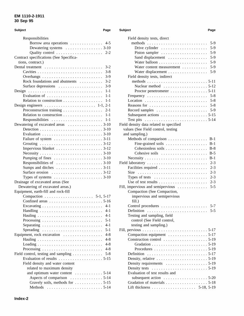
EM 1110-2-191130 Sep 95
Subject Page
ResponsibilitiesBorrow area operations. . . . . . . . . . . . . . 4-5Dewatering systems. . . . . . . . . . . . . . . .3-10Quality control . . . . . . . . . . . . . . . . . . . . 2-2
Contract specifications (See Specifica-tions, contract.)
Dental treatment . . . . . . . . . . . . . . . . . . . . . . . . . 3-2Cavities . . . . . . . . . . . . . . . . . . . . . . . . . . . . 3-8Overhangs. . . . . . . . . . . . . . . . . . . . . . . . . . 3-9Rock foundations and abutments. . . . . . . . . . 3-2Surface depressions. . . . . . . . . . . . . . . . . . . 3-9
Design . . . . . . . . . . . . . . . . . . . . . . . . . . . . . . . . 1-1Evaluation of . . . . . . . . . . . . . . . . . . . . . . . . 1-1Relation to construction. . . . . . . . . . . . . . . . . 1-1
Design engineers. . . . . . . . . . . . . . . . . . . . . .1-1, 2-1Preconstruction training. . . . . . . . . . . . . . . . . 2-1Relation to construction. . . . . . . . . . . . . . . . . 1-1Responsibilities . . . . . . . . . . . . . . . . . . . . . . 1-1
Dewatering of excavated areas. . . . . . . . . . . . . . .3-10Detection. . . . . . . . . . . . . . . . . . . . . . . . . . .3-10Evaluation . . . . . . . . . . . . . . . . . . . . . . . . . .3-10Failure of system. . . . . . . . . . . . . . . . . . . . .3-11Grouting . . . . . . . . . . . . . . . . . . . . . . . . . . .3-12Impervious blanket. . . . . . . . . . . . . . . . . . . .3-12Necessity. . . . . . . . . . . . . . . . . . . . . . . . . . .3-10Pumping of fines . . . . . . . . . . . . . . . . . . . . .3-10Responsibilities of . . . . . . . . . . . . . . . . . . . .3-10Sumps and ditches. . . . . . . . . . . . . . . . . . . .3-11Surface erosion . . . . . . . . . . . . . . . . . . . . . .3-12Types of systems. . . . . . . . . . . . . . . . . . . . .3-10
Drainage of excavated areas (SeeDewatering of excavated areas.)
Equipment, earth-fill and rock-fillCompaction . . . . . . . . . . . . . . . . . . . . . 5-1, 5-17Confined areas. . . . . . . . . . . . . . . . . . . . . . .5-16Excavating. . . . . . . . . . . . . . . . . . . . . . . . . . 4-1Handling . . . . . . . . . . . . . . . . . . . . . . . . . . . 4-1Hauling . . . . . . . . . . . . . . . . . . . . . . . . . . . . 4-1Processing. . . . . . . . . . . . . . . . . . . . . . . . . . 5-1Separating. . . . . . . . . . . . . . . . . . . . . . . . . . 4-1Spreading . . . . . . . . . . . . . . . . . . . . . . . . . . 5-1
Equipment, rock excavation. . . . . . . . . . . . . . . . . 4-8Hauling . . . . . . . . . . . . . . . . . . . . . . . . . . . . 4-8Loading . . . . . . . . . . . . . . . . . . . . . . . . . . . . 4-8Processing. . . . . . . . . . . . . . . . . . . . . . . . . . 4-8
Field control, testing and sampling. . . . . . . . . . . . . 5-8Evaluation of results. . . . . . . . . . . . . . . . . . .5-15Field density and water content
related to maximum densityand optimum water content. . . . . . . . . . . .5-14
Aspects of comparison. . . . . . . . . . . . . .5-14Gravely soils, methods for. . . . . . . . . . . .5-15Methods . . . . . . . . . . . . . . . . . . . . . . . .5-14
Subject Page
Field density tests, directmethods . . . . . . . . . . . . . . . . . . . . . . . . . . 5-9
Drive cylinder . . . . . . . . . . . . . . . . . . . . 5-9Piston sampler. . . . . . . . . . . . . . . . . . . . 5-9Sand displacement. . . . . . . . . . . . . . . . . 5-9Water balloon. . . . . . . . . . . . . . . . . . . . . 5-9Water content measurement. . . . . . . . . . . 5-9Water displacement. . . . . . . . . . . . . . . . . 5-9
Field density tests, indirectmethods. . . . . . . . . . . . . . . . . . . . . . . . . .5-11
Nuclear method . . . . . . . . . . . . . . . . . . .5-12Proctor penetrometer. . . . . . . . . . . . . . . .5-11
Frequency . . . . . . . . . . . . . . . . . . . . . . . . . . 5-8Location . . . . . . . . . . . . . . . . . . . . . . . . . . . 5-8Reasons for. . . . . . . . . . . . . . . . . . . . . . . . . 5-8Record samples. . . . . . . . . . . . . . . . . . . . . . 5-9Subsequent actions. . . . . . . . . . . . . . . . . . . .5-15Test pits . . . . . . . . . . . . . . . . . . . . . . . . . . .5-14
Field density data related to specifiedvalues (See Field control, testingand sampling.)
Methods of comparison. . . . . . . . . . . . . . . . . B-1Fine-grained soils. . . . . . . . . . . . . . . . . . B-1Cohesionless soils. . . . . . . . . . . . . . . . . . B-8Cohesive soils . . . . . . . . . . . . . . . . . . . . B-5
Necessity. . . . . . . . . . . . . . . . . . . . . . . . . . . B-1Field laboratory. . . . . . . . . . . . . . . . . . . . . . . . . . 2-3
Facilities required. . . . . . . . . . . . . . . . . . . . . 2-3Size . . . . . . . . . . . . . . . . . . . . . . . . . . . . . . 2-3Types of tests . . . . . . . . . . . . . . . . . . . . . . . 2-3Use of test results. . . . . . . . . . . . . . . . . . . . . 2-3
Fill, impervious and semipervious. . . . . . . . . . . . . 5-5Compaction (See Compaction,
impervious and semiperviousfill.)
Control procedures. . . . . . . . . . . . . . . . . . . . 5-7Definition . . . . . . . . . . . . . . . . . . . . . . . . . . 5-5Testing and sampling, field
control (See Field control,testing and sampling.)
Fill, pervious . . . . . . . . . . . . . . . . . . . . . . . . . . . .5-17Compaction equipment. . . . . . . . . . . . . . . . .5-17Construction control. . . . . . . . . . . . . . . . . . .5-19
Gradation. . . . . . . . . . . . . . . . . . . . . . . .5-19Procedures. . . . . . . . . . . . . . . . . . . . . . .5-19
Definition . . . . . . . . . . . . . . . . . . . . . . . . . .5-17Density, relative. . . . . . . . . . . . . . . . . . . . . .5-19Density requirements. . . . . . . . . . . . . . . . . .5-19Density tests . . . . . . . . . . . . . . . . . . . . . . . .5-19Evaluation of test results and
subsequent action. . . . . . . . . . . . . . . . . . .5-20Gradation of materials. . . . . . . . . . . . . . . . . .5-18Lift thickness . . . . . . . . . . . . . . . . . . . 5-18, 5-19
Index-2
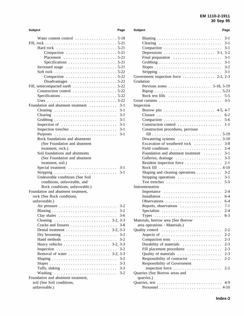
EM 1110-2-191130 Sep 95
Subject Page
Water content control. . . . . . . . . . . . . . . . . .5-18Fill, rock . . . . . . . . . . . . . . . . . . . . . . . . . . . . . . .5-21
Hard rock . . . . . . . . . . . . . . . . . . . . . . . . . .5-21Compaction . . . . . . . . . . . . . . . . . . . . . .5-21Placement . . . . . . . . . . . . . . . . . . . . . . .5-21Specifications. . . . . . . . . . . . . . . . . . . . .5-21
Increased usage. . . . . . . . . . . . . . . . . . . . . .5-21Soft rock . . . . . . . . . . . . . . . . . . . . . . . . . . .5-22
Compaction . . . . . . . . . . . . . . . . . . . . . .5-22Disadvantages. . . . . . . . . . . . . . . . . . . .5-22
Fill, semicompacted earth. . . . . . . . . . . . . . . . . . .5-22Construction control. . . . . . . . . . . . . . . . . . .5-22Specifications. . . . . . . . . . . . . . . . . . . . . . . .5-22Uses . . . . . . . . . . . . . . . . . . . . . . . . . . . . . .5-22
Foundation and abutment treatment. . . . . . . . . . . . 3-1Cleaning . . . . . . . . . . . . . . . . . . . . . . . . . . . 3-1Clearing . . . . . . . . . . . . . . . . . . . . . . . . . . . 3-1Grubbing . . . . . . . . . . . . . . . . . . . . . . . . . . . 3-1Inspection of . . . . . . . . . . . . . . . . . . . . . . . . 3-1Inspection trenches. . . . . . . . . . . . . . . . . . . . 3-1Purposes. . . . . . . . . . . . . . . . . . . . . . . . . . . 3-1Rock foundations and abutments
(See Foundation and abutmenttreatment, rock.)
Soil foundations and abutments(See Foundation and abutmenttreatment, soil.)
Special treatment. . . . . . . . . . . . . . . . . . . . . 3-1Stripping . . . . . . . . . . . . . . . . . . . . . . . . . . . 3-1Undesirable conditions (See Soil
conditions, unfavorable, andRock conditions, unfavorable.)
Foundation and abutment treatment,rock (See Rock conditions,unfavorable.)
Air pressure. . . . . . . . . . . . . . . . . . . . . . . . . 3-2Blasting . . . . . . . . . . . . . . . . . . . . . . . . . . . . 3-2Clay shales . . . . . . . . . . . . . . . . . . . . . . . . . 3-6Cleaning . . . . . . . . . . . . . . . . . . . . . . . .3-2, 3-3Cracks and fissures. . . . . . . . . . . . . . . . . . . . 3-8Dental treatment. . . . . . . . . . . . . . . . . . . 3-2, 3-3Dry brooming . . . . . . . . . . . . . . . . . . . . . . . 3-2Hand methods. . . . . . . . . . . . . . . . . . . . . . . 3-2Heavy vehicles. . . . . . . . . . . . . . . . . . . . 3-2, 3-3Inspection . . . . . . . . . . . . . . . . . . . . . . . . . . 3-2Removal of water. . . . . . . . . . . . . . . . . . 3-2, 3-3Shaping. . . . . . . . . . . . . . . . . . . . . . . . . . . . 3-2Slopes. . . . . . . . . . . . . . . . . . . . . . . . . . . . . 3-3Tuffs, slaking. . . . . . . . . . . . . . . . . . . . . . . . 3-3Washing . . . . . . . . . . . . . . . . . . . . . . . . . . . 3-2
Foundation and abutment treatment,soil (See Soil conditions,unfavorable.)
Subject Page
Blasting . . . . . . . . . . . . . . . . . . . . . . . . . . . . 3-1Clearing . . . . . . . . . . . . . . . . . . . . . . . . . . . 3-1Compaction . . . . . . . . . . . . . . . . . . . . . . . . . 3-1Depressions. . . . . . . . . . . . . . . . . . . . . .3-1, 3-2Final preparation . . . . . . . . . . . . . . . . . . . . . 3-1Grubbing . . . . . . . . . . . . . . . . . . . . . . . . . . . 3-1Slopes. . . . . . . . . . . . . . . . . . . . . . . . . . . . . 3-2Stripping . . . . . . . . . . . . . . . . . . . . . . . . . . . 3-1
Government inspection force. . . . . . . . . . . . . . 2-2, 2-3Gradation
Pervious zones. . . . . . . . . . . . . . . . . . 5-18, 5-19Riprap . . . . . . . . . . . . . . . . . . . . . . . . . . . . .5-23Rock test fills . . . . . . . . . . . . . . . . . . . . . . . 5-5
Grout curtains. . . . . . . . . . . . . . . . . . . . . . . . . . . 3-5Inspection
Borrow pits . . . . . . . . . . . . . . . . . . . . . .4-5, 4-7Closure . . . . . . . . . . . . . . . . . . . . . . . . . . . . 6-2Compaction . . . . . . . . . . . . . . . . . . . . . . . . . 5-6Construction control. . . . . . . . . . . . . . . . . . . 1-1Construction procedures, pervious
fill . . . . . . . . . . . . . . . . . . . . . . . . . . . . . .5-19Dewatering systems. . . . . . . . . . . . . . . . . . .3-10Excavation of weathered rock. . . . . . . . . . . . 3-8Field conditions . . . . . . . . . . . . . . . . . . . . . . 2-4Foundation and abutment treatment. . . . . . . . 3-1Galleries, drainage. . . . . . . . . . . . . . . . . . . . 3-5Resident inspection force. . . . . . . . . . . . . . . . 2-1Rock fill . . . . . . . . . . . . . . . . . . . . . . . . . . .4-10Shaping and cleaning operations. . . . . . . . . . . 3-2Stripping operations. . . . . . . . . . . . . . . . . . . 3-1Test trenches. . . . . . . . . . . . . . . . . . . . . . . . 5-5
InstrumentationImportance . . . . . . . . . . . . . . . . . . . . . . . . . 2-4Installation. . . . . . . . . . . . . . . . . . . . . . . . . . 6-4Observations . . . . . . . . . . . . . . . . . . . . . . . . 6-4Reports, observations. . . . . . . . . . . . . . . . . . 7-1Specialists. . . . . . . . . . . . . . . . . . . . . . . . . . 2-4Types . . . . . . . . . . . . . . . . . . . . . . . . . . . . . 6-3
Materials, borrow area (See Borrowarea operations - Materials.)
Quality control . . . . . . . . . . . . . . . . . . . . . . . . . . 2-2Aspects of . . . . . . . . . . . . . . . . . . . . . . . . . . 2-2Compaction tests. . . . . . . . . . . . . . . . . . . . . 2-3Durability of materials . . . . . . . . . . . . . . . . . 2-3Fill placement procedures. . . . . . . . . . . . . . . 2-3Quality of materials . . . . . . . . . . . . . . . . . . . 2-3Responsibility of contractor. . . . . . . . . . . . . . 2-2Responsibility of Government
inspection force. . . . . . . . . . . . . . . . . . . . . 2-2Quarries (See Borrow areas and
quarries.)Quarries, test. . . . . . . . . . . . . . . . . . . . . . . . . . . . 4-9
Personnel. . . . . . . . . . . . . . . . . . . . . . . . . . .4-10
Index-3

EM 1110-2-191130 Sep 95
Subject Page
Procedures. . . . . . . . . . . . . . . . . . . . . . . . . . 4-9Purpose of. . . . . . . . . . . . . . . . . . . . . . . . . . 4-9Records. . . . . . . . . . . . . . . . . . . . . . . . . . . .4-10
Records and reports, constructionAdditional information . . . . . . . . . . . . . . . . . C-1Compaction control . . . . . . . . . . . . . . . . . . . 7-1Construction foundation. . . . . . . . . . . . . . . . 7-6Contents . . . . . . . . . . . . . . . . . . . . . . . . . . . 2-5Daily . . . . . . . . . . . . . . . . . . . . . . . . . . . . . 7-1Documentation of test results. . . . . . . . . . . . . 2-4Evaluation of claims. . . . . . . . . . . . . . . . . . . 2-5Final . . . . . . . . . . . . . . . . . . . . . . . . . . . . . . 7-6Forms, field compaction control. . . . . . . . . . . C-1Inspection report . . . . . . . . . . . . . . . . . . . . . 2-5Instrumentation observations. . . . . . . . . . . . . 7-1Maintenance of . . . . . . . . . . . . . . . . . . . . . . 1-1Master diary . . . . . . . . . . . . . . . . . . . . . . . . 2-5Necessity of. . . . . . . . . . . . . . . . . . . . . . . . . 1-1Payments, basis for. . . . . . . . . . . . . . . . . . . . 2-5Photographs. . . . . . . . . . . . . . . . . . . . . .1-1, 2-5Preparation instructions. . . . . . . . . . . . . . . . . D-1Test fills . . . . . . . . . . . . . . . . . . . . . . . . . . . 5-1Test quarries . . . . . . . . . . . . . . . . . . . . . . . .4-10Use of data . . . . . . . . . . . . . . . . . . . . . . . . . 2-4
Reports (See Records and reports,construction.)
Resident engineer. . . . . . . . . . . . . . . . . . . . . .1-1, 2-1Assistants . . . . . . . . . . . . . . . . . . . . . . . . . . 2-1Relationship with contractor. . . . . . . . . . . . . . 2-3Responsibilities . . . . . . . . . . . . . . . . . . . . . . 1-1Technical responsibilities. . . . . . . . . . . . . . . . 2-1
Resident inspection force. . . . . . . . . . . . . . . . . . . 2-1Composition . . . . . . . . . . . . . . . . . . . . . . . . 2-1Duties . . . . . . . . . . . . . . . . . . . . . . . . . . . . . 2-1Organization . . . . . . . . . . . . . . . . . . . . .2-1, 2-2Preconstruction training. . . . . . . . . . . . . . . . . 2-1Relationship with contractor. . . . . . . . . . . . . . 2-3Size . . . . . . . . . . . . . . . . . . . . . . . . . . . . . . 2-1
Riprap . . . . . . . . . . . . . . . . . . . . . . . . . . . .5-23, 6-2Removal . . . . . . . . . . . . . . . . . . . . . . . . . . . 6-2Stream protection. . . . . . . . . . . . . . . . . . . . .5-23
Rock conditions, unfavorable. . . . . . . . . . . . . . . . 3-8Cavities . . . . . . . . . . . . . . . . . . . . . . . . . . . . 3-8
Causes. . . . . . . . . . . . . . . . . . . . . . . . . . 3-8Remedies. . . . . . . . . . . . . . . . . . . . . . . . 3-8Untreated. . . . . . . . . . . . . . . . . . . . . . . . 3-8
Detrimental characteristics. . . . . . . . . . . . . . . 3-8Erosion and scour. . . . . . . . . . . . . . . . . . . . . 3-8Fill . . . . . . . . . . . . . . . . . . . . . . . . . . . . . . . 3-8Fractures. . . . . . . . . . . . . . . . . . . . . . . . . . . 3-8Inspection of excavations. . . . . . . . . . . . . . . . 3-8Open joints . . . . . . . . . . . . . . . . . . . . . . . . . 3-8
Subject Page
Overhangs. . . . . . . . . . . . . . . . . . . . . . . . . . 3-9Dental treatment. . . . . . . . . . . . . . . . . . . 3-9Removal . . . . . . . . . . . . . . . . . . . . . . . . 3-9Tamping of soil . . . . . . . . . . . . . . . . . . . 3-9
Springs . . . . . . . . . . . . . . . . . . . . . . . . . . . . 3-9Surface depressions. . . . . . . . . . . . . . . . . . . 3-9
Dental treatment. . . . . . . . . . . . . . . . . . . 3-9Fill procedure. . . . . . . . . . . . . . . . . . . . . 3-9
Weathered rock. . . . . . . . . . . . . . . . . . . . . . 3-8Rock fill, obtaining . . . . . . . . . . . . . . . . . . . . . . .4-10
Blasting . . . . . . . . . . . . . . . . . . . . . . . . . . . .4-10Drilling . . . . . . . . . . . . . . . . . . . . . . . . . . . .4-10Processing. . . . . . . . . . . . . . . . . . . . . . . . . .4-10
Seepage control. . . . . . . . . . . . . . . . . . . . . . . . . . 3-3Blankets . . . . . . . . . . . . . . . . . . . . . . . . . . . 3-5Core trenches (See Seepage
control - Cutoffs.)Cutoffs . . . . . . . . . . . . . . . . . . . . . . . . . . . . 3-3
Compacted backfill trenches. . . . . . . . . . . 3-3Grout curtains . . . . . . . . . . . . . . . . . . . . 3-5Slurry trenches. . . . . . . . . . . . . . . . . . . . 3-3
Excavated areas. . . . . . . . . . . . . . . . . . . . . .3-13Galleries . . . . . . . . . . . . . . . . . . . . . . . . . . . 3-5Relief wells . . . . . . . . . . . . . . . . . . . . . . . . . 3-5Toe drains. . . . . . . . . . . . . . . . . . . . . . . . . . 3-6
Soil conditions, unfavorable. . . . . . . . . . . . . . . . . 3-6Clay shales . . . . . . . . . . . . . . . . . . . . . . . . . 3-6Collapsible soils. . . . . . . . . . . . . . . . . . . . . . 3-7Highly compressible soils. . . . . . . . . . . . . . . 3-6Loose granular soils. . . . . . . . . . . . . . . . . . . 3-7Low-strength soils . . . . . . . . . . . . . . . . . . . . 3-6Old river channels . . . . . . . . . . . . . . . . . . . . 3-7Steep abutment slopes. . . . . . . . . . . . . . . . . . 3-7
Specialists. . . . . . . . . . . . . . . . . . . . . . . . . . . . . . 2-4Design engineers. . . . . . . . . . . . . . . . . . . . . 2-4Field instrumentation technicians. . . . . . . . . . 2-4Geologists . . . . . . . . . . . . . . . . . . . . . . . . . . 2-4Geotechnical engineers. . . . . . . . . . . . . . . . . 2-4
Specifications, contractChanges . . . . . . . . . . . . . . . . . . . . . . . . . . . 2-4Compaction . . . . . . . . . . . . . . . . . . . . . . . . . 5-6Compliance with . . . . . . . . . . . . . . . . . . 1-1, 2-1Rock fill . . . . . . . . . . . . . . . . . . . . . . 4-10, 5-21Test fill . . . . . . . . . . . . . . . . . . . . . . . . . . . . 5-1Understanding of . . . . . . . . . . . . . . . . . . 2-1, 2-3Verification of requirements. . . . . . . . . . . . . . 2-4
Stockpiling (See Borrow areaoperations - Stockpiling.)
Test fills, earth . . . . . . . . . . . . . . . . . . . . . . . . . . 5-5Test fills, rock . . . . . . . . . . . . . . . . . . . . . . . . . . . 5-1
Construction control. . . . . . . . . . . . . . . . . . . 5-1Gradation tests. . . . . . . . . . . . . . . . . . . . . . . 5-5
Index-4

EM 1110-2-191130 Sep 95
Subject Page
Purposes. . . . . . . . . . . . . . . . . . . . . . . . . . . 5-1Test quarries . . . . . . . . . . . . . . . . . . . . . . . . 5-1
Trenches, compacted backfill (SeeSeepage control - Cutoffs.)
Trenches, slurry. (See Seepagecontrol - Cutoffs.)
Subject Page
Water contentBorrow area operations. . . . . . . . . . . . . . . . . 4-6Compaction . . . . . . . . . . . . . . . . . . . . . . . . . 5-7Measurements. . . . . . . . . . . . . . . . . . . . . . . 5-9Microwave oven. . . . . . . . . . . . . . . . . . . . . .5-10Pervious materials . . . . . . . . . . . . . . . . . . . .5-18Related to maximum density
and optimum water content. . . . . . . . . . . .5-14
Index-5