Embed Size (px)
Citation preview

WELLHEADS
TEAMWORK
• Mohamed Abdelshafy Mahmoud Abozeimacell: +20-102-003-2271
• Abraham Makoi Bennycell: +20-111-676-0178
• Omar Labibcell: +20-101-693-9292
• Alshimaa Ibrahim Mohamedcell: +20-101-436-1152
REFERENCES• Heriot Watt University - Production Technology I• API 6A Wellhead Manual• Wood Group Wellhead Manual • Http://Petrowiki.Org• Http://Www.Glossary.Oilfield.Slb.Com/• Https://Www.Onepetro.Org• Minimum Wellhead Requirements An Industry Recommended Practice (IRP) For
The Canadian Oil And Gas Industry Volume 5• Development Consultant, Training On Beam Pumping, Module A.• Cameron Mudline Suspension System.
OUTLINES • Background on Oil and Gas Wells.• Component Requirements Applicable to All Wellheads.• Basic Components of a Wellhead.• Advanced wellhead techniques• Sweet Flowing Wells.• Critical Sour, Sour and Corrosive Wells. • Artificial Lift Wells. • Other Well Types.• Wellhead Installation.
BACKGROUND ON OIL AND GAS WELLS
• fresh water sources pre-date 5000 BC.
BACKGROUND ON OIL AND GAS WELLS
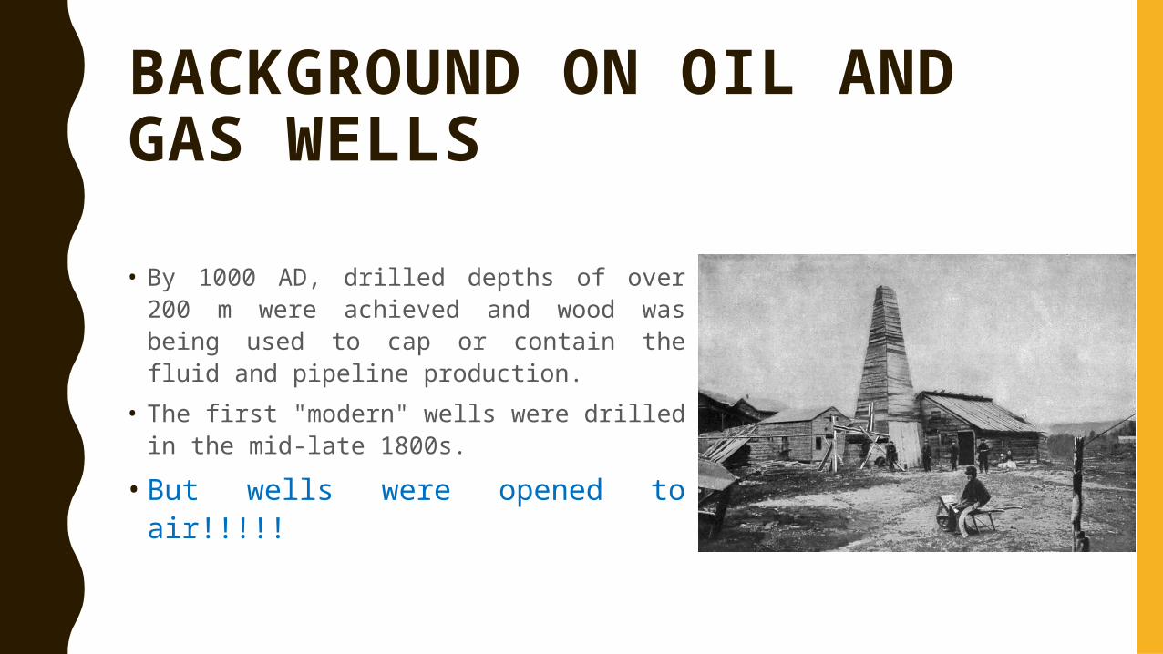
• By 1000 AD, drilled depths of over 200 m were achieved and wood was being used to cap or contain the fluid and pipeline production.
• The first "modern" wells were drilled in the mid-late 1800s.
• But wells were opened to air!!!!!
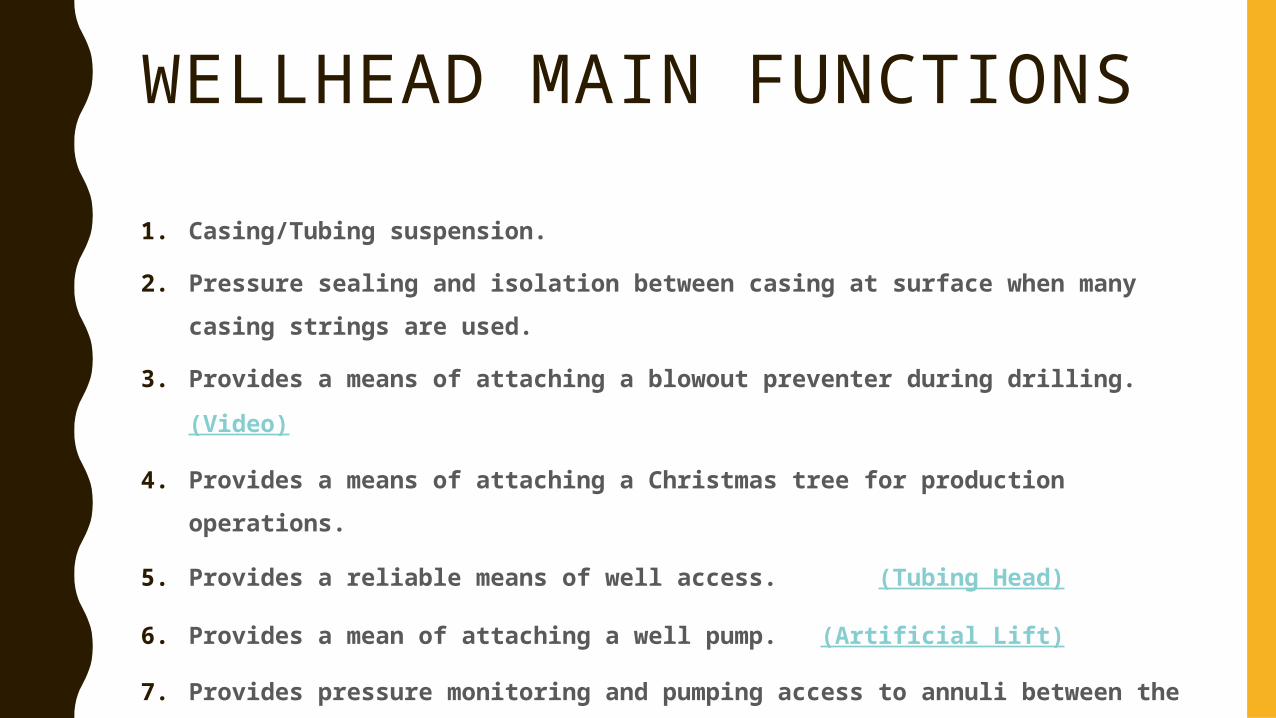
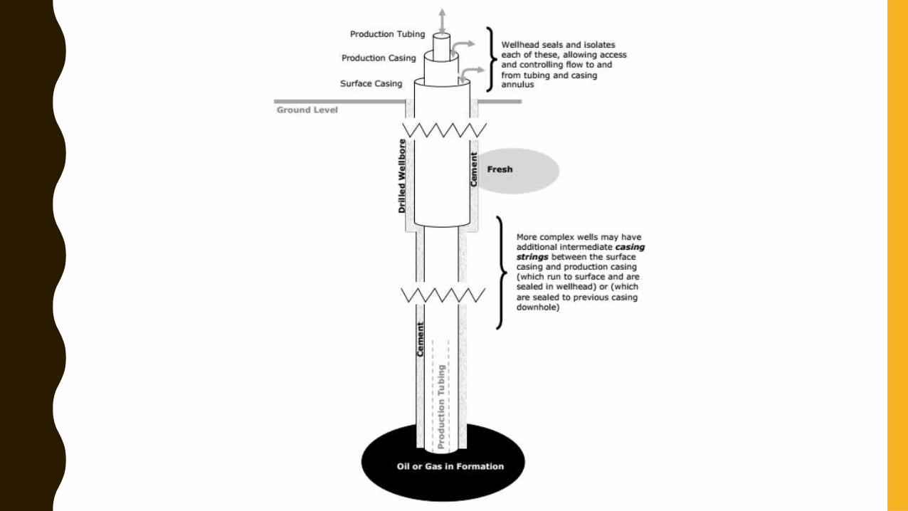
WELLHEAD MAIN FUNCTIONS1. Casing/Tubing suspension.
2. Pressure sealing and isolation between casing at surface when many casing strings are used.
3. Provides a means of attaching a blowout preventer during drilling. (Video)
4. Provides a means of attaching a Christmas tree for production operations.
5. Provides a reliable means of well access. (Tubing Head)
6. Provides a mean of attaching a well pump. (Artificial Lift)
7. Provides pressure monitoring and pumping access to annuli between the different casing/tubing strings (video)
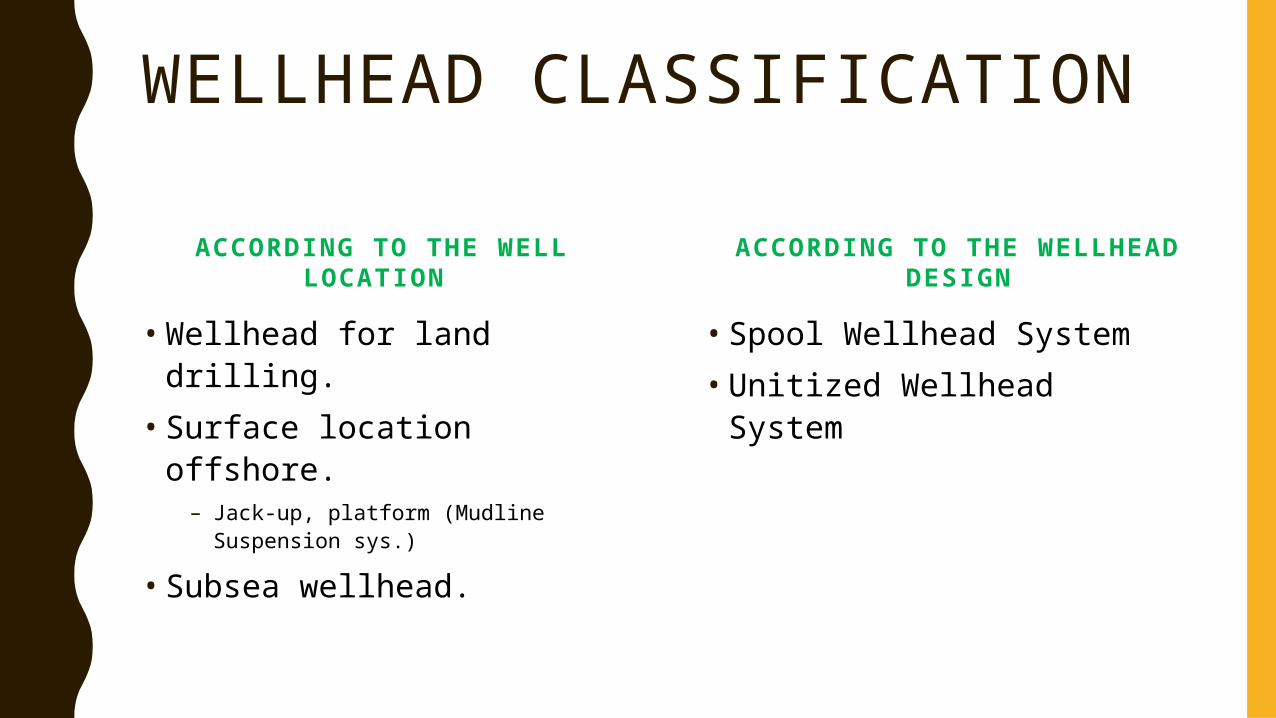
WELLHEAD CLASSIFICATION
ACCORDING TO THE WELL LOCATION
• Wellhead for land drilling.• Surface location offshore.
– Jack-up, platform (Mudline Suspension sys.)
• Subsea wellhead.
ACCORDING TO THE WELLHEAD DESIGN
• Spool Wellhead System• Unitized Wellhead System
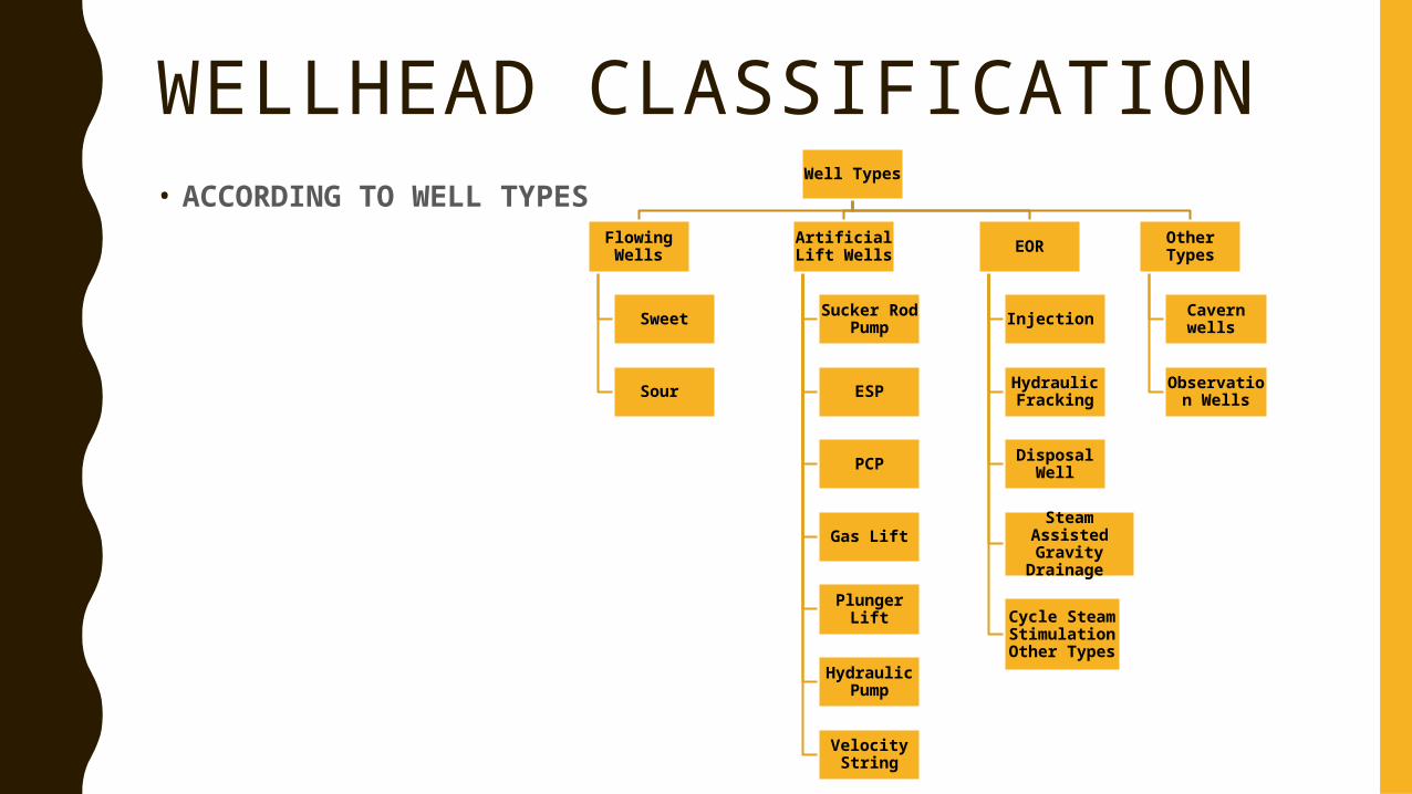
WELLHEAD CLASSIFICATIONWell Types
Flowing Wells
Sweet
Sour
Artificial Lift Wells
Sucker Rod Pump
ESP
PCP
Gas Lift
Plunger Lift
Hydraulic Pump
Velocity String
EOR
Injection
Hydraulic Fracking
Disposal Well
Steam Assisted Gravity
Drainage
Cycle Steam Stimulation Other Types
Other Types
Cavern wells
Observation Wells
• ACCORDING TO WELL TYPES
COMPONENT REQUIREMENTS APPLICABLE TO ALL WELLHEADS
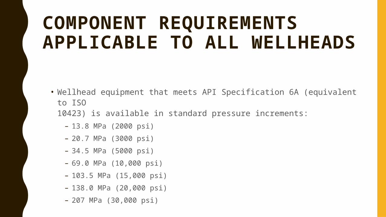
• Wellhead equipment that meets API Specification 6A (equivalent to ISO10423) is available in standard pressure increments:
– 13.8 MPa (2000 psi)– 20.7 MPa (3000 psi)– 34.5 MPa (5000 psi)– 69.0 MPa (10,000 psi)– 103.5 MPa (15,000 psi)– 138.0 MPa (20,000 psi)– 207 MPa (30,000 psi)
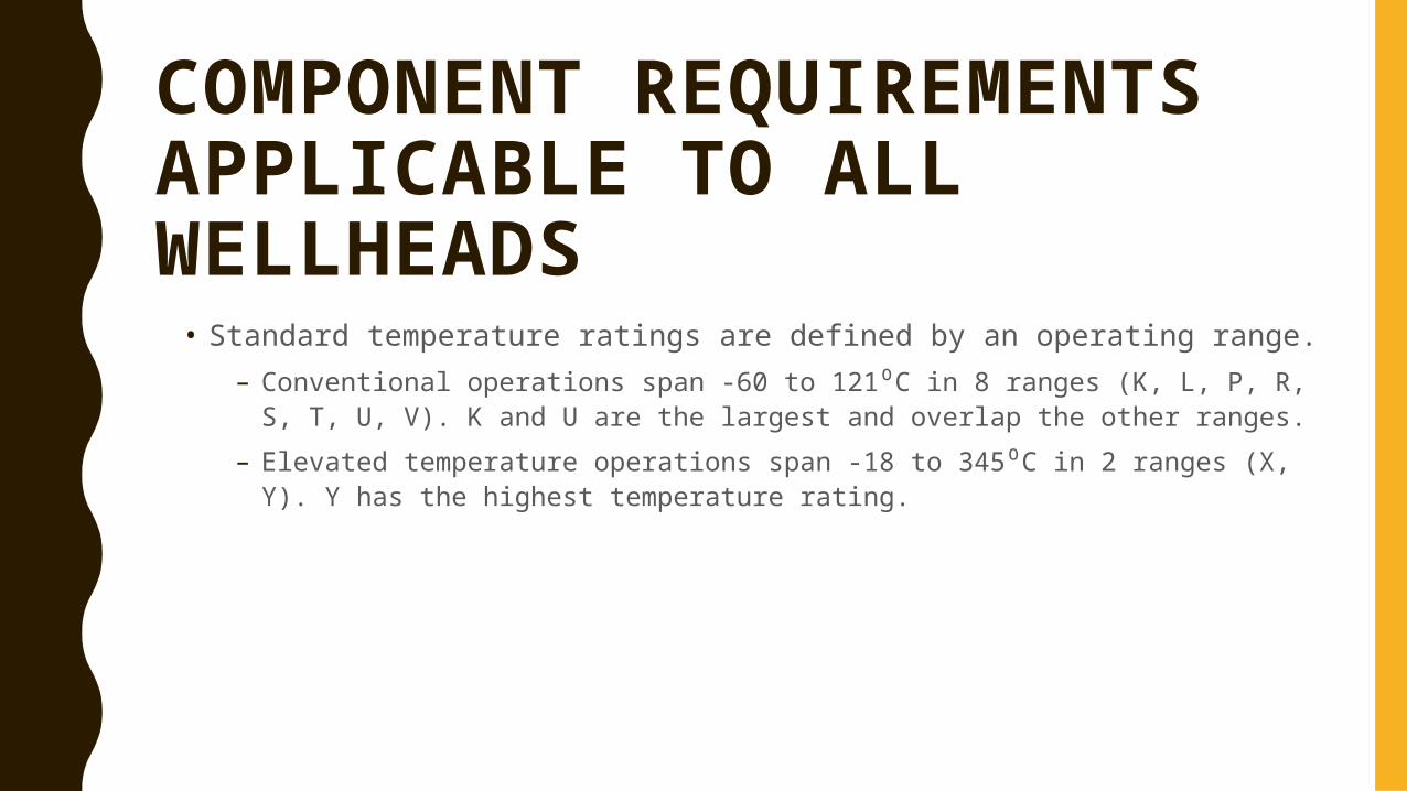
COMPONENT REQUIREMENTS APPLICABLE TO ALL WELLHEADS • Standard temperature ratings are defined by an operating range.
– Conventional operations span -60 to 121⁰C in 8 ranges (K, L, P, R, S, T, U, V). K and U are the largest and overlap the other ranges.
– Elevated temperature operations span -18 to 345⁰C in 2 ranges (X, Y). Y has the highest temperature rating.
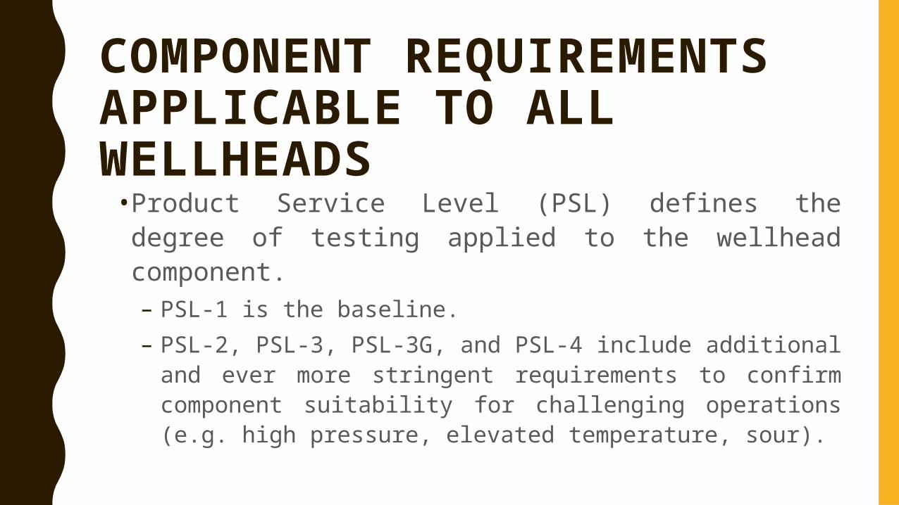
COMPONENT REQUIREMENTS APPLICABLE TO ALL WELLHEADS• Product Service Level (PSL) defines the degree
of testing applied to the wellhead component. –PSL-1 is the baseline. –PSL-2, PSL-3, PSL-3G, and PSL-4 include additional
and ever more stringent requirements to confirm component suitability for challenging operations (e.g. high pressure, elevated temperature, sour).
BASIC COMPONENTS OF A WELLHEAD
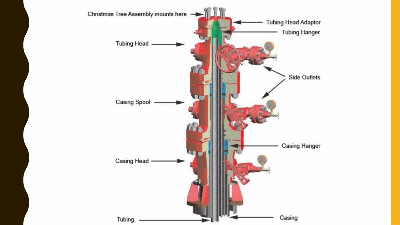
• Casing Head• Casing Spool• Casing Hangers• Pack-off Flange• Tubing Head
• Tubing Hanger• Tubing Head Adaptor• Christmas Tree • Connections • seals
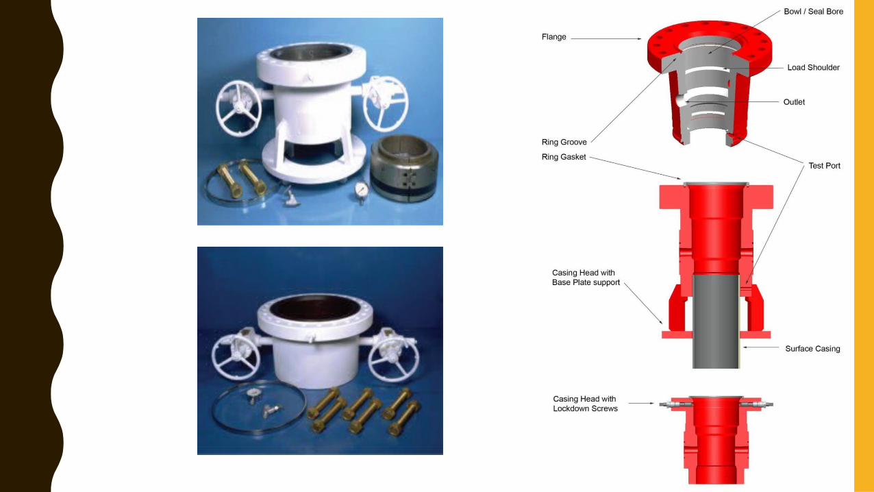
CASING HEAD
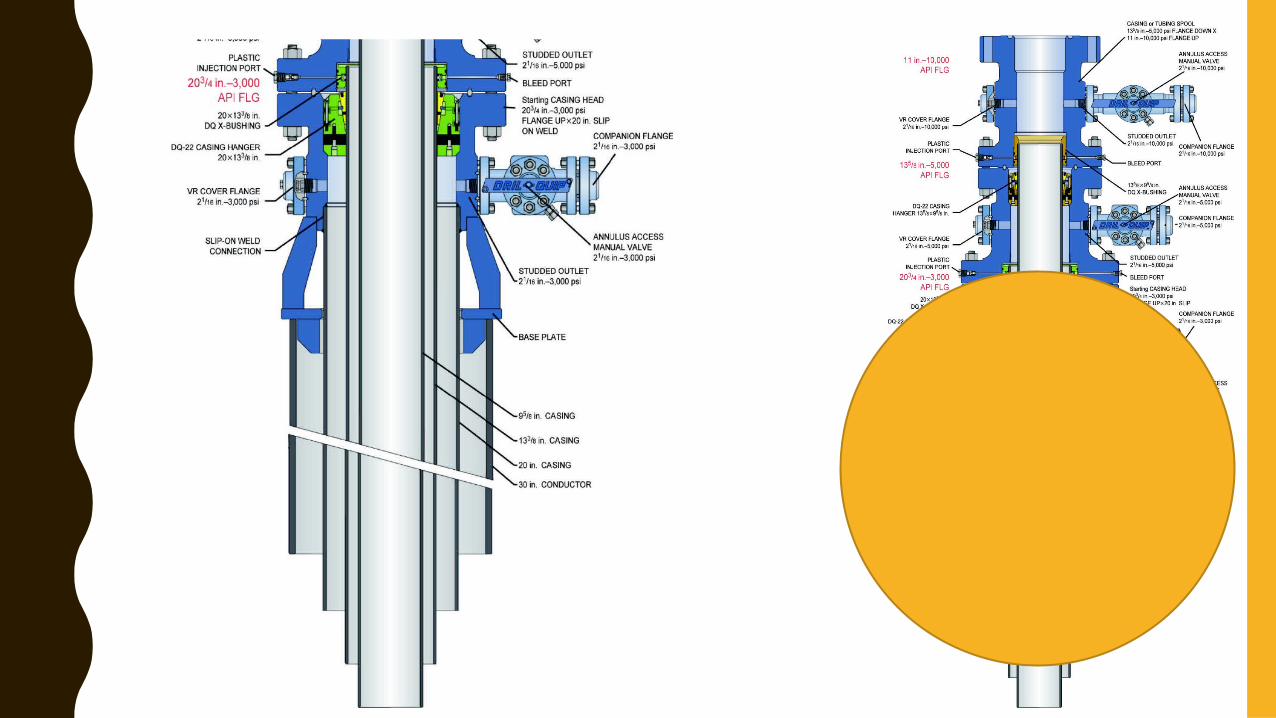
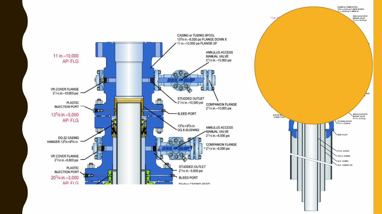
• The casing head, also referred to as a casing bowl.• Is the lowest part of the wellhead assembly. • The bottom of the casing head is configured to attach to the casing below
(typically, the surface casing). • The upper inside of the casing head provides a bowl in which the next casing
string can be set and sealed (if required). • The top of the casing head then connects to the next wellhead component. • A casing head may also be supplied with a landing base plate that takes the
weight load off the surface casing and spreads it over the conductor pipe. • Access to the annulus between the surface casing and the next casing string is
available through side outlets.
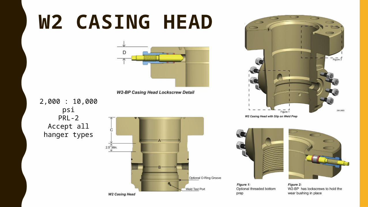
W2 CASING HEAD
2,000 : 10,000 psiPRL-2
Accept all hanger types
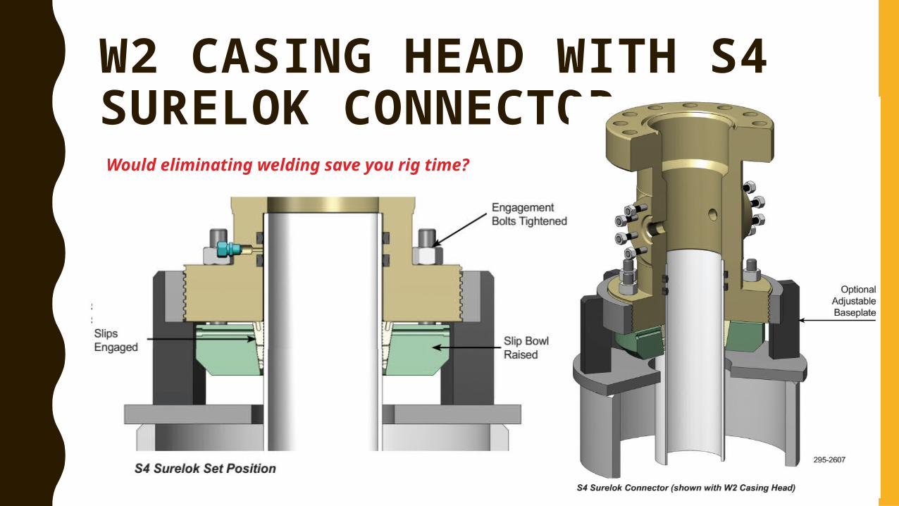
W2 CASING HEAD WITH S4 SURELOK CONNECTOR Would eliminating welding save you rig time?
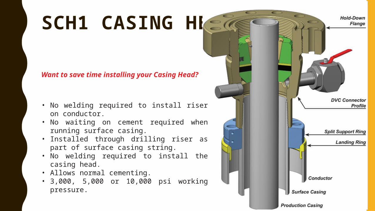
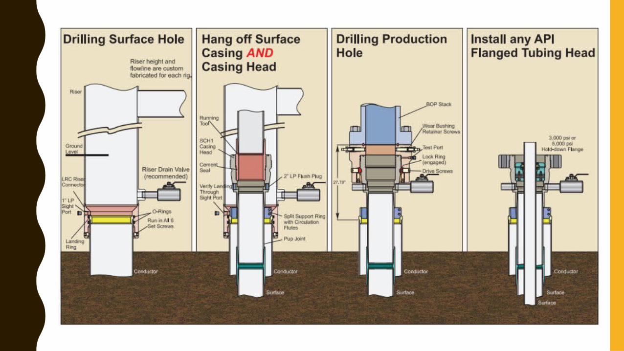
SCH1 CASING HEAD
Want to save time installing your Casing Head?
• No welding required to install riser on conductor.
• No waiting on cement required when running surface casing.
• Installed through drilling riser as part of surface casing string.
• No welding required to install the casing head.
• Allows normal cementing.• 3,000, 5,000 or 10,000 psi working
pressure.
CASING HEAD FUNCTION
• Isolate the inside of the surface casing from the outside environment.• Provide a platform for and a means to test the rig BOP stack during
drilling and well servicing operations.• Support or transfer the weight of drilling and workover equipment
during drilling and well servicing operations.• Allow for suspending and packing off the next casing string • Provide access to the surface inner casing annulus for monitoring and
fluid return purposes. • Access to the annulus is available through side outlets drilled through
the casing head.
CASING SPOOL
• If a well includes one or more intermediate casing strings between the surface andproduction casing, the next component required after the casing head is the casingspool.
• The bottom of the casing spool mounts on top of a casing head or previous spool,and the top connects to the next spool or tubing head assembly.
• The spool is designed so the bottom bowl or counter-bore will allow a secondary seal to be set on the previous casing string, while the top bowl will hold a casing hanger to suspend and allow a primary seal around the next string of casing. Multiple casing spools may be used, one on top of the other, to hang intermediate casing strings and the final production casing string.
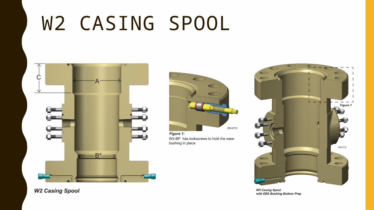
W2 CASING SPOOL
CASING SPOOL FUNCTION
• Allow for a secondary seal on the previous casing string in the counter-bore. • With a secondary seal in place, flange or hub seals and casing hanger seals are
isolated from internal casing pressure.• Provide a port for pressure testing primary and secondary casing seals and flange
connections.• Provide a platform to support, seal and pressure test the BOP during drilling and well
servicing operations.• Provide a load shoulder and controlled bore in the top bowl to support the next casing
hanger and enable a primary seal for the next intermediate or production casing.• Provide annular access for fluid returns or fluid injections and pressure monitoring,
through side outlets drilled in the spool assembly.
CASING HANGER
• Both casing heads and casing spool assemblies may require the use of casing hangers.
• Casing hangers attach to the end of a given casing string and suspend and seal the casing string in the top bowl of a casing head or spool.
• Casing hangers come in two main varieties:– Slip type hangers that are installed around the casing after it is run,
either before or after the casing is cemented into place. • Slip type casing hangers are used as a contingency when pipe is stuck,
allowing the casing to be cut off and set where it sits.– Mandrel type hangers that are threaded onto the casing.
• Mandrel type casing hangers provide superior well control when landing the hanger and improve the annular seal.
CASING HANGER• Shallow intermediate strings are usually suspended from the hanger and then
cemented to surface. • Longer intermediate and production strings that are not cemented to surface are
usually cemented while the casing is suspended in tension from the rig traveling block.
• After the cement has set for a few hours, the traveling block pulls a calculated tension on the casing above the cement and it is at this point the hanger is set in the bowl.
• Casing hangers are often called slips or seals as they are designed with built-in seals.
• Sometimes, we install only a primary seal in shallow depth.• Lock-down (also called hold-down) screws are used to hold the hanger in place.• It may be one piece, two or three pieces ( in larger diameters)
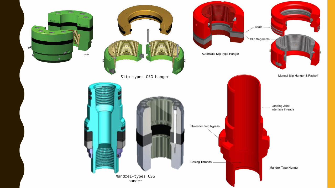
Mandrel-types CSG hanger
Slip-types CSG hanger
CASING HANGER FUNCTION
• To suspend the load of the casing string from the casing head or spool.• To center the casing in the head.• To provide a primary seal against the inside of the casing head and isolate
the casing annulus pressure from upper wellhead components.
PACK-OFF FLANGE
• A pack-off flange is rarely used. • It is set above a casing head or spool assembly and also sealed
against the intermediate or production casing to enable a safe increase in pressure rating between the casing head or spool and any wellhead equipment above the flange, for example, a tubing head.
• It is also known as a “restricted pack-off flange” or “crossover flange”.
PACK-OFF FLANGE FUNCTION• It may be used during well re-entry where anticipated
pressure rise.• In temporary operations such as
– Pressure testing primary seals– As a safety device when drilling out the cement that
remains in the shoe joint.
PROBLEMS & SOLUTIONS• The new pressure in the production casing is expected to
jump from 10MPa to 30 MPa on a well with a 13.8 MPa Casing Head and Tubing Head.
– Solution: A packoff flange on the casing head that provides a transitionfrom 13.8 MPa to 20.7 MPa. The tubing head is upgraded to 34.5 MPa.
• The new pressure in the production casing is expected to jump from 10MPa to 40 MPa on a well with a 13.8 MPa Casing Head and Tubing Head.
– Solution: A packoff flange on the casing head that provides a transitionfrom 13.8 MPa to 20.7 MPa. Another packoff flange on top of theprevious that provides a transition from 20.7 MPa to 34.5 MPa. Thetubing head is upgraded to 69.0 MPa.
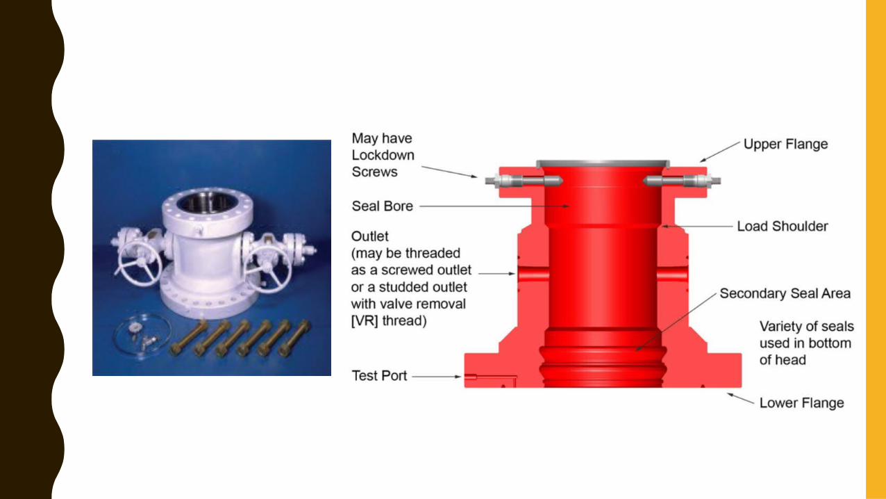
TUBING HEAD• The tubing head assembly provides a means to suspend and seal the
production tubing in the wellhead.• The tubing head is the top spool in the wellhead assembly and is installed
after the last casing string is set. • The bottom of the tubing spool includes a counterbore that can be used to
set a seal against the production casing. • The top of the tubing head provides a landing shoulder and a seal bore for
landing and enabling a seal to the tubing hanger. • Above the tubing head is the tubing head adaptor which provides a
transition to the Christmas tree.
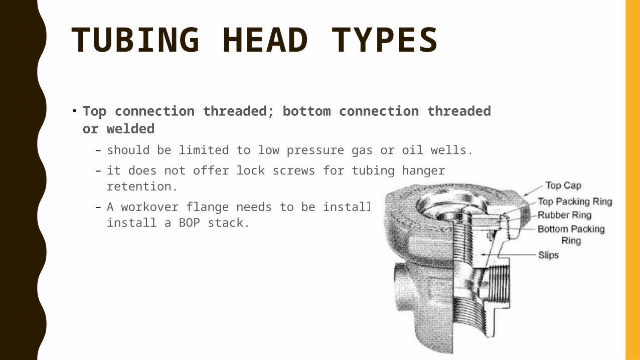
TUBING HEAD TYPES• Top connection threaded; bottom connection threaded
or welded– should be limited to low pressure gas or oil wells.– it does not offer lock screws for tubing hanger retention.– A workover flange needs to be installed in order to install a BOP
stack.
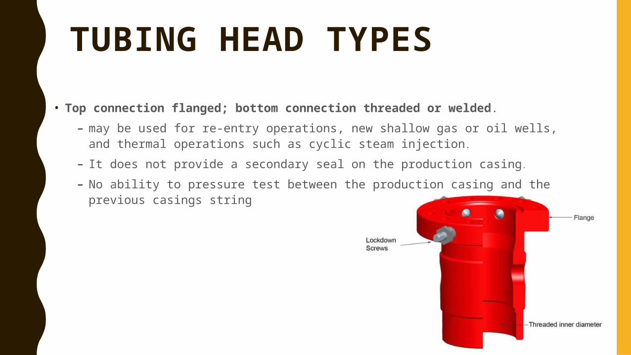
TUBING HEAD TYPES• Top connection flanged; bottom connection threaded or welded.
– may be used for re-entry operations, new shallow gas or oil wells, and thermal operations such as cyclic steam injection.
– It does not provide a secondary seal on the production casing.
– No ability to pressure test between the production casing and the previous casings string
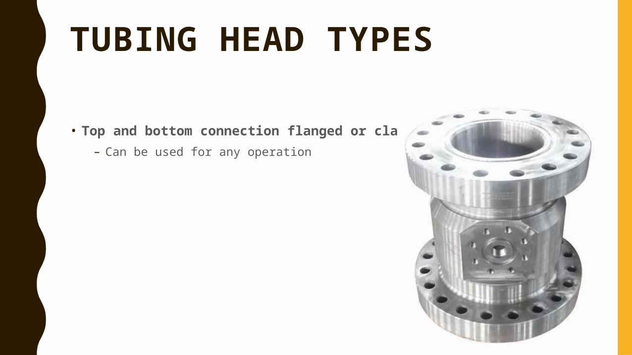
TUBING HEAD TYPES
• Top and bottom connection flanged or clamp hub– Can be used for any operation
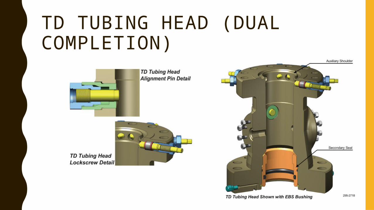
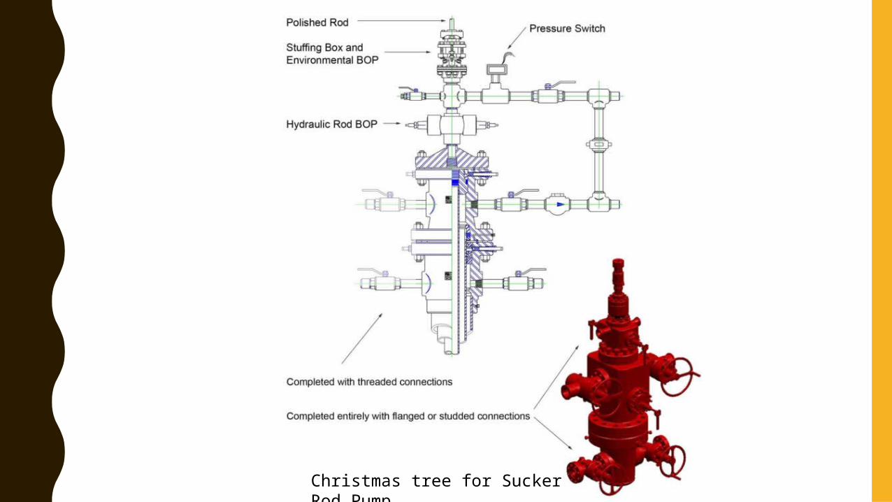
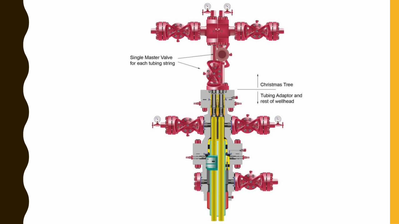
TD TUBING HEAD (DUAL COMPLETION)
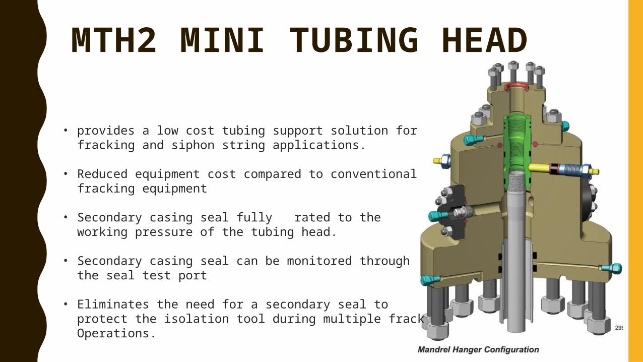
MTH2 MINI TUBING HEAD
• provides a low cost tubing support solution for fracking and siphon string applications.
• Reduced equipment cost compared to conventional fracking equipment
• Secondary casing seal fully rated to the working pressure of the tubing head.
• Secondary casing seal can be monitored through the seal test port
• Eliminates the need for a secondary seal to protect the isolation tool during multiple frack Operations.
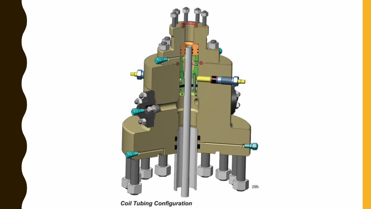
TUBING HEAD FUNCTION• Enable the suspension of the tubing.• Allow for sealing the annulus between the tubing and the production casing.• Allow access to the annulus between the tubing and production casing, through side
outlets.• Provide a means to support and test the service rig BOP during well completions.• Provide a bit guide for running the tubing without causing damage to the production
casing. • Allow a secondary annulus seal to be set around the top of the production casing.• Provide access for a test port to test primary and secondary seals.• Ensure safe running and retrieving of tubing hangers in high pressure operations
(e.g., snubbing operations).• Allow for correct orientation of equipment to enable running multiple tubing strings.
TUBING HANGER
• A tubing hanger is also commonly known as a dog nut.• A tubing hanger typically is threaded onto the top of a tubing
string and is designed to sit and seal in the tubing head. • Usually the tubing hanger is run through the BOP and landed in
the top bowl of the tubing head. • The top of the tubing hanger provides a profile necessary for
the lock screws that will secure the hanger in the tubing head.
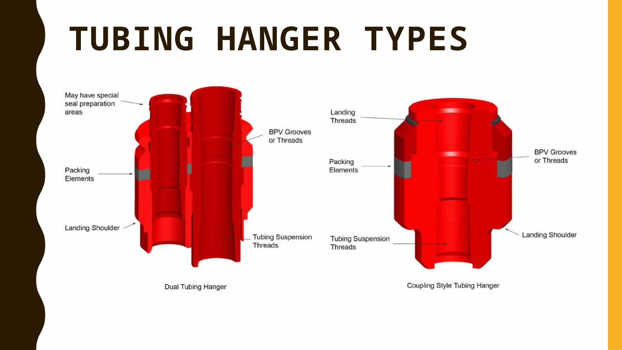
TUBING HANGER TYPES
TUBING HANGER TYPES
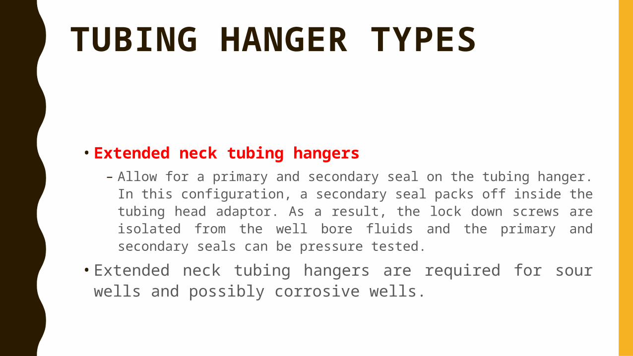
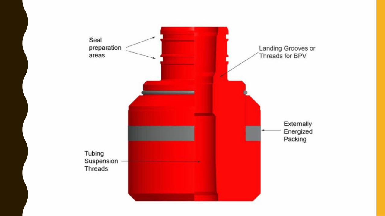
• Extended neck tubing hangers– Allow for a primary and secondary seal on the tubing hanger. In this
configuration, a secondary seal packs off inside the tubing head adaptor. As a result, the lock down screws are isolated from the well bore fluids and the primary and secondary seals can be pressure tested.
• Extended neck tubing hangers are required for sour wells and possibly corrosive wells.
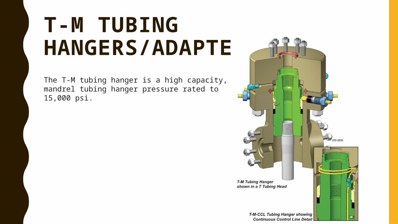
T-M TUBING HANGERS/ADAPTERSThe T-M tubing hanger is a high capacity, mandrel tubing hanger pressure rated to 15,000 psi.
TD-M DUAL TUBING HANGERS/ADAPTERS
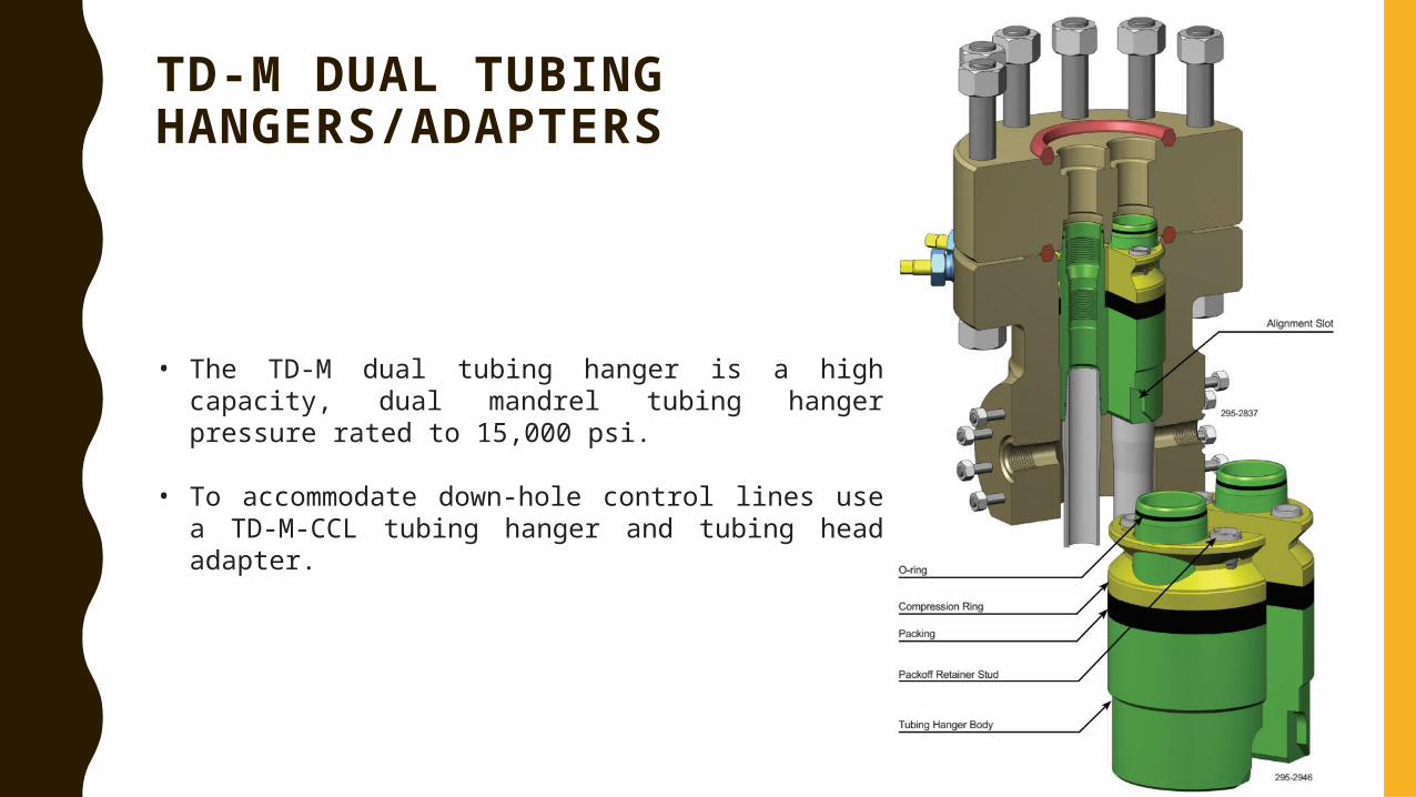
• The TD-M dual tubing hanger is a high capacity, dual mandrel tubing hanger pressure rated to 15,000 psi.
• To accommodate down-hole control lines use a TD-M-CCL tubing hanger and tubing head adapter.
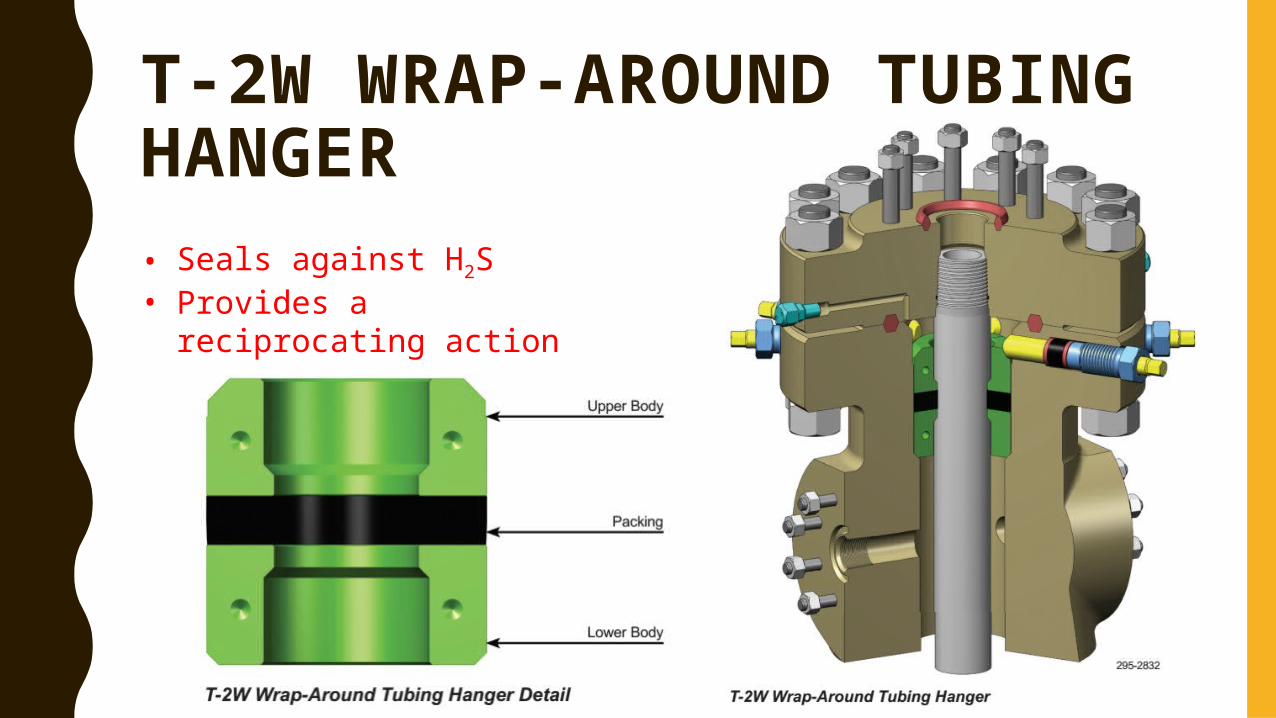
T-2W WRAP-AROUND TUBING HANGER • Seals against H2S• Provides a reciprocating
action
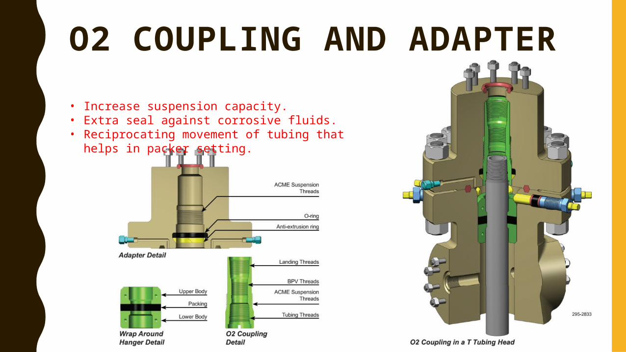
O2 COUPLING AND ADAPTER • Increase suspension capacity.• Extra seal against corrosive fluids.• Reciprocating movement of tubing that helps in
packer setting.
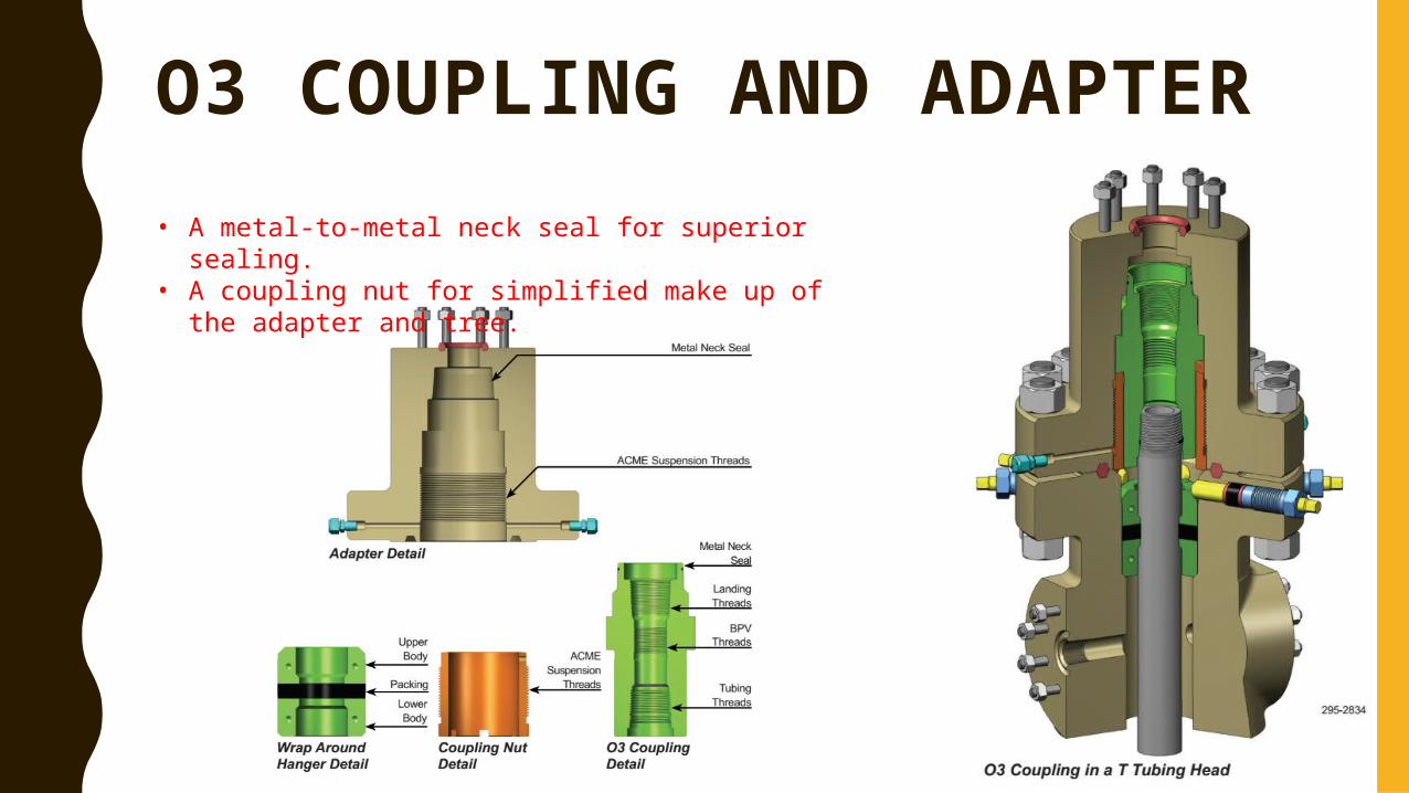
O3 COUPLING AND ADAPTER• A metal-to-metal neck seal for superior sealing.• A coupling nut for simplified make up of the
adapter and tree.
TUBING HANGER BACK-PRESSURE VALVE
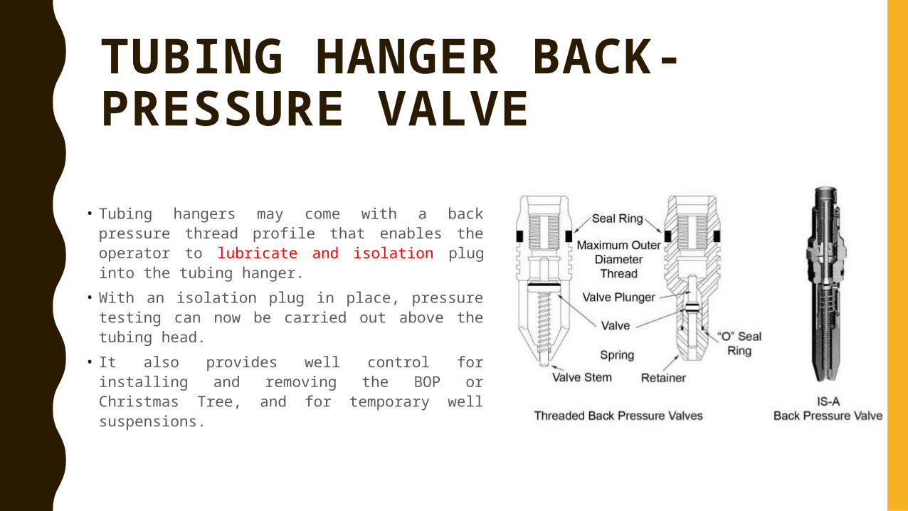
• Tubing hangers may come with a back pressure thread profile that enables the operator to lubricate and isolation plug into the tubing hanger.
• With an isolation plug in place, pressure testing can now be carried out above the tubing head.
• It also provides well control for installing and removing the BOP or Christmas Tree, and for temporary well suspensions.
TUBING HEAD ADAPTOR
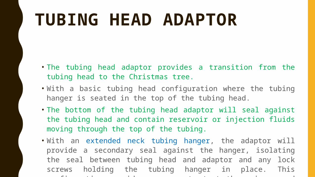
• The tubing head adaptor provides a transition from the tubing head to the Christmas tree.
• With a basic tubing head configuration where the tubing hanger is seated in the top of the tubing head.
• The bottom of the tubing head adaptor will seal against the tubing head and contain reservoir or injection fluids moving through the top of the tubing.
• With an extended neck tubing hanger, the adaptor will provide a secondary seal against the hanger, isolating the seal between tubing head and adaptor and any lock screws holding the tubing hanger in place. This configuration provides a means to test the primary and secondary seals on the tubing hanger.
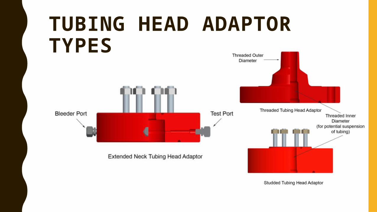
TUBING HEAD ADAPTOR TYPES
WEAR BUSHING
• While drilling the well, it is required that the seal bores in each of the intermediate casing spools and tubing spools be protected.
• A series of wear bushings are supplied to protect the seal areas discussed during the drilling operation.
• The wear bushings are run on a drill pipe tool with J-lugs located on the OD that interface with J-slots located in the top ID section of the wear bushing.
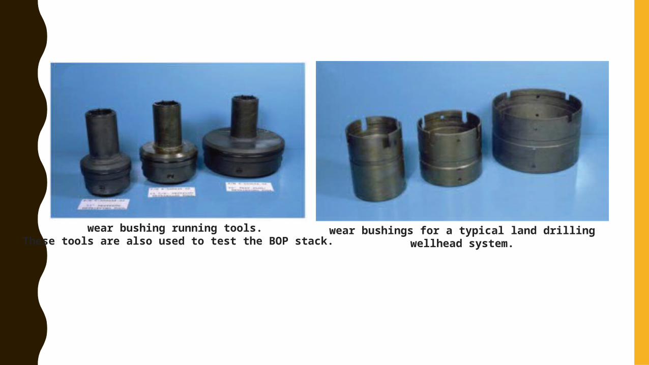
wear bushings for a typical land drilling wellhead system.wear bushing running tools. These tools are also used to test the BOP stack.

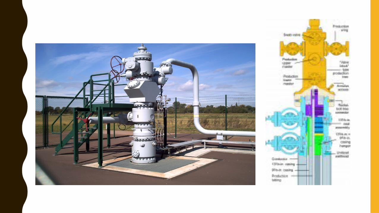
CHRISTMAS TREE
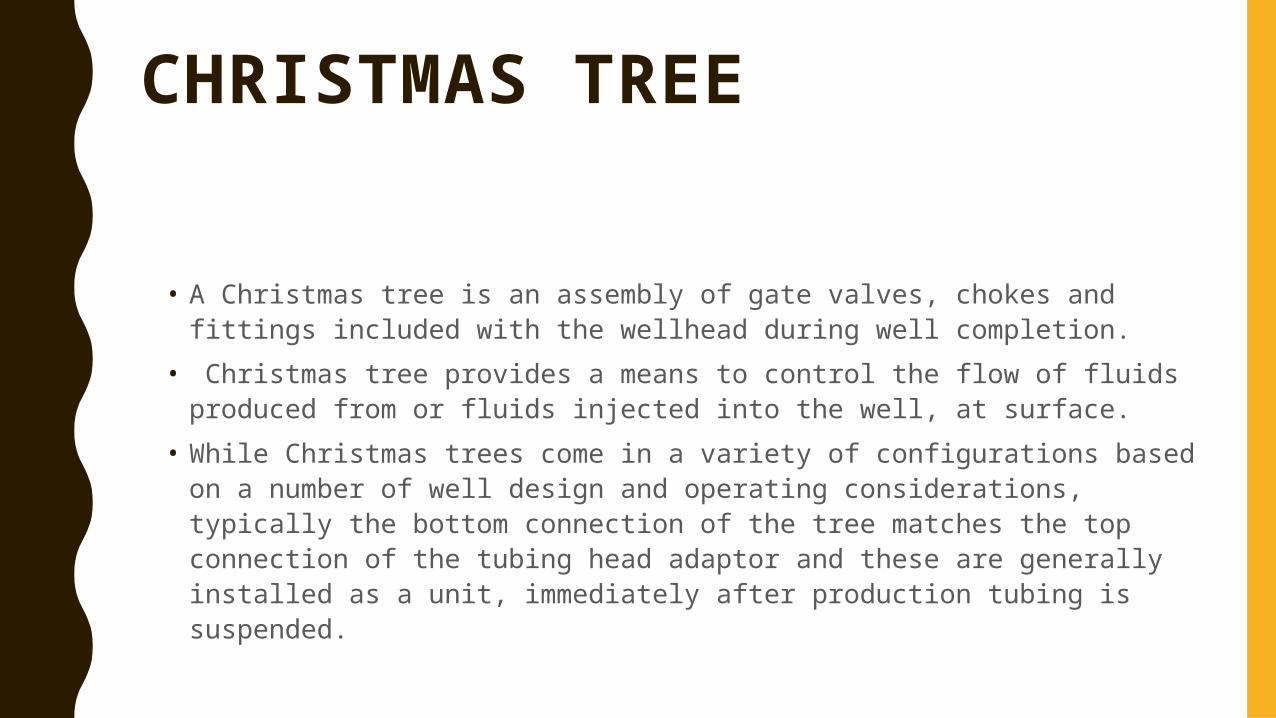
• A Christmas tree is an assembly of gate valves, chokes and fittings included with the wellhead during well completion.
• Christmas tree provides a means to control the flow of fluids produced from or fluids injected into the well, at surface.
• While Christmas trees come in a variety of configurations based on a number of well design and operating considerations, typically the bottom connection of the tree matches the top connection of the tubing head adaptor and these are generally installed as a unit, immediately after production tubing is suspended.
Christmas tree for a flowing well
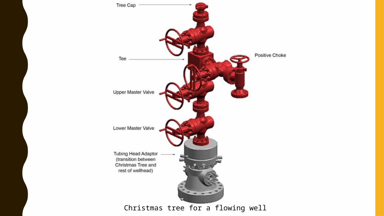
Christmas tree for Sucker Rod Pump
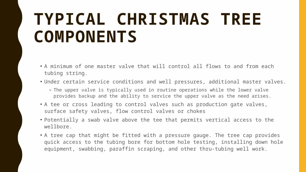
TYPICAL CHRISTMAS TREE COMPONENTS
• A minimum of one master valve that will control all flows to and from each tubing string.
• Under certain service conditions and well pressures, additional master valves.– The upper valve is typically used in routine operations while the lower valve provides
backup and the ability to service the upper valve as the need arises.• A tee or cross leading to control valves such as production gate valves, surface
safety valves, flow control valves or chokes• Potentially a swab valve above the tee that permits vertical access to the wellbore.• A tree cap that might be fitted with a pressure gauge. The tree cap provides quick
access to the tubing bore for bottom hole testing, installing down hole equipment, swabbing, paraffin scraping, and other thru-tubing well work.
CONNECTIONS
• Connections provide a secure, leak free joint between wellhead components. There are five basic connection types commonly used in wellhead design.
– Threaded– Welded– Flanged– Studded– Clamp hub – Sliplock – Connection that is unique to coiled tubing.
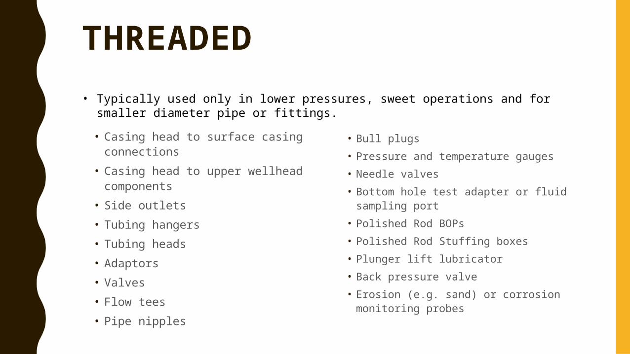
THREADED
• Casing head to surface casing connections
• Casing head to upper wellhead components
• Side outlets• Tubing hangers• Tubing heads• Adaptors• Valves• Flow tees• Pipe nipples
• Bull plugs• Pressure and temperature gauges• Needle valves• Bottom hole test adapter or fluid sampling
port• Polished Rod BOPs• Polished Rod Stuffing boxes• Plunger lift lubricator• Back pressure valve• Erosion (e.g. sand) or corrosion monitoring
probes
• Typically used only in lower pressures, sweet operations and for smaller diameter pipe or fittings.
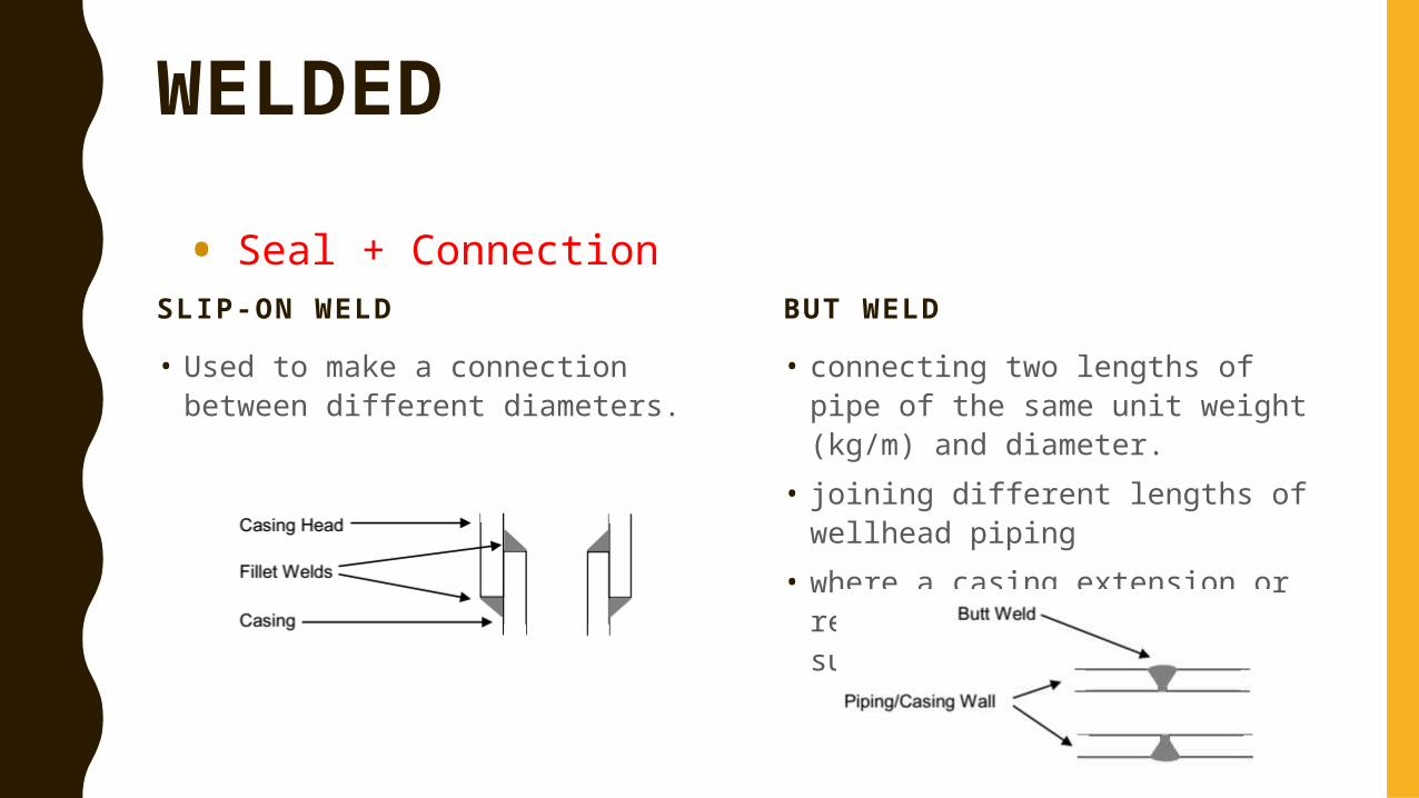
WELDED
SLIP-ON WELD
• Used to make a connection between different diameters.
BUT WELD
• connecting two lengths of pipe of the same unit weight (kg/m) and diameter.
• joining different lengths of wellhead piping
• where a casing extension or repair is required at surface.
• Seal + Connection
STUDDED
• one component that has studs threaded into its housing and a second component with a flange bolted to the studs.
• Uses:– Typically used in any high pressure (i.e., 2000 psi to 30,000 psi) or higher risk
operations.– Used in any operations where there are requirements to shorten the height or
length of the wellhead components.– Used in any operations where there is a need to reduce the bending moment on
equipment.– Along with flanged connections, studded connections allow for the installation of
a test port to meet requirements of pressure testing between primary and secondary seals.
CLAM HUB
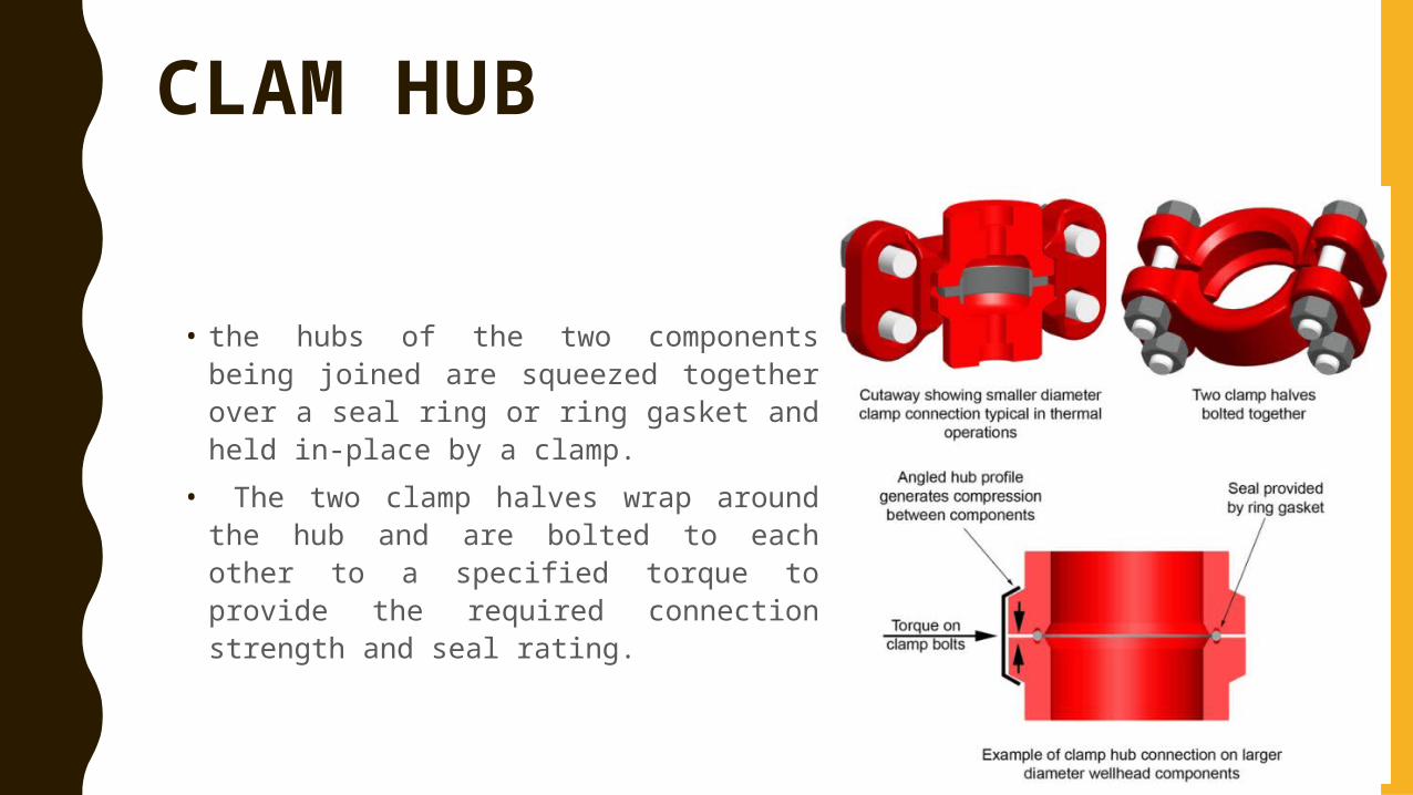
• the hubs of the two components being joined are squeezed together over a seal ring or ring gasket and held in-place by a clamp.
• The two clamp halves wrap around the hub and are bolted to each other to a specified torque to provide the required connection strength and seal rating.
CLAM HUB USES
• Typically used in any high pressure or higher risk operations. • Most commonly found in thermal operations.• Provides a superior ability to align and seal wellhead components and piping
modules as compared to flanged or studded connections, as small differences in alignment are more easily “absorbed” by this type of connection.
• Provides a higher fatigue resistance than flanged or studded connections.• Offers a faster make up time versus flanged or studded connections.• Since any damage to the face of the hub may compromise the metal to metal
seal, special care must be taken in any operation where there is potential for this type of damage.
SLIPLOCK
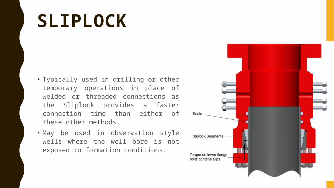
• Typically used in drilling or other temporary operations in place of welded or threaded connections as the Sliplock provides a faster connection time than either of these other methods.
• May be used in observation style wells where the well bore is not exposed to formation conditions.
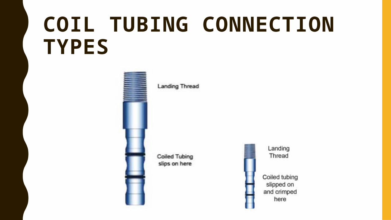
COIL TUBING CONNECTION TYPES
SEALS
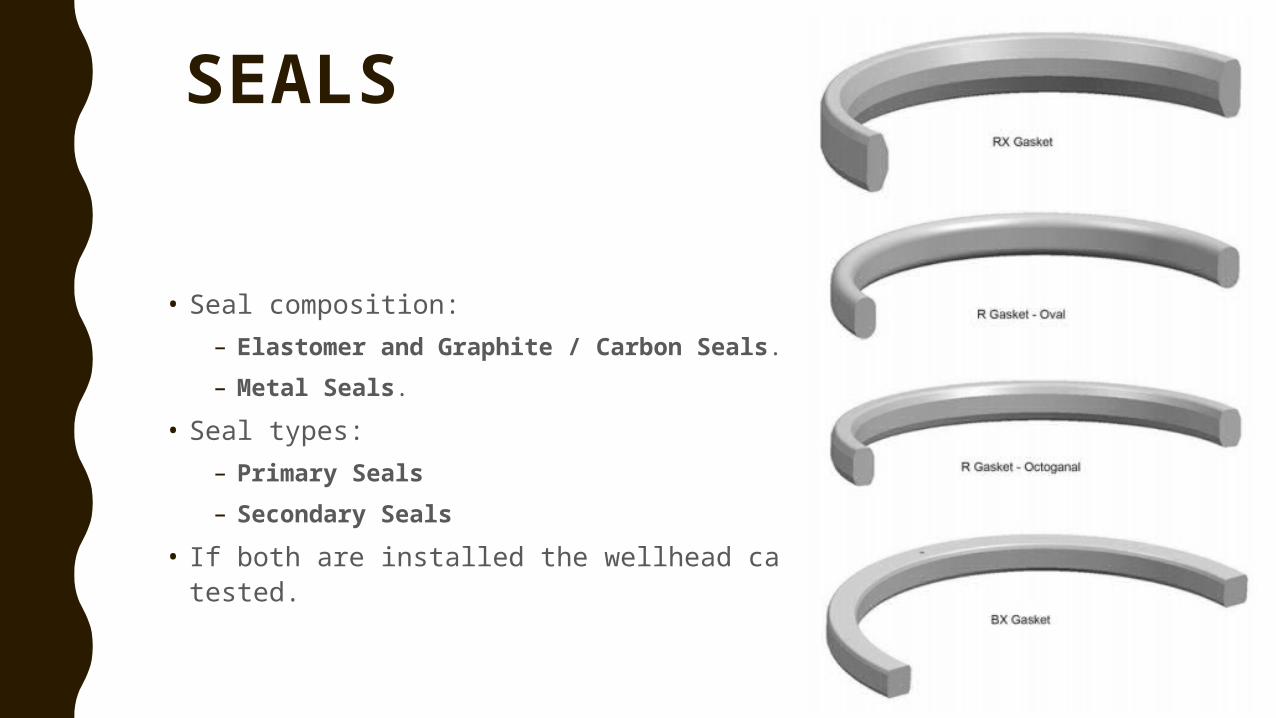
• Seal composition:– Elastomer and Graphite / Carbon Seals.– Metal Seals.
• Seal types: – Primary Seals – Secondary Seals
• If both are installed the wellhead can be pressuretested.
FLOWING WELLS
• When the reservoir pressure is capable to lift fluid to the surface.• Flowing wellheads typically are simple. • Depending on the type of produced fluids and well completion, production
can be up the production casing, production tubing, or the tubing-casing annulus.
– Sweet, low pressure, low risk wells (e.g., shallow gas) often do not have a tubing string installed.
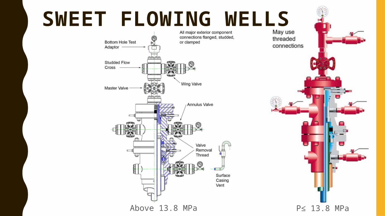
Above 13.8 MPa
SWEET FLOWING WELLS
P≤ 13.8 MPa
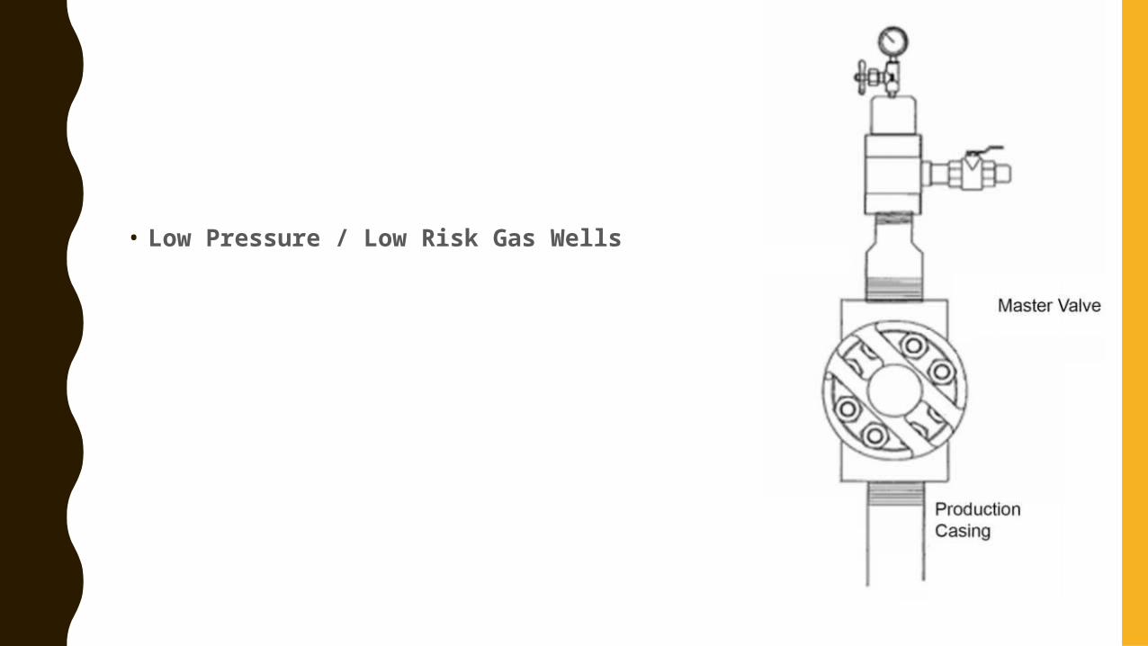
• Low Pressure / Low Risk Gas Wells
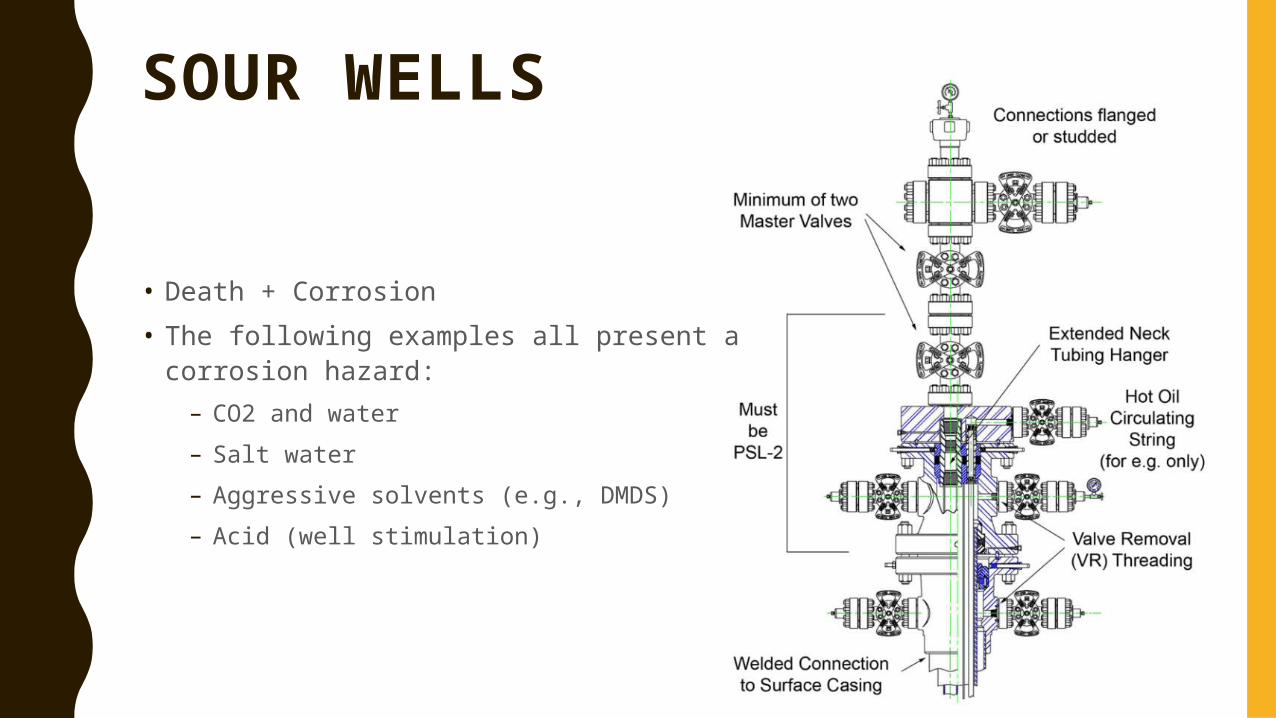
SOUR WELLS
• Death + Corrosion • The following examples all present a corrosion
hazard:– CO2 and water– Salt water– Aggressive solvents (e.g., DMDS)– Acid (well stimulation)
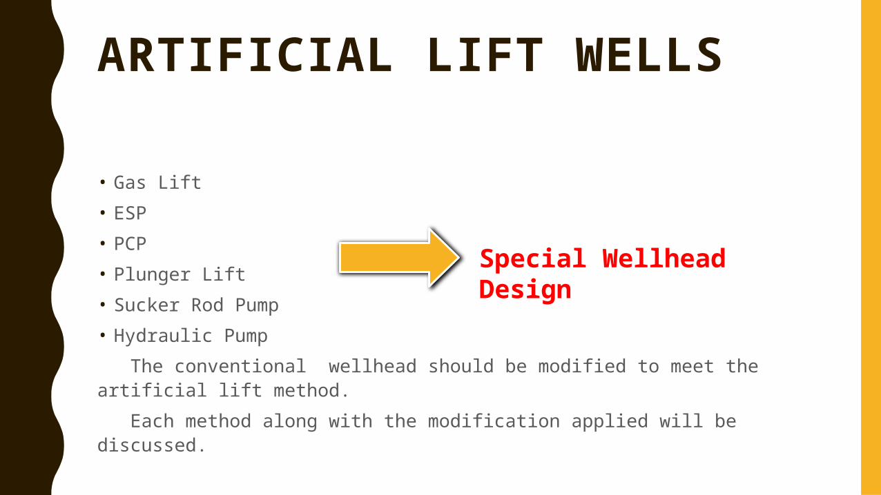
ARTIFICIAL LIFT WELLS
• Gas Lift • ESP• PCP• Plunger Lift • Sucker Rod Pump• Hydraulic Pump
The conventional wellhead should be modified to meet the artificial lift method.
Each method along with the modification applied will be discussed.
Special Wellhead Design
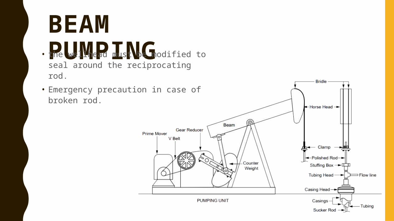
BEAM PUMPING• the wellhead must be modified to seal around the reciprocating rod.
• Emergency precaution in case of broken rod.
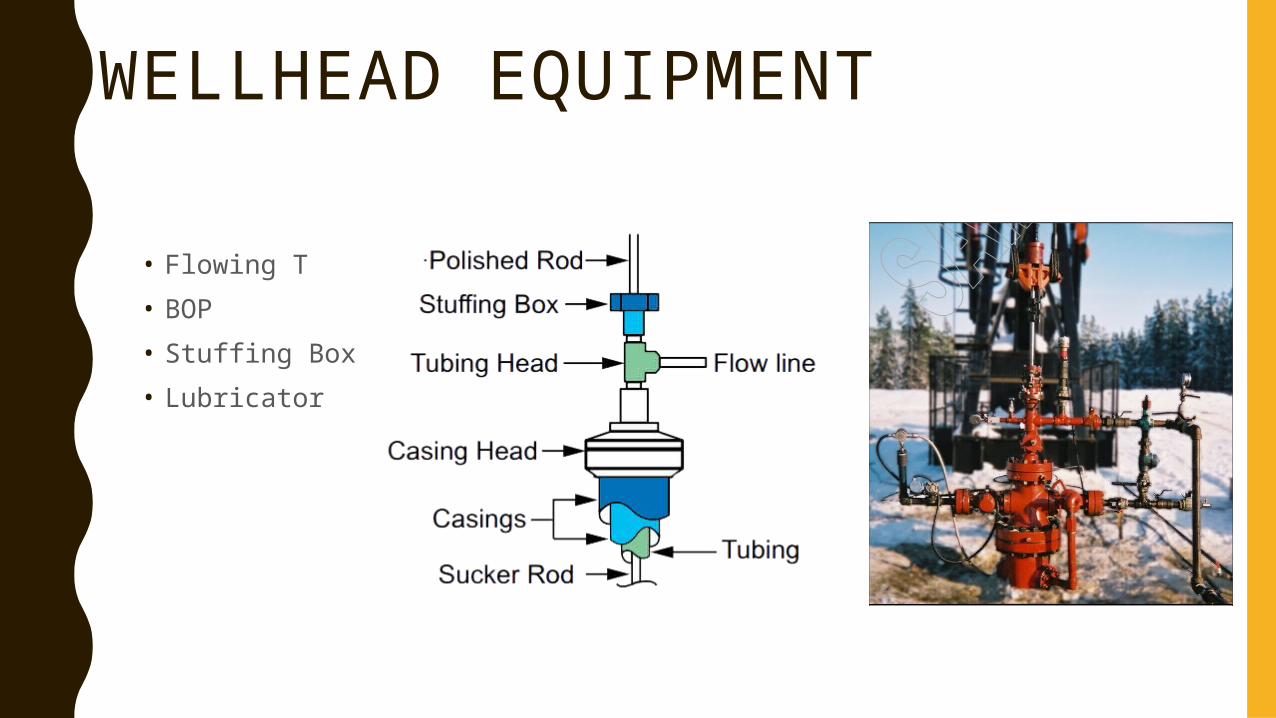
WELLHEAD EQUIPMENT
• Flowing T• BOP• Stuffing Box• Lubricator
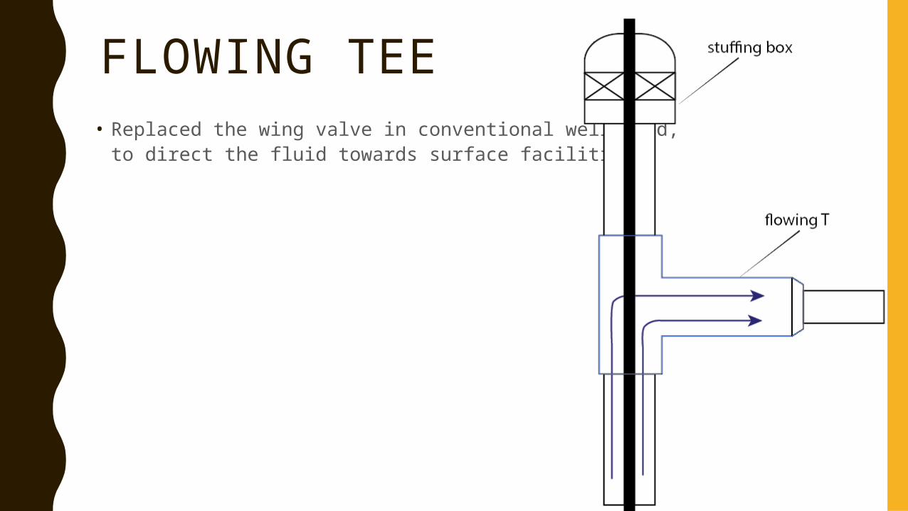
FLOWING TEE• Replaced the wing valve in conventional well head,
to direct the fluid towards surface facilities.
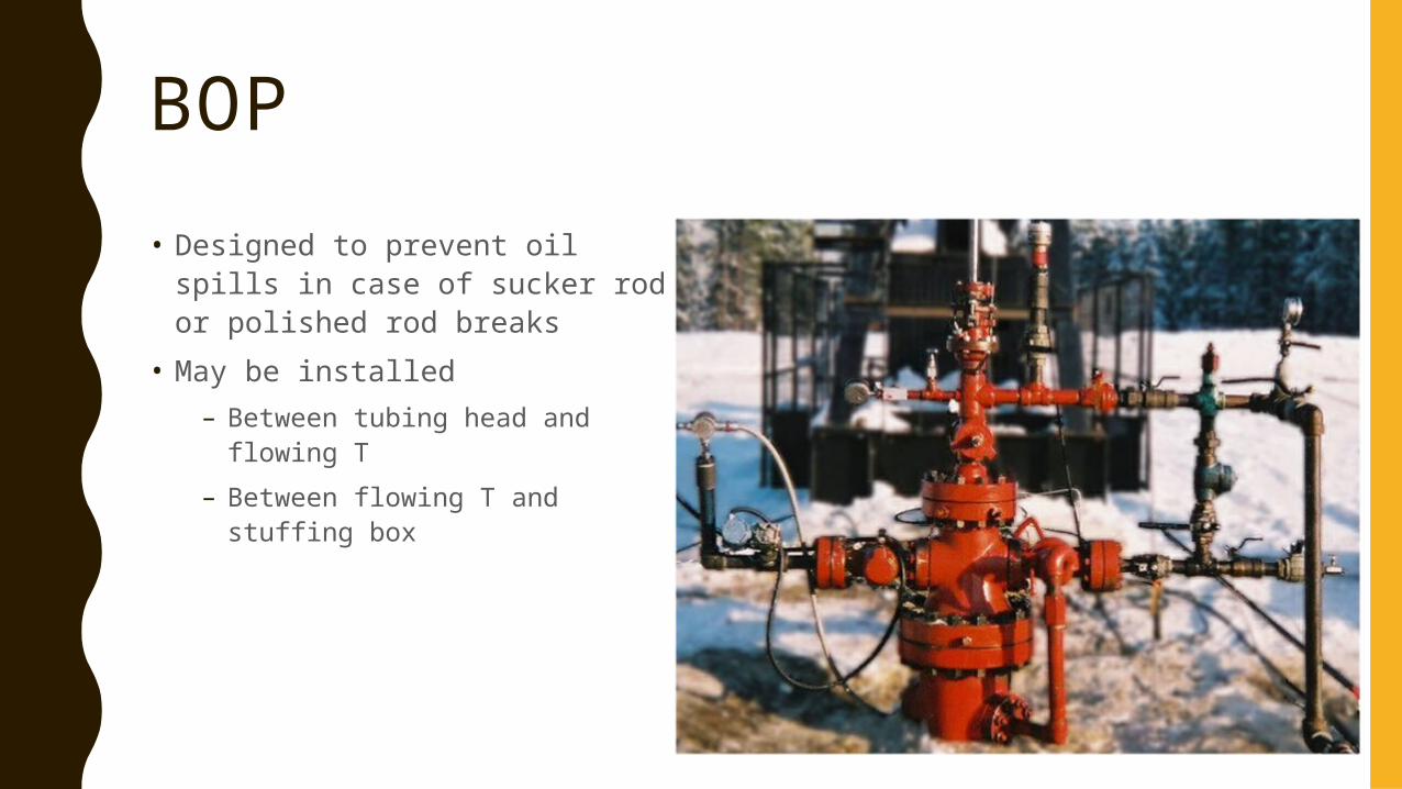
BOP• Designed to prevent oil spills in
case of sucker rod or polished rod breaks
• May be installed – Between tubing head and
flowing T– Between flowing T and stuffing
box
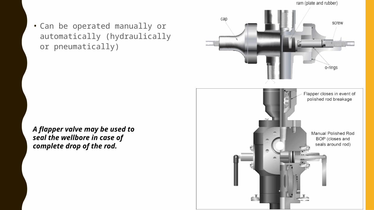
• Can be operated manually or automatically (hydraulically or pneumatically)
A flapper valve may be used to seal the wellbore in case of complete drop of the rod.
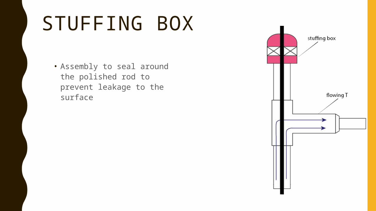
STUFFING BOX• Assembly to seal around the
polished rod to prevent leakage to the surface
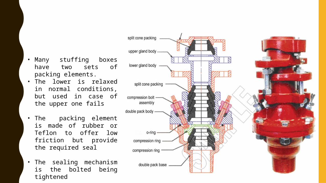
• Many stuffing boxes have two sets of packing elements.
• The lower is relaxed in normal conditions, but used in case of the upper one fails
• The packing element is made of rubber or Teflon to offer low friction but provide the required seal
• The sealing mechanism is the bolted being tightened
LUBRICATION
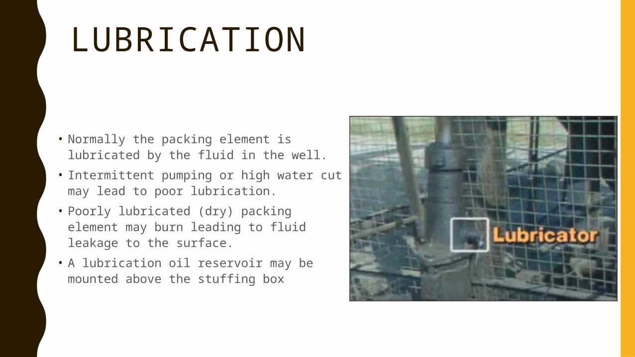
• Normally the packing element is lubricated by the fluid in the well.
• Intermittent pumping or high water cut may lead to poor lubrication.
• Poorly lubricated (dry) packing element may burn leading to fluid leakage to the surface.
• A lubrication oil reservoir may be mounted above the stuffing box
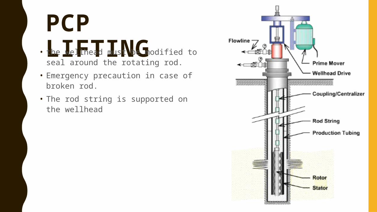
PCP LIFTING• the wellhead must be modified to seal around the rotating rod.
• Emergency precaution in case of broken rod.
• The rod string is supported on the wellhead
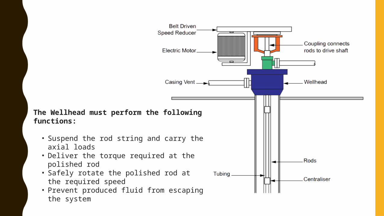
The Wellhead must perform the following functions:
• Suspend the rod string and carry the axial loads• Deliver the torque required at the polished rod• Safely rotate the polished rod at the required
speed• Prevent produced fluid from escaping the system
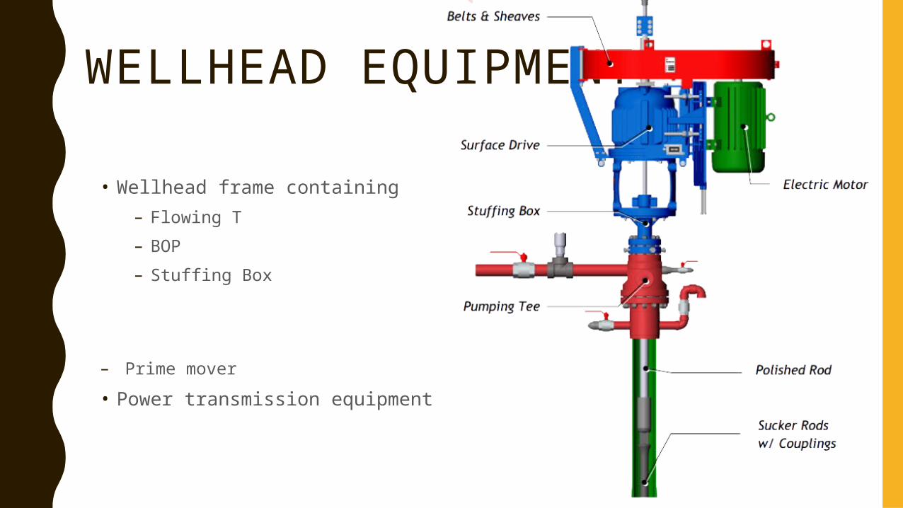
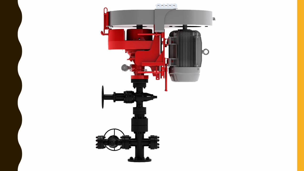
WELLHEAD EQUIPMENT
• Wellhead frame containing– Flowing T– BOP– Stuffing Box
– Prime mover• Power transmission equipment
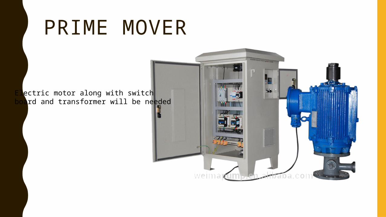
PRIME MOVER
Electric motor along with switchboard and transformer will be needed
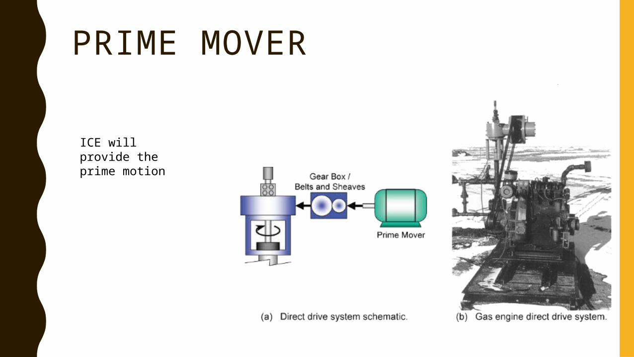
PRIME MOVER
ICE will provide the prime motion
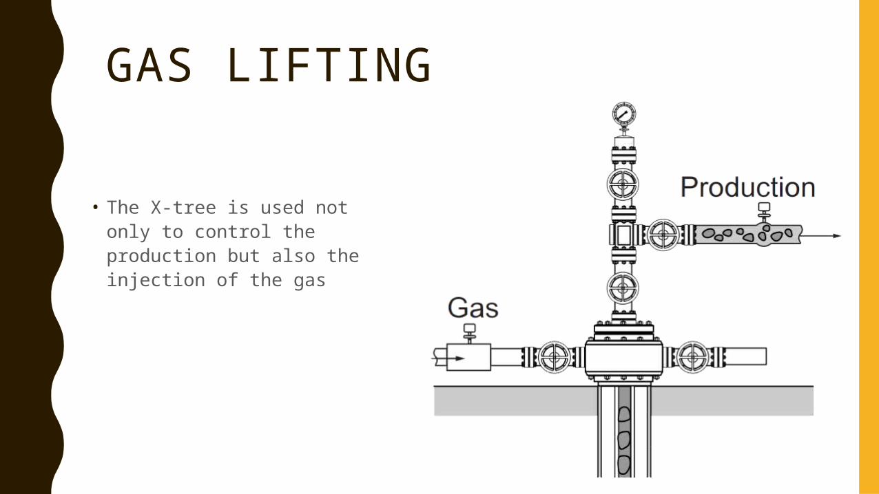
GAS LIFTING
• The X-tree is used not only to control the production but also the injection of the gas
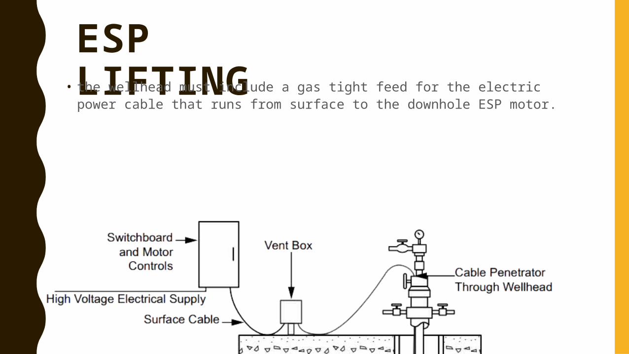
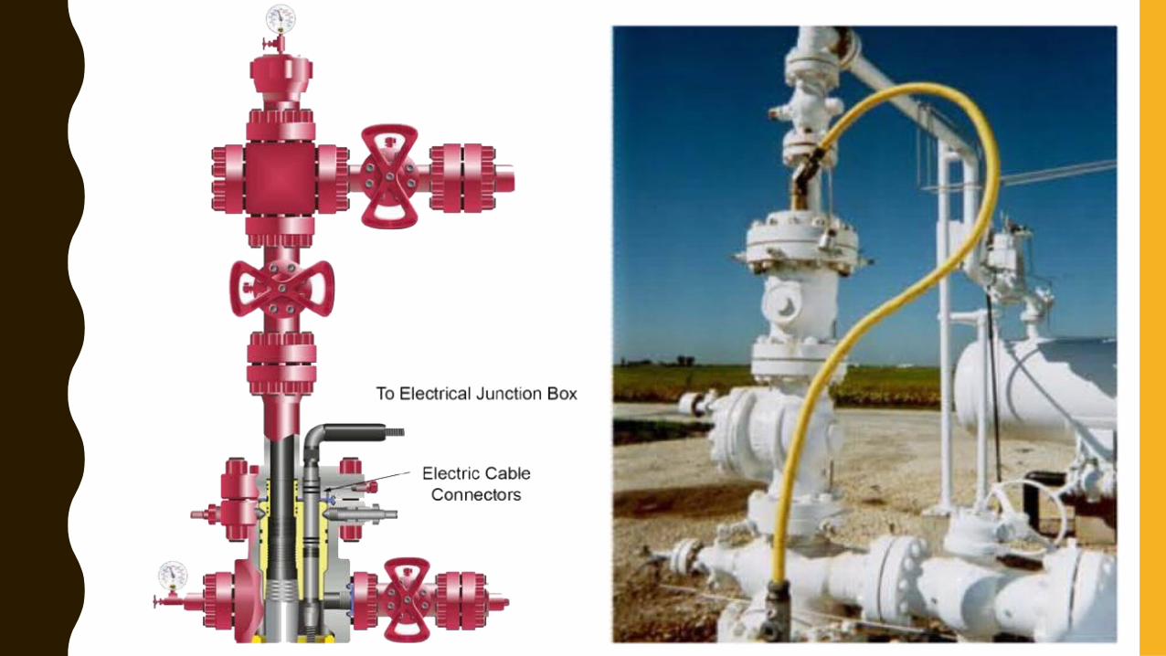
ESP LIFTING• the wellhead must include a gas tight feed for the electric power cable that runs from surface to the downhole ESP motor.
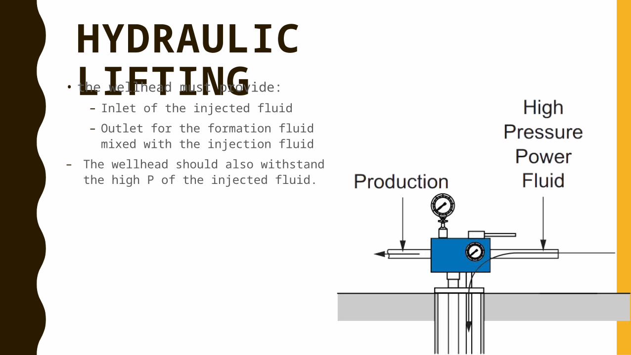
HYDRAULIC LIFTING• the wellhead must provide:
– Inlet of the injected fluid– Outlet for the formation fluid mixed
with the injection fluid– The wellhead should also withstand the
high P of the injected fluid.
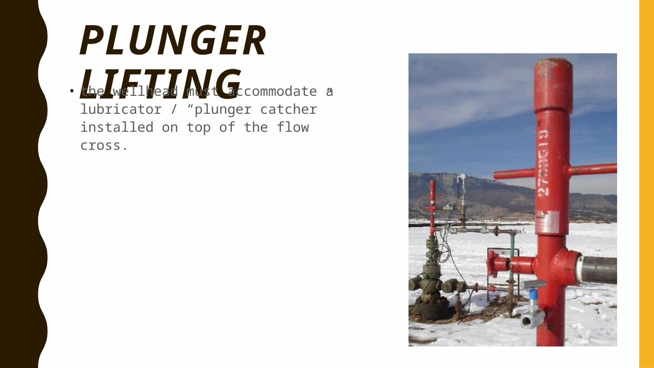
PLUNGER LIFTING• the wellhead must accommodate a lubricator / “plunger catcher” installed on top of the flow cross.
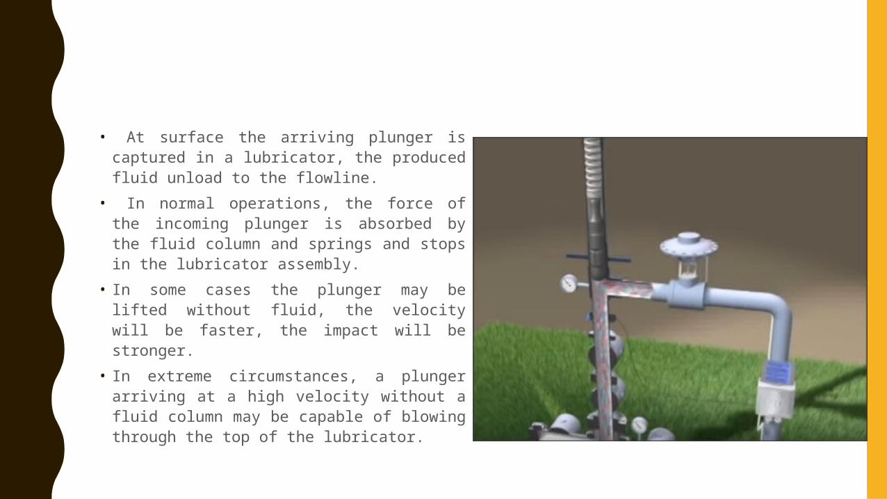
• At surface the arriving plunger is captured in a lubricator, the produced fluid unload to the flowline.
• In normal operations, the force of the incoming plunger is absorbed by the fluid column and springs and stops in the lubricator assembly.
• In some cases the plunger may be lifted without fluid, the velocity will be faster, the impact will be stronger.
• In extreme circumstances, a plunger arriving at a high velocity without a fluid column may be capable of blowing through the top of the lubricator.
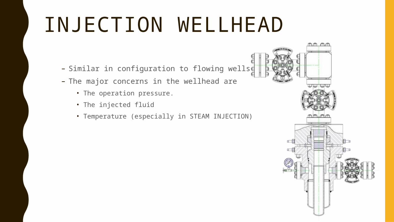
INJECTION WELLHEAD– Similar in configuration to flowing wells.– The major concerns in the wellhead are
• The operation pressure.• The injected fluid• Temperature (especially in STEAM INJECTION)
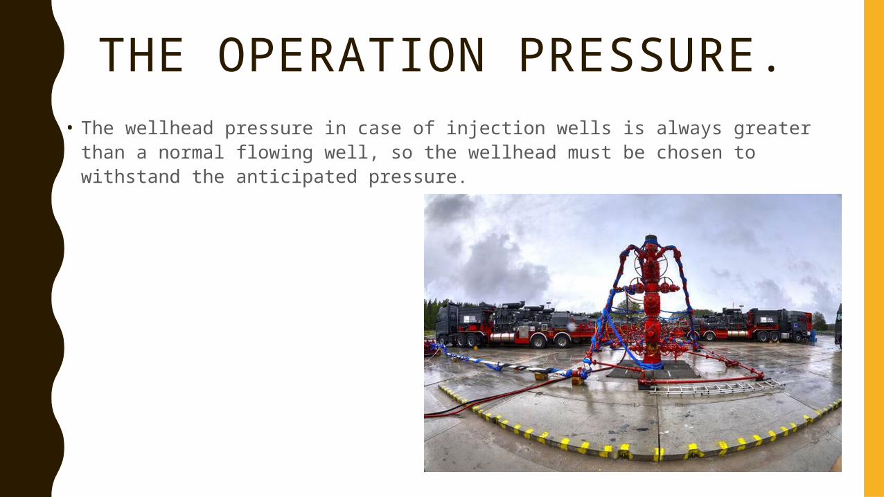
THE OPERATION PRESSURE.• The wellhead pressure in case of injection wells is always greater than a normal
flowing well, so the wellhead must be chosen to withstand the anticipated pressure.
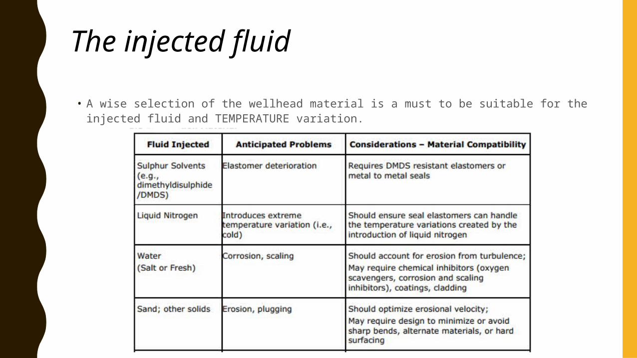
The injected fluid
• A wise selection of the wellhead material is a must to be suitable for the injected fluid and TEMPERATURE variation.

OFFSHORE WELLHEADS
OFFSHORE WELLHEAD
• Mudline suspension • Subsea wellhead
MUDLINE SUSPENSION SYSTEM• as jackup drilling vessels drilled in deeper water, the need to
transfer the weight of the well to the seabed and provide a disconnect-and-reconnect capability became clearly beneficial. This series of hangers, called mudline suspension equipment, provides landing rings and shoulders to transfer the weight of each casing string to the conductor and the sea bed.
• The mudline suspension system also allows the well to be temporarily abandoned (disconnected) when total depth (TD) is achieved (when drilling is finished at total depth)
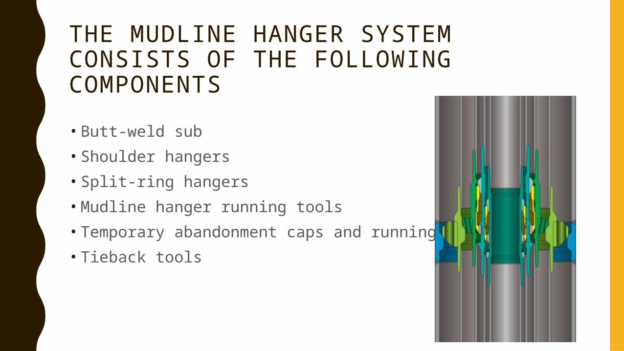
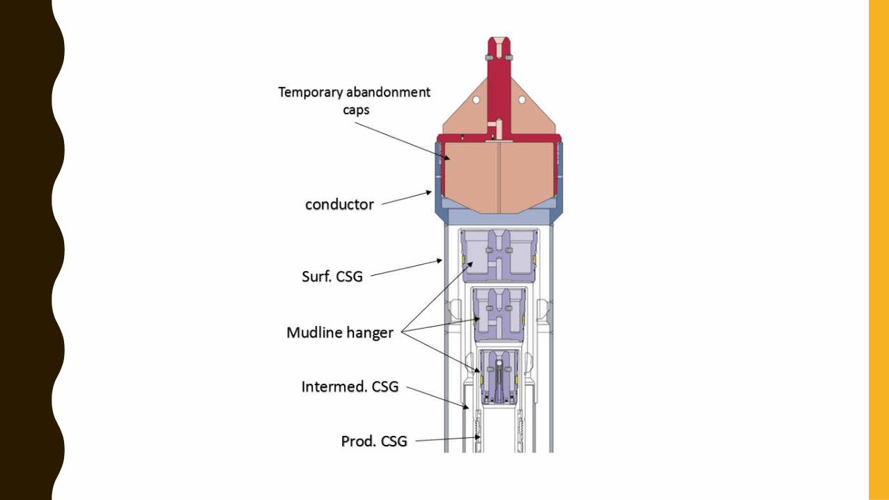
THE MUDLINE HANGER SYSTEM CONSISTS OF THE FOLLOWING COMPONENTS• Butt-weld sub• Shoulder hangers• Split-ring hangers• Mudline hanger running tools• Temporary abandonment caps and running tool• Tieback tools
MUDLINE HANGER SYSTEM
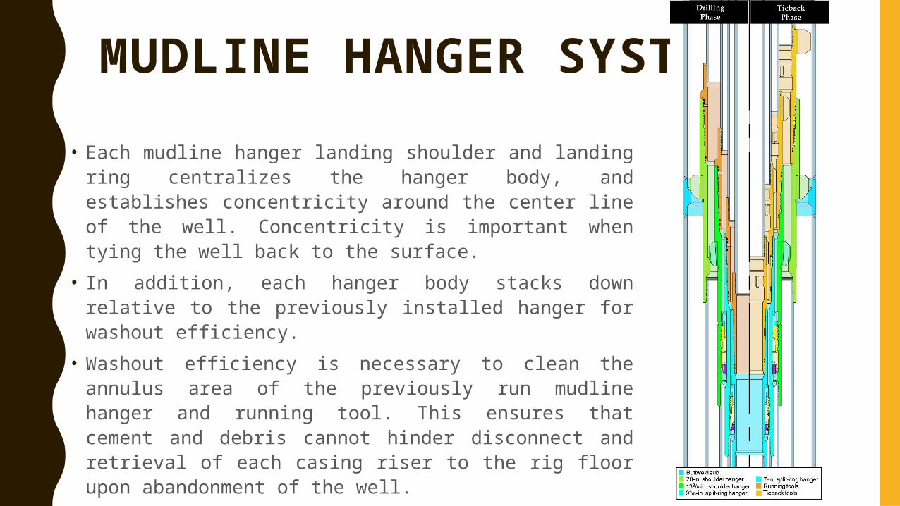
• Each mudline hanger landing shoulder and landing ring centralizes the hanger body, and establishes concentricity around the center line of the well. Concentricity is important when tying the well back to the surface.
• In addition, each hanger body stacks down relative to the previously installed hanger for washout efficiency.
• Washout efficiency is necessary to clean the annulus area of the previously run mudline hanger and running tool. This ensures that cement and debris cannot hinder disconnect and retrieval of each casing riser to the rig floor upon abandonment of the well.
TEMPORARILY ABANDONING THE WELL
• After each casing string is disconnected from the mudline suspension hanger and retrieved to the rig floor in the reverse order of the drilling process, threaded temporary abandonment caps or stab-in temporary abandonment caps (both of which makeup into the threaded running profile of the mudline hanger) are installed in selected mudline hangers before the drilling vessel finishes and leaves the location. The temporary abandonment caps can be retrieved with the same tool that installed them.
RECONNECTING TO THE WELL• A mudline suspension system also incorporates
tieback tools to reconnect the mudline hanger to the surface for re-entry and/or completion.
• A surface wellhead system is installed, and the well is completed similarly to the method used on land drilling operations.
• The mudline suspension system has been designed to accommodate tying the well back to the surface for surface completion, and it also can be adapted for a subsea production tree. A tieback tubing head can be installed to the mudline suspension system at the seabed, and a subsea tree can be installed on this tubing head.
Drilling is done by jack up rig
Sea surface
Sea bed
When the desired depth is reached , mudline system is installed
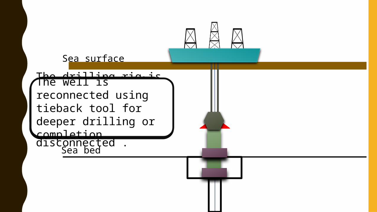
The drilling rig is removed ,so the abandonment cap is installed and the well is disconnected .
The well is reconnected using tieback tool for deeper drilling or completion
DIFFERENCE BETWEEN THE LAND WELLHEADS AND A THE JACKUP MUDLINE
• The main difference between the wellheads used in the land drilling application and the jackup drilling application (with mudline) is the slip-and-seal assembly
• Because the weight of the well now sits at the seabed, a weight-set slip-and-seal assembly is not used. Instead, a mechanical set (energizing the seal by hand) is used, in which cap screws are made up with a wrench against an upper compression plate on the slip-and-seal assembly to energize the elastomeric seal.
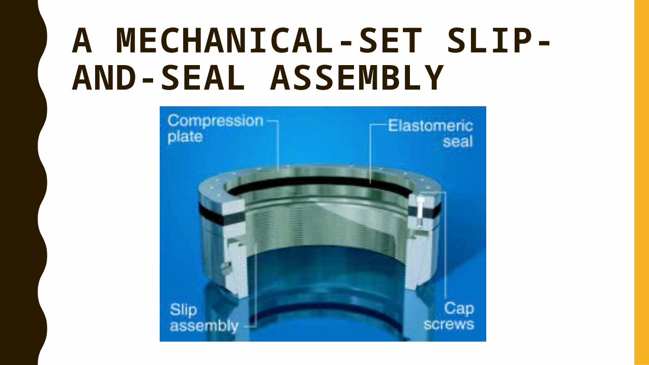
A MECHANICAL-SET SLIP-AND-SEAL ASSEMBLY
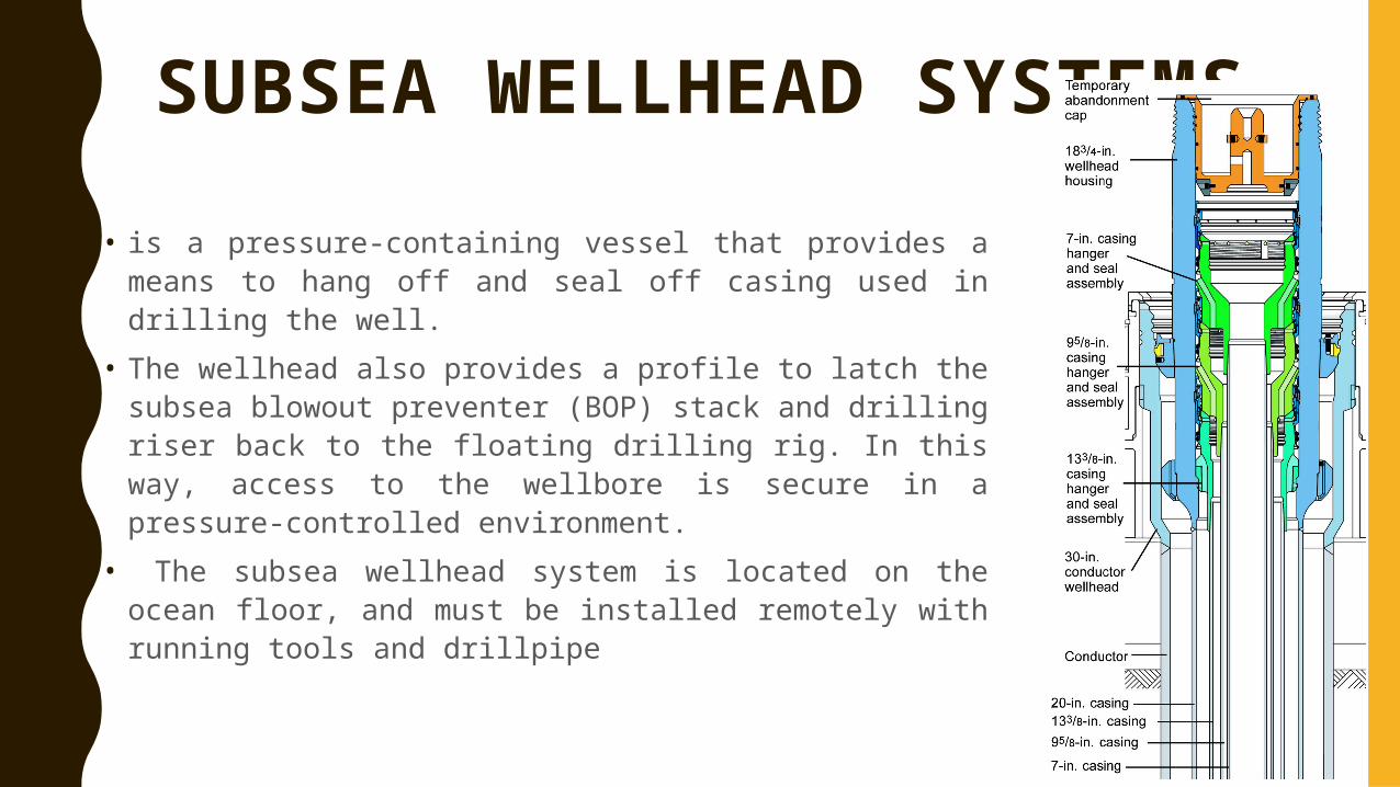
SUBSEA WELLHEAD SYSTEMS
• is a pressure-containing vessel that provides a means to hang off and seal off casing used in drilling the well.
• The wellhead also provides a profile to latch the subsea blowout preventer (BOP) stack and drilling riser back to the floating drilling rig. In this way, access to the wellbore is secure in a pressure-controlled environment.
• The subsea wellhead system is located on the ocean floor, and must be installed remotely with running tools and drillpipe
A STANDARD SUBSEA WELLHEAD SYSTEM WILL TYPICALLY CONSIST OF THE FOLLOWING:
• Drilling guide base.• Low-pressure housing.• High-pressure wellhead housing (typically 18¾ in.).• Casing hangers• Metal-to-metal annulus sealing assembly.• Bore protectors and wear bushings.
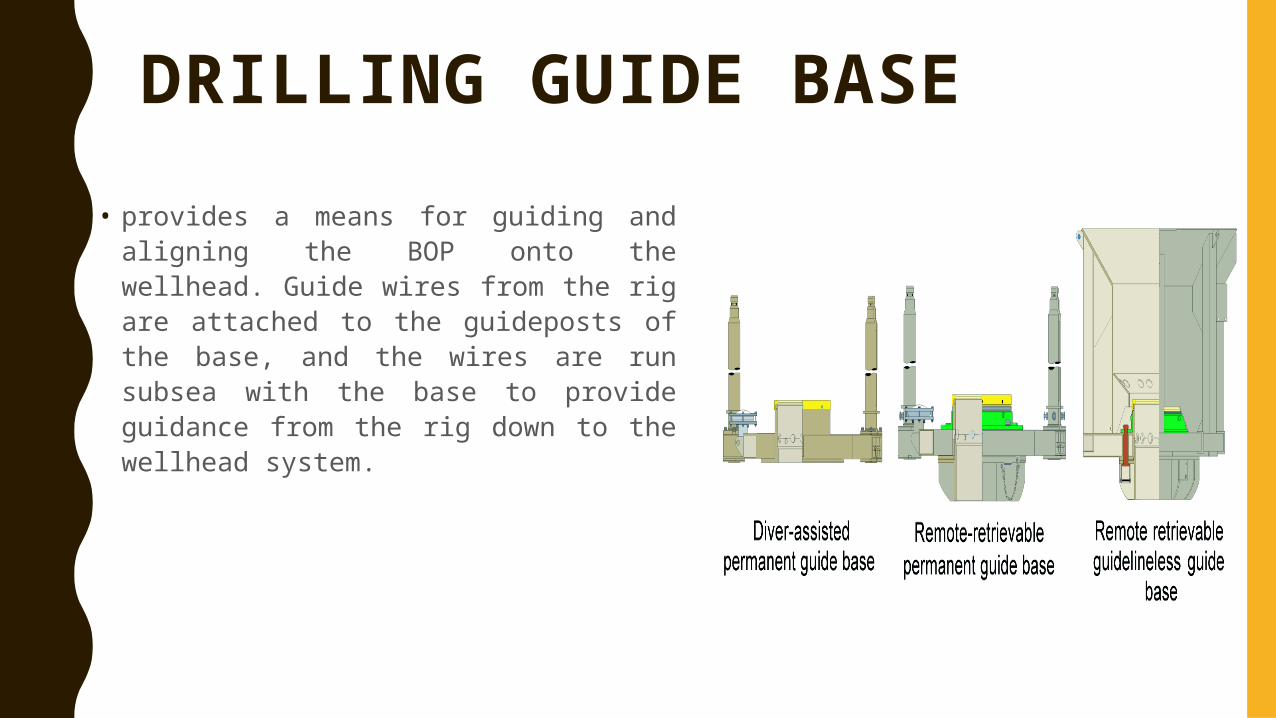
DRILLING GUIDE BASE• provides a means for guiding and
aligning the BOP onto the wellhead. Guide wires from the rig are attached to the guideposts of the base, and the wires are run subsea with the base to provide guidance from the rig down to the wellhead system.
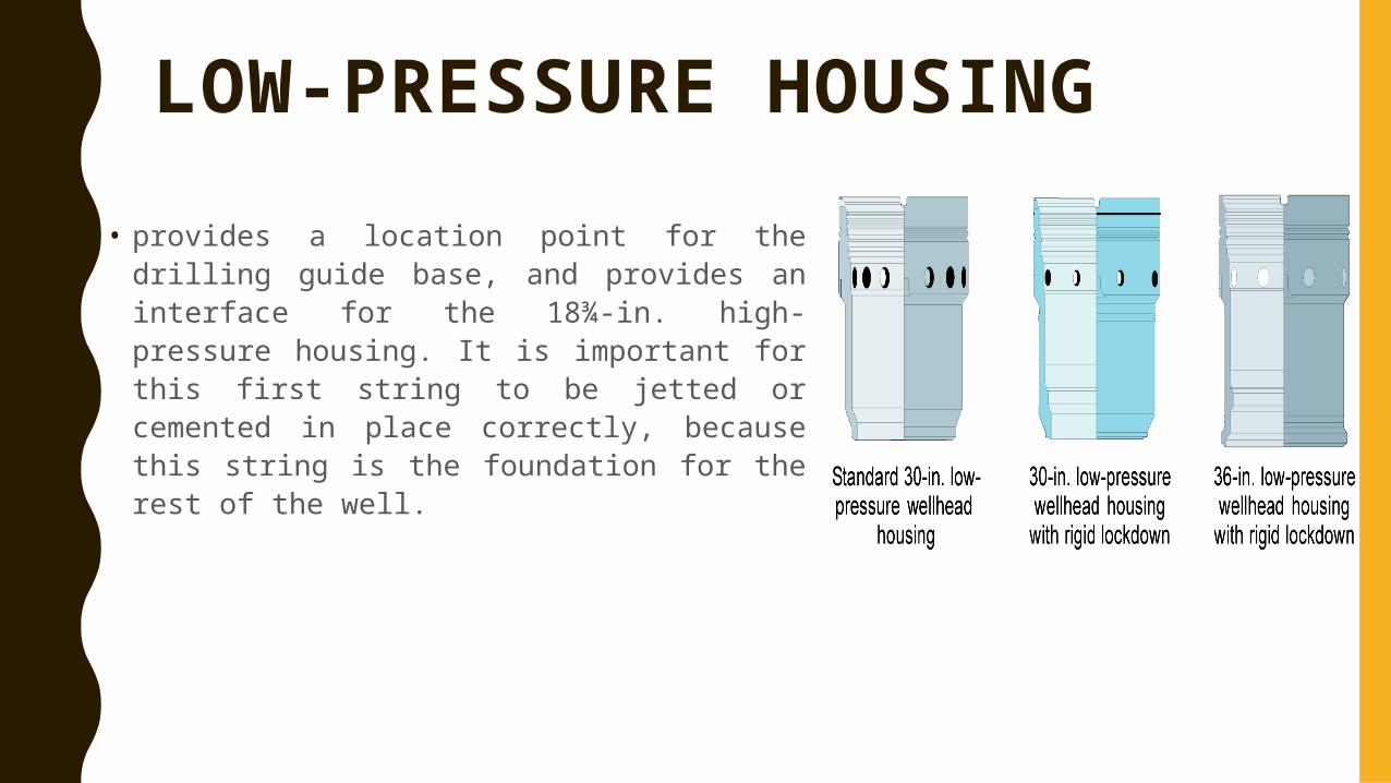
LOW-PRESSURE HOUSING• provides a location point for the drilling guide
base, and provides an interface for the 18¾-in. high-pressure housing. It is important for this first string to be jetted or cemented in place correctly, because this string is the foundation for the rest of the well.
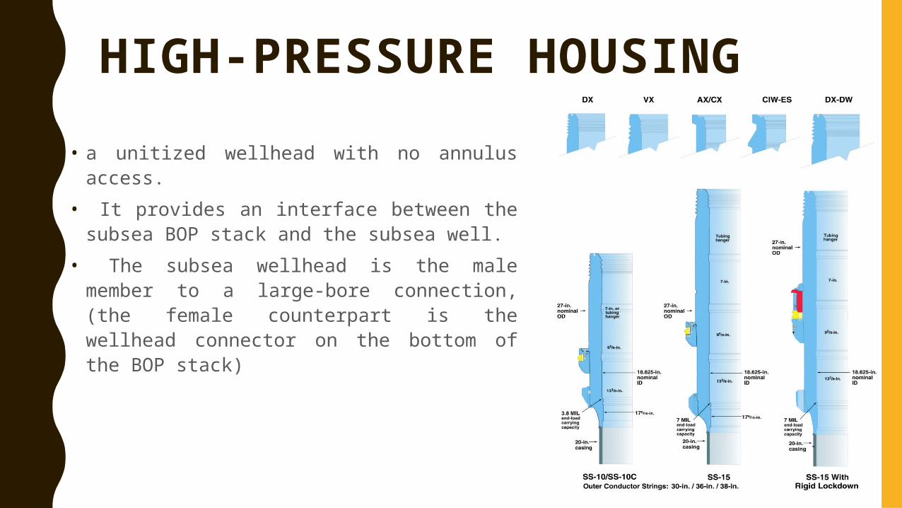
HIGH-PRESSURE HOUSING
• a unitized wellhead with no annulus access.• It provides an interface between the subsea
BOP stack and the subsea well.• The subsea wellhead is the male member to
a large-bore connection, (the female counterpart is the wellhead connector on the bottom of the BOP stack)
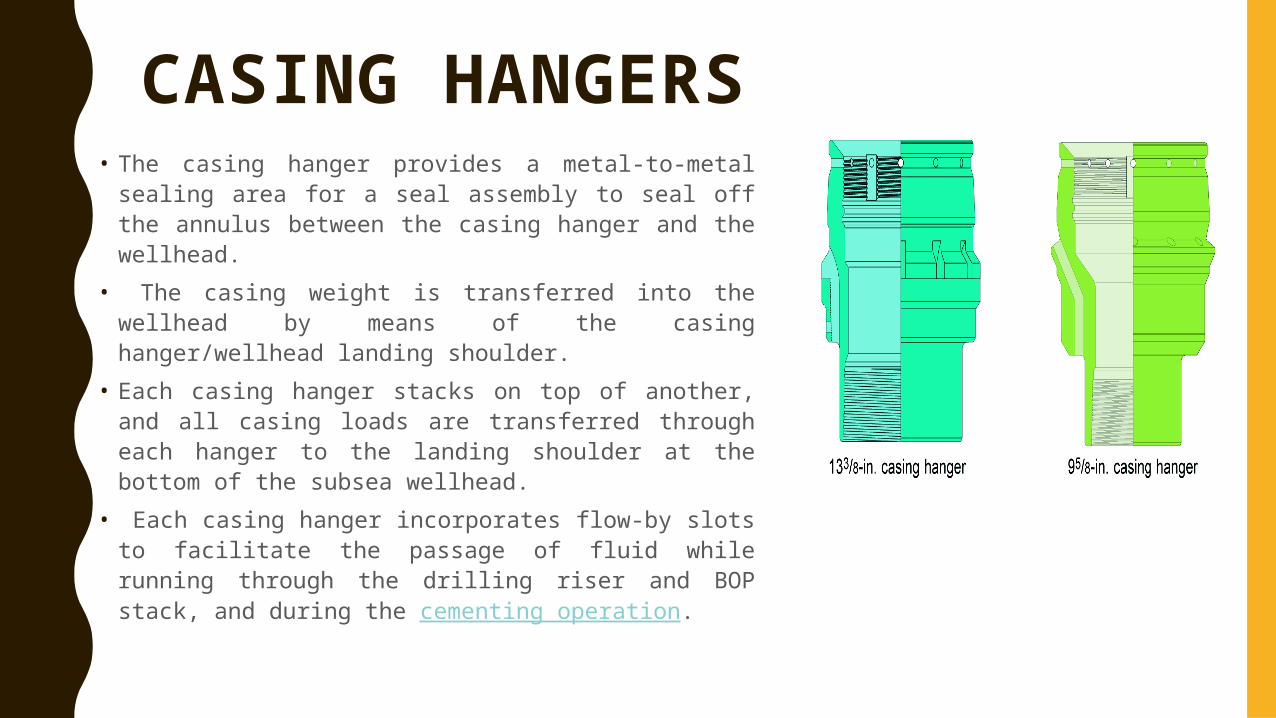
CASING HANGERS• The casing hanger provides a metal-to-metal sealing
area for a seal assembly to seal off the annulus between the casing hanger and the wellhead.
• The casing weight is transferred into the wellhead by means of the casing hanger/wellhead landing shoulder.
• Each casing hanger stacks on top of another, and all casing loads are transferred through each hanger to the landing shoulder at the bottom of the subsea wellhead.
• Each casing hanger incorporates flow-by slots to facilitate the passage of fluid while running through the drilling riser and BOP stack, and during the cementing operation.
METAL-TO METAL ANNULUS SEAL ASSEMBLY
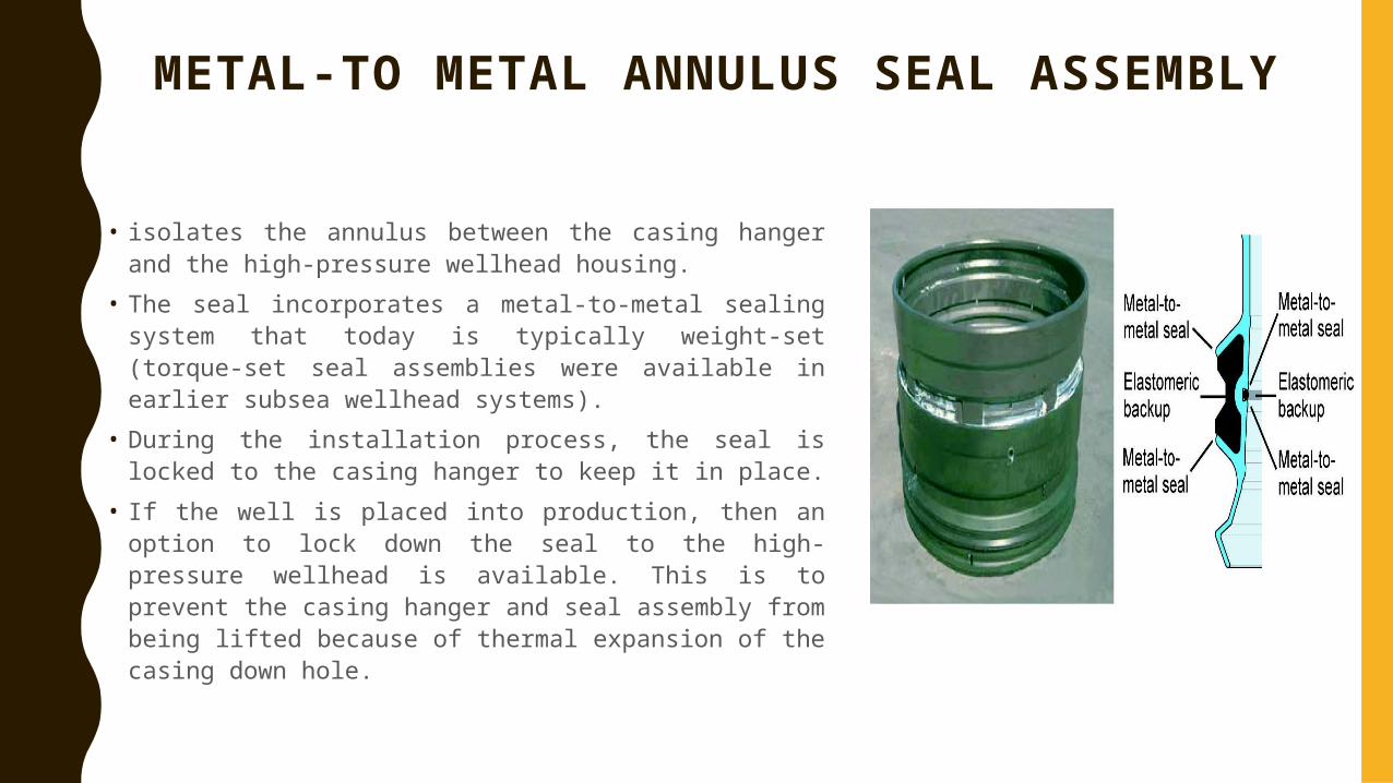
• isolates the annulus between the casing hanger and the high-pressure wellhead housing.
• The seal incorporates a metal-to-metal sealing system that today is typically weight-set (torque-set seal assemblies were available in earlier subsea wellhead systems).
• During the installation process, the seal is locked to the casing hanger to keep it in place.
• If the well is placed into production, then an option to lock down the seal to the high-pressure wellhead is available. This is to prevent the casing hanger and seal assembly from being lifted because of thermal expansion of the casing down hole.
BORE PROTECTORS AND WEAR BUSHINGS
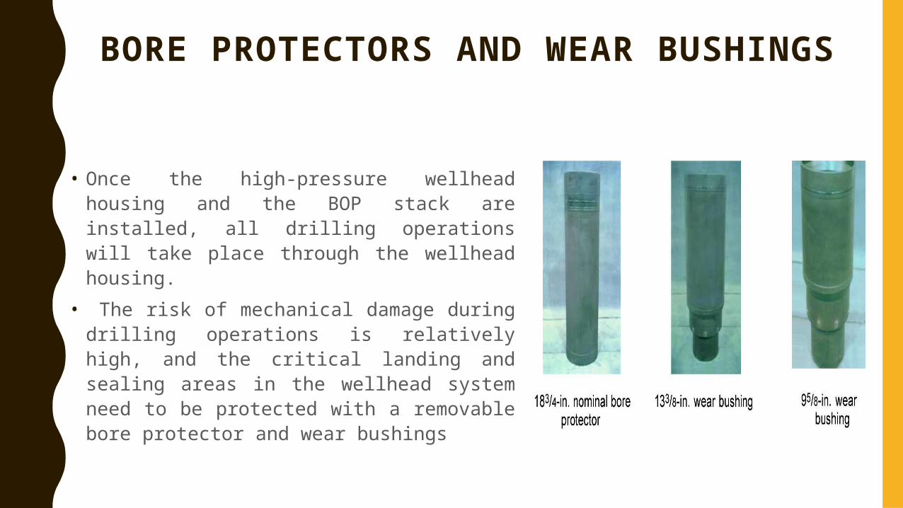
• Once the high-pressure wellhead housing and the BOP stack are installed, all drilling operations will take place through the wellhead housing.
• The risk of mechanical damage during drilling operations is relatively high, and the critical landing and sealing areas in the wellhead system need to be protected with a removable bore protector and wear bushings
BIG BORE SUBSEA WELLHEAD SYSTEMS
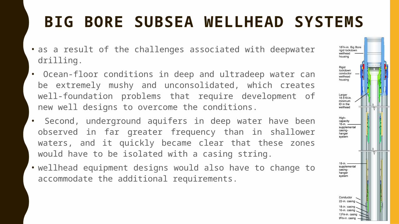
• as a result of the challenges associated with deepwater drilling.• Ocean-floor conditions in deep and ultradeep water can be
extremely mushy and unconsolidated, which creates well-foundation problems that require development of new well designs to overcome the conditions.
• Second, underground aquifers in deep water have been observed in far greater frequency than in shallower waters, and it quickly became clear that these zones would have to be isolated with a casing string.
• wellhead equipment designs would also have to change to accommodate the additional requirements.

WITH SUBSEA WELLHEAD SYSTEMS• conductor and intermediate casing strings can be reconfigured to
strengthen and stiffen the upper section of the well (for higher bending capacities), and overcome the challenges of an unconsolidated ocean floor at the well site.
• Each “water flow” zone encountered while drilling requires isolation with casing and, at the same time, consumes a casing-hanger position in the wellhead.
• It became obvious that more casing strings and hangers were required to reach the targeted depth than the existing wellhead-system designs would accommodate.
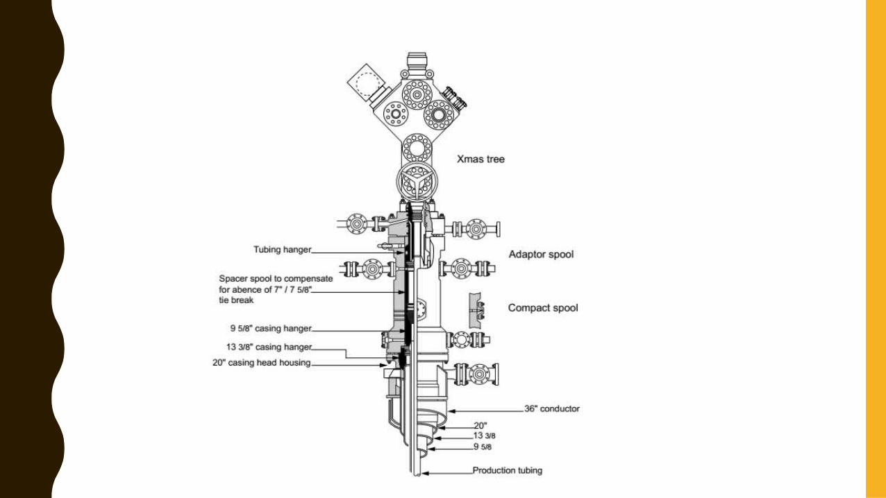
UNITIZED WELLHEAD (C0MPACT)• The unitized wellhead is a one-piece body that is typically run on 13 3/8 -
in. casing through the BOP, and lands on a landing shoulder located inside the starting head or on top of the conductor itself.
• The casing hangers used are threaded and preassembled with a pup joint. • This way, the threaded connection can be pressure tested before leaving
the factory, ensuring that the assembly will have pressure-containing competence.
• Gate valves are installed on the external outlet connections of the unitized wellhead to enable annulus access to each of the intermediate and the production casing strings.
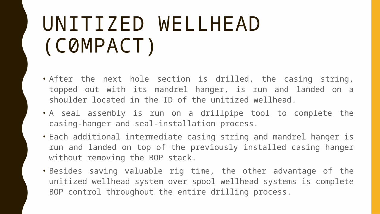
UNITIZED WELLHEAD (C0MPACT)• After the next hole section is drilled, the casing string, topped out with its
mandrel hanger, is run and landed on a shoulder located in the ID of the unitized wellhead.
• A seal assembly is run on a drillpipe tool to complete the casing-hanger and seal-installation process.
• Each additional intermediate casing string and mandrel hanger is run and landed on top of the previously installed casing hanger without removing the BOP stack.
• Besides saving valuable rig time, the other advantage of the unitized wellhead system over spool wellhead systems is complete BOP control throughout the entire drilling process.
TIME-SAVING WELLHEAD
• These types of wellhead is used when rig daily rate is high and there is a massive need to decrease the rig cost by decreasing the time necessary to install the wellhead
• Decreasing the time of testing the BOP.
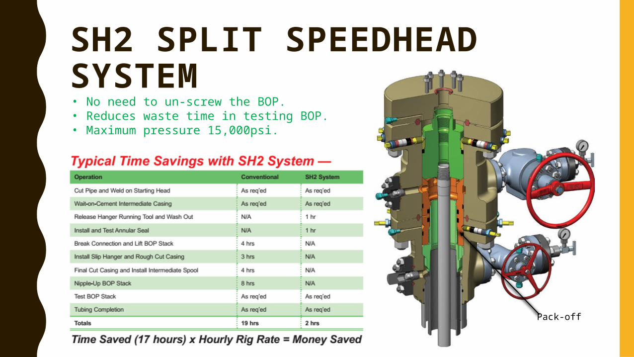
SH2 SPLIT SPEEDHEAD SYSTEM
Pack-off
• No need to un-screw the BOP.• Reduces waste time in testing BOP.• Maximum pressure 15,000psi.
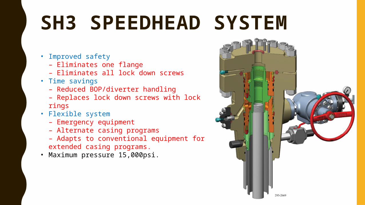
SH3 SPEEDHEAD SYSTEM • Improved safety
– Eliminates one flange– Eliminates all lock down screws
• Time savings– Reduced BOP/diverter handling– Replaces lock down screws with lock rings
• Flexible system– Emergency equipment– Alternate casing programs– Adapts to conventional equipment for extended casing programs.
• Maximum pressure 15,000psi.
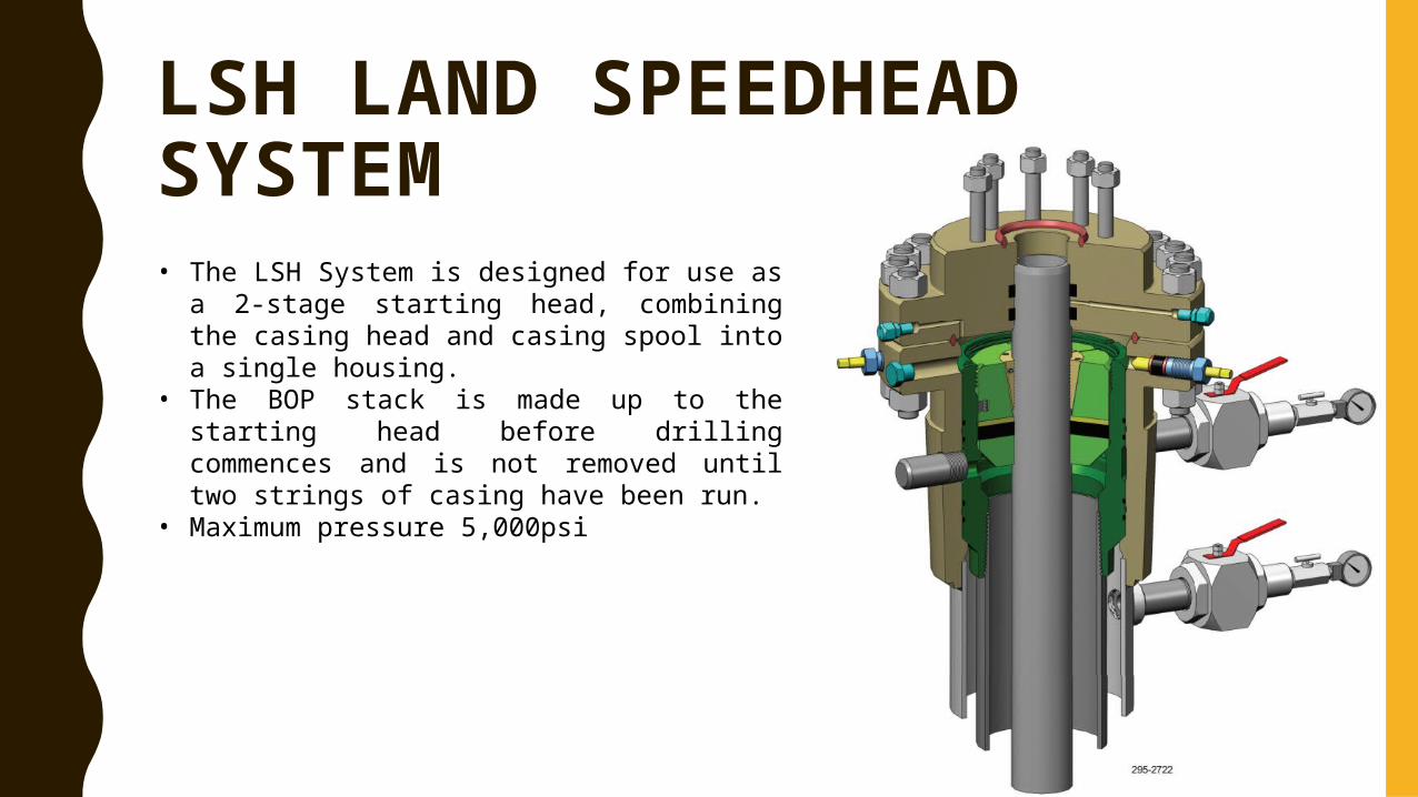
LSH LAND SPEEDHEAD SYSTEM • The LSH System is designed for use as a 2-
stage starting head, combining the casing head and casing spool into a single housing.
• The BOP stack is made up to the starting head before drilling commences and is not removed until two strings of casing have been run.
• Maximum pressure 5,000psi
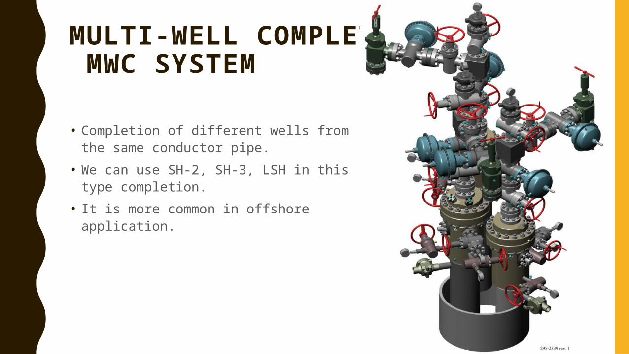
MULTI-WELL COMPLETION MWC SYSTEM
• Completion of different wells from the same conductor pipe.
• We can use SH-2, SH-3, LSH in this type completion.
• It is more common in offshore application.
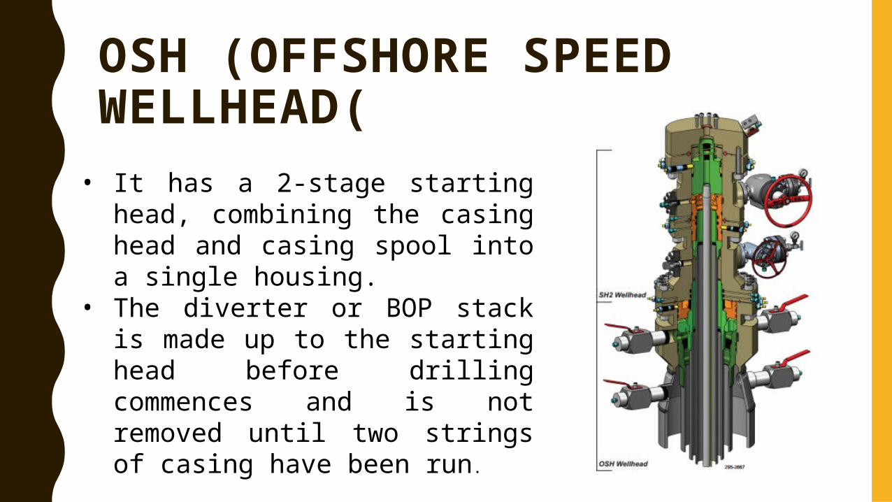
OSH (OFFSHORE SPEED WELLHEAD(
• It has a 2-stage starting head, combining the casing head and casing spool into a single housing.
• The diverter or BOP stack is made up to the starting head before drilling commences and is not removed until two strings of casing have been run.
• This technique impacts both rig costs and safety. By landing two casing strings in one compact forged housing, the OSH system eliminates one complete BOP nipple-down/nipple-up thereby saving significant rig time. By reducing handling of wellhead and BOP equipment and minimizing potential wellhead leakpaths,
• the OSH system substantially improves safety. When combined with the SH2 Split Speed Wellhead System, this package can save from 24 to 40 hours of valuable rig time.
FEATURES1- Improved safety , • Field proven,
– Weld-less attachment option to drive pipe– Run annular seals through BOP.– External seal testing/monitoring capability
2- Time saving– Reduces BOP/diverter handling– Eliminates wait-on-cement time– Uses simple emergency procedure– Installs tubing spool with casing spool
3- Flexible system– Allows alternate casing programs– Has pressure ratings up to 15,000 psi– Accepts standard tubing hangers with continuous control lines– Accepts standard casing hangers in the upper bowl and will connect to a
conventional tubing head spool for extended casing program– Accepts conventional casing spool/tubingSpool