Embed Size (px)
Citation preview
X-BAND TRANSMITTER BASEBAND DSP MODULE
Alexandria University
Mo’menAhmed
Supervised by:
Eng. Hany Bekhit / Eng. Aya Mohamed
X-Band Transmitter DSP project 1
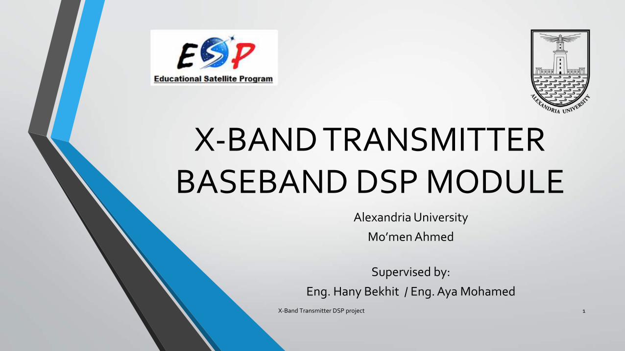
Outline:
• X-band transmitter
• Why baseband DSP ?
• Tools
• Matlab, Simulink and FPGA implementation
• Synthesis
• Lessons learnt
• Future work
X-Band Transmitter DSP project 2
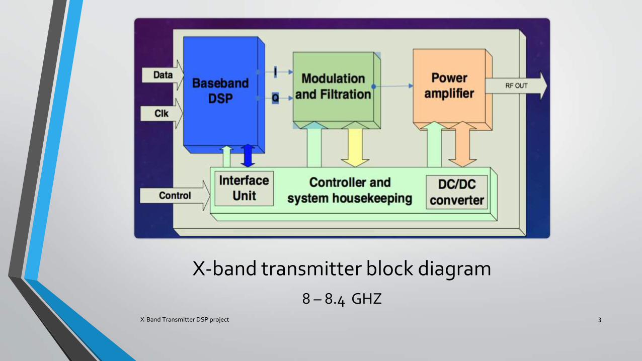
X-band transmitter block diagram
8 – 8.4 GHZX-Band Transmitter DSP project 3
Why Baseband DSP?
X-Band Transmitter DSP project 4
Sending image data without using DSP
X-Band Transmitter DSP project 5
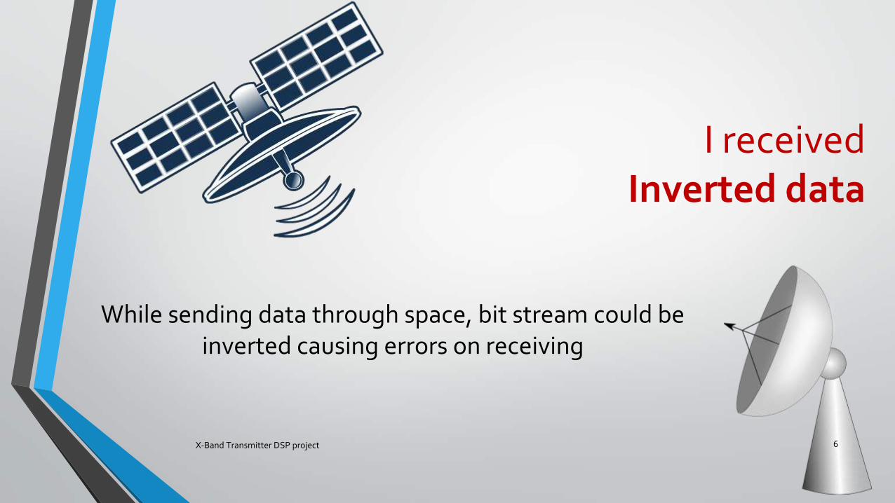
I received Inverted data
X-Band Transmitter DSP project 6
While sending data through space, bit stream could be inverted causing errors on receiving
UseDifferential encoder
X-Band Transmitter DSP project 7
• Hides data in transitions • Overcome polarity inversion of received data
I lost synchronization with you
X-Band Transmitter DSP project 8
While sending data through space, streams of ones and zeros causes the loss of synchronization
UseScrambler
X-Band Transmitter DSP project 9
• Prevents streams of zeros or ones makes receivers easily detect data and synchronize with sender
• 20 bit shift register
I received data withhigh Bit Error rate
X-Band Transmitter DSP project 10
To send data with low BER, use high power amplifiers but they consume lots of power and money
UseConvolutional encoder
X-Band Transmitter DSP project 11
• Convolutional coding acts as an error detection and correction unit hence decease BER with the same transmitted power
DSP module functions
• To receive the clock and data from clock and data interfaces
• To apply the DSP algorithm on the transmitted data. The DSP algorithm includes differential encoding, scrambling and convolutional encoding
• To generate test data pattern to be used in the self-test mode of operation
X-Band Transmitter DSP project 12
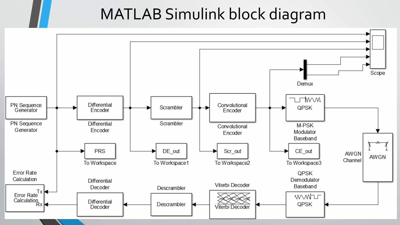
MATLAB Simulink block diagram
X-Band Transmitter DSP project 13
X-Band Transmitter DSP project 14
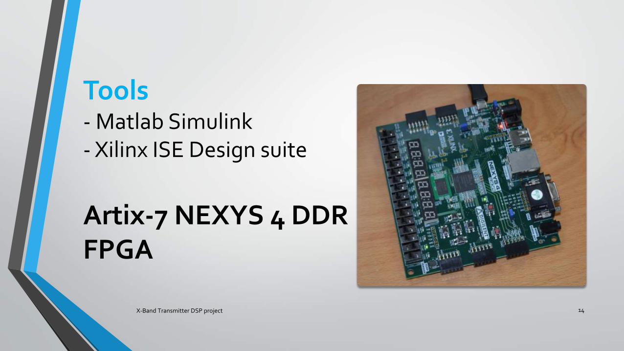
Tools- Matlab Simulink- Xilinx ISE Design suite
Artix-7 NEXYS 4 DDRFPGA
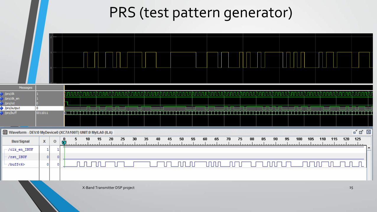
PRS (test pattern generator)
X-Band Transmitter DSP project 15
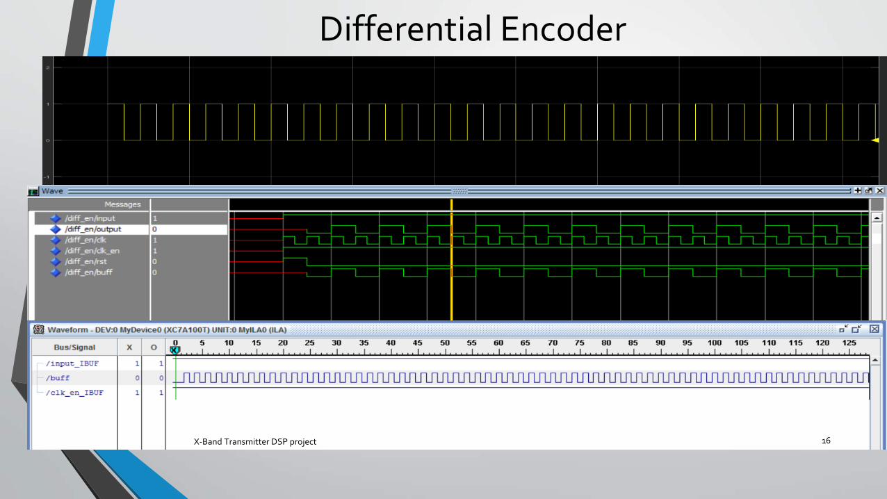
Differential Encoder
X-Band Transmitter DSP project 16
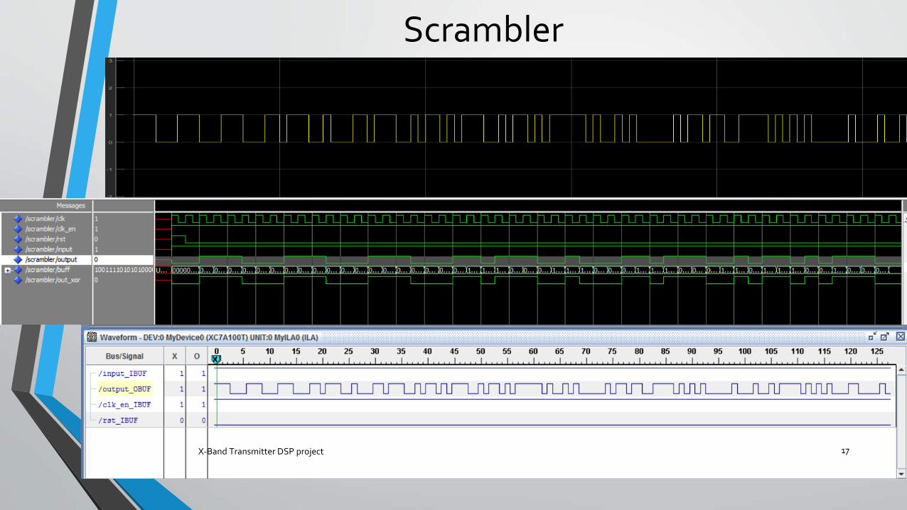
Scrambler
X-Band Transmitter DSP project 17
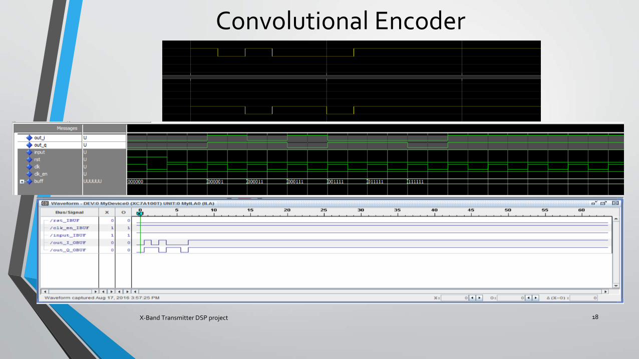
Convolutional Encoder
X-Band Transmitter DSP project 18
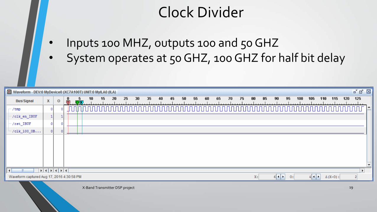
Clock Divider
X-Band Transmitter DSP project 19
• Inputs 100 MHZ, outputs 100 and 50 GHZ• System operates at 50 GHZ, 100 GHZ for half bit delay
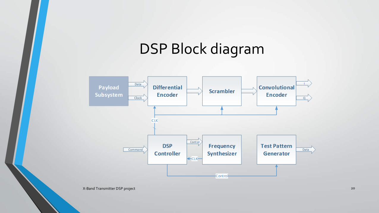
DSP Block diagram
X-Band Transmitter DSP project 20
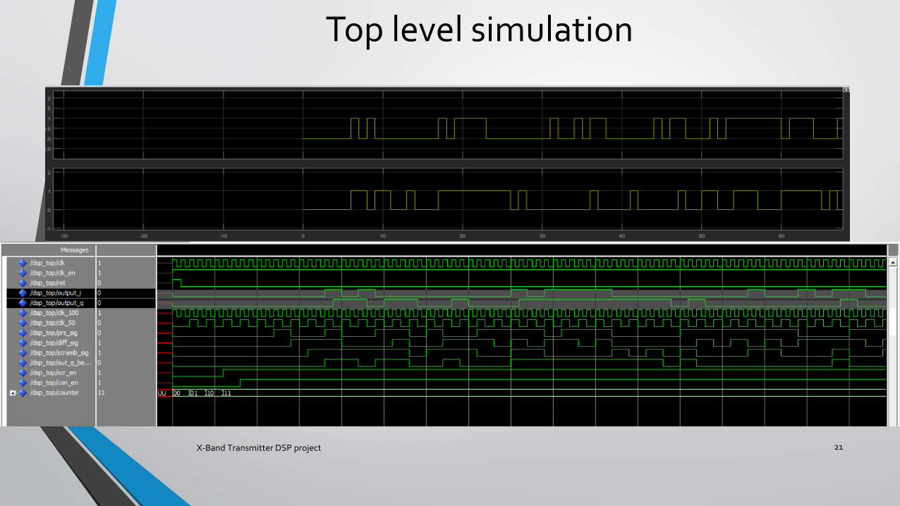
Top level simulation
X-Band Transmitter DSP project 21
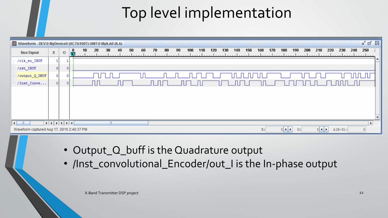
Top level implementation
X-Band Transmitter DSP project 22
• Output_Q_buff is the Quadrature output• /Inst_convolutional_Encoder/out_I is the In-phase output
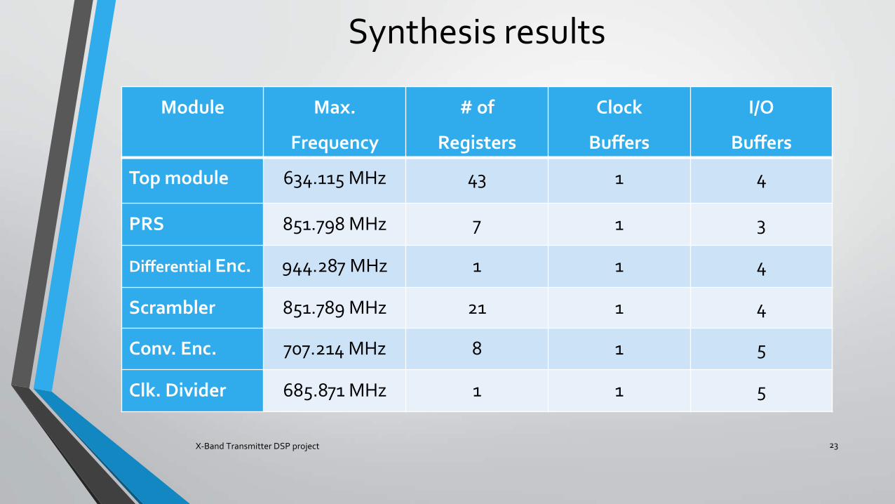
Synthesis results
X-Band Transmitter DSP project 23
Module Max.
Frequency
# of
Registers
Clock
Buffers
I/O
Buffers
Top module 634.115 MHz 43 1 4
PRS 851.798 MHz 7 1 3
Differential Enc. 944.287 MHz 1 1 4
Scrambler 851.789 MHz 21 1 4
Conv. Enc. 707.214 MHz 8 1 5
Clk. Divider 685.871 MHz 1 1 5
Lessons Learnt
• Matlab Simulink for DSP
• In Chip debugging
• In Chip verification
• ChipScope Pro with Artix-7 FPGA
X-Band Transmitter DSP project 24
Conclusion and Future Work
• DSP is very important for satellites communications
• To improve this work, optimization to the recourses used on the FPGA and maximum frequency
• X-Band transmitter module could be implemented
• Modulation on OQPSK design
X-Band Transmitter DSP project 25

Questions ?
X-Band Transmitter DSP project 26