Embed Size (px)
Citation preview

1

The purpose of a stormwater retention system is to retain as much of the rainwater in the native soil as possible while facilitating proper filtration of any excess runoff during storm events.More about this project is in this Facebook Album:
http://bit.ly/RBCTransport
2
The retention system allows any excess runoff from the site’s parking lots during rain events to be filtered then directed to the city’s storm drain.
3
At the recently completed project for RBC Transport Dynamics, the city storm drain empties into the Pacific Ocean.
This project has a bio-swale and permeable concrete. Permeable concrete is often referred to as “magic concrete."
4
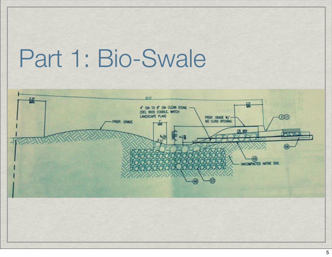
Part 1: Bio-Swale
5

Step 1: Prepare Trench.This is the first cut of the bio-swale trench. In totality it's about 24" deep.
6

Step 2: Line the Trench with Filter Fabric.Step 3: Place and connect 20' sections of pipe, then wrap with Filter Fabric, and place on top of Filter Fabric at the bottom of the trench.
7

Step 4: Add Aggregate125 tons of aggregate is added to the trench and put on top of the wrapped perforated pipe. This aggregate filters the storm water before it is fed through the pipes that eventually end up into the ocean.
8

Step 5: Add Dirt & Form the Bio-Swale.Dirt is gingerly placed, though with heavy equipment, on top of the aggregate. This is a delicate process as the filter fabric cannot be ripped or displaced during this step.
9

Step 6: Plant Vegetation
The design-build landscape architect chose plants that are able to consume and filter much of the parking lot runoff before it enters the storm drain system.
10

Part 2: Permeable Concrete
11

Step 1: Prepare Trench.Step 2: Line Trench with Filter Fabric.Step 3: Place and connect 20' sections of unwrapped perforated pipe.
12
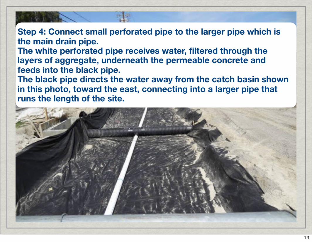
Step 4: Connect small perforated pipe to the larger pipe which is the main drain pipe.The white perforated pipe receives water, filtered through the layers of aggregate, underneath the permeable concrete and feeds into the black pipe. The black pipe directs the water away from the catch basin shown in this photo, toward the east, connecting into a larger pipe that runs the length of the site.
13

Step 5: Place Aggregate
This is a view of the #57 aggregate over the perforated pipe.
14

Step 6: Measure Twice, Pour Once.The worker is standing on the 18" layer of #57 aggregate and he's showing there is 18" remaining. The next 6" layer will be of #8 aggregate followed by 6" of permeable concrete. That leaves 6" of concrete curb in this section of the parking lot.
15

Step 7: Place 6" of #8 Aggregate.
16

Step 8: Pour 6" of Permeable Concrete In this photo, the team is pouring permeable concrete, at a thickness of 6", over the #8 aggregate.
17

Step 9: Power Screed, Add Control Joints, & Cover with Plastic
The plastic is laid out first and is placed over the screed (leveled) concrete once the control joints have been added. The plastic sheeting retains moisture within the permeable concrete while it cures for seven days.
18

This is what finished permeable concrete looks like. Notice that it is porous, not troweled-tight like conventional concrete. This concrete should NEVER receive a slurry coating!!!
19

Step 10: Stripe and Park
Once the permeable concrete has cured it is able to be striped along with the rest of the parking lot. After the paint dries, you're free to park your car.
20

21