ROHINI COLLEGE OF ENGINEERING & TECHNOLOGY
EE8015 ELECTRIC ENERGY GENERATION, UTILIZATION AND CONSERVATION
5.6 EARTHING
If a person touches an appliance, which has heavy currents flowing through it, with
his bare hands there are high chances of encounter being fatal. The electrical potential of
the Earth is considered to be zero. Hence on connecting the electrical channels of any
appliance to the Earth, its potential would become zero too. This is the main concept
behind Earthing, which is a process bonding noncurrent bearing parts of an electrical
device or the neutral summit of the electrical organization to the earth through wires
possessing minor resistance to flow of current.
Requirement of Earthing
To warrant that all pieces of equipment in use by the occupants of a building are
at Earth Potential, thus safeguarding them from electric shocks through direct
contact
To protect electrical apparatus from getting damaged due to weighty currents along
electrical lines
To sustain stable voltages in three phase circuits even under unstable load state
To protect tall buildings from getting harmed under lightning
TYPES OF EARTHING
1. System Earthing
This is the type of earthing which is associated with current carrying conductors.
It is quite relevant because there might be overflows of currents during the process
of its transmission. This type of earthing is put to use in stations and substations of
electrical supply.
2. Equipment Earthing
This is the prime type of earthing for homes and other buildings. It deals with the
safeguarding of noncurrent carrying apparatus and metallic conductors. This type
of earthing serves the dual function of protecting the user of the appliance against
shocks, while at the same time safeguarding the appliance from getting harmed.
METHODS OF EARTHING
1. Plate Earthing
A 2.5m deep pit is dug into the ground and a galvanised Iron (GI) plate is placed inside
along with charcoal and sand for the purpose of maintain low resistance around the

ROHINI COLLEGE OF ENGINEERING & TECHNOLOGY
EE8015 ELECTRIC ENERGY GENERATION, UTILIZATION AND CONSERVATION
plate. An earth wire, which is of GI or tinned copper, is bolted to the plate before burying
it by means of nuts, bolts and washers. The wire is made to pass through a GI pipe through
which some water is poured in to increase conductivity. The earth wire is connected to
the Earth point of the socket and is finally covered. The earthing plate is placed deep into
a pit (usually dug up to 1.5 to 3 meters), along with back filling component eg. Bentonite.
The plate is connected via Copper conductor, or GI Conductor or concealed copper cable
to the respective electrical set-up. A funnel is attached to add water at regular intervals.
The plate electrode is buried vertically. The whole earthing system must be copper or GI,
and bolts should be used of Brass. Copper earthing is the best in plate type earthing
system because of very low resistance than GI.
Earthing Plate Size:
Copper plate:
For LT – 600 mm x 600 mm x 3.18 mm; For HT – 900 mm x 900 mm x 6 mm
GI plate:
For LT – 600 mm x 600 mm x 6.35 mm; For HT – 900 mm x 900 mm x 6 mm
Figure 5.6.1 Plate Electrode
[Source: “Indian Standard Code of Practice for Earthing,” Page: 25]

ROHINI COLLEGE OF ENGINEERING & TECHNOLOGY
EE8015 ELECTRIC ENERGY GENERATION, UTILIZATION AND CONSERVATION
2. Pipe Earthing
A 2.5m long pipe measuring about 35-75 mm in diameter is buried in the dig out pit
along with sand and charcoal. The pipe is provided with several perforations to maintain
dampness around and hence conductivity. The earth wire is tied and clamped near the
summit. Water may be poured into it during summers. The earth wire is safer against
damage in such a setup. Pipe earthing is the best form of earthing and is very cheap in
cost. In this method of earthing, a cast iron pipe of approved length and diameter is placed
up right in the ground. The size of the pipe depends upon the current to be carried and
the type of the soil. Usually it is of diameter upto 110 mm and 1.5 to 3 meters deep in
length for ordinary soil or of greater length in case of dry and rocky soil.
Figure 5.6.2 Pipe Earthing
[Source: “Indian Standard Code of Practice for Earthing,” Page: 24]

ROHINI COLLEGE OF ENGINEERING & TECHNOLOGY
EE8015 ELECTRIC ENERGY GENERATION, UTILIZATION AND CONSERVATION
3. Rod Earthing
This method employs hammering of zinc and copper rods of about 1-1.5 metres length
and 12-20 mm diameter into the general mass of the earth. Successive rods are screwed
together and this chain is tried making as long as possible for lowered resistance by the
surrounding soil. The earth wire is tied and clamped near the summit. This is a very
economical and quick procedure for earthing.
4. Earthing through water pipe
We know that hand pumps are used to extract water from the water bed, which lies
well inside the ground. To the GI pipe of a hand pump, the earth wire is tied and
clamped. This pipe serves as an excellent electrode for carrying excessive currents deep
below the ground. However, the difficulty lies in the probable shocks to users of hand
pumps if the earth wire is not clamped tight enough.
METHOD OF INSTALLATION
1. Piling
Installation process start with piling. Pile diameter should be twice of earthing electrode
diameter. Similarly, earth pit holes can be made by manual as well as boring process
depending upon number of earth pits to be done so that it should be cost effective.
2. Back Filling
Variety of back filling procedure is adopted by customers depending upon soil conditions.
Commonly used practice is to form alternate layers of back fill compound and soil treated
with water for moisture. Generally, recommend 20 kg bag for LT earthing and 40 kg bag
for HT earthing depending upon soil conditions.
3. Inserting Electrodes
Earthing electrode is inserted in soil. Specification of electrodes depends upon load, type
of soil, and other related parameters.
4. Earth Pit
After successful installation of earthing electrode, earth pit chamber is made below or
above ground level as per requirement which can be covered by cast iron cover available
in different sizes.
Earth Pit Design Detail: Earthing Pit Size: 1000 X 1000 X 1800 mm Depth
M.S. / C.I. Plate Size: 500 X 500 X8 mm Thick

ROHINI COLLEGE OF ENGINEERING & TECHNOLOGY
EE8015 ELECTRIC ENERGY GENERATION, UTILIZATION AND CONSERVATION
DOMESTIC EARTHING
The following is the method of implementation of earthing:
1. Low earth resistance is required to give effective earthing protection to electrical
fittings.
2. Dry earth has more resistance whereas moist earth has less resistance.
3. The location of earthing point should be minimum 3 feet away from residential
unit.
4. The location of earth pit should be such where the soil has reasonable chances of
having moisture. If possible, earth plates or pipes should be located near water tap,
water drain or rain water pipe.
5. Electric earthing may be either pipe or plate earthing.
6. Normally GI pipe (2.5inch diameter) or plate (600 mm X 600 mm X 3.18 mm) is
used but if the soil is corrosive then copper pipe or plate should be used.
7. Use Double GI Strip size 25 mm X 2.5 mm to connect GI Plate to System Earthing.
8. SWG GI wire should be used for internal connection.
9. Use back filling component like bentonite for low soil resistance.
10. The position of the earth plate or pipe when fixed should be clear from all building
foundations.
11. Inside building in addition to all electrical appliances, all switch boxes, meter
boxes etc. should be earthed also.
INDUSTRIAL EARTHING
Within industrial plants with potentially explosive atmospheres earthing plays an
essential role in maintaining the electrical systems in safe condition. The earthing system,
although a single physical system, it carries out many different functions including
automatic detection and clearance of electrical faults, prevention of dangerous potential
differences which could cause injury, prevention and dissipation of static charges and
save or increase the life of equipment which comes under grounding. The objective of
earthing system is to provide a surface under and around a station, industry which shall
be at a uniform potential (nearly zero or absolute earth potential). This Earth surface
should be as nearly as possible to the system. This is in order to ensure that, all parts of
apparatus other than live parts and attending personnel shall be at earth potential at all

ROHINI COLLEGE OF ENGINEERING & TECHNOLOGY
EE8015 ELECTRIC ENERGY GENERATION, UTILIZATION AND CONSERVATION
times. Due to this there exists no potential difference, which could cause shock or injury
to a person, when short circuit or any other type of abnormalities takes place.
NECESSITY OF EARTHING
1. To provide the grounding of all conductive enclosures that may be touched by
personnel, thereby eliminating shock hazards.
2. To reduce static electricity that may be generated within facilities.
3. To provide protection from large electrical disturbances (such as lightning) by
creating a low resistive path to earth.
FACTORS ON WHICH EARTH RESISTANCE DEPENDS
a) Type of soil
b) Temperature of soil
c) Wetness of soil
d) Minerals in earth
e) Shape of earth electrode
f) Size of earth electrode
g) Depth of electrode in earth
h) Diameter of earth electrode
i) Number of ground electrodes
j) Distance between two electrodes
STEP POTENTIAL
It is the potential difference available between the legs while standing on the ground. It
is the difference in the voltage between low points, which are one meter apart along the
earth when ground current is flowing.
TOUCH POTENTIAL
It is the potential difference between the leg and hand touches to the equipment.
ELCB- EARTH LEAKAGE CIRCUIT BREAKER
An Earth-leakage circuit breaker (ELCB) is a safety device used in electrical installations
with high earth impedance to prevent shock. It detects small stray voltages on the metal
enclosures of electrical equipment, and interrupts the circuit if a dangerous voltage is
detected. Once widely used, more recent installations instead use residual current circuit
breaker which instead detect leakage current directly.
ROHINI COLLEGE OF ENGINEERING & TECHNOLOGY
EE8015 ELECTRIC ENERGY GENERATION, UTILIZATION AND CONSERVATION
CONSTRUCTION OF ELCB
Basically, there are two types of ELCB: voltage operated and current operated ELCB.
Voltage operated ELCB operates at a detected potential of around 50 V to open a main
breaker and isolate the supply from the protected zones. But since it operates at 50 V, it
is not been used in newer domestic wiring as the 50 V is still considered as safe voltage
for alternating current. Basically, there are two types of ELCB: voltage operated and
current operated ELCB.
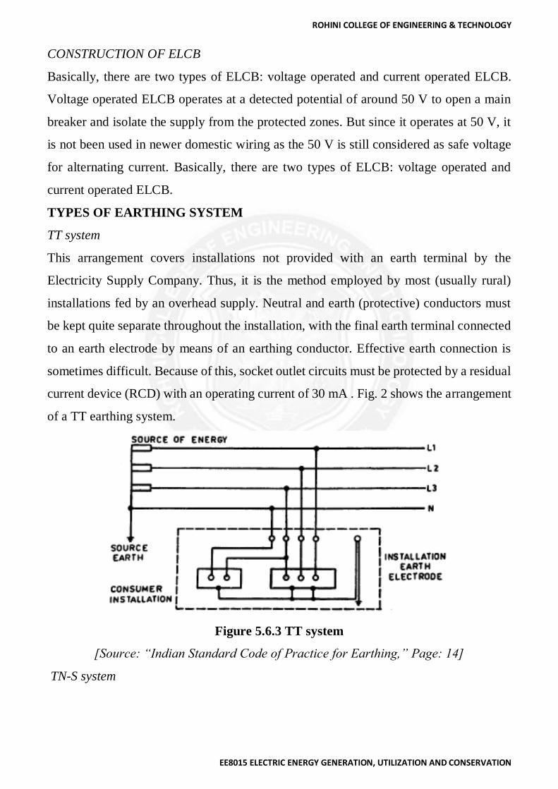
TYPES OF EARTHING SYSTEM
TT system
This arrangement covers installations not provided with an earth terminal by the
Electricity Supply Company. Thus, it is the method employed by most (usually rural)
installations fed by an overhead supply. Neutral and earth (protective) conductors must
be kept quite separate throughout the installation, with the final earth terminal connected
to an earth electrode by means of an earthing conductor. Effective earth connection is
sometimes difficult. Because of this, socket outlet circuits must be protected by a residual
current device (RCD) with an operating current of 30 mA . Fig. 2 shows the arrangement
of a TT earthing system.
Figure 5.6.3 TT system
[Source: “Indian Standard Code of Practice for Earthing,” Page: 14]
TN-S system

ROHINI COLLEGE OF ENGINEERING & TECHNOLOGY
EE8015 ELECTRIC ENERGY GENERATION, UTILIZATION AND CONSERVATION
In this type of earthing, after building distribution point, protective earth (PE) and Neutral
(N) conductors from transformers to consuming device not connected together at any
place
Figure 5.6.4 TN-S system
[Source: “Indian Standard Code of Practice for Earthing,” Page: 12]
TN-C system
Protective earth (PE) and Neutral (N) conductor combined in all the way from the
transformer to the consuming device. This installation is unusual, because combined
neutral and earth wiring is used in both the supply and within the installation itself. Where
used, the installation will usually be the earthed concentric system, which can only be
installed under the special conditions (mostly used in France).
Figure 5.6.5 TN-C system

ROHINI COLLEGE OF ENGINEERING & TECHNOLOGY
EE8015 ELECTRIC ENERGY GENERATION, UTILIZATION AND CONSERVATION
[Source: “Indian Standard Code of Practice for Earthing,” Page: 13]
TNC-S system
Combined PEN conductor from transformer to building distribution point, but separate
PE and N conductors in fixed indoor wiring and flexible power cords.
Figure 5.6.6 TNC-S system
[Source: “Indian Standard Code of Practice for Earthing,” Page: 13]
IT system
The installation arrangements in the IT system are the same for those of the TT system.
However, the supply earthing is totally different. The IT system can have an unearthed
supply, or one which is not solidly earthed but is connected to earth through a current
limiting impedance
Figure 5.6.7 IT system
[Source: “Indian Standard Code of Practice for Earthing,” Page: 12]

ROHINI COLLEGE OF ENGINEERING & TECHNOLOGY
EE8015 ELECTRIC ENERGY GENERATION, UTILIZATION AND CONSERVATION
PRINCIPLE OF EARTHING SYSTEM
1. The path followed by fault current as the result of a low impedance occurring
between the phase conductor and earthed metal is called the earth fault loop.
Current is driven through the loop impedance by the supply voltage.
2. The extent of the earth fault loop for a TT system is made up of the following parts:
Phase conductor from the transformer to the installation
Protective device(s) in the installation
Installation phase conductors from the intake position to the fault
Fault itself (usually assumed to have zero impedance)
Protective conductor system
Main earthing terminal
Earthing conductor
Installation earth electrode
General mass of earth
Supply Company's earth electrode
Supply Company's earthing conductor
Secondary winding of the supply transformer
o For a TN-S system (where the Electricity Supply Company provides an earth
terminal), items 8 to 10 are replaced by the PE conductor, which usually takes the
form of the armouring (and sheath if there is one) of the underground supply cable.
o For a TNC-S system (protective multiple earthing) items 8 to 11 are replaced by
the combined neutral and earth conductor.
o For a TN-C system (earthed concentric wiring), items 5 to 11 are replaced by the
combined neutral and earth wiring of both the installation and of the supply.
o It is readily apparent that the impedance of the loop will probably be a good deal
higher for the TT system, where the loop includes the resistance of two earth
electrodes as well as an earth path, than for the other methods where the complete
loop consists of metallic conductors.
ROHINI COLLEGE OF ENGINEERING & TECHNOLOGY
EE8015 ELECTRIC ENERGY GENERATION, UTILIZATION AND CONSERVATION
Earthing system has three main components
1- Earthing conductors
The earthing conductor is commonly called the earthing lead. It joins the installation
earthing terminal to the earth electrode or to the earth terminal provided by the Electricity
Supply Company. It is a vital link in the protective system, so care must be taken to see
that its integrity will be preserved at all times.
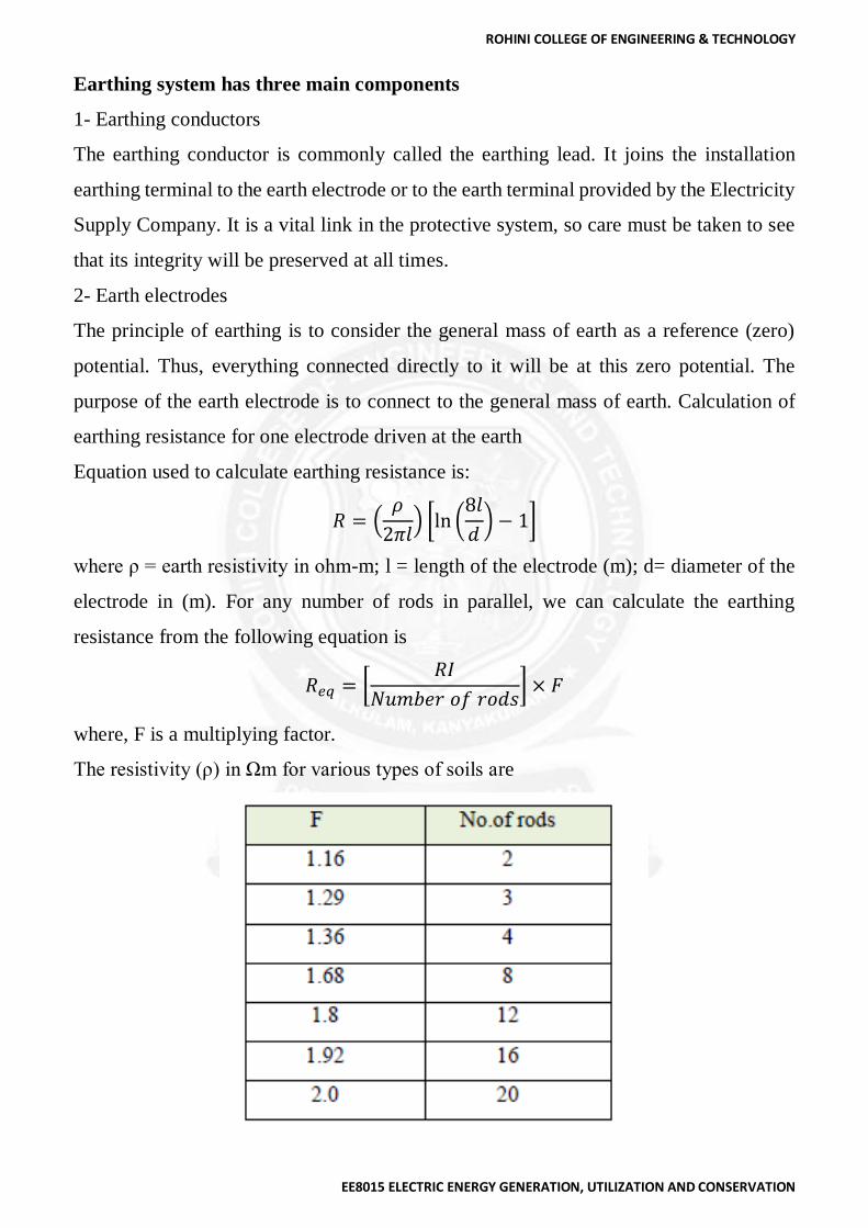
2- Earth electrodes
The principle of earthing is to consider the general mass of earth as a reference (zero)
potential. Thus, everything connected directly to it will be at this zero potential. The
purpose of the earth electrode is to connect to the general mass of earth. Calculation of
earthing resistance for one electrode driven at the earth
Equation used to calculate earthing resistance is:
𝑅 = (𝜌
2𝜋𝑙) [ln (
8𝑙
𝑑) − 1]
where ρ = earth resistivity in ohm-m; l = length of the electrode (m); d= diameter of the
electrode in (m). For any number of rods in parallel, we can calculate the earthing
resistance from the following equation is
𝑅𝑒𝑞 = [𝑅𝐼
𝑁𝑢𝑚𝑏𝑒𝑟 𝑜𝑓 𝑟𝑜𝑑𝑠] × 𝐹
where, F is a multiplying factor.
The resistivity (ρ) in Ωm for various types of soils are
ROHINI COLLEGE OF ENGINEERING & TECHNOLOGY
EE8015 ELECTRIC ENERGY GENERATION, UTILIZATION AND CONSERVATION
3- Inspection points (Earthing well)
For protection of the earthing rod and earthing conductors and also for maintenance and
inspection purposes an earth well is constructed as shown in Fig.9. Earthing conductors,
as well as protective and bonding conductors, must be protected against corrosion.
Probably the most common type of corrosion is electrolytic, which is an electro-chemical
effect between two different metals when a current pass between them whilst they are in
contact with each other and with a weak acid. The acid is likely to be any moisture which
has become contaminated with chemicals carried in the air or in the ground. A main earth
terminal or bar must be provided for each installation to collect and connect together all
protective and bonding conductors. It must be possible to disconnect the earthing
conductor from this terminal for test purposes, but only by the use of a tool. This
requirement is intended to prevent unauthorized or unknowing removal of protection.
Where the final connection to the earth electrode or earthing terminal is made there must
be a clear and permanent label Safety Electrical Connection - Do not remove. With the
increasing use of underground supplies and of protective multiple earthing (PME) it is
becoming more common for the consumer to be provided with an earth terminal rather
than having to make contact with earth using an earth electrode.
SUBSTATION EARTHING (33kV Substation)
Provision of adequate grounding in a substation and switching stations are very important
for the safety of operating personnel as well as electrical devices do not rise above
tolerable thresholds and that the earth connection is rugged to dissipate the fault to the
earth. The importance of an effective, durable and a dependable earth for ensuring safety
from electrical hazards does not require to be elaborated upon more. By earthing,
connecting the electrical equipment to the general mass of the earth, this has a very low
resistance.
Values of earth resistance in substation should be less than
1. Generating station 0.5 Ω
2. Large substation 1.0 Ω
3. Small substation 2.0 Ω
4. From earth electrode to internal assembly 2.0 Ω
5. Neutral bushing 2.0 Ω

ROHINI COLLEGE OF ENGINEERING & TECHNOLOGY
EE8015 ELECTRIC ENERGY GENERATION, UTILIZATION AND CONSERVATION
6. Service connection 4.0 Ω
7. LT lightning arrester 4.0 Ω
8. LT pole 5.0 Ω
9. HT lightning arrester 8.0 Ω
10. HT pole 10.0 Ω
11. Tower 25.0 Ω
ISOLATORS AND SWITCHES
A flexible earth conductor is provided between the handle and earthing conductor
attached to the mounting bracket and the handle of switches is connected to earthing mat
by means of two separate distinct connections made with MS flat. One connection is
made with the nearest longitudinal conductor, while the other is made to the nearest
transverse conductor of the mat.
LIGHTNING ARRESTERS
Conductors as short and straight as practicable to ensure minimum impedance shall
directly connect the bases of the lightning arresters to the earth grid. In addition, there
shall be as direct a connection as practicable from the earth side of lightning arresters to
the frame of the equipment being protected. In the case of lighting arresters mounted near
transformers, earthing conductor shall be located clear off the tank and coolers in order
to avoid possible oil leakage caused by arcing. The resistance of earthing should be as
low as possible, so that the current in lightning arrester, which is caused by excessive
electrical pressures on the line, due to lightning stroke, should go into the uncontrolled
soil and avoid potential damage.
CIRCUIT BREAKERS
For every breaker there will be five earth connections to the earth mat with: MS flat
1. Breaker body
2. Relay panel
3. CTs of the breaker
4. Two side of the breaker structure.

ROHINI COLLEGE OF ENGINEERING & TECHNOLOGY
EE8015 ELECTRIC ENERGY GENERATION, UTILIZATION AND CONSERVATION
TRANSFORMER
It is essential to earth transformer for better performance and safety of transformer.
Mainly transformer consists of four earthings out of which two are connected to neutral
to the star point of LV side of the transformer and two for the body i.e. transformer tank
to pass the leakage current and ground it for better safety.
Purpose of transformer neutral bushing
1. Leakage or unbalanced current is dissolved by the earthing.
2. Possible to install high sensing protection equipment.
3. Help to reduce extra high voltage on line due to lightning or switching surge.
4. Helps to control fault current by connecting resistance in neutral earth.
5. Always helps to keep neutral voltage zero.
The tank of each transformer shall be directly connected to the main grid. In addition,
there shall be as direct connection as practicable from the tank to the earth side of
projecting lightning arresters. The earthing of neutral bushing shall be by two separate
strips to the earth grid and shall likewise be run clear to rank cell and coolers.
CURRENT TRANSFORMERS AND POTENTIAL TRANSFORMERS
The supporting structures of Current Transformer and Potential Transformer unit of
bases, all bolted cover plates to which the bushings are attached connected to the earthing
mat by means of two separate distinct connections made with MS flat. One connection is
made with the nearest longitudinal conductor, while the other is made to the nearest
transverse conductor of the mat.
OTHER EQUIPMENT
All equipment’s, structures, and metallic frames of switches and isolators shall be earthed
separately
FENCES
The Sub-station fence should be generally too far outside the substation equipment and
grounded separately from the station ground. The station and the fence ground should not
be linked. If the distance between the fence and station structures, cannot be increased at
least five feet and if the fence is too near the substation equipment structure etc., the
station fence should be connected to the fence ground.

ROHINI COLLEGE OF ENGINEERING & TECHNOLOGY
EE8015 ELECTRIC ENERGY GENERATION, UTILIZATION AND CONSERVATION
GROUND WIRE
All ground wires over a station must be connected to the station earth grid. In order that
the station earth potentials during fault conditions are not applied to transmission line
ground wires and towers, all ground wires coming to the station must be broken at and
insulated on the station side of the first tower or pole external to the station by means of
10” disc insulator.
CABLES AND SUPPORTS
Metal sheathed cables within the station earth grid area must be connected to that grid.
Multi-core cables must be connected to the grid at least at one point. Single core cables
normally should be connected to the grid at one point only.
PANELS AND CUBICLES
Each panel or cubicle should be provided near the base with a frame earth bar of copper
to which shall be connected the metal bases and covers of switches and contactor unit.
INSTRUCTIONS ABOUT EARTHING IN SUBSTATION
1. On pole of HT line, fittings of all metal parts i.e. cross arm, top fittings, pins of
insulator, clamps, etc. should be fixed by using GI wire of 8 SWG.
2. On pole of LT line, fittings of all metal parts and stay should be connected to
neutral and then this neutral is to be solidly earthed with multiple earthing.
3. The earth wire of lightning arrester should not connect to any pole, it directly
passes from the alkathene pipe and tightly connected to earth electrode.
Type of Earthing to Be Used – CI Pipe Type
Size of Electrode – Ø 120 mm, 3000 mm length
Size of GI Strip – 25mm x 2.5 mm
𝑁𝑢𝑚𝑏𝑒𝑟 𝑜𝑓 𝑒𝑎𝑟𝑡ℎ𝑖𝑛𝑔 𝑝𝑖𝑝𝑒𝑠 𝑢𝑠𝑒𝑑
=𝑇𝑜𝑡𝑎𝑙 𝑓𝑎𝑢𝑙𝑡 𝑐𝑢𝑟𝑟𝑒𝑛𝑡
𝑀𝑎𝑥𝑖𝑚𝑢𝑚 𝑐𝑢𝑟𝑟𝑒𝑛𝑡 𝑑𝑖𝑠𝑠𝑖𝑝𝑎𝑡𝑒𝑑 𝑏𝑦 𝑜𝑛𝑒 𝑒𝑎𝑟𝑡ℎ𝑖𝑛𝑔 𝑝𝑖𝑝𝑒/𝑒𝑙𝑒𝑐𝑡𝑟𝑜𝑑𝑒
Recommended
![A Faint Star-forming System Viewed through the Lensing Cluster Abell 2218: First Light at [CLC][ITAL]z[/ITAL][/CLC] ≃ 5.6](https://img.pdfslide.net/doc/110x75/63185f7fd93a162f9c0e836e/a-faint-star-forming-system-viewed-through-the-lensing-cluster-abell-2218-first.jpg)