K L R 0 4 0 3 7 3 2
DAVIS MALAYSIA SDN. BHD. (336731-A)Lot 526, Jalan Rantau Panjang, Batu 11,
42500 Teluk Panglima Garang,Kuala Langat, Selangor, Malaysia.
Tel: +60 3 3122 2488 Fax: +60 3 31222482Enquiries: [email protected]
Website: www.davis.com.my
V3.17
POWER BUSWAY SYSTEMDAVIS®
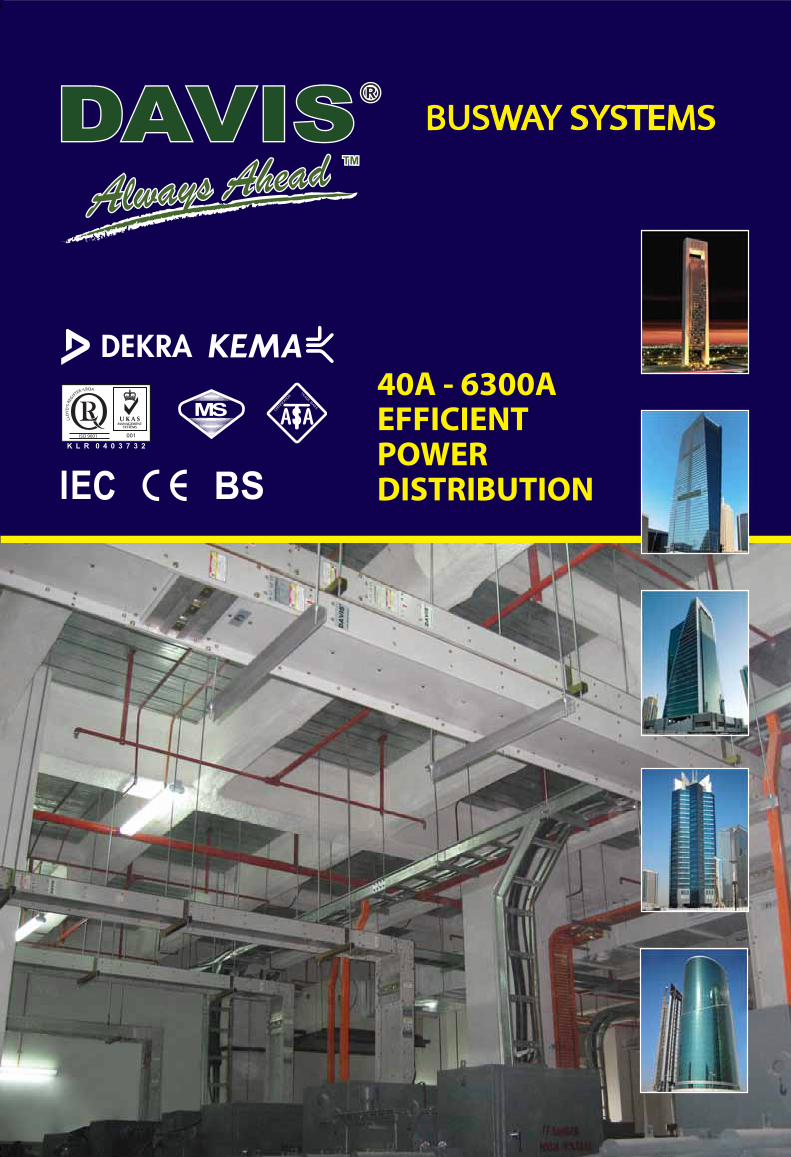
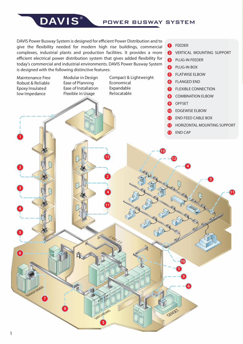
DAVIS Power Busway System is designed for efficient Power Distribution and to give the flexibility needed for modern high rise buildings, commercial complexes, industrial plants and production facilities. It provides a more efficient electrical power distribution system that gives added flexibility for today's commercial and industrial environments. DAVIS Power Busway System is designed with the following distinctive features:
Maintenance FreeRobust & ReliableEpoxy Insulatedlow Impedance
Compact & LightweightEconomicalExpandableRelocatable
Modular in DesignEase of PlanningEase of InstallationFlexible in Usage

3P4W+200%N+1/2G
3P4W+200%N
DAVIS introduces its new version of Maintenance Free Epoxy Insulated Power busway system to meet the latest requirements of modern commercial buildings and industrial complexes. DAVIS Power busway can be easily installed in most site conditions to distribute electrical power efficiently. DAVIS Power busway is available from 100A to 6300A rated at 690VAC in a polyphase system.
DAVIS Power busway is designed, manufactured and tested in compliance with the latest international standards:
Low Voltage Switchgear and Controlgear AssembliesSpecific requirements for buswayCircuit BreakersResistance to FireDegree of Ingress Protection
DAVIS Power busway is designed to withstand a rated insulation voltage of 1000VAC at 50Hz or 60Hz frequency or dielectric voltage of 3.5KV. Higher insulation voltages including medium voltages (up to 11kV) and higher frequencies are also available.
Composition ConductivityCOPPER 99.98% >98% lACSALUMINIUM 99.98% >61% lACS
The conductors used in DAVIS Power busways are carefully selected to meet all electrical, thermal and mechanical properties and are in full compliance with the relevant international standards and requirements. The composition and conductivity of the busbars used are guaranteed as follows:
DAVIS Power busway enclosures are made robust in design to match their intended short circuit capabilities, to accommodate each busbar size, weight, mechanical strength, and to optimize heat dissipation. The sections of the enclosures, flanges and surfaces are efficiently engineered to maximize their heat dissipation capabilities from the busbars to their surrounding areas under natural ambient conditions. The enclosures are treated with anti-corrosive agents, baked and coated with epoxy polyester powder. The enclosures are available in the following materials:
- Galvanised Steel - Extruded Aluminium - Stainless Steel
DAVIS Power busway enclosures are designed and manufactured by computerized CNC machines to achieve a very high degree of precision and accuracy. Various degrees of ingress of protection (lP) in compliance with IEC60529 are available and are verified by independent authorities. DAVIS also makes busways for outdoor installations.Indoor Installation IP42/43/44/54/55Outdoor Installation IP65/66/67Plug-in Risers IP65Plug-in Boxes IP55IP for Plug-in Openings IP2X
DAVIS Power busway is constructed from high conductivity Copper or Aluminium conductors set in a totally enclosed STEEL or Extruded ALUMINIUM enclosure. The following types of busbar configuration are available in a super compact type design or sandwiched type design:
3P3W 3P4W 3P4W+1/4G +1/4G
3P4W+100%G3P4W+1/2G3P3W+1/2G
IEC 60439-1:2004 & IEC 61439-1:2011IEC 60439-2:2005 & IEC 61439-6:2012IEC 60947-2:2003IEC 60331 & BS 6387IEC 60529:2001
POWER BUSWAY SYSTEMDAVIS®
DAVIS uses a very special high thermal conductivity Epoxy insulation material, Class 'F' (155°C), which is able to withstand any glitches and spikes in an electrical system. The Epoxy insulation is non-hygroscopic, halogen free, resistant to water and chemicals, and has a high mechanical strength and complies with UL94V-0 standards. The epoxy insulation is self-extinguishing, impervious to acids, alkalis, acetones, mechanical oils and lubricants and has a long life span compared with other insulation materials. The Epoxy insulation is bonded strongly to the busbar conductor thus eliminating any air gaps between the insulation and the conductor. Class 'H' Epoxy insulation material is also available.
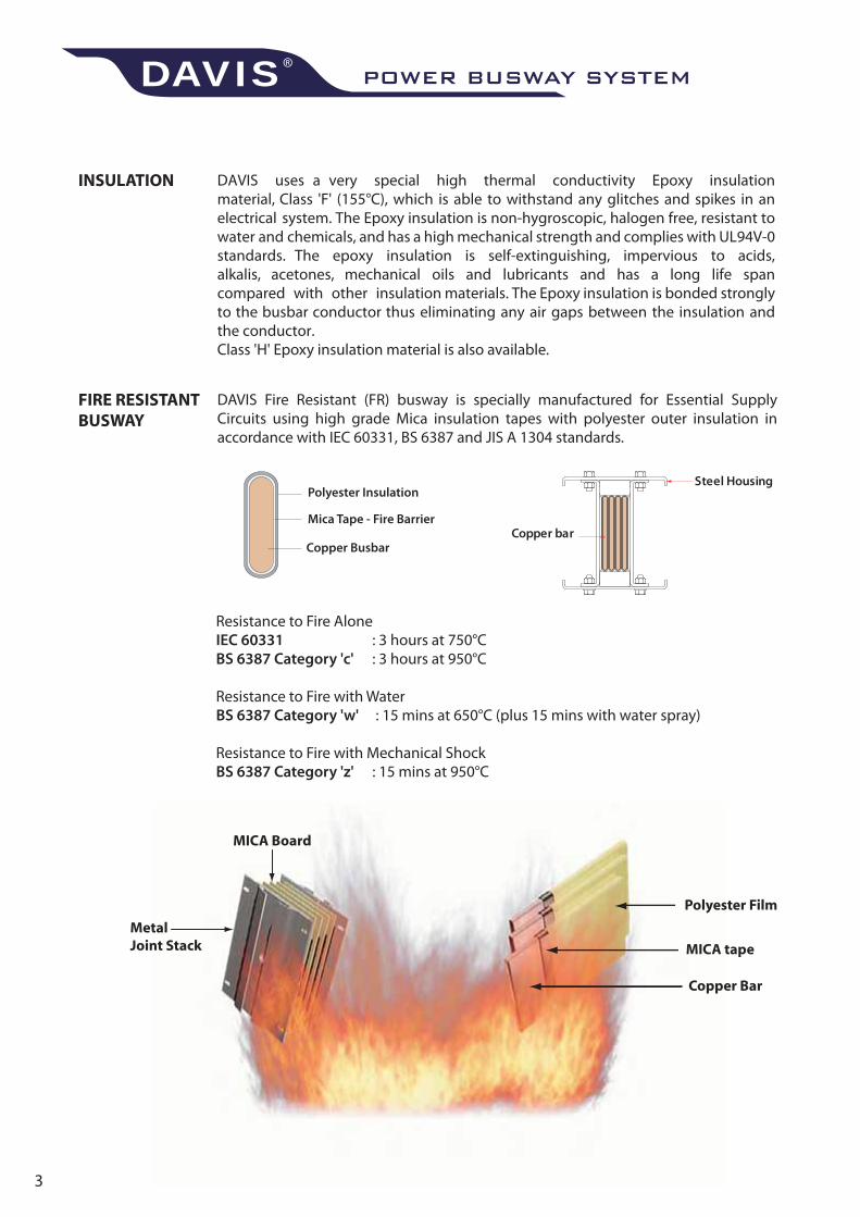
Resistance to Fire AloneIEC 60331 : 3 hours at 750°CBS 6387 Category 'c' : 3 hours at 950°C
Resistance to Fire with WaterBS 6387 Category 'w' : 15 mins at 650°C (plus 15 mins with water spray)
Resistance to Fire with Mechanical ShockBS 6387 Category 'z' : 15 mins at 950°C
Polyester Insulation
Mica Tape - Fire Barrier
Copper Busbar
Steel Housing
Copper bar
DAVIS Fire Resistant (FR) busway is specially manufactured for Essential Supply Circuits using high grade Mica insulation tapes with polyester outer insulation in accordance with IEC 60331, BS 6387 and JIS A 1304 standards.
Every DAVIS Power busway section or part is subjected to Routine Factory Tests before they are delivered to customers. The tests also include 1000VDC Insulation Resistance Tests and 3.5kV Power Frequency Voltage Withstand Tests for 5 seconds.
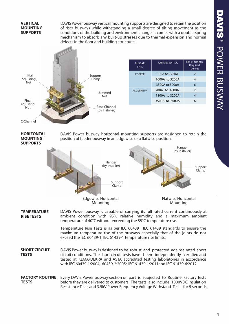
DAVIS Power busway vertical mounting supports are designed to retain the position of riser busways while withstanding a small degree of tilting movement as the conditions of the building and environment change. It comes with a double-spring mechanism to absorb any built-up stresses due to thermal expansion and normal defects in the floor and building structures.
DAVIS Power busway horizontal mounting supports are designed to retain the position of feeder busway in an edgewise or a flatwise position.
DAVIS Power busway is capable of carrying its full rated current continuously at ambient condition with 95% relative humidity and a maximum ambient temperature of 40°C without exceeding the 55°C temperature rise.
Temperature Rise Tests is as per IEC 60439 ; IEC 61439 standards to ensure the maximum temperature rise of the busways especially that of the joints do not exceed the IEC 60439-1; IEC 61439-1 temperature rise limits.
DAVIS Power busway is designed to be robust and protected against rated short circuit conditions. The short circuit tests have been independently certified and tested at KEMA/DEKRA and ASTA accredited testing laboratories in accordance with IEC 60439-1:2004; 60439-2:2005; IEC 61439-1:2011and IEC 61439-6:2012.
AMPERE RATING
100A to 1250A
1600A to 3200A
3500A to 5000A
200A to 1600A
1800A to 3200A
3500A to 5000A
BUSBARTYPE
COPPER
ALUMINIUM
No. of Springs Required
per set
2
4
6
2
4
6
POWER BUSWAY SYSTEMDAVIS®
5
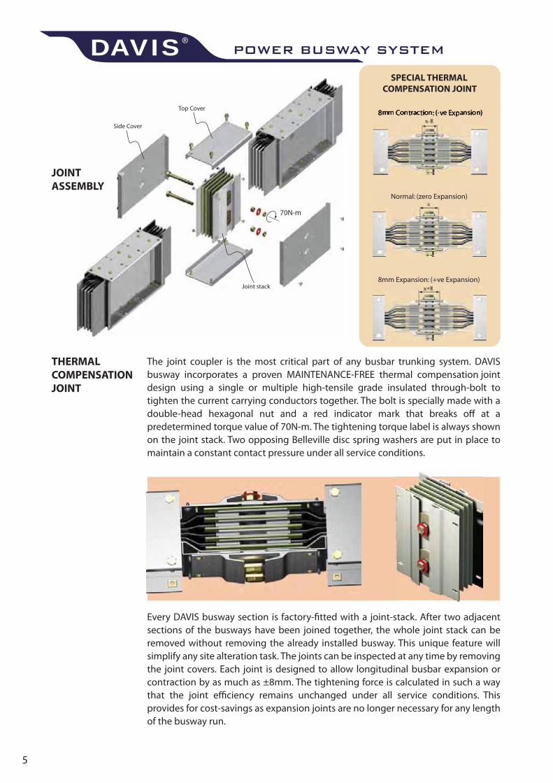
The joint coupler is the most critical part of any busbar trunking system. DAVIS busway incorporates a proven MAINTENANCE-FREE thermal compensation joint design using a single or multiple high-tensile grade insulated through-bolt to tighten the current carrying conductors together. The bolt is specially made with a double-head hexagonal nut and a red indicator mark that breaks off at a predetermined torque value of 70N-m. The tightening torque label is always shown on the joint stack. Two opposing Belleville disc spring washers are put in place to maintain a constant contact pressure under all service conditions.
Every DAVIS busway section is factory-fitted with a joint-stack. After two adjacent sections of the busways have been joined together, the whole joint stack can be removed without removing the already installed busway. This unique feature will simplify any site alteration task. The joints can be inspected at any time by removing the joint covers. Each joint is designed to allow longitudinal busbar expansion or contraction by as much as ±8mm. The tightening force is calculated in such a way that the joint efficiency remains unchanged under all service conditions. This provides for cost-savings as expansion joints are no longer necessary for any length of the busway run.
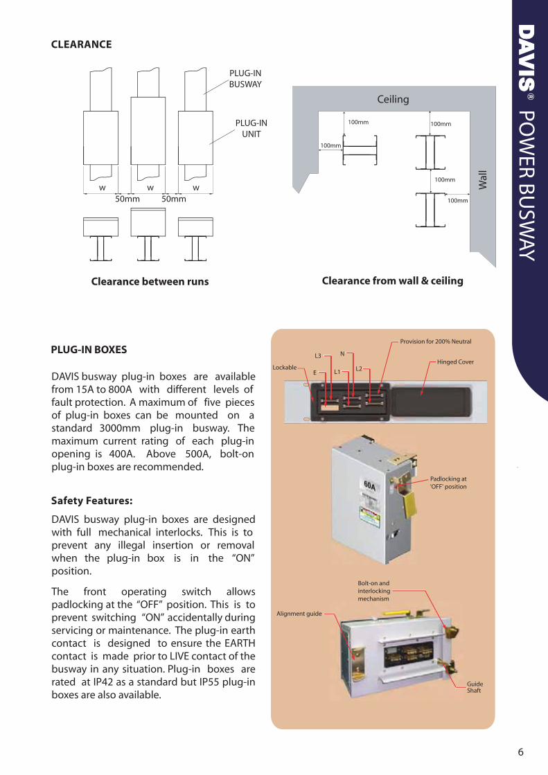
PLUG-IN BOXES
DAVIS busway plug-in boxes are availablefrom 15A to 800A with different levels offault protection. A maximum of five piecesof plug-in boxes can be mounted on a standard 3000mm plug-in busway. The maximum current rating of each plug-in opening is 400A. Above 500A, bolt-on plug-in boxes are recommended.
DAVIS busway plug-in boxes are designedwith full mechanical interlocks. This is to prevent any illegal insertion or removalwhen the plug-in box is in the “ON”position.
The front operating switch allows padlocking at the “OFF” position. This is to prevent switching “ON” accidentally during servicing or maintenance. The plug-in earth contact is designed to ensure the EARTH contact is made prior to LIVE contact of the busway in any situation. Plug-in boxes are rated at IP42 as a standard but IP55 plug-in boxes are also available.
GuideShaft
POWER BUSWAY SYSTEMDAVIS®
AMPERE RATING
E F G
DIMENSIONS (mm)BUSBARTYPE
COPPER 400A to 630A
800A to 1600A
1800A to 2500A
400A
630A to 800A
1000A to 1600A
1800A
ALUMINIUM
500
600
700
600
600
700
700
400
450
450
450
450
450
500
450
450
450
450
450
450
450
AMPERE RATING
L W H
DIMENSIONS (mm)
15A to 225A
125A to 200A
250A to 400A
500A to 800A
Exceed 800A
400
400
500
1000
260
260
310
360
210
210
270
310
PLEASE CONSULT DAVIS FOR DETAILS
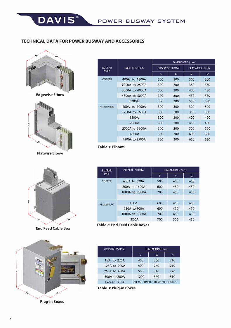
TECHNICAL DATA FOR POWER BUSWAY AND ACCESSORIES
AMPERE RATING
DIMENSIONS (mm)
BUSBARTYPE
COPPER 400A to 1800A
2000A to 2500A
3000A to 4000A
4500A to 5000A
6300A
400A to 1000A
1250A to 1600A
1800A
2000A
2500A to 3500A
4000A
4500A to 5500A
ALUMINIUM
FLATWISE ELBOW
C D
300
350
400
450
550
300
350
400
450
500
600
650
300
350
400
450
550
300
350
400
450
500
600
650
A B
EDGEWISE ELBOW
300
300
300
300
300
300
300
300
300
300
300
300
300
300
300
300
300
300
300
300
300
300
300
300
Table 1: Elbows
Table 2: End Feed Cable Boxes
Table 3: Plug-in Boxes
Edgewise Elbow
Flatwise Elbow
End Feed Cable Box
Plug-in Boxes
600 600 600 600 600
3000
W1
Fig. A
40
W1
W2
Fig. B
W1
W2 W2
Fig. C
W1
W2 W2 W2
40
Fig. D
W1
W2 W2
W1
W2 W2
40
Fig. F
W1
W2 W2 W2
W1
W2 W2 W2
Fig. G
W1
W2 W2
W1
W2 W2
W1
W2 W2
40
Fig. H
W1
W2 W2 W2
W1
W2 W2 W2
W1
W2 W2 W2
40
Fig. I
AMPERE RATING
COPPER DIMENSIONS (mm)
W1 W2 W1 W2
ALUMINIUM DIMENSIONS (mm)
FIGURE FIGURE
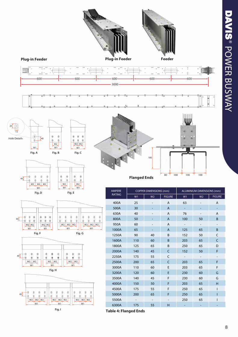
Table 4: Flanged Ends
400A
500A
630A
800A
950A
1000A
1250A
1600A
1800A
2000A
2250A
2500A
3000A
3200A
3500A
4000A
4500A
5000A
5500A
6300A
25
30
40
50
60
65
90
110
125
140
175
200
110
120
140
150
175
200
-
175
-
-
-
-
-
-
40
60
65
45
55
65
60
60
45
50
55
65
-
55
63
-
76
100
-
125
152
203
250
152
-
203
203
230
230
203
250
250
250
-
-
-
-
50
-
65
50
65
65
50
-
65
65
60
60
65
65
65
65
-
A
A
A
A
A
A
B
B
B
C
C
C
E
E
F
F
F
F
-
H
A
-
A
B
-
B
C
C
D
F
-
F
F
G
G
H
I
I
I
-
Flanged Ends
Plug-in Feeder FeederPlug-in Feeder
100 100 10080
180
W1
W2
W1
W2
Fig. E
Hole Details
20
13
POWER BUSWAY SYSTEMDAVIS®
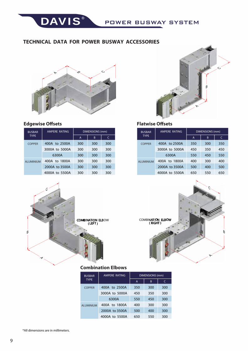
Edgewise Offsets
AMPERE RATING
A B C
DIMENSIONS (mm)BUSBARTYPE
COPPER 400A to 2500A
3000A to 5000A
6300A
400A to 1800A
2000A to 3500A
4000A to 5500A
ALUMINIUM
300
300
300
300
300
300
300
300
300
300
300
300
300
300
300
300
300
300
Flatwise Offsets
AMPERE RATING
A B C
DIMENSIONS (mm)BUSBARTYPE
COPPER 400A to 2500A
3000A to 5000A
6300A
400A to 1800A
2000A to 3500A
4000A to 5500A
ALUMINIUM
350
450
550
400
500
650
300
350
450
300
400
550
350
450
550
400
500
650
TECHNICAL DATA FOR POWER BUSWAY ACCESSORIES
Combination Elbows
AMPERE RATING
A B C
DIMENSIONS (mm)BUSBARTYPE
COPPER 400A to 2500A
3000A to 5000A
6300A
400A to 1800A
2000A to 3500A
4000A to 5500A
ALUMINIUM
350
450
550
400
500
650
300
350
450
300
400
550
300
300
300
300
300
300
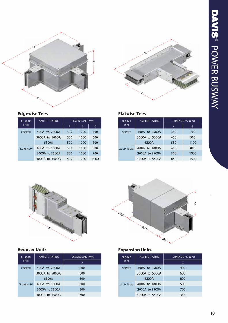
Edgewise TeesAMPERE RATING
A B C
DIMENSIONS (mm)BUSBARTYPE
COPPER 400A to 2500A
3000A to 5000A
6300A
400A to 1800A
2000A to 3500A
4000A to 5500A
ALUMINIUM
500
500
500
500
500
500
1000
1000
1000
1000
1000
1000
400
600
800
500
700
1000
Reducer UnitsAMPERE RATING
B
DIMENSIONS (mm)BUSBARTYPE
COPPER 400A to 2500A
3000A to 5000A
6300A
400A to 1800A
2000A to 3500A
4000A to 5500A
ALUMINIUM
600
600
600
600
600
600
Flatwise TeesAMPERE RATING
A B
DIMENSIONS (mm)BUSBARTYPE
COPPER 400A to 2500A
3000A to 5000A
6300A
400A to 1800A
2000A to 3500A
4000A to 5500A
ALUMINIUM
350
450
550
400
500
650
700
900
1100
800
1000
1300
Expansion UnitsAMPERE RATING
C
DIMENSIONS (mm)BUSBARTYPE
COPPER 400A to 2500A
3000A to 5000A
6300A
400A to 1800A
2000A to 3500A
4000A to 5500A
ALUMINIUM
400
600
800
500
700
1000
POWER BUSWAY SYSTEMDAVIS®
4W + 1/2G4W 3W + 1/2G3W 5W 5W + 1/2G
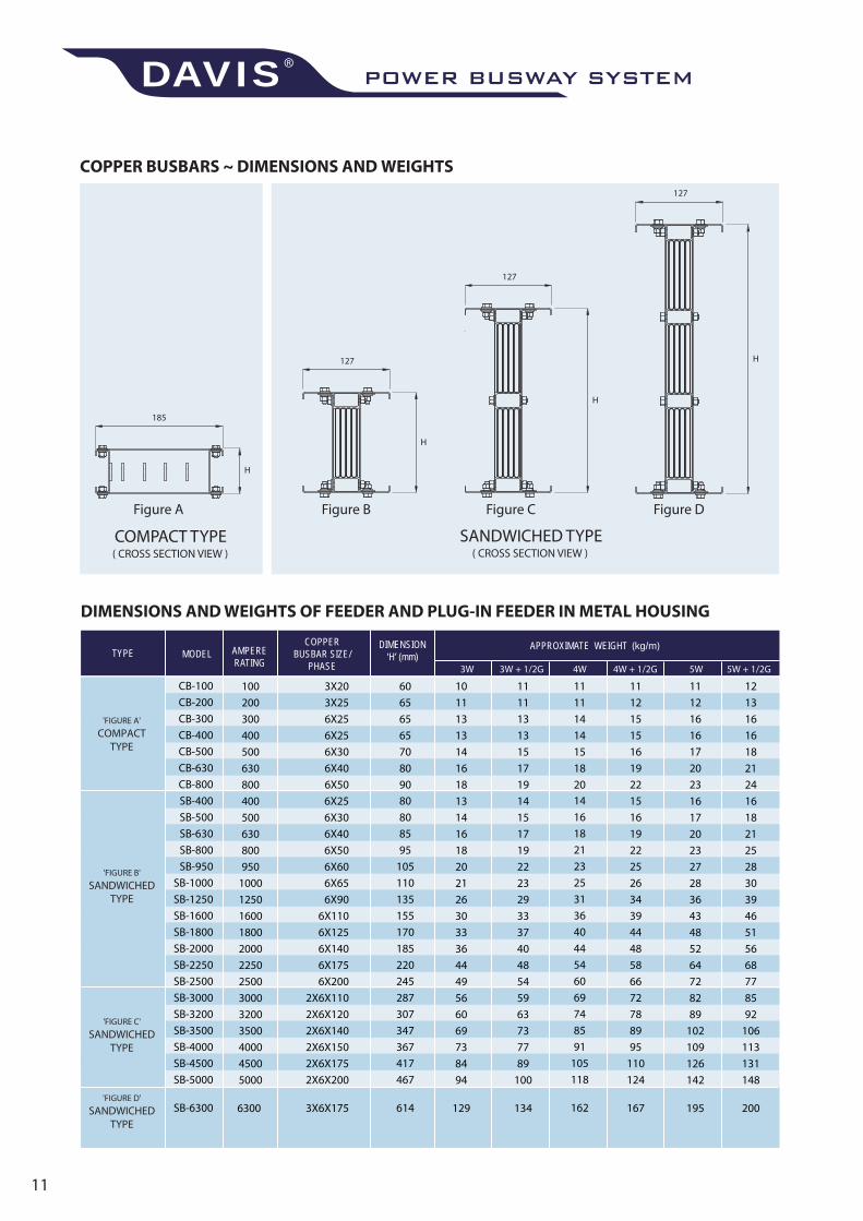
APPROXIMATE WEIGHT (kg/m)MODELTYPE AMPERE
RATING
COPPERBUSBAR SIZE/
PHASE
DIMENSION‘H’ (mm)
( CROSS SECTION VIEW ) ( CROSS SECTION VIEW )
100
200
300
400
500
630
800
3X20
3X25
6X25
6X25
6X30
6X40
6X50
11121515161922
60656565708090
400500630800950
1000125016001800200022502500300032003500400045005000
6300
6X256X306X406X506X606X656X90
6X1106X1256X1406X1756X200
2X6X1102X6X1202X6X1402X6X1502X6X1752X6X200
3X6X175
15161922252634394448586672788995
110124
167
80808595
105110135155170185220245287307347367417467
614
SB-400
SB-500
SB-630
SB-800
SB-950
SB-1000
SB-1250
SB-1600
SB-1800
SB-2000
SB-2250
SB-2500
SB-3000
SB-3200
SB-3500
SB-4000
SB-4500
SB-5000
SB-6300
CB-100CB-200CB-300CB-400CB-500CB-630CB-800
14
16
18
21
23
25
31
36
40
44
54
60
69
74
85
91
105
118
162
11111414151820
1415171922232933374048545963737789
100
134
11111313151719
131416182021263033364449566069738494
129
10111313141618
1618212528303946515668778592
106113131148
200
12131616182124
1617202327283643485264728289
102109126142
195
11121616172023
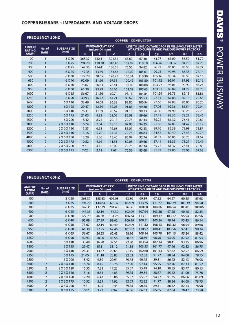
LINE TO LINE VOLTAGE DROP IN MILLI-VOLT PER METER
100200300400500630800950
10001250160018002000225025003000320035004000450050006300
1111111111111112222223
3 X 203 X 256 X 256 X 256 X 306 X 406 X 506 X 606 X 656 X 90
6 X 1106 X 1256 X 1406 X 1756 X 200
2 X 6 X 1102 X 6 X 1202 X 6 X 1402 X 6 X 1502 X 6 X 1752 X 6 X 2003 X 6 X 175
368.37294.70147.35147.35122.7992.0973.6761.3956.6740.9333.4929.4726.31
21.0518.4216.7415.3513.1612.2810.529.217.02
158.53144.84137.2952.1946.3837.9932.1927.9526.2320.0616.9015.1113.6711.189.898.457.836.846.435.594.953.73
401.03328.37201.40156.32131.2699.6280.4067.4662.4545.5837.5133.1229.6523.8320.9118.7617.2314.8313.8611.9210.457.94
63.80102.0976.56
102.09106.34100.49102.09101.0298.1688.6292.8091.8891.1582.0379.7587.0085.0779.7585.0782.0379.7576.56
69.39113.75100.00107.64113.21108.51111.32110.97108.1498.69
103.94103.23102.6892.8290.4597.4495.4989.8495.9792.8290.4586.63
67.52111.77104.06103.36109.17105.26108.43108.41105.7896.96
102.34101.77101.3391.7789.5195.9594.1088.6794.7791.7789.5185.65
64.27107.29104.5497.28
103.1299.94
103.32103.56101.1593.0598.4197.9697.6288.5486.4292.2690.5585.4291.3588.5486.4282.64
60.25101.39103.0190.1895.9493.4596.9497.4195.2487.9293.1592.8292.5784.0882.1387.3385.7781.0086.6684.0882.1378.47
55.6894.50
100.0682.3587.9686.1489.6890.3488.4281.9386.9686.7586.5978.7576.9881.5280.1375.7681.0978.7576.9873.50
100200300400500630800950
10001250160018002000225025003000320035004000450050006300
1111111111111112222223
3 X 203 X 256 X 256 X 256 X 306 X 406 X 506 X 606 X 656 X 90
6 X 1106 X 1256 X 1406 X 1756 X 200
2 X 6 X 1102 X 6 X 1202 X 6 X 1402 X 6 X 1502 X 6 X 1752 X 6 X 2003 X 6 X 175
368.37294.70147.35147.35122.7992.0973.6761.3956.6740.9333.4929.4726.3121.0518.4216.7415.3513.1612.2810.529.217.02
132.11120.70114.4143.4938.6531.6626.8323.2921.8616.7214.0812.5911.399.328.247.046.535.705.364.664.123.11
391.34318.46186.55153.63128.7397.3878.4165.6660.7444.2136.3332.0528.6723.0220.1818.1616.6814.3413.4011.5110.097.67
63.80102.0976.56
102.09106.34100.49102.09101.0298.1688.6292.8091.8891.1582.0379.7587.0085.0779.7585.0782.0379.7576.56
67.40110.1094.82
105.01110.30105.50108.08107.63104.8495.53
100.5499.8099.2389.6687.3494.2592.3386.8392.7489.6687.3483.68
64.77106.7696.9299.75
105.16101.12103.97103.81101.2492.6197.6697.0696.6087.4185.2291.5689.7684.5290.3287.4185.2281.59
61.00101.3296.0592.9898.3495.0198.0198.0995.7587.8892.8392.3691.9983.3581.3287.0385.3980.4986.0583.3581.3277.80
56.5994.7093.5085.3590.5887.9390.9991.2889.1882.1386.9086.5486.2678.2776.4181.4779.9875.4880.7378.2776.4173.05
51.7287.2589.7777.1482.1680.1683.2483.7081.8675.6680.2079.9479.7572.4670.8075.1973.8769.7874.6772.4670.8067.63
POWER BUSWAY SYSTEMDAVIS®
MODELTYPE AMPERERATING
ALUMINIUMBUSBAR SIZE/
PHASE
DIMENSION‘H’ (mm)
APPROXIMATE WEIGHT (kg/m)
4W + 1/2G4W 3W + 1/2G3W 5W 5W + 1/2G
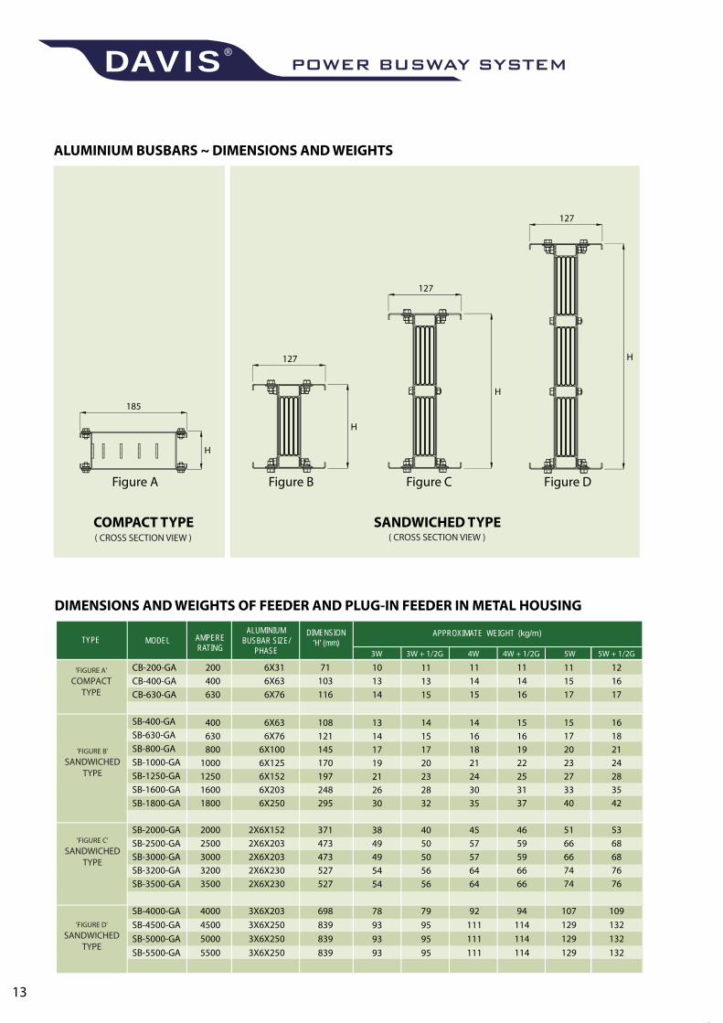
DIMENSIONS AND WEIGHTS OF FEEDER AND PLUG-IN FEEDER IN METAL HOUSING
( CROSS SECTION VIEW ) ( CROSS SECTION VIEW )
-
200400630
6X316X636X76
111416
71103116
CB-200-GACB-400-GACB-630-GA
111415
400 6X63630 6X76800 6X100
1000 6X1251250 6X1521600 6X2031800 6X250
2000 2X6X1522500 2X6X2033000 2X6X2033200 2X6X2303500 2X6X230
4000 3X6X2034500 3X6X2505000 3X6X2505500 3X6X250
SB-400-GASB-630-GASB-800-GASB-1000-GASB-1250-GASB-1600-GASB-1800-GA
SB-2000-GASB-2500-GASB-3000-GASB-3200-GASB-3500-GA
SB-4000-GASB-4500-GASB-5000-GASB-5500-GA
15108161211914522170251973124837295
4637159473594736652766527
94698114839114839114839
14161821243035
4557576464
92111111111
14151720232832
4050505656
79959595
111315
13141719212630
3849495454
78939393
101314
16182124283542
5368687676
109132132132
121617
15172023273340
5166667474
107129129129
111517
LINE TO LINE VOLTAGE DROP IN MILLI-VOLT PER METER
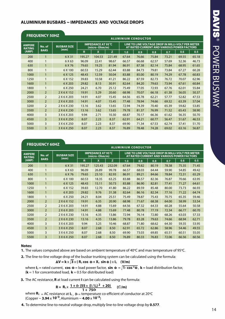
200 1 6 X 31 195.27 104.53 221.49 67.64 76.66 75.84 73.21 69.55 65.18400 1 6 X 63 96.09 22.41 98.67 66.57 66.68 62.57 57.69 52.36 46.73630 1 6 X 76 79.65 19.25 81.94 86.91 87.38 82.14 75.84 68.95 61.65
800 1 6 X 100 60.53 15.29 62.44 83.88 84.73 79.81 73.84 67.27 60.281000 1 6 X 125 48.43 12.59 50.04 83.88 85.00 80.19 74.29 67.78 60.831250 1 6 X 152 39.83 10.58 41.21 86.22 87.59 82.73 76.72 70.07 62.961600 1 6 X 203 29.82 8.13 30.91 82.64 84.20 79.63 73.94 67.61 60.841800 1 6 X 250 24.21 6.70 25.12 75.49 77.05 72.93 67.76 62.01 55.842000 2 2 X 6 X 152 19.91 5.29 20.60 68.98 70.07 66.18 61.38 56.05 50.372500 2 2 X 6 X 203 14.91 4.07 15.45 64.56 65.78 62.21 57.77 52.82 47.533000 2 2 X 6 X 203 14.91 4.07 15.45 77.48 78.94 74.66 69.32 63.39 57.043200 2 2 X 6 X 230 13.16 3.62 13.65 72.94 74.39 70.40 65.39 59.82 53.853500 2 2 X 6 X 230 13.16 3.62 13.65 79.78 81.37 76.99 71.52 65.43 58.904000 3 3 X 6 X 203 9.94 2.71 10.30 68.87 70.17 66.36 61.62 56.35 50.704500 3 3 X 6 X 250 8.07 2.23 8.37 62.91 64.21 60.77 56.47 51.67 46.535000 3 3 X 6 X 250 8.07 2.23 8.37 69.90 71.34 67.53 62.74 57.41 51.705500 3 3 X 6 X 250 8.07 2.23 8.37 76.89 78.48 74.28 69.02 63.16 56.87
200 1 6 X 31 195.27 125.43 232.09 67.64 79.82 80.19 78.38 75.35 71.45400 1 6 X 63 96.09 26.89 99.78 66.57 68.03 64.44 59.90 54.85 49.42630 1 6 X 76 79.65 23.10 82.93 86.91 89.21 84.66 78.84 72.31 65.29800 1 6 X 100 60.53 18.35 63.25 83.88 86.57 82.36 76.87 70.66 63.95
1000 1 6 X 125 48.43 15.11 50.73 83.88 86.90 82.81 77.41 71.27 64.611250 1 6 X 152 39.83 12.70 41.80 86.22 89.59 85.48 80.00 73.73 66.931600 1 6 X 203 29.82 9.76 31.38 82.64 86.16 82.34 77.16 71.22 64.741800 1 6 X 250 24.21 8.04 25.51 75.49 78.87 75.43 70.75 65.35 59.462000 2 2 X 6 X 152 19.91 6.35 20.90 68.98 71.67 68.38 64.00 58.99 53.542500 2 2 X 6 X 203 14.91 4.88 15.69 64.56 67.32 64.33 60.28 55.64 50.583000 2 2 X 6 X 203 14.91 4.88 15.69 77.48 80.78 77.19 72.34 66.77 60.703200 2 2 X 6 X 230 13.16 4.35 13.86 72.94 76.14 72.80 68.26 63.03 57.333500 2 2 X 6 X 230 13.16 4.35 13.86 79.78 83.28 79.63 74.66 68.94 62.714000 3 3 X 6 X 203 9.94 3.25 10.46 68.87 71.80 68.62 64.30 59.35 53.954500 3 3 X 6 X 250 8.07 2.68 8.50 62.91 65.72 62.86 58.96 54.46 49.555000 3 3 X 6 X 250 8.07 2.68 8.50 69.90 73.03 69.85 65.51 60.51 55.055500 3 3 X 6 X 250 8.07 2.68 8.50 76.89 80.33 76.83 72.06 66.56 60.56
COMPACT BUSWAY SYSTEMDAVIS®
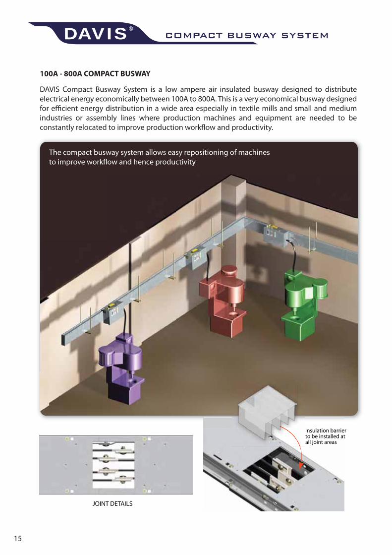
DAVIS Compact Busway System is a low ampere air insulated busway designed to distribute electrical energy economically between 100A to 800A. This is a very economical busway designed for efficient energy distribution in a wide area especially in textile mills and small and medium industries or assembly lines where production machines and equipment are needed to be constantly relocated to improve production workflow and productivity.
The compact busway system allows easy repositioning of machinesto improve workflow and hence productivity
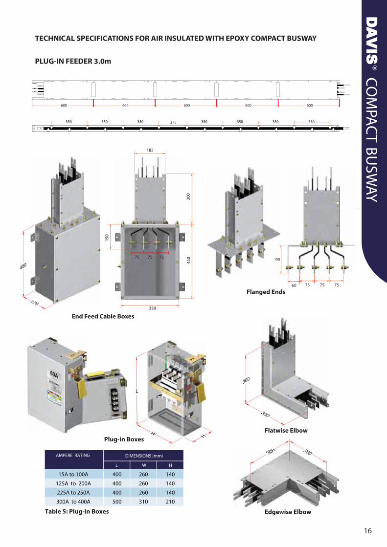
AMPERE RATING
L W H
DIMENSIONS (mm)
15A to 100A
125A to 200A
225A to 250A
300A to 400A
400
400
400
500
260
260
260
310
140
140
140
210
Table 5: Plug-in Boxes
TECHNICAL SPECIFICATIONS FOR AIR INSULATED WITH EPOXY COMPACT BUSWAY
PLUG-IN FEEDER 3.0m
End Feed Cable Boxes
Flanged Ends75 75 7560
150
Edgewise Elbow
Flatwise ElbowPlug-in Boxes
275
600 600 600 600 600
LIGHTRACK BUSWAY SYSTEMDAVIS®
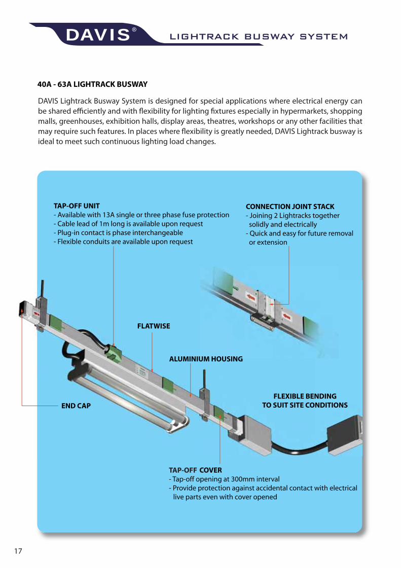
TAP-OFF
DAVIS Lightrack Busway System is designed for special applications where electrical energy can be shared efficiently and with flexibility for lighting fixtures especially in hypermarkets, shopping malls, greenhouses, exhibition halls, display areas, theatres, workshops or any other facilities that may require such features. In places where flexibility is greatly needed, DAVIS Lightrack busway is ideal to meet such continuous lighting load changes.
LIGH
TRAC
K B
USW
AY
18
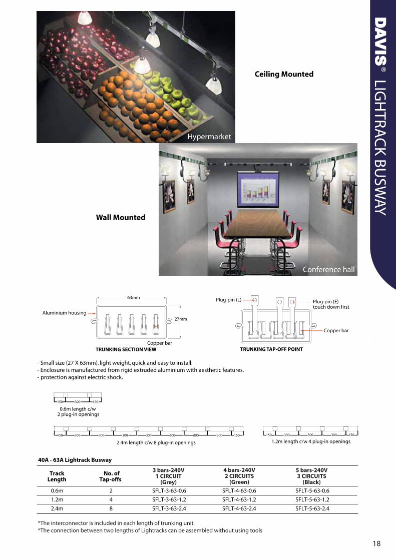
*The interconnector is included in each length of trunking unit*The connection between two lengths of Lightracks can be assembled without using tools
POWERTRACK BUSWAY SYSTEMDAVIS®
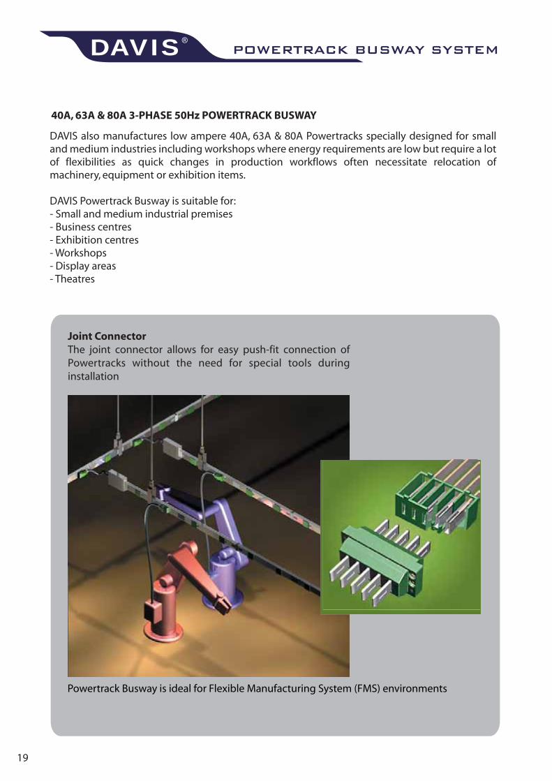
DAVIS also manufactures low ampere 40A, 63A & 80A Powertracks specially designed for small and medium industries including workshops where energy requirements are low but require a lot of flexibilities as quick changes in production workflows often necessitate relocation of machinery, equipment or exhibition items.
DAVIS Powertrack Busway is suitable for:- Small and medium industrial premises- Business centres- Exhibition centres- Workshops- Display areas- Theatres
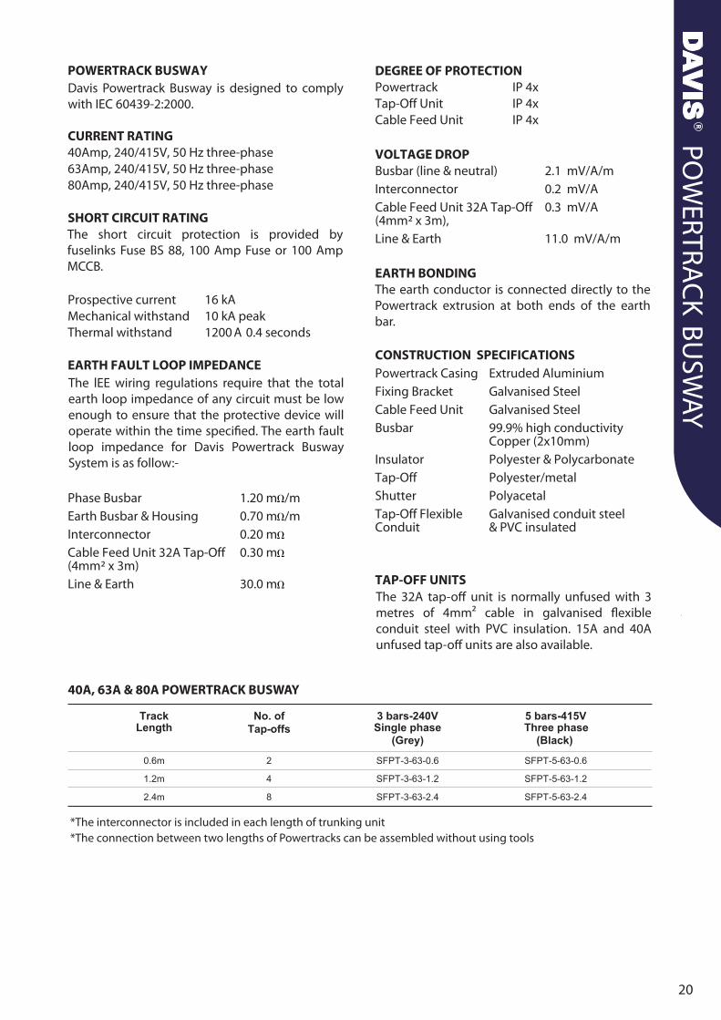
*The interconnector is included in each length of trunking unit*The connection between two lengths of Powertracks can be assembled without using tools
40A, 63A & 80A POWERTRACK BUSWAY
The lEE wiring regulations require that the total earth loop impedance of any circuit must be low enough to ensure that the protective device will operate within the time specified. The earth fault loop impedance for Davis Powertrack Busway System is as follow:-
Davis Powertrack Busway is designed to comply with IEC 60439-2:2000.
The 32A tap-off unit is normally unfused with 3 metres of 4mm2 cable in galvanised flexible conduit steel with PVC insulation. 15A and 40A unfused tap-off units are also available.
The earth conductor is connected directly to the Powertrack extrusion at both ends of the earth bar.
The short circuit protection is provided by fuselinks Fuse BS 88, 100 Amp Fuse or 100 Amp MCCB.
BUSTRACK BUSWAY SYSTEMDAVIS®
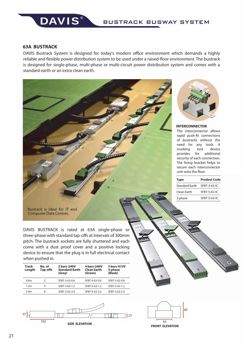
DAVIS Bustrack System is designed for today's modern office environment which demands a highly reliable and flexible power distribution system to be used under a raised-floor environment. The bustrack is designed for single-phase, multi-phase or multi-circuit power distribution system and comes with a standard earth or an extra clean earth.
The interconnector allows rapid push-fit connections of bustracks without the need for any tools. A trunking lock device provides for additional security of each connection. The fixing bracket helps to secure each interconnector unit onto the floor.
DAVIS BUSTRACK is rated at 63A single-phase or three-phase with standard tap-offs at intervals of 300mm pitch. The bustrack sockets are fully shuttered and each come with a dust proof cover and a positive locking device to ensure that the plug is in full electrical contact when pushed in.
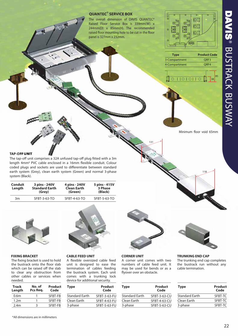
The tap-off unit comprises a 32A unfused tap-off plug fitted with a 3m length 4mm2 PVC cable enclosed in a 16mm flexible conduit. Colour coded plugs and sockets are used to differentiate between standard earth system (Grey), clean earth system (Green) and normal 3-phase system (Black).
The fixing bracket is used to hold the bustrack onto the floor slab which can be raised off the slab to clear any obstruction from other cables or services when needed.
A flexible oversized cable feed unit is designed to ease the termination of cables feeding the bustrack system. Each unit comes with a trunking lock device for additional security.
A corner unit comes with two numbers of cable feed unit. It may be used for bends or as a flyover over an obstacle.
The trunking end cap completes the bustrack run without any cable termination.
The overall dimension of DAVIS QUANTEC® Raised Floor Service Box is 339mm(W) x 244mm(D) x 85mm(H). The recommended raised floor mounting hole to be cut in the floor panel is 327mm x 232mm.
Minimum floor void 65mm
SFBT-FB
SFBT-FBSFBT-FB
SFBT-TCSFBT-TCSFBT-TC

K L R 0 4 0 3 7 3 2
DAVIS MALAYSIA SDN. BHD. (336731-A)Lot 526, Jalan Rantau Panjang, Batu 11,
42500 Teluk Panglima Garang,Kuala Langat, Selangor, Malaysia.
Tel: +60 3 3122 2488 Fax: +60 3 31222482Enquiries: [email protected]
Website: www.davis.com.my
V3.17
Recommended


