10
CHAPTER THREE
SPRINKLER SYSTEM AND FM-200
AGENT SYSTEM
11
Chapter Three
Sprinkler System and FM-200 Agent System
3.1. Background National Fire Protection Association (NFPA 13), Standard for the
installation of sprinkler systems, was prepared by the technical committee
on hanging and bracing of water-based fire protection systems, the
technical committee on sprinkler system discharge criteria, and the
technical committee on sprinkler system installation criteria, released by
the technical correlating committee on automatic sprinkler systems, and
acted on by the National Fire Protection Association, Inc., at its may
meeting held May 17-20, 1999, in Baltimore. It was issued by the
standards council on July 22, 1999, with an effective date of August 13,
1999 [4].
3.2. Sprinkler System 3.2.1 Definition of Sprinkler System
For fire protection purposes, an integrated system of underground
and overhead piping designed in accordance with fire protection
engineering standards. The installation includes one or more automatic
water supplies. The portion of the sprinkler system aboveground is a
network of specially sized or hydraulically designed piping installed in a
building, structure, or area, generally overhead, and to which sprinklers
are attached in a systematic pattern. The valve controlling each system
riser is located in the system riser or its supply piping. Each sprinkler
system riser includes a device for actuating an alarm when the system is
in operation. The system is usually activated by heat from a fire and
discharges water over the fire area [4].
12
3.2.2. Types of Sprinkler Systems
3.2.2.1. Antifreeze Sprinkler System
A wet pipe sprinkler system employing automatic sprinklers that are
attached to a piping system that contains an antifreeze solution and that
are connected to a water supply. The antifreeze solution is discharged,
followed by water, immediately upon operation of sprinklers opened by
heat from a fire.
3.2.2.2 Circulating Closed-Loop Sprinkler System
A wet pipe sprinkler system having non-fire protection connections
to automatic sprinkler systems in a closed-loop piping arrangement for the
purpose of utilizing sprinkler piping to conduct water for heating or
cooling, where water is not removed or used from the system but only
circulated through the piping system.
3.2.2.3. Combined Dry Pipe-Pre action Sprinkler System
A sprinkler system employing automatic sprinklers attached to a
piping system containing air under pressure with a supplemental detection
system installed in the same areas as the sprinklers. Operation of the
detection system actuates tripping devices that open dry pipe valves
simultaneously and without loss of air pressure in the system. Operation
of the detection system also opens listed air exhaust valves at the end of
the feed main, which usually precedes the opening of sprinklers. The
detection system also serves as an automatic fire alarm system.
3.2.2.4. Deluge Sprinkler System
A sprinkler system employing open sprinklers that are attached to a
piping system that is connected to a water supply through a valve that is
opened by the operation of a detection system installed in the same areas
13
as the sprinklers. When this valve opens, water flows into the piping
system and discharges from all sprinklers attached thereto.
3.2.2.5. Dry Pipe Sprinkler System
A sprinkler system employing automatic sprinklers that are attached
to a piping system containing air or nitrogen under pressure, the release of
which (as from the opening of a sprinkler) permits the water pressure to
open a valve known as a dry pipe valve, and the water then flows into the
piping system and out the opened sprinklers.
3.2.2.6. Gridded Sprinkler System
A sprinkler system in which parallel cross mains are connected by
multiple branch lines. An operating sprinkler will receive water from both
ends of its branch line while other branch lines help transfer water between
cross mains.
3.2.2.7. Looped Sprinkler System
A sprinkler system in which multiple cross mains are tied together so
as to provide more than one path for water to flow to an operating sprinkler
and branch lines are not tied together.
3.2.2.8. Preaction Sprinkler System
A sprinkler system employing automatic sprinklers that are attached
to a piping system that contains air that might or might not be under
pressure, with a supplemental detection system installed in the same areas
as the sprinklers.
3.2.2.9. Wet Pipe Sprinkler System
A sprinkler system employing automatic sprinklers attached to a
piping system containing water and connected to a water supply so that
water discharges immediately from sprinklers opened by heat from a fire.
14
3.2.3. System Components
3.2.3.1. Branch Lines
The pipes in which the sprinklers are placed, either directly or
through risers.
3.2.3.2. Cross Mains
The pipes supplying the branch lines, either directly or through risers.
3.2.3.3. Feed Mains
The pipes supplying cross mains, either directly or through risers.
3.2.3.4. Flexible Listed Pipe Coupling
A listed coupling or fitting that allows axial displacement, rotation,
and at least 1 degree of angular movement of the pipe without inducing
harm on the pipe. For pipe diameters of 8 in. (203.2 mm) and larger, the
angular movement shall be permitted to be less than 1 degree but not less
than 0.5 degree sprinkler systems.
3.2.3.5. System Riser
The aboveground horizontal or vertical pipe between the water
supply and the mains (cross or feed) that contains a control valve (either
directly or within its supply pipe) and a water flow alarm device.
3.2.4. Classification of Sprinklers
Sprinklers are classified in two categories; according to design and
performance characteristics and according to orientation for these types.
3.2.4.1. Suppression Fast-Response (SFR) Sprinkler
A type of fast-response sprinkler is listed for its capability to
provide fire suppression of specific high-challenge fire hazards.
15
3.2.4.2. Extended Coverage Sprinkler
A type of spray sprinkler with maximum coverage areas.
3.2.4.3. Large Drop Sprinkler
A type of sprinkler that is capable of producing characteristic large
water droplets and that is listed for its capability to provide fire control of
specific high-challenge fire hazards.
3.2.4.4. Nozzles
A device for use in applications requiring special water discharge
patterns, directional spray, or other unusual discharge characteristics.
3. 2.4.5. Old-Style/Conventional Sprinkler
A sprinkler that directs from 40 percent to 60 percent of the total
water initially in a downward direction and that is designed to be installed
with the deflector either upright or pendent.
3. 2.4.6. Open Sprinkler
A sprinkler that does not have actuators or heat-responsive elements.
3.2.4.7. Quick-Response Early Suppression (QRES) Sprinkler
A type of quick-response sprinkler that is listed for its capability to
provide fire suppression of specific fire hazards.
3.2.4.8. Quick-Response Extended Coverage Sprinkler
A type of quick-response sprinkler that complies with the extended
protection areas.
3.2.4.9. Quick-Response (QR) Sprinkler
A type of spray sprinkler that is listed as a quick-response sprinkler
for its intended use.
16
3.2.4.10. Residential Sprinkler
A type of fast-response sprinkler that has been specifically
investigated for its ability to enhance survivability in the room of fire
origin and is listed for use in the protection of dwelling units.
3.2.4.11 Special Sprinkler
A sprinkler that has been tested.
3.2.4.12. Spray Sprinkler
A type of sprinkler listed for its capability to provide fire control for
a wide range of fire hazards.
3.2.4.13. Standard Spray Sprinkler
A spray sprinkler with maximum coverage areas.
3.2.4.14. Concealed Sprinkler
A recessed sprinkler with cover plates.
3.2.4.15. Flush Sprinkler
A sprinkler in which all or part of the body, including the shank
thread, is mounted above the lower plane of the ceiling.
3.2.4.16. Pendent Sprinkler
A sprinkler designed to be installed in such a way that the water
stream is directed downward against the deflector.
3.2.4.17. Recessed Sprinkler
A sprinkler in which all or part of the body, other than the shank
thread, is mounted within a recessed housing.
3.2.4.18. Sidewall Sprinkler
A sprinkler having special deflectors that are designed to discharge
most of the water away from the nearby wall in a pattern resembling one-
17
quarter of a sphere, with a small portion of the discharge directed at the
wall behind the sprinkler.
3.2.4.19. Upright Sprinkler
A sprinkler designed to be installed in such a way that the water spray
is directed upwards against the deflector.
3.2.5. Classification of Occupancies
Occupancy classifications for this standard shall relate to sprinkler
design, installation, and water supply requirements only. They shall not
be intended to be a general classification of occupancy hazards.
3.2.5.1. Light Hazard Occupancies
Light hazard occupancies shall be occupancies or portions of other
occupancies where the quantity and/or combustibility of contents is low
and fires with relatively low rates of heat release are expected.
3.2.5.2. Ordinary Hazard Occupancies
Ordinary hazard divided in two groups; ordinary hazard (Group 1)
occupancies shall be occupancies or portions of other occupancies where
combustibility is low, quantity of combustibles is moderate, stockpiles of
combustibles do not exceed 8 ft (2.4 m), and fires with moderate rates of
heat release are expected.
Ordinary hazard (Group 2) occupancies shall be occupancies or
portions of other occupancies where the quantity and combustibility of
contents is moderate to high, stockpiles do not exceed 12 ft (3.7 m), and
fires with moderate to high rates of heat release are expected.
18
3.2.5.3. Extra Hazard Occupancies
Extra hazard also is divided in two groups; (Group 1) occupancies
shall be occupancies or portions of other occupancies where the quantity
and combustibility of contents is very high and dust, lint, or other materials
are present, introducing the probability of rapidly developing fires with
high rates of heat release but with little or no combustible or flammable
liquids. And extra hazard (Group 2) occupancies shall include
occupancies with moderate to substantial amounts of flammable or
combustible liquids or occupancies where shielding of combustibles is
extensive.
3.2.6. Position, Location, Spacing, and Use of Sprinklers
3.2.6.1. General
Sprinklers shall be located, spaced, and positioned in accordance
with the requirements of this section. Sprinklers shall be positioned to
provide protection of the area consistent with the overall objectives of this
standard by controlling the positioning and allowable area of coverage for
each sprinkler.
3.2.6.2. Protection Areas per Sprinkler
3.2.6.2.1. Determination of the Protection Area of Coverage
The protection area of coverage per sprinkler (As) shall be
determined as; Along Branch Lines. Determine distance between
sprinklers (or to wall or obstruction inthe case of the end sprinkler on the
branch line) upstream and downstream. Choose the larger of either twice
the distance to the wall or the distance to the next sprinkler. This
dimension will be defined as S. And Between Branch Lines. Determine
perpendicular distance to the sprinkler on the adjacent branch line (or to a
wall or obstruction in the case of the last branch line) on each side of the
19
branch line on which the subject sprinkler is positioned. Choose the larger
of either twice the distance to the wall or obstruction or the distance to the
next sprinkler. This dimension will be defined as L.
The protection area of coverage of the sprinkler shall be established by
multiplying the S dimension by the L dimension, as follows:
As = S * L ………………… (3.1)
Where:
As = Area coverage per sprinkler.
S = Along Branch Lines.
L = Between Branch Lines
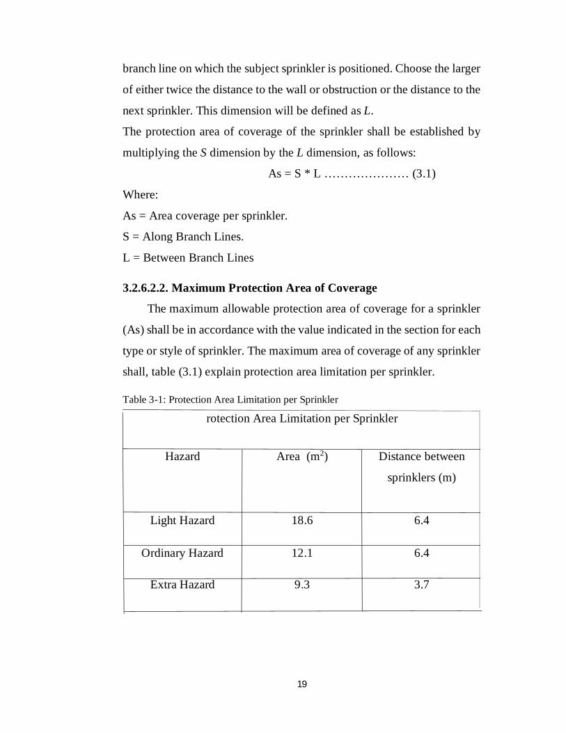
3.2.6.2.2. Maximum Protection Area of Coverage
The maximum allowable protection area of coverage for a sprinkler
(As) shall be in accordance with the value indicated in the section for each
type or style of sprinkler. The maximum area of coverage of any sprinkler
shall, table (3.1) explain protection area limitation per sprinkler.
Table 3-1: Protection Area Limitation per Sprinkler
rotection Area Limitation per Sprinkler
Hazard Area (m2) Distance between
sprinklers (m)
Light Hazard 18.6 6.4
Ordinary Hazard 12.1 6.4
Extra Hazard 9.3 3.7
20
3.2.6.3. Sprinkler Spacing
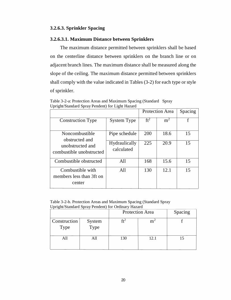
3.2.6.3.1. Maximum Distance between Sprinklers
The maximum distance permitted between sprinklers shall be based
on the centerline distance between sprinklers on the branch line or on
adjacent branch lines. The maximum distance shall be measured along the
slope of the ceiling. The maximum distance permitted between sprinklers
shall comply with the value indicated in Tables (3-2) for each type or style
of sprinkler.
Table 3-2-a: Protection Areas and Maximum Spacing (Standard Spray Upright/Standard Spray Pendent) for Light Hazard
Protection Area Spacing
Construction Type System Type ft2 m2 f
Noncombustible obstructed and
unobstructed and combustible unobstructed
Pipe schedule 200 18.6 15
Hydraulically calculated
225 20.9 15
Combustible obstructed All 168 15.6 15
Combustible with members less than 3ft on
center
All 130 12.1 15
Table 3-2-b. Protection Areas and Maximum Spacing (Standard Spray Upright/Standard Spray Pendent) for Ordinary Hazard
Protection Area Spacing
Construction Type
System Type
ft2 m2 f
All All 130 12.1 15
21
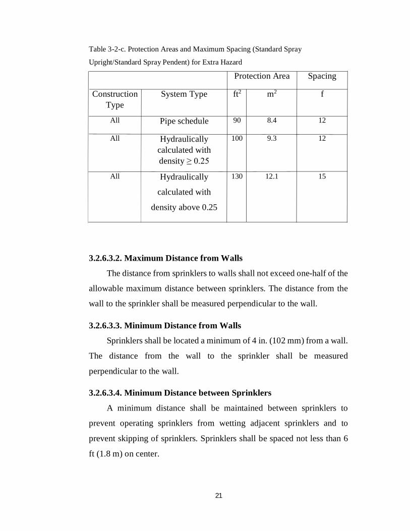
Table 3-2-c. Protection Areas and Maximum Spacing (Standard Spray
Upright/Standard Spray Pendent) for Extra Hazard
Protection Area Spacing
Construction Type
System Type ft2 m2 f
All Pipe schedule 90 8.4 12
All Hydraulically calculated with density ≥ 0.25
100 9.3 12
All Hydraulically
calculated with
density above 0.25
130 12.1 15
3.2.6.3.2. Maximum Distance from Walls
The distance from sprinklers to walls shall not exceed one-half of the
allowable maximum distance between sprinklers. The distance from the
wall to the sprinkler shall be measured perpendicular to the wall.
3.2.6.3.3. Minimum Distance from Walls
Sprinklers shall be located a minimum of 4 in. (102 mm) from a wall.
The distance from the wall to the sprinkler shall be measured
perpendicular to the wall.
3.2.6.3.4. Minimum Distance between Sprinklers
A minimum distance shall be maintained between sprinklers to
prevent operating sprinklers from wetting adjacent sprinklers and to
prevent skipping of sprinklers. Sprinklers shall be spaced not less than 6
ft (1.8 m) on center.
22
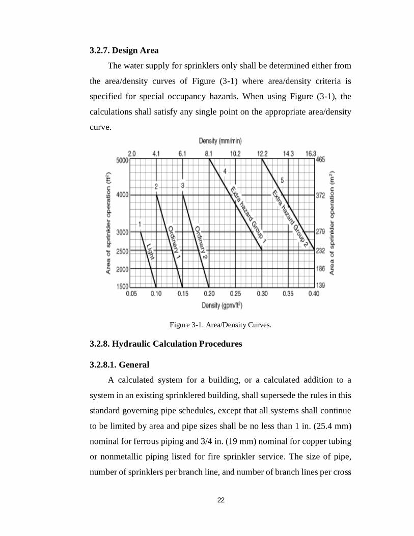
3.2.7. Design Area
The water supply for sprinklers only shall be determined either from
the area/density curves of Figure (3-1) where area/density criteria is
specified for special occupancy hazards. When using Figure (3-1), the
calculations shall satisfy any single point on the appropriate area/density
curve.
Figure 3-1. Area/Density Curves.
3.2.8. Hydraulic Calculation Procedures
3.2.8.1. General
A calculated system for a building, or a calculated addition to a
system in an existing sprinklered building, shall supersede the rules in this
standard governing pipe schedules, except that all systems shall continue
to be limited by area and pipe sizes shall be no less than 1 in. (25.4 mm)
nominal for ferrous piping and 3/4 in. (19 mm) nominal for copper tubing
or nonmetallic piping listed for fire sprinkler service. The size of pipe,
number of sprinklers per branch line, and number of branch lines per cross
23
main shall otherwise be limited only by the available water supply.
However, sprinkler spacing and all other rules covered in this and other
applicable standards shall be observed.
3.2.8.2. Friction Loss Formula
Pipe friction losses shall be determined on the basis of the Hazen-
Williams formula, as follows:
p = (4.52Q1.85 / C1.85d4.87) ..……………… (3.2)
Where
p = frictional resistance in psi per foot of pipe
Q = flow in gpm
C = friction loss coefficient
d = actual internal diameter of pipe in inches
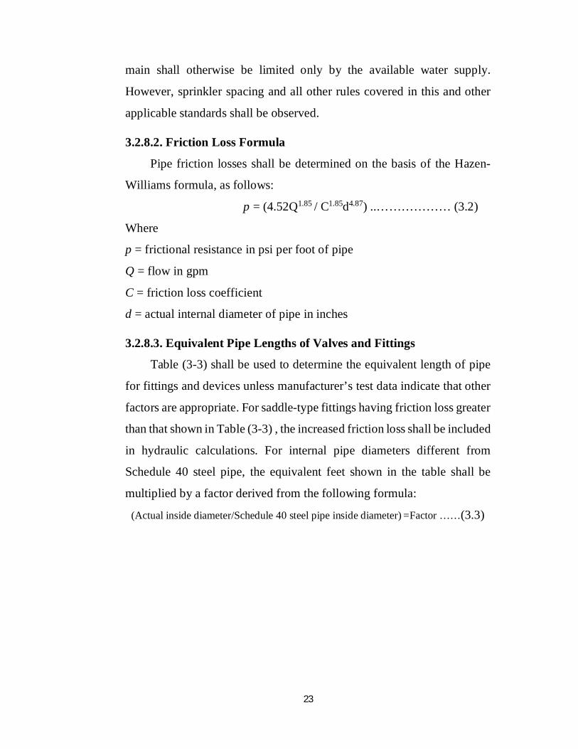
3.2.8.3. Equivalent Pipe Lengths of Valves and Fittings
Table (3-3) shall be used to determine the equivalent length of pipe
for fittings and devices unless manufacturer’s test data indicate that other
factors are appropriate. For saddle-type fittings having friction loss greater
than that shown in Table (3-3) , the increased friction loss shall be included
in hydraulic calculations. For internal pipe diameters different from
Schedule 40 steel pipe, the equivalent feet shown in the table shall be
multiplied by a factor derived from the following formula:
(Actual inside diameter/Schedule 40 steel pipe inside diameter) =Factor ……(3.3)
24
Table 3-3: Equivalent Schedule 40 Steel Pipe Length
Fittings and
Valves
Fittings and Valves Expressed in Equivalent Feet of Pipe
1/2" 3/4" 1" 11/4" 11/2" 2" 21/2" 3" 31/2" 4" 5" 6" 8" 10"
400 Elbow 1 1 1 2 2 3 3 3 4 5 7 9 11
900 Standard
Elbow
1 2 2 3 4 5 6 7 8 10 12 14 18 22
900 Long
Turn Elbow
0.5 1 2 2 2 3 4 5 5 6 8 9 13 16
Tee or Cross 3 4 5 6 8 10 12 15 17 20 25 30 35 50
Butterfly
valve
. . . . . 6 7 `10 . 12 9 10 12 19
Gate valve . . . . . 1 1 1 1 2 2 3 4 5
Swing check . . 5 7 9 11 14 16 19 22 27 32 45 55
3.2.9. Schedule for Light Hazard Occupancies
Branch lines shall not exceed eight sprinklers on either side of a cross
main.
Exception: Where more than eight sprinklers on a branch line are
necessary, lines shall be permitted to be increased to nine sprinklers by
making the two end lengths 1 in. (25.4 mm) and 11/4 in. (33 mm),
respectively, and the sizes thereafter standard. Ten sprinklers shall be
permitted to be placed on a branch line, making the two end lengths 1 in.
(25.4 mm) and 11/4 in. (33 mm), respectively, and feeding the tenth
sprinkler by a 21/2-in. (64-mm) pipe. Pipe sizes shall be in accordance
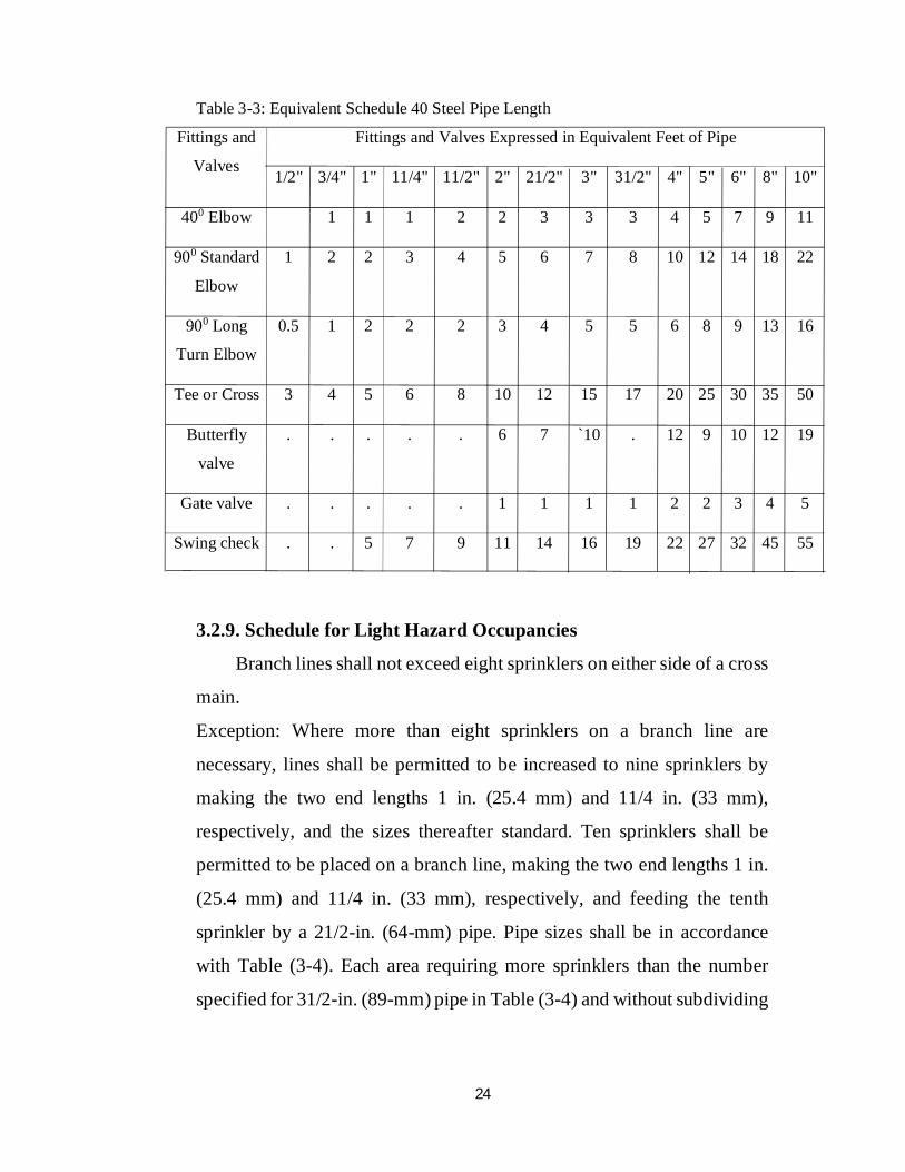
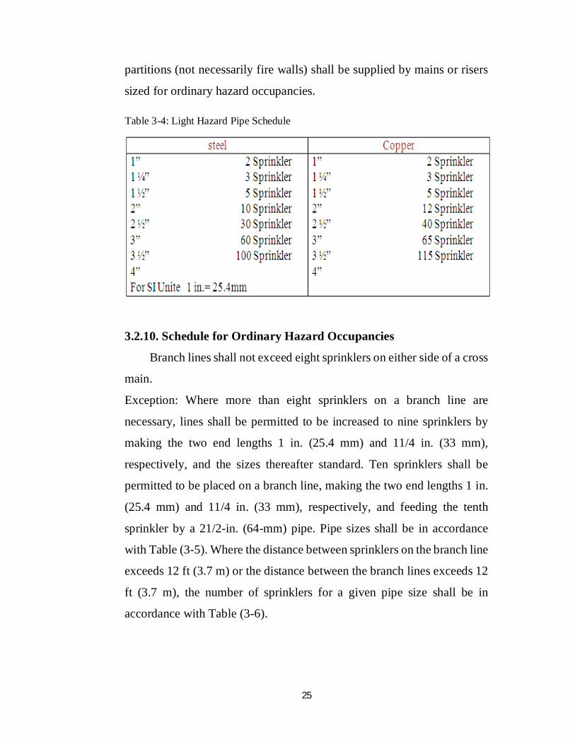
with Table (3-4). Each area requiring more sprinklers than the number
specified for 31/2-in. (89-mm) pipe in Table (3-4) and without subdividing
25
partitions (not necessarily fire walls) shall be supplied by mains or risers
sized for ordinary hazard occupancies.
Table 3-4: Light Hazard Pipe Schedule
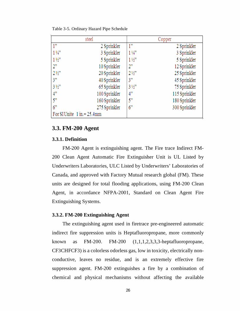
3.2.10. Schedule for Ordinary Hazard Occupancies
Branch lines shall not exceed eight sprinklers on either side of a cross
main.
Exception: Where more than eight sprinklers on a branch line are
necessary, lines shall be permitted to be increased to nine sprinklers by
making the two end lengths 1 in. (25.4 mm) and 11/4 in. (33 mm),
respectively, and the sizes thereafter standard. Ten sprinklers shall be
permitted to be placed on a branch line, making the two end lengths 1 in.
(25.4 mm) and 11/4 in. (33 mm), respectively, and feeding the tenth
sprinkler by a 21/2-in. (64-mm) pipe. Pipe sizes shall be in accordance
with Table (3-5). Where the distance between sprinklers on the branch line
exceeds 12 ft (3.7 m) or the distance between the branch lines exceeds 12
ft (3.7 m), the number of sprinklers for a given pipe size shall be in
accordance with Table (3-6).
26
Table 3-5. Ordinary Hazard Pipe Schedule
3.3. FM-200 Agent
3.3.1. Definition
FM-200 Agent is extinguishing agent. The Fire trace Indirect FM-
200 Clean Agent Automatic Fire Extinguisher Unit is UL Listed by
Underwriters Laboratories, ULC Listed by Underwriters’ Laboratories of
Canada, and approved with Factory Mutual research global (FM). These
units are designed for total flooding applications, using FM-200 Clean
Agent, in accordance NFPA-2001, Standard on Clean Agent Fire
Extinguishing Systems.
3.3.2. FM-200 Extinguishing Agent
The extinguishing agent used in firetrace pre-engineered automatic
indirect fire suppression units is Heptafluoropropane, more commonly
known as FM-200. FM-200 (1,1,1,2,3,3,3-heptafluoropropane,
CF3CHFCF3) is a colorless odorless gas, low in toxicity, electrically non-
conductive, leaves no residue, and is an extremely effective fire
suppression agent. FM-200 extinguishes a fire by a combination of
chemical and physical mechanisms without affecting the available
27
oxygen. This allows personnel to see and breath, permitting them to safely
leave the fire area. It is an effective Total Flooding extinguishing agent
that can be used on many types of fires. It is effective for use on Class A
surface fires, Class B flammable liquid fires, and Class C electrical fires.
3.3.2.1. Cleanliness
FM-200 is clean and leaves no residue, thereby minimizing after fire
clean up, along with keeping expensive downtime to a minimum. Most
materials such as steel, aluminum, stainless steel, brass, as well as plastics,
rubber and electronic components are not affected by exposure to FM-
200. This agent is also environmentally friendly, having an ozone
depletion potential (ODP) of 0.00.
3.3.2.2. Physical Properties of FM-200 (HFC-227ea)
• Chemical Name: Heptafluoropropane (CF3CHFCF3).
• Molecular Weight 170.0
• Boiling Pont (oF) at 14.7psia
• Freezing Point 204 (oF)
• Critical Temperature 214 (oF)
• Critical Pressure 422 (psia)
• Critical Volume 0.0258 (ft3/Ibm)
• Critical Density 38.76 (Ibm/ft3)
• Specific Heat, Liquid (BTU/Ib-oF) at 77oF
• Specific Heat, Vapor (BTU/Lb-oF) at constant 0.185 pressure (1 A.) at
77oF
• Heat of Vaporization (BTU/Ib) at Boiling Point 56.7
• Thermal Conductivity (BTU/h ft oF) of Liquid at 77oF 0.040 Viscosity,
Liquid (Ib/ft hr) at 77oF 0.433, Vapor Pressure 66.4 (psi) at 77oF
• And Ozone Depletion Potential 0.00
28
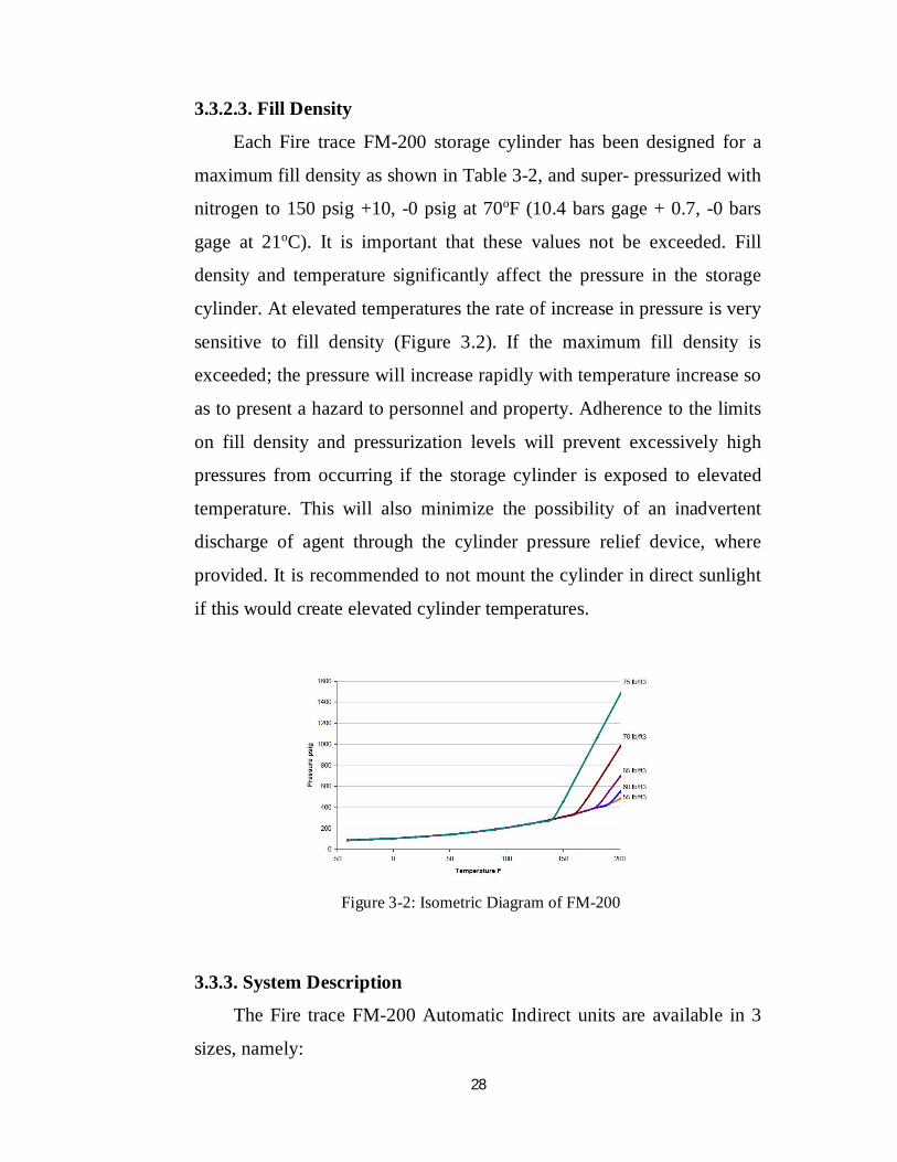
3.3.2.3. Fill Density
Each Fire trace FM-200 storage cylinder has been designed for a
maximum fill density as shown in Table 3-2, and super- pressurized with
nitrogen to 150 psig +10, -0 psig at 70oF (10.4 bars gage + 0.7, -0 bars
gage at 21oC). It is important that these values not be exceeded. Fill
density and temperature significantly affect the pressure in the storage
cylinder. At elevated temperatures the rate of increase in pressure is very
sensitive to fill density (Figure 3.2). If the maximum fill density is
exceeded; the pressure will increase rapidly with temperature increase so
as to present a hazard to personnel and property. Adherence to the limits
on fill density and pressurization levels will prevent excessively high
pressures from occurring if the storage cylinder is exposed to elevated
temperature. This will also minimize the possibility of an inadvertent
discharge of agent through the cylinder pressure relief device, where
provided. It is recommended to not mount the cylinder in direct sunlight
if this would create elevated cylinder temperatures.
Figure 3-2: Isometric Diagram of FM-200
3.3.3. System Description
The Fire trace FM-200 Automatic Indirect units are available in 3
sizes, namely:
29
• Model ILP 300: Charged with 3.0 Lbs. of FM-200
• Model ILP 600: Charged with 6.0 Lbs. of FM-200
• Model ILP 1200: Charged with 12.0 Lbs. of FM-200
These units are designed for use in Total Flooding applications only,
where the hazard is normally unoccupied. The Fire trace indirect units
can be used, but are not limited, to protect; electrical and electronic
cabinets, telecommunication areas, data Processing areas and cabinets,
other high value assets, laboratory fume /exhaust cabinets, pump
enclosures, UPS units, flammable chemicals storage cabinets, generator
enclosures, transformer cabinets, computer/data storage cabinets, CNC &
VMC Machining centers, and many other applications.
FM-200 is a gaseous fire-extinguishing agent that is effective for use
on class A – surface type fires, class B – flammable liquid fires, and class
C – electrical equipment fires
FM-200 should not be used where pyrotechnic chemicals containing
their own oxygen supply, reactive metals such as lithium, sodium,
potassium, magnesium, titanium, zirconium, uranium and plutonium,
metal hydrides, or chemicals capable of undergoing auto thermal
decomposition, such as certain fire trace FM-200 Automatic Indirect units
consists of ; FM-200 Cylinder/Valve assembly, cylinder mounting
Bracket, fire trace detector/actuation tubing and fittings (no substitute),
discharge nozzles, pressure switch, and discharge tubing and fittings
(furnished by others).
Once installed, the Fire trace Automatic Unit becomes a self-
contained, self-actuating unit that does not require an external source of
power or electricity. The unit utilizes unique Fire trace flexible tubing that
is attached to the top of the cylinder valve. This tubing is pressurized with
dry nitrogen to maintain the cylinder valve in the closed position. This
30
tubing is temperature sensitive, and acts as a continuous linear thermal
detector that ruptures at approximately 212oF (100oC). Once the detector
tubing is ruptured, the cylinder valve automatically opens, allowing the
FM-200 agent to flow through the discharge tubing, distributing the
extinguishing agent through the nozzle(s) into the protected area. Upon
actuation the pressure switch can be used to indicate discharge, shutdown
ventilation, close all openings, shut-off electrical power, etc. as may be
required.
3.3.3.1. Operating Pressure:
The FM 200 cylinder is super-pressurized with dry nitrogen to 150
psig at 70oF.
3.3.3.2. Operating Temperature Range Limitations:
The ambient operating temperature range for all unit components is:
0oF to +130oF (-17.8oC to +54.4oC).
3.3.4. Component Descriptions
3.3.4.1. FM-200 Cylinder/Valve Assemblies
FM-200 is stored in DOT steel cylinders as a liquefied compressed
gas, super-pressurized with nitrogen to 150 psig at 70oF (1,034 KPa at
21oC). The cylinder/valve assemblies are available in 3 sizes, namely:
• 3 LB size; filled with 3.0 LBS (1.36 Kg) of FM-200
• 6 LB size; filled with 6.0 LBS (2.72 Kg) of FM-200
• 12 LB size filled with 12.0 LBS (5.45 Kg) of FM-200
Each cylinder is equipped with a brass valve, a pressure gauge to
monitor cylinder pressure, and a quarter turn ball valve that interfaces with
the Fire trace detector tubing. The ball valve must be kept closed at all
times when the cylinder is not in service. In addition, the 6 and 12Lb size
cylinder valves valve is equipped with a pressure relief (rupture disc)
device in compliance with DOT requirements. Each valve is also equipped
31
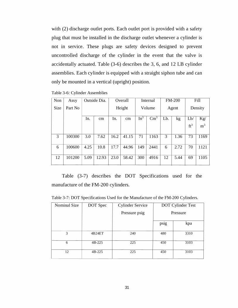
with (2) discharge outlet ports. Each outlet port is provided with a safety
plug that must be installed in the discharge outlet whenever a cylinder is
not in service. These plugs are safety devices designed to prevent
uncontrolled discharge of the cylinder in the event that the valve is
accidentally actuated. Table (3-6) describes the 3, 6, and 12 LB cylinder
assemblies. Each cylinder is equipped with a straight siphon tube and can
only be mounted in a vertical (upright) position.
Table 3-6: Cylinder Assemblies
Non
Size
Assy
Part No
Outside Dia. Overall
Height
Internal
Volume
FM-200
Agent
Fill
Density
In. cm In. cm In3 Cm3 Lb. kg Lb/
ft3
Kg/
m3
3 100300 3.0 7.62 16.2 41.15 71 1163 3 1.36 73 1169
6 100600 4.25 10.8 17.7 44.96 149 2441 6 2.72 70 1121
12 101200 5.09 12.93 23.0 58.42 300 4916 12 5.44 69 1105
Table (3-7) describes the DOT Specifications used for the
manufacture of the FM-200 cylinders.
Table 3-7: DOT Specifications Used for the Manufacture of the FM-200 Cylinders.
Nominal Size DOT Spec Cylinder Service
Pressure psig
DOT Cylinder Test
Pressure
psig kpa
3 4B24ET 240 480 3310
6 4B-225 225 450 3103
12 4B-225 225 450 3103
32
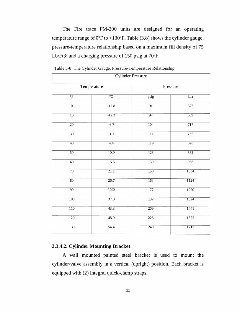
The Fire trace FM-200 units are designed for an operating
temperature range of 0oF to +130oF. Table (3.8) shows the cylinder gauge,
pressure-temperature relationship based on a maximum fill density of 75
Lb/Ft3; and a charging pressure of 150 psig at 70oF.
Table 3-8: The Cylinder Gauge, Pressure-Temperature Relationship Cylinder Pressure
Temperature Pressure
0F 0C psig kpa
0 -17.8 91 672
10 -12.2 97 689
20 -6.7 104 717
30 -1.1 111 765
40 4.4 119 820
50 10.0 128 882
60 15.5 139 958
70 21.1 150 1034
80 26.7 163 1124
90 3202 177 1220
100 37.8 192 1324
110 43.3 209 1441
120 48.9 228 1572
130 54.4 249 1717
3.3.4.2. Cylinder Mounting Bracket
A wall mounted painted steel bracket is used to mount the
cylinder/valve assembly in a vertical (upright) position. Each bracket is
equipped with (2) integral quick-clamp straps.
33
3.3.4.3. Fire trace Flexible Detector/Actuation Tubing
The Fire trace tubing is used as a combination linear heat detector
and unit activation device to cause actuation of the FM-200 agent cylinder.
The tubing is installed throughout the hazard volume, with one end
connected to the top of the FM-200 cylinder valve. The tubing is
pressurized with nitrogen to 150 psig while maintaining the ball valve in
the “OFF” position. An optional pressure gauge or pressure switch can be
connected to the other end of the detector tube to monitor unit pressure
and/or signal unit actuation etc. The detector tubing is heat sensitive and
in a fire situation is designed to rupture at any point along the tube when
the temperature reaches 212oF (100oC). The rupture of the tube releases
the nitrogen pressure causing the FM-200 cylinder valve to actuate,
resulting in complete discharge of the FM-200 agent through the nozzles.
3.3.4.4. Discharge Nozzles
Discharge nozzles are used to distribute FM-200 agent uniformly
throughout the hazard area. Two size nozzles are available. The small
nozzle is for use with the 3 Lb. size unit only. The medium size nozzle is
for use with the 6 Lb. and 12 Lb size units. The nozzles discharge in a
360o pattern and are designed to be installed at the top of the hazard in the
center of the area being protected. The nozzles are brass with female NPT
pipe threads.
3.3.4.5. Pressure Switch
A pressure switch is provided as a standard part of the cylinder valve
assembly and is connected directly into the pressurized portion of the
cylinder valve. This pressure switch is used to monitor unit pressure, unit
actuation and or to energize or de-energize electrically operated
equipment. An additional pressure switch is available as an optional item.
This switch is connected at the end of the line of the fire trace detector
34
tubing to provide additional electrical functions as may be required. Fire
trace recommends that all units use a pressure switch coupled with some
device to alert personnel in the event of discharge.
3.3.4.6. Recharge Adapters, FM-200 Cylinder
The recharge adapter is installed in one of the cylinder valve
discharge ports during the cylinder recharging procedure. The adapter is
used for refilling the cylinder with FM-200 agent.
3.3.4.7. Cylinder Nitrogen Recharge Adapter
The recharge adapter is connected to a fire trace tubing, and the other
end of the tubing is attached to the ball valve, located on top of the cylinder
valve, during the charging procedure. The adapter is used to apply
nitrogen pressure to internally seat the valve piston, and to super
pressurize the FM-200 cylinder with nitrogen.
3.3.4.8. Cylinder Hydrostatic Pressure Test Adapters
These adapters are available for use when a cylinder hydrostatic test
is required in order to comply with DOT regulations.
3.3.4.9. FM-200 Warning Nameplate
The warning plate is required to warn personnel not to enter the
hazard area during or after discharge. Warning signs shall be provided in
a conspicuous location, at the entrance to the protected areas, or in the case
of cabinet protection on the front face of the cabinet.
3.3.5. System Design and Limitation
3.3.5.1. General
The fire trace series of FM-200 Agent pre-engineered automatic
indirect units were tested and limits established by fire trace. Units are
listed by Underwriters Laboratories Inc and Underwriters’ Laboratories of
35
Canada, and approved by Factory Mutual Research Corp. These units
were subjected to numerous performance and fire tests in order to verify
their suitability and to establish design limitations for, hazard volume,
nozzle area coverage and heights, nozzle placement, discharge time and
flow rates, design concentrations & design factors, and Detector tubing
placement
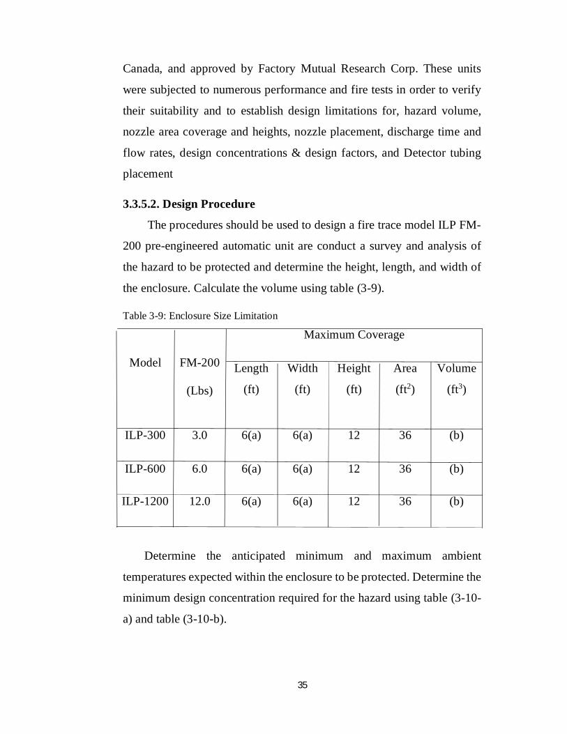
3.3.5.2. Design Procedure
The procedures should be used to design a fire trace model ILP FM-
200 pre-engineered automatic unit are conduct a survey and analysis of
the hazard to be protected and determine the height, length, and width of
the enclosure. Calculate the volume using table (3-9).
Table 3-9: Enclosure Size Limitation
Model
FM-200
(Lbs)
Maximum Coverage
Length
(ft)
Width
(ft)
Height
(ft)
Area
(ft2)
Volume
(ft3)
ILP-300 3.0 6(a) 6(a) 12 36 (b)
ILP-600 6.0 6(a) 6(a) 12 36 (b)
ILP-1200 12.0 6(a) 6(a) 12 36 (b)
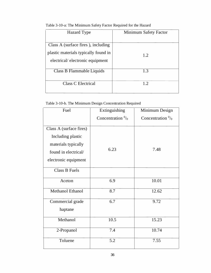
Determine the anticipated minimum and maximum ambient
temperatures expected within the enclosure to be protected. Determine the
minimum design concentration required for the hazard using table (3-10-
a) and table (3-10-b).
36
Table 3-10-a: The Minimum Safety Factor Required for the Hazard
Hazard Type Minimum Safety Factor
Class A (surface fires ), including
plastic materials typically found in
electrical/ electronic equipment
1.2
Class B Flammable Liquids 1.3
Class C Electrical 1.2
Table 3-10-b. The Minimum Design Concentration Required
Fuel Extinguishing
Concentration 0/0
Minimum Design
Concentration 0/0
Class A (surface fires)
Including plastic
materials typically
found in electrical/
electronic equipment
6.23
7.48
Class B Fuels
Aceton 6.9 10.01
Methanol Ethanol 8.7 12.62
Commercial grade
haptane
6.7 9.72
Methanol 10.5 15.23
2-Propanol 7.4 10.74
Toluene 5.2 7.55
37
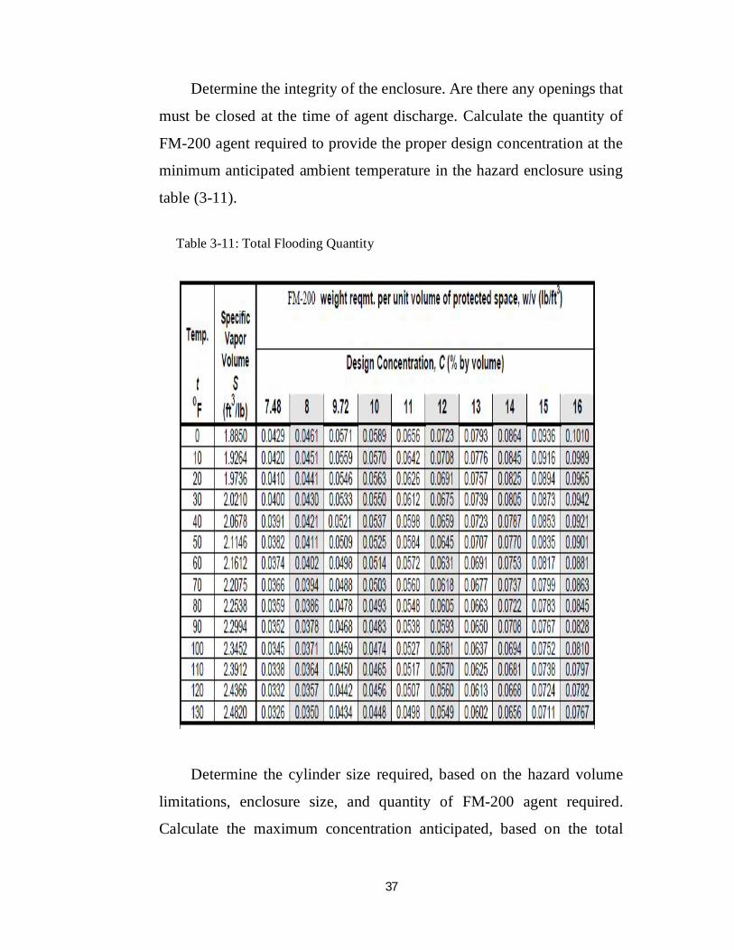
Determine the integrity of the enclosure. Are there any openings that
must be closed at the time of agent discharge. Calculate the quantity of
FM-200 agent required to provide the proper design concentration at the
minimum anticipated ambient temperature in the hazard enclosure using
table (3-11).
Table 3-11: Total Flooding Quantity
Determine the cylinder size required, based on the hazard volume
limitations, enclosure size, and quantity of FM-200 agent required.
Calculate the maximum concentration anticipated, based on the total
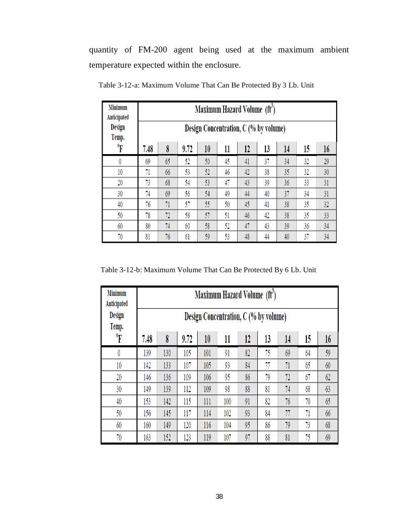
38
quantity of FM-200 agent being used at the maximum ambient
temperature expected within the enclosure.
Table 3-12-a: Maximum Volume That Can Be Protected By 3 Lb. Unit
Table 3-12-b: Maximum Volume That Can Be Protected By 6 Lb. Unit
39
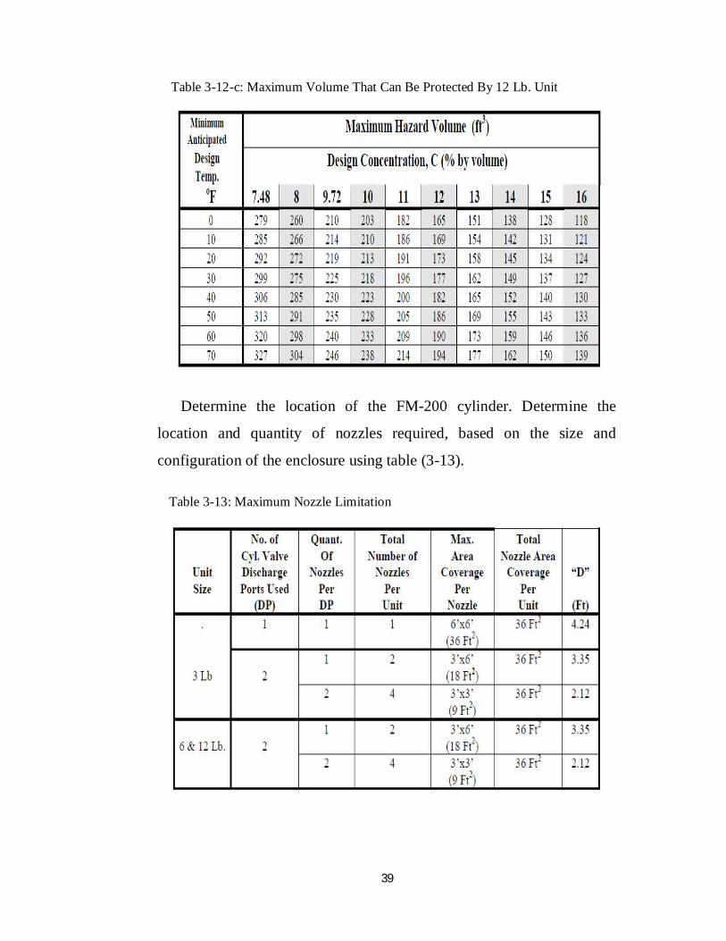
Table 3-12-c: Maximum Volume That Can Be Protected By 12 Lb. Unit
Determine the location of the FM-200 cylinder. Determine the
location and quantity of nozzles required, based on the size and
configuration of the enclosure using table (3-13).
Table 3-13: Maximum Nozzle Limitation
40
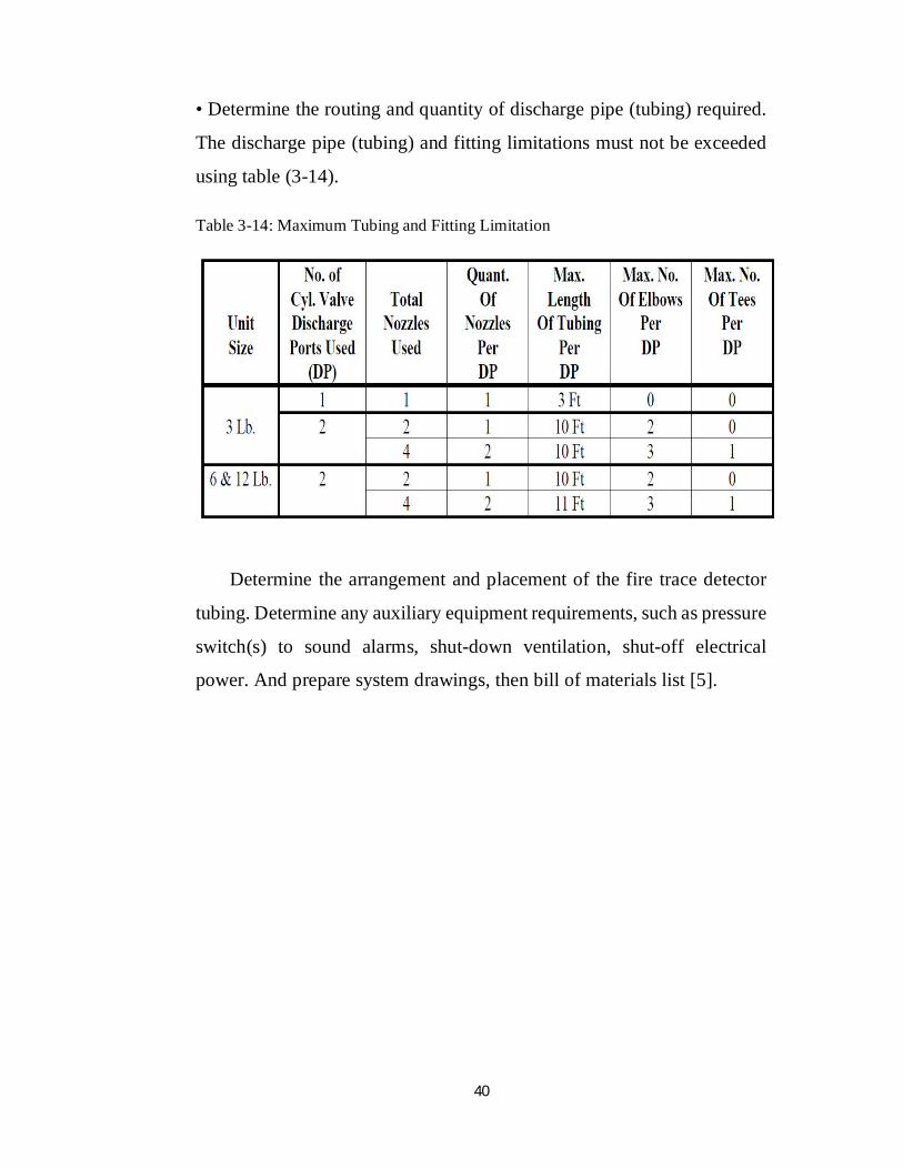
• Determine the routing and quantity of discharge pipe (tubing) required.
The discharge pipe (tubing) and fitting limitations must not be exceeded
using table (3-14).
Table 3-14: Maximum Tubing and Fitting Limitation
Determine the arrangement and placement of the fire trace detector
tubing. Determine any auxiliary equipment requirements, such as pressure
switch(s) to sound alarms, shut-down ventilation, shut-off electrical
power. And prepare system drawings, then bill of materials list [5].
Recommended


