
nhibited,nner. Thestability ofumnpresented
ode. Fournce of shearated
tability
Column Stability and Minimum Lateral Bracing:Effects of Shear Deformations
J. Darío Aristizábal-Ochoa1
Abstract: Stability equations that evaluate the elastic critical load of columns in any type of construction with sidesway unipartially inhibited, and totally inhibited including the effects of bending and shear deformations are derived in a classical ma“modified” shear equation proposed by Timoshenko and Gere is utilized in the derived equations which can be applied to theframes (“unbraced,” “partially braced,” and “totally braced”) with rigid, semirigid, and simple connections. The complete colclassification and the corresponding three stability equations overcome the limitations of current methods. Simple criteria arethat define the concept of minimum lateral bracing required by columns and plane frames to achieve nonsway buckling mexamples are presented that demonstrate the effectiveness and accuracy of the proposed stability equations and the importadeformations in columns with relatively low shear stiffnessAsG such as in built-up metal columns or columns made of lamincomposites(fiber-reinforced polymers).
DOI: 10.1061/(ASCE)0733-9399(2004)130:10(1223)
CE Database subject headings: Bracing; Buckling; Building codes; Columns; Shear deformation; Shear strength; Frames; S.
ide-d-pre-
8,the
er-the
ro-f theof
odesfmesa
ed to
,
on-g the
l-side-ore
oxicalw thelastic
B aselflec-o-
al
fthe
e/-here
ion;
ex-
niv.,
untilidual
t mustaperr 11,
E,
Introduction
The elastic stability equations of prismatic columns with ssway uninhibited, partially inhibited, and totally inhibited incluing the effects of flexural deformations have been previouslysented and discussed by Aristizabal-Ochoa(1996, 1997a,b, 1992001, 2002). It was demonstrated that the stability equation ofpartially braced column was the “missing link” to a full undstanding of the elastic stability of columns and frames and“key” to solve the limitations of current methods. The writer pposed an approach for the stability analysis and calculation oeffective lengthK factor of columns and frames of any typesemirigid connections according to current construction c(ACI 2002; AISC-ASD 1989; AISC-LRFD 2002). Because otheir nonparadoxical results in asymmetrical frames and in frawith leaning columns(fully discussed by Aristizabal-Ocho1997a), the validity of the proposed method has been extendtwo-dimensional(2D) and three-dimensional(3D) multicolumnsystems with semirigid connections(Aristizabal-Ochoa 1997b1998, 2001, 2002).
Objectives
The main objectives of this publication are to present:(1) A newset of classical stability equations for columns with semirigid cnections that include the effects of shear deformations alon
1125-Year Generation Professor, School of Mines, National UA.A. 75267, Medellin, Colombia.
Note. Associate Editor: Dewey H. Hodges. Discussion openMarch 1, 2005. Separate discussions must be submitted for indivpapers. To extend the closing date by one month, a written requesbe filed with the ASCE Managing Editor. The manuscript for this pwas submitted for review and possible publication on Decembe2001; approved on March 24, 2004. This paper is part of theJournal ofEngineering Mechanics, Vol. 130, No. 10, October 1, 2004. ©ASC
ISSN 0733-9399/2004/10-1223–1232/$18.00.JOURNA
columns; and(2) criteria for minimum bracing required by coumns and plane frames to achieve buckling mode withoutsway. The new set of three stability equations, not only is mgeneral than any current method, but also avoids any paradresults. Four comprehensive examples are included that shoeffects of shear deformations and lateral bracing on the estability of columns and frames.
Structural Model
Assumptions
Consider a 2D prismatic element that connects points A andshown in Fig. 1(a). The element is made up of the column itsAB, the lumped flexural connectionska and kb, and the laterashear connectionsSa andSb at the top and bottom ends, resptively. It is assumed that(1) the column AB is made of a homgeneous linear elastic material with elastic moduliE andG; (2)the centroidal axis of the member is a straight line;(3) the columnis loaded with an end axial loadP applied along the centroidaxis of the cross section which is doubly symmetrical(i.e., thecentroid coincides with the shear center) with areaA, effectiveshear areaAs, and principal moment of inertiaI in the plane obending; and(4) deformations and strains are small so thatprinciple of superposition can be applied.
The lumped flexural connections have stiffnesseska and kb
(whose dimensions are in force/distance/radian), respectively. Thdimensions of lateral shear connectionsSa and Sb are in forcedistance. The ratiosRa=ka/ sEI /hd and Rb=kb/ sEI /hd are denoted as the stiffness indices of the flexural connections, wI =column moment of inertia about its principal axis in questand h=column height. These indices vary from zero(i.e., Ra
=Rb=0) for simple connections(i.e., pinned) to infinity (i.e., Ra
=Rb=`) for fully restrained connections(i.e., rigid or clamped).Gerstle(1988) has indicated lower and upper bounds for the fl
ural connectionk. Xu and Grierson(1993) used these bounds inL OF ENGINEERING MECHANICS © ASCE / OCTOBER 2004 / 1223

andemi-
uced
ec-;ess1
con-
allylare:-
, thes as
eryside-adcept,ties
ol-ted,
mnscol-
inge
hoaofively.
nd
-
he
.
nal,-
the design of frames with semirigid connections. Also ChenLui (1991) have presented data as well as the modelling of srigid connections in the stability of steel structures.
For convenience, the following two parameters are introd(Aristizabal-Ochoa 1996, 1997b):
ra =1
1 +3
Ra
s1ad
rb =1
1 +3
Rb
s1bd
wherera andrb are called the fixity factors. For hinged conntions, both the fixity factorr and the stiffness indexR are zerobut for rigid connections, the fixity factor is 1 and the stiffnindex is infinity. Since the fixity factor can only vary from 0 to(while the stiffness indexR may vary form 0 to`), it is moreconvenient to use in the analysis of structures with semirigidnections.
The relationships between the fixity factors(ra andrb) and thealignment charts ratios(Ga and Gb) [i.e., G=S / sEI /hdc/SsEI /Ldg at the top and bottom ends, respectively] of a column ina symmetrical rigid frame with sidesway uninhibited or partiinhibited are:ra=2/s2+Gad, and rb=2/s2+Gbd. In symmetricarigid frames with sidesway totally inhibited, the relationshipsra=2/s2+3Gad, andrb=2/s2+3Gbd. In symmetrical and unsymmetrical frames with semirigid beam-to-column connectionsfixity factors can be determined using structural principleshown by Aristizabal-Ochoa(1996, 1997b, 1998).
Stability Criteria
In a frame with sidesway uninhibited or partially inhibited evcolumn is defined as having reached its critical load whensway buckling of the frame occurs, with the distribution of loamong the columns being as specified. Obviously, in this conthe critical load of each column is a function of its own properand cross section, the properties of the entire frame(support andbracing conditions), and the distribution of load among the cumns in the frame. In a frame with sidesway totally inhibi
Fig. 1. Column with sidesway partially inhibited and with rotatioand lateral end restraints:(a) structural model;(b) end momentsforces, rotations and deflections; and(c) differential element including bending and shear deformations
frame bucking is reached when at least one of columns of the
1224 / JOURNAL OF ENGINEERING MECHANICS © ASCE / OCTOBER 200
frame buckles, with the distribution of load among the colubeing as specified. The stability equations for an individualumn are derived in the next section.
Derivation of the Classical Stability Equations
The stability analysis of a prismatic column including bendand shear deformations[Figs. 1(a–c)] is formulated using th“modified” approach proposed by Timoshenko and Gere(1961,page 134). This approach has been utilized by Aristizabal-Oc(1983) and Koh and Kelly(1989) in the dynamic analysisstructural walls and elastomeric isolation bearings, respectThe governing equations are as follows:
bEIu9sxd + Pusxd = − Ma − sMa + Mb + PDdx
hs2ad
bEIc9sxd + Pcsxd =Ma + Mb + PD
hs2bd
where usxd=lateral deflection of the column center line; acsxd=rotation of the cross section as shown by Fig. 1(c). Thesolutions to the second-order linear differential Eqs.(2a) and(2b)are as follows:
usxd = A cosS x
hfD + B sinS x
hfD +
x
hSMa + Mb
P+ DD −
Ma
Ps3ad
csxd = C cosS x
hfD + D sinS x
hfD +
1
hSMa + Mb
P+ DD s3bd
wheref2=P/ sbEI /h2d.The unknown coefficientsA, B, C, andD can be obtained from
the following boundary conditions:
At x = 0: u = 0, c = ca
At x = h: u = D and c = cb
whereca and cb=rotations of cross sections atA and B due tobending, respectively;Da andDb=lateral sway atA andB, respectively; and D=Da−Db=relative sidesway of column endA withrespect to its bottom endB.
Therefore, A=Ma/P; B=sMa/Pdtansf /2d−sMa+Mbd /P sin f ; C=ca−s1/hdfsMa+Mbdg /P+Dg; and
D =Ca − Cb cosf
sin f− SMa + Mb
P+ DDtansf/2d
Sinceu8=c+V/ sAsGd and V=−sMa+Mb+PDd /h, the followingexpressions forca andcb can be obtained:
ca =Ma
EI/h
sin f − bf cosf
sbfd2 sin f+
Mb
EI/h
sin f − bf
sbfd2 sin f+
D
bh= −
Ma
ka
s4ad
cb =Ma
EI/h
sin f − bf
sbfd2 sin f+
Mb
EI/h
sin f − bf cosf
sbfd2 sin f+
D
bh= −
Mb
kb
s4bd
where b=1/f1+P/ sAsGdg; and As=effective shear area of tcolumn.
Since three unknowns(Ma, Mb, and D) are involved in Eqs
(4a) and(4b), one more equation is required. This equation can be4

l
ol-
as
obtained applying static equilibrium(horizontal and rotationaequilibrium of the column in Fig. 1(b) as follows:
SaDa + SbDb = 0 s5ad
Ma + Mb + PsDa − Dbd − SaDah = 0 s5bd
Substituting Eq.(5a) into Eq. (5b) gives
the
ed”
s;
un-
nd Bsfirst
Eq. (8b)]:
JOURNA
Mb + Ma
h+ FP −
SaSb
Sa + SbhGDa − Db
h= 0 s5cd
or simply
Mb + Ma
h+ fP − SDhg
D
h= 0 s6d
whereSD=SaSb/ sSa+Sbd=overall lateral stiffness provided to cumn AB; andP=f2bEI /h2.
Now, Eqs.(4a) and(4b), can be represented in matrix formfollows:
3h
EISsin f − bf cosf
sbfd2 sin f+
EI/h
kaD h
EI
sin f − bf
sbfd2 sin f1
h
EI
sin f − bf
sbfd2 sin f
h
EISsin f − bf cosf
sbfd2 sin f+
EI/h
kbD 1
1
h
1
hEISbf
hD2
− SDbh43Ma
Mb
D
bh4 = 0 s7d
ectedlitytally
ds is
nant
es:y
Eq. (7) indicates that there are three major buckling modes inelastic range of columns:1. Buckling with relative sidesway totally inhibited(i.e., D=0)
corresponding to what is commonly referred to as “braccolumns;
2. Buckling with relative sidesway partially inhibited(i.e., DÞ0 andSDÞ0) corresponding to “partially braced” columnand
3. Buckling with sidesway uninhibited(i.e., DÞ0 andSDÞ0)corresponding to what is commonly referred to as “braced” columns.
Proposed Stability Equations
Columns with Sidesway Totally Inhibited
For columns in which the lateral sway between the ends A ais totally inhibited[i.e., D=0, Fig. 2(a)] the stability equation iobtained by setting the determinant of the coefficients of thetwo rows and columns in Eq.(7) equal to zero as follows:
Ssin f − bf cosf
sbfd2 sin f+
EI/h
kaDSsin f − bf cosf
sbfd2 sin f+
EI/h
kbD
− F sin f − bf
sbfd2 sin fG2
= 0 s8ad
which in terms of the stiffness indicesRa andRb becomes
sbfd2
RaRb+ S 1
Ra+
1
RbDS1 −
bf
tanfD +
tansf/2dsbf/2d
− 1 = 0 s8bd
or in terms of the fixity factorsra andrb [Eqs.(1a) and(1b) into
s1 − rads1 − rbdsbfd2 + 3sra + rb − 2rarbdS1 −bf
tanfD
+ 9rarbF tansf/2dsbf/2d
− 1G = 0 s8cd
When shear deformations along the member are negl(i.e., As=` or b=1), Eq. (8a) becomes the classical stabiequation for columns with lateral sway between the ends toinhibited (Salmon and Johnson 1996, Chapter 14).
Columns with Sidesway Partially Inhibited
For columns in which the lateral sway between the two enpartially inhibited(i.e., Da−Db=DÞ0) by springsSa andSb [Fig.2(b)], the stability equation is obtained by setting the determiof Eq. (7) equal to zero as follows:
Fig. 2. Column classification according to overall buckling mod(a) column with sidesway totally inhibited;(b) column with sideswapartially inhibited; and(c) column with sidesway uninhibited
L OF ENGINEERING MECHANICS © ASCE / OCTOBER 2004 / 1225
dtion
of
hatf
story-and
truc-vels.lumnq.
dingl-
Fsbfd2 −bSD
sEI/hdGHSsin f − bf cosf
sbfd2 sin f+
EI/h
kaD
3Ssin f − bf cosf
sbfd2 sin f+
EI/h
kbD − F sin f − bf
sbfd2 sin fG2J
− FEI/h
ka+
EI/h
kb−
tanf/2
sbf/2d G = 0 s9ad
which in terms of the stiffness indices Ra and Rb are reduced to
sbfd2
RaRb− 1 +S 1
Ra+
1
RbD bf
tanf− H+
sbfd2
RaRb+ S 1
Ra+
1
RbD
3S1 −bf
tanfD + F tansf/2d
sbf/2d− 1GJSDh3b
f2EI= 0 s9bd
or in terms of the fixity factorsra andrb [Eqs.(1a) and(1b) intoEq. (9b)] becomes
s1 − rads1 − rbdsbfd2 − 9rarb − 3sra + rb − 2rarbdbf
tanf
−SD
bf2EI/h3Hs1 − rads1 − rbdsbfd2 + 3sra + rb − 2rarbd
3S1 −bf
tanfD + 9rarbS tansf/2d
sbf/2d− 1DJ = 0 s9cd
A partially braced column is one which its critical loadPcr liesbetween thePcr of the column with sidesway uninhibited(un-braced) and thePcr of the column with sidesway totally inhibite(braced). This concept is further discussed later in this publicausing lateral bracing criteria.
Notice thatSD= SaSb/Sa+Sb, therefore the combined effect
the lateral shear connectionsSa and Sb is equivalent to a lateralng
ds isn
be obtained directly from Eq.(9b) makingSD=0, as follows:
1226 / JOURNAL OF ENGINEERING MECHANICS © ASCE / OCTOBER 200
spring in seriesSD at either end of the column. Notice also tthe proper evaluation ofSD is vital to the stability analysis oframed structures. In general, there are three sources ofSD: (1)That provided by other columns that are part of the samelevel from which column AB is located;(2) from diagonal bracing or shear walls within the same story level of the frame;(3) from external bracing provided by other structures or stural elements connected to the column’s top and bottom le
For instance, the lateral stiffness provided by a single counder axial compressive loadN can be obtained directly from E
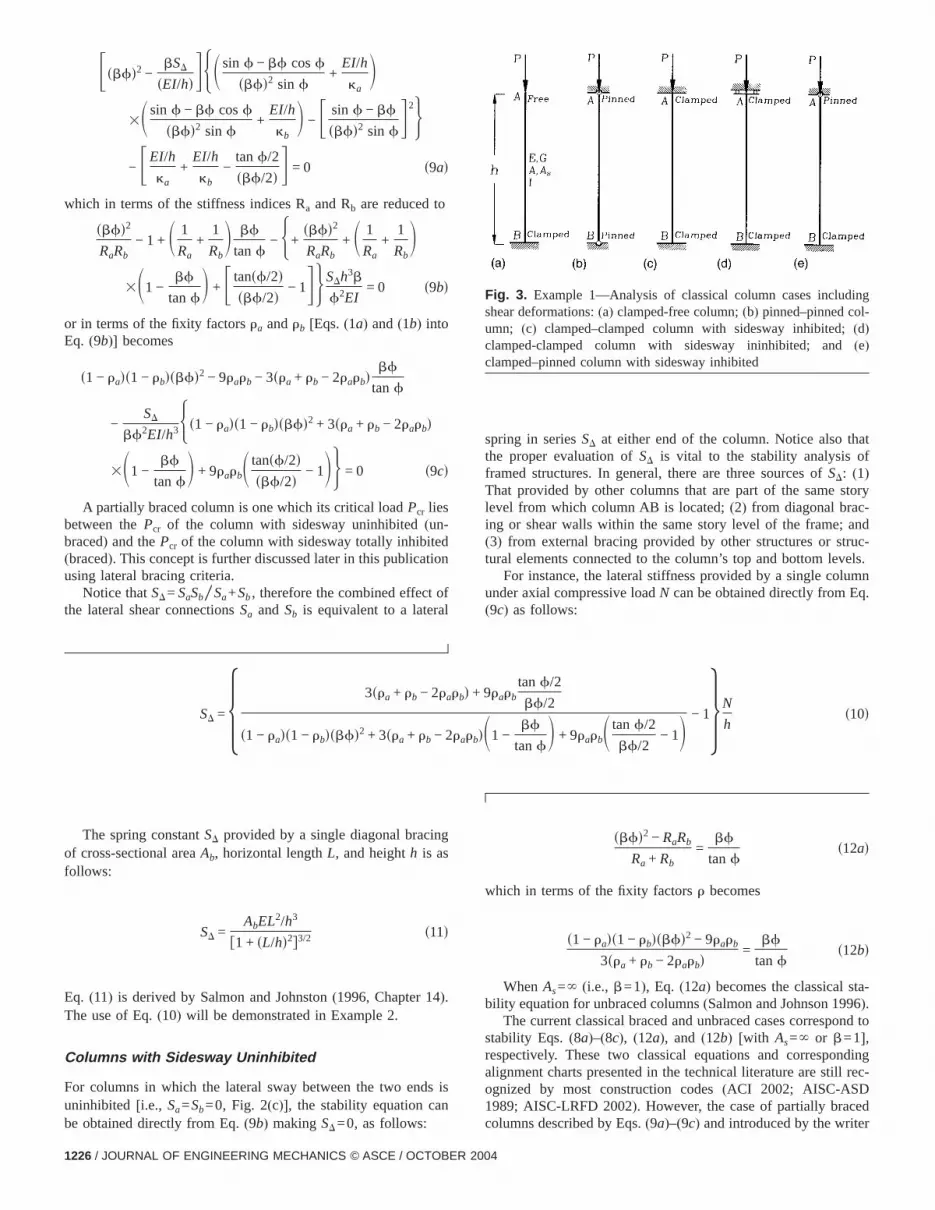
Fig. 3. Example 1—Analysis of classical column cases inclushear deformations:(a) clamped-free column;(b) pinned–pinned coumn; (c) clamped–clamped column with sidesway inhibited;(d)clamped-clamped column with sidesway ininhibited; and(e)clamped–pinned column with sidesway inhibited
(9c) as follows:
SD =5 3sra + rb − 2rarbd + 9rarb
tanf/2
bf/2
s1 − rads1 − rbdsbfd2 + 3sra + rb − 2rarbdS1 −bf
tanfD + 9rarbS tanf/2
bf/2− 1D − 16N
hs10d
ta-6ond to
ndingl rec-
ed
The spring constantSD provided by a single diagonal braciof cross-sectional areaAb, horizontal lengthL, and heighth is asfollows:
SD =AbEL2/h3
f1 + sL/hd2g3/2 s11d
Eq. (11) is derived by Salmon and Johnston(1996, Chapter 14).The use of Eq.(10) will be demonstrated in Example 2.
Columns with Sidesway Uninhibited
For columns in which the lateral sway between the two enuninhibited [i.e., Sa=Sb=0, Fig. 2(c)], the stability equation ca
sbfd2 − RaRb
Ra + Rb=
bf
tanfs12ad
which in terms of the fixity factorsr becomes
s1 − rads1 − rbdsbfd2 − 9rarb
3sra + rb − 2rarbd=
bf
tanfs12bd
WhenAs=` (i.e., b=1), Eq. (12a) becomes the classical sbility equation for unbraced columns(Salmon and Johnson 199).
The current classical braced and unbraced cases correspstability Eqs.(8a)–(8c), (12a), and (12b) [with As=` or b=1],respectively. These two classical equations and correspoalignment charts presented in the technical literature are stilognized by most construction codes(ACI 2002; AISC-ASD1989; AISC-LRFD 2002). However, the case of partially brac
columns described by Eqs.(9a)–(9c) and introduced by the writer4

t
criti-
ped-
d-
qs.
f-
fFig.
ntedn-
e
ral totheethat
ode
Fig.uraler-n
am-
nin-As-
t
hendns
(Aristizabal-Ochoa 1996, 1997a,b, 1998, 2001, 2002) has nobeen acknowledged by the construction codes yet.
Comparative Examples
Example 1: Shear Deformation Effects on ClassicalColumn Cases
Next the effects of shear deformations are determined on thecal axial load of the classical column cases shown in Figs. 3(a–e)(clamped-free, pinned-pinned, clamped-clamped, and clampinned columns).
Clamped-Free ColumnSubstituting ra=0 and rb=1.0 into Eq. (12b) results intanf=`, whose solution is simply f=s2n−1dp /2(where n=1,2,3, . . .). Therefore, f2=fs2n−1dp /2g2=f1+sPcr/AsGdgfPcr/ sEI /h2dg or
Pcr2
AsG+ Pcr − s2n − 1d2p2EI
4h2 = 0 s13d
The solution of this quadratic equation is
Pcr =AsG
2FÎ1 +
4P*
AsG− 1G s14d
where
P* = s2n − 1d2p2EI
4h2 s15d
Notice that the solution given by Eq.(14) and the corresponing shear deformation effects shown in Fig. 4(a) are identical tothose presented by Timoshenko and Gere(1961, p. 134).
Pinned–Pinned ColumnThe first-mode of buckling can be solved using E(14) and (15) with n=1 and replacingh for h/2, that is, Pcr
=sAsG/2dfÎ1+s4P* /AsGd−1g with P* =p2EI /h2. Similarly, anti-symmetrical modes of buckling(with an even number of halsinewaves orn=2,4,6, . . .) can be obtained using Eq.(14) withP* =p2EI / sh/nd2. Symmetrical modes of buckling(with an odd
Fig. 4. Example 1(Continued)—Effects of shear deformations on tcolumns of example 1:(a) clamped-free, pinned–pinned, aclamped–clamped ends; and(b) clamped–clamped end conditiowith sidesway and clamped–pinned ends
number of half-sinewaves orn=1,3,5, . . .) can be obtained using
JOURNA
Eqs. (14) and (15) substitutingh for h/2n. Again, the effects oshear deformations are identical to those already shown in4(a), but with P* =p2EI / sh/nd2.
Clamped–Clamped Column with Sidesway UninhibitedSubstitutingra=rb=1.0 into Eq.(12b) results in tanf=0, whosesolution is simply f=np (with n=1,2,3, . . .). Therefore, f2
=snpd2=f1+sPcr/AsGdgfPcr/ sEI /h2dg or
Pcr2
AsG+ Pcr − n2p2EI
h2 = 0 s16d
The solution of this quadratic isPcr=AsG/2fÎ1+s4P* /AsGd−1g,with P* =n2sp2EI /h2d. This solution is the same as that preseby Koh and Kelly(1989) with the shear deformation effects idetical to those shown in Fig. 4(a).
Clamped–Clamped Column with Sidesway InhibitedThe first mode of buckling(symmetrical) can be solved using thprevious case withn=1 and replacingh for h/2, that isPcr=sAsG/2dfÎ1+s4P* /AsGd−1g with P* =4p2EI /h2. The sheadeformation effects on the first mode of buckling are identicthose shown in Fig. 4(a). The shear deformation effects onsecond-mode of buckling(antisymmetrical) are identical to thosshown in Fig. 4(b) which can be obtained from the casefollows (clamped–pinned column) substitutingh for h/2.
Clamped–Pinned Column without SideswaySubstitutingra=0 andrb=1.0 into Eq.(8c) results in tanf=bfor
tanSÎ Pcr
bEI/h2DbÎ Pcr
bEI/h2
= 1 s17d
The solution of Eq.(17) is plotted in Fig. 4(b) showing theeffects of shear deformations on the fundamental buckling mof the clamped–pinned column[with P* =fp2EI / s0.6992hd2gwhich is thePcr corresponding tob=1].
Example 2: Simple Frame with a Leaning Column
Consider a simple frame with a leaning column shown in5(a). To simplify calculations, assume that the girder’s flexstiffnessEI /L is infinitely larger than that of the columns. Detmine using Eq.(9c), the variation of the critical load of columAB and the total critical load on the frame with the load paretera.
SolutionThis frame appears to be a frame with sidesway-buckling uhibited. However, this classification must be checked first.suming that column CD is restraining column AB,Pcr of columnAB must be determined first from Eq.(9c) taking into accounthat ra=rb=0, thenPcr=SDh1. Then, from Eq.(10) and rc=1.0,0,rd,1.0 for column CD:
SD = 3 s1 − rdd + 3rd
tansf2/2dsb2f2/2d
s1 − rddb2f2
tansb2f2d+ 3rdS tansf2/2d
sb2f2/2d− 1D − 14aPcr
h2
or
L OF ENGINEERING MECHANICS © ASCE / OCTOBER 2004 / 1227

,
lid asles
iti-are
y
pled
ach
vily
r-d re-
gularringcant,on-rated
3 s1 − rdd + 3rd
tansf2/2dsb2f2/2d
s1 − rddb2f2
tansb2f2d+ 3rd
4 = 1 +ah1
h2s18d
where
f2 =ÎF1 +aPcr
As2G2G aPcr
sE2I2d/h22 s19d
Once the values ofh1, h2, E2I2, As2, G2, rd, anda are giventhe value ofPcr can be evaluated from Eq.(18) andSD from theexpression just used above. Notice that this analysis is valong asSDøp2b1E1I1/h1
3, because otherwise column AB buckwithout sidesway at a loadP=p2b1E1I1/h1
2.Figs. 5(b and c) show the variation ofPcr andPtotal with a (for
the particular case of:h1=h2=h, E1I1=E2I2=EI, with As1G1
=As2G2=AsG varying fromEI /h2, 10EI /h2 to infinity and for twovalues ofrd=1.0 and 0.5), respectively. Notice that both the crcal load of each column and the total critical load on the frame
Fig. 5. Example 2—Simple plane frame with a leaning column:(a) svariation of total critical load on the frame witha
reduced substantially by the shear deformations and vary, not
1228 / JOURNAL OF ENGINEERING MECHANICS © ASCE / OCTOBER 200
only with the end flexural restraints(as it is usually specified bmost construction codes), but with a, EI, AsG, and h of eachcolumn. That is, all columns in a particular frame are coutogether and with the stability of the frame depending on(1) theend flexural restraints of each column;(2) the load distributionamong the columns;(3) the flexural and shear stiffnesses of ecolumn; (4) the unsupported lengths of each column; and(5) thecoupling effect by which the stronger columns(i.e., those withlarge EI /h and strong end flexural restraints) and columns withlow axial load provide lateral support or bracing to those healoaded and with soft end flexural restraints.
It is important to emphasize that(1) the effects of shear defomations are not significant and can be neglected in steel aninforced concrete solid columns, such as columns of rectanor I cross sections that are commonly utilized in civil engineeconstruction. However, these effects can become very signifiparticularly in built-up steel columns consisting of struts cnected by lacing bars or batten plates, or columns with perfocover plates, or with open webs in which the shear stiffnessAsGis of the same order of magnitude as 10EI /h2. This problem is
ral model;(b) variation of critical load on column AB witha; and(c)
tructufully discussed by Timoshenko and Gere(1961, pp. 135–142)
4

lumns allhib-d in
-aehearramic
ereino andfi-ch,s of
emenfects.s as
pro-hich
the. 3e
g
ap-.
d
-
re 30above
ed
at
theeacherge
amed ofeenith
ide-me
l
presenting closed-form expressions for laced columns, cowith batten plates, and columns with perforated cover platewith pinned–pinned end conditions and sidesway totally inited; and(2) the effects of shear deformations cannot neglectecolumns made of laminated composites[fiber-reinforced polymers (FRP)], since the shear modulusG of these materials issmall fraction of the elastic modulusE, and in most cases thcross sections are made up of very thin walls making the sstiffnessAsG of the same order of magnitude asEI /h2. The sheaeffects are great importance in the static, stability, and dynbehavior of laminated members made of composites(FRP).
Shear Effects Using Finite Element Analysis
As previously stated, the closed-form solutions presented huse the modified shear approach proposed by TimoshenkGere(1961, p. 135) suitable for parametric studies. Availablenite element method(FEM) programs do not use this approabecause it is much more complex requiring the solutioncoupled Eqs.(2a) and (2b) [given by expressions(3a) and (3b)].As a consequence, two additional degrees of freedom per elwould be required in order to take into account the shear efMost FEM computer solutions include the shear deformationan “additional” curvature which is added to the curvatureduced by the bending moment. This “simplified” approach wis fully described by Timoshenko and Gere(1961, p. 133) yieldsless accurate but more conservative(i.e., lower) buckling loads.
To compare the buckling results by both the modified andsimplified shear approaches, the clamped-free column of Fig(a)and of the simple frame of Fig. 5(a) were analyzed using thSAP2000FEM computer program(1977) assuming the followinnumerical values:• For the the clamped-free column: h=2,540 mm(100 in.), I
=416,231 mm4 s100 in.4d, E=68.95 MPas10,000 ksid, G=26.52 MPas3,846 ksid, and GAs=0.708073106 kN mm2
s246.74 kip in.2d.• For the simple frame: h1=h2=h=2540 mms100 in.d,
I1= I2= I =416,231 mm4 s100 in.4d, E1=E2=E=68.95 MPas10,000 ksid, G1=G2=G=26.52 MPas3,846 ksid, with GAs1
=GAs2=GAs=2.86973106 kN mm2 s1,000 kip in.2d, and a=1.0.The results obtained converge to those of the simplified
proach described by Timoshenko and Gere(1961, Eq. 2-57, p133) which states that the critical load isPe/ f1/s1+Pe/AsGdg.The numerical results obtained using theSAP2000model (thatconsisted of ten segments all of equal length) and the proposeapproach are listed below.1. For the clamped-free column of Fig. 3(a)—Using the
SAP2000 model, Pcr=521.74 kNs117.30 kipsd or Pcr/P*
=0.475<0.5 with Pe=P* =p2EI /4h2 and Pe/AsG=1. Usingthe proposed approach:Pcr=678.3 kNs152.5 kipsd orPcr/P
* =0.618.2. For the simple frame of Fig. 5(a)—Using the SAP2000
model, Pcr=1,144.15 kNs257.23 kipsd or Pcr/P* =0.261
with Pe=P* =p2EI /h2 and Pe/AsG=p2/10. Using the proposed approach,Pcr=1315.1 kNs295.6 kipsd or Pcr/P
*
<0.3.The critical loads obtained using the proposed method a
and 15% higher, respectively, in the two cases discussedthan the values obtained using theSAP2000FEM model. It isinteresting to note that theSAP2000FEM results can be obtaindirectly using Eqs.(13) and(18) or using Figs. 4(a) and 5(a). Pcr
*
is determined first assumingb=1 [AsG=` which makesP =PeJOURNA
t
=Pcr], and thenPcr is reduced by the ratio 1/s1+Pe/AsGd. Forinstance, in the case the simple frame of Fig. 5(a) with a=b=rd=1 and Pe=P* , one can obtain thPcr/ sp2EI /h2d=0.54 using Fig. 5(b) [top curve], then 1/s1+Pe/AsGd<1/2; therefore, the reduced value ofPcr/P
* =0.54/2=0.27. This value is fairly close to 0.261 obtained usingSAP2000model just described. If the number of segments ofcolumn element is increased even further, the result will convto Pcr/P
* =0.27.
Partially Braced Columns and Minimum LateralBracing
Partially Braced Column Criterion
A partially braced column is one whose critical loadPcr lies be-tween thePcr of the unbraced column and thePcr of a totallybraced column or simply:
Pcr Totally Braced Column
from Eq. s8d
.Pcr Partially Braced Column
from Eq. s9d
.Pcr Unbraced Column
from Eq. s12d
s20d
This criterion is simple to apply and indicates that thePcr of apartially braced column is never greater than that of the scolumn but with sidesway totally inhibited. The upper bounPcr for any column with no intermediate lateral support betwits ends is 4p2EI /h2 (corresponding to a braced column wboth ends clamped and infinite shear stiffness).
Minimum Bracing Criterion
The minimum bracing required to convert a column with ssway uninhibited or partially inhibited into a fully braced fracan be determined using Eq.(20) by comparing Eqs.(8a)–(8c),(12a), and(12b).
Pcr Totally Braced Column
from Eq. s8d
=Pcr Partially Braced Column
from Eq. s12ds21d
Fig. 6. Example 4—Simple frame(calculation of minimum laterabracingSD)
L OF ENGINEERING MECHANICS © ASCE / OCTOBER 2004 / 1229

:
d
By combining Eqs.(8c) and (12b), for instance, the requiredSD can be determined directly following the steps described below1. The fixity factorsra andrb must determined for both braced and unbraced conditions, as shown previously by the writer(1998);2. ThePcr under braced conditions is calculated from Eq.(8c) [using, of course, the fixity factorsra andrb for the braced case]; and3. The bracedPcr and ra and rb for unbraced conditions previously calculated are substituted into Eq.(9c) from which the require
minimum bracingSD can be calculated directly as follows:
SD
EI/h3 =Hs1 − rads1 − rbdsbfd2 − 3sra + rb − 2rarbd
bf
tanf− 9rarbJbf2
s1 − rads1 − rbdsbfd2 + 3sra + rb − 2rarbdS1 −bf
tanfD + 9rarbS tanf/2
bf/2− 1D s9c8d
umuck-for-lation
nglumnhearon the
hout
uck-
ear
he reevecol-
ro
ralme
ym-
ed
l--uck-
ice
dvalueing
forchoationthe
ivendi-
ofr-r anyg
iticalrma-d in atran-equa-
n to
. Toorre-
Eq. (9c8) represents the exact solution for the minimamount of lateral bracing required by a column to achieve bling mode without sidesway including the effects of shear demations. Examples 3 and 4 describe the steps for the calcuof SD required by a simple column and by a plane frame.
Examples 3: Minimum Lateral Bracing Requiredby Classical Columns with Sidesway Uninhibited
Using Eqs.(8c) and(9c8) determine the minimum lateral braciSD required by a clamped-free column, clamped–clamped cowith sidesway, and a leaning column. Next, the effects of sdeformations are discussed along the span of the memberrequired minimum lateral bracing.
Clamped-Free Column
Using Eq. (9c8) with ra=0 and rb=1.0 results inSDsEI /h3d=b2f3/ stanf−bfd. However, using Eq.(8c) with ra=0 andrb
=1.0 results in tanf−bf=0, indicating, therefore, that theSD
required by a clamped-free column to achieve buckling witsway is equal to infinity.
Clamped–Clamped Column with Sidesway Uninhibited
Using Eq. (9c8) with ra=rb=1.0 results in SD / sEI /h3d=b2f3/ fbf−2 tansf /2dg. However, using Eq.(8c) with ra=rb
=1.0 results in 2 tansf /2d−bf=0, indicating thatSD=` is re-quired at the top by a clamped–clamped column to achieve bling without sway.
Leaning Column
Using Eq.(9c8) with ra=rb=0 results inSD / sEI /h3d=bf2. How-ever, using Eq.(8c) with ra=rb=0 results inf=s2n−1dp /2(where n=1,2,3, . . .). Therefore, SD=bp2EI /h3 (for the firstmode orn=1); SD=9bp2EI /h3 (for the second mode orn=2);SD=25bp2EI /h3 (for the third mode orn=3); and so on. Noticthat in this caseSD is finite and linearly proportional to the shefactor b.
Note that if the values of both fixity factorsra and rb forbraced and unbraced conditions remain unchanged, then tquired SD becomes equal to infinity for any column to achibuckling without sidesway except for the case of a leaningumn. This comes from the fact that denominator of Eq.(9c8)which is identical to the expression(2b) becomes equal to ze
makingSD=` with the shear factorb having no effect.1230 / JOURNAL OF ENGINEERING MECHANICS © ASCE / OCTOBER 200
-
Example 4. Minimum Lateral Bracing Requiredby a Simple Frame
Using Eqs.(8c) and(9c8), one can determine the minimum latebracing SD required to convert the simple symmetrical frashown in Fig. 6 into a fully braced frame. Assume thata=1 andb=1 for all members.
SolutionTaking into consideration that the frame of Fig. 6 is totally smetrical (when a=1) and Ga=Gc=1 andGb=Gd=0, then(1) ra
=rc=2/3 andrb=rd=1 for columns AB and CD under unbracconditions; and(2) ra=rc=2/5 andrb=rd=1 for columns ABand CD under braced conditions withf=5.01819 for both coumns[value calculated using Eq.(8c)]. Then, the minimum bracing required by each column the frame to achieve nonsway bling mode calculated using Eq.(9c8) is SD=21.515EI /h3.Therefore, the bracing required by the frame of Fig. 6 is twthat value orSD=43.03EI /h3.
Note that in this case the fixity factorsra andrc for braced anunbraced conditions are not the same, resulting in a finitefor the minimumSD required by the frame to achieve bucklwithout sidesway. Further details on the minimum bracingmore complex 2D and 3D frames are given by Aristizabal-O(1998) indicating that the required minimum bracing is a funcof the degrees of fixity of the columns, the load distribution,ratio of the columns stiffnesses and heights, and the effectKfactor of the column that is first to buckle under braced cotions. For instance, for the frame in Fig. 6 froma=0 to a=1buckling under braced conditions is controlled by bucklingcolumn AB, and fora.1 by buckling of column CD. To guaantee braced buckling under any axial loading combination oa, thenSD.43.03EI /h3, which is the minimum lateral bracinrequired to achieve simultaneous buckling in both columns(thatoccurs whena=1).
Summary and Conclusions
The complete set of three stability equations by which the crbuckling load including the effects of bending and shear defotions and semirigid connections can be evaluated is presenteclassical form. The proposed column classification and set ofscendental equations are more general than any method andtions available in technical literature. Definite criteria is givedetermine the minimum amount of lateral bracingSD required bycolumns and plane frames to achieve nonswaying bucklingunderstand the three-way classification of columns and the c
sponding stability equations, four well-documented examples are4

’ workachy thel re-
af theol-lhser
alup-ural
ducebility
attenpenf
wallsas, sta-om-
rma-mns,ctionse si-elas
ithed,-
al-n-
toeptithere ofway
ersityt ofilitywl-
;
,
-,
ral
ed.
d
y
r
of.”
al
.”
presented and the results are compared to other researchersAnalytical studies indicate that both the critical load of e
column and the total critical load on a frame are reduced bshear deformations and vary, not only with the end flexurastraints(as is usually specified by most construction codes), butwith a, EI, AsG, andh of each column. That is, all columns inparticular frame are coupled together and with the stability oframe depending on(1) The end flexural restraints of each cumn; (2) the load distribution among the columns;(3) the flexuraand shear stiffnesses of each column;(4) the unsupported lengtof each column; and(5) the coupling effect by which the strongcolumns (i.e., those with a largeEI /h and strong end flexurrestraints) and columns with a low axial load provide lateral sport or bracing to those heavily loaded and with soft end flexrestraints.
Analytical studies also indicate that shear deformations rethe critical axial load and these must be considered in the staanalysis of columns with relatively low effective shear areas(likein steel structures made of laced columns, columns with bplates or with perforated cover plates, and columns with owebs in which the shear stiffnessAsG is of the same order omagnitude as 10EI /h2) or low shear stiffness[like in in columnsmade of laminated composites(FRP), since the shear modulusGof these materials is a small fraction of the elastic modulusE, andin most cases the cross sections are made up of very thinmaking the shear stiffnessAsG of the same order of magnitudeEI /h2]. The shear effects are great importance in the staticbility, and dynamic behavior of laminated members made of cposites(FRP).
It is important to emphasize that the effects of shear defotions are not significant and can be neglected for solid colusuch as columns of rectangular or most common I cross sein steel and reinforced concrete structures. To determine thmultaneous effects of bending and shear deformations on thetic critical axial load of columns in any type of construction wsidesway uninhibited, partially inhibited, and totally inhibitclosed-form Eqs.(8a)–(8c), (9a)–(9c), (12a), and (12b), are recommended.
Using Eqs.(8c) and(9c8), it was demonstrated that if the vues of both fixity factorsra andrb for braced and unbraced coditions remain unchanged, then the requiredSD becomes equalinfinity for any column to achieve buckling without sway, excfor the case of a leaning column. However, if the values of era andrb vary from braced to unbraced conditions, the valuSDrequired by any column to achieve buckling without sidesis finite as shown previously by Aristizabal-Ochoa(1998).
ACKNOWLEDGMENTS
The presented research was carried out at the National Univof Colombia, at Medellin Colombia with the financial supporDIME. The help from the members of the Structural StabGroup(GES) and Professor Gabriel Gomez is gratefully acknoedged.
Notation
The following symbols are used in this paper:A 5 column cross-sectional area;
As 5 column effective shear area;
E 5 Young’s modulus of the material;JOURNA
.
-
G 5 shear modulus of the material;h 5 column’s height;Ig 5 girder moment of inertia;
I or Ic 5 column’s moment of the inertia;L 5 girder span;
P or N 5 applied axial load;Pcr 5 column’s buckling load;P* 5 p2EI / s0.6992hd2=Pcr for a clamped–pinned
column without sidesway withb=1;Ra,Rb 5 stiffness index of the flexural connection at A and
B, respectivelyfRa=ka/ sEI /hd ,Rb=kb/ sEI /hdg;Sa,Sb 5 lateral stiffnesses or bracings provided to column
at A and B, respectively;SD 5 SaSb/ sSa+Sbd overall lateral stiffness provided to
column AB;usxd 5 lateral deflection of the column center line[Figs.
1(b and c)];a 5 ratio of axial load of column CD to that of
representative column AB=fPCD/PABg;Ga,Gb 5 sSEI /hdc/ sSEI /Ldg at ends A and B of column
AB, respectively;D 5 sDa−Dbd relative lateral sway of A with respect to
B;ka,kb 5 the flexural stiffness of the end connections at A
and B, respectively;ra,rb 5 fixity factors at A and B of column AB, respectively
f2 5 PsbEI /h2d;csxd 5 rotation of the cross section due to bending[Fig.
1(c)]; andca,cb 5 rotations of cross sections at A and B due to
bending, respectively.
References
American Concrete Institute(ACI) Committee 318.(2002). “Buildingcode requirements for structural concrete and commentary.”ACI318-02andACI 318R-02.
American Institute of Steel Construction(AISC). (1989). “Allowablestress design.”Manual of steel construction, 9th Ed., AISC, Chicago1990 (Part 3).
American Institute of Steel Construction(AISC). (2002). “Load and resistance factor design.”Manual of steel construction, 3rd Ed., AISCChicago.
Aristizabal-Ochoa, J. D.(1983). “Cracking and shear effects on structuwalls.” J. Struct. Eng., 109(5), 1267–1277.
Aristizabal-Ochoa, J. D.(1996). “Braced, partially braced and unbraccolumns: Complete set of classical stability equations.”Struct. EngMech. J., 4(4), 365–396.
Aristizabal-Ochoa, J. D.(1997a). “Stability problems in columns anframes.”ACI Struct. J., 94(4), 389–398.
Aristizabal-Ochoa, J. D.(1997b). “Story stability of braced, partiallbraced and unbraced frames: Classical approach.”J. Struct. Eng.,123(6), 799–807.
Aristizabal-Ochoa, J. D.(1998). “Minumum stiffness of bracing fomulti-column systems.”Struct. Eng. Mech. J., 6(3), 305–324.
Aristizabal-Ochoa, J. D.(2001). “Stability and second-order analysesframes with semi-rigid connections under distributed axial loadsJ.Struct. Eng., 127(11), 1306–1315.
Aristizábal-Ochoa, J. D.(2002). “Classical buckling of three-dimensionmulticolumn systems under gravity loads.”J. Eng. Mech., 128(6),613–624.
Chen, W. F., and Lui, E. M.(1991). “Stability design of steel frames
CRC Press, Boca Raton, Florida.L OF ENGINEERING MECHANICS © ASCE / OCTOBER 2004 / 1231
o,
r
nd
ysissity
”
mi-
Gerstle, K. H.(1998). “Effects of connections on frames.”Steel beam-tcolumn building connections, W. F. Chen, ed.(Elsevier ScienceN.Y.), 241–267.
Koh, C. G., and Kelly, J. M.(1989). “Viscoelastic stability model foelastomeric isolation bearings.”J. Struct. Div. ASCE, 115(2), 285–302.
Salmon, C. G., and Johnson, J. E.(1996). “Steel structures: Design a
behavior,” 4th Ed., Harper and Row, N.Y., Chap. 14.1232 / JOURNAL OF ENGINEERING MECHANICS © ASCE / OCTOBER 200
SAP2000, version 6.1. (1997). SAP2000 Integrated finite element analand design of structures, Computers and Structures, Inc., UniverAve., Berkeley, Calif., 94704.
Timoshenko, S. P., and Gere, J. M.(1961). “Theory of Elastic Stability
Engineering Societes Monographs, McGraw-Hill, N.Y., 134–135.Xu, L., and Grierson, D. E.(1993). “Computer-automated design of se
rigid steel frameworks.”J. Struct. Eng., 119(6), 1740–1760.
4

Recommended


