Towards Automated Formal
Analysis of Model
Transformation Specifications
Asmiza Abdul Sani
Doctor of Philosophy
University of York
Computer Science
February, 2013
Abstract
In Model-Driven Engineering, model transformation is a key model
management operation, used to translate models between notations.
Model transformation can be used for many engineering activities,
for instance as a preliminary to merging models from different meta-
models, or to generate codes from diagrammatic models. A mapping
model needs to be developed (the transformation specification) to
represent relations between concepts from the metamodels. The eval-
uation of the mapping model creates new challenges, for both conven-
tional verification and validation, and also in guaranteeing that mod-
els generated by applying the transformation specification to source
models still retain the intention of the initial transformation require-
ments. Most model transformation creates and evaluates a transfor-
mation specification in an ad-hoc manner. The specifications are usu-
ally unstructured, and the quality of the transformations can only be
assessed when the transformations are used. Analysis is not system-
atically applied even when the transformations are in use, so there is
no way to determine whether the transformations are correct and con-
sistent. This thesis addresses the problem of systematic creation and
analysis of model transformation, via a facility for planning and de-
signing model transformations which have conceptual-level properties
that are tractable to formal analysis. We proposed a framework that
provides steps to systematically build a model transformation spec-
ification, a visual notation for specifying model transformation and
a template-based approach for producing a formal specification that
is not just structure-equivalent but also amenable to formal analysis.
The framework allows evaluation of syntactic and semantic correctness
of generated models, metamodel coverage, and semantic correctness
of the transformations themselves, with the help of snapshot analysis
using patterns.
i
Contents
Abstract i
List of Figures xii
List of Tables xviii
List of Accompanying Material xix
Acknowledgements xxii
Author’s Declaration xxiii
1 Introduction 1
1.1 Introducing MDE . . . . . . . . . . . . . . . . . . . . . . . . . . . 1
1.2 Model transformation development . . . . . . . . . . . . . . . . . 2
1.3 Analysis in MDE . . . . . . . . . . . . . . . . . . . . . . . . . . . 3
1.4 Motivation for research . . . . . . . . . . . . . . . . . . . . . . . . 4
1.5 Proposed approach . . . . . . . . . . . . . . . . . . . . . . . . . . 5
1.6 Research hypothesis . . . . . . . . . . . . . . . . . . . . . . . . . . 7
1.7 Research objectives and contribution of thesis . . . . . . . . . . . 7
1.8 Research methodology . . . . . . . . . . . . . . . . . . . . . . . . 8
1.8.1 Research overview . . . . . . . . . . . . . . . . . . . . . . 9
1.9 Thesis Structure . . . . . . . . . . . . . . . . . . . . . . . . . . . . 9
2 Literature review on MDE 12
2.1 Model Driven Engineering . . . . . . . . . . . . . . . . . . . . . . 13
2.2 Model . . . . . . . . . . . . . . . . . . . . . . . . . . . . . . . . . 14
ii
2.2.1 Unified Modelling Language . . . . . . . . . . . . . . . . . 16
2.2.2 Remarks . . . . . . . . . . . . . . . . . . . . . . . . . . . . 18
2.3 Metamodel . . . . . . . . . . . . . . . . . . . . . . . . . . . . . . 19
2.3.1 Metamodelling architecture . . . . . . . . . . . . . . . . . 20
2.3.2 Meta Object Facility (MOF) . . . . . . . . . . . . . . . . . 21
2.3.3 Ecore . . . . . . . . . . . . . . . . . . . . . . . . . . . . . . 21
2.3.4 Remarks . . . . . . . . . . . . . . . . . . . . . . . . . . . . 22
2.4 Model transformation . . . . . . . . . . . . . . . . . . . . . . . . . 24
2.5 Model transformation development process . . . . . . . . . . . . . 25
2.5.1 Remarks . . . . . . . . . . . . . . . . . . . . . . . . . . . . 28
2.6 Model transformation specification . . . . . . . . . . . . . . . . . 29
2.6.1 Graphical model transformation specification . . . . . . . . 31
2.7 Model transformation scenarios . . . . . . . . . . . . . . . . . . . 31
2.7.1 Remarks . . . . . . . . . . . . . . . . . . . . . . . . . . . . 33
2.8 MDE standards and tools . . . . . . . . . . . . . . . . . . . . . . 34
2.9 Remarks . . . . . . . . . . . . . . . . . . . . . . . . . . . . . . . . 35
2.10 Analysis in MDE . . . . . . . . . . . . . . . . . . . . . . . . . . . 36
2.11 Analysis of models . . . . . . . . . . . . . . . . . . . . . . . . . . 37
2.12 Analysis of metamodels . . . . . . . . . . . . . . . . . . . . . . . . 39
2.13 Analysis of model transformation . . . . . . . . . . . . . . . . . . 40
2.13.1 Metamodel coverage . . . . . . . . . . . . . . . . . . . . . 41
2.13.2 Syntactically correct model . . . . . . . . . . . . . . . . . 41
2.13.3 Semantically correct model . . . . . . . . . . . . . . . . . . 42
2.13.4 Semantically correct transformation . . . . . . . . . . . . . 42
2.13.5 Confluence and termination . . . . . . . . . . . . . . . . . 43
2.14 Tool support analysis of model transformation . . . . . . . . . . . 43
2.15 Remarks . . . . . . . . . . . . . . . . . . . . . . . . . . . . . . . . 44
2.16 Chapter remarks . . . . . . . . . . . . . . . . . . . . . . . . . . . 45
2.16.1 Formally analysing relational model transformation at spec-
ification level . . . . . . . . . . . . . . . . . . . . . . . . . 45
2.16.2 Metamodel and transformation feature coverage . . . . . . 46
2.16.3 Standard documentation of model transformation . . . . . 46
2.17 Summary . . . . . . . . . . . . . . . . . . . . . . . . . . . . . . . 46
iii
3 Literature review on formal analysis 48
3.1 Formal specification language . . . . . . . . . . . . . . . . . . . . 49
3.2 Identifying formal specification language for effective formal anal-
ysis of model transformation . . . . . . . . . . . . . . . . . . . . . 50
3.2.1 Remarks . . . . . . . . . . . . . . . . . . . . . . . . . . . . 51
3.3 Potential language and tools . . . . . . . . . . . . . . . . . . . . . 52
3.3.1 Remarks . . . . . . . . . . . . . . . . . . . . . . . . . . . . 52
3.4 Formal methods integration with MDE . . . . . . . . . . . . . . . 55
3.5 Alloy . . . . . . . . . . . . . . . . . . . . . . . . . . . . . . . . . . 56
3.6 Formal Template Language . . . . . . . . . . . . . . . . . . . . . 58
3.7 Chapter remarks . . . . . . . . . . . . . . . . . . . . . . . . . . . 60
3.8 Summary . . . . . . . . . . . . . . . . . . . . . . . . . . . . . . . 60
4 Framework for specification and formal analysis of model trans-
formation 61
4.1 The TSpecProber Framework . . . . . . . . . . . . . . . . . . . . 62
4.2 TSP framework coverage . . . . . . . . . . . . . . . . . . . . . . . 62
4.3 Components of TSP framework . . . . . . . . . . . . . . . . . . . 63
4.3.1 Model Transformation Requirements Model . . . . . . . . 64
4.3.2 Model Transformation Specification Model . . . . . . . . . 65
4.3.3 Formal Template Catalogue . . . . . . . . . . . . . . . . . 66
4.3.4 Model Transformation Formal Specification Model . . . . . 67
4.4 Process for model transformation specification development and
analysis . . . . . . . . . . . . . . . . . . . . . . . . . . . . . . . . 67
4.5 Model structure . . . . . . . . . . . . . . . . . . . . . . . . . . . . 70
4.6 Patterns for specifying and analysis of model transformation . . . 71
4.7 Graphical notations for specifying model transformation . . . . . 72
4.7.1 Phasing . . . . . . . . . . . . . . . . . . . . . . . . . . . . 73
4.8 Model transformation analysis with Alloy . . . . . . . . . . . . . . 73
4.8.1 Model transformation representation in Alloy . . . . . . . 73
4.9 TSP Tool Support . . . . . . . . . . . . . . . . . . . . . . . . . . 75
4.10 Summary . . . . . . . . . . . . . . . . . . . . . . . . . . . . . . . 78
iv
5 Eliciting model transformation requirements and contextualizing
metamodel 79
5.1 Elicit model transformation requirements . . . . . . . . . . . . . . 79
5.1.1 The rationale for eliciting model transformation requirements 80
5.1.2 Model transformation requirements view . . . . . . . . . . 83
5.1.3 Rule mapping requirements view . . . . . . . . . . . . . . 84
5.1.3.1 Model transformation logic . . . . . . . . . . . . 85
5.1.4 Source/Target Metamodel requirements view . . . . . . . . 86
5.1.5 Source/Target model requirements view . . . . . . . . . . 87
5.1.6 Remarks . . . . . . . . . . . . . . . . . . . . . . . . . . . . 88
5.2 Contextualizing user metamodel . . . . . . . . . . . . . . . . . . . 89
5.2.1 Preparing a contextualized user metamodel . . . . . . . . . 89
5.2.2 TSP Metamodelling Language . . . . . . . . . . . . . . . . 90
5.2.3 TSP framework and their level of abstraction . . . . . . . 92
5.2.4 TSP metamodeling approach . . . . . . . . . . . . . . . . 93
5.2.4.1 Defining classes and features . . . . . . . . . . . . 94
5.2.4.2 Defining relations . . . . . . . . . . . . . . . . . . 94
5.2.5 Metamodeling semantics . . . . . . . . . . . . . . . . . . . 99
5.3 Summary . . . . . . . . . . . . . . . . . . . . . . . . . . . . . . . 100
6 Analysing metamodel 101
6.1 Analysis of user metamodel . . . . . . . . . . . . . . . . . . . . . 101
6.1.1 Generating formal model for user metamodel . . . . . . . . 102
6.1.2 Analysis methods using Alloy Analyzer . . . . . . . . . . . 104
6.1.3 User Model template instantiation . . . . . . . . . . . . . . 104
6.1.3.1 Class instantiation . . . . . . . . . . . . . . . . . 104
6.1.3.2 Generalization instantiation . . . . . . . . . . . . 107
6.1.3.3 Association instantiation . . . . . . . . . . . . . . 107
6.1.3.4 Aggregation instantiation . . . . . . . . . . . . . 114
6.1.4 Formalizing user metamodel . . . . . . . . . . . . . . . . . 117
6.1.5 User metamodel correctness . . . . . . . . . . . . . . . . . 119
6.1.6 Model instance notation scheme . . . . . . . . . . . . . . . 120
6.1.7 Positive and negative patterns analysis . . . . . . . . . . . 121
v
6.1.7.1 (1) Positive pattern - Book has chapters . . . . . 122
6.1.7.2 (2) Negative pattern - Chapter belongs to multi-
ple books . . . . . . . . . . . . . . . . . . . . . . 124
6.2 Summary . . . . . . . . . . . . . . . . . . . . . . . . . . . . . . . 126
7 Specifying and analysing model transformation 127
7.1 Generating rule mapping . . . . . . . . . . . . . . . . . . . . . . . 127
7.1.1 Formalizing requirements . . . . . . . . . . . . . . . . . . . 128
7.1.2 Producing mapping model . . . . . . . . . . . . . . . . . . 129
7.2 Decomposing model transformation . . . . . . . . . . . . . . . . . 130
7.2.1 Reason for decomposition . . . . . . . . . . . . . . . . . . 131
7.2.2 TSP model transformation specifications modelling language132
7.2.3 Specifying model transformation with phases . . . . . . . . 133
7.2.3.1 Scope . . . . . . . . . . . . . . . . . . . . . . . . 134
7.2.3.2 Phase application example . . . . . . . . . . . . . 136
7.2.4 Model transformation specifications modelling language no-
tations . . . . . . . . . . . . . . . . . . . . . . . . . . . . . 137
7.2.5 Model transformation specification . . . . . . . . . . . . . 138
7.2.5.1 Phase identification . . . . . . . . . . . . . . . . . 138
7.2.5.2 Example: Phase defining publication from book . 139
7.3 Analysis of model transformation . . . . . . . . . . . . . . . . . . 140
7.3.1 Pattern snapshot analysis and phasing . . . . . . . . . . . 141
7.3.2 Transformation instance notation scheme . . . . . . . . . . 142
7.4 Summary . . . . . . . . . . . . . . . . . . . . . . . . . . . . . . . 148
8 Applying and evaluating the TSP framework 149
8.1 Data modelling and class to relational database transformation . . 150
8.2 Step 1: Eliciting class to relational database model transformation
requirements . . . . . . . . . . . . . . . . . . . . . . . . . . . . . . 151
8.3 Step 2: Contextualizing class and relational database metamodel . 157
8.4 Step 3: Analysis of class user metamodel . . . . . . . . . . . . . . 160
8.4.1 Automated metamodel analysis of class . . . . . . . . . . . 162
8.4.2 Class user metamodel pattern snapshot analysis . . . . . . 164
vi
8.5 Step 4: Generating class to relational database model transforma-
tion rule mapping model . . . . . . . . . . . . . . . . . . . . . . . 176
8.6 Step 5: Decomposing class to relational database model transfor-
mation . . . . . . . . . . . . . . . . . . . . . . . . . . . . . . . . . 178
8.6.1 Phases . . . . . . . . . . . . . . . . . . . . . . . . . . . . . 179
8.6.2 Phase: Defining schemas . . . . . . . . . . . . . . . . . . . 180
8.6.3 Phase: Defining tables . . . . . . . . . . . . . . . . . . . . 181
8.6.4 Phase: Defining child tables . . . . . . . . . . . . . . . . . 187
8.6.5 Remarks . . . . . . . . . . . . . . . . . . . . . . . . . . . . 188
8.7 Step 6: Analysis of class to relational database model transformation188
8.7.1 Analysis patterns for class to relational model transformation189
8.8 Discussion . . . . . . . . . . . . . . . . . . . . . . . . . . . . . . . 201
8.8.1 Extracting and detecting contextualized metamodel elements202
8.8.2 Additional metamodel constraint . . . . . . . . . . . . . . 203
8.8.3 Metamodel and model level constraint . . . . . . . . . . . 203
8.8.4 Contradicting feature changes . . . . . . . . . . . . . . . . 204
8.8.5 Data type operation . . . . . . . . . . . . . . . . . . . . . 204
8.9 Summary . . . . . . . . . . . . . . . . . . . . . . . . . . . . . . . 205
9 Conclusion 206
9.1 Restatement of research aims . . . . . . . . . . . . . . . . . . . . 206
9.2 Research contributions . . . . . . . . . . . . . . . . . . . . . . . . 207
9.2.1 Systematic development process for model transformation 208
9.2.2 Modelling language for specifying and analysing model trans-
formation . . . . . . . . . . . . . . . . . . . . . . . . . . . 210
9.2.3 Formal templates catalogue . . . . . . . . . . . . . . . . . 211
9.2.4 Effective formal analysis . . . . . . . . . . . . . . . . . . . 211
9.3 Limitation of the approach . . . . . . . . . . . . . . . . . . . . . . 212
9.3.1 Lack of support for endogenous model transformations . . 212
9.3.2 Lack of support for dynamic analysis . . . . . . . . . . . . 213
9.4 Future work . . . . . . . . . . . . . . . . . . . . . . . . . . . . . . 213
9.5 Final remark . . . . . . . . . . . . . . . . . . . . . . . . . . . . . 214
vii
Appendix 215
A Definition of generalization kind and its template instantiations215
A.1 Defining generalization . . . . . . . . . . . . . . . . . . . . . . . . 215
A.1.1 Complete subclass type partition . . . . . . . . . . . . . . 215
A.1.2 Incomplete subclass type partition . . . . . . . . . . . . . 215
A.1.3 Disjoint subclass type partition . . . . . . . . . . . . . . . 216
A.1.4 Overlapping subclass type . . . . . . . . . . . . . . . . . . 217
A.2 Formalizing generalization . . . . . . . . . . . . . . . . . . . . . . 217
A.2.1 Incomplete, disjoint (Shared) . . . . . . . . . . . . . . . . 217
A.2.2 Complete, Disjoint (Abstraction) . . . . . . . . . . . . . . 218
A.2.3 Complete, disjoint (Refinement) . . . . . . . . . . . . . . . 219
A.2.4 Complete Overlap . . . . . . . . . . . . . . . . . . . . . . . 220
B Definition of reflexive association kind 222
B.1 Defining reflexive association . . . . . . . . . . . . . . . . . . . . . 222
B.1.1 Irreflexive . . . . . . . . . . . . . . . . . . . . . . . . . . . 222
B.1.2 Symmetric . . . . . . . . . . . . . . . . . . . . . . . . . . . 223
B.1.3 Anti-symmetric . . . . . . . . . . . . . . . . . . . . . . . . 223
B.1.4 Asymmetric . . . . . . . . . . . . . . . . . . . . . . . . . . 224
B.1.5 Acyclic . . . . . . . . . . . . . . . . . . . . . . . . . . . . . 224
B.2 Formalizing reflexive association . . . . . . . . . . . . . . . . . . . 224
B.2.1 Irreflexive . . . . . . . . . . . . . . . . . . . . . . . . . . . 225
B.2.2 Symmetric . . . . . . . . . . . . . . . . . . . . . . . . . . . 226
B.2.3 Anti-symmetric . . . . . . . . . . . . . . . . . . . . . . . . 226
B.2.4 Asymmetric . . . . . . . . . . . . . . . . . . . . . . . . . . 227
B.2.5 Acyclic . . . . . . . . . . . . . . . . . . . . . . . . . . . . . 228
C XML model for Book to Publication transformation example 230
C.1 Figure 5.10: Book user metamodel . . . . . . . . . . . . . . . . . 230
C.2 Figure 5.10: Publication user metamodel . . . . . . . . . . . . . . 231
C.3 Figure 6.20: Positive pattern Book has chapters instantiated from
the user metamodel in Figure 5.10 . . . . . . . . . . . . . . . . . . 231
C.4 Figure 6.22: Negative pattern - Chapter belongs to multiple books 232
viii
C.5 Figure 7.11 and 7.12: Model transformation specification - Defining
publication . . . . . . . . . . . . . . . . . . . . . . . . . . . . . . 234
C.6 Figure 7.15: Transformation instance model of transformation from
book to publication . . . . . . . . . . . . . . . . . . . . . . . . . . 235
D Formal specification of Publication User Metamodel 237
D.1 Formal specification of Publication User Metamodel . . . . . . . . 237
D.1.1 Alloy Model . . . . . . . . . . . . . . . . . . . . . . . . . . 237
E Formal Specification of Relational Database user metamodel 238
E.1 Formal specification of relational database user metamodel (Target)238
E.1.1 Alloy Model . . . . . . . . . . . . . . . . . . . . . . . . . . 238
F XML model for Class to Relational Database transformation ex-
ample 242
F.1 Figure 8.2: Class user metamodel . . . . . . . . . . . . . . . . . . 242
F.2 Figure 8.3: Relational Database user metamodel . . . . . . . . . . 244
F.3 Figure 8.4: A positive snapshot for ReqIM1.0 . . . . . . . . . . . 245
F.4 Figure 8.6: A positive snapshot pattern for ReqIM2.0(1) . . . . . 248
F.5 Figure 8.9: A negative snapshot for ReqIM2.0(1) . . . . . . . . . . 250
F.6 Figure 8.18 and 8.19 : Model transformation specification of the
table definition phase with a primary key . . . . . . . . . . . . . . 252
F.7 Figure 8.29: An instance of Class to Table with primary key trans-
formation . . . . . . . . . . . . . . . . . . . . . . . . . . . . . . . 254
F.8 Figure 8.22 and 8.19: Model transformation specification model
for defining multi-valued attribute . . . . . . . . . . . . . . . . . . 255
G TSP modelling language notation descriptions 259
G.1 User metamodel notation . . . . . . . . . . . . . . . . . . . . . . . 259
G.2 User metamodel instance model notation . . . . . . . . . . . . . . 259
G.3 Requirements model notation . . . . . . . . . . . . . . . . . . . . 260
G.4 Rule mapping model notation . . . . . . . . . . . . . . . . . . . . 261
G.5 Transformation specification model notation . . . . . . . . . . . . 261
G.6 Transformation instance model notation . . . . . . . . . . . . . . 262
ix
H TSpecProber MTFM Alloy Generics 268
I TSpecProber Template Catalogue 271
I.1 Template Format . . . . . . . . . . . . . . . . . . . . . . . . . . . 271
I.2 Module Header . . . . . . . . . . . . . . . . . . . . . . . . . . . . 272
I.2.1 M1:TSpecProber Generics . . . . . . . . . . . . . . . . . . 272
I.2.2 M2: User Metamodel Header . . . . . . . . . . . . . . . . 272
I.2.3 M3: (Link) Metamodel to Transformation file . . . . . . . 273
I.3 User Metamodel: Class . . . . . . . . . . . . . . . . . . . . . . . . 273
I.3.1 C1: Abstract Class . . . . . . . . . . . . . . . . . . . . . . 273
I.3.2 C2: Class . . . . . . . . . . . . . . . . . . . . . . . . . . . 274
I.4 User Metamodel: Relation . . . . . . . . . . . . . . . . . . . . . . 275
I.4.1 Generalization . . . . . . . . . . . . . . . . . . . . . . . . . 275
I.4.1.1 R1: Complete, disjoint (Abstraction) . . . . . . . 275
I.4.1.2 R2: Complete, disjoint (Refinement) . . . . . . . 276
I.4.1.3 R3: Incomplete, disjoint (Shared) . . . . . . . . . 276
I.4.1.4 R4: Complete, Overlap . . . . . . . . . . . . . . . 277
I.4.2 R5: Association (Bi-Directional Only Model) . . . . . . . . 278
I.4.3 R6: Association (Bi-Directional/ Directional) . . . . . . . 279
I.4.4 Reflexive . . . . . . . . . . . . . . . . . . . . . . . . . . . . 281
I.4.4.1 R7: Reflexive - Irreflexive . . . . . . . . . . . . . 281
I.4.4.2 R8: Reflexive - Symmetric . . . . . . . . . . . . . 282
I.4.4.3 R9: Reflexive - Anti-Symmetric . . . . . . . . . . 282
I.4.4.4 R10: Reflexive - Asymmetric . . . . . . . . . . . 283
I.4.4.5 R11: Reflexive - Acyclic . . . . . . . . . . . . . . 283
I.4.5 Aggregation . . . . . . . . . . . . . . . . . . . . . . . . . . 284
I.4.5.1 R12: Strong Aggregation (Composition) . . . . . 284
I.4.5.2 R13: Weak Aggregation . . . . . . . . . . . . . . 284
I.5 Instance Model: Defining Model Instance . . . . . . . . . . . . . . 285
I.5.1 IM1: Element instance definition . . . . . . . . . . . . . . 285
I.5.2 IM2: Element instance facts . . . . . . . . . . . . . . . . . 286
I.5.3 IM3: Model instance structure . . . . . . . . . . . . . . . . 286
I.6 Model Transformation Specification Model . . . . . . . . . . . . . 287
x
I.6.1 TM1: Unconditional local-to-local transformation phase . 287
I.6.2 TM2: Local-to-local transformation phase with condition . 288
I.6.3 TM3: Global-to-local transformation phase . . . . . . . . . 289
I.6.4 TM4: Unconditional non-local transformation phase . . . . 290
I.6.5 TM5: Non-local transformation phase with condition . . . 291
I.6.6 TM6: Assignment operation . . . . . . . . . . . . . . . . . 292
I.7 Instance Model: Defining Transformation Instance . . . . . . . . . 292
I.7.1 IM4: Transformation instance mapping relation . . . . . . 292
References 309
xi
List of Figures
1.1 Research methodology . . . . . . . . . . . . . . . . . . . . . . . . 9
1.2 Overview of the proposed framework . . . . . . . . . . . . . . . . 10
2.1 Basic relations of representation and conformance in MDE [BBJ07] 13
2.2 Jackson’s definition of a model [Jac95] . . . . . . . . . . . . . . . 15
2.3 Spectrum of model use [BBG05] . . . . . . . . . . . . . . . . . . . 16
2.4 UML diagrams . . . . . . . . . . . . . . . . . . . . . . . . . . . . 17
2.5 SysML diagrams . . . . . . . . . . . . . . . . . . . . . . . . . . . 18
2.6 Metamodel to model and a similar non-modelling example (derived
from [sDz09]) . . . . . . . . . . . . . . . . . . . . . . . . . . . . . 19
2.7 Four-layer architecture illustrated in terms of MOF and UML based
on UML 2.2 Infrastructure Specification [UML09] . . . . . . . . . 20
2.8 The Essential MOF (EMOF) classes [MOF11] . . . . . . . . . . . 22
2.9 The Ecore classes . . . . . . . . . . . . . . . . . . . . . . . . . . . 23
2.10 Basic concepts of model transformation [CH06] . . . . . . . . . . 25
2.11 The metalevels of a model transformation [Bie10] . . . . . . . . . 26
2.12 The FIDJI approach coverage [GP04] . . . . . . . . . . . . . . . . 26
2.13 The model transformation development process [KRH05] . . . . . 28
2.14 Examples of model transformation types . . . . . . . . . . . . . . 33
4.1 TSP framework coverage for model transformation . . . . . . . . . 63
4.2 TSP components . . . . . . . . . . . . . . . . . . . . . . . . . . . 64
4.3 TSP abstract processes . . . . . . . . . . . . . . . . . . . . . . . . 68
4.4 TSP steps and outcomes . . . . . . . . . . . . . . . . . . . . . . . 69
4.5 TSP model structure . . . . . . . . . . . . . . . . . . . . . . . . . 70
4.6 Acyclic reflexive association pattern with integrity constraint . . . 72
xii
4.7 The relation between a specification and transformation . . . . . . 74
4.8 Two instances generated from specification of transformation in
Figure 4.7 . . . . . . . . . . . . . . . . . . . . . . . . . . . . . . . 75
4.9 TSP tool prototype - elementary version . . . . . . . . . . . . . . 76
4.10 Example - TSP User Metamodel . . . . . . . . . . . . . . . . . . . 76
5.1 Comparison between conventional object-oriented and MDE de-
velopment . . . . . . . . . . . . . . . . . . . . . . . . . . . . . . . 81
5.2 (Left) Class diagram (right) Activity diagram for display publication 82
5.3 Views for model transformation requirements and their dependencies 84
5.4 TSpecProber Metamodelling Language . . . . . . . . . . . . . . . 91
5.5 TSpecProber model level of abstraction . . . . . . . . . . . . . . . 93
5.6 Meta classes for Book and Publication . . . . . . . . . . . . . . . 94
5.7 Association multiplicity . . . . . . . . . . . . . . . . . . . . . . . . 96
5.8 Relationship between reflexive association types [CCGT06]. . . . . 98
5.9 Strong (composition) and weak aggregation example . . . . . . . . 98
5.10 User metamodel for Book and Publication . . . . . . . . . . . . . 99
6.1 View of user metamodel formal specification . . . . . . . . . . . . 103
6.2 Template C2: Class (Appendix I.3.2) . . . . . . . . . . . . . . . . 105
6.3 Result of executing Listing 6.1 in Alloy Analyzer . . . . . . . . . . 106
6.4 Association multiplicity facts . . . . . . . . . . . . . . . . . . . . . 108
6.5 Model with bi-directional associations and role name . . . . . . . 108
6.6 Result of executing Listing 6.2 . . . . . . . . . . . . . . . . . . . . 109
6.7 Model with bi-directional and numbered multiplicity . . . . . . . 110
6.8 Results of executing Listing 6.3 . . . . . . . . . . . . . . . . . . . 110
6.9 Model with bi-directional relations with association end names . . 111
6.10 Result of executing Listing 6.4 . . . . . . . . . . . . . . . . . . . . 112
6.11 Model with bi-directional and uni-directional associations . . . . . 112
6.12 Result of executing Listing 6.5 . . . . . . . . . . . . . . . . . . . . 113
6.13 Model with reflexive association . . . . . . . . . . . . . . . . . . . 114
6.14 Allowed, conflicted and redundant combination of reflexive associ-
ation type . . . . . . . . . . . . . . . . . . . . . . . . . . . . . . . 115
6.15 Result of executing Listing 6.6 . . . . . . . . . . . . . . . . . . . . 117
xiii
6.16 Result of executing Listing 6.7 in Alloy Analyzer . . . . . . . . . . 118
6.17 Possible instances generated through the user metamodel formal
model . . . . . . . . . . . . . . . . . . . . . . . . . . . . . . . . . 119
6.18 Modelling language for instance model . . . . . . . . . . . . . . . 120
6.19 Relation between patterns, the results of applying a template to
generate instances and their review actions . . . . . . . . . . . . . 121
6.20 Positive pattern Book has chapters instantiated from the user
metamodel in Figure 5.10 . . . . . . . . . . . . . . . . . . . . . . 122
6.21 A successful verification of positive pattern by Alloy Analyzer -
Book has chapters . . . . . . . . . . . . . . . . . . . . . . . . . . . 124
6.22 Negative pattern - Chapter belongs to multiple books . . . . . . . 125
7.1 Requirements model modelling language . . . . . . . . . . . . . . 128
7.2 Requirements Model for Book to Publication model transformation 129
7.3 Mappings modelling language . . . . . . . . . . . . . . . . . . . . 129
7.4 Mapping model for Book to Publication model transformation . . 130
7.5 Model transformation specifications modelling language with phas-
ing support . . . . . . . . . . . . . . . . . . . . . . . . . . . . . . 133
7.6 A local to global transformation [CM09] . . . . . . . . . . . . . . 135
7.7 A global to local transformation [CM09] . . . . . . . . . . . . . . 135
7.8 A global to global transformation [CM09] . . . . . . . . . . . . . . 136
7.9 A phasing mechanism defining two related classes to individual
tables with foreign key reference transformation, specified as local
to global transformation . . . . . . . . . . . . . . . . . . . . . . . 137
7.10 Phase for Book to Publication model transformation . . . . . . . 138
7.11 Specification of defining the publication phase using rule mapping,
input and output element, and function notations . . . . . . . . . 139
7.12 Assignment operation of defining publication phase . . . . . . . . 140
7.13 The association between phasing and pattern analysis using Alloy 141
7.14 Modelling language for transformation instance model . . . . . . . 143
7.15 Transformation instance model of transformation from book to
publication . . . . . . . . . . . . . . . . . . . . . . . . . . . . . . 144
xiv
7.16 Successful verification of defining publication transformation from
executing Listing 7.4 in Alloy Analyzer . . . . . . . . . . . . . . . 147
8.1 Customer banking account . . . . . . . . . . . . . . . . . . . . . . 156
8.2 TSP user metamodel for Class model . . . . . . . . . . . . . . . . 159
8.3 TSP user metamodel for Relational Database model . . . . . . . . 159
8.4 A positive snapshot for ReqIM1.0 . . . . . . . . . . . . . . . . . . 165
8.5 A successful verification of ReqIM1.0 generated by Alloy Analyzer 167
8.6 A positive snapshot pattern for ReqIM2.0(1) with the discovery of
insufficiency - a missing association that defines between two class
elements marked by the question mark . . . . . . . . . . . . . . . 168
8.7 Amended class user metamodel to include a relation between two
instances of a class . . . . . . . . . . . . . . . . . . . . . . . . . . 169
8.8 Successful verification of P (ReqIM2.0[1]) after amendment gener-
ated by Alloy Analyzer . . . . . . . . . . . . . . . . . . . . . . . . 172
8.9 A negative snapshot for ReqIM2.0(1) . . . . . . . . . . . . . . . . 173
8.10 Successful verification of ReqIM2.0[1] generated by Alloy Analyzer 174
8.11 A failed example of a positive pattern and its TSP Model Instance 175
8.12 A successful verification after amending user model to support the
notion of cyclic inheritance generated by Alloy Analyzer . . . . . 176
8.13 TSP Requirements Model . . . . . . . . . . . . . . . . . . . . . . 177
8.14 TSP Rule Mapping Model from Requirements Model in Figure 8.13178
8.15 Phases for Class to Relational Model transformation . . . . . . . . 179
8.16 Specification of local-to-local Schema definition phase . . . . . . . 180
8.17 Assignment operation of specification Schema definition phase . . 180
8.18 Specification of the table definition phase with a primary key . . . 181
8.19 Assignment operation of the table and primary key definition phase181
8.20 Specification of the single value column definition phase . . . . . . 182
8.21 Assignment operation of single value column definition phase . . . 182
8.22 Specification of the multi-valued column definition phase . . . . . 183
8.23 Assignment operation of the multi-valued column definition phase 184
8.24 Specification of the table association definition phase . . . . . . . 185
8.25 Assignment operation of the table association definition phase . . 186
xv
8.26 Specification of the child table definition phase . . . . . . . . . . . 187
8.27 Assignment operation of the child table definition phase . . . . . . 188
8.28 Expected relational model . . . . . . . . . . . . . . . . . . . . . . 189
8.29 An instance of Class to Table with primary key transformation . . 191
8.30 Result of executing Listing 8.6 in Alloy Analyzer . . . . . . . . . . 192
8.31 A positive pattern for a multi-valued attribute to table and foreign
key reference transformation . . . . . . . . . . . . . . . . . . . . . 194
8.32 A successful validation of a multi-valued attribute to table and
foreign key reference transformation by Alloy Analyzer . . . . . . 196
8.33 A failled validation of a multi-valued attribute to table and foreign
key reference transformation by Alloy Analyzer . . . . . . . . . . 196
8.34 A positive pattern for a class association to table and foreign key
reference to foreign key column transformation . . . . . . . . . . . 200
8.35 A successful validation for a class association to table and foreign
key reference to foreign key column transformation by Alloy Analyzer201
A.1 Complete subclass type partition . . . . . . . . . . . . . . . . . . 216
A.2 Incomplete subclass type partition . . . . . . . . . . . . . . . . . . 216
A.3 Disjoint subclass type partition . . . . . . . . . . . . . . . . . . . 216
A.4 Results of executing Listing A.1 . . . . . . . . . . . . . . . . . . . 218
A.5 Result of executing Listing A.2 . . . . . . . . . . . . . . . . . . . 219
A.6 Result of executing Listing A.3 . . . . . . . . . . . . . . . . . . . 220
A.7 Run command on Listing A.4 . . . . . . . . . . . . . . . . . . . . 221
B.1 Irreflexive . . . . . . . . . . . . . . . . . . . . . . . . . . . . . . . 223
B.2 Symmetric . . . . . . . . . . . . . . . . . . . . . . . . . . . . . . . 223
B.3 Anti-symmetric . . . . . . . . . . . . . . . . . . . . . . . . . . . . 223
B.4 Asymmetric . . . . . . . . . . . . . . . . . . . . . . . . . . . . . . 224
B.5 Acylic . . . . . . . . . . . . . . . . . . . . . . . . . . . . . . . . . 224
B.6 Result of executing Listing 6.5 . . . . . . . . . . . . . . . . . . . . 225
B.7 Result of executing Listing B.2 . . . . . . . . . . . . . . . . . . . 226
B.8 Result of executing Listing B.3 . . . . . . . . . . . . . . . . . . . 227
B.9 Result of executing Listing B.4 . . . . . . . . . . . . . . . . . . . 228
B.10 Result of executing Listing B.5 . . . . . . . . . . . . . . . . . . . 229
xvi

I.1 Multiplicity definition for �ofMult� and �multOf�. . . . . . . 279
xvii
List of Tables
5.1 Rule mapping requirements view . . . . . . . . . . . . . . . . . . 85
5.2 Source metamodel requirements view . . . . . . . . . . . . . . . . 87
5.3 Target metamodel requirements view . . . . . . . . . . . . . . . . 87
6.1 TSP metamodel elements corresponding to Alloy components . . 103
7.1 TSP model transformation specification elements corresponding to
Alloy components . . . . . . . . . . . . . . . . . . . . . . . . . . . 142
8.1 Class to relational database rule mapping requirements view - Part 1153
8.2 Class to relational database rule mapping requirements view - Part 2154
8.3 Class metamodel requirements view . . . . . . . . . . . . . . . . 155
8.4 Relational database metamodel requirements view . . . . . . . . . 156
8.5 Banking model derived from class model requirements view . . . . 157
8.6 New rule mapping requirements for model transformation for han-
dling links between two classes . . . . . . . . . . . . . . . . . . . . 169
G.1 TSP metamodelling notation - Part 1 . . . . . . . . . . . . . . . . 260
G.2 TSP metamodelling notation - Part 2 . . . . . . . . . . . . . . . . 261
G.3 TSP metamodelling instance notation . . . . . . . . . . . . . . . . 262
G.4 TSP requirements model notation . . . . . . . . . . . . . . . . . . 263
G.5 TSP rule mapping notation . . . . . . . . . . . . . . . . . . . . . 264
G.6 TSP transformation specification notation - Part 1 . . . . . . . . 265
G.7 TSP transformation specification notation - Part 2 . . . . . . . . 266
G.8 TSP transformation instance model notation . . . . . . . . . . . . 267
xviii
List of Accompanying Material
3.1 Alloy generic syntax . . . . . . . . . . . . . . . . . . . . . . . . . 57
4.1 XML representation of TSP User Metamodel (Figure 4.10) . . . . 77
4.2 Alloy model for TSP User Metamodel (Figure 4.10) . . . . . . . . 77
6.1 Single and multi-value attributes in Alloy . . . . . . . . . . . . . . 105
6.2 R5: Association (Bi-Directional Only Model) (Appendix I.4.2) in-
stantiation . . . . . . . . . . . . . . . . . . . . . . . . . . . . . . . 108
6.3 R5: Association (Bi-Directional Only Model) (Appendix I.4.2) in-
stantiation for numbered multiplicity . . . . . . . . . . . . . . . . 110
6.4 R6: Bi-Directional (In hybrid) (Appendix I.4.3) instantiation . . . 111
6.5 Bi-directional and uni-directional (In hybrid) association instanti-
ation . . . . . . . . . . . . . . . . . . . . . . . . . . . . . . . . . . 112
6.6 Aggregation instantiation . . . . . . . . . . . . . . . . . . . . . . . 115
6.7 Book user metamodel formal model from Figure 5.10 generated by
the tool . . . . . . . . . . . . . . . . . . . . . . . . . . . . . . . . 117
6.8 Positive pattern - Book has chapters instance model formal speci-
fication from Figure 6.20 generated by the tool . . . . . . . . . . . 123
6.9 Negative pattern - Chapter belongs to multiple books instance
model formal specification from Figure 6.22 generated by the tool 125
7.1 Model transformation formal specification - Defining publication
from Figure 7.11 and 7.12 generated by the tool . . . . . . . . . . 144
7.2 Function fragments manually added to Listing 7.1 . . . . . . . . . 145
7.3 Snippet of Book user metamodel formal specification that includes
mapping relations . . . . . . . . . . . . . . . . . . . . . . . . . . . 146
7.4 Transformation instance model formal specification - Defining pub-
lication from Figure 7.15 generated by the tool . . . . . . . . . . . 146
xix
8.1 Class user metamodel formal specification from Figure 8.2 gener-
ated by the tool . . . . . . . . . . . . . . . . . . . . . . . . . . . . 160
8.2 Instance model formal specification for P(ReqIM1.0) from Figure
8.4 generated by the tool . . . . . . . . . . . . . . . . . . . . . . . 165
8.3 Instance model formal specification for P(ReqIM2.0(1)) from Fig-
ure 8.6 with newly included relation generated by the tool . . . . 170
8.4 Instance model formal specification for N(ReqIM2.0(1)) from Fig-
ure 8.9 generated by the tool . . . . . . . . . . . . . . . . . . . . . 173
8.5 Model transformation formal specification for defining table trans-
formation from Figure 8.18 and 8.19 generated by the tool . . . . 191
8.6 Transformation instance model formal specification for defining
Customer table from Figure 8.29 generated by the tool . . . . . . 192
8.7 Model transformation specification model for defining multi-valued
attribute from Figure 8.22 and 8.19 generated by the tool . . . . . 193
8.8 Transformation instance model formal specification for defining
multi-valued attribute from Figure 8.31 generated by the tool . . 195
8.9 Reflexive association definition for transformation specification . . 198
8.10 Model transformation formal specification for defining class asso-
ciation from Figure 8.24 and 8.25 generated by the tool . . . . . . 198
8.11 Transformation instance model formal specification for defining
class association from Figure 8.34 generated by the tool . . . . . . 200
8.12 How to represent data type such as string as atom . . . . . . . . . 204
A.1 R3: Incomplete Disjoint (Shared) (Appendix I.4.1.3) template in-
stantiation . . . . . . . . . . . . . . . . . . . . . . . . . . . . . . . 217
A.2 R1: Complete Disjoint (Abstraction) (Appendix I.4.1.1) template
instantiation . . . . . . . . . . . . . . . . . . . . . . . . . . . . . . 218
A.3 R2: Complete Disjoint (Refinement) (Appendix I.4.1.2) template
instantiation . . . . . . . . . . . . . . . . . . . . . . . . . . . . . . 219
A.4 R4: Complete Overlap (Appendix I.4.1.4) template instantiation . 220
B.1 R8: Reflexive - Irreflexive and Anti-symmetric association (Ap-
pendix I.4.4.2) instantiation . . . . . . . . . . . . . . . . . . . . . 225
B.2 R9: Reflexive - Symmetric association (Appendix I.4.4.3) instan-
tiation . . . . . . . . . . . . . . . . . . . . . . . . . . . . . . . . . 226
xx
B.3 R10: Reflexive - Anti-Symmetric association (Appendix I.4.4.4)
instantiation . . . . . . . . . . . . . . . . . . . . . . . . . . . . . . 227
B.4 R11: Reflexive - Asymmetric association (Appendix I.4.4.5) in-
stantiation . . . . . . . . . . . . . . . . . . . . . . . . . . . . . . . 227
B.5 R12: Reflexive - Acyclic association (Appendix I.4.5.1) instantiation228
C.1 XML representation for Figure 5.10: Book user metamodel . . . . 230
C.2 XML representation for Figure 5.10: Publication user metamodel 231
C.3 XML representation for Figure 6.20: Positive pattern Book has
chapters instantiated from the user metamodel in Figure 5.10 . . . 231
C.4 XML representation for Figure 6.22: Negative pattern - Chapter
belongs to multiple books . . . . . . . . . . . . . . . . . . . . . . 232
C.5 XML representation for Figure 7.11 and 7.12: Model transforma-
tion specification - Defining publication . . . . . . . . . . . . . . . 234
C.6 XML representation for Figure 7.15: Transformation instance model
of transformation from book to publication . . . . . . . . . . . . . 235
D.1 User metamodel formal specification for Publication in Figure 5.10 237
E.1 User metamodel formal specification for relational database in Fig-
ure 8.3 . . . . . . . . . . . . . . . . . . . . . . . . . . . . . . . . . 238
F.1 XML representation for Figure 8.2: Class user metamodel . . . . 242
F.2 XML representation for Figure 5.10: Publication user metamodel 244
F.3 XML representation for Figure 8.4: A positive snapshot for ReqIM1.0245
F.4 XML representation for Figure 8.6: A positive snapshot pattern
for ReqIM2.0(1) . . . . . . . . . . . . . . . . . . . . . . . . . . . . 248
F.5 XML representation for Figure 8.9: A negative snapshot for Re-
qIM2.0(1) . . . . . . . . . . . . . . . . . . . . . . . . . . . . . . . 250
F.6 XML representation for Figure 8.18 and 8.19 : Specification of the
table definition phase with a primary key . . . . . . . . . . . . . . 252
F.7 XML representation for Figure 8.29: An instance of Class to Table
with primary key transformation . . . . . . . . . . . . . . . . . . 254
F.8 XML representation for Figure 8.22 and 8.19: Model transforma-
tion specification model for defining multi-valued attribute . . . . 255
H.1 Single and multi-value attributes . . . . . . . . . . . . . . . . . . 268
xxi

Acknowledgements
Õ�æk�
��QË @ á�
�Ôg
��QË @ é�
��<Ë @ Õ
��.�
�<�
�YÒ
�mÌ'@
First and foremost, I would like to express my utmost gratitude to
my supervisors, Dr. Fiona A. C. Polack and Prof. Richard Paige, for
their patience and guidance in making this thesis possible.
I would also like thank my sponsors, the Ministry of Higher Education,
Malaysia, and University of Malaya, Malaysia, for funding my studies.
To my mentor, Prof. Siti Salwah Salim, thank you for believing that
I can complete this difficult task.
To my devoted husband, Shahriman, thank you for your patience and
support through my ups and downs.
To my beloved brothers, Muhamad Fitri and Muhamad Fahim, thank
you for your antics that always makes me feel merry.
And to my dearest son, Aleef Zickry, I love you so much.
I would like to dedicate this thesis to my loving parents who have
never stop praying for my success and well-being.
Mama (Berenam), and Ayah (Abdul Sani) - this is for you.
*Not forgetting those who have helped me with anything at some point of this journey - Enterprise Systems
group members; friends/collegues: Sofia, Kamal, Rafidah, Raudhah, Huda, Huzalina, Raini, Ike, Shafiq, Er-
miza, Nuno; the Department of Computer Science, University of York; Malaysian York 2009-2013; and the
Faculty of Computer Science, University of Malaya. Thank you.
xxii
Author’s Declaration
I hereby declare that the contents of this thesis are the result of my
own original contribution, except where otherwise stated. The follow-
ing material, presented in this thesis, has been previously published:
• Model Transformation Specification for Automated Formal Ver-
ification. Asmiza Abdul Sani, Fiona A. C. Polack and Richard
F. Paige. The 5th Malaysian Software Engineering Conference.
IEEE. 2011. Awarded Best Paper.
• Generating Formal Model Transformation Using a Template-based
Approach. Asmiza Abdul Sani, Fiona A. C. Polack and Richard
F. Paige. The 3rd York Doctoral Symposium. 2010.
• Developing Model Transformation Specification for Automated
Formal Analysis through a Template Based Approach. Asmiza
Abdul Sani. Presented at the doctoral symposium at Formal
Methods 2011, Limerick, Ireland.
• Trans-DV: A Framework for Developing and Formally Verifying
Model Transformation Specifications. Asmiza Abdul Sani, Fiona
A. C. Polack and Richard F. Paige. The 4rd York Doctoral
Symposium. Poster presentation. 2011.
The thesis work was conducted under the supervision of Dr. Fiona A.
C. Polack and Prof. Richard Paige at Department of Computer Sci-
ence, University of York. This work has not previously been presented
for an award at this, or any other, University.
xxiii
Chapter 1
Introduction
How do we produce a reliable model transformation in Model-Driven Engineering
(MDE)? That is, model transformations that are able to produce a final product
according to the transformation requirements? The question of how to obtain a
valid outcome from software development is not new, nor it is specifically an MDE
problem. It has been discussed since the term “Software Engineering” was intro-
duced in the North Atlantic Treaty Organisation (NATO) Software Engineering
conference in October 1968 in an effort to cope with the so-called “Software Cri-
sis”. It was then that the idea of defining a software engineering paradigm was
discussed in-depth to improve methodologies and tools with the hope of solving
the essential problems in software development [Wir08].
After four decades, the quest to find silver bullets [FPB87] to solve all software
development difficulties is far from over. The emergence and acceptance of MDE
as a valid and productive software engineering approach has presented us with
a new set of challenges related to obtaining products that satisfy our reliability
and functional requirements by the end of development.
1.1 Introducing MDE
MDE is a software engineering paradigm that promotes models as first class engi-
neering artefacts, and uses model transformation to produce the final (executable,
deliverable) artefacts. MDE is based on using models and abstractions defining
relations between elements in the problem domain. Such models and abstractions
1
are eventually mapped to an implementation (which may be executable code, or a
simulation, or a description that can be used for further analysis). As such, MDE
emphasizes developing models and transformations, as opposed to conventional
writing of program code, to produce the final product. Models in MDE describe
features of the domain, while transformations contain mapping instructions that
manipulate these models, to generate output artefact in various forms, including:
(1) fully or partially working code, or (2) other kinds of models, specifications
or reports. There are many different kinds of transformations, include model-to-
model, model-to-text, and update-in-place (discussed in Chapter 2); this thesis
focuses on model-to-model transformations where the source and target languages
differ (we discuss these restrictions later).
1.2 Model transformation development
The MDE approach for developing software is based on the application of mod-
elling languages that have a defining structure (such as a metamodel) and au-
tomated tools for constructing and manipulating models (such as a means for
executing model transformations)1. Works by Guelfi et al. [GP04] who proposed
a framework named FIDJI and Kuster et al. [KRH05] who proposed a systematic
approach to develop systems, are examples of MDE development processes that
are based on the use of transformations.
The key components in executing model transformations are metamodels,
models, transformation specifications and transformation implementations. The
development of model transformations begins with the specification and analysis
of models and metamodels, then the specification and analysis of model trans-
formation; the latter includes the elicitation and specification of transformation
requirements. The works of both Guelfi et al. [GP04] and Kuster et al. [KRH05]
works focus on identifying model transformation features and testing of model
transformations, but do not present a systematic process to develop model trans-
formations from requirements.
1Lies, Damned Lies and UML2Java: http://blog.jot.fm/2013/01/25/lies-damned-lies-and-
uml2java/
2
1.3 Analysis in MDE
MDE, like any other software development approach, needs mechanisms that
can be used to ensure that the final engineering product includes all required
features at an acceptable level of quality. The common approaches in mainstream
software engineering – following life cycles such as waterfall, prototyping, and
spiral variations – see software engineers conducting analysis activities in explicit
phases, very often analysis in a form of testing is performed after a version of an
executable is completed [Som07].
Analysis activity such as validation and verification is a significant problem in
MDE, particularly because each component (models, metamodels, operations like
transformations) requires analysis for ensuring their fitness; in particular, such
components have to be correct and well-formed.
Transformations are a critical component of MDE. To ensure a fit final prod-
uct, engineers have to make certain that transformations are capable of trans-
forming a valid source model into a valid target model according to a set of
transformation requirements. This includes ensuring that the transformation
produces a syntactically conforming target model, and the intended semantics is
preserved.
Several analysis techniques for model transformation have been presented in
the literature. These include testing [MBT06; KAER07], formal reasoning and
proof [Poe08; ABK07], model checking [BCR06] and simulation [ABK07]. Baudry
et al. [BDTM+06] claims that generating effective test cases for transformations
is considered difficult. Examples of testing approaches include mutation testing
[MBT06] and code coverage testing [KAER07].
Testing is one of the most common approaches to validation and verification in
MDE, partly because development of model transformations is often implemen-
tation oriented, and as such developers tend to adopt conventional approaches to
analysis of code. But as testing depends on implementation, faults discovered at
this stage could originate from many different sources, including the models and
metamodels, and it may be difficult to identify the exact source (or sources) of
faults or failures. Moreover, changes that originate in the different MDE com-
ponents (e.g., models and metamodels) can introduce more faults and failures in
3
the implementation. As such, it may be desirable to try to catch faults earlier,
in the design stages of model transformations.
One of the alternative approaches to analysis in software engineering is the
use of formal methods. These techniques use mathematical logic descriptions as
the basis of software specification and analysis [Spi92]. Although formal methods
have been proven to be an effective analysis technique in certain domains and
certain projects, software engineers often seem to avoid using them unless it is
necessary to spend effort to ensure precise measurement [Hal90]. In the context of
model transformation, despite the complexity of MDE components with respect to
their interdependencies, formal methods have not been applied widely for model
transformation analysis.
In general, analysis of model transformation is hard because it includes several
components with complex interdependencies (e.g., instantiation, usage, genera-
tion) of different types. When using formal methods to analyse transformations,
the resulting specifications that are used can be very large and complex, requiring
significant mathematical skills to both formulate and use.
1.4 Motivation for research
In current applications of MDE, model transformation development is commonly
handled in an ad-hoc manner, without much consideration for planning, designing
and analysis of the model transformation specification [GdLK+10]. In conven-
tional software engineering such as object-oriented development, the construction
of executable or downstream artefacts are often well documented, using modelling
languages such as the Unified Modelling Language (UML)1.
The lack of representations that clearly specify the model transformation com-
ponents and their features, makes it difficult to support analysis of model trans-
formations at a conceptual level. Furthermore, established model transformation
analysis techniques are predominantly focused on testing, and as briefly men-
tioned, having shortcomings, particularly their incompleteness (as is the case
with all testing techniques) and the late identification of faults that could create
1UML: http://www.uml.org/
4
other inconsistencies across MDE components. Therefore, we aim to address cor-
rectness and how well-formed the model transformations are from the beginning
of development. Ideally, we want to benefit from the rigorous and mathematical
analysis capabilities provided by formal methods.
The motivation of this research is two fold: one is to create a systematic
means to conceptually design model transformation specifications; the second is
to do so in such a way that effective formal analysis of model transformation
specifications can be performed. Several attempts have been proposed to address
these issues individually. For example, in a literature presented by Siikarla et al.
[SLSS08] showed that a model transformation could be produced by following an
incremental approach to development. In an article by Bettin [Bet03], a compact
language that contains a specialised concrete syntax for specifying model trans-
formation was proposed, while Poernomo [Poe08] showed how formal methods
can be used to specify and analyse model transformations. However, this previ-
ous work does not provide a framework that covers the design process of model
transformations (including the design of the models and metamodels that the
transformation depends on) in such a way that enables formal analysis.
1.5 Proposed approach
The thesis focuses on finding the solutions to these problems:
1. How can we systematically and effectively specify a model transformation?
To this end we propose a number of visual modelling languages that enable
the specification and eventual analysis of model transformations
2. How can we formally analyse model transformation effectively using prac-
tical approaches? (Practical in this sense refers to the ease of application
of formal methods (we define this more precisely in the sequel)). To this
end we propose a process for engineering transformations, as well as a set
of templates that can be used for constructing model transformations that
are more easily amenable to formal analysis.
5
To solve these problems, we aim to create a framework that has: (1) a sys-
tematic process that supports the development of model transformations; (2) a
clear and comprehensible modelling language for representing model transforma-
tions; (3) templates for generating formal specifications of model transformations,
thus enabling reasoning; and finally (4) practical formal methods for providing
effective analysis and feedback.
We choose a visual modelling language for easy and clear comprehension of
the modelling decisions (similar concept as UML). Our visual models support
automated generation of formal specifications via instantiations of templates for
analysis, adopting the approach proposed by Amalio in [Am7].
The process for our approach includes the following stages: (1) elicitation of
model transformation requirements; (2) defining metamodels for the transforma-
tion; (3) analysis of the metamodels to enable later analysis; (4) specifying the
model transformation; and (5) analysis of the model transformation specification.
The mechanisms that allow us to do this are a set of visual modelling languages
for representing model transformations and their components. The modelling lan-
guages we propose have been inspired by Guerra et al. [GdLK+12], who provide
a family of languages for model transformation engineering.
The modelling languages we propose include constructs for: (1) documenting
model transformation requirements; (2) specifying metamodels and model trans-
formations; and (3) representations of model and model transformation instances.
The modelling languages are also used to instantiate templates to produce formal
specification.
The templates are the mechanism that addresses the problem of requiring
significant mathematical expertise when using formal methods for analysis. The
instantiation of templates by modelling language aims to hide the formalism from
the transformation engineers. The use of templates for generating formal spec-
ification was inspired by Amalio’s thesis [Am7], who created a formal template
catalogue that can produce correct-by-construction instantiations of Z specifica-
tions.
The formal method chosen to provide an effective analysis and feedback con-
tains features of the so-called practical formal methods defined by Heitmeyer
6
[Hei98]. In this sense, an effective analysis is a method that provides an auto-
matic analysis of formal specification and also provides clear and comprehensible
feedback that identifies the origin of error.
1.6 Research hypothesis
This research revolves around the hypothesis below, highlighting the significant
terms that it embodies.
In ensuring that a model transformation specification is pre-
cise, we need a framework that provides (1) a set of processes
for model transformation specification development, (2) visual lan-
guages that enable specifying model transformations using diagram-
matic notations, and (3) templates for producing model transfor-
mation specifications that are tractable and amenable to effective
formal analysis.
1.7 Research objectives and contribution of the-
sis
The objectives of this thesis are:
1. To define development processes for constructing model transformation
specifications.
2. To devise modelling languages for specifying model transformation devel-
opment artefacts.
3. To create a formal template catalogue, which corresponds to the modelling
languages, and which can be applied to produce model transformation spec-
ifications amenable to formal analysis.
4. To provide an automated formal analysis of model transformation specifica-
tions where engineers have to interact to a limited degree with the formalism
itself.
7
Ultimately, based on the objectives, the thesis aim to produce a framework
that provides the following:
• A process for model transformation specification development that focuses
on discovering the essential features and components of a model transfor-
mation.
• A visual modelling language for representing model transformation specifi-
cations and their components.
• A catalogue of formal templates for producing formal specifications of model
transformations that are tractable and amenable to effective formal analysis.
1.8 Research methodology
This research takes the approach of qualitative research. Qualitative research
is defined as “research devoted to developing an understanding of human sys-
tem”[SR04]. In the context of this research, the human system refers to MDE
engineers developing model transformations.
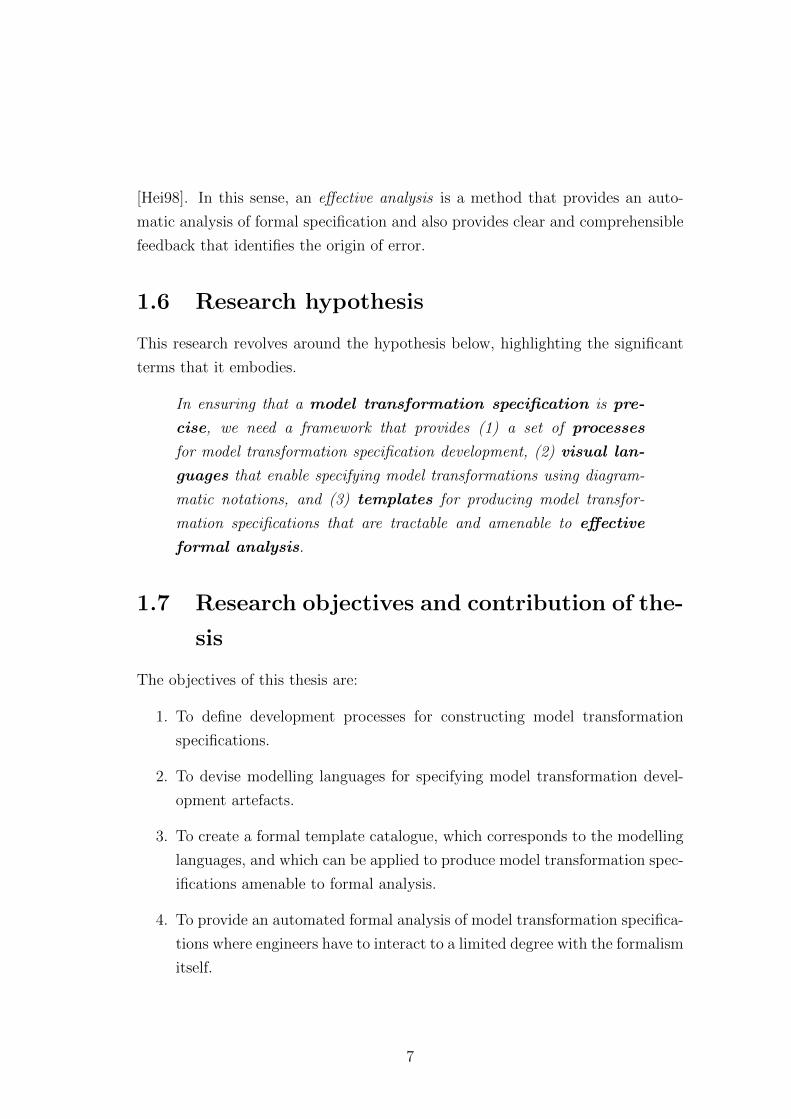
To answer our research questions and to address our hypothesis, we perform
three main activities: (1) domain reviews, (2) framework definition, and (3) ap-
plication, as depicted in Figure 1.1.
In domain review, we aim to understand what is a model transformation, and
what is its application environment. We also reviewed the current trends on anal-
ysis of model transformation. Based on this domain review and analysis, we define
our framework. This includes identifying the processes and components required
to develop and formally analyse model transformation specifications. We then
demonstrate our framework by applying it to a case study, a class-to-relational-
database model transformation. In this activity, we produce artefacts that allow
model transformation specifications to be represented, through structured steps
of eliciting requirements, defining a metamodel, and thereafter specifying the
transformation. We then formally analyse these artefacts via the application of
templates that generate formal specifications.
8
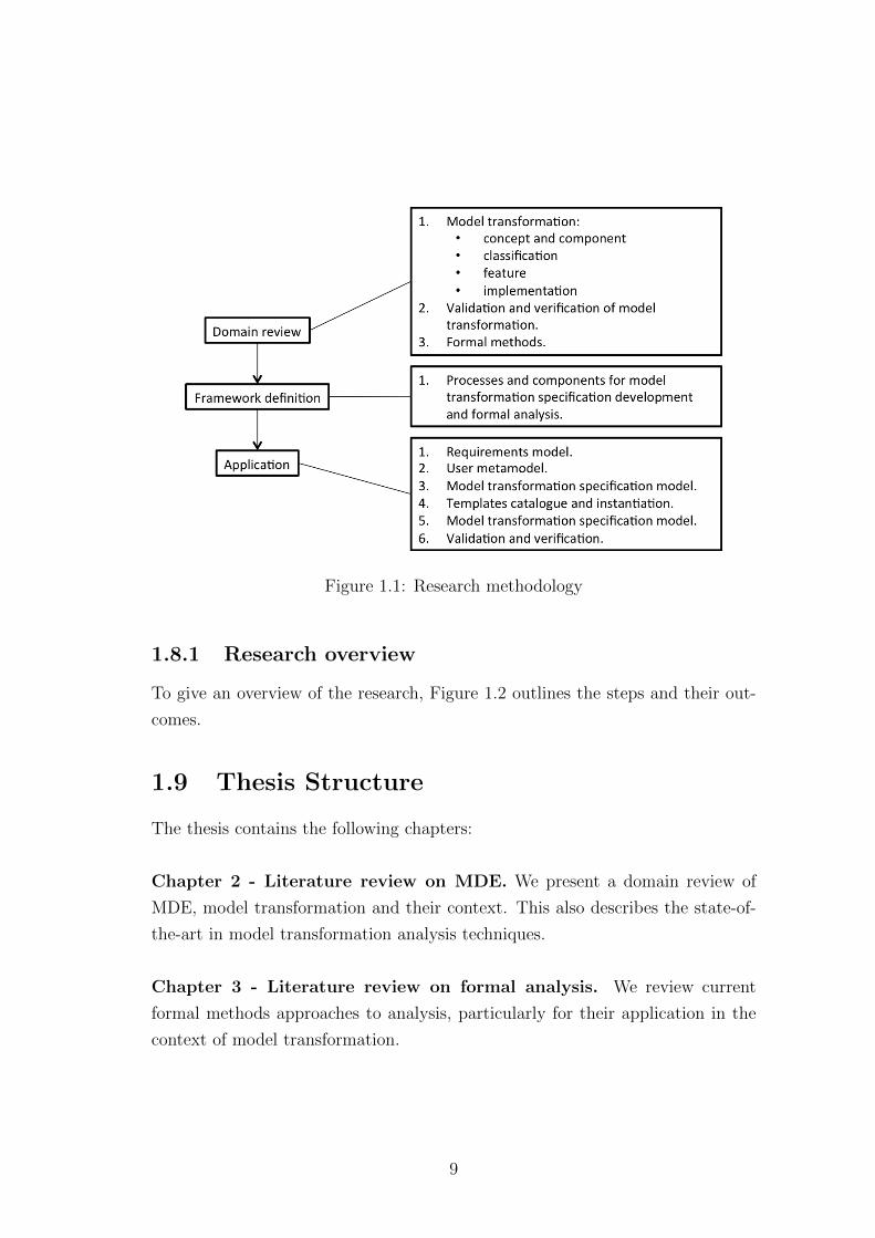
Figure 1.1: Research methodology
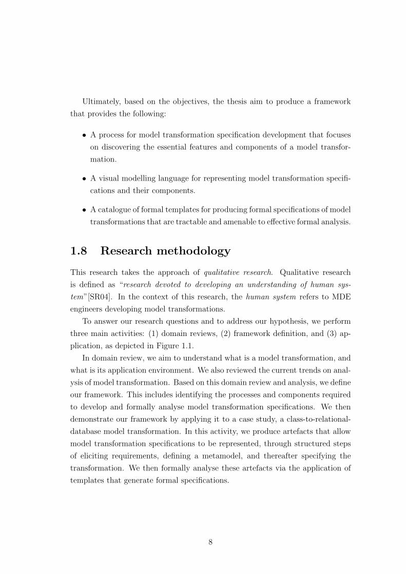
1.8.1 Research overview
To give an overview of the research, Figure 1.2 outlines the steps and their out-
comes.
1.9 Thesis Structure
The thesis contains the following chapters:
Chapter 2 - Literature review on MDE. We present a domain review of
MDE, model transformation and their context. This also describes the state-of-
the-art in model transformation analysis techniques.
Chapter 3 - Literature review on formal analysis. We review current
formal methods approaches to analysis, particularly for their application in the
context of model transformation.
9
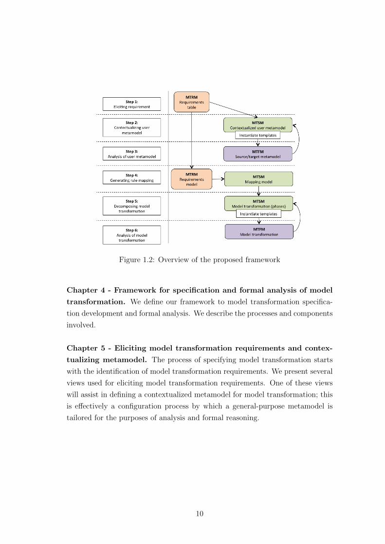
Figure 1.2: Overview of the proposed framework
Chapter 4 - Framework for specification and formal analysis of model
transformation. We define our framework to model transformation specifica-
tion development and formal analysis. We describe the processes and components
involved.
Chapter 5 - Eliciting model transformation requirements and contex-
tualizing metamodel. The process of specifying model transformation starts
with the identification of model transformation requirements. We present several
views used for eliciting model transformation requirements. One of these views
will assist in defining a contextualized metamodel for model transformation; this
is effectively a configuration process by which a general-purpose metamodel is
tailored for the purposes of analysis and formal reasoning.
10
Chapter 6 - Analysing metamodel. Once we have established a contextu-
alized metamodel, we can formally analyse the metamodel for correctness and
how well it is formed by instantiating templates that map the metamodel into a
formal specification.
Chapter 7 - Specifying and analysing model transformation. We show
how to specify model transformations that use the contextualized metamodel
as the source and target model. A requirements model is produced from the
requirements view; it is then used to generate a rule mapping model. Model
transformation phases are identified and the specification uses the rule defined in
the rule mapping model. The specification is then used to analyse model trans-
formation provided via template instantiations that produce formal specifications.
Chapter 8 - Applying and evaluating the TSP framework. To evaluate
the capability of our framework, we apply it to specify and analyse the class to
relational database model transformation.
Chapter 9 - Conclusion. To wrap up our work, we recap the approach. We
highlight the features of our framework and point out the advantages as well as
its limitations. We also discuss future work.
11
Chapter 2
Literature review on MDE
To understand how model transformation can be integrated with formal methods
for an automated analysis, we will review two major domains; (1) Model Driven
Engineering (MDE), which we will be covering in this chapter and, (2) formal
methods, presented in Chapter 3.
Model-Driven Engineering (MDE) is a software engineering approach that
uses models, metamodels and transformations as the key engineering artefacts.
Not only are the components different between MDE and conventional software
development, the processes used for producing the final product are also dissim-
ilar.
This chapter consist of two parts: (1) defines the relevant technologies that
underlie MDE; and (2) presents the challenges of analysis of model transforma-
tion, in parallel to understanding what is required for validation and verification
in the context of MDE. In Chapter 3, we present a review of formal methods and
formal analysis for model transformation. Besides getting to terms with the do-
main of this research, the outcomes of Chapter 2 and 3 determine the features of
our framework for specifying and analysing the model transformation presented
in Chapter 4.
This chapter contains the following main sections. Section 2.1 introduces
MDE and defines what is a model in the context of this research (Section 2.2).
This is followed by Section 2.3 and Section 2.4, where we review two significant
components of MDE; (1) metamodels, and (2) model transformations, respec-
tively. We describe two engineering approaches that define a development process
12
for model transformation in Section 2.5, followed by the model transformation
language definition, and scenarios of model transformation in Section 2.6 and 2.7.
We end the first part of this chapter with a brief introduction to MDE standards
and tools in Section 2.8. In the second part, we highlight the challenge regarding
analysis of model transformation implementation, in the context of MDE (Sec-
tion 2.10). The analysis will take on three perspectives: (1) model in Section 2.11;
(2) metamodel in Section 2.12; and (3) model transformation in Section 2.13. At
the end of the chapter (Section 2.16), we describe some of the challenges in MDE
with regards to the objective of the thesis.
2.1 Model Driven Engineering
Model-Driven Engineering (MDE) is a model centric software engineering ap-
proach to developing systems. It promotes the notion of a model, as its first
class engineering entity and the basis of producing the final product. According
to Bezivin [BBJ07], MDE provides the common and minimal set of fundamen-
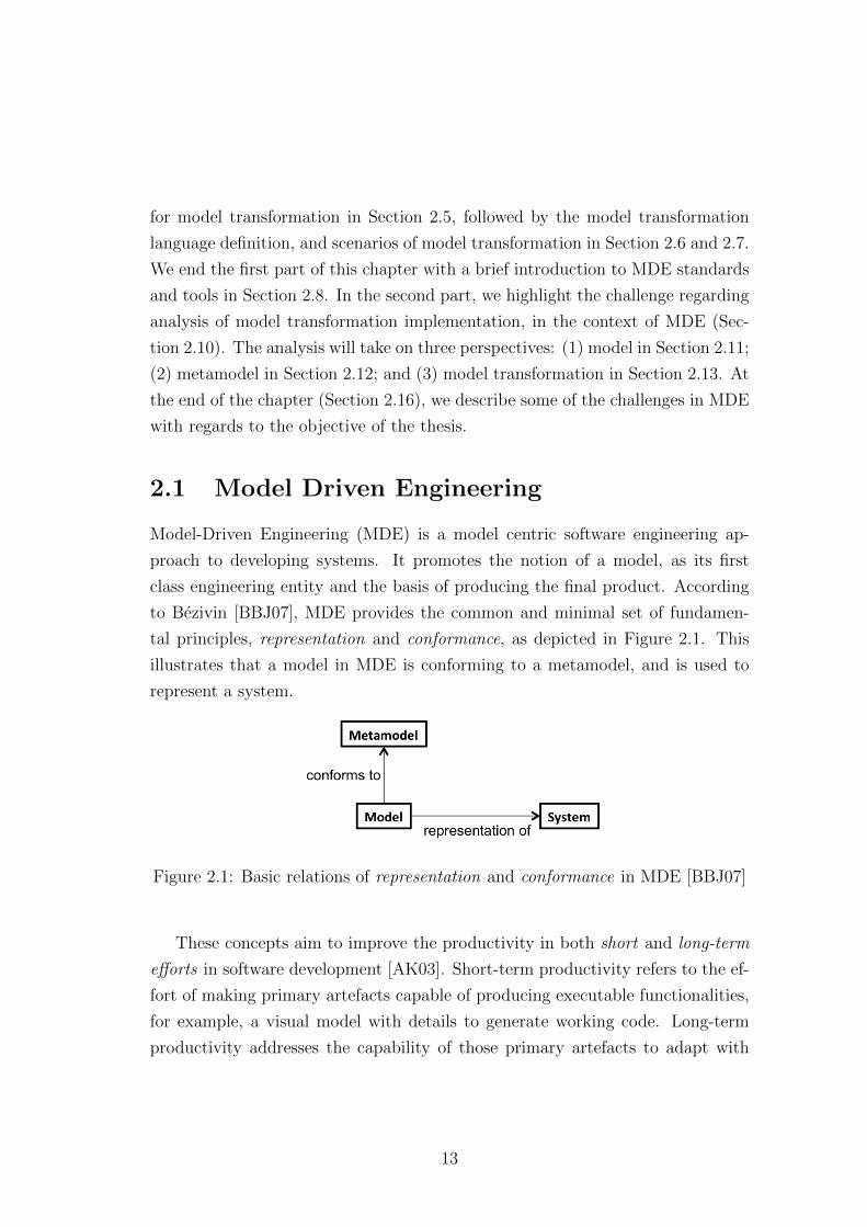
tal principles, representation and conformance, as depicted in Figure 2.1. This
illustrates that a model in MDE is conforming to a metamodel, and is used to
represent a system.
Figure 2.1: Basic relations of representation and conformance in MDE [BBJ07]
These concepts aim to improve the productivity in both short and long-term
efforts in software development [AK03]. Short-term productivity refers to the ef-
fort of making primary artefacts capable of producing executable functionalities,
for example, a visual model with details to generate working code. Long-term
productivity addresses the capability of those primary artefacts to adapt with
13
changes over time and situation, which includes: (1) technical knowledge of de-
velopment personnel; (2) changing of system requirements; (3) development tools
dependency; and (4) platform independent deployment [AK03].
To realize these potential productivity improvements, MDE introduces three
key concepts: (1) model; (2) metamodel; and (3) model transformation. In the
following sections, we define each of these more precisely.
2.2 Model
Models have long proven useful in engineering as a tool for representation. Such
representations are an abstraction of the subject matter. The Oxford Dictionary
defines model as:
noun 1 a three-dimensional representation of a person or thing,
typically on a smaller scale. 2 (in sculpture) a figure made in clay or
wax which is then reproduced in a more durable material. 3 something
used as an example. 4 a simplified mathematical description of a
system or process, used to assist calculations and predictions. 5 an
excellent example of a quality. 6 a person employed to display clothes
by wearing them. 7 a person employed to pose for an artist. 8 a
particular design or version of a product. [CS05]
Based on this definition, it is difficult to define what form models take, but it
is clear that a model can be identified according to the domain that it is being
applied to. In science, models play an important role in representing a particular
scientific theory. Bohr’s model of the atom, the evolutionary model in social
sciences, equilibrium models of markets in economics and the double-helix model
of DNA, are some of the many well-known domains that use a model as a mean
to represent real-world features in context [FH09].
In software engineering, building models has become an essential activity, par-
ticularly at the early stage of software development. Ludewig [Lud03], suggests
that software models can be descriptive, prescriptive or transient. A model is
descriptive if it mirrors the original object. If the model can be used as a spec-
ification of an object to be built, then it is a prescriptive model. A transient
14
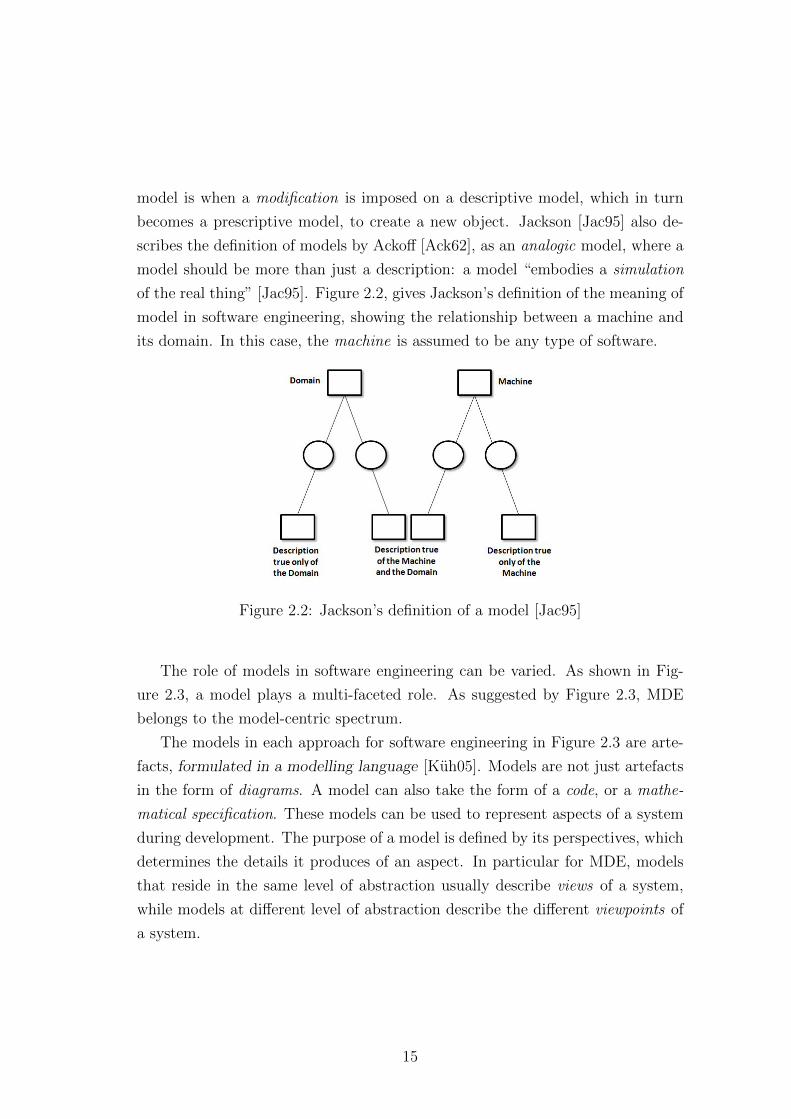
model is when a modification is imposed on a descriptive model, which in turn
becomes a prescriptive model, to create a new object. Jackson [Jac95] also de-
scribes the definition of models by Ackoff [Ack62], as an analogic model, where a
model should be more than just a description: a model “embodies a simulation
of the real thing” [Jac95]. Figure 2.2, gives Jackson’s definition of the meaning of
model in software engineering, showing the relationship between a machine and
its domain. In this case, the machine is assumed to be any type of software.
Figure 2.2: Jackson’s definition of a model [Jac95]
The role of models in software engineering can be varied. As shown in Fig-
ure 2.3, a model plays a multi-faceted role. As suggested by Figure 2.3, MDE
belongs to the model-centric spectrum.
The models in each approach for software engineering in Figure 2.3 are arte-
facts, formulated in a modelling language [Kuh05]. Models are not just artefacts
in the form of diagrams. A model can also take the form of a code, or a mathe-
matical specification. These models can be used to represent aspects of a system
during development. The purpose of a model is defined by its perspectives, which
determines the details it produces of an aspect. In particular for MDE, models
that reside in the same level of abstraction usually describe views of a system,
while models at different level of abstraction describe the different viewpoints of
a system.
15
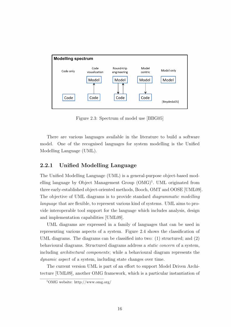
Figure 2.3: Spectrum of model use [BBG05]
There are various languages available in the literature to build a software
model. One of the recognised languages for system modelling is the Unified
Modelling Language (UML).
2.2.1 Unified Modelling Language
The Unified Modelling Language (UML) is a general-purpose object-based mod-
elling language by Object Management Group (OMG)1. UML originated from
three early-established object-oriented methods, Booch, OMT and OOSE [UML09].
The objective of UML diagrams is to provide standard diagrammatic modelling
language that are flexible, to represent various kind of systems. UML aims to pro-
vide interoperable tool support for the language which includes analysis, design
and implementation capabilities [UML09].
UML diagrams are expressed in a family of languages that can be used in
representing various aspects of a system. Figure 2.4 shows the classification of
UML diagrams. The diagrams can be classified into two: (1) structured; and (2)
behavioural diagrams. Structured diagrams address a static concern of a system,
including architectural components ; while a behavioural diagram represents the
dynamic aspect of a system, including state changes over time.
The current version UML is part of an effort to support Model Driven Archi-
tecture [UML09], another OMG framework, which is a particular instantiation of
1OMG website: http://www.omg.org/
16
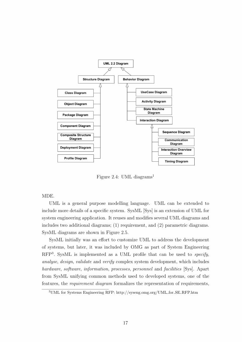
Figure 2.4: UML diagrams1
MDE.
UML is a general purpose modelling language. UML can be extended to
include more details of a specific system. SysML [Sys] is an extension of UML for
system engineering application. It reuses and modifies several UML diagrams and
includes two additional diagrams; (1) requirement, and (2) parametric diagrams.
SysML diagrams are shown in Figure 2.5.
SysML initially was an effort to customize UML to address the development
of systems, but later, it was included by OMG as part of System Engineering
RFP3. SysML is implemented as a UML profile that can be used to specify,
analyse, design, validate and verify complex system development, which includes
hardware, software, information, processes, personnel and facilities [Sys]. Apart
from SysML unifying common methods used to developed systems, one of the
features, the requirement diagram formalizes the representation of requirements,
3UML for Systems Engineering RFP: http://syseng.omg.org/UML for SE RFP.htm
17
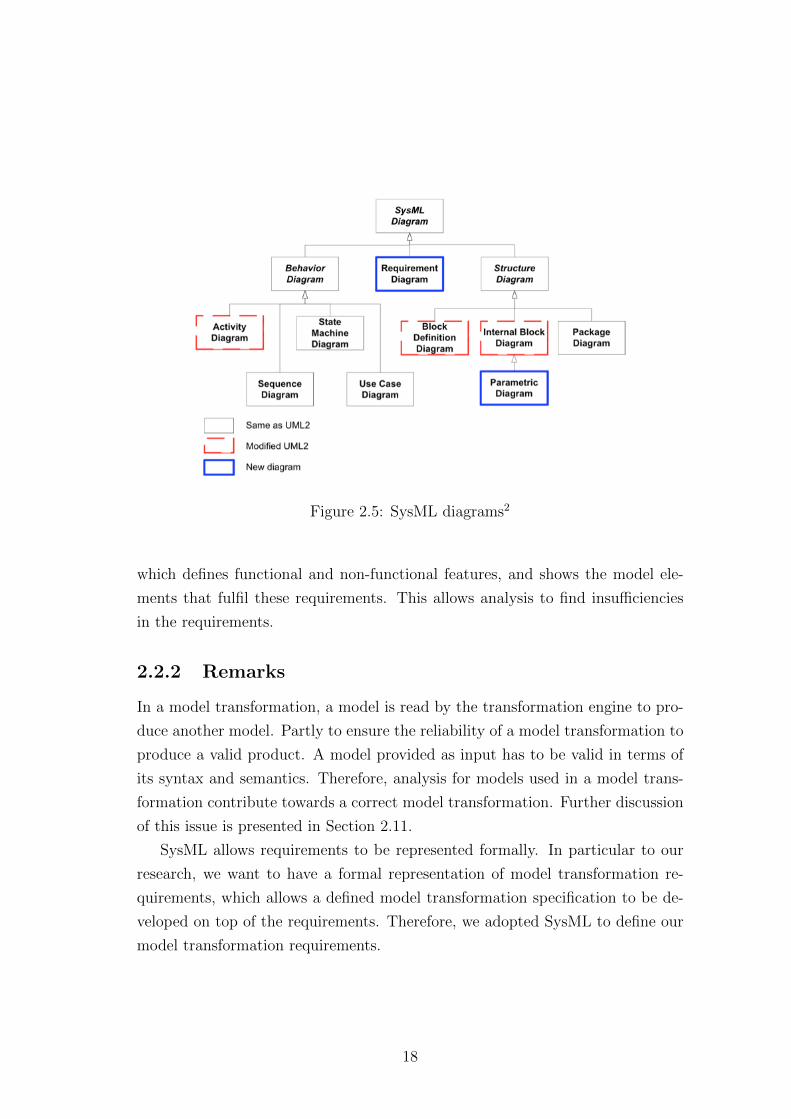
Figure 2.5: SysML diagrams2
which defines functional and non-functional features, and shows the model ele-
ments that fulfil these requirements. This allows analysis to find insufficiencies
in the requirements.
2.2.2 Remarks
In a model transformation, a model is read by the transformation engine to pro-
duce another model. Partly to ensure the reliability of a model transformation to
produce a valid product. A model provided as input has to be valid in terms of
its syntax and semantics. Therefore, analysis for models used in a model trans-
formation contribute towards a correct model transformation. Further discussion
of this issue is presented in Section 2.11.
SysML allows requirements to be represented formally. In particular to our
research, we want to have a formal representation of model transformation re-
quirements, which allows a defined model transformation specification to be de-
veloped on top of the requirements. Therefore, we adopted SysML to define our
model transformation requirements.
18
In MDE, models are often a user defined model that is developed using a
Domain Specific Modelling Language (DSML). A DSML is a language that defines
a concrete syntax. In the next section, we are going to see how a metamodel is
used to give a formal definition to model.
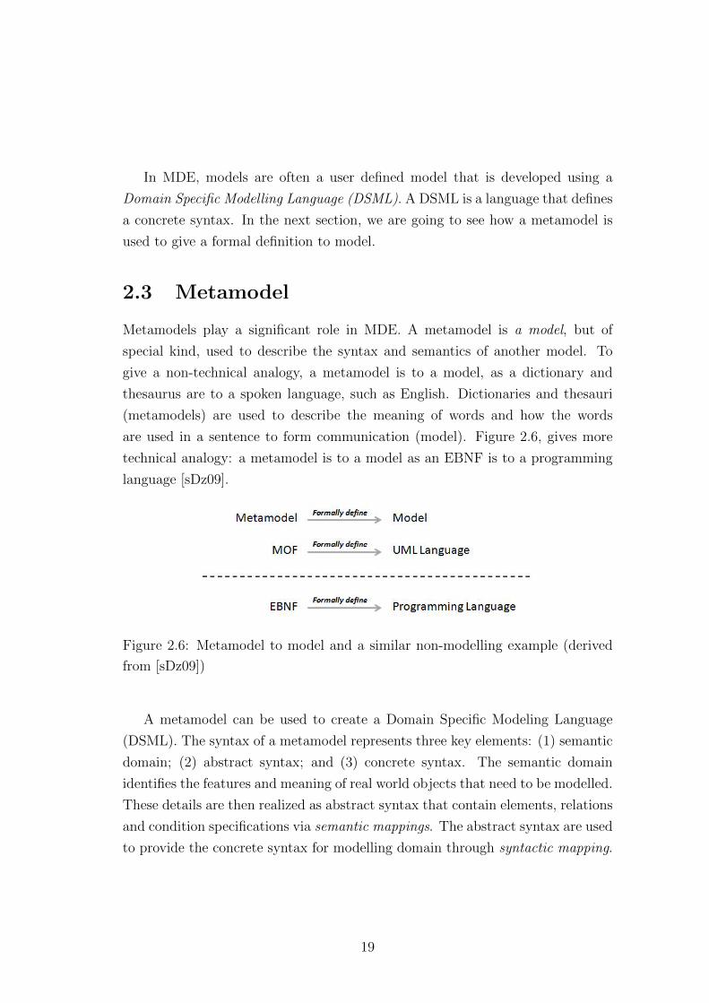
2.3 Metamodel
Metamodels play a significant role in MDE. A metamodel is a model, but of
special kind, used to describe the syntax and semantics of another model. To
give a non-technical analogy, a metamodel is to a model, as a dictionary and
thesaurus are to a spoken language, such as English. Dictionaries and thesauri
(metamodels) are used to describe the meaning of words and how the words
are used in a sentence to form communication (model). Figure 2.6, gives more
technical analogy: a metamodel is to a model as an EBNF is to a programming
language [sDz09].
Figure 2.6: Metamodel to model and a similar non-modelling example (derived
from [sDz09])
A metamodel can be used to create a Domain Specific Modeling Language
(DSML). The syntax of a metamodel represents three key elements: (1) semantic
domain; (2) abstract syntax; and (3) concrete syntax. The semantic domain
identifies the features and meaning of real world objects that need to be modelled.
These details are then realized as abstract syntax that contain elements, relations
and condition specifications via semantic mappings. The abstract syntax are used
to provide the concrete syntax for modelling domain through syntactic mapping.
19
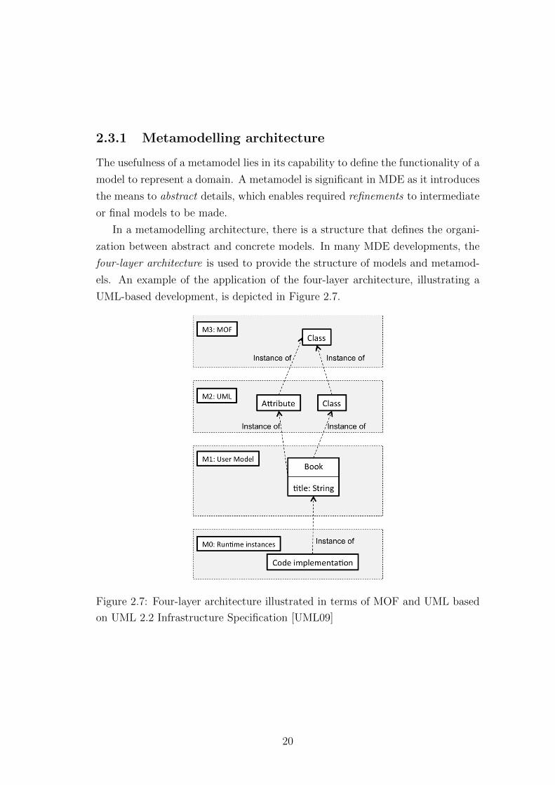
2.3.1 Metamodelling architecture
The usefulness of a metamodel lies in its capability to define the functionality of a
model to represent a domain. A metamodel is significant in MDE as it introduces
the means to abstract details, which enables required refinements to intermediate
or final models to be made.
In a metamodelling architecture, there is a structure that defines the organi-
zation between abstract and concrete models. In many MDE developments, the
four-layer architecture is used to provide the structure of models and metamod-
els. An example of the application of the four-layer architecture, illustrating a
UML-based development, is depicted in Figure 2.7.
Figure 2.7: Four-layer architecture illustrated in terms of MOF and UML based
on UML 2.2 Infrastructure Specification [UML09]
20
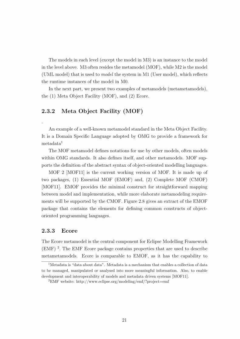
The models in each level (except the model in M3) is an instance to the model
in the level above. M3 often resides the metamodel (MOF), while M2 is the model
(UML model) that is used to model the system in M1 (User model), which reflects
the runtime instances of the model in M0.
In the next part, we present two examples of metamodels (metametamodels),
the (1) Meta Object Facility (MOF), and (2) Ecore.
2.3.2 Meta Object Facility (MOF)
.
An example of a well-known metamodel standard in the Meta Object Facility.
It is a Domain Specific Language adopted by OMG to provide a framework for
metadata1
The MOF metamodel defines notations for use by other models, often models
within OMG standards. It also defines itself, and other metamodels. MOF sup-
ports the definition of the abstract syntax of object-oriented modelling languages.
MOF 2 [MOF11] is the current working version of MOF. It is made up of
two packages, (1) Essential MOF (EMOF) and, (2) Complete MOF (CMOF)
[MOF11]. EMOF provides the minimal construct for straightforward mapping
between model and implementation, while more elaborate metamodeling require-
ments will be supported by the CMOF. Figure 2.8 gives an extract of the EMOF
package that contains the elements for defining common constructs of object-
oriented programming languages.
2.3.3 Ecore
The Ecore metamodel is the central component for Eclipse Modelling Framework
(EMF) 2. The EMF Ecore package contains properties that are used to describe
metametamodels. Ecore is comparable to EMOF, as it has the capability to
1Metadata is “data about data”. Metadata is a mechanism that enables a collection of data
to be managed, manipulated or analysed into more meaningful information. Also, to enable
development and interoperability of models and metadata driven systems [MOF11].2EMF website: http://www.eclipse.org/modeling/emf/?project=emf
21
Figure 2.8: The Essential MOF (EMOF) classes [MOF11]
define common concepts of object-oriented programming language. Figure 2.9
shows the hierarchy of classes in the Ecore package.
2.3.4 Remarks
Metamodels achieve interoperability by providing common constructs for specify-
ing modelling languages. MOF and Ecore are two standard metamodels (metameta-
model) used for defining object-oriented modelling languages and implementa-
tion.
One issue for transformation is the characteristics of the metamodel that
defines the model to be transformed. They can be a model with: (1) huge meta-
model; (2) readily-available metamodel; and (3) non-existent metamodel.
22
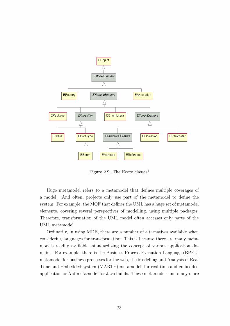
Figure 2.9: The Ecore classes1
Huge metamodel refers to a metamodel that defines multiple coverages of
a model. And often, projects only use part of the metamodel to define the
system. For example, the MOF that defines the UML has a huge set of metamodel
elements, covering several perspectives of modelling, using multiple packages.
Therefore, transformation of the UML model often accesses only parts of the
UML metamodel.
Ordinarily, in using MDE, there are a number of alternatives available when
considering languages for transformation. This is because there are many meta-
models readily available, standardizing the concept of various application do-
mains. For example, there is the Business Process Execution Language (BPEL)
metamodel for business processes for the web, the Modelling and Analysis of Real
Time and Embedded system (MARTE) metamodel, for real time and embedded
application or Ant metamodel for Java builds. These metamodels and many more
23
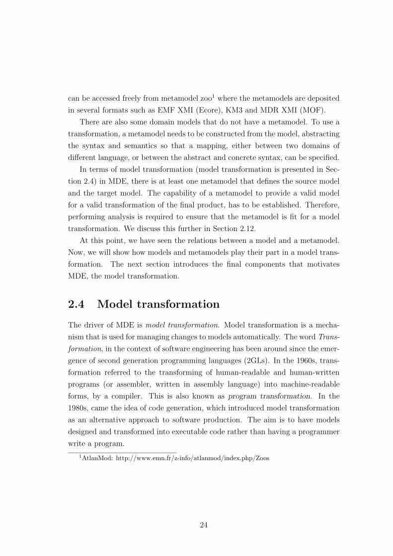
can be accessed freely from metamodel zoo1 where the metamodels are deposited
in several formats such as EMF XMI (Ecore), KM3 and MDR XMI (MOF).
There are also some domain models that do not have a metamodel. To use a
transformation, a metamodel needs to be constructed from the model, abstracting
the syntax and semantics so that a mapping, either between two domains of
different language, or between the abstract and concrete syntax, can be specified.
In terms of model transformation (model transformation is presented in Sec-
tion 2.4) in MDE, there is at least one metamodel that defines the source model
and the target model. The capability of a metamodel to provide a valid model
for a valid transformation of the final product, has to be established. Therefore,
performing analysis is required to ensure that the metamodel is fit for a model
transformation. We discuss this further in Section 2.12.
At this point, we have seen the relations between a model and a metamodel.
Now, we will show how models and metamodels play their part in a model trans-
formation. The next section introduces the final components that motivates
MDE, the model transformation.
2.4 Model transformation
The driver of MDE is model transformation. Model transformation is a mecha-
nism that is used for managing changes to models automatically. The word Trans-
formation, in the context of software engineering has been around since the emer-
gence of second generation programming languages (2GLs). In the 1960s, trans-
formation referred to the transforming of human-readable and human-written
programs (or assembler, written in assembly language) into machine-readable
forms, by a compiler. This is also known as program transformation. In the
1980s, came the idea of code generation, which introduced model transformation
as an alternative approach to software production. The aim is to have models
designed and transformed into executable code rather than having a programmer
write a program.
1AtlanMod: http://www.emn.fr/z-info/atlanmod/index.php/Zoos
24
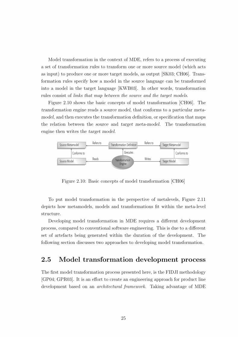
Model transformation in the context of MDE, refers to a process of executing
a set of transformation rules to transform one or more source model (which acts
as input) to produce one or more target models, as output [SK03; CH06]. Trans-
formation rules specify how a model in the source language can be transformed
into a model in the target language [KWB03]. In other words, transformation
rules consist of links that map between the source and the target models.
Figure 2.10 shows the basic concepts of model transformation [CH06]. The
transformation engine reads a source model, that conforms to a particular meta-
model, and then executes the transformation definition, or specification that maps
the relation between the source and target meta-model. The transformation
engine then writes the target model.
Figure 2.10: Basic concepts of model transformation [CH06]
To put model transformation in the perspective of metalevels, Figure 2.11
depicts how metamodels, models and transformations fit within the meta-level
structure.
Developing model transformation in MDE requires a different development
process, compared to conventional software engineering. This is due to a different
set of artefacts being generated within the duration of the development. The
following section discusses two approaches to developing model transformation.
2.5 Model transformation development process
The first model transformation process presented here, is the FIDJI methodology
[GP04; GPR03]. It is an effort to create an engineering approach for product line
development based on an architectural framework. Taking advantage of MDE
25
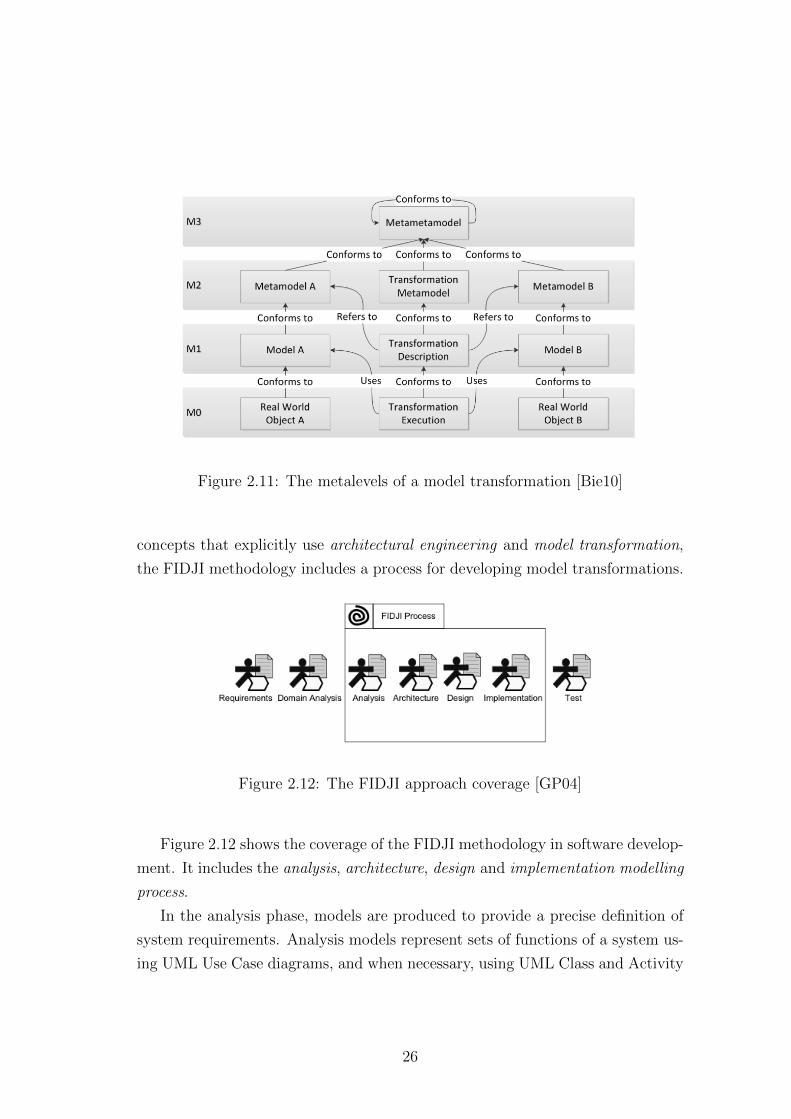
Figure 2.11: The metalevels of a model transformation [Bie10]
concepts that explicitly use architectural engineering and model transformation,
the FIDJI methodology includes a process for developing model transformations.
Figure 2.12: The FIDJI approach coverage [GP04]
Figure 2.12 shows the coverage of the FIDJI methodology in software develop-
ment. It includes the analysis, architecture, design and implementation modelling
process.
In the analysis phase, models are produced to provide a precise definition of
system requirements. Analysis models represent sets of functions of a system us-
ing UML Use Case diagrams, and when necessary, using UML Class and Activity
26
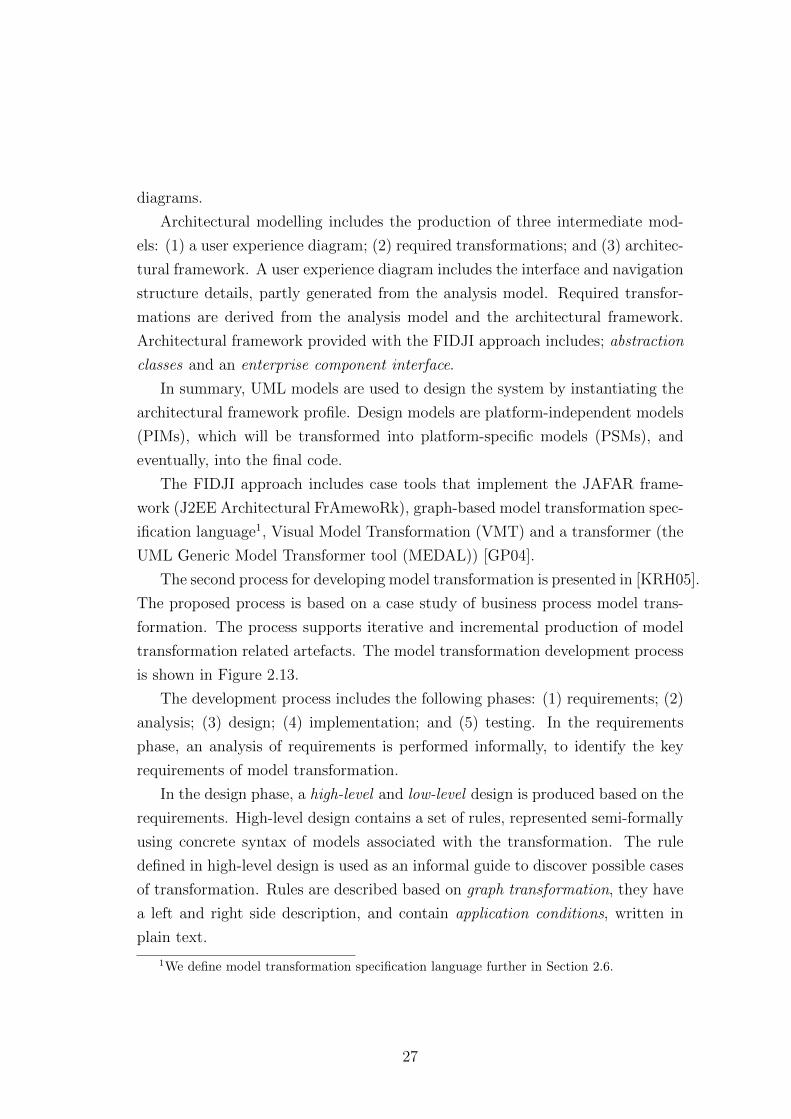
diagrams.
Architectural modelling includes the production of three intermediate mod-
els: (1) a user experience diagram; (2) required transformations; and (3) architec-
tural framework. A user experience diagram includes the interface and navigation
structure details, partly generated from the analysis model. Required transfor-
mations are derived from the analysis model and the architectural framework.
Architectural framework provided with the FIDJI approach includes; abstraction
classes and an enterprise component interface.
In summary, UML models are used to design the system by instantiating the
architectural framework profile. Design models are platform-independent models
(PIMs), which will be transformed into platform-specific models (PSMs), and
eventually, into the final code.
The FIDJI approach includes case tools that implement the JAFAR frame-
work (J2EE Architectural FrAmewoRk), graph-based model transformation spec-
ification language1, Visual Model Transformation (VMT) and a transformer (the
UML Generic Model Transformer tool (MEDAL)) [GP04].
The second process for developing model transformation is presented in [KRH05].
The proposed process is based on a case study of business process model trans-
formation. The process supports iterative and incremental production of model
transformation related artefacts. The model transformation development process
is shown in Figure 2.13.
The development process includes the following phases: (1) requirements; (2)
analysis; (3) design; (4) implementation; and (5) testing. In the requirements
phase, an analysis of requirements is performed informally, to identify the key
requirements of model transformation.
In the design phase, a high-level and low-level design is produced based on the
requirements. High-level design contains a set of rules, represented semi-formally
using concrete syntax of models associated with the transformation. The rule
defined in high-level design is used as an informal guide to discover possible cases
of transformation. Rules are described based on graph transformation, they have
a left and right side description, and contain application conditions, written in
plain text.
1We define model transformation specification language further in Section 2.6.
27
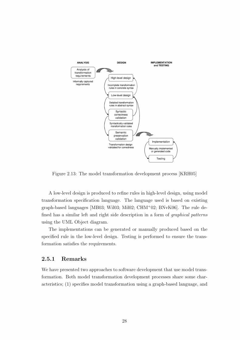
Figure 2.13: The model transformation development process [KRH05]
A low-level design is produced to refine rules in high-level design, using model
transformation specification language. The language used is based on existing
graph-based languages [MB03; Wil03; Mil02; CHM+02; BNvK06]. The rule de-
fined has a similar left and right side description in a form of graphical patterns
using the UML Object diagram.
The implementations can be generated or manually produced based on the
specified rule in the low-level design. Testing is performed to ensure the trans-
formation satisfies the requirements.
2.5.1 Remarks
We have presented two approaches to software development that use model trans-
formation. Both model transformation development processes share some char-
acteristics; (1) specifies model transformation using a graph-based language, and
28
(2) implementation specific development, which uses UML models and UML-
supported technology.
In terms of analysis of model transformation, both approaches support this
feature differently. The analysis ensures that the transformation developed in the
approach fulfils the requirements. The following describes the analysis methods
by both approaches:
• The VMT used in FIDJI can be expressed in terms of graph transforma-
tion rules, which gives the language a formal semantics [SPGB03]. The rule
ordering features in VMT enables model transformation to be defined in
terms of chains of smaller transformations. Which therefore allows proper-
ties such as termination and confluence to be checked [SPGB03].
• Validation of syntactic correctness and semantic preservation is conducted
manually in the low-level design through inspection of the specifications
[KRH05]. Further testing is performed after implementation.
We present a more comprehensive review on model transformation analysis in
Section 2.13.
In both of the model transformation development processes presented in this
section, there were phases focusing on dealing with how a model transformation
specification is produced to represent the rules required in a transformation. In
the next section, we define what is a model transformation specification.
2.6 Model transformation specification
When we look again at the metalevel of model transformation in Figure 2.11, the
transformation description (or transformation definition in Figure 2.10) can also
be known as model transformation specification.
A model transformation specification is represented using a domain specific
modelling language for defining model transformation. The language provides
syntax and semantics specialised for defining transformation mappings between
the source and target models. There are several model transformation specifica-
tion languages, not only able to specify, but can also be executed by a transforma-
tion engine. To distinguish between an executable and a non-executable model
29
transformation specification language, a model transformation language refers to
an executable model transformation specification.
Non-executable model transformation specification language shares the same
classification as an executable model transformation language. An example of
non-executable specification language includes, The Bidirectional Object Ori-
ented Transformation Language (BOTL) [BM03], Visual Model Transformation
(VMT) [SPGB03] and Extended UML Object Diagram [Mil02]. Model transfor-
mation specification language can be categorized into three major paradigms, (1)
declarative, (2) imperative and, (3) hybrid model transformation language.
Declarative languages . Declarative model transformation specification lan-
guages describe what a transformation should do, without considering how it
should be done. Examples of declarative model transformation language are Fu-
jaba1, Tefkat [LS06] and QVT-Relations [QVT08].
Imperative languages . Imperative model transformation specification lan-
guages can also be known as procedural or operational languages. Examples
of imperative model transformation languages are MOLA [KCS05] and SiTRa
[ABE+06].
Hybrid languages. Hybrid model transformation specification languages sup-
port both declarative and imperative features. Some examples of hybrid model
transformation language are Epsilon Transformation Language (ETL)2, Atlas
Transformation Language (ATL) [JABK08] and Graph Rewriting and Transfor-
mation (GReAT)3.
Czarnecki and Helson in [CH06] further define model transformation language
into: (1) direct manipulation; (2) structure driven; (3) template-based; (4) re-
lational; and (5) graph-based. As a result, model transformation languages can
1Fujaba: http://www.fujaba.de/2Epsilon ransformation Language: http://www.eclipse.org/epsilon/3GReAT: http://www.isis.vanderbilt.edu/tools/GReAT
30
belong to several categories, for example, QVT-Relation is a declarative - rela-
tional type, SiTRa is an imperative - direct manipulation type; and GReAT is a
hybrid - graph-based type model transformation language.
Some of the languages are supported by a common platform. For example,
Tefkat, ATL and ETL can be developed within the Eclipse Modelling Framework.
One of the objectives of this thesis is to use visual notation to represent model
transformation specification. The following section discusses current graphical
model transformation specification.
2.6.1 Graphical model transformation specification
Model transformation specification language can be textual or graphical. Cur-
rently, much of the language for model transformation is textual, while there
are only a few graphical languages for model transformation. The most promi-
nent are often based on graph languages such as Fujaba, GReAT and transML
[GdLK+10]. This is due to the capability of these languages to use the formalism
underlying graph theory to produce a well-formed transformation.
There are other graphical languages that are not based on graph theory.
For example, MOLA [KCS05] defines model transformation using structured
flowcharts, mimicking structured programming languages. [RM08] proposes a
notation that has a similar definition to model weaving, providing concrete syn-
tax and general well-formedness rules of a transformation. But their notation
still requires a textual description for specifying the mappings and actions of a
transformation.
Model transformation specification can described as different model transfor-
mation scenarios, as presented in the following section.
2.7 Model transformation scenarios
Model transformation can be categorized into several scenarios: (1) model-to-
model (M2M); (2) model-to-text (M2T); (3) text-to-model (T2M); and (3) text-
to-text (T2T) transformation. An M2M takes a model and transforms it into
another model, perhaps a model at another level of abstraction (or sometimes
31
called a refinement) or a model at the same level of abstraction (for example
UML Sequence Diagram to UML Statechart1). A M2T transformation produces
text; a concrete example is code generation. Code can be in the form of, (1)
programming language such as Java or C++2, or (2) formal specification, such as
UML to CSP [BN04]. A T2M transformation is concerned with parsing and the
reverse engineering domain; while T2T transformation can be used for generating
reports.
Other model transformation scenarios that are worth noting, are model syn-
chronization, conformance checking and update-in-place [JK07]. Model synchro-
nization allows any changes between two models to be made according to a pre-
defined relation, while conformance checking enables two models to be compared,
based on a set of relations without changing the models. Update-in-place trans-
formation changes elements within the same model, for example, in model re-
factoring.
To define the scenarios in terms of their location in the four-layer architec-
ture presented in Subsection 2.3.1, models taking part in a model transformation
could reside in the same, or different level of abstraction. The models could
share the same metamodel or they could come from different metamodels. The
model transformation, according to the model locations and metamodels, can be
distinguished into the following [MG06]:
• Endogenous
• Exogenous
• Vertical
• Horizontal
Figure 2.14 summarises the characteristics of these model transformations in
the four-layer architecture. Endogenous and exogenous transformation involves
transformation between models within the same level of abstraction; endogenous
involves models of the same language, while exogenous involves models of differ-
ent languages. Endogenous can also be dubbed as rephrasing, and exogenous as
1ATL transformation zoo: http://www.eclipse.org/atl/atlTransformations/2Rational System Developer: http://www-01.ibm.com
32
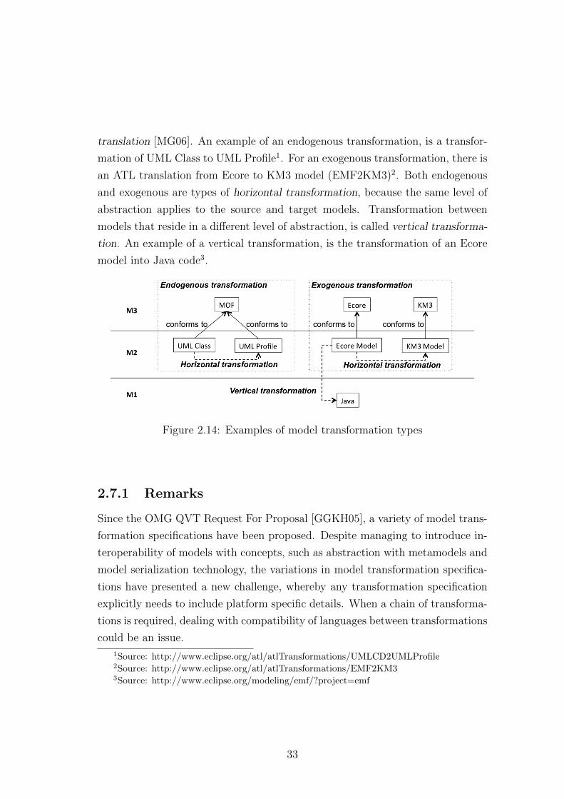
translation [MG06]. An example of an endogenous transformation, is a transfor-
mation of UML Class to UML Profile1. For an exogenous transformation, there is
an ATL translation from Ecore to KM3 model (EMF2KM3)2. Both endogenous
and exogenous are types of horizontal transformation, because the same level of
abstraction applies to the source and target models. Transformation between
models that reside in a different level of abstraction, is called vertical transforma-
tion. An example of a vertical transformation, is the transformation of an Ecore
model into Java code3.
Figure 2.14: Examples of model transformation types
2.7.1 Remarks
Since the OMG QVT Request For Proposal [GGKH05], a variety of model trans-
formation specifications have been proposed. Despite managing to introduce in-
teroperability of models with concepts, such as abstraction with metamodels and
model serialization technology, the variations in model transformation specifica-
tions have presented a new challenge, whereby any transformation specification
explicitly needs to include platform specific details. When a chain of transforma-
tions is required, dealing with compatibility of languages between transformations
could be an issue.
1Source: http://www.eclipse.org/atl/atlTransformations/UMLCD2UMLProfile2Source: http://www.eclipse.org/atl/atlTransformations/EMF2KM33Source: http://www.eclipse.org/modeling/emf/?project=emf
33
Another issue is with regarding graphical model transformation specification
languages that are often based on graph theory. Despite the fact that visual
modelling provides a clearer representation, hence ease of comprehension, with a
graph-based model, it introduces some level of complexity, partly due to the differ-
ent concepts (eg. graph rewriting) as compared to common modelling language
for programming. Instead, a non-graph-based model transformation language
such as ETL, which resembles programming concepts, arguably, seems to be more
accepted. This can be seen through a better tool support for non-graph-based
language such as ETL. This allows a quick knowledge transfer for the developer
when migrating to MDE.
In terms of analysis of model transformation specifications, there are two
common approaches: (1) producing a mathematical-based model transformation
specification and manually proving the properties; and (2) implementing an exe-
cutable model transformation specification to enable tool supported analysis, such
as testing. We describe analysis of model transformation specification further in
Section 2.13.
At this point, we have established what is a model, metamodel and model
transformation; and how these components play a part in implementing the MDE.
In the final section on MDE, we briefly present several of the standards and tools
that implement MDE.
2.8 MDE standards and tools
Model-Driven Architecture (MDA), a second framework adopted by Object Man-
agement Group (OMG) [MDA03], is a standardized instance of MDE. MDA high-
lights the concept of MDE by introducing the five key concepts of: (1) viewpoints;
(2) Platform-Independent Model (PIM); (3) Computational Independent Model
(CIM); (4) Platform-Specific Model (PSM); and (5) model transformation.
Model Integrated Computing (MIC) provided an implementation of MDE.
MIC is created for complex, safety-critical systems [Dav02] and uses the Multi-
graph Architecture (MGA) framework[SK97]. MIC introduces the computational
process of a system via integrated, multiple-view models that enable character-
istics of a system, such as: (1) information processing; (2) physical architecture
34
features; and (3) operational features, to be captured. To provide a configurable
modelling environment, MGA framework implements the Generic Modelling En-
vironment, which provides a suite of tools for development [LMB+01].
Microsoft’s Software Factory (SF)1 is another example of MDE standards,
which focuses on product line development [GSC+04]. SF has a component
called the software schema that captures the domain knowledge of a product
family. Software schema is defined as graph viewpoints that contain information
for producing product members. Each viewpoint generates a model editor for
building models that can be translated into, (1) executable code, or (2) speci-
fication of lower level of abstraction. A collection of patterns are derived from
these, which are stored as software templates for when it is loaded into an IDE,
such as Microsoft’s Visual Studio. It is kept as a software factory to be used for
developing product members.
2.9 Remarks
We have reviewed the key aspects of MDE; its key components, implementations
and processes. The argued benefits of adopting MDE in performing software de-
velopment can be summarized as the following:
Tool interoperability. Tool interoperability is concerned with allowing arte-
facts to be used in different tool platforms. Metamodel, model and model seri-
alization technology allows model transformation artefacts to be performed on
multiple platforms. For example, the MOF metamodel, can be used to define an
object-oriented language such as UML, and XMI as a metadata interchange that
enables a UML model to be used with different UML-based modelling tools.
Artefact reusability. The application of abstraction and refinement potentially
allows artefacts to be reused in multiple settings. Artefacts such as a domain
metamodel and a system model, could potentially be reused in different projects,
1MSDN Website - Visual Studio 2010: http://msdn.microsoft.com
35
provided they are compatible with the requirements.
In the second part of the chapter, we look specifically at how analysis of
models, metamodels and transformations are done in the context of MDE.
2.10 Analysis in MDE
To recap, our motivation for this thesis is to accommodate the formal analysis of
the model transformation specifications. The major challenges in implementing
MDE, as presented in [FR07], can generally be classified as follows:
Modelling language challenges including those related to support for creat-
ing and using problem-level abstractions, or domain concepts, and for analysing
models.
Separation of concerns challenges including the use of multiple, sometimes
overlapping viewpoints, using possibly different languages.
Model manipulation and management challenges which focus on the ca-
pabilities of MDE tools to manage and manipulate MDE artefacts. For example,
(1) defining, analysing, and using model transformations; (2) maintaining trace-
ability links between model elements to support model evolution and round-trip
engineering; (3) maintaining consistency between viewpoints; (4) tracking ver-
sions; and (5) using models during runtime.
A reliable implementation is one that adequately satisfies a set of requirements
established early in the development. The reliability of an implementation of any
software project depends on the fitness of artefacts produced during development.
These artefacts can be analysed, either in a specific phase, i.e. after an integration
or a version of implementation, or on individual artefacts after they have been
produced. In the context of MDE, artefacts are strongly related; faults and
errors may originate from the metamodel, model or the model transformation.
36
This outlines the needs for analysis of each of the artefacts in an effort to catch
any anomalies at an individual phase of the development.
The analysis activity can be varied, depending on the types of artefact, but
generally, it is in the form of validation, verification or testing. Here, we use Balci’s
definitions of validation, verification and testing, in the context of modelling and
simulation [Bal98]:
“Model Verification is substantiating that the model is transformed
from one form into another, as intended, with sufficient accuracy. [..]
Model Validation is substantiating that the model, within its do-
main of applicability, behaves with satisfactory accuracy consistent
with the modelling and simulation objectives. [..] Model Testing is
ascertaining whether inaccuracies or errors exist in the model.”[Bal98]
We used these definitions to classify the validation, verification and testing in
the context of MDE, due to the fact that it was formulated especially for mod-
elling, simulation, and model transformation. To extend the our understanding
of what needs to be done to ensure a fit model transformation, we have also
classified the perspectives into three, (1) model analysis, (2) metamodel analysis,
and (3) model transformation analysis.
2.11 Analysis of models
MDE relies on the concept of abstractions, defining the separation of concerns to
describe a system. This is done using models to represent the different viewpoints
in the domain. A precise model not only represents the intended system correctly,
but also prepares a valid model to be used or generated in a transformation.
As defined early in the chapter, models in MDE can be in the form of a dia-
gram, code or mathematical specification. The issue with analysing these models
is no different to how they are analysed when used in other kinds of develop-
ment. Models in MDE are used as an input, or generated as the output of a
model transformation. Models needs to satisfy the system requirements. This
37
should not be confused with the transformation requirements ; transformation re-
quirements define the transformation features that enables models to satisfy the
system requirements, to be used or generated by a model transformation.
Here, we focused on analysis of diagrammatic models. Diagrammatic models
or visual models in MDE can be, but not necessarily, object-oriented (OO). In
terms of design analysis of an OO model, this can be generally categorized into:
(1) understanding of the problem domain; (2) identifying the requirements; (3)
including scalability and adaptability; and (4) encouraging reuse [CY91].
While through these processes, models should be sufficient to represent a valid
instance, we may need to perform further analysis to ensure the well-formedness
and correctness of models to represents the whole universe of instances.
To verify a model is accurate for all known instances, it must be validated
that the model satisfies the system requirements, or tested to see if any anomalies
exist in the model. In addition, two consistency aspects of models have to be
evaluated, (1) static, and (2) dynamic features. In terms of static feature analysis,
consistency refers to the well-formedness of relations between object classes, while
dynamic features are concerned with states and sequences of interactions between
object classes [RW03].
Diagrammatic notations such as UML have an auxiliary construct, the OCL
[WK03], that helps further refine the well-formedness constraint on models using
textual expressions. OCL incorporates rules and assertions, such as preconditions,
postconditions and invariants in UML models [BC06], to precisely specify the
semantics of objects. Due to this, various work has been done to perform analysis
on UML models using OCL. In some this is done by translating them into formal,
mathematical-based languages to allow them to be computed for analysis [BC06;
CCGdL09; KFdB+05; ABGR10]. While some other analyses of UML models, are
supported by tools1, which provide an automated analysis of the consistency of
models through constraint, for example, identifying any violation of constraint
that results in an non-existent model or semantically incorrect model.
In the larger context of MDE, models are one of the components that con-
tribute to production of the final product during transformations. Ensuring that
1Reational Software Architect: http://www.ibm.com/developerworks/rational/products/rsa/
38
models are a valid and sufficient representation of a domain, should eliminate the
first source of faults and errors in a transformation.
Analysing a model in MDE includes making sure that it is conforming to its
metamodels. In the next section, we presents the analysis of a metamodel, for
providing the formal support for models, to produce a fit input and output model
in a transformation.
2.12 Analysis of metamodels
A metamodel is a special kind of model that provides the syntax and semantics
for another model. In MDE, metamodels contain elements and properties that
define the input and output models of a transformation. These elements and
properties are used in mapping the transformation relations between the source
and target models.
Metamodels are defined in terms of classes and relations. Given that a meta-
model is a kind of model, analysis to ensure the well-formedness of a metamodel
can adopt a similar approach to the analysis of models [GPHS08]. Furthermore,
the concepts of classes and relations in a metamodel, even though this is more
on abstract levels, are the same as in a class model [GPHS08]. Therefore, it is
appropriate that validation, verification and testing of a class model are applied
to analysing a metamodel.
In general, when applied in the context of MDE, analysing a metamodel ad-
dresses the modelling language challenges that relate to the capturing of the prob-
lem domain. Establishing that a metamodel is well-formed, not only provides a
valid input and output model for a transformation [VP03], but also includes ensur-
ing, (1) the compatibility of metamodels to be used in a transformation[KAER07],
and (2) sufficient elements for transformation [WKC06] due to the variations of
conditions a metamodel can have.
In the next section, we presents the analysis of model transformation.
39
2.13 Analysis of model transformation
Analysing model transformation generally aims to address some of the challenges
related to model manipulation and management tasks. We focus on analysing the
model transformation specification to ensure that the transformation is capable
of producing a correct final product. A model transformation engine executes
rules that define the mapping between the source elements and target elements,
that are defined using model transformation language. The analysis of model
transformation is not complete without also analysing the artefacts used in a
transformation. We have covered some methods of how models and metamodels
can be analysed in the previous sections.
Model transformation analysis can be divided into static and dynamic analysis
[SCD12]. Static analysis is when an analysis can be perform without executable
implementations, while dynamic analysis needs some kind of executable imple-
mentation to enable the states of models to be observed [SCD12]. Model trans-
formation analysis can be performed using several approaches, significant ones
includes: (1) testing [Lam07; BFS+06; KAER07]; (2) formal methods [WKK+09;
LLM+07; ABK07]; and (3) simulation [WKK+09; ABK07].
In terms of ensuring the reliability of model transformation as a whole, it re-
quires techniques to measure the properties of a model transformation. Currently,
there are various approaches to how a model transformation can be analysed.
Each has a set of characteristics, which distinguishes its uses to evaluate different
properties of a model transformation. The following defines the properties desired
in a reliable implementation of model transformation [KAER07]:
• Metamodel coverage
• Syntactically correct model
• Semantically correct model
• Semantically correct transformation
• Confluence and termination
40
2.13.1 Metamodel coverage
Metamodel coverage refers to the coverage of model transformation to transform
the source to the target model, according to desired transformation requirements
[WKC06]. Metamodel coverage can also be called syntactic completeness [VP03].
This property is important, as any lack of coverage produces an incomplete
model, which can be due to, (1) transformation not transforming elements, due
to missing rules, or (2) transformation rules not being applied, due to missing or
incompatible types of source element [KAER07].
The problem with a metamodel is that it has various forms (explained in
Section 2.3). Performing an analysis for metamodel coverage ensures a meta-
model is sufficient to be used with the transformation. Model transformation
needs to ensure that every case feature [Kus04] of a metamodel is included in the
transformation.
An example of a situation where a metamodel coverage analysis would be
needed, is when the input model is only a subset of a bigger model. The meta-
model should only include the subset of elements relating only to the input model.
Or, if a set of elements have different configurations, a model transformation
should be able to handle each configuration. To achieve complete coverage of
a metamodel, a process called contextualisation can be performed. Details on
contextualisation of a metamodel is presented in Chapter 5.
Related works on metamodel coverage include an approach proposed by Wang
et al. [WKC06] that checks metamodel coverage by analysing details of feature
coverage, inheritance coverage and association coverage from a Tefkat implemen-
tation.
2.13.2 Syntactically correct model
An input model for a model transformation has to be a valid instance of its
metamodel. Likewise, the generated target model, after a model transformation
has to conformed to its metamodel [VP03; KAER07]. The transformation model
must also conform to its metamodel.
A model has to be syntactically correct for every instance of a model trans-
formation. The result of a syntactically incorrect model violates the constraint
41
defined in the metamodel [KAER07]. This could happen when a transformation
rule incorrectly updates a model [KAER07]. Lack of metamodel coverage, or a
non-confluent transformation can also produce a syntactically incorrect model.
For example, when a transformation is applied to remove a whole-class in a
composition, a model is syntactically correct if the part-class is also removed. To
spot this error, a model can be inspected against a metamodel, possibly with tool
support [KAER07].
2.13.3 Semantically correct model
A semantically correct model is required in a reliable transformation. The fault in
this is subtle but undesirable as it can produce a model that conforms, syntacti-
cally, to the target metamodel, but not be semantically correct [KAER07; EE08].
This can happen when the wrong rule is applied to the source model [KAER07].
For example, a transformation of a class without a primary attribute could gener-
ate a table with an empty primary key column. This is syntactically conforming,
but not semantically correct, as the primary key cannot be empty.
A fault in semantics of models can be identified with the help of tools that
validate the model against the constraints specified in the metamodel1
2.13.4 Semantically correct transformation
A semantically correct transformation is a guarantee that a model transformation
preserves the desired properties from metamodels and transformation require-
ments [KAER07]. A semantically correct transformation also includes a transfor-
mation that preserves the model semantics or produces a semantic equivalence
model [Kus04; HKR+10].
These properties are directly dependent on the syntactical and semantic cor-
rectness of transformation [KAER07]. The problem with semantic equivalence
could also arise from different viewpoints that overlap when describing the com-
mon aspects of a system. Or, the horizontal consistency [EKHG01], and vertical
1Rational Software Architect: http://www.ibm.com/developerworks/rational/products/rsa/
42
consistency that relate to transformation features, such as refinement and be-
havioural properties [KAER07; EKHG01]. If a transformation is not capable of
preserving the semantics, it will produce a semantically incorrect model.
An example of a semantically correct transformation is when a transforma-
tion factorizes a UML Class and OCL into a new model, it has to preserve the
semantics of the original model [BM07]. This can be assured by evaluating the
initial constraint against the new model [BM07].
To note, semantically correct transformation that produce a model conforming
to its metamodel, is compulsory in a transformation. However, semantic preser-
vation may not be the case in some transformations, for example, generating
matrices for a UML Class diagram.
2.13.5 Confluence and termination
Confluence and termination are two properties that compliment each other. A
confluence model transformation produces a unique, deterministic target model
every time a transformation is applied to the same input model [VP03; Kus06;
KAER07]. Non-confluence in a model transformation could also be caused when
an intermediate model cannot be transformed any further, i.e. terminates unex-
pectedly [KAER07]. These properties are particularly important for a rule-based
transformation [Kus04].
In a non-confluent transformation, the order during the application of rules in
a transformation is not independent. A different application generates different
output. [dLT04] presents an approach using the critical pair analysis to identify
when a transformation is not confluent.
2.14 Tool support analysis of model transforma-
tion
In MDE, much of the validation, verification and testing of transformation prop-
erties have some kind of tool support. These tools are often specific to a model
transformation language. The following are a few of the tool-supported solutions
43
to verification, validation and testing of model transformation provided by the
literature.
For verification of model transformation, work by Wang [WKC06] defines
properties and algorithms for verifying meta-model coverage of a Tefkat trans-
formation specification on EMF tool. While Wimmer et al. [WKK+09] defines
behavioural properties and a custom state space function to track and observe
the origin of errors when transformation is using Transformation Nets (TNs) on
Colored Petri Nets (CPN).
For validation of model transformation, Poernomo [Poe08] proposes a math-
ematical approach to writing model transformations, which enable proof checks
of the well-formedness of the transformation using Constructive Type Theory
(CTT). While Lengyel et al. [LLM+07] and Cabot et al. [CCGdL09] propose
a way to validate model transformation by extracting the OCL invariants that
constrain the model transformation.
For the testing of a model transformation, there are Black-box and white-box
testing approaches. Black-box testing, or functional testing is concerned with ver-
ifying the functional requirements of the system, while the white-box testing, or
structural testing, takes into account the details of the implementation structure
of the system [Lam07]. Most literature on the challenges of applying testing to
model transformation focuses on the issue of test case generation. For black-box,
test cases can be generated from the input language metamodel [BFS+06] while
for the white-box, test cases have to be based on the design and implementation
of model transformation [KAER07].
2.15 Remarks
In the second part of the chapter we have presented the analysis in the context
of MDE implementation. Analysis in MDE includes validation, verification and
testing of models, metamodels and model transformations.
Generically, analysis in MDE can be categorized into two stages: (1) at model
and metamodel; and (2) at model transformation development. The reason for
this, is to enable most faults and errors to be detected and eliminated before the
models and metamodels are used for model transformation. Analysis at model
44
and metamodel level is fairly common, using object-oriented analysis methods
and tools. For model transformation, properties are proprietary for model trans-
formation, therefore, approaches and tools are specific for handling the transfor-
mation.
Analysis of desired properties in a transformation is important to ensure a
reliable model transformation implementation. In relation to this thesis, the
analysis of model transformation has to include the checking of these properties,
though compromises and limitations may arise, based on the capability of the
chosen analysis approach.
Focusing on analysis of model transformation, the current situation seems to
prefer an analysed implementation approach for testing for model transforma-
tion properties. This is expected, as model transformation development is often
implementation oriented, therefore, analyses are more practical when there are
executables.
One final observation of analysis of model transformation is that, based on the
experience of the writer, only a few practical (ie. tool supported and easy com-
prehension approach) applications of formal methods are available for analysis of
model transformation. Apart from formalism provided when model transforma-
tions are specified in graph-based languages, formal based analysis often requires
a different set of skills and rigorous application to check for model transformation
properties.
2.16 Chapter remarks
In relation to our objective of research, we would like to extend some of the
challenges, and define the gaps we are addressing in this thesis.
2.16.1 Formally analysing relational model transforma-
tion at specification level
We presented two software engineering approaches [KRH05; GP04] that include
the development of model transformation. Both cover the processes from iden-
tifying requirements to implementations, and provide some methods for manual
45
analysis at specification level, using graph-based language. Manual analysis, es-
pecially using mathematical-based methods, is rigorous and complex. Another
preferred approach for non-graph-based model transformation languages, such as
relational-based transformations, is testing implementation, which is often cho-
sen as a method for checking model transformation properties [GV11]. There
should be an approach that supports a practical formal analysis, with tool sup-
port, at the model transformation specification level for non-graph-based model
transformation languages, particularly, for the relational type transformations.
2.16.2 Metamodel and transformation feature coverage
The variation of metamodel conditions for models, which can be huge, readily-
available and non-existent, raise some issues that relate to providing sufficient cov-
erage in a transformation. [WKC06] proposed a way for checking the metamodel
and feature coverage via implementation. Finding problems during implementa-
tion could cause a change in a specification, which may produce inconsistencies in
the existing specifications. Therefore, discovering insufficiencies at specification
level can avoid problems during implementation.
2.16.3 Standard documentation of model transformation
Another problem with applying model transformation in MDE is the lack of for-
mal documentation that specifies the features of artefacts, such as metamodel,
model and model transformation. We need to have a framework that allows trans-
formation engineers to plan, design and build a transformation that is reliable
and satisfies the requirements, as well as documents their specifications.
2.17 Summary
This chapter has presented Model Driven Engineering, discussing its features,
components and technological spaces. MDE has shown how a model can be the
center of software development, and automation of development methods can be
46

made possible. Still, MDE poses challenges that need to be addressed, particu-
larly in ensuring the consistency and well-formedness of models and transforma-
tion used in the development. We have presented several analysis issues in the
context of MDE. The following chapter will discuss the topic of formal analysis
for model transformation.
47
Chapter 3
Literature review on formal
analysis
In Chapter 2, we presented MDE and reviewed its principles and technology,
highlighting model transformation specification development and analysis.
This chapter extends the review to focus on the background to analysing
model transformation using formal methods. Formal mathematical-based meth-
ods have been applied in the past in analysing model transformation. Though less
mathematical approaches, like testing, have been more widely applied. Testing
is necessary and applicable to implementation, but not specifications, as most of
them are non-executable.
If we want to support early analysis, we need to use formal methods. To recap
our research objectives, we aim to provide an approach to specifying and formally
analysing model transformation specification on a conceptual level (before imple-
mentation). Most often, transformation engineers develop transformations and
implement them intuitively; verification makes use of testing often unsystemati-
cally. We want to have a formal approach to validate and verify model transfor-
mation specifications before implementation. However, we need to do this while
exposing less of the formalism to the transformation engineers.
In this chapter, we proceed with a review of how formal methods can be
used to analyse model transformation, beginning with defining what is formal, in
Section 3.1, followed by integration of formal methods in MDE, in Section 3.4.
48
Then, we outline the language requirements for identification of formal specifi-
cation language for an effective analysis of model transformation, in Section 3.2.
We identify potential formal specification languages for our framework in Sec-
tion 3.3. We have selected and reviewed the formal specification languages in
Section 3.5. Finally, we briefly present a formal template language in Section 3.6.
We conclude our review of the chapter in Section 3.7.
3.1 Formal specification language
The underlying concept of formal specification language is mathematics. A formal
specification language provides a mechanism to formally define properties without
ambiguity. Spivey [Spi92] defines formal specification as the “use of mathematical
notation to describe in a precise way the properties which an information system
must have, without unduly constraining the way in which these properties are
achieved”. A formal specification can be used to represent design features of a
system, which can be used at later stage of development for evolution, testing and
maintenance [WD96]. A formal specification language can be interpreted by a
machine, and thus, “mechanize logical reasoning” [MP93], based on a description
of a problem domain. Logical reasoning uses the advantages of abstraction in
defining concepts of a particular system domain via “mathematical data-types”
[Spi92].
The formal specification languages can have various kinds of application.
Some of the examples include: (1) formally defining system properties which
can be analysed for consistency and well-formedness, for example, using lan-
guages such as Z notation [Am7; PG08]; (2) simulating model properties, for
example, using Alloy [ABK07] and Maude [BCR06]; (3) describing behaviour
through mathematical functions, for example, using the λ calculus [Poe08]; and
(4) translating OCL constraint in a model into formal language, to allow it to be
analysed [BM07].
49
3.2 Identifying formal specification language for
effective formal analysis of model transfor-
mation
To incorporate formal analysis into analysing model transformation, a practical
approach has to be defined to reduce the complexity of using a formal specification
language.
Formal specification languages consist of a well-defined syntax and semantics.
Most formal languages have specific logical representation capabilities that are
targeted for generic application. To apply formal methods in the context of
analysing model transformation, the formal specification language has to be able
to represent model transformation concepts and properties.
Formal specification language can be classified into two types: (1) light-weight;
and (2) heavy-duty [Hei98]. Light-weight techniques refers to the application of
formal methods that do not require much mathematical knowledge or theorem
proving skills (example, Alloy and Eiffle’s Design by Contract). On the other
hand, a heavy-duty technique needs someone with serious mathematical skills to
concoct axioms and perform strategic formal proofs (such as, Z and PVS). To
provide a practical approach to analysis of model transformation, formal specifi-
cation language has to be easy to use, therefore is has to be light-weight, as well
as appropriate.
[Hei98] defines a set of characteristics of practical formal methods. The fol-
lowing describes the characteristics (taken from [Hei98]).
Reduce the effort and expertise to apply formal methods. A practical
formal analysis needs to have certain features: (1) be easy to use and understand
notations, so that the application of formal methods can be more intuitive and
natural; (2) automated analysis that eliminates the need for manual proofs; and
(3) clear and understandable analysis feedback that points to the origins of error.
Tool suite . A practical formal method needs to have a tool supporting sev-
eral analysis aspects. Usually, tools for formal specifications support only certain
50
logical methods. Formal analysis may require a multiple perspective coverage,
therefore, a tool suite can include a consistency checker, simulator or theorem
prover.
Integrate formal methods into a development process . Applying formal
methods is not an isolated process to analyse software artefacts. Instead formal
methods can be integrated into the current software development process, for
example; in object-oriented development, formal methods should be used to for-
malise and reason about object-oriented models.
Provide simulation capabilities. Simulation provides a symbolic represen-
tation of the execution of a formal specification. Simulating a specification can
demonstrate that the specification behaves as expected and can also be used to
check for other properties of interest. Simulation is practical as it provides an
automatic analysis of formal specifications.
3.2.1 Remarks
We have seen a set of criteria of practical formal methods. In the context of this
thesis, we want to build on these criteria of practicality features by incorporating
a visual notation for model transformation. Current visual model transforma-
tion languages that incorporate formal methods, still require rigorous application
and are often implementation specific, such as graph-based model transformation
specification [SCD12]. We aim to create a notation that captures model transfor-
mation features in a conceptual model, which is implementation independent and
expresses enough detail to describe a transformation that can be used to perform
analysis of model transformation properties. In terms of tool capability, we also
need to be able to do consistency checking, to check if a model is type-checked
and well-formed.
We need to find practical formal methods that can support an effective model
transformation specification and analysis. In the next section, we look at potential
51
formal methods that are not just practical, but capable of representing model
transformations and their properties.
3.3 Potential language and tools
Much formalism applied to model transformation is based on the application of
graph theory [ALS+12]. The reason for this is because of its compatibility with a
well-establish formal analysis approach using language such as Petri Nets [Mur89]
that can provide a sound analysis, with tool support.
Two other works on formalization of model transformation are presented in
[Poe08] and [ABK07]. Both approaches treat model transformation as programs
and represent them in terms of functions. [Poe08] suggests that a model transfor-
mation is a higher-order typed functional program and uses type theory to define
model transformation features, which then can be used to produce a lambda cal-
culus specification via extraction. [ABK07] defines mappings of transformation
specifications and well-formedness rules into Alloy, and uses simulation to detect
flaws in the specifications.
Inherently, MDE builds on the features of object-oriented programming, and
model transformations are themselves models. Therefore, the formal methods
that support object-oriented concepts, also have the potential to be used in this
framework. Z [WD96] and B [Abr96] notations are both model-based formal
specification languages that can be use to support the object-oriented concept.
These languages have not been applied in the context of analysing model trans-
formation.
3.3.1 Remarks
There are many formal languages that have the potential to be used to for-
mally analyse model transformations. We require a practical formal specification
language that can provide an effective formal analysis, without the complexity
of heavy-duty formal methods, while supporting our pattern-based approach to
analyse model transformations.
52
Looking at the languages we stated in this section, each of them has the
capabilities and potential to support analysis of model transformation, but we
need to find one suitable for our framework.
Petri Nets is a state based language that is useful to represent the dynamic as-
pect of a system. Specification with Petri Nets, particularly for analysis, requires
engineers to really go into detail in defining each state within a system. This
activity is extensive and could get out of bounds for analysis if applied for com-
plex systems. Furthermore, mapping a state-based model to a relational model
could create more challenges. For example, if we need to specify a relational-
based transformation using Petri Nets, we have to make sure the well-formedness
properties in the Petri Nets model are preserved in transformation model.
Looking at methods that have been applied to analyse model transforma-
tion, the type theory, they also require proofs. Also, the extraction mapping
to lambda calculus gets complicated with more complex transformation [Poe08],
which again, does not fulfil the requirements we need to provide a practical formal
method.
Z and B both have a strong formal foundation and are flexible enough to be
applied to analyse model transformation, but they are proof based and not fun-
damentally object-oriented. Z in particular, has several adaptations to object-
oriented methodology. For example, Z has a language that extends to object-
oriented concepts, called the Object-Z [Smi00], and ZOO [APS05] has an object-
oriented approach for template-generated Z. One interesting fact about the ZOO
approach [APS05] is that the Formal Template Language (FTL) allows Z to be
generated from a UML Class diagram. However, an expert person with formal
skills is still needed to understand and oversee the proof strategies of the specifi-
cation. Here is where we get our inspiration to adopt FTL into our framework,
but to address the expertise issues, we have to find a practical formal specification
language.
Even though Z can be applied in the object-oriented context, for some char-
acteristics, where we want to provide practical formal methods for analysing
model transformation, they were missing. For example, a Z specification cannot
be combined with another specification; the specification has to be concatenate,
which also needs to consider the organization of Z schemas [DD93]. This could
53
be a problem in applying Z for analysing model transformation. Although it is
possible to include metamodel and transformation specification in one model, it
would be an issue when a correct metamodel specification is updated to include
transformation mapping, where it might violate some of the existing proof. B is
related to Z, but it has a better unit management that allows seamless inclusions
of new specifications [DD93]. B is also more implementation oriented, which is
attractive to be integrated in model transformation specification. Even though
both Z and B have tool support, their notations use mathematical symbols which
seem less intuitive to the engineers. Another reason why neither Z or B are the
language we are looking for, is that they do not provide simulation capabilities.
Apart from these languages, other formal methods such as Eiffel Design by
Contract (DbC) [Mey92] and SPARK Pro 1, which have some capabilities of a
lightweight method, also have the potential to be used to analyse model transfor-
mation. DbC has an underlying object-oriented principle that should be able to
address model transformation concepts, while SPARK Pro is a tool suite that pro-
vides proof automation, which could ease the complexity of using formal methods.
Both implement contracts for ensuring correctness and do not have simulation
capabilities.
Finally, there is Alloy for analysing model transformation. Alloy is a nota-
tion that uses natural language for its specifications (no unconventional symbols),
which eases the construction and readability of the specification. Components of
Alloy language substantiate object-oriented techniques [Jac12], therefore, ease of
adaptation due to known, well-established concepts of software development and
MDE. Alloy comes with a tool, the Alloy Analyzer2 that executes Alloy specifi-
cation for analysis that includes, simulation of system behaviour and consistency
checking. We will present in a later chapter how instances producde from sim-
ulation can be used to detect under-constraint and over-constraint. In terms
of modularity of specification between model transformation components, Alloy
supports multiple specifications.
With these, we believe Alloy can provide the practical formal specification
language we needed for our approach. Using FTL to link our modelling language
1SPARK Pro website: http://www.adacore.com/sparkpro/2Alloy Analyzer: http://alloy.mit.edu/
54
to Alloy, could provide the needed practicality for formal analysis of model trans-
formation specification. To note, [ABK07] works do not have a framework that
specifically supports analysis of model transformation specification using patterns
and templates. Even though [ABK07] claims that the limitation of using Alloy
is scalability, our approach has managed to provide a solution to this issue.
3.4 Formal methods integration with MDE
Using a formal method for analysing a system requires engineers to be well versed
with both the application domain and the formal language itself [Hal90; BH95].
Currently, application of formal methods with MDE involves deep knowledge of
the formal language, some of the existing work has been discussed in the previous
section.
Formal methods in MDE have been used to ensure that properties of models,
metamodels, and model transformations hold. In Chapter 2, we have reviewed
some of these properties and approaches, but here, we further highlight analysis
that is enabled using formal methods.
The task of analysing model transformation using formal methods is usu-
ally tool and case specific. Depending on the model transformation implemen-
tation platform, formal analysis may be integrated or independently performed
by other formal analysis tools. Work presented in [WKK+09], proposed an in-
tegrated framework, TROPIC, for verifying model transformation using a DSL
called Transformation Nets (TNs). These are used to represent structural and
behavioural properties of the transformation, which could be fully translated into
Color Petri Nets (CPNs) for simulation and analysis. On the other hand, in
[ABK07], Anastasakis et al. presented an application of model transformation
analysis using the Alloy notation and the Alloy Analyzer tool, which is indepen-
dent from any kind of implementation, but have issues with scalability and a lack
of specific processes and documentation.
Faults and errors in model transformations can originate from various sources.
For example, a semantic error in a transformation can manifest from a syntac-
tically correct but semantically incorrect input model, which may be due to an
imprecise specification of a metamodel. Current approaches to the analysis of
55
model transformation, intend to discover semantic errors by analysing the whole
model transformation specification. Ideally some of the faults and errors can be
eliminated, if the input model is validated and verified before it is used in a trans-
formation. Analysing input and output models for transformation can be done
independently, by applying formal analysis of models using formal notation such
as UML to B [SB01; LCA04], UML to Alloy [ABGR10] and UML to Z [Am7]
(tool by [Wil09]). However, to date, they have not been included as part of the
analysis of model transformation.
3.5 Alloy
Alloy [Jac12] is a declarative, Z-based, first-order logic modelling language. It ex-
tracts Z’s features that are essential for object modelling and creates a lightweight
specification language that is less formal [Jac02]. The notations of Alloy use
ASCII characters, therefore a basic text editor is sufficient for documenting Alloy
specifications [Bar10]. Alloy’s kernel has semantics that are expressive enough to
cover complex properties, while still amenable to efficient analysis [Jac02].
There are two kinds of analysis supported in Alloy: (1) simulation, where
model properties are visualized to demonstrate state and transition of the specifi-
cation, detecting over-constraint if no instance are found; and (2) checking, where
assertions are used to test the specification for any counter-example, which could
be caused by the under-constraint of the specification [Jac02]. To date, Alloy has
shown its capabilities for detecting anomalies in models of graph transformations
[BS06], visual models [SyF05; Bar10] and architectural framework [JS00].
An Alloy specification represents the abstraction of the system in question,
just like the UML but with a mathematical foundation. Alloy specification defines
properties using the concept of atoms and relations. The atom concept is almost
similar to the notion of classes in object-oriented. They are immutable and cannot
be broken further. An atom’s actions and behaviours are described via relations.
The Alloy model is amenable to automated analysis. The Alloy Analyzer is a
tool to analyse Alloy specification by verifying consistency of model properties,
simulating valid model invariants and checking for any counter-example, to show
the existence of invalid instances of the model. Alloy Analyzer provides fully
56
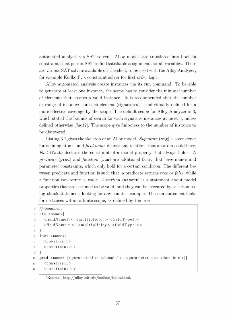
automated analysis via SAT solvers. Alloy models are translated into boolean
constraints that permit SAT to find satisfiable assignments for all variables. There
are various SAT solvers available off-the-shelf, to be used with the Alloy Analyzer,
for example Kodkod1, a constraint solver for first order logic.
Alloy automated analysis create instances via its run command. To be able
to generate at least one instance, the scope has to consider the minimal number
of elements that creates a valid instance. It is recommended that the number
or range of instances for each element (signatures) is individually defined for a
more effective coverage by the scope. The default scope for Alloy Analyzer is 3,
which stated the bounds of search for each signature instances at most 3, unless
defined otherwise [Jac12]. The scope give finiteness to the number of instance to
be discovered.
Listing 3.1 gives the skeleton of an Alloy model. Signature (sig) is a construct
for defining atoms, and field name defines any relations that an atom could have.
Fact (fact) declares the constraint of a model property that always holds. A
predicate (pred) and function (fun) are additional facts, that have names and
parameter constraints, which only hold for a certain condition. The different be-
tween predicate and function is such that, a predicate returns true or false, while
a function can return a value. Assertion (assert) is a statement about model
properties that are assumed to be valid, and they can be executed by selection us-
ing check statement, looking for any counter-example. The run statement looks
for instances within a finite scope, as defined by the user.
1 //<comment
2 s i g <name>{3 <f ieldName1 >: <m u l t i p l i c i t y > <f i e ldType1 >,
4 <f ie ldName n >: <m u l t i p l i c i t y > <f i e ldType n>
5 }6 f a c t <name>{7 <const ra in1>
8 <cons t ra in t n>
9 }10 pred <name> [<parameter1 >: <domain1>, <parameter n >: <domain n>]{11 <const ra in1>
12 <cons t ra in t n>
1Kodkod: http://alloy.mit.edu/kodkod/index.html.
57
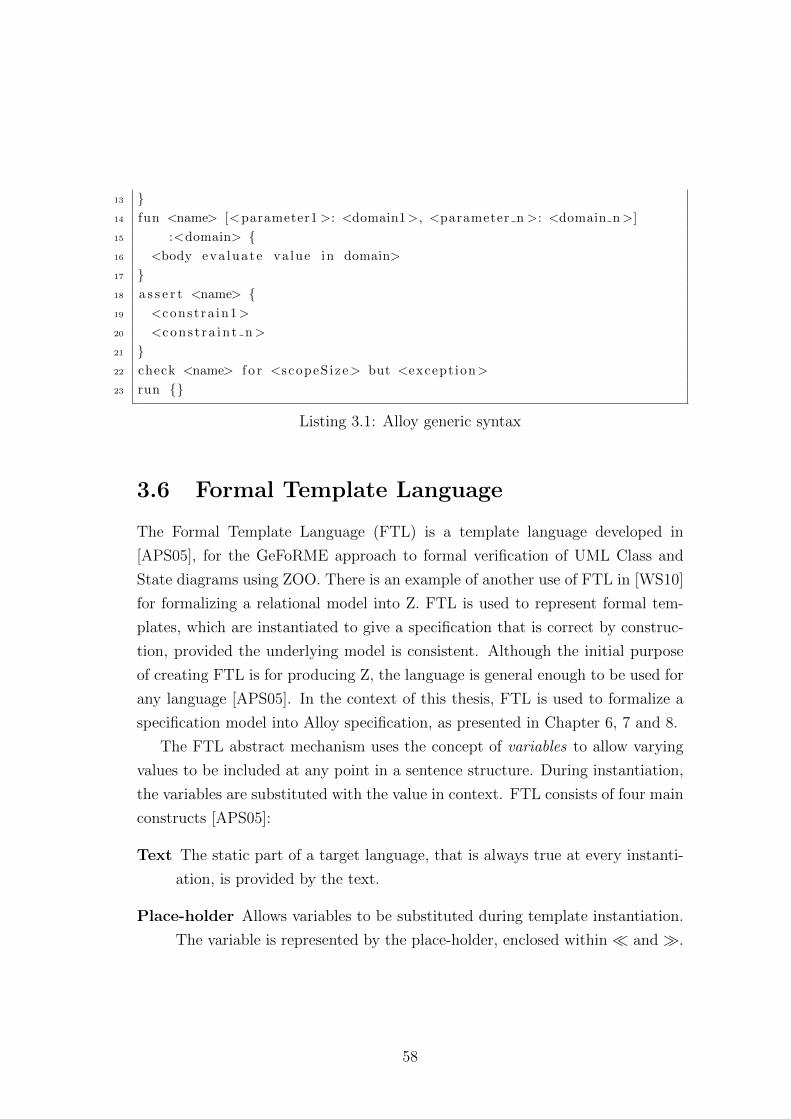
13 }14 fun <name> [<parameter1 >: <domain1>, <parameter n >: <domain n>]
15 :<domain> {16 <body eva luate value in domain>
17 }18 a s s e r t <name> {19 <const ra in1>
20 <cons t ra in t n>
21 }22 check <name> f o r <scopeS ize> but <except ion>
23 run {}
Listing 3.1: Alloy generic syntax
3.6 Formal Template Language
The Formal Template Language (FTL) is a template language developed in
[APS05], for the GeFoRME approach to formal verification of UML Class and
State diagrams using ZOO. There is an example of another use of FTL in [WS10]
for formalizing a relational model into Z. FTL is used to represent formal tem-
plates, which are instantiated to give a specification that is correct by construc-
tion, provided the underlying model is consistent. Although the initial purpose
of creating FTL is for producing Z, the language is general enough to be used for
any language [APS05]. In the context of this thesis, FTL is used to formalize a
specification model into Alloy specification, as presented in Chapter 6, 7 and 8.
The FTL abstract mechanism uses the concept of variables to allow varying
values to be included at any point in a sentence structure. During instantiation,
the variables are substituted with the value in context. FTL consists of four main
constructs [APS05]:
Text The static part of a target language, that is always true at every instanti-
ation, is provided by the text.
Place-holder Allows variables to be substituted during template instantiation.
The variable is represented by the place-holder, enclosed within � and �.
58
List Specifies a list term that comprises of text and parameters and possibly
another list, denoted within [[ and ]]. When using a place-holder within the
list, the variable is an indexed variable.
Choice Provides selection of instantiation. Choices in FTL have two types;
optional, denoted within (( and ))? and multiple, denoted (( and )) with
‖ in between selections. Optional indicates that an instantiation may be
performed, while multiple requires that at least one instantiation has to be
selected.
An example of how FTL works, given an informal template of Z schema, is as
follows [WS10]:
Name =[
declaration | predicates]
Here, Name, declaration and predicates are variables that can be included as
appropriately required. This informal template description can be represented
formally using FTL as follows:
� Name �=[[[� declaration �]] | [[� declaration �]]
]The ZOO approach has been implemented in the AUtoZ tools which automate
the instantiations of the ZOO templates [Wil09]. The capabilities of AUtoZ
include [Wil09] , (1) template translation, (2) template instantiation, and (3)
theorem proving. The tool is implemented as an Eclipse plug-in1 and uses Epsilon
components2 and the Epsilon Generation Language (EGL)3. EGL is a model-to-
text language that allows transformation of serial models into textual artefacts.
1Eclipse: http://www.eclipse.org/2Epsilon: http://www.eclipse.org/epsilon/3Epsilon Generation Language: http://www.eclipse.org/epsilon/doc/egl/
59
3.7 Chapter remarks
To recap, our research aim to specify and formally analyse model transforma-
tion specifications. We have established that currently, development of model
transformations are often ad-hoc, and most analysis techniques are either at im-
plementation level using the testing approach. Or, using graph-based methods
for model transformation definition and analysis at specification level.
We have also established that we need to include analysis of models and meta-
models, to capture any faults that could manifest from an incorrect specification
of models and metamodels, before they ared used to specify model transforma-
tions.
Currently, we do not have a standard documentation of model transformation
that enables model transformation specifications to be planned and conceptually
designed for implementation. Therefore, we need to have a family of modelling
languages for these purposes.
The modelling language for model transformation must be tractable and
amenable to formal analysis. Our selected formal specification language to be
used must be practical (Alloy), and in extension to this, we integrate a visual
notation, provided by the modelling language. The notations instantiate formal
templates (FTL) that represent patterns of model transformation, mechanizing
the production of formal model transformation specification, which can be used
to simulate (Alloy Analyzer) to analyse model transformation specifications.
3.8 Summary
This chapter has presented the related issues to formal methods and how they
have been applied to analyse model transformation. Even though formal methods
appear not to be the favourite choice for this, due to their rigorous application,
they have displayed promising techniques for establishing all the correct proper-
ties for generating a high quality final MDE product. We have highlighted the
approach we are going to use in our framework. In the following chapter, we intro-
duce the framework for specifying and formally analysing model transformation
specifications.
60
Chapter 4
Framework for specification and
formal analysis of model
transformation
We have established a level of understanding of our research domain, the MDE
and formal analysis in Chapter 2 and Chapter 3. Based on the reviews, we
claim that there has not yet been established a systematic way of specifying
and formally analysing model transformation specification using a pattern and
template-based approach. We propose to address this by a framework, called the
TSpecProber, that supports the process of developing a reliable and well-formed
model transformation specification. This chapter introduces the concepts and
components of our proposed framework.
We begin the chapter with the introduction to the framework (Section 4.1
and 4.2), followed by the presentation of the components in Section 4.3. Then
we introduce the processes for specifying and analysing model transformation in
Section 4.4. In Section 4.7 onwards, we describe the details of the key components
in this framework. Finally, we present a scheme for tool supporting this framework
in Section 4.9.
61
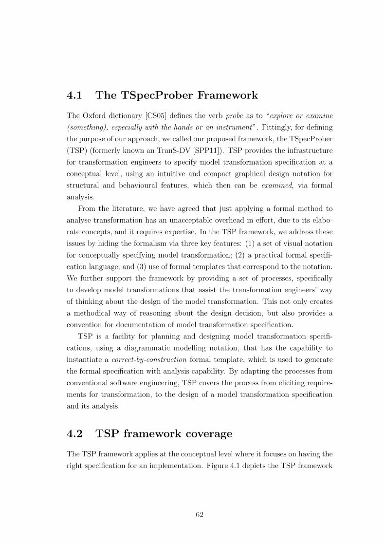
4.1 The TSpecProber Framework
The Oxford dictionary [CS05] defines the verb probe as to “explore or examine
(something), especially with the hands or an instrument”. Fittingly, for defining
the purpose of our approach, we called our proposed framework, the TSpecProber
(TSP) (formerly known an TranS-DV [SPP11]). TSP provides the infrastructure
for transformation engineers to specify model transformation specification at a
conceptual level, using an intuitive and compact graphical design notation for
structural and behavioural features, which then can be examined, via formal
analysis.
From the literature, we have agreed that just applying a formal method to
analyse transformation has an unacceptable overhead in effort, due to its elabo-
rate concepts, and it requires expertise. In the TSP framework, we address these
issues by hiding the formalism via three key features: (1) a set of visual notation
for conceptually specifying model transformation; (2) a practical formal specifi-
cation language; and (3) use of formal templates that correspond to the notation.
We further support the framework by providing a set of processes, specifically
to develop model transformations that assist the transformation engineers’ way
of thinking about the design of the model transformation. This not only creates
a methodical way of reasoning about the design decision, but also provides a
convention for documentation of model transformation specification.
TSP is a facility for planning and designing model transformation specifi-
cations, using a diagrammatic modelling notation, that has the capability to
instantiate a correct-by-construction formal template, which is used to generate
the formal specification with analysis capability. By adapting the processes from
conventional software engineering, TSP covers the process from eliciting require-
ments for transformation, to the design of a model transformation specification
and its analysis.
4.2 TSP framework coverage
The TSP framework applies at the conceptual level where it focuses on having the
right specification for an implementation. Figure 4.1 depicts the TSP framework
62
coverage for specifying and formally analysing model transformation. We intro-
duce new models, defined in the next sections, that cover the specification and
analysis of model transformation components. The TSP models can be extended
to accommodate implementation based on the transformation engine, but this is
a whole new challenge and we have suspended the research in this area for future
work.
Figure 4.1: TSP framework coverage for model transformation
4.3 Components of TSP framework
The TSP is made up of several interrelated components for defining and formally
analysing model transformation. The components can be divided into four main
groups, the (1) requirements models; (2) specification models; (3) templates cat-
alogue; and (4) formal specification models. TSP components are illustrated in
Figure 4.2.
The following parts describe each of the TSP components.
63
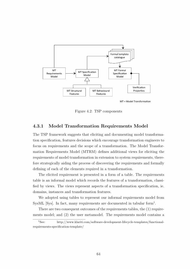
Figure 4.2: TSP components
4.3.1 Model Transformation Requirements Model
The TSP framework suggests that eliciting and documenting model transforma-
tion specification, features decisions which encourage transformation engineers to
focus on requirements and the scope of a transformation. The Model Transfor-
mation Requirements Model (MTRM) defines additional views for eliciting the
requirements of model transformation in extension to system requirements, there-
fore strategically aiding the process of discovering the requirements and formally
defining of each of the elements required in a transformation.
The elicited requirement is presented in a form of a table. The requirements
table is an informal model which records the features of a transformation, classi-
fied by views. The views represent aspects of a transformation specification, ie.
domains, instances and transformation features.
We adopted using tables to represent our informal requirements model from
SysML [Sys]. In fact, many requirements are documented in tabular form1.
There are two consequent outcomes of the requirements tables, the (1) require-
ments model; and (2) the user metamodel. The requirements model contains a
1See: http://www.klariti.com/software-development-lifecycle-templates/functional-
requirements-specification-template/
64
hierarchical, diagrammatic view of the model transformation requirements, giv-
ing the requirements a formal representation. These are used later for defining
the the mapping model. These are presented in detail in Chapter 5.
4.3.2 Model Transformation Specification Model
The TSP provides a visual representation of a model transformation. There are
three types of Model Transformation Specification Model (MTSM), the (1) user
metamodels (source and target), (2) mapping models, and (3) transformation
phases.
The user metamodels are contextualised metamodels of the source and tar-
get metamodel for the transformation under development, produced from the
requirements tables. Contextualized, in this context, refers to a meaningful meta-
model that includes only the elements needed for a transformation. Certain spe-
cial relationships between elements have a formal definitions, allowing analysis
of well-formedness and correctness. Contextualization optimizes the metamodel
and thus, reduces complexity. Contextualization also allows user metamodels
to be formally analysed for well-formedness and correctness. A metamodel in a
transformation can have several forms: (1) huge metamodel; (2) readily-available
metamodel; and (3) non-existent metamodel. The reason we need to create a user
metamodel, is to prepare a sufficient metamodel for the transformation by: (1)
extracting a subset of elements from huge metamodels; (2) ensuring the readily-
available metamodels are appropriate for the transformation; and (3) producing
a metamodel for a transformation. Producing a user metamodel is explained in
Chapter 5 and analysing a user metamodel is presented in Chapter 6.
The mapping model is the result of extracting the required rules of a transfor-
mation from the requirements model. It defines the associating source and target
elements to the rules of the transformation. Generating mapping is defined in
Chapter 7.
The rules in the mapping model are used in defining the transformation
phases. TSP defines the model transformation specification using phases to
modularize model transformation specification, and at the same time encour-
65
aging scalability and re-usability. Phasing of model transformation specification
is demonstrated in Chapter 7
4.3.3 Formal Template Catalogue
To hide the formalism from the transformation engineers, we adopted the template-
based approach to produce a formal specification, which enables an automated
formal analysis. The template catalogue contains formal templates to produce
Alloy fragments instantiated by TSP models. Templates are defined using the
FTL (see Section 3.6).
In Chapter 3, we have identified Alloy as a practical formal specification lan-
guage that is appropriate to be integrated into TSP framework. Our template
catalogue will be used for producing Alloy specifications.
The Alloy template catalogue can be classified into several parts; each of
them has a specific focus, representing patterns of model transformation, and
formally defining transformation specification, to enable effective simulation and
verification of the specification using the Alloy model checker. The following
describes the purpose of parts of Alloy templates catalogue:
Module Provides a header that links all related files (includes TSpecProber
Alloy generics) and global conditions. An example of the content of generics,
is the definition of multiplicity.
User metamodel Describes the structural and behavioural features of user meta-
models. The user metamodel templates are divided into two parts, class
and relation.
Model transformation specification model Defines the structural and be-
havioural features of transformation phases.
Model Instances Corresponds to the instance model patterns defined by the
transformation engineers. There are two types of instance model template,
one is for user metamodels, and the other extends to represent model trans-
formation. This template is used to perform our pattern snapshot analysis.
66
4.3.4 Model Transformation Formal Specification Model
Each instantiation of a template creates parts of a Model Transformation Formal
Specification Model (MTFM). There are three types of MTFM: (1) source and
target user metamodel formal specifications; (2) model transformation formal
specifications; and (3) instance source, target and model transformation formal
specifications.
4.4 Process for model transformation specifica-
tion development and analysis
The TSP aims to cover the whole process, from planning and designing, to imple-
menting model transformations, while ensuring that most requirements are cap-
tured and anomalies are discovered early, before it becomes expensive to mend
later in the development. The generic process for TSP is shown in Figure 4.3.
The processes in TSP support incremental development, where model trans-
formation can be developed part-by-part. In contrast to [KRH05], which presents
an incremental process for model transformation development between high-level
and low-level model transformation specification, TSP model transformation de-
velopment explicitly defines a stage where the metamodel definition is developed.
Requirements elicitation iteratively identifies the prerequisite of the development
of a model transformation, which determines the outcome in the subsequent steps;
the defined metamodels, mapping organizations, rule composition and refinement.
The analysis is a recurring process during the specification of these components.
Ultimately, the specifications can be used for producing transformation imple-
mentations. The extension of TSP to implementation is not in the scope of this
thesis, but the consideration has been included in defining the approach.
TSP provides steps for specifying and analysing model transformation. Fig-
ure 4.4 shows a detailed process of TSP in six steps, which includes the outcomes
and relations of the TSP components.
Step 1: Eliciting Requirements - performs the process of identifying models,
metamodels and transformation requirements. Here, transformation engineers
67

Figure 4.3: TSP abstract processes
create a requirements table that contains informal design decisions for model
transformation components. These are presented in Chapter 5. Outcomes: Re-
quirement tables.
Step 2: Contextualizing user metamodel - performs the process of discov-
ering the minimal set of elements and their relations required for a transforma-
tion. This step allows transformation engineers to prepare the user metamodel
for model transformation specification. The user metamodel includes predefined
relation behavioural using stereotypes for variatios of generalization and associ-
ation. Requirements tables are presented in Chapter 5. Outcomes: Source and
target user metamodels.
Step 3: Analysis of the user metamodel - performs the process of applying
the templates to produce a formal specification of the user source and target meta-
model. It also analyses the specification by finding models and verifying the user
metamodel using positive and negative pattern snapshots. These are presented
68
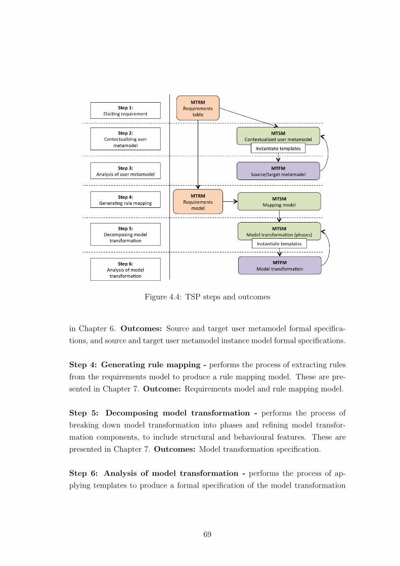
Figure 4.4: TSP steps and outcomes
in Chapter 6. Outcomes: Source and target user metamodel formal specifica-
tions, and source and target user metamodel instance model formal specifications.
Step 4: Generating rule mapping - performs the process of extracting rules
from the requirements model to produce a rule mapping model. These are pre-
sented in Chapter 7. Outcome: Requirements model and rule mapping model.
Step 5: Decomposing model transformation - performs the process of
breaking down model transformation into phases and refining model transfor-
mation components, to include structural and behavioural features. These are
presented in Chapter 7. Outcomes: Model transformation specification.
Step 6: Analysis of model transformation - performs the process of ap-
plying templates to produce a formal specification of the model transformation
69
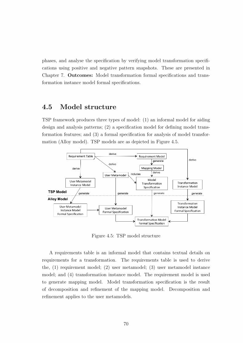
phases, and analyse the specification by verifying model transformation specifi-
cations using positive and negative pattern snapshots. These are presented in
Chapter 7. Outcomes: Model transformation formal specifications and trans-
formation instance model formal specifications.
4.5 Model structure
TSP framework produces three types of model: (1) an informal model for aiding
design and analysis patterns; (2) a specification model for defining model trans-
formation features; and (3) a formal specification for analysis of model transfor-
mation (Alloy model). TSP models are as depicted in Figure 4.5.
Figure 4.5: TSP model structure
A requirements table is an informal model that contains textual details on
requirements for a transformation. The requirements table is used to derive
the, (1) requirement model; (2) user metamodel; (3) user metamodel instance
model; and (4) transformation instance model. The requirement model is used
to generate mapping model. Model transformation specification is the result
of decomposition and refinement of the mapping model. Decomposition and
refinement applies to the user metamodels.
70
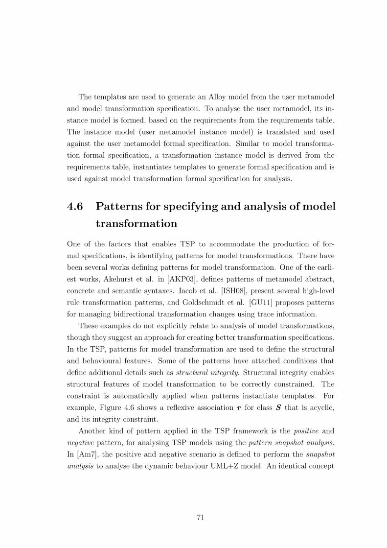
The templates are used to generate an Alloy model from the user metamodel
and model transformation specification. To analyse the user metamodel, its in-
stance model is formed, based on the requirements from the requirements table.
The instance model (user metamodel instance model) is translated and used
against the user metamodel formal specification. Similar to model transforma-
tion formal specification, a transformation instance model is derived from the
requirements table, instantiates templates to generate formal specification and is
used against model transformation formal specification for analysis.
4.6 Patterns for specifying and analysis of model
transformation
One of the factors that enables TSP to accommodate the production of for-
mal specifications, is identifying patterns for model transformations. There have
been several works defining patterns for model transformation. One of the earli-
est works, Akehurst et al. in [AKP03], defines patterns of metamodel abstract,
concrete and semantic syntaxes. Iacob et al. [ISH08], present several high-level
rule transformation patterns, and Goldschmidt et al. [GU11] proposes patterns
for managing bidirectional transformation changes using trace information.
These examples do not explicitly relate to analysis of model transformations,
though they suggest an approach for creating better transformation specifications.
In the TSP, patterns for model transformation are used to define the structural
and behavioural features. Some of the patterns have attached conditions that
define additional details such as structural integrity. Structural integrity enables
structural features of model transformation to be correctly constrained. The
constraint is automatically applied when patterns instantiate templates. For
example, Figure 4.6 shows a reflexive association r for class S that is acyclic,
and its integrity constraint.
Another kind of pattern applied in the TSP framework is the positive and
negative pattern, for analysing TSP models using the pattern snapshot analysis.
In [Am7], the positive and negative scenario is defined to perform the snapshot
analysis to analyse the dynamic behaviour UML+Z model. An identical concept
71
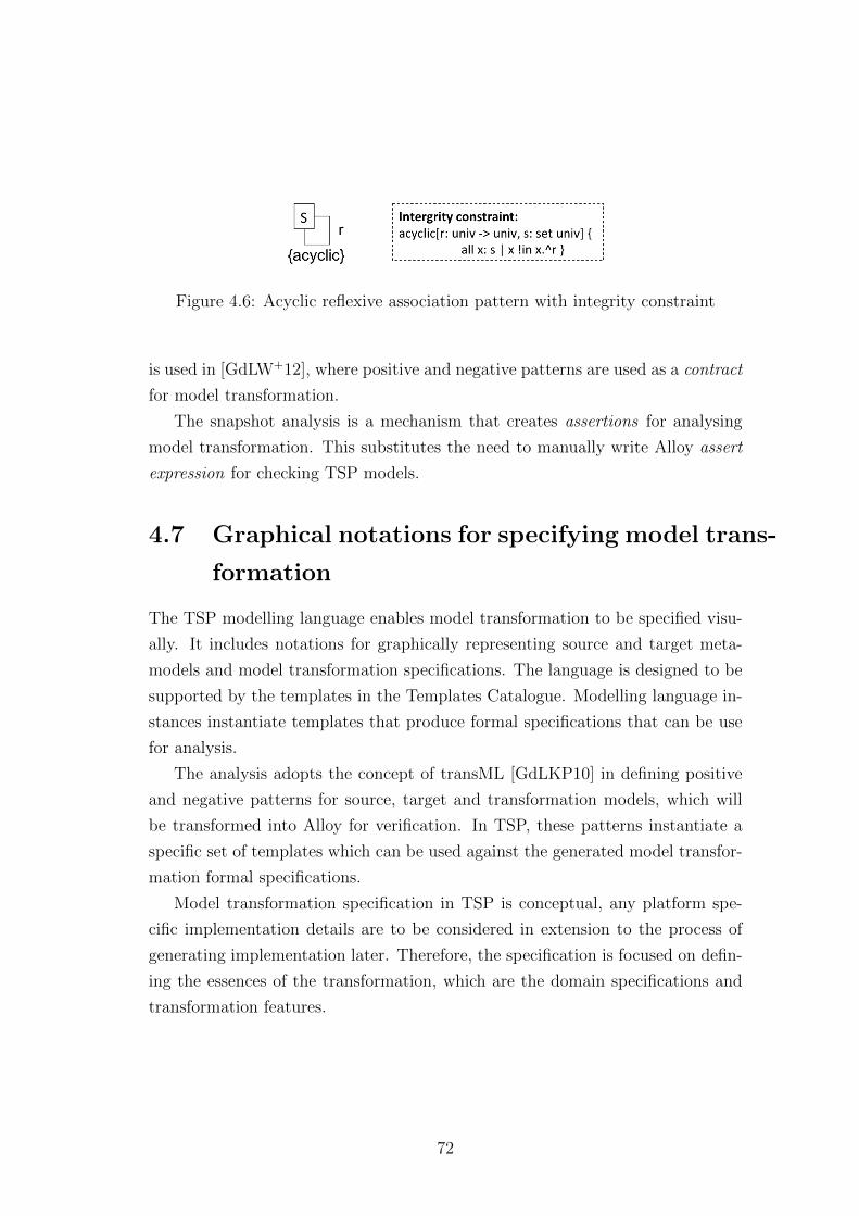
Figure 4.6: Acyclic reflexive association pattern with integrity constraint
is used in [GdLW+12], where positive and negative patterns are used as a contract
for model transformation.
The snapshot analysis is a mechanism that creates assertions for analysing
model transformation. This substitutes the need to manually write Alloy assert
expression for checking TSP models.
4.7 Graphical notations for specifying model trans-
formation
The TSP modelling language enables model transformation to be specified visu-
ally. It includes notations for graphically representing source and target meta-
models and model transformation specifications. The language is designed to be
supported by the templates in the Templates Catalogue. Modelling language in-
stances instantiate templates that produce formal specifications that can be use
for analysis.
The analysis adopts the concept of transML [GdLKP10] in defining positive
and negative patterns for source, target and transformation models, which will
be transformed into Alloy for verification. In TSP, these patterns instantiate a
specific set of templates which can be used against the generated model transfor-
mation formal specifications.
Model transformation specification in TSP is conceptual, any platform spe-
cific implementation details are to be considered in extension to the process of
generating implementation later. Therefore, the specification is focused on defin-
ing the essences of the transformation, which are the domain specifications and
transformation features.
72
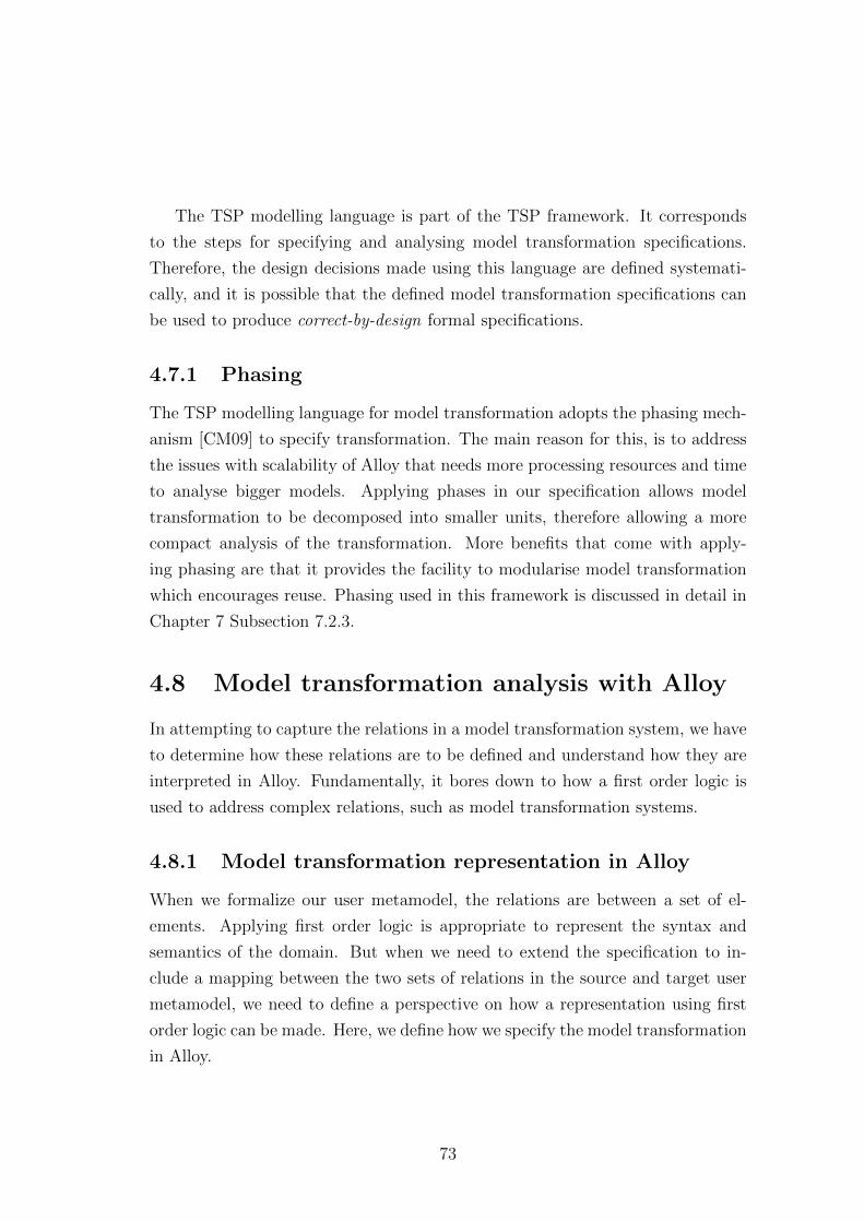
The TSP modelling language is part of the TSP framework. It corresponds
to the steps for specifying and analysing model transformation specifications.
Therefore, the design decisions made using this language are defined systemati-
cally, and it is possible that the defined model transformation specifications can
be used to produce correct-by-design formal specifications.
4.7.1 Phasing
The TSP modelling language for model transformation adopts the phasing mech-
anism [CM09] to specify transformation. The main reason for this, is to address
the issues with scalability of Alloy that needs more processing resources and time
to analyse bigger models. Applying phases in our specification allows model
transformation to be decomposed into smaller units, therefore allowing a more
compact analysis of the transformation. More benefits that come with apply-
ing phasing are that it provides the facility to modularise model transformation
which encourages reuse. Phasing used in this framework is discussed in detail in
Chapter 7 Subsection 7.2.3.
4.8 Model transformation analysis with Alloy
In attempting to capture the relations in a model transformation system, we have
to determine how these relations are to be defined and understand how they are
interpreted in Alloy. Fundamentally, it bores down to how a first order logic is
used to address complex relations, such as model transformation systems.
4.8.1 Model transformation representation in Alloy
When we formalize our user metamodel, the relations are between a set of el-
ements. Applying first order logic is appropriate to represent the syntax and
semantics of the domain. But when we need to extend the specification to in-
clude a mapping between the two sets of relations in the source and target user
metamodel, we need to define a perspective on how a representation using first
order logic can be made. Here, we define how we specify the model transformation
in Alloy.
73
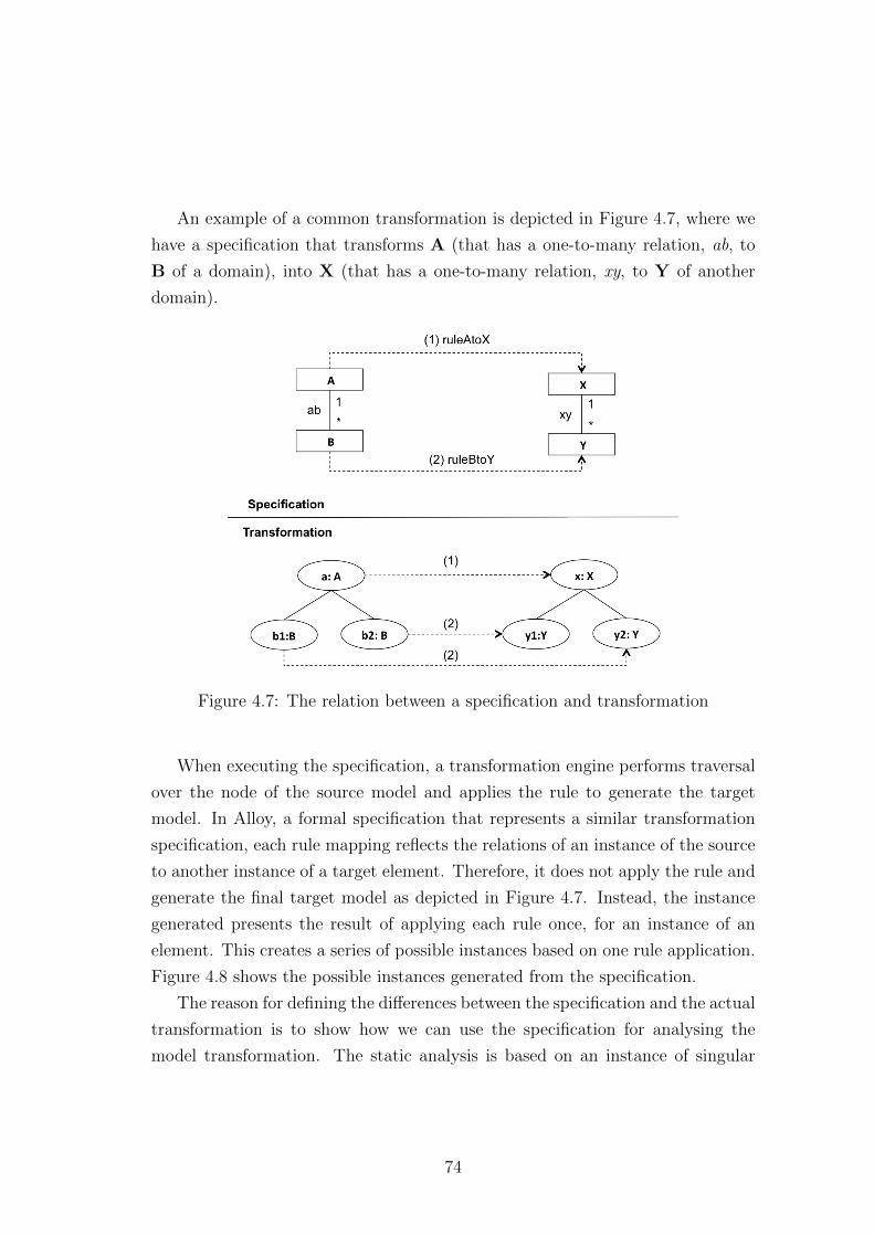
An example of a common transformation is depicted in Figure 4.7, where we
have a specification that transforms A (that has a one-to-many relation, ab, to
B of a domain), into X (that has a one-to-many relation, xy, to Y of another
domain).
Figure 4.7: The relation between a specification and transformation
When executing the specification, a transformation engine performs traversal
over the node of the source model and applies the rule to generate the target
model. In Alloy, a formal specification that represents a similar transformation
specification, each rule mapping reflects the relations of an instance of the source
to another instance of a target element. Therefore, it does not apply the rule and
generate the final target model as depicted in Figure 4.7. Instead, the instance
generated presents the result of applying each rule once, for an instance of an
element. This creates a series of possible instances based on one rule application.
Figure 4.8 shows the possible instances generated from the specification.
The reason for defining the differences between the specification and the actual
transformation is to show how we can use the specification for analysing the
model transformation. The static analysis is based on an instance of singular
74
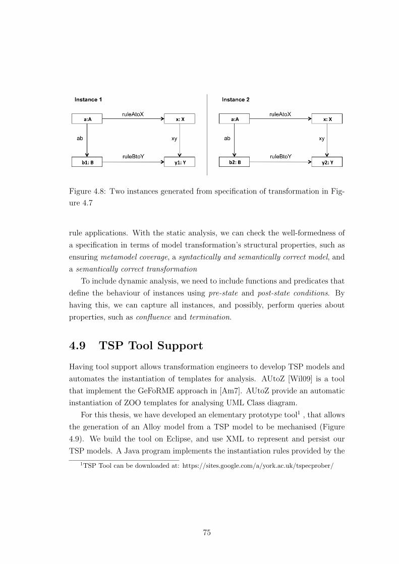
Figure 4.8: Two instances generated from specification of transformation in Fig-
ure 4.7
rule applications. With the static analysis, we can check the well-formedness of
a specification in terms of model transformation’s structural properties, such as
ensuring metamodel coverage, a syntactically and semantically correct model, and
a semantically correct transformation
To include dynamic analysis, we need to include functions and predicates that
define the behaviour of instances using pre-state and post-state conditions. By
having this, we can capture all instances, and possibly, perform queries about
properties, such as confluence and termination.
4.9 TSP Tool Support
Having tool support allows transformation engineers to develop TSP models and
automates the instantiation of templates for analysis. AUtoZ [Wil09] is a tool
that implement the GeFoRME approach in [Am7]. AUtoZ provide an automatic
instantiation of ZOO templates for analysing UML Class diagram.
For this thesis, we have developed an elementary prototype tool1 , that allows
the generation of an Alloy model from a TSP model to be mechanised (Figure
4.9). We build the tool on Eclipse, and use XML to represent and persist our
TSP models. A Java program implements the instantiation rules provided by the
1TSP Tool can be downloaded at: https://sites.google.com/a/york.ac.uk/tspecprober/
75
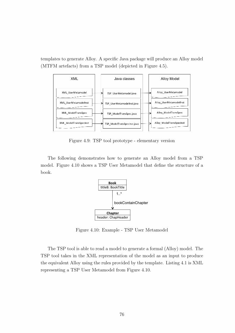
templates to generate Alloy. A specific Java package will produce an Alloy model
(MTFM artefacts) from a TSP model (depicted in Figure 4.5).
Figure 4.9: TSP tool prototype - elementary version
The following demonstrates how to generate an Alloy model from a TSP
model. Figure 4.10 shows a TSP User Metamodel that define the structure of a
book.
Figure 4.10: Example - TSP User Metamodel
The TSP tool is able to read a model to generate a formal (Alloy) model. The
TSP tool takes in the XML representation of the model as an input to produce
the equivalent Alloy using the rules provided by the template. Listing 4.1 is XML
representing a TSP User Metamodel from Figure 4.10.
76
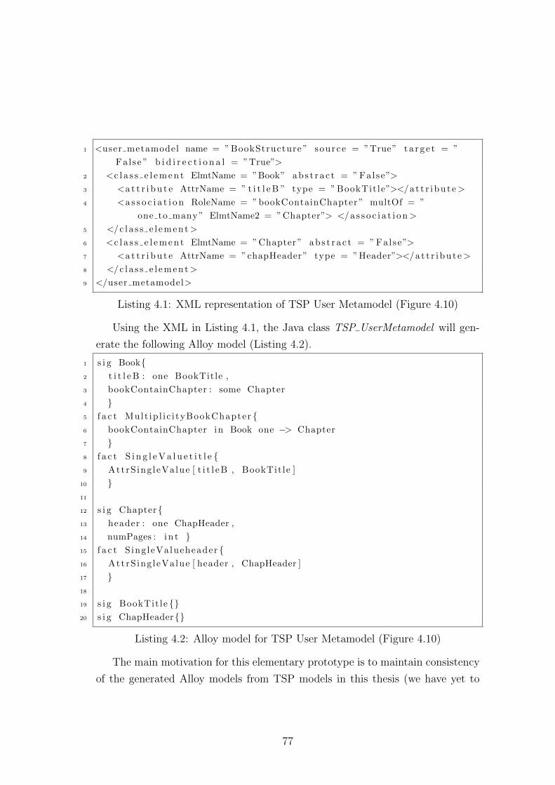
1 <user metamodel name = ” BookStructure ” source = ”True” t a r g e t = ”
Fal se ” b i d i r e c t i o n a l = ”True”>
2 <c l a s s e l e m e n t ElmtName = ”Book” abs t r a c t = ” Fal se”>
3 <a t t r i b u t e AttrName = ” t i t l e B ” type = ” BookTit le”></a t t r i bu t e>
4 <a s s o c i a t i o n RoleName = ”bookContainChapter” multOf = ”
one to many ” ElmtName2 = ”Chapter”> </a s s o c i a t i o n >
5 </c l a s s e l ement>
6 <c l a s s e l e m e n t ElmtName = ”Chapter” ab s t r a c t = ” Fal se”>
7 <a t t r i b u t e AttrName = ”chapHeader” type = ”Header”></a t t r i bu t e>
8 </c l a s s e l ement>
9 </user metamodel>
Listing 4.1: XML representation of TSP User Metamodel (Figure 4.10)
Using the XML in Listing 4.1, the Java class TSP UserMetamodel will gen-
erate the following Alloy model (Listing 4.2).
1 s i g Book{2 t i t l e B : one BookTitle ,
3 bookContainChapter : some Chapter
4 }5 f a c t Mult ip l i c i tyBookChapter {6 bookContainChapter in Book one −> Chapter
7 }8 f a c t S i n g l e V a l u e t i t l e {9 AttrS ing leValue [ t i t l e B , BookTit le ]
10 }11
12 s i g Chapter{13 header : one ChapHeader ,
14 numPages : i n t }15 f a c t S ing leValueheader {16 AttrS ing leValue [ header , ChapHeader ]
17 }18
19 s i g BookTit le {}20 s i g ChapHeader{}
Listing 4.2: Alloy model for TSP User Metamodel (Figure 4.10)
The main motivation for this elementary prototype is to maintain consistency
of the generated Alloy models from TSP models in this thesis (we have yet to
77
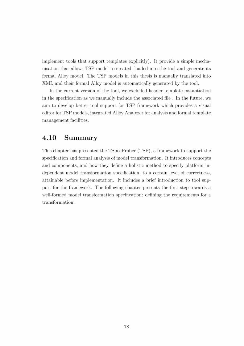
implement tools that support templates explicitly). It provide a simple mecha-
nisation that allows TSP model to created, loaded into the tool and generate its
formal Alloy model. The TSP models in this thesis is manually translated into
XML and their formal Alloy model is automatically generated by the tool.
In the current version of the tool, we excluded header template instantiation
in the specification as we manually include the associated file . In the future, we
aim to develop better tool support for TSP framework which provides a visual
editor for TSP models, integrated Alloy Analyzer for analysis and formal template
management facilities.
4.10 Summary
This chapter has presented the TSpecProber (TSP), a framework to support the
specification and formal analysis of model transformation. It introduces concepts
and components, and how they define a holistic method to specify platform in-
dependent model transformation specification, to a certain level of correctness,
attainable before implementation. It includes a brief introduction to tool sup-
port for the framework. The following chapter presents the first step towards a
well-formed model transformation specification; defining the requirements for a
transformation.
78
Chapter 5
Eliciting model transformation
requirements and contextualizing
metamodel
In Chapter 4, we have briefly introduced the components of TSP framework. This
chapter, we presents how those components work to provide an approach towards
specifying and formally analysing model transformation specifications.
We are going deliver the framework in three parts: (1) eliciting requirements
and contextualizing metamodels (Figure 4.4 Step 1 and 2) in this chapter; (2)
formally analysing metamodels (Figure 4.4 Step 3) in Chapter 6; and (3) decom-
posing model transformation specifications (Figure 4.4 Step 4-6) in Chapter 7.
5.1 Elicit model transformation requirements
Like any software engineering, eliciting requirements plays an important role in
defining the vision of a system. The requirements specification produced during
elicitation includes the descriptions of functional/non-functional requirements,
user requirements, system requirements and interface requirements [Som07]. The
requirements are discovered and documented through requirements engineering
processes that include elicitation, analysis and validation [Lau02].
Problems in any software development can often be traced back to elicita-
tion issues [CK92]. In MDE particularly, requirements specifications have to be
79
interpreted further to define model transformations. Hence, any inadequacy in
requirements specification is propagated, perhaps magnified, into the later stage
of model transformation development and this may be expensive to fix.
In this step of the TSP framework, we aim to address the gap between the
system requirements specification and the transformation requirements specifica-
tion, to allow transformation engineers to have the right focus on defining features
of the transformation.
5.1.1 The rationale for eliciting model transformation re-
quirements
Establishing a requirements specification does not only draw a clear picture of an
ideal final product, but through the process itself, helps to clarify the feasibility of
development. If we look at the current approach to the development process using
model transformation [GP04; KRH05], there is a stage for defining system level
requirements. However, as yet there is no comprehensive approach that facilitates
the process of specifying requirements particularly for model transformation. In
this case, we need to have an additional perspective to define requirements at
model transformation level, based on the system requirements.
We select an example of a conventional object-oriented software development
and compare it to an MDE development to clarify the rationale for eliciting model
transformation. Figure 5.1 shows the difference between the two development
approaches.
In conventional object-oriented development, requirements specifications are
realized using models that include static and dynamic models. Then they are
implemented by programming.
The difference in development using model transformation, is that the re-
quirements specification does not include the requirements that define model
transformation features. This is the gap, a grey area, between requirements spec-
ification and the requirements for model transformation components. Indeed in
MDE, it is usually the case that transformation engineers intuitively interpret
the requirements specification and implement ad-hoc model transformation.
80
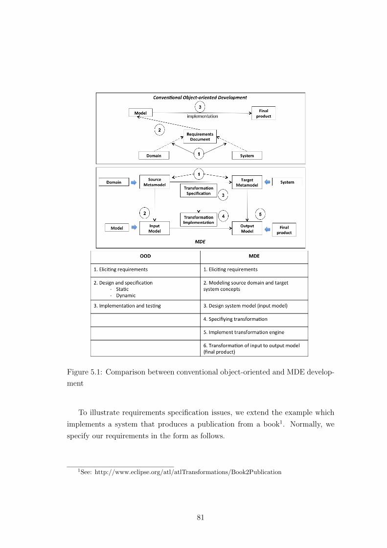
Figure 5.1: Comparison between conventional object-oriented and MDE develop-
ment
To illustrate requirements specification issues, we extend the example which
implements a system that produces a publication from a book1. Normally, we
specify our requirements in the form as follows.
1See: http://www.eclipse.org/atl/atlTransformations/Book2Publication
81
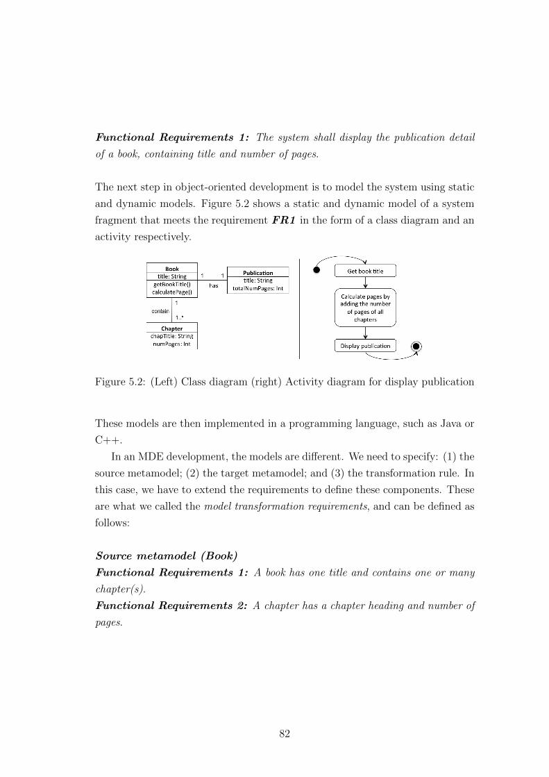
Functional Requirements 1: The system shall display the publication detail
of a book, containing title and number of pages.
The next step in object-oriented development is to model the system using static
and dynamic models. Figure 5.2 shows a static and dynamic model of a system
fragment that meets the requirement FR1 in the form of a class diagram and an
activity respectively.
Figure 5.2: (Left) Class diagram (right) Activity diagram for display publication
These models are then implemented in a programming language, such as Java or
C++.
In an MDE development, the models are different. We need to specify: (1) the
source metamodel; (2) the target metamodel; and (3) the transformation rule. In
this case, we have to extend the requirements to define these components. These
are what we called the model transformation requirements, and can be defined as
follows:
Source metamodel (Book)
Functional Requirements 1: A book has one title and contains one or many
chapter(s).
Functional Requirements 2: A chapter has a chapter heading and number of
pages.
82
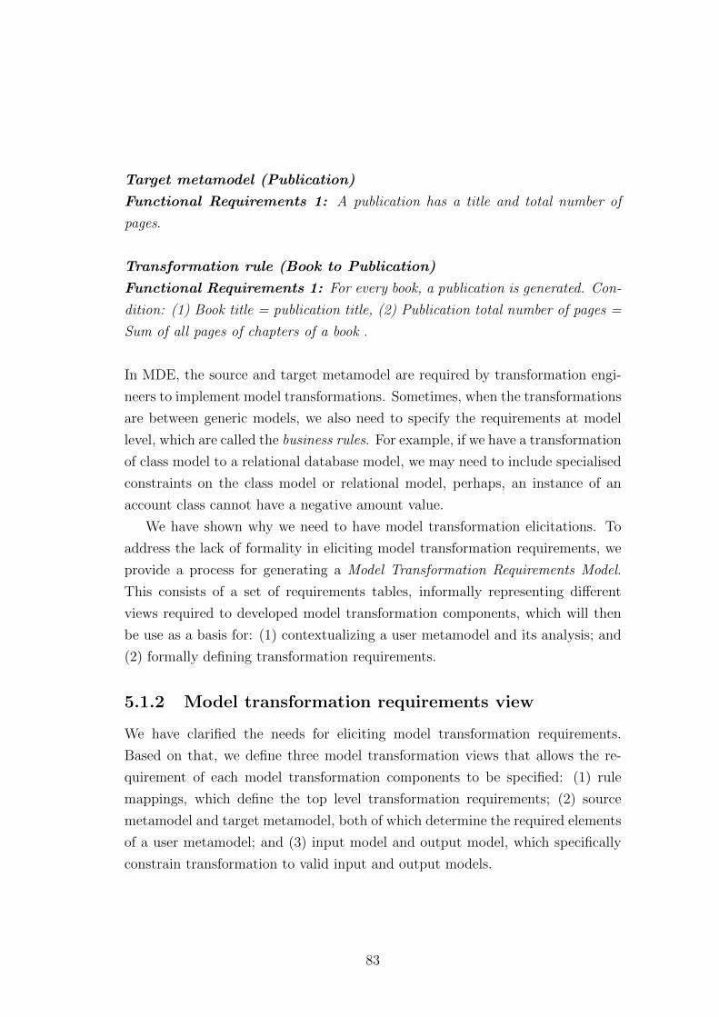
Target metamodel (Publication)
Functional Requirements 1: A publication has a title and total number of
pages.
Transformation rule (Book to Publication)
Functional Requirements 1: For every book, a publication is generated. Con-
dition: (1) Book title = publication title, (2) Publication total number of pages =
Sum of all pages of chapters of a book .
In MDE, the source and target metamodel are required by transformation engi-
neers to implement model transformations. Sometimes, when the transformations
are between generic models, we also need to specify the requirements at model
level, which are called the business rules. For example, if we have a transformation
of class model to a relational database model, we may need to include specialised
constraints on the class model or relational model, perhaps, an instance of an
account class cannot have a negative amount value.
We have shown why we need to have model transformation elicitations. To
address the lack of formality in eliciting model transformation requirements, we
provide a process for generating a Model Transformation Requirements Model.
This consists of a set of requirements tables, informally representing different
views required to developed model transformation components, which will then
be use as a basis for: (1) contextualizing a user metamodel and its analysis; and
(2) formally defining transformation requirements.
5.1.2 Model transformation requirements view
We have clarified the needs for eliciting model transformation requirements.
Based on that, we define three model transformation views that allows the re-
quirement of each model transformation components to be specified: (1) rule
mappings, which define the top level transformation requirements; (2) source
metamodel and target metamodel, both of which determine the required elements
of a user metamodel; and (3) input model and output model, which specifically
constrain transformation to valid input and output models.
83
To visualize the relationship between each view, Figure 5.3 shows their hier-
archical dependency.
Figure 5.3: Views for model transformation requirements and their dependencies
The requirements for each view are informally specified in the form of ta-
bles. One of the reasons why we encourage initial elicitation to be specified in a
form of a table, is to facilitate the thinking process. We want the details to be
made explicit, especially the condition of the rules. This way, we assume that a
transformation engineer will be made aware of the possibilities of structural and
behavioural features, including constraints that apply to the rule. We will see
later (in Chapter 7), in the requirements model, how requirements are formalised
to provide enough details for specifying a transformation, but will not hold much
information about the conditions. The link between the transformation require-
ments table and the transformation requirements model is linked via IDs that
allow trace back to requirements table when needed.
The following section describe the views further.
5.1.3 Rule mapping requirements view
A rule specifies the relationship between the source and target metamodel ele-
ments. Rule mapping defines the rules for generating a target model from source
model.
In this view, transformation engineers need to discover the main rules needed
for a transformation and what are their related elements. The findings are infor-
mally documented in a table. The table for a rule mapping requirements view
84
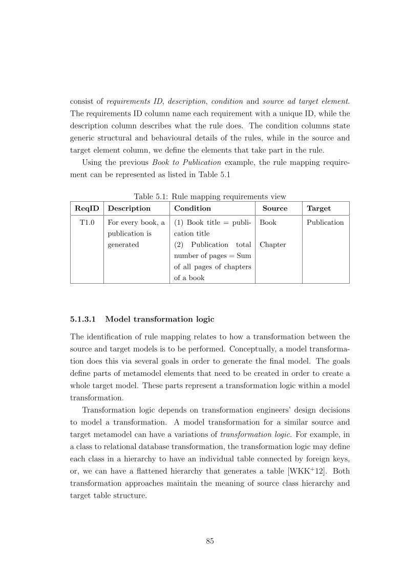
consist of requirements ID, description, condition and source ad target element.
The requirements ID column name each requirement with a unique ID, while the
description column describes what the rule does. The condition columns state
generic structural and behavioural details of the rules, while in the source and
target element column, we define the elements that take part in the rule.
Using the previous Book to Publication example, the rule mapping require-
ment can be represented as listed in Table 5.1
Table 5.1: Rule mapping requirements view
ReqID Description Condition Source Target
T1.0 For every book, a
publication is
generated
(1) Book title = publi-
cation title
Book Publication
(2) Publication total
number of pages = Sum
of all pages of chapters
of a book
Chapter
5.1.3.1 Model transformation logic
The identification of rule mapping relates to how a transformation between the
source and target models is to be performed. Conceptually, a model transforma-
tion does this via several goals in order to generate the final model. The goals
define parts of metamodel elements that need to be created in order to create a
whole target model. These parts represent a transformation logic within a model
transformation.
Transformation logic depends on transformation engineers’ design decisions
to model a transformation. A model transformation for a similar source and
target metamodel can have a variations of transformation logic. For example, in
a class to relational database transformation, the transformation logic may define
each class in a hierarchy to have an individual table connected by foreign keys,
or, we can have a flattened hierarchy that generates a table [WKK+12]. Both
transformation approaches maintain the meaning of source class hierarchy and
target table structure.
85
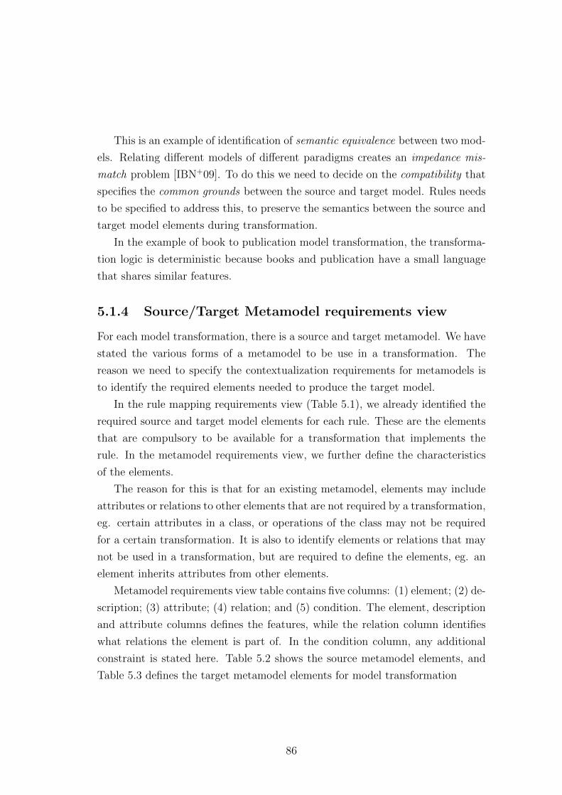
This is an example of identification of semantic equivalence between two mod-
els. Relating different models of different paradigms creates an impedance mis-
match problem [IBN+09]. To do this we need to decide on the compatibility that
specifies the common grounds between the source and target model. Rules needs
to be specified to address this, to preserve the semantics between the source and
target model elements during transformation.
In the example of book to publication model transformation, the transforma-
tion logic is deterministic because books and publication have a small language
that shares similar features.
5.1.4 Source/Target Metamodel requirements view
For each model transformation, there is a source and target metamodel. We have
stated the various forms of a metamodel to be use in a transformation. The
reason we need to specify the contextualization requirements for metamodels is
to identify the required elements needed to produce the target model.
In the rule mapping requirements view (Table 5.1), we already identified the
required source and target model elements for each rule. These are the elements
that are compulsory to be available for a transformation that implements the
rule. In the metamodel requirements view, we further define the characteristics
of the elements.
The reason for this is that for an existing metamodel, elements may include
attributes or relations to other elements that are not required by a transformation,
eg. certain attributes in a class, or operations of the class may not be required
for a certain transformation. It is also to identify elements or relations that may
not be used in a transformation, but are required to define the elements, eg. an
element inherits attributes from other elements.
Metamodel requirements view table contains five columns: (1) element; (2) de-
scription; (3) attribute; (4) relation; and (5) condition. The element, description
and attribute columns defines the features, while the relation column identifies
what relations the element is part of. In the condition column, any additional
constraint is stated here. Table 5.2 shows the source metamodel elements, and
Table 5.3 defines the target metamodel elements for model transformation
86
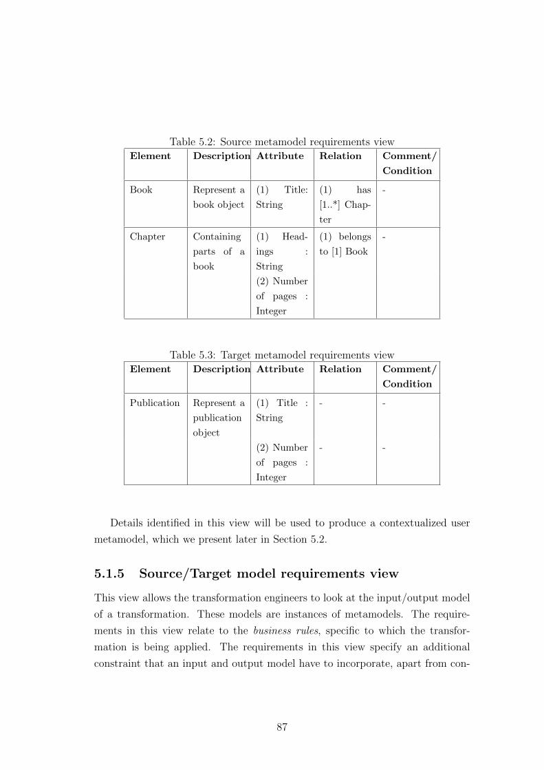
Table 5.2: Source metamodel requirements view
Element Description Attribute Relation Comment/
Condition
Book Represent a
book object
(1) Title:
String
(1) has
[1..*] Chap-
ter
-
Chapter Containing
parts of a
book
(1) Head-
ings :
String
(1) belongs
to [1] Book
-
(2) Number
of pages :
Integer
Table 5.3: Target metamodel requirements view
Element Description Attribute Relation Comment/
Condition
Publication Represent a
publication
object
(1) Title :
String
- -
(2) Number
of pages :
Integer
- -
Details identified in this view will be used to produce a contextualized user
metamodel, which we present later in Section 5.2.
5.1.5 Source/Target model requirements view
This view allows the transformation engineers to look at the input/output model
of a transformation. These models are instances of metamodels. The require-
ments in this view relate to the business rules, specific to which the transfor-
mation is being applied. The requirements in this view specify an additional
constraint that an input and output model have to incorporate, apart from con-
87
straints defined by the metamodel. The requirements table in this view contain
columns: (1) requirement ID; (2) description; and (3) condition.
Our Book to Publication example is trivial, we will explain this further using
a bigger example in Chapter 7.
5.1.6 Remarks
We have presented why and how to elicit model transformation requirements. Ba-
sically, in this step, we provide a systematic coverage for considering the possibili-
ties of defining model transformation and its components. We have explained why
eliciting model transformation requirements is needed and defined three views for
specifying model transformation requirements.
In the rule mapping requirements view, while transformation engineers think
about what rule is required in a transformation, implicitly, this suggests that the
transformation engineers should consider the concept semantics. This relates to
the deliberation of whether the source model can be mapped to the target model
and how it can be done using transformation logic.
For example, features such as inheritance, which have many different seman-
tics, and may not have support, should be given extra consideration during the
specifying of model transformation. For metamodel concepts that are syntacti-
cally and semantically equivalent, such as support for inheritance, then the trans-
formation between them is fairly straight forward. But for a model transformation
where one language does not support inheritance, doing a systematic elicitation
of the model transformation helps to identify additional details on the behaviour
of the transformation. Take for instance, the class to relational database model
transformation, where class diagrams have support for inheritance but the rela-
tional model does not directly have inheritance. Eliciting model transformation
requirements helps engineers to think about all the possibilities for handling in-
heritance in the source model, and transforming to a conventional relationship
with foreign keys.
88
5.2 Contextualizing user metamodel
When a metamodel is correctly defined and formally analysed, the first source
of faults in a model transformation are eliminated, and there are fewer errors
in the implementation. Therefore, in Step 2, contextualizing a user metamodel,
we provide a process for specifying the source and target metamodel, in a way
that is compact, well-formed and sufficient; and amenable to automated formal
analysis. We use the term user metamodel to differentiate between between our
contextualized metamodel and the original or existing metamodel. The result-
ing user metamodel for the source and target metamodel is part of the Model
Transformation Specification Model.
Before we go further into detail about this step, we justify the decision to have
a contextualized user metamodel and its advantages in the following section.
5.2.1 Preparing a contextualized user metamodel
Contextualization is the process of identifying the minimal set of elements re-
quired for a transformation. In TSP, the contextualization of the source and
target user metamodel are specified using the TSP metamodelling language. The
reason for using the TSP metamodelling language is to enable templates to be
fully instantiated to produce a complete formal specification of the user meta-
model. The formal specification is used for analysis to ensure the user metamodel
is correct and well-formed.
Contextualization is useful to acquire and analyse the required metamodel for
models with no existing metamodel for transformation. But the common case
now, is that many models have an existing metamodel, provided by zoos such
as the AtlanMod Zoo1. For an existing metamodel, it is difficult to check if the
metamodel is sufficient for a transformation. Some existing metamodels such as
the UML, contain a huge collection of elements, which makes formal analysis for
correctness and well-formedness almost impossible.
Existing metamodels can be of benefit for contextualizing the user metamodel
by using the user metamodel as a reference to identify the required features. For
1AtlanMod Zoo website http://www.emn.fr/z-info/atlanmod/index.php/Zoos
89
huge metamodels, the user metamodel can be use to extract the required elements.
This is a similar case for readily available metamodels, where user metamodels
can be used to detect if the metamodel contains the required elements. These ex-
tracting and detecting features would be much more useful if they were supported
by a tool.
In the previous step, we have identified the elements by the source and target
metamodel required for the transformation. In this step, we are contextualizing
and formally analysing the source and target metamodel for a transformation.
At the end of this step, we should have a source and target user metamodel that
have the minimal set of elements and relations, whilst containing a sufficient set of
elements and relations to support the model that take part in the transformation,
and also to have them formally analysed for correctness and well-formedness.
5.2.2 TSP Metamodelling Language
A metamodelling language should contain the capabilities to model concepts of
a domain. According to [GPHS08], basic modelling elements sufficient for repre-
senting various domains consist of four important meta-concepts, class, attribute,
association and association end. Based on this, the TSP metamodelling language
provides the abstract construct that uses a minimal set of elements to construct
a contextualized user metamodel.
To ensure that our metamodel can support various implementation formats,
we look at two common metamodels, Ecore and Meta Object Facility (MOF)
[MOF06]. TSP metamodelling language only includes common features and elim-
inates unnecessary features that are often platform specific, e.g., classifiers in
Ecore contain instance declarations for Eclipse.
TSP metamodelling language abstract syntax is defined in Figure 5.4. the con-
cepts for TSP metamodelling language is based on MOF and Ecore constructs.
Each of these constructs have mappings to Alloy produced by the templates. The
mapping is given in Table 6.1 in Chapter 6. The following describes the details
of the concepts.
90
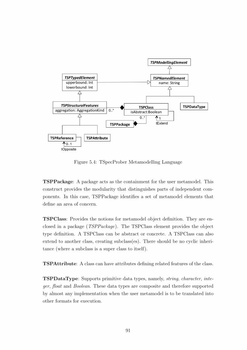
Figure 5.4: TSpecProber Metamodelling Language
TSPPackage: A package acts as the containment for the user metamodel. This
construct provides the modularity that distinguishes parts of independent com-
ponents. In this case, TSPPackage identifies a set of metamodel elements that
define an area of concern.
TSPClass: Provides the notions for metamodel object definition. They are en-
closed in a package (TSPPackage). The TSPClass element provides the object
type definition. A TSPClass can be abstract or concrete. A TSPClass can also
extend to another class, creating subclass(es). There should be no cyclic inheri-
tance (where a subclass is a super class to itself).
TSPAttribute: A class can have attributes defining related features of the class.
TSPDataType: Supports primitive data types, namely, string, character, inte-
ger, float and Boolean. These data types are composite and therefore supported
by almost any implementation when the user metamodel is to be translated into
other formats for execution.
91
TSPReference: TSPClasses can have associations that link between objects of
each class. Association ends defines how these classes participate in the associ-
ations. These are provided by the TSPReference element in TSP metamodel.
Bidirectional associations are provided by tOpposite reference. In this framework,
there are two ways of defining bi-directional association, using role name with bi-
ojectivity function or two uni-directional associations with association end name
and symmetrical constraints. The latter is useful when there are uni-directional
associations in models.
TSPTypedElement : Provides multiplicity for association elements. It can also
be the point of extension to other types, such as operation types.
TSPStructuralFeatures : Defines traits of an association. Aggregation is a
type of relation that defines containment properties of an object. Types of ag-
gregations can be broken down into strong and weak aggregations. Strong ag-
gregation annotates that the head class object holds a definite link with its end
class objects (or a composition), while a weak aggregation may state that a head
class object has a special link to end class objects, but end class objects can exist
independently. This is significant to provide dynamic features of objects.
The TSP metamodelling language can be extended with other features, but
to ensure analysis covers all properties, new templates have to be added into the
catalogue. Before we get into the details of the process of creating a contextualized
user metamodel, we define the our models and their relations in the next section.
TSP metamodelling language has a set of visual notation for defining user
metamodel. The description of the notations are given in Appendix G.1.
5.2.3 TSP framework and their level of abstraction
The organization of TSP models used within this framework adopt the concepts
of the four level of abstraction in its architecture [MDA03]. Figure 5.5 shows the
models in the TSP framework and their location in the level of abstraction.
92
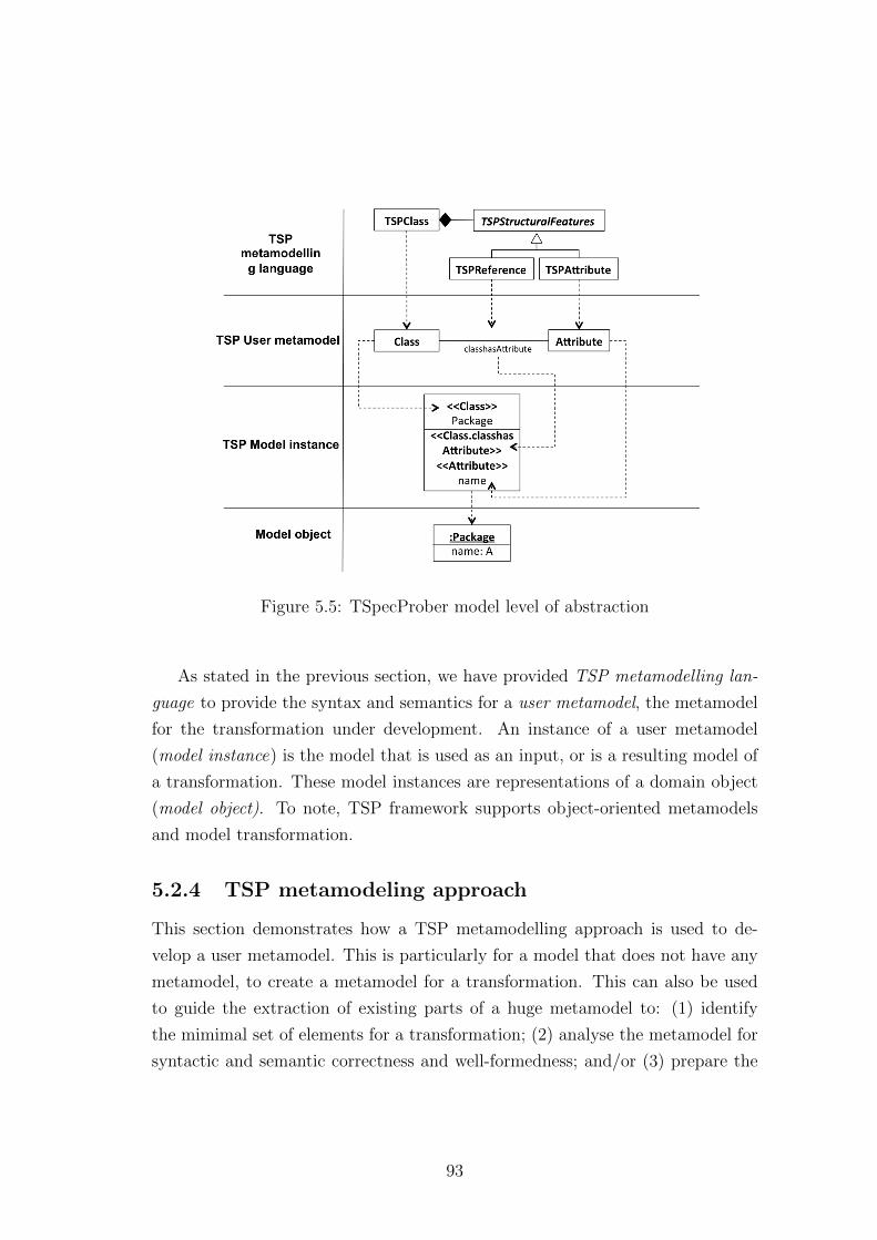
Figure 5.5: TSpecProber model level of abstraction
As stated in the previous section, we have provided TSP metamodelling lan-
guage to provide the syntax and semantics for a user metamodel, the metamodel
for the transformation under development. An instance of a user metamodel
(model instance) is the model that is used as an input, or is a resulting model of
a transformation. These model instances are representations of a domain object
(model object). To note, TSP framework supports object-oriented metamodels
and model transformation.
5.2.4 TSP metamodeling approach
This section demonstrates how a TSP metamodelling approach is used to de-
velop a user metamodel. This is particularly for a model that does not have any
metamodel, to create a metamodel for a transformation. This can also be used
to guide the extraction of existing parts of a huge metamodel to: (1) identify
the mimimal set of elements for a transformation; (2) analyse the metamodel for
syntactic and semantic correctness and well-formedness; and/or (3) prepare the
93
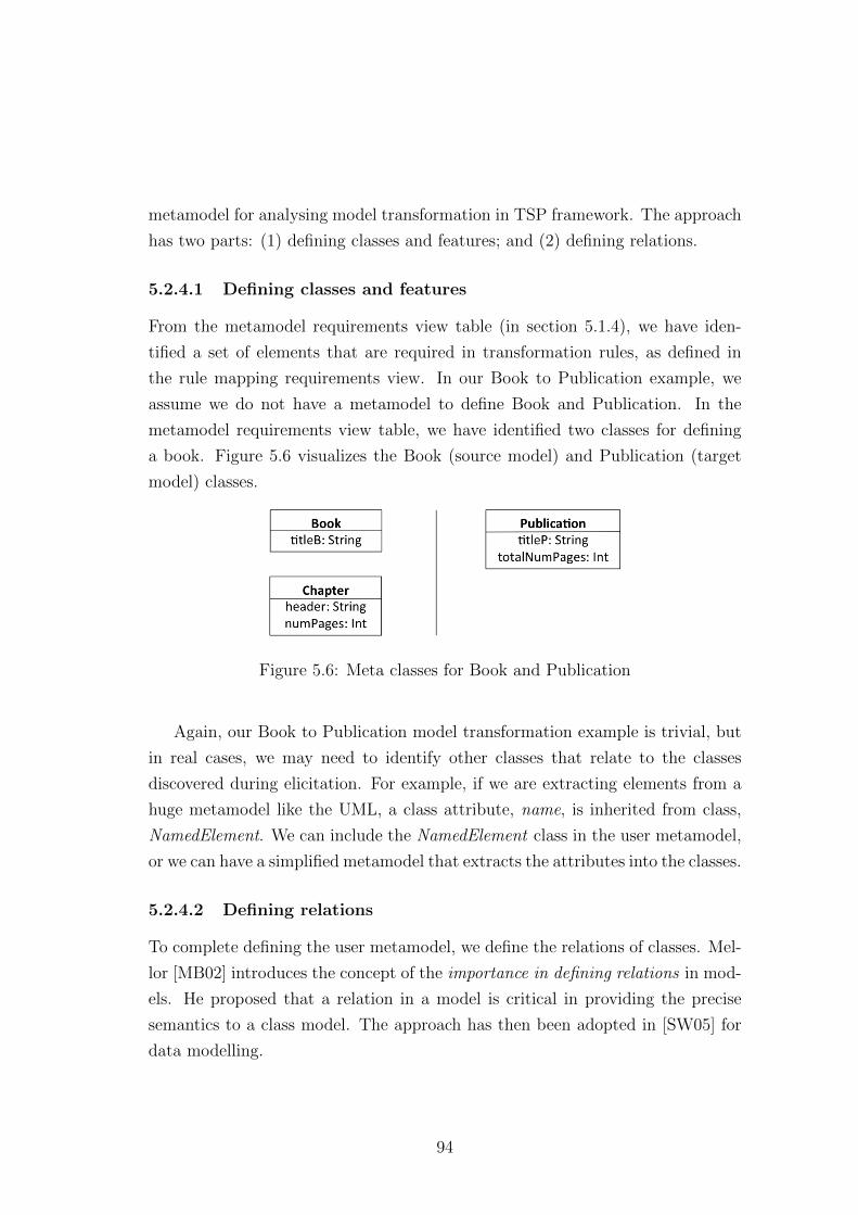
metamodel for analysing model transformation in TSP framework. The approach
has two parts: (1) defining classes and features; and (2) defining relations.
5.2.4.1 Defining classes and features
From the metamodel requirements view table (in section 5.1.4), we have iden-
tified a set of elements that are required in transformation rules, as defined in
the rule mapping requirements view. In our Book to Publication example, we
assume we do not have a metamodel to define Book and Publication. In the
metamodel requirements view table, we have identified two classes for defining
a book. Figure 5.6 visualizes the Book (source model) and Publication (target
model) classes.
Figure 5.6: Meta classes for Book and Publication
Again, our Book to Publication model transformation example is trivial, but
in real cases, we may need to identify other classes that relate to the classes
discovered during elicitation. For example, if we are extracting elements from a
huge metamodel like the UML, a class attribute, name, is inherited from class,
NamedElement. We can include the NamedElement class in the user metamodel,
or we can have a simplified metamodel that extracts the attributes into the classes.
5.2.4.2 Defining relations
To complete defining the user metamodel, we define the relations of classes. Mel-
lor [MB02] introduces the concept of the importance in defining relations in mod-
els. He proposed that a relation in a model is critical in providing the precise
semantics to a class model. The approach has then been adopted in [SW05] for
data modelling.
94
The motivation for this concept is that, relations hold all the important details
that provides the conceptualisation of a domain: an object is like the ‘actor’ of
the domain, and it is the relations that describe the ‘script’ determining the whole
story. Relations contain communication details between objects, not just in terms
of structural features, but strongly dictating the behavioural state of a class in a
system.
In object-oriented models, it is essential that the relations between identified
classes are explored and defined with appropriate annotations. Specifically in this
approach, the way relations are specified plays an important part in providing
the details for generating templates with associated constraints that condition the
user metamodel for automated analysis and verification. We have a collection of
relations pre-defined for the user metamodel. A different template is instantiated
according to the kinds of relations, annotated using {relationKind} notation.
The relations between classes in a user metamodel can be in a form of gen-
eralization and association. The structural features allowed in a relation for this
framework have been briefly explained in Section 5.2.2. The syntax and semantic
definition for the relationship categories are as follows:
Generalization.
The TSP supports variations of generalization that can be use to define in-
stance behaviours of a model. These variations, have been used in entity rela-
tionship diagrams (participation and disjoint constraint) [TLNJ11]. In UML, a
subclass type partitioning is called discriminator.
In this approach, the user metamodels are annotated with additional general-
ization properties using {relationKind} to represent the generalization relation-
ship types, to enhance the semantics of model instance. Particularly in the TSP
framework, the details are used for template instantiation for analysis.
There are four kinds of generalization properties: (1) complete subclass type
partition; (2) incomplete subclass type partition; (3) Disjoint subclass type par-
tition; and (4) overlapping subclass type. Each of these generalization definitions
are provided in Appendix A.
95
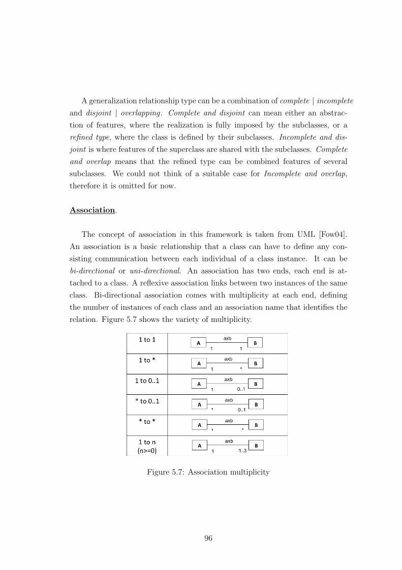
A generalization relationship type can be a combination of complete | incomplete
and disjoint | overlapping . Complete and disjoint can mean either an abstrac-
tion of features, where the realization is fully imposed by the subclasses, or a
refined type, where the class is defined by their subclasses. Incomplete and dis-
joint is where features of the superclass are shared with the subclasses. Complete
and overlap means that the refined type can be combined features of several
subclasses. We could not think of a suitable case for Incomplete and overlap,
therefore it is omitted for now.
Association.
The concept of association in this framework is taken from UML [Fow04].
An association is a basic relationship that a class can have to define any con-
sisting communication between each individual of a class instance. It can be
bi-directional or uni-directional. An association has two ends, each end is at-
tached to a class. A reflexive association links between two instances of the same
class. Bi-directional association comes with multiplicity at each end, defining
the number of instances of each class and an association name that identifies the
relation. Figure 5.7 shows the variety of multiplicity.
Figure 5.7: Association multiplicity
96
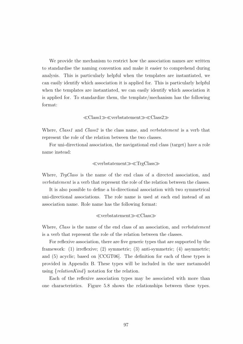
We provide the mechanism to restrict how the association names are written
to standardise the naming convention and make it easier to comprehend during
analysis. This is particularly helpful when the templates are instantiated, we
can easily identify which association it is applied for. This is particularly helpful
when the templates are instantiated, we can easily identify which association it
is applied for. To standardize them, the template/mechanism has the following
format:
�Class1��verbstatement��Class2�
Where, Class1 and Class2 is the class name, and verbstatement is a verb that
represent the role of the relation between the two classes.
For uni-directional association, the navigational end class (target) have a role
name instead:
�verbstatement��TrgClass�
Where, TrgClass is the name of the end class of a directed association, and
verbstatement is a verb that represent the role of the relation between the classes.
It is also possible to define a bi-directional association with two symmetrical
uni-directional associations. The role name is used at each end instead of an
association name. Role name has the following format:
�verbstatement��Class�
Where, Class is the name of the end class of an association, and verbstatement
is a verb that represent the role of the relation between the classes.
For reflexive association, there are five generic types that are supported by the
framework: (1) irreflexive; (2) symmetric; (3) anti-symmetric; (4) asymmetric;
and (5) acyclic; based on [CCGT06]. The definition for each of these types is
provided in Appendix B. These types will be included in the user metamodel
using {relationKind} notation for the relation.
Each of the reflexive association types may be associated with more than
one characteristics. Figure 5.8 shows the relationships between these types.
97
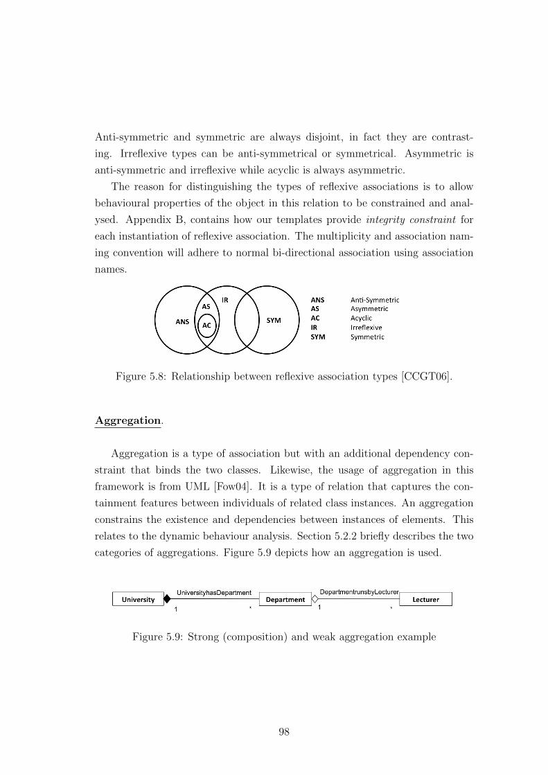
Anti-symmetric and symmetric are always disjoint, in fact they are contrast-
ing. Irreflexive types can be anti-symmetrical or symmetrical. Asymmetric is
anti-symmetric and irreflexive while acyclic is always asymmetric.
The reason for distinguishing the types of reflexive associations is to allow
behavioural properties of the object in this relation to be constrained and anal-
ysed. Appendix B, contains how our templates provide integrity constraint for
each instantiation of reflexive association. The multiplicity and association nam-
ing convention will adhere to normal bi-directional association using association
names.
Figure 5.8: Relationship between reflexive association types [CCGT06].
Aggregation.
Aggregation is a type of association but with an additional dependency con-
straint that binds the two classes. Likewise, the usage of aggregation in this
framework is from UML [Fow04]. It is a type of relation that captures the con-
tainment features between individuals of related class instances. An aggregation
constrains the existence and dependencies between instances of elements. This
relates to the dynamic behaviour analysis. Section 5.2.2 briefly describes the two
categories of aggregations. Figure 5.9 depicts how an aggregation is used.
Figure 5.9: Strong (composition) and weak aggregation example
98
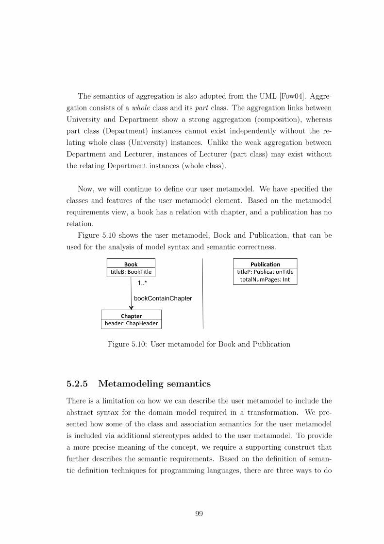
The semantics of aggregation is also adopted from the UML [Fow04]. Aggre-
gation consists of a whole class and its part class. The aggregation links between
University and Department show a strong aggregation (composition), whereas
part class (Department) instances cannot exist independently without the re-
lating whole class (University) instances. Unlike the weak aggregation between
Department and Lecturer, instances of Lecturer (part class) may exist without
the relating Department instances (whole class).
Now, we will continue to define our user metamodel. We have specified the
classes and features of the user metamodel element. Based on the metamodel
requirements view, a book has a relation with chapter, and a publication has no
relation.
Figure 5.10 shows the user metamodel, Book and Publication, that can be
used for the analysis of model syntax and semantic correctness.
Figure 5.10: User metamodel for Book and Publication
5.2.5 Metamodeling semantics
There is a limitation on how we can describe the user metamodel to include the
abstract syntax for the domain model required in a transformation. We pre-
sented how some of the class and association semantics for the user metamodel
is included via additional stereotypes added to the user metamodel. To provide
a more precise meaning of the concept, we require a supporting construct that
further describes the semantic requirements. Based on the definition of seman-
tic definition techniques for programming languages, there are three ways to do
99
this; (1) axiomatic, (2) operational, and (3) denotational approaches [CRC+06].
Commonly, modelling communities adopts the axiomatic approach, using lan-
guage such as OCL to further define model features. Formalization of OCL for
a class model has been looked at in [ABGR10]. We will extend the template for
formalizing OCL in future work.
5.3 Summary
In this chapter, we have defined how we approach elicit model transformation re-
quirements and contextualize a metamodel for model transformation. In the next
chapter, we present how our approach analyses the contextualized metamodel for
being correct and well-formed.
100
Chapter 6
Analysing metamodel
In the previous chapter, we have presented how a model transformation require-
ment is specified and how it can be used to produce a requirements model and
contextualized user metamodel. This chapter proceeds to analysing the user
metamodel to check that it is correct and well-formed. As stated in Section 4.9,
the example models in this chapter have been manually translated into XML (Ap-
pendix C) and its formal Alloy model have been created using the tool described
earlier.
6.1 Analysis of user metamodel
TSP generates a formal counterpart of the user metamodel as part of providing
a clear definition of the needed features of a model instance in a transformation.
This allows models to be type checked for consistency and analysed for correct-
ness. The templates used to generate the formal Alloy models are equipped with
integrity constraints that express how well-formed the elements are in the user
metamodel, making it tractable to automated analysis. Consistency between
the user metamodel and the formal metamodel specification is provided by the
templates which are correct-by-construction [Am7].
Once a formal specification of a user metamodel is generated, we can per-
form formal analysis. The definition of validation of the user metamodel, in our
approach, is to check for the existence of anomalies in our model instances. Al-
loy provides this by performing the process of finding models of a type checked
101
and consistent specification. We can determined how well-formed the user meta-
model is from this. To determine the correctness, we do a verification of the
user metamodel. A snapshot instance of a model based on the requirements is
created and transformed into Alloy, via templates; this is used to check against
the specification. This allows for verification that the user metamodel supports
the features.
6.1.1 Generating formal model for user metamodel
The formal model of the user metamodel is generated by applying a collection
of templates. The templates are separated into views, representing patterns for
each user metamodel component.
Figure 6.1 shows the views of formal specification for the TSP User Meta-
model. An Alloy representation of each of these views is generated by templates,
which define properties according to the user metamodel. In Amalio’s frame-
work [APS05], templates are organized into views according to the structure of
a UML Class diagram. For the user metamodel, the views of Alloy templates
consider the structures of both the metamodel and Alloy building blocks. The
Class and Relational views define structural properties, with additional facts and
predicates that describe conditions applied to instances of user metamodel. Mod-
ule, Assertion, Check, Command and Run are views related to Alloy structure.
Module provides a header used by Alloy Analyzer to include other specifications.
A command will provide the order for Run, for finding model instances, or run-
ning predicates and verifying assertions respectively. We can have a user defined
assertion to perform a check on the specification. The instantiation is provided
by the user metamodel.
The properties of a user metamodel in the TSP are provided by the TSP
Metamodel. Therefore, each element is represented by certain parts of Alloy frag-
ments, as shown in Figure 6.1. It shows how the structural elements of a TSP
User Metamodel are addressed by the Alloy components. Additional Alloy sec-
tions, that are responsible for providing the analysis, will be attached accordingly
during the elements’ template instantiation. This is where the details provided
102
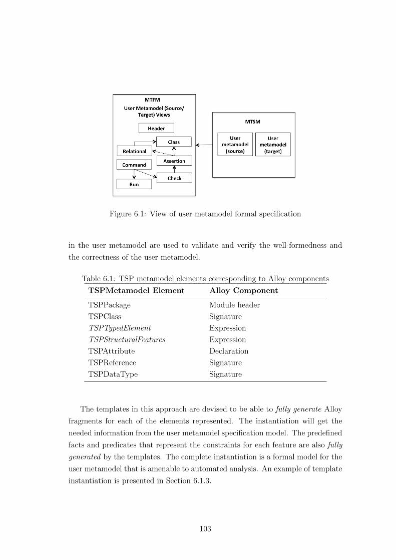
Figure 6.1: View of user metamodel formal specification
in the user metamodel are used to validate and verify the well-formedness and
the correctness of the user metamodel.
Table 6.1: TSP metamodel elements corresponding to Alloy components
TSPMetamodel Element Alloy Component
TSPPackage Module header
TSPClass Signature
TSPTypedElement Expression
TSPStructuralFeatures Expression
TSPAttribute Declaration
TSPReference Signature
TSPDataType Signature
The templates in this approach are devised to be able to fully generate Alloy
fragments for each of the elements represented. The instantiation will get the
needed information from the user metamodel specification model. The predefined
facts and predicates that represent the constraints for each feature are also fully
generated by the templates. The complete instantiation is a formal model for the
user metamodel that is amenable to automated analysis. An example of template
instantiation is presented in Section 6.1.3.
103
6.1.2 Analysis methods using Alloy Analyzer
Analysis of TSP models mainly relies on executing their model formal specifica-
tions, which mechanically produced from instantiations of templates. For user
metamodel formal specification, transformation engineers will manually examine
the instances given by Alloy Analyzer. If there is no irregularities in the small
universe of instances generated and they are conforming to the requirements
specified, transformation engineers can be sure that the model is valid.
For checking user metamodel correctness, patterns (user metamodel instance
model) are produced based on the requirements and its formal specification (user
metamodel instance model formal specification) is executed. The classification
of scenario in relation to applying and executing this is presented in Figure 6.19.
The classification also applies for analysing transformation model formal specifi-
cation and transformation instance model formal specification (see Section 7.3.2).
Similarly, transformation engineers will manually go through instances generated
by Alloy Analyzer.
6.1.3 User Model template instantiation
In the generation of the user metamodel formal specification, all the classes and
relations of the user metamodel are translated to Alloy. The formal specifications
are fully generated by instantiating templates; User Metamodel: Class tem-
plates and User Metamodel: Relation templates. The existing templates
provided by the TSP templates catalogue are given in Appendix I.
6.1.3.1 Class instantiation
There are two types of classes predefined in the TSP framework; abstract and
concrete. Conceptually, abstract classes provide generic features of a set of classes;
in their implementation, abstract classes always require a concrete class for them
to be instantiated. Class instantiation is provided by User Metamodel: Class
templates.
In Alloy, each TSPClass (from now on, we refer to TSPClass as class) is rep-
resented as a signature and class instances are that signatures atom. The concept
104
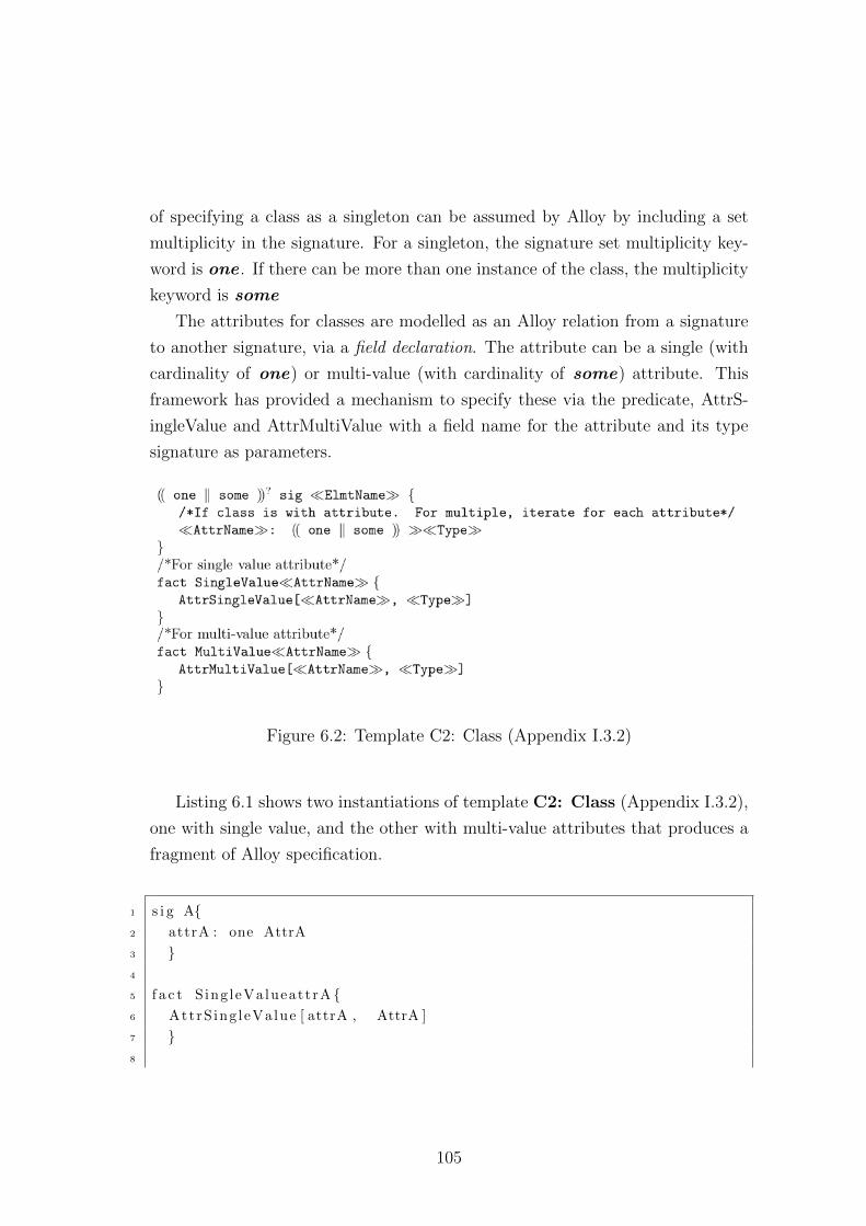
of specifying a class as a singleton can be assumed by Alloy by including a set
multiplicity in the signature. For a singleton, the signature set multiplicity key-
word is one . If there can be more than one instance of the class, the multiplicity
keyword is some
The attributes for classes are modelled as an Alloy relation from a signature
to another signature, via a field declaration. The attribute can be a single (with
cardinality of one) or multi-value (with cardinality of some) attribute. This
framework has provided a mechanism to specify these via the predicate, AttrS-
ingleValue and AttrMultiValue with a field name for the attribute and its type
signature as parameters.
Figure 6.2: Template C2: Class (Appendix I.3.2)
Listing 6.1 shows two instantiations of template C2: Class (Appendix I.3.2),
one with single value, and the other with multi-value attributes that produces a
fragment of Alloy specification.
1 s i g A{2 attrA : one AttrA
3 }4
5 f a c t S ing leValueattrA {6 AttrS ing leValue [ attrA , AttrA ]
7 }8
105
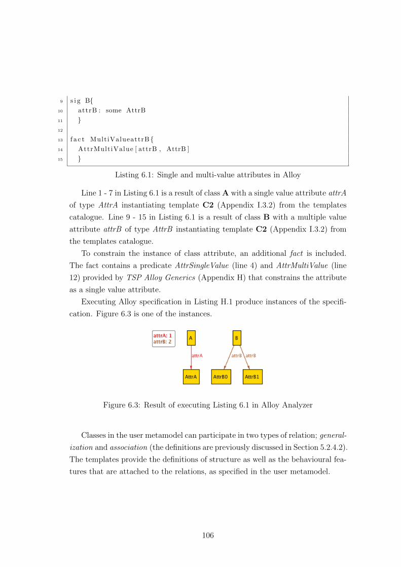
9 s i g B{10 attrB : some AttrB
11 }12
13 f a c t Mult iValueattrB {14 AttrMultiValue [ attrB , AttrB ]
15 }
Listing 6.1: Single and multi-value attributes in Alloy
Line 1 - 7 in Listing 6.1 is a result of class A with a single value attribute attrA
of type AttrA instantiating template C2 (Appendix I.3.2) from the templates
catalogue. Line 9 - 15 in Listing 6.1 is a result of class B with a multiple value
attribute attrB of type AttrB instantiating template C2 (Appendix I.3.2) from
the templates catalogue.
To constrain the instance of class attribute, an additional fact is included.
The fact contains a predicate AttrSingleValue (line 4) and AttrMultiValue (line
12) provided by TSP Alloy Generics (Appendix H) that constrains the attribute
as a single value attribute.
Executing Alloy specification in Listing H.1 produce instances of the specifi-
cation. Figure 6.3 is one of the instances.
Figure 6.3: Result of executing Listing 6.1 in Alloy Analyzer
Classes in the user metamodel can participate in two types of relation; general-
ization and association (the definitions are previously discussed in Section 5.2.4.2).
The templates provide the definitions of structure as well as the behavioural fea-
tures that are attached to the relations, as specified in the user metamodel.
106
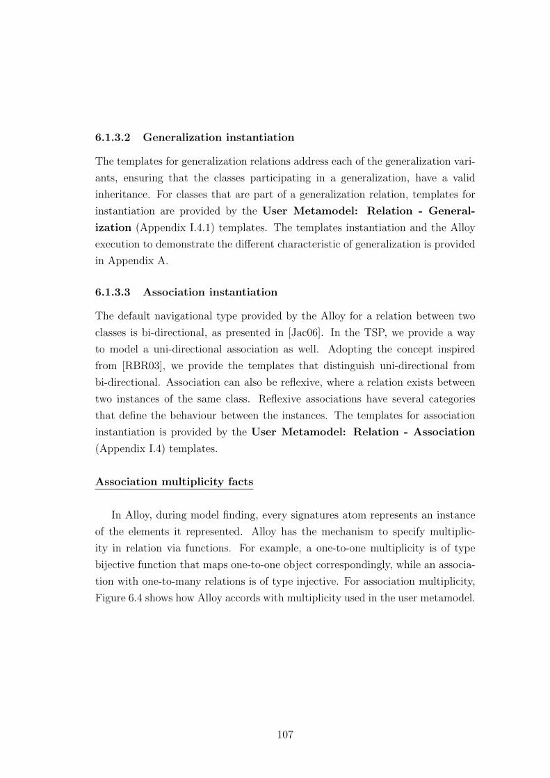
6.1.3.2 Generalization instantiation
The templates for generalization relations address each of the generalization vari-
ants, ensuring that the classes participating in a generalization, have a valid
inheritance. For classes that are part of a generalization relation, templates for
instantiation are provided by the User Metamodel: Relation - General-
ization (Appendix I.4.1) templates. The templates instantiation and the Alloy
execution to demonstrate the different characteristic of generalization is provided
in Appendix A.
6.1.3.3 Association instantiation
The default navigational type provided by the Alloy for a relation between two
classes is bi-directional, as presented in [Jac06]. In the TSP, we provide a way
to model a uni-directional association as well. Adopting the concept inspired
from [RBR03], we provide the templates that distinguish uni-directional from
bi-directional. Association can also be reflexive, where a relation exists between
two instances of the same class. Reflexive associations have several categories
that define the behaviour between the instances. The templates for association
instantiation is provided by the User Metamodel: Relation - Association
(Appendix I.4) templates.
Association multiplicity facts
In Alloy, during model finding, every signatures atom represents an instance
of the elements it represented. Alloy has the mechanism to specify multiplic-
ity in relation via functions. For example, a one-to-one multiplicity is of type
bijective function that maps one-to-one object correspondingly, while an associa-
tion with one-to-many relations is of type injective. For association multiplicity,
Figure 6.4 shows how Alloy accords with multiplicity used in the user metamodel.
107
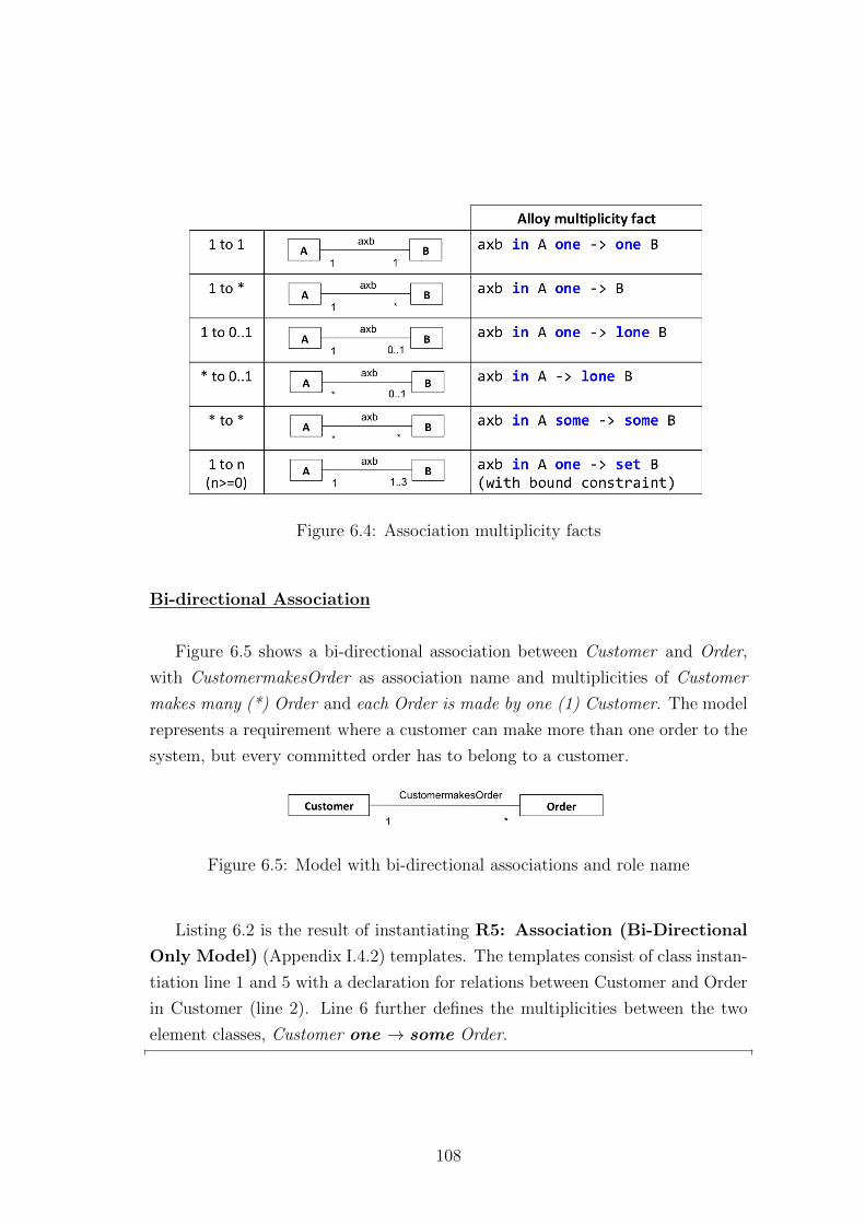
Figure 6.4: Association multiplicity facts
Bi-directional Association
Figure 6.5 shows a bi-directional association between Customer and Order,
with CustomermakesOrder as association name and multiplicities of Customer
makes many (*) Order and each Order is made by one (1) Customer. The model
represents a requirement where a customer can make more than one order to the
system, but every committed order has to belong to a customer.
Figure 6.5: Model with bi-directional associations and role name
Listing 6.2 is the result of instantiating R5: Association (Bi-Directional
Only Model) (Appendix I.4.2) templates. The templates consist of class instan-
tiation line 1 and 5 with a declaration for relations between Customer and Order
in Customer (line 2). Line 6 further defines the multiplicities between the two
element classes, Customer one → some Order.
108
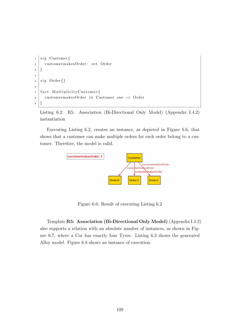
1 s i g Customer{2 customermakesOrder : s e t Order
3 }4
5 s i g Order{}6
7 f a c t Mult ip l i c i tyCustomer {8 customermakesOrder in Customer one −> Order
9 }
Listing 6.2: R5: Association (Bi-Directional Only Model) (Appendix I.4.2)
instantiation
Executing Listing 6.2, creates an instance, as depicted in Figure 6.6, that
shows that a customer can make multiple orders for each order belong to a cus-
tomer. Therefore, the model is valid.
Figure 6.6: Result of executing Listing 6.2
Template R5: Association (Bi-Directional Only Model) (Appendix I.4.2)
also supports a relation with an absolute number of instances, as shown in Fig-
ure 6.7, where a Car has exactly four Tyres. Listing 6.3 shows the generated
Alloy model. Figure 6.8 shows an instance of execution.
109
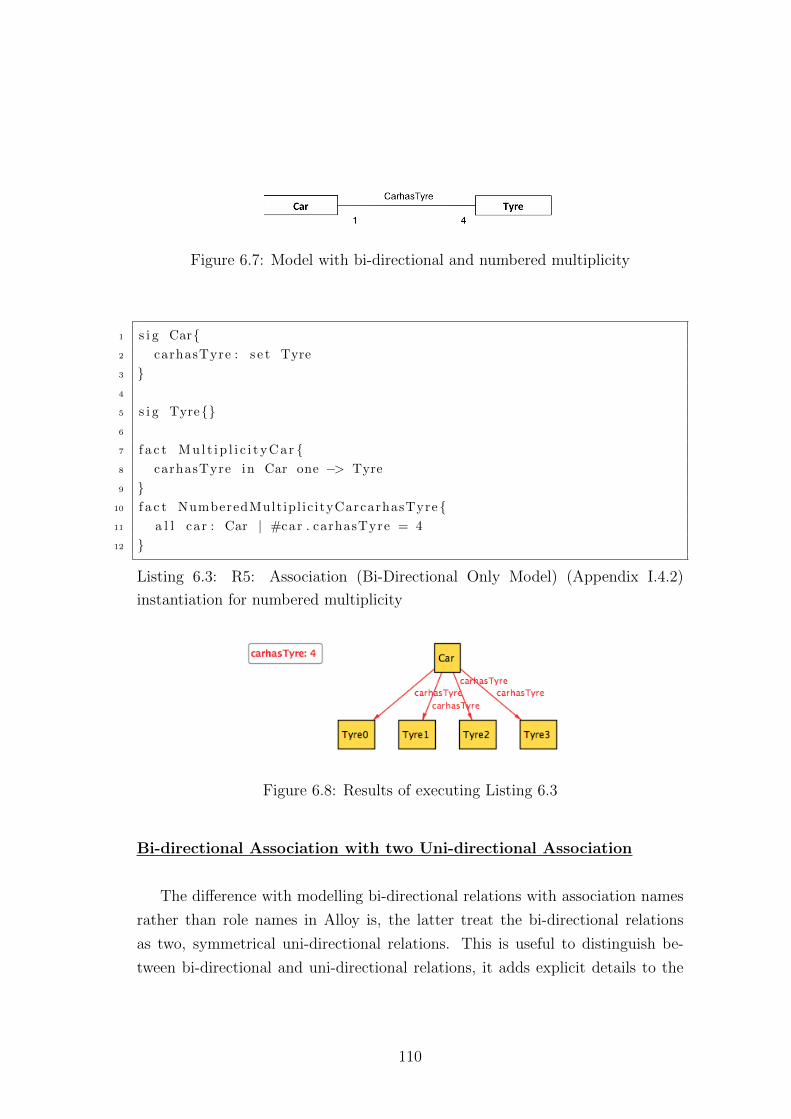
Figure 6.7: Model with bi-directional and numbered multiplicity
1 s i g Car{2 carhasTyre : s e t Tyre
3 }4
5 s i g Tyre{}6
7 f a c t Mu l t i p l i c i t y C a r {8 carhasTyre in Car one −> Tyre
9 }10 f a c t NumberedMult ipl ic ityCarcarhasTyre {11 a l l car : Car | #car . carhasTyre = 4
12 }
Listing 6.3: R5: Association (Bi-Directional Only Model) (Appendix I.4.2)
instantiation for numbered multiplicity
Figure 6.8: Results of executing Listing 6.3
Bi-directional Association with two Uni-directional Association
The difference with modelling bi-directional relations with association names
rather than role names in Alloy is, the latter treat the bi-directional relations
as two, symmetrical uni-directional relations. This is useful to distinguish be-
tween bi-directional and uni-directional relations, it adds explicit details to the
110
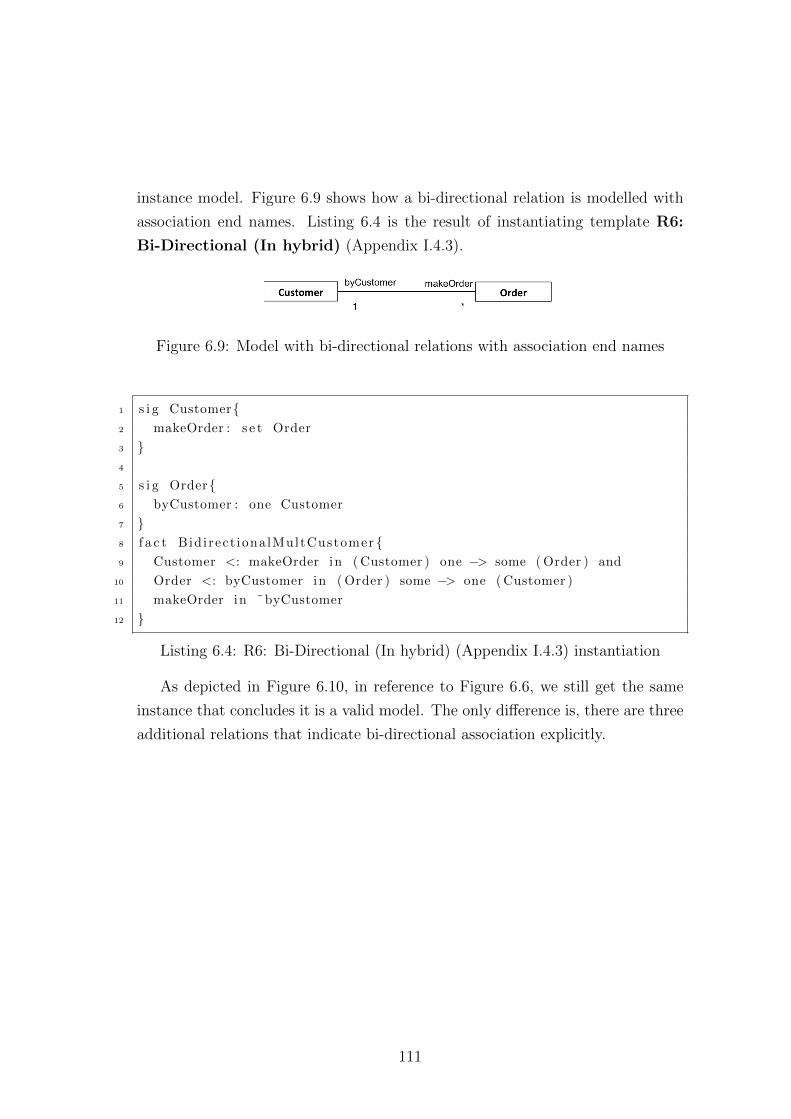
instance model. Figure 6.9 shows how a bi-directional relation is modelled with
association end names. Listing 6.4 is the result of instantiating template R6:
Bi-Directional (In hybrid) (Appendix I.4.3).
Figure 6.9: Model with bi-directional relations with association end names
1 s i g Customer{2 makeOrder : s e t Order
3 }4
5 s i g Order{6 byCustomer : one Customer
7 }8 f a c t Bid i rect iona lMultCustomer {9 Customer <: makeOrder in ( Customer ) one −> some ( Order ) and
10 Order <: byCustomer in ( Order ) some −> one ( Customer )
11 makeOrder in ˜byCustomer
12 }
Listing 6.4: R6: Bi-Directional (In hybrid) (Appendix I.4.3) instantiation
As depicted in Figure 6.10, in reference to Figure 6.6, we still get the same
instance that concludes it is a valid model. The only difference is, there are three
additional relations that indicate bi-directional association explicitly.
111
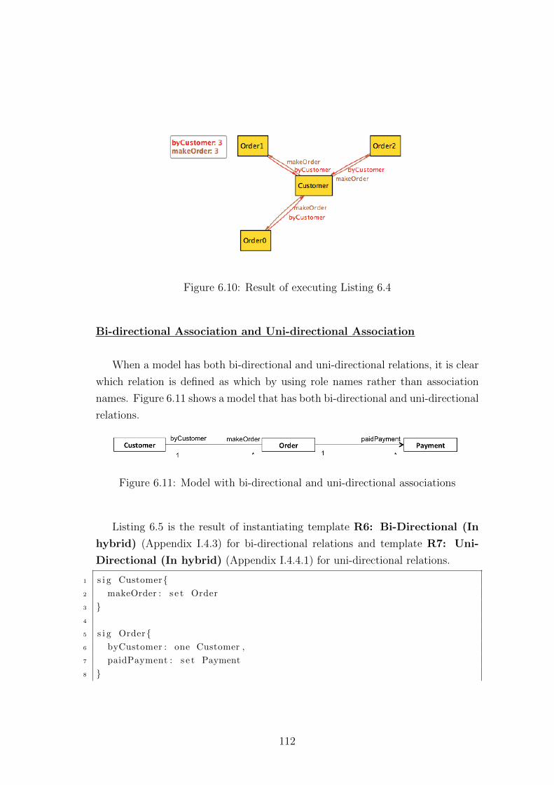
Figure 6.10: Result of executing Listing 6.4
Bi-directional Association and Uni-directional Association
When a model has both bi-directional and uni-directional relations, it is clear
which relation is defined as which by using role names rather than association
names. Figure 6.11 shows a model that has both bi-directional and uni-directional
relations.
Figure 6.11: Model with bi-directional and uni-directional associations
Listing 6.5 is the result of instantiating template R6: Bi-Directional (In
hybrid) (Appendix I.4.3) for bi-directional relations and template R7: Uni-
Directional (In hybrid) (Appendix I.4.4.1) for uni-directional relations.
1 s i g Customer{2 makeOrder : s e t Order
3 }4
5 s i g Order{6 byCustomer : one Customer ,
7 paidPayment : s e t Payment
8 }
112
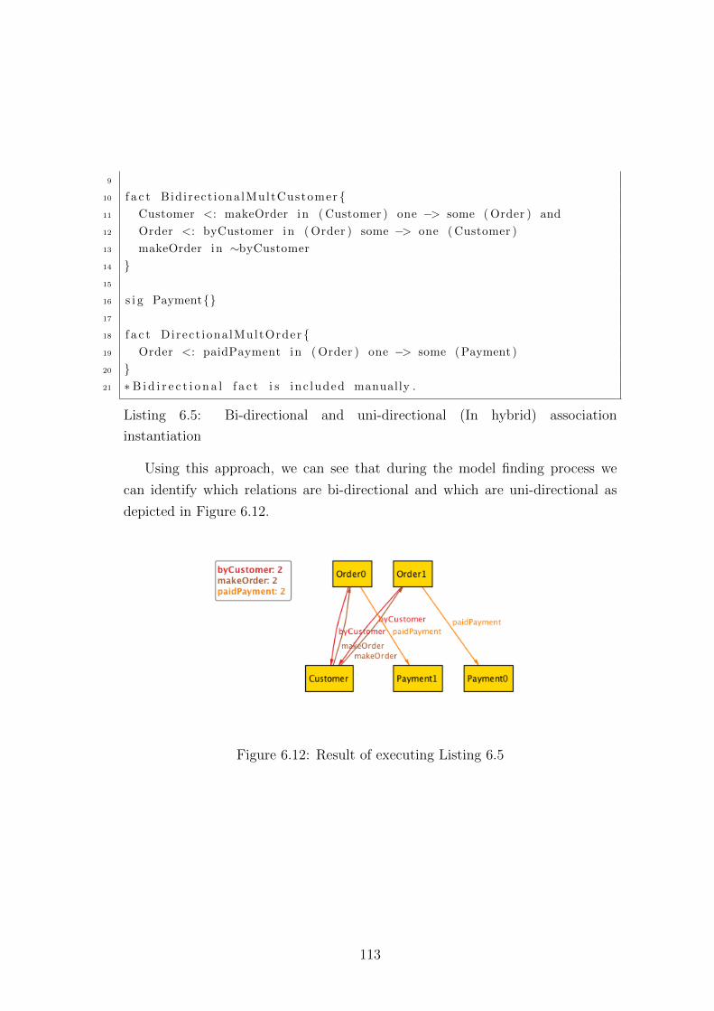
9
10 f a c t Bid i rect iona lMultCustomer {11 Customer <: makeOrder in ( Customer ) one −> some ( Order ) and
12 Order <: byCustomer in ( Order ) some −> one ( Customer )
13 makeOrder in ∼byCustomer
14 }15
16 s i g Payment{}17
18 f a c t Direct iona lMultOrder {19 Order <: paidPayment in ( Order ) one −> some ( Payment )
20 }21 ∗B i d i r e c t i o n a l f a c t i s inc luded manually .
Listing 6.5: Bi-directional and uni-directional (In hybrid) association
instantiation
Using this approach, we can see that during the model finding process we
can identify which relations are bi-directional and which are uni-directional as
depicted in Figure 6.12.
Figure 6.12: Result of executing Listing 6.5
113
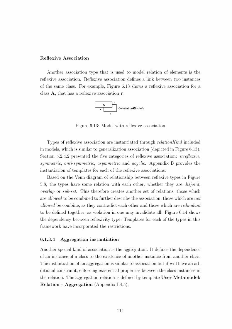
Reflexive Association
Another association type that is used to model relation of elements is the
reflexive association. Reflexive association defines a link between two instances
of the same class. For example, Figure 6.13 shows a reflexive association for a
class A, that has a reflexive association r .
Figure 6.13: Model with reflexive association
Types of reflexive association are instantiated through relationKind included
in models, which is similar to generalization association (depicted in Figure 6.13).
Section 5.2.4.2 presented the five categories of reflexive association: irreflexive,
symmetric, anti-symmetric, asymmetric and acyclic. Appendix B provides the
instantiation of templates for each of the reflexive associations.
Based on the Venn diagram of relationship between reflexive types in Figure
5.8, the types have some relation with each other, whether they are disjoint,
overlap or sub-set. This therefore creates another set of relations; those which
are allowed to be combined to further describe the association, those which are not
allowed be combine, as they contradict each other and those which are redundant
to be defined together, as violation in one may invalidate all. Figure 6.14 shows
the dependency between reflexivity type. Templates for each of the types in this
framework have incorporated the restrictions.
6.1.3.4 Aggregation instantiation
Another special kind of association is the aggregation. It defines the dependence
of an instance of a class to the existence of another instance from another class.
The instantiation of an aggregation is similar to association but it will have an ad-
ditional constraint, enforcing existential properties between the class instances in
the relation. The aggregation relation is defined by template User Metamodel:
Relation - Aggregation (Appendix I.4.5).
114
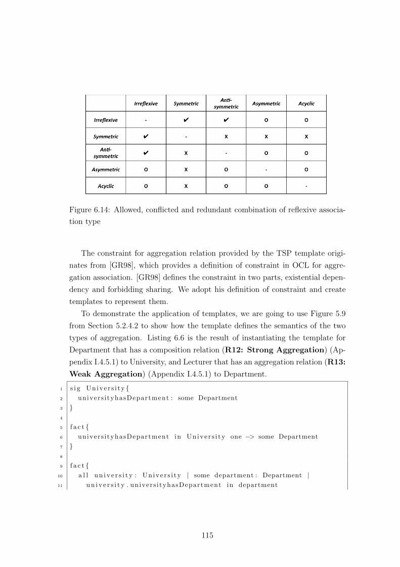
Figure 6.14: Allowed, conflicted and redundant combination of reflexive associa-
tion type
The constraint for aggregation relation provided by the TSP template origi-
nates from [GR98], which provides a definition of constraint in OCL for aggre-
gation association. [GR98] defines the constraint in two parts, existential depen-
dency and forbidding sharing. We adopt his definition of constraint and create
templates to represent them.
To demonstrate the application of templates, we are going to use Figure 5.9
from Section 5.2.4.2 to show how the template defines the semantics of the two
types of aggregation. Listing 6.6 is the result of instantiating the template for
Department that has a composition relation (R12: Strong Aggregation) (Ap-
pendix I.4.5.1) to University, and Lecturer that has an aggregation relation (R13:
Weak Aggregation) (Appendix I.4.5.1) to Department.
1 s i g Un ive r s i ty {2 univers i tyhasDepartment : some Department
3 }4
5 f a c t {6 univers i tyhasDepartment in Un ive r s i ty one −> some Department
7 }8
9 f a c t {10 a l l u n i v e r s i t y : Un ive r s i ty | some department : Department |11 u n i v e r s i t y . univers i tyhasDepartment in department
115
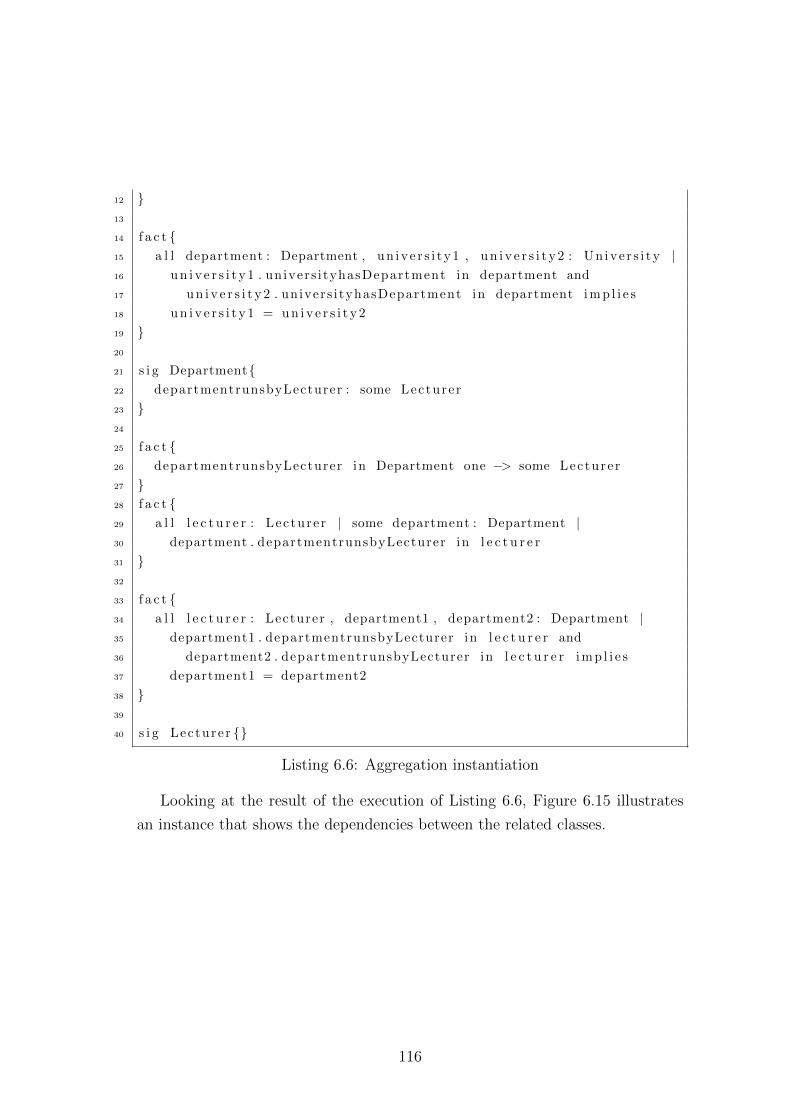
12 }13
14 f a c t {15 a l l department : Department , un ive r s i t y1 , u n i v e r s i t y 2 : Un ive r s i ty |16 u n i v e r s i t y 1 . univers i tyhasDepartment in department and
17 u n i v e r s i t y 2 . univers i tyhasDepartment in department i m p l i e s
18 u n i v e r s i t y 1 = u n i v e r s i t y 2
19 }20
21 s i g Department{22 departmentrunsbyLecturer : some Lecturer
23 }24
25 f a c t {26 departmentrunsbyLecturer in Department one −> some Lecturer
27 }28 f a c t {29 a l l l e c t u r e r : Lecturer | some department : Department |30 department . departmentrunsbyLecturer in l e c t u r e r
31 }32
33 f a c t {34 a l l l e c t u r e r : Lecturer , department1 , department2 : Department |35 department1 . departmentrunsbyLecturer in l e c t u r e r and
36 department2 . departmentrunsbyLecturer in l e c t u r e r i m p l i e s
37 department1 = department2
38 }39
40 s i g Lecturer {}
Listing 6.6: Aggregation instantiation
Looking at the result of the execution of Listing 6.6, Figure 6.15 illustrates
an instance that shows the dependencies between the related classes.
116
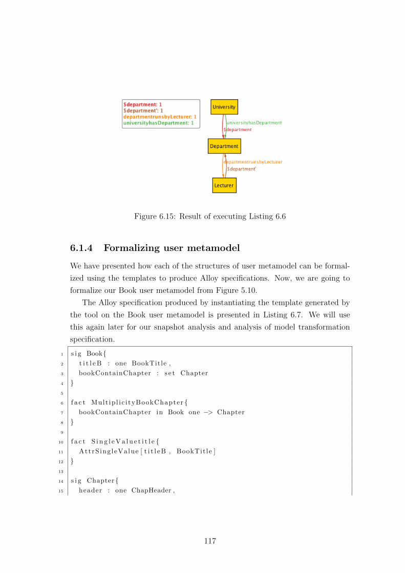
Figure 6.15: Result of executing Listing 6.6
6.1.4 Formalizing user metamodel
We have presented how each of the structures of user metamodel can be formal-
ized using the templates to produce Alloy specifications. Now, we are going to
formalize our Book user metamodel from Figure 5.10.
The Alloy specification produced by instantiating the template generated by
the tool on the Book user metamodel is presented in Listing 6.7. We will use
this again later for our snapshot analysis and analysis of model transformation
specification.
1 s i g Book{2 t i t l e B : one BookTitle ,
3 bookContainChapter : s e t Chapter
4 }5
6 f a c t Mult ip l i c i tyBookChapter {7 bookContainChapter in Book one −> Chapter
8 }9
10 f a c t S i n g l e V a l u e t i t l e {11 AttrS ing leValue [ t i t l e B , BookTit le ]
12 }13
14 s i g Chapter{15 header : one ChapHeader ,
117
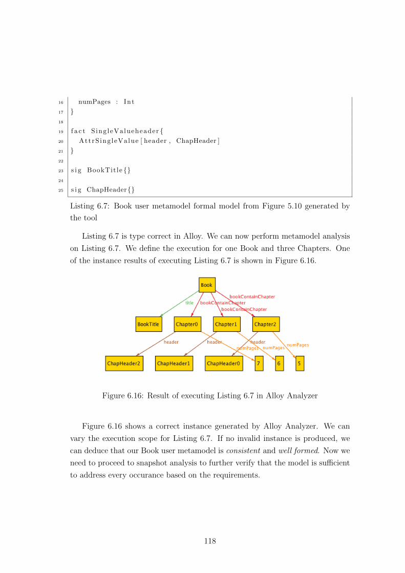
16 numPages : Int
17 }18
19 f a c t S ing leValueheader {20 AttrS ing leValue [ header , ChapHeader ]
21 }22
23 s i g BookTit le {}24
25 s i g ChapHeader{}
Listing 6.7: Book user metamodel formal model from Figure 5.10 generated by
the tool
Listing 6.7 is type correct in Alloy. We can now perform metamodel analysis
on Listing 6.7. We define the execution for one Book and three Chapters. One
of the instance results of executing Listing 6.7 is shown in Figure 6.16.
Figure 6.16: Result of executing Listing 6.7 in Alloy Analyzer
Figure 6.16 shows a correct instance generated by Alloy Analyzer. We can
vary the execution scope for Listing 6.7. If no invalid instance is produced, we
can deduce that our Book user metamodel is consistent and well formed. Now we
need to proceed to snapshot analysis to further verify that the model is sufficient
to address every occurance based on the requirements.
118
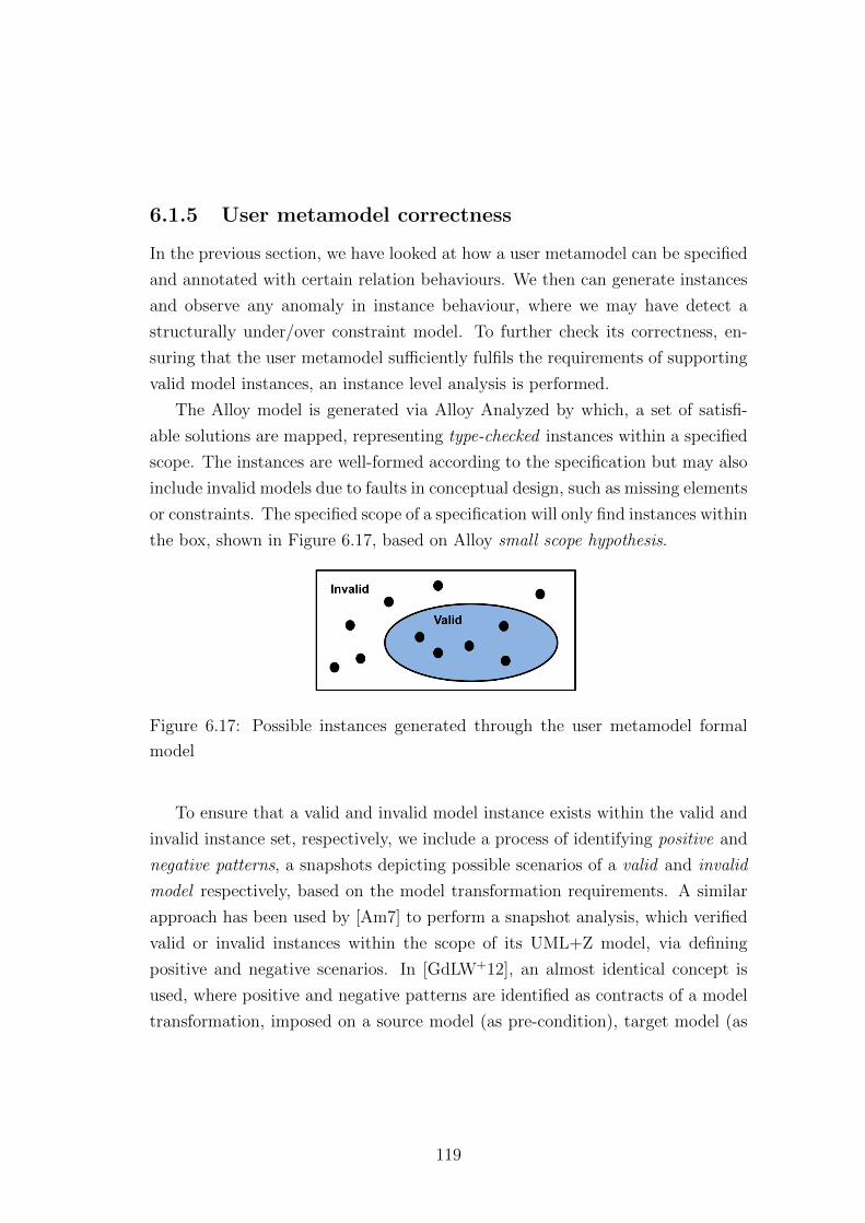
6.1.5 User metamodel correctness
In the previous section, we have looked at how a user metamodel can be specified
and annotated with certain relation behaviours. We then can generate instances
and observe any anomaly in instance behaviour, where we may have detect a
structurally under/over constraint model. To further check its correctness, en-
suring that the user metamodel sufficiently fulfils the requirements of supporting
valid model instances, an instance level analysis is performed.
The Alloy model is generated via Alloy Analyzed by which, a set of satisfi-
able solutions are mapped, representing type-checked instances within a specified
scope. The instances are well-formed according to the specification but may also
include invalid models due to faults in conceptual design, such as missing elements
or constraints. The specified scope of a specification will only find instances within
the box, shown in Figure 6.17, based on Alloy small scope hypothesis.
Figure 6.17: Possible instances generated through the user metamodel formal
model
To ensure that a valid and invalid model instance exists within the valid and
invalid instance set, respectively, we include a process of identifying positive and
negative patterns, a snapshots depicting possible scenarios of a valid and invalid
model respectively, based on the model transformation requirements. A similar
approach has been used by [Am7] to perform a snapshot analysis, which verified
valid or invalid instances within the scope of its UML+Z model, via defining
positive and negative scenarios. In [GdLW+12], an almost identical concept is
used, where positive and negative patterns are identified as contracts of a model
transformation, imposed on a source model (as pre-condition), target model (as
119
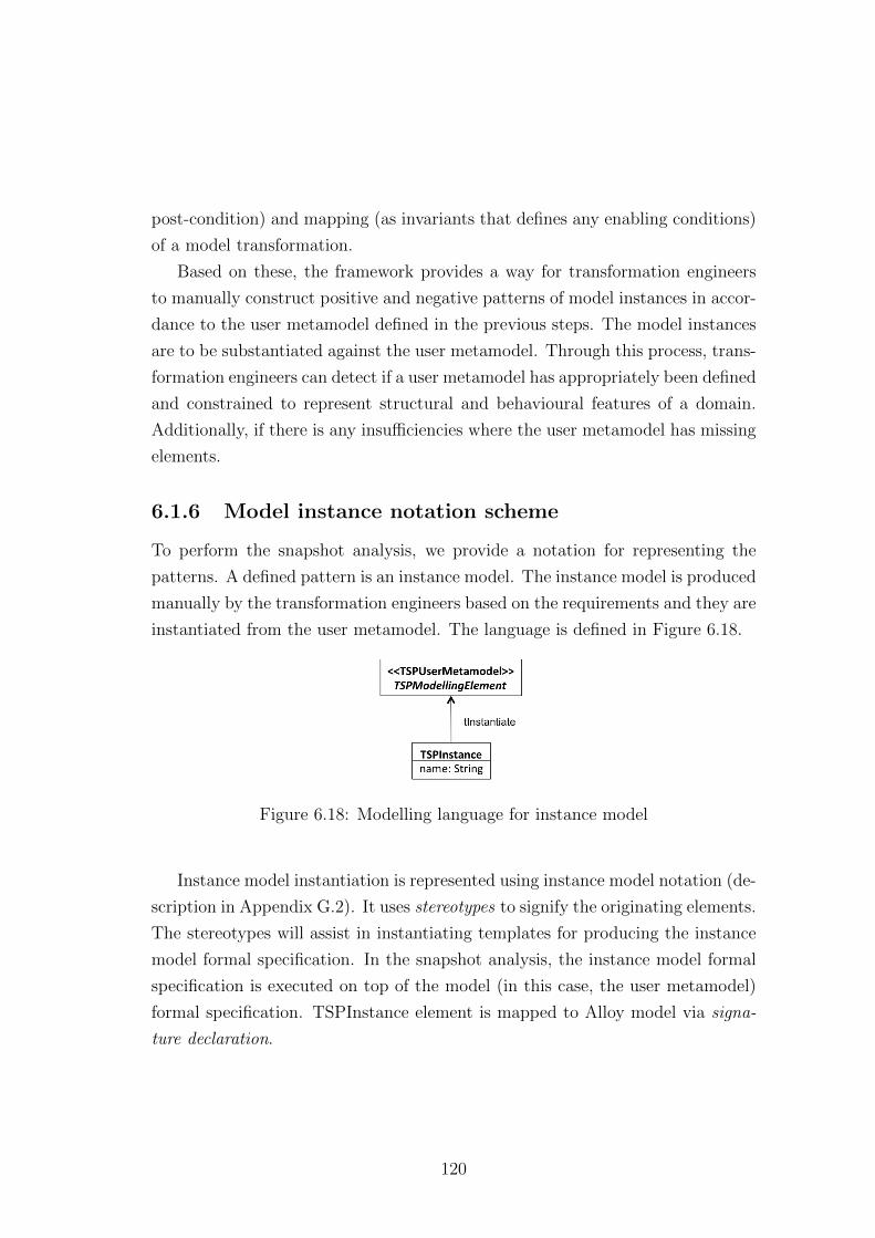
post-condition) and mapping (as invariants that defines any enabling conditions)
of a model transformation.
Based on these, the framework provides a way for transformation engineers
to manually construct positive and negative patterns of model instances in accor-
dance to the user metamodel defined in the previous steps. The model instances
are to be substantiated against the user metamodel. Through this process, trans-
formation engineers can detect if a user metamodel has appropriately been defined
and constrained to represent structural and behavioural features of a domain.
Additionally, if there is any insufficiencies where the user metamodel has missing
elements.
6.1.6 Model instance notation scheme
To perform the snapshot analysis, we provide a notation for representing the
patterns. A defined pattern is an instance model. The instance model is produced
manually by the transformation engineers based on the requirements and they are
instantiated from the user metamodel. The language is defined in Figure 6.18.
Figure 6.18: Modelling language for instance model
Instance model instantiation is represented using instance model notation (de-
scription in Appendix G.2). It uses stereotypes to signify the originating elements.
The stereotypes will assist in instantiating templates for producing the instance
model formal specification. In the snapshot analysis, the instance model formal
specification is executed on top of the model (in this case, the user metamodel)
formal specification. TSPInstance element is mapped to Alloy model via signa-
ture declaration.
120
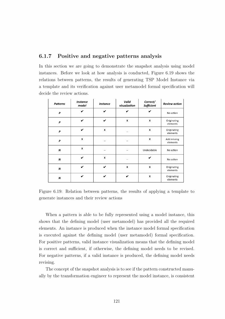
6.1.7 Positive and negative patterns analysis
In this section we are going to demonstrate the snapshot analysis using model
instances. Before we look at how analysis is conducted, Figure 6.19 shows the
relations between patterns, the results of generating TSP Model Instance via
a template and its verification against user metamodel formal specification will
decide the review actions.
Figure 6.19: Relation between patterns, the results of applying a template to
generate instances and their review actions
When a pattern is able to be fully represented using a model instance, this
shows that the defining model (user metamodel) has provided all the required
elements. An instance is produced when the instance model formal specification
is executed against the defining model (user metamodel) formal specification.
For positive patterns, valid instance visualization means that the defining model
is correct and sufficient, if otherwise, the defining model needs to be revised.
For negative patterns, if a valid instance is produced, the defining model needs
revising.
The concept of the snapshot analysis is to see if the pattern constructed manu-
ally by the transformation engineer to represent the model instance, is consistent
121
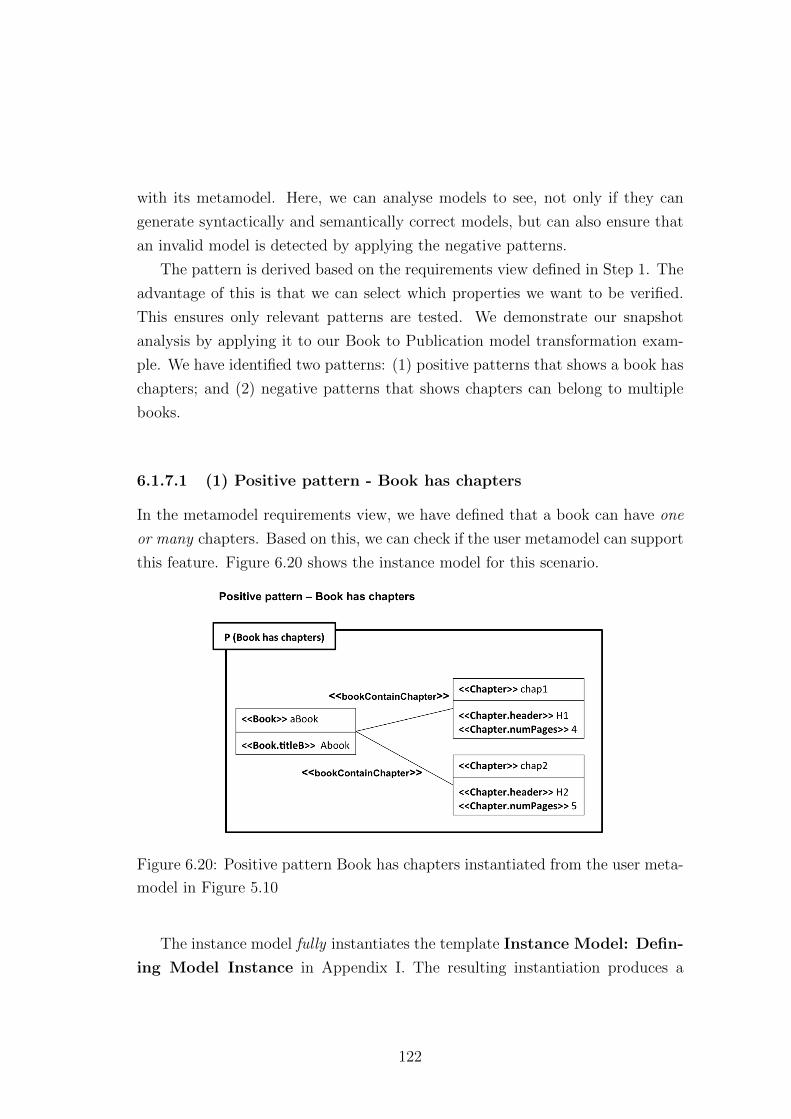
with its metamodel. Here, we can analyse models to see, not only if they can
generate syntactically and semantically correct models, but can also ensure that
an invalid model is detected by applying the negative patterns.
The pattern is derived based on the requirements view defined in Step 1. The
advantage of this is that we can select which properties we want to be verified.
This ensures only relevant patterns are tested. We demonstrate our snapshot
analysis by applying it to our Book to Publication model transformation exam-
ple. We have identified two patterns: (1) positive patterns that shows a book has
chapters; and (2) negative patterns that shows chapters can belong to multiple
books.
6.1.7.1 (1) Positive pattern - Book has chapters
In the metamodel requirements view, we have defined that a book can have one
or many chapters. Based on this, we can check if the user metamodel can support
this feature. Figure 6.20 shows the instance model for this scenario.
Figure 6.20: Positive pattern Book has chapters instantiated from the user meta-
model in Figure 5.10
The instance model fully instantiates the template Instance Model: Defin-
ing Model Instance in Appendix I. The resulting instantiation produces a
122
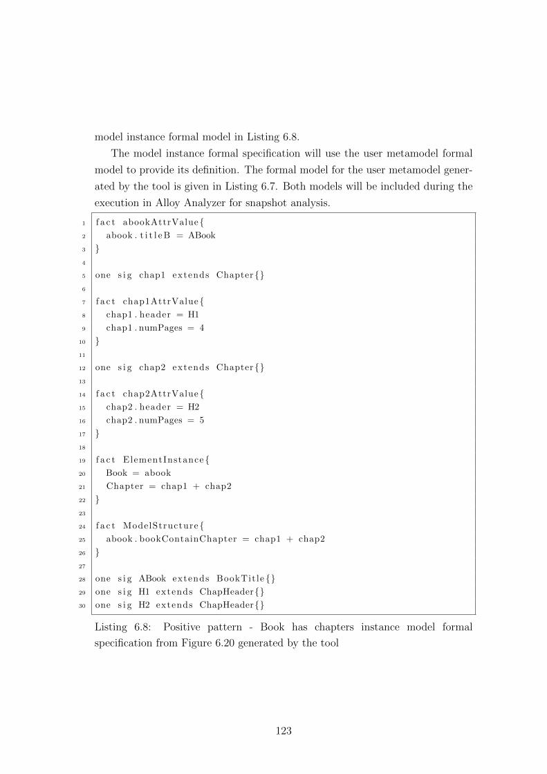
model instance formal model in Listing 6.8.
The model instance formal specification will use the user metamodel formal
model to provide its definition. The formal model for the user metamodel gener-
ated by the tool is given in Listing 6.7. Both models will be included during the
execution in Alloy Analyzer for snapshot analysis.
1 f a c t abookAttrValue{2 abook . t i t l e B = ABook
3 }4
5 one s i g chap1 extends Chapter{}6
7 f a c t chap1AttrValue{8 chap1 . header = H1
9 chap1 . numPages = 4
10 }11
12 one s i g chap2 extends Chapter{}13
14 f a c t chap2AttrValue{15 chap2 . header = H2
16 chap2 . numPages = 5
17 }18
19 f a c t ElementInstance {20 Book = abook
21 Chapter = chap1 + chap2
22 }23
24 f a c t ModelStructure {25 abook . bookContainChapter = chap1 + chap2
26 }27
28 one s i g ABook extends BookTit le {}29 one s i g H1 extends ChapHeader{}30 one s i g H2 extends ChapHeader{}
Listing 6.8: Positive pattern - Book has chapters instance model formal
specification from Figure 6.20 generated by the tool
123
In Listing 6.8, Line 1 - 17 is the declaration of model instances object features
for the two chapters from the Positive Pattern in Figure 6.20. Each instance is
defined as a type element from the metamodel (Line 19 - 22). The structure of
the model is declared in Line 24 - 26.
Executing Listing 6.8 produces a successful verification by producing a valid
instance, as depicted in Figure 6.21. This shows that the features are correctly
defined by the user metamodel.
Figure 6.21: A successful verification of positive pattern by Alloy Analyzer - Book
has chapters
6.1.7.2 (2) Negative pattern - Chapter belongs to multiple books
The scenario in Figure 6.22 is a negative pattern for our Book to Publication
model transformation example. In the metamodel requirements view, we have
stated that chapters can only belong to one and only one book.
When instantiating the model instance template, the model instance formal
specification (Listing 6.9) is produced. Executing the specification does not pro-
duce any instance in which chapter is linked to more than one book. A negative
pattern should not produce an example in the Alloy Analyzer, therefore, we can
conclude that the model conforms to its defined metamodel.
124
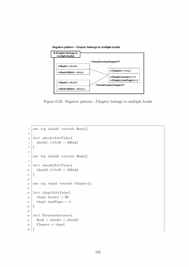
Figure 6.22: Negative pattern - Chapter belongs to multiple books
1 one s i g abook1 extends Book{}2
3 f a c t abook1AttrValue{4 abook1 . t i t l e B = ABook1
5 }6
7 one s i g abook2 extends Book{}8
9 f a c t abook2AttrValue{10 abook2 . t i t l e B = ABook2
11 }12
13 one s i g chap1 extends Chapter{}14
15 f a c t chap1AttrValue{16 chap1 . header = H1
17 chap1 . numPages = 4
18 }19
20 f a c t ElementInstance {21 Book = abook1 + abook2
22 Chapter = chap1
23 }
125
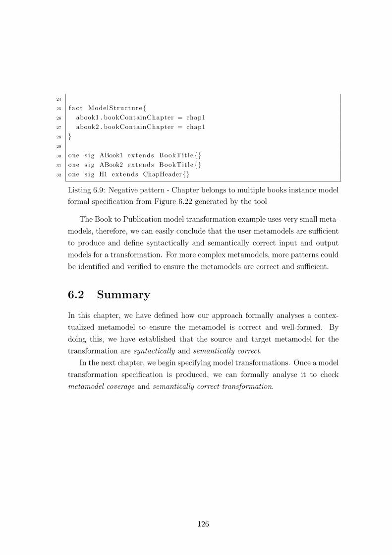
24
25 f a c t ModelStructure {26 abook1 . bookContainChapter = chap1
27 abook2 . bookContainChapter = chap1
28 }29
30 one s i g ABook1 extends BookTit le {}31 one s i g ABook2 extends BookTit le {}32 one s i g H1 extends ChapHeader{}
Listing 6.9: Negative pattern - Chapter belongs to multiple books instance model
formal specification from Figure 6.22 generated by the tool
The Book to Publication model transformation example uses very small meta-
models, therefore, we can easily conclude that the user metamodels are sufficient
to produce and define syntactically and semantically correct input and output
models for a transformation. For more complex metamodels, more patterns could
be identified and verified to ensure the metamodels are correct and sufficient.
6.2 Summary
In this chapter, we have defined how our approach formally analyses a contex-
tualized metamodel to ensure the metamodel is correct and well-formed. By
doing this, we have established that the source and target metamodel for the
transformation are syntactically and semantically correct.
In the next chapter, we begin specifying model transformations. Once a model
transformation specification is produced, we can formally analyse it to check
metamodel coverage and semantically correct transformation.
126
Chapter 7
Specifying and analysing model
transformation
In the previous chapters we identified the requirements for model transformation,
production of a contextualized user metamodel and checks for well-formedness,
correctness and sufficiency. In this chapter, we proceed with the next step to-
wards specifying and formally analysing model transformation. We have defined
the process into three further steps, (Step 4) Generating rule mapping, (Step
5) Decomposing model transformation, and (Step 6) Analysis of model transfor-
mation. TSP models in this chapter have been manually translated into XML
(Appendix C) and its formal Alloy model have been created using the tool de-
scribed in Section 4.9.
7.1 Generating rule mapping
Conceptually, a transformation describes how each element in the source model
of the required transformation maps to concepts in its target model. A model
transformation contains mappings that define the relations between the source
and target metamodel, and these are normally implemented as rules. These
relations specify associated model elements of the transformation domains and
any conditions that ensure the relations to be valid.
In our approach, we are able to generate the model transformation mapping
model from the requirements model, where we can identify which elements partic-
127
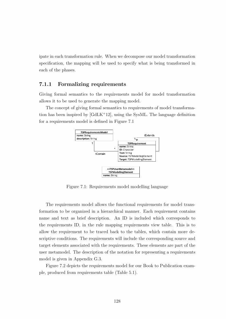
ipate in each transformation rule. When we decompose our model transformation
specification, the mapping will be used to specify what is being transformed in
each of the phases.
7.1.1 Formalizing requirements
Giving formal semantics to the requirements model for model transformation
allows it to be used to generate the mapping model.
The concept of giving formal semantics to requirements of model transforma-
tion has been inspired by [GdLK+12], using the SysML. The language definition
for a requirements model is defined in Figure 7.1
Figure 7.1: Requirements model modelling language
The requirements model allows the functional requirements for model trans-
formation to be organized in a hierarchical manner. Each requirement contains
name and text as brief description. An ID is included which corresponds to
the requirements ID, in the rule mapping requirements view table. This is to
allow the requirement to be traced back to the tables, which contain more de-
scriptive conditions. The requirements will include the corresponding source and
target elements associated with the requirements. These elements are part of the
user metamodel. The description of the notation for representing a requirements
model is given in Appendix G.3.
Figure 7.2 depicts the requirements model for our Book to Publication exam-
ple, produced from requirements table (Table 5.1).
128
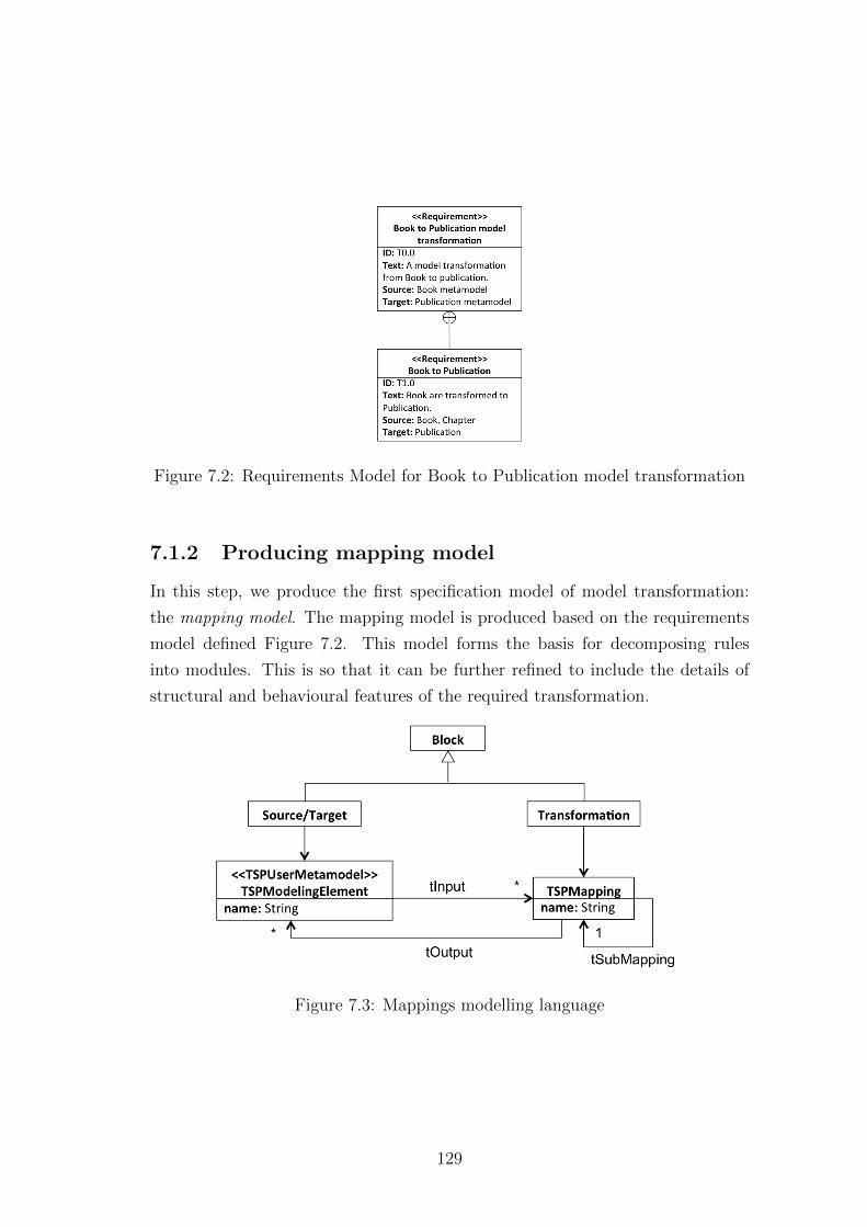
Figure 7.2: Requirements Model for Book to Publication model transformation
7.1.2 Producing mapping model
In this step, we produce the first specification model of model transformation:
the mapping model. The mapping model is produced based on the requirements
model defined Figure 7.2. This model forms the basis for decomposing rules
into modules. This is so that it can be further refined to include the details of
structural and behavioural features of the required transformation.
Figure 7.3: Mappings modelling language
129
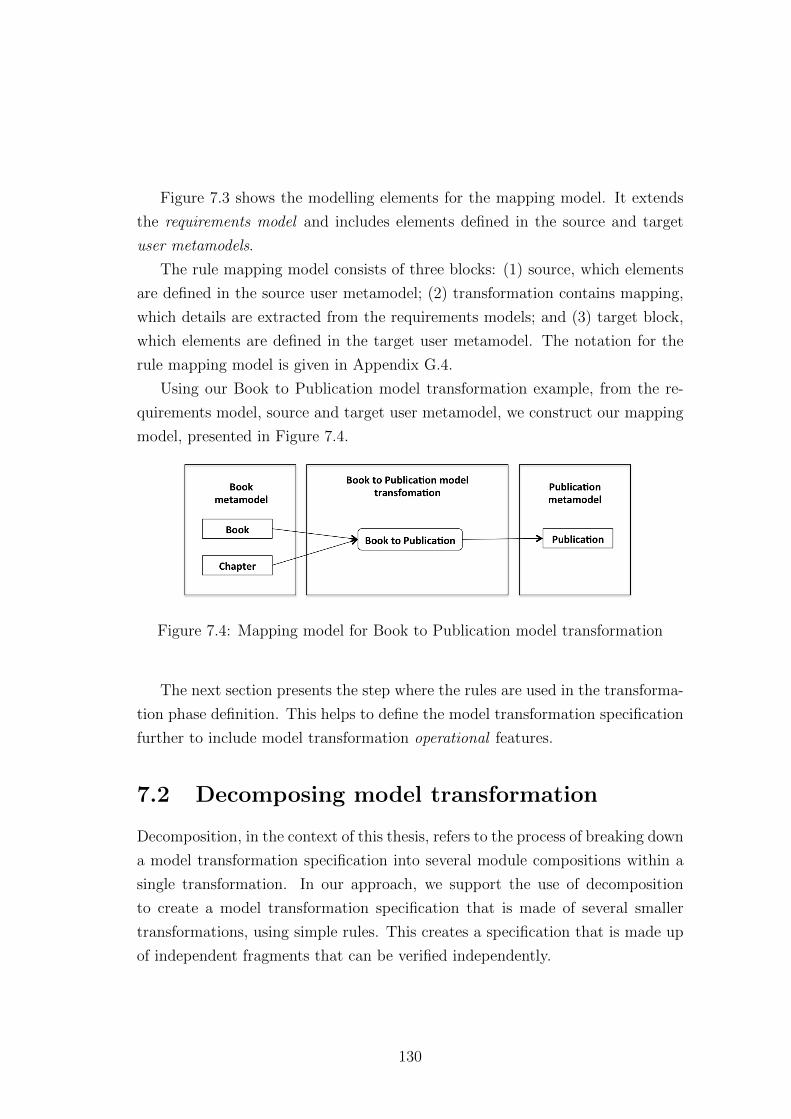
Figure 7.3 shows the modelling elements for the mapping model. It extends
the requirements model and includes elements defined in the source and target
user metamodels.
The rule mapping model consists of three blocks: (1) source, which elements
are defined in the source user metamodel; (2) transformation contains mapping,
which details are extracted from the requirements models; and (3) target block,
which elements are defined in the target user metamodel. The notation for the
rule mapping model is given in Appendix G.4.
Using our Book to Publication model transformation example, from the re-
quirements model, source and target user metamodel, we construct our mapping
model, presented in Figure 7.4.
Figure 7.4: Mapping model for Book to Publication model transformation
The next section presents the step where the rules are used in the transforma-
tion phase definition. This helps to define the model transformation specification
further to include model transformation operational features.
7.2 Decomposing model transformation
Decomposition, in the context of this thesis, refers to the process of breaking down
a model transformation specification into several module compositions within a
single transformation. In our approach, we support the use of decomposition
to create a model transformation specification that is made of several smaller
transformations, using simple rules. This creates a specification that is made up
of independent fragments that can be verified independently.
130
7.2.1 Reason for decomposition
Most of the time, model transformation specifications are built as a singular mod-
ule consisting of a set of rules. Rules are the basic modular constructs in model
transformation languages [KG06]. Rules can be too fine grained to be the sole
unit of composition as they introduce strong dependencies between components.
Compositions are generally considered at an architectural level, where modules
of several different transformations are chained via orchestration. The orchestra-
tion of model transformation can be between homogeneous languages [RRgLr+09]
(external transformation composition) or multiple languages [Kle06] ( external
transformation composition).
Goals for composition in general, regarding specifying transformation, are
used to create reusability and adaptability [KG06], comprehensibility and main-
tainability [DKST05]. Incorporating these goals generically in designing trans-
formation specification is often constrained by the features of implementation
language, such as rule inheritance, which is not supported by the tool Model-
Morf1.
Particularly for the TSP, we define a decomposing mechanism to address the
scalability issues in analysing model transformations in Alloy. [ABK07] claimed
that one of the problems with analysing model transformations with Alloy, is the
requirement for memory resources and execution time, which increased exponen-
tially with the size of the specification.
Architectural components and rules are the two extremes in promoting some
kind of composition in model transformation. In our approach, we address a
composition that is coarser-grained than a rule to specify model transformation,
not only for enabling scalability in analysis, but also incorporating qualities such
as reuse, maintainability and portability in model transformation specification.
We have adopted the phasing method for decomposing model transformation
[CM09].
To use the template-based analysis, we provide a visual notation for specify-
ing transformation. Inspired by [GdLK+10], we produce a set of notations that
specify features of model transformation, which also incorporate the support for
1http://www.tcs-trddc.com/trddc website/ModelMorf/ModelMorf.htm
131
decomposition of model transformation specification. Having these, we are able
to generate a model transformation formal specification via template instantia-
tions that are amenable to formal analysis. The concept of template instantiation
for model transformation has similar applications to template instantiation for
user metamodels presented in Section 6.1.3.
7.2.2 TSP model transformation specifications modelling
language
To create effective fragments that are not just functional, but also incorporate
a focused logical concern that creates independent verifiable parts, we adopt the
phasing mechanism presented in [CM09].
Our model transformation specification is decomposed from the mapping
model using phases. Fundamentally, phasing is used to define individual trans-
formations and implies which rules are invoked when, for each phase. [CH06].
But due to the nature of explicitly determining the organization of rules using
phases, it is also used for composing model transformation.
Figure 7.5 depicts the features of TSP modelling language for model transfor-
mation that supports phasing, and in parallel, constrained the notation for our
template instantiations.
There are two type of phase: (1) primitive phase; and (2) composite phase. A
primitive phase contains a set of rules, and it is executed by evaluating its rules.
Each phase contains rules that implement the mappings and well-formedness
constraints that define the condition and assignment operation for the rule to
be applied. Composite phases contain nested primitive phases and execution of
composite phase is by executing the nested phases.
Each phase contains rules that implement the mappings identified in the map-
ping model. The phases use domain elements from the metamodels as parameters.
Model transformation specification is usually a composite phase that executes
in a single stage [CM09]. With the phasing mechanism, model transformation
specification can have an internal composition that allows multi-stage execution
[CM09].
132
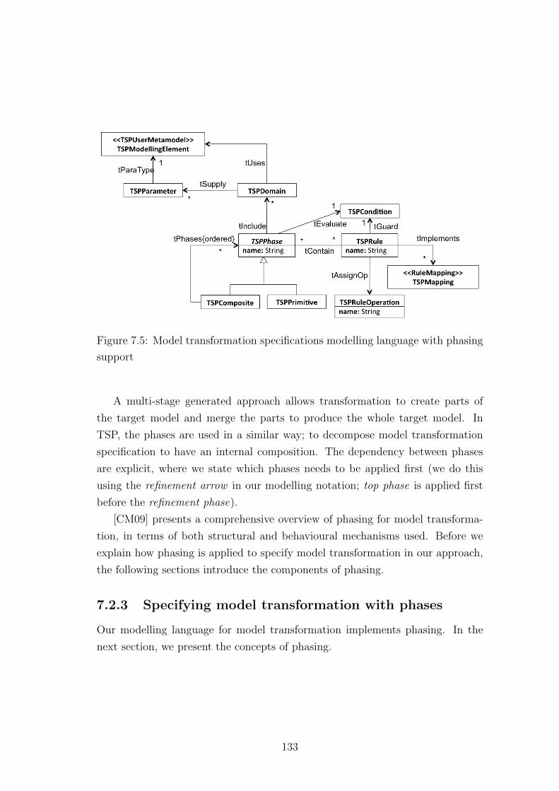
Figure 7.5: Model transformation specifications modelling language with phasing
support
A multi-stage generated approach allows transformation to create parts of
the target model and merge the parts to produce the whole target model. In
TSP, the phases are used in a similar way; to decompose model transformation
specification to have an internal composition. The dependency between phases
are explicit, where we state which phases needs to be applied first (we do this
using the refinement arrow in our modelling notation; top phase is applied first
before the refinement phase).
[CM09] presents a comprehensive overview of phasing for model transforma-
tion, in terms of both structural and behavioural mechanisms used. Before we
explain how phasing is applied to specify model transformation in our approach,
the following sections introduce the components of phasing.
7.2.3 Specifying model transformation with phases
Our modelling language for model transformation implements phasing. In the
next section, we present the concepts of phasing.
133
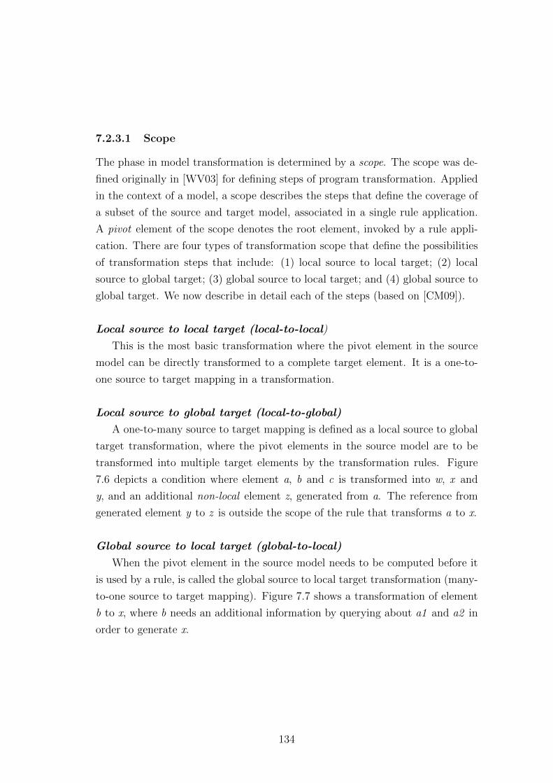
7.2.3.1 Scope
The phase in model transformation is determined by a scope. The scope was de-
fined originally in [WV03] for defining steps of program transformation. Applied
in the context of a model, a scope describes the steps that define the coverage of
a subset of the source and target model, associated in a single rule application.
A pivot element of the scope denotes the root element, invoked by a rule appli-
cation. There are four types of transformation scope that define the possibilities
of transformation steps that include: (1) local source to local target; (2) local
source to global target; (3) global source to local target; and (4) global source to
global target. We now describe in detail each of the steps (based on [CM09]).
Local source to local target (local-to-local)
This is the most basic transformation where the pivot element in the source
model can be directly transformed to a complete target element. It is a one-to-
one source to target mapping in a transformation.
Local source to global target (local-to-global)
A one-to-many source to target mapping is defined as a local source to global
target transformation, where the pivot elements in the source model are to be
transformed into multiple target elements by the transformation rules. Figure
7.6 depicts a condition where element a, b and c is transformed into w, x and
y, and an additional non-local element z, generated from a. The reference from
generated element y to z is outside the scope of the rule that transforms a to x.
Global source to local target (global-to-local)
When the pivot element in the source model needs to be computed before it
is used by a rule, is called the global source to local target transformation (many-
to-one source to target mapping). Figure 7.7 shows a transformation of element
b to x, where b needs an additional information by querying about a1 and a2 in
order to generate x.
134
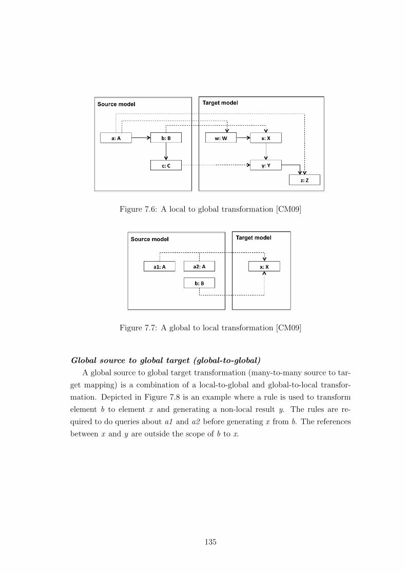
Figure 7.6: A local to global transformation [CM09]
Figure 7.7: A global to local transformation [CM09]
Global source to global target (global-to-global)
A global source to global target transformation (many-to-many source to tar-
get mapping) is a combination of a local-to-global and global-to-local transfor-
mation. Depicted in Figure 7.8 is an example where a rule is used to transform
element b to element x and generating a non-local result y. The rules are re-
quired to do queries about a1 and a2 before generating x from b. The references
between x and y are outside the scope of b to x.
135
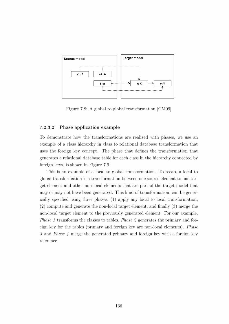
Figure 7.8: A global to global transformation [CM09]
7.2.3.2 Phase application example
To demonstrate how the transformations are realized with phases, we use an
example of a class hierarchy in class to relational database transformation that
uses the foreign key concept. The phase that defines the transformation that
generates a relational database table for each class in the hierarchy connected by
foreign keys, is shown in Figure 7.9.
This is an example of a local to global transformation. To recap, a local to
global transformation is a transformation between one source element to one tar-
get element and other non-local elements that are part of the target model that
may or may not have been generated. This kind of transformation, can be gener-
ically specified using three phases; (1) apply any local to local transformation,
(2) compute and generate the non-local target element, and finally (3) merge the
non-local target element to the previously generated element. For our example,
Phase 1 transforms the classes to tables, Phase 2 generates the primary and for-
eign key for the tables (primary and foreign key are non-local elements). Phase
3 and Phase 4 merge the generated primary and foreign key with a foreign key
reference.
136
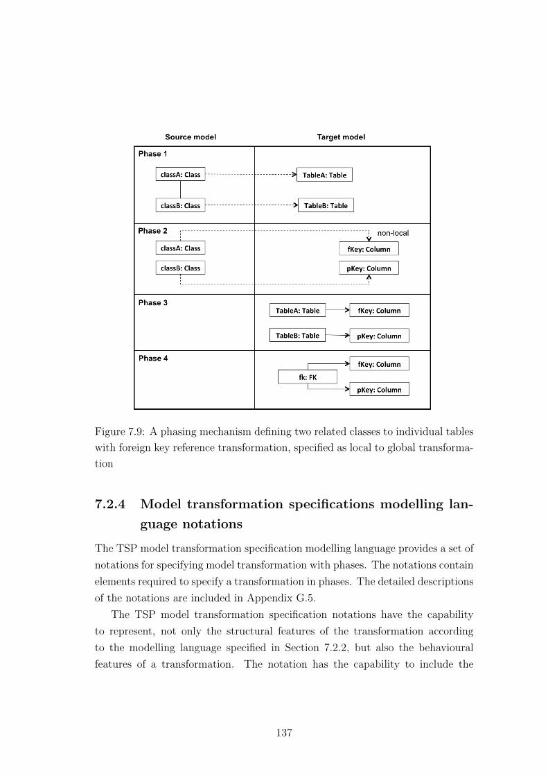
Figure 7.9: A phasing mechanism defining two related classes to individual tables
with foreign key reference transformation, specified as local to global transforma-
tion
7.2.4 Model transformation specifications modelling lan-
guage notations
The TSP model transformation specification modelling language provides a set of
notations for specifying model transformation with phases. The notations contain
elements required to specify a transformation in phases. The detailed descriptions
of the notations are included in Appendix G.5.
The TSP model transformation specification notations have the capability
to represent, not only the structural features of the transformation according
to the modelling language specified in Section 7.2.2, but also the behavioural
features of a transformation. The notation has the capability to include the
137
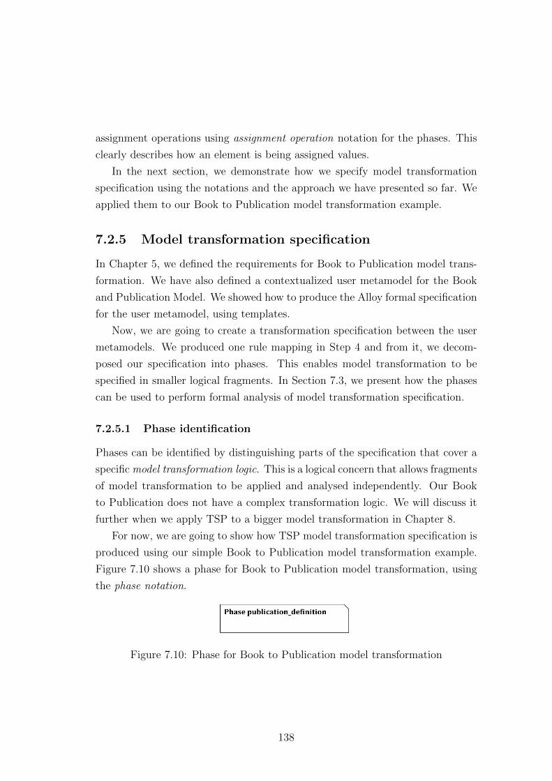
assignment operations using assignment operation notation for the phases. This
clearly describes how an element is being assigned values.
In the next section, we demonstrate how we specify model transformation
specification using the notations and the approach we have presented so far. We
applied them to our Book to Publication model transformation example.
7.2.5 Model transformation specification
In Chapter 5, we defined the requirements for Book to Publication model trans-
formation. We have also defined a contextualized user metamodel for the Book
and Publication Model. We showed how to produce the Alloy formal specification
for the user metamodel, using templates.
Now, we are going to create a transformation specification between the user
metamodels. We produced one rule mapping in Step 4 and from it, we decom-
posed our specification into phases. This enables model transformation to be
specified in smaller logical fragments. In Section 7.3, we present how the phases
can be used to perform formal analysis of model transformation specification.
7.2.5.1 Phase identification
Phases can be identified by distinguishing parts of the specification that cover a
specific model transformation logic. This is a logical concern that allows fragments
of model transformation to be applied and analysed independently. Our Book
to Publication does not have a complex transformation logic. We will discuss it
further when we apply TSP to a bigger model transformation in Chapter 8.
For now, we are going to show how TSP model transformation specification is
produced using our simple Book to Publication model transformation example.
Figure 7.10 shows a phase for Book to Publication model transformation, using
the phase notation.
Figure 7.10: Phase for Book to Publication model transformation
138
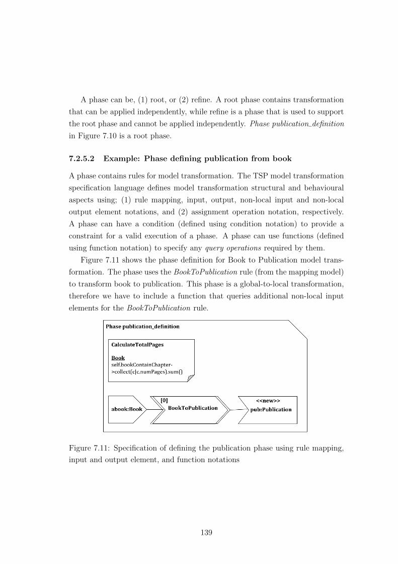
A phase can be, (1) root, or (2) refine. A root phase contains transformation
that can be applied independently, while refine is a phase that is used to support
the root phase and cannot be applied independently. Phase publication definition
in Figure 7.10 is a root phase.
7.2.5.2 Example: Phase defining publication from book
A phase contains rules for model transformation. The TSP model transformation
specification language defines model transformation structural and behavioural
aspects using; (1) rule mapping, input, output, non-local input and non-local
output element notations, and (2) assignment operation notation, respectively.
A phase can have a condition (defined using condition notation) to provide a
constraint for a valid execution of a phase. A phase can use functions (defined
using function notation) to specify any query operations required by them.
Figure 7.11 shows the phase definition for Book to Publication model trans-
formation. The phase uses the BookToPublication rule (from the mapping model)
to transform book to publication. This phase is a global-to-local transformation,
therefore we have to include a function that queries additional non-local input
elements for the BookToPublication rule.
Figure 7.11: Specification of defining the publication phase using rule mapping,
input and output element, and function notations
139
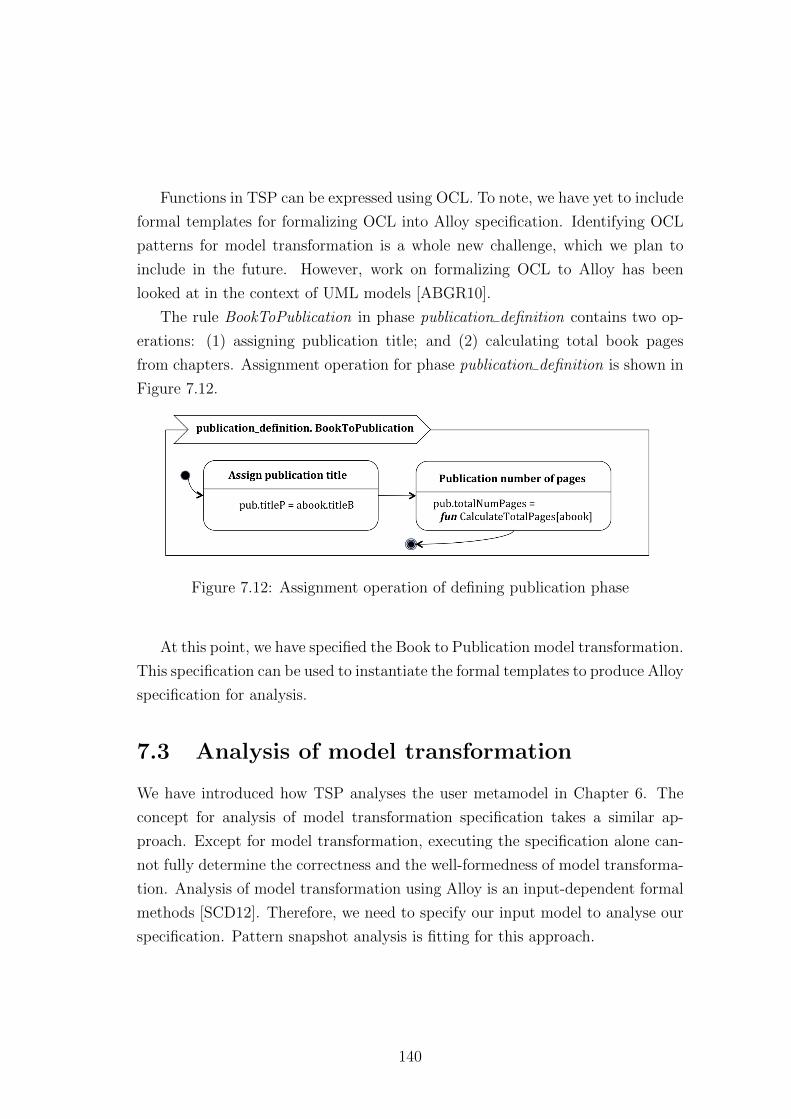
Functions in TSP can be expressed using OCL. To note, we have yet to include
formal templates for formalizing OCL into Alloy specification. Identifying OCL
patterns for model transformation is a whole new challenge, which we plan to
include in the future. However, work on formalizing OCL to Alloy has been
looked at in the context of UML models [ABGR10].
The rule BookToPublication in phase publication definition contains two op-
erations: (1) assigning publication title; and (2) calculating total book pages
from chapters. Assignment operation for phase publication definition is shown in
Figure 7.12.
Figure 7.12: Assignment operation of defining publication phase
At this point, we have specified the Book to Publication model transformation.
This specification can be used to instantiate the formal templates to produce Alloy
specification for analysis.
7.3 Analysis of model transformation
We have introduced how TSP analyses the user metamodel in Chapter 6. The
concept for analysis of model transformation specification takes a similar ap-
proach. Except for model transformation, executing the specification alone can-
not fully determine the correctness and the well-formedness of model transforma-
tion. Analysis of model transformation using Alloy is an input-dependent formal
methods [SCD12]. Therefore, we need to specify our input model to analyse our
specification. Pattern snapshot analysis is fitting for this approach.
140
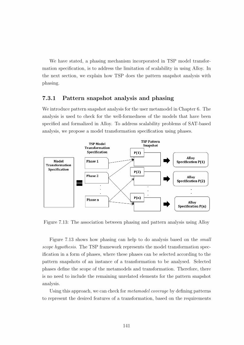
We have stated, a phasing mechanism incorporated in TSP model transfor-
mation specification, is to address the limitation of scalability in using Alloy. In
the next section, we explain how TSP does the pattern snapshot analysis with
phasing.
7.3.1 Pattern snapshot analysis and phasing
We introduce pattern snapshot analysis for the user metamodel in Chapter 6. The
analysis is used to check for the well-formedness of the models that have been
specified and formalized in Alloy. To address scalability problems of SAT-based
analysis, we propose a model transformation specification using phases.
Figure 7.13: The association between phasing and pattern analysis using Alloy
Figure 7.13 shows how phasing can help to do analysis based on the small
scope hypothesis. The TSP framework represents the model transformation spec-
ification in a form of phases, where these phases can be selected according to the
pattern snapshots of an instance of a transformation to be analysed. Selected
phases define the scope of the metamodels and transformation. Therefore, there
is no need to include the remaining unrelated elements for the pattern snapshot
analysis.
Using this approach, we can check for metamodel coverage by defining patterns
to represent the desired features of a transformation, based on the requirements
141
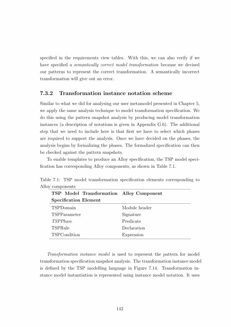
specified in the requirements view tables. With this, we can also verify if we
have specified a semantically correct model transformation because we devised
our patterns to represent the correct transformation. A semantically incorrect
transformation will give out an error.
7.3.2 Transformation instance notation scheme
Similar to what we did for analysing our user metamodel presented in Chapter 5,
we apply the same analysis technique to model transformation specification. We
do this using the pattern snapshot analysis by producing model transformation
instances (a description of notations is given in Appendix G.6). The additional
step that we need to include here is that first we have to select which phases
are required to support the analysis. Once we have decided on the phases, the
analysis begins by formalizing the phases. The formalized specification can then
be checked against the pattern snapshots.
To enable templates to produce an Alloy specification, the TSP model speci-
fication has corresponding Alloy components, as shown in Table 7.1.
Table 7.1: TSP model transformation specification elements corresponding to
Alloy components
TSP Model Transformation
Specification Element
Alloy Component
TSPDomain Module header
TSPParameter Signature
TSPPhase Predicate
TSPRule Declaration
TSPCondition Expression
Transformation instance model is used to represent the pattern for model
transformation specification snapshot analysis. The transformation instance model
is defined by the TSP modelling language in Figure 7.14. Transformation in-
stance model instantiation is represented using instance model notation. It uses
142
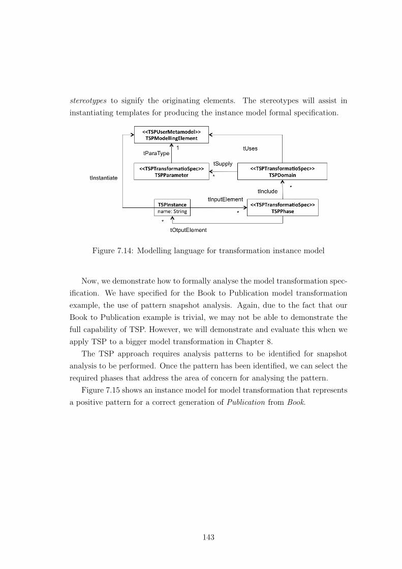
stereotypes to signify the originating elements. The stereotypes will assist in
instantiating templates for producing the instance model formal specification.
Figure 7.14: Modelling language for transformation instance model
Now, we demonstrate how to formally analyse the model transformation spec-
ification. We have specified for the Book to Publication model transformation
example, the use of pattern snapshot analysis. Again, due to the fact that our
Book to Publication example is trivial, we may not be able to demonstrate the
full capability of TSP. However, we will demonstrate and evaluate this when we
apply TSP to a bigger model transformation in Chapter 8.
The TSP approach requires analysis patterns to be identified for snapshot
analysis to be performed. Once the pattern has been identified, we can select the
required phases that address the area of concern for analysing the pattern.
Figure 7.15 shows an instance model for model transformation that represents
a positive pattern for a correct generation of Publication from Book.
143
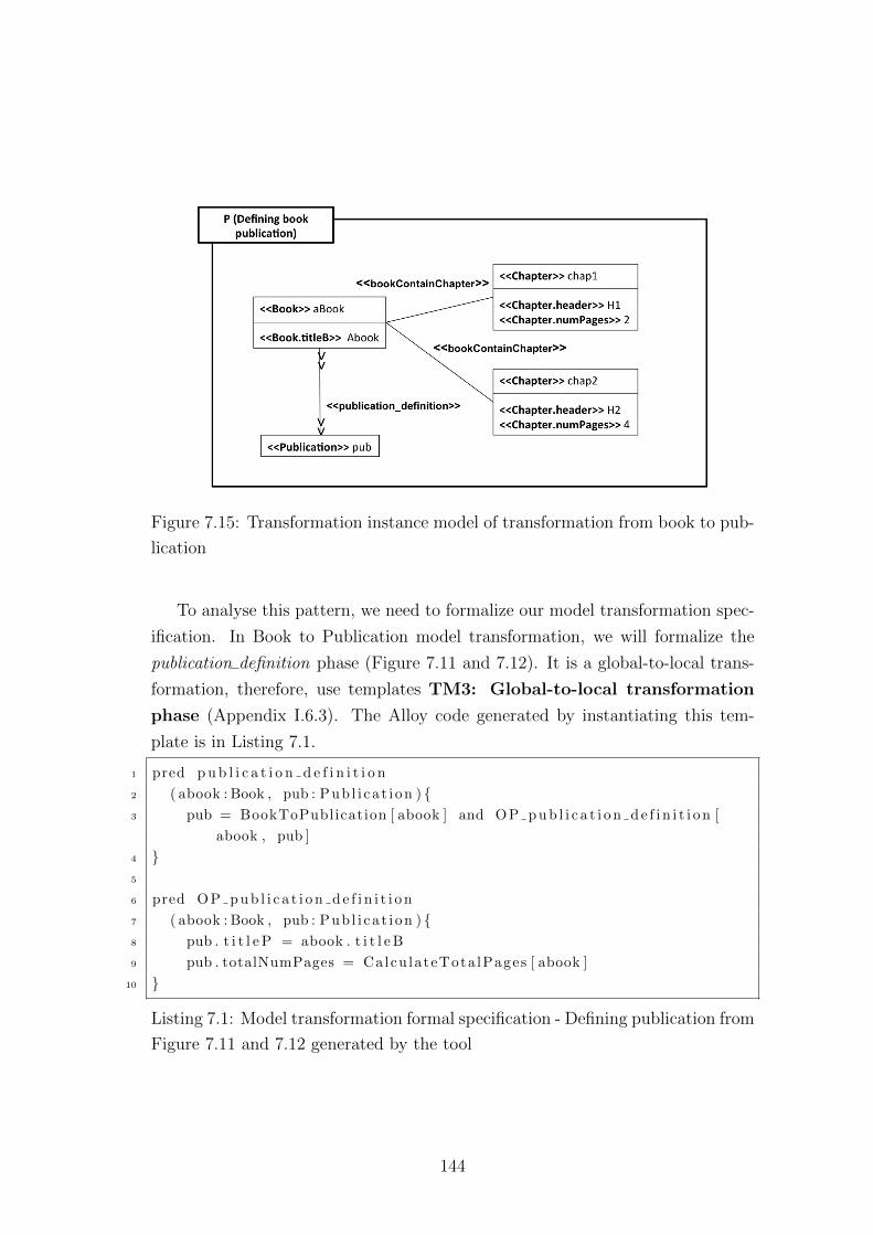
Figure 7.15: Transformation instance model of transformation from book to pub-
lication
To analyse this pattern, we need to formalize our model transformation spec-
ification. In Book to Publication model transformation, we will formalize the
publication definition phase (Figure 7.11 and 7.12). It is a global-to-local trans-
formation, therefore, use templates TM3: Global-to-local transformation
phase (Appendix I.6.3). The Alloy code generated by instantiating this tem-
plate is in Listing 7.1.
1 pred p u b l i c a t i o n d e f i n i t i o n
2 ( abook : Book , pub : Pub l i ca t i on ) {3 pub = BookToPublication [ abook ] and O P p u b l i c a t i o n d e f i n i t i o n [
abook , pub ]
4 }5
6 pred O P p u b l i c a t i o n d e f i n i t i o n
7 ( abook : Book , pub : Pub l i ca t i on ) {8 pub . t i t l e P = abook . t i t l e B
9 pub . totalNumPages = Calcu lateTota lPages [ abook ]
10 }
Listing 7.1: Model transformation formal specification - Defining publication from
Figure 7.11 and 7.12 generated by the tool
144
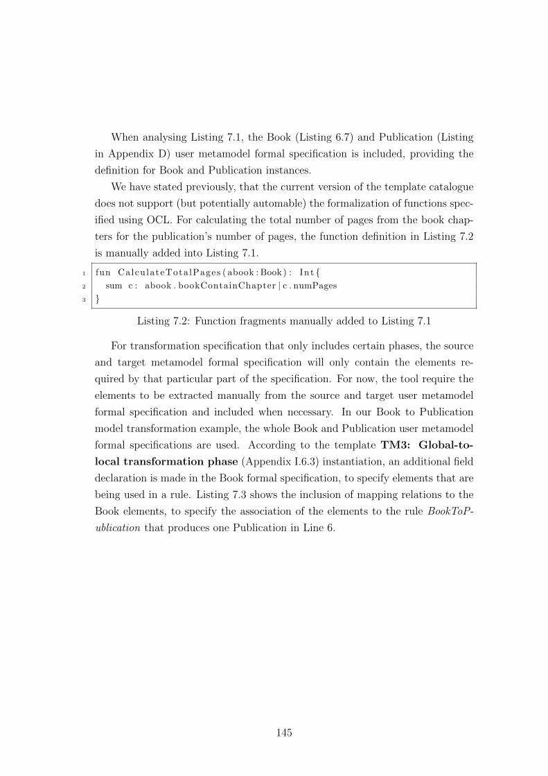
When analysing Listing 7.1, the Book (Listing 6.7) and Publication (Listing
in Appendix D) user metamodel formal specification is included, providing the
definition for Book and Publication instances.
We have stated previously, that the current version of the template catalogue
does not support (but potentially automable) the formalization of functions spec-
ified using OCL. For calculating the total number of pages from the book chap-
ters for the publication’s number of pages, the function definition in Listing 7.2
is manually added into Listing 7.1.
1 fun Calcu lateTota lPages ( abook : Book ) : Int {2 sum c : abook . bookContainChapter | c . numPages
3 }
Listing 7.2: Function fragments manually added to Listing 7.1
For transformation specification that only includes certain phases, the source
and target metamodel formal specification will only contain the elements re-
quired by that particular part of the specification. For now, the tool require the
elements to be extracted manually from the source and target user metamodel
formal specification and included when necessary. In our Book to Publication
model transformation example, the whole Book and Publication user metamodel
formal specifications are used. According to the template TM3: Global-to-
local transformation phase (Appendix I.6.3) instantiation, an additional field
declaration is made in the Book formal specification, to specify elements that are
being used in a rule. Listing 7.3 shows the inclusion of mapping relations to the
Book elements, to specify the association of the elements to the rule BookToP-
ublication that produces one Publication in Line 6.
145
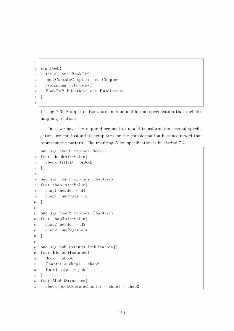
1 . . .
2 s i g Book{3 t i t l e : one BookTitle ,
4 bookContainChapter : s e t Chapter
5 /∗Mapping r e l a t i o n ∗/6 BookToPublication : one Pub l i ca t i on
7 }8 . . .
Listing 7.3: Snippet of Book user metamodel formal specification that includes
mapping relations
Once we have the required segment of model transformation formal specifi-
cation, we can instantiate templates for the transformation instance model that
represent the pattern. The resulting Alloy specification is in Listing 7.4.
1 one s i g abook extends Book{}2 f a c t abookAttrValue{3 abook . t i t l e B = ABook
4 }5
6 one s i g chap1 extends Chapter{}7 f a c t chap1AttrValue{8 chap1 . header = H1
9 chap1 . numPages = 2
10 }11
12 one s i g chap2 extends Chapter{}13 f a c t chap2AttrValue{14 chap2 . header = H2
15 chap2 . numPages = 4
16 }17
18 one s i g pub extends Pub l i ca t i on {}19 f a c t ElementInstance {20 Book = abook
21 Chapter = chap1 + chap2
22 Pub l i ca t i on = pub
23 }24 f a c t ModelStructure {25 abook . bookContainChapter = chap1 + chap2
146
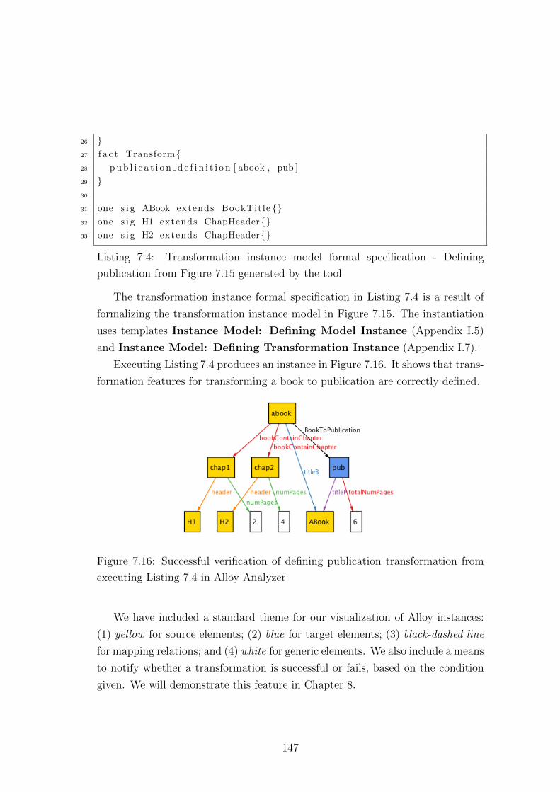
26 }27 f a c t Transform{28 p u b l i c a t i o n d e f i n i t i o n [ abook , pub ]
29 }30
31 one s i g ABook extends BookTit le {}32 one s i g H1 extends ChapHeader{}33 one s i g H2 extends ChapHeader{}
Listing 7.4: Transformation instance model formal specification - Defining
publication from Figure 7.15 generated by the tool
The transformation instance formal specification in Listing 7.4 is a result of
formalizing the transformation instance model in Figure 7.15. The instantiation
uses templates Instance Model: Defining Model Instance (Appendix I.5)
and Instance Model: Defining Transformation Instance (Appendix I.7).
Executing Listing 7.4 produces an instance in Figure 7.16. It shows that trans-
formation features for transforming a book to publication are correctly defined.
Figure 7.16: Successful verification of defining publication transformation from
executing Listing 7.4 in Alloy Analyzer
We have included a standard theme for our visualization of Alloy instances:
(1) yellow for source elements; (2) blue for target elements; (3) black-dashed line
for mapping relations; and (4) white for generic elements. We also include a means
to notify whether a transformation is successful or fails, based on the condition
given. We will demonstrate this feature in Chapter 8.
147
7.4 Summary
We have presented the final parts of our framework, which are the decomposing
and refining of the model transformation specifications. We produced a set of
transformation phases that create modularizations in the model transformation
specifications. These phases can be analysed independently, thus a smaller, more
focused analysis can be performed.
In the next chapter, we are going to evaluate our approach on a bigger trans-
formation.
148
Chapter 8
Applying and evaluating the TSP
framework
We have outlined in Figure 4.4 the steps in TSP framework: (1) elicit model
transformation requirements; (2) contextualize a metamodel; (3) analyse a meta-
model; (4) generate rule mapping; (5) decompose and refine a model transfor-
mation specification; and (6) formally analyse a model transformation. We have
presented the TSP framework for specifying and formally analysing model trans-
formation specification in Chapter 5 - 7 by applying templates to produce formal
model. The consistency of the generated formal model presented in this thesis is
maintain by the TSP tool (Section 4.9). In this chapter, we will show how TSP
can be applied to another example with more transformation features to further
evaluate the capability of the framework.
TSP can be used to formalise transformations from any type of user meta-
model. In this chapter, we apply the TSP framework, to an example, transform-
ing from a UML class model notation to a Relational Database notation. The
transformation follows the six TSP steps presented in the previous chapters; the
only different in this chapter is that the example uses a bigger, more familiar
model transformation to demonstrate the capability of the framework to cater
for real world applications. The example models in this chapter have been man-
ually translated into XML (Appendix F) and its formal Alloy model have been
created using the tool described in Section 4.9.
149
The user metamodel used in Book to Publication and UML class model to a
Relational Database model transformation has one dissimilarity; they belong to a
different level of abstractions. The Book user metamodel in Book to Publication
example have one level of instantiation (that is from Book user metamodel to a
Book model), while in UML class model to a Relational Database example, Class
user metamodel may have several instantiation (producing Bank account model
which can be instantiated further to, for example, John’s bank account). In this
case, the differences does not present any significant impact as TSP is capable to
address any type of user metamodel, provided it is used in a transformation.
8.1 Data modelling and class to relational database
transformation
Data modelling [SW04] is a process that defines the features of data using three
kinds of model structures: (1) a conceptual model, that identifies and documents
the required entities and their relationships to the system; (2) a logical model,
that defines the entities and their relationships, excluding implementation details;
and (3) a physical model, that defines the database structure based on the logical
model in a specific database implementation format [Spa11].
Object-oriented data modelling (OODM) is an approach that allows database
design using object concepts. OODM contains two components: (1) conceptual
schema that uses objects and relations between them to represent the domain;
and (2) data operations that define the data model operations [ZR88].
OODM extends data modelling languages capabiity such as the Entity-Relationship
Diagrams. OODM incorporates data modelling support using a class diagram
[GL03; AT05; SS03]. There are also software development suites that support
the specification and data models generation, such as relational database models
for implementing SQL from a class diagram, such as the UML Class Diagram.
Examples of these tools are, IBM InfoSphere Data Architect1, Enterprise Archi-
1IBM InfoSphere Data Architect: http://www-01.ibm.com/software/data/optim/data-
architect/
150
tect1, and Visual Paradigm2.
Challenges in analysing a class diagram to a relational model transformation
includes, ensuring the generated relational model is complete and semantically
correct over a set of rule mapping from a class diagram. The object-relational
impedance mismatch expresses the semantic gap between an object and rela-
tional model [IBN+09] when specifying a semantic equivalent transformation. In
TSP, an analysis of model transformation is performed by formalizing the model
transformation specification.
Class to Relational Database model transformation is a model-to-model trans-
formation. It is used to translate a class diagram to a relational model that defines
a database structure. We present our approach to analysing this transformation,
following the TSP steps defined in Chapter 4.
8.2 Step 1: Eliciting class to relational database
model transformation requirements
Specifying model transformation requirements between a class and relational
model is a complex task, due to the object-relational impedance mismatch prob-
lem. [IBN+09] highlights a list of mismatches and proposes a framework that
defines four levels of impedance mismatch organization: (1) paradigm; (2) lan-
guage; (3) schema; and (4) instance, to address this problem.
For transformation engineers that need to specify model transformation be-
tween a class and relational database model, identifying compatibility concerns
requires extra effort. We are not focusing on an approach for analysing object
and relational models in particular, therefore we focus on the fundamental fea-
tures of class to relational database transformation. The aim is to assess whether
our approach can specify and analyse model transformation from the identified
requirements.
The first step is to elicit requirements for class to relational database model
transformation to produce the MTSM (Figure 4.4). In our transformation, we
1Enterprise Architect: http://www.sparxsystems.com/products/ea/index.html2Visual Paradigm: http://www.visual-paradigm.com/
151
have identified the following features explaining in terms of semantic concepts of
the two types of model:
1. For each instance of persistent Class, an instance of Table and a primary
key column is created. We assume all classes are persistent.
2. For every child class, an instance of Table and a foreign key Column is
created, pointing to the primary key of the parent class.
3. For each instance of attribute that belongs to a persistent Class, an instance
of Column is generated.
4. For every attribute with multiple values, a Table with Columns to store
values and their IDs is created. A foreign key Column is added into the
owner’s Table for reference to the value table.
5. For each class with an association, a table for each class is created. The
first class has a primary key column and the second class has a foreign key
pointing to the first class.
Table 8.1 and 8.2 presents a full set of transformation rules . They contain the
rule mapping requirements view for class to relational database transformation.
152
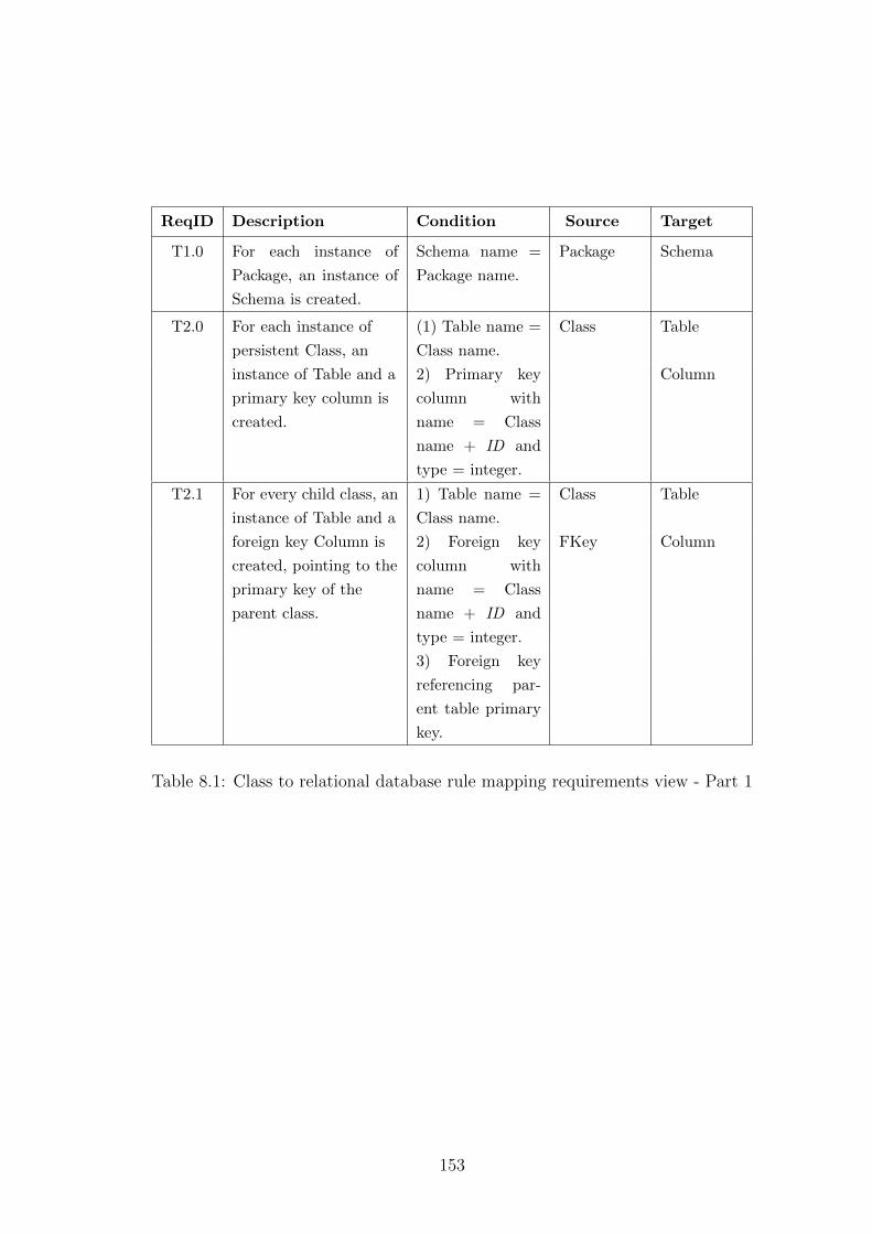
ReqID Description Condition Source Target
T1.0 For each instance of
Package, an instance of
Schema is created.
Schema name =
Package name.
Package Schema
T2.0 For each instance of
persistent Class, an
instance of Table and a
primary key column is
created.
(1) Table name =
Class name.
Class Table
2) Primary key
column with
name = Class
name + ID and
type = integer.
Column
T2.1 For every child class, an
instance of Table and a
foreign key Column is
created, pointing to the
primary key of the
parent class.
1) Table name =
Class name.
Class Table
2) Foreign key
column with
name = Class
name + ID and
type = integer.
FKey Column
3) Foreign key
referencing par-
ent table primary
key.
Table 8.1: Class to relational database rule mapping requirements view - Part 1
153
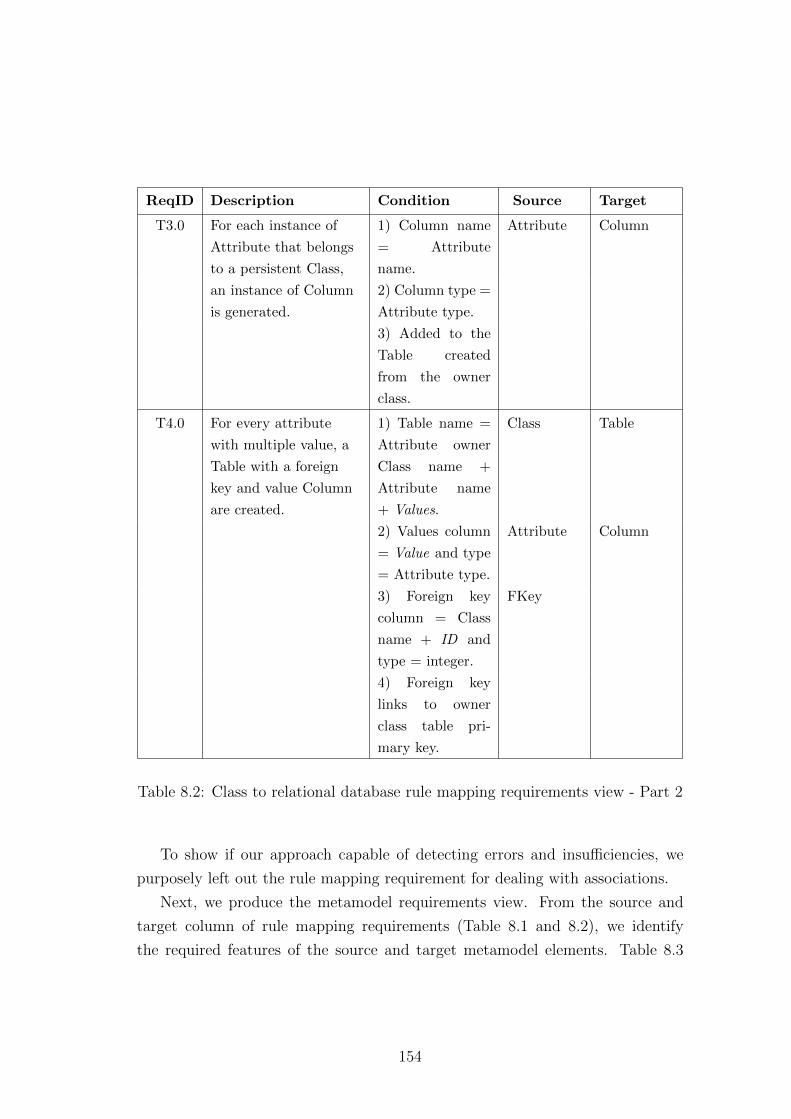
ReqID Description Condition Source Target
T3.0 For each instance of
Attribute that belongs
to a persistent Class,
an instance of Column
is generated.
1) Column name
= Attribute
name.
Attribute Column
2) Column type =
Attribute type.
3) Added to the
Table created
from the owner
class.
T4.0 For every attribute
with multiple value, a
Table with a foreign
key and value Column
are created.
1) Table name =
Attribute owner
Class name +
Attribute name
+ Values.
Class Table
2) Values column
= Value and type
= Attribute type.
Attribute Column
3) Foreign key
column = Class
name + ID and
type = integer.
FKey
4) Foreign key
links to owner
class table pri-
mary key.
Table 8.2: Class to relational database rule mapping requirements view - Part 2
To show if our approach capable of detecting errors and insufficiencies, we
purposely left out the rule mapping requirement for dealing with associations.
Next, we produce the metamodel requirements view. From the source and
target column of rule mapping requirements (Table 8.1 and 8.2), we identify
the required features of the source and target metamodel elements. Table 8.3
154
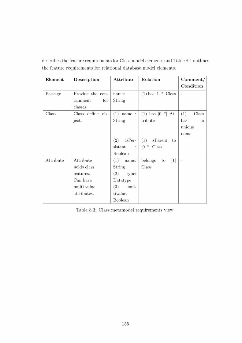
describes the feature requirements for Class model elements and Table 8.4 outlines
the feature requirements for relational database model elements.
Element Description Attribute Relation Comment/
Condition
Package Provide the con-
tainment for
classes.
name:
String
(1) has [1..*] Class -
Class Class define ob-
ject.
(1) name :
String
(1) has [0..*] At-
tribute
(1) Class
has a
unique
name
(2) isPer-
sistent :
Boolean
(1) isParent to
[0..*] Class
Attribute Attribute
holds class
features.
Can have
multi value
attributes.
(1) name:
String
belongs to [1]
Class
-
(2) type:
Datatype
(3) mul-
tivalue:
Boolean
Table 8.3: Class metamodel requirements view
155

Element Description Attribute Relation Comment/
Condition
Schema Containing table
structure.
(1) name :
String
has [1..*] Table -
Table Containing a col-
lection of values.
name :
String
(1) has PKey[1..*]
Column
-
(2) has value [1..*]
Column
(3) has For-
eignKey [0..*]
Column
Column Containing spe-
cific values.
(1) name :
String
belongs to [1] Ta-
ble
-
(2) type :
DataType
FKey Links between ta-
bles.
- (1) referParent [1]
Column
-
(2) referChild [1]
Column
-
Table 8.4: Relational database metamodel requirements view
TSP is used to analyse the transformation specification. To evaluate the
usability of the resultant transformation, we are going to apply this to transform
customer banking account details into a database. Figure 8.1 is the class diagram
that defines our customer banking account structure.
Figure 8.1: Customer banking account
156
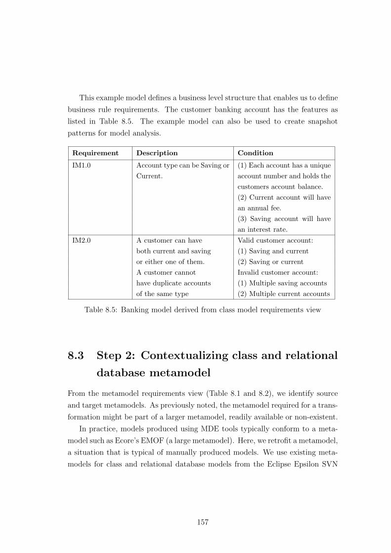
This example model defines a business level structure that enables us to define
business rule requirements. The customer banking account has the features as
listed in Table 8.5. The example model can also be used to create snapshot
patterns for model analysis.
Requirement Description Condition
IM1.0 Account type can be Saving or
Current.
(1) Each account has a unique
account number and holds the
customers account balance.
(2) Current account will have
an annual fee.
(3) Saving account will have
an interest rate.
IM2.0 A customer can have
both current and saving
or either one of them.
A customer cannot
have duplicate accounts
of the same type
Valid customer account:
(1) Saving and current
(2) Saving or current
Invalid customer account:
(1) Multiple saving accounts
(2) Multiple current accounts
Table 8.5: Banking model derived from class model requirements view
8.3 Step 2: Contextualizing class and relational
database metamodel
From the metamodel requirements view (Table 8.1 and 8.2), we identify source
and target metamodels. As previously noted, the metamodel required for a trans-
formation might be part of a larger metamodel, readily available or non-existent.
In practice, models produced using MDE tools typically conform to a meta-
model such as Ecore’s EMOF (a large metamodel). Here, we retrofit a metamodel,
a situation that is typical of manually produced models. We use existing meta-
models for class and relational database models from the Eclipse Epsilon SVN
157
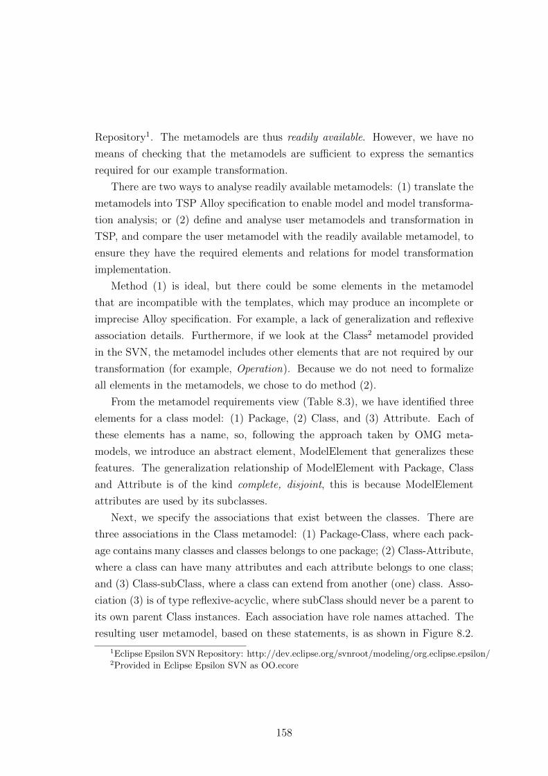
Repository1. The metamodels are thus readily available. However, we have no
means of checking that the metamodels are sufficient to express the semantics
required for our example transformation.
There are two ways to analyse readily available metamodels: (1) translate the
metamodels into TSP Alloy specification to enable model and model transforma-
tion analysis; or (2) define and analyse user metamodels and transformation in
TSP, and compare the user metamodel with the readily available metamodel, to
ensure they have the required elements and relations for model transformation
implementation.
Method (1) is ideal, but there could be some elements in the metamodel
that are incompatible with the templates, which may produce an incomplete or
imprecise Alloy specification. For example, a lack of generalization and reflexive
association details. Furthermore, if we look at the Class2 metamodel provided
in the SVN, the metamodel includes other elements that are not required by our
transformation (for example, Operation). Because we do not need to formalize
all elements in the metamodels, we chose to do method (2).
From the metamodel requirements view (Table 8.3), we have identified three
elements for a class model: (1) Package, (2) Class, and (3) Attribute. Each of
these elements has a name, so, following the approach taken by OMG meta-
models, we introduce an abstract element, ModelElement that generalizes these
features. The generalization relationship of ModelElement with Package, Class
and Attribute is of the kind complete, disjoint, this is because ModelElement
attributes are used by its subclasses.
Next, we specify the associations that exist between the classes. There are
three associations in the Class metamodel: (1) Package-Class, where each pack-
age contains many classes and classes belongs to one package; (2) Class-Attribute,
where a class can have many attributes and each attribute belongs to one class;
and (3) Class-subClass, where a class can extend from another (one) class. Asso-
ciation (3) is of type reflexive-acyclic, where subClass should never be a parent to
its own parent Class instances. Each association have role names attached. The
resulting user metamodel, based on these statements, is as shown in Figure 8.2.
1Eclipse Epsilon SVN Repository: http://dev.eclipse.org/svnroot/modeling/org.eclipse.epsilon/2Provided in Eclipse Epsilon SVN as OO.ecore
158
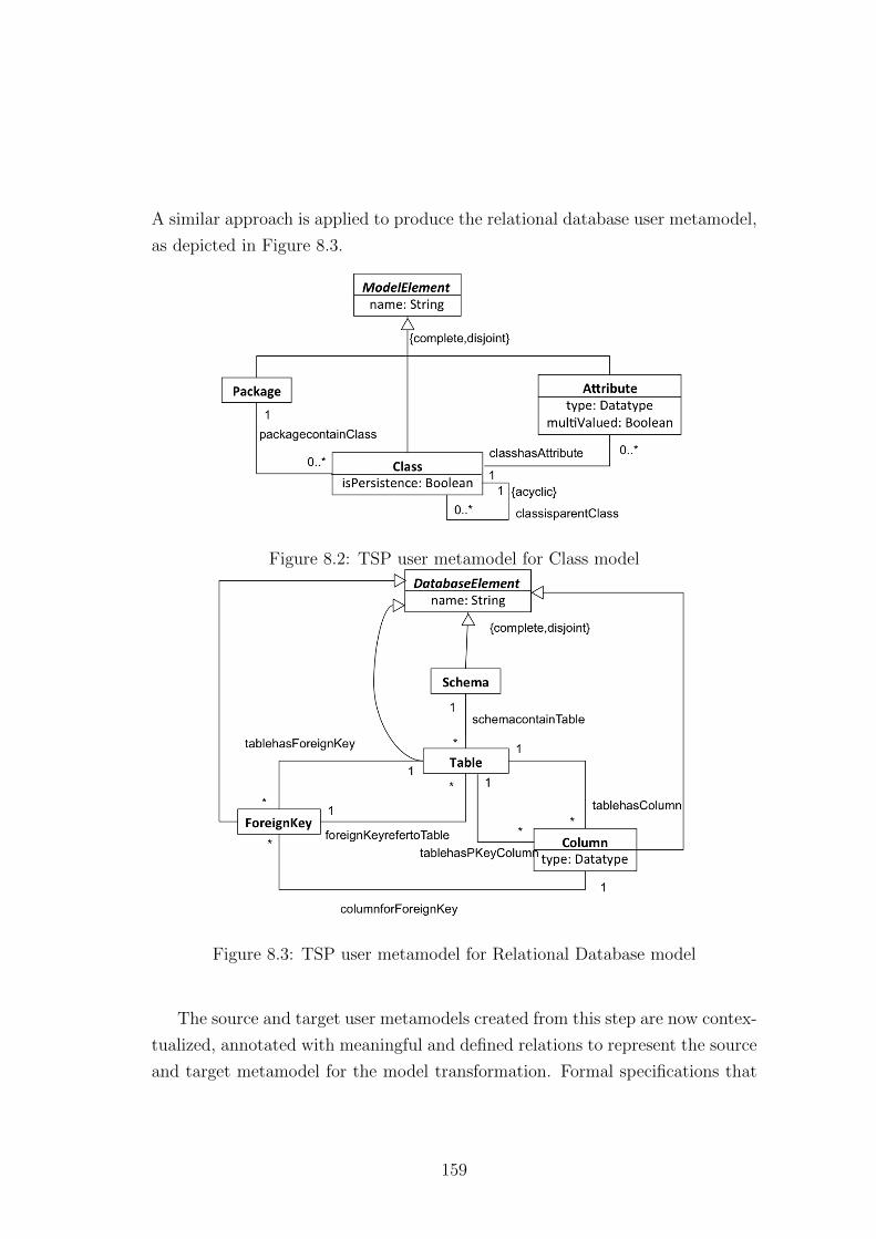
A similar approach is applied to produce the relational database user metamodel,
as depicted in Figure 8.3.
Figure 8.2: TSP user metamodel for Class model
Figure 8.3: TSP user metamodel for Relational Database model
The source and target user metamodels created from this step are now contex-
tualized, annotated with meaningful and defined relations to represent the source
and target metamodel for the model transformation. Formal specifications that
159
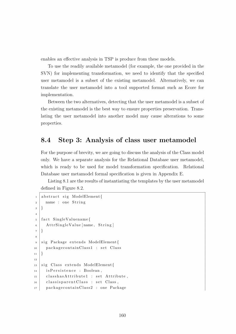
enables an effective analysis in TSP is produce from these models.
To use the readily available metamodel (for example, the one provided in the
SVN) for implementing transformation, we need to identify that the specified
user metamodel is a subset of the existing metamodel. Alternatively, we can
translate the user metamodel into a tool supported format such as Ecore for
implementation.
Between the two alternatives, detecting that the user metamodel is a subset of
the existing metamodel is the best way to ensure properties preservation. Trans-
lating the user metamodel into another model may cause alterations to some
properties.
8.4 Step 3: Analysis of class user metamodel
For the purpose of brevity, we are going to discuss the analysis of the Class model
only. We have a separate analysis for the Relational Database user metamodel,
which is ready to be used for model transformation specification. Relational
Database user metamodel formal specification is given in Appendix E.
Listing 8.1 are the results of instantiating the templates by the user metamodel
defined in Figure 8.2.
1 abs t r a c t s i g ModelElement{2 name : one St r ing
3 }4
5 f a c t SingleValuename{6 AttrS ing leValue [ name , S t r ing ]
7 }8
9 s i g Package extends ModelElement{10 packageconta inClass1 : s e t Class
11 }12
13 s i g Class extends ModelElement{14 i s P e r s i s t e n c e : Boolean ,
15 c l a s s h a s A t t r i b u t e 1 : s e t Attr ibute ,
16 c l a s s i s p a r e n t C l a s s : s e t Class ,
17 packageconta inClass2 : one Package
160
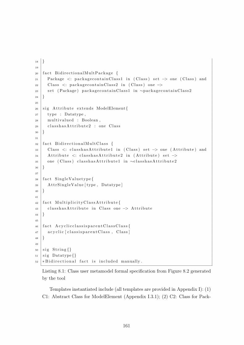
18 }19
20 f a c t Bid i rect iona lMultPackage {21 Package <: packageconta inClass1 in ( Class ) s e t −> one ( Class ) and
22 Class <: packageconta inClass2 in ( Class ) one −>23 s e t ( Package ) packageconta inClass1 in ∼packageconta inClass2
24 }25
26 s i g Att r ibute extends ModelElement{27 type : Datatype ,
28 mult iva lued : Boolean ,
29 c l a s s h a s A t t r i b u t e 2 : one Class
30 }31
32 f a c t B id i r e c t i ona lMu l tC la s s {33 Class <: c l a s s h a s A t t r i b u t e 1 in ( Class ) s e t −> one ( Att r ibute ) and
34 Attr ibute <: c l a s s h a s A t t r i b u t e 2 in ( Att r ibute ) s e t −>35 one ( Class ) c l a s s h a s A t t r i b u t e 1 in ∼c l a s s h a s A t t r i b u t e 2
36 }37
38 f a c t S ing leValuetype {39 AttrS ing leValue [ type , Datatype ]
40 }41
42 f a c t M u l t i p l i c i t y C l a s s A t t r i b u t e {43 c l a s s h a s A t t r i b u t e in Class one −> Attr ibute
44 }45
46 f a c t A c y c l i c c l a s s i s p a r e n t C l a s s C l a s s {47 a c y c l i c [ c l a s s i s p a r e n t C l a s s , Class ]
48 }49
50 s i g S t r ing {}51 s i g Datatype{}52 ∗B i d i r e c t i o n a l f a c t i s inc luded manually .
Listing 8.1: Class user metamodel formal specification from Figure 8.2 generated
by the tool
Templates instantiated include (all templates are provided in Appendix I): (1)
C1: Abstract Class for ModelElement (Appendix I.3.1); (2) C2: Class for Pack-
161
age (Appendix I.3.2), Class and Attribute; (3) R1: Complete, disjoint (Abstrac-
tion) (Appendix I.4.1.1) for generalization of ModelElement and its subclasses,
Package, Class and Attribute; (4) R5: Association (Bi-Directional Only Model)
(Appendix I.4.2) for PackasgeContainClass and ClassHasAttribute relation; (5)
R11: Reflexive - Acyclic (Appendix I.4.4.5) for ClassIsParentClass relation; and
(6) Module header from M1:TSpecProber Generics (Appendix I.2.1) and M2:
User Metamodel Header (Appendix I.2.2). The instantiation of classes preceeds
the instantiations of relations.
8.4.1 Automated metamodel analysis of class
Based on Listing 8.1, we now perform an automated analysis of the Class user
metamodel. We conduct the analysis to validate the user model through several
runs, each defined by a specific scope to allow focus on the instances. The number
of runs depend on how Alloy Analyzer produces the instances where in each run,
we will have different configuration to observe a certain features based on the
requirements defined earlier in the process. If the features are not given within
the first few instances, the specification is re-run with different run configurations.
Models are valid if they can produce valid instances for all run configurations while
an invalid instances occurence indicate inconsistencies in the model.
Here, we execute Listing 8.1 and look through a series of instances generated
by Alloy Analyzer. Any anomaly is detected by examining the instances. We do
not include instances here, but we state the result of our observation of the in-
stances generated by Alloy Analyzer. The scope setting is based on the concept
of small scope analysis, which enables each run to be manually decided. This
gives some level of confidence that the focus part is adequately covered. The
decision that a model is finally correct will be based on an educated judgement of
transformation engineers. This has a similar act to unit testing in programming.
Alloy Run 1
For the first run, we chose to consider one Package, two Classes and two At-
tributes, on Alloy for the scope of six (the scope has to consider the minimal
162
number of elements that creates a valid instance) which are required to repre-
sent the complete instantiation of metamodel elements; one Package contains
three Classes, class1 is a parent to class2; and classes can have none or many
Attributes, an Attribute belongs to one Class.
Alloy Analysis of Run 1
From Run 1, we have observed from the instances generated by Alloy Analyzer,
that there is no anomaly present in the series of instances, for Package and its
Class(es), where every class belongs to a package. We can also validate that there
are no inconsistencies between a Class and its Attribute(s), where each attribute
belongs to a class. Attributes, too, do not show any anomaly. We can increase the
number of each element to see if Alloy Analyzer still generate valid instances for
any possible number of elements. For this case, no inconsistencies are detected.
However, based on the requirement, it is not clear how the relations feature,
classisparentClass behaves within this model. Therefore, we are going to create
a scope of Run 2 to have these relations.
Alloy Run 2
For Run 2 we can specify the scope configuration as follows: one Package, three
Classes, three classisparentClass, for the scope of four in Alloy Analyzer. clas-
sisparentClass is acyclic, so the minimal number of instance to see if this is
simulated, is with three classes with three classisparentClass relations.
Alloy Analysis of Run 2
From Run 2, we can observed from the instances generated by Alloy Analyzer,
that there are no anomalies for classisparentClass relation.
Analysis result
The two runs are able to generate several sets of instances in the Alloy Analyzer.
Based on our observation on those sets, we did not detect any anomaly in the
model. Therefore, we can conclude have a structurally consistent and well-formed
user metamodel.
163
Even though the we did not detect any inconsistency, we still need to do
further analysis to check if we have a model that is sufficiently address all scenario
required by the requirements. We will proceed with the snapshot analysis.
8.4.2 Class user metamodel pattern snapshot analysis
The TSP analysis of the user metamodel can be performed using the pattern for
snapshot analysis (Chapter 6). This is to check that the models are syntactically
and semantically correct to be used as the source and target metamodel for the
transformation.
We have discovered several patterns and selected three to demonstrate using
the scenarios. We use the customer bank account detail example, to check if the
metamodel is sufficient. The scenarios are: (1) Positive patterns that instanti-
ate and generate a valid instance; (2) Positive patterns that do not completely
instantiate the template; (3) Negative patterns that instantiate and generate a
valid instance. We also include an example that shows (4) Positive patterns that
instantiate but do not generate any instances.
(1) Positive patterns that instantiate and generate a valid instance
In Step 1, we have defined some model instance requirements for a customer
banking account. ReqIM1.0 defines the types of account existing. From this,
we can write a positive pattern snapshot that describes a valid account type, us-
ing a class user metamodel we have defined. Figure 8.4 shows a positive instance
model for ReqIM1.0 where an account has type Current and Saving.
164
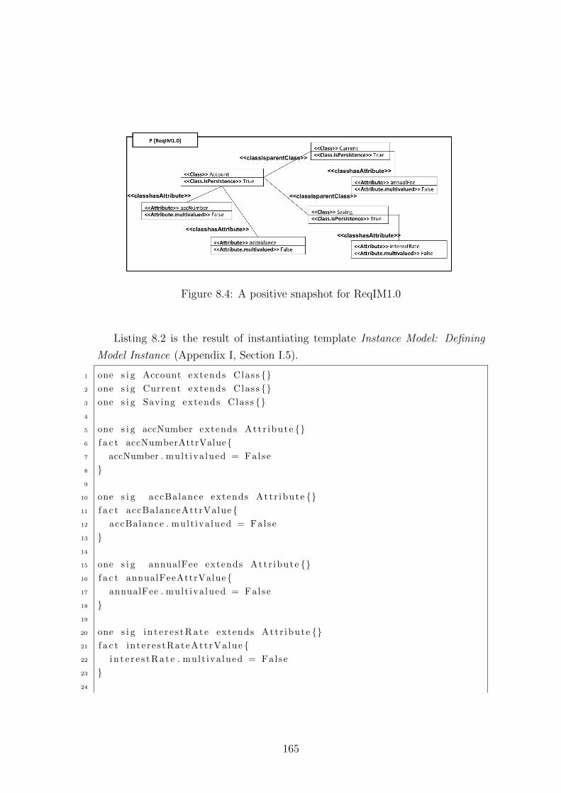
Figure 8.4: A positive snapshot for ReqIM1.0
Listing 8.2 is the result of instantiating template Instance Model: Defining
Model Instance (Appendix I, Section I.5).
1 one s i g Account extends Class {}2 one s i g Current extends Class {}3 one s i g Saving extends Class {}4
5 one s i g accNumber extends Att r ibute {}6 f a c t accNumberAttrValue{7 accNumber . mult iva lued = False
8 }9
10 one s i g accBalance extends Att r ibute {}11 f a c t accBalanceAttrValue {12 accBalance . mult iva lued = False
13 }14
15 one s i g annualFee extends Att r ibute {}16 f a c t annualFeeAttrValue{17 annualFee . mult iva lued = False
18 }19
20 one s i g i n t e r e s t R a t e extends Att r ibute {}21 f a c t in te re s tRateAtt rVa lue {22 i n t e r e s t R a t e . mult iva lued = False
23 }24
165
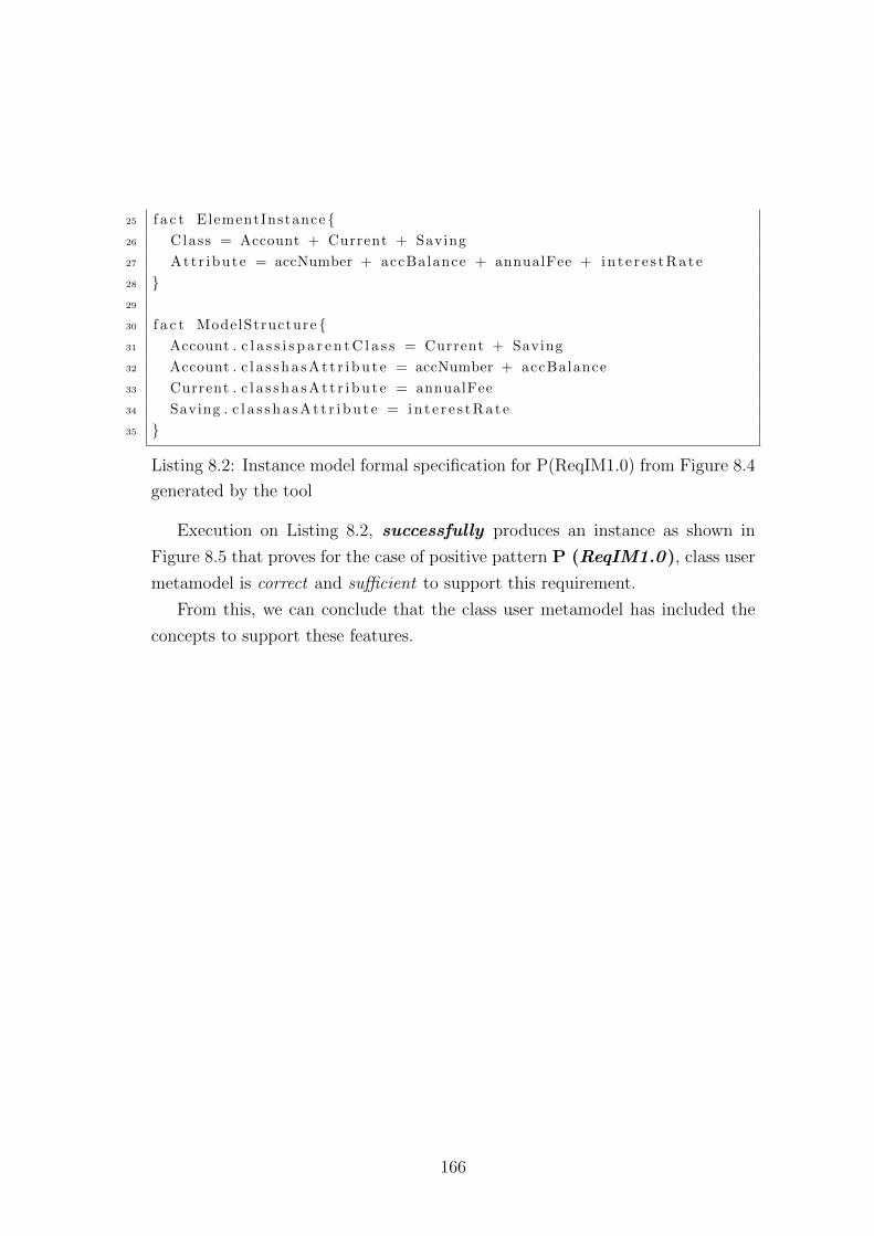
25 f a c t ElementInstance {26 Class = Account + Current + Saving
27 Attr ibute = accNumber + accBalance + annualFee + i n t e r e s t R a t e
28 }29
30 f a c t ModelStructure {31 Account . c l a s s i s p a r e n t C l a s s = Current + Saving
32 Account . c l a s s h a s A t t r i b u t e = accNumber + accBalance
33 Current . c l a s s h a s A t t r i b u t e = annualFee
34 Saving . c l a s s h a s A t t r i b u t e = i n t e r e s t R a t e
35 }
Listing 8.2: Instance model formal specification for P(ReqIM1.0) from Figure 8.4
generated by the tool
Execution on Listing 8.2, successfully produces an instance as shown in
Figure 8.5 that proves for the case of positive pattern P (ReqIM1.0 ), class user
metamodel is correct and sufficient to support this requirement.
From this, we can conclude that the class user metamodel has included the
concepts to support these features.
166
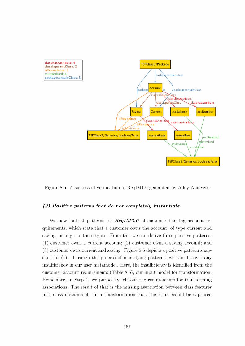
Figure 8.5: A successful verification of ReqIM1.0 generated by Alloy Analyzer
(2) Positive patterns that do not completely instantiate
We now look at patterns for ReqIM2.0 of customer banking account re-
quirements, which state that a customer owns the account, of type current and
saving; or any one these types. From this we can derive three positive patterns:
(1) customer owns a current account; (2) customer owns a saving account; and
(3) customer owns current and saving. Figure 8.6 depicts a positive pattern snap-
shot for (1). Through the process of identifying patterns, we can discover any
insufficiency in our user metamodel. Here, the insufficiency is identified from the
customer account requirements (Table 8.5), our input model for transformation.
Remember, in Step 1, we purposely left out the requirements for transforming
associations. The result of that is the missing association between class features
in a class metamodel. In a transformation tool, this error would be captured
167
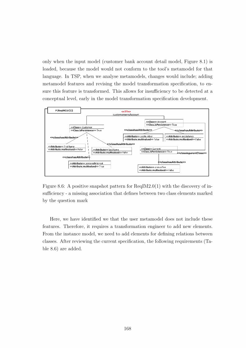
only when the input model (customer bank account detail model, Figure 8.1) is
loaded, because the model would not conform to the tool’s metamodel for that
language. In TSP, when we analyse metamodels, changes would include; adding
metamodel features and revising the model transformation specification, to en-
sure this feature is transformed. This allows for insufficiency to be detected at a
conceptual level, early in the model transformation specification development.
Figure 8.6: A positive snapshot pattern for ReqIM2.0(1) with the discovery of in-
sufficiency - a missing association that defines between two class elements marked
by the question mark
Here, we have identified we that the user metamodel does not include these
features. Therefore, it requires a transformation engineer to add new elements.
From the instance model, we need to add elements for defining relations between
classes. After reviewing the current specification, the following requirements (Ta-
ble 8.6) are added.
168
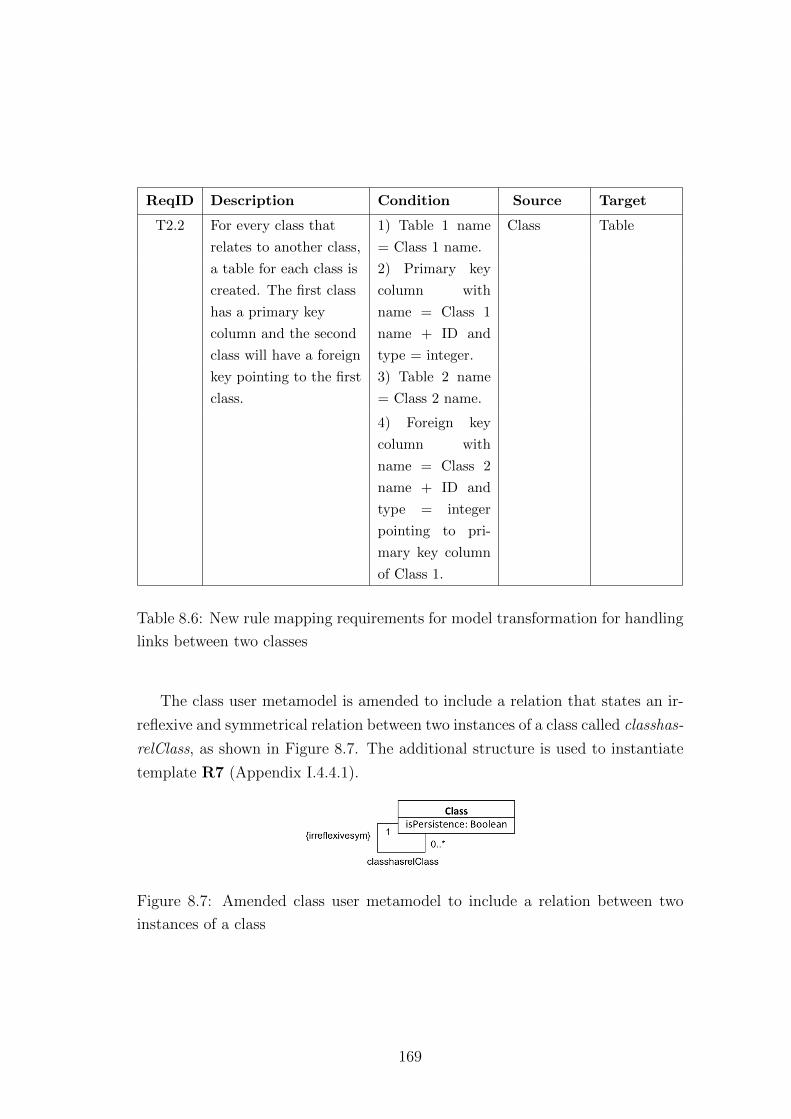
ReqID Description Condition Source Target
T2.2 For every class that
relates to another class,
a table for each class is
created. The first class
has a primary key
column and the second
class will have a foreign
key pointing to the first
class.
1) Table 1 name
= Class 1 name.
Class Table
2) Primary key
column with
name = Class 1
name + ID and
type = integer.
3) Table 2 name
= Class 2 name.
4) Foreign key
column with
name = Class 2
name + ID and
type = integer
pointing to pri-
mary key column
of Class 1.
Table 8.6: New rule mapping requirements for model transformation for handling
links between two classes
The class user metamodel is amended to include a relation that states an ir-
reflexive and symmetrical relation between two instances of a class called classhas-
relClass, as shown in Figure 8.7. The additional structure is used to instantiate
template R7 (Appendix I.4.4.1).
Figure 8.7: Amended class user metamodel to include a relation between two
instances of a class
169
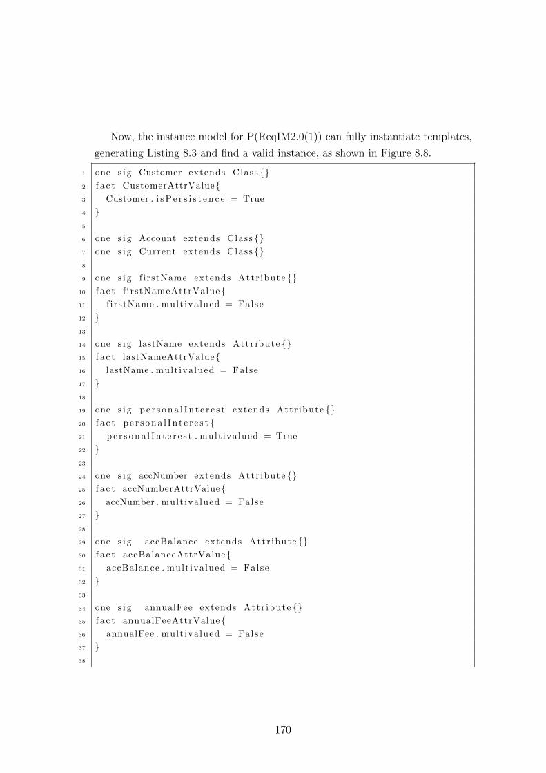
Now, the instance model for P(ReqIM2.0(1)) can fully instantiate templates,
generating Listing 8.3 and find a valid instance, as shown in Figure 8.8.
1 one s i g Customer extends Class {}2 f a c t CustomerAttrValue{3 Customer . i s P e r s i s t e n c e = True
4 }5
6 one s i g Account extends Class {}7 one s i g Current extends Class {}8
9 one s i g f i rstName extends Att r ibute {}10 f a c t f i rstNameAttrValue {11 f i r stName . mult iva lued = False
12 }13
14 one s i g lastName extends Attr ibute {}15 f a c t lastNameAttrValue{16 lastName . mult iva lued = False
17 }18
19 one s i g p e r s o n a l I n t e r e s t extends Attr ibute {}20 f a c t p e r s o n a l I n t e r e s t {21 p e r s o n a l I n t e r e s t . mult iva lued = True
22 }23
24 one s i g accNumber extends Att r ibute {}25 f a c t accNumberAttrValue{26 accNumber . mult iva lued = False
27 }28
29 one s i g accBalance extends Att r ibute {}30 f a c t accBalanceAttrValue {31 accBalance . mult iva lued = False
32 }33
34 one s i g annualFee extends Att r ibute {}35 f a c t annualFeeAttrValue{36 annualFee . mult iva lued = False
37 }38
170
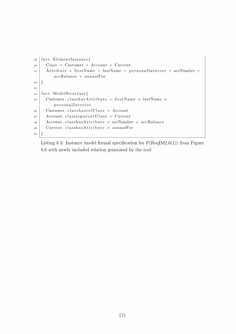
39 f a c t ElementInstance {40 Class = Customer + Account + Current
41 Attr ibute = f irstName + lastName + p e r s o n a l I n t e r e s t + accNumber +
accBalance + annualFee
42 }43
44 f a c t ModelStructure {45 Customer . c l a s s h a s A t t r i b u t e = f irstName + lastName +
p e r s o n a l I n t e r e s t
46 Customer . c l a s s h a s r e l C l a s s = Account
47 Account . c l a s s i s p a r e n t C l a s s = Current
48 Account . c l a s s h a s A t t r i b u t e = accNumber + accBalance
49 Current . c l a s s h a s A t t r i b u t e = annualFee
50 }
Listing 8.3: Instance model formal specification for P(ReqIM2.0(1)) from Figure
8.6 with newly included relation generated by the tool
171
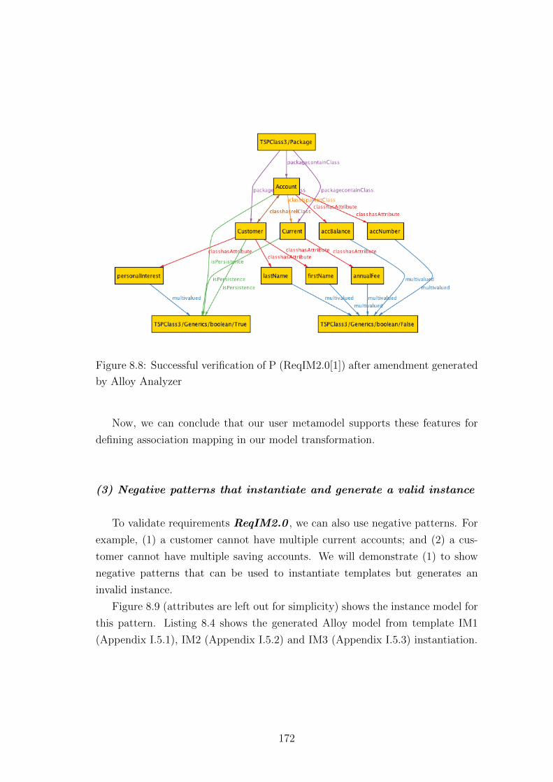
Figure 8.8: Successful verification of P (ReqIM2.0[1]) after amendment generated
by Alloy Analyzer
Now, we can conclude that our user metamodel supports these features for
defining association mapping in our model transformation.
(3) Negative patterns that instantiate and generate a valid instance
To validate requirements ReqIM2.0 , we can also use negative patterns. For
example, (1) a customer cannot have multiple current accounts; and (2) a cus-
tomer cannot have multiple saving accounts. We will demonstrate (1) to show
negative patterns that can be used to instantiate templates but generates an
invalid instance.
Figure 8.9 (attributes are left out for simplicity) shows the instance model for
this pattern. Listing 8.4 shows the generated Alloy model from template IM1
(Appendix I.5.1), IM2 (Appendix I.5.2) and IM3 (Appendix I.5.3) instantiation.
172
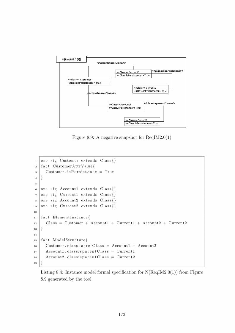
Figure 8.9: A negative snapshot for ReqIM2.0(1)
1 one s i g Customer extends Class {}2 f a c t CustomerAttrValue{3 Customer . i s P e r s i s t e n c e = True
4 }5
6 one s i g Account1 extends Class {}7 one s i g Current1 extends Class {}8 one s i g Account2 extends Class {}9 one s i g Current2 extends Class {}
10
11 f a c t ElementInstance {12 Class = Customer + Account1 + Current1 + Account2 + Current2
13 }14
15 f a c t ModelStructure {16 Customer . c l a s s h a s r e l C l a s s = Account1 + Account2
17 Account1 . c l a s s i s p a r e n t C l a s s = Current1
18 Account2 . c l a s s i s p a r e n t C l a s s = Current2
19 }
Listing 8.4: Instance model formal specification for N(ReqIM2.0(1)) from Figure
8.9 generated by the tool
173
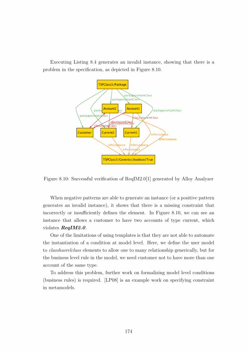
Executing Listing 8.4 generates an invalid instance, showing that there is a
problem in the specification, as depicted in Figure 8.10.
Figure 8.10: Successful verification of ReqIM2.0[1] generated by Alloy Analyzer
When negative patterns are able to generate an instance (or a positive pattern
generates an invalid instance), it shows that there is a missing constraint that
incorrectly or insufficiently defines the element. In Figure 8.10, we can see an
instance that allows a customer to have two accounts of type current, which
violates ReqIM2.0 .
One of the limitations of using templates is that they are not able to automate
the instantiation of a condition at model level. Here, we define the user model
to classhasrelclass elements to allow one to many relationship generically, but for
the business level rule in the model, we need customer not to have more than one
account of the same type.
To address this problem, further work on formalizing model level conditions
(business rules) is required. [LP08] is an example work on specifying constraint
in metamodels.
174
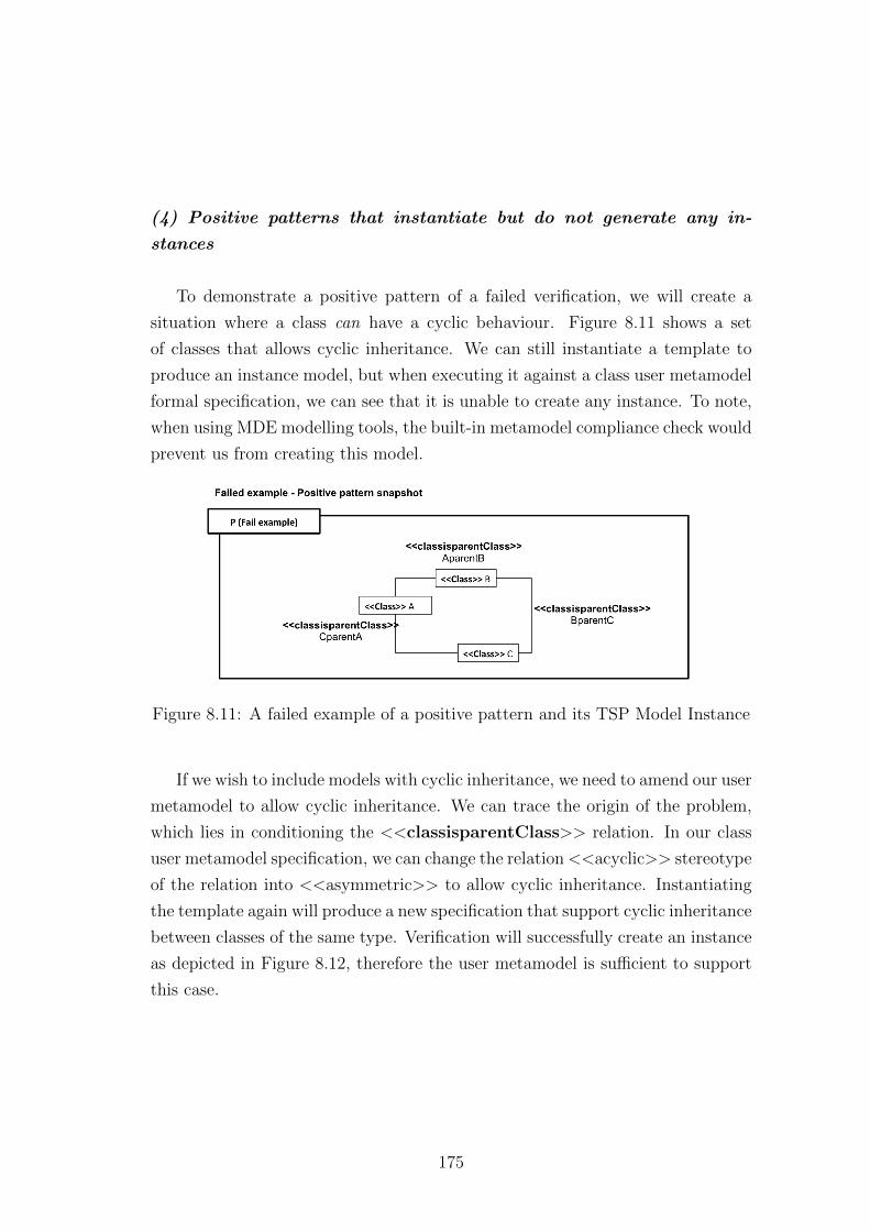
(4) Positive patterns that instantiate but do not generate any in-
stances
To demonstrate a positive pattern of a failed verification, we will create a
situation where a class can have a cyclic behaviour. Figure 8.11 shows a set
of classes that allows cyclic inheritance. We can still instantiate a template to
produce an instance model, but when executing it against a class user metamodel
formal specification, we can see that it is unable to create any instance. To note,
when using MDE modelling tools, the built-in metamodel compliance check would
prevent us from creating this model.
Figure 8.11: A failed example of a positive pattern and its TSP Model Instance
If we wish to include models with cyclic inheritance, we need to amend our user
metamodel to allow cyclic inheritance. We can trace the origin of the problem,
which lies in conditioning the <<classisparentClass>> relation. In our class
user metamodel specification, we can change the relation<<acyclic>> stereotype
of the relation into <<asymmetric>> to allow cyclic inheritance. Instantiating
the template again will produce a new specification that support cyclic inheritance
between classes of the same type. Verification will successfully create an instance
as depicted in Figure 8.12, therefore the user metamodel is sufficient to support
this case.
175
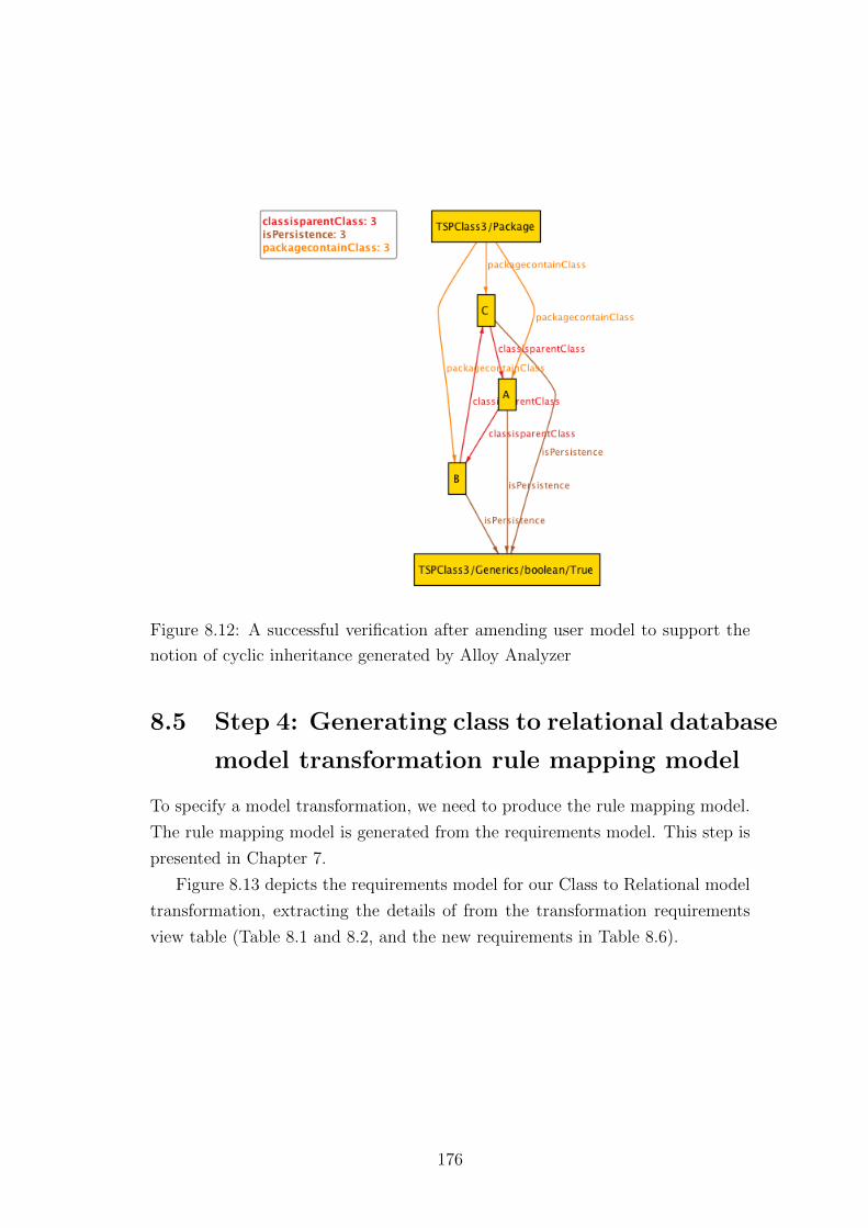
Figure 8.12: A successful verification after amending user model to support the
notion of cyclic inheritance generated by Alloy Analyzer
8.5 Step 4: Generating class to relational database
model transformation rule mapping model
To specify a model transformation, we need to produce the rule mapping model.
The rule mapping model is generated from the requirements model. This step is
presented in Chapter 7.
Figure 8.13 depicts the requirements model for our Class to Relational model
transformation, extracting the details of from the transformation requirements
view table (Table 8.1 and 8.2, and the new requirements in Table 8.6).
176
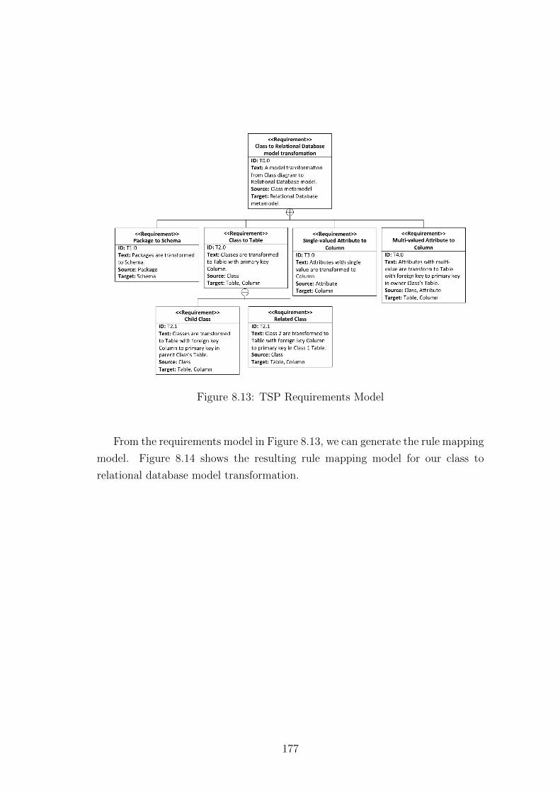
Figure 8.13: TSP Requirements Model
From the requirements model in Figure 8.13, we can generate the rule mapping
model. Figure 8.14 shows the resulting rule mapping model for our class to
relational database model transformation.
177
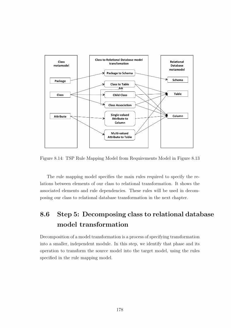
Figure 8.14: TSP Rule Mapping Model from Requirements Model in Figure 8.13
The rule mapping model specifies the main rules required to specify the re-
lations between elements of our class to relational transformation. It shows the
associated elements and rule dependencies. These rules will be used in decom-
posing our class to relational database transformation in the next chapter.
8.6 Step 5: Decomposing class to relational database
model transformation
Decomposition of a model transformation is a process of specifying transformation
into a smaller, independent module. In this step, we identify that phase and its
operation to transform the source model into the target model, using the rules
specified in the rule mapping model.
178
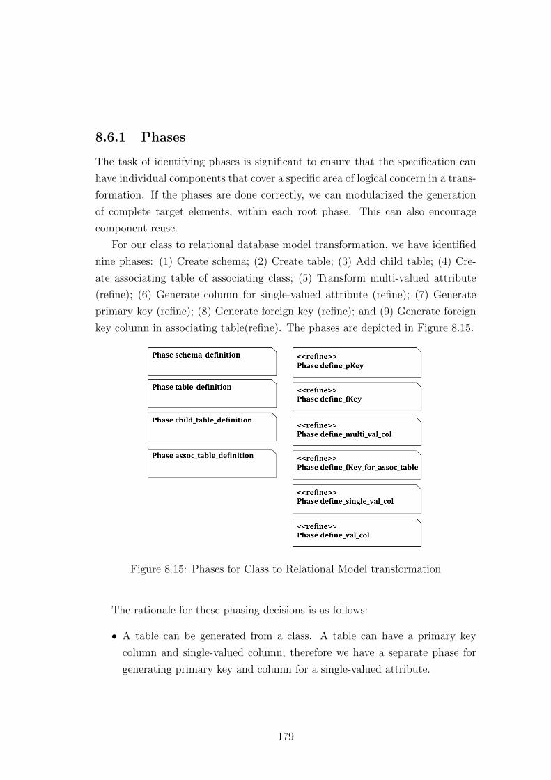
8.6.1 Phases
The task of identifying phases is significant to ensure that the specification can
have individual components that cover a specific area of logical concern in a trans-
formation. If the phases are done correctly, we can modularized the generation
of complete target elements, within each root phase. This can also encourage
component reuse.
For our class to relational database model transformation, we have identified
nine phases: (1) Create schema; (2) Create table; (3) Add child table; (4) Cre-
ate associating table of associating class; (5) Transform multi-valued attribute
(refine); (6) Generate column for single-valued attribute (refine); (7) Generate
primary key (refine); (8) Generate foreign key (refine); and (9) Generate foreign
key column in associating table(refine). The phases are depicted in Figure 8.15.
Figure 8.15: Phases for Class to Relational Model transformation
The rationale for these phasing decisions is as follows:
• A table can be generated from a class. A table can have a primary key
column and single-valued column, therefore we have a separate phase for
generating primary key and column for a single-valued attribute.
179
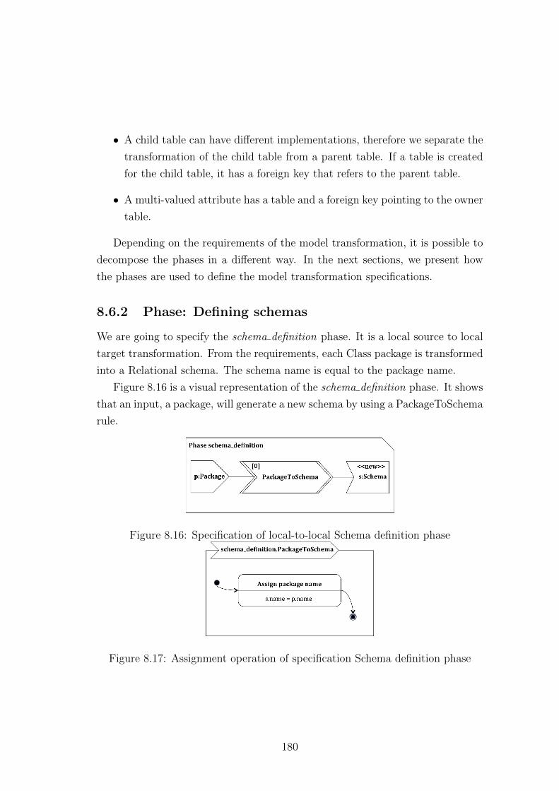
• A child table can have different implementations, therefore we separate the
transformation of the child table from a parent table. If a table is created
for the child table, it has a foreign key that refers to the parent table.
• A multi-valued attribute has a table and a foreign key pointing to the owner
table.
Depending on the requirements of the model transformation, it is possible to
decompose the phases in a different way. In the next sections, we present how
the phases are used to define the model transformation specifications.
8.6.2 Phase: Defining schemas
We are going to specify the schema definition phase. It is a local source to local
target transformation. From the requirements, each Class package is transformed
into a Relational schema. The schema name is equal to the package name.
Figure 8.16 is a visual representation of the schema definition phase. It shows
that an input, a package, will generate a new schema by using a PackageToSchema
rule.
Figure 8.16: Specification of local-to-local Schema definition phase
Figure 8.17: Assignment operation of specification Schema definition phase
180
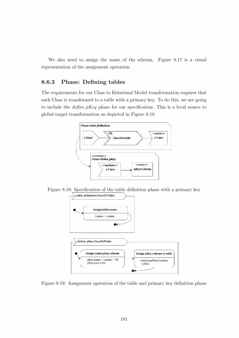
We also need to assign the name of the schema. Figure 8.17 is a visual
representation of the assignment operation.
8.6.3 Phase: Defining tables
The requirements for our Class to Relational Model transformation requires that
each Class is transformed to a table with a primary key. To do this, we are going
to include the define pKey phase for our specification. This is a local source to
global target transformation as depicted in Figure 8.18.
Figure 8.18: Specification of the table definition phase with a primary key
Figure 8.19: Assignment operation of the table and primary key definition phase
181
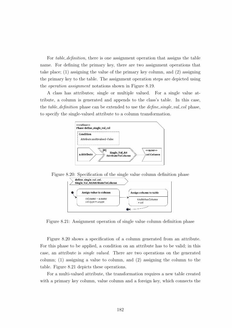
For table definition, there is one assignment operation that assigns the table
name. For defining the primary key, there are two assignment operations that
take place; (1) assigning the value of the primary key column, and (2) assigning
the primary key to the table. The assignment operation steps are depicted using
the operation assignment notations shown in Figure 8.19.
A class has attributes; single or multiple valued. For a single value at-
tribute, a column is generated and appends to the class’s table. In this case,
the table definition phase can be extended to use the define single val col phase,
to specify the single-valued attribute to a column transformation.
Figure 8.20: Specification of the single value column definition phase
Figure 8.21: Assignment operation of single value column definition phase
Figure 8.20 shows a specification of a column generated from an attribute.
For this phase to be applied, a condition on an attribute has to be valid; in this
case, an attribute is single valued. There are two operations on the generated
column; (1) assigning a value to column, and (2) assigning the column to the
table. Figure 8.21 depicts these operations.
For a multi-valued attribute, the transformation requires a new table created
with a primary key column, value column and a foreign key, which connects the
182
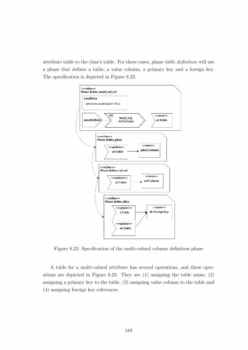
attribute table to the class’s table. For these cases, phase table definition will use
a phase that defines a table, a value column, a primary key and a foreign key.
The specification is depicted in Figure 8.22.
Figure 8.22: Specification of the multi-valued column definition phase
A table for a multi-valued attribute has several operations, and these oper-
ations are depicted in Figure 8.23. They are (1) assigning the table name, (2)
assigning a primary key to the table, (3) assigning value column to the table and
(4) assigning foreign key references.
183
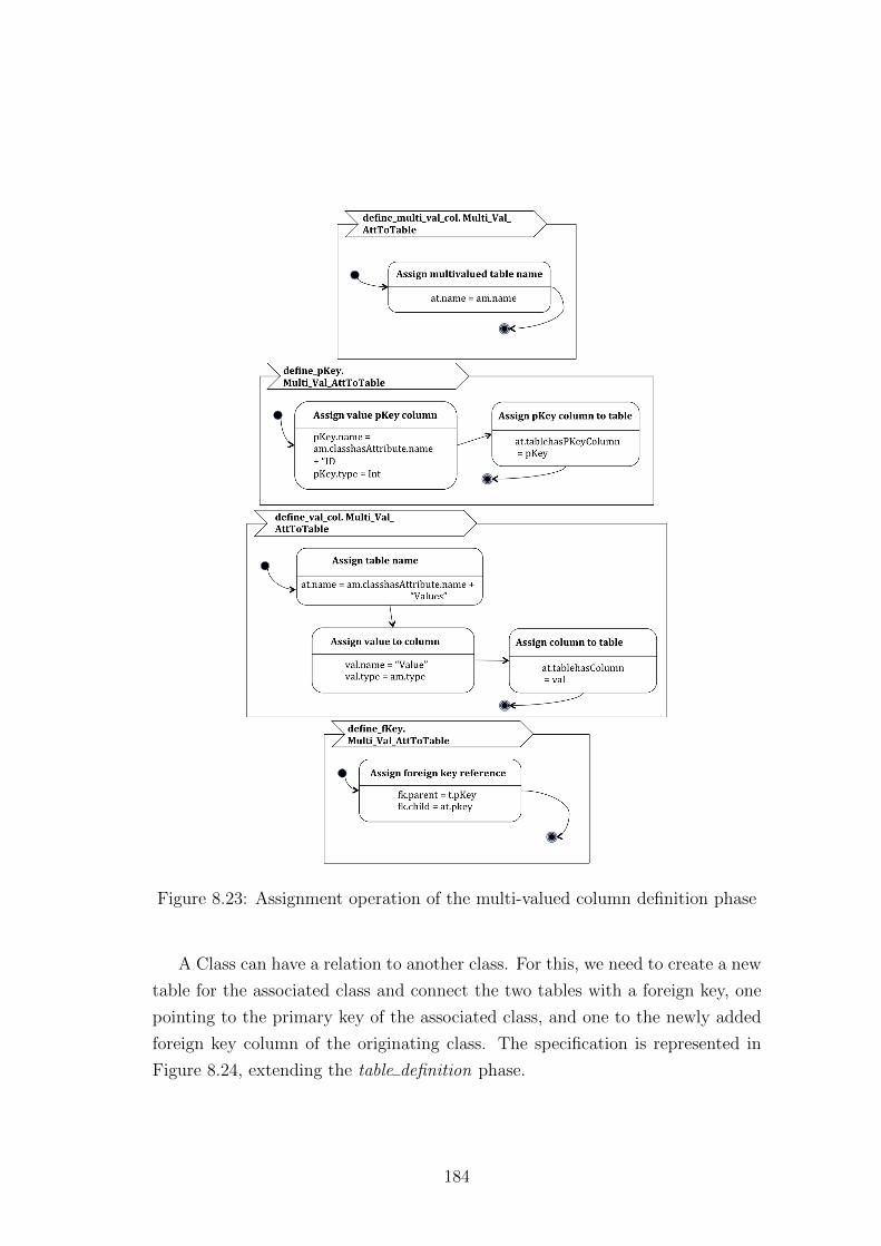
Figure 8.23: Assignment operation of the multi-valued column definition phase
A Class can have a relation to another class. For this, we need to create a new
table for the associated class and connect the two tables with a foreign key, one
pointing to the primary key of the associated class, and one to the newly added
foreign key column of the originating class. The specification is represented in
Figure 8.24, extending the table definition phase.
184
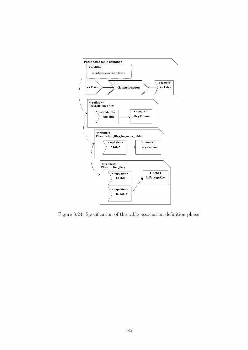
Figure 8.24: Specification of the table association definition phase
185
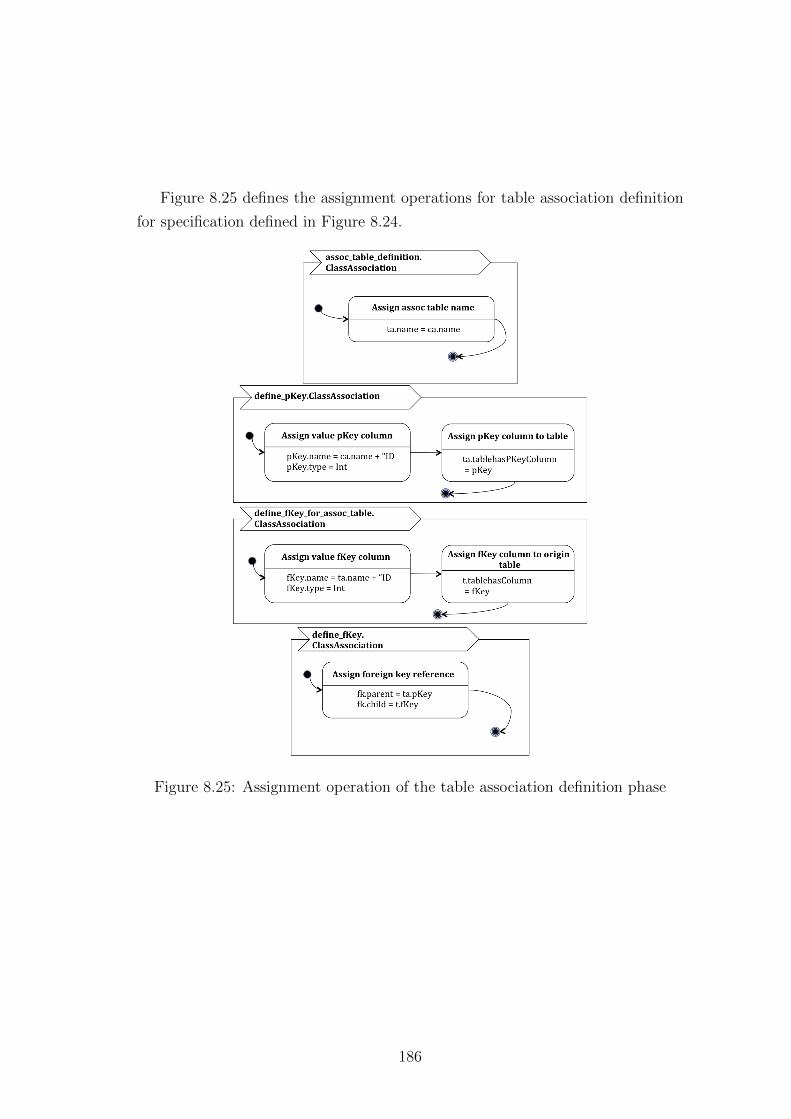
Figure 8.25 defines the assignment operations for table association definition
for specification defined in Figure 8.24.
Figure 8.25: Assignment operation of the table association definition phase
186
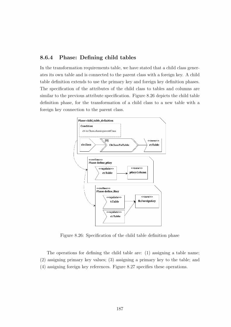
8.6.4 Phase: Defining child tables
In the transformation requirements table, we have stated that a child class gener-
ates its own table and is connected to the parent class with a foreign key. A child
table definition extends to use the primary key and foreign key definition phases.
The specification of the attributes of the child class to tables and columns are
similar to the previous attribute specification. Figure 8.26 depicts the child table
definition phase, for the transformation of a child class to a new table with a
foreign key connection to the parent class.
Figure 8.26: Specification of the child table definition phase
The operations for defining the child table are: (1) assigning a table name;
(2) assigning primary key values; (3) assigning a primary key to the table; and
(4) assigning foreign key references. Figure 8.27 specifies these operations.
187
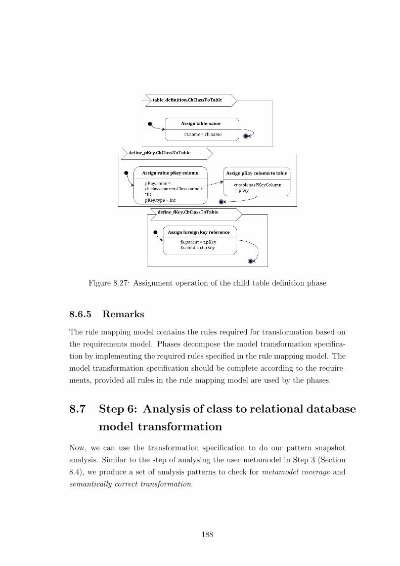
Figure 8.27: Assignment operation of the child table definition phase
8.6.5 Remarks
The rule mapping model contains the rules required for transformation based on
the requirements model. Phases decompose the model transformation specifica-
tion by implementing the required rules specified in the rule mapping model. The
model transformation specification should be complete according to the require-
ments, provided all rules in the rule mapping model are used by the phases.
8.7 Step 6: Analysis of class to relational database
model transformation
Now, we can use the transformation specification to do our pattern snapshot
analysis. Similar to the step of analysing the user metamodel in Step 3 (Section
8.4), we produce a set of analysis patterns to check for metamodel coverage and
semantically correct transformation.
188
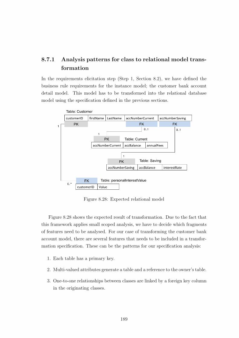
8.7.1 Analysis patterns for class to relational model trans-
formation
In the requirements elicitation step (Step 1, Section 8.2), we have defined the
business rule requirements for the instance model; the customer bank account
detail model. This model has to be transformed into the relational database
model using the specification defined in the previous sections.
Figure 8.28: Expected relational model
Figure 8.28 shows the expected result of transformation. Due to the fact that
this framework applies small scoped analysis, we have to decide which fragments
of features need to be analysed. For our case of transforming the customer bank
account model, there are several features that needs to be included in a transfor-
mation specification. These can be the patterns for our specification analysis:
1. Each table has a primary key.
2. Multi-valued attributes generate a table and a reference to the owner’s table.
3. One-to-one relationships between classes are linked by a foreign key column
in the originating classes.
189
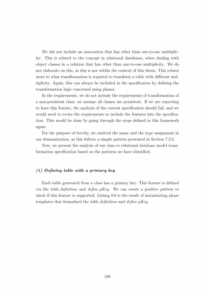
We did not include an association that has other than one-to-one multiplic-
ity. This is related to the concept in relational databases, when dealing with
object classes in a relation that has other than one-to-one multiplicity. We do
not elaborate on this, as this is not within the context of this thesis. This relates
more to what transformation is required to transform a table with different mul-
tiplicity. Again, this can always be included in the specification by defining the
transformation logic concerned using phases.
In the requirements, we do not include the requirements of transformation of
a non-persistent class; we assume all classes are persistent. If we are expecting
to have this feature, the analysis of the current specification should fail, and we
would need to revise the requirements to include the features into the specifica-
tion. This would be done by going through the steps defined in this framework
again.
For the purpose of brevity, we omitted the name and the type assignment in
our demonstration, as this follows a simple pattern presented in Section 7.3.2.
Now, we present the analysis of our class to relational database model trans-
formation specification based on the patterns we have identified.
(1) Defining table with a primary key
Each table generated from a class has a primary key. This feature is defined
via the table definition and define pKey. We can create a positive pattern to
check if this feature is supported. Listing 8.6 is the result of instantiating phase
templates that formalized the table definition and define pKey.
190
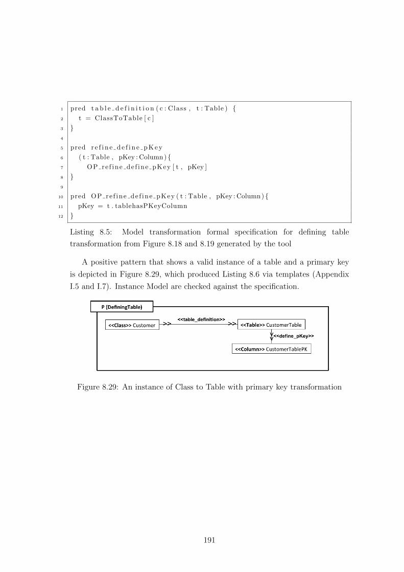
1 pred t a b l e d e f i n i t i o n ( c : Class , t : Table ) {2 t = ClassToTable [ c ]
3 }4
5 pred r e f i n e d e f i n e p K e y
6 ( t : Table , pKey : Column) {7 OP re f ine de f ine pKey [ t , pKey ]
8 }9
10 pred OP re f ine de f ine pKey ( t : Table , pKey : Column) {11 pKey = t . tablehasPKeyColumn
12 }
Listing 8.5: Model transformation formal specification for defining table
transformation from Figure 8.18 and 8.19 generated by the tool
A positive pattern that shows a valid instance of a table and a primary key
is depicted in Figure 8.29, which produced Listing 8.6 via templates (Appendix
I.5 and I.7). Instance Model are checked against the specification.
Figure 8.29: An instance of Class to Table with primary key transformation
191
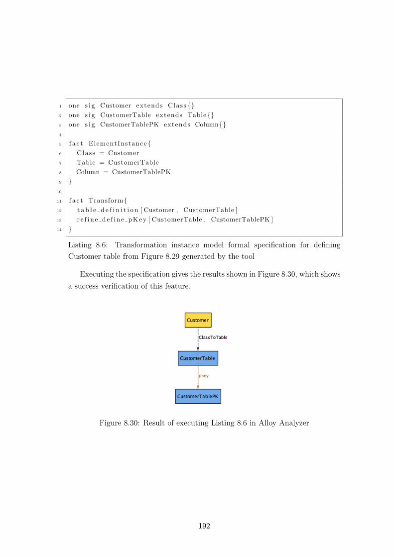
1 one s i g Customer extends Class {}2 one s i g CustomerTable extends Table {}3 one s i g CustomerTablePK extends Column{}4
5 f a c t ElementInstance {6 Class = Customer
7 Table = CustomerTable
8 Column = CustomerTablePK
9 }10
11 f a c t Transform{12 t a b l e d e f i n i t i o n [ Customer , CustomerTable ]
13 r e f i n e d e f i n e p K e y [ CustomerTable , CustomerTablePK ]
14 }
Listing 8.6: Transformation instance model formal specification for defining
Customer table from Figure 8.29 generated by the tool
Executing the specification gives the results shown in Figure 8.30, which shows
a success verification of this feature.
Figure 8.30: Result of executing Listing 8.6 in Alloy Analyzer
192
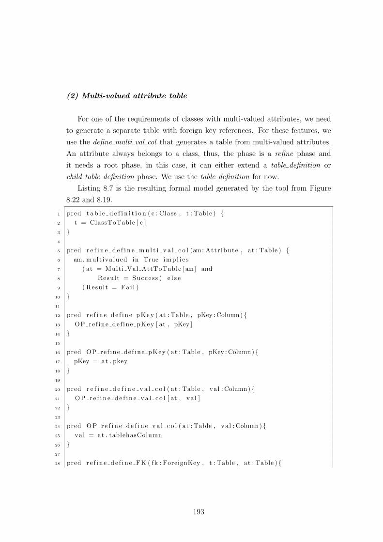
(2) Multi-valued attribute table
For one of the requirements of classes with multi-valued attributes, we need
to generate a separate table with foreign key references. For these features, we
use the define multi val col that generates a table from multi-valued attributes.
An attribute always belongs to a class, thus, the phase is a refine phase and
it needs a root phase, in this case, it can either extend a table definition or
child table definition phase. We use the table definition for now.
Listing 8.7 is the resulting formal model generated by the tool from Figure
8.22 and 8.19.
1 pred t a b l e d e f i n i t i o n ( c : Class , t : Table ) {2 t = ClassToTable [ c ]
3 }4
5 pred r e f i n e d e f i n e m u l t i v a l c o l (am: Attr ibute , at : Table ) {6 am. mult iva lued in True i m p l i e s
7 ( at = Multi Val AttToTable [am] and
8 Result = Success ) e l s e
9 ( Result = Fa i l )
10 }11
12 pred r e f i n e d e f i n e p K e y ( at : Table , pKey : Column) {13 OP re f ine de f ine pKey [ at , pKey ]
14 }15
16 pred OP re f ine de f ine pKey ( at : Table , pKey : Column) {17 pKey = at . pkey
18 }19
20 pred r e f i n e d e f i n e v a l c o l ( at : Table , va l : Column) {21 O P r e f i n e d e f i n e v a l c o l [ at , va l ]
22 }23
24 pred O P r e f i n e d e f i n e v a l c o l ( at : Table , va l : Column) {25 va l = at . tablehasColumn
26 }27
28 pred r e f i n e d e f i n e F K ( fk : ForeignKey , t : Table , at : Table ) {
193
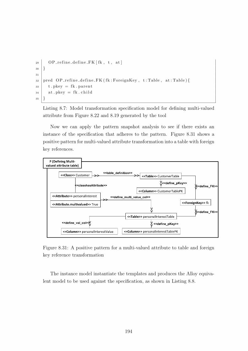
29 OP re f ine de f ine FK [ fk , t , at ]
30 }31
32 pred OP re f ine de f ine FK ( fk : ForeignKey , t : Table , at : Table ) {33 t . pkey = fk . parent
34 at . pkey = fk . c h i l d
35 }
Listing 8.7: Model transformation specification model for defining multi-valued
attribute from Figure 8.22 and 8.19 generated by the tool
Now we can apply the pattern snapshot analysis to see if there exists an
instance of the specification that adheres to the pattern. Figure 8.31 shows a
positive pattern for multi-valued attribute transformation into a table with foreign
key references.
Figure 8.31: A positive pattern for a multi-valued attribute to table and foreign
key reference transformation
The instance model instantiate the templates and produces the Alloy equiva-
lent model to be used against the specification, as shown in Listing 8.8.
194
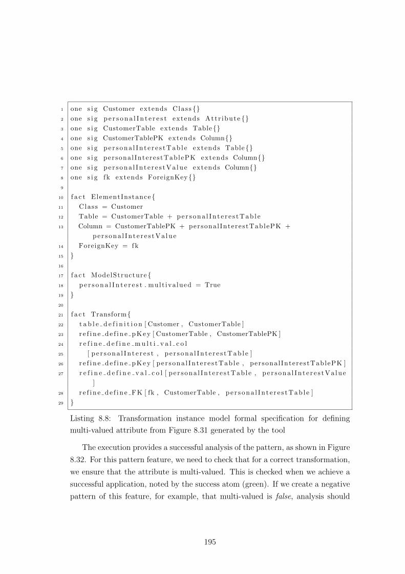
1 one s i g Customer extends Class {}2 one s i g p e r s o n a l I n t e r e s t extends Attr ibute {}3 one s i g CustomerTable extends Table {}4 one s i g CustomerTablePK extends Column{}5 one s i g p e r s o n a l I n t e r e s t T a b l e extends Table{}6 one s i g persona l InterestTablePK extends Column{}7 one s i g p e r s o n a l I n t e r e s t V a l u e extends Column{}8 one s i g fk extends ForeignKey {}9
10 f a c t ElementInstance {11 Class = Customer
12 Table = CustomerTable + p e r s o n a l I n t e r e s t T a b l e
13 Column = CustomerTablePK + persona l InterestTablePK +
p e r s o n a l I n t e r e s t V a l u e
14 ForeignKey = fk
15 }16
17 f a c t ModelStructure {18 p e r s o n a l I n t e r e s t . mult iva lued = True
19 }20
21 f a c t Transform{22 t a b l e d e f i n i t i o n [ Customer , CustomerTable ]
23 r e f i n e d e f i n e p K e y [ CustomerTable , CustomerTablePK ]
24 r e f i n e d e f i n e m u l t i v a l c o l
25 [ p e r s o n a l I n t e r e s t , p e r s o n a l I n t e r e s t T a b l e ]
26 r e f i n e d e f i n e p K e y [ pe r sona l In t e r e s tTab l e , persona l InterestTablePK ]
27 r e f i n e d e f i n e v a l c o l [ p e r s ona l In t e r e s tTab l e , p e r s o n a l I n t e r e s t V a l u e
]
28 r e f i n e d e f i n e F K [ fk , CustomerTable , p e r s o n a l I n t e r e s t T a b l e ]
29 }
Listing 8.8: Transformation instance model formal specification for defining
multi-valued attribute from Figure 8.31 generated by the tool
The execution provides a successful analysis of the pattern, as shown in Figure
8.32. For this pattern feature, we need to check that for a correct transformation,
we ensure that the attribute is multi-valued. This is checked when we achieve a
successful application, noted by the success atom (green). If we create a negative
pattern of this feature, for example, that multi-valued is false, analysis should
195
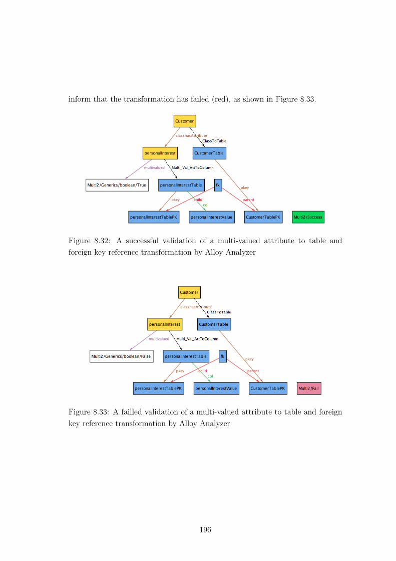
inform that the transformation has failed (red), as shown in Figure 8.33.
Figure 8.32: A successful validation of a multi-valued attribute to table and
foreign key reference transformation by Alloy Analyzer
Figure 8.33: A failled validation of a multi-valued attribute to table and foreign
key reference transformation by Alloy Analyzer
196
(3) One-to-one relationship between classes
For this case, we need to address the limitations of the templates and Alloy,
to represent a scenario where the related instances come from the same class,
particularly, of elements with reflexive association. In our Class user metamodel,
we defined a reflexive association for a relation between two instances of the
same class. This came down again to how Alloy represents model transformation
systems. In a reflexive association, there are two instances originating from the
same element within one relation. Therefore in Alloy, when two instances of the
same element take part in a mapping relation, we need to define two distinct
instances of the same element to enable us to check for the feature.
We define the two instances of an element, that take part in a reflexive as-
sociation, using membership of two elements of the same type. In a reflexive
association, the two objects of the class is of the same relation type. Therefore,
capturing the reflexive association semantics for specifying two different objects
of the same class transformation, can be done by assuming that there is two
different types that are part of a class that relates to itself.
Let us say that, we have a reflexive association rel of element A that is acyclic.
We can prepare the input parameter to include two sub-elements of A (Ai and
Aj) to represent the pair ends of a reflexive association.
Listing 8.9 shows the definition of A for a transformation between elements
in a reflexive association.
197
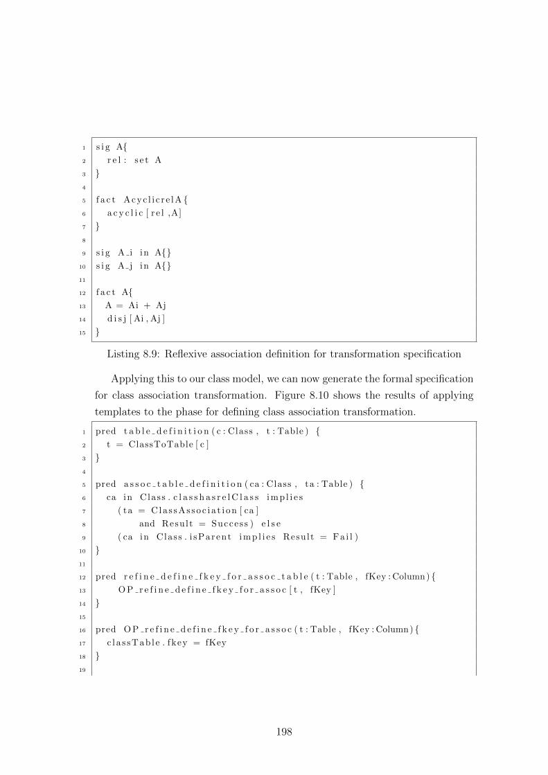
1 s i g A{2 r e l : s e t A
3 }4
5 f a c t Acyc l i c r e lA {6 a c y c l i c [ r e l ,A]
7 }8
9 s i g A i in A{}10 s i g A j in A{}11
12 f a c t A{13 A = Ai + Aj
14 d i s j [ Ai , Aj ]
15 }
Listing 8.9: Reflexive association definition for transformation specification
Applying this to our class model, we can now generate the formal specification
for class association transformation. Figure 8.10 shows the results of applying
templates to the phase for defining class association transformation.
1 pred t a b l e d e f i n i t i o n ( c : Class , t : Table ) {2 t = ClassToTable [ c ]
3 }4
5 pred a s s o c t a b l e d e f i n i t i o n ( ca : Class , ta : Table ) {6 ca in Class . c l a s s h a s r e l C l a s s i m p l i e s
7 ( ta = Cla s sAs soc i a t i on [ ca ]
8 and Result = Success ) e l s e
9 ( ca in Class . i sParent i m p l i e s Result = F a i l )
10 }11
12 pred r e f i n e d e f i n e f k e y f o r a s s o c t a b l e ( t : Table , fKey : Column) {13 O P r e f i n e d e f i n e f k e y f o r a s s o c [ t , fKey ]
14 }15
16 pred O P r e f i n e d e f i n e f k e y f o r a s s o c ( t : Table , fKey : Column) {17 c l a s sTab l e . fkey = fKey
18 }19
198
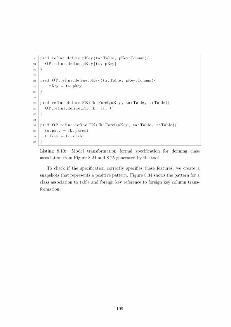
20 pred r e f i n e d e f i n e p K e y ( ta : Table , pKey : Column) {21 OP re f ine de f ine pKey [ ta , pKey ]
22 }23
24 pred OP re f ine de f ine pKey ( ta : Table , pKey : Column) {25 pKey = ta . pkey
26 }27
28 pred r e f i n e d e f i n e F K ( fk : ForeignKey , ta : Table , t : Table ) {29 OP re f ine de f ine FK [ fk , ta , t ]
30 }31
32 pred OP re f ine de f ine FK ( fk : ForeignKey , ta : Table , t : Table ) {33 ta . pkey = fk . parent
34 t . fkey = fk . c h i l d
35 }
Listing 8.10: Model transformation formal specification for defining class
association from Figure 8.24 and 8.25 generated by the tool
To check if the specification correctly specifies these features, we create a
snapshots that represents a positive pattern. Figure 8.34 shows the pattern for a
class association to table and foreign key reference to foreign key column trans-
formation.
199
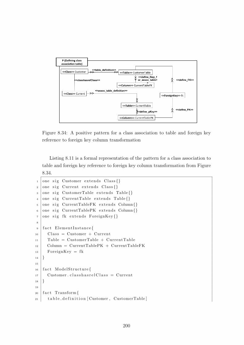
Figure 8.34: A positive pattern for a class association to table and foreign key
reference to foreign key column transformation
Listing 8.11 is a formal representation of the pattern for a class association to
table and foreign key reference to foreign key column transformation from Figure
8.34.
1 one s i g Customer extends Class {}2 one s i g Current extends Class {}3 one s i g CustomerTable extends Table {}4 one s i g CurrentTable extends Table{}5 one s i g CurrentTableFK extends Column{}6 one s i g CurrentTablePK extends Column{}7 one s i g fk extends ForeignKey {}8
9 f a c t ElementInstance {10 Class = Customer + Current
11 Table = CustomerTable + CurrentTable
12 Column = CurrentTablePK + CurrentTableFK
13 ForeignKey = fk
14 }15
16 f a c t ModelStructure {17 Customer . c l a s s h a s r e l C l a s s = Current
18 }19
20 f a c t Transform{21 t a b l e d e f i n i t i o n [ Customer , CustomerTable ]
200
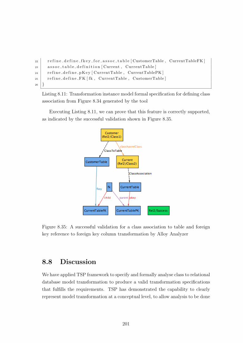
22 r e f i n e d e f i n e f k e y f o r a s s o c t a b l e [ CustomerTable , CurrentTableFK ]
23 a s s o c t a b l e d e f i n i t i o n [ Current , CurrentTable ]
24 r e f i n e d e f i n e p K e y [ CurrentTable , CurrentTablePK ]
25 r e f i n e d e f i n e F K [ fk , CurrentTable , CustomerTable ]
26 }
Listing 8.11: Transformation instance model formal specification for defining class
association from Figure 8.34 generated by the tool
Executing Listing 8.11, we can prove that this feature is correctly supported,
as indicated by the successful validation shown in Figure 8.35.
Figure 8.35: A successful validation for a class association to table and foreign
key reference to foreign key column transformation by Alloy Analyzer
8.8 Discussion
We have applied TSP framework to specify and formally analyse class to relational
database model transformation to produce a valid transformation specifications
that fulfills the requirements. TSP has demonstrated the capability to clearly
represent model transformation at a conceptual level, to allow analysis to be done
201
before the specification is implemented. It has raised some interesting questions
and limitations, which we noted as future work to extend the capability of TSP
framework
TSP framework allows transformation engineers to: (1) establish a set of
model transformation requirements that define the required model transforma-
tion features by including the process of documenting model transformation re-
quirements; (2) produce contextualized metamodels that ensure the sufficiency of
elements from the process of identifying the necessary elements for the source and
target model of the transformation; (3) perform formal analysis on a metamodel
to check for a well-formed metamodel and correctness using snapshot analysis;
(4) extract details from requirements and form the formal requirement model,
for generating the rule mapping model that will be used to decomposing model
transformation specification using phases and (5) formally analyse a model trans-
formation specification using snapshot analysis.
TSP framework has demonstrate how a model transformation and their arte-
facts can be developed and analysed through a set of processes, visual languages
and template-generated formal specifications. The approach systematically pro-
vides the means to unambiguously define model transformation and formally
analyse the specification, without directly dealing with formal methods complex-
ity.
Applying TSP to class to relational database model transformation raised
several interesting questions; most are worth further work for extending TSP in
the future and some are the limitations that we have to agree with. The following
sections discuss the identified matters.
8.8.1 Extracting and detecting contextualized metamodel
elements
The TSP has provided a way to produce a metamodel that is sufficient to sat-
isfy the requirements of a transformation. This is useful for models without any
existing metamodel. For existing ones, they could be, (1) large, or (2) include
unrelated or missing related elements for the transformation. In an implementa-
tion, a large metamodel or a metamodel with unrelated elements are not much
202
of an issue. But it is difficult to ensure that the metamodel is sufficient for a
transformation, especially for detecting missing elements.
Currently, the TSP is able to address the matter of ensuring metamodel suf-
ficiency through contextualization and analysis. A contextualized metamodel is
compatible with metamodel formats such as Ecore. To use the contextualized
and analysed metamodel with existing metamodel, we could implement a tool
that extracts or detects elements from existing metamodel, according to the con-
textualized metamodel.
8.8.2 Additional metamodel constraint
TSP has provided templates that address the structural features of the minimal
set of elements for a metamodel in our metamodelling language. The templates
have also provided integrity constraints that condition the behavioural aspect of
the elements. We have found that we need to include some other behavioural
patterns that define metamodelling elements, such as when multiple relations ex-
ist between two classes. We encounter this when we try to formalize the relations
between a Table and Column that has three distinct types of relation: (1) a pri-
mary key; (2) a value; and (3) a foreign key. We do not include the analysis of
the relational database metamodel in detail in this thesis.
With the current template instantiation, the specification still generates valid
instances and allows positive patterns to be successfully verified. But the model
is under-constraint, where it will allow an invalid instance to be generated and
accepted. To extend the effectiveness of the framework, we need to developed an
additional set of templates that represent model constraints by identifying more
behavioural patterns of models.
8.8.3 Metamodel and model level constraint
We encounter this problem when we try to verify that the customer can only
have one of each type of account (pattern snapshot (3) presented in Section 8.4).
Normally, this is addressed by including an OCL constraint on the model. Our
template has yet to include formalization of OCL expressions. This is a useful
feature to have in TSP framework and we leave it as future work.
203
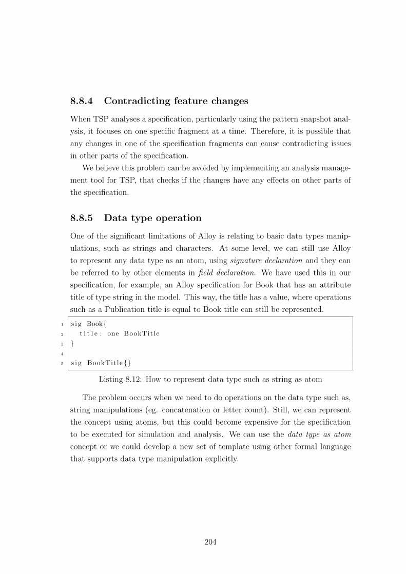
8.8.4 Contradicting feature changes
When TSP analyses a specification, particularly using the pattern snapshot anal-
ysis, it focuses on one specific fragment at a time. Therefore, it is possible that
any changes in one of the specification fragments can cause contradicting issues
in other parts of the specification.
We believe this problem can be avoided by implementing an analysis manage-
ment tool for TSP, that checks if the changes have any effects on other parts of
the specification.
8.8.5 Data type operation
One of the significant limitations of Alloy is relating to basic data types manip-
ulations, such as strings and characters. At some level, we can still use Alloy
to represent any data type as an atom, using signature declaration and they can
be referred to by other elements in field declaration. We have used this in our
specification, for example, an Alloy specification for Book that has an attribute
title of type string in the model. This way, the title has a value, where operations
such as a Publication title is equal to Book title can still be represented.
1 s i g Book{2 t i t l e : one BookTit le
3 }4
5 s i g BookTit le {}
Listing 8.12: How to represent data type such as string as atom
The problem occurs when we need to do operations on the data type such as,
string manipulations (eg. concatenation or letter count). Still, we can represent
the concept using atoms, but this could become expensive for the specification
to be executed for simulation and analysis. We can use the data type as atom
concept or we could develop a new set of template using other formal language
that supports data type manipulation explicitly.
204
8.9 Summary
We have applied TSP framework to specify and formally analyse a class to rela-
tional database model transformation. TSP has demonstrated its capability to
clearly represent model transformation at a conceptual level, to allow analysis
to be done before the specification is implemented. It has raised some interest-
ing questions and limitations that relates to the TSP framework as dicussed in
the previous section which we noted as future work (Section 9.4) to extend TSP
framework capability.
205
Chapter 9
Conclusion
This thesis aimed to address the broad question of how to obtain reliable model
transformations, by presenting the TSpecProber (TSP) framework, which can be
used for specifying and analysing model transformations. TSP was founded on
previous work in the domain of formal methods and MDE (reviewed systemati-
cally in Chapters 2 and 3). An overview of TSP was presented in Chapter 4. We
then presented the main parts of TSP in more detail. In particular, in Chapter
5, we described a set of techniques to elicit model transformation requirements,
and also explained how metamodels could be contextualized for specific analysis
problems. We showed how to analyse a contextualised metamodel, particularly
to check for well-formedness, in Chapter 6. We then described in detail, how a
model transformation can be specified and analysed (Chapter 7). The overall ap-
proach was evaluated by applying TSP to specify and formally analyse a specific
instance of model transformation – class-to-relational-database – in Chapter 8.
9.1 Restatement of research aims
At the start of the thesis we identified the following key research questions:
1. How can we systematically and effectively specify a model transformation?
2. How can we formally analyse model transformation effectively using prac-
tical approaches? Practical, in this sense, refers to the ease of application
206
of formal methods, particularly not requiring significant expertise in under-
standing the theory behind the formal method.
With this in mind, we postulated the following thesis hypothesis:
In ensuring a model transformation specification is precise,
we need to have a framework that provides (1) a set of processes
for model transformation specification development, (2) visual nota-
tions for specifying model transformation specification, and (3) tem-
plates for producing model transformation formal specification that
is tractable and amenable to effective formal analysis of model
transformation.
Based on the successful application of the framework presented in Chapter
8, we conclude that we have answered our initial research question and provided
confidence that the hypothesis is correct. We summarise our contributions in the
next section.
9.2 Research contributions
We have presented a novel approach to formally specifying and analysing model
transformations, based on the use of templates and on a rigorous process in which
transformations are specified and constructed. Overall, we have contributed an
approach that can help increase engineers’ level of confidence in their model
transformations. We have also demonstrated the feasibility of the approach by
showing how it can be used to analyse a typical model transformation (class-to-
relational-database). More specifically, we have contributed:
• A process for model transformation specification development that focuses
on discovering the essential features and components of a model transfor-
mation.
• A visual modelling language for representing a model transformation spec-
ification and its components.
207
• A catalogue of formal templates that can be used for producing formal
specifications of model transformations that are amenable to effective formal
analysis.
The following sections describe the contributions in detail.
9.2.1 Systematic development process for model transfor-
mation
Typically, model transformations are not developed systematically; there is no
clearly understood or precisely defined process that is widely used. Development
therefore, is normally ad-hoc and depends on the skills, insights, and intuition
(or lack thereof) of the transformation engineers. Clearly this has drawbacks: (1)
there is usually no clear documentation nor justification for the design decisions
made; (2) there are limited ways of analysing transformations before they are
implemented; and (3) repeatability of construction is difficult.
With TSP, we provided a way for model transformations to be systematically
developed and analysed conceptually before they are implemented. We presented
six steps to produce a precise model transformation.
Step 1 is the identification of model transformation requirements. We clar-
ified the difference between software requirements and transformation require-
ments, why eliciting model transformation requirements is required, and, showed
how this is done to support development. We described several views for model
transformation requirements that capture their features and components. This is
presented in detail in Chapter 5.
Step 2 is to create a contextualized metamodel (TSP user metamodel) that is
sufficient according to the elicited requirements using visual notation provided by
the framework. Contextualized metamodel contains a minimal set of elements for
specifying the model transformation of interest. The contextualized metamodel
can be used as (1) an implementation source and target metamodel (by encoding
it in a suitable format readable by a tool, e.g., EMF/MDR), or (2) as a guide to
extract or detect a sufficient metamodel embedded in an existing metamodel.
208
In Step 3, the contextualized metamodel is analysed for well-formedness; this
is presented in Chapter 6. The contextualized user metamodel will instantiate
a set of templates to generate an equivalent formal Alloy model which can be
executed in Alloy Analyzer to ensures that the metamodel used for the transfor-
mation is syntactically and semantically correct. We introduced a snapshot anal-
ysis that includes user metamodel instance pattern that can be formalised into
Alloy model via instantiating a set of templates to check if the user metamodel
has been correctly and sufficiently defined based on the requirements. While we
thoroughly presented the contextualization process and how such a metamodel
can be analysed, we did not show how to implement such a metamodel in diverse
technologies (this is standard practice and has been left for future work). This is
presented in detail in Chapter 5.
Step 4 is where we begin specifying model transformations (TSP model trans-
formation specifications) using visual notation provided by the framework. The
requirements and specification is bridged via a formal requirements model which
extracts the details of the model transformation’s features. A requirements model
is used to generate the rule mapping model that contains the rules required by
the transformation. This is presented in Chapter 7.
An overall model transformation specification is decomposed from the rule
mapping model using visual notation provided by the framework in Step 5. The
decomposition uses the phasing mechanism, which provides modularization of a
transformation into smaller, independent transformation parts, using the rules
defined in the rule mapping model. The phases also help to address scalability
issues associated with analysing transformations using SAT-based tools, but its
application also encourages re-usability of model transformation specifications.
Currently, TSP requires good judgement of a transformation engineers in deciding
the phases of a model transformation. Automation of phasing is out of the scope
of this thesis and will be included as further work.
Finally in Step 6, the model transformation specification instantiates a set of
templates to produce an equivalent formal model that can be used for analysis to
ensure metamodel coverage (i.e., that the transformation specification does not
omit consideration of any elements in the transformation) and semantic correct-
ness. The analysis includes snapshot analysis that uses model transformation
209
instance pattern, which can be formalised into Alloy model by instantiating a set
of templates to check if model transformation specifications has been correctly
and sufficiently defined based on the requirements.
In summary, TSP provides a systematic approach to develop a precise model
transformation, from requirements to specification, that includes the necessary
analysis to identify errors and faults at the component level.
9.2.2 Modelling language for specifying and analysing model
transformation
The TSP framework addresses the absence of standard representations of model
transformation, which makes it difficult for model transformation to be analysed
at the conceptual level. For this purpose, we have defined a set of visual modelling
languages for specifying transformations and their components. The language
includes notations for the requirements model, user metamodels, mapping model
and model transformation specification.
The TSP modelling language concrete syntaxes are conceptual models; it
does not require any specific implementation. The modelling language is part of
the framework, therefore it is designed to sufficiently represent the key concepts
and logic of model transformations, while at the same time accommodating the
templates used to support analysis. The modelling languages are presented in
Chapter 5 (user metamodel) and Chapter 7 (requirements model, mapping model,
model transformation specification). The TSP modelling language also supports
the concept of phasing for decomposition of specification and analysis constructs.
The TSP framework incorporates a notion of pattern snapshot analysis for
analysing model transformations. To do this, TSP provides another set of mod-
elling elements for representing model instances. This is presented in detail in
Chapter 6 and 7.
In summary, TSP has contributed to providing a set of representations that
allow model transformation to be conceptually specified and analysed.
210
9.2.3 Formal templates catalogue
To address the complexity of applying formal methods, we have adopted a template-
based approach for specifying and reasoning about transformations. Templates
are a mechanism used to hide formalism from transformation engineers by gen-
erating formal specifications via instantiation. The templates are correct-by-
construction, representing model transformation patterns and integrity constraints.
The templates are populated in a catalogue to be instantiated by TSP models.
The current version of the TSP formal templates catalogue is based upon Alloy,
but templates can in principle, be specified in other languages (such as Z).
The current template catalogue is sufficient to completely represent model
transformation specification provided by TSP models. The template catalogue
can be extended accordingly whenever new elements are added in TSP models,
provided they are also compatible with Alloy representation and analysis capa-
bilities.
The use of templates for analysis is presented in detail in Chapter 6 and 7.
The TSP Alloy template catalogue is provided in Appendix I.
In summary, we have produced a set of templates that can be used to cre-
ate formal specifications from TSP models. The templates have demonstrated
their ability to support formal methods ‘under the hood’, so that transformation
experts can benefit from their use without having to work with them directly.
9.2.4 Effective formal analysis
We have identified Alloy as a practical formal method. The features of Alloy
that provide effective formal analysis include: (1) the notation uses aspects of
natural language for easy comprehension; (2) it provides analysis in a form of
simulation and type checking; and (3) its tools support automated analysis of the
specification.
We have shown how Alloy can be use to represent model transformation, and
what kind of analysis Alloy supports to provide an effective analysis. The capa-
bility of Alloy to analyse model transformation is constrained by the capability of
its modelling language and the templates to represent structural and behavioural
211
features. Currently, the analysis that is supported is static. To enable dynamic
analysis, TSP models, particularly the instance model, have to provide a richer
representation of state change to extend pattern snapshot analysis capabilities,
to enable simulation.
In summary, we have provided an approach, together with TSP models and
a template catalogue, enabling Alloy to be used to support effective analysis of
model transformations.
9.3 Limitation of the approach
The TSP framework is not without limitations, which we now briefly outline.
9.3.1 Lack of support for endogenous model transforma-
tions
The approach has been successfully applied to exogenous, horizontal transfor-
mations (e.g., the class to relational database transformation) but has yet to be
tried on endogenous transformations. The approach should be applicable to ex-
ogenous vertical transformations, as long as they have different source and target
metamodels. This is due to the way Alloy specifications correspond to the TSP
models and templates, and how they represent rule mapping and specification.
In particular, the mapping to Alloy requires that each rule will have one source
element and one target element, from different source and target metamodels and
as such, endogenous transformations are excluded.
We cannot yet say whether TSP can support endogenous transformations
(between models of the same metamodel) in the future. We would need to enhance
our visual representations to support endogenous features (perhaps inspired by
visual graph transformation approaches), and would also need to investigate the
extent to which Alloy can reason about updates (state changes) to models from
the same language.
212
9.3.2 Lack of support for dynamic analysis
TSP currently supports static analysis of model transformations. This is be-
cause the pattern snapshot analysis only captures one instance of the state of a
transformation. Further work is needed to analyse dynamic properties, such as
confluence and termination.
It is not impossible to implement dynamic analysis in TSP. We need to extend
the instance model to represent dynamic behaviours of model transformations.
One concern though, is that we may require more processing capacity (bigger
memory and longer execution time) to handle dynamic analysis, due to the use
of large state spaces for each element in Alloy. One way to overcome this, is to
produce a new set of formal template catalogues in a different language that has
better dynamic analysis capabilities.
9.4 Future work
There are several directions that can be followed to extend the capability of the
TSP framework. They can be divided into two categories: (1) tool support, and
(2) formal template extension.
We have briefly discussed an elementary prototype TSP tool in Chapter 4,
Section 4.9 for the purpose of maintaining the consistencies of Alloy model pro-
duce from TSP model. The advantages of having a better tool to support the
TSP framework includes: (1) a visual editor for constructing TSP models; (2)
automatic instantiations of templates; (3) potentially tighter integration with the
Alloy Analyzer for analysis and feedback; (4) template management for adding
or changing the template catalogue; (5) automatic consistency checking for any
changes made to a specification; and (6) a traceability comment in the formal
specification indicating the source templates. We would also want the tool to be
able to generate implementation artefacts, for example, Ecore metamodels from
contextualized metamodels, and ETL specification from model transformation
specification.
In terms of template extensions, it would be useful to add templates for for-
malizing OCL patterns for models, metamodels and model transformations. With
213
templates that can be used to encode and apply OCL, it would then be possible
to reason about user-defined functions and constraints. It would also be possible
to develop a new template catalogue that supports other languages for analysing
model transformation specification.
9.5 Final remark
This concludes the thesis. In general, a precise model transformation can be
obtained from systematically developing model transformation, using a visual
representation that has the capability to instantiate templates for producing for-
mal specifications, which are amenable to formal analysis.
214
Appendix A
Definition of generalization kind
and its template instantiations
A.1 Defining generalization
The following define the generalization kind supported by TSP metamodelling
language for specifying generalization features.
A.1.1 Complete subclass type partition
A specialization where each individual instances of a class is an instance of its
subclasses (where attributes are inherited) called a complete subclass type parti-
tion. Figure A.1 shows an example of complete subclass type partition instances
of class Car is a LocalMade or Imported.
A.1.2 Incomplete subclass type partition
In a situation where some individual instance of a class is not an instance of
any its subclasses and contains only the shared attributes without any special-
ization, this is called an incomplete subclass type partition. Figure A.2 is an
215
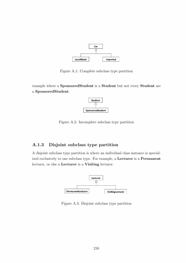
Figure A.1: Complete subclass type partition
example where a SponsoredStudent is a Student but not every Student are
a SponsoredStudent.
Figure A.2: Incomplete subclass type partition
A.1.3 Disjoint subclass type partition
A disjoint subclass type partition is where an individual class instance is special-
ized exclusively to one subclass type. For example, a Lecturer is a Permanent
lecturer, or else a Lecturer is a Visiting lecturer.
Figure A.3: Disjoint subclass type partition
216
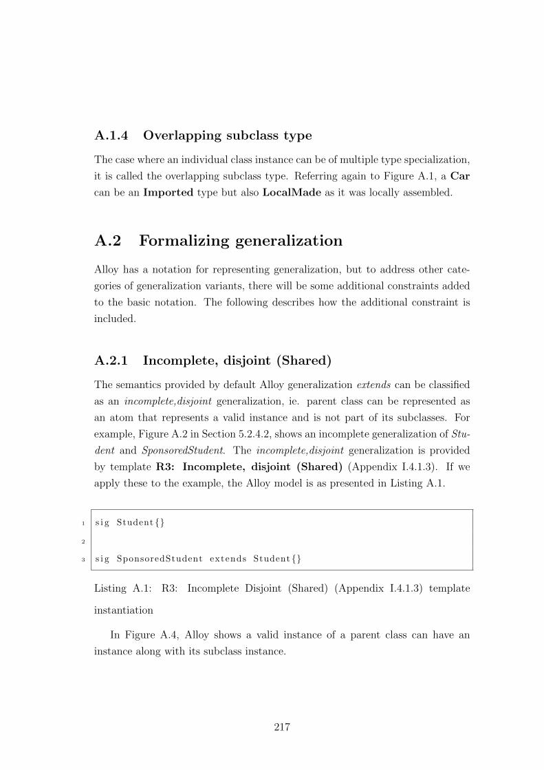
A.1.4 Overlapping subclass type
The case where an individual class instance can be of multiple type specialization,
it is called the overlapping subclass type. Referring again to Figure A.1, a Car
can be an Imported type but also LocalMade as it was locally assembled.
A.2 Formalizing generalization
Alloy has a notation for representing generalization, but to address other cate-
gories of generalization variants, there will be some additional constraints added
to the basic notation. The following describes how the additional constraint is
included.
A.2.1 Incomplete, disjoint (Shared)
The semantics provided by default Alloy generalization extends can be classified
as an incomplete,disjoint generalization, ie. parent class can be represented as
an atom that represents a valid instance and is not part of its subclasses. For
example, Figure A.2 in Section 5.2.4.2, shows an incomplete generalization of Stu-
dent and SponsoredStudent. The incomplete,disjoint generalization is provided
by template R3: Incomplete, disjoint (Shared) (Appendix I.4.1.3). If we
apply these to the example, the Alloy model is as presented in Listing A.1.
1 s i g Student {}
2
3 s i g SponsoredStudent extends Student {}
Listing A.1: R3: Incomplete Disjoint (Shared) (Appendix I.4.1.3) template
instantiation
In Figure A.4, Alloy shows a valid instance of a parent class can have an
instance along with its subclass instance.
217
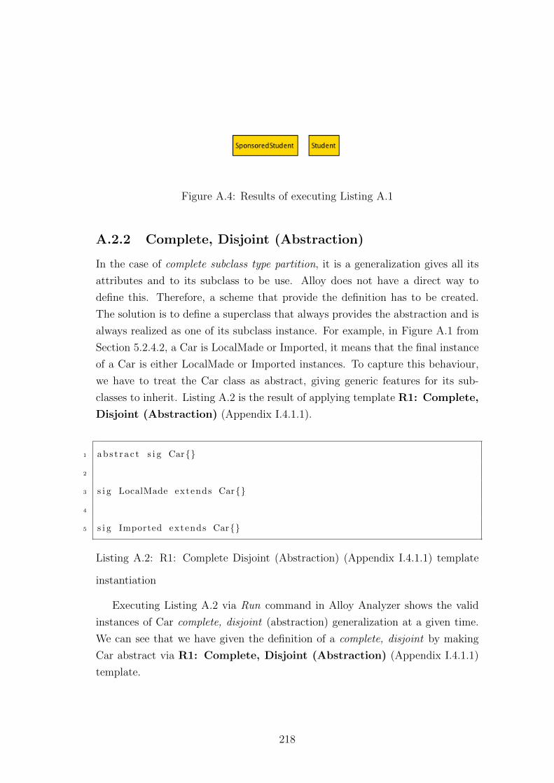
Figure A.4: Results of executing Listing A.1
A.2.2 Complete, Disjoint (Abstraction)
In the case of complete subclass type partition, it is a generalization gives all its
attributes and to its subclass to be use. Alloy does not have a direct way to
define this. Therefore, a scheme that provide the definition has to be created.
The solution is to define a superclass that always provides the abstraction and is
always realized as one of its subclass instance. For example, in Figure A.1 from
Section 5.2.4.2, a Car is LocalMade or Imported, it means that the final instance
of a Car is either LocalMade or Imported instances. To capture this behaviour,
we have to treat the Car class as abstract, giving generic features for its sub-
classes to inherit. Listing A.2 is the result of applying template R1: Complete,
Disjoint (Abstraction) (Appendix I.4.1.1).
1 abs t r a c t s i g Car{}
2
3 s i g LocalMade extends Car{}
4
5 s i g Imported extends Car{}
Listing A.2: R1: Complete Disjoint (Abstraction) (Appendix I.4.1.1) template
instantiation
Executing Listing A.2 via Run command in Alloy Analyzer shows the valid
instances of Car complete, disjoint (abstraction) generalization at a given time.
We can see that we have given the definition of a complete, disjoint by making
Car abstract via R1: Complete, Disjoint (Abstraction) (Appendix I.4.1.1)
template.
218
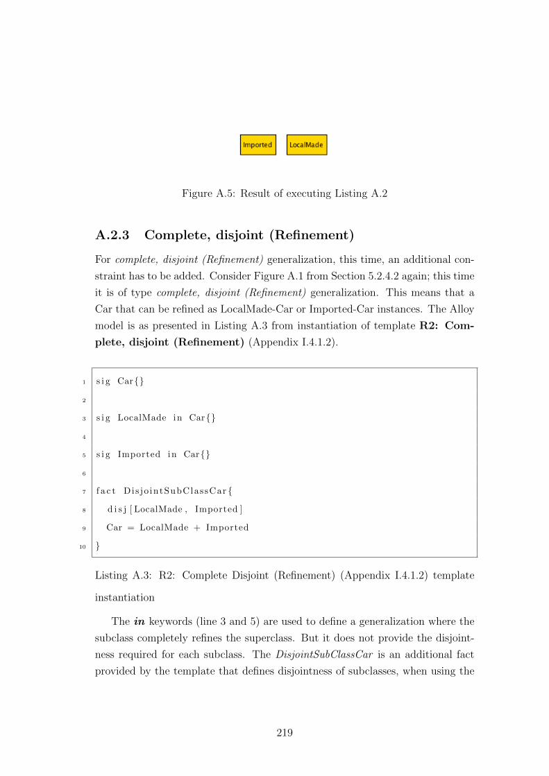
Figure A.5: Result of executing Listing A.2
A.2.3 Complete, disjoint (Refinement)
For complete, disjoint (Refinement) generalization, this time, an additional con-
straint has to be added. Consider Figure A.1 from Section 5.2.4.2 again; this time
it is of type complete, disjoint (Refinement) generalization. This means that a
Car that can be refined as LocalMade-Car or Imported-Car instances. The Alloy
model is as presented in Listing A.3 from instantiation of template R2: Com-
plete, disjoint (Refinement) (Appendix I.4.1.2).
1 s i g Car{}
2
3 s i g LocalMade in Car{}
4
5 s i g Imported in Car{}
6
7 f a c t Dis jo intSubClassCar {
8 d i s j [ LocalMade , Imported ]
9 Car = LocalMade + Imported
10 }
Listing A.3: R2: Complete Disjoint (Refinement) (Appendix I.4.1.2) template
instantiation
The in keywords (line 3 and 5) are used to define a generalization where the
subclass completely refines the superclass. But it does not provide the disjoint-
ness required for each subclass. The DisjointSubClassCar is an additional fact
provided by the template that defines disjointness of subclasses, when using the
219
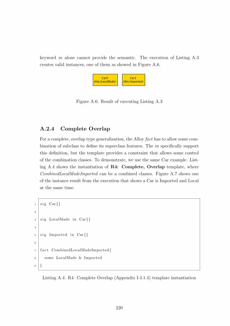
keyword in alone cannot provide the semantic. The execution of Listing A.3
creates valid instances, one of them as showed in Figure A.6.
Figure A.6: Result of executing Listing A.3
A.2.4 Complete Overlap
For a complete, overlap type generalization, the Alloy fact has to allow some com-
bination of subclass to define its superclass features. The in specifically support
this definition, but the template provides a constraint that allows some control
of the combination classes. To demonstrate, we use the same Car example. List-
ing A.4 shows the instantiation of R4: Complete, Overlap template, where
CombinedLocalMadeImported can be a combined classes. Figure A.7 shows one
of the instance result from the execution that shows a Car is Imported and Local
at the same time.
1 s i g Car{}
2
3 s i g LocalMade in Car{}
4
5 s i g Imported in Car{}
6
7 f a c t CombinedLocalMadeImported{
8 some LocalMade & Imported
9 }
Listing A.4: R4: Complete Overlap (Appendix I.4.1.4) template instantiation
220
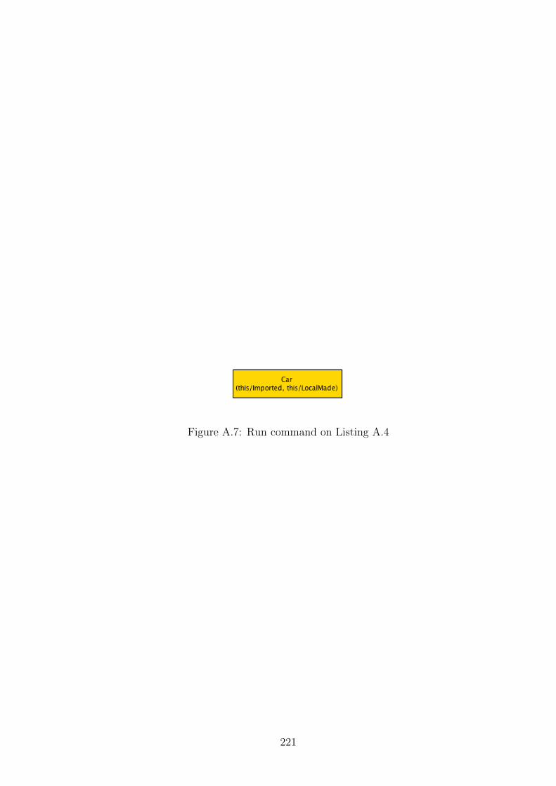
Figure A.7: Run command on Listing A.4
221
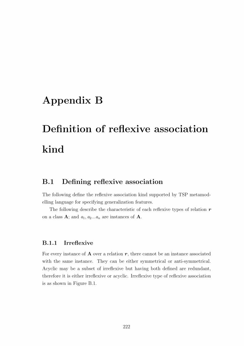
Appendix B
Definition of reflexive association
kind
B.1 Defining reflexive association
The following define the reflexive association kind supported by TSP metamod-
elling language for specifying generalization features.
The following describe the characteristic of each reflexive types of relation r
on a class A; and a1, a2...an are instances of A.
B.1.1 Irreflexive
For every instance of A over a relation r , there cannot be an instance associated
with the same instance. They can be either symmetrical or anti-symmetrical.
Acyclic may be a subset of irreflexive but having both defined are redundant,
therefore it is either irreflexive or acyclic. Irreflexive type of reflexive association
is as shown in Figure B.1.
222
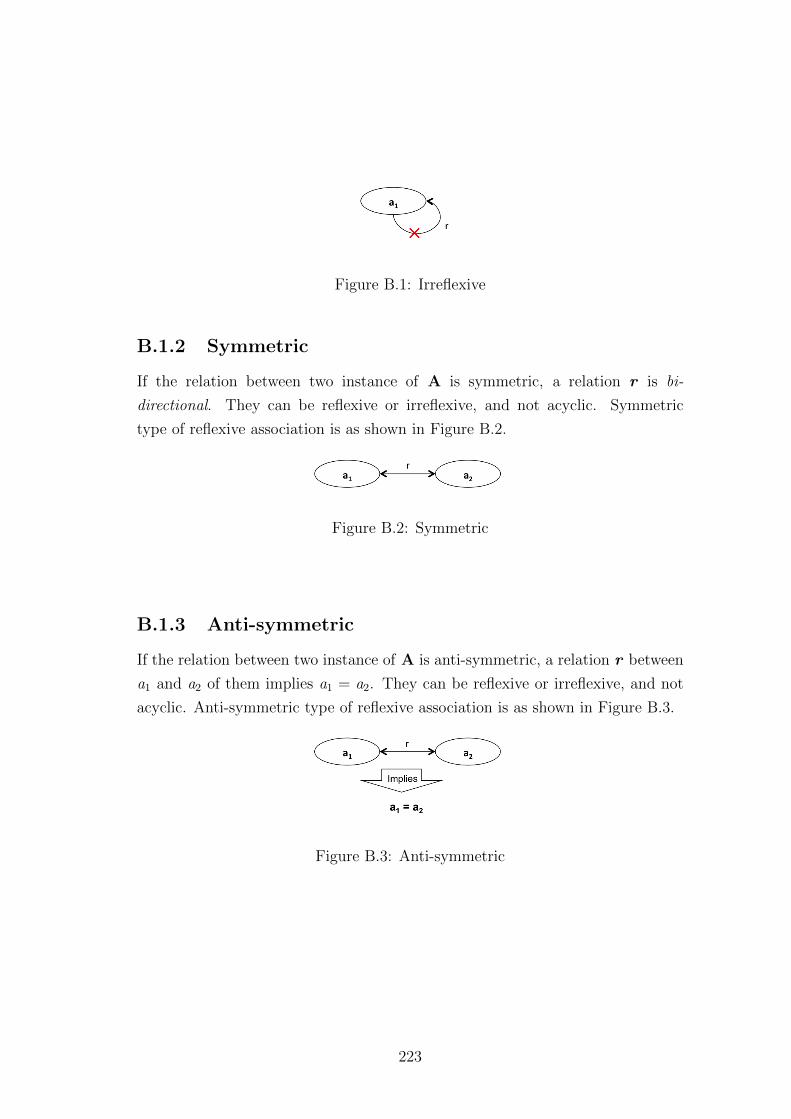
Figure B.1: Irreflexive
B.1.2 Symmetric
If the relation between two instance of A is symmetric, a relation r is bi-
directional. They can be reflexive or irreflexive, and not acyclic. Symmetric
type of reflexive association is as shown in Figure B.2.
Figure B.2: Symmetric
B.1.3 Anti-symmetric
If the relation between two instance of A is anti-symmetric, a relation r between
a1 and a2 of them implies a1 = a2. They can be reflexive or irreflexive, and not
acyclic. Anti-symmetric type of reflexive association is as shown in Figure B.3.
Figure B.3: Anti-symmetric
223
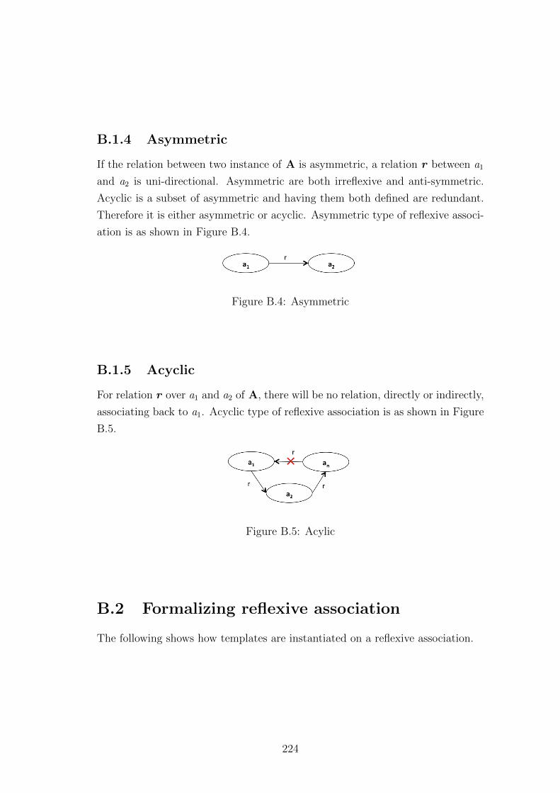
B.1.4 Asymmetric
If the relation between two instance of A is asymmetric, a relation r between a1
and a2 is uni-directional. Asymmetric are both irreflexive and anti-symmetric.
Acyclic is a subset of asymmetric and having them both defined are redundant.
Therefore it is either asymmetric or acyclic. Asymmetric type of reflexive associ-
ation is as shown in Figure B.4.
Figure B.4: Asymmetric
B.1.5 Acyclic
For relation r over a1 and a2 of A, there will be no relation, directly or indirectly,
associating back to a1. Acyclic type of reflexive association is as shown in Figure
B.5.
Figure B.5: Acylic
B.2 Formalizing reflexive association
The following shows how templates are instantiated on a reflexive association.
224
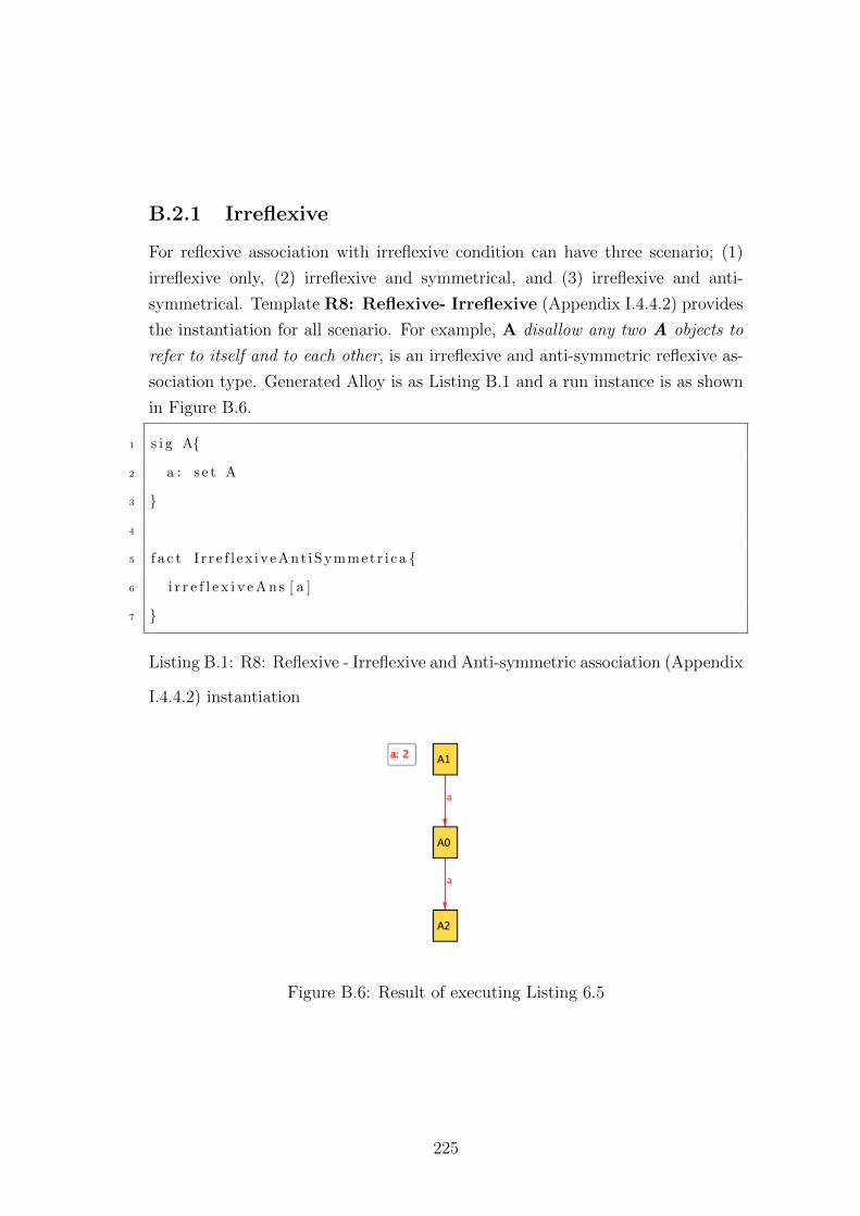
B.2.1 Irreflexive
For reflexive association with irreflexive condition can have three scenario; (1)
irreflexive only, (2) irreflexive and symmetrical, and (3) irreflexive and anti-
symmetrical. Template R8: Reflexive- Irreflexive (Appendix I.4.4.2) provides
the instantiation for all scenario. For example, A disallow any two A objects to
refer to itself and to each other, is an irreflexive and anti-symmetric reflexive as-
sociation type. Generated Alloy is as Listing B.1 and a run instance is as shown
in Figure B.6.
1 s i g A{
2 a : s e t A
3 }
4
5 f a c t I r r e f l ex iveAnt iSymmetr i ca {
6 i r r e f l e x i v e A n s [ a ]
7 }
Listing B.1: R8: Reflexive - Irreflexive and Anti-symmetric association (Appendix
I.4.4.2) instantiation
Figure B.6: Result of executing Listing 6.5
225
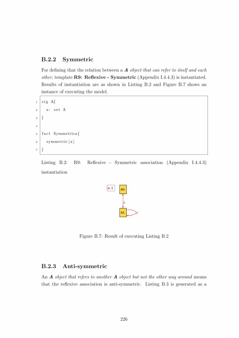
B.2.2 Symmetric
For defining that the relation between a A object that can refer to itself and each
other, template R9: Reflexive - Symmetric (Appendix I.4.4.3) is instantiated.
Results of instantiation are as shown in Listing B.2 and Figure B.7 shows an
instance of executing the model.
1 s i g A{
2 a : s e t A
3 }
4
5 f a c t Symmetrica{
6 symmetric [ a ]
7 }
Listing B.2: R9: Reflexive - Symmetric association (Appendix I.4.4.3)
instantiation
Figure B.7: Result of executing Listing B.2
B.2.3 Anti-symmetric
An A object that refers to another A object but not the other way around means
that the reflexive association is anti-symmetric. Listing B.3 is generated as a
226
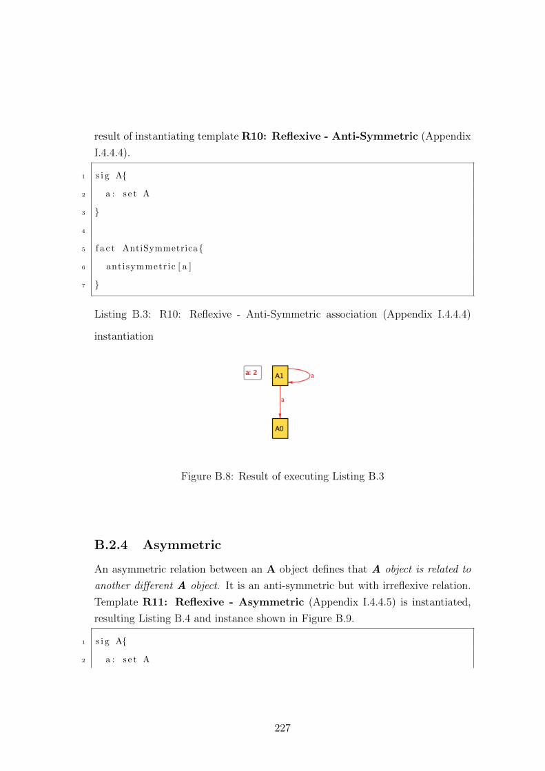
result of instantiating template R10: Reflexive - Anti-Symmetric (Appendix
I.4.4.4).
1 s i g A{
2 a : s e t A
3 }
4
5 f a c t AntiSymmetrica{
6 antisymmetr ic [ a ]
7 }
Listing B.3: R10: Reflexive - Anti-Symmetric association (Appendix I.4.4.4)
instantiation
Figure B.8: Result of executing Listing B.3
B.2.4 Asymmetric
An asymmetric relation between an A object defines that A object is related to
another different A object. It is an anti-symmetric but with irreflexive relation.
Template R11: Reflexive - Asymmetric (Appendix I.4.4.5) is instantiated,
resulting Listing B.4 and instance shown in Figure B.9.
1 s i g A{
2 a : s e t A
227
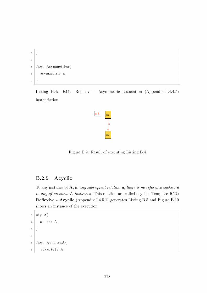
3 }
4
5 f a c t Asymmetrica{
6 asymmetric [ a ]
7 }
Listing B.4: R11: Reflexive - Asymmetric association (Appendix I.4.4.5)
instantiation
Figure B.9: Result of executing Listing B.4
B.2.5 Acyclic
To any instance of A, in any subsequent relation a, there is no reference backward
to any of previous A instances. This relation are called acyclic. Template R12:
Reflexive - Acyclic (Appendix I.4.5.1) generates Listing B.5 and Figure B.10
shows an instance of the execution.
1 s i g A{
2 a : s e t A
3 }
4
5 f a c t AcyclicaA{
6 a c y c l i c [ a ,A]
228
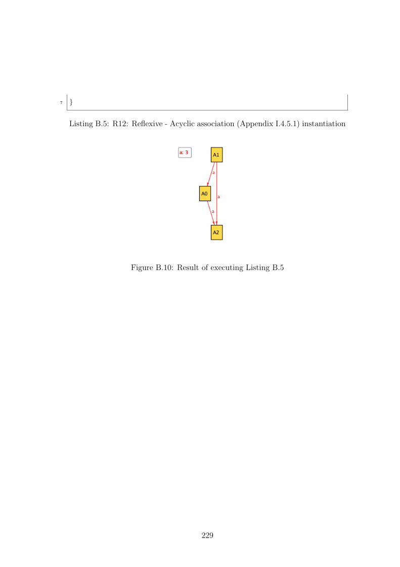
7 }
Listing B.5: R12: Reflexive - Acyclic association (Appendix I.4.5.1) instantiation
Figure B.10: Result of executing Listing B.5
229
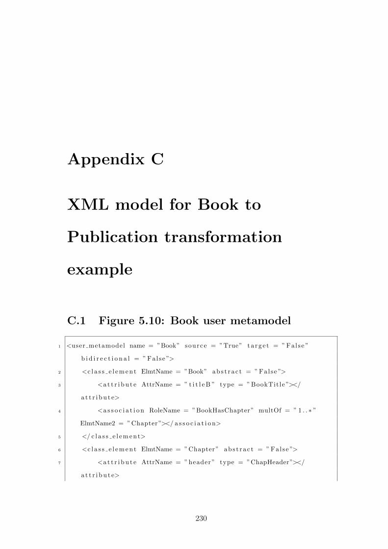
Appendix C
XML model for Book to
Publication transformation
example
C.1 Figure 5.10: Book user metamodel
1 <user metamodel name = ”Book” source = ”True” t a r g e t = ” Fal se ”
b i d i r e c t i o n a l = ” Fal se ”>
2 <c l a s s e l e m e n t ElmtName = ”Book” abs t r a c t = ” Fal se ”>
3 <a t t r i b u t e AttrName = ” t i t l e B ” type = ” BookTit le ”></
a t t r i b u t e>
4 <a s s o c i a t i o n RoleName = ”BookHasChapter” multOf = ” 1 . . ∗ ”
ElmtName2 = ”Chapter”></ a s s o c i a t i o n>
5 </ c l a s s e l e m e n t>
6 <c l a s s e l e m e n t ElmtName = ”Chapter” ab s t r a c t = ” False ”>
7 <a t t r i b u t e AttrName = ” header ” type = ”ChapHeader”></
a t t r i b u t e>
230
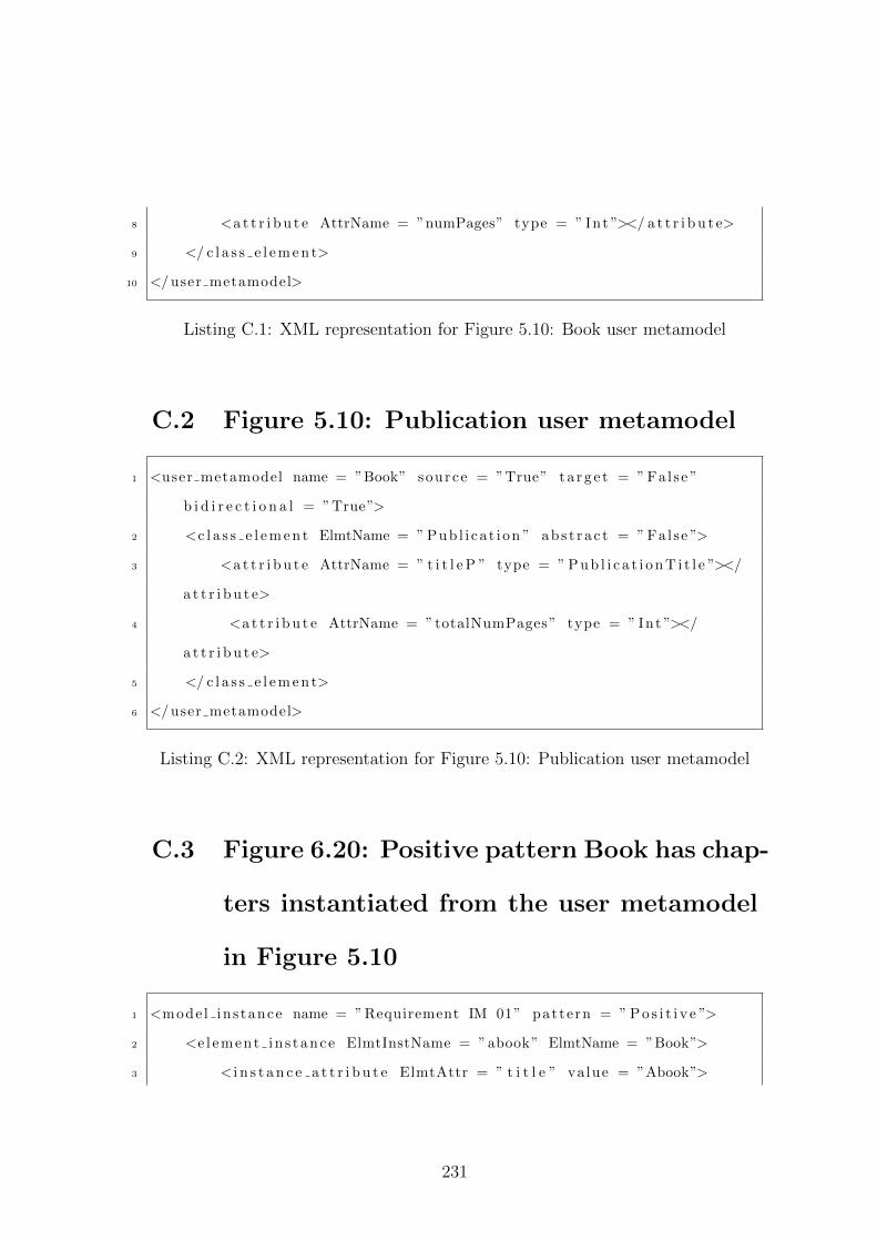
8 <a t t r i b u t e AttrName = ”numPages” type = ” Int ”></ a t t r i b u t e>
9 </ c l a s s e l e m e n t>
10 </ user metamodel>
Listing C.1: XML representation for Figure 5.10: Book user metamodel
C.2 Figure 5.10: Publication user metamodel
1 <user metamodel name = ”Book” source = ”True” t a r g e t = ” Fal se ”
b i d i r e c t i o n a l = ”True”>
2 <c l a s s e l e m e n t ElmtName = ” Pub l i ca t i on ” abs t r a c t = ” Fal se ”>
3 <a t t r i b u t e AttrName = ” t i t l e P ” type = ” P u b l i c a t i o n T i t l e ”></
a t t r i b u t e>
4 <a t t r i b u t e AttrName = ”totalNumPages” type = ” Int ”></
a t t r i b u t e>
5 </ c l a s s e l e m e n t>
6 </ user metamodel>
Listing C.2: XML representation for Figure 5.10: Publication user metamodel
C.3 Figure 6.20: Positive pattern Book has chap-
ters instantiated from the user metamodel
in Figure 5.10
1 <mode l ins tance name = ”Requirement IM 01” pattern = ” P o s i t i v e ”>
2 <e l ement in s tance ElmtInstName = ”abook” ElmtName = ”Book”>
3 < i n s t a n c e a t t r i b u t e ElmtAttr = ” t i t l e ” va lue = ”Abook”>
231
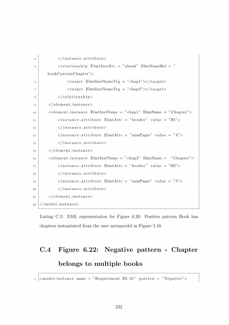
4 </ i n s t a n c e a t t r i b u t e>
5 <r e l a t i o n s h i p ElmtInstSrc = ”abook” ElmtNameRel = ”
bookContainChapter”>
6 <t a r g e t ElmtInstNameTrg = ”chap1”></ t a r g e t>
7 <t a r g e t ElmtInstNameTrg = ”chap2”></ t a r g e t>
8 </ r e l a t i o n s h i p>
9 </ e l ement in s tance>
10 <e l ement in s tance ElmtInstName = ”chap1” ElmtName = ”Chapter”>
11 < i n s t a n c e a t t r i b u t e ElmtAttr = ” header ” value = ”H1”>
12 </ i n s t a n c e a t t r i b u t e>
13 < i n s t a n c e a t t r i b u t e ElmtAttr = ”numPages” value = ”4”>
14 </ i n s t a n c e a t t r i b u t e>
15 </ e l ement in s tance>
16 <e l ement in s tance ElmtInstName = ”chap2” ElmtName = ”Chapter”>
17 < i n s t a n c e a t t r i b u t e ElmtAttr = ” header ” value = ”H2”>
18 </ i n s t a n c e a t t r i b u t e>
19 < i n s t a n c e a t t r i b u t e ElmtAttr = ”numPages” value = ”5”>
20 </ i n s t a n c e a t t r i b u t e>
21 </ e l ement in s tance>
22 </ mode l ins tance>
Listing C.3: XML representation for Figure 6.20: Positive pattern Book has
chapters instantiated from the user metamodel in Figure 5.10
C.4 Figure 6.22: Negative pattern - Chapter
belongs to multiple books
1 <mode l ins tance name = ”Requirement IM 01” pattern = ” Negative ”>
232
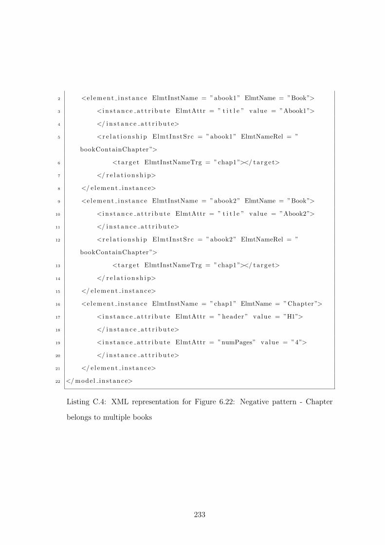
2 <e l ement in s tance ElmtInstName = ”abook1” ElmtName = ”Book”>
3 < i n s t a n c e a t t r i b u t e ElmtAttr = ” t i t l e ” va lue = ”Abook1”>
4 </ i n s t a n c e a t t r i b u t e>
5 <r e l a t i o n s h i p ElmtInstSrc = ”abook1” ElmtNameRel = ”
bookContainChapter”>
6 <t a r g e t ElmtInstNameTrg = ”chap1”></ t a r g e t>
7 </ r e l a t i o n s h i p>
8 </ e l ement in s tance>
9 <e l ement in s tance ElmtInstName = ”abook2” ElmtName = ”Book”>
10 < i n s t a n c e a t t r i b u t e ElmtAttr = ” t i t l e ” va lue = ”Abook2”>
11 </ i n s t a n c e a t t r i b u t e>
12 <r e l a t i o n s h i p ElmtInstSrc = ”abook2” ElmtNameRel = ”
bookContainChapter”>
13 <t a r g e t ElmtInstNameTrg = ”chap1”></ t a r g e t>
14 </ r e l a t i o n s h i p>
15 </ e l ement in s tance>
16 <e l ement in s tance ElmtInstName = ”chap1” ElmtName = ”Chapter”>
17 < i n s t a n c e a t t r i b u t e ElmtAttr = ” header ” value = ”H1”>
18 </ i n s t a n c e a t t r i b u t e>
19 < i n s t a n c e a t t r i b u t e ElmtAttr = ”numPages” value = ”4”>
20 </ i n s t a n c e a t t r i b u t e>
21 </ e l ement in s tance>
22 </ mode l ins tance>
Listing C.4: XML representation for Figure 6.22: Negative pattern - Chapter
belongs to multiple books
233
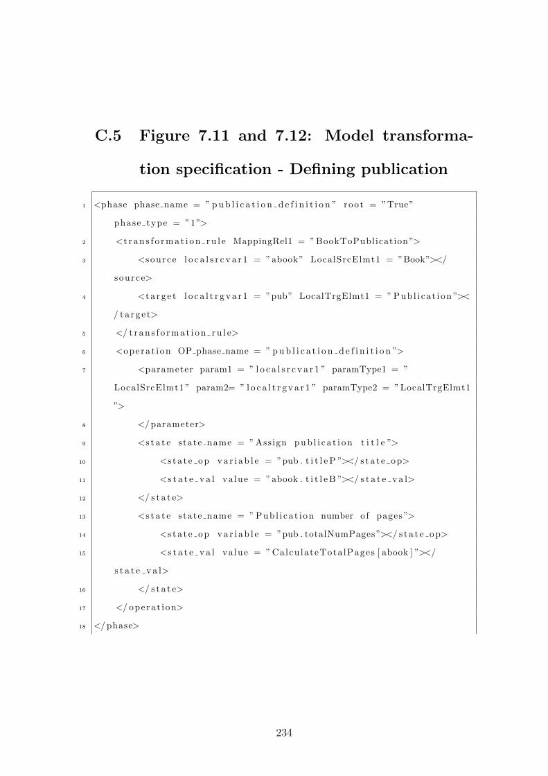
C.5 Figure 7.11 and 7.12: Model transforma-
tion specification - Defining publication
1 <phase phase name = ” p u b l i c a t i o n d e f i n i t i o n ” root = ”True”
phase type = ”1”>
2 <t r a n s f o r m a t i o n r u l e MappingRel1 = ” BookToPublication ”>
3 <source l o c a l s r c v a r 1 = ”abook” LocalSrcElmt1 = ”Book”></
source>
4 <t a r g e t l o c a l t r g v a r 1 = ”pub” LocalTrgElmt1 = ” Pub l i ca t i on ”><
/ t a r g e t>
5 </ t r a n s f o r m a t i o n r u l e>
6 <opera t ion OP phase name = ” p u b l i c a t i o n d e f i n i t i o n ”>
7 <parameter param1 = ” l o c a l s r c v a r 1 ” paramType1 = ”
LocalSrcElmt1 ” param2= ” l o c a l t r g v a r 1 ” paramType2 = ”LocalTrgElmt1
”>
8 </ parameter>
9 <s t a t e state name = ” Assign p u b l i c a t i o n t i t l e ”>
10 <s t a t e o p v a r i a b l e = ”pub . t i t l e P ”></ s t a t e o p>
11 <s t a t e v a l va lue = ”abook . t i t l e B ”></ s t a t e v a l>
12 </ s t a t e>
13 <s t a t e state name = ” Pub l i ca t i on number o f pages ”>
14 <s t a t e o p v a r i a b l e = ”pub . totalNumPages”></ s t a t e o p>
15 <s t a t e v a l va lue = ” Calcu lateTota lPages [ abook ] ”></
s t a t e v a l>
16 </ s t a t e>
17 </ opera t i on>
18 </ phase>
234
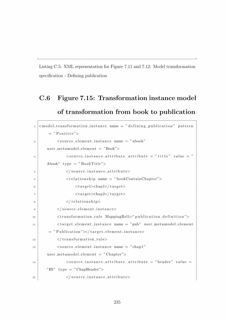
Listing C.5: XML representation for Figure 7.11 and 7.12: Model transformation
specification - Defining publication
C.6 Figure 7.15: Transformation instance model
of transformation from book to publication
1 <mode l t ran s f o rmat i on in s tance name = ” d e f i n i n g p u b l i c a t i o n ” pattern
= ” P o s i t i v e ”>
2 <s o u r c e e l e m e n t i n s t a n c e name = ”abook”
user metamodel e lement = ”Book”>
3 <s o u r c e i n s t a n c e a t t r i b u t e a t t r i b u t e = ” t i t l e ” va lue = ”
Abook” type = ” BookTit le ”>
4 </ s o u r c e i n s t a n c e a t t r i b u t e>
5 <r e l a t i o n s h i p name = ”bookContainChapter”>
6 <t a r g e t>chap1</ t a r g e t>
7 <t a r g e t>chap2</ t a r g e t>
8 </ r e l a t i o n s h i p>
9 </ s o u r c e e l e m e n t i n s t a n c e>
10 <t r a n s f o r m a t i o n r u l e MappingRel1=” p u b l i c a t i o n d e f i n i t i o n ”>
11 <t a r g e t e l e m e n t i n s t a n c e name = ”pub” user metamodel e lement
= ” Pub l i ca t i on ”></ t a r g e t e l e m e n t i n s t a n c e>
12 </ t r a n s f o r m a t i o n r u l e>
13 <s o u r c e e l e m e n t i n s t a n c e name = ”chap1”
user metamodel e lement = ”Chapter”>
14 <s o u r c e i n s t a n c e a t t r i b u t e a t t r i b u t e = ” header ” value =
”H1” type = ”ChapHeader”>
15 </ s o u r c e i n s t a n c e a t t r i b u t e>
235
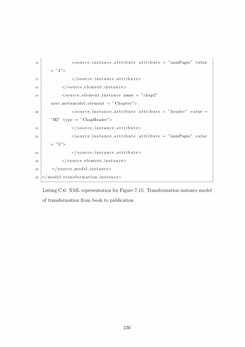
16 <s o u r c e i n s t a n c e a t t r i b u t e a t t r i b u t e = ”numPages” value
= ”4”>
17 </ s o u r c e i n s t a n c e a t t r i b u t e>
18 </ s o u r c e e l e m e n t i n s t a n c e>
19 <s o u r c e e l e m e n t i n s t a n c e name = ”chap2”
user metamodel e lement = ”Chapter”>
20 <s o u r c e i n s t a n c e a t t r i b u t e a t t r i b u t e = ” header ” value =
”H2” type = ”ChapHeader”>
21 </ s o u r c e i n s t a n c e a t t r i b u t e>
22 <s o u r c e i n s t a n c e a t t r i b u t e a t t r i b u t e = ”numPages” value
= ”5”>
23 </ s o u r c e i n s t a n c e a t t r i b u t e>
24 </ s o u r c e e l e m e n t i n s t a n c e>
25 </ sour c e mode l i n s tance>
26 </ mode l t r an s f o rmat i on in s tance>
Listing C.6: XML representation for Figure 7.15: Transformation instance model
of transformation from book to publication
236
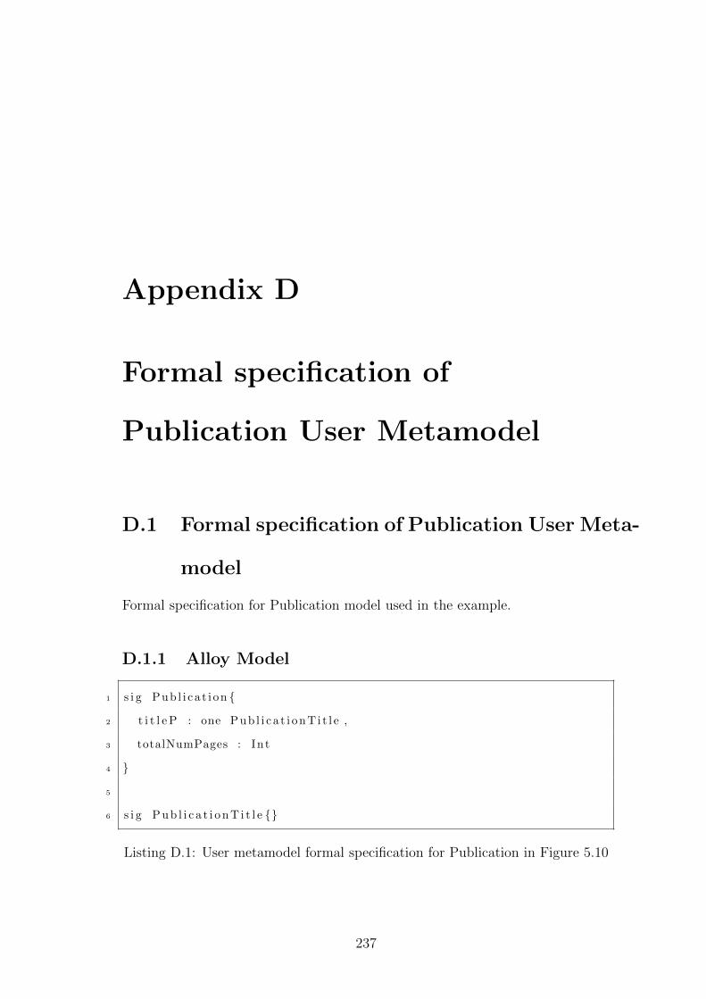
Appendix D
Formal specification of
Publication User Metamodel
D.1 Formal specification of Publication User Meta-
model
Formal specification for Publication model used in the example.
D.1.1 Alloy Model
1 s i g Pub l i ca t i on {
2 t i t l e P : one Pub l i c a t i onT i t l e ,
3 totalNumPages : Int
4 }
5
6 s i g P u b l i c a t i o n T i t l e {}
Listing D.1: User metamodel formal specification for Publication in Figure 5.10
237
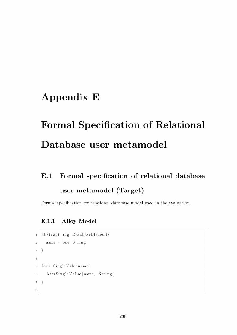
Appendix E
Formal Specification of Relational
Database user metamodel
E.1 Formal specification of relational database
user metamodel (Target)
Formal specification for relational database model used in the evaluation.
E.1.1 Alloy Model
1 abs t r a c t s i g DatabaseElement{
2 name : one St r ing
3 }
4
5 f a c t SingleValuename{
6 AttrS ing leValue [ name , S t r ing ]
7 }
8
238
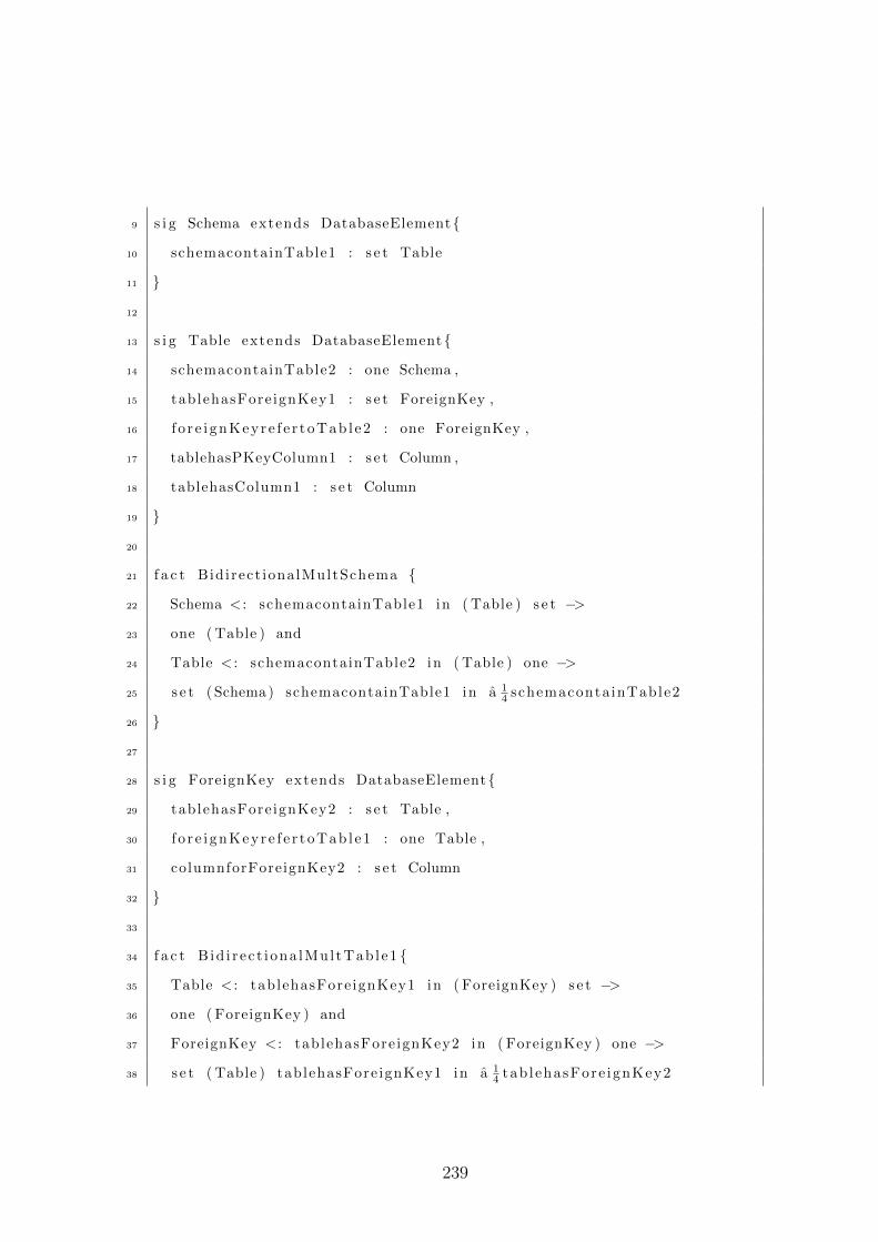
9 s i g Schema extends DatabaseElement{
10 schemacontainTable1 : s e t Table
11 }
12
13 s i g Table extends DatabaseElement{
14 schemacontainTable2 : one Schema ,
15 tablehasFore ignKey1 : s e t ForeignKey ,
16 f o r e i gnKeyre f e r toTab l e2 : one ForeignKey ,
17 tablehasPKeyColumn1 : s e t Column ,
18 tablehasColumn1 : s e t Column
19 }
20
21 f a c t Bidirect ionalMultSchema {
22 Schema < : schemacontainTable1 in ( Table ) s e t −>
23 one ( Table ) and
24 Table < : schemacontainTable2 in ( Table ) one −>
25 s e t ( Schema ) schemacontainTable1 in a 14 schemaconta inTable2
26 }
27
28 s i g ForeignKey extends DatabaseElement{
29 tablehasFore ignKey2 : s e t Table ,
30 f o r e i gnKeyre f e r toTab l e1 : one Table ,
31 columnforForeignKey2 : s e t Column
32 }
33
34 f a c t B id i r ec t i ona lMul tTab le1 {
35 Table < : tablehasFore ignKey1 in ( ForeignKey ) s e t −>
36 one ( ForeignKey ) and
37 ForeignKey < : tablehasFore ignKey2 in ( ForeignKey ) one −>
38 s e t ( Table ) tablehasFore ignKey1 in a 14 tab l ehasFore ignKey2
239
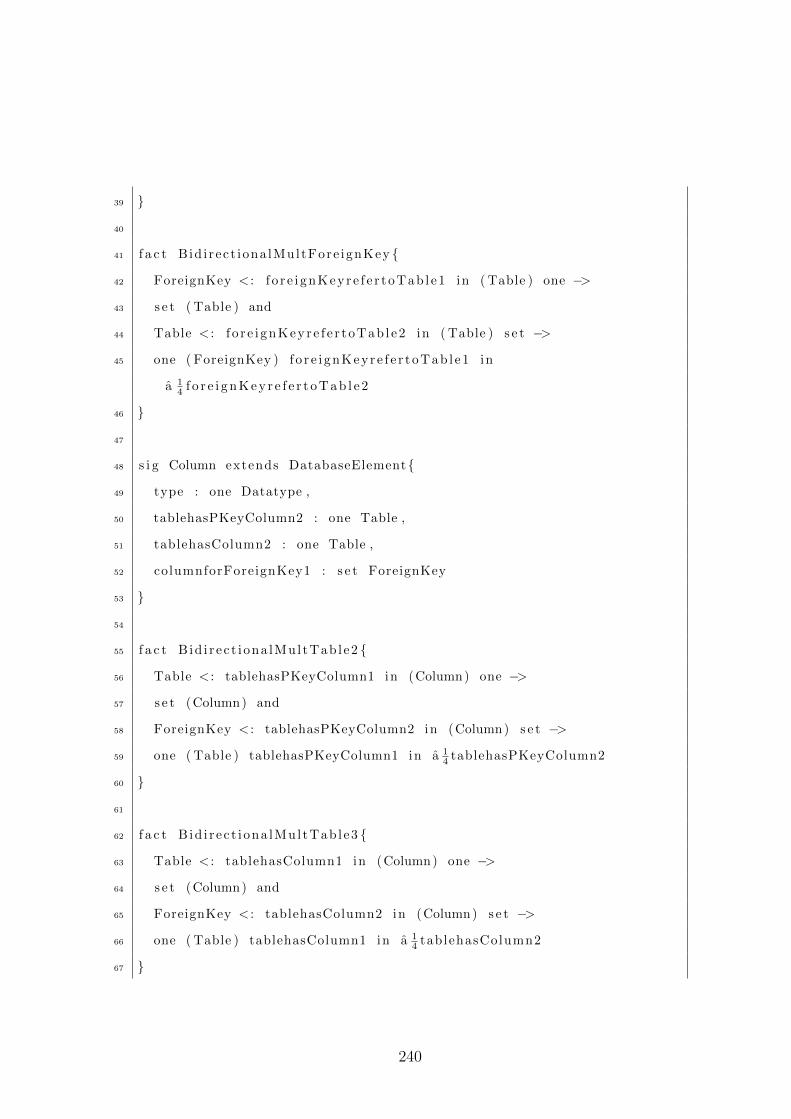
39 }
40
41 f a c t Bid i rect iona lMultFore ignKey {
42 ForeignKey < : f o r e i gnKeyre f e r toTab l e1 in ( Table ) one −>
43 s e t ( Table ) and
44 Table < : f o r e i gnKeyre f e r toTab l e2 in ( Table ) s e t −>
45 one ( ForeignKey ) f o r e i gnKeyre f e r toTab l e1 in
a 14 f o r e i g n K e y r e f e r t o T a b l e 2
46 }
47
48 s i g Column extends DatabaseElement{
49 type : one Datatype ,
50 tablehasPKeyColumn2 : one Table ,
51 tablehasColumn2 : one Table ,
52 columnforForeignKey1 : s e t ForeignKey
53 }
54
55 f a c t B id i r ec t i ona lMul tTab le2 {
56 Table < : tablehasPKeyColumn1 in (Column) one −>
57 s e t (Column) and
58 ForeignKey < : tablehasPKeyColumn2 in (Column) s e t −>
59 one ( Table ) tablehasPKeyColumn1 in a 14 tablehasPKeyColumn2
60 }
61
62 f a c t B id i r ec t i ona lMul tTab le3 {
63 Table < : tablehasColumn1 in (Column) one −>
64 s e t (Column) and
65 ForeignKey < : tablehasColumn2 in (Column) s e t −>
66 one ( Table ) tablehasColumn1 in a 14 tablehasColumn2
67 }
240
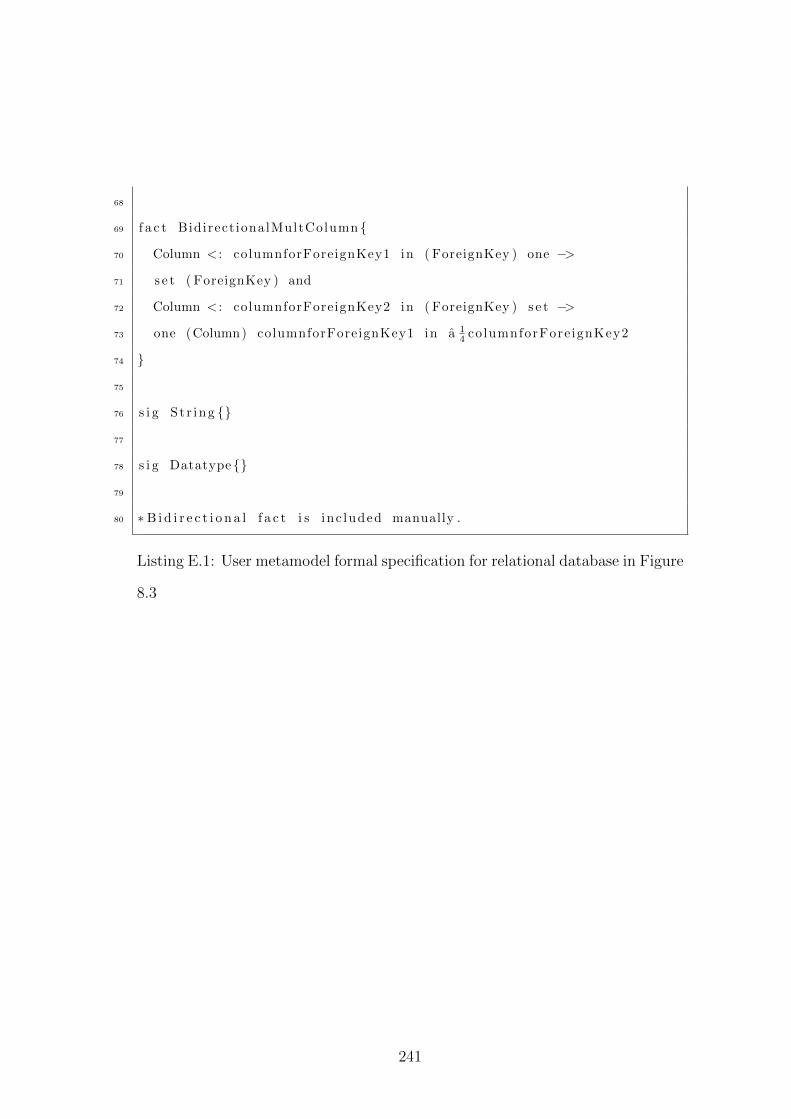
68
69 f a c t Bidirect ionalMultColumn {
70 Column < : columnforForeignKey1 in ( ForeignKey ) one −>
71 s e t ( ForeignKey ) and
72 Column < : columnforForeignKey2 in ( ForeignKey ) s e t −>
73 one (Column) columnforForeignKey1 in a 14 co lumnforFore ignKey2
74 }
75
76 s i g S t r ing {}
77
78 s i g Datatype{}
79
80 ∗B i d i r e c t i o n a l f a c t i s inc luded manually .
Listing E.1: User metamodel formal specification for relational database in Figure
8.3
241
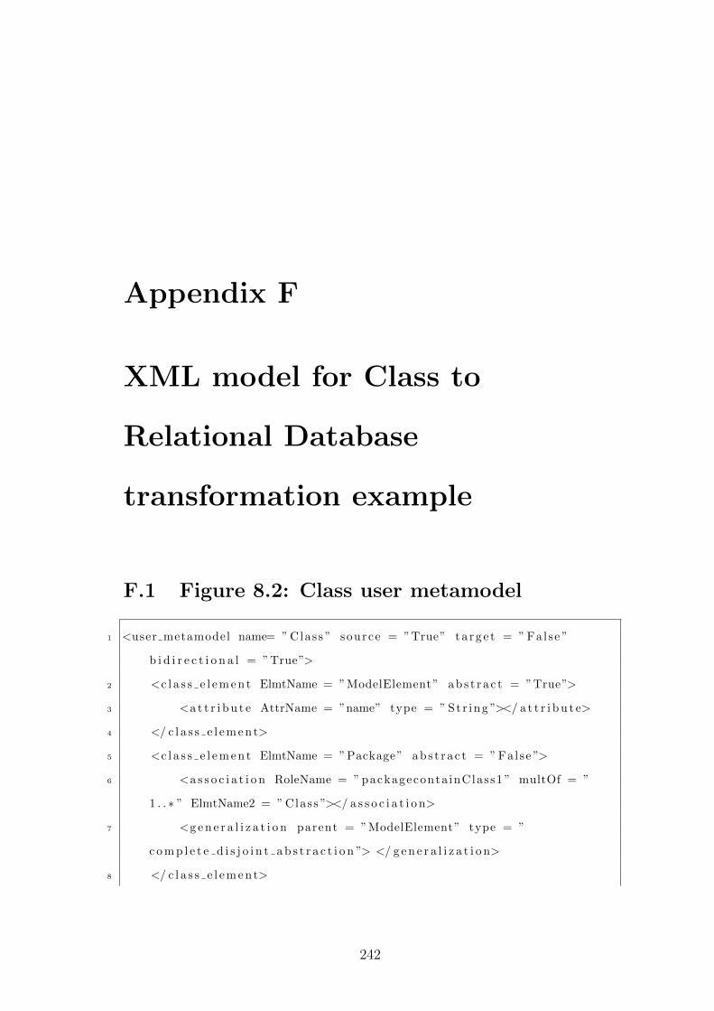
Appendix F
XML model for Class to
Relational Database
transformation example
F.1 Figure 8.2: Class user metamodel
1 <user metamodel name= ” Class ” source = ”True” t a r g e t = ” False ”
b i d i r e c t i o n a l = ”True”>
2 <c l a s s e l e m e n t ElmtName = ”ModelElement” ab s t r a c t = ”True”>
3 <a t t r i b u t e AttrName = ”name” type = ” St r ing ”></ a t t r i b u t e>
4 </ c l a s s e l e m e n t>
5 <c l a s s e l e m e n t ElmtName = ”Package” abs t r a c t = ” False ”>
6 <a s s o c i a t i o n RoleName = ” packageconta inClass1 ” multOf = ”
1 . . ∗ ” ElmtName2 = ” Class ”></ a s s o c i a t i o n>
7 <g e n e r a l i z a t i o n parent = ”ModelElement” type = ”
c o m p l e t e d i s j o i n t a b s t r a c t i o n ”> </ g e n e r a l i z a t i o n>
8 </ c l a s s e l e m e n t>
242
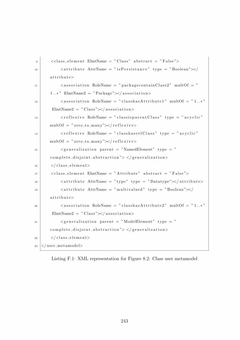
9 <c l a s s e l e m e n t ElmtName = ” Class ” ab s t r a c t = ” Fal se ”>
10 <a t t r i b u t e AttrName = ” i s P e r s i s t a n c e ” type = ” Boolean ”></
a t t r i b u t e>
11 <a s s o c i a t i o n RoleName = ” packageconta inClass2 ” multOf = ”
1 . . ∗ ” ElmtName2 = ”Package”></ a s s o c i a t i o n>
12 <a s s o c i a t i o n RoleName = ” c l a s s h a s A t t r i b u t e 1 ” multOf = ” 1 . . ∗ ”
ElmtName2 = ” Class ”></ a s s o c i a t i o n>
13 <r e f l e x i v e RoleName = ” c l a s s i s p a r e n t C l a s s ” type = ” a c y c l i c ”
multOf = ” zero to many ”></ r e f l e x i v e>
14 <r e f l e x i v e RoleName = ” c l a s s h a s r e l C l a s s ” type = ” a c y c l i c ”
multOf = ” zero to many ”></ r e f l e x i v e>
15 <g e n e r a l i z a t i o n parent = ”NamedElement” type = ”
c o m p l e t e d i s j o i n t a b s t r a c t i o n ”> </ g e n e r a l i z a t i o n>
16 </ c l a s s e l e m e n t>
17 <c l a s s e l e m e n t ElmtName = ” Attr ibute ” abs t r a c t = ” Fal se ”>
18 <a t t r i b u t e AttrName = ” type ” type = ”Datatype”></ a t t r i b u t e>
19 <a t t r i b u t e AttrName = ” mult iva lued ” type = ” Boolean ”></
a t t r i b u t e>
20 <a s s o c i a t i o n RoleName = ” c l a s s h a s A t t r i b u t e 2 ” multOf = ” 1 . . ∗ ”
ElmtName2 = ” Class ”></ a s s o c i a t i o n>
21 <g e n e r a l i z a t i o n parent = ”ModelElement” type = ”
c o m p l e t e d i s j o i n t a b s t r a c t i o n ”> </ g e n e r a l i z a t i o n>
22 </ c l a s s e l e m e n t>
23 </ user metamodel>
Listing F.1: XML representation for Figure 8.2: Class user metamodel
243
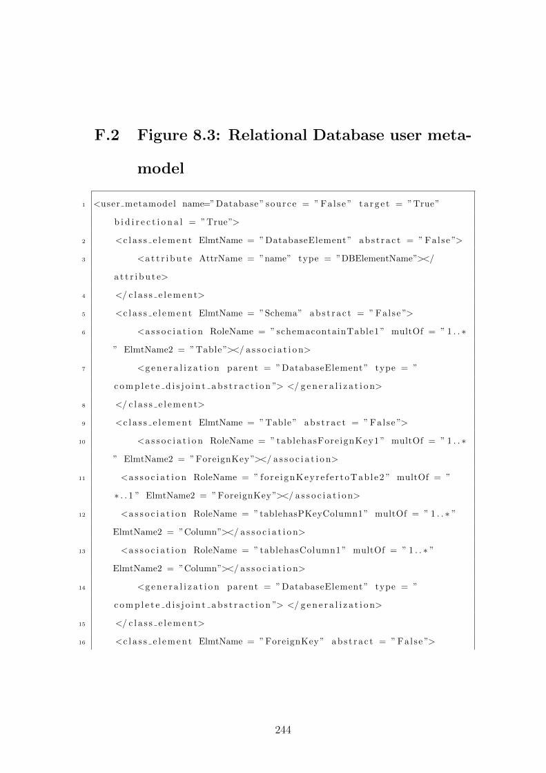
F.2 Figure 8.3: Relational Database user meta-
model
1 <user metamodel name=”Database” source = ” False ” t a r g e t = ”True”
b i d i r e c t i o n a l = ”True”>
2 <c l a s s e l e m e n t ElmtName = ”DatabaseElement” abs t r a c t = ” Fal se ”>
3 <a t t r i b u t e AttrName = ”name” type = ”DBElementName”></
a t t r i b u t e>
4 </ c l a s s e l e m e n t>
5 <c l a s s e l e m e n t ElmtName = ”Schema” abs t r a c t = ” False ”>
6 <a s s o c i a t i o n RoleName = ” schemacontainTable1 ” multOf = ” 1 . . ∗
” ElmtName2 = ”Table”></ a s s o c i a t i o n>
7 <g e n e r a l i z a t i o n parent = ”DatabaseElement” type = ”
c o m p l e t e d i s j o i n t a b s t r a c t i o n ”> </ g e n e r a l i z a t i o n>
8 </ c l a s s e l e m e n t>
9 <c l a s s e l e m e n t ElmtName = ”Table” abs t r a c t = ” Fal se ”>
10 <a s s o c i a t i o n RoleName = ” tablehasFore ignKey1 ” multOf = ” 1 . . ∗
” ElmtName2 = ”ForeignKey”></ a s s o c i a t i o n>
11 <a s s o c i a t i o n RoleName = ” fo r e i gnKeyre f e r toTab l e2 ” multOf = ”
∗ . . 1 ” ElmtName2 = ”ForeignKey”></ a s s o c i a t i o n>
12 <a s s o c i a t i o n RoleName = ”tablehasPKeyColumn1” multOf = ” 1 . . ∗ ”
ElmtName2 = ”Column”></ a s s o c i a t i o n>
13 <a s s o c i a t i o n RoleName = ” tablehasColumn1 ” multOf = ” 1 . . ∗ ”
ElmtName2 = ”Column”></ a s s o c i a t i o n>
14 <g e n e r a l i z a t i o n parent = ”DatabaseElement” type = ”
c o m p l e t e d i s j o i n t a b s t r a c t i o n ”> </ g e n e r a l i z a t i o n>
15 </ c l a s s e l e m e n t>
16 <c l a s s e l e m e n t ElmtName = ”ForeignKey” abs t r a c t = ” False ”>
244
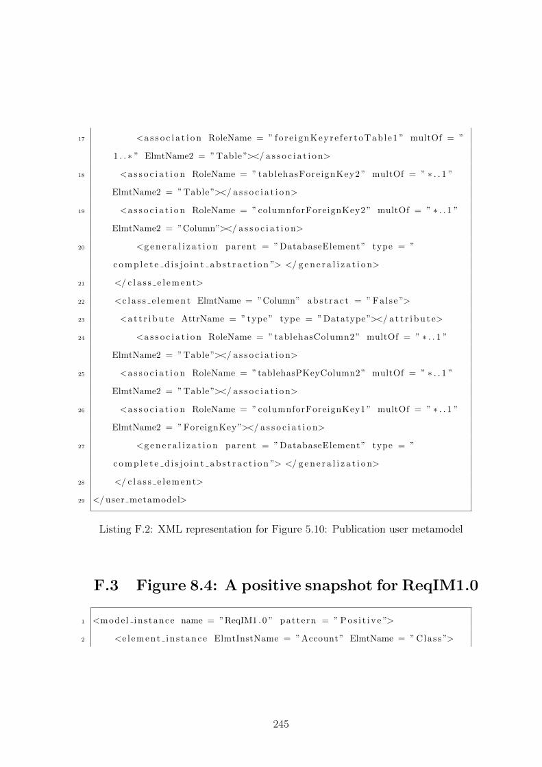
17 <a s s o c i a t i o n RoleName = ” fo r e i gnKeyre f e r toTab l e1 ” multOf = ”
1 . . ∗ ” ElmtName2 = ”Table”></ a s s o c i a t i o n>
18 <a s s o c i a t i o n RoleName = ” tablehasFore ignKey2 ” multOf = ” ∗ . . 1 ”
ElmtName2 = ”Table”></ a s s o c i a t i o n>
19 <a s s o c i a t i o n RoleName = ” columnforForeignKey2 ” multOf = ” ∗ . . 1 ”
ElmtName2 = ”Column”></ a s s o c i a t i o n>
20 <g e n e r a l i z a t i o n parent = ”DatabaseElement” type = ”
c o m p l e t e d i s j o i n t a b s t r a c t i o n ”> </ g e n e r a l i z a t i o n>
21 </ c l a s s e l e m e n t>
22 <c l a s s e l e m e n t ElmtName = ”Column” abs t r a c t = ” Fal se ”>
23 <a t t r i b u t e AttrName = ” type ” type = ”Datatype”></ a t t r i b u t e>
24 <a s s o c i a t i o n RoleName = ” tablehasColumn2 ” multOf = ” ∗ . . 1 ”
ElmtName2 = ”Table”></ a s s o c i a t i o n>
25 <a s s o c i a t i o n RoleName = ”tablehasPKeyColumn2” multOf = ” ∗ . . 1 ”
ElmtName2 = ”Table”></ a s s o c i a t i o n>
26 <a s s o c i a t i o n RoleName = ” columnforForeignKey1 ” multOf = ” ∗ . . 1 ”
ElmtName2 = ”ForeignKey”></ a s s o c i a t i o n>
27 <g e n e r a l i z a t i o n parent = ”DatabaseElement” type = ”
c o m p l e t e d i s j o i n t a b s t r a c t i o n ”> </ g e n e r a l i z a t i o n>
28 </ c l a s s e l e m e n t>
29 </ user metamodel>
Listing F.2: XML representation for Figure 5.10: Publication user metamodel
F.3 Figure 8.4: A positive snapshot for ReqIM1.0
1 <mode l ins tance name = ”ReqIM1 . 0 ” pattern = ” P o s i t i v e ”>
2 <e l ement in s tance ElmtInstName = ”Account” ElmtName = ” Class ”>
245
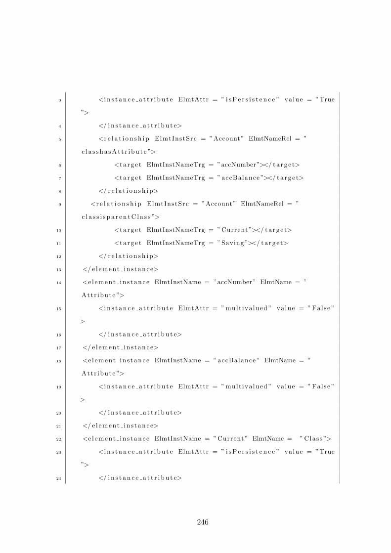
3 < i n s t a n c e a t t r i b u t e ElmtAttr = ” i s P e r s i s t e n c e ” value = ”True
”>
4 </ i n s t a n c e a t t r i b u t e>
5 <r e l a t i o n s h i p ElmtInstSrc = ”Account” ElmtNameRel = ”
c l a s s h a s A t t r i b u t e ”>
6 <t a r g e t ElmtInstNameTrg = ”accNumber”></ t a r g e t>
7 <t a r g e t ElmtInstNameTrg = ” accBalance ”></ t a r g e t>
8 </ r e l a t i o n s h i p>
9 <r e l a t i o n s h i p ElmtInstSrc = ”Account” ElmtNameRel = ”
c l a s s i s p a r e n t C l a s s ”>
10 <t a r g e t ElmtInstNameTrg = ” Current ”></ t a r g e t>
11 <t a r g e t ElmtInstNameTrg = ” Saving ”></ t a r g e t>
12 </ r e l a t i o n s h i p>
13 </ e l ement in s tance>
14 <e l ement in s tance ElmtInstName = ”accNumber” ElmtName = ”
Attr ibute ”>
15 < i n s t a n c e a t t r i b u t e ElmtAttr = ” mult iva lued ” value = ” False ”
>
16 </ i n s t a n c e a t t r i b u t e>
17 </ e l ement in s tance>
18 <e l ement in s tance ElmtInstName = ” accBalance ” ElmtName = ”
Attr ibute ”>
19 < i n s t a n c e a t t r i b u t e ElmtAttr = ” mult iva lued ” value = ” False ”
>
20 </ i n s t a n c e a t t r i b u t e>
21 </ e l ement in s tance>
22 <e l ement in s tance ElmtInstName = ” Current ” ElmtName = ” Class ”>
23 < i n s t a n c e a t t r i b u t e ElmtAttr = ” i s P e r s i s t e n c e ” value = ”True
”>
24 </ i n s t a n c e a t t r i b u t e>
246
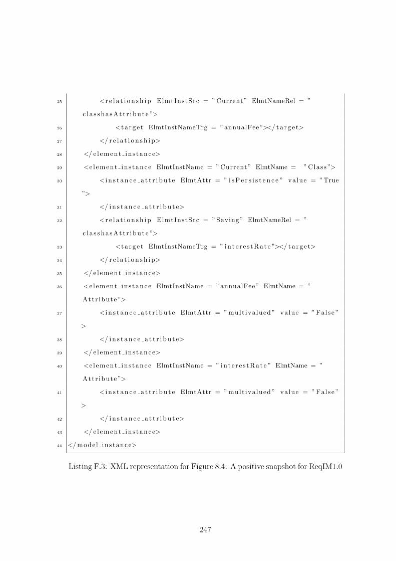
25 <r e l a t i o n s h i p ElmtInstSrc = ” Current ” ElmtNameRel = ”
c l a s s h a s A t t r i b u t e ”>
26 <t a r g e t ElmtInstNameTrg = ” annualFee ”></ t a r g e t>
27 </ r e l a t i o n s h i p>
28 </ e l ement in s tance>
29 <e l ement in s tance ElmtInstName = ” Current ” ElmtName = ” Class ”>
30 < i n s t a n c e a t t r i b u t e ElmtAttr = ” i s P e r s i s t e n c e ” value = ”True
”>
31 </ i n s t a n c e a t t r i b u t e>
32 <r e l a t i o n s h i p ElmtInstSrc = ” Saving ” ElmtNameRel = ”
c l a s s h a s A t t r i b u t e ”>
33 <t a r g e t ElmtInstNameTrg = ” i n t e r e s t R a t e ”></ t a r g e t>
34 </ r e l a t i o n s h i p>
35 </ e l ement in s tance>
36 <e l ement in s tance ElmtInstName = ” annualFee ” ElmtName = ”
Attr ibute ”>
37 < i n s t a n c e a t t r i b u t e ElmtAttr = ” mult iva lued ” value = ” False ”
>
38 </ i n s t a n c e a t t r i b u t e>
39 </ e l ement in s tance>
40 <e l ement in s tance ElmtInstName = ” i n t e r e s t R a t e ” ElmtName = ”
Attr ibute ”>
41 < i n s t a n c e a t t r i b u t e ElmtAttr = ” mult iva lued ” value = ” False ”
>
42 </ i n s t a n c e a t t r i b u t e>
43 </ e l ement in s tance>
44 </ mode l ins tance>
Listing F.3: XML representation for Figure 8.4: A positive snapshot for ReqIM1.0
247
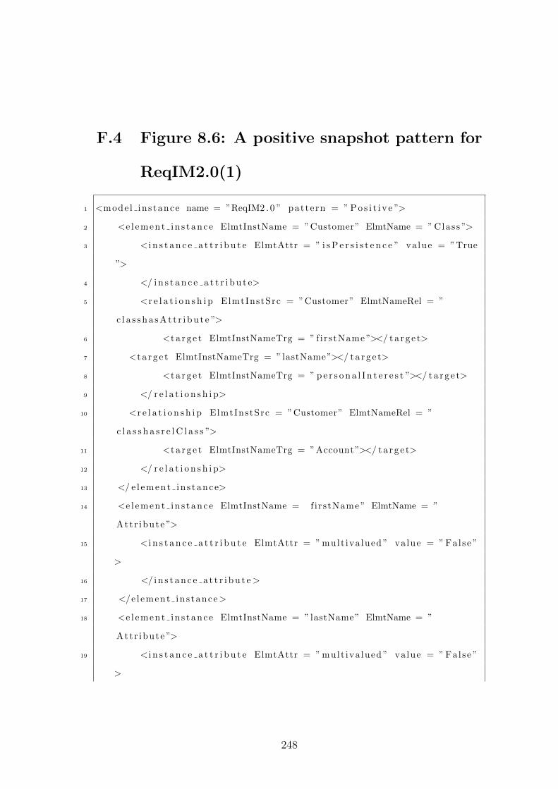
F.4 Figure 8.6: A positive snapshot pattern for
ReqIM2.0(1)
1 <mode l ins tance name = ”ReqIM2 . 0 ” pattern = ” P o s i t i v e ”>
2 <e l ement in s tance ElmtInstName = ”Customer” ElmtName = ” Class ”>
3 < i n s t a n c e a t t r i b u t e ElmtAttr = ” i s P e r s i s t e n c e ” value = ”True
”>
4 </ i n s t a n c e a t t r i b u t e>
5 <r e l a t i o n s h i p ElmtInstSrc = ”Customer” ElmtNameRel = ”
c l a s s h a s A t t r i b u t e ”>
6 <t a r g e t ElmtInstNameTrg = ” f irstName ”></ t a r g e t>
7 <t a r g e t ElmtInstNameTrg = ” lastName”></ t a r g e t>
8 <t a r g e t ElmtInstNameTrg = ” p e r s o n a l I n t e r e s t ”></ t a r g e t>
9 </ r e l a t i o n s h i p>
10 <r e l a t i o n s h i p ElmtInstSrc = ”Customer” ElmtNameRel = ”
c l a s s h a s r e l C l a s s ”>
11 <t a r g e t ElmtInstNameTrg = ”Account”></ t a r g e t>
12 </ r e l a t i o n s h i p>
13 </ e l ement in s tance>
14 <e l ement in s tance ElmtInstName = firstName ” ElmtName = ”
Attr ibute ”>
15 < i n s t a n c e a t t r i b u t e ElmtAttr = ” mult iva lued ” value = ” False ”
>
16 </ i n s t a n c e a t t r i b u t e >
17 </e l ement ins tance>
18 <e l ement in s tance ElmtInstName = ”lastName” ElmtName = ”
Attr ibute ”>
19 < i n s t a n c e a t t r i b u t e ElmtAttr = ” mult iva lued ” value = ” False ”
>
248
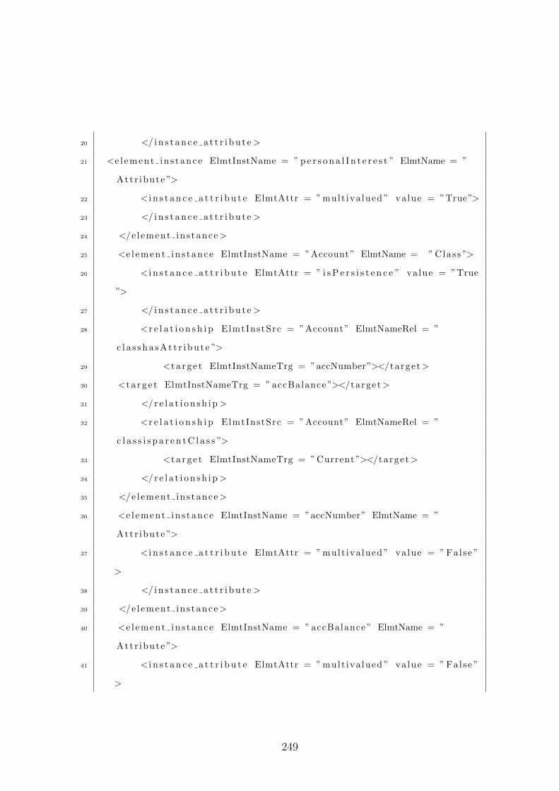
20 </ i n s t a n c e a t t r i b u t e >
21 <e l ement in s tance ElmtInstName = ” p e r s o n a l I n t e r e s t ” ElmtName = ”
Attr ibute ”>
22 < i n s t a n c e a t t r i b u t e ElmtAttr = ” mult iva lued ” value = ”True”>
23 </ i n s t a n c e a t t r i b u t e >
24 </e l ement ins tance>
25 <e l ement in s tance ElmtInstName = ”Account” ElmtName = ” Class ”>
26 < i n s t a n c e a t t r i b u t e ElmtAttr = ” i s P e r s i s t e n c e ” value = ”True
”>
27 </ i n s t a n c e a t t r i b u t e >
28 <r e l a t i o n s h i p ElmtInstSrc = ”Account” ElmtNameRel = ”
c l a s s h a s A t t r i b u t e ”>
29 <t a r g e t ElmtInstNameTrg = ”accNumber”></target>
30 <t a r g e t ElmtInstNameTrg = ” accBalance ”></target>
31 </r e l a t i o n s h i p >
32 <r e l a t i o n s h i p ElmtInstSrc = ”Account” ElmtNameRel = ”
c l a s s i s p a r e n t C l a s s ”>
33 <t a r g e t ElmtInstNameTrg = ” Current ”></target>
34 </r e l a t i o n s h i p >
35 </e l ement ins tance>
36 <e l ement in s tance ElmtInstName = ”accNumber” ElmtName = ”
Attr ibute ”>
37 < i n s t a n c e a t t r i b u t e ElmtAttr = ” mult iva lued ” value = ” False ”
>
38 </ i n s t a n c e a t t r i b u t e >
39 </e l ement ins tance>
40 <e l ement in s tance ElmtInstName = ” accBalance ” ElmtName = ”
Attr ibute ”>
41 < i n s t a n c e a t t r i b u t e ElmtAttr = ” mult iva lued ” value = ” False ”
>
249
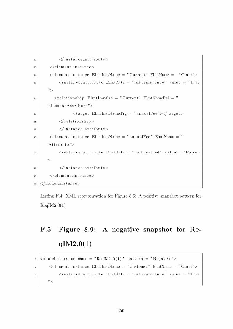
42 </ i n s t a n c e a t t r i b u t e >
43 </e l ement ins tance>
44 <e l ement in s tance ElmtInstName = ” Current ” ElmtName = ” Class ”>
45 < i n s t a n c e a t t r i b u t e ElmtAttr = ” i s P e r s i s t e n c e ” value = ”True
”>
46 <r e l a t i o n s h i p ElmtInstSrc = ” Current ” ElmtNameRel = ”
c l a s s h a s A t t r i b u t e ”>
47 <t a r g e t ElmtInstNameTrg = ” annualFee ”></target>
48 </r e l a t i o n s h i p >
49 </ i n s t a n c e a t t r i b u t e >
50 <e l ement in s tance ElmtInstName = ” annualFee ” ElmtName = ”
Attr ibute ”>
51 < i n s t a n c e a t t r i b u t e ElmtAttr = ” mult iva lued ” value = ” False ”
>
52 </ i n s t a n c e a t t r i b u t e >
53 </e l ement ins tance>
54 </model instance>
Listing F.4: XML representation for Figure 8.6: A positive snapshot pattern for
ReqIM2.0(1)
F.5 Figure 8.9: A negative snapshot for Re-
qIM2.0(1)
1 <mode l ins tance name = ”ReqIM2 . 0 ( 1 ) ” pattern = ” Negative ”>
2 <e l ement in s tance ElmtInstName = ”Customer” ElmtName = ” Class ”>
3 < i n s t a n c e a t t r i b u t e ElmtAttr = ” i s P e r s i s t e n c e ” value = ”True
”>
250
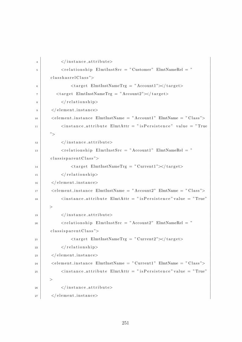
4 </ i n s t a n c e a t t r i b u t e>
5 <r e l a t i o n s h i p ElmtInstSrc = ”Customer” ElmtNameRel = ”
c l a s s h a s r e l C l a s s ”>
6 <t a r g e t ElmtInstNameTrg = ”Account1”></ t a r g e t>
7 <t a r g e t ElmtInstNameTrg = ”Account2”></ t a r g e t>
8 </ r e l a t i o n s h i p>
9 </ e l ement in s tance>
10 <e l ement in s tance ElmtInstName = ”Account1” ElmtName = ” Class ”>
11 < i n s t a n c e a t t r i b u t e ElmtAttr = ” i s P e r s i s t e n c e ” value = ”True
”>
12 </ i n s t a n c e a t t r i b u t e>
13 <r e l a t i o n s h i p ElmtInstSrc = ”Account1” ElmtNameRel = ”
c l a s s i s p a r e n t C l a s s ”>
14 <t a r g e t ElmtInstNameTrg = ” Current1 ”></ t a r g e t>
15 </ r e l a t i o n s h i p>
16 </ e l ement in s tance>
17 <e l ement in s tance ElmtInstName = ”Account2” ElmtName = ” Class ”>
18 < i n s t a n c e a t t r i b u t e ElmtAttr = ” i s P e r s i s t e n c e ” value = ”True”
>
19 </ i n s t a n c e a t t r i b u t e>
20 <r e l a t i o n s h i p ElmtInstSrc = ”Account2” ElmtNameRel = ”
c l a s s i s p a r e n t C l a s s ”>
21 <t a r g e t ElmtInstNameTrg = ” Current2 ”></ t a r g e t>
22 </ r e l a t i o n s h i p>
23 </ e l ement in s tance>
24 <e l ement in s tance ElmtInstName = ” Current1 ” ElmtName = ” Class ”>
25 < i n s t a n c e a t t r i b u t e ElmtAttr = ” i s P e r s i s t e n c e ” value = ”True”
>
26 </ i n s t a n c e a t t r i b u t e>
27 </ e l ement in s tance>
251
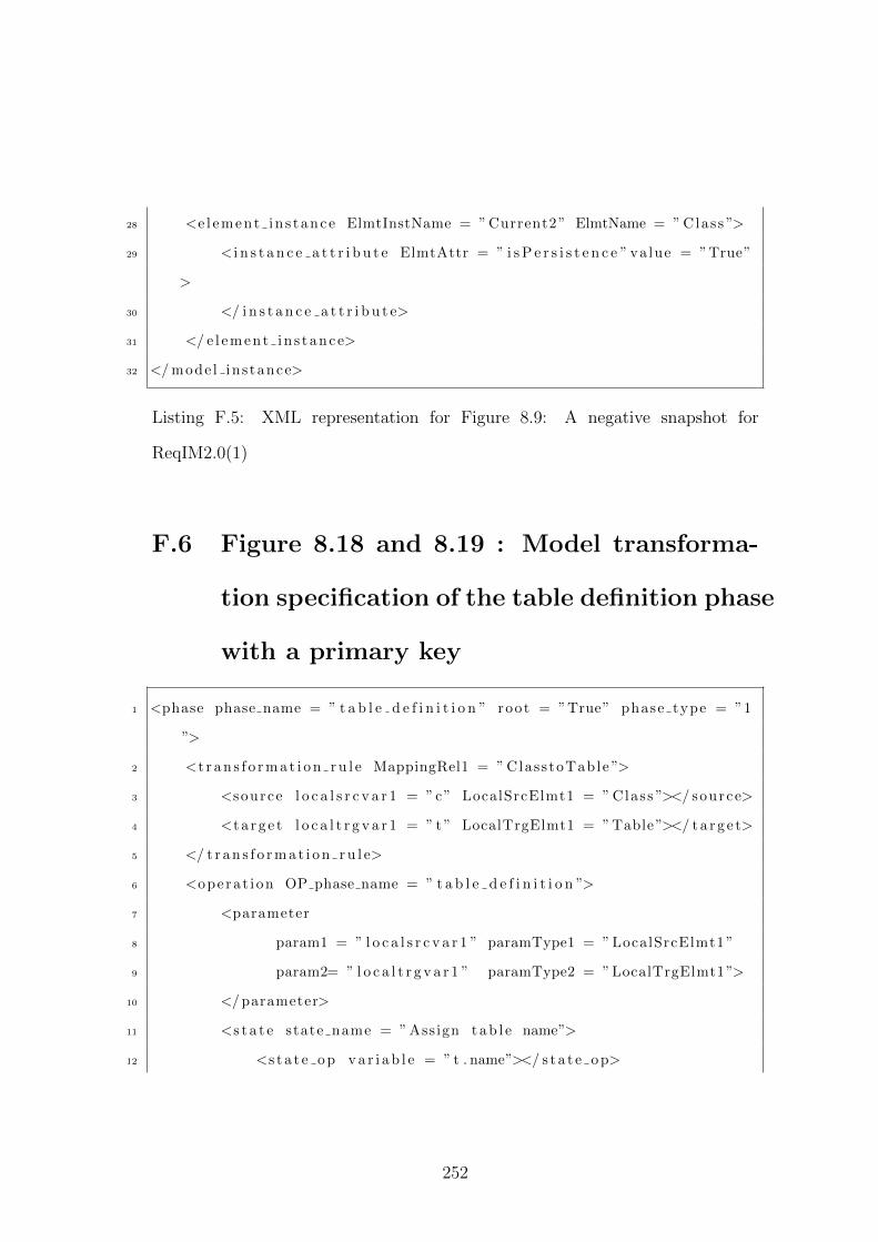
28 <e l ement in s tance ElmtInstName = ” Current2 ” ElmtName = ” Class ”>
29 < i n s t a n c e a t t r i b u t e ElmtAttr = ” i s P e r s i s t e n c e ” value = ”True”
>
30 </ i n s t a n c e a t t r i b u t e>
31 </ e l ement in s tance>
32 </ mode l ins tance>
Listing F.5: XML representation for Figure 8.9: A negative snapshot for
ReqIM2.0(1)
F.6 Figure 8.18 and 8.19 : Model transforma-
tion specification of the table definition phase
with a primary key
1 <phase phase name = ” t a b l e d e f i n i t i o n ” root = ”True” phase type = ”1
”>
2 <t r a n s f o r m a t i o n r u l e MappingRel1 = ” ClasstoTable ”>
3 <source l o c a l s r c v a r 1 = ”c” LocalSrcElmt1 = ” Class ”></ source>
4 <t a r g e t l o c a l t r g v a r 1 = ” t ” LocalTrgElmt1 = ”Table”></ t a r g e t>
5 </ t r a n s f o r m a t i o n r u l e>
6 <opera t ion OP phase name = ” t a b l e d e f i n i t i o n ”>
7 <parameter
8 param1 = ” l o c a l s r c v a r 1 ” paramType1 = ” LocalSrcElmt1 ”
9 param2= ” l o c a l t r g v a r 1 ” paramType2 = ”LocalTrgElmt1”>
10 </ parameter>
11 <s t a t e state name = ” Assign t a b l e name”>
12 <s t a t e o p v a r i a b l e = ” t . name”></ s t a t e o p>
252
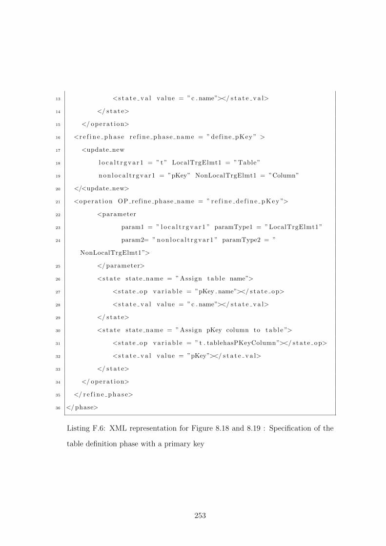
13 <s t a t e v a l va lue = ”c . name”></ s t a t e v a l>
14 </ s t a t e>
15 </ opera t i on>
16 <r e f i n e p h a s e re f ine phase name = ” def ine pKey ” >
17 <update new
18 l o c a l t r g v a r 1 = ” t ” LocalTrgElmt1 = ”Table”
19 non l o ca l t r gva r1 = ”pKey” NonLocalTrgElmt1 = ”Column”
20 </<update new>
21 <opera t ion OP ref ine phase name = ” r e f i n e d e f i n e p K e y ”>
22 <parameter
23 param1 = ” l o c a l t r g v a r 1 ” paramType1 = ”LocalTrgElmt1”
24 param2= ” non l o ca l t r gva r1 ” paramType2 = ”
NonLocalTrgElmt1”>
25 </ parameter>
26 <s t a t e state name = ” Assign t a b l e name”>
27 <s t a t e o p v a r i a b l e = ”pKey . name”></ s t a t e o p>
28 <s t a t e v a l va lue = ”c . name”></ s t a t e v a l>
29 </ s t a t e>
30 <s t a t e state name = ” Assign pKey column to t ab l e ”>
31 <s t a t e o p v a r i a b l e = ” t . tablehasPKeyColumn”></ s t a t e o p>
32 <s t a t e v a l va lue = ”pKey”></ s t a t e v a l>
33 </ s t a t e>
34 </ opera t i on>
35 </ r e f i n e p h a s e>
36 </ phase>
Listing F.6: XML representation for Figure 8.18 and 8.19 : Specification of the
table definition phase with a primary key
253
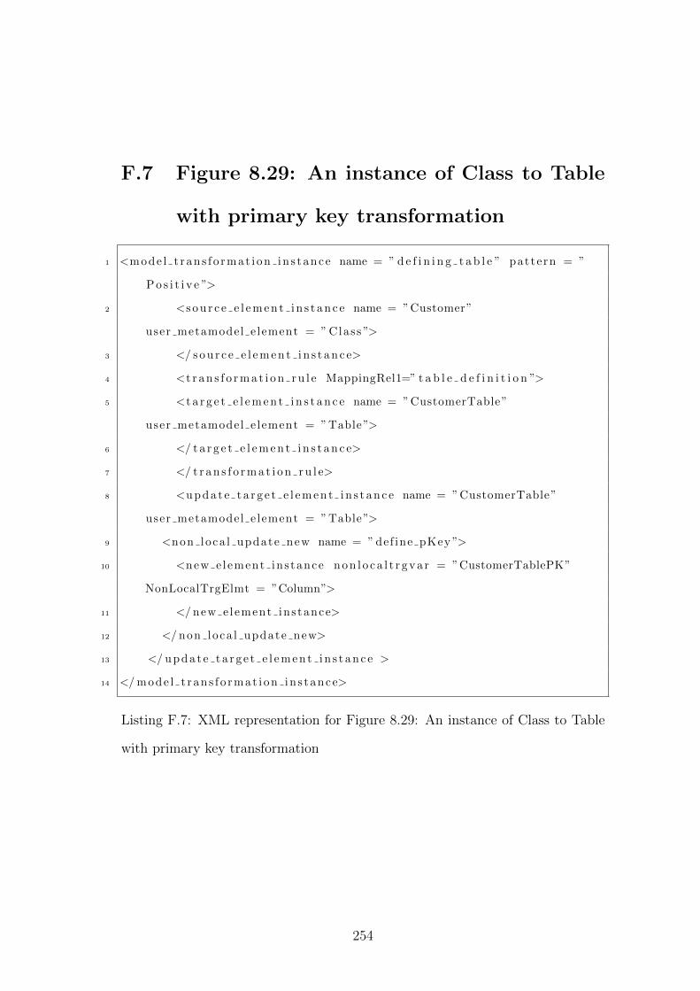
F.7 Figure 8.29: An instance of Class to Table
with primary key transformation
1 <mode l t ran s f o rmat i on in s tance name = ” d e f i n i n g t a b l e ” pattern = ”
P o s i t i v e ”>
2 <s o u r c e e l e m e n t i n s t a n c e name = ”Customer”
user metamodel e lement = ” Class ”>
3 </ s o u r c e e l e m e n t i n s t a n c e>
4 <t r a n s f o r m a t i o n r u l e MappingRel1=” t a b l e d e f i n i t i o n ”>
5 <t a r g e t e l e m e n t i n s t a n c e name = ”CustomerTable”
user metamodel e lement = ”Table”>
6 </ t a r g e t e l e m e n t i n s t a n c e>
7 </ t r a n s f o r m a t i o n r u l e>
8 <u p d a t e t a r g e t e l e m e n t i n s t a n c e name = ”CustomerTable”
user metamodel e lement = ”Table”>
9 <non loca l update new name = ” def ine pKey ”>
10 <new e lement ins tance n o n l o c a l t r g v a r = ”CustomerTablePK”
NonLocalTrgElmt = ”Column”>
11 </ new e lement ins tance>
12 </ non loca l update new>
13 </ u p d a t e t a r g e t e l e m e n t i n s t a n c e >
14 </ mode l t r an s f o rmat i on in s tance>
Listing F.7: XML representation for Figure 8.29: An instance of Class to Table
with primary key transformation
254
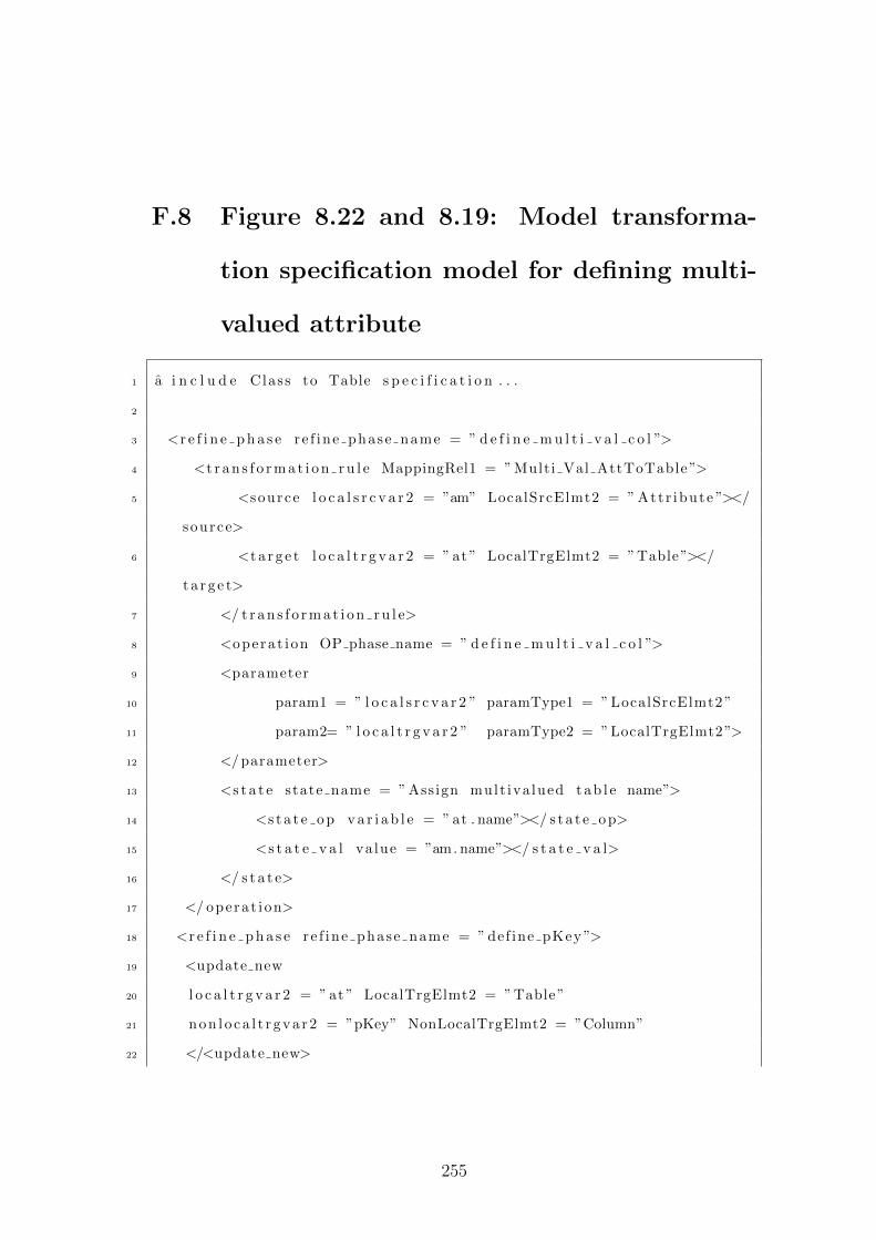
F.8 Figure 8.22 and 8.19: Model transforma-
tion specification model for defining multi-
valued attribute
1 a i n c l u d e Class to Table s p e c i f i c a t i o n . . .
2
3 <r e f i n e p h a s e re f ine phase name = ” d e f i n e m u l t i v a l c o l ”>
4 <t r a n s f o r m a t i o n r u l e MappingRel1 = ” Multi Val AttToTable ”>
5 <source l o c a l s r c v a r 2 = ”am” LocalSrcElmt2 = ” Attr ibute ”></
source>
6 <t a r g e t l o c a l t r g v a r 2 = ” at ” LocalTrgElmt2 = ”Table”></
t a r g e t>
7 </ t r a n s f o r m a t i o n r u l e>
8 <opera t ion OP phase name = ” d e f i n e m u l t i v a l c o l ”>
9 <parameter
10 param1 = ” l o c a l s r c v a r 2 ” paramType1 = ” LocalSrcElmt2 ”
11 param2= ” l o c a l t r g v a r 2 ” paramType2 = ”LocalTrgElmt2”>
12 </ parameter>
13 <s t a t e state name = ” Assign mult iva lued t a b l e name”>
14 <s t a t e o p v a r i a b l e = ” at . name”></ s t a t e o p>
15 <s t a t e v a l va lue = ”am. name”></ s t a t e v a l>
16 </ s t a t e>
17 </ opera t i on>
18 <r e f i n e p h a s e re f ine phase name = ” def ine pKey ”>
19 <update new
20 l o c a l t r g v a r 2 = ” at ” LocalTrgElmt2 = ”Table”
21 non l o ca l t r gva r2 = ”pKey” NonLocalTrgElmt2 = ”Column”
22 </<update new>
255
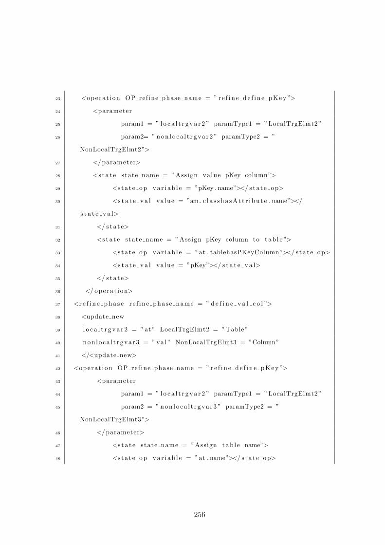
23 <opera t ion OP ref ine phase name = ” r e f i n e d e f i n e p K e y ”>
24 <parameter
25 param1 = ” l o c a l t r g v a r 2 ” paramType1 = ”LocalTrgElmt2”
26 param2= ” non l o ca l t r gva r2 ” paramType2 = ”
NonLocalTrgElmt2”>
27 </ parameter>
28 <s t a t e state name = ” Assign value pKey column”>
29 <s t a t e o p v a r i a b l e = ”pKey . name”></ s t a t e o p>
30 <s t a t e v a l va lue = ”am. c l a s s h a s A t t r i b u t e . name”></
s t a t e v a l>
31 </ s t a t e>
32 <s t a t e state name = ” Assign pKey column to t ab l e ”>
33 <s t a t e o p v a r i a b l e = ” at . tablehasPKeyColumn”></ s t a t e o p>
34 <s t a t e v a l va lue = ”pKey”></ s t a t e v a l>
35 </ s t a t e>
36 </ opera t i on>
37 <r e f i n e p h a s e re f ine phase name = ” d e f i n e v a l c o l ”>
38 <update new
39 l o c a l t r g v a r 2 = ” at ” LocalTrgElmt2 = ”Table”
40 non l o ca l t r gva r3 = ” va l ” NonLocalTrgElmt3 = ”Column”
41 </<update new>
42 <opera t ion OP ref ine phase name = ” r e f i n e d e f i n e p K e y ”>
43 <parameter
44 param1 = ” l o c a l t r g v a r 2 ” paramType1 = ”LocalTrgElmt2”
45 param2 = ” non l o ca l t r gva r3 ” paramType2 = ”
NonLocalTrgElmt3”>
46 </ parameter>
47 <s t a t e state name = ” Assign t a b l e name”>
48 <s t a t e o p v a r i a b l e = ” at . name”></ s t a t e o p>
256
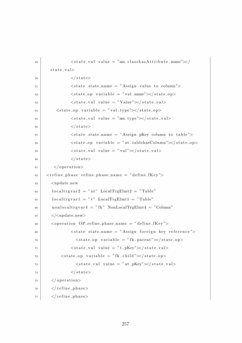
49 <s t a t e v a l va lue = ”am. c l a s s h a s A t t r i b u t e . name”></
s t a t e v a l>
50 </ s t a t e>
51 <s t a t e state name = ” Assign value to column”>
52 <s t a t e o p v a r i a b l e = ” va l . name”></ s t a t e o p>
53 <s t a t e v a l va lue = ”Value”></ s t a t e v a l>
54 <s t a t e o p v a r i a b l e = ” va l . type ”></ s t a t e o p>
55 <s t a t e v a l va lue = ”am. type ”></ s t a t e v a l>
56 </ s t a t e>
57 <s t a t e state name = ” Assign pKey column to t a b l e ”>
58 <s t a t e o p v a r i a b l e = ” at . tablehasColumn ”></ s t a t e o p>
59 <s t a t e v a l va lue = ” va l ”></ s t a t e v a l>
60 </ s t a t e>
61 </ opera t i on>
62 <r e f i n e p h a s e re f ine phase name = ” de f in e fKey ”>
63 <update new
64 l o c a l t r g v a r 2 = ” at ” LocalTrgElmt2 = ”Table”
65 l o c a l t r g v a r 1 = ” t ” LocalTrgElmt1 = ”Table”
66 non l o ca l t r gva r4 = ” fk ” NonLocalTrgElmt4 = ”Column”
67 </<update new>
68 <opera t ion OP ref ine phase name = ” de f ine fKey ”>
69 <s t a t e state name = ” Assign f o r e i g n key r e f e r e n c e ”>
70 <s t a t e o p v a r i a b l e = ” fk . parent ”></ s t a t e o p>
71 <s t a t e v a l va lue = ” t . pKey”></ s t a t e v a l>
72 <s t a t e o p v a r i a b l e = ” fk . c h i l d ”></ s t a t e o p>
73 <s t a t e v a l va lue = ” at . pKey”></ s t a t e v a l>
74 </ s t a t e>
75 </ opera t i on>
76 </ r e f i n e p h a s e>
77 </ r e f i n e p h a s e>
257

78 </ r e f i n e p h a s e>
79 </ r e f i n e p h a s e>
80 </ phase>
Listing F.8: XML representation for Figure 8.22 and 8.19: Model transformation
specification model for defining multi-valued attribute
258
Appendix G
TSP modelling language notation
descriptions
This appendix contain the description of TSP modelling language notations. The
modelling language contain six notations, (1) user metamodel, (2) user metamodel
instance model, (3) requirements model, (4) rule mapping model, (5) transfor-
mation specification model, and (6) transformation instance model.
The following gives the detail of each notations.
G.1 User metamodel notation
This notation is use to represent user metamodel define by TSP metamodelling
language (Figure 5.4). Table G.1 and G.2 define the notation for TSP metamod-
elling language.
G.2 User metamodel instance model notation
User metamodel instance notation is used to define instance pattern for the snap-
shot analysis of the user metamodel. Table G.3 describes the notations for TSP
259
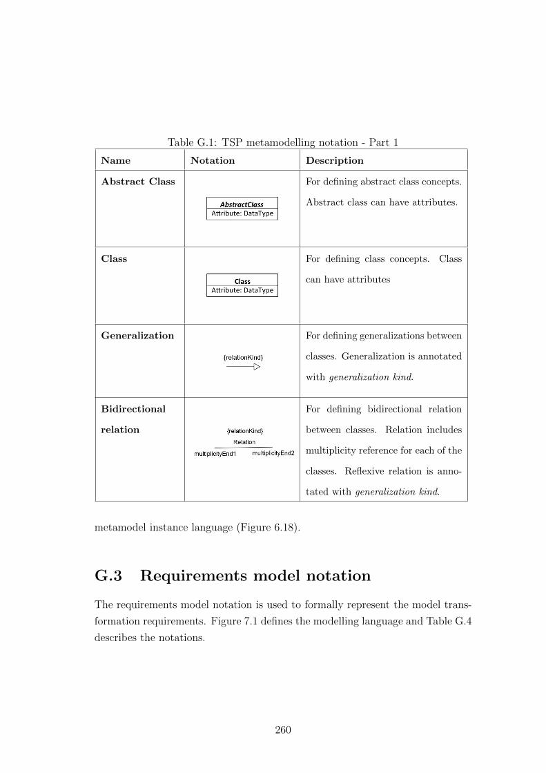
Table G.1: TSP metamodelling notation - Part 1
Name Notation Description
Abstract Class For defining abstract class concepts.
Abstract class can have attributes.
Class For defining class concepts. Class
can have attributes
Generalization For defining generalizations between
classes. Generalization is annotated
with generalization kind.
Bidirectional
relation
For defining bidirectional relation
between classes. Relation includes
multiplicity reference for each of the
classes. Reflexive relation is anno-
tated with generalization kind.
metamodel instance language (Figure 6.18).
G.3 Requirements model notation
The requirements model notation is used to formally represent the model trans-
formation requirements. Figure 7.1 defines the modelling language and Table G.4
describes the notations.
260
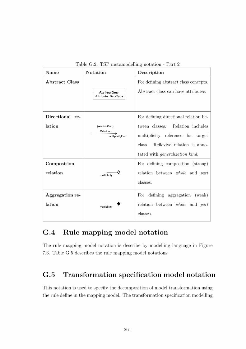
Table G.2: TSP metamodelling notation - Part 2
Name Notation Description
Abstract Class For defining abstract class concepts.
Abstract class can have attributes.
Directional re-
lation
For defining directional relation be-
tween classes. Relation includes
multiplicity reference for target
class. Reflexive relation is anno-
tated with generalization kind.
Composition
relation
For defining composition (strong)
relation between whole and part
classes.
Aggregation re-
lation
For defining aggregation (weak)
relation between whole and part
classes.
G.4 Rule mapping model notation
The rule mapping model notation is describe by modelling language in Figure
7.3. Table G.5 describes the rule mapping model notations.
G.5 Transformation specification model notation
This notation is used to specify the decomposition of model transformation using
the rule define in the mapping model. The transformation specification modelling
261
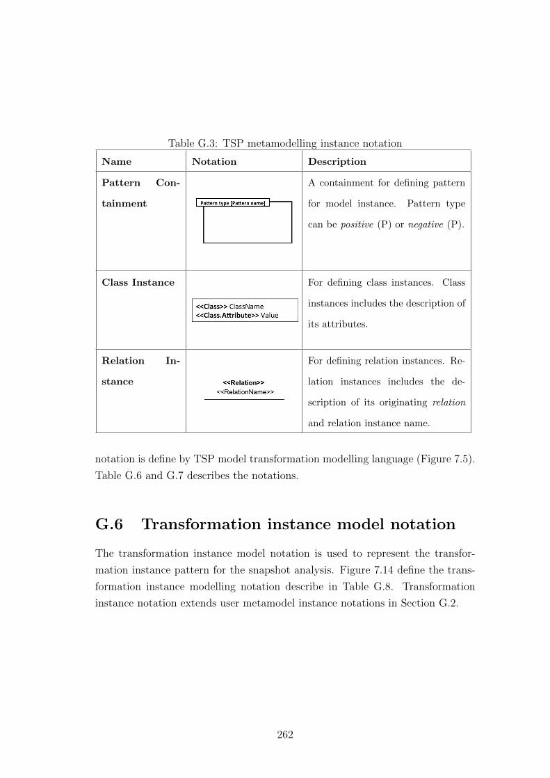
Table G.3: TSP metamodelling instance notation
Name Notation Description
Pattern Con-
tainment
A containment for defining pattern
for model instance. Pattern type
can be positive (P) or negative (P).
Class Instance For defining class instances. Class
instances includes the description of
its attributes.
Relation In-
stance
For defining relation instances. Re-
lation instances includes the de-
scription of its originating relation
and relation instance name.
notation is define by TSP model transformation modelling language (Figure 7.5).
Table G.6 and G.7 describes the notations.
G.6 Transformation instance model notation
The transformation instance model notation is used to represent the transfor-
mation instance pattern for the snapshot analysis. Figure 7.14 define the trans-
formation instance modelling notation describe in Table G.8. Transformation
instance notation extends user metamodel instance notations in Section G.2.
262
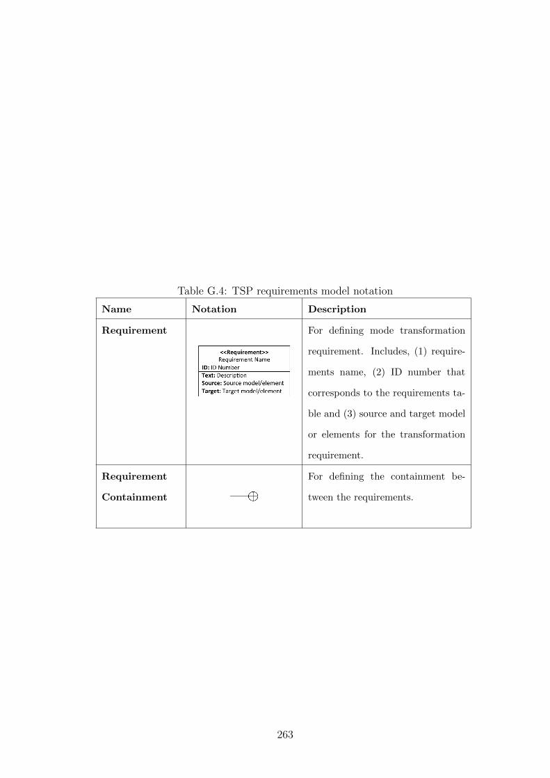
Table G.4: TSP requirements model notation
Name Notation Description
Requirement For defining mode transformation
requirement. Includes, (1) require-
ments name, (2) ID number that
corresponds to the requirements ta-
ble and (3) source and target model
or elements for the transformation
requirement.
Requirement
Containment
For defining the containment be-
tween the requirements.
263
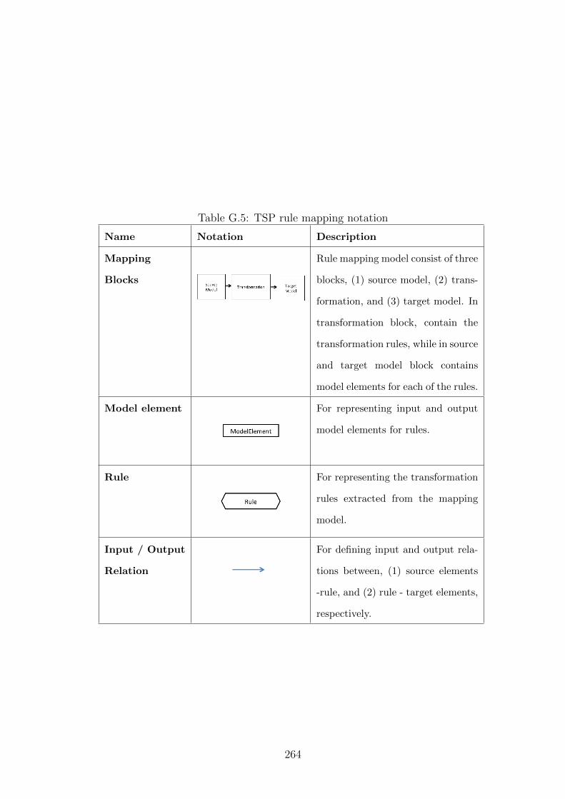
Table G.5: TSP rule mapping notation
Name Notation Description
Mapping
Blocks
Rule mapping model consist of three
blocks, (1) source model, (2) trans-
formation, and (3) target model. In
transformation block, contain the
transformation rules, while in source
and target model block contains
model elements for each of the rules.
Model element For representing input and output
model elements for rules.
Rule For representing the transformation
rules extracted from the mapping
model.
Input / Output
Relation
For defining input and output rela-
tions between, (1) source elements
-rule, and (2) rule - target elements,
respectively.
264
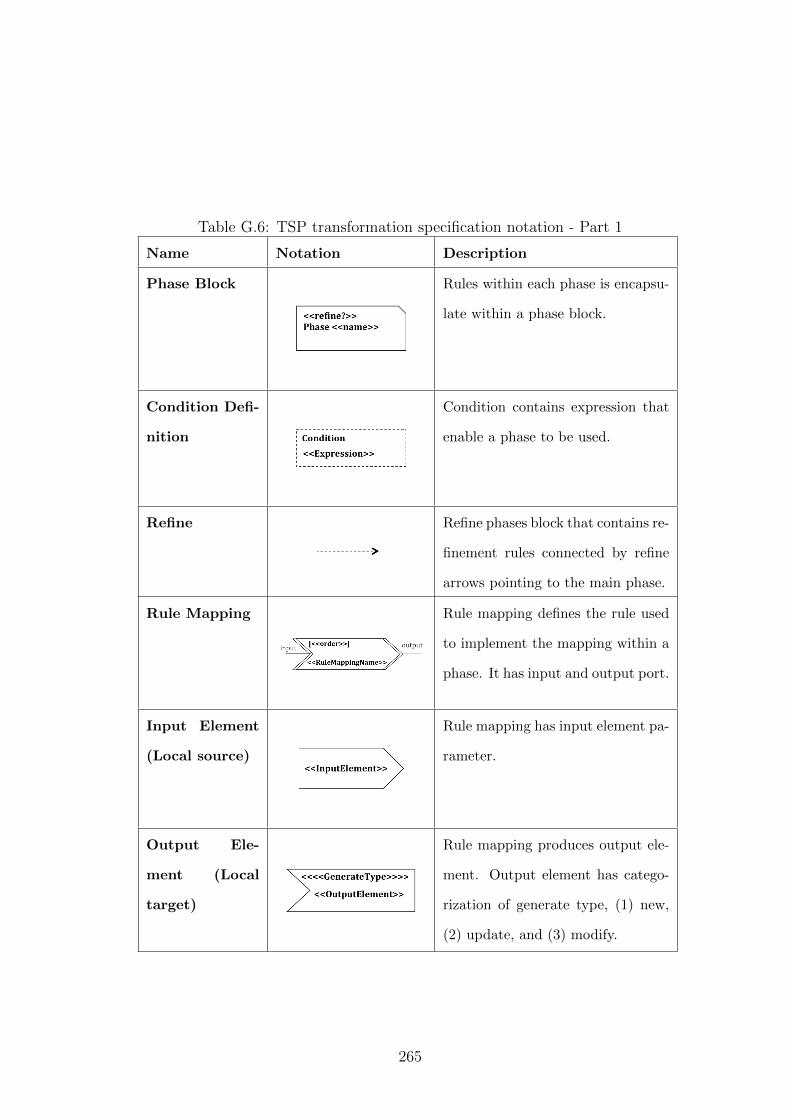
Table G.6: TSP transformation specification notation - Part 1
Name Notation Description
Phase Block Rules within each phase is encapsu-
late within a phase block.
Condition Defi-
nition
Condition contains expression that
enable a phase to be used.
Refine Refine phases block that contains re-
finement rules connected by refine
arrows pointing to the main phase.
Rule Mapping Rule mapping defines the rule used
to implement the mapping within a
phase. It has input and output port.
Input Element
(Local source)
Rule mapping has input element pa-
rameter.
Output Ele-
ment (Local
target)
Rule mapping produces output ele-
ment. Output element has catego-
rization of generate type, (1) new,
(2) update, and (3) modify.
265
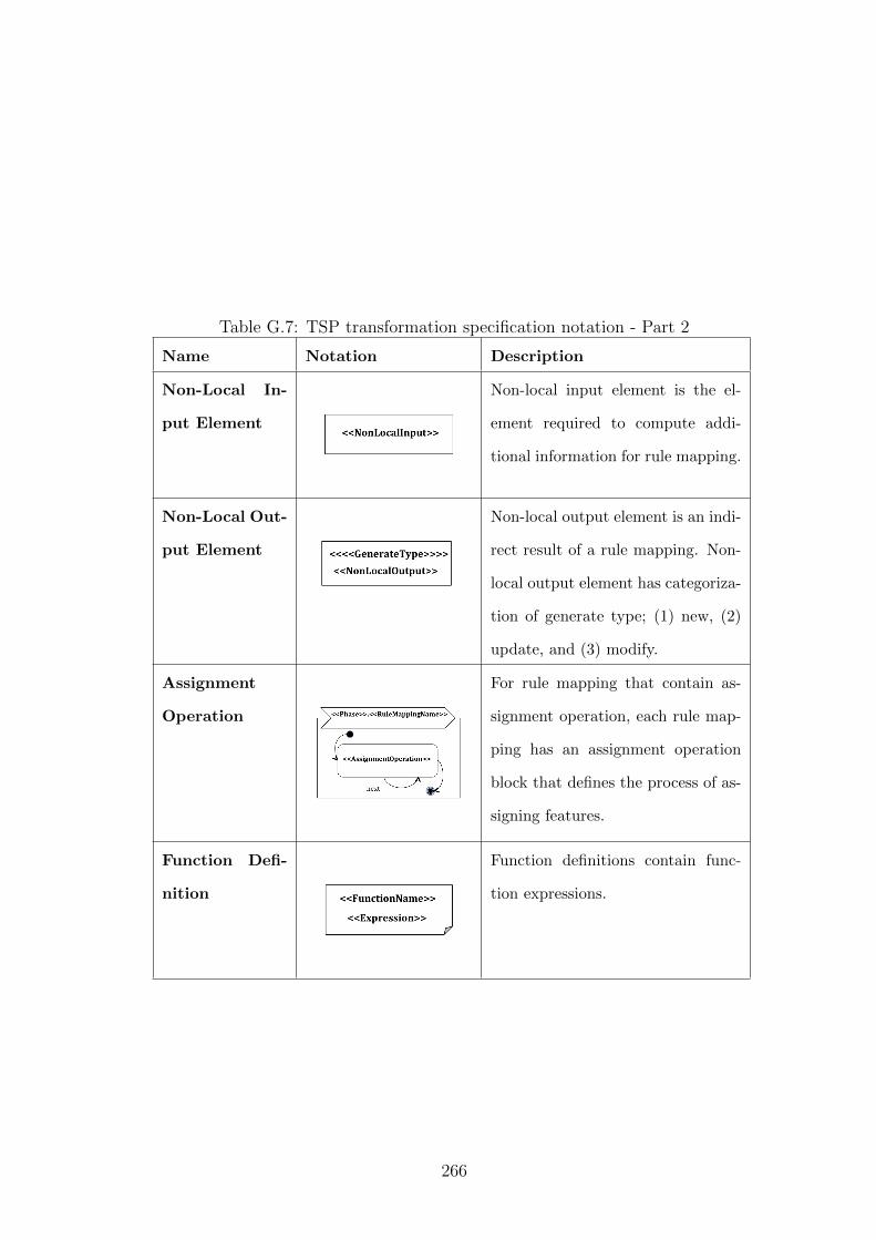
Table G.7: TSP transformation specification notation - Part 2
Name Notation Description
Non-Local In-
put Element
Non-local input element is the el-
ement required to compute addi-
tional information for rule mapping.
Non-Local Out-
put Element
Non-local output element is an indi-
rect result of a rule mapping. Non-
local output element has categoriza-
tion of generate type; (1) new, (2)
update, and (3) modify.
Assignment
Operation
For rule mapping that contain as-
signment operation, each rule map-
ping has an assignment operation
block that defines the process of as-
signing features.
Function Defi-
nition
Function definitions contain func-
tion expressions.
266
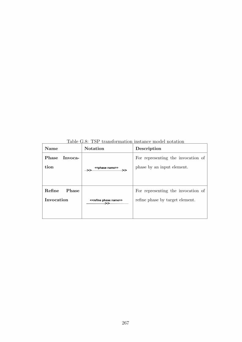
Table G.8: TSP transformation instance model notation
Name Notation Description
Phase Invoca-
tion
For representing the invocation of
phase by an input element.
Refine Phase
Invocation
For representing the invocation of
refine phase by target element.
267
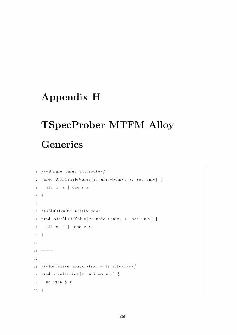
Appendix H
TSpecProber MTFM Alloy
Generics
1 /∗∗ S i n g l e va lue a t t r i b u t e ∗/
2 pred AttrS ing leValue [ r : univ−>univ , s : s e t univ ] {
3 a l l x : s | one r . x
4 }
5
6 /∗∗Mult iva lue a t t r i b u t e ∗/
7 pred AttrMultiValue [ r : univ−>univ , s : s e t univ ] {
8 a l l x : s | l one r . x
9 }
10
11 −−−−−
12
13 /∗∗R e f l e x i v e a s s o c i a t i o n − I r r e f l e x i v e ∗/
14 pred i r r e f l e x i v e [ r : univ−>univ ] {
15 no iden & r
16 }
268
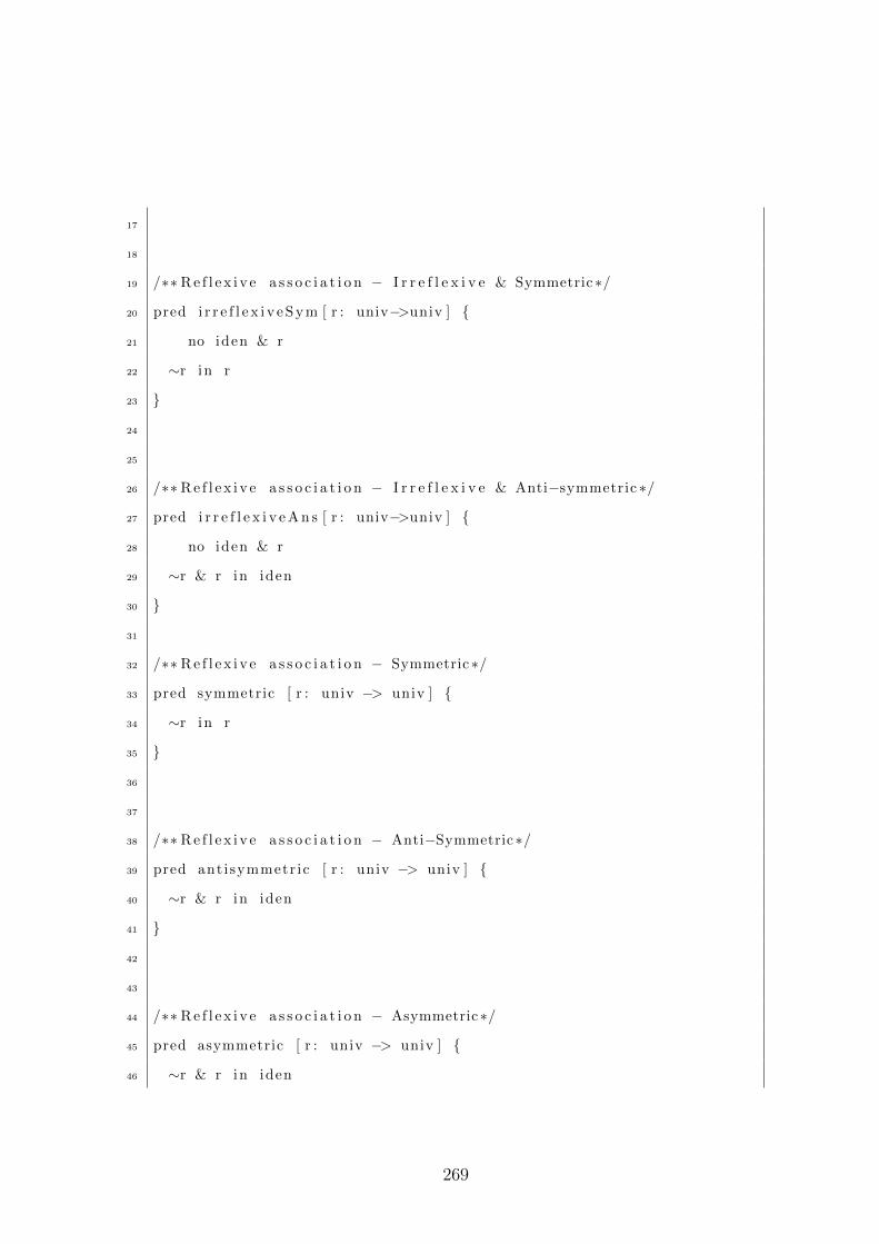
17
18
19 /∗∗R e f l e x i v e a s s o c i a t i o n − I r r e f l e x i v e & Symmetric∗/
20 pred i r r e f l e x i v e S y m [ r : univ−>univ ] {
21 no iden & r
22 ∼r in r
23 }
24
25
26 /∗∗R e f l e x i v e a s s o c i a t i o n − I r r e f l e x i v e & Anti−symmetric ∗/
27 pred i r r e f l e x i v e A n s [ r : univ−>univ ] {
28 no iden & r
29 ∼r & r in iden
30 }
31
32 /∗∗R e f l e x i v e a s s o c i a t i o n − Symmetric∗/
33 pred symmetric [ r : univ −> univ ] {
34 ∼r in r
35 }
36
37
38 /∗∗R e f l e x i v e a s s o c i a t i o n − Anti−Symmetric∗/
39 pred antisymmetr ic [ r : univ −> univ ] {
40 ∼r & r in iden
41 }
42
43
44 /∗∗R e f l e x i v e a s s o c i a t i o n − Asymmetric∗/
45 pred asymmetric [ r : univ −> univ ] {
46 ∼r & r in iden
269
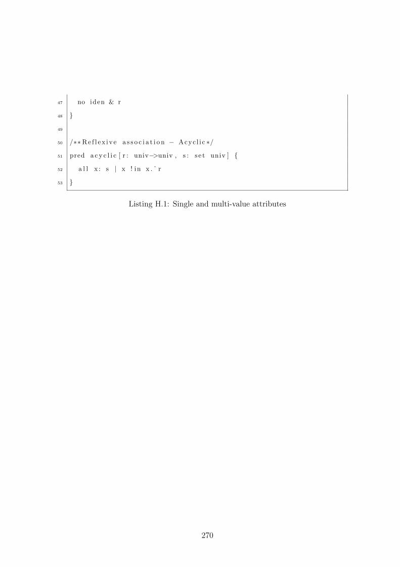
47 no iden & r
48 }
49
50 /∗∗R e f l e x i v e a s s o c i a t i o n − Acyc l i c ∗/
51 pred a c y c l i c [ r : univ−>univ , s : s e t univ ] {
52 a l l x : s | x ! in x . ˆ r
53 }
Listing H.1: Single and multi-value attributes
270
Appendix I
TSpecProber Template
Catalogue
This appendix contain the Alloy TSP templates for formalizing model transfor-
mation. The templates are divided into several parts: (1) Module header, (2) User
metamodel: Class, (3) User metamodel: Relation, (4) Instance model: Defining
model instance, (5) Model transformation specification model, and (6) Instance
model : Defining transfomation.
Before we present our templates, the next section describe the templates for-
mat.
I.1 Template Format
TEMPLATE ID:
TEMPLATE NAME:
PURPOSE:
SOURCE CONDITION:
TARGET SPECIFICATION:
271
where, template ID is a unique identifier for a particular template with a format,
character + integer, template name is the name of the template, purpose
describes the reason for applying the template, source condition shows the
model fragment it applies and target specification is the formal statement
fragment of the intended language, in this particular case, the Alloy.
All templates instantiation aim to be fully generated and ready for analy-
sis. But in some cases, it may require additional details to be included during
instantiation.
I.2 Module Header
The module header templates provide the template to define the links between
multiple specification.
I.2.1 M1:TSpecProber Generics
TEMPLATE ID: M1
TEMPLATE NAME: TSpecProber Generics
PURPOSE: Include TSpecProber Generics file
SOURCE CONDITION: Generics file existed within the directory else include
directory path.
TARGET SPECIFICATION:
open Generics
I.2.2 M2: User Metamodel Header
TEMPLATE ID: M2
TEMPLATE NAME: User Metamodel Header
PURPOSE: User metamodel file(s) header
SOURCE CONDITION: (Mandatory)
272
TARGET SPECIFICATION:
module UserModel/�metamodelName�
I.2.3 M3: (Link) Metamodel to Transformation file
TEMPLATE ID: M3
TEMPLATE NAME: (Link) Metamodel to Transformation file
PURPOSE: Include metamodel file(s)
SOURCE CONDITION: (Mandatory) For multiple source, repeat for every
file. At least one source file and target file.
TARGET SPECIFICATION:
open UserModel/�metamodelName�
I.3 User Metamodel: Class
This section provide the templates to instantiate TSP classes.
I.3.1 C1: Abstract Class
TEMPLATE ID: C1
TEMPLATE NAME: Abstract Class
PURPOSE: Defining abstract elements class in user metamodel.
SOURCE CONDITION: When a class is abstract.
TARGET SPECIFICATION:
(( one ‖ some ))? abstract sig �ElmtName� {/*If class is with attribute.
For multiple, iterate for each attribute*/
�AttrName�: (( one ‖ some )) �Type�}
273
/*For single value attribute*/
fact SingleValue�AttrName� {AttrSingleValue[�AttrName�, �Type�]
}/*For multi-value attribute*/
fact MultiValue�AttrName� {AttrMultiValue[�AttrName�, �Type�]
}For class with relations, refer to template User Model: Relation.
I.3.2 C2: Class
TEMPLATE ID: C2
TEMPLATE NAME: Class
PURPOSE: Defining element class in user metamodel.
SOURCE CONDITION: When a class is abstract.
TARGET SPECIFICATION:
(( one ‖ some ))? sig �ElmtName� {/*If class is with attribute.
For multiple, iterate for each attribute*/
�AttrName�: (( one ‖ some )) ��Type�}/*For single value attribute*/
fact SingleValue�AttrName� {AttrSingleValue[�AttrName�, �Type�]
}/*For multi-value attribute*/
fact MultiValue�AttrName� {AttrMultiValue[�AttrName�, �Type�]
}For class with relations, refer to template User Model: Relation. For singleton
class the �mult�is one .
274
I.4 User Metamodel: Relation
This section provide the templates to instantiate relations of a user metamodel.
I.4.1 Generalization
For each class that has tExtend.isDefined, the following types can be applied:
1. Complete, disjoint
• Abstraction
• Refinement
2. Incomplete, disjoint
• Shared
3. Complete, Overlap
I.4.1.1 R1: Complete, disjoint (Abstraction)
TEMPLATE ID: R1
TEMPLATE NAME: Complete, disjoint (Abstraction)
PURPOSE: For generalization classes that has the purpose of abstracting fea-
tures for its subclasses.
SOURCE CONDITION: Class tExtend.isDefined and include Generics.
TARGET SPECIFICATION:
/*Superclass*/
abstract sig �ElmtName� {/*If class is with attribute. Refer Class instantiation*/
}/*Subclass (Iterate for every class for the same level subclass element*/
sig �ElmtName� extends �SClassElmtName� {/*If class is with attribute. Refer Class instantiation*/
}
275
I.4.1.2 R2: Complete, disjoint (Refinement)
TEMPLATE ID: R2
TEMPLATE NAME: Complete, disjoint (Refinement)
PURPOSE: For generalization classes that has the purpose of subclass refining
features of the superclass.
SOURCE CONDITION: Class tExtend.isDefined.
TARGET SPECIFICATION:
/*Superclass*/
sig �ElmtName� {/*If class is with attribute. Refer Class instantiation*/
}/*Subclass (Iterate for every class for the same level subclass element*/
sig �ElmtName� in �SClassElmtName� {/*If class is with attribute. Refer Class instantiation*/
}
/*For disjoint sub-class element*/
fact DisjointSubClass�SClassElmtName� {disj [�ElmtName1�,�ElmtName2�..�ElmtNameN�]
�SClassElmtName� = �ElmtName1� + �ElmtName2� + .. +
�ElmtNameN� }
I.4.1.3 R3: Incomplete, disjoint (Shared)
TEMPLATE ID: R3
TEMPLATE NAME: Incomplete, disjoint (Shared)
PURPOSE: For generalization classes that has the purpose of superclass shar-
ing features with subclass.
SOURCE CONDITION: Class tExtend.isDefined.
TARGET SPECIFICATION:
276
/*Superclass*/
sig �ElmtName� {/*If class is with attribute. Refer Class instantiation*/
}/*Subclass (Iterate for every class for the same level subclass element*/
sig �ElmtName� extends �SClassElmtName� {/*If class is with attribute. Refer Class instantiation*/
}
I.4.1.4 R4: Complete, Overlap
TEMPLATE ID: R4
TEMPLATE NAME: Complete, overlap
PURPOSE: For generalization classes that has the purpose of superclass shar-
ing features with multiple subclasses.
SOURCE CONDITION: Class tExtend.isDefined.
TARGET SPECIFICATION:
/*Superclass*/
sig �ElmtName� {/*If class is with attribute. Refer Class instantiation*/
}
/*Subclass (Iterate for every class for the same level subclass element*/
sig �ElmtName� in �SClassElmtName� {/*If class is with attribute. Refer Class instantiation*/
}
/*For combined and disjoint sub-class element.Iterate every possible pairs of sub-
classes that are allowed to combined */
fact Combined�ElmtName1��ElmtName2� {some �ElmtName1� & �ElmtName2�
}
277
/*For disjoint sub-class element*/
fact DisjointSubClass�SClassElmtName� {disj [�ElmtName1�,�ElmtName2�..�ElmtNameN�]
�SClassElmtName� = �ElmtName1� + �ElmtName2� + .. +
�ElmtNameN� }
I.4.2 R5: Association (Bi-Directional Only Model)
TEMPLATE ID: R5
TEMPLATE NAME: Association (Bi-directional Only Model)
PURPOSE: For defining relation between two classes of a model that contain
bi-directional relations only. Definition includes role name and multiplicity
SOURCE CONDITION: Relation between Class 1 and Class 2 has not been
define.
TARGET SPECIFICATION:
/*Class End 1 (Element 1)*/
sig �ElmtName1� {/*If class is with attribute. Refer Class instantiation*/
/*Iterate for each association attached to Class End 2.
If not define, instantiate Class End 2 (Element 2)
with Class instantiation.*/
�RoleName�: �multOf� �ElmtName2� }
/*Multiplicity facts.*/
fact Multiplicity�ElmtName1��ElmtName2� {/*Iterate for each association*/
�RoleName�: �ElmtName1� �ofMult� -> �multOf� �ElmtName2�}
/*Numbered multiplicity facts = n.*/
fact NumberedMultiplicity�ElmtName1��RoleName� {all �var�: �ElmtName1� | # �var�.�RoleName� �CompareOp�
278
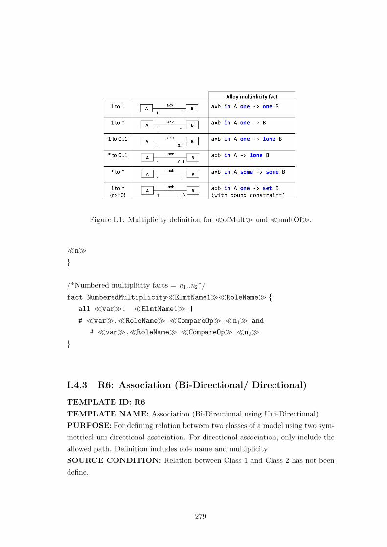
Figure I.1: Multiplicity definition for �ofMult� and �multOf�.
�n�}
/*Numbered multiplicity facts = n1..n2*/
fact NumberedMultiplicity�ElmtName1��RoleName� {all �var�: �ElmtName1� |
# �var�.�RoleName� �CompareOp� �n1� and
# �var�.�RoleName� �CompareOp� �n2�}
I.4.3 R6: Association (Bi-Directional/ Directional)
TEMPLATE ID: R6
TEMPLATE NAME: Association (Bi-Directional using Uni-Directional)
PURPOSE: For defining relation between two classes of a model using two sym-
metrical uni-directional association. For directional association, only include the
allowed path. Definition includes role name and multiplicity
SOURCE CONDITION: Relation between Class 1 and Class 2 has not been
define.
279
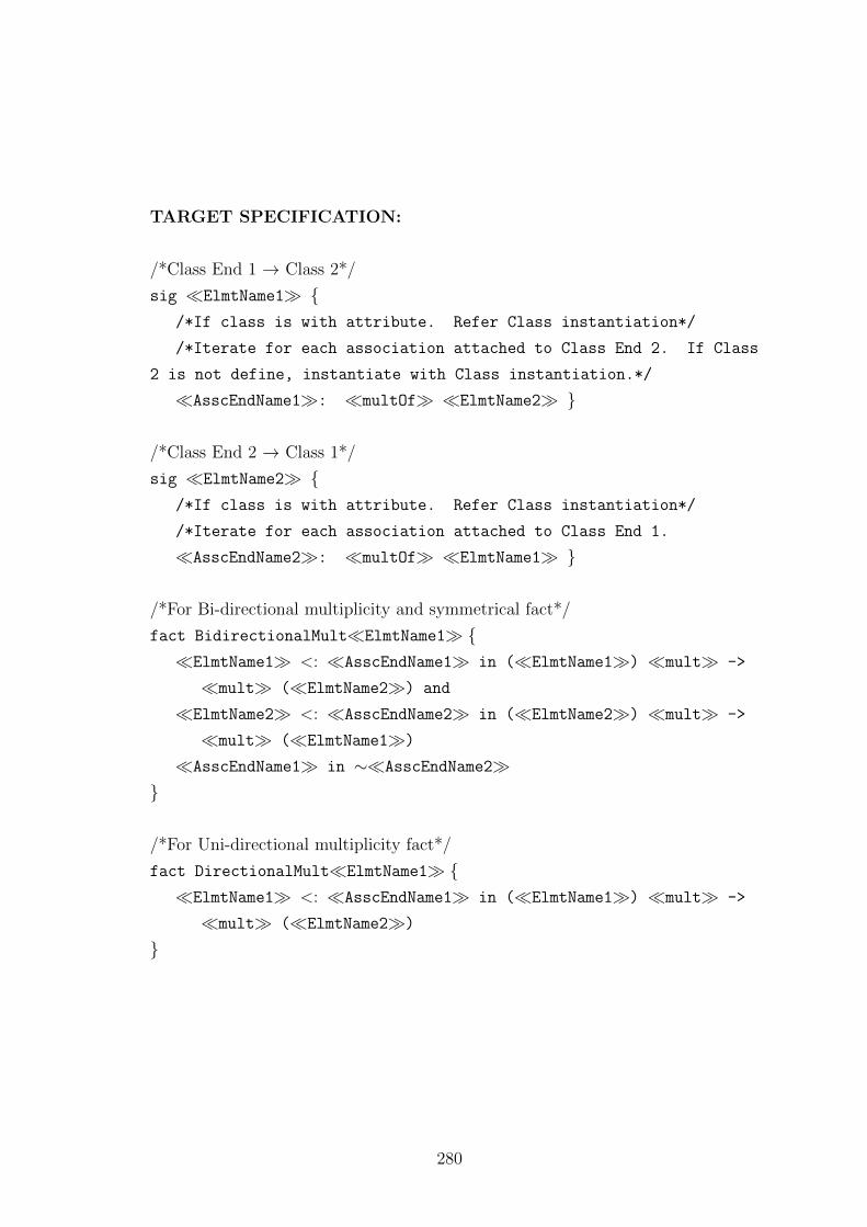
TARGET SPECIFICATION:
/*Class End 1 → Class 2*/
sig �ElmtName1� {/*If class is with attribute. Refer Class instantiation*/
/*Iterate for each association attached to Class End 2. If Class
2 is not define, instantiate with Class instantiation.*/
�AsscEndName1�: �multOf� �ElmtName2� }
/*Class End 2 → Class 1*/
sig �ElmtName2� {/*If class is with attribute. Refer Class instantiation*/
/*Iterate for each association attached to Class End 1.
�AsscEndName2�: �multOf� �ElmtName1� }
/*For Bi-directional multiplicity and symmetrical fact*/
fact BidirectionalMult�ElmtName1� {�ElmtName1� <: �AsscEndName1� in (�ElmtName1�) �mult� ->
�mult� (�ElmtName2�) and
�ElmtName2� <: �AsscEndName2� in (�ElmtName2�) �mult� ->
�mult� (�ElmtName1�)
�AsscEndName1� in ∼�AsscEndName2�}
/*For Uni-directional multiplicity fact*/
fact DirectionalMult�ElmtName1� {�ElmtName1� <: �AsscEndName1� in (�ElmtName1�) �mult� ->
�mult� (�ElmtName2�)
}
280
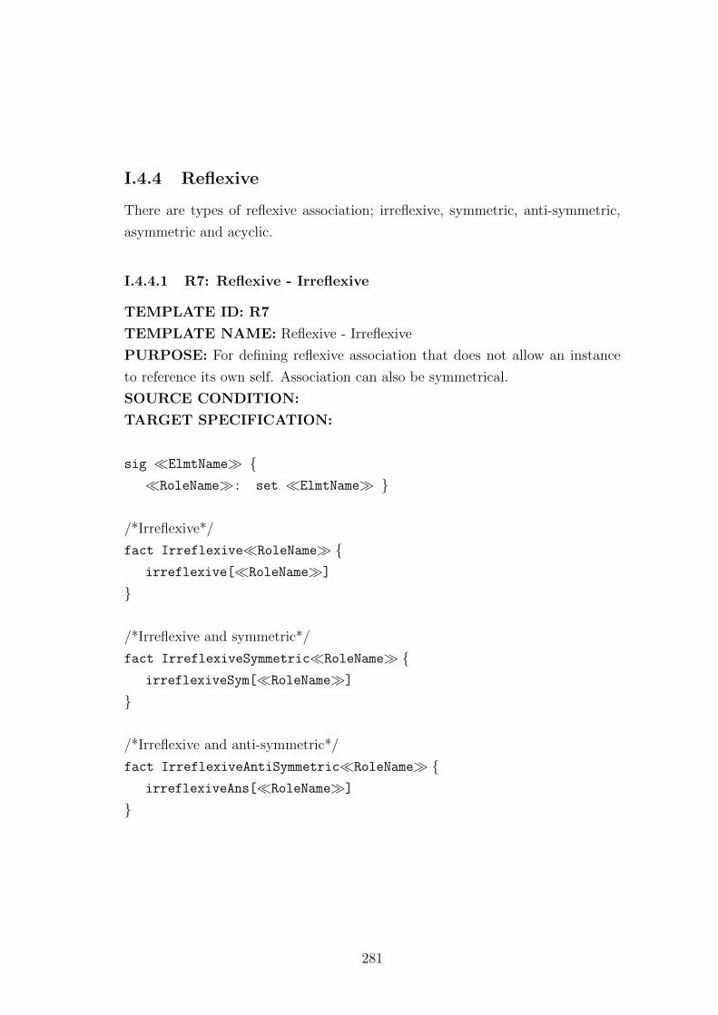
I.4.4 Reflexive
There are types of reflexive association; irreflexive, symmetric, anti-symmetric,
asymmetric and acyclic.
I.4.4.1 R7: Reflexive - Irreflexive
TEMPLATE ID: R7
TEMPLATE NAME: Reflexive - Irreflexive
PURPOSE: For defining reflexive association that does not allow an instance
to reference its own self. Association can also be symmetrical.
SOURCE CONDITION:
TARGET SPECIFICATION:
sig �ElmtName� {�RoleName�: set �ElmtName� }
/*Irreflexive*/
fact Irreflexive�RoleName� {irreflexive[�RoleName�]
}
/*Irreflexive and symmetric*/
fact IrreflexiveSymmetric�RoleName� {irreflexiveSym[�RoleName�]
}
/*Irreflexive and anti-symmetric*/
fact IrreflexiveAntiSymmetric�RoleName� {irreflexiveAns[�RoleName�]
}
281
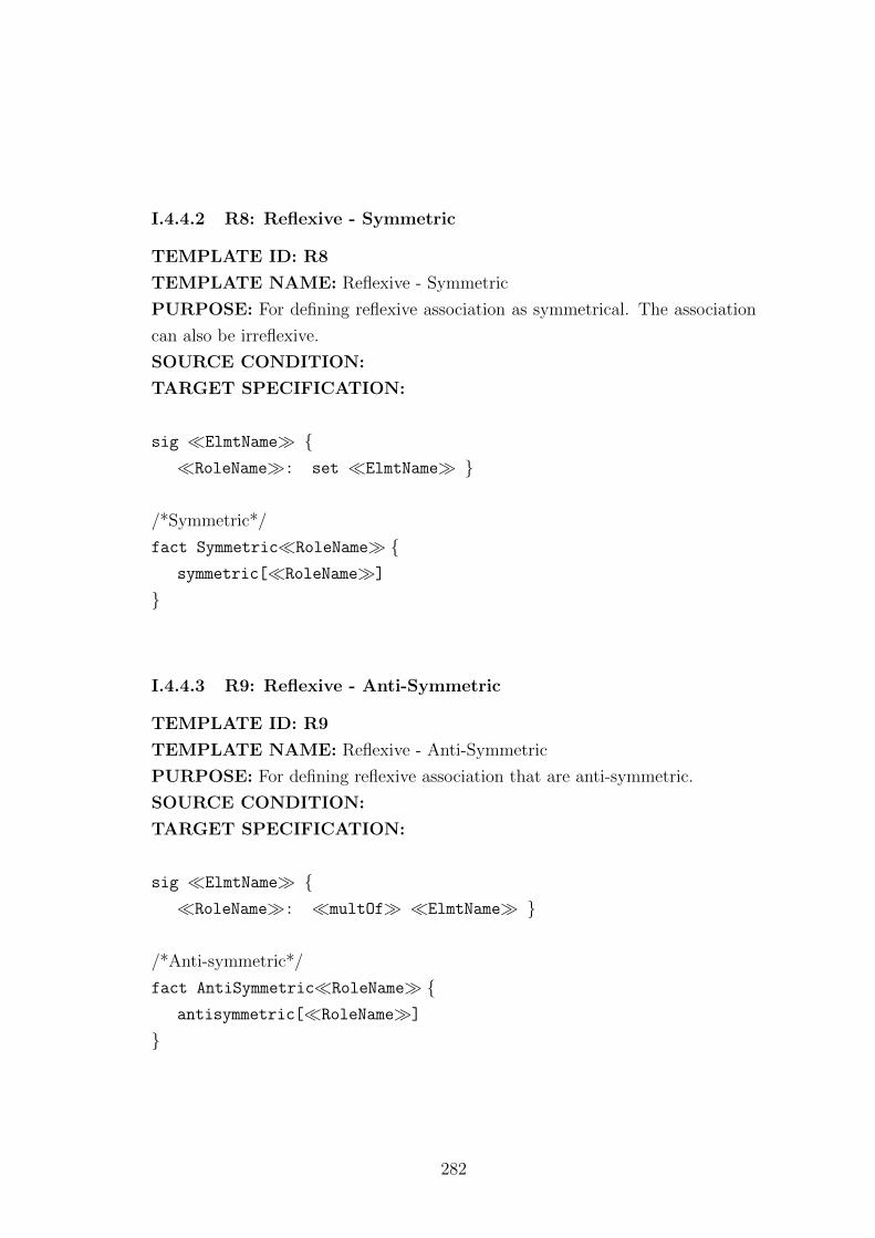
I.4.4.2 R8: Reflexive - Symmetric
TEMPLATE ID: R8
TEMPLATE NAME: Reflexive - Symmetric
PURPOSE: For defining reflexive association as symmetrical. The association
can also be irreflexive.
SOURCE CONDITION:
TARGET SPECIFICATION:
sig �ElmtName� {�RoleName�: set �ElmtName� }
/*Symmetric*/
fact Symmetric�RoleName� {symmetric[�RoleName�]
}
I.4.4.3 R9: Reflexive - Anti-Symmetric
TEMPLATE ID: R9
TEMPLATE NAME: Reflexive - Anti-Symmetric
PURPOSE: For defining reflexive association that are anti-symmetric.
SOURCE CONDITION:
TARGET SPECIFICATION:
sig �ElmtName� {�RoleName�: �multOf� �ElmtName� }
/*Anti-symmetric*/
fact AntiSymmetric�RoleName� {antisymmetric[�RoleName�]
}
282
I.4.4.4 R10: Reflexive - Asymmetric
TEMPLATE ID: R10
TEMPLATE NAME: Reflexive - Asymmetric
PURPOSE: For defining reflexive association that are asymmetric.
SOURCE CONDITION:
TARGET SPECIFICATION:
sig �ElmtName� {�RoleName�: �multOf� �ElmtName� }
/*Asymmetric*/
fact Asymmetric�RoleName� {asymmetric[�RoleName�]
}
I.4.4.5 R11: Reflexive - Acyclic
TEMPLATE ID: R11
TEMPLATE NAME: Reflexive - Acyclic
PURPOSE: For defining reflexive association that does not allow acyclic rela-
tion.
SOURCE CONDITION:
TARGET SPECIFICATION:
sig �ElmtName� {�RoleName�: set �ElmtName� }
/*Acyclic*/
fact Acyclic�RoleName��ElmtName� {acyclic[�RoleName�, �ElmtName�]
}
283
I.4.5 Aggregation
The aggregation is divided into two types, the strong aggregation (composition)
and the weak aggregation. The formal definition is similar to defining normal
associations. Except for �ElmtName1� in an aggregation association, is the
whole class for �ElmtName2�.
I.4.5.1 R12: Strong Aggregation (Composition)
For each strong aggregation relation, refer to Association instantiation. The
following facts are added for defining strong aggregation.
/* Strong dependency*/
fact {all �var1�: �ElmtName1�|
some �var2�:�ElmtName2�|
�var1�.�RoleName� in �var2�}/*Disjoint*/
fact {all �var1�:�ElmtName2�, �var2�,�var3�:�ElmtName1�|
�var2�.�RoleName� in �var1� and
�var3�.�RoleName� in �var1�implies �var2� = �var3�
}
I.4.5.2 R13: Weak Aggregation
For each weak aggregation relation, refer to Association instantiation. The fol-
lowing facts are added for defining weak aggregation.
/* Weak dependency*/
fact {all �var1�: �ElmtName2�|
some �var2�:�ElmtName1�|
�var2�.�RoleName� in �var1�
284
}/*Disjoint*/
fact {all �var1�:�ElmtName2�, �var2�,�var3�:�ElmtName1�|
�var2�.�RoleName� in �var1� and
�var3�.�RoleName� in �var1�implies �var2� = �var3�
}
I.5 Instance Model: Defining Model Instance
The following templates instantiate model instance snapshots based on user meta-
model.
I.5.1 IM1: Element instance definition
TEMPLATE ID: IM1
TEMPLATE NAME: Element instance definition.
PURPOSE: For defining elements instance used to create an instance model.
SOURCE CONDITION:
TARGET SPECIFICATION:
one sig �ElmtInstName� extends �ElmtName� {}/*For elements with value attribute. Iterate for each attribute*/
fact �ElmtInstName�AttrValue {�ElmtInstName�.�ElmtAttr� = �value�
}
285
I.5.2 IM2: Element instance facts
TEMPLATE ID: IM2
TEMPLATE NAME: Element instance facts.
PURPOSE: For defining elements instance facts used to create an instance
model.
SOURCE CONDITION:
TARGET SPECIFICATION:
/*For each element, assign instance used in the model*/
fact ElementInstance{�ElmtName� = �ElmtInstName1� + �ElmtInstNamen�
}
I.5.3 IM3: Model instance structure
TEMPLATE ID: IM3
TEMPLATE NAME: Model instance structure.
PURPOSE: For defining model instance structure.
SOURCE CONDITION:
TARGET SPECIFICATION:
fact ModelStructure{/*For 1..1 relation*/
�ElmtInstNameSrc�.�ElmtNameRel� = �ElmtInstNameTrg�/*For 1..* relation*/
�ElmtNameSrc�.�ElmtNameRel� = �ElmtInstNameTrg1� +
�ElmtInstNameTrgn�}
286
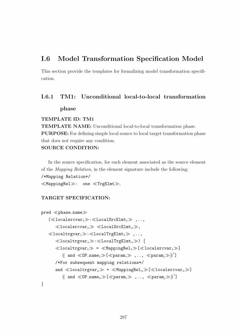
I.6 Model Transformation Specification Model
This section provide the templates for formalizing model transformation specifi-
cation.
I.6.1 TM1: Unconditional local-to-local transformation
phase
TEMPLATE ID: TM1
TEMPLATE NAME: Unconditional local-to-local transformation phase.
PURPOSE: For defining simple local source to local target transformation phase
that does not require any condition.
SOURCE CONDITION:
In the source specification, for each element associated as the source element
of the Mapping Relation, in the element signature include the following:
/*Mapping Relation*/
�MappingRel�: one �TrgElmt�,
TARGET SPECIFICATION:
pred �phase name�(�localsrcvar1�:�LocalSrcElmt1� ,..,
�localsrcvarn� �LocalSrcElmtn�,
�localtrgvar1�:�LocalTrgElmt1� ,..,
�localtrgvarn�:�LocalTrgElmtn�) {�localtrgvar1� = �MappingRel1�[�localsrcvar1�]
(( and �OP name1�[�parami� ,.., �paramj�))?]
/*For subsequent mapping relations*/
and �localtrgvarn� = �MappingReln�[�localsrcvarn�]
(( and �OP namen�[�parami� ,.., �paramj�))?]
}
287
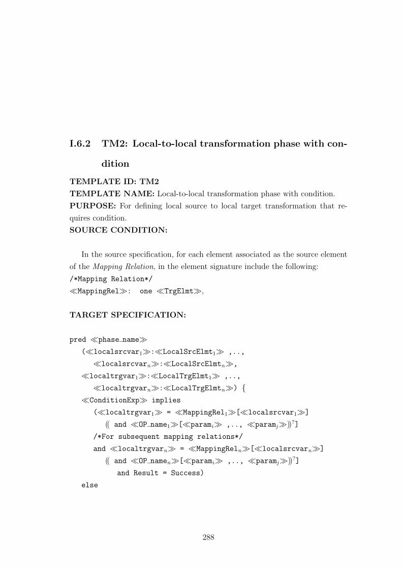
I.6.2 TM2: Local-to-local transformation phase with con-
dition
TEMPLATE ID: TM2
TEMPLATE NAME: Local-to-local transformation phase with condition.
PURPOSE: For defining local source to local target transformation that re-
quires condition.
SOURCE CONDITION:
In the source specification, for each element associated as the source element
of the Mapping Relation, in the element signature include the following:
/*Mapping Relation*/
�MappingRel�: one �TrgElmt�,
TARGET SPECIFICATION:
pred �phase name�(�localsrcvar1�:�LocalSrcElmt1� ,..,
�localsrcvarn�:�LocalSrcElmtn�,
�localtrgvar1�:�LocalTrgElmt1� ,..,
�localtrgvarn�:�LocalTrgElmtn�) {�ConditionExp� implies
(�localtrgvar1� = �MappingRel1�[�localsrcvar1�]
(( and �OP name1�[�parami� ,.., �paramj�))?]
/*For subsequent mapping relations*/
and �localtrgvarn� = �MappingReln�[�localsrcvarn�]
(( and �OP namen�[�parami� ,.., �paramj�))?]
and Result = Success)
else
288
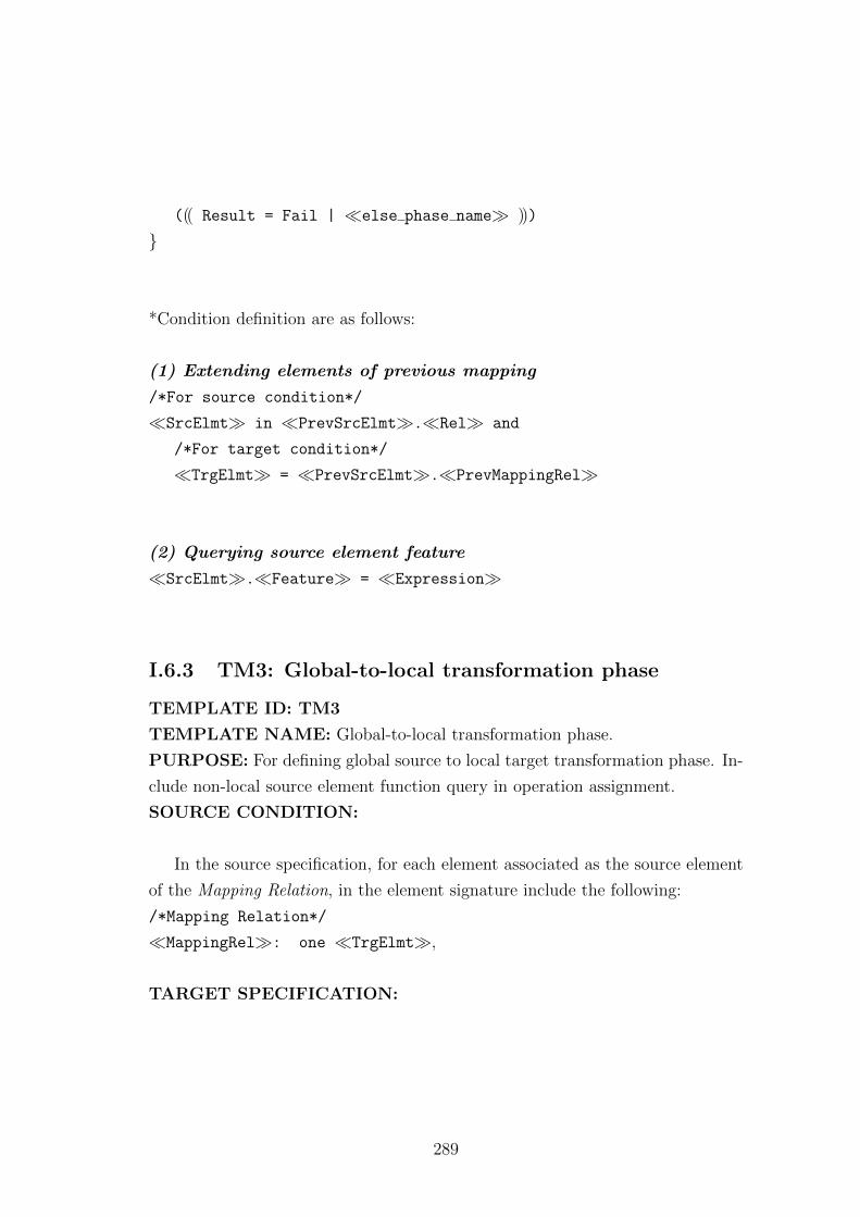
((( Result = Fail | �else phase name� )))
}
*Condition definition are as follows:
(1) Extending elements of previous mapping
/*For source condition*/
�SrcElmt� in �PrevSrcElmt�.�Rel� and
/*For target condition*/
�TrgElmt� = �PrevSrcElmt�.�PrevMappingRel�
(2) Querying source element feature
�SrcElmt�.�Feature� = �Expression�
I.6.3 TM3: Global-to-local transformation phase
TEMPLATE ID: TM3
TEMPLATE NAME: Global-to-local transformation phase.
PURPOSE: For defining global source to local target transformation phase. In-
clude non-local source element function query in operation assignment.
SOURCE CONDITION:
In the source specification, for each element associated as the source element
of the Mapping Relation, in the element signature include the following:
/*Mapping Relation*/
�MappingRel�: one �TrgElmt�,
TARGET SPECIFICATION:
289
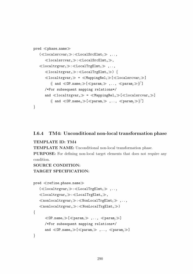
pred �phase name�(�localsrcvar1�:�LocalSrcElmt1� ,..,
�localsrcvarn�:�LocalSrcElmtn�,
�localtrgvar1�:�LocalTrgElmt1� ,..,
�localtrgvarn�:�LocalTrgElmtn�) {�localtrgvar1� = �MappingRel1�[�localsrcvar1�]
(( and �OP name1�[�parami� ,.., �paramj�))?]
/*For subsequent mapping relations*/
and �localtrgvarn� = �MappingReln�[�localsrcvarn�]
(( and �OP namen�[�parami� ,.., �paramj�))?]
}
I.6.4 TM4: Unconditional non-local transformation phase
TEMPLATE ID: TM4
TEMPLATE NAME: Unconditional non-local transformation phase.
PURPOSE: For defining non-local target elements that does not require any
condition.
SOURCE CONDITION:
TARGET SPECIFICATION:
pred �refine phase name�(�localtrgvar1�:�LocalTrgElmt1� ,..,
�localtrgvarn�:�LocalTrgElmtn�,
�nonlocaltrgvar1�:�NonLocalTrgElmt1� ,..,
�nonlocaltrgvarn�:�NonLocalTrgElmtn�)
{�OP name1�[�parami� ,.., �paramj�]
/*For subsequent mapping relations*/
and �OP namen�[�parami� ,.., �paramj�]
}
290
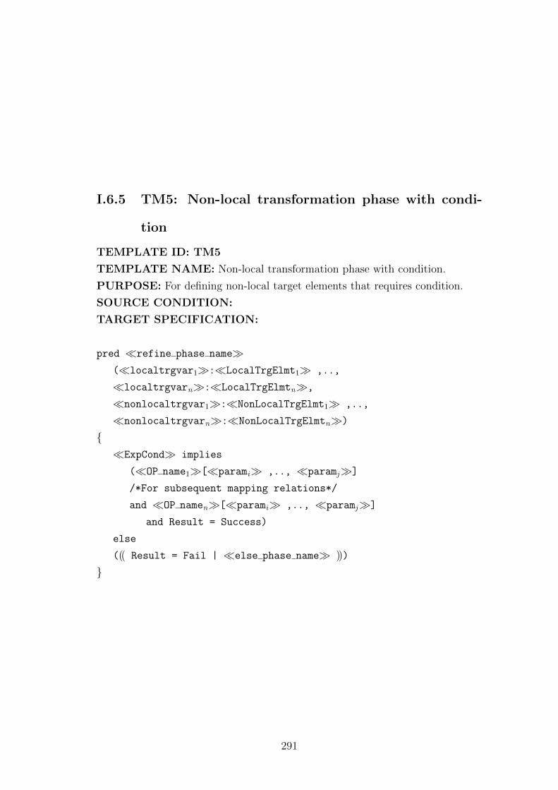
I.6.5 TM5: Non-local transformation phase with condi-
tion
TEMPLATE ID: TM5
TEMPLATE NAME: Non-local transformation phase with condition.
PURPOSE: For defining non-local target elements that requires condition.
SOURCE CONDITION:
TARGET SPECIFICATION:
pred �refine phase name�(�localtrgvar1�:�LocalTrgElmt1� ,..,
�localtrgvarn�:�LocalTrgElmtn�,
�nonlocaltrgvar1�:�NonLocalTrgElmt1� ,..,
�nonlocaltrgvarn�:�NonLocalTrgElmtn�)
{�ExpCond� implies
(�OP name1�[�parami� ,.., �paramj�]
/*For subsequent mapping relations*/
and �OP namen�[�parami� ,.., �paramj�]
and Result = Success)
else
((( Result = Fail | �else phase name� )))
}
291
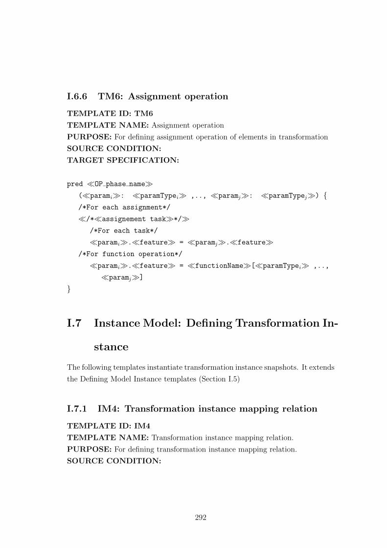
I.6.6 TM6: Assignment operation
TEMPLATE ID: TM6
TEMPLATE NAME: Assignment operation
PURPOSE: For defining assignment operation of elements in transformation
SOURCE CONDITION:
TARGET SPECIFICATION:
pred �OP phase name�(�parami�: �paramTypei� ,.., �paramj�: �paramTypej�) {/*For each assignment*/
�/*�assignement task�*/�/*For each task*/
�parami�.�feature� = �paramj�.�feature�/*For function operation*/
�parami�.�feature� = �functionName�[�paramTypei� ,..,
�paramj�]
}
I.7 Instance Model: Defining Transformation In-
stance
The following templates instantiate transformation instance snapshots. It extends
the Defining Model Instance templates (Section I.5)
I.7.1 IM4: Transformation instance mapping relation
TEMPLATE ID: IM4
TEMPLATE NAME: Transformation instance mapping relation.
PURPOSE: For defining transformation instance mapping relation.
SOURCE CONDITION:
292

TARGET SPECIFICATION:
fact Transform{/*For each participating phase. Provide phase parameters*/
�phase name�[�ElmtInsName1� ,.., �ElmtInsNamen�]
}
293
References
[ABE+06] David Akehurst, Behzad Bordbar, Michael Evans, Gareth Howells,
and Klaus McDonald-Maier. SiTra: Simple Transformations in Java.
In Model Driven Engineering Languages and Systems, volume 4199
of LNCS, pages 351–364. Springer, 2006.
[ABGR10] Kyriakos Anastasakis, Behzad Bordbar, Geri Georg, and Indrakshi
Ray. On challenges of model transformation from UML to Alloy.
Software and Systems Modeling, 9:69–86, 2010.
[ABK07] Kyriakos Anastasakis, Behzad Bordbar, and Jochen M. Kuster.
Analysis of Model Transformations via Alloy. In Models in Soft-
ware Engineering, LNCS. Springer, 2007.
[Abr96] J.-R. Abrial. The B-book: Assigning Programs to Meanings. Cam-
bridge University Press, 1996.
[Ack62] Russell L. Ackoff. Scientific Method: Optimizing Applied Research
Decision. Wiley, 1962.
[AK03] Colin Atkinson and Thomas Kuhne. Model-Driven Development: A
Metamodeling Foundation. IEEE Software, 20(5):36–41, 2003.
[AKP03] David H. Akehurst, Stuart Kent, and Octavian Patrascoiu. A rela-
tional approach to defining and implementing transformations be-
tween metamodels. Software and System Modeling, 2(4):215–239,
2003.
294
[ALS+12] Moussa Amrani, Levi Lucio, Gehan Selim, Benoıt Combemale,
Jurgen Dingel, Hans Vangheluwe, Yves Le Traon, and James R.
Cordy. A Tridimensional Approach for Studying the Formal Verifi-
cation of Model Transformations. In Software Testing, Verification
and Validation, pages 921–928. IEEE, 2012.
[Am7] Nuno Amalio. Generative frameworks for rigorous model-driven de-
velopment. PhD thesis, University of York, United Kingdom, 2007.
[APS05] Nuno Amalio, Fiona Polack, and Susan Stepney. Frameworks Based
on Templates for Rigorous Model-driven Development. Integrated
Formal Methods Conference, 191:3–23, 2005.
[AT05] Sharon Allen and Evan Terry. Beginning Relational Data Modelling.
Springer, 2nd edition, 2005.
[Bal98] Osman Balci. Verification, Validation, and Accreditation. In Winter
Simulation Conference, pages 41–48, Los Alamitos, CA, USA, 1998.
IEEE.
[Bar10] Fernando Valles Barajas. A Precise Specification For The Modelling
Of Collaborations. Malaysian Journal of Computer Science, 23:18–
36, 2010.
[BBG05] Sami Beydeda, Matthias Book, and Volker Gruhn, editors. Model
Driven Software Development. Springer, 2005.
[BBJ07] Jean Bezivin, Mikael Barbero, and Frederic Jouault. On the Ap-
plicability Scope of Model Driven Engineering. In Model-Based
Methodologies for Pervasive and Embedded Software, pages 3–7.
IEEE, 2007.
[BC06] Andrea Baruzzo and Marco Comini. Static Verification of UML
Model Consistency. In 3rd Workshop Model Design and Validation,
pages 111–126, 2006.
295
[BCR06] Artur Boronat, Jose A Carsı, and Isidro Ramos. Algebraic Specifica-
tion of a Model Transformation Engine. In Fundamental Approaches
to Software Engineering, volume 3922, pages 262–277. Springer,
2006.
[BDTM+06] Benoit Baudry, Trung Dinh-Trong, Jean-Marie Mottu, Devon Sim-
monds, Robert France, Sudipto Ghosh, Franck Fleurey, and Yves Le
Traon. Model Transformation Testing challenges. In ECMDA work-
shop on Integration of Model Driven Development and Model Driven
Testing, 2006.
[Bet03] Jorn Bettin. Ideas for a Concrete Visual Syntax for Model-to-Model
Transformations. In Workshop on Generative Techniques in the con-
text of Model Driven Architecture, number 18 in Object-Oriented
Programming, Systems, Languages and Application, 2003.
[BFS+06] Erwan Brottier, Franck Fleurey, Jim Steel, Benoit Baudry, and
Yves Le Traon. Metamodel-based Test Generation for Model Trans-
formations: an Algorithm and a Tool. In Software Reliability Engi-
neering, pages 85–94. IEEE, 2006.
[BH95] Jonathan P. Bowen and Michael G. Hinchey. Seven More Myths of
Formal Methods. IEEE Software, 12(4):34–41, 1995.
[Bie10] Matthias Biehl. Literature Study on Model Transformations. Tech-
nical report, Royal Institute of Technology Stockholm, Sweden,
2010.
[BM03] Peter Braun and Frank Marschall. BOTL The Bidirectional Object
Oriented Transformation Language. Technical report, Institut fur
Informatik Technische Universitat Munchen, 2003.
[BM07] Thomas Baar and Slavisa Markovic. A graphical approach to prove
the semantic preservation of UML/OCL refactoring rules. In Andrei
Ershov memorial conference on Perspectives of systems informatics.
Springer, 2007.
296
[BN04] Boumediene Belkhouche and Anastasia Nix. Formal Analysis of
UML-Based Designs. In Software Engineering Research and Prac-
tice, 2004.
[BNvK06] Daniel Balasubramanian, Anantha Narayanan, Chris vanBuskirk,
and Gabor Karsai. The Graph Rewriting and Transformation Lan-
guage: GReAT. In Graph Transformations, volume 4178. Springer,
2006.
[BS06] Luciano Baresi and Paola Spoletini. On the Use of Alloy to Analyze
Graph Transformation Systems. In Graph Transformations, volume
4178, pages 306–320. Springer, 2006.
[CCGdL09] Jordi Cabot, Robert Clariso, Esther Guerra, and Juan de Lara.
Verification and Validation of Declarative Model-to-Model Transfor-
mations through Invariants. The Journal of Systems and Software,
2009.
[CCGT06] Dolors Costal, Ruth Raventos Cristina Gomez, Anna Queralt, and
Ernest Teniente. Facilitating the Definition of General Constraints
in UML. In Model Driven Engineering Languages and Systems,
volume 4199, pages 260–274. Springer, 2006.
[CH06] Krzysztof Czarnecki and Simon Helsen. Feature-based Survey of
Model Transformation Approaches. IBM System Journal, 45(3),
2006.
[CHM+02] Gyorgy Csertan, Gabor Huszerl, Istvan Majzik, Zsigmond Pap,
Andras Pataricza, and Daniel Varro. VIATRA - Visual Automated
Transformations for Formal Verification and Validation of UML
Models. In Automated Software Engineering, pages 267 – 270. IEEE,
2002.
[CK92] Michael Christel and Kyo C. Kang. Issues in Requirements Elici-
tation. Technical report, Software Engineering Institute, Carnegie
Mellon University, 1992.
297
[CM09] Jesus Sanchez Cuadrado and Jesus Garcıa Molina. Modularization
of model transformations through a phasing mechanism. Software
and Systems Modeling, 8(3):325–345, 2009.
[CRC+06] Benoit Combemale, Sylvain Rougemaille, Xavier Cregut, Frederic
Migeon, Marc Pantel, Christine Maurel, and Bernard Coulette. To-
wards Rigorous Metamodeling. In ICEIS workshop on MDEIS, 2006.
[CS05] Sara Hawker Catherine Soanes, editor. Compact Oxford Dictionary
definition on Model. Oxford University Press, 3 edition, 2005.
[CY91] Peter Coad and Edward Yourdon. Objet-Oriented Analysis. Prentice
Hall, 2 edition, 1991.
[Dav02] James R. Davis. Model Integrated Computing: A Framework for
Creating Domain Specific Design Environments. In World Multi-
conference on Systems, Cybernetics, and Informatics, 2002.
[DD93] Antoni Diller and Rosemary Docherty. A Comparison of Z and
Abstract Machine Notation. Technical report, University of Birm-
ingham, School of Computer Science, 1993.
[DKST05] David P. Darcy, Chris F. Kemerer, Sandra A. Slaughter, and
James E. Tomayko. The Structural Complexity of Software: An
Experimental Test. Sotware Engineering, 31(11):982–995, 2005.
[dLT04] Juan de Lara and Gabriele Taentzer. Automated Model Transfor-
mation and Its Validation Using AToM 3 and AGG. Diagrammatic
Representation and Inference, pages 182–198, 2004.
[EE08] Hartmut Ehrig and Claudia Ermel. Semantical Correctness and
Completeness of Model Transformations Using Graph and Rule
Transformation. In Graph Transformations, pages 194 – 210.
Springer, 2008.
298
[EKHG01] Gregor Engels, Jochem M. Kuster, Reiko Heckel, and Luuk Groe-
newegen. A methodology for specifying and analyzing consistency
of object-oriented behavioral models. SIGSOFT Softw. Eng. Notes,
26(5):186–195, 2001.
[FH09] Roman Frigg and Stephan Hartmann. Models in Sci-
ence. http://plato.stanford.edu/archives/sum2009/entries/models-
science/, 2009.
[Fow04] Martin Fowler. UML Distilled: A Brief Guide to the Standard Object
Modelling Language. Addison Wesley, 3rd edition, 2004.
[FPB87] Jr. Frederick P. Brooks. No Silver Bullet: Essence and Accidents of
Software Engineering. Computer Magazine, 20(4):10–19, 1987.
[FR07] Robert France and Bernhard Rumpe. Model-driven Development
of Complex Software: A Research Roadmap. In Future of Software
Engineering, pages 37–54. IEEE, 2007.
[GdLK+10] Esther Guerra, Juan de Lara, Dimitrios S. Kolovos, Richard F.
Paige, and Osmar Marchi dos Santos. transML: A Family of Lan-
guages to Model Model Transformations. In Model Driven Engineer-
ing Languages and Systems, volume 6394 of LNCS, pages 106–120.
Springer, 2010.
[GdLK+12] Esther Guerra, Juan de Lara, Dimitrios S. Kolovos, Richard F.
Paige, and Osmar Marchi dos Santos. Engineering model trans-
formations with transML . Software and Systems Modeling, 11,
2012.
[GdLKP10] Esther Guerra, Juan de Lara, Dimitrios S. Kolovos, and Richard F.
Paige. A Visual Specification Language for Model-to-Model Trans-
formations. In Visual Languages and Human-Centric Computing.
IEEE, 2010.
299
[GdLW+12] Esther Guerra, Juan de Lara, Manuel Wimmer, Gerti Kappel,
Angelika Kusel, Werner Retschitzegger, Johannes Schonbock, and
Wieland Schwinger. Automated verification of model transforma-
tions based on visual contracts. Automated Software Engineering,
2012.
[GGKH05] Tracy Gardner, Catherine Griffin, Jana Koehler, and Rainer Hauser.
A review of OMG MOF 2.0 Query / Views / Transformations Sub-
missions and Recommendations towards the final Standard. In In-
formation Systems Development: Advances in Theory, Practice, and
Education, 2005.
[GL03] Martin Gogolla and Arne Lindow. Transforming Data Models with
UML. In Borys Omelayenko and Michel Klein, editors, Knowl-
edge Transformation for the Semantic Web, pages 18–33. IOS Press,
2003.
[GP04] Nicolas Guelfi and Gilles Perrouin. Using Model Transformation
and Architectural Frameworks to Support the Software Develop-
ment Process: the FIDJI Approach. In Midwest Software Engineer-
ing Conference, 2004.
[GPHS08] Cesar Gonzales-Perez and Brian Henderson-Sellers. Metamodeling
for Software Engineering. John Wiley & Sons Inc., 2008.
[GPR03] Nicolas Guelfi, Gilles Perrouin, and Benoıt Ries. Improving Archi-
tectural Framework-based Development Using Model Transforma-
tion: The FIDJI Approach. Technical report, Faculty of Science,
Technology and Communication, University of Luxemberg, 2003.
[GR98] Martin Gogolla and Mark Richters. Equivalence Rules for UML
Class Diagrams. In UML: Beyond Notation. Springer, 1998.
[GSC+04] Jack Greenfield, Keith Short, Steve Cook, Stuart Kent, and
John Crupi (Aut. Software Factories: Assembling Applications with
Patterns, Models, Frameworks, and Tools. John Wiley & Sons Inc.,
2004.
300
[GU11] Thomas Goldschmidt and Axel Uhl. A Formal Framework for Re-
tainment Patterns for Trace-Based Model Transformations. In Soft-
ware Engineering and Advanced Applications, pages 91 – 99. IEEE,
2011.
[GV11] Martin Gogolla and Antonio Vallecillo. Tractable Model Transfor-
mation Testing. In Modelling Foundations and Applications, volume
6698, pages 221–235. Springer, 2011.
[Hal90] Anthony Hall. Seven Myths of Formal Methods. IEEE Software,
7(5):11–19, 1990.
[Hei98] Constance Heitmeyer. On the Need for Practical Formal Methods.
In Formal Techniques in RealTime and Real-Time Fault-Tolerant
Systems, pages 18–26. Springer, 1998.
[HKR+10] Mathias Huksbusch, Barbara Konig, Arend Rensink, Maria Se-
menyak, Christian Soltenborn, and Heike Wehrheim. Showing Full
Semantics Preservation in Model Transformation - A Comparison
of Techniques. In Integrated Formal Methods. Springer, 2010.
[IBN+09] Christopher Ireland, David Bowers, Michael Newton, , and Kevin
Waugh. A Classification of Object-Relational Impedance Mismatch.
In Advances in Databases, Knowledge, and Data Applications, pages
36 – 43. IEEE, 2009.
[ISH08] Maria-Eugenia Iacob, Maarten W. A. Steen, and Lex Heerink.
Reusable Model Transformation Patterns. In Enterprise Distributed
Object Computing Conference Workshops, pages 1–10. IEEE, 2008.
[JABK08] Frederic Jouault, Freddy Allilaire, Jean Bezivin, and Ivan Kurtev.
ATL: A model transformation tool. Science of Computer Program-
ming, 72(1-2):31–39, June 2008. Special Issue on Second issue of
experimental software and toolkits (EST).
[Jac95] Micheal Jackson. Requirements and Specifications: A Lexicon of
Software Practice, Principles and Prejudices. ACM, 1995.
301
[Jac02] Daniel Jackson. Alloy: A Lightweight Object Modelling Nota-
tion. ACM Transactions on Software Engineering and Methodology,
11(2):256–290, 2002.
[Jac06] Daniel Jackson. Software Abstraction: Logic, Language, and Anal-
ysis. MIT Press, 2006.
[Jac12] Daniel Jackson. Software Abstractions: Logic, Language and Anal-
ysis (Revised edition). MIT Press, 2012.
[JK07] Frederic Jouault and Ivan Kurtev. On the interoperability of model-
to-model transformation languages. Science of Computer Program-
ming, 68(3):114–137, 2007. Special Issue on Model Transformation.
[JS00] Daniel Jackson and Kevin Sullivan. COM Revisited: Tool-Assisted
Modelling of an Architectural Framework. In ACM SIGSOFT In-
ternational Symposium on Foundations of Software Engineering:
Twenty-first Century Applications, volume 25, pages 149–158. ACM,
2000.
[KAER07] Jochen M. Kuster and Mohamed Abd-El-Razik. Validation of Model
Transformations: First Experiences Using a White Box Approach.
In Models in Software Engineering, volume 4364 of LNCS, pages
193–204. Springer, 2007.
[KCS05] Audris Kalnins, Edgars Celms, and Agris Sostaks. Model Transfor-
mation Approach Based on MOLA. In Conference on Model Driven
Engineering Languages and Systems, LNCS. Springer, 2005.
[KFdB+05] Marcel Kyas, Harald Fecher, Frank S. de Boer, Joost Jacob, Jozef
Hooman, Mark van der Zwaag, Tamarah Arons, and Hillel Kugler.
Formalizing UML Models and OCL Constraints in PVS. Electronic
Notes in Theoretical Computer Science, 115:39–47, 2005.
[KG06] Ivan Kurtev and Atlas Group. Rule-based modularization in model
transformation languages illustrated with ATL. In Annual ACM
Symposium on Applied Computing, pages 1202–1209. ACM, 2006.
302
[Kle06] Anneke Kleppe. MCC: A Model Transformation Environment. In
Model Driven Architecture? Foundations and Applications: Second
European Conference, pages 173–187. Springer, 2006.
[KRH05] Jochen M. Kuster, Ksenia Ryndina, and Rainer Hauser. A Sys-
tematic Approach to Designing Model Transformations. Technical
report, IBM Research, 2005.
[Kuh05] Thomas Kuhne. What is a Model? In Jean Bezivin and Reiko
Heckel, editors, Language Engineering for Model-Driven Software
Development, number 04101 in Dagstuhl Seminar Proceedings,
Dagstuhl, Germany, 2005. Internationales Begegnungs.
[Kus04] Jochen M. Kuster. Systematic Validation of Model Transforma-
tions. In Essentials of the 3rd UML Workshop in Software Model
Engineering, 2004.
[Kus06] Jochen M. Kuster. Definition and Validation of Model Transfor-
mations. Software and Systems Modeling, 5(3):233–259, September
2006.
[KWB03] Anneke Kleppe, Jos Warmer, and W. Bast. MDA Explained:The
Model Driven Architecture-Practice and Promise. Addison-Wesley,
2003.
[Lam07] Maher Lamari. Towards an Automated Test Generation for the Ver-
ification of Model Transformations. In ACM symposium on Applied
computing, pages 998 – 1005. ACM, 2007.
[Lau02] Soren Lauesen. Software Requirements: Styles and Techniques. Ad-
dison Wesley, 2002.
[LCA04] K. Lano, D. Clark, and K. Androutsopoulos. UML to B: Formal
Verification of Object-Oriented Models. In Integrated Formal Meth-
ods, volume 2999, pages 187–206. Springer, 2004.
303
[LLM+07] Lazlo Lengyel, Tihamer Levendovszky, Gergely Mezei, Tamas Vajk,
and Hassan Charaf. Practical Uses of Validated Model Transforma-
tion. In The International Conference on ”Computer as a Tool”,
pages 2200–2207. IEEE, 2007.
[LMB+01] Akos Ledeczi, Miklos Maroti, Arpad Bakay, Gabor Karsai, Jason
Garrett, Charles Thomason, Greg Nordstrom, Jonathan Sprinkle,
and Peter Volgyesi. The Generic Modeling Environment. In Work-
shop on Intelligent Signal Processing, 2001.
[LP08] Regine Laleau and Fiona Polack. Using Formal Metamodels to
Check Consistency of Functional Views in Information Systems
Specification. Information and Software Technology, 50(7-8):797814,
2008.
[LS06] Michael Lawley and Jim Steel. Practical Declarative Model Trans-
formation With Tefkat. In International Conference on Model
Driven Engineering Languages and Systems, volume 3844 of LNCS.
Springer, 2006.
[Lud03] Jochen Ludewig. Models in Software Engineering: An Introduction.
Software and Systems Modeling, 2(1):5–14, 2003.
[MB02] Stephen J. Mellor and Marc J. Balcer. Executable UML: A Foun-
dation For Model-Driven Architecture. Addison-Wesley, 2002.
[MB03] Frank Marschall and Peter Braun. Model Transformations for the
MDA with BOTL. Technical report, University of Twente, 2003.
[MBT06] Jean-Marie Mottu, Benoit Baudry, and Yves Le Traon. Reusable
MDA Components: A Testing-for-Trust Approach. In Model Driven
Engineering Languages and Systems, volume 4199/2006 of LNCS,
pages 589–603. Springer, 2006.
[MDA03] MDA Guide Version 1.0.1, June 2003.
304
[Mey92] Bertrand Meyer. Applying Design by Contract. IEEE Computer,
25(10):40–51, 1992.
[MG06] Tom Mens and Pieter Van Gorp. A Taxonomy of Model Trans-
formation. In International Workshop on Graph and Model Trans-
formation, volume 152 of Electronic Notes in Theoretical Computer
Science, pages 125–142. Elsevier, 2006.
[Mil02] Dragan Milicev. Domain mapping using extended UML object dia-
grams . IEEE Software, 19(2):90–97, 2002.
[MOF06] Meta Object Facility (MOF) Core Specification, 2006.
[MOF11] MOF Core specification, 2011.
[MP93] Mike McMorran and Steve Powell. Z Guide for Beginners. Blackwell
Scientific Publications, 1993.
[Mur89] Tadao Murata. Petri nets: Properties, analysis and applications.
Proceedings of the IEEE, 77(4):541 – 580, 1989.
[PG08] Claudia Pons and Diego Garciaa. A Lightweight Approach for the
Semantic Validation of Model Refinements. In Workshop on Model
Based Testing, volume 220 of Electronic Notes in Theoretical Com-
puter Science, pages 43–61. Elsevier, 2008.
[Poe08] Iman Poernomo. Proofs-as-Model-Transformations. In Theory and
Practice of Model Transformations, volume 5063 of LNCS, pages
214–228. Springer, 2008.
[QVT08] Meta Object Facility (MOF) 2.0 Query/View/Transformation Spec-
ification, 2008.
[RBR03] David Roe, Krysia Broda, and Alessandra Russo. Mapping uml
models incorporating ocl constraints into object-z. Technical report,
Department of Computing, Imperial College London, 2003.
305
[RM08] Lukman Ab. Rahim and Sharifah Bahiyah Rahayu Syed Mansoor.
Proposed Design Notation for Model Transformation. In 19th Aus-
tralian Conference on Software Engineering, pages 589 – 598. IEEE,
2008.
[RRgLr+09] J. E. Rivera, D. Ruiz-gonzalez, F. Lopez-romero, J. Bautista, and
A. Vallecillo. Orchestrating ATL Model Transformations. In In-
ternational Workshop on Model Transformation with ATL, pages
34–46, 2009.
[RW03] Holger Rasch and Heike Wehrheim. Checking Consistency in UML
Diagrams: Classes and State Machines. In Formal Methods for
Open Object-Based Distributed Systems, volume 2884, pages 229–
243. Springer, 2003.
[SB01] Colin Snook and Michael Butler. Using a Graphical Design Tool for
Formal Specification. In Workshop of the Psychology of Program-
ming Interest Group, pages 311–321, 2001.
[SCD12] Gehan Selim, James R. Cordy, and Juergen Dingel. Analysis of
Model Transformations. Technical report, School of Computing,
Queens University, 2012.
[sDz09] Dragan Gasevic, Dragan Djuric, and Vladan Devedzic. Model
Driven Engineering and Ontology Development, volume IVI, chapter
Mappings of MDA-Based Languages and Ontologies, pages 245–261.
Springer, 2009.
[SK97] Janos Sztipanovits and Gabor Karsai. Model-Integrated Comput-
ing. IEEE Computer, 30(4):110–111, 1997.
[SK03] Shane Sendall and Wojtek Kozaczynski. Model Transformation:
The Heart and Soul of Model-Driven Software Development. IEEE
Software, 20(5):42–45, 2003.
306
[SLSS08] Mika Siikarla, Markku Laitkorpi, Petri Selonen, and Tarja Systa.
Transformations Have to be Developed ReST Assured. In Theory
and Practice of Model Transformations, pages 1–15. Springer, 2008.
[Smi00] Graeme Smith. The Object-Z Specification Language. Kluwer Aca-
demic, 2000.
[Som07] Ian Sommerville. Software Engineering. Addison Wesley, 8 edition,
2007.
[Spa11] Sparx Systems-Enterprise Architect. From Conceptual Model to
DBMS, 2011.
[SPGB03] Shane Sendall, Gilles Perrouin, Nicolas Guelfi, and Olivier Biber-
stein. Supporting Model-to-Model Transformations: The VMT Ap-
proach. Technical report, Workshop on Model Driven Architecture:
Foundations and Applications, 2003.
[Spi92] Michael Spivey. The Z Notation: A Reference Manual. Prentice
Hall, 1992.
[SPP11] Asmiza Abdul Sani, Fiona A. C. Polack, and Richard F. Paige.
Model Transformation Specification for Automated Formal Verifica-
tion. In The 5th Malaysian Software Engineering Conference. IEEE,
2011.
[SR04] Wilhelmina C. Savenye and Rhonda S. Robinson. Qualitative Re-
search Issues and Methods: an Introduction for Educational Tech-
nologists, chapter 39, pages 1045–1072. Handbook of Research on
Educational Communications and Technology. Lawrence Erlbaum,
2004.
[SS03] Devang Shah and Sandra Slaughter. UML and the Unified Pro-
cess, chapter Chapter 10: Transforming UML Class Diagrams into
Relational Data Models, pages 217–236. IRM Press, 2003.
307
[SW04] Graeme Simsion and Graham Witt. Data Modeling Essentials. Mor-
gan Kaufmann Publishers Inc, 3rd edition, 2004.
[SW05] Graeme Simsion and Graham Witt, editors. Data Modelling Essen-
tial. Elsevier, 2005.
[SyF05] Anthony J. H. Simons and Carlos Alberto Fernandez y Fernandez.
Using Alloy to Model-Check Visual Design Notations. In Mexi-
can International Conference on Computer Science, pages 121–128.
IEEE, 2005.
[Sys] OMG Systems Modeling Language (OMG SysML) 1.3.
http://www.omg.org/spec/SysML/1.3/.
[TLNJ11] Toby Teorey, Sam Lightstone, Tom Nadeau, and H. V. Jagadish.
Database Modeling and Design: Logical Design. Elsevier, 2011.
[UML09] OMG Unified Modeling Language (OMG UML), Infrastructure Ver-
sion 2.2, 2009.
[VP03] Daniel Varro and Andras Pataricza. Automated Formal Verifica-
tion of Model Tranformations. In Workshop on Critical Systems
Development in UML, 2003.
[WD96] Jim Woodcock and Jim Davies. Using Z Specification, Refinement,
and Proof. Prentice Hall, 1996.
[Wil03] Edward D. Willink. UMLX - A Graphical Transformation Language
for MDA. In Workshop on Generative Techniques in the context of
Model Driven Architecture, 2003.
[Wil09] James Robert Williams. AUtoZ: Automatic Formalisation of UML
to Z. Master’s thesis, University Of York, United Kingdom, 2009.
[Wir08] Niklaus Wirth. A Brief History of Software Engineering. IEEE
Annals of the History of Computing, 30(3):32–39, 2008.
308
[WK03] Jos Warmer and Anneke Kleppe. The Object Constraint Language:
Getting Your Models Ready for MDA. Addison Wesley, 2 edition,
2003.
[WKC06] Junhua Wang, Soon-Kyeong Kim, and David Carrington. Verify-
ing Metamodel Coverage of Model Transformations. In Australian
Software Engineering Conference, pages 10–19. IEEE, 2006.
[WKK+09] Manuel Wimmer, Gerti Kappel, Angelika Kusel, Werner Rets-
chitzegger, Johannes Schoenboeck, and Wieland Schwinger. Right
or Wrong?: Verification of Model Transformations using Colored
Petri Nets. In Workshop on Domain-Specific Modeling, 2009.
[WKK+12] Manuel Wimmer, Gerti Kappel, Angelika Kusel, Werner Rets-
chitzegger, Johannes Schonbock, and Wieland Schwinger. Fact
or Fiction - Reuse in Rule-Based Model-to-Model Transformation
Languages. In International Conference on Model Transformation,
pages 280–295. Springer, 2012.
[WS10] Nicolas Wu and Andrew Simpson. Towards Formally Templated Re-
lational Database Representations in Z. In Abstract State Machines,
Alloy, B and Z, volume 5977, pages 363–376. Springer, 2010.
[WV03] Jonne Van Wijngaarden and Eelco Visser. Program Transformation
Mechanics: A classification of Mechanisms for Program Transforma-
tion with a Survey of Existing Transformation Systems. Technical
report, Institute of Information and Computing Sciences Utrecht
University, 2003.
[ZR88] Liping Zhao and S.A. Roberts. An Object-Oriented Data Model for
Database Modelling, Implementation and Access. The Computer
Journal, 31(2):116–124., 1988.
309
Recommended