
Mechatronics 22 (2012) 327–337
Contents lists available at SciVerse ScienceDirect
Mechatronics
journal homepage: www.elsevier .com/ locate/mechatronics
Model-based feedback controller design for dual actuated atomic force microscopy
S. Kuiper a, G. Schitter a,b,⇑a Delft Center for Systems and Control, Precision and Microsystems Engineering, Delft University of Technology, Mekelweg 2, 2628CD Delft, The Netherlandsb Automation and Control Institute, Vienna University of Technology, Gusshausstrasse 27-29, 1040 Vienna, Austria
a r t i c l e i n f o a b s t r a c t
Article history:Available online 12 October 2011
Keywords:Atomic force microscopyModel-based controlPiezoelectric actuatorDual actuationAnti-windup control
0957-4158/$ - see front matter � 2011 Elsevier Ltd. Adoi:10.1016/j.mechatronics.2011.08.003
⇑ Corresponding author at: Automation and Controof Technology, Gusshausstrasse 27–29, 1040 Vienna,
E-mail addresses: [email protected] (S. Kuipe(G. Schitter).
In atomic force microscopy (AFM) the imaging speed is strongly limited by the bandwidth of the feedbackloop that controls the interaction force between the measurement tip and the sample. A significantincrease in closed-loop bandwidth without sacrificing positioning range can be achieved by combininga long-range, low-bandwidth actuator with a short-range, high-bandwidth actuator, forming a dual actu-ated system. This contribution discusses the design of a model-based feedback controller that controlsthe tip-sample force in dual actuated AFM. Special emphasis is given on guaranteeing robust stabilityof the feedback loop under influence of variations in the dynamical behavior of the system, and to preventstrong destructive interference between both actuators. To prevent instability of the feedback loop due tosaturation of the short-range actuator, an anti-windup controller is presented that robustly stabilizes thesystem under all imaging conditions. The designed feedback controller is implemented on a prototypedual actuated AFM system, and demonstrates a disturbance rejection bandwidth of 20 kHz, which isabout 20 times faster than the model-based controlled single actuated system. AFM images are obtainedverifying a significant reduction of force variations between the tip and the sample while imaging. Thefaster control of the tip-sample force reduces the residual tracking error and, thus, reduces the chanceof damage or wear of the tip and the sample, and allows for faster imaging.
� 2011 Elsevier Ltd. All rights reserved.
1. Introduction several minutes per frame for most commercially available AFM-
Atomic force microscopes (AFMs) are mechanical microscopes inwhich the sample is probed by a very sharp tip, while scanning thesample relative to the measurement tip in a raster scan pattern[1]. In AFM the measurement tip is mounted on the free end of a mi-cro-cantilever, which allows to measure the force between the tipand sample by detecting the micro-cantilever deflection via a opticalsensing system [2]. During imaging the force between the tip and thesample is controlled via a feedback loop in order to minimize thechances of damage or wear of the tip and the sample, and to convertthe force measurement into a measurement of the sample topogra-phy. To provide the scanning motion and the control of the tip-sam-ple force, most often a piezo-based positioning stage is used to allowpositioning of the sample relative to the measurement tip in all threespatial directions with nanometer precision.
Due to its capability of providing (sub-) nanometer resolutionimages in all kinds of environmental conditions, AFM has becomea very popular tool in the fields of nanotechnology, micro-biologyand material sciences. One of the main limitations of AFM,however, is its relatively low imaging speed, taking in the order of
ll rights reserved.
l Institute, Vienna UniversityAustria.r), [email protected]
systems, which results in a low through-put of these systems, andrestricts its application to the imaging of fairly static features [3].
In order to improve the imaging speed of AFM, a vast amount ofresearch is dedicated to improve both the speed of the lateral scan-ning motion, as well as faster control of the tip-sample force [4,5].Recently, various prototype AFM systems are reported in literatureallowing high speed lateral scanning via improved mechanicaldesigns of the scanning stage [6,7], as well as improved controlof the scanning motion [8–12]. Some laboratory prototype AFMsystems are reported with scanning speeds allowing to captureup to several frames per second [6,7,13,14]. The improved scanningspeed, however, is putting strong demands on the control of thetip-sample force during imaging, which is considered as the mainlimitation on high-speed AFM imaging nowadays [3].
In AFM the force between the tip and the sample can be mea-sured in both contact-mode, as well as in tapping mode [4]. Often,in high-speed imaging applications contact mode imaging is pre-ferred due to its faster, direct measurement of the tip-sample force,although recently significant improvements also have been madeon high speed tapping mode imaging [16–18]. For both imagingmodes high-bandwidth control of the tip-sample force is veryimportant in order to provide a good measurement of the sampletopography, and to prevent damage or wear of the tip and sample,particulary when imaging fragile biological specimen [3]. Recently,improved control of the tip-sample force by use of modern

Feedbackcontroller
Z
X
Cantilever
Piezoelectrictube scanner
Sample
Z
Piezoelectric plate actuator
Tip
Data X
Z deflection
Photo detectorLaser
328 S. Kuiper, G. Schitter / Mechatronics 22 (2012) 327–337
model-based control techniques has been investigated [19,20],showing a significant improvement in closed-loop bandwidth ascompared to the classical PI-controllers used in most commerciallyavailable AFM systems nowadays. Moreover, prototype systemsare reported in literature with improved actuator designs to allowfaster manipulation of the tip-sample separation, utilizing high-bandwidth piezo-based actuators [6,7,21,22], as well as MEMS-based actuators with integrated measurement probes [23,24].
Optimizing these type of actuators for high-bandwidth posi-tioning, however, often comes at the cost of a significant reductionin positioning range, limiting the application of these actuators tosamples with relatively small topographic features when used asthe sole means of controlling the tip-sample force. Meanwhile,most often in AFM imaging the largest topographic variations tobe tracked by the vertical feedback loop are relatively slow varying(e.g. due to the sample tilt), and can be easily tracked by a rela-tively low-bandwidth actuator. This aspect allows to combine along-range, low-bandwidth actuator with a short-range, high-bandwidth actuator in order to obtain a system with both a highcontrol bandwidth as well as a large effective positioning range.This technique is generally referred to as dual-actuation, and hasbeen thoroughly investigated for implementations on Hard DiskDrives (HDD) (e.g. [25,26]), and also found its way towards scan-ning probe microscopes [22,23,27–29], showing vast improve-ments on the control-bandwidths of the vertical feedback loopsas compared to single actuated system.
In the majority of the earlier published work on dual-actuatedAFM, the main focuss it put on the development of the short-range,high-bandwidth actuators, while the design of the feedback con-troller is done in a more heuristic manner. The contribution of thispaper is focussed on developing a systematic approach to the de-sign of a feedback controller for a given dual-actuated AFM, utiliz-ing modern model-based control techniques. The experimentalsetup used in this research is introduced in Section 2, and subse-quently the overall control problem and design procedure isoutlined. When designing such feedback controllers, a majorlimitation on the closed-loop bandwidth is often posed by the vari-ations in dynamical behavior of the actuators, which occurs whenchanging the measurement probe or sample, or by variations oftheir alignments with the scanner [30]. In Section 3 an identifica-tion procedure is proposed in order to identify the system’sdynamical behavior and its variations. This allows to analyze theachievable feedback bandwidth, as well as the robustness of thedesigned dual-actuated closed-loop system. The design of themodel-based feedback controller is discussed in Section 4, puttingspecial emphasis on how to prevent strong destructive interferencebetween both actuators, and on taking into account the robustnessof the controlled system. An important consideration in the designof a controller for these type of dual actuated systems is the limitedactuation range of the short-range actuator. As the short-rangeactuator might saturate when imaging large sample features, thiscan lead to instability of the closed-loop system. In Section 5 anapproach is discussed to analyze the stability of the feedback loopduring saturation of the short-range actuator, and an anti-windupcontroller is introduced that assures stability of the feedback loopunder all imaging conditions. The improved closed-loop band-width of the dual-actuated system is experimentally verified inSection 6, and demonstrated in an imaging application, enablinghigher imaging speeds.
Y
YX
aquisitionY
Fig. 1. Schematic representation of a dual actuated atomic force microscope.
2. Problem analysis and design strategy
A dual actuated AFM is a rather complex system, and detailedunderstanding of the system is required in order to design a wellperforming controller for it. In this section the experimental setup
is introduced, and subsequently the control problem and the de-sign strategy for the controller is outlined.
2.1. Experimental setup
The system used in this research is based on a commerciallyavailable AFM-system (Multimode V, Bruker, Santa Barbara, USA),and shown schematically in Fig. 1. The force between the tip andthe sample is measured by reflecting a laser beam off the freeend of the micro cantilever where the measurement tip is mountedat, and measuring the deflected laser spot with a segmentedphotodiode. A piezoelectric tube-scanner (J-Scanner, Bruker, SantaBarbara, USA), is utilized to provide the scanning motion of thesample during imaging, as well as the vertical positioning of thesample to control the tip-sample force. This piezoelectric tubescanner will be referred to as the ‘long-range actuator’, and isdriven by an external piezo amplifier (PZD700, Trek, Medina,USA) which combined provides a vertical positioning range of5 lm. This system is extended to a dual actuated system by usinga small piezoelectric plate actuator (CMAP12, Noliac, Kvistgaard,Denmark) which is glued onto the cantilever holder to form thenew mounting spot for the cantilever-chip (cf. Fig. 1), and allowsvertical positioning of the cantilever-chip. The plate-actuator isdriven by a piezo amplifier (A400, FLC-electronics, Partille,Sweden), of which the output voltage is restricted to 20 Vpp toprevent it from running into its current limitations while dynami-cally driving the 36 nF capacitive load of the piezoelectric plateactuator. This allows a maximum positioning range of about0.5 lm for the piezoelectric plate actuator, which will be referredto as the ’short-range actuator’. The resulting dual actuated AFMis a simple form of an overactuated system in which the tip-sampleforce can be controlled via the two actuators.
2.2. Controller design problem
To minimize the force variations between the measurement tipand the sample during imaging, a feedback controller should bedesigned which provides the highest possible control bandwidthgiven the two actuators. It should be noted that the pushing thecontrol bandwidth of the system as high as possible can havenegative influence on the accuracy of the topography measure-ment, as discussed in [31], and is therefore not always the bestchoice for AFM application where high priority is given to the

S. Kuiper, G. Schitter / Mechatronics 22 (2012) 327–337 329
metrological aspects of the system. However, in imaging applica-tion where minimizing the imaging forces to prevent damage tothe tip and sample is most important, for instance when imagingfragile biological samples at high speed, fast control of the tip-sam-ple force has the highest priority, which is the scope of thisresearch.
When designing a controller for dual actuated AFM, it should beconsidered that during normal imaging experiments various sam-ples and cantilevers might be used, which can cause variations inthe dynamic behavior of the system. Apart from the weight varia-tions introduced by the various measurement probes and samples,the system is also sensitive to slight variations in the alignment ofthe sample and cantilevers with respect to the actuators, which cancause couplings towards the lateral resonance modes of the system[30]. Although during each individual imaging experiment thedynamical behavior of the system might be fairly constant, re-identifying the system and adjusting the controller before eachimaging experiment is not desirable, as this would be time-con-suming, would require additional skills of the operator, and islikely to cause damage or contamination to the tip and sample. Itis therefore important that the designed feedback controller pro-vides satisfactory performance and stability for all possible combi-nations of samples and measurement probes and the possiblevariations in the alignments over various imaging experiments.
Other than for conventional, single actuated AFMs, one impor-tant design consideration for the feedback controller of a dual-actuated AFM is posed by the limited positioning range of theshort-range actuator. To prevent damage to the tip and the sample,the control system should be designed such that under normalimaging conditions the chance of saturation of the short-rangeactuator is minimal. The underlying assumption of dual actuatedAFM, is that the long-range actuator primarily tracks the largeramplitude low-frequency topography variations, while the short-range actuator has sufficient range to track high frequency topog-raphy variations that typically have smaller amplitudes. However,incidental large disturbances, for instance during the initializationphase of the imaging experiment or due to large steps in thesample surface might still drive the short-range actuator towardssaturation, and the controller should guarantee overall stabilityand fast recovery of the system if such an event occurs. The designof the controller is therefore split into two stages; first a nominallinear feedback controller is designed aimed at optimal perfor-mance within the nominal operating regime of the system, andsecondly an anti-windup controller is designed which guaranteesstability and fast recovery of the system in case of saturation ofthe short-range actuator. The design of the nominal feedbackcontroller constitutes the major part of the design process, andthe used design strategy is further outlined in the remainder of thissection. The design and implementation of the anti-windupcontroller is discussed in Section 5.
2.3. Design procedure nominal feedback controller
Although the dual-actuated servo systems are multi input/sin-gle output (MISO) systems, several controller design methods canbe found in literature which are based on SISO controller designtechniques. Examples are the nested or Master–Slave structure(e.g. [23]), and the decoupled Master–Slave structure [32], in whichthe individual control paths are sequentially tuned. Alternatively,in [33] a method is proposed in which first design of the controlleris focussed on tuning the frequency separation between both con-trol-paths, while in a second step the overall feedback control ac-tion is tuned. Although these SISO-based design methods provideintuitive ways to design a feedback controller for dual actuatedsystems, the sequential design of the different controller facets,and the fact that specific controller structures are pre-imposed
might not always lead to the most optimal performance of theoverall system.
Model-based controller design methods are well suited forthese type of MISO systems, and have the advantage that theoverall closed-loop behavior can be directly enforced, withoutpre-imposing a certain structure on the controller. Model-basedfeedback controller designs for dual actuated systems are reportedin literature for dual-stage HDD drives (see [26] and the referencetherein), and more recently on dual-actuated AFM [27]. As outlinedabove, an important design criterion for the feedback controller inAFM is to provide robustness against the dynamical variations ofthe system, occurring for instance when using varying cantileversand samples and by variations of the alignment. Model-basedcontroller design guaranteeing both robust stability as well asrobust performance against dynamic uncertainties of the systemare shown in [34] for dual-stage HDD drives by over-boundingthe multiplicative dynamical uncertainty of the system withweighting filters and applying l-synthesis. To reduce conservatismof this method, a tight over-bound of the dynamic uncertainty isneeded. This, however, might lead to very high model orders andconsequently high order feedback controllers which may belimited at the practical implementation, particulary when a highcontrol bandwidth (and thus sampling rate) is required. In [35]the model order is significantly reduced by capturing the dynamicuncertainty in a parametric sense. For the actuators used in thisparticular research, however, the uncertain dynamical modes inthe frequency range of interest are too numerous, and thereforeit is impossible to sufficiently capture the dynamical uncertaintyin a parametric sense (cf. Fig. 2).
In this work the feedback controller for the dual actuated AFMis therefore designed based on a model capturing only the nominaldynamics of the actuators, but by ensuring sufficient attenuation ofthe dynamical uncertainty by proper choice of the weightingfilters, as discussed in Section 4. After the design of the feedbackcontroller the robustness of the control system is verified vial-analysis. As a first step of this design process, the actuatordynamics are identified for various combinations of measurementsprobes and cantilevers to analyze the dynamic behavior of thesystem over various measurement experiments, and to acquire amodel of the systems dynamics to be used for model-based controldesign.
3. System identification
The frequency responses of the vertical actuators of the AFM-system can be identified by applying a reference signal to the actu-ators and measuring the cantilever deflection, while the tip is incontact with the sample and the scanning motion is disabled. Toidentify both the nominal dynamical behavior of the system, aswell as its dynamical variations over various imaging experiments,the frequency responses of both actuators are measured 12different times while varying the type and the alignment of themeasurement probes and/or sample discs. The various load condi-tions are representative for actual AFM-measurements with thetypical variation in the system setup. As the system used in thisparticular research typically is used for high-speed contact-modeimaging, only AFM-cantilevers with high free resonance frequencyare considered, (300 kHz < f0 < 600 kHz). The weight of the samplediscs used ranges from 0.5 to 1 g. The frequency responses arerecorded by a network analyzer (4395A, Agilent, Santa Clara,USA), and stored in vectors denoted Uj,k(xf), with xf 2Xf thefrequency points ranging from 10 Hz to 1 MHz, and integerk 2 [0,n] denoting the measurement number. Subscript j is usedto denote the corresponding actuator, with j = 1 being the long-range actuator, and j = 2 the short-range actuator. The results of

(b)(a)
−60−50−40−30−20−10
0102030
Mag
nitu
de (d
B)
101 102 103 104 105 106−720
−540
−360
−180
0
180
Phas
e (d
eg)
Frequency (Hz)
6 kHz
−30
−20
−10
0
10
20
30
Mag
nitu
de (d
B)
101 102 103−720
−540
−360
−180
0
180
Pha
se (d
eg)
104 105 106
Frequency (Hz)
40 kHz
Fig. 2. Frequency responses from the long-range actuator (a), and of the short-range actuator (b), for two different measurement runs (gray, dashed and solid lines), theunparameterized nominal model (black, solid lines), and the parameterized models capturing the nominal dynamics (black, dashed-dotted lines).
101 102 103 104 105 106−40
−30
−20
−10
0
10
20
30M
agni
tude
(dB)
Frequency (Hz)
Fig. 3. Bode magnitude plot of the multiplicative dynamic uncertainty Wj(xf) forthe long-range actuator (solid) and for the short-range actuator (dashed).
330 S. Kuiper, G. Schitter / Mechatronics 22 (2012) 327–337
two typical realizations of the identification experiments for bothactuators are shown in Fig. 2 (gray, solid and dashed lines). Basedon the measurement data a frequency response model can bedetermined that contains the dynamical behavior of the systemas well as its uncertainty:
Gðxf ;DÞ¼C1ðxf Þ � ð1þD1ðxf ÞW1ðxf ÞÞC2ðxf Þ � ð1þD2ðxf ÞW2ðxf ÞÞ
�; jD1ðxf Þj61;jD2ðxf Þj61;8xf 2Xf ;
ð1Þ
with the ’nominal’ frequency response Cjðxf Þ 2 C which is at thecenter of the set of frequency responses, and calculated as:
Cjðxf Þ ¼ arg minCjðxf Þ
maxk¼1...n
jUj;kðxf Þ � Cjðxf Þj; ð2Þ
and with Wj,k(xf) bounding the multiplicative uncertainty at eachfrequency point, given by:
Wjðxf Þ ¼ maxk¼1...n
Uj;kðxf Þ � Cjðxf ÞCjðxf Þ
��������: ð3Þ
Parameter Dðxf Þ 2 C is a normalized, complex uncertainparameter which describes the dynamical uncertainty of the sys-tem. Although the model of Eq. (1) might capture a larger set of fre-quency responses than the actual dynamics of the system, andtherefore might be a bit conservative, it can provide useful infor-mation for controller design and stability analysis. Fig. 2 showsthe nominal responses Cj(s) for both actuators (black, solid lines).The corresponding multiplicative uncertainties Wj(xf) are shownin Fig. 3, showing that the dynamical uncertainty of both actuatorssignificantly increases at higher frequencies. Moreover, Fig. 3shows that the dynamic uncertainty does not only occur aroundthe longitudinal resonance modes, but also due to couplings to-wards the lateral resonance modes which are very sensitive forthe variations in alignment of the sample and measurement probewith respect to the scanner (e.g. for the long-range actuator at1 kHz, and for the short-range actuator at 40 kHz).
At frequency regions where the magnitude of the multiplicativedynamical uncertainty is larger than one (Wj(xf) P 1), the dynam-ical variation of the system is more then 100% of its nominal value,and hence the phase behavior of the system is fully unpredictablein that frequency region (cf. Eq. (1)). Therefore, the frequency atwhich the multiplicative uncertainty exceeds the 0 dB-line can beseen as the limit on the actuation bandwidth for each actuator atwhich stability of the system still can be guaranteed. From Fig. 3it can therefore be deduced that for the long-range actuator the
maximum allowable bandwidth is about 6 kHz, and for theshort-range actuator the maximum bandwidth is about 40 kHz.These bandwidth limitations are explicitly taken into account inthe design of the nominal feedback controller. The robustness ofthe feedback controller is verified afterwards via l-analysis, usingthe frequency response model of Eq. (1).
In order to allow model-based design of the feedback controller,parameterized transfer function models are fitted that are based onthe nominal frequency responses Cj(xf) (cf. Eq. (2)) using leastsquares data-fitting via the matlab-function fitfrd.mat. The7th order model G1(s) of the long-stroke actuator, and the 5th ordermodel G2(s) of the short-range actuator are shown in Fig. 2 (black,dashed-dotted lines), and are used for controller synthesis asdiscussed in the next section.
4. Model-based feedback controller design
To enable model-based controller design the system is cast inthe mixed-sensitivity framework as depicted in Fig. 4. The follow-ing transfer function blocks can be recognized: the nominal actua-tor dynamics GðsÞ ¼ diag½G1ðsÞ; G2ðsÞ�; WeðsÞ is the weighting filteron the control error, WyðsÞ ¼ diag½Wy1ðsÞ; Wy2ðsÞ� are weightingfilters on the actuator outputs, and WuðsÞ ¼ diag½Wu1ðsÞ; Wu2ðsÞ�are the weighting filters on the controller outputs. The optimiza-tion objective is to find the parameters h of controller

d(t)
e(t)u1(t) u2(t)
T
y1(t) y2(t)T
K1(θ)
K2(θ)
G1 0
G20
We
Wy1
Wu1
z1(t)
z2(t)
z3(t)
Fig. 4. Block diagram of the system representation used for controller synthesis,with controller K(s,h), plant dynamics G(s), and weighting filters We(s), Wy(s), andWu(s).
S. Kuiper, G. Schitter / Mechatronics 22 (2012) 327–337 331
Kðs; hÞ ¼ ½K1ðs; hÞ; K2ðs; hÞ�T which minimizes the H1-norm of thesystem:
c P minh
WeðsÞ � Sðs; hÞWyðsÞ � Tðs; hÞWuðsÞ � Sðs; hÞ � Kðs; hÞ
�������
�������1
; ð4Þ
with Sðs; hÞ ¼ 1þPfGðsÞ � Kðs; hÞgð Þ�1 the sensitivity function, and
T(s,h) = G(s) � K(s,h) � S(s,h) the transfer towards the individual actu-ator outputs.
The weighting filters are used to enforce the desired behavioron the closed-loop system. Fig. 5 shows the Bode magnituderesponses of the individual (inverse) weighting filters togetherwith the corresponding transfer function of the resulting closed-loop system. The most important criteria is the disturbance
−80
−40
0
−40
−20
0
102 104 106−40
−20
0
102 104 106
Frequency (Hz)
Mag
nitu
de (d
B)M
agni
tude
(dB)
Mag
nitu
de (d
B)
Frequency (Hz)
(a)
(b)
(d)
(c)
(e)
S (ω) W −1e (s)
T1(s) W −1y 1
(s) T2(s) W −1y 2
(s)
K1(s) · S (s) W −1u 1
(s) K2(s) · S (s) W −1u 2
(s)
Fig. 5. Bode magnitude plots showing the results of the model-based controllersynthesis. The black lines correspond to the design case aimed for the highertransition frequency (2.5 kHz) between both actuators and the gray lines corre-spond to the design case aimed for the lower transition frequency (500 Hz).
rejection, which is enforced by choosing the weighting filterWe(s) as an inverse high-pass filter (cf. Fig. 5a), pushing the band-width as high as possible.
As discussed in Section 3 the actuation bandwidths should belimited to 6 kHz for the long-range actuator and 40 kHz for theshort-range actuators to prevent instability due to excitation ofthe uncertain dynamics. To this end, weighting filters W�1
u1ðsÞ;
W�1y1ðsÞ, and W�1
y2ðsÞ are chosen as first order low-pass filters with
corresponding cornering frequency. The dc-gain of these filters isset to 2 in order not to put too strong weights on potential peakingabove the 0 dB line of these transfer functions, that naturally oc-curs just before the cross-over frequency (cf. Fig. 5b–d). Weightingfilter W�1
u2ðsÞ provides 2nd order roll-off in order to enforce a stee-
per roll-off of the controller output for the short-range actuator athigher frequencies (cf. Fig. 5e). To enforce the frequency separationbetween both actuators, a weight is put on the control action of theshort-range actuator at lower frequency via weighting filterW�1
u2ðsÞ. This frequency separation should be carefully designed to
minimize the chance of saturation of the short-range actuatorduring imaging.
4.1. Frequency separation
One important design aspect for dual actuated systems, is that ifthe phase difference between both control paths gets too large in aparticular frequency region, the actuators might start to ’fight’ eachother as in compensating part of each others motion. Fighting be-tween both actuators should be avoided as this could result inlarge and inefficient controller outputs, which might in turn causeundesirable excitation of (non-linear) dynamics and would in-crease the chance of actuator saturation during imaging.
When actuator fighting occurs in a particular frequency region,the magnitude of the overall complementary sensitivity function(i.e. the sum of the actuator outputs) is smaller than the largestmagnitude of the individual actuator outputs in that frequencyregion; jT1(ix) + T2(ix)j < max{jT1(ix)j,jT2(ix)j}. As depicted inFig. 6 this destructive interference between the two actuatorsstarts from a phase difference of 90� for min{jT1(ix)j,jT2(ix)j}�max{jT1(ix)j,jT2( ix)j)} up to 120� at the transition frequencyjT1(ix)j = jT2(ix)j.
To prevent too large phase differences the transition betweenboth actuators is restricted to a first order roll-on for the short-range actuator at lower frequency, i.e. having a 90� phase lead withrespect to the long-range actuator. After the transition frequencyxtj(jT1(ixt)j = jT2(ixt)j) the phase difference between both controlpaths is largely determined by the roll-off for the long-range actu-ator. Naturally one would like to choose the transition frequency ashigh as possible to make maximum use of the positioning range ofthe long-range actuator. However, the transition frequency shouldnot be chosen too high, as this might require a steeper roll-off forthe long-range actuator to provide sufficient attenuation of itsuncertain dynamics at higher frequencies. Such rapid roll-off
DestructiveInterference
120O
A
B |A+B|=|A|=|B|
|A+B|=|A|>|B|
Constructive Interference
Fig. 6. Illustration of the domains of constructive and destructive interference oftwo actuator outputs which are represented by vectors A and B. The destructiveinterference (i.e. jA + Bj < max{jAj, jBj}) will start at a phase difference between 90�and 120� depending on the difference in magnitude of both vectors.

332 S. Kuiper, G. Schitter / Mechatronics 22 (2012) 327–337
would result large phase differences between both control paths,and consequently strong actuator fighting above the transition fre-quency. Therefore, careful choice of the transition frequency is re-quired to minimize the chance of actuator saturation given theexpected disturbance spectrum to be tracked by the system.
During typical AFM imaging experiments, the height signal tobe tracked by the vertical feedback loop can be split into largeramplitude, low frequency components stemming mainly from apossible tilt of the sample and the overall shape of the sample,and smaller amplitude, high frequency components stemmingfrom the actual nano-scale sample topography. Consequently, theheight signal has a predominantly triangular shape with a base fre-quency equal to the line-scan frequency and an amplitude spec-trum which decays inversely proportional to the frequency. Inorder to minimize the actuator fighting at higher frequencies, thetransition frequency between both actuators is chosen such thatthe long-range actuator has just sufficient bandwidth to track theheight variations due to the sample tilt. As for this particular sys-tem is designed for scanning speed up to about 50 Hz, a trackingbandwidth of about 500 Hz would be sufficient for the long-strokeactuator to track the height variations due to a tilt of the sample upto the 9th the harmonic. To enforce this actuator transition in thecontroller synthesis, weighting filter W�1
u2 ðsÞ is provided with a firstorder high-pass behavior with a cornering frequency of 500 Hz.The maximum gain of W�1
u2 ðsÞ is set to 1 in order to a provide higherweighting on any potential peaking of the short-range actuatorcontroller output associated with fighting of the actuators (cf.Fig. 5e, gray lines).
In order to illustrate the importance of choosing the transitionfrequency between both actuators carefully, a second design caseis considered in which the transition frequency is chosen such thatthe actuation bandwidth of the long-range actuator is pushed to itsmaximum 6 kHz. In this case weighting filter W�1
u2 ðsÞ is providedwith a maximum gain of two and a high-pass behavior of whichthe cornering frequency is tuned towards the point that an actua-tion bandwidth of 6 kHz is achieved for the long-range actuator.
4.2. Synthesis results
The controller synthesis is performed using the Robust ControlToolbox of matlab, which in both cases results in c 6 1.5 (cf. Eq.(4)). For both design cases a disturbance rejection bandwidth isachieved of about 20 kHz (cf. Fig. 5a), and a tracking bandwidthof 40 kHz (cf. Fig. 5c). As can be seen from Fig. 5c and d, the control-ler and actuator outputs of the short-range actuator are slightlyexceeding the magnitudes of the corresponding inverse weightingfilters. However, by applying l-analysis based on the unstructuredfrequency response model of Eq. (1) it is verified that for both de-sign cases the closed loop system is robustly stable against thedynamical variations of the system, as discussed in more detailin Section 5.
The difference between both design cases is clearly revealedwhen comparing the contributions of both actuators. Fig. 7 showsthe complementary sensitivity functions of both design cases alongwith the contributions of the long-range actuator (dash-dottedline) and the short-range actuator (solid). In the first design casethe transition frequency between both actuators is at 500 Hz,and the peak gain of the short-range actuator is 0.7 dB (Fig. 7a),whereas in the second design case the transition frequency is at2.5 kHz, and the peak gain of the short-range actuator is 3.8 dB(Fig. 7b). At these peaks of the short-range actuator output it canbe seen that the magnitude of the complementary sensitivity func-tion of the total system (dashed line) is significantly lower, whichindicates that in those frequency regions the actuators are negatingpart of each others motion.
The maximum topography variation that can be tracked by thesystem before saturation of one of the control paths would occurcan be calculated at each frequency point by:
dmaxðxÞ ¼ minr1max
jSðixÞ � K1ðixÞj;
r2max
jSðixÞ � K2ðixÞj
� �; ð5Þ
with r1max ¼ 5 l m, and r2max ¼ 0:5 l m the maximum range for thelong-range and short-range actuator respectively. Fig. 8 shows thecalculated maximum disturbance amplitudes dmax(x) for both de-sign cases. At lower frequency (<60 Hz) both designs utilize the fullpositioning range of the long-range actuator of 5 lm. Beyond thedisturbance rejection bandwidth of 20 kHz both plots show a steepincline due to the fact that the controller gains at those frequencieshave a steep roll-off and therefore saturation is less likely to hap-pen. However, in the intermediate frequency region between60 Hz and 20 kHz the short-range actuator might compromisingthe positioning range (cf. Fig. 8). For the design case (a) with thelower transition frequency between both actuators the positioningrange starts to roll-off at about 60 Hz, while for the design case(b) with the higher transition frequency this roll off starts only at220 Hz. On the other side, the minimum positioning range for thecase (a) is 0.47 lm at a frequency of 3 kHz, while for the case (b)this is 0.33 lm at a frequency of 8 kHz. Hence, due to the actuatorfighting at those frequencies, the effective positioning range is re-duced by 6% and 34%, respectively, of the 0.5 lm full positioningrange of the short-range actuator.
This comparison between the two designs illustrates that push-ing the bandwidth of the long-range actuator higher than neces-sary might compromise the positioning range at higherfrequencies due to the large phase differences between both con-trol paths. Although the second design provides a large positioningrange at lower frequencies, the reduction in positioning range be-yond 2.5 kHz may pose higher chances of saturation of the short-range actuator while imaging rough sample surfaces at highspeeds. Moreover, the larger actuator fighting in the second designcase may also cause stronger excitation of the uncertain dynamicsof the system in those frequency regions (cf. Fig. 3), which mightdegrade the reliability of the topography estimate [31]. Therefore,in the sequel of the paper only the first controller design isconsidered.
4.3. Controller reduction and implementation
The resulting feedback controller from the model-based con-troller synthesis is an 18th order one input/two outputs (SITO) sys-tem. The frequency response plots of the controller are shown inFig. 9, showing that K1(s) has a high feedback gain predominantlyat lower frequencies while the feedback gain of K2(s) is larger thanK1(s) at frequencies above the transition frequency of 500 Hz,resulting in the frequency separation between both actuators. Tofacilitate implementation, the controller is split into two SISO con-trollers that are reduced to 6th and 7th order for the long-rangeand short-range actuator, respectively. The frequency responsesof the reduced order controller are shown in Fig. 9 (dashed lines)as well, showing only small deviations from to the full-order con-trollers within the respective actuation bandwidths.
The feedback controllers are implemented using an Field-Pro-grammable Gate Array (FPGA, Virtex-II Pro XtremeDSP Develop-ment Kit, Nallatech, Camarillo CA, USA), which runs at asampling frequency of 65 MHz. To minimize the quantization ef-fects on the actual pole-locations the input data is down-sampledinternally by a factor of 100 for the implementation of poles andzeros for controller K1(s), and by a factor of 15 for the implementa-tion of the poles and zeros of controller K2(s). For this implementa-tion the poles and zeros of the respective notch filters are grouped

−40
−20
0
Mag
nitu
de (d
B)
101 102 103 104 105 106
−360
−180
0
Phas
e (d
eg)
Frequency (Hz)
−40
−20
0
Mag
nitu
de (d
B)
101 102 103 104 105 106
−360
−180
0
Phas
e (d
eg)
Frequency (Hz)
0.7 dB500 Hz 3.8 dB2.5 kHz
Fig. 7. Frequency response plots of the complementary sensitivity function (dashed) and the contribution of the long-range actuator (dashed-dotted), and the short-rangeactuator (solid) for the closed-loop controlled system with a lower transition frequency between both actuators (a), and with a higher transition frequency between bothactuators (b).
101 102 103 104 105 1060
1
2
3
4
5
Ran
ge (µ
m)
Frequency (Hz)
20 kHz
Fig. 8. The maximum allowable disturbance amplitude dmax(x) before saturation ofone of the control paths would occur as a function of frequency. The dashed linecorresponds to the closed-loop controlled system with the lower transitionfrequency between both actuators, and the solid line corresponds to the systemwith a higher transition frequency.
−40
0
40
80
Mag
nitu
de (d
B)
101 102 103 104 105 106−360
−270
−180
−90
0
Phas
e (d
eg)
Frequency (Hz)
500 Hz 25 kHz
Fig. 9. Bode magnitude plots of the controllers K1(s) (gray lines) and K2(s) (blacklines), full order (solid) and after order reduction (dashed).
S. Kuiper, G. Schitter / Mechatronics 22 (2012) 327–337 333
in a biquad structure and discretized using a bilinear transforma-tion via the c2d.mat command of matlab. The FPGA adds anadditional 400 ns delay to the feedback loop which results in aphase lag of about 4� at the 0 dB crossing of the loop gain of theshort-range actuator at 25 kHz, which is well within in the phasemargin of the control system and does not influence the systemperformance considerably.
In order to analyze the performance of the newly designed dualactuated AFM, the disturbance rejection bandwidth is measuredusing the network analyzer. The results are shown in Fig. 10 (solidline) together with the modeled sensitivity function (dashed line),showing that the measured disturbance rejection bandwidth of20 kHz closely matches with the modeled sensitivity function(Fig. 10). The achieved closed loop bandwidth is significantlyhigher than what can be achieved with the conventional singleactuated AFM system, resulting in reduced force variations duringimaging, particulary at high speeds (see Section 6).
5. Anti-windup control for dual actuated AFM
Due to the limited positioning range of the short-range actuator,saturation of this feedback path might occur at large topographyvariations of the sample when scanning at high speed, or largedisturbances during the initialization phase of the imaging exper-iment. Once saturation of the short-range actuator occurs, it isimportant that the control-loop remains stable and the system
101 102 103 104 105 106−80
−60
−40
−20
0
Frequency (Hz)
Mag
nitu
de (d
B)
Fig. 10. Frequency response of the measured (solid) and modeled (dashed)sensitivity function.

102 103 104 105 106
−30
−20
−10
0
Mag
nitu
de (d
B)
Frequency (Hz)
Fig. 12. Structured Singular Value (SSV) plot for the unconstrained system,disregarding the actuator saturation (black, solid line), for the constrained systemwithout anti-windup controller H(s) = 0 (black, dashed line), and for the constrainedsystem with a static anti-windup controller H = G2(s = 0) (gray solid line).
334 S. Kuiper, G. Schitter / Mechatronics 22 (2012) 327–337
quickly recovers to its nominal operation. This saturation problemhas been addressed earlier for dual actuated HDD-system. In [32] asolution is provided to guarantee stability of dual actuated systemsdesigned according to the decoupled Master/Slave structure. In[36] a more general solution is presented to synthesize both full-order and reduced order anti-windup controllers for dual actuatedfeedback systems. These methods, however, do not allow to di-rectly take into account the dynamical uncertainty of the actuators.In this section, the robust stability of the closed-loop system isanalyzed by casting the problem into a Linear–Fractional–Transfor-mation (LFT) (see for instance [37]). Based on the obtained LFT ananti-windup controller is proposed which is shown to provideglobal stability of the closed-loop system with constrained control-ler output for the short-range actuator.
5.1. Anti-windup controller design
In the following analysis the block structure is assumed as de-picted in Fig. 11a, with the designed feedback controller K, theuncertain actuator dynamics Gðxf ;DÞ (cf. Eq. (1)), and the anti-windup controller H(s) that feeds back the differences betweenthe unconstrained and the constrained control signal for theshort-range actuator. The constrained controller output is givenby:
�u2ðtÞ ¼ satðu2ðtÞÞ ¼signðu2ðtÞÞ � umax ; ju2ðtÞj > umax
u2ðtÞ ; ju2ðtÞj 6 umax
�; ð6Þ
(a)
(b)
(c)
Fig. 11. (a) Block diagram of the constrained dual actuated system with anti-windup compensator H. (b) Alternative system representation where the saturationblock is replaced by a dead-zone non-linearity. (c) Linear fractional transformationof the normalized system Ps interconnected with the dynamical uncertainty D andthe normalized output non-linearity w.
Fig. 11b shows an alternative representation of this saturation prob-lem where the saturation non-linearity is replaced by a dead-zonenon-linearity [38], of which the output equals the difference be-tween the unconstrained and constrained controller output:
~u2ðtÞ ¼ /ðu2ðtÞÞ ¼ u2ðtÞ � �u2ðtÞ ¼ u2ðtÞ � satðu2ðtÞÞ: ð7Þ
The dead-zone non-linearity /(u2(t)) can be seen as a non-lineargain belonging to the sector [0,1], and is interconnected with thetransfer from ~u2ðtÞ towards the u2(t) denoted P(xf,D) (cf. Fig. 11b):
Pðxf ;DÞ ¼K2ðixf ÞðG2ðxf ;D2Þ � Hðixf ÞÞ
1þ Kðixf Þ � Gðxf ;DÞ; ð8Þ
Following the ’loop transformation’ procedure as described in [38],this interconnected system can be normalized by defining[w(u2) = 2 � /(u2) � I] which belongs to the sector [�1,1], and
Psðxf ;DÞ ¼0:5 � Pðxf ;DÞ
1þ 0:5 � Pðxf ;DÞ: ð9Þ
By also pulling out the dynamical uncertainty D the system canbe represented by the LFT of Fig. 11c. Based on this LFT the robust-ness of the system can be analyzed for both the dynamical uncer-tainty D as well as the non-linearity posed by the actuator
−2−1
01
erro
r (V)
−500
50100150
outp
ut u
1 (V
)
1 2 3 4 5−10
0
10
outp
ut u
2 (V
)
time (ms)
Fig. 13. Measured system response to a reference step input of about 1 lm whichresults in saturation of the control output for the short-range actuator (u2(t)),shown with (solid) and without (dashed) static anti-windup compensation.

50 µm
50 µm
0 µm−300 mV
0 mV
300 mV
50 µm
50 µm
0 µm0 nm
800 nm
50 µm 50 µm
50 µm
50 µm
0 µm0 nm
800 nm
50 µm
0 µm 0 nm
800 nm
50 µm
0 µm−300 mV
0 mV
300 mV
0 µm 50 µm
50 µm
−300 mV
0 mV
300 mV
−50 nm
0 nm
50 nm50 µm
0 µm
50 µm
50 µm
50 µm
0 µm0 nm
800 nm
(a)
(b)
(c)
Height
Height
Height
Cantilever deflection
Cantilever deflection
Cantilever deflection
Control action long-range actuator Control action short-range actuator
PI c
ontr
olle
d
sing
le a
ctua
ted
AFM
Mod
el-b
ased
con
trol
led
sing
le a
ctua
ted
AFM
Mod
el-b
ased
con
trol
led
dual
act
uate
d A
FM
Fig. 14. AFM images of the same area of a silica calibration grating (10 lm pitch, 200 nm step height), obtained with the single actuated PI controlled AFM (a), the model-based controlled single actuated AFM (b), and the newly proposed model-based dual actuated AFM. (c) The images recorded with the dual actuated AFM show a significantreduction of cantilever deflection, and thus reduced force variations between the measurement tip and the sample as compared the both single actuated AFM’s. The white linein the deflection images indicates the cross-sections shown in Fig. 15.
S. Kuiper, G. Schitter / Mechatronics 22 (2012) 327–337 335
saturation by applying l-analysis [37]. Global asymptotic stabilityof the system is assured when the calculated Structured SingularValue (SSV) l(x) of the system is lower than one for all frequencies(l(x) 6 1,"x 2Xf), which can be calculated with the mussv.mat-function of the robust control toolbox of matlab. The black solidline of Fig. 12 shows the calculated SSV-plot for the system whenonly regarding the dynamical uncertainty D, and the actuator
saturation is neglected. As for this case SSV-plot is below the0 dB line for all frequencies, it can be concluded that the feedbackcontroller K designed in the previous section indeed providesrobust stability of the unconstrained system. The dashed black lineof Fig. 12, however, shows the SSV-plot when taking the actuatorsaturation into account, but without implementation of ananti-windup controller (i.e. H(s) = 0). As for some frequencies this
0 0.05 0.1 0.15−400
0
200
400
Time (s)
Can
tilev
er d
efle
ctio
n (m
V)
−200
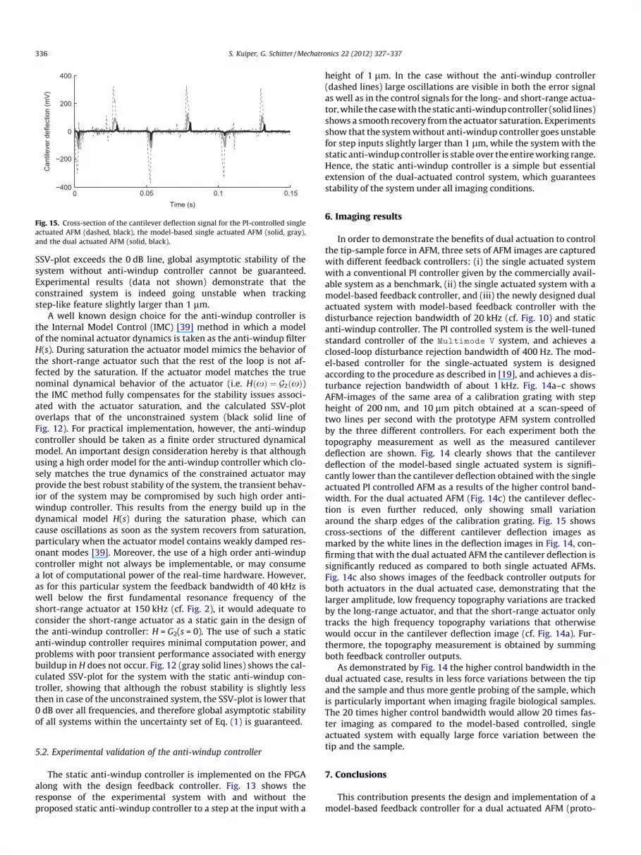
Fig. 15. Cross-section of the cantilever deflection signal for the PI-controlled singleactuated AFM (dashed, black), the model-based single actuated AFM (solid, gray),and the dual actuated AFM (solid, black).
336 S. Kuiper, G. Schitter / Mechatronics 22 (2012) 327–337
SSV-plot exceeds the 0 dB line, global asymptotic stability of thesystem without anti-windup controller cannot be guaranteed.Experimental results (data not shown) demonstrate that theconstrained system is indeed going unstable when trackingstep-like feature slightly larger than 1 lm.
A well known design choice for the anti-windup controller isthe Internal Model Control (IMC) [39] method in which a modelof the nominal actuator dynamics is taken as the anti-windup filterH(s). During saturation the actuator model mimics the behavior ofthe short-range actuator such that the rest of the loop is not af-fected by the saturation. If the actuator model matches the truenominal dynamical behavior of the actuator (i.e. HðxÞ ¼ G2ðxÞ)the IMC method fully compensates for the stability issues associ-ated with the actuator saturation, and the calculated SSV-plotoverlaps that of the unconstrained system (black solid line ofFig. 12). For practical implementation, however, the anti-windupcontroller should be taken as a finite order structured dynamicalmodel. An important design consideration hereby is that althoughusing a high order model for the anti-windup controller which clo-sely matches the true dynamics of the constrained actuator mayprovide the best robust stability of the system, the transient behav-ior of the system may be compromised by such high order anti-windup controller. This results from the energy build up in thedynamical model H(s) during the saturation phase, which cancause oscillations as soon as the system recovers from saturation,particulary when the actuator model contains weakly damped res-onant modes [39]. Moreover, the use of a high order anti-windupcontroller might not always be implementable, or may consumea lot of computational power of the real-time hardware. However,as for this particular system the feedback bandwidth of 40 kHz iswell below the first fundamental resonance frequency of theshort-range actuator at 150 kHz (cf. Fig. 2), it would adequate toconsider the short-range actuator as a static gain in the design ofthe anti-windup controller: H = G2(s = 0). The use of such a staticanti-windup controller requires minimal computation power, andproblems with poor transient performance associated with energybuildup in H does not occur. Fig. 12 (gray solid lines) shows the cal-culated SSV-plot for the system with the static anti-windup con-troller, showing that although the robust stability is slightly lessthen in case of the unconstrained system, the SSV-plot is lower that0 dB over all frequencies, and therefore global asymptotic stabilityof all systems within the uncertainty set of Eq. (1) is guaranteed.
5.2. Experimental validation of the anti-windup controller
The static anti-windup controller is implemented on the FPGAalong with the design feedback controller. Fig. 13 shows theresponse of the experimental system with and without theproposed static anti-windup controller to a step at the input with a
height of 1 lm. In the case without the anti-windup controller(dashed lines) large oscillations are visible in both the error signalas well as in the control signals for the long- and short-range actua-tor, while the case with the static anti-windup controller (solid lines)shows a smooth recovery from the actuator saturation. Experimentsshow that the system without anti-windup controller goes unstablefor step inputs slightly larger than 1 lm, while the system with thestatic anti-windup controller is stable over the entire working range.Hence, the static anti-windup controller is a simple but essentialextension of the dual-actuated control system, which guaranteesstability of the system under all imaging conditions.
6. Imaging results
In order to demonstrate the benefits of dual actuation to controlthe tip-sample force in AFM, three sets of AFM images are capturedwith different feedback controllers: (i) the single actuated systemwith a conventional PI controller given by the commercially avail-able system as a benchmark, (ii) the single actuated system with amodel-based feedback controller, and (iii) the newly designed dualactuated system with model-based feedback controller with thedisturbance rejection bandwidth of 20 kHz (cf. Fig. 10) and staticanti-windup controller. The PI controlled system is the well-tunedstandard controller of the Multimode V system, and achieves aclosed-loop disturbance rejection bandwidth of 400 Hz. The mod-el-based controller for the single-actuated system is designedaccording to the procedure as described in [19], and achieves a dis-turbance rejection bandwidth of about 1 kHz. Fig. 14a–c showsAFM-images of the same area of a calibration grating with stepheight of 200 nm, and 10 lm pitch obtained at a scan-speed oftwo lines per second with the prototype AFM system controlledby the three different controllers. For each experiment both thetopography measurement as well as the measured cantileverdeflection are shown. Fig. 14 clearly shows that the cantileverdeflection of the model-based single actuated system is signifi-cantly lower than the cantilever deflection obtained with the singleactuated PI controlled AFM as a results of the higher control band-width. For the dual actuated AFM (Fig. 14c) the cantilever deflec-tion is even further reduced, only showing small variationaround the sharp edges of the calibration grating. Fig. 15 showscross-sections of the different cantilever deflection images asmarked by the white lines in the deflection images in Fig. 14, con-firming that with the dual actuated AFM the cantilever deflection issignificantly reduced as compared to both single actuated AFMs.Fig. 14c also shows images of the feedback controller outputs forboth actuators in the dual actuated case, demonstrating that thelarger amplitude, low frequency topography variations are trackedby the long-range actuator, and that the short-range actuator onlytracks the high frequency topography variations that otherwisewould occur in the cantilever deflection image (cf. Fig. 14a). Fur-thermore, the topography measurement is obtained by summingboth feedback controller outputs.
As demonstrated by Fig. 14 the higher control bandwidth in thedual actuated case, results in less force variations between the tipand the sample and thus more gentle probing of the sample, whichis particularly important when imaging fragile biological samples.The 20 times higher control bandwidth would allow 20 times fas-ter imaging as compared to the model-based controlled, singleactuated system with equally large force variation between thetip and the sample.
7. Conclusions
This contribution presents the design and implementation of amodel-based feedback controller for a dual actuated AFM (proto-

S. Kuiper, G. Schitter / Mechatronics 22 (2012) 327–337 337
type). In order to identify the dynamical behavior of the system forvarying imaging conditions, the frequency responses of both actu-ators are measured with various measurement probes and sampleholders. Based on the measured frequency responses, dynamicalmodels for both actuators including an uncertainty descriptionare derived, and the maximum allowable actuation bandwidthsare determined. Based on these models, a model-based feedbackcontroller is designed to control the tip-sample interaction forcevia both actuators simultaneously. Special emphasis is given onproviding sufficient attenuation of the dynamic uncertainty toachieve robust stability under all working conditions, while alsopreventing strong destructive interference between both actuators.In order to ensure stability of the closed-loop under possible satu-ration of the short-range actuator, an anti-windup controller ispresented which is shown to provide stability of the system underall imaging conditions. The designed controller is implemented onthe prototype system by utilizing an FPGA, achieving a closed-loopdisturbance rejection of about 20 kHz, which is about 20 timeshigher than the model-based controlled single actuated system.
AFM-images are obtained with the newly designed dual-actu-ated AFM system in order demonstrate the significant reductionin residual control error, given by the cantilever deflection, ascompared to the single actuated AFM that is controlled either bya PI-controller or a model-based controller. The reduced force vari-ations between the tip and the sample results in a more gentleprobing of the sample surface, and allows for faster imaging whichis especially important when imaging fragile biological samples.
In this research it is shown that the dynamical uncertainty ofthe system under various imaging condition may pose a limitationon the achievable closed-loop bandwidth for controlling the tip-sample force. Therefore, reducing the uncertainty of the systemdynamics for all potential imaging conditions may be an importantadditional design criterion for future high-speed AFMs, in order topush the closed-loop bandwidth even higher without jeopardizingsystem stability. Moreover, the reducing the dynamic uncertaintyof the system may improve accuracy of the sample topographyestimation, as discussed in [31]. The design methodology proposedin this research may be used for analysis as well as controller syn-thesis for the next generation of high-speed AFMs.
Acknowledgment
The authors would like to thank C.J. Slinkman and A. Kunnappil-lil Madhusudhanan of the Delft University of Technology for theirsupport on the development of the electronics used in thisresearch.
References
[1] Binnig G, Quate C, Gerber C. Atomic force microscope. Phys Rev Lett1986;56(9):930–3.
[2] Alexander S, Hellemans L, Marti O, Schneir J, Elings V, Hansma P, et al. Anatomic-resolution atomic-force microscope implemented using an opticallever. J Appl Phys 1989;65:164–7.
[3] Hansma P, Schitter G, Fantner G, Prater C. High speed atomic force microscopy.Science 2006;314:601–2.
[4] Abramovitch D, Andersson S, Pao L, Schitter G. A tutorial on the mechanisms,dynamics, and control of atomic force microscopes. In: Proceedings of theAmerican control conference; 2007. p. 3488–502.
[5] Devasia S, Eleftheriou E, Moheimani S. A survey of control issues innanopositioning. IEEE Trans Control Syst Technol 2007;15:802–23.
[6] Ando T, Kodera N, Takai E, Maruyama D, Saito K, Toda A. A high-speed atomicforce microscope for studying biological macromolecules. Proc Nat Acad Sci2001;98(22):12468–72.
[7] Schitter G, Aström K, DeMartini B, Thurner P, Turner K, Hansma P. Design andmodeling of a high-speed afm-scanner. IEEE Trans Control Syst Technol2007;15:906–15.
[8] Croft D, Devasia S. Vibration compensation for high speed scanning tunnelingmicroscopy. Rev Sci Instrum 1999;70:4600–5.
[9] Sebastian A, Salapaka S. Design methodologies for robust nano-positioning.IEEE Trans Control Syst Technol 2005;13(6):868–76.
[10] Moheimani S, Yong Y. Simultaneous sensing and actuation with a piezoelectrictube scanner. Rev Sci Instrum 2008;79:073702.
[11] Butterworth J, Pao L, Abramovitch D. A comparison of control architectures foratomic force microscopes. Asian J Control 2009;11(2):175–81.
[12] Kuiper S, Schitter G. Active damping of a piezoelectric tube scanner using self-sensing piezo actuation. Mechatronics 2010;20:656–65.
[13] Picco L, Bozec L, Ulcinas A, Engledew D, Antognozzi M, Horton M, et al.Breaking the speed limit with atomic force microscopy. Nanotechnology2007;18:044030.
[14] Rost M, Crama L, Schakel P, Van Tol E, van Velzen-Williams G, Overgauw C,et al. Scanning probe microscopes go video rate and beyond. Rev Sci Instrum2005;76:053710.
[16] Ando T, Kodera N, Naito Y, Kinoshita T, Furuta K, Toyoshima Y. A high-speedatomic force microscope for studying biological macromolecules in action.Chemphyschem 2003;4(11):1196–202.
[17] Kodera N, Sakashita M, Ando T. Dynamic proportional-integral-differentialcontroller for high-speed atomic force microscopy. Rev Sci Instrum2006;77:083704.
[18] Jeong Y, Jayanth G, Jhiang S, Menq C. Direct tip-sample interaction forcecontrol for the dynamic mode atomic force microscopy. Appl Phys Lett2006;88:204102. 1–3.
[19] Schitter G, Stemmer A, Allgöwer F. Robust two-degree-of-freedom control ofan atomic force microscope. Asian J Control 2004;6(2):156–63.
[20] Salapaka S, De T, Sebastian A. A robust control based solution to the sample-profile estimation problem in fast atomic force microscopy. Int J Robust NonlinControl 2005;15(16):821–38.
[21] Knebel D, Amrein M, Voigt K, Reichelt R. A fast and versatile scan unit forscanning force microscopy. Scanning 1997;19(4):264–8.
[22] Fleming A, Kenton B, Leang K. Bridging the gap between conventional andvideo-speed scanning probe microscopes. Ultramicroscopy2010;110:1205–14.
[23] Sulchek T, Minne S, Adams J, Fletcher D, Atalar A, Quate C, et al. Dual integratedactuators for extended range high speed atomic force microscopy. Appl PhysLett 1999;75:1637–9.
[24] Tabak F, Disseldorp E, Wortel G, Katan A, Hesselberth M, Oosterkamp T, et al.MEMS-based fast scanning probe microscopes. Ultramicroscopy2010;110(6):599–604.
[25] Mori K, Munemoto T, Otsuki H, Yamaguchi Y, Akagi K. A dual-stage magneticdisk drive actuator using a piezoelectricdevice for a high track density. IEEETrans Magnet 1991;27(6 Part 2):5298–300.
[26] Horowitz R, Li Y, Oldham K, Kon S, Huang X. Dual-stage servo systems andvibration compensation in computer hard disk drives. Control Eng Prac2007;15(3):291–305.
[27] Schitter G, Rijkee W, Phan N. Dual actuation for high-bandwidthnanopositioning. In: Proceedings of the 47th IEEE Conference in DecisionControl, 2008; 2008. p. 5176–81.
[28] Jeong Y, Jayanth G, Menq C. Control of tip-to-sample distance in atomic forcemicroscopy: a dual-actuator tip-motion control scheme. Rev Sci Instrum2007;78:093706. 1–7.
[29] Fantner G, Burns D, Belcher A, Rangelow I, Youcef-Toumi K, et al. MeasurControl 2009;131:061104. 1–13.
[30] van Hulzen JR, Schitter G, Van den Hof PM, van Eijk J. Dynamics and modalcontrol of piezoelectric tube actuators. In: Proceedings of IFAC MechatronicsConference, 2010; 2010.
[31] Kuiper S, Van den Hof P, Schitter G. Towards integrated design of a robustfeedback controller and topography estimator for atomic force microscopy. In:Proceedings of the 18th IFAC World Congress, 2011; 2011.
[32] Guo G, Wu D, Chong T. Modified dual-stage controller for dealing withsecondary-stage actuator saturation. IEEE Trans Magnet 2003;39(6):3587–92.
[33] Schroeck S, Messner W. On controller design for linear time-invariant dual-input single-output systems. In: Proceedings of American Control Conference,1999, vol. 6; 1999.
[34] Hernandez D, Park S, Horowitz R, Packard A. Dual-stage track-following servodesign for hard disk drives. In: Proceedings of American Control Conference onIEEE, 1999, vol. 6; 1999. p. 4116–21.
[35] de Callafon R, Nagamune R, Horowitz R. Robust dynamic modeling and controlof dual-stage actuators. IEEE Trans Magnet 2006;42:247–54.
[36] Herrmann G, Turner M, Postlethwaite I, Guo G. Practical implementation of anovel anti-windup scheme in a HDD-dual-stage servo-system. IEEE/ASMETrans Mechatron 2004;9(3):580–92.
[37] Skogestad S, Postlethwaite I. Multivariable feedback control: analysis anddesign. John Wiley & Sons; 2005.
[38] Edwards C, Postlethwaite I. An anti-windup scheme with closed-loop stabilityconsiderations* 1. Automatica 1999;35(4):761–5.
[39] Walgama K, Ronnback S, Sternby J. Generalisation of conditioning techniquefor anti-windup compensators. IEE Proceedings of D Control TheoryApplications, vol. 139. IET; 2008. p. 109–18.
Recommended


