NOTICE OF INCORPORATIONUnited States Legal Document
≠ All citizens and residents are hereby advised that this is a legally binding document duly incorporated by reference and that failure to comply with such requirements as hereby detailed within may subject you to criminal or civil penalties under the law. Ignorance of the law shall not excuse noncompliance and it is the responsibility of the citizens to inform themselves as to the laws that are enacted in the United States of America and in the states and cities contained therein. ±
«
ASME B31.1 (2007), Code for Pressure Piping, Section on Power Piping, 2008 Addenda, as required by the laws of the States of Arizona, Alaska, Colorado, Illinois, Iowa, Kansas, Michigan, Missouri, Minnesota, Nebraska, Nevada, North Dakota, Ohio, Oregon, Wisconsin, et. alia.

Addenda to ASME 831.1-2007 Power Piping
ASME Code for Pressure Piping, B31
AN AMERICAN NATIONAL STANDARD
Date of Issuance: June 9, 2008
ASME is the registered trademark of The American Society of Mechanical Engineers.
This code or standard was developed under procedures accredited as meeting the criteria for American National Standards. The Standards Committee that approved the code or standard was balanced to assure that individuals from competent and concerned interests have had an opportunity to participate. The proposed code or standard was made available for public review and comment that provides an opportunity for additional public input from industry, academia, regulatory agencies, and the public-at-Iarge.
ASME does not "approve," "rate," or "endorse" any item, construction, proprietary device, or activity. ASME does not take any position with respect to the validity of any patent rights asserted in connection with any
items mentioned in this document, and does not undertake to insure anyone utilizing a standard against liability for
infringement of any applicable letters patent, nor assume any such liability. Users of a code or standard are expressly advised that determination of the validity of any such patent rights, and the risk of infringement of such rights, is
entirely their own responsibility. Participation by federal agency representative(s) or person(s) affiliated with industry is not to be interpreted as
government or industry endorsement of this code or standard. ASME accepts responsibility for only those interpretations of this document issued in accordance with the established
ASME procedures and pOlicies, which precludes the issuance of interpretations by individuals.
No part of this document may be reproduced in any form, in an electronic retrieval system or otherwise,
without the prior written permission of the publisher.
The American Society of Mechanical Engineers Three Park Avenue, New York, NY 10016-5990
Copyright © 2008 by THE AMERICAN SOCIETY OF MECHANICAL ENGINEERS
All rights reserved Printed in U.s.A.
Copyright © 2008 by the American Society of Mechanical Engineers. ~ No reproduction may be made oftbis material without '\Titten consent of ASME. ~
ASME B31.1a .. 2008
Fo]]owing approval by the B31 Committee and ASME, and after public reviFw, ASME B31.1a-200S was approved by the American National Standards Institute on March 3, 200S.
Addenda to ASME B31.1-2007 are issued in the form of replacement pages. Revisions, additions, and deletions are incorporated directly into the affected pages. It is advisable, however, that this page, the Addenda title and copyright pages, and all replaced pages be retained for reference.
SUMMARY OF CHANGES
This is the first Addenda to be published to ASME B31.1-2007.
Replace or insert the pages listed. Changes given below are identified on the pages by a margin note, (A08), placed next to the affected area. Revisions introduced in ASME B31.1-2007 are indicated by (07). The pages not listed are the reverse sides of the listed pages and contain no changes.
Page
vii-Ix
3
10, 10.1
13
16-16.2
lS, lS.1
19
23
24
41,42
50
62, 62.1
Location
Committee Roster
Fig. 100.1.2(B)
101.2.5
Equation (2)
102.4.7
104.1.1
104.1.2
Table 10204.7
104.1.4
104.3.1(0.2)
104.3.1(GA)
104.3.1 (G.5)
Fig. 104.3.1(G)
119.10.1
Fig. 122.1.7(C)
123.2.2(C)
12304
(c)
Change
Updated
(1) In left half of drawing, near para. 122.1.7(0) call outs, two circles indicating jurisdiction and responsibility corrected by errata to be open
(2) In right half of drawing, h""o references to para. 122.1.7 deleted and new one added by errata
Added
Equation and its nomenclature revised
Added
Added
Title revised
Added
Added'
(1) Do deleted (2) Doh and Doh added
Revised
Revised
Callouts revised
Nomenclature for Ec and Ell revised
Call outs revised
Added
Added
Copyright © 2008 by the American Society of Mechanical Engineers. ~ No reproduction may be made of this material without written consent of ASME. ~
Page
63
67
68
70
75
80
87-88.1
93
118
132, 133
138, 139
144, 145
148, 149
150, 151
154, 155
Location
124.4
124.5
124.6(C)
Table 126.1
Table 126.1
Table 126.1
127.4.3
1275.3(B)
Table 132
Table 136.4
Table A-2
Table A-3
Table A-3
Table A-3
Table A-3
Table A-3
Table A-3
(d)
Change
In text table, for last three entries, crossreferences corrected by errata
In text table, for last three entries, crossreferences corrected by errata
In text table, for sixth through eighth entries, cross-references corrected by errata
(1) Under Forgings, for ASTM B 462, title revised
(2) Under Seamless Pipe and Tube, ASTM B 690 added
(1) Under Welded Pipe and Tube, second entry corrected by errata to read B 608
(2) ASTM B 675, B 676, and B 804 added (3) Under Plate, Sheet, and Strip, AST~1
B 171 added, B 402 deleted, and B 688 added
(4) Under Rods, Bars, and Shapes, ASTM B 691 added
Under National Fire Codes, NFPA 54/ ANSI Z223.1 added, NFPA 85 added, NFPA 1963 revised, and NFPA 8503 deleted
Revised
Last paragraph revised
P-No. 5B revised
General Note (f) added
Under Electric Fusion Welded Pipe -Filler tvletal Added, for both A 691 Grade 91 lines, Note (17) references deleted by errata
Under Seamless Pipe and Tube, Ferritic/ Austenitic, A 789 and A 790 S32205 and S32750 added
Under \Velded Pipe and Tube - Without Filler Metal, Ferri tic/ Austenitic, A 789 and A 790 S32205 and S32750 added
Under Plate, Sheet, and Strip, Ferritic/ Austenitic, A 240 S32205 and S32750 added
Under Forgings, Ferritic/ Austenitic, A 182 Grades F60 and F53 added
Under Fittings, Ferri tic/ Austenitic, A 815 S32205 added
Under Bolts, Nuts, and Studs, Austenitic, for A 453 Grade 660, stress values for 200°F through 1,000°F added
Copyright © 2008 by the American Society ofMecbanical Engineers. ~ No reproduction may be made of this material without written consent of ASME. ~
Page
158
160-169
170
174, 175
176, 177
Location
Table A-3
Table A-4
Table A-4
Table A-4
Table A-4
Table A-4
Table A-4
Table A-4
Table A-4
Table A-4
Table A-4
Table A-6
Table A-6
Table A-6
Table A-6
Table A-6
Table A-6
Table A-6
(e)
Change
Note (39) added
Under Seamless Pipe and Tube, two B 690 N08367 lines revised and two added
Under vVelded Pipe and Tube, two B 675 N08367 lines revised and two added
Two B 676 N08367 lines revised and two added
Two B 804 N08367 lines revised and two added
(1) Under Plate, Sheet, and Strip, first two B 688 N08367 lines deleted
(2) For four remaining B 688 N08367 lines, Temper or Condition, Nominal Composition, and Notes revised
Under Bars, Rods, Shapes, and Forgings, for both B 564 N08367 lines, Temper or Condition, Nominal Composition, and Notes revised
For both B 691 N08367 lines, Temper or Condition, Nominal Composition, and Notes revised
Under Seamless Fittings, for both B 462 N08367 lines, Temper or Condition, Nominal Composition, and Notes revised
Under vVelded Fittings, two B 366 N08367 lines added
Notes (21) and (22) added
Under Seamless Pipe and Tube, for second B 42 line, Size or Thickness revised
For third B 42 line, Size or Thickness and stress value for 250°F revised
For B 111 C60800, stress value for 3500 P revised
For B 280 C12200 Annealed, stress value for 200°F revised
For B 466 C71500, stress values for 650°F and 700°F added
Under Welded Pipe and Tube, for B 608, stress line revised
(1) Under Plate, for C70600 Annealed and both C71500 lines, B 402 replaced by B 171
(2) Line for C70600 Hot rolled added
Copyright © 2008 by the American Society of Mechanical Engineers. No reproduction may be made of this material without written consent of ASME.
Page
205
208,209
217-219
220-226
264
265
297
298
300
SPECIAL NOTE:
Location
Table A-6
Table A-6
Table A-6
Table C-l (51)
Table C-2 (51)
Mandatory Appendix F
Mandatory Appendix G
Table III-4.3.1
Table III-4.3.2
Index
Index
Index
Change
(3) For first C71500 line, stress values for 750°F and 800°F deleted
Under Rod and Bar, for B 151 C71500, stress values for 650°F and 700°F added
Under Castings, for B 148 C95200, stress value for 500°F revised, and values for 5500 P and 600°F added
For B 148 C95400, stress values for 550°F and 600°F added
In column heads, top line revised
In column heads, top line revised
(1) ASTM A 182/ A 182.1'vl, A 240/ A 240M, A 789/ A 789M, A 790/ A 790M, A 815, and B 462 revised
(2) ASTM B 171, B 675, B 676, B 688, B 690, B 691, and B 804 added
(3) NFPA 54/ ANSI Z223.1 and NFPA 85 added
(4) NFPA 1963 revised (5) NFPA 8503 deleted
(1) Previous second D symbol replaced by dj
(2) For Do and D,)h, references revised (3) For Doh, definition and references
revised (4) Previous second d entry deleted (5) For second E, 51 units revised (6) Previous first r symbol replaced by q (7) For second R, references revised (8) Wadded
Revised in its entirety
Revised in its entirety
For flexible hose, nonmetallic, entry corrected by errata to read 105.3(D)
For pressure, reducing valves, first entry corrected by errata to read 107.1 (F)
For valves, pressure regulator, entry corrected by errata to read 107.1(F)
The interpretations to A5ME B31.1 issued between January 1,2007 and December 31, 2007 follow the last page of this Addenda as a separate supplement, Interpretations Volume 43. After the Interpretations, a separate supplement, Cases No. 33, follows.
([)
Copyright © 2008 by the American Society of Mechanical Engineers. ~ .. No reproduction may be made of this material without written consent of ASME. ~
ASME 831 COMMITTEE Code for Pressure Piping
COMMITTEE OFFICERS
M. L Nayyar, Chair K. C. Bodenhamer, Vice Chair
N. Lobo, Secretary
COMMITTEE PERSONNEL
R. J. T. Appleby, ExxonMobil Upstream Research Co. C. Becht IV, Becht Engineering Co. A. E. Beyer, Fluor Enterprises, Inc. K. C. Bodenhamer, Enterprise Products CO. J. S. (hin, TransCanada Pipeline U.S. D. l. (oym, Worley Parsons j. A. Drake, Spectra Energy Transmission P. D. flenner, Flenner Engineering Services D. M. fox, Atmos Energy j. W. frey, Stress Engineering Service, Inc. D. R. frikken, Becht Engineering Co. R. A. Grichuk, Fluor Corp. R. W. Haupt, Pressure Piping Engineering Associates, Inc. L E. Hayden, Jr., Consultant G. A. jolly, Vogt Valves/Flowserve Corp. N. Lobo, The American Society of Mechanical Engineers W. J. Mauro, American Electric Power
J. E. Meyer, Louis Perry & Associates, Inc. E. Michalopoulos, University of Macedonia M. L Nayyar, Bechtel Power Corp. T. J. O'Grady II, BP Exploration (Alaska), Inc. R. G. Payne, Alstom Power, Inc. j. T. Powers, Worley Parsons E. H. Rinaca, Dominion Resources, Inc. M. J. Rosenfeld, Kiefner & Associates, Inc. R. j. Silvia, Process Engineers and Constructors, Inc. W. J. Sperko, Sperko Engineering Services, Inc. G. W. Spohn m. Coleman Spohn Corp. K. A. Vilminot, Black & Veatch A. L Watkins, First Energy Corp. K. H. Wooten, ConocoPhillips Pipe Line Co. W. J. Koves, Ex-Officio, UOP LLC A. P. Rangus, EkOfficio, Bechtel C. j. Meto, Alternate, Worley Parsons A. Soni, Delegate, Engineers India Ltd.
B31.1 POWER PIPING SECTION COMMITTEE
M. L Nayyar, Chair, Bechtel Power Corp. P. D. flenner, Vice Chair, Flenner Engineering Services S. Vasquez, Secretary, The American Society of Mechanical
Engineers H. A. Ainsworth, Consultant W. R. Broz, CTG Forensics, Inc. D. D. (hristian, Victaulic M. J. (ohn, Aptech Engineering Services, Inc. D. H. Creates, Ontario Power Generation, Inc. G. J. Delude, Penpower R. P. Deubler, Fronek Power Systems, LLC A. S. Drake, Constellation Energy Group S. J. findlan, Electric Power Resea rch Institute j. W. Frey, Stress Engineering Service, Inc. E. C. Goodling, Jr., Worley Parsons T. E. Hansen, American Electric Power R. W. Haupt, Pressure Piping Engineering Associates, Inc. C. L. Henley, Black & Veatch B. P. Holbrook, Riley Power, Inc. J. Kaliyadan, Dominion
vii
R. J. Kennedy, Detroit Edison Co. D. J. Leininger, Worley Parsons S. P. licud, Bechtel Power Corp. W. M. Lundy, U.S. Coast Guard W. J. Mauro. American Electric Power D. C. Moore, Southern Co. Services, Inc. R. D. Patel, GE Energy Nuclear R. G. Payne. Alstom Power, Inc. D. W. Rahoi, Metallurgist K. I. Rapkin, FPL R. K. Reamey, Turner Industries Group, LLC E. H. Rinaca, Dominion Resources, Inc. R. D. Schueler, Jr., The National Board of Boiler and Pressure
Vessel Inspectors J. P. Scott, Dominion J. J. Sekely. Welding Services, Inc. H. R. Simpson, Industry and Energy Associates, LLC S. K. Sinha, Lucius Pitkin, Inc. K. A. Vilminot. Black & Veatch A. L. Watkins, First Energy Corp.
Copyright © 2008 by the American Society of Mechanical Engineers. ~ No reproduction may be made oftms material "ithout written consent of ASME. ~
(A08)
B31.1 SUBGROUP ON DESIGN
K. A. Vilminot, Chair, Black & Veatch W. R. Bmz, CTG Forensics, Inc. D. H. Creates, Ontario Power Generation, Inc. S. D. Cross, Utility Engineering M. K. Engelkemier, Stanley Consultants, Inc. j. W. Goodwin, Southern CO. R. W. Haupt, Pressure Piping Engineering Associates, Inc. B. P. Holbrook, Riley Power, Inc. M. W. Johnson, Reliant Energy
R. J. Kennedy, Detroit Edison Co. W. M. lundy, U.s. Coast Guard D. C. Moore, Southern Co. Services, Inc. A. D. Nance, Consultant R. D. Patel, GE Energy Nuclear R. G. Payne, Aistom Power, Inc. D. D. Pierce, Puget Sound Naval Shipyard K. I. Rapkin, FPL A. l. Watkins, First Energy Corp.
B31.1 SUBGROUP ON fABRICATION AND EXAMINATION
P. D. Flenner, Chair, Flenner Engineering Services R. B. Corbit, Exelon Nuclear C. Emslander S. J. Findlan, Electric Power Research Institute J. W. Frey, Stress Engineering Service, Inc. E. F. Gerwin J. Hainsworth, The Babcock & Wilcox Co.
T. E. Hansen, American Electric Power D. J. leininger, Worley Parsons S. P. licud, Bechtel Power Corp. T. Monday, Team Industries, Inc. R. K. Reamey, Turner Industries Group, LLC J. J. Sekely, Welding Services, Inc. E. F. Summers, Jr., Babcock & Wilcox Construction Co.
B31.1 SUBGROUP ON GENERAL REQUIREMENTS
w. J. Mauro, Chair, American Electric Power H. A. Ainsworth, Consultant D. D. Christian, Victaulic G. J. Delude, Pen power
J. Kaliyadan, Dominion R. D. Schueler, Jr., The National Board of Boiler and Pressure
Vessel Inspectors
B31.1 SUBGROUP ON MATERIALS
C. l. Henley, Chair, Black & Veatch R. P. Deubler, Fronek Power Systems, LLC P. J. Dobson, Cummins & Barnard, Inc.
A. S. Drake, Constellation Energy Group M. l. Nayyar, Bechtel Power Corp. D. W. Rahoi, Metallurgist
B31.1 SUBGROUP ON PIPING SYSTEM PERfORMANCE
J. W. Frey, Chair, Stress Engineering Service, Inc. M. J. Cohn, Aptech Engineering Services, Inc. D. H. Creates, Ontario Power Generation, Inc. P. D. Flenner, Flenner Engineering Services E. C. Goodling, Jr., Worley Parsons j. W. Goodwin, Southern Co. R. W. Haupt, Pressure Piping Engineering Associates, Inc. B. P. Holbrook, Riley Power, Inc.
M. W. Johnson, Reliant Energy R. J. Kennedy. Detroit Edison Co. D. C. Moore, Southern Co. Services, Inc. R. G. Payne, Alstom Power, Inc. K. I. Rapkin, FPL R. K. Reamey, Turner Industries Group, LLC E. H. Rinaca, Dom in ion Resources, Inc. J. P. Scott, Dominion
B31.1 SUBGROUP ON SPECIAL ASSIGNMENTS
E. H. Rinaca, Chair, Dominion Resources, Inc. M. J. Cohn, Aptech Engineering Services, Inc. E. C. Goodling, Jr., Worley Parsons
J. P. Scott, Dominion H. R. Simpson, Industry and Energy Associates, LLC S. K. Sinha, Lucius Pitkin, Inc.
B31 EXECUTIVE COMMITTEE
N. lobo, Secretary, The American Society of Mechanical Engineers C. Becht IV, Becht Engineering Co. K. C. Bodenhamer, Enterprise Products CO. J. A. Drake, Spectra Energy Transmission P. D. Flenner, Flenner Engineering Services D. R. Frikken, Becht Engineering Co. R. W. Haupt, Pressure Piping Engineering Associates, Inc. B. P. Holbrook, Riley Power, Inc. G. A. Jolly, Vogt Valves/Flowserve Corp.
viii
W. J. Koves, UOP LLC E. Michalopoulos, University of Macedonia M. L Nayyar, Bechtel Power Corp. T. J. O'Grady II, BP Exploration (Alaska), Inc. R. G. Payne, Alstom Power, Inc. A. P. Rangus, Bechtel W. J. Sperko, Sperko Engineering Services, Inc. G. W. Spohn III, Coleman Spohn Corp.
Copyright © 2008 by the American Society of Mechanical Engineers. ~ ~ No reproduction may be made oftbis material \\~thout \\I1'itten consent of ASME.
B31 fABRICATION AND EXAMINATION COMMITTEE
A. P. Rangus, Chair, Bechtel P. D. Stumpf, Secretary, The American Society of Mechanical
Engineers J. P. Ellenberger R. J. ferguson, Xaloy, Inc. D. J. felzner, BP Exploration (Alaska), Inc. P. D. flenner, Flenner Engineering Services W. W. lewis, E. I. DuPont
S. P. Ucud, Bechtel Power Corp. A. D. Nalbandian. Thielsch Engineering, Inc. R. I. Seals, Consultant R. J. Silvia, Process Engineers and Constructors, Inc. W. J. Sperko, Sperko Engineering Services, Inc. E. F. Summers, Jr., Babcock & Wilcox Construction Co. P. l. Vaughan, ONEOK Partners
831 MATERIALS TECHNICAL COMMITTEE
M. l. Nayyar, Chair, Bechtel Power Corp. N. lobo, Secretary, The American Society of Mechanical Engineers M. H. Barnes, Sebesta Blomberg & Associates J. A. Cox, Lieberman Consulting LLC R. P. Deubler, Fronek Power Systems, LLC P. j. Dobson, Cummins & Barnard, Inc. W. H. Eskridge, Jr., Aker Kvaerner Engineering & Construction
R. A. Grichuk, Fluor Corp. e. l. Henley, Black & Veatch D. W. Rahoi, Metallurgist R. A. Schmidt, Hackney Ladish, Inc. H. R. Simpson, Industry and Energy Associates, LLC J. l. Smith, Jacobs Engineering Group Z. Djilali, Contributing Member, BEREP
831 MECHANICAL DESIGN TECHNICAL COMMITTEE
W. J. Koves, Chair, UOP LLC G. A. Antaki, Vice Chair, Becht Nuclear Services N. lobo, Secretary, The American Society of Mechanical Engineers C. Becht IV, Becht Engineering CO. J. P. Breen, Engineering Advisor J. P. Ellenberger D. j. Fetzner, BP Exploration (Alaska), Inc. J. A. Graziano, Tennessee Valley Authority j. D. Hart, SSD, Inc. R. W. Haupt, Pressure Piping Engineering Associates, Inc. B. P. Holbrook, Riley Power, Inc.
G. D. Mayers, Alion Science & Technology T. Q. McCawLey, TQM Engineering, PC R. J. Medvick, Swage 10k J. C. Minichiello, AREVA NP T. J. O'Grady II. BP Exploration (Alaska), Inc. A. W. Paulin. Paulin Research Group R. A. Robleto, Senior Technical Advisor M. J. Rosenfeld, Kiefner & Associates, Inc. G. Stevick, Berkeley Engineering & Research, Inc. E. A. Wais, Wais and Associates, Inc. E. e. Rodabaugh, Honorary Member, Consultant
831 CONfERENCE GROUP
A. Bell, Bonneville Power Administration G. Bynog, The National Board of BoHer and Pressure Vessel
Inspectors R. A. Coomes, Commonwealth of Kentucky, Dept. of Housing/Boiler
Section D. H. Hanrath
e. J. Harvey, Alabama Public Service Commission D. T. Jagger, Ohio Department of Commerce M. Kotb, Regie du Batiment du Quebec K. T. lau, Alberta Boilers Safety Association R. G. Marini, New Hampshire Public Utilities Commission I. W. Mault, Manitoba Department of Labour
ix
A. W. Meiring, Division of Fire and Building Safety/Indiana R. f. Mullaney, Boiler and Pressure Vessel Safety Branch/
Vancouver P. Sher, State of Connecticut M. E. Skarda, Arkansas Department of Labor D. A. Starr, Nebraska Department of Labor D. J. Stursma, Iowa Utilities Board R. P. Sullivan, The National Board of Boiler and Pressure Vessel
Inspectors J. E. Troppman, Division of Labor/State of Colorado Boiler
Inspections W. A. M. West, Lighthouse Assistance, Inc. T. F. Wickham, Rhode Island Department of Labor
Copyright © 2008 by the American Society of Mecbanical Engineers. ~ No reproduction may be made oftbis material without written consent of ASME. ~
INTRODUCTION
The ASME B31 Code for Pressure Piping consists of a number of individually published Sections, each an American National Standard, under the direction of ASME Committee B31, Code for Pressure Piping.
Rules for each Section have been developed considering the need for application of specific requirements for various types of pressure piping. Applications considered for each Code Section include:
B31.1 Power Piping: piping typically found in electric pmver generating stations, in industrial and institutional plants, geothermal heating systems, and central and district heating and cooling systelTls;
B31.3 Process Piping: piping typically found in petroleum refineries, chemical, pharmaceutical, textile, paper, semiconductor, and cryogenic plants, and related processing plants and terminals;
B31.4 Pipeline Transportation Systems for Liquid Hydrocarbons and Other Liquids: piping transporting products which are predominately liquid between plants and terminals and within terminals, pumping, regulating, and metering stations;
B31.5 Refrigeration Piping: piping for refrigerants and secondary coolants;
B31.8 Gas Transportation and Distribution Piping Systems: piping transporting products which are predominately gas between sources and terminals, including compressor, regulating, and metering stations; and gas gathering pipelines;
B31.9 Building Services Piping: piping typically found in industrial, institutional, commercial, and public buildings, and in multi-unit residences, which does not require the range of sizes, pressures, and temperatures covered in B31.1;
B31.11 Slurry Transportation Piping Systems: piping transporting aqueous slurries between plants and terminals and within terminals, pumping, and regulating stations.
This is the B31.1 Power Piping Code Section. Hereafter, in this Introduction and in the text of this Code Section B31.1, where the word Code is used without specific identification, it means this Code Section.
It is the owner's responsibility to select the Code Section which most nearly applies to a proposed piping installation. Factors to be considered by the owner include: limitations of the Code Section, jurisdictional requirements, and the applicability of other codes and standards. All applicable requirements of the selected Code Section shall be met. For so.me installations, more than one Code Section may apply to different parts of the installation. The owner is also responsible for imposing
x
requirements supplementary to those of the selected Code Section, if necessary, to assure safe piping for the proposed installation.
Certain piping within a facili ty may be subject to other codes and standards, including but not limited to:
ASME Boiler and Pressure Vessel Code, Section TIT: nuclear power piping;
ANSI Z223.1 National Fuel Gas Code: piping for fuel gas from the point of delivery to the connection of each fuel utilization device;
NFPA Fire Protection Standards: fire protection systems using water, carbon dioxide, halon, foam, dry chemical, and wet chemicals;
NFPA 99 Health Care Facilities: medical and laboratory gas systems;
NFPA 8503 Standard for Pulverized Fuel Systems: piping for pulverized coal from the coal mills to the burners;
Building and plumbing codes, as applicable, for potable hot and cold water, and for sewer and drain systems.
The Code sets forth engineering requirements deemed necessary for safe design and construction of pressure piping. While safety is the basic consideration, this factor alone will not necessarily govern the final specifications for any piping system. The designer is cautioned that the Code is not a design handbook; it does not do away with the need for the designer or for competent engineering judgment.
To the greatest possible extent, Code requirements for design are stated in terms of basic design principles and formulas. These are supplemented as necessary wi th specific requirements to assure uniform application of principles and to guide selection and application of piping elements. The Code prohibits designs and practices known to be unsafe and contains warnings where caution, but not prohibition, is warranted.
The specific design requirements of the Code usually revolve around a simplified engineering approach to a subject. It is intended that a designer capable of applying more complete and rigorous analysis to special or unusual problems shall have latitude in the development of such designs and the evaluation of complex or combined stresses. In such cases the designer is responsible for demonstrating the validity of his approach.
This Code Section includes the following: (a) references to acceptable material specifications
and component standards, including dimensional requirements and pressure-temperature ratings
(b) requirements for design of components and assemblies, including pipe supports
Copyright © 2008 by the American Society of Mechanical Engineers. ~ No reproduction may be made oftbis material without written consent of ASME. ~
ASME B31.1a-2008
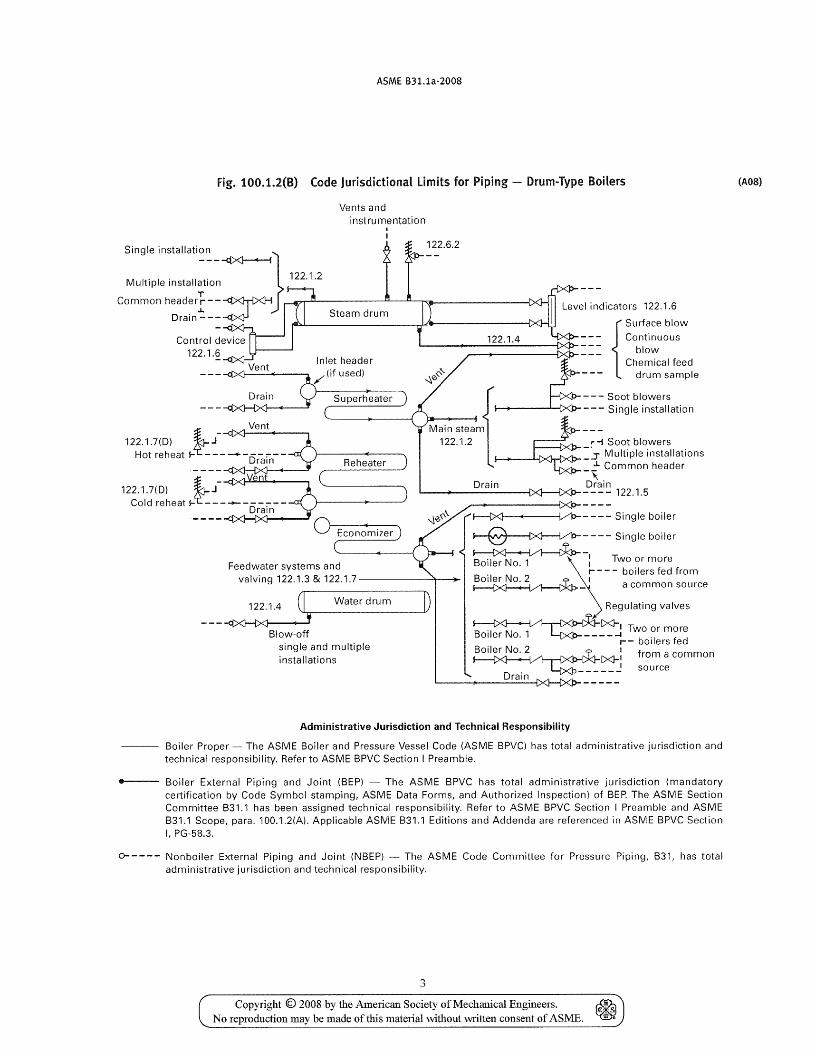
fig. 100.1.2(B) Code Jurisdictional limits for Piping - Drum-Type Boilers
Vents and instrumentation
122.6.2
:~~~i:li~~::~::li~~O~~} 122.1.2
Common header roo -~ ....-fI!7I..Il-----...--l:L---Ll-rw---------t><l-I Drain ----¢<j-l. Steam drum
122.1.6
Drain
Vent
Inlet header /(if used)
Superheater
{
Surface blow
122.1.4 === Continuous r--__+------lXI:)- __ _ __ blow
~ Chemical feed
--- drum sample
122.1.7(D) ~A J
Hot reheat l-~------:--Drain
{
=== ~~~~I~I~n:::I~ation Main steam ~---
122.1.2 .. -l Soot blowers =:.:r Multiple installations
.l. Common header Reheater -, Drain Drain 122.1.7(D) J ~
-'---------[:>(}---{XP- -- -- -- - 122.1.5
Cold reheat l- ----------Drain
Feedwater systems and valving 122.1.3 & 122.1.7------+-~
(I Water drum I) 122.1.4 .J..,..,.. ____ ----V
- - - -ct><t-t><l I ¥ Blow-off
single and multiple installations
~---- Single boiler
~---- Single boiler
~-Boiler No. 1 ~I Two or more Boiler No.2 i - - -- boilers fed from ~_ a common source
Regulating valves
~i%.1><J-1 T' Boiler No.1 Ltx:P------I wo or more
r-- boilers fed
~~~ :r~u~c: common
Drain
Administrative Jurisdiction and Technical Responsibility
Boiler Proper - The ASME Boiler and Pressure Vessel Code (ASME BPVCl has total administrative jurisdiction and technical responsibility. Refer to ASME BPVC Section I Preamble.
---- Boiler External Piping and Joint (BEP) - The ASME BPVC has total administrative jurisdiction (mandatory certification by Code Symbol stamping, ASME Data Forms, and Authorized Inspection) of BEP. The ASME Section Committee B31.1 has been assigned technical responsibility. Refer to ASME BPVC Section I Preamble and ASME B31.1 Scope, para. 100.1.2(A). Applicable ASME B31.1 Editions and Addenda are referenced in ASME BPVC Section I, PG-58.3.
0----- Nonboiler External Piping and Joint (NBEP) - The ASME Code Committee for Pressure Piping, B31, has total administrative jurisdiction and technical responsibility.
3
Copyright © 2008 by the American Society of Mechanical Engineers. ~ €. -s No reproduction may be made of this material without written consent of ASME. III ~
(A08)
ASME B31.1a-2008
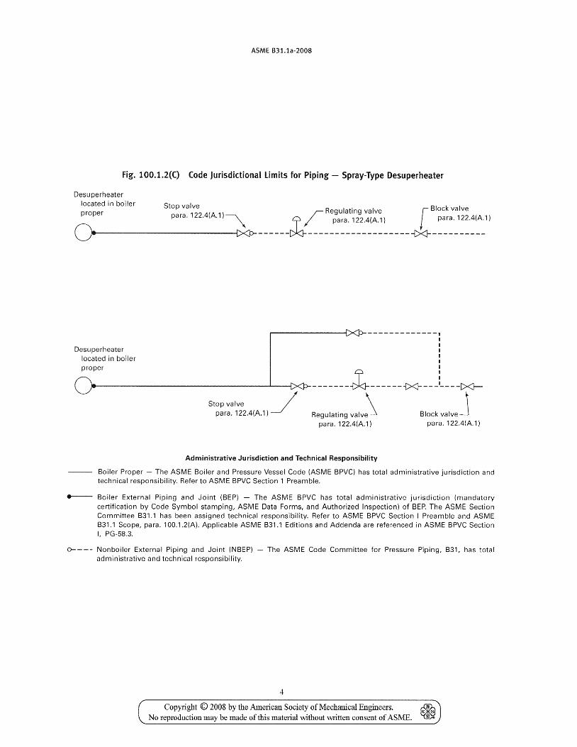
fig. 100.1.2(C} Code Jurisdictional limits for Piping - Spray-Type Desuperheater
Desu perheater
located in boiler Stop valve . BI k I proper 224(A ) r Regulating valve r oc va ve
O ________ p_a_r_a_. , __ . _·_'_~__I~--- __ -U---::~~~~2~~~~~----_t><J_-:~:-1~:.~~'1
Desuperheater located in boiler proper
Stop valve ~ para. 122.4(A.l)
-------------, I I I I I I
-------l-------{><J- - - -L ---C><l-
Regulating valv~ para. 122.4(A.1)
Block valveJ pa ra. 122 A(A.1)
Administrative Jurisdiction and Technical Responsibility
Boiler Proper - The ASME Boiler and Pressure Vessel Code (ASME BPVC) has total administrative jurisdiction and technical responsibility. Refer to ASME BPVC Section 1 Preamble.
e--- Boiler External Piping and Joint (BEP) - The ASME BPVC has total administrative jurisdiction (mandatory certification by Code Symbol stamping, ASME Data Forms, and Authorized Inspection) of BEP. The ASME Section Committee 831.1 has been assigned technical responsibility. Refer to ASME BPVC Section I Preamble and ASME 831.1 Scope, para. 1 OO.1.2(A). Applicable ASME B31.1 Editions and Addenda are referenced in ASME 8PVC Section I, PG-58.3.
0---- Nonboiler External Piping and Joint (NBEP) - The ASME Code Committee for Pressure Piping, 831, has total administrative and technical responsibility.
4
Copyright © 2008 by the American Society of Mechanical Engineers. ~ No reproduction may be made of this material without written consent of ASME. ~
ASME B31.1a·2008
steel: an alloy of iron and carbon with no more than 2% carbon by weight. Other alloying elements may include manganese, sulfur, phosphorus, silicon, aluminum, chromium, coppel~ nickel, molybdenum, vanadium, and others depending upon the type of steel. For acceptable material specifications for steel, refer to Chapter III, Materials.
stresses displacemenl stress: a stress developed by the self
constraint of the structure. It must satisfy an imposed strain pattern rather than being in equilibrium wi th an external load. The basic characteristic of a displacement stress is that it is self-limiting. Local yielding and minor distortions can satisfy the displacement or expansion conditions which cause the stress to occur. Failure from one application of the stress is not to be expected. Further, the displacement stresses calculated in this Code are "effective" stresses and are generally lmver than those predicted by theory or measured in strain-gage tests. 1
peak stress: the highest stress in the region under consideration. The basic characteristic of a peak stress is that it causes no significant distortion and is objectionable only as a possible source of a fatigue crack initiation or a brittle fracture. This Code does not utilize peak stress as a design basis, but rather uses effective stress values for sustained stress and for displacement stress; the peak stress effect is combined with the displacement stress effect in the displacement stress range calculation.
sustained stress: a stress developed by an imposed loading which is necessary to satisfy the laws of equilibrium between external and internal forces and moments. The basic characteristic of a sustained stress is that it is not self-limiting. If a sustained stress exceeds the yield strength of the ma terial through the entire thickness, the prevention of failure is entirely dependent on the strainhardening properties of the material. A thermal stress is not classified as a sustained stress. Further, the sustained stresses calculated in this Code are "effective" stresses and are generally lower than those predicted by theory or measured in strain-gage tests.
stress-relieving: see heat treatments.
submerged arc weldi11g: an arc welding process wherein coalescence is produced by heating with an electric arc or arcs betvveen a bare metal electrode or electrodes and the work. The welding is shielded by a blanket of
1 Norma]]y, the most significant displacement stress is encountered in the thermal expansion stress range from ambient to the normal operating condition. This stress range is also the stress range usually considered in a flexibility analysis. However, if other significant stress ranges occur, whether they are displacement stress ranges (such as from other thermal expansion or contraction events, or differential support movements) or sustained stress ranges (such as from cyclic pressure, steam hammer, or earthquake inertia forces), paras. 102.3.2(B) and 104.8.3 may be used to evaluate their effect on fatigue life.
9
granular, fusible material on the work. Pressure is not used, and filler metal is obtained from the electrode and sometimes from a supplementary welding rod.
supplementary steel: steel members which are installed between existing menlbers for the purpose of installing supports for piping or piping equipment.
swivel joint: a component which permits single-plane rotational movement in a piping system.
tack weld: a weld made to hold parts of a weldment in proper alignment until the final welds are made.
throat of a fillet weld actual: the shortest distance from the root of a fillet
weld to its face. theoretical: the distance from the beginning of the root
of the joint perpendicular to the hypotenuse of the largest right triangle that can be inscribed within the fillet weld cross section.
toe of weld: the junction behveen the face of the weld and the base metal.
tube: refer to pipe and tube.
tungsten electrode: a nonfi1ler metal electrode used in arc welding, consisting of a tungsten wire.
undercut: a groove melted into the base metal adjacent to the toe of a weld and not filled with weld metal.
vis1lal examination: the observation of whatever portions of components, joints, and other piping elements that are exposed to such observation either before, during, or after manufacture, fabrication, assembly, erection, inspection, or testing. This examination may include verification of the applicable requirements for materials, components, dimensions, joint preparation, alignment welding or joining, supports, assembly, and erection.
·weld: a localized coalescence of 1l1etal which is produced by heating to suitable temperatures, with or without the application of pressure, and with or without the use of filler metal. The filler metal shall have a melting point approximately the same as the base metal.
welder: one who is capable of performing a manual or semiautomatic welding operation.
WelderlWelding Operator Performance Qualification (WPQ): demonstration of a welder's ability to produce welds in a manner described in a VVelding Procedure Specification that meets prescribed standards.
zveldingopemtor: one who operates machine or automatic welding equipment.
Welding Procedure Spec(fication (WPS): a written qualified welding procedure prepared to provide direction for making production welds to Code requirements. The WPS or other documents may be used to provide direction to the welder or welding operator to assure compliance with the Code requirements.
weldment: an assembly whose component parts are joined by welding.
Copyright © 2008 by the Amedcan Society of Mechanical Engineers. ~ No reproduction may be made of this material without ,;witten consent of AS ME. ~
ASME B31.1a·2008
Chapter II Design
PART 1 CONDITIONS AND CRITERIA
101 DESIGN CONDITIONS
101.1 General
These design conditions define the pressures, temperatures and various forces applicable to the design of power piping systems. Power piping systems shall be designed for the most severe condition of coincident pressure, temperature and loading, except as herein stated. 'The most severe condition shall be that which results in the greatest required pipe wall thickness and the highest flange rating.
101.2 Pressure
All pressures referred to in this Code are expressed in pounds per square inch and kilopascals above atmospheric pressure, i.e., psig [kPa (gage)], unless otherwise stated.
101.2.2 Internal Design Pressure. The internal design pressure shall be not less than the maximum sustained operating pressure (MSOP) within the piping system including the effects of static head.
101.2.4 External Design Pressure. Piping subject to external pressure shall be designed for the maximum differential pressure anticipated during operating, shutdown, or test conditions.
(A08) 101.2.5 Pressure Cycling. This Code does not address the contribution to fatigue in fittings and components caused by pressure cycling. Special consideration may be necessary where systems are subjected to a very high number of large pressure cycles.
101.3 Temperature
101.3.1 All temperatures referred to in this Code, unless otherwise stated, are the average metal temperatures of the respective materials expressed in degrees Fahrenheit, i.e., OF (Celsius, i.e., °C).
101.3.2 Design Temperature (A) The piping shall be designed for a metal tempera
ture representing the maximum sustained condition expected. The design temperature shall be assumed to be the same as the fluid temperature unless calculations or tests support the use of other data, in which case the design temperature shall not be less than the average of the fluid temperature and the outside wall temperature.
10
(B) Where a fluid passes through heat exchangers in series, the design temperature of the piping in each section of the system shall conform to the most severe temperature condition expected to be produced by the heat exchangers in that section of the system.
(C) For steam, feedwater, and hot water piping leading from fired equipment (such as boiler, reheater, superheater, economizer, etc.), the design temperature shall be based on the expected continuous operating condition plus the equipment manufacturers guaranteed maximum temperature tolerance. For operation at temperatures in excess of this condition, the limitations described in para. 102.2.4 shall apply.
(0) Accelerated creep damage, leading to excessive creep strains and potential pipe rupture, caused by extended operation above the design temperature shall be considered in selecting the design temperature for piping to be operated above 800°F (425°C).
101.4 Ambient Influences
101.4.1 Cooling Effects on Pressure. Where the cooling of a fluid may reduce the pressure in the piping to below atmospheric, the piping shall be designed to withstand the external pressure or provision shall be made to break the vacuum.
101.4.2 Fluid Expansion Effects. Where the expansion of a fluid may increase the pressure, the piping system shall be designed to withstand the increased pressure or provision shall be made to relieve the excess pressure.
101.5 Dynamic Effects
101.5.1 Impact. Impact forces caused by all external and internal conditions shall be considered in the piping design. One form of internal impact force is due to the propagation of pressure waves produced by sudden changes in fluid momentum. This phenomena is often called water or steam "hammer." It may be caused by the rapid opening or closing of a valve in the system. The designer should be aware that this is only one example of this phenomena and that other causes of impact loading exist.
101.5.2 Wind. Exposed piping shall be designed to withstand \vind loadings, using meteorological data to determine wind forces. Where state or municipal ordinances covering the design of building structures are in
Copyright © 2008 by the American Society of Mechanical Engineers. No reproduction may be made of this material without written consent of ASME.
ASME B31.1a-2008
effect and specify wind loadings, these values shall be considered the minimum design values.
101.5.3 Earthquake. The effect of earthquakes, where applicable, shall be considered in the design of piping, piping supports, and restraints, using data for
10.1
Copyright © 2008 by the American Society of Mechanical Engineers. No reproduction may be made of this material \vithout written consent of ASME.

INTENTIONALLY LEFT BLANK
Copyright © 2008 by the American Society of Mechanical Engineers. ~ No reproduction may be made of this material without ""ritten consent of AS ME. ~
(AOS)
ASME 631.1a-2008
fis 0.15, which results in an allowable displacement stress range for a total number of equivalent reference displacement stress range cycles greater than 108 cycles.
Sc basic material al10wable stress from Appendix A at the minimum metal temperature expected during the reference stress range cycle, psi (kPa)2
SI! basic material allowable stress from Appendix A at the maximum metal temperature expected du ring the reference stress range cycle, psi (kPa)2 -
In determining the basic material allowable stresses, Sc and SII, for welded pipe, the joint efficiency factor, E, need not be applied (see para. 102.4.3). The values of the allowable stresses from Appendix A may be divided by the joint efficiency factor given for that material. In determining the basic material allowable stresses for castings, the casting quality factor, F, shall be applied (see para. 102.4.6).
When considering more than a single displacem.ent stress range, whether from thermal expansion or other cyclic conditions, each significant stress range shall be computed. The reference displacement stress range, SE, is defined as the greatest computed displacement stress range. The total number of reference displacement stress range cycles, N, may then be calculated by eq. (2)
where N[ number of cycles of the reference displacement
stress range, Sf number of cycles associated with displacement stress range, 51 S)S[ any computed stress range other than the reference displacement stress range, psi (kPa)
102.3.3 limits of Calculated Stresses Due to Occasional loads
(A) During Operation. The sum of the longitudinal stresses produced by internal pressure, live and dead loads and those produced by occasional loads, such as the temporary supporting of extra weight, may exceed the allowable stress values given in the Allowable Stress Tables by the amounts and durations of time given in para. 104.8.2.
(B) During Test. During pressure tests performed in accordance with para. 137, the circumferential (hoop) stress shall not exceed 90% of the yield strength (0.2% offset) at test temperature. In addition, the sum of longitudinal stresses due to test pressure and live and dead
2 For materials with a minimum tensile strength of over 70 ksi (480 MFa), eqs. (lA) and (lB) shall be calculated using 5, or 5'1 values no greater than 20 ksi (140 MFa), unless othenvise justified.
13
loads at the time of test, excluding occasional loads, shall not exceed 90% of the yield strength at test temperature.
102.4 Allowances
102.4.1 Corrosion or Erosion. When corrosion or erosion is expected, an increase in wall thickness of the piping shall be provided over that required by other design requirements. This allowance in the judgment of the designer shall be consistent vvith the expected life of the piping.
102.4.2 Threading and Grooving. The calculated minimum thickness of piping (or tubing) which is to be threaded shall be increased by an allowance equal to thread depth; dimension h of ASME B1.20.1 or equivalent shall apply. For machined surfaces or grooves, where the tolerance is not specified, the tolerance shall be assumed to be in. (0.40 mm) in addition to the specified depth of cut. The requirements of para. 104.1.2(C) shall also apply.
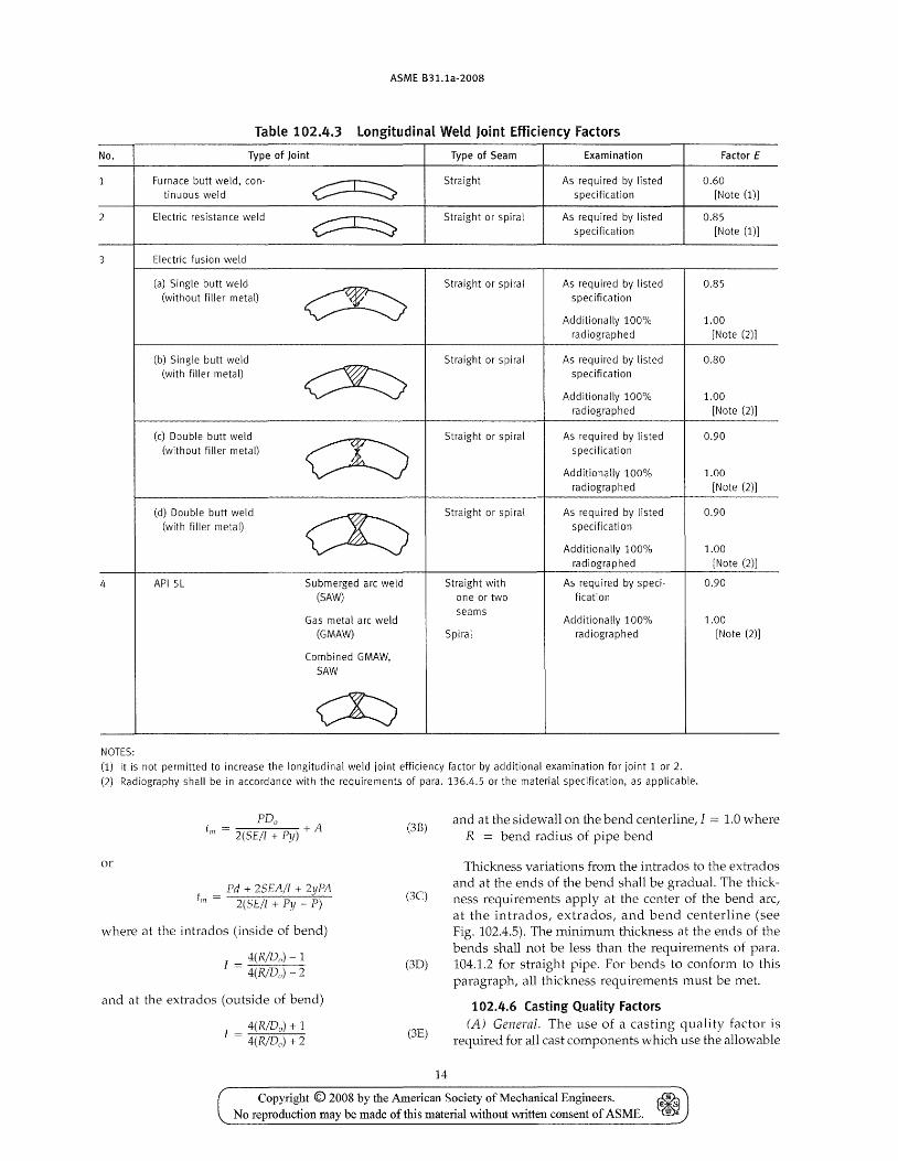
102.4.3 Weld Joint Efficiency Factors. The use of joint efficiency factors for welded pipe is required by this Code. The factors in Table 102.4.3 are based on full penetration welds. These factors are included in the allowable stress values given in Appendix A. The factors in Table 102.4.3 apply to both straight seam and spiral seam welded pipe.
102.4.4 Mechanical Strength. Where necessary for mechanical strength to prevent damage, collapse, excessive sag, or buckling of pipe due to superimposed loads from supports or other causes, the wall thickness of the pipe should be increased; or, if this is impractical or would cause excessive local stresses, the superimposed loads or other causes shall be reduced or eliminated by other design methods. The requirements of para. 1D4.1.2(C) shall also apply.
102.4.5 Bending. The minimum wall thickness at any point on the bend shall conform to (A) or (B) below.
(A) The minimum wall thickness at any point in a completed bend shall not be less than required by eq. (3) or (3A) of para. 104.1.2(A).
(A.1) Table 102.4.5 is a guide to the designer who must specify wall thickness for ordering pipe. In general, it has been the experience that when good shop practices are employed, the minimum thicknesses of straight pipe shmvn in Table 102.4.5 should be sufficient for bending and still meet the minimum thickness requirements of para. 104.1.2(A).
(A.2) The bend thinning allo\vance in Table 102.4.5 may be provided in all parts of the cross section of the pipe circumference without any detrimental effects being produced.
(B) The minimum required thickness, till' of a bend, after bending, in its finished form, shall be determined in accordance with eq. (3B) or (3C)
Copyright © 2008 by the American Society of Mechanical Engineers. ~ No reproduction may be made of this material \vithout VliTitten consent of ASME. ~
(07)
ASME 831.1a-2008
Table 102.4.3 Longitudinal Weld Joint Efficiency Factors
No. Type of Joint Type of Seam Examination Factor E
1 Furnace butt weld, con-
~ Straight As required by listed 0.60
tinuous weld specification [Note (1)]
2 Electric resistance weld
~ Straight or spiral As required by listed 0.85
specification [Note (1)]
3 Electric fusion weld
(a) Single butt weld
~ Straight or spiral As required by listed 0.85
(without filler metal) specification
Additionally 100% 1.00 radiographed [Note (2)]
(b) Single butt weld Straight or spiral As required by listed 0.80 (with filler metal)
~ specification
Additionally 100% 1.00 radiographed [Note (2)]
(c) Double butt weld
~ Straight or spiral As required by listed 0.90
(without filler metal) specification
Additionally 100% 1.00 radiographed [Note (2)]
(d) Double butt weld
CK:) Straight or spiral As required by listed 0.90
(with filler metal) specification
Additionally 100% 1.00 radiographed [Note (2)]
4 API 5L Submerged arc weld Straight with As required by speci- 0.90 (SAW) one or two fication
seams Gas metal arc weld Additionally 100% 1.00
(GMAW) Spiral rad iographed [Note (2)]
Combined GMAW, SAW
~ NOTES: (1) It is not permitted to increase the longitudinal weld joint efficiency factor by additional examination for joint 1 or 2.
(2) Radiography shall be in accordance with the requirements of para. 136.4.5 or the material specification, as applicable.
or
FDu tm = 2(5E/1 + Py) + A
Pd + 2SEA/l + 2yPA till = 2(5E/I + Fy - F)
where at the intrados (inside of bend)
I = 4(R/Do) - 1 4(R/Do) - 2
and at the extrados (outside of bend)
I = 4(R/Do) + 1 4(R/D,,) + 2
(3B)
(3C)
(3D)
(3E)
14
and at the sidewall on the bend centerline,l = 1.0 where R = bend radius of pipe bend
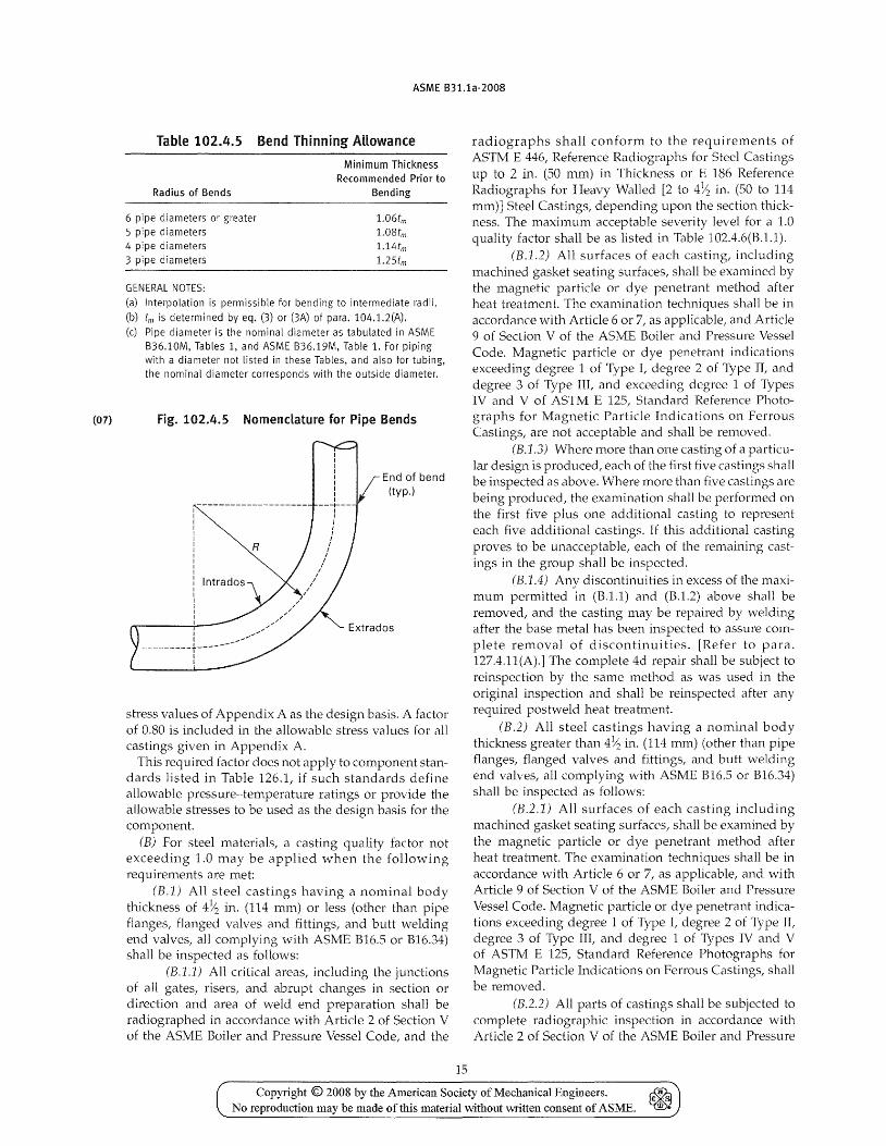
Thickness variations from the intrados to the extrados and at the ends of the bend shall be gradual. The thickness requirements apply at the center of the bend arc, at the intrados, extrados, and bend centerline (see Fig. 102.4.5). The minimum thickness at the ends of the bends shall not be less than the requirements of para. 104.1.2 for straight pipe. For bends to conform to this paragraph, all thickness requirements must be met.
102.4.6 Casting Quality Factors (A) General. The use of a casting quality factor is
required for all cast components which use the allowable
Copyright © 2008 by the American Society of Mechanical Engineers. ~ No reproduction may be made of this material without written consent of ASME. ~
(07)
ASME 831.1a-2008
Table 102.4.5 Bend Thinning Allowance
Radius of Bends
6 pipe diameters or greater
5 pipe diameters 4 pipe diameters
3 pipe diameters
GENERAL NOTES:
Minimum Thickness Recommended Prior to
Bending
1.0 6 trn 1.08tm 1.14trn 1.25trn
(a) Interpolation is permissible for bending to intermediate radii.
(b) tm is determined by eq. (3) or (3A) of para. 104.1.2(A).
(c) Pipe diameter is the nominal diameter as tabulated in ASME
B36.10M, Tables 1, and ASME B36.19M, Table 1. For piping with a diameter not listed in these Tables, and also for tubing,
the nominal diameter corresponds with the outside diameter.
Fig. 102.4.5 Nomenclature for Pipe Bends
I I
---------+----I I
R
End of bend (typ.)
Extrados
stress values of Appendix A as the design basis. A factor of 0.80 is included in the allowable str~ss values for all castings given in Appendix A.
This required factor does not apply to component standards listed in Table 126.1, if such standards define allowable pressure-temperature ratings or provide the allowable stresses to be used as the design basis for the component.
(B) For steel materials, a casting quality factor not exceeding 1.0 may be applied when the following requirements are met:
(B.]) All steel castings having a nominal body thickness of 4Yz in. (114 mm) or less (other than pipe flanges, flanged valves and fittings, and butt welding end valves, all complying with ASME B16.5 or B16.34) shall be inspected as follows:
(B.l.]) All critical areas, including the junctions of all gates, risers, and abrupt changes in section or direction and area of weld end preparation shall be radiographed in accordance with Article 2 of Section V of the ASME Boiler and Pressure Vessel Code, and the
15
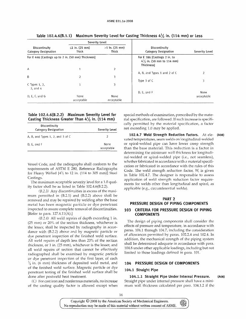
radiographs shall conform to the requirements of ASTM E 446, Reference Radiographs for Steel Castings up to 2 in. (50 mm) in Thickness orE 186 Reference Radiographs for Heavy Walled [2 to 4~ in. (50 to 114 mm)] Steel Castings, depending upon the section thickness. The maximum acceptable severity level for a 1.0 quality factor shall be as listed in Table 102.4.6(B.1.1).
(B.l.2) All surfaces of each casting, including machined gasket seating surfaces, shall be examined by the magnetic particle or dye penetrant method after heat treatment. The examination techniques shall be in accordance with Article 6 or 7, as applicable, and Article 9 of Section V of the ASME Boiler and Pressure Vessel Code. Magnetic particle or dye penetrant indications exceeding degree 1 of Type I, degree 2 of Type TI, and degree 3 of Type TIt and exceeding degree 1 of Types IV and V of ASTM E 125, Standard Reference Photographs for Magnetic Particle Indications on Ferrous Castings, are not acceptable and shall be removed.
(B.1-3) Where more than one casting of a particular design is produced, each of the first five castings shall be inspected as above. \tVhere more than five castings are being produced, the examination shall be performed on the first five plus one additional casting to represent each five additional castings. If this additional casting proves to be unacceptable, each of the remaining castings in the group shall be inspected.
(B.1A) Any discontinuities in excess of the maximum permitted in (B.1.l) and (B.1.2) above shall be removed, and the casting may be repaired by welding after the base metal has been inspected to assure complete removal of discontinuities. [Refer to para. 127.4.11(A).] The complete 4d repair shall be subject to reinspection by the same method as was used in the original inspection and shall be reinspected after any required postweld heat treatment.
(B.2) All steel castings having a nominal body thickness greater than 4Yz in. (114 mm) (other than pipe flanges, flanged valves and fittings, and butt welding end valves, all complying with ASME B16.5 or B16.34) shall be inspected as follows:
(B.2.1) All surfaces of each casting including machined gasket seating surfaces, shall be examined by the magnetic particle or dye penetrant method after heat treatment. The examination techniques shall be in accordance with Article 6 or 7, as applicable, and with Article 9 of Section V of the A5.ME Boiler and Pressure Vessel Code. Magnetic particle or dye penetrant indications exceeding degree 1 of Type t degree 2 of Type II, degree 3 of Type IIt and degree 1 of Types IV and V of ASTM E 125, Standard Reference Photographs for Magnetic Particle Indications on Ferrous Castings, shall be removed.
(B.2.2) All parts of castings shall be subjected to complete radiographic inspection in accordance with Article 2 of Section V of the ASl'v1E Boiler and Pressure
Copyright © 2008 by the American Society of Mechanical Engineers. ~ No reproduction may be made of this material vvithout written consent of ASME. ~
ASME B31.1a-2008
Table 102.4.6(B.1.1) Maximum Severity Level for Casting Thickness 4 ~ in. (114 mm) or Less
Severity level
Discontinuity Category Designation
::;1 in. (25 mm) Thick
>1 in. (25 mm) Thick
Discontinuity Category Designation Severity level
For E 446 [Castings up to 2 in. (50 mm) Thickness]
A
B
C Types 1, 2,
3, and 4
2
3
3
D, E, F, and G None acceptable
None acceptable
Table 102.4.6(B.2.2) Maximum Severity Level for Casting Thickness Greater Than 4~ in. (114 mm)
Discontinuity Category Designation
A, B, and Types 1, 2, and 3 of C
D, E, and F
Severity level
2
None acceptable
Vessel Code, and the radiographs shall conform to the requirements of ASTM E 280, Reference Radiographs for Heavy Walled [4Y2 to 12 in. (114 to 305 mm)] Steel Castings.
The maximum acceptable severity level for a 1.0 quality factor shall be as listed in Table 102.4.6(B.2.2).
(B.2.3) Any discontinuities in excess of the maximum permitted in (B.2.1) and (B.2.2) above shall be removed and may be repaired by welding after the base metal has been magnetic particle or dye penetrant inspected to assure complete removal of discontinuities. [Refer to para. 127.4.11(A).]
(B.2.4) All \veld repairs of depth exceeding 1 in. (25 mm) or 20% of the section thickness, whichever is the lesser, shall be inspected by radiography in accordance wi th (B.2.2) above and by magnetic particle or dye penetrant inspection of the finished weld surface. All weld repairs of depth less than 20% of the section thickness, or 1 in. (25 mm), whichever is the lesser, and all weld repairs of section that cannot be effectively radiogrClphed shCl11 be examined by magnetic particle or dye penetrant inspection of the first layer, of each >4 in. (6 mm) thickness of deposited weld metal, and of the finished weld surface. Magnetic particle or dye penetrant testing of the finished weld surface shall be done after postweld heat treatment.
(C) For cast iron and nonferrous materials! no increase of the casting quality factor is allowed except when
16
For E 186 [Castings 2 in. to 4 V2 in. (50 mm to 114 mm) Thickness]
A, B, and Types 1 and 2 of C
Type 3 of C
D,E,andF
2
3
None acceptable
special methods of examination, prescribed by the material specification, are followed. If such increase is specifically permitted by the material specification! a factor not exceeding 1.0 may be applied.
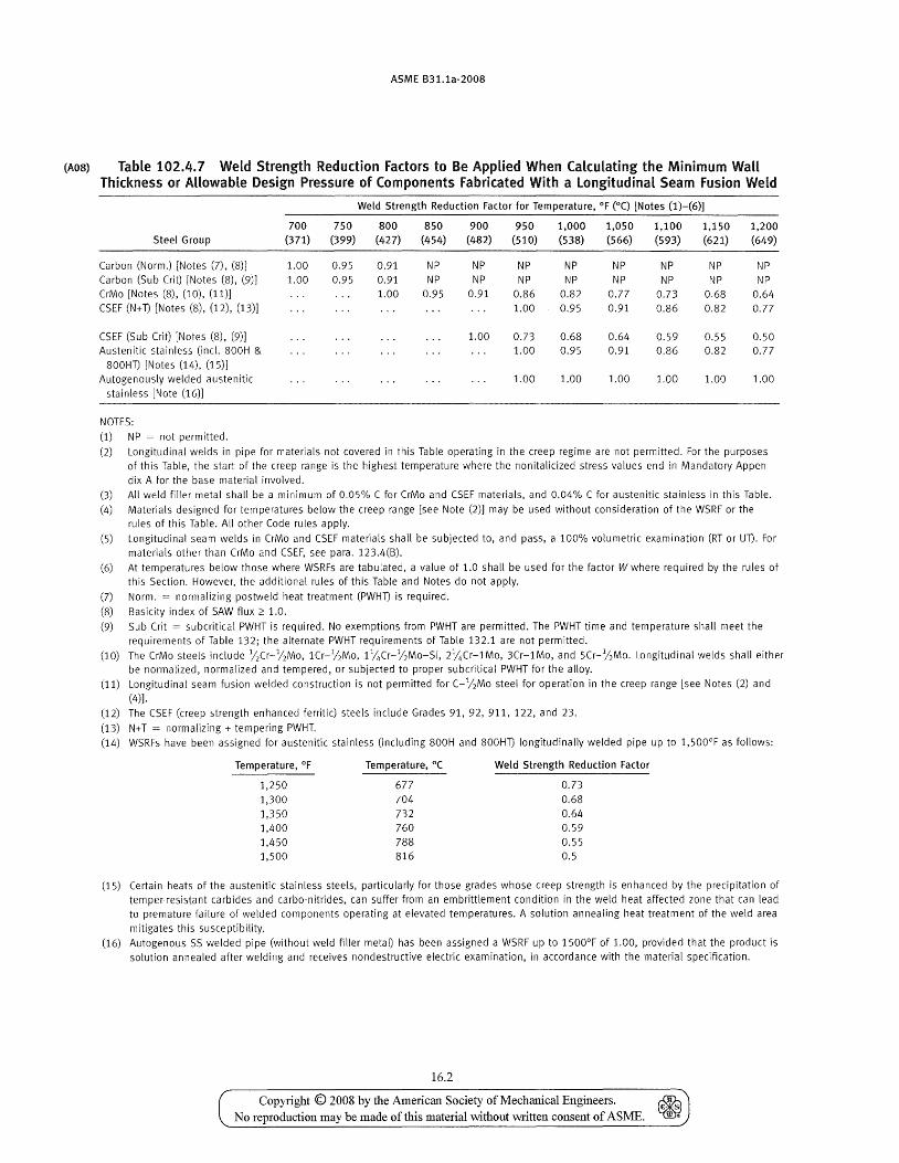
102.4.7 WeLd Strength Reduction Factors. At ele- (A08)
vated temperatures, seam welds on longitudinal-welded or spiral-welded pipe can have lower creep strength than the base material. This reduction is a factor in determining the minimum wall thickness for longitudinal-welded or spiral-\velded pipe (i.e.! not seamless), whether fabricated in accordance with a material specification or fabricated in accordance with the rules of this Code. The weld strength reduction factor, W, is given in Table 102.4.7. The designer is responsible to assess application of weld strength reduction factor require-ments for ,-velds other than longi tudinal and spiral, as applicable (e.g.! circumferential welds).
PART 2 PRESSURE DESIGN OF PIPING COMPONENTS
103 CRITERIA FOR PRESSURE DESIGN OF PIPING COMPONENTS
The design of piping components shall consider the effects of pressure and temperature, in accordance with paras. 104.1 through 104.7, including the consideration of allowances permitted by paras. 102.2.4 and 102.4. In addition, the mechanical strength of the piping system shall be determined adequate in accordance with para. 104.8 under other applicable loadings, including but not limited to those loadings defined in para. 101.
104 PRESSURE DESIGN OF COMPONENTS
104.1 Straight Pipe
104.1.1 Straight Pipe Under Internal Pressure. (A08)
Straight pipe under internal pressure shall have a mini-mum wall thickness calculated per para. 104.1.2 if the
Copyright © 2008 by the American Society of Mechanical Engineers. ~ No reproduction may be made of this material without written consent of ASME. ~
ASME B31.1a·2008
pipe is of seamless construction or is designed for sustained operation below the creep range. Straight pipe under internal pressure shall have a minimum wall thickness calculated per para. 104.1.4 if the pipe is of longitudinal-welded or spiral-\velded construction designed for sustained operation within the creep range. (See para. 123.4 for definition of the creep range.)
(Aoa) 104.1.2 Straight Pipe Under Internal Pressure -Seamless, longitudinal Welded, or Spiral Welded and Operating Below the Creep Range
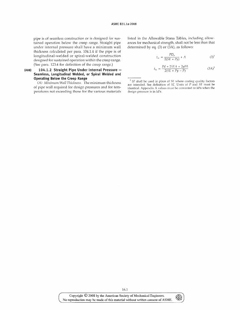
(A) Mini11l.um Wall Thickness. The minimum thickness of pipe wall required for design pressures and for temperatures not exceeding those for the various materials
16.1
listed in the Allovvable Stress Tables, including allowances for mechanical strength, shall not be less than that determined by eq. (3) or (3A), as follows:
Pd + 25EA + 2yPA till = 2(5E + Py P) (3/\/
3 SF shall be used in place of Sf where c(lsting quality factors are intended. See definition of SE. Units of P and SE must be identical. Appendix A values must be converted to kPa ,·\Then the design pressure is in kPa.
Copyright © 2008 by the American Society of Mechanical Engineers. ~ No reproduction may be made of this material without 'Wl'itten consent of ASME. ~
ASME B31.1a-2008
(A08) Table 102.4.7 Weld Strength Reduction Factors to Be Applied When Calculating the Minimum Wall Thickness or Allowable Design Pressure of Components Fabricated With a longitudinal Seam Fusion Weld
Weld Strength Reduction Factor for Temperature, OF (0C) [Notes (1)-(6)]
700 750 800 850 900 950 1,000 1,050 1,100 1,150 1,200 Steel Group (371) (399) (427) (454) (482) (510) (538) (566) (593) (621) (649)
Carbon (Norm.) [Notes (7), (8)] 1.00 0.95 0.91 NP NP NP NP NP NP NP NP Carbon (Sub (rit) [Notes (8), (9)J 1.00 0.95 0.91 NP NP NP NP NP NP NP NP CrMo [Notes (8), (10), (11)] 1.00 0.95 0.91 0.86 0.82 0.77 0.73 0.68 0.64 (SEF (N+ n [Notes (8), (12), (13)J 1.00 0.95 0.91 0.86 0.82 0.77
(SEF (Sub (rit) [Notes (8), (9)] 1.00 0.73 0.68 0.64 0.59 0.55 0.50 Austenitic stainless (inc\. 800H & 1.00 0.95 0.91 0.86 0.S2 0.77
SOOHn [Notes (14), (15)] Autogenously welded austenitic 1.00 1.00 1.00 1.00 1.00 1.00
stainless [Note (16)]
NOTES:
(1) NP = not permitted.
(2) Longitudinal welds in pipe for materials not covered in this Table operating in the creep regime are not permitted. For the purposes of this Table, the start of the creep range is the highest temperature where the non italicized stress values end in Mandatory Appendix A for the base material involved.
(3) All weld filler metal shall be a minimum of 0.05% C for CrMo and CSEF materials, and 0.04% C for austenitic stainless in this Table.
(4) Materials designed for temperatures below the creep range [see Note (2)] may be used without consideration of the WSRF or the rules of this Table. All other Code rules apply.
(5) Longitudinal seam welds in CrMo and CSEF materials shall be subjected to, and pass, a 100% volumetric examination (RT or Un. For materials other than CrMo and CSEF, see para. 123.4(B).
(6) At temperatures below those where WSRFs are tabulated, a value of 1.0 shall be used for the factor W where required by the rules of this Section. However, the additional rules of this Table and Notes do not apply.
(7) Norm. = normalizing postweld heat treatment (PWHn is required.
(8) Basicity index of SAW flux 2': 1.0.
(9) Sub Crit = subcritical PWHT is required. No exemptions from PWHT are permitted. The PWHT time and temperature shall meet the requirements of Table 132; the alternate PWHT requirements of Table 132.1 are not permitted.
(10) The CrMo steels include 12Cr-12Mo, lCr-12Mo, 11/+Cr-l/2Mo-Si, 2%Cr-1Mo, 3Cr-1Mo, and 5Cr-"hMo. Longitudinal welds shall either be normalized, normalized and tempered, or subjected to proper subcritical PWHT for the alloy.
(11) Longitudinal seam fusion welded construction is not permitted for C-12Mo steel for operation in the creep range [see Notes (2) and (4)].
(12) The CSEF (creep strength enhanced ferritic) steels include Grades 91,92,911,122, and 23.
(13) N+ T = normalizing + tempering PWHT. (14) WSRFs have been assigned for austenitic stainless (including 800H and 800Hn longitudinally welded pipe up to 1,500°F as follows:
Temperature, OF Temperature, O( Weld Strength Reduction Factor
1,250 677 0.73
1,300 704 0.68
1,350 732 0.64 1,400 760 0.59
1,450 788 0.55 1,500 816 0.5
(15) Certain heats of the austenitic stainless steels, particularly for those grades whose creep strength is enhanced by the precipitation of temper-resistant carbides and carbo-nitrides, can suffer from an embrittlement condition in the weld heat affected zone that can lead to premature failure of welded components operating at elevated temperatures. A solution annealing heat treatment of the weld area
mitigates this susceptibility. (16) Autogenous SS welded pipe (without weld filler metal) has been assigned a WSRF up to 1500°F of 1.00, provided that the product is
solution annealed after welding and receives nondestructive electric examination, in accordance with the material specification.
16.2
Copyright © 2008 by the American Society of Mechanical Engineers. ~ No reproduction may be made of this material without written consent of ASME. ~
ASME B31.1a-2008
Design pressure shall not exceed
2SE(tm - A) p= ,
Do - 2yUm - A)
2SE(tll! - A) p = ~------~---
d - 2y(t1l1 - A) + 2illl (4A)3
where the nomenclature used above is: (Al) t1/1 = minimum required wall thickness, in.
(mm) (A.1.l) If pipe is ordered by its nomi
nal wall thickness, the manufacturing tolerance on wall thickness must be taken into account. After the minimum pipe wall thickness till is determined by eq. (3) or (3A), this minimum thickness shall be increased by an amount sufficient to providE:' the manufacturing tolerance allowed in the applicable pipe specification or required by the process. The next heavier commercial wall thickness shall then be selected from thickness schedules such as contained in ASME B36.10M or from manufacturers' schedules for other than standard thickness.
(A.l.2) To compensate for thinning in bends, refer to para. 102.4.5.
(AJ.3) For cast piping components, refer to para. 102.4.6.
(A.l.4) Where ends are subject to forming or machining for jointing, the wall thickness of the pipe, tube, or component after such forming or machining shall not be less than tm minus the amount provided for removal by para. 104.1.2 (A.6.1).
(A.2) P = internal design pressure, psig [kPa (gage)]
NOTE: When computing the design pressure for a pipe of a definite minimum wall thickness by eq. (4) or (4A)i the value of P obtained by these formulas may be rounded out to the next higher unit of 10. For cast iron pipe, see para. 104.L2(B).
(A3) Do = outside diameter of pipe, in. (mm). For design calculations, the outside diameter of pipe as given in tables of standards and speci fications shall be used in obtaining the value of tm' When calculating the allowable working pressure of pipe on hand or in stock, the actual measured outside diameter and actual measured minimum wall thickness at the thinner end of the pipe may be used to
(A4) d calculate this pressure. inside diameter of pipe, in. (mm). For design calculations, the inside diameter of pipe is the maximum possible value allowable under the purchase specification. When calculating the allowable
17
(A5) SE or SF
(A.6) A
(A.7) y
working pressure of pipe on hand or in stock, the actual measured inside diameter and actual measured minimum wall thickness at the thinner end of the pipe may be used to calculate this pressure.
maximum allowable stress in material due to internal pressure and joint efficiency (or casting quality factor) at the design temperature, psi (MPa). The value of SE or SF shall not exceed that given in Appendix A, for the respective material and design temperature. These values include the weld joint efficiency, E, or the casting factor, F. additional thickness, in. (mm)
(A.6.1) To compensate for material removed in threading, grooving, etc., required to make a mechanical joint, refer to para. 102.4.2.
(A.6.2) To provide for mechanical strength of the pipe, refer to para. 102.4.4 (not intended to provide for extreme conditions of misapplied external loads or for mechanical abuse).
(A6.3) 'fb provide for corrosion and/ or erosion, refer to para. 102.4.1. coefficient having values as given in Table 104.1.2(A)
(B) Thickness of gray and ductile iron tlttmgs conveying liquids may be determined from ANSI! AWWA CllO/ A21.10 or ANSI! AWWA C153/ A21.53. The thickness of ductile iron pipe may be determined by ANSI/ AWVvA C1l5/ A21.15 or ANSI! AWWA Cl50/ A21.50. These thicknesses include allo\,vances for foundry tolerances and water hammer.
(C) \A/hile the thickness detenTtined from eq. (3) or (3A) is theoretically ample for both bursting pressure and material removed in threading, the following minimum requirements are mandatory to furnish added mechanical strength:
(Cl) Where steel pipe is threaded and used for steam service at pressure above 250 psi (1 750 kPa) or for water service above 100 psi (700 kPa) with water temperature above 220°F (105°C), the pipe shall be seamless having the minimum ultimate tensile strength of 48,000 psi (330 I'vlPa) and a weight at Jeast equal to Schedule 80 of ASME B36.10M.
(C2) Where threaded brass or copper pipe is used for the services described in (C.1) above, it shall comply with pressure and temperature classifications permitted for these materials by other paragraphs of this Code and shall have a wall thickness at least equal to that specified above for steel pipe of corresponding size.
(C3) Plain end nonferrous pipe or tube shall have minimum wall thicknesses as follows:
Copyright © 2008 by the American Society of Mechanical Engineers. ~ No reproduction may be made of this material without written consent of ASME. ~
(A08)
ASME B31.1a-2008
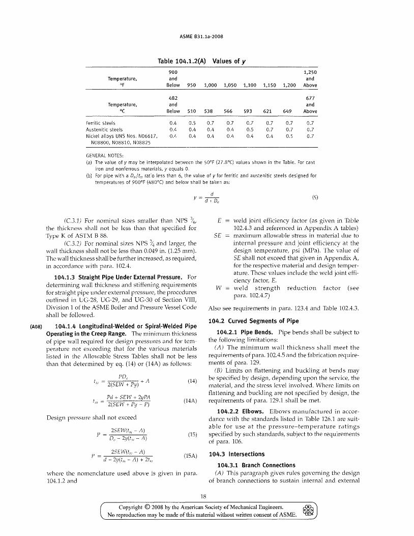
TabLe 104.1.2(A) Values of y
900 1,250 Temperature, and and
OF Below 950 1,000 1,050 1,100 1,150 1,200 Above
482 677 Temperature, and and
°C Below 510 538 566 593 621 649 Above
Ferritic steels 0.4 0.5 0.7 0.7 0.7 0.7 0.7 0.7 Austenitic steels 0.4 0.4 0.4 0.4 0.5 0.7 0.7 0.7 Nickel alloys UNS Nos. N06617, 0.4 0.4 0.4 0.4 0.4 0.4 0.5 0.7
N08800, N08810, N08825
GENERAL NOTES: (a) The value of y may be interpolated between the 50°F (27.8°C) values shown in the Table. For cast
iron and nonferrous materials, y equals O.
(b) For pipe with a Do/tm ratio less than 6, the value of y for ferritic and austenitic steels designed for temperatures of 900°F (480°C) and below shall be taken as:
d y = d + Do (5)
(C.3.1) For nominal sizes smaller than NPS %, the thickness shall not be less than that specified for Type K of ASTM B 88.
(C.3.2) For nominal sizes NPS % and larger, the wall thickness shall not be less than 0.049 in. (1.25 mm). The wall thickness shall be further increased, as required, in accordance with para. 102.4.
104.1.3 Straight Pipe Under External Pressure. For determining wall thickness and stiffening requirements for straight pipe under external pressure, the procedures outlined in UG-28, UG-29, and UG-30 of Section VIII, Division 1 of the ASME Boiler and Pressure Vessel Code shall be followed.
104.1.4 longitudinal-Welded or Spiral-Welded Pipe Operating in the Creep Range. The minimum thickness of pipe wall required for design pressures and for temperature not exceeding that for the various materials listed in the Allowable Stress Tables shall not be less than that determined by eq. (14) or (14A) as follows:
PDo tlil = +A
2(SEW + Py)
_ Pd + SEW + 2yPA till - 2(SEW + Py _ P)
Design pressure shall not exceed
2SEW(t1l1 - A) P = ---------:.... Do - 2y(tm - A)
2SEW(tm - A) P = --------------
d - 2y(trll - A) + 2tn/
(14)
(14A)
(15)
(15A)
where the nomenclature used above is given in para. 104.1.2 and
18
E weld joint efficiency factor (as given in Table 102.4.3 and referenced in Appendix A tables)
SE maximum a110vvable stress in material due to internal pressure and joint efficiency at the design temperature, psi (MPa). The value of Sf shall not exceed that given in Appendix A, for the respective material and design temperature. These values include the weld joint efficiency factor, E.
W weld strength reduction factor (see para. 102.4.7)
Also see requirements in para. 123.4 and Table 102.4.3.
104.2 Curved Segments of Pipe
104.2.1 Pipe Bends. Pipe bends shall be subject to the following limitations:
(A) The minimum wall thickness shall meet the req uirements of para. 102.4.5 and the fabrication requirements of para. 129.
(B) Limits on flattening and buckling at bends may be specified by design, depending upon the service, the material, and the stress level involved. vVhere limits on flattening and buckling are not specified by design, the requirements of para. 129.1 shall be met.
104.2.2 Elbows. Elbows manufactured in accordance with the standards listed in Table 126.1 are suitable for use at the pressure-temperature ratings specified by such standards, subject to the requirements of para. 106.
104.3 Intersections
104.3.1 Branch Connections (A) This paragraph gives rules governing the design
of branch connections to sustain internal and external
Copyright © 2008 by the American Society of Mechanical Engineers. No reproduction may be made of this material without vvritten consent of ASME.
ASME B31.1a-2008
pressure in cases where the axes of the branch and the run intersect, and the angle between the axes of the branch and of the run is between 45 deg and 90 deg, inclusive.
Branch connections in which the smaller angle between the axes of the branch and the run is less than 45 deg or branch connections where the axes of the branch and the run do not intersect impose special design and fabrication problems. The rules given herein may be used as a guide, but sufficient additional strength must be provided to assure safe service. Such branch connections shall be designed to meet the requirement of para. 104.7.
(B) Branch connections in piping may be made from materials listed in Appendix A by the use of the following:
(B.1) fittings, such as tees, laterals, and crosses made in accordance with the applicable standards listed
18.1
in Table 126.1 where the attachment of the branch pipe to the fitting is by butt welding, socket welding, brazing, soldering, threading, or by a flanged connection.
(B.2) weld outlet fittings, such as cast or forged nozzles, couplings and adaptors, or similar items where the attachment of the branch pipe to the fitting is by butt welding, socket welding, threading, or by a flanged connection. Such \veld outlet fittings are attached to the run by welding similar to that shown in Fig. 127.4.8(E). Couplings are restricted to a maximum of NPS 3.
(B.3) extruded outlets at right angles to the run pipe, in accordance with (G) below, where the attachment of the branch pipe is by butt welding.
(B.4) piping directly attached to the fun pipe by welding in accordance with para. 127.4.8 Of by socket welding or threading as stipulated below:
Copyright © 2008 by the American Society of Mechanical Engineers. ~ No reproduction may be made of this material without written consent of ASME. ~

INTENTIONALLY LEFT BLANK
Copyright © 2008 by the American Society of Mechanical Engineers. ~ No reproduction may be made of this material without written consent of ASME. ~
ASME B31.1a-2008
(B.4.1) socket welded right angle branch connections may be made by attaching the branch pipe directly to the run pipe provided.
(B.4.1.1) the nominal size of the branch does not exceed NPS 2 or one-fourth of the nominal size of the run, whichever is smaller.
(B.4.1.2) the depth of the socket measured at its minimum depth in the run pipe is at least equal to that shown in ASME 516.11. If the run pipe wall does not have sufficient thickness to provide the proper depth of socket, an alternate type of construction shall be used.
(B.4.1.3) the clearance between the bottom of the socket and the end of the inserted branch pipe is in accordance with Fig. 127.4.4(C).
(B.4.1.4) the size of the fillet weld is not less than 1.09 times the nominal wall thickness of the branch pipe.
(B.4.2) threaded right angle branch connections may be made by attaching the branch pipe directly to the run provided
(B.4.2.1) the nominal size of the branch does not exceed NPS 2 or one-fourth of the nominal size of the run, whichever is smaller.
(B.4.2.2) the minimum thread engagement is: 6 full threads for NPS Y2 and NPS ~ branches; 7 for NPS 1, NPS 1>4, and NPS 112 branches; and 8 for NPS 2 branches. If the run pipe wall does not have sufficient thickness to provide the proper depth for thread engagement, an alternative type of construction shall be used.
(C) Branch Connections Not Req1liring Reinforcemellt. A pipe having a branch connection is weakened by the opening that must be made in it. Unless the wall thickness of the branch and/or run pipe is sufficiently in excess of that required to sustain the pressure, it is necessary to provide additional material in order to meet the reinforcement requirements of (D) and (E) below. However, there are certain branch connections for which supporting calculations are not required. These are as follows:
(C1) branch connections made by the use of a fitting (tee, lateral, cross/ or branch weld-on fitting), manufactured in accordance with a standard listed in Table 126.1, and used within the limits of pressuretemperature ratings specified in that standard.
(C2) branch connections made by welding a coupling or half coupling directly to the run pipe in accordance with Fig. 127.4.8(E), provided the nominal diameter of the branch does not exceed NPS 2 or onefourth the nominal diameter of the run, whichever is less. The minimum wall thickness of the coupling anywhere in the reinforcement zone (if threads are in the zone, wall thickness is measured from the root of the thread to the minimum O.D.) shall not be less than that of the unthreaded branch pipe. In no case shall the thickness of the coupling be less than extra heavy or Class 3000 rating.
19
Small branch connections NPS 2 or smaller as shown in Fig. 127.4.8(F) may be used, provided tw is not less than the thickness of schedule 160 pipe of the branch size.
(C.3) integrally reinforced fittings welded directly to the run pipe when the reinforcements provided by the fitting and the deposited weld metal meets the requirements of (D) below.
(C4) integrally reinforced extruded outlets in the run pipe. The reinforcement requirements shall be in accordance with (G) belm,v.
(D) Branch Connections Subject to lntemal Pressure Requiring Reh~forcement
(D.V Reinforcement is required when it is not provided inherently in the components of the branch connection. This paragraph gives rules covering the design of branch connections to sustain internal pressure in cases where the angle between the axes of the branch and of the run is between 45 deg and 90 deg. Subparagraph (E) below gives rules governing the design of connections to sustain external pressure.
(0.2) Figure 104.3.1(D) illustrates the notations (07)
used in the pressure-temperature design conditions of (A08)
branch connections. These notations are as follows: b subscript referring to branch
Dab outside diameter of branch, in. (mm) Doh outside diameter of headel~ in. (mm)
d1 inside centerline longitudinal dimension of the finished branch opening in the run of the pipe, in. (mm) [Doh - 2(T/l - A)]/sin a
d2 "half width" of reinforcing zone, in. (mm) the greater of d1 or eft; - A) + (TJz - A) + dd2 but in no case more than Doll, in. (mm)
h subscript referring to run or header L4 altitude of reinforcement zone outside of
run, in. (mm) 2.5(Tb - A) + tr or 2.5(T/i - A), whichever is sma1ler
t f thickness of attached reinforcing pad, in Example A, in. (mm); or height of the largest 60 deg right triangle supported by the run and branch outside diameter projected surfaces and lying completely within the area of integral reinforcement, in Example B, in. (mm)
T/)f Til actual (by measurement), or minimum wall thickness of the branch or header pipe, in. (mm), permissible under purchase specification
t1llb, tmli required minimum wall thickness, in. (mm), of the branch or header pipe as determined by use of eq. (3) or (3A) in para. 104.1.2(A)
a = angle between axes of branch and run, deg
(0.2.1) If the run pipe contains a longitudinal seam which is not intersected by the branch, the stress value of seamless pipe of con{parable grade may be
Copyright © 2008 by the American Society of Mechanical Engineers. No reproduction may be made of this material without \Vl'itten consent of ASME.
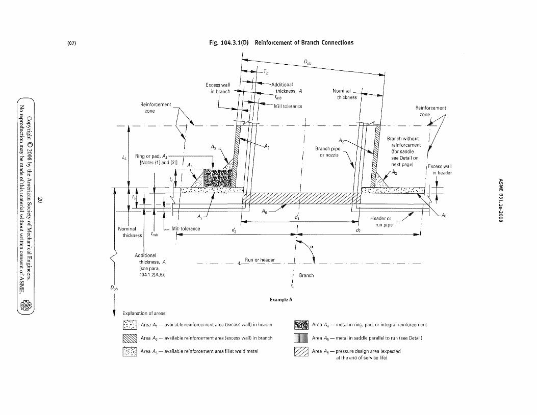
z o >-;
~ Q o "d P-« >= t:J. a. ~ o ..... 1= S @ ~ t-.l '< 0 er o (I) 00
S~ ~S" (I) (I)
~~ rJ'} ::1. S () s. § (I) r/J t:J.o ~ ()
i$ S"o o >-+,
a ~ ~. 8-~ f:l 1= ~. () ~ o ...... 1= tr1 V> 1= ~ Uq ;:;.. s· o (I) >-+,(1)
>fi3 r/J
~
~
N o
(07)
DOll
~
Fig. 104.3.1(D) Reinforcement of Branch Connections
Excess wall Nominal
thickness
Reinforcement ~ zone
Reinforcement
-~-
I L4 I Ring or pad, A4 --;------,
[Notes (1) and (2)]
Til
d
Branch without reinforcement (for saddle see Detail on next page)
A3
1 .... 1 Header or
Mill tolerance d I I run pipe '.... 2 d2 I I ........ ....
Nominal thickness I tmll
I~a Additional
thickness, A [see para. 104.1.2(A.6)]
__ t~n_ o~a?e_r - . -f- ._ _ ,. I Branch
t
Example A
Explanation of areas:
D·· ...... .....
~ [2]
Area Al - available reinforcement area (excess wall) in header
Area A2 - available reinforcement area (excess wall) in branch
Area A3 - available reinforcement area fillet weld metal
g m ~
Area A4 - metal in ring, pad, or integral reinforcement
Area A5 - metal in saddle parallel to run (see Detail)
Area A6 - pressure design area (expected at the end of service life)
Al
» VI s: m OJ w ..... ;.., III
N o o 00
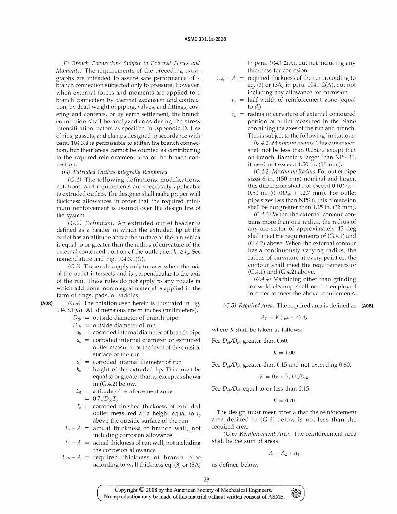
(A08)
ASME B31.1a-2008
(F) Branch Connections Subject to External Forces and Momen ts. The requirements of the preceding p,nagraphs are intended to assure safe performance of a branch connection subjected only to pressure. However, when external forces and moments are applied to a branch connection by thermal expansion and contraction, by dead weight of piping, valves, and fittings, covering and contents, or by earth settlement, the branch connection shall be analyzed considering the stress intensification factors as specified in Appendix D. Use of ribs, gussets, and clamps designed in accordance "vith para. 104.3.4 is permissible to stiffen the branch connection, but their areas cannot be counted as contributing to the required reinforcement area of the branch connection.
(G) Extruded Outlets integrally Reinforced (G.1) The following definitions, modifications,
notations, and requirements are specifically applicable to extruded outlets. The designer shall make proper wall thickness allowances in order that the required minimum reinforcement is assured over the design life of the system.
(G.2) Definitio1l. An extruded outlet header is defined as a header in which the extruded lip at the outlet has an altitude above the surface of the run which is equal to or greater than the radius of curvature of the external contoured portion of the outlet; i.e., lzo ~ roo See nomenclature and Fig. 104.3.1(G).
(G.3) These rules apply only to cases where the axis of the outlet intersects and is perpendicular to the axis of the run. These rules do not apply to any nozzle in which additional nonintegral material is applied in the form of rings, pads, or saddles.
(G.4) The notation used herein is illustrated in Fig. 104.3.1 (G). All dimensions are in inches (millimeters).
Dol! ou tside diameter of branch pipe Doli au tside diameter of run
db corroded internal diameter of branch pipe de corroded internal diameter of extruded
outlet measured at the level of the outside surface of the run
tmh - A
corroded internal diameter of run height of the extruded lip. This must be equal to or greater than rOt except as shown in (G.4.2) below. altitude of reinforcement zone 0.7 jDouTo corroded finished thickness of extruded outlet measured at a height equal to 1'0
above the outside surface of the run actual thickness of branch walt not including corrosion allowance actual thickness of run wall, not including the corrosion allowance required thickness of branch pipe according to wall thickness eq. (3) or (3A)
23
r o
in para. 104.1.2(A), but not including any thickness for corrosion required thickness of the run according to eq. (3) or (3A) in para. 104.1.2(A), but not including any allowance for corrosion half width of reinforcement zone (equal to de) radius of curvature of external contoured portion of outlet measured in the plane containing the axes of the run and branch. This is subject to the following limitations:
(G.4.1) Minimum Radius. This dimension shall not be less than 0.05Dob except that on branch dianleters larger than NPS 30, it need not exceed 1.50 in. (38 mm).
(G.4.2) Maxim.u11l Radius. For outlet pipe sizes 6 in. (150 mm) nominal and larger, this dimension shall not exceed O.lODo/! + 0.50 in. (0.10Doh + 12.7 mm). For outlet pipe sizes less than NPS 6, this dimension shall be not greater than 1.25 in. (32 mm).
(G.4.3) When the external contour contains more than one radius, the radius of any arc sector of approximately 45 deg shall meet the requirements of (GA.1) and (G.4.2) above. When the external contour has a continuously varying radius, the radius of curvature at every point on the contour shall meet the requirements of (GA.1) and (G.4.2) above.
(G.4.4) Machining other than grinding for "veld cleanup shall not be employed in order to meet the above requirements.
(G,S) Required Area. The required area is defined as (A08)
where K shall be taken as follows:
For DOl/DOh greater than 0.60,
K = 1.00
For Dab/Doh greater than 0.15 and not exceeding 0.60,
For Doh/Doh equal to or less than 0.15,
K = 0.70
The design must meet criteria that the reinforcement area defined in (C.6) below is not less than the required area.
(G.6) Reinforcenlent Area. The reinforcement area shall be the sum of areas
as defined below.
Copyright © 2008 by the American Society of Mechanical Engineers. ~ (> ·s
No reproduction may be made oftms material without written consent of ASME. iii ..
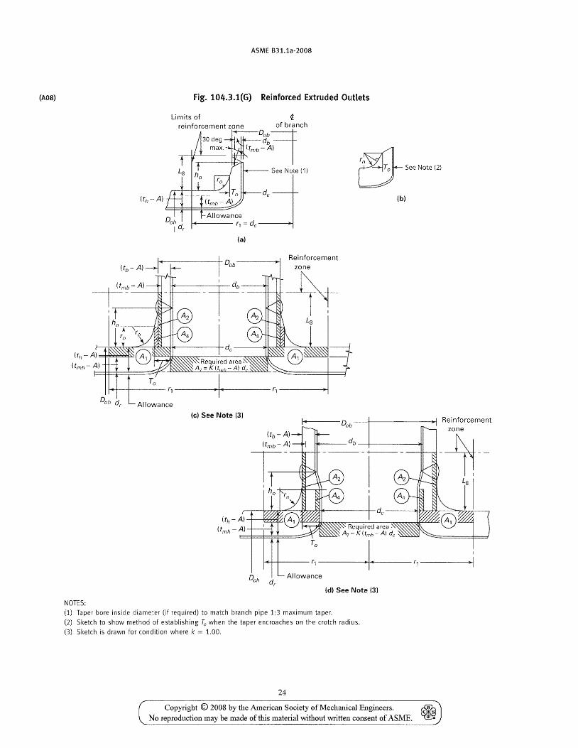
(A08)
ASME B31.1a-2008
Fig. 104.3.1(G) Reinforced Extruded Outlets
Limits of
db (tmb - A)
reinforcement zone DOb90f branch
rgt 0-See Note (2)
(til A)===j:oj~~~
(tmll A) F==t::t=i===*==::::5-(,
(a)
) I Reinforcement Dob----~ zone
--++--1+-+ Ls
(b)
I~--+-------G-------~~--------G----~
Allowance
(e) See Note (3) I .. Dob--~------~
~ ____ db __ +-________ ~
----- - +1 -----
Reinforcement zone
--tn--
To I 1~~----G-----~·+~·----r1----------~)1
Allowance
(d) See Note (3)
NOTES: (1) Taper bore inside diameter (if required) to match branch pipe 1:3 maximum taper. (2) Sketch to show method of establishing To when the taper encroaches on the crotch radius. (3) Sketch is drawn for condition where k = 1.00.
24
Copyright © 2008 by the American Society of Mechanical Engineers. No reproduction may be made of this material without \V1'itten consent of ASME.
ASME B31.1a-2008
where D nominal pipe size (NPS), in. (mm) Ec modulus of elasticity at room temperature,
psi (kPa) L developed length of pipe (total length of pipe
taken along the piping longitudinal axes), ft (m)
SA allowable displacement stress range determined in accordance with para. 102.3.2(B), eq. (lA), psi (kPa)
U anchor distance (length of straight line between the anchors), ft (m)
Y resultant displacement between the anchors to be absorbed by the piping system, in. (mm)
WARNING: No general proof can be offered that this equation will yield accurate or consistently conservative results. It was developed for ferrous materials and is not applicable to systems used under severe cyclic conditions. It should be used with caution in configurations such as unequal leg V-bends (L/U> 2.5),
or near straight "saw-tooth" runs, or for large diameter thin-wall pipe, or where extraneous displacements (not in the direction connecting anchor points) constitute a large part of the total displacement, or where piping operates in the creep range. There is no assurance that anchor reactions will be acceptably low, even when a piping system meets the above requirements.
(B) All systems not meeting the above criteria, or where reas~nable doubt exists as to adequate flexibility between the anchors, sha11 be analyzed by simplified, approxima te, or comprehensive methods of analysis that are appropria te for the specific case. The results of such analysis shall be evaluated using para. 104.8.3, eq. (13).
(C) Approximate or simplified methods may be applied only if they are used for the range of configurations for which their adequate accuracy has been demonstrated.
(D) Acceptable comprehensive methods of analysis include: analytical, model tests, and chart methods which provid~ an evaluation of the forces, moments and stresses caused by bending and torsion from the simultaneous consideration of terminal and intermediate restraints to thermal expansion of the entire piping system under consideration, and including all external movements transmitted to the piping by its terminal and intermediate attachments. Correction factors shall be applied for the stress intensification of curved pipe and branch connections, as provided by the details of these rules, and may be applied for the increased flexibility of such component parts.
119.7.3 Basic Assumptions and Requirements. In calculating the flexibility or displacement stresses of a piping system between anchor points, the system between anchor points shall be treated as a whole. The significance of all parts of the line and of all restraints, such as supports or guides, including intermediate restraints introduced for the purpose of reducing
41
mom(:~nts and forces on equipment or small branch lines, shall be considered.
Flexibility calculations shall take into account stress intensifying conditions found in components and joints. Credit may be taken when extra flexibility exists in such compone~ts. In the absence of more directly applicable data the flexibility factors and stress-intensification fac-
, 4 tors shown in AppendiX D may be used.
Dimensional properties of pipe and fittings used in flexibility calculations shall be based on nominal dimensions.
The total reference displacement range resulting from using the coefficient of thermal expansion determined in accordance with para. 119.6.1 shall be used, whether or not the piping is cold sprung. Not only the expansion of the line itself, but also linear and angular movements of the equipment to which it is attached, shall be considered.
Where simplifying assumptions are used in calculations or model tests, the likelihood of attendant underestimates of forces, moments, and stresses, including the effects of stress intensification, shall be e\laluated.
119.8 Movements
l\;lovements caused by thermal expansion and loadings shall be determined for consideration of obstructions and design of proper supports.
119.9 Cold Spring
The beneficial effect of judicious cold springing in assisting a system to attain its most favorable position sooner is recognized. Inasmuch as the life of a system under cvclic condi tions depends on the stress range rather than the stress level at anyone time, no credit for cold spring is allowed wi th regard to stresses. In calculating end thrusts and moments acting on equipment the actual reactions at any one time, rather than their 'range, are significant. Credit for cold springing is accordino-Iv allO\ved in the calculation of thrusts and b _
moments, provided an effective method of obtaining the designed cold spring is specified and used.
119.10 Reactions
119.10.1 Computing Hot and Cold Reactions. In a (A08)
piping system with no cold spring or an equal percent-age of cold springing in all directions, the reactions (forces and moments) of Rh and Ro in the hot and cold conditions, respectively, shall be obtained from the reac-tion, R, derived from the flexibility calculations based
4 The stress-intensification factoT5 in Appendix D have been developed from fatigue tests of representative coml1l.ercially available, matching product forms and assemblies manutactured from ductile ferrous materials. The allowable stress range 1S based on tests of carbon and stainless steels. Caution should be exercised when applying Figs. (1) and (13) for the allmvable str?ss range for certain nonferrous rnaterials (e.g., copper and alUlTllnUm alloys) for other than low cycle applications.
Copyright © 2008 by the American Society of Mechanical Engineers. ~ No reproduction may be made oftbis material \vithout written consent of ASME.
ASME B31.1a-2008
on the modulus of elasticity at room temperature, Eu using eqs. (9) and (10).
(9)
R, = -- CR., or
(10)
whichever is greater, and with the further condition that
where C
E c
R
cold spring factor varying from zero for no cold spring to 1.00 for 100% cold spring modulus of elasticity in the cold condition, psi (MFa) modulus of elasticity in the hot condition, psi (MFa) maximum reaction for full expansion range based on Ec which assumes the most severe condition (100% cold spring, whether such is used or not), Ib and in.-lb (N and mm·N) maximum reactions estimated to occur in the cold and hot conditions, respectively, lb and in.-lb (N and mm·N) computed thermal expansion stress range, psi (MFa) basic material allowable stress at maximum (hot) temperature, without the 20 ksi limitation as noted in para. 102.3.2(C)
If a piping system is designed ,,\lith different percentages of cold spring in various directions, eqs. (9) and (10) are not applicable. In this case, the piping system shall be analyzed by a comprehensive method. The calculated hot reactions shall be based on theoretical cold springs in all directions not greater than two-thirds of the cold springs as specified or measured.
119.10.2 Reaction Limits. The reactions computed shall not exceed limits vvhich the attached equipment can sustain. Equipment allowable reaction limits (forces and moments) on piping connections are normally established by the equipment manufacturer.
120 LOADS ON PIPE SUPPORTING ELEMENTS
120.1 General
(A) The broad terms "supporting elements" or IISUpports" as used herein shall encompass the entire range of the various methods of carrying the weight of pipe lines, insulation, and the fluid carried. It, therefore, includes "hangers" that are generally considered as
42
those elements which carry the weight from above, with the supporting members being mainly in tension. Likewise, it includes "supports" which on occasion are delineated as those that carry the weight from below, with the supporting members being mainly in compression. In many cases a supporting element may be a combination of both of these.
(B) In addition to the weight effects of piping components, consideration shall be given in the design of pipe supports to other load effects introduced by service pressure, wind, earthquake, etc., as defined in para. 101. Hangers and supporting elements shall be fabricated and assembled to permit the free movement of piping caused by thermal expansion and contraction. The design of elements for supporting or restraining piping systems, or components thereof, shall be based on all the concurrently acting loads transmitted into the supporting elements.
(C) Where the resonance with imposed vibration and/ or shock occurs during operation, suitable dampeners, restraints, anchors, etc., shall be added to remove these effects.
120.2 Supports, Anchors, and Guides
120.2.1 Rigid-Type Supports (A) The required strength of all supporting elements
shall be based on the loadings as given in para. 120.1, including the weight of the fluid transported or the fluid used for testing, whichever is heavier. The allowable stress in supporting equipment shall be as specified in para. 121.2.
(B) Exceptions may be made in the case of supporting elements for large size gas or air piping, exhaust steam, relief or safety valve relief piping, but only under the conditions where the possibility of the line becoming full of water or other liquid is very remote.
120.2.2 Variable and Constant Supports. Load calculations for variable and constant supports, such as springs or counterweights, shall be based on the design operating conditions of the piping. They shall not include the weight of the hydrostatic test fluid. However, the support shall be capable of carrying the total load under test conditions, unless additional support is provided during the test period.
120.2.3 Anchors or Guides. Where anchors or guides are provided to restrain, direct, or absorb piping movements, their design shall take into account the forces and moments at these elements caused by internal pressure and thermal expansion.
120.2.4 Supplementary SteeL. Where it is necessary to frame structural members between existing steel members, such supplementary steel shall be designed in accordance with American Institute of Steel Construction specifications, or similar recognized structural design standards. Increases of allowable stress values
Copyright © 2008 by the American Society of Mechanical Engineers. ~ No reproduction may be made of this material without written consent of ASME. ~
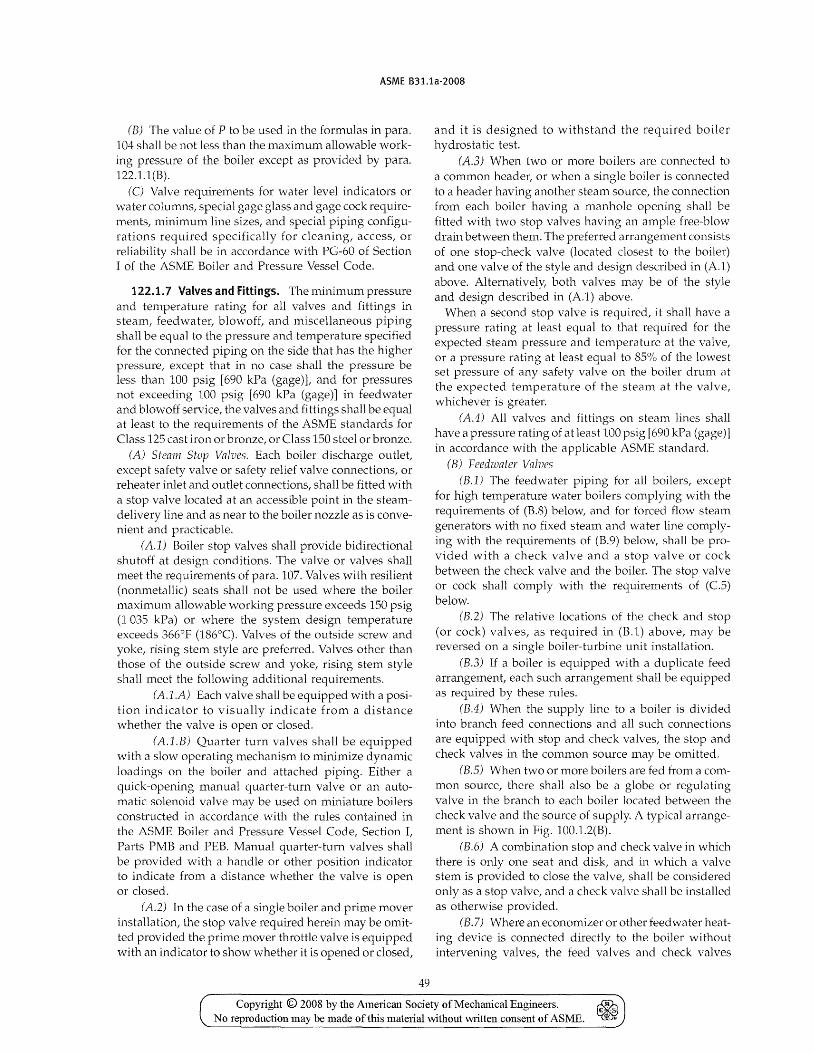
ASME B31.1a-2008
(B) The value of P to be used in the formulas in para. 104 shall be not less than the maximum allowable working pressure of the boiler except as provided by para. 122.1.1 (B).
(C) Valve requirements for water level indicators or water columns, special gage glass and gage cock requirements, minimum line sizes, and special piping configurations required specifically for cleaning, access, or reliability shall be in accordance with PG-60 of Section I of the ASME Boiler and Pressure Vessel Code.
122.1.7 VaLves and Fittings. The minimum pressure and temperature rating for all valves and fittings in steam, feedwater, blowoff, and miscellaneous piping shall be equal to the pressure and temperature specified for the connected piping on the side that has the higher pressure, except that in no case shall the pressure be less than 100 psig [690 kPa (gage)L and for pressures not exceeding lOO psig [690 kPa (gage)] in feedwater and blowoff service, the valves and fittings shall be equal at least to the requirements of the ASME standards for Class 125 cast iron or bronze, or Class 150 steel or bronze.
(A) Steam Stop Valves. Each boiler discharge outlet, except safety valve or safety relief valve connections, or reheater inlet and outlet connections, shall be fitted with a stop valve located at an accessible point in the steamdelivery line and as near to the boiler nozzle as is convenient and practicable.
(A.1) Boiler stop valves shall provide bidirectional shutoff at design conditions. The valve or valves shall meet the requirements of para. 107. Valves with resilient (nonmetallic) seats shall not be used where the boiler maximum allowable working pressure exceeds 150 psig (1 035 kPa) or where the system design temperature exceeds 366°F (186°C). Valves of the outside screw and yoke, rising stem style are preferred. Valves other than those of the outside screw and yoke, rising stem style shall meet the following additional requirements.
(Al.A) Each valve shall be equipped with a position indicator to visually indicate from a distance whether the valve is open or closed.
(A.l.B) Quarter turn valves shall be equipped with a slow operating mechanism to minimize dynamic loadings on the boiler and attached piping. Either a quick-opening manual quarter-turn valve or an automatic solenoid valve may be used on miniature boilers constructed in accordance \-vith the rules contained in the ASME Boiler and Pressure Vessel Code, Section I, Parts PMB and PEB. Manual quarter-turn valves shall be provided with a handle or other position indicator to indicate from a distance whether the valve is open or closed.
(A2) In the case of a single boiler and prime mover installation, the stop valve required herein may be omitted provided the prime mover throttle valve is equipped with an indicator to show whether it is opened or closed,
49
and it is designed to withstand the required boiler hydrostatic test.
(A.3) When hvo or more boilers are connected to a common header, or when a single boiler is connected to a header having another steam source, the connection from each boiler having a manhole opening shall be fitted with two stop valves having an ample free-blow drain between them. The preferred arrangement consists of one stop-check valve (located closest to the boiler) and one valve of the style and design described in (A.l) above. Alternatively, both valves may be of the style and design described in (A.l) above.
When a second stop valve is required, it shall have a pressure rating at least equal to that required for the expected steam pressure and temperature at the valve, or a pressure rating at least equal to 85% of the lowest set pressure of any safety valve on the boiler drum at the expected temperature of the steam at the valve, v'lhichever is greater.
(A4) All valves and fittings on steam lines shall have a pressure rating of at least 100 psig [690 kPa (gage)] in accordance with the applicable ASME standard.
(8) Feedwatcr Valves (B.l) The feedwater piping for all boilers, except
for high temperature \vater boilers complying with. the requirements of (B.S) below, and for forced flow steam generators \vith no fixed steam and \-vater line complying with the requirements of (B.9) below, shall be provided \vith a check valve and a stop valve or cock between the check valve and the boiler. The stop valve or cock shall comply with the requirements of (C.5) below.
(B.2) The relative locations of the cbeck and stop (or cock) valves, as required in (B.l) above, may be reversed on a single boiler-turbine unit installation.
(B.3) If a boiler is equipped with a duplicate feed arrangement, each such arrangement shall be equipped as required by these rules.
(B.4) When the supply line to a boiler is divided into branch feed connections and all such connections are equipped with stop and check valves, the stop and check valves in the common source may be omitted.
(8.5) When two or more boilers are fed from a common source, there shall also be a globe or regulating valve in the branch to each boiler located between the check valve and the source of supply. A typical arrangement is shown in Fig. 100.1.2(B).
(8.6) A combination stop and check valve in which there is only one seat and disk, and in which a valve stem is provided to close the valve, shall be considered only as a stop valve, and a check valve shall be installed as otherwise provided.
(B.7) Where an economizer or other feedvvater beating device is connected directly to the boiler without intervening valves, the feed valves and check valves
Copyright © 2008 by the American Society of Mechallical Engineers. ~ No reproduction may be made of this material without Mitten consent of ASME. ~
(A08)
ASME 831.1a-2008
Fig. 122.1.7(C) Typical Globe Valves
(a)
required shall be placed on the inlet of the economizer or feedwater heating device.
(B.S) The recirculating return line for a high temperature \vater boiler shall be provided with the same stop valve, or valves, required by (B.1) and (B.3) above. The use of a check valve in the recirculating return line is optional. A check valve shall not be a substitute for a stop valve.
(B.9) The feed water boiler external piping for a forced flow steam generator with no fixed steam and water line may terminate up to and including the stop valve(s) and omitting the check valve(s) provided that a check valve having a pressure rating no less than the boiler inlet design pressure is installed at the discharge of each boiler feed pump or elsewhere in the feedline between the feed pUlnp and the stop valve(s).
(B.JO) Wherever globe valves are used vvithin BEP feedwater piping for either isolation or regulation, the inlet shall be under the disk of the valve.
(C) BlozuoJf Valves (e1) Ordinary globe valves as shown in
Fig. 122.1.7(C) sketch (a), and other types of valves that have dams or pockets where sediment can collect, shall not be used on blmvoff connections.
(C2) Y-type globe valves as shown in Fig. 122.1.7(C) sketch (b) or angle valves may be used in vertical pipes, or they nlay be used in horizontal runs of piping provided they are so constructed or installed that the lowest edge of the opening through the seat is at least 25(Yo of the inside diameter below the centerline of the valve.
(C.3) The blowoff valve or valves, the pipe between them, and the boiler connection shall be of the same size except that a larger pipe for the return of condensate may be used.
50
(b)
(C.4) For all boilers [except electric steam boilers having a normal water content not exceeding 100 gal (380 L), traction-purpose, and portable steam boilers; see (Cll) and (C.12) below] with allowable working pressure in excess of 100 psig [690 kPa (gage)L each bottom blowoff pipe shall have two slow-opening valves, or one quick-opening valve or cock, at the boiler nozzle followed by a slow-opening valve. All valves shall comply with the requirements of (C5) and (C6) below.
(C5) When the value of P required by para. 122.1.4(A.1) does not exceed 250 psig [1 725 kPa (gage)], the valves or cocks shall be bronze, cast iron, ductile iron, or steel. The valves or cocks, if of cast iron, shall not exceed NPS 2~ and shall meet the requirements of the applicable ASME standard for Class 250, as given in Table 126.1, and if of bronze, steel, or ductile iron construction, shall meet the requirements of the applicable standards as given in Table 126.1 or para. 124.6.
(C6) When the value of P required by para. 122.1.4(A.1) is higher than 250 psig [1 725 kPa (gage)], the valves or cocks shall be of steel construction equaJ at least to the requirements of Class 300 of the applicable ASME standard listed in Table 126.1. The minimum pressure rating shall be equal to the value of P required by para. 122.1.4(A.1).
(C7) If a blowoff cock is used, the plug shall be held in place by a guard or gland. The plug shall be distinctly marked in line with the passage.
(eS) A slow-opening valve is a valve which requires at least five 360 deg turns of the operating mechanism to change from fully closed to fully opened.
(C9) On a boiler having multiple blowoff pipes, a single master valve may be placed on the common blowoff pipe from the boiler, in which case only one valve
Copyright © 2008 by the American Society of Mechanical Engineers. No reproduction may be made of this material without written consent of ASME.
ASME B31.1a-2008
Chapter III Materials
123 GENERAL REQUIREMENTS
Chapter III contains limitations and required qualifications for materials based on their inherent properties. Use of these materials in piping systems is also subject to requirements and limitations in other parts of this Code.
123.1 Materials and Specifications
123.1.1 Listed MateriaLs. Material meeting the following requirements shall be considered listed and acceptable material:
(A) Materials for which allowable stress values are listed in Appendix A or which have been approved by the procedure established by (C) below.
(B) A ma terial conforming to a specifica hon for which allowable stresses are not listed in Appendix A is acceptable provided its use is not specifically prohibited by this Code Section and it satisfies one of the following requirements:
(B.l) It is referenced in a standard listed in Table 126.1. Such a material shall be used only within the scope of and in the product form covered by the referencing standard listed in Table 126.1.
(B.2) It is referenced in other parts of this Code Section and shall be used only within the scope of and in the product form permitted by the referencing text.
(C) Where it is desired to use materials \vhich are not currently acceptable under the rules of this Code Section, written application shall be made to the Committee fully describing the proposed material and the contemplated use. Such material shall not be considered listed and not used as a listed material until it has been approved by the Committee and allowable stress values have been assigned. Details of information which should be included in such applications are given in Appendix VI. See para. 123.1.2.
(D) Materials conforming to ASME SA or SB specifications may be used interchangeably with material specified to the listed ASTM A or B specifications of the same number, except where the requirements of para. 123.2.2 apply.
(E) The tabulated stress values in Appendix A that are shown in italics are at temperatures in the range where creep and stress rupture strength govern the selection of stresses.
123.1.2 Unlisted Materials. Materials other than those meeting the requirements of para. 123.1.1 shall be
61
considered unlisted m8teri8ls. Such unlisted materials may only be used for nonboiler external piping provided they satisfy all of the following requirements:
(A) Unlisted materials are certified by the mClterial manufacturer to satisfy the requirements of a specification listed in any Code Section of the ASME B31 Code for Pressure Piping, the ASME Boiler and Pressure Vessel Code, Section II, Part D, or to a published specification covering chemistry, physical8nd mechanical properties, method and process of manufacture, heat treatment, and quality control.
(B) The allowable stresses of the unlisted materials shall be determined in accordance with the rules of para. 102.3.1 (C).
(C) Unlisted materials shall be qualified for service within a stated range of mininmm and maximum temperatures based upon data associated with successful experience, tests, or analysis; or a combination thereof.
(D) The designer shall document the owner's acceptance for use of unlisted material.
(E) All other requirements of this Code are satisfied.
123.1.3 Unknown Materials. Materials of unknown specification shall not be used for pressure containing piping components.
123.1.5 Size or Thickness. Materi8ls outside the limits of size or thickness given in the title or scope clause of any specification listed in Table 126.1 may be used if the material is in compliance with the other requirements of the specification, and no other similar limitation is given in the rules for construction.
123.1.6 Marking of Materials or Products. Materials or products marked as meeting the requirements for more than one grade, type, or alloy of a material specification or multiple specifications, are acceptable provided
(A) one of the markings includes the material specification, gr8de, class, and type or alloy of the materi81 permitted by this Code and the material meets aU the requirements of that specification
(B) the appropriate allowable stress for the specified grade, type, or alloy of a material specification from Appendix A is used
(C) all other requirements of this Code are satisfied for the material permitted
123.1.7 Materials Manufactured to Other Specification Editions. IVlaterials may meet the requirements of
Copyright © 2008 by' the American Society of Mecbanical Engineers. ~ c;: •• ~ No reproduction may be made oftbis material without written consent of ASME. ~
ASME B31.1a-2008
material specification editions other than the editions listed in Appendix F provided
(A) the materials are the same specification, grade, type, class, or alloy, and heat-treated condition, as applicable.
(B) the material tensile and yield strengths shall be compared and any differences shall be evaluated. If the material has a lower strength than required by the edition of the specification in Appendix F, the effect of the reduction on the allowable stress and the design shall be reconciled.
123.2 Piping Components
123.2.1 GeneraL. Materials which do not comply with the rules of para. 123.1 may be used for flared, f]areless, and compression type tubing fittings, provided that the requirements of para. 115 are met.
123.2.2 Boiler External Piping (A) Materials for boiler external piping, as defined in
para. 100.1.2(A), shall be specified in accordance with ASME SA, S6, or SFA specifications. Material produced under an ASTM specification may be used, provided that the requirements of the ASTM specification are identical or more stringent than the ASME specification for the Grade, Class, ~r Type produced. The material manufacturer or component manufacturer shall certify, with evidence acceptable to the Authorized Inspector, that the ASME specification requirements have been met. Materials produced to ASME or ASTM material specifications are not limited as to country of origin.
(B) Materials which are not fully identified shall comply with PG-I0 of Section I of the ASME Boiler and Pressure Vessel Code.
(A08) (C) In addition to materials listed in Appendix A without Note (1), materials that are listed in Section I of the ASME Boiler and Pressure Vessel Code may be used in boiler external piping. When such Section I materials are used, the allowable stresses shall be those listed in Section II, Part D, Subpart I, Tables lA and IB applicable to Section 1. For these Section I materials, the applicable requirements in Table lA, Table IB, and Section I paras. PG-5 through PG-13, PW-5, PWT-5, PMB-5, and PEB-5 shall me met.
123.3 Pipe-Supporting Elements
Materials used for pipe-supporting elements shall be suitable for the service and shall comply with the requirements of para. 121.2(C), para. 121.7.2(C), para. I21.7.2(D), para. 123.1, or MSS SP-58. When utilizing MSS SF-58, the allowable stresses for unlisted materials shall be established in accordance with the rules of para. 102.3.1(C) of ASME B31.1 in lieu of para. 4.4 of MSS SP-58.
62
123.4 Longitudinal-Welded or Spiral-Welded Pipe (A08)
With Filler Metal Added
(A) For the purposes of para. 104.1.1, the start of the creep range is the highest temperature where the nonitalicized stress values end in Appendix A.
(B) All welds in longitudinal-welded or spiral-welded pipe operating in the creep range shall receive and pass a 10m~ volumetric examination (RT or UT) per the applicable material specification or in accordance with para. 136.4.5 or 136.4.6 and Table 136.4, or the joint efficiency factor (used as a multiplier to the weld strength reduction factor) from Table 102.4.7 shall be used.
124 LIMITATIONS ON MATERIALS
124.1 Temperature Limitations
124.1.1 Upper Temperature limits. The materials listed in the Allowable Stress Tables A-I through A-9, Appendix A, shall not be used at design temperatures above those for which stress values are given except as permitted by para. 122.6.2(G).
124.1.2 Lower Temperature Limits. The designer shall give consideration to the possibility of brittle fracture at 100v service temperature.
124.2 Steel
(A) Upon prolonged exposure to temperatures above 800°F (427°C), the carbide phase of plain carbon steel, plain nickel alloy steel, carbon-manganese alloy steel, manganese-vanadium alloy steel, and carbon-silicon steel may be converted to graphite.
(B) Upon prolonged exposure to temperatures above 875°F (470°C), the carbide phase of alloy steels, such as carbon-molybdenum, manganese-molybdenumvanadium, manganese-chromium-vanadium, and chromium-vanadium, may be converted to graphite.
(C) Carbon or alloy steel having carbon content of more than 0.35% shall not be used in welded construction or be shaped by oxygen cutting process or other thermal cutting processes.
(D) Where low alloy 2%% chromium steels are used at temperatures above 850°F, the carbon content of the base material and weld filler metal shall be 0.05% or higher.
124.4 Cast Gray Iron (A08)
The low ductility of cast gray iron may result in sudden failure if shock loading (pressure, temperature, or mechanical) should occur. Possible shock loadings and consequences of failure must be considered before specifying the use of such material. Cast iron components may be used within the nonshock pressure-temperature ratings established by the standards and specifications herein and in para. 105,2.1(B). Castings to ASME SA-278 and ASTM A 278 shall have maximum limits of 250 psig [1 725 kPa (gage)] and 450°F (230°C).
Copyright © 2008 by the American Society of Mechanical Engineers. No reproduction may be made oftbis material without written consent of ASME.
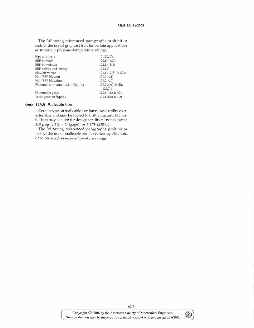
ASME B31.1a-2008
The following referenced paragraphs prohibit or n:'strict the use of gray cast iron for certain applications or to certain pressure-temperature ratings:
Pipe supports BEP blowoff BEP blowdown BEP valves and fittings Blowoff valves Non-BEP blowoff Non-BEP blowdown Flammable or combustible liquids
Flammable gases Toxic gases or liquids
(A08) 124.5 Malleable Iron
121.7.2(C) 122.1.4(A.3) 122.1.4(B.3) 122.1.7 122.1.7(C.5) &. (C.6) 122.2(A.1) 122.2(A.2) 122.7.2(A) &. (B),
122.7.4 122.S.1(B) &. (C) 122.8.2(B) & (D)
Certain types of malleable iron have low ductility characteristics and may be subject to brittle fracture. Malleable iron may be used for design conditions not to exceed 350 psig [2415 kPa (gage)] or 4500 P (230°C).
The following referenced paragraphs prohibit or restrict the use of malleable iron for certain applications or to certain pressure-temperature ratings:
62.1
Copyright © 2008 by the American Society of Mechauical Engineers. ~ No reproduction may be made of this material without written consent of ASME. ~
INTENTIONALLY LEFT BLANK
Copyright © 2008 by the American Society of Mechanical Engineers. ~ E- S
No reproduction may be made of this material without ",,,ritlen consent of ASME. f1l "
(A08)
ASME B31.1a-2008
Pipe supports EEF blowoff BEF blowdown Non-EEP blowoH Non-EEP blo\'I'down Flammable or combustible liquids Flammable gases Toxic gases or liquids
124.6 Ductile (Nodular) Iron
121.7.2(D) 122.1.4(A3) 122.1.4(B.3) 122.2(Al) 122.2(A.2) 122.7.2(A) & (E) l22.8.1(E) & (C) I22.S.2(E) & (D)
Ductile iron components complying with ANSI! AWWA CllO/ A21.10, C1l5/ A21.15, CI5I/ A21.5I, or CIS3/ A21.53 may be used for water and other nontoxic, nonflammable service, vvith pressure limits as specified in those standards and temperature limits as specified in para. 106(E). These components may not be used for boiler external piping.
Ductile (nodular) iron components conforming to ASME B16.42 may be used for services including boiler external piping under the following conditions:
(A) Components for boiler external piping shall be used only within the following limitations.
(A.]) Only ASME SA-395 material may be used. (A.2) Design pressure shall not exceed 350 psig
[2415 kPa (gage)]. (A.3) Design temperature shall not exceed 450°F
(230°C). (B) Welding shall not be used, either in fabrication of
the components or in their assembly as a part of a piping system.
(C) The following referenced paragraphs prohibit or restrict the use of ductile iron for certain applications or to certain pressure-temperature ratings:
EEP blowoff BEP blowdown BEP blowoff valves Non-BEF blow off NOl1-BEP blow down Flammable or combustible liquids Flammable gases Toxic gases or liquids Pipe supports
124.7 Nonferrous Metals
122.1.4(A.3) 122.1.4(B.3) 122.1.7(C.S) & (C.6) 122.2(A1) 122.2(A2) 122.7.2(A) & (B) 122.8.1(B) & (C) 122.S.2(B) & (D) 123.3
Nonferrous ntetals may be used in piping systenls under the follmving conditions:
(A) The melting points of copper, copper alloys, aluminum, and aluminum alloys must be considered particularly where there is a fire hazard.
(B) The Designer shall consider the possibility of galvanic corrosion when combinations of dissimilar metals, such as copper, aluminum, and their alloys, are used in conjunction with each other or with steel or other metals in the presence of an electrolyte.
(C) Threaded Connections. A suitable thread compound shall be used in making up threaded joints in aluminum pipe to prevent seizing which might cause
63
leakage and perhaps prevent disassembly. Pipe in the annealed temper should not be threaded.
124.8 Cladding and lining Materials
Materials with cladding or lining may be used provided that
(a) the base material is an approved Code material. 'The allowable stress used shall be that of the base metal at the design temperature.
(b) the cladding or lining is a material that in the judgment of the user is suitable for the intended service, and the cladding/lining and its method of application do not detract from the serviceability of the base material.
(c) bending procedures are such that damaging or detrimental thinning of the cladding material is prevented.
(d) \velding and the inspection of welds is in accordance with the provisions of Chapters V and VI of this Code.
(e) the thickness of the cladding is not credited for structural strength in the piping design.
124.9 Nonmetallic Pipe
This Code recognizes the existence of a wide variety of nonmetallic piping materials which may be used on corrosive (either internal or external) or other specialized applications. Extreme care must be taken in their selection as their design properties vary greatly and depend upon the materiat type and grade. Particular consideration shall be given to the possibility of
(A) destruction where fire hazard is involved. (B) decrease in tensile strength at slight increase in
temperature. (C) effects of toxicity. Another consideration is that
of providing adequate support for the flexible pipe. For nonmandatory rules for nonmetallic piping, see
Appendix III of this Code.
124.10 Deterioration of Materials in Service
It is the responsibility of the engineer to select materials suitable for the intended application. Some guideline for selection of protective coatings for metallic piping are provided in Appendix IV
125 MATERIALS APPLIED TO MISCELLANEOUS PARTS
125.1 Gaskets
Limitations on gasket materials are covered in para. 10S.4.
125.2 Bolting
Limitations on bolting materials are covered in para. 10S.5.
Copyright © 2008 by the American Society of Mechanical Engineers. No reproduction may be made of this material \vithout written consent of ASME.
ASME B31.1a-2008
Chapter IV Dimensional Requirements
126 MATERIAL SPECIFICATIONS AND STANDARDS FOR STANDARD AND NONSTANDARD PIPING COMPONENTS
126.1 Standard Piping Components
Dimensions of standard piping components shall comply with the standards and specifications listed in Table 126.1 in accordance with para. 100.
126.2 Nonstandard Piping Components
When nonstandard piping components are designed in accordance with para. 104, adherence to dimensional standards of ANSI and ASME is strongly recommended when practicable.
64
126.3 Referenced Documents The documents listed in Table 126.1 may contain refer
ences to codes, standards, or specifications not listed in this Table. Such unlisted codes, standards, or specifications are to be used only in the context of the listed documents in which they appear.
Where documents listed in Table 126.1 contain design rules \vhich are in conflict with this Code, the design rules of this Code shall govern.
The fabrication, assembly, examination, inspection, and testing requirements of Chapters V and VI apply to the construction of piping systems. These requirements are not applicable to piping components manufactured in accordance with the documents listed in Table 126.1 unless specifically so stated.
Copyright © 2008 by the American Society of Mechanical Engineers. No reproduction may be made oftms material without written consent of ASME.
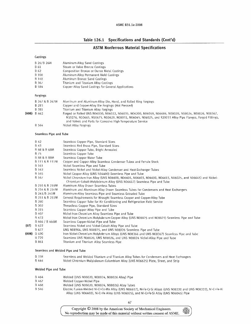
(A08)
(07)
(A08)
Castings
B 26/B 26M
B 61 B 62 B 108 B 148
B 367 B 584
Forgings
B 247 & B 247M B 283
B 381 B 462
B 564
ASME B31.1a-2008
Table 126.1 Specifications and Standards (Cont'd) --------------------------------
ASTM Nonferrous Material Specifications
Aluminum-Alloy Sand Castings
Steam or Valve Bronze Castings
Composition Bronze or Ounce Metal Castings Aluminum-Alloy Permanent Mold Castings Aluminum-Bronze Sand Castings
Titanium and Titanium Alloy Castings Copper Alloy Sand Castings for General Applications
Aluminum and Aluminum-Alloy Die, Hand, and Rolled Ring Forgings Copper and Copper-Alloy Die Forgings (Hot Pressed)
Titanium and Titanium Alloy Forgings Forged or Rolled UNS N06030, N06022, N06035, N06200, N06059, N06686, N08020, N08024, N08026, N08367,
NI0276, NI0665, NI0675, N10629, N08031, N06045, N06025, and R20033 Alloy Pipe Flanges, Forged Fittings, and Valves and Parts for Corrosive High-Temperature Service
Nickel Alloy Forgings
Seamless Pipe and Tube
B 42 B 43
B 68 & B 68M B 75
B 88 & B 88M Bl11&Bl11M
B 161 B 163
B 165 B 167
B 210 & B 210M
B 234 & B 234M
B 241/8 241M
B 251 & B 251M B 280
8 302
B 315 B 407
8423
B 466 / B 466M 8622
B677
8690
B 729
8 861
Seamless Copper Pipe, Standard Sizes Seamless Red Brass Pipe, Standard Sizes
Seamless Copper Tube, Bright Annealed Seamless Copper Tube
Seamless Copper Water Tube
Copper and Copper-Alloy Seamless Condenser Tubes and Ferrule Stock Nickel Seamless Pipe and Tube
Seamless Nickel and Nickel-Alloy Condenser and Heat-Exchanger Tubes
Nickel-Copper Alloy (UNS N04400) Seamless Pipe and Tube
Nickel-Chromium-Iron Alloy (UNS N06600, N06601, N06603, N06690, N06693, N06025, and N06645) and Nickel-Chromium-Cobalt-Molybdenum Alloy (UNS N06617) Seamless Pipe and Tube
Aluminum Alloy Drawn Seamless Tubes
Aluminum and Aluminum-Alloy Drawn Seamless Tubes for Condensers and Heat Exchangers Aluminum-Alloy Seamless Pipe and Seamless Extruded Tube
General Requirements for Wrought Seamless Copper and Copper-Alloy Tube
Seamless Copper Tube for Air Conditioning and Refrigeration Field Service Threadless Copper Pipe, Standard Sizes
Seamless Copper Alloy Pipe and Tube
Nickel-lron-Chromium Alloy Seamless Pipe and Tube
Nickel-lron-Chromium-Molybdenum-Copper Alloy (UNS N08825 and N08821) Seamless Pipe and Tube
Seamless Copper-Nickel Pipe and Tube Seamless Nickel and Nickel-Cobalt Alloy Pipe and Tube
UNS N08904, UNS N08925, and UNS N08926 Seamless Pipe and Tube
lron-Nickel-Chromium-Molybdenum Alloys (UNS N08366 and UNS N08367) Seamless Pipe and Tube
Seamless UNS N08020, UNS N08026, and UNS N08024 Nickel-Alloy Pipe and Tube Titanium and Titanium Alloy Seamless Pipe
Seamless and Welded Pipe and Tube
B 338
B 444 Seamless and Welded Titanium and Titanium Alloy Tubes for Condensers and Heat Exchangers
Nickel-Chromium-Molybdenum-Columbium Alloy (UNS N06625) Plate, Sheet, and Strip
Welded Pipe and Tube
B 464
B 467
B 468 B 546
Welded (UNS N08020, N08024, N08026 Alloy) Pipe Welded Copper-Nickel Pipe
Welded (UNS N08020, N08024, N08026) Alloy Tubes Electric Fusion-Welded Ni-Cr-Co-Mo Alloy (UNS N06617), Ni-Fe·Cr·Si Alloys (UNS N08330 and UNS N08332), Ni-Cr-Fe-Al
Alloy (UNS N06603), Ni-Cr-Fe Alloy (UNS N06025), and Ni-Cr-Fe-Si Alloy (UNS N06045) Pipe
67
Copyright © 2008 by the American Society of Mechanical Engineers_ No reproduction may be made of this material vvithout written consent of ASME.
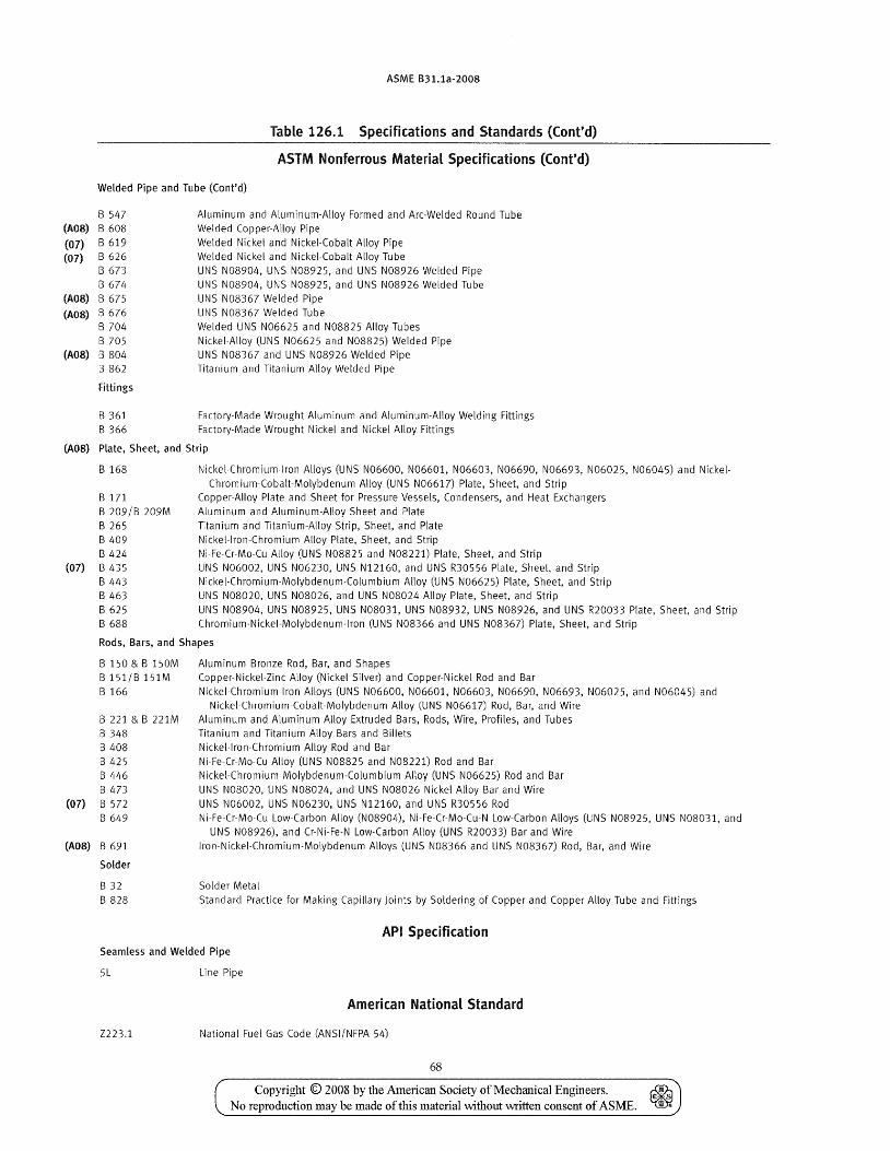
ASME 831.1a-2008
Table 126.1 Specifications and Standards (Cont'd)
ASTM Nonferrous MateriaL Specifications (Cont'd)
Welded Pipe and Tube (Cant'd)
B 547 (A08) B 608
(07) B 619
(07) B 626 B673 B 67[1
(A08) B 675
(A08) B 676 B 704 B 705
(A08) B 804 B 862
Fittings
B 361 B 366
Aluminum and Aluminum-Alloy Formed and Arc-Welded Round Tube Welded Copper-Alloy Pipe Welded Nickel and Nickel-Cobalt Alloy Pipe Welded Nickel and Nickel-Cobalt Alloy Tube UNS N08904, UNS N08925, and UNS N08926 Welded Pipe UNS N08904, UNS N08925, and UNS N08926 Welded Tube UNS N08367 Welded Pipe UNS N08367 Welded Tube Welded UNS N06625 and N08825 Alloy Tubes Nickel-Alloy (UNS N06625 and N08825) Welded Pipe UNS N08367 and UNS N08926 Welded Pipe Titanium and Titanium Alloy Welded Pipe
Factory-Made Wrought Aluminum and Aluminum-Alloy Welding Fittings Factory-Made Wrought Nickel and Nickel Alloy Fittings
(A08) Plate, Sheet, and Strip
B 168
B 171 B 209/B 209M B 265 B 409 B 424
(07) B 435 B 443 B 463 B 625 B 688
Nickel-Chromium-Iron Alloys (UNS N06600, N06601, N06603, N06690, N06693, N06025, N06045) and Nickel-Chromium-Cobalt-Molybdenum Alloy (UNS N06617) Plate, Sheet, and Strip
Copper-Alloy Plate and Sheet for Pressure Vessels, Condensers, and Heat Exchangers Aluminum and Aluminum-Alloy Sheet and Plate Titanium and Titanium-Alloy Strip, Sheet, and Plate Nickel-lron-Chromium Alloy Plate, Sheet, and Strip Ni-Fe-Cr-Mo-Cu Alloy (UNS N08825 and N08221) Plate, Sheet, and Strip UNS N06002, UNS N06230, UNS N12160, and UNS R30556 Plate, Sheet, and Strip Nickel-Chromium-Molybdenum-Columbium Alloy (UNS N06625) Plate, Sheet, and Strip UNS N08020, UNS N08026, and UNS N08024 Alloy Plate, Sheet, and Strip UNS N08904, UNS N08925, UNS N08031, UNS N08932, UNS N08926, and UNS R20033 Plate, Sheet, and Strip Chromium-Nickel-Molybdenum-Iron (UNS N08366 and UNS N08367) Plate, Sheet, and Strip
Rods, Bars, and Shapes
(07)
(AOS)
B150&B150M B 151/B 151M B 166
B 221 & B 221M B 348 B 408 B 425 B 446 B473 B 572 B 649
B 691
Solder
B 32 B 828
Aluminum Bronze Rod, Bar, and Shapes Copper-Nickel-Zinc Alloy (Nickel Silver) and Copper-Nickel Rod and Bar Nickel-Chromium-lron Alloys (UNS N06600, N06601, N06603. N06690, N06693, N06025, and N06045) and
Nickel-Chromium-Cobalt-Molybdenum Alloy (UNS N06617) Rod, Bar, and Wire Aluminum and Aluminum Alloy Extruded Bars, Rods, Wire, Profiles, and Tubes Titanium and Titanium Alloy Bars and Billets Nickel-Iran-Chromium Alloy Rod and Bar Ni-Fe-Cr-Mo-Cu Alloy (UNS N08825 and N08221) Rod and Bar Nickel-Chromium Molybdenum-Columbium Alloy (UNS N06625) Rod and Bar UNS N08020, UNS N08024, and UNS N08026 Nickel Alloy Bar and Wire UNS N06002. UNS N06230, UNS N12160, and UNS R30556 Rod Ni-Fe-Cr-Mo-Cu Low-Carbon Alloy (N08904), Ni-Fe-Cr-Mo-Cu-N Low-Carbon Alloys (UNS N08925, UNS N08031, and
UNS N08926), and Cr-Ni-Fe-N Low-Carbon Alloy (UNS R20033) Bar and Wire lron-Nickel-Chromium-Molybdenum Alloys (UNS N08366 and UNS N08367) Rod, Bar, and Wire
Solder Metal Standard Practice for Making Capillary Joints by Soldering of Copper and Copper Alloy Tube and Fittings
API Specification Seamless and Welded Pipe
5L Line Pipe
American National Standard
Z223.1 National Fuel Gas Code (ANSI/NFPA 54)
68
Copyright © 2008 by the Amelican Society of Mechanical Engineers. ~ No reproduction may be made of this material without written consent of ASME. ~
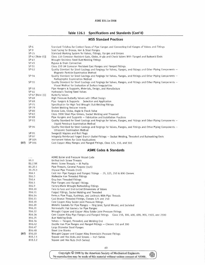
SP-6
SP-9
SP-25
SP-42 [Note (1)]
SP-43
SP-45
SP-51
SP-53
SP-54
SP-55
SP-58
SP-61
SP-67 [Note (1)]
SP-68
SP-69
SP-75
SP-79
SP-80
SP-83
SP-89
SP-93
SP-91-i
SP-95 SP-97
SP-I05 (07) SP-I06
Bl.l
Bl.13M
Bl.20.1 Bl.20.3
B16.1
B16.3
816.4
816.5
816.9
B16.10
B16.11
B16.14
B16.15
B16.18
B16.20
B16.21
B16.22
B16.24
B16.25
B16.34
B16.42
816.47
B16.48 (07) 816.50
BI8.2.1
B18.2.2
ASME B31.1a-2008
Table 126.1 Specifications and Standards (Cont'd)
MSS Standard Practices
Standard Finishes for Contact Faces of Pipe Flanges and Connecting-End Flanges of Valves and Fittings
Spot-Facing for Bronze, Iron & Steel Flanges
Standard Marking System for Valves, Fittings, Flanges and Unions
Class 150 Corrosion Resistant Gate, Globe, Angle and Check Valves With Flanged and Buttweld Ends
Wrought Stainless Steel Butt·Welding Fittings
Bypass & Drain Connection
Class 150 LW Corrosion Resistant Cast Flanges and Flanged Fittings
Quality Standard for Steel Castings and Forgings for Valves, Flanges, and Fittings and Other Piping Components -
Magnetic Particle Examination Method
Quality Standard for Steel Castings and Forgings for Valves, Flanges, and Fittings and Other Piping Components -
Radiographic Examination Method
Quality Standard for Steel Castings and Forgings for Valves, Flanges, and Fittings and Other Piping Components -
Visual Method for Evaluation of Surface Irregularities
Pipe Hangers & Supports, Materials, Design, and Manufacture
Hydrostatic Testing Steel Valves Butterfly Valves
High Pressure Butterfly Valves with Offset Design
Pipe Hangers & Supports - Selection and Application
Specification for High Test Wrought Butt-Welding Fittings
Socket Welding Reducer Inserts
Bronze Gate, Globe, Angle & Check Valve
Class 3000 Steel Pipe Unions, Socket Welding and Threaded
Pipe Hangers and Supports - Fabrication and Installation Practices
Quality Standard for Steel Castings and Forgings for Valves, Flanges, and Fittings and Other Piping Components -
Liquid Penetrant Examination Method
Quality Standard for Steel Castings and Forgings for Valves, Flanges, and Fittings and Other Piping Components -
Ultrasonic Examination Method
Swage(d) Nipples and Bull Plugs
Integrally Reinforced Forged Branch Outlet Fittings - Socket Welding, Threaded and Buttwelding Ends Instrument Valves for Code Applications
Cast Copper Alloy Flanges and Flanged Fittings, Class 125, 150, and 300
ASME Codes & Standards
ASME Boiler and Pressure Vessel Code Unified Inch Screw Threads
Metric Screw Threads - M Profile
Pipe Threads, General Purpose (Inch) Dryseal Pipe Threads (Inch)
Cast Iron Pipe Flanges and Flanged Fittings - 25, 125, 250 & 800 Classes
Malleable Iron Threaded Fittings
Gray Iron Threaded Fittings
Pipe Flanges and Flanged Fittings
Factory-Made Wrought Buttwelding Fittings
Face-to-Face and End-to-End Dimensions of Valves
Forged Fittings, Socket-Welding and Threaded
Ferrous Pipe Plugs, Bushings, and Locknuts With Pipe Threads
Cast Bronze Threaded Fittings, Classes 125 and 250
Cast Copper Alloy Solder-Joint Pressure Fittings
Metallic Gaskets for Pipe Flanges - Ring Joint, Spiral Wound, and Jacketed Nonmetallic Flat Gaskets for Pipe Flanges
Wrought Copper and Copper Alloy Solder Joint Pressure Fittings
Cast Copper Alloy Pipe Flanges and Flanged Fittings - Class 150, 300, 400, 600, 900, 1500, and 2500 Butt Welding Ends
Valves - Flanged, Threaded, and Welding End
Ductile Iron Pipe Flanges and Flanged Fittings - Classes 150 and 300
Large Diameter Steel Flanges Steel Line Blanks
Wrought Copper and Copper Alloy Braze-Joint Pressure Fittings
Square and Hex Bolts and Screws - Inch Series
Square and Hex Nuts (Inch Series)
69
Copyright © 2008 by the Ame1ican Society of Mechanical Engineers. ~ No reproduction may be made of this material without written consent of ASME. ~
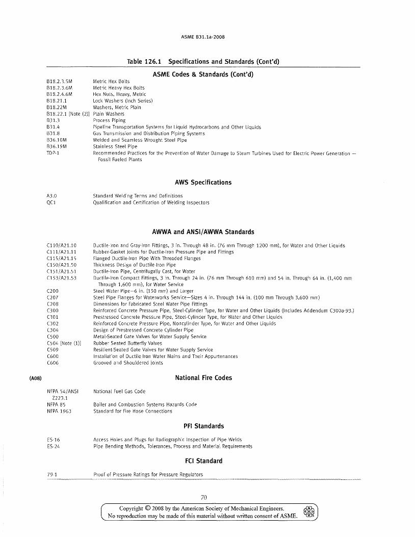
(A08)
ASME B31.1a-2008
Table 126.1 Specifications and Standards (Cont'd)
ASME Codes & Standards (Cont'd) B18.2.3.5M Metric Hex Bolts B18.2.3.6M Metric Heavy Hex Bolts B18.2.4.6M Hex Nuts, Heavy, Metric B18.21.1 Lock Washers (Inch Series) B18.22M Washers, Metric Plain B18.22.1 [Note (2)] Plain Washers B31.3 Process Piping B31.4 Pipeline Transportation Systems for Liquid Hydrocarbons and Other Liquids B31.8 Gas Transmission and Distribution Piping Systems B36.10M Welded and Seamless Wrought Steel Pipe B36.19M Stainless Steel Pipe TDp·l Recommended Practices for the Prevention of Water Damage to Steam Turbines Used for Electric Power Generation -
A3.0 QCl
Cll0/ A21.10 C 111/ A21.11 Cl15/ A21.15 C150/ A21. 50 C1 51 / A21. 51 C153/A21.53
(200 (207 C208 000 C301 002 004 C500 C504 [Note (1)] C509 C600 C606
NFPA 54/ANSI Z223.1
NFPA 85 NFPA 1963
ES-16 ES-24
79-1
Fossil Fueled Plants
AWS Specifications
Standard Welding Terms and Definitions Qualification and Certification of Welding Inspectors
AWWA and ANSI/ AWWA Standards
Ductile-Iron and Gray-Iron Fittings, 3 in. Through 48 in. (76 mm Through 1200 mm), for Water and Other Liquids Rubber-Gasket Joints for Ductile-Iron Pressure Pipe and Fittings Flanged Ductile-Iron Pipe With Threaded Flanges Thickness Design of Ductile-Iron Pipe Ductile-Iron Pipe, Centrifugally Cast, for Water Ductile-Iron Compact Fittings, 3 in. Through 24 in. (76 mm Through 610 mm) and 54 in. Through 64 in. (1,400 mm
Through 1,600 mm), for Water Service Steel Water Pipe-6 in. (150 mm) and Larger Steel Pipe Flanges for Waterworks Service-Sizes 4 in. Through 144 in. (100 mm Through 3,600 mm) Dimensions for Fabricated Steel Water Pipe Fittings Reinforced Concrete Pressure Pipe, Steel-Cylinder Type, for Water and Other Liquids (Includes Addendum 000a-93.) Prestressed Concrete Pressure Pipe, Steel-Cylinder Type, for Water and Other Liquids Reinforced Concrete Pressure Pipe, Noncylinder Type, for Water and Other Liquids Design of Prestressed Concrete Cylinder Pipe Metal-Seated Gate Valves for Water Supply Service Rubber Seated Butterfly Valves Resilient-Seated Gate Valves for Water Supply Service Installation of Ductile-Iron Water Mains and Their Appurtenances Grooved and Shouldered Joints
National Fire Codes
National Fuel Gas Code
Boiler and Combustion Systems Hazards Code Standard for Fire Hose Connections
PFI Standards
Access Holes and Plugs for Radiographic Inspection of Pipe Welds Pipe Bending Methods, Tolerances, Process and Material Requirements
Fel Standard
Proof of Pressure Ratings for Pressure Regulators
70
Copyright © 2008 by the American Society of Mechanical Engineers. No reproduction may be made of this material without \\-Titten consent of ASME.
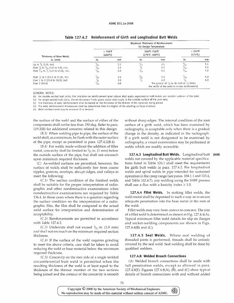
ASME B31.1a-2008
Table 127.4.2 Reinforcement of Girth and Longitudinal Butt Welds
Thickness of Base Metal, in. (mm)
Up to % (3.0), incl. Over % to %6 (3.0 to 5.0), incl. Over 3;;6 to 1/2 (5.0 to 13.0), incl.
Over;; to 1 (13.0 to 25.0), incl. Over 1 to 2 (25.0 to 50.0), incl. Over 2 (50.0)
GENERAL NOTES:
in. mm
1;;6 2.0
;116 2.0 1;;6 2.0
2.5 3.0 /1.0
Maximum Thickness of Reinforcement for Design Temperature
350°F-750°F (175°C-400°C)
in. mm
3/32 2.5 % 3.0 %2 4.0
in. mm
3;;6 5.0
/16 5.0 '116 5.0
5.0 3;;6 5.0 6.0 6.0 1;;,
The greater of Ji, in. (6 mm) or Vr3 times the width of the weld in inches (millimeters).
(a) For double welded butt joints, this limitation on reinforcement given above shall apply separately to both inside and outside surfaces of the joint. (b) For single welded butt joints, the reinforcement limits given above shall apply to the outside surface of the joint only. ec) The thickness of weld reinforcement shall be based on the thickness of the thinner of the materials being joined. Cd) The weld reinforcement thicknesses shall be determined from the higher of the abutting surfaces involved. (e) Weld reinforcement may be removed if so desired.
the surface of the \veld and the surface of either of the components shall not be less than 150 deg. Refer to para. 119.3(B) for additional concerns related to this design.
(B.3) When welding pipe to pipe, the surface of the weld shall, as a minimum, be flush with the outer surface of the pipe, except as permitted in para. 127.4.2(B.4).
(B.4) For welds made without the addition of filler metal, concavity shall be limited to ~'l2 in. (1 mm) below the outside surface of the pipe, but shall not encroach upon minimum required thickness.
(C) As-welded surfaces are permitted; however, the surface of welds shall be sufficiently free from coarse ripples, grooves, overlaps, abrupt ridges, and valleys to meet the following:
(Cl) The surface condition of the finished welds shall be suitable for the proper interpretation of radiographic and other nondestructive examinations when nondestructive examinations are required by Table 136.4. In those cases where there is a question regarding the surface condition on the interpretation of a radiographic film, the film shall be compared to the actual weld surface for interpretation and determination of acceptability.
(C2) Reinforcements are permitted in accordance with Table 127.4.2.
(C3) Undercuts shall not exceed ~2 in. (1.0 mm) and shall not encroach on the minimum required section thickness.
(C4) If the surface of the weld requires grinding to meet the above criteria, care shall be taken to avoid reducing the weld or base material below the minimum required thickness.
(CS) Concavity on the root side of a single welded circumferential butt weld is permitted when the resulting thickness of the vveld is at least equal to the thickness of the thinner member of the two sections being joined and the contour of the concavity is smooth
75
without sharp edges. The internal condition of the root surface of a girth weld, which has been examined by radiography, is acceptable only when there is a gradual change in the density, as indicated in the radiograph. If a girth weld is not designated to be examined by radiography, a visual examination may be performed at welds which are readily accessible.
127.4.3 Longitudinal Butt Welds. Longitudinal butt (AOS)
vvelds not covered by the applicable material specifica-tions listed in Table 126.1 shall meet the requirements for girth butt welds in para. 127.4.2. For longitudinal welds and spiral welds in pipe intended for sustained operation in the creep range (see paras. 104.1.1 and 123.4, and Table 102.4.7), any welding using the SAW process shall use a flux with a basicity index;:::: 1.0.
127.4.4 Fillet Welds. In making fillet welds, the weld metal shall be deposited in such a way as to secure adequate penetration into the base metal at the root of the weld.
Fillet welds may vary from convex to concave. The size of a fillet weld is determined as shown in Fig. 127.4.4(A). Typical minimum fillet weld details for slip-on flanges and socket-welding components are shown in Figs. 127.4.4(B) and (C).
127.4.5 Seal Welds. Where seal welding of threaded joints is performed, threads shall be entirely covered by the seal weld. Seal welding shall be done by qualified welders.
127.4.8 Welded Branch Connections (A) Welded branch connections shall be made with
full penetration welds, except as allowed in para. 127.4.8(F). Figures 127.4.8(A), (B), and (C) show typical details of branch connections with and without added
Copyright © 2008 by the American Society of Mechanical Engineers. ~ No reproduction may be made of this material without written consent of ASME. ~
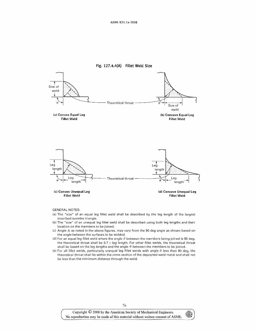
(a) Convex Equal Leg Fillet Weld
ASME B31.1a-2008
fig. 127.4.4(A) fillet Weld Size
.-.----- Theoretical throat -----
(b) Concave Equal Leg Fillet Weld
-.----\---- Theoretical throat ------""
(c) Convex Unequal Leg Fillet Weld
GENERAL NOTES:
(d) Concave Unequal Leg Fillet Weld
(a) The "size" of an equal leg fillet weld shall be described by the leg length of the largest inscribed isoceles triangle.
(b) The "size" of an unequal leg fillet weld shall be described using both leg lengths and their location on the members to be joined.
(c) Angle 0, as noted in the above figures, may vary from the 90 deg angle as shown based on the angle between the surfaces to be welded.
(d) For an equal leg fillet weld where the angle () between the members being joined is 90 deg, the theoretical throat shall be 0.7 x leg length. For other fillet welds, the theoretical throat shall be based on the leg lengths and the angle 0 between the members to be joined.
(e) For all fillet welds, particularly unequal leg fillet welds with angle () less than 90 deg, the theoretical throat shall lie within the cross section of the deposited weld metal and shall not be less than the minimum distance through the weld.
76
Copyright © 2008 by the American Society of Me challi cal Engineers. No reproduction may be made of this material \vithout written consent of ASME.
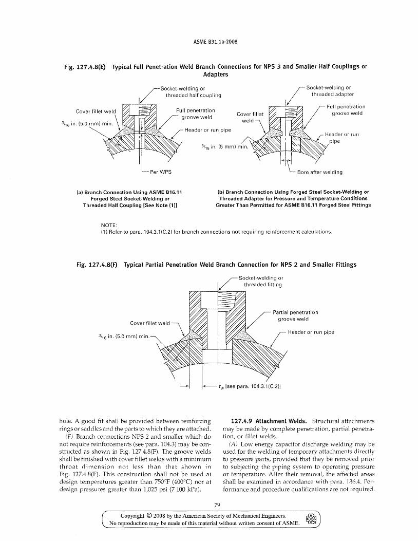
ASME B31.1a-2008
Fig. 127.4.8(E) Typical Fun Penetration Weld Branch Connections for NPS 3 and Smaller Half Couplings or Adapters
r Socket-welding or / threaded half coupling
P""7:'r--"--"17"A
3/16 in. (5.0 mm) min.
Full penetration groove weld
Header or run pipe I He~der or run
pipe 3/16 in. (5 mm) min.
Per WPS
(a) Branch Connection Using ASME B16.11 Forged Steel Socket-Welding or
Threaded Half Coupling [See Note (1)]
NOTE:
(b) Branch Connection Using Forged Steel Socket-Welding or Threaded Adapter for Pressure and Temperature Conditions
Greater Than Permitted for ASME B16.11 Forged Steel Fittings
(1) Refer to para. 104.3.1 (C.2) for branch connections not requiring reinforcement calculations.
Fig. 127.4.8(F) Typical Partial Penetration Weld Branch Connection for NPS 2 and Smaller Fittings
3/16 in. (5.0 mm) min.
hole. A good fit shall be provided between reinforcing rings or saddles and the parts to which they are attached.
(F) Branch connections NPS 2 and smaller which do not require reinforcements (see para. 104.3) may be constructed as shown in Fig. 127.4.8(F). The groove welds shall be finished with cover fillet welds with a minimum throat dimension not less than that shown in Fig. 127.4.8(F). This construction shall not be used at design temperatures greater than 750°F (400°C) nor at design pressures greater than 1,025 psi (7 100 kPa).
79
Socket-welding or threaded fitting
Partial penetration groove weld
Header or run pipe
127.4.9 Attachment Welds. Structural attachments may be made by complete penetration, partial penetration, or fillet welds.
(A) Low energy capacitor discharge welding may be used for the welding of temporary attachments directly to pressure parts, provided that they be removed prior to subjecting the piping system to operating pressure or temperature. After their removal, the affected areas shall be examined in accordance with para. 136.4. Performance and procedure qualifications are not required.
Copyright © 2008 by the American Society of Mechanical Engineers. ~ No reproduction may be made of this material without written consent of ASME. ~
ASME 831.1a-2008
This method of welding may also be used for the permanent attachment of nonstructural items, such as strain gages or thermocouples, provided that
(A.1) a welding procedure specification is prepared describing the capacitor discharge equipment, the materials to be joined, and the techniques of application; the qualification of the procedure is not required
(A.2) the minimum thickness of the material to which the attachment is to be made is 0.090 in. (2.3 mm)
(A.3) the power input is limited to less than 125 W-sec
127.4.10 Heat Treatment. Preheat and postweld heat treatment for welds shall be in accordance with para. 131 or 132 as applicable.
127.4.11 Repair Welding (A) Defect Renwval. All defects in vvelds or base mate
rials requiring repair shall be removed by flame or arc gouging, grinding, chipping, or machining. Preheating may be required for flame or arc gouging on certain alloy materials of the air hardening type in order to prevent surface checking or cracking adjacent to the flame or arc gouged surface. When a defect is removed bu t vvelding repair is unnecessary, the surface shall be contoured to eliminate any sharp notches or corners. The contoured surface shall be reinspected by the same means originally used for locating the defect.
(B) Repair Welds. Repair welds shall be made in accordance with a WPS using qualified welders or welding operators (see para. 127.5), recognizing that the cavity to be repair welded may differ in contour and dimension from a normal joint preparation and may present different restraint conditions. The types, extent, and methods of examination shall be in accordance with Table 136.4. For repairs to welds the minimum examination shall be the same method that revealed the defect in the original weld. For repairs to base material, the minimum examination shall be the same as required for butt welds.
127.5 Qualification
127.5.1 GeneraL Qualificabon of the WPS to be used, and of the performance of welders and welding operators, is required, and shall comply with the requirements of the ASME Boiler and Pressure Vessel Code (Section IX) except as modified herein.
Certain materials listed in Appendix A do not appear in ASME Section IX P-Number groups. Where these materi~ls h~ve been ~ssigned P-Numbers in Appendix A, they may be welded under this Code for nonboiler external piping only without separate qualification as if they were listed in ASME Section IX.
127.5.2 Welding ResponsibHity. Each employer (see para. 100.2) shall be responsible for the welding performed by his/her org~nization and the performance of welders or welding operators employed by that organization.
80
127.5.3 Qualification Responsibility (A) Procedures. Each employer shall be responsible
for qualifying any WPS that he/she intends to have used by personnel of his /her organization. However, to avoid duplication of effort, and subject to ~pproval of the Owner, a WPS qualified by a technically competent group or agency may be used:
(A.1) if the group or agency qualifying the WPS meets all of the procedure qualification requirements of this Code
(A.2) if the fabricator accepts the WPS thus qualified
(A. 3) if the user of the \VPS has qualified at least one welder using the WPS
(A.4) if the user of the WPS assumes specific responsibility for the procedure qualification work done for him/her by signing the records required by para. 127.6
All four of the above conditions shall be met before a vVPS thus qualified may be used.
(B) Welders and Welding Operators. Each employer (A08)
shall be responsible for qualifying all the welders and vvelding operators employed by him/her.
However, to avoid duplication of effort, he/she may accept a Welder/Welding Operator Performance Qualification (VVPQ) made by a previous employer (subject to the approval of the Owner or his/her agent) on piping using the same or an equivalent procedure wherein the essential variables are within the limits established in Section IX, ASME Boiler and Pressure Vessel Code. An employer accepting such qualification tests by a previous employer shall obtain a copy of the original WPQ, showing the name of the employer by whom the welders or welding operators were qualified, the dates of such qualification, and evidence that the welder or 'iNelding operator has maintained qualification in accordance \vith QW~322 of Section IX, ASME Boiler and Pressure Vessel Code. The evidence of process usage to maint~in continuity may be obtained from employers other than the original qualifying employer. The employer shall then prepare and sign the record required in para. 127.6 accepting responsibility for the ability of the welder or welding operator.
127.5.4 Standard Welding Procedure Specifications. Standard Welding Procedure Specific~tions published by the American Welding Society and listed in Appendix E of Section IX of the ASME Boiler and Pressure Vessel Code are permitted for Code construction within the limitations established by Article V of ASME Section IX.
127.6 Welding Records The employer sha11 maintain a record (WPS and/or
WPQ) signed by him/her, and available to the purchaser or his/her agent and the inspector, of the WPSs used and the welders and/or welding operators employed by him/her, showing the date and results of procedure and performance qualification.
Copyright © 2008 by the i\merican Society of Mechanical Engineers. ~ No reproduction may be made of this material without written consent of ASME. ~
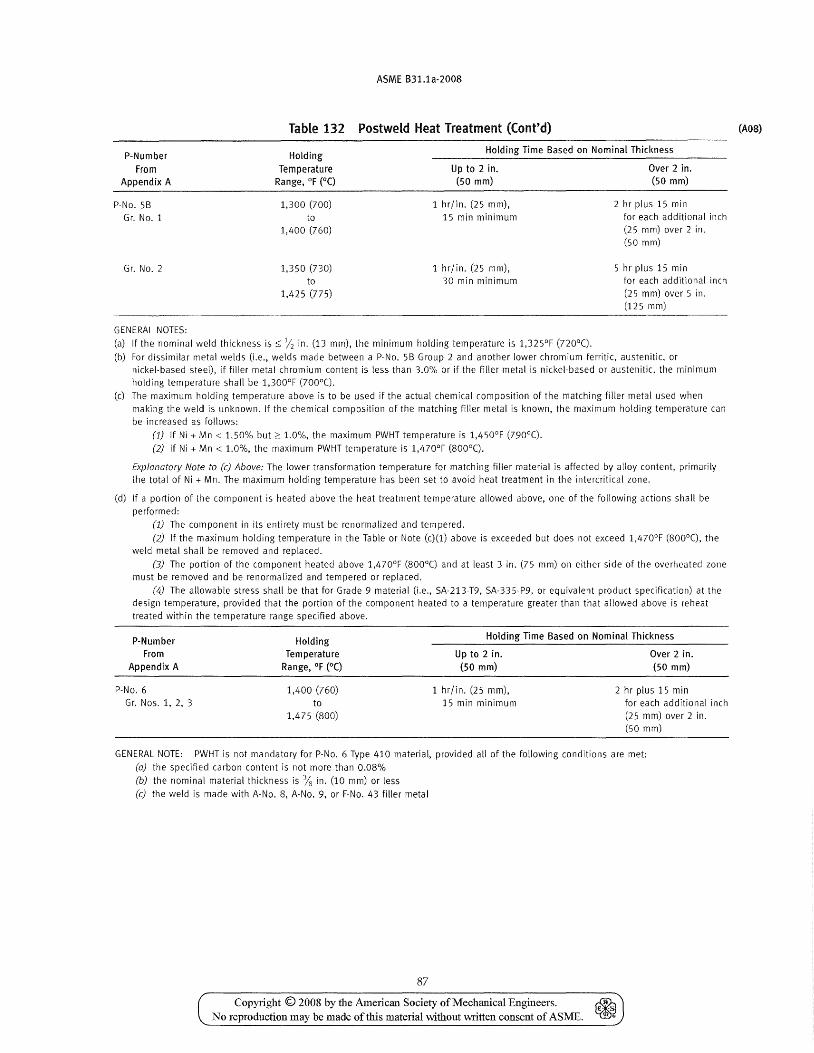
ASME 831.1a-2008
Table 132 Postweld Heat Treatment (Cont'd)
P-Number
From Appendix A
Holding
Temperature Range, DF (DC)
Holding Time Based on Nominal Thickness
P-No. 58
Gr. No.1
Gr. NO.2
GENERAL NOTES:
1,300 (700)
to 1,400 (760)
1,350 (730)
to 1,425 (775)
Up to 2 in. (50 mm)
1 hr/in. (25 mm),
15 min minimum
1 hr/in. (25 mm), 30 min minimum
(a) If the nominal weld thickness is:::;; Y2 in. (13 mm), the minimum holding temperature is 1,325°F (nODe).
Over 2 in. (50 mm)
2 hr plus 15 min
for each additional inch (25 mm) over 2 in. (50 mm)
5 hr plus 15 min for each additional inch
(25 mm) over 5 in. (125 mm)
(b) For dissimilar metal welds (i.e., welds made between a P-No. 58 Group 2 and another lower chromium ferritic, austenitic, or nickel-based steel), if filler metal chromium content is less than 3.0% or if the filler metal is nickel-based or austenitic, the minimum
holding temperature shall be 1,300DF (700De). (c) The maximum holding temperature above is to be used if the actual chemical composition of the matching filler metal used when
making the weld is unknown. If the chemical composition of the matching filler metal is known, the maximum holding temperature can
be increased as follows:
(1) If Ni + Mn < 1.50% but;::: 1.0%, the maximum PWHT temperature is 1,450°F (790 D e). (2) If Ni + Mn < 1.0%, the maximum PWHT temperature is 1,470°F (800 D e).
Explanatory Note to (c) Above: The lower transformation temperature for matching filler material is affected by alloy content, primarily
the total of Ni + Mn. The maximum holding temperature has been set to avoid heat treatment in the intercritical zone.
(d) If a portion of the component is heated above the heat treatment temperature allowed above, one of the following actions shall be
performed:
(1) The component in its entirety must be renormalized and tempered.
(2) If the maximum holding temperature in the Table or Note (c)(l) above is exceeded but does not exceed 1,470oF (SOoae), the weld metal shall be removed and replaced.
(3) The portion of the component heated above 1,470°F (800De) and at least 3 in. (75 mm) on either side of the overheated zone must be removed and be renormalized and tempered or replaced.
(4) The allowable stress shall be that for Grade 9 material (i.e., SA-213-T9, SA-335-P9, or equivalent product specification) at the
design temperature, provided that the portion of the component heated to a temperature greater than that allowed above is reheat
treated within the temperature range specified above.
P-Number
From
Appendix A
Holding Temperature
Range, DF (DC)
Holding Time 8ased on Nominal Thickness
Up to 2 in.
(50 mm)
Over 2 in.
(50 mm)
P-No.6 1,400 (760)
to 1,475 (800)
1 hr/in. (25 mm), 15 min minimum
2 hr plus 15 min Gr. Nos. 1, 2, 3 for each additional inch
(25 mm) over 2 in. (50 mm)
GENERAL NOTE: PWHT is not mandatory for P-No. 6 Type 410 material, provided all of the following conditions are met:
(a) the specified carbon content is not more than 0.08%
(b) the nominal material thickness is % in. (10 mm) or less
(c) the weld is made with A-No.8, A-No.9, or F-No. 43 filler metal
87
Copyri!lht © 2008 by the American Society of Mechanical Emrineers. ~ ~ ~ € ... ~
No reproduction may be made of this material without \\>Titlen consent of ASME.
(A08)
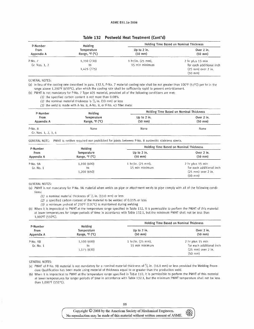
ASME B31.1a-2008
Table 132 Postweld Heat Treatment (Cont'd)
P-Number From
Appendix A
Holding Temperature
Range, of (0C)
Holding Time Based on Nominal Thickness
Up to 2 in. Over 2 in. (50 mm) (50 mm)
P-No.7
Gr. Nos. 1, 2
GENERAL NOTES:
1,350 (730)
to 1,425 (775)
1 hr/in. (25 mm),
15 min minimum 2 hr plus 15 min
for each additional inch (25 mm) over 2 in. (50 mm)
(a) In lieu of the cooling rate described in para. 132.5, P-No. 7 material cooling rate shall be not greater than 100°F (55°C) per hr in the range above 1,200°F (650°C), after which the cooling rate shall be sufficiently rapid to prevent embrittlement.
(b) PWHT is not mandatory for P-No. 7 Type 405 material, provided all of the following conditions are met:
(1) the specified carbon content is not more than 0.08%
(2) the nominal material thickness is % in. (10 mm) or less
(3) the weld is made with A-No.8, A-No.9, or F-No. 43 filler metal
P-Number From
Appendix A
Holding Temperature
Range, OF (0C)
Holding Time Based on Nominal Thickness
P-No.8 None
Gr. Nos. 1, 2,3, 4
Up to 2 in. (50 mm)
None
GENERAL NOTE: PWHT is neither required nor prohibited for joints between P-No. 8 austenitic stainless steels.
Over 2 in. (50 mm)
None
P-Number
From Appendix A
Holding
Temperature Range, OF (0C)
Holding Time Based on Nominal Thickness
P-No.9A
Gr. No.1
GENERAL NOTES:
1,100 (600) to
1,200 (650)
Up to 2 in. (50 mm)
1 hr/in. (25 mm), 15 min minimum
Over 2 in. (50 mm)
2 hr plus 15 min for each additional inch (25 mm) over 2 in. (50 mm)
(a) PWHT is not mandatory for P·No. 9A material when welds on pipe or attachment welds to pipe comply with all of the following condi-
tions: (1) a nominal material thickness of 12 in. (13.0 mm) or less
(2) a specified carbon content of the material to be welded of 0.15% or less
(3) a minimum preheat of 250°F (120°e) is maintained during welding
(b) When it is impractical to PWHT at the temperature range specified in Table 132, it is permissible to perform the PWHT of this material at lower temperatures for longer periods of time in accordance with Table 132.1, but the minimum PWHT shall not be less than
1,000oF (550°C).
P-Number From
Appendix A
P-No. 9B
Gr. No.1
GENERAL NOTES:
Holding Temperature
Range, OF (DC)
1,100 (600)
to 1,175 (630)
Holding Time Based on Nominal Thickness
Up to 2 in. (50 mm)
1 hr/in. (25 mm),
15 min minimum
Over 2 in. (50 mm)
2 hr plus 15 min
for each additional inch (25 mm) over 2 in.
(50 mm)
(a) PWHT of P-No. 9B material is not mandatory for a nominal material thickness of % in. (16.0 mm) or less provided the Welding Procedure Qualification has been made using material of thickness equal to or greater than the production weld.
(b) When it is impractical to PWHT at the temperature range specified in Table 132, it is permissible to perform the PWHT of this material at lower temperatures for longer periods of time in accordance with Table 132.1, but the minimum PWHT temperature shall not be less
than 1,OOO°F (550°C).
88
Copyright © 2008 by the American Society of Mechanical Engineers. ~ No reproduction may be made of this material without written consent of ASME. ~
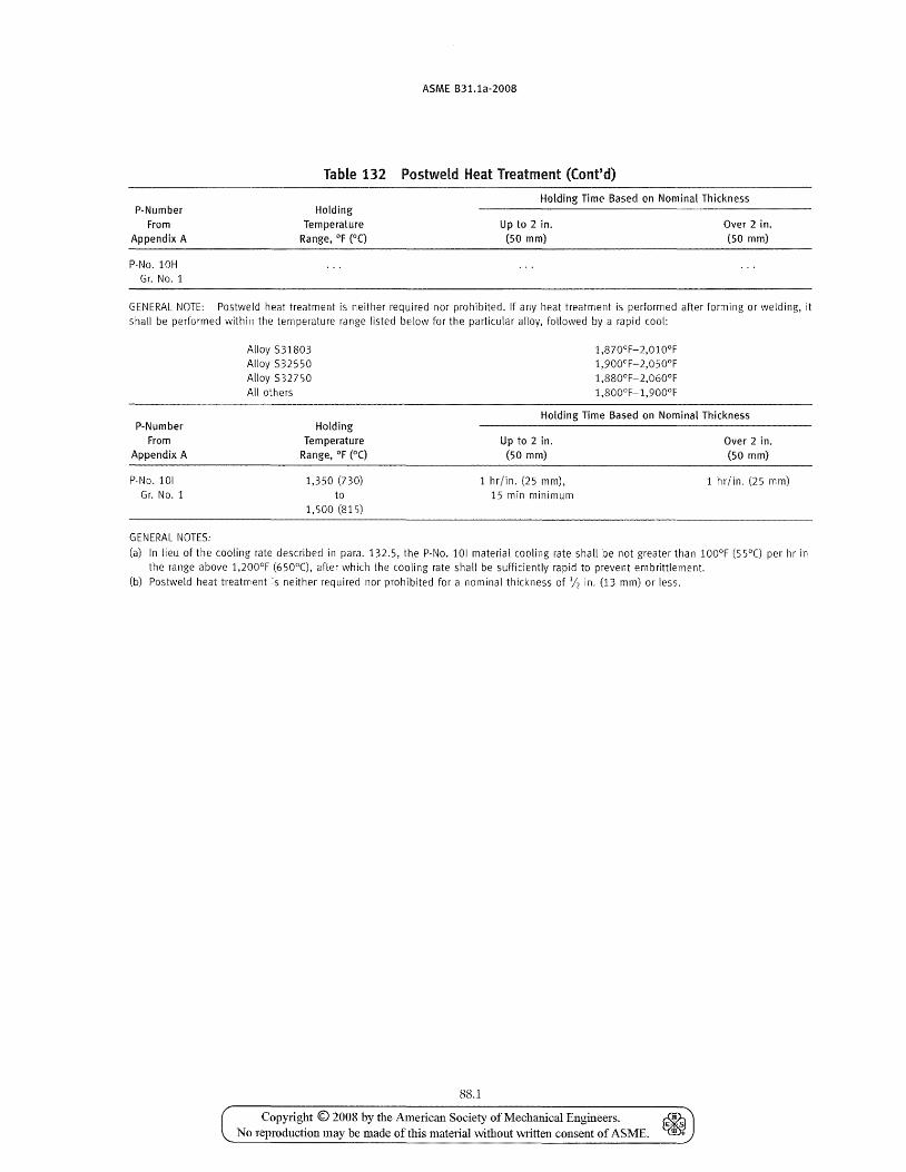
P-Number From
Appendix A
P-No. 10H Gr. No.1
ASME 831.1a-2008
Table 132 Postweld Heat Treatment (Cont'd)
Holding Time Based on Nominal Thickness Holding
Temperature Range, OF (OC)
Up to 2 in. (50 mm)
Over 2 in. (50 mm)
GENERAL NOTE: Postweld heat treatment is neither required nor prohibited. If any heat treatment is performed after forming or welding, it shall be performed within the temperature range listed below for the particular alloy, fonowed by a rapid (001:
Alloy 531803 Alloy 532550 Alloy 532750 All others
1,870°F-2,010°F 1 ,900°F- 2,0 50°F 1 ,880°F- 2,060°F 1,800°F-1,900°F
Holding Time Based on Nominal Thickness P-Number
From Appendix A
P-No. 101 Gr. No.1
GENERAL NOTES:
Holding Temperature
Range, OF (DC)
1,350 (730) to
1,500 (815)
Up to 2 in. (50 mm)
1 hr/in. (25 mm), 15 min minimum
Over 2 in. (50 mm)
1 hr/in. (25 mm)
(a) In lieu of the cooling rate described in para. 132.5, the P-No. 101 material cooling rate shall be not greater than 100°F (55°C) per hr in the range above 1,200°F (650°C), after which the cooling rate shall be sufficiently rapid to prevent embrittlement.
(b) Postweld heat treatment is neither required nor prohibited for a nominal thickness of in. (13 mm) or less.
88.1
Copyright © 2008 by the American Society of Mechallical Engineers. ~ No reproduction may be made of this material without written consent of ASME. ~

INTENTIONALLY LEFT BLANK
Copyright © 2008 by the AmeJi.can Society of Mechanical Engineers. No reproduction may be made oftbis material without written consent of ASME.
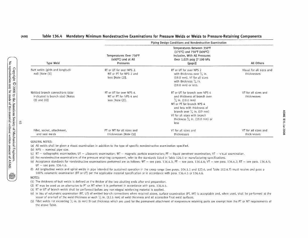
z o
.g (j
a,g 0.. ,< g ::I. ~. C§. § .... S @ !:lJ N
'< ° r:;rO !"P 00
S$ ::>l ....
ft~
2~ ~. g. S () ~ § g. ~ ::>l ()
i$ S-o o >-+;
;:;.~ ~ g ..... P'
~ ~. () a § tTJ f/). 1:1 !"PIJC< a s· o !"P >-+;!"P
>?l r:/1
~ ~ ~
(A08)
\0 VJ
Table 136.4 Mandatory Minimum Nondestructive Examinations for Pressure Welds or Welds to Pressure-Retaining Components
Type Weld
Butt welds (girth and longitudinal) [Note 0)]
Welded branch connections (size indicated is branch size) [Notes (3) and (L,)]
Fillet, socket, attachment,
and seal welds
GENERAL NOTES:
Temperatures Over 750°F (400°C) and at All
Pressures
RT or UT for over NPS 2. MT or PT for NPS 2 and less [Note (2)].
RT or UT for over NPS 4. MT or PT for NPS 4 and less [Note (2)].
PT or MT for all sizes and
thicknesses [Note (5)]
Piping Design Conditions and Nondestructive Examination
Temperatures Between 350°F (175°C) and 750°F (400°C)
Inclusive, With All Pressures Over 1,025 psig [7 100 kPa
(gage)]
RT or UT for over NPS 2 with thickness over % in. (19.0 mm)_ VT for all sizes
with thickness % in. (19.0 m m) or less.
RT or UT for branch over NPS 4 and thickness of branch over % in. (19.0 mm)
MT or PT for branch NPS 4
and less with thickness of
branch over % in. (19 mm) VT for all sizes with branch
thickness % in. (19.0 mm) or
less
VT for all sizes and
thicknesses
(a) All welds shall be given a visual examination in addition to the type of specific nondestructive examination specified.
(b) NPS - nominal pipe size.
All Others
Visual for all sizes and th icknesses
VT for all sizes and th icknesses
VT for all sizes and
th icknesses
(c) RT - radiographic examination; UT - ultrasonic examination; MT - magnetic particle examination; PT - liquid penetrant examination; VT - visual examination.
(d) For nondestructive examinations of the pressure retaining component, refer to the standards listed in Table 126.1 or manufacturing specifications.
(e) Acceptance standards for nondestructive examinations performed are as follows: MT - see para. 136.4.3; PT - see para. 136.4.4; VT - see para. 136.4.2; RT - see para. 136.4.5; UT - see para. 136.4.6.
(f) All longitudinal welds and spiral welds in pipe intended for sustained operation in the creep range (see paras. 104.1.1 and 123.4, and Table 102.4.7) must receive and pass a 100% volumetric examination (RT or Un per the applicable material specification or in accordance with para. 136.4.5 or 136.4.6.
NOTES:
(1) The thickness of butt welds is defined as the thicker of the two abutting ends after end preparation.
(2) RT may be used as an alternative to PT or MT when it is performed in accordance with para. 136.4.5.
(3) RT or UT of branch welds shall be performed before any nonintegral reinforcing material is applied.
(4) In lieu of volumetric examination (RT, UT) of welded branch connections when required above, surface examination (PT, MT) is acceptable and, when used, shall be performed at the lesser of one-half of the weld thickness or each Y2 in. (12.5 mm) of weld thickness and all accessible final weld surfaces.
(5) Fillet welds not exceeding % in. (6 mm) throat thickness which are used for the permanent attachment of nonpressure retaining parts are exempt from the PT or MT requirements of the above Table.
» Vl S m OJ W ..... ;.... OJ
N o o 00
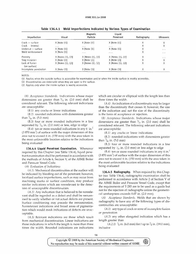
ASME B31.1a-2008
Table 136.4.1 Weld Imperfections Indicated by Various Types of Examination
Magnetic Imperfection Visual Particle
Crack - surface X [Note (1)] X [Note (1)] Crack - internal Undercut - surface X [Note (1)] X [Note (1)]
Weld reinforcement X [Note (1)]
liquid Penetrant
X [Note (1)]
X [Note (1)]
Radiography
X X X X
Ultrasonic
X X
Porosity X [Notes (1), (2)J X [Notes (1), (2)] X [Notes (1), (2)] X Slag inclusion X [Note (2)] X [Note (2)] X [Note (2)] X Lack of fusion X [Notes (1), (2)] X [Notes (1), (2)] X [Notes (1), (2)] X
x X
(on surface) Incomplete penetration X [Note (3)] X [Note (3)] X [Note (3)] X X
NOTES:
(1) Applies when the outside surface is accessible for examination and/or when the inside surface is readily accessible.
(2) Discontinuities are detectable when they are open to the surface.
(3) Applies only when the inside surface is readily accessible.
(B) Acceptance Standards. Indications whose major dimensions are greater than~6 in. (2.0 mm) shall be considered relevant. The following relevant indications are unacceptable:
(B.l) any cracks or linear indications (B.2) rounded indications with dimensions greater
than X6 in. (5.0 mm) (B.3) four or more rounded indications in a line
separated by ~6 in. (2.0 mm) or less, edge to edge (B.4) ten or more rounded indications in any 6 in?
(3870 mm2) of surface with the major dimension of this
area not to exceed 6 in. (150 mm) with the area taken in the most unfavorable location relative to the indications being evaluated
136.4.4 Liquid Penetrant Examination. \J\Thenever required by this Chapter (see Table 136.4), liquid penetrant examination shall be performed in accordance with the methods of Article 6, Section V, of the ASME Boiler and Pressure Vessel Code.
(A) Evaluation of Indications (A.l) Mechanical discontinuities at the surface will
be indicated by bleeding out of the penetrant; however, localized surface imperfections, such as may occur from machining marks or surface conditions, may produce similar indications which are nonrelevant to the detection of unacceptable discontinuities.
(A.2) Any indication that is believed to be nonrelevant shall be regarded as a defect and shall be reexamined to verify whether or not actual defects are present. Surface conditioning may precede the reexamination. Nonrelevant indications and broad areas of pigmentation which would mask indications of defects are unacceptable.
(A.3) Relevant indications are those which result from mechanical discontinuities. Linear indications are those indications in which the length is more than three times the width. Rounded indications are indications
94
which are circular or elliptical with the length less than three times the width.
(A.4) An indication of a discontinuity may be larger than the discontinuity that causes it; however, the size of the indication and not the size of the discontinuity is the basis of acceptance or rejection.
(B) Acceptance Standards. Indications whose major dimensions are greater than~16 in. (2.0 mm) shall be considered relevant. The following relevant indications are unacceptable:
(B.l) any cracks or linear indications (B.2) rounded indications with dimensions greater
than ~6 in. (5.0 mm) (B.3) four or more rounded indications in a line
separated by ~6 in. (2.0 mm) or less edge to edge (B.4) ten or more rounded indications in any 6 in.:>
(3870 mm2) of surface with the major dimension of this
area not to exceed 6 in. (150 mm) with the area taken in the most unfavorable location relative to the indications being evaluated
136.4.5 Radiography. \Vhen required by this Chapter (see Table 136.4), radiographic examination shall be performed in accordance with Article 2 of Section V of the ASME Boiler and Pressure Vessel Code, except that the requirements of T-285 are to be used as a guide but not for the rejection of radiographs unless the geometrical unsharpness exceeds 0.07 in. (2.0 mm).
(A) Acceptance Standards. Welds that are shown by radiography to have any of the following types of discontinuities are unacceptable:
(A.1) any type of crack or zone of incomplete fusion or penetration
(A.2) any other elongated indication which has a length greater than
(A.2.l) ~ in. (6.0 mm) for t up to % in. (19.0 mm), inclusive
Copyright © 2008 by the Amelican Society of Mechanical Engineers. ~ No reproduction may be made of this material without written consent of ASME. ~
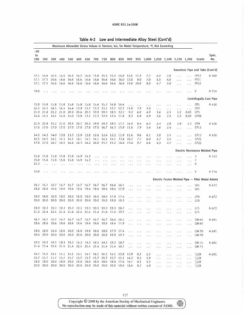
ASME B31.1a·2008
Table A-2 Low and Intermediate AHoy Steel (Cont'd)
Maximum Allowable Stress Values in Tension, ksi, for Metal Temperature, of, Not Exceeding
-20
to Spec.
100 200 300 400 500 600 650 700 750 800 850 900 950 1,000 1,050 1,100 1,150 1,200 Grade No.
17.1 16.8 16.5 16.5 16.5 16.3 16.0 15.8 15.5 15.3 14.9 14.5 11.3 7.2 17.1 17.1 16.6 16.6 16.6 16.6 16.6 16.6 16.6 16.6 16.0 12.0 9.0 7.0 17.1 17.1 16.6 16.6 16.6 16.6 16.6 16.6 16.6 16.6 16.6 13.6 10.8 8.0
18.6
15.8 15.8 15.8 15.8 15.8 15.8 15.8 15.6 15.2 14.8 14.4 14.5 14.5 14.5 14.5 14.4 13.9 13.7 13.3 13.1 12.7 12.3 11.8 7.8 5.0 21.9 21.8 21.2 21.0 20.9 20.6 20.3 19.9 19.3 18.5 12.2 9.3 6.8 4.9 14.6 14.5 14.1 14.0 14.0 13.8 13.5 13.3 12.9 12.4 11.8 9.3 6.8 4.9
21.9 21.8 21.2 21.0 20.9 20.7 20.3 19.9 19.3 18.5 17.7 14.0 9.4 6.3 17.0 17.0 17.0 17.0 17.0 17.0 17.0 17.0 16.7 16.3 15.9 11.6 7.9 5.4
14.5 14.3 14.0 13.8 13.3 12.9 12.8 12.6 12.4 12.2 11.9 11.6 9.6 6.1 14.5 14.5 14.1 14.1 14.1 14.1 14.1 14.1 14.1 14.1 13.6 10.2 7.7 6.0 17.0 17.0 16.7 16.5 16.4 16.3 16.2 16.0 15.7 15.2 14.6 13.4 9.7 6.6
15.8 15.8 15.8 15.8 15.8 14.9 14.2 15.8 15.8 15.8 15.8 15.8 14.9 14.2 15.3
15.8
4.5 5.5 5.7
3.6 3.6
4.3 3.6
3.8 4.7 4.3
2.8 4.0 3.8
2.5 2.5
2.8 2.4
2.4 3.4 2.7
Seamless Pipe and Tube (Cont'd)
FP12
FP21 FP22
v
A 369
A 714
Centrifugally Cast Pipe
(Pl CP2
1.5 0.85 CPS 1.5 0.85 CP5b
1.9 1.3 CP9 (P11
(P12 (P21
(P22
A 426
A 426
A 426
Electric Resistance Welded Pipe
3 7 9
v
A 333
A 714
Electric Fusion Welded Pipe - Filler Metal Added
16.7 16.7 16.7 16.7 16.7 16.7 16.7 16.7 16.7 16.6 16.1 18.6 18.6 18.6 18.6 18.6 18.6 18.6 18.6 18.6 18.4 17.9
18.0 18.0 18.0 18.0 18.0 18.0 18.0 18.0 18.0 17.9 17.4 20.0 20.0 20.0 20.0 20.0 20.0 20.0 20.0 20.0 19.9 19.3
19.3 19.3 19.3 19.3 19.3 19.3 19.3 19.3 19.3 19.3 18.7 21.4 21.4 21.4 21.4 21.4 21.4 21.4 21.4 21.4 21.4 20.7
14.1 14.1 14.1 14.1 14.1 14.1 14.1 14.1 14.1 14.1 13.8 12.9 8.3 5.3 15.7 15.7 15.7 15.7 15.7 15.7 15.7 15.7 15.7 15.7 15.3 14.3 9.2 5.9 18.0 18.0 18.0 18.0 18.0 18.0 18.0 18.0 18.0 18.0 17.6 16.7 8.3 5.3 20.0 20.0 20.0 20.0 20.0 20.0 20.0 20.0 20.0 20.0 19.5 18.6 9.2 5.9
117
Copyright © 2008 by the American Society of Mechanical Engineers. No reproduction may be made of this material \\7J.thout written consent of ASME.
L65 L65
L70 L70
L75 L75
CM·65 CM-65
(M-70 (M-70
CM-75 CM-75
Y2 CR
J2CR
Y2 CR
Y2 CR
A 672
A 672
A 672
A 691
A 691
A 691
A 691
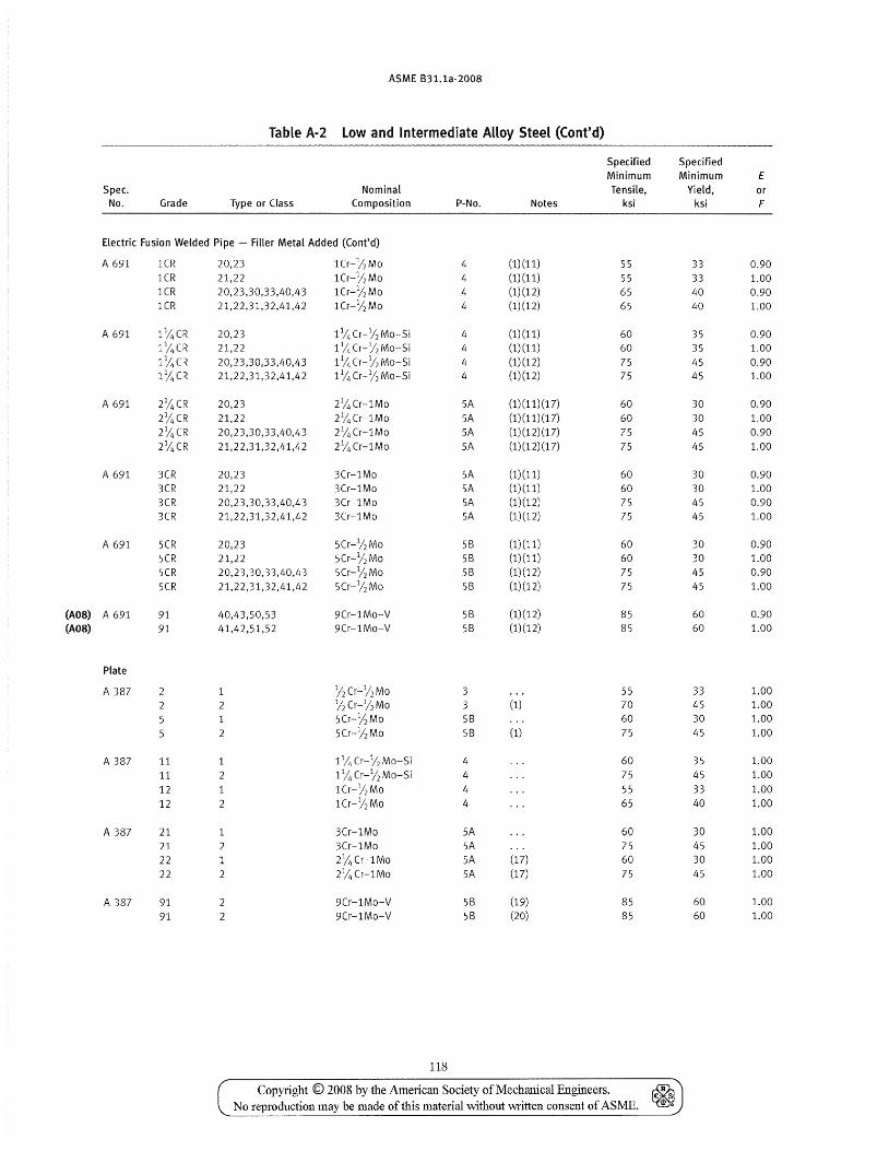
ASME B31.1a-2008
Table A-2 Low and Intermediate AHoy Steel (Cont'd)
Specified Specified Minimum Minimum E
Spec. Nominal Tensile, Yield, or No. Grade Type or Class Composition P-No. Notes ksi ksi F
Electric Fusion Welded Pipe - Filler Metal Added (Cont'd)
A 691 lCR 20,23 lCr-'/2 Mo 4 (1)(11) 55 33 0.90 lCR 21,22 lCr-'/2 Mo 4 (1)(11) 55 33 1.00 lCR 20,23,30,33,40,43 lCr-'/2 Mo 4 (1)(12) 65 40 0.90 lCR 21,22,31,32,41,42 lCr-%Mo 4 (1)(12) 65 40 1.00
A 691 11;;, CR 20,23 11/4 Cr-% Mo-Si 4 (1) (11) 60 35 0.90
l%CR 21,22 11;;, Cr-12 Mo-Si 4 (1) (11) 60 35 1.00 l%CR 20,23,30,33,40,43 11/, Cr-% Mo-Si 4 (1)(12) 75 45 0.90 l%CR 21,22,31,32,41,42 1 % Cr-% Mo-Si 4 (1)(12) 75 45 1.00
A 691 2%CR 20,23 2% Cr-1Mo 5A (1)(11)(17) 60 30 0.90 2%CR 21,22 21/4 Cr-1Mo 5A (1) (11) (17) 60 30 1.00 2%CR 20,23,30,33,40,43 21/4 Cr-1Mo 5A (1) (12) (17) 75 45 0.90 2%CR 21,22,31,32,41,42 21/4 Cr-1Mo 5A (1) (12) (17) 75 45 1.00
A 691 3CR 20,23 3Cr-1Mo 5A (1)(11) 60 30 0.90 3CR 21,22 3Cr-1Mo SA (1)(11) 60 30 1.00 3CR 20,23,30,33,40,43 3Cr-1Mo 5A (1)(12) 75 45 0.90 3CR 21,22,31,32,41,42 3Cr-1Mo 5A (1)(12) 75 45 1.00
A 691 5CR 20,23 5Cr-12 Mo 58 (1)(11) 60 30 0.90 5CR 21,22 5Cr-l/2 Mo 58 (1)(11) 60 30 1.00 5CR 20,23,30,33,40,43 5Cr-12 Mo 58 (1)(12) 75 45 0.90 5CR 21,22,31,32,41,42 5Cr-12 Mo 58 (1)(12) 75 45 1.00
(A08) A 691 91 40,43,50,53 9Cr-1Mo-V 58 (1)(12) 85 60 0.90 (A08) 91 41,42,51,52 9Cr-1Mo-V 58 (1) (12) 85 60 1.00
Plate
A 387 12 Cr-1/2 Mo 3 55 33 1.00
2 2 12 Cr-12 Mo 3 (1) 70 45 1.00
5 5Cr-12 Mo 58 60 30 1.00 2 5Cr-l/2 Mo 58 (1) 75 45 1.00
A 387 11 1 1 % Cr-12 Mo-Si 4 60 35 1.00
11 2 1 % Cr-12 Mo-Si 4 75 45 1.00
12 1 lCr-12 Mo 4 55 33 1.00 12 2 lCr-12 Mo 4 65 40 1.00
A 387 21 3Cr-1Mo SA 60 30 1.00 21 2 3Cr-1Mo 5A 75 45 1.00
22 1 2% Cr-1Mo SA (17) 60 30 1.00
22 2 2% Cr-1Mo 5A (17) 75 45 1.00
A 387 91 2 9Cr-1Mo-V 58 (19) 85 60 1.00
91 2 9Cr-1Mo-V 58 (20) 85 60 1.00
118
Copyright © 2008 by the American Society of Mechanical Engineers. ~ No reproduction may be made of this material without written consent of ASME. ~
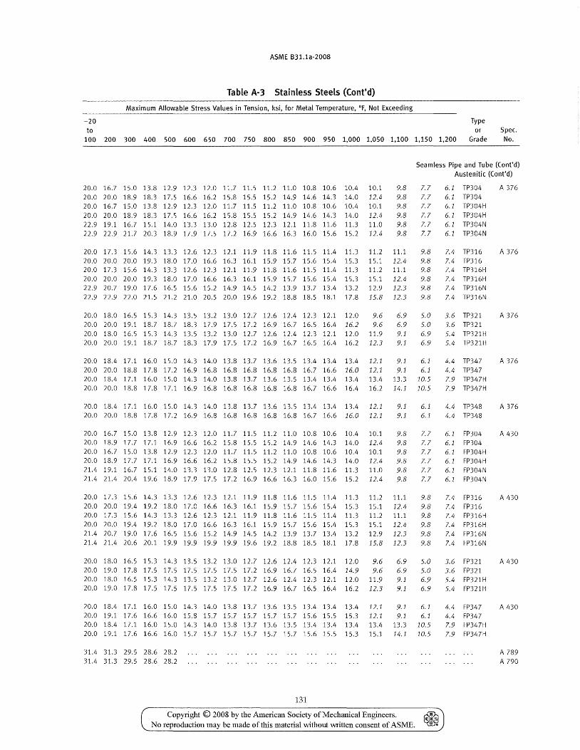
ASME B31.1a-200B
Table A-3 Stainless Steels (Cont'd)
Maximum Allowable Stress Values in Tension, ksi, for Metal Temperature, of, Not Exceeding
-20 Type to or Spec.
100 200 300 400 500 600 650 700 750 800 850 900 950 1,000 1,050 1,100 1,150 1,200 Grade No.
Seamless Pipe and Tube (Cont'd) Austenitic (Cont'd)
20.0 16.7 15.0 13.8 12.9 12.3 12.0 11.7 11.5 11.2 11.0 10.8 10.6 10.4 10.1 9.8 20.0 20.0 18.9 18.3 17.5 16.6 16.2 15.8 15.5 15.2 14.9 14.6 14.3 14.0 12.4 9.8 20.0 16.7 15.0 13.8 12.9 12.3 12.0 11.7 11.5 11.2 11.0 10.8 10.6 10.4 10.1 9.8 20.0 20.0 18.9 18.3 17.5 16.6 16.2 15.8 15.5 15.2 14.9 14.6 14.3 14.0 12.4 9.8 22.9 19.1 16.7 15.1 14.0 13.3 13.0 12.8 12.5 12.3 12.1 11.8 11.6 11.3 11.0 9.8 22.9 22.9 21.7 20.3 18.9 17.9 17.5 17.2 16.9 16.6 16.3 16.0 15.6 15.2 12.4 9.8
20.0 17.3 15.6 14.3 13.3 12.6 12.3 12.1 11.9 11.8 11.6 11.5 11.4 11.3 11.2 11.1 20.0 20.0 20.0 19.3 18.0 17.0 16.6 16.3 16.1 15.9 15.7 15.6 15.4 15.3 20.0 17.3 15.6 14.3 13.3 12.6 12.3 12.1 11.9 11.8 11.6 11.5 11.4 11.3 20.0 20.0 20.0 19.3 18.0 17.0 16.6 16.3 16.1 15.9 15.7 15.6 15.4 15.3 22.9 20.7 19.0 17.6 16.5 15.6 15.2 14.9 14.5 14.2 13.9 13.7 13.4 13.2 22.9 22.9 22.0 21.5 21.2 21.0 20.5 20.0 19.6 19.2 18.8 18.5 18.1 17.8
15.1 12.4 11.2 11.1 15.1 12.4 12.9 12.3 15.8 12.3
7.7 6.1 TP304 7.7 6.1 TP304 7.7 6.1 TP304H 7.7 6.1 TP304H 7.7 6.1 TP304N 7.7 6.1 TP304N
9.8 9.8 9.8 9.8 9.8 9.8
7.4 TP316 7.4 TP316 7.4 TP316H 7.4 TP316H 7.4 TP316N 7.4 TP316N
A 376
A 376
20.0 18.0 16.5 15.3 14.3 13.5 13.2 13.0 12.7 12.6 12.4 12.3 12.1 12.0 9.6 6.9 5.0 3.6 TP321 A 376 20.0 20.0 19.1 18.7 18.7 18.3 17.9 17.5 17.2 16.9 16.7 16.5 16.4 16.2 9.6 20.0 18.0 16.5 15.3 14.3 13.5 13.2 13.0 12.7 12.6 12.4 12.3 12.1 12.0 11.9 20.0 20.0 19.1 18.7 18.7 18.3 17.9 17.5 17.2 16.9 16.7 16.5 16.4 16.2 12.3
6.9 5.0 3.6 TP321 9.1 6.9 5.4 TP321H 9.1 6.9 5.4 TP321H
20.0 18.4 17.1 16.0 15.0 14.3 14.0 13.8 13.7 13.6 13.5 13.4 13.4 13.4 12.1 20.020.018.817.817.216.916.816.816.816.816.816.7 16.6 16.0 12.1
9.1 6.1 4.4 TP347 A 376 9.1 6.1 4.4 TP347
20.0 18.4 17.1 16.0 15.0 14.3 14.0 13.8 13.7 13.6 13.5 13.4 13.4 13.4 13.4 13.3 10.5 20.020.018.817.817.116.916.816.816.816.816.816.7 16.6 16.4 16.2 14.1 10.5
20.0 18.4 17.1 16.0 15.0 14.3 14.0 13.8 13.7 13.6 13.5 13.4 13.4 13.4 12.1 20.0 20.0 18.8 17.8 17.2 16.9 16.8 16.8 16.8 16.8 16.8 16.7 16.6 16.0 12.1
9.1 9.1
6.1 6.1
7.9 TP347H 7.9 TP347H
4.4 TP348 4.4 TP348
A 376
20.0 16.7 15.0 13.8 12.9 12.3 12.0 11.7 11.5 11.2 11.0 10.8 10.6 10.4 10.1 9.8 7.7 6.1 FP304 A 430 20.0 18.9 17.7 17.1 16.9 16.6 16.2 15.8 15.5 15.2 14.9 14.6 14.3 14.0 12.4 9.8 7.7 6.1 FP304 20.016.7 15.0 13.8 12.9 12.312.011.7 11.5 11.2 11.010.810.6 10.4 10.1 9.8 7.7 6.1 FP304H 20.0 18.9 17.7 17.1 16.9 16.6 16.2 15.8 15.5 15.2 14.9 14.6 14.3 14.0 12.4 9.8 7.7 6.1 FP304H 21.4 19.1 16.7 15.1 14.0 13.3 13.0 12.8 12.5 12.3 12.1 11.8 11.6 11.3 11.0 9.8 7.7 6.1 FP304N 21.4 21.4 20.4 19.6 18.9 17.9 17.5 17.2 16.9 16.6 16.3 16.0 15.6 15.2 12.4 9.8 7.7 6.1 FP304N
20.0 17.3 15.6 14.3 13.3 12.6 12.3 12.1 11.9 11.8 11.6 11.5 11.4 11.3 11.2 11.1 9.8 7.4 FP316 A 430 20.0 20.0 19.4 19.2 18.0 17.0 16.6 16.3 16.1 15.9 15.7 15.6 15.4 15.3 15.1 12.4 9.8 7.4 FP316 20.0 17.3 15.6 14.3 13.3 12.6 12.3 12.1 11.9 11.8 11.6 11.5 11.4 11.3 11.2 11.1 9.8 20.0 20.0 19.4 19.2 18.0 17.0 16.6 16.3 16.1 15.9 15.7 15.6 15.4 15.3 15.1 12.4 9.8 21.4 20.7 19.0 17.6 16.5 15.6 15.2 14.9 14.5 14.2 13.9 13.7 13.4 13.2 12.9 12.3 9.8 21.4 21.4 20.6 20.1 19.9 19.9 19.9 19.9 19.6 19.2 18.8 18.5 18.1 17.8 15.8 12.3 9.8
7.4 FP316H 7.4 FP316H 7.4 FP316N 7.4 FP316N
20.0 18.0 16.5 15.3 14.3 13.5 13.2 13.0 12.7 12.6 12.4 12.3 12.1 12.0 9.6 6.9 5.0 3.6 FP321 20.0 19.0 17.8 17.5 17.5 17.5 17.5 17.5 17.2 16.9 16.7 16.5 16.4 14.9 9.6 6.9 5.0 3.6 FP321 20.0 18.0 16.5 15.3 14.3 13.5 13.2 13.0 12.7 12.6 12.4 12.3 12.1 12.0 11.9 9.1 6.9 5.4 FP321H 20.0 19.0 17.8 17.5 17.5 17.5 17.5 17.5 17.2 16.9 16.7 16.5 16.4 16.2 12.3 9.1 6.9 5.4 FP321H
A 430
20.0 18.4 17.1 16.0 15.0 14.3 14.0 13.8 13.7 13.6 13.5 13.4 13.4 13.4 12.1 9.1 6.1 4.4 FP347 A 430 20.0 19.1 17.6 16.6 16.0 15.8 15.7 15.7 15.7 15.7 15.7 15.6 15.5 15.3 12.1 9.1 6.1 20.0 18.4 17.1 16.0 15.0 14.3 14.0 13.8 13.7 13.6 13.5 13.4 13.4 13.4 13.4 13.3 10.5 20.0 19.1 17.6 16.6 16.0 15.7 15.7 15.7 15.7 15.7 15.7 15.6 15.5 15.3 15.1 14.1 10.5
31.4 31.3 29.5 28.6 28.2 31.4 31.3 29.5 28.6 28.2
131
Copyright © 2008 by the American Society of Mechanical Engineers. ~ No reproduction may be made of this material without written consent of AS ME. ~
4.4 FP347 7.9 FP347H 7.9 FP347H
A 789 A 790
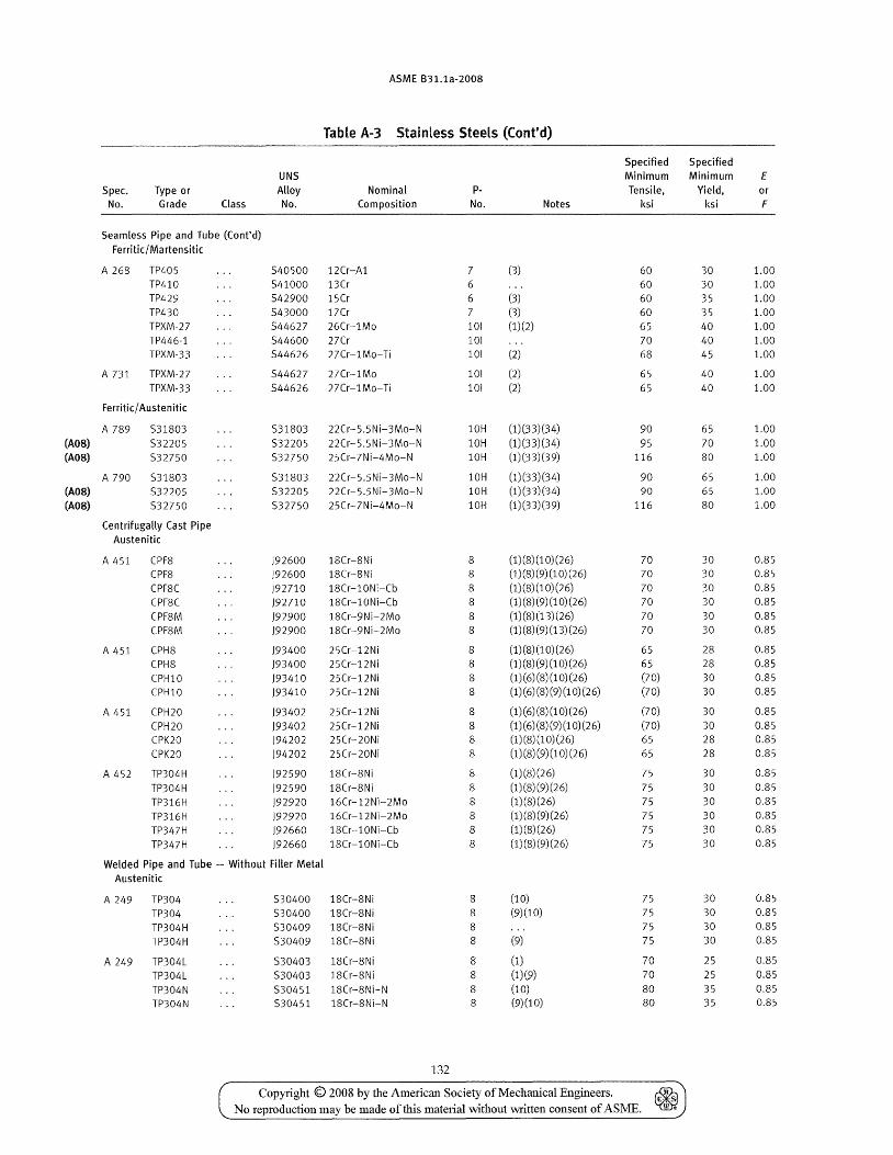
ASME B31.1a-2008
Table A-3 Stainless Steels «(ont'd)
Spec. No.
Type or Grade Class
Seamless Pipe and Tube (Cont'd) Ferritic/ Martensitic
A 26S TP405 TP410 TP429 TP430 TPXM-27 TP446-1 TPXM-33
A 731 TPXM-27 TPXM-33
Ferritk/ Austen itk
A 789 531803
(A08) 532205 (A08) 532750
A 790 531803 (A08) 532205 (A08) 532750
Centrifugally Cast Pipe Austenitic
A 451 CPF8 CPFS CPF8C CPFSC
CPF8M CPF8M
A 451 CPH8 CPH8 CPHI0 CPHI0
A 451 CPH20
CPH20 CPK20 CPK20
A 452 TP304H
TP304H TP316H TP316H TP347H TP347H
UNS Alloy No.
Nominal Composition
540500 12Cr-Al 541000 13Cr 542900 15Cr 543000 17Cr 544627 26Cr-1Mo 544600 27Cr 544626 27Cr-1Mo-Ti
544627 27Cr-1Mo 544626 27Cr-lMo-Ti
531803 22Cr-5.5Ni-3Mo-N 532205 22Cr-S.5Ni-3Mo-N 532750 25Cr-7Ni-4Mo-N
531803 22Cr-S.5Ni-3Mo-N 532205 22Cr-5.5Ni-3Mo-N 532750 25Cr-7Ni-4Mo-N
)92600 )92600 )92710 )92710
)92900 )92900
)93400 )93400 )93410 )93410
)93402
)93402 )94202
)94202
)92590
)92590 )92920 )92920 )92660 )92660
1SCr-SNi lSCr-SNi 1SCr-10Ni-Cb 1SCr-10Ni-Cb 1SCr-9Ni-2Mo 1SCr-9Ni-2Mo
25Cr-12Ni 25Cr-12Ni 25Cr-12Ni 25Cr-12Ni
25Cr-12Ni 25Cr-12Ni 25Cr-20Ni 25Cr-20Ni
1SCr-SNi 1SCr-SNi 16Cr-12Ni-2Mo 16Cr-12Ni-2Mo 1SCr-l0Ni-Cb lSCr-l0Ni-Cb
Welded Pipe and Tube - Without Filler Metal Austenitic
A 249 TP304 TP304 TP304H TP304H
A 249 TP304L TP304L TP304N TP304N
530400 1SCr-SNi 530400 1SCr-8Ni 530409 1SCr-SNi 530409 1SCr-SN i
530403 18Cr-8Ni 530403 18Cr-8Ni 530451 18Cr-8Ni-N 530451 lSCr-SNi-N
132
pNo.
7 6 6 7 101
101
101
101 101
(3)
(3) (3) (1)(2)
(2)
(2) (2)
Notes
10H (1)(33)(34) 10H (1)(33)(34) 10H (1)(33)(39)
10H (1)(33)(34) 10H (1)(33)(34) 10H (1)(33)(39)
8 8 8 8 8 8
8 8 8 8
8
8 8 8
8 8 8 8 8 8
8 8 8 8
8
8 8 8
(1) (8) (1 0) (26) (1) (8) (9) (1 0) (26) (1) (8) (1 0) (26) (1) (8) (9) (1 0) (26)
(1) (8) (13) (26) (1) (8) (9) (13) (26)
(1) (8) (1 0) (26) (1) (8) (9) (1 0) (26) (1)(6) (8) (1 0) (26) (1) (6) (8) (9) (1 0) (26)
(1)(6) (8) (1 0) (26) (1)(6) (8) (9) (1 0) (26) (1) (8) (1 0) (26) (1)(8) (9) (1 0) (26)
(1)(8)(26) (1)(8)(9)(26) (1)(8)(26) (1)(8)(9)(26) (1)(8)(26) (1) (8) (9) (26)
(10) (9)(10)
(9)
(1) (1)(9) (10)
(9)(10)
Specified Specified Minimum Minimum Tensile, Yield,
ksi ksi
60 60 60 60 65 70 68
65 65
90
95 116
90 90
116
70 70
70 70 70 70
65
65 (70) (70)
(70) (70) 65
65
75 75 75 75 75 75
75 75 75 75
70 70 80 SO
30 30
35 35 40 40 45
40
40
65 70 80
65 65 80
30 30 30 30 30 30
28 28 30 30
30
30 28 28
30 30 30 30 30 30
30 30 30 30
25
25
35 35
Copyright © 2008 by the American Society of Mechanical Engineers. ~ No reproduction may be made of this material without written consent of ASME. ~
E or F
1.00 1.00 1.00 1.00 1.00 1.00 1.00
1.00
1.00
1.00 1.00 1.00
1.00 1.00 1.00
0.85 0.85 0.85 0.85
0.85 0.85
0.85 0.85 0.85
0.85
0.85
0.85 0.85
0.85
0.85 0.85 0.85 0.85 0.85 0.85
0.85 0.85 0.85 0.85
0.85 0.85 0.85 0.85
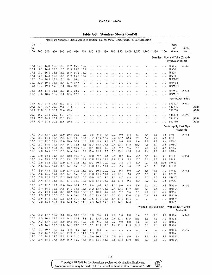
ASME B31.1a-2008
Table A-3 Stainless Steels (Cont'd)
Maximum Allowable Stress Values in Tension, ksi, for Metal Temperature, of, Not Exceeding
-20 Type to or Spec.
100 200 300 400 500 600 650 700 750 800 850 900 950 1,000 1,050 1,100 1,150 1,200 Grade No.
17.1 17.1 16.8 16.5 16.3 15.9 15.6 15.2 17.1 17.1 16.8 16.5 16.3 15.9 15.6 15.2 17.1 17.1 16.8 16.5 16.3 15.9 15.6 15.2 17.1 17.1 16.8 16.5 16.3 15.9 15.6 15.2 18.6 18.6 18.3 18.1 18.1 18.1 18.1 20.0 20.0 19.3 18.8 18.4 17.9 17.7 19.4 19.4 19.3 19.0 18.8 18.4 18.1
18.6 18.6 18.3 18.1 18.1 18.1 18.1 18.6 18.6 18.4 18.2 18.0 17.6 17.3
25.7 25.7 24.8 23.9 23.3 23.1 27.1 27.1 26.2 25.2 24.6 24.3 33.1 33.0 31.2 30.1 29.6 29.4
25.7 25.7 24.8 23.9 23.3 23.1 25.7 25.7 24.8 23.9 23.3 23.1 33.1 33.0 31.2 30.1 29.6 29.4
17.0 14.2 12.7 11.7 11.0 10.5 10.2 9.9 9.8 9.5 9.4 9.2 9.0 8.8 8.1 17.0 16.1 15.0 14.5 14.4 14.1 13.8 13.4 13.2 12.9 12.7 12.4 12.2 10.4 8.1 17.0 14.2 12.7 11.7 11.0 10.4 10.2 10.0 9.8 9.5 9.4 9.2 9.0 8.8 8.6 17.0 16.1 15.0 14.5 14.4 14.1 13.8 13.5 13.2 12.9 12.6 12.4 12.1 11.9 10.3 17.0 14.6 13.2 12.1 11.3 10.7 10.4 10.3 10.1 10.0 9.9 9.8 9.7 9.6 9.5 17.0 17.0 16.5 16.3 15.2 14.4 14.1 13.8 13.6 13.5 13.3 13.2 13.1 12.6 9.8
15.8 13.0 12.0 11.5 11.1 10.8 10.5 10.3 10.0 9.7 9.4 9.1 8.7 8.4 7.2 15.8 14.4 13.4 13.1 13.1 13.1 13.0 12.9 12.8 12.5 12.2 11.8 11.3 9.4 7.2 17.0 13.9 12.8 12.3 11.9 11.5 11.3 11.0 10.7 10.4 10.0 9.7 7.8 5.0 3.2 17.0 15.6 14.5 14.1 14.1 14.1 14.0 13.9 13.8 13.5 13.1 12.7 7.8 5.0 3.2
17.0 13.9 12.8 12.3 11.9 11.5 11.3 11.0 10.7 10.4 10.0 9.7 9.4 9.0 7.2 17.0 15.6 14.5 14.1 14.1 14.1 14.0 13.9 13.8 13.5 13.1 12.7 12.1 9.4 7.2 15.8 13.0 12.0 11.5 11.1 10.8 10.5 10.3 10.0 9.7 9.4 9.1 8.7 8.4 15.S 14.4 13.4 13.1 13.1 13.1 13.0 12.9 12.8 12.5 12.2 11.8 11.3 9.6
8.1 8.3
6.4 6.4 7.8 7.8 7.6 7.6
5.5 5.5 2.1 2.1
5.5 5.5 7.2 7.2
17.0 14.2 12.7 11.7 11.0 10.4 10.2 10.0 9.8 9.6 9.4 9.2 9.0 8.8 8.6 8.3 17.0 17.0 16.1 15.5 14.8 14.1 13.8 13.5 13.2 12.9 12.6 12.4 12.1 11.9 10.5 8.3 17.0 14.7 13.2 12.1 11.3 10.7 10.5 10.3 10.1 10.0 9.9 9.8 9.7 9.6 9.5 9.4 17.0 17.0 17.0 16.4 15.3 14.5 14.1 13.9 13.7 13.5 13.4 13.2 13.1 13.0 12.9 10.5 17.0 15.6 14.6 13.6 12.8 12.2 11.9 11.8 11.6 11.5 11.5 11.4 11.4 11.4 17.0 17.0 16.0 15.1 14.6 14.3 14.3 14.3 14.3 14.3 14.3 14.2 14.1 14.0
Seamless Pipe and Tube (Cont'd) Ferritic/ Martensitic
TP405 TP410 TP429 TP430 TPXM-27 TP446-1 TPXM-33
A 268
TPXM-27 A 731 TPXM-33
Ferritic/ Austenitic
531803 532205 532750
531803 532205 532750
A 789
A 790
Centrifugally Cast Pipe Austenitic
5.1 4.1 (PF8 5.1 4.1 (PF8 5.2 3.8 (PF8C 5.2 3.8 (PF8C 5.9 4.6 (PF8M 5.9 4.6 (PFSM
4.3 3.2 (PH8 4.3 3.2 (PH8 1.3 0.85 (PHI0 1.3 0.85 (PHI0
4.3 3.2 (PH20 4.3 3.2 (PH20 6.2 6.2
5.1 (PK20 5.1 (PK20
A 451
A 451
A 451
6.6 6.6 8.3 8.3
5.2 TP304H A 452 5.2 TP304H 6.3 TP316H 6.3 TP316H
TP347H TP347H
Welded Pipe and Tube - Without Filler Metal Austenitic
17.0 14.2 12.7 11.7 11.0 10.4 10.2 10.0 9.8 9.6 9.4 9.2 9.0 8.8 8.6 17.0 17.0 16.1 15.5 14.8 14.1 13.8 13.5 13.2 12.9 12.6 12.4 12.1 11.9 10.5 17.0 14.2 12.7 11.7 11.0 10.4 10.2 10.0 9.8 9.6 9.4 9.2 9.0 8.8 8.6 17.0 17.0 16.1 15.5 14.8 14.1 13.8 13.5 13.2 12.9 12.6 12.4 12.1 11.9 10.5
14.2 12.1 10.9 9.9 9.3 8.S 8.6 8.5 8.3 8.2 14.2 14.2 14.2 13.4 12.5 11.9 11.7 11.4 11.3 11.1 19.416.214.212.811.911.311.010.810.610.510.310.0 9.8 9.6 9.4 19.4 19.4 18.5 17.3 16.0 15.2 14.9 14.6 14.4 14.1 13.8 13.6 13.3 13.0 10.5
133
Copyright © 2008 by the American Society of Mechanical Engineers.
8.3 8.3 8.3 8.3
8.3 8.3
No reproduction may be made of this material without written consent of AS ME.
6.6 6.6 6.6 6.6
6.6 6.6
5.2 TP304 A 249 5.2 TP304 5.2 TP304H 5.2 TP304H
TP304L A 249 TP304L
5.2 TP304N 5.2 TP304N
(AOS) (AOS)
(AOS) (AOS)
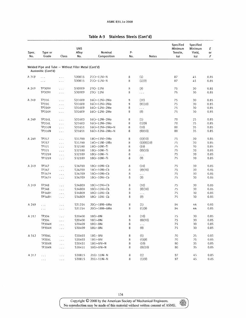
Spec. No.
Type or Grade Class
UNS Alloy No.
ASME B31.1a-2008
Table A-3 Stainless Steels (Cont'd)
Nominal Composition
PNo. Notes
Specified Minimum Tensile,
ksi
Welded Pipe and Tube - Without Filler Metal (Cont'd) Austenitic (Cont'd)
A 249
A 249 TP309H TP309H
A 249 TP316 TP316 TP316H TP316H
A 249 TP316L TP316L TP316N TP316N
A 249 TP317 TP317 TP321 TP321 TP321H TP321H
A 249 TP347 TP347 TP347H TP347H
A 249 TP348
A 249
TP348 TP348H TP348H
A 312 TP304 TP304 TP304H TP304H
A312 TP304L
A 312
TP304L TP304N TP304N
530815 21Cr-llNi-N 530815 21Cr-llNi-N
530909 23Cr-12Ni 530909 23Cr-12Ni
531600 16Cr-12Ni-2Mo 531600 16Cr-12Ni-2Mo 531609 16Cr-12Ni-2Mo 531609 16Cr-12Ni-2Mo
531603 16Cr-12Ni-2Mo 531603 16Cr-12Ni-2Mo 531651 16Cr-12Ni-2Mo-N 531651 16Cr-12Ni-2Mo-N
531700 18Cr-13Ni-3Mo 531700 lSCr-13Ni-3Mo 532100 18Cr-l0Ni-Ti 532100 18Cr-l0Ni-Ti 532109 18Cr-l0Ni-Ti 532109 lSCr-l0Ni-Ti
534700 18Cr-10Ni-Cb 534700 lSCr-10Ni-Cb 534709 lSCr-10Ni-Cb 534709 lSCr-l0Ni-Cb
534800 lSCr-l0Ni-Cb 534800 lSCr-10Ni-Cb 534S09 18Cr-l0Ni-Cb 534S09 lSCr-l0Ni-Cb
531254 20Cr-18Ni-6Mo 531254 20Cr-18Ni-6Mo
530400 lSCr-SNi 530400 18Cr-8Ni 530409 lSCr-SNi 530409 18Cr-8N i
530403 18Cr-8Ni 530403 lSCr-8Ni 530451 18Cr-8Ni-N 530451 18Cr-SNi-N
530815 21Cr-l1Ni-N 530815 21Cr-11Ni-N
134
S
S
8 S
S
8 8 8
8 8 8 8
8 8 8 8 8 8
8 8 8 8
8 8 8 8
8 8
8
8 8 8
8 8 8 8
8
8
(1)
(1)(9)
(9)
(10) (9)(10)
(9)
(1) (1)(9) (10) (9)(10)
(1) (1 0) (1)(9)(10) (10) (9)(10)
(9)
(10) (9)(10)
(9)
(10) (9)(10)
(9)
(1) (1)(9)
(10)
(9)(10)
(9)
(1) (1)(9)
(10) (9)(10)
(1)
(1)(9)
87 87
75 75
75 75 75 75
70 70 80 80
75 75 75 75 75 75
75 75 75 75
75 75 75 75
94 94
75 75 75 75
70 70 80 80
87 87
Copyright © 2008 by the American Society of Mechanical Engineers. ~ No reproduction may be made of this material without '-"Titten consent of ASME. ~
Specified Minimum
Yield, ksi
45 45
30 30
30 30 30 30
25 25 35 35
30 30 30 30 30 30
30 30 30 30
30 30 30 30
44 44
30 30 30 30
25 25 35 35
45 45
E or F
0.85 0.85
0.85 0.85
0.85 0.85 0.85 0.85
0.85 0.85 0.85 0.85
0.85 0.85 0.85 0.85 0.85 0.85
0.85 0.85 0.85 0.85
0.S5 0.S5 0.85 0.S5
0.S5 0.S5
0.S5 0.85 0.85 0.85
0.85 0.85 0.85 0.S5
0.85 0.85
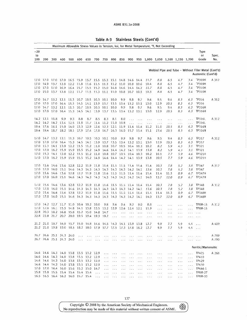
ASME B31.1a-2008
Table A-3 Stainless Steels (Cont'd)
Maximum Allowable Stress Values in Tension, ksi, for Metal Temperature, of, Not Exceeding
-20 Type to or Spec.
100 200 300 400 500 600 650 700 750 800 850 900 950 1,000 1,050 1,100 1,150 1,200 Grade No.
Welded Pipe and Tube - Without Filler Metal (Cont'd) Austenitic (Cont'd)
17.0 17.0 17.0 17.0 16.5 15.9 15.7 15.5 15.3 15.1 14.8 14.6 14.4 11.7 8.8 17.0 14.9 13.7 12.8 12.2 11.8 11.6 11.5 11.3 11.2 11.0 10.8 10.6 10.4 8.8 17.0 17.0 17.0 16.9 16.4 15.7 15.5 15.2 15.0 14.8 14.6 14.4 14.2 11.7 8.8 17.0 15.0 13.7 12.8 12.1 11.7 11.5 11.3 11.1 11.0 10.8 10.7 10.5 10.3 8.8
17.0 14.7 13.2 12.1 11.3 10.7 10.5 10.3 10.1 10.0 9.9 9.8 9.7 9.6 9.5
6.5 6.5 6.5 6.5
9.4 17.0 17.0 17.0 16.4 15.3 14.5 14.1 13.9 13.7 13.5 13.4 13.2 13.1 13.0 12.9 10.5
17.0 14.7 13.2 12.1 11.3 10.7 10.5 10.3 10.1 10.0 9.9 9.8 9.7 9.6 9.5 9.4 17.0 17.0 17.0 16.4 15.3 14.5 14.1 13.9 13.7 13.5 13.4 13.2 13.1 13.0 12.9 10.5
14.2 12.1 10.8 9.9 9.3 8.8 8.7 8.5 8.3 8.1 8.0 14.2 14.2 14.2 13.4 12.5 11.9 11.7 11.4 11.2 11.0 10.8 19.4 17.6 16.1 15.0 14.0 13.3 12.9 12.6 12.3 12.1 11.9 11.6 11.4 11.2 11.0 10.5 19.4 19.4 18.7 18.2 18.1 17.9 17.4 17.0 16.7 16.3 16.0 15.7 15.4 15.1 13.4 10.5
4.7 4.7 4.7 4.7
8.3 8.3 8.3 8.3
8.3 8.3
17.0 14.7 13.2 12.1 11.3 10.7 10.5 10.3 10.1 10.0 9.9 9.8 9.7 9.6 9.5 9.4 8.3 17.0 17.0 17.0 16.4 15.3 14.5 14.1 13.9 13.7 13.5 13.4 13.2 13.1 13.0 12.9 10.5 8.3 17.0 15.3 14.1 13.0 12.2 11.5 11.2 11.0 10.8 10.7 10.5 10.4 10.3 10.2 8.2 5.9 4.3 17.0 17.0 16.2 15.9 15.9 15.5 15.2 14.9 14.6 14.4 14.2 14.1 13.9 13.8 8.2 5.9 4.3 17.0 15.3 14.1 13.0 12.2 11.5 11.2 11.0 10.8 10.7 10.5 10.4 10.3 10.2 10.1 7.7 5.9 17.0 17.0 16.2 15.9 15.9 15.5 15.2 14.9 14.6 14.4 14.2 14.1 13.9 13.8 10.5 7.7 5.9
17.0 15.6 14.6 13.6 12.8 12.2 11.9 11.8 11.6 11.5 11.5 11.4 11.4 11.4 10.3 7.8 5.2 17.0 17.0 16.0 15.1 14.6 14.3 14.3 14.3 14.3 14.3 14.3 14.2 14.1 13.6 10.3 7.8 5.2 17.0 15.6 14.6 13.6 12.8 12.2 11.9 11.8 11.6 11.5 11.5 11.4 11.4 11.4 11.4 11.3 8.9 17.0 17.0 16.0 15.1 14.6 14.3 14.3 14.3 14.3 14.3 14.3 14.2 14.1 14.0 13.7 12.0 8.9
17.0 15.6 14.6 13.6 12.8 12.2 11.9 11.8 11.6 11.5 11.5 11.4 11.4 11.4 10.3 7.8 5.2 17.0 17.0 16.0 15.1 14.6 14.3 14.3 14.3 14.3 14.3 14.3 14.2 14.1 13.6 10.3 7.8 5.2 17.0 15.6 14.6 13.6 12.8 12.2 11.9 11.8 11.6 11.5 11.5 11.4 11.4 11.4 11.4 11.3 8.9 17.0 17.0 16.0 15.1 14.6 14.3 14.3 14.3 14.3 14.3 14.3 14.2 14.1 14.0 13.7 12.0 8.9
17.0 14.2 12.7 11.7 11.0 10.4 10.2 10.0 9.8 9.6 9.4 9.2 9.0 8.8 17.0 17.0 16.1 15.5 14.8 14.1 13.8 13.5 13.2 12.9 12.6 12.4 12.1 11.9 22.8 20.3 18.2 16.8 15.8 15.2 15.0 14.8 14.7 22.8 22.8 21.7 20.7 20.0 19.5 19.4 19.3 19.2
21.2 21.0 18.7 16.9 15.7 15.0 14.8 14.6 14.5 14.3 14.1 13.9 13.8 12.7 21.2 21.0 19.8 19.0 18.5 18.2 18.0 17.9 17.7 17.5 17.3 17.0 16.2 12.7
26.7 26.6 25.1 24.3 24.0 26.7 26.6 25.1 24.3 24.0
14.6 14.6 14.3 14.0 13.8 13.5 13.2 12.9 14.6 14.6 14.3 14.0 13.8 13.5 13.2 12.9 14.6 14.6 14.3 14.0 13.8 13.5 13.2 12.9 14.6 14.6 14.3 14.0 13.8 13.5 13.2 12.9 17.0 17.0 16.4 16.0 15.6 15.2 15.0 14.7 15.8 15.8 15.5 15.4 15.4 15.4 15.4 16.5 16.5 16.4 16.2 16.0 15.7 15.4
137
9.9 9.9
7.7 7.7
5.9 5.9
Copyright © 2008 by the American Society of Mechanical Engineers. ~ No reproduction may be made of this material without VvTitten consent of ASME. ~
3.4 TP309H A312 3.4 TP309H 3.4 TP310H 3.4 TP310H
6.3 TP316 6.3 TP316 6.3 TP316H 6.3 TP316H
TP316L TP316L
6.3 TP316N 6.3 TP316N
A 312
A 312
6.3 TP31 7 A 312 6.3 TP317 3.1 TP321 3.1 TP321 4.6 TP321H 4.6 TP321H
3.8 TP347 A 312 3.8 TP347 6.7 TP347H 6.7 TP347H
3.8 TP348 A 312 3.8 TP348 6.7 TP348H 6.7 TP348H
TPXM-15 A 312 TPXM-15
4.4 4.4
A 409
A 789 A 790
Ferritic/ Martensitic
TP405 TP410 TP429 TP430 TP446-1 TPXM-27 TPXM-33
A 268
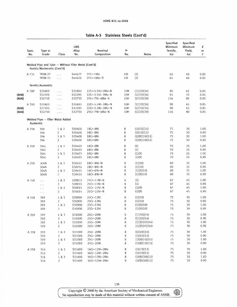
Spec. No.
Type or Grade Class
UNS Alloy No.
ASME B31.1a-2008
Table A-3 Stainless Steels (Cont'd)
Nominal Composition
PNo. Notes
Welded Pipe and Tube - Without Filler Metal (Cont'd) Ferritic/Martensitic (Cont'd)
A 731 TPXM-27 TPXM-33
Ferritic/ Austenitic
A 789 531803 (A08) 532205 (A08) 532750
A 790 531803 (A08) 532205 (A08) 532750
Welded Pipe - Filler Metal Added Austenitic
A 358 304 304 304 304
A 358 304L 304L 304L 304L
A 358 304N
A 358
304N 304N 304N
A 358 309 309 309 309
A 358 310 310 310 310
A 358 310 310 310 310
A 358 316 316 316 316
1 & 3 2 1 & 3
1 & 3
1 & 3
1 & 3 2 1 & 3 2
1 & 3 2 1 & 3
1 & 3
1 & 3 2
1 & 3 2 1 & 3 2
1 & 3 2 1 & 3 2
1 & 3 2 1 & 3 2
544627 27Cr-IMo 544626 27Cr-IMo-Ti
531803 22Cr-5.5Ni-3Mo-N 532205 22Cr-5.5Ni-3Mo-N 532750 25Cr-7Ni-4Mo-N
531803 22Cr-5.5Ni-3Mo-N 532205 22Cr-5.5Ni-3Mo-N 532750 25Cr-7Ni-4Mo-N
530400 18Cr-8Ni 530400 18Cr-8Ni 530400 18Cr-8Ni 530400 18Cr-8Ni
530403 18Cr-8Ni 530403 18Cr-8Ni 530403 18Cr-8Ni 530403 18Cr-8Ni
530451 18Cr-8Ni-N 530451 18Cr-8Ni-N 530451 18Cr-8Ni-N 530451 18Cr-8Ni-N
530815 21Cr-llNi-N 530815 21Cr-llNi-N 530815 21Cr-llNi-N 530815 21Cr-l1 Ni-N
530900 23Cr-12Ni 530900 23Cr-12Ni 530900 23Cr-12Ni 530900 23Cr-12Ni
531000 25Cr-20Ni 531000 25Cr-20Ni 531000 25Cr-20Ni 531000 25Cr-20Ni
531000 25Cr-20Ni 531000 25Cr-20Ni 531000 25Cr-20Ni 531000 25Cr-20Ni
531600 16Cr-12Ni-2Mo 531600 16Cr-12Ni-2Mo 531600 16Cr-12Ni-2Mo 531600 16Cr-12Ni-2Mo
138
101 101
(2)
(2)
10H (1)(33)(34) 10H (1)(33)(34) 10H (1)(33)(39)
10H (1)(33)(34) 10H (1)(33)(34) 10H (1)(33)(39)
8 8 8 8
8 8 8 8
8 8 8 8
8 8 8
8
8 8 8
8
8 8 8 8
8 8 8 8
8 8 8 8
(1) (1 0) (11) (1)(10)(11) (1)(9)(10)(11) (1)(9)(10)(11)
(1) (1) (1)(9) (1)(9)
(1) (1 0) (1)(10) (1) (9) (1 0) (1)(9)(10)
(1) (1) (1)(9) (1)(9)
(1)(10) (1)(10) (1)(9)(10) (1)(9)(10)
(1)(10)(14) (1)(10)(14) (1)(9)(10)(14) (1)(9)(10)(14)
(1)(10)(15) (1)(10)(15) (1)(9)(10)(15) (1) (9) (1 0) (15)
(1) (1 0) (11) (1) (1 0) (11) (1) (9) (1 0) (11) (1)(9)(10)(11)
Specified Minimum Tensile,
ksi
65 65
90 95
116
90 90
116
75 75 75 75
70 70 70 70
80 80 80 80
87 87 87 87
75 75 75 75
75 75 75 75
75 75 75 75
75 75 75 75
Copyright © 2008 by the American Society of Mechanical Engineers. ~ No reproduction may be made of this material without written consent of ASME. ~
Specified Minimum
Yield, ksi
40 40
65 70 80
65 65 80
30 30 30 30
25 25 25 25
35 35 35 35
45 45 45 45
30 30 30 30
30 30 30 30
30 30 30 30
30 30 30 30
E or F
0.85 0.85
0.85 0.85 0.85
0.85 0.85 0.85
1.00 0.90 1.00 0.90
1.00 0.90 1.00 0.90
1.00 0.90 1.00 0.90
1.00 0.90 1.00 0.90
1.00 0.90 1.00 0.90
1.00 0.90 1.00 0.90
1.00 0.90 1.00 0.90
1.00 0.90 1.00 0.90
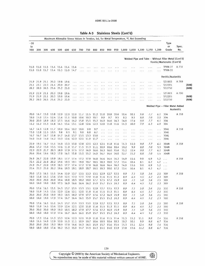
ASME B31.1a-200S
Table A-3 StainLess Steels (Cont'd)
Maximum Allowable Stress Values in Tension, ksi, for Metal Temperature, of, Not Exceeding
-20 Type to or Spec.
100 200 300 400 500 600 650 700 750 SOO S50 900 950 1,000 1,050 1,100 1,150 1,200 Grade No.
Welded Pipe and Tube - Without Filler Metal (Cont'd) Ferritic/ Martensitic (Cont'd)
15.8 15.8 15.5 15.4 15.4 15.4 15.4 15.815.815.715.415.315.014.7
TPXM-27 A 731 ... TPXM-33
Ferritic/ Austen itic
21.9 21.9 21.1 20.3 19.8 19.6 23.1 23.1 22.3 21.4 20.9 20.7 28.2 28.0 26.5 25.6 25.2 25.0
531803 A 789 532205 (AOS) 532750 (AOS)
21.9 21.9 21.1 20.3 19.8 19.6 21.9 21.9 21.1 20.3 19.8 19.6 28.2 28.0 26.5 25.6 25.2 25.0
531803 A 790 532205 (AOS) 532750 (AOS)
Welded Pipe - Filler Metal Added Austenitic
20.0 16.7 15.0 13.8 12.9 12.3 12.0 11.7 11.5 11.2 11.0 10.8 10.6 10.4 10.1 9.8 7.7 6.1 304 18.0 15.0 13.5 12.4 11.6 11.1 10.8 10.6 10.3 10.1 9.9 9.7 9.5 9.3 9.1 8.8 7.0 5.5 304 20.0 20.0 18.9 18.3 17.5 16.6 16.2 15.8 15.5 15.2 14.9 14.6 14.3 14.0 12.4 9.8 7.7 6.1 304 16.2 16.2 15.3 14.8 14.1 13.4 13.1 12.8 12.6 12.3 12.0 11.8 11.6 11.3 10.0 7.9 6.3 4.9 304
16.7 14.3 12.8 11.7 10.9 10.4 10.2 10.0 9.8 9.7 15.0 12.8 11.5 10.5 9.8 9.3 9.1 9.0 8.8 8.7 16.7 16.7 16.7 15.8 14.7 14.0 13.7 13.5 13.3 13.0 15.0 15.0 15.0 14.2 13.3 12.6 12.3 12.1 11.9 11.7
304L 304L 304L 304L
A 358
A 358
22.9 19.1 16.7 15.1 14.0 13.3 13.0 12.8 12.5 12.3 12.1 11.8 11.6 11.3 11.0 9.8 7.7 6.1 304N A 358 20.6 17.2 15.0 13.5 12.6 11.9 11.7 11.5 11.3 11.1 10.9 10.6 10.4 10.2 9.9 8.8 7.0 5.5 304N 22.9 22.9 21.7 20.3 18.9 17.9 17.5 17.2 16.9 16.6 16.3 16.0 15.6 15.2 12.4 9.8 7.7 6.1 304N 20.6 20.6 19.6 18.3 17.0 16.1 15.8 15.5 15.2 14.9 14.7 14.4 14.0 13.7 11.2 8.8 7.0 5.5 304N
24.9 24.7 22.0 19.9 18.5 17.7 17.4 17.2 17.0 16.8 16.6 16.4 16.2 14.9 11.6 9.0 6.9 5.2 A 358 22.4 22.2 21.0 20.2 19.6 19.3 19.1 18.9 18.7 18.5 18.3 18.0 17.2 13.4 10.4 8.1 6.2 4.7 24.9 24.7 22.0 19.9 18.5 17.7 17.4 17.2 17.0 16.8 16.6 16.4 16.2 14.9 11.6 9.0 6.9 5.2 22.4 22.2 21.0 20.2 19.6 19.3 19.1 18.9 18.7 18.5 18.3 18.0 17.2 13.4 10.4 8.1 6.2 4.7
20.0 17.5 16.1 15.1 14.4 13.9 13.7 13.5 13.3 13.1 12.9 12.7 12.5 9.9 7.1 5.0 3.6 2.5 309 A 358 18.0 15.8 14.5 13.6 13.0 12.5 12.3 12.1 12.0 11.8 11.6 11.5 11.3 8.9 6.4 4.5 3.2 2.3 309 20.0 20.0 20.0 20.0 19.4 18.8 18.5 18.2 18.0 17.7 17.5 17.2 15.9 9.9 7.1 5.0 3.6 2.5 309 18.0 18.0 18.0 18.0 17.5 16.9 16.6 16.4 16.2 15.9 15.7 15.5 14.3 8.9 6.4 4.5 3.2 2.3 309
20.0 17.6 16.1 15.1 14.3 13.7 13.5 13.3 13.1 12.9 12.7 12.5 12.3 9.9 7.1 5.0 3.6 2.5 310 A 358 18.0 15.9 14.5 13.6 12.9 12.4 12.1 12.0 11.8 11.6 11.5 11.3 11.1 8.9 6.4 4.5 3.2 2.3 310 20.0 20.0 20.0 19.9 19.3 18.5 18.2 17.9 17.7 17.4 17.2 16.9 15.9 9.9 7.1 5.0 3.6 2.5 310 18.0 18.0 18.0 17.9 17.4 16.7 16.4 16.1 15.9 15.7 15.5 15.2 14.3 8.9 6.4 4.5 3.2 2.3 310
20.017.616.115.114.313.713.513.3 13.112.912.7 12.512.3 9.9 7.1 5.0 3.6 2.5 310 A 358 18.0 15.9 14.5 13.6 12.9 12.4 12.1 12.0 11.8 11.6 11.5 11.3 11.1 8.9 6.4 4.5 3.2 2.3 310 20.0 20.0 20.0 19.9 19.3 18.5 18.2 17.9 17.7 17.4 17.2 16.9 15.9 9.9 7.1 5.0 3.6 2.5 310 18.0 18.0 18.0 17.9 17.4 16.7 16.4 16.1 15.9 15.7 15.5 15.2 14.3 8.9 6.4 4.5 3.2 2.3 310
20.0 17.3 15.6 14.3 13.3 12.6 12.3 12.1 11.9 11.8 11.6 11.5 11.4 11.3 11.2 11.1 9.8 7.4 316 A 358 18.0 15.5 14.0 12.9 12.0 11.3 11.1 10.9 10.7 10.6 10.5 10.4 10.3 10.2 10.1 9.9 8.8 6.7 316 20.0 20.0 20.0 19.3 18.0 17.0 16.6 16.3 16.1 15.9 15.7 15.6 15.4 15.3 15.1 12.4 9.8 7.4 316 18.0 18.0 18.0 17.4 16.2 15.3 15.0 14.7 14.5 14.3 14.1 14.0 13.9 13.8 13.6 11.2 8.8 6.7 316
139
Copyright © 2008 by the American Society of Mechanical Engineers. No reproduction may be made of this material without written consent of ASME.
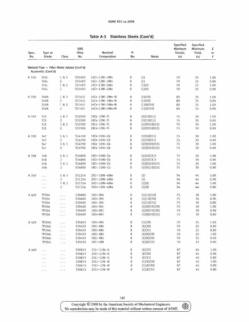
ASME B31.1a-2008
Table A-3 Stainless Steels (Cont'd)
Spec. No.
Type or Grade Class
UNS Alloy No.
Nominal Composition
Welded Pipe - Filler Metal Added (Cont'd) Austenitic (Cont'd)
A 358 316L 316L 316L 316L
A 358 316N 316N 316N 316N
A 358 321 321 321 321
A 358 347 347 347 347
A 358 348 348 348 348
1 & 3 2 1 & 3 2
1 & 3 2 1 & 3
1 & 3
1 & 3
1 & 3
1 & 3 2
1 & 3 2 1 & 3
A 358 1 & 3 2
A 409 TP304 TP304 TP304 TP304 TP304 TP304
A 409 TP304L
A 409
TP304L TP304L TP304L TP304L TP304L
1 & 3 2
531603 16Cr-12Ni-2Mo 531603 16Cr-12Ni-2Mo 531603 16Cr-12Ni-2Mo 531603 16Cr-12Ni-2Mo
531651 16Cr-12Ni-2Mo-N 531651 16Cr-12Ni-2Mo-N 531651 16Cr-12Ni-2Mo-N 531651 16Cr-12Ni-2Mo-N
532100 18Cr-10Ni-Ti 532100 18Cr-10Ni-Ti 532100 18Cr-10Ni-Ti 532100 18Cr-10Ni-Ti
534700 18Cr-10Ni-Cb 534700 18Cr-10Ni-Cb 534700 18Cr-10Ni-Cb 534700 18Cr-10Ni-Cb
534800 18Cr-l0Ni-Cb 534800 18Cr-10Ni-Cb 534800 18Cr-10Ni-Cb 534800 18Cr-l0Ni-Cb
531254 20Cr-18Ni-6Mo 531254 20Cr-18Ni-6Mo 531254 20Cr-18Ni-6Mo 531254 20Cr-18Ni-6Mo
530400 18Cr-8Ni 530400 18Cr-8Ni 530400 18Cr-8Ni 530400 18Cr-8Ni 530400 18Cr-8Ni 530400 18Cr-8Ni
530403 18Cr-8Ni 530403 18Cr-8N i 530403 18Cr-8Ni 530403 18Cr-8Ni 530403 18Cr-8N i 530403 18Cr-8Ni
530815 21Cr-11Ni-N 530815 21Cr-11Ni-N 530815 2lCr-11Ni-N 530815 21Cr-11Ni-N 530815 21Cr-11Ni-N 530815 21Cr-llNi-N
140
pNo.
8 8 8 8
8 8 8 8
8 8 8 8
8 8 8 8
8 8 8 8
8 8 8 8
8 8 8 8 8 8
8 8
8 8 8 8
8
8 8 8 8 8
(1)
(1) (1)(9) (1)(9)
Notes
(1)(10) (1)(10) (1)(9)(10) (1)(9)(10)
(1) (1 0) (11) (1) (1 0) (11) (1)(9)(10)(11) (1)(9)(10)(11)
(1) (1 0) (11) (1)(10)(11) (1)(9)(10)(11) (1)(9)(10)(11)
(1)(10)(11) (1)(10)(11) (1)(9)(10)(11) (1)(9)(10)(11)
(1) (1) (1)(9) (1)(9)
(1)(10)(29) (1) (1 0) (30) (1)(10)(31) (1) (9) (1 0) (29) (1) (9) (1 0) (30) (1) (9) (10) (31)
(1)(29) (1)(30) (1)(31) (1)(9)(29) (1)(9)(30) (1)(9)(31)
(1)(29) (1)(30) (1)(31) (1)(9)(29) (1)(9)(30) (1)(9)(31)
Specified Specified Minimum Minimum Tensile, Yield,
ksi ksi
70 70 70 70
80 80 80 80
75 75 75 75
75 75 75 75
75 75 75 75
94 94 94 94
75 75 75 75 75 75
70 70 70 70 70 70
87 87 87 87 87 87
25 25 25 25
35 35 35 35
30 30 30 30
30 30 30 30
30 30 30 30
44 44 44 44
30 30 30 30 30 30
25 25 25 25 25 25
45 45 45 45 45 45
Copyright © 2008 by the Amelican Society of Mechanical Engineers. ~ No reproduction may be made of this material without written consent of ASME. ~
£ or F
1.00 0.90 1.00 0.90
1.00 0.90 1.00 0.90
1.00 0.90 1.00 0.90
1.00 0.90 1.00 0.90
1.00 0.90 1.00 0.90
1.00 0.90 1.00 0.90
1.00 0.90 0.80 1.00 0.90 0.80
1.00 0.90 0.80 1.00 0.90 0.80
1.00 0.90 0.80 1.00 0.90 0.80
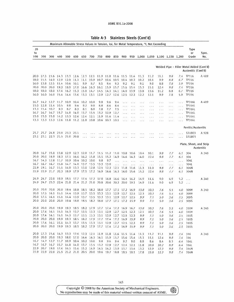
ASME B31.1a-2008
Table A-3 Stainless Steels (Cont'd)
Maximum Allowable Stress Values in Tension, ksi, for Metal Temperature, of, Not Exceeding
-20 Type to or Spec.
100 200 300 400 500 600 650 700 750 800 850 900 950 1,000 1,050 1,100 1,150 1,200 Grade No.
Welded Pipe - Filler Metal Added (Cont'd) Austenitic (Cont'd)
20.0 17.3 15.6 14.3 13.3 12.6 12.3 12.1 11.9 11.8 11.6 11.5 11.4 11.3 11.2 11.1 9.8 18.0 15.5 14.0 12.9 12.0 11.3 11.1 10.9 10.7 10.6 10.5 10.4 10.3 10.2 10.1 9.9 8.8 16.0 13.8 12.5 11.4 10.6 10.1 9.9 9.7 9.5 9.4 9.3 9.2 9.1 9.1 9.0 8.8 7.8 20.0 20.0 20.0 19.3 18.0 17.0 16.6 16.3 16.1 15.9 15.7 15.6 15.4 15.3 15.1 12.4 9.8 18.0 18.0 18.0 17.4 16.2 15.3 15.0 14.7 14.5 14.3 14.1 14.0 13.9 13.8 13.6 11.2 8.8 16.0 16.0 16.0 15.4 14.4 13.6 13.3 13.1 12.9 12.7 12.6 12.5 12.3 12.2 12.1 9.9 7.8
7.4 TP316 6.7 TP316 5.9 TP316 7.4 TP316 6.7 TP316 5.9 TP316
A 409
16.7 14.2 12.7 11.7 10.9 10.4 10.2 10.0 9.8 9.6 9.4 15.0 12.8 11.4 10.5 9.8 9.4 9.2 9.0 8.8 8.6 8.4 13.3 11.4 10.2 9.3 8.7 8.3 8.1 8.0 7.8 7.7 7.5 16.7 16.7 16.7 15.7 14.8 14.0 13.7 13.5 13.2 12.9 12.7 15.0 15.0 15.0 14.2 13.3 12.6 12.4 12.1 11.9 11.6 11.4 13.3 13.3 13.3 12.6 11.8 11.2 11.0 10.8 10.6 10.3 10.1
TP316L A 409 TP316L TP316L TP316L TP316L TP316L
Ferritic/ Austen itic
25.7 25.7 24.8 23.9 23.3 23.1 23.1 23.1 22.3 21.5 21.0 20.8
531803 A 928 . .. 531803
Plate, Sheet, and Strip Austenitic
20.0 16.7 15.0 13.8 12.9 12.3 12.0 11.7 11.5 11.2 11.0 10.8 10.6 10.4 10.1 20.0 20.0 18.9 18.3 17.5 16.6 16.2 15.8 15.5 15.2 14.9 14.6 14.3 14.0 12.4 16.7 14.3 12.8 11.7 10.9 10.4 10.2 10.0 9.8 9.7 16.7 16.7 16.7 15.8 14.7 14.0 13.7 13.5 13.3 13.0 22.9 19.1 16.7 15.1 14.0 13.3 13.0 12.8 12.5 12.3 12.1 11.8 11.6 11.3 11.0 22.9 22.9 21.7 20.3 18.9 17.9 17.5 17.2 16.9 16.6 16.3 16.0 15.6 15.2 12.4
24.9 24.7 22.0 19.9 18.5 17.7 17.4 17.2 17.0 16.8 16.6 16.4 16.2 14.9 11.6 24.9 24.7 23.3 22.4 21.8 21.4 21.2 21.0 20.8 20.6 20.3 20.0 19.1 14.9 11.6
20.0 20.0 20.0 20.0 19.4 18.8 18.5 18.2 18.0 17.7 17.5 17.2 16.9 13.8 10.3 20.0 17.5 16.1 15.1 14.4 13.9 13.7 13.5 13.3 13.1 12.9 12.7 12.5 12.3 10.3 20.0 17.5 16.1 15.1 14.4 13.9 13.7 13.5 13.3 13.1 12.9 12.7 12.5 9.9 7.1 20.0 20.0 20.0 20.0 19.4 18.8 18.5 18.2 18.0 17.7 17.5 17.2 15.9 9.9 7.1
20.0 20.0 20.0 19.9 19.3 18.5 18.2 17.9 17.7 17.4 17.2 16.9 16.7 13.8 10.3 20.0 17.6 16.1 15.1 14.3 13.7 13.5 13.3 13.1 12.9 12.7 12.5 12.3 12.1 10.3 20.0 17.6 16.1 15.1 14.3 13.7 13.5 13.3 13.1 12.9 12.7 12.5 12.3 9.9 7.1 20.0 20.0 20.0 19.9 19.3 18.5 18.2 17.9 17.7 17.4 17.2 16.9 15.9 9.9 7.1 20.0 17.6 16.1 15.1 14.3 13.7 13.5 13.3 13.1 12.9 12.7 12.5 12.3 9.9 20.0 20.0 20.0 19.9 19.3 18.5 18.2 17.9 17.7 17.4 17.2 16.9 15.9 9.9
7.1 7.1
9.8 7.7 6.1 304 9.8 7.7 6.1 304
304L 304L
9.8 7.7 6.1 304N 9.8 7.7 6.1 304N
9.0 6.9 9.0 6.9
7.6 5.5
5.2 5.2
4.0 309H 7.6 5.5 4.0 309H 5.0 3.6 2.5 3095 5.0 3.6 2.5 3095
7.6 5.5 4.0 310H 7.6 5.5 4.0 310H 5.0 3.6 2.5 3105 5.0 3.6 2.5 3105 5.0 3.6 5.0 3.6
2.5 3105 2.5 3105
A 240
A 240
A 240
A 240
20.0 17.3 15.6 14.3 13.3 12.6 12.3 12.1 11.9 11.8 11.6 11.5 11.4 11.3 11.2 11.1 9.8 7.4 316 A 240 20.0 20.0 20.0 19.3 18.0 17.0 16.6 16.3 16.1 15.9 15.7 15.6 15.4 15.3 15.1 12.4 9.8 7.4 316 16.7 14.2 12.7 11.7 10.9 10.4 10.2 10.0 9.8 9.6 9.4 9.2 9.0 8.8 8.6 8.4 8.3 6.4 316L 16.7 16.7 16.7 15.7 14.8 14.0 13.7 13.5 13.2 12.9 12.7 12.4 12.1 11.8 10.8 10.2 8.8 6.4 316L 22.9 20.7 19.0 17.6 16.5 15.6 15.2 14.9 14.5 14.2 13.9 13.7 13.4 13.2 12.9 12.3 9.8 7.4 316N 22.9 22.9 22.0 21.5 21.2 21.0 20.5 20.0 19.6 19.2 18.8 18.5 18.1 17.8 15.8 12.3 9.8 7.4 316N
143
Copyright © 2008 by the American Society of Mechanical Engineers. ~ No reproduction may be made of this material "Without written consent of ASME. lID'
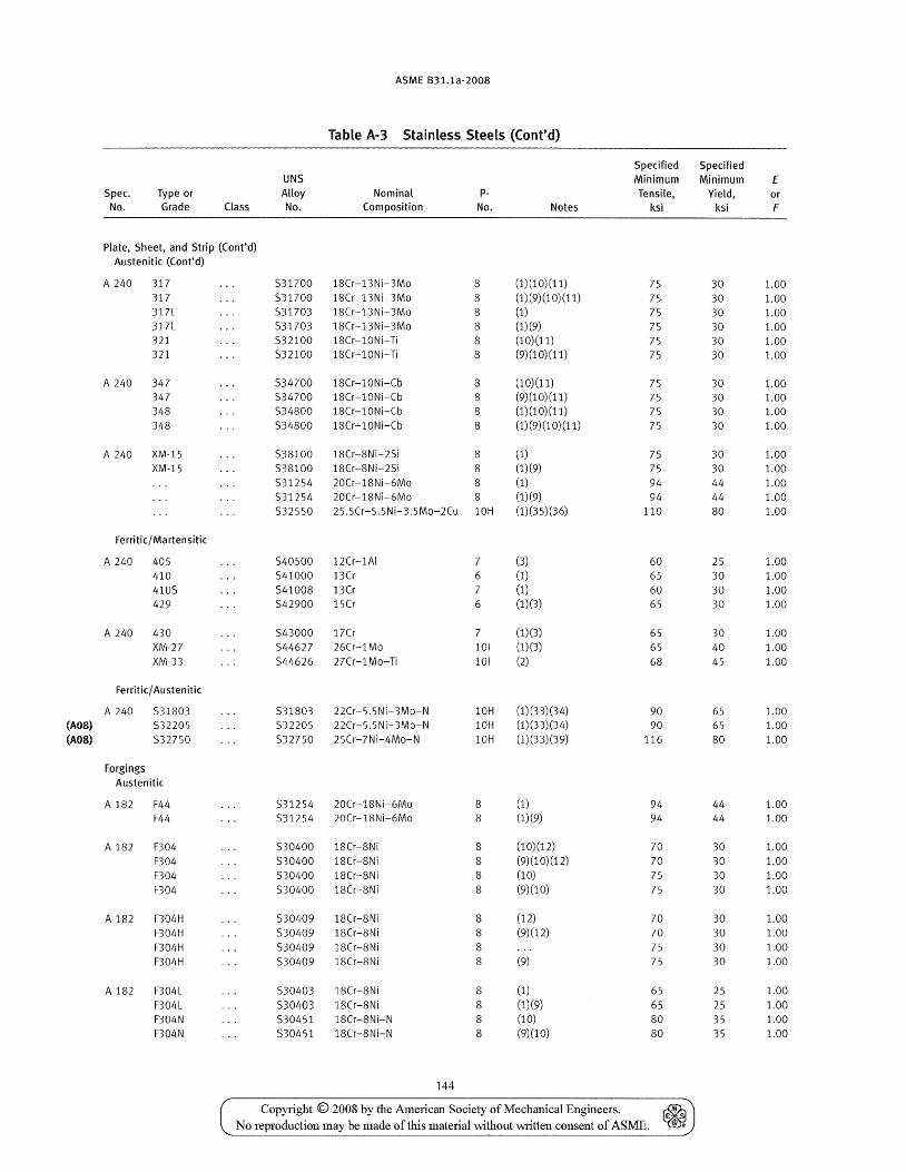
ASME B31.1a-2008
Table A-3 Stainless Steels (Cont'd)
Specified Specified UNS Minimum Minimum E
Spec. Type or Alloy Nominal P- Tensile, Yield, or No. Grade Class No. Composition No. Notes ksi ksi F
Plate, Sheet, and Strip (Cont'd) Austenitic (Cont'd)
A 240 317 531700 18Cr-13Ni-3Mo 8 (1) (10) (11) 75 30 1.00 317 531700 18Cr-13Ni-3Mo 8 (1) (9) (1 0) (11) 75 30 1.00 311L 531703 18Cr-13Ni-3Mo 8 (1) 75 30 1.00 311L 531703 18Cr-13Ni-3Mo 8 (1)(9) 75 30 1.00 321 532100 18Cr-l0Ni-Ti 8 (10)(11) 75 30 1.00 321 532100 18Cr-l0Ni-Ti 8 (9)(10)(11) 75 30 1.00
A 240 347 534700 18Cr-l0Ni-Cb 8 (10)(11) 75 30 1.00 347 534700 18Cr-l0Ni-Cb 8 (9)(10)(11) 75 30 1.00 348 534800 18Cr-l0Ni-Cb 8 (1) (1 0) (11) 75 30 1.00 348 534800 18Cr-l0Ni-Cb 8 (1) (9) (1 0) (11) 75 30 1.00
A 240 XM-15 538100 18Cr-8Ni-25i 8 (1) 75 30 1.00 XM-15 538100 18Cr-8Ni-25i 8 (1)(9) 75 30 1.00
531254 20Cr-18Ni-6Mo 8 (1) 94 44 1.00 531254 20Cr-18Ni-6Mo 8 (1)(9) 94 44 1.00 532550 25.5Cr-5.5Ni- 3.5Mo-2Cu 10H (1)(35)(36) 110 80 1.00
Ferritic/ Martensitic
A 240 405 540500 12Cr-1AI 7 (3) 60 25 1.00 410 541000 13Cr 6 (1) 65 30 1.00 4105 54100S 13Cr 7 (1) 60 30 1.00 429 542900 15Cr 6 (1)(3) 65 30 1.00
A 240 430 543000 17Cr 7 (1)(3) 65 30 1.00 XM-27 544627 26Cr-1Mo 101 (1)(3) 65 40 1.00 XM-33 544626 27Cr-1Mo-Ti 101 (2) 68 45 1.00
Ferritic/ Austenitic
A 240 531803 531803 22Cr-5.5Ni-3Mo-N 10H (1) (33) (34) 90 65 1.00 (A08) 532205 532205 22Cr-5.5Ni-3Mo-N 10H (1)(33)(34) 90 65 1.00 (A08) 532750 532750 25Cr-7Ni-4Mo-N 10H (1)(33)(39) 116 80 1.00
Forgings Austenitic
A 182 F44 531254 20Cr-18Ni-6Mo 8 (1) 94 44 1.00 F44 531254 20Cr-18Ni-6Mo 8 (1)(9) 94 44 1.00
A 182 F304 530400 18Cr-8Ni 8 (10)(12) 70 30 1.00 F304 530400 18Cr-8Ni 8 (9)(10)(12) 70 30 1.00 F304 530400 18Cr-8Ni 8 (10) 75 30 1.00 F304 530400 18Cr-8Ni 8 (9)(10) 75 30 1.00
A 182 F304H 530409 18Cr-8Ni 8 (12) 70 30 1.00 F304H 530409 18Cr-8Ni 8 (9)(12) 70 30 1.00 F304H 530409 18Cr-8Ni 8 75 30 1.00 F304H 530409 18Cr-8Ni 8 (9) 75 30 1.00
A 182 F304L 530403 18Cr-8Ni S (1) 65 25 1.00 F304L 530403 18Cr-8Ni 8 (1)(9) 65 25 1.00 F304N 530451 lSCr-SNi-N 8 (10) 80 35 1.00 F304N 530451 lSCr-SNi-N 8 (9)(10) SO 35 1.00
144
Copyright © 2008 by the American Society of Mechanical Engineers. ~ No reproduction may be made of this material \Vlthout written consent of ASME. ill",
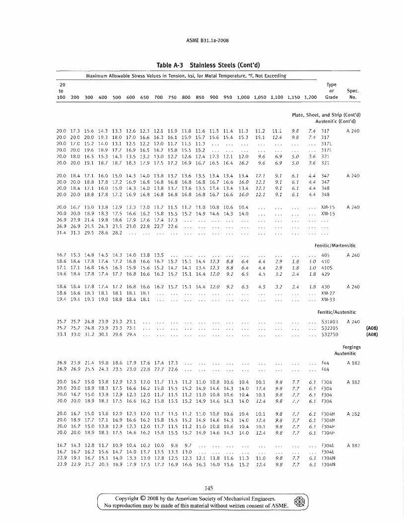
ASME B31.1a-2008
Table A·3 Stainless Steels (Cont'd)
Maximum Allowable Stress Values in Tension, ksi, for Metal Temperature, of, Not Exceeding
-20 Type to or Spec.
100 200 300 400 500 600 650 700 750 800 850 900 950 1,000 1,050 1,100 1,150 1,200 Grade No.
20.0 17.3 15.6 14.3 13.3 12.6 12.3 12.1 11.9 11.8 11.6 11.5 11.4 11.3 11.2 11.1 20.0 20.0 20.0 19.3 18.0 17.0 16.6 16.3 16.1 15.9 15.7 15.6 15.4 15.3 15.1 12.4 20.0 17.0 15.2 14.0 13.1 12.5 12.2 12.0 11.7 11.5 11.3 20.0 20.0 19.6 18.9 17.7 16.9 16.5 16.2 15.8 15.5 15.2 20.0 18.0 16.5 15.3 14.3 13.5 13.2 13.0 12.7 12.6 12.4 12.3 12.1 12.0 9.6 6.9 20.0 20.0 19.1 18.7 18.7 18.3 17.9 17.5 17.2 16.9 16.7 16.5 16.4 16.2 9.6 6.9
20.0 18.4 17.1 16.0 15.0 14.3 14.0 13.8 13.7 13.6 13.5 13.4 13.4 13.4 12.1 9.1 20.0 20.0 18.8 17.8 17.2 16.9 16.8 16.8 16.8 16.8 16.8 16.7 16.6 16.0 12.1 9.1 20.0 18.4 17.1 16.0 15.0 14.3 14.0 13.8 13.7 13.6 13.5 13.4 13.4 13.4 12.1 9.1 20.0 20.0 18.8 17.8 17.2 16.9 16.8 16.8 16.8 16.8 16.8 16.7 16.6 16.0 12.1
20.0 16.7 15.0 13.8 12.9 12.3 12.0 11.7 11.5 11.2 11.0 10.8 10.6 10.4 20.0 20.0 18.9 18.3 17.5 16.6 16.2 15.8 15.5 15.2 14.9 14.6 14.3 14.0 26.9 23.9 21.4 19.8 18.6 17.9 17.6 17.4 17.3 26.9 26.9 25.5 24.3 23.5 23.0 22.8 22.7 22.6 31.4 31.3 29.5 28.6 28.2
16.7 15.3 14.8 14.5 14.3 14.0 13.8 13.5 18.6 18.4 17.8 17.4 17.2 16.8 16.6 16.2 15.7 15.1 14.4 12.3 8.8 6.4 17.1 17.1 16.8 16.5 16.3 15.9 15.6 15.2 14.7 14.1 13.4 12.3 8.8 6.4 18.6 18.4 17.8 17.4 17.2 16.8 16.6 16.2 15.7 15.1 14.4 12.0 9.2 6.5
18.618.417.817.417.216.816.616.215.715.114.412.0 9.2 6.5 18.6 18.6 18.3 18.1 18.1 18.1 18.1 19.4 19.4 19.3 19.0 18.8 18.4 18.1
25.7 25.7 24.8 23.9 23.3 23.1 25.7 25.7 24.8 23.9 23.3 23.1 33.1 33.0 31.2 30.1 29.6 29.4
26.9 23.9 21.4 19.8 18.6 17.9 17.6 17.4 17.3 26.9 26.9 25.5 24.3 23.5 23.0 22.8 22.7 22.6
4.4 4.4 4.5
4.5
20.0 16.7 15.0 13.8 12.9 12.3 12.0 11.7 11.5 11.2 11.0 10.8 10.6 10.4 10.1 20.0 20.0 18.9 18.3 17.5 16.6 16.2 15.8 15.5 15.2 14.9 14.6 14.3 14.0 12.4 20.0 16.7 15.0 13.8 12.9 12.3 12.0 11.7 11.5 11.2 11.0 10.8 10.6 10.4 10.1 20.0 20.0 18.9 18.3 17.5 16.6 16.2 15.8 15.5 15.2 14.9 14.6 14.3 14.0 12.4
20.0 16.7 15.0 13.8 12.9 12.3 12.0 11.7 11.5 11.2 11.0 10.8 10.6 10.4 10.1 20.0 18.9 17.7 17.1 16.9 16.6 16.2 15.8 15.5 15.2 14.9 14.6 14.3 14.0 12.4 20.0 16.7 15.0 13.8 12.9 12.3 12.0 11.7 11.5 11.2 11.0 10.8 10.6 10.4 10.1 20.0 20.0 18.9 18.3 17.5 16.6 16.2 15.8 15.5 15.2 14.9 14.6 14.3 14.0 12.4
16.7 14.3 12.8 11.7 10.9 10.4 10.2 10.0 9.8 9.7 16.7 16.7 16.2 15.6 14.7 14.0 13.7 13.5 13.3 13.0 22.9 19.1 16.7 15.1 14.0 13.3 13.0 12.8 12.5 12.3 12.1 11.8 11.6 11.3 11.0 22.9 22.9 21.7 20.3 18.9 17.9 17.5 17.2 16.9 16.6 16.3 16.0 15.6 15.2 12.4
145
9.1
2.9 2.9 3.2
3.2
9.8 9.8 9.8 9.8
9.8 9.8 9.8 9.8
9.8 9.8
Plate, Sheet, and Strip (Cont'd) Austenitic (Cont'd)
9.8 9.8
5.0 5.0
6.1 6.1 6.1 6.1
7.4 317 7.4 317
317l 317L
3.6 321 3.6 321
4.4 347 4.4 347 4.4 348 4.4 348
XM-15 XM-15
A 240
A 240
A 240
Ferritic/ Martensitic
1.8 1.8 2.4
2.4
405 1.0 410 1.0 4105 1.8 429
1.8 430 XM-27 XM-33
A 240
A 240
Ferritic/ Austenitic
531803 532205 532750
A 240
Forgings Austenitic
7.7 7.7 7.7 7.7
F44 F44
6.1 F304 6.1 F304 6.1 F304 6.1 F304
7.7 6.1 F304H 7.7 6.1 F304H 7.7 6.1 F304H 7.7 6.1 F304H
7.7 7.7
F304l F304l
6.1 F304N 6.1 F304N
A 182
A 182
A 182
A 182
Copyright © 2008 by the American Society of Mechanical Engineers. ~ No reproduction may be made of this material without written consent of ASME. ~
(A08) (AOS)
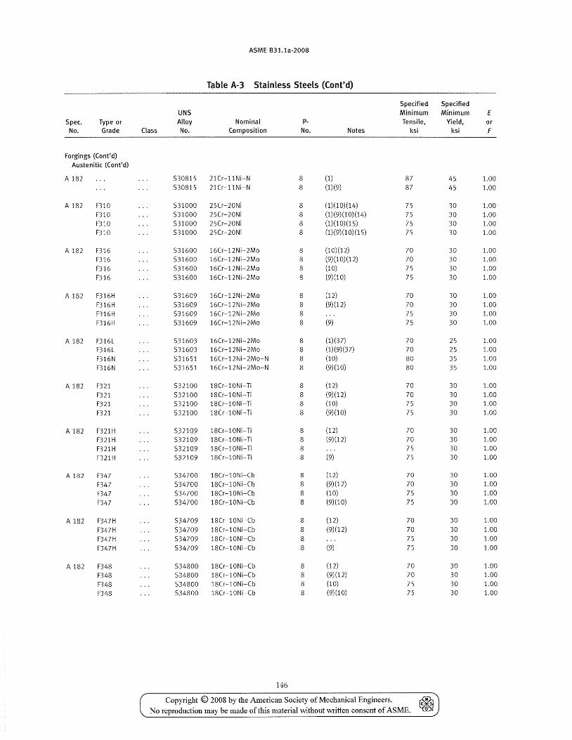
ASME 831.1a-2008
Table A-3 Stainless Steels (Cont'd)
Specified Specified UNS Minimum Minimum E
Spec. Type or Alloy Nominal p- Tensile, Yield, or No. Grade Class No. Composition No. Notes ksi ksi F
Forgings (Cont'd) Austenitic (Cont'd)
A 182 530815 21Cr-llNi-N 8 (1) 87 45 1.00 530815 21Cr-llNi-N 8 (1)(9) 87 45 1.00
A 182 F310 531000 25Cr-20Ni 8 (1) (1 0) (14) 75 30 1.00 F310 531000 25Cr-20Ni 8 (1) (9) (1 0) (14) 75 30 1.00 F310 531000 25Cr-20Ni 8 (1) (1 0) (15) 75 30 1.00 F310 531000 25Cr-20Ni 8 (1)(9)(10)(15) 75 30 1.00
A 182 F316 531600 16Cr-12Ni-2Mo 8 (10)(12) 70 30 1.00 F316 531600 16Cr-12Ni-2Mo 8 (9) (1 0) (12) 70 30 1.00 F316 531600 16Cr-12Ni-2Mo 8 (10) 75 30 1.00 F316 531600 16Cr-12Ni-2Mo 8 (9)(10) 75 30 1.00
A 182 F316H 531609 16Cr-12Ni-2Mo 8 (12) 70 30 1.00 F316H 531609 16Cr-12Ni-2Mo 8 (9)(12) 70 30 1.00 F316H 531609 16Cr-12Ni-2Mo 8 75 30 1.00 F316H 531609 16Cr-12Ni-2Mo 8 (9) 75 30 1.00
A 182 F316L 531603 16Cr-12Ni-2Mo 8 (1)(37) 70 25 1.00 F316L 531603 16Cr-12 Ni-2Mo 8 (1)(9)(37) 70 25 1.00 F316N 531651 16Cr-12Ni-2Mo-N 8 (10) 80 35 1.00 F316N 531651 16Cr-12Ni-2Mo-N 8 (9)(10) 80 35 1.00
A 182 F321 532100 18Cr-l0Ni-Ti 8 (12) 70 30 1.00 F321 532100 18Cr-l0Ni-Ti 8 (9)(12) 70 30 1.00 F321 532100 18Cr-l0Ni-Ti 8 (10) 75 30 1.00
F321 532100 18Cr-l0Ni-Ti 8 (9)(10) 75 30 1.00
A 182 F321H 532109 18Cr-l0Ni-Ti 8 (12) 70 30 1.00 F321H 532109 18Cr-l0Ni-Ti 8 (9)(12) 70 30 1.00 F321H 532109 18Cr-l0Ni-Ti 8 75 30 1.00 F321H 532109 18Cr-l0Ni-Ti 8 (9) 75 30 1.00
A 182 F347 534700 18Cr-l0Ni-Cb 8 (12) 70 30 1.00
F347 534700 18Cr-l0Ni-Cb 8 (9)(12) 70 30 1.00
F347 534700 18Cr-l0Ni-Cb 8 (10) 75 30 1.00
F347 534700 18Cr-l0Ni-Cb 8 (9)(10) 75 30 1.00
A 182 F347H 534709 18Cr-l0Ni-Cb 8 (12) 70 30 1.00
F347H 534709 18Cr-l0Ni-Cb 8 (9)(12) 70 30 1.00
F347H 534709 18Cr-l0Ni-Cb 8 75 30 1.00
F347H 534709 18Cr-l0Ni-Cb 8 (9) 75 30 1.00
A 182 F348 534800 18Cr-l0Ni-Cb 8 (12) 70 30 1.00
F348 534800 18Cr-l0Ni-Cb 8 (9)(12) 70 30 1.00
F348 534800 18Cr-l0Ni-Cb 8 (10) 75 30 1.00 F348 534800 18Cr-l0Ni-Cb 8 (9)(10) 75 30 1.00
146
Copyright © 2008 by the American Society of Mechanical Engineers. ~ No reproduction may be made of this material \\>i.thout Mitten consent of ASME. ~
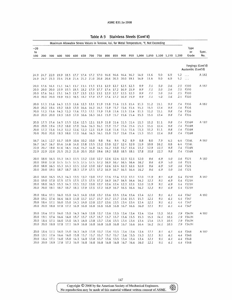
ASME B31.1a-2008
Table A-3 Stainless Steels (Cont'd)
Maximum Allowable Stress Values in Tension, ksi, for Metal Temperature, of, Not Exceeding
-20 Type to or Spec.
100 200 300 400 500 600 650 700 750 800 850 900 950 1,000 1,050 1,100 1,150 1,200 Grade No.
24.9 24.7 22.0 19.9 18.5 17.7 17.4 17.2 17.0 16.8 16.6 16.4 16.2 14.9 11.6 24.924.723.322.421.821.421.221.020.820.620.320.0 19.1 14.9 11.6
20.0 17.6 16.1 15.1 14.3 13.7 13.5 13.3 13.1 12.9 12.7 12.5 12.3 9.9 20.0 20.0 20.0 19.9 19.3 18.5 18.2 17.9 17.7 17.4 17.2 16.9 15.9 9.9 20.0 1 7.6 16. 1 1 5. 1 14.3 13 .7 13 . 5 13 . 3 13 .1 12.9 12.7 1 2. 5 12.3 9. 9 20.0 20.0 20.0 19.9 19.3 18.5 18.2 17.9 17.7 17.4 17.2 16.9 15.9 9.9
7.1 7.1 7.1 7.1
9.0 9.0
6.9 6.9
5.0 3.6 5.0 3.6 5.0 3.6 5.0 3.6
20.0 17.3 15.6 14.3 13.3 12.6 12.3 12.1 11.9 11.8 11.6 11.5 11.4 11.3 11.2 11.1 9.8 20.0 20.0 19.4 19.2 18.0 17.0 16.6 16.3 16.1 15.9 15.7 15.6 15.4 15.3 15.1 12.4 9.8 20.0 17.3 15.6 14.3 13.3 12.6 12.3 12.1 11.9 11.8 11.6 11.5 11.4 11.3 11.2 11.1 9.8 20.0 20.0 20.0 19.3 18.0 17.0 16.6 16.3 16.1 15.9 15.7 15.6 15.4 15.3 15.1 12.4 9.8
20.0 17.3 15.6 14.3 13.3 12.6 12.3 12.1 11.9 11.8 11.6 11.5 11.4 11.3 11.2 11.1 9.8 20.0 20.0 19.4 19.2 18.0 17.0 16.6 16.3 16.1 15.9 15.7 15.6 15.4 15.3 15.1 12.4 9.8 20.0 17.3 15.6 14.3 13.3 12.6 12.3 12.1 11.9 11.8 11.6 11.5 11.4 11.3 11.2 11.1 9.8 20.0 20.0 20.0 19.3 18.0 17.0 16.6 16.3 16.1 15.9 15.7 15.6 15.4 15.3 15.1 12.4 9.8
16.7 14.1 12.7 11.7 10.9 10.4 10.2 10.0 9.8 9.6 9.4 9.2 8.9 8.8 8.0 7.9 16.7 16.7 16.7 15.6 14.8 14.0 13.8 13.5 13.2 13.0 12.7 12.4 12.0 11.9 10.8 10.2
6.5 8.8
22.9 20.7 19.0 17.6 16.5 15.6 15.2 14.9 14.5 14.2 13.9 13.7 13.4 13.2 12.9 12.3 9.8 22.9 22.9 22.0 21.5 21.2 21.0 20.5 20.0 19.6 19.2 18.8 18.5 18.1 17.8 15.8 12.3 9.8
20.0 18.0 16.5 15.3 14.3 13.5 13.2 13.0 12.7 12.6 12.4 12.3 12.1 12.0 9.6 6.9 5.0 20.0 19.0 17.8 17.5 17.5 17.5 17.5 17.5 17.2 16.9 16.7 16.5 16.4 16.2 9.6 6.9 5.0 20.0 18.0 16.5 15.3 14.3 13.5 13.2 13.0 12.7 12.6 12.4 12.3 12.1 12.0 9.6 6.9 5.0 20.0 20.0 19.1 18.7 18.7 18.3 17.9 17.5 17.2 16.9 16.7 16.5 16.4 16.2 9.6 6.9 5.0
20.0 18.0 16.5 15.3 14.3 13.5 13.2 13.0 12.7 12.6 12.4 12.3 12.1 12.0 11.9 9.1 6.9 20.0 19.0 17.8 17.5 17.5 17.5 17.5 17.5 17.2 16.9 16.7 16.5 16.4 16.2 12.3 9.1 6.9 20.0 18.0 16.5 15.3 14.3 13.5 13.2 13.0 12.7 12.6 12.4 12.3 12.1 12.0 11.9 9.1 6.9 20.0 20.0 19.1 18.7 18.7 18.3 17.9 17.5 17.2 16.9 16.7 16.5 16.4 16.2 12.3 9.1 6.9
20.0 18.4 17.1 16.0 15.0 14.3 14.0 13.8 13.7 13.6 13.5 13.4 13.4 13.4 12.1 9.1 6.1 20.0 19.1 17.6 16.6 16.0 15.8 15.7 15.7 15.7 15.7 15.7 15.6 15.5 15.3 12.1 9.1 6.1 20.0 18.4 17.1 16.0 15.0 14.3 14.0 13.8 13.7 13.6 13.5 13.4 13.4 13.4 12.1 9.1 6.1 20.020.018.817.817.216.916.816.816.816.816.816.7 16.6 16.0 12.1 9.1 6.1
20.0 18.4 17.1 16.0 15.0 14.3 14.0 13.8 13.7 13.6 13.5 13.4 13.4 13.4 13.4 13.3 10.5 20.0 19.1 17.6 16.6 16.0 15.7 15.7 15.7 15.7 15.7 15.7 15.6 15.5 15.3 15.1 14.1 10.5 20.0 18.4 17.1 16.0 15.0 14.3 14.0 13.8 13.7 13.6 13.5 13.4 13.4 13.4 13.4 13.3 10.5 20.0 20.0 18.8 17.8 17.1 16.9 16.8 16.8 16.8 16.8 16.8 16.7 16.6 16.4 16.2 14.1 10.5
20.0 18.4 17.1 16.0 15.0 14.3 14.0 13.8 13.7 13.6 13.5 13.4 13.4 13.4 12.1 9.1 6.1 20.0 19.1 17.6 16.6 16.0 15.8 15.7 15.7 15.7 15.7 15.7 15.6 15.5 15.3 12.1 9.1 6.1 20.0 18.4 17.1 16.0 15.0 14.3 14.0 13.8 13.7 13.6 13.5 13.4 13.4 13.4 12.1 20.0 20.0 18.8 17.8 17.2 16.9 16.8 16.8 16.8 16.8 16.8 16.7 16.6 16.0 12.1
147
9.1 9.1
6.1 6.1
Copyright © 2008 by the American Society of Mechanical Engineers. ~ No reproduction may be made of this material \vithout written consent of ASME. ~
Forgings (Cont'd) Austenitic (Cont'd)
5.2 5.2
2.5 F310 2.5 F310 2.5 F310 2.5 F310
7.4 F316 7.4 F316 7.4 F316 7.4 F316
7.4 F316H 7.4 F316H 7.4 F316H 7.4 F316H
6.4 F316L 6.4 F316L 7.4 F316N 7.4 F316N
3.6 F321 3.6 F321 3.6 F321 3.6 F321
5.4 F321 H 5.4 F321 H 5.4 F321H 5.4 F321 H
4.4 F347 4.4 F347 4.4 F347 4.4 F347
7.9 F347H 7.9 F347H 7.9 F347H 7.9 F347H
4.4 F348 4.4 F348 4.4 F348 4.4 F348
A 182
A 182
A 182
A 182
A 182
A 182
A 182
A 182
A 182
A 182
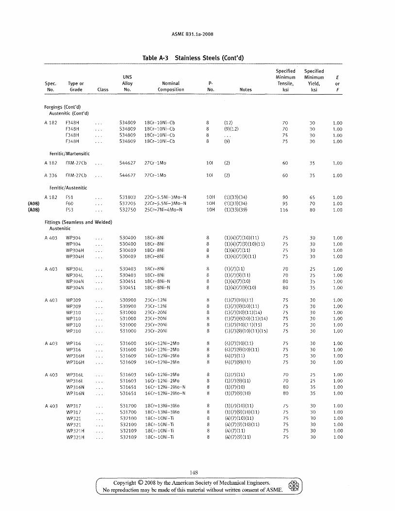
Spec. No.
Type or Grade
Forgings (Cont'd) Austenitic (Cont'd)
A 182 F348H F348H F348H F348H
Ferritic/ Martensitic
A 182 FXM-27Cb
A 336 FXM-27Cb
Ferritic/ Austenitic
A 182 F51 (A08) F60 (A08) F53
Class
Fittings (Seamless and Welded) Austenitic
A 403 WP304 WP304 WP304H WP304H
A 403 WP304L WP304L WP304N
WP304N
A 403 WP309 WP309 WP310 WP310 WP310 WP310
A 403 WP316 WP316 WP316H WP316H
A 403 WP316L WP316L WP316N WP316N
A 403 WP317 WP317 WP321 WP321 WP321H
WP321H
ASME B31.1a-2008
Table A-3 Stainless Steels (Cont'd)
UN5 Alloy No.
Nominal Composition
534809 18Cr-l0Ni-Cb 534809 18Cr-l0Ni-Cb 534809 18Cr-l0Ni-Cb 534809 18Cr-l0Ni-Cb
544627 27Cr-lMo
544627 27Cr-lMo
531803 22Cr-5.5Ni-3Mo-N 532205 22Cr-5.5Ni-3Mo-N
532750 25Cr-7Ni-4Mo-N
530400 18Cr-8Ni 530400 18Cr-8Ni 530409 18Cr-8Ni 530409 18Cr-8Ni
530403 18Cr-8Ni 530403 18Cr-8Ni 530451 lSCr-8Ni-N 530451 18Cr-SNi-N
530900 23Cr-12Ni 530900 23Cr-12Ni 531000 23Cr-20Ni 531000 23Cr-20Ni 531000 23Cr-20Ni 531000 23Cr-20Ni
531600 16Cr-12Ni-2Mo
531600 16Cr-12Ni-2Mo 531609 16Cr-12Ni-2Mo 531609 16Cr-12Ni-2Mo
531603 16Cr-12Ni-2Mo 531603 16Cr-12Ni-2Mo 531651 16Cr-12Ni-2Mo-N 531651 16Cr-12Ni-2Mo-N
531700 18Cr-13Ni-3Mo 531700 18Cr-13Ni-3Mo 532100 18Cr-l0Ni-Ti
532100 lSCr-l0Ni-Ti 532109 18Cr-l0Ni-Ti 532109 18Cr-l0Ni-Ti
148
pNo.
8 8 8 8
101
101
(12) (9)(12)
(9)
(2)
(2)
Notes
10H (1)(33)(34) 10H (1)(33)(34)
10H (1)(33)(39)
8 8 8 8
8 8 8 8
8 8
8 8 8 8
8 8 8 8
8 8
8 8
8 8 8 8 8 8
(1)(4)(7)(10)(11) (1) (4) (7) (9) (1 0) (11) (1) (4) (7) (11) (1) (4) (7) (9) (11)
(1)(7)(11) (1)(7)(9)(11) (1) (4) (7) (1 0) (1) (4) (7) (9) (1 0)
(1) (7) (1 0) (11) (1) (7) (9) (1 0) (11) (1) (7) (1 0) (11) (14) (1) (7) (9) (1 0) (11) (14) (1) (7) (1 0) (11) (15)
(1) (7) (9) (1 0) (11) (15)
(4)(7)(10)(11) (4) (7) (9) (1 0) (11) (4)(7)(11) (4)(7)(9)(11)
(1) (7) (11) (1)(7)(9)(11) (1)(7)(10) (1) (7) (9) (1 0)
(1)(7)(10)(11) (1)(7)(9)(10)(11) (4)(7)(10)(11) (4)(7)(9)(10)(11) (4) (7) (11)
(4)(7)(9)(11)
Specified Minimum Tensile,
ksi
70 70 75 75
60
60
90 95
116
75 75 75 75
70 70 80 80
75 75 75 75 75 75
75
75 75
75
70 70 80 80
75 75 75
75 75 75
Copyright © 2008 by the American Society of Mechanical Engineers. ~ No reproduction may be made of this material without written consent of ASME. ~
Specified Minimum
Yield, ksi
30 30
30 30
35
35
65 70 80
30 30 30 30
25 25
35 35
30 30 30 30 30 30
30
30 30 30
25 25 35 35
30 30 30
30 30 30
E or F
1.00 1.00 1.00 1.00
1.00
1.00
1.00 1.00
1.00
1.00 1.00 1.00 1.00
1.00 1.00
1.00 1.00
1.00 1.00 1.00 1.00 1.00 1.00
1.00
1.00
1.00 1.00
1.00 1.00 1.00 1.00
1.00 1.00 1.00 1.00 1.00 1.00
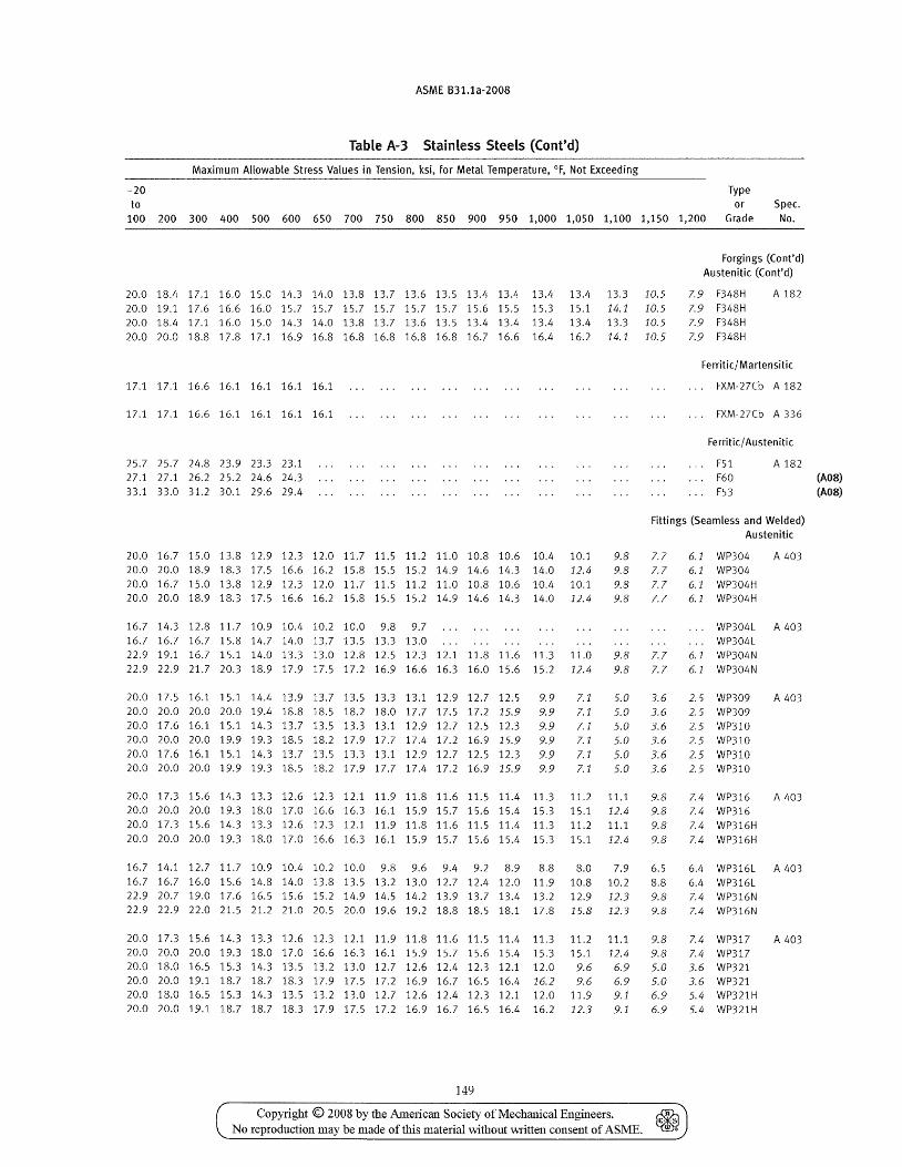
ASME B31.1a-2008
Table A-3 Stainless Steels (Cont'd)
Maximum Allowable Stress Values in Tension, ksi, for Metal Temperature, of, Not Exceeding
-20 Type to or Spec.
100 200 300 400 500 600 650 700 750 800 850 900 950 1,000 1,050 1,100 1,150 1,200 Grade No.
20.0 18.4 17.1 16.0 15.0 14.3 14.0 13.8 13.7 13.6 13.5 13.4 13.4 13.4 13.4 13.3 10.5 20.0 19.1 17.6 16.6 16.0 15.7 15.7 15.7 15.7 15.7 15.7 15.6 15.5 15.3 15.1 14.1 10.5 20.0 18.4 17.1 16.0 15.0 14.3 14.0 13.8 13.7 13.6 13.5 13.4 13.4 13.4 13.4 13.3 10.5 20.0 20.0 18.8 17.8 17.1 16.9 16.8 16.8 16.8 16.8 16.8 16.7 16.6 16.4 16.2 14.1 10.5
17.1 17.1 16.6 16.1 16.1 16.1 16.1
17.1 17.1 16.6 16.1 16.1 16.1 16.1
25.7 25.7 24.8 23.9 23.3 23.1 27.1 27.1 26.2 25.2 24.6 24.3 33.1 33.0 31.2 30.1 29.6 29.4
Forgings (Cont'd) Austenitic (Cont'd)
7.9 F348H 7.9 F348H 7.9 F348H 7.9 F348H
A 182
Ferritic/ Martensitic
FXM-27Cb A 182
FXM-27Cb A 336
Ferritic/ Austenitic
F51 F60 F53
A 182
Fittings (Seamless and Welded) Austenitic
20.0 16.7 15.0 13.8 12.9 12.3 12.0 11.7 11.5 11.2 11.0 10.8 10.6 10.4 10.1 20.0 20.0 18.9 18.3 17.5 16.6 16.2 15.8 15.5 15.2 14.9 14.6 14.3 14.0 12.4 20.0 16.7 15.0 13.8 12.9 12.3 12.0 11.7 11.5 11.2 11.0 10.8 10.6 10.4 10.1 20.0 20.0 18.9 18.3 17.5 16.6 16.2 15.8 15.5 15.2 14.9 14.6 14.3 14.0 12.4
16.7 14.3 12.8 11.7 10.9 10.4 10.2 10.0 9.8 9.7 16.7 16.7 16.7 15.8 14.7 14.0 13.7 13.5 13.3 13.0 22.9 19.1 16.7 15.1 14.0 13.3 13.0 12.8 12.5 12.3 12.1 11.8 11.6 11.3 11.0 22.9 22.9 21.7 20.3 18.9 17.9 17.5 17.2 16.9 16.6 16.3 16.0 15.6 15.2 12.4
20.0 17.5 16.1 15.1 14.4 13.9 13.7 13.5 13.3 13.1 12.9 12.7 12.5 9.9 20.0 20.0 20.0 20.0 19.4 18.8 18.5 18.2 18.0 17.7 17.5 17.2 15.9 9.9 20.0 17.6 16.1 15.1 14.3 13.7 13.5 13.3 13.1 12.9 12.7 12.5 12.3 9.9 20.0 20.0 20.0 19.9 19.3 18.5 18.2 17.9 17.7 17.4 17.2 16.9 15.9 9.9 20.0 17.6 16.1 15.1 14.3 13.7 13.5 13.3 13.1 12.9 12.7 12.5 12.3 9.9 20.0 20.0 20.0 19.9 19.3 18.5 18.2 17.9 17.7 17.4 17.2 16.9 15.9 9.9
7.1 7.1 7.1 7.1 7.1 7.1
9.8 9.8 9.8 9.8
9.8 9.8
5.0 5.0 5.0 5.0 5.0 5.0
7.7 7.7 7.7 7.7
7.7 7.7
3.6 3.6 3.6 3.6 3.6 3.6
20.0 17.3 15.6 14.3 13.3 12.6 12.3 12.1 11.9 11.8 11.6 11.5 11.4 11.3 11.2 11.1 9.8 20.0 20.0 20.0 19.3 18.0 17.0 16.6 16.3 16.1 15.9 15.7 15.6 15.4 15.3 15.1 12.4 9.8 20.0 17.3 15.6 14.3 13.3 12.6 12.3 12.1 11.9 11.8 11.6 11.5 11.4 11.3 11.2 11.1 9.8 20.0 20.0 20.0 19.3 18.0 17.0 16.6 16.3 16.1 15.9 15.7 15.6 15.4 15.3 15.1 12.4 9.8
16.7 14.1 12.7 11.7 10.9 10.4 10.2 10.0 9.8 9.6 9.4 9.2 8.9 8.8 8.0 7.9 6.5 16.7 16.7 16.0 15.6 14.8 14.0 13.8 13.5 13.2 13.0 12.7 12.4 12.0 11.9 10.8 10.2 8.8 22.9 20.7 19.0 17.6 16.5 15.6 15.2 14.9 14.5 14.2 13.9 13.7 13.4 13.2 12.9 12.3 9.8 22.9 22.9 22.0 21.5 21.2 21.0 20.5 20.0 19.6 19.2 18.8 18.5 18.1 17.8 15.8 12.3 9.8
20.0 17.3 15.6 14.3 13.3 12.6 12.3 12.1 11.9 11.8 11.6 11.5 11.4 11.3 11.2 11.1 9.8 20.0 20.0 20.0 19.3 18.0 17.0 16.6 16.3 16.1 15.9 15.7 15.6 15.4 15.3 15.1 12.4 9.8 20.0 18.0 16.5 15.3 14.3 13.5 13.2 13.0 12.7 12.6 12.4 12.3 12.1 12.0 9.6 6.9 5.0 20.0 20.0 19.1 18.7 18.7 18.3 17.9 17.5 17.2 16.9 16.7 16.5 16.4 16.2 9.6 6.9 5.0 20.0 18.0 16.5 15.3 14.3 13.5 13.2 13.0 12.7 12.6 12.4 12.3 12.1 12.0 11.9 9.1 6.9 20.0 20.0 19.1 18.7 18.7 18.3 17.9 17.5 17.2 16.9 16.7 16.5 16.4 16.2 12.3 9.1 6.9
149
Copyright © 2008 by the American Society of Mechanical Engineers. No reproduction may be made of this material without written consent of ASME.
6.1 WP304 A 403 6.1 WP304 6.1 WP304H 6.1 WP304H
WP304L A 403 WP304L
6.1 WP304N 6.1 WP304N
2.5 WP309 2.5 WP309 2.5 WP310 2.5 WP310 2.5 WP310 2.5 WP310
A 403
7.4 WP316 A 403 7.4 WP316 7.4 WP316H 7.4 WP316H
6.4 WP316L A 403 6.4 WP316L 7.4 WP316N 7.4 WP316N
7.4 WP317 A 403 7.4 WP317 3.6 WP321 3.6 WP321 5.4 WP321H 5.4 WP321H
(A08) (A08)
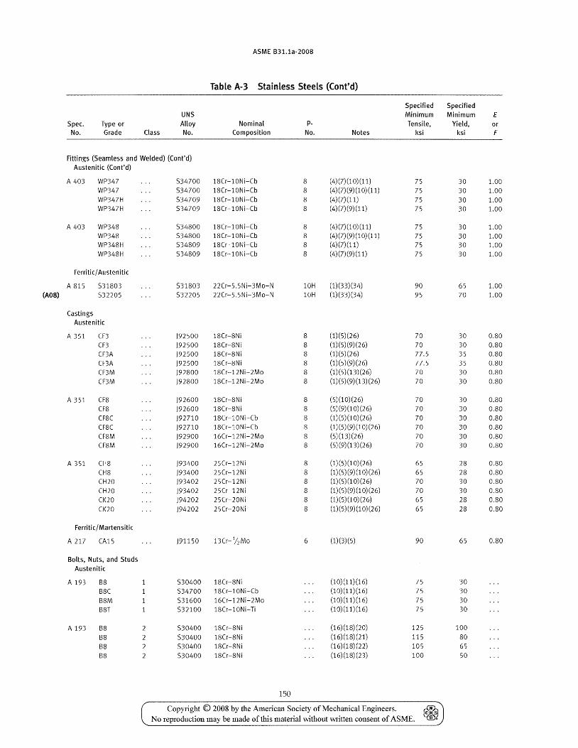
ASME B31.1a-2008
Table A-3 Stainless Steels (Cont'd)
Specified Specified UNS Minimum Minimum E
Spec. Type or Alloy Nominal p- Tensile, Yield, or No. Grade Class No. Composition No. Notes ksi ksi F
fittings (Seamless and Welded) (Cont'd) Austenitic (Cont'd)
A 403 WP347 534700 18Cr-l0Ni-Cb 8 (4) (7) (1 0) (11) 75 30 1.00 WP347 534700 18Cr-l0Ni-Cb 8 (4) (7) (9) (1 0) (11) 75 30 1.00 WP347H 534709 18Cr-l0Ni-Cb 8 (4)(7)(11) 75 30 1.00 WP347H 534709 18Cr-l0Ni-Cb 8 (4)(7)(9)(11) 75 30 1.00
A 403 WP348 534800 18Cr-l0Ni-Cb 8 (4)(7)(10)(11) 75 30 1.00 WP348 534800 18Cr-l0Ni-Cb 8 (4)(7)(9)(10)(11) 75 30 1.00 WP348H 534809 18Cr-l0Ni-Cb 8 (4)(7)(11) 75 30 1.00 WP348H 534809 18Cr-l0Ni-Cb 8 (4)(7)(9)(11) 75 30 1.00
Ferritic/ Austenitic
A 815 531803 531803 22Cr-S.SNi-3Mo-N 10H (1)(33)(34) 90 65 1.00 (A08) 532205 532205 22Cr-5.5Ni-3Mo-N 10H (1)(33)(34) 95 70 1.00
Castings Austenitic
A 351 CF3 )92500 18Cr-8Ni 8 (1)(5)(26) 70 30 0.80
CF3 )92500 18Cr-8Ni 8 (1) (5) (9) (26) 70 30 0.80
CF3A )92500 18Cr-8Ni 8 (1)(5)(26) 77.5 35 0.80
CF3A )92500 18Cr-8Ni 8 (1)(5)(9)(26) 77.5 35 O.SO CF3M )92800 18Cr-12Ni-2Mo 8 (1) (5) (13) (26) 70 30 0.80
CF3M )92800 18Cr-12Ni-2Mo S (1) (5) (9) (13) (26) 70 30 O.SO
A 351 CF8 )92600 18Cr-8Ni 8 (5)(10)(26) 70 30 0.80 CF8 )92600 18Cr-8Ni 8 (5)(9)(10)(26) 70 30 0.80
CF8C )92710 18Cr-l0Ni-Cb 8 (1)(5)(10)(26) 70 30 0.80
CF8C )92710 18Cr-l0Ni-Cb 8 (1) (5) (9) (10) (26) 70 30 0.80
CF8M )92900 16Cr-12Ni-2Mo 8 (5)(13)(26) 70 30 0.80 CF8M )92900 16Cr-12Ni-2Mo 8 (5) (9) (13) (26) 70 30 0.80
A 351 CH8 )93400 25Cr-12Ni 8 (1) (5) (1 0) (26) 65 28 0.80
CH8 )93400 25Cr-12Ni 8 (1) (5) (9) (1 0) (26) 65 28 0.80 CH20 )93402 25Cr-12Ni 8 (1)(5)(10)(26) 70 30 0.80
CH20 )93402 25Cr-12Ni 8 (1) (5) (9) (1 0) (26) 70 30 0.80
CI<20 )94202 25Cr-20Ni 8 (1)(5)(10)(26) 65 28 0.80
CI<20 )94202 25Cr-20Ni 8 (1) (5) (9) (1 0) (26) 65 28 O.SO
Ferritic/ Martensitic
A 217 CA15 )91150 13Cr- 1/2 Mo 6 (1)(3)(5) 90 65 0.80
Bolts, Nuts, and Studs Austenitic
A 193 B8 530400 18Cr-8Ni (10)(11)(16) 75 30
B8C 534700 18Cr-10Ni-Cb (10)(11)(16) 75 30
B8M 531600 16Cr-12Ni-2Mo (10)(11)(16) 75 30
B8T 532100 18Cr-l ONi-Ti (10)(11)(16) 75 30
A 193 B8 2 530400 18Cr-8Ni (16)(18)(20) 125 100
BS 2 530400 18Cr-8Ni (16)(18)(21) 115 80
B8 2 530400 1SCr-8Ni (16)(18)(22) 105 65
B8 2 530400 18Cr-8Ni (16)(18)(23) 100 50
150
Copyright © 2008 by the American Society of Mechanical Engineers. ~ No reproduction may be made of this material without written consent of ASME. ~
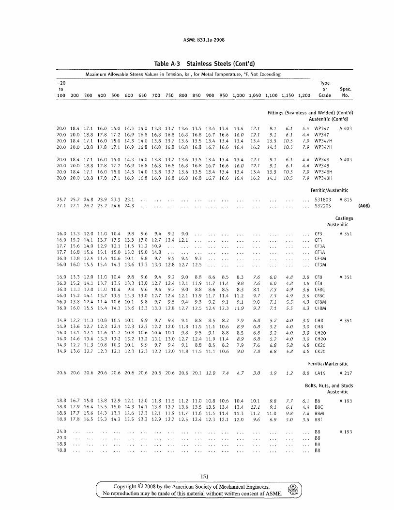
ASME B31.1a-2008
Table A-3 Stainless Steels (Cont'd)
Maximum Allowable Stress Values in Tension, ksi, for Metal Temperature, of, Not Exceeding
-20 Type to or Spec.
100 200 300 400 500 600 650 700 750 800 850 900 950 1,000 1,050 1,100 1,150 1,200 Grade No.
Fittings (Seamless and Welded) (Cont'd) Austenitic (Cont'd)
20.0 lS.4 17.1 16.0 15.0 14.3 14.0 U.S 13.7 13.6 13.5 13.4 13.4 13.4 12.1 9.1 6.1 20.020.0 lS.8 17.8 17.2 16.9 16.S 16.S 16.8 16.8 16.8 16.7 16.6 16.0 12.1 9.1 6.1 20.0 18.4 17.1 16.0 15.0 14.3 14.0 13.8 13.7 13.6 13.5 13.4 13.4 13.4 13.4 13.3 10.5 20.0 20.0 18.8 17.8 17.1 16.9 16.8 16.8 16.8 16.8 16.8 16.7 16.6 16.4 16.2 14.1 10.5
20.0 18.4 17.1 16.0 15.0 14.3 14.0 13.8 13.7 13.6 13.5 13.4 13.4 13.4 12.1 9.1 6.1 20.0 20.0 18.8 17.8 17.2 16.9 16.8 16.8 16.8 16.8 16.S 16.7 16.6 16.0 12.1 9.1 6.1 20.0 18.4 17.1 16.0 15.0 14.3 14.0 13.8 13.7 13.6 13.5 13.4 13.4 13.4 13.4 13.3 10.5 20.020.0 lS.8 17.8 17.116.9 16.S 16.8 16.8 16.S 16.8 16.7 16.6 16.4 16.2 14.1 10.5
25.7 25.7 24.8 23.9 23.3 23.1 27.1 27.1 26.2 25.2 24.6 24.3
16.0 13.3 12.0 11.0 10.4 9.8 9.6 9.4 9.2 9.0 16.0 15.2 14.1 13.7 13.5 13.3 13.0 12.7 12.4 12.1 17.7 15.6 14.0 12.9 12.1 11.5 11.2 10.9 17.7 16.8 15.6 15.1 15.0 15.0 15.0 14.8 16.0 13.8 12.4 11.4 10.6 10.1 9.8 9.7 9.5 9.4 9.3 16.0 16.0 15.5 15.4 14.3 13.6 13.3 13.0 12.8 12.7 12.5
16.0 13.3 12.0 11.0 10.4 9.8 9.6 9.4 9.2 9.0 8.8 8.6 8.5 8.3 16.0 15.2 14.1 13.7 13.5 13.3 13.0 12.7 12.4 12.1 11.9 11.7 11.4 9.8 16.0 13.3 12.0 11.0 10.4 9.8 9.6 9.4 9.2 9.0 8.8 8.6 8.5 8.3
7.6 7.6 B.l
16.0 15.2 14.1 13.7 13.5 13.3 13.0 12.7 12.4 12.1 11.9 11.7 11.4 11.2 9.7 16.0 13.8 12.4 11.4 10.6 10.1 9.8 9.7 9.5 9.4 9.3 9.2 9.1 9.1 9.0 16.0 16.0 15.5 15.4 14.3 13.6 13.3 13.0 12.8 12.7 12.5 12.4 12.3 11.9 9.2
14.9 12.2 11.3 10.8 10.5 10.1 9.9 9.7 9.4 9.1 8.8 8.5 8.2 7.9 14.9 13.6 12.7 12.3 12.3 12.3 12.3 12.2 12.0 11.8 11.5 11.1 10.6 8.9 16.0 13.1 12.1 11.6 11.2 10.8 10.6 10.4 10.1 9.8 9.5 9.1 8.8 8.5 16.0 14.6 13.6 13.3 13.2 13.2 13.2 13.1 13.0 12.7 12.4 11.9 11.4 8.9 14.9 12.2 11.3 10.8 10.5 10.1 9.9 9.7 9.4 9.1 8.8 8.5 8.2 7.9 14.9 13.6 12.7 12.3 12.3 12.3 12.3 12.2 12.0 11.8 11.5 11.1 10.6 9.0
6.8 6.8 6.8 6.8 7.6 7.8
20.6 20.6 20.6 20.6 20.6 20.6 20.6 20.6 20.6 20.6 20.1 12.0 7.4 4.7 3.0
18.8 16.7 15.0 13.8 12.9 12.1 12.0 11.8 11.5 11.2 11.0 10.8 10.6 10.4 10.1
6.0 6.0 7.3 7.3 7.1 7.1
5.2 5.2 5.2 5.2 6.8 6.8
1.9
9.8 18.8 17.9 16.4 15.5 15.0 14.3 14.1 13.8 13.7 13.6 13.5 13.5 13.4 13.4 12.1 9.1 18.817.7 15.6 14.3 13.3 12.612.312.111.911.711.611.511.4 11.3 11.2 11.0 18.8 17.8 16.5 15.3 14.3 13.5 13.3 12.9 12.7 12.5 12.4 12.3 12.1 12.0 9.6 6.9
25.0 20.0 18.8 18.8
151
4.8 4.8 4.9 4.9 5.5 5.5
4.0 4.0 4.0 4.0 5.8 5.8
1.2
7.7 6.1 9.8 5.0
Copyright © 2008 by the American Society of Mechanical Engineers. ~ No reproduction may be made of this matelial without written consent of ASME. ~
4.4 WP347 A 403 4.4 WP347 7.9 WP347H 7.9 WP347H
4.4 WP348 A 403 4.4 WP348 7.9 WP348H 7.9 WP348H
Ferritic/ Austenitic
531803 A 815 . .. 532205 (AOS)
CF3 CF3 CF3A CF3A CF3M CF3M
3.8 CF8 3.8 CF8 3.6 CFBC 3.6 CFSC 4.3 CF8M 4.3 CFSM
3.0 CH8 3.0 CHS 3.0 CH20 3.0 CH20 4.8 CK20 4.8 CK20
Castings Austenitic
A 351
A 351
A 351
Ferritic/ Martensitic
0.8 CA15 A 217
Bolts, Nuts, and Studs Austenitic
6.1 88 4.4 B8C 7.4 88M 3.6 B8T
88 88 88 B8
A 193
A 193
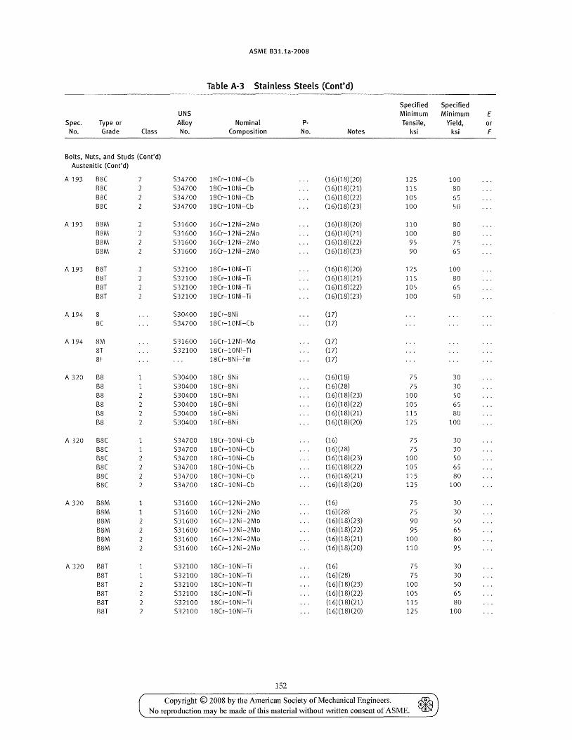
ASME B31.1a-2008
Table A·3 Stainless Steels (Cont'd)
Specified Specified UNS Minimum Minimum E
Spec. Type or Alloy Nominal p- Tensile, Yield, or No. Grade Class No. Composition No. Notes ksi ksi F
Bolts, Nuts, and Studs (Cont'd) Austenitic (Cont'd)
A 193 BSC 534700 lSCr-l0Ni-Cb (16)(lS)(20) 125 100 B8C 534700 lSCr-l0Ni-Cb (16)(18)(21) 115 80 B8C 534700 18Cr-l0Ni-Cb (16)(18)(22) 105 65 BSC 2 534700 18Cr-l0Ni-Cb (16)(18)(23) 100 50
A 193 BSM 2 531600 16Cr-12Ni-2Mo (16) (18) (20) 110 80 B8M 2 531600 16Cr-12Ni-2Mo (16) (18) (21) 100 80 BSM 531600 16Cr-12Ni-2Mo (16)(18)(22) 95 75 BSM 531600 16Cr-12Ni-2Mo (16) (18) (23) 90 65
A 193 B8T 532100 18Cr-l0Ni-Ti (16)(18)(20) 125 100 BST 532100 18Cr-l0Ni-Ti (16)(lS)(21) 115 SO BST 532100 18Cr-l0Ni-Ti (16)(18)(22) 105 65 B8T 532100 18Cr-l0Ni-Ti (16)(18)(23) 100 50
A 194 8 530400 18Cr-8Ni (17)
8C 534700 18Cr-l0Ni--Cb (17)
A 194 8M 531600 16Cr-12Ni-Mo (17) 8T 532100 18Cr-l0Ni-Ti (17) 8F 18Cr-8Ni-Fm (17)
A 320 BS 530400 lSCr-SNi (16)(18) 75 30 BS 530400 lSCr-SNi (16)(28) 75 30 BS 2 530400 lSCr-SNi (16)(18)(23) 100 50 B8 2 530400 18Cr-8Ni (16)(18)(22) 105 65 BS 2 530400 lSCr-SNi (16)(18)(21) 115 SO B8 2 530400 lSCr-SNi (16) (18) (20) 125 100
A 320 B8C 534700 lSCr-l0Ni-Cb (16) 75 30 B8C 534700 lSCr-l0Ni-Cb (16)(28) 75 30 BSC 534700 lSCr-l0Ni-Cb (16) (lS) (23) 100 50 BSC 534700 lSCr-l0Ni-Cb (16) (18) (22) 105 65 S8C 2 534700 lSCr-l0Ni-Cb (16) (18) (21) 115 80 B8C 2 534700 lSCr-l0Ni-Cb (16) (18) (20) 125 100
A 320 B8M 1 531600 16Cr-12Ni-2Mo (16) 75 30 B8M 1 531600 16Cr-12Ni-2Mo (16)(28) 75 30 B8M 2 531600 16Cr-12Ni-2Mo (16)(18)(23) 90 50 BSM 2 531600 16Cr-12Ni-2Mo (16) (18) (22) 95 65 88M 531600 16Cr-12Ni-2Mo (16)(18)(21) 100 80 B8M 531600 16Cr-12Ni-2Mo (16) (18) (20) 110 95
A 320 B8T 532100 18Cr-l0Ni-Ti (16) 75 30 B8T 532100 18Cr-l0Ni-Ti (16)(28) 75 30 B8T 532100 18Cr-l0Ni-Ti (16)(18)(23) 100 50 B8T 532100 18Cr-l0Ni-Ti (16)(18)(22) 105 65 88T 532100 lSCr-l0Ni-Ti (16)(18)(21) 115 80 BST 532100 lSCr-l0Ni-Ti (16)(18)(20) 125 100
152
Copyright © 2008 by the Amedcan Society of Mechanical Engineers. No reproduction may be made of this material without written consent of ASME.
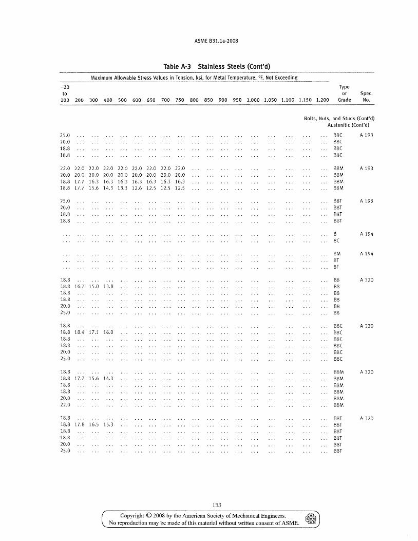
ASME B31.1a-2008
Table A-3 Stainless Steels (Cont'd)
Maximum Allowable Stress Values in for Metal
-20 Type to or Spec.
100 200 300 400 500 600 650 700 750 800 850 900 950 1,000 1,050 1,100 1,150 1,200 Grade No.
Bolts, Nuts, and Studs (Cont'd) Austenitic (Cont'd)
25.0 B8C A 193 20.0 B8C 18.8 B8C 18.8 B8C
22.0 22.0 22.0 22.0 22.0 22.0 22.0 22.0 22.0 B8M A 193 20.0 20.0 20.0 20.0 20.0 20.0 20.0 20.0 20.0 B8M 18.8 17.7 16.3 16.3 16.3 16.3 16.3 16.3 16.3 88M 18.S 17.7 15.6 14.3 13.3 12.6 12.5 12.5 12.5 88M
25.0 8ST A 193 20.0 B8T IS.S B8T 18.8 88T
8 A 194 8C
8M A 194 8T 8F
18.8 88 A 320 18.8 16.7 15.0 13.8 88 18.S B8 18.S 88 20.0 B8 25.0 88
18.8 B8C A 320 18.8 18.4 17.1 16.0 88C 18.8 BSC 18.8 88C 20.0 BSC 25.0 B8C
18.8 B8M A 320 18.8 17.7 15.6 14.3 B8M 18.8 B8M 18.8 B8M 20.0 8SM 22.0 B8M
18.8 B8T A 320 18.8 17.8 16.5 15.3 B8T 18.8 88T lS.S BST 20.0 B8T 25.0 BST
153
Copyright © 2008 by the American Society of Mechanical Engineers. ~ No reproduction may be made of this material \vithout written consent of ASME. ~
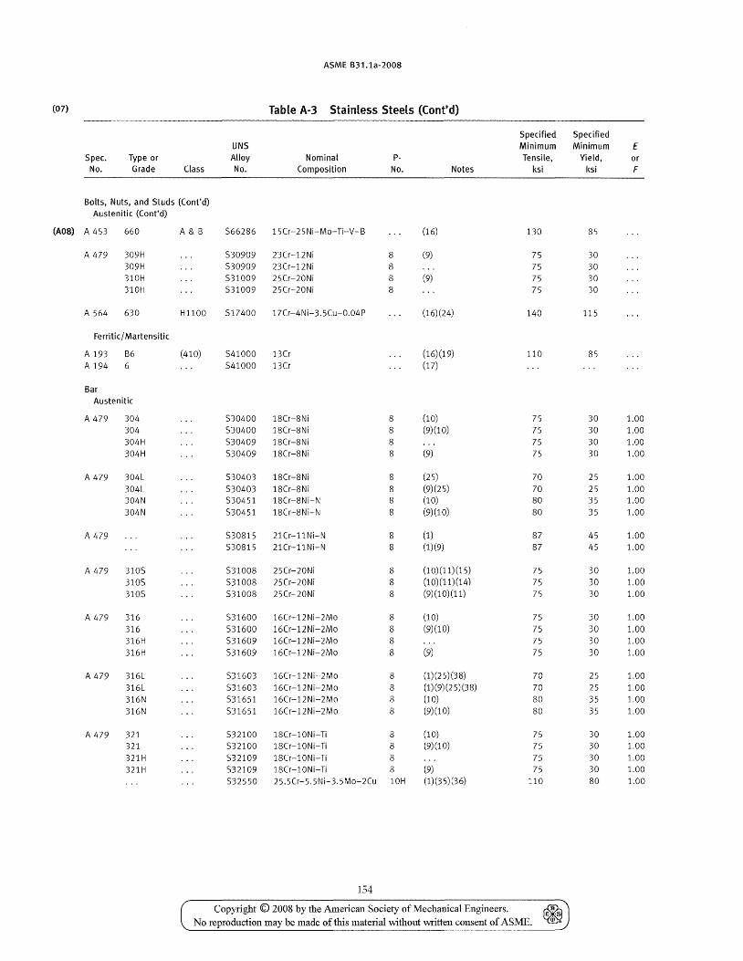
ASME S31.1a-2008
(07) Table A-3 Stainless Steels (Cont'd)
Specified Specified UNS Minimum Minimum E
Spec. Type or Alloy Nominal p- Tensile, Yield, or No. Grade Class No. Composition No. Notes ksi ksi F
Bolts, Nuts, and Studs (Cont'd) Austenitic (Cont'd)
(A08) A 453 660 A&B 566286 15Cr-25Ni-Mo-Ti-V-B (16) 130 85
A 479 309H 530909 23Cr-12Ni 8 (9) 75 30 309H 530909 23Cr-12Ni 8 75 30 310H 531009 25Cr-20Ni 8 (9) 75 30 310H 531009 25Cr-20Ni 8 75 30
A 564 630 H1100 517400 17Cr-4Ni-3.5Cu-0.04P (16)(24) 140 115
Ferritic/ Martensitic
A 193 B6 (410) 541000 13Cr (16)(19) 110 85 A 194 6 541000 13Cr (17)
Bar Austenitic
A 479 304 530400 18Cr-8Ni 8 (10) 75 30 1.00 304 530400 18Cr-8Ni 8 (9)(10) 75 30 1.00 304H 530409 18Cr-8Ni 8 75 30 1.00 304H 530409 18Cr-8Ni 8 (9) 75 30 1.00
A 479 304L 530403 18Cr-8Ni 8 (25) 70 25 1.00
304L 530403 18Cr-8Ni 8 (9)(25) 70 25 1.00 304N 530451 18Cr-8Ni-N 8 (10) 80 35 1.00
304N 530451 18Cr-8Ni-N 8 (9)(10) 80 35 1.00
A 479 530815 21Cr-11Ni-N 8 (1) 87 45 1.00 530815 21Cr-11Ni-N 8 (1)(9) 87 45 1.00
A 479 3105 531008 25Cr-20Ni 8 (10)(11)(15) 75 30 1.00
3105 531008 25Cr-20Ni 8 (10)(11)(14) 75 30 1.00 3105 531008 25Cr-20Ni 8 (9)(10)(11) 75 30 1.00
A 479 316 531600 16Cr-12Ni-2Mo 8 (10) 75 30 1.00
316 531600 16Cr-12Ni-2Mo 8 (9)(10) 75 30 1.00 316H 531609 16Cr-12Ni-2Mo 8 75 30 1.00 316H 531609 16Cr-12Ni-2Mo 8 (9) 75 30 1.00
A 479 316L 531603 16Cr-12Ni-2Mo 8 (1)(25)(38) 70 25 1.00 316L 531603 16Cr-12Ni-2Mo 8 (1) (9) (2 5) (38) 70 25 1.00 316N 531651 16Cr-12Ni-2Mo 8 (10) 80 35 1.00
316N 531651 16Cr-12Ni-2Mo 8 (9)(10) 80 35 1.00
A 479 321 532100 18Cr-l0Ni-Ti 8 (10) 75 30 1.00 321 532100 18Cr-l0Ni-Ti 8 (9)(10) 75 30 1.00
321H 532109 18Cr-10Ni-Ti 8 75 30 1.00
321H 532109 18Cr-l0Ni-Ti 8 (9) 75 30 1.00
532550 25.5Cr-5. 5Ni-3. 5Mo-2Cu 10H (1)(35)(36) 110 80 1.00
154
Copyright © 2008 by the American Society of Mechanical Engineers. No reproduction may be made of this material without written consent of ASME.
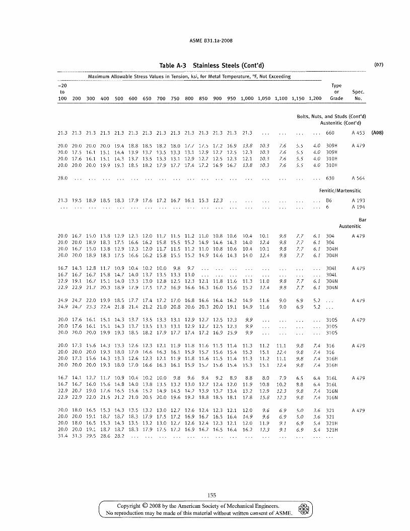
ASME B31.1a-2008
Table A-3 Stainless Steels (Cont'd)
Maximum Allowable Stress Values in Tension, ksi, for Metal Temperature, OF, Not Exceeding
-20 Type to or Spec.
100 200 300 400 500 600 650 700 750 800 850 900 950 1,000 1,050 1,100 1,150 1,200 Grade No.
Bolts, Nuts, and Studs «(ont'd) Austenitic «(ont'd)
(07)
21.3 21.3 21.3 21.3 21.3 21.3 21.3 21.3 21.3 21.3 21.3 21.3 21.3 21.3 660 A 453 (AOS)
20.0 20.0 20.0 20.0 19.4 18.8 18.5 18.2 18.0 17.7 17.5 17.2 16.9 13.8 10.3 20.0 17.5 16.1 15.1 14.4 13.9 13.7 13.5 13.3 13.1 12.9 12.7 12.5 12.3 10.3 20.0 17.6 16.1 15.1 14.3 13.7 13.5 13.3 13.1 12.9 12.7 12.5 12.3 12.1 10.3 20.0 20.0 20.0 19.9 19.3 18.5 18.2 17.9 17.7 17.4 17.2 16.9 16.7 13.8 10.3
28.0
21.3 19.5 18.9 18.5 18.3 17.9 17.6 17.2 16.7 16.1 15.3 12.3
20.0 16.7 15.0 13.8 12.9 12.3 12.0 11.7 11.5 11.2 11.0 10.8 10.6 10.4 10.1 20.0 20.0 18.9 18.3 17.5 16.6 16.2 15.8 15.5 15.2 14.9 14.6 14.3 14.0 12.4 20.0 16.7 15.0 13.8 12.9 12.3 12.0 11.7 11.5 11.2 11.0 10.8 10.6 10.4 10.1 20.0 20.0 18.9 18.3 17.5 16.6 16.2 15.8 15.5 15.2 14.9 14.6 14.3 14.0 12.4
16.7 14.3 12.8 11.7 10.9 10.4 10.2 10.0 9.8 9.7 16.7 16.7 16.7 15.8 14.7 14.0 13.7 13.5 13.3 13.0 22.9 19.1 16.7 15.1 14.0 13.3 13.0 12.8 12.5 12.3 12.1 11.8 11.6 11.3 11.0 22.9 22.9 21.7 20.3 18.9 17.9 17.5 17.2 16.9 16.6 16.3 16.0 15.6 15.2 12.4
24.9 24.7 22.0 19.9 18.5 17.7 17.4 17.2 17.0 16.8 16.6 16.4 16.2 14.9 11.6 24.9 24.7 23.3 22.4 21.8 21.4 21.2 21.0 20.8 20.6 20.3 20.0 19.1 14.9 11.6
20.0 17.6 16.1 15.1 14.3 13.7 13.5 13.3 13.1 12.9 12.7 12.5 12.3 9.9 20.0 17.6 16.1 15.1 14.3 13.7 13.5 13.3 13.1 12.9 12.7 12.5 12.3 9.9 20.0 20.0 20.0 19.9 19.3 18.5 18.2 17.9 17.7 17.4 17.2 16.9 15.9 9.9
7.6 7.6 7.6 7.6
9.8 9.8 9.8 9.8
9.8 9.8
9.0 9.0
20.0 17.3 15.6 14.3 13.3 12.6 12.3 12.1 11.9 11.8 11.6 11.5 11.4 11.3 11.2 11.1 20.0 20.0 20.0 19.3 18.0 17.0 16.6 16.3 16.1 15.9 15.7 15.6 15.4 15.3 15.1 12.4 20.0 17.3 15.6 14.3 13.3 12.6 12.3 12.1 11.9 11.8 11.6 11.5 11.4 11.3 11.2 11.1 20.0 20.0 20.0 19.3 18.0 17.0 16.6 16.3 16.1 15.9 15.7 15.6 15.4 15.3 15.1 12.4
16.7 14.1 12.7 11.7 10.9 10.4 10.2 10.0 9.8 9.6 9.4 9.2 8.9 8.8 8.0 7.9 16.7 16.7 16.0 15.6 14.8 14.0 13.8 13.5 13.2 13.0 12.7 12.4 12.0 11.9 10.8 10.2 22.9 20.7 19.0 17.6 16.5 15.6 15.2 14.9 14.5 14.2 13.9 13.7 13.4 13.2 12.9 12.3 22.9 22.9 22.0 21.5 21.2 21.0 20.5 20.0 19.6 19.2 18.8 18.5 18.1 17.8 15.8 12.3
20.0 18.0 16.5 15.3 14.3 13.5 13.2 13.0 12.7 12.6 12.4 12.3 12.1 12.0 9.6 6.9 20.0 20.0 19.1 18.7 18.7 18.3 17.9 17.5 17.2 16.9 16.7 16.5 16.4 14.9 9.6 6.9 20.0 18.0 16.5 15.3 14.3 13.5 13.2 13.0 12.7 12.6 12.4 12.3 12.1 12.0 11.9 9.1 20.0 20.0 19.1 18.7 18.7 18.3 17.9 17.5 17.2 16.9 16.7 16.5 16.4 16.2 12.3 9.1 31.4 31.3 29.5 28.6 28.2
155
5.5 5.5 5.5 5.5
7.7 7.7 7.7 7.7
7.7 7.7
6.9 6.9
9.8 9.8 9.8 9.8
6.5 8.8 9.8 9.8
5.0 5.0 6.9 6.9
Copyright © 2008 by the American Society of Mechanical Engineers. ~ No reproduction may be made of this material without written consent of ASME. ~
4.0 309H 4.0 309H 4.0 310H 4.0 310H
630
A 479
A 564
Ferritic/ Martensitic
B6 A 193 . .. 6 A 194
6.1 304 6.1 304 6.1 304H 6.1 304H
304L 304L
6.1 304N 6.1 304N
Bar
Austenitic
A 479
A 479
5.2 A 479 5.2
3105 310S 3105
7.4 316 7.4 316 7.4 316H 7.4 316H
6.4 316L 6.4 316L 7.4 316N 7.4 316N
3.6 321 3.6 321 5.4 321H 5.4 321H
A 479
A 479
A 479
A 479
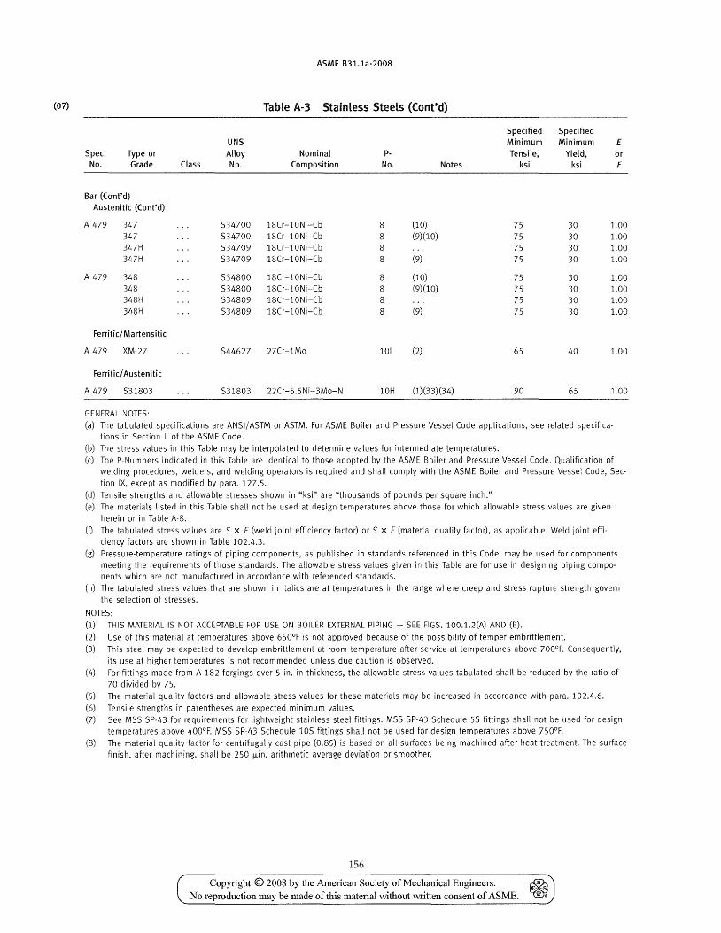
(07)
ASME B31.1a-2008
Table A-3 Stainless Steels (Cont'd)
Specified Specified UNS Minimum Minimum E
Spec. Type or Alloy Nominal p- Tensile, Yield, or No. Grade Class No. Composition No. Notes ksi ksi F
Bar (Cont'd) Austenitic (Cont'd)
A 479 347 534700 18Cr-10Ni-Cb 8 (10) 75 30 1.00 347 534700 18Cr-10Ni-Cb 8 (9)(10) 75 30 1.00 347H S34709 18Cr-10Ni-Cb 8 75 30 1.00 347H 534709 18Cr-10Ni-Cb 8 (9) 75 30 1.00
A 479 348 534800 18Cr-l0Ni-Cb 8 (10) 75 30 1.00 348 534800 18Cr-l0Ni-Cb 8 (9)(10) 75 30 1.00 348H 534809 18Cr-10Ni-Cb 8 75 30 1.00 348H 534809 18Cr-l0Ni-Cb 8 (9) 75 30 1.00
Ferritic/ Martensitic
A 479 XM-27 544627 27Cr-1Mo 101 (2) 65 40 1.00
Ferritic/ Austenitic
A 479 531803 531803 22Cr-5.5Ni-3Mo-N 10H (1)(33)(34) 90 65 1.00
GENERAL NOTES:
(a) The tabulated specifications are ANSI/ASTM or ASTM. For ASME Boiler and Pressure Vessel Code applications, see related specifications in Section II of the ASME Code.
(b) The stress values in this Table may be interpolated to determine values for intermediate temperatures.
(c) The P-Numbers indicated in this Table are identical to those adopted by the ASME Boiler and Pressure Vessel Code. Qualification of welding procedures, welders, and welding operators is required and shall comply with the ASME Boiler and Pressure Vessel Code, Sec
tion IX, except as modified by para. 127.5.
(d) Tensile strengths and allowable stresses shown in "ksi" are "thousands of pounds per square inch."
(e) The materials listed in this Table shall not be used at design temperatures above those for which allowable stress values are given
herein or in Table A-S.
(t) The tabulated stress values are 5 x E (weld joint efficiency factor) or 5 x F (material quality factor), as applicable. Weld joint effi
ciency factors are shown in Table 102.4.3.
(g) Pressure-temperature ratings of piping components, as published in standards referenced in this Code, may be used for components meeting the requirements of those standards. The allowable stress values given in this Table are for use in designing piping components which are not manufactured in accordance with referenced standards.
(h) The tabulated stress values that are shown in italics are at temperatures in the range where creep and stress rupture strength govern the selection of stresses.
NOTES:
(1) THIS MATERIAL IS NOT ACCEPTABLE FOR USE ON BOILER EXTERNAL PIPING - SEE FIGS. 100.1.2(A) AND (B).
(2) Use of this material at temperatures above 650°F is not approved because of the possibility of temper embrittlement.
(3) This steel may be expected to develop embrittlement at room temperature after service at temperatures above 700°F. Consequently,
its use at higher temperatures is not recommended unless due caution is observed.
(4) For fittings made from A 182 forgings over 5 in. in thickness, the allowable stress values tabulated shall be reduced by the ratio of
70 divided by 75.
(5) The material quality factors and allowable stress values for these materials may be increased in accordance with para. 102.4.6.
(6) Tensile strengths in parentheses are expected minimum values.
(7) See MSS SP-43 for requirements for lightweight stainless steel fittings. MSS SP-43 Schedule 55 fittings shall not be used for design temperatures above 400°F. MSS SP-43 Schedule 105 fittings shall not be used for design temperatures above 750°F.
(8) The material quality factor for centrifugally cast pipe (0.85) is based on all surfaces being machined after heat treatment. The surface finish, after machining, shall be 250 l.Lin. arithmetic average deviation or smoother.
156
Copyright © 2008 by the American Society of Mechanical Engineers. ~ No reproduction may be made of this material \vithout written consent of ASME. ~
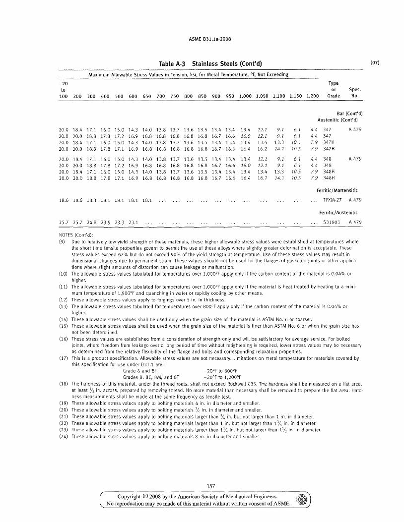
ASME B31.1a-2008
Table A-3 Stainless Steels (Cont'd)
Maximum Allowable Stress Values in Tension, ksi, for Metal Temperature, of, Not Exceeding
-20 Type to or Spec.
100 200 300 400 500 600 650 700 750 800 850 900 950 1,000 1,050 1,100 1,150 1,200 Grade No.
Bar (Cont'd) Austenitic (Cont'd)
20.0 18.4 17.1 16.0 15.0 14.3 14.0 13.S 13.7 13.6 13.5 13.4 13.4 13.4 12.1 9.1 6.1 4.4 347 A 479
20.0 20.0 lS.S 17.S 17.2 16.9 16.8 16.8 16.8 16.8 16.8 16.7 16.6 16.0 12.1 9.1 6.1 4.4 347
20.0 18.4 17.1 16.0 15.0 14.3 14.0 13.8 13.7 13.6 13.5 13.4 13.4 13.4 13.4 13.3 10.5 7.9 347H
20.0 20.0 18.8 17.8 17.1 16.9 16.8 16.8 16.8 16.8 16.8 16.7 16.6 16.4 16.2 14.1 10.5 7.9 347H
20.0 18.4 17.1 16.0 15.0 14.3 14.0 13.8 13.7 13.6 13.5 13.4 13.4 13.4 12.1 9.1 6.1 4.4 348 A 479
20.0 20.0 18.S 17.8 17.2 16.9 16.S 16.S 16.S 16.8 16.8 16.7 16.6 16.0 12.1 9.1 6.1 4.4 348
20.0 18.4 17.1 16.0 15.0 14.3 14.0 13.8 13.7 13.6 13.5 13.4 13.4 13.4 13.4 13.3 10.5 7.9 348H
20.0 20.0 18.8 17.8 17.1 16.9 16.8 16.8 16.8 16.S 16.8 16.7 16.6 16.4 16.2 14.1 10.5 7.9 348H
Ferriti c/ Martensitic
18.6 18.6 18.3 18.1 lS.l lS.1 lS.1 . " TPXM-27 A 479
Ferriticj Austenitic
25.7 25.7 24.8 23.9 23.3 23.1 531803 A 479
NOTES (Cant' d):
(9) Due to relatively low yield strength of these materials, these higher allowable stress values were established at temperatures where the short time tensile properties govern to permit the use of these alloys where slightly greater deformation is acceptable. These stress values exceed 67% but do not exceed 90% of the yield strength at temperature. Use of these stress values may result in dimensional changes due to permanent strain. These values should not be used for the flanges of gasketed joints or other applications where slight amounts of distortion can cause leakage or malfunction.
(10) The allowable stress values tabulated for temperatures over 1,000°F apply only if the carbon content of the material is 0.04% or higher.
(11) The allowable stress values tabulated for temperatures over 1,000oF apply only if the material is heat treated by heating to a minimum temperature of 1,900°F and quenching in water or rapidly cooUng by other means.
(12) These allowable stress values apply to forgings over 5 in. in thickness.
(13) The allowable stress values tabulated for temperatures over SOOoF apply only if the carbon content of the material is 0.04% or higher.
(14) These allowable stress values shall be used only when the grain size of the material is ASTM No.6 or coarser.
(15) These allowable stress values shall be used when the grain size of the material is finer than ASTM No.6 or when the grain size has not been determined.
(16) These stress values are established from a consideration of strength only and will be satisfactory for average service. For bolted joints, where freedom from leakage over a long period of time without retightening is required, lower stress values may be necessary as determined from the relative flexibility of the flange and bolts and corresponding relaxation properties.
(17) This is a product specification. Allowable stress values are not necessary. Limitations on metal temperature for materials covered by this specification for use under 831.1 are:
Grade 6 and 8F -20°F to 800°F Grades 8, 8(, 8M, and ST -20°F to 1,200°F
(18) The hardness of this material, under the thread roots, shall not exceed Rockwell C35. The hardness shall be measured on a flat area, at least % in. across, prepared by removing thread. No more material than necessary shall be removed to prepare the flat area. Hardness measurements shall be made at the same frequency as tensile test.
(19) These allowable stress values apply to bolting materials 4 in. in diameter and smaller.
(20) These allowable stress values apply to bolting materials 3/, in. in diameter and smaller.
(21) These allowable stress values apply to bolting materials larger than 3/, in. but not larger than 1 in. in diameter.
(22) These allowable stress values apply to bolting materials larger than 1 in. but not larger than 1 Yt, in. in diameter. (23) These allowable stress values apply to bolting materials larger than IVt. in. but not larger than 11/2 in. in diameter.
(24) These allowable stress values apply to bolting materials 8 in. in diameter and smaller.
157
Copyright © 2008 by the American Society of Mechanical Engineers. ~ No reproduction may be made oftbis material \vithout written consent of ASME. ~
(07)
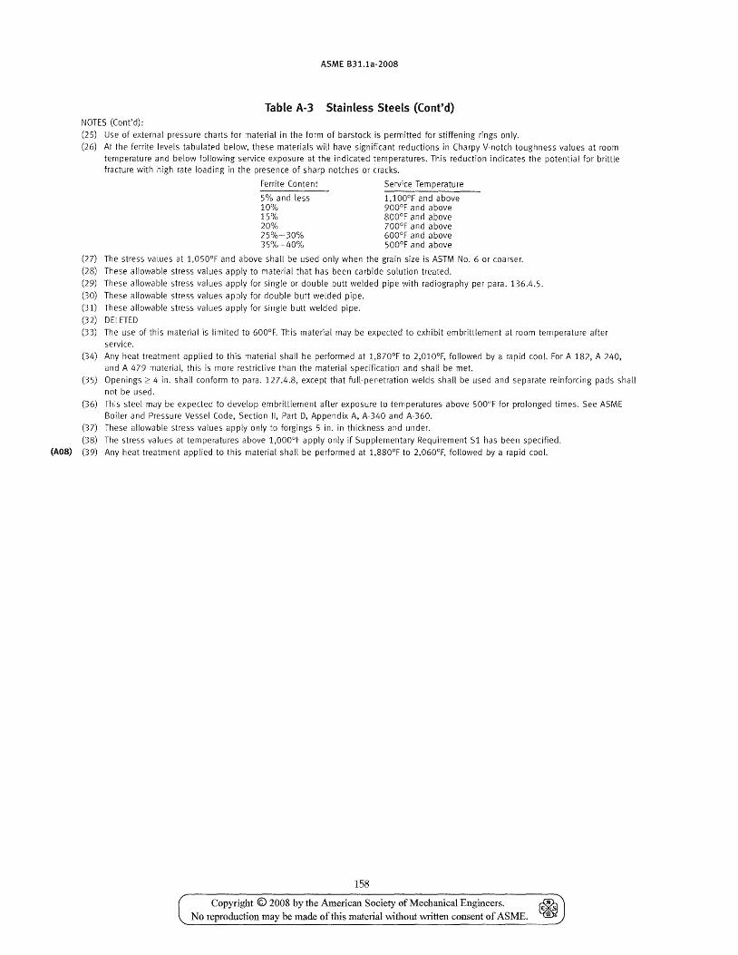
(A08)
ASME B31.1a-2008
Table A-3 Stainless SteeLs (Cont'd) NOTES (Cont'd):
(25) Use of external pressure charts for material in the form of barstock is permitted for stiffening rings only.
(26) At the ferrite levels tabulated below, these materials will have significant reductions in Charpy V-notch toughness values at room temperature and below following service exposure at the indicated temperatures. This reduction indicates the potential for brittle fracture with high rate loading in the presence of sharp notches or cracks.
(27)
(28) (29)
(30)
(31)
(32)
(33)
(34)
(35)
(36)
(37)
(38)
(39)
Ferrite Content Service Temperature
5% and less 1,100°F and above 10% 900°F and above 15% 800°F and above 20% 700°F and above 25%-30% 600°F and above 35%-40% 500°F and above
The stress values at 1,050°F and above shall be used only when the grain size is ASTM No.6 or coarser.
These allowable stress values apply to material that has been carbide solution treated.
These allowable stress values apply for single or double butt welded pipe with radiography per para. 136.4.5.
These allowable stress values apply for double butt welded pipe.
These allowable stress values apply for single butt welded pipe.
DELETED
The use of this material is limited to 600°F. This material may be expected to exhibit embrittlement at room temperature after service.
Any heat treatment applied to this material shall be performed at 1,870oF to 2,010cF, followed by a rapid cool. For A 182, A 240, and A 479 material, this is more restrictive than the material specification and shall be met.
Openings 2:": 4 in. shall conform to para. 127.4.8, except that full-penetration welds shall be used and separate reinforcing pads shall not be used.
This steel may be expected to develop embrittlement after exposure to temperatures above 500°F for prolonged times. See ASME Boiler and Pressure Vessel Code, Section II, Part D, Appendix A, A-340 and A-360.
These allowable stress values apply only to forgings 5 in. in thickness and under.
The stress values at temperatures above 1,OOooF apply only if Supplementary Requirement S1 has been specified.
Any heat treatment applied to this material shall be performed at 1,880°F to 2,060°F, followed by a rapid cool.
158
Copyright © 2008 by the American Society of Mechanical Engineers. ~ C','S
No reproduction may be made of this material without written consent of ASME. ill ..
ASME B31.1a-2008
Table A-4 begins on the next page.
159
Copyright © 2008 by the American Society of Mechanical Engineers. ~ No reproduction may be made of this matelial without written consent of ASME. ~
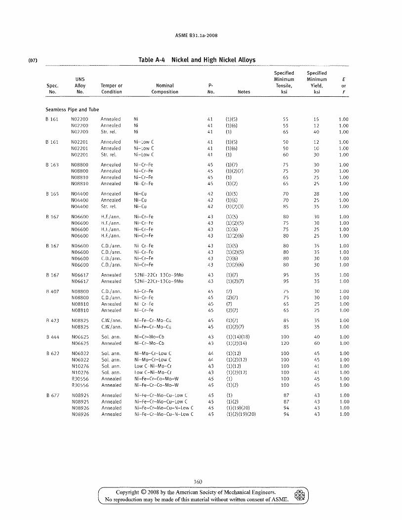
ASME B31.1a-2008
(07) Table A-4 Nickel and High Nickel Alloys
Specified Specified UNS Minimum Minimum E
Spec. Alloy Temper or Nominal p. Tensile, Yield, or No. No. Condition Composition No. Notes ksi ksi F
Seamless Pipe and Tube
B 161 N02200 Annealed Ni 41 (1)(5) 55 15 1.00 N02200 Annealed Ni 41 (1)(6) 55 12 1.00 N02200 Str. reI. Ni 41 (1) 65 40 1.00
B 161 N02201 Annealed Ni-Low C 41 (1)(5) 50 12 1.00 N02201 Annealed Ni-Low C 41 (1)(6) 50 10 1.00 N02201 Str. reI. Ni-Low C 41 (1) 60 30 1.00
B 163 N08800 Annealed Ni-Cr-Fe 45 (1)(7) 75 30 1.00 N08800 Annealed Ni-Cr-Fe 45 (1)(2)(7) 75 30 1.00 N08810 Annealed Ni-Cr-Fe 45 (1) 65 25 1.00 N08810 Annealed Ni-Cr-Fe 45 (1)(2) 65 25 1.00
B 165 N04400 Annealed Ni-Cu 42 (1)(5) 70 28 1.00 N04400 Annealed Ni-Cu 42 (1)(6) 70 25 1.00 N04400 Str. reI. Ni-Cu 42 (1) (2) (3) 85 35 1.00
B 167 N06600 H.F./ann. Ni-Cr-Fe 43 (1)(5) 80 30 1.00 N06600 H.F./ann. Ni-Cr-Fe 43 (1)(2)(5) 75 30 1.00 N06600 H.F./ann. Ni-Cr-Fe 43 (1)(6) 75 25 1.00 N06600 H.F./ann. Ni-Cr-Fe 43 (1)(2)(6) 80 25 1.00
B 167 N06600 C.O'/al1l1. Ni-Cr-Fe 43 (1) (5) 80 35 1.00 N06600 C.O./ann. Ni-Cr-Fe 43 (1) (2) (5) 80 35 1.00 N06600 C.O./ann. Ni-Cr-Fe 43 (1)(6) 80 30 1.00 N06600 C.D./ann. Ni-Cr-Fe 43 (1)(2)(6) 80 30 1.00
B 167 N06617 Annealed 52 Ni-22Cr-13Co-9Mo 43 (1)(7) 95 35 1.00 N06617 Annealed 52 Ni-22Cr-13Co-9Mo 43 (1) (2) (7) 95 35 1.00
B 407 N08800 C.O./ann. Ni-Cr-Fe 45 (7) 75 30 1.00 N08800 C.O./ann. Ni-Cr-Fe 45 (2) (7) 75 30 1.00 N08S10 Annealed Ni-Cr-Fe 45 (7) 65 25 1.00 N08810 Annealed Ni-Cr-Fe 45 (2) (7) 65 25 1.00
B 423 N08825 c.w./ann. Ni-Fe-Cr-Mo-Cu 45 (1)(7) 85 35 1.00 N08825 C.W./ann. Ni-Fe-Cr-Mo-Cu 45 (1)(2)(7) 85 35 1.00
B 444 N06625 Sol. ann. Ni-Cr-Mo-Cb 43 (1)(14)(18) 100 40 1.00 N06625 Annealed Ni-Cr-Mo-Cb 43 (1) (2) (14) 120 60 1.00
B622 N06022 Sol. ann. Ni-Mo-Cr-Low C 44 (1)(12) 100 45 1.00 N06022 Sol. ann. Ni-Mo-Cr-Low C 44 (1) (2) (12) 100 45 1.00 NI0276 Sol. ann. Low C-Ni-Mo-Cr 43 (1) (12) 100 41 1.00 NI0276 Sol. ann. Low C-Ni-Mo-Cr 43 (1)(2)(12) 100 41 1.00 R30556 Annealed Ni-Fe-Cr-Co-Mo-W 45 (1) 100 45 1.00 R30556 Annealed Ni-Fe-Cr-Co-Mo-W 45 (1)(2) 100 45 1.00
B677 N08925 Annealed Ni-Fe-Cr-Mo-Cu-Low C 45 (1) 87 43 1.00 N08925 Annealed Ni-Fe-Cr-Mo-Cu-Low C 45 (1)(2) 87 43 1.00 N08926 Annealed Ni-Fe-Cr-Mo-Cu-N-Low C 45 (1)(19)(20) 94 43 1.00 N08926 Annealed Ni-Fe-Cr-Mo-Cu-N-Low C 45 (1) (2) (19)(20) 94 43 1.00
160
Copyright © 2008 by the American Society of Mechanical Engineers. No reproduction may be made of this material without written consent of ASME.
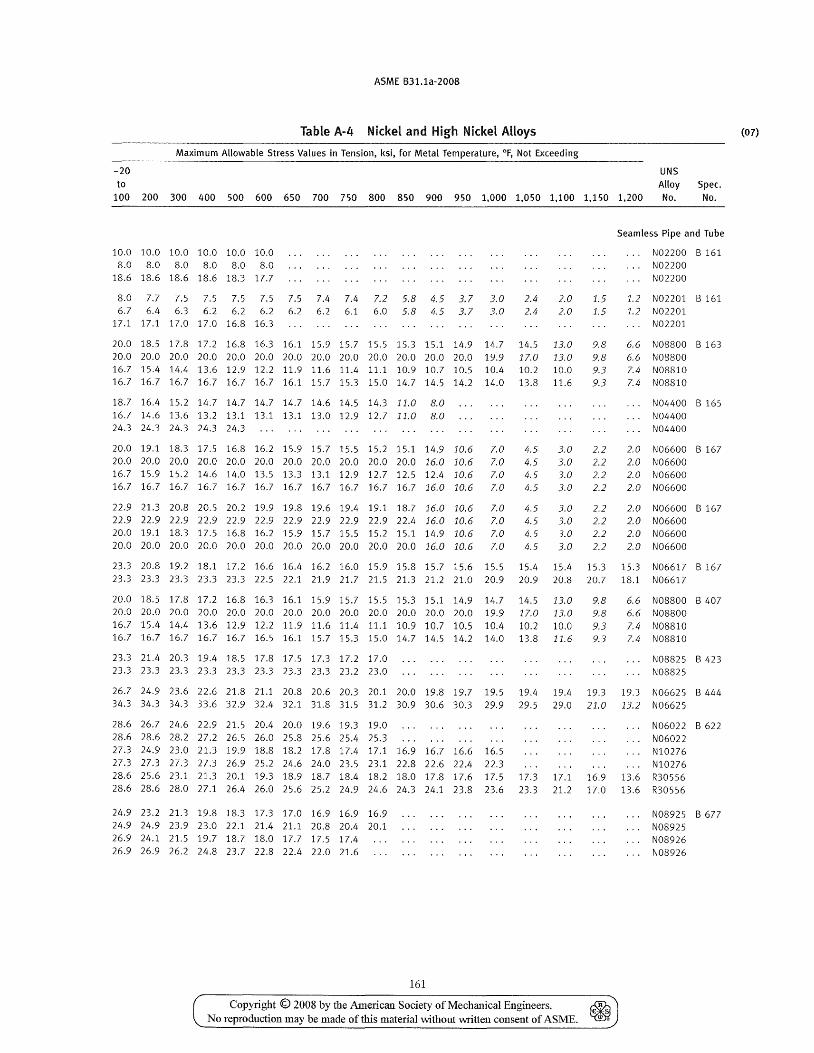
ASME B31.1a-2008
Table A-4 Nickel and High Nickel Alloys
Maximum Allowable Stress Values in Tension, ksi, for Metal Temperature, of, Not Exceeding
-20 UNS to Alloy Spec.
100 200 300 400 500 600 650 700 750 800 850 900 950 1,000 1,050 1,100 1,150 1,200 No. No.
10.0 10.0 10.0 10.0 10.0 10.0 8.0 8.0 8.0 8.0 8.0 8.0
18.6 18.6 18.6 18.6 18.3 17.7
8.0 7.7 7.5 7.5 7.5 7.5 7.5 7.4 7.4 7.2 5.8 4.5 3.7 3.0 6.7 6.4 6.3 6.2 6.2 6.2 6.2 6.2 6.1 6.0 5.8 4.5 3.7 3.0
17.1 17.1 17.0 17.0 16.8 16.3
2.4 2.4
2.0 2.0
1.5 1.5
20.0 18.5 17.8 17.2 16.8 16.3 16.1 15.9 15.7 15.5 15.3 15.1 14.9 14.7 14.5 13.0 9.8 20.0 20.0 20.0 20.0 20.0 20.0 20.0 20.0 20.0 20.0 20.0 20.0 20.0 19.9 17.0 13.0 9.8 16.7 15.4 14.4 13.6 12.9 12.2 11.9 11.6 11.4 11.1 10.9 10.7 10.5 10.4 10.2 10.0 9.3 16.7 16.7 16.7 16.7 16.7 16.7 16.1 15.7 15.3 15.0 14.7 14.5 14.2 14.0 13.8 11.6 9.3
18.7 16.4 15.2 14.7 14.7 14.7 14.7 14.6 14.5 14.3 11.0 8.0 16.7 14.6 13.6 13.2 13.1 13.1 13.1 13.0 12.9 12.7 11.0 8.0 24.3 24.3 24.3 24.3 24.3
20.0 19.1 18.3 17.5 16.8 16.2 15.9 15.7 15.5 15.2 15.1 14.9 10.6 7.0 4.5 3.0 20.0 20.0 20.0 20.0 20.0 20.0 20.0 20.0 20.0 20.0 20.0 16.0 10.6 7.0 4.5 3.0 16.7 15.9 15.2 14.6 14.0 13.5 13.3 13.1 12.9 12.7 12.5 12.4 10.6 7.0 4.5 3.0 16.7 16.7 16.7 16.7 16.7 16.7 16.7 16.7 16.7 16.7 16.7 16.0 10.6 7.0 4.5 3.0
22.9 21.3 20.8 20.5 20.2 19.9 19.8 19.6 19.4 19.1 18.7 16.0 10.6 7.0 4.5 3.0 22.9 22.9 22.9 22.9 22.9 22.9 22.9 22.9 22.9 22.9 22.4 16.0 10.6 7.0 4.5 3.0 20.0 19.1 18.3 17.5 16.8 16.2 15.9 15.7 15.5 15.2 15.1 14.9 10.6 7.0 4.5 3.0 20.0 20.0 20.0 20.0 20.0 20.0 20.0 20.0 20.0 20.0 20.0 16.0 10.6 7.0 4.5 3.0
2.2 2.2 2.2 2.2
2.2 2.2 2.2 2.2
Seamless Pipe and Tube
N02200 B 161 N02200 N02200
1.2 N02201 B 161 1.2 N02201
N02201
6.6 N08800 B 163 6.6 N08800 7.4 N08810 7.4 N08810
N04400 B 165 N04400 N04400
2.0 N06600 B 167 2.0 N06600 2.0 N06600 2.0 N06600
2.0 N06600 B 167 2.0 N06600 2.0 N06600 2.0 N06600
23.3 20.8 19.2 18.1 17.2 16.6 16.4 16.2 16.0 15.9 15.8 15.7 15.6 15.5 15.4 15.4 15.3 15.3 N06617 B 167 23.3 23.3 23.3 23.3 23.3 22.5 22.1 21.9 21.7 21.5 21.3 21.2 21.0 20.9 20.9 20.8 20.7 18.1 N06617
20.0 18.5 17.8 17.2 16.8 16.3 16.1 15.9 15.7 15.5 15.3 15.1 14.9 14.7 14.5 13.0 9.8 20.0 20.0 20.0 20.0 20.0 20.0 20.0 20.0 20.0 20.0 20.0 20.0 20.0 19.9 17.0 13.0 9.8 16.7 15.4 14.4 13.6 12.9 12.2 11.9 11.6 11.4 11.1 10.9 10.7 10.5 10.4 10.2 10.0 9.3 16.7 16.7 16.7 16.7 16.7 16.5 16.1 15.7 15.3 15.0 14.7 14.5 14.2 14.0 13.8 11.6 9.3
23.3 21.4 20.3 19.4 18.5 17.8 17.5 17.3 17.2 17.0 23.3 23.3 23.3 23.3 23.3 23.3 23.3 23.3 23.2 23.0
6.6 N08800 B 407 6.6 N08800 7.4 N08810 7.4 N08810
N08825 B 423 N08825
26.7 24.9 23.6 22.6 21.8 21.1 20.8 20.6 20.3 20.1 20.0 19.8 19.7 19.5 19.4 19.4 19.3 19.3 N06625 B 444 34.3 34.3 34.3 33.6 32.9 32.4 32.1 31.8 31.5 31.2 30.9 30.6 30.3 29.9 29.5 29.0 21.0 13.2 N06625
28.6 26.7 24.6 22.9 21.5 20.4 20.0 19.6 19.3 19.0 28.6 28.6 28.2 27.2 26.5 26.0 25.8 25.6 25.4 25.3 27.3 24.9 23.0 21.3 19.9 18.8 18.2 17.8 17.4 17.1 16.9 16.7 16.6 16.5 27.3 27.3 27.3 27.3 26.9 25.2 24.6 24.0 23.5 23.1 22.8 22.6 22.4 22.3
N06022 B 622 N06022 NI0276 NI0276
28.6 25.6 23.1 21.3 20.1 19.3 18.9 18.7 18.4 18.2 18.0 17.8 17.6 17.5 17.3 17.1 16.9 13.6 R30556 28.6 28.6 28.0 27.1 26.4 26.0 25.6 25.2 24.9 24.6 24.3 24.1 23.8 23.6 23.3 21.2 17.0 13.6 R30556
24.9 23.2 21.3 19.8 18.3 17.3 17.0 16.9 16.9 16.9 24.9 24.9 23.9 23.0 22.1 21.4 21.1 20.8 20.4 20.1 26.9 24.1 21.5 19.7 18.7 18.0 17.7 17.5 17.4 26.9 26.9 26.2 24.8 23.7 22.8 22.4 22.0 21.6
161
Copyright © 2008 by the American Society of Mechanical Engineers. ~ No reproduction may be made of this material without written consent of ASME. ~
N08925 B 677 N08925 N08926 N08926
(07)
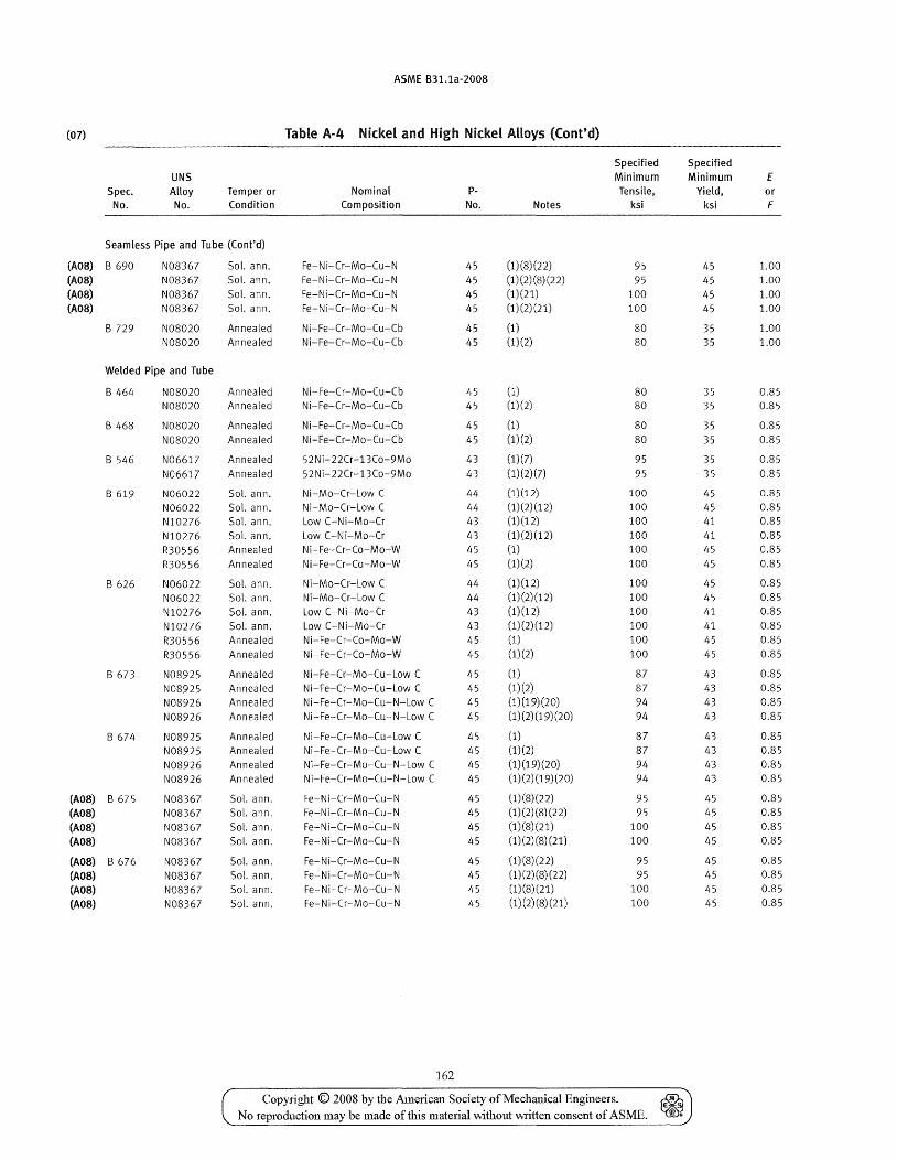
ASME B31.1a-2008
(07) Table A-4 Nickel and High Nickel Alloys (Cont'd)
Specified Specified UNS Minimum Minimum E
Spec. Alloy Temper or Nominal P- Tensile, Yield. or No. No. Condition Composition No. Notes ksi ksi F
Seamless Pipe and Tube (Cont'd)
(A08) B 690 N08367 Sol. ann. Fe-Ni-Cr-Mo-Cu-N 45 (1) (8) (2 2) 95 45 1.00 (A08) N08367 Sol. ann. Fe-Ni-Cr-Mo-Cu-N 45 (1) (2) (8)(22) 95 45 1.00 (A08) N08367 Sol. ann. Fe-N i-Cr-Mo-Cu- N 45 (1)(21) 100 45 1.00 (AOS) N08367 Sol. ann. Fe-Ni-Cr-Mo-Cu-N 45 (1)(2)(21) 100 45 1.00
B 729 NOS020 Annealed Ni-Fe-Cr-Mo-Cu-Cb 45 (1) 80 35 1.00 NOS020 Annealed Ni-Fe-Cr-Mo-Cu-Cb 45 (1)(2) 80 35 1.00
Welded Pipe and Tube
B 464 N08020 Annealed Ni-Fe-Cr-Mo-Cu-Cb 45 (1) 80 35 0.85 N08020 Annealed Ni-Fe-Cr-Mo-Cu-Cb 45 (1)(2) 80 35 0.85
B 468 N08020 Annealed Ni-Fe-Cr-Mo-Cu-Cb 45 (1) 80 35 0.85 N08020 Annealed Ni-Fe-Cr-Mo-Cu-Cb 45 (1)(2) 80 35 0.85
8 546 N06617 Annealed 52Ni-22Cr-13Co-9Mo 43 (1)(7) 95 35 0.85
N06617 Annealed 52 Ni- 22Cr-13Co-9Mo 43 (1)(2)(7) 95 35 0.S5
B 619 N06022 Sol. ann. Ni-Mo-Cr-Low C 44 (1)(12) 100 45 0.85
N06022 Sol. ann. Ni-Mo-Cr-Low C 44 (1) (2) (12) 100 45 0.85 NI0276 Sol. ann. Low C-Ni-Mo-Cr 43 (1)(12) 100 41 0.85
NI0276 Sol. ann. Low C-Ni-Mo-Cr 43 (1)(2)(12) 100 41 0.85
R30556 Annealed Ni-Fe-Cr-Co-Mo-W 45 (1) 100 45 0.85
R30556 Annealed Ni-Fe-Cr-Co-Mo-W 45 (1)(2) 100 45 0.85
B 626 N06022 Sol. ann. Ni-Mo-Cr-Low C 44 (1) (12) 100 45 0.85 N06022 Sol. ann. Ni-Mo-Cr-Low C 44 (1)(2)(12) 100 45 0.85
NI0276 Sol. ann. Low C-Ni-Mo-Cr 43 (1)(12) 100 41 0.85
NI0276 Sol. ann. Low C-Ni-Mo-Cr 43 (1)(2)(12) 100 41 0.S5
R30556 Annealed Ni-Fe-Cr-Co-Mo-W 45 (1) 100 45 0.85
R30556 Annealed Ni-Fe-Cr-Co-Mo-W 45 (1)(2) 100 45 0.85
8673 NOS925 Annealed Ni-Fe-Cr-Mo-Cu-Low C 45 (1) 87 43 0.85
N08925 Annealed Ni-Fe-Cr-Mo-Cu-Low C 45 (1)(2) 87 43 0.85 N08926 Annealed Ni-Fe-Cr-Mo-Cu-N-Low C 45 (1)(19)(20) 94 43 0.S5 N08926 Annealed Ni-Fe-Cr-Mo-Cu-N-Low C 45 (1)(2)(19)(20) 94 43 0.85
B 674 N08925 Annealed Ni-Fe-Cr-Mo-Cu-Low C 45 (1) S7 43 0.85 N08925 Annealed Ni-Fe-Cr-Mo-Cu-Low C 45 (1)(2) 87 43 0.85
N08926 Annealed Ni-Fe-Cr-Mo-Cu-N-Low C 45 (1)(19)(20) 94 43 0.85 N08926 Annealed Ni-Fe-Cr-Mo-Cu-N-Low C 45 (1)(2)(19)(20) 94 43 0.85
(AOS) B 675 N08367 Sol. ann. Fe-Ni-Cr-Mo-Cu-N 45 (1)(8)(22) 95 45 0.85
(AOS) N08367 Sol. ann. Fe-Ni-Cr-Mo-Cu-N 45 (1) (2) (8) (22) 95 45 0.85
(AOS) N08367 Sol. ann. Fe-Ni-Cr-Mo-Cu-N 45 (1)(8)(21) 100 45 0.85 (AOS) N08367 Sol. ann. Fe-Ni-Cr-Mo-Cu-N 45 (1)(2)(8)(21) 100 45 0.85
(AOS) B 676 N08367 Sol. ann. Fe-N i-Cr-Mo-Cu-N 45 (1)(8)(22) 95 45 0.85
(AOS) N08367 Sol. ann. Fe-N i-Cr-Mo-Cu-N 45 (1) (2) (8) (2 2) 95 45 0.85
(AOS) N08367 Sol. ann. Fe-Ni-Cr-Mo-Cu-N 45 (1)(8)(21) 100 45 0.85
(AOS) N08367 Sol. ann. Fe- N i-Cr-Mo-Cu-N 45 (1)(2) (8) (21) 100 45 0.85
162
Copyright © 2008 by the American Society of Mechanical Engineers. No reproduction may be made of this material without written consent of ASME.
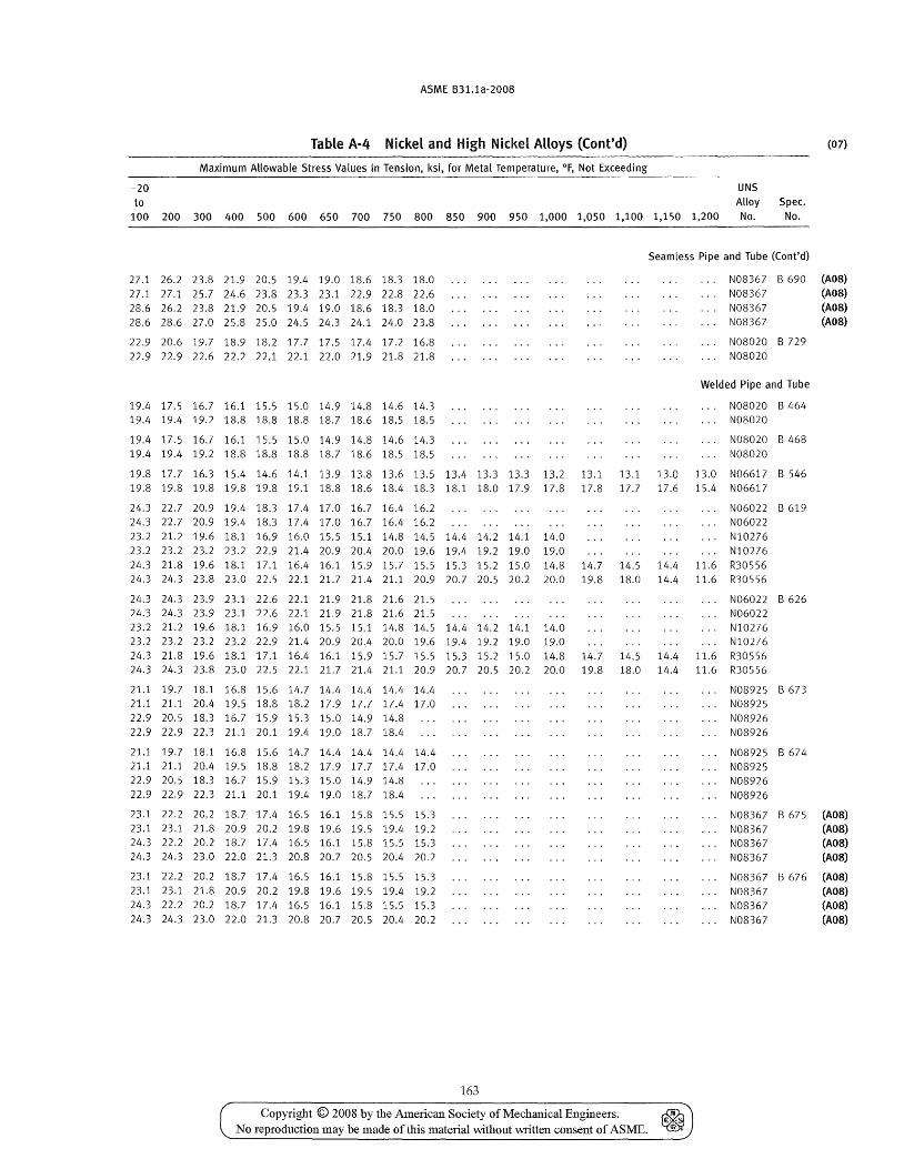
ASME B31.1a-2008
Table A-4 Nickel and High Nickel Alloys (Cont'd) (07)
Maximum Allowable Stress Values in Tension, ksi, for Metal Temperature, of, Not Exceeding
-20 UNS to Alloy Spec.
100 200 300 400 500 600 650 700 750 800 850 900 950 1,000 1,050 1,100 1,150 1,200 No. No.
27.1 26.2 23.8 21.9 20.5 19.4 19.0 18.6 18.3 18.0 27.1 27.1 25.7 24.6 23.8 23.3 23.1 22.9 22.8 22.6 28.6 26.2 23.8 21.9 20.5 19.4 19.0 18.6 lS.3 18.0 28.6 2S.6 27.0 25.8 25.0 24.5 24.3 24.1 24.0 23.S
Seamless Pipe and Tube (Cont'd)
N08367 B 690 (ADS)
22.9 20.6 19.7 IS.9 lS.2 17.7 17.5 17.4 17.2 16.S 22.9 22.9 22.6 22.2 22.1 22.1 22.0 21.9 21.S 21.S
19.4 17.5 16.7 16.1 15.5 15.0 14.9 14.8 14.6 14.3 19.4 19.4 19.2 lS.S 18.8 18.S 18.7 18.6 18.5 18.5
19.4 17.5 16.7 16.1 15.5 15.0 14.9 14.8 14.6 14.3 19.4 19.4 19.2 18.8 18.S 18.8 18.7 18.6 lS.5 18.5
19.8 17.7 16.3 15.4 14.6 14.1 13.9 13.S 13.6 13.5 13.4 13.3 13.3 13.2 13.1 13.1 13.0 19.8 19.8 19.8 19.8 19.5 19.1 18.8 18.6 18.4 18.3 18.1 18.0 17.9 17.8 17.8 17.7 17.6
24.3 22.7 20.9 19.4 18.3 17.4 17.0 16.7 16.4 16.2 24.3 22.7 20.9 19.4 lS.3 17.4 17.0 16.7 16.4 16.2 23.2 21.2 19.6 18.1 16.9 16.0 15.5 15.1 14.8 14.5 14.4 14.2 14.1 14.0 23.2 23.2 23.2 23.2 22.9 21.4 20.9 20.4 20.0 19.6 19.4 19.2 19.0 19.0 24.3 21.8 19.6 18.1 17.1 16.4 16.1 15.9 15.7 15.5 15.3 15.2 15.0 14.8 14.7 14.5 14.4 24.3 24.3 23.8 23.0 22.5 22.1 21.7 21.4 21.1 20.9 20.7 20.5 20.2 20.0 19.8 18.0 14.4
24.3 24.3 23.9 23.1 22.6 22.1 21.9 21.8 21.6 21.5
N08367 (ADS) NOS367 (AOS) NOS367 (AOS)
NOS020 B 729 NOS020
Welded Pipe and Tube
N08020 B 464 N08020
N08020 B 468 N08020
13.0 N06617 B 546 15.4 N06617
N060n B 619 N06022 NI0276 N10276
11.6 R30556 11.6 R30556
N06022 B 626 24.3 24.3 23.9 23.1 22.6 22.1 21.9 21.8 21.6 21.5 N06022 23.2 21.2 19.6 18.1 16.9 16.0 15.5 15.1 14.8 14.5 14.4 14.2 14.1 14.0 N10276 23.2 23.2 23.2 23.2 22.9 21.4 20.9 20.4 20.0 19.6 19.4 19.2 19.0 19.0 N10276 24.3 21.8 19.6 18.1 17.1 16.4 16.1 15.9 15.7 15.5 15.3 15.2 15.0 14.8 14.7 14.5 14.4 11.6 R30556 24.3 24.3 23.8 23.0 22.5 22.1 21.7 21.4 21.1 20.9 20.7 20.5 20.2 20.0 19.8 18.0 14.4 11.6 R30556
21.1 19.7 18.1 16.8 15.6 14.7 14.4 14.4 14.4 14.4 21.1 21.1 20.4 19.5 18.8 18.2 17.9 17.7 17.4 17.0 22.9 20.5 18.3 16.7 15.9 15.3 15.0 14.9 14.8 22.9 22.9 22.3 21.1 20.1 19.4 19.0 18.7 18.4
21.1 19.7 18.1 16.8 15.6 14.7 14.4 14.4 14.4 14.4 21.1 21.1 20.4 19.5 lS.8 18.2 17.9 17.7 17.4 17.0 22.9 20.5 18.3 16.7 15.9 15.3 15.0 14.9 14.8 22.9 22.9 22.3 21.1 20.1 19.4 19.0 18.7 18.4
23.1 22.2 20.2 18.7 17.4 16.5 16.1 15.8 15.5 15.3 23.1 23.1 21.8 20.9 20.2 19.8 19.6 19.5 19.4 19.2 24.3 22.2 20.2 18.7 17.4 16.5 16.1 15.8 15.5 15.3 24.3 24.3 23.0 22.0 21.3 20.8 20.7 20.5 20.4 20.2
23.1 22.2 20.2 18.7 17.4 16.5 16.1 15.8 15.5 15.3 23.1 23.1 21.8 20.9 20.2 19.8 19.6 19.5 19.4 19.2 24.3 22.2 20.2 18.7 17.4 16.5 16.1 15.8 15.5 15.3 24.3 24.3 23.0 22.0 21.3 20.8 20.7 20.5 20.4 20.2
163
Copyright © 2008 by the American Society of Mechanical Engineers. ~ No reproduction may be made of this material vvithout written consent of ASME. ~
N08925 B 673 N08925 N08926 N08926
N08925 B 674 N08925 N08926 N08926
N08367 B 675 (ADS) N08367 (AOS) N08367 (ADS) NOS367 (AOS)
N08367 B 676 (AOS) N08367 (AOS) N08367 (AOS) N08367 (AOS)
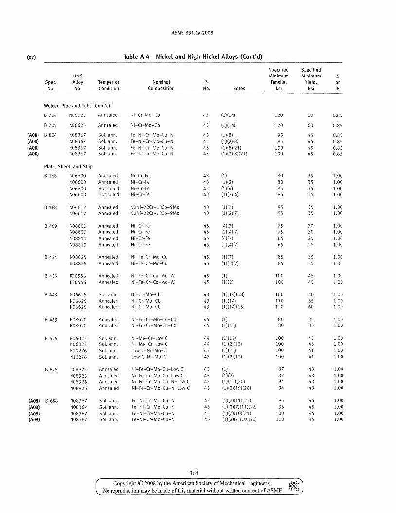
ASME B31.1a-2008
(07) Table A-4 Nickel and High Nickel Alloys (Cont'd)
Specified Specified UNS Minimum Minimum E
Spec. Alloy Temper or Nominal P- Tensile, Yield, or No. No. Condition Composition No. Notes ksi ksi F
Welded Pipe and Tube (Cont'd)
B 704 N06625 Annealed Ni-Cr-Mo-Cb 43 (1)(14) 120 60 0.85
B 705 N06625 Annealed Ni-Cr-Mo-Cb 43 (1)(14) 120 60 0.85
(AOS) B 804 N08367 Sol. ann. Fe-N i-Cr-Mo-Cu-N 45 (1)(8) 95 45 0.85 (AOS) NOS367 Sol. ann. Fe-Ni-Cr-Mo-Cu-N 45 (1) (2) (S) 95 45 0.S5 (AOS) N08367 Sol. ann. Fe-N i-Cr-M o-Cu-N 45 (1)(S)(21) 100 45 0.85 (AOS) NOS367 Sol. ann. Fe-Ni-Cr-Mo-Cu-N 45 (1)(2)(S)(21) 100 45 0.85
Plate, Sheet, and Strip
B 16S N06600 Annealed Ni-Cr-Fe 43 (1) SO 35 1.00 N06600 Annealed Ni-Cr-Fe 43 (1)(2) 80 35 1.00 N06600 Hot rolled Ni-Cr-Fe 43 (1)(4) 85 35 1.00 N06600 Hot rolled Ni-Cr-Fe 43 (1)(2)(4) 85 35 1.00
B 168 N06617 Annealed 52Ni-22Cr-13Co-9Mo 43 (1)(7) 95 35 1.00 N06617 Annealed 52Ni- 22Cr-13Co-9Mo 43 (1) (2) (7) 95 35 1.00
B 409 N08800 Annealed Ni-Cr-Fe 45 (4)(7) 75 30 1.00
N08800 Annealed Ni-Cr-Fe 45 (2)(4)(7) 75 30 1.00 N08S10 Annealed Ni-Cr-Fe 45 (4)(7) 65 25 1.00
N08810 Annealed Ni-Cr-Fe 45 (2)(4)(7) 65 25 1.00
B 424 N08825 Annealed Ni-Fe-Cr-Mo-Cu 45 (1) (7) 85 35 1.00 N08825 Annealed Ni-Fe-Cr-Mo-Cu 45 (1) (2) (7) 85 35 1.00
B 435 R30556 Annealed Ni-Fe-Cr-Co-Mo-W 45 (1) 100 45 1.00
R30556 Annealed Ni-Fe-Cr-Co-Mo-W 45 (1)(2) 100 45 1.00
B 443 N06625 Sol. ann. Ni-Cr-Mo-Cb 43 (1)(14)(18) 100 40 1.00 N06625 Annealed Ni-Cr-Mo-Cb 43 (1)(14) 110 55 1.00 N06625 Annealed Ni-Cr-Mo-Cb 43 (1)(14)(15) 120 60 1.00
B 463 N08020 Annealed Ni-Fe-Cr-Mo-Cu-Cb 45 (1) 80 35 1.00
N08020 Annealed Ni-Fe-Cr-Mo-Cu-Cb 45 (1)(12) 80 35 1.00
B 575 N06022 Sol. ann. Ni-Mo-Cr-Low C 44 (1)(12) 100 45 1.00
N06022 Sol. ann. Ni-Mo-Cr-Low C 44 (1) (2) (12) 100 45 1.00
N10276 Sol. ann. Low C-Ni-Mo-Cr 43 (1) (12) 100 41 1.00
NI0276 Sol. ann. Low C-Ni-Mo-Cr 43 (1) (2) (12) 100 41 1.00
B 625 NOS925 Annealed Ni-Fe-Cr-Mo-Cu-Low C 45 (1) 87 43 1.00
N08925 Annealed Ni-Fe-Cr-Mo-Cu-Low C 45 (1)(2) 87 43 1.00
NOS926 Annealed Ni-Fe-Cr-Mo-Cu-N-Low C 45 (1) (19) (20) 94 43 1.00
NOS926 Annealed Ni-Fe-Cr-Mo-Cu-N-Low C 45 (1) (2) (19) (20) 94 43 1.00
(AOS) B 688 N08367 Sol. ann. Fe-Ni-Cr-Mo-Cu-N 45 (1)(7)(11)(22) 95 45 1.00
(AOS) NOS367 Sol. ann. Fe-Ni-Cr-Mo-Cu-N 45 (1) (2) (7) (11) (2 2) 95 45 1.00
(AOS) N08367 Sol. ann. Fe-Ni-Cr-Mo-Cu-N 45 (1)(7)(10)(21) 100 45 1.00
(A08) N08367 Sol. ann. Fe-Ni-Cr-Mo-Cu-N 45 (1) (2) (7) (1 0) (21) 100 45 1.00
164
Copyright © 2008 by the Ame11can Society of Mechanical Engineers. ~ No reproduction may be made of this material without written consent of ASME. ~
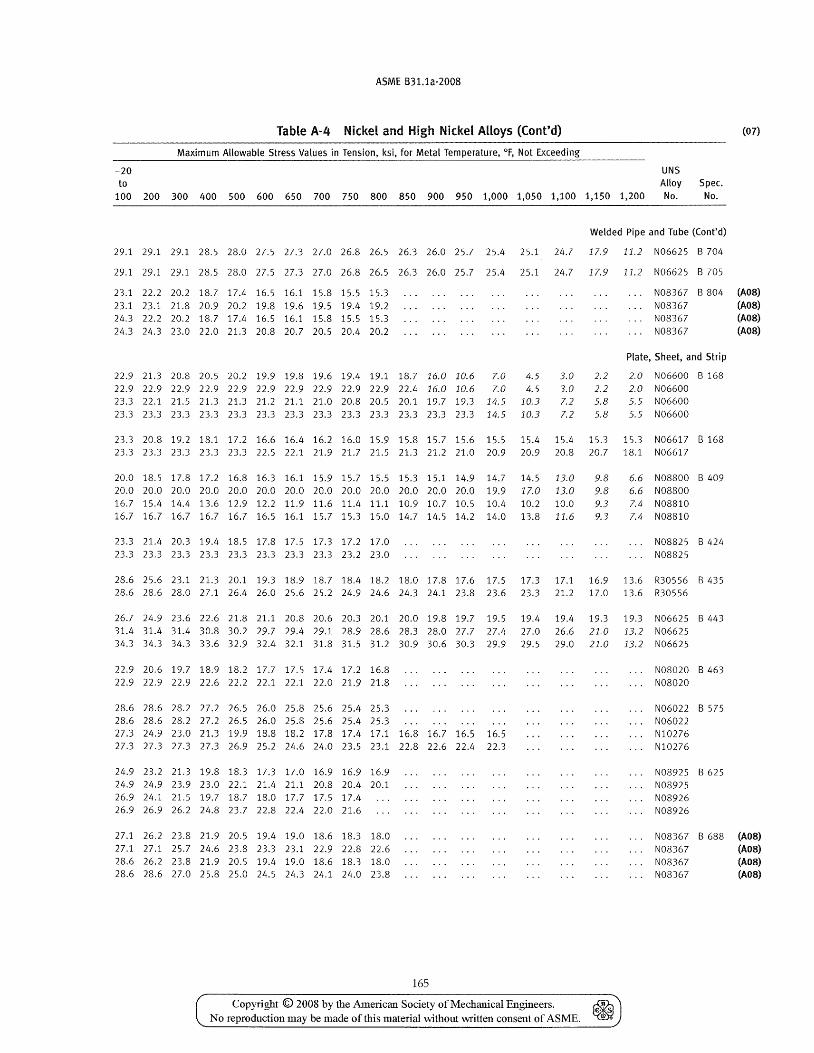
ASME B31.1a-2008
Table A-4 Nickel and High Nickel Alloys (Cont'd) (07)
Maximum Allowable Stress Values in Tension, ksi, for Metal Temperature, of, Not Exceeding
-20 UNS to Alloy Spec.
100 200 300 400 500 600 650 700 750 800 850 900 950 1,000 1,050 1,100 1,150 1,200 No. No.
Welded Pipe and Tube (Cont'd)
29.1 29.1 29.1 28.5 28.0 27.5 27.3 27.0 26.8 26.5 26.3 26.0 25.7 25.4 25.1 24.7 17.9 11.2 N06625 B 704
29.1 29.1 29.1 2S.5 2S.0 27.5 27.3 27.0 26.S 26.5 26.3 26.0 25.7 25.4 25.1 24.7 17.9 11.2 N06625 B 705
23.1 22.2 20.2 IS.7 17.4 16.5 16.1 15.S 15.5 15.3 23.1 23.1 21.S 20.9 20.2 19.5 19.6 19.5 19.4 19.2 24.3 22.2 20.2 lS.7 17.4 16.5 16.1 15.8 15.5 15.3 24.3 24.3 23.0 22.0 21.3 20.8 20.7 20.5 20.4 20.2
N08367 B S04 (AOS)
22.9 21.3 20.8 20.5 20.2 19.9 19.8 19.6 19.4 19.1 18.7 16.0 10.6 7.0 4.5 3.0 22.9 22.9 22.9 22.9 22.9 22.9 22.9 22.9 22.9 22.9 22.4 16.0 10.6 7.0 4.5 3.0 23.3 22.1 21.5 21.3 21.3 21.2 21.1 21.0 20.8 20.5 20.1 19.7 19.3 14.5 10.3 7.2 23.3 23.3 23.3 23.3 23.3 23.3 23.3 23.3 23.3 23.3 23.3 23.3 23.3 14.5 10.3 7.2
2.2 2.2 5.8 5.8
N08367 (AOS) N08367 (AOS) N08367 (A08)
Plate, Sheet, and Strip
2.0 N06600 B 168 2.0 N06600 5.5 N06600 5.5 N06600
23.3 20.8 19.2 18.1 17.2 16.6 16.4 16.2 16.0 15.9 15.8 15.7 15.6 15.5 15.4 15.4 15.3 15.3 N06617 B 168 23.3 23.3 23.3 23.3 23.3 22.5 22.1 21.9 21.7 21.5 21.3 21.2 21.0 20.9 20.9 20.8 20.7 lS.1 N06617
20.0 lS.5 17.S 17.2 16.S 16.3 16.1 15.9 15.7 15.5 15.3 15.1 14.9 14.7 14.5 13.0 9.8 6.6 N08800 B 409 20.0 20.0 20.0 20.0 20.0 20.0 20.0 20.0 20.0 20.0 20.0 20.0 20.0 19.9 17.0 13.0 9.8 6.6 N08S00 16.7 15.4 14.4 13.6 12.9 12.2 11.9 11.6 11.4 11.1 10.9 10.7 10.5 10.4 10.2 10.0 9.3 7.4 N08810 16.7 16.7 16.7 16.7 16.7 16.5 16.1 15.7 15.3 15.0 14.7 14.5 14.2 14.0 13.S 11.6 9.3 7.4 N08810
23.3 21.4 20.3 19.4 18.5 17.S 17.5 17.3 17.2 17.0 23.3 23.3 23.3 23.3 23.3 23.3 23.3 23.3 23.2 23.0
N08825 8 424 NOS825
2S.6 25.6 23.1 21.3 20.1 19.3 18.9 18.7 18.4 lS.2 18.0 17.8 17.6 17.5 17.3 17.1 16.9 13.6 R30556 8435 28.6 28.6 28.0 27.1 26.4 26.0 25.6 25.2 24.9 24.6 24.3 24.1 23.8 23.6 23.3 21.2 17.0 13.6 R30556
26.7 24.9 23.6 22.6 21.8 21.1 20.8 20.6 20.3 20.1 20.0 19.8 19.7 19.5 19.4 19.4 19.3 19.3 N06625 B 443 31.4 31.4 31.4 30.8 30.2 29.7 29.4 29.1 28.9 28.6 28.3 28.0 27.7 27.4 27.0 26.6 21.0 13.2 N06625 34.3 34.3 34.3 33.6 32.9 32.4 32.1 31.8 31.5 31.2 30.9 30.6 30.3 29.9 29.5 29.0 21.0 13.2 N06625
22.9 20.6 19.7 18.9 18.2 17.7 17.5 17.4 17.2 16.8 22.9 22.9 22.9 22.6 22.2 22.1 22.1 22.0 21.9 21.8
28.6 28.6 28.2 27.2 26.5 26.0 25.8 25.6 25.4 25.3 28.6 28.6 28.2 27.2 26.5 26.0 25.8 25.6 25.4 25.3 27.3 24.9 23.0 21.3 19.9 18.8 18.2 17.8 17.4 17.1 16.8 16.7 16.5 16.5 27.3 27.3 27.3 27.3 26.9 25.2 24.6 24.0 23.5 23.1 22.8 22.6 22.4 22.3
24.9 23.2 21.3 19.5 lS.3 17.3 17.0 16.9 16.9 16.9 24.9 24.9 23.9 23.0 22.1 21.4 21.1 20.S 20.4 20.1 26.9 24.1 21.5 19.7 lS.7 lS.0 17.7 17.5 17.4 26.9 26.9 26.2 24.S 23.7 22.S 22.4 22.0 21.6
27.1 26.2 23.8 21.9 20.5 19.4 19.0 18.6 18.3 18.0 27.1 27.1 25.7 24.6 23.8 23.3 23.1 22.9 22.8 22.6 28.6 26.2 23.8 21.9 20.5 19.4 19.0 18.6 18.3 18.0 28.6 28.6 27.0 25.8 25.0 24.5 24.3 24.1 24.0 23.8
165
Copyright © 2008 by the American Society of Mechanical Engineers. ~ No reproduction may be made of this material without written consent of ASME. ~
N08020 8 463 N08020
N06022 8 575 N06022 NI0276 NI0276
N08925 8 625 N08925 N08926 N08926
N08367 8 688 (A08) N08367 (AOS) N08367 (AOS) N08367 (AOS)
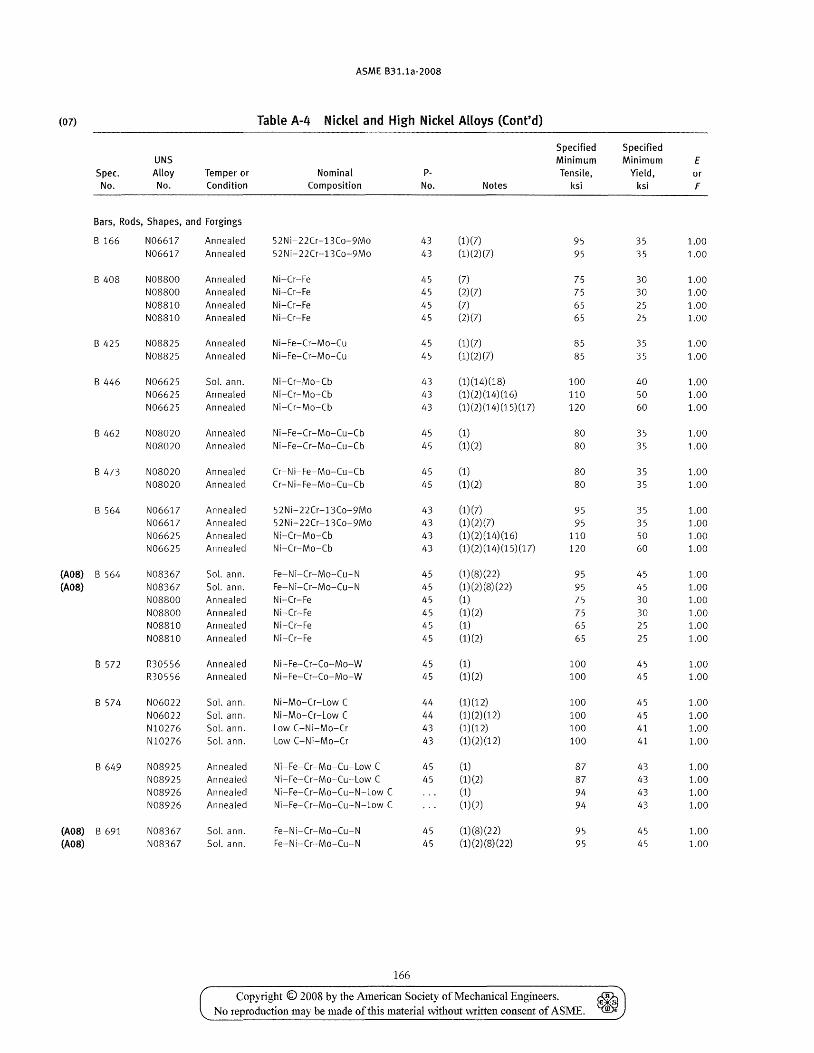
ASME B31.1a-2008
(07) Table A-4 Nickel and High Nickel Alloys (Cont'd)
Specified Specified UNS Minimum Minimum E
Spec. Alloy Temper or Nominal p- Tensile, Yield, or No. No. Condition Composition No. Notes ksi ksi F
Bars, Rods, Shapes, and Forgings
B 166 N06617 Annealed 52Ni-22Cr-13Co-9Mo 43 (1)(7) 95 35 1.00 N06617 Annealed 52Ni-22Cr-13Co-9Mo 43 (1)(2)(7) 95 35 1.00
B 408 N08800 Annealed Ni-Cr-Fe 45 (7) 75 30 1.00 N08800 Annealed Ni-Cr-Fe 45 (2) (7) 75 30 1.00 N08810 Annealed Ni-Cr-Fe 45 (7) 65 25 1.00 N08810 Annealed Ni-Cr-Fe 45 (2)(7) 65 25 1.00
B 425 N08825 Annealed Ni-Fe-Cr-Mo-Cu 45 (1)(7) 85 35 1.00 N08825 Annealed Ni-Fe-Cr-Mo-Cu 45 (1) (2) (7) 85 35 1.00
B 446 N06625 Sol. ann. Ni-Cr-Mo-Cb 43 (1)(14)(18) 100 40 1.00 N06625 Annealed Ni-Cr-Mo-Cb 43 (1)(2)(14)(16) 110 50 1.00 N06625 Annealed Ni-Cr-Mo-Cb 43 (1) (2) (14) (15) (17) 120 60 1.00
B 462 N08020 Annealed Ni-Fe-Cr-Mo-Cu-Cb 45 (1) 80 35 1.00 N08020 Annealed Ni-Fe-Cr-Mo-Cu-Cb 45 (1)(2) 80 35 1.00
B473 N08020 Annealed Cr-Ni-Fe-Mo-Cu-Cb 45 (1) 80 35 1.00 N08020 Annealed Cr-Ni-Fe-Mo-Cu-Cb 45 (1)(2) 80 35 1.00
B 564 N06617 Annealed 52Ni-22Cr-13Co-9Mo 43 (1)(7) 95 35 1.00 N06617 Annealed 52 N i- 22Cr-13Co-9Mo 43 (1)(2)(7) 95 35 1.00 N06625 Annealed Ni-Cr-Mo-Cb 43 (1)(2)(14)(16) 110 50 1.00 N06625 Annealed Ni-Cr-Mo-Cb 43 (1)(2) (14) (15) (17) 120 60 1.00
(A08) B 564 N08367 Sol. ann. Fe-Ni-Cr-Mo-Cu-N 45 (1)(8)(22) 95 45 1.00 (A08) N08367 Sol. ann. Fe-Ni-Cr-Mo-Cu-N 45 (1) (2) (8) (22) 95 45 1.00
N08800 Annealed Ni-Cr-Fe 45 (1) 75 30 1.00 N08800 Annealed Ni-Cr-Fe 45 (1) (2) 75 30 1.00 N08810 Annealed Ni-Cr-Fe 45 (1) 65 25 1.00 N08810 Annealed Ni-Cr-Fe 45 (1) (2) 65 25 1.00
B572 R30556 Annealed Ni-Fe-Cr-Co-Mo-W 45 (1) 100 45 1.00 R30556 Annealed Ni-Fe-Cr-Co-Mo-W 45 (1)(2) 100 45 1.00
B 574 N06022 Sol. ann. Ni-Mo-Cr-Low C 44 (1)(12) 100 45 1.00 N06022 Sol. ann. Ni-Mo-Cr-Low C 44 (1)(2)(12) 100 45 1.00 NI0276 Sol. ann. Low C-Ni-Mo-Cr 43 (1)(12) 100 41 1.00 NI0276 Sol. ann. Low C-Ni-Mo-Cr 43 (1)(2)(12) 100 41 1.00
B 649 N08925 Annealed Ni-Fe-Cr-Mo-Cu-Low C 45 (1) 87 43 1.00 N08925 Annealed Ni-Fe-Cr-Mo-Cu-Low C 45 (1)(2) 87 43 1.00 N08926 Annealed Ni-Fe-Cr-Mo-Cu-N-Low C (1) 94 43 1.00 N08926 Annealed Ni-Fe-Cr-Mo-Cu-N-Low C (1)(2) 94 43 1.00
(A08) B 691 N08367 Sol. ann. Fe-Ni-Cr-Mo-Cu-N 45 (1)(8)(22) 95 45 1.00 (A08) N08367 Sol. ann. Fe-Ni-Cr-Mo-Cu-N 45 (1) (2) (8) (22) 95 45 1.00
166
Copyright © 2008 by the American Society of Mechanical Engineers. ~ No reproduction may be made of this material without written consent of ASME. ~
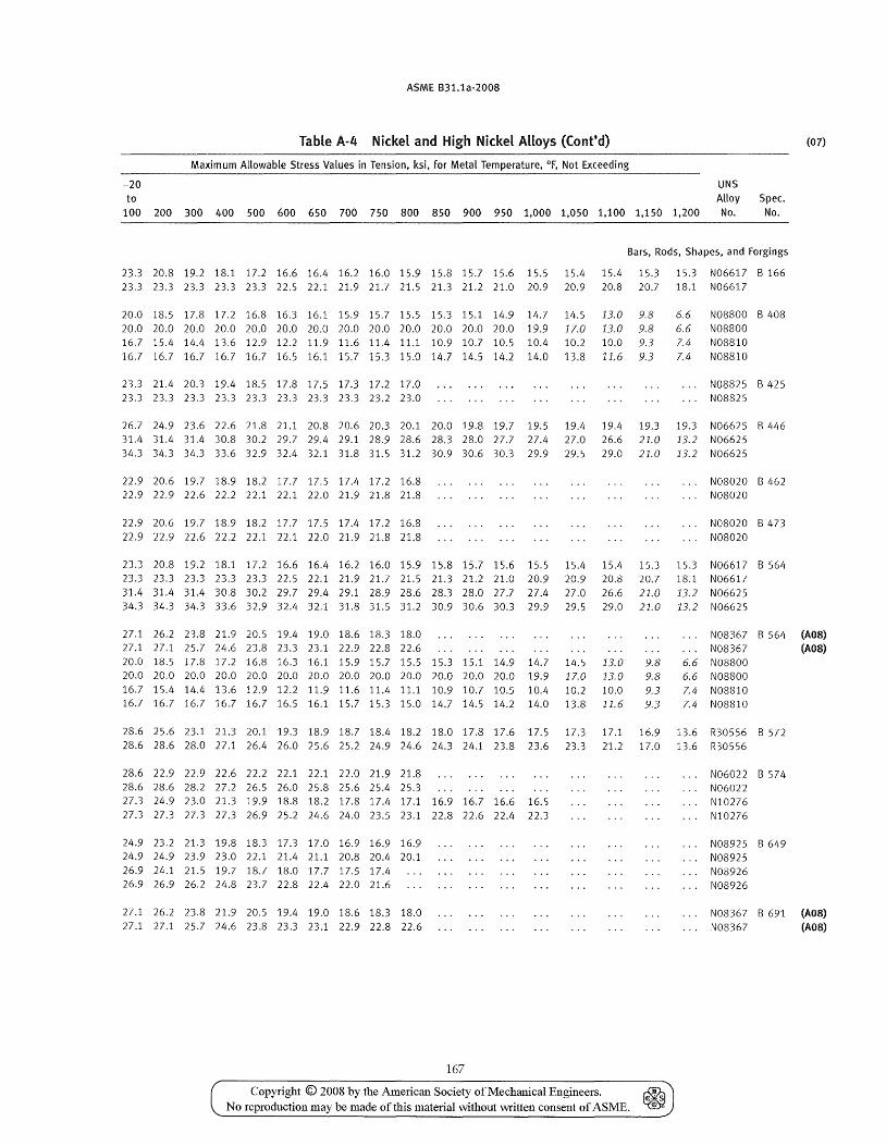
ASME B31.1a-2008
Table A-4 Nickel and High Nickel Alloys (Cont'd)
Maximum Allowable Stress Values in Tension, ksi, for Metal Temperature, of, Not Exceeding
-20 UNS to Alloy Spec.
100 200 300 400 500 600 650 700 750 800 850 900 950 1,000 1,050 1,100 1,150 1,200 No. No.
Bars, Rods, Shapes, and Forgings
23.3 20.8 19.2 18.1 17.2 16.6 16.4 16.2 16.0 15.9 15.8 15.7 15.6 15.5 15.4 15.4 15.3 15.3 N06617 B 166 23.3 23.3 23.3 23.3 23.3 22.5 22.1 21.9 21.7 21.5 21.3 21.2 21.0 20.9 20.9 20.8 20.7 18.1 N06617
20.0 18.5 17.8 17.2 16.8 16.3 16.1 15.9 15.7 15.5 15.3 15.1 14.9 14.7 14.5 13.0 9.8 6.6 N08800 B 40S 20.0 20.0 20.0 20.0 20.0 20.0 20.0 20.0 20.0 20.0 20.0 20.0 20.0 19.9 17.0 13.0 9.8 6.6 N08800 16.7 15.4 14.4 13.6 12.9 12.2 11.9 11.6 11.4 11.1 10.9 10.7 10.5 10.4 10.2 10.0 9.3 7.4 NOS810 16.7 16.7 16.7 16.7 16.7 16.5 16.1 15.7 15.3 15.0 14.7 14.5 14.2 14.0 13.8 11.6 9.3 7.4 N08810
23.3 21.4 20.3 19.4 18.5 17.8 17.5 17.3 17.2 17.0 23.3 23.3 23.3 23.3 23.3 23.3 23.3 23.3 23.2 23.0
N08825 B 425 N08S25
26.7 24.9 23.6 22.6 21.S 21.1 20.S 20.6 20.3 20.1 20.0 19.5 19.7 19.5 19.4 19.4 19.3 19.3 N06625 B 446 31.4 31.4 31.4 30.8 30.2 29.7 29.4 29.1 28.9 28.6 28.3 28.0 27.7 27.4 27.0 26.6 21.0 13.2 N06625 34.3 34.3 34.3 33.6 32.9 32.4 32.1 31.8 31.5 31.2 30.9 30.6 30.3 29.9 29.5 29.0 21.0 13.2 N06625
22.9 20.6 19.7 18.9 18.2 17.7 17.5 17.4 17.2 16.8 22.9 22.9 22.6 22.2 22.1 22.1 22.0 21.9 21.8 21.8
22.9 20.6 19.7 18.9 18.2 17.7 17.5 17.4 17.2 16.8 22.9 22.9 22.6 22.2 22.1 22.1 22.0 21.9 21.8 21.8
N08020 B 462 N08020
NOS020 B 473 N08020
23.3 20.8 19.2 18.1 17.2 16.6 16.4 16.2 16.0 15.9 15.8 15.7 15.6 15.5 15.4 15.4 15.3 15.3 N06617 B 564 23.3 23.3 23.3 23.3 23.3 22.5 22.1 21.9 21.7 21.5 21.3 21.2 21.0 20.9 20.9 20.8 20.7 18.1 N06617 31.4 31.4 31.4 30.8 30.2 29.7 29.4 29.1 28.9 28.6 28.3 28.0 27.7 27.4 27.0 26.6 21.0 13.2 N06625 34.3 34.3 34.3 33.6 32.9 32.4 32.1 31.8 31.5 31.2 30.9 30.6 30.3 29.9 29.5 29.0 21.0 13.2 N06625
(07)
27.1 26.2 23.8 21.9 20.5 19.4 19.0 18.6 18.3 18.0 27.1 27.1 25.7 24.6 23.8 23.3 23.1 22.9 22.8 22.6 20.0 18.5 17.8 17.2 16.8 16.3 16.1 15.9 15.7 15.5 15.3 15.1 14.9 14.7 14.5 13.0 9.8
N08367 B 564 (AOS) N08367 (A08)
6.6 N08800 20.0 20.0 20.0 20.0 20.0 20.0 20.0 20.0 20.0 20.0 20.0 20.0 20.0 19.9 17.0 13.0 9.8 6.6 N08800 16.7 15.4 14.4 13.6 12.9 12.2 11.9 11.6 11.4 11.1 10.9 10.7 10.5 10.4 10.2 10.0 9.3 7.4 N08810 16.7 16.7 16.7 16.7 16.7 16.5 16.1 15.7 15.3 15.0 14.7 14.5 14.2 14.0 13.8 11.6 9.3 7.4 N08810
28.6 25.6 23.1 21.3 20.1 19.3 18.9 18.7 18.4 18.2 18.0 17.8 17.6 17.5 17.3 17.1 16.9 13.6 R30556 B 572 28.6 28.6 28.0 27.1 26.4 26.0 25.6 25.2 24.9 24.6 24.3 24.1 23.8 23.6 23.3 21.2 17.0 13.6 R30556
28.6 22.9 22.9 22.6 22.2 22.1 22.1 22.0 21.9 21.8 28.6 28.6 28.2 27.2 26.5 26.0 25.8 25.6 25.4 25.3 27.3 24.9 23.0 21.3 19.9 18.8 18.2 17.8 17.4 17.1 16.9 16.7 16.6 16.5 27.3 27.3 27.3 27.3 26.9 25.2 24.6 24.0 23.5 23.1 22.8 22.6 22.4 22.3
24.9 23.2 21.3 19.8 18.3 17.3 17.0 16.9 16.9 16.9 24.9 24.9 23.9 23.0 22.1 21.4 21.1 20.8 20.4 20.1 26.9 24.1 21.5 19.7 18.7 18.0 17.7 17.5 17.4 26.9 26.9 26.2 24.8 23.7 22.8 22.4 22.0 21.6
27.1 26.2 23.8 21.9 20.5 19.4 19.0 18.6 18.3 18.0 27.1 27.1 25.7 24.6 23.8 23.3 23.1 22.9 22.8 22.6
167
Copyright © 2008 by the American Society of Mechanical Engineers. ~ No reproduction may be made of this material without vvritten consent of ASME. ~
N06022 B 574 N06022 NI0276 NI0276
N08925 B 649 N08925 N08926 N08926
N08367 B 691 (AOS) N08367 (A08)
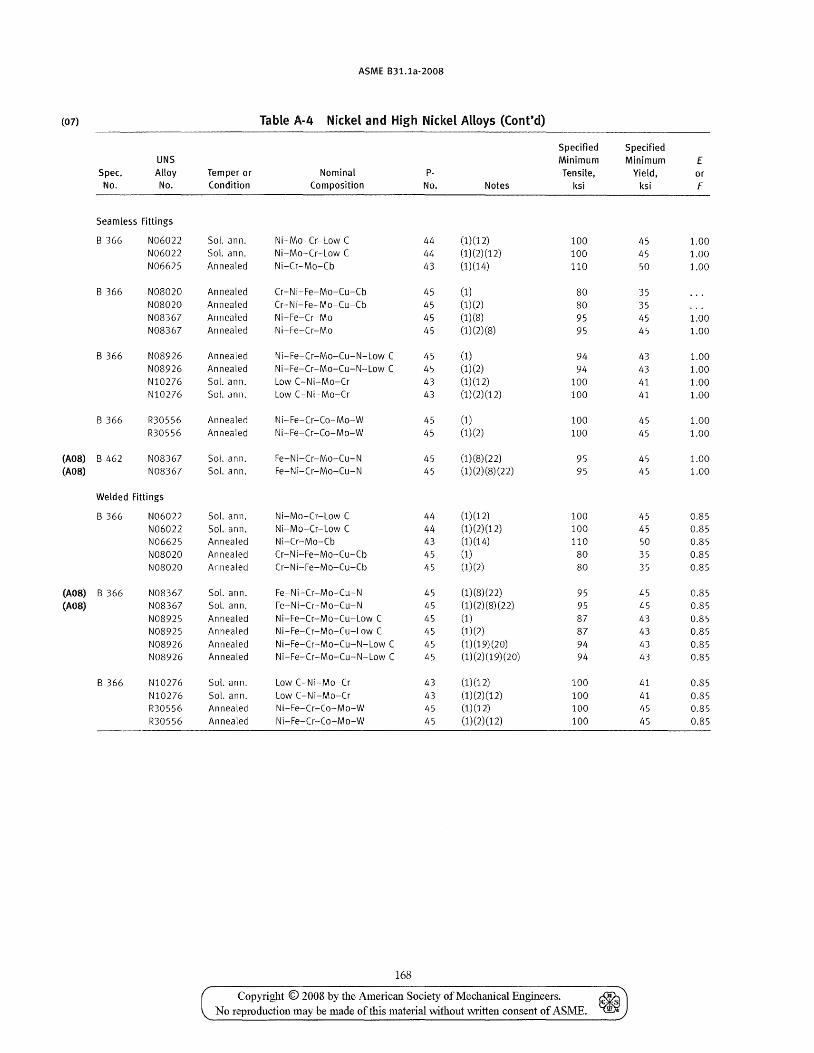
ASME B31.1a-2008
(07) Table A-4 Nickel and High Nickel Alloys (Cont'd)
Specified Specified UNS Minimum Minimum E
Spec. Alloy Temper or Nominal p- Tensile, Yield, or No. No. Condition Composition No. Notes ksi ksi F
Seamless Fittings
B 366 N06022 Sol. ann. Ni-Mo-Cr-Low C 44 (1)(12) 100 45 1.00 N06022 Sol. ann. Ni-Mo-Cr-Low C 44 (1)(2)(12) 100 45 1.00 N06625 Annealed Ni-Cr-Mo-Cb 43 (1)(14) 110 50 1.00
B 366 NOS020 Annealed Cr-Ni-Fe-Mo-Cu-Cb 45 (1) 80 35 NOS020 Annealed Cr-Ni-Fe-Mo-Cu-Cb 45 (1)(2) 80 35 N08367 Annealed Ni-Fe-Cr-Mo 45 (1)(8) 95 45 1.00 N08367 Annealed Ni-Fe-Cr-Mo 45 (1)(2)(8) 95 45 1.00
B 366 N08926 Annealed Ni-Fe-Cr-Mo-Cu-N-Low C 45 (1) 94 43 1.00 N08926 Annealed Ni-Fe-Cr-Mo-Cu-N-Low C 45 (1)(2) 94 43 1.00 NI0276 Sol. ann. Low C-Ni-Mo-Cr 43 (1)(12) 100 41 1.00 NI0276 Sol. ann. Low C-Ni-Mo-Cr 43 (1)(2)(12) 100 41 1.00
B 366 R30556 Annealed Ni-Fe-Cr-Co-Mo-W 45 (1) 100 45 1.00 R30556 Annealed Ni-Fe-Cr-Co-Mo-W 45 (1)(2) 100 45 1.00
(AOS) B 462 N08367 Sol. ann. Fe-Ni-Cr-Mo-Cu-N 45 (1)(8)(22) 95 45 1.00 (AOS) N08367 Sol. ann. Fe-Ni-Cr-Mo-Cu-N 45 (1) (2) (8) (22) 95 45 1.00
Welded Fittings
B 366 N06022 Sol. ann. Ni-Mo-Cr-Low C 44 (1) (12) 100 45 0.85 N06022 Sol. ann. Ni-Mo-Cr-Low C 44 (1)(2)(12) 100 45 0.85 N06625 Annealed Ni-Cr-Mo-Cb 43 (1)(14) 110 50 0.85 N08020 Annealed Cr-Ni-Fe-Mo-Cu-Cb 45 (1) 80 35 0.85 NOS020 Annealed Cr-Ni-Fe-Mo-Cu-Cb 45 (1)(2) SO 35 0.85
(AOS) B 366 NOS367 Sol. ann. Fe-Ni-Cr-Mo-Cu-N 45 (1)(S)(22) 95 45 0.85 (AOS) N08367 Sol. ann. Fe-Ni-Cr-Mo-Cu-N 45 (1) (2)(8) (22) 95 45 0.85
N08925 Annealed Ni-Fe-Cr-Mo-Cu-Low C 45 (1) 87 43 0.S5 N08925 Annealed Ni-Fe-Cr-Mo-Cu-Low C 45 (1)(2) 87 43 0.S5 N08926 Annealed Ni-Fe-Cr-Mo-Cu-N-Low C 45 (1) (19) (20) 94 43 0.85 N08926 Annealed Ni-Fe-Cr-Mo-Cu-N-Low C 45 (1)(2)(19)(20) 94 43 0.85
B 366 N10276 Sol. ann. Low C-Ni-Mo-Cr 43 (1)(12) 100 41 0.85 N10276 Sol. ann. Low C-Ni-Mo-Cr 43 (1)(2)(12) 100 41 0.85 R30556 Annealed Ni-Fe-Cr-Co-Mo-W 45 (1)(12) 100 45 0.85 R30556 Annealed Ni-Fe-Cr-Co-Mo-W 45 (1) (2) (12) 100 45 0.85
168
Copyright © 2008 by the American Society of Mechanical Engineers. No reproduction may be made of this material without written consent of ASME.
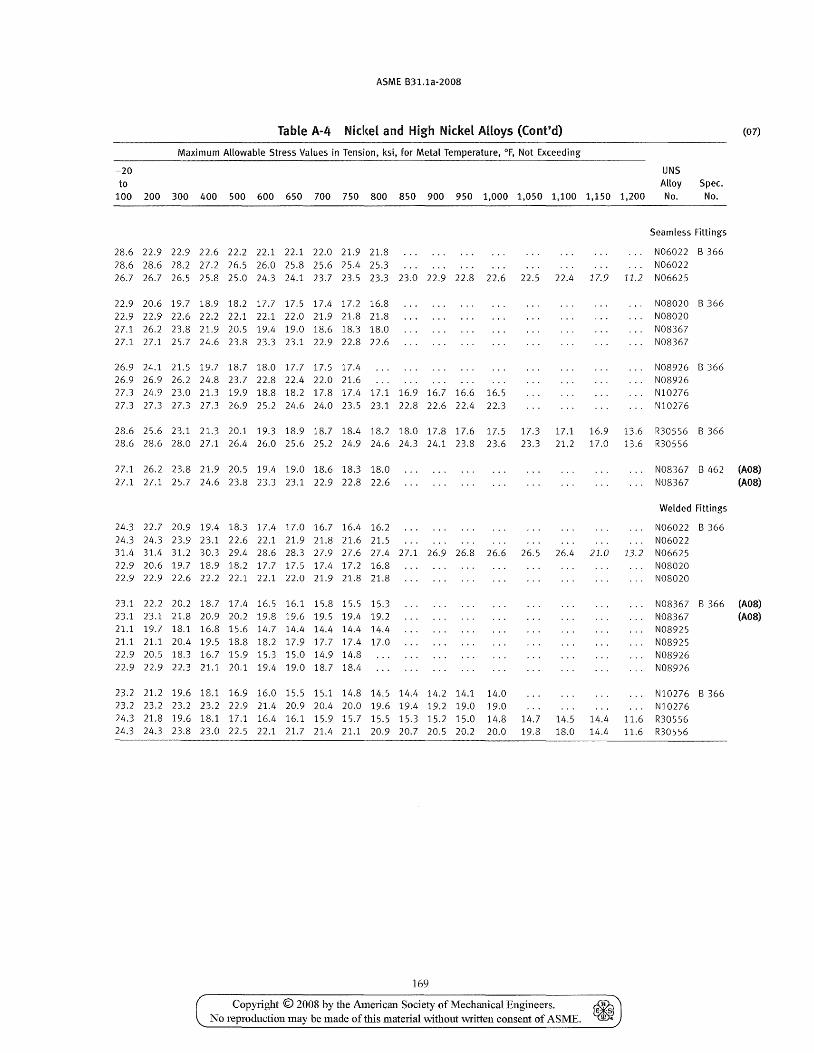
ASME B31.1a-2008
Table A-4 Nickel and High Nickel Alloys (Cont'd)
Maximum Allowable Stress Values in Tension, ksi, for Metal Temperature, of, Not Exceeding
-20 UNS to Alloy Spec.
100 200 300 400 500 600 650 700 750 800 850 900 950 1,000 1,050 1,100 1,150 1,200 No. No.
Seamless Fittings
28.6 22.9 22.9 22.6 22.2 22.1 22.1 22.0 21.9 21.8 N06022 B 366 28.6 28.6 28.2 27.2 26.5 26.0 25.8 25.6 25.4 25.3 N06022 26.7 26.7 26.5 25.8 25.0 24.3 24.1 23.7 23.5 23.3 23.0 22.9 22.8 22.6 22.5 22.4 17.9 11.2 N06625
22.9 20.6 19.7 1S.9 lS.2 17.7 17.5 17.4 17.2 16.8 22.9 22.9 22.6 22.2 22.1 22.1 22.0 21.9 21.S 21.S 27.1 26.2 23.S 21.9 20.5 19.4 19.0 18.6 18.3 18.0 27.1 27.1 25.7 24.6 23.S 23.3 23.1 22.9 22.8 22.6
26.9 24.1 21.5 19.7 18.7 18.0 17.7 17.5 17.4 26.9 26.9 26.2 24.8 23.7 22.8 22.4 22.0 21.6 27.3 24.9 23.0 21.3 19.9 18.8 18.2 17.8 17.4 17.1 16.9 16.7 16.6 16.5 27.3 27.3 27.3 27.3 26.9 25.2 24.6 24.0 23.5 23.1 22.8 22.6 22.4 22.3
NOS020 B 366 NOS020 N08367 N08367
N08926 B 366 N08926 NI0276 N10276
28.6 25.6 23.1 21.3 20.1 19.3 lS.9 18.7 18.4 1S.2 18.0 17.8 17.6 17.5 17.3 17.1 16.9 13.6 R30556 B 366 28.6 28.6 28.0 27.1 26.4 26.0 25.6 25.2 24.9 24.6 24.3 24.1 23.8 23.6 23.3 21.2 17.0 13.6 R30556
(07)
27.1 26.2 23.8 21.9 20.5 19.4 19.0 18.6 18.3 18.0 27.1 27.1 25.7 24.6 23.8 23.3 23.1 22.9 22.8 22.6
N08367 B 462 (A08) N08367 (A08)
24.3 22.7 20.9 19.4 18.3 17.4 17.0 16.7 16.4 16.2 24.3 24.3 23.9 23.1 22.6 22.1 21.9 21.8 21.6 21.5
Welded Fittings
N06022 B 366 N06022
31.4 31.4 31.2 30.3 29.4 2S.6 28.3 27.9 27.6 27.4 27.1 26.9 26.8 26.6 26.5 26.4 21.0 13.2 N06625 22.9 20.6 19.7 lS.9 18.2 17.7 17.5 17.4 17.2 16.8 NOS020 22.9 22.9 22.6 22.2 22.1 22.1 22.0 21.9 21.8 21.8 N08020
23.1 22.2 20.2 lS.7 17.4 16.5 16.1 15.S 15.5 15.3 23.1 23.1 21.8 20.9 20.2 19.8 19.6 19.5 19.4 19.2 21.1 19.7 18.1 16.8 15.6 14.7 14.4 14.4 14.4 14.4 21.1 21.1 20.4 19.5 lS.8 18.2 17.9 17.7 17.4 17.0 22.9 20.5 18.3 16.7 15.9 15.3 15.0 14.9 14.8 22.9 22.9 22.3 21.1 20.1 19.4 19.0 18.7 18.4
23.2 21.2 19.6 18.1 16.9 16.0 15.5 15.1 14.8 14.5 14.4 14.2 14.1 14.0
N08367 B 366 N08367 N08925 N08925 N08926 N08926
NI0276 B 366 23.2 23.2 23.2 23.2 22.9 21.4 20.9 20.4 20.0 19.6 19.4 19.2 19.0 19.0 NI0276 24.3 21.8 19.6 18.1 17.1 16.4 16.1 15.9 15.7 15.5 15.3 15.2 15.0 14.8 14.7 14.5 14.4 11.6 R30556 24.3 24.3 23.8 23.0 22.5 22.1 21.7 21.4 21.1 20.9 20.7 20.5 20.2 20.0 19.8 18.0 14.4 11.6 R30556
169
Copyright © 2008 by the American Society of Mechanical Engineers. ~ e· '-: No reproduction may be made of this matelial without written consent of ASME. ~
(A08) (A08)
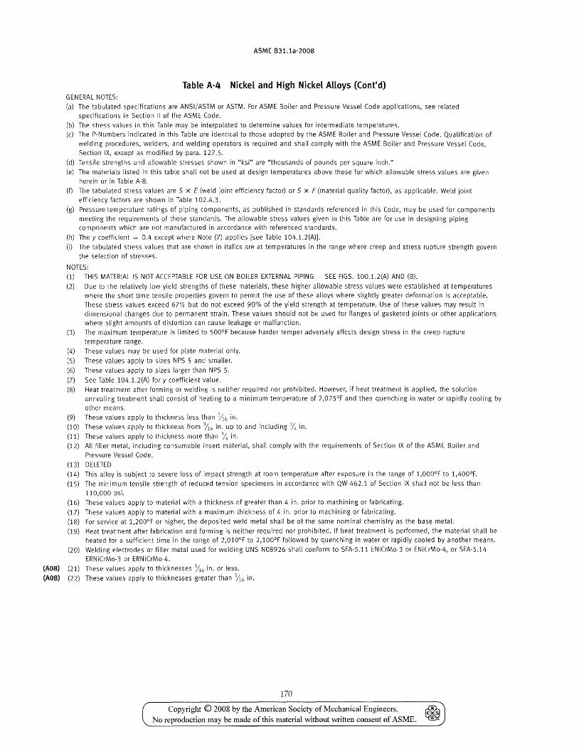
ASME 831.1a-2008
Table A·4 Nickel and High Nickel Alloys (Cont'd) GENERAL NOTES:
(a) The tabulated specifications are ANSI/ ASTM or ASTM. For ASME Boiler and Pressure Vessel Code applications, see related specifications in Section II of the ASME Code.
(b) The stress values in this Table may be interpolated to determine values for intermediate temperatures.
(c) The P-Numbers indicated in this Table are identical to those adopted by the ASME Boiler and Pressure Vessel Code. Qualification of
welding procedures, welders, and welding operators is required and shaH comply with the ASME Boiler and Pressure Vessel Code, Section IX, except as modified by para. 127.5.
(d) Tensile strengths and allowable stresses shown in "ksi" are "thousands of pounds per square inch."
(e) The materials listed in this table shall not be used at design temperatures above those for which allowable stress values are given herein or in Table A-S.
(f) The tabulated stress values are 5 x E (weld joint efficiency factor) or 5 x F (material quality factor), as applicable. Weld joint efficiency factors are shown in Table 102.4.3.
(g) Pressure-temperature ratings of piping components, as published in standards referenced in this Code, may be used for components
meeting the requirements of those standards. The allowable stress values given in this Table are for use in designing piping components which are not manufactured in accordance with referenced standards.
(h) The y coefficient = 0.4 except where Note (7) applies [see Table 104.1.2(A)].
(i) The tabulated stress values that are shown in italics are at temperatures in the range where creep and stress rupture strength govern
the selection of stresses.
NOTES: (1) THIS MATERIAL IS NOT ACCEPTABLE FOR USE ON BOILER EXTERNAL PIPING - SEE FIGS. 100.1.2(A) AND (B).
(2) Due to the relatively low yield strengths of these materials, these higher allowable stress values were established at temperatures where the short time tensile properties govern to permit the use of these aHoys where slightly greater deformation is acceptable.
These stress values exceed 67'10 but do not exceed 90% of the yield strength at temperature. Use of these values may result in dimensional changes due to permanent strain. These values should not be used for flanges of gasketed joints or other applications where slight amounts of distortion can cause leakage or malfunction.
(3) The maximum temperature is limited to 500°F because harder temper adversely affects design stress in the creep rupture
temperature range.
(4) These values may be used for plate material only.
(5) These values apply to sizes NPS S and smaller.
(6) These values apply to sizes larger than NPS S.
(7) See Table 104.1.2(A) for y coefficient value.
(8) Heat treatment after forming or welding is neither required nor prohibited. However, if heat treatment is applied, the solution
annealing treatment shall consist of heating to a minimum temperature of 2,02SoF and then quenching in water or rapidly cooling by
other means.
(9) These values apply to thickness less than 116 in.
(10) These values apply to thickness from %6 in. up to and including % in.
(11) These values apply to thickness more than % in.
(12) All filler metal, including consumable insert material, shall comply with the requirements of Section IX of the ASME Boiler and
Pressure Vessel Code.
(13) DELETED
(14) This alloy is subject to severe loss of impact strength at room temperature after exposure in the range of 1,OOooF to 1,400°F.
(1S) The minimum tensile strength of reduced tension specimens in accordance with QW-462.1 of Section IX shall not be less than
110,000 psi. (16) These values apply to material with a thickness of greater than 4 in. prior to machining or fabricating.
(17) These values apply to material with a maximum thickness of 4 in. prior to machining or fabricating.
(18) For service at 1,200°F or higher, the deposited weld metal shall be of the same nominal chemistry as the base metal.
(19) Heat treatment after fabrication and forming is neither required nor prohibited. If heat treatment is performed, the material shall be heated for a sufficient time in the range of 2,010°F to 2,100°F followed by quenching in water or rapidly cooled by another means.
(20) Welding electrodes or filler metal used for welding UNS N08926 shall conform to SFA-S.l1 ENiCrMo-3 or ENiCrMo-4, or SFA-S.14
ERNiCrMo-3 or ERNiCrMo-4.
(AOS) (21) These values apply to thicknesses %6 in. or less.
(AOS) (22) These values apply to thicknesses greater than %6 in.
170
Copyright © 2008 by the A.merican Society of Mechanical Engineers. No reproduction may be made of this material without written consent of ASME.
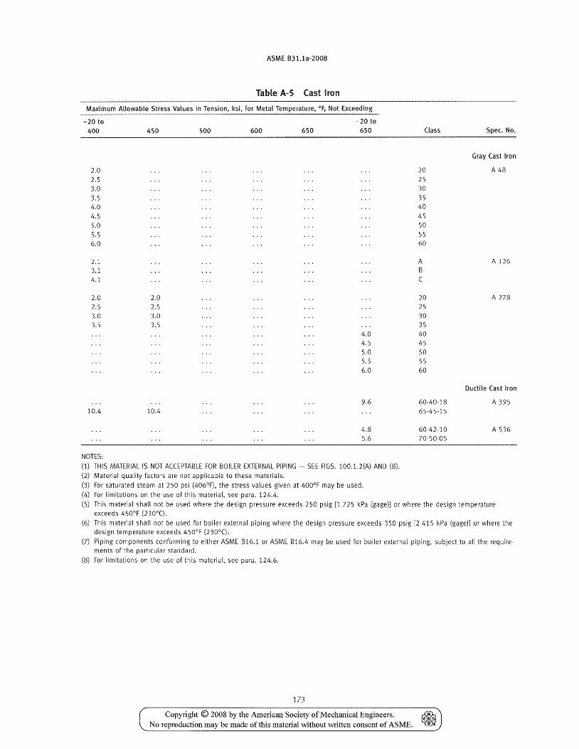
ASME B31.1a-2008
Table A-5 Cast Iron
Maximum Allowable Stress Values in Tension, ksi, for Metal Temperature, of, Not Exceeding
-20 to -20 to
400 450 500 600 650 650
2.0
2.5 3.0
3.5 4.0
4.5 5.0
5.5 6.0
2.1 3.1 4.1
2.0 2.0 2.5 2.5 3.0 3.0 3.5 3.5
4.0 4.5
5.0 5.5 6.0
9.6 10.4 10.4
4.8 5.6
NOTES:
(1) THIS MATERIAL IS NOT ACCEPTABLE FOR BOILER EXTERNAL PIPING - SEE FIGS. 100.1.2(A) AND (B).
(2) Material quality factors are not applicable to these materials.
(3) For saturated steam at 250 psi (406°F), the stress values given at 400°F may be used.
(4) For limitations on the use of this material, see para. 124.4.
Class Spec. No.
Gray Cast Iron
20 A 48
25 30
35 40
45 50
55 60
A A 126 B e
20 A 278
25 30 35 40 45 50 55 60
Ductile Cast Iron
60-40-18 A 395 65-45-15
60-42-10 A 536 70-50-05
(5) This material shall not be used where the design pressure exceeds 250 psig [1 725 kPa (gage)] or where the design temperature exceeds 450°F (2300 e).
(6) This material shall not be used for boiler external piping where the design pressure exceeds 350 psig [2 415 kPa (gage)] or where the design temperature exceeds 450°F (230 0 e).
(7) Piping components conforming to either ASME B16.1 or ASME B16.4 may be used for boiler external piping, subject to all the requirements of the particular standard.
(8) For limitations on the use of this material, see para. 124.6.
173
Copyright © 2008 by the American Society ofMecharucal Engineers. ~ No reproduction may be made of this material without written consent of ASME. ~
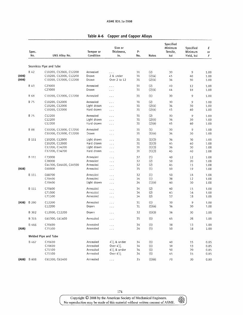
ASME B31.1a-2008
Table A-6 (opper and (opper Alloys
Specified Size or Minimum Specified E
Spec. Temper or Thickness, p- Tensile, Minimum or No. UNS Alloy No. Condition in. No. Notes ksi Yield, ksi F
Seamless Pipe and Tube
B 42 (10200, (12000, (12200 Annealed 31 (2) 30 9 1.00 (A08) (10200, (12000, (12200 Drawn 2 & under 31 (2)(4) 45 40 1.00 (A08) (10200, (12000, (12200 Drawn Over 2 to 12 31 (2)(4) 36 30 1.00
B 43 C23000 Annealed 31 (2) 40 12 1.00 C23000 Drawn 31 (2)(4) 44 18 1.00
B 68 (10200, C12000, C12200 Annealed 31 (1) 30 9 1.00
B 75 (10200, (12000 Annealed 31 (2) 30 9 1.00 (10200, C12000 Light drawn 31 (2)(4) 36 30 1.00 (10200, C12000 Hard drawn 31 (2)(4) 45 40 1.00
B 75 (12200 Annealed 31 (2) 30 9 1.00 (12200 Light drawn 31 (2)(4) 36 30 1.00 (12200 Hard drawn 31 (2)(4) 45 40 1.00
B 88 (10200, C12000, (12200 Annealed 31 (1) 30 9 1.00 (10200, (12000, (12200 Drawn 31 (1)(4) 36 30 1.00
B 111 (10200, (12000 Light drawn 31 (1)(3) 36 30 1.00 (10200, (12000 Hard drawn 31 (1)(3) 45 40 1.00 (12200, (14200 Light drawn 31 (1)(3) 36 30 1.00 (12200, (14200 Hard drawn 31 (1) (3) 45 40 1.00
B 111 C23000 Annealed 32 (1) 40 12 1.00 (28000 Annealed 32 (2) 50 20 1.00 (44300, C44400, (44500 Annealed 32 (2) 45 15 1.00
(AOS) (60800 Annealed 35 (1) 50 19 1.00
B 111 (68700 Annealed 32 (1) 50 18 1.00 C70400 Annealed 34 (1) 38 12 1.00 C70400 Light drawn 34 (1)(4) 40 30 1.00
B 111 C70600 Annealed 34 (2) 40 15 1.00 (71000 Annealed 34 (2) 45 16 1.00 (71500 Annealed 34 (2) 52 18 1.00
(AOS) B 280 (12200 Annealed 31 (1) 30 9 1.00 C12200 Drawn 31 (1)(4) 36 30 1.00
B 302 (12000, Cl2200 Drawn 32 (1)(3) 36 30 1.00
B 315 (61300, (61400 Annealed 35 (1) 65 28 1.00
B 466 C70600 Annealed 34 (1) 38 13 1.00 (AOS) (71500 Annealed 34 (1) 50 18 1.00
Welded Pipe and Tube
B 467 C70600 Annealed 41/ 2 & under 34 (1) 40 15 0.85
C70600 Annealed Over 4)12 34 (1) 38 13 0.85 (71500 Annealed 41
/ 2 & under 34 (1) 50 20 0.85 (71500 Annealed Over 4)12 34 (1) 45 15 0.85
(AOS) B 608 (61300, C61400 Annealed 35 (1)(6) 70 30 0.80
174
Copyright © 2008 by the American Society of Mechanical Engineers. No reproduction may be made of this material without written consent of ASME.
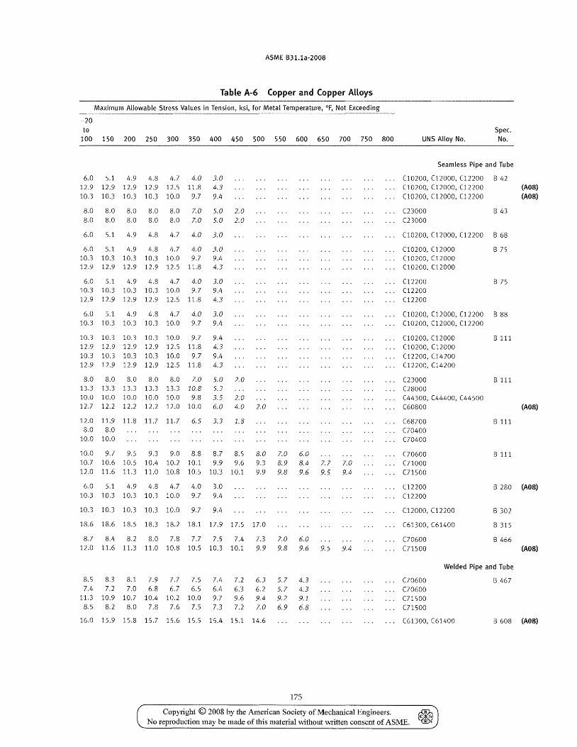
ASME B31.1a-2008
Table A-6 (opper and (opper Alloys
Maximum Allowable Stress Values in Tension, ksi, for Metal Temperature, of, Not Exceeding
-20 to
100 150 200 250 300 350 400 450 500 550 600 650 700 750 800
6.0 5.1 4.9 4.8 4.7 4.0 3.0 12.9 12.9 12.9 12.9 12.5 11.8 4.3 10.3 10.3 10.3 10.3 10.0 9.7 9.4
8.0 8.0 8.0 8.0 8.0 7.0 5.0 2.0 8.0 8.0 8.0 8.0 8.0 7.0 5.0 2.0
6.0 5.1 4.9 4.8 4.7 4.0 3.0
6.0 5.1 4.9 4.8 4.7 4.0 3.0 10.3 10.3 10.3 10.3 10.0 9.7 9.4 12.9 12.9 12.9 12.9 12.5 11.8 4.3
6.0 5.1 4.9 4.8 4.7 4.0 3.0 10.3 10.3 10.3 10.3 10.0 9.7 9.4 12.9 12.9 12.9 12.9 12.5 11.8 4.3
6.0 5.1 4.9 4.8 4.7 4.0 3.0 10.3 10.3 10.3 10.3 10.0 9.7 9.4
10.3 10.3 10.3 10.3 10.0 9.7 9.4 12.9 12.9 12.9 12.9 12.5 11.8 4.3 10.3 10.3 10.3 10.3 10.0 9.7 9.4 12.9 12.9 12.9 12.9 12.5 11.8 4.3
8.0 8.0 8.0 8.0 8.0 7.0 5.0 2.0 13.3 13.3 13.3 13.3 13.3 10.8 5.3 10.0 10.0 10.0 10.0 10.0 9.8 3.5 2.0 12.7 12.2 12.2 12.2 12.0 10.0 6.0 4.0 2.0
12.0 11.9 11.8 11.7 11.7 6.5 3.3 1.8 8.0 8.0
10.0 10.0
10.0 9.7 9.5 9.3 9.0 8.8 8.7 8.5 10.7 10.6 10.5 10.4 10.2 10.1 9.9 9.6 12.0 11.6 11.3 11.0 10.8 10.5 10.3 10.1
6.0 5.1 4.9 4.8 4.7 4.0 3.0 10.3 10.3 10.3 10.3 10.0 9.7 9.4
10.3 10.3 10.3 10.3 10.0 9.7 9.4
8.0 7.0 6.0 9.3 8.9 8.4 7.7 7.0 9.9 9.8 9.6 9.5 9.4
18.6 18.6 18.5 18.3 18.2 18.1 17.9 17.5 17.0
8.7 8.4 8.2 8.0 7.8 7.7 7.5 7.4 7.3 7.0 6.0 12.0 11.6 11.3 11.0 10.8 10.5 10.3 10.1 9.9 9.8 9.6 9.5 9.4
8.5 8.3 8.1 7.9 7.7 7.5 7.4 7.2 6.3 5.7 4.3 7.4 7.2 7.0 6.8 6.7 6.5 6.4 6.3 6.2 5.7 4.3
11.3 10.9 10.7 10.4 10.2 10.0 9.7 9.6 9.4 9.2 9.1 8.5 8.2 8.0 7.8 7.6 7.5 7.3 7.2 7.0 6.9 6.8
16.0 15.9 15.8 15.7 15.6 15.5 15.4 15.1 14.6
175
Copyright © 2008 by the American Society of Mechanical Engineers.
Spec. UNS Alloy No. No.
Seamless Pipe and Tube
(10200, C12000, (12200 8 42 (10200, (12000, (12200 C10200, (12000, (12200
(23000 (23000
B 43
C10200, (12000, C12200 B 68
(10200, (12000 (10200, (12000 (10200, (12000
(12200 (12200 (12200
B 75
B 75
(10200, (12000, (12200 B 88 (10200, (12000, (12200
(10200, C12000 (10200, (12000 (12200, (14200 (12200, (14200
B 111
(23000 B 111 C28000 (44300, (44400, (44500
(AOS) (AOS)
(60800 (AOS)
(68700 C70400 C70400
(70600 (71000 Cl1500
C12200 (12200
(12000, C12200
(61300, (61400
C70600 (71500
B 111
B 111
B 280 (AOS)
B 302
B 315
B 466 (A08)
C70600 Cl0600 (71500 (71500
Welded Pipe and Tube
B 467
(61300, (61400 B 608 (AOS)
No reproduction may be made of this material \vithout vvritten consent of ASME.
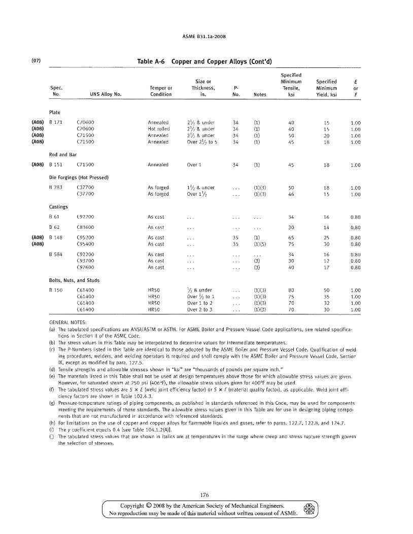
(07)
(A08) (A08) (A08) (A08)
(A08)
(A08) (A08)
ASME B31.1a-2008
Table A-6 Copper and Copper Alloys (Cont'd)
Specified Size or Minimum Specified E
Spec. Temper or Thickness, P- Tensile, Minimum or No. UNS Alloy No. Condition in. No. Notes ksi Yield, ksi F
Plate
B 171 C70600 Annealed 2V2 & under 34 (1) 40 15 1.00 C70600 Hot rolled 2/2 & under 34 (1) 40 15 1.00 C71500 Annealed 21/2 & under 34 (1) 50 20 1.00 C71500 Annealed Over 21/2 to 5 34 (1) 45 18 1.00
Rod and Bar
B 151 C71500 Annealed Over 1 34 (1) 45 18 1.00
Die Forgings (Hot Pressed)
B 283 C37700 As forged 11/2 & under (1)(3) 50 18 1.00 C37700 As forged Over 1 V2 (1)(3) 46 15 1.00
Castings
B 61 C92200 As cast 34 16 0.80
B 62 C83600 As cast 30 14 0.80
B 148 (95200 As cast 35 (1) 65 25 0.80 (95400 As cast 35 (1)(5) 75 30 0.80
B 584 C92200 As cast 34 16 0.80 C93700 As cast (3) 30 12 0.80 C97600 As cast (3) 40 17 0.80
Bolts, Nuts, and Studs
B 150 (61400 HR50 % & under (1) (3) 80 50 1.00 C61400 HR50 Over V2 to 1 (1)(3) 75 35 1.00 C61400 HR50 Over 1 to 2 (1)(3) 70 32 1.00 C61400 HR50 Over 2 to 3 (1)(3) 70 30 1.00
GENERAL NOTES:
(a) The tabulated specifications are ANSI/ASTM or ASTM. For ASME Boiler and Pressure Vessel Code applications, see related specifications in Section II of the ASME Code.
(b) The stress values in this Table may be interpolated to determine values for intermediate temperatures. (c) The P-Numbers listed in this Table are identical to those adopted by the ASME Boiler and Pressure Vessel Code. Qualification of weld
ing procedures. welders, and welding operators is required and shall comply with the ASME Boiler and Pressure Vessel (ode, Section IX, except as modified by para. 127.5.
(d) Tensile strengths and allowable stresses shown in "ksi" are "thousands of pounds per square inch."
(e) The materials listed in this Table shall not be used at design temperatures above those for which allowable stress values are given. However, for saturated steam at 250 psi (406°F), the allowable stress values given for 400°F may be used.
(f) The tabulated stress values are 5 x E (weld joint efficiency factor) or 5 x F (material quality factor), as applicable. Weld joint efficiency factors are shown in Table 102.4.3.
(g) Pressure-temperature ratings of piping components, as published in standards referenced in this Code, may be used for components meeting the requirements of those standards. The allowable stress values given in this Table are for use in designing piping components that are not manufactured in accordance with referenced standards.
(h) For limitations on the use of copper and copper alloys for flammable liquids and gases, refer to paras. 122.7, 122.8, and 124.7.
(i) The y coefficient equals 0.4 [see Table 104.1.2(A)].
(D The tabulated stress values that are shown in italics are at temperatures in the range where creep and stress rupture strength govern the selection of stresses.
176
Copyright © 2008 by the American Society of Mechanical Engineers. No reproduction may be made of this material without written consent of ASME.
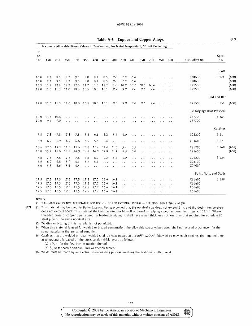
ASME B31.1a-2008
Table A-6 Copper and Copper Alloys
Maximum Allowable Stress Values in Tension, ksi, for Metal Temperature, OF, Not Exceeding
-20 to Spec.
100 150 200 250 300 350 400 450 500 550 600 650 700 750 800 UNS Alloy No. No.
Plate
10.0 9.7 9.5 9.3 9.0 8.8 8.7 8.5 8.0 7.0 6.0 C70600 B 171
10.0 9.7 9.5 9.3 9.0 8.8 8.7 8.5 8.0 7.0 6.0 C70600
13.3 12.9 12.6 12.3 12.0 11.7 11.5 11.2 11.0 10.8 10.7 10.6 10.4 C71500 12.0 11.6 11.3 11.0 10.8 10.5 10.3 10.1 9.9 9.8 9.6 9.5 9.4 C71500
Rod and Bar
12.0 11.6 11.3 11.0 10.8 10.5 10.3 10.1 9.9 9.8 9.6 9.5 9.4 C71500 B 151
Die Forgings (Hot Pressed)
12.0 11.3 10.8 07700 B 283 10.0 9.4 9.0 C37700
Castings
7.8 7.8 7.8 7.8 7.8 7.8 6.6 6.2 5.4 4.0 (92200 B 61
6.9 6.9 6.9 6.9 6.6 6.5 5.5 5.4 (83600 B 62
13.4 12.6 12.2 11.8 11.6 11.4 11.4 11.4 11.4 9.4 5.9 C95200 B 148 16.0 15.2 15.0 14.8 14.8 14.8 14.8 12.8 11.1 8.6 6.8 (95400
7.8 7.8 7.8 7.8 7.8 7.8 6.6 6.2 5.8 5.0 (92200 B 584 6.9 6.9 5.8 5.4 5.3 5.2 5.1 C93700 6.0 5.8 5.6 5.5 5.4 (97600
Bolts, Nuts, and Studs
17.5 17.5 17.5 17.5 17.5 17.5 17.2 16.6 16.1 (61400 B 150 17.5 17.5 17.5 17.5 17.5 17.5 17.2 16.6 16.1 (61400 17.5 17.5 17.5 17.5 17.5 17.5 17.2 16.6 16.1 (61400 17.5 17.5 17.5 17.5 17.5 17.5 17.2 16.6 16.1 (61400
NOTES: (1) THIS MATERIAL IS NOT ACCEPTABLE FOR USE ON BOILER EXTERNAL PIPING - SEE FIGS. 100.1.2(A) and (B).
(07) (2) This material may be used for Boiler External Piping provided that the nominal size does not exceed 3 in. and the design temperature does not exceed 406°F. This material shall not be used for blowoff or blowdown piping except as permitted in para. 122.1.4. Where threaded brass or copper pipe is used for feedwater piping, it shall have a wall thickness not less than that required for schedule 80 steel pipe of the same nominal size.
(3) Welding or brazing of this material is not permitted.
(4) When this material is used for welded or brazed construction, the allowable stress values used shall not exceed those given for the same material in the annealed condition.
(5) Castings that are welded or repair welded shall be heat treated at 1,150°F-l,200oF, followed by moving-air cooUng. The required time at temperature is based on the cross-section thicknesses as follows:
(a) 1 Y2 hr for the first inch or fraction thereof
(b) % hr for each additional inch or fraction thereof
(6) Welds must be made by an electric fusion welding process involving the addition of filler metal.
177
Copyright © 2008 by the American Society of Mechanical Engineers. ~ No reproduction may be made of this material without written consent of ASME. ~
(07)
(AOS) (AOS) (AOS) (AOS)
(AOS)
(AOS) (AOS)
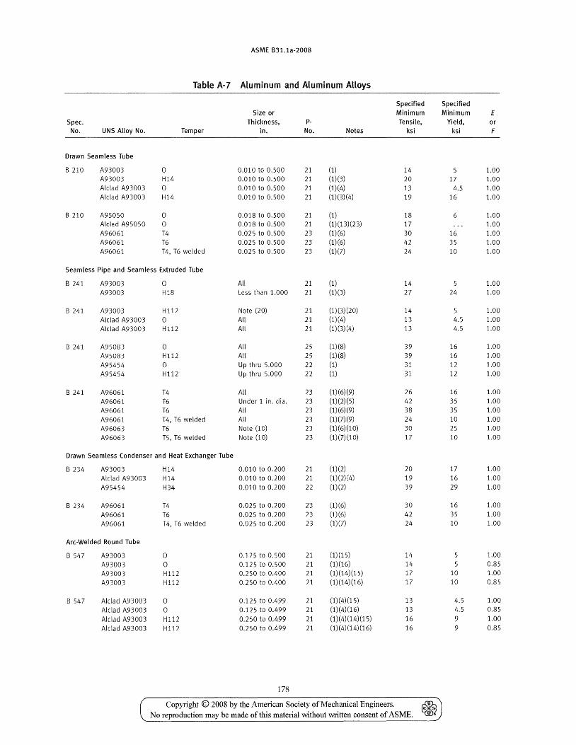
ASME B31.1a-2008
Table A-7 Aluminum and Aluminum AUoys
Specified Size or Minimum
Spec. Thickness, P- Tensile, No. UNS Alloy No. Temper in. No. Notes ksi
Drawn Seamless Tube
B 210 A93003 0 0.010 to 0.500 21 (1) 14 A93003 H14 0.010 to 0.500 21 (1)(3) 20 Alclad A93003 0 0.010 to 0.500 21 (1)(4) 13 Alclad A93003 H14 0.010 to 0.500 21 (1)(3)(4) 19
B 210 A95050 0 0.018 to 0.500 21 (1) 18 Alclad A95050 0 0.018 to 0.500 21 (1)(13)(23) 17 A96061 T4 0.025 to 0.500 23 (1)(6) 30 A96061 T6 0.025 to 0.500 23 (1)(6) 42 A96061 T4, T6 welded 0.025 to 0.500 23 (1)(7) 24
Seamless Pipe and Seamless Extruded Tube
B 241 A93003 0 All 21 (1) 14 A93003 H18 Less than 1.000 21 (1)(3) 27
B 241 A93003 Hl12 Note (20) 21 (1)(3)(20) 14 Alclad A93003 0 All 21 (1)(4) 13 Alclad A93003 H112 All 21 (1)(3)(4) 13
B 241 A95083 0 All 25 (1)(8) 39 A95083 Hl12 All 25 (1)(8) 39 A95454 0 Up thru 5.000 22 (1) 31 A95454 Hl12 Up thru 5.000 22 (1) 31
B 241 A96061 T4 All 23 (1) (6) (9) 26
A96061 T6 Under 1 in. dia. 23 (1) (2) (5) 42 A96061 T6 AU 23 (1)(6)(9) 38 A96061 T4, T6 welded All 23 (1) (7) (9) 24 A96063 T6 Note (10) 23 (1)(6)(10) 30 A96063 T5, T6 welded Note (10) 23 (1)(7) (1 0) 17
Drawn Seamless Condenser and Heat Exchanger Tube
B 234 A93003 H14 0.010 to 0.200 21 (1)(2) 20 Alclad A93003 H14 0.010 to 0.200 21 (1)(2)(4) 19 A95454 H34 0.010 to 0.200 22 (1)(2) 39
B 234 A96061 T4 0.025 to 0.200 23 (1)(6) 30 A96061 T6 0.025 to 0.200 23 (1)(6) 42 A96061 T4, T6 welded 0.025 to 0.200 23 (1)(7) 24
Arc-Welded Round Tube
8 547 A93003 0 0.125 to 0.500 21 (1)(15) 14
A93003 0 0.125 to 0.500 21 (1)(16) 14 A93003 Hl12 0.250 to 0.400 21 (1)(14)(15) 17
A93003 H112 0.250 to 0.400 21 (1)(14)(16) 17
8 547 Alclad A93003 0 0.125 to 0.499 21 (1)(4)(15) 13 Alclad A93003 0 0.125 to 0.499 21 (1)(4)(16) 13 Alclad A93003 Hll2 0.250 to 0.499 21 (1)(4)(14)(15) 16 Alclad A93003 H112 0.250 to 0.499 21 (1)(4)(14)(16) 16
178
Copyright © 2008 by the i\.merican Society of Mechanical Engineers. & No reproduction may be made of this material without written consent of ASME. ~
Specified Minimum E
Yield, or ksi F
1.00 17 1.00
4.5 1.00 16 1.00
6 1.00 1.00
16 1.00 35 1.00 10 1.00
1.00 24 1.00
5 1.00 4.5 1.00 4.5 1.00
16 1.00 16 1.00 12 1.00 12 1.00
16 1.00 35 1.00 35 1.00 10 1.00 25 1.00 10 1.00
17 1.00 16 1.00 29 1.00
16 1.00 35 1.00 10 1.00
1.00 0.85
10 1.00 10 0.85
4.5 1.00 4.5 0.85
9 1.00 9 0.85
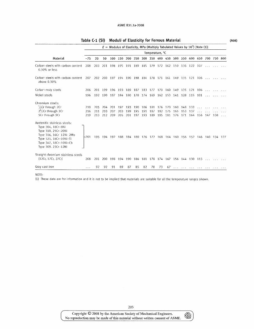
ASME B31.1a·2008
Table (-1 (51) Moduli of Elasticity for Ferrous Material
E = Modulus of Elasticity, MPa (Multiply Tabulated Values by 103) [Note (1)]
Temperature, O(
Material -75 20 50 100 150 200 250 300 350 400 450 500 550 600 650 700 750 800
Carbon steels with carbon content 208 203 201 198 195 191 189 185 179 172 162 150 136 122 107 0.30% or less
Carbon steels with carbon content 207 202 200 197 194 190 188 184 178 171 161 149 135 121 106 above 0.30%
Carbon-moly steels 206 201 199 196 193 189 187 183 177 170 160 149 135 121 106
Nickel steels 196 192 190 187 184 180 178 174 169 162 153 141 128 115 101
Chromium steels: 12Cr through 2Cr 210 205 204 201 197 193 190 186 181 176 170 160 148 133 21/t,Cr through 3Cr 216 211 210 207 203 199 195 191 187 182 175 165 153 137 5Cr through 9Cr 219 213 212 209 205 201 197 193 189 185 181 176 171 164 156
Austenitic stainless steels: Type 304, 18Cr-8Ni
}O1 Type 310, 25Cr-20Ni Type 316, 16Cr-12Ni-2Mo
195 194 192 188 184 180 176 172 168 164 160 156 152 146 Type 321, 18Cr-10Ni-Ti Type 347, 18Cr-l0Ni-Cb Type 309. 23Cr-12Ni
Straight chromium stainless steels (12Cr, 17Cr, 27er) 208 201 200 198 194 190 186 181 178 174 167 156 144 130 113
Gray cast iron 92 92 91 89 87 85 82 78 73 67
NOTE:
...
147
140
(1) These data are for information and it is not to be implied that materials are suitable for all the temperature ranges shown.
205
Copyright © 2008 by the American Society of Mechanical Engineers. ~ No reproduction may be made of this material without written consent of ASME. ~
.. . .. .
138
134 127
(A08)
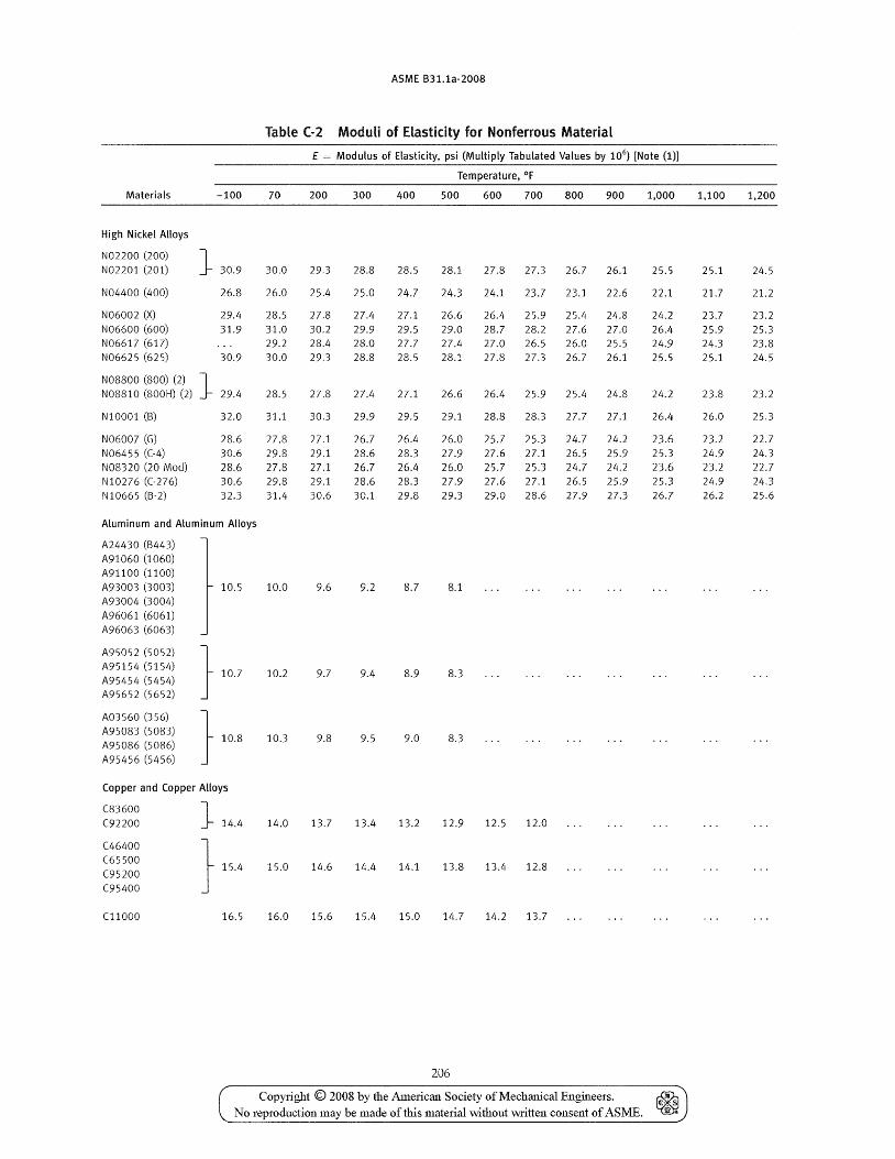
ASME B31.1a-2008
Table (-2 Moduli of Elasticity for Nonferrous Material
E = Modulus of Elasticity, psi (Multiply Tabulated Values by 106) [Note (1)]
Temperature, of
Materials -100 70 200 300 400 500 600 700 800 900 1,000 1,100 1,200
High Nickel Alloys
N02200 (200) J N02201 (201) 30.9 30.0 29.3 28.8 28.5 28.1 27.8 27.3 26.7 26.1 25.5 25.1 24.5
N04400 (400) 26.8 26.0 25.4 25.0 24.7 24.3 24.1 23.7 23.1 22.6 22.1 21.7 21.2
N06002 (X) 29.f~ 28.5 27.8 27.4 27.1 26.6 26.4 25.9 25.4 24.8 24.2 23.7 23.2 N06600 (600) 31.9 31.0 30.2 29.9 29.5 29.0 28.7 28.2 27.6 27.0 26.4 25.9 25.3 N06617 (617) 29.2 28.4 28.0 27.7 27.4 27.0 26.5 26.0 25.5 24.9 24.3 23.8 N06625 (625) 30.9 30.0 29.3 28.8 28.5 28.1 27.8 27.3 26.7 26.1 25.5 25.1 24.5
NOSSOO (SOO) (2) J N08810 (800H) (2) 29.4 28.5 27.8 27.4 27.1 26.6 26.4 25.9 25.4 24.8 24.2 23.8 23.2
NI0001 (B) 32.0 31.1 30.3 29.9 29.5 29.1 28.8 28.3 27.7 27.1 26.4 26.0 25.3
N06007 (G) 2S.6 27.S 27.1 26.7 26.4 26.0 25.7 25.3 24.7 24.2 23.6 23.2 22.7 N06455 ((-4) 30.6 29.8 29.1 28.6 28.3 27.9 27.6 27.1 26.5 25.9 25.3 24.9 24.3 N08320 (20 Mod) 28.6 27.8 27.1 26.7 26.4 26.0 25.7 25.3 24.7 24.2 23.6 23.2 22.7 N10276 ((·276) 30.6 29.8 29.1 28.6 28.3 27.9 27.6 27.1 26.5 25.9 25.3 24.9 24.3 NI0665 (B-2) 32.3 31.4 30.6 30.1 29.8 29.3 29.0 28.6 27.9 27.3 26.7 26.2 25.6
Aluminum and Aluminum Alloys
A24430 (6443) A91060 (1060) A91100 (1100) A93003 (3003) 10.5 10.0 9.6 9.2 8.7 8.1 A93004 (3004) A96061 (6061) A96063 (6063)
A95052 (5052) } A95154 (5154) 10.7 10.2 9.7 9.4 S.9 8.3
A95454 (5454) A95652 (5652)
A03560 (356)
} 108 A950S3 (5083)
10.3 9.8 9.5 9.0 8.3 A95086 (5086) A95456 (5456)
Copper and Copper Alloys
(83600 J (92200 14.4 14.0 13.7 13.4 13.2 12.9 12.5 12.0
(46400 } (65500 15.4 15.0 14.6 14.4 14.1 13.8 13.4 12.8
(95200 (95400
(11000 16.5 16.0 15.6 15.4 15.0 14.7 14.2 13.7
206
Copyright © 2008 by the American Society of Mechanical Engineers. ~ No reproduction may be made of this material without Mitten consent of ASME. ~
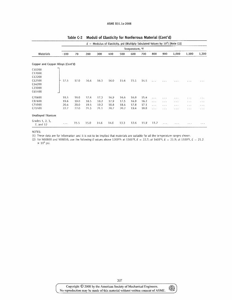
ASME B31.1a-2008
Table (-2 Moduli of Elasticity for Nonferrous Material (Cont'd)
E = Modulus of Elasticity, psi (Multiply Tabulated Values by 106) [Note (1)]
Temperature, of
Materials -100 70 200 300 400 500 600 700 800 900 1,000 1,100 1,200
Copper and Copper Alloys (Cont'd)
(10200 (12000 (12200 (12500 17.5 17.0 16.6 16.3 16.0 15.6 15.1 14.5 C14200 C23000 (61400
C70600 18.5 18.0 17.6 17.3 16.9 16.6 16.0 15.4 (97600 19.6 19.0 18.5 18.2 17.9 17.5 16.9 16.2 (71000 20.6 20.0 19.5 19.2 18.8 18.4 17.8 17.1 (71500 22.7 22.0 21.5 21.1 20.7 20.2 19.6 18.8
Unalloyed Titanium
Grades 1, 2, 3, 15.5 15.0 14.6 14.0 13.3 12.6 11.9 11.2
7, and 12
NOTES:
(1) These data are for information and it is not to be implied that materials are suitable for all the temperature ranges shown. (2) For N08800 and N08810, use the following E values above 1200°F: at 1300DF, E = 22.7; at 1400°F, E = 21.9; at 1500DF, E = 21.2
X 106 psi.
207
Copyright © 2008 by the American Society of Mecbanical Engineers. ~ No reproduction may be made of this material without \witten consent of ASME. ~
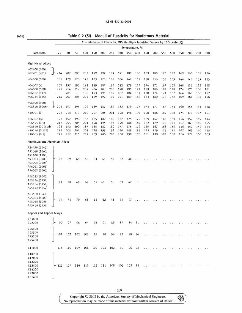
(A08)
Materials
High Nickel Alloys
N02200 (200) N02201 (201)
N04400 (400)
N06002 (X) N06600 (600) N06617 (617) N06625 (625)
N08800 (800) N08810 (800H)
NI0001 (B)
N06007 (G) N06455 ((-4) N08320 (20 Mod)
NI0276 ((-276) NI0665 (B-2)
ASME B31.1a-2008
Table (-2 (51) Moduli of Elasticity for Nonferrous Material
E = Modulus of Elasticity, MPa (Multiply Tabulated Values by 103) [Note (1)]
Temperature, O(
-75 20 50 100 150 200 250 300 350 400 450 500 550 600 650 700 750 800
J 214 207 205 202 199 197 194 191 189 186 183 180 176 172 169 164 161 156
185 179 178 175 173 170 168 166 164 161 158 156 153 149 146 142 139 135
203 197 195 192 189 187 184 182 179 177 174 171 167 163 160 156 153 148 221 214 212 209 206 203 200 198 195 192 189 186 182 178 174 170 166 161
201 196 193 191 189 187 184 181 178 174 171 167 164 160 156 152 214 207 205 202 199 197 194 191 189 186 183 180 176 172 169 164 161 156
J 203 197 195 192 189 187 184 182 179 177 174 171 167 163 160 156 153 148
222 214 213 210 207 204 201 198 196 193 190 186 182 178 175 170 167 161
198 192 190 187 185 182 180 177 175 172 169 167 163 159 156 152 149 144 212 205 204 201 198 195 193 190 188 185 182 179 175 171 167 163 160 155 198 192 190 187 185 182 180 177 175 172 169 167 163 159 156 152 149 144 212 205 204 201 198 195 193 190 188 185 182 179 175 171 167 163 160 155 224 217 215 212 209 206 203 200 198 195 191 188 184 180 176 172 168 163
Aluminum and Aluminum Alloys
A2L,430 (B443) A91060 (1060) A91100 (1100) A93003 (3003) A93004 (3004) A96061 (6061) A96063 (6063)
A95052 (5052) A95154 (5154) A95454 (5454) A95652 (5652)
A03560 (356) A95083 (5083) A95086 (5086) A95456 (5456)
72 69
70
71
68 66
69 67
70 68
63 61 57 52 46 ...
65 62 58 53 47
65 62 58 54 47
Copper and Copper Alloys
C83600 C92200
C46400 (65500 (95200 (95400
(11000
(10200 C12000 C12200 C12500 C14200 C23000 C61400
97 96 94 93 91 89 87 84 81
103 102 101 99 98 96 93 90 86
114 110 109 108 106 104 102 99 96 92
121 117 116 115 113 111 108 106 102 98
208
Copyright © 2008 by the American Society of Mechanical Engineers. No reproduction may be made of this material without written consent of ASME.
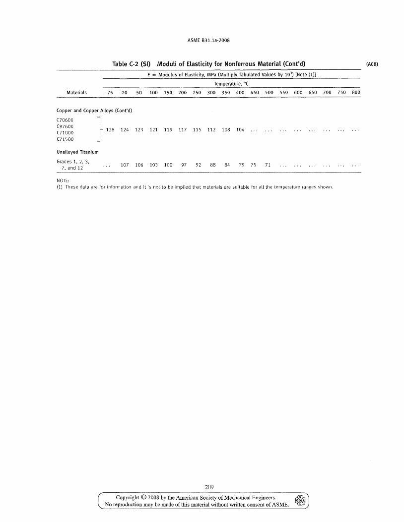
ASME 831.1a-2008
Table C-2 (51) Moduli of ELasticity for Nonferrous Material (Cont'd) (A08)
E = Modulus of Elasticity, MPa (Multiply Tabulated Values by 103) [Note (1)]
Temperature, O(
Materials -75 20 50 100 150 200 250 300 350 400 450 500 550 600 650 700 750 800
Copper and Copper Alloys (Cont'd)
C70600 } (97600 128 124 123 121 119 117 115 112 108 104 (71000
(71500
Unalloyed Titanium
Grades 1, 2, 3, 107 106 103 100 97 92 88 84 79 75 71 7, and 12
NOTE:
(1) These data are for information and it is not to be implied that materials are suitable for all the temperature ranges shown,
209
Copyright © 2008 by the American Society of Mechanical Engineers. ~ No reproduction may be made of this material without written consent of ASME. ~
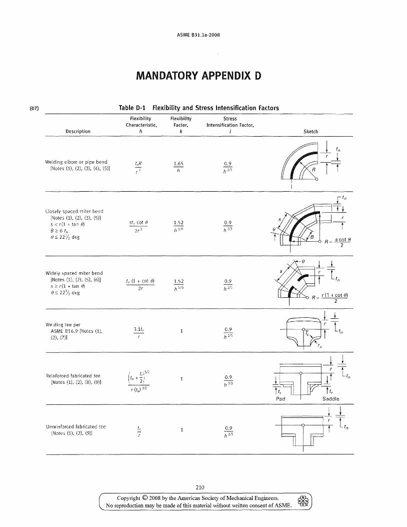
(07)
Description
Welding elbow or pipe bend [Notes (1), (2), (3), (4), (5)]
Closely spaced miter bend [Notes (1), (2), (3), (5)] 5 < r(l + tan 0)
B:::: 6 tn () S;; 22Y2 deg
Widely spaced miter bend [Notes (1), (2), (5), (6)] 5:::: r(l + tan fJ) () s;; 22Y2 deg
Welding tee per ASME B16.9 [Notes (1), (2), (7)]
Reinforced fabricated tee [Notes (1), (2), (8), (9)]
Unreinforced fabricated tee [Notes (1), (2), (9)]
ASME B31.1a-2008
MANDATORY APPENDIX D
Table 0-1 Flexibility and Stress Intensification Factors
Flexibility Characteristic,
h
tnR r2
tn (1 + cot 0)
2r
3.1tn
( trt~ t +-,n 2,
r (t,J 3/2
tn
Flexibility Factor,
k
1.65 h
1.52 h 5/6
1.52 h 5/6
210
Stress Intensification Factor,
0.9 h 2/3
0.9 h2;'3
0.9 h 2/3
0.9 h 2/'3
0.9 h 2,/'3
0.9 h 2;'3
Sketch
~ tn
r~
it
"I'-+--H--"'----o R = scot 8 2
r (1 + cot 0) R=
2
1~ w.Lt"
rx
~~
--±-Ltn
Pad Saddle
~~ r T t n
Copyright © 2008 by the American Society of Mechanical Engineers. ~ No reproduction may be made of this material vvithout written consent of ASME. ~
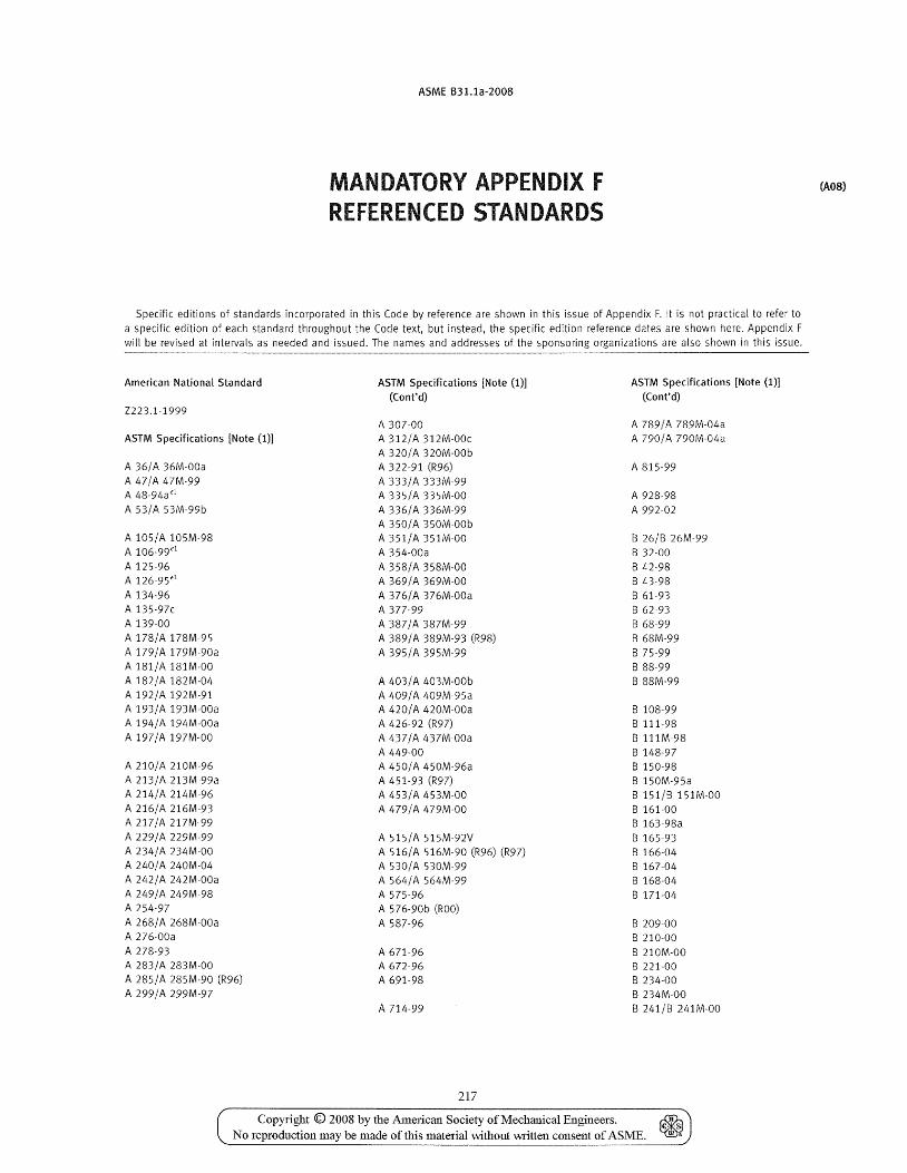
ASME B31.1a-2008
MANDATORY APPENDIX F REFERENCED STANDARDS
Specific editions of standards incorporated in this Code by reference are shown in this issue of Appendix F. It is not practical to refer to a specific edition of each standard throughout the Code text, but instead, the specific edition reference dates are shown here. Appendix F will be revised at intervals as needed and issued. The names and addresses of the sponsoring organizations are also shown in this issue.
American National Standard ASTM Specifications [Note (1)] ASTM Specifications [Note (1)]
(Cont'd) (Cont'd) Z223.1-1999
A 307-00 A 789/A 789M-04a ASTM Specifications [Note (1)] A 312/A 312M-00c A 790/A 790M-04a
A 320/A 320M-00b A 36/A 36M-00a A 322-91 (R96) A 815-99 A 47/A 47M-99 A 333/A 333M-99 A 48-94a<1 A 335/A 335M-00 A 928-98 A 53/A 53M-99b A 336/A 336M-99 A 992-02
A 350/A 350M-00b A lOS/A 105M-98 A 351/A 351M-OO B 26/B 26M-99 A 106-99<1 A 354-00a B 32-00 A 125-96 A 358/A 358M-OO B 42-98 A 126-95<1 A 369/ A 369M-00 B 43-98 A 134-96 A 376/A 376M-00a B 61-93 A 135-97c A 377-99 B 62-93 A 139-00 A 387/A 387M-99 B 68-99 A 178/A 178M-95 A 389/ A 389M-93 (R98) B 68M-99 A 179/A 179M-90a A 395/A 395M-99 B 75-99 A 181/A 181M-OO B 88-99 A 182/A 182M-04 A 403/A 403M-OOb B 88M-99 A 192!A 192M-91 A 409/A 409M-95a A 193/A 193M-OOa A 420/A 420M-OOa B 108-99 A 194!A 194M-00a A 426-92 (R97) B 111-98 A 197/A 197M-00 A 437/A 437M-00a B ll1M-98
A 449-00 B 148-97 A 210!A 210M-96 A 450/A 450M-96a B 150-98 A 213!A 213M-99a A 451-93 (R97) B 150M-95a A 214/A 214M-96 A 453/A 453M-00 B 151/B 151M-00 A 216!A 216M-93 A 479/A 479M-00 B 161-00 A 217/A 217M-99 B 163-98a A 229/A 229M-99 A 515/A 515M-92V B 165-93 A 234!A 234M-00 A 516/A 516M-90 (R96) (R97) B 166-04 A 240/A 240M-04 A 530/A 530M-99 B 167-04 A 242/A 242M-00a A 56/+/A 564M-99 B 168-04 A 249/A 249M-98 A 575-96 B 171-04 A 254-97 A 576-90b (ROO) A 268/ A 268M-00a A 587-96 B 209-00 A 276-00a B 210-00 A 278-93 A 671-96 B 210M-00 A 283/A 283M-00 A 672-96 B 221-00 A 28S/A 285M-90 (R96) A 691-98 B 234-00 A 299/A 299M-97 B 234M-OO
A 714-99 B 241/8 241M-OO
217
Copyright © 2008 by the American Society of Mechanical Engineers. ~ No reproduction may be made of this material without written consent of ASME. ~
(A08)

ASME 831.1a-2008
(07) Referenced Standards (Cont'd)
(A08)
ASTM Specifications [Note (1)] ASTM Specifications [Note (1)J API Specification (Cont'd) (Cont'd)
5L, 38th Edition, 1990 B 247-00 8 691-95
B 247M-OO ASME Codes & Standards 8 251-97 8 704-91 B 251M-97 B 705-94 80iler and Pressure Vessel Code, 8 265-99 8 729-00 2001 Edition, including
8 280-99 Addenda 8 283-99a 8 804-02
B 828-00 81.1-1989 8 302-00 B 861-00 Bl.13M-2001
8 315-99 B 862-99 Bl.20.1-1983 (R01)
B 338-99 (ANSI/ASME B1.20.1) 8 348-00 ASTM Standard Test Methods 81.20.3-1976 (R98)
B 361-95 (ANSI 81.20.3)
8 366-04b D 323-99 816.1-1998
B 367-93 (R98) E 94-00 816.3-1998
8 381-00 E 125-63 (R85) 816.4-1998 E 186-91 816.5-1996
8 407-96 E 280-93 816.9-2001
B 408-96 E 446-91 B16.10-2000
B 409-96a B16.11-2001
8 423-99 MSS Standard Practices 816.14-1991
8 424-98a 816.15-1985 (R94)
8 425-99 SP-6-96 (ANSI/ASME 816.15)
8 435-03 SP-9-97 816.18-1984 (R94)
8 443-93 SP-25-98 (ANSI B16.18)
8 444-94 SP-42-90 B16.20-1998
B 446-93 SP-43-91 816.21-1992
8 462-04 SP-45-98 B16.22-1995
8 463-99 SP-51-91 816.24-2001
8 464-99 SP-53-95 816.25-1997
8 466/8 466M-98 SP-54-95 816.34-1996 (98A)
8 467-88 (R97) SP-55-96 816.42-1998
8 468-99 SP-58-93 816.47-1996 (98A) 8 473-96 SP-61-92 816.48-1997
SP-67-95 816.50-2001
8 546-04 SP-68-97
8 547/8 547M-00 SP-69-96 818.2.1-1996 (99A)
8 564-00a SP-75-98 818.2.2-1987 (R99)
8 572-03 SP-79-92 (ASMEjANSI 818.2.2)
8 584-00 SP-80-97 818.2.3.5M-1979 (R01)
SP-83-01 B18.2.3.6M-1979 (R01)
8 608-95 SP-89-98 B18.2.4.6M-1979 (R98)
B 619-05 SP-93-87 818.21.1-1999
B 622-04a SP-94-92 B18.22M-1981
8 625-99 SP-95-00 818.22.1-1965 (R98)
8 626-04 SP-97-95
8 649-95 SP-105-96 B31.3-2002
8 673-96 SP-I06-03 B31.4-2002
8 674-96 831.8-1999
8 675-02 B36.10M-2000
B 676-03 AWS Specifications B36.19M-1985 (R94)
B 677-99 (ANSljASME B36.19M)
B 688-96 (R04) A3.0-94
B 690-02 QCl-88 TDP-1-1998
218
Copyright © 2008 by the AmeIican Society of Mechanical Engineers. ~ No reproduction may be made of this material \vithout written consent of ASME. ~
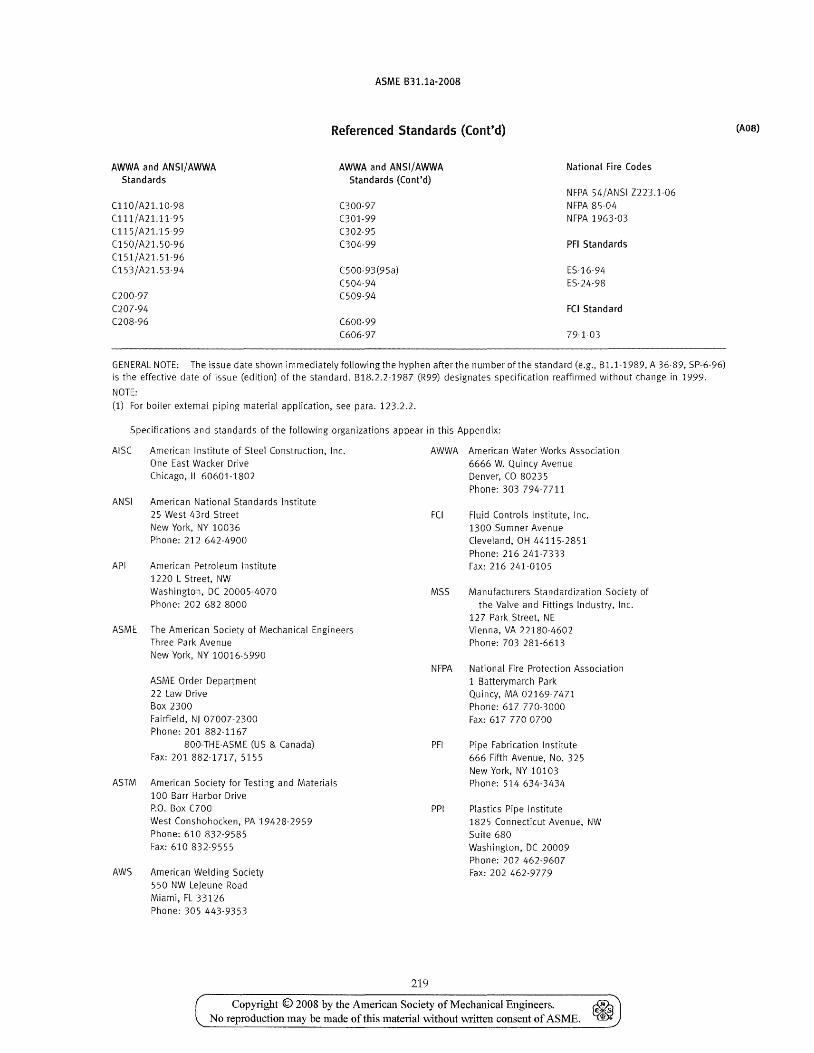
ASME B31.1a-2008
Referenced Standards (Cont'd)
AWWA and ANSI/ AWWA Standards
AWWA and ANSI/ AWWA Standards (Cont'd)
National Fire Codes
Cll0/A21.10-98 C111/A21.11-95 C115/A21.15-99 (150/A21.50-96
C151/A21.51-96 C153/A21.53-94
C200-97
C207-94 C208-96
C300-97 (301-99
C302-95
004-99
C500-93(95a) C504-94 C509-94
C600-99 C606-97
NFPA 54/ANSI Z223.1-06 NFPA 85-04 N FPA 1963-03
PFI Standards
ES-16-94 ES-24-98
FCi Standard
79-1-03
GENERAL NOTE: The issue date shown immediately following the hyphen after the number of the standard (e.g., B 1.1-1989, A 36-89, SP-6-96) is the effective date of issue (edition) of the standard. B18.2.2-1987 (R99) designates specification reaffirmed without change in 1999.
NOTE:
(1) For boiler external piping material application, see para. 123.2.2.
Specifications and standards of the following organizations appear in this Appendix:
AISC American Institute of Steel Construction, Inc. One East Wacker Drive Chicago, IL 60601-1802
ANSI American National Standards Institute 25 West 43rd Street
New York, NY 10036 Phone: 212 642-4900
API American Petroleum Institute 1220 L Street, NW Washington, DC 20005-4070 Phone: 202 682-8000
ASME The American Society of Mechanical Engineers Three Park Avenue New York, NY 10016-5990
ASME Order Department 22 Law Drive Box 2300 Fairfield, NJ 07007-2300 Phone: 201 882-1167
800-THE-ASME (US & Canada) Fax: 201 882-1717, 5155
ASTM American Society for Testing and Materials 100 Barr Harbor Drive P.O. Box ClOO West Conshohocken, PA 19428-2959 Phone: 610 832-9585
Fax: 610 832-9555
AWS American Welding Society 550 NW Lejeune Road
Miami, FL 33126 Phone: 305 443-9353
219
AWWA American Water Works Association 6666 W. Quincy Avenue
FCI
MSS
Denver, CO 80235
Phone: 303 794-7711
Fluid Controls Institute, Inc. 1300 Sumner Avenue Cleveland, OH 44115-2851
Phone: 216 241-7333 Fax: 216 241-0105
Manufacturers Standardization Society of the Valve and Fittings Industry, Inc.
127 Park Street, NE Vienna, VA 22180-4602 Phone: 703 281-6613
NFPA National Fire Protection Association 1 Batterymarch Park
PFI
PPI
Quincy, MA 02169-7471 Phone: 617 770-3000 Fax: 617 770-0700
Pipe Fabrication Institute 666 Fifth Avenue, No. 325 New York, NY 10103 Phone: 514 634-3434
Plastics Pipe Institute 1825 Connecticut Avenue, NW Suite 680 Washington, DC 20009 Phone: 202 462-9607 Fax: 202 462-9779
Copyright © 2008 by the American Society of Mechanical Engineers. ~ No reproduction may be made of this material vvithout written consent of ASME. ~
(AOS)
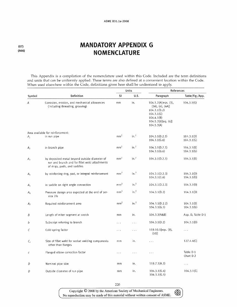
(07)
(AOS)
ASME B31.1a-2008
MANDATORY APPENDIX G NOMENCLATURE
This Appendix is a compilation of the nomenclature used within this Code. Included are the term definitions and units that can be uniformly applied. These terms are also defined at a convenient location within the Code. When used elsewhere within the Code, definitions given here shall be understood to apply.
Units References
Symbol Definition 51 U.s. Paragraph Table/Fig./ App.
A Corrosion, erosion, and mechanical allowances mm in. 104.1.2(A)[eqs. (3), 104.3.1(G) (including threading, grooving) (3A), (4), (4A)]
104.3.1(0.2) 104.3.1(G) 104.4.1(B) 104.S.2(B)[eq. (6)] 104.S.3(A)
Area available for reinforcement:
Al in run pipe -, . -,
104.3.1 (0.2 .3) 104.3.1(0) mm- In. -
104.3.1(G.6) 104.3.1(G)
A2 in branch pipe mm 2 in.2 104.3.1(D.2.3) 104.3.1(D) 104.3.1(G.6) 104.3.1(G)
A3 by deposited metal beyond outside diameter of mm 2 in.2 104.3.1(0.2.3) 104.3.1(0) run and branch and for fillet weld attachments of rings, pads, and saddles
AL, by reinforcing ring, pad, or integral reinforcement -,
in.2 104.3.1(0.2.3) 104.3.1(0) mm-104.3.1(G.6) 104.3.1(G)
As in saddle on right angle connection mm 2 in.2 104.3.1(0.2.3) 104.3.1(0)
A6 Pressure design area expected at the end of ser- mm 2 in.2 104.3.1(0.2) 104.3.1(0)
vice life
A7 Required reinforcement area mm 2 in.2 104.3.1(0.2.2) 104.3.1(0) 104.3.1(G.S) 104.3.1(G)
B Length of miter segment at crotch mm in. 104.3.3(A&B) App. 0, Table 0-1
b Subscript referring to branch 104.3.1(0.2) 104.3.1(0)
C Cold-spring factor 119.10.1[eqs. (9), (10)]
Cx Size of fillet weld for socket welding components mm in. 127.4.4(C)
other than flanges
Flanged elbow correction factor Table 0-1 Chart 0-2
D Nominal pipe size mm in. 119.7.1(A.3)
D Outside diameter of run pipe mm in. 104.3.1(G.4) 104.3.1(G) 104.3.1(G.S)
220
Copyright © 2008 by the American Society of Mechanical Engineers. ~ - ~> .~
No reproduction may be made of this material \vithout written consent of ASME. ~
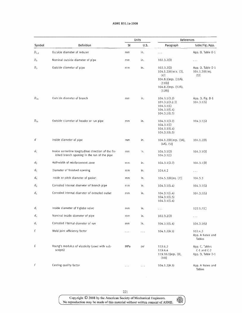
ASME B31.1a-2008
Units References
Symbol Definition 51 U.S. Paragraph Table/Fig./ App.
01,2 Outside diameter of reducer mm in. App. D, Table D-l
On Nominal outside diameter of pipe mm in. 102.3.2(D)
Do Outside diameter of pipe mm in. 102.3.2(D) App. D, Table D-l 104.1.2(A)[eqs. (3), 104.1.2(A)[eq.
(4)) (5)]
104.8.1 [eqs. (11A), (11 B)]
104.8.2[eqs. (12A), (12B)]
Dab Outside diameter of branch mm in. 104.3.1(D.2) App. D, Fig. D-l 104.3.1(D.2.3) 104.3.1(G) 104.3.1(E) 104.3.1(G.4) 104.3.1(G.5)
Doh Outside diameter of header or run pipe mm in. 104.3.1(D.2) 104.3.1(G) 104.3.1(E) 104.3.1(G.4) 104.3.1(G.5)
d Inside diameter of pipe mm in. 104.1.2(A)[eqs. (3A), 104.1.2(A) (4 A) , (5))
d1 Inside centerline longitudinal direction of the fin- mm in. 104.3.1(D) 104.3.1(D) ished branch opening in the run of the pipe 104.3_1 (E)
d2 Half-width of reinforcement zone mm in. 104.3.1(D.2) 104.3.1(D)
ds Diameter of finished opening mm in. 104.4.2
d6 Inside or pitch diameter of gasket mm in. 104.S.3(A)[eq. (7)) 104.5.3
db Corroded internal diameter of branch pipe mm in. 104.3.1(G.4) 104.3.1(G)
de Corroded internal diameter of extruded outlet mm in. 104.3.1(G.4) 104.3.1(G) 104.3.1(G.5) 104.3.1 (G.6)
di Inside diameter of Y-globe valve mm in. 122.1. 7(e)
dn Nominal inside diameter of pipe mm in. 102.3.2(D)
dr Corroded internal diameter of run mm in. 104.3.1(G.4) 104.3.1(G)
E Weld joint efficiency factor 104.1.2(A.S) 102.4.3 App. A Notes and
Tables
E Young's modulus of elasticity (used with sub- MPa psi 119.6.2 App. C, Tables scripts) 119.6.4 C-1 and C-2
119.10.1[eqs. (9), App. D, Table D-1 (10))
F Casting quality factor 104.1.2(A.5) App. A Notes and Tables
221
Copyright © 2008 by the American Society of Mechanical Engineers. ~ E"-: No reproduction may be made of this material without written consent of ASME. ~
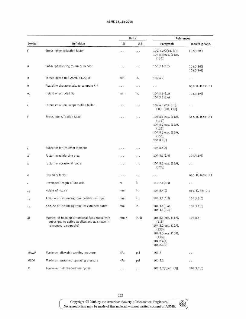
ASME B31.1a-2008
Units References
Symbol Definition SI U.S. Paragraph Table/Fig.j App.
f Stress range reduction factor 102.3.2(C)[eq. (1)] 102.3.2(C) 104.8.3[eqs. (13 A) ,
(13 B)]
h Subscript referring to run or header 104.3.1(0.2) 104.3.1(0) lO4.3.1(G)
h Thread depth (ref. ASME B1.20.1) mm in. 102.4.2
h Flexibility characteristic, to compute i, k App. 0, Table 0-1
ho Height of extruded lip mm in. 104.3.1 (G.2) 104.3.1(G) 104.3.1(G.4)
Lorenz equation compensation factor 102.4.5[eqs. (3B), (3C), (3D), (3E)]
Stress intensification factor 104.8.1 [eqs. (llA), App. 0, Table 0-1 (11B)]
104.8.2[eqs. (12A), (12 B)]
104.8.3[eqs. (13 A) , (13 B))
104.8.4(C)
Subscript for resultant moment 104.8.4(A)
K Factor for reinforcing area 104.3.1(G.5) 104.3.1(G)
k Factor for occasional loads 104.8.2[eqs. (12A), (12B)]
k Flexibility factor App. 0, Table 0-1
Developed length of line axis m ft 119.7.1(A.3)
L] Height of nozzle mm in. 104.8.4(C) App. 0, Fig. 0-1
L4 Altitude of reinforcing zone outside run pipe mm in. 104.3.1(0.2) 104.3.1(D)
L8 Altitude of reinforcing zone for extruded outlet mm in. 104.3.1(G.4) 104.3.1(G) 104.3.1(G.6)
M Moment of bending or torsional force (used with mm·N in.-Ib 104.8.1 [eqs. (llA), 104.8.4 subscripts to define applications as shown in (11 B)] referenced paragraphs) 104.8.2[eqs. (12A),
(12B)] 104.8.3[eqs. (13 A) ,
(13 B)] 104.8.4(A) 104.8.4(C)
MAWP Maximum allowable working pressure kPa psi 100.2
MSOP Maximum sustained operating pressure kPa psi 101.2.2
N Equivalent full temperature cycles 102.3.2(C)[eq. (2)] 102.3.2(C)
222
Copyright © 2008 by the American Society of Mechanical Engineers. ~ No reproduction may be made of this material without WTitten consent of ASME. ~
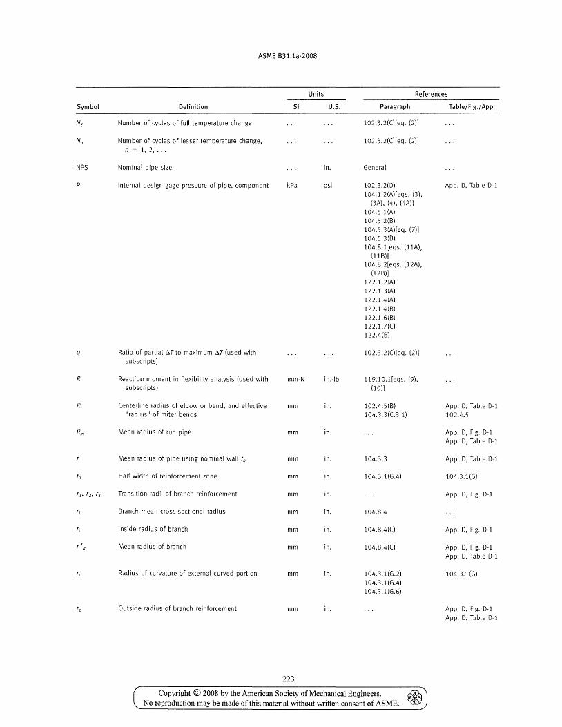
ASME B31.1a-2008
Units References
Symbol Definition SI U.S. Paragraph Table/Fig./ App.
NE Number of cycles of full temperature change 102.3.2(C)[eq. (2))
Nfl Number of cycles of lesser temperature change, 102.3.2(C)[eq. (2)) n = 1,2, ...
NPS Nominal pipe size in. General
p Internal design gage pressure of pipe, component kPa psi 102.3.2(0) App. 0, Table 0-1 104.1.2(A)[eqs. (3),
(3A) , (4), (4A)) 104.5.1(A) 104.5.2(8) 104.5.3(A)[eq. (7)) 104.5.3(B) 104.8.1[eqs. (11A),
(llB)] 104.8.2[eqs. (12A),
(12 B)] 122.1.2 (A) 122.1.3(A) 122. 1.4 (A) 122.1.4(B) 122.1.6(B) 122.1.7(C) 122.4(B)
q Ratio of partial LlT to maximum LlT (used with 102.3.2(C)[eq. (2)] subscripts)
R Reaction moment in flexibility analysis (used with mm-N in.-lb 119.10.1[eqs. (9), subscripts) (10)]
R Centerline radius of elbow or bend, and effective mm in. 102.4.5(B) App. 0, Table D-l "radius" of miter bends 104.3.3(C.3.1) 102.4.5
Rm Mean radius of run pipe mm in. App. D, Fig. D-l App. D, Table D-l
Mean radius of pipe using nominal wall tn mm in. 104.3.3 App. 0, Table 0-1
r1 Half width of reinforcement zone mm in. 104.3.1(G.4) 104.3.1(G)
r], rb r3 Transition radii of branch reinforcement mm in. App. D, Fig. D-l
rb Branch mean cross-sectional radius mm in. 104.8.4
ri Inside radius of branch mm in. 104.8.4(C) App. 0, Fig. D-l
r' m Mean radius of branch mm in. 104.8.4(C) App. 0, Fig. 0-1 App. D, Table 0-1
ro Radius of curvature of external curved portion mm in. 104.3.1(G.2) 104.3.1(G) 104.3.1(G.4) 104.3.1(G.6)
rp Outside radius of branch reinforcement mm in. App. 0, Fig. D-l App. D, Table D-l
223
Copyright © 2008 by the American Society of Mechanical Engineers. ~ No reproduction may be made of this material without written consent of ASME. l{®t
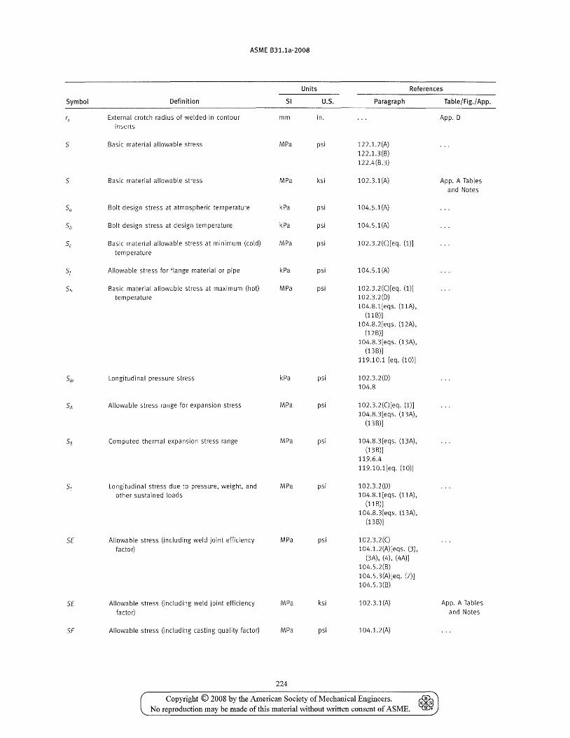
ASME 831.1a-2008
Units References
Symbol Definition SI U.S. Paragraph Table/Fig./ App.
rx Externa! crotch radius of we!ded·in contour mm in. App. D inserts
S Basic material allowable stress MPa psi 122.1.2(A)
122.1.3(B) 122.4(B.3)
S Basic material allowable stress MPa ksi 102.3.1 (A) App. A Tables and Notes
Sa Bolt design stress at atmospheric temperature kPa psi 104.5.1(A)
Sb Bolt design stress at design temperature kPa psi 104.5.1(A)
Sc Basic material allowable stress at minimum (cold) MPa psi 102.3.2(C)[eq. (1)]
temperature
Sf Allowable stress for flange material or pipe kPa psi 104.5.1(A)
Sh Basic material allowable stress at maximum (hot) MPa psi 102.3.2(C)[eq. (1)]
temperature 102.3.2(D) 104.8.1[eqs. (llA),
(11 B)] 104.8.2[eqs. (12A),
(12 B)] 104.8.3[eqs. (13A),
(13 B)] 119.10.1 [eq. (10)]
Sip Longitudinal pressure stress kPa psi 102.3.2(D) 104.8
SA Allowable stress range for expansion stress MPa psi 102.3.2(C)[eq. (1)J 104.8.3[eqs. (13A),
(13 B)]
Sf Computed thermal expansion stress range MPa psi 104.8.3[eqs. (13A), (13 B)]
119.6.4 119.10.1[eq. (10)]
SL Longitudinal stress due to pressure, weight, and MPa psi 102.3.2(D) other sustained loads 104.8.1 [eqs. (11A),
(11 B)] 104.8.3[eqs. (13 A) ,
(13 B)]
Sf Allowable stress (including weld joint efficiency MPa psi 102.3.2(C)
factor) 104.1.2(A)[eqs. (3), (3A), (4), (4A)]
104.5.2(B) 104.5.3(A)[eq. (7)] 104.5.3(B)
Sf Allowable stress (including weld joint efficiency MPa ksi 102.3.1 (A) App. A Tables
factor) and Notes
SF Allowable stress (including casting quality factor) MPa psi 104.1.2(A)
224
Copyright © 2008 by the American Society of Mechanical Engineers. ~ fl· ,s ..
No reproduction may be made of this material \vithout \Witten consent of ASME.
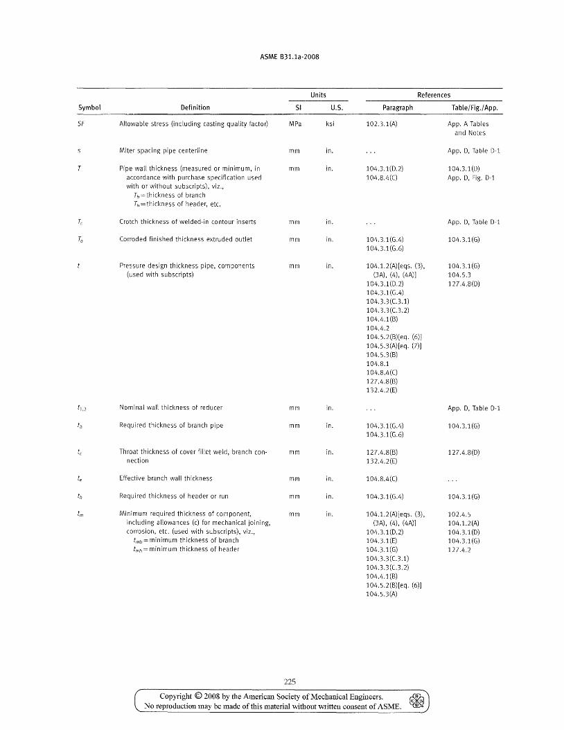
ASME B31.1a-2008
Units References
Symbol Definition SI U.S. Paragraph Table/Fig./ App.
SF Allowable stress (including casting quality factor) MPa ksi 102.3.1(A) App. A Tables and Notes
5 Miter spacing pipe centerline mm in. App. D, Table D-l
T Pipe wall thickness (measured or minimum, in mm in. 104.3.1(D.2) 104.3.1 (D) accordance with purchase specification used 104.8.4(C) App. D, Fig. D-l with or without subscripts), viz.,
h=thickness of branch Th = th ickn ess of header, etc.
Tc Crotch thickness of welded-in contour inserts mm in. App. D, Table D-l
To Corroded finished thickness extruded outlet mm in. 104.3.1(G.4) 104.3.1(G) 104.3.1(G.6)
Pressure design thickness pipe, components mm in. 104.1.2(A)[eqs. (3), 104.3.1(G) (used with subscripts) (3A), (4), (4A)] 104.5.3
104.3.1(D.2) 127.4.8(D) 104.3.1(G.4) 104.3.3(C.3.1) 104.3.3(C.3.2) 104.4.1(B) 104.4.2 104.5.2(B)[eq. (6)] 104.5.3(A)[eq. (7)] 104.5.3(B) 104.8.1 104.8.4(C) 127.4.8(B) 132.4.2(E)
t1,2 Nominal wall thickness of reducer mm in. App. D, Table D-l
tb Required thickness of branch pipe mm in. 104.3.1 (G.4) 104.3.1(G) 104.3.1(G.6)
tc Throat thickness of cover fillet weld, branch con- mm in. 127.4.8(8) 127.4.8(D) nection 132.4.2(E)
te Effective branch wall thickness mm in. 104.8.4(C)
til Required thickness of header or run mm in. 104.3.1 (G.4) 104.3.1(G)
trn Minimum required thickness of component, mm in. 104.1.2(A)[eqs. (3), 102.4.5 including allowances (c) for mechanical joining, (3A), (4), (4A)] 104.1.2(A) corrosion, etc. (used with subscripts), viz., 104.3.1 (D.2) 104.3.1(D)
tmb == minimum thickness of branch 104.3.1(E) 104.3.1(G) tmh == minimum thickness of header 104.3.1(G) 127.4.2
104.3.3(C.3.1) 104.3.3(C.3.2) 104.4.1(8) 104.5.2(B)[eq. (6)] 104.5.3(A)
225
Copyright © 2008 by the American Society of Mechanical Engineers. ~ No reproduction may be made oftbis material without written consent of ASME. ~
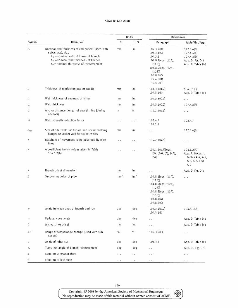
ASME B31.1a-2008
Units References
Symbol Definition 51 U.s. Paragraph Table/Fig./ App.
tn Nominal wall thickness of component (used with mm in. 102.3.2(D) 127.4.4(B) subscripts), viz., 104.3.1(G) 127.4.4(C)
tnb = nominal wall thickness of branch 104.3.3 127.4.8(0) tnh = nominal wall thickness of header 104.8.1[eqs. (11 A) , App. D, Fig. 0-1 tnr= nominal thickness of reinforcement (11 B)] App. 0, Table D-l
104.8.2[eqs. (12A), (12B)]
104.8.4(C)
127.4.8(B) 132.4.2(E)
tr Thickness of reinforcing pad or saddle mm in. 104.3.1(0.2) 104.3.1(D) 104.3.1(E) App. D, Table D-l
t, Wall thickness of segment or miter mm in. 104.3.3 (C.3)
til' Weld thickness mm in. 104.3.1(C.2) 127.4.8(F)
U Anchor distance (length of straight line joining m ft 119.7.1(A.3) anchors)
W Weld strength reduction factor 102.4.7 102.4.7 104.1.4
Xmin Size of fillet weld for slip-on and socket welding mm in. 127.4.4(B) flanges or socket wall for socket welds
y Resultant of movement to be absorbed by pipe- 119.7.1(A.3) lines
y A coefficient having values given in Table 104.1.2 (A.7)[ eqs. 104.1.2(A) 104.1.2(A) (3), (3A), (4), (4A) , App. A, Notes to
(5)] Tables A-4, A-5, A-6, A-7, and
A-9
y Branch offset dimension mm in. App. D, Fig. 0-1
Z Section modulus of pipe mm 3 in.} 104.8.1[eqs. (llA), (11B)]
104.8.2[eqs. (12A), (12B)]
104.8.3[eqs. (13 A) , (13 B)]
104.8.4(A)
104.8.4(C)
(I' Angle between axes of branch and run deg deg 104.3.1(0.2) 104.3.1 (D) 104.3.1(E)
(I' Reducer cone angle deg deg App. D, Table D-l
8 Mismatch or offset mm in. App. 0, Table 0-1
6.T Range of temperature change (used with sub- °C OF 102.3.2(C) scripts)
f} Angle of miter cut deg deg 104.3.3 App. 0, Table 0-1
fJn Transition angle of branch reinforcement deg deg App. D., Fig. D-l
;::: Equal to or greater than
~ Equal to or less than
226
Copyright © 2008 by the American Society of Mechanical Engineers. ~ No reproduction may be made of this material without written consent of ASME. ~
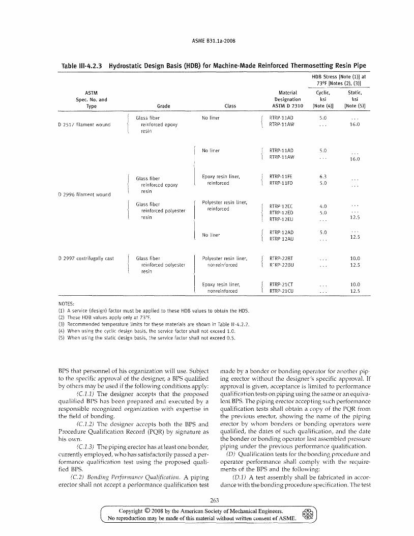
ASME B31.1a-2008
Table 111-4.2.3 Hydrostatic Design Basis (HOB) for Machine-Made Reinforced Thermosetting Resin Pipe
HOB Stress [Note (1)] at 73°F [Notes (2), (3)]
ASTM Material Cyclic, Static, Spec. No. and Designation ksi ksi
Type Grade Class ASTM D 2310 [Note (4)] [Note (5)]
Glass fiber No liner RTRP-I1AD 5_0 D 2517 filament wound reinforced epoxy RTRP-I1AW 16.0
resin
No liner { RTRP-I1AD 5.0 RTRP-I1AW 16.0
Glass fiber Epoxy resin liner, { RTRP-I1FE 6.3
reinforced epoxy rei nforced RTRP-I1FD 5.0
D 2996 filament wound resin
Glass fiber Polyester resin liner. RTRP-12EC 4.0
reinforced polyester reinforced RTRP-12ED 5.0
resin RTRP-12EU 12.5
No liner { RTRP-12AD 5.0 RTRP-12AU 12.5
o 2997 centrifugally cast Glass fiber Polyester resin liner, t RTRP-22BT 10_0 reinforced polyester nonreinforced RTRP-22BU 12.5 resin
Epoxy resin liner, t RTRP-21CT 10.0 nonreinforced RTRP-21CU 12.5
NOTES: (1) A service (design) factor must be applied to these HDB values to obtain the HDS. (2) These HDB values apply only at 73°F. (3) Recommended temperature limits for these materials are shown in Table 111-4.2.2. (4) When using the cyclic design basis, the service factor shaH not exceed 1.0. (5) When using the static design basis, the service factor shall not exceed 0.5.
BPS that personnel of his organization will use. Subject to the specific approval of the designer, a BPS qualified by others may be used if the following conditions apply:
(C.1.1) The designer accepts that the proposed qualified BPS has been prepared and executed by a responsible recognized organization with expertise in the field of bonding.
(C1.2) The designer accepts both the BPS and Procedure Qualification Record (PQR) by signature as his own.
(CJ.3) The piping erector has at least one bonder, currently employed, who has satisfactorily passed a performance qualification test using the proposed qualified BPS.
(C2) Bonding Pe~formance Qualification. A piping erector shall not accept a performance qualification test
263
made by a bonder or bonding operator for another piping erector without the designer's specific approval. If approval is given, acceptance is limited to performance qualification tests on piping using the same or an equivalent BPS. The piping erector accepting such performance qualification tests shall obtain a copy of the PQR from the previous erector, showing the name of the piping erector by whom bonders or bonding operators were qualified, the dates of such qualification, and the date the bonder or bonding operator last assembled pressure piping under the previous performance qualification.
(D) Qualification tests for the bonding procedure and operator performance shall comply with the requirements of the BPS and the following:
(D.1) A test assembly shall be fabricated in accordance with the bonding procedure specification. The test
Copyright © 2008 by the American Society of Mechanical Engineers. ~ No reproduction may be made of this material without written consent of ASME. ~
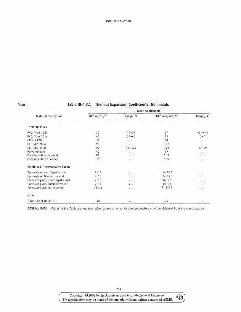
(M8)
ASME B31.1a-2008
Table 111-4.3.1 Thermal Expansion Coefficients, Nonmetals
Material Description
Thermoplastics
PVC, Type 1120 PVC, Type 2116 CPVC 4120 PE, Type 2406 PE, Type 3408 Polypropylene
Poly(vinylidine chloride)
Poly(vinylidine fluoride)
Reinforced Thermosetting Resins
Epoxy-glass, centrifugally cast
Epoxy-glass, filament-wound
Polyester-glass, centrifugally cast
Polyester-glass, filament-wound
Polyester-glass, hand lay-up
Other
Hard rubber (Buna N)
30 40 34 90 90 43 85 100
9-13 9-13 9-15 9-11
12-15
40
Mean Coefficients
23-37 54 37-45 72
61 162
70-120 162 77
153 180
16-23.5 16-23.5 16-27 16-20
21.5-27
72
Range, DC
-5 to +3 3-7
21-49
GENERAL NOTE: Values in this Table are representative. Values at actual design temperature shall be obtained from the manufacturers.
264
Copyright © 2008 by the American Society of Mechanical Engineers. No reproduction may be made of this material without written consent of ASME.
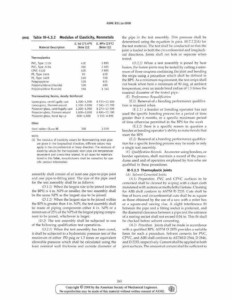
(A08)
ASME B31.1a-2008
Table 111-4.3.2 Modulus of Elasticity, Nonmetals
E, ksi (73.4°F)
Material Description [Note (1)]
Thermoplastics
PVC, Type 1120 420 PVC, Type 2116 360 CPVC4120 420 PE, Type 2406 90 PE, Type 3408 110 Polypropylene 120 Poly(vinylidene/chloride) 100 Poly(vinylidene fluoride) 194
Thermosetting Resins, Axially Reinforced
Epoxy-glass, centrifugally cast Epoxy-glass, filament-wound Polyester-glass, centrifugally cast Polyester-glass, filament-wound Polyester-glass, hand lay-up
Other
Hard rubber (Buna N)
NOTE:
1,200-1,900 1,100-2,000 1,200-1,900 1,000-2,000 800-1,000
300
E, MPa (23°C) [Note (1)]
2895 2485 2895 620 740 825 690
1 340
8 725-13 100 7 585-13 790 8275-13 100 6895-13 790 5 515-6895
2 070
(1) The modulus of elasticity values for thermosetting resin pipe are given in the longitudinal direction; different values may apply in the circumferential or hoop direction. The modulus of elasticity values for thermoplastic resin pipe are temperaturedependent and stress-time related. In all cases for materials listed in this Table, manufacturers shall be consulted for specific product information.
assembly shall consist of at least one pipe-to-pipe joint and one pipe-to-fitting joint. The size of the pipe used for the test assembly shall be as follows:
(D.1.1) When the largest size to be joined (within the BPS) is 4 in. NPS or smaller, the test assembly shall be the same NPS as the largest size to be joined.
(0.1.2) When the largest size to be joined within the BPS is greater than 4 in. NPS, the test assembly shall be made of piping components either 4 in. NPS or a minimum of 25% of the NPS of the largest piping component to be joined, whichever is larger.
(0.2) The test assembly shall be subjected to one of the following qualification test operations.
(0.2.1) When the test assembly has been cured, it shall be subjected to a hydrostatic pressure test of the maximum of either 150 psig or 1.5 times an equivalent allowable pressure which shall be calculated using the least nominal waH thickness and outside diameter of
265
the pipe in the test assembly. This pressure shall be determined using the equation in para. III-2.2.2(A) for the test material. The test shall be conducted so that the joint is loaded in both the circumferential and longitudinal directions. Joints shall not leak or separate 'when tested.
(D.2.2) 'Nhen a test assembly is joined by heat fusion, the fusion joints may be tested by cutting a minimum of three coupons containing the joint and bend ing the strips using a procedure which shall be defined in the BPS. As a minimum requirement, the test strips shall not break when bent a minimum of 90 deg, at ambient temperature, over an inside bend radius of 1.5 times the nominal diameter of the tested pipe.
(E) Pelformance Requalification (E.1) Renewal of a bonding performance qualifica
tion is required when (E.1.1) a bonder or bonding operator has not
used the specific bonding process for a period of time greater than 6 months, or a specific maximum period of time otherwise permitted in the BPS for the work
(£.1.2) there is a specific reason to question a bonder or bonding operator's ability to make bonds that meet the BPS
(£.2) Renewal of a bonding performance qualification for a specific bonding process may be made in only a single test assembly.
(F) Qualification Records. An erector using bonders, or bonder operators, shall maintain a record of the procedures used and of operators employed by him who are qualified in these procedures.
111-5.1.3 Thermoplastic Joints (A) Solvent-Cemented foints
(A.l) Preparation. PVC and CPVC surfaces to be cemented shall be cleaned by wiping with a clean cloth moistened with acetone or methylethyl ketone. Cleaning for ABS shall conform to ASTM D 2235. Cuts shall be free of burrs and circumferential cuts shall be as square as those obtained by the use of a saw with a miter box or a square-end sawing vise. A slight interference fit between the pipe and a fitting socket is preferred, and the diametral clearance between a pipe and the entrance of a mating socket shall not exceed 0.04 in. This fit shall be checked before solvent cementing.
(A.2) Procedure. Joints shall be made in accordance with a qualified BPS. ASTM D 2855 provides a suitable basis for such a procedure. Solvent cements for PVC, CPVc, and ABS shall conform to ASTM D 2564, D 2846, and D 2235, respectively. Cement shall be applied to both joint surfaces. The amount of cement shall be sufficient to
Copyright © 2008 by the American Society of Mechanical Engineers. ~ No reproduction may be made of this material without written consent of ASME. ~
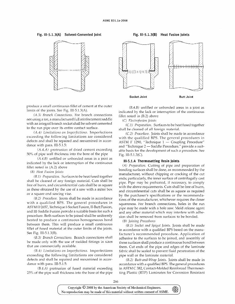
ASME B31.1a-2008
Fig. 111-5.1.3(A} Solvent-Cemented Joint
produce a small continuous fillet of cement at the outer limits of the joints. See Fig. 1II-5.1.3(A).
(A.3) Branch Connections. For branch connections not using a tee, a manufactured full reinforcement saddle with an integral branch socket shall be solvent cemented to the run pipe over its entire contact surface.
(A.4) Limitations on ImpcI/ections. Imperfections exceeding the following limitations are considered defects and shall be repaired and reexamined in accordance with para. 1II-5.1.5:
(A.4.A) protrusion of dried cement exceeding SO'Yo of pipe wall thickness into the bore of the pipe
(A.4.B) unfilled or unbonded areas in a joint as indicated by the lack or interruption of the continuous fillet noted in (A.2) above
(B) Heat Fusion joints (B.1) Preparation. Surfaces to be heat fused together
shall be cleaned of any foreign materiaL Cuts shall be free of burrs, and circumferential cuts shall be as square as those obtained by the use of a saw with a miter box or a square-end sawing vise.
(B.2) Procedure. Joints shall be made in accordance wi th a qualified BPS. The genera] procedures in ASTM D 2657, Technique I-Socket Fusion, II-Butt Fusion, and III-Saddle Fusion provide a suitable basis for such a procedure. Both surfaces to be joined shall be uniformly hea ted to produce a continuous homogeneous bond between them. This will produce a small continuous fillet of fused material at the outer limits of the joints. See Fig. III-5.l.3(B).
(B.3) Branch Connections. Branch connections shall be made only with the use of molded fittings in sizes that are commercially available.
(B.4) Limitations on Imperfections. Imperfections exceeding the following limitations are considered defects and shall be repaired and reexamined in accordance with para. III-S.l.S:
(B.4.A) protrusion of fused material exceeding 25% of the pipe wall thickness into the bore of the pipe
266
Fig. 111-5.1.3(B} Heat Fusion Joints
Socket Joint Butt Joint
(B.4.B) unfilled or unbonded areas in a joint as indicated by the lack or interruption of the continuous fillet noted in (B.2) above
(C) Electrofusion joints (C1) Preparation. Surfaces to be heat fused together
shall be cleaned of all foreign material. (e2) Procedure. Joints shall be made in accordance
with the qualified BPS. The general procedures in ASTM F 1290, "Technique 1 - Coupling Procedure" and "Technique 2 - Saddle Procedure," provide a suitable basis for the development of such a procedure. See Fig. III-5.l.3(C).
111-5.1.4 Thermosetting Resin Joints (A) PrtfJaratioll. Cutting of pipe and preparation of
bonding surfaces shall be done, as recommended by the manufacturer, without chipping or cracking of the cut ends; particularly, the inner surface of centrifugally cast pipe. Pipe may be preheated, if necessary, to comply with the above requirements. Cuts shall be free of burrs, and circumferentiCll cuts shall be as square as required by the purchaser's specifications or the recommendations of the manufacturer! whichever requires the closer squareness. For branch connections, holes in the run pipe may be made "vith a hole saw. Mold release agent and any other material which may interfere with adhesion shall be removed from surfaces to be bonded.
(B) Joining Procedures (B.1) Socket and Spigot joints. Joints shall be made
in accordance with a qualified BPS based on the manufacturer's recommended procedure. Application of adhesive to the surfaces to be joined, and assembly of those surfaces shall produce a continuous bond between them. Cut ends of the pipe and edges of the laminate fabric shall be sealed to prevent fluid penetration of the pipe wall or the laminate material.
(B.2) Butt-and-Wrap Joints. Joints shall be made in accordance with a qualified BPS. The general procedures in ASTwl C 582, Contact-Molded Reinforced Thermosetting Plastic (RTP) Laminates for Corrosion Resistant
Copyright © 2008 by the American Society of Mechanical Engineers. ~ No reproduction may be made of this material without written consent of ASME.
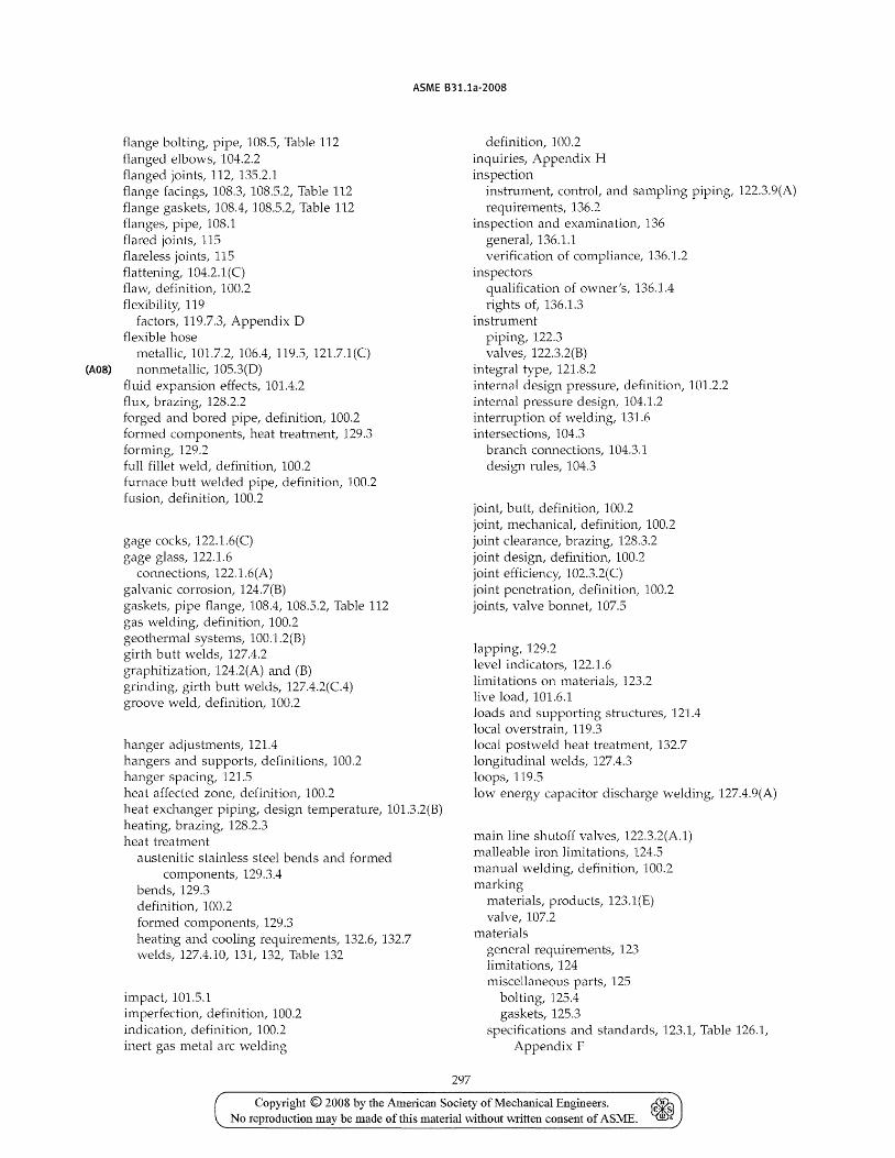
ASME B31.1a-2008
flange bolting, pipe, 108.5, Table 112 flanged elbows, 104.2.2 flanged joints, 112, 135.2.1 flange facings, 108.3, 108.5.2, Table 112 flange gaskets, 108.4, 108.5.2, Table 112 flanges, pipe, 108.1 flared joints, 115 flareless joints, 115 flattening, 104.2.1(C) flaw, definition, 100.2 flexibility, 119
factors, 119.7.3, Appendix D flexible hose
metallic, 101.7.2, 106.4, 119.5, 121.7.1(C) (A08) nonmetallic, 105.3(D)
fluid expansion effects, 101.4.2 flux, brazing, 128.2.2 forged and bored pipe, definition, 100.2 fonned components, heat treatment, 129.3 forming, 129.2 full fillet weld, definition, 100.2 furnace butt welded pipe, definition, 100.2 fusion, definition, 100.2
gage cocks, 122.1.6(C) gage glass, 122.1.6
connections, 122.1.6(A) galvanic corrosion, 124.7(B) gaskets, pipe flange, 108.4, 108.5.2, Table 112 gas welding, definition, 100.2 geothermal systems, 100.1.2(B) girth butt welds, 127.4.2 graphitization, 124.2(A) and (B) grinding, girth butt welds, 127.4.2(C.4) groove weld t definition, 100.2
hanger adjustments, 121.4 hangers and supports, definitions, 100.2 hanger spacing, 121.5 heat affected zone, definition, 100.2 heat exchanger piping, design temperature, 101.3.2(B) heating, brazing, 128.2.3 heat treatment
austenitic stainless steel bends and formed components, 129.3.4
bends, 129.3 definition, 100.2 formed components, 129.3 heating and cooling requirements, 132.6, 132.7 welds, 127.4.10, 131, 132, Table 132
impact, 101.5.1 imperfection, definition, 100.2 indication, definition, 100.2 inert gas metal arc welding
297
definition, 100.2 inquiries, Appendix H inspection
instrument, control, and sampling piping, 122.3.9(A)
requirements, 136.2 inspection and examination, 136
generat 136.1.1 verification of compliance, 136.1.2
inspectors qualification of owner's, 136.1.4 rights of, 136.1.3
instrument piping, 122.3 valves, 122.3.2(B)
integral type, 121.8.2 internal design pressure, definition, 101.2.2 internal pressure design/ 104.1.2 interruption of welding, 131.6 intersections, 104.3
branch connections, 104.3.1 design rules, 104.3
joint, butt, definition, 100.2 joint, mechanical, definition, 100.2 joint clearance, brazing, 128.3.2 joint design, definition, 100.2 joint efficiency, 102.3.2(C) joint penetration, definition, 100.2 joints, valve bonnet, 107.5
lapping, 129.2 level indicators, 122.1.6 limitations on materials, 123.2 live load, 101.6.1 loads and supporting structures, 121.4 10ea 1 overstrain, 119.3 local postweld heat treatment, 132.7 longitudinal welds, 127.4.3 loops, 119.5 low energy capacitor discharge welding, 127.4.9(A)
main line shutoff valves, 122.3.2(A.l) malleable iron limitations, 124.5 manual welding, definition, 100.2 marking
materials, products, 123.1(E) valve, 107.2
materials general requirements, 123 limitations, 124 miscellaneous parts, 125
bolting, 125.4 gaskets, 125.3
specifications and standards, 123.1, Table 126.1, Appendix F
Copyright © 2008 by the American SociehT of Mechanical Engm' eers. ~ _ ".l ~ •. ~
No reproduction may be made of this material without written consent of ASME. -
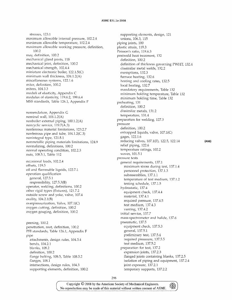
ASME B31.1a-2008
stresses, 123.1 maximum allowable internal pressure, 102.2.4 maximum allowable temperature, 102.2.4 maximum allowable working pressure, definition,
100.2 may, definition, 100.2 mechanical gland joints, 118 mechanical joint, definition, 100.2 mechanical strength, 102.4.4 miniature electronic boilel~ 122.1.5(C) minimum \'vall thickness, 104.1.2(A) miscellaneous systems, 122.1.6 nliter, definition, 100.2 miters, 104.3.3 moduli of elasticity, Appendix C modulus of elasticity, 119.6.2, 199.6.4 MSS standards, Table 126.1, Appendix F
nornendClture, Appendix G nominal wall, 104.1.2(A) nonboiler external piping, 100.1.2(A) noncyc1ic service, 119.7(A.3) nonferrous material limitations, 123.2.7 nonferrous pipe and tube, 104.1.2(C.3) nonintegral type, 121.8.1 nonmetallic piping materials limitations, 124.9 normalizing, definitions, 100.2 normal operating condition, 102.2.3 nuts, 108.5.1, Table 112
occasional loads, 102.2.4 offsets, 119.5 oil and flammable liquids, 122.7.1 operation qualification
general, 127.5.1 responsibility, 127.5.3(B)
operatOl~ welding, definitions, 100.2 other rigid types (fixtures), 121.7.2 outside screw and yoke, valve, 107.4 ovality, 104.2.1(B) overpressurization, Valve, 107.1(C) oxygen cutting, definition, 100.2 oxygen gouging, definition, 100.2
peening, 100.2 penetration, root, definition, 100.2 PFI standards, Table 126.1, Appendix F pipe
attachments, design rules, 104.3.4 bends, 104.2.1 blanks, 108.2 definition, 100.2 flange bolting, 108.5, Table 108.5.2 flanges, 108.1 intersections, design rules, 104.3 supporting elements, definition, 100.2
298
supporting elements, design, 121 unions, 106.3, 115
piping joints, 100 plastic strain, 119.3 Poisson's ratio, 119.6.3 postweld heat treatment, 132
definition, 100.2 definition of thickness governing PWBT, 132.4 dissimilar metal welds, 132.2 exemptions, 132.3 furnace heating, 132.6 heating and cooling rates, 132.5 local heating, 132.7 mandatory requirements, Table 132 minimum holding temperature, Table 132 minimum holding time, Table 132
preheating, 131 definition, 100.2 dissimilar metals, 131.2 temperature, 131.4
preparation for welding, 127.3 pressure
definition, 100.2 entrapped liquids, valve, 107.1(C) gages, 122.1.6 reducing valves, 107.1(F), 122.5, 122.14 relief piping, 122.6 tempera ture ratings, 102.2 waves, 101.5.1
pressure tests general requirements, 137.1
maximum stress during test, 137.1.4 personnel protection, 137.1.3 subassemblies, 137.1.1 temperature of test medium, 137.1.2 testing schedule, 137.1.5
hydrostatic, 137.4 equipment check, 137.4.4 material, 137.4.1 required pressure, 137.4.5 test medium, 137.4.3 venting, 137.4.2
initial service, 137.7 mass-spectrometer and halide, 137.6 pneumatic, 137.5
equipment check, 137.5.3 general, 137.5.1 preliminary test, 137.5.4 required presssure, 137.5.5 test medium, 137.5.2
preparation for test, 137.2 expansion joints, 137.2.3 flanged joints containing blanks, 137.2.5 isolation of piping and equipment, 137.2.4 joint exposure, 137.2.1 temporary supports, 137.2.2
Copyright © 2008 by the American Society of Mechanical Engineers. No reproduction may be made of this material without written consent of ASME.
(A08)
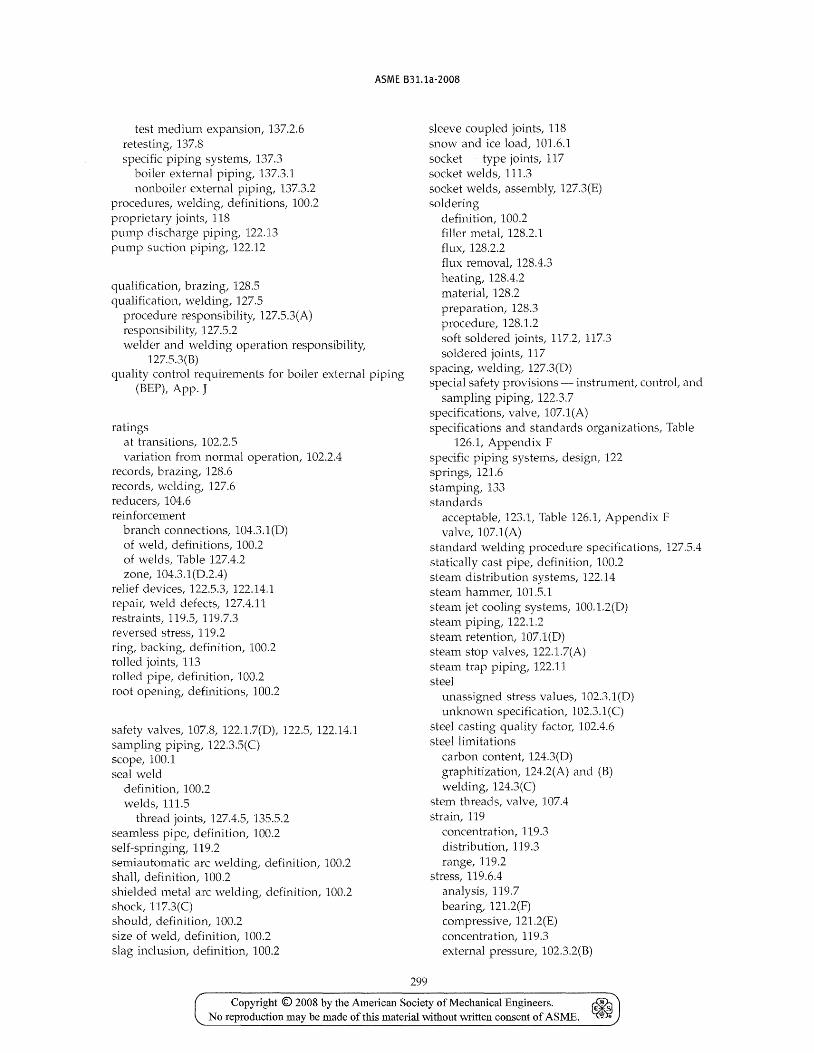
ASME B31.1a-2008
test medium expansion, 137.2.6 retesting, 137.8 sp(xific piping systems, 137.3
boiler external piping, 137.3.1 nonboiler external piping, 137.3.2
procedures, welding, definitions, 100.2 proprietary joints, 118 puntp discharge piping, 122.13 pump suction piping, 122.12
qUCllification, brazing, 128.5 qualification, welding, 127.5
procedure responsibility, 127.5.3(A) responsibility, 127.5.2 welder and welding operation responsibility,
127.5.3(B) quality control requirements for boiler external piping
(BEP), App. J
ratings at transitions, 102.2.5 variation from normal operCltion, 102.2.4
records, brazing, 128.6 records, welding, 127.6 reducers, 104.6 reinforcement
branch connections, 104.3.1 (D) of weld, definitions, 100.2 of welds, Table 127.4.2 zone, 104.3.1(D.2.4)
relief devices, 122.5.3, 122.14.1 repail~ weld defects, 127.4.11 restraints, 119.5, 119.7.3 reversed stress, 119.2 ring, backing, definition, 100.2 rolled joints, 113 rolled pipe, definition, 100.2 root opening, definitions, 100.2
safety valves, 107.8, 122.1.7(D), 122.5, 122.14.1 sampling piping, 122.3.5(C) scope, 100.1 sea] weld
definition, 100.2 welds, 111.5
thread joints, 127.4.5, 135.5.2 seamless pipe, definition, 100.2 self-springing, 119.2 semiautomatic arc welding, definition, 100.2 shall, definition, 100.2 shielded metal arc -welding, definition, 100.2 shock, 117.3(C) should, definition, 100.2 size of weld, definition, 100.2 slag inclusion, definition, 100.2
299
sleeve coupled joints, 118 snow and ice load, 101.6.1 socket - type joints, 117 socket welds, 111.3 socket welds, assembly, 127.3(E) soldering
definition, 100.2 filler met at 128.2.1 flux, 128.2.2 flux removal, 128.4.3 heating, 128.4.2 material, 128.2 preparation, 128.3 procedure, 128.1.2 soft soldered joints, 117.2, 117.3 soldered joints, 117
spacing, welding, 127.3(D) special safety provisions - instrument, con trot and
sampling piping, 122.3.7 specifications, valve, 107.1(A) specifications and standards organizations, Table
126.1, Appendix F specific piping systems, design, 122 springs, 121.6 stamping, 133 standards
acceptable, 123.1, Table 126.1, Appendix F valve, 107.1(A)
standard welding procedure specifications, 127.5.4 statically cast pipe, definition, 100.2 steam distribution systems, 122.14 steam hammer, 101.5.1 steam jet cooling systems, 100.1.2(D) steam piping, 122.1.2 steam retention, 107.1(D) steam stop valves, 122.1.7(A) steam trap piping, 122.11 steel
unassigned stress values, 102.3.1(D) unknown specification, 102.3.1 (C)
steel casting quality factor, 102.4.6 steel limitations
carbon content, 124.3(D) graphitization, 124.2(A) and (B) welding, 124.3(C)
stem threads, valve, 107.4 strain, 119
concentration, 119.3 dis tribu tion, 119.3 range, 119.2
stress, 119.6.4 analysis, 119.7 bearing, 121.2(F) compressive, 121.2(E) concentra tion, 119.3 external pressure, 102.3.2(B)
Copyright © 2008 by the American Society of Mechanical Engineers. ~ .. No reproduction may be made of this material without written consent of ASME. ~
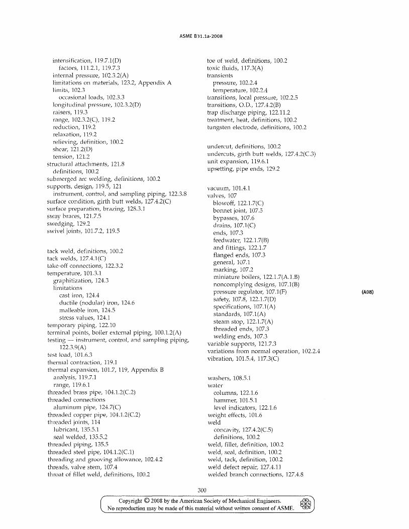
ASME B31.1a-2008
intensification, 119.7.1(D) factors, 111.2.1, 119.7.3
internal pressure, 102.3.2(A) limitations on materials, 123.2, Appendix A limits, 102.3
occasional loads, 102.3.3 longitudinal pressure, 102.3.2(D) raisers, 119.3 range, 102.3.2(C), 119.2 reduction, 119.2 relaxation, 119.2 relieving, definition, 100.2 shear, 121.2(D) tension, 121.2
structural attachments, 121.8 definitions, 100.2
submerged arc welding, definitions, 100.2 supports, design, 119.5, 121
instrument, control, and sampling piping, 122.3.8 surface condition, girth butt welds, 127.4.2(C) surface preparation, brazing, 128.3.1 sway braces, 121.7.5 swedging, 129.2 swivel joints, 101.7.2, 119.5
tack weld, definitions, 100.2 tack welds, 127.4.1 (C) take-off connections, 122.3.2 temperature, 101.3.1
graphitization, 124.3 limitations
cast iron, 124.4 ductile (nodular) iron, 124.6 malleable iron, 124.5 stress values, 124.1
temporary piping, 122.10 terminal points, boiler external piping, 100.1.2(A) testing - instrument, controt and sampling piping,
122.3.9(A) test load, 101.6.3 thermal contraction, 119.1 thermal expansion, 101.7, 1191 Appendix B
analysis, 119.7.1 range, 119.6.1
threaded brass pipe, 104.1.2(C2) threaded connections
aluminum pipe, 124.7(C) threaded copper pipe, 104.1.2(C2) threaded joints, 114
lubricant, 135.5.1 seal welded, 135.5.2
threaded piping, 135.5 threaded steel pipe, 104.1.2(Cl) threading and grooving allowance, 102.4.2 threads, valve stem, 107.4 throat of fillet weld, definitions, 100.2
300
toe of weld, definitions, 100.2 toxic fluids, 117.3(A) transients
pressure, 102.2.4 temperature, 102.2.4
transitions, local pressure, 102.2.5 transitions, O.D., 127.4.2(B) trap discharge piping, 122.11.2 treatment, heat, definitions, 100.2 tungsten electrode, definitions, 100.2
undercut, definitions, 100.2 undercuts, girth butt welds, 127.4.2(C3) unit expansion, 119.6.1 upsetting, pipe ends, 129.2
vacuum, 101.4.1 valves, 107
blowoff, 122.1.7(C) bonnet joint, 107.5 bypasses, 107.6 drains, 107.1(C) ends, 107.3 feedwater, 122.1.7(8) and fittings, 122.1.7 flanged ends, 107.3 generat 107.1 marking, 107.2 miniature boilers, 122.1.7(A.1.B) noncomplying designs, 107.1(B) pressure regulator, 107.1 (F) safety, 107.8, 122.1.7(D) specifications, 107.1 (A) standards, 107.1(A) steam stop, 122.1.7(A) threaded ends, 107.3 welding ends, 107.3
variable supports, 121.7.3 variations from normal operation, 102.2.4 vibration, 101.5.4, 117.3(C)
washers, 108.5.1 "vater
columns, 122.1.6 hammer, 101.5.1 level indicators, 122.1.6
weight effects, 101.6 weld
concavity, 127.4.2(C5) definitions, 100.2
weld, fillet, definition, 100.2 weld, seal, definition, 100.2 weld, tack, definition, 100.2 ,veld defect repair, 127.4.11 welded branch connections, 127.4.8
Copyright © 2008 by the American Society of Mechanical Engineers. ~ No reproduction may be made of this material without written consent of ASME. ~
(A08)
ASME 831.1 INTERPRETATIONS VOLUME 43
Replies to Technical Inquiries January 1, 2007 Through December 31, 2007
FOREWORD
It has been agreed to publish interpretations issued by the B31 Committee concerning B31.1 as part of the update service to the Code. The interpretations have been assigned numbers in chronological order. Each interpretation applies either to the latest Edition or Addenda at the tin1e of issuance of the interpretation or the Edition or Addenda stated in the reply. Subsequent revisions to the Code may have superseded the reply.
The replies are taken verbatim from the original letters, except for a few typographical and editorial corrections made for the purpose of improved clarity. In some instances, a review of the interpretation revealed a need for corrections of a technical nature. In these cases, a revised reply bearing the original interpretation number with the suffix R is presented. In the case where an interpretation is corrected by errata, the original interpretation number with the suffix E is used.
ASME procedures provide for reconsideration of these interpretations when or if additional information is available which the inquirer believes might affect the interpretation. Further, persons aggrieved by an interpretation may appeal to the cognizant ASME committee or subcommittee. As stated in the Statement of Policy in the Code documents, ASME does not lIapprove," "certify," "rate/' or "endorse" any item, construction, proprietary device, or activity.
For the 2007 Edition, interpretations will be issued as necessary up to twice a year until the publication of the 2010 Edition.
The page numbers for the Interpretation supplements included with updates to the 2007 Edition start with 1-1 and will continue consecutively through the last update to this Edition.
1-5
Copyright © 2008 by the American Society of Mechanical Engineers. ~ No reproduction may be made of tills material without written consent of ASME. ~
ASME 831.1 INTERPRETATIONS VOLUME 43
831.1 Interpretation File No.
Applicability of B31.1 for Piping in a Gas-Cooled Nuclear Power Plant ....... . 43-3 06-1173 Ovvner ................................................................. . 43-5 03-744 Para. 104.8.2, Stress Due to Occasional Loads .............................. . 43-4 05-1275 Para. 136, Visual Examination ............................................ . 43-6 07-752 Para. 137.4, H yd rostatic Testing .......................................... . 43-2 06-1144 Use of Other Code for Nonboiler External Piping Design, Fabrication, and
Inspection ............................................................ . 43-1 03-670
1-6
Copyright © 2008 by the American Society of Mechanical Engineers. No reproduction may be made of this material without written consent of ASME.
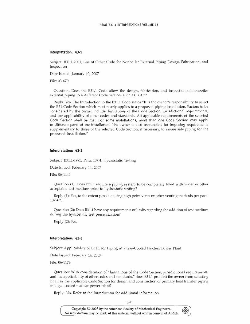
ASME 831.1 INTERPRETATIONS VOLUME 43
Interpretation: 43-1
Subject: B31.1-2001, Use of Other Code for Nonboiler External Piping Design, Fabrication, and Inspection
Date Issued: January 10, 2007
File: 03-670
Question: Does the B31.1 Code allow the design, fabrication, and inspection of nonboiler external piping to a different Code Section, such as B31.3?
Reply: Yes. The Introduction to the B31.1 Code states "It is the owner's responsibility to select the B31 Code Section which most nearly applies to a proposed piping installation. Factors to be considered by the owner include: limitations of the Code Section, jurisdictional requirements, and the applicabiHty of other codes and standards. All applicable requirements of the selected Code Section shall be met. For some installations, more than one Code Section may apply to different parts of the installation. The owner is also responsible for imposing requirements supplementary to those of the selected Code Section, if necessary, to assure safe piping for the proposed installation."
Interpretation: 43-2
Subject: B31.1-1995, Para. 137.4, Hydrostatic Testing
Date Issued: February 14, 2007
File: 06-1144
Question (1): Does 831.1 require a piping system to be completely filled with water or other acceptable test medium prior to hydrostatic testing?
Reply (1): Yes, to the extent possible using high point vents or other venting methods per para. 137.4.2.
Question (2): Does B31.1 have any requirements or limits regarding the addition of test medium during the hydrostatic test pressurization?
Reply (2): No.
Interpretation: 43-3
Subject: Applicability of B31.1 for Piping in a Gas-Cooled Nuclear Power Plant
Date Issued: February 14, 2007
File: 06-1173
Question: With consideration of "limitations of the Code Section, jurisdictional requirements, and the applicability of other codes and standards," does B31.1 prohibit the o\vner from selecting B31.1 as the applicable Code Section for design and construction of primary heat transfer piping in a gas-cooled nuclear power plant?
Reply: No. Refer to the Introduction for additional information.
1-7
Copyright © 2008 by the American Society of Mechanical Engineers. ~ No reproduction may be made of this material without written consent of ASME. ~
ASME B31.1 INTERPRETATIONS VOLUME 43
interpretation: 43-4
Su bject: B31.1-2004, Para. 104.8.2, Stress Due to Occasional Loads
Date Issued: May 3, 2007
File: 05-1275
Question: Tn accordance "vith the Code para. 101.1, when a piping system operates at multiple sets of coincident operating temperatures and pressures, and the system may at random be loaded with an occasional load as defined in para. 102.3.3, may the maximum allowable stress used in para. 104.8.2 equations (12A) and (12B) be based on the corresponding temperature for each set of loading conditions that could occur?
Reply: Yes.
Interpretation: 43-5
Subject: B31.1-2004, Owner
Date Issued: June 11, 2007
File: 03-744
Question: Does the ASME B31.1-2004 Edition define the term "owner"?
Reply: No.
Interpretation: 43-6
Subject: B31.1-2004, Para. 136, Visual Examination
Date Issued: October 4, 2007
File: 07-752
Question (1): Is it required that flaws which are found using nonrequired radiography, but which could have been found during visual observation of an incomplete weld, meet the acceptance criteria of para. 136.4.2(A)?
Reply (1): No; the acceptance standards given in para. 136.4.2(A) only apply to completed welds.
Question (2): Is it required that flaws found during radiography, which is not required, meet the acceptance criteria of para. 136.4.5(A)?
Reply (2): The acceptance criteria for nonrequired examinations are not given by the Code. See Interpretation 37-2 of B31.1.
1-8
Copyright © 2008 by the American Society of Mechanical Engineers. No reproduction may be made oftms material without written consent of ASME.
ASME B31.1 CASES
831.1 -- Cases No. 33
A Case is the official method of handling a reply to an inquiry when study indicates that the Code wording needs clarification, or when the reply modifies the existing requirements of the Code or grants permission to use new materials or alternative constructions.
ASME has agreed to publish Cases issued by the B31 Committee concerning B31.1 as part of the update service to B31.1. The text of proposed new and revised Cases and reaffirmations of current Cases appear on the ASME website at http://cstools.asme.org/csconnect/CommitteePages.cfm for public review. New and revised Cases, as well as announcements of reaffirmed Cases and annulments, then appear in the next update. As of the 1992 and later editions, all Cases currently in effect at the time of publication of an edition are included with it as an update.
The ASME B31 Code for Pressure Piping Standards Committee took action to eliminate Code Case expiration dates effective September 21, 2007. This means that all Code Cases listed in this update and beyond will remain available for use until annulled by the ASME B31 Code for Pressure Piping Standards Committee.
This update, Cases No. 33, which is included after the last page of the 2008 Addenda and the Interpretations Volume 43 that follow, contains the following Cases:
175 176 177 179 182 183
The page numbers for the Cases supplements included with updates to the 2007 Edition start with C-1 and will continue consecutively through the last update to this Edition. The Cases affected by this supplement are as follows:
Page Location Change
C-15 Case 175 Expiration date eliminated
C-17 Case 176 Expiration date eliminated
C-19 Case 177 Expiration date eliminated
C-20 Case 179 Expiration date eliminated
C-21 Case 182 Expiration date eliminated
C-23 Case 183 Expiration date eliminated
C-13
Copyright © 2008 by the American Society of Mechanical Engineers. ~ No reproduction may be made of this material without written consent of ASME. ~
INTENTIONALLY LEFf BLANK
Copyright © 2008 by the American Society of Mechanical Engineers. No reproduction may be made ofthis mateJial without vvritten consent of ASME.
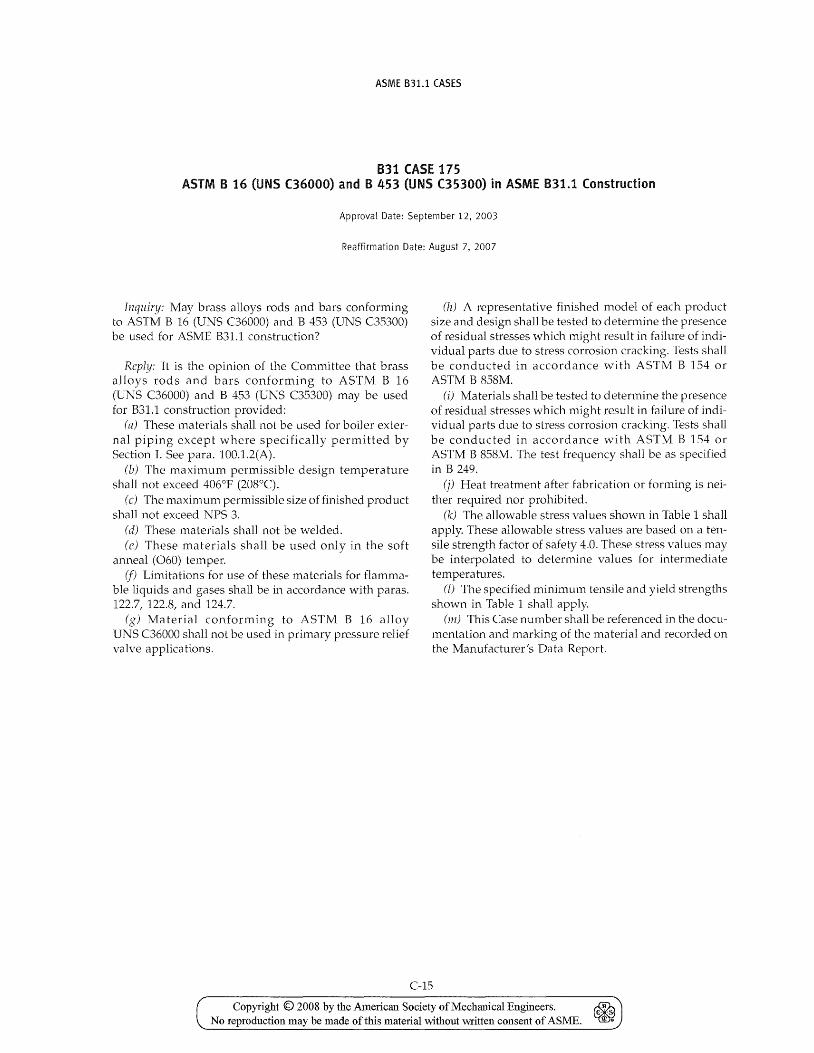
ASME B31.1 CASES
831 (ASE 175 ASTM B 16 (UNS (36000) and B 453 (UNS (35300) in ASME B31.1 Construction
Approval Date: September 12, 2003
Reaffirmation Date: August 7, 2007
Inquiry: May brass alloys rods and bars conforming to ASTM B 16 (UNS C36000) and B 453 (UNS C35300) be used for ASME B31.1 construction?
Reply: It is the opinion of the Committee that brass alloys rods and bars conforming to ASTM B 16 (UNS C36000) and B 453 (UNS C35300) may be used for B31.1 construction provided:
(a) These materials shall not be used for boiler external piping except where specifically permitted by Section T. See para. 100.1.2(A).
(b) The maximum permissible design temperature shall not exceed 406°P (208°C).
(c) The maximum permissible size of finished product shall not exceed NPS 3.
(d) These materials shall not be welded. (e) These materials shall be used only in the soft
anneal (060) temper. if) Limitations for use of these materials for flamma
ble liquids and gases shall be in accordance with paras. 122.71 122.81 and 124.7.
(g) Material conforming to ASTM B 16 alloy UNS C36000 shall not be used in primary pressure relief valve applications.
(lz) A representative finished model of each product size and design shall be tested to determine the presence of residual stresses which might result in failure of individual parts due to stress corrosion cracking. Tests shall be conducted in accordance with ASTM B 154 or ASTM B 858rv1.
(i) Materials shall be tested to determine the presence of residual stresses which might result in failure of individual parts due to stress corrosion cracking. Tests shall be conducted in accordance with ASTM B 154 or ASTM B 858M. The test frequency shall be as specified in B 249.
(f) Heat treatment after fabrication or forming is neither required nor prohibited.
(k) The allowable stress values shmvn in Table 1 shall apply. These allowable stress values are based on a tensile strength factor of safety 4.0. These stress values may be interpolated to determine values for intermediate temperatures.
(l) The specified minimum tensile and yield strengths shown in Table 1 shall apply.
(m) This Case number shall be referenced in the documentation and marking of the material and recorded on the Manufacturer's Data Report.
C-15
Copyright © 2008 by the American Society of Mechanical Engineers. ~ No reproduction may be made of this material without written consent of ASME. ~
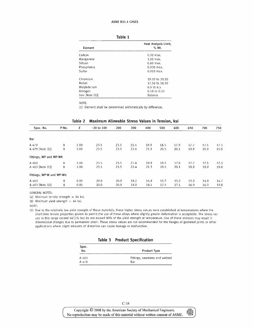
Element
Carbon Manganese Silicon Phosphorus Sulfur
Chromium Nickel Molybdenum Nitrogen Iron [Note (1)]
NOTE;
ASME B31.1 CASES
Table 1
Heat Analysis Limit, % Wt.
0.20 max. 1.00 max. 0.80 max. 0.030 max. 0.010 max.
19.50 to 20.50 17.50 to 18.50 6.0 to 6.5 0.18 to 0.22 Balance
(1) Element shall be determined arithmetically by difference.
Table 2 Maximum Allowable Stress Values in Tension, ksi
Spec. No.
Bar
A 479 A 479 [Note (1)]
P-No.
8 8
Fittings, WP and WP-WX
A 403 A 403 [Note (1)]
8 8
Fittings, WP-W and WP-WU
A 403 A 403 [Note (1)]
GENERAL NOTES:
8 8
E
1.00 1.00
1.00 1.00
0.85 0.85
(a) Minimum tensile strength = 94 ksi. (b) Minimum yield strength = 44 ksi.
NOTE:
-20 to 100
23.5 23.5
23.5 23.5
20.0 20.0
200 300 400 500 600
23.5 21.4 19.9 18.5 17.9 23.5 22.4 21.3 20.5 20.1
23.5 21.4 19.9 18.5 17.9 23.5 22.4 21.3 20.5 20.1
20.0 18.2 16.9 15.7 15.2 20.0 19.0 18.1 17.4 17.1
650 700 750
17.7 17.5 17.3 19.9 19.9 19.8
17.7 17.5 17.3 19.9 19.9 19.8
15.0 14.9 14.7 16.9 16.9 19.8
(1) Due to the relatively low yield strength of these materials, these higher stress values were established at temperatures where the short-time tensile properties govern to permit the use of these alloys where slightly greater deformation is acceptable. The stress values in this range exceed 66%% but do not exceed 90% of the yield strength at temperature. Use of these stresses may result in dimensional changes due to permanent strain. These stress values are not recommended for the flanges of gasketed joints or other applications where slight amounts of distortion can cause leakage or malfunction.
Table 3 Product Specification
Spec. No. Product Type
A 403 Fittings, seamless and welded A 479 Bar
C-18
Copyright © 2008 by the American Society of Mechanical Engineers. ~ No reproduction may be made of this material \\~thout written consent of ASME. ~
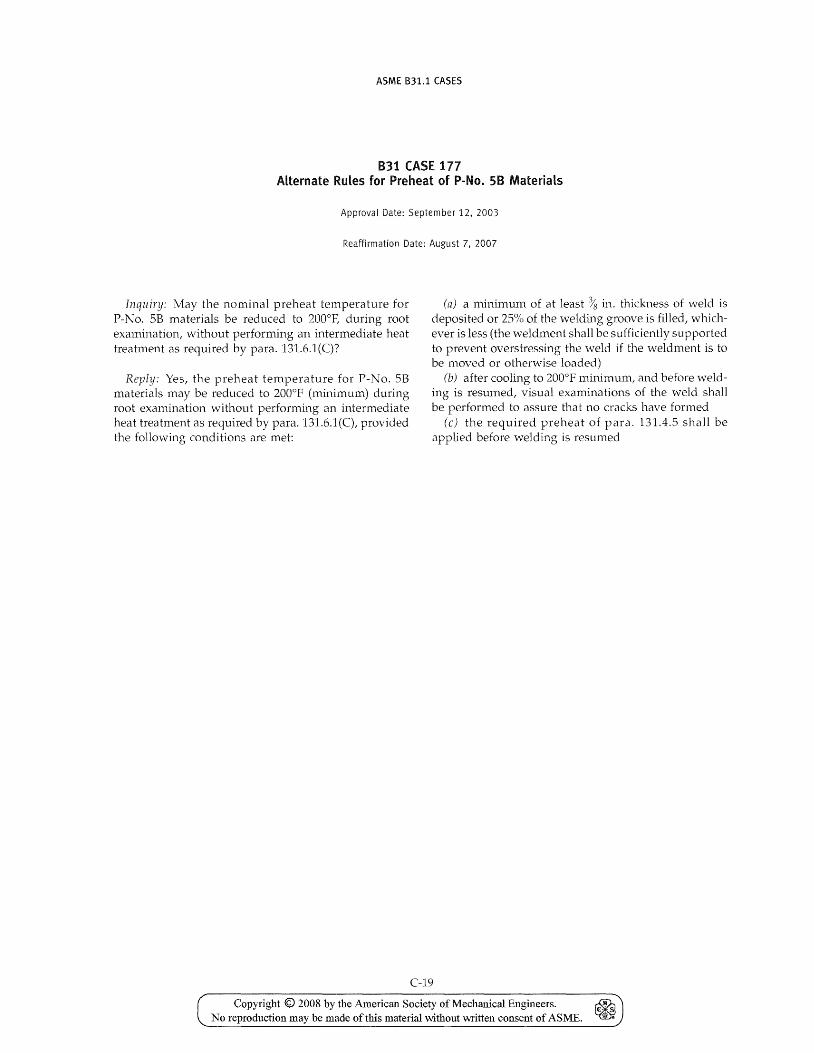
ASME B31.1 CASES
831 CASE 177 Alternate Rules for Preheat of P-No. 58 Materials
Approval Date: September 12,2003
Reaffirmation Date: August 7, 2007
Inquiry: May the nominal preheat temperature for P-No. 5B materials be reduced to 200°F, during root examination, without performing an intermediate heat treatment as required by para. 131.6.1(C)?
Reply: Yes, the preheat temperature for P-No. 5B materials may be reduced to 200°F (minimum) during root examination without performing an intermediate heat treatment as required by para. 131.6.1(C), provided the following conditions are met:
(n) a minimum of at least % in. thickness of weld is deposited or 25% of the welding groove is filled, whichever is less (the weldment shall be sufficiently supported to prevent overstressing the weld if the weldment is to be moved or otherwise loaded)
(b) after cooling to 200°F minimum, and before welding is resumed, visual examinations of the weld sha11 be performed to assure that no cracks have formed
(c) the required preheat of para. 131.4.5 shall be applied before welding is resumed
C-19
Copyright © 2008 by the American Society of Mecharucal Engineers. ~ No reproduction may be made of this material without written consent of ASME. ~
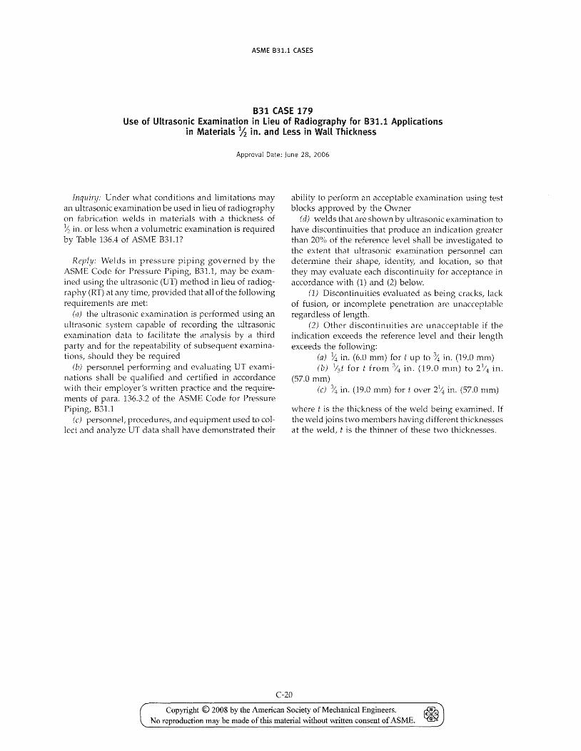
ASME B31.1 CASES
B31 CASE 179 Use of Ultrasonic Examination in Lieu of Radiography for B31.1 Applications
in Materials Ih in. and less in Wall Thickness
Approval Date: June 28, 2006
lnquily' Under what conditions and limitations may an ul trasonic examination be used in lieu of radiography on fabrication welds in materials with a thickness of ~ in. or less \vhen a volumetric examination is required by Table 136.4 of ASME B31.1?
Reply: Welds in pressure piping governed by the ASME Code for Pressure Piping, B31.1, may be examined using the ultrasonic (UT) method in lieu of radiography (RT) at any time, provided that all of the following requirements are met:
(17) the ultrasonic examination is performed using an ultrasonic system capable of recording the ultrasonic examination data to facilitate the analysis by a third party and for the repeatability of subsequent examinations, should they be required
(b) personnel performing and evaluating UT examinations shall be qualified and certified in accordance with their employer's written practice and the requirements of para. 136.3.2 of the ASME Code for Pressure Piping, B31.1
(c) personnet procedures, and equipment used to collect and analyze UT data shall have demonstrated their
ability to perform an acceptable examination using test blocks approved by the Owner
(d) "velds that are shown by ultrasonic examination to have discontinuities that produce an indication greater than 20% of the reference level shall be investigated to the extent that ultrasonic examination personnel can determine their shape, identity, and location, so that they may evaluate each discontinuity for acceptance in accordance with (1) and (2) below.
(1) Discontinuities evaluated as being cracks, lack of fusion, or inconlplete penetration are unacceptable regardless of length.
(2) Other discontinuities are unacceptable if the indication exceeds the reference level and their length exceeds the follmving:
(a) 14 in. (6.0 mm) for t up to % in. (19.0 mm) (b) 1(3t for t from % in. (19.0 mm) to 21/4 in.
(57.0 mm) (c) ~ in. (19.0 mm) for I: over 2~ in. (57.0 mm)
where t is the thickness of the weld being examined. If the weld joins two members having different thicknesses at the weld, t is the thinner of these two thicknesses.
C-20
Copyright © 2008 by the American Society of Mechanical Engineers. No reproduction may be made ofthis material without \Vl'itten consent of ASME.
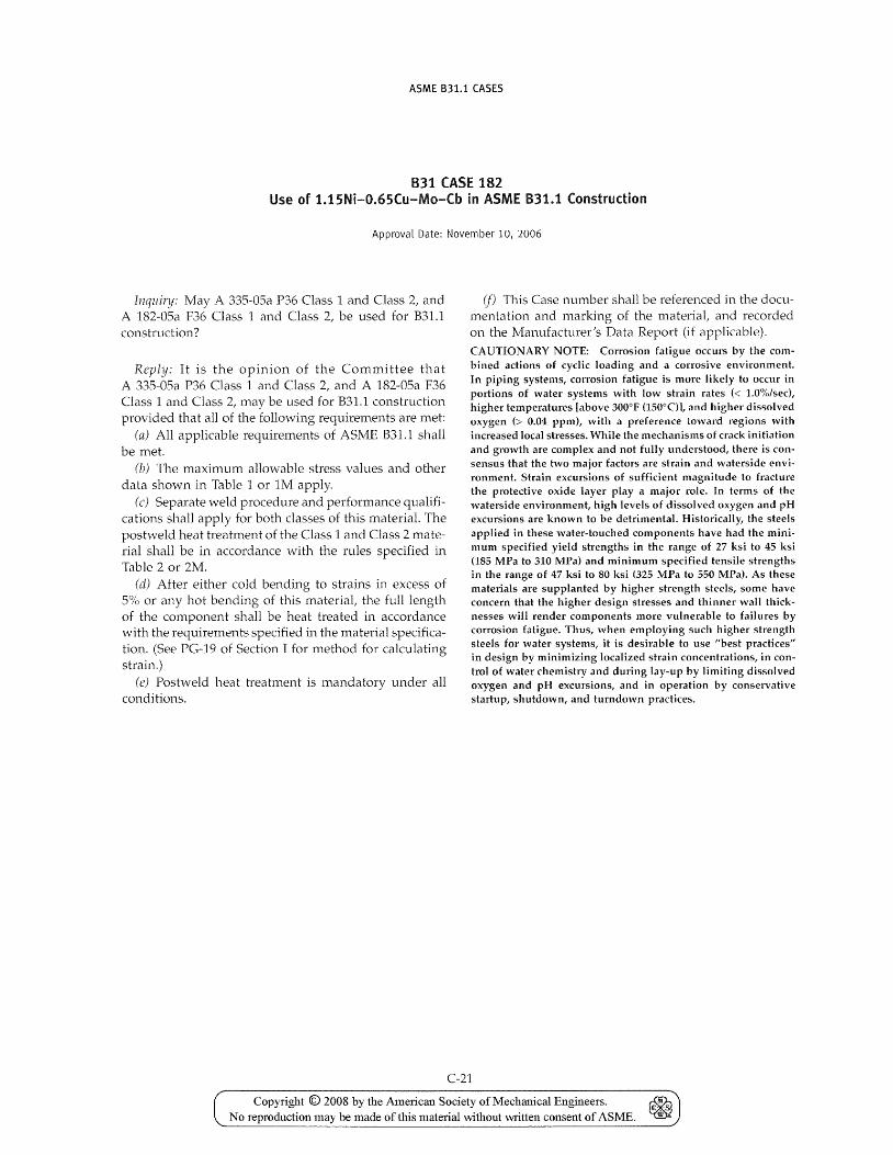
ASME B31.1 CASES
831 CASE 182 Use of 1.1SNi-O.6SCu-Mo-Cb in ASME B31.1 Construction
Approval Date: November 10, 2006
Inquiry: May A 335-05a P36 Class 1 and Class 2, and A 182-05a F36 Class 1 and Class 2, be used for B31.1 cons tru ction ?
Reply: It is the Opll1lOn of the Committee that A 335-05a P36 Class 1 and Class 2, and A 182-05a F36 Class 1 and Class 2, may be used for B31.1 construction provided that all of the following requirements are met:
(a) All applicable requirements of ASME B31.1 shall be met.
(b) The maximum allowable stress values and other data shown in Table 1 or 1M apply.
(c) Separate weld procedure and performance qualificaborls shall apply for both classes of this material. The postweld heat treatment of the Class 1 and Class 2 material shall be in accordance with the rules specified in Table 2 or 2M.
(d) After either cold bending to strains in excess of 5% or any hot bending of this material, the full length of the component shall be heat treated in accordance with the requirements specified in the material specification. (See PG-19 of Section T for method for calculating strain.)
(e) Postweld heat treatment is mandatory under all conditions.
(f) This Case number shall be referenced in the documentation and marking of the material, and recorded on the Manufacturer's Data Report (if applicable). CAUTIONARY NOTE: Corrosion fatigue occurs by the combined actions of cyclic loading and a corrosive environment. In piping systems, corrosion fatigue is more likely to occur in portions of water systems with low strain rates « 1.0%/sec), higher temperatures [above 300°F (150°0), and higher dissolved oxygen (> 0.04 ppm), with a preference toward regions with increased local stresses. While the mechanisms of crack initiation and growth are complex and not fully understood, there is consensus that the two major factors are strain and waterside environment. Strain excursions of sufficient magnitude to fracture the protective oxide layer playa major role. In terms of the waterside environment, high levels of dissolved oxygen and pH excursions are known to be detrimental. Historically, the steels applied in these water-touched components have had the minimum specified yield strengths in the range of 27 ksi to 45 ksi (185 MPa to 310 MPa) and minimum specified tensile strengths in the range of 47 ksi to 80 ksi (325 MPa to 550 MPa). As these materials are supplanted by higher strength steels, some have concern that the higher design stresses and thinner wall thicknesses will render components more vulnerable to failures by corrosion fatigue. Thus, when employing such higher strength steels for water systems, it is desirable to use "best practices" in design by minimizing localized strain concentrations, in control of water chemistry and during lay-up by limiting dissolved oxygen and pH excursions, and in operation by conservative startup, shutdown, and turndown practices.
C-21
Copyright © 2008 by the American Society of Mechanical Engineers. ~ No reproduction may be made oftbis material without written consent of ASME. ~
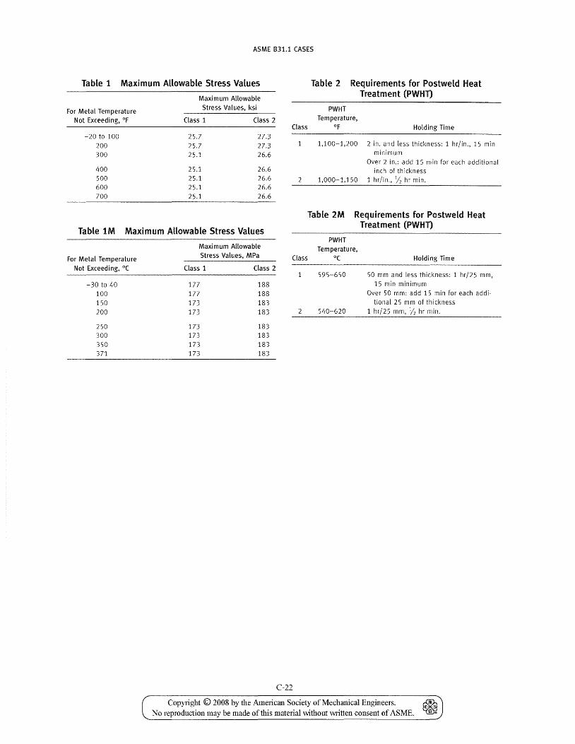
ASME B31.1 CASES
Table 1 Maximum Allowable Stress Values Table 2 Requirements for Postweld Heat Treatment (PWHT)
Maximum Allowable
For Metal Temperature Stress Values, ksi
Not Exceeding, OF Class 1 Class 2
-20 to 100 25.7 27.3 200 25.7 27.3 300 25.1 26.6
400 25.1 26.6 500 25.1 26.6 600 25.1 26.6 700 25.1 26.6
PWHT Temperature,
Class of Holding Time
1,100-1,200 2 in. and less thickness: 1 hr/in., 15 min minimum
Over 2 in.: add 15 min for each additional inch of thickness
2 1,000-1,150 1 hr/in., 1/2 hr min.
Table 1M Maximum Allowable Stress Values
Table 2M Requirements for Postweld Heat Treatment (PWHT)
For Metal Temperature Not Exceeding, °C
-30 to 40 100 150 200
250 300 350 371
Maximum Allowable Stress Values, MPa
Class 1 Class 2
177 188 177 188 173 183 173 183
173 183 173 183 173 183 173 183
Class
C-22
PWHT Tem perature,
O(
595-650
540-620
Holding Time
50 mm and less thickness: 1 hr/25 mm, 15 min minimum
Over 50 mm: add 15 min for each additional 25m m of th i ckness
1 hr/25 mm, J'2 hr min.
Copyright © 2008 by the American Society of Mechanical Engineers. ~ No reproduction may be made of this material "vithout written consent of ASME. ~
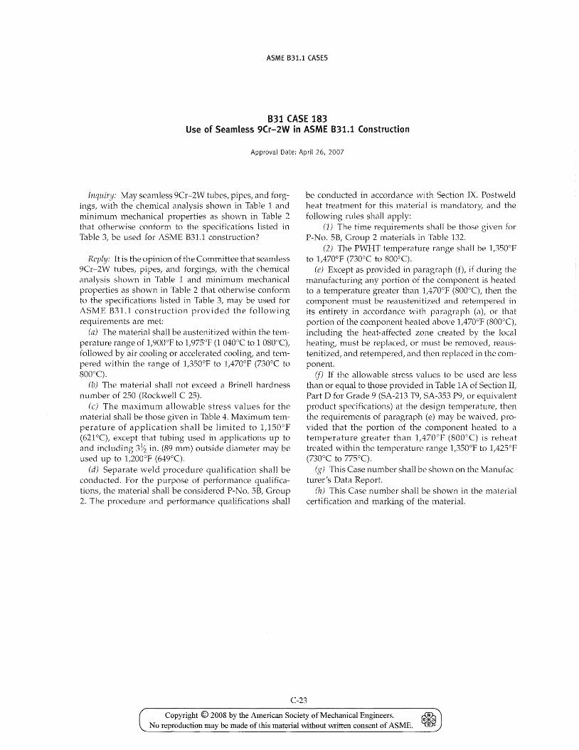
ASME B31.1 CASES
B31 CASE 183 Use of Seamless 9Cr-2W in ASME 831.1 Construction
Approval Date: April 26, 2007
Inq1liry: May seamless 9Cr-2vV tubes, pipes, and forgings, with the chemical analysis shown in Table 1 and mininlum mechanical properties as shmvn in Table 2 that otherwise conform to the specifications listed in Table 3, be used for ASME B31.1 construction?
Reply: It is the opinion of the Committee that seamless 9Cr-2W tubes, pipes, and forgings, ,vith the chemical analysis shown in Table 1 and minimum mechanical properties as shown in Table 2 that otherwise conform to the specifications listed in Table 3, may be used for ASME B31.1 construction provided the following requirements are met:
(a) The material shall be austenitized within the temperature range of 1,900oP to 1,975°F (1 040°C to 1 OSO°C), followed by air cooling or accelerated cooling, and tempered within the range of 1,350°F to 1,470°F (730°C to 800°C).
(b) The material shall not exceed a Brinell hardness number of 250 (Rockwell C 25).
(c) The maximum allowable stress values for the material shall be those given in Table 4. Maximum temperature of application shall be limited to 1,150o P (621°C), except that tubing used in applications up to and including 3~ in. (S9 111m) outside diameter may be used up to t2000P (649°C).
(d) Separate weld procedure qualification shall be conducted. Por the purpose of performance qualifications, the material shall be considered P-No. 5B, Group 2. The procedure and performance qualifications shall
be conducted in accordance with Section IX. Postweld heat treatment for this material is mandatory, and the follmving rules shall apply:
(1) The time requirements shall be those given for P-No. 5B, Group 2 materials in Table 132.
(2) The PWHT temperature range shall be 1,350oP to 1,470o P (730°C to SOO°C).
(e) Except as provided in paragraph (f), if during the manufacturing any portion of the component is heated to a temperature greater than 1,470°F (SOO°C), then the component must be reaustenitized and retempered in its entirety in accordance with paragraph (a), or that portion of the component heated above 1,470oP (SOO°C), including the heat-affected zone created by the local heating, must be replaced, or must be removed, reaustenitized, and retempered, and then replaced in the component.
if) If the allowable stress values to be used are less than or equal to those provided in Table lA of Section It Part D for Grade 9 (SA-213 T9, SA-353 P9, or equivalent product specifications) at the design temperature, then the requirements of paragraph (e) may be waived, provided that the portion of the component heated to a temperature greater than 1,470°F (SOO°C) is reheat treated within the temperature range 1,350oP to 1,425°F (730°C to 775°C).
(g) This Case number shall be shown on the Manufacturer's Data Report.
(h) This Case number shall be shown in the material certification and marking of the material.
C-23
Copyright © 2008 by the American Society of Mechanical Engineers. ~ No reproduction may be made of this material without written consent of ASME. ~
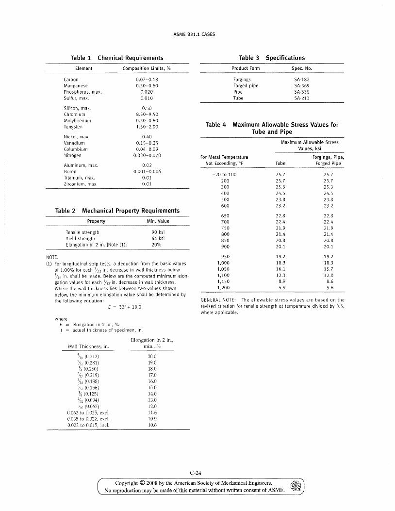
ASME 831.1 CASES
Table 1 Chemical Requirements
Element Composition limits, %
Carbon 0.07-0.13 Manganese 0.30-0.60 Phosphorus, max. 0.020 Sulfur, max. 0.010
Silicon, max. 0.50 Chromium 8.50-9.50 Molybdenum 0.30-0.60 Tungsten 1.50-2.00
Nickel, max. 0.40 Vanadium 0.15-0.25 Columbium 0.04-0.09 Nitrogen 0.030-0.070
Aluminum, max. 0.02 Boron 0.001-0.006 Titanium, max. 0.01 Zirconium, max. 0.01
Table 2 Mechanical Property Requirements
NOTE:
Property
Tensile strength Yield strength Elongation in 2 in. [Note (1)]
Min. Value
90 ksi 64 ksi 20%
(1) For longitudinal strip tests, a deduction from the basic values of 1.00% for each Jnin. decrease in wall thickness below
in. shall be made. Below are the computed minimum elongation values for each linin. decrease in wall thickness. Where the wall thickness lies between two values shown below, the minimum elongation value shall be determined by the following equation:
E = 32t + 10.0
where E elongation in 2 in., % t = actual thickness of specimen, in.
Wall Thickness, in.
(0.312) (0.281) (0.250)
~'2 (0.219) ~;'6 (0.188) Y'll (0.156) ~q (0.125)
~'2 (0.094) ~6 (O'()62)
0.062 to 0.035, excl. 0.035 to 0.022, excl. 0,022 to 0.015, incl.
Elongation in 2 in., min.,%
20.0 19.0 18.0 17.0 16.0 15.0 14.0 13.0 12.0 11.6 10.9 10.6
Table 3 Specifications
Product Form Spec. No.
Forgings Forged pipe Pipe Tube
SA-182 SA-369 SA-335 SA-213
Table 4 Maximum Allowable Stress Values for Tube and Pipe
Maximum Allowable Stress Values, ksi
For Metal Temperature Forgings, Pipe, Not Exceeding, OF Tube Forged Pipe
-20 to 100 25.7 25.7 200 25.7 25.7 300 25.3 25.3 400 24.5 24.5 500 23.8 23.8 600 23.2 23.2
650 22.8 22.8 700 22.4 22.4 750 21.9 21.9 800 21.4 21.4 850 20.8 20.8 900 20.1 20.1
950 19.2 19.2 1,000 18.3 18.3 1,050 16.1 15.7 1,100 12.3 12.0 1,150 8.9 8.6 1,200 5.9 5.6
GENERAL NOTE: The allowable stress values are based on the revised criterion for tensile strength at temperature divided by 3.5, where applicable.
C-24
Copyright © 2008 by the American Society of Mechanical Engineers. No reproduction may be made of this mate1'ial without written consent of AS ME.
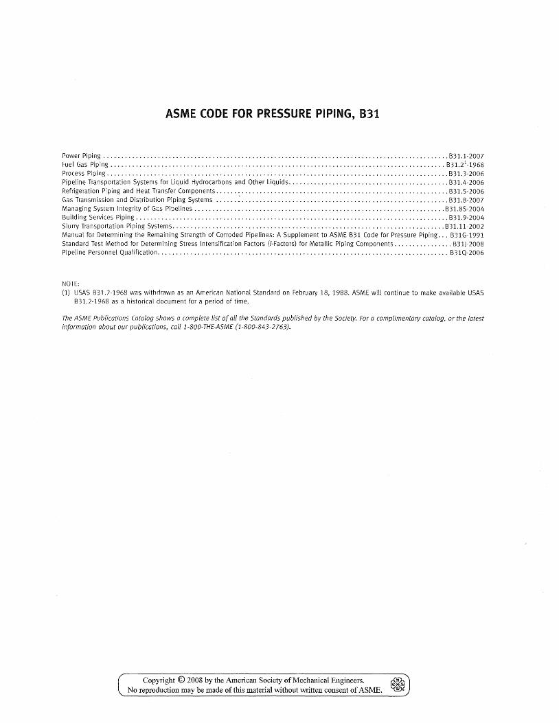
ASME (ODE FOR PRESSURE PIPING, 831
Power Piping ........................................................................................ , ...... B31.1-2007 Fuel Gas Piping ............................................................................................ B31.21-1968
Process Piping .............................................................................................. B31.3-2006 Pipeline Transportation Systems for Liquid Hydrocarbons and Other Liquids ............................................ B31.4-2006
Refrigeration Piping and Heat Transfer Components ................................................................ B31.5-2006 Gas Transmission and Distribution Piping Systems ...... : ......................................................... B31.8-2007 Managing System Integrity of Gas Pipelines ..................................................................... B31.8S-2004 Building Services Piping ...................................................................................... B31.9-2004 Slurry Transportation Piping Systems ........................................................................... 831.11-2002 Manual for Determining the Remaining Strength of Corroded Pipelines: A Supplement to ASME B31 Code for Pressure Piping ... B31G-1991 Standard Test Method for Determining Stress Intensification Factors (i-Factors) for Metallic Piping Components ................ B31)-2008 Pipeline Personnel Qualification ................................................................................ B31Q-2006
NOTE:
(1) USAS B31.2-1968 was withdrawn as an American National Standard on February 18, 1988. ASME will continue to make available USAS B31.2-1968 as a historical document for a period of time.
The ASME Publications Catalog shows a complete list of all the Standards published by the Society. For a complimentary catalog, or the latest information about our publications, call 1-800-THE-ASME (1-800-843-2763).
Copyright © 2008 by the American Society of Mechanical Engineers. ~ € S
No reproduction may be made of this material without written consent of ASME. Ill ..
ASME Services
ASME is committed to developing and delivering technical information. At ASME's Information Central, we make every effort to answer your questions and expedite your orders. Our representatives are ready to assist you in the following areas:
ASME Press Codes & Standards Credit Card Orders IMechE Publications Meetings & Conferences Member Dues Status
Member Services & Benefits Other ASME Programs Payment Inquiries Professional Development
Short Courses Publications
How can you reach us? It's easier than ever!
Public Information Self-Study Courses Shipping Information Subscriptions/Jou rnals/ Magazines Symposia Volumes Technical Papers
There are four options for making inquiries* or placing orders. Simply mail, phone, fax, or E-mail us and an Information Central representative will handle your request.
Mail ASME 22 Law Drive, Box 2900 Fairfield, New Jersey 07007-2900
Call Toll Free US & Canada: 800-THE-ASME (800-843-2763) Mexico: 95-800-THE-ASME (95-800-843-2763) Universal: 973-882-1167
Fax-24 hours 973-882-1717 973-882-5155
E-Mail-24 hours [email protected]
* Information Central staff are not permitted to answer inquiries about the technical content of this code or standard. Information as to whether or not technical inquiries are issued to this code or standard is shown on the copyright page. All technical inquiries must be submitted in writing to the staff secretary. Additional procedures for inquiries may be listed within.
Copyright © 2008 by the American Society of Mechanical Engineers. ~ No reproduction may be made of this material without written consent of ASME. ~
Recommended