
Struct Multidisc Optim (2008) 37:165–184DOI 10.1007/s00158-008-0227-6
RESEARCH PAPER
Optimization of anisotropic composite panelswith T-shaped stiffeners including transverseshear effects and out-of-plane loading
J. Enrique Herencia · Paul M. Weaver ·Michael I. Friswell
Received: 3 August 2007 / Revised: 4 October 2007 / Accepted: 27 November 2007 / Published online: 14 March 2008© Springer-Verlag 2008
Abstract A two-step method to optimize anisotropiccomposite panels with T-shaped stiffeners, includinga new formulation of the transverse shear propertiesand an approximation of the ply contiguity (blocking)constraints as functions of the lamination parameters isprovided. At the first step, a representative element ofthe stiffened panel (superstiffener) is optimized usingmathematical programming and lamination parame-ters subjected to combined loading (in-plane and out-of-plane) under strength (laminate or ply failure),buckling and practical design constraints. Ply blockingconstraints are imposed at this step to improve conver-gence towards practical laminates. At the second step,the actual superstiffener’s laminates are obtained byusing a genetic algorithm. Results, for the case consid-ered, show that the inclusion of transverse shear effectshas an associated 2.5% mass penalty and that neglect-ing its effects might invoke earlier buckling failure. Inaddition, the influence of designing for failure strengthat laminate or ply level is assessed.
Keywords Optimization · Anisotropic ·Lamination parameters · Composite-stiffened panels ·Transverse shear effects · Out-of-plane loading ·Genetic algorithm
J. E. Herencia · P. M. Weaver (B) · M. I. FriswellDepartment of Aerospace Engineering,University of Bristol,Bristol BS8 1TR, UKe-mail: [email protected]
Nomenclaturea panel lengthA, A membrane stiffness matrix, membrane, areaAij terms of the membrane stiffness matrix,
i = j = 1, 2, 6Asf area of the stiffener flangeAskin area of the skinAstg area of the stiffenerAsw area of the stiffener webb panel widthbsf stiffener flange widthB membrane–bending coupling stiffness matrixc continuousd discreteD bending stiffness matrix, bendingDij terms of the bending stiffness matrix, i = j =
1, 2, 6e eccentricityEij Young’s modulus in ij direction, i = j = 1, 2Ei
x Young’s modulus in x direction for elementi, i = skin, sf, sw
EIc longitudinal bending stiffness of the supers-tiffener element
Fc longitudinal force applied at the superstiff-ener centroid
Fskin axial force in the skinFstg axial force in the stiffenerGi ith design constraintGi
xy shear modulus for element i, i = skin, sf, swGij shear modulus i = 1, 2; j = 2, 3h laminate thicknesshsw stiffener web heightH transverse shear matrixHij terms of the transverse shear matrix, i = j =
4, 5
166 J.E. Herencia et al.
K stiffness matrixKd differential stiffness matrixKdp differential stiffness matrix for the preloading
caseM, M running moment vector, mass of the supers-
tiffener elementMi non-linear bending moment at i evaluation
point, i = a, c; mass i = c, dMij non-linear bending moment due to i at evalu-
ation point j, i = p, i, e; j = a, cms mid-plane symmetricnc number of design constraintsnv number of design variablesN running load vectorN j
i load per unit length in i direction for elementj, i = x, y, xy; j = skin, sf, sw
p maximum number of plies of the same orien-tation that can be stacked together, pressure
pα percentage of α degree plies, α = 0, 90,45, −45
P lateral pressureQ j transverse shear resultants, i = x, yQij terms of the reduced stiffness matrix, i = j =
1, 2, 4, 5, 6s symmetrict thickness of the skintp ply thicknessta thickness of the stiffener flangetsf total thickness of the stiffener flangetsw thickness of the stiffener webtw thickness of the webt totalUi,, U∗
j material invariants, i = 1..5; j = 1, 2
w f ji weighting factor for lamination parameters,
i = 1, 2, 3; j = A, Dx, x vector of design variables, abscisey, y gene, ordinateβ smeared ply angleγ 0
i transverse shear strain, i = xz, yzδ bowε
0 ji laminate applied strain, i = T, C; j = x, y, xy
εjai laminate allowable strain, i=T, C; j=x, y, xy
εjαi ply applied strain, α = 0, 90, 45, −45; i = T,
C; j = 1, 2, 12ε
jaαi ply allowable strain, α = 0, 90, 45, −45; i = T,
C; j = 1, 2, 12ζ, η tolerance valueκ middle surface curvaturesλi buckling or strength load factor (eigenvalue),
i = b , s
λji laminate strength load factor, i = T, C; j =
x, y, xyλ
jϕi ply strength load factor, i = T, C; j = 1, 2, 12
vi Poisson’s ratio in i direction, i = 12, 21ξ
ji lamination parameters, i = 1, 2, 3; j = A, D
ρ densityυα volume fraction of α degree ply angle,
α = 0, 90, 45, −45ϕ fibre orientation angleθ, ψ, φ encoded ply angle for the skin, stiffener flange
and web, respectively�i ith eigenvector
1 Introduction
The commercial aviation industry is progressivelyemploying composite materials as primary structures toreduce weight whilst maintaining structural integrity.Primary flight structures such as wings, fuselages orempennages are mainly designed using stiffened pan-els under combined in-plane and out-of-plane load-ing. Composite materials are characterized by theirhigh specific strength and stiffness ratios (Jones 1999).Moreover, in contrast to metallic structures, compositestructures can be stiffness tailored. This latter feature isintimately related to their design and manufacture. Dueto practical, yet often limiting, manufacturing consider-ations, composite panels have been restricted to sym-metric or mid-plane symmetric laminates with 0˚, 90˚,45˚ and −45˚ ply angles. In addition, the manufactureof T-shaped stiffeners increases design complexity asthickness variation is permitted in the stiffener web andflange by adding extra and capping plies, respectively.
Generally, composite materials might exhibit somedegree of anisotropy. Flexural anisotropy, for instance,has an impact on buckling behavior (Ashton andWaddoups 1969) and, if neglected in the buckling analy-sis, results can be non-conservative (Chamis 1969).Nemeth (1986) described the importance of flexuralanisotropy and provided bounds within which its effectwould be significant. Flexural anisotropy is intrinsicallyrelated to the laminate stacking sequence. Further-more, transverse shear deformation could significantlyaffect the response of anisotropic laminates (Whitney1969). Theories formulated have covered this effectby factorising the transverse shear properties (Whitney1973; Laitinen et al. 1995), employing energy princi-ples in cylindrical bending (Rolfes and Rohwer 1997;Anonymous 2004) or applying a weighting function tothe transverse shear stresses (Vinson and Sierakowski

Optimization of anisotropic composite panels 167
1986). Moreover, composite structures may be exposedto out-of-plane displacements. Out-of-plane displace-ments are produced by out-of-plane loading, whichin turn is caused by lateral pressure, initial geometricimperfections and eccentricities in the in-plane load-ing. Giles and Anderson (1972) studied the effect ofeccentricities and lateral pressure on the design of stiff-ened compression panels. Computer programmes likePASCO (Stroud and Anderson 1981), VICONOPT(Butler and Williams 1990) and PANDA2 (Bushnell1987a) incorporate the out-of-plane effects in theiranalysis methods.
Throughout the years, optimization techniques havebeen developed to assist in composite design. Thenature of composite optimization is non-linear. The lay-up optimization problem is a non-linear problem withdiscrete variables which has a non-convex design space.Early work on composite optimization started withSchmit and Farshi (1973, 1977) who optimized sym-metric laminates with homogeneous and orthotropicproperties, considering ply thicknesses as continuousvariables. In the same trend, Stroud and Agranoff(1976) optimized composite hat-stiffened and corru-gated panels with orthotropic properties, using non-linear mathematical techniques with a simplified set ofbuckling equations as constraints. The dimensions ofthe cross-sections were the design variables.
Tsai and Pagano (1968) and Tsai and Hahn (1980)characterized the stiffness properties of compositeplates by the use of lamination parameters. Laminationparameters were initially used by Miki and Sugiyama(1991) to address the discrete lay-up optimization prob-lem. Optimum designs for constraints such as stiffnessor buckling were obtained from geometric relationsbetween the lamination parameters feasible region andthe objective function. Fukunaga and Vanderplaats(1991) used lamination parameters and mathematicalprogramming (MP) techniques to perform stiffness op-timization of orthotropic-laminated composites. Haftkaand Walsh (1992) first and then Nagendra et al. (1992)used integer programming techniques and laminationparameters to carry out laminate stacking sequenceoptimization under buckling and buckling and strainconstraints, respectively, on symmetric and balancedlaminated plates. However, integer programming tech-niques usually require large computational resources asproblem complexity increases.
Fukunaga et al. (1995) used MP techniques and lami-nation parameters to maximize buckling loads undercombined loading of symmetric laminates includingthe effect of the flexural anisotropy. Their findingshighlighted that under shear and shear-normal loading
flexural anisotropy could increase or decrease the criti-cal buckling load. Grenestedt (1991) performed lay-upoptimization of shear panels with and without flexuralanisotropy under buckling loads showing that the opti-mum point was expected to be off axis.
An alternative to integer programming and MP isthe use of genetic algorithms (GAs). GAs are searchalgorithms based on the mechanics of natural selectionand natural genetics (Goldberg 1989), which do notrequire gradient information. GAs are widely used fortheir ability to tackle search spaces with many localoptima (Coley 1999) and, therefore, a non-convex de-sign space. This latter feature makes them suitable forthe discrete lay-up optimization (Le Riche and Haftka1993). Nagendra et al. (1993, 1996) investigated theapplication of a GA to the design of blade-stiffenedcomposite panels. VIPASA (Wittrick and Williams1974) was used as the analysis tool and results werecompared with PASCO, which used VIPASA as theanalysis tool and CONMIN (Vanderplaats 1973) asoptimizer. Although it was concluded that the designsobtained by the GA offered improved performanceover the continuous designs, the large computationalcost associated with GAs was recognized. Bushnell(1987b) provided a different strategy using PANDA2to find the minimum weight design of flat andcurved composite-stiffened panels. It was shown thatPANDA2 could handle structure dimensions, thick-nesses and ply angles as design variables. Resultswere compared with the literature and with STAGS(Almroth and Brogan 1976). More recently, Liu et al.(2006) employed VICONOPT to perform optimizationof composite-stiffened panels under strength, bucklingand practical design constraints. A bi-level approachwas adopted. VICONOPT was employed at the firstlevel to minimize the panel weight, employing equiv-alent orthotropic properties for the laminates with con-tinuous thickness, whereas at the second level, laminatethicknesses were rounded up and associated with pre-determined design lay-ups.
A combined strategy using MP techniques, GAsand lamination parameters, was initially proposed byYamazaki (1996). The optimization was split into twolevels. Firstly, a gradient-based optimization was per-formed using the lamination parameters as design vari-ables. Secondly, the lamination parameters from thefirst level were targeted using a GA. Among otherobjectives, buckling load and natural frequencies ofa composite panel were optimized. Autio (2000) fol-lowing a similar approach, investigated actual lay-ups.A more sophisticated approach was formulated byTodoroki and Haftka (1998) to maximize the buckling

168 J.E. Herencia et al.
load of a composite plate. Their approach was alsodivided into two levels. First, the lamination parameterswere used to identify the neighborhood of the optimumdesign. Next, a response surface approximation wascreated in that neighborhood and the GA was appliedto that approximation.
Diaconu and Sekine (2004) contributed to lay-upoptimization with the definition of the laminationparameter feasible region. They performed lay-up op-timization of laminated composite shells to maximizethe buckling load, using the lamination parametersand including their feasible region. They defined therelations between the membrane, coupling and bendinglamination parameters for ply angles restricted to 0˚,90˚, 45˚ and −45˚. Although developed independentlyfrom each other, their definition of the feasible regionfor the lamination parameters was consistent with theone provided by Liu and Haftka (2004) for only twomembranes and bending lamination parameters.
The authors’ previous work (Herencia et al. 2007),based on a two-step optimization approach, which cou-pled MP with GAs, showed that composite anisotropyand, hence, elastic tailoring could be used to improvestructural performance of composite-stiffened panels.Design constraints such as strength (failure at laminatelevel), local and global buckling or practical design ruleswere considered. Manufacturing details of the stiffenerwere embedded within the optimization. This paperextends that work and includes transverse shear prop-erties, an approximation of the ply contiguity (referredto as blocking) constraints in the first optimization stepto improve convergence towards practical laminatedesigns, out-of-plane loads and failure strength at plylevel. The novelty of this paper lies in the new formula-tion of the transverse shear properties and ply blockingconstraints as functions of the lamination parameters.
2 Superstiffener geometry and loading
The composite-stiffened panel is assumed to be wideand composed of a series of skin-stiffener assemblies orsuperstiffeners under combined loading (in-plane andout-of-plane). Each superstiffener element consists ofthree flat plates that are considered to be rigidly con-nected (all degrees of freedom match at the interface),corresponding to the skin, stiffener flange and stiffenerweb, respectively. The behavior of the stiffened panelis modeled by a single superstiffener element. Figure 1defines the superstiffener geometry, material axis andpositive sign convention for the applied loading.
The geometry of the stiffener is affected by itsdesign and manufacturing process. Four different stiff-
ener configurations can be considered. The stiffener ismanufactured as a back to back angle (Fig. 2a), addingcapping plies in the stiffener flange (Fig. 2b) or extraplies in the stiffener web (Fig. 2c) and, finally, thecombination of the previous configurations (Fig. 2d).
3 Laminate constitutive equations
The laminate constitutive equations for the skin (skin),stiffener flange (sf ) and stiffener web (sw), are obtainedby considering transverse shear deformation (TSD)(Berthlot 1998) in each of them. Thus:
⎡⎣
NMQ
⎤⎦ =
⎡⎣
A B 0B D 00 0 H
⎤⎦
⎡⎣
ε0
κ
γ 0
⎤⎦ (1)
The above properties can be expressed in terms ofmaterial stiffness invariants (U, U*) and 12 laminationparameters (ξ) (e.g. Tsai and Hahn 1980). Laminatesare considered to be symmetric or mid-plane symmet-ric; thus, the membrane–bending coupling matrix B willvanish. This also reduces the number of the laminationparameters to eight. In addition, individual plies areassumed to be orthotropic and laminated at only 0˚, 90˚,45˚ and −45˚ fibre angles. As a result, the laminationparameters are further decreased to six. The mem-brane, bending and transverse shear stiffness terms areas follows:
⎡⎢⎢⎢⎢⎢⎢⎣
A11
A12
A22
A66
A16
A26
⎤⎥⎥⎥⎥⎥⎥⎦
= h
⎡⎢⎢⎢⎢⎢⎢⎢⎢⎢⎣
1 ξ A1 ξ A
2 0 0
0 0 −ξ A2 1 0
1 −ξ A1 ξ A
2 0 0
0 0 −ξ A2 0 1
0 ξ A32 0 0 0
0 ξ A32 0 0 0
⎤⎥⎥⎥⎥⎥⎥⎥⎥⎥⎦
⎡⎢⎢⎢⎢⎣
U1
U2
U3
U4
U5
⎤⎥⎥⎥⎥⎦
(2)
⎡⎢⎢⎢⎢⎢⎢⎣
D11
D12
D22
D66
D16
D26
⎤⎥⎥⎥⎥⎥⎥⎦
= h3
12
⎡⎢⎢⎢⎢⎢⎢⎢⎣
1 ξ D1 ξ D
2 0 00 0 −ξ D
2 1 01 −ξ D
1 ξ D2 0 0
0 0 −ξ D2 0 1
0 ξ D32 0 0 0
0 ξ D32 0 0 0
⎤⎥⎥⎥⎥⎥⎥⎥⎦
⎡⎢⎢⎢⎢⎣
U1
U2
U3
U4
U5
⎤⎥⎥⎥⎥⎦
(3)
⎡⎣
H55
H45
H44
⎤⎦ = 5h
6
⎡⎢⎢⎣
1 − 12
(3ξ A
1 − ξ D1
)
0 − 12
(3ξ A
3 − ξ D3
)
1 12
(3ξ A
1 − ξ D1
)
⎤⎥⎥⎦
[U∗
1U∗
2
](4)

Optimization of anisotropic composite panels 169
Fig. 1 Superstiffener element
A
A'
cF
xyN
yN
x
y
o0
o90o45
a
b
tsft
swt
swh
Section AA’
sfb
P
swt io
sfb
Stiffener flange
Skin
Stiffener web
Superstiffener
The derivation of the laminate transverse shearproperties H is given in Appendix A. The materialstiffness invariants (U, U*) are given by:
⎡⎢⎢⎢⎢⎣
U1
U2
U3
U4
U5
⎤⎥⎥⎥⎥⎦
= 1
8
⎡⎢⎢⎢⎢⎣
3 2 3 44 0 −4 01 −2 1 −41 −6 1 −41 −2 1 4
⎤⎥⎥⎥⎥⎦
⎡⎢⎢⎣
Q11
Q12
Q22
Q66
⎤⎥⎥⎦ (5)
[U∗
1U∗
2
]=
[ 12
12
12 − 1
2
][Q44
Q55
](6)
The lamina stiffness properties (Qij) are related tothe ply Young’s moduli and Poisson’s ratios by thefollowing equations:
Q11 = E11
1 − ν12ν21(7)

170 J.E. Herencia et al.
at
at
wt
a
b
c
d
Fig. 2 T-shaped stiffener types
Q12 = ν12 E22
1 − ν12ν21(8)
Q22 = E22
1 − ν12ν21(9)
Q21 = Q12 (10)
Q66 = G12 (11)
Q44 = G23 (12)
Q55 = G13 (13)
ν21 = ν12E22
E11(14)
The membrane and bending lamination parametersare calculated, respectively, by the following integrals:
ξ A[1 2 3] = 1
h
∫ h/2
−h/2
[cos 2ϕ cos 4ϕ sin 2ϕ
]dz (15)
ξ D[1 2 3] = 12
h3
∫ h/2
−h/2
[cos 2ϕ cos 4ϕ sin 2ϕ
]z2dz (16)
4 Out-of-plane loading
Out-of-plane loading is caused by the action of lat-eral pressure, the presence of initial geometric (bow
type) imperfections in the panel and eccentricities inthe applied in-plane loading. Out-of-plane loading ismanifested as a result of out-of-plane displacementsgenerated by non-linear bending moments, which even-tually develop out-of-plane strains. The non-linearbending moments are calculated using beam-columntheory (Timoshenko and Gere 1961) and followingStroud and Anderson (1981). This implies that thestiffened panel and, hence, the superstiffener behavesas a wide column with simply supported or clampedconditions along the width. The non-linear bendingmoments are calculated at certain evaluation pointswhere they have a maximum value. For instance, anevaluation point is located at the centre of the panel ifthe panel is assumed simply supported or at the centreand at one of the edges if the panel is assumed clamped.Figure 3 shows the types of out-of-plane loading hereinconsidered. Bow and eccentricity are positive as shownin Fig. 3.
4.1 Lateral pressure
The non-linear bending moment for a simply supportedbeam under lateral pressure and in-plane loading atthe centre of the span (Timoshenko and Gere 1961) isgiven by:
Mpc = Pa2
4bu2
(1
cos (u)− 1
)(17)
with
u = a2
√−Fc
EIc(18)1
The non-linear bending moments for a clampedbeam under lateral pressure and in-plane loading at thecentre of the span and at its edges (Timoshenko andGere 1961) are given by:
Mpc = Pa2
4bu2
(u
sin (u)− 1
)(19)
Mpa = − Pa2
4bu2
(1 − u
tan (u)
)(20)
1Note that when u is imaginary, the non-linear bending momentsare still real since the trigonometric terms transform into hyper-bolic functions.

Optimization of anisotropic composite panels 171
Fig. 3 Out-of-plane loading:a lateral pressure with simplysupported conditions; blateral pressure with clampedconditions; c eccentricity inloading; and d initialgeometric imperfection
a
e
Evaluation point
Section AA'
A
A'
A
A'
A
A'
A
A'
z
x
b
c d
pcM
ecM
cM aM
P P
cF cF
cF cF
icM
e
Evaluation point
Section AA'
A
A'
AA
A'
A
A'
AA
A'
A
A'
AA
A'
A
A'
AA
A'
z
x
pcM
ecM
cM aM
P P
cF− cF−
cF−cF−
icM
δ
4.2 Initial geometric imperfections
The initial geometric imperfections considered here arethe so-called bow type imperfections. The non-linearbending moment for a simply supported beam with abow and in-plane loading at the centre of the span(Timoshenko and Gere 1961) is as follows:
Mic = −Fcδ
1 − 4u2
π2
(21)
4.3 Eccentricities in loading
The non-linear bending moment in a simply supportedbeam produced as a consequence of an eccentric-ity in the in-plane loading at the centre of the span(Timoshenko and Gere 1961) is as follows:
Mec = −Fcecos (u)
(22)
Following Stroud and Anderson (1981), the expres-sions for the combined non-linear bending moments atthe centre and at the edges of the stiffened panel are,respectively:
Mc = Mpc + Mic + Mec (23)
Ma = Mpa + Mic + Mec (24)
As assumed by Stroud and Anderson (1981), thesenon-linear bending moments are assumed to act overthe entire stiffened panel (superstiffener) length. Theyare used to calculate the out-of-plane strains to assessfailure strength and the pre-buckling strains for buck-ling analysis. Pre-buckling strains are only applied tolocal buckling modes and not to global modes, as for the
latter, the non-linear bending moments tend to infinity.Note that this analysis method provides an approxima-tion of the non-linear behavior for the stiffened panelmainly under the action of normal in-plane loading.
5 Optimization strategy
The optimization strategy (Herencia et al. 2007) isshown in Fig. 4. The strategy consists of two steps. Atthe first step, the optimum dimensions and lamination
1) Gradient-based optimization
Loads GeometryMaterial
properties
2) GA-based optimization
Step-1constraints
check
NO
YES
Final design
Step-1 constraints
Step-2 constraints
Fig. 4 Optimization flow chart

172 J.E. Herencia et al.
parameters of the superstiffener element are obtainedby utilizing gradient-based techniques. At the secondstep, a GA is used to target the optimum laminationparameters from the previous step to obtain the actuallay-ups for both the skin and the stiffener. Note thatafter the second step the actual superstiffener ischecked against the first step constraints to verify itsfeasibility and to guarantee overall convergence.
5.1 First step—gradient-based optimization
At this step, a non-linear constrained optimization isperformed. The basic mathematical optimization prob-lem can be expressed as follows:
Minimize M (x)
Subject to Gi (x) ≤ 0 i = 1, . . . ., nc
xlj ≤ x j ≤ xu
j j = 1, . . . ., nv
x = {x1, x2, . . . ., xn} (25)
In this case, the objective function is the mass of thesuperstiffener element, the inequality constraints arestrength, local and global buckling and practical designrules. The design variables, which depend on the stiff-ener type, are the thicknesses of the skin, stiffener flangeand web and their related membrane and bending lami-nation parameters. MATLAB (2006) is employed toconduct the gradient-based optimization.
5.1.1 Objective function
The objective function is the mass of the superstiffenerelement. The mass as a function of the design variables,materials properties and geometry is given by:
M (x) = a(ρskin Askin (x) + ρstg Astg (x)
)(26)
where the skin and stiffener areas are defined asfollows:
Askin = tb (27)
Astg = Asf + Asw = tsf b sf + tswhsw (28)
5.1.2 Design variables
The design variables (Herencia et al. 2007) for thesuperstiffener element depending on the stiffener typeare listed in Table 1.
Note that the stiffener web laminate is not the sameas the web laminate. The stiffener web laminate is madeof two stiffener flange laminates for stiffener type a, isequivalent to the stiffener flange laminate for stiffenertype b, and is composed of three sub-laminates (two
Table 1 Table of design variables
Stiffener type Design variables
Skin Stiffener flange Stiffener web
a tah bsf hsw
ξA,D[1 2 3] ξ
A,D[1 2 3]
t = h tsf = ta tsw = 2ta
b As stiffener type a, knowing thattsf = ta tsw = ta
c ta twh bsf hsw
ξA,D[1 2 3] ξ
A,D[1 2 3] ξ
A,D[1 2 3]
t = h tsf = ta tsw = 2ta + tw
d As stiffener type c, knowing thattsf = 2ta
outer stiffener flange laminates and one inner weblaminate) for stiffener types c and d.
5.1.3 Design constraints
The following sections describe in detail the constraintsused for the optimization of the superstiffener element.
5.1.3.1 Lamination parameter feasible region The fea-sible region for the membrane and bending laminationparameters of a symmetric or mid-plane symmetriclaminate with ply angles restricted to 0˚, 90˚, 45˚ and−45˚ (e.g. Miki and Sugiyama 1991) is given by:
2∣∣∣ξ A,D
1
∣∣∣ − ξA,D
2 − 1 ≤ 0 (29)
2∣∣∣ξ A,D
3
∣∣∣ + ξA,D
2 − 1 ≤ 0 (30)
In addition, the bounds that define the interactionbetween the membrane and bending lamination para-meters (Diaconu and Sekine 2004) are given as follows:
(ξ A
i − 1)4 − 4
(ξ D
i − 1) (
ξ Ai − 1
) ≤ 0 i = 1, 2, 3
(31)
(ξ A
i + 1)4 − 4
(ξ D
i + 1) (
ξ Ai + 1
) ≤ 0 i = 1, 2, 3
(32)
(2ξ A
1 − ξ A2 − 1
)4
− 16(2ξ D
1 − ξ D2 − 1
) (2ξ A
1 − ξ A2 − 1
) ≤ 0 (33)

Optimization of anisotropic composite panels 173
(2ξ A
1 + ξ A2 + 1
)4
− 16(2ξ D
1 + ξ D2 + 1
) (2ξ A
1 + ξ A2 + 1
) ≤ 0 (34)
(2ξ A
1 − ξ A2 + 3
)4
− 16(2ξ D
1 − ξ D2 + 3
) (2ξ A
1 − ξ A2 + 3
) ≤ 0 (35)
(2ξ A
1 + ξ A2 − 3
)4
− 16(2ξ D
1 + ξ D2 − 3
) (2ξ A
1 + ξ A2 − 3
) ≤ 0 (36)
(2ξ A
3 − ξ A2 + 1
)4
− 16(2ξ D
3 − ξ D2 + 1
) (2ξ A
3 − ξ A2 + 1
) ≤ 0 (37)
(2ξ A
3 + ξ A2 − 1
)4
− 16(2ξ D
3 + ξ D2 − 1
) (2ξ A
3 + ξ A2 − 1
) ≤ 0 (38)
(2ξ A
3 − ξ A2 − 3
)4
− 16(2ξ D
3 − ξ D2 − 3
) (2ξ A
3 − ξ A2 − 3
) ≤ 0 (39)
(2ξ A
3 + ξ A2 + 3
)4
− 16(2ξ D
3 + ξ D2 + 3
) (2ξ A
3 + ξ A2 + 3
) ≤ 0 (40)
(ξ A
1 − ξ A3 − 1
)4
− 4(ξ D
1 − ξ D3 − 1
) (ξ A
1 − ξ A3 − 1
) ≤ 0 (41)
(ξ A
1 + ξ A3 + 1
)4
− 4(ξ D
1 + ξ D3 + 1
) (ξ A
1 + ξ A3 + 1
) ≤ 0 (42)
(ξ A
1 − ξ A3 + 1
)4
− 4(ξ D
1 − ξ D3 + 1
) (ξ A
1 − ξ A3 + 1
) ≤ 0 (43)
(ξ A
1 + ξ A3 − 1
)4
− 4(ξ D
1 + ξ D3 − 1
) (ξ A
1 + ξ A3 − 1
) ≤ 0 (44)
Those constraints are applied to the skin, stiffenerflange and web laminates, respectively.
5.1.3.2 Strength constraints Failure strength at lam-inate level (Herencia et al. 2007) and at ply level(e.g. Kogiso et al. 1994) are considered. The appliedlongitudinal loads for the skin, stiffener flange andstiffener web, are calculated by adding the in-plane
and out-of-plane strains (Stroud and Anderson 1981).Thus:
Nix = hEi
x
(εin
xi + εmxi
)i = skin, sf, sw; h = t, tsf , tsw
(45)
The in-plane applied strains are given by:
εinxi = Fc
Eix Ai
i = skin, sf, sw (46)
The out-of-plane strains are developed by the non-linear bending moments as a consequence of the out-of-plane loading. Thus:
εmxi = Mm
EIczi i = skin, sf, sw; m = a, c (47)
where zi is the vertical distance measured from thesuperstiffener centroid to the extreme fibres of the skin,stiffener flange and stiffener web, respectively.
If the stiffened panel is simply supported along thewidth, the out-of-plane strains are calculated at thecentre of the panel, hence Mm is equal to Mc. Whenthe stiffened panel presents clamped conditions alongthe width, the out-of-plane strains are evaluated at thecentre and at the edges of the panel. Thus, Mm is equalto Mc or Ma, respectively. Note that the out-of-planestrains are only calculated in the longitudinal directionof the stiffened panel.
The shear loads are applied to the skin directly andproduced in the stiffener web as a result of lateralpressure (Bushnell and Bushnell 1994). Hence, theshear loads for the stiffener flange and stiffener web,respectively, are given by:
Nsfxy = Nskin
xytsf Gsf
xy
tGskinxy + tsf Gsf
xy
(48)
and
Nswxy = Pba
2hsw(49)
a. Failure strength at laminate level The magnitude ofthe strain taken by the laminate in tension, com-pression and shear in the x, y and xy directions,respectively, is limited by an allowable strain value.Laminate strains for the skin, stiffener flange andstiffener web, are calculated by the classical lami-nate theory (CLT) (Jones 1999). Therefore:⎡⎢⎣
ε0x
ε0y
ε0xy
⎤⎥⎦ =
⎡⎣
A11 A12 A16
A12 A22 A26
A16 A26 A66
⎤⎦
−1 ⎡⎣
Nx
Ny
Nxy
⎤⎦ (50)

174 J.E. Herencia et al.
The laminate strength load factor is given by theratio between the allowable and applied strain. Hence:
λji = ε
jai
ε0 ji
i = x, y, xy; j = T, C (51)
where T and C denote tension and compression,respectively.
Failure strength at laminate level for both the ten-sion and compression cases is implemented as con-straints as follows:
1
λji
− 1 ≤ 0 i = x, y, xy; j = T, C (52)
These constraints are applied to the skin, stiffenerflange and stiffener web laminates, respectively.
b. Failure strength at ply level The maximum straincriterion (Jones 1999) is used to assess failurestrength at ply level. Ply angle strains in tension,compression and shear in 1, 2 and 12 directions,respectively, are restricted not to exceed an allow-able strain value. The CLT is used to calculate thestrains in the ply angle directions. Thus:⎡⎣
εα1
εα2
εα12
⎤⎦ =
⎡⎣
m2 n2 mnn2 m2 −mn
−2mn 2mn m2 − n2
⎤⎦
⎡⎣
ε0x
ε0y
ε0xy
⎤⎦ (53)
where m = cos ϕ, n = sin ϕ and α = 0, 90, 45, −45.
The ply strength load factor is defined by the ratiobetween the allowable and applied ply angle strain.Therefore:
λjαi = ε
jaαi
εjαi
α = 0, 90, 45, −45; i = 1, 2, 12; j = T, C
(54)
Failure strength at ply level for both the tension andcompression cases is defined as constraints as follows:
1
λjαi
− 1 ≤ 0 α = 0, 90, 45, −45; i = 1, 2, 12; j = T, C
(55)
These constraints are applied to each of theskin, stiffener flange and stiffener web ply angles,respectively.
5.1.3.3 Buckling constraints Local and global buck-ling constraints for the anisotropic composite-stiffenedpanels are evaluated by finite element (FE) analysis(Herencia et al. 2007). Local buckling constraints
comprise: failure of the skin, failure of the stiffenerweb and the skin-stiffener interaction. Global bucklingconstraints comprise the overall failure of the stiffenedpanel.
MD NASTRAN (2006) is used to perform linearbuckling analysis (SOL 105) (Lee 2003). The super-stiffener is modeled using quadrilateral elements withfour nodes (CQUAD4). A minimum of five nodesare used per half wavelength (Lee 2003). The skin,stiffener flange and stiffener web dimensions and theirmembrane, bending and transverse shear propertiesare introduced using PSHELL and MAT2 cards. Rigidbody elements (RBE2s) are employed to simulate rigidconnections and to account for the offsets between theskin and the stiffener flange and the stiffener flangeand the stiffener web, respectively. The superstiffener isassumed to be simply supported along the short edgesand restrained in longitudinal rotation along the longedges. This rotation provides symmetry (or continu-ity) conditions and simulates that the stiffened panelconsists of a series of superstiffener elements. Normalloading is introduced via RBE2 elements, transverseand shear loading using nodal forces and out-of-planeloading is applied by opposite and equal moments alongthe width to produce the pre-buckling strains. ThisFE modeling technique captures both local and globalbuckling behaviors of an anisotropic stiffened panel.Figures 5 and 6 show in detail the features of the FEmodeling.
Buckling load factors are calculated with and withoutthe influence of out-of-plane loading as certain loadingconditions may stabilize the skin and create instabil-ity in the stiffener web or vice versa. Furthermore,pre-buckling strains are only applied to local bucklingmodes so global buckling is the asymptote of the panel’sbehavior. Note that the longitudinal bending stiffnessof the superstiffener (EIc) is determined numerically byFE.
5.1.3.4 Practical design constraints Practical design con-straints are taken from Herencia et al. (2007). The de-sign constraints are described in the following sections.
a. Percentages of ply angles The percentages of theply angles are directly proportional to the volumefraction of the plies that constitute the laminateand, hence, are directly related to its membranelamination parameters (Tsai and Hahn 1980). Forcomposite design, Niu (1992) proposed that at least10% of each ply orientation should be provided.The maximum and minimum percentages of theply angles for the skin, stiffener flange and stiffenerweb are limited. The percentages of the 0˚, 90˚, 45˚

Optimization of anisotropic composite panels 175
Fig. 5 Superstiffener FEmodel with boundaryconditions
Rotation in x is constrained along the long edges(symmetry condition)
Displacement in z isconstrained along the short edges(simply supported condition)
Rotation in x is constrained along the long edges(symmetry condition)
Displacement in z isconstrained along the short edges(simply supported condition)
and −45˚ ply angles for each of those elements aregiven by:
pα = 2tαh
100 α = 0, 90, 45, −45; h = t, tsf , tsw
(56)
The maximum and minimum percentages of the 0˚,90˚, 45˚ and −45˚ ply angles are implemented in termsof design constraints as follows:
1 − pmaxα
pα
≤ 0 (57)
pminα
pα
− 1 ≤ 0 (58)
b. Skin-stiffener flange Poisson’s ratio mismatch Thereduction of the Poisson’s ratio mismatch is criticalin composite-bonded structures (Niu 1992). Thedifference between the skin and the stiffener flangePoisson’s ratio is limited by a small number ζ toreduce the mismatch. An acceptable value of ζ isassumed to be 0.05. The Poisson’s ratio mismatch
Fig. 6 Superstiffener FEmodel with in-plane andout-of-plane loading
Shear loading (nodal forces)
Normal loading(RBE2s force at skin-stiffener centroid)
Offsets (RBE2s skin-stiffener flange and stiffener flange-stiffener web)
Out-of-plane loading (RBE2s moment at skin-stiffener centroid)
Shear loading (nodal forces)
Normal loading(RBE2s force at skin-stiffener centroid)
Offsets (RBE2s skin-stiffener flange and stiffener flange-stiffener web)
Out-of-plane loading (RBE2s moment at skin-stiffener centroid)

176 J.E. Herencia et al.
design constraint between the skin and the stiffenerflange is given by:∣∣∣νskin
xy − νsfxy
∣∣∣ − ζ ≤ 0 (59)
c. Skin gauge The minimum skin gauge is usuallyrelated to the danger of a puncture due to light-ning strike (Niu 1992). Skin gauge is considered bylimiting the maximum and minimum skin thickness.Thus, the design constraints for the skin gauge areas follows:
1 − tmax
t≤ 0 (60)
tmin
t− 1 ≤ 0 (61)
d. Ply blocking The maximum number of plies (p)
with the same orientation that can be stacked to-gether is limited. This design constraint provides anapproximation for the bending lamination parame-ter
(ξ D
2
)by calculating a practical bending lamina-
tion parameter(ξ D
2p
). This constraint is relaxed by
a tolerance (η). Thus:
ξ D2p (p, υα) − η ≤ ξ D
2 α = 0, 90 (62)
where the practical bending lamination parameterdepends on the maximum number of plies of thesame orientation that can be stacked together andthe volume fraction of the 0˚ and 90˚ plies. Furtherdetails of the derivation of this constraint are foundin Appendix B.
Haftka and Walsh (1992) used a maximum of fourplies with the same fibre angle stacked together toprevent matrix cracking. Hence, for this paper, p isequal to 4. For this work, an acceptable value of η isassumed to be 0.1.
5.1.4 Sensitivities
Failure strength, lamination parameter and practicaldesign constraints sensitivities (Vanderplaats 2001) arecalculated by the forward finite difference approxima-tion given by:
∂Gi (x)
∂xj= Gi
(x + �xj
) − Gi (x)
�xj(63)
h1θ 2θ … …
n−1θ nθ=1,2,3,4,5,6,7iθ
Fig. 7 Gene with chromosomes for the skin
Stiffener types a-b
at 1ψ 2ψ … …m−1ψ mψ
1,2,3,4,5,6,7=iψ
Stiffener types c-d
at 1ψ 2ψ … …m−1ψ mψ
wt 1φ 2φ …… q−1φ qφ
1== ii φψ 1,2,3,4,5,6,7
Fig. 8 Genes with chromosomes for the different stiffener types
where �xj is a small perturbation times the jth designvariable. After a trial error exercise, a suitable step sizefor the perturbation was determined as 0.0001.
Buckling load factor or eigenvalue sensitivities arecomputed in MD NASTRAN using the design sensi-tivity and optimization solution (SOL 200) (Johnson2005). Accounting for the pre-buckling state due toout-of-plane loading, the expression for the eigenvaluesensitivities is as follows:
∂λi
∂x j= −
�iT
(∂[K+Kdp]
∂x j+ λi
∂Kd∂x j
)�i
�iTKd�i
(64)
5.2 Second step—GA-based optimization
A standard GA (e.g. Gürdal et al. 1999) is employedat this step to solve the discrete lay-up optimizationproblem. The lamination parameters from the first opti-mization step are targeted to obtain the laminate stack-ing sequences for the skin, stiffener flange and web,respectively. The GA is applied separately to the skin,stiffener flange and web. The structure of a standardGA is well reported in the literature (e.g. Coley 1999;Gürdal et al. 1999). The GA used in this paper includesthe following operators: initial population, evaluation,crossover, reproduction, mutation and elitism.
5.2.1 Fitness function
The fitness function is expressed in terms of the squareddifferences between the optimum and actual laminationparameters (Diaconu and Sekine 2004). Thus:
f(y)=
3∑i=1
w f Ai
(ξ A
i − ξ Aiopt
)2+3∑
i=1
w f Di
(ξ D
i − ξ Diopt
)2
(65)

Optimization of anisotropic composite panels 177
Table 2 Superstiffener properties from Liu et al. (2006)
M (kg) a (mm) b (mm) bsf (mm) hsw (mm) Lay-up 0%/±45%/90%
1.60 770 165 75 60 Skin (18 plies) Skin[45/−45/03/90/02/45/ 56/33/11−45/02/90/03/45/−45]T Stiffener flangeStiffener flange (32 plies) 62/28/10[(±45/03)2/90/03/±45]S Stiffener webStiffener web (29 plies) 56/38/6[(±45/03)2/90/03/90]MS
The lamination parameter weighting factors (wf A,Di )
were taken to be equal to 1 so that the membraneand bending lamination parameters can have the sameimpact on the fitness function.
5.2.2 Design constraints
Ply contiguity constraints are applied by adding extrapenalty terms in (65). Thus:
g(y) =
4∑i=1
�i (66)
where �i is the ith penalty term related to the maximumnumber of plies of the same orientation that can bestacked together (p). As stated in Section 5.1.3.4.d thevalue of p is equal to 4. When p > 4, the value of �i is1, otherwise it is 0.
In addition, if required, a set of ±45˚ plies can belocated at the outer surface of the laminate. This designconstraint is enforced during the generation of theinitial population.
5.2.3 Genes and chromosomes
The design variables are the thicknesses and the 0˚,90˚, 45˚ and −45˚ ply angles that constitute the lam-inate stacking sequences for the skin, stiffener flangeand web, respectively (Herencia et al. 2007). Thosevariables are encoded and modeled as chromosomesin genes within the GA. The corresponding encodedchromosomes to ply angles are: 1, 2, 3, 4, 5, 6 and 7 for±45˚, 90◦
2, 0◦2, 45˚, −45˚, 90˚ and 0˚, respectively. Figure 7
shows the modeling of the skin gene. The total skinthickness is given by h, the encoded ply angle is θ andn corresponds to half or half plus one plies dependingon whether the skin laminate is symmetric or mid-planesymmetric.
The modeling of the genes for the stiffener flangeand web depending on the stiffener type are shown inFig. 8. The variables ta and tw are defined in Table 1where ψ and φ are the encoded ply angles for thestiffener flange and web, respectively, and m and q are
half or half plus one plies depending on whether thestiffener flange and web laminates are symmetric ormid-plane symmetric.
6 Numerical examples
An optimized stiffened panel with blade stiffenerswith in-plane and out-of-plane loading and understrength, buckling and practical design constraints wastaken from Liu et al. (2006) for comparison purposesand is shown in Table 2. The stiffened panel wasmade of CFRP IM tape with the following prop-erties: E11 = 131,000 N/mm2, E22 = 7,100 N/mm2,G12 = 3,500 N/mm2, v12 = 0.3, tp = 0.184 mm andρ = 1.584·10−6 kg/mm3. The corresponding loading ex-perienced by the superstiffener was: Fc = −315,150 N,Nxy = 100 N/mm and P = −0.109 N/mm2. The stiffenedpanel was designed to maintain a strain level below3,600 micro-strains (με) in compression. The stiffenedpanel was assumed to have clamped support conditionsunder the pressure loading.
First, the strength and buckling methods described inSections 5.1.3.2–3, were used to evaluate the optimumdesign from Liu et al. (2006). Table 3 provides thestrength and buckling load factors (with and withouttransverse shear effects). Note that Liu et al. (2006)assessed failure strength at laminate level. Good corre-lation is found between the methods herein presentedand the results reported by Liu et al. (2006), whichused VICONOPT. It is observed that the bucklingload factor obtained with FE is approximately 4.7%lower (no transverse shear) than the one providedby VICONOPT, corresponding to the critical bucklingmode for the local skin-stiffener interaction. It is also
Table 3 Strength and buckling load factors
Liu et al. (2006) Present
λbNeglecting transverse shear 1.06 1.01Including transverse shear – 0.86
λs – 0.98 0.99
178 J.E. Herencia et al.
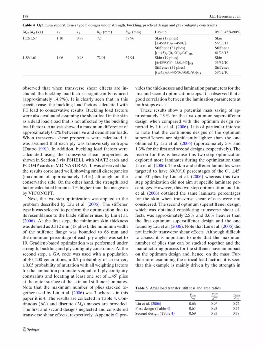
Table 4 Optimum superstiffener type b designs under strength, buckling, practical design and ply contiguity constraints
Mc/Md (kg) λb λs bsf (mm) hsw (mm) Lay-up 0%/±45%/90%
1.52/1.57 1.10 0.99 72 57.96 Skin (18 plies) Skin[±45/90/03/−45/02]S 56/33/11Stiffener (31 plies) Stiffener[(±45)2/(04/90)2/0/0]MS 61/26/13
1.58/1.61 1.06 0.98 72.01 57.94 Skin (19 plies) Skin[±45/90/0/−45/04/45]MS 53/37/10Stiffener (31 plies) Stiffener[(±45)2/02/45/03/90/04/90]MS 58/32/10
observed that when transverse shear effects are in-cluded, the buckling load factor is significantly reduced(approximately 14.9%). It is clearly seen that in thisspecific case, the buckling load factors calculated withFE lead to conservative results. Buckling load factorswere also evaluated assuming the shear load in the skinas a dead load (load that is not affected by the bucklingload factor). Analysis showed a maximum difference ofapproximately 0.2% between live and dead shear loads.When transverse shear properties were calculated, itwas assumed that each ply was transversely isotropic(Datoo 1991). In addition, buckling load factors werecalculated using the transverse shear properties asshown in Section 3 via PSHELL with MAT2 cards andPCOMP cards in MD NASTRAN. It was observed thatthe results correlated well, showing small discrepancies(maximum of approximately 1.4%) although on theconservative side. On the other hand, the strength loadfactor calculated herein is 1% higher than the one givenby VICONOPT.
Next, the two-step optimization was applied to theproblem described by Liu et al. (2006). The stiffenertype b was selected to perform the optimization due toits resemblance to the blade stiffener used by Liu et al.(2006). At the first step, the minimum skin thicknesswas defined as 3.312 mm (18 plies), the minimum widthof the stiffener flange was bounded to 68 mm andthe minimum percentage of each ply angles was set to10. Gradient-based optimization was performed understrength, buckling and ply contiguity constraints. At thesecond step, a GA code was used with a populationof 40, 200 generations, a 0.7 probability of crossover,a 0.05 probability of mutation with all weighting factorsfor the lamination parameters equal to 1, ply contiguityconstraints and locating at least one set of ±45˚ pliesat the outer surface of the skin and stiffener laminates.Note that the maximum number of plies stacked to-gether used by Liu et al. (2006) was 3, whereas in thispaper it is 4. The results are collected in Table 4. Con-tinuous (Mc) and discrete (Md) masses are provided.The first and second designs neglected and consideredtransverse shear effects, respectively. Appendix C pro-
vides the thicknesses and lamination parameters for thefirst and second optimization steps. It is observed that agood correlation between the lamination parameters atboth steps exists.
These results show a potential mass saving of ap-proximately 1.9% for the first optimum superstiffenerdesign when compared with the optimum design re-ported by Liu et al. (2006). It is of particular interestto note that the continuous designs of the optimumsuperstiffeners are significantly lighter than the oneobtained by Liu et al. (2006) (approximately 5% and1.3% for the first and second designs, respectively). Thereason for this is because this two-step optimizationexplored more laminates during the optimization thanLiu et al. (2006). The skin and stiffener laminates weretargeted to have 60/30/10 percentages of the 0˚, ±45˚and 90˚ plies by Liu et al. (2006) whereas this two-step optimization did not aim at specific laminate per-centages. However, this two-step optimization and Liuet al. (2006) obtained the same laminate percentagesfor the skin when transverse shear effects were notconsidered. The second optimum superstiffener design,which was obtained considering transverse shear ef-fects, was approximately 2.5% and 0.6% heavier thanthe first optimum superstiffener design and the onefound by Liu et al. (2006). Note that Liu et al. (2006) didnot include transverse shear effects. Although difficultto assess, it is important to note that the maximumnumber of plies that can be stacked together and themanufacturing process for the stiffener have an impacton the optimum design and, hence, on the mass. Fur-thermore, examining the critical load factors, it is seenthat this example is mainly driven by the strength in
Table 5 Axial load transfer, stiffness and area ratios
FskinFstg
Eskinx
Estgx
AskinAstg
Liu et al. (2006) 0.66 0.96 0.72First design (Table 4) 0.65 0.93 0.74Second design (Table 4) 0.69 0.93 0.78

Optimization of anisotropic composite panels 179
Table 6 Superstiffener properties from Herencia et al. (2007)
Mc/Md (kg) λb λs bsf (mm) hsw (mm) Lay-up 0%/±45%/90%
2.74/2.89 1.07 1.00 60.01 69.95 Skin (59 plies) Skin[(±45)2/453/902/(±45/04)2/45/ 53/37/1004/45/02/90/0/0]MS StiffenerStiffener (31 plies) 61/26/13[±45/90/−45/04/45/04/90/0/0]MS
the longitudinal direction. Hence, the optimum super-stiffener laminates do not significantly benefit fromflexural anisotropy. Note that the shear loading is smallin comparison to the normal loading. For other cases,elastic tailoring effects have shown substantial gains(e.g. Herencia et al. 2007). Additionally, it was ob-served that ply contiguity constraints at the first stepwere not active and, hence, did not have an influence ofthe optimum design.
Table 5 shows the axial load transfer, in-plane stiff-ness and area ratios between the skin and the stiffenerfor Liu et al. (2006) and the optimum designs presentedin this paper. It is clearly seen that for the same stiffnessratio an increase in the axial load transfer leads to ahigher area ratio and, therefore, to a heavier solution.Note that the out-of-plane loads experienced by thesuperstiffener are transformed into in-plane loads ineach of the superstiffener’s laminates. Hence, the forcesin each of the superstiffener’s laminates are functions oftheir areas and their membrane properties. In addition,the mass of the superstiffener is a function of its area.Therefore, the effect of the axial load transfer on thesuperstiffener mass is related to the superstiffener’sarea. Note that as the skin becomes thinner it generallybecomes less stiff and decreases its load transfer. Thismight happen for local buckling (buckling of the skinand skin-stiffener interaction) where the skin tends tobe less stiff and the loss in load-carrying capability isovercome by increasing the stiffness and/or the area ofthe stiffener.
In addition, an optimum design corresponding toan anisotropic stiffened panel with T-shaped stiffen-ers (stiffeners type a) under strength, buckling, prac-tical design and ply contiguity constraints was takenfrom Herencia et al. (2007) to assess the influence offailure strength at laminate and ply levels. For this
example, the stiffened panel was made of AS4/3502with the following properties: E11 = 127,553.8 N/mm2,E22 = 11,307.47 N/mm2, G12 = 5,998.48 N/mm2,v12 = 0.3, tp = 0.132 mm and ρ = 1.578·10−6 kg/mm3. Thesuperstiffener loading was: Fc = −711,716.13 N andNxy = −875.63 N/mm. Neither out-of-plane loadingnor transverse shear effects were considered. Table 6shows the selected superstiffener design. Table 7 liststhe strength load factors for the 0˚, 90˚, 45˚ and −45˚plies for the skin, stiffener flange and stiffener web. Plystrain allowables are assumed to be 3,600 με in tensionand compression in 1 and 2 directions and 7,200 με inshear (12 directions). From these results, it is clearlyseen that there are other plies that fail apart fromthe 0˚ plies. Note that designing for failure strengthat laminate level involves limiting the strains in the0˚ ply in 1, 2 and 12 directions. This is because thematerial axis of the 0˚ plies aligns with the laminateaxis (plate). In addition, it is observed that the loweststrength load factor corresponds to the ±45˚ plies in1 and 2 directions, respectively. This is believed to bebecause the skin contains membrane anisotropy, whichimplies that the skin laminate shears under tension orcompression load. Note also that the lowest strengthload factor reported by Herencia et al. (2007), whichwas initially in the stiffener, is now in the skin dueto its membrane anisotropy. This suggests that if thelaminate exhibits membrane anisotropy, special careshould be taken when designing for strength as failureat laminate level might not capture completely the plyfailure phenomena.
Accordingly, this two-step optimization was appliedto the example of Herencia et al. (2007) with the dif-ference that failure strength was assessed at ply levelinstead of at laminate level. The results are presented inTable 8. For this example, it is clearly seen that failure
Table 7 Strength load factorsfor each ply angle andlaminate
ϕ(◦) Skin Stiffener flange Stiffener web
λ1s λ2
s λ12s λ1
s λ2s λ12
s λ1s λ2
s λ12s
0 1.08 1.61 1.09 1.00 3.29 1.42 1.00 3.29 –45 0.93 1.31 1.29 0.95 2.83 1.53 2.85 2.85 1.53−45 1.31 0.93 1.29 2.83 0.95 1.53 2.85 2.85 1.5390 1.61 1.08 1.09 3.29 1.00 1.42 3.29 1.00 –
180 J.E. Herencia et al.
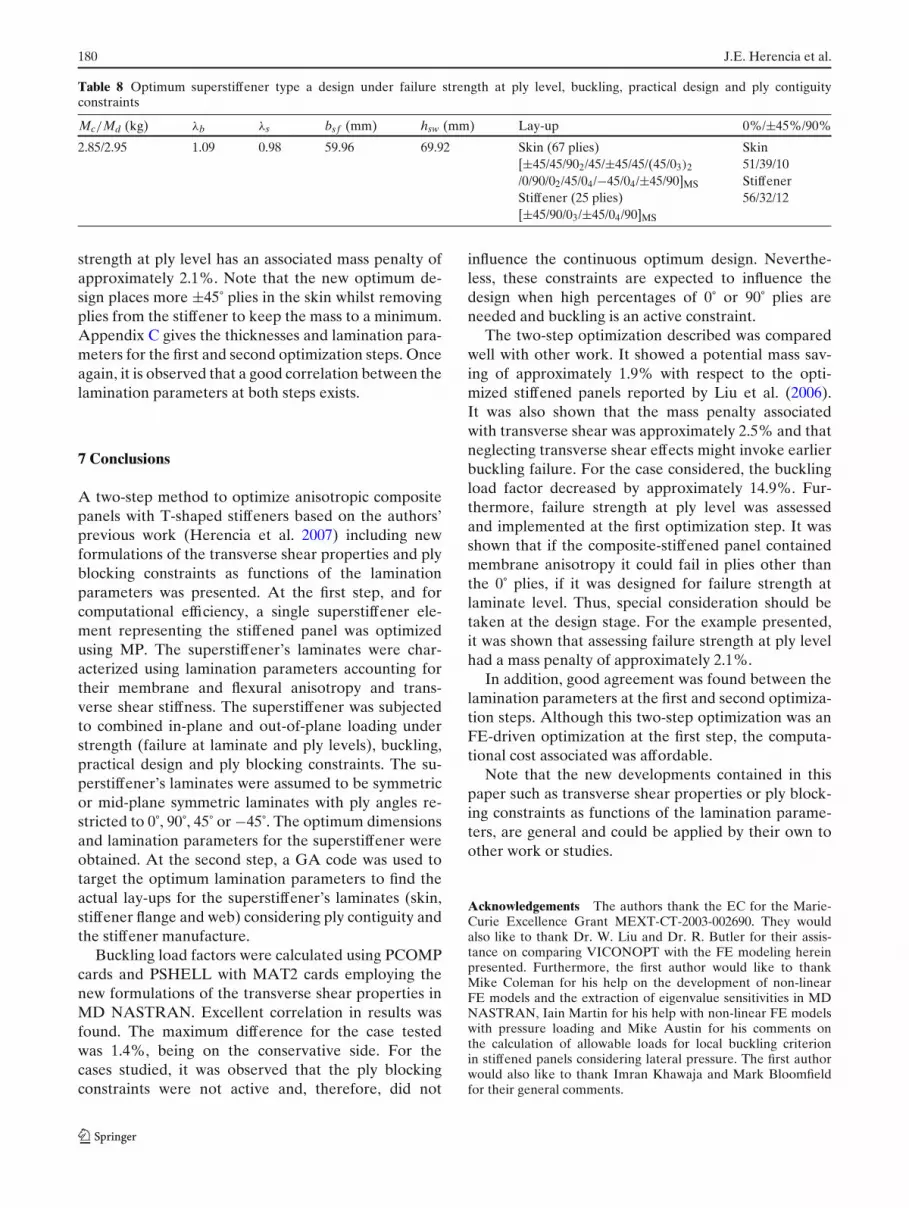
Table 8 Optimum superstiffener type a design under failure strength at ply level, buckling, practical design and ply contiguityconstraints
Mc/Md (kg) λb λs bsf (mm) hsw (mm) Lay-up 0%/±45%/90%
2.85/2.95 1.09 0.98 59.96 69.92 Skin (67 plies) Skin[±45/45/902/45/±45/45/(45/03)2 51/39/10/0/90/02/45/04/−45/04/±45/90]MS StiffenerStiffener (25 plies) 56/32/12[±45/90/03/±45/04/90]MS
strength at ply level has an associated mass penalty ofapproximately 2.1%. Note that the new optimum de-sign places more ±45˚ plies in the skin whilst removingplies from the stiffener to keep the mass to a minimum.Appendix C gives the thicknesses and lamination para-meters for the first and second optimization steps. Onceagain, it is observed that a good correlation between thelamination parameters at both steps exists.
7 Conclusions
A two-step method to optimize anisotropic compositepanels with T-shaped stiffeners based on the authors’previous work (Herencia et al. 2007) including newformulations of the transverse shear properties and plyblocking constraints as functions of the laminationparameters was presented. At the first step, and forcomputational efficiency, a single superstiffener ele-ment representing the stiffened panel was optimizedusing MP. The superstiffener’s laminates were char-acterized using lamination parameters accounting fortheir membrane and flexural anisotropy and trans-verse shear stiffness. The superstiffener was subjectedto combined in-plane and out-of-plane loading understrength (failure at laminate and ply levels), buckling,practical design and ply blocking constraints. The su-perstiffener’s laminates were assumed to be symmetricor mid-plane symmetric laminates with ply angles re-stricted to 0˚, 90˚, 45˚ or −45˚. The optimum dimensionsand lamination parameters for the superstiffener wereobtained. At the second step, a GA code was used totarget the optimum lamination parameters to find theactual lay-ups for the superstiffener’s laminates (skin,stiffener flange and web) considering ply contiguity andthe stiffener manufacture.
Buckling load factors were calculated using PCOMPcards and PSHELL with MAT2 cards employing thenew formulations of the transverse shear properties inMD NASTRAN. Excellent correlation in results wasfound. The maximum difference for the case testedwas 1.4%, being on the conservative side. For thecases studied, it was observed that the ply blockingconstraints were not active and, therefore, did not
influence the continuous optimum design. Neverthe-less, these constraints are expected to influence thedesign when high percentages of 0˚ or 90˚ plies areneeded and buckling is an active constraint.
The two-step optimization described was comparedwell with other work. It showed a potential mass sav-ing of approximately 1.9% with respect to the opti-mized stiffened panels reported by Liu et al. (2006).It was also shown that the mass penalty associatedwith transverse shear was approximately 2.5% and thatneglecting transverse shear effects might invoke earlierbuckling failure. For the case considered, the bucklingload factor decreased by approximately 14.9%. Fur-thermore, failure strength at ply level was assessedand implemented at the first optimization step. It wasshown that if the composite-stiffened panel containedmembrane anisotropy it could fail in plies other thanthe 0˚ plies, if it was designed for failure strength atlaminate level. Thus, special consideration should betaken at the design stage. For the example presented,it was shown that assessing failure strength at ply levelhad a mass penalty of approximately 2.1%.
In addition, good agreement was found between thelamination parameters at the first and second optimiza-tion steps. Although this two-step optimization was anFE-driven optimization at the first step, the computa-tional cost associated was affordable.
Note that the new developments contained in thispaper such as transverse shear properties or ply block-ing constraints as functions of the lamination parame-ters, are general and could be applied by their own toother work or studies.
Acknowledgements The authors thank the EC for the Marie-Curie Excellence Grant MEXT-CT-2003-002690. They wouldalso like to thank Dr. W. Liu and Dr. R. Butler for their assis-tance on comparing VICONOPT with the FE modeling hereinpresented. Furthermore, the first author would like to thankMike Coleman for his help on the development of non-linearFE models and the extraction of eigenvalue sensitivities in MDNASTRAN, Iain Martin for his help with non-linear FE modelswith pressure loading and Mike Austin for his comments onthe calculation of allowable loads for local buckling criterionin stiffened panels considering lateral pressure. The first authorwould also like to thank Imran Khawaja and Mark Bloomfieldfor their general comments.

Optimization of anisotropic composite panels 181
Appendix A: Laminate transverse shear properties
The transverse shear stresses are assumed to adopt aparabolic distribution through the laminate thickness todetermine the transverse shear resultants (1). A contin-uous weighting function f (z) (Vinson and Sierakowski1986) is applied instead of maintaining continuity at theinterface of each ply. Thus:
σ ixz =
(Q
i55γ
0xz + Q
i45γ
0yz
)f (z) (67)
σ iyz =
(Q
i45γ
0xz + Q
i44γ
0yz
)f (z) (68)
with
f (z) = 5
4
(1 −
(2zh
)2)
(69)
Qi55 = U∗
1 − U∗2 cos 2ϕ (70)
Qi44 = U∗
1 + U∗2 cos 2ϕ (71)
Qi45 = −U∗
2 sin 2ϕ (72)
The transverse shear resultants are calculated inte-grating those stresses through the laminate thickness.Therefore:
Qx = 5
4γ 0
xz
⎛⎝
∫ h/2
−h/2U∗
1 dz −∫ h/2
−h/2U∗
2 cos 2ϕdz−∫ h/2
−h/2U∗
1
(4z2
h2
)dz +
∫ h/2
−h/2U∗
2 cos 2ϕ
(4z2
h2
)dz
⎞⎠
+5
4γ 0
yz
⎛⎝−
∫ h/2
−h/2U∗
2 sin 2ϕdz +∫ h/2
−h/2U∗
2 cos 2ϕ
(4z2
h2
)dz
⎞⎠ (73)
Qy = 5
4γ 0
xz
⎛⎝−
∫ h/2
−h/2U∗
2 sin 2ϕdz +∫ h/2
−h/2U∗
2 cos 2ϕ
(4z2
h2
)dz
⎞⎠
+5
4γ 0
yz
⎛⎝∫ h/2
−h/2U∗
1 dz+∫ h/2
−h/2U∗
2 cos 2ϕdz−∫ h/2
−h/2U∗
1
(4z2
h2
)dz −
∫ h/2
−h/2U∗
2 cos 2ϕ
(4z2
h2
)dz
⎞⎠ (74)
In addition, the transverse shear resultants can beexpressed as follows:
Qx = H55γ0xz + H45γ
0yz (75)
Qy = H45γ0xz + H44γ
0yz (76)
The laminate transverse shear properties are ob-tained by employing the definition of lamination
parameters from (15) to (16), rearranging and simpli-fying terms in (73), (74), (75) and (76). Hence:
H55 = 5h6
(U∗
1 − 1
2
(3ξ A
1 − ξ D1
)U∗
2
)(77)
H45 = 5h6
(−1
2
(3ξ A
3 − ξ D3
)U∗
2
)(78)
H44 = 5h6
(U∗
1 + 1
2
(3ξ A
1 − ξ D1
)U∗
2
)(79)

182 J.E. Herencia et al.
Note that when the laminate exhibits isotropy theproperties above are multiplied by 5
6 , which is thetransverse shear factor presented by Reissner (1945)for homogeneous, isotropic materials.
Appendix B: Ply blocking constraints
The ply blocking constraints are derived based on thefact that under normal buckling the ±45˚ plies will tendto group towards the outside of the laminate surface soas to maximize buckling resistance. It is assumed that0˚ and 90˚ plies will block between each other and theexcess will be blocked by the ±45˚ plies. Homogeneityand linear properties are assumed in the laminate zonewhere ply angles are mixed. The volume fraction of aply angle can be defined as a function of the total andply angle thickness. Therefore:
υα = 2tαh
α = 0, 90, 45, −45 (80)
If υ90 > υ0, the volume fraction of the 90˚ pliesremaining after blocking the 0˚ plies is given by:
υ∗90 = υ90 − pυ0 (81)
where p is the maximum number of plies of the sameorientation that can be stacked together.
The volume fraction of the ±45˚ plies remainingafter blocking the already left (unblocked) 90˚ plies isdetermined by:
υ∗45 = υ45 − υ∗
90
p(82)
At the zone of mixed plies, homogeneity and linear-ity in properties are applied to identify a smeared (oraverage) ply angle (β), hence:(
(−1)υ∗
90
p+ (1) υ∗
90
)
= cos 4β
((1 − υ∗
45
) −(
υ∗90 + υ∗
90
p
))(83)
Substituting (81) and (82) in the above expressionand rearranging, it is found that:
cos 4β = p − 1
p + 1(84)
The expression of the “practical” bending laminationparameter calculated as a function of the volume frac-tion of the ply angles is given by:
ξ D2p =
3∑k=1
cos 4ϕk(υ3
i − υ3i−1
)(85)
Substituting the volume fractions and the ply anglesin the above expression, it can be demonstrated that:
ξ D2p = (−1)
(1 − (
1 − υ∗45
)3)
+ cos 4β((
1 − υ∗45
)3 − (υ90 + υ0 − υ∗
90
)3)
+ (1)((
υ90 + υ0 − υ∗90
)3)
(86)
Thus, substituting (84) into (86), reorganizing andsimplifying gives:
ξ D2p = −1 + 2 (1 + p)2
p2υ3
90 + 2 (1 + p)2 υ30 (87)
Similarly, if υ0 > υ90, it can be demonstrated that:
ξ D2p = −1 + 2 (1 + p)2
p2υ3
0 + 2 (1 + p)2 υ390 (88)
Finally, following Tsai and Hahn (1980), the volumefractions of the ply angles can be expressed as functionsof the membrane lamination parameters as follows:
υ0 = 1
4
(1 + ξ A
2 + 2ξ A1
)(89)
υ90 = 1
4
(1 + ξ A
2 − 2ξ A1
)(90)
Note that if υ0 = 0 or υ90 = 0, as the lamination para-meter is bounded in the interval [−1, 1], the maximumvalue of the remaining volume fraction is derived from(87) and (88) as follows:
υα ≤ 3
√p2
(1 + p)2 α = 0, 90 (91)
Appendix C: Optimum thicknesses and laminationparameters
This appendix contains the tables with the thicknessesand values of the lamination parameters at the twooptimization steps, for the optimum designs hereinpresented.

Optimization of anisotropic composite panels 183
Table 9 Optimum/actual thicknesses and lamination parameters for superstiffener type b designs under strength, buckling and plycontiguity constraints
h (mm) Membrane lamination parameters Bending lamination parameters
ξ A1 ξ A
2 ξ A3 ξ D
1 ξ D2 ξ D
3
Skin First step 3.3120 0.5182 0.4364 −0.0069 0.0291 −0.1131 −0.0914Second step 3.3120 0.4444 0.3333 −0.1111 0.0960 −0.1111 0.0398
Stiffener First step 5.4145 0.5215 0.4431 0.0652 0.2679 −0.2487 0.0505Second step 5.7040 0.4839 0.4839 0.0000 0.3227 −0.1832 0.0435
Skin First step 3.4254 0.4931 0.3861 −0.0045 −0.0124 −0.1408 −0.1059Second step 3.4960 0.4211 0.2632 −0.0526 0.0607 −0.1917 −0.0281
Stiffener First step 5.6146 0.4920 0.3840 0.0611 0.2660 −0.3373 0.0157Second step 5.7040 0.4839 0.3548 0.0645 0.3026 −0.3138 0.1088
Table 10 Optimum/actual thicknesses and lamination parameters for superstiffener type a design under failure strength at ply level,buckling, practical design and ply contiguity constraints
h (mm) Membrane lamination parameters Bending lamination parameters
ξ A1 ξ A
2 ξ A3 ξ D
1 ξ D2 ξ D
3
Skin First step 8.7121 0.4379 0.2758 0.1621 −0.0076 −0.2862 0.3122Second step 8.8440 0.4030 0.2239 0.1493 0.1226 −0.1272 0.2843
Stiffener First step 3.0018 0.5630 0.5261 0.0370 0.1445 −0.0505 −0.0054Second step 3.3000 0.4400 0.3600 0.0000 0.1912 −0.0025 0.0522
References
Almroth BO, Brogan FA (1976) The STAGS computercode. NASA CR-2950, NASA. Langley Research Centre,Hampton, VA
Anonymous (2004) MSC/NASTRAN reference manual, chapter13, section 2.3. MSC Software, Santa Ana, CA
Ashton JE, Waddoups ME (1969) Analysis of anisotropic plates.J Compos Mater 3:148–165
Autio M (2000) Determining the real lay-up of a laminate cor-responding to optimal lamination parameters by geneticsearch. Struct Multidisc Optim 20:301–310
Berthlot JM (1998) Composite materials. Springer, New YorkBushnell D (1987a) Theoretical basis of the PANDA computer
program for preliminary design of stiffened panels undercombined in-plane loads. Comput Struct 27:541–563
Bushnell D (1987b) PANDA2-Program for minimum weightdesign of stiffened, composite, locally buckled panels. Com-put Struct 25:469–605
Bushnell D, Bushnell WD (1994) Minimum weight design of astiffened panel via PANDA2 and evaluation of the opti-mized panel via STAGS. Comput Struct 50:569–602
Butler R, Williams FW (1990) Optimum design features ofVICONOPT, an exact buckling program for prismaticassemblies of anisotropic plates. Cardiff University, Cardiff,Wales, AIAA-1990-1068-226
Chamis CC (1969) Buckling of anisotropic composite plates.J Struct Div 95:2119–2139
Coley DA (1999) An introduction to genetic algorithms forscientist and engineers. World Scientific, Singapore
Datoo MH (1991) Mechanics of fibrous composites. ElsevierScience, England, pp 31–32
Diaconu CG, Sekine H (2004) Layup optimization for bucklingof laminated composite shells with restricted layer angles.AIAA J 42:2153–2163
Fukunaga H, Vanderplaats GN (1991) Stiffness optimization oforthotropic laminated composites using lamination parame-ters. AIAA J 29:641–646
Fukunaga H, Sekine H, Sato M, Iino A (1995) Buckling design ofsymmetrically laminated plates using lamination parameters.Comput Struct 57:643–649
Giles GL, Anderson MS (1972) Effects of eccentricities and lat-eral pressure on the design of stiffened compression panels.Langley Research Centre, Hampton, VA, NASA TN-D-6784
Goldberg DE (1989) Genetic algorithms in search, optimizationand machine learning. Addison-Wesley Longman, Reading,MA
Grenestedt JL (1991) Layup optimization against buckling ofshear panels. Struct Optim 3:115–120
Gürdal Z, Haftka RT, Hajela P (1999) Design optimization oflaminated composite materials. Wiley, New York
Haftka RT, Walsh JL (1992) Stacking sequence optimization forbuckling of laminated plates by integer programming. AIAAJ 30:814–819
Herencia JE, Weaver PM, Friswell MI (2007) Optimizationof long anisotropic laminated fiber composite panels withT-shaped stiffeners. AIAA J 45:2497–2509
Johnson EH (2005) MSC/NASTRAN design sensitivity andoptimization, user’s guide. MSC Software, Santa Ana, CA
Jones RM (1999) Mechanics of composite materials, 2nd edn.Taylor and Francis, Philadelphia, PA
Kogiso N, Watson LT, Gürdal Z, Haftka RT, Nagendra S (1994)Minimum thickness design of composite laminates subjectto buckling and strength constraints by genetic algorithms.Proceedings of the AIAA/ASME/ASCE/AHS/ASC 35thStructures, Structural Dynamics and Materials Conference,Hilton Head, NC, 18–20 April, pp 2257–2275
Laitinen M, Lahtinen H, Sjölind S (1995) Transverse shear cor-rection factors for laminates in cylindrical bending. CommunNumer Methods Eng 11:41–47
Lee JM (2003) MSC/NASTRAN linear static analysis, user’sguide, chapter 13, linear buckling. MSC Software, SantaAna, CA
Le Riche R, Haftka RT (1993) Optimization of laminate stackingsequence for buckling load maximization by genetic algo-rithm. AIAA J 31:951–956

184 J.E. Herencia et al.
Liu W, Butler R, Mileham AR, Green AJ (2006) Bi-level opti-mization and postbuckling of highly strained composite stiff-ened panels. AIAA J 44:2562–2570
Liu B, Haftka RT (2004) Single level composite wing opti-mization based on flexural lamination parameters. StructMultidiscipl Optim 26:111–120
MATLAB (2006) Software package V.7.1. The MathWorksMD NASTRAN (2006) Software package 2006r1. MSC Soft-
ware, Santa Ana, CAMiki M, Sugiyama Y (1991) Optimum design of laminated com-
posite plates using lamination parameters. Proceedings ofthe AIAA/ASME/ASCE/AHS/ASC 32nd Structures, Struc-tural Dynamics and Materials Conference, Baltimore MD,Part 1, pp 275–283
Nagendra S, Haftka RT, Gürdal Z (1992) Stacking sequence op-timization of simple supported laminates with stability andstrain constraints. AIAA J 30:2132–2137
Nagendra S, Haftka RT, Gürdal Z (1993) Design of a bladestiffened composite panel by a genetic algorithm. Proceed-ings of the AIAA/ASME/ASCE/AHS/ASC 34th Structures,Structural Dynamics and Materials Conference, San Diego,CA, 19–21 April, Part 4, pp 2418–2436
Nagendra S, Jestin D, Gürdal Z, Haftka RT, Watson LT (1996)Improved genetic algorithm for the design of stiffened com-posite panels. Comput Struct 58:543–555
Nemeth MP (1986) Importance of anisotropy on buckling ofcompression-loaded symmetric composite plates. AIAA J24:1831–1835
Niu CYM (1992) Composite airframe structures—practical de-sign information and data. Hong Kong Conmilit Press, HongKong
Reissner E (1945) The effect of transverse shear deformation onthe bending of elastic plates. J Appl Mech 67:A69–A77
Rolfes R, Rohwer K (1997) Improved transverse shear stress incomposite finite elements based on first order shear defor-mation theory. Int J Numer Methods Eng 40:51–60
Schmit LA, Farshi B (1973) Optimum laminate design forstrength and stiffness. Int J Numer Methods Eng 7:519–536
Schmit LA, Farshi B (1977) Optimum design of laminated fibercomposite plates. Int J Numer Methods Eng 11:623–640
Stroud WJ, Agranoff N (1976) Minimum mass design of fila-mentary composite panels under combined loads: designprocedure based on simplified equations. Langley ResearchCentre, Hampton, VA, NASA TN D-8257
Stroud WJ, Anderson MS (1981) PASCO-Structural panelanalysis and sizing code, capability and analytical founda-tions. Langley Research Centre, Hampton, VA, NASA-TM-80181
Timoshenko SP, Gere JM (1961) Theory of elastic stability.McGraw-Hill, New York
Todoroki A, Haftka RT (1998) Lamination parameters forefficient genetic optimization of the stacking sequences ofcomposite panels. AIAA Paper 98-4817, Proceedings of the7th AIAA/USAF/NASA/ISSMO Symposium on Multidis-ciplinary Analysis and Optimization, St. Louis, MO, 2–4September, pp 870–879
Tsai SW, Hahn HT (1980) Introduction to composite materials.Technomic, Stamford, CT
Tsai SW, Pagano NJ (1968) Composite materials workshop.Technomic, Stamford, CT, pp 233–253
Vanderplaats GN (1973) A FORTRAN program for constrainedfunction minimization: user’s manual. NASA Ames, CA,NASA-TM-X-62282
Vanderplaats GN (2001) Numerical optimization techniquesfor engineering design, 3rd edn. Vanderplaats Research &Development, Colorado Springs, CO
Vinson JR, Sierakowski RL (1986) The behavior of struc-tures composed of composite materials. Martinus Nijhoff,Dordrecht, The Netherlands
Whitney JM (1969) The effect of transverse shear deformation onthe bending of laminated plates. J Comput Math 3:534–547
Whitney JM (1973) Shear correction factors for orthotropic lami-nates under static loading. J Appl Mech 40:302–304
Wittrick WH, Williams FW (1974) Buckling and vibration ofanisotropic or isotropic plate assemblies under combinedloadings. Int J Mech Sci 16:209–239
Yamazaki K (1996) Two-level optimization technique of compos-ite laminate panels by genetic algorithms. AIAA Paper 96-1539-CP, Presented at the AIAA/ASME/ASCE/AHS 37thStructures, Structural Dynamics and Materials Conference,pp 1882–1887
Recommended


