1. Introduction
In recent years the traffic due to multipoint network-based applications keeps on growing in transport net-works. Multipoint applications include very importantbroadband services such as digital media broadcasting(e.g. IP-TV, IP-Radio, etc.), VoD streaming, distancelearning, virtual private LAN services, etc [1].
In spite of its benefits in terms of bandwidth sav-ings, today the multicast service is not made availableto the end users by most commercial ISPs due to anumber of practical reasons. This means that today ahuge amount of bandwidth is wasted due to multipointdelivery based on application-layer multicasting (ALM)i.e. unicast-based distribution. In this sense, a recentapplication that may impel the operators to open themulticast service is TV peer-casting. This application isstarting to take an unnecessarily high share of the net-work capacity as the same streaming informationcomes in and out of the network for thousands of usersby unicast relaying.
Nonetheless, even though not directly available toend users, the multicast service is an essential featurepresent in the core of the transport network because itis the key to the scalable implementation of the triple-play concept: TV channels are usually multicast from acontent distributor to local caches/relays near the endusers.
In general, it can be said that it is less costly toimplement multicast in the lowest layers of the networkhierarchy; however, when the underlying technology isconnection-oriented - as it is the case of optical net-works - the number of supported connections becomesa strict bound. In the case of wavelength-routed opticalnetworks, this limit is set by: the number of lambdas,the amount of multipoint units in optical nodes, theirfan-out and the optical power budget. Given this limita-tion, optimizing light tree construction is quite a relevantchallenge in next generation multicast-capable opticalnetworks.
In this paper we investigate the problem of dynam-ic multicast trees, where the member tree leaves arecontinually changing. New destination nodes may login to the tree to receive the content, while other nodesmay leave the tree and return at a later time. This cor-responds to a scenario where IP membership drivesoptical tree set up. In a real setting, the tree would be“optical” due to the aggregation of multiple multicastsessions or it could be given by a selected set of indi-vidual ultra broadband multicast sessions. Several mul-ticast trees can exist in the network at the same time. Ifthe trees have sub-lambda bandwidths, grooming canbe applied to make network utilization more efficient.
A typical application can be a digital media distribu-tion service, where the audience is varying in time. Newcustomers appear, who subscribe for the content, andother customers with expired subscription leave thenetwork. In this case a customer does not necessarilymean an individual home user, rather a local provider(e.g. a local cable-TV provider).
Another example can be a virtual LAN service,where LAN broadcast has to be delivered to all end-points. In contrast to the previous scenario, this appli-cation is less sensitive to minor interruptions in trans-mission caused by reconfiguration of the multicast tree.
The continuous changing of tree members causesthe degradation of the multicast tree in the sense ofnetwork and resource costs. This degradation can becured by regular reconfiguration of the tree. Recon-figuration results in significant spare of network re-sources (and of the cost), which is clearly beneficial forthe operator: resources (including link capacities) thatare freed up can be reused.
However, there are also some drawbacks of recon-figuration:
It may consume lots of computation time as com-puting the Steiner tree is an NP-complete problem. How-ever, considerable saving can be achieved by usingfaster heuristic methods trading-off speed and optimal-ity.
2 VOLUME LXIII. • 2008/1
Periodic reconfiguration of groomed multicast trees in WDM networks
MARCELL PERÉNYI, PÉTER SOPRONI, TIBOR CINKLER
Budapest University of Technology and Economics, Department of Telecommunication and Media Informatics
{perenyim, soproni, cinkler}@tmit.bme.hu
Keywords: dynamic multicast, light-tree, optical network, grooming, reconfiguration, WDM, performance evaluation, simulation
In a typical multicast scenario the tree members (users attached to the tree) change all the time. New users join the tree,
while some existing users leave it. Here we consider these dynamically changing multicast trees in two-layer, grooming-
capable, optical networks. The continuous changing of the tree members (users) causes the degradation of the tree. Therefore
a huge amount of network resources can be spared by periodically repeated reconfiguration. In this paper the benefits of
reconfiguration are investigated for different multi-cast routing algorithms and reconfiguration periods.
Reviewed

Reconfiguration can cause a short disruption in thedata transmission flow or cause packet reordering,which is sometimes not acceptable by the applicationand should be avoided. Furthermore, reconfigurationimplies an additional signaling overhead.
1.1. Surviving to tree reconfigurationAlthough our paper does not intend to solve this
problem, we suggest some techniques to show that itis feasible.
A solution for an interruption-sensitive application(e.g. media streaming) is a soft switch-over from onelight tree to the new one. In this case the updated lighttree is already set up, before the old one is torn down.There is a short period when both trees exist and areable to transmit data at the same time. In order to pre-vent loss of sequence during the change of the tree,the transmission can be held for a short time at theingress to guarantee that all the packets are flushedout of the original tree. Alternatively, the first packetsthat travel through the new tree are buffered at the eg-ress node until an end-of-transmission signaling pack-et arrives through the old tree. However, smooth recon-figuration needs extra resources from the network. Inour simple network model if one free wavelength isavailable in every link the reconfiguration of one light-tree can be performed - for example by ILP (IntegerLinear Programming) optimization. In a DWDM networkwith at least 30 WLs per link this extra capacity is ac-ceptable (especially compared to the huge cost gain,that the optimization results). However, it is not guar-anteed that this extra capacity is always available.
1.2. Other publications in the areaQuite a few papers were published in the field of
optimizing the cost of multicast routing (light-trees) inoptical networks. Since the problem of routing the de-mands optimally is often infeasible or time-consuming,several heuristic approaches were proposed and theirperformance was compared with ILP-based optimal so-lutions.
The problem of static multicast for optical wavelengthrouting was investigated for ring and mesh networksamong others in [2] and [3], respectively. The authorsof [3] presented an analytical model of grooming prob-lem represented as non-linear programming formula-tion and compared the results with heuristic approach-es. Heuristic optimization algorithms are proposed in [4-6]. The authors of [7] use an ILP formulation to solvethe optimal routing and wavelength assignment prob-lem, and show that a network with only a few splittersand wavelength converters can efficiently transfer mul-ticast demands. Mustafa et al. [8] also presented anILP formulation and heuristic solutions assuming groom-ing for minimizing the number of electronic-layer equip-ments and the number of wavelengths.
In recent time the optimization of dynamically chang-ing multicast trees attracted more attention. In the dy-namic case the goal is usually to minimize the blocking
ratio, not to route all demands (according to some con-straints) as in the static case. This problem in general iseven more resource- and computation-intensive thanthe static version. We found, however, that some sub-problems of routing (e.g. optimization of a single tree,or several trees separately) can be solved optimally byILP. Therefore, it is worth to compare the performanceof dynamic routing algorithms to the optimal solution,and to calculate the benefit.
Several provisioning methods of dynamic trees(assuming grooming) are discussed in [9-11].
In [12] traffic engineering is performed through dy-namic traffic grooming in grooming-capable WDM net-works in the unicast scenario.
The authors of [13] proposed a dynamic wave-length assignment algorithm for multicast to minimizecall blocking probability by maximizing the remainingnetwork capacity in each step. Chowdhary et al. add-ressed in [14] a similar problem by provisioning on-linemulticast demands with the objective of increasing theresource utilization and minimizing the blocking proba-bility for the future arriving requests.
Boworntummarat et al. introduced light-tree-basedprotection schemes against single link failure in [15].ILP formulations were developed to measure and com-pare the minimum spare capacity requirement of theproposed protection strategies.
According to our knowledge no work was publishedanalyzing the effect of regular reconfiguration of light-trees, investigating the degradation of dynamic routingalgorithms, and comparing the dynamically changingcosts to the optimum.
2. Problem formulation
A two-layer network is assumed, where the upper, elec-tronic layer is time switching capable while the lower,optical layer is a wavelength (space) switching capableone. The electronic layer can perform traffic grooming,i.e. multiplexing low bandwidth demands into a singleWL channel. The two layers are assumed to be eitherinterconnected according to the peer model [16] or ver-tically integrated, i.e. the control plane has informationon both layers and both layers take part in accommo-dating a demand.
The network topology and the number of fibers areassumed given as well as the parameters (distributionof inter-arrival time and holding time) of dynamic trafficdemands. The capacity of WL channels and the cost ofrouting, (e.g. space switching, optical to electronic con-version, etc.) can also be given in advance.
We assume dynamic traffic consisting of multicasttraffic demands. As explained before, these demandsmay correspond to an individual ultra-high speed IPmulticast session or to a set of aggregated sessionsthat share most of the leaves. The heuristics for aggre-gating multiple sessions into a single light tree fall outof the scope of this paper. The same consideration is
Periodic reconfiguration of groomed multicast trees
VOLUME LXIII. • 2008/1 3
made regarding joint optimization of light trees and lighttree merging: for the sake of simplicity, in this paperlight-trees are optimized separately, although, joint opti-mization could yield a higher cost gain at a higher com-putational cost.
A multicast tree consists of multiple so-called sub-demands, which can share resources in the network(e.g. their bandwidths are not additional). One sub-demand is assigned to each destination node (mem-ber) of the tree. The source of every sub-demand is thesingle source node of the multicast tree. Destinationnodes of the tree change dynamically: new nodes canlog in the tree or existing nodes can log out at anytime. Paths of new sub-demands have to be calculat-ed online while paths of leaving nodes need to be torndown as carefully as possible not to affect other sub-demands.
Both the active session time (holding time) and theidle (inter-arrival) time for every destination node havean exponential distribution. The traffic load can be deter-mined by appropriately setting the rate parameters (λ)of the distributions. The objective is to reach all currentdestination nodes from the source in each time step.
3. Network model
We use a wavelength graph model for routing in twolayer networks with grooming and with different types ofnodes. The model handles any regular mesh topologyand supports the peer-model. The WL graph that cor-responds to the logical network is derived from thephysical network considering the topology and capabil-ities of physical devices.
A simpler version of the model has been first pro-posed in [17]. ILP formulation of the static RWA problemwith grooming and protection has been given in [18].
The network consists of nodes and links connectingthe nodes. Both ends of an optical link (fiber) areattached to an interface (IF) of a physical device, whichdetermines the number of supported WLs in the fiber.Every physical device contains an internal switchingfabric and some IFs. Each link and every physical de-vice has a specific logical representation in the WL graph.
A physical link is derived to as many logical edgesas the number of available WLs in the link. The logicalsub-graph of a physical device depends on the capa-bilities of the device. Every edge in the graph has acapacity and a cost of usage. The capacity of the edgeusually equals to the WL capacity, which depends onthe used carrier (typically 2.5 Gbps – which was as-sumed in our simulations – or 10 Gbps). The cost of theedge is determined by its functionality (WL edge, O/Econversion, etc.).
The WL graph model (together with our ILP frame-work) can support devices with different capabilitiesappearing in the network at the same time. The modelis easily extendable; the type of devices can be changedlater if new internal models are introduced.
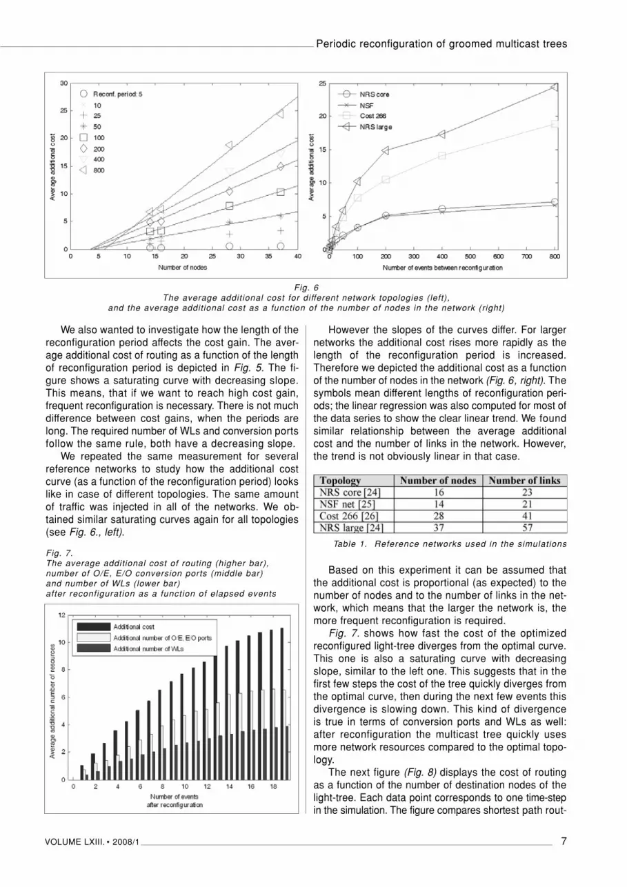
A sub-graph of a versatile physical device is depict-ed in Fig. 1. The equipment is a combination of an OXCwith WL-conversion and an OADM that can originateand terminate traffic demands, as well as perform spaceswitching. WL-conversion and splitting (branching) oflight-trees can only be performed in the electronic layer.We will use this complex node in our simulations.
4. Routing algorithms
We applied several algorithms to route the demands inthe network. We wanted to compare their costs andperformances. A simple example illustrating the differ-ent outcome of the algorithms is shown in Fig. 2.
4.1. ILP routing and formulationILP always provides the optimal cost of routing the
current demands in the system, thus it serves as abaseline for comparison. However, this does not nec-essarily mean that the numbers of certain resources(e.g. wavelengths, O/E, E/O converter ports) are all mi-nimal as well. On the other hand ILP routing usuallyconsumes much time. Fortunately, the routing time ofone multicast tree is still acceptable even for larger net-works. This time varied from 3 seconds to 180 secondson a 2.8 GHz Pentium for COST266 network [19], whichconsists of 28 nodes and 41 links. If we want to routeseveral trees together by introducing grooming muchmore cost can be spared, however, the solution timebecomes unacceptably high. So it is only possible toroute different trees separately one after the other.
An important disadvantage of ILP routing is that theconsecutive configurations are very dissimilar, thusreconfiguration of the paths of demands (includingswitching devices along the path) is unavoidable.
We used the ILP formulation introduced in [22] and[23] to route multiple multicast trees in the network.
HÍRADÁSTECHNIKA
4 VOLUME LXIII. • 2008/1
Fig. 1. Sub-graph of an OXC-WL device in the wavelength graph

This formulation is able to route unicast and multicastdemands as well, or even demands from both types atthe same time.
4.2. Accumulative shortest path (Dijsktra’s algorithm)Accumulative shortest path algorithm is fast and sim-
ple. It can be applied for routing a new demand by notinterrupting the current active sub-demands in the net-work. On the other hand this algorithm is rather costly.
The accumulative shortest path algorithm works asfollows: routes are calculated between the source andthe destination nodes one after the other. The algo-rithm operates directly on the logical network (wave-length graph). The source and the destination nodesof a sub-demand are the electronic nodes of the cor-responding physical device. The cost of already re-served edges of the graph is set to zero, which meansit can be used for free.
Paths to leaving destination nodes are cleared.Edges that are not used by the multicast tree anymoreare de-allocated (i.e. this sub-demand was the last onethat used these edges). Dijsktra’s algorithm never mod-ifies paths of existing sub-demands, which unfortu-nately often results in longer paths.
4.3. Minimal Path Heuristic (MPH)The MPH algorithm transforms the original wave-
length graph into a virtual graph and applies Prim’s al-gorithm [20] to form a minimum cost spanning tree. A virtual graph is a full mesh, in which only the singlesource and all the destination electronic nodes are pre-sented. The weight of an edge in the virtual graph ex-presses the cost of the shortest path in the original wave-length graph (which implies that the shortest path hasto be calculated for every node pair in back and forth).
Prim’s algorithm is applied in this “upper-layer” virtualgraph. After the minimal cost spanning tree is found thepaths are traced back into the original wavelength
graph. Already used edges of the virtual graph areequal to zero when updating the spanning tree after anew destination node logs in. This ensures that pathsof existing sub-demands are not modified. Details ofMPH algorithm can be found in [21].
4.4. Tree routingThis algorithm is similar to the MPH algorithm, ex-
cept that it operates in the wavelength-graph, not in aderived “upper layer”, virtual graph. It applies the samePrim’s algorithm to determine a minimal cost spanningtree in the WL graph. Updating the tree and modifica-tion of the edge costs are also similar to the former case.
A phenomenon can occur in case of both, tree rout-ing and MPH that needs attention: trees can branch insuch nodes, where splitting is not allowed (i.e. in non-electronic nodes). These forbidden branches need tobe corrected by a post-processing. In fact it is prettysimple to solve the problem by moving both branchedpaths up to the electronic layer.
5. Results
The simulations were carried out on the COST 266European reference network [26] with the same trafficdemands used in case of all algorithms.
In Fig. 3. the cost of routing is plotted as a functionof elapsed events. Every change of the light-tree (i.e.a destination node enters or exits the tree) is consid-ered as an “event”. In Fig. 3 the lower curve marked asILP represents the optimal cost in every step, while theupper one (marked as Dijkstra with no reconfiguration)stands for the case when no reconfiguration was app-lied. The middle curve shows the effect of the regularreconfiguration in every 20th event.
In our experiment “Dijsktra without reconfiguration”exceeds the optimal solution by more than 60 percent
Periodic reconfiguration of groomed multicast trees
VOLUME LXIII. • 2008/1 5
Fig. 2. (a) Original topology
with the source node S and three leave nodes D1, D2 and D3,
(b) tree routing, (c) accumulative shortest
path routing, (d) MPH virtual topology
and routing, (e) MPH routing, (f) ILP optimal routing

on average. The reconfiguration curve usually divergesrapidly from the optimal curve. It has the same cost,though, as the optimal one in every 20th event be-cause of the reconfiguration. Although reconfigurationis clearly beneficial (according to Fig. 3), it surely dependson the network topology, the applied dynamic routingalgorithm and the reconfiguration period as well.
Therefore we also investigated the cost of differentrouting algorithms (described in Section 4), and accumu-lative shortest path routing (Dijsktra) with different re-configuration periods.
The results are depicted in Fig. 4. It is clear, that allof the algorithms (without reconfiguration) are far fromoptimal: in the current simulation the additional cost isaround 34 to 57 percent compared to the optimum.Much cost can be spared by regular reconfiguration. Asexpected, the shorter the period of reconfiguration, thecloser the average cost approaches the optimal value.However, we should know that reconfiguration can becomputation-demanding and has other disadvan-tages as well (see Section 1.1). These drawbacks arenot taken into account in the cost.
The results are very similar for network resourcesnecessary to realize the routing: i.e. the number of re-quired O/E and E/O conversion units and the number ofwavelengths (Fig. 4).
One interesting fact is that Dijsktra’s algorithm withoutreconfiguration has an outstanding WL usage, whilethe usage of opto-electronic converters is behind MPHrouting. Both WL and conversion port usage approachoptimal value by decreasing the length of reconfigura-tion period.
HÍRADÁSTECHNIKA
6 VOLUME LXIII. • 2008/1
Fig. 3. The cost of routing as a function of elapsed eventsfor Dijsktra’s algorithm with (middle curve) and without (upper curve) reconfiguration compared with optimal ILP solut ion (lower curve)
Fig. 4. The average routing cost, conversion ports (O/E, E/O)usage and WL usage of different algorithms and (Dijsktra’s) shortest path algorithm with differentreconfiguration periods
Fig. 5. The average additional cost of routing (upper curve),number of O/E, E/O conversion ports (middle curve)
and number of WLs (lower curve) as a function of the length of reconfiguration period
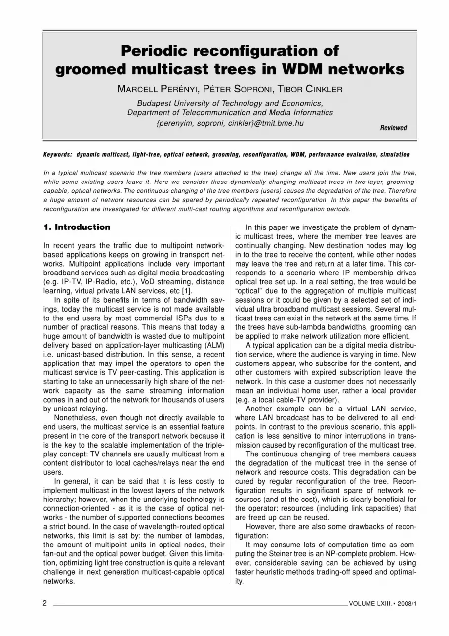
We also wanted to investigate how the length of thereconfiguration period affects the cost gain. The aver-age additional cost of routing as a function of the lengthof reconfiguration period is depicted in Fig. 5. The fi-gure shows a saturating curve with decreasing slope.This means, that if we want to reach high cost gain,frequent reconfiguration is necessary. There is not muchdifference between cost gains, when the periods arelong. The required number of WLs and conversion portsfollow the same rule, both have a decreasing slope.
We repeated the same measurement for severalreference networks to study how the additional costcurve (as a function of the reconfiguration period) lookslike in case of different topologies. The same amountof traffic was injected in all of the networks. We ob-tained similar saturating curves again for all topologies(see Fig. 6., left).
However the slopes of the curves differ. For largernetworks the additional cost rises more rapidly as thelength of the reconfiguration period is increased.Therefore we depicted the additional cost as a functionof the number of nodes in the network (Fig. 6, right). Thesymbols mean different lengths of reconfiguration peri-ods; the linear regression was also computed for most ofthe data series to show the clear linear trend. We foundsimilar relationship between the average additionalcost and the number of links in the network. However,the trend is not obviously linear in that case.
Table 1. Reference networks used in the simulations
Based on this experiment it can be assumed thatthe additional cost is proportional (as expected) to thenumber of nodes and to the number of links in the net-work, which means that the larger the network is, themore frequent reconfiguration is required.
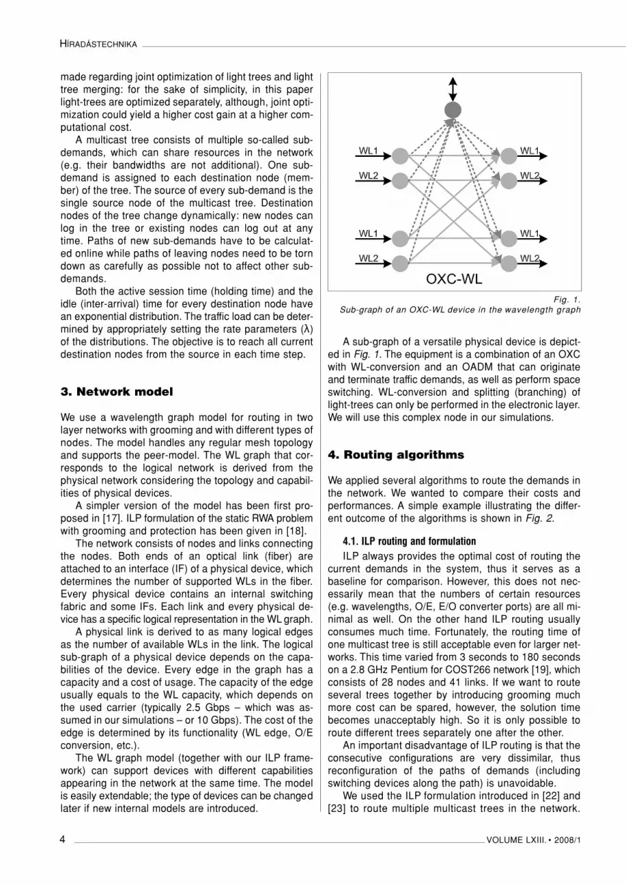
Fig. 7. shows how fast the cost of the optimizedreconfigured light-tree diverges from the optimal curve.This one is also a saturating curve with decreasingslope, similar to the left one. This suggests that in thefirst few steps the cost of the tree quickly diverges fromthe optimal curve, then during the next few events thisdivergence is slowing down. This kind of divergenceis true in terms of conversion ports and WLs as well:after reconfiguration the multicast tree quickly usesmore network resources compared to the optimal topo-logy.
The next figure (Fig. 8) displays the cost of routingas a function of the number of destination nodes of thelight-tree. Each data point corresponds to one time-stepin the simulation. The figure compares shortest path rout-
Periodic reconfiguration of groomed multicast trees
VOLUME LXIII. • 2008/1 7
Fig. 6 The average additional cost for different network topologies (left),
and the average additional cost as a function of the number of nodes in the network (right)
Fig. 7. The average additional cost of routing (higher bar), number of O/E, E/O conversion ports (middle bar) and number of WLs (lower bar) after reconfiguration as a function of elapsed events

ing with and without reconfiguration to the optimal solu-tion. As expected, the routing cost naturally raises asthe number of the destinations increases. The signsshow the typical ranges of the dynamically changingcost for the routing methods. It is noticeable that therange of shortest path with reconfiguration is some-where between the optimum- and the “no-reconfigura-tion” range.
In our last experiment we are considering multipletrees (5) at the same time with specific bandwidths.Note, that in this case all trees were optimized sepa-rately by ILP in a certain order (in decreasing order oftree size), which does not provide the global optimum.These bandwidths are set so that grooming should beapplicable. The routing cost (including conversion portand WL usage) of shortest path routing and ILP arecompared. The figures suggest that reconfiguration ismore beneficial in case of higher bandwidths, sincegrooming is less useful in such a case. This observationis true for both the necessary number of conversionports and WLs, and for the total cost as well (Fig. 9-11).
6. Conclusion
In this paper we showed that reconfiguration of dyna-mic light-trees is clearly beneficial for the transport net-work operator. Lots of cost (including network resour-ces, e.g. O/E converter units and wavelength capacity)can be spared by restoring the optimal topology of thetree. Since after the reconfiguration the tree divergesquite quickly from the optimal one frequent reconfigu-ration is required.
In this paper we have tried to measure the cost sav-ing and the dynamics for periodic reconfiguration withseveral heuristics. The results show that reconfigura-tion can be a cost-effective option if the average timebetween events (subscriptions or leaves) is enough totake advantage of the WLs saving achieved. In this
case the saved resources make up for the reconfigu-ration cost. Still, a number of technical challenges mustbe addressed to make reconfiguration practical, like theseamless switch over of traffic from the old to the newtree.
Acknowledgements
This work was supported by the EC within the IST FP6 NoE e-Photon/ONe+ (www.e-photon-one.org)
and IP NOBEL II (www.ist-nobel.org) research frameworks.
References
[1] B. Quinn and K. Almeroth, “IP multicast applications: Challenges and solutions”, IETF RFC 3170, Sep. 2001.
[2] Madhyastha et al., “Grooming of multicast sessions in WDM ring networks”OptiComm 2003, Nov. 2003.
[3] G. V. Chowdhary and C. S. R. Murthy, “Grooming of Multicast Sessions in WDM Mesh Networks”, WS on Traffic Grooming, 2004.
[4] X. Zhang et al., “Constrained Multicast Routing in WDM Networkswith Sparse Light Splitting”, Journal of Lightwave Technology, Vol. 18, Issue 12, p.1917., Dec. 2000.
[5] X. H. Jia et al., “Optimization of Wavelength Assignment for QoSMulticast in WDM Networks”, IEEE Transactions on Communications, Vol. 49, No. 2, Feb. 2001.
[6] Fatih Köksal and Cem Ersoy, “Multicasting for all-optical multifiber networks”,Journal of Optical Networking, Vol. 6, Issue 2, Jan. 2007.
HÍRADÁSTECHNIKA
8 VOLUME LXIII. • 2008/1
Fig. 8 The cost of routing as a function of the number of destination nodes of the light-tree

[7] D. Yang and W. Liao, “Design of light-tree based logical topologies formulticast streams in wavelength routed optical networks,” in Proc. IEEE INFOCOM, San Francisco, CA, Apr. 2003.
[8] R. Mustafa and A.E. Kamal, “Design and provisioning of WDM networks withmulticast traffic grooming”, IEEE Journal on Selected Areas in Communications,Vol. 24, Issue 4, 2006.
[9] X. Huang et al., “Multicast traffic grooming in wavelength-routedWDM mesh networks using dynamically changing light-trees”, Journal of Lightwave Technology, Vol. 23, No. 10, Oct. 2005.
[10] Ahmed E. Kamat et al., “Algorithms for multicast traffic grooming in WDM mesh networks”,
Periodic reconfiguration of groomed multicast trees
VOLUME LXIII. • 2008/1 9
Fig. 9. Average routing cost for different bandwidth of demands
Fig. 10. Average number of converter ports (O/E, E/O) for different bandwidth of demands
Fig. 11. Average number of used WLs for different bandwidth of demands

IEEE Communications Magazine, Vol. 44, Issue 11, Nov. 2006.
[11] A. Khalil et al., “Dynamic provisioning of low-speed unicast/multicasttraffic demands in mesh-based WDM optical networks”,Journal of Lightwave Technology, Vol. 24, Issue 2, Feb. 2006.
[12] Keyao Zhu et al., “Traffic Engineering in Multi-granularityHeterogeneous Optical WDM Mesh NetworksThrough Dynamic Traffic Grooming”, IEEE NETWORK, Vol. 17, No. 2, Mar./Apr. 2003.
[13] J. Wang and B. Chen, “Dynamic Wavelength Assignment for Multicast in All-Optical WDM Networks to Maximize the Network Capacity”, IEEE Journal on Selected Areas in Communication,Vol. 21, No. 8, Oct. 2003.
[14] G. Chowdhary and C. S. R. Murthy, “Dynamic multicast traffic engineering in WDM groomedmesh networks”, WS on Traffic Grooming, 2004.
[15] C. Boworntummarat et al., Light-tree based protection strategies for multicasttraffic in transport WDM mesh networks with multifiber systems, IEEE Int. Conf. on Communications, Jun. 2004.
[16] E. Dotaro, M. Vigoureux, D. Papadimitriou: “Multi-Region Networks: Generalized Multi-Protocol Label Switching asEnabler for Vertical Integration”, Alcatel Technology White Paper, Feb. 2005.
[17] T. Cinkler et al., “Configuration and Re-Configuration of WDM networks” NOC’98, European Conference onNetworks and Optical Communications, Manchester, UK, 1998.
[18] T. Cinkler, “ILP formulation of Grooming over WavelengthRouting with Protection”, 5th Conf. on Optical Network Design and Modeling, Wien, Feb. 2001.
[19] A. Betker et al., “Reference transport network scenarios”, Technical report, BMBF-Project MultiTeraNet, 2003.http://www.pt-it.pt-dlr.de/_media/MTN_Referenz_Netze.pdf
[20] Thomas H. Cormen et al., “Introduction to Algorithms”, Second Edition, MIT Press and McGraw-Hill, 2001.Section 23.2: “The algorithms of Kruskal and Prim”,pp.567–574.
[21] M. Ali and J.S. Deogun, “Cost-effective implementation of multicasting in wavelength-routed networks”, Journal of Lightwave Techn., Vol. 18, No. 12, 2000.
[22] P. Soproni, M. Perényi, T. Cinkler, “Grooming-Enhanced Multicast in Multilayer Networks”, ONDM 2007, Athens, May 2007.
[23] M. Perényi, P. Soproni, T. Cinkler, “Multicast fák rendszeres újrakonfigurálása többrétegû optikai hálózatokban”, Híradástechnika 2007/8.
[24] NRS network topologies,http://www.ibcn.intec.ugent.be/INTERNAL/NRS/index.html
[25] D. Hart, “A Brief History of NSF and the Internet”, Aug. 2003.http://www.nsf.gov/news/news_summ.jsp?cntn_id=103050
[26] R. Inkret et al., Advanced Infrastructure for Photonic Networks:Extended Final Report of COST Action 266, Faculty of Electrical Engineering and Computing,University of Zagreb, 2003.
Authors
Marcell Perényi received his M.Sc. degree in Computer Science from the Buda-pest University of Technology and Economics (BUTE), Hungary, in 2005. He iscurrently a Ph.D. student at the Department of Telecommunication and MediaInformatics. He has participated in several research projects supported by theEU and the Hungarian government. He is a member of IEEE and the secretaryof the HTE Education Committee. His research interests include simulation, algo-rithmic optimization and planning of optical networks, as well as identificationand analysis of traffic of IP networks, especially P2P, VoIP and other multime-dia applications. He has experience in planning and maintaining of databasesystems, web services and Microsoft infrastructures.
Péter Soproni is a graduate M.Sc. student at Budapest University of Technologyand Economics (BUTE), Department of Telecommunication and Media Informa-tics. He has participated in several research projects supported by the EU andthe Hungarian government. His research interests include algorithmic optimi-zation, simulation and planning of optical networks. He has experience in .NETbased software development, as well as soft-computing especially bacterialalgorithms.
Tibor Cinkler has received M.Sc.('94) and Ph.D.('99) degrees from the BudapestUniversity of Technology and Economics (BUTE), Hungary, where he is cur-rently associate professor at the Department of Telecommunications and MediaInformatics. His research interests focus on optimisation of routing, traffic engi-neering, design, configuration, dimensioning and resilience of IP, Ethernet,MPLS, ngSDH, OTN and particularly of heterogeneous GMPLS-controlled WDM-based multilayer networks. He is author of over 180 refereed scientific publi-cations and of 4 patents. He has been involved in numerous related Europeanand Hungarian projects including ACTS METON and DEMON; COST 266, 291,293; IP NOBEL I and II and MUSE; NoE e-Photon/ONe, NoE e-Photon/ONe+ andNoE BONE; CELTIC PROMISE and CELTIC TIGER 2; NKFP, GVOP, ETIK; and heis member of ONDM, DRCN, BroadNets, AccessNets, IEEE ICC and Globecom,EUNICE, CHINACOM, Networks, WynSys, ICTON, etc. Scientific and ProgramCommittees. He has been guest editor of a Feature Topic of the IEEE ComMagand reviewer for many conferences and journals.
HÍRADÁSTECHNIKA
10 VOLUME LXIII. • 2008/1

VOLUME LXIII. • 2008/1 11
1. Introduction
In this kind of environment a distributed architecture be-comes necessary for the voluntary cooperation of auto-nomous networks, which controls the cooperations [3].No central confidence of infrastructure is to be assumed.
Promise theory is a graph theoretical framework,which simplifies the understanding of complex relation-ships in a network environment that requires compli-ance with diverse restrictions [3], [4]. According to thebasic idea, fully autonomous nodes connect with eachother through promises. The cooperative nodes organizegroups. Every single promise implies a restriction on thebehavior of the promising node.
In large scale distributed networks the componentsof the network share their services and network-man-agement functions with each other. However, it is not agood choice for the nodes to share all their serviceswith the others.
Each network node needs services from other nodes.If a node only requires services, but does not serve therequests of the other nodes, that means that this nodebehaves in a selfish way. In order to terminate suchbehavior in the network and motivate the nodes to co-operate, one may use several kinds of techniques. Theprinciple of these solutions is that one rewards the gen-erous nodes and punishes the selfish ones. If a nodereceives a reward, it is more likely that its requests willbe served by other nodes. If a node receives a pun-ishment, it will be less likely that such node is served.The game theory approach is the most suitable way tomodel the above described method. The most fittinggame for this model is the general prisoner’s dilemma.In order to make a decision whether or not to serve acertain service request, the nodes must store somekind of information about the behavior of the othernodes to make the system work.
Behavioral information and history can be storedbasically in two ways: by shared history or by privatehistories [5]. The two storage methods have different
drawbacks, in case of storage in a commonly used areaa node may send false recommendation related to an-other node, that is to say it lies about another nodeand this can ruin the cooperation. To store informationin a common field a distributed data-storage method isalso required, e.g., by way of distributed hash tables.In case of a large number of nodes individually storedhistory results in infeasible memory requirements, sothe above mentioned method can be used only to alimited extent.
Description of resource sharing by game theory mo-dels is a widely researched field, especially since the P2Pfile-distributed networks have become popular. Severalapproaches have been developed to motivate the par-ticipants of the network to share their resources. Inthese reputation-based incentive systems the nodeshave a utility value, which they want to increase andmaximize during their operation. The calculation of theutility value is based on the resource sharing level ofthe node and the extent of the utilization of other nodes.One of the most comprehensive studies in this field wasconducted by Ion Stoica and his team [5], but manyother valuable publications were made on this topic.These researches differ in several ways, e.g., the typeof the game theory used to analyze the system. IonStoica and his team used an asymmetric model withtwo participants, while for example Philippe Golle con-ducted his analysis with a multi-agent reinforcementlearning model [6].
Existing game theoretic descriptions are based onP2P principle, i.e., any participant may contact any otherparticipant to request or to perform a service. The solu-tion, described in this paper, differs from these app-roaches in the fact that a topological network is used todeliver service interactions as the chain of physical,node-to-node interactions. As an example, in ambientnetworks [1] the nodes have only a limited coveragearea, so they can communicate directly only with theirneighbours. Consequently, routing is required in thenetwork, and a service request goes through several
Incentive scheme for voluntary and autonomous cooperation
in distributed networksLÁSZLÓ HARRI NÉMETH, RÓBERT SZABÓ
Budapest University of Technology and Economics, Department of Telecommunication and Media Informatics
{nemethl, szabo}@tmit.bme.hu
Keywords: ambient networks, voluntary cooperation, game theory, peer-to-peer, distributed networks, promise theory
Today’s communication networks are becoming increasingly dynamic in the sense that they do not have fixed infrastructure,
or the configuration of infrastructure-based networks continuously changes. Examples include distributed access networks
using WLAN technology, ad-hoc networks, ambient intelligence networks [1,2] or sensor networks. These networks have con-
siderable independence and autonomy and they might frequently act in a selfish manner. Autonomy means that such net-
works have no central administrative or management principles that would determine their operation.
Reviewed

nodes. Therefore, upon a service request three differ-ent kinds of nodes participating in the process can bedistinguished: an initiator node, which requests the ser-vice, a target node, from which the service is request-ed and optionally some transport nodes, which transmitthe requests and the answers. Naturally, a node mayrequest service from its direct neighbor. In this case thetransport nodes are left out.
2. System Model
Game theory is a branch of mathematics trying to ans-wer the question: which behavior is reasonable in a sit-uation when the results and effects of a participant’sdecisions are also affected by other participants’ deci-sions. The description of a game basically requires thespecification of three elements: the players, the strate-gies and the payments, or in other word, payoffs.
Players are the participants of the game, who wantto maximize their payoffs. By strategy we mean thebehavior of the players, namely, the kind of decisionsthe players may come to. By payoff we mean the play-er’s utility diagram, the value, which may be recorded tothe player’s credit at the end of the game. This valuedepends on the strategy the player has chosen andthe strategies of other players. Since the player is ratio-nal, he wishes this utility value to be as high as possi-ble. To reach this, the player has to consider the otherplayers’ decisions or decision options, as well as hisown payoffs in relation to the above. There are sever-al kinds and classifications of the games, e.g., normalform or extensive form games, symmetrical or asym-metrical, zero sum or non-zero sum games. The easiestway to specify a normal form game is the payoff matrix.This matrix shows the players, the strategies and thepayoffs.
In order to understand the operation of the systemfirst we should discuss the prisoner’s dilemma. Thereare many versions of this game. The basic idea is thattwo prisoners, suspected of a crime are imprisoned in
separate cells. They have the same options: if a pris-oner testifies against the other he will be released andthe other is punished to 10 years’ imprisonment. If nei-ther of them testifies, they receive 6 months each, ifboth of them testify, they get 6 years each. The pris-oners must not communicate with each other hencethey are unable to cooperate (non-cooperative game).Thus the duration of the punishment may be consid-ered as a kind of negative utility we wish to minimize.The payoff matrix of the above described game is illus-trated in Table 1 (in a cell the first number is the payoffof the Player 1 /utility/ and the second number belongsto the Player 2).
The difference between the original and the gener-alized game is that several restrictions and rules weredefined for the payoff values. Based on the above var-ious prisoner’s dilemma games may be described whichfulfill these rules. We do not discuss these in details.
For asymmetric games, like a client-server interac-tion, the classical prisoner-dilemma game can be ex-tended as shown in Table 2. The numbers in Table 2indicate the utility and payoffs of certain players. Thisgame is played many times by the participants of thenetwork and the scores are cumulated. In the very caseof Table 2, when a node requests a service from anoth-er node, two events can occur: the node either servesthe client node’s request, in which case the servernode receives -1 point and the client receives 7 points,or the server rejects the request, so each of them re-ceive 0 points.
The players may have 3 different strategies: alwayscooperate, always defeat (never cooperative) and tobe reciprocative. The first strategy means that the nodefulfils every inbound request unconditionally. The sec-ond strategy is the opposite of the first: the node neverfulfils any request.
The information about the behavior of the request-ing nodes stored by the nodes becomes relevant in thereciprocative strategy. Using this strategy, the decisionof a node whether to serve the requesting node or not,is based on some stored information. During the pro-
HÍRADÁSTECHNIKA
12 VOLUME LXIII. • 2008/1
Table 1.Payoff matrix - Classical prisoner’s di lemma game
Table 2.Payoff matrix for the game played by nodes

cedure the nodes collect their scores (or loose them)game by game. Each node compiles statistics aboutwhich strategy has been the most profitable for them.If a node considers that another strategy would bemore profitable than the one it currently uses, it chang-es strategy. In this case the identifier of the node alsochanges, so the information about this node stored bythe others loses its relevance. (A traitorous node is anexception to this rule, since it keeps its identifier evenif it changes strategy. This issue will be discussed later.)
A node may increase its utility not only by serving,but also transferring requests. The value of transferringrequests is identical to the value of serving a request.For the requesting node, it is practically transparent whoprovides the service. The transport of the services isimplemented in a way of a routing mechanism. Thenodes are aware of the routes through which they canreach other nodes, thus they know which of their neigh-bors they have to turn to first if they request servicefrom a specific node.
The following question may arise: why would a serv-er node perform services upon a client’s request if thisresults in a negative score for such a node? The ans-wer lies behind the previously described private historystored by the nodes. If a node does not perform ser-vices to the other nodes, then sooner or later its re-quests will be declined as well, so it would be unable tocollect scores. This means that in the long term it wouldnot profit from such operation. Performing or not per-forming services also depends on the relationship ofthe serving node with other nodes, since as it will be sub-sequently shown, in certain cases a node may preferthe non-cooperative strategy to the other strategies.
Additionally, a traitorous type of node has also beenintroduced into the system with the following operation:When this kind of node changes strategy its identifierremains unchanged and the information stored by theother nodes about it also remains valid. Theoretically, anode like this may cooperate with every other node inthe first part of the operation, while it refuses to serveany requests in the second part, since due to the highscore collected in the first part its requests will most like-ly be served by the other nodes, which conduct recip-rocative strategy. We have examined the operation ofthe system also in the presence of such of nodes.
During the operation of the system the nodes alsostore information on the nodes they had previous con-nections with. The nodes “remember” the clients whichhad requested services from them. They use this mem-ory when they act as client nodes and they are morelikely to request services from those nodes which hadalready requested services from them. Thus, a nodecan return a service by performing a request for theother node.
Due to this principle, during the simulation the be-havior of the network converges to a relatively stablecondition, and although some strategy changes mayoccur at the last stages of the simulation, no drastic u-turns take place, thus the system becomes stable.
3. Numerical Results
The examination of the above described system wasconducted by way of simulation. The simulation wasdivided into cycles and every node requested servicefrom another node in each cycle, that is, they playedthe above described game. The game goes throughthe entire service path, that is, the path on which theperformance of services takes place between the clientand server nodes. Each simulation contains 1,000 cyc-les. The examination of the operation of the systemwas conducted with respect to several cases.
The storing method of histories stored about thenodes was examined both from short-term and long-term respect. If we store such information only for ashort-term, this means, that a node may quickly “white-wash” itself, so the system is forgiving, however this be-havior might be disadvantageous for the other nodessubsequently. However the storage of long-term histo-ry requires extra memory and for satisfactory operationan efficient search must be implemented as well. Thesetwo cases we examined in relation to private and sharedhistory.
During the simulation we examined the operation ofa network containing 100 nodes. The nodes were ran-domly positioned, so the topology developed in thisway is also random. We examined which strategy is themost profitable for a certain node. The use of a certainstrategy depends on several circumstances, e.g., onthe position of the node in the network (whether it hasa few or a lot of neighbours) or the strategies its neigh-bours use. At the beginning of the simulation the stra-tegies were randomly distributed between the nodes inthe same proportion, thus 1/3 of the nodes were coop-erative, 1/3 were defective (non-cooperative) and 1/3played the reciprocative strategy. In general it can beestablished that in most cases the cooperative and thereciprocative strategies were the most profitable ones.However, in certain cases, in some parts of the networkthe non-cooperative behavior became more popular.The system acted differently if the presence of traitor-ous nodes were also allowed, the proportion of whichwas set to 25%.
During the simulation the network approached to astable state. This means that the majority of the nodeswere not interested in strategy change and the fre-quency of strategy changes decreased in the entirenetwork. The diagrams show the number of nodes thatuse a certain strategy in a certain simulation cycle, butit does not indicate which specific nodes use such stra-tegy, so we cannot find out if the strategy was used bythe same nodes or some others. To demonstrate theaforementioned characteristics, we prepared a networktopology in each simulation cycle, which indicates eachstrategy by different color.
By examining these topologies, we came to the con-clusion that the bulk strategy changes took place at thebeginning of the simulation and at further stages nosubstantial changes happened. The examination of this
Incentive scheme...
VOLUME LXIII. • 2008/1 13

process provides an opportunity to focus on the distri-bution of the strategies depending on position withinthe topology.
Fig. 1. shows the topology reached by the end ofthe simulation in case of various simulation scenarios.It is obvious that in the case of the presence of traitor-ous nodes, the number of the non-cooperative nodesis larger than the number of defective nodes if only nor-mal operating nodes are present in the network. It isworth noticing when the short-term history is used andsome traitorous nodes are present every node be-haved in a non-cooperative way towards the othersshown at extension of the right-hand side portion ofthe graph. Thus, this effect spread over in that part ofthe network and such behavior could be observed atthe presence of the traitorous nodes. In those parts ofthe network where the nodes are relatively denselypositioned the behavior of the nodes is more or lessthe same, however, there are some areas, where, be-cause of the presence of the traitorous nodes, thenodes become less cooperative.
Fig. 2. shows the distribution of the nodes using spe-cific strategies. It can be seen that, if traitorous nodesare present, the distribution of the nodes is more un-steady, the nodes more frequently change strategies.This effect can be clearly seen also when comparing
the solutions using short-term and long-term history. Inaccordance with previous diagram it can be observedthat how many nodes followed the various strategiesby the end of the simulation. At the presence of thetraitorous nodes the difference is clearly noticeable, bythe end of the simulation more nodes used the strate-gy of never cooperating with the others.
4. Summary
In summary, we may establish that the proposed incen-tive system is able to motivate the nodes to voluntarycooperation. In some cases this cooperation is high-level and the number of the non-cooperative nodes isinsignificant, while in other cases some parts of the net-work form non-cooperative groups.
The study of the system may be continued differentways, e.g., we might examine a specific situation whenthe nodes are not steady, but change their positions.In this case we certainly must provide effective routingfor the nodes to be able to find each other in a quick-ly changing network. Several studies were made to thiseffect, however small but frequent changes the net-work topology had a significant effect on the nodes’strategy selection.
HÍRADÁSTECHNIKA
14 VOLUME LXIII. • 2008/1
Fig. 1. Distribution of nodes by strategies in the topology graph

This means, that we may not draw many conclusionfrom describing diagrams like the above ones. The stu-dy of such case constitutes the subject of further re-search.
References
[1] N. Niebert, H. Flinck, R. Hancock, H. Karl, C. Prehofer, Ambient Networks – Research for CommunicationNetworks Beyond 3G, 2004.
[2] Kovács Balázs, Simon Csaba, “Ambient” hálózatok, 2005.
[3] Mark Burgess, An Approach to Understanding Policy Based onAutonomy and Voluntary Cooperation, Lecture Notes on Computer Science, 2005.
[4] Mark Burgess and Siri Fagernes, Pervasive Computer Management: A Model of Network Policy with Local Autonomy,IEEE Transactions on Networking, 1999.
[5] Michalel Feldman, Kevin Lai, Ion Stoica, John Chuang,Robust incentive techniques for peer-to-peer networks,ACM Conference on Electronic Commerce, June 2004.
[6] Philippe Golle, Kevin Leyton-Brown, Ilya Mironov,Incentives for sharing in peer-to-peer networks, 3rd ACM conference on Electronic Commerce,Tampa, Florida, USA, 2001.
Authors
László Harri Németh obtained his M.Sc. in Computer Engineering, graduated inBudapest University of Technology and Economics in 2006. Currently he is aPh.D. student of Budapest University of Technology and Economics, Departmentof Telecommunication and Mediainformatics. His research interests are peer-to-peer and ambient networks and Wi-Fi based positioning techniques for pres-ence and location based services. He participated in the development of posi-tioning algorithms for WLANpos, a Wi-Fi based indoor local positioning system.
????
Incentive scheme...
VOLUME LXIII. • 2008/1 15
Fig. 2. The numbers of the nodes using the different strategies during the simulation
Recommended


