
1 23
Biomedical MicrodevicesBioMEMS and BiomedicalNanotechnology ISSN 1387-2176 Biomed MicrodevicesDOI 10.1007/s10544-012-9661-8
Polyimide/SU-8 catheter-tip MEMS gaugepressure sensor
Willyan Hasenkamp, David Forchelet,Kristopher Pataky, Jimmy Villard,Harald Van Lintel, Arnaud Bertsch,Qing Wang & Philippe Renaud

1 23
Your article is published under the Creative
Commons Attribution license which allows
users to read, copy, distribute and make
derivative works, as long as the author of
the original work is cited. You may self-
archive this article on your own website, an
institutional repository or funder’s repository
and make it publicly available immediately.

Biomed MicrodevicesDOI 10.1007/s10544-012-9661-8
Polyimide/SU-8 catheter-tip MEMS gauge pressure sensor
Willyan Hasenkamp · David Forchelet · Kristopher Pataky ·Jimmy Villard · Harald Van Lintel · Arnaud Bertsch ·Qing Wang · Philippe Renaud
© The Author(s) 2012. This article is published with open access at Springerlink.com
Abstract This paper describes the development of apolyimide/SU-8 catheter-tip MEMS gauge pressuresensor. Finite element analysis was used to investigatecritical parameters, impacting on the device design andsensing characteristics. The sensing element of the de-vice was fabricated by polyimide-based micromachin-ing on a flexible membrane, using embedded thin-filmmetallic wires as piezoresistive elements. A chambercontaining this flexible membrane was sealed usingan adapted SU-8 bonding technique. The device wasevaluated experimentally and its overall performancecompared with a commercial silicon-based pressure
W. Hasenkamp and D. Forchelet contribute equally.
W. Hasenkamp (B) · D. Forchelet · K. Pataky ·H. Van Lintel · A. Bertsch · P. Renaud (B)École Polytechnique Fédérale de Lausanne,Lausanne, Switzerlande-mail: [email protected], [email protected]: lmis4.epfl.ch
W. Hasenkamp · D. Forchelet · H. Van Lintel · A. Bertsch ·P. RenaudMicrosystems Laboratory, STI-LMIS4, Station 17, EPFL,Lausanne, Switzerland
K. PatakyMicrosystems Laboratory, STI-LMIS1, Station 17, EPFL,Lausanne, Switzerland
J. VillardKlinikum rechts der Isar, Technische UniversitätMünchen - TUM, Munich, Germany
Q. WangDepartment of Medicine, Division of Nephrology andHypertension, CHUV, Lausanne, Switzerland
sensor. Furthermore, the device use was demonstratedby measuring blood pressure and heart rate in vivo.
Keywords Pressure sensor · Pressure monitoring ·Biosensor · Strain sensor · Catheter-tip · Polyimide ·SU-8
1 Introduction
Polymer-based microelectromechanical systems(MEMS) are increasingly being used in biomedicalapplications (Grayson et al. 2004). Inexpensive well-established micromachining techniques, materialversatility, robustness and biocompatibility constitutesome of its potential advantages over conventionalbiomedical device fabrication methods (Liu 2007). Anumber of polymer-based devices has been realizedincluding implantable microelectrodes (Metz et al.2004), microsystems for neural prostheses (Mercanziniet al. 2008), microfluidic devices (Metz et al. 2001),temperature sensors (Moser and Gijs 2007), humiditysensors (Zeng et al. 2006), sensors for orthopedicimplants (Arami et al. 2011), tactile sensors (Fan et al.2004) and pressure sensors (Mannsfeld et al. 2010; Hillet al. 2007; Lim et al. 2005; Leonardi et al. 2003).
Polyimide has been used in various aspects of micro-electronics fabrication including multilevel intercon-nect technology and flexible electronics (Frazier 1994).Polyimide is a highly suited material for micromachinedmedical devices, as it is biocompatible, electrically insu-lating, thermally stable and exhibits low water uptake(Richardson et al. 1993). Additionally, polyimide hasa high magnetic permeability, offers a low residualstructural stress, and suits for fabrication of dynamic

Biomed Microdevices
microsystems since it has proven to be a durable ma-terial in MEMS devices (Frazier 1995).
SU-8 is a negative epoxy-based photoresist whichhas been widely used for packaging MEMS (Zine-El-Abidine and Okoniewski 2009) and for creating high as-pect ratio features using conventional photolithography(Dellmann et al. 1998). SU-8 micromachining providesa short device manufacturing cycle. It can be bondedand laminated, reducing the fabrication cost and com-plexity when compared with conventional silicon tech-nology (Hill et al. 2007). SU-8 can be processed atlow temperatures and cures into a glassy biocompatibleelement with reduced biofouling (Grayson et al. 2004).
In general, equipment requirements for polyimide/SU-8 MEMS processing are similar to those of conven-tional microfabrication techniques, hence commonlyavailable cleanroom equipment and materials canbe utilized for processing without extensive develop-ment. We have chosen to integrate polyimide andSU-8 into the fabrication of a catheter-tip MEMSgauge pressure sensor. Polymer-based pressure sen-sors have many in vivo applications such as intracra-nial pressure monitoring in case of head trauma (Liet al. 2010), intraocular pressure evaluation for glau-coma (Leonardi et al. 2004), blood pressure andheart rate monitoring for cardiovascular assessment(Grayson et al. 2004). In biomedical research, genet-ically modified mice are met with growing interest,since diseases can be expressed and studied in a con-venient platform, creating needs for more compact andprecise devices. Miniaturized pressure sensors offer po-tential improvement over fluid-filled catheters (Glantzand Tyberg 1979), as they can be mounted on thecatheter-tip directly which avoids signal damping due topressure dynamics. In fluid-filled systems, the catheteris inserted into the target site and transmits the pres-sure to a remote sensor through the fluid column—effectively creating a low-pass filter impairing the mon-itoring of rapid fluctuations (Wang et al. 2004). Fur-thermore, miniaturize sensors can decrease the riskof thrombosis, embolism and infections since commonavailable commercial sensors are oversized and will notfit into specific small vessels or cavities (Hill et al. 2007).
This paper presents the development of a 400 μm-wide hybrid polymer-based (Polyimide/SU-8) straingauge pressure sensor mounted at the tip of a Pebaxcatheter (inner diameter/outer diameter: 0.20/0.48 mm).Finite Element Analysis (FEA) was used to investi-gate the distribution of the stress and strain on thepolyimide membrane and to evaluate the device di-mensions and the appropriate locations for the place-ment of the sensing elements. The sensing elementsconsist of piezoresistive thin-film metallic wires em-
bedded in a flexible polyimide membrane. A sealedpressure chamber is created upon the polyimide mem-brane using an adapted bonding technique, commonlyemployed to fabricate microchannels (Metz et al. 2001).Next, the device is evaluated experimentally. First, itsperformance is compared with a commercial silicon-based pressure sensor. Next, the response of both sen-sors are compared when exposed to high-speed pres-sure fluctuations. Finally, the device is used in vivo tomeasure blood pressure of a mouse.
2 Finite element analysis
The chosen method for measuring the pressure is todetect mechanical deformations in a thin polyimidemembrane supported by a sealed pressure chambermade in SU-8. Finite Element Analysis (FEA) is aneffective tool to investigate the distribution of the stressand strain in various types of structures (Kasi et al.2011). In this article FEA was used to investigate thestress and strain in the polyimide (PI) membrane inorder to determine the appropriate membrane thick-ness, to assure no plastic deformation occurs during theoperation of the device and to assist with the placementof the strain gauges within the device. A 2D ComputerAssisted Design (CAD) model was built into a com-mercial FEA software, COMSOL Multiphysics (v4.2a).The 2D CAD model is presented in Fig. 1, and com-prises a PI membrane, platinum wires as the piezore-sistive element and a pressure chamber made of SU-8.The total width of the device was limited to 400 μmin order to match the tip-width of a Pebax catheter(inner diameter/outer diameter: 0.20/0.48 mm). The100 μm-wide, 50 μm-thick SU-8 pressure chamber wasdesigned to prevent deformations other than those ofthe PI membrane. Other geometrical dimensions (i.e.membrane thickness and strain gauge line length) werechosen from the results of the simulation.
The FEA was modeled in the Structural Mechanicsmodule of Comsol in stationary mode assuming a linearelastic behavior for all parts. The fundamental consid-erations in this approach are to assume a small strain(or stress) and a linear relationship between the com-ponents stress/strain (i.e. Young’s modulus). Moreover,the results are valid only for stress states that do notproduce plastic deformation, therefore stresses abovethe yield point (YP) of the materials will be discredited.The material properties necessary to perform the FEAare: density (ρ), Young’s modulus (E) and Poisson’sratio (ν). The assumed values are presented in Table 1.
The following constraints were added to the model.A boundary condition load was applied around the

Biomed Microdevices
Fig. 1 CAD modelcomprising the polyimidemembrane, the platinum aspiezoresistive material andthe SU-8 enclosed chamber(cross-section along thedevice width)
device to account for pressure changes outside thedevice. Another boundary condition load was definedinside the device, corresponding to the inner part ofthe SU-8 pressure chamber. This constraint accountsfor pressure changes inside the device due to changesin the cross-sectional area of the pressure chamberinduced by the external change in pressure. Equation 1defines the pressure change as a function of the cross-sectional area, where �p corresponds to the pressurechange inside the device, p0 is the gauge pressure insidethe pressure chamber (considered to be the ambientpressure in which the the device was fabricated), A0 isthe pressure chamber cross-sectional area at ambientpressure (105 μm2), A is the pressure chamber cross-sectional area induced by the external changes in pres-sure and γ is the adiabatic index (1.4 for air). To com-plete the model, a fixed constraint is defined at the bot-tom of the device to avoid overall device displacementwhich can introduce discrepancies in the simulation.
�p = p0
((A0
A
)γ
− 1
)(1)
An unstructured progressive triangular meshing al-gorithm was utilized for meshing the model with min-imum and maximum element size of 8 nm and 4 μm,respectively. The total number of elements generatedby the meshing was 34,088. The convergence criteriawas establish by a MUMPS solver.
Table 1 Material properties used in the FEA
Material ρ (kg/m3) E (Pa) ν
Polyimide 1,400 8 × 10⁹ 0.2Platinum 21,450 145 × 109 0.38SU-8 1,200 4.4 × 10⁹ 0.22
3 Results of the finite element analysis
FEA was first used to evaluate the acceptable thicknessvalues for a PI membrane closing the SU-8 chamber.The PI has a yield point (YP) of approximately 65 MPaand larger values of stress result in plastic deformationof PI, permanently damaging the device. The simula-tion was performed in a simplified model using a mono-litic PI membrane without platinum tracks and exposedto a pressure of 350 mmHg, corresponding to morethe twice the blood pressure for mice. Figure 2 showsthe evolution of the x-component of the membranestress with the membrane thickness, along the devicewidth and in the location where the membrane stressis maximum (in the transverse plane situated at the top
Fig. 2 x-component of the membrane stress along the devicewidth as a function of the membrane thickness, in the transverseplane situated at the top of the PI membrane

Biomed Microdevices
of the PI membrane). Clearly visible is the presence ofhigh values of stress where the PI membrane is attachedto the SU-8 chamber, and the limit of plastic deforma-tion of PI is reached at those locations for membranesthinner than 3 μm. For the fabrication of the device, PImembranes were therefore chosen to be 5 μm in totalthickness.
The PI membrane deflection was also analyzed, bothin width and in length, for different values of pres-sures. These pressure variations were added to theatmospheric pressure of 1 atm. Figure 3 presents theresults for a 5 μm thick PI membrane deflection inresponse to applied pressure, in the transverse planesituated at the top of the PI membrane. Figure 3(a)
Fig. 3 PI membrane deflection with the applied pressure, in thetransverse plane situated at the top of the PI membrane. (a)Width cross-section and (b) Length cross-section
shows the deflection in a cross-section along the widthof the device and Fig. 3(b) presents the deflection ina cross-section along the length of the device. Bothgraphs in Fig. 3 show no deflection of the PI mem-brane at 0 mmHg (corresponding to the atmosphericpressure). This is expected since the pressure inside thesensor’s pressure chamber was set to 1 atm (matchingthe packaging ambient pressure). At the pressure of300 mmHg the computed deflection of the membraneis approximately 2.1 μm with the two graphs in Fig. 3showing a linear deformation of the membrane withthe applied pressure. In Fig. 3(b) we verify a constantstrain region in the center of the membrane alongapproximately 0.6 mm in length. Therefore, we choseto fabricate strain gauges having a maximum width of600 μm to fit into a 1 mm long membrane.
To define the line length of the active strain gauge aFEA simulation was performed to investigate the strainon the PI membrane. Figure 4 shows the x-componentof the strain of a 5 μm thick membrane as a function ofthe applied pressure, in the transverse plane situated atthe top of the PI membrane, along the device width.Highly strained regions are present in the middle ofthe device (mostly compressive) and close to the SU-8 walls (both compressive and tensile), however thecentral part of the membrane sustains the strain overa longer region, without changing from compressive totensile strain. Therefore, the active strain gauge of thedevice was placed in the central part of the membrane.To avoid tensile strain and keep a safe margin foralignment during fabrication, a line length of 90 μm waschosen for the active strain gauge. To fit the defined
Fig. 4 x-component of the membrane strain with the appliedpressure, in the transverse plane situated at the top of the PImembrane and along the device width. 2D model without plat-inum trace
Biomed Microdevices
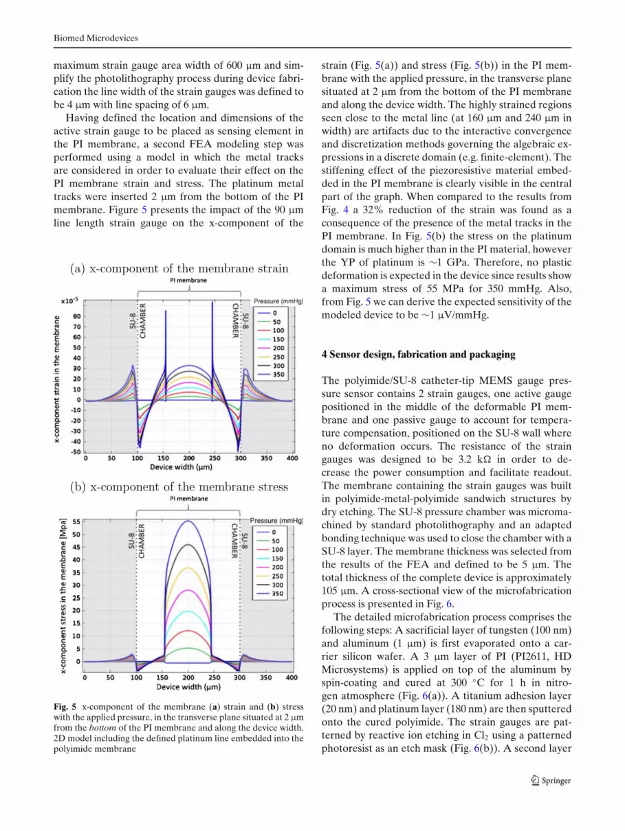
maximum strain gauge area width of 600 μm and sim-plify the photolithography process during device fabri-cation the line width of the strain gauges was defined tobe 4 μm with line spacing of 6 μm.
Having defined the location and dimensions of theactive strain gauge to be placed as sensing element inthe PI membrane, a second FEA modeling step wasperformed using a model in which the metal tracksare considered in order to evaluate their effect on thePI membrane strain and stress. The platinum metaltracks were inserted 2 μm from the bottom of the PImembrane. Figure 5 presents the impact of the 90 μmline length strain gauge on the x-component of the
Fig. 5 x-component of the membrane (a) strain and (b) stresswith the applied pressure, in the transverse plane situated at 2 μmfrom the bottom of the PI membrane and along the device width.2D model including the defined platinum line embedded into thepolyimide membrane
strain (Fig. 5(a)) and stress (Fig. 5(b)) in the PI mem-brane with the applied pressure, in the transverse planesituated at 2 μm from the bottom of the PI membraneand along the device width. The highly strained regionsseen close to the metal line (at 160 μm and 240 μm inwidth) are artifacts due to the interactive convergenceand discretization methods governing the algebraic ex-pressions in a discrete domain (e.g. finite-element). Thestiffening effect of the piezoresistive material embed-ded in the PI membrane is clearly visible in the centralpart of the graph. When compared to the results fromFig. 4 a 32% reduction of the strain was found as aconsequence of the presence of the metal tracks in thePI membrane. In Fig. 5(b) the stress on the platinumdomain is much higher than in the PI material, howeverthe YP of platinum is ∼1 GPa. Therefore, no plasticdeformation is expected in the device since results showa maximum stress of 55 MPa for 350 mmHg. Also,from Fig. 5 we can derive the expected sensitivity of themodeled device to be ∼1 μV/mmHg.
4 Sensor design, fabrication and packaging
The polyimide/SU-8 catheter-tip MEMS gauge pres-sure sensor contains 2 strain gauges, one active gaugepositioned in the middle of the deformable PI mem-brane and one passive gauge to account for tempera-ture compensation, positioned on the SU-8 wall whereno deformation occurs. The resistance of the straingauges was designed to be 3.2 k� in order to de-crease the power consumption and facilitate readout.The membrane containing the strain gauges was builtin polyimide-metal-polyimide sandwich structures bydry etching. The SU-8 pressure chamber was microma-chined by standard photolithography and an adaptedbonding technique was used to close the chamber with aSU-8 layer. The membrane thickness was selected fromthe results of the FEA and defined to be 5 μm. Thetotal thickness of the complete device is approximately105 μm. A cross-sectional view of the microfabricationprocess is presented in Fig. 6.
The detailed microfabrication process comprises thefollowing steps: A sacrificial layer of tungsten (100 nm)and aluminum (1 μm) is first evaporated onto a car-rier silicon wafer. A 3 μm layer of PI (PI2611, HDMicrosystems) is applied on top of the aluminum byspin-coating and cured at 300 ◦C for 1 h in nitro-gen atmosphere (Fig. 6(a)). A titanium adhesion layer(20 nm) and platinum layer (180 nm) are then sputteredonto the cured polyimide. The strain gauges are pat-terned by reactive ion etching in Cl2 using a patternedphotoresist as an etch mask (Fig. 6(b)). A second layer

Biomed Microdevices
Fig. 6 Cross-section view ofthe fabrication process
of PI, 2 μm in thickness, is spin-coated and likewisecured. An etch mask of sputtered SiO2 (500 nm) isdeposited onto the sandwich structure and then pat-terned by reactive ion etching using a photoresist etchmask. This oxide layer is then used as hard mask during
the subsequent oxygen-plasma etch of the polyimide todefine both the structure outline and open contact padsto the strain gauges (Fig. 6(c)). A 50 μm layer of SU-8(GM1070, Gersteltec Engineering Solutions) is appliedon top of the polyimide membrane by spin-coating and
Fig. 7 Optical images of areleased device comprisingthe enclosed SU-8 chamber,the active and passive straingauges, as well as thesuspended PI membrane

Biomed Microdevices
Fig. 8 Assembled polyimide/SU-8 catheter-tip MEMS gaugepressure sensor in comparison with a commercial Millar Mikro-Cath™ disposable pressure catheter
processed according to the manufacturer specifications(Fig. 6(d)). The SU-8 wall that will support the coverlayer is made by photolithography, the development ofthe SU-8 is performed in propylene glycol methyl etheracetate (PGMEA) after which it is cured at 90 ◦C for15 min (Fig. 6(e)). On a second carrier substrate, twothin layers of Ordil™ and one layer of Mylar™ aremade to adhere temporarily to the carrier. Afterwards,50 μm of SU-8 is spun onto the Mylar™ foil. TheSU-8 is then pre-baked up to 65 ◦C, flipped onto thefirst wafer, contacting the SU-8 sidewalls and then theMylar™ is removed (Fig. 6(f)). The laminated SU-8sandwich undergoes photolithography to define thepressure chamber on the underlying device. Devel-opment is performed with PGMEA, and laminate isheated up to 90 ◦C to ensure bonding and cure theepoxy effectively, thus sealing the pressure chamber.The devices are detached from the substrate by anodicmetal dissolution in a 10 wt% sodium chloride solu-tion, dissolving the aluminum and releasing the devices(Fig. 6(g)). Optical images of a released device compris-ing the enclosed SU-8 chamber, the active and passivestrain gauges, as well as the suspended PI membraneare shown in Fig. 7. At this stage the device is ready tobe packaged into a catheter.
The packaging of the device into the Pebax catheterconsists of bonding 40 μm diameter insulated cop-
per wires to the device contact pads using a conduc-tive epoxy. This Pebax tube has an inner diameter of0.20 mm and an outer diameter of 0.48 mm. The copperwires provide the connection between the strain gaugesand the complementary electronic circuitry. They werewired through the inner part of the catheter and con-nected to the rest of the circuit. To protect the con-nections and attach the device to the tip of the Pebaxcatheter a standard insulating epoxy was used. Theassembled polyimide/SU-8 catheter-tip MEMS gaugepressure sensor is shown in Fig. 8 in comparison witha commercial Millar Mikro-Cath™ disposable pressurecatheter fabricated using CMOS technology.
5 Experimental setup and procedure
The calibration consists of measuring the voltage out-put of the device when it is submitted to pressurechanges. For this procedure the device and a refer-ence pressure sensor are inserted into a sealed rigidtube. The tube is plugged to a relief valve, which willprovide a constant value of pressure (PDC). The reliefvalve is directly connected to a compressed air supply(Psupply). Pressure variations (PAC) are generated witha pneumatic actuator also connected to the rigid tube.The schematic diagram of the experimental setup ispresented in Fig. 9.
The polyimide/SU-8 catheter-tip MEMS gauge pres-sure sensor is connected in a Wheatstone bridgeconfiguration using two external standard resistors withsimilar impedance to strain gauges in the membrane.The bridge is powered with 2.5 V and the output sig-nals were recorded with a National Instruments dataacquisition board (NI-Daqpad-6015) and a signal con-ditioning unit (SC-2345) connected to a full-bridge in-put channel (SCC-SG04). For displaying and recordingthe measurements a LabView (National Instruments)interface is configured. A calibrated pressure sensor
Fig. 9 Schematic diagram ofthe experimental setup

Biomed Microdevices
(ENTRAN Pressure Transducer, Model EPX-N01-0.7B) is also attached to the experimental setup andused as reference sensing element for calibrating thedevice. The reference pressure sensor is powered with10 V and the signal is acquired using the NationalInstruments electronic interface previously described,and adding a full-bridge input channel (SCC-SG24).The signal conditioner’s gain and span controls for bothsensors are set to obtain a full-scale electrical outputsignal.
6 Experimental Results
A time-dependent signal was acquired during the dy-namic change in pressure using both sensors, thePolyimide/SU-8 catheter-tip MEMS gauge pressuresensor and the reference pressure sensor. The cali-bration curve (reference pressure as a function of thevoltage output of the gauge pressure sensor) is shownin Fig. 10. The linear regression (adjusted R-square =0.9982) shows that the gauge pressure sensor has asensitivity of 2.78 μV/mmHg. The sensor response tochanges in temperature is shown in Fig. 11 togetherwith a linear fit of the data (adjusted R-square =0.9974). This fit implies a temperature sensitivity of90 μV/◦C.
Before in vivo testing, the performance of the pack-aged sensor was evaluated in response to an externaloscillating pressure. The pressure inside the rigid tube
Fig. 10 Polyimide/SU-8 gauge pressure sensor calibration curveshowing reference pressure as a function of the voltage outputof the gauge pressure sensor and corresponding linear regressionfitting the data
Fig. 11 Polyimide/SU-8 gauge pressure sensor response tochanges in ambient temperature as a function of the voltageoutput of the gauge pressure sensor and corresponding linearregression fitting to the data
was varied at a frequency of ∼7 Hz to emulate themouse heart beat while the pressure was recordedusing both the reference pressure transducer and thepolyimide/SU-8 gauge pressure sensors. Results arepresented in Fig. 12. The polyimide/SU-8 catheter-tipMEMS gauge pressure sensor performed similarly tothe commercial reference sensor. The time-delay ob-served between the reference sensor and the polymer-based pressure sensor is due to the distance betweenthe sensors in the experimental setup.
Fig. 12 Response of the reference pressure transducer and thepolyimide/SU-8 gauge pressure sensor as a function of the timefor pressure variations at a frequency of ∼7 Hz

Biomed Microdevices
Fig. 13 Trace of carotid arterial blood pressure and heart rate ina male C57BL/6J mouse during inhalation of 0.5–1% isoflurane
7 In vivo experiment
The goal of the in vivo experiment was to prove thedevice concept and measure mouse blood pressure andheart rate. A male C57BL/6J mouse (weighting 45g)was anesthetized via inhalation of 1–2% isofluranemixed with oxygen. The left carotid artery was exposedfor a length of 5 mm. The fabricated polyimide/SU-8catheter-tip MEMS gauge pressure sensor was inserted4 mm into the left carotid artery and tied. The pressuresensor wire was connected to the data-acquisition sys-tem to record blood pressure (BP) and heart rate (HR)for about 5 min at a sampling rate of 1 kHz. Anesthesiawas maintained by 0.5–1% isoflurane inhalation mixedwith oxygen.
Figure 13 shows a trace of intra-arterial BP andHR for 2 s. HR is 450 beats/min, systolic BP is 129 ±1 mmHg and diastolic BP is 115 ± 1 mmHg. The wave-form of blood pressure is similar to results obtainedwith fluid-filled catheters and standard commercial sen-sors (Wang et al. 2004).
8 Discussion
In the present study, a polymer-based catheter-tipgauge pressure sensor was developed for biomedicalapplications. Experimental results were in good agree-ment with simulations regarding the device sensitivity.The experimental data demonstrated the sensor hassimilar characteristics to commercial available devicesand can be used in selected biomedical applications (i.e.cardiovascular assessments), and as an alternative tofluid-filled catheters.
The sensitivity of the device can be improved bydecreasing the PI membrane thickness and by chang-ing the placement of the strain gauges inside the PImembrane. FEA indicates a nearly 10 fold increasein sensitivity when using a 4 μm thick PI membranewith platinum strain gauges positioned 500 nm fromthe bottom of the membrane. Optionally, in order tohermetically seal the gauge pressure sensor and im-prove biocompatibility, a layer of Parylene could beevaporated on the device.
The polyimide/SU-8 catheter-tip MEMS gauge pres-sure sensor is simple to package and represents a costeffective solution for certain in vivo pressure mon-itoring applications. Adapting the design, improvingthe packaging and further miniaturizing the pressuresensor will allow not only to insert the device in thecarotid artery of mice, but also to place it directly onthe heart of the mouse to measure the pressure inthe ventricle. Moreover, the device could be integratedwith implantable wireless telemetry, which can increasemonitoring efficiency, allowing for long time measure-ments and permitting pressure measurements in awakeanimals.
9 Conclusion
In this work, we demonstrated a polyimide/SU-8catheter-tip MEMS gauge pressure sensor. Throughoutthe design process, FEA modeling results were used tooptimize the device before fabrication. The polymer-based technology and SU-8 lamination step are wellsuited for biomedical applications and provide a sig-nificant cost advantage over silicon microfabricationtechniques. Compared to a silicon-based pressure sen-sor, the polymer-based device was found to show asimilar performance while operating at a lower volt-age supply. Finally, the in vivo use of this sensor wasdemonstrated by measuring the heart rate and carotidblood pressure in mice.
Open Access This article is distributed under the terms ofthe Creative Commons Attribution License which permits anyuse, distribution, and reproduction in any medium, provided theoriginal author(s) and the source are credited.
References
A. Arami, M. Simoncini, O. Atasoy, W. Hasenkamp, S. Ali,A. Bertsch, E. Meurville, S. Tanner, H. Dejnabadi,V. Leclercq, P. Renaud, C. Dehollain, P.-A. Farine, B.M.Jolles, K. Aminian, P. Ryser, Instrumented prosthesis forknee implants monitoring. in 2011 IEEE International
Biomed Microdevices
Conference on Automation Science and Engineering (IEEE,2011), pp. 828–835
L. Dellmann, S. Roth, C. Beuret, G. Racine, Fabrication processof high aspect ratio elastic and SU-8 structures for piezoelec-tric motor applications. Sens. Actuators A 70(1998), 42–47(1998)
Z. Fan, J. Engel, J. Chen, C. Liu, Parylene surface-micro-machined membranes for sensor applications. J. MEMS13(3), 484–490 (2004)
A. Frazier, Uses of polyimide for micromachining applications.in 20th International Conference on Industrial Electronics,Control and Instrumentation, 1994. IECON’94, vol. 3 (IEEE,1994), pp. 1483–1487
A. Frazier, Recent applications of polyimide to micromachiningtechnology. IEEE Trans. Ind. Electron. 42(5), 442–448 (1995)
S. Glantz, J.V. Tyberg, Determination of frequency responsefrom step response: application to fluid-filled catheters. Am.J. Physiol. Heart Circ. Physiol. 236, H376–H378 (1979)
A. Grayson, R. Shawgo, A. Johnson, N. Flynn, Y. Li, M. Cima, R.Langer, A BioMEMS review: MEMS technology for physi-ologically integrated devices. Proc. IEEE 92(1), 6–21 (2004)
G. Hill, R. Melamud, F. Declercq, A. Davenport, I. Chan, P.Hartwell, B. Pruitt, SU-8 MEMS Fabry-Perot pressure sen-sor. Sens. Actuators A Phys. 138(1), 52–62 (2007)
H. Kasi, W. Hasenkamp, G. Cosendai, A. Bertsch, P. Renaud,Simulation of epiretinal prostheses—Evaluation of geomet-rical factors affecting stimulation thresholds. J. Neuroengi-neering Rehabil. 8(1), 44 (2011)
M. Leonardi, P. Leuenberger, D. Batrand, A. Bertsch, P. Renaud,A soft contact lens with a MEMS strain gage embeddedfor intraocular pressure monitoring. Solid-State Sensors 2,1043–1046 (2003)
M. Leonardi, P. Leuenberger, D. Bertrand, A. Bertsch, P. Re-naud, First steps toward noninvasive intraocular pressuremonitoring with a sensing contact lens. Investig. Ophthal-mol. Vis. Sci. 45(9), 3113–3117 (2004)
C. Li, P.-M. Wu, L.A. Shutter, R.K. Narayan, Dual-mode opera-tion of flexible piezoelectric polymer diaphragm for intracra-nial pressure measurement. Appl. Phys. Lett. 96(5), 053502(2010)
H. Lim, B. Schulkin, M. Pulickal, S. Liu, R. Petrova, G. Thomas,S. Wagner, K. Sidhu, J. Federici, Flexible membrane pres-sure sensor. Sens. Actuators A Phys. 119(2), 332–335(2005)
C. Liu, Recent Developments in Polymer MEMS. Adv. Mater.19(22), 3783–3790 (2007)
S.C.B. Mannsfeld, B.C.-K. Tee, R.M. Stoltenberg, C.V.H.-H.Chen, S. Barman, B.V.O. Muir, A.N. Sokolov, C. Reese,Z. Bao, Highly sensitive flexible pressure sensors with mi-crostructured rubber dielectric layers. Nat. Mater. 9(10),859–864 (2010)
A. Mercanzini, K. Cheung, D. Buhl, M. Boers, A. Maillard, P.Colin, J. Bensadoun, A. Bertsch, P. Renaud, Demonstrationof cortical recording using novel flexible polymer neuralprobes. Sens. Actuators A Phys. 143(1), 90–96 (2008)
S. Metz, R. Holzer, P. Renaud, Polyimide-based microfluidic de-vices. Lab Chip 1(1), 29–34 (2001)
S. Metz, A. Bertsch, D. Bertrand, P. Renaud, Flexible polyimideprobes with microelectrodes and embedded microfluidicchannels for simultaneous drug delivery and multi-channelmonitoring of bioelectric activity. Biosens. Bioelectron.19(10), 1309–1318 (2004)
Y. Moser, M. Gijs, Miniaturized flexible temperature sensor. J.MEMS 16(6), 1349–1354 (2007)
R.R. Richardson Jr., J.A. Miller, W.M. Reichert, R.R. Richardson,Polyimides as biomaterials: preliminary biocompatibilitytesting. Biomaterials 14(8), 627–635 (1993)
Q. Wang, H.R. Brunner, M. Burnier, Determination of cardiaccontractility in awake unsedated mice with a fluid-filledcatheter. Am. J. Physiol. Heart Circ. Physiol. 286(2), H806–H814 (2004)
H. Zeng, Z. Zhao, H. Dong, Z. Fang, P. Guo, Fabrication andTest of MEMS/NEMS based Polyimide Integrated Humid-ity, Temperature and Pressure Sensor. in 2006 1st IEEEInternational Conference on Nano/Micro Engineered andMolecular Systems (2006), pp. 788–791
I. Zine-El-Abidine, M. Okoniewski, A Low-Temperature SU-8 Based Wafer-Level Hermetic Packaging for MEMSDevices. IEEE Trans. Adv. Packaging 32(2), 448–452(2009)
Recommended


