Pre-Purchase of On-Site Sodium Hypochlorite Generation System for the
Central Water Integration Pipeline Project
SAWS Job No. 18-8616 Solicitation No. 18-18090
RELEASED FOR BID JUNE 2018
DIVISIONS 1, 11, 15
Tetra Tech, Inc. Texas Registered Engineering Firm No. 3924 700 North Saint Mary’s Street, Suite 300 San Antonio, Texas 78205
Pre-Purchase of On-Site Sodium Hypochlorite Generation System for the
Central Water Integration Pipeline Project
SAWS Job No. 18-8616 Solicitation No. 18-18090
RELEASED FOR BID JUNE 2018
DIVISION 17
Tetra Tech, Inc. Texas Registered Engineering Firm No. 3924 700 North Saint Mary’s Street, Suite 300 San Antonio, Texas 78205
TABLE OF CONTENTS
CENTRAL WATER INTEGRATION PIPELINE TERMINUS TREATMENT FACILITY OSG EARLY PROCUREMENT PACKAGE TABLE OF CONTENTS JUNE 2018 TOC - i
Section Title
DIVISION 11 – EQUIPMENT
11366 On-Site Sodium Hypochlorite Generation System DIVISION 17 – INSTRUMENTATION 17306 Vendor Packaged Process Control Systems
APPENDIX A – DIVISION 1 – GENERAL REQUIREMENTS 01300 Submittals 01600 Material and Equipment 01640 Manufacturer’s Field Services 01730 Operation and Maintenance Data 01752 Facility Startup Commissioning Requirements
APPENDIX B: DIVISION 15 – MECHANICAL 15000 Mechanical General Requirements
APPENDIX C: DRAWINGS
DIVISION 11
EQUIPMENT
CENTRAL WATER INTEGRATION PIPELINE TERMINUS TREATMENT FACILITY ON-SITE SODIUM HYPOCHLORITE GENERATION SYSTEM JUNE 2018 11366 - 1
SECTION 11366
ON-SITE SODIUM HYPOCHLORITE GENERATION SYSTEM
PART 1 GENERAL 1.01 SCOPE OF WORK
A. This specification describes a complete operational system to be furnished by a single
responsible On-Site Sodium Hypochlorite Generation (OSG) MANUFACTURER. B. It is the intent of this specification that the OSG MANUFACTURER assume system
responsibility for the OSG equipment and appurtenances. Therefore the OSG equipment manufacturer shall provide the OSG equipment and all appurtenances described in this section of the specification including but not limited to items identified in these specifications and as shown on the drawings including the P&IDs.
C. The OSG MANUFACTURER will be selected and issued a Purchase Order by the Owner for
early submittal of shop drawings prior to advertising and bidding of the Terminus Treatment Facilities Bid Package, which will be awarded to a General Contractor, referenced herein as CONTRACTOR. The OSG MANUFACTURER shall be responsible for coordination with the construction schedule of the CONTRACTOR to ensure that equipment is delivered to the site in accordance with the Contractor’s critical path schedule.
D. The OSG MANUFACTURER is responsible for the furnishing and functional operation of the
OSG Systems to enable on-site production of a 0.8% (+/- 0.05%) sodium hypochlorite solution through the electrolysis of brine at the SAWS Terminus Treatment Facility. The OSG MANUFACTUER shall coordinate the design, assembly, and testing of the sodium hypochlorite generation skids as specified herein. Two (2) hypochlorite generation skids will be installed. Each Sodium Hypochlorite Generator Skid shall have integral piping, valves system control panel with PLC as well as ancillary equipment as specified herein.
1. The OSG unit shall be furnished will all necessary accessory equipment including
but not limited to: a. Two (2) Skid-mounted, pre-assembled, piped, wired, and factory-tested
1200 ppd OSG skid
b. Two (2) Brine pump (one per skid)
c. Two (2) Transformer Rectifier (one per skid)
d. Two (2) Skid-Mounted Electrical Control Panel (one per skid)
e. Two (2) Harmonic Filters (one per skid)
f. One (1) Blower Panel
g. One (1) Electrical Control Panel Splitter
CENTRAL WATER INTEGRATION PIPELINE TERMINUS TREATMENT FACILITY ON-SITE SODIUM HYPOCHLORITE GENERATION SYSTEM JUNE 2018 11366 - 2
h. Four (4) Hydrogen Vent Blowers in the hypochlorite generation room
(one duty and one standby for each generation unit).
i. Four (4) Hydrogen Dilution Blowers (one duty and one standby per Sodium Hypochlorite Tank).
j. Four (4) Flow Sensors.
k. Six (6) Cartridge Filters (two (2) water filters, two (2) soft water filters, and two (2) brine filters).
l. Three (3) Dual Tank Water Softeners
m. Two (2) Brine Storage Tank (one duty and one standby).
n. One (1) Hardness Monitor.
o. One (1) Hydrogen Gas Detector.
p. One (1) Acid Cleaning Cart.
q. Integrated piping, valves, flow meters, solenoid control valves and accessories on the skid and where shown on the P&IDs.
2. The OSG MANUFACTURER shall also coordinate with the CONTRACTOR to ensure that all related systems furnished under the CONTRACTOR’s scope of work will form a complete integrated operating system. The OSG MANUFACTURER for this project shall coordinate the OSG system with the following equipment supplied by the CONTRACTOR, and their manufacturers: a. Sodium Hypochlorite Storage Tanks
b. Sodium Hypochlorite Metering Pumps
c. Interconnecting Process Piping and Valves
d. Instrumentation and Control
e. Electrical
3. The OSG MANUFACTURER shall provide the following services to ensure the
safe and efficient operation of the system: a. Skid factory test
b. System commissioning and installation inspection
CENTRAL WATER INTEGRATION PIPELINE TERMINUS TREATMENT FACILITY ON-SITE SODIUM HYPOCHLORITE GENERATION SYSTEM JUNE 2018 11366 - 3
c. System startup
d. Operational Readiness Evaluation
e. System performance test
f. Operator training
g. Follow-up operator training for life of system at no additional charge
4. The CONTRACTOR shall furnish all labor, materials, equipment and appurtenances required to install, test and place into satisfactory operation the system furnished by the OSG MANUFACTURER, including, but not limited to: a. Mechanical installation of system components, piping, piping supports,
fittings, valves and appurtenances not specified herein.
b. Electrical installation of external system components, circuit breakers, transformers, raceways, fittings, conduits and cable trays, wires and cables, panel boards, metering devices, grounding systems, power factor correction capacitors and surge protection.
D. General:
1. All electrical, mechanical, painting and instrumentation work included herein shall
conform to the applicable Sections or Divisions of these Specifications except as otherwise shown or specified.
2. The proposed OSG system shall employ a state-of-the-art, fully automated control system for all normal daily operations including automated sequencing of system start-up, automated control of normal operation at steady state conditions, and automated sequencing of plant shutdowns (both emergency and operator initiated). The OSG MANUFACTURER shall be responsible for providing OSG process control strategies that safeguard the OSG system equipment and warranties, and account for specific equipment furnished for the project. The developed control strategies shall be sufficiently detailed to allow use by the Process Control System Integrator (PCSI) for control system coordination efforts. The OSG MANUFACTURER shall be responsible for coordination of control strategies with the PCSI throughout the control system programming effort, and shall assist the PCSI with any changes that are required during startup and testing.
3. OSG MANUFACTURER shall furnish, test, and put into operation all instrumentation and control equipment necessary for a complete and fully functional system. As a minimum, the instrumentation and control equipment shall include control panels, VFDs, rectifiers, programmable logic controller (PLC), an Operator Interface Terminal (OIT), appropriate networking devices, indicators, control stations, controllers, alarm annunciators, push buttons, lights, selector switches, power and control as required.
CENTRAL WATER INTEGRATION PIPELINE TERMINUS TREATMENT FACILITY ON-SITE SODIUM HYPOCHLORITE GENERATION SYSTEM JUNE 2018 11366 - 4
4. The OSG MANUFACTURER shall coordinate the control system for proper operation with related equipment and materials and with the plant Process Control System (PCS). The OSG MANUFACTURER shall be responsible for coordination with the PCSI, and shall assume ultimate responsibility in providing all items required to form a complete and operable OSG system whether specified herein or not.
5. The OSG MANUFACTURER shall provide all applications programming and services required to achieve a fully integrated and operational OSG control system.
6. OSG MANUFACTURER shall be responsible for providing all hardware, software and firmware including development of drivers if required for interface with the plant PCS system. The OSG MANUFACTURER shall be present for and conduct testing as described herein. The OSG MANUFACTURER shall provide on-site support for the CONTRACTOR and subcontractors as described herein.
7. The Sodium Hypochlorite Generation unit and other major components of the system shall be factory assembled and tested, factory witnessed tested, and shall be shipped in as large an assembly as practical to minimize field assembling effort.
E. Design Conditions
1. The water entering the system shall have a pressure of 50 psi to 80 psi. 2. The water entering the system shall be 83 (+/- 5) °F 3. The ambient temperature is the room with the OSG system will be between
65°F and 85°F F. Coordination:
1. Review installation and start-up requirements under other Sections and Divisions.
1.02 RELATED SECTIONS
A. Section 01300 Submittals.
B. Section 01600 Material and Equipment C. Section 01640 Manufacturer’s Field Services
D. Section 01730 Operation and Maintenance Data E. Section 01752 Facility Startup and Commissioning
F. Section 15000 Mechanical General Requirements
G. Section 17306 Vendor Packaged Process Control Systems
1.03 QUALITY ASSURANCE
CENTRAL WATER INTEGRATION PIPELINE TERMINUS TREATMENT FACILITY ON-SITE SODIUM HYPOCHLORITE GENERATION SYSTEM JUNE 2018 11366 - 5
A. All system components shall be supplied to the CONTRACTOR by a single OSG
MANUFACTURER. The sodium hypochlorite generation equipment shall be pre-assembled and shop tested to assure compliance with pressure and operation requirements.
B. The OSG MANUFACTURER shall guarantee that the system shall be capable of
producing 0.8% +/- 0.05% sodium hypochlorite solution as described and specified herein. C. The OSG MANUFACTURER shall have at least ten (10) years’ experience in the design
and manufacture of Electrolytic Technology for on-site electrolytic hypochlorite generation systems of similar capacity to the equipment specified herein. As part of the bid package, the OSG MANUFACTURER shall submit the following documentation:
1. Provide a list of at least ten (10) installations of similar capacity and capability with
evidence of successful operation for at least five (5) years. Provide location of installation, contact person name and phone number, capacity of generation system and year installed.
2. Listing of all new projects received over the past 2 years in the USA. D. The design for the sodium hypochlorite system is based solely upon the Microclor On-site
Sodium Hypochlorite Generation System manufactured by Process Solutions Inc. (PSI). Bidders shall base their bid on the use of base brand equipment prices. Bidders may offer deductive alternates to the base brand equipment. Proposed deductive alternates offered shall meet all the detailed requirements of the specifications and shall be equal to the specified equipment. The manufacturer/model number/deduction offered shall be clearly stated for the OWNER’s consideration. The proposal shall also include a complete, detailed, descriptive information packet containing all information required for the OWNER to review the proposed deductive alternate, including but not limited to any and all exceptions, deviations, or changes to the specifications and drawings. The OWNER is not obligated to accept any of the deductive alternatives. Clearances shown on the drawings shall be maintained. Any changes or modifications are subject to review and acceptance in writing by the ENGINEER. OSG equipment shall meet or exceed the requirements of this specification. OSG System shall be manufactured by: 1. Base Brand Equipment: UGSI Solutions: Process Solutions, Inc., MicrOclor. 1. Deductive Alternates: “Or Equal” equipment as reviewed and accepted by the
OWNER and ENGINEER E. Comply with applicable provisions and recommendations of the following, except as
otherwise shown or specified.
1. American Society for Testing and Materials (ASTM). 2. National Electric Manufacturer’s Association (NEMA). 3. National Electrical Code (NEC). 4. Institute of Electrical and Electronic Engineers (IEEE). 5. American National Standards Institute (ANSI). 6. Standards of American Water Works Association (AWWA). 7. Air Movement & Control Association (AMCA).
CENTRAL WATER INTEGRATION PIPELINE TERMINUS TREATMENT FACILITY ON-SITE SODIUM HYPOCHLORITE GENERATION SYSTEM JUNE 2018 11366 - 6
8. National Sanitation Foundation, NSF. F. The brine tanks shall meet the requirement of ASME RTP-1, Reinforced Thermoset
Plastic Corrosion Resistant Equipment. 1.04 SUBMITTALS
A. Pre-Purchase Contract Schedule: It is anticipated that this pre-purchase contract will follow the approximate schedule below:
1. Submittals – Preliminary: with the bid
2. Purchase Order for Submittals Only: July 13, 2018
3. Submittals - Level 1: August 1, 2018
4. Submittals – Level 2: August 31, 2018
B. The OSG MANUFACTURER shall submit the following with the bid:
1. Preliminary fabrication drawings with all dimensions indicated. Include identification and catalog cuts for purchase components and details for manufactured components.
2. Complete Bill of Materials.
3. Pump & Blower Data: For each pump/blower, provide: head, capacity, efficiency, operating weights, and horsepower, including the dimensional and layout data. Provide descriptive literature bulletins, catalogs of the equipment including materials of construction and parts list, to indicate full conformance with this section.
4. Piping and Instrumentation Diagrams (P&IDs) showing location of all instruments, valves and auxiliary equipment, and process loop descriptions showing and describing the operation and control of the system.
5. The OSG MANUFACTURER shall provide a performance guarantee for three (3) years after the date of final acceptance by the OWNER.
6. Submit shop drawings showing details of construction and erection of the fiberglass brine tanks, including:
a. ASME RTP-1 Certification.
b. Resin used and complete description of chemical resistance for all
materials that will come in contact with chemical stored, including a statement from the resin manufacturer that the materials used are suitable for the intended service;
CENTRAL WATER INTEGRATION PIPELINE TERMINUS TREATMENT FACILITY ON-SITE SODIUM HYPOCHLORITE GENERATION SYSTEM JUNE 2018 11366 - 7
c. Manufacturer’s catalog information, descriptive literature, specifications, and identification of materials of construction for the ladder and handrails. Include complete resin system information for the ladder and handrails.
C. The OSG MANUFACTURER shall submit the following with the Level 1 – Submittals
(August 1, 2018): 1. Manufacturer’s literature and specifications, including a complete description in
sufficient detail to permit comparison with the technical specifications. 2. Bill of Materials, including as a minimum the following data for each component:
a. Manufacturer. b. Model number. c. Quantity provided. d. Description. e. Capacity. f. Weights.
3. Dimensional drawings (including anchor bolt layout) for each component of the
system. Include dimensions, size and location of connections to other work, critical clearance requirements, interconnections and interface requirements and weight of equipment or component.
4. Piping and Instrumentation Diagrams (P&IDs) showing location of all
instruments, valves and auxiliary equipment, and process loop descriptions showing and describing the operation and control of the system.
5. Motor Data: For each motor, furnish a certified motor data sheet for the actual
motor. 6. Pump & Blower Data: For each pump/blower, furnish a performance certification
indicating: head, capacity, efficiency, operating weights, and horsepower. Provide descriptive literature bulletins, or catalogs of the equipment including materials of construction and parts list, to indicate full conformance with this section.
7. A list of any and all parameters, ratings or other characteristics where the proposed
system deviates from the requirements set forth in these Specifications. 8. Affidavits of compliance with referenced standards and codes. 9. Delivery, unloading, storage and installation instructions. 10. Submit shop drawings showing details of construction and erection of the
fiberglass brine tanks, including: a. ASME RTP-1 Certification. b. Dimensions of tank, fittings and attachments; c. Wall thicknesses (shell, head and base); d. Locations of fittings, anchor bolts, attachments and joints;
CENTRAL WATER INTEGRATION PIPELINE TERMINUS TREATMENT FACILITY ON-SITE SODIUM HYPOCHLORITE GENERATION SYSTEM JUNE 2018 11366 - 8
e. Width and thickness of joint overlays; f. Resin used and complete description of chemical resistance for all materials
that will come in contact with chemical stored, including a statement from the resin manufacturer that the materials used are suitable for the intended service;
g. Weight of tanks; h. The data shall also indicate the sizes of all major tank components
including tank diameter, wall thickness, overall length, nozzle details and locations, supports and brackets, anchor bolt locations and details, and full information and details concerning field assembly and installation.
i. Manufacturer’s catalog information, descriptive literature, specifications, and identification of materials of construction. Include complete resin system information.
j. Detailed fabrication drawings. k. Design calculations for tanks, supports, and appropriate accessories
(seismic, wind, shell calculations, critical buckling of shell, dome top calculation, anchor bolt calculations, etc.) and inspection records. Design calculations shall be stamped and sealed by a Professional Engineer and will be for record only. A finite element analysis is not required for these design calculations.
l. Tank capacity chart indicating gallons for each inch of depth and cumulative total from bottom.
m. Fabricator's detailed requirements for tank foundations. n. Recommendations for tank material selection and fabrication methods for
services indicated on the Tank Data Sheets included at the end of the Detailed Specifications.
o. Statement that design, engineering calculations and fabrication are in accordance with this Section, all applicable ASTM standards and the building code.
p. Written instructions for handling, storage and installation of tanks. These instructions shall include bolt torque values and detailed instructions for pipe connections.
q. Installation list of tanks with similar applications and comparable size. The list shall include project site location, date of installation and contact person’s name and phone number of each reference. The list shall demonstrate the fabricator has a minimum of ten years’ experience with the manufacture of FRP tanks as specified in this Section.
l. Visual inspection results for individual components taken before and after assembly.
m. Certified test data on representative samples of standard laminate materials which verify that their physical properties meet the requirements and service conditions specified. Include verification of structural design parameters.
n. Factory Test Report, prepared by Manufacturer’s quality assurance supervisor, including certification by signature of results.
o. Field Inspection and Test Report, prepared by manufacturer’s shop inspector.
CENTRAL WATER INTEGRATION PIPELINE TERMINUS TREATMENT FACILITY ON-SITE SODIUM HYPOCHLORITE GENERATION SYSTEM JUNE 2018 11366 - 9
p. Manufacturer’s Certificate of Proper Installation in accordance with manufacturer’s written recommendations.
q. Complete catalog information, descriptive literature, specifications, and materials of construction for tank heating panels, temperature controllers, and other components of the tank heating system.
r. Power and control wiring diagrams for heating panel system, including terminals and numbers.
s. Suggested spare parts list to maintain heating panel system for a period of 2 years. Include a list of any special tools required for checking testing, parts replacement, and maintenance.
t. Final Configuration of Tank Appurtenances: The final locations of tank appurtenances including, but not limited to, nozzles, manways, pipe supports, anchor lugs, ladder, and handrail will be confirmed by the Engineer during review of Contractor's drawing submittals.
u. All calculations including but not limited to structural, wind and seismic calculations, shall be sealed by a Professional Engineer registered in Texas, shall be provided for the required tie-down lugs and lifting channels. Include calculations for reactions at anchor bolts and selection of the size, depth, and number of bolts required for use with Simpson Set Epoxy anchor system. Manufacturer can assume Grade 60 rebar and 4000 psi concrete.
v. The design wind pressures (psf) to be used for components of structures in accordance with 2015 International Building Code.
Method 1 – Section ##, ASCE 7-10: V = 115 mph
I = 1.15 Exposure = C (based on surface roughness category C)
11. Exceptions and Deviations:
a. Should the submittal include any items not in compliance with this
specification and/or the Drawings, provide a full description of the non-complying aspects. The acceptability of any device or methodology submitted as an “or equal” or “exception” to the specifications shall be at the sole discretion of the ENGINEER.
b. In the event that it is impossible to conform to certain details of the specifications due to different manufacturing techniques, describe completely all non-conforming aspects.
c. If no exceptions are taken to the specifications or drawings, the
Manufacturer shall make a statement as such. If there is not statement by the Manufacturer, then it is acknowledged that no exceptions are taken.
12. The OSG MANUFACTURER shall submit calculations for the following:
a. Supporting calculations for the equipment sizing including, but not limited to hydrogen generation, brine pump and dilution blower sizing.
CENTRAL WATER INTEGRATION PIPELINE TERMINUS TREATMENT FACILITY ON-SITE SODIUM HYPOCHLORITE GENERATION SYSTEM JUNE 2018 11366 - 10
b. Calculation of the electrolytic cell current density with all relevant
electrolytic cell data. Data shall include electrode area measurements, and current flows. Electrode service factor shall be expressed as amps per square inch of active electrode surface.
c. Supporting calculations for associated supports, if not part of the OSG
MANUFACTURER’s standard support system. All non-standard support needs of the equipment shall be designed and stamped by a professional engineer licensed in the state of Texas.
C. The OSG MANUFACTURER shall submit the following with the Level 2 – Submittals
(August 31, 2018): 1. The OSG MANUFACTURER shall submit the following for
Electrical/Instrumentation: complete electrical, instrumentation and control, and wiring diagrams in sufficient detail to allow installation of instrumentation and controls and electrical components. Control system submittals shall comply with 17306 and as specified herein.
2. The following submittals shall be required Panel drawings and wiring diagrams:
a. Rectifiers b. Panel front elevation and layout drawings c. Detailed bill of materials for all components including manufacturer’s
name, description and catalog number d. Conduit access locations e. Fabricating and painting specifications f. Panel control schematics g. Heating and cooling calculations for each panel, and recommended type
of equipment required for both heating and cooling. h. Submit evidence that all control panels are constructed in conformance
with UL508 and bear the UL seal confirming the construction. i. Point-to-point I/O wiring diagrams. j. Recommended spare parts list k. Clear indication of power and control circuitry to be extended by the
CONTRACTOR. 3. Field instrument:
a. Submit complete documentation of all field instruments using ISA-S20 data sheet formats. Submit separate data sheets for each instrument
b. Certified calibration data for all flow metering devices 4. Control system:
CENTRAL WATER INTEGRATION PIPELINE TERMINUS TREATMENT FACILITY ON-SITE SODIUM HYPOCHLORITE GENERATION SYSTEM JUNE 2018 11366 - 11
a. Control System Hardware: Shall provide complete documentation of the proposed hardware (PLCs, OITs, communication equipment, cables, and peripherals). The submittal shall include the following: 1) System block diagram 2) Complete bill of materials 3) Equipment data sheets
b. Input/Output (I/O) list submittal: This submittal shall provide the
following information: 1) Field device tag name 2) I/O tag 3) Description 4) Physical point address: rack, slot and point for each I/O point. 5) Logical point address: I/O address of each point 6) I/O type: use DO - Discrete Output, DI - Discrete Input, AO -
Analog Output, AI -Analog Input, PI - Pulse Input, PO – Pulse Output or Ethernet (serial DI/DO/AI/AO)
7) Range 8) Engineering unit
c. Software package submittal:
1) Submit details of all software packages provided with the PLC and the OIT. Indicate all standard and optional features provided. Include copies of license agreements indicating assignment of licenses to the Owner.
2) Indicate the specific software versions that will be provided for each package.
d. Control System Standards and Conventions:
1) Submit system configuration, including network (TCP/IP) addressing. Network addressing shall be defined to enable the existing plant PCS system to communicate with the OSG control system.
2) Software tag naming conventions 3) OIT Graphic display standards, including color conventions,
equipment symbols, display format, and samples of each proposed type of graphic display.
4) Alarm configuration standards, including priorities, logging, and resetting
5) Security configuration standards, including user groups and privileges
6) PLC software templates, including equipment control, sequence control and equipment runtime calculations
5. Operator Interface:
a. Submit all proposed graphic displays, trends, and logs.
CENTRAL WATER INTEGRATION PIPELINE TERMINUS TREATMENT FACILITY ON-SITE SODIUM HYPOCHLORITE GENERATION SYSTEM JUNE 2018 11366 - 12
b. Quantity of graphic displays to be submitted shall be as required to depict all monitoring and control requirements, defined herein and in the contract documents. As a minimum, the following graphic displays and types shall be submitted:
1) Process Overview Displays 2) Unit Process Displays 3) Alarm Summary Display 4) Key Performance Indicators (KPI): provide dedicated graphic
displays for system key performance indicators. 5) Control Strategy Setup Displays 6) Equipment Control Pop-up Displays 7) System Diagnostic Displays
c. Submit process control narratives prepared specifically for this project.
5. Data Transfer Address List:
a. Submit a complete Data Transfer List defining all software points for communication to/from the plant PCS.
b. The data transfer points shall be based on the Drawings, the requirements outlined in the Specifications, and coordination meetings with the OWNER, ENGINEER, CONTRACTOR and Project Control Systems Integrator.
c. The data transfer list shall be submitted in both a Microsoft Excel readable
electronic file format and hard copy.
d. As a minimum, the data transfer list shall include the following information: 1) TAG NAME: The identifier assigned to the software point. 2) DESCRIPTION: A description of the function of the device 3) LOGICAL POINT ADDRESS: Software address of each point. 4) POINT TYPE:
a) DO - Discrete Output is written to the OSG control system by the plant PCS.
b) DI - Discrete Input is read from the OSG control system by the plant PCS.
c) AO - Analog Output is written to the OSG control system by the plant PCS.
d) AI - Analog Input is read from the OSG control system by the plant PCS.
5) DATA FORMAT: For analog points, the data format shall be either Integer or floating point. For discrete points, the data format shall be either maintained or momentary.
CENTRAL WATER INTEGRATION PIPELINE TERMINUS TREATMENT FACILITY ON-SITE SODIUM HYPOCHLORITE GENERATION SYSTEM JUNE 2018 11366 - 13
6) RANGE/STATE: The range in engineering units corresponding to an analog 4-20 mA signal; or, the state at which the value of the discrete points are “1.”
7) ENGINEERING UNITS: The engineering units associated with the Analog points.
D. The OSG MANUFACTURER shall submit the following under the Contractor’s scope of
supply and not with the Pre-Purchase Contract:
1. Testing Plan Submittal a. Submit the procedures proposed to be followed for each test. Procedures shall
include test descriptions, forms, and checklists to be used to control and document the required tests. Include sign-off forms for each testing phase or loop with signoff areas for the Manufacturer, Engineer, and Owner.
b. Preliminary documentation shall be provided at least 2 weeks prior to the
various tests.
c. Detailed plans for (a) Unwitnessed Factory Test, (b) Factory Witnessed Test of the Control System Components, (c) Operational Readiness Evaluation, and (d) Performance Test that shall satisfy the requirements specified herein. Included shall be the certified data guaranteeing the power consumption for the system, with liquidated damages for excess consumption, which shall be measured during subsequent performance test required by another part of this section.
d. Each loop shall have a Loop Status signoff form to organize and track its inspection, adjustment and calibration. These forms shall include the following information and check off items:
1) Project Name 2) Loop Number 3) Detailed test procedure indicating exactly how the loop will be
tested including all required test equipment, necessary terminal block numbers, and simulation techniques required.
4) Tag Number for each component. 5) Calibration/adjustment 6) I/O interface terminations 7) Space for comments 8) Check offs/signoffs for each component and the loop, with sign off
and date fields for the OSG MANUFACTURER, Engineer and Project Control Systems Integrator.
e. Each active analog device shall have a Component Calibration form. These
forms shall have the following information including space for data entry:
1) Project Name 2) Loop Number
CENTRAL WATER INTEGRATION PIPELINE TERMINUS TREATMENT FACILITY ON-SITE SODIUM HYPOCHLORITE GENERATION SYSTEM JUNE 2018 11366 - 14
3) Tag Number and I/O Module Address 4) Manufacturer 5) Model Number/Serial Number 6) Summary of Functional Requirements 7) Calibration details
f. Each test procedure shall include punch list forms. The punch list forms
shall be used to document issues that arise during the testing. Punch list forms, at a minimum, shall include a specification cross reference; an issues description field; a resolution description field; and a sign-off area for the Manufacturer, Owner, and Engineer.
g. Test Documentation: Upon completion of each required test, document the
test by submitting a copy of the signed off test procedures, forms, and checklists.
1) Signed-off test documentation shall be submitted to the Engineer
for approval within ten days of completion of each test. 2) Testing shall not be considered complete until the signed-off test
procedures have been submitted and favorably reviewed. 3) Submittal of other test documentation, including “highlighted”
wiring diagrams with field technician notes, are not acceptable substitutes for the formal test documentation.
2. Preliminary Training Plan Submittal: Prior to the preparation of the Final Training Plans, submit outlines of the specific training, resumes of trainers, prerequisite requirements for each class, and general samples of handouts for review.
3. Final Training Plan Submittal: Upon receipt of the Design Engineer’s comments on the preliminary training plan, submit the specific proposed training plan. The training plan shall include:
a. Definitions of each course. b. Specific course attendance. c. Schedule of training courses including dates, duration and locations of
each class. d. Complete copy of all proposed handouts and training materials. Training
information shall be logically arranged in a three ring binder with all materials reduced to a maximum size of 11 inch by 17 inch, then folded to 8.5 inch by 11 inch for inclusion into the binder.
e. Spares, Expendables, and Test Equipment Submittal: This submittal shall include: 1) Suggested spare parts list with guaranteed price (inclusive of any
escalation in pricing) information for five years. 2) List of special tools required (define the required special tools)
and furnished for checking, testing, parts replacement and maintenance (special tools are those that have been specially designed or adapted for use on parts of the equipment and that are
CENTRAL WATER INTEGRATION PIPELINE TERMINUS TREATMENT FACILITY ON-SITE SODIUM HYPOCHLORITE GENERATION SYSTEM JUNE 2018 11366 - 15
not customarily and routinely carried by maintenance mechanics). Special tools include electrical and mechanical equipment.
3) List of maintenance materials required and furnished for the equipment prior to and during startup.
4) Unit and total costs for the additional spare items specified or recommended.
4. Operations and Maintenance Data: Submit complete Operation & Maintenance Data in accordance with the requirements of Section 01730, Operation and Maintenance, and as described below. a. Safety Precautions. b. Protective Equipment and Clothing. c. Electrode warranty conditions. d. Technical Data, including detailed descriptions of system operation, and
each component. e. Installation data, procedures and recommendations. f. Operation instructions, including startup and shutdown procedures and
sequence. g. Service and Maintenance data, including all information and instructions
required by plant personnel to keep equipment properly cleaned, lubricated and adjusted, so that it functions economically throughout its full design life.
h. Illustrations. i. Spare Parts List. j. Name, address and phone number of manufacturer and manufacturer’s
local service representative. k. O&M Manuals shall include Warranty Certificate complete with relevant
contact information.
1.05 WARRANTY
A. Prior to acceptance of the Sodium Hypochlorite Generator System, provide written warranty from the OSG MANUFACTURER that includes the following statements:
1. The complete system shall be free from defects in materials and workmanship for a period of 36 months from Final Acceptance of the system, and includes parts and labor and freight and shipping costs. Warranty includes everything in the OSG MANUFACTURER’s Scope of Supply.
2. Electrode plates shall be warranted for a period of 7 years as follows: a. The electrode warranty shall cover the entire cell including all electrodes
and cell housing replacement cost for the first 3 years of operation. b. The electrode warranty shall cover the electrode replacement cost on a
prorated basis from the 4th to the 7th year of operation.
3. OSG MANUFACTURER shall provide the following after sales service: a. 24-hour 365-day toll free service hot line.
CENTRAL WATER INTEGRATION PIPELINE TERMINUS TREATMENT FACILITY ON-SITE SODIUM HYPOCHLORITE GENERATION SYSTEM JUNE 2018 11366 - 16
b. Next day technician availability. c. Same day or overnight parts availability. d. Evidence of spare parts availability on this system such as electrodes,
rectifiers, and control cabinets.
5. If the equipment requires repair or replacement because of ordinary wear and tear under normal conditions, the Manufacturer will repair or replace such equipment as required without cost (including shipping, handling and labor) to the OWNER.
B. During the warranty period, the Manufacturer shall within 30 days of the receipt of a notice from the OWNER regarding defective components, material, or workmanship, make good all defective material and workmanship without cost to the OWNER.
C. If the performance guarantees are not met, the Manufacturer shall immediately upon notice from the ENGINEER make changes to the equipment such that the performance as guaranteed is obtained, without cost to the OWNER.
D. Notice of Non-Compliance: If, at any time during the performance guarantee period the OSG
system fails to meet the guaranteed performance, then the OWNER shall issue a written Notice of Non-Compliance to the OSG MANUFACTURER. The notification shall include all necessary information on site conditions, solution quality, and equipment status. The OWNER shall include a confirmation that the system has been operated according to the approved Operations and Maintenance Manuals. If it is clear that the OWNER has operated the system in accordance with the approved O&M Manuals, then the OSG MANUFACTURER shall be given a maximum 30 days to troubleshoot and resolve the problem that created the Non-Compliance. The OSG MANUFACTURER shall be given a maximum of 30 days to troubleshoot and resolve the problem that created the Non-Compliance. The OSG MANUFACTURER shall be able to demonstrate to the OWNER’s satisfaction, within a 14-day period following application of their solution to the problem that their solution did in fact resolve the Non-Compliance problem. If sufficient demonstration is not provided to the OWNER, then the Manufacturer shall be given a maximum of 100 days after the Notice of Compliance to fully implement the following Corrective Action Plan.
E. Corrective Action Plan Required after Notice of Non-Compliance: Regardless of the magnitude of the non-compliance events, the OSG MANUFACTURER shall be required to provide for the complete installation of a new OSG unit in place of existing OSG unit, including but not limited to complete electrolytic cell(s), transformer rectifier, PLC control panel, hydrogen dilution blowers, water softeners, required additional programming, and all field installation and testing for a complete and operable system at no added cost to the OWNER.
1.06 PRODUCT DELIVERY, STORAGE AND HANDLING
A. CONTRACTOR shall be responsible for delivery of OSG equipment to the Project Site. OSG MANURACTURER shall be available for inspection to verify condition of components and direct unloading at time of delivery as coordinated between the OSG MANUFACTURER and CONTRACTOR.
B. All equipment and materials shall be inspected against approved Shop Drawings at time of delivery. Equipment and materials damaged or not meeting requirements of the approved
CENTRAL WATER INTEGRATION PIPELINE TERMINUS TREATMENT FACILITY ON-SITE SODIUM HYPOCHLORITE GENERATION SYSTEM JUNE 2018 11366 - 17
Shop Drawings shall be immediately returned to the manufacturer for replacement or repair.
C. Equipment and materials shall be stored in a dry location and protected from the elements
according to the manufacturer’s instructions.
D. Equipment and materials shall be handled in an approved manner according to the manufacturer’s instructions.
E. Refer to Section 01600, Material and Equipment, for additional comments. PART 2 - PRODUCTS 2.01 HYPOCHLORITE GENERATION SKIDS
A. Functional Requirements
1. The electrolyzer skid shall include cells, control panel and all required
instrumentation, wiring, piping, valves, fittings and appurtenances to generate the required lbs/day of a 0.8% +/- 0.05% sodium hypochlorite solution requiring only DC power, potable water and saturated brine. There shall be two (2) Skids each rated at 1200 lbs/day as Free Available Chlorine (FAC). For hydrogen handling safety, the cells must be configured in a vertical position, and operated at atmospheric pressure.
2. In order to reduce footprint, minimize installation cost and expedite startup, all
the components of the skid shall be furnished pre-piped, pre-wired and pre-mounted on an engineered frame. As a minimum, each skid shall include the following components: a. Electrolyzer Cells. b. Rectifier (mounted next to skid). c. System Control Panel. d. Generator Instrumentation. e. Brine Dilution System.
3. Each skid shall be a ready-to-use and factory tested unit.
a. CONTRACTOR shall provide labor and materials required for
power/communication connections to the components listed below: 1) Power to Rectifier: 460VAC, 3PH, 60Hz. 2) Power to Generator Control Panels: 120VAC, 60Hz normal
power, 120VAC, 60Hz UPS power. 3) Power to Blower Panel: 460 VAC, 3 PH, 60 Hz 4) Power to Water Chillers: 460 VAC, 3 PH, 60 Hz
5) Ethernet connectivity to skid mounted control panels from
main control panel.
CENTRAL WATER INTEGRATION PIPELINE TERMINUS TREATMENT FACILITY ON-SITE SODIUM HYPOCHLORITE GENERATION SYSTEM JUNE 2018 11366 - 18
4. In addition to the hypochlorite generation skids, the OSG MANUFACTURER shall furnish at each site the ancillary components required for a fully operational system as specified in Section 1.01.C.
5. The skid design shall allow for maintenance access for every component without
the need to remove other components. 6. The skid shall be factory tested prior to shipment. Prior to testing, the skid shall
be connected and operated for at least eight (8) hours. As a minimum, the factory test shall include:
a. Startup sequence verification. b. Sodium hypochlorite concentration verification (0.8% +/- 0.05%). c. Power consumption verification (kWh AC per lb of chlorine produced). d. Salt consumption verification (lb of salt per lb of chlorine produced). e. Alarm simulation and verification. f. Shut down sequence verification.
7. Brine and soft water piping shall be routed on the skid so that the inlet connection
for both skids is located next to the pipe trench as shown on the Drawings. B. Materials
1. The skid base shall be corrosion resistant 316 stainless steel.
2. Equipment and piping support shall be corrosion resistant 316 stainless steel.
3. All interconnecting skid piping shall be schedule 80 PVC conforming to ASTM D1785 unless otherwise noted on the drawings. Schedule 80 pipe shall have solvent welded joints. Threaded connections are permissible when connecting to valves or other equipment where solvent weld connections are not an option. In no cases is connection of PVC female threads to metal male threads allowable. Female threads shall be special reinforced with stainless steel collars. Male threads shall be reinforced with stainless steel insert.
C. Features
1. The skid shall have maximum dimensions as shown on each site layout drawing. 2. The skid shall include the following instruments and accessories for brine flow to the
first electrolyzer cell: a. One (1) pressure indicator (PI) with a diaphragm seal. b. One (1) flow transmitter (FT). c. Two (2) isolation ball valves (BV). d. One (1) valve connection and ½-inch hose for acid cleaning and draining of
the cells.
CENTRAL WATER INTEGRATION PIPELINE TERMINUS TREATMENT FACILITY ON-SITE SODIUM HYPOCHLORITE GENERATION SYSTEM JUNE 2018 11366 - 19
3. The skid shall include the following instruments and accessories for the final electrolyzer outlet: a. One (1) low cell level switch (LSL). b. One (1) temperature transmitter (TT). c. One (1) valve and 1/2” hose for product sampling.
2.02 ELECTROLYTIC CELLS – SKID MOUNTED
A. Functional Requirements
1. A sodium hypochlorite solution with a concentration of 0.8% (+/- 0.05%) expressed as available chlorine shall be produced through the electrolysis of brine, consuming only water, salt and power in a hypochlorite generator.
2. The electrolyzer shall consume a maximum of 3.0 lb of salt, 15 gal of softened water, and 2.0 kWh AC per lb of equivalent chlorine.
3. The electrolyzer shall receive the following process streams: (a) diluted brine
from the brine feed pump and (b) dilution water from the water softeners.
4. The electrolyzer shall only produce hydrogen gas as a by-product of the reaction. Hydrogen gas shall be removed from the electrolyzer and storage tanks, diluted and vented to the atmosphere.
5. The electrolyzer shall operate at constant capacity and automatically start and stop
based on the low and high level signals from the hypochlorite storage tank.
6. For safety, the cells shall operate at atmospheric pressure, back pressure valves and rupture disks are not an acceptable alternative.
B. Materials and Construction
1. The electrolytic cell shall be constructed of clear acrylic materials, allowing for
full visual inspection of electrodes from all angles.
2. Cell construction shall be Recirculating, Vertical Technology with the cell electrodes and housing being a cartridge type designed for removal and installation as a single unit.
3. Electrodes shall be vertically oriented and operate at atmospheric pressure to allow for hydrogen gas removal. Pressurized cells are not allowed.
4. Each electrolytic cell shall be constructed utilizing DSA coated titanium anodes and titanium cathodes.
5. The cells are to be configured in a vertical format with a recirculating loop provided for each cell. This recirculating loop will allow the passive removal of hydrogen from each cell via the upper hydrogen vent. Under no circumstance will
CENTRAL WATER INTEGRATION PIPELINE TERMINUS TREATMENT FACILITY ON-SITE SODIUM HYPOCHLORITE GENERATION SYSTEM JUNE 2018 11366 - 20
hydrogen be allowed to be driven from one cell or cell loop to the next. This allows hydrogen to blind the electrolytic sites and can greatly reduce salt consumption efficiencies.
6. The wetted cell components will consist only of the electrodes and acrylic cell body. No internal baffles, spacers or connecting hardware will be allowed.
7. Maximum allowable cell current density shall be no more than 1.25 amps per square inch.
8. For added redundancy, the generator will be built and configured to allow one of the electrolytic cells to be removed (replaced with a manufacturer furnished blank pipe spool) and still run at a reduced production capacity of 80%. This is done with only minor adjustments to the required generator controls.
C. Features
1. The electrolyzer shall include an integral electrolyte low level switch, to prevent
operation of the system if the cell level is low.
2.03 BRINE FEED PUMP
A. Functional Requirements
1. The saturated brine shall be pumped from the brine storage tanks to each sodium hypochlorite generator at a variable rate to provide consistent blended electrolyte.
2. One (1) brine feed pump shall be furnished for each sodium hypochlorite generator.
3. Brine feed pump shall be powered and controlled by the system control panel.
4. Type: Gear
5. Drive Type: Electromagnetic
6. Power Requirements: 24 VDC
7. Speed Control: 0-5 VDC
B. Materials
1. Materials of construction shall be compatible with the chemicals.
a) Housing shall be 316SS b) Gear shall be PPS c) Seals shall be PTFE.
C. Manufacturer
CENTRAL WATER INTEGRATION PIPELINE TERMINUS TREATMENT FACILITY ON-SITE SODIUM HYPOCHLORITE GENERATION SYSTEM JUNE 2018 11366 - 21
1. Micropump I-Drive
2.04 BRINE STORAGE TANKS
A. Manufacturer 1. The tanks shall be manufactured by an established ASME RTP-1 certified
manufacturer for fiberglass reinforced polymer vessels. The manufactured tanks shall be stamped with the official symbol for ASME RTP-1 certified vessels, indicating the fabricators full compliance to the design code and standards. a) Diamond Fiberglass b) Belding Tank c) Augusta Fiberglass d) Plas-Tanks Industries
B. Functional Requirements
1. The saturated brine solution shall be prepared by exposing a bed of coarse grade
solar salt to softened water. 2. Two (2) brine storage tanks (one duty and one standby) shall be furnished to:
a. Store bulk solar salt and keep an acceptable salt inventory level.
b. Prepare a saturated brine solution by exposing softened water to the bed of solar salt inside the storage tank.
3. Each brine storage tank shall be sized to store a minimum of 40 tons of granular
solar salt. Recommended specifications for medium or coarse grade Solar Salt:
a. Sodium chloride: 99.9% min.
b. Magnesium chloride: 0.06% max.
c. Magnesium sulfate: 0.02% max.
d. Calcium sulfate: 0.30% max.
e. Calcium chloride: 0.10% max.
f. Water insolubles: 0.10% max.
g. Coarse or medium grades must contain greater than 25 percent No.12 Mesh US Sieve Analysis.
CENTRAL WATER INTEGRATION PIPELINE TERMINUS TREATMENT FACILITY ON-SITE SODIUM HYPOCHLORITE GENERATION SYSTEM JUNE 2018 11366 - 22
C. Materials 1. The brine storage tanks shall be constructed of filament wound reinforced thermoset
plastic, manufactured in accordance with Specification ASTM D-3299-00 with the inner surface and the interior layer included in the structural wall calculation, where applicable.
2. Inner corrosion liner shall be fabricated with Isophthalic polyester resin, reinforced with 10-20 mil “C” glass surface veil and backed with 80 mil chop strand fiberglass laminate. Balance of laminate shall be fabricated to full wall thickness with the same resin as above. Exterior surface shall be finished with translucent protective coating with ultraviolet inhibitors.
Resin Bisphenol-A polyester or vinyl ester Resins suitable for
use with the specified chemicals. Reinforcement Glass fiber with a suitable coupling agent. Surfacing Mat Burlington Formed Fabrics "Nexus Veil", Nicofibers
"Surmat 100", or equal. Plastic Laminate In conformity with the applicable governing standards. Exposed Metal ANSI Type 316 stainless steel. Exposed Assembly and ANSI Type 316 stainless steel. Bolts, Nuts, and Washers Protected Metal Carbon steel, ASTM A36, with fiberglass reinforced
plastic coating. Ultra violet Stabilizer Add to the resin used in the wax coat for all FRP exterior
surfaces in the type and amount recommended by the resin manufacturer.
D. Features
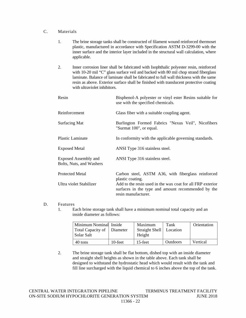
1. Each brine storage tank shall have a minimum nominal total capacity and an inside diameter as follows:
Minimum NominalTotal Capacity of Solar Salt
Inside Diameter
Maximum Straight Shell Height
Tank Location
Orientation
40 tons 10-feet 15-feet Outdoors Vertical
2. The brine storage tank shall be flat bottom, dished top with an inside diameter and straight shell heights as shown in the table above. Each tank shall be designed to withstand the hydrostatic head which would result with the tank and fill line surcharged with the liquid chemical to 6 inches above the top of the tank.
CENTRAL WATER INTEGRATION PIPELINE TERMINUS TREATMENT FACILITY ON-SITE SODIUM HYPOCHLORITE GENERATION SYSTEM JUNE 2018 11366 - 23
3. The brine storage tank shall include the following nozzles in the location and orientation shown on the Drawings:
a. Salt inlet and salt fill line: one (1) 4” conically gusseted flanged nozzle
with 4” diameter 316 stainless steel schedule-40 salt fill pipe with 3/4” water injection port, 4” aluminum camlock coupling and cap. Fiberglass clips shall be furnished to support the pipe off the vessel wall.
b. Brine outlet: one (1) 2” conically gusseted flanged nozzle brine outlet with internal brine plenum with slotted PVC filter pipe.
c. Water inlet: one (1) 2” conically gusseted flanged nozzle, one solenoid
actuated flow control valve, and a 1 1/4” PVC water distribution ring.
d. Vent: one (1) 8” vent with PVC vent extension, clips to attach to vessel wall, polyester dust collection bag, rubber connection boot.
e. Overflow: one (1) 3” conically gusseted flanged nozzle with 3” diameter schedule 80 PVC internal down comer pipe extending below the brine outlet elevation. Fiberglass clips shall be furnished to support the pipe off the vessel wall.
f. Drain: one (1) 3” conically gusseted flanged nozzle.
g. Sidewall level pressure transmitter: one (1) 2” conically gusseted flanged nozzle.
h. Solids level indicator: Suitable connection for the BinMaster yo-yo type level indicator.
i. Side manway: one (1) 36” side flanged manway with bolted cover, neoprene gasket, and 316 stainless steel fasteners.
j. Top manway; one (1) 30” top flanged manway with bolted cover, neoprene gasket, and 316 stainless steel fasteners.
4. The brine storage tank shall be provided with tie down lugs constructed of type
316 stainless steel. 5. The brine storage tank shall include a minimum of four (4) type 316 stainless
steel lifting channels.
6. Ladders: The Brine tank shall be furnished with an external access ladder and access platform to facilitate access to the manway. Ladders shall meet applicable OSHA standards and the building code applicable to the project.
a. Ladders shall be FRP construction. Uncoated or exposed carbon steel
parts or fasteners will not be acceptable. The ladders shall be supported
CENTRAL WATER INTEGRATION PIPELINE TERMINUS TREATMENT FACILITY ON-SITE SODIUM HYPOCHLORITE GENERATION SYSTEM JUNE 2018 11366 - 24
on and anchored to the concrete base and bracketed to the tank shell as required.
b. Ladders shall be provided with necessary assembly and mounting hardware. Mounts shall not penetrate tank wall. All mounting hardware shall be Type 316 stainless steel.
c. The ladder shall include safety rails across the top of the tank to the access manhole, attached to the ladder side rails, and anchored to the tank head as required.
d. The ladders shall have a clear width of at least 16 inches, with rungs at least ¾-inches in diameter and spaced not more than 12 inches apart and a clearance of at least 12 inches between the back of the ladder and the tank wall. Ladder shall extend beyond tank bottom to within 6 inches of concrete tank pad. Refer to SAWS detail DD-900-16 Standard Tank Ladder Interior and Exterior for general dimensions
e. Safety rails and platform shall be fabricated of fiberglass reinforced plastic shapes and shall be fabricated and installed in accordance with OSHA regulations and the building code applicable to the project. Safety railings with 3 rails and kick plate or skirt-style handrail shall be provided around the perimeter of each manway opening, attached to the ladder side rails and anchored to the tank head as required.
f. Vinyl ester resin shall be used in the fabrication of all FRP parts of the ladder.
g. Ultra violet stabilizer: Add to the resin used in the wax coat for exterior surfaces in the type and amount recommended by the resin manufacturer.
h. Acceptable Ladder Manufacturers: Fibergrate Corporation, Dallas, TX or approved equal.
7. Handrails: handrails shall be fabricated of fiberglass reinforced plastic shapes and
shall be fabricated and installed in accordance with OSHA regulation and the building code applicable to the project. Safety railings with 3 rails and kick plate or skirt-styple handrail shall be provided around the perimeter of the top of dome of each tank.
8. Pipe supports: Provide pre-molded offset pipe support brackets for the attachment of pipe supports for support of vertical runs of piping from the outside of the tank in the locations shown on the drawings.
9. The brine storage tank shall be designed to meet the following seismic load parameters: a. Ss (maximum short-term spectral response acceleration) = 0.230g. b. S1 (maximum 1-second spectral response acceleration) = 0.071g. c. SDs (design short-term spectral response acceleration) = 0.245g. d. SD1 (design 1-second spectral response acceleration) = 0.113g. e. Ie (Seismic Importance Factor) = 1.25. f. Occupancy Category = III. g. Seismic Design Category = B. h. Site Class = D.
CENTRAL WATER INTEGRATION PIPELINE TERMINUS TREATMENT FACILITY ON-SITE SODIUM HYPOCHLORITE GENERATION SYSTEM JUNE 2018 11366 - 25
E. Controls
1. Provide salt and brine level measuring devices. The two (2) OSG generator PLC
panels shall receive signals from the level measuring devices, and shall include the following:
a. Salt level input signal from a yo-yo type Binmaster solids level
indication device. Shall be the SmartBob II Base model with stainless steel heavy spike bob probe and nylon cable.
b. Brine level input signal from a from pressure type level transmitter.
F. Accessories
1. Salt level shall be measured with a yo-yo type Binmaster solids level indication
device.
2. Softened water inlet solenoid valve flow control device.
3. Softened water inlet water distribution ring/orifice.
4. Polyester dust filter bag.
5. Heat Tracing & Insulation
6. Water inlet pressure regulating valve and pressure gauge
7. Water inlet magnetic flow meter
8. Nameplates: each tank shall be provided with a nameplate to identify the use of the tank. The nameplates shall be orange phenolic material with black engraved lettering one inch high and shall be mounted on the tank at a location acceptable to the Engineer.
9. Certification Plates: A stainless steel certification plate shall be installed below each storage tank nameplate. The following data shall be included on the certification plate: Name of tank fabricator, Date of manufacture, Product to be stored, resin designation.
10. Anchor Bolts: Type 316, stainless steel bolts, size by fabricator and at least 1/2 -inch in diameter.
11. Anchor Lugs: Anchor lugs shall be provided and shall be designed to withstand all specified wind load conditions. No less than 8 anchor lugs shall be provided. Details of anchors shall be shown on fabrication drawings. Anchor lugs shall be type 316 stainless steel.
CENTRAL WATER INTEGRATION PIPELINE TERMINUS TREATMENT FACILITY ON-SITE SODIUM HYPOCHLORITE GENERATION SYSTEM JUNE 2018 11366 - 26
12. Heating and Insulation: The tank manufacturer shall provide 2” polyurethane insulation covered with an exterior FRP skin of no less than 3/16” thick consisting of chop hoop construction. The manufacturer shall install either heat tracing or heat panels designed to maintain 60 degree F at outdoor ambient temperature of 20 degree F. Design of heating system to be supplied as part of the submittal process.
2.05 POWER TRANSFORMER/RECTIFIER
A. Functional Requirements
1. A transformer/rectifier shall be furnished to provide DC power to each hypochlorite generator.
2. Input to transformer/rectifier shall be 460 V +/-5%, 3 PH, 60 Hz.
3. The transformer/rectifier shall have a minimum efficiency of 93.5% at rated output and normal operating conditions.
4. The transformer/rectifier shall be designed for a 100% duty cycle (24 hr/day & 7 days per week).
5. The transformer/rectifier shall be appropriate for use at altitudes of less than
3,300 feet above sea level.
B. Materials
1. Enclosure shall be 316 stainless steel.
2. Manufacturer recommended/supplied DC power cable shall be furnished to connect transformer/rectifier to the sodium hypochlorite generator.
C. Features
1. The transformer/rectifier dimensions shall be as shown on the site layout in the
drawings. 2. The transformer/rectifier shall include the following protection features:
a. Transformer winding over-temperature. b. DC current and voltage limit. c. Fan failure detection. d. Door interlock switch. e. Input phase monitor. f. The power supply will automatically shut down in the event of a fault.
3. Output voltage and current shall be monitored by in-built digital voltmeter and
ammeter. These instruments shall have accuracy of 1% or better. 4. A built-in potentiometer shall be provided to allow manual current adjustment.
CENTRAL WATER INTEGRATION PIPELINE TERMINUS TREATMENT FACILITY ON-SITE SODIUM HYPOCHLORITE GENERATION SYSTEM JUNE 2018 11366 - 27
5. The following outputs shall be provided:
a. Rectifier Failure. b. Rectifier Status. c. Rectifier Voltage 4-20mA. d. Rectifier Current 4-20mA.
6. Electrical connections to be sized by OSG MANUFACTURER. 7. Harmonic Filters to meet IEEE 519 will be provided by the OSG
MANUFACTURER.
2.06 HYDROGEN DILUTION BLOWER A. Functional Requirements
1. Air dilution blowers shall be furnished to provide forced ventilation for the generators and hypochlorite storage tanks and reduce the concentration of hydrogen gas in the tank to below 1% in air (v/v), which is equivalent to 25% of hydrogen’s low explosive limit (LEL = 4% v/v).
2. The hydrogen dilution process shall include the following:
a. Passive vent at each electrolytic cell operated at atmospheric pressure, so that hydrogen gas cannot be contained or pressurized.
b. Four (4) blowers shall be furnished for the hypochlorite storage tanks. Two (2) will be duty and two (2) will be standby.
c. Four (4) blowers shall be furnished for the hypochlorite generators. Two (2) will be duty and two (2) will be standby.
3. On system shut down, the blower must remain active for a period of 15 minutes. 4. Blowers to include drilled flanged inlet & outlet, drain with plug, shaft seal and inlet
guard. 5. Blowers are to meet AMCA Classification “Type B” Spark Resistant
Construction. 6. Blowers to be rated for outdoor use. 7. Blowers shall be equipped with a 6-inch flanged outlet connection. 8. Bug screen shall be provided on the blower inlet.
B. Materials
1. The housing material shall be 319 cast aluminum.
CENTRAL WATER INTEGRATION PIPELINE TERMINUS TREATMENT FACILITY ON-SITE SODIUM HYPOCHLORITE GENERATION SYSTEM JUNE 2018 11366 - 28
2. The pressure blowers shall be radial blade, single-stage type, and direct drive arrangement #4.
3. The wheel shall be 319 cast aluminum to ensure a spark free environment.
4. Wheels constructed of steel or stainless steel shall not be allowed to avoid spark formation.
5. Blowers to include drilled flanged inlet and outlets, drains with plug, shaft seal and inlet guard.
C. Accessories
1. Blower discharge ventilation plumbing shall include:
a. A flow sensor shall be installed at the vent of the tank and on the OSHG units vent piping to provide an indication of low air flow. The flow sensor shall provide the low flow signal to the control panel.
b. The flow sensor shall interface with the control system to establish system operating permissive and activation of the standby blower. If both blowers fail to produce high enough flow, then the OSG skid will be shut down.
D. Manufacturer
1. Cincinnati Fan.
2. Or approved equal. 2.07 HYDROGEN GAS DETECTOR
A. Functional Requirements
1. The hydrogen gas monitoring system shall continuously measure and display gas concentration and provide alarms when preset limits are exceeded. Transmitter will send signal to the PLC
2. Combustible gas detectors shall be furnished and installed above the on-site hypochlorite generating systems (at highest point).
3. Hydrogen-in-air detector shall be calibrated for hydrogen LEL detection and
provide one analog signal and three alarm relay outputs for monitoring and control interlocks in the PLC control system.
4. Any deviation from the hydrogen management specification must be
accompanied by a letter form the OSG MANUFACTURER stating that none of the prior installations of the proposed system have experienced any type of hydrogen ignition explosion or damage due to over pressurization. This letter
CENTRAL WATER INTEGRATION PIPELINE TERMINUS TREATMENT FACILITY ON-SITE SODIUM HYPOCHLORITE GENERATION SYSTEM JUNE 2018 11366 - 29
must be signed by a corporate officer and shall be included with the bid. Failure to do so may result in disqualification.
5. Under no circumstance will the Hydrogen Management requirements be relaxed or modified as they are critical safety features and core to the generator design.
B. Materials
1. Enclosure: NEMA 4X. 2. Display: Two line, 8 character alphanumeric LCD display. 3. Output Signal: Linear 4-20 mA.
C. Manufacturer
1. Analytical Technologies Inc (ATI) Model B14 with Auto Test feature.
2. Conspec CN06 with Programmer/Calibrator and Calibration Kit. 2.08 ACID CLEANING SYSTEM
A. Acid Cleaning System:
1. One portable (1) acid cleaning system shall be furnished for the sodium hypochlorite generator skids.
2. Each cleaning system shall consist of an acid storage tank and a magnetic drive pump suitable for muriatic acid service with appropriate valving and piping. The tank shall be constructed of materials compatible with muriatic acid.
3. The acid cleaning system shall be mounted on a polyethylene spill containment
platform chemically compatible and shall be portable/easily maneuverable. Required connections for the acid cleaning system shall be provided as recommended by the manufacturer.
2.09 WATER SOFTENER SYSTEM
A. Water Softener System:
1. Provide an ion exchange water softener system to supply softened plant service water to the on-site sodium hypochlorite generator system and brine water makeup, as shown on the Drawings.
2. The water softener system shall have three sets of dual tank water softeners for continuous duty. One set per skid plus one set for brine makeup. The system shall be factory supplied to include all pipe appurtenances, appropriate valves and piping, and a control valve.
CENTRAL WATER INTEGRATION PIPELINE TERMINUS TREATMENT FACILITY ON-SITE SODIUM HYPOCHLORITE GENERATION SYSTEM JUNE 2018 11366 - 30
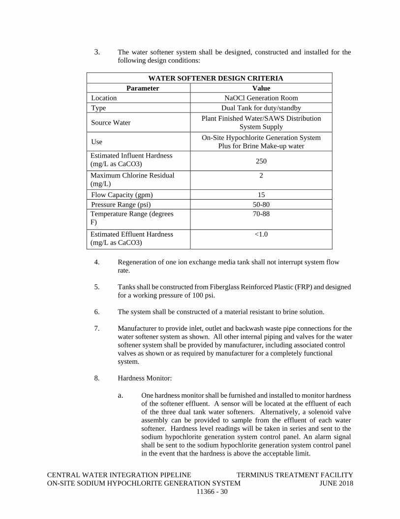
3. The water softener system shall be designed, constructed and installed for the following design conditions:
WATER SOFTENER DESIGN CRITERIA
Parameter Value Location NaOCl Generation Room Type Dual Tank for duty/standby
Source Water Plant Finished Water/SAWS Distribution System Supply
Use On-Site Hypochlorite Generation System Plus for Brine Make-up water
Estimated Influent Hardness (mg/L as CaCO3) 250
Maximum Chlorine Residual (mg/L)
2
Flow Capacity (gpm) 15 Pressure Range (psi) 50-80 Temperature Range (degrees F)
70-88
Estimated Effluent Hardness (mg/L as CaCO3)
<1.0
4. Regeneration of one ion exchange media tank shall not interrupt system flow
rate. 5. Tanks shall be constructed from Fiberglass Reinforced Plastic (FRP) and designed
for a working pressure of 100 psi. 6. The system shall be constructed of a material resistant to brine solution. 7. Manufacturer to provide inlet, outlet and backwash waste pipe connections for the
water softener system as shown. All other internal piping and valves for the water softener system shall be provided by manufacturer, including associated control valves as shown or as required by manufacturer for a completely functional system.
8. Hardness Monitor:
a. One hardness monitor shall be furnished and installed to monitor hardness of the softener effluent. A sensor will be located at the effluent of each of the three dual tank water softeners. Alternatively, a solenoid valve assembly can be provided to sample from the effluent of each water softener. Hardness level readings will be taken in series and sent to the sodium hypochlorite generation system control panel. An alarm signal shall be sent to the sodium hypochlorite generation system control panel in the event that the hardness is above the acceptable limit.
CENTRAL WATER INTEGRATION PIPELINE TERMINUS TREATMENT FACILITY ON-SITE SODIUM HYPOCHLORITE GENERATION SYSTEM JUNE 2018 11366 - 31
b. Hardness monitor shall be Hach Model SP 510.
10. Operation:
a. The operation and control of the water softener system shall be
completely automatic. When the capacity of one tank is nearly exhausted, flow will be diverted to the second tank while initiating a brine backwash of the first tank from the brine bulk tank.
b. The regeneration process and frequency will be accomplished by the
water supply hydraulic pressure.
c. Provide a manufacturer’s standard four-year written guarantee.
d. Provide a statement from manufacturer stating that the water softener conforms to the requirements of the design criteria in Paragraph 2.09.A.3 of this Section.
11. Product and Manufacturer:
a. Kinetico only, No equal.
2.10 CARTRIDGE FILTERS
A. Provide a cartridge filter assembly as shown on the Drawings to allow for removal of one filter from service without interrupting flow to the water softener system.
B. Perforation size shall be recommended by the water softener system manufacturer.
C. Materials of construction shall be compatible with the service fluid and connecting piping, with a pressure rating of 120 psi.
D. Cartridges shall be fully removable to allow for cleaning and maintenance. E. Provide pressure gauges to measure pressure drop across filters.
2.11 VALVES AND APPURTENANCES FOR CHEMICAL SERVICE
A. General - Valves
1. Chemical system valves shall be made of chemical-resistant materials and shall be rated 150 psig working pressure.
2. All valves shall be certified as completely compatible with the intended and
specified service in Section 11242 Paragraph 1.01; compatibility shall apply to the material of the valve and internal components, including all seals, gaskets, O-rings, and washers; solvents and primers used in valve joint make-up shall be specifically in conformance with the written instructions of the valve supplier.
CENTRAL WATER INTEGRATION PIPELINE TERMINUS TREATMENT FACILITY ON-SITE SODIUM HYPOCHLORITE GENERATION SYSTEM JUNE 2018 11366 - 32
3. Except as otherwise specified valve ends shall be socket-type designed for
solvent welding. The valve manufacturer shall provide specific recommendations for solvent and primer.
4. Except as otherwise noted, valves and equipment shall be double true union style
with solvent welded socket ends. 5. All valves, except butterfly valves shall have a nonshock service pressure rating of
not less than 120 psig at 70 degrees F. 6. All valves shall be given hydrostatic and pressure and leakage tests at the factory.
Provide certified copy of test results. 7. Valves shall be the standard, catalogued products of the following manufacturers:
a. Chemtrol. b. Asahi/America. c. Plast-O-Matic. d. Hayward.
B. Ball Valves
1. Ball valves 2-in and smaller shall be the double-union, socket-ended type, unless
otherwise specified, with full-port opening. Ball valves 3-in and larger shall be equipped with integral full faced, ANSI 150-lb flanges.
2. Provide quarter-turn manual valve operator and valve seat adjustability. 3. Plastic ball valves in sodium hypochlorite service shall have the ball drilled to
permit venting of pressure and gas from the confined ball cavity, when the valve is closed. The drilling shall vent to the upstream end of the valve. The drilling shall be 1/8-in opening, de-burred. An arrow shall be inscribed on the valve body to indicate direction of flow.
C. Ball Check Valves
1. Ball check valves shall be double-union style with socket ends, solid and completely spherical ball and capable of either horizontal or vertical mounting.
D. Butterfly Valves
1. Butterfly valves 4-inch and smaller:
a. Bodies: ASTM D1784, PVC. Shall be one piece body and disc. b. Stem: 316 Stainless Steel c. Operator: Lever d. Shall contain external disc position and flow indication. An arrow shall be
inscribed on the valve body to indicate direction of flow. e. Pressure Rated at 150 psi
CENTRAL WATER INTEGRATION PIPELINE TERMINUS TREATMENT FACILITY ON-SITE SODIUM HYPOCHLORITE GENERATION SYSTEM JUNE 2018 11366 - 33
E. Pressure Relief Valve:
1. Pressure relief valve shall be of the angle pattern design and manufactured of
Type 4, Grade 1 CPVC with a Teflon shaft and Viton seals. Valve shall be provided with threaded-end connections.
2. Operator: Adjusting screw.
3. Pressure: 100 psi
F. Basket Strainers
1. Basket Strainers shall be Hayward SB Series, constructed of PVC with 3/16” perforations.
G. Wye Strainers
1. Wye strainers shall be furnished as shown on the Drawings. Wye strainers shall
have 1/32-in perforations. 2. Strainer materials shall be clear PVC body, solvent ends, and PVC screens. 3. Strainers shall be as manufactured by ASAHI, George Fischer or approved equal.
H. Solenoid Valves:
1. Solenoid valve shall be bronze body, resilient seated, general purpose. 2. Operator: Solenoid, 120 volt service. 3. ASCO Red-Hat or approved equal.
2.12 INSTRUMENTATION AND CONTROL
A. Overview:
1. This section outlines the minimum level of instrumentation and control to be
supplied and delivered by the OSG MANUFACTURER. The OSG MANUFACTURER shall supply and deliver additional instrumentation and controls to provide a safe and efficient hypochlorite generation process.
2. The OSG MANUFACTURER shall furnish and deliver a complete instrumentation and control system that provides automatic/manual operation for the hypochlorite generation process. Each of the two (2) 1200 ppd Onsite Hypochlorite Generation System shall have an identical PLC control panel. Each panel will be capable of being placed into a lead or lag position. Lead panel status will commence operation of one or both chlorine generation systems.
CENTRAL WATER INTEGRATION PIPELINE TERMINUS TREATMENT FACILITY ON-SITE SODIUM HYPOCHLORITE GENERATION SYSTEM JUNE 2018 11366 - 34
3. All four (4) panels will be configured in such a way that either generator panel can be powered down without effecting the second redundant generator’s functionality. The only common wiring in the four (4) panel configuration will be the 24 VDC power supply, which will be configured with an online redundant power supply plus monitoring for power supply failure.
4. A blower panel will be provided for control of eight (8) blowers, two (2) duty and two (2) standby for primary dilution (hydrogen vent blowers) and two (2) duty and two (2) standby for storage dilution (hydrogen dilution blowers). The blower panel will also be the hub for all peripheral signals and will be wired in a manner to provide independent redundant discrete and analog signals to both generator PLC panels.
5. 480 VAC, 3 phase and 120VAC, 1 phase power shall be split into two separate panels.
B. Control System:
1. The control system shall be an OIT/PLC-based control/monitoring system. The
OIT/PLC equipment shall be mounted in a NEMA 4X rated, skid mount panel conforming to the Control Package specification section 17306.
2. The hypochlorite generation control system shall interface with the plant PCS system via Ethernet communications. The hypochlorite generation control system shall receive signals from the plant PCS system (over Ethernet) and shall make available process data for collection by the plant PCS system. The specific data shall be as defined herein and finalized during the Data Transfer Coordination Meeting.
3. Coordination with plant Application Services Provider (ASP) and PCS system
integrator (PCSI): The OSG MANUFACTURER shall coordinate and cooperate with the ASP, PCSI, Design Engineer, and others to provide for all input/output interfaces (i.e. Register assignments and I/O lists) between the hypochlorite generation control system and the plant PCS system. The OSG MANUFACTURER shall provide all drivers and software to enable Ethernet communications between the plant PCS and the hypochlorite generation control system. See section 17306 for additional information on coordination.
4. Programming:
a. The OSG MANUFACTURER shall furnish the Control System
equipment complete with all programming to perform all operations functionally specified herein and as required for a completely debugged and operating system. The completeness and accuracy of the programming shall be verified with the Factory Witnessed Test and the site Functional test, as specified in this section.
b. PLC Programming software shall be as specified in 17306.
CENTRAL WATER INTEGRATION PIPELINE TERMINUS TREATMENT FACILITY ON-SITE SODIUM HYPOCHLORITE GENERATION SYSTEM JUNE 2018 11366 - 35
c. Provide Full documentation of application programming code.
d. Provide CDs of programming code to OWNER. 5. Two completely redundant PLC control panels, one for each generator skid, which
will be fully independent and a common blower panel, shall be furnished to control and monitor the operation of the system.
6. The system shall be designed where one PLC panel can be powered down
without affecting the other generation system or other peripheral systems such as tank level monitoring or brine maker control.
7. At a minimum, each control panel shall include:
a. One (1) Allen Bradley CompactLogix PLC for control
and monitoring of all functions specified here in and shown on the Contract Drawings. The PLC shall communicate via Ethernet to the plant PCS and include I/O Modules to support function of the hypochlorite generation system with 20% spare I/O.
b. I/O Modules:
1) Discrete inputs shall be optically isolated, 24 VDC from dry field contacts unless otherwise required. All discrete inputs shall be fused.
2) Discrete outputs shall be 24 DC with separate interposing relays (optical isolation not required in this case).
3) Analog input/output shall be isolated, unipolar, 12-bit resolution type capable of receiving/providing a 4-20 mA 24 VDC linear signal.
4) Fusing and interposing relays integrated with terminal assemblies are acceptable
5) Optical isolation shall be rated at not less than 1,500 V RMS. 6) Power Supplies: Field I/O power supplies shall be redundant,
Sola or approved equal. c. Wiring: Input/output modules shall be configured for ease of wiring and
maintenance. The modules shall be connected to wiring arms, which are removable to permit removal of a module without disturbing field wiring. Covers shall be provided to prevent operator personnel from inadvertently touching the terminals. The process interface modules shall be provided with screw-type terminal blocks with barriers between adjacent terminals for connection of field inputs. Contacts for dry contact outputs to the field shall be rated 5 amps, minimum, either integral or through interposing relays. Output failure mode shall be selectable so that upon station or communication system failure all outputs shall be placed in the non-conducting mode, or remain as they were prior to failure. Wire module terminals to control panel field wiring terminal blocks. No direct
CENTRAL WATER INTEGRATION PIPELINE TERMINUS TREATMENT FACILITY ON-SITE SODIUM HYPOCHLORITE GENERATION SYSTEM JUNE 2018 11366 - 36
connections between any field devices and I/O module terminals will be accepted.
d. Supply power shall be 120 VAC, 1 PH, 60 Hz (one utility circuit and one
UPS circuit for the PLC, OIT, and associated controls).
e. Control panel materials: 1) The control panel enclosure shall be 316 stainless steel NEMA
4X with lockable disconnect. 2) The control panel shall be built in accordance with UL 508
standards and shall be UL labeled.
8. In case of a PLC failure and the system turned to manual mode, all safety protection circuits shall remain operational.
9. Operator Interface Terminal (OIT):
a. The Operator Interface Terminal shall be shall be as specified in Specification Section 17306.
b. Storage Memory: 1 GB of flash memory on a removable compact flash card to hold all required process application, alarm, help, form and recipe pages.
c. The latest version of the Allen-Bradley FactoryTalk View (required for the PanelView Plus devices) shall be used for developing the OIT application. The OIT device shall be provided with the corresponding Runtime License. A development license for the Owner is required.
C. Functional Requirements:
1. General:
a. A complete PLC-based control system shall be supplied by the OSG
MANUFACTURER that will provide fully automatic operation of the hypochlorite generation process. The onsite sodium hypochlorite generation (OSG) control system shall be provided with an Operator Interface Terminal (OIT) for local monitoring and control.
b. The OSG control system will interface with the plant PCS system via Ethernet communications. The OSG system shall receive signals from the plant PCS system over Ethernet and shall make available process data for collection by the plant PCS system. The specific data shall be as defined herein and finalized during a Coordination Meeting.
c. The OSG MANUFACTURER shall coordinate with and cooperate with the ASP, PCSI and engineer to provide for all input/output interfaces (i.e. Register assignments and I/O lists) between the OSG system and the plant PCS system. The OSG MANUFACTURER shall provide all drivers and
CENTRAL WATER INTEGRATION PIPELINE TERMINUS TREATMENT FACILITY ON-SITE SODIUM HYPOCHLORITE GENERATION SYSTEM JUNE 2018 11366 - 37
software to enable Ethernet communications between the plant PCS and the OSG control system.
d. The hypochlorite generator unit produces hypochlorite using salt water (brine) and electricity. The unit consists of a variable speed brine pump, Vertical Technology electrolytic cells, and a full-wave DC rectifier. The variable speed pump feeds brine to the electrolytic cells.
e. A hydrogen vent blower is also part of this system. The hydrogen vent blower is used to blow air into the system at a flow rate high enough to
f. dilute the hydrogen gas before venting to the atmosphere.
g. A hydrogen leak detector provides leak detection signal.
h. The O&M Help Section shall be installed into the PLC so that an operator can troubleshoot the equipment without using an O&M hardcopy.
2. The Hydrogen Dilution and Hydrogen Vent Blowers shall be provided with a
single local control panel for local operation. As a minimum, the local control panel will have the following devices for each blower: a. Hand-Off-Remote (HOR) switch. When the switch is in the remote
position, the blowers will be controlled from the OSG control system. b. Start-Stop pushbuttons. When the HOR switch is in the hand position,
the blowers are operated from the Start-Stop pushbuttons. c. Status Indication – Indicating lights for blower ON/OFF status
3. PLC Control, from OSG control panel:
a. Monitoring signals:
1) Brine flow rate to the electrolytic cells 2) Brine pump speed 3) Brine pump on/off Status 4) Electrolytic cell temperature for each cell 5) Electrolytic cell low level for each cell 6) Rectifier current 7) Rectifier voltage 8) Room hydrogen monitor 9) Hydrogen vent blower on/off status 10) Hydrogen vent blower remote status 11) Hydrogen dilution blower on/off status 12) Hydrogen dilution blower remote status 13) Low flow for hydrogen vent blower discharge to vent 14) Low flow for hydrogen dilution blower discharge to vent
b. Control modes of hypochlorite generation:
CENTRAL WATER INTEGRATION PIPELINE TERMINUS TREATMENT FACILITY ON-SITE SODIUM HYPOCHLORITE GENERATION SYSTEM JUNE 2018 11366 - 38
1) Manual: In the manual mode, the hypochlorite generator unit can
be started and stopped by the operator at the OIT 2) Auto: The hypochlorite generator unit will start and stop based on
the “Start Generation” and “Stop Generation” commands, respectively. These commands are based on the hypochlorite storage tank levels.
c. Software Interlocks: The generator unit shall be shutdown if any of the
following conditions occur:
1) Low brine flow to cells 2) High hypochlorite temperature (greater than 130 degF) 3) Low cell level for any cell 4) Hydrogen vent blower fault 5) Hydrogen dilution blower fault 6) Rectifier high/low current 7) Rectifier high temperature 8) High hydrogen level from hydrogen gas detector
d. The PLC shall provide for the following operation for the brine pump:
1) The brine pump will operate when the generator unit is running. 2) The brine pump speed will be adjusted based on an active
feedback loop. The feedback loop calculates the appropriate amount of brine to mix with the incoming water to maintain constant current from the rectifier.
e. The PLC shall provide for the following operation for the hydrogen
dilution and vent blowers:
1) Manual: None. 2) Auto: The blower automatically starts/stops when the
hypochlorite generator unit is on/off, respectively. 3) Software Interlocks: The blower shall stop if a high differential
pressure is detected. 4. OIT Interface at OSG control panel:
a. The OIT shall display the following process variables:
1) Brine flow rate to the electrolytic cells 2) High/low brine flow rate to the electrolytic cells 3) Brine pump speed. 4) Brine pump on/off status 5) Brine pump failure alarm 6) Electrolytic cell high temperature for each cell 7) Electrolytic cell high level for each cell 8) Rectifier current
CENTRAL WATER INTEGRATION PIPELINE TERMINUS TREATMENT FACILITY ON-SITE SODIUM HYPOCHLORITE GENERATION SYSTEM JUNE 2018 11366 - 39
9) Rectifier high/low current alarm 10) Hydrogen vent blower on/off status 11) Hydrogen vent blower remote status 12) Hydrogen vent blower failure alarm 13) Hydrogen dilution blower on/off status 14) Hydrogen dilution blower remote status 15) Hydrogen dilution blower failure alarm 16) Low flow for blower discharge
b. The OIT shall provide the following operator input
fields:
1) Hypochlorite Generator Unit Auto/Manual commands 2) Hypochlorite Generator Unit Start/Stop commands 3) Hypochlorite Generator Unit Reset command 4) Brine Pump Auto/Manual commands 5) Brine Pump Start/Stop commands 6) Brine Pump Reset command for the pump fail alarm 7) Hydrogen Vent Blower Reset command for fail alarm 8) Hydrogen Dilution Blower Reset command for fail alarm
5. Alarms at OSG control panel: The PLC shall generate the following alarm
conditions, and the OIT shall monitor and annunciate these alarms:
a. High/low brine flow rate b. Brine pump failure c. High sodium hypochlorite temperature d. High/low level for each cell e. High/low current for the rectifier f. High temperature for the rectifier g. Hydrogen vent blower failure h. Hydrogen dilution blower failure i. Low flow for blower discharge
6. The following signals shall be sent from OSG control system to the PCS over the
Ethernet link and will be sent to the offsite SCADA for remote monitoring:
a. Brine flow rate to the electrolytic cells b. High/low brine flow rate to the electrolytic cells c. Brine Pump Speed d. Brine Pump on/off status e. Brine Pump Failure alarm f. High/low brine flow rate g. High sodium hypochlorite temperature h. Low level for each cell i. High/low current for the rectifier j. High temperature for the rectifier k. Hydrogen vent blower on/off status
CENTRAL WATER INTEGRATION PIPELINE TERMINUS TREATMENT FACILITY ON-SITE SODIUM HYPOCHLORITE GENERATION SYSTEM JUNE 2018 11366 - 40
l. Hydrogen vent blower remote status m. Hydrogen dilution blower on/off status n. Hydrogen dilution blower remote status o. Hydrogen vent blower failure alarm p. Hydrogen dilution blower failure alarm q. Low flow for blower discharge r. Softened Water Hardness s. High Hardness Alarm t. Emergency stop pressed
7. Remote monitoring on offsite SCADA HMI: See above listed signals in part 6.
D. Instrumentation:
1. Flow Magnetic Meters/Transmitters
a. Magnetic sss/transmitters shall be by Endress-Hauser, Rosemount, ABB
or Siemens.
b. Signal interface shall be 4-20 ma.
c. All magnetic flow meters shall have remote transmitters. 2. Pressure Elements/Transmitters
a. Pressure elements/transmitters shall be by Endress-Hauser or Rosemount. b. Signal interface shall be 4-20 ma.
3. Ultrasonic Level Element/Transmitter
a. Ultrasonic Level Element/transmitters shall be Siemens Milltronics
HydroRanger 200.
b. Signal interface shall be 4-20 ma. 4. Level Transmitter
a. Level Transmitter shall be Rosemount 2051L or approved equal.
b. Signal interface shall be 4-20ma.
5. Pressure Gauges/Switches
a. Pressure gauges/switches shall be Ashcroft Model 1279 or equal by
Ametek/US Gauge Division. 6. Wetted parts of primary elements and appurtenances used for chemical service
shall be resistant to corrosion by that chemical.
CENTRAL WATER INTEGRATION PIPELINE TERMINUS TREATMENT FACILITY ON-SITE SODIUM HYPOCHLORITE GENERATION SYSTEM JUNE 2018 11366 - 41
2.13 COMMUNICATION NETWORK
A. General: The OSG MANUFACTURER shall furnish and install equipment and software to communicate with the plant PCS System over the plant IEEE 802.3 compliant Ethernet Local Area Network (LAN). The OSG MANUFACTURER shall furnish all necessary cables, face plates, connectors, modems, transceivers, repeaters, modules, splice kits, fiber patch panels, and switches required.
B. Components: The system shall be designed using industry standard, readily available components. Prototype components, or custom designed components are unacceptable.
1. Switches that interface to PCS: Managed Ethernet switches with minimum 4
copper and (1) one Fiber Port by Cisco Industrial, IE-3000-8TC-E or approved equal.
2. Six (6) Port Fiber Patch panel by Corning or approved equal.
C. See Specification Section 17515, Instrumentation and Controls - Communications Interface Equipment.
2.14 CONTROL PANELS AND ENCLOSURES
A. See Spec Section 17306, Vendor Packaged Process Control Systems.
B. Any local control panels/stations that are located outside of the electrical room shall be
NEMA 4X. 2.15 PAINTING
A. All equipment, motors, drives, frames, baseplates, and appurtenances shall be painted.
B. Machined, polished, and non-ferrous surfaces, except stainless steel, shall be painted.
C. Certify, in writing, that the shop primer and shop finish coating system conforms to the requirements herein.
2.16 TOOLS, SPARE PARTS AND MAINTENANCE MATERIALS
A. The on-site sodium hypochlorite generation system shall be furnished with the following
total quantity of spare parts:
1. One (1) complete set of spare fuses (Control Panel & Transformer/Rectifier). 2. One (1) set of brine feed pump recommended spare parts by manufacturer. 3. One (1) electrolytic cell level/temperature switch assembly. 4. One (1) spare electrolytic cell, complete with housing and electrodes. 5. Complete set of gaskets for all gasketed covers and connections. 6. One of each instrument normally attached to the electrolytic cells. 7. One spare brine feed pump.
CENTRAL WATER INTEGRATION PIPELINE TERMINUS TREATMENT FACILITY ON-SITE SODIUM HYPOCHLORITE GENERATION SYSTEM JUNE 2018 11366 - 42
8. One spare differential pressure switch for the blowers. 9. One spare rotameter of each size used on the system. 10. One spare dust collector bag. 11. Filter, Cartridge, 50 micron, 10” LG, FIBPP 12. List of optional spare parts and pricing.
B. The water softener system shall be furnished with the following spare parts:
1. One control valve. 2. Additional media for each ion-exchange media tank. 3. Water hardness test kit. 4. Media, Cation Resin, I CUFT. 5. Media Gravel, 1 CUFT. 6. Kit, Calibration, hydrogen detector 2% 7. Kit, Maintenance for Hach SP510 Analyzer 8. Kit, test strips water harness 0-25 GPG.
C. Spare parts shall be packed in sturdy containers with clear indelible identification
markings and shall be stored in a dry, warm location until transferred to the OWNER. D. Furnish an initial supply of all greases and lubricants required to start operations.
PART 3 - EXECUTION 3.01 INSTALLATION
A. OSG MANUFACTURER shall inspect OSG equipment upon delivery for equipment condition and verify storage requirement are met.
B. Responsibility of the CONTRACTOR
1. Installation of the equipment shall be in accordance with the Contract Drawings and with instructions and recommendations from the OSG MANURACTURER. Conflicts of information shall be called to the attention of the ENGINEER.
2. All equipment units or assemblies shall be installed on concrete bases and secured with anchor bolts in accordance with the manufacturer’s recommendations and as shown. The concrete bases shall be poured up to 1 inch below the metal bases, legs, or soleplates. See Division 3 for concrete and grout requirements.
3. Inspect all concrete pads for proper elevation, dimensions, cutouts, evenness and anchor bolt locations, and correct if necessary.
4. Provide a drain for each piece of equipment, according to the manufacturer’s requirements.
5. Support piping independent of equipment. Equipment shall be free from all loads and stresses induced by the piping.
CENTRAL WATER INTEGRATION PIPELINE TERMINUS TREATMENT FACILITY ON-SITE SODIUM HYPOCHLORITE GENERATION SYSTEM JUNE 2018 11366 - 43
6. All equipment including motors, belts and drives shall be aligned to the best
industrial standards.
7. Inspect all equipment prior to installation. If damaged, notify the OSG MANURFACTUER promptly. Do not install damaged equipment until equipment is replaced or repairs are made in accordance with manufacturer’s written instructions and approval by the ENGINEER.
8. Make all electrical connections in conformance with the requirements of Division 16, Electrical.
3.02 COMMISSIONING AND START-UP
A. The OSG MANUFACTURER shall inspect equipment installation, piping and wiring to ensure proper installation of each component in accordance with approved submittals. A written statement certifying that the equipment has been properly installed and interconnected shall be provided by the OSG MANUFACTURER.
B. After completion of installation, the system shall be completely tested to ensure compliance with the operating requirements, indicated on the Drawings and in accordance with Section 01752, Facility Startup and Commissioning.
C. The OSG MANUFACTURER shall coordinate initial system start-up to ensure operating procedures are followed in accordance with approved submittal’s Instructions Manuals.
D. All chemicals required for the production of sodium hypochlorite (salt) shall be provided by the OWNER.
E. When installation has been completed and all connections have been made, all tank surfaces, interior and exterior, shall be thoroughly cleaned as recommended by the fabricator and to the satisfaction of the Engineer. Abrasive cleaning agents shall not be used. The tank and wetted accessories shall be completely dried before being placed into service.
3.03 OPERATIONAL READINESS EVALUATION
A. CONTRACTOR shall notify ENGINEER three (3) weeks in advance of anticipated
operational readiness evaluation.
B. Operational Readiness Evaluation: 1. Prior to the scheduled performance test, the OSG MANUFACTURER shall
conduct an operational readiness evaluation of the entire sodium hypochlorite generation system to evaluate proper installation, calibration, and system communications (i.e. signal and alarm verification) for a minimum of 72 hours. The sodium hypochlorite generation system shall be adjusted as needed on a component-by-component basis to ensure that it is in conformance with the Contract Documents and will operate satisfactorily.
CENTRAL WATER INTEGRATION PIPELINE TERMINUS TREATMENT FACILITY ON-SITE SODIUM HYPOCHLORITE GENERATION SYSTEM JUNE 2018 11366 - 44
2. As part of the operational readiness evaluation the OSG MANUFACTURER shall, at a minimum, conduct the following services:
a. Verify that all sodium hypochlorite generator components of the system
have been installed properly as per manufacturer recommendations.
b. Inspect, adjust, and calibrate equipment in preparation for dilute sodium hypochlorite solution (0.8%) production. OSG MANUFACTURER shall ensure that all components are installed correctly and electrical connections are sound in readiness for sodium hypochlorite production.
c. Complete a 100% pass of component inspection. The OSG MANUFACTURER shall maintain inspection status reports and component calibration sheets at the job site and make them available to the ENGINEER at any time. Witnessing of this inspection shall be at the discretion of the ENGINEER. The inspection should ensure that there is 100% pass of I/O validation and that 100% pass of signal transmission and reception is validated.
d. Confirm that the hydrogen detection and dilution system are integrated to the system and are calibrated and operational.
e. OSG MANUFACTURER to coordinate with CONTRACTOR to ensure that all the necessary consumables and supporting appurtenances/facilities required to perform the operational readiness evaluation are available.
g. Train the plant staff on operations and maintenance of the sodium hypochlorite generation system as outlined in Specification section 01640, Manufacturer’s Field Services .
3.04 PERFORMANCE TEST
A. CONTRACTOR shall coordinate with OSG MANUFACTURER for Performance Test.
CONTRACTOR shall notify ENGINEER three (3) weeks in advance of anticipated Performance Test and shall be at a time acceptable to the OWNER and ENGINEER.
B. In order to determine compliance of the system with the performance requirements set forth in this specification, a performance test shall be carried out for a period of eight (8) consecutive hours or as per the developed Commissioning and Acceptance plan.
C. Necessary pre-requisites for the performance test are:
1. System has met the requirements of the Operational Readiness Evaluation Test.
2. System has been started up to the satisfaction of Manufacturer, OWNER and ENGINEER.
3. System must be running before the test period starts.
CENTRAL WATER INTEGRATION PIPELINE TERMINUS TREATMENT FACILITY ON-SITE SODIUM HYPOCHLORITE GENERATION SYSTEM JUNE 2018 11366 - 45
4. Incoming water temperature is higher than 55 °F but lower than 89 °F.
5. Incoming water hardness is less than 10 mg/L.
6. Solar salt with a minimum sodium chloride (NaCl) content of 99.5% is available.
7. Brine feed pump has been calibrated.
8. Level instrument in hypochlorite tank has been calibrated.
9. Power meter (by others) measuring AC feed to rectifier has been calibrated.
D. Four performance parameters shall be measured:
1. Hypochlorite Solution Concentration
a. Sodium hypochlorite solution samples shall be taken at the outlet of the hypochlorite generator by the OSG MANUFACTURER.
b. Samples shall be taken every hour during the 8-hour testing period.
c. Samples shall be analyzed for available chlorine concentration following titration procedures as per the ANSI/AWWA Standard B300-99 Section 5.2.2 “Testing for Available Chlorine in Sodium Hypochlorite” by the OSG MANUFACTURER.
d. The test shall be deemed successful if the average chlorine concentration is between 0.75 and 0.85% (7.5 to 8.5 g/L).
2. Generation Capacity
a. The generation capacity of the system shall be determined by multiplying
the volume of solution generated by the system during the 8-hr testing period by the average of the eight hypochlorite concentrations measured (reported in g/L or lb/gal).
b. The volume of solution generated during the testing period shall be measured by comparing the liquid level in the hypochlorite storage tank before and after the 8-hr test as measured by the level instrument.
c. The generator capacity shall be reported in pounds per day.
d. The test shall be deemed successful if the generator capacity is greater than the capacity required in section 2.01 of this specification.
3. Salt Consumption
CENTRAL WATER INTEGRATION PIPELINE TERMINUS TREATMENT FACILITY ON-SITE SODIUM HYPOCHLORITE GENERATION SYSTEM JUNE 2018 11366 - 46
a. Brine samples shall be taken at the inlet of the hypochlorite generator every hour during the 8-hour testing period.
b. Temperature and specific gravity shall be measured for each sample to determine salt concentration, expressed in mg/L.
c. Brine feed rate shall be determined by calibrating the brine feed pump before the testing period starts.
d. Salt consumption during the 8-hr testing period shall be determined by multiplying brine flow rate times the average of the salt concentrations, and dividing by the total mass of chlorine produced in the 8-hr testing period.
e. The salt consumption shall be reported in pounds of salt per pound of equivalent chlorine.
f. The test shall be deemed successful if the salt consumption does not exceed 3.0 lb of salt per lb of equivalent chlorine.
4. Power Consumption
a. A kilo-watt meter (supplied by others) shall be used to measure incoming AC power to the transformer/rectifier.
b. AC power consumption, expressed in kW shall be recorded every hour during the 8-hr testing period by the OSG MANUFACTURER.
c. The total power consumption shall be determined by multiplying the average kW reading by 8 hours and dividing the product by the total mass, pounds chlorine produced in the 8 hour period.
d. The test shall be deemed successful if the power consumption does not exceed 2.0 kWh per lb of equivalent chlorine.
E. Should any of the performance tests as described above be deemed unsuccessful, the
OSG MANUFACTURER shall, at its own cost, make any and all the modifications required to achieve a successful test.
3.05 30-DAY ACCEPTANCE TEST
A. 30-day Acceptance test to be performed by the OSG MANUFACTURER, concurrent with
the project Acceptance Test, following the operational readiness evaluation and the performance test.
B. The processes and instrumentation and control system shall be completed in accordance with the Contract Documents prior to commencement of the 30-day operational test. All preliminary performance testing shall be completed as outlined and specified herein. The sodium hypochlorite generation system shall be ready for automated control using minor adjustments of set points for the 30-day test period.
CENTRAL WATER INTEGRATION PIPELINE TERMINUS TREATMENT FACILITY ON-SITE SODIUM HYPOCHLORITE GENERATION SYSTEM JUNE 2018 11366 - 47
C. The sodium hypochlorite generation system shall be operated in the “Remote Manual”
mode for the first 15 days of the test period, in the “Remote Automatic” automated mode for the next 15 days of the test period. The sodium hypochlorite generation system will remain in the “Remote Automatic” mode as the default mode following successful completion of the 30-day (720-hour) acceptance test.
D. The test clock will be stopped under the following circumstances:
1. Any sodium hypochlorite generation system malfunction(s) that could result in potential loss of water quality compliance as deemed fit by the ENGINEER.
2. Excessive alarms and system malfunctions as determined by ENGINEER.
3. Significant interruption in the system will require the 30-day operational test to stop and restart following corrections. Significant interruption includes the following:
a. Failure to meet the specified performance for more than 24 consecutive
hours.
b. Failure of any critical equipment unit or component.
c. Failure of noncritical unit or component that is not satisfactorily corrected within 48-hours after failure.
4. The OSG MANUFACTURER shall keep a query log that documents description of the query, time of t he significant interruption, time it was resolved, how it was resolved, and date and duration of test clock halts during the 30-day test period.
5. The test clock will resume when all outstanding queries are resolved (as
determined by the ENGINEER and after the sodium hypochlorite generation system has resumed steady state operation), and testing shall continue until the 30 days of successful operation has been achieved.
E. The OSG MANUFACTURER shall include a one (1) day site visit to coincide with the
switching of the system operation mode from “Remote Manual” mode to “Remote Automatic” mode during the 30-day operational test.
F. Successful completion of the 30-day test shall be a requisite for Substantial Completion of the project.
3.06 TRAINING
A. The OSG MANUFACTURER shall provide operator training at the site in accordance with Section 01640, Manufacturer’s Field Services. Training shall include operation, maintenance and troubleshooting for each component of the system.
B. During the 30-day Acceptance Test, OSG MANUFACTURER shall provide real-time training to the Maintenance Personnel.
CENTRAL WATER INTEGRATION PIPELINE TERMINUS TREATMENT FACILITY ON-SITE SODIUM HYPOCHLORITE GENERATION SYSTEM JUNE 2018 11366 - 48
C. The OSG MANUFACTURER shall also include Life-Time refresher training courses at
no additional charge, including labor, time and travel costs. 3.07 MANUFACTURER’S SERVICES
A. On-Site Sodium Hypochlorite Generation System Manufacturer’s Field Services:
1. Retain factory-trained representatives of the manufacturer of each component
(electrolytic generator and controls) with demonstrated ability and experience in the installation and operation of the equipment to perform the services listed below:
a. Inspect the completed installation and prepare an inspection report.
b. Test, calibrate and adjust all components for optimum performance over
a minimum one-day period. Tests required include confirming the solution strength produced is 0.8 percent and confirming the salt, water and power usage rates are at or below the specified value.
c. Assist in initial start-up and field testing.
d. Instruct OWNER'S personnel in the operation and user maintenance of all components. Conduct a 4-day training seminar at the site. Training shall be in accordance with the requirements of Section 01640, Manufacturer’s Field Services .
e. Supervise the correction of any defective or faulty work before and after acceptance by OWNER.
f. Conduct 30-day acceptance test i. Train OWNER’s personnel during 30-day acceptance test.
ii. Include one (1) additional day Site visit to coincide with switching from “Remote Manual” to “Remote Automatic” mode.
2. Inspect the installation during and after construction completion to verify the
system is free from faults and defects and is in conformance with the Contract Documents.
3. The representative shall make a minimum of four visits, minimum eight hours on
site for each visit, to the site. The first visit shall be for assistance in the installation of equipment. The second visit shall be for checking the completed installation and start-up of the system. The third visit shall be to test operate the system in the presence of ENGINEER and verify that the system is in conformance with the Contract Documents. The fourth site visit shall be to conduct the 30-day operational test including observing switching from “Remote Manual” to “Remote Automatic” mode during the 30-day acceptance test. It is expected that the OSG Manufacturer will be on-site during the complete 30-day Acceptance Test period.
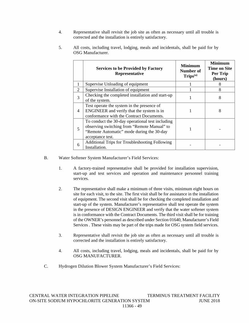
CENTRAL WATER INTEGRATION PIPELINE TERMINUS TREATMENT FACILITY ON-SITE SODIUM HYPOCHLORITE GENERATION SYSTEM JUNE 2018 11366 - 49
4. Representative shall revisit the job site as often as necessary until all trouble is corrected and the installation is entirely satisfactory.
5. All costs, including travel, lodging, meals and incidentals, shall be paid for by
OSG Manufacturer.
Services to be Provided by Factory
Representative
Minimum Number of
Trips(a)
Minimum Time on Site
Per Trip (hours)
1 Supervise Unloading of equipment 1 8 2 Supervise Installation of equipment 1 8
3 Checking the completed installation and start-up of the system. 1 8
4 Test operate the system in the presence of ENGINEER and verify that the system is in conformance with the Contract Documents.
1 8
5
To conduct the 30-day operational test including observing switching from “Remote Manual” to “Remote Automatic” mode during the 30-day acceptance test.
1 -
6 Additional Trips for Troubleshooting Following Installation. - -
B. Water Softener System Manufacturer’s Field Services:
1. A factory-trained representative shall be provided for installation supervision, start-up and test services and operation and maintenance personnel training services.
2. The representative shall make a minimum of three visits, minimum eight hours on site for each visit, to the site. The first visit shall be for assistance in the installation of equipment. The second visit shall be for checking the completed installation and start-up of the system. Manufacturer’s representative shall test operate the system in the presence of DESIGN ENGINEER and verify that the water softener system is in conformance with the Contract Documents. The third visit shall be for training of the OWNER’s personnel as described under Section 01640, Manufacturer’s Field Services . These visits may be part of the trips made for OSG system field services.
3. Representative shall revisit the job site as often as necessary until all trouble is corrected and the installation is entirely satisfactory.
4. All costs, including travel, lodging, meals and incidentals, shall be paid for by OSG MANUFACTURER.
C. Hydrogen Dilution Blower System Manufacturer’s Field Services:
CENTRAL WATER INTEGRATION PIPELINE TERMINUS TREATMENT FACILITY ON-SITE SODIUM HYPOCHLORITE GENERATION SYSTEM JUNE 2018 11366 - 50
1. A factory-trained representative shall be provided for installation supervision, start-up and test services and operation and maintenance personnel training services.
2. The representative shall make a minimum of three visits, minimum eight hours on site for each visit, to the site. The first visit shall be for assistance in the installation of equipment. The second visit shall be for checking the completed installation and start-up of the system. Manufacturer’s representative shall test operate the system in the presence of DESIGN ENGINEER and verify that the blowers are in conformance with the Contract Documents. The third visit shall be for training of the OWNER’s personnel as described under Section 01640, Manufacturer’s Field Services. These visits may be part of the trips made for OSG system field services.
3. Representative shall revisit the job site as often as necessary until all trouble is corrected and the installation is entirely satisfactory.
4. All costs, including travel, lodging, meals and incidentals, shall be paid for by CONTRACTOR.
D. Brine Tank Manufacturer’s Field Services:
1. Provide fabricator’s representative at site in accordance with Section 01730 for installation assistance, inspections and certification of proper installation and start-up assistance for specified component, subsystem, equipment, or system.
2. Manufacture’s Authorized Representative: Present at Work site designated by the CONTRACTOR for the minimum person-days. One (1) person-day for installation assistance, inspection and certification of installation for each type of tank. Furnish assistance, inspection and certification services at such times as requested by the CONTRACTOR.
END OF SECTION
DIVISION 17
INSTRUMENTATION
CENTRAL WATER INTEGRATION PIPELINE TERMINUS TREATMENT FACILITY VENDOR PACKAGED PROCESS CONTROL SYSTEMS JUNE 2018 17306 - 1
SECTION 17306
VENDOR PACKAGED PROCESS CONTROL SYSTEMS
PART 1 GENERAL
1.01 SCOPE OF WORK
A. Furnish all labor, materials and equipment required to provide, install, test and make operational, a Vendor Packaged Process Control System as specified herein and related specifications, and as shown on the Drawings.
B. The work shall include furnishing, installing and testing the equipment and materials as specified herein and related Divisions.
C. Equipment furnished as a part of other Divisions, and shown on the Instrumentation and/or Electrical Drawings shall be integrated into the overall Instrumentation System under the Instrumentation Sections of this Division. Instrumentation specified in other Divisions shall meet the Specification requirements of the Instrumentation Sections of this Division.
D. The Equipment Manufacturer (Supplier) shall provide the services to perform all work necessary to select, furnish, configure, customize, debug, install, connect, calibrate, and place into operation all instrumentation hardware specified herein and related specifications, and as shown on the Drawings, including application software programming, which is specified for Programmable Logic Controllers (PLCs) and Operator Interface Terminals (OIT). The Supplier shall coordinate with the Owner, Engineer, Contractor and Application Services Provider (ASP) for all scheduling, installation, and startup services.
E. The Supplier shall coordinate with the Process Control System Integrator (PCSI) and ASP for all data transfer, I/O lists and standard OIT graphics.
F. The Supplier shall be responsible for coordination with the PCSI, and shall assume ultimate responsibility in providing all items required to form a complete and operable s control system specific to the Supplier’s system whether specified herein or not.
1. The proposed system shall employ a state-of-the-art, fully automated control system for all normal daily operations including automated sequencing of system start-up, automated control of normal operation at steady state conditions, and automated sequencing of plant shutdowns (both emergency and operator initiated). The Supplier shall be responsible for providing process control strategies that safeguard the system equipment and warranties, and account for specific equipment furnished for the project. The developed control strategies shall be sufficiently detailed to allow use by the PCSI for control system coordination efforts. The Supplier shall be responsible for coordination of control strategies with the PCSI throughout the control system programming effort, and shall assist the PCSI with any changes that are required during startup and testing.
G. The following panels shall be furnished by the Supplier. Each panel shall e supplied with full back panels and side panels as necessary.
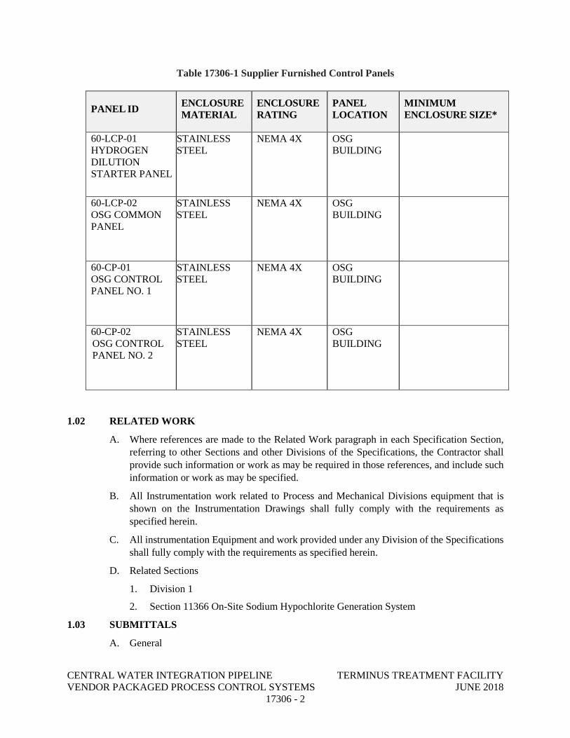
CENTRAL WATER INTEGRATION PIPELINE TERMINUS TREATMENT FACILITY VENDOR PACKAGED PROCESS CONTROL SYSTEMS JUNE 2018 17306 - 2
Table 17306-1 Supplier Furnished Control Panels
PANEL ID ENCLOSURE
MATERIAL ENCLOSURE RATING
PANEL LOCATION
MINIMUM ENCLOSURE SIZE*
60-LCP-01 HYDROGEN DILUTION STARTER PANEL
STAINLESS STEEL
NEMA 4X OSG BUILDING
60-LCP-02 OSG COMMON PANEL
STAINLESS STEEL
NEMA 4X OSG BUILDING
60-CP-01 OSG CONTROL PANEL NO. 1
STAINLESS STEEL
NEMA 4X OSG BUILDING
60-CP-02 OSG CONTROL PANEL NO. 2
STAINLESS STEEL
NEMA 4X OSG BUILDING
1.02 RELATED WORK
A. Where references are made to the Related Work paragraph in each Specification Section, referring to other Sections and other Divisions of the Specifications, the Contractor shall provide such information or work as may be required in those references, and include such information or work as may be specified.
B. All Instrumentation work related to Process and Mechanical Divisions equipment that is shown on the Instrumentation Drawings shall fully comply with the requirements as specified herein.
C. All instrumentation Equipment and work provided under any Division of the Specifications shall fully comply with the requirements as specified herein.
D. Related Sections
1. Division 1
2. Section 11366 On-Site Sodium Hypochlorite Generation System
1.03 SUBMITTALS
A. General
CENTRAL WATER INTEGRATION PIPELINE TERMINUS TREATMENT FACILITY VENDOR PACKAGED PROCESS CONTROL SYSTEMS JUNE 2018 17306 - 3
1. Refer to Division 1 for general project submittal requirements.
2. Shop drawings shall be submitted as detailed herein. Shop drawings shall demonstrate that the equipment and services to be furnished comply with the provisions of these specifications and shall provide a complete record of the equipment as manufactured, delivered, installed and placed in service.
3. Submittals shall be complete and shall give equipment specifications, details of connections, wiring, ranges, installation requirements, and specific dimensions. Submittals consisting of only general sales literature shall not be acceptable.
4. Submittals shall be bound in separate three-ring binders, with an index and sectional dividers, and with all included drawings reduced to a maximum size of 11-inches by 17-inches, then folded to 8.5-inches by 11-inches for inclusion inside the binder. Maximum binder thickness shall be 3 inches.
5. The shop drawings title block shall include, as a minimum, the Supplier’s registered business name and address, Owner and project name, drawing name, revision level, and shall identify personnel responsible for the content of the drawing.
6. Incomplete submittals not complying with the submittal requirements outlined in this Section will be returned without review.
7. In each submission, include the applicable specification section noted with Supplier’s indication of compliance with each requirement.
8. Unless discussed with and approved by the Engineer prior to submission, partial submittals are not acceptable and will be returned un-reviewed.
9. Any reproduction of the Contract Documents or portions thereof, and presentation of these as submittal content to the Owner and Engineer is not acceptable unless it is for indicating compliance with specification requirements and is clearly marked as such.
10. Include project-specific tagging and descriptions as shown in the Contract Documents as well as quantities for all devices and systems being provided to facilitate Owner’s and Engineer’s cross-referencing with requirements and verification of completeness.
B. Hardware and Software Packages Submittal
1. For each Control Panel listed in Table 17306-1, submit a cover page that lists, at a minimum, date, specification number, product name, manufacturer, model number, location(s), quantities and power required. Preferred format for the cover page is ISA S20, general data sheet; however, other formats will be acceptable provided they contain all required information.
2. Catalog cuts for supplied Programmable Logic Controller (PLC), process controller equipment, including central processing units, memory, input modules, output modules, modems, network interface modules, mounting racks, and power supplies. Submit descriptive literature for each hardware component that fully describes the units being provided. Additional information for PLC shall include:
a. Bill of materials for each PLC clearly identifying all components and quantities.
CENTRAL WATER INTEGRATION PIPELINE TERMINUS TREATMENT FACILITY VENDOR PACKAGED PROCESS CONTROL SYSTEMS JUNE 2018 17306 - 4
3. Catalog cuts for supplied Operator Interface Terminals (OIT), including network interface modules and power supplies. Submit descriptive literature for each hardware component that fully describes the unites being provided.
4. Catalog cuts for uninterruptible power supplies (UPS), power supplies, and all other network hardware being provided. Submit descriptive literature for each hardware component, which fully describes the units being provided. Additional information for UPS shall include:
a. Bill of materials listing all components provided
b. Deviation list indicating all purpose exceptions
c. Power single line and control schematic drawings. All external connections and their terminal block locations shall be fully detailed. All internal wiring shall include terminal numbers and color coding.
d. UPS specifications as follows:
(i) kVA rating
(ii) Input and output voltage and phase
(iii) Run time at full and half load
(iv) Voltage (output regulation, input tolerance, unbalance, transfer/retransfer voltage, etc.)
(v) Heat rejection
e. Instruction and replacement parts manuals
f. Name, address, and telephone number of the nearest service facility
g. Battery specifications and warranty
h. Batter sizing calculations.
5. Submit details of field instrument and field device digital networks. Submittal shall include details of the field device digital networks technology including type, power requirements, wiring requirements, configuration details, device addressing, and interface to the process control system. Include separate details of the field device digital network configuration(s) for each field level digital network and sub-network.
6. Submit details for all software packages to be furnished, including specification number, product name, manufacturer, product number, license versions and quantities.
C. Input/Output (I/O) List Submittal
1. The Supplier shall develop and submit the system I/O list that includes all I/O identified in the project drawing P&IDs. Submittal shall be a complete system I/O list for all equipment connected to the control system under this Contract.
2. The I/O list shall be submitted in both a Microsoft Excel readable electronic file format and an 8-1/2 inch by 11-inch hard copy.
CENTRAL WATER INTEGRATION PIPELINE TERMINUS TREATMENT FACILITY VENDOR PACKAGED PROCESS CONTROL SYSTEMS JUNE 2018 17306 - 5
3. The I/O list shall reflect all active and spare I/O points. Add points to accommodate spare I/O.
4. The I/O list shall be arranged such that each control panel has a dedicated worksheet. At a minimum, I/O worksheet tables shall include the following information:
a. TAG NUMBER(S): The identifier assigned to a device that performs a function in the control system. As part of this information, the loop number of the tag shall be broken out to allow for sorting by loop.
b. DESCRIPTION: A description of the function of the device (text that includes signal source, control function, etc.) Include the text "Spare Points" for all I/O module points that are not connected to equipment.
c. PHYSICAL LOCATION: The Control Panel designation of where the I/O point is wired to.
d. Physical POINT ADDRESS: Rack, Slot, and Point (or Channel) assignment for each I/O point.
e. LOGICAL POINT ADDRESS: I/O address of each point
f. I/O TYPE: use DO - Discrete Output, DI - Discrete Input, AO - Analog Output, AI - Analog Input, PI - Pulse Input, or PO – Pulse Output.
g. RANGE/STATE: The range in engineering units corresponding to an analog 4-20 mA signal, or, the state at which the value of the discrete points is "1."
h. ENGINEERING UNITS: The engineering units associated with the Analog I/O.
i. ALARM LIMITS: Include alarm limits based on the control descriptions and the Drawings.
j. P&ID – the P&ID or drawing where the I/O point appears on. Mark as "NA" (Not Applicable) if the I/O point is derived from a specification requirement and is not on the P&IDs.
5. The I/O list shall be sorted in order by:
a. Physical location
b. I/O Type
c. Loop Number
d. Device Tag
6. Once the I/O List is approved, the PLC I/O addresses may not be modified without approval by the Design Engineer and ASP.
7. Where multiple mechanical components are provided for process redundancy, their field connections to I/O modules shall be arranged such that the failure of a single I/O module will not disable all mechanical components of the redundant system. This applies to all I/O types.
D. Data Transfer Address List Submittal
CENTRAL WATER INTEGRATION PIPELINE TERMINUS TREATMENT FACILITY VENDOR PACKAGED PROCESS CONTROL SYSTEMS JUNE 2018 17306 - 6
1. Submit a complete Data Transfer List defining all software points for communication to/from the plant SCADA.
2. The data transfer points shall be based on the Drawings, the requirements outlined in the Specifications, and coordination meetings with the Owner, Engineer, General Contractor and PCSI.
3. The data transfer list shall be submitted in both a Microsoft Excel readable electronic file format and hard copy.
4. As a minimum, the data transfer list shall include the following information:
a. TAG NAME: The identifier assigned to the software point.
b. DESCRIPTION: A description of the function of the device
c. LOGICAL POINT ADDRESS: Software address of each point.
d. POINT TYPE:
(i) DO - Discrete Output is written to the Supplier control system by the plant SCADA.
(ii) DI - Discrete Input is read from the Supplier control system by the plant SCADA.
(iii) AO - Analog Output is written to the Supplier control system by the plant SCADA.
(iv) AI - Analog Input is read from the Supplier control system by the plant SCADA.
e. DATA FORMAT: For analog points, the data format shall be either Integer or floating point. For discrete points, the data format shall be either maintained or momentary.
f. RANGE/STATE: The range in engineering units corresponding to an analog 4-20 mA signal; or, the state at which the value of the discrete point is “1.”
g. ENGINEERING UNITS: The engineering units associated with the Analog points.
E. Equipment Supplier Control Narrative Submittal
1. This submittal shall provide the following information:
a. System Overview
b. Mode of Operation
c. Local Manual Control
d. Local Automatic Control
e. Remote Manual Control
f. Remote Automatic Control
g. Alarms
CENTRAL WATER INTEGRATION PIPELINE TERMINUS TREATMENT FACILITY VENDOR PACKAGED PROCESS CONTROL SYSTEMS JUNE 2018 17306 - 7
h. Interlocks
i. Tuning Parameters
j. Equipment Runtimes
k. Historical Recording
F. Control System Standards and Conventions Submittal
1. Submit system configuration, including network (TCP/IP) addressing. Network addressing shall be defined to enable the plant PLC system to communicate with the Supplier control system.
2. Software tag naming conventions
3. OIT Graphic display standards, including color conventions, equipment symbols, display format, and samples of each proposed type of graphic display.
4. Alarm configuration standards, including priorities, logging, and resetting
5. Security configuration standards, including user groups and privileges
6. PLC software templates, including equipment control, sequence control and equipment runtime calculations
G. Operator Interface Submittal
1. Submit all proposed graphic displays, trends, and logs.
2. Quantity of graphic displays to be submitted shall be as required to depict all monitoring and control requirements, defined herein and in the contract documents. As a minimum, the following graphic displays and types shall be submitted:
3. Process Overview Displays
4. Unit Process Displays
5. Alarm Summary Display
6. Key Performance Indicators (KPI): provide dedicated graphic displays for system key performance indicators.
7. Control Strategy Setup Displays
8. Equipment Control Pop-up Displays
9. System Diagnostic Displays
H. Process Instruments Submittal
1. Submit complete documentation of all field instruments using ISA-S20 data sheet formats. Submit a complete Bill of Materials (BOM) listing all instrumentation equipment using project identification, such as tags and descriptions as shown in the Contract Documents.
2. Submit separate data sheets for each instrument including:
a. Plant Equipment Number and ISA tag number per the Drawings
CENTRAL WATER INTEGRATION PIPELINE TERMINUS TREATMENT FACILITY VENDOR PACKAGED PROCESS CONTROL SYSTEMS JUNE 2018 17306 - 8
b. Product (item) name used herein and on the Contract Drawings
c. Manufacturer's complete model number
d. Location of the device
e. Input - output characteristics
f. Range, size, and graduations in engineering units
g. Physical size with dimensions, enclosure NEMA classification and mounting details in sufficient detail to determine compliance with the requirements of the Contract Documents
h. Materials of construction for enclosure and wetted parts
i. Instrument or control device sizing calculations where applicable
j. Certified calibration data for all flow metering devices
k. Two-wire or four-wire device type, as applicable
3. Submit index and data sheets in electronic format as well as hard copies on 8 1/2" x 11" formats. Electronic format shall be in Microsoft Excel or Word. Submit electronic copy.
I. Panel Layout Drawings, Wiring Diagrams and Loop Wiring Diagrams Submittal
1. Include a complete Bill of Materials for each individual control panel being furnished.
2. Include manufacturer literature for each item in the Bill of Materials with all required markings indicating exactly what versions, options, etc. are being proposed and indicate compliance with specification requirements. Manufacturer literature for common components need only be included once, for the first panel in the submittal with references to this literature included as applicable thereafter in submittal.
3. Panel Layout Drawings: Drawings shall be furnished for all panels, consoles, and equipment enclosures specified. Panel assembly and elevation drawings shall be drawn to scale and detail all equipment in or on the panel. Panel drawings shall be 11 "x 17" minimum in size. As a minimum, the panel drawings shall include the following:
a. Interior and exterior panel elevation drawings to scale
b. Nameplate schedule
c. Conduit access locations
d. Panel construction details
e. Include cabinet assembly and layout drawings shown drawn to scale. The assembly drawing shall include a bill of material on the drawing with each panel component clearly defined. The bill of material shall be cross-referenced to the assembly drawing so that a non-technical person can readily identify any component of the assembly by manufacturer and model number.
f. Fabrication and painting specifications including color (or color samples)
CENTRAL WATER INTEGRATION PIPELINE TERMINUS TREATMENT FACILITY VENDOR PACKAGED PROCESS CONTROL SYSTEMS JUNE 2018 17306 - 9
g. Submit construction details, NEMA ratings, intrinsically safe barrier information, gas sealing recommendations, purging system details, etc. for panels located in hazardous locations or interfacing to equipment located in hazardous areas.
h. Heating and cooling calculations for each panel supplied indicating conformance with cooling requirements of the supplied equipment and environmental conditions. Calculations shall include the recommended type of equipment required for both heating and cooling.
i. Submit evidence that all control panels shall be constructed in conformance with UL 508 and bear the UL seal confirming the construction. Specify if UL compliance and seal application shall be accomplished at the fabrication location or by field inspection by UL inspectors. All costs associated with obtaining the UL seal and any inspections shall be borne by the Supplier and included in the Project Bid Price.
4. Panel Wiring Diagrams: Panel wiring diagrams depicting wiring within and on the panel as well as connections to external devices. Equipment external to the control panel and related external connections do not need to be shown on the Panel Wiring Diagrams. Panel wiring diagrams shall include power and signal connections, UPS and normal power sources, all panel ancillary equipment, protective devices, wiring and wire numbers, and terminal blocks and numbering. Field device wiring shall include the device ISA-tag and a unique numeric identifier. The diagrams shall identify all device terminal points that the system connects to, including terminal points where I/O wiring lands on equipment not supplied by the Supplier. Wiring labeling used on the drawings shall match that shown on the Contract Documents or as developed by the Supplier and approved by the Engineer. I/O wiring shall be numbered with rack number, slot number, and point number. Two-wire and four-wire equipment shall be clearly identified and power sources noted. Submit final wire numbering scheme. Panel drawings shall be 11" x 17" minimum in size.
5. ISA Loop Wiring Diagrams: Detailed ISA loop wiring diagrams showing requirements for each loop which is shown on the contract drawings. The Loop Drawings shall be prepared in accordance with ISA Standard S5.4, latest version, and with the layout following Figures 5 and 6 (shown in the S5.4 Standard), titled Minimum Required Items Plus Optional items". Loop drawings shall be 11" x 17" minimum in size. The information required on the Loop Drawings to satisfy the "minimum" and "optional" requirements is as follows:
a. Minimum Required Items – The following information shall be provided on Loop Drawings to meet this requirement:
b. Identification of the loop and loop components shown on the P&IDs Other principal components of the loop to be shown and identified under ISA-5.1, "Instrumentation Symbols and Identification"
c. Word description of loop functions within the title. If not adequate, use a supplemental note. Identify any special features or functions of shutdown and safety circuits.
CENTRAL WATER INTEGRATION PIPELINE TERMINUS TREATMENT FACILITY VENDOR PACKAGED PROCESS CONTROL SYSTEMS JUNE 2018 17306 - 10
d. Indication of the interrelation to other instrumentation loops, including overrides, interlocks, cascaded set points, shutdowns and safety circuits.
e. All point-to-point interconnections with identifying numbers or colors of electrical cables, conductors, pneumatic multitubes, and individual pneumatic and hydraulic tubing and this identification of interconnections includes junction boxes, terminals, bulkheads, ports, and grounding connections.
f. General location of devices such as field, panel, auxiliary equipment, rack, termination cabinet, cable spreading room, I/O cabinet, etc.
g. Energy sources of devices, such as electrical power, air supply, and hydraulic fluid supply. Identify voltage, pressure, and other applicable requirements. For electrical sources, identify circuit or disconnect numbers.
h. Process lines and equipment sufficient to describe the process side of the loop and provide clarity of control action. Include what is being measured and what is being controlled.
i. Actions or fail-safe positions (electronic, pneumatic, or both) of control devices such as controllers, switches, control valves, solenoid valves, and transmitters (if reverse- acting). These are to be identified in accordance with ISA-5.1, "Instrumentation Symbols and Identification".
j. References to equipment descriptions, manufacturers, model numbers, hardware types, specifications or data sheets, purchase order numbers.
k. Signal ranges and calibration information, including set point values for switches, and alarm and shutdown devices.
J. Testing Plan Submittal
1. Test Procedures: Submit the procedures proposed to be followed for each test. Procedures shall include test descriptions, forms, and checklists to be used to control and document the required tests. Include sign-off forms for each testing phase or loop with sign-off areas for the Supplier, Engineer, and Owner. Refer to Section 0100 General Conditions for specific testing requirements, and submit separate procedures for each specified test phase including:
a. Unwitnessed Hardware Factory Acceptance Testing (UFT)
b. System Integration Testing (SIT)
c. Witnessed Hardware Factory Test (WHFT)
d. Witnessed Software Factory Test (WSFT)
e. Unwitnessed Operational
2. Test Documentation: Upon completion of each required test, document the test by submitting a copy of the signed off test procedures. Testing shall not be considered complete until the signed-off test procedures have been submitted and favorably reviewed. Submittal of other test documentation, including "highlighted" wiring
CENTRAL WATER INTEGRATION PIPELINE TERMINUS TREATMENT FACILITY VENDOR PACKAGED PROCESS CONTROL SYSTEMS JUNE 2018 17306 - 11
diagrams with field technician notes, are not acceptable substitutes for the formal test documentation.
3. Each loop shall have a Loop Status signoff form to organize and track its inspection, adjustment and calibration. These forms shall include the following information and check-off items:
a. Project Name
b. Loop Number
c. Detailed test procedure indicating exactly how the loop will be tested including all required test equipment, necessary terminal block numbers, and simulation techniques required.
d. Tag Number for each component.
e. Check-offs/sign-offs for each component:
Tag/identification Installation Termination - wiring Termination - tubing Calibration/adjustment
f. Check-off/sign-off space for each loop:
Panel interface terminations I/O interface terminations I/O signal operation Inputs/outputs operational: received/sent, processed, adjusted Total loop operation Space for comments. Sign off and date fields for the Owner, the Engineer, and the Supplier.
4. Each active analog subsystem element shall have a Component Calibration form. These forms shall have the following information including space for data entry:
a. Project Name
b. Loop Number
c. ISA Tag Number and I/O Module Address
d. Manufacturer
e. Model Number/Serial Number
f. Summary of Functional Requirements, for example:
For Indicators: Scale ranges For Transmitters/Converters: Scale and chart ranges For Computing Elements: Function For Controllers: Action (direct/reverse) control modes (PID)
CENTRAL WATER INTEGRATION PIPELINE TERMINUS TREATMENT FACILITY VENDOR PACKAGED PROCESS CONTROL SYSTEMS JUNE 2018 17306 - 12
For Switching Elements: Unit range, differential (fixed/adjustable), reset (auto/manual) For I/O Modules: Input or output
g. Calibrations, for example:
For Analog Devices: Required and actual inputs and outputs at 0, 25, 50, 75 and 100 percent of span.
For Discrete Devices: Required and actual trip points and reset points.
For Controllers: Mode settings (PID).
For I/O Modules: Required and actual inputs or outputs for 0, 50 and 100 percent of span.
h. Space for comments
i. Sign off and date fields for the Owner, the Engineer, and the PCSI.
K. Spares, Expendables, and Test Equipment
1. All spares, expendables and test equipment in the listed Sections shall be included in a single submittal.
2. This submittal shall include for each subsystem:
a. A list of, and descriptive literature for, spares, expendables, and test equipment as specified under Division 17 specifications
b. A list of, and descriptive literature for, additional spares, expendables, and test equipment recommended by the manufacturer
c. Unit and total costs for the additional spare items specified or recommended for each subsystem.
L. Final System Documentation
1. The Final System Documentation shall consist of operations and maintenance manuals as specified herein. The manuals shall be bound in three-ring binders, maximum size of three inches, with Drawings reduced to 11 inches by 17 inches, then folded to 8.5 inch by 11 inches for inclusion. Each section shall have a uniquely numbered tab divider, and each component within each section shall have a separate binder tab divider.
2. The Operations and Maintenance manuals shall, at a minimum, contain the following information:
a. Table of Contents
A Table of Contents shall be provided for the entire manual with the specific contents of each volume clearly listed. The complete Table of Contents shall appear in each volume.
b. Instrument and Equipment Lists
CENTRAL WATER INTEGRATION PIPELINE TERMINUS TREATMENT FACILITY VENDOR PACKAGED PROCESS CONTROL SYSTEMS JUNE 2018 17306 - 13
The following lists shall be developed in Excel and provided not only as a hardcopy in O&M.
An instrument list for all devices supplied including tag number, description, specification section and paragraph number, manufacturer, model number, serial number, range, span, location, manufacturer phone number, local supplier name, local supplier phone number, completion year replacement cost, and any other pertinent data.
An equipment list for all non-instrument devices supplied listing description, specification section and paragraph number, manufacturer, model number, serial number, location, manufacturer phone number, local supplier name, local supplier phone number, completion year replacement cost, and any other pertinent data.
c. Data Sheets with Vendor Operations and Maintenance Information
d. ISA S20 data sheets shall be provided for all field instruments.
Cover page for each device, piece of equipment, and OEM software that lists, at a minimum, date, specification number, product name, manufacturer, model number, Location(s), and power required. Preferred format for the cover page is ISA S20, general data sheet; however, other formats will be acceptable provided they contain all required information.
Final vendor O&M documentation for each device, piece of equipment, or OEM software shall be either new documentation written specifically for this project, or modified standard vendor documentation. All standard vendor documentation furnished shall have all portions that apply clearly indicated with arrows or circles. All portions that do not apply shall be neatly lined out or crossed out. Groups of pages that do not apply at all to the specific model supplied shall be removed.
For any component requiring dip switch settings or custom software configuration, that information shall be included along with the corresponding data sheets and O&M information.
e. As-Built Drawings
Complete As-built Drawings, including all Drawings and diagrams specified in this Section under the "Submittals" paragraph. These Drawings shall include all termination points on all equipment the system in connected to, including terminal points of equipment not supplied by the Supplier.
As-built documentation shall include information from submittals, as described in this Specification, updated to reflect the as-built system. Any errors in or modifications to the system resulting from the Factory and/or Functional Acceptance Tests shall be incorporated in this documentation.
f. Original Licensed Software
Submit original software diskettes or CD-ROMs for all software provided under this Contract. Submit original documentation, both hard copies and in electronic format, for all software provided. Submit license agreement information including serial numbers, license agreements, User Registration Numbers and
CENTRAL WATER INTEGRATION PIPELINE TERMINUS TREATMENT FACILITY VENDOR PACKAGED PROCESS CONTROL SYSTEMS JUNE 2018 17306 - 14
related information. All software provided under this Contract shall be licensed to the Owner at the time of purchase. Provide media in original packages provided by manufacturer.
g. Electronic O&M Information
In addition to the hard copy of O&M data, provide an electronic version of all equipment manuals. Electronic documents shall be supplied in Adobe Acrobat format.
Provide electronic files for all custom-developed manuals. Text shall be supplied in both Microsoft Office format and .pdf format.
Provide electronic files for all drawings produced. Drawings shall be in AutoCAD 2007 ".dwg" format and in .pdf format. Drawings shall be provided using the AutoCAD eTransmit feature to bind external references, pen/line styles, and fonts into individual zip files along with the drawing file. • Each computer system hardware device shall be backed up onto CDROM
or DVD after Substantial Completion and shall be turned over to the Owner. • If specified in the training section, provide digital copies of all training
videos. Videos shall be in a format that is readable by standard DVD players and by standard PC DVD drives. Format and shall be a minimum of 800 by 600 pixels and shall include sound.
3. The cover and edge of each volume shall contain the following information:
4. Project Name (refer to Contract Documents)
5. Contract Number (refer to Contract Documents)
6. Instrumentation and Control Systems
7. Hardware [or Applications Engineering] Operations and Maintenance Manual
8. Specification Sections _____, _____, ______
9. Subcontractor Name
10. Date
11. Volume X of Y
12. (Where X is the volume number and Y is the number of volumes)
1.04 TESTING
A. General Test Requirements
1. The Supplier shall test all equipment prior to shipment. Unless otherwise specified in the individual specification sections, all equipment provided by the Supplier shall be tested as a single fully integrated system.
2. As a minimum, the testing shall include the following:
a. Unwitnessed Factory Test (UFT)
CENTRAL WATER INTEGRATION PIPELINE TERMINUS TREATMENT FACILITY VENDOR PACKAGED PROCESS CONTROL SYSTEMS JUNE 2018 17306 - 15
b. Witnessed Factory Test (WFT)
c. Operational Readiness Tests (ORT)
d. Functional Demonstration Tests (FDT)
e. 30-Day Site Acceptance Tests (SAT)
3. Each test shall be in the cause and effect format. The person conducting the test shall initiate an input (cause) and, upon the system's or subsystem's producing the correct result (effect), the specific test requirement shall be satisfied.
4. All tests shall be conducted in accordance with prior Engineer-approved procedures, forms, and check lists. Each specific test shall be described and followed by a section for sign off by the appropriate party after its status completion.
5. Copies of these sign off test procedures, forms, and check lists will constitute the required test documentation.
6. Provide all special testing materials and equipment. Wherever possible, perform tests using actual process variables, equipment, and data. Where it is not practical to test with real process variables, equipment, and data, provides suitable means of simulation. Define these simulation techniques in the test procedures.
7. The General Contractor shall require the Supplier to coordinate all testing with the Engineer, all affected Subcontractors, and the Owner.
8. The Engineer reserves the right to test or retest all specified functions whether explicitly stated in the prior approved Test Procedures.
9. The Engineer's decision shall be final regarding the acceptability and completeness of all testing.
10. No equipment shall be shipped to the Project Site until the Engineer has received all test results and approved the system as ready for shipment.
11. The Supplier shall furnish the services of servicemen, all special calibration and test equipment and labor to perform the field tests as specified in Section 11366.
12. Correction of Deficiencies
a. All deficiencies in workmanship and/or items not meeting specified testing requirements shall be corrected to meet specification requirements at no additional cost to the Owner.
b. Testing, as specified herein, shall be repeated after correction of deficiencies is made until the specified requirements are met. This work shall be performed at no additional cost to the Owner.
1.05 REFERENCE CODES AND STANDARDS
A. Instrumentation equipment, materials and installation shall comply with the National Electrical Code (NEC) and with the latest edition of the following codes and standards:
1. National Electrical Safety Code (NESC)
CENTRAL WATER INTEGRATION PIPELINE TERMINUS TREATMENT FACILITY VENDOR PACKAGED PROCESS CONTROL SYSTEMS JUNE 2018 17306 - 16
2. Occupational Safety and Health Administration (OSHA)
3. National Fire Protection Association (NFPA)
a. NFPA 79, Electrical Standard for Industrial Machinery
4. National Electrical Manufacturers Association (NEMA)
a. NEMA ICS 1-10 Diagrams, Designations and Symbols
b. NEMA ICS 4 Terminal Blocks for Industrial Use
c. NEMA ICS 6 Enclosures for Industrial Control Systems
d. NEMA LS1 Low Voltage Surge Protection Devices
5. American National Standards Institute (ANSI)
a. ANSI/ISA-5.06.01-2007 – Functional Requirements Documentation for Control Software Applications
6. Insulated Cable Engineers Association (ICEA)
7. The International Society of Automation (ISA)
a. ISA-TR20.00.01-2007 – Specification Forms for Process Measurement and Control Insruments Part 1: General Considerations Updated with 27 New Specification Forms in 2004-2006 and updated with 11 New Specification Forms in 2007
b. ISA-5.1-2009 Instrumentation Symbol and Identification
c. ISA-5.2-1976 (R1992) Binary Logic Diagrams for Process Operations
d. ISA-5.3-1983 Graphic Symbols for Distributed Control/Shared Display Instrumentation, Logic, and Computer Systems
e. ISA-5.4-1991 Instrument Loop Diagrams
f. ISA-5.5-1985 Graphic Symbols for Process Displays
g. ISA-20-1981 Specification Forms for Process Measurement and Control Instruments, Primary Elements, and Control Valves
8. Underwriters Laboratories (UL) a. UL 508, the Standard of Safety for Industrial Control Equipment
b. UL 508A, the Standard of Safety for Industrial Control Panels
c. UL 50, the Standard of Safety for Enclosures for Electrical Equipment.
d. UL 1449 Third Edition Surge Protective Devices
9. Factory Mutual (FM)
10. All equipment and installations shall satisfy applicable Federal, State, and local codes.
B. Where reference is made to one of the above standards, the revision in effect at the time of bid opening shall apply.
CENTRAL WATER INTEGRATION PIPELINE TERMINUS TREATMENT FACILITY VENDOR PACKAGED PROCESS CONTROL SYSTEMS JUNE 2018 17306 - 17
C. All material and equipment, for which a UL standard exists, shall bear a UL label. No such material or equipment shall be brought onsite without the UL label affixed.
D. If the issue of priority is due to a conflict or discrepancy between the provisions of the Contract Documents and any referenced standard, or code of any technical society, organization or association, the provisions of the Contract Documents shall take precedence if they are more stringent or presumptively cause a higher level of performance. If there is any conflict or discrepancy between standard specifications, or codes of any technical society, organization or association, or between Laws and Regulations, the higher performance requirement shall be binding on the Contractor, unless otherwise directed by the Owner/Engineer.
E. In accordance with the intent of the Contract Documents, Supplier accepts the fact that compliance with the priority order specified shall not justify an increase in Contract Price or an extension in Contract Time nor limit in any way, the Supplier’s responsibility to comply with all Laws and Regulations at all times
F. All control panels shall be constructed and the labeling shall be affixed in a UL 508 facility.
1.06 CODES, INSPECTION AND FEES
A. Equipment, materials and installation shall comply with the requirements of the local authority having jurisdiction.
B. Obtain all necessary permits and pay all fees required for permits and inspections.
1.07 SIZE OF EQUIPMENT
A. Investigate each space in the structure through which equipment must pass to reach its final location. Coordinate shipping splits with the manufacturer to permit safe handling and passage through restricted areas in the structure.
B. The equipment shall be kept upright at all times during storage and handling. When equipment must be tilted for passage through restricted areas, brace the equipment to ensure that the tilting does not impair the functional integrity of the equipment.
1.08 MATERIALS AND EQUIPMENT
A. Materials and equipment shall be new, except where specifically identified on the Drawings to be re-used.
B. The Supplier shall not bring onsite, material or equipment from a manufacturer, not submitted and approved for this project. Use of any such material or equipment, will be rejected, removed and replaced by the Supplier with the approved material and equipment, at his own expense.
C. Material and equipment shall be UL listed, where such listing exists.
D. The Supplier shall be responsible for all material, product, equipment and workmanship being furnished by him for the duration of the project. He shall replace the equipment if it does not meet the requirements of the Contract Documents.
1.09 WARRANTY
CENTRAL WATER INTEGRATION PIPELINE TERMINUS TREATMENT FACILITY VENDOR PACKAGED PROCESS CONTROL SYSTEMS JUNE 2018 17306 - 18
A. The Supplier shall provide warranty as specified in Section 11366.
1.10 DELIVERY, STORAGE AND HANDLING
A. Equipment shall be handled and stored in accordance with Section 11366 and as specified herein.
B. Where space heaters are provided in equipment or control panels, provide temporary electrical power and operate space heaters during jobsite storage and after equipment is installed in permanent location, until equipment is placed in service.
1.11 EQUIPMENT IDENTIFICATION
A. Identify equipment (control panels, control stations, instruments, etc) furnished with the name of the equipment it serves. Control panels, Instruments, meters junction or terminal boxes, etc., shall have nameplate designations as shown on the Drawings.
B. Nameplates shall be engraved, laminated impact acrylic, black lettering on a white background, matte finish, not less than 1/16-in thick by 3/4-in by 2-1/2-in, Rowmark 322402. Nameplates shall be 316 SS screw mounted to all enclosures except for NEMA 4 and 4X. Nameplates for NEMA 4 and 4X enclosures shall be attached with double faced adhesive strips, TESA TUFF TAPE 4970, .009 X ½”, no equal. Prior to installing the nameplates, the metal surface shall be thoroughly cleaned, with a 70% alcohol solution, until the metal surface residue has been removed. Epoxy adhesive or foam tape is not acceptable.
PART 2 PRODUCTS
2.01 GENERAL
A. All materials that come into contact with the water being treated or the finished water shall be ANSI/NSF Standard 61 certified for use in contact with potable water. Manufacturers shall submit an affidavit with the shop drawings indicating ANSI/NSF Standard 61 conformance for the materials used in products that come in contact with the water.
2.02 PROCESS INSTRUMENTS
A. Flow Instruments
1. Electromagnetic Flow Meter
a. Subject to compliance with the Contract Documents, the following manufacturers are acceptable:
(i) ABB
(ii) Endress + Hauser
(iii) Siemens
b. The listing of specific manufacturers above does not imply acceptance of their products that do not meet the specified ratings, features and functions.
CENTRAL WATER INTEGRATION PIPELINE TERMINUS TREATMENT FACILITY VENDOR PACKAGED PROCESS CONTROL SYSTEMS JUNE 2018 17306 - 19
Manufacturers listed above are not relieved from meeting these specifications in their entirety.
c. General
(i) Provide sufficient lengths of manufacturer’s specialty cables for installation of power and signal conductors as provided with each instrument.
(ii) Provide a hand-held programmer, for each transmitter, where full setup is not available for the instrument directly.
(iii) Each electromagnetic flow meter shall be provided according to the Table 17306-2.
d. Type
(i) Microprocessor based intelligent type.
e. Function/Performance:
(i) Output: 4-20 mA DC. Output shall be linear for pressure applications.
(ii) Accuracy: 0.5 percent of span (linear output).
(iii) Stability: Combined temperature effects shall be less than 0.2 percent of maximum span per 50 degrees F temperature change. Effect on accuracy, due to static pressure changes, shall be negligible.
(iv) RFI Protection: 0.1 percent error between 27 and 500 MHZ at 30 v/m field intensity.
(v) Drift: 0.10 percent per six months for 4-20 mA output.
(vi) Temperature rating: Suitable for process liquid temperature up to 70 degrees C and an ambient of 65 degrees C.
(vii) Pressure rating: 240 PSI if 150 lb flanges are used; 700 PSI if 300 lb flanges are used.
(viii) Meter shall be capable of running empty indefinitely without damage to any component.
f. Physical:
(i) Metering Tube (a) Carbon steel with 304 Stainless interior unless otherwise indicated. (b) Electrical Classification: Rating shall be FM approved for the location
shown on the Drawings (c) Tube Flanges: Match piping AWWA rating of the pipe. Minimum
AWWA 150# Flange. (d) Tube Liner: Polyurethane or EDPM, certified as ANSI/NSF Standard 61
compliant for direct contact with potable water, unless noted otherwise.
CENTRAL WATER INTEGRATION PIPELINE TERMINUS TREATMENT FACILITY VENDOR PACKAGED PROCESS CONTROL SYSTEMS JUNE 2018 17306 - 20
(e) Tube Electrodes: ANSI 316 stainless steel or Hastelloy C, bullet nosed or elliptical self-cleaning type unless otherwise noted.
(f) Tube Housing: Meters in below grade, vaults, basements, etc., shall be designed for accidental submergence in 30 feet of water for 24 hours. Meters above grade shall be of splash proof/drip proof design unless otherwise noted.
(g) Painting: All external surfaces shall be painted with a chemical and corrosion resistant epoxy finish.
g. Transmitter
(i) Transmitter Enclosure: NEMA 4X.
(ii) Electrical Classification: Rating shall be FM approved for the location shown on the Drawings
(iii) Transmitter shall be remotely mounted unless indicated on Drawings.
h. Power Requirements
(i) Input Power: 100VAC-230VAC
i. Options/ Accessories
(i) Factory calibration: Each meter shall be factory calibrated, with a copy of the Report delivered with the device and in the O&M manual.
(ii) Grounding: Meter shall be grounded with rings. Provide 316 Stainless Steel ground rings, ground wires, and gaskets, etc. All materials shall be suitable for the liquid being measured. Where sodium hypochlorite is the liquid being measured provide Hastelloy C grounding materials.
(iii) Electrode cleaning: Where listed on the instrument device schedules, or shown on the Drawings, provide an electrode cleaning system. The cleaning system electronics shall be housed in a NEMA 4X wall mounted panel. Provide all necessary cables and connectors. The system shall be powered through the special cables to the magnetic flow meter.
(iv) Provide a hand-held programmer for each transmitter, where full setup is not available from the instrument transmitter display directly.
B. Level Instruments
1. Ultrasonic Level Transmitter (Remote Sensor)
a. Subject to compliance with the Contract Documents, the following Manufacturers are acceptable:
(i) Endress + Hauser
(ii) Siemens HydroRanger 200
(iii) Approved Equal
CENTRAL WATER INTEGRATION PIPELINE TERMINUS TREATMENT FACILITY VENDOR PACKAGED PROCESS CONTROL SYSTEMS JUNE 2018 17306 - 21
b. The listing of specific manufacturers above does not imply acceptance of their products that do not meet the specified ratings, features and functions. Manufacturers listed above are not relieved from meeting these specifications in their entirety.
c. General
(i) Provide sufficient lengths of Manufacturer’s specialty cables for installation of power and signal conductors as provided with each instrument.
d. Type:
(i) Separate ultrasonic transducer
(ii) Dual 4-20ma outputs & 2 Form A & 1 Form C Outputs
e. Function/Performance
(i) Function: Sense and transmit a variable liquid level.
(ii) Principle: Pulse ultrasonic signals from the transducer toward the liquid and receive an echo, measuring the time between sending and receiving the pulse signal, and proportioning that to the measured liquid depth.
(iii) Range Capability: 1 feet to 50 feet
(iv) Beam Angle: 7 degrees
(v) Shall have integral temperature compensation unit.
(vi) Accuracy. Current output 1 percent of selected full-scale range.
(vii) Repeatability. 0.25 percent full scale.
f. Physical
(i) Transmitter housing: shall be NEMA 4X polycarbonate enclosure. Sensor shall be completely encapsulated PVC and submersible with an aluminum outer cover, suitable for Class I Div 1 locations.
g. Power Requirements
(i) Input Power: 100VAC-230VAC
h. Options/Accessories
(i) Provide span and zero adjustment at each transmitter.
(ii) Provide local indication at each transmitter, either analog gauge or LCD readout. Scale shall be in engineering units.
(iii) Provide an integral indicator scaled in engineering units.
(iv) Provide hand held programmer(s) where full setup is not available for the instrument
2. Ultrasonic Level Transmitter (Integral Sensor)
CENTRAL WATER INTEGRATION PIPELINE TERMINUS TREATMENT FACILITY VENDOR PACKAGED PROCESS CONTROL SYSTEMS JUNE 2018 17306 - 22
a. Subject to compliance with the Contract Documents, the following Manufacturers are acceptable:
(i) Endress + Hauser
(ii) Siemens Probe
(iii) Approved Equal
b. The listing of specific manufacturers above does not imply acceptance of their products that do not meet the specified ratings, features and functions. Manufacturers listed above are not relieved from meeting these specifications in their entirety.
c. General
(i) Provide sufficient lengths of any Manufacturer’s specialty cables for installation of power and signal conductors as provided with each instrument.
d. Type:
(i) Microprocessor based intelligent type
(ii) The instrument shall measure level.
e. Function/Performance
(i) Accuracy: +/- ¼ inch.
(ii) Built-in temperature compensation.
(iii) Output: 4-20 mA
(iv) Repeatability: =/< 0.12 in.
f. Physical
(i) Electrical Classification: Shall be the same as the area as shown on the Drawings.
(ii) Enclosure: NEMA 4X and NEMA 6.
g. Power Requirements
(i) Loop powered two-wire type
h. Options/Accessories
(i) Provide an integral indicator scaled in engineering units.
(ii) Provide hand held programmer(s) where full setup is not available for the instrument directly.
3. Radar Level transmitter
a. Subject to compliance with the Contract Documents, the following Manufacturers are acceptable:
(i) Vega - VEGAPULS 62
(ii) Approved Equal
CENTRAL WATER INTEGRATION PIPELINE TERMINUS TREATMENT FACILITY VENDOR PACKAGED PROCESS CONTROL SYSTEMS JUNE 2018 17306 - 23
b. The listing of specific manufacturers above does not imply acceptance of their products that do not meet the specified ratings, features and functions. Manufacturers listed above are not relieved from meeting these specifications in their entirety.
c. General
(i) Principle: To pulse K Band signals form the transducer toward the liquid and receive the echo measuring the time between sending and receiving the pulse signal and proportioning that to the measured liquid depth.
d. Type:
(i) 316 SS Antenna sensor
(ii) Wetted parts 316L
(iii) Horn Antenna
e. Function Performance
(i) Function: To sense variable liquid level.
(ii) Input Power: From transmitter signal wire 4 – 20 mA 24 VDC.
(iii) Range Capability: 1 feet to 99 feet
(iv) Beam Angle: 8 degrees
(v) Shall have integral temperature compensation unit.
(vi) Accuracy. Current output 1 percent of selected full-scale range.
(vii) Repeatability. 0.25 percent full scale.
f. Physical
(i) Mounting: flange mounted. Flange shall be as shown on plans", 150 lb. RF. All flanges for chemical tanks shall be coated to match the antennae and flange coatings.
(ii) Antennae shall be shaped to optimize reading accuracy and desired location.
g. Options/Accessories
(i) Provide stainless steel hardware.
4. Submersible Pressure Sensing Level Transmitter
a. Subject to compliance with the Contract Documents, the following Manufacturers are acceptable:
(i) Sitrans P Submersible Transmitters for hydrostatic Level MPS Series.
(ii) Approved Equal
b. The listing of specific manufacturers above does not imply acceptance of their products that do not meet the specified ratings, features and functions.
CENTRAL WATER INTEGRATION PIPELINE TERMINUS TREATMENT FACILITY VENDOR PACKAGED PROCESS CONTROL SYSTEMS JUNE 2018 17306 - 24
Manufacturers listed above are not relieved from meeting these specifications in their entirety.
c. General
(i) Type: Measuring level by continuously measuring hydrostatic pressure via its sensing element, an ion implanted silicon semiconductor chip. Data is transmitted by an analog, 4 to 20 mA DC output signals.
d. Performance Requirements:
(i) Accuracy: ±0.25 percent full scale.
(ii) Zero Offset: ±0.50 percent full scale.
(iii) Span: ±0.50 percent full scale.
(iv) Operating Temperature Ranges: +14 to 176 degrees F.
(v) Storage Temperature Range: -40 to 212 degrees F.
e. Physical:
(i) Sensor: Type 316 stainless steel.
(ii) Housing: Type 316 stainless steel.
(iii) Cable shall be provided of required length and fully submersible construction.
(iv) Power supply: 12 to 28 VDC with surge and lightning protection.
(v) Electrical Connection: Attached 3-wire, 20-gauge polyethylene shielded unspliced cable.
(vi) Level Digital display shall accept 4-20 ma loop powered, 0.1 % of span, wall mounted and NEMA 4X rated. Preferred Sitrans RD100 or approved equal.
5. Pressure Sensing Level Transmitter
a. Subject to compliance with the Contract Documents, the following manufacturers are acceptable:
(i) ABB
(ii) Endress + Hauser
(iii) Schneider Electric Rosemount
(iv) Emerson Foxboro
(v) Siemens
(vi) Approved equal
b. The listing of specific manufacturers above does not imply acceptance of their products that do not meet the specified ratings, features and functions. Manufacturers listed above are not relieved from meeting these specifications in their entirety.
CENTRAL WATER INTEGRATION PIPELINE TERMINUS TREATMENT FACILITY VENDOR PACKAGED PROCESS CONTROL SYSTEMS JUNE 2018 17306 - 25
c. General
(i) Provide surge protection for each instrument.
d. Type
(i) Microprocessor based intelligent type, diaphragm actuated.
(ii) The instrument shall measure level in inches or feet of water column.
e. Function/Performance
(i) Accuracy: Plus or minus 0.1 percent of calibrated span.
(ii) Over Range Protection: Provide positive over range protection to maximum process pressure.
(iii) RFI Protection: 0.1 percent error between 27 and 500 MHZ at 20 v/m field intensity.
(iv) Output: 4-20 mA
(v) Stability: Combined temperature effects shall be less than 0.2 percent of maximum span per 50 degrees F temperature change.
f. Physical
(i) Electrical Classification: Intrinsically safe or explosion proof for Class I and Class II, Division 1 locations.
(ii) Enclosure: Rated NEMA 4X.
(iii) Diaphragm Sensor Material: 316 Stainless Steel alloy or Hastelloy C.
(iv) Sensor Fill Fluid: Shall be suitable for process fluid being measured. When used for chemical metering service, the fill fluid shall be rated for the chemical being measured.
g. Power Requirements
(i) Loop powered two-wire type
h. Required Options/Accessories
(i) If required to meet the range or suppression/elevation requirements, the Contractor shall supply a differential pressure transmitter.
(ii) Provide a shutoff valve and mounting bracket for each transmitter.
(iii) Provide an integral indicator scaled in engineering units.
(iv) Provide hand held programmer(s) where full setup is not available for the instrument directly.
6. Flange Mounted Pressure Sensing Level Transmitter
a. Subject to compliance with the Contract Documents, the following manufacturers are acceptable:
(i) ABB
CENTRAL WATER INTEGRATION PIPELINE TERMINUS TREATMENT FACILITY VENDOR PACKAGED PROCESS CONTROL SYSTEMS JUNE 2018 17306 - 26
(ii) Endress + Hauser
(iii) Emerson Foxboro
(iv) Schneider Electric Rosemount
(v) Siemens
(vi) Approved equal
b. The listing of specific manufacturers above does not imply acceptance of their products that do not meet the specified ratings, features and functions. Manufacturers listed above are not relieved from meeting these specifications in their entirety.
(i) Provide surge protection for each instrument.
c. Type
(i) The instrument shall measure level in inches or feet of water column.
(ii) Differential pressure type with flanged diaphragm seal(s).
(iii) Microprocessor based intelligent type.
d. Function/Performance
(i) Accuracy: Plus or minus 0.1 percent of calibrated span.
(ii) Output: 4-20 mA
(iii) RFI Protection: 0.1 percent error between 27 and 500 MHZ at 20 v/m field intensity.
(iv) Over Range Protection: Positive over range protection.
(v) Stability: Combined temperature effects shall be less than 0.2 percent of maximum span per 50-degree F temperature change.
e. Physical
(i) Electrical Classification: Intrinsically safe or explosion proof for Class I and Class II, Division 1 locations.
(ii) Enclosure: NEMA 4X.
(iii) Diaphragm Sensor Material: 316 Stainless Steel alloy or Hastelloy C.
(iv) Connection: Process connection shall be with a 2-in, Class 150, carbon steel flange.
(v) Process or atmospheric reference connection shall be a ½-in NPT.
(vi) Sensor Fill Fluid: Suitable for the process fluid being measured. When used for chemical metering service, the fill fluid shall be rated for the chemical being measured.
f. Power Requirement
(i) Loop powered two-wire type.
CENTRAL WATER INTEGRATION PIPELINE TERMINUS TREATMENT FACILITY VENDOR PACKAGED PROCESS CONTROL SYSTEMS JUNE 2018 17306 - 27
g. Options/Accessories
(i) Provide an integral indicator scaled in engineering units.
(ii) Provide hand held programmer(s) as specified under tools and test equipment.
(iii) Provide hand held programmer(s) where full setup is not available for the instrument directly.
7. Float Level Switch
a. Subject to compliance with the Contract Documents, the following Manufacturers are acceptable:
(i) Endress+Hauser FTS20
(ii) Flygt Model ENM-10.
(iii) Contegra FS-90
(iv) Approved Equal
b. The listing of specific manufacturers above does not imply acceptance of their products that do not meet the specified ratings, features and functions. Manufacturers listed above are not relieved from meeting these specifications in their entirety.
c. General
(i) Provide sufficient lengths of Manufacturer’s specialty cables for installation of power and signal conductors as provided with each instrument.
d. Type:
(i) The switch assembly shall be weighted and suspended on its own cable.
e. Function/Performance:
(i) Temperature Rating: 0-50 degrees C.
(ii) Contact Rating: Up to 150 V AC/DC and 1 amps AC, 1 amps DC.
(iii) Contact Arrangement: Form C contact which is field selectable normally open or closed.
f. Physical:
(i) Contact: Sealed mercury free switch housed in a chemical-resistant polypropylene or stainless-steel casing.
(ii) Switch shall have a rating for the area in which it is installed.
(iii) Flexible Support Cable: Synthetic four wire cable, minimum 19 AWG wire.
(iv) Specific Gravity: Match to fluid being measured.
g. Power Requirements
(i) None
CENTRAL WATER INTEGRATION PIPELINE TERMINUS TREATMENT FACILITY VENDOR PACKAGED PROCESS CONTROL SYSTEMS JUNE 2018 17306 - 28
h. Required Options/Accessories
(i) Provide flexible support cable of sufficient length to ensure no splice or connection is required in the wet well.
(ii) Provide junction box rated for the area in which it is installed.
(iii) Provide stainless steel supports/mounting accessories as required.
i. Installation
(i) Provide All Hardware from the manufacture for the installation as described and shown on the plans.
(ii) Provide stainless steel wire ties for all cables within the wet well area or exposed to outdoor environments.
C. Pressure Instruments
1. Differential Pressure Transmitter
a. Subject to compliance with the Contract Documents, the following Manufacturers are acceptable:
(i) Endress + Hauser
(ii) Schneider Electric Foxboro
(iii) Emerson Rosemount
(iv) Siemens
(v) Approved Equal
b. The listing of specific manufacturers above does not imply acceptance of their products that do not meet the specified ratings, features and functions. Manufacturers listed above are not relieved from meeting these specifications in their entirety.
c. General
(i) Provide signal surge protection at all transmitters.
(ii) Each differential pressure transmitters shall be provided according to the Table 17306-2.
d. Type
(i) Microprocessor based intelligent type.
(ii) Diaphragm actuated.
e. Function/Performance:
(i) Output: 4-20 mA DC. Output shall be linear for pressure applications.
(ii) Accuracy: 0.1 percent of span (linear output).
CENTRAL WATER INTEGRATION PIPELINE TERMINUS TREATMENT FACILITY VENDOR PACKAGED PROCESS CONTROL SYSTEMS JUNE 2018 17306 - 29
(iii) Stability: Combined temperature effects shall be less than 0.2 percent of maximum span per 50 degrees F temperature change. Effect on accuracy due to static pressure changes shall be negligible.
(iv) RFI Protection: 0.1 percent error between 27 and 500 MHZ at 30 v/m field intensity.
(v) Drift: 0.10 percent per six months for 4-20 mA output.
(vi) Sensor Technology: Digital.
(vii) Over Range Protection: Provide positive over range protection.
f. Physical
(i) Electrical Classification: Intrinsically safe for Class I and Class II, Division 1 locations.
(ii) Enclosure: NEMA 4X.
(iii) Sensor Diaphragm Material: 316 Stainless Steel alloy or Hastelloy C.
(iv) Gaskets: Teflon.
(v) Sensor Fill Fluid: Shall be suitable for process fluid being measured. When used for chemical metering service, sensor fill fluid shall be rated specifically for the chemical being measured.
g. Power Requirements:
(i) Loop powered, two-wire type.
h. Required Options/Accessories
(i) Provide span and zero adjustment at each transmitter.
(ii) Provide local indication at each transmitter using LCD readout. Scale shall be in engineering units. With a minimum of 4 digits of precision
(iii) For each transmitter provide a manifold as specified herein, with the following Modes: (a) Normal Mode (b) Zeroing Mode (c) Isolation Mode (d) Calibration Mode (e) Blowdown Mode
(iv) Provide hand held programmer(s) where full setup is not available for the instrument directly from the display.
2. Pressure Transmitter
a. Subject to compliance with the Contract Documents, the following Manufacturers are acceptable:
CENTRAL WATER INTEGRATION PIPELINE TERMINUS TREATMENT FACILITY VENDOR PACKAGED PROCESS CONTROL SYSTEMS JUNE 2018 17306 - 30
(i) ABB
(ii) Endress + Hauser
(iii) Schneider Electric Foxboro
(iv) Emerson Rosemount
(v) Siemens
(vi) Approved Equal
b. The listing of specific manufacturers above does not imply acceptance of their products that do not meet the specified ratings, features and functions. Manufacturers listed above are not relieved from meeting these specifications in their entirety.
c. General
(i) Provide surge protection for each instrument.
(ii) Each pressure transmitter shall be provided according to the Table 17306-2.
d. Type
(i) Microprocessor based intelligent type, diaphragm actuated.
(ii) The instrument shall measure gage pressure.
e. Function/Performance
(i) Accuracy: Plus or minus 0.1 percent of calibrated span.
(ii) Over Range Protection: Provide positive over range protection to maximum process pressure.
(iii) RFI Protection: 0.1 percent error between 27 and 500 MHZ at 20 v/m field intensity.
(iv) Output: 4-20 mA
(v) Stability: Combined temperature effects shall be less than 0.2 percent of maximum span per 50 degrees F temperature change.
f. Physical
(i) Electrical Classification: Intrinsically safe or explosion proof for Class I and Class II, Division 1 locations.
(ii) Enclosure: Rated NEMA 4X.
(iii) Diaphragm Sensor Material: 316 Stainless Steel alloy or Hastelloy C.
(iv) Sensor Fill Fluid: Shall be suitable for process fluid being measured. When used for chemical metering service, the fill fluid shall be rated for the chemical being measured.
g. Power Requirements
(i) Loop powered two-wire type
CENTRAL WATER INTEGRATION PIPELINE TERMINUS TREATMENT FACILITY VENDOR PACKAGED PROCESS CONTROL SYSTEMS JUNE 2018 17306 - 31
h. Required Options/Accessories
(i) If required to meet the range or suppression/elevation requirements, the Contractor shall supply a differential pressure transmitter.
(ii) Provide a shutoff valve and mounting bracket for each transmitter.
(iii) Provide an integral indicator scaled in engineering units.
(iv) Provide hand held programmer(s) where full setup is not available for the instrument directly.
3. Flange Mounted Pressure Transmitter
a. Subject to compliance with the Contract Documents, the following Manufacturers are acceptable:
(i) Endress + Hauser
(ii) Schneider Electric Foxboro
(iii) Emerson Rosemount
(iv) Siemens
(v) Approved Equal
b. The listing of specific manufacturers above does not imply acceptance of their products that do not meet the specified ratings, features and functions. Manufacturers listed above are not relieved from meeting these specifications in their entirety.
c. General
(i) Provide sufficient lengths of any Manufacturer’s specialty cables for installation of power and signal conductors as provided with each instrument.
(ii) Each flange-mounted pressure transmitters shall be provided according to the Table 17306-2.
d. Type
(i) Differential pressure type with remote flanged diaphragm seal(s).
(ii) Microprocessor based intelligent type.
e. Function/Performance
(i) Accuracy: Plus or minus 0.1 percent of calibrated span.
(ii) Output: 4-20 mA
(iii) RFI Protection: 0.1 percent error between 27 and 500 MHZ at 20 v/m field intensity.
(iv) Over Range Protection: Positive over range protection.
(v) Stability: Combined temperature effects shall be less than 0.2 percent of maximum span per 50 degree F temperature change.
CENTRAL WATER INTEGRATION PIPELINE TERMINUS TREATMENT FACILITY VENDOR PACKAGED PROCESS CONTROL SYSTEMS JUNE 2018 17306 - 32
f. Physical
(i) Electrical Classification: Intrinsically safe or explosion proof for Class I and Class II, Division 1 locations.
(ii) Enclosure: NEMA 4X.
(iii) Diaphragm Sensor Material: 316 Stainless Steel alloy or Hastelloy C.
(iv) Connection: Process connection shall be with a 2-in, Class 150, carbon steel flange.
(v) Process or atmospheric reference connection shall be a ½-in NPT.
(vi) Sensor Fill Fluid: Suitable for the process fluid being measured. When used for chemical metering service, the fill fluid shall be rated for the chemical being measured.
g. Power Requirement
(i) Loop powered two-wire type.
h. Options/Accessories
(i) Provide an integral indicator scaled in engineering units.
(ii) Provide hand held programmer(s) as specified under tools and test equipment.
(iii) Provide all necessary remote seal equipment and accessories to mount the transmitter up to ten feet from the remote seal.
(iv) Provide hand held programmer(s) where full setup is not available for the instrument directly.
4. Pressure Gauge
a. Subject to compliance with the Contract Documents, the following Manufacturers are acceptable
(i) Ashcroft Model 1279
(ii) Ametek/U.S. Gauge Division
(iii) Wika
(iv) Approved equal
b. The listing of specific manufacturers above does not imply acceptance of their products that do not meet the specified ratings, features and functions. Manufacturers listed above are not relieved from meeting these specifications in their entirety.
c. General
(i) Ratings shall be equal to or exceed the piping.
(ii) Each pressure gauge shall be provided according to the Table 17306-2.
CENTRAL WATER INTEGRATION PIPELINE TERMINUS TREATMENT FACILITY VENDOR PACKAGED PROCESS CONTROL SYSTEMS JUNE 2018 17306 - 33
d. Type:
(i) Bourdon tube actuated pressure gauge.
e. Function/Performance:
(i) Accuracy: Plus or minus 1.0 percent of span or better.
f. Physical:
(i) Case: Phenolic shock resistant or 316 stainless steel for surface/stem mounting with a pressure relieving back. The case shall be vented for temperature/atmospheric compensation. Gauge shall be capable of being liquid filled in the field or at the factory.
(ii) Window: Clear acrylic or shatter proof glass.
(iii) Bourdon Tube: 316 stainless steel.
(iv) Connection: ½-in NPT.
(v) Gauge size: Minimum 4.0 inches viewable.
(vi) Pointer travel: Not less than 200 degrees nor more than 270-degree arc.
(vii) Range: As indicated in the instrument device schedule.
g. Power Requirements
(i) None
h. Required Options/Accessories
(i) Shutoff valve: Each gauge shall have a process shutoff valve which can also be used as an adjustable pressure snubber.
(ii) Special scales: The Engineer reserves the right to require special scales and/or calibration if the manufacturer’s standard is not suitable for the application.
(iii) Gauges listed as liquid filled in the Instrument Device Schedule shall be liquid filled at the Manufacturer’s Factory.
5. Pressure Switch
a. Subject to compliance with the Contract Documents, the following Manufacturers are acceptable:
(i) Static-O-Ring (SOR)
(ii) United Electric
(iii) Ashcroft
(iv) Approved equal
b. The listing of specific manufacturers above does not imply acceptance of their products that do not meet the specified ratings, features and functions. Manufacturers listed above are not relieved from meeting these specifications in their entirety.
CENTRAL WATER INTEGRATION PIPELINE TERMINUS TREATMENT FACILITY VENDOR PACKAGED PROCESS CONTROL SYSTEMS JUNE 2018 17306 - 34
c. General
(i) Ratings shall be equal to or exceed the piping.
(ii) Each pressure switch shall be provided according to the Table 17306-2.
d. Type:
(i) Diaphragm actuated.
e. Function/Performance:
(i) Repeatability: Greater than 1.0 percent of pressure.
(ii) Setpoint: Field adjustable and set between 30 and 70 percent of the adjustable range.
(iii) Dead Band: Adjustable
(iv) Reset: Unit shall be of the automatic reset type unless noted otherwise on the Instrument Device Schedules.
(v) Over Range Protection: Over range protection to maximum process line pressure.
(vi) Switch Rating: 250 V AC at 10 amps; and 30 V DC at 5 amps.
f. Physical:
(i) Housing: NEMA 4X.
(ii) Switching Arrangement: Single pole double throw (SPDT) unless double pole double throw (DPDT) switches are shown on the instrument device schedule.
(iii) Wetted Parts: 316 Stainless Steel Alloy, Hastelloy C or Monel diaphragm, viton seals, stainless steel connection port as confirmed compatible with the process fluid by the manufacture.
(iv) Connection Size: ½-in NPT.
g. Power Requirements
(i) None
h. Required Options/Accessories
(i) Shutoff Valve: Provide process shutoff valve which can be used as an adjustable pressure snubber.
6. Differential Pressure Switch
a. Subject to compliance with the Contract Documents, the following Manufacturers are acceptable:
(i) Dwyer Series 1630
(ii) Ashcroft
(iii) Approved equal
CENTRAL WATER INTEGRATION PIPELINE TERMINUS TREATMENT FACILITY VENDOR PACKAGED PROCESS CONTROL SYSTEMS JUNE 2018 17306 - 35
b. The listing of specific manufacturers above does not imply acceptance of their products that do not meet the specified ratings, features and functions. Manufacturers listed above are not relieved from meeting these specifications in their entirety.
c. General
(i) Ratings shall be equal to or exceed the piping.
(ii) Each differential pressure switch shall be provided according to the Table 17306-2.
d. Type:
(i) Differential pressure actuated.
e. Function/Performance:
(i) Setpoint: Field adjustable.
(ii) Dead Band: Factory set.
(iii) Switch Rating: 250 V AC at 10 amps
f. Physical:
(i) Housing: NEMA 4X.
(ii) Switching Arrangement: Single pole double throw (SPDT) unless double pole double throw (DPDT) switches are shown on the instrument device schedule.
(iii) Connection Size: 1/4-in NPT Minimum.
g. Power Requirements
(i) None
h. Required Options/Accessories
(i) Shutoff Valve: Provide process shutoff valve which can be used as an adjustable pressure snubber.
D. Temperature Instruments
1. Temperature Gauge – Bimetal Type
a. Subject to compliance with the Contract Documents, the following Manufacturers are acceptable:
(i) Ashcroft
(ii) Wekslar
(iii) Ametek/US Gauge
(iv) Approved Equal
b. The listing of specific manufacturers above does not imply acceptance of their products that do not meet the specified ratings, features and functions.
CENTRAL WATER INTEGRATION PIPELINE TERMINUS TREATMENT FACILITY VENDOR PACKAGED PROCESS CONTROL SYSTEMS JUNE 2018 17306 - 36
Manufacturers listed above are not relieved from meeting these specifications in their entirety.
c. General
(i) Provide gauge with ratings for the area where installed.
d. Type
(i) Bimetal type.
e. Function/Performance:
(i) Helical bimetal element enclosed in a metal shield expands when heated.
(ii) Range: Refer to the loop diagrams.
(iii) Accuracy: +/-1 percent.
(iv) Stem Length: One-half (½) the pipe diameter.
f. Physical
(i) Dial Size: 3-1/2-inch minimum.
(ii) Case: Painted steel.
(iii) Ring/Window: Polycarbonate.
(iv) Dial: Steel, white with black markings.
(v) Element: 316 stainless steel.
(vi) Connection: ½-inch NPT.
g. Power Requirements
(i) None
h. Options/Accessories
(i) Scale shall be in engineering units.
(ii) Swivel Head: Provide adjustable gauge position for viewing from any angle.
(iii) Over Range Protection: Provide positive over range protection.
2. Temperature Transmitter – RTD Type
a. Subject to compliance with the Contract Documents, the following Manufacturers are acceptable:
(i) Emerson Rosemount
(ii) Schneider Electric Foxboro
(iii) Approved Equal
b. The listing of specific manufacturers above does not imply acceptance of their products that do not meet the specified ratings, features and functions. Manufacturers listed above are not relieved from meeting these specifications in their entirety.
CENTRAL WATER INTEGRATION PIPELINE TERMINUS TREATMENT FACILITY VENDOR PACKAGED PROCESS CONTROL SYSTEMS JUNE 2018 17306 - 37
c. General
(i) Provide sufficient lengths of Manufacturer’s specialty cables for installation of power and signal conductors as provided with each instrument.
d. Type:
(i) Input: 3-wire, 100 Ohm platinum RTD.
(ii) Output: 2-wire, 4-20 mA DC into 750 Ohm
(iii) Element mounted
e. Function/Performance:
(i) Receive input signal from resistance temperature device (RTD) indicated in process units and transmit a 4-20mA DC signal linear proportional to the measured temperature.
(ii) Calibrated Accuracy - + 0.25 percent of calibrated span, or, + 0.1 percent, whichever is greater.
(iii) Independent Linearity - + 0.05 percent of calibrated span
(iv) Speed of Response - 0.5 seconds for 90 percent of step change
(v) Stability - + 0.02 percent (1 degree F.) zero and span
f. Physical:
(i) Case Material: Cast aluminum
(ii) Cast Type: NEMA 4X
(iii) Mounting: Threaded connection on a thermowell
(iv) Indicator: 2-in ARC type
g. Power Requirements
(i) Loop powered
h. Options/Accessories
(i) Provide span and zero adjustment at each transmitter.
(ii) Provide local indication at each transmitter, either analog gauge or LCD readout. scale shall be in engineering units.
(iii) Provide hand held programmer(s) where full setup is not available for the instrument directly.
3. Temperature Transmitter – Thermocouple Type
a. Subject to compliance with the Contract Documents, the following Manufacturers are acceptable:
(i) Moore
(ii) Procession Digital
CENTRAL WATER INTEGRATION PIPELINE TERMINUS TREATMENT FACILITY VENDOR PACKAGED PROCESS CONTROL SYSTEMS JUNE 2018 17306 - 38
(iii) Approved Equal
b. The listing of specific manufacturers above does not imply acceptance of their products that do not meet the specified ratings, features and functions. Manufacturers listed above are not relieved from meeting these specifications in their entirety.
c. General
(i) Provide sufficient lengths of Manufacturer’s specialty cables for installation of power and signal conductors as provided with each instrument.
d. Type:
(i) Input: Thermocouple Type T
(ii) Output: 2-wire, 4-20 mA DC into 750 Ohm
(iii) Element mounted
e. Function/Performance:
(i) Receive input signal from a Type T thermocouple, converted to process units and transmit a 4-20mA DC signal linear proportional to the measured temperature.
(ii) Calibrated Accuracy - + 0.25 percent of calibrated span, or, + 0.1 percent, whichever is greater.
(iii) Independent Linearity - + 0.05 percent of calibrated span
(iv) Speed of Response - 0.5 seconds for 90 percent of step change
(v) Stability - + 0.02 percent (1 degree F.) zero and span
f. Physical:
(i) Case Material: Cast aluminum
(ii) Cast Type: NEMA 4X
(iii) Mounting: Threaded connection on an thermowell
(iv) Indicator: 2-in ARC type
g. Power Requirements
(i) Loop powered
h. Options/Accessories
(i) Provide span and zero adjustment at each transmitter.
(ii) Provide local indication at each transmitter, either analog gauge or LCD readout. scale shall be in engineering units.
(iii) Provide hand held programmer(s) where full setup is not available for the instrument directly.
4. Temperature Gauge – Mercury Type
CENTRAL WATER INTEGRATION PIPELINE TERMINUS TREATMENT FACILITY VENDOR PACKAGED PROCESS CONTROL SYSTEMS JUNE 2018 17306 - 39
a. Subject to compliance with the Contract Documents, the following Manufacturers are acceptable:
(i) Marshalltown Manufacturing Co.
(ii) H. O. Terrace Co.
(iii) Palmer Instruments, Inc.
(iv) Moeller Instrument Co.
(v) Weiss and Son, Inc.
(vi) U. S. Gauge, Inc.
(vii) Approved Equal
b. The listing of specific manufacturers above does not imply acceptance of their products that do not meet the specified ratings, features and functions. Manufacturers listed above are not relieved from meeting these specifications in their entirety.
c. General
(i) Provide gauge with ratings for the area where installed.
d. Type
(i) Industrial thermometer, straight, angle or adjustable, mercury tube type
(ii) Function/Performance
(iii) Accuracy: + one scale division.
(iv) Scale: White background with jet black embossed figures and markings.
(v) Range: Shall be selected so that the normal operating temperature of the material being measured will fall approximately in the middle of the scale and shall read to the reasonably expected extremes of the system fluid temperatures.
e. Physical
(i) Case: 9-in die cast aluminum with metallic blue black finish or brass with suitable finish.
f. Power Requirements
(i) None
g. Options/Accessories
(i) Scale shall be in engineering units.
5. Field Mounted Temperature Indicator
a. Subject to compliance with the Contract Documents, the following Manufacturers are acceptable:
(i) Precision Digital
CENTRAL WATER INTEGRATION PIPELINE TERMINUS TREATMENT FACILITY VENDOR PACKAGED PROCESS CONTROL SYSTEMS JUNE 2018 17306 - 40
(ii) Moore Industries
(iii) Approved equal
b. The listing of specific manufacturers above does not imply acceptance of their products that do not meet the specified ratings, features and functions. Manufacturers listed above are not relieved from meeting these specifications in their entirety.
c. Design and fabrication:
(i) Power source: Loop powered by the 4-20 ma signal with a drop of no more than 1 volt.
(ii) Input: 4-20 mA DC.
(iii) Accuracy (maximum error): ±0.25 percent.
(iv) Ambient temperature range: 0-120 degrees F.
(v) Display shall be in a NEMA 4X Factory Enclosure suitable for wall or pipe mounting.
(vi) Three and a half digit one inch high characters shall be the minimum.
(vii) Unit shall be field calibratable with operating range suitable for the process value to be indicated.
(viii) Minimum size 5.5 inch diameter housing.
6. Temperature Switch
a. Subject to compliance with the Contract Documents, the following Manufacturers are acceptable:
(i) Ashcroft
(ii) United Electric
(iii) Approved Equal
b. The listing of specific manufacturers above does not imply acceptance of their products that do not meet the specified ratings, features and functions. Manufacturers listed above are not relieved from meeting these specifications in their entirety.
c. General
(i) Ratings shall be equal to or exceed the piping.
d. Type:
(i) Bi-metal actuated.
e. Function/Performance:
(i) Repeatability: Greater than 1.0 percent of temperature.
CENTRAL WATER INTEGRATION PIPELINE TERMINUS TREATMENT FACILITY VENDOR PACKAGED PROCESS CONTROL SYSTEMS JUNE 2018 17306 - 41
(ii) Setpoint: Field adjustable and set between 30 and 70 percent of the adjustable range.
(iii) Dead Band: Adjustable
(iv) Reset: Unit shall be of the automatic reset type unless noted otherwise on the Instrument Device Schedules.
(v) Over Range Protection: Over temperature protection to maximum process line temperature.
(vi) Switch Rating: 250V AC at 10 amps; and 30V DC at 5 amps.
f. Physical:
(i) Housing: NEMA 4X.
(ii) Switching Arrangement: Single pole double throw (SPDT) unless double pole double throw (DPDT) switches are shown on the instrument device schedule.
(iii) Wetted Parts: Teflon coated diaphragm, viton seals, stainless steel connection port.
(iv) Connection Size: ½-in NPT.
g. Power Requirements
(i) None
h. Options/Accessories
(i) Provide with thermowell
2.03 VENDOR PACKAGE CONTROL PANEL
A. General
1. Each control panel containing different voltage levels shall be designed and provided with separate enclosures for low and high voltage. The voltage level in the low voltage enclosure shall not exceed 120VAC.
a. Control transformers and power supplies with inputs greater than 120VAC shall be installed in the high voltage enclosure and output wired to the low voltage enclosure.
b. Control circuits, relays, pilot indicators and selector switches integral to the control and monitoring of utilization equipment shall be permitted in the high voltage enclosure.
B. Material Manufacturers
1. Subject to compliance with the contract documents, the following material manufacturers are acceptable:
a. Hoffman
b. EMF
CENTRAL WATER INTEGRATION PIPELINE TERMINUS TREATMENT FACILITY VENDOR PACKAGED PROCESS CONTROL SYSTEMS JUNE 2018 17306 - 42
c. Approved Equal
2. The listing of specific manufacturers above does not imply acceptance of their products that do not meet the specified ratings, features and functions. Materials Manufactures listed above are not relieved from meeting these Specifications in their entirety.
3. Manufactures of all related devises and components shall be as specified elsewhere in related work specifications
C. RATINGS
1. The complete control panel assembly shall be UL certified or carry a UL 508A listing for "Industrial Control Panels".
2. The control panel shall meet all applicable requirements of the National Electrical Code.
3. All devices unless otherwise specified shall be designed for continuous operation at rated current in a 40-degree C ambient temperature
4. For additional ratings and construction notes, refer to the drawings.
5. The service voltage shall be as specified and as shown on the drawings. The overall short circuit withstand and interrupting rating of the equipment and devices shall be equal to or greater than the overall short circuit withstand and interrupting rating of the feeder device immediately upstream of the Control Panel, but not less than 10,000 amperes RMS symmetrical at 120 volts single phase.
D. CONSTRUCTION
1. General:
a. Refer to the drawings for: schematics, actual layout and location of equipment and components; current ratings of devices, bus bars, components; protective relays, voltage ratings of devices, components and assemblies; and other required details.
2. Enclosures:
a. General:
(i) Each enclosure shall incorporate a removable back panel, and side panels, on which control components shall be mounted. Back panel shall be secured to the enclosure with collar studs for wall mounted enclosures, and 316 SS hardware for free standing enclosures.
(ii) All free-standing enclosures shall be provided with feet of the same construction as the enclosure.
(iii) Back panel shall be tapped to accept all mounting screws. Self-tapping screws shall not be used to mount any components.
(iv) All enclosure doors shall have bonding studs. The enclosure interior shall have a bonding stud.
(v) Each enclosure shall be provided with a documentation pocket on the inner door.
CENTRAL WATER INTEGRATION PIPELINE TERMINUS TREATMENT FACILITY VENDOR PACKAGED PROCESS CONTROL SYSTEMS JUNE 2018 17306 - 43
(vi) Enclosures shall not have holes or knockouts.
(vii) Provide manufacturer’s window kits where shown on the drawings.
(viii) All panels installed outdoors shall have a factory applied, suitable primer and final coat of weatherproof white paint.
(ix) All enclosures shall be pad lockable.
(x) Each enclosure shall have one, UPS powered, 150-watt receptacle.
(xi) All enclosures shall be lockable, and keyed alike.
(xii) All control panels shall have a “Panel Interface Connector” (PIC) as specified in Section 13327 Panel Mounted Equipment.
(xiii) All PLC Control Panels shall have an integral folding shelf on the exterior for service / maintenance personnel; shelf shall match panel enclosure in material and color.
b. NON METALLIC:
(i) Chemical Rooms NEMA 4X constructed as follows: (a) PVC or Fiberglass reinforced polyester body and door. (b) UV inhibitors (c) Luggage type quick release latches (d) Foam-in-place gasket doors
(ii) Manufacturers: (a) Hoffman Polypro (b) Hubbell-Wiegmann Non-Metallic (c) Approved Equal
c. NEMA 12 Steel:
(i) NEMA 12 (a) Mild grade steel, body and door (b) Stainless steel continuous hinge pin or concealed stainless steel hinges (c) Foam in-place gasket or PORON AquaPro (d) Single point quarter turn latches (20” x 24” and below). All others 3-
point latch
(ii) Manufacturers: (a) Hoffman Comline (b) EMF Company (c) NEMA Enclosures Company (d) Hammond Company
CENTRAL WATER INTEGRATION PIPELINE TERMINUS TREATMENT FACILITY VENDOR PACKAGED PROCESS CONTROL SYSTEMS JUNE 2018 17306 - 44
(e) Unity Manufacturing (f) Approved Equal
d. NEMA 4X All panels not otherwise Defined:
(i) Where an enclosure is not otherwise defined or shown on the drawing: (a) NEMA 4X 316 Stainless Steel (b) Type 316 stainless steel, body and door (c) Stainless steel continuous hinge or concealed stainless steel hinges (d) Foam in-place gasket or PORON AquaPro (e) Single point quarter turn latches (20” x 24” and below). All others 3-
point latch
(ii) Manufacturers: (a) Hoffman Concept Series (b) EMF Company (c) NEMA Enclosures Company (d) Hammond Company (e) Unity Manufacturing (f) Approved Equal
3. Environmental Controls:
a. Enclosure Condensate Heaters:
(i) A self-contained enclosure condensation heater with thermostat and fan shall be mounted inside the control panel, if panel is to be installed outdoors or in a non-air-conditioned space: (a) Enclosure heaters shall be energized from 120 volt, single-phase power
supply and sized to prevent condensation within the enclosure. (b) Locate enclosure heaters to avoid overheating electronic hardware or
producing large temperature fluctuations on the hardware. (c) Enclosure heaters shall have an internal fan for heat distribution and
shall be controlled with adjustable thermostats. The thermostat shall have an adjustment range of 40 degrees Fahrenheit to 90 degrees Fahrenheit. Provide a circuit breaker or fused disconnect switch within the enclosure.
(d) Enclosure heaters shall be Hoffman type DAH.
(ii) Strip heaters may be provided if they are 240 volt rated, powered at 120 volts AC and do not have a surface temperature higher than 60° C. Strip heaters and thermostats shall be as manufactured by Chromalox:
CENTRAL WATER INTEGRATION PIPELINE TERMINUS TREATMENT FACILITY VENDOR PACKAGED PROCESS CONTROL SYSTEMS JUNE 2018 17306 - 45
(a) Strip heaters shall be Chromalox, Type OT, 1.5-in wide, 240 Volts, single phase, 150 watts, energized at 120 volts, with rust resisting iron sheath, Catalog No. OT-715, Product Code No. 129314. Provide sufficient wattage in heaters to prevent condensation should the interior temperature of the enclosure drop below the dew point.
(b) A control thermostat mounted inside the control Panel shall be Chromalox, Type WR, single stage, Catalog No. WR-80, Product Code No.263177
(c) The strip heater terminals shall be guarded by a protective terminal cover.
(d) High temperature connecting lead wire shall be used between the thermostat and the heater terminals. Wire shall be No. 12 AWG stranded nickel-plated copper with Teflon glass insulation and shall be the product of Chromalox, Catalog No. 6-CFI-12, and Product Code No. 263783.
b. Enclosure Air Conditioner:
(i) Enclosures containing electronic devices or electrical equipment to be installed outdoors or in a non-air conditioned space shall have air conditioners that will maintain the internal temperature at or below the equipment rating without violating the NEMA rating of the enclosure.
(ii) The panel builder shall provide panel internal heat rise calculations to show that the panel internal temperatures will be maintained below the maximum operating temperatures of the panel components: (a) For enclosures mounted indoors in non-air-conditioned spaces, include
an ambient air temperature of 40 degrees C and a humidity of 100% non-condensing.
(b) For enclosures mounted in direct sunlight add the appropriate solar heat gain component to the calculation, and raise the ambient temperature to 60 degrees C.
(c) The calculation shall show all the internal and external heat gain loads, the expected internal temperature rise in degrees C above the specified ambient without the air conditioner. Provide a calculation showing the expected temperature rise in degrees C above the specified ambient with the air conditioner running.
(iii) The air conditioner shall have the following features: (a) Use CFC-free R134a refrigerant. (b) Have fully gasket flanges on all four mounting edges for a watertight
seal that maintains NEMA rating of the panel. (c) Thermostatic low temperature control to provide energy efficient
operation and prevents over-cooling.
CENTRAL WATER INTEGRATION PIPELINE TERMINUS TREATMENT FACILITY VENDOR PACKAGED PROCESS CONTROL SYSTEMS JUNE 2018 17306 - 46
(d) EMI/RFI suppressor to minimize transient spikes during compressor on/off cycling
(e) Separated blower-driven evaporator and condenser air systems for closed loop cooling
(f) UL listed. (g) Stainless steel enclosure rated NEMA 4X. (h) Internal corrosion resistant coating and/or galvanized steel components (i) Low ambient kit (j) Short cycle protector
(iv) Manufacturers: (a) Rittal (b) Cooper B-Line (c) ICE Cube (d) Approved Equal
c. Corrosion Protection:
(i) Provide corrosion protection in each control panel with a Corrosion- Inhibiting vapor capsule as manufactured by Northern Instruments; Model Zerust VC, or Hoffman Engineering; Model A-HCI.
E. Panel Equipment
1. Equipment Requirements:
a. The requirements for equipment, controls, meters, converters, etc., for each Control Panel, shall be as shown on the Panel Schedule herein, the drawings, panel schematics, and the functions specified in the control narratives sections of the specifications.
b. Provide a main circuit protective device, DIN rail mounted, to protect the panel equipment with an external cable actuated lockable disconnected means.
2. Panel Control Device Requirements:
a. Control Devices and Indicators:
(i) All operating control devices, indicators, and instruments shall be securely mounted on the panel door. All controls and indicators shall be 30 mm, corrosion resistant, NEMA 4X/13, anodized aluminum or reinforced plastic. Booted control devices are not acceptable. Auxiliary contacts shall be provided for remote run indication and indication of each status and alarm condition. Additional controls shall be provided as specified herein and as required by the detailed mechanical and electrical equipment requirements.
(ii) Indicator lamps shall be LED type. For all control applications, indicator lamps shall incorporate a push-to-test feature. Lens colors shall be as follows:
CENTRAL WATER INTEGRATION PIPELINE TERMINUS TREATMENT FACILITY VENDOR PACKAGED PROCESS CONTROL SYSTEMS JUNE 2018 17306 - 47
(a) Red for RUNNING, Valve OPENED, and Breaker CLOSED. (b) Green for OFF, Valve CLOSED, and Breaker OPEN (c) Amber for FAILED (d) Blue for READY (e) White for POWER ON
(iii) Mode selector switches (HAND-OFF-AUTO, LOCAL-OFF-REMOTE, etc.) shall be as shown on the drawings. Units shall have the number of positions and contact arrangements, as required. Each switch shall have an extra dry contact for remote monitoring.
(iv) Pushbuttons shall be as follows: (a) Red for RUNNING, Valve OPEN, Breaker CLOSE, and mushroom Red
for EMERGENCY STOP (b) Green for STOP, Valve CLOSE, and Breaker OPEN (c) Black for RESET
(v) Furnish nameplates for each device. All nameplates shall be laminated plastic, black lettering on a white background, attached with stainless steel screws. Device mounted nameplates are not acceptable.
b. A failure alarm with horn and beacon light shall be provided when required or specified. Silence and reset buttons shall be furnished. Alarm horn and beacon shall be by Federal Signal or Crouse-Hinds, NEMA 4X for all areas except for NEMA 7 areas, which shall be NEMA 7/4X cast aluminum.
c. Control and Instrument Power Transformers:
(i) Control power transformers shall be provided where shown on the drawings. Transformer shall be sized for the entire load, including space heaters, plus 25% spare capacity, and shall be not less than 100 VA.
(ii) Control power transformers shall be 120 volt grounded secondary. Primary side of the transformer shall be fused in both legs. One leg of the transformer secondary shall be solidly grounded while the other leg shall be fused.
3. Equipment Installation
a. Equipment Mounting:
(i) The location of the installed equipment shall be as shown on the Panel Layouts on the drawings.
(ii) Each piece of equipment shall be securely mounted to the back plate or side plate in accordance with the manufacturer’s installation instructions. All mounting hardware shall be from the front of the back plate or side plate with threaded screws. Attaching hardware shall not be installed from the rear of the back plate or side plate. Removal of any piece of equipment shall not require the removal or loosening of any other piece of equipment.
CENTRAL WATER INTEGRATION PIPELINE TERMINUS TREATMENT FACILITY VENDOR PACKAGED PROCESS CONTROL SYSTEMS JUNE 2018 17306 - 48
(iii) Operator interface equipment installed on the door shall be arranged as shown on the drawings in accordance with the manufacturer’s installation instructions. No penetrations of the door shall be made except for equipment mounting. Provide adequate clearance between pieces of equipment and door latching mechanisms.
b. Nameplates:
(i) External: (a) Nameplates shall be engraved, laminated impact acrylic, matte finish,
not less than 1/16-in thick by 3/4-in by 2-1/2-in, Rowmark 322402. Nameplates shall be 316 SS screw mounted to all enclosures except for NEMA 4 and 4X. Nameplates for NEMA 4 and 4X enclosures shall be attached with double faced adhesive strips, TESA TUFF TAPE 4970, .009 X ½”. Prior to installing the adhesive nameplates, the metal surface shall be thoroughly cleaned with 70% alcohol until all residues has been removed. Epoxy adhesive or foam tape is not acceptable:
There shall be a master nameplate that indicates supply voltage equipment ratings, short circuit current rating, manufacturer's name, shop order number and general information. Cubicle nameplates shall be mounted on the front face, on the rear panel and inside the assembly, visible when the rear panel is removed. Provide permanent warning signs as follows:
"Danger- High Voltage- Keep Out" on all doors where any voltage over 125 volts AC is present.
"Warning- Hazard of Electric Shock - Disconnect Power Before Opening or Working On This Unit" on main power disconnect or disconnects.
(ii) Internal: (a) Provide the panel with a UL 508A label. (b) Control components mounted within the assembly, such as fuse blocks,
relays, pushbuttons, switches, etc., shall be suitably marked for identification, corresponding to appropriate designations on the submitted and reviewed wiring diagrams.
(iii) Special: (a) Identification nameplates shall be white with black letters, caution
nameplates shall be yellow with black letters, and warning nameplates shall be red with white letters.
c. Wiring Trough and Terminal Block Installation:
(i) Space between wiring troughs and equipment shall be such that space for terminal blocks is provided for termination of each conductor or group of
CENTRAL WATER INTEGRATION PIPELINE TERMINUS TREATMENT FACILITY VENDOR PACKAGED PROCESS CONTROL SYSTEMS JUNE 2018 17306 - 49
conductors before connection to the equipment. Removal of equipment for service shall not leave any exposed conductors hanging unconnected.
(ii) Install the wiring troughs such that one may be removed without interference from the other. Troughs shall be installed such that trough covers may be removed without cover interference.
(iii) Install terminal blocks on DIN rail with adequate space for access to the terminal with clear view of the wire identification label. All incoming or outgoing wiring shall enter or leave the panel on terminal blocks. Terminal blocks or wiring troughs shall not be installed on the doors. Provide terminal blocks on side plates and back plates for all door mounted equipment.
(iv) In no case shall internal and external wiring share a wiring trough.
(v) Provide 600 volt rated terminal blocks for any conductor carrying any voltage over 120 volts to ground.
(vi) Provide 600 volt rated strap screw terminal blocks for any power conductors carrying over 20 amps, at any voltage. Terminals shall be double sided and supplied with removable covers to prevent accidental contact with live circuits.
(vii) Power conductors carrying over 20 amps, at any voltage shall be terminated to strap-screw type terminal blocks with crimp type, pre-insulated, ring-tongue lugs. Lugs shall be of the appropriate size for the terminal block screws and for the number and size of the wires terminated. Do not terminate more than one conductor in any lug, and do not land more than two conductors under any strap- screw terminal point.
(viii) Terminals shall have permanent, legible identification, clearly visible with the protective cover removed. Each terminal block shall have 20 percent spare terminals, but not less than two spare terminals.
(ix) Do not land more than two conductors per terminal point. Use the manufacturer’s provided bridge connectors to interconnect terminal blocks terminating common or ground conductors.
(x) Twisted shielded pair or triad cables shall have each individual conductor and shield drain wire landed on individual terminal blocks. Use the manufacturer’s provided bridge connectors to interconnect terminal blocks terminating the shield drain wire conductors.
(xi) Provide an AC ground bar bonded to the panel enclosure, if metal, with 20 percent spare terminals.
(xii) Provided ground terminal blocks for each twisted-shielded pair drain wire.
d. Internal Panel Wiring:
(i) Power and control wiring shall be tinned stranded copper, minimum size No. 14 AWG, with 600 volt, 90-degree C, flame retardant, Type MTW thermoplastic insulation. Line side power wiring shall be sized for the full
CENTRAL WATER INTEGRATION PIPELINE TERMINUS TREATMENT FACILITY VENDOR PACKAGED PROCESS CONTROL SYSTEMS JUNE 2018 17306 - 50
fault current rating or frame size of the connected device, and as shown on the drawings.
(ii) Analog signal wires shall be 600 Volt Class, insulated stranded tinned copper, twisted shielded #16 AWG pair.
(iii) All interconnecting wires between panel mounted equipment and external equipment shall be terminated at numbered terminal blocks. Field wiring shall not be terminated directly on any panel-mounted device.
(iv) All wiring shall be tagged and coded with an identification number as shown on the drawings. Coding shall be typed on a heat shrinkable tube applied to each end showing origination and destination of each wire. The marking shall be permanent, non-smearing, solvent-resistant type similar to Raychem TMS-SCE.
(v) All wiring shall be enclosed in PVC wire trough with slotted side openings and removable cover. Plan wire routing such that no twisted shielded pair cable conducting analog 4-20 mA signals or low voltage analog signals are routed in the same wire trough as conductors carrying discrete signals or power.
(vi) Control panel wire color code shall be as follows: (a) Black: AC power at line voltage (b) Red: switched AC power (c) Orange: May be energized while the main disconnect is in the off
position (d) White: AC neutral (e) Orange/white stripe or white/orange stripe: separate derived neutral (f) Red/white stripe or white/red stripe: switched neutral (g) Green or green w/ yellow tracer: ground/earth ground (h) Blue: Ungrounded DC power (i) Blue/white stripe or white/blue stripe: DC grounded common (j) Brown: 480 V AC 3 phase - phase A (k) Orange: 480 V AC 3 phase - phase B (l) Yellow: 480 V AC 3 Phase - phase C (m) Purple: common for analog signal wiring (n) Brown: positive leg of an analog signal
e. Field Entrance Internal Wiring:
(i) Field entrance internal wiring shall be neatly grouped by circuit and bound by plastic tie wraps. Circuit groups shall be supported so that circuit
CENTRAL WATER INTEGRATION PIPELINE TERMINUS TREATMENT FACILITY VENDOR PACKAGED PROCESS CONTROL SYSTEMS JUNE 2018 17306 - 51
terminations are not stressed. In addition, low signal wiring (millivolt and milliamp) shall be bundle separately from the rest of the control wiring.
(ii) All field wiring shall be tagged and coded with an identification number. Coding shall be typed on a heat shrinkable tube applied to each end of the wire. The marking shall be a permanent, non-smearing, solvent-resistant type similar to Raychem TMS-SCE.
(iii) All conduit entering or leaving equipment shall be coordinated, in advance with the panel installer, so that the conduit entrances to the enclosure are directly below the termination area for immediate termination. Conduits shall not enter the top or side of the panel unless approved in writing by the Owner and Engineer.
f. Fusing of PLC Inputs and Outputs:
(i) All PLC analog inputs and outputs shall be individually fused for each channel. All discrete inputs and outputs shall be buffered with relays from the field connections. Discrete points shall be fused for each circuit group with no less than one fuse per PLC I/O card.
2.04 PANEL MOUNTED CONTROL DEVICES
A. Mode Selector Switches, Pushbuttons and Indicating Lamps
1. Subject to compliance with the contract documents, the following manufacturers are acceptable:
a. Rockwell Automation Allen Bradley
b. Eaton Cutler Hammer
c. General Electric
d. Schneider Electric Square D
e. Approved Equal
2. The listing of specific manufacturers above does not imply acceptance of their products that do not meet the specified ratings, features and functions. Manufacturers listed above are not relieved from meeting these specifications in their entirety.
3. Construction:
a. 30 mm Diameter
b. Corrosion resistant
c. NEMA 4/4X/13 without booted covers
d. “Finger safe” contact blocks, 10A rating
e. Function indicating colors per NFPA 79 unless otherwise shown on the drawings
f. Engraved corrosion resistant nameplates
g. LED lamps
CENTRAL WATER INTEGRATION PIPELINE TERMINUS TREATMENT FACILITY VENDOR PACKAGED PROCESS CONTROL SYSTEMS JUNE 2018 17306 - 52
h. Mode selector switches shall have 1 spare set auxiliary contacts
i. Indicator lights to be Push-to-Test
j. Potentiometer ratings to match I/O devices connected
B. Terminal Blocks:
1. Subject to compliance with the contract documents, the following manufacturers are acceptable:
a. Phoenix Contact
b. Entrelec
c. Weidmuller
d. Rockwell Automation Allen Bradley
e. Approved Equal
2. The listing of specific manufacturers above does not imply acceptance of their products that do not meet the specified ratings, features and functions. Manufacturers listed above are not relieved from meeting these specifications in their entirety.
3. Terminal Blocks:
a. Terminal blocks shall be DIN-rail-mounted one-piece molded plastic blocks with tubular-clamp-screw type, with end barriers, dual side terminal block numbers and terminal group identifiers. Terminal blocks shall be rated for 600 volts except for control and instrumentation circuits, or 4-20 mA analog signal conductors.
b. Provide 600 volt rated terminal blocks for any conductor carrying any voltage over 120 volts to ground.
c. Provide 600 volt rated strap screw terminal blocks for any power conductors carrying over 20 amps, at any voltage. Terminals shall be double sided and supplied with removable covers to prevent accidental contact with live circuits.
d. Power conductors carrying over 20 amps, at any voltage shall be terminated to strap-screw type terminal blocks with crimp type, pre-insulated, ring-tongue lugs. Lugs shall be of the appropriate size for the terminal block screws and for the number and size of the wires terminated. Do not terminate more than one conductor in any lug, and do not land more than two conductors under any strap- screw terminal point.
e. Terminals shall have permanent, legible identification, clearly visible with the protective cover removed. Each terminal block shall have 20 percent spare terminals, but not less than two spare terminals.
f. Do not land more than two conductors per terminal point. Use the manufacturer’s provided bridge connectors to interconnect terminal blocks terminating common or ground conductors.
CENTRAL WATER INTEGRATION PIPELINE TERMINUS TREATMENT FACILITY VENDOR PACKAGED PROCESS CONTROL SYSTEMS JUNE 2018 17306 - 53
g. Twisted shielded pair or triad cables shall have each individual conductor and shield drain wire landed on individual terminal blocks. Use the manufacturer’s provided bridge connectors to interconnect terminal blocks terminating the shield drain wire conductors.
h. Control circuits, 120 volts and below, and 4-20 mA analog signal conductors shall be terminated with manufacturer’s recommended ferrules. Ferrules shall be provided with plastic sleeves.
i. Provide an AC ground bar bonded to the panel enclosure, if metal, with 20 percent spare terminals.
j. Provided ground terminal blocks for each twisted-shielded pair drain wire.
C. Wire Troughs:
1. Subject to compliance with the contract documents, the following manufacturers are acceptable:
a. Panduit
b. Taylor
c. Approved Equal
2. The listing of specific manufacturers above does not imply acceptance of their products that do not meet the specified ratings, features and functions. Manufacturers listed above are not relieved from meeting these specifications in their entirety.
D. Din Rails:
1. Subject to compliance with the contract documents, the following manufacturers are acceptable:
a. Phoenix Contact
b. Entrelec
c. Weidmuller
d. Approved Equal
2. The listing of specific manufacturers above does not imply acceptance of their products that do not meet the specified ratings, features and functions. Manufacturers listed above are not relieved from meeting these specifications in their entirety.
E. Signal Isolators, Boosters, Converters
1. Subject to compliance with the contract documents, the following manufacturers are acceptable:
a. Phoenix Contact
b. Acromag Inc.
c. Moore Industries
d. Approved Equal
CENTRAL WATER INTEGRATION PIPELINE TERMINUS TREATMENT FACILITY VENDOR PACKAGED PROCESS CONTROL SYSTEMS JUNE 2018 17306 - 54
2. The listing of specific manufacturers above does not imply acceptance of their products that do not meet the specified ratings, features and functions. Manufacturers listed above are not relieved from meeting these specifications in their entirety:
3. Type:
a. Externally powered solid state electronic type/ Loop powered devices are not acceptable.
4. Functional/Performance:
a. Accuracy: 0.15 percent
b. Inputs: Current, voltage, frequency, temperature, or resistance as required
c. Outputs: Current or voltage as required
d. Isolation: There shall be complete isolation between input circuitry, output circuitry, and the power supply
e. Adjustments: Zero and span adjustment shall be provided
f. Protection: Provide RFI protection
g. 24 VDC power input
5. Physical:
a. Mounting Suitable for DIN Rail mounting in an enclosure or instrument rack
6. Options/Accessories Required:
a. Mounting rack or general purpose enclosure as required.
F. Potentiometer / RTD Transmitters
1. Subject to compliance with the contract documents, the following manufacturers are acceptable:
a. Phoenix Contact
b. Moore Industries
c. Approved Equal
2. The listing of specific manufacturers above does not imply acceptance of their products that do not meet the specified ratings, features and functions. Manufacturers listed above are not relieved from meeting these specifications in their entirety.
3. Design and fabrication:
a. Solid state electronics
b. Transmit analog signal directly proportional to measured impedance input.
c. Power source: 24 VDC.
d. Input: 0-1000 ohms.
e. Output signal: 4-20 mA DC.
CENTRAL WATER INTEGRATION PIPELINE TERMINUS TREATMENT FACILITY VENDOR PACKAGED PROCESS CONTROL SYSTEMS JUNE 2018 17306 - 55
f. Accuracy (maximum error): ±0.25 percent.
g. Ambient temperature range: 0-140 Degrees F.
G. Panel Displays
1. Subject to compliance with the contract documents, the following manufacturers are acceptable:
a. Precision Digital
b. Red Lion
c. Moore Industries
d. Approved Equal
2. The listing of specific manufacturers above does not imply acceptance of their products that do not meet the specified ratings, features and functions. Manufacturers listed above are not relieved from meeting these specifications in their entirety.
3. Design and fabrication:
a. Input: analog 4-20 mA
b. Rating: NEMA 4X, IP65
c. Shallow Depth Case 3.6" Behind Panel
d. Power Supply: 24 VDC or 120 VAC as shown on drawings
4. Optional features to be supplied: Four separate contacts
a. Output: analog 4-20 mA
b. Display: minimum digit height of 1”; sunlight readable
H. Relays and Timers
1. Subject to compliance with the contract documents, the following manufacturers are acceptable:
a. Schneider Electric Square D
b. IDEC
c. Potter-Broomfield
d. Rockwell Automation Allen-Bradley
e. Approved Equal
2. The listing of specific manufacturers above does not imply acceptance of their products that do not meet the specified ratings, features and functions. Manufacturers listed above are not relieved from meeting these specifications in their entirety.
3. Type:
a. Relays shall be double pole, double throw (form C) type, except for PLC I/O buffer relays, which shall be single pole, double throw (form C) type; and shall
CENTRAL WATER INTEGRATION PIPELINE TERMINUS TREATMENT FACILITY VENDOR PACKAGED PROCESS CONTROL SYSTEMS JUNE 2018 17306 - 56
be the spade plug in style with a transparent dust cover included. The relays shall be equipped with an indicating light to indicate when its coil is energized.
b. Units shall be the general purpose plug-in type.
4. Functional/Performance:
a. Coil voltage shall match supply voltage.
b. Contact arrangement/function shall be as required to meet the specified control function.
c. Mechanical life expectancy shall be in excess of 10,000,000 cycles.
d. Duty cycle shall be rated for continuous operation.
e. Units shall be provided with integral indicating light to indicate if relay is energized.
f. Solid state time delays shall be provided with polarity protection (DC units) and transient protection.
g. Time delay units shall be adjustable and available in ranges from .1 second to 4.5 hours.
h. Plug-in general purpose relay.
i. Blade connector type
j. Contact material: Silver cadmium oxide
k. Relay sockets are DIN rail mounted
l. Internal neon or LED indicator is lit when coil is energized
m. Clear polycarbonate dust cover with clip fastener
n. Operating temperature: -20 to +150 Degrees F
o. UL listed or recognized
5. Ratings:
a. For 120 VAC service provide contacts rated 10 amps at 120 VAC, for 24 VDC service provide contacts rated 5 amps at 28 VDC, for electronic (milliamp/ millivolt) switching applicator provide gold plated contacts rated for electronic service.
b. Relays shall be provided with dust and moisture resistant covers.
6. Physical:
a. DIN Rail mounting base
b. Screw Terminals
7. Options/Accessories Required:
a. Provide mounting sockets with pressure type terminal blocks rated 300 volt and 10 amps.
CENTRAL WATER INTEGRATION PIPELINE TERMINUS TREATMENT FACILITY VENDOR PACKAGED PROCESS CONTROL SYSTEMS JUNE 2018 17306 - 57
b. Provide mounting rails/holders as required.
I. Analog Signal Surge Protective Devices
1. Subject to compliance with the contract documents, the following manufacturers are acceptable:
a. AGM Electronics
b. Acromag Inc.
c. Moore Industries
d. Phoenix Contact
e. EDCO
f. Approved Equal
2. The listing of specific manufacturers above does not imply acceptance of their products that do not meet the specified ratings, features and functions. Manufacturers listed above are not relieved from meeting these specifications in their entirety.
3. Type:
a. For devices to be located in control or termination panels, provide DIN Rail mountable type
b. For devices to be mounted at loop-powered transmitters, provide pipe mountable type
J. Power Supplies
1. Subject to compliance with the contract documents, the following manufacturers are acceptable:
a. PULS Silverline
b. Phoenix Contact
c. Sola
d. Approved Equal
2. The listing of specific manufacturers above does not imply acceptance of their products that do not meet the specified ratings, features and functions. Manufacturers listed above are not relieved from meeting these specifications in their entirety.
3. Design and fabrication:
a. Converts 120 VAC input to DC power at required voltage.
b. Sized as required by the load/ Minimum 2.4 A output
c. AC input: 120 VAC +10 percent -13 percent; 47 to 63 HZ
d. Provision for output failure alarm contact
e. DIN rail mountable
f. All power supplies shall be furnished in redundant pairs
CENTRAL WATER INTEGRATION PIPELINE TERMINUS TREATMENT FACILITY VENDOR PACKAGED PROCESS CONTROL SYSTEMS JUNE 2018 17306 - 58
K. Surge Protective Devices (Spd Ul 1449 Type 3)
1. Subject to compliance with the Contract Documents, the following Manufacturers are acceptable (Type 3):
a. EDCO SLAC Series
b. Phoenix Contact
c. Brick Wall Model PWOM20
d. Approved Equal
2. The listing of specific manufacturers above does not imply acceptance of their products that do not meet the specified ratings, features and functions. Manufacturers listed above are not relieved from meeting these specifications in their entirety.
3. Construction of Type 3.SPD
a. Fully Integrated Component Design: All of the SPDs components and diagnostics shall be contained within one discrete assembly. SPDs or individual SPD modules that must be ganged together in order to achieve higher surge current ratings or other functionality will not be accepted.
b. Maintenance Free Design: The SPD shall be maintenance free and shall not require any user intervention throughout its life. SPDs containing items such as replaceable modules, replaceable fuses, or replaceable batteries are not acceptable. SPDs requiring any maintenance of any sort such as periodic tightening of connections are not acceptable.
c. Electrical Noise Filter: Each unit shall include a high-performance EMI/RFI noise rejection filter. Noise attenuation for electric line noise shall be up to 50 dB from 10 kHz to 100 MHz using the MIL-STD-220A insertion loss test method.
d. Internal Connections: No plug-in component modules or printed circuit boards shall be used as surge current conductors. All internal components shall be soldered, hardwired with connections utilizing low impedance conductors.
e. Power and ground connections shall be prewired within the protected equipment.
f. Local Monitoring: Visible indication of proper SPD connection and operation shall be provided. The indicator light shall indicate that the module is fully operable. The status of each SPD module shall be monitored on the front cover of the module.
g. SPD shall be listed in accordance with UL 1449 Third Edition and UL 1283, Electromagnetic Interference Filters.
h. SPD shall be tested with the ANSI/IEEE Category C High exposure waveform (20 kV-1.2/50 µs, 10 kA-8/20 µs).
4. Individual Control Panel and Related Equipment Protection (Type 3) Installation
a. Locate the SPD on the load side of the ground and neutral connections.
CENTRAL WATER INTEGRATION PIPELINE TERMINUS TREATMENT FACILITY VENDOR PACKAGED PROCESS CONTROL SYSTEMS JUNE 2018 17306 - 59
b. The SPD shall be connected through a disconnect circuit breaker or fuse as shown on the drawings. The disconnection means shall be located in immediate proximity to the SPD. Connection shall be made via bus, conductors, or other connections originating in the SPD and shall be kept as short as possible.
c. All monitoring and diagnostic features shall be visible from the front of the equipment.
L. Panel Interface Connector (PIC)
1. Subject to compliance with the contract documents, the following manufacturers are acceptable:
a. Automation Direct
(i) Model: Zip Port Series
b. Grace Engineered Products, Inc.
(i) Model: GracePort Series
2. The listing of specific manufacturers above does not imply acceptance of their products that do not meet the specified ratings, features and functions. Manufacturers listed above are not relieved from meeting these specifications in their entirety.
3. For all PLC control panels, provide a Panel Interface Connector (PIC) pass-through unit to be mounted to the exterior of the control panel to give the capability to interface with the PLC without the need to open the enclosure door.
4. Design and fabrication:
a. Interface shall include the following:
b. UL Recognized and RoHS compliant
c. Housing rating shall match or be of higher NEMA rating than control panel
d. Gasket: thermo-plastic (TPE)
e. One GFCI power outlet with rating of 120 VAC
f. One Ethernet RJ-45 type 10/100 port connected to control panel switch.
g. Cover shall be attached with a continuous hinge and lockable.
h. Provide locks for all interfaces keyed alike.
M. Nameplates
1. Furnish nameplates for each device as indicated in drawings. Nameplates shall be engraved, laminated impact acrylic, matte finish, black lettering on a white background, not less than 1/16-in thick by 1/2-in by 1-1/2-in, Rowmark 322402. Nameplates shall be attached to the back plate with double faced adhesive strips, TESA TUFF TAPE 4970, .009 X ½”. Prior to installing the nameplates, the metal surface shall be thoroughly cleaned with 70% alcohol until all residues has been removed. Epoxy adhesive or foam tape is not acceptable.
2.05 PROGRAMMBLE LOGIC CONTORLLER (PLC)
CENTRAL WATER INTEGRATION PIPELINE TERMINUS TREATMENT FACILITY VENDOR PACKAGED PROCESS CONTROL SYSTEMS JUNE 2018 17306 - 60
A. Programmable Logic Controller System
1. Subject to compliance with the Contract Documents, the following manufacturers are acceptable:
a. Rockwell Automation CompactLogix Series using Studio 5000 ENU software
b. No others Approved
2. The listing of specific manufacturers above does not imply acceptance of their products that do not meet the specified ratings, features and functions. Manufacturers listed above are not relieved from meeting these specifications in their entirety.
3. Programming Languages
a. Each PLC shall support IEC Standard 61131-3 including the following programming languages:
(i) Ladder (LD)
(ii) Function Block Diagram (FBD)
(iii) Sequential Functional Chart (SFC)
(iv) Structured Text (ST)
(v) Instruction List (IL)
b. Provide one (1) copy of the manufacturer’s programming software for this class of PLC, with the highest-level capability, fully licensed in the Owner’s name. Request Owner’s contact information during the first PCSI construction meeting.
c. PLC shall support user defined functions for customization and user defined tag structures
d. PLC shall have application-specific instructions for process, drive, batch, motion and safety applications built into the controller.
4. Central Processor Unit
a. Field PLC processors shall be Allen Bradley 1769-L30ER.
b. Provide hardware employing identical revisions of software and firmware as applicable.
5. Physical Construction (Rack)
a. The PLC shall be of modular construction, consisting of a back plane, plug in modules for the processor, communications modules, I/O modules and expansion modules.
b. Provide appropriate PLC I/O end cap / terminators as required.
c. Provide Allen Bradley blank filler modules in empty rack slots as required.
d. Provide the ability to monitor and override I/O.
e. Provide I/O modules in the base bid.
CENTRAL WATER INTEGRATION PIPELINE TERMINUS TREATMENT FACILITY VENDOR PACKAGED PROCESS CONTROL SYSTEMS JUNE 2018 17306 - 61
f. Provide the ability to preselect the failure mode of each output point in the event of CPU failure.
g. I/O modules shall support wiring interface devices that allow the removal and reinstallation of I/O modules without removing wires from terminals. All required wiring interface devices shall be included in the bid.
6. Power Supply (PS)
a. The Field PLC power supply shall be 120 Volt 60 Hz, and shall be Allen Bradley 1769- PA4. Provide additional power supplies as required for specific I/O requirements.
7. Analog Input and Output Modules (AI and AO)
a. Field PLC
(i) Analog Input Modules shall be Allen Bradley 1769 CompactLogix 8 Channel Analog Input Modules 1769-IF8 (Current). (a) Provide Allen Bradley Bulletin 1492 wiring system pre-wired cables
and Interface Modules (IFMs) appropriate for the 1769-IF8 module.
(ii) Analog Output Modules shall be Allen Bradley 1769 CompactLogix 8 Channel Analog Output Modules 1769-OF8 (Current). (a) Provide Allen Bradley Bulletin 1492 wiring system pre-wired cables
and Interface Modules (IFMs) appropriate for 1769-OF8 module.
8. Discrete Input Modules (DI)
a. Field PLC
(i) Discrete inputs shall be Allen Bradley 1769 Compact 32 Channel Digital DC Input Model 1769-IQ32. (a) Provide Allen Bradley Bulletin 1492 wiring system pre-wired cables
and Interface Modules (IFMs) appropriate for the 1769-IQ32 module. Interface module should be supplied with integral channel status LEDs.
9. Discrete Output Modules (DO)
a. Field PLC
(i) Discrete outputs shall be Allen Bradley 1769 Compact 32 Channel Digital DC Output module 1769-OB32. (a) Provide Allen Bradley Bulletin 1492 wiring system pre-wired cables
and Interface Modules (IFMs) appropriate for the 1769-OB32 module. Interface module should be supplied with integral channel status LEDs.
10. Communications Modules
a. All PLCs shall include an integral Ethernet interface or a communications adapter module with at least one Ethernet interface port. Ethernet interface ports shall accept a standard Ethernet patch cable via RJ-45 connector.
CENTRAL WATER INTEGRATION PIPELINE TERMINUS TREATMENT FACILITY VENDOR PACKAGED PROCESS CONTROL SYSTEMS JUNE 2018 17306 - 62
11. Active Spare Requirement
a. Provide a minimum of 20 percent wired spare I/O channels of each type furnished. All I/O points provided shall be wired to DIN rail mounted terminals.
2.06 OPERATOR INTERFACE TERMINAL (OIT)
A. Operator Interface Terminal
1. Subject to compliance with the Contract Documents, the following Manufacturers are acceptable:
a. Rockwell Automation/Allen Bradley PanelView 5500 Touchscreen with Keypad and Studio 5000 software
2. The listing of specific manufacturers above does not imply acceptance of their products that do not meet the specified ratings, features and functions. Manufacturers listed above are not relieved from meeting these specifications in their entirety.
3. Environmental
a. Operating Temperature 32 – 113 Degrees F
b. Relative Humidity 10% - 90% Non-condensing
c. Shock (Operating) 15 G for 11 ms.
d. NEMA 4
4. Physical
a. Sizes 15 “
b. ColorTFT LCD Touch screen and keypad
c. Cooling fans as required
d. Embedded Operating System
e. Two serial and USB ports
f. Minimum 64 Mb of battery backed memory
g. Programmable keys as required.
h. Power Supply 120 VAC
5. Protocol Interfaces
a. Rockwell Automation Ethernet/IP
b. Modbus TCP
c. Allen Bradley DF1
d. Modbus RTU
6. Programming Capability
a. Provide Manufacturer’s software package for programming the OIT.
b. Alarm and event management.
CENTRAL WATER INTEGRATION PIPELINE TERMINUS TREATMENT FACILITY VENDOR PACKAGED PROCESS CONTROL SYSTEMS JUNE 2018 17306 - 63
c. Bar graphs.
d. Multi colored background and objects.
e. Multi-level password security.
2.07 UNINTERRUPTABLE POWER SUPPLY (UPS)
A. GENERAL REQUIREMENTS
1. External Battery Enclosure: A separate enclosure shall be provided for housing the additional batteries required to provide the minimum run time as specified. The battery enclosure shall match the main UPS enclosure in style and color.
2. All cabling required to interconnect all components of the UPS system (including but not limited to the maintenance bypass, external battery enclosure, etc) shall be provided by the UPS manufacturer.
3. Battery protection shall be provided an internal circuit breaker disconnect. Battery cabinets shall be protected by an internal circuit breaker.
4. Current limiting circuitry shall protect the inverter output under any load condition. High speed semiconductor fusing shall protect the static bypass in the event of an output short circuit.
5. The AC output neutral shall be electrically isolated from the UPS chassis. The UPS chassis shall have an equipment ground terminal. Provisions for installation of a bonding connector shall be provided.
6. The UPS shall be suitable for installation at the location as shown on the Drawings.
B. Performance Requirements
1. Subject to compliance with the Contract Documents, the following manufacturers are acceptable:
a. APS Online Smart UPS Series
2. Ratings
a. Output power: 120 VAC
b. Battery runtime: 2 hours at constant load.
3. The UPS shall comply with the following requirements:
a. Environment:
b. Ambient temperature: 0 to 40° C.
c. Elevation: Up to 500-ft above mean sea level
d. Relative humidity: 0 to 95 percent non-condensing
4. System Input – Primary source:
a. Single input: 120 VAC
b. Frequency: 60 Hertz plus or minus 5 percent.
CENTRAL WATER INTEGRATION PIPELINE TERMINUS TREATMENT FACILITY VENDOR PACKAGED PROCESS CONTROL SYSTEMS JUNE 2018 17306 - 64
c. Input Power Factor: 0.96 lag minimum, 50 to 100 percent load.
d. Input Current Total Harmonic Distortion (THD): <33 percent.
e. Input Surge Withstand Rating: Per IEEE 587/ANSI C62.41. Category A and B, (6 kV)
5. System Output:
a. 120 VAC
b. Frequency: 60 Hertz plus or minus 3 Hertz.
c. 100 percent load with 3:1 Crest Ratio
d. Frequency Slew Rate: 1 Hz/second. (Adjustable at startup)
e. AC to AC Efficiency: (100 percent load @ rated PF): 91 percent
6. Acoustical Noise: Noise generated by the UPS under normal operation shall not exceed 65 dBA (60 dBA typical) at one meter from any surface, measured at 25 degrees C (77 degrees F) and full load.
7. EMI Suppression: The UPS shall meet FCC Rules and Regulation 47, Part 15, Subpart J, for Class A devices.
C. Modes of Operation
1. The UPS shall operate as a double conversion on-line, fully automatic system in the following modes:
a. Normal: The critical load shall be continuously supplied with filtered and regulated AC power by the inverter. The rectifier/battery chargers shall derive power from the preferred AC source and supply DC power to the inverter while simultaneously floats charging the batteries.
b. Emergency: Upon failure of the preferred ac power source, the critical load shall continue to be supplied by the inverter. Inverter power shall be supplied without switching from the storage battery. There shall be no interruption to the critical load upon failure or restoration of the preferred ac sources. If neither AC source can be restored before the battery discharges to its low voltage dropout value, the UPS shall automatically shut itself down in an orderly manner.
c. Recharge: Upon restoration of the preferred ac source, the rectifier/battery charger shall power the inverter and simultaneously recharges the batteries. This shall be an automatic function causing no interruption to the critical load.
d. Bypass Mode: The automatic bypass shall transfer the critical load to the commercial AC source, bypassing the UPS’ inverter/rectifier, in the case of an overload, load fault, or internal failure.
e. Maintenance Mode: If the UPS is taken out of service for maintenance or repair, the external manual bypass switch shall be operated to transfer the load to the alternate source. This transfer shall occur without interruption.
CENTRAL WATER INTEGRATION PIPELINE TERMINUS TREATMENT FACILITY VENDOR PACKAGED PROCESS CONTROL SYSTEMS JUNE 2018 17306 - 65
f. Downgrade: If the batteries alone are taken out of service, they shall be disconnected by battery circuit breakers. The UPS shall continue to function and meet all the performance criteria specified herein, except for the reserve time capability.
D. Rectifier/Charger
1. The term rectifier/charger shall denote the solid-state equipment and controls necessary to convert incoming AC power to regulated DC power for input to the inverter and for battery charging. The rectifier/charger shall be a solid-state SCR/IGBT power transistor type with constant voltage/current limiting control circuitry.
E. Inverter
1. The inverter shall include all solid-state equipment and controls to convert DC power from the rectifier/charger or battery to a regulated AC power for powering the critical load. The inverter shall use Insulated Gate Bipolar Transistors (IGBTs) in a phase- controlled, pulse width modulated (PWM) design capable of providing the specified AC output.
2. The inverter shall be capable of supplying current and voltage for overloads exceeding 100 percent. The inverter is to provide 150 percent of full load for 30 seconds and 125 percent of full load for 2 minutes. A status indicator and audible alarm shall indicate overload operation. The UPS shall transfer the load to bypass when overload capacity is exceeded.
3. The output voltage shall be maintained to within plus or minus 4 percent.
4. The output voltage total harmonic distortion shall not be greater than 5 percent for all loads. For 100 percent rated load of 3:1 crest factor nonlinear loads, the output voltage total harmonic distortion shall not be greater than 4 percent. The output rating shall not be derated in kVA or kW due to the 100 percent nonlinear load with 3:1 crest factor.
5. The inverter shall use software control to adjust the output voltage from plus or minus 5 percent of the nominal value.
F. Batteries
1. The batteries shall be VRLA (valve-regulated lead-acid), sealed, maintenance-free, high- rate discharge, lead-acid cells suitable for use indoors with no off gassing, water addition requirements. Batteries shall not require special ventilation. The battery shall consist of one or more battery banks with the number of cells required to meet the requirements of the rest of these specifications.
2. Battery Design Life: 5 years.
3. Run time operation of the UPS shall be accomplished using batteries mounted within the UPS enclosure and supplemented as required with an external battery enclosure to provide the battery runtime specified.
G. Static Transfer Switch
CENTRAL WATER INTEGRATION PIPELINE TERMINUS TREATMENT FACILITY VENDOR PACKAGED PROCESS CONTROL SYSTEMS JUNE 2018 17306 - 66
1. A static transfer switch and bypass circuit shall be provided as an integral part of the UPS. The static switch shall be a naturally commutated high-speed static (SCR-type) device rated to conduct full load current continuously. The switch shall have an overload rating adequate to clear a 20-ampere load branch circuit breaker.
2. The static transfer switch control logic shall contain an automatic transfer control circuit that senses the status of the inverter logic signals and operating and alarm conditions. This control circuit shall provide an uninterrupted transfer of the load to an alternate bypass source, without exceeding the transient limits specified herein, when an overload or malfunction occurs within the UPS, or for bypassing the UPS for maintenance.
3. The transfer control logic shall automatically turn on the static transfer switch, transferring the critical AC load to the bypass source, after the transfer logic senses any of the following conditions:
a. Inverter overload
b. Critical AC load over voltage or under voltage
c. Battery protection period expired
d. UPS fault condition
4. The transfer control logic shall inhibit an automatic transfer of the critical load to the bypass source if any of the following conditions are present:
a. Inverter/bypass voltage difference exceeding preset limits
b. Bypass frequency out of limits
c. Bypass out-of-synchronization range with inverter output
5. Retransfer of the critical AC load from the bypass source to the inverter output shall be automatically initiated unless inhibited by manual control. The transfer control logic shall inhibit an automatic retransfer of the critical load to the inverter if one of the following conditions exists:
a. Bypass out of synchronization range with inverter output
b. Inverter/bypass voltage difference exceeding preset limits
c. Overload condition exists in excess of inverter full load rating
d. UPS fault condition present
H. Maintenance Bypass
1. Internal Maintenance Bypass Switch
a. A manually operated make-before-break maintenance bypass switch shall be incorporated into the UPS cabinet to directly connect the critical load to the bypass AC input power source, bypassing the rectifier/charger, inverter, and static transfer switch.
b. All energized terminals shall be shielded to ensure that maintenance personnel do not inadvertently come in contact with energized parts or terminals. A means
CENTRAL WATER INTEGRATION PIPELINE TERMINUS TREATMENT FACILITY VENDOR PACKAGED PROCESS CONTROL SYSTEMS JUNE 2018 17306 - 67
to de-energize the static switch shall be provided when the UPS is in the maintenance bypass mode of operation.
c. With the critical load powered from the maintenance bypass circuit, it shall be possible to check out the operation of the rectifier/charger, inverter, battery, and static transfer switch.
2. External Maintenance Bypass Switch
a. A matching external make-before-break maintenance bypass switch installed in a separate cabinet shall be provided to enable the UPS module to be completely isolated from the electrical system while the critical load is powered through the external maintenance bypass line.
b. This maintenance bypass switch shall provide make-before-break operation for transfers to and from the external maintenance bypass line with a single rotary switch.
c. The following components shall be included: input and output circuit breakers, single rotary switch with auxiliary contacts, inter-cabinet wiring, casters, and leveling feet. Voltage matching transformers and isolation transformers shall be included as required for proper system operation.
d. This matching cabinet shall bolt to the side of the UPS module with a barrier shield to separate the two cabinets. Only front access shall be required for installation and service.
I. Monitoring and Control
1. Microprocessor-controlled circuitry: Fully automatic operation of the UPS shall be provided through the use of a microprocessor-based controller. All operating and protection parameters shall be firmware-controlled. The logic shall include system test capability to facilitate maintenance and troubleshooting. Startup, battery charging, and transfers shall be automatic functions. The UPS shall be capable of being programmed for auto-restart.
2. Graphical Display: The UPS control panel shall utilize an LCD graphical display for all UPS control, monitoring, alarming, configuration and diagnostic functions. The graphical display shall have the following features:
a. System mimic diagram with an outlined power path and current operating mode.
b. Menu driven display with pushbutton or soft key navigation
c. Real time clock display (time and date)
d. Alarm history display (with time and date stamp) for displaying a historical log of the latest 500 system events
e. Configuration, setup and system information: Display serial communication port configuration, firmware revision and other system setup and statistic information.
CENTRAL WATER INTEGRATION PIPELINE TERMINUS TREATMENT FACILITY VENDOR PACKAGED PROCESS CONTROL SYSTEMS JUNE 2018 17306 - 68
3. Controls: As a minimum, the following operational controls and indicators shall be provided on the UPS control panel:
a. UPS On/Off control
b. Emergency Power Off control
c. Alarm reset control
d. Battery in operation status
e. Rectifier / charger in operation status
f. Load on Inverter status
g. Load on By-Pass status
h. UPS malfunction alarm
4. Metering: The following parameters shall be provided with 1 percent minimum accuracy metering on the UPS control panel:
a. AC input voltage (line to line)
b. AC input current (each phase)
c. AC input power (kW, kVA and power factor)
d. DC battery voltage
e. Battery current (charge and discharge)
f. AC output voltage (line to line and line to neutral)
g. AC output current (each phase)
h. AC output frequency
i. AC output power (kW, kVA and power factor)
5. Diagnostic Alarms: Specific details for all UPS alarms and status parameters shall be indicated on the graphical panel for diagnosis. As a minimum, the following parameters shall be provided in user friendly text format:
a. Input power out of tolerance
b. Battery charger problem
c. Battery failed test
d. Low battery warning
e. Low battery shutdown
f. DC bus over voltage
g. Bypass frequency out of range
h. Load transferred to bypass
i. Excessive retransfers
CENTRAL WATER INTEGRATION PIPELINE TERMINUS TREATMENT FACILITY VENDOR PACKAGED PROCESS CONTROL SYSTEMS JUNE 2018 17306 - 69
j. Static bypass switch failure
k. UPS output not synchronized to bypass power
l. Output under voltage
m. Output over voltage
n. Output over current
o. System overload
p. Over temperature
q. AC input current (each phase)
r. External shutdown control activated
6. Remote alarm and status indication:
a. Individual contacts shall be provided on the external service bypass panel for separate annunciation of the following alarm and status conditions as shown in the drawings:
(i) Loss of Incoming Power
(ii) On Bypass
(iii) UPS on Battery
(iv) UPS Alarm
J. Battery Runtime/Health Monitoring
1. Battery Runtime Monitoring: UPS shall monitor battery and provide status to end user of battery run time via front panel, serial communications, or both. Run time calculation to be based on load demand and analysis of battery health.
2. Battery Health Monitoring: UPS shall continuously monitor battery health and the UPS will provide warnings visually, audibly and/or via serial communications when battery capacity falls below 80% of original capacity. Battery testing may also be user-initiated via the front panel or serial communications.
K. Factory Testing
1. Prior to shipment, the complete UPS system shall undergo the manufacturer’s standard factory test.
2. Certified factory tests shall be submitted for review and approval before shipment. Certified tests shall include the UPS equipment serial number.
2.08 PROCESS INSTRUMENT SUPPORT HARDWARE
A. Anchoring Systems
1. Acceptable Manufacturers
a. Subject to compliance with the Contract Documents, the following Manufacturers are acceptable:
CENTRAL WATER INTEGRATION PIPELINE TERMINUS TREATMENT FACILITY VENDOR PACKAGED PROCESS CONTROL SYSTEMS JUNE 2018 17306 - 70
b. Hilti Kwik Bolt 3
c. Approved Equal
d. The listing of specific manufacturers above does not imply acceptance of their products that do not meet the specified ratings, features and functions. Manufacturers listed above are not relieved from meeting these specifications in their entirety.
2. Product Description
a. Torque controlled expansion anchor consisting of anchor body, expansion element (wedges), washer and nut. Anchor shall be used for anchor sizes less than 3/8 inch.
b. All parts and materials shall be manufactured of 316 stainless steel and conform to SAE 316 standards.
c. UL 203 Rated.
B. Adhesive Anchoring Systems
1. Acceptable Manufacturers
a. Subject to compliance with the Contract Documents, the following Manufacturers are acceptable:
(i) Hilti HIT-RTZ with HIT-HY 150 MAX
(ii) Approved Equal
b. The listing of specific manufacturers above does not imply acceptance of their products that do not meet the specified ratings, features and functions. Manufacturers listed above are not relieved from meeting these specifications in their entirety.
2. Product Description
a. Anchor body with helical cone shaped thread on the embedded end and standard threads on the exposed end, with washer and nut, inserted into Injection adhesive. Anchor shall be used for anchor sizes 3/8 inch and larger.
b. All parts and material shall be manufactured of 316 Stainless Steel and shall conform to SAE 316 standards.
C. Strut Support Systems
1. Acceptable Manufacturers
a. Subject to compliance with the Contract Documents, the following Manufacturers are acceptable:
(i) Tyco Unistrut
(ii) Cooper B-Line
(iii) Approved Equal
b. The listing of specific manufacturers above does not imply acceptance of their products that do not meet the specified ratings, features and functions. Manufacturers listed above are not relieved from meeting these specifications in their entirety.
2. Product Description
a. Metal framing system for use in the mounting or support of electrical systems, panels
CENTRAL WATER INTEGRATION PIPELINE TERMINUS TREATMENT FACILITY VENDOR PACKAGED PROCESS CONTROL SYSTEMS JUNE 2018 17306 - 71
and enclosures, and including lighting fixture supports, trapeze hangers and conduit supports.
b. Components shall consist of telescoping channels, slotted back-to-back channels, end clamps all threads and conduit clamps.
c. Minimum sizes shall be 13/16” through 3-1/4”
d. Components shall be assembled by means of flat plate fittings, 90 degree angle fittings, braces, clevis fittings, U-fittings, Z-fittings, Wing-fittings, Post Bases, channel nuts, washers, etc.
e. Field welding of components will not be permitted.
f. Unless otherwise specified or shown on the Drawings, all parts shall be manufactured of 316 stainless steel and conform to SAE 316 standards.
g. Framing systems for chlorine and ammonia rooms shall be manufactured of structural fiberglass.
D. Instrument Pipe Stand
1. Acceptable Manufacturers
a. Subject to compliance with the Contract Documents, the following Manufacturers are acceptable:
(i) O’Brien Saddlepak
(ii) Approved Equal
b. The listing of specific manufacturers above does not imply acceptance of their products that do not meet the specified ratings, features and functions. Manufacturers listed above are not relieved from meeting these specifications in their entirety.
2. Product Description
a. Floor mount pipe stand for use in the mounting or support of Instrumentation Transmitters.
b. Stand shall consist of a 10 by 10-inch base plate of 1/4 inch steel with a minimum 40 inch long 2 inch steel tube center welded with a minimum of two 8 inch long gussets fully welded for maximum strength. The base plate shall have slotted mounting holes near all four corners.
c. The stand shall be fully zinc metallized or hot dip galvanize coated.
d. Field welding of components will not be permitted.
E. Instrument Sunshield
1. Acceptable Manufacturers
a. Subject to compliance with the Contract Documents, the following manufacturers are acceptable:
(i) International Metal Engineering
(ii) Approved Equal
b. The listing of specific manufacturers above does not imply acceptance of their products that do not meet the specified ratings, features and functions. Manufacturers
CENTRAL WATER INTEGRATION PIPELINE TERMINUS TREATMENT FACILITY VENDOR PACKAGED PROCESS CONTROL SYSTEMS JUNE 2018 17306 - 72
listed above are not relieved from meeting these specifications in their entirety.
2. Product Description
a. Pipe stand or structure mounted sunshield for use in the protection of instrument(s) from direct sunlight.
b. Sunshield shall consist of a minimum 10-inch overhang with a clear view of the instrument display and working space for service of the instrumentation without removal. The sunshield shall be made of stainless steel unless shown otherwise on the drawings. All mounting hardware shall be fabricated of 316 stainless steel. Include hinged display shield as shown in the Drawings.
c. All edges of all metal steel sunshields shall be ground smooth without burs or sharp edges.
2.09 NETWORK AND COMMUNICATION EQUIPMENT
A. Industrial Ethernet Layer 3 Modular
1. Subject to compliance with the Contract Documents, the following manufacturers are acceptable:
a. Cisco IE3000 Series
2. The listing of specific manufacturers above does not imply acceptance of their products that do not meet the specified ratings, features and functions. Manufacturers listed above are not relieved from meeting these specifications in their entirety.
3. Environmental
a. Operating temperature: -40° F to 167° F
b. Operating humidity: 10 – 95% non-condensing
c. Storage Temperature: -13° F to 185° F
d. Electrical certification: UL 508, UL 60950-1
4. Physical
a. Enclosure: General purpose, DIN-rail mountable
b. Power Supply: 120 VAC from UPS source
c. Microprocessor based managed type.
d. Modular, feature-based construction
5. Functional Performance
a. Per Port status LED indication
b. Port based Ethernet MAC security individually port configurable.
c. Wire Speed switching, 16 Gigabit Switching Fabric
d. HSRP Protocol Support
e. Cisco Express Forwarding Hardware Routing Architecture
CENTRAL WATER INTEGRATION PIPELINE TERMINUS TREATMENT FACILITY VENDOR PACKAGED PROCESS CONTROL SYSTEMS JUNE 2018 17306 - 73
f. SNMPv1, SNMPv2c, and SNMPv3 Support
g. 802.1d Spanning Tree Protocol Support
h. HTTPS accessible
i. Cisco Smartport templates for Ethernet/IP
j. PROFINET v2 certification
k. Alarm Contacts for external fault notification.
l. 10/100BaseT ports with RJ-45 connectors for Category 6 cabling
m. Switch configuration stored on swappable Flash memory module
n. LC type Fiber Optic Connectors for 100BaseFX, 1000BaseSX for Multimode Fiber and 1000BaseLX for Single-mode Fiber as shown on the drawings
o. Fully managed switch capability.
6. Options and Accessories Required:
a. Provide maximum installation space for additional future modules for each switch location.
b. Provide manufacturer’s AC power module(s) to provide sufficient power for fully configured switch.
c. Provide twenty (20) percent spare port capacity for each port type.
B. Industrial Ethernet Media Converter
1. Subject to compliance with the Contract Documents, the following manufacturers are acceptable:
a. B & B Electronics
2. The listing of specific manufacturers above does not imply acceptance of their products that do not meet the specified ratings, features and functions. Manufacturers listed above are not relieved from meeting these specifications in their entirety.
3. Environmental
a. Operating temperature: 32° F to 104° F
b. Operating humidity: 20 – 95% Non-condensing
c. Storage Temperature: -40° F to 158° F
4. Physical
a. Power Supply: 24 VDC
b. Microprocessor based managed type.
c. DIN Rail mountable.
5. Functional Performance
a. Per Port status LED indication
CENTRAL WATER INTEGRATION PIPELINE TERMINUS TREATMENT FACILITY VENDOR PACKAGED PROCESS CONTROL SYSTEMS JUNE 2018 17306 - 74
b. Wire Speed switching.
c. 10/100BaseT ports with RJ-45 connectors for Category 6 cabling; provide with PoE as shown on the drawings.
d. ST or SC type Fiber Optic Connectors for 100BaseFX, 1000BaseSX for Multimode Fiber and 1000BaseLX for Single Mode fiber as shown on the drawings.
6. Options and Accessories Required:
a. Provide minimum 3 year warranty.
C. Industrial Protocol Converter
1. Subject to compliance with the contract documents, the following manufacturers are acceptable:
a. Digi One IAP Series
b. Moxa MGate 5105-MB-EIP Series
2. The listing of specific manufacturers above does not imply acceptance of their products that do not meet the specified ratings, features and functions. Manufacturers listed above are not relieved from meeting these specifications in their entirety.
3. Environmental
a. Operating temperature: 32° F to 104° F
b. Operating humidity: 20 – 95% non-condensing
c. Storage temperature: -40 to 158° F
4. Physical
a. Power supply: 24 V DC
b. Microprocessor based managed type.
c. DIN rail mountable.
d. Class 1 Division 2 rated
5. Functional Performance
a. Per port status LED indication
b. Wire speed switching.
c. 10/100BaseT ports with RJ-45 connectors for Category 6 cabling.
d. ST or SC type fiber optic connectors for 100BaseFX, 1000BaseSX for multimode fiber and 1000BaseLX for single mode fiber as shown on the drawings
e. RS-485 ports with terminals. Selectable link termination (100 ~120 Ohms)
6. Options and Accessories Required:
a. The protocol interface shall implement the following:
CENTRAL WATER INTEGRATION PIPELINE TERMINUS TREATMENT FACILITY VENDOR PACKAGED PROCESS CONTROL SYSTEMS JUNE 2018 17306 - 75
(i) Transfer of basic I/O data via User Datagram Protocol (UDP)-based implicit messaging
(ii) Uploading and downloading of parameters, set points, programs and recipes via TCP (i.e., explicit messaging)
(iii) Polled, cyclic and change-of-state monitoring via UDP, such as RPI and COS in Allen Bradley's CompactLogix control systems
(iv) One-to-one (unicast) and one-to-all (broadcast) communication via TCP
(v) Use of well-known TCP port number 44818 for explicit messaging and UDP port number 2222 for implicit messaging
b. The protocol converter shall meet the following additional criteria:
c. The converter shall support 10/100Base-T Ethernet. The serial port speed (baud rate) shall support 230 kbps. The protocol shall support Modbus TCP, EtherNet/IP, DF1, and Modbus RTU/ASCII. Protocol shall be Web Browser configurable.
D. Industrial Serial to Fiber Media Gateway
1. Subject to compliance with the Contract Documents, the following Manufacturers are acceptable:
a. Moxa Mgate Series
b. B&B Electronics MESR900 Series
c. Approved Equal
2. The listing of specific manufacturers above does not imply acceptance of their products that do not meet the specified ratings, features and functions. Manufacturers listed above are not relieved from meeting these specifications in their entirety.
3. Environmental
a. Operating temperature: - 32 Degrees F to 140 Degrees F Minimum
b. Operating humidity: 20 – 95% Non-condensing
c. Storage Temperature: -40 to 158 Degrees F
4. Physical
a. Power Supply: 12 VDC to 48 VDC Range
b. Microprocessor based managed type.
c. DIN Rail mountable.
d. Class 1 Division 2 rated
e. UL Listed
5. Functional Performance
a. Configurable from supplied utility or via Web Interface.
CENTRAL WATER INTEGRATION PIPELINE TERMINUS TREATMENT FACILITY VENDOR PACKAGED PROCESS CONTROL SYSTEMS JUNE 2018 17306 - 76
b. Media and protocol conversion as further defined elsewhere in the contract documents.
c. Fiber Optic Connectors for Multimode or Single Mode Fiber as shown on the drawings.
d. RS-485 Ports with terminals. Selectable link termination (100 ~120 Ohms)
e. Low Latency, High Throughput.
f. Pass-through Ethernet Port
6. Protocol requirements
a. The System shall communicate utilizing the Native Protocol of the Master device as required. Ethernet/IP as defined by ODVA and/or Modbus TCP Protocol as defined the Modbus Organization
b. Modbus shall have the minimum capabilities as follows:
(i) All data shall be available and/or mirrored within the Modbus 4x or "Holding Register" memory area. The other areas can be optionally supported, but all 0x, 1x, and 3x data shall be readable and writable in the 4x memory area. For digital writes, supports of single-bit writes (function 5) to the 0x area are acceptable on a case by case basis. Products that require access to the 1x and 3x area to operate are not acceptable; access to 1x/3x area shall be optional.
(ii) Register 4x00001 shall exist and be readable to allow simple, predictable "communications tests".
(iii) Software tools shall function properly with slaves’ only supporting Modbus functions 3, 4 and 16. Requiring support of diagnostic function 8 is not acceptable.
(iv) Software tools shall be configurable to write a single register as either function 6 or 16.
(v) Software tools shall allow setting the Modbus/TCP "Unit Id" to be a value other than zero. This is required for Ethernet-to-Serial bridging.
c. Ethernet/IP Protocol with the following as minimum capabilities:
(i) Transfer of basic I/O data via User Datagram Protocol (UDP)-based implicit messaging
(ii) Uploading and downloading of parameters, set points, programs and recipes via TCP (i.e., explicit messaging.)
(iii) Polled, cyclic and change-of-state monitoring via UDP, such as RPI and COS in Allen Bradley's ControlLogix control systems.
(iv) One-to-one (unicast), one-to-many (multicast), and one-to-all (broadcast) communication via TCP
(v) Use of well-known TCP port number 44818 for explicit messaging and UDP port number 2222 for implicit messaging.
CENTRAL WATER INTEGRATION PIPELINE TERMINUS TREATMENT FACILITY VENDOR PACKAGED PROCESS CONTROL SYSTEMS JUNE 2018 17306 - 77
7. Options and Accessories Required:
a. Provide minimum 5-year warranty.
b. The System shall communicate utilizing the Native Protocol of the Master device as required. Ethernet/IP as defined by ODVA and / or Modbus TCP Protocol as defined the Modbus Organization.
E. Communication Cables
1. Cables for Ethernet and serial communications shall be rated and shall be:
a. Category 5e above Grade shielded Cable Conductors: 4 bonded pair 24AWG Bare Copper Insulation: Polyolefin Shield: 100 percent aluminum foil polyester tape with drain wire Jacket: PVC with 600 volts rated and manufacturer’s identification Misc.: UL21047 and UL1666 listed for indoor and dry locations use Manufacturers: Belden 7957A or approved equal
b. Category 5e above Grade un-shielded Cable Conductors: 4 bonded pair 24AWG Bare Copper Insulation: Polyolefin Jacket: PVC with 300 volts rated and manufacturer’s identification NEC CMR Misc.: UL1666 listed for indoor and dry locations use Manufacturers: Belden 7923A or approved equal
c. Category 6 above Grade shielded Cable Conductors: 4 bonded pair 23 AWG Bare Copper Insulation: Polypropylene Shield: 100 percent aluminum foil polyester tape with drain wire Jacket: PVC with 600 volts rated and manufacturer’s identification Transmission Standards: Category 6 - TIA 568.C.2 NEC CMR Flame Test Method: UL1666 Vertical Riser listed for indoor and dry locations use Manufacturers: Belden 7953A or approved equal
d. Category 6 above Grade un-shielded Cable Conductors: 4 bonded pair 23 AWG Bare Copper Insulation: Polyolefin Jacket: PVC with 300 volts rated and manufacturer’s identification Transmission Standards: Category 6 - TIA 568.C.2 Nominal Velocity of Propagation: 72 % Flame Test Method: UL1666 Vertical Riser listed for indoor and dry locations use Manufacturers: Belden 7940A or approved equal
e. Category 5e below Grade shielded Cable Conductors: 4 pair 24AWG Bare Copper Insulation: Polyolefin Shield: 100 percent aluminum foil polyester tape with drain wire
CENTRAL WATER INTEGRATION PIPELINE TERMINUS TREATMENT FACILITY VENDOR PACKAGED PROCESS CONTROL SYSTEMS JUNE 2018 17306 - 78
Jacket: LLPE (Linear Low Density Polyethylene) with 300 volts rated and manufacturer’s identification Misc.: NEMA WC-63.1, listed for outdoor and wet locations use Manufacturers: Belden 7937A or approved equal
f. 485 Communications Cable Conductors: 1 pair 24AWG Tinned Copper Insulation: Polyethylene Shield: 100 percent aluminum foil polyester tape with tinned copper drain wire Jacket: PVC with 300 volts rated and manufacturer’s identification Misc.: UL2919 listed for indoor and dry locations use Manufacturers: Belden 9841 or approved equal
2. Color code for Ethernet communications cables shall be as follows.
a. Green – Phone
b. Red – FIRE / Security
c. Blue – Administrative Network
d. Yellow – SCADA
F. Ethernet Surge Protectors
1. Subject to compliance with the contract documents, the following manufacturers are acceptable:
a. Transtector
b. PolyPhaser
c. Phoenix Contact
d. Cooper Bussman
2. The listing of specific manufacturers above does not imply acceptance of their products that do not meet the specified ratings, features and functions. Manufacturers listed above are not relieved from meeting these specifications in their entirety.
3. Environmental
a. Operating temperature: -40° F to 176° F
b. Operating humidity: 95% non-condensing for indoor applications
c. Storage Temperature: -40 to 176° F
4. Physical
a. DIN rail mountable indoors
b. I/O connectors: RJ-45
c. Power over Ethernet POE+ to IEEE802.3 at up to 57 VDC
5. Functional Performance
CENTRAL WATER INTEGRATION PIPELINE TERMINUS TREATMENT FACILITY VENDOR PACKAGED PROCESS CONTROL SYSTEMS JUNE 2018 17306 - 79
a. Protection: handles 100 or more lightning strikes at surge levels of 8/20uSec at 6kV/3kA
b. Standard: Compliant to IEC61000-4-5.
PART 3 EXECUTION
3.01 COORDINATION MEETINGS
A. The Supplier shall be required to attend four (4) coordination meetings and/or ASP workshops scheduled by the PCSI. The Supplier’s Project Engineer responsible for the control system including the I/O List, Data Transfer List and Control System Standards and Conventions shall at a minimum attend. Additional representatives from the Supplier may attend. All costs of attendance shall be included in the Contract Price.
3.02 TESTING A. Unwitnessed Test (UFT)
1. The entire system, except primary elements, final control elements, and field mounted transmitters, shall be interconnected and tested to ensure the system operates as specified. All analog and discrete input/output points not interconnected at this time shall be simulated to ensure proper operation of all alarms, monitoring devices/functions, and control devices/functions.
2. All panels and assemblies shall be inspected and tested to verify that they are in conformance with related submittals, specifications, and Contract Drawings.
3. During the tests, all digital system hardware and software shall have operated continuously or five days without a failure to verify the system is capable of continuous operation. The un-witnessed test results shall be submitted to the Engineer for approval prior to the start of the Witnessed Test (WFT).
B. Witnessed Factory Test (WFT)
1. Before scheduling the Witnessed Test, the Supplier must determine through his own test and quality assurance program that the equipment is ready for shipment to the jobsite.
2. All system tests specified for the UFT shall be repeated.
3. After receiving Un-witnessed Test approval, the Supplier shall notify the Engineer and Owner in writing that the system is ready for the Witnessed Test. The Engineer and/or Owner shall schedule a test date within 30 days of receipt of the "Ready to Test" letter. At the time of notification, the Supplier shall submit any revisions to the detailed test procedure previously approved by the Engineer.
4. This test shall verify the functionality, performance, and stability of the hardware and software. The system must operate continuously for 100 hours without failure before the test shall be judged successful. Successful completion of this test, as determined by the Engineer, shall be the basis for approval of the system to be shipped to the site.
CENTRAL WATER INTEGRATION PIPELINE TERMINUS TREATMENT FACILITY VENDOR PACKAGED PROCESS CONTROL SYSTEMS JUNE 2018 17306 - 80
5. The various tests performed during the Witnessed Factory Test shall be designed to demonstrate that hardware and software fulfill all the requirements of the Specifications and Contract drawings. The test conditions shall resemble, as closely as possible, the actual installed conditions. Any additional hardware or software that may be required to successfully verify system operation shall be supplied at no cost to the Owner.
6. The Supplier shall be responsible to simulate the I/O signals for any equipment or device communicating with any new or existing PLC through peer-to-peer network by using a computer system with appropriate simulation software to implement the memory map in the protocol as specified elsewhere. Simulating the I/O signals by forcing them from the PLC programming software will not be acceptable.
7. Tests to be performed shall include, but not be limited to, the following:
a. Demonstrate operability of all equipment
b. Demonstrate operability of the control data communication network under anticipated full load conditions
c. 100 percent point check of I/O, including wiring
d. Demonstrate the ability to monitor and change at least 20 pieces of digital and analog data in each PLC/RIO from the OIT software at all operator workstations
e. Demonstrate the ability for each workstation to read and write to and from designated files from other workstations on the LAN
f. Demonstrate the operability of all mass storage equipment
g. Demonstrate communication failure and system restart
h. Demonstrate total power failure and recovery. NOTE: The UPS shall call for server shutdown and on power restoration the servers shall restart.
i. Demonstrate a catastrophic failure and recovery of a server, workstation, and PLC.
j. Demonstrate procedure for backing up the computer system (including PC and PLC); reload using a backup; and completely restoring a PC and/or PLC from a backup.
k. Demonstrate the ability of each workstation to print alarm/events on the local printer. During the test for a period of time equal to at least 20 percent of the test duration, the Engineer’s and/or Owner's representative shall have unrestricted access to the system.
8. All analog control panels shall be included in these tests.
9. All deficiencies identified during these tests shall be corrected and retested prior to completing the Witnessed Test as determined by the Owner/Engineer.
CENTRAL WATER INTEGRATION PIPELINE TERMINUS TREATMENT FACILITY VENDOR PACKAGED PROCESS CONTROL SYSTEMS JUNE 2018 17306 - 81
10. The following documentation shall be made available to the Engineer at the test site both before and during the Witnessed Test:
a. All Contract Drawings and Specifications, addenda, and change orders
b. Master copy of the test procedure
c. List of the equipment to be tested including make, model, and serial number
d. Design-related hardware submittal applicable to the equipment being tested
e. Software license
11. The daily schedule during these tests shall be as follows:
a. Morning meeting to review the day's test schedule
b. Scheduled tests and signoffs
c. Evening meetings to review the day's test results and to review or revise the next day's test schedule
d. Unstructured testing period by the witnesses
12. All test data and procedures followed during testing shall be logged and certified copies of the logs shall be provided to the Engineer and Owner.
C. Operational Readiness Tests (ORT)
1. Prior to startup and the Functional Demonstration Test, the entire system shall be certified (inspected, tested, and documented) that it is ready for operation. The ORT test may be witnessed by the Owner and/or Engineer at their discretion. If the ORT is not to be witnessed, the Owner and/or Engineer may, at any time they choose, conduct spot checks of test progress during testing activities.
2. Loop/Component Inspections and Tests: The entire system shall be checked for proper installation, calibrated, and adjusted on a loop-by-loop and component-by-component basis to ensure that it is in conformance with related submittal's and these Specifications.
a. The Loop/Component Inspections and Input / Output Tests shall be implemented using Engineer-approved forms and check lists.
(i) Each loop shall have a Loop Status Report to organize and track its inspection, adjustment, and calibration. These reports shall include the following information and check off items with space for sign off by the Supplier. (a) Project Name (b) Loop Number (c) Tag Number for each component
CENTRAL WATER INTEGRATION PIPELINE TERMINUS TREATMENT FACILITY VENDOR PACKAGED PROCESS CONTROL SYSTEMS JUNE 2018 17306 - 82
(d) Check offs/sign offs for each component
(ii) Tag/identification
(iii) Installation
(iv) Termination – wiring
(v) Termination – tubing
(vi) Calibration/adjustment – Check offs/sign offs for the loop
(vii) Panel interface terminations
(viii) I/O interface terminations
(ix) I/O signal operation
(x) Inputs/outputs operational: received/sent, processed, and adjusted.
(xi) Total loop operation – Provide space for comments
(xii) Each active Analog Subsystem element and each I/O module shall have a Component Calibration Sheet. These sheets shall have the following information, spaces for data entry, and a space for sign off by the PCSI: (a) Project Name (b) Loop Number (c) Component Tag Number of I/O Module Number (d) Component Code Number Analog System (e) Manufacturer (for Analog system element) (f) Model Number/Serial Number (for Analog system) (g) Summary of Functional Requirements:
Indicators and Recorders: Scale and chart ranges
Transmitters/Converters: Scale and chart ranges
Computing Elements: Function
Controllers: Action (direct/reverse) control Modes (PID)
Switching Elements: Unit range, differential
(FIXED/ADJUSTABLE), Preset (AUTO/MANUAL)
I/O Modules: Input or output
b. Calibrations:
CENTRAL WATER INTEGRATION PIPELINE TERMINUS TREATMENT FACILITY VENDOR PACKAGED PROCESS CONTROL SYSTEMS JUNE 2018 17306 - 83
(i) Analog Devices: Required and actual inputs and outputs at 0, 25, 50, 75, and 100 percent of span, rising and falling
(ii) Discrete Devices: Required and actual trip points and reset points
(iii) Controllers: Mode settings (PID)
(iv) I/O Modules: Required an actual inputs or outputs for 0, 25, 50, 75, and 100 percent of span, rising and falling. (a) Provide space for comments (b) Space for sign off by the Supplier.
c. The General Contractor shall require the PCSI to maintain the Loop Status Reports and Component Calibration Sheets at the job-site and make them available to the Engineer/Owner at any time.
d. These inspections and tests require witnessing by the OWNER/ENGINEER. The Engineer will review and initial all Loop Status Sheets and Component Calibration Sheets and spot-check their entries periodically and upon completion of the Operational Readiness Test. Any deficiencies found shall be corrected.
D. Functional Demonstration Test (FDT)
1. Prior to startup and the 30-Day Test, the entire installed instrument and control system shall be certified that it is ready for operation. All preliminary testing, inspection, and calibration shall be complete as defined in the Operational Readiness Tests. The FDT will be a joint test by the PCSI and the Equipment suppliers.
2. Once the facility has been started up and is operating, a witnessed Functional Demonstration Test shall be performed on the complete system to demonstrate that it is operating and in compliance with these Specifications. Each specified function shall be demonstrated on a paragraph-by-paragraph, loop-by-loop, and site-by-site basis.
3. Loop-specific and non-loop-specific tests shall be the same as specified under Functional Demonstration Tests except that the entire installed system shall be tested and all functionality demonstrated.
4. Updated versions of the documentation specified to be provided for during the tests shall be made available to the Engineer at the job-site both before and during the tests. In addition, one (1) copy of all O&M Manuals shall be made available to the Engineer at the job-site both before and during testing.
5. The daily schedule specified to be followed during the tests shall also be followed during the Functional Demonstration Test.
6. The system shall operate for 100 continuous hours without failure before this test shall be considered successful.
7. Demonstrate communication failure and recovery
CENTRAL WATER INTEGRATION PIPELINE TERMINUS TREATMENT FACILITY VENDOR PACKAGED PROCESS CONTROL SYSTEMS JUNE 2018 17306 - 84
E. 30-Day Site Acceptance Test (SAT)
1. After completion of the Operational Readiness and Functional Demonstration Tests, the Supplier shall be responsible for operation of the entire system for a period of 30 consecutive days, under conditions of full plant process operation, without a single non-field repairable malfunction.
2. During this test, plant operating and Supplier personnel shall be present as required. For this test, the Supplier is expected to provide personnel who have an intimate knowledge of the system hardware and software.
3. While this test is proceeding, the Owner shall have full use of the system. Only plant operating personnel shall be allowed to operate equipment associated with live plant processes.
4. Any malfunction during the tests shall be analyzed and corrected by the Supplier. The Engineer and/or Owner will determine whether any such malfunctions are sufficiently serious to warrant a repeat of this test.
5. During this 30-consecutive day test period, any malfunction which cannot be corrected within 24 hours of occurrence by Supplier personnel, or more than two similar failures of any duration, will be considered a non-field-repairable malfunction.
6. Upon completion of repairs by the Supplier, the test shall be repeated as specified herein.
7. In the event of rejection of any part or function, the Supplier shall perform repairs or replacement within 90 days.
8. The total availability of the system shall be greater than 99.5 percent (99.5%) during this test period. Availability shall be defined as:
Availability = (Total Testing Time-Down Time) / Total Testing Time
9. Down times due to power outages or other factors outside the normal protection devices or back-up power supplies provided shall not contribute to the availability test times above.
10. Upon successful completion of the 30-day site acceptance test and subsequent review and approval of complete system final documentation, the system shall be considered substantially complete, and the one-year warranty period shall commence.
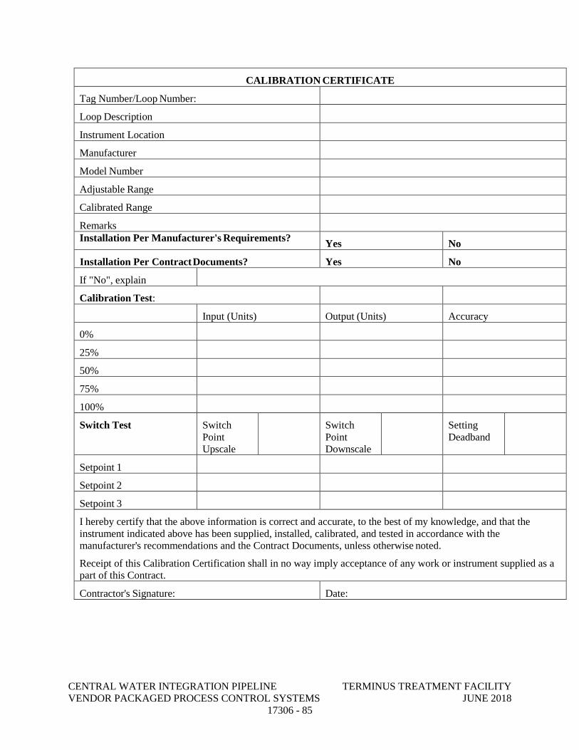
CENTRAL WATER INTEGRATION PIPELINE TERMINUS TREATMENT FACILITY VENDOR PACKAGED PROCESS CONTROL SYSTEMS JUNE 2018 17306 - 85
CALIBRATION CERTIFICATE
Tag Number/Loop Number:
Loop Description
Instrument Location
Manufacturer
Model Number
Adjustable Range
Calibrated Range
Remarks
Installation Per Manufacturer's Requirements? Yes No
Installation Per Contract Documents? Yes No
If "No", explain
Calibration Test:
Input (Units) Output (Units) Accuracy
0%
25%
50%
75%
100%
Switch Test Switch Point Upscale
Switch Point Downscale
Setting Deadband
Setpoint 1
Setpoint 2
Setpoint 3
I hereby certify that the above information is correct and accurate, to the best of my knowledge, and that the instrument indicated above has been supplied, installed, calibrated, and tested in accordance with the manufacturer's recommendations and the Contract Documents, unless otherwise noted.
Receipt of this Calibration Certification shall in no way imply acceptance of any work or instrument supplied as a part of this Contract.
Contractor's Signature: Date:
CENTRAL WATER INTEGRATION PIPELINE TERMINUS TREATMENT FACILITY VENDOR PACKAGED PROCESS CONTROL SYSTEMS JUNE 2018 17306 - 86
3.03 INSTALLATION
A. Any work not installed according to the Drawings and this Section shall be subject to change as directed by the Owner/Engineer. No extra compensation will be allowed for making these changes.
B. All dimensions shall be field verified at the job site and coordinated with the work of all other trades.
C. Equipment shall be protected at all times against mechanical injury or damage by water. Equipment shall not be stored outdoors. Equipment shall be stored in dry permanent shelters as required by each Specification Section. Do not install equipment in its permanent location until structures are weather-tight. If any apparatus has been subject to possible injury by water, Equipment shall be thoroughly dried out and tested as directed by the Owner/Engineer, or shall be replaced at no additional cost at the Owner/Engineer's discretion.
D. Equipment that has been damaged shall be replaced or repaired by the equipment manufacturer, at the Owner/Engineer's discretion.
E. Repaint any damage to the factory applied paint finish using touch-up paint furnished by the equipment manufacturer. If the metallic portion of the panel or section is damaged, the entire panel or section shall be replaced, at no additional cost to the Owner.
3.04 MANUFACTURER’S SERVICE
A. Provide manufacturer's services for testing and start-up of the equipment as listed Specification Section 11366.
B. Testing and startup shall not be combined with training. Testing and start-up time shall not be used for manufacturer’s warranty repairs.
C. Check interlocking, control and instrument wiring for each system and/or part of a system to prove that the system will function properly as indicated by schematics, wiring diagrams and Control Descriptions.
D. Testing shall be scheduled and coordinated with the Owner/Engineer at least six months in advance. Provide qualified test personnel, instruments and test equipment.
END OF SECTION
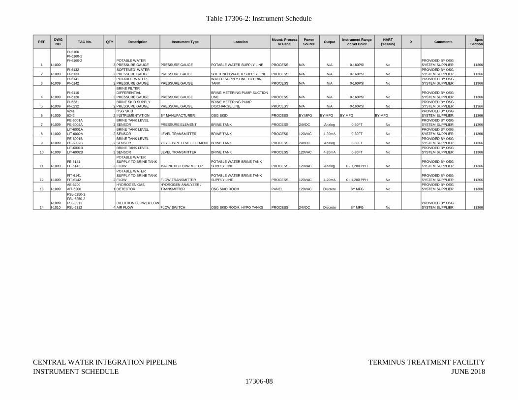
Table 17306-2: Instrument Schedule
REF DWG NO. TAG No. QTY Description Instrument Type Location Mount: Process
or PanelPower Source Output Instrument Range
or Set PointHART
(Yes/No) X Comments Spec Section
1 I-1009
PI-6160PI-6160-1PI-6160-2
3POTABLE WATER PRESSURE GAUGE PRESSURE GAUGE POTABLE WATER SUPPLY LINE PROCESS N/A N/A 0-160PSI No
PROVIDED BY OSG SYSTEM SUPPLIER 11366
2 I-1009PI-6132PI-6133 2
SOFTENED WATER PRESSURE GAUGE PRESSURE GAUGE SOFTENED WATER SUPPLY LINE PROCESS N/A N/A 0-160PSI No
PROVIDED BY OSG SYSTEM SUPPLIER 11366
3 I-1009PI-6141PI-6142 2
POTABLE WATER PRESSURE GAUGE PRESSURE GAUGE
WATER SUPPLY LINE TO BRINE TANK PROCESS N/A N/A 0-160PSI No
PROVIDED BY OSG SYSTEM SUPPLIER 11366
4 I-1009PI-6110PI-6120 2
BRINE FILTER DIFFERENTIAL PRESSURE GAUGE PRESSURE GAUGE
BRINE METERING PUMP SUCTION LINE PROCESS N/A N/A 0-160PSI No
PROVIDED BY OSG SYSTEM SUPPLIER 11366
5 I-1009PI-6231PI-6232 2
BRINE SKID SUPPLY PRESSURE GAUGE PRESSURE GAUGE
BRINE METERING PUMP DISCHARGE LINE PROCESS N/A N/A 0-160PSI No
PROVIDED BY OSG SYSTEM SUPPLIER 11366
6 I-100962416242 2
OSG SKID INSTRUMENTATION BY MANUFACTURER OSG SKID PROCESS BY MFG BY MFG BY MFG BY MFG
PROVIDED BY OSG SYSTEM SUPPLIER 11366
7 I-1009PE-6001APE-6002A 2
BRINE TANK LEVEL SENSOR PRESSURE ELEMENT BRINE TANK PROCESS 24VDC Analog 0-30FT No
PROVIDED BY OSG SYSTEM SUPPLIER 11366
8 I-1009LIT-6001ALIT-6002A 2
BRINE TANK LEVEL SENSOR LEVEL TRANSMITTER BRINE TANK PROCESS 120VAC 4-20mA 0-30FT No
PROVIDED BY OSG SYSTEM SUPPLIER 11366
9 I-1009PE-6001BPE-6002B 2
BRINE TANK LEVEL SENSOR YOYO TYPE LEVEL ELEMENT BRINE TANK PROCESS 24VDC Analog 0-30FT No
PROVIDED BY OSG SYSTEM SUPPLIER 11366
10 I-1009LIT-6001BLIT-6002B 2
BRINE TANK LEVEL SENSOR LEVEL TRANSMITTER BRINE TANK PROCESS 120VAC 4-20mA 0-30FT No
PROVIDED BY OSG SYSTEM SUPPLIER 11366
11 I-1009FE-6141FE-6142 2
POTABLE WATER SUPPLY TO BRINE TANK FLOW MAGNETIC FLOW METER
POTABLE WATER BRINE TANK SUPPLY LINE PROCESS 120VAC Analog 0 - 1,200 PPH No
PROVIDED BY OSG SYSTEM SUPPLIER 11366
12 I-1009FIT-6141FIT-6142 2
POTABLE WATER SUPPLY TO BRINE TANK FLOW FLOW TRANSMITTER
POTABLE WATER BRINE TANK SUPPLY LINE PROCESS 120VAC 4-20mA 0 - 1,200 PPH No
PROVIDED BY OSG SYSTEM SUPPLIER 11366
13 I-1009AE-6200AIT-6200 1
HYDROGEN GAS DETECTOR
HYDROGEN ANALYZER / TRANSMITTER OSG SKID ROOM PANEL 120VAC Discrete BY MFG No
PROVIDED BY OSG SYSTEM SUPPLIER 11366
14I-1009I-1010
FSL-6250-1FSL-6250-2FSL-6311FSL-6312 4
DILLUTION BLOWER LOW AIR FLOW FLOW SWITCH OSG SKID ROOM, HYPO TANKS PROCESS 24VDC Discrete BY MFG No
PROVIDED BY OSG SYSTEM SUPPLIER 11366
CENTRAL WATER INTEGRATION PIPELINE INSTRUMENT SCHEDULE
17306-88
TERMINUS TREATMENT FACILITYJUNE 2018
APPENDIX A
DIVISION 1
GENERAL REQUIREMENTS
CENTRAL WATER INTEGRATION PIPELINE TERMINUS TREATMENT FACILITY SUBMITTALS JUNE 2018 01300- 1
SECTION 01300
SUBMITTALS
PART 1 - GENERAL
1.01 DESCRIPTION OF WORK
A. This section describes the requirements for preparing and presenting submittals that are necessary for the execution of this contract. Requirements within the following subject areas are included:
1. Definitions.
2. Procedures.
3. Product Data.
4. Shop drawings.
5. Samples.
6. Manufacturer’s certificates.
7. Miscellaneous submittals.
8. Schedule of Values.
9. Quality Control Documentation (Blank Copies of Report).
1.02 DEFINITIONS
A. Product Data and Shop Drawing - General Definition
1. Drawings, diagrams, illustrations, brochures, schedules, bills of materials and other data prepared by the EARLY PROCUREMENT EQUIPMENT SUPPLIER (SUPPLIER), his subcontractors, suppliers or distributors, or equipment manufacturers and fabricators; illustrating the manufacture, fabrication, construction, or installation of the Work or a portion thereof.
B. Shop Drawings
1. Assembly and fabrication drawings, bills of materials for items shop fabricated exclusively for this project. In addition, shop drawings should show fabrication details of each part, the assembly of each part and how each part and/or assembly is integrated into the project including existing parts or assemblies.
CENTRAL WATER INTEGRATION PIPELINE TERMINUS TREATMENT FACILITY SUBMITTALS JUNE 2018 01300- 2
C. Manufacturer’s Representative
1. Manufacturer’s representative shall be from the manufacturer’s plant with five (5) years of experience in the actual problems of manufacturing, installing, and operating the particular product. Sales representatives or agents of the manufacturer will not be acceptable.
D. Working Drawings
1. SUPPLIER prepared plans for temporary structures and facilities. Working drawings for elements of work that may affect the safety and health of persons or property will be certified by an engineer licensed in the State of Texas. Calculations, as necessary, will accompany working drawings.
E. Design Calculations
1. Whenever the SUPPLIER is required to submit design calculations as part of a submittal, such calculations shall bear the signature and seal of a professional engineer registered in the appropriate branch. ENGINEER reserves the right to request submittal by SUPPLIER of a hard copy of design calculations.
1.03 PROCEDURES
A. Electronic Submittal Procedures
1. All electronic submittals shall be transmitted in Portable Document Format (PDF) as generated by the Adobe Acrobat Professional Version 7.0 or higher.
2. It will be the SUPPLIER’s responsibility to scan all necessary documents or convert previously received electronic files from vendors into pdf format before uploading the files to the specific designated project site. Scanned images must be at a readable resolution. For most documents, they should be scanned at 300 dots per inch (dpi). Optical character Recognition (OCR) capture must be performed on these images so that text can be searched and copied from the generated PDF file.
3. When it is not possible to make submittals electronically, SUPPLIER may deliver submittals to OWNER using conventional mail only after securing OWNER's written approval. When electronic submittals are not possible, hard copy submissions will be made as required in this section. Submittal of a transmittal page into the contract-specific Prolog site of Portal by SUPPLIER shall still be required for recordkeeping.
4. When electronic submittal is not possible and upon securing OWNER's written approval, SUPPLIER may submit hard copies of product data and shop drawings according to the following distribution list:
a. OWNER's designated Agent (if applicable): Three (3) copies.
b. OWNER (if a designated Agent reviews the submittals): One (1) copy.
c. ENGINEER: One (1) copy.
CENTRAL WATER INTEGRATION PIPELINE TERMINUS TREATMENT FACILITY SUBMITTALS JUNE 2018 01300- 3
5. If regular mail delivery is approved by OWNER, the submittal transmittal form shall still be logged into the contract specific Contract and Project Management System (CPMS) by SUPPLIER for record keeping purposes.
6. All responses to a submittal by ENGINEER will be made electronically and no hard copies of the response will be sent to SUPPLIER.
B. Supplier’s Responsibilities
1. Submit a list of specified submittals and identify the long lead items to the OWNER within five (5) calendar days of receipt of the Notice to Proceed (NTP).
2. Within 30 days after the pre-construction conference and at the same time that the initial critical path schedule is submitted, a schedule shall be submitted of the items of materials and equipment for which shop drawings are required by the specifications. For each required shop drawing, the date shall be given for intended submission of the drawing to ENGINEER for review and the date required for its return to avoid delay in any activity beyond the scheduled start date. Sufficient time shall be allowed for initial review, correction and resubmission, and final review of all shop drawings. In no case shall a schedule be acceptable which allows less than 21 days for each review by ENGINEER.
3. SUPPLIER to approve all submittals prior to submission.
4. SUPPLIER shall submit dimensional and layout drawings and product data, certified correct for construction, for review by the ENGINEER.
5. Submit shop drawings and product data in accordance with the approved submittal schedule. Also, submit shop drawings to the ENGINEER for review prior to their need in the Work, allowing sufficient time for the ENGINEER’s review and the SUPPLIER response.
6. SUPPLIER shall make specific mention of those items that vary from the requirements of the Contract Documents in the letter of transmittal. The letter transmittal shall include the specification number, detail name/number, or plan sheet of the item being submitted.
7. Submit shop drawings and product data covering related items of equipment or material or integrated systems of equipment or material at the same time. Partial submissions will not be accepted.
8. All submittals, regardless of origin, shall be stamped with the approval of SUPPLIER and identified with the name and number of this contract, SUPPLIER name, and references to applicable specification paragraphs and Contract Drawings. Each submittal shall indicate the intended use of the item in the Work. When catalog pages are submitted, applicable items shall be clearly identified and inapplicable data crossed out. The current revision, issue number, and date shall be indicated on all drawings and other descriptive data.
9. SUPPLIER shall be solely responsible for the completeness of each submission. SUPPLIER stamp of approval is a representation to OWNER that SUPPLIER accepts sole responsibility for determining and verifying all quantities, dimensions, field construction criteria,
CENTRAL WATER INTEGRATION PIPELINE TERMINUS TREATMENT FACILITY SUBMITTALS JUNE 2018 01300- 4
materials, catalog number, and similar data, and that SUPPLIER has reviewed and coordinated each submittal with the requirements of the Work and the Contract Documents.
10. SUPPLIER shall coordinate shop drawings and product data with drawings previously submitted, with drawings being prepared, and with drawings and data previously approved. All such coordination shall be indicated by reference.
11. SUPPLIER shall assign a sequential number to each submittal.
a. Assignment of numbers shall be by means of a letter prefix, a sequence number, a letter suffix to indicate resubmittals and a specification number. For example, submittal SD-012C-01300 is the third re-submittal of the twelfth Shop Drawing for the Project.
b. The sequence number shall be issued in chronological order. Resubmittals shall be followed by a letter of the alphabet to indicate the number of times a submittal has been resubmitted to the ENGINEER for processing. As an example, a shop drawing with the number SD-001 indicates that the submittal is the first shop drawing submitted for the project. Shop Drawing Number SD-002A indicates that the submittal is the second shop drawing submitted for and is being submitted for the second time. Acceptable prefixes for submittals are as follows:
i. SD -Shop Drawing ii. PS – Project Schedule
iii. RD – Record Data iv. OM – Operation and Maintenance Manual
c. Correct assignment of numbers is essential as different submittal types are processed in different ways. Some submittals received do not require that any response be given for the material. SUPPLIER and ENGINEER shall both maintain a log of submissions to allow the processing of SUPPLIER's submittals to be monitored. Logs will be reviewed periodically to determine that all submittals are received and processed.
d. Submittals shall be marked to show clearly the applicable sections of the specification and sheet number of drawings.
e. Submittals shall be accompanied by a Submittal Transmittal Form to be provided by the OWNER. A separate form shall be used for each specific item, class of material, equipment, and items specified in separate discrete sections, etc. for which a submittal is required. Submittals for various items shall be made with a single form when the items taken together constitute a manufacturer's package or are so functionally related that they should be.
12. SUPPLIER shall not deliver to the site, storage, or incorporate into the Work, any materials or equipment for which approved submittals have not been obtained.
13. If a submittal is returned to the SUPPLIER marked “NO EXCEPTIONS NOTED”, formal revision and resubmission shall not be required. SUPPLIER may proceed to perform submittal related Work.
CENTRAL WATER INTEGRATION PIPELINE TERMINUS TREATMENT FACILITY SUBMITTALS JUNE 2018 01300- 5
14. If a submittal is returned marked “EXCEPTIONS NOTED”, SUPPLIER shall make the corrections on the submittal, but formal revision and resubmission shall not be required and the SUPPLIER shall proceed with the Work.
15. If a submittal is returned marked “RETURNED FOR CORRECTION,” the SUPPLIER shall revise it and resubmit to the OWNER for review. Resubmittal and a grade of “NO EXCEPTIONS NOTED” or “EXCEPTIONS NOTED” is required before the SUPPLIER may proceed with the Work, unless approved in writing by the OWNER. Resubmittal of portions of multi-page or multi-drawing submittals shall not be allowed. For example, if a Shop Drawing submittal consisting of 10 drawings contains one drawing noted as “RETURNED FOR CORRECTION”, the submittal as a whole is deemed “RETURNED FOR CORRECTION”, and all 10 drawings are required to be resubmitted.
16. If a submittal is returned marked “NOT ACCEPTABLE,” it shall mean either that the submitted material or product does not satisfy the Specification, the submittal is so incomplete that it cannot be reviewed, or it is a substitution request not in accordance with the General Conditions of the Contract. SUPPLIER shall prepare and deliver a new submittal to the ENGINEER for review.
17. Resubmittal of rejected portions of a previous submittal shall not be allowed. When resubmittals are needed, every change from a submittal to a resubmittal or from a resubmittal to a subsequent resubmittal shall be clearly identified and flagged on the resubmittal by SUPPLIER.
18. When resubmittals are needed, resubmittals shall be made within 30 days of the date on which documents to be modified or corrected were posted on CPMS by ENGINEER or its designated reviewer (electronic submittals) or of the postmark date of the letter returning the material (if a hard copy-type submittal was approved by OWNER), whichever is later. A time extension shall be considered by ENGINEER only if within the required number of days SUPPLIER submits an acceptable request for an extension of time, listing the reasons why the resubmittal cannot be completed within the stipulated time.
19. The need for more than one resubmittal, or any other delay in obtaining ENGINEER’s review of submittals, shall not entitle SUPPLIER to extension of the Contract Times unless delay of the Work is the direct result of a change in the Work authorized by a Change Order or failure of OWNER to review and return any submittal to SUPPLIER within the specified review period.
20. SUPPLIER shall not deliver to the site, store, or incorporate into the Work, any materials or equipment for which approved submittals have not been obtained.
21. When electronic submittals are not possible, hard copy submissions shall be made as required in this Section. Submittal of a transmittal form into the contract-specific web-based project management system by SUPPLIER shall still be required for record keeping.
22. SUPPLIER is responsible for frequent monitoring of the web-based documents and the submittal process status.
C. ENGINEER Responsibility
CENTRAL WATER INTEGRATION PIPELINE TERMINUS TREATMENT FACILITY SUBMITTALS JUNE 2018 01300- 6
1. ENGINEER will conduct a thorough review within 21 calendar days after its receipt in CPMS so as not to create delay. This review will be for general conformance, subject to the requirements of the Contract Documents, and will be an effort to assist the SUPPLIER to discover errors and omissions in submittals. ENGINEER review, approval, or other appropriate action regarding SUPPLIER submissions will be only to check conformity with the design concept of the Project and for compliance with the information contained in the Contract Documents and shall not extend to means, methods, techniques, sequences or procedures of construction (except where a specific means, method, technique, sequence or procedure of construction is indicated in or required by the Contract Documents) or to safety precautions or programs incident thereto. The review and approval of a separate component item will not indicate approval of the assembly into which the item is functionally integrated. SUPPLIER shall make corrections required by ENGINEER, and shall return the required number of corrected copies of Shop Drawings to the OWNER. SUPPLIER may be required to resubmit, as required, revised Shop Drawings or Samples for further review and approval. SUPPLIER shall direct specific attention in writing to any new revisions not specified by SUPPLIER on previous SUPPLIER submissions.
2. ENGINEER review does not relieve the SUPPLIER of the obligation and responsibility to coordinate the Work and plan the details of the Work.
3. The OWNER reserves the right to require written confirmation from the SUPPLIER that the comments placed on submittals stamped "Exceptions Noted" will actually be followed.
4. Review by the ENGINEER will not be construed as relieving the SUPPLIER of the responsibility for the accuracy, proper fit, functioning, or performance of the Work.
1.04 PRODUCT DATA
A. Product data, including materials reproduced from manufacturer’s product catalogs will not be larger than 8 ½" by 11" in size.
B. Catalog data will be explicit with regards to the name of the manufacturer and to the details of the products being furnished. It will also be complete enough to enable the OWNER to determine that the products being submitted conform to the requirements of the Specifications.
C. For submittals with more than one style or size of a product on a sheet, the SUPPLIER will clearly indicate which product is being submitted for review.
D. SUPPLIER will provide electronic submittals in .pdf format of all product data to the OWNER. Files shall be readable using Adobe Acrobat Reader Version 7.0.
1.05 SHOP DRAWINGS
A. SUPPLIER shall reasonably check and verify all field measurements and will submit to the OWNER for review and approval. These shop drawings will bear a stamp from the SUPPLIER that indicates that the SUPPLIER has reviewed the shop drawings and that the submittal is complete and in compliance with Contract Documents.
CENTRAL WATER INTEGRATION PIPELINE TERMINUS TREATMENT FACILITY SUBMITTALS JUNE 2018 01300- 7
B. Substitute and “Or Approved Equal” Items: Meet requirements of Paragraph 5.12 of the General Conditions.
C. SUPPLIER will submit detailed drawings and descriptions of proposed deviations from details or component arrangement indicated on the Plans.
D. Single line drawings will not be acceptable. Copies of the Plans will not be accepted for submission as drawings, nor will catalog numbers alone of materials or equipment.
E. SUPPLIER will submit electronic copies in .pdf format of each shop drawing to the OWNER for review. Files shall be readable using Adobe Acrobat Reader 7.0.
1.06 SAMPLES
A. SUPPLIER will furnish samples of items and materials as required. Samples shall be submitted to the OWNER in duplicate. Each sample will be properly labeled and identified by providing the following:
1. Date.
2. Job name for which it is offered.
3. Specification section and paragraph.
4. SUPPLIER’s name.
5. Supplier and trade name.
6. Other data indicating conformance to the Specifications.
7. Color charts or samples with manufacturer’s number.
1.07 MANUFACTURER’S CERTIFICATES AND AFFIDAVITS
A. Where specified in the Contract Documents that a certificate and affidavit shall be submitted to the OWNER for review of a particular product, or component of a product, such submittals shall be made in accordance with the following:
1. A certificate submitted for a product, or component of a product, indicates test results proving that product, or component of a product, meets the requirements of the standard specified in the Contract Documents.
2. An affidavit consisting of a sworn statement by an official of the company manufacturing the product indicating that the information on the certificate is true and accurate shall accompany the certificate.
3. A statement from the SUPPLIER, or his subcontractors, suppliers, or other agent which indicates that a particular item of equipment, product, or component of a product, meets the
CENTRAL WATER INTEGRATION PIPELINE TERMINUS TREATMENT FACILITY SUBMITTALS JUNE 2018 01300- 8
requirements of the Contract Documents shall not be considered a certificate and will not be approved.
1.08 MANUFACTURER'S REPRESENTATIVE
A. SUPPLIER will include in the Contract Price the cost of furnishing competent and experienced manufacturer’s representatives who will represent the manufacturer on products finished and to assist the SUPPLIER to install the products in conformity with the Contract Documents.
1.09 MISCELLANEOUS SUBMISSIONS
A. Provide the following submissions electronically using the designated project website (to be defined during the initial construction meeting). Files shall be readable using Adobe Acrobat Reader 7.0. Provide hard copies as requested by OWNER.
1. Work plans.
2. Quality Control (QC) Plan.
(i) QC Plan must be submitted and approved prior to commencing Work.
3. Accident reports.
4. Inspection and test reports.
5. Guarantees and warranties.
6. Operation and Maintenance Manuals.
7. Course of Action Plan (Fuel Spill or Other Substances).
(i) SUPPLIER must submit the Course of Action Plan (Fuel Spill or Other Substances) to the OWNER prior to start of construction.
(ii) With regard to the accidental spill of fuel, the Plan must address the procedures required by applicable regulations and laws.
8. SUPPLIER’s Safety and Health Plan.
PART 2 PRODUCTS – NOT USED
PART 3 EXECUTION – NOT USED
END OF SECTION
CENTRAL WATER INTEGRATION PIPELINE TERMINUS TREATMENT FACILITY MATERIAL AND EQUIPMENT JUNE 2018 01600- 1
SECTION 01600
MATERIAL AND EQUIPMENT PART 1 GENERAL
1.01 DESCRIPTION OF WORK
A. This Section describes the requirements for material and equipment that are necessary for the execution of this contract. Requirements within the following subject areas are included:
1. Products.
2. Preparation for shipment.
3. Packaging and delivery of spare parts and tools.
4. Shipment and handling.
5. Inspection
6. Storage and protection
7. Inventory control.
8. Product options.
9. Substitutions.
10. Systems demonstration.
11. Warranties.
1.02 PRODUCTS
A. The term "products" means new material, machinery, components, equipment, fixtures, and systems forming the Work. It does not include machinery and equipment used for preparation, fabrication, conveying, and erection of the Work. Products may also include existing materials or components required for reuse.
B. Do not use materials and equipment salvaged from this project, except as specifically permitted by the Plans.
C. Materials and equipment to be provided under this contract shall be standard catalogue products of manufacturers regularly engaged in the manufacture of the products and shall duplicate material and equipment in satisfactory service for at least two (2) years.
D. Material and equipment shall meet the requirements of the Contract and shall be suitable for the installation for which they are planned. Where two (2) or more of the same equipment class are furnished, the equipment shall be from the same manufacturer and shall be interchangeable. Materials and equipment shall be new and free from defects.
E. Materials and equipment shall be installed in accordance with the requirements of the Plans and approved recommendations of the manufacturer.
CENTRAL WATER INTEGRATION PIPELINE TERMINUS TREATMENT FACILITY MATERIAL AND EQUIPMENT JUNE 2018 01600- 2
1.03 PREPARATION FOR SHIPMENT
A. When practical, equipment shall be factory assembled. The equipment parts and assemblies that are shipped unassembled shall be furnished with an assembly plan and instructions. The separate parts and assemblies will be match-marked or tagged in a manner to facilitate field assembly.
B. Generally, machined and unpainted parts subject to damage by the elements shall be protected with an application of a strippable protective coating.
C. Equipment shall be packaged or crated in a manner that will provide protection from damage during shipping, handling, and storage.
D. The outside of the package or crate shall be adequately marked or tagged to indicate its contents by name and equipment number, if applicable, approximate weight, special handling precautions, and recommended storage procedures.
1.04 PACKAGING AND DELIVERY OF SPARE PARTS AND SPECIAL TOOLS
A. Spare parts and special tools shall be properly marked to identify the associated equipment by name, equipment type, and part number. Parts shall be packaged in a manner for protection against damage from the elements during shipping, handling, and storage. Spare parts and special tools shall be shipped in boxes that shall be marked to indicate the contents. Delivery of spare parts and special tools shall be made prior to the time the associated equipment is scheduled for its initial test run.
1.05 SHIPMENT AND HANDLING
A. Shipments shall be addressed to the CONTRACTOR who will be responsible for their receipt, unloading, handling, and storage at the site. The OWNER will not accept deliveries on behalf of the CONTRACTOR or his subcontractors nor assume responsibility for the security of the materials, equipment, or supplies delivered to the site.
B. CONTRACTOR will transport and handle products in accordance with manufacturer’s instructions.
C. Provide equipment and personnel to handle products by methods to prevent soiling, disfigurement, or damage.
1.06 INSPECTION
A. Immediately upon receipt of equipment and materials at the job site, the CONTRACTOR will inspect for completeness and any evidence of damage. Should there appear to be any damage, the CONTRACTOR will immediately notify the Construction Observer/Inspector (COI). CONTRACTOR will then be responsible for notifying the manufacturers and the transportation company of the extent of the damage. If the item or items require replacing, the CONTRACTOR will take the necessary measures for replacement.
CENTRAL WATER INTEGRATION PIPELINE TERMINUS TREATMENT FACILITY MATERIAL AND EQUIPMENT JUNE 2018 01600- 3
1.07 STORAGE AND PROTECTION
A. CONTRACTOR will store products in accordance with the manufacturer’s instructions, with
seals and labels intact and legible. Sensitive items will be stored in weather-tight enclosures; with the humidity and temperature maintained within the ranges recommended by the manufacturer.
B. For exterior storage of fabricated products, the CONTRACTOR will place on sloped supports above ground. Products that are subject to deterioration will be covered with an impervious sheet and will be supplied with adequate ventilation to avoid condensation.
C. CONTRACTOR will store loose granular materials on solid surfaces in a well-drained area in such a manner as to prevent mixing.
D. CONTRACTOR shall arrange to provide access for inspection. He will also periodically inspect to ensure products are undamaged and are maintained under required conditions.
1.08 INVENTORY CONTROL
A. Equipment and materials shall be stored in a manner to provide easy access for inspection and inventory control. CONTRACTOR shall keep a running account of all materials in storage to facilitate inspection and to estimate progress payments for materials delivered but not installed in the Work.
1.09 PRODUCT OPTIONS
A. CONTRACTOR has the following options in providing products specified for the Work:
1. Products specified by reference standards or by description only: CONTRACTOR may provide any product meeting the standard.
2. Products specified by naming one or more manufacturers: CONTRACTOR may provide the product from the named manufacturer or he may submit a request for substitution for any manufacturer not specifically named.
1.10 SUBSTITUTIONS
A. Only after execution of the Contract will the OWNER consider requests from the CONTRACTOR for substitutions. Substitutions will be considered only when a product becomes unavailable due to no fault of the CONTRACTOR or is shown to be superior to the specified product.
B. CONTRACTOR will document each request with complete data substantiating compliance of proposed substitution with the Contract Documents. Each request constitutes a declaration from the CONTRACTOR that:
1. CONTRACTOR has investigated the proposed product and determined that it meets or exceeds, in all respects, the specified product.
CENTRAL WATER INTEGRATION PIPELINE TERMINUS TREATMENT FACILITY MATERIAL AND EQUIPMENT JUNE 2018 01600- 4
2. CONTRACTOR will provide the same warranty for substitution as for the specified product.
3. CONTRACTOR will coordinate installation and make all other changes, which may be required for the Work to be complete in all respects.
4. CONTRACTOR waives claims for additional costs and/or time, which may subsequently become apparent.
C. Substitutions will not be considered when they are indicated or implied on shop drawings or
product data submittals without a separate written request, or when acceptance will require substantial revision of the Contract Documents.
D. OWNER will determine acceptability of proposed substitution, and will notify CONTRACTOR of acceptance or rejection in writing within a reasonable period of time.
E. Only one request for substitution will be considered for each product. When substitution is not accepted, the CONTRACTOR will provide the specified product.
1.11 SYSTEMS DEMONSTRATION
A. Prior to final inspection, demonstrate operation of each system to the OWNER.
B. CONTRACTOR will instruct the OWNER's personnel in operation, adjustment, and maintenance of equipment and systems, using the operation and maintenance data as the basis of instruction.
PART 2 PRODUCTS – NOT USED PART 3 EXECUTION – NOT USED
END OF SECTION
CENTRAL WATER INTEGRATION PIPELINE TERMINUS TREATMENT FACILITY MANUFACTURER’S FIELD SERVICES JUNE 2018 01640 - 1
SECTION 01640
MANUFACTURER’S FIELD SERVICES PART 1 GENERAL 1.01 SCOPE
This section shall govern the requirements established for MANUFACTURER’S field services associated with the installation of equipment.
1.02 RELATED WORK
A. Section 01300 – Submittals
B. Section 01600 – Material and Equipment
C. Section 01752 – Facility Start Up/Commissioning Requirements
1.03 DESCRIPTION OF WORK
CONTRACTOR shall arrange for and coordinate the MANUFACTURER’S services as specified below.
1.04 1.04 SUBMITTALS
A. Training Plan (Pre Start Up and Post Start Up):
1. Submit not less than 21 calendar days prior to start of equipment testing and revise as necessary for OWNER’s acceptance.
2. Submit MANUFACTURER’S tentative training schedule, training plan, and contact person not less than 60 calendar days prior to commencement of any training.
a. MANUFACTURER’S proposed Training Plan shall include the elements presented in the Outline of Instruction Training Plan specified herein. Specific components and procedures shall be identified in the proposed Training Plan. Hands-on demonstrations planned for the instruction shall be described in the Training Plan. The MANUFACTURER shall indicate the estimated duration of each segment of the Training Plan.
b. Outline of Instruction Training Plan:
i. Equipment Description and Purpose
ii. Equipment operation
iii. Detailed component description
CENTRAL WATER INTEGRATION PIPELINE TERMINUS TREATMENT FACILITY MANUFACTURER’S FIELD SERVICES JUNE 2018 01640 - 2
iv. Equipment preventative maintenance (PM)
v. Equipment troubleshooting
vi. Equipment corrective maintenance
3. Provide complete training materials, to include operation and maintenance data as required in this section to be retained by each trainee.
B. Quality Control Submittals:
1. MANUFACTURER’S Certificate of Proper Installation:
a. When specified in the individual equipment specification sections or Equipment Schedule, submit certificate certifying:
i. The product or system has been installed in accordance with the MANUFACTURER’S recommendations, inspected by a MANUFACTURER’S authorized representative, and serviced with the proper lubricants.
ii. Necessary safety equipment has been properly installed.
iii. Electrical and mechanical connections have been made meeting quality and safety standards as required.
iv. Free from undue stress imposed by exterior connections or loads.
v. Proper adjustments have been made and the product or system is ready for testing, facilities startup, operational test, and operation.
b. Submit MANUFACTURER’S Certificated of Proper Installation Form at end of this Specification.
4. Certificate of Successful Equipment Testing: Prepare and submit where specified in individual equipment specification sections or Equipment Schedule, and upon completion of successful testing of respective equipment by the CONTRACTOR. See Certificate of Successful Equipment Testing Form at end of this Specification.
5. Certificate of Successful Equipment System, Subsystem or Component, Start Up Testing including Functional and Performance Tests: Prepare and submit where specified in individual equipment specification sections or Equipment Schedule, and upon completion of successful Start Up testing of respective equipment system, subsystem or component by the CONTRACTOR. See Certificate of Successful Equipment System, subsystem or component Start Up Testing Form at end of this Specification.
6. Certificate of qualification of MANUFACTURER’S representative.
CENTRAL WATER INTEGRATION PIPELINE TERMINUS TREATMENT FACILITY MANUFACTURER’S FIELD SERVICES JUNE 2018 01640 - 3
1.05 QUALIFICATION OF MANUFACTURER’S REPRESENTATIVE
Authorized representative of the MANUFACTURER, Certified by MANUFACTURER, factory trained, and experienced in the technical applications, installation, operation, and maintenance of respective equipment, system, subsystem, or component. Representative subject to acceptance by OWNER. No substitute representatives will be allowed unless prior written approval by OWNER has been given.
1.06 FULFILLMENT OF SPECIFIED MINIMUM SERVICES
A. Where MANUFACTURER’S field services are specified, furnish MANUFACTURER’S representative qualified to provide these services. Where time is necessary in excess of that stated in the Contract Documents for MANUFACTURER’S' field services, additional time required to perform the specified services shall be considered incidental work.
B. Coordinate and Schedule MANUFACTURER’S field services to avoid conflicting with other field testing or other MANUFACTURER’S field services. Determine that all conditions necessary to allow successful testing have been met before scheduling field services.
C. Only those days of service approved by OWNER will be credited to fulfill the specified minimum services.
D. If specified, MANUFACTURER’S field services shall include as a minimum:
1. Assistance during installation to include observation, guidance, instruction of CONTRACTOR's assembly, erection, installation or application procedures.
2. Inspection, checking, and adjustment as required for equipment to function as warranted by MANUFACTURER and necessary to provide written approval of installation.
3. Revisiting the site as required to correct problems and until installation and operation are acceptable to OWNER.
4. Resolution of assembly or installation problems attributable to, or associated with, respective MANUFACTURER’S products, equipment, system, subsystem and components.
5. Assistance during testing and Start Up demonstration, and until product acceptance by the OWNER.
6. Training of OWNER's personnel in the operation and maintenance of respective products as required herein.
7. Completion of MANUFACTURER’S Certificate of Proper Installation and applicable certificates of Successful Equipment Testing and Successful Equipment System, Subsystem or Component Start Up Testing, as required, including functional and performance tests service. (Forms at the end of this Specification)
CENTRAL WATER INTEGRATION PIPELINE TERMINUS TREATMENT FACILITY MANUFACTURER’S FIELD SERVICES JUNE 2018 01640 - 4
1.07 TRAINING SCHEDULE
A. List specified equipment, system, subsystem, and component with respective MANUFACTURERs that require training services of MANUFACTURER’S representatives and show:
1. Estimated dates for installation completion.
2. Estimate training dates to allow for multiple sessions when several shifts are involved.
3. Use Equipment Schedule as guidance and revise as needed to meet individual equipment specifications or MANUFACTURER’S requirements for the preparation of estimated dates. Dates must be included as milestones on general project schedule, and must be coordinated as to allow completion of the project including Start Up Phase by Substantial Completion Date.
B. Adjust training schedule to ensure training of appropriate personnel as deemed necessary by OWNER and to allow full participation by MANUFACTURER’S representatives. Adjust schedule for interruptions in operability of equipment.
C. Training shall not proceed until all individual equipment, systems, subsystems or components have been installed and approved by the MANUFACTURER and completed the testing requirements indicated in specification 01650.
D. Pre Start Up Training:
1. Coordinate and furnish classroom training sessions with the OWNER's operating personnel and MANUFACTURER’S representatives.
2. Conduct training prior to as defined in Specification Section 01752 – Facility Start-up/Commissioning Requirements.
3. Provide Draft O&M Manuals.
E. Post Start Up Training:
1. Coordinate and furnish on-site training sessions with the OWNER’s operating personnel and MANUFACTURER’S representatives.
2. Conduct after Facility Start Up, but prior to Operational Testing of the equipment as defined in Specification Section 01752.
3. Provide Final O&M Manuals.
1.08 TRAINING OWNER'S PERSONNEL
A. Provide trained, articulate personnel acceptable to the OWNER to coordinate and expedite training, to be present during training coordination meetings with OWNER and familiar with operation and maintenance manual information.
CENTRAL WATER INTEGRATION PIPELINE TERMINUS TREATMENT FACILITY MANUFACTURER’S FIELD SERVICES JUNE 2018 01640 - 5
B. MANUFACTURER’S Representative shall provide the number of days of training for equipment as indicated in the Equipment Schedule section. Operator training days shall be in addition to MANUFACTURER’S field services required as indicated in the Equipment Schedule and submittals sections.
1. All training will be performed during the operating staff's normal business hours and at other times requested and approved by the OWNER.
C. MANUFACTURER’S representatives to provide detailed training to OWNER's personnel on operation and maintenance of specified product (equipment, system, subsystem, and component) and as required in applicable Contract Documents. This includes operation, disassembly, and assembly of major equipment items, start up, shutdown, safety concerns, troubleshooting, installation, alignment, and recommended corrective and preventative maintenance procedures for all equipment.
1. Training services include Pre Start Up classroom instruction and Post Start Up onsite hands-on instruction.
2. MANUFACTURER’S Representative shall be familiar with system operation and maintenance requirements for specified equipment, system, subsystem, or component.
D. Taping of Training Sessions: MANUFACTURER to videotape Pre Start and Post Start Up training sessions and furnish to the OWNER.
PART 2 - PRODUCTS (NOT USED)
PART 3 - EXECUTION (NOT USED)
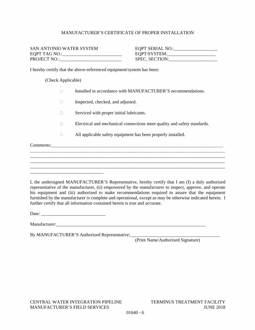
CENTRAL WATER INTEGRATION PIPELINE TERMINUS TREATMENT FACILITY MANUFACTURER’S FIELD SERVICES JUNE 2018 01640 - 6
MANUFACTURER’S CERTIFICATE OF PROPER INSTALLATION SAN ANTONIO WATER SYSTEM EQPT SERIAL NO.:___________________ EQPT TAG NO.:__________________________ EQPT/SYSTEM:_____________________ PROJECT NO.:___________________________ SPEC. SECTION:_____________________ I hereby certify that the above-referenced equipment/system has been: (Check Applicable) � Installed in accordance with MANUFACTURER’S recommendations. � Inspected, checked, and adjusted. � Serviced with proper initial lubricants. � Electrical and mechanical connections meet quality and safety standards. � All applicable safety equipment has been properly installed. Comments:_______________________________________________________________________________________________________________________________________________________________________________________________________________________________________________________________________________________________________________________________________________________________________________________________________________________________________________________________ I, the undersigned MANUFACTURER’S Representative, hereby certify that I am (I) a duly authorized representative of the manufacturer, (ii) empowered by the manufacturer to inspect, approve, and operate his equipment and (iii) authorized to make recommendations required to assure that the equipment furnished by the manufacturer is complete and operational, except as may be otherwise indicated herein. I further certify that all information contained herein is true and accurate. Date: ____________________________ Manufacturer:_________________________________________________________________ By MANUFACTURER’S Authorized Representative:_______________________________________ (Print Name/Authorized Signature)
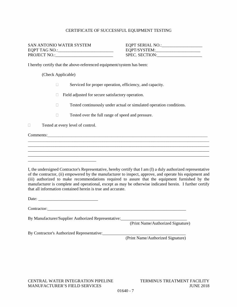
CENTRAL WATER INTEGRATION PIPELINE TERMINUS TREATMENT FACILITY MANUFACTURER’S FIELD SERVICES JUNE 2018 01640 - 7
CERTIFICATE OF SUCCESSFUL EQUIPMENT TESTING SAN ANTONIO WATER SYSTEM EQPT SERIAL NO.:___________________ EQPT TAG NO.:__________________________ EQPT/SYSTEM:_____________________ PROJECT NO.:___________________________ SPEC. SECTION:_____________________ I hereby certify that the above-referenced equipment/system has been: (Check Applicable) � Serviced for proper operation, efficiency, and capacity.
� Field adjusted for secure satisfactory operation. � Tested continuously under actual or simulated operation conditions. � Tested over the full range of speed and pressure. � Tested at every level of control. Comments:_______________________________________________________________________________________________________________________________________________________________________________________________________________________________________________________________________________________________________________________________________________________________________________________________________________________________________________________________ I, the undersigned Contractor's Representative, hereby certify that I am (I) a duly authorized representative of the contractor, (ii) empowered by the manufacturer to inspect, approve, and operate his equipment and (iii) authorized to make recommendations required to assure that the equipment furnished by the manufacturer is complete and operational, except as may be otherwise indicated herein. I further certify that all information contained herein is true and accurate. Date: ____________________________ Contractor:_________________________________________________________________ By Manufacturer/Supplier Authorized Representative:_______________________________ (Print Name/Authorized Signature) By Contractor's Authorized Representative:_______________________________________ (Print Name/Authorized Signature)
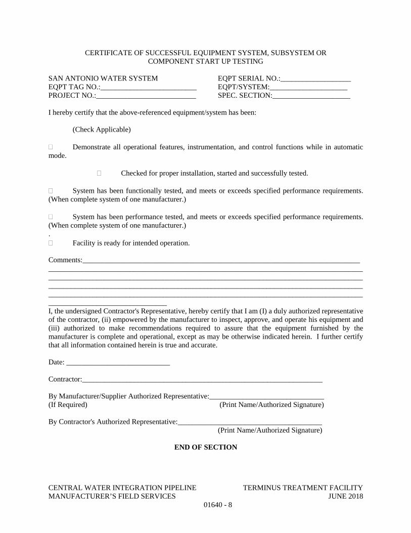
CENTRAL WATER INTEGRATION PIPELINE TERMINUS TREATMENT FACILITY MANUFACTURER’S FIELD SERVICES JUNE 2018 01640 - 8
CERTIFICATE OF SUCCESSFUL EQUIPMENT SYSTEM, SUBSYSTEM OR COMPONENT START UP TESTING
SAN ANTONIO WATER SYSTEM EQPT SERIAL NO.:___________________ EQPT TAG NO.:__________________________ EQPT/SYSTEM:_____________________ PROJECT NO.:___________________________ SPEC. SECTION:_____________________ I hereby certify that the above-referenced equipment/system has been: (Check Applicable) � Demonstrate all operational features, instrumentation, and control functions while in automatic mode. � Checked for proper installation, started and successfully tested. � System has been functionally tested, and meets or exceeds specified performance requirements. (When complete system of one manufacturer.) � System has been performance tested, and meets or exceeds specified performance requirements. (When complete system of one manufacturer.) . � Facility is ready for intended operation. Comments:_______________________________________________________________________________________________________________________________________________________________________________________________________________________________________________________________________________________________________________________________________________________________________________________________________________________________________________________________ I, the undersigned Contractor's Representative, hereby certify that I am (I) a duly authorized representative of the contractor, (ii) empowered by the manufacturer to inspect, approve, and operate his equipment and (iii) authorized to make recommendations required to assure that the equipment furnished by the manufacturer is complete and operational, except as may be otherwise indicated herein. I further certify that all information contained herein is true and accurate. Date: ____________________________ Contractor:_________________________________________________________________ By Manufacturer/Supplier Authorized Representative:_______________________________ (If Required) (Print Name/Authorized Signature) By Contractor's Authorized Representative:_______________________________________ (Print Name/Authorized Signature)
END OF SECTION
CENTRAL WATER INTEGRATION PIPELINE TERMINUS TREATMENT FACILITY OPERATION AND MAINTENANCE DATA JUNE 2018 01730 - 1
SECTION 01730
OPERATION AND MAINTENANCE DATA
PART 1 GENERAL
1.01 DEFINITIONS
A. Maintenance Operation: As used in the Maintenance Summary Form, attached to this specification, maintenance operation is defined to mean any routine operation required to ensure satisfactory performance and longevity of equipment. Examples of typical maintenance operations are lubrication, belt tensioning, adjustment of pump packing glands, and routine adjustments.
B. System and Subsystem: Refer to Section 01652 – System Operation and Section 01752 – Facility Startup and Commissioning Requirements.
1.02 QUALITY ASSURANCE
A. Manuals for equipment and systems shall be prepared by equipment manufacturer or system Supplier.
1.03 SEQUENCING AND SCHEDULING
A. Manual Outline: Submit detailed outline of each manual prior to preparation of Preliminary Manuals.
B. Manuals for Equipment and Systems:
1. Preliminary Manuals: Submit prior to shipment date for equipment, system, subsystem, or component. Include copy of warranties, bonds, and service agreements if specified.
2. Final Manuals: Submit not less than 30 days prior to equipment or system field testing or startup.
C. Manuals for Materials and Finishes:
1. Preliminary Manuals: Submit at least 30 days prior to request for final inspection.
2. Final Manuals: Submit within 10 days after final inspection.
1.04 GENERAL
A. Furnish for each item of equipment or system as specified in the individual Specification sections.
B. Prepare data for use by OWNER's personnel in the form of an instructional manual in both paper format and on electronic media. Data for electronic media shall be provided to OWNER on optical compact disc.
CENTRAL WATER INTEGRATION PIPELINE TERMINUS TREATMENT FACILITY OPERATION AND MAINTENANCE DATA JUNE 2018 01730 - 2
C. Manual Format:
1. Size: 8-1/2 inches x 11 inches.
2. Paper: 20-pound minimum, white for typed pages.
3. Text: Manufacturer's printed data, or neatly typewritten.
4. Three-hole punch data for binding and composition; arrange printing so that punched holes do not obliterate data.
5. Provide flyleaf for each separate product or each piece of operating equipment, with typed description of product and major component parts of equipment and provide with heavy section dividers with numbered plastic index tabs.
6. Provide each manual with title page, and typed table of contents with consecutive page numbers. Place contents of entire set, identified by volume number, in each binder.
7. Cover: Identify each volume with typed or printed title “OPERATION AND MAINTENANCE MANUAL, VOLUME NO. – OF – ”, if applicable, and list:
a. Project title.
b. Designate the system or equipment for which it is intended.
c. Identity of separate structure as applicable.
d. Identity of equipment number and Specification section.
8. Assemble and bind material in same order as specified, as much as possible.
9. Final copy shall not have fax copies or photocopies of manufacturer information. Each manual shall have original materials.
10. Binders:
a. Preliminary Manuals: Heavy paper covers.
b. Final Manuals: Commercial quality, substantial, permanent, three-ring binders with durable, cleanable, plastic binders.
11. Table of contents neatly typewritten, arranged in a systematic order:
a. CONTRACTOR, name of responsible principal, address, and telephone number.
b. List of each product required to be included, indexed to content of each volume.
CENTRAL WATER INTEGRATION PIPELINE TERMINUS TREATMENT FACILITY OPERATION AND MAINTENANCE DATA JUNE 2018 01730 - 3
c. List with Each Product: Name, address, and telephone number of Subcontractor, Supplier, installer, and maintenance contractor, as appropriate.
i. Identify area of responsibility of each.
ii. Provide local source of supply for parts and replacement.
d. Identify each product by product name and other identifying numbers or symbols as set forth in Contract Documents.
12. Product Data:
a. Include only those sheets that are pertinent to specific product.
b. Clearly annotate each sheet to:
i. Identify specific product or part installed.
ii. Identify data applicable to installation.
iii. Delete references to inapplicable information.
13. Drawings: Supplement product data with Drawings as necessary to clearly illustrate:
a. Relations of component parts of equipment and systems.
b. Control and flow diagrams.
c. Coordinate drawings with Project record documents to assure correct illustration of completed installation.
d. Do not use Project record documents as maintenance manual drawings.
e. Provide reinforced punched binder tab, bind in with text.
f. Reduced to 8-1/2 inches x 11 inches, or 11 inches x 17 inches folded to 8-1/2 inches x 11 inches.
g. Where reduction is impractical, fold and place in 8-1/2-inch x 11-inch envelopes bound in text.
h. Identify Specification section and product on Drawings and envelopes.
14. Instructions and Procedures: Within text, as required to supplement product data.
CENTRAL WATER INTEGRATION PIPELINE TERMINUS TREATMENT FACILITY OPERATION AND MAINTENANCE DATA JUNE 2018 01730 - 4
a. Handling, storage, maintenance during storage, assembly, erection, installation, adjusting, testing, operating, shutdown in emergency, troubleshooting, maintenance, interface, and as may otherwise be required.
b. Organize in a consistent format under separate heading for each different procedure.
c. Provide a logical sequence of instructions for each procedure.
d. Provide information sheet for OWNER's personnel, including:
i. Proper procedures in the event of failure.
ii. Instances that might affect the validity of warranties or Bonds.
15. Warranties, Bonds, and Service Agreements.
D. Electronic Format: All electronic submittals shall be transmitted in Portable Document Format (PDF) as generated by the Adobe Acrobat Professional Version 7.0 or higher. The PDF file(s) shall be fully indexed using the Table of Contents, searchable with thumbnails generated.
1. File names shall use the “eight dot three” convention (XXXXX_YY.pdf), where X is the five digit number corresponding to the specification section, and YY is a sequential ID number. The ID number is to track multiple O&M manuals per specification section. If technical problems require breaking of the submittal into multiple files then a letter extension shall be added to the end of the filename (example: 13100.01A.PDF). The number of files shall be kept to a minimum.
2. Scanned images must be at a readable resolution. For most documents, they should be scanned at 300 dots per inch (dpi). Optical Character Recognition (OCR) capture must be performed on these images. OCR settings shall be performed with the “original image with hidden text” option in Adobe Acrobat Exchange.
3. One PDF document (PDF file) shall be created for each equipment service manual. The entire manual shall be converted to a single .PDF file via scanning or other method of conversion. Drawings or other graphics shall also be converted to .PDF format and included into the single PDF document. Pages that must be viewed in landscape format shall be rotated to the appropriate position for easy reading on screen. Word searches of the PDF document must operate successfully.
4. The PDF documents shall have a bookmark created in the navigation frame for each major entry (“Section” or “Chapter”) in the Table of Contents. Thumbnails shall be generated for each page or graphic in the PDF file.
5. Labeling: As a minimum requirement, include the following labeling on all final O&M materials.

CENTRAL WATER INTEGRATION PIPELINE TERMINUS TREATMENT FACILITY OPERATION AND MAINTENANCE DATA JUNE 2018 01730 - 5
a. Manufacturer Name
b. Equipment name and/or O&M title spelled out in complete words. (example: “Operations and Maintenance Manual” “Oscillating Wastewater Converter”)
c. Specification Section No.
d. Project Name
1.05 SUBMITTAL PROCEDURE
A. Sequencing and Scheduling
1. Manual Outline: Submit to OWNER detailed outline of each manual prior to preparation of Preliminary Manuals.
2. Manuals for Equipment and Systems
a. Preliminary Manuals: Submit prior to shipment date for equipment, system, subsystem, or component. Include copy of warranties, Bonds, and service agreements if specified.
b. Final Manuals: Submit not less than 30 days prior to equipment or system field testing or startup.
3. Manuals for Materials and Finishes
a. Preliminary Manuals: Submit at least 30 days prior to request for final inspection.
b. Final Manuals: Submit within 10 days after final inspection.
B. Preliminary Manuals
1. Submittal Procedure: In accordance with Section 01300 – Submittals.
2. If Accepted submit six (6) hard copies of Final Manual.
3. If Rejected:
a. Follow procedure as outlined in Section 01300 – Submittals.
C. Final Manuals:
1. If different than accepted Preliminary Manuals, submit:
a. Two (2) copies of any necessary supplemental material, including revised table of contents.
CENTRAL WATER INTEGRATION PIPELINE TERMINUS TREATMENT FACILITY OPERATION AND MAINTENANCE DATA JUNE 2018 01730 - 6
b. Instructions for insertion of supplemental material in unreturned sets.
2. If Final Manuals are acceptable, CONTRACTOR will be so notified as outlined in Section 01300 – Submittals.
3. If rejected, and at OWNER's option:
a. Follow procedure as outlined in Section 01300 – Submittals.
1.02 MANUALS FOR EQUIPMENT AND SYSTEMS
A. Content for Each Unit (or Common Units) and System:
1. Description of unit and component parts, including controls, accessories, and appurtenances:
a. Function, normal operating characteristics, and limiting conditions.
b. Performance curves, engineering data, nameplate data, and tests.
c. Complete nomenclature and commercial number of replaceable parts.
2. Operating Procedures:
a. Startup, break-in, routine, and normal operating instructions.
b. Test procedures and results of factory tests where required.
c. Regulation, control, stopping, and emergency instructions.
d. Description of operation sequence by control manufacturer.
e. Shutdown instructions for both short and extended duration.
f. Summer and winter operating instructions, as applicable.
g. Safety precautions.
h. Special operating instructions.
i. Installation instructions.
3. Maintenance and Overhaul Procedures:
a. Routine operations.
b. Guide to troubleshooting.
c. Disassembly, removal, repair, reinstallation, and reassemble.
CENTRAL WATER INTEGRATION PIPELINE TERMINUS TREATMENT FACILITY OPERATION AND MAINTENANCE DATA JUNE 2018 01730 - 7
4. Installation Instructions: Including alignment, adjusting, calibrating, and checking.
5. Original manufacturer's parts list, illustrations, detailed assembly drawings showing each part with part numbers and sequentially numbered parts list, and diagrams required for maintenance.
6. Spare parts ordering instructions.
7. Where applicable, identify installed spares and other provisions for future work (e.g., reserved panel space, unused components, wiring, and terminals).
8. Manufacturer's printed operating and maintenance instructions.
9. As-installed, color-coded piping diagrams.
10. Charts of valve tag numbers, with the location and function of each valve.
B. Maintenance Summary:
1. Compile an individual Maintenance Summary for each applicable equipment item, respective unit or system, and for components or sub-units.
2. Format:
a. Use Maintenance Summary Form bound with this section, or an electronic facsimile of such.
b. Each Maintenance Summary may take as many pages as required.
c. Use only 8-1/2-inch x 11-inch size paper.
d. Complete using typewriter or electronic printing.
3. Include detailed lubrication instructions and diagrams showing points to be greased or oiled; recommend type, grade, and temperature range of lubricants and frequency of lubrication.
4. Recommended Spare Parts:
a. Data to be consistent with manufacturer's Bill of Materials/Parts List furnished in O&M manuals.
b. “Unit” is the unit of measure for ordering the part.
c. “Quantity” is the number of units recommended.
d. “Unit Cost” is the current purchase price.
C. Content for Each Electric or Electronic Item or System:
CENTRAL WATER INTEGRATION PIPELINE TERMINUS TREATMENT FACILITY OPERATION AND MAINTENANCE DATA JUNE 2018 01730 - 8
1. Description of Unit and Component Parts:
a. Function, normal operating characteristics, and limiting conditions.
b. Performance curves, engineering data, nameplate data, and tests.
c. Complete nomenclature and commercial number of replaceable parts.
d. Interconnection wiring diagrams, including all control and lighting systems.
2. Circuit Directories of Panel Boards:
a. Electrical service.
b. Controls.
c. Communications.
3. List of electrical relay settings, and control and alarm contact settings.
4. Electrical interconnection wiring diagram, including control and lighting systems.
5. As-installed control diagrams by control manufacturer.
6. Operating Procedures:
a. Routine and normal operating instructions.
b. Sequences required.
c. Safety precautions.
d. Special operating instructions.
7. Maintenance Procedures:
a. Routine operations.
b. Guide to troubleshooting.
c. Adjustment and checking.
d. List of relay settings, control and alarm contact settings.
8. Manufacturer's printed operating and maintenance instructions.
9. List of original manufacturer's spare parts, manufacturer's current prices, and recommended quantities to be maintained in storage.
CENTRAL WATER INTEGRATION PIPELINE TERMINUS TREATMENT FACILITY OPERATION AND MAINTENANCE DATA JUNE 2018 01730 - 9
1.07 MANUALS FOR MATERIALS AND FINISHES
A. Content for Architectural Products, Applied Materials, and Finishes:
1. Manufacturer's data, giving full information on products:
a. Catalog number, size, and composition.
b. Color and texture designations.
c. Information required for reordering special-manufactured products.
2. Instructions for Care and Maintenance:
a. Manufacturer's recommendation for types of cleaning agents and methods.
b. Cautions against cleaning agents and methods that are detrimental to product.
c. Recommended schedule for cleaning and maintenance.
B. Content for Moisture Protection and Weather Exposed Products:
1. Manufacturer's data, giving full information on products:
a. Applicable standards.
b. Chemical composition.
c. Details of installation.
2. Instructions for inspections, maintenance, and repair.
1.08 SUPPLEMENTS
A. The supplements listed below, following “END OF SECTION”, are part of this Specification.
1. Forms: Maintenance Summary Form. PART 2 - PRODUCTS (NOT USED)
PART 3 - EXECUTION (NOT USED)
END OF SECTION
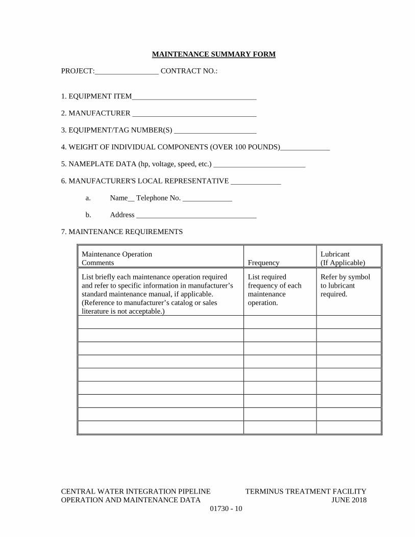
CENTRAL WATER INTEGRATION PIPELINE TERMINUS TREATMENT FACILITY OPERATION AND MAINTENANCE DATA JUNE 2018 01730 - 10
MAINTENANCE SUMMARY FORM
PROJECT: CONTRACT NO.:
1. EQUIPMENT ITEM
2. MANUFACTURER
3. EQUIPMENT/TAG NUMBER(S)
4. WEIGHT OF INDIVIDUAL COMPONENTS (OVER 100 POUNDS)
5. NAMEPLATE DATA (hp, voltage, speed, etc.)
6. MANUFACTURER'S LOCAL REPRESENTATIVE
a. Name Telephone No.
b. Address
7. MAINTENANCE REQUIREMENTS
Maintenance Operation Comments
Frequency
Lubricant (If Applicable)
List briefly each maintenance operation required and refer to specific information in manufacturer’s standard maintenance manual, if applicable. (Reference to manufacturer’s catalog or sales literature is not acceptable.)
List required frequency of each maintenance operation.
Refer by symbol to lubricant required.
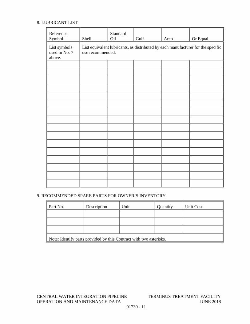
CENTRAL WATER INTEGRATION PIPELINE TERMINUS TREATMENT FACILITY OPERATION AND MAINTENANCE DATA JUNE 2018 01730 - 11
8. LUBRICANT LIST
Reference Symbol
Shell
Standard Oil
Gulf
Arco
Or Equal
List symbols used in No. 7 above.
List equivalent lubricants, as distributed by each manufacturer for the specific use recommended.
9. RECOMMENDED SPARE PARTS FOR OWNER’S INVENTORY.
Part No. Description Unit Quantity Unit Cost
Note: Identify parts provided by this Contract with two asterisks.
CENTRAL WATER INTEGRATION PIPELINE TERMINUS TREATMENT FACILITY FACILITY START UP COMMISSIONING REQUIREMENTS JUNE 2018 01752 - 1
SECTION 01752
FACILITY START UP COMMISSIONING REQUIREMENTS
PART 1 GENERAL 1.01 SCOPE
A. This section covers starting of systems for all items of mechanical, electrical, and control equipment. Additional requirements may be specified in individual equipment section.
B. Procedures and actions required of the CONTRACTOR, which are necessary to achieve a Letter of Substantial Completion.
1. Pre Start Up (Construction Phase)
a. Factory Tests
b. Field Test
c. Test Log Submittals
2. System Start Up
a. Functional Tests
b. Performance Tests
C. Procedures and actions required of the CONTRACTOR, which are necessary to achieve a Memo of Final Acceptance.
1. Operational Test
1.02 RELATED WORK
A. Section 01300 – Submittals.
B. Section 01600 – Material and Equipment.
C. Section 01640 – Manufacturer’s Field Services.
1.03 DEFINITIONS
A. System: The overall process, or a portion thereof, that performs a specific function. A system may consist of the entire facility or two (2) or more subsystems as well as two (2) or more types of equipment or components.
B. Pre Start Up: The period of time of unspecified duration during construction and installation activities which the CONTRACTOR, with assistance from MANUFACTURER’s Representatives, performs the following sequence:
CENTRAL WATER INTEGRATION PIPELINE TERMINUS TREATMENT FACILITY FACILITY START UP COMMISSIONING REQUIREMENTS JUNE 2018 01752 - 2
1. Finishes construction work so that the Project has reached a tentative state of Substantial Completion pending completion of the System Start Up.
2. MANUFACTURER’s Field Services
a. Equipment and Pre Start Up Assistance
b. Installation and Equipment Testing Certifications
c. Pre Start Up Training
C. System Start Up: A period of time of specified duration, following the Pre-Start Up Period, during which the CONTRACTOR initiates process flow through the facility and operates the facility without exceeding specified downtime limitations, to prove the functional integrity of the mechanical and electrical equipment and components; the control interfaces of the respective equipment; and components comprising the facility, as evidence of Substantial Completion. The following test activities must be executed by the CONTRACTOR with assistance from the MANUFACTURER’s Representative as needed.
1. Functional Tests: Test or tests performed by the CONTRACTOR in the presence of the OWNER to demonstrate that installed equipment, system, subsystem or components meet MANUFACTURER’s installation and adjustment requirements; and other requirements specified including, but not limited to: noise, vibration, alignment, speed, proper electrical and mechanical connections, thrust restraint, proper rotation, and initial servicing.
2. Performance Test: A test performed by the CONTRACTOR in the presence of the OWNER and after all required functional tests specified, to demonstrate and confirm that the equipment, system, subsystem or components meet the specified performance requirements.
3. MANUFACTURER’s Field Services
a. Equipment and System Start Up Assistance
b. Equipment, System, Subsystem, or Component Start Up Testing Certification.
c. Post Start Up Training
D. Operational Test: A test of specified duration, performed by the OWNER with the assistance of the CONTRACTOR after all System Start Up testing has been completed. The equipment, system, subsystem, or component shall operate continuously without any malfunctions.
PART 2 PRODUCTS (NOT USED)
CENTRAL WATER INTEGRATION PIPELINE TERMINUS TREATMENT FACILITY FACILITY START UP COMMISSIONING REQUIREMENTS JUNE 2018 01752 - 3
PART 3 EXECUTION
3.01 DESCRIPTION OF WORK
A. All items of mechanical and electrical equipment shall be tested for proper operation, efficiency, and capacity. All required adjustments, tests, operation checks, and other Pre Start Up activity shall be provided.
3.02 PRE START UP (CONSTRUCTION PHASE)
A. Factory Tests
1. All items of equipment so specified shall be tested at the point of MANUFACTURER’s facility at the CONTRACTOR's expense. Submittals shall in accordance with Section 01300 – Submittals.
2. Coordinate with the OWNER and ENGINEER for factory test schedule, if witness testing of equipment is specified in individual specification of the equipment.
3. Equipment shall not be shipped until the ENGINEER has reviewed the test results and notified the CONTRACTOR in writing that the equipment is acceptable for shipment. Such acceptance, however, shall not be considered as final acceptance, which will only be made on the basis of the test results of the equipment after installation.
A. Field Tests
1. All items of mechanical, electrical, and control equipment shall be tested by the CONTRACTOR after installation for proper operation, efficiency, and capacity. CONTRACTOR's test operation of each piece of equipment shall continue for not less than eight (8) hours without interruption. All moving parts of equipment and machinery shall be carefully tested for operation, and adjusted so all parts move freely and function to secure satisfactory operation. All parts shall operate satisfactorily in all respects, under continuous full load and in accordance with the specified requirements, for the full duration of the eight (8) hour test period. If necessary, corrections or repairs shall be made and the full eight-hour test operation, as specified, shall be completed after all parts operate satisfactorily.
2. CONTRACTOR shall furnish and pay for all power, water, fuels, oil, grease, chemicals, and auxiliaries that are required for conducting the CONTRACTOR's testing of the equipment for proper operation, efficiency, and capacity during Pre Start Up.
3. Field Tests of all process and pumping equipment, drive motors, including auxiliaries shall be made in accordance with the appropriate and approved test codes of the American Society of Mechanical Engineers (ASME), Hydraulic Institute Standards, National Electrical Manufacturers Association (NEMA), and Institute of Electrical and Electronics Engineers (IEEE).
CENTRAL WATER INTEGRATION PIPELINE TERMINUS TREATMENT FACILITY FACILITY START UP COMMISSIONING REQUIREMENTS JUNE 2018 01752 - 4
4. Field testing shall be conducted before the Work is ready for System Start Up and is substantially complete so each item of equipment is ready for integrated operation with other equipment at the facility. Testing, measuring, and calibrating procedures shall be submitted to the ENGINEER for review and acceptance prior to field testing of equipment. The facility control system must be in place and MANUFACTURER’s Certificate of Proper Installation must be completed prior to equipment tests.
5. All equipment shall be tested continuously under actual or simulated operating conditions. Equipment shall be tested over the full range of speed, capacity and pressure. Equipment shall also be tested at every level of control. Valves shall be throttled as required to simulate the full operating range. Curves shall be developed from the test data and compared to the specified performance criteria. CONTRACTOR shall provide all appurtenances as required, but not limited to flow meters for liquid and gas flow pressure gauges and throttling valves, to verify performance. CONTRACTOR shall be fully responsible for the operation and maintenance of the equipment during Pre Start Up. During testing, pressure, flow rate, amperage, voltage, vibration, equipment temperature, ambient temperature, tank level and the level of all water surfaces shall be measured. MANUFACTURER's representative shall make all necessary field adjustments and correct defects in materials or workmanship during this test period. The equipment shall be properly filled, by the CONTRACTOR, with oil and grease.
6. The period of inspection, Pre Start Up operation, and field adjustment shall be as required to achieve satisfactory installation and operation of the items furnished.
B. TEST LOG SUBMITTALS
1. MANUFACTURER’s Certificate of Proper Installation – Utilize the MANUFACTURER’s Certificate of Proper Installation Form from Section 01640 – Manufacturer’s Field Services, supplemented as necessary, to document results, problems, and conclusions.
2. Equipment Test - Test report and certification of test for each piece of equipment, system, subsystem, or component specified. See Section 01640.
3. I/O Loop Test – Third Party Independent Test Agency.
4. Equipment Calibration Sheets - Certifications of calibration for testing equipment and permanent equipment.
5. Electrical Testing - Third Party Independent Test Agency.
6. Certificate of Successful Equipment Testing – Utilize the Certificate of Successful Equipment Testing Form from Section 01640 – Manufacturer’s Field Services, supplemented as necessary to document results, problems, and conclusions.
CENTRAL WATER INTEGRATION PIPELINE TERMINUS TREATMENT FACILITY FACILITY START UP COMMISSIONING REQUIREMENTS JUNE 2018 01752 - 5
C. Additional Pre Start Up Activities
1. General activities include:
a. Cleaning.
b. Removing temporary protective coatings.
c. Flushing and replacing greases and lubricants, where required by the MANUFACTURER.
d. Lubrication.
e. Check shaft and coupling alignments and reset where needed.
f. Check and set motor, pump and other equipment rotation, safety interlocks, and belt tensions.
g. Check and correct if necessary leveling plates, grout, bearing plates, anchor bolts, fasteners, and alignment of piping which may put stress on pumping equipment connected to it.
h. All adjustments required.
2. Minimum activities include:
a. Bearings and Shafts
i. Inspect for cleanliness, clean and remove foreign materials.
ii. Verify alignment.
iii. Replace defective bearings, and those which run rough or noisy.
iv. Grease as necessary, in accordance with MANUFACTURER's recommendations.
b. Drives
i. Adjust tension in V-belt drives, and adjust vary pitch sheaves and drives for proper equipment speed (if necessary).
ii. Adjust drives for alignment.
iii. Clean and remove foreign materials before starting operation.
c. Motors
i. Check each motor for comparison to amperage nameplate value.
CENTRAL WATER INTEGRATION PIPELINE TERMINUS TREATMENT FACILITY FACILITY START UP COMMISSIONING REQUIREMENTS JUNE 2018 01752 - 6
ii. Correct conditions which produce excessive current flow, and which exist due to equipment malfunction.
iii. Check each motor for proper rotation.
d. Pumps
i. Check glands and seals for cleanliness and adjustment before running pump.
ii. Inspect shaft sleeves for scoring.
iii. Inspect mechanical faces, chambers, and seal rings, and replace if defective.
iv. Verify that piping system is free of dirt and scale before circulating liquid through the pump.
e. Valves
i. Open and close valves by hand and operate to check for binding, interference, or improper functioning.
ii. Inspect both manual and automatic control valves, clean bonnets and stems.
iii. Tighten packing glands to assure no leakage, but permit valve stems to operate without galling.
iv. Replace packing in valves to retain maximum adjustment after system is judged complete.
v. Replace packing on any valve which continues to leak.
vi. Remove and repair bonnets which leak.
vii. Coat packing gland threads and valve stems with an appropriate surface preparation after cleaning.
f. Verify that control valve seats are free from foreign material, and are properly positioned for intended service.
g. Tighten all pipe joints after system has been field tested. Replace gaskets which show any sign of leaking after tightening.
h. Inspect all joints for leakage.
i. Promptly remake each joint which appears to be faulty, do not wait for rust to form.
j. Clean threads on both parts, apply compound and remake joints.
CENTRAL WATER INTEGRATION PIPELINE TERMINUS TREATMENT FACILITY FACILITY START UP COMMISSIONING REQUIREMENTS JUNE 2018 01752 - 7
k. Clean strainers, dirt pockets, orifices, valve seats, and headers in fluid system, to assure freedom from foreign materials.
l. Open traps and air vents where used, remove operating elements. Clean thoroughly, replace internal parts and put back in readiness mode.
m. Remove rust, scale and foreign materials from equipment and renew defaced surfaces.
n. Set and calibrate permanent equipment.
o. Check each electrical control circuit to assure that operation complies with Contract Documents and requirements to provide desired performance.
p. Inspect each pressure gage and thermometer for calibration. Replace items which are defaced, broken, or which read incorrectly.
q. Repair damaged insulation.
r. Vent gases trapped in any part of systems. Verify that liquids are drained from all parts of gas or air system.
s. Calibrate testing equipment for accurate results.
t. Check power supply to electric-powered equipment for correct voltage.
u. Adjust clearances and torque.
v. Test piping for leaks.
w. Balance HVAC systems, measuring airflow (cfm) static pressure, and component pressure losses. Furnish report documenting results of balancing.
x. Equipment and electrical tagging complete.
y. All spare parts and special tools delivered to OWNER.
3.03 SYSTEM START UP
A. Submittal
1. Administrative Submittals.
a. Functional and Performance test schedules.
b. Plan for equipment, systems, subsystem, or component at least twenty-one (21) calendar days prior to start of related testing. Include test plan, procedures, and log format.
CENTRAL WATER INTEGRATION PIPELINE TERMINUS TREATMENT FACILITY FACILITY START UP COMMISSIONING REQUIREMENTS JUNE 2018 01752 - 8
c. Schedule and plan of System Start Up activities at least thirty (30) calendar days prior to commencement.
2. Certificate of Successful Equipment, System, Subsystem, or Component Start Up Testing – Utilize the Certificate of Successful Equipment, system, subsystem, or component Start Up Testing Form from Section 01640 – Manufacturer’s Field Services, supplemented as necessary, to document functional and performance procedures, results, problems, and conclusions.
B. Contractor Facility Start Up Responsibilities
1. General
a. Prepare and pretest all equipment insofar as possible to check its ability for sustained operation, including inspections and adjustments by manufacturer’s servicemen.
b. Be responsible for System Start Up of all facilities constructed under this Contract.
c. Perform Work for tests specified.
d. Demonstrate proper installation, adjustment, function and performance of equipment, systems, subsystem, or components, control devices, and required interfaces individually and in conjunction with process instrumentation and control system.
e. CONTRACTOR shall furnish and pay for all power, water, fuels, oil, grease, chemicals, and auxiliaries that are required for conducting CONTRACTOR's testing of the equipment for proper operation, efficiency, and the capacity during System Start Up.
C. Owner’s Facility Start Up Responsibilities
1. General
a. Review CONTRACTOR's test plan and schedule.
b. Witness each functional and performance tests.
c. Provide assistance and support for start up and performance testing.
d. OWNER will operate the portion of facilities that are not part of the construction contract.
CENTRAL WATER INTEGRATION PIPELINE TERMINUS TREATMENT FACILITY FACILITY START UP COMMISSIONING REQUIREMENTS JUNE 2018 01752 - 9
D. Testing Preparation
1. General.
a. Complete Work associated with the equipment, system, subsystem, or components and related processes before testing, including related MANUFACTURER's representative services.
b. Furnish qualified MANUFACTURER's representatives when required to assist in testing.
c. Utilize the Certificate of Successful Equipment, System, Subsystem or component Start Up Testing Form from Section 01640 – Manufacturers Field Services, supplemented as necessary, to document functional and performance procedures, results, problems, and conclusions.
d. Schedule and attend pretest (functional and performance) meetings related to test schedule, plan of test, materials, chemicals, and liquids required, facilities' operations interface, OWNER involvement.
e. Designate and furnish one or more persons to be responsible for coordinating and expediting CONTRACTOR's System Start Up duties. The person or persons shall be present during System Start Up meetings and shall be available at all times during the System Start Up period.
f. Provide temporary valves, gauges, piping, test equipment and other materials and equipment required to conduct testing.
2. Cleaning and Checking: Prior to starting functional testing.
a. Calibrate testing equipment for accurate results.
b. Inspect and clean equipment, devices, connected piping, and structures so they are free of foreign material.
c. Lubricate equipment in accordance with MANUFACTURER’s instructions.
d. Turn rotating equipment by hand and check motor-driven equipment for correct rotation.
e. Open and close valves by hand and operate other devices to check for binding, interference, or improper functioning.
f. Check power supply to electric-powered equipment for correct voltage.
g. Adjust clearances and torque.
h. Test piping for leaks.
CENTRAL WATER INTEGRATION PIPELINE TERMINUS TREATMENT FACILITY FACILITY START UP COMMISSIONING REQUIREMENTS JUNE 2018 01752 - 10
i. Obtain completion of applicable portions of MANUFACTURER's Certificate of Proper Installation in accordance with Section 01640 – Manufacturer’s Field Services.
3. Ready-to-test determination will be by OWNER based at least on the following:
a. Notification by CONTRACTOR of equipment and system readiness for testing.
b. Acceptable Test Log Submittal to OWNER.
c. Acceptable testing plan.
d. Acceptable Final Draft Operation and Maintenance Manuals.
e. Receipt of MANUFACTURER's Certificate of Proper Installation, as required.
f. Receipt of Certificate of Successful Equipment Testing, as required.
g. Adequate completion of Work adjacent to, or interfacing with, equipment to be tested.
h. Availability and acceptability of MANUFACTURER's representative, when specified, to assist in testing of respective equipment, and satisfactory fulfillment of other specified MANUFACTURER's responsibilities.
i. Equipment and electrical tagging complete.
j. All spare parts and special tools delivered to and become property of the OWNER.
E. Functional Test - General
1. Begin testing at a time mutually agreed upon by the OWNER and CONTRACTOR.
2. OWNER and MANUFACTURER’s Representative will be present during test. Notify in writing MANUFACTURER's representative(s) at least twenty-one (21) calendar days prior to scheduled date of functional tests.
3. Separate items of equipment demonstrated to function properly during subsystem testing may require no further Functional test if documentation of subsystem testing is acceptable to OWNER.
4. Conduct functional tests as specified for each equipment, system, subsystem, on component for a minimum period of eight (8) hours.
CENTRAL WATER INTEGRATION PIPELINE TERMINUS TREATMENT FACILITY FACILITY START UP COMMISSIONING REQUIREMENTS JUNE 2018 01752 - 11
5. Demonstrate all operational features and instrumentation and control functions while in automatic mode.
6. If, in OWNER's opinion, functional test results do not meet requirements specified, the systems will be considered as non-conforming.
7. Performance testing shall not commence until the equipment, system, subsystem, or components meets the specified functional tests.
F. Performance Test - General
1. Begin testing at a time mutually agreed upon by the OWNER and CONTRACTOR.
2. OWNER will be present during test. Notify in writing MANUFACTURER’s representative(s) at least twenty-one (21) days prior to scheduled date of performance tests.
3. Conduct performance tests as specified for each equipment, system, subsystem, or component for a minimum period of one (1) day.
4. Unless otherwise indicated, furnish all labor, materials, and supplies for conducting the test and taking all samples and performance measurements.
5. Prepare performance test report summarizing test method. Include test logs, pertinent calculations, and CONTRACTOR's Certificate of Successful Equipment, System, Subsystem, or Component Start Up Testing.
G. System Start Up Test Period
1. General.
a. Attend planning meetings and arrange for attendance by key major equipment MANUFACTURER representatives as required by the Contract Documents.
b. Designate one or more persons on the CONTRACTOR's staff to be able for coordinating and expediting CONTRACTOR's System Start Up duties.
c. When System Start Up has commenced, schedule remaining Work so as not to interfere with or delay the completion of System Start Up.
d. Support System Start Up activities with adequate staff to prevent delays. Such staff shall include, but not be limited to, equipment, system, subsystem, or component, MANUFACTURER's representatives, electricians, instrumentation and control personnel, millwrights, pipe fitters, and plumbers.
e. Furnish and coordinate specified MANUFACTURER's System Start Up services.
CENTRAL WATER INTEGRATION PIPELINE TERMINUS TREATMENT FACILITY FACILITY START UP COMMISSIONING REQUIREMENTS JUNE 2018 01752 - 12
2. System Start Up Testing.
a. System Start Up of the entire system or any portion thereof requires the coordinated operation of the facilities by the CONTRACTOR, SUBCONTRACTORs, OWNER's operating personnel, ENGINEER, and MANUFACTURER's representatives.
b. System Start Up of the entire facility or any portion thereof shall be considered complete when, in the opinion of the OWNER, the facility or designated portion has operated in the manner intended without interruption. This includes any training, functional or performance test periods specified herein.
c. An interruption may include but is not limited to any of the following events.
i. Failure of CONTRACTOR to maintain qualified onsite System Start Up personnel as schedule D.
ii. Failure to meet specified functional or performance tests.
iii. Failure of any critical equipment, system, subsystem or component that is not satisfactorily corrected within two (2) hours after failure.
iv. Failure of any non-critical equipment, system, subsystem, component that is not satisfactorily corrected within four (4) hours after failure.
v. As may be determined by OWNER.
d. An interruption will require the System Start Up, then in progress, to be stopped and restarted after corrections are made.
3. Startup Test Reports: As applicable to the equipment furnished, certify in writing that:
a. Hydraulic structures, piping systems, and valves have been successfully tested.
b. Equipment, systems, subsystems, or component have been checked for proper installation, started, and successfully tested to indicate that they are operational.
c. Equipment, systems, subsystems, or components are capable of performing their intended functions, including fully automatic.
CENTRAL WATER INTEGRATION PIPELINE TERMINUS TREATMENT FACILITY FACILITY START UP COMMISSIONING REQUIREMENTS JUNE 2018 01752 - 13
d. Facilities are ready for intended operation.
e. Final O&M Manuals have been submitted and approved by OWNER.
3.04 OPERATIONAL TEST
A. As a condition of Partial Acceptance (Substantial Completion), after all functional and performance tests and the entire system is safe and ready to operate, the OWNER will test all constructed facilities using all specified systems in combination with each other for a period of thirty (30) days continuous operation (either actual or simulated) without interruption due to malfunctions of constructed facilities. All defects of material or workmanship which appear during this test period shall be corrected by the CONTRACTOR. After such corrections are made, the thirty (30) day test shall be restarted at zero and run again before partial acceptance (substantial completion) of the equipment. The time need not be continuous based on malfunctions of associated existing facilities.
B. OWNER will supply all power, water, oil, fuels, grease, chemicals, auxiliaries, and operating personnel required for this final operational test.
C. Each MANUFACTURER who furnishes equipment that requires factory trained service personnel shall adjust the equipment until the operational tests have been met and the results of the operational tests have been accepted by the ENGINEER.
D. CONTRACTOR’s Representative shall be on site for the thirty (30) day operational test for assisting in the operation and maintenance of the System.
END OF SECTION
APPENDIX B
DIVISION 15
MECHANICAL
CENTRAL WATER INTEGRATION PIPELINE TERMINUS TREATMENT FACILITY MECHANICAL GENERAL REQUIREMENTS JUNE 2018 15000 - 1
SECTION 15000
MECHANICAL GENERAL REQUIREMENTS PART 1 GENERAL 1.01 DESCRIPTION A. Scope of Work:
1. All equipment furnished and installed under this contract shall conform to the general stipulations set forth in this section except as otherwise specified in other sections.
2. Contractor shall coordinate all details of equipment with other related parts of the Work, including verification that all structures, piping, wiring, and equipment components are compatible. Contractor shall be responsible for all structural and other alternations in the Work required to accommodate equipment differing in dimensions or other characteristics from that contemplated in the Contract Drawings or Specifications.
B. General Design:
1. Contract Drawings and Specifications: The Contract Drawings and Specifications shall be considered as complementary, one to the other, so that materials and work indicated, called for, or implied by the one and not by the other shall be supplied and installed as though specifically called for by both. The Contract Drawings are to be considered diagrammatic, not necessarily showing in detail or to scale all of the equipment or minor items. In the event of discrepancies between the Contract Drawings and Specifications, or between either of these and any regulations or ordinances governing work of these specifications, the bidder shall notify the Engineer in ample time to permit revisions.
1.02 RELATED SECTIONS
A. The Following is a list of related sections. Other section may also apply.
1. General Requirements: Division 1 2. Concrete: Division 3
3. Metals: Division 5 4. Finishes: Division 9 5. Equipment: Division 11 6. Special Construction: Division 13 7. Mechanical: Division 15 8. Electrical: Division 16
CENTRAL WATER INTEGRATION PIPELINE TERMINUS TREATMENT FACILITY MECHANICAL GENERAL REQUIREMENTS JUNE 2018 15000 - 2
1.03 QUALITY ASSURANCE A. Materials and Equipment: Unless otherwise specified, all materials and equipment
furnished for permanent installation in the work shall conform to applicable standards and specifications and shall be new, unused, and undamaged when installed or otherwise incorporated in the work. No such material or equipment shall be used by the Contractor for any purpose other than that intended or specified, unless such use is specifically authorized in writing by the Owner. No material shall be delivered to the work site workout prior acceptance of drawings and data by the Engineer.
B. Equivalent Materials and Equipment:
1. Whenever a material or article is specified or described by using the name of a proprietary product or the name of a particular manufacturer or vendor, the specific item mentioned shall be understood as establishing the type, function, and quality desired. Other manufacturers' products will be accepted provided sufficient information is submitted to allow the Engineer to determine that the products proposed are equivalent to those named. Such items shall be submitted for review in accordance with Section 01300 – Submittals.
2. Requests for review of equivalency will not be accepted from anyone except the Contractor and such requests will not be considered until after the contract has been awarded.
C. Governing Standards: Equipment and appurtenances shall be designed in conformity
with ANSI, ASME, ASTM, IEEE, NEMA, OSHA, AGMA, and other generally accepted applicable standards. They shall be of rugged construction and of sufficient strength to withstand all stresses which may occur during fabrication, testing, transportation, installation, and all conditions or operations. All bearings and moving parts shall be adequately protected against wear by bushings or other acceptable means. Provisions shall be made for adequate lubrication with readily accessible means.
D. Tolerances: Machinery parts shall conform to the dimensions indicated on the drawings
within allowable tolerances. Protruding members such as joints, corners, and gear covers shall be finished in appearance. All exposed welds shall be ground smooth and the corners of structural shapes shall be rounded or chamfered.
E. Clearances: Ample clearances shall be provided for inspection and adjustment. All
equipment shall fit the allotted space and shall leave reasonable access room for servicing and repairs. Greater space and room required by substituted equipment shall be provided by the Contractor and at his expense.
F. Testing:
1. When the equipment is specified to be factory tested, the results of the tests shall be submitted to the Engineer and approval of the test results shall be obtained before shipment of the equipment.
CENTRAL WATER INTEGRATION PIPELINE TERMINUS TREATMENT FACILITY MECHANICAL GENERAL REQUIREMENTS JUNE 2018 15000 - 3
2. When an item of equipment, including controls and instrumentation, has been completely erected, the Contractor shall notify the Engineer, who will designate a time to make such tests as required, and operate the item to the satisfaction of the Contractor. All testing shall be done in the presence of the Contractor. "Completely erected" shall mean that the installation is erected, all necessary adjustments have been made, all required utility connections have been made, required lubricants and hydraulic fluid have been added and the unit has been cleaned and painted.
G. Pressure Test:
1. Contractor shall provide a blind flange with cap for pressure testing. After installation, all piping shall be pressure tested. Piping shall be tested in accordance with Section 15085 – Water Pipeline Testing for water distribution piping.
2. All tests shall be made in the presence of and to the satisfaction of the Engineer and also, to the satisfaction of any local or state inspector having jurisdiction.
a. Provide not less than three (3) days notice to the Engineer and the authority having jurisdiction when it is proposed to make the tests.
b. Any piping or equipment that has been left unprotected and subject to mechanical or other injury in the opinion of the Engineer shall be retested in part or in whole as directed by the Engineer.
c. The piping systems may be tested in sections as the work progresses by no joint or portion of the system shall be left untested.
3. All elements within the system that may be damaged by the testing operation shall be removed or otherwise protected during the operation.
4. All defects and leaks observed during the tests shall be corrected and made tight
in an approved manner and the tests repeated until the system is proven tight. 5. Repair all damage done to existing or adjacent work or materials due to or on
account of the tests. 6. Provide test pumps, gauges, or other instruments and equipment required for the
performance of all tests. Provide all temporary bracing, test plugs, additional restraint, and thrust blocking which may be required for test pressures above normal working pressures.
7. All tests shall be maintained for as long a time as required to detect all defects
and leaks but not less than the duration specified for each type of pipe or piping system in this Division.
CENTRAL WATER INTEGRATION PIPELINE TERMINUS TREATMENT FACILITY MECHANICAL GENERAL REQUIREMENTS JUNE 2018 15000 - 4
H. Failure of Test: 1. Defects: Any defects in the equipment, or deviations from the guarantees or
requirements of the Specifications, shall be promptly corrected by the Contractor by replacements or otherwise. The decision of the Engineer as to whether or not the Contractor has fulfilled his obligations under the Contract shall be final and conclusive. If the Contractor fails to correct any defects or deviations, or if the replaced equipment when tested shall fail again to meet the guarantees or specified requirements, the Owner, notwithstanding his having made partial payment for work and materials which have entered into the manufacturer for such equipment, may reject that equipment and order the Contractor to remove it from the premises at the Contractor's expense.
2. Rejection of Equipment: In case the Owner rejects a particular item of
equipment, then the Contractor hereby agrees to repay to the Owner all sums of money paid to him to deliver to the Contractor a bill of sale of all his rights, title, and interest in and to the rejected equipment provided, however that the equipment shall not be removed from the premises until the Owner obtains from other sources other equipment to take the place of that rejected. The bill of sale shall not abrogate the Owner's right to recover damages for delays, losses or other conditions arising out of the basic Contract. The Owner hereby agrees to obtain the alternate equipment within a reasonable time and the Contractor agrees that the Owner may use the original equipment furnished by him without rental or other charge until the other equipment is obtained.
I. Responsibility During Tests: The Contractor shall be fully responsible for the proper
operation of equipment during tests and instruction periods and shall neither have nor make any claim for damage which may occur to equipment prior to the time when the Owner formally takes over the operation thereof.
J. Acceptance of Materials: 1. Only new materials and equipment shall be incorporated in the work. All
materials and equipment furnished by the Contractor shall be subject to the inspection and acceptance of the Owner. No material shall be delivered to the work without prior submittal approval of the Engineer.
2. The Contractor shall submit to the Project Manager and Professional Engineer
data relating to materials and equipment he proposes to furnish for the work. Such data shall be in sufficient detail to enable the Engineer to identify the particular product and to form an opinion as to its conformity to the specifications.
3. Facilities and labor for handling and inspection of all materials and equipment
shall be furnished by the Contractor. If the Engineer requires, either prior to beginning or during the progress of the work, the Contractor shall submit samples of materials for such special test as may be necessary to demonstrate
CENTRAL WATER INTEGRATION PIPELINE TERMINUS TREATMENT FACILITY MECHANICAL GENERAL REQUIREMENTS JUNE 2018 15000 - 5
that they conform to the specification. Such sample shall be furnished, stored, packed, and shipped as directed at the Contractor's expense. Except as otherwise noted, the Owner will make arrangements for and pay for tests.
4. The Contractor shall submit data and samples sufficiently early to permit
consideration and acceptance before materials are necessary for incorporation in the work.
K. Safety Requirements: 1. In addition to the components shown and specified, all machinery and equipment
shall be safeguarded in accordance with the safety features required by the current codes and regulations of ANSI, OSHA, and local industrial codes.
2. The Contractor shall provide for each V-belt drive or rotating shaft a protective
guard which shall be securely bolted to the floor or apparatus. The guard shall completely enclose drives and pulleys and be constructed to comply with all safety requirements.
3. For double inlet fans, the belt guard shall be arranged so as not to restrict the air
flow into the fan inlet. Guards shall not interfere with lubrication of equipment. 1.04 SUBMITTALS
A. See Section 01300 – Submittals. 1.05 PRODUCT DELIVERY, STORAGE AND HANDLING A. Packaging: All equipment shall be suitably packaged to facilitate handling and protect
against damage during transit and storage. All equipment shall be boxed, crated, or otherwise completely enclosed and protected during shipment, handling, and storage. All equipment shall be protected from exposure to the elements and shall be kept thoroughly dry at all times.
B. Protection: All machined surfaces and shafting shall be cleaned and protected from
corrosion by the proper type and amount of coating necessary to assure protection during shipment and prior to installation. Painted surfaces shall be protected against impact, abrasion, discoloration, and other damage as specified in Sections 09900 – Paints and Coatings. All painted surfaces which are damaged prior to acceptance of equipment shall be repainted to the satisfaction of Engineer.
C. Lubrication: Grease and lubricating oil shall be applied to all bearings and similar items
as necessary to prevent damage during shipment and storage. D. Marking: Each item of equipment shall be tagged or marked as identified in the delivery
schedule or on the Shop Drawings. Complete packing lists and bills of material shall be included with each shipment.
CENTRAL WATER INTEGRATION PIPELINE TERMINUS TREATMENT FACILITY MECHANICAL GENERAL REQUIREMENTS JUNE 2018 15000 - 6
E. Fabricated sub-assemblies, if any, shall be shipped in convenient sections as permitted by carrier regulations and shall be properly match-marked for ease of field erection.
F. Responsibility: 1. The Contractor shall be responsible for all material, equipment, and supplies
sold and delivered to the site under this Contract until final inspection of the work and acceptance thereof by the Owner. In the event any such material, equipment, and supplies are lost, stolen, damaged, or destroyed prior to final inspection and acceptance, the Contractor shall replace same without additional cost to the Owner.
2. Should the Contractor fail to take proper action on storage and handling of
equipment supplied under this Contract within seven days after written notice to do so has been given, the Owner retains the right to correct all deficiencies noted in previously transmitted written notice and deduct the cost associated with these corrections from the Contractor's Contract. These costs may be comprised of expenditures for labor, equipment usage, administrative, clerical, engineering, and any other costs associated with making the necessary corrections.
G. Delivery: The Contractor shall arrange deliveries of products in accordance with
construction schedules and coordinate to avoid conflict with work and condition at the site.
1. The Contractor shall deliver products in undamaged condition, in manufacturer's
original containers or packaging, with identifying labels intact and legible. 2. Immediately on delivery, the Contractor shall inspect shipments to assure
compliance with requirements of Contract Documents and accepted submittals, and that products are properly protected and undamaged.
3. Under no circumstances shall the Contractor deliver equipment to the site more
than one month prior to installation without written authorization from the Engineer. Operation and maintenance data shall be submitted to the Engineer for review prior to shipment of equipment as described in Section 01730 – Operation and Maintenance Data.
H. Storage and Protection of Products: 1. The Contractor shall furnish a covered, weather-protected storage structure
providing a clean, dry noncorrosive environment for all mechanical equipment, valves, architectural items, electrical and instrumentation equipment, and special equipment to be incorporated into this project. Storage of equipment shall be in strict accordance with the "Instructions for Storage" of each equipment supplier and manufacturer including connection of space heaters, and placing of storage lubricants in equipment. Corroded, damaged, or deteriorated equipment and parts shall be replaced before acceptance of the project. Equipment and materials not properly stored will not be included in a payment estimate.
CENTRAL WATER INTEGRATION PIPELINE TERMINUS TREATMENT FACILITY MECHANICAL GENERAL REQUIREMENTS JUNE 2018 15000 - 7
a. The Contractor shall store products subject to damage by the elements in
weathertight enclosures.
b. The Contractor shall maintain temperature and humidity within the ranges required by manufacturer's instructions.
c. The Contractor shall store fabricated products above the ground, on blocking or skids, to prevent soiling or staining. The Contractor shall cover products which are subject to deterioration with impervious sheet coverings and provide adequate ventilation to avoid condensation.
d. The Contractor shall store loose granular materials in a well drained area on solid surfaces to prevent mixing with foreign matter.
2. All materials and equipment to be incorporated in the work shall be handled and
stored by the Contractor before, during, and after shipment in a manner to prevent warping, twisting, bending, breaking, chipping, rusting, and any injury, theft, or damage of any kind whatsoever to the material or equipment.
3. Cement, sand, lime shall be stored under a roof and off the ground, and shall be
kept completely dry at all times. All structural and miscellaneous steel and reinforcing steel shall be stored off the ground or otherwise to prevent accumulations of dirt, or grease, and in a position to prevent accumulations of standing water, staining, chipping, or cracking. Brick, block, and similar masonry products shall be handled and stored in a manner to reduce breakage, chipping, cracking and peeling to a minimum.
4. All materials which, in the opinion of the Engineer, have become damaged and
are unfit for the use intended or specified, shall be promptly removed from the site of the work, and the Contractor shall receive no compensation for the damaged material or its removal.
5. The Contractor shall arrange storage in a manner to provide easy access for
inspection. The Contractor shall make periodic inspections of stored products to assure products are maintained under specified conditions, and free from damage or deterioration.
6. Protection After Installation: The Contractor shall provide substantial coverings
as necessary to protect installed products from damage from traffic and subsequent construction operations. The Contractor shall remove covering when no longer needed.
I. Extended Storage Requirements For Equipment: Because of the long period allowed for
construction, special attention shall be given to extended storage and handling of equipment onsite. As a minimum, the procedure specified herein shall be followed:
1. If equipment will be stored onsite for more than one month prior to incorporation
into the Work, the Contractor shall submit a written request to the Engineer
CENTRAL WATER INTEGRATION PIPELINE TERMINUS TREATMENT FACILITY MECHANICAL GENERAL REQUIREMENTS JUNE 2018 15000 - 8
outlining any special provision to be made to protect and maintain the equipment while it is being stored. All such provisions shall be acceptable to the Engineer. No equipment shall be stored onsite for more than one month without prior written authorization from the Engineer.
2. All equipment having moving parts including gears, electric motors, and/or
instruments shall be stored in a temperature and humidity controlled building accepted by the Engineer, until such time as the equipment is to be installed.
3. All equipment shall be stored fully lubricated with oil and grease unless
otherwise instructed by the manufacturer. 4. Manufacturer's storage instructions shall be carefully studied by the Contractor
and reviewed by him with the Manufacturer’s Representative. These instructions shall be carefully followed and a written record of this review kept by the Contractor.
5. Moving parts shall be rotated a minimum of once weekly to ensure proper
lubrication and to avoid metal-to-metal "welding". Upon installation of the equipment, the Contractor shall start the equipment, and operate loaded when possible, weekly for an adequate period of time to ensure that the equipment does not deteriorate from lack of use.
6. Lubricants shall be changed upon completion of installation and as frequently as
required thereafter during the period between installation and acceptance. Mechanical equipment to be used in the work, if stored for longer than ninety days, shall have the bearings cleaned, flushed, and lubricated prior to testing and startup, at no extra cost to the Owner.
7. Prior to acceptance of the equipment, the Contractor shall have the manufacturer
inspect the equipment and certify that its condition has not been detrimentally affected by the long storage period. Such certifications by the manufacturer shall be deemed to mean that the equipment is judged by the manufacturer to be in a condition equal to that of equipment that has been shipped, installed, tested, and accepted in a minimum time period. As such, the manufacturer will guarantee the equipment equally in both instances. If such a certification is not given, the equipment shall be judged to be defective, and it shall be removed and replaced at the Contractor's expense.
8. A maintenance log shall be maintained by the Contractor outlining the schedule
of maintenance required for each piece of equipment as well as the date on which the maintenance was actually performed and the initials of the individual performing the work. Submit a copy of the maintenance log monthly with the progress pay application.
CENTRAL WATER INTEGRATION PIPELINE TERMINUS TREATMENT FACILITY MECHANICAL GENERAL REQUIREMENTS JUNE 2018 15000 - 9
1.06 WARRANTY AND GUARANTEES
A. Provide equipment warranty in accordance with Sections 01740: Warranties and Bonds.
B. The manufacturer's written warranty shall be submitted for all major pieces of equipment, as specified in Section 01600 – Material and Equipment.
PART 2 - PRODUCTS 2.01 GENERAL A. All materials that come into contact with the water being treated or the finished water
shall be on either the EPA or NSF lists of products approved for use in contact with potable water. Manufacturers shall submit an affidavit with the shop drawings indicating approval by the EPA or NSF for the materials used in products that come into contact with the water, in accordance with Rule 290.44(a) of the Texas Administrative Code.
2.02 MATERIALS AND EQUIPMENT A. Fabrication and Manufacture: 1. Workmanship and Materials: a. Contractor shall guarantee all equipment against faulty or inadequate
design, improper assembly or erection, defective workmanship or materials, and leakage, breakage or other failure. Materials shall be suitable for service conditions.
b. All equipment shall be designed, fabricated, and assembled in accordance with recognized and acceptable engineering and shop practice. Individual parts shall be manufactured to standard sizes and gages so that repair parts, furnished at any time, can be installed in the field. Like parts of duplicate units shall be interchangeable. Equipment shall not have been in service at any time prior to delivery, except as required by tests.
c. Except where otherwise specified, structural and miscellaneous fabricated steel used in equipment shall conform to AISC standards. All structural members shall be designed for shock or vibratory loads. Unless otherwise specified, all steel which will be submerged, all or in part, during normal operation of the equipment shall be at least 1/4 inch thick.
2. Lubrication: a. Equipment shall be adequately lubricated by systems which require
attention no more frequently than weekly during continuous operation.
CENTRAL WATER INTEGRATION PIPELINE TERMINUS TREATMENT FACILITY MECHANICAL GENERAL REQUIREMENTS JUNE 2018 15000 - 10
Lubrications systems shall not require attention during startup or shutdown and shall not waste lubricants.
b. Lubricants of the type recommended by the equipment manufacturer shall be furnished by the Contractor in sufficient quantity to fill all lubricant reservoirs and to replace all consumption during testing, startup, and operation prior to acceptance of equipment by Owner. Unless otherwise specified or permitted, the use of synthetic lubricants will not be acceptable.
c. Lubrication facilities shall be convenient and accessible. Oil drains and fill openings shall be easily accessible from the normal operating area or platform. Drains shall allow for convenient collection of waste oil in containers from the normal operating area or platform without removing the unit from its normal installed position.
3. Electric Motors: Unless otherwise specified, motors furnished with equipment
shall be rated and constructed as specified in Division 16 – Electrical. a. Manufacturer's standard motor may be supplied on integrally
constructed, packaged assemblies such as appliances, tools, unit heaters, and similar equipment specified by model number, in which case a redesign of the unit would be required to furnish motors of other than the manufacturer's standard design. However, in all cases, totally enclosed motors are preferred and shall be furnished if offered by the manufacturer as a standard option.
4. Drive Units: The nominal input horsepower rating of each gear or speed reducer
shall be at least equal to the nameplate horsepower of the drive motor. Drive units shall be designed for 24 hour continuous service.
a. Gear Reducers: i. Each gear reducer shall be a totally enclosed unit with oil or
grease lubricated antifriction, rolling element bearings throughout.
ii. Helical, spiral bevel, combination bevel-helical, and worm gear reducers shall have a service factor of at least 1.50 based on the nameplate horsepower of the drive motor. Shaft-mounted and flange-mounted gear reducers shall be rated AGMA Class 11. Helical gear reducers shall have a gear strength rating to catalog rating of 1.5. Each gear reducer shall bear an AGMA nameplate.
iii. The thermal horsepower rating of each unit shall equal or exceed the nameplate horsepower of the drive motor. During continuous operation, the maximum sump oil temperature shall not rise more than 100 F above the ambient air temperature in the vicinity of the unit and shall not exceed 200 F.
CENTRAL WATER INTEGRATION PIPELINE TERMINUS TREATMENT FACILITY MECHANICAL GENERAL REQUIREMENTS JUNE 2018 15000 - 11
iv. Each grease lubricated bearing shall be installed in a bearing housing designed to facilitate periodic regreasing of the bearing by means of a manually operated grease gun. Each bearing housing shall be designed to evenly distribute new grease, to properly dispose of old grease, and to prevent overgreasing of the bearing. The use of permanently sealed, grease lubricated bearings will not be acceptable. An internal or external oil pump and appurtenances shall be provided if required to properly lubricate oil lubricated bearings. A dipstick or sight glass arranged to permit visual inspection of lubricant level shall be provided on each unit.
v. Gear reducers which require the removal of parts or periodic disassembly of the unit for cleaning and manual regreasing of bearings will not be acceptable.
vi. Certification shall be furnished by the gear reducer manufacturer indicating that the intended application of each unit has been reviewed in detail by the manufacturer and that the unit provided is fully compatible with the conditions of installation and service.
b. Variable Speed Drives: Each variable speed drive shall have a service factor of at least 1.75 at maximum speed based on the nameplate horsepower of the drive motor. A spare belt shall be provided with each variable speed drive unit employing a belt for speed change. Unless specifically permitted by the detailed equipment specifications, bracket type mounting will not be acceptable for variable speed drives.
c. V-Belt Drives: Each V-belt drive shall include a sliding base or other suitable tension adjustment. V-belt drives shall have a service factor of at least 1.6 maximum speed based on the nameplate horsepower of the drive motor.
5. Safety Guards: All belt or chain drives, fan blades, couplings, and other moving
or rotating parts shall be covered on all sides by a safety guard. Safety guards shall be fabricated form 16 USS gage or heavier galvanized or aluminum-clad sheet steel or 1/2 inch mesh galvanized expanded metal. Each guard shall be designed for easy installation and removal. All necessary supports and accessories shall be provided for each guard. Supports and accessories, including bolts, shall be galvanized. All safety guards in outdoor locations shall be designed to prevent the entrance of rain and dripping water.
6. Equipment Foundation Supports: a. All foundations, platforms and hangers required for the proper
installation of equipment shall be furnished and installed by the Contractor.
CENTRAL WATER INTEGRATION PIPELINE TERMINUS TREATMENT FACILITY MECHANICAL GENERAL REQUIREMENTS JUNE 2018 15000 - 12
b. Unless otherwise indicated or specified, all equipment shall be installed on reinforced concrete bases at least 6 inches high and shall conform to Section 03300 – Cast-in-Place Concrete. Cast iron or welded steel baseplates shall be provided for pumps, compressors, and other equipment. Each unit and its drive assembly shall be supported on a single baseplate of neat design. Baseplates shall have pads for anchoring all components and adequate grout holes. Baseplates for pumps shall have a means for collecting leakage and a threaded drain connection. Baseplates shall be anchored to the concrete base with suitable anchor bolts and the space beneath filled with grout as specified in Section 03300. All open equipment bases shall be filled with nonshrinking grout sloped to drain to the perimeter of the base.
c. The Contractor shall furnish, install and protect all necessary guides, bearing plates, anchor and attachment bolts, and all other appurtenances required for the installation of equipment. These shall be of ample size and strength for the purpose intended.
d. Equipment suppliers shall furnish suitable anchor bolts for each item of equipment. Anchor bolts, together with templates or setting drawings, shall be delivered sufficiently early to permit setting the anchor bolts when the structural concrete is placed. Anchor bolts shall comply with Division 5 – Metals and, unless otherwise specified, shall have a minimum diameter of 3/4 inch. Unless otherwise indicated or specified, anchor bolts for items of equipment mounted on baseplates shall be long enough to permit 1-1/2 inches of grout beneath the baseplate and to provide adequate anchorage into structural concrete.
e. Structural steel supports and miscellaneous steel required for supporting and/or hanging equipment and piping furnished under this Division shall be provided and installed by Contractor.
f. All foundations, anchor pads, piers, thrust blocks, inertia blocks and structural steel supports shall be built to template and reinforced as required for loads imposed on them.
g. The Contractor shall assume all responsibility for sizes, locations and design of all foundations, anchor pads, pier, thrust blocks, inertia blocks, curbs and structural steel supports.
7. Shop Painting: a. All steel and iron surfaces shall be protected by suitable paint or
coatings applied in the shop. Surfaces which will be inaccessible after assembly shall be protected for the life of the equipment. Exposed surfaces shall be finished smooth, thoroughly cleaned, and filled as necessary to provide a smooth uniform base for painting. Electric motors, speed reducers, starters, and other self-contained or enclosed components shall be shop primed or finished with a high-grade oil
CENTRAL WATER INTEGRATION PIPELINE TERMINUS TREATMENT FACILITY MECHANICAL GENERAL REQUIREMENTS JUNE 2018 15000 - 13
resistant enamel suitable for coating in the field with an alkyd enamel. Coatings shall be suitable for the environment where the equipment is installed.
b. Surfaces to be painted after installation shall be prepared for painting as recommended by the paint manufacturer for the intended service, and then shop painted with one or more coats of the specified primer. Unless otherwise specified, the shop primer for steel and iron surfaces shall be Cook "391-N-167 Barrier Coat", Koppers "No. 10 Inhibitive Primer", or equal.
c. Machined, polished, and nonferrous surfaces which are not to be painted shall be coated with rust-preventive compound, Houghton "Rust Veto 344", Rust-Oleum "R-9", or equal.
8. Nameplates: Contractor shall provide equipment identification nameplates for
each item of equipment. Nameplates shall be 1/8-inch Type 304 stainless steel and shall be permanently fastened. Plates shall be fastened using round head metallic drive screws, or where metallic drive screws are impractical, with stainless steel pop rivets. Metallic drive screws shall be brass or stainless steel, Type V and No. 8 by 3/8-inch long. Names and/or equipment designations shall be engraved on the plates and the engraving painted with a primer and black paint system compatible with stainless steel. Contractor shall submit a list of proposed names and designations for review prior to fabrication of nameplates. At a minimum, each nameplate shall include equipment manufacturers name, year of manufacture, serial number and principal rating data.
9. Pipe Identification: a. Underground pipe and tube: Pipe and tube shall be located by laying 2-
inch wide plastic tape continuously along the run of pipe or tube. Where possible, color of tape shall be consistent with the color of bands on interior pipe and as approved by the Engineer, or shall bear an imprinted identification of the line.
i. Location: Tape shall be laid approximately 12 inches below
ground surface and directly over pipe location.
ii. Manufacturer: Tape shall be an inert plastic film highly resistant to alkaline, acids or other destructive chemical components likely to be encountered in soils and shall be Terra Tape as manufactured by Griffolyn Company, or underground warning tape by Seton Name Plate Corporation or equal. Pipe of PVC shall be protected with a detectable tape with a metallized foil core and shall be Terra Tape "D" or equal.
10. Valve Identification: On all valves, except shut-off valves located at a fixture or
piece of equipment, the Contractor shall provide a coded and numbered tag attached with brass chain and/or brass "S" hooks.
CENTRAL WATER INTEGRATION PIPELINE TERMINUS TREATMENT FACILITY MECHANICAL GENERAL REQUIREMENTS JUNE 2018 15000 - 14
a. Tag Types: i. Tags for valves on pipe and tube lines conducting hot medium
(steam, condensate, hot water, etc.) shall be brass or anodized aluminum.
ii. Tags for all other valves shall be Type 304 stainless steel.
iii. Square tags shall be used to indicate normally closed valves and round tags shall indicate normally open valves.
b. Coding: In addition to the color coding, each tag shall be stamped or engraved with wording or abbreviations to indicate the line service. All color and letter coding shall be approved by the Engineer.
c. Valve Schedule: The Contractor shall provide a typewritten list of all tagged valves giving tag shape, letter code and number, the valve size, type, use and general location within building.
11. Noise Attenuation and Control:
a. Unless otherwise specified, the maximum permissible noise level for a complete installed piece of equipment located within or outside a structure shall not exceed 85 dB at 3 feet. A complete piece of equipment includes the driver and driven equipment, plus any intermediate couplings, gears, and auxiliaries. All equipment provided herein that is specified to be factory and field tested shall be tested as specified herein for noise generation at the equipment manufacturer's expense.
b. Maximum permissible noise (sound pressure) levels shall be in decibels as read on the "A" weighting scale of a standard sound level meter (dB); all measurements shall be made in relation to a reference pressure of 0.0002 microbar. Measurements of emitted noise levels shall be made on a sound level meter meeting at least the Type 2 requirements set forth in ANSI S1.4, Specification for Sound Level Meters. The sound level meter shall be set on the "A" scale and to slow response. Unless otherwise specified for a particular piece of equipment, the point of measurement of sound level shall be made at the specified distance from any major surface along the entire perimeter and at midheight of the piece of equipment, or at the specified distance from an outer major surface encompassing the sound source including inlets or outlets.
12. Fire Hazard Rating: a. All piping, duct work, and equipment insulation, fastener, and jacketing
materials shall have a fire hazard rating not to exceed 25 for flame spread, 50 for fuel contributed, and 50 for smoke developed. Rating shall
CENTRAL WATER INTEGRATION PIPELINE TERMINUS TREATMENT FACILITY MECHANICAL GENERAL REQUIREMENTS JUNE 2018 15000 - 15
be determined by ASTM Designation E84, "Surface Burning Characteristics of Building Materials". Corresponding ratings determined by Underwriters' Laboratories, Inc., UL-723, "Test Method for Fire Hazard Classification of Building Materials", will also be acceptable.
b. Flameproofing treatments will not be acceptable. 13. Heating, Ventilation and Domestic Plumbing Equipment: a. Interchangeability: In all design and purchasing, interchangeability of
items of equipment, subassemblies, parts, motors, starters, relays, and other items is essential. All similar items shall be of the same manufacturer, type, model, and dimensions.
2.03 ACCESSORIES A. Special Tools and Accessories: Equipment requiring periodic repair and adjustment shall
be furnished complete with all special tools, instruments, and accessories required for proper maintenance. Equipment requiring special devices for lifting or handling shall be furnished complete with those devices.
2.04 SPARE PARTS A. Spare parts for certain equipment provided under Divisions 11, 13, 15, and 16 have been
specified in the pertinent sections of the specifications. The Contractor shall collect and store all spare parts in an area to be designated by the Engineer. In addition, the Contractor shall furnish to the Engineer an inventory listing of all spare part, the equipment they are associated with, and the name and address of the supplier.
B. Maintenance Materials: 1. All grease, oil, and fuel required for testing of equipment shall be furnished with
the respective equipment. The Owner shall be furnished with a year's supply of required lubricants including grease and oil of the type recommended by the manufacturer with each item of equipment supplied.
2.. The Contractor shall be responsible for changing the oil in all drives and
intermediate drives of each mechanical equipment after initial break-in of the equipment, which in no event shall be any longer than three weeks of operation.
2.05 QUALITY CONTROL A. Contractor shall follow Manufacturer's and Supplier's recommended product quality
control specifics as required for project.
CENTRAL WATER INTEGRATION PIPELINE TERMINUS TREATMENT FACILITY MECHANICAL GENERAL REQUIREMENTS JUNE 2018 15000 - 16
PART 3 - EXECUTION 3.01 INSTALLATION A. Installation: Equipment shall not be installed or operated except by, or with the guidance
of, qualified personnel having the knowledge and experience necessary for proper results. When so specified, or when employees of Contractor or his subcontractors are not qualified, such personnel shall be field representatives of the manufacturer of the equipment or materials being installed.
1. The Contractor shall have on site sufficient proper construction equipment and
machinery of ample capacity to facilitate the work and to handle all emergencies normally encountered in work of this character. To minimize field erection problems, mechanical units shall be factory assembled when practical.
2. Equipment shall be erected in a neat and workmanlike manner on the
foundations and supports at the locations and elevations shown on the Drawings, unless otherwise directed by the Engineer during installation.
3. All equipment shall be installed in such a manner as to provide access for routine
maintenance including lubrication. 4. For equipment such as pumping units, which require field alignment and
connections, the Contractor shall provide the services of the equipment manufacturer's qualified mechanic, millwright, machinist, or authorized representative, to align the pump and motor prior to making piping connections or anchoring the pump base.
5. Equipment of a portable nature which require no installation shall be delivered to
a location designated by the Owner. B. Tolerances: Precision gauges and levels shall be used in setting all equipment. All piping
and equipment shall be perfectly aligned, horizontally and vertically. Tolerances for piping and equipment installation shall be 1/2 inch to 30 ft horizontal and vertically. All valves and operators shall be installed in the position shown on the Contract Drawings or as directed by the Engineer, if not shown.
C. Alignment and Level: The equipment shall be brought to proper level by shims (1/4 inch
maximum). After the machine has been leveled and aligned, the nuts on the anchor bolts shall be tightened to bind the machine firmly into place against the wedges or shims. Grouting shall be as specified in Section 03300.
D. Grouting: The grout shall be tamped into position with a board, steel bar, or other tool.
Tamping should not be so hard as to raise or otherwise displace the plate. E. Contact of Dissimilar Metals: Where the contact of dissimilar metal may cause
electrolysis and where aluminum will contact concrete, mortar, or plaster, the contact
CENTRAL WATER INTEGRATION PIPELINE TERMINUS TREATMENT FACILITY MECHANICAL GENERAL REQUIREMENTS JUNE 2018 15000 - 17
surface of the metals shall be separated using not less than one coat of zinc chromate primer and one heavy coat of aluminum pigmented asphalt paint on each surface.
F. Cutting and Patching: All cutting and patching necessary for the work shall be performed
by the Contractor. G. Operation: All equipment installed under this Contract, including that furnished by
Owner or others under separate contract, shall be placed into successful operation according to the written instructions of the manufacturer or the instructions of the manufacturer's field representative. All required adjustments, tests, operation checks, and other startup activity shall be provided.
3.02 INSPECTION AND TESTING A. Where the specifications require observation of performance tests by the Engineer, such
tests shall comply with the quality assurance paragraph in this section. 3.03 START-UP AND INSTRUCTION A. Services Furnished Under This Contract: 1. An experienced, competent, and authorized representative of the manufacturer of
each item of equipment shall visit the site of the Work and inspect, check, adjust if necessary, and approve the equipment installation. In each case, the manufacturer's representative shall be present when the equipment is placed in operation. The manufacturer's representative shall revisit the jobsite as often as necessary until all trouble is corrected and the equipment installation and operation are satisfactory in the opinion of Engineer.
2. Each manufacturer's representative shall furnish to Engineer, Owner and
Contractor, a letter of certification stating that the equipment has been properly installed and lubricated; is in accurate alignment; is free from any undue stress imposed by connecting piping or anchor bolts; and has been operated under full load conditions and that it operated satisfactorily.
3. All costs for field services shall be included in the contract amount.
END OF SECTION
APPENDIX C
DRAWINGS
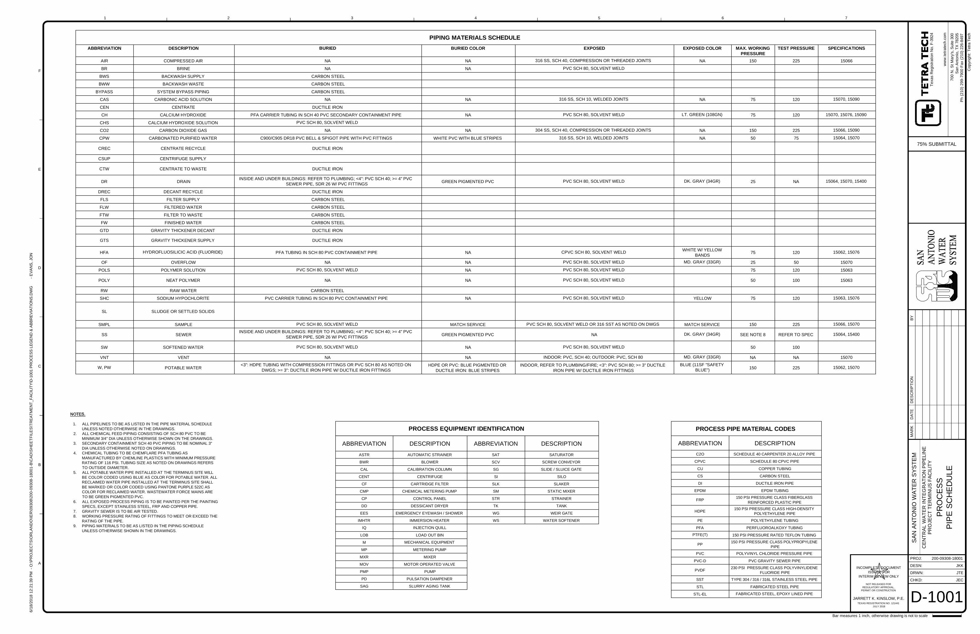
CHKD:
DRWN:
PROJ:
DESN:
ww
w.te
trate
ch.c
om
MAR
KD
ATE
DES
CR
IPTI
ON
BY
6/18
/201
812
:21:
39PM
-O:\P
RO
JEC
TS\O
RLA
ND
O\IE
R\0
9308
\200
-093
08-1
8001
-B\C
AD
\SH
EE
TFIL
ES
\TR
EATM
ENT_
FAC
ILIT
Y\D
-100
1PR
OC
ESS
LEG
END
&AB
BREV
IATI
ON
S.D
WG
-EVA
NS
,JO
N
1
A
B
C
D
E
F
2 3 4 5 6 7
Cop
yrig
ht:T
etra
Tech
Bar measures 1 inch, otherwise drawing is not to scale
200-09308-18001
CE
NTR
AL
WA
TER
INTE
GR
ATIO
NPI
PELI
NE
PR
OJE
CT
TER
MIN
US
FAC
ILIT
Y
SAN
AN
TON
IOW
ATER
SYS
TEM
700
N.S
tMar
y's,
Suite
300
San
Ant
onio
,TX
7820
5P
h(2
10)2
99-7
900
Fax
(210
)226
-849
7
Texa
sR
egis
tratio
nN
o.F-
3924
JARRETT K. KINSLOW, P.E.
INCOMPLETE DOCUMENTISSUED FOR
INTERIM REVIEW ONLY
NOT RELEASED FORREGULATORY APPROVAL,
PERMIT OR CONSTRUCTION
TEXAS REGISTRATION NO. 121441JULY 2018
ABBREVIATION DESCRIPTION
ASTR AUTOMATIC STRAINER
BWR BLOWER
CAL CALIBRATION COLUMN
CENT CENTRIFUGE
CF CARTRIDGE FILTER
CMP CHEMICAL METERING PUMP
CP CONTROL PANEL
DD DESSICANT DRYER
EES EMERGENCY EYEWASH / SHOWER
IMHTR IMMERSION HEATER
IQ INJECTION QUILL
LOB LOAD OUT BIN
M MECHANICAL EQUIPMENT
MP METERING PUMP
MXR MIXER
MOV MOTOR OPERATED VALVE
PMP PUMP
PD PULSATION DAMPENER
SAG SLURRY AGING TANK
ABBREVIATION DESCRIPTION
SAT SATURATOR
SCV SCREW CONVEYOR
SG SLIDE / SLUICE GATE
SI SILO
SLK SLAKER
SM STATIC MIXER
STR STRAINER
TK TANK
WG WEIR GATE
WS WATER SOFTENER
PROCESS PIPE MATERIAL CODES
ABBREVIATION DESCRIPTION
C2O SCHEDULE 40 CARPENTER 20 ALLOY PIPE
CPVC SCHEDULE 80 CPVC PIPE
CU COPPER TUBING
CS CARBON STEEL
DI DUCTILE IRON PIPE
EPDM EPDM TUBING
FRP 150 PSI PRESSURE CLASS FIBERGLASSREINFORCED PLASTIC PIPE
HDPE 150 PSI PRESSURE CLASS HIGH-DENSITYPOLYETHYLENE PIPE
PE POLYETHYLENE TUBING
PFA PERFLUOROALKOXY TUBING
PTFE(T) 150 PSI PRESSURE RATED TEFLON TUBING
PP 150 PSI PRESSURE CLASS POLYPROPYLENEPIPE
PVC POLYVINYL CHLORIDE PRESSURE PIPE
PVC-D PVC GRAVITY SEWER PIPE
PVDF 230 PSI PRESSURE CLASS POLYVINYLIDENEFLUORIDE PIPE
SST TYPE 304 / 316 / 316L STAINLESS STEEL PIPE
STL FABRICATED STEEL PIPE
STL-EL FABRICATED STEEL, EPOXY LINED PIPE
PIPING MATERIALS SCHEDULEABBREVIATION DESCRIPTION BURIED BURIED COLOR EXPOSED EXPOSED COLOR MAX. WORKING
PRESSURETEST PRESSURE SPECIFICATIONS
AIR COMPRESSED AIR NA NA 316 SS, SCH 40, COMPRESSION OR THREADED JOINTS NA 150 225 15066
BR BRINE NA NA PVC SCH 80, SOLVENT WELD
BWS BACKWASH SUPPLY CARBON STEEL
BWW BACKWASH WASTE CARBON STEEL
BYPASS SYSTEM BYPASS PIPING CARBON STEEL
CAS CARBONIC ACID SOLUTION NA NA 316 SS, SCH 10, WELDED JOINTS NA 75 120 15070, 15090
CEN CENTRATE DUCTILE IRON
CH CALCIUM HYDROXIDE PFA CARRIER TUBING IN SCH 40 PVC SECONDARY CONTAINMENT PIPE NA PVC SCH 80, SOLVENT WELD LT. GREEN (108GN) 75 120 15070, 15076, 15090
CHS CALCIUM HYDROXIDE SOLUTION PVC SCH 80, SOLVENT WELD
CO2 CARBON DIOXIDE GAS NA NA 304 SS, SCH 40, COMPRESSION OR THREADED JOINTS NA 150 225 15066, 15090
CPW CARBONATED PURIFIED WATER C900/C905 DR18 PVC BELL & SPIGOT PIPE WITH PVC FITTINGS WHITE PVC WITH BLUE STRIPES 316 SS, SCH 10, WELDED JOINTS NA 50 75 15064, 15070
CREC CENTRATE RECYCLE DUCTILE IRON
CSUP CENTRIFUGE SUPPLY
CTW CENTRATE TO WASTE DUCTILE IRON
DR DRAININSIDE AND UNDER BUILDINGS: REFER TO PLUMBING; <4": PVC SCH 40; >= 4" PVC
SEWER PIPE, SDR 26 W/ PVC FITTINGS GREEN PIGMENTED PVC PVC SCH 80, SOLVENT WELD DK. GRAY (34GR) 25 NA 15064, 15070, 15400
DREC DECANT RECYCLE DUCTILE IRON
FLS FILTER SUPPLY CARBON STEEL
FLW FILTERED WATER CARBON STEEL
FTW FILTER TO WASTE CARBON STEEL
FW FINISHED WATER CARBON STEEL
GTD GRAVITY THICKENER DECANT DUCTILE IRON
GTS GRAVITY THICKENER SUPPLY DUCTILE IRON
HFA HYDROFLUOSILICIC ACID (FLUORIDE) PFA TUBING IN SCH 80 PVC CONTAINMENT PIPE NA CPVC SCH 80, SOLVENT WELD WHITE W/ YELLOWBANDS 75 120 15062, 15076
OF OVERFLOW NA NA PVC SCH 80, SOLVENT WELD MD. GRAY (33GR) 25 50 15070
POLS POLYMER SOLUTION PVC SCH 80, SOLVENT WELD NA PVC SCH 80, SOLVENT WELD 75 120 15063
POLY NEAT POLYMER NA NA PVC SCH 80, SOLVENT WELD 50 100 15063
RW RAW WATER CARBON STEEL
SHC SODIUM HYPOCHLORITE PVC CARRIER TUBING IN SCH 80 PVC CONTAINMENT PIPE NA PVC SCH 80, SOLVENT WELD YELLOW 75 120 15063, 15076
SL SLUDGE OR SETTLED SOLIDS
SMPL SAMPLE PVC SCH 80, SOLVENT WELD MATCH SERVICE PVC SCH 80, SOLVENT WELD OR 316 SST AS NOTED ON DWGS MATCH SERVICE 150 225 15066, 15070
SS SEWERINSIDE AND UNDER BUILDINGS: REFER TO PLUMBING; <4": PVC SCH 40; >= 4" PVC
SEWER PIPE, SDR 26 W/ PVC FITTINGS GREEN PIGMENTED PVC NA DK. GRAY (34GR) SEE NOTE 8 REFER TO SPEC 15064, 15400
SW SOFTENED WATER PVC SCH 80, SOLVENT WELD NA PVC SCH 80, SOLVENT WELD 50 100
VNT VENT NA NA INDOOR: PVC, SCH 40; OUTDOOR: PVC, SCH 80 MD. GRAY (33GR) NA NA 15070
W, PW POTABLE WATER<3": HDPE TUBING WITH COMPRESSION FITTINGS OR PVC SCH 80 AS NOTED ON
DWGS; >= 3": DUCTILE IRON PIPE W/ DUCTILE IRON FITTINGSHDPE OR PVC: BLUE PIGMENTED OR
DUCTILE IRON: BLUE STRIPESINDOOR, REFER TO PLUMBING/FIRE; <3": PVC SCH 80; >= 3" DUCTILE
IRON PIPE W/ DUCTILE IRON FITTINGSBLUE (11SF "SAFETY
BLUE") 150 225 15062, 15070
1. ALL PIPELINES TO BE AS LISTED IN THE PIPE MATERIAL SCHEDULEUNLESS NOTED OTHERWISE IN THE DRAWINGS.
2. ALL CHEMICAL FEED PIPING CONSISTING OF SCH 80 PVC TO BEMINIMUM 3/4" DIA UNLESS OTHERWISE SHOWN ON THE DRAWINGS.
3. SECONDARY CONTAINMENT SCH 40 PVC PIPING TO BE NOMINAL 3"DIA UNLESS OTHERWISE NOTED ON DRAWINGS.
4. CHEMICAL TUBING TO BE CHEMFLARE PFA TUBING ASMANUFACTURED BY CHEMLINE PLASTICS WITH MINIMUM PRESSURERATING OF 116 PSI. TUBING SIZE AS NOTED ON DRAWINGS REFERSTO OUTSIDE DIAMETER.
5. ALL POTABLE WATER PIPE INSTALLED AT THE TERMINUS SITE WILLBE COLOR CODED USING BLUE AS COLOR FOR POTABLE WATER. ALLRECLAIMED WATER PIPE INSTALLED AT THE TERMINUS SITE SHALLBE MARKED OR COLOR CODED USING PANTONE PURPLE 522C ASCOLOR FOR RECLAIMED WATER. WASTEWATER FORCE MAINS ARETO BE GREEN PIGMENTED PVC.
6. ALL EXPOSED PROCESS PIPING IS TO BE PAINTED PER THE PAINTINGSPECS, EXCEPT STAINLESS STEEL, FRP AND COPPER PIPE.
7. GRAVITY SEWER IS TO BE AIR TESTED.8. WORKING PRESSURE RATING OF FITTINGS TO MEET OR EXCEED THE
RATING OF THE PIPE.9. PIPING MATERIALS TO BE AS LISTED IN THE PIPING SCHEDULE
UNLESS OTHERWISE SHOWN IN THE DRAWINGS.
PROCESS EQUIPMENT IDENTIFICATION
D-1001
PR
OC
ESS
PIP
ESC
HE
DU
LE
JKK
JTE
JEC
75% SUBMITTAL
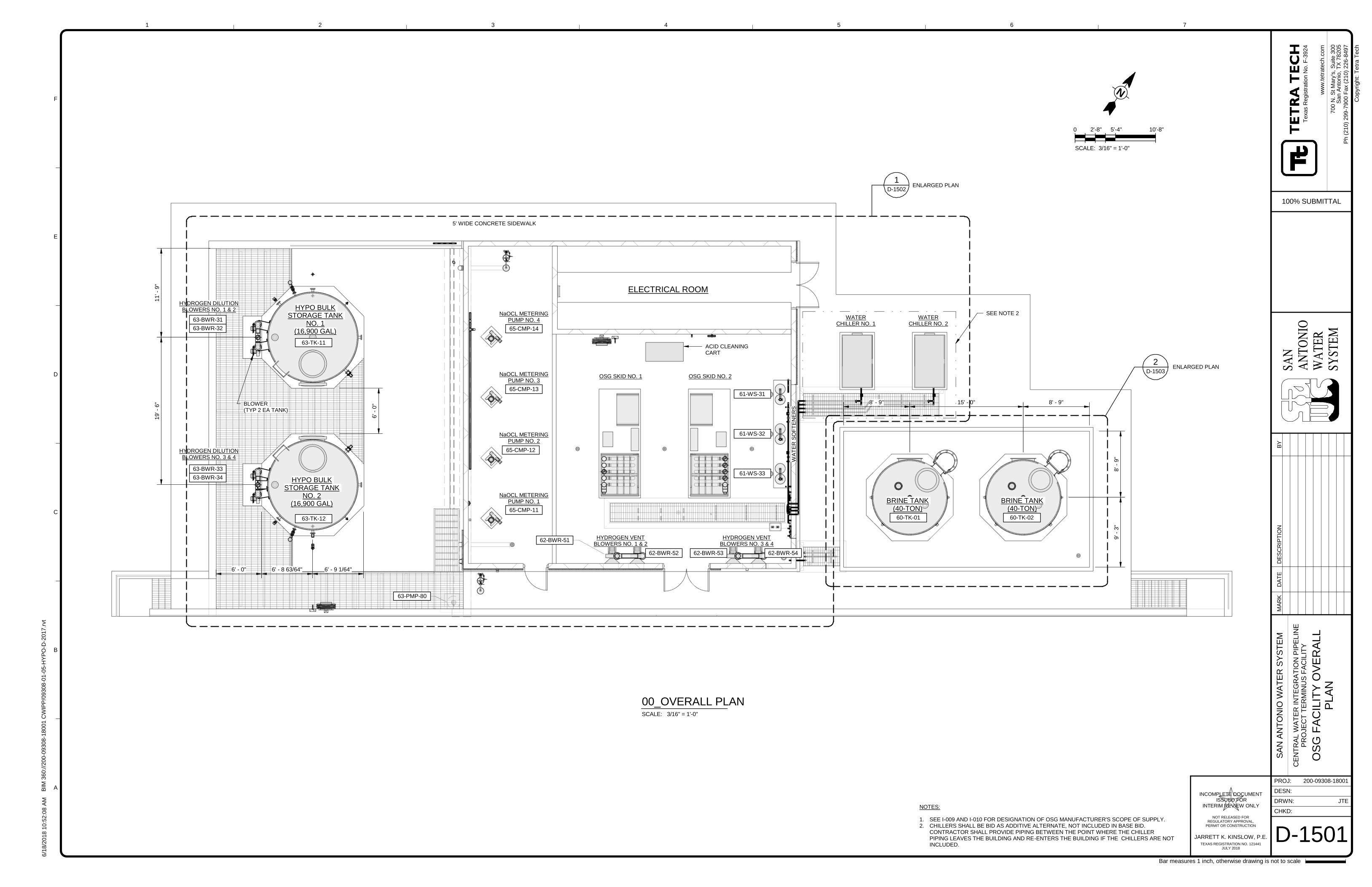
BLOWER(TYP 2 EA TANK)
HYPO BULKSTORAGE TANK
NO. 2(16,900 GAL)
HYPO BULKSTORAGE TANK
NO. 1(16,900 GAL)
ACID CLEANINGCART
BRINE TANK(40-TON)
BRINE TANK(40-TON)
15' - 0"
NaOCL METERINGPUMP NO. 2
NaOCL METERINGPUMP NO. 1
OSG SKID NO. 1 OSG SKID NO. 2
WA
TE
RS
OF
TE
NE
RS
HYDROGEN VENTBLOWERS NO. 1 & 2
HYDROGEN VENTBLOWERS NO. 3 & 4
HYDROGEN DILUTIONBLOWERS NO. 1 & 2
HYDROGEN DILUTIONBLOWERS NO. 3 & 4
NaOCL METERINGPUMP NO. 3
ELECTRICAL ROOM
63-BWR-32
63-BWR-31
63-TK-11
63-TK-12
63-BWR-33
63-BWR-34
65-CMP-13
65-CMP-12
65-CMP-11
62-BWR-51
62-BWR-52 62-BWR-53 62-BWR-54
61-WS-33
61-WS-32
61-WS-31
60-TK-01
19'-
6"
60-TK-02
6'-
0"
6' - 8 63/64" 6' - 9 1/64"
NaOCL METERINGPUMP NO. 4
65-CMP-14
63-PMP-80
5' WIDE CONCRETE SIDEWALK
11'-
9"
6' - 0"
8'-
9"
9'-
3"
8' - 9"8' - 9"
D-1503
2
D-1502
1ENLARGED PLAN
ENLARGED PLAN
WATERCHILLER NO. 1
WATERCHILLER NO. 2
SEE NOTE 2
SAN
AN
TON
IOW
ATE
RSY
STEM
CHKD:
DRWN:
PROJ:
DESN:
ww
w.t
etr
ate
ch
.co
m
1
A
B
C
D
E
F
2 3 4 5 6 7
Bar measures 1 inch, otherwise drawing is not to scale
Co
pyr
ight:
Te
tra
Te
ch
JARRETT K. KINSLOW, P.E.
INCOMPLETE DOCUMENTISSUED FOR
INTERIM REVIEW ONLY
NOT RELEASED FORREGULATORY APPROVAL,
PERMIT OR CONSTRUCTION
TEXAS REGISTRATION NO. 121441JULY 2018
6/1
8/2
018
10:5
2:0
8A
MB
IM3
60://2
00-0
9308
-180
01
CW
IPP
/09308
-01-0
5-H
YP
O-D
-2017
.rvt
200-09308-18001
JTE
D-1501
SA
NA
NT
ON
IOW
AT
ER
SY
ST
EM
CE
NT
RA
LW
AT
ER
INT
EG
RA
TIO
NP
IPE
LIN
EP
RO
JE
CT
TE
RM
INU
SF
AC
ILIT
Y
OS
GF
AC
ILIT
YO
VE
RA
LL
PLA
N
Texa
sR
eg
istr
atio
nN
o.F
-3924
700
N.S
tM
ary
's,S
uite
300
San
An
ton
io,T
X78
205
100% SUBMITTAL
Ph
(210)
299-7
900
Fax
(210)
226-8
497
SCALE: 3/16" = 1'-0"
00_OVERALL PLAN
0 2'-8" 5'-4" 10'-8"
SCALE: 3/16" = 1'-0"
N
MA
RK
DA
TE
DE
SC
RIP
TIO
NB
Y
NOTES:
1. SEE I-009 AND I-010 FOR DESIGNATION OF OSG MANUFACTURER'S SCOPE OF SUPPLY.2. CHILLERS SHALL BE BID AS ADDITIVE ALTERNATE, NOT INCLUDED IN BASE BID.
CONTRACTOR SHALL PROVIDE PIPING BETWEEN THE POINT WHERE THE CHILLERPIPING LEAVES THE BUILDING AND RE-ENTERS THE BUILDING IF THE CHILLERS ARE NOTINCLUDED.
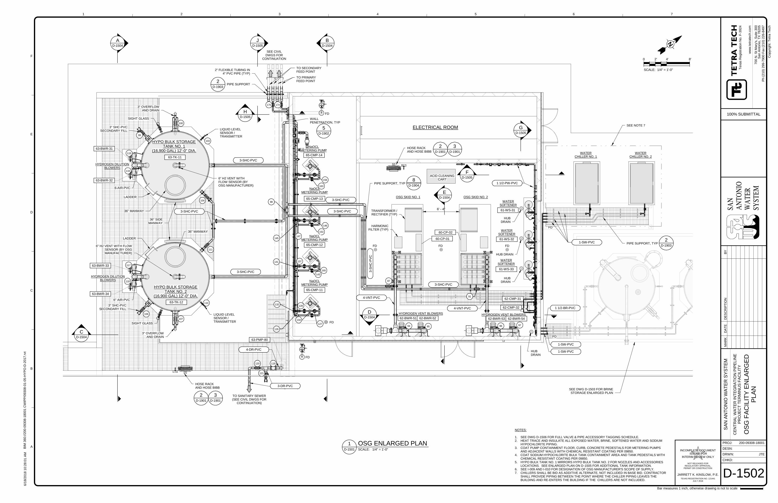
FD-1505
GD-1505
BD-1504
AD-1504
CD-1504
ACID CLEANINGCART
NaOCLMETERING PUMP
OSG SKID NO. 1 OSG SKID NO. 2
WATERSOFTENER
HYDROGEN VENT BLOWERS HYDROGEN VENT BLOWERS
HYDROGEN DILUTIONBLOWERS
HYPO BULK STORAGETANK NO. 2
(16,900 GAL) 12'-0" DIA.
HYPO BULK STORAGETANK NO. 1
(16,900 GAL) 12'-0" DIA.
36" MANWAY
3" OVERFLOWAND DRAIN
63-TK-12
63-TK-11
6-AIR-PVC
3" OVERFLOWAND DRAIN
3" SHC-PVCSECONDARY FILL
SIGHT GLASS
SIGHT GLASS
3" SHC-PVCSECONDARY FILL
6" AIR-PVC
6" H2 VENT WITHFLOW SENSOR (BYOSG MANUFACTURER)
6" H2 VENT WITH FLOWSENSOR (BY OSGMANUFACTURER)
63-BWR-31
63-BWR-32
HYDROGEN DILUTIONBLOWERS
63-BWR-33
63-BWR-34
65-CMP-13
65-CMP-12
65-CMP-11
62-BWR-51 62-BWR-52 62-BWR-53 62-BWR-54
61-WS-31
61-WS-32
61-WS-33
WATERSOFTENER
WATERSOFTENER
HD-1505
104
99
100
111
117
118
106
107
115
116
98
147
153
141 137
143
132128
134
126
145
JD-1505
NaOCLMETERING PUMP
NaOCLMETERING PUMP
LIQUID LEVELSENSOR /TRANSMITTER
LIQUID LEVELSENSOR /TRANSMITTER
110
103
87
91
94 95 96 97
62-CMP-32
62-CMP-31
TO PRIMARYFEED POINT
TO SECONDARYFEED POINT
2" FLEXIBLE TUBING IN4" PVC PIPE (TYP)
175 174
ELECTRICAL ROOM
3-SHC-PVC
3-SHC-PVC
3-SHC-PVC
36" MANWAY
3-SHC-PVC
3-SHC-PVC
127
165
146
HOSE RACKAND HOSE BIBB
2D-1901
3D-1901
3-DR-PVC
4-DR-PVC
3-S
HC
-PV
C
3-SHC-PVC
1 1/2-BR-PVC
1-SW-PVC
1-SW-PVC
1 1/2-PW-PVC
120
121
119
TO SANITARY SEWER(SEE CIVIL DWGS FOR
CONTINUATION)
LADDER
LADDER
36" SIDEMANWAY
63-PMP-80
65-CMP-14
NaOCLMETERING PUMP
163
156
6' - 4"
DD-1504
HOSE RACKAND HOSE BIBB
2D-1901
3D-1901
ED-1504
WALLPENETRATION, TYP
5D-1902
PIPE SUPPORT, TYP8
D-1904
FD FDFD
HUBDRAIN
HUB DRAIN
HUBDRAIN
HUBDRAIN
FD
FD
FD
60-CP-01
60-CP-02
SEE DWG D-1503 FOR BRINESTORAGE ENLARGED PLAN
WATERCHILLER NO. 1
WATERCHILLER NO. 2
1-SW-PVC
4-VNT-PVC
4-VNT-PVC
SEE CIVILDWGS FOR
CONTINUATION
PIPE SUPPORT2
D-1903
TRANSFORMER /RECTIFIER (TYP)
HARMONICFILTER (TYP)
PIPE SUPPORT, TYP2
D-1903
FD
FD
SEE NOTE 7
SAN
AN
TON
IOW
ATE
RSY
STEM
CHKD:
DRWN:
PROJ:
DESN:
ww
w.t
etr
ate
ch
.co
m
1
A
B
C
D
E
F
2 3 4 5 6 7
Bar measures 1 inch, otherwise drawing is not to scale
Co
pyr
ight:
Te
tra
Te
ch
JARRETT K. KINSLOW, P.E.
INCOMPLETE DOCUMENTISSUED FOR
INTERIM REVIEW ONLY
NOT RELEASED FORREGULATORY APPROVAL,
PERMIT OR CONSTRUCTION
TEXAS REGISTRATION NO. 121441JULY 2018
6/1
8/2
018
10:2
8:0
1A
MB
IM3
60://2
00-0
9308
-180
01
CW
IPP
/09308
-01-0
5-H
YP
O-D
-2017
.rvt
200-09308-18001
JTE
D-1502
SA
NA
NT
ON
IOW
AT
ER
SY
ST
EM
CE
NT
RA
LW
AT
ER
INT
EG
RA
TIO
NP
IPE
LIN
EP
RO
JE
CT
TE
RM
INU
SF
AC
ILIT
Y
OS
GF
AC
ILIT
YE
NLA
RG
ED
PLA
N
Texa
sR
eg
istr
atio
nN
o.F
-3924
700
N.S
tM
ary
's,S
uite
300
San
An
ton
io,T
X78
205
100% SUBMITTAL
Ph
(210)
299-7
900
Fax
(210)
226-8
497
SCALE: 1/4" = 1'-0"D-1501
1 OSG ENLARGED PLAN
NOTES:
1. SEE DWG D-1506 FOR FULL VALVE & PIPE ACCESSORY TAGGING SCHEDULE.2. HEAT TRACE AND INSULATE ALL EXPOSED WATER, BRINE, SOFTENED WATER AND SODIUM
HYPOCHLORITE PIPING.3. COAT PUMP CONTAINMENT FLOOR, CURB, CONCRETE PEDESTALS FOR METERING PUMPS
AND ADJACENT WALLS WITH CHEMICAL RESISTANT COATING PER 09850.4. COAT SODIUM HYPOCHLORITE BULK TANK CONTAINMENT AREA AND TANK PEDESTALS WITH
CHEMICAL RESISTANT COATING PER 09850.5. HYPO BULK TANK NO. 1 MIRRORS HYPO BULK TANK NO. 2 FOR NOZZLES AND ACCESSORIES
LOCATIONS. SEE ENLARGED PLAN ON D-1505 FOR ADDITIONAL TANK INFORMATION.6. SEE I-009 AND I-010 FOR DESIGNATION OF OSG MANUFACTURER'S SCOPE OF SUPPLY.7. CHILLERS SHALL BE BID AS ADDITIVE ALTERNATE, NOT INCLUDED IN BASE BID. CONTRACTOR
SHALL PROVIDE PIPING BETWEEN THE POINT WHERE THE CHILLER PIPING LEAVES THEBUILDING AND RE-ENTERS THE BUILDING IF THE CHILLERS ARE NOT INCLUDED.
N
0 2' 4' 8'
SCALE: 1/4" = 1'-0"
MA
RK
DA
TE
DE
SC
RIP
TIO
NB
Y
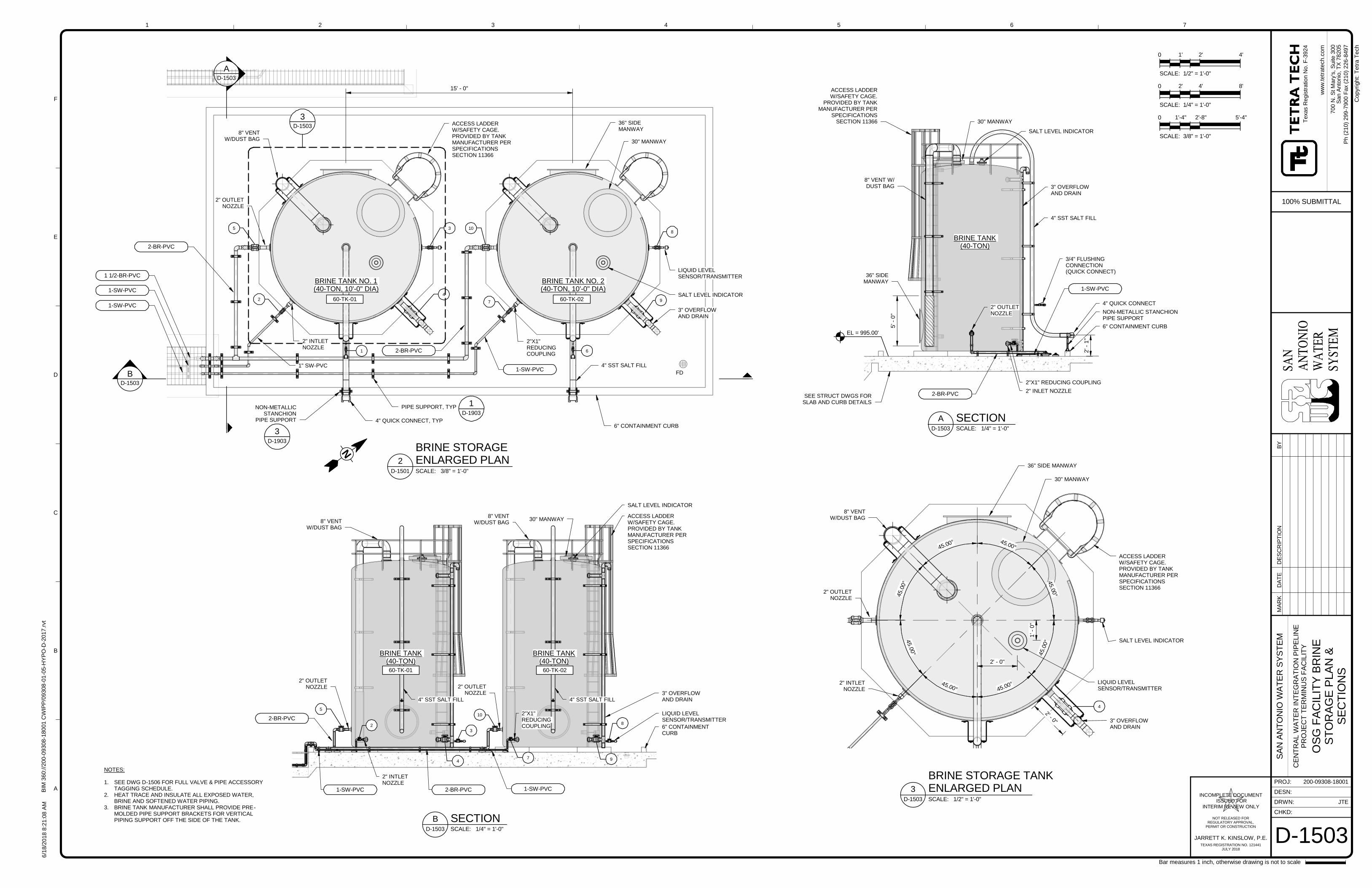
BD-1503
AD-1503
BRINE TANK NO. 1(40-TON, 10'-0" DIA)
15' - 0"
4" QUICK CONNECT, TYP
NON-METALLICSTANCHION
PIPE SUPPORT
ACCESS LADDERW/SAFETY CAGE.PROVIDED BY TANKMANUFACTURER PERSPECIFICATIONSSECTION 11366
4" SST SALT FILL
30" MANWAY
LIQUID LEVELSENSOR/TRANSMITTER
SALT LEVEL INDICATOR
3" OVERFLOWAND DRAIN
2" OUTLETNOZZLE
1" SW-PVC
2"X1"REDUCINGCOUPLING
6" CONTAINMENT CURB
8
9
6
7
103
4
1
2
5
60-TK-01
BRINE TANK NO. 2(40-TON, 10'-0" DIA)
60-TK-02
1 1/2-BR-PVC
1-SW-PVC
1-SW-PVC
2-BR-PVC
2-BR-PVC
1-SW-PVCFD
PIPE SUPPORT, TYP 1D-1903
3D-1903
D-1503
3
2" INTLETNOZZLE
8" VENTW/DUST BAG
36" SIDEMANWAY
ACCESS LADDERW/SAFETY CAGE.PROVIDED BY TANKMANUFACTURER PERSPECIFICATIONSSECTION 11366
30" MANWAY
LIQUID LEVELSENSOR/TRANSMITTER
SALT LEVEL INDICATOR
3" OVERFLOWAND DRAIN
8" VENTW/DUST BAG
2" OUTLETNOZZLE
2" INTLETNOZZLE
2"X1"REDUCINGCOUPLING 6" CONTAINMENT
CURB
4" SST SALT FILL
2" OUTLETNOZZLE
8" VENTW/DUST BAG
4" SST SALT FILL
BRINE TANK(40-TON)
BRINE TANK(40-TON)
60-TK-0260-TK-01
1-SW-PVC 2-BR-PVC 1-SW-PVC
2-BR-PVC
5
2
4
3
10
7 9
8
5'-
0"
4" QUICK CONNECT
NON-METALLIC STANCHIONPIPE SUPPORT
ACCESS LADDERW/SAFETY CAGE.
PROVIDED BY TANKMANUFACTURER PER
SPECIFICATIONSSECTION 11366
4" SST SALT FILL
30" MANWAY
SALT LEVEL INDICATOR
3" OVERFLOWAND DRAIN
8" VENT W/DUST BAG
2" OUTLETNOZZLE
2" INLET NOZZLE
2"X1" REDUCING COUPLING
6" CONTAINMENT CURB
3/4" FLUSHINGCONNECTION(QUICK CONNECT)
BRINE TANK(40-TON)
2-BR-PVC
EL = 995.00'
1-SW-PVC
2'-
1"
SEE STRUCT DWGS FORSLAB AND CURB DETAILS
36" SIDEMANWAY
45.00°
45.00
°
45.0
0°
45.00°45.00°
45.00
°
45.0
0°
45.00°
2' - 0"
2' - 0"
1'-
0"
ACCESS LADDERW/SAFETY CAGE.PROVIDED BY TANKMANUFACTURER PERSPECIFICATIONSSECTION 11366
2" OUTLETNOZZLE
2" INTLETNOZZLE
8" VENTW/DUST BAG
4
LIQUID LEVELSENSOR/TRANSMITTER
SALT LEVEL INDICATOR
3" OVERFLOWAND DRAIN
30" MANWAY
36" SIDE MANWAY
SAN
AN
TON
IOW
ATE
RSY
STEM
CHKD:
DRWN:
PROJ:
DESN:
ww
w.t
etr
ate
ch
.co
m
1
A
B
C
D
E
F
2 3 4 5 6 7
Bar measures 1 inch, otherwise drawing is not to scale
Co
pyr
ight:
Te
tra
Te
ch
JARRETT K. KINSLOW, P.E.
INCOMPLETE DOCUMENTISSUED FOR
INTERIM REVIEW ONLY
NOT RELEASED FORREGULATORY APPROVAL,
PERMIT OR CONSTRUCTION
TEXAS REGISTRATION NO. 121441JULY 2018
6/1
8/2
018
8:2
1:0
8A
MB
IM3
60://2
00-0
9308
-180
01
CW
IPP
/09308
-01-0
5-H
YP
O-D
-2017
.rvt
200-09308-18001
JTE
D-1503
SA
NA
NT
ON
IOW
AT
ER
SY
ST
EM
CE
NT
RA
LW
AT
ER
INT
EG
RA
TIO
NP
IPE
LIN
EP
RO
JE
CT
TE
RM
INU
SF
AC
ILIT
Y
OS
GF
AC
ILIT
YB
RIN
ES
TO
RA
GE
PLA
N&
SE
CT
ION
S
Texa
sR
eg
istr
atio
nN
o.F
-3924
700
N.S
tM
ary
's,S
uite
300
San
An
ton
io,T
X78
205
100% SUBMITTAL
Ph
(210)
299-7
900
Fax
(210)
226-8
497
SCALE: 3/8" = 1'-0"D-1501
2
BRINE STORAGEENLARGED PLAN
SCALE: 1/4" = 1'-0"D-1503
B SECTION
SCALE: 1/4" = 1'-0"D-1503
A SECTION
NOTES:
1. SEE DWG D-1506 FOR FULL VALVE & PIPE ACCESSORYTAGGING SCHEDULE.
2. HEAT TRACE AND INSULATE ALL EXPOSED WATER,BRINE AND SOFTENED WATER PIPING.
3. BRINE TANK MANUFACTURER SHALL PROVIDE PRE-MOLDED PIPE SUPPORT BRACKETS FOR VERTICALPIPING SUPPORT OFF THE SIDE OF THE TANK.
N
0 1'-4" 2'-8" 5'-4"
SCALE: 3/8" = 1'-0"
0 2' 4' 8'
SCALE: 1/4" = 1'-0"
SCALE: 1/2" = 1'-0"D-1503
3
BRINE STORAGE TANKENLARGED PLAN
0 1' 2' 4'
SCALE: 1/2" = 1'-0"
MA
RK
DA
TE
DE
SC
RIP
TIO
NB
Y
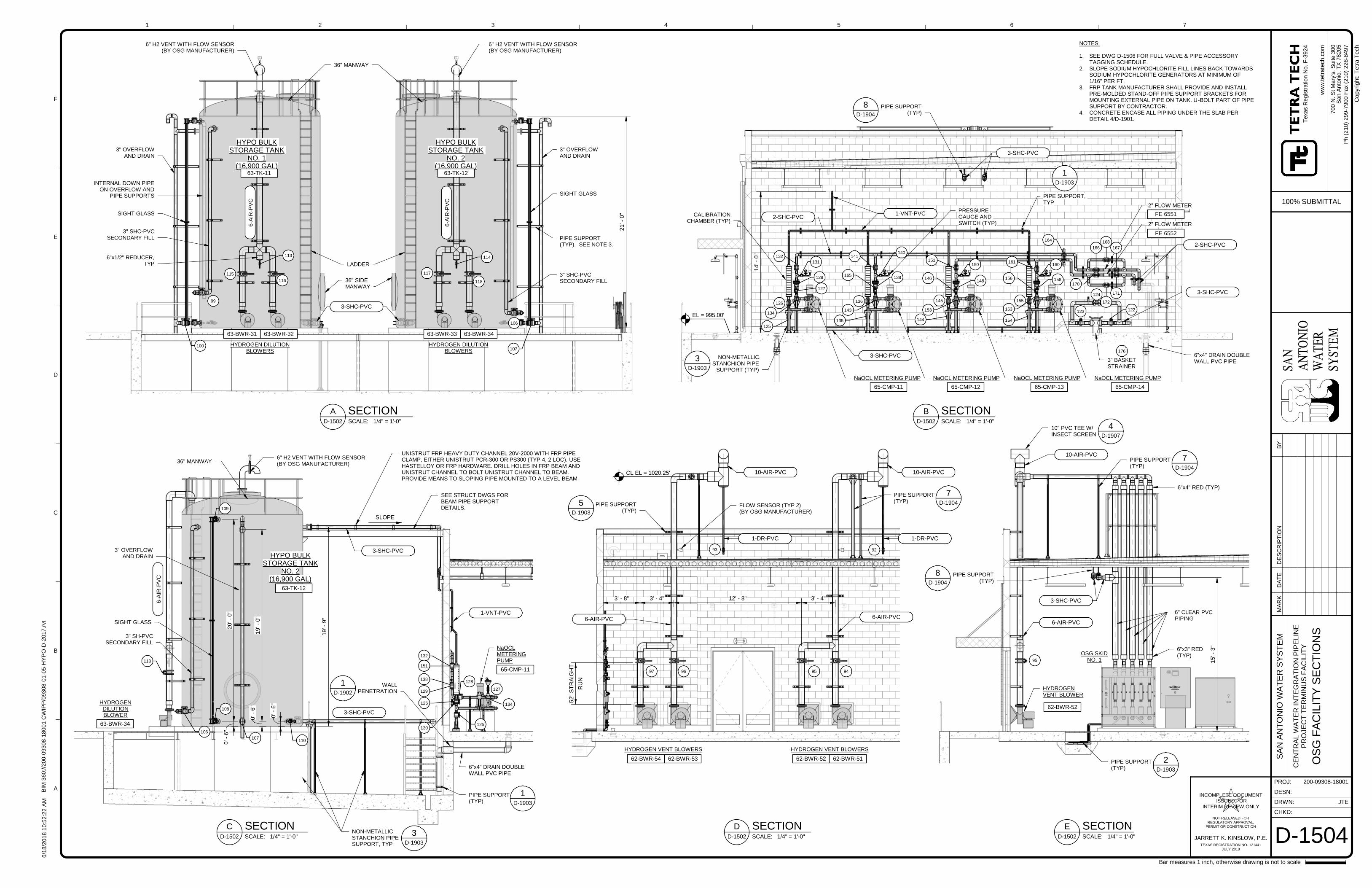
HYDROGEN DILUTIONBLOWERS
HYPO BULKSTORAGE TANK
NO. 2(16,900 GAL)
HYPO BULKSTORAGE TANK
NO. 1(16,900 GAL)
36" MANWAY
3" OVERFLOWAND DRAIN
3" OVERFLOWAND DRAIN
3" SHC-PVCSECONDARY FILL
SIGHT GLASS
3" SHC-PVCSECONDARY FILL
6" H2 VENT WITH FLOW SENSOR(BY OSG MANUFACTURER)
6" H2 VENT WITH FLOW SENSOR(BY OSG MANUFACTURER)
HYDROGEN DILUTIONBLOWERS
63-TK-1263-TK-11
63-BWR-3263-BWR-31 63-BWR-33 63-BWR-34
115
116
100
99
117
118
107
106
6-A
IR-P
VC
6-A
IR-P
VC
3-SHC-PVC
SIGHT GLASS
LADDER
36" SIDEMANWAY
6"x1/2" REDUCER,TYP
113 114
INTERNAL DOWN PIPEON OVERFLOW AND
PIPE SUPPORTS
PIPE SUPPORT(TYP). SEE NOTE 3.
21'-
0"
63-TK-12
63-BWR-34
65-CMP-11
NaOCLMETERINGPUMP
HYPO BULKSTORAGE TANK
NO. 2(16,900 GAL)
36" MANWAY
3" OVERFLOWAND DRAIN
3" SH-PVCSECONDARY FILL
6" H2 VENT WITH FLOW SENSOR(BY OSG MANUFACTURER)
HYDROGENDILUTIONBLOWER
106
110107
118
125
134
127
128
126
130
129
132
141151
138
6-A
IR-P
VC
3-SHC-PVC
3-SHC-PVC
1-VNT-PVC
SIGHT GLASS
SEE STRUCT DWGS FORBEAM PIPE SUPPORTDETAILS.
NON-METALLICSTANCHION PIPESUPPORT, TYP
3D-1903
SLOPE
19'-
9"
109
108
20'-
0"
0'-
6"
0'-
6"
UNISTRUT FRP HEAVY DUTY CHANNEL 20V-2000 WITH FRP PIPECLAMP, EITHER UNISTRUT PCR-300 OR PS300 (TYP 4, 2 LOC). USEHASTELLOY OR FRP HARDWARE. DRILL HOLES IN FRP BEAM ANDUNISTRUT CHANNEL TO BOLT UNISTRUT CHANNEL TO BEAM.PROVIDE MEANS TO SLOPING PIPE MOUNTED TO A LEVEL BEAM.
PIPE SUPPORT(TYP)
1D-1903
6"x4" DRAIN DOUBLEWALL PVC PIPE
WALLPENETRATION
1D-1902
19'-
0"
0'-
6"
NaOCL METERING PUMP
3" BASKETSTRAINER
65-CMP-11 65-CMP-12 65-CMP-13
NaOCL METERING PUMPNaOCL METERING PUMP
CALIBRATIONCHAMBER (TYP)
2" FLOW METER
124
172
170
171
167
168
166
FE 6551
FE 6552
2" FLOW METER
151150
145
141132
131
140
126 136
129
127
134
165
143
138
153
146148
3-SHC-PVC
1-VNT-PVC
3-SHC-PVC
3-SHC-PVC
2-SHC-PVC
2-SHC-PVC
EL = 995.00'
161160
155
163
156 158
135 144 154
125
NaOCL METERING PUMP
65-CMP-14
164
PRESSUREGAUGE ANDSWITCH (TYP)
PIPE SUPPORT,TYP
1D-1903
176
14'-
0"
123 122
NON-METALLICSTANCHION PIPE
SUPPORT (TYP)
3D-1903
PIPE SUPPORT(TYP)
8D-1904
6"x4" DRAIN DOUBLEWALL PVC PIPE
RU
N
52"
ST
RA
IGH
T
HYDROGEN VENT BLOWERS HYDROGEN VENT BLOWERS
62-BWR-54 62-BWR-53 62-BWR-52 62-BWR-51
94959697
6-AIR-PVC 6-AIR-PVC
10-AIR-PVC 10-AIR-PVC
93 92
1-DR-PVC1-DR-PVC
3' - 4"12' - 8"3' - 4"3' - 8"
PIPE SUPPORT(TYP)
7D-1904
CL EL = 1020.25'
PIPE SUPPORT(TYP)
5D-1903
FLOW SENSOR (TYP 2)(BY OSG MANUFACTURER)
95
62-BWR-52
OSG SKIDNO. 1
3-SHC-PVC
10-AIR-PVC
HYDROGENVENT BLOWER
6-AIR-PVC
6" CLEAR PVCPIPING
10" PVC TEE W/INSECT SCREEN
4D-1907
15'-
3"
6"x4" RED (TYP)
6"x3" RED(TYP)
PIPE SUPPORT(TYP)
7D-1904
PIPE SUPPORT(TYP)
2D-1903
PIPE SUPPORT(TYP)
8D-1904
SAN
AN
TON
IOW
ATE
RSY
STEM
CHKD:
DRWN:
PROJ:
DESN:
ww
w.t
etr
ate
ch
.co
m
1
A
B
C
D
E
F
2 3 4 5 6 7
Bar measures 1 inch, otherwise drawing is not to scale
Co
pyr
ight:
Te
tra
Te
ch
JARRETT K. KINSLOW, P.E.
INCOMPLETE DOCUMENTISSUED FOR
INTERIM REVIEW ONLY
NOT RELEASED FORREGULATORY APPROVAL,
PERMIT OR CONSTRUCTION
TEXAS REGISTRATION NO. 121441JULY 2018
6/1
8/2
018
10:5
2:2
2A
MB
IM3
60://2
00-0
9308
-180
01
CW
IPP
/09308
-01-0
5-H
YP
O-D
-2017
.rvt
200-09308-18001
JTE
D-1504
SA
NA
NT
ON
IOW
AT
ER
SY
ST
EM
CE
NT
RA
LW
AT
ER
INT
EG
RA
TIO
NP
IPE
LIN
EP
RO
JE
CT
TE
RM
INU
SF
AC
ILIT
Y
OS
GF
AC
ILIT
YS
EC
TIO
NS
Texa
sR
eg
istr
atio
nN
o.F
-3924
700
N.S
tM
ary
's,S
uite
300
San
An
ton
io,T
X78
205
100% SUBMITTAL
Ph
(210)
299-7
900
Fax
(210)
226-8
497
SCALE: 1/4" = 1'-0"D-1502
A SECTION
SCALE: 1/4" = 1'-0"D-1502
C SECTION
NOTES:
1. SEE DWG D-1506 FOR FULL VALVE & PIPE ACCESSORYTAGGING SCHEDULE.
2. SLOPE SODIUM HYPOCHLORITE FILL LINES BACK TOWARDSSODIUM HYPOCHLORITE GENERATORS AT MINIMUM OF1/16" PER FT.
3. FRP TANK MANUFACTURER SHALL PROVIDE AND INSTALLPRE-MOLDED STAND-OFF PIPE SUPPORT BRACKETS FORMOUNTING EXTERNAL PIPE ON TANK. U-BOLT PART OF PIPESUPPORT BY CONTRACTOR.
4. CONCRETE ENCASE ALL PIPING UNDER THE SLAB PERDETAIL 4/D-1901.
SCALE: 1/4" = 1'-0"D-1502
B SECTION
SCALE: 1/4" = 1'-0"D-1502
D SECTIONSCALE: 1/4" = 1'-0"D-1502
E SECTION
MA
RK
DA
TE
DE
SC
RIP
TIO
NB
Y
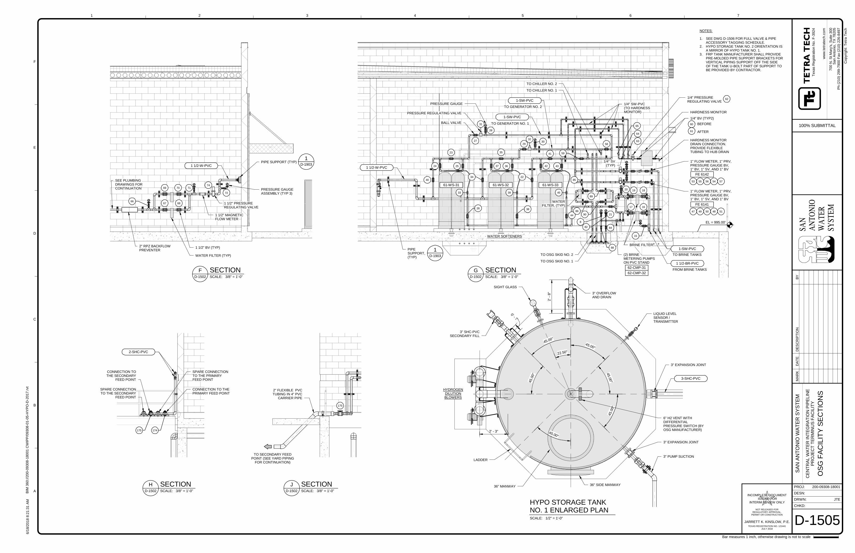
61-WS-3361-WS-3261-WS-31
WATER SOFTENERS
HARDNESS MONITORDRAIN CONNECTION.PROVIDE FLEXIBLETUBING TO HUB DRAIN
HARDNESS MONITOR
1/4" BV (TYP2)
1/4" PRESSUREREGULATING VALVE
1/4" SV(TYP)
1/4" SW-PVC(TO HARDNESSMONITOR)
WATERFILTER, (TYP)
BRINE FILTER
(2) BRINEMETERING PUMPSON PVC STAND
62-CMP-32
62-CMP-31
TO BRINE TANKS
PIPESUPPORT,(TYP)
1D-1903
TO GENERATOR NO. 1
TO GENERATOR NO. 2
40
24
23
25
34
35
37 4236
41
43
22
33 39 45
26 38
44
58
59
65
64
63
85
8690
89
62
60
61
BEFORE
AFTER
53 55 56 54 57
FE 6142
47 49 50 48 51
FE 6141
1" FLOW METER, 1" PRV,PRESSURE GAUGE BV,1" BV, 1" SV, AND 1" BV
20 19 18
17 16
15
8
82
88
84
1" FLOW METER, 1" PRV,PRESSURE GAUGE BV,1" BV, 1" SV, AND 1" BV
21
1 1/2-W-PVC
1 1/2-BR-PVC
1-SW-PVC
1-SW-PVC
1-SW-PVC
FROM BRINE TANKS
EL = 995.00'
TO CHILLER NO. 1
TO CHILLER NO. 2
TO OSG SKID NO. 2
TO OSG SKID NO. 1
BALL VALVE
PRESSURE REGULATING VALVE
PRESSURE GAUGE
27
31
28
29
3230
SEE PLUMBINGDRAWINGS FORCONTINUATION
WATER FILTER (TYP)
PRESSURE GAUGEASSEMBLY (TYP 3)
1 1/2" PRESSUREREGULATING VALVE
PIPE SUPPORT (TYP)
1 1/2" BV (TYP)
1 1/2" MAGNETICFLOW METER
72
74717069
67 6866
1D-19031 1/2-W-PVC
2" RPZ BACKFLOWPREVENTER
SPARE CONNECTIONTO THE PRIMARYFEED POINT
SPARE CONNECTIONTO THE SECONDARY
FEED POINT
CONNECTION TOTHE SECONDARY
FEED POINT
CONNECTION TO THEPRIMARY FEED POINT
175 174
2-SHC-PVC
TO SECONDARY FEEDPOINT (SEE YARD PIPING
FOR CONTINUATION)
2" FLEXIBLE PVCTUBING IN 4" PVC
CARRIER PIPE
175
45.00°
22.50°
45.00°
45.0
0° 4
5.00
°
45.0
0°
45.00°
HYDROGENDILUTIONBLOWERS
36" MANWAY
SIGHT GLASS
3" SHC-PVCSECONDARY FILL
6" H2 VENT WITHDIFFERENTIALPRESSURE SWITCH (BYOSG MANUFACTURER)
LIQUID LEVELSENSOR /TRANSMITTER
3-SHC-PVC
LADDER
36" SIDE MANWAY
3" OVERFLOWAND DRAIN
3" PUMP SUCTION
2' - 3"
2'-
8"
3" EXPANSION JOINT
3" EXPANSION JOINT
0' - 7"
SAN
AN
TON
IOW
ATE
RSY
STEM
CHKD:
DRWN:
PROJ:
DESN:
ww
w.t
etr
ate
ch
.co
m
1
A
B
C
D
E
F
2 3 4 5 6 7
Bar measures 1 inch, otherwise drawing is not to scale
Co
pyr
ight:
Te
tra
Te
ch
JARRETT K. KINSLOW, P.E.
INCOMPLETE DOCUMENTISSUED FOR
INTERIM REVIEW ONLY
NOT RELEASED FORREGULATORY APPROVAL,
PERMIT OR CONSTRUCTION
TEXAS REGISTRATION NO. 121441JULY 2018
6/1
8/2
018
8:2
1:3
1A
MB
IM3
60://2
00-0
9308
-180
01
CW
IPP
/09308
-01-0
5-H
YP
O-D
-2017
.rvt
200-09308-18001
JTE
D-1505
SA
NA
NT
ON
IOW
AT
ER
SY
ST
EM
CE
NT
RA
LW
AT
ER
INT
EG
RA
TIO
NP
IPE
LIN
EP
RO
JE
CT
TE
RM
INU
SF
AC
ILIT
Y
OS
GF
AC
ILIT
YS
EC
TIO
NS
Texa
sR
eg
istr
atio
nN
o.F
-3924
700
N.S
tM
ary
's,S
uite
300
San
An
ton
io,T
X78
205
100% SUBMITTAL
Ph
(210)
299-7
900
Fax
(210)
226-8
497
SCALE: 3/8" = 1'-0"D-1502
G SECTIONSCALE: 3/8" = 1'-0"D-1502
F SECTION
SCALE: 3/8" = 1'-0"D-1502
H SECTIONSCALE: 3/8" = 1'-0"D-1502
J SECTION
SCALE: 1/2" = 1'-0"
HYPO STORAGE TANKNO. 1 ENLARGED PLAN
NOTES:
1. SEE DWG D-1506 FOR FULL VALVE & PIPEACCESSORY TAGGING SCHEDULE.
2. HYPO STORAGE TANK NO. 2 ORIENTATION ISA MIRROR OF HYPO TANK NO. 1.
3. FRP TANK MANUFACTURER SHALL PROVIDEPRE-MOLDED PIPE SUPPORT BRACKETS FORVERTICAL PIPING SUPPORT OFF THE SIDEOF THE TANK U-BOLT PART OF SUPPORT TOBE PROVIDED BY CONTRACTOR.
MA
RK
DA
TE
DE
SC
RIP
TIO
NB
Y
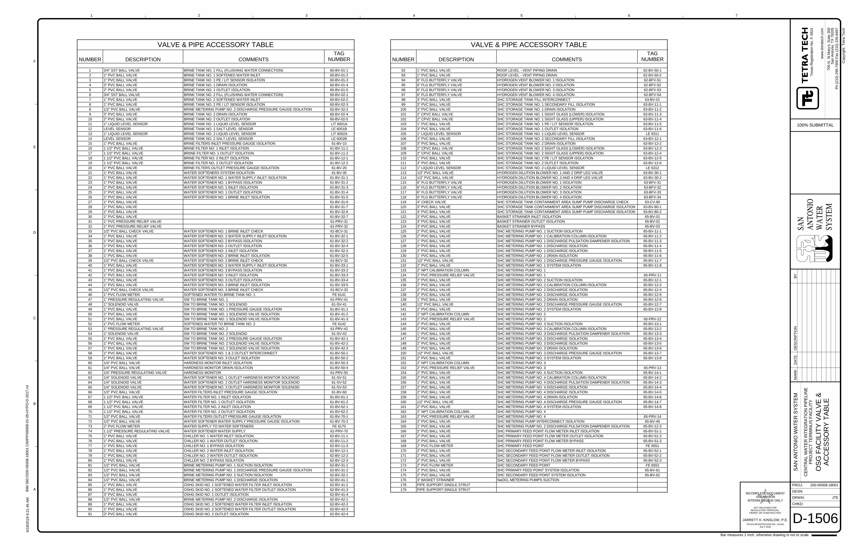
SAN
AN
TON
IOW
ATE
RSY
STEM
CHKD:
DRWN:
PROJ:
DESN:
ww
w.t
etr
ate
ch
.co
m
1
A
B
C
D
E
F
2 3 4 5 6 7
Bar measures 1 inch, otherwise drawing is not to scale
Co
pyr
ight:
Te
tra
Te
ch
JARRETT K. KINSLOW, P.E.
INCOMPLETE DOCUMENTISSUED FOR
INTERIM REVIEW ONLY
NOT RELEASED FORREGULATORY APPROVAL,
PERMIT OR CONSTRUCTION
TEXAS REGISTRATION NO. 121441JULY 2018
6/1
8/2
018
8:2
1:4
6A
MB
IM3
60://2
00-0
9308
-180
01
CW
IPP
/09308
-01-0
5-H
YP
O-D
-2017
.rvt
200-09308-18001
JTE
D-1506
SA
NA
NT
ON
IOW
AT
ER
SY
ST
EM
CE
NT
RA
LW
AT
ER
INT
EG
RA
TIO
NP
IPE
LIN
EP
RO
JE
CT
TE
RM
INU
SF
AC
ILIT
Y
OS
GF
AC
ILIT
YV
ALV
E&
AC
CE
SS
OR
YT
AB
LE
Texa
sR
eg
istr
atio
nN
o.F
-3924
700
N.S
tM
ary
's,S
uite
300
San
An
ton
io,T
X78
205
100% SUBMITTAL
Ph
(210)
299-7
900
Fax
(210)
226-8
497
VALVE & PIPE ACCESSORY TABLE
NUMBER DESCRIPTION COMMENTSTAG
NUMBER
92 1" PVC BALL VALVE ROOF LEVEL - VENT PIPING DRAIN 62-BV-50-1
93 1" PVC BALL VALVE ROOF LEVEL - VENT PIPING DRAIN 62-BV-50-2
94 6" FLG BUTTERFLY VALVE HYDROGEN VENT BLOWER NO. 1 ISOLATION 62-BFV-51
95 6" FLG BUTTERFLY VALVE HYDROGEN VENT BLOWER NO. 2 ISOLATION 62-BFV-52
96 6" FLG BUTTERFLY VALVE HYDROGEN VENT BLOWER NO. 3 ISOLATION 62-BFV-53
97 6" FLG BUTTERFLY VALVE HYDROGEN VENT BLOWER NO. 4 ISOLATION 62-BFV-54
98 3" PVC BALL VALVE SHC STORAGE TANK FILL INTERCONNECT 63-BV-01
99 3" PVC BALL VALVE SHC STORAGE TANK NO. 1 SECONDARY FILL ISOLATION 63-BV-11-1
100 3" PVC BALL VALVE SHC STORAGE TANK NO. 1 DRAIN ISOLATION 63-BV-11-2
101 2" CPVC BALL VALVE SHC STORAGE TANK NO. 1 SIGHT GLASS (LOWER) ISOLATION 63-BV-11-3
102 2" CPVC BALL VALVE SHC STORAGE TANK NO. 1 SIGHT GLASS (UPPER) ISOLATION 63-BV-11-4
103 1" PVC BALL VALVE SHC STORAGE TANK NO. 1 PE / LIT SENSOR ISOLATION 63-BV-11-5
104 3" PVC BALL VALVE SHC STORAGE TANK NO. 1 OUTLET ISOLATION 63-BV-11-6
105 1" LIQUID LEVEL SENSOR SHC STORAGE TANK NO. 1 LIQUID LEVEL SENSOR LE 6311
106 3" PVC BALL VALVE SHC STORAGE TANK NO. 2 SECONDARY FILL ISOLATION 63-BV-12-1
107 3" PVC BALL VALVE SHC STORAGE TANK NO. 2 DRAIN ISOLATION 63-BV-12-2
108 2" CPVC BALL VALVE SHC STORAGE TANK NO. 2 SIGHT GLASS (LOWER) ISOLATION 63-BV-12-3
109 2" CPVC BALL VALVE SHC STORAGE TANK NO. 2 SIGHT GLASS (UPPER) ISOLATION 63-BV-12-4
110 1" PVC BALL VALVE SHC STORAGE TANK NO. 2 PE / LIT SENSOR ISOLATION 63-BV-12-5
111 3" PVC BALL VALVE SHC STORAGE TANK NO. 2 OUTLET ISOLATION 63-BV-12-6
112 1" LIQUID LEVEL SENSOR SHC STORAGE TANK NO. 2 LIQUID LEVEL SENSOR LE 6312
113 1/2" PVC BALL VALVE HYDROGEN DILUTION BLOWER NO. 1 AND 2 DRIP LEG VALVE 63-BV-30-1
114 1/2" PVC BALL VALVE HYDROGEN DILUTION BLOWER NO. 3 AND 4 DRIP LEG VALVE 63-BV-30-2
115 6" FLG BUTTERFLY VALVE HYDROGEN DILUTION BLOWER NO. 1 ISOLATION 63-BFV-31
116 6" FLG BUTTERFLY VALVE HYDROGEN DILUTION BLOWER NO. 2 ISOLATION 63-BFV-32
117 6" FLG BUTTERFLY VALVE HYDROGEN DILUTION BLOWER NO. 3 ISOLATION 63-BFV-33
118 6" FLG BUTTERFLY VALVE HYDROGEN DILUTION BLOWER NO. 4 ISOLATION 63-BFV-34
119 4" CHECK VALVE SHC STORAGE TANK CONTAINMENT AREA SUMP PUMP DISCHARGE CHECK 63-CV-80
120 3" PVC BALL VALVE SHC STORAGE TANK CONTAINMENT AREA SUMP PUMP DISCHARGE ISOLATION 63-BV-80-1
121 3" PVC BALL VALVE SHC STORAGE TANK CONTAINMENT AREA SUMP PUMP DISCHARGE ISOLATION 63-BV-80-2
122 3" PVC BALL VALVE BASKET STRAINER INLET ISOLATION 65-BV-01
123 3" PVC BALL VALVE BASKET STRAINER OUTLET ISOLATION 65-BV-02
124 3" PVC BALL VALVE BASKET STRAINER BYPASS 65-BV-03
125 2" PVC BALL VALVE SHC METERING PUMP NO. 1 SUCTION ISOLATION 65-BV-11-1
126 2" PVC BALL VALVE SHC METERING PUMP NO. 1 CALIBRATION COLUMN ISOLATION 65-BV-11-2
127 1" PVC BALL VALVE SHC METERING PUMP NO. 1 DISCHARGE PULSATION DAMPENER ISOLATION 65-BV-11-3
128 2" PVC BALL VALVE SHC METERING PUMP NO. 1 DISCHARGE ISOLATION 65-BV-11-4
129 2" PVC BALL VALVE SHC METERING PUMP NO. 1 DISCHARGE ISOLATION 65-BV-11-5
130 1" PVC BALL VALVE SHC METERING PUMP NO. 1 DRAIN ISOLATION 65-BV-11-6
131 1/2" PVC BALL VALVE SHC METERING PUMP NO. 1 DISCHARGE PRESSURE GAUGE ISOLATION 65-BV-11-7
132 2" PVC BALL VALVE SHC METERING PUMP NO. 1 SYSTEM ISOLATION 65-BV-11-8
133 2" NPT CALIBRATION COLUMN SHC METERING PUMP NO. 1
134 2" PVC PRESSURE RELIEF VALVE SHC METERING PUMP NO. 1 65-PRV-11
135 2" PVC BALL VALVE SHC METERING PUMP NO. 2 SUCTION ISOLATION 65-BV-12-1
136 2" PVC BALL VALVE SHC METERING PUMP NO. 2 CALIBRATION COLUMN ISOLATION 65-BV-12-2
137 2" PVC BALL VALVE SHC METERING PUMP NO. 2 DISCHARGE ISOLATION 65-BV-12-4
138 2" PVC BALL VALVE SHC METERING PUMP NO. 2 DISCHARGE ISOLATION 65-BV-12-5
139 1" PVC BALL VALVE SHC METERING PUMP NO. 2 DRAIN ISOLATION 65-BV-12-6
140 1/2" PVC BALL VALVE SHC METERING PUMP NO. 2 DISCHARGE PRESSURE GAUGE ISOLATION 65-BV-12-7
141 2" PVC BALL VALVE SHC METERING PUMP NO. 2 SYSTEM ISOLATION 65-BV-12-8
142 2" NPT CALIBRATION COLUMN SHC METERING PUMP NO. 2
143 2" PVC PRESSURE RELIEF VALVE SHC METERING PUMP NO. 2 65-PRV-12
144 2" PVC BALL VALVE SHC METERING PUMP NO. 3 SUCTION ISOLATION 65-BV-13-1
145 2" PVC BALL VALVE SHC METERING PUMP NO. 3 CALIBRATION COLUMN ISOLATION 65-BV-13-2
146 1" PVC BALL VALVE SHC METERING PUMP NO. 3 DISCHARGE PULSATION DAMPENER ISOLATION 65-BV-13-3
147 2" PVC BALL VALVE SHC METERING PUMP NO. 3 DISCHARGE ISOLATION 65-BV-13-4
148 2" PVC BALL VALVE SHC METERING PUMP NO. 3 DISCHARGE ISOLATION 65-BV-13-5
149 1" PVC BALL VALVE SHC METERING PUMP NO. 3 DRAIN ISOLATION 65-BV-13-6
150 1/2" PVC BALL VALVE SHC METERING PUMP NO. 3 DISCHARGE PRESSURE GAUGE ISOLATION 65-BV-13-7
151 2" PVC BALL VALVE SHC METERING PUMP NO. 3 SYSTEM ISOLATION 65-BV-13-8
152 2" NPT CALIBRATION COLUMN SHC METERING PUMP NO. 3
153 2" PVC PRESSURE RELIEF VALVE SHC METERING PUMP NO. 3 65-PRV-13
154 2" PVC BALL VALVE SHC METERING PUMP NO. 4 SUCTION ISOLATION 65-BV-14-1
155 2" PVC BALL VALVE SHC METERING PUMP NO. 4 CALIBRATION COLUMN ISOLATION 65-BV-14-2
156 1" PVC BALL VALVE SHC METERING PUMP NO. 4 DISCHARGE PULSATION DAMPENER ISOLATION 65-BV-14-3
157 2" PVC BALL VALVE SHC METERING PUMP NO. 4 DISCHARGE ISOLATION 65-BV-14-4
158 2" PVC BALL VALVE SHC METERING PUMP NO. 4 DISCHARGE ISOLATION 65-BV-14-5
159 1" PVC BALL VALVE SHC METERING PUMP NO. 4 DRAIN ISOLATION 65-BV-14-6
160 1/2" PVC BALL VALVE SHC METERING PUMP NO. 4 DISCHARGE PRESSURE GAUGE ISOLATION 65-BV-14-7
161 2" PVC BALL VALVE SHC METERING PUMP NO. 4 SYSTEM ISOLATION 65-BV-14-8
162 2" NPT CALIBRATION COLUMN SHC METERING PUMP NO. 4
163 2" PVC PRESSURE RELIEF VALVE SHC METERING PUMP NO. 4 65-PRV-14
164 2" PVC BALL VALVE SHC METERING PUMP INTERCONNECT ISOLATION 65-BV-40
165 1" PVC BALL VALVE SHC METERING PUMP NO. 2 DISCHARGE PULSATION DAMPENER ISOLATION 65-BV-12-3
166 2" PVC BALL VALVE SHC PRIMARY FEED POINT FLOW METER INLET ISOLATION 65-BV-51-1
167 2" PVC BALL VALVE SHC PRIMARY FEED POINT FLOW METER OUTLET ISOLATION 65-BV-51-2
168 2" PVC BALL VALVE SHC PRIMARY FEED POINT FLOW METER BYPASS 65-BV-51-3
169 2" PVC FLOW METER SHC PRIMARY FEED POINT FE 6551
170 2" PVC BALL VALVE SHC SECONDARY FEED POINT FLOW METER INLET ISOLATION 65-BV-52-1
171 2" PVC BALL VALVE SHC SECONDARY FEED POINT FLOW METER OUTLET ISOLATION 65-BV-52-2
172 2" PVC BALL VALVE SHC SECONDARY FEED POINT FLOW METER BYPASS 65-BV-52-3
173 2" PVC FLOW METER SHC SECONDARY FEED POINT FE 6552
174 2" PVC BALL VALVE SHC PRIMARY FEED POINT SYSTEM ISOLATION 65-BV-61
175 2" PVC BALL VALVE SHC SECONDARY FEED POINT SYSTEM ISOLATION 65-BV-62
176 3" BASKET STRAINER NaOCL METERING PUMPS SUCTION
178 PIPE SUPPORT-SINGLE STRUT
179 PIPE SUPPORT-SINGLE STRUT
VALVE & PIPE ACCESSORY TABLE
NUMBER DESCRIPTION COMMENTSTAG
NUMBER
1 3/4" SST BALL VALVE BRINE TANK NO. 1 FILL (FLUSHING WATER CONNECTION) 60-BV-01-1
2 1" PVC BALL VALVE BRINE TANK NO. 1 SOFTENED WATER INLET 60-BV-01-2
3 1" PVC BALL VALVE BRINE TANK NO. 1 PE / LIT SENSOR ISOLATION 60-BV-01-3
4 3" PVC BALL VALVE BRINE TANK NO. 1 DRAIN ISOLATION 60-BV-01-4
5 2" PVC BALL VALVE BRINE TANK NO. 1 OUTLET ISOLATION 60-BV-01-5
6 3/4" SST BALL VALVE BRINK TANK NO. 2 FILL (FLUSHING WATER CONNECTION) 60-BV-02-1
7 1" PVC BALL VALVE BRINE TANK NO. 2 SOFTENED WATER INLET 60-BV-02-2
8 1" PVC BALL VALVE BRINE TANK NO. 2 PE / LIT SENSOR ISOLATION 60-BV-02-3
8 1/2" PVC BALL VALVE BRINE METERING PUMP NO. 2 DISCHARGE PRESSURE GAUGE ISOLATION 62-BV-32-2
9 3" PVC BALL VALVE BRINE TANK NO. 2 DRAIN ISOLATION 60-BV-02-4
10 2" PVC BALL VALVE BRINE TANK NO. 2 OUTLET ISOLATION 60-BV-02-5
11 1" LIQUID LEVEL SENSOR BRINE TANK NO. 1 LIQUID LEVEL SENSOR LIT 6001A
12 LEVEL SENSOR BRINE TANK NO. 1 SALT LEVEL SENSOR LE 6001B
13 1" LIQUID LEVEL SENSOR BRINE TANK NO. 2 LIQUID LEVEL SENSOR LIT 6002A
14 LEVEL SENSOR BRINE TANK NO. 2 SALT LEVEL SENSOR LE 6002B
15 1" PVC BALL VALVE BRINE FILTERS INLET PRESSURE GAUGE ISOLATION 61-BV-10
16 1 1/2" PVC BALL VALVE BRINE FILTER NO. 1 INLET ISOLATION 61-BV-11-1
17 1 1/2" PVC BALL VALVE BRIINE FILTER NO. 1 OUTLET ISOLATION 61-BV-11-2
18 1 1/2" PVC BALL VALVE BRINE FILTER NO. 2 INLET ISOLATION 61-BV-12-1
19 1 1/2" PVC BALL VALVE BRINE FILTER NO. 2 OUTLET ISOLATION 61-BV-12-2
20 1" PVC BALL VALVE BRINE FILTERS OUTLET PRESSURE GAUGE ISOLATION 61-BV-20
21 1" PVC BALL VALVE WATER SOFTENERS SYSTEM ISOLATION 61-BV-30
22 1" PVC BALL VALVE WATER SOFTENER NO. 1 WATER SUPPLY INLET ISOLATION 61-BV-31-1
23 1" PVC BALL VALVE WATER SOFTENER NO. 1 BYPASS ISOLATION 61-BV-31-2
24 1" PVC BALL VALVE WATER SOFTENER NO. 1 INLET ISOLATION 61-BV-31-3
25 1" PVC BALL VALVE WATER SOFTENER NO. 1 OUTLET ISOLATION 61-BV-31-4
26 1" PVC BALL VALVE WATER SOFTENER NO. 1 BRINE INLET ISOLATION 61-BV-31-5
27 1" PVC BALL VALVE 61-BV-31-6
28 1" PVC BALL VALVE 61-BV-31-7
29 1" PVC BALL VALVE 61-BV-32-6
30 1" PVC BALL VALVE 61-BV-32-7
31 1" PVC PRESSURE RELIEF VALVE 61-PRV-31
32 1" PVC PRESSURE RELIEF VALVE 61-PRV-32
33 1/2" PVC BALL CHECK VALVE WATER SOFTENER NO. 1 BRINE INLET CHECK 61-BCV-31
34 1" PVC BALL VALVE WATER SOFTENER NO. 2 WATER SUPPLY INLET ISOLATION 61-BV-32-1
35 1" PVC BALL VALVE WATER SOFTENER NO. 2 BYPASS ISOLATION 61-BV-32-2
36 1" PVC BALL VALVE WATER SOFTENER NO. 2 OUTLET ISOLATION 61-BV-32-4
37 1" PVC BALL VALVE WATER SOFTENER NO. 2 INLET ISOLATION 61-BV-32-3
38 1" PVC BALL VALVE WATER SOFTENER NO. 2 BRINE INLET ISOLATION 61-BV-32-5
39 1/2" PVC BALL CHECK VALVE WATER SOFTENER NO. 2 BRINE INLET CHECK 61-BCV-32
40 1" PVC BALL VALVE WATER SOFTENER NO. 3 WATER SUPPLY INLET ISOLATION 61-BV-33-1
41 1" PVC BALL VALVE WATER SOFTENER NO. 3 BYPASS ISOLATION 61-BV-33-2
42 1" PVC BALL VALVE WATER SOFTENER NO. 3 INLET ISOLATION 61-BV-33-3
43 1" PVC BALL VALVE WATER SOFTENER NO. 3 OUTLET ISOLATION 61-BV-33-4
44 1" PVC BALL VALVE WATER SOFTENER NO. 3 BRINE INLET ISOLATION 61-BV-33-5
45 1/2" PVC BALL CHECK VALVE WATER SOFTENER NO. 3 BRINE INLET CHECK 61-BCV-33
46 1" PVC FLOW METER SOFTENED WATER TO BRINE TANK NO. 1 FE 6141
47 1" PRESSURE REGULATING VALVE SW TO BRINE TANK NO. 1 61-PRV-41
48 1" SOLENOID VALVE SW TO BRINE TANK NO. 1 SOLENOID 61-SV-41
49 1" PVC BALL VALVE SW TO BRINE TANK NO. 1 PRESSURE GAUGE ISOLATION 61-BV-41-1
50 1" PVC BALL VALVE SW TO BRINE TANK NO. 1 SOLENOID VALVE ISOLATION 61-BV-41-2
51 1" PVC BALL VALVE SW TO BRINE TANK NO. 1 SOLENOID VALVE ISOLATION 61-BV-41-3
52 1" PVC FLOW METER SOFTENED WATER TO BRINE TANK NO. 2 FE 6142
53 1" PRESSURE REGULATING VALVE SW TO BRINE TANK NO. 2 61-PRV-42
54 1" SOLENOID VALVE SW TO BRINE TANK NO. 2 SOLENOID 61-SV-42
55 1" PVC BALL VALVE SW TO BRINE TANK NO. 2 PRESSURE GAUGE ISOLATION 61-BV-42-1
56 1" PVC BALL VALVE SW TO BRINE TANK NO. 2 SOLENOID VALVE ISOLATION 61-BV-42-2
57 1" PVC BALL VALVE SW TO BRINE TANK NO. 2 SOLENOID VALVE ISOLATION 61-BV-42-3
58 1" PVC BALL VALVE WATER SOFTENER NO. 1 & 2 OUTLET INTERCONNECT 61-BV-50-1
59 1" PVC BALL VALVE WATER SOFTENER NO. 3 OULET ISOLATION 61-BV-50-2
60 1/4" PVC BALL VALVE HARDNESS MONITOR INLET ISOLATION 61-BV-50-3
61 1/4" PVC BALL VALVE HARDNESS MONITOR DRAIN ISOLATION 61-BV-50-4
62 1/4" PRESSURE REGULATING VALVE HARDNESS MONITOR 61-PRV-50
63 1/4" SOLENOID VALVE WATER SOFTENER NO. 1 OUTLET HARDNESS MONITOR SOLENOID 61-SV-51
64 1/4" SOLENOID VALVE WATER SOFTENER NO. 2 OUTLET HARDNESS MONITOR SOLENOID 61-SV-52
65 1/4" SOLENOID VALVE WATER SOFTENER NO. 3 OUTLET HARDNESS MONITOR SOLENOID 61-SV-53
66 1/2" PVC BALL VALVE WATER FILTERS INLET PRESSURE GAUGE ISOLATION 61-BV-60
67 1 1/2" PVC BALL VALVE WATER FILTER NO. 1 INLET ISOLATION 61-BV-61-1
68 1 1/2" PVC BALL VALVE WATER FILTER NO. 1 OUTLET ISOLATION 61-BV-61-2
69 1 1/2" PVC BALL VALVE WATER FILTER NO. 2 INLET ISOLATION 61-BV-62-1
70 1 1/2" PVC BALL VALVE WATER FILTER NO. 2 OUTLET ISOLATION 61-BV-62-2
71 1/2" PVC BALL VALVE WATER FILTERS OUTLET PRESSURE GAUGE ISOLATION 61-BV-70-1
72 1/2" PVC BALL VALVE WATER SOFTENER WATER SUPPLY PRESSURE GAUGE ISOLATION 61-BV-70-2
73 2" PVC FLOW METER WATER SUPPLY TO WATER SOFTENERS FE 6170
74 1 1/2" PRESSURE REGULATING VALVE WATER SOFTENER WATER SUPPLY 61-PRV-70
75 1" PVC BALL VALVE CHILLER NO. 1 WATER INLET ISOLATION 62-BV-11-1
76 1" PVC BALL VALVE CHILLER NO. 1 WATER OUTLET ISOLATION 62-BV-11-2
77 1" PVC BALL VALVE CHILLER NO. 1 BYPASS ISOLATION 62-BV-11-3
78 1" PVC BALL VALVE CHILLER NO. 2 WATER INLET ISOLATION 62-BV-12-1
79 1" PVC BALL VALVE CHILLER NO. 2 WATER OUTLET ISOLATION 62-BV-12-2
80 1" PVC BALL VALVE CHILLER NO. 2 BYPASS ISOLATION 62-BV-12-3
81 1/2" PVC BALL VALVE BRINE METERING PUMP NO. 1 SUCTION ISOLATION 62-BV-31-1
82 1/2" PVC BALL VALVE BRINE METERING PUMP NO. 1 DISCHARGE PRESSURE GAUGE ISOLATION 62-BV-31-2
83 1/2" PVC BALL VALVE BRINE METERING PUMP NO. 2 SUCTION ISOLATION 62-BV-32-1
84 1/2" PVC BALL VALVE BRINE METERING PUMP NO. 1 DISCHARGE ISOLATION 62-BV-41-1
85 1" PVC BALL VALVE OSHG SKID NO. 1 SOFTENED WATER FILTER INLET ISOLATION 62-BV-41-2
86 1" PVC BALL VALVE OSHG SKID NO. 1 SOFTENED WATER FILTER OUTLET ISOLATION 62-BV-41-3
87 3" PVC BALL VALVE OSHG SKID NO. 1 OUTLET ISOLATION 62-BV-41-4
88 1/2" PVC BALL VALVE BRINE METERING PUMP NO. 2 DISCHARGE ISOLATION 62-BV-42-1
89 1" PVC BALL VALVE OSHG SKID NO. 2 SOFTENED WATER FILTER INLET ISOLATION 62-BV-42-2
90 1" PVC BALL VALVE OSHG SKID NO. 2 SOFTENED WATER FILTER OUTLET ISOLATION 62-BV-42-3
91 3" PVC BALL VALVE OSHG SKID NO. 2 OUTLET ISOLATION 62-BV-42-4
MA
RK
DA
TE
DE
SC
RIP
TIO
NB
Y
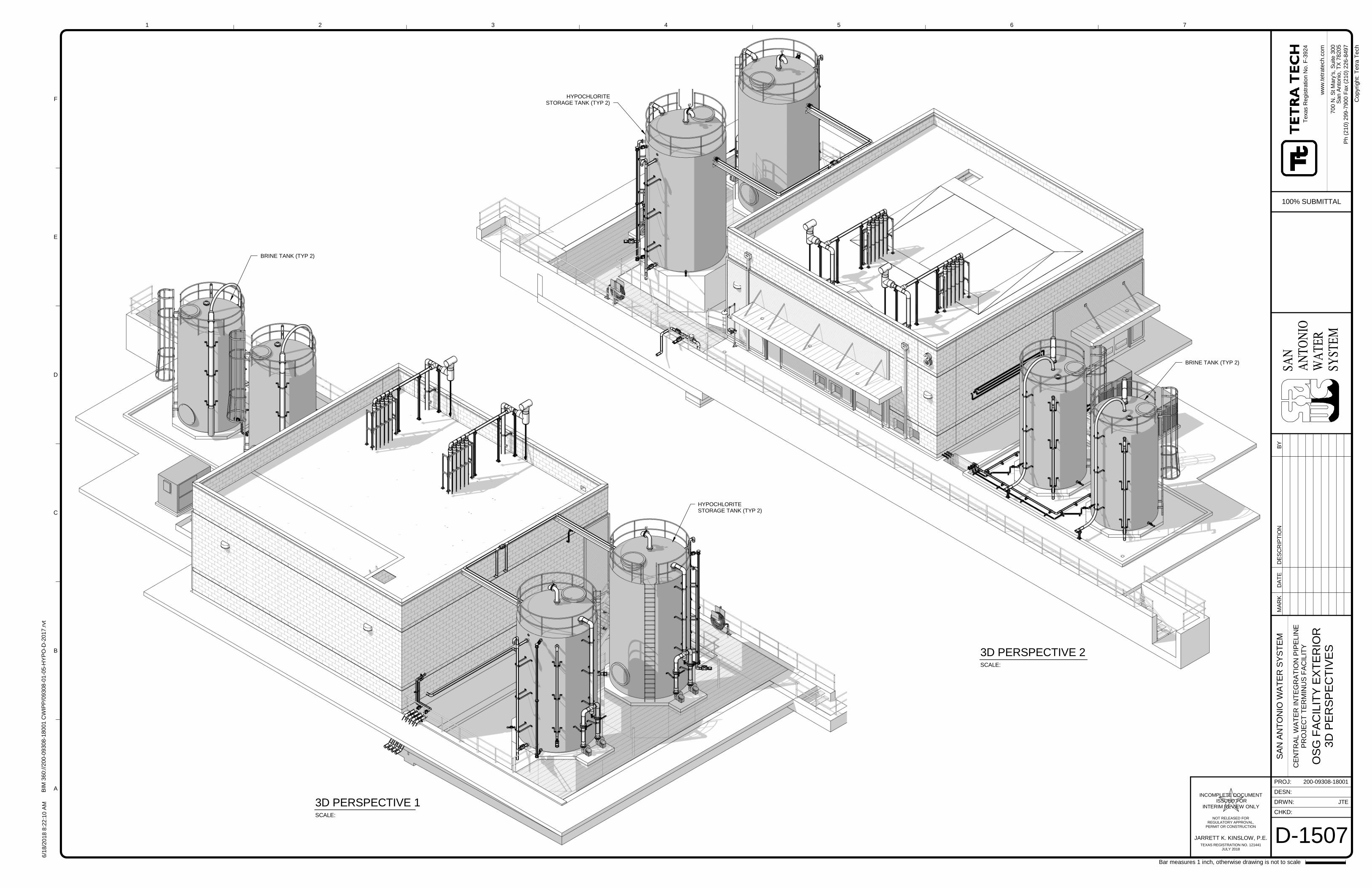
SAN
AN
TON
IOW
ATE
RSY
STEM
CHKD:
DRWN:
PROJ:
DESN:
ww
w.t
etr
ate
ch
.co
m
1
A
B
C
D
E
F
2 3 4 5 6 7
Bar measures 1 inch, otherwise drawing is not to scale
Co
pyr
ight:
Te
tra
Te
ch
JARRETT K. KINSLOW, P.E.
INCOMPLETE DOCUMENTISSUED FOR
INTERIM REVIEW ONLY
NOT RELEASED FORREGULATORY APPROVAL,
PERMIT OR CONSTRUCTION
TEXAS REGISTRATION NO. 121441JULY 2018
6/1
8/2
018
8:2
2:1
0A
MB
IM3
60://2
00-0
9308
-180
01
CW
IPP
/09308
-01-0
5-H
YP
O-D
-2017
.rvt
200-09308-18001
JTE
D-1507
SA
NA
NT
ON
IOW
AT
ER
SY
ST
EM
CE
NT
RA
LW
AT
ER
INT
EG
RA
TIO
NP
IPE
LIN
EP
RO
JE
CT
TE
RM
INU
SF
AC
ILIT
Y
OS
GF
AC
ILIT
YE
XT
ER
IOR
3D
PE
RS
PE
CT
IVE
S
Texa
sR
eg
istr
atio
nN
o.F
-3924
700
N.S
tM
ary
's,S
uite
300
San
An
ton
io,T
X78
205
100% SUBMITTAL
Ph
(210)
299-7
900
Fax
(210)
226-8
497
BRINE TANK (TYP 2)
SCALE:
3D PERSPECTIVE 1
HYPOCHLORITESTORAGE TANK (TYP 2)
SCALE:
3D PERSPECTIVE 2
HYPOCHLORITESTORAGE TANK (TYP 2)
BRINE TANK (TYP 2)
MA
RK
DA
TE
DE
SC
RIP
TIO
NB
Y
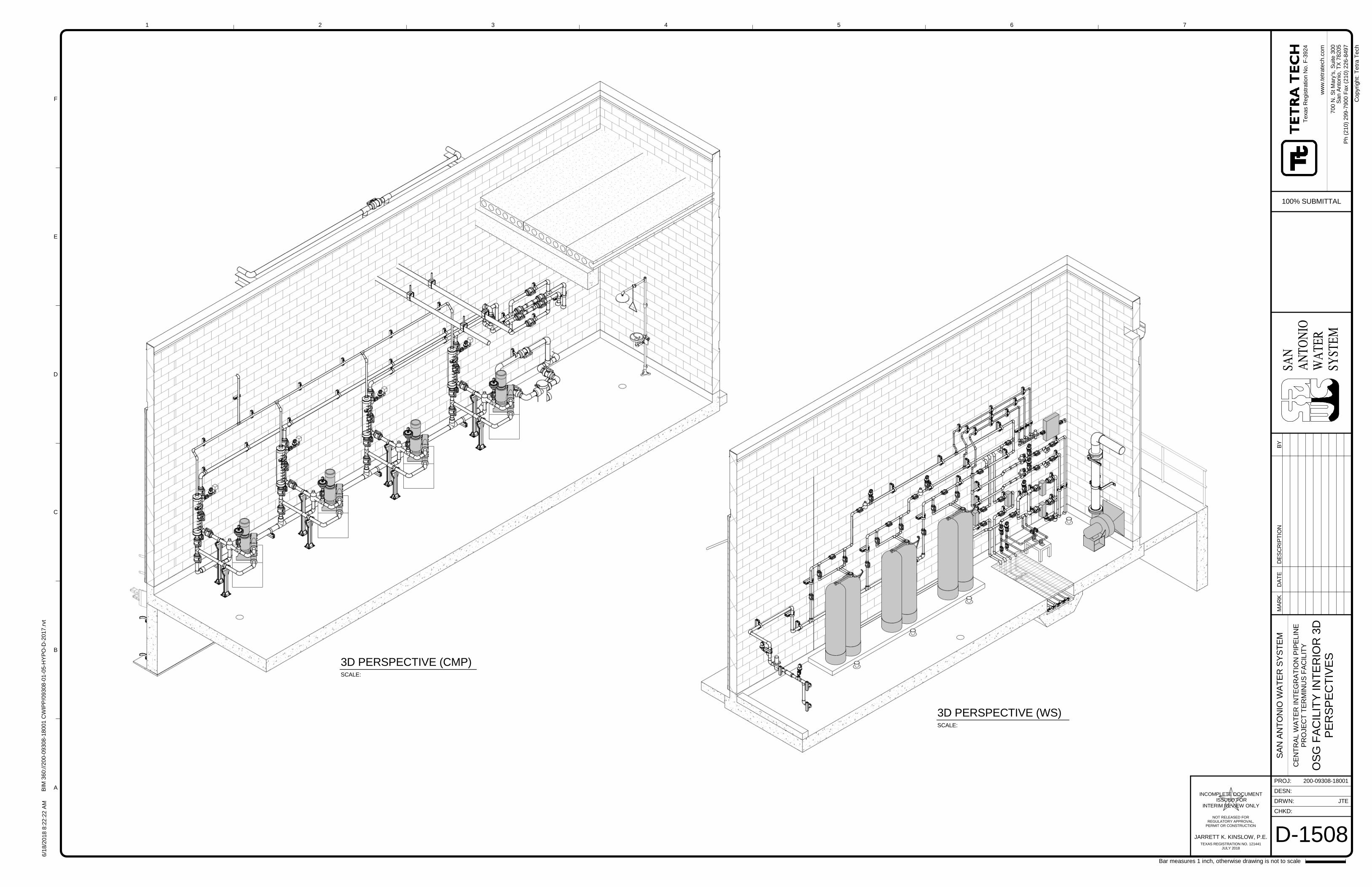
SAN
AN
TON
IOW
ATE
RSY
STEM
CHKD:
DRWN:
PROJ:
DESN:
ww
w.t
etr
ate
ch
.co
m
1
A
B
C
D
E
F
2 3 4 5 6 7
Bar measures 1 inch, otherwise drawing is not to scale
Co
pyr
ight:
Te
tra
Te
ch
JARRETT K. KINSLOW, P.E.
INCOMPLETE DOCUMENTISSUED FOR
INTERIM REVIEW ONLY
NOT RELEASED FORREGULATORY APPROVAL,
PERMIT OR CONSTRUCTION
TEXAS REGISTRATION NO. 121441JULY 2018
6/1
8/2
018
8:2
2:2
2A
MB
IM3
60://2
00-0
9308
-180
01
CW
IPP
/09308
-01-0
5-H
YP
O-D
-2017
.rvt
200-09308-18001
JTE
D-1508
SA
NA
NT
ON
IOW
AT
ER
SY
ST
EM
CE
NT
RA
LW
AT
ER
INT
EG
RA
TIO
NP
IPE
LIN
EP
RO
JE
CT
TE
RM
INU
SF
AC
ILIT
Y
OS
GF
AC
ILIT
YIN
TE
RIO
R3D
PE
RS
PE
CT
IVE
S
Texa
sR
eg
istr
atio
nN
o.F
-3924
700
N.S
tM
ary
's,S
uite
300
San
An
ton
io,T
X78
205
100% SUBMITTAL
Ph
(210)
299-7
900
Fax
(210)
226-8
497
SCALE:
3D PERSPECTIVE (CMP)
SCALE:
3D PERSPECTIVE (WS)
MA
RK
DA
TE
DE
SC
RIP
TIO
NB
Y
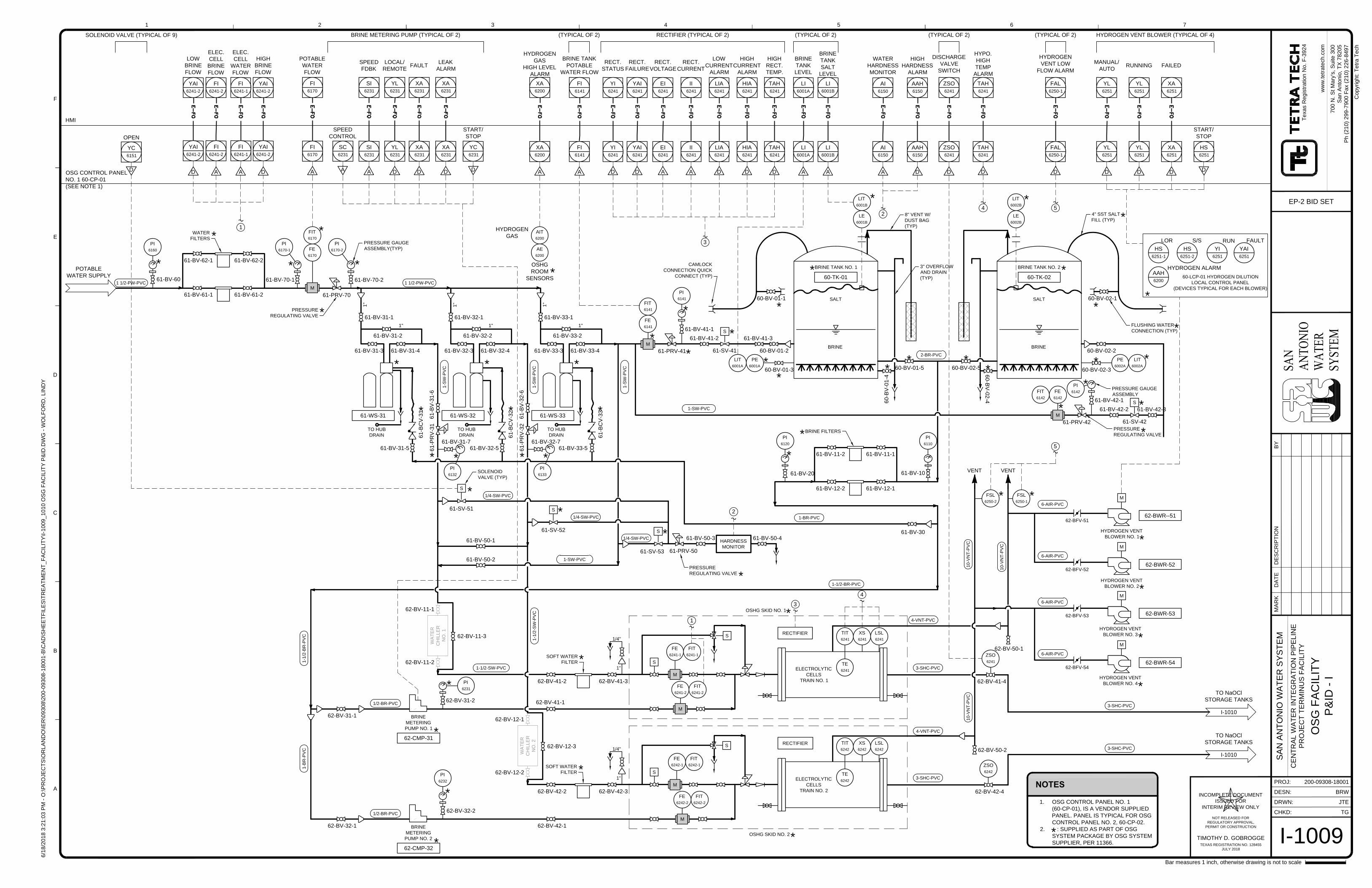
ZSO
6241
ZSO
6242
FI
6170
FI
6141
YC
6151
YL
6231
XA
6231
XA
6231
ZSO
6241
YL
6251
YL
6251
XA
6251
HS
6251
XA
6200
LI
6001A
AI
6150
LI
6001B
FI
6241-1
SC
6231
SI
6231
FI
6241-2
YAI
6241-2
YAI
6241-2
YI
6241
YAI
6241
EI
6241
II
6241
LIA
6241
HIA
6241
TAH
6241
AAH
6150
TAH
6241
FAL
6250-1
ELECTROLYTIC
CELLS
TRAIN NO. 1
BRINE
METERING
PUMP NO. 1
ELECTROLYTIC
CELLS
TRAIN NO. 2
POTABLE
WATER SUPPLY
62-BFV-51
62-BFV-53
HYDROGEN VENT
BLOWER NO. 1
HYDROGEN VENT
BLOWER NO. 3
M
SALT
BRINE
M
BRINE TANK NO. 1
61-SV-41
M
M
HARDNESS
MONITOR
61-SV-53
S
61-PRV-50
I-1010
TO NaOCl
STORAGE TANKS
I-1010
TO NaOCl
STORAGE TANKS
62-BFV-52
HYDROGEN VENT
BLOWER NO. 2
M
S
SOLENOID
VALVE (TYP)
8" VENT W/
DUST BAG
(TYP)
3" OVERFLOW
AND DRAIN
(TYP)
OSHG SKID NO. 2
OSHG SKID NO. 1
61
-B
CV
-3
1
61-PRV-41
WATER
FILTERS
1"
BRINE
METERING
PUMP NO. 2
61-BV-70-2
61-PRV-70
PRESSURE GAUGE
ASSEMBLY(TYP)
PRESSURE
REGULATING VALVE
FLUSHING WATER
CONNECTION (TYP)
M
62-BV-31-2
62-BV-32-2
61-BV-41-1
61-BV-70-161-BV-60
M
M
M
62-BFV-54
HYDROGEN VENT
BLOWER NO. 4
M
SOFT WATER
FILTER
SOFT WATER
FILTER
S
S
S
S
PRESSURE
REGULATING VALVE
TO HUB
DRAIN
61-SV-52
S
61-SV-51
S
SALT
BRINE
CAMLOCK
CONNECTION QUICK
CONNECT (TYP)
4" SST SALT
FILL (TYP)
FE
6170
FIT
6170
FE
6141
FIT
6141
FE
6241-1
FIT
6241-1
FE
6241-2
FIT
6241-2
FE
6242-1
FIT
6242-1
FE
6242-2
FIT
6242-2
POTABLE
WATER
FLOW
A
BRINE TANK
POTABLE
WATER FLOW
A
OPEN
D
SOLENOID VALVE (TYPICAL OF 9)
LOCAL/
REMOTE
FAULT
LEAK
ALARM
START/
STOP
D D D
D
BRINE METERING PUMP (TYPICAL OF 2)
DISCHARGE
VALVE
SWITCH
D
(TYPICAL OF 2)
MANUAL/
AUTO
RUNNING FAILED
START/
STOP
D D D
D
HYDROGEN VENT BLOWER (TYPICAL OF 4)
61-BV-61-1
61-BV-62-1
61-BV-61-2
61-BV-62-2
61-BV-31-1 61-BV-32-1 61-BV-33-1
61-BV-31-5 61-BV-32-5 61-BV-33-5
61-BV-31-2
61-BV-31-3 61-BV-31-4
61-BV-32-2
61-BV-32-3 61-BV-32-4
61-BV-33-2
61-BV-33-3 61-BV-33-4
TO HUB
DRAIN
TO HUB
DRAIN
61-WS-31 61-WS-32 61-WS-33
61-BV-41-2 61-BV-41-3
60-BV-01-2 60-BV-02-2
60-BV-02-3
60-TK-01
BRINE TANK NO. 2
60-TK-02
60-BV-01-1 60-BV-02-1
61-BV-50-1
61-BV-50-2
61-BV-50-3 61-BV-50-4
60
-B
V-0
1-4
60-BV-01-5 60-BV-02-5
60
-B
V-0
2-4
62-BV-31-1
62-BV-32-1
62-BV-41-2
62-BV-41-1
62-BV-42-2
62-BV-42-1
62-BV-41-3
62-BV-42-3
62-CMP-32
62-CMP-31
62-BV-42-4
62-BV-41-4
62-BV-50-2
62-BV-50-1
62-BWR--51
62-BWR-52
62-BWR-53
62-BWR-54
61
-B
CV
-3
2
61
-B
CV
-3
3
1" 1" 1"
61-BV-30
BRINE FILTERS
61-BV-10
61-BV-11-161-BV-11-2
61-BV-20
61-BV-12-161-BV-12-2
1 1/2-PW-PVC 1 1/2-PW-PVC
1-S
W-P
VC
1-S
W-P
VC
1-S
W-P
VC
1/4-SW-PVC
1/4-SW-PVC
1-SW-PVC
1/4-SW-PVC
1-BR-PVC
1-1/2-BR-PVC
1/2-BR-PVC
1-1/2-B
R-P
VC
1-1/2-SW-PVC
1-1/2-S
W-P
VC
1/2-BR-PVC
1-B
R-P
VC
2-BR-PVC
6-AIR-PVC
6-AIR-PVC
6-AIR-PVC
6-AIR-PVC
3-SHC-PVC
3-SHC-PVC
3-SHC-PVC
4-VNT-PVC
3-SHC-PVC
4-VNT-PVC
10-V
NT
-P
VC
10-V
NT
-P
VC
10-V
NT
-P
VC
M
61-SV-42
S
61-PRV-42
PRESSURE GAUGE
ASSEMBLY
PRESSURE
REGULATING VALVE
61-BV-42-1
FE
6142
FIT
6142
61-BV-42-2 61-BV-42-3
(TYPICAL OF 2)
60-BV-01-3
HYDROGEN
GAS
HIGH LEVEL
ALARM
A
AIT
6200
AE
6200
HYDROGEN
GAS
BRINE
TANK
LEVEL
A
WATER
HARDNESS
MONITOR
A
PE
6001A
LIT
6001A
RECTIFIER (TYPICAL OF 2)
PE
6002A
LIT
6002A
LIT
6002B
LE
6002B
A
LIT
6001B
LE
6001B
BRINE
TANK
SALT
LEVEL
ELEC.
CELL
WATER
FLOW
A
HMI
OSG CONTROL PANEL
NO. 1 60-CP-01
(SEE NOTE 1)
OSHG
ROOM
SENSORS
2
1
1
2
SPEED
CONTROL
SPEED
FDBK
A
A
ELEC.
CELL
BRINE
FLOW
A
LOW
BRINE
FLOW
D
HIGH
BRINE
FLOW
D
RECT.
STATUS
RECT.
FAILURE
RECT.
VOLTAGE
RECT.
CURRENT
LOW
CURRENT
ALARM
HIGH
CURRENT
ALARM
HIGH
RECT.
TEMP.
D D A A D D D
RECTIFIER
RECTIFIER
3
3
TIT
6241
XS
6241
LSL
6241
TE
6241
TIT
6242
XS
6242
LSL
6242
TE
6242
4
HIGH
HARDNESS
ALARM
D
4
D
HYPO.
HIGH
TEMP
ALARM
HS
6251-1
LOR
YI
6251
RUN
YAI
6251
FAULT
HS
6251-2
S/S
60-LCP-01 HYDROGEN DILUTION
LOCAL CONTROL PANEL
(DEVICES TYPICAL FOR EACH BLOWER)
AAH
6200
HYDROGEN ALARM
D
HYDROGEN
VENT LOW
FLOW ALARM
5
5
(TYPICAL OF 2)
62-BV-12-3
WA
TE
R
CH
ILLE
R
NO
. 1
62-BV-11-3
WA
TE
R
CH
ILLE
R
NO
. 2
1"
1"
1-SW-PVC
FI
6241-1
FI
6241-2
YAI
6241-2
YAI
6241-2
FI
6170
YL
6231
XA
6231
XA
6231
YC
6231
SI
6231
FI
6141
ZSO
6241
YL
6251
YL
6251
XA
6251
XA
6200
LI
6001A
AI
6150
LI
6001B
YI
6241
YAI
6241
EI
6241
II
6241
LIA
6241
HIA
6241
TAH
6241
AAH
6150
TAH
6241
FAL
6250-1
1"
1/4"
1"
1/4"
61
-B
V-3
1-6
61-BV-31-7
PI
6132
61
-P
RV
-3
2
PI
6133
PI
6170-1
PI
6170-2
PI
6160
PI
6141
PI
6120
PI
6110
PI
6232
PI
6231
PI
6142
*
*
*
*
*
*
* *
*
*
*
*
*
*
*
*
*
*
*
*
*
*
*
*
*
*
* *
*
*
*
*
*
*
*
*
*
*
*
*
*
*
61-BV-32-7
61
-B
V-3
2-6
61
-P
RV
-3
1
*
*
*
* *
*
*
*
*
*
*
*
*
* *
*
*
*
FSL
6250-1
VENTVENT
*
FSL
6250-2
*
(TYPICAL OF 2)
62-BV-12-2
62-BV-12-1
62-BV-11-2
62-BV-11-1
CHKD:
DRWN:
PROJ:
DESN:
ww
w.te
tra
te
ch
.co
m
MA
RK
DA
TE
DE
SC
RIP
TIO
NB
Y
6/1
8/2
01
8 3
:2
1:0
3 P
M - O
:\P
RO
JE
CT
S\O
RL
AN
DO
\IE
R\0
93
08
\2
00
-0
93
08
-1
80
01
-B
\C
AD
\S
HE
ET
FIL
ES
\T
RE
AT
ME
NT
_F
AC
IL
IT
Y\I-1
00
9_
10
10
O
SG
F
AC
IL
IT
Y P
&ID
.D
WG
- W
OL
FO
RD
, L
IN
DY
1
A
B
C
D
E
F
2 3 4 5 6 7
Co
pyrig
ht: T
etra
T
ech
Bar measures 1 inch, otherwise drawing is not to scale
200-09308-18001
CE
NT
RA
L W
AT
ER
IN
TE
GR
AT
IO
N P
IP
ELIN
E
PR
OJE
CT
T
ER
MIN
US
F
AC
ILIT
Y
SA
N A
NT
ON
IO
W
AT
ER
S
YS
TE
M
70
0 N
. S
t M
ary's, S
uite
3
00
Sa
n A
nto
nio
, T
X 7
82
05
Ph
(2
10
) 2
99
-7
90
0 F
ax (2
10
) 2
26
-8
49
7
Te
xa
s R
eg
istra
tio
n N
o. F
-3
92
4
TIMOTHY D. GOBROGGE
INCOMPLETE DOCUMENT
ISSUED FOR
INTERIM REVIEW ONLY
NOT RELEASED FOR
REGULATORY APPROVAL,
PERMIT OR CONSTRUCTION
TEXAS REGISTRATION NO. 128455
JULY 2018
I-1009
OS
G F
AC
ILIT
Y
P&
ID
- I
BRW
JTE
TG
EP-2 BID SET
NOTES
1. OSG CONTROL PANEL NO. 1
(60-CP-01), IS A VENDOR SUPPLIED
PANEL. PANEL IS TYPICAL FOR OSG
CONTROL PANEL NO. 2, 60-CP-02.
2. : SUPPLIED AS PART OF OSG
SYSTEM PACKAGE BY OSG SYSTEM
SUPPLIER, PER 11366.
*
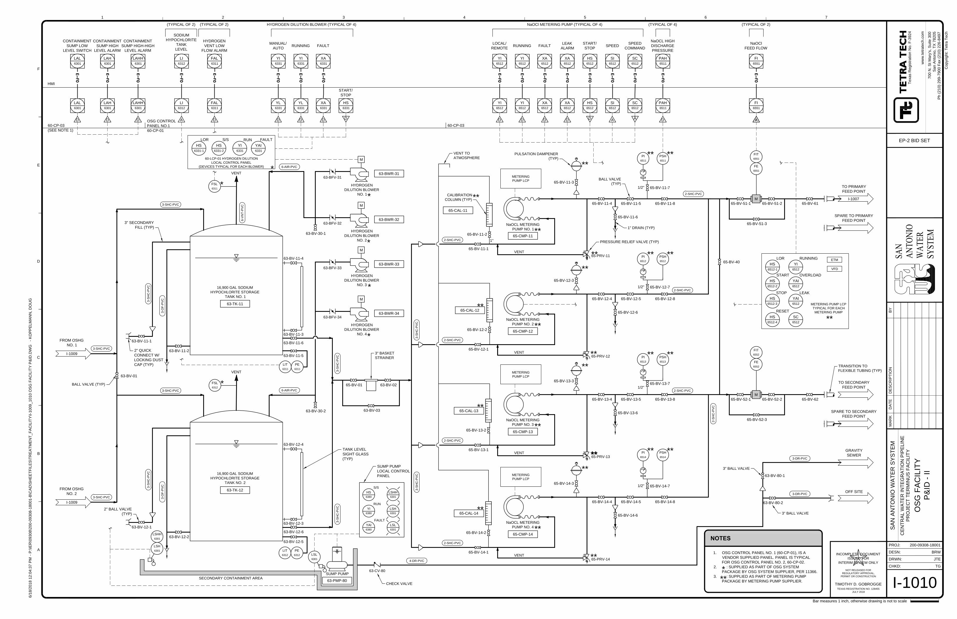
LAL
6301
LAH
6301
LI
6312
YI
6331
YI
6331
XA
6331
HS
6331
YI
6512
YI
6512
XA
6512
XA
6512
HS
6512
SI
6512
SC
6512
FI
6551
PAH
6511
LAHH
6301
FAL
6311
16,900 GAL SODIUM
HYPOCHLORITE STORAGE
TANK NO. 1
16,900 GAL SODIUM
HYPOCHLORITE STORAGE
TANK NO. 2
M
VENT
VENT
HYDROGEN
DILUTION BLOWER
NO. 1
NaOCL METERING
PUMP NO. 1
NaOCL METERING
PUMP NO. 2
M
SUMP PUMP
OFF SITE
GRAVITY
SEWER
SECONDARY CONTAINMENT AREA
63-CV-80
CHECK VALVE
I-1009
FROM OSHG
NO. 1
I-1009
FROM OSHG
NO. 2
HYDROGEN
DILUTION BLOWER
NO. 2
HYDROGEN
DILUTION BLOWER
NO. 3
M
63-BFV-32
63-BFV-31
63-BFV-33
NaOCL METERING
PUMP NO. 4
65-PRV-11
M
PULSATION DAMPENER
(TYP)
1" DRAIN (TYP)
PRESSURE RELIEF VALVE (TYP)
VENT
BALL VALVE
(TYP)
CALIBRATION
COLUMN (TYP)
VENT
VENT
VENT TO
ATMOSPHERE
3" BASKET
STRAINER
BALL VALVE (TYP)
TRANSITION TO
FLEXIBLE TUBING (TYP)
HYDROGEN
DILUTION BLOWER
NO. 4
M
63-BFV-34
1"
3" BALL VALVE
3" BALL VALVE
M
A
MANUAL/
AUTO
RUNNING FAULT
START/
STOP
D D D
D
HYDROGEN DILUTION BLOWER (TYPICAL OF 4)
63-BWR-31
63-TK-11
63-TK-12
63-BWR-32
63-BWR-33
63-BWR-34
63-BV-01
63-BV-11-2
63-BV-12-2
63-BV-12-6
63-BV-11-6
65-BV-01 63-BV-02
63-BV-03
63-PMP-80
63-BV-80-1
63-BV-80-2
65-BV-61
65-BV-62
65-BV-51-1 65-BV-51-2
65-BV-51-3
65-BV-52-1 65-BV-52-2
65-BV-52-3
65-BV-12-1
65-BV-12-2
65-BV-12-4 65-BV-12-5 65-BV-12-8
65-CMP-11
65-CMP-12
65-CMP-14
65-CAL-11
65-CAL-12
65-CAL-14
65-BV-12-3
65-BV-14-1
65-BV-14-2
65-BV-14-4 65-BV-14-5 65-BV-14-8
65-BV-14-3
65-BV-11-1
65-BV-11-2
65-BV-11-4 65-BV-11-5
65-BV-11-6
65-BV-11-8
65-BV-11-3
65-PRV-12
65-PRV-14
I-1007
TO PRIMARY
FEED POINT
SPARE TO PRIMARY
FEED POINT
TO SECONDARY
FEED POINT
SPARE TO SECONDARY
FEED POINT
3-SHC-PVC
3-SHC-PVC
3-SHC-PVC
3-SHC-PVC
6-V
NT
-P
VC
3-O
F-P
VC
3-O
F-P
VC
6-AIR-PVC
6-AIR-PVC
3-S
HC
-P
VC
3-S
HC
-P
VC
3-S
HC
-P
VC
3-S
HC
-P
VC
2-SHC-PVC
4-DR-PVC
2-SHC-PVC
2-SHC-PVC
2-SHC-PVC
2-SHC-PVC
2-S
HC
-P
VC
3-DR-PVC
3-DR-PVC
63-BV-11-1
2" QUICK
CONNECT W/
LOCKING DUST
CAP (TYP)
2" BALL VALVE
(TYP)
3-S
HC
-P
VC
63-BV-12-1
3-S
HC
-P
VC
3" SECONDARY
FILL (TYP)
63-BV-11-4
63-BV-11-3
63-BV-12-4
63-BV-12-3
TANK LEVEL
SIGHT GLASS
(TYP)
D
LSH
6301
PE
6311
LIT
6311
PE
6312
LIT
6312
SODIUM
HYPOCHLORITE
TANK
LEVEL
A
(TYPICAL OF 2)
LOCAL/
REMOTE
RUNNING FAULT
LEAK
ALARM
START/
STOP
D D D D
D
NaOCl METERING PUMP (TYPICAL OF 4)
SPEED
SPEED
COMMAND
A
A
1/2"
65-BV-12-71/2"
1/2"
NaOCl
FEED FLOW
A
(TYPICAL OF 2)
65-BV-14-7
65-BV-11-7
FIT
6551
FE
6551
FIT
6552
FE
6552
PI
6511
PSH
6511
D
PSH
6512
PI
6512
PSH
6514
PI
6514
(TYPICAL OF 4)
NaOCL HIGH
DISCHARGE
PRESSURE
CONTAINMENT
SUMP HIGH
LEVEL ALARM
HMI
60-CP-03
(SEE NOTE 1)
63-BV-12-5
63-BV-11-5
65-BV-12-6
65-BV-14-6
VENT
2-SHC-PVC
2-SHC-PVC
1/2"
PSH
6513
PI
6513
NaOCL METERING
PUMP NO. 3
65-CMP-13
65-CAL-13
65-BV-13-1
65-BV-13-2
65-BV-13-4 65-BV-13-5 65-BV-13-8
65-BV-13-3
65-PRV-13
65-BV-13-7
65-BV-13-6
65-BV-40
D
CONTAINMENT
SUMP HIGH-HIGH
LEVEL ALARM
D
CONTAINMENT
SUMP LOW
LEVEL SWITCH
LSHH
6301
LSL
6301
HS
6380
S/S
YI
6380
RUN
YAI
6380
FAULT
LSHH
6301
LSH
6301
LSL
6301
SUMP PUMP
LOCAL CONTROL
PANEL
HS
6331-1
LOR
YI
6331
RUN
YAI
6331
FAULT
HS
6331-2
S/S
60-LCP-01 HYDROGEN DILUTION
LOCAL CONTROL PANEL
(DEVICES TYPICAL FOR EACH BLOWER)
HS
6512-1
LOR
HS
6512-3
STOP
HS
6512-4
RESET
HS
6512-2
START
METERING PUMP LCP
TYPICAL FOR EACH
METERING PUMP
YI
6512
RUNNING
YAI
6512
LEAK
SC
6512
YAI
6512
OVERLOAD
ETM
VFD
METERING
PUMP LCP
METERING
PUMP LCP
METERING
PUMP LCP
D
HYDROGEN
VENT LOW
FLOW ALARM
63-BV-30-1
63-BV-30-2
YI
6512
YI
6512
XA
6512
XA
6512
HS
6512
SI
6512
SC
6512
FI
6551
PAH
6511
YL
6331
YL
6331
XA
6331
LAL
6301
LAH
6301
LI
6312
LAHH
6301
FAL
6311
*
*
*
*
*
**
**
**
**
**
** **
**
**
**
**
** ****
**
**
**
** ****
**
**
**
** **
**
FSL
6311
*
FSL
6312
*
OSG CONTROL
PANEL NO.1
60-CP-01
(TYPICAL OF 2)
60-CP-03
CHKD:
DRWN:
PROJ:
DESN:
ww
w.tetratech.com
MA
RK
DA
TE
DE
SC
RIP
TIO
NB
Y
6/18/2018 12:04:37 P
M - P
:\IE
R\09308\200-09308-18001-B
\C
AD
\S
HE
ET
FILE
S\T
RE
AT
ME
NT
_F
AC
ILIT
Y\I-1009_1010 O
SG
F
AC
ILIT
Y P
&ID
.D
WG
- K
OP
PE
LM
AN
N, D
OU
G
1
A
B
C
D
E
F
2 3 4 5 6 7
Copyright: T
etra T
ech
Bar measures 1 inch, otherwise drawing is not to scale
200-09308-18001
CE
NT
RA
L W
AT
ER
IN
TE
GR
AT
IO
N P
IP
ELIN
E
PR
OJE
CT
T
ER
MIN
US
F
AC
ILIT
Y
SA
N A
NT
ON
IO
W
AT
ER
S
YS
TE
M
700 N
. S
t M
ary's, S
uite 300
San A
ntonio, T
X 78205
Ph (210) 299-7900 F
ax (210) 226-8497
Texas R
egistration N
o. F
-3924
TIMOTHY D. GOBROGGE
INCOMPLETE DOCUMENT
ISSUED FOR
INTERIM REVIEW ONLY
NOT RELEASED FOR
REGULATORY APPROVAL,
PERMIT OR CONSTRUCTION
TEXAS REGISTRATION NO. 128455
JULY 2018
I-1010
OS
G F
AC
IL
IT
Y
P&
ID
- II
BRW
JTE
TG
EP-2 BID SET
NOTES
1. OSG CONTROL PANEL NO. 1 (60-CP-01), IS A
VENDOR SUPPLIED PANEL. PANEL IS TYPICAL
FOR OSG CONTROL PANEL NO. 2, 60-CP-02.
2. : SUPPLIED AS PART OF OSG SYSTEM
PACKAGE BY OSG SYSTEM SUPPLIER, PER 11366.
3. : SUPPLIED AS PART OF METERING PUMP
PACKAGE BY METERING PUMP SUPPLIER.
*
**
Recommended


