Representing and Using Non-Functional Requirements:A Process-Oriented ApproachJohn Mylopoulos, Lawrence Chung and Brian NixonDepartment of Computer ScienceUniversity of TorontoToronto, Ontario, Canada M5S 1A4Abstract The paper proposes a comprehensive framework for representing and using non-functionalrequirements during the development process. The framework consists of �ve basic components whichprovide for the representation of non-functional requirements in terms of interrelated goals. Such goals canbe re�ned through re�nement methods and can be evaluated in order to determine the degree to which a setof non-functional requirements is supported by a particular design. Evidence for the power of the frameworkis provided through the study of accuracy and performance requirements for information systems.1 IntroductionThe complexity of an information system is determined partly by its functionality | i.e., what the systemdoes | and partly by global requirements on its development or operational costs, performance, reliability,maintainability, portability, robustness and the like. These non-functional requirements1 play a crucial roleduring system development, serving as selection criteria for choosing among myriads of decisions. Errors ofomission or commission in laying down and taking properly into account such requirements are generallyacknowledged to be among the most expensive and di�cult to correct once the information system has beencompleted. Surprisingly, non-functional requirements have received little attention by researchers and arede�nitely less well understood than other, less critical factors in software development. As far as softwareengineering practice is concerned, they are generally stated only informally during requirements analysis, areoften contradictory, di�cult to enforce during software development and to validate for the user once the�nal system has been built. The only glimmer of technical light in an otherwise bleak landscape originatesin technical work on software quality metrics that allow the quanti�cation of the degree to which a softwaresystem meets non-functional requirements [26, 5, 3].There is not a formal de�nition or a complete list of non-functional requirements. In a report published bythe RomeAir Development Center (RADC) [7], non-functional requirements (\software quality attributes" intheir terminology) are classi�ed into consumer-oriented (or software quality factors) and technically-orientedattributes (or software quality criteria). The former refers to non-functional requirements observable bythe consumer, such as e�ciency, correctness and interoperability. The latter addresses system-orientedrequirements such as anomaly management, completeness and functional scope. Table 1.1 shows the RADCconsumer-oriented attributes. The non-functional requirements listed in the table apply to all softwaresystems. However, additional requirements may apply for special classes of software. For instance, precisionwould be an important non-functional requirement for a numerical analysis software package, while accuracy(of maintained information) might feature prominently during the development of an information system.Two basic approaches characterize the formal treatment of non-functional requirements and we shallrefer to them as product-oriented and process-oriented. The �rst attempts to develop formal de�nitions ofnon-functional requirements so that a software system can be evaluated as to the degree to which it meetsits requirements. For example, measuring software visibility may include, among other things, measuringthe amount of branching in a software system. This might be achieved globally with a criterion such as:\There shall be no more than X branches per 1,000 lines of code" or locally with a criterion such as \Thereshall be no more than Y% of system modules that violate the above criterion."1Also referred to as constraints [41], goals [31] and quality attributes [26] in the literature.1
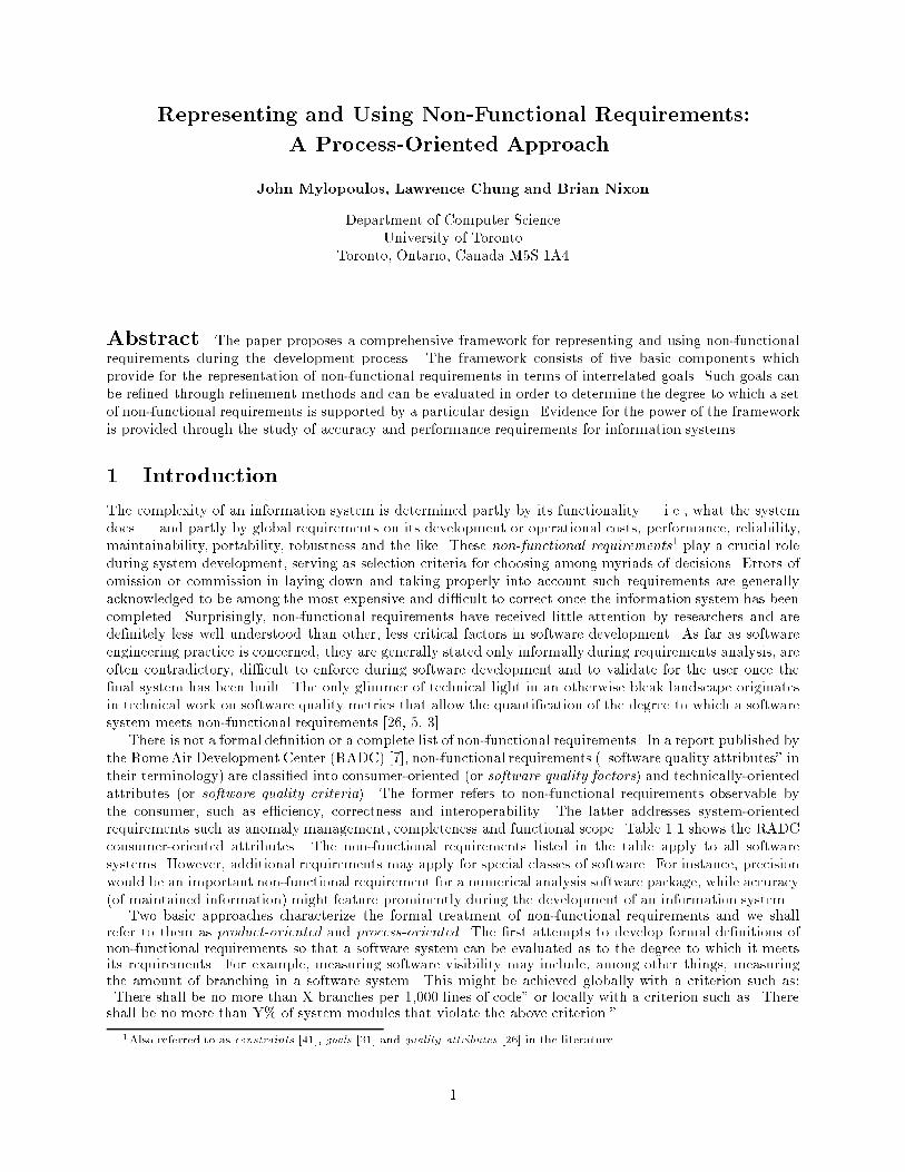
Acquisition Concern User Concern Quality AttributeHow well does it utilize a resource? E�ciencyHow secure is it? IntegrityPerformance | How well does What con�dence can be placed in what it does? Reliabilityit function? How well will it perform under adverse conditions? SurvivabilityHow easy is it to use it? UsabilityHow well does it conform to the requirements? CorrectnessDesign | How valid is How easy is it to repair? Maintainabilitythe design? How easy is it to verify its performance? Veri�abilityHow easy is it to expand or upgradeits capability or performance? ExpandabilityHow easy is it to change? FlexibilityAdaptation | How adaptable How easy is it to interfere with another system? Interoperabilityis it? How easy is it to transport? PortabilityHow easy is it to convert for use in another application? ReusabilityTable 1.1 The RADC software quality consumer-oriented attributes. [26]The product-oriented approach has received almost exclusive attention in the literature and is nicely overviewedin [26]. Earlier work by Boehm et al. [5] considered quality characteristics of software, noting that designer-awareness alone improved the quality of the �nal product. Also supporting a quantitative approach tosoftware quality, Basili and Musa [3] advocate models and metrics of the software engineering process froma management perspective. It is interesting that Hauser et al. [21] provide a methodology for re ectingcustomer attributes in di�erent phases of automobile design.An alternative approach, explored in this paper, is to develop techniques for justifying design decisionsduring the software development process. Instead of evaluating the �nal product, the emphasis here is ontrying to rationalize the development process in terms of non-functional requirements. Design decisionsmay a�ect positively or negatively particular non-functional requirements. These positive and negativedependencies can serve as basis for arguing that a software system indeed meets a certain non-functionalrequirement or explaining why it does not.Orthogonally, treatments of non-functional requirements can be classi�ed into quantitative and qualitativeones. Most of the product-oriented approaches alluded to earlier are quantitative in the sense that theystudy quantitative metrics for measuring the degree to which a software system satis�es a non-functionalrequirement. The process-oriented treatment proposed here, on the other hand, is de�nitely qualitative,adopting ideas from qualitative reasoning [1]. It should be acknowledged that a process-oriented treatmentof non-functional requirements need not be qualitative. Indeed, one could imagine quantitative measuresfor, say, software visibility that can be used as the system is being developed to o�er advance warning thatnon-functional requirements are not being met. Qualitative techniques were chosen here primarily becauseit was felt that the problem of quantitatively measuring an incomplete software system is even harder thanthat of measuring the �nal product.Of course, neither product-oriented quantitative metrics nor process-oriented qualitative measures havea monopoly on properly treating non-functional requirements. They are best seen as complementary, bothcontributing to an evolving comprehensive framework for dealing with non-functional requirements.Two sources of ideas were particularly in uential on our work. The �rst involves recent work on decisionsupport systems, such as that described in [28, 29] and [19]. Lee's work, for example, adopts an earlier modelfor representing design rationale [38] and extends it by making explicit the goals presupposed by arguments.The work reported here can be seen as an attempt to adopt this model to the representation and use ofnon-functional requirements. The second source of ideas is the DAIDA environment for information systemdevelopment [23] which has provided us with a comprehensive software development framework covering bothnotations for requirements modelling, design, implementation and decision support, as well as a starting pointon how the treatment of non-functional requirements might be integrated into that framework. Users of theDAIDA environment are o�ered three languages through which they can elaborate requirements, design andimplementation speci�cations. In developing a design speci�cation, the user consults and is constrained bycorresponding requirements speci�cations. Likewise, the generation of an implementation is guided by a2
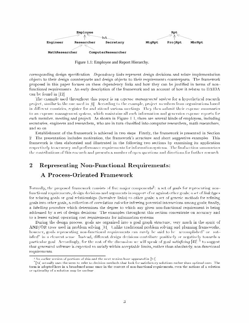
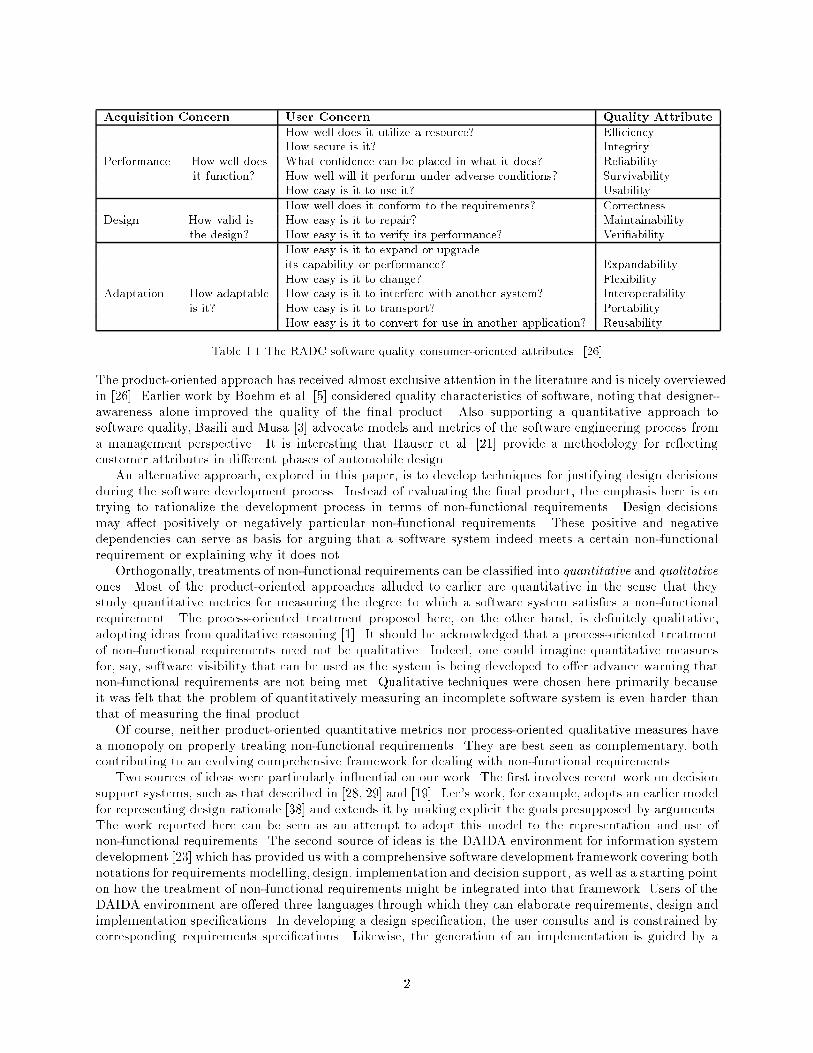
Figure 1.1: Employee and Report Hierarchy.
ComputerResearcherMathResearcher
IsA
RptEmployee
MbrRptProjRptMtgRptSecretaryResearcherEngineercorresponding design speci�cation. Dependency links represent design decisions and relate implementationobjects to their design counterparts and design objects to their requirements counterparts. The frameworkproposed in this paper focuses on these dependency links and how they can be justi�ed in terms of non-functional requirements. An early description of the framework and an account of how it relates to DAIDAcan be found in [12].The example used throughout this paper is an expense management system for a hypothetical researchproject, similar to the one used in [6]. According to the example, project members from organizations basedin di�erent countries, register for and attend various meetings. They then submit their expense summariesto an expense management system, which maintains all such information and generates expense reports foreach member, meeting and project. As shown in Figure 1.1, there are several kinds of employees, includingsecretaries, engineers and researchers, who are in turn classi�ed into computer researchers, math researchers,and so on.Establishment of the framework is achieved in two steps. Firstly, the framework is presented in Section2. The presentation includes motivation, the framework's structure and short suggestive examples. Thisframework is then elaborated and illustrated in the following two sections by examining its applicationrespectively to accuracy and performance requirements for information systems. The �nal section summarizesthe contributions of this research and presents a number of open questions and directions for further research.2 Representing Non-Functional Requirements:A Process-Oriented FrameworkFormally, the proposed framework consists of �ve major components2: a set of goals for representing non-functional requirements, design decisions and arguments in support of or against other goals; a set of link typesfor relating goals or goal relationships (hereafter links) to other goals; a set of generic methods for re�ninggoals into other goals; a collection of correlation rules for inferring potential interactions among goals; �nally,a labelling procedure which determines the degree to which any given non-functional requirement is beingaddressed by a set of design decisions. The examples throughout this section concentrate on accuracy andto a lesser extent operating cost requirements for information systems.During the design process, goals are organized into a goal graph structure, very much in the spirit ofAND/OR trees used in problem solving [34]. Unlike traditional problem solving and planning frameworks,however, goals representing non-functional requirements can rarely be said to be \accomplished" or \sat-is�ed" in a clearcut sense. Instead, di�erent design decisions contribute positively or negatively towards aparticular goal. Accordingly, for the rest of the discussion we will speak of goal satis�cing [42] 3 to suggestthat generated software is expected to satisfy within acceptable limits, rather than absolutely, non-functionalrequirements.2An earlier version of portions of this and the next section have appeared in [13].3[42] actually uses the term to refer to decision methods that look for satisfactory solutions rather than optimal ones. Theterm is adopted here in a broadened sense since in the context of non-functional requirements, even the notions of a solutionor optimality of a solution may be unclear. 3
2.1 GoalsThe space of goals includes three mutually exclusive classes, namely, non-functional requirements goals (NFRgoals), satis�cing goals and argumentation goals. In general, each goal will have an associated sort and zero ormore parameters whose nature depends on the goal sort. For example, an operating cost requirement mighthave as parameter a desired upper bound on the annual operating costs of the system under development.Sorts may be further subdivided into subsorts, representing special cases for each goal class. For instance,the Performance sort may have subsorts TimePerformance (or simply Time) and SpacePerformance (orsimply Space), representing respective time and space performance requirements on a particular system.Goals, NFRGoals, SatGoals and ArgGoals will refer respectively to the set of all possible goals, NFR goals,satis�cing goals and argumentation goals.1. Non-functional requirements goals. The sorts for such goals range over the di�erent categories of suchrequirements, including accuracy, security, development, operating or hardware costs and performance. Forour expense management system, suppose that it is expected of the system under development to maintainaccurately employee data. Such a goal might be represented by:Accuracy[attributes(Employee)]where Accuracy is the goal sort and the parameter of attributes(Employee) evaluates to the set of allattributes associated with the data class Employee. The interpretation of this goal is that instances of theattributes of the data class Employee, i.e., all attributes of employees, ought to be maintained accuratelyin the system's database. As another example, it may also be expected that the system under developmentmake minimal demands on manpower. This can be treated as an operating cost requirement and since thereare several contributing factors to operating costs (manpower, maintenance, etc.), this requirement mightbe represented as OperatingCost[manpower].2. Satis�cing goals. These are also sorted and parameterized. In this case, however, the sorts rangeover di�erent categories of design decisions that might be adopted in order to satis�ce one or more non-functional requirements goals. The parameters associated with each sort, again, depend on the nature of thecorresponding satis�cing goal. For instance, one way to satis�ce the accuracy goal mentioned earlier mightbe to validate all employee data entered into the system. This can be represented as a satis�cing goal:Validation[attributes(Employee)];where Validation is the goal sort and attributes(Employee) is as before. This goal, in turn, might bere�ned into another satis�cing goal,ValidatedBy[JohnWong;attributes(Employee)];representing the situation that JohnWong will be doing the validation.3. ArgumentationGoals (orArguments). These always have the sort Claim, with subsorts FormalClaimand InformalClaim, representing formally or informally stated evidence or counter-evidence for other goalsor goal re�nements. Consider:FormalClaim[9e : ValidatedBy[e;attributes(Employee)] ^ EmpStatus(e;Sec I)]This argumentation goal supports the re�nement from the goal of validating employee data to the oneassigning JohnWong to the task, by claiming that class I secretaries will perform the validation. In contrast,InformalClaim[\Rigorous examination is recommended for publications by employees:"]is an informally-stated argumentation goal supporting the previous argumentation goal by pointing out whyclass I secretaries should validate employee data.2.2 Link TypesAs indicated earlier, design proceeds by re�ning one or more times each goal, the parent, into a set of othergoals, the o�spring. Unlike AND/OR goal trees, where the relationship between a collection of o�spring4
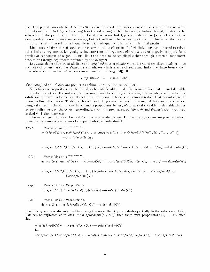
and their parent can only be AND or OR, in our proposed framework there can be several di�erent typesof relationships or link types describing how the satis�cing of the o�spring (or failure thereof) relates to thesatis�cing of the parent goal. The need for at least some link types is evidenced in [5] which states thatsome quality characteristics are necessary, but not su�cient, for achieving others. Boehm et al. then use afour-grade scale to correlate each quality metric with quality attributes in the �nal product.Links may relate a parent goal to one or several of its o�spring. In fact, links may also be used to relateother links to argumentation goals, to indicate that an argument o�ers positive or negative support for aparticular re�nement of a goal. Thus, links too need to be satis�ced either through a formal re�nementprocess or through arguments provided by the designer.Let Links denote the set of all links and satis�ced be a predicate which is true of satis�ced goals or linksand false of others. Also, let denied be a predicate which is true of goals and links that have been shownunsatis�ceable (\unsolvable" in problem solving terminology [34]). IfPropositions = Goals [ Links;then satis�ced and denied are predicates taking a proposition as argument.Sometimes a proposition will be found to be satis�ceable | thanks to one re�nement | and deniable| thanks to another. For instance, the accuracy goal for employee data might be satis�ceable thanks to avalidation procedure adopted for all such data, but deniable because of a user interface that permits generalaccess to this information. To deal with such con icting cases, we need to distinguish between a propositionbeing satis�ced or denied, on one hand, and a proposition being potentially satis�ceable or deniable thanksto some re�nement on the other. Accordingly, two more predicates, satis�ceable and deniable are introducedto deal with the latter case.The set of logical types to be used for links is presented below. For each type, axioms are provided whichformalize its semantics in terms of the predicates just introduced:AND : Propositions� 2Propositions :satisficed(G1) ^ satisficed(G2) ^ : : : ^ satisficed(Gn) ^ satisficed(AND(G0; fG1;G2; : : : ;Gng))�! satisficeable(G0)satisficed(AND(G0; fG1;G2; : : : ;Gng) ^ (denied(G1) _ denied(G2) _ : : : _ denied(Gn)) �! deniable(G0)OR : Propositions� 2Propositions :denied(G1) ^ denied(G2) ^ : : : ^ denied(Gn) ^ satisficed(OR(G0; fG1; G2; : : : ;Gng)) �! deniable(G0)satisficed(OR(G0; fG1;G2; : : : ;Gng) ^ (satisficed(G1) _ satisficed(G2) _ : : : _ satisficed(Gn))�! satisficeable(G0)sup : Propositions� Propositions:satisficed(G1) ^ satisficed(sup(G0;G1)) �! satisficeable(G0)sub : Propositions� Propositions:denied(G1) ^ satisficed(sub(G0;G1)) �! deniable(G0)The link type sub is also intended to convey the sense that G1 contributes partially to the satis�cing of G0.This can be expressed as follows: If satisficed(sub(G0 ; G1)) then there exist propositions G2; : : : ; Gn suchthat :(satisficed(G2) ^ : : : ^ satisficed(Gn) �! satisficeable(G0))butsatisficed(G1) ^ satisficed(G2) ^ : : : ^ satisficed(Gn) ^ satisficed(sub(G0;G1)) �! satisficeable(G0)5
In words, if G1 is a sub(proposition) of G0 then there exist propositions G2; : : : ; Gn which cannot achievethe satis�cing of G0 without the contribution of G1.Two additional link types are introduced to represent negative in uences of one goal on another.�sup : Propositions� Propositions:satisficed(G1) ^ satisficed(�sup(G0;G1)) �! deniable(G0)�sub : Propositions� Propositions:denied(G1) ^ satisficed(�sub(G0;G1)) �! satisficeable(G0)If � sub(G0;G1) then there exist G2; : : : ;Gn such that:(satisficed(G2) ^ : : : ^ satisficed(Gn) ^ satisficed(�sub(G0;G1)) �! deniable(G0))butsatisficed(G1) ^ satisficed(G2) ^ : : : ^ satisficed(Gn) ^ satisficed(�sub(G0;G1)) �! deniable(G0)In words, if G1 is a negative sub(proposition) of G0 then denial of G1 leads to the satis�cing of G0 andsatis�cing of G1 contributes to the denial of G0.Finally, it is useful to de�ne the eql (equivalent) link type in terms of the link types introduced here:eql : Propositions� Propositions:eql(G0;G1) � sup(G0;G1) ^ sup(G1;G0) ^ sub(G0;G1) ^ sub(G1; G0)At times, it may be hard to determine a priori the logical relationship between a set of o�spring andtheir parent goal without further expansion of the goal graph. For example, the designer may see that acertain hiring policy for technical sta� is relevant, without being sure of its impact on a particular goal, say,in justifying the assignment of a class I secretary to the task of validating employee data. This situation isaccommodated through three variations of an undetermined link type:und : Propositions� Propositions:und(G0;G1) indicates the possible presence of positive or negative influence between G0 and G1:Likewise, +und and �und indicate respectively possible positive or negative in uence between two propo-sitions.2.3 MethodsGoals may be re�ned by the designer, who is then responsible for satis�cing not only the goal's o�springbut also the re�nement itself represented as a link. Alternatively, the framework provides goal re�nementmethods (methods for short) which represent generic procedures for re�ning a goal into one or more o�spring,such as:\To maintain accurately data about class x, you need to maintain accurately data about allrelevant subclasses of x."Every such re�nement is represented in terms of a link having one of the types of the previous section andwhich is considered satis�ced.Generally, a method has the formx1=C1;x2=C2; : : :xn=Cn : SelP (x1;x2; : : :xn) jG0(x1; : : :xn) �L�! fG0(x1; : : :xn) j For all G0 such that Pred(G0;x1; : : :xn))gHere G0 represents the parent goal, predicate Pred determines the set of o�spring while L is the link typerelating G0 to its o�spring. The re�nement of G0 through a method is subject to the method's selectioncriterion, SelP , consisting of a Boolean expression with free variables x1; x2; : : : ; xn. These are bound toobjects of type C1; : : : ; Cn respectively when the method is applied.6
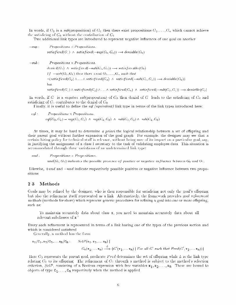
There are three types of goal re�nement methods, corresponding to the three types of goals introducedearlier:1. Goal Decomposition Methods. These are usually AND decomposition methods of the formSelP : G �A�N�D�! fG1, G2, : : :, Gng used to decompose a goal G into an AND set of o�spring G1; G2; : : : ; Gn.For instance, the following method decomposes a goal having a class as argument into goals having as argu-ments its immediate specializations:x=Class : G[x] �A�N�D�! fG[xi]; j (xi isA x) ^8xj [((xi isA xj) ^ (xj isA X))) ((xj = xi) _ (xj = x))]gSince there are three specializations of Employee in our example, the accuracy goalAccuracy[attributes(Employee)](abbreviated as A[attributes(Employee)]) can be re�ned using the subclass goal decomposition method:A[attributes(Employee)] �A�N�D�! fA[attributes(Researcher)]; : : : ; A[attributes(Secretary)]gIn Figure 2.1, o�spring are shown underneath the parent goal. Link types are sometimes omitted from �gures.Now each of these goals needs to be satis�ced in turn. Likewise, satis�cing the goal ofA[attributes(Researcher)] requires that all attributes of Researcher be maintained accurately. This de-composition can be accomplished by a method of the form:x=Class : A[attributes(x)] �A�N�D�! fA[attr(x)] j attr 2 attributes(x)gThis method leads to the following further decomposition of A[attributes(Researcher)]. Assuming thatresearch employees have attributes degree and publ (publications), in addition to those of Employee,A[attributes(Researcher)] �A�N�D�! fA[Researcher:name]; : : : ;A[Researcher:degree]; A[Researcher:publ]g2. Goal Satis�cingMethods. Such methods re�ne a goal into a set of satis�cing goals, thereby committingthe design that is being generated to particular design decisions. Returning to our example, there may be twosatis�cing methods o�ered for the goal A[Researcher.publ]. If the publication record of each researcheris obtained from existing databases, the accuracy of this information might be ensured through periodicauditing of those databases. If, on the other hand, these data are fed directly by the employee in question,a method may call for the validation of the data by the employee's manager:i=InformationItem : A[i] �+�u�n�d�! Audit[i]i=InformationItem : A[i] �s�u�p�! Validation[i]Using these methods,A[Researcher.publ] can be re�ned toAudit[Researcher.publ] or Validation[Researcher.publ]through +und and sup links respectively. Note that the designer may later change the type of the +undlink once the design has proceeded further and it can be determined that auditing indeed leads to moreaccurate publication data. Clearly, selection of one of the two alternatives leads to very di�erent types ofuser interfaces for the system under development. In particular, if validation is selected, all publicationinformation will have to be con�rmed by another person, while auditing calls for the inclusion of an auditrequirement on the database from which publication data are imported.3. Argumentation methods. These methods re�ne a goal or a link into an argumentation goal, therebyindicating evidence/counter-evidence, in terms of arguments, for the satis�cing of a goal. For instance, aformal claim consisting of a conjunction could be re�ned into claims of each conjunct related to the parentthrough an AND link.Figure 2.1 illustrates the goal structure that might be generated by the simple example we have beenintroducing piecemeal. In the bigger picture of information system development, a source object, say acomponent of a requirements speci�cation, is mapped into one (or possibly several) target object(s), saycomponents of a design speci�cation [13]. The dependencies among these objects are shown through depen-dency links on the left- and right-hand sides of Figure 2.1. The use of the goal structure generated by thedesigner from non-functional requirements, possibly with the help of methods, is intended to help her selectamong alternatives and justify her design decisions. She can selectively focus attention, thus controlling goalstructure expansion. 7
mapping source
Auditing[Researcher.publ]
[Hiring policy for technical staff]InformalClaim
[Sec I, Researcher.publ]ValidatedBy
A[attributes(Researcher)]
[Researcher.publ]Validation
A[attributes(Engineer)]
A[attributes(Employee)]
Figure 2.1: Goal graph structure for accurate employee attributes.
OR nodeAND node
+undsup
... data are imported ..."]
["This acc. ...InformalClaim
InformalClaim
Script w.validation
activityEnter publ data
script
Auditing
Legend
satisficing goal
argument
non-functional requirement goal
rigorous exam. for pub.][Policy of
mapping targetjustification-for-selection
dependency linksatisficing link
A[attributes(Programmer)]
[Researcher.name]A
[Researcher.publ]A
[Researcher.degree]A
2.4 Correlation RulesAs indicated earlier, the non-functional requirements set down for a particular system may be contradictory.For instance, having built-in procedures for validating or auditing the data managed by the informationsystem in general requires additional manpower thereby interfering with the operating cost requirement,OperatingCost[manpower]. Guidance is needed by the designer in discovering such implicit relationships andin selecting the satis�cing goals that best meet a set of given NFR goals. This is achieved either throughexternal input by the designer herself or through the representation of generic interactions between goalsthrough correlation rules.Consider a satis�cing goal whereby the system under design will o�er an interface for \casual" users, say,all company employees, who wish to query or update the system's database.OperatingCost[manpower] �s�u�b�! CasualUserInterface[Employee;Database]Unfortunately, making the database readily available to all employees is likely to lead to data inaccuracy,thereby interfering with accuracy goals. This can be expressed, for example, by a rule such as:CasualUserInterface[e;i] ^ cardinality(e) > 5 ^A[i0] ^ i0 � i�! �sub(A[i0];CasualUserInterface[e;i])This rule can be used to infer a -sub link between the goals CasualUserInterface[Employee, Database] andA[attributes(Employee)], assuming that attributes(Employee) � Database and that there are morethan �ve employees.Likewise, consider a security goal (with sort S) discouraging secretaries from accessing research publi-cation data. Now a validation goal which is positive for A[Researcher.publ], with a class I secretary asvalidator, would also contribute negatively to such a security goal, and vice versa:4(S[i;e;accessCond] ^ ValidatedBy[e0;i0] ^ (i � i0) ^ isA(e;e0) ^ HigherClassi�cation(e;e0) ^accessCond) �! (�sup(S[i;e;accessCond]; V alidation[i0]) ^ �sup(V alidation[i0];S[i;e;accessCond]))4The representation of security requirements is adopted from [20].8
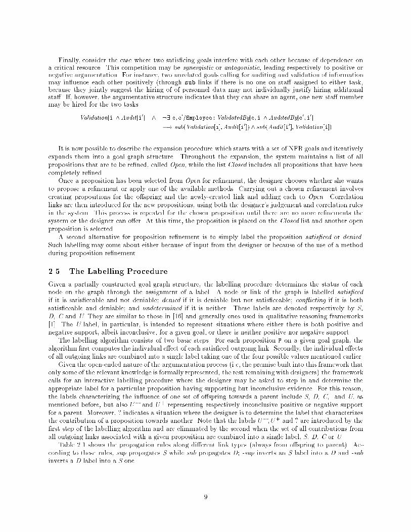
Finally, consider the case where two satis�cing goals interfere with each other because of dependence ona critical resource. This competition may be synergistic or antagonistic, leading respectively to positive ornegative argumentation. For instance, two unrelated goals calling for auditing and validation of informationmay in uence each other positively (through sub links if there is no one on sta� assigned to either task,because they jointly suggest the hiring of of personnel data may not individually justify hiring additionalsta�. If, however, the argumentative structure indicates that they can share an agent, one new sta� membermay be hired for the two tasks.Validation[i]^Audit[i0] ^ :9 e;e0=Employee : ValidatedBy[e;i]^AuditedBy[e0;i0]�! sub(Validation[i];Audit[i0]) ^ sub(Audit[i0];Validation[i])It is now possible to describe the expansion procedure which starts with a set of NFR goals and iterativelyexpands them into a goal graph structure. Throughout the expansion, the system maintains a list of allpropositions that are to be re�ned, called Open, while the list Closed includes all propositions that have beencompletely re�ned.Once a proposition has been selected from Open for re�nement, the designer chooses whether she wantsto propose a re�nement or apply one of the available methods. Carrying out a chosen re�nement involvescreating propositions for the o�spring and the newly-created link and adding each to Open. Correlationlinks are then introduced for the new propositions, using both the designer's judgement and correlation rulesin the system. This process is repeated for the chosen proposition until there are no more re�nements thesystem or the designer can o�er. At this time, the proposition is placed on the Closed list and another openproposition is selected.A second alternative for proposition re�nement is to simply label the proposition satis�ced or denied.Such labelling may come about either because of input from the designer or because of the use of a methodduring proposition re�nement.2.5 The Labelling ProcedureGiven a partially constructed goal graph structure, the labelling procedure determines the status of eachnode on the graph through the assignment of a label. A node or link of the graph is labelled satis�cedif it is satis�ceable and not deniable; denied if it is deniable but not satis�ceable; con icting if it is bothsatis�ceable and deniable; and undetermined if it is neither. These labels are denoted respectively by S,D, C and U. They are similar to those in [16] and generally ones used in qualitative reasoning frameworks[1]. The U label, in particular, is intended to represent situations where either there is both positive andnegative support, albeit inconclusive, for a given goal, or there is neither positive nor negative support.The labelling algorithm consists of two basic steps. For each proposition P on a given goal graph, thealgorithm �rst computes the individual e�ect of each satis�ced outgoing link. Secondly, the individual e�ectsof all outgoing links are combined into a single label taking one of the four possible values mentioned earlier.Given the open-ended nature of the argumentation process (i.e, the premise built into this framework thatonly some of the relevant knowledge is formally represented, the rest remaining with designers) the frameworkcalls for an interactive labelling procedure where the designer may be asked to step in and determine theappropriate label for a particular proposition having supporting but inconclusive evidence. For this reason,the labels characterizing the in uence of one set of o�spring towards a parent include S, D, C, and U, asmentioned before, but also U� and U+ representing respectively inconclusive positive or negative supportfor a parent. Moreover, ? indicates a situation where the designer is to determine the label that characterizesthe contribution of a proposition towards another. Note that the labels U�; U+ and ? are introduced by the�rst step of the labelling algorithm and are eliminated by the second when the set of all contributions fromall outgoing links associated with a given proposition are combined into a single label, S, D, C or U.Table 2.1 shows the propagation rules along di�erent link types (always from o�spring to parent). Ac-cording to these rules, sup propagates S while sub propagates D; -sup inverts an S label into a D and -subinverts a D label into a S one. 9
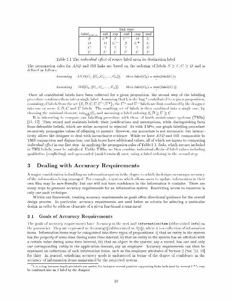
link typelabelsource sub sup -sub -sup undS U+ S U� D UD D U� S U+ UC ? ? ? ? UU U U U U UTable 2.1 The individual e�ect of source label upon its destination label.The propagation rules for AND and OR links are based on the ordering of labels S � U;C � D and isde�ned as follows:Assuming AND(G0; fG1;G2; : : : ;Gng) then label(G0) = mini (label(Gi))Assuming OR(G0; fG1;G2; : : : ;Gng) then label(G0) = maxi (label(Gi))Once all contributed labels have been collected for a given proposition, the second step of the labellingprocedure combines them into a single label. Assuming that L is the bag 5 contributed to a given proposition,consisting of labels from the set fS;D;C; U; U�; U+g, the U+ and U� labels are �rst combined by the designerinto one or more S;D;C and U labels. The resulting set of labels is then combined into a single one, bychoosing the minimal element, minl2L(l), and assuming a label ordering S;D � U � C.It is interesting to compare our labelling procedure with those of truth maintenance systems (TMSs)[15, 17]. They record and maintain beliefs, their justi�cations and assumptions, while distinguishing factsfrom defeasible beliefs, which are either accepted or rejected. As with TMSs, our graph labelling procedurerecursively propagates values of o�spring to parents. However, our procedure is not automatic, but interac-tively allows the designer to deal with inconclusive evidence. While we have AND and OR, comparable toTMS conjunction and disjunction, our link types have additional values, all of which are inputs to computingindividual e�ect in our �rst step. In applying the propagation rules of Table 2.1, links, which are not includedin TMS beliefs, must be satis�ced. Unlike TMSs, we then combine individual e�ects of label values includingqualitative (con icting) and open-ended (undetermined) ones, using a label ordering in the second step.3 Dealing with Accuracy RequirementsAmajor consideration in building an information system is the degree to which its design encourages accuracyof the information being managed. For example, a system which allows users to update information in theirown �les may be user-friendly, but one will not have con�dence in the information it contains. There aremany ways to promote accuracy requirements for an information system. Restricting access to resources isonly one such technique.Within our framework, treating accuracy requirements as goals o�ers directional guidance for the overalldesign process. In particular, accuracy requirements are used below as criteria for selecting a particulardesign in order to address elements of a given functional requirement.3.1 Goals of Accuracy RequirementsThe goals of accuracy requirements have Accuracy as the sort and InformationItem (abbreviated Info) asthe parameter. They are expressed as Accuracy[i] (abbreviated as A[i]), where i is a collection of informationitems. Information items may be categorized into three types of propositions: i) that an entity in the systemhas the property of some class during some time interval; ii) that an entity in the system has an attribute witha certain value during some time interval; iii) that an object in the system, say a record, has one and onlyone corresponding entity in the application domain, say an employee. Accuracy requirements can then beexpressed on collections of such information items, such as the employee attributes of Section 2 (See [12, 13]for this). In general, satis�cing accuracy goals is understood in terms of the degree of con�dence in theaccuracy of information items maintained by the projected system.5L is a bag because duplicate labels are useful; for instance several positive supporting links indicated by several U+'s maybe combined into an S label by the designer. 10
3.2 Goal Re�nement Methods3.2.1 Goal Decomposition MethodsWe present below some examples of accuracy decomposition methods, to be used in the illustration of Section3.4.� subclass method: In order to establish the accuracy of a class C of information items, establish theaccuracy of each immediate specialization, Ci, of C. This is a special case of the goal decompositionmethod mentioned in Section 2.3.� subset method: To establish the accuracy of a set of information items, establish the accuracy of eachsubset of information items. Similarly, a superset method can be provided.� individualAttributesmethod: To establish the accuracy of the attributes of a class of information items,establish the accuracy of each attribute of the class.� derivedInfo method: To establish the accuracy of a set of information items, establish that the functionwhich derives them is correctly designed and that all of the function's source parameters, currently inthe system, are accurate.� attributeSelection method: To establish the accuracy of an information item obtained by a sequenceof attribute selections (e.g., Joe.project.budget), establish the accuracy of each information itemobtained in the sequence (e.g., Joe.project, Project.budget).� conservation method: To establish the accuracy of a collection of information items which can nolonger be decomposed into information items currently in the system, establish i) their accuracy, whenreceived by the system from some external agent, and ii) their correct internal manipulation by thesystem.� correctExternalManipulation method: To establish the accuracy of information items upon receipt,establish CorrectInfoFlow, i.e., they were accurate when they were �rst transmitted by the originalsender, and have subsequently been correctly manipulated until receipt by the system. CorrectInfoFlowis a sub-sort of Correctness goals which, unlike accuracy goals, are related to actions that induce certainresults.3.2.2 Goal Satis�cing MethodsTaking the premise that the accuracy of information items depends entirely on the process in which they aremanipulated within the system and its environment, accuracy satis�cing goals alter that process6 . Accuracysatis�cing goals include preventive, curative and precautionary techniques. They a�ect the level of ourcon�dence in the accuracy of information items.Preventive accuracy satis�cing goals detect and disallow inaccuracies, when information items are receivedby the system. Most of them require direct interaction between the system and agents in the application do-main. They can be specialized by varying the agent who performs the needed task, the volume of informationitems, evidences attached, the time of processing and output, etc.:� con�rmation: The informant, either a machine or a person, double-checks the previously-submittedinformation item. This technique can be specialized: to con�rmation-via-identical-channel if the con-�rmation and �rst transmission use the same channel; otherwise to con�rmation-via-distinct-channel(e.g., via a daisy-channel).� veri�cation: A veri�er, who is a co-worker of the sender of information item makes a duplicate entryof the item onto some medium in the system (e.g., via duplicate IBM key-entry operation). As withcon�rmation, veri�cation can be specialized to veri�cation-via-identical-channel or veri�cation-via-distinct-channel.6Martin[30], for instance, o�ers a glossary of techniques for improving accuracy.11
� validation: A validator performs checking in the application domain, using certain records or proce-dural guidelines to ensure that the information item meets predetermined standards. The type andthoroughness of the checking can be re ected in specialized methods: creation-validation for directlycontacting the information source, experimentation for re-testing the information item, etc.� audit: An accuracy auditor uses procedures to periodically go through suspicious sampled informationitems.� consistency-checking: To prevent frequently-occurring errors, the system enforces certain integrityconstraints (e.g., check-sums incorporated into ISBNs).Curative satis�cing goals trace inaccuracies to their source, and provide for recovery from inaccuracies.Precautionary satis�cing goals make information ow more reliable in terms of what is involved, such assenders, receivers, and communication channels.3.2.3 Goal Argumentation MethodsThese methods support or deny the use of accuracy satis�cing goals and various re�nements in terms ofarguments. Examples include:� resource-assignment: In performing a task for a satis�cing goal, assign resources in the applicationdomain. For example, one can support a re�nement from a goal of validating expense summariesto one assigning a sta� member to the task, by claiming that class I secretaries will perform thevalidation.Validation[Summary] �s�u�p�! FormalClaim[9e : ValidatedBy[e;Summary] ^ EmpStatus(e;Sec I)]� policy-manual-consultation: When a question arises about the applicability of various types of methods,consult policy manuals in the application domain.� priority-based-selection: Select a method among alternatives according to their relative priority. E.g.,for a satis�cing goal which is good for high-priority accuracy goal A but bad for goal B, the prioritywould be a positive argument for A but negative for B.3.3 Correlation RulesAccuracy satis�cing goals, such as veri�cation, usually contribute positively to accuracy goals (such asA[attribute(Researcher)]) provided the (veri�cation) process is rapid. Otherwise, information items willbecome less timely. This perturbation is an example of a satis�cing goal becoming negative. For example:7Veri�edBy[e;i;t] ^ Excessive(t)^ A[i0] ^ i0 � i �! �sub(A[i0];Veri�cation[i])Veri�cation may be negative for a security goal if the veri�er is not allowed to access the information itemto be veri�ed.A security satis�cing goal (such asMutual-ID) or a user-friendliness satis�cing goal (such asCasualUserInterface)can be positive or negative for an accuracy goal. Consider Mutual-ID[a:Agent, i:Info, p:Procedure,t:Time]. To mutually ensure the identity of the agent a, attempting to access certain information items i,and the identity of the system process, both the agent and the system, during time interval t, go through atest procedure, p, which requires alternating queries and answers by the two (This is similar to the challengeresponse process [37]). This would be positive for accuracy goals if a malicious user, in the absence of mutualidenti�cation, would penetrate the system and falsify the information item.Table 3.1 summarizes some of the correlations. Entries of the form: < condition; orientation > mean \ifthe condition holds, then the relationship between the requirements goal and satis�cing goal is given by theorientation."7The time parameter (t) is omitted when not needed. 12
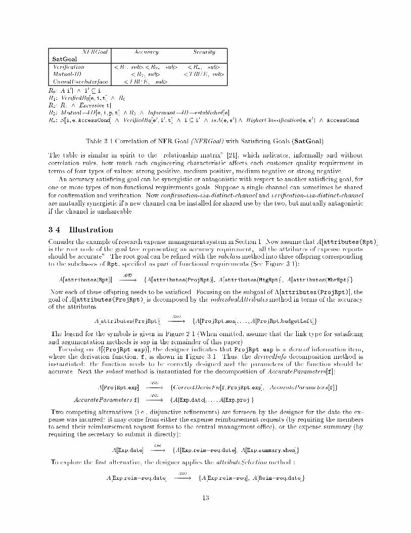
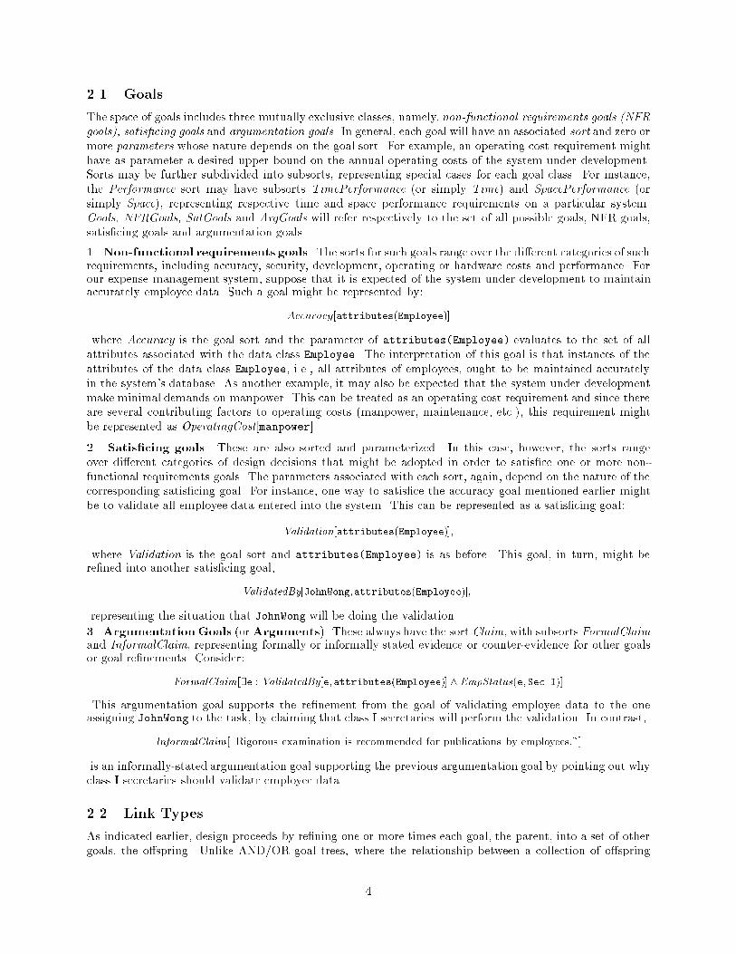
NFRGoal Accuracy SecuritySatGoalVeri�cation <R1, sub>,<R2, {sub> <R4, {sub>Mutual-ID <R3, sub> <TRUE, sub>CasualUserInterface <TRUE, {sub>R0: A[i0] ^ i0 � iR1: Veri�edBy[e;i;t] ^ R0R2: R1 ^ Excessive[t]R3: Mutual�ID[e;i;p;t] ^R0 ^ Informant�ID�established[e]R4: S[i;e;AccessCond] ^ Veri�edBy[e0;i0;t] ^ i � i0 ^ isA(e;e0) ^ HigherClassi�cation(e;e0) ^ AccessCondTable 3.1 Correlation of NFR Goal (NFRGoal) with Satis�cing Goals (SatGoal).The table is similar in spirit to the \relationship matrix" [21], which indicates, informally and withoutcorrelation rules, how much each engineering characteristic a�ects each customer quality requirement interms of four types of values: strong positive, medium positive, medium negative or strong negative.An accuracy satis�cing goal can be synergistic or antagonistic with respect to another satis�cing goal, forone or more types of non-functional requirements goals. Suppose a single channel can sometimes be sharedfor con�rmation and veri�cation. Now con�rmation-via-distinct-channel and veri�cation-via-distinct-channelare mutually synergistic if a new channel can be installed for shared use by the two, but mutually antagonisticif the channel is unshareable.3.4 IllustrationConsider the example of research expense management system in Section 1. Now assume thatA[attributes(Rpt)]is the root node of the goal tree representing an accuracy requirement, \all the attributes of expense reportsshould be accurate". The root goal can be re�ned with the subclass method into three o�spring correspondingto the subclasses of Rpt, speci�ed as part of functional requirements (See Figure 3.1):A[attributes(Rpt)] �A�N�D�! fA[attributes(ProjRpt)]; A[attributes(MtgRpt)]; A[attributes(MbrRpt)]gNow each of these o�spring needs to be satis�ced. Focusing on the subgoal of A[attributes(ProjRpt)], thegoal of A[attributes(ProjRpt)] is decomposed by the individualAttributesmethod in terms of the accuracyof the attributes.A[attributes(ProjRpt)] �A�N�D�! fA[ProjRpt:mon]; : : : ;A[ProjRpt:budgetLeft]gThe legend for the symbols is given in Figure 2.1 (When omitted, assume that the link type for satis�cingand argumentation methods is sup in the remainder of this paper).Focusing on A[(ProjRpt.exp)], the designer indicates that ProjRpt.exp is a derived information item,where the derivation function, f, is shown in Figure 3.1. Thus, the derivedInfo decomposition method isinstantiated: the function needs to be correctly designed and the parameters of the function should beaccurate. Next the subset method is instantiated for the decomposition of AccurateParameters[f]:A[ProjRpt:exp] �A�N�D�! fCorrectDerivFn[f;ProjRpt:exp]; AccurateParameters[f]gAccurateParameters[f] �A�N�D�! fA[Exp:date]; : : : ;A[Exp:proj]gTwo competing alternatives (i.e., disjunctive re�nements) are foreseen by the designer for the date the ex-pense was incurred: it may come from either the expense reimbursement requests (by requiring the membersto send their reimbursement request forms to the central management o�ce), or the expense summary (byrequiring the secretary to submit it directly):A[Exp:date] �O�R�! fA[Exp:reim�req:date]; A[Exp:summary:when]gTo explore the �rst alternative, the designer applies the attributeSelection method :A[Exp:reim�req:date] �A�N�D�! fA[Exp:reim�req]; A[Reim�req:date]g13
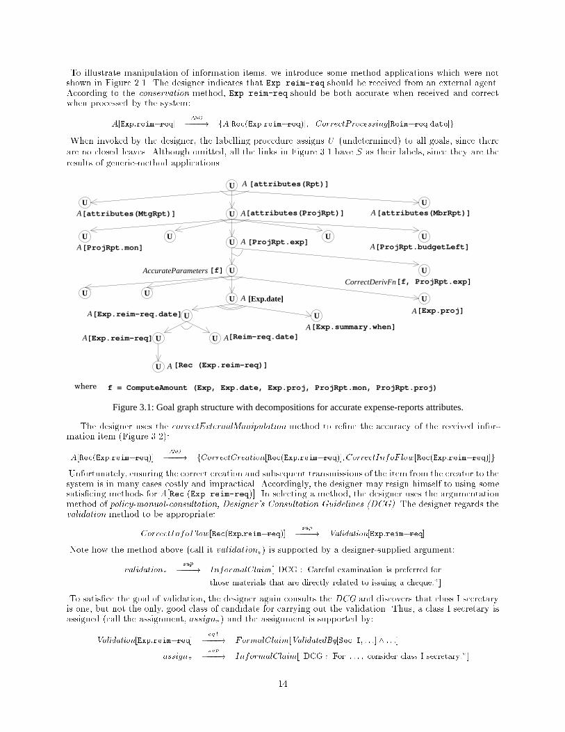
To illustrate manipulation of information items, we introduce some method applications which were notshown in Figure 2.1. The designer indicates that Exp.reim-req should be received from an external agent.According to the conservation method, Exp.reim-req should be both accurate when received and correctwhen processed by the system:A[Exp:reim�req] �A�N�D�! fA[Rec(Exp:reim�req)]; CorrectProcessing[Reim�req:date]gWhen invoked by the designer, the labelling procedure assigns U (undetermined) to all goals, since thereare no closed leaves. Although omitted, all the links in Figure 3.1 have S as their labels, since they are theresults of generic-method applications.[attributes(Rpt)]
AccurateParameters [f]
[Exp.summary.when]A
A[ProjRpt.budgetLeft]
A[attributes(MbrRpt)]
Figure 3.1: Goal graph structure with decompositions for accurate expense-reports attributes.
[Rec (Exp.reim-req)]
[ProjRpt.mon]
[attributes(MtgRpt)] [attributes(ProjRpt)]
[Exp.proj]
[Reim-req.date]
CorrectDerivFn
f = ComputeAmount (Exp, Exp.date, Exp.proj, ProjRpt.mon, ProjRpt.proj)where
U
UU
U
U UU
U
U
U U
UU
UU
U
U
UU
U
A
A
[Exp.date]A
A
AA
A
[ProjRpt.exp]A
A
A[Exp.reim-req]
[f, ProjRpt.exp]
[Exp.reim-req.date]A
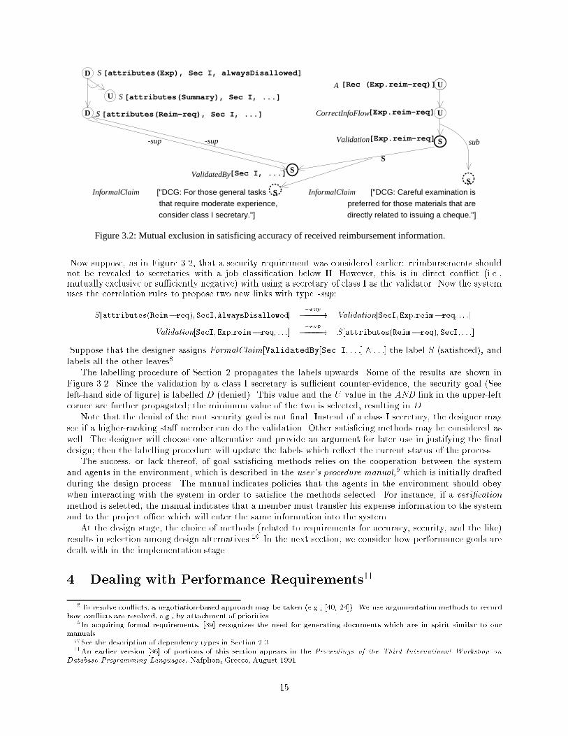
The designer uses the correctExternalManipulation method to re�ne the accuracy of the received infor-mation item (Figure 3.2):A[Rec(Exp:reim�req)] �A�N�D�! fCorrectCreation[Rec(Exp:reim�req)];CorrectInfoF low[Rec(Exp:reim�req)]gUnfortunately, ensuring the correct creation and subsequent transmissions of the item from the creator to thesystem is in many cases costly and impractical. Accordingly, the designer may resign himself to using somesatis�cing methods for A[Rec (Exp.reim-req)]. In selecting a method, the designer uses the argumentationmethod of policy-manual-consultation, Designer's Consultation Guidelines (DCG). The designer regards thevalidation method to be appropriate:CorrectInfoF low[Rec(Exp:reim�req)] �s�u�p�! Validation[Exp:reim�req]Note how the method above (call it validatione) is supported by a designer-supplied argument:validatione �s�u�p�! InformalClaim[\DCG : Careful examination is preferred forthose materials that are directly related to issuing a cheque:"]To satis�ce the goal of validation, the designer again consults the DCG and discovers that class I secretaryis one, but not the only, good class of candidate for carrying out the validation. Thus, a class I secretary isassigned (call the assignment, assignv) and the assignment is supported by:Validation[Exp:reim�req] �e�q�l�! FormalClaim[ValidatedBy[Sec I; : : :] ^ : : :]assignv �s�u�p�! InformalClaim[\DCG : For : : : ; consider class I secretary:"]14
A [Rec (Exp.reim-req)]
[Exp.reim-req]Validation
CorrectInfoFlow[Exp.reim-req]
directly related to issuing a cheque."]consider class I secretary."]
[attributes(Reim-req), Sec I, ...]
[attributes(Summary), Sec I, ...]
[attributes(Exp), Sec I, alwaysDisallowed]
U
U
subS
D
U
D
S
S
S
S
S
S
preferred for those materials that are["DCG: Careful examination isInformalClaimS["DCG: For those general tasks InformalClaim
that require moderate experience,
-sup-sup
Figure 3.2: Mutual exclusion in satisficing accuracy of received reimbursement information.
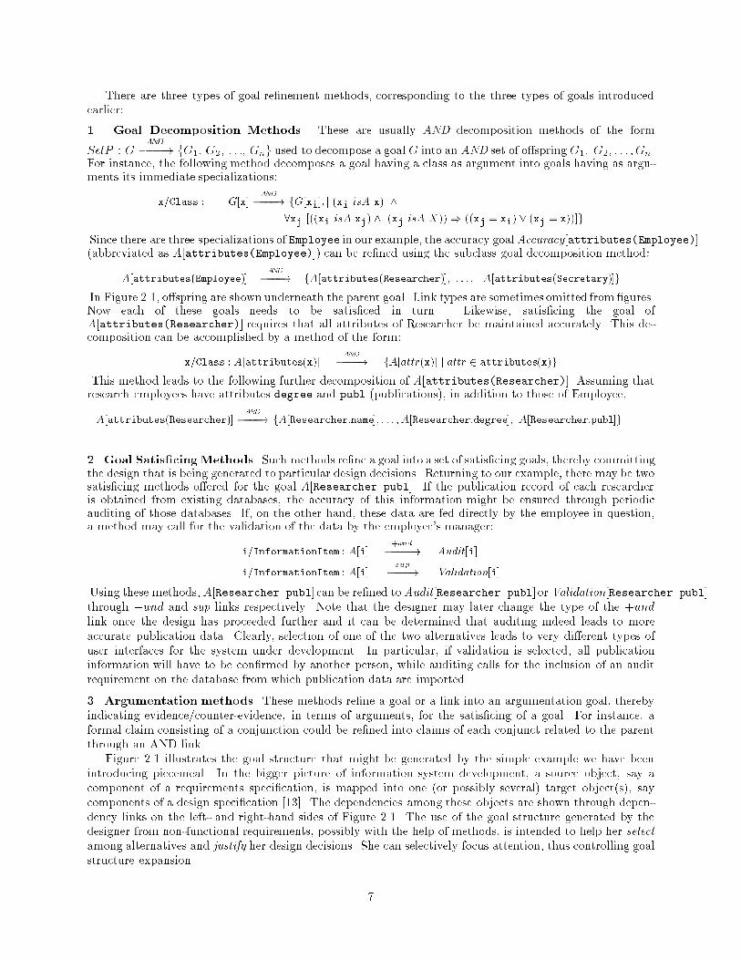
[Sec I, ...]ValidatedByNow suppose, as in Figure 3.2, that a security requirement was considered earlier: reimbursements shouldnot be revealed to secretaries with a job classi�cation below II. However, this is in direct con ict (i.e.,mutually exclusive or su�ciently negative) with using a secretary of class I as the validator. Now the systemuses the correlation rules to propose two new links with type -sup:S[attributes(Reim�req);SecI;AlwaysDisallowed] ���s�u�p�! Validation[SecI;Exp:reim�req; : : :]Validation[SecI;Exp:reim� req; : : :] ���s�u�p�! S[attributes(Reim� req);SecI; : : :]Suppose that the designer assigns FormalClaim[ValidatedBy[Sec I; : : :] ^ : : :] the label S (satis�ced), andlabels all the other leaves8.The labelling procedure of Section 2 propagates the labels upwards. Some of the results are shown inFigure 3.2. Since the validation by a class I secretary is su�cient counter-evidence, the security goal (Seeleft-hand side of �gure) is labelled D (denied). This value and the U value in the AND link in the upper-leftcorner are further propagated; the minimum value of the two is selected, resulting in D.Note that the denial of the root security goal is not �nal. Instead of a class I secretary, the designer maysee if a higher-ranking sta� member can do the validation. Other satis�cing methods may be considered aswell. The designer will choose one alternative and provide an argument for later use in justifying the �naldesign; then the labelling procedure will update the labels which re ect the current status of the process.The success, or lack thereof, of goal satis�cing methods relies on the cooperation between the systemand agents in the environment, which is described in the user's procedure manual,9 which is initially draftedduring the design process. The manual indicates policies that the agents in the environment should obeywhen interacting with the system in order to satis�ce the methods selected. For instance, if a veri�cationmethod is selected, the manual indicates that a member must transfer his expense information to the systemand to the project o�ce which will enter the same information into the system.At the design stage, the choice of methods (related to requirements for accuracy, security, and the like)results in selection among design alternatives.10 In the next section, we consider how performance goals aredealt with in the implementation stage.4 Dealing with Performance Requirements118To resolve con icts, a negotiation-based approach may be taken (e.g., [40, 24]). We use argumentation methods to recordhow con icts are resolved, e.g., by attachment of priorities.9In acquiring formal requirements, [39] recognizes the need for generating documents which are in spirit similar to ourmanuals.10See the description of dependency types in Section 2.3.11An earlier version [36] of portions of this section appears in the Proceedings of the Third International Workshop onDatabase Programming Languages, Nafplion, Greece, August 1991.15
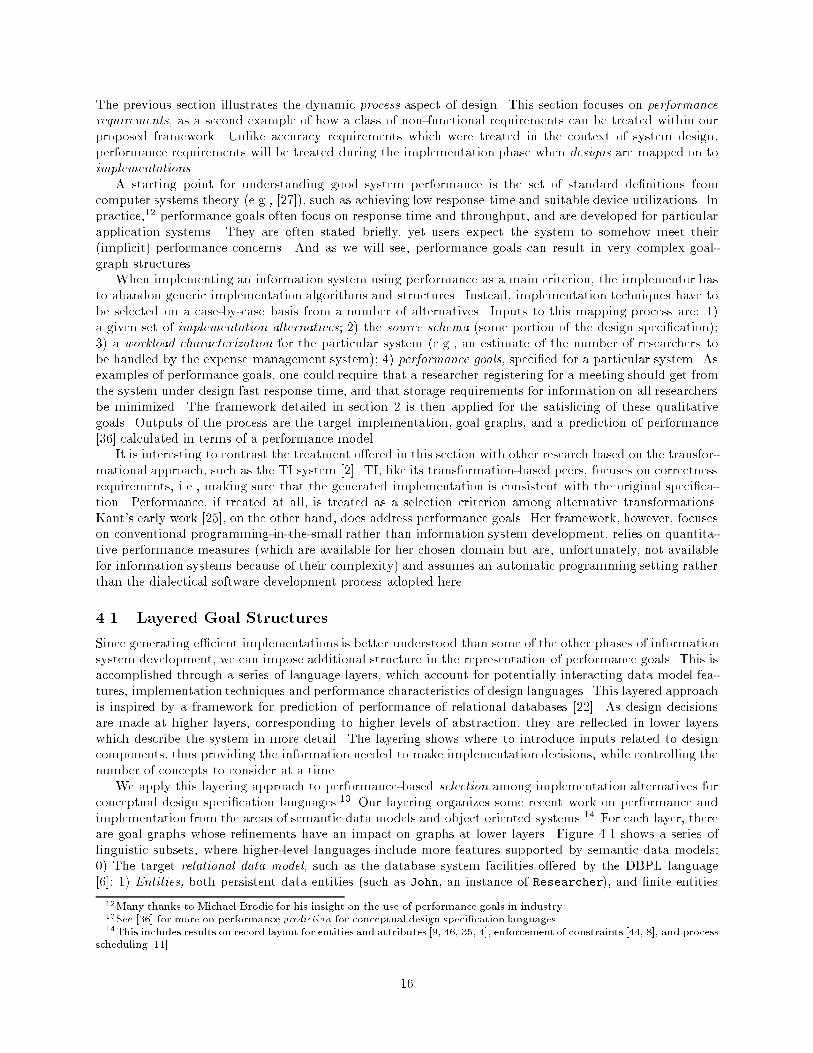
The previous section illustrates the dynamic process aspect of design. This section focuses on performancerequirements, as a second example of how a class of non-functional requirements can be treated within ourproposed framework. Unlike accuracy requirements which were treated in the context of system design,performance requirements will be treated during the implementation phase when designs are mapped on toimplementations.A starting point for understanding good system performance is the set of standard de�nitions fromcomputer systems theory (e.g., [27]), such as achieving low response time and suitable device utilizations. Inpractice,12 performance goals often focus on response time and throughput, and are developed for particularapplication systems. They are often stated brie y, yet users expect the system to somehow meet their(implicit) performance concerns. And as we will see, performance goals can result in very complex goal-graph structures.When implementing an information system using performance as a main criterion, the implementor hasto abandon generic implementation algorithms and structures. Instead, implementation techniques have tobe selected on a case-by-case basis from a number of alternatives. Inputs to this mapping process are: 1)a given set of implementation alternatives; 2) the source schema (some portion of the design speci�cation);3) a workload characterization for the particular system (e.g., an estimate of the number of researchers tobe handled by the expense management system); 4) performance goals, speci�ed for a particular system. Asexamples of performance goals, one could require that a researcher registering for a meeting should get fromthe system under design fast response time, and that storage requirements for information on all researchersbe minimized. The framework detailed in section 2 is then applied for the satis�cing of these qualitativegoals. Outputs of the process are the target implementation, goal graphs, and a prediction of performance[36] calculated in terms of a performance model.It is interesting to contrast the treatment o�ered in this section with other research based on the transfor-mational approach, such as the TI system [2]. TI, like its transformation-based peers, focuses on correctnessrequirements, i.e., making sure that the generated implementation is consistent with the original speci�ca-tion. Performance, if treated at all, is treated as a selection criterion among alternative transformations.Kant's early work [25], on the other hand, does address performance goals. Her framework, however, focuseson conventional programming-in-the-small rather than information system development, relies on quantita-tive performance measures (which are available for her chosen domain but are, unfortunately, not availablefor information systems because of their complexity) and assumes an automatic programming setting ratherthan the dialectical software development process adopted here.4.1 Layered Goal StructuresSince generating e�cient implementations is better understood than some of the other phases of informationsystem development, we can impose additional structure in the representation of performance goals. This isaccomplished through a series of language layers, which account for potentially interacting data model fea-tures, implementation techniques and performance characteristics of design languages. This layered approachis inspired by a framework for prediction of performance of relational databases [22]. As design decisionsare made at higher layers, corresponding to higher levels of abstraction, they are re ected in lower layerswhich describe the system in more detail. The layering shows where to introduce inputs related to designcomponents, thus providing the information needed to make implementation decisions, while controlling thenumber of concepts to consider at a time.We apply this layering approach to performance-based selection among implementation alternatives forconceptual design speci�cation languages.13 Our layering organizes some recent work on performance andimplementation from the areas of semantic data models and object oriented systems.14 For each layer, thereare goal graphs whose re�nements have an impact on graphs at lower layers. Figure 4.1 shows a series oflinguistic subsets, where higher-level languages include more features supported by semantic data models:0) The target relational data model, such as the database system facilities o�ered by the DBPL language[6]; 1) Entities, both persistent data entities (such as John, an instance of Researcher), and �nite entities12Many thanks to Michael Brodie for his insight on the use of performance goals in industry.13See [36] for more on performance prediction for conceptual design speci�cation languages.14This includes results on record layout for entities and attributes [9, 46, 35, 4], enforcement of constraints [44, 8], and processscheduling [11]. 16
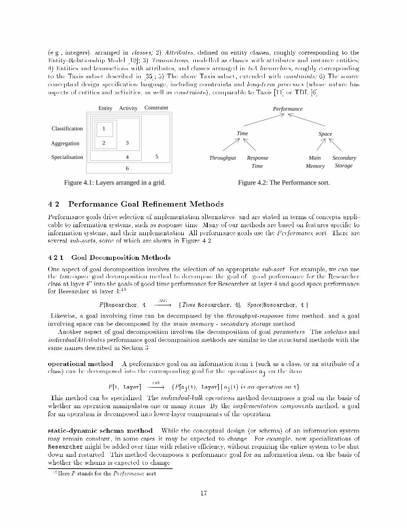
(e.g., integers), arranged in classes; 2) Attributes, de�ned on entity classes, roughly corresponding to theEntity-Relationship Model [10]; 3) Transactions, modelled as classes with attributes and instance entities;4) Entities and transactions with attributes, and classes arranged in IsA hierarchies, roughly correspondingto the Taxis subset described in [35]; 5) The above Taxis subset, extended with constraints; 6) The sourceconceptual design speci�cation language, including constraints and long-term processes (whose nature hasaspects of entities and activities, as well as constraints), comparable to Taxis [11] or TDL [6].Specialisation
Time
Throughput Response
Time
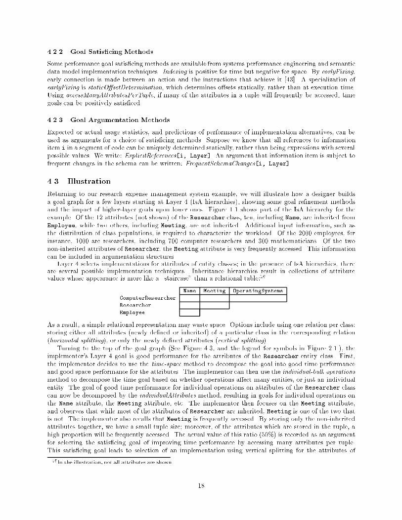
Figure 4.2: The Performance sort.Figure 4.1: Layers arranged in a grid.
Space
Entity Activity Constraint Performance
StorageMemory
Main
6
4 5
1
2 3
Secondary
Classification
Aggregation4.2 Performance Goal Re�nement MethodsPerformance goals drive selection of implementation alternatives, and are stated in terms of concepts appli-cable to information systems, such as response time. Many of our methods are based on features speci�c toinformation systems, and their implementation. All performance goals use the Performance sort. There areseveral sub-sorts, some of which are shown in Figure 4.2.4.2.1 Goal Decomposition MethodsOne aspect of goal decomposition involves the selection of an appropriate sub-sort. For example, we can usethe time-space goal decomposition method to decompose the goal of \good performance for the Researcherclass at layer 4" into the goals of good time performance for Researcher at layer 4 and good space performancefor Researcher at layer 4:15P [Researcher; 4] �A�N�D�! fTime [Researcher; 4]; Space[Researcher; 4]gLikewise, a goal involving time can be decomposed by the throughput-response time method, and a goalinvolving space can be decomposed by the main memory - secondary storage method.Another aspect of goal decomposition involves the decomposition of goal parameters. The subclass andindividualAttributes performance goal decomposition methods are similar to the structural methods with thesame names described in Section 3.operational method. A performance goal on an information item i (such as a class, or an attribute of aclass) can be decomposed into the corresponding goal for the operations oj on the item.P [i; Layer] �s�u�b�! fP [oj(i); Layer] j oj(i) is an operation on igThis method can be specialized. The individual-bulk operations method decomposes a goal on the basis ofwhether an operation manipulates one or many items. By the implementation components method, a goalfor an operation is decomposed into lower-layer components of the operation.static-dynamic schema method. While the conceptual design (or schema) of an information systemmay remain constant, in some cases it may be expected to change. For example, new specializations ofResearchermight be added over time with relative e�ciency, without requiring the entire system to be shutdown and restarted. This method decomposes a performance goal for an information item, on the basis ofwhether the schema is expected to change.15Here P stands for the Performance sort. 17
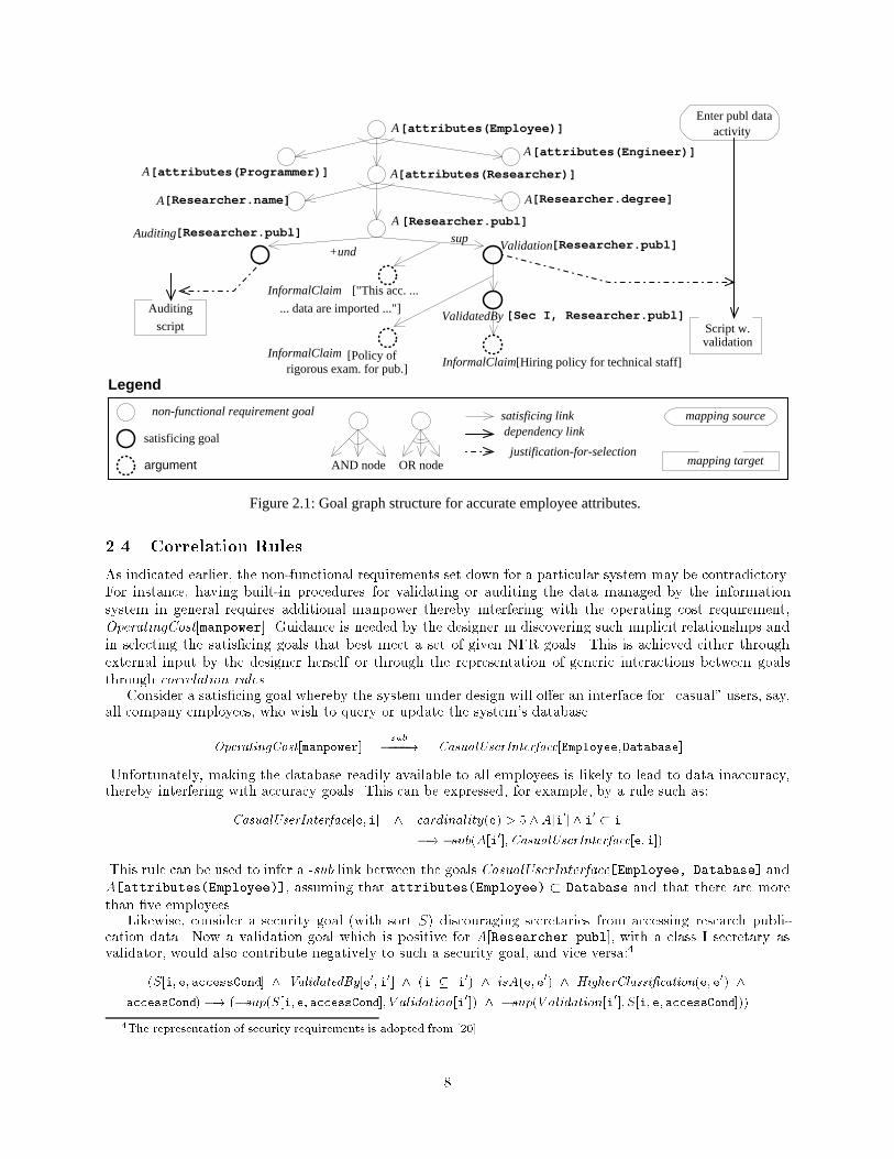
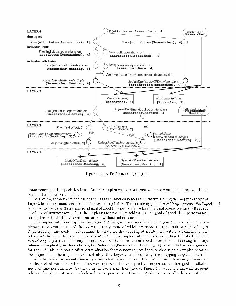
4.2.2 Goal Satis�cing MethodsSome performance goal satis�cing methods are available from systems performance engineering and semanticdata model implementation techniques. Indexing is positive for time but negative for space. By earlyFixing,early connection is made between an action and the instructions that achieve it [43]. A specialization ofearlyFixing is staticO�setDetermination, which determines o�sets statically, rather than at execution time.Using accessManyAttributesPerTuple, if many of the attributes in a tuple will frequently be accessed, timegoals can be positively satis�ced.4.2.3 Goal Argumentation MethodsExpected or actual usage statistics, and predictions of performance of implementation alternatives, can beused as arguments for a choice of satis�cing methods. Suppose we know that all references to informationitem i in a segment of code can be uniquely determined statically, rather than being expressions with severalpossible values. We write: ExplicitReferences[i, Layer]. An argument that information item is subject tofrequent changes in the schema can be written: FrequentSchemaChanges[i, Layer]4.3 IllustrationReturning to our research expense management system example, we will illustrate how a designer buildsa goal graph for a few layers starting at Layer 4 (IsA hierarchies), showing some goal re�nement methodsand the impact of higher-layer goals upon lower ones. Figure 1.1 shows part of the IsA hierarchy for theexample. Of the 12 attributes (not shown) of the Researcher class, ten, including Name, are inherited fromEmployee, while two others, including Meeting, are not inherited. Additional input information, such asthe distribution of class populations, is required to characterize the workload. Of the 2000 employees, forinstance, 1000 are researchers, including 700 computer researchers and 300 mathematicians. Of the twonon-inherited attributes of Researcher, the Meeting attribute is very frequently accessed. This informationcan be included in argumentation structures.Layer 4 selects implementations for attributes of entity classes; in the presence of IsA hierarchies, thereare several possible implementation techniques. Inheritance hierarchies result in collections of attributevalues whose appearance is more like a \staircase" than a relational table:16Name Meeting OperatingSystemsComputerResearcherResearcherEmployeeAs a result, a simple relational representation may waste space. Options include using one relation per class:storing either all attributes (newly de�ned or inherited) of a particular class in the corresponding relation(horizontal splitting), or only the newly de�ned attributes (vertical splitting).Turning to the top of the goal graph (See Figure 4.3, and the legend for symbols in Figure 2.1.), theimplementor's Layer 4 goal is good performance for the attributes of the Researcher entity class. First,the implementor decides to use the time-space method to decompose the goal into good time performanceand good space performance for the attributes. The implementor can then use the individual-bulk operationsmethod to decompose the time goal based on whether operations a�ect many entities, or just an individualentity. The goal of good time performance for individual operations on attributes of the Researcher classcan now be decomposed by the individualAttributes method, resulting in goals for individual operations onthe Name attribute, the Meeting attribute, etc. The implementor then focuses on the Meeting attribute,and observes that while most of the attributes of Researcher are inherited, Meeting is one of the two thatis not. The implementor also recalls that Meeting is frequently accessed. By storing only the non-inheritedattributes together, we have a small tuple size; moreover, of the attributes which are stored in the tuple, ahigh proportion will be frequently accessed. The actual value of this ratio (50%) is recorded as an argumentfor selecting the satis�cing goal of improving time performance by accessing many attributes per tuple.This satis�cing goal leads to selection of an implementation using vertical splitting for the attributes of16In the illustration, not all attributes are shown. 18
AccessManyAttributesPerTuple [Researcher.Meeting, 4]
individual attributes
individual-bulk
time-space
Time Time
-sub
ReduceRunTimeReorganization
[individual operations onResearcher.Meeting, 3]
[individual operations on
[attributes(Researcher), 4]]
[individual operations onResearcher.Meeting, 4]
attributes(Researcher), 4]
[attributes(Researcher), 4]Space
Time [bulk operations on
[attributes(Researcher), 4]
attributes(Researcher), 4][individual operations on
Researcher.Meeting, 3] MeetingResearcher.
attributes of
DynamicOffsetDetermination[Resarcher.Meeting, 1]
VerticalSplitting HorizontalSplitting
StaticOffsetDetermination[Researcher.Meeting, 1]
[Resarcher, 3][Researcher, 3]
LAYER 4
LAYER 3
LAYER 2
LAYER 1
ReduceDuplicationOfEntityIdentifiers
[find offset, 2]
[
[find offset, 2][Researcher.Meeting, 2]]
individual ops. on
ResearcherP[attributes(Researcher), 4]
Time
[retrieve
InformalClaim
[individual operations onResearcher.Name, 4]
FormalClaimfrom storage, 2]
EarlyFixing
Time
FrequentSchemaChanges
[retrieve from storage, 2]
UniformTime
["50% attrs. frequently accessed"]
Time Time
[Researcher.Meeting, 2]]
Time
FormalClaim ExplicitReferences[
sub
subFigure 4.3: A Performance goal graph.Researcher and its specializations. Another implementation alternative is horizontal splitting, which cano�er better space performance.At Layer 4, the designer dealt with the Researcher class in an IsA hierarchy, leaving the mapping target atLayer 3 being the Researcher class using vertical splitting. The satis�cing goalAccessManyAttributesPerTuple[...]is re�ned to the Layer 3 (transactions) goal of good time performance for individual operations on the Meetingattribute of Researcher. Thus the implementor continues addressing the goal of good time performance,but at Layer 3, which deals with operations without inheritance.The implementor decomposes the Layer 3 Time goal (See middle left of Figure 4.3) according the im-plementation components of the operation (only some of which are shown). The result is a set of Layer2 (attributes) time goals | for �nding the o�set for the Meeting attribute �eld within a relational tuple,retrieving the value from secondary storage, etc. The implementor focuses on �nding the o�set quickly;earlyFixing is positive. The implementor reviews the source schema and observes that Meeting is alwaysreferenced explicitly in the code. ExplicitReferences[Researcher.Meeting, 2] is recorded as an argumentfor the sub link, and static o�set determination for the Meeting attribute is chosen as an implementationtechnique. Thus the implementor has dealt with a Layer 2 issue, resulting in a mapping target at Layer 1.An alternative implementation is dynamic o�set determination. The -sub link records its negative impacton the goal of minimizing time. However, this would have a positive impact on another goal | o�eringuniform time performance. As shown in the lower right-hand side of Figure 4.3, when dealing with frequentschema changes, a structure which reduces expensive run-time reorganization can o�er less variation in19
response time.5 ConclusionsThe main contribution of this research is that it o�ers a concrete framework for integrating non-functionalrequirements into the software development process, at least for information systems. In tackling this task,our research extends earlier work by Lee [28, 29] and [38, 14]. The framework is still under re�nement anda prototype implementation is under way, intended to provide a vehicle for more thorough testing and forgaining experience with the framework's strengths and weaknesses.Much remains to be done with this work. Firstly, the framework needs to be applied to other types of non-functional requirements and life-size examples. Secondly, the framework needs a theoretical foundation forrepresenting and reasoning with non-functional requirements. This foundation needs to include a semanticsfor non-functional requirements. For example, what does it really mean to claim that a particular designdecision enhances system accuracy concerning employee data? Moreover, a proof theory based on thissemantics is required, including e�cient algorithms for special classes of inferences related to non-functionalrequirements. The whole framework we have o�ered here can then be justi�ed on formal semantic groundsrather than informal, intuitive ones.Unfortunately, it seems that such a formal semantic treatment of non-functional requirements would needto be done individually for di�erent types of requirements and is therefore a long term research project. Inthe meantime, an experimental approach such as the one adopted here can o�er solutions that may �ndimmediate use in an area of computer practice that is in great need of concepts, methodologies and tools.AcknowledgmentsWe would like to thank the referees for their constructive and detailed comments, as well as Eric Yu andSheila McIlraith for providing helpful suggestions.References[1] Artif. Intell. J., vol. 24, nos. 1{3, Dec., 1984.[2] R. Balzer, \A 15 Year Perspective on Automatic Programming" IEEE Trans. Software Eng., vol. SE{11, no. 11,Nov. 1985, pp. 1257{1268.[3] V. R. Basili and J. D. Musa, \The Future Engineering of Software: AManagement Perspective," IEEE Computer,vol 24, no. 9, Sept. 1991, pp. 90{96.[4] V. Benzaken, \An Evaluation Model for Clustering Strategies in the O2 Object-Oriented Database System," inProc. 3rd Int. Conf. Database Theory, Paris, Dec. 1990. Berlin: Springer-Verlag, 1990, pp. 126{140.[5] B. W. Boehm, J. R. Brown, H. Kaspar, M. Lipow, G. J. MacLeod and M. J. Merritt, Characteristics of SoftwareQuality. Amsterdam: North-Holland, 1978.[6] A. Borgida, J. Mylopoulos, J. W. Schmidt and I. Wetzel, \Support for Data-Intensive Applications: ConceptualDesign and Software Development," in Proc. 2nd Int. Workshop on Database Programming Languages, June1989, Gleneden Beach, Oregon. San Mateo, CA: Morgan Kaufmann, 1990, pp. 258{280.[7] T. P. Bowen, G. B. Wigle and J. T. Tsai, \Speci�cation of Software Quality Attributes," Rep. RADC{TR{85{37,Rome Air Development Center, Gri�ss Air Force Base, NY, Feb. 1985.[8] S. Ceri and J. Widom, \Deriving Production Rules for Constraint Management," in Proc. 16th Int. Conf. VeryLarge Data Bases, Brisbane, Australia, Aug. 1990, pp. 566{577.[9] A. Chan, S. Danberg, S. Fox, W.-T. K. Lin, A. Nori and D. Ries, \Storage and Access Structures to Support aSemantic Data Model," in Proc. 8th Int. Conf. Very Large Data Bases, Mexico City, Sept. 1982, pp. 122{130.[10] P. P.-S. Chen, The Entity-Relationship Model | Toward a Uni�ed View of Data. ACM Trans. Database Systems,vol. 1, no. 1, March 1976, pp. 9{36. 20
[11] K. L. Chung, D. Rios-Zertuche, B. A. Nixon and J. Mylopoulos, \Process Management and Assertion Enforce-ment for a Semantic Data Model," in Proc. EDBT '88, Int. Conf. Extending Database Technology,Venice, Italy,March 1988. Berlin: Springer-Verlag, 1988, pp. 469{487.[12] L. Chung, \Representation and Utilization of Non-Functional Requirements for Information System Design," inProc. CAiSE '91, 3rd Int. Conf. Advanced Information Systems Eng., Trondheim, Norway, May 1991. Berlin:Springer-Verlag, 1991, pp. 5{30.[13] K. L. Chung, P. Katalagarianos, M. Marakakis, M. Mertikas, J. Mylopoulos and Y. Vassiliou, \From InformationSystem Requirements to Designs: A Mapping Framework," Information Systems, vol. 16, no. 4, 1991, pp. 429{461.[14] J. Conklin and M. L. Begeman, \gIBIS: A Hypertext Tool for Explanatory Policy Discussions," ACM Trans.O�ce Information Systems, vol. 6, no. 4, 1988, pp. 303{331.[15] J. de Kleer, \Problem Solving with the ATMS," Artif. Intell. J., vol. 28, 1986, pp. 127{162.[16] C. DiMarco, \Computational Stylistics for Natural Language Translation," Ph.D. Thesis, Dept. of ComputerScience, Univ. of Toronto, 1990.[17] J. Doyle, \A Truth Maintenance System," Artif. Intell. J., vol. 12, 1979, pp. 231{272.[18] S. F. Fickas, \Automating the Transformational Development of Software," IEEE Trans. Software Eng., vol.SE{11, no. 11, Nov. 1985, pp. 1268{1277.[19] U. Hahn, M. Jarke and T. Rose, \Teamwork Support in a Knowledge-Based Information Systems Environment,"IEEE Trans. Software Eng., vol. 17, no. 5, May 1991, pp. 467{482,[20] H. R. Hartson and D. K. Hsiao, \Full Protection Speci�cations in the Semantic Model for Database ProtectionLanguages," in Proc. ACM Annual Conf., Houston, TX, Oct. 1976, pp. 90{95.[21] J. R. Hauser and D. Clausing, \The House of Quality," Harvard Business Review, May-June 1988, pp. 63{73.[22] W. F. Hyslop, \Performance Prediction of Relational Database Management Systems," Ph.D. Thesis, Dept. ofComputer Science, Univ. of Toronto, 1991.[23] M. Jarke, J. Mylopoulos, J. W. Schmidt and Y. Vassiliou, \DAIDA: An Environment for Evolving InformationSystems," ACM Trans. Information Systems, vol. 10, no. 1, Jan. 1992, forthcoming.[24] W. L. Johnson, M. S. Feather, D. R. Harris and K. M. Benner, \Representation and Presentation of RequirementsKnowledge." Manuscript, USC/Information Sciences Institute, Oct. 1991.[25] E. Kant, \On the E�cient Synthesis of E�cient Programs," Artif. Intell. J., vol. 20, no. 3, May 1983, pp.253{305.[26] S. E. Keller, L. G. Kahn and R. B. Panara, \Specifying Software Quality Requirements with Metrics," in Tutorial:System and Software Requirements Engineering, R. H. Thayer and M. Dorfman, Eds. IEEE Computer SocietyPress, 1990, pp. 145{163,[27] E. D. Lazowska, J. Zahorjan, G. S. Graham and K. C. Sevcik, Quantitative System Performance. EnglewoodCli�s, NJ: Prentice-Hall, 1984.[28] J. Lee, \SIBYL: A Qualitative Decision Management System," in Arti�cial Intelligence at MIT: ExpandingFrontiers, vol. 1, P. H. Winston and S. A. Shellard, Eds. Cambridge, MA: The MIT Press, 1990, pp. 105{133.[29] J. Lee, \Extending the Potts and Bruns Model for Recording Design Rationale," in Proc. 13th Int. Conf. SoftwareEng., Austin, TX, May 1991, pp. 114{125.[30] J. Martin, Security, Accuracy, and Privacy in Computer Systems. Englewood Cli�s, NJ: Prentice-Hall, 1973.[31] J. Mostow, \Towards Better Models of the Design Process," AI Magazine, vol. 6, no. 1, Spring 1985, pp. 44{57.[32] J. Mylopoulos, P. A. Bernstein and H. K. T. Wong, \A Language Facility for Designing Database-IntensiveApplications," ACM Trans. Database Systems, vol. 5, no. 2, June 1980, pp. 185{207.[33] J. Mylopoulos, A. Borgida, M. Jarke and M. Koubarakis, \Telos: Representing Knowledge about InformationSystems," ACM Trans. Information Systems, vol. 8, no. 4, Oct. 1992, pp. 325{362.[34] N. Nilsson, Problem-Solving Methods in Arti�cial Intelligence. New York, McGraw-Hill, 1971.[35] B. Nixon, L. Chung, D. Lauzon, A. Borgida, J. Mylopoulos and M. Stanley, \Implementation of a Compiler fora Semantic Data Model: Experiences with Taxis," in Proc. ACM SIGMOD 1987 Annual Conf., San Francisco,CA, May 1987, (ACM SIGMOD Record, vol. 16, no. 3, Dec. 1987), pp. 118{131.21
[36] B. Nixon, \Implementation of Information System Design Speci�cations: A Performance Perspective," in Proc.3rd Int. Workshop on Database Programming Languages, Nafplion, Greece, Aug. 1991, P. Kanellakis and J. W.Schmidt, Eds. San Mateo, CA: Morgan Kaufmann, forthcoming.[37] C. P. P eeger, Security in Computing. Englewood Cli�s, NJ: Prentice-Hall, 1989.[38] C. Potts and G. Bruns, \Recording the Reasons for Design Decisions," in Proc. 10th Int. Conf. Software Eng.,1988, pp. 418{427.[39] H. Reubenstein, \Automated Acquisition of Evolving Informal Descriptions," Ph.D. Thesis; also Tech. Rep.1205, MIT Artif. Intell. Lab., 1990.[40] W. N. Robinson, \Negotiation Behavior During Requirement Speci�cation," in Proc. 12th Int. Conf. SoftwareEng., Nice, France, March 1990, pp. 268{276.[41] G.-C. Roman, \A Taxonomy of Current Issues in Requirements Engineering," IEEE Computer, vol. 18, no. 4,Apr. 1985, pp. 14{23.[42] H. A. Simon, The Sciences of the Arti�cial, 2nd ed. Cambridge, MA: The MIT Press, 1981.[43] C. U. Smith, Performance Engineering of Software Systems. Reading, MA: Addison-Wesley, 1990.[44] M. Stonebraker, \Triggers and Inference in Database Systems," in On Knowledge Base Management Systems,M. L. Brodie and J. Mylopoulos, Eds. New York: Springer-Verlag, 1986, pp. 297{314.[45] R. H. Thayer and M. C. Thayer, \Glossary," in Tutorial: System and Software Requirements Engineering,Richard H. Thayer and Merlin Dorfman, Eds. IEEE Computer Society Press, 1990, pp. 605{676.[46] G. E. Weddell, \Selection of Indexes to Memory-Resident Entities for Semantic Data Models," IEEE Trans.Knowledge and Data Eng., vol. 1, no. 2, June 1989, pp. 274{284.
22
Contents1 Introduction 12 Representing Non-Functional Requirements: 32.1 Goals : : : : : : : : : : : : : : : : : : : : : : : : : : : : : : : : : : : : : : : : : : : : : : : : : 42.2 Link Types : : : : : : : : : : : : : : : : : : : : : : : : : : : : : : : : : : : : : : : : : : : : : : 42.3 Methods : : : : : : : : : : : : : : : : : : : : : : : : : : : : : : : : : : : : : : : : : : : : : : : : 62.4 Correlation Rules : : : : : : : : : : : : : : : : : : : : : : : : : : : : : : : : : : : : : : : : : : : 82.5 The Labelling Procedure : : : : : : : : : : : : : : : : : : : : : : : : : : : : : : : : : : : : : : : 93 Dealing with Accuracy Requirements 103.1 Goals of Accuracy Requirements : : : : : : : : : : : : : : : : : : : : : : : : : : : : : : : : : : 103.2 Goal Re�nement Methods : : : : : : : : : : : : : : : : : : : : : : : : : : : : : : : : : : : : : : 113.2.1 Goal Decomposition Methods : : : : : : : : : : : : : : : : : : : : : : : : : : : : : : : : 113.2.2 Goal Satis�cing Methods : : : : : : : : : : : : : : : : : : : : : : : : : : : : : : : : : : 113.2.3 Goal Argumentation Methods : : : : : : : : : : : : : : : : : : : : : : : : : : : : : : : : 123.3 Correlation Rules : : : : : : : : : : : : : : : : : : : : : : : : : : : : : : : : : : : : : : : : : : : 123.4 Illustration : : : : : : : : : : : : : : : : : : : : : : : : : : : : : : : : : : : : : : : : : : : : : : 134 Dealing with Performance Requirements 154.1 Layered Goal Structures : : : : : : : : : : : : : : : : : : : : : : : : : : : : : : : : : : : : : : : 164.2 Performance Goal Re�nement Methods : : : : : : : : : : : : : : : : : : : : : : : : : : : : : : 174.2.1 Goal Decomposition Methods : : : : : : : : : : : : : : : : : : : : : : : : : : : : : : : : 174.2.2 Goal Satis�cing Methods : : : : : : : : : : : : : : : : : : : : : : : : : : : : : : : : : : 184.2.3 Goal Argumentation Methods : : : : : : : : : : : : : : : : : : : : : : : : : : : : : : : : 184.3 Illustration : : : : : : : : : : : : : : : : : : : : : : : : : : : : : : : : : : : : : : : : : : : : : : 185 Conclusions 20Bibliography 20
Recommended


