Self-Heating Cup Haonan Wang
Peiming Wu
Chengyao Zou
Final Report for ECE 445, Senior Design, Spring 2020
TA: Shaoyu Meng
Abstract
The existing problem is that people who want to drink warm beverages don’t have access to devices like microwaves in the working environment. The original solution proposed to design an Electric Thermos Box to heat/cool the beverage. Our new solution is to design a self-heating cup with an attachable coaster. Our new solution reduced the heating time and made it convenient to carry around under working environments compared to the original solution.
2
Contents
1. Motivation 4
1.1 Problem Statement 4
1.2 Solution 4
1.3 High Level Requirement 5
1.4 Visual Aid 5
1.5 Block Diagram and State Machine 7
2 Implementation 8
2.1 Details and Analysis 9
3. Conclusion 12
3.1 Implementation Summary 12
3.2 Unknowns, uncertainties and test needed 12
3.3 Ethics and Safety 13
3.4 Project Improvements 14
4. Progress made on first project 15
References 16
3
1. Motivation
1.1 Problem Statement
Coffee and tea culture are long living both in the east and the west. Either of them require warm or hot water to make. These days, although cafes like Starbucks or even the Daily Byte in ECEB are everywhere in the United States, the temperature of the coffee or tea usually does not hold for a long time. Especially for people who work in the office, they don’t want to walk in and out to reheat their drinking. Scenarios like a long meeting and your coffee was totally cold after one hour and you don’t have access to a microwave at that awkward moment. Therefore, our objective is to always keep your coffee or tea warm whenever you drink it with our designed mug with a self-heating coaster.
1.2 Solution
The original project Electric Thermos Box[10] tried to solve the problem by designing a heating box with heating pads attached inside the box. They expected ~20 mins to heat the 250ml beverage. However, we believe this is too much time for waiting. From that, we decided to improve the heating efficiency of the original project and redo the physical design. By doing research on existing products for solving the same problem on the market. To this point, we came up with our solution by designing a self-heating cup with a heating coaster. The main difference of our solution to the original solution is that our solution solves the low heating efficiency issue of the original project by putting silicone heating pads inside the ceramic mug. Our product is smaller than the original project in that it’s pretty much a standard mug and a coaster. Hence, the person who has the problem is interested in our product since our product is convenient to take around and has significantly less time to heat than the original solution. We found the Ember Mug[1], which is a highly integrated mug with PCB on the bottom side of the mug. This product is expensive (~$100) and it has a rechargeable battery inside the mug, which comes up with some safety concerns from reviews. Also, this product has the issue of heating beverages unevenly since the heat comes from the bottom. Our product removes the built-in battery to reduce the safety concern and put most of our PCBs inside the coaster instead of the mug. The silicone heating pads attached to the side area of the mug also helps heat the beverage uniformly and hence provide a better drinking experience.
4
1.3 High Level Requirement
1. The heating process within 10 mins to heat the liquid to a certain temperature (Maximum 50 celsius). 2. The difference between the temperature we set and the temperature of the liquid after heating should be less than 5 celsius. 3. The whole design should be fit in a bag and can be carried to anywhere conveniently.
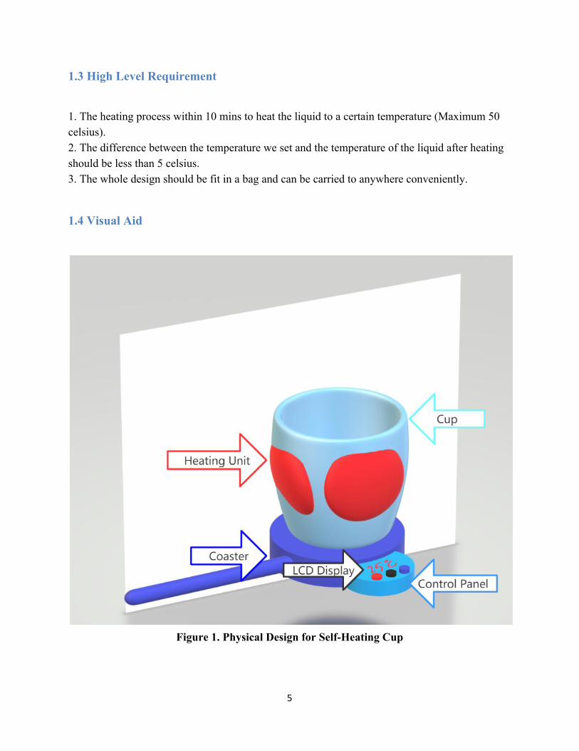
1.4 Visual Aid
Figure 1. Physical Design for Self-Heating Cup
5
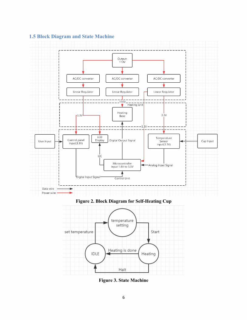
1.5 Block Diagram and State Machine
Figure 2. Block Diagram for Self-Heating Cup
Figure 3. State Machine
6
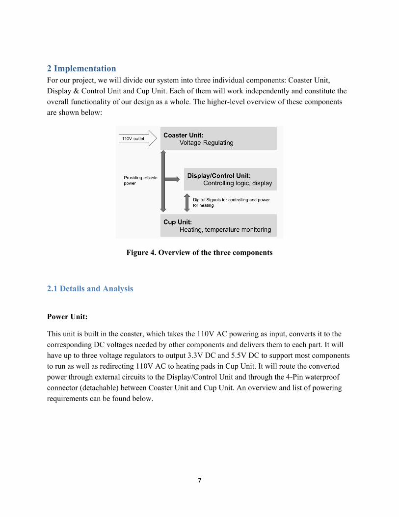
2 Implementation For our project, we will divide our system into three individual components: Coaster Unit, Display & Control Unit and Cup Unit. Each of them will work independently and constitute the overall functionality of our design as a whole. The higher-level overview of these components are shown below:
Figure 4. Overview of the three components
2.1 Details and Analysis
Power Unit:
This unit is built in the coaster, which takes the 110V AC powering as input, converts it to the corresponding DC voltages needed by other components and delivers them to each part. It will have up to three voltage regulators to output 3.3V DC and 5.5V DC to support most components to run as well as redirecting 110V AC to heating pads in Cup Unit. It will route the converted power through external circuits to the Display/Control Unit and through the 4-Pin waterproof connector (detachable) between Coaster Unit and Cup Unit. An overview and list of powering requirements can be found below.
7
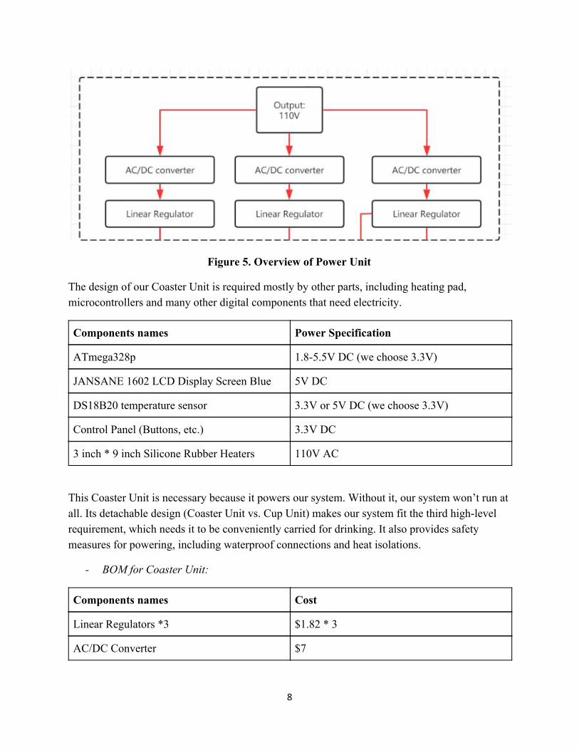
Figure 5. Overview of Power Unit
The design of our Coaster Unit is required mostly by other parts, including heating pad, microcontrollers and many other digital components that need electricity.
Components names Power Specification
ATmega328p 1.8-5.5V DC (we choose 3.3V)
JANSANE 1602 LCD Display Screen Blue 5V DC
DS18B20 temperature sensor 3.3V or 5V DC (we choose 3.3V)
Control Panel (Buttons, etc.) 3.3V DC
3 inch * 9 inch Silicone Rubber Heaters 110V AC
This Coaster Unit is necessary because it powers our system. Without it, our system won’t run at all. Its detachable design (Coaster Unit vs. Cup Unit) makes our system fit the third high-level requirement, which needs it to be conveniently carried for drinking. It also provides safety measures for powering, including waterproof connections and heat isolations.
- BOM for Coaster Unit:
Components names Cost
Linear Regulators *3 $1.82 * 3
AC/DC Converter $7
8
Total: $12.46
Display & Control Unit:
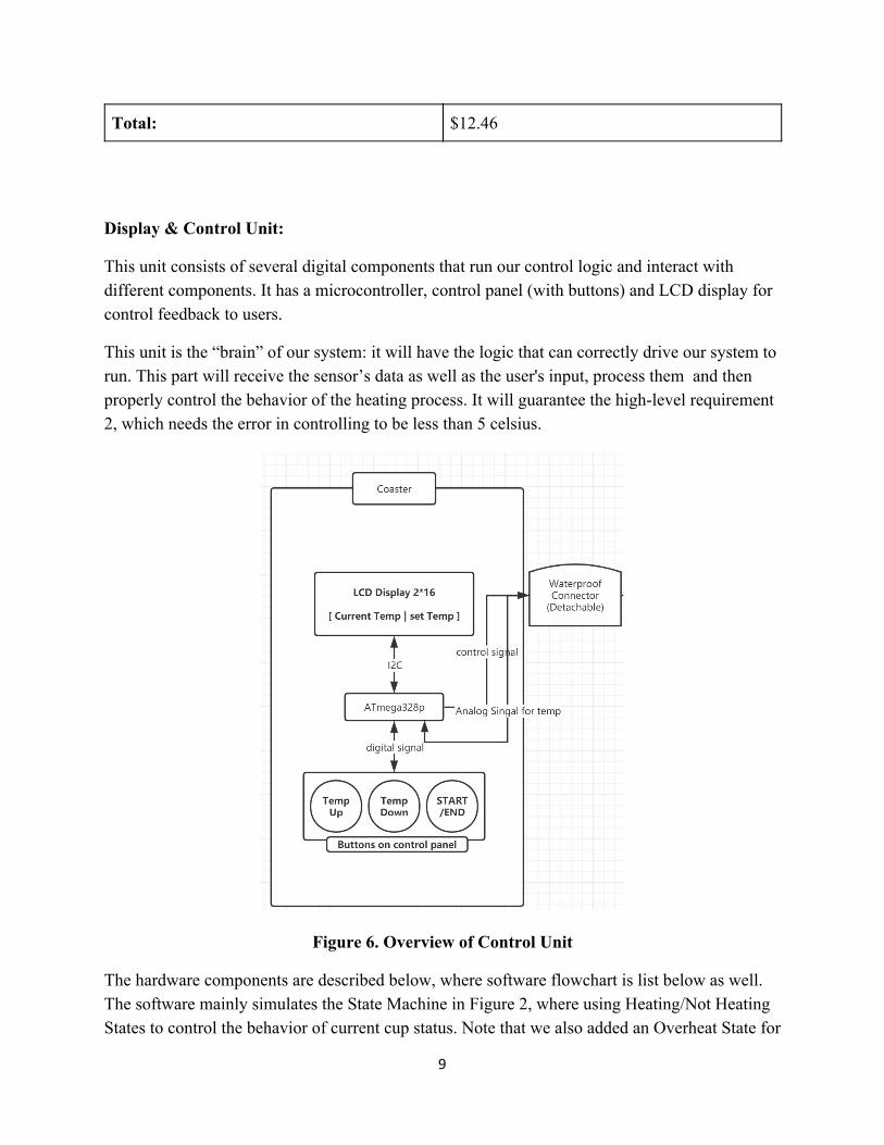
This unit consists of several digital components that run our control logic and interact with different components. It has a microcontroller, control panel (with buttons) and LCD display for control feedback to users.
This unit is the “brain” of our system: it will have the logic that can correctly drive our system to run. This part will receive the sensor’s data as well as the user's input, process them and then properly control the behavior of the heating process. It will guarantee the high-level requirement 2, which needs the error in controlling to be less than 5 celsius.
Figure 6. Overview of Control Unit
The hardware components are described below, where software flowchart is list below as well. The software mainly simulates the State Machine in Figure 2, where using Heating/Not Heating States to control the behavior of current cup status. Note that we also added an Overheat State for
9
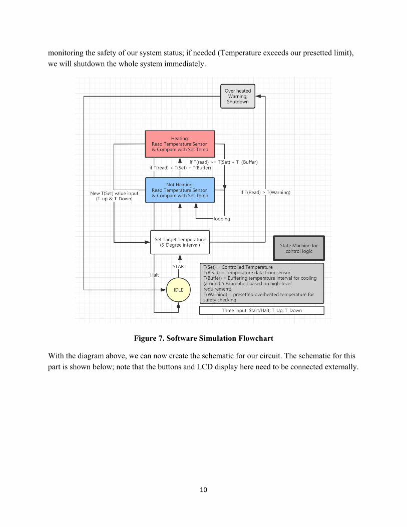
monitoring the safety of our system status; if needed (Temperature exceeds our presetted limit), we will shutdown the whole system immediately.
Figure 7. Software Simulation Flowchart
With the diagram above, we can now create the schematic for our circuit. The schematic for this part is shown below; note that the buttons and LCD display here need to be connected externally.
10
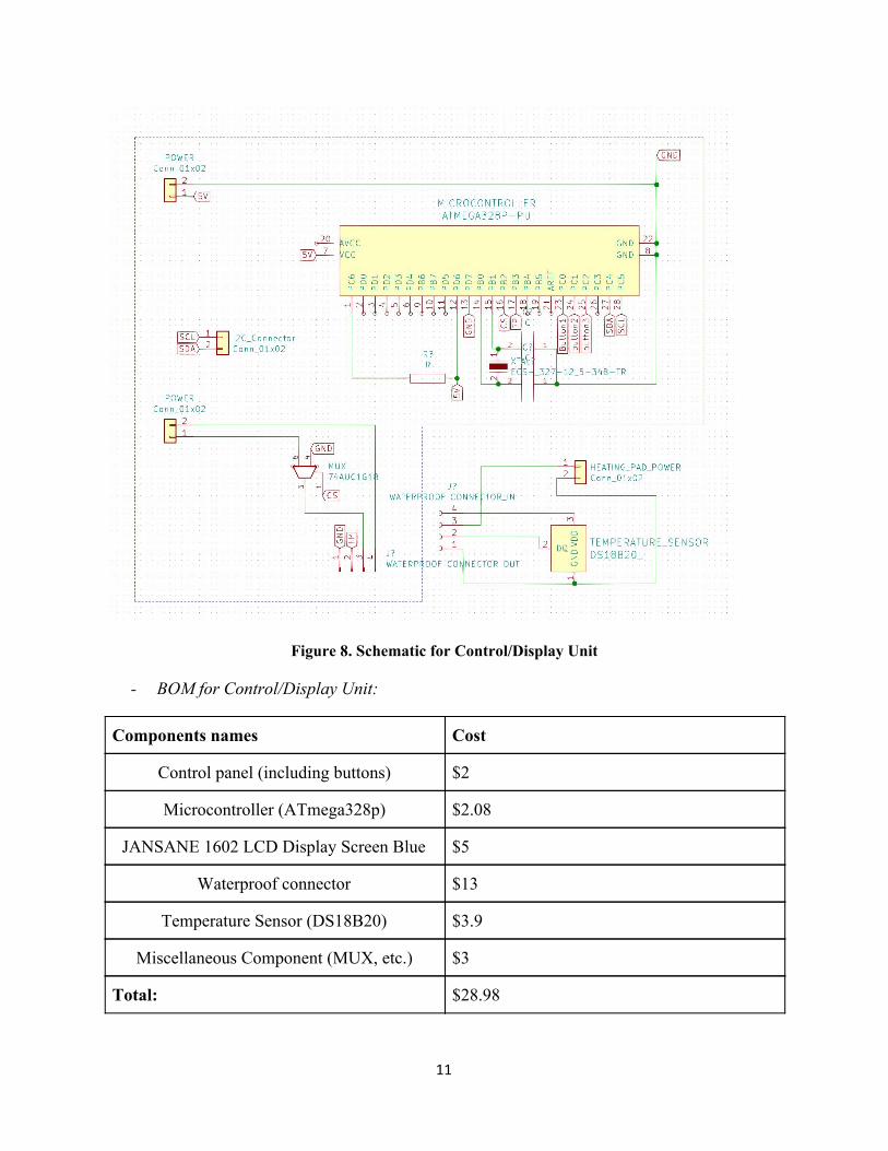
Figure 8. Schematic for Control/Display Unit
- BOM for Control/Display Unit:
Components names Cost
Control panel (including buttons) $2
Microcontroller (ATmega328p) $2.08
JANSANE 1602 LCD Display Screen Blue $5
Waterproof connector $13
Temperature Sensor (DS18B20) $3.9
Miscellaneous Component (MUX, etc.) $3
Total: $28.98
11
Heating Unit
The core of our project is the heating unit. We want to heat the ceramic cup within around 10 mins. We decided to use a silicone rubber heater pad[7] to cover the cup to ensure uniform heating. The ideal power of the silicone rubber heater pad is 3W/ . We will assume the size ofni 2 the cup with 3.5inch in height and 1.5 inch radius. Therefore, we anticipate the width and height of the heater pad are:
Width: 2π * 3.5 inch = ~ 9 inch Height: 3 inch
The area of the whole heater pad and expected power then will be:
Area = Width * Height = 27 ni 2
Power = Area * Power per = 27 * 3W/ = 81 Wni 2 ni 2 ni 2
We assume using 200ml(0.2kg) water to be heated and the heating time of water is as follows[8]:
heating power in W attsAmount of water in kg (end temperature in ℃− start temperature in ℃) (4168 J /kg/℃)* *
Theoretically, using 0.2 kg normal tap water with a starting temperature of 7℃ and heat up to 50℃ will get the lower bound of the time heating process:
= 442.5 secs = 7.38 mins81W
0.2 kg (50℃−7℃) (4168 J /kg/℃)* *
In practice, we have to take the heat efficiency into consideration:
1. It takes ~3 mins to heat the heater pads to desired heating temperature. 2. There is part of the heat loss into the air. However, this could not be done in paper work
at this point so we anticipate 50% efficiency of our heating process.
12
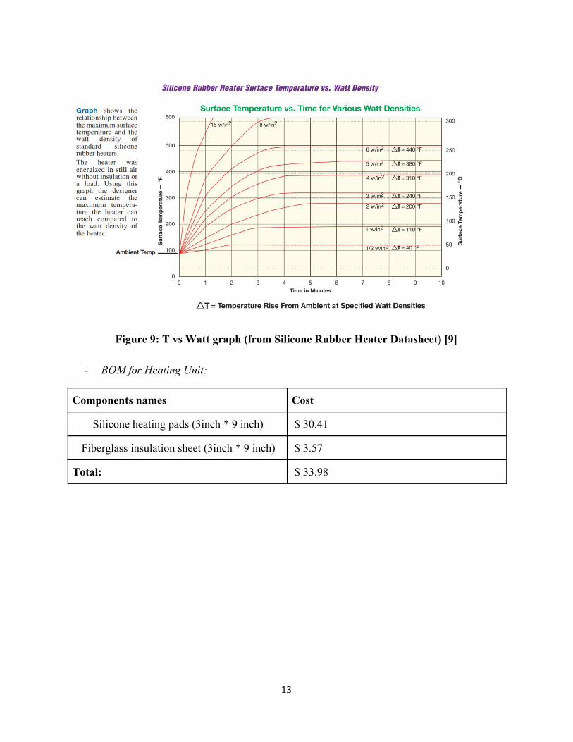
Figure 9: T vs Watt graph (from Silicone Rubber Heater Datasheet) [9]
- BOM for Heating Unit:
Components names Cost
Silicone heating pads (3inch * 9 inch) $ 30.41
Fiberglass insulation sheet (3inch * 9 inch) $ 3.57
Total: $ 33.98
13
3. Conclusion
3.1 Implementation Summary
Our design consists of three units,which are power unit, heating unit and control unit. The detailed design in chapter 2 can provide us with a reliable system with powering, I/O controlling and feedback, as well as the safety measures. All these parts contribute to the design of a fully functional self-heating cup with all the high-level requirements satisfied.
The power unit is taking in the standard 110V AC voltage input. Using AD/DC converter and linear voltage regulators, the power unit will provide necessary voltage input to the heating unit and control unit.
The heating unit consists of the silicone heating pads and the heating base (i.e. the coaster). This part is necessary to provide heat transfer during the heating process. A temperature sensor will be employed to detect the temperature of the beverage inside the mug to communicate with the control unit. The use of high-efficiency silicone heating pads makes it possible to realize one of our high level requirements that the heating process is within 10 mins.
The control unit will perform the logic for our system to run and also guarantees safety while using. It is also responsible for the I/O interaction between our design and users. It makes sure that our design is user-friendly.
Haonan Wang is in charge of the heating unit and part of the Control Unit.
Peiming Wu is in charge of the Power Unit and part of the heating unit design.
Chengyao Zou is in charge of the Display/Control Unit and microcontroller programming.
3.2 Unknowns, uncertainties and test needed
Even though we believe our project provides better heating efficiency by putting silicone heating pads inside the mug instead of exposing them to the air, which will lead to significant heat loss. We could only provide a theoretical timing for the heating process in the tolerance analysis, which is 7.4 mins by assuming no heat loss. However, this is obviously not the real case. We could not test the actual heating efficiency without parts combined since we use several different
14
materials when designing the composition of the cup. We have no idea how these will impact the exact heating efficiency. If we have the access to the lab, we would measure the temperature of the beverage with a waterproof temperature sensor and also measure the time to reach the desired temperature to give the actual heating time and the heating efficiency.
3.3 Ethics and Safety
Our consistency in keeping our system safe is throughout the whole design process. For the two main potential safety issues - liquid and heat, we are still focusing on dealing with them. The first is to counter the extra heat: while heating the liquid, the extra heat could not only interrupt the functionality of our design but also could destroy other parts if it exceeds the thermal limit. For example, the ATmega328p’s operational temperature has a maximum of 85 °C [3]. During our design and building process, we will closely monitor the heating temperature, isolate or dissipate these extra heat as much as we can to prevent thermal issues from happening. In our updated software logic, we also added another safety check module that constantly reads the temperature data. Once the data goes too high (much larger than the temperature we want), we will shut down the system immediately. This could be an extra safety measure from the software level. The second challenge is from the liquid, which could cause the water damage to the system. Our solution is to solidify our system, including PCB, to be water-resistant from water and moisture. Some post-processing of the PCB can make it waterproof up to IP48 protection level. We will aim for the IP48 protection level, as we should also be safe in events like spilling water accidentally over it. The PCB will be mainly on the heating coaster, so water-proof is mainly about the heating coaster and the connections, while the cup itself would be a fully-integrated design. As safety comes first in our design, it also corresponds to the first goal in IEEE Code of Ethics: “ hold paramount the safety, health, and welfare of the public...” [4] We will always put safety as our top priority for our project. It also corresponds to the ninth goal in IEEE Code of Ethics, “to avoid injuring others, their property, reputation, or employment by false or malicious action;” [5], that we will eliminate the possibility of injuring others by false. We will share our design document and open-source all materials needed for this project. This is also aligned with the tenth goal in IEEE Code of Ethics, where it states that “to assist colleagues and co-workers in their professional development and to support them in following this code of ethics.” [6]. Thus, we encourage students to learn, share and improve this project further in the future.
15
There’s some new concerns about the structure of our waterproof connector. Since the robustness of the connector is largely determined by its quality, we will choose the purchase waterproof connectors on the market that have the best quality for our project to use. Once we receive the product, we will also do a verification test according to our needs. Also, we will place the connector hidden underneath the cup, which wouldn’t disturb the normal use of the cup on a flat surface.
3.4 Project Improvements
If we had a year to accomplish our project, there are three improvements we can make on our project. The first one is to seek cheap and feasible material and lower the cost of the project. Our project’s cost is about 80 dollars for now which is still a little bit high for some customers. Many people will just bring their coffee to the microwave rather than paying 80 bucks to get a self-heating cup. In this case, we need to find some material that is cheaper and even replace our silicon heating pad with some other heating materials.
The second improvement will be minimizing the temperature error. We aim to make our heating cup heat the coffee to a certain temperature with an error within 5 Celsius for now. Currently our heating process is halted when the temperature sensor senses that the temperature of the liquid has reached the value user set. However, the heating pad will still remain hot for a short time which will lead to a higher temperature. So, we need to take this into consideration and calculate the energy the heating pad provides when it is turned off and halt the heating process early accordingly. We aim to decrease the error within 2 Celsius to satisfy some users that required more about the taste.
Third, we will add more functionality to the cup. We will add a screen to show how long it remains to finish the heating process to let the users know when they can enjoy their coffee.
16
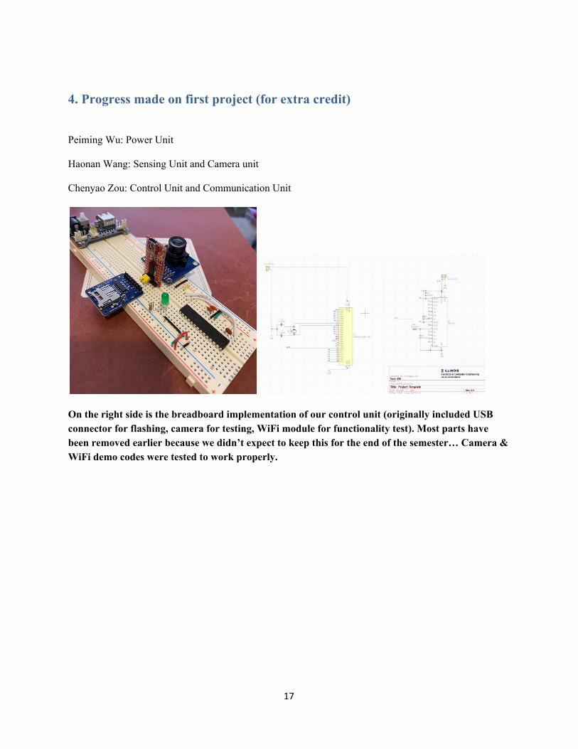
4. Progress made on first project (for extra credit)
Peiming Wu: Power Unit
Haonan Wang: Sensing Unit and Camera unit
Chenyao Zou: Control Unit and Communication Unit
On the right side is the breadboard implementation of our control unit (originally included USB connector for flashing, camera for testing, WiFi module for functionality test). Most parts have been removed earlier because we didn’t expect to keep this for the end of the semester… Camera & WiFi demo codes were tested to work properly.
17
References
[1] Ember®. (n.d.). Ember Mug². Retrieved from https://ember.com/products/ember-mug-2 [2] Ceramic or Glass Coffee Cups? (2017, September 21). Retrieved from https://driftaway.coffee/coffeecup/ [3] ATMEGA328P-PU. (n.d.). Retrieved from https://www.digikey.com/product-detail/en/microchip-technology/ATMEGA328P-PU/ATMEGA328P-PU-ND/1914589?utm_adgroup=xGeneral&utm_source=google&utm_medium=cpc&utm_campaign=Dynamic Search&utm_term=&utm_content=xGeneral&gclid=CjwKCAjwvZv0BRA8EiwAD9T2VU-z0T8I8NZK_cPrMhU9OOCQ_RN6GTFdYQeX7JRLOD5K1yjrxsZZyBoCVSUQAvD_BwE [4] IEEE Code of Ethics. (n.d.). Retrieved from https://www.ieee.org/about/corporate/governance/p7-8.html [5] IEEE Code of Ethics. (n.d.). Retrieved from https://www.ieee.org/about/corporate/governance/p7-8.html [6] IEEE Code of Ethics. (n.d.). Retrieved from https://www.ieee.org/about/corporate/governance/p7-8.html [7] Silicone Rubber Heaters. Tutco Heating Solutions Group. Retrieved from: https://farnam-custom.com/custom/silicone-rubber-heaters?gclid=EAIaIQobChMI-_XT6Jrw6AIVk5OzCh0AlQbqEAAYAiAAEgJQKvD_BwE [8] Water Heating Time Calculator. GetTopics. Retrieved from: https://gettopics.com/en/calc/water-heating-time [9] Silicone Rubber Heaters. (n.d.). Retrieved from https://www.tempco.com/Products/Electric-Heaters-and-Elements/Flexible-Heaters/Silicone-Rubber-Heaters.htm [10] ECE445-SP20-Electronic-Thermal-Box, Retrieved from https://courses.engr.illinois.edu/ece445/getfile.asp?id=16771
18
Recommended


