NEAR EAST UNIVERSITY
Faculty of Engineering
Department of Electrical and Electronic Engineering
A MW Radio design & Amplifier
Graduation Project EE400
Students: Talal Khader (20010829) Baba Khalaf (20010694)
Supervisor: Assoc. Prof. Dr. Adnan Khashman
Nicosia - 2005
ACKNOWLEDGEMENT
First of all I would like to thanks Allah {God} for guiding us through my studies.
More over we want to pay special regards to my parents who are enduring these all
expenses and supporting me in all events. We are nothing without their prayers. They also
encmyaged me in crises. We shall never forget their sacrifices for my education so that i
can enjoy my successful life as they are expecting. They may get peaceful life in Heaven.
Also, !feel proud to pay my special regards to my project adviser "Assoc. Prof Dr.
Adnan Khashman ". He never disappointed us in any affair. He delivered us too much
information and did his best of efforts to make us able to complete my project, as well as -, thanks to my electronic lab assistant Mr KAMEL/or his help. Not to forget to give my
thanks to the NEAR EAST UNIVERSITY education staff especially to electrical and
electronic engineering doctors for their helping to take this degree and to achieve this level
of education.
I will never forget the days that I have been in Cyprus, from the University to the good
friends that I have enjoyed my 4 years with them.i would like to thank my partner baha
KHALAF and, AbdulLAtif , Omar , Ala MANSMY, Al-QHEWE , Abu Sharkes ,
ENG.Daoud ,ENG.Sameh, M.MASLAT , Hamm OZTURK, 6zcan,Gulsah, my best
friends in Abu Dhabi (Akram,Ghassan),a special thanks to my brother and sisters ,ENG
Rami Alia and Ayse 6ZTURK. TALAL KHADER
1

ACKNOWLEDGEMENT
IN THE NAME OF ALLAH, MOST GRACIOUS, MOST MERCIFUL.
I would like to express my deepest appreciation to my god who stood beside me all
the time, who supported me in all my achievements and who has given me the power and
patience to finish my college studies successfully.
Firstly I would like to thank my parents and pay special regards for guiding me through
my studies, which are enduring these all expenses and supporting me in all events. I am
nothing without their prayers. They also encouraged me in crises. I shall never forget
their sacrifices for my education so that I can enjoy my successful life as they are
expecting. They may get peaceful life in Heaven.
And I feel proud to pay my special regards to my project adviser" Assoc. Prof Dr.
Adnan Khashman ". He never disappointed me in any affair. He delivered me too much
information and did his best of efforts to make me able to complete our project. He has
Devine place in my heart and I am less than the half without his help. I am really thankful
to my doctor. as well as thanks to our electronic lab assistant ENG. KAMEL for his help .
Not to forget to give my thanks to the NEAR EAST UNIVERSITY education staff
especially to electrical and electronic engineering doctors for their help to take this
degree and to achieve this level.
At the end again I am thankfully to all persons specially my brother IHAB KHALAF
who helped me or even encouraged me to complete our project. My all efforts to complete
this project might be fruitful.
11

ACKNOWLEDGEMENT
And I want to honor those all persons who have supported me or helped me in our
project starting with my partner Ta/al KHADER and my best .friends Omar ENBA WI,
Ala MANSOUR, Moh 'd MASLAT, AbdulLAtif AL SHAMALI, Khaled ABO ZAGHLIH,
ENG. Daoud , ENG. Gulsah ,ENG. Rami ,ENG. MAL DARI ,ENG. Kamel BEYAZ. I
also pay my special thanks to my all .friends in Jordan.
And the best thanks of this ACKNOWLEDGEMENT to my love
AZIME TEKIN for her kindness in helping me to complete our project.
BAHA'KHALAF
111
ABSTRACT
As the human mind is unlimited, as the technology never stopped and the inventing is
still goes on without a limit, the radio has played an important role in our life. Radio is
portable, reaching people at home, in their automobile, in their office, and many other
places, thereby allowing radio advertisers to influence audiences immediately prior to their
making decisions, as it works extremely well whether used as a stand alone medium or in
combination with complementary media (i.e. Television, Newspaper, Outdoor, & Transit).
One of Radio's greatest strengths of all is that it's Local, offering local news
and local community information on a daily basis. Radio creates awareness, moves
customers, sells products and/or services and influences listeners, so there are a lot of
reasons that makes this divice important in our life.
This project presents a hardware electronic project which is designing and building an
MW radio. The design would later on be modified to receive FM signals.
iv
INTRODUCTION
The radio was used within this century widely in the communication purposes in
almost the all life parts; as it was installed in some other products as an additional option;
to give the opportunity to people to keep up dated and connected to latest news and other
life branches. It is almost unimaginable to live without it anymore; radios become a part of
our modem life.
The purpose ofthis project is to design, build and test a MW radio circuit with its basic
elements. In four chapters we tried to show the work we have done as clear as the
theoretical and method in a simple way for readers to get the maximum usage and gain, as
well as to modify our circuit by adding FM radio.
Chapter one will present components which will be used in building the circuit of the
radio. Their characteristics, properties and functions will also be discussed. Also safety
guidelines, which must be kept in mind when working on electronic projects, will be
described.
Chapter two will present frequencies which are used in radio and other purposes are
described of course MW transmission is included; differences and applications are also
mentioned.
Chapter three will present in detail the operation of the circuit, starting with the input
and how it is processed, through each component until it is ready to leave the circuit as
a sound.
Chapter four will present the modification that has been done to MW radio, where FM
radio has been added to it, explaining the components have been used and how it works as
well as what are the differences between MW and FM.
viii
TABLE OF CONTENTS
ACKNOWLEDGMENT i ABSTRACT iv TABLE OF CONTENTS iii INTRODUCTION VI
1. ELECTRONIC COMPONENTS 1 1.1 Overview 1 1.2 Introduction 1 1.3 Resistors 1
1.3 .1 Color Coding of Resistors 2 1.3.2 Types of Resistors 3
1.4 Capacitor 4 1.4.1 Capacitance 4 1.4.2 Charge and Energy Stored 4 1.4.3 Capacitors in Series and Parallel 5 1.4.4 Charging a capacitor 5 1.4.5 Discharging a capacitor 6 1.4.6 Uses of capacitors 8
1.5 LM380 8 1.5 .1 Features 9
1.6 Loudspeaker 9 1. 7 Semiconductors 10 1. 8 Transistor 12
1.8.1 Types of transistor 12 1.9 Diodes 13 1.10 Switches 14
1.10.1 Selecting a Switch 14 1.10.2 Switches Contacts 14
1.11 Ferrite Aerial 15 1.12 Battery Clips and Holders 16 1.13 Safety Guidelines 16 1.14 Summary 19
111
2. RADIO WA VE PROPAGATION AND ITS FRQUENCIES
2.1 overview
2.2 Introduction
2.3 Waves and the electromagnetic spectrum
2 .4 How a radio wave travels
2.5 Radio Frequencies
2.5.1 MF Medium Frequencies
2.5.2 VHF Very High Frequencies·
2.6 Propagation of waves
2. 7 Modulation
2.7.1 (AM) Amplitude Modulation
2.7.2 (FM) Frequency Modulation
2.8 Application
2.9 Summary
3. HARD WARE APO PROCH OF THE MW RADIO
3 .1 Overview
3 .2 Radio Circuit
3.2.1 Oscillating Part
3.2.1 Amplifying part
3 .3 Modification recommendation
3.4 Project's Components' List
3.5 Summary
4. MODIFICATION OF THE MW RADIO
4.1 Overview
4.2 Electrical components
4.2.1 CXA1619BS
4.2.2 Variable Resistors (Potentiometer)
4.2.3 Ceramic Filters
4.3 Radio circuit
lV
20
20
20
20
21
22
23
24
25
27
27
28
29
30
31
31
31
31
33
36
37
38
39
39
39
39
40
41
42
4.3.1 Project components list
4.4 In general how radio works?
4.5 What are the differences between FM and AM radio?
4.5.1 AM radio
4.5.2 FM radio
4.6 Modification recommendation
4.7 Results and Analysis
4.8 Summary
Conclusion
References
V
44
45
45
46
47
48
49
49
51
53
CHAPTER ONE
ELECTRONIC COMPONENTS
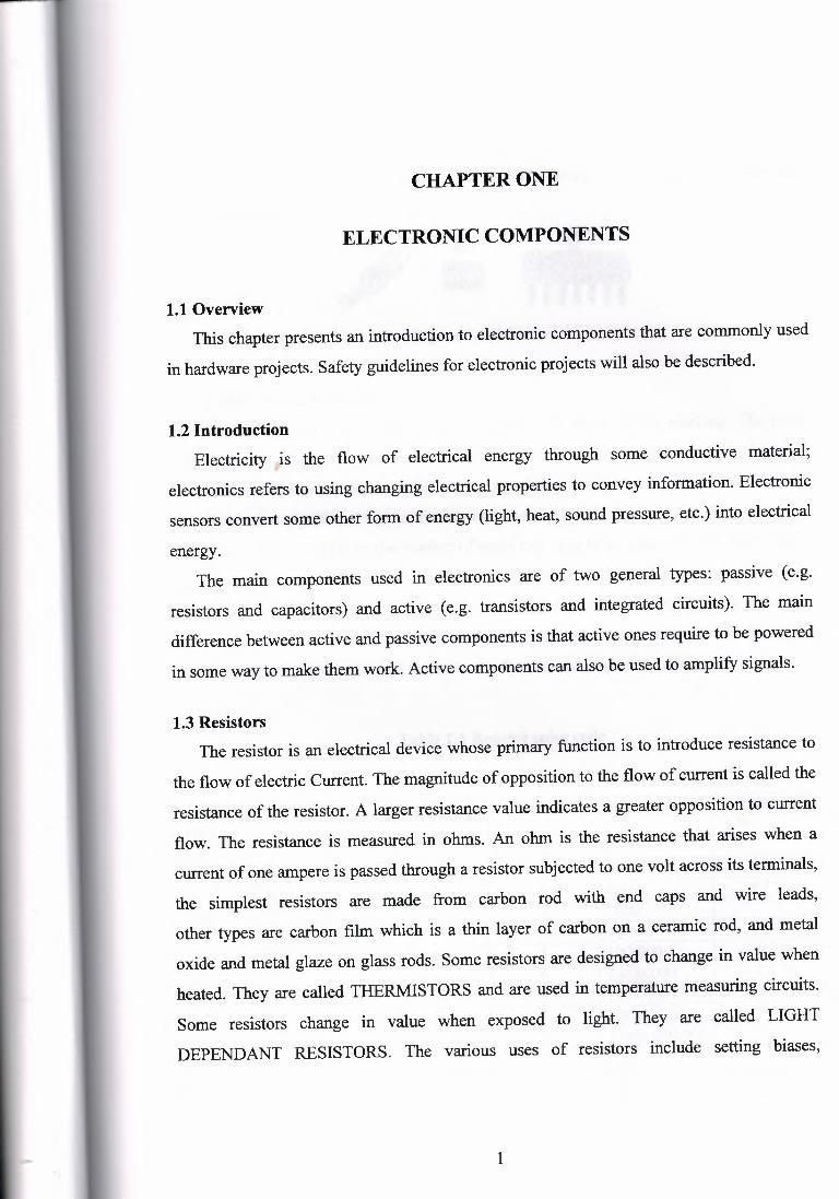
1.1 Overview This chapter presents an introduction to electronic components that are commonly used
in hardware projects. Safety guidelines for electronic projects will also be described.
1.2 Introduction Electricity is the flow of electrical energy through some conductive material;
electronics refers to using changing electrical properties to convey information. Electronic
sensors convert some other form of energy (light, heat, sound pressure, etc.) into electrical
energy. The main components used in electronics are of two general types: passive (e.g.
resistors and capacitors) and active (e.g. transistors and integrated circuits). The main
difference between active and passive components is that active ones require to be powered
in some way to make them work. Active components can also be used to amplify signals.
1.3 Resistors The resistor is an electrical device whose primary function is to introduce resistance to
the flow of electric Current. The magnitude of opposition to the flow of current is called the
resistance of the resistor. A larger resistance value indicates a greater opposition to current
flow. The resistance is measured in ohms. An ohm is the resistance that arises when a
current of one ampere is passed through a resistor subjected to one volt across its terminals,
the simplest resistors are made from carbon rod with end caps and wire leads,
other types are carbon film which is a thin layer of carbon on a ceramic rod, and metal
oxide and metal glaze on glass rods. Some resistors are designed to change in value when
heated. They are called THERMISTORS and are used in temperature measuring circuits.
Some resistors change in value when exposed to light. They are called LIGHT
DEPENDANT RESISTORS. The various uses of resistors include setting biases,
1
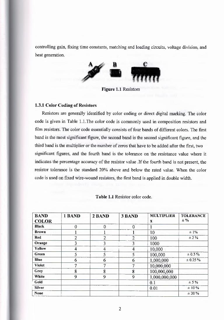
controlling gain, fixing time constants, matching and loading circuits, voltage division, and
heat generation.
Figure 1.1 Resistors
1.3.1 Color Coding of Resistors
Resistors are generally identified by color coding or direct digital marking. The color
code is given in Table LI.The color code is commonly used in composition resistors and
film resistors. The color code essentially consists of four bands of different colors. The first
band is the most significant figure, the second band is the second significant figure, and the
third band is the multiplier or the number of zeros that have to be added after the first, two
significant figures, and the fourth band is the tolerance on the resistance value where it
indicates the percentage accuracy of the resistor value .If the fourth band is not present, the
resistor tolerance is the standard 20% above and below the rated value. When the color
code is used on fixed wire-wound resistors, the first band is applied in double width.
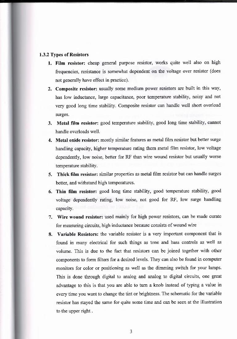
Table 1.1 Resistor color code.
BAND lBAND 2BAND 3BAND MULTIPLIER TOLERANCE COLOR X ± O/o Black 0 0 0 1 Brown 1 1 1 10 ± 1% Red 2 2 2 100 ±2% Orange 3 3 3 1000 Yellow 4 4 4 10,000 Green 5 5 5 100,000 ±0.5% Blue 6 6 6 1,000,000 ± 0.25 % Violet 7 7 7 10,000,000 Grey 8 8 8 100,000,000 White 9 9 9 1,000,000,000 Gold 0.1 ±5% Silver 0.01 ±10% None ±20%
2
1.3.2 Types of Resistors
1. Film resistor: cheap general purpose resistor, works quite well also on high
frequencies, resistance is somewhat dependent on the voltage over resistor ( does
not generally have effect in practice).
2. Composite resistor: usually some medium power resistors are built in this way,
has low inductance, large capacitance, poor temperature stability, noisy and not
very good long time stability. Composite resistor can handle well short overload
surges.
3. Metal film resistor: good temperature stability, good long time stability, cannot
handle overloads well.
4. Metal oxide resistor: mostly similar features as metal film resistor but better surge
handling capacity, higher temperature rating them metal film resistor, low voltage
dependently, low noise, better for RF than wire wound resistor but usually worse
temperature stability.
5. Thick film resistor: similar properties as metal film resistor but can handle surges
better, and withstand high temperatures.
6. Thin film resistor: good long time stability, good temperature stability, good
voltage dependently rating, low noise, not good for RF, low surge handling
capacity.
7. Wire wound resistor: used mainly for high power resistors, can be made curate
for measuring circuits, high inductance because consists of wound wire
8. Variable Resistors: the variable resistor is a very important component that is
found in many electrical for such things as tone and bass controls as well as
volume. This is due to the fact that resistors can be joined together with other
components to form filters for a desired levels. They can also be found in computer
monitors for color or positioning as well as the dimming switch for your lamps.
This is done through digital to analog and analog to digital circuits, one great
advantage to this is that you are able to turn a knob instead of typing a value in
every time you want to change the tint or brightness. The schematic for the variable
resistor has stayed the same for quite some time and can be seen at the illustration
to the upper right .
3
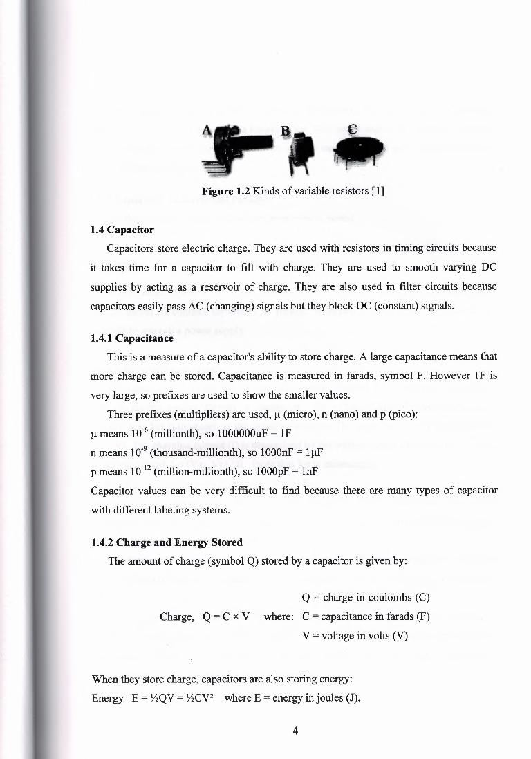
Figure 1.2 Kinds of variable resistors [1]
1.4 Capacitor
Capacitors store electric charge. They are used with resistors in timing circuits because
it takes time for a capacitor to fill with charge. They are used to smooth varying DC
supplies by acting as a reservoir of charge. They are also used in filter circuits because
capacitors easily pass AC (changing) signals but they block DC (constant) signals.
1.4.1 Capacitance
This is a measure of a capacitor's ability to store charge. A large capacitance means that
more charge can be stored. Capacitance is measured in farads, symbol F. However 1 F is
very large, so prefixes are used to show the smaller values.
Three prefixes (multipliers) are used, µ (micro), n (nano) and p (pico):
µ means 10-6 (millionth), so lOOOOOOµF = lF
n means 10-9 (thousand-millionth), so lOOOnF = lµF
p means 10-12 (million-millionth), so 1 OOOpF = lnF
Capacitor values can be very difficult to find because there are many types of capacitor
with different labeling systems.
1.4.2 Charge and Energy Stored
The amount of charge (symbol Q) stored by a capacitor is given by:
Q = charge in coulombs (C)
Charge, Q = C x V where: C = capacitance in farads (F) V = voltage in volts (V)
When they store charge, capacitors are also storing energy:
Energy E = YzQV = YzCV2 where E = energy in joules (J).
4
The capacitors return their stored energy to the circuit. They do not 'use up' electrical
energy by converting it to heat as a resistor does. The energy stored by a capacitor is much
smaller than the energy stored by a battery so they cannot be used as a practical source of
energy for most purposes.
1.4.3 Capacitors in Series and Parallel Combined capacitance of capacitors connected in series:
1 1 1 1 -=-+-+-+ . C C1 C2 C3
Combined capacitance of capacitors connected in parallel: C=C1+C2+C3+ .
Two or more capacitors are rarely deliberately connected in series in real circuits, but it
can be useful to connect capacitors in parallel to obtain a very large capacitance, for
example to smooth a power supply.
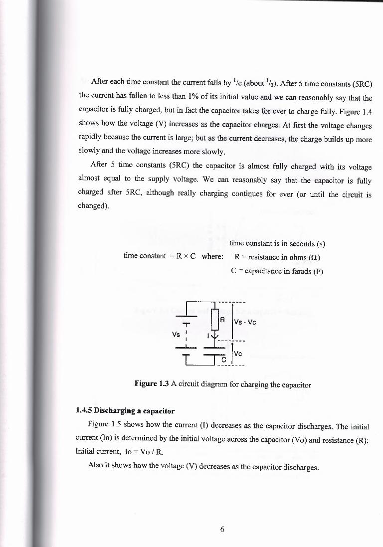
1.4.4 Charging a capacitor The capacitor (C) in the circuit diagram is being charged from a supply voltage (Vs)
with the current passing through a resistor (R). The voltage across the capacitor (V c) is
initially zero but it increases as the capacitor charges. The capacitor is fully charged when
Ve= Vs. The charging current (I) is determined by the voltage across the resistor (Vs - Ve):
Charging current, I = (Vs - V c) I R (note that V c is increasing).
At first V c = OV so the initial current, Io = Vs I R. Ve increases as soon as charge (Q) starts to build up (Ve= Q/C), this reduces the voltage
across the resistor and therefore reduces the charging current. This means that the rate of
charging becomes progressively slower. A large time constant means the capacitor charges slowly. The time constant is a property
of the circuit containing the capacitance and resistance; it is not a property of a capacitor
alone. The time constant is the time taken for the charging ( or discharging) current (I) to fall to
' 1 /e of its initial value (Io). 'e' is the base of natural logarithms, an important number in
mathematics (like lt). e = 2.71828 (to 6 significant figures) so we can roughly say that the
time constant is the time taken for the current to fall to 1 /3 of its initial value.
5
After each time constant the current falls by 1/e (about 1/J). After 5 time constants (5RC)
the current has fallen to less than 1 % of its initial value and we can reasonably say that the
capacitor is fully charged, but in fact the capacitor takes for ever to charge fully. Figure 1.4
shows how the voltage (V) increases as the capacitor charges. At first the voltage changes
rapidly because the current is large; but as the current decreases, the charge builds up more slowly and the voltage increases more slowly.
After 5 time constants (5RC) the capacitor is almost fully charged with its voltage
almost equal to the supply voltage. We can reasonably say that the capacitor is fully
charged after 5RC, although really charging continues for ever ( or until the circuit is changed).
time constant is in seconds ( s)
time constant = R x C where: R = resistance in ohms (CJ)
C = capacitance in farads (F)
R IVs. Ve ,.. Vs ' I
Figure 1.3 A circuit diagram for charging the capacitor
1.4.5 Discharging a capacitor
Figure 1.5 shows how the current (I) decreases as the capacitor discharges. The initial
current (Io) is determined by the initial voltage across the capacitor (Vo) and resistance (R): Initial current, Io = Vo I R.
Also it shows how the voltage (V) decreases as the capacitor discharges.
6
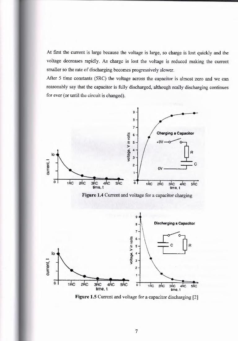
At first the current is large because the voltage is large, so charge is lost quickly and the
voltage decreases rapidly. As charge is lost the voltage is reduced making the current
smaller so the rate of discharging becomes progressively slower.
After 5 time constants (5RC) the voltage across the capacitor is almost zero and we can
reasonably say that the capacitor is fully discharged, although really discharging continues
for ever ( or until the circuit is changed).
9
B
lo
7
.!!! 6 g
.5 S
Charging a Capacitor
>
0 1: I "i I f 1 RC 2RC 3RC 4RC 5RC
time, t 2RC 3RC 4RC SAC
time.t Figure 1.4 Current and voltage for a capacitor charging
9
a -I\ Discharging a capacitor
7
f, I I
2RC 3RC 4RC SRC time,, t
f I J.
-tRC 2RC 3RC 4RC SAC time, t
Figure 1.5 Current and voltage for a capacitor discharging [2]
7

1.4.6 Uses of Capacitors
Capacitors are used for several purposes:
1. Timing - for example with a 555 timer IC controlling the charging and discharging.
2. Smoothing - for example in a power supply.
3. Coupling - for example between stages of an audio system and to connect a
loudspeaker.
4. Filtering - for example in the tone control of an audio system.
5. Tuning - for example in a radio system.
6. Storing energy - for example in a camera flash circuit.
Figure 1.6 Kinds of capacitors
1.5 LM380
The LM380 is a power audio amplifier for consumer application. In order to hold
system cost to a minimum, gain is internally fixed at 34 dB. A unique input stage allows
inputs to be ground referenced. The output is automatically self centering to one half the
supply voltages. The output is short circuit proof with internal thermal limiting. The
package outline is standard dual-in-line. A copper lead frame is used with the center three
pins on either side comprising a heat sink. This makes the device easy to use in standard p-c
layout. Uses include simple phonograph amplifiers, intercoms, line drivers, teaching
machine outputs, alarms, ultrasonic drivers, TV sound systems, AM-FM radio, small servo drivers,
8
Power converters, etc. A selected part for more power on higher supply voltages is
available as the LM384.
1.5.1 Features
1. Wide supply voltage range.
2. Low quiescent power drain.
3. Voltage gain fixed at 50.
4. High peak current capability.
5. Input referenced to GND.
6. High input impedance.
7. Low distortion.
8. Quiescent output voltage is at one-half of the supply voltage.
9. Standard dual-in-line package.
LM3SON
u ll( 110MwtRm110; nmn z
·'J ttl -111' GNII'
1e
• :II(:
• C#llf4
j6
!!iVUTV!IG llJPUT Ii
GNO J
GMO GIID
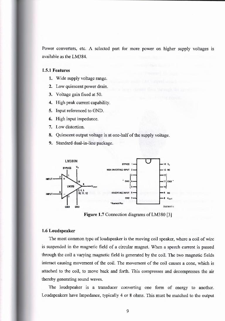
Figure 1. 7 Connection diagrams of LM3 80 [3]
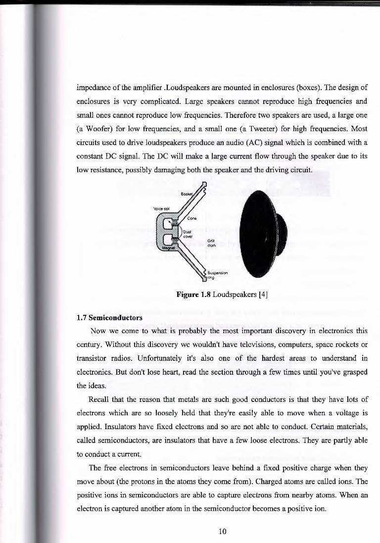
1.6 Loudspeaker
The most common type of loudspeaker is the moving coil speaker, where a coil of wire
is suspended in the magnetic field of a circular magnet. When a speech current is passed
through the coil a varying magnetic field is generated by the coil. The two magnetic fields
interact causing movement of the coil. The movement of the coil causes a cone, which is
attached to the coil, to move back and forth. This compresses and decompresses the air
thereby generating sound waves.
The loudspeaker is a transducer converting one form of energy to another.
Loudspeakers have Impedance, typically 4 or 8 ohms. This must be matched to the output
9
---·--
impedance of the amplifier .Loudspeakers are mounted in enclosures (boxes). The design of
enclosures is very complicated. Large speakers cannot reproduce high frequencies and
small ones cannot reproduce low frequencies. Therefore two speakers are used, a large one
(a Woofer) for low frequencies, and a small one (a Tweeter) for high frequencies. Most
circuits used to drive loudspeakers produce an audio (AC) signal which is combined with a
constant DC signal. The DC will make a large current flow through the speaker due to its
low resistance, possibly damaging both the speaker and the driving circuit.
Figure 1.8 Loudspeakers [4]
1. 7 Semiconductors
Now we come to what is probably the most important discovery in electronics this
century. Without this discovery we wouldn't have televisions, computers, space rockets or
transistor radios. Unfortunately it's also one of the hardest areas to understand in
electronics. But don't lose heart, read the section through a few times until you've grasped
the ideas.
Recall that the reason that metals are such good conductors is that they have lots of
electrons which are so loosely held that they're easily able to move when a voltage is
applied. Insulators have fixed electrons and so are not able to conduct. Certain materials,
called semiconductors, are insulators that have a few loose electrons. They are partly able
to conduct a current.
The free electrons in semiconductors leave behind a fixed positive charge when they
move about (the protons in the atoms they come from). Charged atoms are called ions. The
positive ions in semiconductors are able to capture electrons from nearby atoms. When an
electron is captured another atom in the semiconductor becomes a positive ion.
10

These behaviors can be thought of as a 'hole' moving about the material, moving in just the
same way that electrons move. So now there are two ways of conducting a current through
a semiconductor, electrons moving in one direction and holes in the other. There are two
kinds of current carriers. The holes don't really move of course. It is just fixed positive ions
grabbing neighboring electrons, but it appears as if holes are moving.
electrons moving to the left= 'holes' moving to the right
Figure 1.9 Moving of electronic
In a pure semiconductor there are not enough free electrons and holes to be of much use
their number can be greatly increased however by adding an impurity, called a donor. If the
donor gives up some extra free electrons we get an n-type semiconductor (n for negative).
If the donor soaks up some of the free electrons we get a p-type semiconductor (p for
positive). In both cases the impurity donates extra current carriers to the semiconductor.
In the n type semiconductors there are more electrons than holes and they are the main
current carriers. In p-type semiconductors there are more holes than electrons and they are
the main current carriers. The donor atoms become either positive ions (n-type) or negative
ions (p-type ).
• positive ion
• negative ion
• electron ,,, hole .,,,
n-type p-type
Figure 1.10 Two types of semiconductors [5]
The most common semiconductors are silicon (basically sand) and germanium.
Common donors are arsenic and phosphorus. When we combine n-type and p-type s~miconductors together we make useful devices,
like transistors and diodes and silicon chips.
11

1.8 Transistor
Transistors amplify current, for example they can be used to amplify the small output
current from a logic chip so that it can operate a lamp, relay or other high current device. In
many circuits a resistor is used to convert the changing current to a changing voltage, so the
transistor is being used to amplify voltage. A transistor may be used as a switch ( either
fully on with maximum current, or fully off with no current) and as an amplifier (always
partly on). The amount of current amplification is called the current gain, symbol hFE·
Figure 1.11 Transistors
1.8.1 Types of transistor
There are two types of standard transistors, NPN and PNP, with different circuit
symbols. The letters refer to the layers of semiconductor material used to make the
transistor. Most transistors used today are NPN because this is the easiest type to make
from silicon. The leads are labeled base (B), collector (C) and emitter (E).
The difference between PNP and NPN transistors is that NPN use electrons as carriers
of current and PNP use a lack of electrons (known as "holes"). Basically, nothing moves
very far at a time. One atom simply robs an electron from an adjacent atom so you get the
impression of "flow". It's a bit like "light pipes". In the case of "N" material, there are lots
of spare electrons. In the case of "P" there aren't. In fact "P" is gasping for electrons.
A Darlington pair is two transistors connected together to give a very high current gain.
~~
~~ NPN PNP
Figure 1.12 Transistor circuit symbols [6]
12
1.9 Diodes
Diodes allow electricity to flow in only one direction. The arrow of the circuit symbol
shows the direction in which the current can flow. Diodes are the electrical version of a
valve and early diodes were actually called valves.
Electricity uses up a little energy pushing its way through the diode, rather like a person
pushing through a door with a spring. This means that there is a small voltage across a
conducting diode, it is called the forward voltage drop and is about 0.7V for all normal
diodes which are made from silicon. The forward voltage drop of a diode is almost constant
what ever the current passing through the diode so they have a very steep characteristic.
When a reverse voltage is applied a perfect diode does not conduct, but all real diodes
leak a very tiny current of a few µA or less. This can be ignored in most circuits because it
will be very much smaller than the current flowing in the forward direction. However, all
diodes have a maximum reverse voltage (usually 50V or more) and if this is exceeded the
diode will fail and pass a large current in the reverse direction, this is called breakdown.
Ordinary diodes can be split into two types: Signal diodes which pass small currents of
1 OOmA or less and Rectifier diodes which can pass large currents. In addition there are
LEDs and Zener diodes where it's used to maintain a fixed voltage. They are designed to
'breakdown' in a reliable and non-destructive way so that they can be used in reverse to maintain a fixed voltage across their terminals.
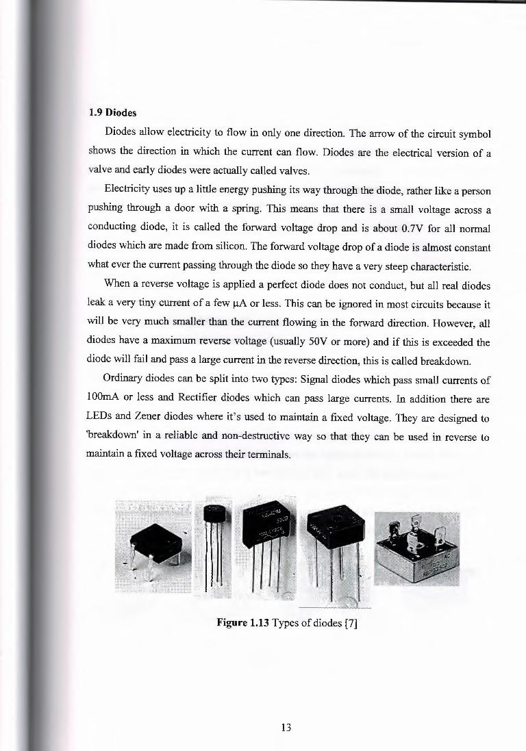
Figure 1.13 Types of diodes [7]
13
1.10 Switches
A switch is in its simplest form, is just a wire that is connected or disconnected when
some mechanical force is applied. The mechanical force can be anything from a person
activating it by force (such as pressing a button on a keyboard), or the weight of water
pressing on it (pressure switch), magnetic force from a fixed magnet or electromagnet
1.10.1 Selecting a Switch
There are three important features to consider when selecting a switch :
1. Contacts (e.g. single pole, double throw).
2. Ratings (maximum voltage and current).
3. Method of Operation (toggle, slide, key etc).
1.10.2 Switches Contacts
Several terms are used to describe switch contacts:
1. Throw - number of conducting positions, single or double.
2. Way - number of conducting positions, three or more.
3. Momentary - switch returns to its normal position when released.
4. Pole - number of switch contact sets.
5. Open -Off position, contacts not conducting.
Switch contacts are rated with a maximum voltage and current, and there may be
different ratings for AC and DC. The AC values are higher because the current falls to zero
many times each second and an arc is less likely to form across the switch contacts.
For low voltage electronics projects the voltage rating will not matter, but you may
need to check the current rating. The maximum current is less for inductive loads ( coils and
motors) because they cause more sparking at the contacts when switched off.
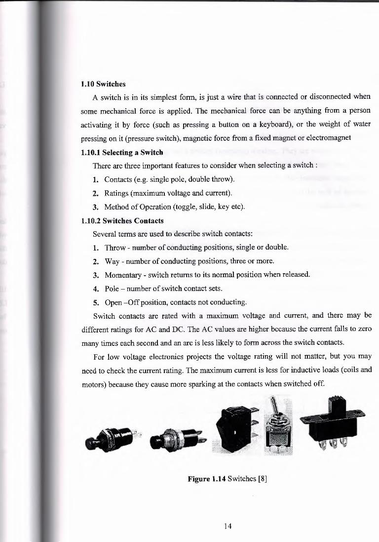
Figure 1.14 Switches [8]
14
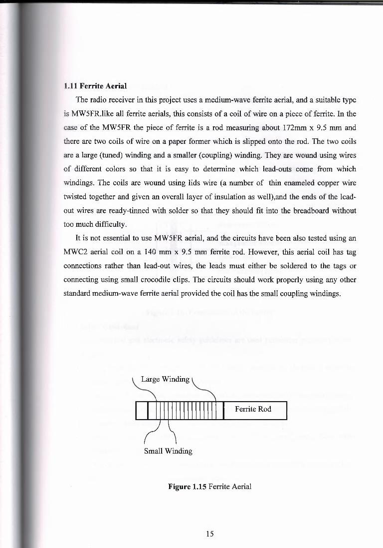
1.11 Ferrite Aerial
The radio receiver in this project uses a medium-wave ferrite aerial, and a suitable type
is MW5FR.like all ferrite aerials, this consists of a coil of wire on a piece of ferrite. In the
case of the MW5FR the piece of ferrite is a rod measuring about 172mm x 9.5 mm and
there are two coils of wire on a paper former which is slipped onto the rod. The two coils
are a large (tuned) winding and a smaller (coupling) winding. They are wound using wires
of different colors so that it is easy to determine which lead-outs come from which
windings. The coils are wound using lids wire ( a number of thin enameled copper wire
twisted together and given an overall layer of insulation as well),and the ends of the lead
out wires are ready-tinned with solder so that they should fit into the breadboard without
too much difficulty.
It is not essential to use MW5FR aerial, and the circuits have been also tested using an
MWC2 aerial coil on a 140 mm x 9.5 mm ferrite rod. However, this aerial coil has tag
connections rather than lead-out wires, the leads must either be soldered to the tags or
connecting using small crocodile clips. The circuits should work properly using any other
standard medium-wave ferrite aerial provided the coil has the small coupling windings.
Large Winding
Ferrite Rod
Small Winding
Figure 1.15 Ferrite Aerial
15
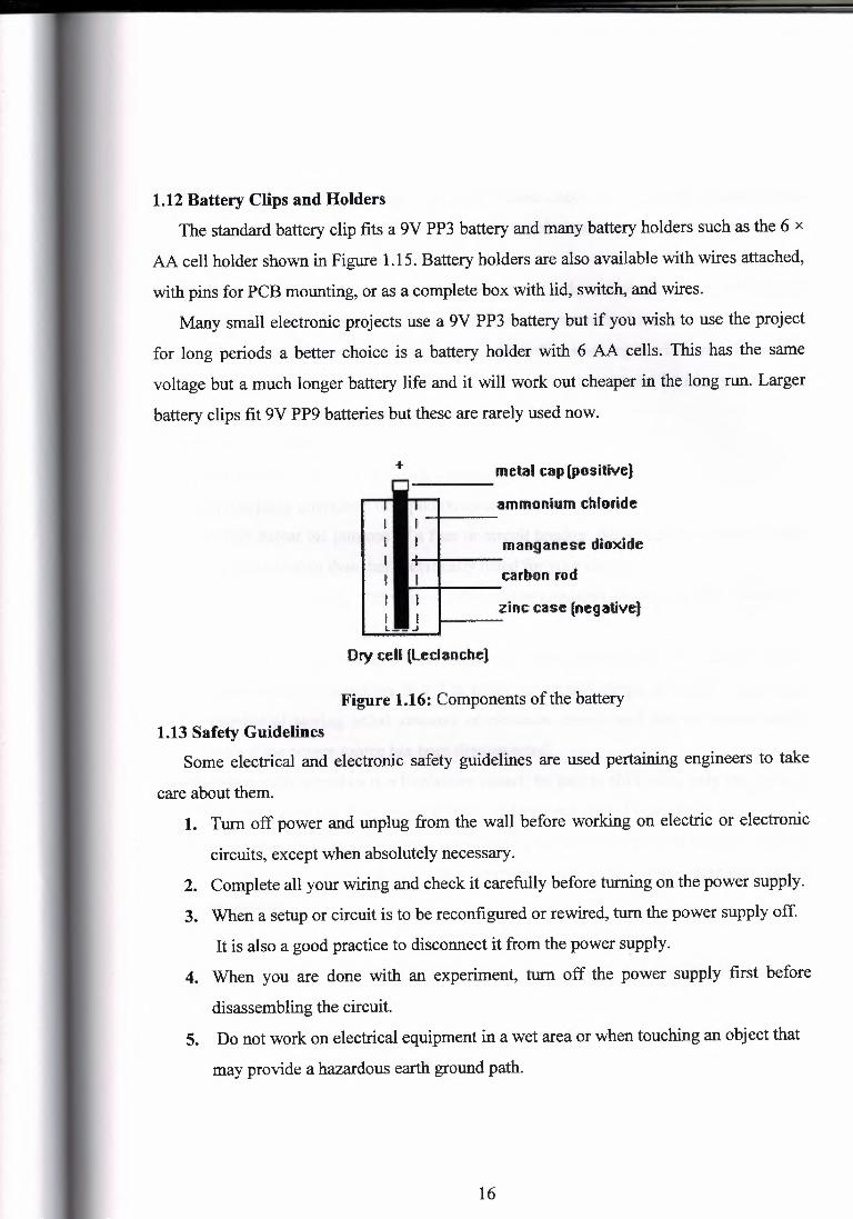
1.12 Battery Clips and Holders
The standard battery clip fits a 9V PP3 battery and many battery holders such as the 6 x
AA cell holder shown in Figure 1.15. Battery holders are also available with wires attached,
with pins for PCB mounting, or as a complete box with lid, switch, and wires.
Many small electronic projects use a 9V PP3 battery but if you wish to use the project
for long periods a better choice is a battery holder with 6 AA cells. This has the same
voltage but a much longer battery life and it will work out cheaper in the long run. Larger
battery clips fit 9V PP9 batteries but these are rarely used now.
metal cap[posi1ive)
i i I I I I I I I
I I t
ii I
L-- ..I
mmonium chfodde
manganese dioxide
carbon rod
zinc case (negative)
Ory cell (leclanche)
Figure 1.16: Components of the battery
1.13 Safety Guidelines Some electrical and electronic safety guidelines are used pertaining engineers to take
care about them. 1. Turn off power and unplug from the wall before working on electric or electronic
circuits, except when absolutely necessary.
2. Complete all your wiring and check it carefully before turning on the power supply.
3. When a setup or circuit is to be reconfigured or rewired, turn the power supply off.
It is also a good practice to disconnect it from the power supply.
4. When you are done with an experiment, turn off the power supply first before
disassembling the circuit.
5. Do not work on electrical equipment in a wet area or when touching an object that
may provide a hazardous earth ground path.
16
6. Turn off power and unplug equipment before checking or replacing fuses. Locate
and correct the cause of a blown fuse or tripped circuit breaker before replacing the
fuse or resetting the circuit breaker.
7. Immediately report and do not use defective cords and plugs. Inspect cabling for
defects such as frayed wiring, loose connections, or cracked insulation.
8. Remove metal jewelry, watches, rings, etc., before working on electrical circuits.
9. Always check the electrical ratings of equipment you use and be sure you use that
equipment within its ratings.
10. Never overload circuits.
11. Never leave unprotected systems unattended.
12. Never place containers of liquid on electrical systems.
13. Never defeat the purpose of a fuse or circuit breaker. Never install a fuse of higher
amperage rating than that specifically listed for your circuit.
14. Make sure equipment chassis or cabinets are grounded. Never cut off or defeat the
ground connection on a plug.
15. Safely discharge capacitors in equipment before working on the circuits. Why?
Because, large capacitors found in many laser flash lamps and other systems are
capable of storing lethal amounts of electrical energy and pose a serious danger
even if the power source has been disconnected.
16. When shifting probes in a live/active circuit, be sure to shift using only one hand: It
is best to keep the other hand off other surfaces and behind your back.
17. If you are working on a design project and you plan to work with voltages equal to
or above 50 volts, notify your instructor and obtain their approval before
proceeding.
17
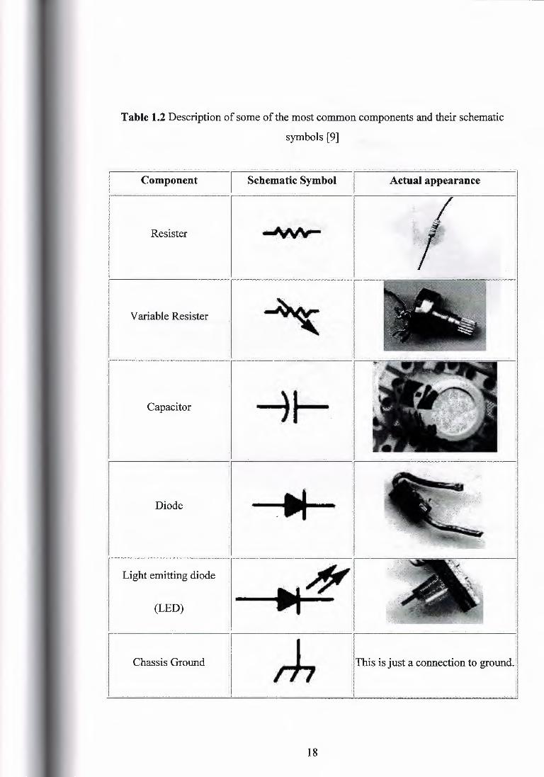
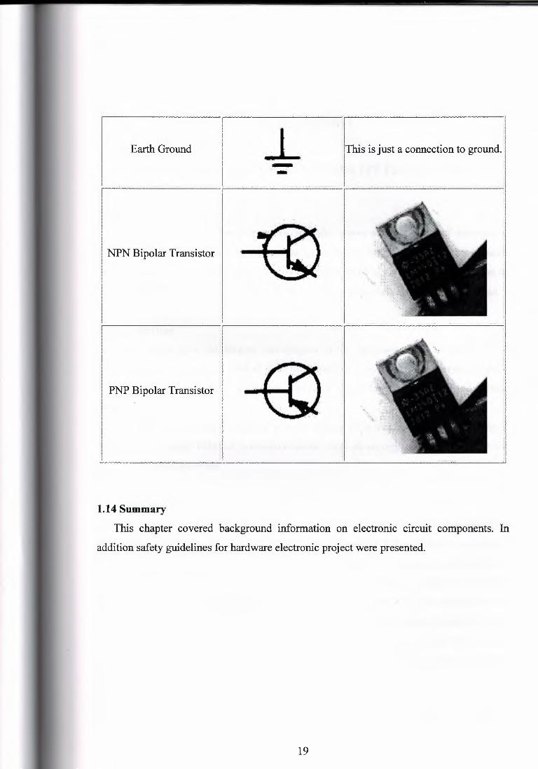
Table 1.2 Description of some of the most common components and their schematic
symbols [9]
.............................. - ,,.,' ., ' ' _ ,,,,, ·"''l
Schematic Symbol I Actual appearance d Component
Resister ·~·
Variable Resister
Capacitor
---- .... '-- .. -
1 --u-- :I
Diode
Light emitting diode
(LED)
Chassis Ground This is just a connection to ground.i
18
- I ,1
11bis is just a connection to ground. I
J Earth Ground J_ . -
PNP Bipolar Transistor
1.14 Summary
Ibis chapter covered background information on electronic circuit components. In
addition safety guidelines for hardware electronic project were presented.
19
CHAPTER TWO
RADIO WAVE PROPAGATION AND ITS FRQUENCIES
2.1 Overview
This chapter presents the propagation of radio waves and the affect of atmosphere
layers on it, how a radio wave travels and the types of propagation. As this chapter presents
classifications of frequencies which are used in radio and other purposes, and describe of
course MW and VHW transmission, differences and application is also will be mentioned.
2.2 Introduction
Radio waves have the longest wavelengths in the electromagnetic spectrum. These
waves can be longer than a football field or as short as a football. Radio waves do more
than just bring music to your radio. They also carry signals for your television and cellular
phones.
Electromagnetic waves are formed when an electric field couples with a magnetic field.
Magnetic and electric fields of an electromagnetic wave are perpendicular to each other and
to the direction of the wave.
2.3 Waves and the electromagnetic spectrum
We do not know exactly what really electromagnetic waves are, excepting that they
look sometimes like waves, sometimes like particles (quanta). The simplest representation
of a wave is a three dimensional structure made of an electric and a magnetic field crossed
polarized in both vertical and horizontal planes. Its energy is moving back and forth from
one field to the other; this phenomenon is known as oscillation. If the signal is omni
directional, this complex field evolves evenly into space like waves that we observe on the
water surface or still better, like a sphere that gradually become more a larger. If the signal
is directional the sphere becomes a cardiod more or less extended in the propagation
direction.
Radio waves are a form of electromagnetic radiation sensible to charged particles like
free electrons. In free space they travel in straight line (in fact following geodesics) at the
20
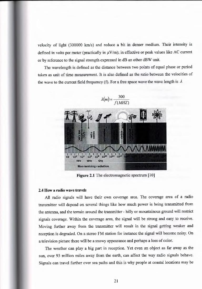
velocity of light (300000 km/s) and reduce a bit in denser medium. Their intensity is
defined in volts per meter (practically in µV/m); in effective or peak values like AC current
or by reference to the signal strength expressed in dB an other dBW unit.
The wavelength is defined as the distance between two points of equal phase or period
taken as unit of time measurement. It is also defined as the ratio between the velocities of
the wave to the current field frequency (f). For a free space wave the wave length is A
300 J(m)= f(MHZ)
Figure 2.1 The electromagnetic spectrum [10]
2.4 How a radio wave travels All radio signals will have their own coverage area. The coverage area of a radio
transmitter will depend on several things like how much power is being transmitted from
the antenna, and the terrain around the transmitter - hilly or mountainous ground will restrict
signals coverage. Within the coverage area, the signal will be strong and easy to receive.
Moving further away from the transmitter will result in the signal getting weaker and
reception is degraded. On a stereo FM station for instance the signal will become noisy. On
a television picture there will be a snowy appearance and perhaps a loss of color.
The weather can play a big part in reception. Yet even an object as far away as the
sun, over 93 million miles away from the earth, can affect the way radio signals behave.
Signals can travel further over sea paths and this is why people at coastal locations may be
21
able to receive radio or TV stations from nearby countries. Even the trails of meteors in the
night sky are able to bounce radio signals way beyond their normal coverage area.
2.5 Radio Frequencies Radio frequencies are ranging from a few hertz, wavelengths of several thousands of
km from peak-to-peak for brain waves, subsonic and oscillating at less than one cycle per
second, to several thousands of gigahertz, wavelengths of a few mm from peak-to-peak for
microwaves. Above we enter in the world oflight (IR, visible, UV, X-ray and gamma).
This spectrum is divided in octaves, the natural way to represent frequencies. An octave
represents eight diatonic degrees or a gradual frequency increasing of a 10-factor. Humans
can hear sounds (vibrations) between 20 Hz and 20 kHz, a range of 3 octaves. Their
wavelengths are ranging between 1500 and 15 km. The electromagnetic spectrum is also
arbitrary divided into "bands". Each band extends over 3 octaves or so, the energy level
increasing of about 10 times between the beginning and the end of the band. Natural
radiation becomes a health hazard only from the UV light and above frequencies, even
though, because all depends on the duration of exposure to the radiation, the distance to the
source, and its intensity.
ELF are only used by some submarines and to carry AC over power lines. Otherwise,
its main use is of course to carry the sound of low and mid frequencies as well infrasonic
vibrations (animals).
VLF are also the carrier of sound up to about 20 kHz. This band is also used for long
distance communications (few thousands km) and experimentation by scientists and the
avy.
LF is mainly used for regional broadcasting purposes while MF are used for worldwide
broadcasting. HF are of our concern, these are formerly frequencies ranging from 1.8 to 30
Wiz (160-10 m bands). Know as "short waves", these bands are very appreciated by all
radio services and operators as they allow long distance communications, broadcasting and
trans horizon radar operations.
VHF and UHF begin at 30 MHz (10 m) to end well above 1 GHz and are mainly used
for radio and TV broadcasting as well as mobile communications over short distances ( a
ew hundreds km) and more recently by cell phones.
22

Above these frequencies we find cent metric and mill metric waves, the famous
microwaves. We know them essentially through home devices like microwave ovens (Short
or S-band), wireless LAN ( compromise or C-band), and some satellite and radar
transmissions (Kurtz or K-bands). Then close your ears and open your eyes, you enter in
the near infrared and visible parts of the spectrum! Over it, wear your anti UV-glasses to
protect you against ultraviolet radiations. At last take your lead protection, we enter the
world of X and y rays.
Most services work in the lower bands of the electromagnetic spectrum, the only one
frequency able to transport information on long distances with a very simple technology
and low energy.
Each band requests special receivers and aerials according to the frequency used and
the type of waves (ground, space, ionosphere, etc). However these waves are affected by
the medium in which they propagate its electronic density and its dielectric constant.
In this project MWand VHW transmissions will be discussed in detail.
2.5.1 MF Medium Frequencies
This segment of spectrum is between 300-3000 KHz. Within this segment there is
Medium Wave radio broadcasting band which is between 520-1610 KHz.
Channel spacing is 9 kHz for Continental Europe and the Middle East and 10 kHz for north
and South America. MW is quite different than L W as to reflection effect of ionosphere;
half of MW frequencies below 1000 kHz are almost similar to L W frequencies; however
frequencies above 1000 kHz are almost similar to short wave frequencies in the high
frequency segment of the frequency spectrum. Especially at night, MW frequencies maybe
reflected from the ionosphere and may reach to far distances. For instance many Middle
Eastern MW transmitters can be received in Turkey while Turkish MW transmitters can be -,
received at far distances such as Cairo. This characteristic requires that MW frequencies are
not purely domestic frequencies and they have to be regionally planned. Such plans must be
realized with close relationship of neighboring countries. In the history of MW
broadcasting there had been many instances of tense relationships between the countries
with hostile positions.
23
Due to the ionospheric reflection possibilities of MW frequencies, MW is a band not
only for domestic radio broadcast but also for international radio broadcast. This may easily
be seen in the relays that carry a program of a far distanced transmitter. VOA (Voice of
America has MW relays in Rhodes while BBC has in Southern Cyprus (1323 KHz. Radio
Monte Carlo (relays also Trans World Radio program) has a MW relay in Southern Cyprus
(1233 KHz). Lower and upper ends of MW band are allocated for navigation finding and
wireless communication. 2182 KHz.
2.5.2 VHF Very High Frequencies
They range between 30- 300 MHz. Within this segment of the spectrum there exist FM
radio broadcast band between 88 and 108 MHz. FM radio band is usually for local radio
broadcasters since the electromagnetic waves on this band can only travel on the surface up
to 100 Km. if there are no physical obstacles such as mountains. Relay (repeaters) stations
must be used if a larger geographic area is to be covered in FM band. FM band is very
suitable for music broadcasting because it has a wider audio bandwidth nearly enough for
Hi-Fi music reproduction. Additionally in FM band stereo broadcasting is also possible and
this is vital for good quality music reproduction in the receiver. TV Band I, S- Band (for
cable-TV) and TV Band III are also in VHF segment of the spectrum. Other portions of the
segment are used for several telecommunication services [10].
Figure 2.2 Radio
24
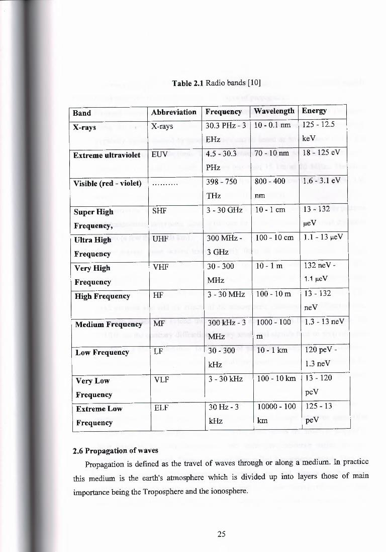
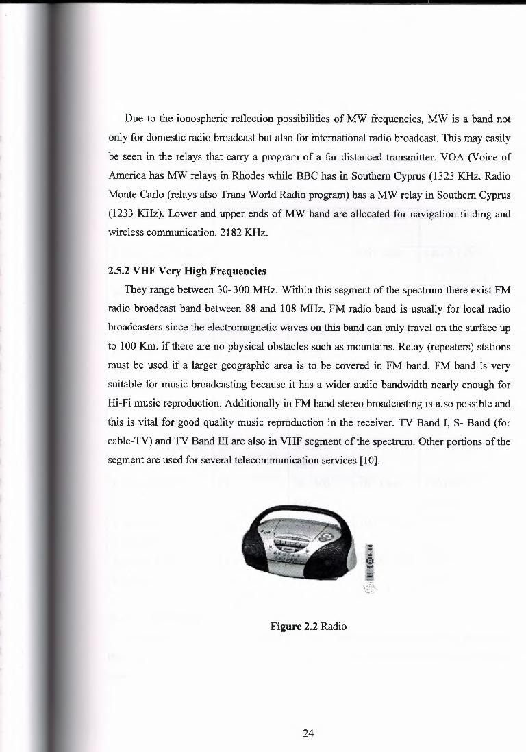
Table 2.1 Radio bands [1 O]
Band Abbreviation Frequency Wavelength Energy
X-rays I X-rays 30.3 PHz- 3 10 - 0.1 run 125 - 12.5
EHz keV
Extreme ultraviolet EUV 4.5 - 30.3 70-10 run 18 - 125 eV
PHz
Visible (red - violet) ·········· 398 - 750 800 - 400 1.6 - 3.1 eV
THz run
Super High SHF 3 - 30 GHz 10 - 1 cm 13 - 132
Frequency, µeV
Ultra High UHF 300 MHz- 100 - 10 cm 1.1 - 13 µeV
Frequency 3GHz
Very High VHF 30 - 300 10-1 m 132 neV -
Frequency MHz 1.1 µeV
High Frequency HF 3 - 30 MHz 100 - 10 m 13 - 132
neV
Medium Frequency MF 300 kHz - 3 1000 - 100 1.3 - 13 neV
MHz m
Low Frequency LF 30 - 300 10-lkm 120 peV -
kHz 1.3 neV
Very Low VLF 3 - 30 kHz 100-10 km 13 - 120
Frequency peV
Extreme Low ELF 30 Hz- 3 10000 - 100 125 - 13
Frequency kHz km peV
2.6 Propagation of waves Propagation is defined as the travel of waves through or along a medium. In practice
this medium is the earth's atmosphere which is divided up into layers those of main
importance being the Troposphere and the ionosphere.
25
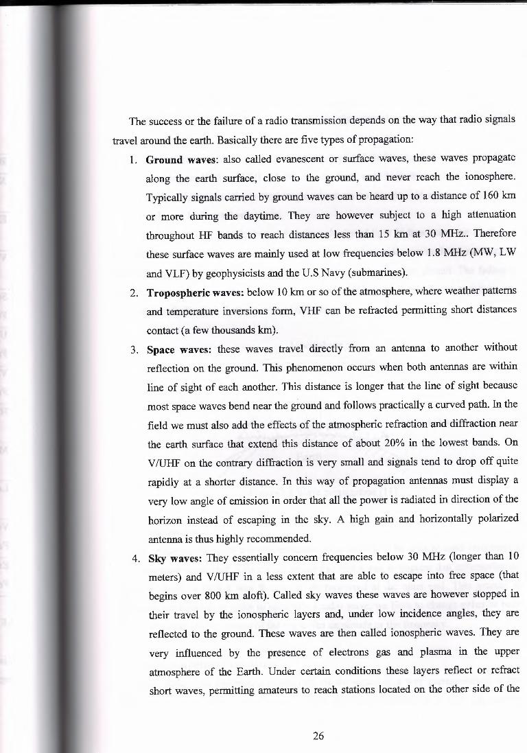
The success or the failure of a radio transmission depends on the way that radio signals
travel around the earth. Basically there are five types of propagation:
1. Ground waves: also called evanescent or surface waves, these waves propagate
along the earth surface, close to the ground, and never reach the ionosphere.
Typically signals carried by ground waves can be heard up to a distance of 160 km
or more during the daytime. They are however subject to a high attenuation
throughout HF bands to reach distances less than 15 km at 30 MHz .. Therefore
these surface waves are mainly used at low frequencies below 1.8 MHz (MW, LW
and VLF) by geophysicists and the U.S Navy (submarines).
2. Tropospheric waves: below 10 km or so of the atmosphere, where weather patterns
and temperature inversions form, VHF can be refracted permitting short distances
contact (a few thousands km).
3. Space waves: these waves travel directly from an antenna to another without
reflection on the ground. This phenomenon occurs when both antennas are within
line of sight of each another. This distance is longer that the line of sight because
most space waves bend near the ground and follows practically a curved path. In the
field we must also add the effects of the atmospheric refraction and diffraction near
the earth surface that extend this distance of about 20% in the lowest bands. On
V /UHF on the contrary diffraction is very small and signals tend to drop off quite
rapidly at a shorter distance. In this way of propagation antennas must display a
very low angle of emission in order that all the power is radiated in direction of the
horizon instead of escaping in the sky. A high gain and horizontally polarized
antenna is thus highly recommended.
4. Sky waves: They essentially concern frequencies below 30 MHz (longer than 10
meters) and V!UHF in a less extent that are able to escape into free space (that
begins over 800 km aloft). Called sky waves these waves are however stopped in
their travel by the ionospheric layers and, under low incidence angles, they are
reflected to the ground. These waves are then called ionospheric waves. They are
very influenced by the presence of electrons gas and plasma in the upper
atmosphere of the Earth. Under certain conditions these layers reflect or refract
short waves, permitting amateurs to reach stations located on the other side of the
26
Earth in a succession of jumps between the ground and the ionosphere, called
multihops.
5. Free space waves: they are the most common but the less used! We encounter them
working in VHF or UHF where, due to their very high frequency, at incidence
angles higher that the critical angle, short waves escape into space instead of be
reflected by ionospheric layers. If waves travel in straight line and at the velocity of light in free space, on Earth, the
ground, the air and the ionosphere affect wave propagation; radio waves do no more travel
from one point to another in straight line and their signals are often altered. The fading is
probably the alteration, Radio waves are mainly subject to four effects and they are
Attenuation, Reflection, Refraction and Diffraction.
Ionosphere
Earth
Figure2.3 Wave propagation [ 11]
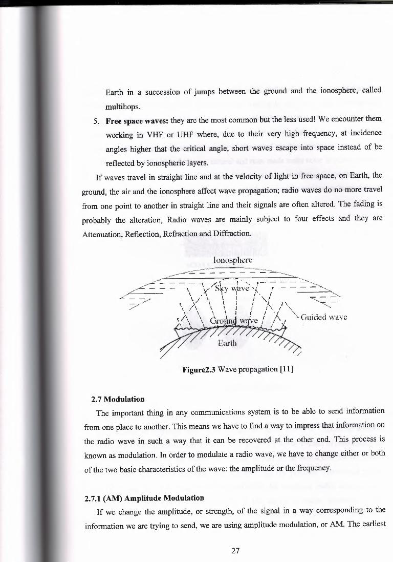
2. 7 Modulation The important thing in any communications system is to be able to send information
from one place to another. This means we have to find a way to impress that information on
the radio wave in such a way that it can be recovered at the other end. This process is
known as modulation. In order to modulate a radio wave, we have to change either or both
of the two basic characteristics of the wave: the amplitude or the frequency.
2.7.1 (AM) Amplitude Modulation If we change the amplitude, or strength, of the signal in a way corresponding to the
information we are trying to send, we are using amplitude modulation, or AM. The earliest
27
means of radio communications was by Morse code, and the code key would turn the
transmitter on and off. The amplitude went from nothing to full power whenever the key
was pressed, a basic form of AM. Modem AM transmitters vary the signal level smoothly
in direct proportion to the sound they are transmitting. Positive peaks of the sound produce
maximum radio energy, and negative peaks of the sound produce minimum energy. The
main disadvantage of AM is that most natural and man made radio noise is AM in nature,
and AM receivers have no means of rejecting that noise. Also, weak signals are (because of
their lower amplitude) quieter than strong ones, which requires the receiver to have circuits
to compensate for the signal level differences.
UNMCD.JLAlEO CAAAlER
M:lDULATlNG SIGNAL
V AM MOOULAlED CAAREA
Figure 2.4 Amplitude Modulation
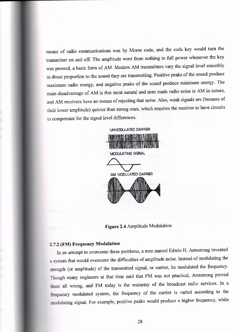
2.7.2 (FM) Frequency Modulation In an attempt to overcome these problems, a man named Edwin H. Armstrong invented
1
a system that would overcome the difficulties of amplitude noise. Instead of modulating the
strength (or amplitude) of the transmitted signal, or carrier, he modulated the frequency.
Though many engineers at that time said that FM was not practical, Armstrong proved
them all wrong, and FM today is the mainstay of the broadcast radio services. In a
frequency modulated system, the frequency of the carrier is varied according to the
modulating signal. For example, positive peaks would produce a higher frequency, while
28
negative peaks would produce a lower frequency. At the receiving end, a limiting circuit
removes all amplitude variations from the signal, and a discriminator circuit converts the
frequency variations back to the original signal. In this way, the effects of amplitude noise
are minimized. Since the recovered audio is dependent only on the frequency, and not the
strength, no compensation for different signal levels is required, as is the case with AM
receivers.
M:IOUI.ATING SGNAL
D r'\ ./\ ·~~v
Figure 2.5 Frequency Modulation [12]
2.8 Application Each band of frequency has its own applications which are used in our life, these
application are shown in table 2.2.
29
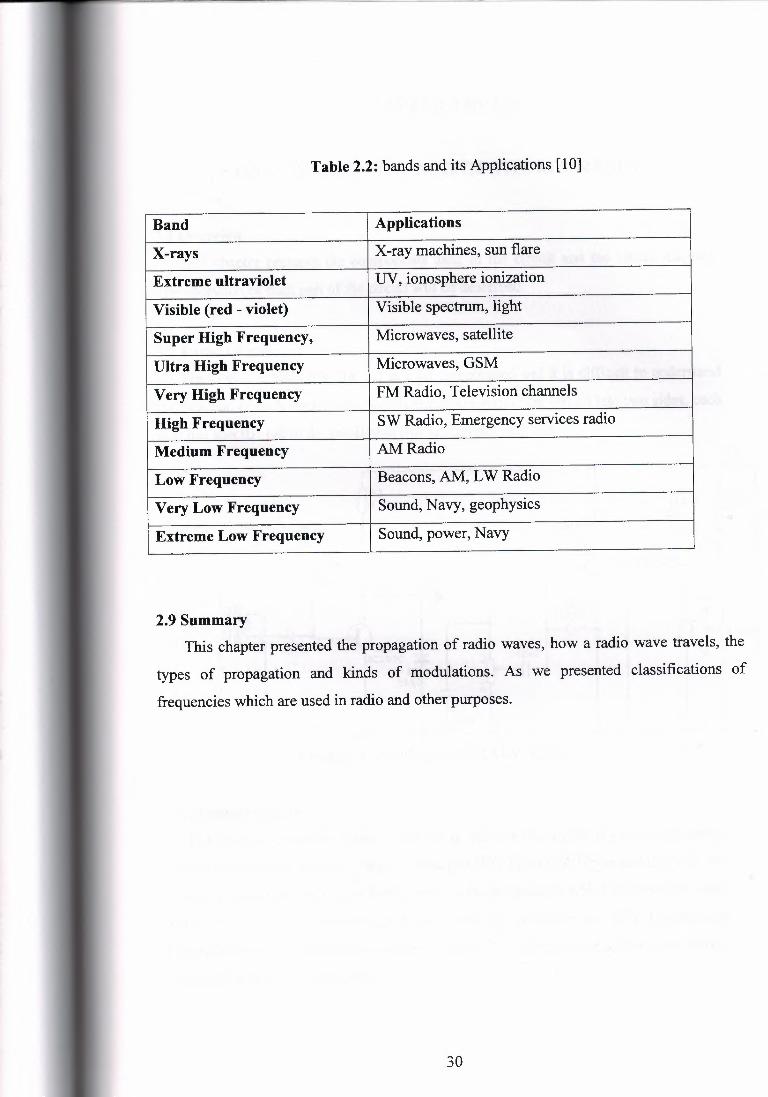
Table 2.2: bands and its Applications [10]
Band Applications
X-rays X-ray machines, sun flare
Extreme ultraviolet UV, ionosphere ionization
Visible (red - violet) Visible spectrum, light
Super High Frequency, Microwaves, satellite
Ultra High Frequency Microwaves, GSM
Very High Frequency FM Radio, Television channels
High Frequency SW Radio, Emergency services radio
Medium Frequency AM Radio
Low Frequency Beacons, AM, L W Radio
Very Low Frequency Sound, Navy, geophysics
Extreme Low Frequency Sound, power, Navy
2.9 Summary This chapter presented the propagation of radio waves, how a radio wave travels, the
types of propagation and kinds of modulations. As we presented classifications of
frequencies which are used in radio and other purposes.
30
CHAPTER THREE
HARDWARE APPROACH OF THE MW RADIO
3.1 Overview This chapter presents the components used in the circuit and the circuit diagram.
The operation of each part of the circuit will be described.
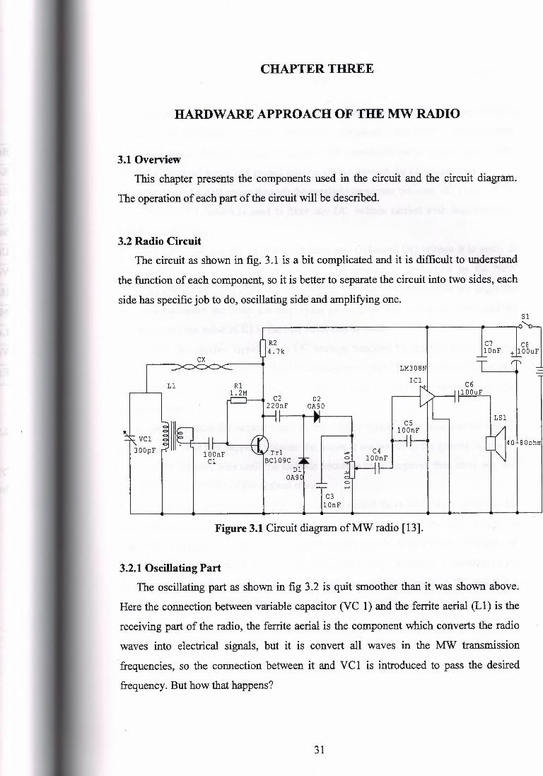
3.2 Radio Circuit The circuit as shown in fig. 3 .1 is a bit complicated and it is difficult to understand
the function of each component, so it is better to separate the circuit into two sides, each
side has specific job to do, oscillating side and amplifying one.
R2 4.7k
ex r LM308N
I Cl 11 Rl
1.2M D2
OA90 N I cs
lDDnF r-Jlllt- ' -' ..
VCl \
30DpF I""' I '' 'lYTrl ! I ~;l C4 , nnnt.' BC109C lODnF
Dl OA90
Sl
~
C +11:
I 't -
C7 lDnF
C6 lDDuF
LS1
0 .-I
C3 lOnF
Figure 3.1 Circuit diagram of MW radio [13].
3.2.1 Oscillating Part The oscillating part as shown in fig 3 .2 is quit smoother than it was shown above.
Here the connection between variable capacitor (VC 1) and the ferrite aerial (LI) is the
receiving part of the radio, the ferrite aerial is the component which converts the radio
waves into electrical signals, but it is convert all waves in the MW transmission
:frequencies, so the connection between it and VCI is introduced to pass the desired
frequency. But how that happens?
31
(3.1)
The above equation gives the output of a capacitor and inductor connected in
parallel, this frequency is called resonance frequency. And when the resonance
:frequency equal to transmission :frequency, the transmitter radio signal enter to the
circuit as electrical signal and passed into the circuit through the LC connection.
After the desired signal enters through the parallel connection between VC 1 and Ll, the
signal reaches C 1, which is used to filter any DC voltage carried with desired signal, . which is an AC type.
After the signal has been filtered out from any undesired DC voltage it is ready to
enter the phase of pre-amplifying process. This process is performed by the NPN
transistor and Rl which is used as feedback path, it is know in general that the larger the
feedback resistance the better the amplifying process, but this rule has a limit, and for
this transistor, the value of Rl is the best value can be used. Again after the desired signal has a DC voltage supplied by the battery, so another
capacitor (C2) is used to prevent this DC voltage from continuing its way up to the next
part of the circuit (it is know that a DC voltage will act as a noise or unwanted signal in
the loudspeaker). D 1 is used to cancel the negative part of the desired signal as the loudspeaker use the
positive part. And that happens because the anode is connected to the ground, so the D 1
is not in the forward bias until the cathode becomes more negative than zero, and that
means the negative side of the desired signal. D2 has a minor role compared to D 1; its role is to cancel the residue of the negative side
of the desired signal, as D 1 allow a small value of negative side of the desired signal to
reach D2. That happens due to the triggering voltage which is needed to change the
statues of Dl from isolator to conductor, and this voltage depends on the type of the
diode, so if the diode is made of silicon, this needed voltage equal to -0. 7V, and Wit is
made of germanium -0.3V is the needed voltage to trigger Dl.
32

CABLl
R2 :4. 2k
R2 1.2M
C2 02 220nF OA90
Ll
VCl ' 300pF
BC109C Trl
01 OA90
Figure 3.2 Oscillating part diagram of MW radio.
3.2.2 Amplifying part
After the desired signal is cleanly out of the huge number transmission frequencies,
and prepared to be amplified by filtering any DC voltage from it, it is almost ready to
enter to the amplifying phase, see fig.3.3.
This extremely simple circuit provides an output of power of about 200 mW
RMS (about equal in volume to a small or medium-size transistor radio) and has an
input sensitivity of about 50 m V RMS into 100 kQ for maximum output. This
enables the unit to be fed from a variety of signal sources, such as a crystal or
ceramic pickup, radio tuner, etc.
The circuit is primarily intended as a simple one to demonstrate the
properties of the LM380N audio-power amplifier device, and it makes a very useful
and inexpensive workshop amplifier if the circuit is built as a proper, cased project.
When a capacitor is connected between the earth and the path of any signal, it
allows a certain band of frequency to pass through (it acts like a band pass filter), so to
make sure that no any other radio waves entered to the circuit, C3 is used to let only the
desired signal to pass, the values of the capacitance and the impedance of C3 control the
range of allowed frequencies to pass, in MW it allows frequencies up to 3000 kHz.
VRI is the volume control resistance; by tuning it we can control the input signal
going to IC (LM308N) and coming in from the radio circuit and which has been
33
filtered by the C3 capacitor which is connected parallel with VRl.
As a fmal assurance of eliminating any DC voltage C4 is used, so that almost pure AC
will enter to the amplifier from pin-2 (the non inverting input pin).
CS has not a vital role in fi.ltermg process, but it is important for LM3 i()N' s gain. value
determining, actually the gain of this amplifier varies as the value of C5 change, the
gain range is from 34 dB to 40 dB. IC 1 has an internal bias circuit that gives a quiescent output voltage at the output
terminal (pin 8) of nominally half the supply voltage, the AC input signal causes the
output to swing positive and negative of this quiescent level by about plus and minus
3 volts or so, and this enables a reasonably high output power to be obtained without
the output going fully positive or fully negative, and serious distortion being caused
by clipping of the output waveform. If a DC component on the input signal was allowed to reach the input of IC 1 this
would alter the quiescent output voltage of IC 1, and could result in the output going
almost fully positive or negative. Only a very small output power would then be
possible without the signal becoming badly distorted. C6 provides DC blocking at the output so that loudspeaker only receives the varying
output voltage from IC 1, and not the quiescent (DC) output voltage, which would
Give a high standing current through the loudspeaker produce a very high level of
current consumption. The LM380N has a class AB output stage, and this means that the average
current consumption of the device (which is around 10 mA) remains virtually
constant at low and medium output powers, but increases somewhat at high output
powers. This gives reasonable battery economy, and a PP6 or larger 9-volt battery
makes a suitable power source. There is some variation in the supply voltage due to variations in the loading on
the battery by IC 1 as the output power inevitably fluctuates quite rapidly and over a
fairly wide range with any practical input signal This can result in a loss of
performance or instability, and decoupling capacitors C7 and C8 are included to
prevent either of these occurring. As finally the C7 and C8 are connected in parallel with battery to cancel any AC
signal coming from it. An additional decoupling capacitor can be added from pin 1
of IC 1 to the negative supply, and this decouples the supply to the preamplifier
stages of the device. This is not normally necessary when the LM3 80N is employed
34
with a battery supply, and is a facility give a high standing current through the
loudspeaker produce a very high level of current consumption.
An additional decoupling capacitor can be added from pin 1 of 10 to the negative
supply, and this decouples the supply to the preamplifier stages of the device. Ibis is
not normally necessary when the LM380N is employed with a battery supply, and is a
facility that is normally only required when the device is used with a mains power
supply that has high ripple content.
You might be confused by the fact that one lead to ICI in Fig. 3.3 is marked 3, 4,
5, 7, 10, 11, and 12. This lead is marked with six pin numbers merely because these
six, pins are internally interconnected, and a connection to one of them is a
connection to the other five.
The case should ideally be an all metal type so that it screens the Circuitry from
stray pickup of mains hum and similar electrical signals, and the case should be
earthed to the negative supply.
With most types of audio socket, this chassis connection will be automatically
provided through the earth lead to the socket. The test leads should use screened cable
(the outer braiding connecting to the chassis of the amplifier).
An interesting feature of the LM3 80N device is that it has two inputs, pin 2 is the
non-inverting input and pm 6 is the Inverting input.
An input signal to pin 6 produces a change in output voltage that is of the
opposite polarity, whereas an input to pin 2 gives a change in output voltage that is
of the same polarity as the input signal.
There is no audible difference between the two, and the fact that the signal is
inverted through IC 1 if the input at pin 6 is used is not really of any practical
importance. The circuit works equally well whichever of the two inputs is used and this
fact can easily be demonstrated in practice
35
Sl
C7 lOnF + CB
lOOuF I Cl
LM380N
C6 lOOuF + ± V -=- 9'
cs 3.3nF
C3 lOnF VRl
C4 lOOnF
LS1 100k 40%
40-BOohm
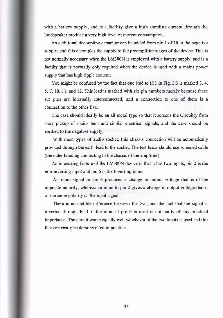
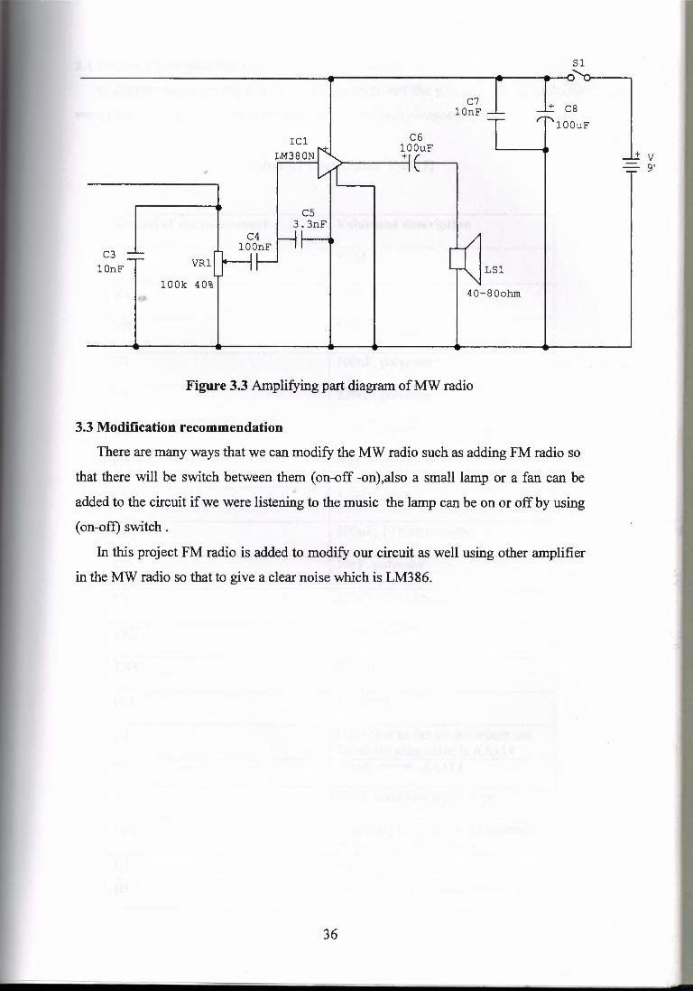
Figure 3.3 Amplifying part diagram of MW radio
3.3 Modification recommendation
There are many ways that we can modify the MW radio such as adding FM radio so
that there will be switch between them ( on-off -on),also a small lamp or a fan can be " added to the circuit if we were listening to the music the lamp can be on or off by using
( on-off) switch .
In this project FM radio is added to modify our circuit as well using other amplifier
in the MW radio so that to give a clear noise which is LM386.
36
- L[
nns oi .rorootnroo ptra A6 ::lZ!S 9dd IH
fB!J::lB ::ll!JJ::l d 1'1 snrqo os-ot ::iilirnJ ::iqi ti!
aotrepcdtm Im illl!ABl:{ acL(i ::lJillBIUfW IS'l
::icL(i ::i188oi amranmn .LSdS IS
tllVV +-- 06VO Z<I t1 IVY S! ::iAµBw::iire =n punOJ
ion ::lJ::ll:{M. sopotp ::iqi SB inq 06VO I<I
N08£W'I I:JI
:::HOl:JH nu. ::,µi::,::iP!P P!I0s c1ctoo£ I:JA
:J!l.AJOJpap Ol'dTiOOI 8:J
J::llS::lAJOd 'dUO I L:J
:J!l.AJOJpap AOl 'dTiOOl 9:J
omraroo 'dU£"£ S:J
J::llS::lAJOd 'dUOO l t:J
J::llS::lAJOd 'dUO I £:)
J::llS::lAJOd 'dUOll Z:J
J::llS::lAJOd 'dUOOI I:J
uoqrao ·801 ){00 I IHA
){l't za wz·1 HI
uoudposap pus an1e A rnauodmoa aqJ JO 1oqmAS
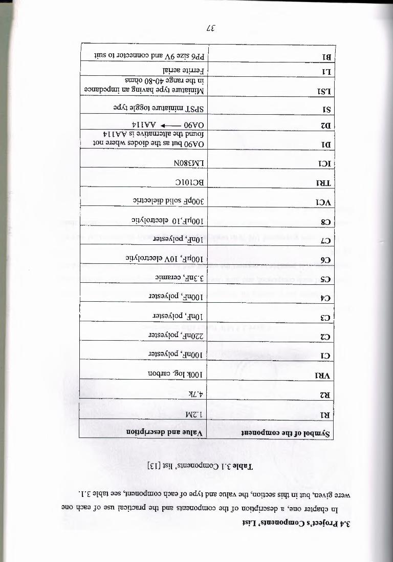
·I·£ ::lJqBl eos 1u::iuodmo::, 1:{:JBa JO ::icL(i pirn anreA aqi 'uonoes S!lp ti! inq 'uaA~ ::iJ::iM.
euo 1:{:JB::l JO osn re::,µ::,rud aqi pirn siuouoduroo ::iqi JO uopduosop B '::iuo J::iidBl:J::, u:r
JS!'1 ,sJuauodmo:J s,J:>af o.1d J,"f
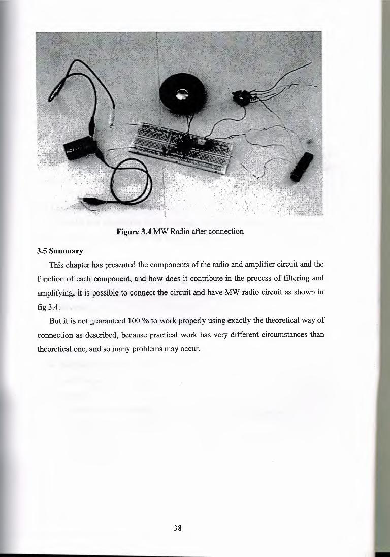
Figure 3.4 MW Radio after connection
3.5 Summary This chapter has presented the components of the radio and amplifier circuit and the
function of each component, and how does it contribute in the process of filtering and
amplifying, it is possible to connect the circuit and have MW radio circuit as shown in
fig 3.4.
But it is not guaranteed 100 % to work properly using exactly the theoretical way of
connection as described, because practical work has very different circumstances than
theoretical one, and so many problems may occur.
38 I-
CHAPTER FOUR
MODIFICATION OF THE MW RADIO
4.1 Overview
This chapter present the FM radio where it's added to the AM radio and it explains the
design of the FM circuit, the components that has been used . This chapter also contains explanation about the differences between the FM and AM radio.
4.2 Electrical components
In chapter one information about electronics components where discussed but in this
chapter there are new components that has been used on the hardware of the FM radio.
4.2.1 CXA1619BS
CXA1619BS is a one-chip FM/AM radio IC designed for radio-cassette tape recorders and headphone tape recorders.
4.2.2 Features
• Small number of peripheral components.
• Low current consumption (VCC=3 V).
• For FM: ID=5.8 m.A.
• Built-in FM/AM select switch.
• Large output of AF amplifier. 4.2.3 Function
• RF amplifier, Mixer and OSC ((incorporating AFC variable capacitor). • IF amplifier.
• Quadrature detection.
• Tuning LED driver.
39
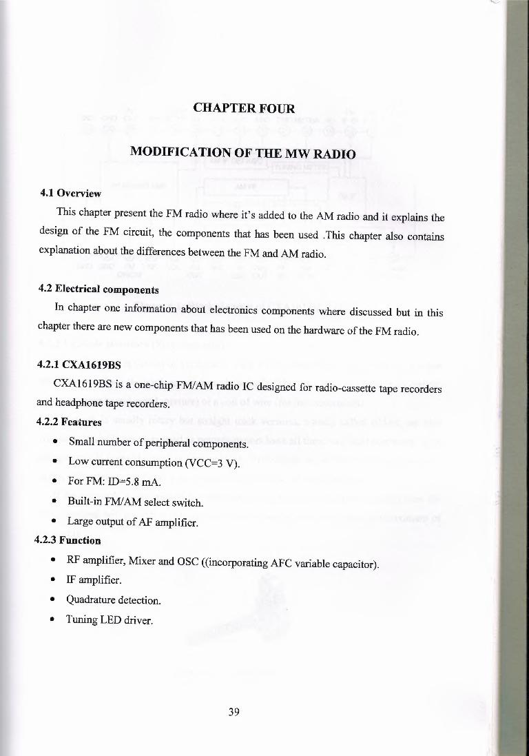
FM/AM AF Ripple AF DET PEC AFC IF FM AM BANCJ
GND GND orr Vee FILTER IN OUT AOC AOC GNCJ METER NC IF IN IF IN SELECT ,---C:~r-G~-{;l:m--{;[l}--{;l6)--{;~-{;l4}--{;;!3l---{;~-{21 ..•..... -
AFPOWERAMP FMIF
GND GND FM NF VOL AM AFC FM DISCRI OSC OSC
AM RFIN
- -11 - FM FE FflNAM
RF IN GND FE OUT
Figure 4.1: Block diagram of CXA1619BS [14]
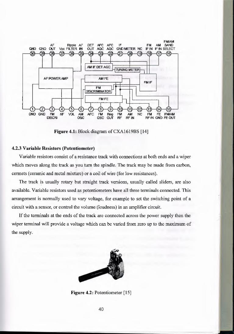
4.2.3 Variable Resistors (Potentiometer)
Variable resistors consist of a resistance track with connections at both ends and a wiper
which moves along the track as you turn the spindle. The track may be made from carbon,
cermets (ceramic and metal mixture) or a coil of wire (for low resistances).
The track is usually rotary but straight track versions, usually called sliders, are also '
available. Variable resistors used as potentiometers have all three terminals connected. This
arrangement is normally used to vary voltage, for example to set the switching point of a
circuit with a sensor, or control the volume (loudness) in an amplifier circuit.
If the terminals at the ends of the track are connectedacross the power supply then the
wiper terminal will provide a voltage which can be varied from zero up to the maximum of
the supply.
Figure 4.2: Potentiometer [ 15]
40
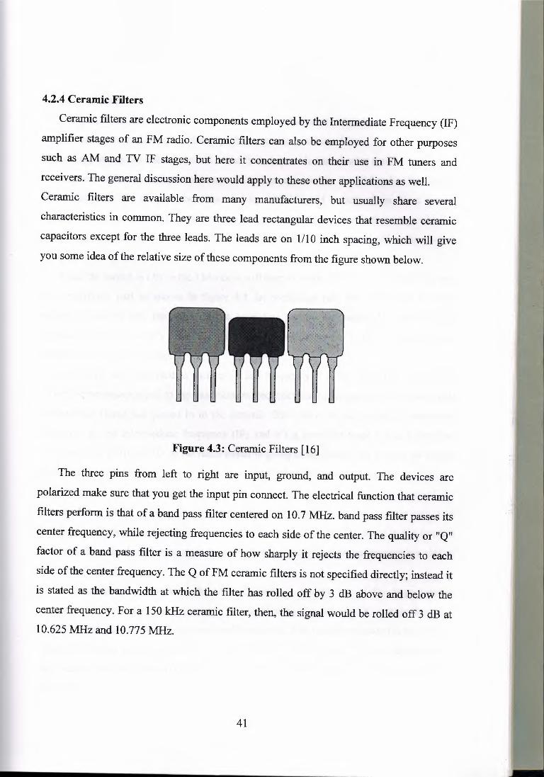
4.2.4 Ceramic Filters
Ceramic filters are electronic components employed by the Intermediate Frequency (IF)
amplifier stages of an FM radio. Ceramic filters can also be employed for other purposes
such as AM and TV IF stages, but here it concentrates on their use in FM tuners and
receivers. The general discussion here would apply to these other applications as well.
Ceramic filters are available from many manufacturers, but usually share several
characteristics in common. They are three lead rectangular devices that resemble ceramic
capacitors except for the three leads. The leads are on 1/10 inch spacing, which will give
you some idea of the relative size of these components from the figure shown below.
Figure 4.3: Ceramic Filters [16]
The three pins from left to right are input, ground, and output. The devices are
polarized make sure that you get the input pin connect. The electrical function that ceramic
filters perform is that of a band pass filter centered on 10. 7 MHz. band pass filter passes its
center frequency, while rejecting frequencies to each side of the center. The quality or "Q"
factor of a band pass filter is a measure of how sharply it rejects the frequencies to each
side of the center frequency. The Q of FM ceramic filters is not specified directly; instead it
is stated as the bandwidth at which the filter has rolled off by 3 dB above and below the
center frequency. For a 150 kHz ceramic filter, then, the signal would be rolled off 3 dB at 10.625 MHz and 10.775 MHz.
41
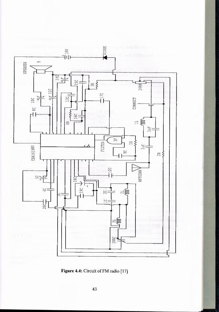
4.3 Radio circuit
This circuit as shown in fig 4.4 is a bit complicated where it contains one integrated
circuit, capacitors, resistors, variable capacitors, resistors and one filter.
Some components has been discussed in the first chapter .In this chapter it will represent an
introduction of the new electrical components that are used in the FM radio .Beside the
MW radio the FM radio will be connected by ON-OFF-ON switch where it's a special
version of the standard SPDT switch. It has a third switching position in the centre which is
off. Momentary (ON)-OFF-(ON) where the switch returns to the central off position when
released.
When the switch is ON in the FM side it will start to work, the radio has oscillating part
and amplifying part as shown in figure 4.4 .In oscillating part the connection between
variable capacitor and the aerial is the receiving part in the radio, this aerial is the
component which converts the radio waves in to electrical signal in the HF transmission
frequencies as it is FM radio.
C7 and Ll are connected in parallel so this frequency is called resonance frequency
. When the resonance equal to the transmission frequency the radio signal enter to the circuit
as electrical signal and passes in to the ceramic filter where its an electrical component
employed by the intermediate frequency (IF) and it's a amplifier stage it has a band pas
filter centered as 10. 7 MHz so the radio signal is going to be filtered and pass to the circuit
through the IC connection .the desired signal which has DC voltage supplied by battery .
D 1 is used, to cancel the negative part of the desired signal in one of the legs of the
Potentiometer which controls the volume of the loudspeaker using the positive part. And
that happens because the anode is connected to the ground, so the D 1 is not in the forward
bias until the cathode becomes more negative than zero, and that means the negative side of
the desired signal.
In the amplifying part after the desired signal is cleanly out of the huge number
transmission frequencies and prepared to be amplified by filtering any DC voltage from it.
This IC works also as an audio power amplifier device ,VR(variable resistor) is the volume
control resistance by tuning it signal going to the IC can be controlled .from these process
the channels will be received by the tuning the VC(variable capacitor) we an get different
channels.
42
t...) =
~r ,-.::i t...)
c-a I I I =-, TT
__.__ I
.------i L)
t...) .------i u =
C"'-l
Figure 4.4: Circuit of FM radio [17]
43
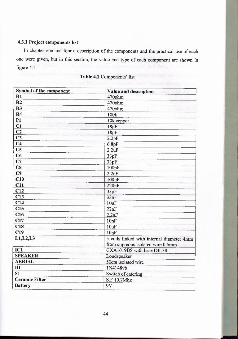
4.3.1 Project components list
In chapter one and four a description of the components and the practical use of each
one were given, but in this section, the value and type of each component are shown in
figure 4.1.
Table 4.1 Components' list
Symbol of the component Value and description Rl 470ohm R2 470ohm R3 470ohm R4 100k Pl I Ok ceppot Cl l8pF C2 18pF C3 2.2pF C4 6.8pF cs ,.
2.2uF C6 33pF C7 33pF C8 IOOnF C9 2.2nF ClO IOOuF Cll 220nF C12 33pF C13 33nF C14 c IOuF C15 22nF C16 2.2uF C17 IOnF C18 IOuF C19 IOnF Ll,L2,L3 5 coils linked with internal diameter 4mm
from cupreous isolated wire 0.6mm I Cl CXA1019BS with base D1L30 SPEAKER Loudspeaker AERIAL 50cm isolated wire Dl IN4148vb Sl Switch of catering Ceramic Filter S.F 10.7Mhz Battery 9V
44
4.4 In general how radio works?
Radio station launches a radio wave by moving electric charges rhythmically up and
down their antenna. As this electric charge accelerates back and forth, it produces a
changing electric field a structure in space that pushes on electric charges and a changing
magnetic field a structure in space that pushes on magnetic poles. Because the electric field
changes with time, it creates the magnetic field and because the magnetic field changes
with time, it creates the electric field. The two travel off across space as a pair, endlessly
recreating one another in an electromagnetic wave that will continue to the ends of the
universe. However, when this wave encounters the antenna of your radio, its electric field
begins to push electric charges up and down on that antenna. Your radio senses this motion
of electric charges and thus detects the passing radio wave.
To convey audio information (sound) to you radio, the radio station makes one of
several changes to the radio wave it transmits. In the AM or Amplitude Modulation
technique, it adjusts the amount of charge it moves up and down its antenna, and hence the
strength of its radio wave, in order to signal which way to move the speaker of your radio.
These movements of the speaker are what cause your radio to emit sound. In the FM or
Frequency Modulation technique, the radio station adjusts the precise frequency at which it
moves charge up and down its antenna. Your radio senses these slight changes in frequency
and moves its speaker accordingly [18].
4.5 What are the differences between FM and AM radio?
These days, radios just look like electronic circuit boards inside AM and FM are both
techniques whereby the radio station tells your radio which way to move the diaphragm of
its speaker and by how much, in order to make sound. In the AM or Amplitude Modulation
technique, the station raises or lowers the power of its radio wave to tell your radio to move
its speaker diaphragm toward you or away from you, respectively.
The higher the power of the radio wave, the more your radio pushes its diaphragm
toward you. In the FM or Frequency Modulation technique, the station raises or lowers the
frequency of its radio wave slightly to tell your radio to move its speaker diaphragm toward
you or away from you, respectively.
45
The more it raises the frequency of its radio wave, the more your radio pushes its
diaphragm toward you.
4.5.1 AM radio
The AM band covers 535KHZ to l.7MHZ .There are signals from thousands of radio
transmitters on many different frequencies inducing signal voltages in the aerial. The RF filter selects the desired station from the many.
It is adjustable so that the selection frequency can be altered. This is called TUNING.
The selected frequency is applied to the mixer; the output of an oscillator is also applied to the mixer.
The mixer and oscillator form a FREQUENCY CHANGER circuit. The output from
the mixer is the intermediate frequency (i.f.) .The i.f. is a fixed frequency of about 455 kHz.
No matter what the frequency of the selected radio station is, the i.f. is always 455 kHz.
The i.f. signal is fed into the i.f. amplifier. The advantage of the i.f. amplifier is that its
frequency and bandwidth are fixed, no matter what the frequency of the incoming signal is.
This makes the design and operation of the amplifier much simpler. The amplified i.f.
signal is fed to the demodulator. This circuit recovers the audio signal and discards the R.F. carrier.
It usually incorporates a diode in the circuit. Some of the audio is fed back to the i.f. amplifier as an AUTOMATIC GAIN CONTROL voltage.
This ensures that when tuning from a weak station to a strong one, the loudness from
the loudspeaker stays the same. The audio signal voltage is increased in amplitude by a
voltage amplifier. The power level is increased sufficiently to drive the loudspeaker by the power amplifier.
46
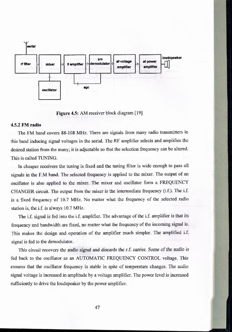
rf fllter mixer If amplifier am
demodulator I at voltage 1mpllfler
., l)<>Wtt ampllfler
loudspeaker
Hr1al
Figure 4.5: AM receiver block diagram [19]
4.5.2 FM radio The FM band covers 88-108 MHz. There are signals from many radio transmitters in
this band inducing signal voltages in the aerial. The RF amplifier selects and amplifies the
desired station from the many; it is adjustable so that the selection frequency can be altered.
This is called TUNING. In cheaper receivers the tuning is fixed and the tuning filter is wide enough to pass all
signals in the F .M band. The selected frequency is applied to the mixer. The output of an
oscillator is also applied to the mixer. The mixer and oscillator form a FREQUENCY
CHANGER circuit. The output from the mixer is the intermediate frequency (i.f.). The i.f.
is a fixed frequency of 10.7 MHz. No matter what the frequency of the selected radio
station is, the i.f. is always 10.7 MHz.
The i.f. signal is fed into the i.f. amplifier. The advantage of the i.f. amplifier is that its
frequency and bandwidth are fixed, no matter what the frequency of the incoming signal is.
This makes the design and operation of the amplifier much simpler. The amplified i.f.
signal is fed to the demodulator.
This circuit recovers the audio signal and discards the r.f carrier. Some of the audio is
fed back to the oscillator as an AUTOMATIC FREQUENCY CONTROL voltage. This
ensures that the oscillator frequency is stable in spite of temperature changes. The audio
signal voltage is increased in amplitude by a voltage amplifier. The power level is increased
sufficiently to drive the loudspeaker by the power amplifier.
47
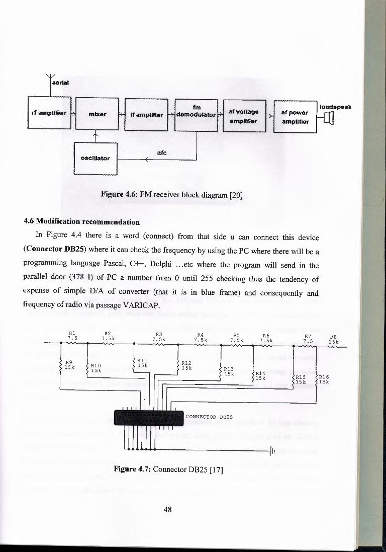
."¥
aerial
rf amplifier ~ mixer fm
t'H lfamplifler ~demodutatorH afvouage I-+ amplifier
t afc
osentator
Figure 4.6: FM receiver block diagram [20]
4.6 Modification recommendation
In Figure 4.4 there is a word ( connect) from that side u can connect this device
(Connector DB25) where it can check the frequency by using the PC where there will be a
programming language Pascal, C++, Delphi ... etc where the program will send in the
parallel door (378 I) of PC a number from O until 255 checking thus the tendency of
expense of simple DIA of converter (that it is in blue frame) and consequently and frequency of radio via passage V ARICAP.
R6 R7 RS R4 RS 7.5 15k
R3 7.Sk
Rl R2 7.Sk 7.Sk 7.Sk 7.5 7.Sk
E R12 ~ R13
R9 } RlO k 15k
<R14 ~ RlS ?16
15k 15k
15k
15k 15k 15k
CONNECTOR DB25
•..•..•.•...•..•.•..•. _jl1
Figure 4.7: Connector DB25 [17]
48
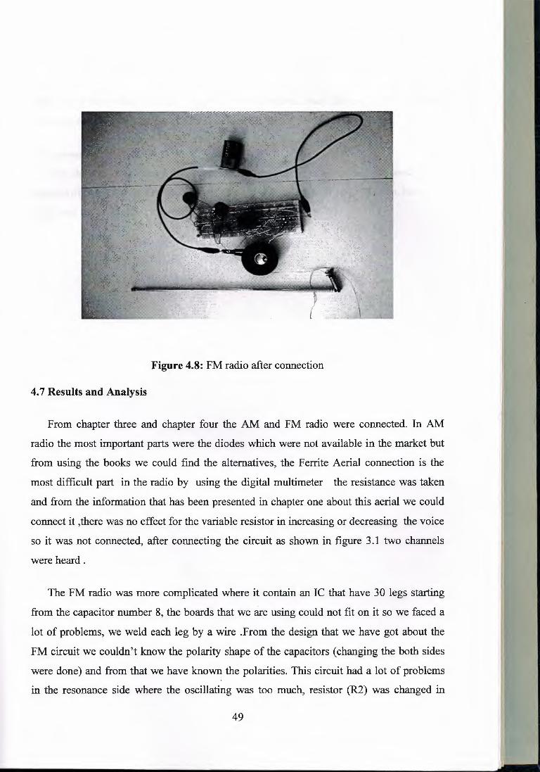
Figure 4.8: FM radio after connection
4. 7 Results and Analysis
From chapter three and chapter four the AM and FM radio were connected. In AM
radio the most important parts were the diodes which were not available in the market but
from using the books we could find the alternatives, the Ferrite Aerial connection is the
most difficult part in the radio by using the digital multimeter the resistance was taken
and from the information that has been presented in chapter one about this aerial we could
connect it ,there was no effect for the variable resistor in increasing or decreasing the voice
so it was not connected, after connecting the circuit as shown in figure 3 .1 two channels
were heard.
The FM radio was more complicated where it contain an IC that have 30 legs starting
from the capacitor number 8, the boards that we are using could not fit on it so we faced a
lot of problems, we weld each leg by a wire .From the design that we have got about the
FM circuit we couldn't know the polarity shape of the capacitors ( changing the both sides
were done) and from that we have known the polarities. This circuit had a lot of problems
in the resonance side where the oscillating was too much, resistor (R2) was changed in
49
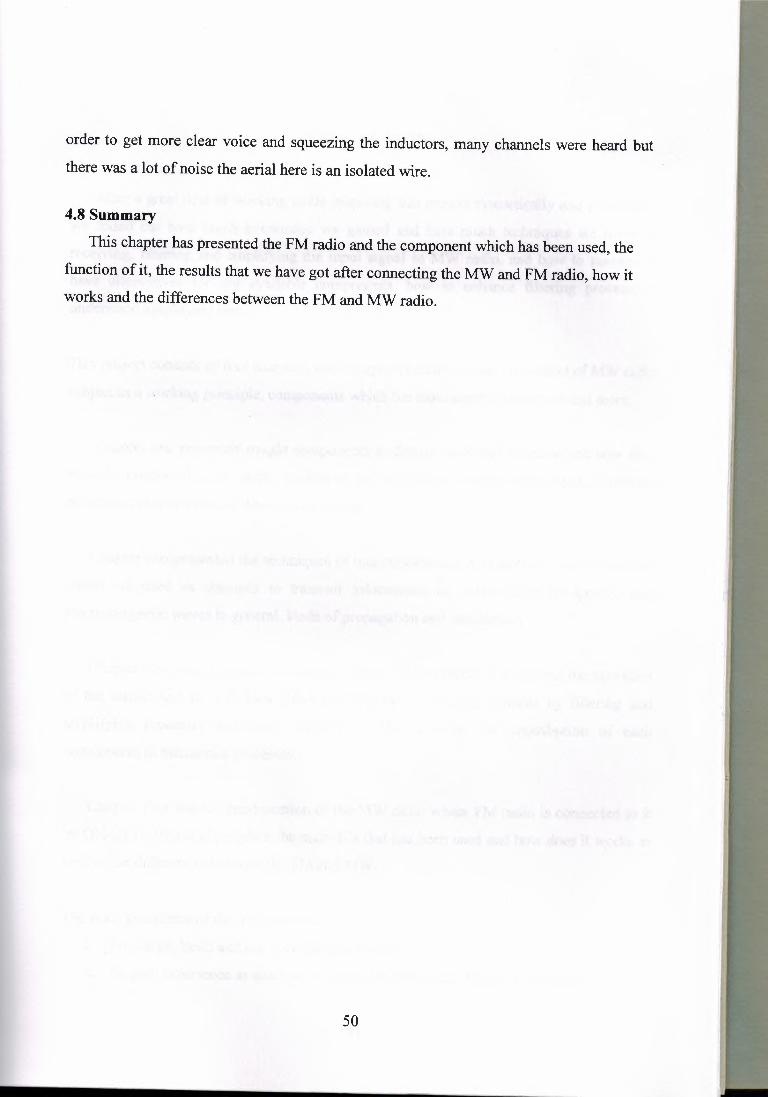
order to get more clear voice and squeezing the inductors, many channels were heard but
there was a lot of noise the aerial here is an isolated wire.
4.8 Summary
This chapter has presented the FM radio and the component which has been used, the
function of it, the results that we have got after connecting the MW and FM radio, how it
works and the differences between the FM and MW radio.
50

CONCLUSION
After a great deal of working while preparing this project theoretically and practically;
we found out how much knowledge we gained and how much techniques we learnt in
receiving, filtering and amplifying the input signal in MW radio, and how to manage to
have alternatives for not available components, how to enhance filtering process, to understand amplifying one.
This project consists of four chapters; each chapter presented a specific aspect of MW radio
subject as a working principle, components which the radio circuit consists of and more.
Chapter one presented sought components in details, how they function and how they
must be connected. Also safety guidelines for electronics projects mentioned to prevent
possible mistakes that may damage the circuit.
Chapter two presented the techniques of transmission and propagations, the frequencies
which are used as channels to transmit information as radio waves in specific and
electromagnetic waves in general, kinds of propagation and modulation.
Chapter three was the most important chapter of this project, it presented the operation
of the circuit and how it does affect the behavior of the input signal by filtering and
amplifying processes with used techniques, also describe the contribution of each
components in mentioned processes.
Chapter four was the modification of the MW radio where FM radio is connected to it
by ON-OFF-ON switch, explain the main ICs that has been used and how does it works as
well as the differences between the FM and MW.
The main guidelines of this project were:
1. To design, build and test a working MW radio
2. To gain experience as much as we could with practical electronics projects.
51
- ---- -- ----
3. To sort out problems within the circuits and make modifications, to overcome the
problems. 4. To get information about the kinds of frequencies, modulation, propagation and the
main application of each kind of the frequency bands .
. s. Modifying the MW where FM radio is added.
Firstly while the project was in progress, we realized the components which were
supposed to be used in the project, then we started connecting the circuit as planned.
When the circuit got ready, we started testing the circuit and detecting the problems
were preventing circuit from working properly.
While connecting the radio circuit; and during some of unpleasant conclusions we
realized that we were doing mistakes in some positions. By trial we got more careful and
aware while we were working, and also gave us the motivation and determination to make
the circuit work.
The main problem was when a component was not available and since the market in
North Cyprus is limited we were forced to find alternative components by using the internet
or some references, getting some components from Istanbul if we couldn't find the
alternatives of it and also by asking some advices from experienced people.
In summary, a great experience and knowledge of hands-on work with electronic
projects have been gained. Problem solving skills where also developed through out
working on this project.
52
REFRENCES
[ 1] http://www.electronic-circuits-diagrams.com/tutorials/resistors.shtml
[2] http://www.kpsec.freeuk.com/components/capac.htm
[3] http://wwwl.jaycar.com.au/images_uploaded/LM380.PDF
[ 4] http://www.kpsec.freeuk.com/ components/ other .htm#loudspeaker
[ 5] http://www.chembio.uoguelph.ca/ educmat/ chm 729/band/psemi.ht
[ 6] http://www.kpsec.freeuk.com/ components/tran.htm
[7] http://www.kpsec.freeuk.com/components/diode.htm
[8] http://www.kpsec.freeuk.com/ components/ switch.htm
[9] http://www.kpsec.freeuk.com/symbol.htm
[10] http://www.astrosurf.org/lombry/qsl-propa.htm
[ 11] http://www.radio-electronics.com/info/propagation/index.php
[ 12] http://www.radiodesign.com/radwrks.htm
[13] Khashman A, handout on electronic projects, Near East University, Nicosia.
[14] http://www.semiconductors.sony.com/acrobat_download/datasheets/ CXA1619.
CNV.2.pdf
53
[ 15] http ://www.kpsec.freeuk.com/ components/vres.htm
[ 16] http://www.hem.passagen.se/communication.ceramic.htm
[17] The circuit is taken from INT-EL International Elektronik Sanayi ve Ticaret
ue.su 1ST ANBUL (Sony kit 67).
[18] http://ourworld.cs.com/gknott54 l 3/elect116.htm
[19] http://ourworld.cs.com/gknott5413/elect1 l 5,htm
54
Recommended


