
The Atomic Redesign of the Internet Future Architecture
Project full title: The Atomic Redesign of the Internet Future Architecture
Project acronym: TARIFA
Start date: 01/07/2009
End date: 31/06/2011
Participants
Fundació i2CAT I2CAT
Sebastià Sallent,
Albert Vidal,
Oriol Madriles
Wireless Network Group of
Technical University of Catalonia WNG
Josep Paradells,
Xavier Sánchez
MediaENTEL of Technical
University of Catalonia ME
Jesus Alcober,
Alberto José González
Grup de Xarxes Optiques of
Technical University of Catalonia GXO
Cristina Cervelló,
Yury Andrea Jiménez
Grup de Disseny Col·laboratiu de
Sistemes a les TIC of Technical
University of Catalonia
COLS Josep M Monguet,
Alfredo Gutiérrez
Network Technologies and
Strategies of Pompeu Fabra
University
NeTS Boris Bellalta,
Trang Cao Minh
Grup de Tecnologies Multimèdia
of Ramon Llull University – La
Salle
GTM Francesc Pinyol,
Ramon Martín de Pozuelo
Adavanced Network
Architectures of Technical
University of Catalonia
ANA Xavier Masip,
Martín Germán
Observers
Vodafone España VF Guillermo Cajigas
Televisió de Catalunya TVC Christian Adell
Fundació i2CAT – CTX I2CAT-CTX Sergi Figuerola
Essex University ESSEX Kenneth M Guild

The Atomic Redesign of the Internet Future Architecture TWP2.2.D1
28/05/2010
Page 2 of 52
The Atomic Redesign of the Internet Future Architecture
Deliverable title: Evolutionary Use Cases Specification
Version: V.3
Authors
Grup de Tecnologies Multimèdia of
Ramon Llull University – La Salle GTM Ramon Martín de Pozuelo
Grup de Xarxes Optiques of Technical
University of Catalonia GXO Yury Andrea Jiménez
MediaENTEL of Technical University of
Catalonia ME Alberto José González
Adavanced Network Architectures of
Technical University of Catalonia ANA Martín Germán
Grup de Disseny Col·laboratiu de
Sistemes a les TIC of Technical
University of Catalonia
COLS Alfredo Gutiérrez
Network Technologies and Strategies of
Pompeu Fabra University NeTS Trang Cao Minh
Reviewers
Fundació i2CAT I2CAT
Sebastià Sallent,
Albert Vidal,
Oriol Madriles
Wireless Network Group of Technical
University of Catalonia WNG
Josep Paradells,
Xavier Sánchez
MediaENTEL of Technical University of
Catalonia ME
Jesus Alcober
Grup de Xarxes Optiques of Technical
University of Catalonia GXO
Cristina Cervelló
Grup de Disseny Col·laboratiu de
Sistemes a les TIC of Technical
University of Catalonia
COLS Josep M Monguet
Network Technologies and Strategies of
Pompeu Fabra University NeTS
Boris Bellalta
Grup de Tecnologies Multimèdia of
Ramon Llull University – La Salle GTM Francesc Pinyol
Adavanced Network Architectures of
Technical University of Catalonia ANA Xavier Masip

The Atomic Redesign of the Internet Future Architecture TWP2.2.D1
28/05/2010
Page 3 of 52
Executive Summary TARIFA aims at defining a clean slate approach to a Future Internet architectural redesign
based on a role-based paradigm consisting of non-divisible, or atomic, functions. In this
purpose, WP2 of this project designs two set of use cases from two different perspectives. First
one focus on demonstrate that the simplification of the architecture does not affect to its
performance, comparing it to current networks and achieving an equivalent functionality.
This document defines the scenarios, actors and flow charts of the cases that must prove this
first vision, while analyzing which aspects of the architecture [1] should be more developed
and which ones are already suitable for a Future Internet approach.
In the first section of this document an overview of the use cases is done, providing an
introduction, motivation, and a general summary of the use case. In second and third section
all actors and elements that participate in the different use cases scenarios are defined,
respectively. Fourth section specifies the non-functional requirements that have to accomplish
every defined use case, and fifth section describes the development that should follow the use
cases, including a global definition of every phase, its functional requirements and every flow
table of the use case. Then, sixth section introduces which parameters are subject to be
evaluated and how we will measure them. And finally, the document summarizes and
concludes the thoughts of TARIFA members after preparing this deliverable.

The Atomic Redesign of the Internet Future Architecture TWP2.2.D1
28/05/2010
Page 4 of 52
Preface This document specifies an incremental development of the evolutionary set of use cases, so it
is required to validate a phase in order to advance to the following one. Furthermore, this
document should be a primary development guideline for WP 3, 4 and 5 but it could be subject
to changes and revisions during the project duration to adapt it to changes in the architecture
definition, the simulation tool used, or other WP 3, 4 and 5 developments, if necessary.
Although, the development in these WPs is not only limited to what use cases specified.

The Atomic Redesign of the Internet Future Architecture TWP2.2.D1
28/05/2010
Page 5 of 52
Table of contents 1 Overview ........................................................................................................................... 7
1.1 Introduction .............................................................................................................. 7
1.2 Evolutionary and revolutionary .................................................................................. 8
1.3 Phases ....................................................................................................................... 9
1.4 Use Case Summary .................................................................................................... 9
2 Actors ............................................................................................................................. 11
2.1 Application .............................................................................................................. 11
2.2 Node Components ................................................................................................... 12
2.2.1 Controller ........................................................................................................ 12
2.2.2 Service Manager .............................................................................................. 13
2.2.3 Service Monitor ............................................................................................... 13
2.2.4 Service Composer ............................................................................................ 14
2.2.5 Router ............................................................................................................. 14
2.2.6 Accounting and Management Broker ............................................................... 14
2.2.7 Context Manager ............................................................................................. 15
2.3 End Node ................................................................................................................. 15
2.4 Intermediate Node .................................................................................................. 15
2.5 Consumer User ........................................................................................................ 16
2.6 Service Providers ..................................................................................................... 16
2.6.1 ISP ................................................................................................................... 16
2.6.2 Accounting and admission control ................................................................... 17
2.6.3 FTP .................................................................................................................. 17
2.6.4 Videoconference .............................................................................................. 18
3 Logical Architecture......................................................................................................... 18
3.1 Consumer Node ....................................................................................................... 18
3.2 User Access Segment ............................................................................................... 18
3.3 ISP ........................................................................................................................... 18
3.3.1 Border Nodes ................................................................................................... 18
3.3.1.1 Points of Interconnection ............................................................................. 19
3.3.2 Domain scheme ............................................................................................... 19
3.4 Content provider segment ....................................................................................... 19
3.5 Videoconference segment ....................................................................................... 19

The Atomic Redesign of the Internet Future Architecture TWP2.2.D1
28/05/2010
Page 6 of 52
4 Non-functional requirements .......................................................................................... 20
5 Phases ............................................................................................................................. 22
5.1 Node architecture ................................................................................................... 22
5.1.1 Definition ......................................................................................................... 22
5.1.2 Functional requirements .................................................................................. 23
5.1.3 Use case tables ................................................................................................ 24
5.1.3.1 Application interface .................................................................................... 24
5.1.3.2 Control Plane interface ................................................................................ 25
5.1.3.3 Resource Plane interface .............................................................................. 26
5.1.3.4 Service Plane interface ................................................................................. 28
5.2 Basic communication ............................................................................................... 29
5.2.1 Definition ......................................................................................................... 29
5.2.2 Functional requirements .................................................................................. 30
5.2.3 Use case tables ................................................................................................ 30
5.3 Forwarding .............................................................................................................. 33
5.3.1 Definition ......................................................................................................... 33
5.3.2 Functional requirements .................................................................................. 34
5.3.3 Use case tables ................................................................................................ 34
5.4 Routing and network configuration ......................................................................... 37
5.4.1 Definition ......................................................................................................... 37
5.4.2 Functional requirements .................................................................................. 38
5.4.3 Use case tables ................................................................................................ 38
5.5 End-to-end inter-domain communication ................................................................ 43
5.5.1 Definition ......................................................................................................... 43
5.5.2 Functional Requirements ................................................................................. 44
5.5.3 Use case tables ................................................................................................ 44
5.6 Delay-critical multimedia communication ................................................................ 47
5.6.1 Definition ......................................................................................................... 47
5.6.2 Functional Requirements ................................................................................. 48
5.6.3 Use case tables ................................................................................................ 48
6 Test and evaluation ......................................................................................................... 49
7 Conclusions ..................................................................................................................... 51
8 References ...................................................................................................................... 51

The Atomic Redesign of the Internet Future Architecture TWP2.2.D1
28/05/2010
Page 7 of 52
1 Overview
1.1 Introduction
Aiming to solve some of the problems of current Internet architecture, TARIFA project
presents a clean-slate approach that should be context-aware, flexible and adaptable enough
to perform reasonably well in all kind of environments, without making assumptions about
execution environment, infrastructure support or a minimum set of device capabilities.
Therefore, if we define an architecture that accomplishes these goals working with
minimalistic devices in restricted networks like Wireless Sensor Networks, it should be easier
to extrapolate it to work in more complex environments, without capacity restrictions, like
wired computer networks. Hence, we would like to invert the tendency to design complex
protocols for wired and backbone networks (with computers and routers as reference nodes)
and then adapting them to environments with restrictions, approach that poses a lot of
implementation, design and performance issues.
Furthermore, we advocate for the micro-modularization of networking protocols, building
function or roles, extending the traditional concept of mechanisms and protocols. This,
consequently, requires the design of fundamental policies, mechanisms for creating the roles
of the Future Internet architecture.
With this vision in mind, main objectives that the current project wants to achieve are:
Context-aware service composition
This objective refers to the study and proposes solutions in order to enable the
provisioning of Future Internet services by means of context-aware service
composition in order to provide adapted and personalized services, dealing with high
dynamic and heterogeneous environments. Specifically, we will provide solutions for
the provisioning of Future Media Internet and Future Internet of Things services.
Autonomic Network Management
Define and design a reliable, scalable and robust network infrastructure based on
automatic management principles that allow reacting properly to the elements
network front to different scenarios in order to guarantee to the end-to-end goals of
the data flows.
Internet Routing Scalability
This objective refers to the analysis of the existing ideas for the routing scalability
problem, based on this, propose a solution scheme and then make the functional
design, implementation and evaluate the solution.
Socioeconomic Impact
Define and design a business model that can be exploited in the context of the
Internet of the Future.
Hence, to prove the improvement of these proposals towards the current state of current
Internet, we should define specific use cases that involve the evaluation of our new
architecture at different levels, and a comparison between them and current scenarios.
The Atomic Redesign of the Internet Future Architecture TWP2.2.D1
28/05/2010
Page 8 of 52
1.2 Evolutionary and revolutionary
In the research community, there are two approaches to solve current Internet crisis:
evolutionary and disruptive or revolutionary. In our opinion, it is hard to believe that the
evolutionary path will be able to solve efficiently all the issues and challenges facing the
Internet. This belief comes from the fact that most of the known issues to solve derive from
the basic architectural principles behind the TCP/IP stack. The Internet was not designed for its
current uses -neither for its amazing success nor growth of scale-, thus we firmly believe it is
better to try to redesign the network architecture with current requirements, building on all
the knowledge on the field gathered during these years. Most of the known issues can be
cleanly solved if we design a new network architecture from scratch that encompasses all the
requirements to achieve. This is why we advocate for a clean-slate redesign of the Internet
architecture.
In order to evaluate our new architecture, we define a set of use cases divided in two
perspectives, evolutionary and revolutionary. However, these terms should not be directly
identified with the meaning explained in the previous paragraph, so all of them are deployed
in a revolutionary (clean-slate) approach of the Internet architecture. Therefore, the correct
interpretation of these terms must be explained as the following:
Evolutionary point of view will present a use case focused on demonstrating the equal
functionality of the new proposal regarding current Internet. It will validate our clean
slate approach as a whole network deployment defining a solution based on atomic
functionalities that could run an ordinary current Internet service. Although the overall
objective of the project is to define a clean slate proposal that replaces the current
protocol stack, this use case may also consider this approach as a superset of the
current Internet. If some of the parts of architecture definition could be deployed as
an overlay of current Internet, making its functional advantages available to
applications without requiring universal adoption. In terms of development, these set
of use cases make some assumptions that facilitate TARIFA approach validation.
Hence, this cases tackle most of the new functionalities added by this project using
templates or considering that, for example, routing or context tables are already filled.
This fact permits these cases to focus on the validation of the architecture, negotiation
protocol and the overall framework avoiding the complexity of some issues that will be
defined and developed in the revolutionary set of cases.
On the other hand, revolutionary view will defend the idea that this architecture
proposal also copes with problems that could never be efficiently resolved by current
Internet. It should demonstrate that TARIFA network offers new ways to do things
more efficiently without adding patches and patches over current Internet.
Furthermore, these use cases will help studying and defining a foreseen Future
Internet scenarios that are not possible to be carried out by present protocol stack,
and will demonstrate some of the goodness of the new architecture design. Taking this
into account, revolutionary set of cases will make more emphasis on the monitoring
system that provides context to the network and permits a context-aware dynamic
and run-time composition of services. It will also test and validate the semantic

The Atomic Redesign of the Internet Future Architecture TWP2.2.D1
28/05/2010
Page 9 of 52
resolution proposal presented by WP5, and the usage of new addressing schemes
based on attributes.
Besides, in both sets of use cases, energy-efficiency, information-centric and heterogeneity of
networks and devices issues will be taken into account for its definition and the description of
requirements.
1.3 Phases
There are many relevant projects that are proposing new architectures and new features to be
included in Future Internet definition. However, they have many difficulties in the architecture
evaluation process [2] mainly because of its complexity and the problem to find appropriate
scenarios where evaluate every behaviour or added feature of their new architecture.
Furthermore, its comparison to current architecture is very complex as well, so it usually needs
a complete development and deployment of the architecture, whether simulating or through
prototyping.
It is also relevant that our architecture approach starts from the point that every node should
be completely autonomous. Therefore, an incremental definition of use cases fits very well this
vision, starting from the basic node functionalities simulation and evaluation. It should permit
us to identify architecture and protocol conflicts, and then, in next steps extend the case by
proposing the addition of other functionalities, nodes and actors, and considering a typical
current Internet service scenario in a final phase.
1.4 Use Case Summary
Herein, in Evolutionary Use Case definition, we propose a set of use cases that will help to
evaluate the new node/network architecture presented in TARIFA project. These cases will be
focused on the validation of our approach defining scenarios that are somehow feasible
nowadays with current Internet. In fact, these set of evolutionary use cases should
demonstrate that TARIFA framework can provide at least the same services as current
networks do. It is necessary to point out that the approximation for these cases will not be
more static than defined by WP1 [1], so the development will consider a global knowledge of
the network, making some assumptions (e.g. negotiation or forwarding tables previously filled)
in the negotiation and composition processes that help the evaluation and validation of
TARIFA architecture and negotiation protocol. These cases should put the basis of the new
framework and validate the overall behaviour but avoid a big effort in these processes which
involve more novel functionalities (context providing, service composition and allocation,
service semantic resolution) and are hardly comparable with current networks. Hence,
revolutionary use cases must fill the gaps that are not considered in the evolutionary set,
focusing in the development of these functionalities.
However, some features that permit to provide more efficiency in some aspects, or easier
ways to do the same could be considered as well within this set, although they will be more
detailed and tested in the development of revolutionary use cases set.

The Atomic Redesign of the Internet Future Architecture TWP2.2.D1
28/05/2010
Page 10 of 52
As mentioned in previous section, the development of the evolutionary use cases will be done
incrementally, taking into account some phases. First ones are the most relevant so they will
focus its efforts in testing the operation of TARIFA nodes and validating that our proposal is
well-grounded. Then, while advancing, new phases propose scenarios where incorporate step
by step more complexity and high-level services. Finally, fifth and sixth phases propose very
ambitious scenarios but that could be helpful in comparing services operation over current
networks and a TARIFA network.
First phase (node architecture): First phase will evaluate the basic behaviour of a
TARIFA node, simulating the interactions between all node components defined in
WP1. It should be one of the most (if not the most) important phase in all use cases
development, so it will test and polish how nodes will act, and consequently, how
network will finally act. For this purpose, a set of test cases is defined in order to
assure that the operation of all node components is coherent with what was originally
defined in WP1, and identify definition problems or errors. Besides, for the validation
of the architecture, there are some extra work aspects not directly reflected in use
cases, but critical to complete this phase, as syntax definition for all the basic
vocabulary that nodes should manage (attributes, atomic services, profiles,
requirements, etc.).
Second phase (basic communication): This phase will simulate a basic two-node
communication. This scenario must validate the operation of the preliminary
negotiation protocol defined in [3], establishing a basic connectivity between two
nodes. Additionally in this phase, error control and flow control services in order to
test a reliable transmission of data between two TARIFA nodes that are directly
connected.
Third phase (forwarding): This scenario adds two intermediate nodes to previous
phase, obtaining a single path that involves these two intermediate-nodes and two
end-nodes with between them. This phase should validate the forwarding services of
the intermediate nodes and estimate the forwarding delay introduced by each node.
Fourth phase (routing and network configuration): This scenario involves six to eight
mesh-connected intermediate-nodes and two end-nodes connected to one of these
intermediate-nodes. This phase will validate the routing process using TARIFA nodes. It
also introduces fault recovery tests in a small network by linking down some of the
service path links, measure the recovery time in a simulation (and estimate a real
recovery time if necessary).
Fifth phase (end-to-end inter-domain communication): This phase introduces a more
complex scenario where simulate the behaviour of a TARIFA network offering an FTP
connection from a user to a content provider. Content provider will receive a specific
content request and provide it to the user using a reliable connection. It is also the first
inter-domain scenario that will be simulated, where two ISPs will be defined (as a
bigger example of fourth phase scenario) and interconnected by two points of
interconnection. FTP service will also define two content providers (one mirror), and
linking down segment provider tests will be done, in order to prove the recovery of the
service without losing information and transparent to the consumer user.

The Atomic Redesign of the Internet Future Architecture TWP2.2.D1
28/05/2010
Page 11 of 52
Sixth phase (delay-critical multimedia communication): This phase proposes a
videoconference communication simulation from a user to another user. Service
provider will receive requests from both users demanding for a videoconference,
connect them, and manage session messages and conference synchronization. It will
test delay-critical communications over TARIFA architecture in a typical conference
scenario, evaluating the QoS/QoE that users receive of this service.
Figure 1.1. Evolutionary use case final scenario
2 Actors In this section all the actors that participate in the different phases of the use case will be
introduced. First actors specified are more low-level, so they are the main participants in initial
phases. Thus, they are more relevant in the behaviour of a simple node; meanwhile the final
actors are defined in a greater scenario context, where basic node components are looked
down on, focusing on network entities dialog.
2.1 Application
Application should be seen as the interface between a user and a node. It provides a
communication system between both, being the final data sender and receiver. It is the
responsible of providing the user requests to the node, and receiving resource or service
information from other node components. It has interaction with Controller, Service Manager,
Router and Context Manager. Session initiation and other control messages are relayed to
controller, whilst data transfer messages are relayed directly to the service manager.
Interactions with other node components are:

The Atomic Redesign of the Internet Future Architecture TWP2.2.D1
28/05/2010
Page 12 of 52
Controller: it is the main component of the node that interacts with Application. It
receives composed service requests from Application, and derives them to Service
Composer, in order to know exactly which atomic services will be involved in the
requested service.
Service Manager: it establishes a communication channel with application in order to
provide to user the final data from service that it has received from Service plane. This
channel also offer interaction between user and the service in use, so it permits to
configure the service, add changes once it has started or introduce messages that
should be sent through Service plane.
Context Manager: it interacts with Application providing information about node
resources and registering or informing about context changes that have been
produced in the Knowledge Plane. It permits application to update their (node or user)
features profiles.
Router: it allows Application to register existent services in order it can be accessible
and identifiable in Resource plane by other nodes.
2.2 Node Components
2.2.1 Controller
Controller is the signalling and control protocols manager. It manages the transmission and
reception of service discovery and negotiation protocol packets, plus transmission and
reception of context exchange and other management protocols (if any).
Interactions with other node components are:
Application: it can request initiating the service discovery and negotiation protocol to
find and consume a certain service.
Service Manager: it can request initiating the control protocol for the reallocation of
routes. Besides, once a service is negotiated the Controller delegates the service
management to the Service Manager.
Context Manager: it interacts with the Controller to distribute context data in the
Knowledge Plane. The basic procedure uses the context exchange protocol, whilst for
enhanced distribution and fetching, the service discovery and negotiation protocol is
executed to consume the enhanced distribution service.
Router: it interacts with the Controller to distribute data in the Resource plane. The
basic procedure uses the context exchange protocol, whilst for enhanced distribution
and fetching, the service discovery and negotiation protocol is executed to consume
the enhanced distribution service. Besides, the Router resolves received semantic
queries at the request of the Controller.
Service Composer: at request by the Controller, it resolves the selection and
composition of services and routes, based on the data obtained from the negotiation
protocol
A&M Broker: it interacts with the Controller to distribute data in the Accounting and
Management plane. The dedicated composed services for distribution and fetching of

The Atomic Redesign of the Internet Future Architecture TWP2.2.D1
28/05/2010
Page 13 of 52
A&M data are built on top of the service discovery and negotiation protocol like the
rest of data services.
2.2.2 Service Manager
It manages the execution of composed services, that is, it manages the reception and
transference of data packets and reacts to any non-fulfilment of Service Level Agreement
(SLA)1 signalled by the Service Monitor, signalling to the Controller at its own discretion which
actions should be performed according to the policies specified in the Service Composer during
service composition.
Interactions with other node components are:
Application: It forces the execution of specific workflows according to the purpose
which it is built for. It can generate inputs to the services in execution. Typical inputs
from the application are control functions (for instance, play, pause, and stop in a
multimedia session) or application data. Application is in charge of receiving the
corresponding data from the associated executed services. Besides it has to decide and
specify which requirements (including also functionalities) to use at a specific time
through high-level functionality invocation.
Controller: The Service Manager communicates with the Controller in order to execute
the corresponding control functions and associated signalling (negotiation protocol).
Furthermore, the Controller will look for new routes at instances of the Service
Manager. In addition, this component receives control messages from the Controller in
order to notify the Service Manager to execute or modify the operation of a Service.
These notifications may be pushed by intermediate nodes or the source node as well.
Service Monitor: The Service Manager component allows modifying the operation of a
service based on the reports generated by the Service Monitor element.
2.2.3 Service Monitor
It monitors composed services behaviour and reacts to any non-fulfilment of SLA, signalling
any SLA violating event to the Service Manager.
Interactions with other node components are:
Service Manager: The communication between the Service Manager (SManager) and
Service Monitor (SMonitor) has two purposes: to establish which composed services
must be supervised by the SMonitor and to advertise to SManager when any event or
fault in the delivery service exists (e.g. Route degradation and SLA violation) in order to
reconfigure the operation of the services if SManager considers it necessary.
1 SLA concept basically remains the same as legacy networks, but its application is more fine-grained: we have
providers and consumer agreeing on a certain level of service assurance and behaviour. Tussles amongst providers
will probably remain the same as today, hence the same problems to establish long-standing contracts and
agreements between different providers will arise. However, contracts established among the different
stakeholders will allow to the appearance of novel and innovative business models.

The Atomic Redesign of the Internet Future Architecture TWP2.2.D1
28/05/2010
Page 14 of 52
Share State: SMonitor supervises the state of the atomic services executed in order to
announce some fault.
Accounting & Management Broker: SMonitor also provides information about
parameters related to the service execution in order to evaluate the level of fulfilment
that was defined by SManager. These parameters are reported to the Accounting &
Management plane to have a register of the resources in order to manage them.
2.2.4 Service Composer
It manages the composition, allocation and orchestration of services (both atomic and
composed) from the control data obtained from the controller via the discovery and
negotiation protocol. It dictates the orchestration policies (establishing relations and
interactions between atomic services (ASs) and, possibly, between different composed
services) to compose the service workflow.
Interactions with other node components are:
Controller: it requests a service composition and orchestration when it received a
service demand.
A&M Broker: it interacts with the Service Composer to incorporate the network
policies as other requirements in the service composition process.
2.2.5 Router
It manages the routing of discovery packets: where to forward packets based on the packets’
semantic query. Besides, it also acts as a semantic resolver, concretizing source semantic
queries at controller’s request. Semantic resolving may need communication with the context
manager both for local knowledge and for external knowledge (access to Knowledge plane).
Interactions with other node components are:
Application: registers available service profiles.
Controller: This component makes connection requests in the same way the
Application does.
Context Manager: This component is responsible for given all the context information
(network’s resources) that it is necessary to carry out the services semantic lookups.
2.2.6 Accounting and Management Broker
The broker collects monitoring data with the purpose of accounting and network resource
management. Hence, it directly collaborates with the Accounting and Management plane to
distribute and manage collected data.
Interactions with other node components are:
Controller: AMB communicates with the Control plane (Controller) to execute the
distribution of accounting data.
Service Monitor: It provides the state of the service delivery, in order to evaluate the
level of fulfilment required by the user.

The Atomic Redesign of the Internet Future Architecture TWP2.2.D1
28/05/2010
Page 15 of 52
Context Manager: It provides context states information of the node resources.
Accounting and Management Plane: It provides all information related to the state
resources and services executed on the node in order to this plane can help to manage
the operation and to account resource usage.
Service Composer: A&M Broker incorporates to Service Composer the network
policies based on network and services states in order to offer a self-adaptable service
composition process.
2.2.7 Context Manager
It manages the context data (register of profiles and different context monitoring data) in itself
plus its interchange with the Knowledge plane (including elemental Knowledge plane formed
with its neighbours).
Interactions with other node components are:
Controller: Context Manager communicates with the Control plane (Controller) to
execute the distribution of context and gather context data from external sources by
means the context exchange protocol.
Router: It provides context information to the Router in order to carry out the
semantic resolving.
Application: It registers the user profile, for example, specifies the requirements of the
service and the preferences of the user.
Accounting & Management Broker: Context Manager provides information about
parameters related to the nodes and link states in order to report to the Accounting &
Management Plane to establish the management of the resource utilization and
therefore supervise the service delivered to the application.
Context Monitor: provides different context information.
2.3 End Node
End Node is a start point or end point of a connection. It can establish the connection to other
nodes for asking the service it needs or providing the service which is requested. In case the
requesting end node not directly connected to the providing end node, a routing and
forwarding process (Phase 3 & Phase 4) will be used to deliver the data.
Interactions with other actors are:
Intermediate Nodes: End nodes send service resource reservation requests to
Intermediate Nodes and composed service data and extra control messages that
should be resent to end nodes (consumer or provider).
2.4 Intermediate Node
Intermediate nodes are nodes that allow the connection and the service composition between
the edges nodes, thus they can forward and route the packets toward the destination. These
nodes need to know about which nodes can forward packets, which links/nodes are available,

The Atomic Redesign of the Internet Future Architecture TWP2.2.D1
28/05/2010
Page 16 of 52
what service they have and how to get them. In order to discover the route and resources a
Service Discovery and Negotiation Protocol is executed.
When the application has a service requirement it asks to the network for a service by means
of a semantic query, the goal of these process is to lookup the possible paths in an end-to-end
communication, taking into account semantic characteristics during the search. Once a service
which satisfies the semantic query is found, it sends a response message to the application,
who must take the decision about accepting or rejecting the options.
When the application selects one of the discovery options, it has to specify the atomic services
that will be executed in each Intermediate Node. Then, the application sends the reservation
message along the path that contains the selected nodes; this message indicates the atomic
services to be used in each node in order to provide the end-to-end service. Once the route
based on discovery services is defined the data transference is initiated among the selected
Intermediate Nodes.
2.5 Consumer User
Consumer user is the actor who utilizes an application in order to obtain access to a service or
content offered by a service provider and to consume those services. The services or contents
should be available to the Consumer User in a fully transparent way (e.g. avoiding connection
details).
Interactions with other actors are:
Application: Looks for services and/or contents according to Consumer User querying
criteria, and interests. Provides information about contents, availability, and costs.
ISP: Facilitates connection services.
Service Provider: Grants access according to its policies. Facilitates contents.
2.6 Service Providers
A Service Provider is an entity which provides a specific service or services. The Service
Provider can be a single node or a group of nodes (cluster) providing a specific service. Service
Providers specify their services with public descriptions, allowing consumers (including other
service providers and services) to discover and request them. In addition, they will also specify
concrete SLAs.
A key issue in Future Internet will be the establishment of relationships among consumers and
providers, yielding to new business models and opportunities.
Next, some basic services considered in the use case definition are described.
2.6.1 ISP The Internet Service Provider (ISP) is an entity that is responsible for providing connectivity
among Consumer Users and other Service Providers, so that the services or content that a
Service Provider offers can be used or consumed by the Consumer User. In turn, it is through

The Atomic Redesign of the Internet Future Architecture TWP2.2.D1
28/05/2010
Page 17 of 52
the ISP that other higher-level Service Providers publish its services and content which will
then be used or consumed. In addition, the manner of how the services or content are found
by the Consumer User is transparent to the latter.
Interactions with other actors or node components are:
Consumer User: Uses or consumes the connectivity service from ISP.
Higher-level Service Providers (FTP, Videoconference): ISP provides visibility to the services or content that will be used or consumed.
2.6.2 Accounting and admission control
Service Providers will perform accounting actions in order to quantify the resources consumed
by their consumers. The accounting service will receive the monitoring reports gathered by the
border nodes placed in the ISP network.
Accounting information will be a key enabler for billing services of any Service Provider,
specifically for current and future ISPs.
Admission control will be another basic functionality, which will be performed by Service
Providers in order to guarantee a certain level of QoS for each consumer and to satisfy specific
requirements of each one. Admission control will be implemented between Border Nodes and
core network to control the traffic entering the network.
2.6.3 FTP
In order to verify the correctness of a transaction among two entities it is proposed a basic
service for information exchange among two entities (in this case, two nodes). Concretely, it
will be studied and analyzed how to deploy a FTP-based service with the TARIFA architecture.
The main goal will be to achieve a reliable transmission of a file between two nodes. Focusing
on this service, it will be required a Service Provider and a Consumer. The Service Provider
stores a file that the consumer will request for download. The service and the file will be
discovered thanks to the discovery protocol provided by the TARIFA architecture. Next, the file
will be transferred from Service Provider to Consumer according to the specific requirements
of the established connection.
In a first approach, the discovery protocol will be not used. It will be assumed that the service
and the file location are already known by the Consumer.
The requirements of this communication will be transferred by the FTP client and server
applications to the Controller and Service Composer components.
This basic service will permit to verify the correct operation of the TARIFA architecture, starting
from the correct behaviour of a single node, the interaction among two nodes till reaching a
complex end-to-end communication across different networks with changing conditions. In
addition, this basic service could form the basis for moving towards more complex services
such as the one described in section 2.7.3.

The Atomic Redesign of the Internet Future Architecture TWP2.2.D1
28/05/2010
Page 18 of 52
2.6.4 Videoconference
Videoconference is a more challenging communication than file-sharing. Videoconference
poses critical requirements to be accomplished and maintained in order to guarantee a fluid
communication and interactivity among the connected parties.
The requirements of this communication will be transferred by the videoconference
application to the Controller and Service Composer components.
In this document it will be considered a videoconference service between 2 parties,
establishing a real-time bidirectional full-duplex communication of audio and video using the
TARIFA architecture.
3 Logical Architecture This section provides a brief description of the logical components that are involved in the final
phases’ scenario (See figure 1.1).
3.1 Consumer Node
The Consumer Node is a physical entity that has the architecture of a TARIFA node, and an
Application that permits a user to search for a composed service. This node has the minimum
set of atomic services and a subset of some composed services depending on the functional
requirements of the use case phase. Its communication capabilities able to consume network
services to itself, and provides a run-time environment for service execution and composition.
3.2 User Access Segment
User Access Segment is the utility which allows the Consumer User node to access to the ISP
network through any kind of physical access technology. This segment should be formed by
more than one access link between Consumer Node and ISP, permitting the node to switch
automatically (without user intervention) to other access link when it loses connection. For
example, if the wired link died, the node should auto-detect any available connection (Wi-Fi,
3G, etc.) and reconnect.
3.3 ISP
The ISP is composed of the Border Nodes, Domain Scheme and Points of Interconnection. In
next a brief description of each of these components is presented.
3.3.1 Border Nodes The edge nodes are the ones who are responsible for establishing a communication between
the other higher-level Service Providers and the ISP. Service Providers from outside ISP
domain contacts with the Border Nodes which are the requirements for the service or content
that it provides, so that it can be used or consumed by a consumer node. In addition, this
component is responsible for notifying to external Service Providers if any of the services or
content that it provides cannot be distributed because of the network can not satisfy the
predetermined quality requirements for that service or content.

The Atomic Redesign of the Internet Future Architecture TWP2.2.D1
28/05/2010
Page 19 of 52
3.3.1.1 Points of Interconnection A Point of Interconnection is the physical element that involves a Border Node and the
segment that links it to a Border Node of another ISP. It allows the traffic of some network
(control message, data flow) can pass through of several domains or ISPs in order to reach
their destination (end user or a server); these points are considered as an intermediate node
with special functions. This physical element can be a node or link which must be aware of the
technological differences between the connected networks so that these can establish a
successful communication (e.g. manage the transmission rate, avoid queues, adapt the data
format, among other aspects).
The main goal of the Points of Interconnection is to allow the interworking and interoperability
between networks. Through this point two different domains can interchange information of
the operation states to coordinate the transmission process between them.
3.3.2 Domain scheme For the fourth phase scenario (section 5.4) the following network scheme is proposed: to have
six to eight intermediate nodes interconnected in a mesh and in the ends two Border Nodes
connected to this mesh, in one of the ends a Service Provider connected to one of the Border
Nodes and at the other end a Consumer node connected to the other Border Node.
For scenarios of the phases five and six raises the following network scheme is proposed: to
have two ISPs connected to each other through two Points of Interconnection, within each ISP
to have six to eight Intermediate Nodes interconnected in a mesh and in the ends two Border
Nodes connected to this mesh, in one of the ends a Service Provider connected to one of the
Border Nodes and at the other end a Consumer node connected to the other Border Node.
3.4 Content provider segment
The Content Provider Segment is the part of infrastructure which establishes communication
between a Content Service Provider and an ISP. This part of TARIFA infrastructure model
ensures an enough communication capacity to support connection requests in order to
maintain the quality in the communication process between the content Provider and the ISP,
and to ensure a quality contents' delivery.
This segment is responsible of negotiate with ISP and ask it for reservation of enough
resources and QoS to deliver the contents asked for the Consumer User according to the
policies and capacities agreed between Content Provider and Content Consumer.
3.5 Videoconference segment
In the last and sixth phase of the evolutionary use case definition it is considered a delay-
critical communication service between two nodes. Concretely, these two nodes will establish
and maintain a videoconference session. In this scenario, all the previous logical elements will
interact in order to enable this challenging communication.

The Atomic Redesign of the Internet Future Architecture TWP2.2.D1
28/05/2010
Page 20 of 52
End Consumer Nodes will implement a videoconference application. They will specify the
corresponding requirements (and a workflow) required to be executed by the node.
Intermediate Nodes will be configured to allow end-to-end communication and the proper
allocation of the required resources and services. Moreover, these intermediate-nodes must
be aware of the context in order to react and adapt the communication according to changes
and possible degradations or failures.
This service is especially interesting as allows testing the proper behaviour of the TARIFA
architecture according to the specific requirements demanded by the videoconference
communication. It could be appreciated all the potential of the context-aware capability in
order to select the best path between both callers.
4 Non-functional requirements In order to develop all functionalities planned to be executed and evaluated in the system,
some non-functional requirements will be presented divided in different quality areas. These
requirements will not be explicitly demonstrated in use cases, but they define how a TARIFA
network is supposed to be and what characteristics are expected to offer taking into account
TARIFA project definition [4] and architecture definition deliverable [1]. In each of these
points, some features will be considered for executing efficiently and effectively all of the
system purposes in the evolutionary set of use cases.
Performance: Reduce to minimum delay time from asking a service to receive the first
packet of this service. It should be comparably or lightly superior to current Internet
services, taking into account that TARIFA architecture adds service discovery and
configuration by off-line previous processes (in evolutionary use cases this will be done
using templates). Hence, our proposal will take more time in receiving the first data
packet than in TCP/IP, but if configured accordingly, its performance, in terms of
average QoS metrics, once the connection is established should be better. Although,
this is a critical parameter which should be one of the best benefits of a TARIFA
network, but is necessary to point out that an excessive delay in service establishment
processes must be avoided, in order to not turn it into a drawback.
Reliability/Operability: TARIFA network must provide safe and reliable operation
according to pre-defined requirements. It also should anticipate measures to take in
order to cover eventualities in the network or within a node. Both (single node and
network) should have somehow exception or error catching capacities.
Resilience: System must be able to provide and maintain a certain level of service
when failures occur or unexpected behaviour (especially interesting for video
streaming services).
Recovery: System must be capable to react as fast as possible to network or service
failures, trying to recover it before consumer user can realize of the error, if possible.
Efficiency: Optimize the process and services execution and reduce resource
congestion. These statements are inherent to TARIFA architecture definition and they
should be guaranteed in final tests of the network. This characteristic will be key to
reduce energy consumption of the overall architecture.

The Atomic Redesign of the Internet Future Architecture TWP2.2.D1
28/05/2010
Page 21 of 52
Availability: Always guarantee the node availability to connect to a network.
Node capacity: Minimal technical capacities should be considered so node to manage
the planes, services and resources. Somewhat increasing number of services and
resources should also be planned. These minimal features should permit to node a
stable interaction with a user and with the other nodes in the network. However, node
capacities will be selected depending on its functions in the network and the services it
can offer (as they act as a end-node, intermediate-node, have monitor capacities, etc.)
Node mobility: By default, node should be adaptable to multiple interface connections
to the network in order to provide mobility features. When node connection is lost,
node could search for another available link and adapt its interface to reconnect to the
network.
User nomadism: user is able to change its device and location in a transparent way.
Portability: The design of the TARIFA node architecture (for a proof-of-concept
framework development in Use Cases) should not be bound to any development or
deployment system, so it can be portable from one device to another with different
characteristics whenever it satisfies minimal technical features. In order to accomplish
that, it is important to previous parameterize system variables, and offer the
possibility to change them to adapt it to another device.
Scalability: Addressing system proposed for the project should permit scalable
networks. Indeed, TARIFA network architecture should permit to create networks that
work efficiently even when all hosts are worldwide, as current Internet are served.
TARIFA design presents an inherent decentralized network design. However, all
possible bottlenecks that restrict scalability have to be indentified and avoided. System
may expand indefinitely without the need to add supporting resources (other than
nodes themselves). Furthermore, protocols presented in the project should be scalable
with respect to network size, considering that routing table on each node does not
grow more than O(log N), where N [5] is the number of nodes in the network.
Network heterogeneity: Terminal and network must be able to operate in
heterogeneous environments composed of different kind of terminals, intermediate
nodes and networks.
Security: System should offer channel encryption data transmission for specific
process, and permit an encrypted storage of some data. It will also permit to include a
system event register, in order to monitor user and node consumptions of the
network.
Traceability: User or node connection must be traceable.
Extensibility: System should accept new features and services as easily as possible for
network administrators (if needed) and users.
Maintenance: Develop a complete documentation of TARIFA node features and how
interaction with final applications, users or network administrators is needed.
Consequently, a reference manual of node/application API must be done.
Furthermore, some guidelines of how a TARIFA network can be formed must be
developed as well, taking into account all node basic needs to be added to a network.

The Atomic Redesign of the Internet Future Architecture TWP2.2.D1
28/05/2010
Page 22 of 52
Implementation cost: Implementation cost of the network architecture must be
reduced as far as possible.
Reusability: Existent standards must be used in specifications that are suitable for the
new architecture. If there are features that are not feasible to this statement (because
of the addition of new functionalities or the inefficiency of current standards), create
new ones and push for a global standardization of them, considering future
implementations in Future Internet.
Usability: User interaction with TARIFA network must be, at least, as easy as current
Internet access.
5 Phases The evolutionary use case is divided in six phases. They start from the most basic case, where
only a single and isolated node is considered, and then it is incremented the complexity till
achieve the communication of two nodes across different networks.
5.1 Node architecture
5.1.1 Definition
In first phase of the evolutionary use case, single node behaviour will be tested. For this
purpose, a set of test cases is defined in order to assure that the operation of all node
components is coherent with what was originally defined in WP1, and identify definition
problems or errors. This validation will mainly include communications between elements
within a node. It also will test node components handling methods from Application requests
or Control, Service and Resource plane messages. This should validate the structure of the
node and the right interaction of the different node components. However, in this phase most
of the components still only interact in a basic level (in some cases a dummy implementation
of them) and it will not be capable of managing a service session or a service discovery
process. Besides, for the validation of the architecture, there are some extra work aspects not
directly reflected in use cases, but critical to complete this phase, as syntax definition for all
the basic vocabulary that nodes should manage (attributes, atomic services, profiles,
requirements, etc.).

The Atomic Redesign of the Internet Future Architecture TWP2.2.D1
28/05/2010
Page 23 of 52
Figure 5.1. Phase 1: Node Architecture
The primary actors of this phase are application and node components (Controller, Service
Manager, Service Composer, Service Monitor, Router, and Context Manager). All node
components should accept application requests or other within node components calls and
react according to node architecture specifications. Simulation process for this phase will be
limited to one node, so some of the use cases presented up to here will have its final step
when the message is formed. In these cases, the use case will be successful if the message is
correctly formed.
Main goals of first phase are the complete simulation of node reaction to incoming requests,
calls or messages. It also will analyze the node behaviour and planes deployment within a
node, identifying relations that are not considered initially, incorrect timeline in component
processes or wrong specifications of node components intercommunication.
5.1.2 Functional requirements A single communication API should be defined to interconnect Application and node
components.
Messages arrived from the different planes should follow protocol specification from
WP1.
Input handlers: This phase requires the implementation of input handlers of all node
components mentioned in last section. Beyond these message handlers,
implementation should react and send proper messages to the other components or
to other nodes through the different planes.

The Atomic Redesign of the Internet Future Architecture TWP2.2.D1
28/05/2010
Page 24 of 52
Service Composition will be made statically using pre-defined templates. These
templates will specify the atomic services workflow to create a composed service and
also their allocation through the network.
Context Manager should have profiles and context tables previously filled from its
context monitors and prepare an advertisement n message to Knowledge plane if it
notices a change in node context profile.
SLA and QoS agreements representation should be specified in order to monitor and
assure them in the operation of next phases.
Service Manager and Service Composer should act in case SLA service is not
accomplished following a set of pre-defined politics and rules. These rules and how the
application requirements are mapped into the composition and adaptation processes
will be more developed in revolutionary use cases.
5.1.3 Use case tables
5.1.3.1 Application interface
Use case name Composed service request
Goal In Context Application actor requests to get a composed service
Preconditions The application has an interface to access the node
Forwarding and neighbor tables of the node are filled
Service Composer has a set of pre-defined templates that match a composed service and
specific requirements with a specific workflow
Successful End
Condition
Router prepare a service discovery query for searching a composed service that matches all
atomic services required
Failed End Condition Router cannot create a service discovery query, or the query is not correctly formed
Primary Actors Application
Secondary
Actors
Controller, Router, Service Composer
Trigger The Application requests the controller for a composed service (including
desired ASs and other QoS requirements)
Main Flow Step Action
1 Controller receives it
2 Controller derives it to Service Composer
3 Service Composer identify a workflow of atomic services that suits the
complete chain of processes needed to provide the requested service
The Atomic Redesign of the Internet Future Architecture TWP2.2.D1
28/05/2010
Page 25 of 52
4 Service Composer returns the workflow of atomic services and their
configuration
5 Controller receive it and inform the router about the workflow needed
6 Router creates a service discovery query based on this preliminary
workflow (final workflow will be created in a subsequent process adding
neighbor’s capabilities and QoS information returned from negotiation
protocol)
Step Branching Action
Extensions 3.1 There are not templates associated with requested service
3.1.a Service Composer requests to application for a new template
3.1.b Service Composer receives a new template and stores it
3.1.c go to step 4
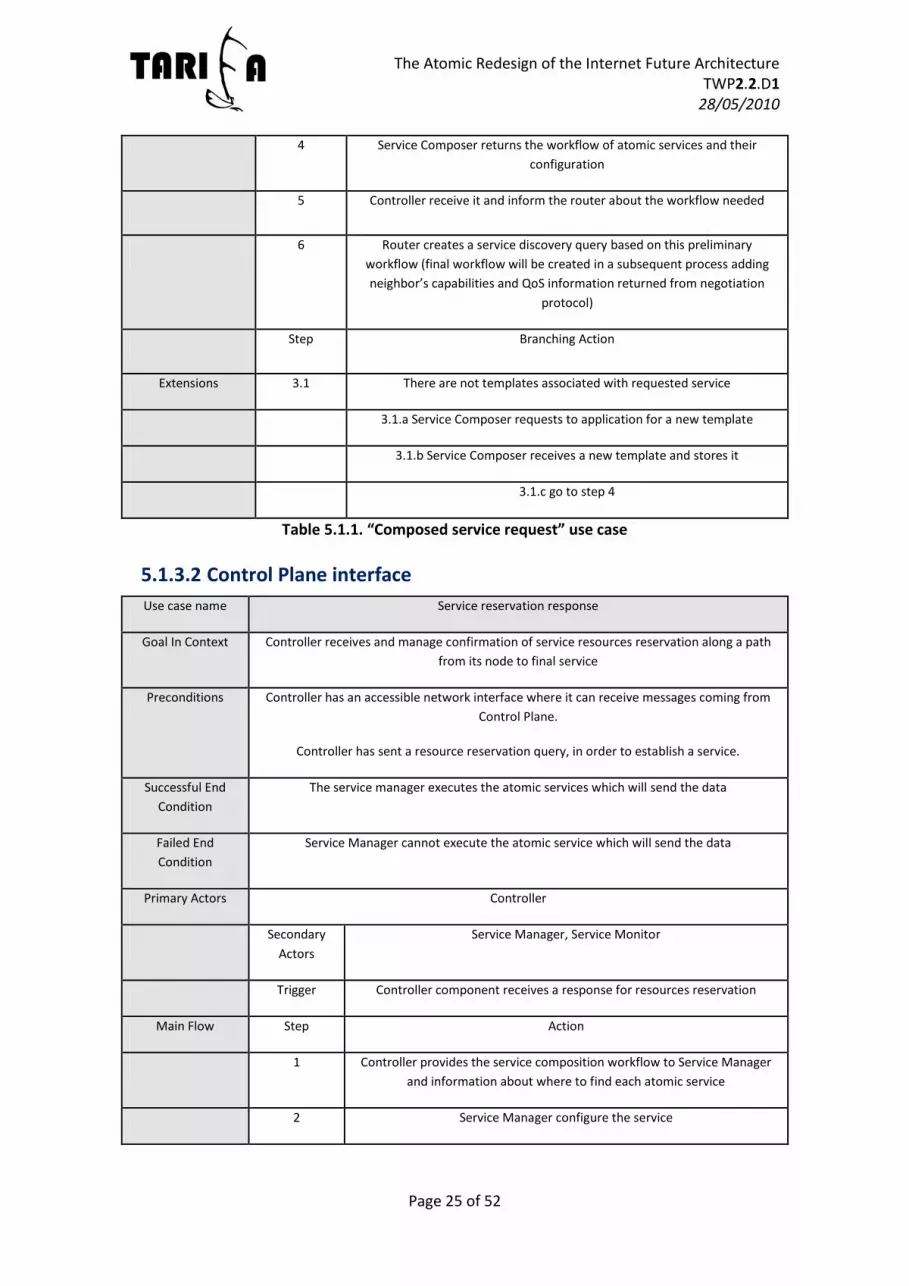
Table 5.1.1. “Composed service request” use case
5.1.3.2 Control Plane interface
Use case name Service reservation response
Goal In Context Controller receives and manage confirmation of service resources reservation along a path
from its node to final service
Preconditions Controller has an accessible network interface where it can receive messages coming from
Control Plane.
Controller has sent a resource reservation query, in order to establish a service.
Successful End
Condition
The service manager executes the atomic services which will send the data
Failed End
Condition
Service Manager cannot execute the atomic service which will send the data
Primary Actors Controller
Secondary
Actors
Service Manager, Service Monitor
Trigger Controller component receives a response for resources reservation
Main Flow Step Action
1 Controller provides the service composition workflow to Service Manager
and information about where to find each atomic service
2 Service Manager configure the service
The Atomic Redesign of the Internet Future Architecture TWP2.2.D1
28/05/2010
Page 26 of 52
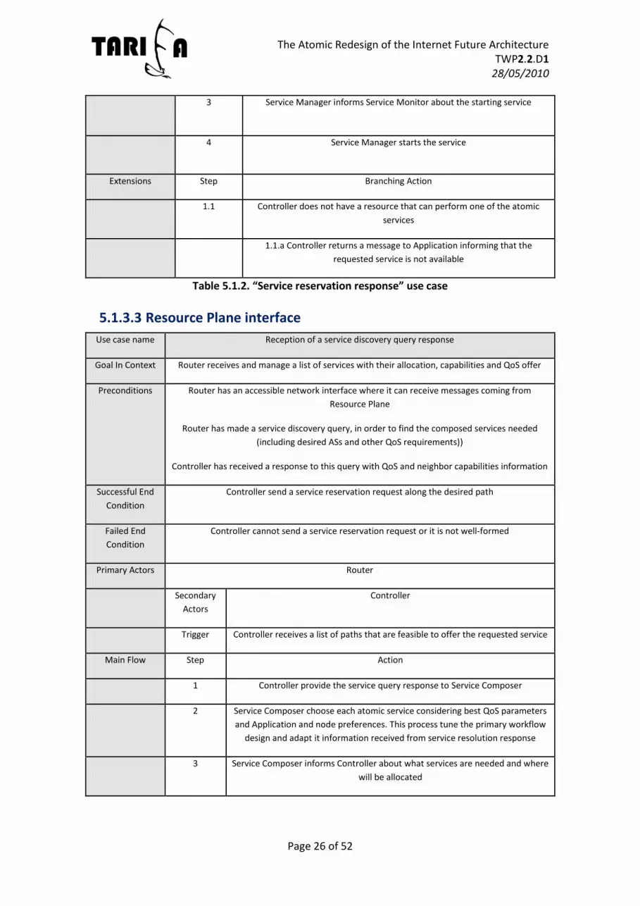
3 Service Manager informs Service Monitor about the starting service
4 Service Manager starts the service
Extensions Step Branching Action
1.1 Controller does not have a resource that can perform one of the atomic
services
1.1.a Controller returns a message to Application informing that the
requested service is not available
Table 5.1.2. “Service reservation response” use case
5.1.3.3 Resource Plane interface
Use case name Reception of a service discovery query response
Goal In Context Router receives and manage a list of services with their allocation, capabilities and QoS offer
Preconditions Router has an accessible network interface where it can receive messages coming from
Resource Plane
Router has made a service discovery query, in order to find the composed services needed
(including desired ASs and other QoS requirements))
Controller has received a response to this query with QoS and neighbor capabilities information
Successful End
Condition
Controller send a service reservation request along the desired path
Failed End
Condition
Controller cannot send a service reservation request or it is not well-formed
Primary Actors Router
Secondary
Actors
Controller
Trigger Controller receives a list of paths that are feasible to offer the requested service
Main Flow Step Action
1 Controller provide the service query response to Service Composer
2 Service Composer choose each atomic service considering best QoS parameters
and Application and node preferences. This process tune the primary workflow
design and adapt it information received from service resolution response
3 Service Composer informs Controller about what services are needed and where
will be allocated
The Atomic Redesign of the Internet Future Architecture TWP2.2.D1
28/05/2010
Page 27 of 52
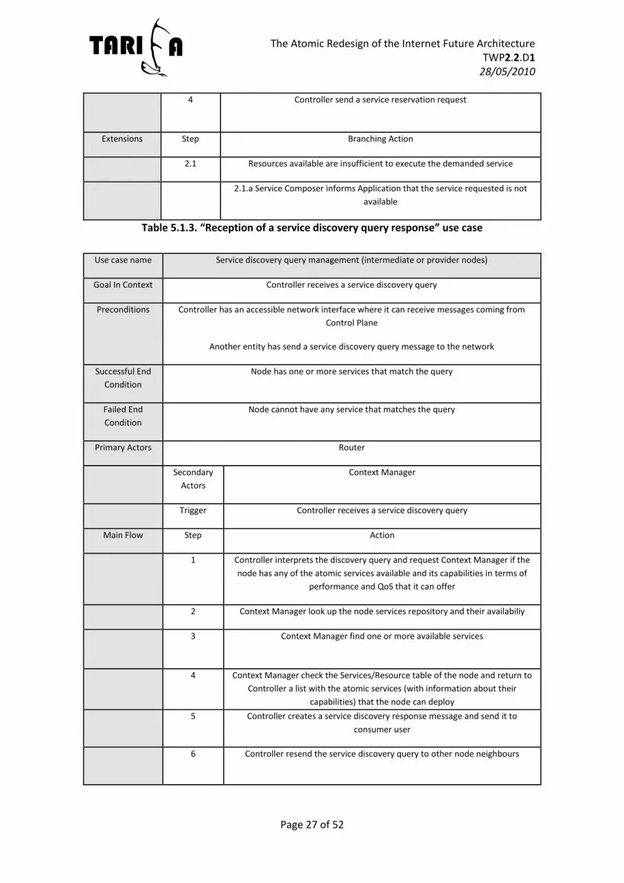
4 Controller send a service reservation request
Extensions Step Branching Action
2.1 Resources available are insufficient to execute the demanded service
2.1.a Service Composer informs Application that the service requested is not
available
Table 5.1.3. “Reception of a service discovery query response” use case
Use case name Service discovery query management (intermediate or provider nodes)
Goal In Context Controller receives a service discovery query
Preconditions Controller has an accessible network interface where it can receive messages coming from
Control Plane
Another entity has send a service discovery query message to the network
Successful End
Condition
Node has one or more services that match the query
Failed End
Condition
Node cannot have any service that matches the query
Primary Actors Router
Secondary
Actors
Context Manager
Trigger Controller receives a service discovery query
Main Flow Step Action
1 Controller interprets the discovery query and request Context Manager if the
node has any of the atomic services available and its capabilities in terms of
performance and QoS that it can offer
2 Context Manager look up the node services repository and their availabiliy
3 Context Manager find one or more available services
4 Context Manager check the Services/Resource table of the node and return to
Controller a list with the atomic services (with information about their
capabilities) that the node can deploy
5 Controller creates a service discovery response message and send it to
consumer user
6 Controller resend the service discovery query to other node neighbours

The Atomic Redesign of the Internet Future Architecture TWP2.2.D1
28/05/2010
Page 28 of 52
Extensions Step Branching Action
3.1 Context Manager cannot find any of the requested atomic services available
3.1.a Context manager returns a negative response to Controller
3.1.b Go to step 6
Table 5.1.4. “Service discovery query management (intermediate or provider nodes)” use
case
5.1.3.4 Service Plane interface
Use case name Service consumption
Goal In Context Service Manager receive data from a service session
Preconditions Service Manager has an accessible network interface where it can receive messages coming
from Service Plane
The service manager has previously established a service and the node is consuming it
The node has a framing/unframing atomic service that extracts relevant information from
data received from Service Plane
Successful End
Condition
Application is receiving the requested service
Failed End
Condition
Application cannot receive the requested service
Primary Actors Service Manager
Secondary
Actors
Service Manager, Application, Service Monitor
Trigger Service Manager receive a data chunk relative to a service
Main Flow Step Action
1 Service Manager provide received information to Service Monitor
2 Service Manager active unframing AS to extract relevant information (not
service control messages)
3 Service Manager distributes relevant information to Application or
Composed Services active for this service session
4 Application and Composed Services process the information
Extensions Step Branching Action
2.1 Service Manager does not find an available unframing AS or it does not
know how to extract information from the received message

The Atomic Redesign of the Internet Future Architecture TWP2.2.D1
28/05/2010
Page 29 of 52
2.1.a Service Manager returns a message error to the service provider
2.1.b Service Manager informs Application or Composed Service that should
have received the information
4.1 Application or Composed Services find that information received is not right
4.1.a They inform Service Manager that an error has occurred
4.1.b Service Manager returns a message error to the service provider
Table 5.1.5. “Service consumption” use case
5.2 Basic communication
5.2.1 Definition
In the second phase of the evolutionary use cases an interconnection of two TARIFA nodes will
be tested. In order to validate it, this connection will start sending an advertisement packet
between two adjacent nodes. This scenario must validate the operation of the preliminary
negotiation protocol defined in [3], establishing a basic connectivity between two nodes.
For this purpose, all node components behaviour should be previously validated in phase 1,
especially those from Controller, Router, and Service Manager. We can see the whole nodes as
the primary actors in this phase, but these node elements cited are the primary actors in
service reservation and service establishment, the fundamental processes of node
intercommunication.
However, additionally in this phase, error control and flow control services in order to test a
reliable transmission of data between two TARIFA nodes that are directly connected. In order
to test it, this connection will be tested for a small packet (e.g. 1500 bytes of an Ethernet MTU)
transmission, in a TCP-like transference. Then, once it is accomplished successfully, the service
information will be incremented, and error control and flow control tests will be done.
Herein, the main goals of this phase are obtaining a trust specification of TARIFA node
communication, polishing up possible arising issues from protocol specification in WP1. And
then, when this basic forwarding data services are assured start demonstrating session
establishments’ processes that handle flow and error control messages.

The Atomic Redesign of the Internet Future Architecture TWP2.2.D1
28/05/2010
Page 30 of 52
Figure 5.2. Phase 2: Basic Communication scenario
5.2.2 Functional requirements Messages arrived from the different planes should follow protocol specification from
WP1.
Node should have implemented Control and Service plane interfaces.
N1 should be able to establish a data transmission service between itself and N2.
Receiver node should monitor the data received and notify the sender if it is has
errors or perceives that it is not what should be.
Sender node should accept flow variation requests from N1.
Sender node should accept retransmission requests and resend claimed information.
5.2.3 Use case tables
Use case name Advertisement messages (context Distribution)
Goal In Context N1 sends an advertisement message to N2
Preconditions N1 and N2 have directly connection between them and they know how to find the other
node
Successful End
Condition
N2 change its neigbor table adapting it to context changes arrived from N1
Failed End Condition N2 cannot change its neigbor table
Primary Actors N1, N2
Secondary Actors -
Trigger N1 controller component sends an advertisement message to N2
Main Flow Step Action
1 N2 controller receives the advertisement message

The Atomic Redesign of the Internet Future Architecture TWP2.2.D1
28/05/2010
Page 31 of 52
2 N2 change its neigbor table adapting it to context changes
Extensions Step Branching Action
2.1 N2 cannot change its neighbor table
Table 5.2.1. “Advertisement messages (context Distribution) ” use case
Use case name Service establishment with 2 nodes
Goal In Context N1 demands for a data service of N2
Preconditions N1 and N2 have directly connection between them and they know how to find the other
node
Successful End
Condition
Data from N2 is transferred to N1 without errors
Failed End Condition Data from N2 is not correctly transferred to N1
Primary Actors N1, N2
Secondary Actors -
Trigger N1 send a service resource reservation request to N2
Main Flow Step Action
1 N2 look for its atomic services availability
2 N2 reserve all atomic services needed to send data to N1
3 N2 send a OK resource reservation response to N1
4 N1 starts the receiving realiable data service
5 N2 starts the forwarding realiable data service
Extensions Step Branching Action
2.1 The required service are not available in N2
2.1.a N2 send a negative resource reservation response
Table 5.2.2. “Service establishment with 2 nodes” use case
Use case name Flow Control with 2 nodes
Goal In Context N1 wants to reduce the throughput of service data sent by N2
Preconditions N1 is receiving a data service from N2

The Atomic Redesign of the Internet Future Architecture TWP2.2.D1
28/05/2010
Page 32 of 52
N1 and N2 have a session control service
N1 is almost at its maximum capacity and can hardly handle data that arrives from N2
Successful End
Condition
N2 reduces its sending throughput
Failed End Condition N2 does not reduce its sending throughput
Primary Actors N1, N2
Secondary Actors -
Trigger N1 send a request to N2 to reduce the data throughput of the
service
Main Flow Step Action
1 N2 receives the request
2 Service Manager of N2 reduces its sending throughput
Extensions Step Branching Action
2.1 N2 cannot reduce its sending throughput
2.1.a N2 advise N1 that it will not reduce the throughput
Table 5.2.3. “Flow Control with 2 nodes” use case
Use case name Error Control / Retransmission with 2 nodes
Goal In Context Some data of the service is lost, N1 perceives it and wants to receive it
Preconditions N1 is receiving a data service from N2
N1 and N2 have a session control service
Successful End
Condition
N2 resends the data previously lost
Failed End Condition N2 cannot resend the data previously lost
Primary Actors N1, N2
Secondary
Actors
-
Trigger N1 send a request to N2 to resend a chunk of data
Main Flow Step Action
1 N2 receives the request
2 Service Manager of N2 requests to the service that provides this data

The Atomic Redesign of the Internet Future Architecture TWP2.2.D1
28/05/2010
Page 33 of 52
3 Service that has generated this data resends it to Service Manager of N2
4 N2 resend the portion of data that was previously lost
Extensions Step Branching Action
3.1 Service that generates this data cannot regenerate this portion of
information lost
2.1.a Service that has generated this data notify to Service Manager of N2
that is impossible to resend it
2.1.b N2 notifies N1 that cannot recover the lost data
Table 5.2.4. “Error Control / Retransmission with 2 nodes” use case
5.3 Forwarding
5.3.1 Definition
This scenario involves two intermediate-nodes and two end-nodes with a single path between
them. This phase should validate the forwarding services of the intermediate nodes and the
forwarding delay introduced by each node, estimating this value and comparing it to values
provided by current networks..
This use case takes the results of the past scenario where we validated the transmission
between two nodes, this case increase the complexity including two intermediate nodes
between the source and the destination in order to check the response time of each node in
the discovery and execution of the service. The intermediate nodes are responsible to discover
the route and resources from the source to the destination for a request. Protocol of discovery
service is lack in this use cases due to we only have an end to end path, however we suppose
that along this path the requirements are satisfied, we use a template that specifies the atomic
services that be used in intermediate nodes along the path (N1 and N2).
This scenario should validate requested service transmission, forwarding delay between nodes,
synchronization and establishment of the end to end communication. Exchange of control
messages and also manage messages will be simulated due to each node must accomplish
specific tasks (execute specific mechanisms) in order to provide a reliable communication. For
this purpose, the node’s operation must be previously validated in phases 1 and 2.

The Atomic Redesign of the Internet Future Architecture TWP2.2.D1
28/05/2010
Page 34 of 52
Figure 5.3 Phase 3: Forwarding scenario
5.3.2 Functional requirements Messages arrived from the different planes should follow protocol specification from
WP1.
Nodes must have implemented Control and Service plane interfaces.
N1 should be able to establish an end to end data transmission service.
Intermediate nodes N3 and N4 should be able to execute specific atomic services required.
N3 and N4 should be able to inform to the neighbourhood about its operation when it is necessary (context aware).
Each node (receiver node) should monitor the received data and notify the sender node if it has errors or perceives if it is not what should be.
Sender node should accept flow variation requests from N1
Sender node should accept retransmission requests and resend claimed information.
5.3.3 Use case tables Use case name Service establishment with 4 nodes
Goal In Context validate the forwarding services of the intermediate nodes
Preconditions N1 demand a composed service request to destination N2,
Intermediate nodes know how find the resources and atomic services to provide end service.
Intermediate nodes execute mechanisms necessaries to stablish service
Successful End
Condition
Application select a workflow that satisfy the requirements and the workflow selected is
successfully executed through the intermediate nodos.
Service is transferred to N1 without errors and with the QoS arranged by the involved nodes.
Failed End
Condition
Service cannot be establish
Intermediate node dont contain the neccesary atomic services
Network cannot satisfy the application request (delay between nodes)
Service is established/executed but it is not satisfy the requirements.

The Atomic Redesign of the Internet Future Architecture TWP2.2.D1
28/05/2010
Page 35 of 52
Primary Actors N1, N2, N3, N4
Secondary Actors -
Trigger N1 send a request of service
Main Flow Step Action
1 Intermediate nodes look for route that contain the
neccesary atomic services to provide the requested
service
2 N3 informs about services that can provide
3 N4 informs about services that can provide
4 N2 node broadcasts all possible workflows to the
requesting node
5 The requestor node (N1) selects the best route
among the discovered ones.
6 Each node executed specific atomic service based on
workflow selected and reserve the resources.
7 N2 starts the forwarding realiable data service
Extensions Step Branching Action
5.1 The required service are not available in N2
5.1.a N2 send a negative resource reservation
response to all nodes (N3,N4, and N1)
Table 5.3.1. “Service Establishment with 4 nodes” use case
Use case name Flow Control with 4 nodes
Goal In Context N1 or intermediate nodes wants to reduce the throughput of service data sent by N2
Preconditions N1 is receiving a data service from N2 through intermediate nodes.
All nodes have a session control service
N1, N3 or N4 is almost at its maximum capacity and can hardly handle data that arrives
from other node.
Successful End N2, N3 or N4 reduces its sending throughput

The Atomic Redesign of the Internet Future Architecture TWP2.2.D1
28/05/2010
Page 36 of 52
Condition
Failed End Condition N2, N3 or N4 does not reduce its sending throughput and there are loss packets.
Primary Actors N1, N2, N3 and N4
Secondary
Actors
-
Trigger N1, N3 or N4 send a request to their direct neigbour node to reduce the
data throughput of the service
Main Flow Step Action
1 N2, N3 or N4 receives the request
2 N2, N3 or N4 reduces their sending throughput
Extensions Step Branching Action
2.1 N2, N3 and N4 cannot reduce their sending throughput
2.1.a N2, N3 and N4 advise their direct neigbour node that it will not
reduce the throughput.
Table 5.3.2. “Flow Control with 4 nodes” use case
Use case name Error Control / Retransmission with 4 nodes
Goal In Context Some data of the data service is lost, N1, N3 or N4 perceives it and wants to receive it
again
Preconditions N1, N3 or N4 is receiving a data service from its direct neigbour node
Nodes have a session control service among them.
Successful End
Condition
Interested node resends the data previously lost
Failed End Condition N2, N3 or N4 cannot resend the data previously lost
Primary Actors N1, N2, N3 and N4
Secondary
Actors
-
Trigger N1, N3 or /and N4 send a request to its neigbour to resend a chunk of
data
Main Flow Step Action
1 N2, N3 or/and N4 receives the request
2 Nodes (N2, N3 or/and N4) requests to the service that provides this
data

The Atomic Redesign of the Internet Future Architecture TWP2.2.D1
28/05/2010
Page 37 of 52
3 Service that has generated this data resends it to the node (s ) that
realized the petition.
4 N2, N3 or/and N4 resend the portion of data that was previously lost
Extensions Step Branching Action
3.1 Service that generates this data cannot regenerate this portion of
information lost
3.1.a Service that has generated this data notify to node (s) that is
impossible to resend it
3.1.b N2, N3 or N4 notifies to their neigbour that cannot recover the
lost data
Table 5.3.3. “Error Control / Retransmission with 4 nodes” use case
5.4 Routing and network configuration
This scenario involves six to eight mesh-connected intermediate-nodes and two end-nodes connected to one of these intermediate-nodes. This phase should validate the routing process using TARIFA nodes. It also introduces fault recovery tests in a small network by linking down some of the service path links, measure the recovery time in simulation (and estimate a real recovery time if necessary).
5.4.1 Definition In phase four of the Use Case Evolutionary the intra-domain interconnection between two TARIFA nodes will be simulated. This scenario is an evolution of the scenarios previously defined in which the most basic functions were validated, which are necessary to test this scenario. The main objective of this scenario is to test the service discovery dynamically on intra-domain network. Then, once the communication between the two nodes is established, a link that affects the communication between the two nodes will be downed with the aim of measuring the time that it takes to re-establish the communication. In turn, an overload on a link that affects the communication between the two nodes will be made in order to degrade the communication with the objective that the intermediate node(s) that are affected and involved in the communication redirect their flow so as to continue to comply with the service.
Figure 5.4. Phase 4: Routing and network configuration scenario

The Atomic Redesign of the Internet Future Architecture TWP2.2.D1
28/05/2010
Page 38 of 52
5.4.2 Functional requirements N2 publishes the services and/or contents that provides.
N1 searches for services and/or contents.
N3-N10 distribute the N2’s services and/or contents.
N3-N10 search for services and/or contents requested by N1 node.
N3-N10 retransmit the data generated by N1 and N2.
5.4.3 Use case tables Use case name Service establishment for single path service
Goal In Context N1 searches a service and N2 provides it.
Preconditions All the nodes and links are actives and their neighbour tables are filled properly
Successful End
Condition
Data from N2 is transferred to N1 without errors
Failed End
Condition
Cannot establish the communication between N1 and N2
Primary Actors N1, N2, N3, N5, N7, N9, N10
Secondary
Actors
Trigger N2 sends to N10 the services and/or contents that provides
Main Flow Step Action
1 N10 distributes inside the “Domain A” those services and contents
2 N1 sends a request to N3 for a specific service
3 N3 finds locally who provide that service
4 N3 concretizes (using Resource Plane information) which are the best paths
available to provide the service and send it to N1
5 N1 triggers a path configuration to N2, it contains the resources reservation
necessary to provide that service
6 N3 reserves the resources and forwards the request to N5
7 N5 reserves the resources and forwards the request to N7
8 N7 reserves the resources and forwards the request to N9
9 N9 reserves the resources and forwards the request to N10
10 N10 reserves the resources and forwards the request to N2

The Atomic Redesign of the Internet Future Architecture TWP2.2.D1
28/05/2010
Page 39 of 52
11 N2 look for its atomic services availability
12 N2 reserve all atomic services needed to send data to N1
13 N2 send a OK resource reservation response to N1
14 N1 starts the receiving reliable data service
15 N2 starts the forwarding reliable data service
Extensions Step Branching Action
1 3.1 N3 does not find locally who provides that service, forwards the request
through the network and waits for a response
3.1.a N3 receives the possible paths to the service
3.1.b Returns to step 4
2 12.1 The required service are not available in N2
12.1.a N2 send a negative resource reservation response
Table 5.4.1. “Service establishment for single path service” use case
Use case name Service establishment for a multi-path service
Goal In Context N1 searches for a service and N2 provides it
Preconditions All the nodes and links are active
Successful End
Condition
Data from N2 is transferred to N1 without errors
Failed End
Condition
The communication between N1 and N2 cannot be established
Primary Actors N1, N2, N3, N4, N5, N6, N7, N8, N9, N10
Secondary
Actors
Trigger N2 sends to N10 the services and/or contents that provides
Main Flow Step Action
1 N10 distributes inside the “Domain A” those services and/or contents
2 N1 sends to N3 a request for a specific service
3 N3 finds locally who provides that service

The Atomic Redesign of the Internet Future Architecture TWP2.2.D1
28/05/2010
Page 40 of 52
4 N3 concretizes (using Resource Plane information) which are the best paths
available to provide the service and send it to N1
5 N1 triggers several path configurations to N2, it contains the resource
reservation necessary to provide that service
6 N3 reserves the resources and forwards the request to N5
N4 reserves the resources and forwards the request to N6
7 N5 reserves the resources and forwards the request to N7
N6 reserves the resources and forwards the request to N8
N7 reserves the resources and forwards the request to N9
N8 reserves the resources and forwards the request to N10
N9 reserves the resources and forwards the request to N10
N10 reserves the resources and forwards the request to N2
N2 look for its atomic services availability
N2 reserve all atomic services needed to send data to N1
N2 send a OK resource reservation response to N1
N1 starts the receiving reliable data service
N2 starts the forwarding reliable data service
Extensions Step Branching Action
1 3.1 N3 does not find locally who provides that service, forwards the request
through the network and waits for a response
3.1.a N3 receives the possible paths to the service
3.1.b Returns to step 4
2 12.1 The required service are not available in N2
12.1.a N2 send a negative resource reservation response
Table 5.4.2. “Service establishment for a multi-path service” use case
Use case name Network reaction facing a path degradation
Goal In Context Adapt the data flow due to a service degradation
Preconditions There is a communication established between N1 and N2

The Atomic Redesign of the Internet Future Architecture TWP2.2.D1
28/05/2010
Page 41 of 52
The degradation is produced between N3 and N5
Successful End
Condition
An alternative path that fulfils all the requirements necessaries to continue with the service
is found
Failed End
Condition
An alternative path that fulfils all the requirements necessaries to continue with the service
is not found
Primary Actors N1, N2, N3, N4, N5, N7, N9, N10
Secondary
Actors
Trigger N1 detects that the service is degraded and sends a notification to N3 to
find an alternative path
Main Flow Step Action
1 N3 verifies if the degradation is produced with N5
2 N3 searches for an alternative paths that fulfils the service’s requirements
3 N3 finds locally alternative paths
4 N3 sends the possible paths to the service to N1
5 N1 triggers a path configuration to N2, it contains the resource reservation
necessary to provide the service
6 N3 reserve and forwards the request to N4
7 N4 reserve and forwards the request to N7
8 N7 confirms the resource reservation to N4 and reroute de data
9 N4 confirms the resource reservation to N3 and reroute de data
Extensions Step Branching Action
1 3.1 N3 does not find locally who provides that service, forwards the request
through the network and waits for a response
3.1.a N3 receives the possible paths to the service
3.1.b Returns to step 4
2 3.2 N3 does not find an alternative path
3.2.a The service is put down and the resources are freed
Table 5.4.3. “Network reaction facing a path degradation” use case
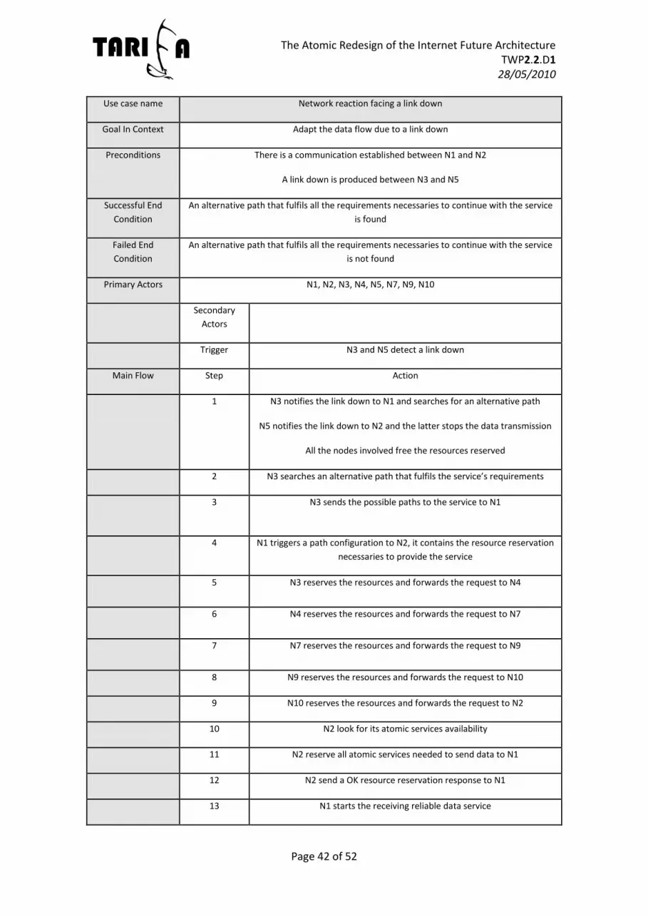
The Atomic Redesign of the Internet Future Architecture TWP2.2.D1
28/05/2010
Page 42 of 52
Use case name Network reaction facing a link down
Goal In Context Adapt the data flow due to a link down
Preconditions There is a communication established between N1 and N2
A link down is produced between N3 and N5
Successful End
Condition
An alternative path that fulfils all the requirements necessaries to continue with the service
is found
Failed End
Condition
An alternative path that fulfils all the requirements necessaries to continue with the service
is not found
Primary Actors N1, N2, N3, N4, N5, N7, N9, N10
Secondary
Actors
Trigger N3 and N5 detect a link down
Main Flow Step Action
1 N3 notifies the link down to N1 and searches for an alternative path
N5 notifies the link down to N2 and the latter stops the data transmission
All the nodes involved free the resources reserved
2 N3 searches an alternative path that fulfils the service’s requirements
3 N3 sends the possible paths to the service to N1
4 N1 triggers a path configuration to N2, it contains the resource reservation
necessaries to provide the service
5 N3 reserves the resources and forwards the request to N4
6 N4 reserves the resources and forwards the request to N7
7 N7 reserves the resources and forwards the request to N9
8 N9 reserves the resources and forwards the request to N10
9 N10 reserves the resources and forwards the request to N2
10 N2 look for its atomic services availability
11 N2 reserve all atomic services needed to send data to N1
12 N2 send a OK resource reservation response to N1
13 N1 starts the receiving reliable data service

The Atomic Redesign of the Internet Future Architecture TWP2.2.D1
28/05/2010
Page 43 of 52
14 N2 starts the forwarding reliable data service
Extensions Step Branching Action
3.1 N3 does not find locally who provides that service, forwards the request
through the network and waits for a response
3.1.a N3 receives the possible paths to the service
3.1.b Returns to step 4
3.2 N3 does not find an alternative path
3.2.a The services is put down
2 11.1 The required service are not available in N2
11.1.a N2 send a negative resource reservation response
Table 5.4.4. “Network reaction facing a link down” use case
5.5 End-to-end inter-domain communication
5.5.1 Definition
Fifth and sixth phases propose very ambitious scenarios but that could be helpful in comparing
services operation over current networks and a TARIFA network. The fifth phase will simulate a
FTP connection from a user to a content provider. Content provider will receive a request for a
specific content and it will provide it to the user using a reliable connection. In this scenario,
two ISPs will be also simulated (as a bigger example of the previous case scenario). Hence, it is
the first scenario where an inter-domain communication in TARIFA architecture will be tested.
Figure 5.5. Phase 5: FTP scenario
FTP service should also define two content providers (mirror 1 and mirror 2) belonging to the
same service provider. In that sense, tests of service recovery will be done. We will link down
mirror 1 (M1) from content service provider segment, in order to prove the automatic

The Atomic Redesign of the Internet Future Architecture TWP2.2.D1
28/05/2010
Page 44 of 52
reconnection to mirror 2 (M2) and the recovery of the service without losing information and
in a transparent way to the consumer user (U1).
Actors participating in this set of use cases will be a consumer user, two ISPs that have to
manage the network knowledge and consumer and provider access. It is important to point
out that for this case, we need to know and check how to abstract a domain as a node and
what information is exposed to other domain. These are questions that should be resolved
previously by the WP 3, 4 and 5 developments, and they should be tested and evaluated
before attempting this case.
Besides, accounting services in each domain will be provided by ISP and will be simulated in
this phase.
This scenario should validate an inter-domain communication, the management of planes
information between different domains and test a content service offer and provision to a
different domain consumer user.
5.5.2 Functional Requirements Messages arrived from the different planes should follow protocol specification from
WP1.
N1 and CP node must have implemented Control and Service Plane interfaces.
N1 and CP node must have selected a specific workflow for file transference
application.
CP must be able to manage the file transference session.
U1 should be able to establish and terminate a FTP-like session with CP.
ISP and Service provider must agree QoS parameters in order to guarantee a good
communication experience
Quality of service: must guarantee a maximum throughput and a minimum number of
retransmissions over the duration of the file transference session despite the variation
in channel conditions.
5.5.3 Use case tables
Use case name Reliable content transmission (session establishment + transmission + session closed)
Goal In Context U1 and CP establish a FTP session
Preconditions U1 has installed the FTP application
U1 are registered into the CP registry
CP is available to start the file-transfer service
The FTP service is already known by U1 application.
CP and ISPA and ISPB have agreed an SLA for providing certain levels of QoS for file
transference applications

The Atomic Redesign of the Internet Future Architecture TWP2.2.D1
28/05/2010
Page 45 of 52
Successful End
Condition
U1 has started and closed the session with CP
U1 has access and downloaded a specific file of CP
CP has billed U1
Failed End
Condition
The connection could not be established
The connection terminated unexpectedly
The file is not accessible or not transfered correctly
Primary Actors U1, CP
Secondary Actors ISP
Trigger U1 wants to establish a file transfer session with CP.
U1 application sends a session establishment
message to CP
Main Flow Step Action
1 Establishment U1-CP: CP receives a session
establishment message through the service plane
2 CP notifies U1 that it has connection to FTP service
and sends its repository information
3 U1 demands for a specific file
4 CP sends the file to U1
5 U1 starts receiving file from CP
6 U1 notices that file is completely download
6 U1 sends a terminate session message to CP.
7 CP receives the terminate session message sent by
U1. CP updates the session status and stops
accounting resources
Extensions Step Branching Action
1.1 ISP reserves and establishes a path between U1 an
CP. ISP starts accounting the used resources in the
communucation between them (border nodes)
Table 5.5.1. “Reliable content transmission” use case
Use case name Connection lost with FTP Mirror 1 (Service recovery)
Goal In Context U1 and CP-M2 restablish a FTP session when connection between U1 and CP-M1 is lost

The Atomic Redesign of the Internet Future Architecture TWP2.2.D1
28/05/2010
Page 46 of 52
Preconditions U1 has installed the FTP application
U1 are registered into the CP registry
CP is available to start the file-transfer service
The FTP service is already known by U1 application.
CP and ISPA and ISPB have agreed an SLA for providing certain levels of QoS for file
transference applications
U1 and CP-M2 have a session established and a file transference service is in process
Successful End
Condition
U1 has restablished the session with CP-M2 after lost connection with M1
U1 continues downloading a specific file of CP without losing the service
Failed End
Condition
Service could not be restablished
File transfer ongoing process is lost
Primary Actors CP-M1, CP-M2, U1
Secondary Actors ISP
Trigger U1 lose connection with CP-M1
Main Flow Step Action
1 U1 make a request to restablish the service with CP-
M1
2 ISPB redirect request to CP-M2
3 U1 restablish the service with CP-M2
4 CP-M2 recognize the request and restablish the
service with U1
5 U1 send a request for recover the file transferce
process that was receiving
4 U1 starts to receive from CP-M2 the file that was
previously receiving from CP-M1
Extensions Step Branching Action
3.1 ISP reserves and establishes a path between U1 an
CP. ISP restarts accounting the used resources in the
communucation between them (border nodes)
Table 5.5.2. “FTP-connection lost” use case

The Atomic Redesign of the Internet Future Architecture TWP2.2.D1
28/05/2010
Page 47 of 52
5.6 Delay-critical multimedia communication
5.6.1 Definition
This sixth phase is the last phase proposed in the evolutionary use case. Here, it will simulate a
videoconference connection between two users: user 1 (U1) and user 2 (U2). U1 is accessing
from Node 1 (N1) connected via domain A while U2 is accessing from Node 2 (N2) via domain
B. U1 will take the role of caller and U2 will act as called. Both have the corresponding
videoconference applications installed in their devices.
In this scenario, there is also a videoconference service provider. This provider will receive
requests from both users demanding for a videoconference, connect them, and manage the
session messages and conference synchronization. That is, it will manage all videoconferences
registered in the service it provides.
Figure 5.6. Phase 6: Videoconference scenario
This phase requires that all previous phases must be validated. However, in this scenario, the
participating actors are the following ones:
ISP: provides connectivity to each user and provides QoS according to the service
requirements
Consumer User: there are two consumers (U1 and U2) of the videoconference service
Videoconference Service Provider (VSP): implements all the management, accounting
and billing services required to provide the videoconference service.
Accounting service Provider, from ISP and VSP.
The main goal of the sixth phase is to test a delay-critical communication over TARIFA
architecture in a typical conference scenario, evaluating the QoS/QoE that users receive of this
service.

The Atomic Redesign of the Internet Future Architecture TWP2.2.D1
28/05/2010
Page 48 of 52
5.6.2 Functional Requirements Messages arrived from the different planes should follow protocol specification from
WP1.
N1 and N2 must have implemented Service Plane interfaces.
N1 and N2 must have selected a specific workflow for videoconference application
U1 should be able to establish and terminate a videoconference session with U2.
U1 and U2 must be able to transmit audio and video simultaneously all along the
established path.
VSP must be able to manage the videoconference session.
ISP and Service provider must agree QoS parameters in order to guarantee a good
communication experience
End-to-end delay: delays longer than 400 milliseconds are not accepted (ITU-T
recommendation G.114 [6]) in order to guarantee fluid interactivity among them. A
one-way transmission delay of 150ms is considered to offer the same experience as
using PSTN.
Bandwidth constraint: the stream rate must not exceed the channel capacity
available.
Quality of service: must guarantee a minimum decoded video and audio quality and a
maximum transmission error rate over the duration of the streaming session despite
the variation in channel conditions.
5.6.3 Use case tables
This use case table specifies the required steps to establish a videoconference between two
nodes. No failures are considered. All application signalling and data messages are sent
through the service plane.
Use case name Videoconference session (session establishment + transmission + session closed)
Goal In Context U1 and U2 establish a videoconference session
Preconditions U1 and U2 have installed the videoconference application
U1 and U2 are registered into the VSP registry
U1 and U2 are available to start the videoconference service
The videoconference service is already known by U1 and U2 applications.
VSP and ISP has agreed an SLA for providing certain levels of QoS for videoconference
applications
Successful End
Condition
U1 and U2 have maintained a videoconference for a certain time
VSP has started and closed the session between U1 and U2
VSP has billed U1 and U2
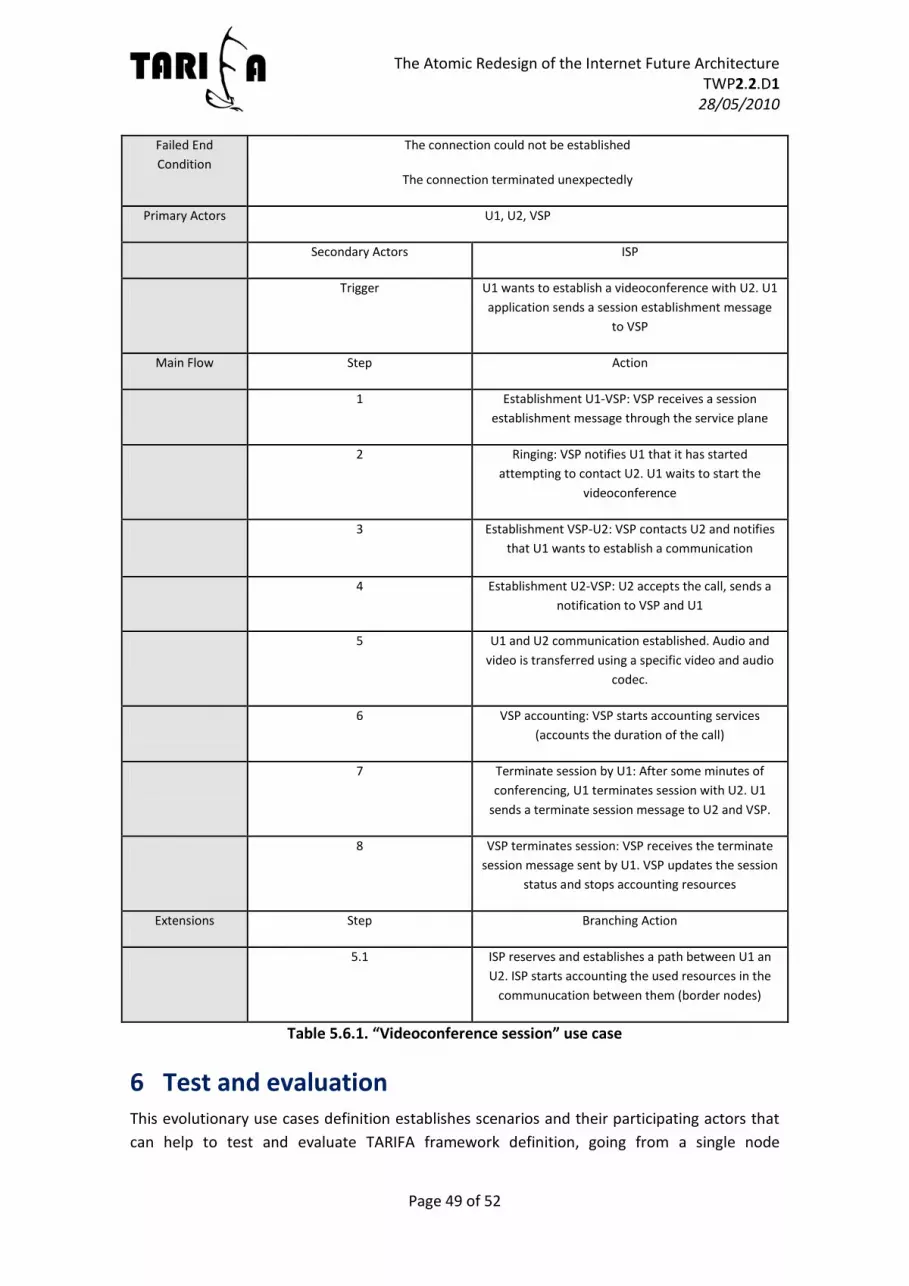
The Atomic Redesign of the Internet Future Architecture TWP2.2.D1
28/05/2010
Page 49 of 52
Failed End
Condition
The connection could not be established
The connection terminated unexpectedly
Primary Actors U1, U2, VSP
Secondary Actors ISP
Trigger U1 wants to establish a videoconference with U2. U1
application sends a session establishment message
to VSP
Main Flow Step Action
1 Establishment U1-VSP: VSP receives a session
establishment message through the service plane
2 Ringing: VSP notifies U1 that it has started
attempting to contact U2. U1 waits to start the
videoconference
3 Establishment VSP-U2: VSP contacts U2 and notifies
that U1 wants to establish a communication
4 Establishment U2-VSP: U2 accepts the call, sends a
notification to VSP and U1
5 U1 and U2 communication established. Audio and
video is transferred using a specific video and audio
codec.
6 VSP accounting: VSP starts accounting services
(accounts the duration of the call)
7 Terminate session by U1: After some minutes of
conferencing, U1 terminates session with U2. U1
sends a terminate session message to U2 and VSP.
8 VSP terminates session: VSP receives the terminate
session message sent by U1. VSP updates the session
status and stops accounting resources
Extensions Step Branching Action
5.1 ISP reserves and establishes a path between U1 an
U2. ISP starts accounting the used resources in the
communucation between them (border nodes)
Table 5.6.1. “Videoconference session” use case
6 Test and evaluation This evolutionary use cases definition establishes scenarios and their participating actors that
can help to test and evaluate TARIFA framework definition, going from a single node

The Atomic Redesign of the Internet Future Architecture TWP2.2.D1
28/05/2010
Page 50 of 52
operation, planes deployment and validating the communication between two nodes from
basic context exchange to service establishments.
Use cases (evolutionary and revolutionary) also pretend to test that our approach is almost
equivalent in some network technical parameters such as delays, throughputs, loses, etc. and
more efficient and flexible in some other aspects that were not originally addressed by current
Internet, offering the possibility to obtain network resource information from what today are
the upper layers of OSI model. It should permit functionalities not considered in the original
design of current Internet and the extension to future requirements.
However, not all of these new characteristics will be explicitly demonstrated in this set of
evolutionary use case. We think that validate architecture and protocol definition is already a
very ambitious goal and evolutionary use cases will not to try to go far beyond that. Hence,
these use cases are defined taking into account that they will be the main tools to identify
design errors and polish architecture and protocol definition, assuring that all processes are
correctly defined.
As a result, besides the validation of the test cases defined in this document, we propose the
additional measurements in order to evaluate key aspects of the architecture and to make
some type of comparisons with current Internet architecture/services:
End to end measurements:
o Service reception delay: It is the time passed from an application demand for a
composed service to start receiving the service. It could be divided as the sum
of the following parameters (plus propagation delay):
Service composition delay: Time spent by service composer creating a
workflow that fits with the composed service demanded. In these
cases it will be used predefined templates, so this time will be
simplified. Run-time context-aware composition and adaptation will
be evaluated deeply in revolutionary use cases
Service discovery delay: Time spent from sending a service discovery
query from the router to receive a response with all atomic services
offers.
Service reservation delay: Time spent from sending a service resource
reservation call from the controller to receive a response.
Service establishment delay: Time spent by service manager to
configure correctly the service and start communication.
o Recovery time (see Figure 1.1):
S1 fault: Once a service is established and it is consumed by node N1
S1 segment is linked down. This measure evaluates the time that the
node spent recovering the service from this fault. Origin node has to
search for another access network and re-establish the service.
S2/S3/S4 fault: This fault evaluates the time that network spent
searching for another equivalent service by linking down service

The Atomic Redesign of the Internet Future Architecture TWP2.2.D1
28/05/2010
Page 51 of 52
provider segments. It measures the time from a Service provider
segment fault to the recovery of the service in the consumer node.
ISPA fault: It evaluates the convergence time of the ISP network when
a link is broken.
POI1 fault: It evaluates the capacity of border nodes reconfiguration
when one of their points of interconnection is down between domain
A and domain B.
o Throughput: Measure of the throughput achieved in each service transmission
use case.
o Loses: Measure of the BER achieved in each service transmission use case.
Other additional metrics considered for this parameter are the number of
retransmissions or the number of lost data chunks, depending on the use case.
o Overhead: Overhead will also be evaluated for short and long transmissions,
taking into account total service and control data to establish and manage the
service divide by the data that are really true information of the service.
Other measurements:
o Average time to access the routing table: It measures the time that nodes
spent consulting the routing table, as an approach to measure the
simplification of routes and routing tables in TARIFA approach.
7 Conclusions In this document we have defined the TARIFA evolutionary use cases, which should be
developed in WP3-5 and integrated together in WP7. These cases will be the main tool for
evaluate the benefits of our approach and identify wrong assumptions or bad design in some
aspects. Thus, the development of these cases may suggest some corrections to the
architecture definition. Additionally, other test cases could be added to test TARIFA framework
even before starting these use cases. Having said that, these cases are not the only
development of WP 3, 4 and 5 and other test cases will also be considered by each of the WP
in order to achieve specific WP goals.
Moreover, they should evaluate the communication of TARIFA nodes and their performance in
a small-medium network, somehow comparing its characteristics with current networks.
However, this document is not completely definitive and could be subject to changes and
revisions during the project duration to adapt it to changes in the architecture or the
simulation tool used, if necessary.
8 References [1] X. Sánchez, J. Paradells, A.J. Gonzalez, Y. Jiménez, M. Germán, and R. Martín de Pozuelo,
“TARIFA deliverable TWP1.1.D1: Architecture Definition,” May. 2010. [2] K. Tutschku and G. Haring, “How to Evaluate and Compare Architectures:
State of the Art and Beyond,” Valencia: 2010. [3] X. Sánchez and J. Paradells, “TARIFA deliverable TWP1.2.D1: Service discovery, negotiation
and reservation protocol specification,” May. 2010.

The Atomic Redesign of the Internet Future Architecture TWP2.2.D1
28/05/2010
Page 52 of 52
[4] Albert Vidal et al., “TARIFA project definition,” 2009. [5] E.K. Lua, J. Crowcroft, M. Pias, R. Sharma, and S. Lim, “A survey and comparison of peer-to-
peer overlay network schemes,” IEEE Communications Surveys & Tutorials, vol. 7, 2005, pp. 72–93.
[6] ITU-T, “Rec G.114: 'One-way transmission time',” , 1996.
Recommended


