O P E R A T I O N & M A I N T E N A N C E M A N U A L F E B R U A R Y 2 0 2 2
T H E T R A I L E R I N F R O N T
A G R I C U L T U R A L & C O N T R A C T T I P P E R SA R A B L E & R O O T C R O P T R A I L E R S
B A L E & P A L L E T T R A I L E R SL O W L O A D E R S F U E L B O W S E R S W A T E R B O W S E R
2
O P E R AT I O N & M A I N T E N A N C E M A N UA L
The Bailey range of trailers is supplied with a full two year warranty from the date of despatch from the factory.
Any malfunctioning equipment, omissions or deviations from the original specification, must be reported to Bailey Trailers Ltd within 7 days of the delivery to the dealer.
Any damage sustained in transport must be reported to the delivery agent or transport company.
There are some exclusions, namely:-
Wheels and tyres, damage caused by misuse and abuse, damage caused by overloading.
For full details refer to the manufacturer’s warranty documentation.
Warranty procedure
If you have a claim under warranty contact the manufacturer’s agent, from whom you purchased the trailer, quoting the model and serial number.
Do not delay, as you should realise that further or excessive damage caused by delaying the repair of an otherwise warrantable failure may mean the claim cannot be fully accepted.
Our continuous improvement policy means that you should provide your dealer with as much information as possible relating to the failure, for example the length of haul, type of material, towing vehicle etc. as this will help to diagnose the cause of any failure.
Note: normal maintenance and servicing routines are not covered by warranty.
No warranty repairs are to be carried out without prior authorisation and the issuing of a claim number from Baileys’ warranty department.
After the repairs are completed a warranty claim can be submitted to Baileys’ warranty department for consideration. Any new parts supplied relevant to the claim will be invoiced at full retail value and then credited after the faulty material has been returned and the warranty claim approved.
WA R R A N T Y
N O T E S
3
O P E R AT I O N & M A I N T E N A N C E M A N UA L
Make a note of the trailer serial number in this box for future reference and when ordering replacement parts.
It is the responsibility of the operator to read and understand the contents of this manual before operating the trailer for the first time.
The operators manual must accompany the trailer at all times. If the trailer is resold the operators manual must be given with the trailer to the new owners.
ManufacturerManufacturers name : Bailey Trailers LtdManufacturers address : Pride Parkway, Sleaford, Lincolnshire NG34 8GL Tel: +44 (0) 1529 303411 baileytrailers.co.uk
How to use this manual
Before use of the trailer familiarise yourself with the manual and its contents. The trailer may only be operated, serviced and repaired by persons who are familiar with the trailer and who have read and understood this manual, and are informed of the risks.
Modifications to the trailer (including the fitment of non original/non approved parts or attachments) without the specific approval of the manufacturer, exclude the manufacturer from any liability or damage resulting from the modifications. Failure to follow the procedures given in this manual could invalidate the warranty given.
The operator and user must read this manual fully before commencing work with or transporting the trailer. If the operator or user does not understand any part of this manual further help and advice is available from the manufacturer or from the manufacturers agent shown above.
WARNING
Agent
4
O P E R AT I O N & M A I N T E N A N C E M A N UA L
C O N T E N T S
Warranty 02Exclusions and procedures 02
Introduction 05
Safety decals 06Safety decals 06
Location of safety decals 07
Legal requirements 09Identification plate 09Operating on public roads 09Road transport 09Disposal of trailer 09
General safety 10Before operating the trailer 10
General hazard perception and safety 10
Specifications 17 General 17Water Bowser 18TB 19Root Special 20Beeteaper 21Ejector 22High Lift 23Bale & Pallet 24Agricultural Dumper 25Contract Dumper 26Contract Tipper 27Low Loaders 28Low Loaders - Beavertail 29Low Loaders - Flat Deck 30Dropsides 31
Before operation 32Checks 32Transportation & handling 33Coupling to towing vehicle – hitch 34Coupling to towing vehicle – air brakes 35Coupling to towing vehicle – hydraulic brakes 35ABS connections 35Coupling to towing vehicle – hydraulic connections 36Adjusting sprung drawbar height 37Adjustments before towing the trailer 37
Operation 38Loading the trailer 38Moving off 38Tipping the trailer 39Reversing the trailer 40Examples of foreseen misuse 41
Maintenance & service schedules 42Service schedules 42Grease points 44Service checks 46Axles & brakes 48Tightening wheel nuts 48Greasing hub bearings 49Checking hub bearings 50Suspension maintenance 50Adjusting hub bearings 51Brake maintenance and adjustment 52Two-line air braking system 53Tyre pressures 68Recommended lubricants 68Laying up & long term storage 68
Additional information 69Rollover Sheet operation 69Low loading trailers equipment 70Fuel Bowser operation 72EU declaration of conformity 74
5
O P E R AT I O N & M A I N T E N A N C E M A N UA L
I N T R O D U C T I O N
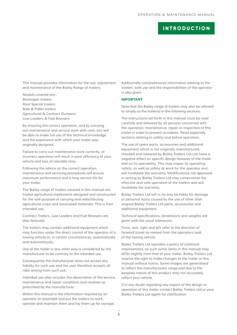
This manual provides information for the use, adjustment and maintenance of the Bailey Range of trailers.
Models covered are:-Beeteaper trailersRoot Special trailersBale & Pallet trailersAgricultural & Contract DumpersLow Loaders & Fuel Bowsers
By ensuring the correct operation, and by carrying out maintenance and service work with care, you will be able to make full use of the technical knowledge and the experience with which your trailer was originally designed.
Failure to carry out maintenance work correctly, or incorrect operation will result in poor efficiency of your vehicle and loss of valuable time.
Following the advice on the correct operation, maintenance and servicing procedures will ensure maximum performance and a long service life for your trailer.
The Bailey range of trailers covered in this manual are trailed agricultural implements designed and constructed for the sole purpose of carrying and redistributing agricultural crops and associated materials. This is their intended use.
Contract Trailers, Low Loaders and Fuel Bowsers are also featured.
The trailers may contain additional equipment which may function under the direct control of the operator of a towing vehicle or, in certain circumstances, automatically and autonomously.
Use of the trailer in any other way is considered by the manufacturer to be contrary to the intended use.
Consequently the manufacturer does not accept any liability for such use and the user therefore accepts all risks arising from such use.
Intended use also includes the observation of the service, maintenance and repair conditions and routines as prescribed by the manufacturer.
Within this manual is the information required by an operator to assemble and put the trailers to work, operate and maintain them and lay them up for storage.
Additionally comprehensive information relating to the trailers’ safe use and the responsibilities of the operator is also given.
IMPORTANT
Note that the Bailey range of trailers may also be referred to simply as the trailer(s) in the following sections.
The instructions set forth in this manual must be read carefully and followed by all persons concerned with the operation, maintenance, repair or inspection of this trailer in order to prevent accidents. Read especially sections relating to safety and before operation.
The use of spare parts, accessories and additional equipment which is not originally manufactured, checked and released by Bailey Trailers Ltd can have a negative effect on specific design features of the trailer and on its operability. This may impair its operating safety, as well as safety at work for the operator and will invalidate the warranty. Modifications not approved in writing by Bailey Trailers Ltd may compromise the effective and safe operation of the trailers and will invalidate the warranty.
Bailey Trailers Ltd will in no way be liable for damage or personal injury caused by the use of other than original Bailey Trailers Ltd parts, accessories and additional equipment.
Technical specifications, dimensions and weights are given with the usual tolerances.
Front, rear, right and left refer to the direction of forward travel as viewed from the operators seat of the towing vehicle.
Bailey Trailers Ltd operates a policy of continual improvement, as such some items in this manual may differ slightly from that of your trailer. Bailey Trailers Ltd reserve the right to make changes to the trailer or this manual without notice. Some images are generalised to reflect the manufacturers range and due to the bespoke nature of this product may not accurately reflect your vehicle.
If in any doubt regarding any aspect of the design or operation of this trailer contact Bailey Trailers Ltd or your Bailey Trailers Ltd agent for clarification.
6
O P E R AT I O N & M A I N T E N A N C E M A N UA L
S A F E T Y D E C A L S
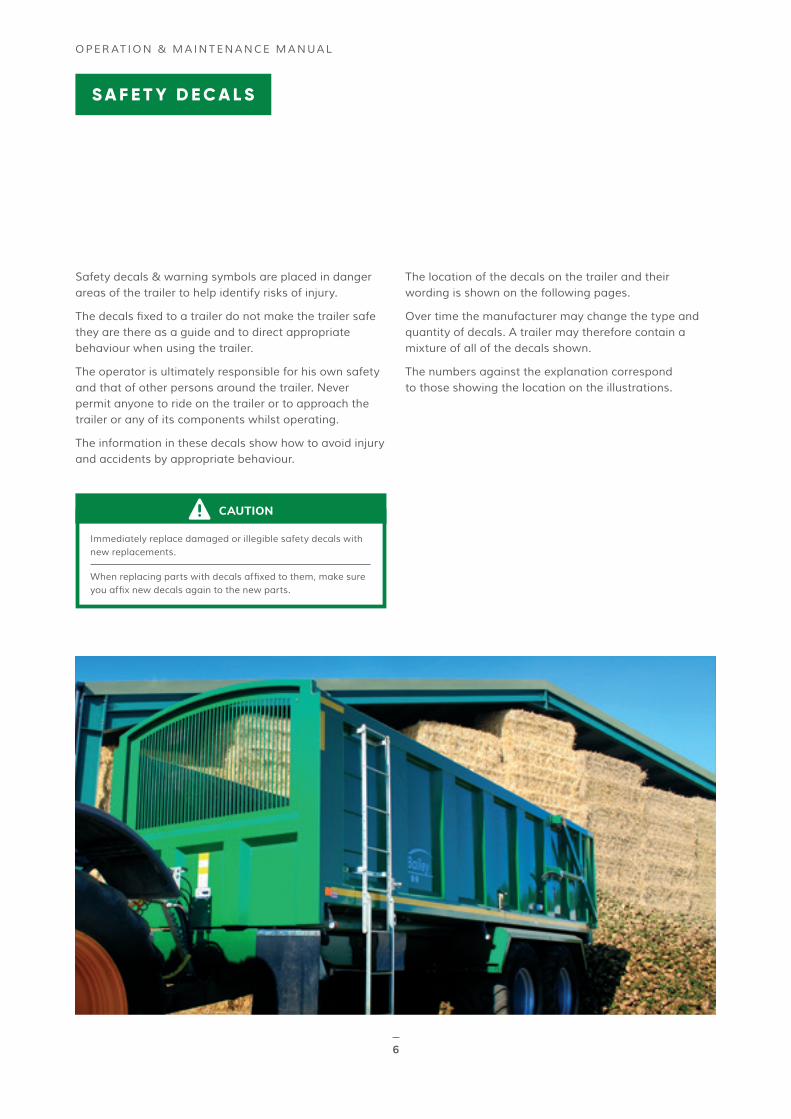
Safety decals & warning symbols are placed in danger areas of the trailer to help identify risks of injury.
The decals fixed to a trailer do not make the trailer safe they are there as a guide and to direct appropriate behaviour when using the trailer.
The operator is ultimately responsible for his own safety and that of other persons around the trailer. Never permit anyone to ride on the trailer or to approach the trailer or any of its components whilst operating.
The information in these decals show how to avoid injury and accidents by appropriate behaviour.
The location of the decals on the trailer and their wording is shown on the following pages.
Over time the manufacturer may change the type and quantity of decals. A trailer may therefore contain a mixture of all of the decals shown.
The numbers against the explanation correspond to those showing the location on the illustrations.
Immediately replace damaged or illegible safety decals with new replacements.
When replacing parts with decals affixed to them, make sure you affix new decals again to the new parts.
CAUTION
7
O P E R AT I O N & M A I N T E N A N C E M A N UA L
L O C AT I O N O F S A F E T Y D E C A L S
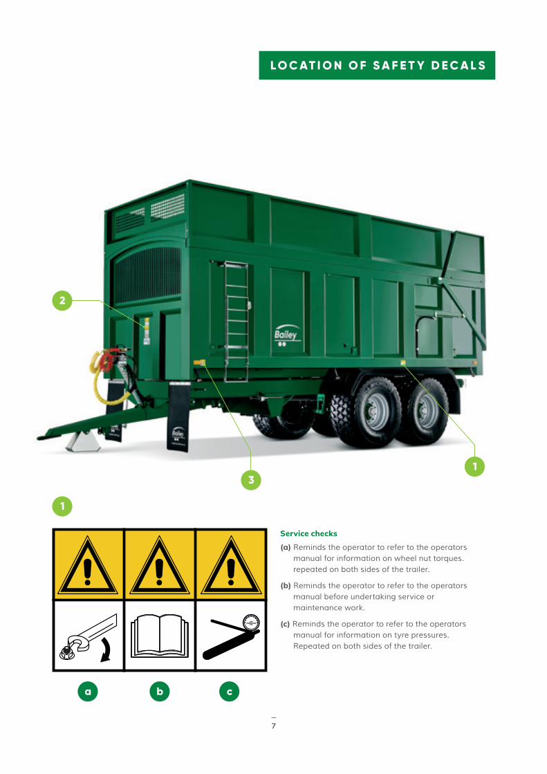
Service checks
(a) Reminds the operator to refer to the operators manual for information on wheel nut torques. repeated on both sides of the trailer.
(b) Reminds the operator to refer to the operators manual before undertaking service or maintenance work.
(c) Reminds the operator to refer to the operators manual for information on tyre pressures. Repeated on both sides of the trailer.
1
2
3
1
a b c
8
O P E R AT I O N & M A I N T E N A N C E M A N UA L
L O C AT I O N O F S A F E T Y D E C A L S
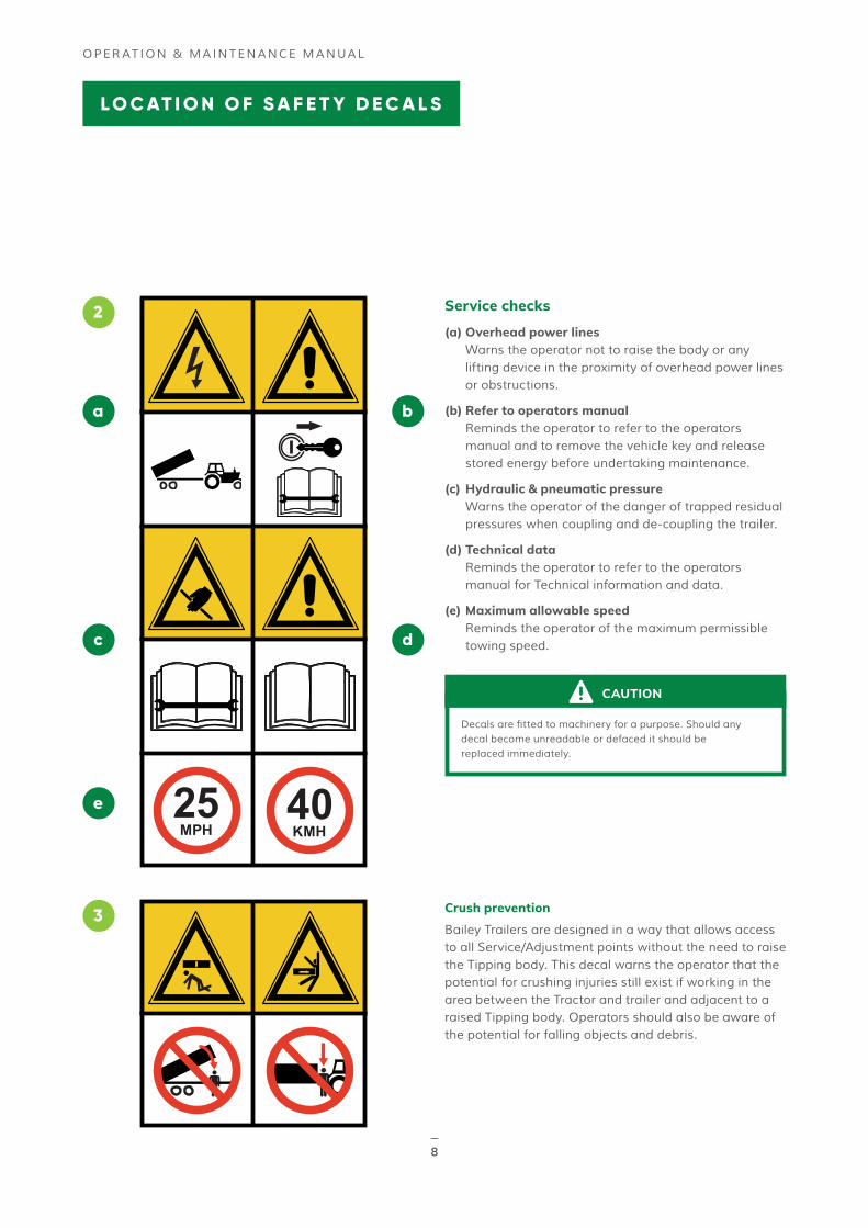
Service checks
(a) Overhead power lines Warns the operator not to raise the body or any
lifting device in the proximity of overhead power lines or obstructions.
(b) Refer to operators manual Reminds the operator to refer to the operators
manual and to remove the vehicle key and release stored energy before undertaking maintenance.
(c) Hydraulic & pneumatic pressure Warns the operator of the danger of trapped residual
pressures when coupling and de-coupling the trailer.
(d) Technical data Reminds the operator to refer to the operators
manual for Technical information and data.
(e) Maximum allowable speed Reminds the operator of the maximum permissible
towing speed.
Decals are fitted to machinery for a purpose. Should any decal become unreadable or defaced it should be replaced immediately.
CAUTION
2
3
a
c
e
b
d
Crush prevention
Bailey Trailers are designed in a way that allows access to all Service/Adjustment points without the need to raise the Tipping body. This decal warns the operator that the potential for crushing injuries still exist if working in the area between the Tractor and trailer and adjacent to a raised Tipping body. Operators should also be aware of the potential for falling objects and debris.
40KMH
25MPH
9
O P E R AT I O N & M A I N T E N A N C E M A N UA L
L E G A L R E Q U I R E M E N T S
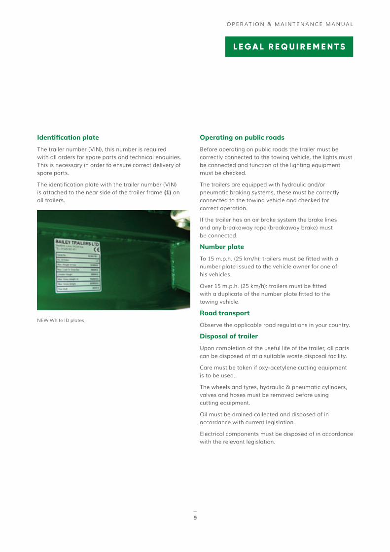
Identificationplate
The trailer number (VIN), this number is required with all orders for spare parts and technical enquiries. This is necessary in order to ensure correct delivery of spare parts.
The identification plate with the trailer number (VIN) is attached to the near side of the trailer frame (1) on all trailers.
Operating on public roads
Before operating on public roads the trailer must be correctly connected to the towing vehicle, the lights must be connected and function of the lighting equipment must be checked.
The trailers are equipped with hydraulic and/or pneumatic braking systems, these must be correctly connected to the towing vehicle and checked for correct operation.
If the trailer has an air brake system the brake lines and any breakaway rope (breakaway brake) must be connected.
Number plate
To 15 m.p.h. (25 km/h): trailers must be fitted with a number plate issued to the vehicle owner for one of his vehicles.
Over 15 m.p.h. (25 km/h): trailers must be fitted with a duplicate of the number plate fitted to the towing vehicle.
Road transport
Observe the applicable road regulations in your country.
Disposal of trailer
Upon completion of the useful life of the trailer, all parts can be disposed of at a suitable waste disposal facility.
Care must be taken if oxy-acetylene cutting equipment is to be used.
The wheels and tyres, hydraulic & pneumatic cylinders, valves and hoses must be removed before using cutting equipment.
Oil must be drained collected and disposed of in accordance with current legislation.
Electrical components must be disposed of in accordance with the relevant legislation.
NEW White ID plates
10
O P E R AT I O N & M A I N T E N A N C E M A N UA L
General hazard perception and safety
Warnings or cautions for hazards that may be present when operating the trailer, or during maintenance of the trailer, are shown in the following sections.
Before operating the trailer
The following warnings and cautions are of a general nature and are not task specific. All personnel operating or maintaining this trailer must be fully aware of these warnings.
WARNING
Before operating the trailer
This trailer must be operated only by correctly trained and authorised personnel. Certain local operating conditions may require the trailer operator to obtain an operators licence or a certificate. The trailer operator must be fully aware of the trailers capabilities and limitations. The operator must also be familiar with the local working area or site and in particular:
– Check the area for vertical and horizontal clearances.
– Check for overhead obstructions.
– Check for electrical power lines and make sure the trailer keeps at least 7.6m (25 ft) away.
Check the work area or site for changes in the stability of the ground surface, back filled trenches and structural integrity of buildings, roofs etc.
Make sure that all protective guards and covers are correctly installed on the vehicle.
Make sure that if the trailer is equipped with a fully working lighting system that is adequate for the working conditions, and is compliant with local or national road traffic regulations.
Make sure that the trailer reverse alarm and other warning devices are in full working order.
Make sure that all obstacles are cleared from the intended path or route of the trailer.
Make sure that before the trailer is moved, there are no personnel on, under or near the trailer.
Collision of high speed road traffic and slow moving trailers can cause personal injury or death. When on a public road, use flashing beacon and other lights according to local laws. Use a Slow Moving Vehicle (SMV) emblem displayed at the rear of the trailer where this is a national requirement. Pull over to let faster traffic pass. Signal and slow down before turning off the road.
Use warning devices (flags, SMV emblem, lights, etc.) which are approved for use by your local government agencies, when using equipment on public roads. Keep these devices clean and in good working order.
General
Unauthorised personnel must not be permitted to operate or maintain this trailer.
Make sure the location of high voltage power lines and buried power cables are known. Serious injury or death, by electrocution, can occur if the trailer contacts these hazards.
Do not wear loose clothing or jewellery, which can snag on the controls or trailer structure, causing personal injury.
Make sure that all protective guards and covers are secured in place on the trailer. If guards and covers are removed, a hazard to personnel will exist.
Make sure that all foreign objects and materials, such as oil, tools, debris and other items, are kept clear from equipment, walkways and steps on the trailer. Failure to do this can cause personal injury.
Make sure that all loose items, such as tools, lunch boxes and other items, which are not part of the equipment, are secured correctly before operating the trailer. Failure to do this can cause personal injury.
G E N E R A L S A F E T Y
11
O P E R AT I O N & M A I N T E N A N C E M A N UA L
WARNING
G E N E R A L S A F E T Y
Always wear the correct protective equipment, including a hard hat and protective glasses, as required.
Trailer operators must be aware of the correct hand signals and those personnel authorised to give them.
Operators must accept hand signals only from a single and authorised person.
Make sure that all fluids used during maintenance of the trailer are stored in the correct containers. Never store these fluids in other types, such as glass containers.
Make sure that all fluids are disposed of correctly and in accordance with Local Health and Safety Regulations.
Make sure that all cleaning fluids are used with care and that any necessary repairs are reported immediately.
Make sure the size of the trailer, including any load, is known. This will ensure a correct and safe clearance is maintained, when operating the trailer in confined spaces or near obstacles.
Pressurised air and water
If released, air or water in pressurised trailer systems can cause debris or hot water to be ejected. This can cause personal injury. Care must be taken when working on pressurised trailer systems.
Operators using pressurised air or water for cleaning purposes must wear the correct protective equipment. This includes protective clothing, shoes/boots and goggles or face shield.
Operators using pressurised air or water for cleaning purposes must not exceed the following maximum operating pressures:
Air – 205 kPa (30 psi)
Water – 275 kPa (40 psi)
Residual hydraulic pressure
Refer to the service manual before releasing hydraulic pressure. Non-operating hydraulic systems can retain residual hydraulic pressure. If released, this residual pressure can cause:
– Sudden movement of the trailer or trailer attachments.
– Disconnected hoses to whip.
– Hydraulic fluid to be sprayed, causing a personal hazard through direct contact or ingestion.
Fluid penetration
Residual hydraulic pressure must be released before any hydraulic maintenance, disconnection or component removal is done. Refer to the service manual before releasing hydraulic pressure. Non-operating hydraulic systems can retain residual hydraulic pressure. If not released correctly, personal injury can occur.
Leaking fluid, even from a pin hole leak, can penetrate the skin, causing serious injury or death. Always use cardboard or a board to check fluid leaks. If fluid penetration of the skin occurs, you must seek medical help immediately, preferably from experienced medical staff.
Fluid spillage
Care must be taken to avoid fluid spillage during trailer maintenance, testing, adjusting and repair. Before any possible fluid spillage can occur, a suitable container must be positioned to collect the fluid.
12
O P E R AT I O N & M A I N T E N A N C E M A N UA L
WARNING
G E N E R A L S A F E T Y
Disposal of waste material
The disposal of waste materials, including potentially harmful fluids, must be in accordance with local health and safety regulations.
Improper disposal procedures can be harmful to personnel and the environment. Always use the correct and leakproof type of container for the storage of waste fluids. Do not dispose of these fluids by pouring onto the ground, into water sources or into drains. Improper disposal procedures can be harmful to personnel and the environment.
Asbestos hazards
Contact with asbestos must be avoided, particularly inhalation of airborne dust, which can cause serious Injury or death.
If it becomes necessary to come into contact with asbestos, you must use the guidelines that follow:
– Avoid creating dust if handling debris or components that may contain asbestos, such as brake pads and bands, liner material, clutch plates and some gaskets.
– Never use compressed air for cleaning purposes.
– Avoid machining or brushing materials that may contain asbestos.
– Before disposal, use a wet, damping down method to concentrate material dust and debris.
– If possible, a vacuum cleaner fitted with a high particle air filter (HEPA), should be used to collect debris and dust.
– Use exhaust ventilation on permanent machining work.
– Wear an approved respirator if there is no other way to control any dust produced.
– Always comply with the applicable environmental regulations for the disposal of asbestos.
– Stay away from areas that may contain airborne asbestos particles.
– Always comply with the applicable rules and regulations for the work place.
– Use genuine Bailey equipment, components and parts, which are supplied asbestos free.
Crushing or cutting prevention
Support equipment correctly before you do any work or maintenance from beneath that equipment.
Unless instructed otherwise, never attempt to do adjustments whilst the trailer is moving or the engine or other power source is running.
Clearances in trailer control linkages will change with control operation or trailer movement.
Always keep clear of controls or areas that may experience clearance changes.
Always keep clear of rotating or moving parts of the trailer. Always re-install any guard or cover that has been temporarily removed.
When handling cables, always wear protective gloves. Never use kinked or frayed cables.
Striking any object can cause debris chips to fly off, causing personal injury.
13
O P E R AT I O N & M A I N T E N A N C E M A N UA L
WARNING
G E N E R A L S A F E T Y
Always wear protective glasses/goggles before striking an object and make sure that the area is clear of other personnel.
If a retaining pin is struck with force, it may be ejected and cause personal injury. Always wear protective glasses/goggles before striking a retaining pin and make sure that the area is clear of other personnel.
Burn prevention
Some components will get hot during operation, causing a potential burn hazard to personnel. Before you do any maintenance on these parts, you must:
– Always allow these parts to fully cool before you do any maintenance work.
– Always release residual pressure in the air, hydraulic and lubrication systems and associated pipe lines/hoses, before you do any maintenance work.
– Hot fluids and surfaces can cause personal injury. Avoid direct contact with hot fluid or surfaces.
Fire and explosion prevention
All fuels, most lubricants and some coolant mixtures are flammable and if leaking onto a hot surface or electrical components, can create a fire. Fire can cause severe personal injury or death.
Do not operate the trailer close to a naked flame or heat source.
Always clean pipes thoroughly with a non-flammable solvent first.
Examine all electrical wires daily and check and tighten all electrical connections. If necessary, repair loose or frayed wires before you operate the trailer.
Dust produced from repairs to non-metallic components, such as hoods or fenders, can be flammable.
Always repair such components in a well ventilated area, away from naked flame and heat sources.
Leaking pipes and hoses can cause a fire. Examine all pipes, hoses and associated supports for wear, deterioration and damage and ensure that pipe and hose clamps are secure.
Make sure pipe and hose connections are correctly torqued.
Remove all flammable materials such as fuel, oil and debris from the trailer. Do not allow the accumulation of flammable materials on or around the trailer.
Always store fuels and lubricants in the correct and properly marked containers and away from unauthorised personnel.
Always store soiled oily rags and other flammable materials in protective containers.
Do not smoke in areas that are used for the storage of flammable materials.
Do not operate the trailer close to naked flames.
Do not weld or flame cut any pipes or tanks that contain flammable fluids or gases. Always clean such pipes and tanks thoroughly with a non-flammable solvent first.
14
O P E R AT I O N & M A I N T E N A N C E M A N UA L
WARNING
Pipes, tubes and hoses
Leaks from loose or damaged pipes, tubes or hoses can cause a system failure or a fire. Examine pipes, tubes and hoses regularly, particularly for signs of damage, leaks or being loose.
Never use bare hands to check for leaks from pipes, tubes or hoses. Always use cardboard or a board and if necessary, torque connections to the recommended value.
Do not bend or strike high pressure pipes or install a bent or damaged high pressure pipe.
You must replace any pipe, tube or hose if:
– End fittings are damaged or leaking.
– Outer coverings are chafed or cut.
– Wires are exposed.
– Outer covering is blistered or ballooning.
– Flexible portion of a hose is kinked.
– Outer covers have embedded armouring.
– End fittings are damaged or displaced.
Clamps, guards and heat shields are installed to prevent vibration, contact between components and excessive heat. Make sure that all clamps, guards and heat shields are installed correctly.
Tyre hazards
An air inflated tyre can expand and explode if excessive heat is applied through welding, heating rim components, external fire or excessive use of the brakes. An exploding tyre can eject axle and wheel debris 500 m (1500 ft) or more from the vehicle, causing damage and possibly personal injury or death. All personnel must be aware of the hazards of overheating tyres.
An over-inflated tyre can blow out or cause a rim failure. This can cause damage or personal injury. Inflation of tyres must only be done by trained personnel.
When you inflate a tyre, you must stand behind the tyre tread and use a self attaching inflator. Maintenance on tyres and rims can be hazardous. The use of incorrect procedures can result in a tyre exploding. An exploding tyre can eject axle and wheel debris 500 m (1500 ft) or more from the vehicle, causing damage and possibly personal injury or death. Maintenance on tyres and rims must be done only by trained personnel, using the correct tools and procedures. The tyre dealer or manufacturers instructions must be followed.
Mounting and dismounting
You must never attempt to mount, dismount or jump from a trailer that is moving.
Always mount or dismount the trailer at the recognised locations, which have steps and/or hand holds. Make sure the steps and/or hand hold are clean and examined regularly. Make any necessary repairs.
When you mount or dismount the trailer, always keep a three-point contact with the steps and hand holds. Three-point contact can be two feet/one hand or two hands/one foot.
When you mount or dismount the trailer, always face the trailer and never attempt to carry tools or supplies. Tools and supplies should be raised or lowered from the Trailer using a hand line or other suitable method.
G E N E R A L S A F E T Y
15
O P E R AT I O N & M A I N T E N A N C E M A N UA L
G E N E R A L S A F E T Y
General safety instructions
Check that the trailer is roadworthy and safe to operate every time it is put into operation.
1. Observe the current regulations regarding safety and accident prevention as well as the information in the operator’s manual.
2. When using public roads observe all traffic regulations.
3. Make yourself familiar with all equipment and controls and their functions before starting work as it will be too late once you have set off.
4. Make sure that there is no one in close proximity to the trailer before putting it into operation (be especially aware of children). Check that visibility is good, particularly when reversing (have someone direct you if necessary).
5. Clothing worn by the operator must be close fitting. Avoid wearing loose fitting clothing when operating or maintaining the trailer.
6. Keep the trailer clean to prevent fire.
7. If it is necessary to access the trailer, the engine of the towing vehicle must be switched off. The ignition key of the towing vehicle must be removed.
9. Any safety guards must be checked regularly for wear and replaced if necessary.
10. Any safety decals that are missing must be replaced immediately.
General
1. Use only the recommended fastenings on the trailer.
2. Do not exceed the maximum load on the trailer drawbar.
3. Use extreme caution when coupling and uncoupling the trailer from the towing vehicle to avoid risk of injury.
4. During maintenance or after use prevent the trailer from rolling away by use of the parking brake or wheel chocks.
5. A risk of injury due to crushing exists in the vicinity of the towing vehicle 3-point linkage.
6. Couple and uncouple the trailer to the towing vehicle only as specified in the instructions.
7. The performance of the towing vehicle can be influenced by the trailer, ensure the towing vehicle has sufficient steering and braking capacity.
8. Make sure no one is between the trailer and the towing vehicle unless both are secured and prevented from moving.
9. The travel speed must always be matched to the under wheel conditions. Avoid sudden turns and braking when driving up or down hill or across a slope.
10. Observe the maximum permissible axle loads and total weights.
11. Operate the trailer only when all guards are fitted and in the correct position.
12. Ensure that the trailer is stable when parked.
13. Ensure all equipment is placed in the transport position before driving on the road.
14. Always switch off the engine of the towing vehicle before carrying out troubleshooting, and for repair, maintenance and cleaning work. Remove the towing vehicle ignition key.
15. When working under raised covers ensure that they are sufficiently supported.
16. When handling sharp-edged parts, wear appropriate protection (gloves, shoes etc).
17 . Do not stand near hinged covers.
16
O P E R AT I O N & M A I N T E N A N C E M A N UA L
Brakes
1. Check the brakes before every journey.
2. Check the brake system thoroughly at regular intervals.
3. If the brake system malfunctions, do not use the trailer, stop the towing vehicle immediately. Repair faults immediately.
4. Any adjustments and repairs to the brake system must be carried out by your Bailey Trailers Ltd agent or approved specialist workshop.
5. Engage a lower gear before going downhill.
6. Engage the parking brake before coupling or uncoupling the towing vehicle.
7. The brakes must always be correctly adjusted. No liability can be accepted for normal wear or unauthorised modifications.
Hydraulic system
1. The hydraulic system is under high pressure.
2. When connecting the hydraulic hoses to the towing vehicle hydraulics, make sure that the hydraulic systems are de-pressurised on the tractor side and on the trailer side.
3. The female and male couplings between the tractor and the trailer should be labelled to prevent incorrect connections. If connections are reversed (e.g. lifting/lowering), there is a risk of accident.
4. Keep the hydraulic plugs clean.
5. Check hydraulic lines at regular intervals, and replace them if they are damaged.
6. Any replaced hydraulic lines must meet the technical requirements of the manufacturer.
7. The towing vehicle engine must be switched off and the system de-pressurised before starting work on the hydraulic system.
8. Repair work on the hydraulic system must be carried out by approved specialised work shops only.
Wheels and tyres
1. Repair work to the tyres must be carried out by qualified technicians using suitable tools.
2. When working on the wheels make sure that the trailer is secured and that wheels are chocked to prevent it from moving.
3. Tighten the wheel nuts after the first trip with a load.
4. After replacing the wheels re-tighten the wheel nuts or bolts after the first 10 operating hours, then check them every 50 hours.
5. Make sure that the jack used has sufficient load capacity.
6. Avoid excessive inflation pressure.
7. The specified tyre pressure must be maintained.
8. Stand clear of the tyre when inflating.
9. Check the pressure regularly.
10. Regularly check nuts and screws for tightness and re-tighten them, if necessary.
11. All mounting bolts and nuts must be tightened to the torque specified by the manufacturer.
Maintenance
1. Always switch off the towing vehicle engine before carrying out any troubleshooting, and before all repair, maintenance and cleaning work. Remove the ignition key.
2. Use suitable tools and wear safety gloves when replacing working parts.
3. Always disconnect the power supply before working on the electrical system.
4. Protection devices that are subjected to wear must be checked at regular intervals and replaced as necessary.
G E N E R A L S A F E T Y
17
O P E R AT I O N & M A I N T E N A N C E M A N UA L
G E N E R A L S A F E T Y
Stand clear of the area beneath the tipping body whilst the trailer is raised or lowered.
WARNING
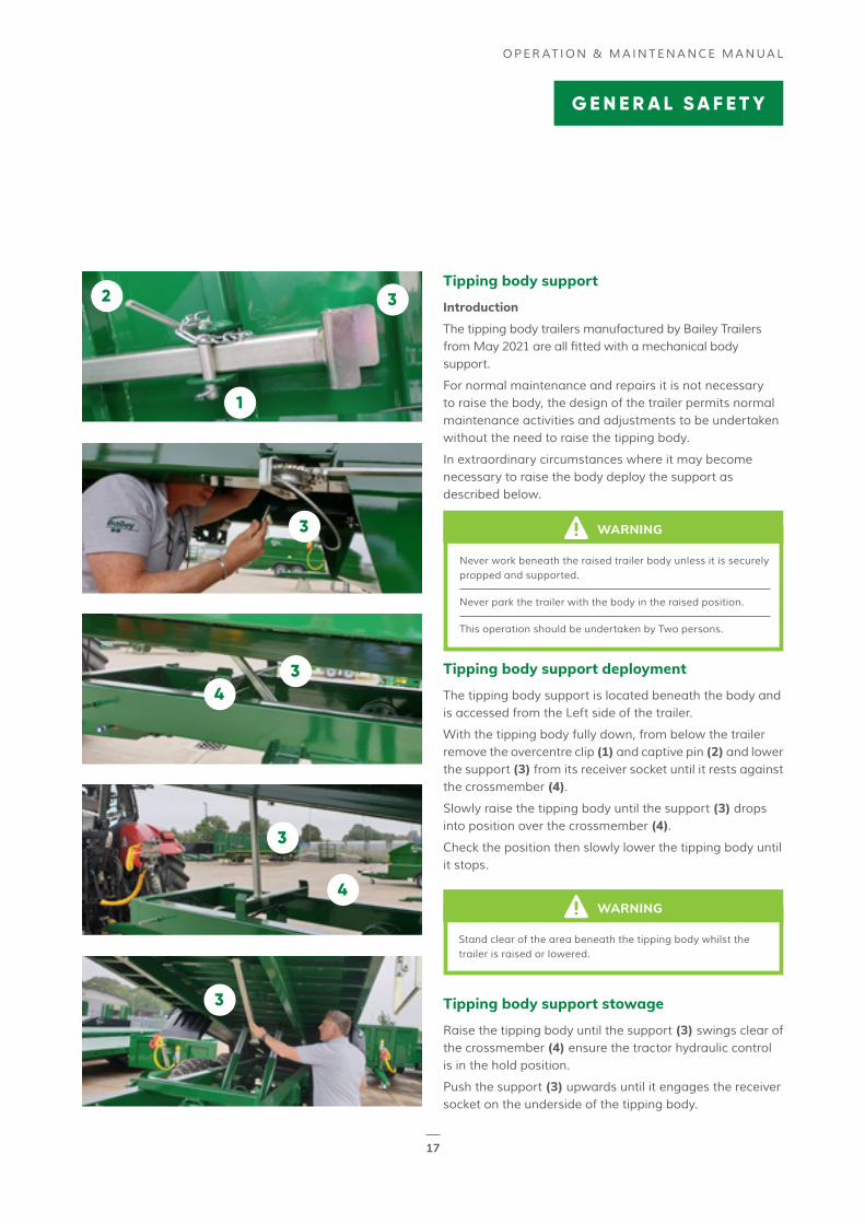
Tipping body support
Introduction
The tipping body trailers manufactured by Bailey Trailers from May 2021 are all fitted with a mechanical body support.
For normal maintenance and repairs it is not necessary to raise the body, the design of the trailer permits normal maintenance activities and adjustments to be undertaken without the need to raise the tipping body.
In extraordinary circumstances where it may become necessary to raise the body deploy the support as described below.
Tipping body support deployment
The tipping body support is located beneath the body and is accessed from the Left side of the trailer.
With the tipping body fully down, from below the trailer remove the overcentre clip (1) and captive pin (2) and lower the support (3) from its receiver socket until it rests against the crossmember (4).
Slowly raise the tipping body until the support (3) drops into position over the crossmember (4).
Check the position then slowly lower the tipping body until it stops.
Tipping body support stowage
Raise the tipping body until the support (3) swings clear of the crossmember (4) ensure the tractor hydraulic control is in the hold position.
Push the support (3) upwards until it engages the receiver socket on the underside of the tipping body.
3
1
2 3
3
3
3
4
4
Never work beneath the raised trailer body unless it is securely propped and supported.
Never park the trailer with the body in the raised position.
This operation should be undertaken by Two persons.
WARNING
18
O P E R AT I O N & M A I N T E N A N C E M A N UA L
G E N E R A L S A F E T Y
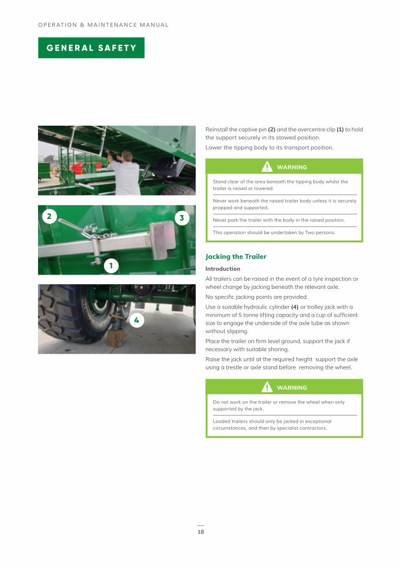
Reinstall the captive pin (2) and the overcentre clip (1) to hold the support securely in its stowed position.
Lower the tipping body to its transport position.
1
4
2 3
Stand clear of the area beneath the tipping body whilst the trailer is raised or lowered.
Never work beneath the raised trailer body unless it is securely propped and supported.
Never park the trailer with the body in the raised position.
This operation should be undertaken by Two persons.
Do not work on the trailer or remove the wheel when only supported by the jack.
Loaded trailers should only be jacked in exceptional circumstances, and then by specialist contractors.
WARNING
WARNING
Jacking the Trailer
Introduction
All trailers can be raised in the event of a tyre inspection or wheel change by jacking beneath the relevant axle.
No specific jacking points are provided.
Use a suitable hydraulic cylinder (4) or trolley jack with a minimum of 5 tonne lifting capacity and a cup of sufficient size to engage the underside of the axle tube as shown without slipping.
Place the trailer on firm level ground, support the jack if necessary with suitable shoring.
Raise the jack until at the required height support the axle using a trestle or axle stand before removing the wheel.
19
O P E R AT I O N & M A I N T E N A N C E M A N UA L
Model TB & Beeteaper Dumper Root Special Bale & Pallet/
Water BowserContract
Tipper Low Loader High Lift/Ejector
Electric system
Voltage V(dc) 12 12 12 12 12 12 12
Current (cont) A 10 10 10 10 10 10 10
Current (max) A 15 15 15 15 15 15 15
Braking system
Standard Single line hydraulic brakes
Option 1 Dual line airbrakes with Load Sensing and/or ABS
Speed
Std. braking system kmh 65 65 65 65 65 65 65
Option 1 kmh max. towing max. towing max. towing max. towing max. towing max. towing max. towing
Option 2 kmh vehicle speed vehicle speed vehicle speed vehicle speed vehicle speed vehicle speed vehicle speed
Hydraulic system
Supply as towing vehicle
Working hyd. pressure bar as towing vehicle
Max. hyd. pressure bar 207 207 207 207 207 207 207
Min. hyd. pressure bar 172 172 172 172 172 172 172
Max. brake pressure bar 150 150 150 150 150 150 150
Min. brake pressure bar 120 120 120 120 120 120 120
Max. hyd. flowrate L/min 90 90 90 90 90 90 90
Noise dB(A) <70 <70 <70 <70 <70 <70 <70
G E N E R A L S P E C I F I C AT I O N S
20
O P E R AT I O N & M A I N T E N A N C E M A N UA L
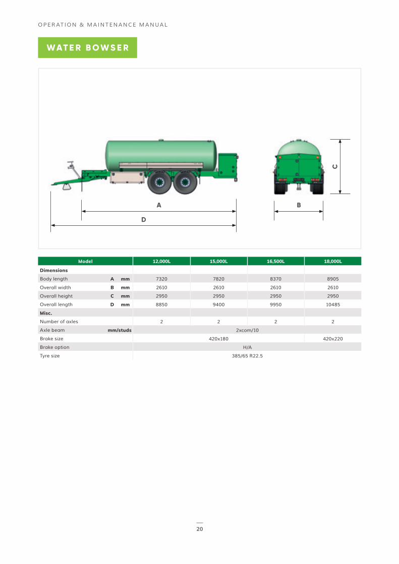
WAT E R B O W S E R
B
Model 12,000L 15,000L 16,500L 18,000L
Dimensions
Body length A mm 7320 7820 8370 8905
Overall width B mm 2610 2610 2610 2610
Overall height C mm 2950 2950 2950 2950
Overall length D mm 8850 9400 9950 10485
Misc.
Number of axles 2 2 2 2
Axle beam mm/studs 2xcom/10
Brake size 420x180 420x220
Brake option H/A
Tyre size 385/65 R22.5
C
D
A
21
O P E R AT I O N & M A I N T E N A N C E M A N UA L
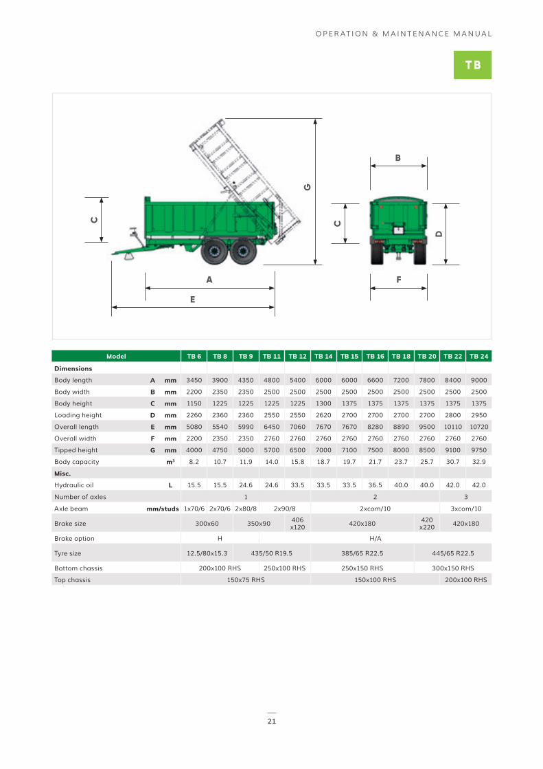
T B
Model TB 6 TB 8 TB 9 TB 11 TB 12 TB 14 TB 15 TB 16 TB 18 TB 20 TB 22 TB 24
Dimensions
Body length A mm 3450 3900 4350 4800 5400 6000 6000 6600 7200 7800 8400 9000
Body width B mm 2200 2350 2350 2500 2500 2500 2500 2500 2500 2500 2500 2500
Body height C mm 1150 1225 1225 1225 1225 1300 1375 1375 1375 1375 1375 1375
Loading height D mm 2260 2360 2360 2550 2550 2620 2700 2700 2700 2700 2800 2950
Overall length E mm 5080 5540 5990 6450 7060 7670 7670 8280 8890 9500 10110 10720
Overall width F mm 2200 2350 2350 2760 2760 2760 2760 2760 2760 2760 2760 2760
Tipped height G mm 4000 4750 5000 5700 6500 7000 7100 7500 8000 8500 9100 9750
Body capacity m3 8.2 10.7 11.9 14.0 15.8 18.7 19.7 21.7 23.7 25.7 30.7 32.9
Misc.
Hydraulic oil L 15.5 15.5 24.6 24.6 33.5 33.5 33.5 36.5 40.0 40.0 42.0 42.0
Number of axles 1 2 3
Axle beam mm/studs 1x70/6 2x70/6 2x80/8 2x90/8 2xcom/10 3xcom/10
Brake size 300x60 350x90 406 x120 420x180 420
x220 420x180
Brake option H H/A
Tyre size 12.5/80x15.3 435/50 R19.5 385/65 R22.5 445/65 R22.5
Bottom chassis 200x100 RHS 250x100 RHS 250x150 RHS 300x150 RHS
Top chassis 150x75 RHS 150x100 RHS 200x100 RHS
E
A
G
C
B
F
D
C
22
O P E R AT I O N & M A I N T E N A N C E M A N UA L
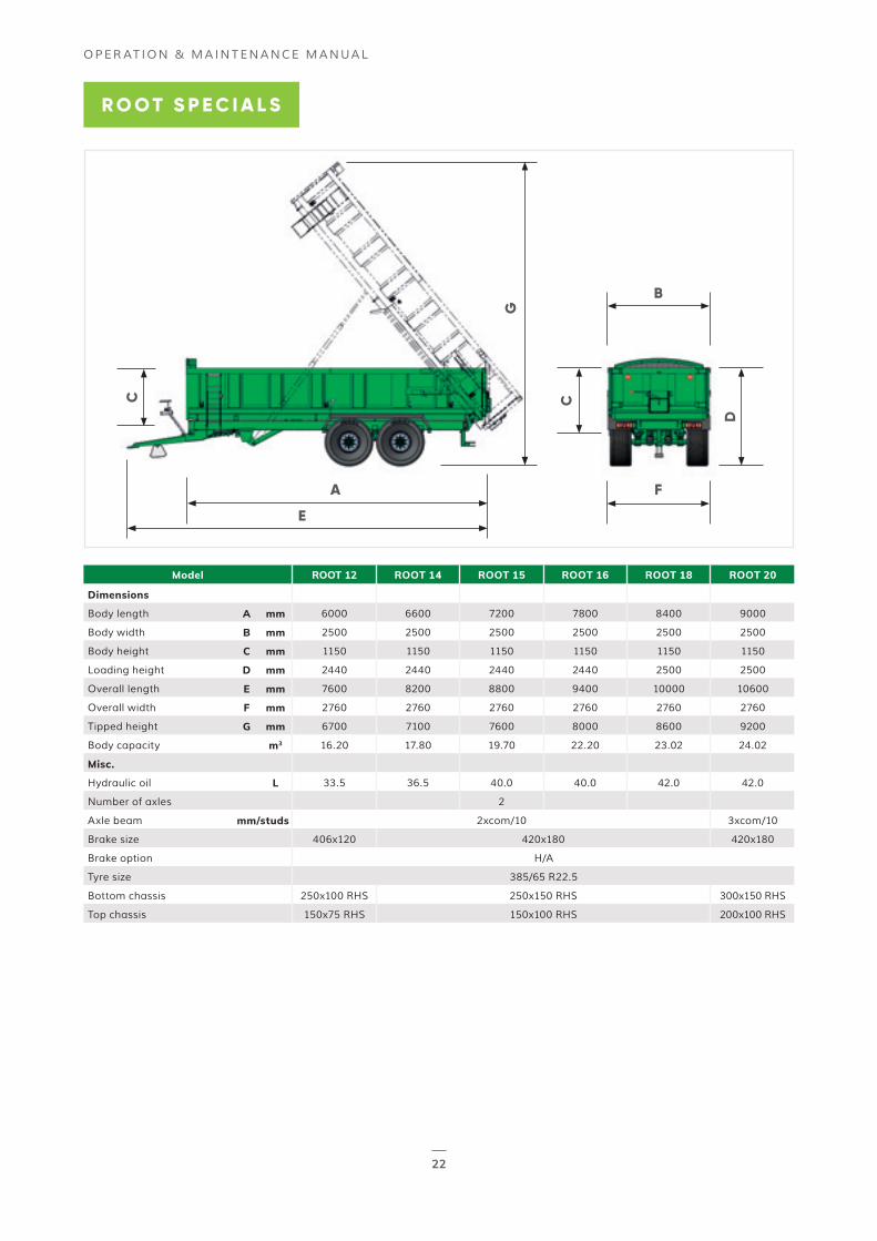
R O O T S P E C I A L S
Model ROOT 12 ROOT 14 ROOT 15 ROOT 16 ROOT 18 ROOT 20
Dimensions
Body length A mm 6000 6600 7200 7800 8400 9000
Body width B mm 2500 2500 2500 2500 2500 2500
Body height C mm 1150 1150 1150 1150 1150 1150
Loading height D mm 2440 2440 2440 2440 2500 2500
Overall length E mm 7600 8200 8800 9400 10000 10600
Overall width F mm 2760 2760 2760 2760 2760 2760
Tipped height G mm 6700 7100 7600 8000 8600 9200
Body capacity m3 16.20 17.80 19.70 22.20 23.02 24.02
Misc.
Hydraulic oil L 33.5 36.5 40.0 40.0 42.0 42.0
Number of axles 2
Axle beam mm/studs 2xcom/10 3xcom/10
Brake size 406x120 420x180 420x180
Brake option H/A
Tyre size 385/65 R22.5
Bottom chassis 250x100 RHS 250x150 RHS 300x150 RHS
Top chassis 150x75 RHS 150x100 RHS 200x100 RHS
E
AG
C
B
F
D
C
23
O P E R AT I O N & M A I N T E N A N C E M A N UA L
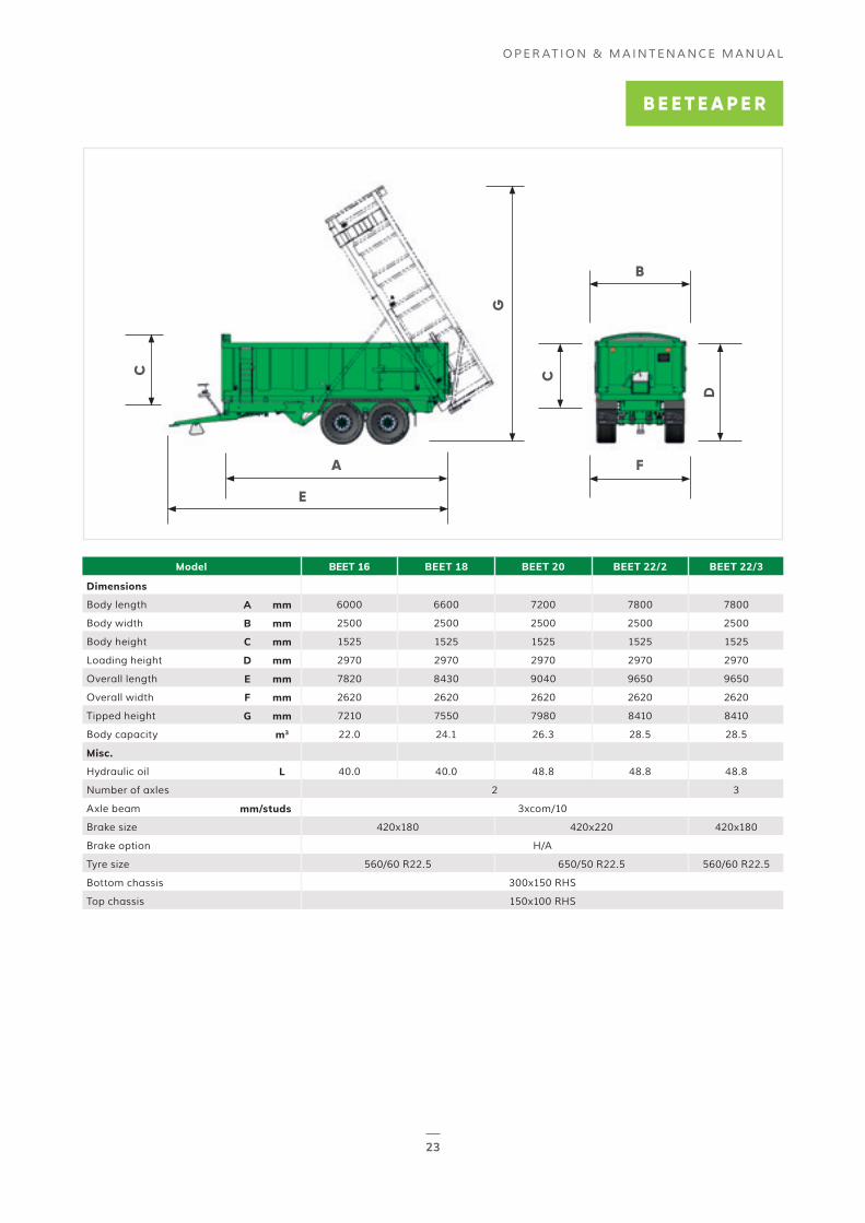
B E E T E A P E R
Model BEET 16 BEET 18 BEET 20 BEET 22/2 BEET 22/3
Dimensions
Body length A mm 6000 6600 7200 7800 7800
Body width B mm 2500 2500 2500 2500 2500
Body height C mm 1525 1525 1525 1525 1525
Loading height D mm 2970 2970 2970 2970 2970
Overall length E mm 7820 8430 9040 9650 9650
Overall width F mm 2620 2620 2620 2620 2620
Tipped height G mm 7210 7550 7980 8410 8410
Body capacity m3 22.0 24.1 26.3 28.5 28.5
Misc.
Hydraulic oil L 40.0 40.0 48.8 48.8 48.8
Number of axles 2 3
Axle beam mm/studs 3xcom/10
Brake size 420x180 420x220 420x180
Brake option H/A
Tyre size 560/60 R22.5 650/50 R22.5 560/60 R22.5
Bottom chassis 300x150 RHS
Top chassis 150x100 RHS
E
A
G
C
B
F
D
C
24
O P E R AT I O N & M A I N T E N A N C E M A N UA L
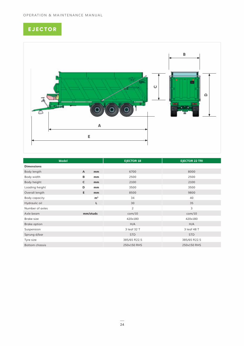
E J E C T O R
Model EJECTOR 18 EJECTOR 22 TRI
Dimensions
Body length A mm 6700 8000
Body width B mm 2500 2500
Body height C mm 2100 2100
Loading height D mm 3500 3500
Overall length E mm 8500 9800
Body capacity m3 34 40
Hydraulic oil L 30 35
Number of axles 2 3
Axle beam mm/studs com/10 com/10
Brake size 420x180 420x180
Brake option H/A H/A
Suspension 3 leaf 32 T 3 leaf 48 T
Sprung d/bar STD STD
Tyre size 385/65 R22.5 385/65 R22.5
Bottom chassis 250x150 RHS 250x150 RHS
E
A
B
D
C
25
O P E R AT I O N & M A I N T E N A N C E M A N UA L
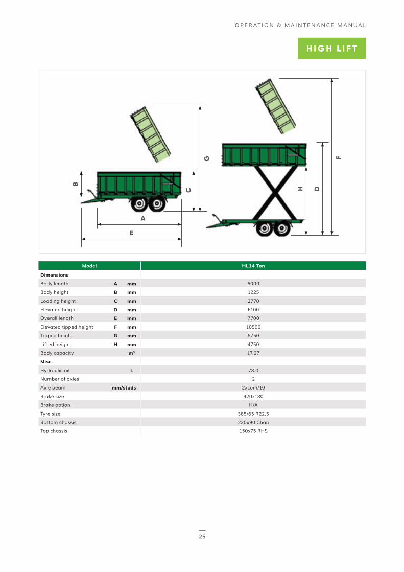
H I G H L I F T
Model HL14 Ton
Dimensions
Body length A mm 6000
Body height B mm 1225
Loading height C mm 2770
Elevated height D mm 6100
Overall length E mm 7700
Elevated tipped height F mm 10500
Tipped height G mm 6750
Lifted height H mm 4750
Body capacity m3 17.27
Misc.
Hydraulic oil L 78.0
Number of axles 2
Axle beam mm/studs 2xcom/10
Brake size 420x180
Brake option H/A
Tyre size 385/65 R22.5
Bottom chassis 220x90 Chan
Top chassis 150x75 RHS
F
DH
E
A
G
C
B
26
O P E R AT I O N & M A I N T E N A N C E M A N UA L
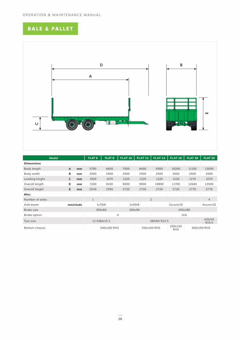
B A L E & PA L L E T
Model FLAT 6 FLAT 8 FLAT 10 FLAT 12 FLAT 14 FLAT 16 FLAT 18 FLAT 20
Dimensions
Body length A mm 5700 6600 7500 8400 9300 10200 11100 12000
Body width B mm 2500 2500 2500 2500 2500 2500 2500 2500
Loading height C mm 1020 1070 1220 1220 1220 1220 1270 1070
Overall length D mm 7200 8100 9000 9900 10800 11700 12600 13500
Overall height E mm 2540 2590 2720 2720 2720 2720 2770 2770
Misc.
Number of axles 1 2 4
Axle beam mm/studs 1x70/6 2x90/8 2xcom/10 4xcom/10
Brake size 300x60 350x90 420x180
Brake option H H/A
Tyre size 12.5/80x15.3 385/65 R22.5 435/50 R19.5
Bottom chassis 200x100 RHS 250x100 RHS 250x150 RHS 300x150 RHS
A
D B
C
E
27
O P E R AT I O N & M A I N T E N A N C E M A N UA L
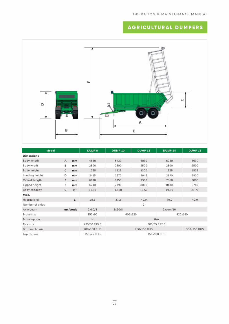
A G R I C U LT U R A L D U M P E R S
Model DUMP 8 DUMP 10 DUMP 12 DUMP 14 DUMP 16
Dimensions
Body length A mm 4630 5430 6030 6030 6630
Body width B mm 2500 2500 2500 2500 2500
Body height C mm 1225 1225 1300 1525 1525
Loading height D mm 2415 2570 2645 2870 2920
Overall length E mm 6070 6750 7360 7360 8000
Tipped height F mm 6710 7390 8000 8130 8740
Body capacity G m3 11.50 13.80 16.50 19.50 21.70
Misc.
Hydraulic oil L 28.6 37.2 40.0 40.0 40.0
Number of axles 2
Axle beam mm/studs 2x80/8 2x90/8 2xcom/10
Brake size 350x90 406x120 420x180
Brake option H H/A
Tyre size 435/50 R19.5 385/65 R22.5
Bottom chassis 200x100 RHS 250x150 RHS 300x150 RHS
Top chassis 150x75 RHS 150x100 RHS
E
A
F
B
D
C
28
O P E R AT I O N & M A I N T E N A N C E M A N UA L
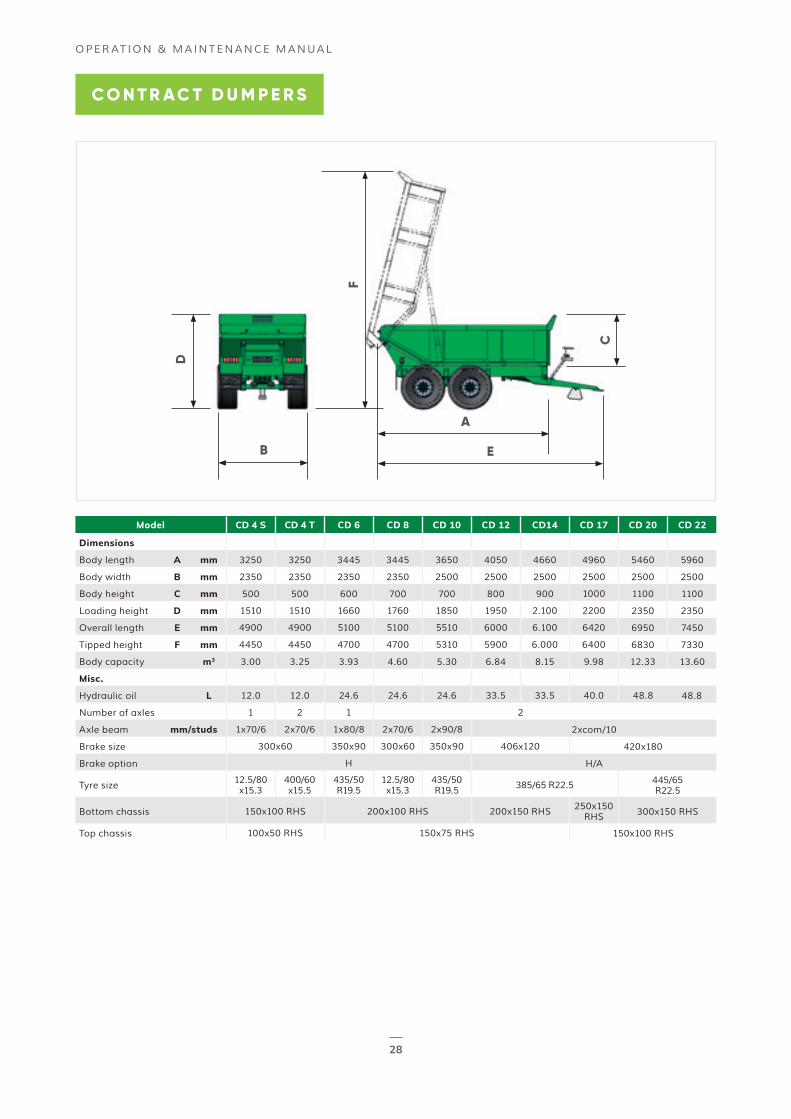
C O N T R A C T D U M P E R S
Model CD 4 S CD 4 T CD 6 CD 8 CD 10 CD 12 CD14 CD 17 CD 20 CD 22
Dimensions
Body length A mm 3250 3250 3445 3445 3650 4050 4660 4960 5460 5960
Body width B mm 2350 2350 2350 2350 2500 2500 2500 2500 2500 2500
Body height C mm 500 500 600 700 700 800 900 1000 1100 1100
Loading height D mm 1510 1510 1660 1760 1850 1950 2.100 2200 2350 2350
Overall length E mm 4900 4900 5100 5100 5510 6000 6.100 6420 6950 7450
Tipped height F mm 4450 4450 4700 4700 5310 5900 6.000 6400 6830 7330
Body capacity m3 3.00 3.25 3.93 4.60 5.30 6.84 8.15 9.98 12.33 13.60
Misc.
Hydraulic oil L 12.0 12.0 24.6 24.6 24.6 33.5 33.5 40.0 48.8 48.8
Number of axles 1 2 1 2
Axle beam mm/studs 1x70/6 2x70/6 1x80/8 2x70/6 2x90/8 2xcom/10
Brake size 300x60 350x90 300x60 350x90 406x120 420x180
Brake option H H/A
Tyre size 12.5/80 x15.3
400/60x15.5
435/50R19.5
12.5/80x15.3
435/50R19.5 385/65 R22.5 445/65
R22.5
Bottom chassis 150x100 RHS 200x100 RHS 200x150 RHS 250x150 RHS 300x150 RHS
Top chassis 100x50 RHS 150x75 RHS 150x100 RHS
E
A
F
B
D
C
29
O P E R AT I O N & M A I N T E N A N C E M A N UA L
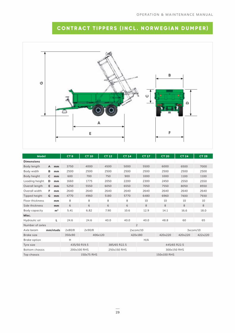
C O N T R A C T T I P P E R S ( I N C L . N O R W E G I A N D U M P E R )
E
A
G
B
F
C
D
Model CT 8 CT 10 CT 12 CT 14 CT 17 CT 20 CT 24 CT 28
Dimensions
Body length A mm 3750 4000 4500 5000 5500 6000 6500 7000
Body width B mm 2500 2500 2500 2500 2500 2500 2500 2500
Body height C mm 600 700 750 900 1000 1000 1100 1100
Loading height D mm 1660 1775 2050 2200 2300 2450 2550 2550
Overall length E mm 5250 5550 6050 6550 7050 7550 8050 8550
Overall width F mm 2640 2640 2640 2640 2640 2640 2640 2640
Tipped height G mm 4770 4960 5180 5770 6480 6960 7400 7930
Floor thickness mm 8 8 8 8 10 10 10 10
Side thickness mm 6 6 6 6 8 8 8 8
Body capacity m3 5.41 6.82 7.90 10.6 12.9 14.1 16.6 18.0
Misc.
Hydraulic oil L 24.6 24.6 40.0 40.0 40.0 48.8 60 65
Number of axles 2
Axle beam mm/studs 2x80/8 2x90/8 2xcom/10 3xcom/10
Brake size 350x90 406x120 420x180 420x220 420x220 422x220
Brake option H H/A
Tyre size 435/50 R19.5 385/65 R22.5 445/65 R22.5
Bottom chassis 200x100 RHS 250x150 RHS 300x150 RHS
Top chassis 150x75 RHS 150x100 RHS
30
O P E R AT I O N & M A I N T E N A N C E M A N UA L
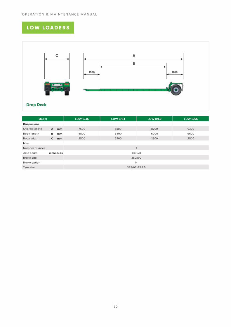
L O W L O A D E R S
Model LOW 8/46 LOW 8/54 LOW 8/60 LOW 8/66
Dimensions
Overall length A mm 7500 8100 8700 9300
Body length B mm 4800 5400 6000 6600
Body width C mm 2500 2500 2500 2500
Misc.
Number of axles 1
Axle beam mm/studs 1x90/8
Brake size 350x90
Brake option H
Tyre size 385/65xR22.5
Drop Deck
C A
B
12001500
31
O P E R AT I O N & M A I N T E N A N C E M A N UA L
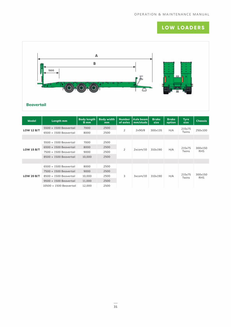
L O W L O A D E R S
Beavertail
A
B
1500
Model Length mm Body length B mm
Body width mm
Number of axles
Axle beam mm/studs
Brake size
Brake option
Tyre size Chassis
LOW 12 B/T5500 + 1500 Beavertail 7000 2500
2 2x90/8 300x135 H/A 215x75 Twins 250x100
6500 + 1500 Beavertail 8000 2500
LOW 15 B/T
5500 + 1500 Beavertail 7000 2500
2 2xcom/10 310x190 H/A 215x75 Twins
300x150 RHS
6500 + 1500 Beavertail 8000 2500
7500 + 1500 Beavertail 9000 2500
8500 + 1500 Beavertail 10,000 2500
LOW 20 B/T
6500 + 1500 Beavertail 8000 2500
3 3xcom/10 310x190 H/A 215x75 Twins
300x150 RHS
7500 + 1500 Beavertail 9000 2500
8500 + 1500 Beavertail 10,000 2500
9500 + 1500 Beavertail 11,000 2500
10500 + 1500 Beavertail 12,000 2500
32
O P E R AT I O N & M A I N T E N A N C E M A N UA L
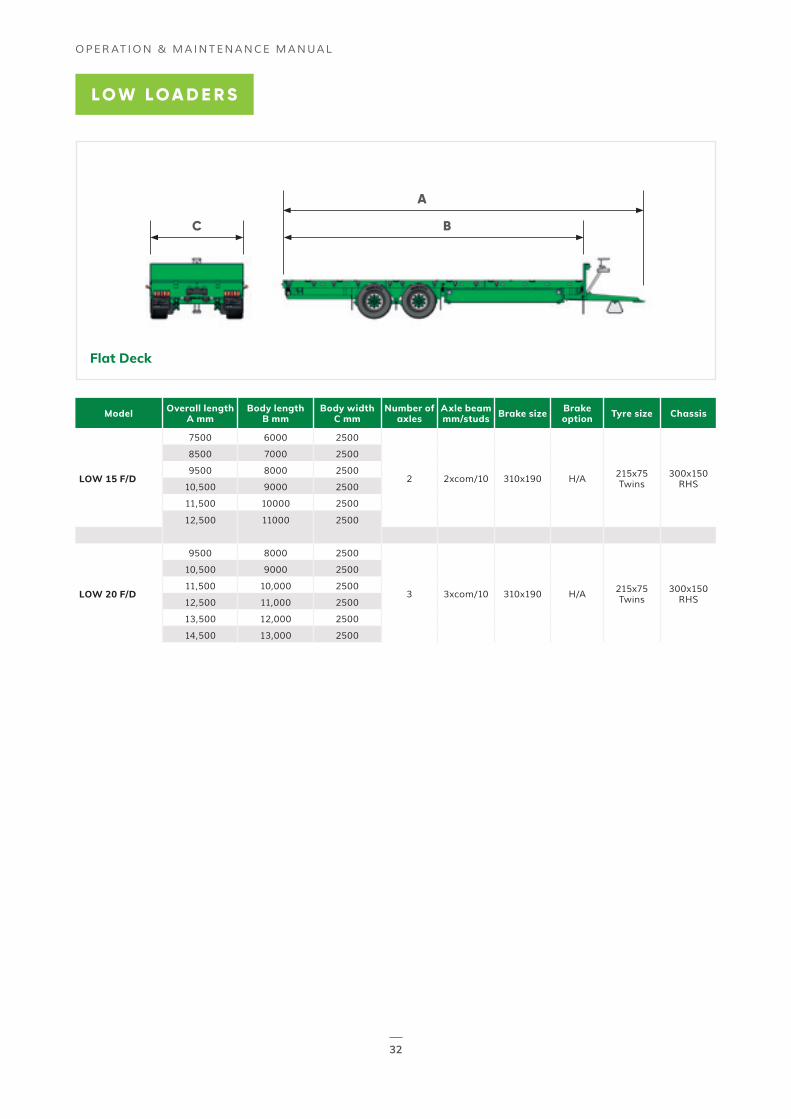
Flat Deck
A
BC
Model Overall length A mm
Body length B mm
Body width C mm
Number of axles
Axle beam mm/studs Brake size Brake
option Tyre size Chassis
LOW 15 F/D
7500 6000 2500
2 2xcom/10 310x190 H/A 215x75 Twins
300x150 RHS
8500 7000 2500
9500 8000 2500
10,500 9000 2500
11,500 10000 2500
12,500 11000 2500
LOW 20 F/D
9500 8000 2500
3 3xcom/10 310x190 H/A 215x75 Twins
300x150 RHS
10,500 9000 2500
11,500 10,000 2500
12,500 11,000 2500
13,500 12,000 2500
14,500 13,000 2500
L O W L O A D E R S
33
O P E R AT I O N & M A I N T E N A N C E M A N UA L
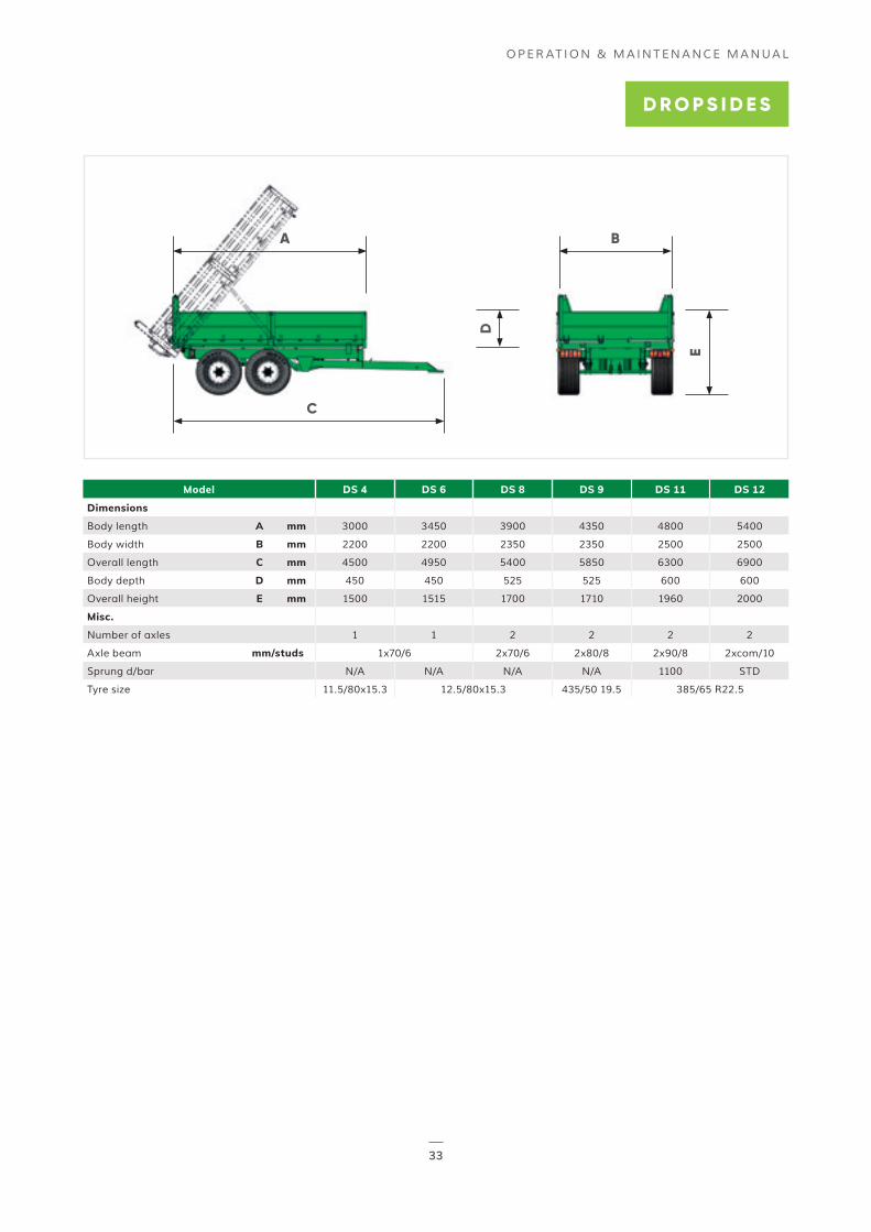
D R O P S I D E S
Model DS 4 DS 6 DS 8 DS 9 DS 11 DS 12
Dimensions
Body length A mm 3000 3450 3900 4350 4800 5400
Body width B mm 2200 2200 2350 2350 2500 2500
Overall length C mm 4500 4950 5400 5850 6300 6900
Body depth D mm 450 450 525 525 600 600
Overall height E mm 1500 1515 1700 1710 1960 2000
Misc.
Number of axles 1 1 2 2 2 2
Axle beam mm/studs 1x70/6 2x70/6 2x80/8 2x90/8 2xcom/10
Sprung d/bar N/A N/A N/A N/A 1100 STD
Tyre size 11.5/80x15.3 12.5/80x15.3 435/50 19.5 385/65 R22.5
BA
C
DE
34
O P E R AT I O N & M A I N T E N A N C E M A N UA L
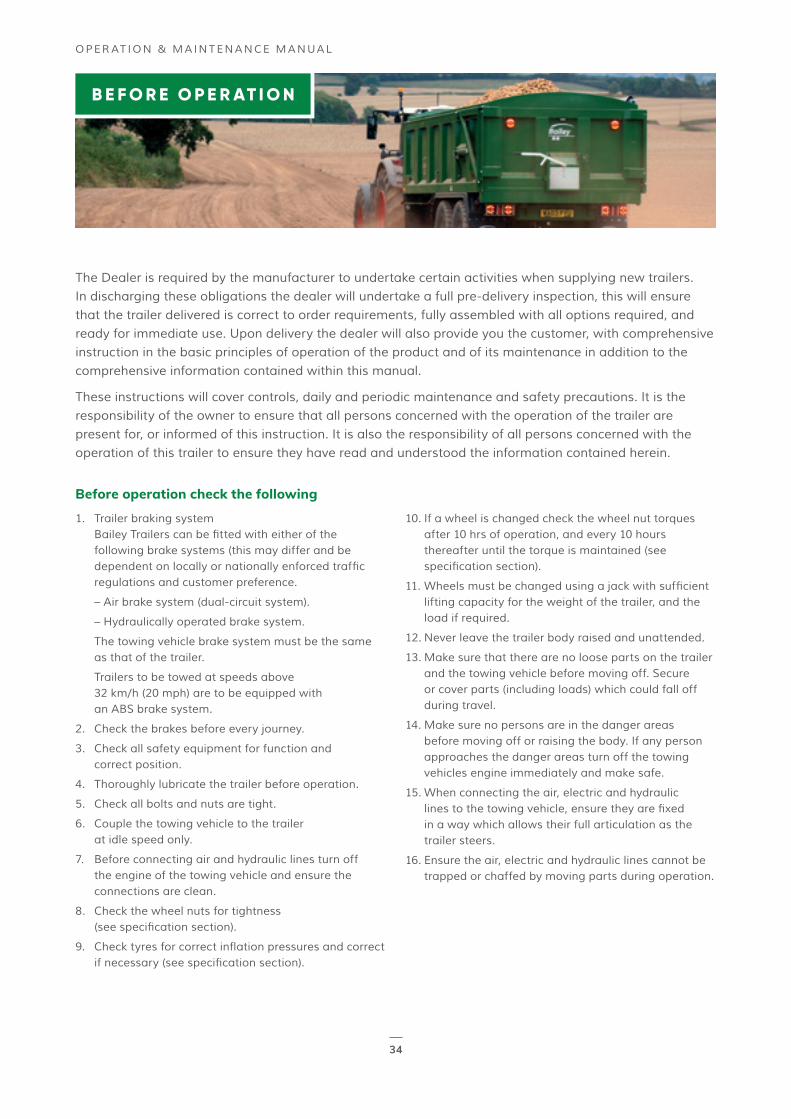
B E F O R E O P E R AT I O N
The Dealer is required by the manufacturer to undertake certain activities when supplying new trailers. In discharging these obligations the dealer will undertake a full pre-delivery inspection, this will ensure that the trailer delivered is correct to order requirements, fully assembled with all options required, and ready for immediate use. Upon delivery the dealer will also provide you the customer, with comprehensive instruction in the basic principles of operation of the product and of its maintenance in addition to the comprehensive information contained within this manual.
These instructions will cover controls, daily and periodic maintenance and safety precautions. It is the responsibility of the owner to ensure that all persons concerned with the operation of the trailer are present for, or informed of this instruction. It is also the responsibility of all persons concerned with the operation of this trailer to ensure they have read and understood the information contained herein.
Before operation check the following
1. Trailer braking system Bailey Trailers can be fitted with either of the
following brake systems (this may differ and be dependent on locally or nationally enforced traffic regulations and customer preference.
– Air brake system (dual-circuit system).
– Hydraulically operated brake system.
The towing vehicle brake system must be the same as that of the trailer.
Trailers to be towed at speeds above 32 km/h (20 mph) are to be equipped with an ABS brake system.
2. Check the brakes before every journey.
3. Check all safety equipment for function and correct position.
4. Thoroughly lubricate the trailer before operation.
5. Check all bolts and nuts are tight.
6. Couple the towing vehicle to the trailer at idle speed only.
7. Before connecting air and hydraulic lines turn off the engine of the towing vehicle and ensure the connections are clean.
8. Check the wheel nuts for tightness (see specification section).
9. Check tyres for correct inflation pressures and correct if necessary (see specification section).
10. If a wheel is changed check the wheel nut torques after 10 hrs of operation, and every 10 hours thereafter until the torque is maintained (see specification section).
11. Wheels must be changed using a jack with sufficient lifting capacity for the weight of the trailer, and the load if required.
12. Never leave the trailer body raised and unattended.
13. Make sure that there are no loose parts on the trailer and the towing vehicle before moving off. Secure or cover parts (including loads) which could fall off during travel.
14. Make sure no persons are in the danger areas before moving off or raising the body. If any person approaches the danger areas turn off the towing vehicles engine immediately and make safe.
15. When connecting the air, electric and hydraulic lines to the towing vehicle, ensure they are fixed in a way which allows their full articulation as the trailer steers.
16. Ensure the air, electric and hydraulic lines cannot be trapped or chaffed by moving parts during operation.
35
O P E R AT I O N & M A I N T E N A N C E M A N UA L
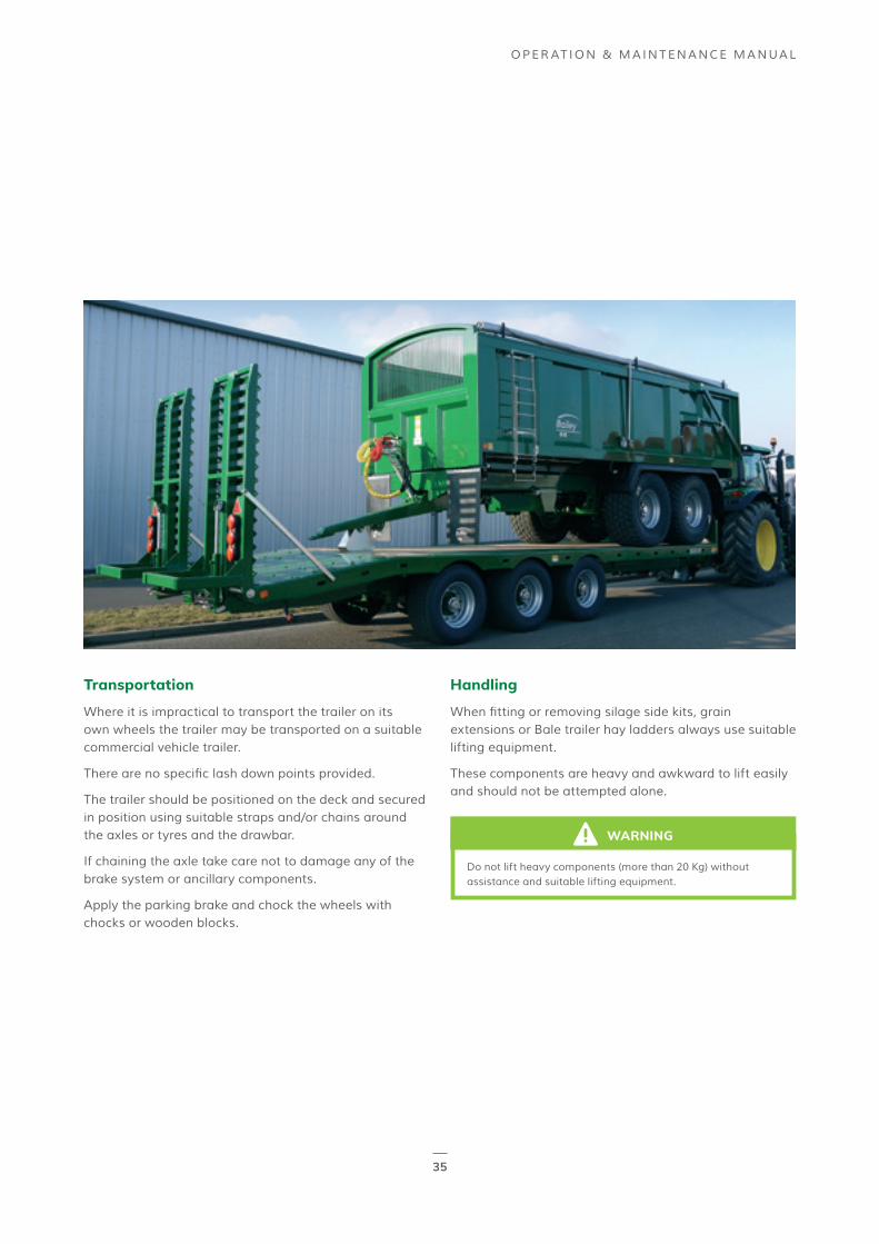
Transportation
Where it is impractical to transport the trailer on its own wheels the trailer may be transported on a suitable commercial vehicle trailer.
There are no specific lash down points provided.
The trailer should be positioned on the deck and secured in position using suitable straps and/or chains around the axles or tyres and the drawbar.
If chaining the axle take care not to damage any of the brake system or ancillary components.
Apply the parking brake and chock the wheels with chocks or wooden blocks.
Handling
When fitting or removing silage side kits, grain extensions or Bale trailer hay ladders always use suitable lifting equipment.
These components are heavy and awkward to lift easily and should not be attempted alone.
Do not lift heavy components (more than 20 Kg) without assistance and suitable lifting equipment.
WARNING
36
O P E R AT I O N & M A I N T E N A N C E M A N UA L
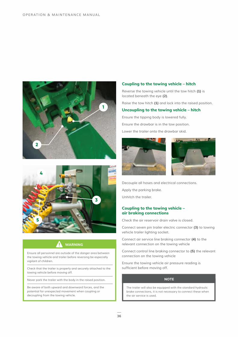
Coupling to the towing vehicle – hitch
Reverse the towing vehicle until the tow hitch (1) is located beneath the eye (2).
Raise the tow hitch (1) and lock into the raised position.
Uncoupling to the towing vehicle – hitch
Ensure the tipping body is lowered fully.
Ensure the drawbar is in the tow position.
Lower the trailer onto the drawbar skid.
Decouple all hoses and electrical connections.
Apply the parking brake.
Unhitch the trailer.
Ensure all personnel are outside of the danger area between the towing vehicle and trailer before reversing be especially vigilant of children.
Check that the trailer is properly and securely attached to the towing vehicle before moving off.
Never park the trailer with the body in the raised position.
Be aware of both upward and downward forces, and the potential for unexpected movement when coupling or decoupling from the towing vehicle.
WARNING
2
1
3
5
Coupling to the towing vehicle – air braking connections
Check the air reservoir drain valve is closed.
Connect seven pin trailer electric connector (3) to towing vehicle trailer lighting socket.
Connect air service line braking connector (4) to the relevant connection on the towing vehicle
Connect control line braking connector to (5) the relevant connection on the towing vehicle
Ensure the towing vehicle air pressure reading is sufficient before moving off.
The trailer will also be equipped with the standard hydraulic brake connections, it is not necessary to connect these when the air service is used.
NOTE
4
37
O P E R AT I O N & M A I N T E N A N C E M A N UA L
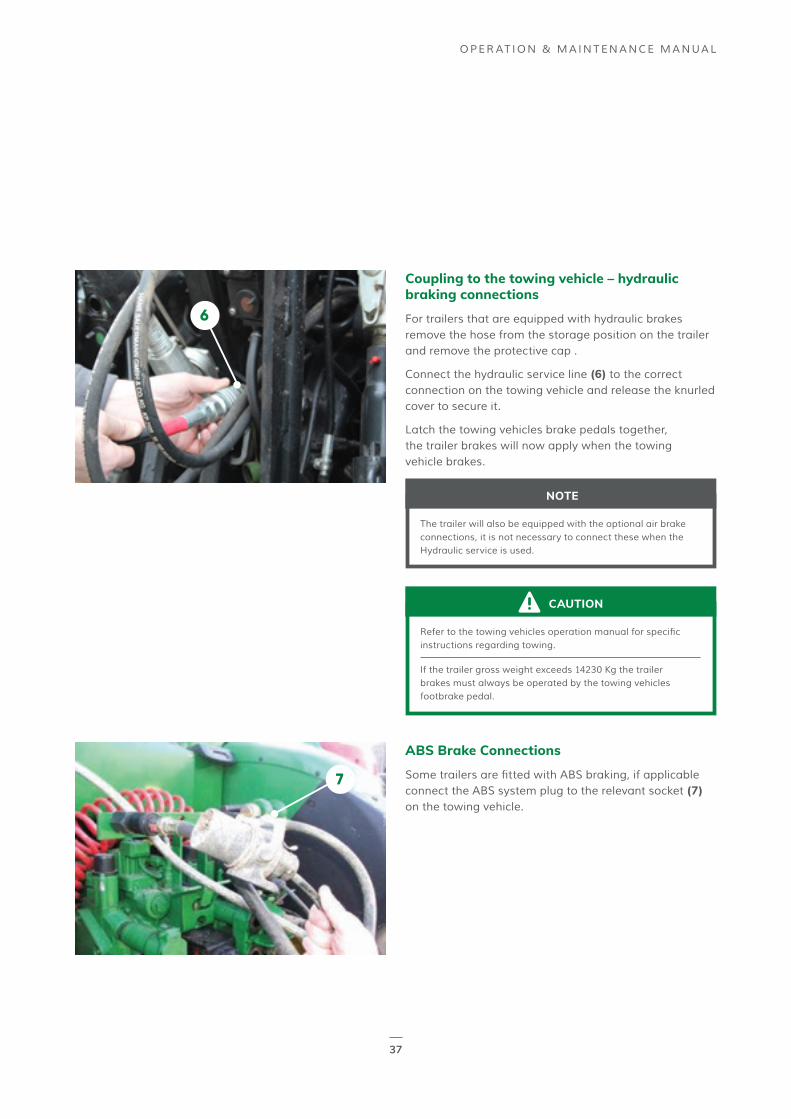
Coupling to the towing vehicle – hydraulic braking connections
For trailers that are equipped with hydraulic brakes remove the hose from the storage position on the trailer and remove the protective cap .
Connect the hydraulic service line (6) to the correct connection on the towing vehicle and release the knurled cover to secure it.
Latch the towing vehicles brake pedals together, the trailer brakes will now apply when the towing vehicle brakes.
ABS Brake Connections
Some trailers are fitted with ABS braking, if applicable connect the ABS system plug to the relevant socket (7) on the towing vehicle.
The trailer will also be equipped with the optional air brake connections, it is not necessary to connect these when the Hydraulic service is used.
NOTE
Refer to the towing vehicles operation manual for specific instructions regarding towing.
If the trailer gross weight exceeds 14230 Kg the trailer brakes must always be operated by the towing vehicles footbrake pedal.
CAUTION
7
6
38
O P E R AT I O N & M A I N T E N A N C E M A N UA L
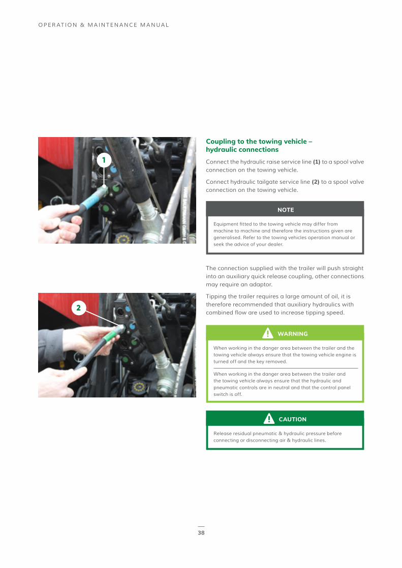
Coupling to the towing vehicle – hydraulic connections
Connect the hydraulic raise service line (1) to a spool valve connection on the towing vehicle.
Connect hydraulic tailgate service line (2) to a spool valve connection on the towing vehicle.
The connection supplied with the trailer will push straight into an auxiliary quick release coupling, other connections may require an adaptor.
Tipping the trailer requires a large amount of oil, it is therefore recommended that auxiliary hydraulics with combined flow are used to increase tipping speed.
Equipment fitted to the towing vehicle may differ from machine to machine and therefore the instructions given are generalised. Refer to the towing vehicles operation manual or seek the advice of your dealer.
NOTE
When working in the danger area between the trailer and the towing vehicle always ensure that the towing vehicle engine is turned off and the key removed.
When working in the danger area between the trailer and the towing vehicle always ensure that the hydraulic and pneumatic controls are in neutral and that the control panel switch is off.
WARNING
Release residual pneumatic & hydraulic pressure before connecting or disconnecting air & hydraulic lines.
CAUTION
1
2
39
O P E R AT I O N & M A I N T E N A N C E M A N UA L
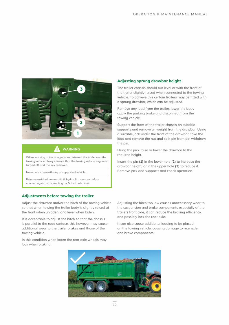
Adjusting sprung drawbar height
The trailer chassis should run level or with the front of the trailer slightly raised when connected to the towing vehicle. To achieve this certain trailers may be fitted with a sprung drawbar, which can be adjusted.
Remove any load from the trailer, lower the body apply the parking brake and disconnect from the towing vehicle.
Support the front of the trailer chassis on suitable supports and remove all weight from the drawbar. Using a suitable jack under the front of the drawbar, take the load and remove the nut and split pin from pin withdraw the pin.
Using the jack raise or lower the drawbar to the required height.
Insert the pin (1) in the lower hole (2) to increase the drawbar height, or in the upper hole (3) to reduce it. Remove jack and supports and check operation.
Adjustments before towing the trailer
Adjust the drawbar and/or the hitch of the towing vehicle so that when towing the trailer body is slightly raised at the front when unladen, and level when laden.
It is acceptable to adjust the hitch so that the chassis is parallel to the road surface, this however may cause additional wear to the trailer brakes and those of the towing vehicle.
In this condition when laden the rear axle wheels may lock when braking.
Adjusting the hitch too low causes unnecessary wear to the suspension and brake components especially of the trailers front axle, it can reduce the braking efficiency, and possibly lock the rear axle.
It can also cause additional loading to be placed on the towing vehicle, causing damage to rear axle and brake components.
3
When working in the danger area between the trailer and the towing vehicle always ensure that the towing vehicle engine is turned off and the key removed.
Never work beneath any unsupported vehicle.
Release residual pneumatic & hydraulic pressure before connecting or disconnecting air & hydraulic lines.
WARNING
2
1
40
O P E R AT I O N & M A I N T E N A N C E M A N UA L
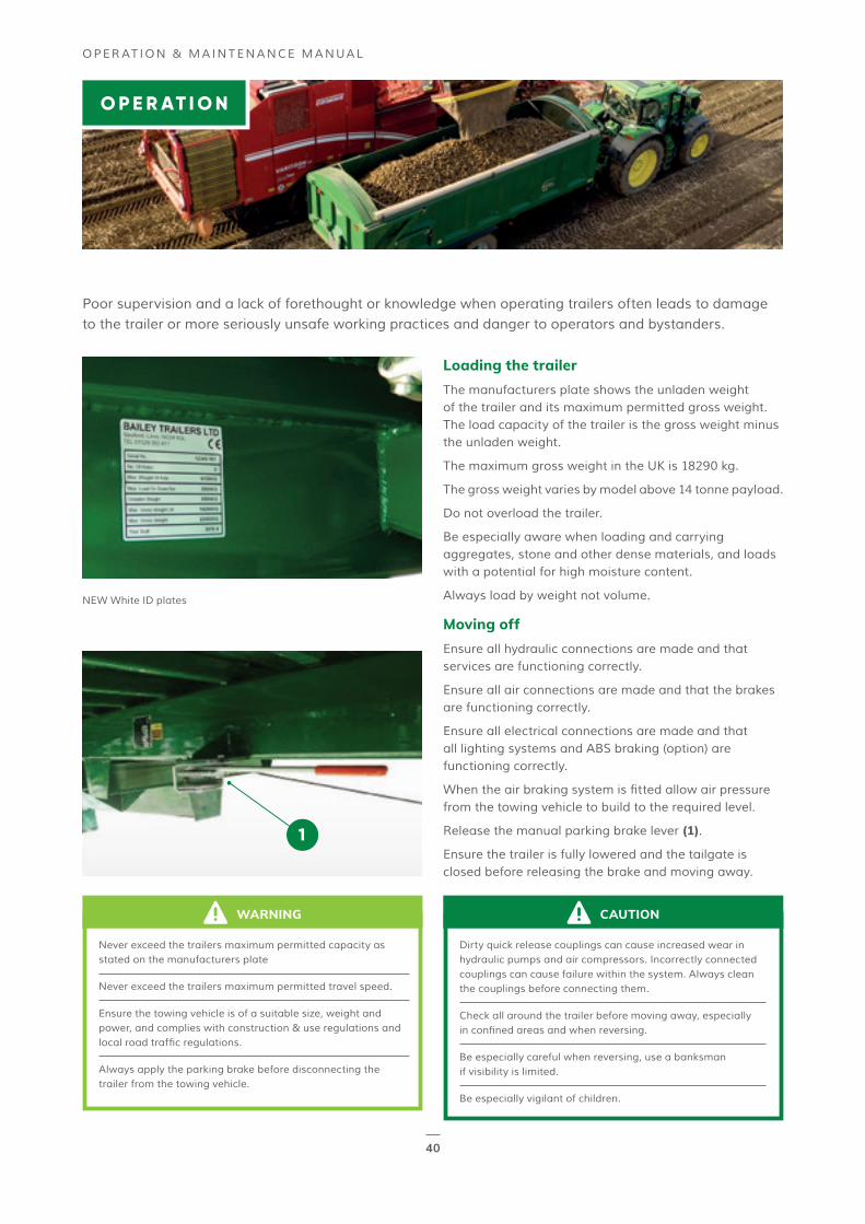
Loading the trailer The manufacturers plate shows the unladen weight of the trailer and its maximum permitted gross weight. The load capacity of the trailer is the gross weight minus the unladen weight.
The maximum gross weight in the UK is 18290 kg.
The gross weight varies by model above 14 tonne payload.
Do not overload the trailer.
Be especially aware when loading and carrying aggregates, stone and other dense materials, and loads with a potential for high moisture content.
Always load by weight not volume.
Moving off Ensure all hydraulic connections are made and that services are functioning correctly.
Ensure all air connections are made and that the brakes are functioning correctly.
Ensure all electrical connections are made and that all lighting systems and ABS braking (option) are functioning correctly.
When the air braking system is fitted allow air pressure from the towing vehicle to build to the required level.
Release the manual parking brake lever (1).
Ensure the trailer is fully lowered and the tailgate is closed before releasing the brake and moving away.
1
Never exceed the trailers maximum permitted capacity as stated on the manufacturers plate
Never exceed the trailers maximum permitted travel speed.
Ensure the towing vehicle is of a suitable size, weight and power, and complies with construction & use regulations and local road traffic regulations.
Always apply the parking brake before disconnecting the trailer from the towing vehicle.
WARNING
Dirty quick release couplings can cause increased wear in hydraulic pumps and air compressors. Incorrectly connected couplings can cause failure within the system. Always clean the couplings before connecting them.
Check all around the trailer before moving away, especially in confined areas and when reversing.
Be especially careful when reversing, use a banksman if visibility is limited.
Be especially vigilant of children.
CAUTION
O P E R AT I O N
Poor supervision and a lack of forethought or knowledge when operating trailers often leads to damage to the trailer or more seriously unsafe working practices and danger to operators and bystanders.
NEW White ID plates
41
O P E R AT I O N & M A I N T E N A N C E M A N UA L
Before discharging ensure no persons or obstructions are in the tipping zone.
If drawing forward to enable discharge be aware the trailer will be less stable. Take extreme care and lower the tipping body as soon as soon as fully discharged.
WARNING
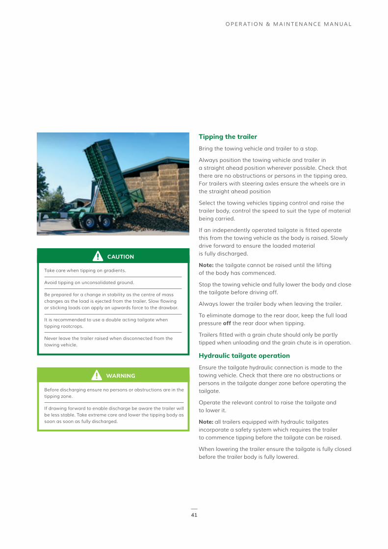
Tipping the trailer
Bring the towing vehicle and trailer to a stop.
Always position the towing vehicle and trailer in a straight ahead position wherever possible. Check that there are no obstructions or persons in the tipping area. For trailers with steering axles ensure the wheels are in the straight ahead position
Select the towing vehicles tipping control and raise the trailer body, control the speed to suit the type of material being carried.
If an independently operated tailgate is fitted operate this from the towing vehicle as the body is raised. Slowly drive forward to ensure the loaded material is fully discharged.
Note: the tailgate cannot be raised until the lifting of the body has commenced.
Stop the towing vehicle and fully lower the body and close the tailgate before driving off.
Always lower the trailer body when leaving the trailer.
To eliminate damage to the rear door, keep the full load pressure off the rear door when tipping.
Trailers fitted with a grain chute should only be partly tipped when unloading and the grain chute is in operation.
Hydraulic tailgate operation
Ensure the tailgate hydraulic connection is made to the towing vehicle. Check that there are no obstructions or persons in the tailgate danger zone before operating the tailgate.
Operate the relevant control to raise the tailgate and to lower it.
Note: all trailers equipped with hydraulic tailgates incorporate a safety system which requires the trailer to commence tipping before the tailgate can be raised.
When lowering the trailer ensure the tailgate is fully closed before the trailer body is fully lowered.
Take care when tipping on gradients.
Avoid tipping on unconsolidated ground.
Be prepared for a change in stability as the centre of mass changes as the load is ejected from the trailer. Slow flowing or sticking loads can apply an upwards force to the drawbar.
It is recommended to use a double acting tailgate when tipping rootcrops.
Never leave the trailer raised when disconnected from the towing vehicle.
CAUTION
42
O P E R AT I O N & M A I N T E N A N C E M A N UA L
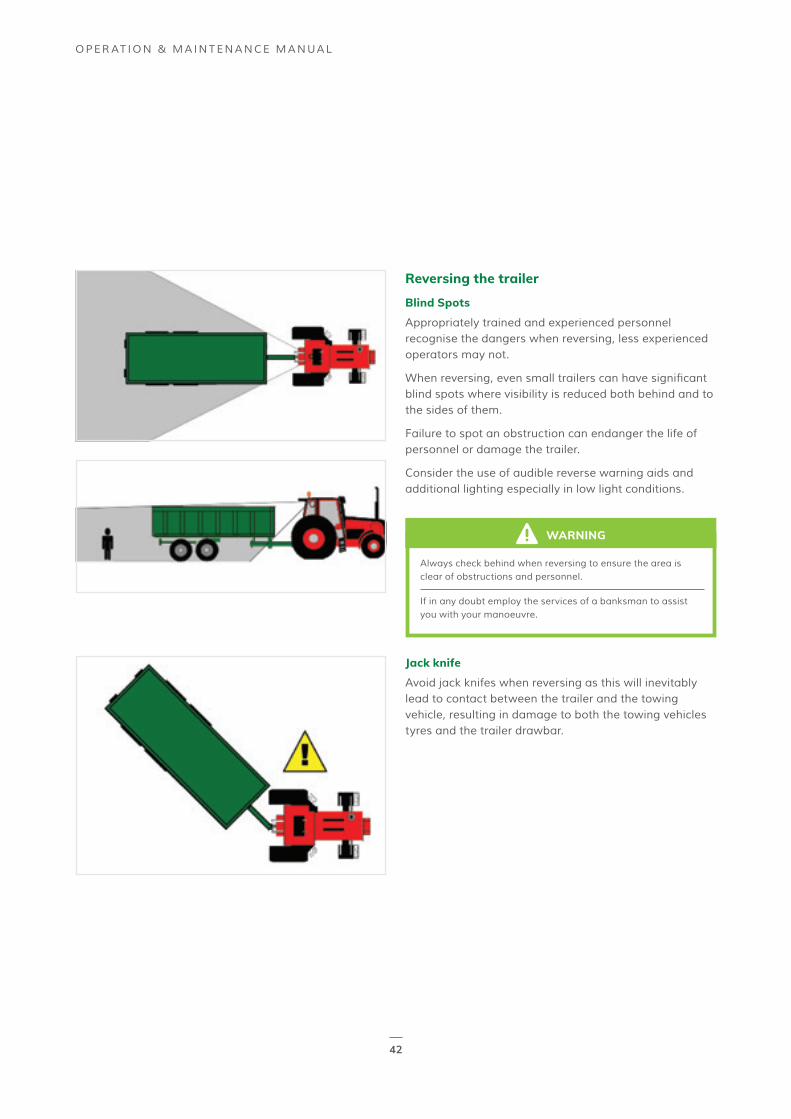
Reversing the trailer
Blind Spots
Appropriately trained and experienced personnel recognise the dangers when reversing, less experienced operators may not.
When reversing, even small trailers can have significant blind spots where visibility is reduced both behind and to the sides of them.
Failure to spot an obstruction can endanger the life of personnel or damage the trailer.
Consider the use of audible reverse warning aids and additional lighting especially in low light conditions.
Jack knife
Avoid jack knifes when reversing as this will inevitably lead to contact between the trailer and the towing vehicle, resulting in damage to both the towing vehicles tyres and the trailer drawbar.
Always check behind when reversing to ensure the area is clear of obstructions and personnel.
If in any doubt employ the services of a banksman to assist you with your manoeuvre.
WARNING
43
O P E R AT I O N & M A I N T E N A N C E M A N UA L
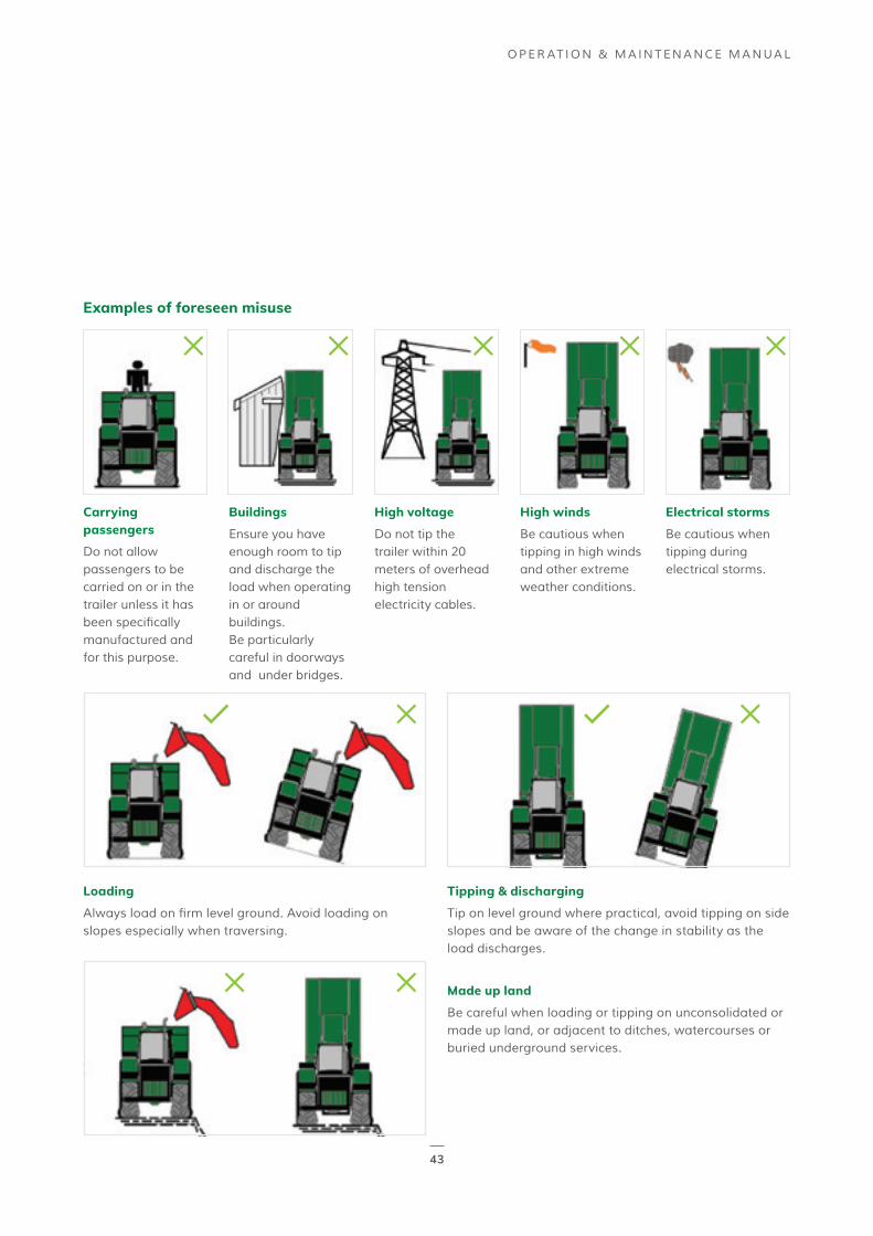
Carrying passengers
Do not allow passengers to be carried on or in the trailer unless it has been specifically manufactured and for this purpose.
Buildings
Ensure you have enough room to tip and discharge the load when operating in or around buildings. Be particularly careful in doorways and under bridges.
High voltage
Do not tip the trailer within 20 meters of overhead high tension electricity cables.
High winds
Be cautious when tipping in high winds and other extreme weather conditions.
Electrical storms
Be cautious when tipping during electrical storms.
Loading
Always load on firm level ground. Avoid loading on slopes especially when traversing.
Made up land
Be careful when loading or tipping on unconsolidated or made up land, or adjacent to ditches, watercourses or buried underground services.
Tipping & discharging
Tip on level ground where practical, avoid tipping on side slopes and be aware of the change in stability as the load discharges.
Examples of foreseen misuse
44
O P E R AT I O N & M A I N T E N A N C E M A N UA L
Correct Installation and regular maintenance will do much to prevent annoying and unnecessary breakdowns.
The service and maintenance schedule must be adhered to ensure the optimum availability and efficiency of the trailer is maintained. Bailey Trailers are designed with the safety of operator in mind. Whilst trailers are provided with a means to support a partially raised tipping body (see Page 17), this is not a recommended means of
Maintenance or repair. The design of the trailer is such that all common Service, Adjustment, Maintenance and Repair operations can be carried out from ground level with the tipping body lowered.
Failure to adhere to these schedules may cause damage to the trailer and possibly endanger the operator and others.
The warranty given for the trailer will become void if the maintenance schedule is not followed.
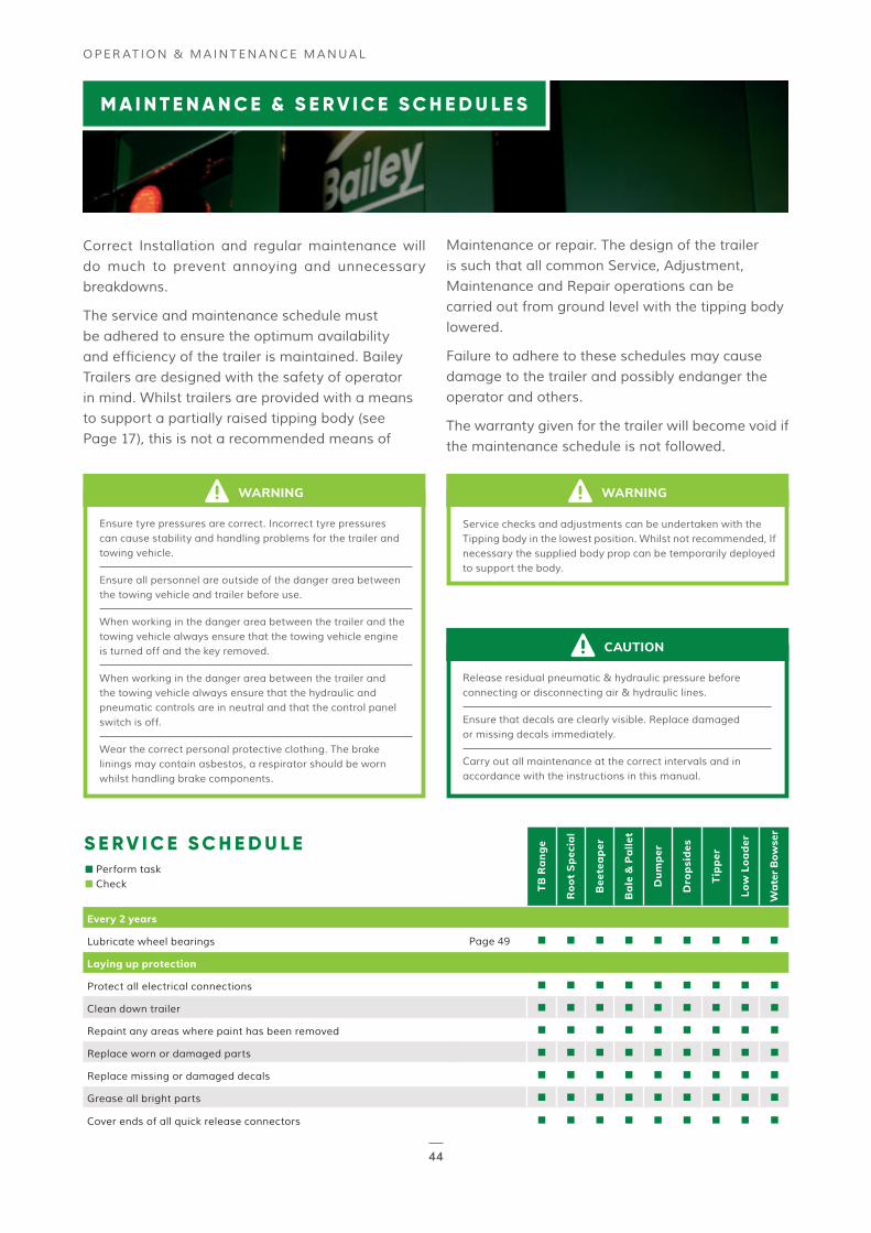
M A I N T E N A N C E & S E R V I C E S C H E D U L E S
Ensure tyre pressures are correct. Incorrect tyre pressures can cause stability and handling problems for the trailer and towing vehicle.
Ensure all personnel are outside of the danger area between the towing vehicle and trailer before use.
When working in the danger area between the trailer and the towing vehicle always ensure that the towing vehicle engine is turned off and the key removed.
When working in the danger area between the trailer and the towing vehicle always ensure that the hydraulic and pneumatic controls are in neutral and that the control panel switch is off.
Wear the correct personal protective clothing. The brake linings may contain asbestos, a respirator should be worn whilst handling brake components.
WARNING
Service checks and adjustments can be undertaken with the Tipping body in the lowest position. Whilst not recommended, If necessary the supplied body prop can be temporarily deployed to support the body.
WARNING
Release residual pneumatic & hydraulic pressure before connecting or disconnecting air & hydraulic lines.
Ensure that decals are clearly visible. Replace damaged or missing decals immediately.
Carry out all maintenance at the correct intervals and in accordance with the instructions in this manual.
CAUTION
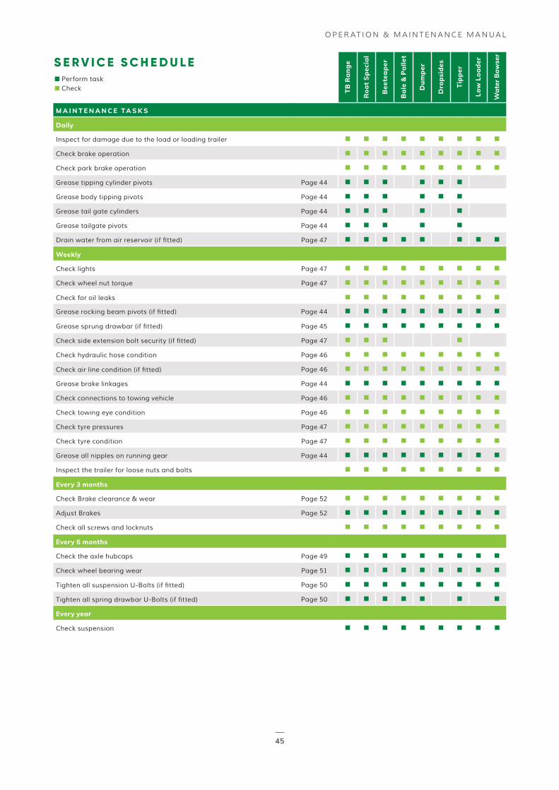
S E R V I C E S C H E D U L E■ Perform task■ Check TB
Ran
ge
Roo
t S
peci
al
Bee
teap
er
Bal
e &
Pal
let
Dum
per
Dro
psid
es
Tipp
er
Low
Loa
der
Wat
er B
owse
r
Every 2 years
Lubricate wheel bearings Page 49 ■ ■ ■ ■ ■ ■ ■ ■ ■
Laying up protection
Protect all electrical connections ■ ■ ■ ■ ■ ■ ■ ■ ■
Clean down trailer ■ ■ ■ ■ ■ ■ ■ ■ ■
Repaint any areas where paint has been removed ■ ■ ■ ■ ■ ■ ■ ■ ■
Replace worn or damaged parts ■ ■ ■ ■ ■ ■ ■ ■ ■
Replace missing or damaged decals ■ ■ ■ ■ ■ ■ ■ ■ ■
Grease all bright parts ■ ■ ■ ■ ■ ■ ■ ■ ■
Cover ends of all quick release connectors ■ ■ ■ ■ ■ ■ ■ ■ ■
45
O P E R AT I O N & M A I N T E N A N C E M A N UA L
S E R V I C E S C H E D U L E■ Perform task■ Check TB
Ran
ge
Roo
t S
peci
al
Bee
teap
er
Bal
e &
Pal
let
Dum
per
Dro
psid
es
Tipp
er
Low
Loa
der
Wat
er B
owse
r
M A I N T E N A N C E TA S K S
Daily
Inspect for damage due to the load or loading trailer ■ ■ ■ ■ ■ ■ ■ ■ ■
Check brake operation ■ ■ ■ ■ ■ ■ ■ ■ ■
Check park brake operation ■ ■ ■ ■ ■ ■ ■ ■ ■
Grease tipping cylinder pivots Page 44 ■ ■ ■ ■ ■ ■
Grease body tipping pivots Page 44 ■ ■ ■ ■ ■ ■
Grease tail gate cylinders Page 44 ■ ■ ■ ■ ■
Grease tailgate pivots Page 44 ■ ■ ■ ■ ■
Drain water from air reservoir (if fitted) Page 47 ■ ■ ■ ■ ■ ■ ■ ■
Weekly
Check lights Page 47 ■ ■ ■ ■ ■ ■ ■ ■ ■
Check wheel nut torque Page 47 ■ ■ ■ ■ ■ ■ ■ ■ ■
Check for oil leaks ■ ■ ■ ■ ■ ■ ■ ■ ■
Grease rocking beam pivots (if fitted) Page 44 ■ ■ ■ ■ ■ ■ ■ ■ ■
Grease sprung drawbar (if fitted) Page 45 ■ ■ ■ ■ ■ ■ ■ ■ ■
Check side extension bolt security (if fitted) Page 47 ■ ■ ■ ■
Check hydraulic hose condition Page 46 ■ ■ ■ ■ ■ ■ ■ ■ ■
Check air line condition (if fitted) Page 46 ■ ■ ■ ■ ■ ■ ■ ■ ■
Grease brake linkages Page 44 ■ ■ ■ ■ ■ ■ ■ ■ ■
Check connections to towing vehicle Page 46 ■ ■ ■ ■ ■ ■ ■ ■ ■
Check towing eye condition Page 46 ■ ■ ■ ■ ■ ■ ■ ■ ■
Check tyre pressures Page 47 ■ ■ ■ ■ ■ ■ ■ ■ ■
Check tyre condition Page 47 ■ ■ ■ ■ ■ ■ ■ ■ ■
Grease all nipples on running gear Page 44 ■ ■ ■ ■ ■ ■ ■ ■ ■
Inspect the trailer for loose nuts and bolts ■ ■ ■ ■ ■ ■ ■ ■ ■
Every 3 months
Check Brake clearance & wear Page 52 ■ ■ ■ ■ ■ ■ ■ ■ ■
Adjust Brakes Page 52 ■ ■ ■ ■ ■ ■ ■ ■ ■
Check all screws and locknuts ■ ■ ■ ■ ■ ■ ■ ■ ■
Every 6 months
Check the axle hubcaps Page 49 ■ ■ ■ ■ ■ ■ ■ ■ ■
Check wheel bearing wear Page 51 ■ ■ ■ ■ ■ ■ ■ ■ ■
Tighten all suspension U-Bolts (if fitted) Page 50 ■ ■ ■ ■ ■ ■ ■ ■ ■
Tighten all spring drawbar U-Bolts (if fitted) Page 50 ■ ■ ■ ■ ■ ■ ■
Every year
Check suspension ■ ■ ■ ■ ■ ■ ■ ■ ■
46
O P E R AT I O N & M A I N T E N A N C E M A N UA L
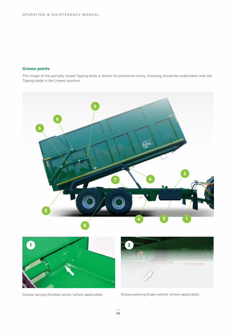
Grease sprung drawbar pivots (where applicable). Grease parking brake ratchet (where applicable).
Grease points
The image of the partially raised Tipping body is shown for positional clarity. Greasing should be undertaken with the Tipping body in the Lowest position.
6
5
8
7 42
4 3 1
6
6
1 2
47
O P E R AT I O N & M A I N T E N A N C E M A N UA L
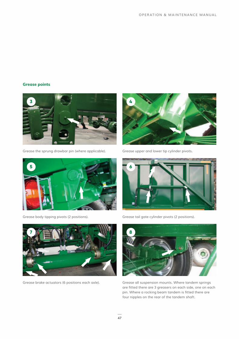
Grease points
Grease the sprung drawbar pin (where applicable).
Grease body tipping pivots (2 positions).
Grease brake actuators (6 positions each axle).
Grease upper and lower tip cylinder pivots.
Grease tail gate cylinder pivots (2 positions).
Grease all suspension mounts. Where tandem springs are fitted there are 3 greasers on each side, one on each pin. Where a rocking beam tandem is fitted there are four nipples on the rear of the tandem shaft.
3
5
7
4
6
8
48
O P E R AT I O N & M A I N T E N A N C E M A N UA L
1
2
34
5
6
7
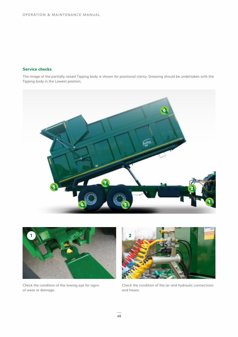
Check the condition of the towing eye for signs of wear or damage.
Check the condition of the air and hydraulic connections and hoses.
21
Service checks
The image of the partially raised Tipping body is shown for positional clarity. Greasing should be undertaken with the Tipping body in the Lowest position.
49
O P E R AT I O N & M A I N T E N A N C E M A N UA L
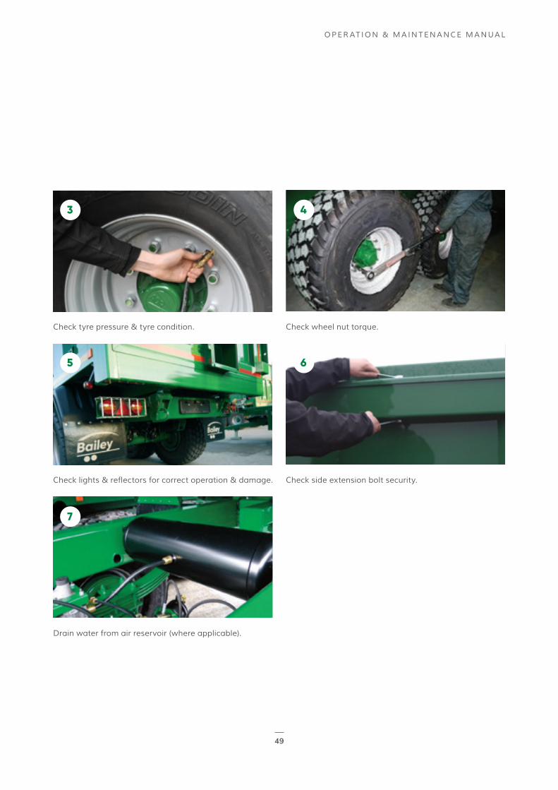
Check tyre pressure & tyre condition.
Check lights & reflectors for correct operation & damage.
Drain water from air reservoir (where applicable).
Check wheel nut torque.
Check side extension bolt security.
4
6
3
5
7
50
O P E R AT I O N & M A I N T E N A N C E M A N UA L
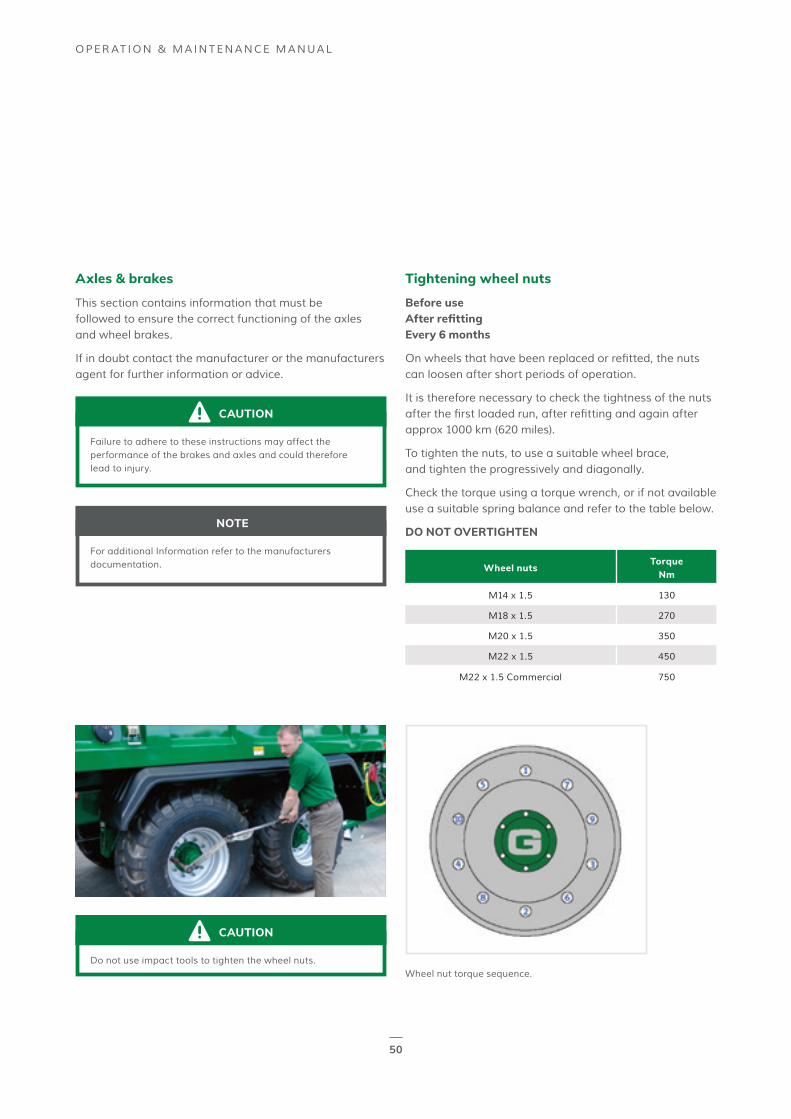
Axles & brakes
This section contains information that must be followed to ensure the correct functioning of the axles and wheel brakes.
If in doubt contact the manufacturer or the manufacturers agent for further information or advice.
Tightening wheel nuts
Before useAfterrefittingEvery 6 months
On wheels that have been replaced or refitted, the nuts can loosen after short periods of operation.
It is therefore necessary to check the tightness of the nuts after the first loaded run, after refitting and again after approx 1000 km (620 miles).
To tighten the nuts, to use a suitable wheel brace, and tighten the progressively and diagonally.
Check the torque using a torque wrench, or if not available use a suitable spring balance and refer to the table below.
DO NOT OVERTIGHTEN
Failure to adhere to these instructions may affect the performance of the brakes and axles and could therefore lead to injury.
CAUTION
Do not use impact tools to tighten the wheel nuts.
CAUTION
For additional Information refer to the manufacturers documentation.
NOTE
Wheel nutsTorque
Nm
M14 x 1.5 130
M18 x 1.5 270
M20 x 1.5 350
M22 x 1.5 450
M22 x 1.5 Commercial 750
Wheel nut torque sequence.
51
O P E R AT I O N & M A I N T E N A N C E M A N UA L
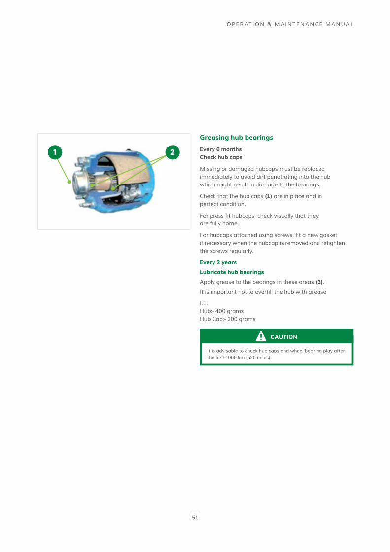
Greasing hub bearings
Every 6 monthsCheck hub caps
Missing or damaged hubcaps must be replaced immediately to avoid dirt penetrating into the hub which might result in damage to the bearings.
Check that the hub caps (1) are in place and in perfect condition.
For press fit hubcaps, check visually that they are fully home.
For hubcaps attached using screws, fit a new gasket if necessary when the hubcap is removed and retighten the screws regularly.
Every 2 years
Lubricate hub bearings
Apply grease to the bearings in these areas (2).
It is important not to overfill the hub with grease.
I.E.Hub:- 400 gramsHub Cap:- 200 grams
1 2
It is advisable to check hub caps and wheel bearing play after the first 1000 km (620 miles).
CAUTION
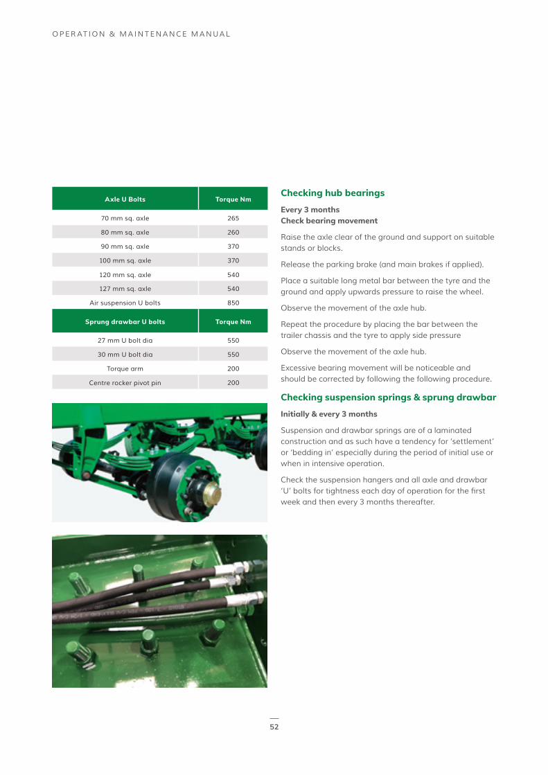
52
O P E R AT I O N & M A I N T E N A N C E M A N UA L
Axle U Bolts Torque Nm
70 mm sq. axle 265
80 mm sq. axle 260
90 mm sq. axle 370
100 mm sq. axle 370
120 mm sq. axle 540
127 mm sq. axle 540
Air suspension U bolts 850
Sprung drawbar U bolts Torque Nm
27 mm U bolt dia 550
30 mm U bolt dia 550
Torque arm 200
Centre rocker pivot pin 200
Checking hub bearings
Every 3 monthsCheck bearing movement
Raise the axle clear of the ground and support on suitable stands or blocks.
Release the parking brake (and main brakes if applied).
Place a suitable long metal bar between the tyre and the ground and apply upwards pressure to raise the wheel.
Observe the movement of the axle hub.
Repeat the procedure by placing the bar between the trailer chassis and the tyre to apply side pressure
Observe the movement of the axle hub.
Excessive bearing movement will be noticeable and should be corrected by following the following procedure.
Checking suspension springs & sprung drawbar
Initially & every 3 months
Suspension and drawbar springs are of a laminated construction and as such have a tendency for ‘settlement’ or ‘bedding in’ especially during the period of initial use or when in intensive operation.
Check the suspension hangers and all axle and drawbar ‘U’ bolts for tightness each day of operation for the first week and then every 3 months thereafter.
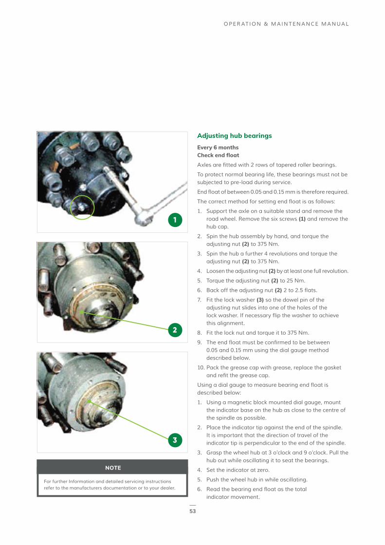
53
O P E R AT I O N & M A I N T E N A N C E M A N UA L
Adjusting hub bearings
Every 6 monthsCheckendfloat
Axles are fitted with 2 rows of tapered roller bearings.
To protect normal bearing life, these bearings must not be subjected to pre-load during service.
End float of between 0.05 and 0.15 mm is therefore required.
The correct method for setting end float is as follows:
1. Support the axle on a suitable stand and remove the road wheel. Remove the six screws (1) and remove the hub cap.
2. Spin the hub assembly by hand, and torque the adjusting nut (2) to 375 Nm.
3. Spin the hub a further 4 revolutions and torque the adjusting nut (2) to 375 Nm.
4. Loosen the adjusting nut (2) by at least one full revolution.
5. Torque the adjusting nut (2) to 25 Nm.
6. Back off the adjusting nut (2) 2 to 2.5 flats.
7. Fit the lock washer (3) so the dowel pin of the adjusting nut slides into one of the holes of the lock washer. If necessary flip the washer to achieve this alignment.
8. Fit the lock nut and torque it to 375 Nm.
9. The end float must be confirmed to be between 0.05 and 0.15 mm using the dial gauge method described below.
10. Pack the grease cap with grease, replace the gasket and refit the grease cap.
Using a dial gauge to measure bearing end float is described below:
1. Using a magnetic block mounted dial gauge, mount the indicator base on the hub as close to the centre of the spindle as possible.
2. Place the indicator tip against the end of the spindle. It is important that the direction of travel of the indicator tip is perpendicular to the end of the spindle.
3. Grasp the wheel hub at 3 o’clock and 9 o’clock. Pull the hub out while oscillating it to seat the bearings.
4. Set the indicator at zero.
5. Push the wheel hub in while oscillating.
6. Read the bearing end float as the total indicator movement.
For further Information and detailed servicing instructions refer to the manufacturers documentation or to your dealer.
NOTE
1
2
3
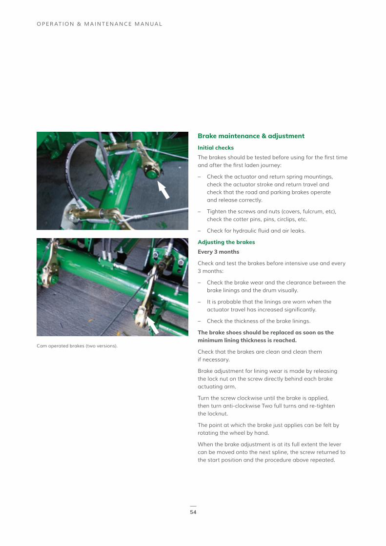
54
O P E R AT I O N & M A I N T E N A N C E M A N UA L
Brake maintenance & adjustment
Initial checks
The brakes should be tested before using for the first time and after the first laden journey:
– Check the actuator and return spring mountings, check the actuator stroke and return travel and check that the road and parking brakes operate and release correctly.
– Tighten the screws and nuts (covers, fulcrum, etc), check the cotter pins, pins, circlips, etc.
– Check for hydraulic fluid and air leaks.
Adjusting the brakes
Every 3 months
Check and test the brakes before intensive use and every 3 months:
– Check the brake wear and the clearance between the brake linings and the drum visually.
– It is probable that the linings are worn when the actuator travel has increased significantly.
– Check the thickness of the brake linings.
The brake shoes should be replaced as soon as the minimum lining thickness is reached.
Check that the brakes are clean and clean them if necessary.
Brake adjustment for lining wear is made by releasing the lock nut on the screw directly behind each brake actuating arm.
Turn the screw clockwise until the brake is applied, then turn anti-clockwise Two full turns and re-tighten the locknut.
The point at which the brake just applies can be felt by rotating the wheel by hand.
When the brake adjustment is at its full extent the lever can be moved onto the next spline, the screw returned to the start position and the procedure above repeated.
Cam operated brakes (two versions).
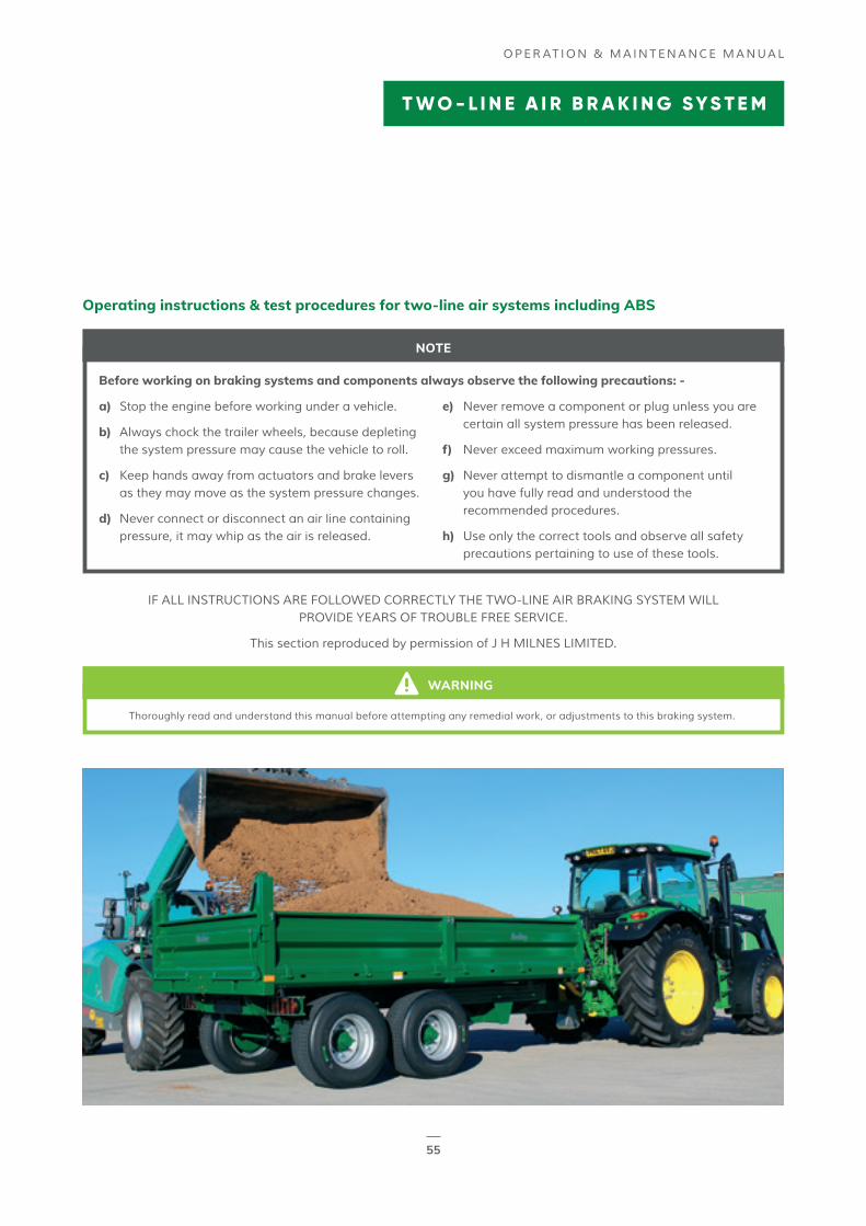
55
O P E R AT I O N & M A I N T E N A N C E M A N UA L
Operating instructions & test procedures for two-line air systems including ABS
IF ALL INSTRUCTIONS ARE FOLLOWED CORRECTLY THE TWO-LINE AIR BRAKING SYSTEM WILL PROVIDE YEARS OF TROUBLE FREE SERVICE.
This section reproduced by permission of J H MILNES LIMITED.
Thoroughly read and understand this manual before attempting any remedial work, or adjustments to this braking system.
WARNING
T W O - L I N E A I R B R A K I N G S Y S T E M
Before working on braking systems and components always observe the following precautions: -
a) Stop the engine before working under a vehicle.
b) Always chock the trailer wheels, because depleting the system pressure may cause the vehicle to roll.
c) Keep hands away from actuators and brake levers as they may move as the system pressure changes.
d) Never connect or disconnect an air line containing pressure, it may whip as the air is released.
e) Never remove a component or plug unless you are certain all system pressure has been released.
f) Never exceed maximum working pressures.
g) Never attempt to dismantle a component until you have fully read and understood the recommended procedures.
h) Use only the correct tools and observe all safety precautions pertaining to use of these tools.
NOTE
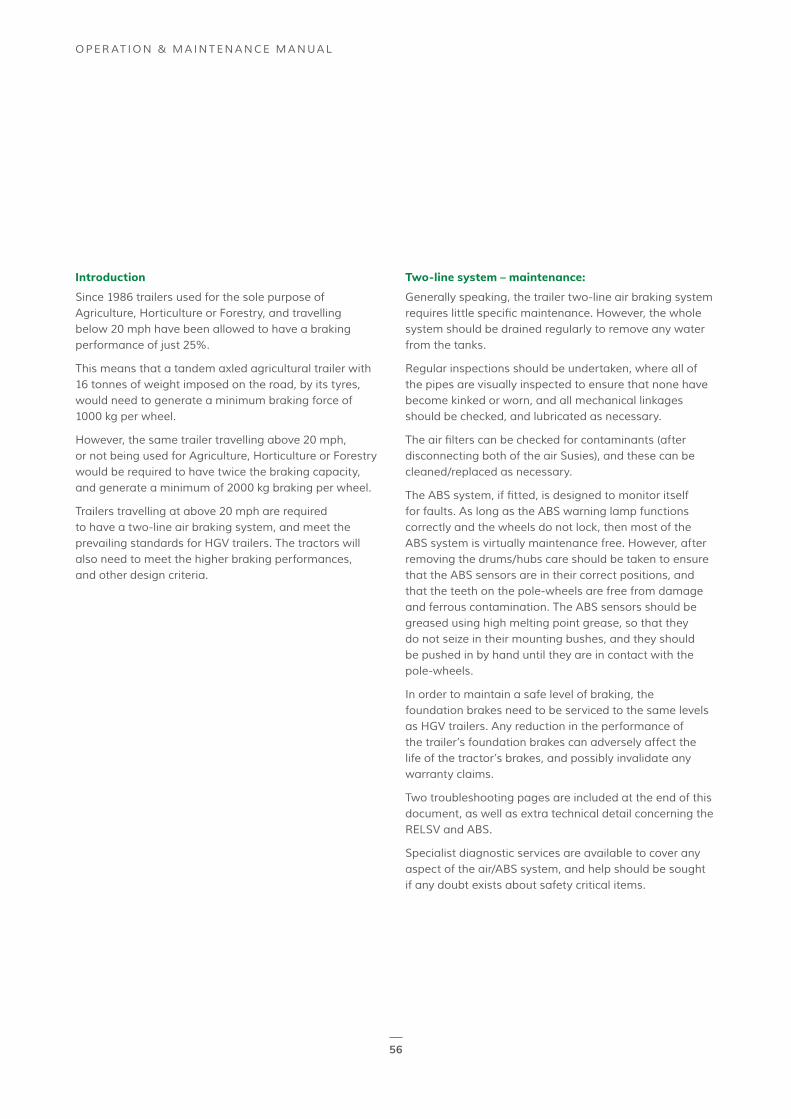
56
O P E R AT I O N & M A I N T E N A N C E M A N UA L
Introduction
Since 1986 trailers used for the sole purpose of Agriculture, Horticulture or Forestry, and travelling below 20 mph have been allowed to have a braking performance of just 25%.
This means that a tandem axled agricultural trailer with 16 tonnes of weight imposed on the road, by its tyres, would need to generate a minimum braking force of 1000 kg per wheel.
However, the same trailer travelling above 20 mph, or not being used for Agriculture, Horticulture or Forestry would be required to have twice the braking capacity, and generate a minimum of 2000 kg braking per wheel.
Trailers travelling at above 20 mph are required to have a two-line air braking system, and meet the prevailing standards for HGV trailers. The tractors will also need to meet the higher braking performances, and other design criteria.
Two-line system – maintenance:
Generally speaking, the trailer two-line air braking system requires little specific maintenance. However, the whole system should be drained regularly to remove any water from the tanks.
Regular inspections should be undertaken, where all of the pipes are visually inspected to ensure that none have become kinked or worn, and all mechanical linkages should be checked, and lubricated as necessary.
The air filters can be checked for contaminants (after disconnecting both of the air Susies), and these can be cleaned/replaced as necessary.
The ABS system, if fitted, is designed to monitor itself for faults. As long as the ABS warning lamp functions correctly and the wheels do not lock, then most of the ABS system is virtually maintenance free. However, after removing the drums/hubs care should be taken to ensure that the ABS sensors are in their correct positions, and that the teeth on the pole-wheels are free from damage and ferrous contamination. The ABS sensors should be greased using high melting point grease, so that they do not seize in their mounting bushes, and they should be pushed in by hand until they are in contact with the pole-wheels.
In order to maintain a safe level of braking, the foundation brakes need to be serviced to the same levels as HGV trailers. Any reduction in the performance of the trailer’s foundation brakes can adversely affect the life of the tractor’s brakes, and possibly invalidate any warranty claims.
Two troubleshooting pages are included at the end of this document, as well as extra technical detail concerning the RELSV and ABS.
Specialist diagnostic services are available to cover any aspect of the air/ABS system, and help should be sought if any doubt exists about safety critical items.
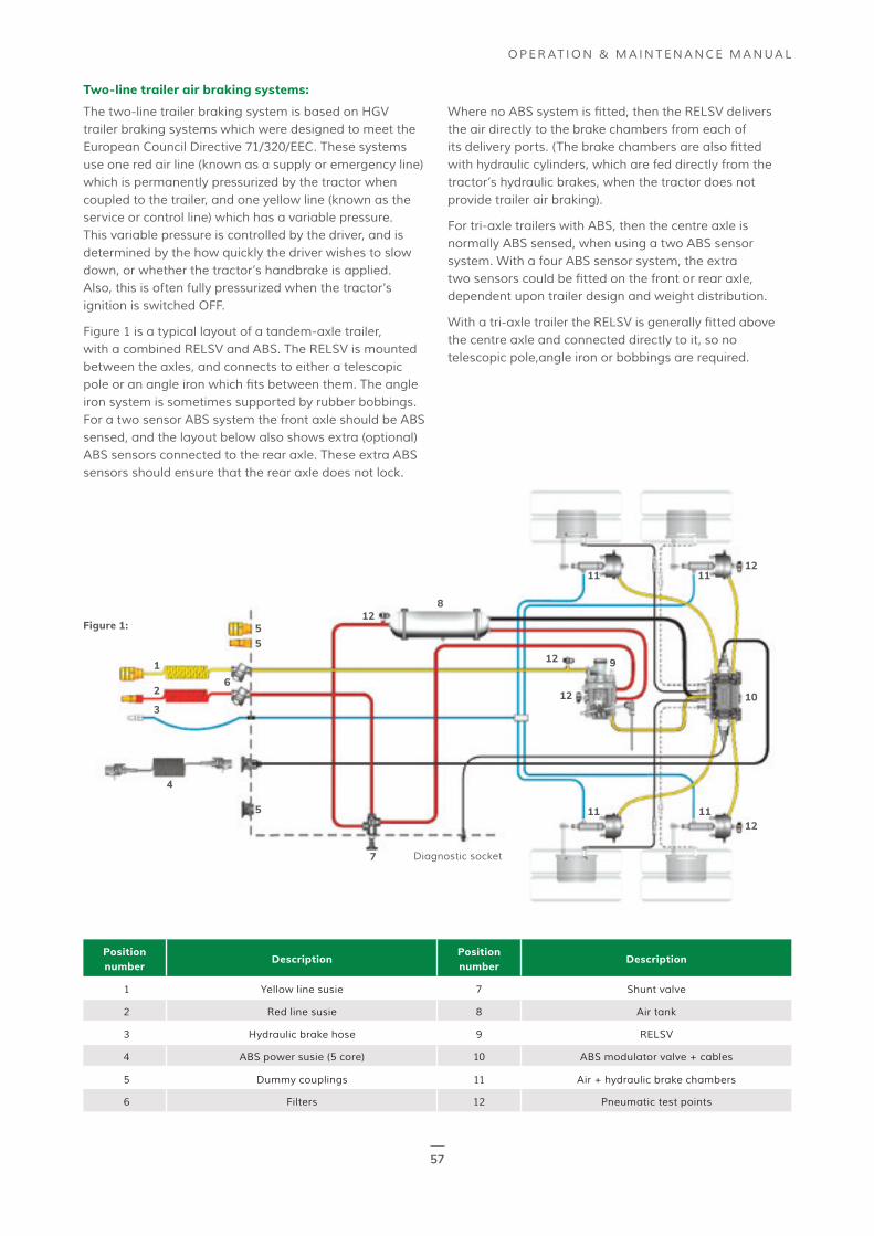
57
O P E R AT I O N & M A I N T E N A N C E M A N UA L
Positionnumber
DescriptionPositionnumber
Description
1 Yellow line susie 7 Shunt valve
2 Red line susie 8 Air tank
3 Hydraulic brake hose 9 RELSV
4 ABS power susie (5 core) 10 ABS modulator valve + cables
5 Dummy couplings 11 Air + hydraulic brake chambers
6 Filters 12 Pneumatic test points
Figure 1:
Diagnostic socket
1
2
3
4
55
5
7
6
812
11 1112
12
12
12 9
11 11
10
Two-line trailer air braking systems:
The two-line trailer braking system is based on HGV trailer braking systems which were designed to meet the European Council Directive 71/320/EEC. These systems use one red air line (known as a supply or emergency line) which is permanently pressurized by the tractor when coupled to the trailer, and one yellow line (known as the service or control line) which has a variable pressure. This variable pressure is controlled by the driver, and is determined by the how quickly the driver wishes to slow down, or whether the tractor’s handbrake is applied. Also, this is often fully pressurized when the tractor’s ignition is switched OFF.
Figure 1 is a typical layout of a tandem-axle trailer, with a combined RELSV and ABS. The RELSV is mounted between the axles, and connects to either a telescopic pole or an angle iron which fits between them. The angle iron system is sometimes supported by rubber bobbings. For a two sensor ABS system the front axle should be ABS sensed, and the layout below also shows extra (optional) ABS sensors connected to the rear axle. These extra ABS sensors should ensure that the rear axle does not lock.
Where no ABS system is fitted, then the RELSV delivers the air directly to the brake chambers from each of its delivery ports. (The brake chambers are also fitted with hydraulic cylinders, which are fed directly from the tractor’s hydraulic brakes, when the tractor does not provide trailer air braking).
For tri-axle trailers with ABS, then the centre axle is normally ABS sensed, when using a two ABS sensor system. With a four ABS sensor system, the extra two sensors could be fitted on the front or rear axle, dependent upon trailer design and weight distribution.
With a tri-axle trailer the RELSV is generally fitted above the centre axle and connected directly to it, so no telescopic pole,angle iron or bobbings are required.
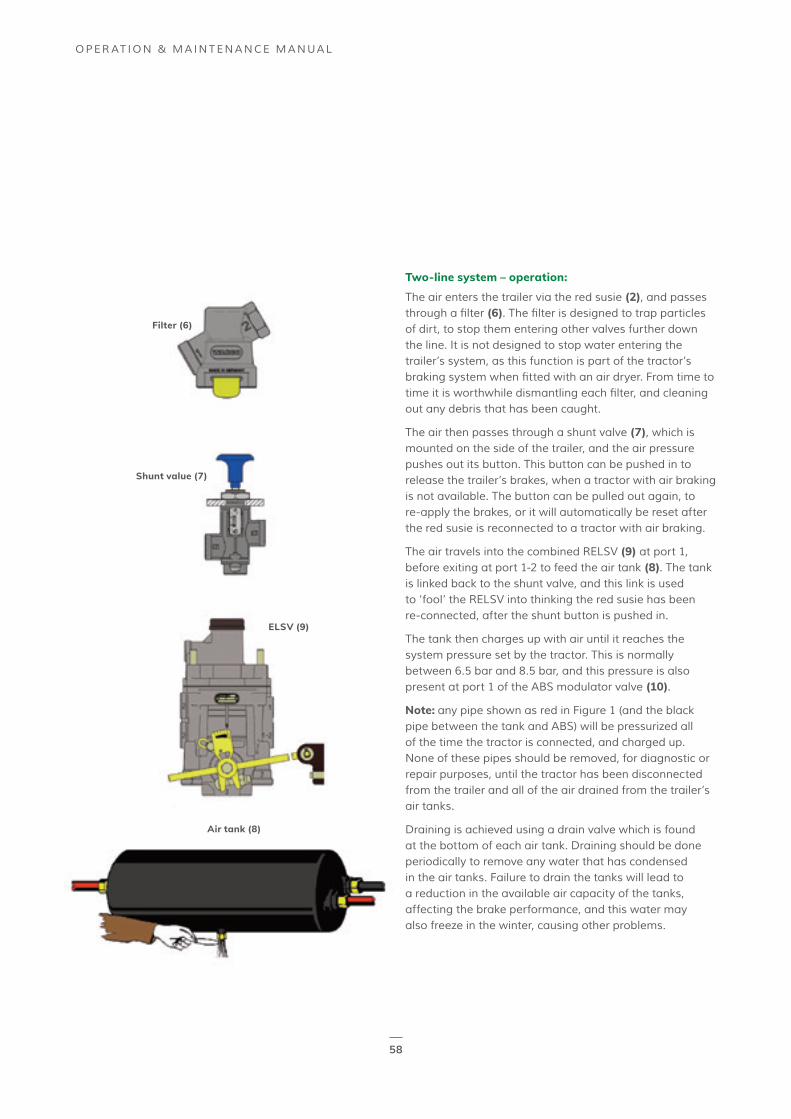
58
O P E R AT I O N & M A I N T E N A N C E M A N UA L
Two-line system – operation:
The air enters the trailer via the red susie (2), and passes through a filter (6). The filter is designed to trap particles of dirt, to stop them entering other valves further down the line. It is not designed to stop water entering the trailer’s system, as this function is part of the tractor’s braking system when fitted with an air dryer. From time to time it is worthwhile dismantling each filter, and cleaning out any debris that has been caught.
The air then passes through a shunt valve (7), which is mounted on the side of the trailer, and the air pressure pushes out its button. This button can be pushed in to release the trailer’s brakes, when a tractor with air braking is not available. The button can be pulled out again, to re-apply the brakes, or it will automatically be reset after the red susie is reconnected to a tractor with air braking.
The air travels into the combined RELSV (9) at port 1, before exiting at port 1-2 to feed the air tank (8). The tank is linked back to the shunt valve, and this link is used to ‘fool’ the RELSV into thinking the red susie has been re-connected, after the shunt button is pushed in.
The tank then charges up with air until it reaches the system pressure set by the tractor. This is normally between 6.5 bar and 8.5 bar, and this pressure is also present at port 1 of the ABS modulator valve (10).
Note: any pipe shown as red in Figure 1 (and the black pipe between the tank and ABS) will be pressurized all of the time the tractor is connected, and charged up. None of these pipes should be removed, for diagnostic or repair purposes, until the tractor has been disconnected from the trailer and all of the air drained from the trailer’s air tanks.
Draining is achieved using a drain valve which is found at the bottom of each air tank. Draining should be done periodically to remove any water that has condensed in the air tanks. Failure to drain the tanks will lead to a reduction in the available air capacity of the tanks, affecting the brake performance, and this water may also freeze in the winter, causing other problems.
Filter (6)
Shunt value (7)
ELSV (9)
Air tank (8)
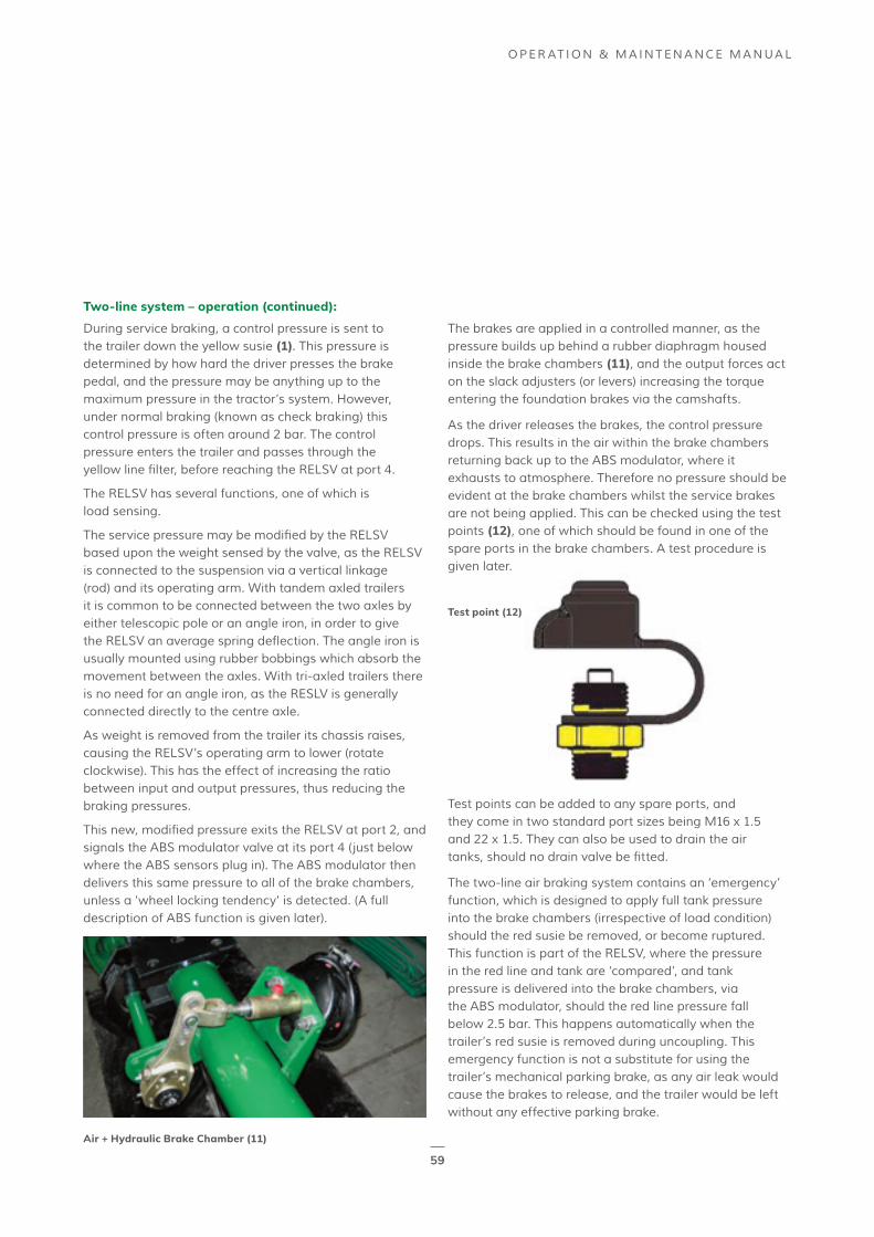
59
O P E R AT I O N & M A I N T E N A N C E M A N UA L
Two-line system – operation (continued):
During service braking, a control pressure is sent to the trailer down the yellow susie (1). This pressure is determined by how hard the driver presses the brake pedal, and the pressure may be anything up to the maximum pressure in the tractor’s system. However, under normal braking (known as check braking) this control pressure is often around 2 bar. The control pressure enters the trailer and passes through the yellow line filter, before reaching the RELSV at port 4.
The RELSV has several functions, one of which is load sensing.
The service pressure may be modified by the RELSV based upon the weight sensed by the valve, as the RELSV is connected to the suspension via a vertical linkage (rod) and its operating arm. With tandem axled trailers it is common to be connected between the two axles by either telescopic pole or an angle iron, in order to give the RELSV an average spring deflection. The angle iron is usually mounted using rubber bobbings which absorb the movement between the axles. With tri-axled trailers there is no need for an angle iron, as the RESLV is generally connected directly to the centre axle.
As weight is removed from the trailer its chassis raises, causing the RELSV’s operating arm to lower (rotate clockwise). This has the effect of increasing the ratio between input and output pressures, thus reducing the braking pressures.
This new, modified pressure exits the RELSV at port 2, and signals the ABS modulator valve at its port 4 (just below where the ABS sensors plug in). The ABS modulator then delivers this same pressure to all of the brake chambers, unless a 'wheel locking tendency' is detected. (A full description of ABS function is given later).
The brakes are applied in a controlled manner, as the pressure builds up behind a rubber diaphragm housed inside the brake chambers (11), and the output forces act on the slack adjusters (or levers) increasing the torque entering the foundation brakes via the camshafts.
As the driver releases the brakes, the control pressure drops. This results in the air within the brake chambers returning back up to the ABS modulator, where it exhausts to atmosphere. Therefore no pressure should be evident at the brake chambers whilst the service brakes are not being applied. This can be checked using the test points (12), one of which should be found in one of the spare ports in the brake chambers. A test procedure is given later.
Test points can be added to any spare ports, and they come in two standard port sizes being M16 x 1.5 and 22 x 1.5. They can also be used to drain the air tanks, should no drain valve be fitted.
The two-line air braking system contains an ‘emergency’ function, which is designed to apply full tank pressure into the brake chambers (irrespective of load condition) should the red susie be removed, or become ruptured. This function is part of the RELSV, where the pressure in the red line and tank are ‘compared’, and tank pressure is delivered into the brake chambers, via the ABS modulator, should the red line pressure fall below 2.5 bar. This happens automatically when the trailer’s red susie is removed during uncoupling. This emergency function is not a substitute for using the trailer’s mechanical parking brake, as any air leak would cause the brakes to release, and the trailer would be left without any effective parking brake.
Air + Hydraulic Brake Chamber (11)
Test point (12)
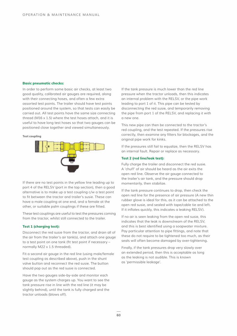
60
O P E R AT I O N & M A I N T E N A N C E M A N UA L
Basic pneumatic checks:
In order to perform some basic air checks, at least two good quality, calibrated air gauges are required, along with their connecting hoses, and often a few extra assorted test points. The trailer should have test points positioned around the system, so that tests can easily be carried out. All test points have the same size connecting thread (M16 x 1.5) where the test hoses attach, and it is useful to have long test hoses so that two gauges can be positioned close together and viewed simultaneously.
If there are no test points in the yellow line leading up to port 4 of the RELSV (port in the top section), then a good alternative is to make up a test coupling c/w a test point to fit between the tractor and trailer’s susie. These can have a male coupling at one end, and a female at the other, or suitable palm couplings if these are fitted.
These test couplings are useful to test the pressures coming from the tractor, whilst still connected to the trailer.
Test 1 (charging test):
Disconnect the red susie from the tractor, and drain all of the air from the trailer’s air tank(s), and attach one gauge to a test point on one tank (fit test point if necessary – normally M22 x 1.5 threaded).
Fit a second air gauge in the red line (using male/female test coupling as described above), push in the shunt valve button and reconnect the red susie. The button should pop out as the red susie is connected.
Have the two gauges side-by-side and monitor each gauge as the system charges up. You want to see the tank pressure rise in line with the red line (it may be slightly behind), until the tank is fully charged and the tractor unloads (blows off).
If the tank pressure is much lower than the red line pressure when the tractor unloads, then this indicates an internal problem with the RELSV, or the pipe work leading to port 1 of it. This pipe can be tested by disconnecting the red susie, and temporarily removing the pipe from port 1 of the RELSV, and replacing it with a new one.
This new pipe can then be connected to the tractor’s red coupling, and the test repeated. If the pressures rise correctly, then examine any filters for blockages, and the original pipe work for kinks.
If the pressures still fail to equalize, then the RELSV has an internal fault. Repair or replace as necessary.
Test 2 (red line/leak test):
Fully charge the trailer and disconnect the red susie. A 'chuff' of air should be heard as the air exits the open red line. Observe the air gauge connected to the trailer’s air tank, and the pressure should drop momentarily, then stabilize.
If the tank pressure continues to drop, then check the open red line for the presence of air pressure (A new thin rubber glove is ideal for this, as it can be attached to the open red susie, and sealed with tape/cable tie and left. If it inflates quickly, this indicates a leaking RELSV).
If no air is seen leaking from the open red susie, this indicates that the leak is downstream of the RELSV, and this is best identified using a soapwater mixture. Pay particular attention to pipe fittings, and note that these do not require to be tightened too much, as their seals will often become damaged by over-tightening.
Finally, if the tank pressures drop very slowly over an extended period, then this is acceptable as long as the leaking is not audible. This is known as ‘permissible leakage’.
Test coupling
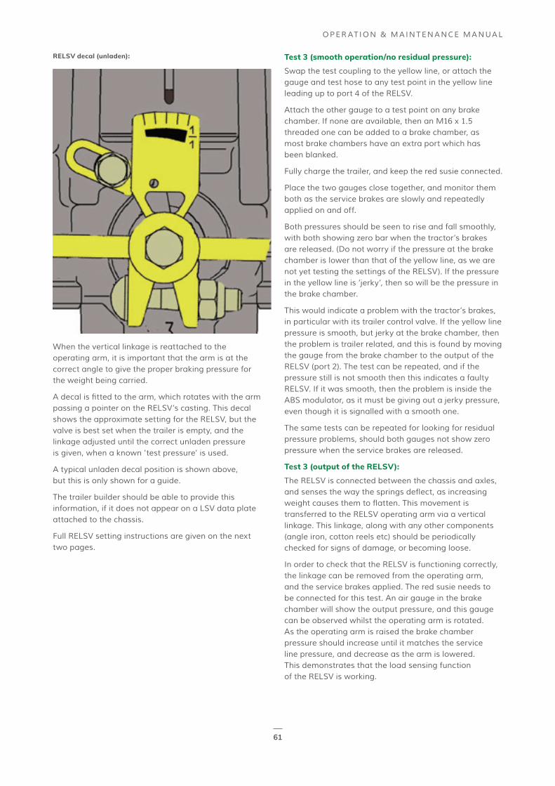
61
O P E R AT I O N & M A I N T E N A N C E M A N UA L
When the vertical linkage is reattached to the operating arm, it is important that the arm is at the correct angle to give the proper braking pressure for the weight being carried.
A decal is fitted to the arm, which rotates with the arm passing a pointer on the RELSV’s casting. This decal shows the approximate setting for the RELSV, but the valve is best set when the trailer is empty, and the linkage adjusted until the correct unladen pressure is given, when a known 'test pressure' is used.
A typical unladen decal position is shown above, but this is only shown for a guide.
The trailer builder should be able to provide this information, if it does not appear on a LSV data plate attached to the chassis.
Full RELSV setting instructions are given on the next two pages.
Test 3 (smooth operation/no residual pressure):
Swap the test coupling to the yellow line, or attach the gauge and test hose to any test point in the yellow line leading up to port 4 of the RELSV.
Attach the other gauge to a test point on any brake chamber. If none are available, then an M16 x 1.5 threaded one can be added to a brake chamber, as most brake chambers have an extra port which has been blanked.
Fully charge the trailer, and keep the red susie connected.
Place the two gauges close together, and monitor them both as the service brakes are slowly and repeatedly applied on and off.
Both pressures should be seen to rise and fall smoothly, with both showing zero bar when the tractor’s brakes are released. (Do not worry if the pressure at the brake chamber is lower than that of the yellow line, as we are not yet testing the settings of the RELSV). If the pressure in the yellow line is ‘jerky’, then so will be the pressure in the brake chamber.
This would indicate a problem with the tractor’s brakes, in particular with its trailer control valve. If the yellow line pressure is smooth, but jerky at the brake chamber, then the problem is trailer related, and this is found by moving the gauge from the brake chamber to the output of the RELSV (port 2). The test can be repeated, and if the pressure still is not smooth then this indicates a faulty RELSV. If it was smooth, then the problem is inside the ABS modulator, as it must be giving out a jerky pressure, even though it is signalled with a smooth one.
The same tests can be repeated for looking for residual pressure problems, should both gauges not show zero pressure when the service brakes are released.
Test 3 (output of the RELSV):
The RELSV is connected between the chassis and axles, and senses the way the springs deflect, as increasing weight causes them to flatten. This movement is transferred to the RELSV operating arm via a vertical linkage. This linkage, along with any other components (angle iron, cotton reels etc) should be periodically checked for signs of damage, or becoming loose.
In order to check that the RELSV is functioning correctly, the linkage can be removed from the operating arm, and the service brakes applied. The red susie needs to be connected for this test. An air gauge in the brake chamber will show the output pressure, and this gauge can be observed whilst the operating arm is rotated. As the operating arm is raised the brake chamber pressure should increase until it matches the service line pressure, and decrease as the arm is lowered. This demonstrates that the load sensing function of the RELSV is working.
RELSV decal (unladen):
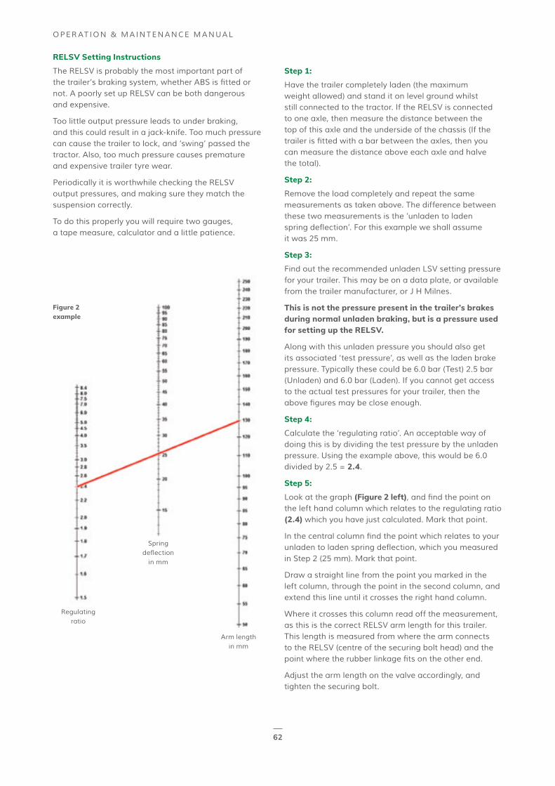
62
O P E R AT I O N & M A I N T E N A N C E M A N UA L
RELSV Setting Instructions
The RELSV is probably the most important part of the trailer’s braking system, whether ABS is fitted or not. A poorly set up RELSV can be both dangerous and expensive.
Too little output pressure leads to under braking, and this could result in a jack-knife. Too much pressure can cause the trailer to lock, and ‘swing’ passed the tractor. Also, too much pressure causes premature and expensive trailer tyre wear.
Periodically it is worthwhile checking the RELSV output pressures, and making sure they match the suspension correctly.
To do this properly you will require two gauges, a tape measure, calculator and a little patience.
Step 1:
Have the trailer completely laden (the maximum weight allowed) and stand it on level ground whilst still connected to the tractor. If the RELSV is connected to one axle, then measure the distance between the top of this axle and the underside of the chassis (If the trailer is fitted with a bar between the axles, then you can measure the distance above each axle and halve the total).
Step 2:
Remove the load completely and repeat the same measurements as taken above. The difference between these two measurements is the ‘unladen to laden spring deflection’. For this example we shall assume it was 25 mm.
Step 3:
Find out the recommended unladen LSV setting pressure for your trailer. This may be on a data plate, or available from the trailer manufacturer, or J H Milnes.
This is not the pressure present in the trailer’s brakes during normal unladen braking, but is a pressure used for setting up the RELSV.
Along with this unladen pressure you should also get its associated ‘test pressure’, as well as the laden brake pressure. Typically these could be 6.0 bar (Test) 2.5 bar (Unladen) and 6.0 bar (Laden). If you cannot get access to the actual test pressures for your trailer, then the above figures may be close enough.
Step 4:
Calculate the ‘regulating ratio’. An acceptable way of doing this is by dividing the test pressure by the unladen pressure. Using the example above, this would be 6.0 divided by 2.5 = 2.4.
Step 5:
Look at the graph (Figure 2 left), and find the point on the left hand column which relates to the regulating ratio (2.4) which you have just calculated. Mark that point.
In the central column find the point which relates to your unladen to laden spring deflection, which you measured in Step 2 (25 mm). Mark that point.
Draw a straight line from the point you marked in the left column, through the point in the second column, and extend this line until it crosses the right hand column.
Where it crosses this column read off the measurement, as this is the correct RELSV arm length for this trailer. This length is measured from where the arm connects to the RELSV (centre of the securing bolt head) and the point where the rubber linkage fits on the other end.
Adjust the arm length on the valve accordingly, and tighten the securing bolt.
Figure 2 example
Arm length in mm
Regulating ratio
Spring deflection
in mm
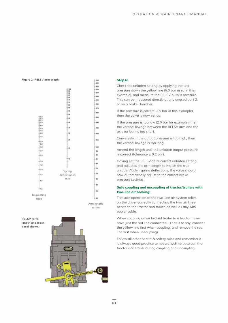
63
O P E R AT I O N & M A I N T E N A N C E M A N UA L
Step 6:
Check the unladen setting by applying the test pressure down the yellow line (6.0 bar used in this example), and measure the RELSV output pressure. This can be measured directly at any unused port 2, or on a brake chamber.
If the pressure is correct (2.5 bar in this example), then the valve is now set up.
If the pressure is too low (2.0 bar for example), then the vertical linkage between the RELSV arm and the axle (or bar) is too short.
Conversely, if the output pressure is too high, then the vertical linkage is too long.
Amend the length until the unladen output pressure is correct (tolerance ± 0.2 bar).
Having set the RELSV at its correct unladen setting, and adjusted the arm length to match the true unladen/laden spring deflections, the valve should now automatically adjust to the correct brake pressure settings.
Safe coupling and uncoupling of tractor/trailers with two-line air braking:
The safe operation of the two-line air system relies on the driver correctly connecting the two air lines between the tractor and trailer, as well as any ABS power cable.
When coupling an air braked trailer to a tractor never have just the red line connected. (That is to say, connect the yellow line first when coupling, and remove the red line first when uncoupling).
Follow all other health & safety rules and remember it is always good practice to not walk/climb between the tractor and trailer during coupling and uncoupling.
Figure 2 (RELSV arm graph)
RELSV (arm length and laden decal shown)
Regulating ratio
Spring deflection in
mm
Arm length in mm
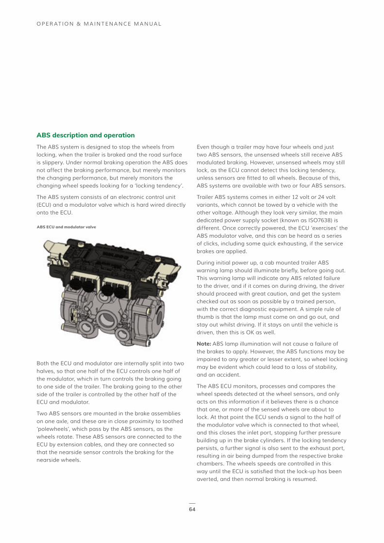
64
O P E R AT I O N & M A I N T E N A N C E M A N UA L
ABS description and operation
The ABS system is designed to stop the wheels from locking, when the trailer is braked and the road surface is slippery. Under normal braking operation the ABS does not affect the braking performance, but merely monitors the changing performance, but merely monitors the changing wheel speeds looking for a ‘locking tendency’.
The ABS system consists of an electronic control unit (ECU) and a modulator valve which is hard wired directly onto the ECU.
Both the ECU and modulator are internally split into two halves, so that one half of the ECU controls one half of the modulator, which in turn controls the braking going to one side of the trailer. The braking going to the other side of the trailer is controlled by the other half of the ECU and modulator.
Two ABS sensors are mounted in the brake assemblies on one axle, and these are in close proximity to toothed ‘polewheels’, which pass by the ABS sensors, as the wheels rotate. These ABS sensors are connected to the ECU by extension cables, and they are connected so that the nearside sensor controls the braking for the nearside wheels.
Even though a trailer may have four wheels and just two ABS sensors, the unsensed wheels still receive ABS modulated braking. However, unsensed wheels may still lock, as the ECU cannot detect this locking tendency, unless sensors are fitted to all wheels. Because of this, ABS systems are available with two or four ABS sensors.
Trailer ABS systems comes in either 12 volt or 24 volt variants, which cannot be towed by a vehicle with the other voltage. Although they look very similar, the main dedicated power supply socket (known as ISO7638) is different. Once correctly powered, the ECU ‘exercises’ the ABS modulator valve, and this can be heard as a series of clicks, including some quick exhausting, if the service brakes are applied.
During initial power up, a cab mounted trailer ABS warning lamp should illuminate briefly, before going out. This warning lamp will indicate any ABS related failure to the driver, and if it comes on during driving, the driver should proceed with great caution, and get the system checked out as soon as possible by a trained person, with the correct diagnostic equipment. A simple rule of thumb is that the lamp must come on and go out, and stay out whilst driving. If it stays on until the vehicle is driven, then this is OK as well.
Note: ABS lamp illumination will not cause a failure of the brakes to apply. However, the ABS functions may be impaired to any greater or lesser extent, so wheel locking may be evident which could lead to a loss of stability, and an accident.
The ABS ECU monitors, processes and compares the wheel speeds detected at the wheel sensors, and only acts on this information if it believes there is a chance that one, or more of the sensed wheels are about to lock. At that point the ECU sends a signal to the half of the modulator valve which is connected to that wheel, and this closes the inlet port, stopping further pressure building up in the brake cylinders. If the locking tendency persists, a further signal is also sent to the exhaust port, resulting in air being dumped from the respective brake chambers. The wheels speeds are controlled in this way until the ECU is satisfied that the lock-up has been averted, and then normal braking is resumed.
ABS ECU and modulator valve
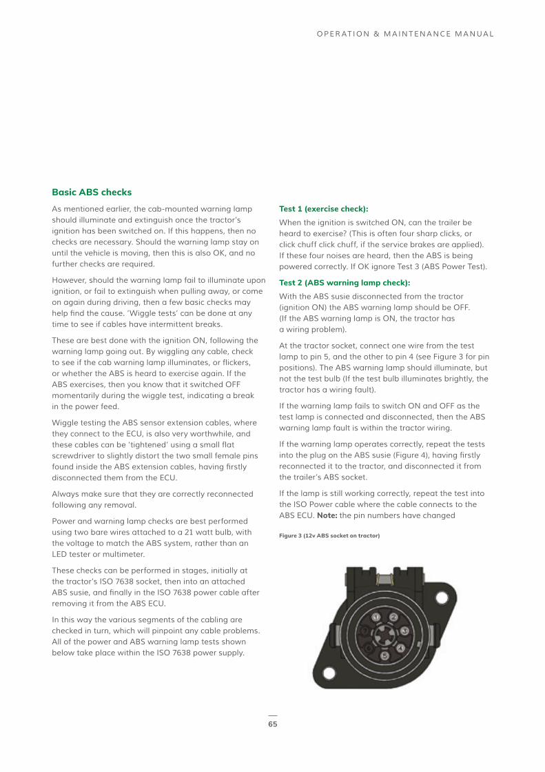
65
O P E R AT I O N & M A I N T E N A N C E M A N UA L
Basic ABS checks
As mentioned earlier, the cab-mounted warning lamp should illuminate and extinguish once the tractor’s ignition has been switched on. If this happens, then no checks are necessary. Should the warning lamp stay on until the vehicle is moving, then this is also OK, and no further checks are required.
However, should the warning lamp fail to illuminate upon ignition, or fail to extinguish when pulling away, or come on again during driving, then a few basic checks may help find the cause. ’Wiggle tests’ can be done at any time to see if cables have intermittent breaks.
These are best done with the ignition ON, following the warning lamp going out. By wiggling any cable, check to see if the cab warning lamp illuminates, or flickers, or whether the ABS is heard to exercise again. If the ABS exercises, then you know that it switched OFF momentarily during the wiggle test, indicating a break in the power feed.
Wiggle testing the ABS sensor extension cables, where they connect to the ECU, is also very worthwhile, and these cables can be ‘tightened’ using a small flat screwdriver to slightly distort the two small female pins found inside the ABS extension cables, having firstly disconnected them from the ECU.
Always make sure that they are correctly reconnected following any removal.
Power and warning lamp checks are best performed using two bare wires attached to a 21 watt bulb, with the voltage to match the ABS system, rather than an LED tester or multimeter.
These checks can be performed in stages, initially at the tractor’s ISO 7638 socket, then into an attached ABS susie, and finally in the ISO 7638 power cable after removing it from the ABS ECU.
In this way the various segments of the cabling are checked in turn, which will pinpoint any cable problems. All of the power and ABS warning lamp tests shown below take place within the ISO 7638 power supply.
Test 1 (exercise check):
When the ignition is switched ON, can the trailer be heard to exercise? (This is often four sharp clicks, or click chuff click chuff, if the service brakes are applied). If these four noises are heard, then the ABS is being powered correctly. If OK ignore Test 3 (ABS Power Test).
Test 2 (ABS warning lamp check):
With the ABS susie disconnected from the tractor (ignition ON) the ABS warning lamp should be OFF. (If the ABS warning lamp is ON, the tractor has a wiring problem).
At the tractor socket, connect one wire from the test lamp to pin 5, and the other to pin 4 (see Figure 3 for pin positions). The ABS warning lamp should illuminate, but not the test bulb (If the test bulb illuminates brightly, the tractor has a wiring fault).
If the warning lamp fails to switch ON and OFF as the test lamp is connected and disconnected, then the ABS warning lamp fault is within the tractor wiring.
If the warning lamp operates correctly, repeat the tests into the plug on the ABS susie (Figure 4), having firstly reconnected it to the tractor, and disconnected it from the trailer’s ABS socket.
If the lamp is still working correctly, repeat the test into the ISO Power cable where the cable connects to the ABS ECU. Note: the pin numbers have changed
Figure 3 (12v ABS socket on tractor)
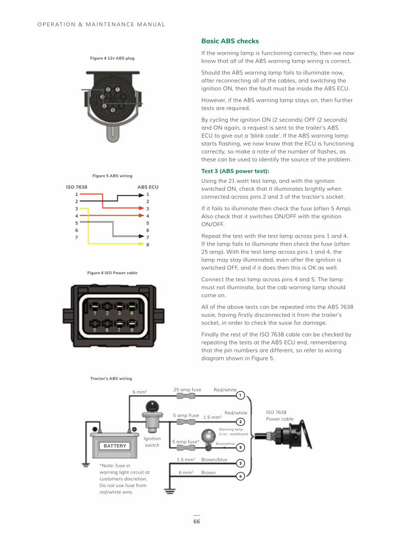
66
O P E R AT I O N & M A I N T E N A N C E M A N UA L
Basic ABS checks
If the warning lamp is functioning correctly, then we now know that all of the ABS warning lamp wiring is correct.
Should the ABS warning lamp fails to illuminate now, after reconnecting all of the cables, and switching the ignition ON, then the fault must be inside the ABS ECU.
However, if the ABS warning lamp stays on, then further tests are required.
By cycling the ignition ON (2 seconds) OFF (2 seconds) and ON again, a request is sent to the trailer’s ABS ECU to give out a ‘blink code’. If the ABS warning lamp starts flashing, we now know that the ECU is functioning correctly, so make a note of the number of flashes, as these can be used to identify the source of the problem.
Test 3 (ABS power test):
Using the 21 watt test lamp, and with the ignition switched ON, check that it illuminates brightly when connected across pins 2 and 3 of the tractor’s socket.
If it fails to illuminate then check the fuse (often 5 Amp). Also check that it switches ON/OFF with the ignition ON/OFF.
Repeat the test with the test lamp across pins 1 and 4. If the lamp fails to illuminate then check the fuse (often 25 amp). With the test lamp across pins 1 and 4, the lamp may stay illuminated, even after the ignition is switched OFF, and if it does then this is OK as well.
Connect the test lamp across pins 4 and 5. The lamp must not illuminate, but the cab warning lamp should come on.
All of the above tests can be repeated into the ABS 7638 susie, having firstly disconnected it from the trailer’s socket, in order to check the susie for damage.
Finally the rest of the ISO 7638 cable can be checked by repeating the tests at the ABS ECU end, remembering that the pin numbers are different, so refer to wiring diagram shown in Figure 5.
Figure 4 12v ABS plug
Figure 5 ABS wiring
Figure 6 ISO Power cable
Tractor’s ABS wiring
BATTERY
*Note: fuse in warning light circuit at customers discretion. Do not use fuse from red/white wire.
6 mm2 25 amp fuse
5 amp Fuse
5 amp fuse*Ignition switch
1.5 mm2 Brown/blue
Brown6 mm2
1.5 mm2
Blue/yellow
Warming lamp (2 w) – dashboard
Red/white
ISO 7638 Power cable
1
2
5
3
4
ISO 76381234567
12345678
ABS ECU
Red/white
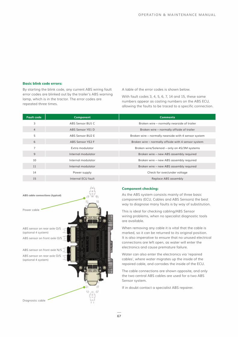
67
O P E R AT I O N & M A I N T E N A N C E M A N UA L
Basic blink code errors:
By starting the blink code, any current ABS wiring fault error codes are blinked out by the trailer’s ABS warning lamp, which is in the tractor. The error codes are repeated three times.
A table of the error codes is shown below.
With fault codes 3, 4, 5, 6, 7, 14 and 15, these same numbers appear as casting numbers on the ABS ECU, allowing the faults to be traced to a specific connection.
Component checking:
As the ABS system consists mainly of three basic components (ECU, Cables and ABS Sensors) the best way to diagnose many faults is by way of substitution.
This is ideal for checking cabling/ABS Sensor wiring problems, when no specialist diagnostic tools are available.
When removing any cable it is vital that the cable is marked, so it can be returned to its original position. It is also imperative to ensure that no unused electrical connections are left open, as water will enter the electronics and cause premature failure.
Water can also enter the electronics via 'repaired cables', where water migrates up the inside of the repaired cable, and corrodes the inside of the ECU.
The cable connections are shown opposite, and only the two central ABS cables are used for a two ABS Sensor system.
If in doubt contact a specialist ABS repairer.
Fault code Component Comments
3 ABS Sensor BU1 C Broken wire – normally nearside of trailer
4 ABS Sensor YE1 D Broken wire – normally offside of trailer
5 ABS Sensor BU2 E Broken wire – normally nearside with 4 sensor system
6 ABS Sensor YE2 F Broken wire – normally offside with 4 sensor system
7 Extra modulator Broken wire/Solenoid – only on 4S/3M systems
9 Internal modulator Broken wire – new ABS assembly required
10 Internal modulator Broken wire – new ABS assembly required
11 Internal modulator Broken wire – new ABS assembly required
14 Power supply Check for over/under voltage
15 Internal ECU fault Replace ABS assembly
ABS cable connections (typical)
Diagnostic cable
Power cable
ABS sensor on rear axle O/S (optional 4 system)
ABS sensor on rear axle O/S (optional 4 system)
ABS sensor on front axle O/S
ABS sensor on front axle N/S
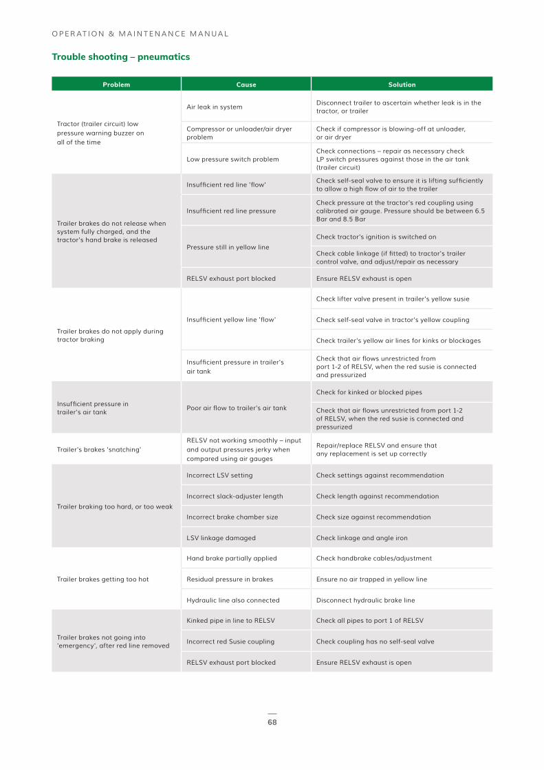
68
O P E R AT I O N & M A I N T E N A N C E M A N UA L
Trouble shooting – pneumatics
Problem Cause Solution
Tractor (trailer circuit) lowpressure warning buzzer onall of the time
Air leak in systemDisconnect trailer to ascertain whether leak is in the tractor, or trailer
Compressor or unloader/air dryer problem
Check if compressor is blowing-off at unloader, or air dryer
Low pressure switch problemCheck connections – repair as necessary check LP switch pressures against those in the air tank (trailer circuit)
Trailer brakes do not release when system fully charged, and the tractor's hand brake is released
Insufficient red line 'flow'Check self-seal valve to ensure it is lifting sufficiently to allow a high flow of air to the trailer
Insufficient red line pressureCheck pressure at the tractor's red coupling using calibrated air gauge. Pressure should be between 6.5 Bar and 8.5 Bar
Pressure still in yellow line
Check tractor's ignition is switched on
Check cable linkage (if fitted) to tractor's trailer control valve, and adjust/repair as necessary
RELSV exhaust port blocked Ensure RELSV exhaust is open
Trailer brakes do not apply during tractor braking
Insufficient yellow line 'flow'
Check lifter valve present in trailer's yellow susie
Check self-seal valve in tractor's yellow coupling
Check trailer's yellow air lines for kinks or blockages
Insufficient pressure in trailer's air tank
Check that air flows unrestricted from port 1-2 of RELSV, when the red susie is connected and pressurized
Insufficient pressure in trailer's air tank
Poor air flow to trailer's air tank
Check for kinked or blocked pipes
Check that air flows unrestricted from port 1-2 of RELSV, when the red susie is connected and pressurized
Trailer's brakes 'snatching'RELSV not working smoothly – input and output pressures jerky when compared using air gauges
Repair/replace RELSV and ensure that any replacement is set up correctly
Trailer braking too hard, or too weak
Incorrect LSV setting Check settings against recommendation
Incorrect slack-adjuster length Check length against recommendation
Incorrect brake chamber size Check size against recommendation
LSV linkage damaged Check linkage and angle iron
Trailer brakes getting too hot
Hand brake partially applied Check handbrake cables/adjustment
Residual pressure in brakes Ensure no air trapped in yellow line
Hydraulic line also connected Disconnect hydraulic brake line
Trailer brakes not going into 'emergency', after red line removed
Kinked pipe in line to RELSV Check all pipes to port 1 of RELSV
Incorrect red Susie coupling Check coupling has no self-seal valve
RELSV exhaust port blocked Ensure RELSV exhaust is open
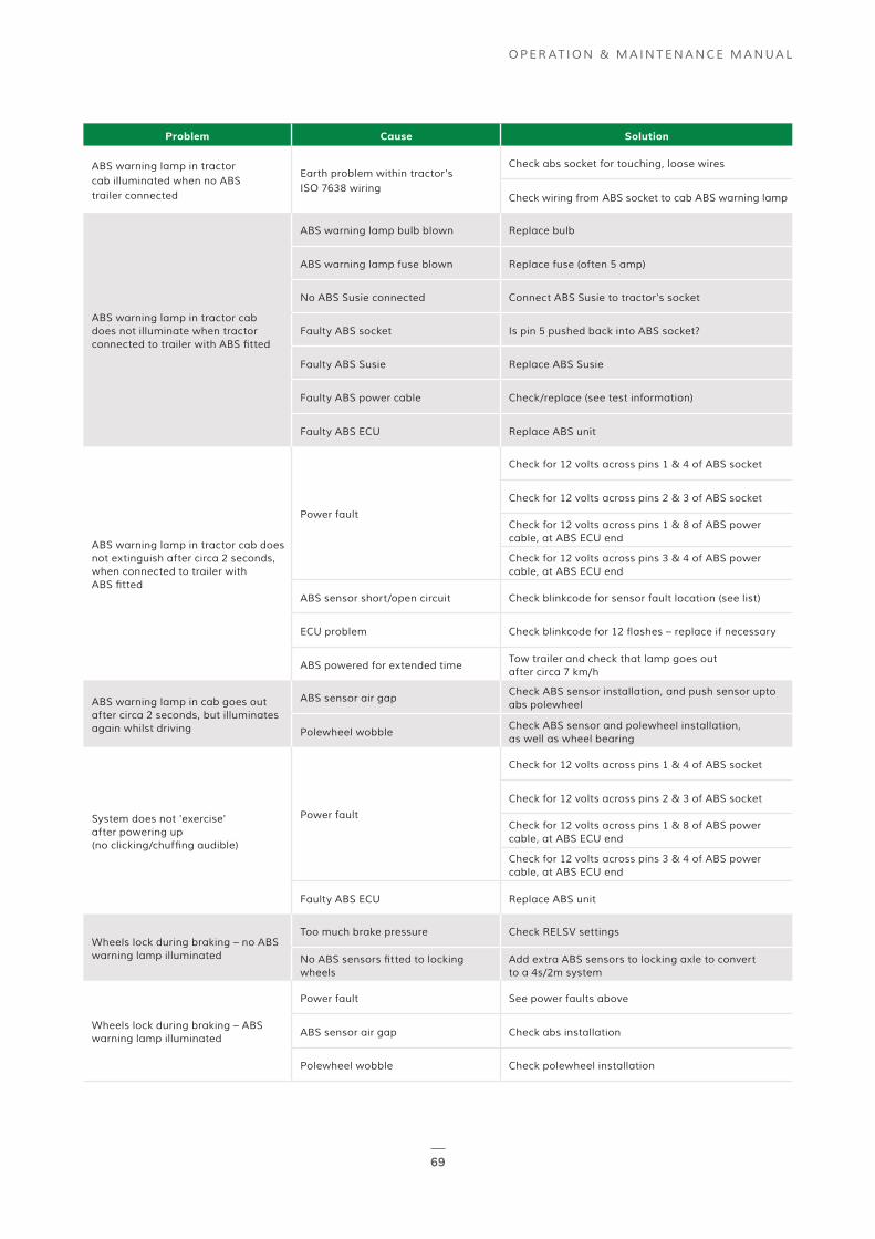
69
O P E R AT I O N & M A I N T E N A N C E M A N UA L
Problem Cause Solution
ABS warning lamp in tractor cab illuminated when no ABS trailer connected
Earth problem within tractor's ISO 7638 wiring
Check abs socket for touching, loose wires
Check wiring from ABS socket to cab ABS warning lamp
ABS warning lamp in tractor cab does not illuminate when tractor connected to trailer with ABS fitted
ABS warning lamp bulb blown Replace bulb
ABS warning lamp fuse blown Replace fuse (often 5 amp)
No ABS Susie connected Connect ABS Susie to tractor's socket
Faulty ABS socket Is pin 5 pushed back into ABS socket?
Faulty ABS Susie Replace ABS Susie
Faulty ABS power cable Check/replace (see test information)
Faulty ABS ECU Replace ABS unit
ABS warning lamp in tractor cab does not extinguish after circa 2 seconds, when connected to trailer withABS fitted
Power fault
Check for 12 volts across pins 1 & 4 of ABS socket
Check for 12 volts across pins 2 & 3 of ABS socket
Check for 12 volts across pins 1 & 8 of ABS power cable, at ABS ECU end
Check for 12 volts across pins 3 & 4 of ABS power cable, at ABS ECU end
ABS sensor short/open circuit Check blinkcode for sensor fault location (see list)
ECU problem Check blinkcode for 12 flashes – replace if necessary
ABS powered for extended timeTow trailer and check that lamp goes out after circa 7 km/h
ABS warning lamp in cab goes out after circa 2 seconds, but illuminates again whilst driving
ABS sensor air gapCheck ABS sensor installation, and push sensor upto abs polewheel
Polewheel wobbleCheck ABS sensor and polewheel installation, as well as wheel bearing
System does not 'exercise' after powering up (no clicking/chuffing audible)
Power fault
Check for 12 volts across pins 1 & 4 of ABS socket
Check for 12 volts across pins 2 & 3 of ABS socket
Check for 12 volts across pins 1 & 8 of ABS power cable, at ABS ECU end
Check for 12 volts across pins 3 & 4 of ABS power cable, at ABS ECU end
Faulty ABS ECU Replace ABS unit
Wheels lock during braking – no ABS warning lamp illuminated
Too much brake pressure Check RELSV settings
No ABS sensors fitted to locking wheels
Add extra ABS sensors to locking axle to convert to a 4s/2m system
Wheels lock during braking – ABS warning lamp illuminated
Power fault See power faults above
ABS sensor air gap Check abs installation
Polewheel wobble Check polewheel installation
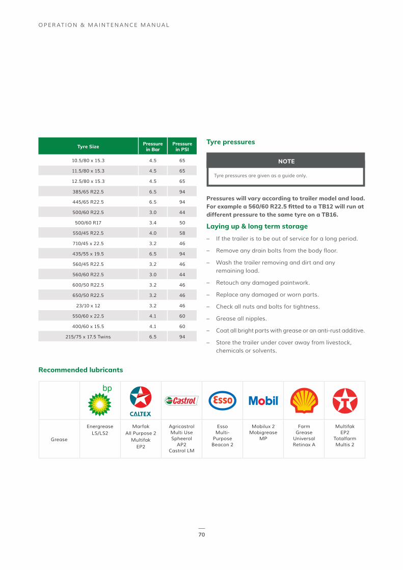
70
O P E R AT I O N & M A I N T E N A N C E M A N UA L
Tyre pressures
Pressures will vary according to trailer model and load. Forexamplea560/60R22.5fittedtoaTB12willrunatdifferent pressure to the same tyre on a TB16.
Laying up & long term storage
– If the trailer is to be out of service for a long period.
– Remove any drain bolts from the body floor.
– Wash the trailer removing and dirt and any remaining load.
– Retouch any damaged paintwork.
– Replace any damaged or worn parts.
– Check all nuts and bolts for tightness.
– Grease all nipples.
– Coat all bright parts with grease or an anti-rust additive.
– Store the trailer under cover away from livestock, chemicals or solvents.
Tyre Size Pressure in Bar
Pressure in PSI
10.5/80 x 15.3 4.5 65
11.5/80 x 15.3 4.5 65
12.5/80 x 15.3 4.5 65
385/65 R22.5 6.5 94
445/65 R22.5 6.5 94
500/60 R22.5 3.0 44
500/60 R17 3.4 50
550/45 R22.5 4.0 58
710/45 x 22.5 3.2 46
435/55 x 19.5 6.5 94
560/45 R22.5 3.2 46
560/60 R22.5 3.0 44
600/50 R22.5 3.2 46
650/50 R22.5 3.2 46
23/10 x 12 3.2 46
550/60 x 22.5 4.1 60
400/60 x 15.5 4.1 60
215/75 x 17.5 Twins 6.5 94
Recommended lubricants
Tyre Size Pressure in Bar
Pressure in PSI
Grease
EnergreaseLS/LS2
Marfak All Purpose 2
MultifakEP2
AgricastrolMulti UseSpheerol
AP2Castrol LM
Esso Multi-
PurposeBeacon 2
Mobilux 2Mobigrease
MP
FarmGrease
UniversalRetinax A
MultifakEP2
TotalfarmMultis 2
Tyre pressures are given as a guide only.
NOTE
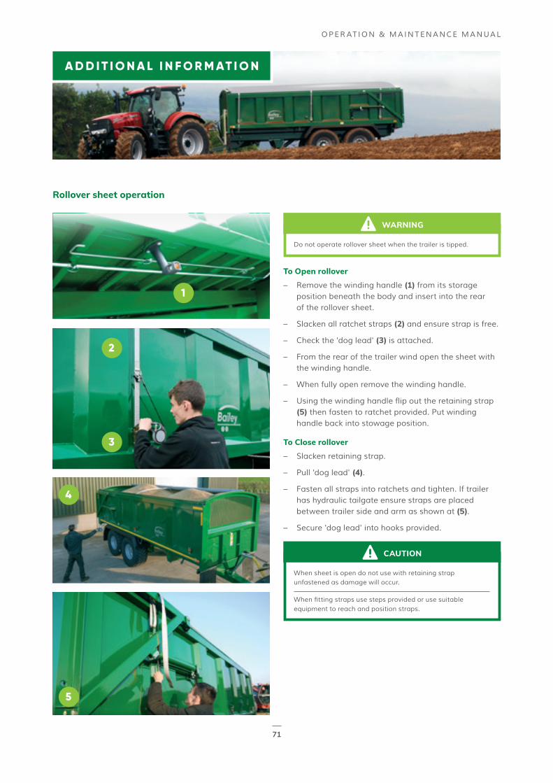
71
O P E R AT I O N & M A I N T E N A N C E M A N UA L
Rollover sheet operation
A D D I T I O N A L I N F O R M AT I O N
Do not operate rollover sheet when the trailer is tipped.
WARNING
To Open rollover
– Remove the winding handle (1) from its storage position beneath the body and insert into the rear of the rollover sheet.
– Slacken all ratchet straps (2) and ensure strap is free.
– Check the 'dog lead' (3) is attached.
– From the rear of the trailer wind open the sheet with the winding handle.
– When fully open remove the winding handle.
– Using the winding handle flip out the retaining strap (5) then fasten to ratchet provided. Put winding handle back into stowage position.
To Close rollover
– Slacken retaining strap.
– Pull 'dog lead' (4).
– Fasten all straps into ratchets and tighten. If trailer has hydraulic tailgate ensure straps are placed between trailer side and arm as shown at (5).
– Secure 'dog lead' into hooks provided.
When sheet is open do not use with retaining strap unfastened as damage will occur.
When fitting straps use steps provided or use suitable equipment to reach and position straps.
CAUTION
1
4
5
2
3
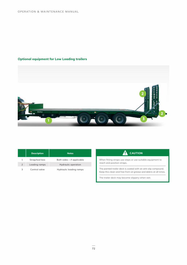
72
O P E R AT I O N & M A I N T E N A N C E M A N UA L
Optional equipment for Low Loading trailers
Description Notes
1 Strap/tool box Both sides – if applicable
2 Loading ramps Hydraulic operation
3 Control valve Hydraulic loading ramps
When fitting straps use steps or use suitable equipment to reach and position straps.
The painted trailer deck is coated with an anti-slip compound. Keep this clean and free from oil grease and debris at all times.
The trailer deck may become slippery when wet.
CAUTION
231
2
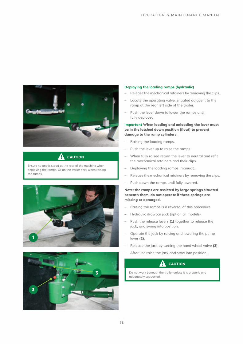
73
O P E R AT I O N & M A I N T E N A N C E M A N UA L
Deploying the loading ramps (hydraulic)
– Release the mechanical retainers by removing the clips.
– Locate the operating valve, situated adjacent to the ramp at the rear left side of the trailer.
– Push the lever down to lower the ramps until fully deployed.
Important When loading and unloading the lever must beinthelatcheddownposition(float)topreventdamage to the ramp cylinders.
– Raising the loading ramps.
– Push the lever up to raise the ramps.
– When fully raised return the lever to neutral and refit the mechanical retainers and their clips.
– Deploying the loading ramps (manual).
– Release the mechanical retainers by removing the clips.
– Push down the ramps until fully lowered.
Note: the ramps are assisted by large springs situated beneath them, do not operate if these springs are missing or damaged.
– Raising the ramps is a reversal of this procedure.
– Hydraulic drawbar jack (option all models).
– Push the release levers (1) together to release the jack, and swing into position.
– Operate the jack by raising and lowering the pump lever (2).
– Release the jack by turning the hand wheel valve (3).
– After use raise the jack and stow into position.
Do not work beneath the trailer unless it is properly and adequately supported.
CAUTION
Ensure no one is stood at the rear of the machine when deploying the ramps. Or on the trailer deck when raising the ramps.
CAUTION
1
3
3
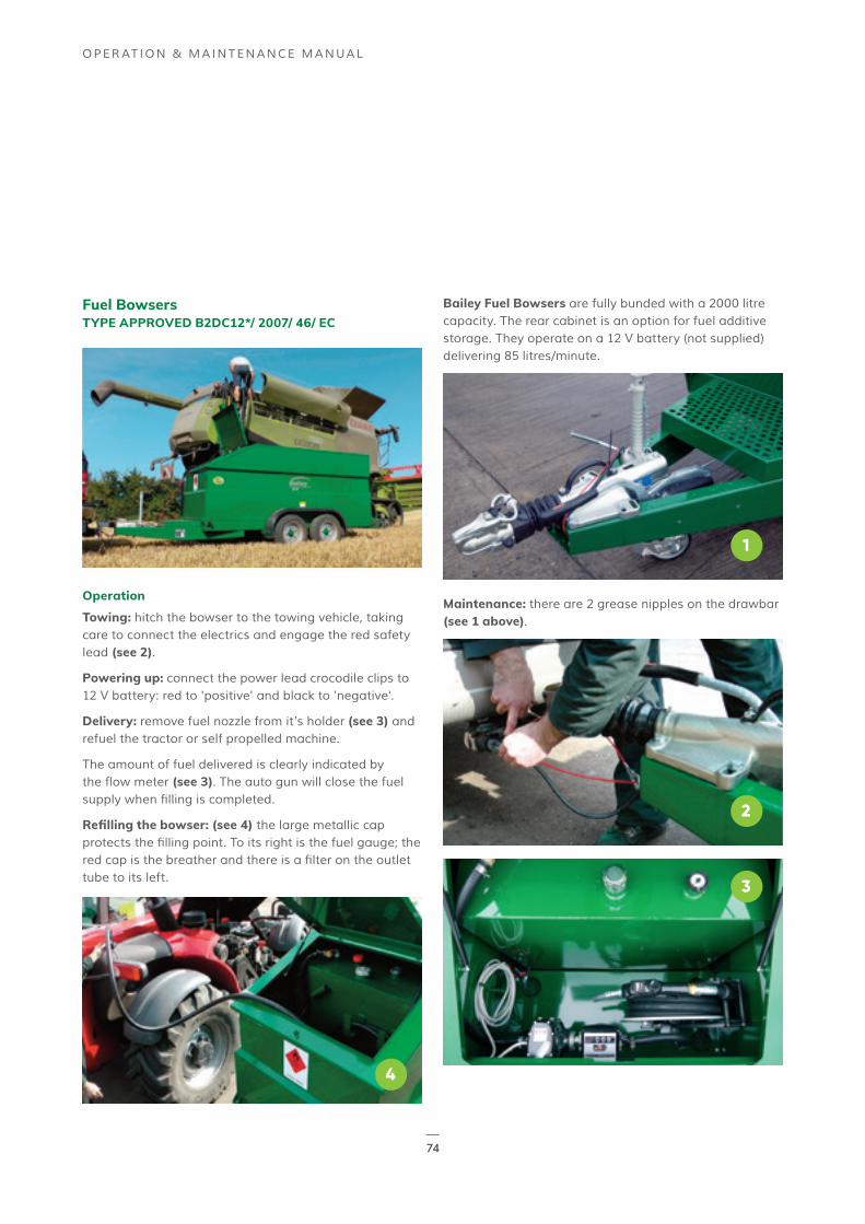
74
O P E R AT I O N & M A I N T E N A N C E M A N UA L
Bailey Fuel Bowsers are fully bunded with a 2000 litre capacity. The rear cabinet is an option for fuel additive storage. They operate on a 12 V battery (not supplied) delivering 85 litres/minute.
Maintenance: there are 2 grease nipples on the drawbar (see 1 above).
Fuel BowsersTYPE APPROVED B2DC12*/ 2007/ 46/ EC
Operation
Towing: hitch the bowser to the towing vehicle, taking care to connect the electrics and engage the red safety lead (see 2).
Powering up: connect the power lead crocodile clips to 12 V battery: red to 'positive' and black to 'negative'.
Delivery: remove fuel nozzle from it’s holder (see 3) and refuel the tractor or self propelled machine.
The amount of fuel delivered is clearly indicated by the flow meter (see 3). The auto gun will close the fuel supply when filling is completed.
Refillingthebowser:(see4) the large metallic cap protects the filling point. To its right is the fuel gauge; the red cap is the breather and there is a filter on the outlet tube to its left.
1
2
3
4
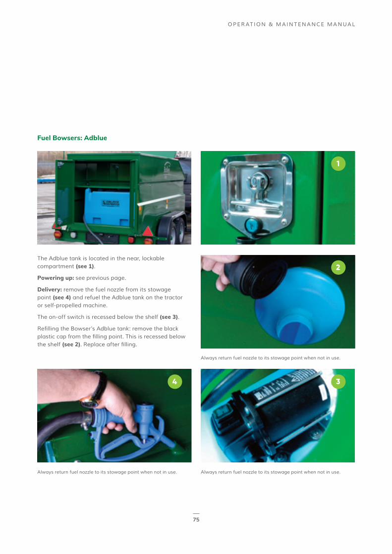
75
O P E R AT I O N & M A I N T E N A N C E M A N UA L
The Adblue tank is located in the near, lockable compartment (see 1).
Powering up: see previous page.
Delivery: remove the fuel nozzle from its stowage point (see 4) and refuel the Adblue tank on the tractor or self-propelled machine.
The on-off switch is recessed below the shelf (see 3).
Refilling the Bowser’s Adblue tank: remove the black plastic cap from the filling point. This is recessed below the shelf (see 2). Replace after filling.
Fuel Bowsers: Adblue
1
4
2
3
Always return fuel nozzle to its stowage point when not in use. Always return fuel nozzle to its stowage point when not in use.
Always return fuel nozzle to its stowage point when not in use.

B A I L E Y T R A I L E R S L I M I T E D
Pride Parkway, Sleaford, Lincolnshire NG34 8GL +44 (0) 1529 303411 [email protected]
baileytrailers.co.uk
F O L L O W T H E L E A D E R
All references in this publication to operating weights, sizes, capacities and other performance measurements are provided for guidance only and may vary dependent upon the exact specification of the product. They should not therefore be relied upon in relation to suitability for a particular application. Guidance and advice should always be sought from your Bailey Trailers dealer.
Bailey Trailers Limited reserves the right to change specifications without notice. Illustrations and specification shown may include optional equipment.
Recommended


