Embed Size (px)
Citation preview

Geophysics of overburden – moving geophysics from exploration to
application
Susan J. Webb1, Michael Q. W. Jones1, Raymond J. Durrheim1, Andy A. Nyblade2
1School of Geosciences, University of the Witwatersrand, South Africa 2Department of Geosciences, Penn State University, USA


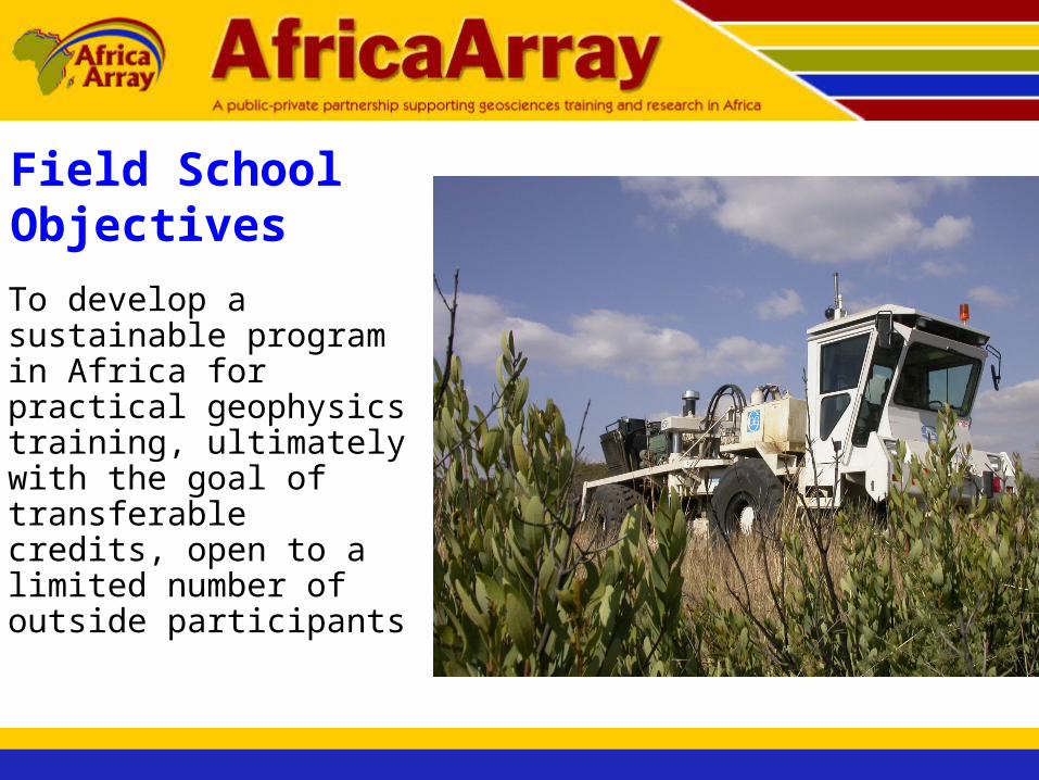
Field School Objectives
• To develop a sustainable program in Africa for practical geophysics training, ultimately with the goal of transferable credits, open to a limited number of outside participants

Practical Goals
• Most geophysics programs have eliminated field programs due to cost and time, few opportunities exist in Africa
• Getting the students out of the starting blocks

• Focus on solvable problems typically encountered in exploration and mining
• 10 years of industry support!!
Practical Goals
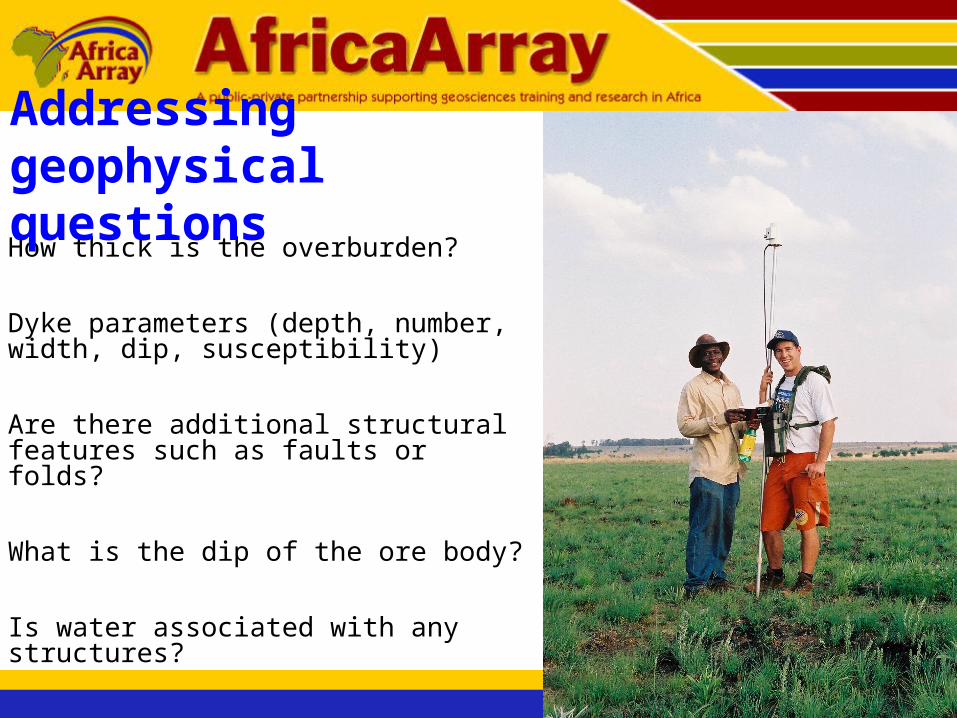
• How thick is the overburden?
• Dyke parameters (depth, number, width, dip, susceptibility)
• Are there additional structural features such as faults or folds?
• What is the dip of the ore body?
• Is water associated with any structures?
Addressing geophysical questions

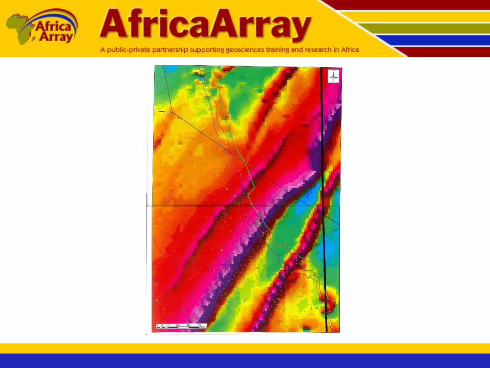
Location of proposed ground grid relative to aeromagnetic data
Grid north
Grid west
Grid south
Grid 0,0
2003Field school
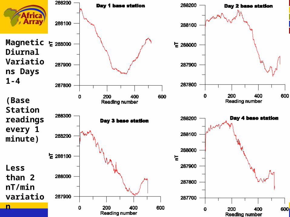
Magnetic Diurnal Variations Days 1-4
(Base Station readings every 1 minute)
Less than 2 nT/minvariation
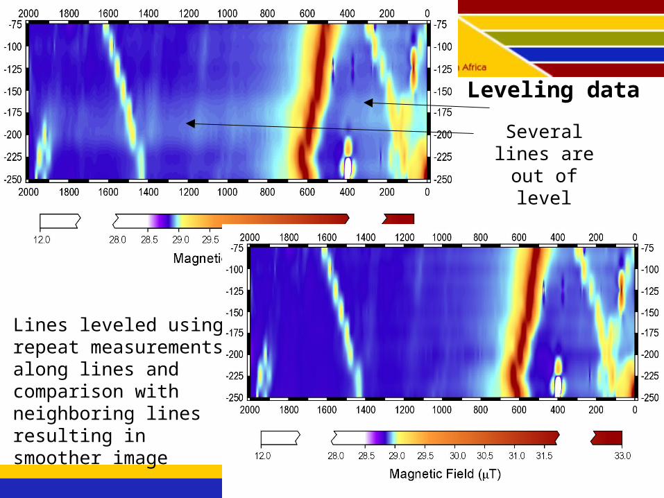
Leveling data
Several lines are out of level
Lines leveled using repeat measurements along lines and comparison with neighboring lines resulting in smoother image
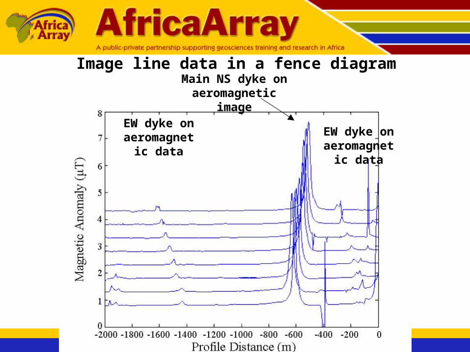
Image line data in a fence diagramMain NS dyke on
aeromagnetic image
EW dyke on aeromagnetic
data
EW dyke on aeromagnetic
data

Enhance vertical resolution of fence diagram

Greatly enhance vertical scale – notice increase in noise!
Cell phone ?Mine noise?

Smooth data using low pass filter
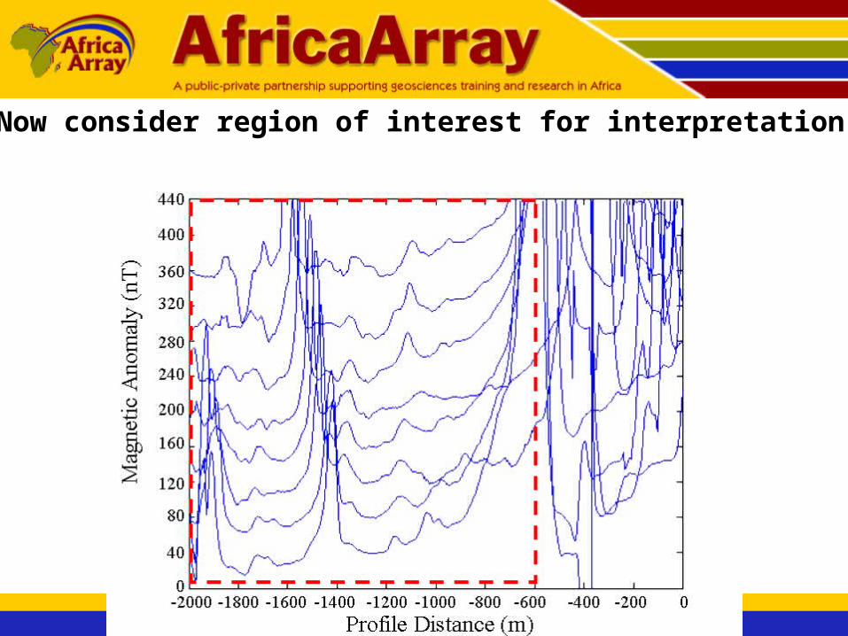
Now consider region of interest for interpretation
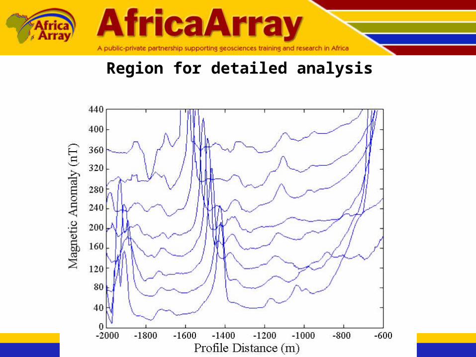
Region for detailed analysis
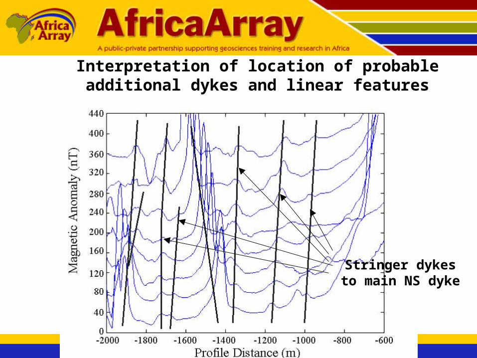
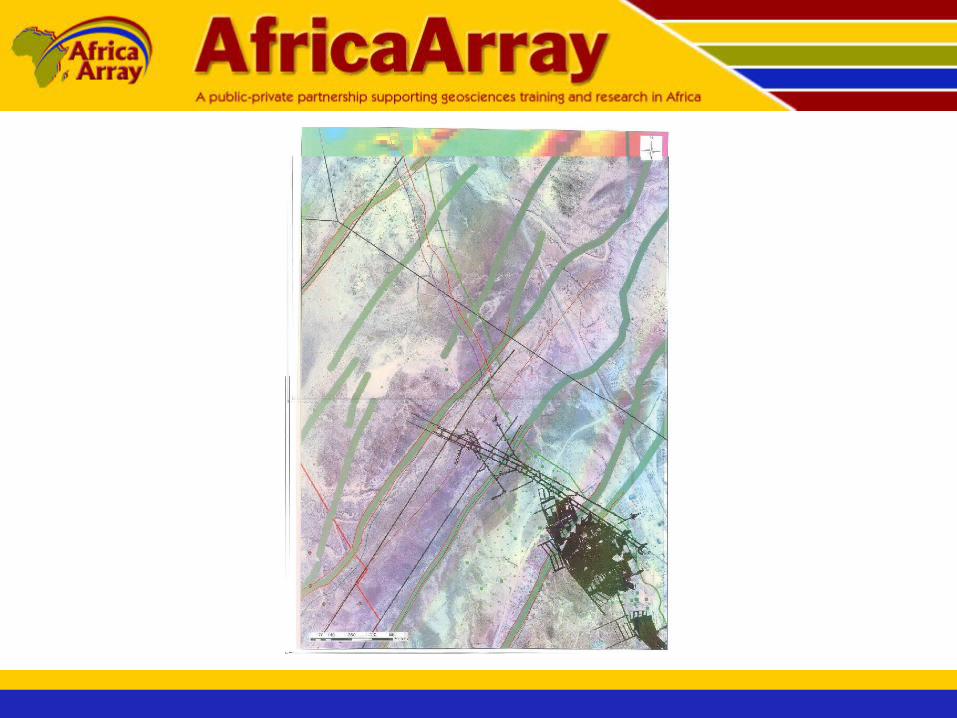
Interpretation of location of probable additional dykes and linear features
Stringer dykes to main NS dyke
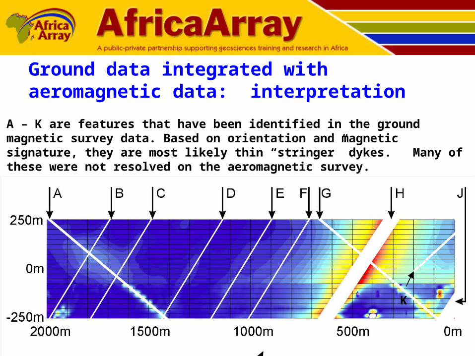
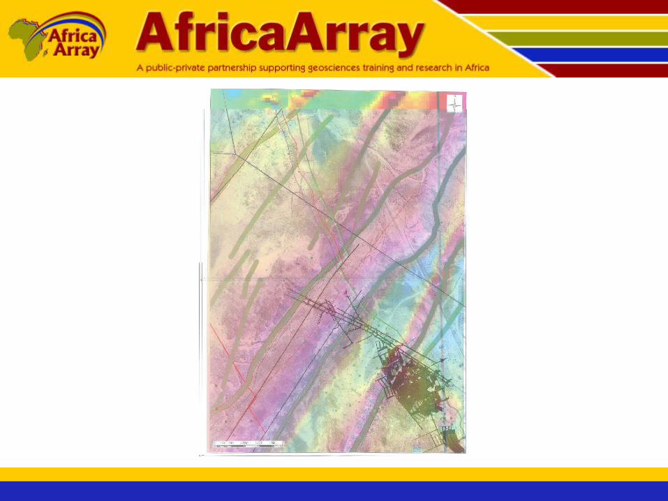
Ground data integrated with aeromagnetic data: interpretation
K
A – K are features that have been identified in the ground magnetic survey data. Based on orientation and magnetic signature, they are most likely thin “stringer” dykes. Many of these were not resolved on the aeromagnetic survey.

Ground magnetic data results• Two different dyke populations a) ~NS, b)~EW• ~EW dykes have a stronger magnetic signature in
the west probably due to being more deeply buried in the east
• Many additional thin “stringer” dykes identified in ground magnetic survey
• Main dykes (both EW and NS) are significantly narrower than suggested by the aeromagnetic survey
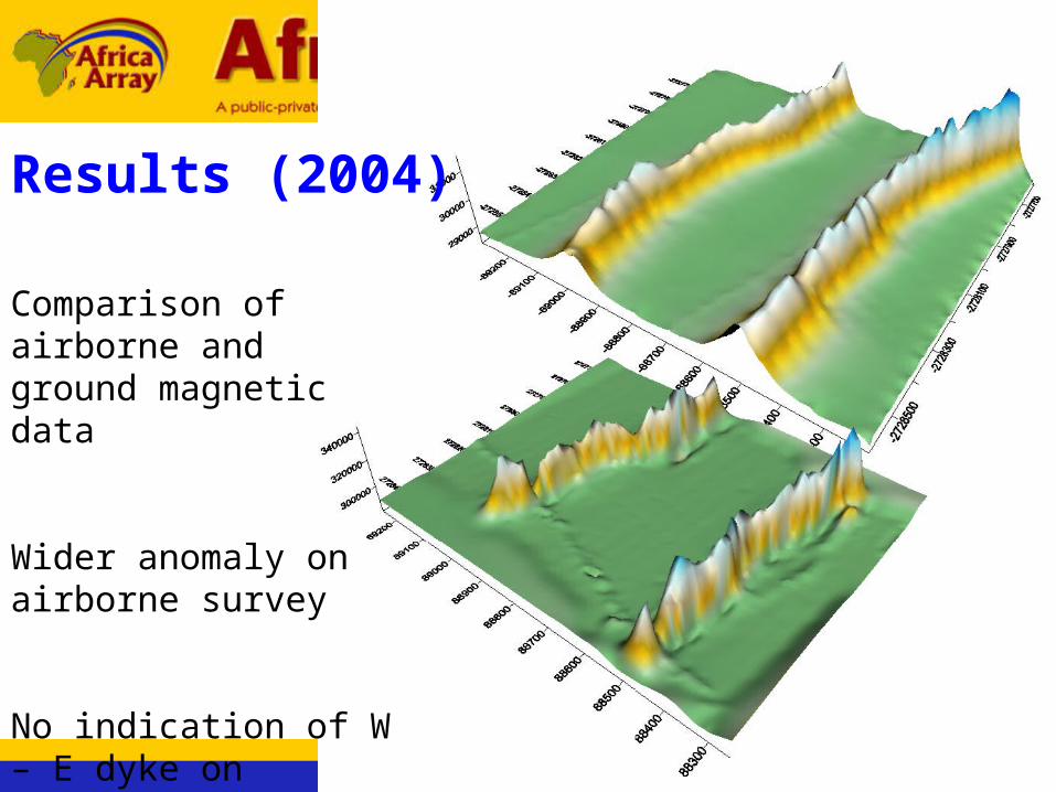
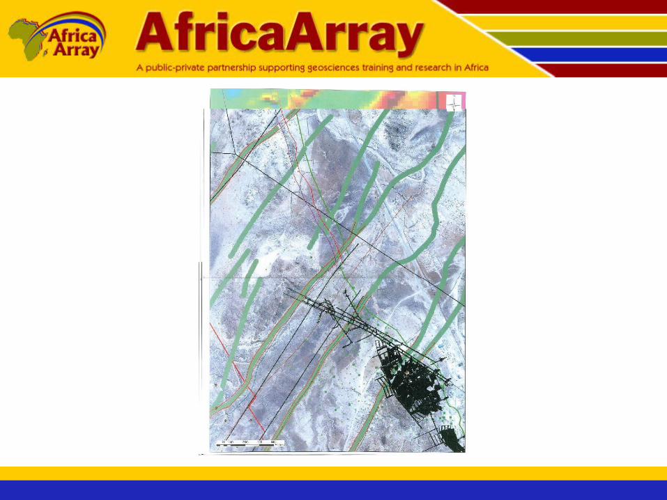
Comparison of airborne and ground magnetic data
Wider anomaly on airborne survey
No indication of W – E dyke on airborne
Results (2004)
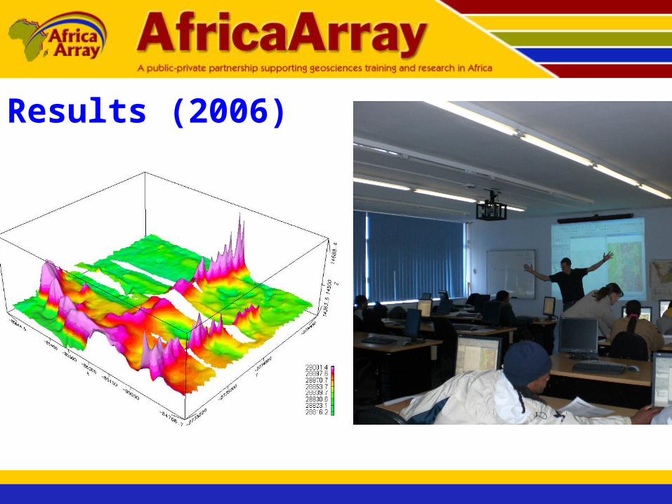
Results (2006)

Ground Penetrating Radar (GPR) 2009
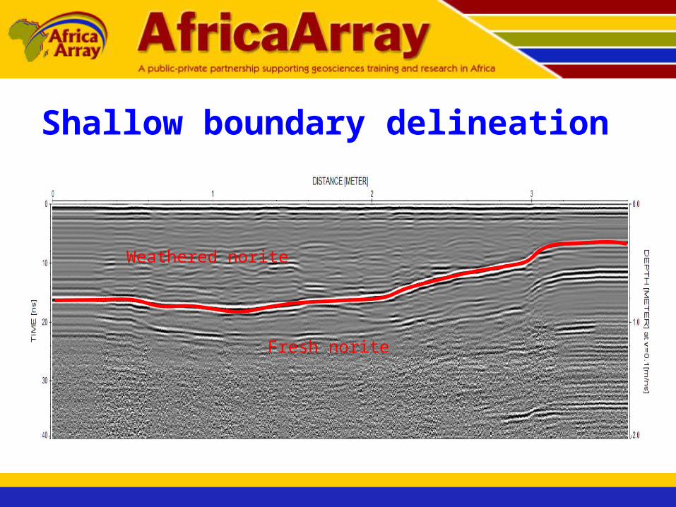
Shallow boundary delineation
Weathered norite
Fresh norite

REFRACTION SEISMICS

SoilV1=100-500 m/s
BedrockdV2=500-7000m/s
Garrison (1990) Garrison (1990)
Applications Rock competence for
engineering applications
Groundwater exploration Depth to Bedrock
How it works Rays must be critically
refracted (V2 >V1) Obey Snell’s law

Processing Tra
vel Tim
e
(ms)
Distance (m)
50
100
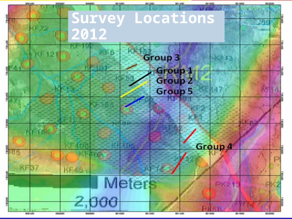
Survey Locations 2012

Group 2- NE-SW
NE SW
Ele
vati
on
(m
)
Distance (m)
0.2 km/s 0.8 km/s
3.5 km/s
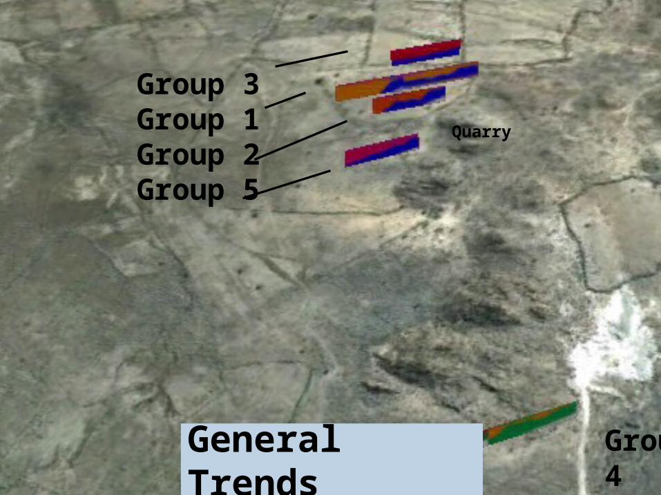
Quarry
Group 3Group 1Group 2Group 5
Group 4
General Trends
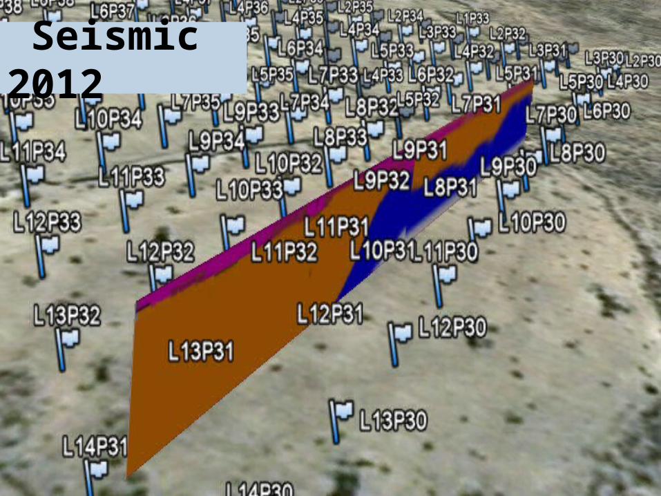
Seismic 2012
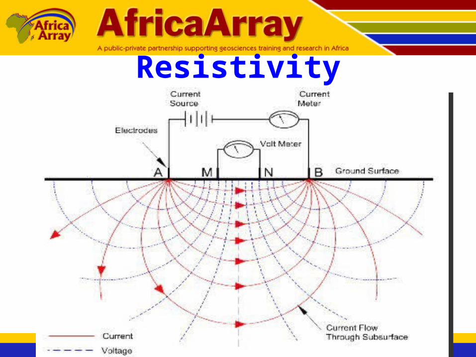
Resistivity
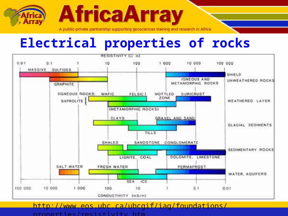
Electrical properties of rocks
http://www.eos.ubc.ca/ubcgif/iag/foundations/properties/resistivity.htm
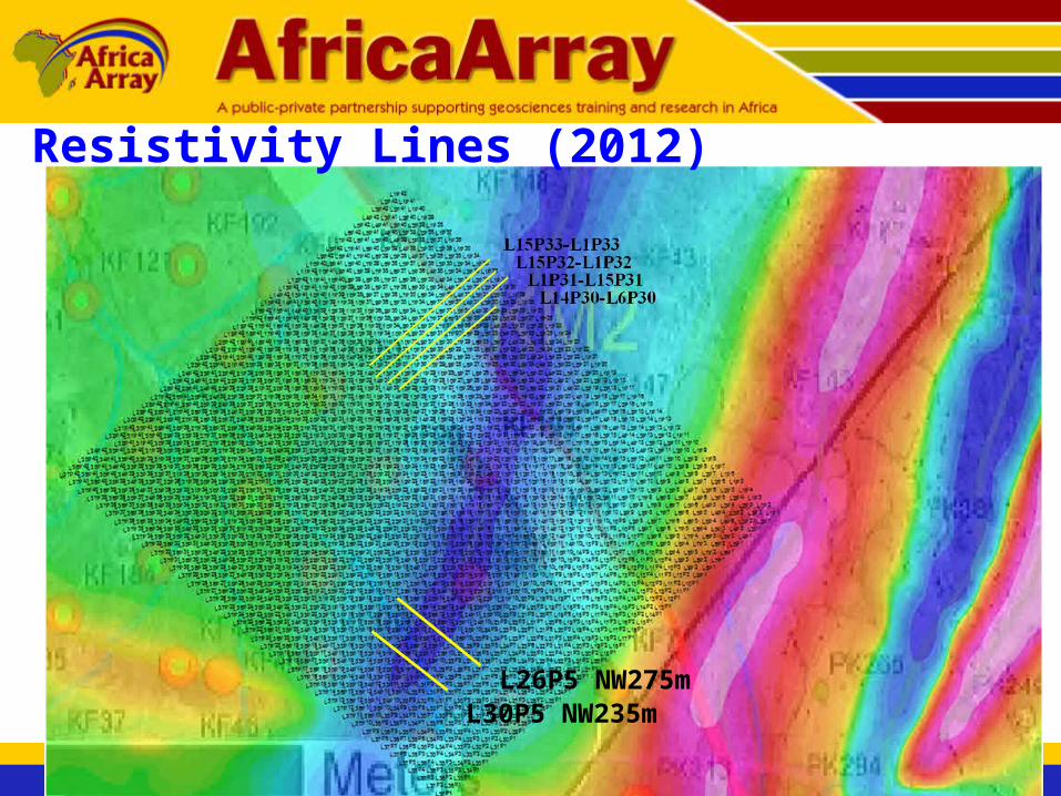
L26P5 NW275mL30P5 NW235m
Resistivity Lines (2012)
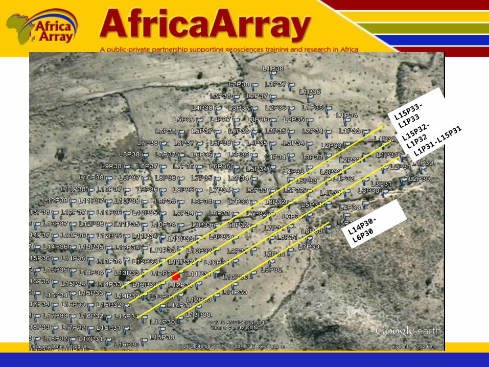
L15P33-L1P33
L15P32-L1P32
L1P31-L15P31
L14P30-L6P30
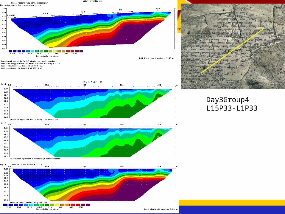
Day3Group4L15P33-L1P33
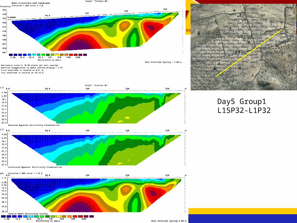
Day5 Group1L15P32-L1P32
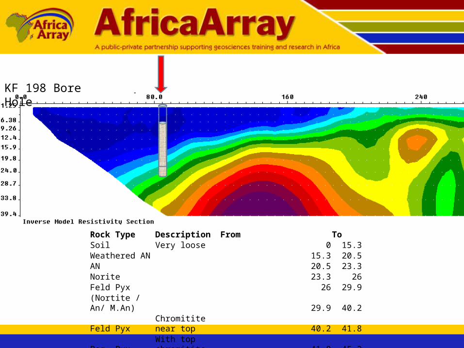
KF 198 Bore Hole
Rock Type Description From ToSoil Very loose 0 15.3Weathered AN 15.3 20.5AN 20.5 23.3Norite 23.3 26Feld Pyx 26 29.9(Nortite / An/ M.An) 29.9 40.2
Feld Pyx Chromitite near top 40.2 41.8
Peg. Pyx With top chromitite 41.8 45.3
Norite 45.3 52.7Feld Pyx 52.7 53.7
AnGrades into Feld Pyx 53.7 56.7
EOH 56.7 56.7
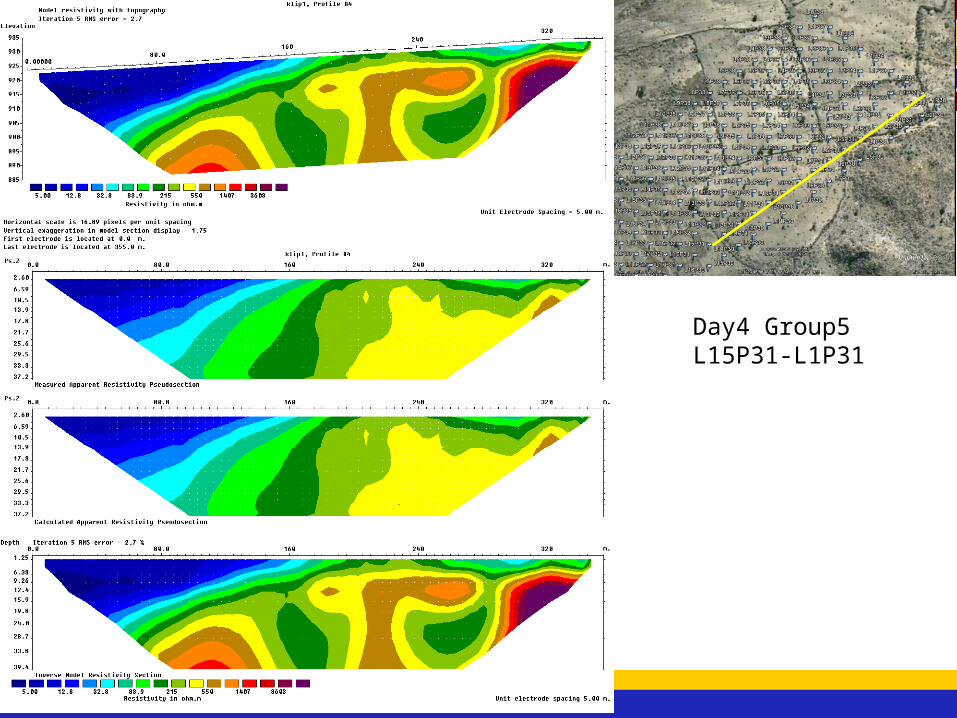
Day4 Group5L15P31-L1P31
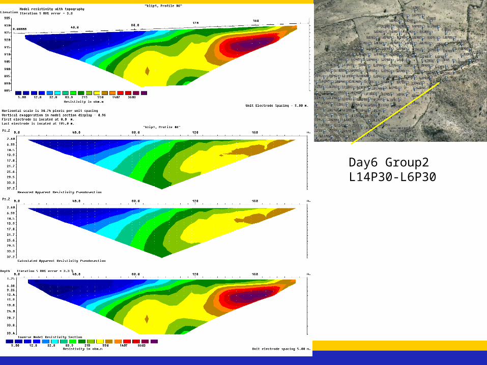
Day6 Group2L14P30-L6P30


Seismic, Resistivity and Borehole

Applications of geophysics for mine planning
• Ground magnetics useful for delineating dykes, especially stringers
• GPR useful for detailed structure
• Refraction seismic can map overburden
• Multielectrode resistivity is a rapid method for mapping overburden structure (but be careful about when data are collected!)

DIAS

Loke for Res2Dinv
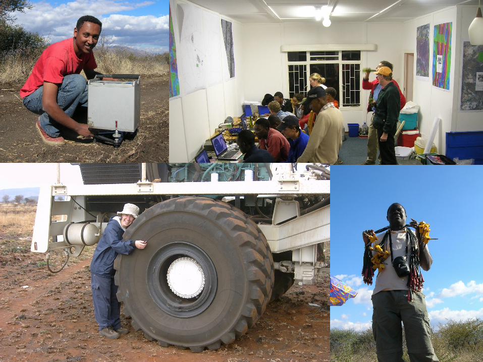
10 years of students!!