Embed Size (px)
DESCRIPTION
Dosimetric effects caused by couch tops and immobilization devices AAPM 2014
Citation preview
Dosimetric effects caused by couch tops and immobilization devices:Report of AAPM Task Group 176
Arthur J. Olcha)
Radiation Oncology Department, University of Southern California and Children’s Hospital Los Angeles,Los Angeles, California 90027
Lee GerigDepartment of Physics, Ottawa Hospital Regional Cancer Centre, Carleton University, Ottawa, Ontario K1S5B6, Canada and Faculty of Medicine, University of Ottawa, Ottawa, Ontario K1N 6N5, Canada
Heng LiDepartment of Radiation Physics, UT MD Anderson Cancer Center, Houston, Texas 77030
Ivaylo MihaylovDepartment of Radiation Oncology Department, University of Miami, Miami, Florida 33136
Andrew MorganThe Beacon Centre, Musgrove Park Hospital, Taunton TA1 5DA, England
(Received 10 January 2014; revised 22 April 2014; accepted for publication 27 April 2014;published 27 May 2014)
The dosimetric impact from devices external to the patient is a complex combination of increasedskin dose, reduced tumor dose, and altered dose distribution. Although small monitor unit or dosecorrections are routinely made for blocking trays, ion chamber correction factors, e.g., accounting fortemperature and pressure, or tissue inhomogeneities, the dose perturbation of the treatment couch topor immobilization devices is often overlooked. These devices also increase skin dose, an effect whichis also often ignored or underestimated. These concerns have grown recently due to the increaseduse of monolithic carbon fiber couch tops which are optimal for imaging for patient position verifi-cation but cause attenuation and increased skin dose compared to the “tennis racket” style couch topthey often replace. Also, arc delivery techniques have replaced stationary gantry techniques whichcause a greater fraction of the dose to be delivered from posterior angles. A host of immobilizationdevices are available and used to increase patient positioning reproducibility, and these also have at-tenuation and skin dose implications which are often ignored. This report of Task Group 176 servesto present a survey of published data that illustrates the magnitude of the dosimetric effects of awide range of devices external to the patient. The report also provides methods for modeling couchtops in treatment planning systems so the physicist can accurately compute the dosimetric effects forindexed patient treatments. Both photon and proton beams are considered. A discussion on avoid-ance of high density structures during beam planning is also provided. An important aspect of thisreport are the recommendations the authors make to clinical physicists, treatment planning systemvendors, and device vendors on how to make measurements of surface dose and attenuation andhow to report these values. For the vendors, an appeal is made to work together to provide accu-rate couch top models in planning systems. © 2014 American Association of Physicists in Medicine.[http://dx.doi.org/10.1118/1.4876299]
Key words: carbon fiber couch top, immobilization device, surface dose, couch model
TABLE OF CONTENTS
1 INTRODUCTION . . . . . . . . . . . . . . . . . . . . . . . . . . . . . 22 DOSIMETRIC EFFECTS OF EXTERNAL
DEVICES . . . . . . . . . . . . . . . . . . . . . . . . . . . . . . . . . . . . 82.A Couch tops . . . . . . . . . . . . . . . . . . . . . . . . . . . . . 8
2.A.1 Impact on skin dose . . . . . . . . . . . . . 82.A.2 Impact on attenuation . . . . . . . . . . . . 11
2.B Immobilization device effect on skin doseand attenuation . . . . . . . . . . . . . . . . . . . . . . . . . 13
2.B.1 Body immobilization bags . . . . . . . 132.B.2 Head holders . . . . . . . . . . . . . . . . . . . 132.B.3 Thermoplastic shells . . . . . . . . . . . . . 13
2.C Equipment combinations . . . . . . . . . . . . . . . . 142.D Calypso . . . . . . . . . . . . . . . . . . . . . . . . . . . . . . . . 152.E Impact of external devices on clinical
proton beams . . . . . . . . . . . . . . . . . . . . . . . . . . . 153 INCLUSION OF COUCH TOPS BY
TREATMENT PLANNING SYSTEMS . . . . . . . . . 153.A Photon beam planning systems . . . . . . . . . . . 153.B Proton beam planning systems . . . . . . . . . . . 18
4 MEASUREMENT METHODS FORATTENUATION AND SURFACE DOSE FROMEXTERNAL DEVICES . . . . . . . . . . . . . . . . . . . . . . . . 18
4.A Methods of attenuation measurements . . . . 18
061501-1 Med. Phys. 41 (6), June 2014 © 2014 Am. Assoc. Phys. Med. 061501-10094-2405/2014/41(6)/061501/30/$30.00
061501-2 Olch et al.: AAPM Task Group 176 061501-2
4.A.1 Geometry for attenuationmeasurements . . . . . . . . . . . . . . . . . . 18
4.A.2 Methods of attenuationmeasurement . . . . . . . . . . . . . . . . . . . 194.A.2.a Point measurements . . . . . 194.A.2.b 2D measurements . . . . . . . 19
4.B Surface dose and buildup measurements . . 204.B.1 Geometry for surface dose and
buildup measurements . . . . . . . . . . . 204.B.2 Detectors used for measurement of
surface dose and buildup . . . . . . . . . 214.B.2.a Extrapolation chamber . . 214.B.2.b Plane parallel ion
chambers . . . . . . . . . . . . . . . 214.B.2.c TLD . . . . . . . . . . . . . . . . . . . 224.B.2.d Film . . . . . . . . . . . . . . . . . . . 224.B.2.e Diamond, MOSFET,
OSL, and diode detectors 224.C Manufacturer supplied data (photons) . . . . . 224.D Proton beam measurements . . . . . . . . . . . . . . 23
4.D.1 Measurement methods . . . . . . . . . . . 234.D.2 Manufacturer supplied data
(protons) . . . . . . . . . . . . . . . . . . . . . . . 235 AVOIDANCE OF EXTERNAL DEVICES
DURING TREATMENT PLANNING . . . . . . . . . . . 245.A Couch top avoidance . . . . . . . . . . . . . . . . . . . . 245.B Immobilization device avoidance . . . . . . . . . 25
6 RECOMMENDATIONS TO TPS AND COUCHTOP VENDORS AND PHYSICISTS . . . . . . . . . . . 26
6.A Recommendations to TPS and couch topvendors . . . . . . . . . . . . . . . . . . . . . . . . . . . . . . . . 26
6.B Recommendations to the physicist . . . . . . . . 267 SUMMARY AND CONCLUSIONS . . . . . . . . . . . . 26A APPENDIX: ELECTRONIC SUPPLEMENT . . . . 27
1. INTRODUCTION
Radiotherapy patients are not treated suspended in mid-air, but often the treatment planning process proceeds as ifthey are. The dosimetric impact from devices external to thepatient is a complex combination of increased skin dose, re-duced tumor dose, and altered dose distribution; the magni-tude being a function of beam energy, relative geometry of thebeam and devices, the fraction of dose delivered through thesedevices, and their physical composition. Devices remote fromthe patient act primarily as attenuators and scatterers. Devicesclose to the patient act like bolus, increasing the skin doseand shifting the depth dose curve toward the patient surface.The overall effect can often be clinically significant as will bedescribed in this report.
Maximizing radiotherapy outcomes generally demandsdose delivery accurate to within 3% to 5% based on theo-retical radiobiology considerations.1–3 Using modern dosime-try protocols such as TG-51,4 calibration uncertainty is 1% to2% (for k = 1) while modern calculation methods have sub-stantially improved treatment planning dose calculation ac-curacy. Many centers routinely make small (typically 2%–4%) monitor unit (MU) corrections for dose perturbations
caused by blocking trays, and to account for tissue inhomo-geneities using the treatment planning system (TPS), evenin tissue and bone where the correction is only a few per-cent. Temperature and pressure corrections to ion cham-ber readings and making the change to TG-51 calibrationmethods are two other examples of routine efforts to apply1% to 2% dose corrections. While it is routine to addressthese small corrections, many in the radiotherapy commu-nity ignore the potentially larger dosimetric effects of devicessuch as couch tops and immobilization systems. This over-sight is probably historical since there have rarely been ac-curate or practical ways of incorporating these devices intodose calculations and vendor-supplied data on the dosimet-ric impact of their devices has generally been inadequate.For beams perpendicular to a uniform slab, attenuation cor-rection factors can be measured and applied manually tothe MU calculation. However, for beams passing obliquelythrough nonuniform portions of the device, it is difficultto accurately account for these in manual MU calculations.The ability for TPS dose calculation algorithms to considerthese devices is either not present or much more frequently,not implemented by the user. As with the other situationslisted above where dosimetric corrections are regarded asnecessary, dosimetric perturbations caused by devices exter-nal to the patient such as the couch top and immobilizationdevices should be included in dose calculations wheneverpossible.
Primarily driven by imaging considerations [Image GuidedRadiotherapy (IGRT) and Cone Beam CT (CBCT)], moderncouch tops are of a carbon fiber sandwich design; two thincarbon fiber plates each 2 mm to 4 mm thick sandwichingan air-equivalent polymeric foam or resin-impregnated paperhoneycomb material. Carbon fiber materials are desirable dueto their high mechanical strength, low specific density, andrelative radio-translucence as first reported by de Mooy.5 Al-though less attenuating than conventional solid couch topswhich typically also incorporate solid metal rails, these newcouch tops produce greater skin dose and dose attenuationthan the older tennis racket inserts on conventional couchtops.6
The dosimetric effects of external devices (increased skindose and reduced tumor dose) have been reported in the litera-ture dating back to at least 1982.7 Our literature search (com-pleted in 2012) found 13 papers in the 1990s on this topic butthat number grew quickly as the prevalence of carbon fibercouches and immobilization devices in the clinic increased.Since 2000, we identified 53 papers on this subject, 25 of thembeing published in 2009–2011. In many cases, the detaileddosimetric findings of the investigators have been at vari-ance with the properties stated by the manufacturers. Thesereferences are found in Tables I and II and throughout thisreport.
With the introduction of volumetric modulated arc therapy(VMAT), a significant portion of the target dose is deliveredthrough the couch top (and rails when present), creating a re-newed interest in evaluating dose perturbations such as atten-uation, increased skin dose, and target coverage effects. Thisreport provides a literature review of the dosimetric effects
Medical Physics, Vol. 41, No. 6, June 2014
061501-3 Olch et al.: AAPM Task Group 176 061501-3
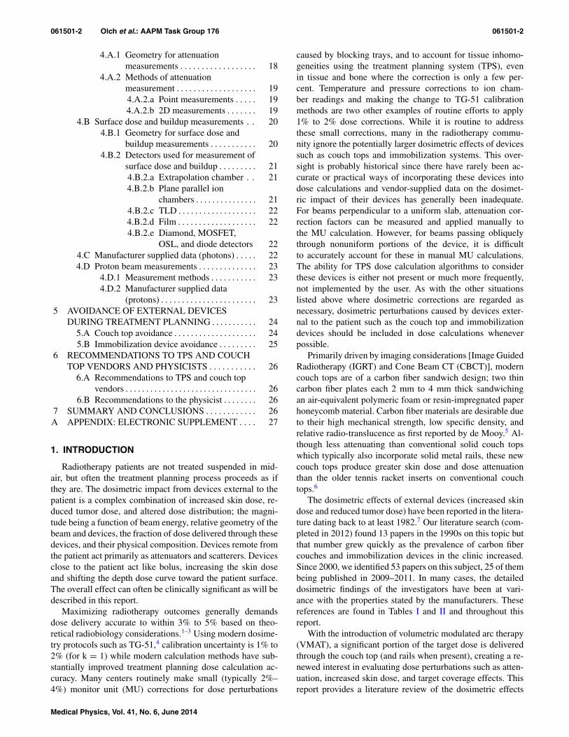
TABLE I. Surface dose by type of external device and delivery method.
Depth on Surface dose in% ofDelivery Beam surface dmax/open field dose Detector Study
Device type angle(s) (cm) in% of dmax (energy) type reference
Carbon fiber grid Single 0◦a 0.015 32%/19% (6 MV) Ion chamber Butson et al. (Ref. 24)tabletop (Varian) beam 15◦b 38%/19% (6 MV) parallel-plate
30◦b 41%/19% (6 MV) (Attix)45◦b 49%/19% (6 MV)60◦b 62%/19% (6 MV) EBT
Gafchromicfilm
Carbon fiber insert Single Normal 0.0 68%/18% (8 MV) Ion chamber Higgins et al. (Ref. 19)(Sinmed) beam incidence 0.0 parallel-plate
(PTW)
Carbon fiber tabletop Single 180◦a 0.05 77%/17% (6 MV) Ion chamber Gerig et al. (Ref. 13)(Medtec) beam 49%/10% (18 MV) parallel-plate
(PTW, Scanditronix)Carbon fiber tabletop 180◦a 89%/17% (6 MV)(Medical Intelligence) 75%/13% (10 MV)
iBEAM Carbon fiber tabletop Single beam 0◦a 0.0 92%/18% (6 MV) EBT Gafchromic film Smith et al. (Ref. 66)(Medical Intelligence) 60◦b 98%/34% (10 MV)
0◦a 78%/13% (6 MV)60◦b 92%/27% (10 MV)
Carbon fiber tabletop IMRT single 5-field/2 0.0 58%/NA (10 MV) TLD Lee et al. (Ref. 47)+ vacuum immobilization device fraction posterior
Contessa tabletop Candor Aps Single beam 0◦a 0.5 97%/83% (6 MV) Ion chamber parallel- Berg et al. (Ref. 23)79%/59% (18 MV) plate (PTW)
Contessa tabletop 0◦a 100%/83% (6 MV)+ breastboard Candor Aps 93%/59% (18 MV)
Carbon fiber tabletop Single beam 180◦a 0.1 92%/51% (6 MV) Ion chamber parallel- Poppe et al. (Ref. 55)(Reuther Medizintechnik) 80%/36% (10 MV) plate (PTW)
150◦b 94%/51% (6 MV)84%/36% (10 MV)
Carbon fiber tabletop + combiboard 180◦a 98%/51% (6 MV)93%/36% (10 MV)
150◦b 99%/51% (6 MV)95%/36% (10 MV)
Carbon fiber Mylar insert (Varian) Single beam 0◦a 0.017 48%/16% (6 MV) Gafchromic film Butson et al. (Ref. 24)Carbon fiber tennis string insert (Varian) 0◦a 35%/16% (6 MV)
Elekta C-arm tabletop Single beam 180◦a 0.1 38%/28% (6 MV) EDR2 radiographic film Gillis et al. (Ref. 38)20%/16% (18 MV)
Sinmed Mastercouch 180◦a 74%/28% (6 MV)48%/16% (18 MV)
Sinmed Mastercouch + support bar 180◦a 83%/28% (6 MV)62%/16% (18 MV)
Carbon fiber grid with mylar sheet Single beam 180◦a 0.015 26%/20% (6 MV) EBT radiochromic film Chiu-Tsao and Chan
Orfit carbon fiber base plate 71%/20% (6 MV) (Ref. 56)Balsa wood board 69%/20% (6 MV)Styrofoam 55%/20% (6 MV)Aqua-plast sheet 38%/20% (6 MV)Alpha-cradle 45%/20% (6 MV)
PMMA 12.5 mm plate Single beam 0◦a 0.0 100%/18% (Co-60) Ion chamber parallel- De Ost et al. (Ref. 18)83%/21% (6 MV) plate (Markus)74%/20% (23 MV)
Wood 0◦a 100%/18% (Co-60)82%/21% (6 MV)73%/20% (23 MV)
Carbon1 Orfit 0◦a 74%/18% (Co-60)49%/21% (6 MV)
Medical Physics, Vol. 41, No. 6, June 2014

061501-4 Olch et al.: AAPM Task Group 176 061501-4
TABLE I. (Continued).
Depth on Surface dose in% ofDelivery Beam surface Dmax/open field dose Detector Study
Device type angle(s) (cm) in% of dmax (energy) type reference
29%/20% (23 MV)Carbon2 Orfit 0◦a 77%/18% (Co-60)
55%/21% (6 MV)34%/20% (23 MV)
Carbon3 Sinmed 0◦a 76%/18% (Co-60)51%/21% (6 MV)32%/20% (23 MV)
Carbon fiber 1.1 cm Normal 0.0 64%/19% (4 MV) Ion chamber parallel- Carl and Vestergaard
incidence 50%/15% (6 MV) plate (NACP) (Ref. 29)38%/11% (10 MV)
Carbon fiber 4.1 cm 82%/19% (4 MV)66%/15% (6 MV)53%/11% (10 MV)
Polystyrene cradle 1.0 cm 51%/19% (4 MV)41%/15% (6 MV)30%/11% (10 MV)
Polystyrene cradle 4.0 cm 66%/19% (4 MV)56%/15% (6 MV)42%/11% (10 MV)
Thermoplastic material 0.15 cm 39%/19% (4 MV)c
30%/15% (6 MV)c
22%/11% (10 MV)c
Thermoplastic material 0.2 cm 49%/19% (4 MV)c
40% / 15% (6 MV)c
28%/11% (10 MV)c
Carbon fiber composite slab Single beam 180◦a 0.004 59%/18% (5 MV) Ion chamber parallel- Meara and Langmack
56% / 15% (6 MV) plate (Vinten) (Ref. 48)43%/12% (8 MV)
PMMA baseboard 98%/18% (5 MV)98%/15% (6 MV)93%/12% (8 MV)
PETG copolyester 78%/18% (5 MV)75%/15% (6 MV)62%/12% (8 MV)
Thermoplastic immobilization devices Single beam Normal 0.0 60%/17% (6 MV)c Ion chamber parallel- Hadley et al. (Ref. 50)incidence 40%/11% (15 MV)c plate (Attix)
Thermoplastic immobilization devices Single beam Normal 0.05 77%/57% (Co-60) TLD Halm et al. (Ref. 51)incidence 63%/49% (4 MV)
63%/49% (6 MV)
Thermoplastic immobilization IMRT 7-field 0.0 152 cGy /125 cGy (6 MV) TLD Lee et al. (Ref. 31)(Med-Tec) (with/without mask)
Aquaplast solid 0.3 cm Single beam Normal 0.1 80%/24% (6 MV)c Ion chamber parallel- Fontenla et al. (Ref. 52)incidence 58%/19% (15 MV)c plate (Holt)
Thermoplastic mask Single beam Normal 0.0 36%/15% (6 MV) Ion chamber parallel- Mellenberg (Ref. 45)incidence 24%/12% (15 MV) plate (PTW)
Immobilization cradle (polyurethane) 63%/15% (6 MV)c
47%/12% (15 MV)c
Immobilization cradle (polystyrene) 66%/15% (6 MV)45%/12% (15 MV)
Thermoplastic immobilization devices Single beam Normal Ion chamber parallel- Fiorino et al. (Ref. 53)incidence plate (Markus)
Orfit Raycast 0.2 cm 0.0 56%/16% (6 MV)Orfit Raycast 0.32 cm 0.0 74%/16% (6 MV)Optimold 0.24 cm 0.0 62%/16% (6 MV)Optimold 0.32 cm 0.0 67%/16% (6 MV)
Medical Physics, Vol. 41, No. 6, June 2014

061501-5 Olch et al.: AAPM Task Group 176 061501-5
TABLE I. (Continued).
Depth on Surface dose in% ofDelivery Beam surface Dmax/open field dose Detector Study
Device type angle(s) (cm) in% of dmax (energy) type reference
Vacuum compressed immobilization Single beam Normal 0.01 52%/16% (6 MV) Ion chamber Cheung et al. (Ref. 46)
device (Vacbag) incidence parallel-plate (Attix)
Polyurethane-foam immobilization Single beam Normal 0.0 91%/28% (Co-60)c Ion chamberparallel-plate Mondalekal (Ref. 7)
devices incidence (Capintec)
76%/20% (4 MV)c
48%/13% (10 MV)c
38%/10% (15 MV)c
Immobilization devices Single beam Normal 0.0 Ion chamber Johnson et al. (Ref. 44)
incidence parallel-plate (Capintec)Alpha Cradle 81%/28% (Co-60)c
51% / 17% (6 MV)c
31%/14% (18 MV)c
VacFix 89%/28% (1.2 MV)c
58%/17% (6 MV)c
35%/14% (18 MV)c
Silicon-based burn dressing Single beam Normal 0.1 50.5%/16% (6 MV) Ion chamber parallel- Butson et al. (Ref. 25)
incidence plate (Attix)
TLD
EBT Gafchromic film
Brainlab Single beam Normal 0.06 98.6%/44.3% (6 MV) Plane parallel chamber Seppälä and Kulmala
(10 × 10) incidence NACP-02 (uncorrected) (Ref. 6)
Qfix kVue standard 88.5%/44.3% (6 MV)
Medtec 90.1%/44.3% (6 MV)
Varian Exact IGRT 90.8%/44.3% (6 MV)
Dignity Airplate 86.0%/44.3% (6 MV)
Qfix DoseMax 75.1%/44.3% (6 MV)
Varian Grid insert 61.2%/44.3% (6 MV)
aPosterior.bPosterior oblique.cVariable with stretching/thickness.
of couch tops and immobilization devices, including dosime-try data for many commonly available devices and linacs. Itdoes not address devices such as bolus, blocks or wedges thatare deliberately introduced to modify dose. The magnitudeof the dosimetric effects caused by particular devices in lowand high energy beams is given as well as guidance on themeasurements required by the physicist and how these mea-surements may be made.
Target localization systems such as the Calypso system in-troduce devices which the beam may pass through but are notpresent in the planning CT images. The dosimetric effects ofthis system are discussed.
In CT-based planning, the CT couch top is typically partof the patient image. Although the linac couch top mayattenuate the beam by up to 15% (see Table II), beforearound 2008, it was difficult to include it in TPS dose cal-culations. Many current TPS software releases still do notprovide the means to replace the CT couch top with theactual treatment couch top, however, from its earliest ver-sion, the TomoTherapy (Accuray, Sunnyvale, CA) planning
software has implemented this. Varian has recently imple-mented software to automatically insert certain Varian couchtops under the patient to increase the accuracy of the dosecalculations.8–10 Other treatment planning systems have alsobegun to offer methods to directly include the treatment couchtop in the planning CT while others can accept modified CTdatasets.11–14 These methods will be discussed in more de-tail later in the report as well as guidance on the creationof plans in which beams largely miss external structures andon methods that predict when beams will pass through thesestructures.
Dose perturbation due to the couch top may vary if theposition of the patient relative to the couch top varies dayto day, making a single compensatory solution potentiallyinaccurate. Indexed patient immobilization systems are nowcommonly used to establish reproducible patient positionrelative to the couch and employing such devices providesthe best opportunity to accurately account for the couch top(and rails if present) during the planning process. The rec-ommendations in this report will be most relevant to the
Medical Physics, Vol. 41, No. 6, June 2014
061501-6 Olch et al.: AAPM Task Group 176 061501-6
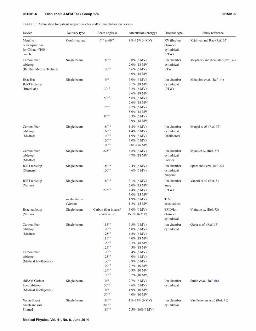
TABLE II. Attenuation for patient support couches and/or immobilization devices.
Device Delivery type Beam angle(s) Attenuation (energy) Detector type Study reference
Metallic Conformal arc 0◦a to 60◦b 8%–12% (4 MV) XV film/ion Krithivas and Rao (Ref. 35)centerspine bar chamberfor Clinac 4/100 cylindricalcouch (PTW)
Carbon fiber Single beam 180◦a 3.0% (6 MV) Ion chamber Meydanci and Kemikler (Ref. 32)tabletop 2.0% (18 MV) cylindrical(Reuther MedizinTechnik) 120◦b 5.6% (6 MV) PTW
4.0% (18 MV)
ExacTrac Single beam 0◦a 3.0% (6 MV) Ion chamber Mihaylov et al. (Ref. 14)IGRT tabletop 0.1% (18 MV) cylindrical(BrainLab) 30◦b 3.2% (6 MV) (PTW)
0.6% (18 MV)50◦b 5.6% (6 MV)
2.6% (18 MV)75◦b 8.7% (6 MV)
5.0% (18 MV)83◦b 5.3% (6 MV)
2.9% (18 MV)
Carbon fiber Single beam 180◦a 1.2% (6 MV) Ion chamber Munjal et al. (Ref. 57)tabletop 160◦b 1.4% (6 MV) cylindrical(Medtec) 140◦b 1.9% (6 MV) (Wellhofer)
120◦b 3.0% (6 MV)100◦b 0.01% (6 MV)
Carbon fiber Single beam 225◦b 6.8% (6 MV) Ion chamber Myint et al. (Ref. 37)tabletop 4.7% (18 MV) cylindrical(Medtec) Farmer
IGRT tabletop Single beam 180◦a 2.4% (6 MV) Ion chamber Spezi and Ferri (Ref. 22)(Siemens) 150◦b 4.6% (6 MV) cylindrical
pinpoint
IGRT tabletop Single beam 180◦a 3.1% (6 MV) Ion chamber Vanetti et al. (Ref. 8)(Varian) 2.0% (15 MV) array
225◦b 4.4% (6 MV) (PTW)3.0% (15 MV)
modulated arc 1.9% (6 MV) TPS(Varian) 1.3% (15 MV) calculations
Exact tabletop Single beam Carbon fiber insertsa 3.0% (6 MV) EPID/Ion Vieira et al. (Ref. 73)(Varian) couch railsb 15.0% (6 MV) chamber
cylindrical
Carbon fiber Single beam 115◦b 5.5% (6 MV) Ion chamber Gerig et al. (Ref. 13)tabletop 120◦b 5.0% (6 MV) cylindrical(Medtec) 125◦b 6.5% (6 MV)
115◦b 4.0% (18 MV)120◦b 3.3% (18 MV)125◦b 4.3% (18 MV)
Carbon fiber 120◦b 3.4% (6 MV)tabletop 125◦b 4.0% (6 MV)(Medical Intelligence) 130◦b 3.9% (6 MV)
120◦b 2.7% (10 MV)125◦b 3.3% (10 MV)130◦b 3.2% (10 MV)
iBEAM Carbon Single beam 0◦a 2.7% (6 MV) Ion chamber Smith et al. (Ref. 66)fiber tabletop 50◦b 4.6% (6 MV) cylindrical(Medical Intelligence) 0◦a 1.9% (10 MV)
50◦b 4.0% (10 MV)
Varian Exact Single beam 180◦a 1%–17% (6 MV) Ion chamber Van Prooijen et al. (Ref. 41)couch and rail 240◦b cylindricalSinmed 180◦a 2.5%–16%(6 MV)
Medical Physics, Vol. 41, No. 6, June 2014

061501-7 Olch et al.: AAPM Task Group 176 061501-7
TABLE II. (Continued).
Device Delivery type Beam angle(s) Attenuation (energy) Detector type Study reference
Mastercouch 240◦b 2.2%–14% (10 MV)and wedged 1.6%–11% (18 MV)section
Sinmed BV Single beam 180◦a 2.2% (6 MV) Ion chamber McCormack et al. (Ref. 21)Posisert insert 110◦b 8.7% (6 MV) cylindrical
(PTW)
Contessa Single beam 0◦a 2.0% (6 MV) Ion chamber Berg et al. (Ref. 23)tabletop 1.3% (18 MV) cylindricalCandor Aps 60◦b 4.8% (6 MV) Farmer
2.9% (18 MV)75◦b 5.5% (6 MV)
3.4% (18 MV)Contessa 0◦a 3.5% (6 MV)tabletop + breastboard 1.9% (18 MV)Candor Aps 60◦b 8.0% (6 MV)
5.2% (18 MV)75◦b 5.3% (6 MV)
3.5% (18 MV)
Elekta Single beam 180◦a 6.9% (6 MV) Ion chamber Becker et al. (Ref. 59)stereotactic 4.8% (16 MV) cylindricalbody frame + 215◦b 10.6% (6 MV) (Exradin A16)table 7.0% (16 MV)
246◦b 5.8% (6 MV)4.0% (16 MV)
270◦ 6.8% (6 MV)4.8% (16 MV)
284◦ 9.4% (6 MV)5.5% (16 MV)
Carbon fiber Single beam 180◦a 2.7% (6 MV) Ion chamber Poppe et al. (Ref. 55)tabletop 2.3% (10 MV) parallel-plate(Reuther Medizintechnik) 150◦b 3.2% (6 MV) (PTW)
2.4% (10 MV)Carbon fiber 180◦a 5.2% (6 MV)tabletop + 4.1% (10 MV)combiboard 150◦b 6.4% (6 MV)
4.9% (10 MV)
Patient support Conformal arc 0◦a to 359◦b 2.9% (6 MV) Ion chamber Sharma and Johnson (Ref. 36)assembly 1.8% (18 MV) cylindricalcenterspine bar FarmerPatient support 2.9% (6 MV)assembly 2.4% (18 MV)side rails
Elekta C-arm Single beam 180◦a 0.3% (6 MV) Ion chamber Gillis et al. (Ref. 38)tabletop 0.2% (18 MV) cylindricalSinmed 180◦a 1.5% (6 MV) FarmerMastercouch 1.5% (18 MV)Sinmed Mastercouch 180◦a 3.7% (6 MV)+ support bar 2.4% (18 MV)
Carbon fiber Single beam 180◦a 0.8% (5 MV) Ion chamber Meara and Langmack (Ref. 48)composite slab 0.5% (6 MV) cylindrical
0.4% (8 MV) FarmerPMMA 4.3% (5MV)baseboard 3.7% (6 MV)
3.2% (8 MV)PETG 1.2% (5MV)copolyester 1.4% (6 MV)
1.2% (8 MV)
Medical Physics, Vol. 41, No. 6, June 2014

061501-8 Olch et al.: AAPM Task Group 176 061501-8
TABLE II. (Continued).
Device Delivery type Beam angle(s) Attenuation (energy) Detector type Study reference
PMMA 12.5 mm Single beam 0◦a 5.0% (Co-60) Ion chamber De Ost et al. (Ref. 18)plate 4.0% (6 MV) parallel-plate
2.0% (23 MV) (Markus)Wood 0◦a 5.0% (Co-60)
4.0% (6 MV)2.0% (23 MV)
Carbon1 Orfit 0◦a 0.0% (Co-60)0.0% (6 MV)0.0% (23 MV)
Carbon2 Orfit 0◦a 1.0% (Co-60)1.0% (6 MV)0.0% (23 MV)
Carbon3 Sinmed 0◦a 1.0% (Co-60)0.0% (6 MV)0.0% (23 MV)
Carbon fiber Single beam Base platea 4.0% (6 MV Diode Olch and Lavey (Ref. 49)head fixationVBH HeadFix Vertical postsa 15.0% (6 MV)
Polyurethane- Single beam Normal 1.7% (Co-60)c Ion chamber Mondalek (Ref. 7)foam incidence 1.6% (4 MV)c parallel-plateimmobilization 1.1% (10 MV)c (Capintec)devices 1.0% (15 MV)c
Brainlab Single beam Normal 3.6% (6 MV) Ion chamber Seppälä and Kulmala (Ref. 6)Qfix kVue standard incidence 2.1% (6 MV) (NE-2571)Medtec 1.9% (6 MV)Varian Exact IGRT 1.9% (6 MV)Dignity Airplate 1.9% (6 MV)Qfix DoseMax 1.3% (6 MV)Varian Grid insert 0.3% (6 MV)
aPosterior.bPosterior oblique.cVariable with stretching/thickness.
situation of the indexed patient, but will apply more generallyas well.
Although the majority of this report is concerned with pho-ton beams, charged particle therapy is potentially even moreimpacted by external devices which partially use the finiteparticle range, potentially causing substantially underdosedregions in the distal portions of the PTV. Most electron beamtreatments are single en-face fields that directly irradiate thepatient, but proton beam therapy is often optimized usingbeams from different directions, some of which can intersectthe couch top and immobilization devices. This report alsodiscusses the dosimetric impact of these devices on protonbeams.
A review of current limitations of commonly used TPSsreveals some of the practical problems encountered when in-cluding all sources of beam perturbation in the dose calcula-tion. This report provides recommendations to TPS vendorsregarding features that should be included in TPS software toallow the accurate inclusion of all external structures that af-fect dose. Recommendations are also made to couch top andimmobilization device vendors to provide attenuation and sur-face dose data for limited but defined irradiation conditions as
well as detailed information about the structure and materialcomposition of each device.
2. DOSIMETRIC EFFECTS OF EXTERNAL DEVICES
2.A. Couch tops
2.A.1. Impact on skin dose
From the early days of radiotherapy, skin was used as a“dosimeter” (erythema dose) and there is a significant knowl-edge base for skin dose-response. Archambeau et al. providesan excellent discussion of the pathophysiology, anatomy, anddose response of the skin, describing clinically observed skinand hair changes as a function of total dose and fractionsize. Skin doses over about 25 Gy at 2 Gy per fraction pro-duce clinically relevant skin reactions and greater than 45 Gymay produce dry desquamation.15 The radio-sensitivity of theskin is often enhanced by concomitant chemotherapy or nearsites of surgical intervention while larger doses per fraction,commonly used in stereotactic radiotherapy, exacerbate theskin reaction for the same total dose.16 In this report, the term
Medical Physics, Vol. 41, No. 6, June 2014

061501-9 Olch et al.: AAPM Task Group 176 061501-9
“surface dose” is used to describe the dose to an infinitesimalmass at the very surface of a phantom, while “skin dose” is aclinical term and refers to the dose to the radiation sensitiveepithelial layer.
There are many well-known clinical situations where skindose can be excessive (e.g., skin folds, electron or orthovolt-age beams, bolus). However, the impact of couch tops and im-mobilization devices is often not well recognized. Kry et al.recently presented a review of all factors affecting skin dosein radiotherapy.17 Interestingly, there are more physics-basedreports on the potential loss of skin sparing from external de-vices than clinical reports on skin toxicity due to those de-vices. This disparity does not necessarily mean clinically rel-evant skin reactions are not occurring; they may be under-reported or other mitigating factors are at work, such as theuse of multiple beams reducing the dose to any one part ofthe skin.
Numerous publications show a significant increase in sur-face dose when beams first transit carbon fiber couch tops ateither normal or oblique incidence6, 18–24 and show these tobe larger than for the mylar-covered tennis racket couch top25
(Table I). While there is some consistency in the methodologyused for measuring and reporting the dose attenuation, thereare large variations in the methodology used to determine andreport the surface dose. One must be cautious when interpret-ing reported surface doses because the dose gradient at thesurface is very steep at approximately 2% for every 0.1 mmso that the true depth at which the “surface” dose is reportedbecomes critical (see Tables III–V). In our literature review,various authors reported the “surface” dose of 13% up to 83%for depths ranging from 0 to 0.5 cm for (typically 10 × 10cm2) 6 MV x-rays compared to accurate estimates of surfacedose of about 16% (Table V). Errors in the measurement of
TABLE III. PDD for 6 MV x-rays in the buildup region (data measuredwith an Attix parallel plate chamber, adapted from data provided by MichaelEvans, McGill University, Montreal, Canada).
6 MV buildup PDDSquare field size (cm)
Depth (mm) 4 6 8 10 15 20 30
0 9 11 14 16 22 28 401 33 35 37 39 44 49 592 52 53 55 56 61 64 723 65 66 67 69 72 75 804 74 75 76 77 79 82 855 81 82 82 83 85 86 886 85 86 87 87 88 89 907 89 89 90 90 91 91 928 91 92 92 92 93 93 939 93 94 94 94 95 95 9510 95 95 96 96 97 97 9711 97 97 97 97 99 99 9912 98 98 99 99 99 100 10013 99 100 100 99 9914 100 100 100 100 10015 100 100 100 100
TABLE IV. PDD for 10 MV x-rays in the buildup region (data measuredwith an Attix parallel plate chamber, adapted from data provided by MichaelEvans, McGill University, Montreal, Canada).
10 MV buildup PDDSquare field size (cm)
Depth (mm) 4 6 8 10 15 20 30
0 7 8 10 13 19 24 341 24 25 27 30 35 39 492 38 40 41 43 48 52 603 50 51 52 55 58 62 704 60 61 62 64 67 70 775 68 69 69 71 74 77 826 74 75 76 77 79 82 867 79 80 80 82 84 86 908 83 84 84 85 87 89 929 86 87 87 88 90 91 9410 89 89 90 91 92 93 9511 91 91 92 92 94 95 9612 92 93 93 94 95 96 9713 94 94 94 95 96 97 9814 95 95 96 96 97 98 9915 96 96 97 97 98 99 10016 97 97 98 98 99 9917 98 98 98 99 99 10018 99 99 99 99 10019 99 99 99 9920 99 99 100 10021 99 10022 100
the unattenuated surface dose will generally carry over to themeasurement for intervening devices. It should also be notedthat field size dependence of surface dose (see Tables III–V) isconsiderably greater than that for attenuation. Table I detailsthe reported surface doses for 24 studies for a wide variety ofdevices. The reported surface doses for the external devicesshould be understood in light of the open field surface doseand depth of measurement also listed.
To determine the clinical effect of surface dose it is impor-tant to consider the skin anatomy. Whitton reported the depthof the sensitive basal cell (growing) layer varies between 0.05and 0.4 mm, depending on anatomical site.26 The ICRU andICRP recommend that skin dose be measured at 0.07 mmdepth, which corresponds to the approximate depth of thebasal cell layer.27, 28 A depth of 0.1 mm has frequently beenused as a reasonable reference depth of the basal cell layer ofskin.29 Measurements made at an effective depth greater thanthe basal layer depth will overestimate the “skin dose.” Carland Vestergaard measured surface doses for beams passingthrough a variety of thermoplastic and carbon fiber devicesand provided water equivalent thicknesses (WET) and normaltissue complication probability (NTCP) calculations of earlyand late skin damage for 4, 6, and 10 MV photon beams.29
The clinical importance of skin dose is often overlookedwhen treating with megavoltage photon beams, where theclinical goal is to eradicate deep seated tumors. However,clinically relevant skin toxicity due to the passage of beams
Medical Physics, Vol. 41, No. 6, June 2014
061501-10 Olch et al.: AAPM Task Group 176 061501-10
TABLE V. PDD for 18 MV x-rays in the buildup region (data measuredwith an Attix parallel plate chamber, adapted from data provided by MichaelEvans, McGill University, Montreal, Canada).
18 MV buildup PDDSquare field size (cm)
Depth (mm) 4 6 8 10 15 20 30
0 6 9 12 16 23 29 411 17 21 24 27 34 41 522 28 31 34 37 44 51 613 37 40 43 46 53 59 684 45 48 51 54 60 66 745 52 55 58 60 66 72 796 58 61 64 66 72 76 827 63 66 69 71 76 80 858 68 71 73 75 80 83 889 72 74 77 79 83 86 9010 76 78 80 82 85 88 9111 79 81 82 84 88 90 9212 81 83 85 86 89 91 9313 84 85 87 88 91 93 9414 86 87 88 90 92 94 9515 87 89 90 91 93 95 9616 89 90 91 92 94 96 9717 90 91 92 93 95 96 9818 91 92 93 94 96 97 9819 93 93 94 95 97 98 9920 94 94 95 96 97 99 9921 95 95 96 97 98 99 10022 96 96 97 97 98 10023 96 97 98 98 9924 97 98 98 99 10025 98 98 99 9926 99 99 99 10027 99 99 10028 100 10029 10030
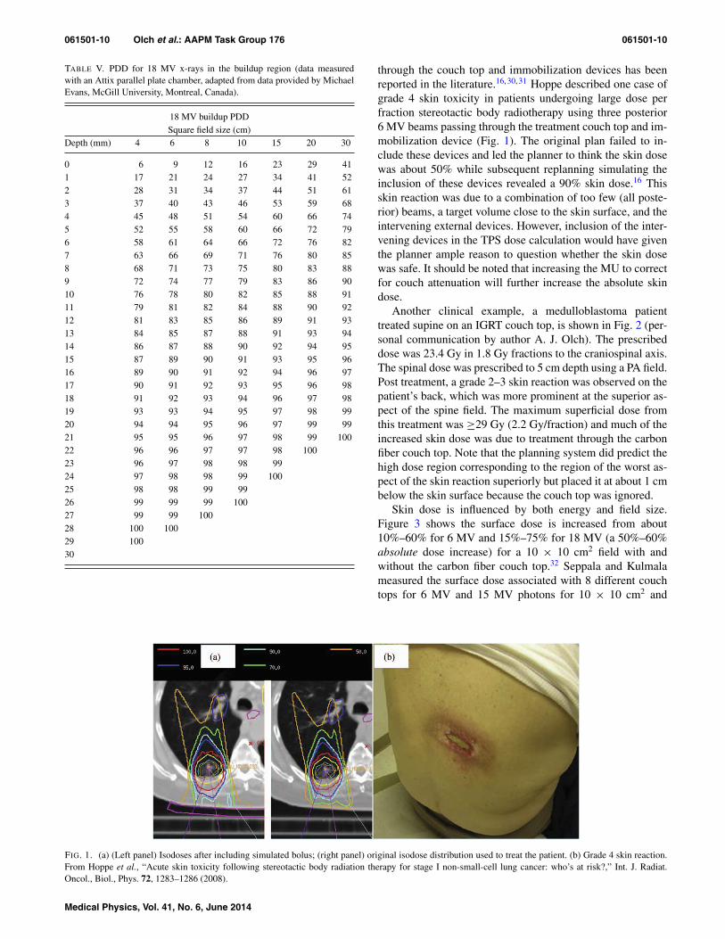
through the couch top and immobilization devices has beenreported in the literature.16, 30, 31 Hoppe described one case ofgrade 4 skin toxicity in patients undergoing large dose perfraction stereotactic body radiotherapy using three posterior6 MV beams passing through the treatment couch top and im-mobilization device (Fig. 1). The original plan failed to in-clude these devices and led the planner to think the skin dosewas about 50% while subsequent replanning simulating theinclusion of these devices revealed a 90% skin dose.16 Thisskin reaction was due to a combination of too few (all poste-rior) beams, a target volume close to the skin surface, and theintervening external devices. However, inclusion of the inter-vening devices in the TPS dose calculation would have giventhe planner ample reason to question whether the skin dosewas safe. It should be noted that increasing the MU to correctfor couch attenuation will further increase the absolute skindose.
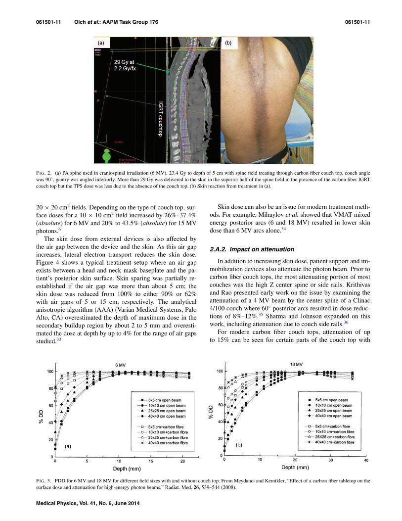
Another clinical example, a medulloblastoma patienttreated supine on an IGRT couch top, is shown in Fig. 2 (per-sonal communication by author A. J. Olch). The prescribeddose was 23.4 Gy in 1.8 Gy fractions to the craniospinal axis.The spinal dose was prescribed to 5 cm depth using a PA field.Post treatment, a grade 2–3 skin reaction was observed on thepatient’s back, which was more prominent at the superior as-pect of the spine field. The maximum superficial dose fromthis treatment was ≥29 Gy (2.2 Gy/fraction) and much of theincreased skin dose was due to treatment through the carbonfiber couch top. Note that the planning system did predict thehigh dose region corresponding to the region of the worst as-pect of the skin reaction superiorly but placed it at about 1 cmbelow the skin surface because the couch top was ignored.
Skin dose is influenced by both energy and field size.Figure 3 shows the surface dose is increased from about10%–60% for 6 MV and 15%–75% for 18 MV (a 50%–60%absolute dose increase) for a 10 × 10 cm2 field with andwithout the carbon fiber couch top.32 Seppala and Kulmalameasured the surface dose associated with 8 different couchtops for 6 MV and 15 MV photons for 10 × 10 cm2 and
FIG. 1. (a) (Left panel) Isodoses after including simulated bolus; (right panel) original isodose distribution used to treat the patient. (b) Grade 4 skin reaction.From Hoppe et al., “Acute skin toxicity following stereotactic body radiation therapy for stage I non-small-cell lung cancer: who’s at risk?,” Int. J. Radiat.Oncol., Biol., Phys. 72, 1283–1286 (2008).
Medical Physics, Vol. 41, No. 6, June 2014
061501-11 Olch et al.: AAPM Task Group 176 061501-11
FIG. 2. (a) PA spine used in craniospinal irradiation (6 MV), 23.4 Gy to depth of 5 cm with spine field treating through carbon fiber couch top, couch anglewas 90◦, gantry was angled inferiorly. More than 29 Gy was delivered to the skin in the superior half of the spine field in the presence of the carbon fiber IGRTcouch top but the TPS dose was less due to the absence of the couch top. (b) Skin reaction from treatment in (a).
20 × 20 cm2 fields. Depending on the type of couch top, sur-face doses for a 10 × 10 cm2 field increased by 26%–37.4%(absolute) for 6 MV and 20% to 43.5% (absolute) for 15 MVphotons.6
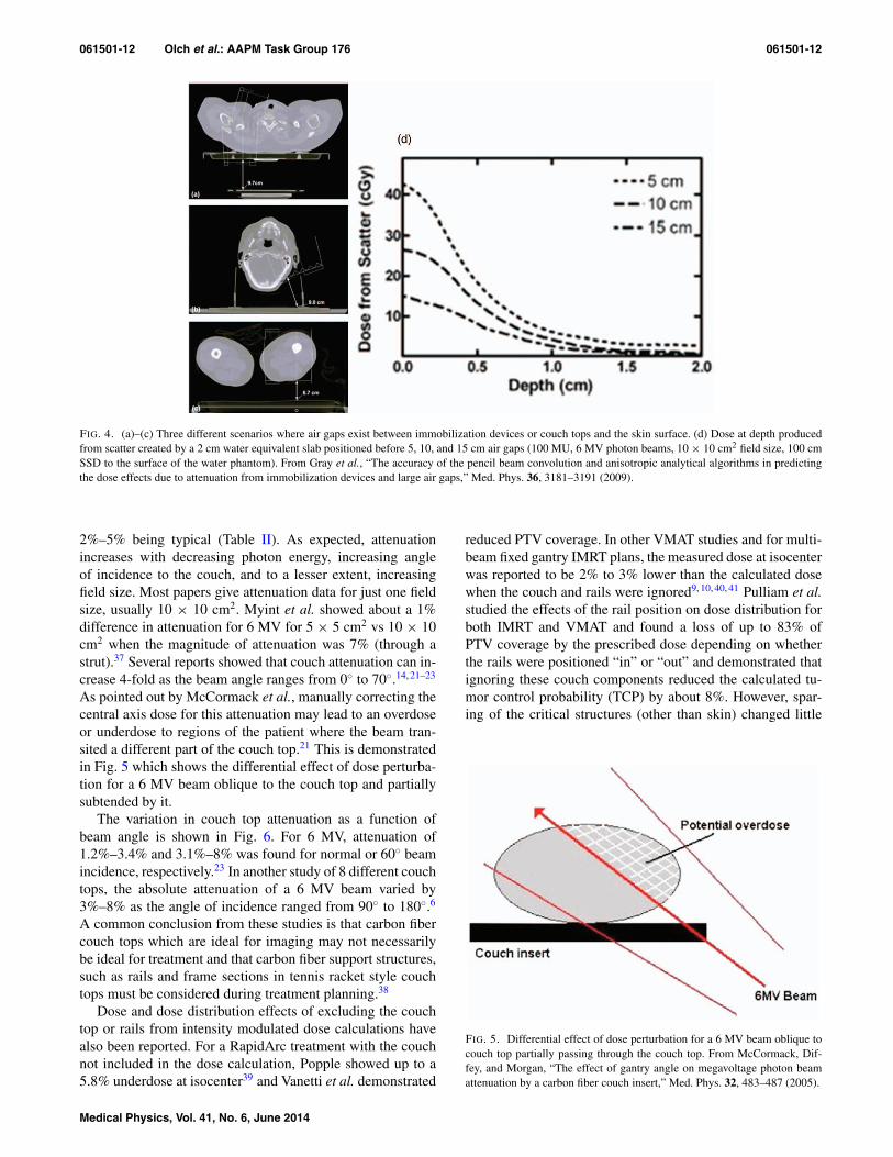
The skin dose from external devices is also affected bythe air gap between the device and the skin. As this air gapincreases, lateral electron transport reduces the skin dose.Figure 4 shows a typical treatment setup where an air gapexists between a head and neck mask baseplate and the pa-tient’s posterior skin surface. Skin sparing was partially re-established if the air gap was more than about 5 cm; theskin dose was reduced from 100% to either 90% or 62%with air gaps of 5 or 15 cm, respectively. The analyticalanisotropic algorithm (AAA) (Varian Medical Systems, PaloAlto, CA) overestimated the depth of maximum dose in thesecondary buildup region by about 2 to 5 mm and overesti-mated the dose at depth by up to 4% for the range of air gapsstudied.33
Skin dose can also be an issue for modern treatment meth-ods. For example, Mihaylov et al. showed that VMAT mixedenergy posterior arcs (6 and 18 MV) resulted in lower skindose than 6 MV arcs alone.34
2.A.2. Impact on attenuation
In addition to increasing skin dose, patient support and im-mobilization devices also attenuate the photon beam. Prior tocarbon fiber couch tops, the most attenuating portion of mostcouches was the high Z center spine or side rails. Krithivasand Rao presented early work on the issue by examining theattenuation of a 4 MV beam by the center-spine of a Clinac4/100 couch where 60◦ posterior arcs resulted in dose reduc-tions of 8%–12%.35 Sharma and Johnson expanded on thiswork, including attenuation due to couch side rails.36
For modern carbon fiber couch tops, attenuation of upto 15% can be seen for certain parts of the couch top with
FIG. 3. PDD for 6 MV and 18 MV for different field sizes with and without couch top. From Meydanci and Kemikler, “Effect of a carbon fiber tabletop on thesurface dose and attenuation for high-energy photon beams,” Radiat. Med. 26, 539–544 (2008).
Medical Physics, Vol. 41, No. 6, June 2014
061501-12 Olch et al.: AAPM Task Group 176 061501-12
FIG. 4. (a)–(c) Three different scenarios where air gaps exist between immobilization devices or couch tops and the skin surface. (d) Dose at depth producedfrom scatter created by a 2 cm water equivalent slab positioned before 5, 10, and 15 cm air gaps (100 MU, 6 MV photon beams, 10 × 10 cm2 field size, 100 cmSSD to the surface of the water phantom). From Gray et al., “The accuracy of the pencil beam convolution and anisotropic analytical algorithms in predictingthe dose effects due to attenuation from immobilization devices and large air gaps,” Med. Phys. 36, 3181–3191 (2009).
2%–5% being typical (Table II). As expected, attenuationincreases with decreasing photon energy, increasing angleof incidence to the couch, and to a lesser extent, increasingfield size. Most papers give attenuation data for just one fieldsize, usually 10 × 10 cm2. Myint et al. showed about a 1%difference in attenuation for 6 MV for 5 × 5 cm2 vs 10 × 10cm2 when the magnitude of attenuation was 7% (through astrut).37 Several reports showed that couch attenuation can in-crease 4-fold as the beam angle ranges from 0◦ to 70◦.14, 21–23
As pointed out by McCormack et al., manually correcting thecentral axis dose for this attenuation may lead to an overdoseor underdose to regions of the patient where the beam tran-sited a different part of the couch top.21 This is demonstratedin Fig. 5 which shows the differential effect of dose perturba-tion for a 6 MV beam oblique to the couch top and partiallysubtended by it.
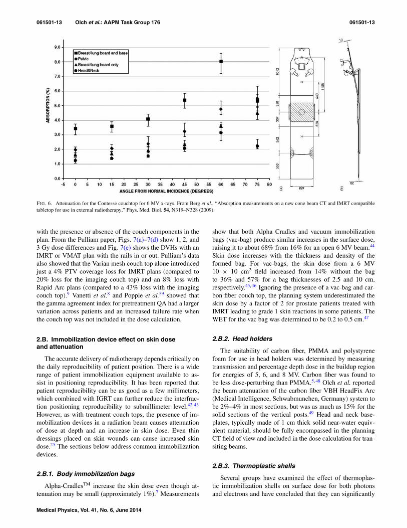
The variation in couch top attenuation as a function ofbeam angle is shown in Fig. 6. For 6 MV, attenuation of1.2%–3.4% and 3.1%–8% was found for normal or 60◦ beamincidence, respectively.23 In another study of 8 different couchtops, the absolute attenuation of a 6 MV beam varied by3%–8% as the angle of incidence ranged from 90◦ to 180◦.6
A common conclusion from these studies is that carbon fibercouch tops which are ideal for imaging may not necessarilybe ideal for treatment and that carbon fiber support structures,such as rails and frame sections in tennis racket style couchtops must be considered during treatment planning.38
Dose and dose distribution effects of excluding the couchtop or rails from intensity modulated dose calculations havealso been reported. For a RapidArc treatment with the couchnot included in the dose calculation, Popple showed up to a5.8% underdose at isocenter39 and Vanetti et al. demonstrated
reduced PTV coverage. In other VMAT studies and for multi-beam fixed gantry IMRT plans, the measured dose at isocenterwas reported to be 2% to 3% lower than the calculated dosewhen the couch and rails were ignored9, 10, 40, 41 Pulliam et al.studied the effects of the rail position on dose distribution forboth IMRT and VMAT and found a loss of up to 83% ofPTV coverage by the prescribed dose depending on whetherthe rails were positioned “in” or “out” and demonstrated thatignoring these couch components reduced the calculated tu-mor control probability (TCP) by about 8%. However, spar-ing of the critical structures (other than skin) changed little
FIG. 5. Differential effect of dose perturbation for a 6 MV beam oblique tocouch top partially passing through the couch top. From McCormack, Dif-fey, and Morgan, “The effect of gantry angle on megavoltage photon beamattenuation by a carbon fiber couch insert,” Med. Phys. 32, 483–487 (2005).
Medical Physics, Vol. 41, No. 6, June 2014
061501-13 Olch et al.: AAPM Task Group 176 061501-13
FIG. 6. Attenuation for the Contesse couchtop for 6 MV x-rays. From Berg et al., “Absorption measurements on a new cone beam CT and IMRT compatibletabletop for use in external radiotherapy,” Phys. Med. Biol. 54, N319–N328 (2009).
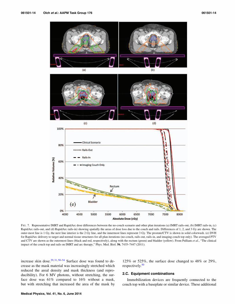
with the presence or absence of the couch components in theplan. From the Pulliam paper, Figs. 7(a)–7(d) show 1, 2, and3 Gy dose differences and Fig. 7(e) shows the DVHs with anIMRT or VMAT plan with the rails in or out. Pulliam’s dataalso showed that the Varian mesh couch top alone introducedjust a 4% PTV coverage loss for IMRT plans (compared to20% loss for the imaging couch top) and an 8% loss withRapid Arc plans (compared to a 43% loss with the imagingcouch top).9 Vanetti et al.8 and Popple et al.39 showed thatthe gamma agreement index for pretreatment QA had a largervariation across patients and an increased failure rate whenthe couch top was not included in the dose calculation.
2.B. Immobilization device effect on skin doseand attenuation
The accurate delivery of radiotherapy depends critically onthe daily reproducibility of patient position. There is a widerange of patient immobilization equipment available to as-sist in positioning reproducibility. It has been reported thatpatient reproducibility can be as good as a few millimeters,which combined with IGRT can further reduce the interfrac-tion positioning reproducibility to submillimeter level.42, 43
However, as with treatment couch tops, the presence of im-mobilization devices in a radiation beam causes attenuationof dose at depth and an increase in skin dose. Even thindressings placed on skin wounds can cause increased skindose.25 The sections below address common immobilizationdevices.
2.B.1. Body immobilization bags
Alpha-CradlesTM increase the skin dose even though at-tenuation may be small (approximately 1%).7 Measurements
show that both Alpha Cradles and vacuum immobilizationbags (vac-bag) produce similar increases in the surface dose,raising it to about 68% from 16% for an open 6 MV beam.44
Skin dose increases with the thickness and density of theformed bag. For vac-bags, the skin dose from a 6 MV10 × 10 cm2 field increased from 14% without the bagto 36% and 57% for a bag thicknesses of 2.5 and 10 cm,respectively.45, 46 Ignoring the presence of a vac-bag and car-bon fiber couch top, the planning system underestimated theskin dose by a factor of 2 for prostate patients treated withIMRT leading to grade 1 skin reactions in some patients. TheWET for the vac bag was determined to be 0.2 to 0.5 cm.47
2.B.2. Head holders
The suitability of carbon fiber, PMMA and polystyrenefoam for use in head holders was determined by measuringtransmission and percentage depth dose in the buildup regionfor energies of 5, 6, and 8 MV. Carbon fiber was found tobe less dose-perturbing than PMMA.5, 48 Olch et al. reportedthe beam attenuation of the carbon fiber VBH HeadFix Arc(Medical Intelligence, Schwabmunchen, Germany) system tobe 2%–4% in most sections, but was as much as 15% for thesolid sections of the vertical posts.49 Head and neck base-plates, typically made of 1 cm thick solid near-water equiv-alent material, should be fully encompassed in the planningCT field of view and included in the dose calculation for tran-siting beams.
2.B.3. Thermoplastic shells
Several groups have examined the effect of thermoplas-tic immobilization shells on surface dose for both photonsand electrons and have concluded that they can significantly
Medical Physics, Vol. 41, No. 6, June 2014
061501-14 Olch et al.: AAPM Task Group 176 061501-14
FIG. 7. Representative IMRT and RapidArc dose differences between the no-couch scenario and other plan iterations (a) IMRT rails-out, (b) IMRT rails-in, (c)RapidArc rails-out, and (d) RapidArc rails-in) showing spatially the areas of dose loss due to the couch and rails. Differences of 1, 2, and 3 Gy are shown. Theouter-most line is 1 Gy, the next line interior is the 2 Gy line, and the innermost lines represent 3 Gy. The prostate/CTV is shown in solid colorwash. (e) DVHfor RapidArc delivery to target and normal tissue structures for all plan iterations (no-couch, rails-out, rails-in, and imaging couch top only). The averaged PTVand CTV are shown as the outermost lines (black and red, respectively), along with the rectum (green) and bladder (yellow). From Pulliam et al., “The clinicalimpact of the couch top and rails on IMRT and arc therapy,” Phys. Med. Biol. 56, 7435–7447 (2011).
increase skin dose.29, 31, 50–54 Surface dose was found to de-crease as the mask material was increasingly stretched whichreduced the areal density and mask thickness (and repro-ducibility). For 6 MV photons, without stretching, the sur-face dose was 61% compared to 16% without a mask,but with stretching that increased the area of the mask by
125% or 525%, the surface dose changed to 48% or 29%,respectively.50
2.C. Equipment combinations
Immobilization devices are frequently connected to thecouch top with a baseplate or similar device. These additional
Medical Physics, Vol. 41, No. 6, June 2014
061501-15 Olch et al.: AAPM Task Group 176 061501-15
devices, often made of carbon fiber, plastic, or aluminum, alsoincrease attenuation and skin dose with a magnitude varyingwith type and composition of the device. The dosimetric ef-fects of the combination of the couch top and immobiliza-tion devices are of course greater than either alone and it isthe composite that must be considered in dose calculations.Skin sparing is greatly diminished by beam transit throughthe couch and the additional material of an immobilization de-vice all but eliminates it.55, 56 Attenuation effects of up to 11%from the combination of couch and various immobilizationdevices including body and head frames used for stereotacticradiosurgery have been reported.55, 57–59 Many of the entriesin Tables I and II relate to couch and immobilization devicecombinations.
2.D. Calypso
Calypso (Varian Medical Systems, Palo Alto, CA) is a 4Dreal time electromagnetic tracking system which monitors theposition of an implanted transponder during radiation treat-ment. The patient lies on a Calypso overlay which replacesthe couch top and an electromagnetic array is then positionedabove the patient to facilitate transponder localization andtracking. No part of the system is present during CT treat-ment planning. For the Calypso array, Pouliot et al.60 mea-sured 0.5% attenuation in a prototype using normally incident6 MV x-rays but others reported attenuation for the array inline with manufacturer’s specifications, typically 1% to 2%at normal beam incidence, increasing with oblique beam in-cidence up to 5%.61–63 Attenuation of the couch overlay wasmeasured to be 1%.63 Although not reported in the literature,for each patient, one could segment into the TPS a slab withaccurate geometry and density so the dose calculation can ac-count for this device.
2.E. Impact of external devices on clinicalproton beams
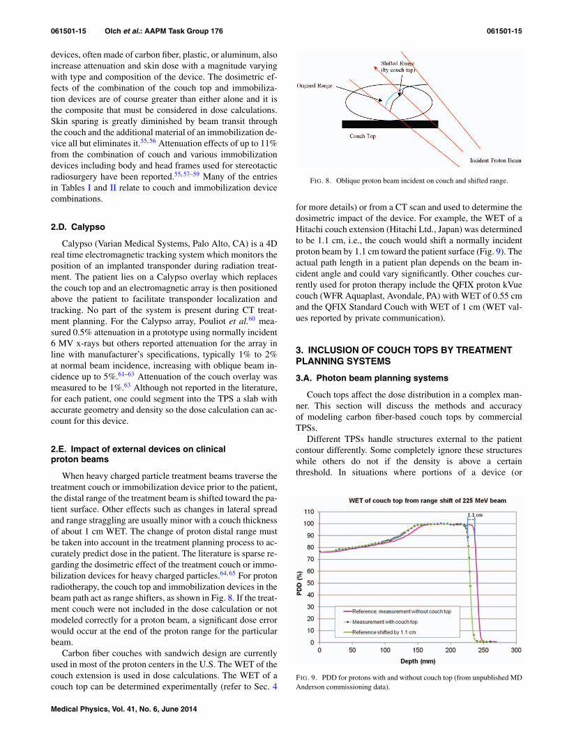
When heavy charged particle treatment beams traverse thetreatment couch or immobilization device prior to the patient,the distal range of the treatment beam is shifted toward the pa-tient surface. Other effects such as changes in lateral spreadand range straggling are usually minor with a couch thicknessof about 1 cm WET. The change of proton distal range mustbe taken into account in the treatment planning process to ac-curately predict dose in the patient. The literature is sparse re-garding the dosimetric effect of the treatment couch or immo-bilization devices for heavy charged particles.64, 65 For protonradiotherapy, the couch top and immobilization devices in thebeam path act as range shifters, as shown in Fig. 8. If the treat-ment couch were not included in the dose calculation or notmodeled correctly for a proton beam, a significant dose errorwould occur at the end of the proton range for the particularbeam.
Carbon fiber couches with sandwich design are currentlyused in most of the proton centers in the U.S. The WET of thecouch extension is used in dose calculations. The WET of acouch top can be determined experimentally (refer to Sec. 4
FIG. 8. Oblique proton beam incident on couch and shifted range.
for more details) or from a CT scan and used to determine thedosimetric impact of the device. For example, the WET of aHitachi couch extension (Hitachi Ltd., Japan) was determinedto be 1.1 cm, i.e., the couch would shift a normally incidentproton beam by 1.1 cm toward the patient surface (Fig. 9). Theactual path length in a patient plan depends on the beam in-cident angle and could vary significantly. Other couches cur-rently used for proton therapy include the QFIX proton kVuecouch (WFR Aquaplast, Avondale, PA) with WET of 0.55 cmand the QFIX Standard Couch with WET of 1 cm (WET val-ues reported by private communication).
3. INCLUSION OF COUCH TOPS BY TREATMENTPLANNING SYSTEMS
3.A. Photon beam planning systems
Couch tops affect the dose distribution in a complex man-ner. This section will discuss the methods and accuracyof modeling carbon fiber-based couch tops by commercialTPSs.
Different TPSs handle structures external to the patientcontour differently. Some completely ignore these structureswhile others do not if the density is above a certainthreshold. In situations where portions of a device (or
FIG. 9. PDD for protons with and without couch top (from unpublished MDAnderson commissioning data).
Medical Physics, Vol. 41, No. 6, June 2014
061501-16 Olch et al.: AAPM Task Group 176 061501-16
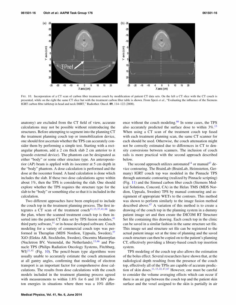
FIG. 10. Incorporation of a CT scan of carbon fiber treatment couch by modification of patient CT data sets. On the left a CT slice with the CT couch ispresented, while on the right the same CT slice but with the treatment carbon fiber table is shown. From Spezi et al., “Evaluating the influence of the SiemensIGRT carbon fibre tabletop in head and neck IMRT,” Radiother. Oncol. 89, 114–122 (2008).
anatomy) are excluded from the CT field of view, accuratecalculations may not be possible without reintroducing thestructures. Before attempting to segment into the planning CTthe treatment planning couch top or immobilization device,one should first ascertain whether the TPS can accurately con-sider them by performing a simple test. Starting with a rect-angular phantom, add a 2 cm thick slab 2 cm anterior to it(psuedo external device). The phantom can be designated aseither “body” or some other structure type. An anteroposte-rior (AP) beam is applied with its isocenter at 5 cm depth inthe “body” phantom. A dose calculation is performed and thedose at the isocenter found. A hand calculation is done whichincludes the slab. If these two dose calculations agree withinabout 1%, then the TPS is considering the slab. One shouldexplore whether the TPS requires the structure type for theslab to be “body” or something else so that it is included in thecalculation.
Two different approaches have been employed to includethe couch top in the treatment planning process. The first in-tegrates a CT scan of the treatment couch11, 13, 37, 41, 66 intothe plan, where the scanned treatment couch top is then in-serted into the patient CT data set by TPS fusion modules,41
third party software,11 or in-house developed software. Couchmodeling for a variety of commercial couch tops was per-formed in Theraplan (MDS Nordion, Uppsala, Sweden),37
XiO (Elekta AB, Stockholm, Sweden), Oncentra Masterplan(Nucletron BV, Veenendal, the Netherlands),13, 66 and Pin-nacle TPS (Philips Radiation Oncology Systems, Fitchburg,WI)11, 41 (Fig. 10). The pencil-beam type algorithms wereusually unable to accurately estimate the couch attenuationat all gantry angles, confirming that modeling of electrontransport is an important factor for comprehensive dose cal-culations. The results from dose calculations with the couchmodels included in the treatment planning process agreedwith measurements to within 1.8% for 6 and 10 MV pho-ton energies in situations where there was a 10% differ-
ence without the couch modeling.66 In some cases, the TPSalso accurately predicted the surface dose to within 3%.13
When using a CT scan of the treatment couch top fusedwith each treatment planning scan, the same CT scanner foreach should be used. Otherwise, the couch attenuation mightnot be correctly estimated due to differences in CT to den-sity conversions between scanners. The inclusion of couchrails is more practical with the second approach describedbelow.
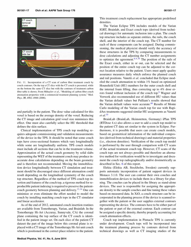
The second approach utilizes automated14 or manual47 de-vice contouring. The BrainLab (BrainLab, Heimstetten, Ger-many) IGRT couch top was modeled in the Pinnacle TPSthrough automatic contouring (realized by Pinnacle scripting)(Fig. 11) and the Sinmed carbon fiber couch (Siemens Med-ical Solutions, Concord, CA) in the Helax TMS (MDS Nor-dion, Uppsala, Sweden) TPS by manual contouring and as-signment of appropriate WETs to the contours. This methodwas shown to perform similarly to the image fusion methoddescribed above.47 A variation of this method is to create adrawing of the couch top in the planning system in a dummypatient image set and then create the DICOM RT StructureSet file containing this drawing. Each couch top in the cliniccan be saved in a similar fashion in the same structure set file.This image set and structure set file can be registered to theactual patient image set at the time of planning and the savedcouch structure can then be copied on to the patient’s planningCT, effectively providing a library-based couch top insertionsystem.
TPS modeling of the couch top also allows the estimationof the bolus effect. Several researchers have shown that, at theradiological depth resulting from the presence of the couchtop, effectively all of the TPSs are capable of accurate predic-tion of skin doses.11, 13, 22, 47, 67 However, one must be carefulto consider the volume averaging effects which can occur ifthere is an air gap between the couch top and the patient skinsurface and the voxel assigned to the skin is partially in air
Medical Physics, Vol. 41, No. 6, June 2014
061501-17 Olch et al.: AAPM Task Group 176 061501-17
FIG. 11. Incorporation of a CT scan of carbon fiber treatment couch bycouch contours. On the top a CT slice with the CT couch is presented, whileon the bottom the same CT slice but with the contours of treatment carbonfiber table is shown. From Mihaylov et al., “Modeling of carbon fiber couchattenuation properties with a commercial treatment planning system,” Med.Phys. 35, 4982–4988 (2008).
and partially in the patient. The dose value calculated for thisvoxel is based on the average density of the voxel. Reducingthe CT image and calculation grid voxel size minimizes thiseffect. One must also carefully select the HU threshold thatdefines the skin surface.
Clinical implementation of TPS couch top modeling re-quires adequate commissioning and validation measurementsof the device in the TPS. It should be noted that some couchtops have cross-sectional features which vary longitudinallywhile some are longitudinally uniform. TPS couch modelsmust include all sections that can be in the treatment volume.Approximation of the actual couch geometry by solid slabsrepresenting the WET of the treatment couch may produce in-accurate dose calculations depending on the beam geometryand is therefore not recommended. Moving the immobiliza-tion device longitudinally between CT simulation and treat-ment should be discouraged since different attenuation couldresult depending on the longitudinal symmetry of the couchtop structure. Regardless of the method of TPS couch top in-sertion and features of the couch top, a rigorous method for re-producible patient indexing is required to preserve the patient-couch geometry between planning and delivery.13, 14 One canminimize or even eliminate the effort needed to model thecouch by installing matching couch tops in the CT simulatorand linear accelerator.
As of the end of 2012, automated couch insertion routinesare available from Tomotherapy, Varian, and Brainlab. In theTomotherapy Hi-Art (Accuray, Sunnyvale, CA) the coronalplane containing the top surface of the CT couch is identi-fied in the patient image set. On each slice of the patient CTdataset the part of the image below this coronal plane is re-placed with a CT image of the Tomotherapy Hi-Art unit couchwhich is positioned in the correct place relative to the patient.
This treatment couch replacement has appropriate predefineddensities.
The Varian Eclipse TPS includes models of the VarianIGRT, Brainlab, and Exact couch tops (derived from techni-cal drawings) for automatic inclusion into a plan. The couchtop structure includes as separate entities, the rails, the couchshell, and the interior of the couch top. The CT number foreach of these components can be assigned. During commis-sioning, the medical physicist should verify the accuracy ofthese structures in the TPS by comparing measurements todose calculations and adjusting the CT number assignmentsto optimize the agreement.8, 9, 39 The position of the rails ofthe Exact couch, either in or out, can be selected and theposition of the entire couch top can be adjusted to the cor-rect location relative to the patient. Users must apply qualityassurance measures daily which enforce the planned couchand rail positions. Vanetti et al. concluded that Eclipse mod-eled the couch attenuation to within 1% based on optimizedHounsfield Unit (HU) numbers for the outer couch shell andthe internal foam filling, thus correcting up to 4% dose er-rors found without inclusion of the couch top.8 Wagner andVorwerk also recommended use of different HU values thanthe Varian default values but Pulliam’s results showed thatthe Varian default values were accurate.68 Results of MonteCarlo modeling of the Varian couch top for use with Rapi-dArc treatments suggested similar HU assignments as Vanettiet al.10
BrainLab (BrainLab, Heimstetten, Germany) iPlan TPS(RTDose 4.x) also allows a user to add a couch top model tothe patient CT data set similar to the system in Eclipse. Fur-thermore, it is possible that users can create couch models,based on geometrical information of the individual compos-ites (derived from technical drawings) and material properties(i.e., electron densities). Verification of the couch top modelis performed by the user through comparison with CT scansof the actual treatment couch top. However, CT scans of thecouch tops are not always possible and therefore an alterna-tive method for verification would be to investigate and docu-ment the couch top radiographically and/or dosimetrically asdescribed in Sec. 6 of this report.
Elekta (Elekta AB, Stockholm, Sweden) currently sup-ports automatic incorporation of patient support devices inMonaco 3.1.0. The user can contour their own couches andimmobilization devices to include them in a library for plan-ning. The couches can be placed in the library as stand-alonedevices. The user is responsible for assigning the appropri-ate density to the sample couches and fine tuning these valuesbased on measured data. In XiO, a couch structure can be in-corporated in the planning process if the device is scanned to-gether with the patient or the user supplies external contoursrepresenting the device. The contours have to be either part ofthe patient or part of the external contour. Each contour canbe assigned a specific density, thereby properly accounting forcouch attenuation effects.
Couch top implementation in Pinnacle TPS is currentlyunder development. Couch tops will be incorporated intothe treatment planning process by contours derived fromtechnical drawings as well as CT imaging studies of the
Medical Physics, Vol. 41, No. 6, June 2014

061501-18 Olch et al.: AAPM Task Group 176 061501-18
devices. The physical densities of the couch top componentswill be based on couch top technical specifications and willbe fine-tuned based on absolute dosimetric measurements aswell as CT imaging data where available. Until then, thescripting utility can be used to incorporate couch tops intoPinnacle.
3.B. Proton beam planning systems
Presently, several vendors offer proton treatment planningsystems; Elekta (XiO), Varian (Eclipse), RaySearch (Ray-Search Laboratories AB, Stockholm, Sweden) (Raystation)and Philips (Pinnacle) (under development). Those TPSs arebased on pencil beam algorithms although Monte Carlo sys-tems are under development. Using artificial tissue phantoms,a CT number-to-density calibration is established and the CTnumbers are converted to relative proton stopping powers andthen to WET for dose calculations.69 Since the material com-position and thus relative stopping power of the treatmentcouch top and other patient supporting devices are usuallydifferent from the artificial tissue materials used in the CTnumber calibration process, potential errors could be madein the stopping power calculation if the tissue phantom cal-ibration were used. Instead, one must independently knowthe proton stopping power for the various materials used inthe couch top.70 To address this in the TPS, one commonlyused technique is to use a scan of the treatment couch topwhich then replaces the CT couch top in the planning CTand assign CT numbers to the couch top structures which willcause the dose calculation to use the known proton stoppingpower. The calculation should be validated with measurementduring the commissioning of the TPS/supporting device (seeSec. 4). None of the commercially available TPSs currentlysupport automatic inclusion of a couch top. For beams thatpass through the treatment couch top and/or patient immobi-lization devices, especially the nonuniform regions such asedges of the couch top, it is highly recommended to takeinto account the uncertainty of device WET due to CT num-ber calibration and patient setup, when designing beam spe-cific margins and compensator smearing.71, 72 This practicecould minimize the dosimetric impact of such uncertaintieson the target coverage.65 Rounded edges of the couch top arepreferred to minimize these effects. Using the same couchtop for planning as for treatment simplifies some of theseprocedures.
Some of the proton beam planning systems require an ex-ternal contour for dose calculation. Material outside of theexternal contour is ignored and dose is not calculated in theseareas. Users of such systems should also verify that the exter-nal contour encompasses all patient support devices used fortreatment.
4. MEASUREMENT METHODS FOR ATTENUATIONAND SURFACE DOSE FROM EXTERNAL DEVICES
This section outlines the measurements that should bemade to characterize attenuation and surface dose perturba-
tions caused by devices external to the patient and providesan overview of the various detectors suitable for performingthese measurements. It also includes recommendations fordata and documentation that should be provided by manu-facturers of such devices. Ideally, all treatment devices andpatient support systems intersected by the treatment beamshould be included in the TPS calculation model. The dataobtained from the measurements outlined in this section willbe useful for the validation of the TPS. In addition, the dataset described here could be used to estimate correction factors(if the TPS is not used), to identify geometries that shouldbe avoided clinically, or to validate independent calculationmethods.
4.A. Methods of attenuation measurements
4.A.1. Geometry for attenuation measurements
The large number of geometric relationships among thebeam source (gantry angle, collimator angle, field size) andthe beam perturbing device makes it impossible to performmeasurements representative of all clinical situations. There-fore, it is important to acquire data representative of typical aswell as worst case clinical conditions for beam perturbations.Measurements should at least include the most probable treat-ment geometries (e.g., IEC gantry angles of 120◦ and 180◦
for perturbation effects of patient support devices) as well asthose geometries that represent the worst case scenarios suchas maximum attenuation or geometries resulting in large at-tenuation gradients such as those that can be expected nearthe edge of a support device. These measurements character-ize the attenuating properties of the device and should be usedto validate TPS calculations that include them. Determiningthe worst case geometry may most easily be achieved by tak-ing a CT scan of the device in question and looking for pathsof greatest integrated mass. Alternatively one could use man-ufacturer supplied drawings or use the linac Electronic PortalImaging Device (EPID) to search for the region of greatestattenuation. Many treatment support devices do not have ho-mogenous construction, and care should be taken to examinethe full longitudinal and lateral extent of the device that canbe intersected with the beam during treatment. Measurementsmade near dmax will be insensitive to attenuation by a 5 to8 mm WET for 6 to 18 MV x-rays due to the broad shoulderof the depth dose curve. Depths much greater than dmax (werecommend 10 cm) should be used for attenuation measure-ments.
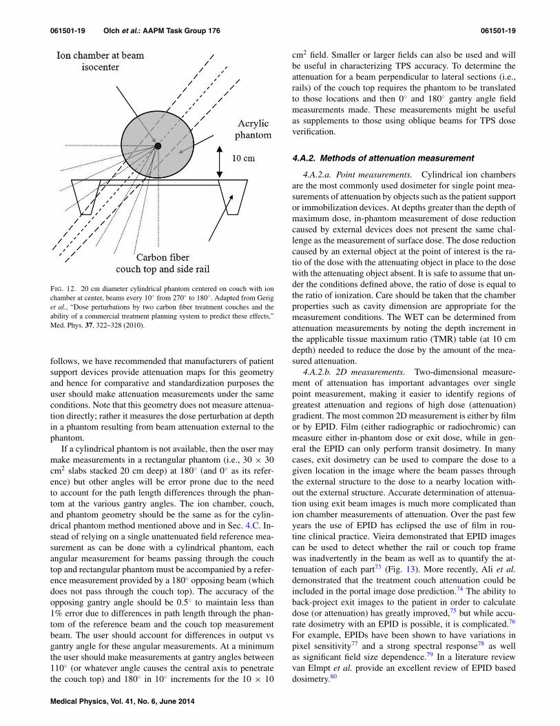
A common geometry used to measure attenuation by pa-tient support devices13, 21, 37, 41 is shown in Fig. 12. A 20 cmdiameter cylinder with an ion chamber at its geometric centeris positioned such that the ion chamber is at the linac isocen-ter. This can be verified by physical front pointer measure-ments for 0◦, 90◦, and 270◦ (IEC gantry angles) or by ion-ization measurements; in either case, the same value shouldbe obtained at all angles. Also the center of the phantommust be at the lateral center of the couch. This can be ver-ified by ensuring that the sagittal laser passes through thecenter of the couch and the phantom. In the section that
Medical Physics, Vol. 41, No. 6, June 2014
061501-19 Olch et al.: AAPM Task Group 176 061501-19
FIG. 12. 20 cm diameter cylindrical phantom centered on couch with ionchamber at center, beams every 10◦ from 270◦ to 180◦. Adapted from Geriget al., “Dose perturbations by two carbon fiber treatment couches and theability of a commercial treatment planning system to predict these effects,”Med. Phys. 37, 322–328 (2010).
follows, we have recommended that manufacturers of patientsupport devices provide attenuation maps for this geometryand hence for comparative and standardization purposes theuser should make attenuation measurements under the sameconditions. Note that this geometry does not measure attenua-tion directly; rather it measures the dose perturbation at depthin a phantom resulting from beam attenuation external to thephantom.
If a cylindrical phantom is not available, then the user maymake measurements in a rectangular phantom (i.e., 30 × 30cm2 slabs stacked 20 cm deep) at 180◦ (and 0◦ as its refer-ence) but other angles will be error prone due to the needto account for the path length differences through the phan-tom at the various gantry angles. The ion chamber, couch,and phantom geometry should be the same as for the cylin-drical phantom method mentioned above and in Sec. 4.C. In-stead of relying on a single unattenuated field reference mea-surement as can be done with a cylindrical phantom, eachangular measurement for beams passing through the couchtop and rectangular phantom must be accompanied by a refer-ence measurement provided by a 180◦ opposing beam (whichdoes not pass through the couch top). The accuracy of theopposing gantry angle should be 0.5◦ to maintain less than1% error due to differences in path length through the phan-tom of the reference beam and the couch top measurementbeam. The user should account for differences in output vsgantry angle for these angular measurements. At a minimumthe user should make measurements at gantry angles between110◦ (or whatever angle causes the central axis to penetratethe couch top) and 180◦ in 10◦ increments for the 10 × 10
cm2 field. Smaller or larger fields can also be used and willbe useful in characterizing TPS accuracy. To determine theattenuation for a beam perpendicular to lateral sections (i.e.,rails) of the couch top requires the phantom to be translatedto those locations and then 0◦ and 180◦ gantry angle fieldmeasurements made. These measurements might be usefulas supplements to those using oblique beams for TPS doseverification.
4.A.2. Methods of attenuation measurement
4.A.2.a. Point measurements. Cylindrical ion chambersare the most commonly used dosimeter for single point mea-surements of attenuation by objects such as the patient supportor immobilization devices. At depths greater than the depth ofmaximum dose, in-phantom measurement of dose reductioncaused by external devices does not present the same chal-lenge as the measurement of surface dose. The dose reductioncaused by an external object at the point of interest is the ra-tio of the dose with the attenuating object in place to the dosewith the attenuating object absent. It is safe to assume that un-der the conditions defined above, the ratio of dose is equal tothe ratio of ionization. Care should be taken that the chamberproperties such as cavity dimension are appropriate for themeasurement conditions. The WET can be determined fromattenuation measurements by noting the depth increment inthe applicable tissue maximum ratio (TMR) table (at 10 cmdepth) needed to reduce the dose by the amount of the mea-sured attenuation.
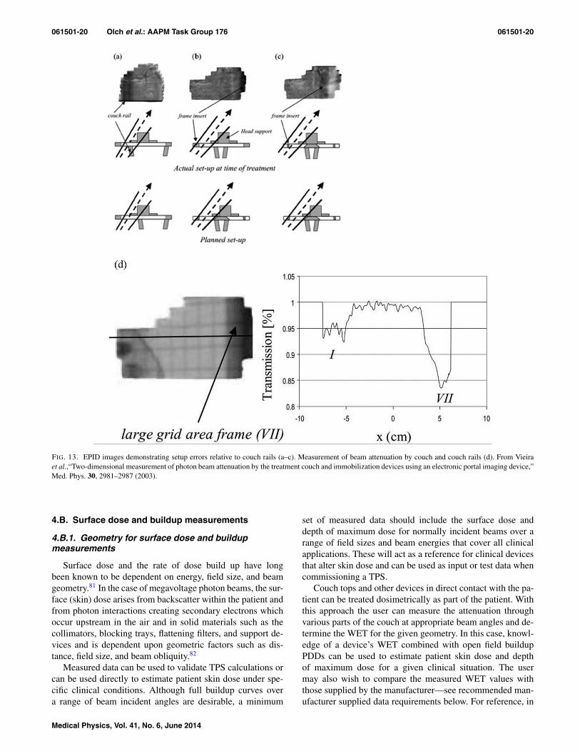
4.A.2.b. 2D measurements. Two-dimensional measure-ment of attenuation has important advantages over singlepoint measurement, making it easier to identify regions ofgreatest attenuation and regions of high dose (attenuation)gradient. The most common 2D measurement is either by filmor by EPID. Film (either radiographic or radiochromic) canmeasure either in-phantom dose or exit dose, while in gen-eral the EPID can only perform transit dosimetry. In manycases, exit dosimetry can be used to compare the dose to agiven location in the image where the beam passes throughthe external structure to the dose to a nearby location with-out the external structure. Accurate determination of attenua-tion using exit beam images is much more complicated thanion chamber measurements of attenuation. Over the past fewyears the use of EPID has eclipsed the use of film in rou-tine clinical practice. Vieira demonstrated that EPID imagescan be used to detect whether the rail or couch top framewas inadvertently in the beam as well as to quantify the at-tenuation of each part73 (Fig. 13). More recently, Ali et al.demonstrated that the treatment couch attenuation could beincluded in the portal image dose prediction.74 The ability toback-project exit images to the patient in order to calculatedose (or attenuation) has greatly improved,75 but while accu-rate dosimetry with an EPID is possible, it is complicated.76
For example, EPIDs have been shown to have variations inpixel sensitivity77 and a strong spectral response78 as wellas significant field size dependence.79 In a literature reviewvan Elmpt et al. provide an excellent review of EPID baseddosimetry.80
Medical Physics, Vol. 41, No. 6, June 2014
061501-20 Olch et al.: AAPM Task Group 176 061501-20
FIG. 13. EPID images demonstrating setup errors relative to couch rails (a–c). Measurement of beam attenuation by couch and couch rails (d). From Vieiraet al.,“Two-dimensional measurement of photon beam attenuation by the treatment couch and immobilization devices using an electronic portal imaging device,”Med. Phys. 30, 2981–2987 (2003).
4.B. Surface dose and buildup measurements
4.B.1. Geometry for surface dose and buildupmeasurements
Surface dose and the rate of dose build up have longbeen known to be dependent on energy, field size, and beamgeometry.81 In the case of megavoltage photon beams, the sur-face (skin) dose arises from backscatter within the patient andfrom photon interactions creating secondary electrons whichoccur upstream in the air and in solid materials such as thecollimators, blocking trays, flattening filters, and support de-vices and is dependent upon geometric factors such as dis-tance, field size, and beam obliquity.82
Measured data can be used to validate TPS calculations orcan be used directly to estimate patient skin dose under spe-cific clinical conditions. Although full buildup curves overa range of beam incident angles are desirable, a minimum
set of measured data should include the surface dose anddepth of maximum dose for normally incident beams over arange of field sizes and beam energies that cover all clinicalapplications. These will act as a reference for clinical devicesthat alter skin dose and can be used as input or test data whencommissioning a TPS.
Couch tops and other devices in direct contact with the pa-tient can be treated dosimetrically as part of the patient. Withthis approach the user can measure the attenuation throughvarious parts of the couch at appropriate beam angles and de-termine the WET for the given geometry. In this case, knowl-edge of a device’s WET combined with open field buildupPDDs can be used to estimate patient skin dose and depthof maximum dose for a given clinical situation. The usermay also wish to compare the measured WET values withthose supplied by the manufacturer—see recommended man-ufacturer supplied data requirements below. For reference, in
Medical Physics, Vol. 41, No. 6, June 2014
061501-21 Olch et al.: AAPM Task Group 176 061501-21
Tables III–V, we provide typical open beam percent depthdoses for the buildup region for 6, 10, and 18 MV pho-ton beams. These data were measured with an Attix paral-lel plate chamber which gives results similar to an extrap-olation chamber.83 In addition, Monte Carlo calculations ofbuildup percent depth dose support the values in the tables.84
Note that these data are not for clinical use but can be usedby vendors to standardize their reporting of surface dosefrom external devices. The actual buildup curves for a spe-cific linac beam can differ from the data provided herein.As an example of how to use WET values combined withopen beam buildup depth dose data, consider a couch topwith a known WET of 4 mm for a normally incident beam.The estimated surface dose from a 6 MV 10 × 10 cm2 pos-terior beam is 77%, found by looking at the buildup PDDat a depth of 4 mm in Table V. Directly measured surfacedose can be accurately obtained within 10% of the local dose(1%–3% absolute) which corresponds to about 0.1–0.2 mmdistance to agreement but accuracy within 5% absolute of-ten provides a clinically useful result. The error in estimat-ing inferred surface dose from typical external device WETsof at least 0.3 cm should also be less than 10% of the localdose.
4.B.2. Detectors used for measurement of surfacedose and buildup
Although a measured WET combined with a priori knowl-edge of the open field buildup curve can be used to infer thesurface dose, it is important to understand how surface dosecan be directly measured. In vivo measurements for patient-specific skin dose determinations are often required whenthere is a suspicion that skin dose may be excessive. Treat-ments with a single PA beam, AP/PA beams, or plans withmany beams for which the target volume is close to the skincan create this condition. Determination of surface dose bymeasurement is difficult and the choice of detector is criti-cal. The typical setup for measurement of surface dose witha parallel plate ion chamber is to irradiate the chamber in asolid water phantom with no additional material between thecollecting volume and the source. To assess the impact on sur-face dose of a device, such as the couch top, one would irra-diate through the couch top with a PA beam with the chamberand phantom inverted so the chamber is lying on the couchtop. Large dose gradients and electronic disequilibrium nearthe surface require the dosimeter to have a small, well de-fined measurement volume and to be insensitive to changesin the electron energy spectrum.85 When choosing a detectorfor a specific measurement, characteristics such as spatial res-olution, dose range, accuracy, precision, angular dependence,spectral (energy) dependence, and the effective depth of mea-surement must be considered.13, 86–89
In general it is assumed that for ion chamber measure-ment in photon beams at depths greater than dmax, the per-turbation correction factors and the stopping power ratios areindependent of depth and the ionization ratio can be con-sidered equal to the dose ratio.84 In the buildup region orother regions where electronic equilibrium does not exist,
this assumption is not necessarily valid. The design and ge-ometry of the ionization chamber influences the perturba-tion factors required to calculate unperturbed ionization. Flu-ence perturbations usually result in an over response of thedetector and an over estimate of the PDD if not properlyaddressed.90 The magnitude of the error is detector and beamspecific. The user should take care to understand the mag-nitude of error and uncertainty for their given experimentalconditions.
The most common detectors used for the measurement ofbuildup and surface dose are extrapolation chambers, planeparallel chambers, TLD, and film. Cylindrical ion chambersare not recommended for megavoltage surface dose measure-ments due to the large chamber-dependent corrections neededto get an accurate dose. There are also numerous reportsin the literature describing the use of diamond, diode, opti-cally stimulated luminescent (OSL) detectors, and metal ox-ide semiconductor field effect transistor (MOSFET) detectors.Below we provide specific information about each type ofdetector.
4.B.2.a. Extrapolation chamber. The extrapolationchamber, designed by Failla in 1937,91 is still accepted asthe “gold standard” for surface dose measurement of MVbeams, primarily because most perturbations introduced byion chambers are eliminated with the use of an extrapola-tion chamber.92, 93 It is often implied or suggested that theextrapolated zero volume ionization ratio (PDI) gives thePDD.87, 90, 94 In fact the extrapolated zero volume ionizationgives the true ionization that would have occurred if therewere no perturbation effects. The change in stopping powerratio from the surface to depth of maximum dose still remainsa source of uncertainty in converting PDI to PDD evenwith an extrapolation chamber. Although considered thegold standard, their use is very time consuming, costly, andnot practical for multi-field measurements causing manyphysicists to use other detectors.
4.B.2.b. Plane parallel ion chambers. Plane parallel ionchambers are a viable alternative to extrapolation chambers,but unlike extrapolation chambers, perturbation correctionsare required under disequilibrium conditions. This was ad-dressed in detail by Velkley et al. who used extrapolationchamber data to develop an empirical correction (kion).93 Theapproach was later refined by Gerbi and Khan87 to accountfor the guard ring dimensions of the fixed parallel plate cham-ber. Failure to account for perturbation can result in an up to15% (absolute) over-response in the determination of surfacedose.87
In general, parallel plate ion chambers display a polarityeffect, which can be significant in regions of electronic dis-equilibrium such as the dose buildup region. This has beendocumented as early as 1951 by Howarth et al.95 and stud-ied in detail by Gerbi and Khan.87 The present day consen-sus is that for measurements using parallel plate chambers theaverage of the dosimetric signal measured with positive andnegative bias should be used to estimate ionization. For paral-lel plate chambers, beam geometry is important. As shown byGerbi and Khan87 and by Dogan and Glasgow,86, 88 the pertur-bation caused by in-scattering increases with obliquity of the
Medical Physics, Vol. 41, No. 6, June 2014
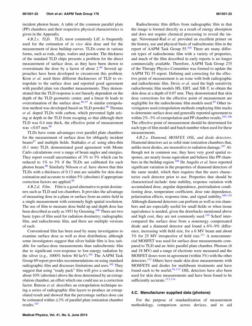
061501-22 Olch et al.: AAPM Task Group 176 061501-22
incident photon beam. A table of the common parallel plate(PP) chambers and their respective physical characteristics isgiven in the Appendix.
4.B.2.c. TLD. TLD, most commonly LiF, is frequentlyused for the estimation of in vivo skin dose and for themeasurement of dose buildup curves. TLDs come in variousforms, such as rods, chips, wafers and powder. The thicknessof the standard TLD chips presents a problem for the directmeasurement of surface dose, as they have been shown tooverestimate the dose by a factor of about 2.90 Several ap-proaches have been developed to circumvent this problem.Kron et al. used three different thicknesses of TLD to ex-trapolate to the surface dose and reported good agreementwith parallel plate ion chamber measurements. They demon-strated that the TLD response is not linearly dependent on thedepth of the TLD geometric center, and a linear fit leads tooverestimation of the surface dose.96, 97 A similar extrapola-tion method was developed based on TLD powder.98 Thomaset al. doped TLDs with carbon, which prevented light aris-ing at depth in the TLD from escaping so that although theirTLD was 0.4 mm thick, the effective point of measurementwas <0.07 mm.99
TLDs have some advantages over parallel plate chambersfor the measurement of surface dose for obliquely incidentbeams87 and multiple fields. Stathakis et al. using ultra-thin(0.1 mm) TLD, demonstrated good agreement with MonteCarlo calculations over a range of beam angles and energies.They report overall uncertainties of 3% to 5% which can bereduced to 1% to 3% if the TLDs are calibrated for eachphoton beam.88 Similarly Nilsson et al. have shown that thinTLDs with a thickness of 0.13 mm are suitable for skin doseestimation and accurate to within 5% (absolute) if appropriatecorrection factors are applied.90
4.B.2.d. Film. Film is a good alternative to point dosime-ters such as TLD and ion chambers. It provides the advantageof measuring dose in a plane or surface from an entire field ina single measurement with extremely high spatial resolution.The use of film to measure dose build up and depth dose hasbeen described as early as 1951 by Greening.100 There are twobasic types of film used for radiation dosimetry; radiographicfilm, and radiochromic film, and there are multiple versionsof each.
Conventional film has been used by many investigators toexamine surface dose as well as dose distribution, althoughsome investigators suggest that silver halide film is less suit-able for surface-dose measurements than radiochromic filmdue to significant over-response to low-energy radiation bythe silver (e.g., 1000% below 80 keV).101 The AAPM TaskGroup 69 report provides recommendations on using standardradiographic film and discusses limitations and uses.102 Theysuggest that using “ready pack” film will give a surface doseabout 10% (absolute) above the dose determined by an extrap-olation chamber, an offset which one could use as a correctionfactor. Butson et al. describes an extrapolation technique us-ing a series of radiographic film layers to produce an extrap-olated result and showed that the percentage surface dose canbe estimated within ±3% of parallel plate ionization chamberresults.103
Radiochromic film differs from radiographic film in thatthe image is formed directly as a result of energy absorptionand does not require chemical processing to reveal the im-age. Niroomand-Rad et al. provided an excellent primer onthe history, use and physical basis of radiochromic film in thereport of AAPM Task Group 55.104 There are many differ-ent types of radiochromic film with a variety of properties,and much of the film described in early reports is no longercommercially available. Therefore, AAPM Task Group 235of the Therapy Physics Committee was formed to update theAAPM TG 55 report. Defining and correcting for the effec-tive point of measurement is an issue with both radiographicand radiochromic film. Devic et al. used the high sensitivityradiochromic film models HS, EBT, and XR-T, to obtain theskin dose at a depth of 0.07 mm. They demonstrated that skindose corrections for the effective point of measurement arenegligible for the radiochromic film models used.85 Other in-vestigators used extrapolation methods employing film stacksto determine surface dose and generally reported agreement towithin 2%–3% of extrapolation and PP chamber results.105, 106
The effective point of measurement should be determined foreach type of film model and batch number when used for thesemeasurements.
4.B.2.e. Diamond, MOSFET, OSL, and diode detectors.Diamond detectors act as solid state ionization chambers that,unlike most diodes, are insensitive to radiation damage.107 Al-though not in common use, they have very good spatial re-sponse, are nearly tissue equivalent and behave like PP cham-bers in the buildup region.108 De Angelis et al. have reportedsignificant variation in the properties of diamond detectors ofthe same model, which then requires that the users charac-terize each detector prior to use. Properties that should becharacterized include: time stability, response variation withaccumulated dose, angular dependence, preirradiation condi-tioning dose, temperature coefficient, dose rate dependence,polarization effects, response time, and signal stability.109, 110
Although diamond detectors can perform as well as ion cham-bers and are especially useful for small fields or when tissueequivalence is needed, given the drawbacks mentioned aboveand high cost, they are not commonly used.110 Scherf inter-compared the surface dose from a nonenergy compensateddiode and a diamond detector and found a 6%–9% differ-ence, increasing with field size, for a 6 MV beam and about3% for 25 MV irrespective of field size.111 A noncommer-cial MOSFET was used for surface dose measurements com-pared to TLD and an Attix parallel plate chamber. Photons (6and 18 MV) and a range of electrons were measured and theMOSFET doses were in agreement (within 3%) with the otherdetectors.112 Others have made skin dose measurements withMOSFETS and diodes for multibeam treatments and havefound each to be useful.54, 113 OSL detectors have also beenused for skin dose measurements and have been found to besufficiently accurate.113, 114
4.C. Manufacturer supplied data (photons)
For the purpose of standardization of measurementmethodology, comparison across devices, and to aid
Medical Physics, Vol. 41, No. 6, June 2014

061501-23 Olch et al.: AAPM Task Group 176 061501-23
verification of TPS modeling, we recommend that manufac-turers of patient support devices provide the following data:
i. A polar distribution of attenuation and WET in thearea of the device most likely to be irradiated dur-ing treatment as well as any areas of the couch topdesignated for a specific purpose (e.g., a specializedhead and neck section). The geometry shown in Fig.12 should be used. Here a 20 cm diameter cylinderwith an ion chamber at its geometric center is cen-tered on the treatment couch and is positioned sothat the ion chamber is at linac isocenter. Measure-ments should be made every 10◦ from normal in-cidence through the couch top to the largest anglefor which the central axis of the beam traverses thecouch top and any other permanently attached immo-bilization device. The dose for a 90◦ (lateral) beamwill be measured and will serve as the normaliza-tion for the other angles. Attenuation at each angleshould be provided for nominal beam energies of 6,10, and 18 MV for a 10 × 10 cm2 field size. Themanufacturer should specify the PDD10 or TPR20/10
for each beam used. The WET will be computed byreferring to the appropriate TMR table and finding theincremental depth beyond 10 cm that would result inthe attenuation measured at the nominal depth in thephantom.
ii. Attenuation and WET for a beam normal to the mostattenuating parts of the device (which have not beenlabeled as regions to avoid) should be documentedby the location and percentage attenuation andWET.
iii. Surface dose for the angular and energy range in itemi., computed by using the PDD values in Tables III–V and recording the surface PDD for a depth equal tothe WET. This measure of surface dose is a calculatedvalue and not necessarily the dose one would directlymeasure at the surface of the phantom.
4.D. Proton beam measurements
4.D.1. Measurement methods
As discussed in Secs. 2 and 3, patient support devices in theproton beam line act effectively as a range shifter, and mea-surements should be used to validate the WET of the devicecalculated by the TPS, as well as the surface dose change. ACT scan of the couch top is necessary to identify any nonuni-formities in the couch top, and the TPS should be used tocalculate the WET of the couch top using the CT number-to-stopping power calibration. Supporting devices should alwaysbe in the field-of-view (FOV) for the patient CT scan. TheTPS calculated WET should be compared with measurement,manufacturer supplied data and independent calculation dur-ing the commissioning of the TPS to ensure that the couchwas modeled properly.
For proton range measurements, it is critical to accuratelydetermine the depth of measurement for all measurementpoints. Proton PDD and range measurements have tradition-
ally been made with a water-scanning parallel plate chamber.This process is time consuming as scanning with submillime-ter step sizes are required to resolve the Bragg-peak or thedistal end of a spread-out-Bragg-peak (SOBP). With the in-troduction of a multi-layer ion chamber device (e.g., Zebra,IBA Dosimetry GmbH., Schwarzenbruck, Germany) whichcan scan an entire proton PDD curve almost instantly, mea-surements of proton range and PDD are becoming more effi-cient. Two-dimensional range and profile measurements canbe made with films or detector arrays such as Matrixx (IBADosimetry GmbH. Schwarzenbruck, Germany). For WETmeasurement, the same setup as the proton range measure-ment can be used. Range measurements with and withoutthe patient supporting device in the beamline should be madewith the range difference between the two measurements be-ing the WET of the device. Parallel plate chambers or TLDcan be used for surface dose measurements in proton beamswithout the electron equilibrium considerations for photonbeams as the PDD is nearly flat for a depth much greater thanthe dimensions of most detectors used for beam scanning orpoint dose measurements.
The PDD with and without the Hitachi treatment couch topwere measured with an Advanced Markus (PTW, Freiburg,Germany) parallel plate ion chamber, for a proton beam withenergy of 225 MeV, SOBP of 10 cm, and range of 23.6 cm.The measurement was made in a water tank for depths be-tween 2 and 27 cm, and an additional in-air measurementwas made for the surface dose. The range of the proton beamwas determined from the PDD with and without the couchtop in the beam, and range change due to the couch top wasfound to be 1.1 cm (Fig. 9). This shift is applicable across alldepths measured. The surface dose change was determinedto be <1%. The beam was normal to the couch top for thesemeasurements. Couch top induced range effects at oblique an-gles are difficult to measure and generally have to be inferredfrom the TPS calculations that have been validated at nor-mal beam incidence. For patient supporting devices, the WETof the device at different locations should be measured, withthe same technique discussed above. The measurement resultsshould be compared with the WET as calculated by the TPSat the same locations. If a discrepancy between measurementand the TPS calculation of greater than 2 mm is found, thematerial of the device and the CT calibration curve should beverified. To account for this discrepancy, techniques such asCT number overwriting (Sec. 3.B) or using additional marginsin the planning process for beams that transverse the devicecan be used.
4.D.2. Manufacturer supplied data (protons)
We recommend that manufacturers of couch tops and otherpatient support devices for proton radiotherapy provide thefollowing data:
1. Material composition of the device, and relative stop-ping power ratio of individual materials.
2. WET for a 200 MeV proton beam incident normal toand at the center of the device surface.
Medical Physics, Vol. 41, No. 6, June 2014
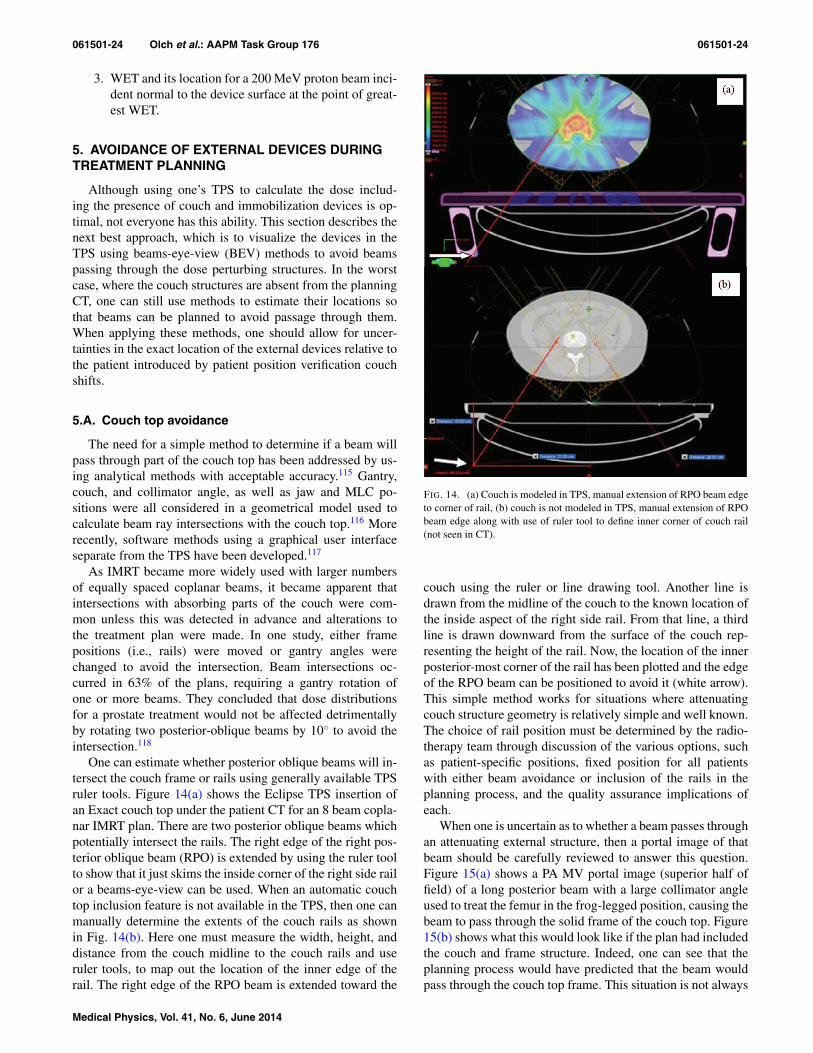
061501-24 Olch et al.: AAPM Task Group 176 061501-24
3. WET and its location for a 200 MeV proton beam inci-dent normal to the device surface at the point of great-est WET.
5. AVOIDANCE OF EXTERNAL DEVICES DURINGTREATMENT PLANNING
Although using one’s TPS to calculate the dose includ-ing the presence of couch and immobilization devices is op-timal, not everyone has this ability. This section describes thenext best approach, which is to visualize the devices in theTPS using beams-eye-view (BEV) methods to avoid beamspassing through the dose perturbing structures. In the worstcase, where the couch structures are absent from the planningCT, one can still use methods to estimate their locations sothat beams can be planned to avoid passage through them.When applying these methods, one should allow for uncer-tainties in the exact location of the external devices relative tothe patient introduced by patient position verification couchshifts.
5.A. Couch top avoidance
The need for a simple method to determine if a beam willpass through part of the couch top has been addressed by us-ing analytical methods with acceptable accuracy.115 Gantry,couch, and collimator angle, as well as jaw and MLC po-sitions were all considered in a geometrical model used tocalculate beam ray intersections with the couch top.116 Morerecently, software methods using a graphical user interfaceseparate from the TPS have been developed.117
As IMRT became more widely used with larger numbersof equally spaced coplanar beams, it became apparent thatintersections with absorbing parts of the couch were com-mon unless this was detected in advance and alterations tothe treatment plan were made. In one study, either framepositions (i.e., rails) were moved or gantry angles werechanged to avoid the intersection. Beam intersections oc-curred in 63% of the plans, requiring a gantry rotation ofone or more beams. They concluded that dose distributionsfor a prostate treatment would not be affected detrimentallyby rotating two posterior-oblique beams by 10◦ to avoid theintersection.118
One can estimate whether posterior oblique beams will in-tersect the couch frame or rails using generally available TPSruler tools. Figure 14(a) shows the Eclipse TPS insertion ofan Exact couch top under the patient CT for an 8 beam copla-nar IMRT plan. There are two posterior oblique beams whichpotentially intersect the rails. The right edge of the right pos-terior oblique beam (RPO) is extended by using the ruler toolto show that it just skims the inside corner of the right side railor a beams-eye-view can be used. When an automatic couchtop inclusion feature is not available in the TPS, then one canmanually determine the extents of the couch rails as shownin Fig. 14(b). Here one must measure the width, height, anddistance from the couch midline to the couch rails and useruler tools, to map out the location of the inner edge of therail. The right edge of the RPO beam is extended toward the
FIG. 14. (a) Couch is modeled in TPS, manual extension of RPO beam edgeto corner of rail, (b) couch is not modeled in TPS, manual extension of RPObeam edge along with use of ruler tool to define inner corner of couch rail(not seen in CT).
couch using the ruler or line drawing tool. Another line isdrawn from the midline of the couch to the known location ofthe inside aspect of the right side rail. From that line, a thirdline is drawn downward from the surface of the couch rep-resenting the height of the rail. Now, the location of the innerposterior-most corner of the rail has been plotted and the edgeof the RPO beam can be positioned to avoid it (white arrow).This simple method works for situations where attenuatingcouch structure geometry is relatively simple and well known.The choice of rail position must be determined by the radio-therapy team through discussion of the various options, suchas patient-specific positions, fixed position for all patientswith either beam avoidance or inclusion of the rails in theplanning process, and the quality assurance implications ofeach.
When one is uncertain as to whether a beam passes throughan attenuating external structure, then a portal image of thatbeam should be carefully reviewed to answer this question.Figure 15(a) shows a PA MV portal image (superior half offield) of a long posterior beam with a large collimator angleused to treat the femur in the frog-legged position, causing thebeam to pass through the solid frame of the couch top. Figure15(b) shows what this would look like if the plan had includedthe couch and frame structure. Indeed, one can see that theplanning process would have predicted that the beam wouldpass through the couch top frame. This situation is not always
Medical Physics, Vol. 41, No. 6, June 2014
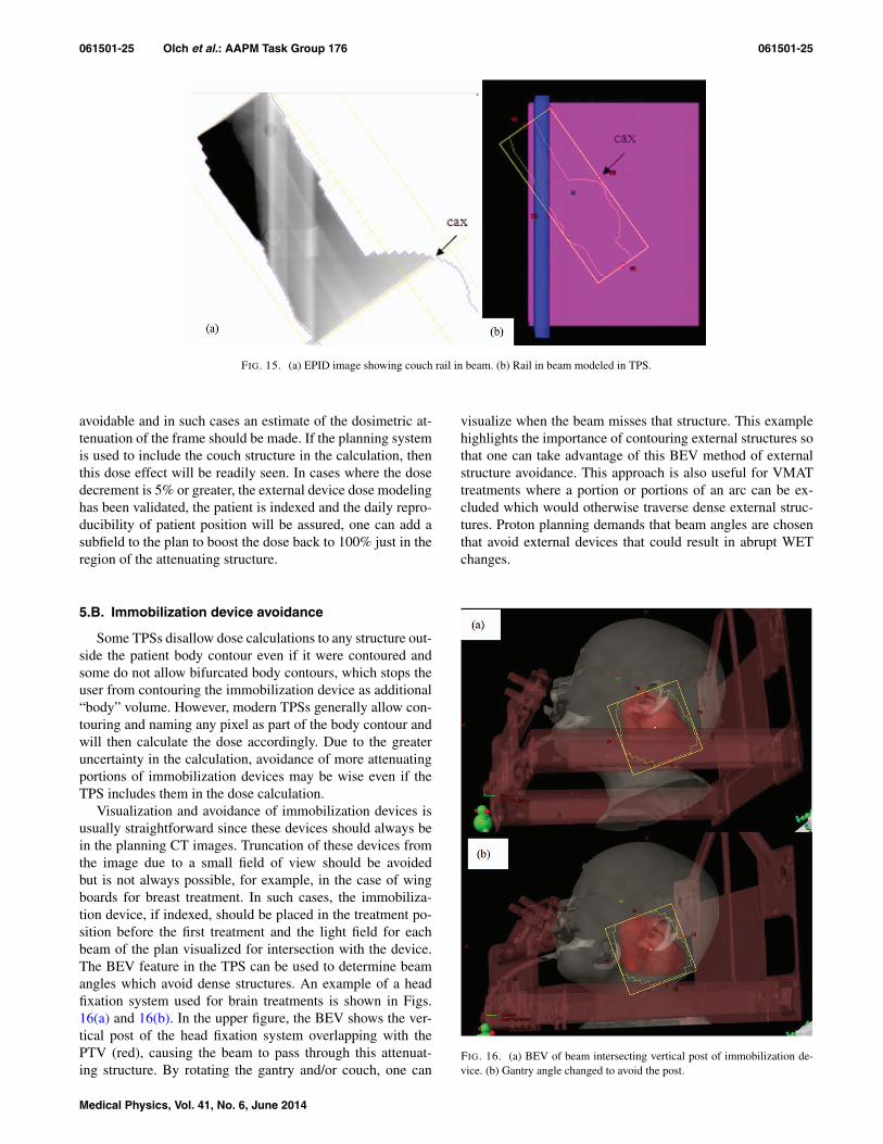
061501-25 Olch et al.: AAPM Task Group 176 061501-25
FIG. 15. (a) EPID image showing couch rail in beam. (b) Rail in beam modeled in TPS.
avoidable and in such cases an estimate of the dosimetric at-tenuation of the frame should be made. If the planning systemis used to include the couch structure in the calculation, thenthis dose effect will be readily seen. In cases where the dosedecrement is 5% or greater, the external device dose modelinghas been validated, the patient is indexed and the daily repro-ducibility of patient position will be assured, one can add asubfield to the plan to boost the dose back to 100% just in theregion of the attenuating structure.
5.B. Immobilization device avoidance
Some TPSs disallow dose calculations to any structure out-side the patient body contour even if it were contoured andsome do not allow bifurcated body contours, which stops theuser from contouring the immobilization device as additional“body” volume. However, modern TPSs generally allow con-touring and naming any pixel as part of the body contour andwill then calculate the dose accordingly. Due to the greateruncertainty in the calculation, avoidance of more attenuatingportions of immobilization devices may be wise even if theTPS includes them in the dose calculation.
Visualization and avoidance of immobilization devices isusually straightforward since these devices should always bein the planning CT images. Truncation of these devices fromthe image due to a small field of view should be avoidedbut is not always possible, for example, in the case of wingboards for breast treatment. In such cases, the immobiliza-tion device, if indexed, should be placed in the treatment po-sition before the first treatment and the light field for eachbeam of the plan visualized for intersection with the device.The BEV feature in the TPS can be used to determine beamangles which avoid dense structures. An example of a headfixation system used for brain treatments is shown in Figs.16(a) and 16(b). In the upper figure, the BEV shows the ver-tical post of the head fixation system overlapping with thePTV (red), causing the beam to pass through this attenuat-ing structure. By rotating the gantry and/or couch, one can
visualize when the beam misses that structure. This examplehighlights the importance of contouring external structures sothat one can take advantage of this BEV method of externalstructure avoidance. This approach is also useful for VMATtreatments where a portion or portions of an arc can be ex-cluded which would otherwise traverse dense external struc-tures. Proton planning demands that beam angles are chosenthat avoid external devices that could result in abrupt WETchanges.
FIG. 16. (a) BEV of beam intersecting vertical post of immobilization de-vice. (b) Gantry angle changed to avoid the post.
Medical Physics, Vol. 41, No. 6, June 2014
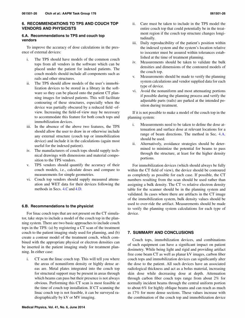
061501-26 Olch et al.: AAPM Task Group 176 061501-26
6. RECOMMENDATIONS TO TPS AND COUCH TOPVENDORS AND PHYSICISTS
6.A. Recommendations to TPS and couch topvendors
To improve the accuracy of dose calculations in the pres-ence of external devices:
i. The TPS should have models of the common couchtops from all vendors in the software which can beplaced under the patient for indexed patients. Thecouch models should include all components such asrails and other structures.
ii. The TPS should allow models of the user’s immobi-lization devices to be stored in a library in the soft-ware so they can be placed onto the patient CT plan-ning images for indexed patients. This will facilitatecontouring of these structures, especially when thedevice was partially obscured by a reduced field -of-view. Increasing the field-of-view may be necessaryto accommodate this feature for both couch tops andimmobilization devices.
iii. In the absence of the above two features, the TPSshould allow the user to draw in or otherwise includeany external structure (couch top or immobilizationdevice) and include it in the calculations (again mostuseful for the indexed patient).
iv. The manufacturers of couch tops should supply tech-nical drawings with dimensions and material compo-sition to the TPS vendors.
v. TPS vendors should quantify the accuracy of theircouch models, i.e., calculate doses and compare tomeasurements for simple geometries.
vi. Couch top vendors should supply measured attenu-ation and WET data for their devices following themethods in Secs. 4.C and 4.D.
6.B. Recommendations to the physicist
For linac couch tops that are not present on the CT simula-tor, take steps to include a model of the couch top in the plan-ning system. There are two basic approaches to include couchtops in the TPS: (a) by registering a CT scan of the treatmentcouch to the patient imaging study used for planning, and (b)create a contour model of the treatment couch, which com-bined with the appropriate physical or electron densities canbe inserted in the patient imaging study for treatment plan-ning. In either case:
i. CT scan the linac couch top. This will tell you wherethe areas of nonuniform density or highly dense ar-eas are. Metal plates integrated into the couch topfor structural support may be present in areas throughwhich beams can pass but their presence is not alwaysobvious. Performing this CT scan is most feasible atthe time of couch top installation. If CT scanning thelinac couch top is not feasible, it can be surveyed ra-diographically by kV or MV imaging.
ii. Care must be taken to include in the TPS model theentire couch top that could potentially be in the treat-ment region if the couch top structure changes longi-tudinally.
iii. Daily reproducibility of the patient’s position withinthe indexed system and the system’s location relativeto isocenter must be assured within tolerances estab-lished at the time of treatment planning.
iv. Measurements should be taken to validate the bulkdensities and dimensions of the contoured models ofthe couch top.
v. Measurements should be made to verify the planningsystem calculations and vendor supplied data for eachtype of device.
vi. Avoid the nonuniform and most attenuating portionsif possible during the planning process and verify theadjustable parts (rails) are parked at the intended po-sition during treatment.
If it is not possible to make a model of the couch top in theplanning system:
i. Measurements need to be taken to define the dose at-tenuation and surface dose at relevant locations for arange of beam directions. The method in Sec. 4.A.should be used.
ii. Alternatively, avoidance strategies should be deter-mined to minimize the potential for beams to passthrough the structure, at least for the higher densityportions.
For immobilization devices (which should always be fullywithin the CT field of view), the device should be contouredas completely as possible for each case. If possible, the CTnumbers resulting from the scan should be used rather thanassigning a bulk density. The CT vs relative electron densitytable for the scanner should be in the planning system andvalidated. In cases where there are artifacts in the CT imageof the immobilization system, bulk density values should beused to over-ride the artifact. Measurements should be madeto verify the planning system calculations for each type ofdevice.
7. SUMMARY AND CONCLUSIONS
Couch tops, immobilization devices, and combinationsof such equipment can have a significant impact on patientdosimetry. While being light and rigid and providing artifactfree cone beam CT as well as planar kV images, carbon fibercouch tops and immobilization devices can significantly alterthe dose to the patient. All such devices have an associatedradiological thickness and act as a bolus material, increasingskin dose while decreasing dose at depth. Attenuationthrough carbon fiber couch tops range from about 2% fornormally incident beams through the central uniform portionto about 6% for highly oblique beams and can reach as muchas 17% for more dense sections. These values increase withthe combination of the couch top and immobilization device
Medical Physics, Vol. 41, No. 6, June 2014

061501-27 Olch et al.: AAPM Task Group 176 061501-27
(Table II) and skin doses can reach 100% of dose maximum(Table I).
Simplistic correction methods for couch attenuation maylead to an over- or underdose of part of the treatment vol-ume. Manual alteration of TPS generated monitor units alsorisks transcription errors in the patient treatment plan. Mod-ern treatment planning systems are generally capable of ac-curate and reliable dose calculations in the presence of pa-tient immobilization devices. It has also been shown that var-ious methods of couch incorporation into the treatment plan-ning process can result in acceptable dose calculation accu-racy. We recommend that TPS vendors automate this pro-cess and provide information for at least the most commoncouch tops. With the advent of VMAT, where a portion ofthe dose is almost always being delivered through posterioroblique angles, there is an increased interest in accountingfor the presence of the couch top in the planning system. In-corporation of the couch top into proton beam planning sys-tems is also recommended and can result in acceptable doseaccuracy.
Measurement methods were described to assist the med-ical physicist in making measurements of attenuation andsurface dose (or inference of surface dose from the WETand PDD) for external devices. These measurements serveto verify those supplied by the manufacturer and to val-idate the TPS modeling of those devices. Recommenda-tions for measurement methods for manufacturers are givento provide consistency and transparency in reporting thesevalues.
To avoid the need to modify or augment the planning CTimages, it is strongly recommended that the same couch topbe used for CT planning as for treatment and that a largeenough field of view be utilized to encompass the full width ofthe couch top. For those who do not have dual couch tops (orin situations where the entire couch top is not included in theFOV), the TPS should provide the ability to position an ac-curate outline and assign appropriate densities of commonlyavailable couch tops superimposed on the planning CT so thatthey can be included in the dose calculations. When it is notpossible to include the treatment couch in the dose calcula-tion, various methods were presented to avoid beam angleswhich would traverse highly attenuating external structures.Even if the TPS were capable of inclusion of the treatmentcouch top into the planning CT and dose calculation, it maybe wise to simply avoid beams passing through the more at-tenuating sections.
ACKNOWLEDGMENTS
The authors thank Michael Evans, McGill University,Montreal, Canada, for the PDD buildup-region data inTables III–V.
APPENDIX: ELECTRONIC SUPPLEMENT
Win
dow
Win
dow
thic
knes
sC
olle
ctor
Ele
ctro
deW
all
Gua
rdri
ngC
ham
ber
mat
eria
lgm
/cm
2C
olle
ctor
diam
eter
mm
sepa
ratio
nm
mm
ater
ial
wid
thm
mR
efer
ence
PTW
30–3
29(M
arku
s)Po
lyet
hyle
new
ithgr
aphi
teel
ectr
ode
2.7
Gra
phite
onpo
lyst
yren
e5.
42
0.3
Ger
bi(R
ef.8
3)C
apin
tec
PS-0
33M
ylar
(alu
min
ized
)0.
0005
Car
bon
impr
egna
ted
Shon
kaC
552
16.2
2.4
poly
styr
ene
2.5
Cap
inte
cca
talo
gA
TT
IX(R
MI
449)
Gra
phite
load
edK
apto
n0.
0048
Gra
phite
dPo
lyet
hyle
ne12
.71
Solid
wat
er13
.5IA
EA
TR
S38
1PP
C05
(IB
A)
Shon
kaC
552
0.17
6PE
EK
grap
hite
9.9
0.6
Shon
kaC
552
3.5
IBA
spec
PPC
40PM
MA
0.11
8PM
MA
grap
hite
d16
2PM
MA
4IB
Asp
ecIB
AN
AC
PM
ylar
and
grap
hite
0.10
4PM
MA
grap
hite
d10
2PM
MA
3IB
Asp
ecR
OO
Sch
ambe
rPT
W34
001
PMM
Agr
aphi
teco
ated
0.11
9PM
MA
grap
hite
coat
ed15
2A
cryl
ic4
PTW
spec
shee
tM
arku
s–
Exr
adin
A10
Kap
ton
film
0.00
386
Shon
kaC
552
5.4
2Sh
onka
C55
24.
3E
xrad
insp
ecsh
eet
Spok
as–
Exr
adin
A11
Shon
kaC
552
0.17
6Sh
onka
C55
220
2Sh
onka
C55
24.
4E
xrad
insp
ecsh
eet
Spok
as–
Exr
adin
A11
TW
Kap
ton
0.00
386
Shon
ka20
3Sh
onka
4.4
Mar
kus
2334
3PT
WPo
lyet
hyle
nefo
il(g
raph
ited)
0.10
2Po
lyst
yren
e(g
raph
ited)
5.3
2Po
lyet
hyle
ne0.
2N
AC
P01
Scan
datr
onix
Gra
phite
0.09
Rex
olite
(gra
phite
d)10
2G
raph
itean
dre
xolit
e3
IAE
AT
RS
381
NA
CP0
2Sc
anda
tron
ixM
ylar
foil
and
grap
hite
0.10
4R
exol
ite(g
raph
ited)
102
Gra
phite
and
rexo
lite
3IA
EA
TR
S38
1
Medical Physics, Vol. 41, No. 6, June 2014

061501-28 Olch et al.: AAPM Task Group 176 061501-28
a)Author to whom correspondence should be addressed. Electronic mail:[email protected]
1B. J. Mijnheer, J. J. Battermann, and A. Wambersie, “What degree of ac-curacy is required and can be achieved in photon and neutron therapy?,”Radiother. Oncol. 8, 237–252 (1987).
2A. Brahme, “Dosimetric precision requirements in radiation therapy,”Acta Radiol.: Oncol. 23, 379–391 (1984).
3S. Bentzen, “High-tech in radiation oncology: should there be a ceiling?,”Int. J. Radiat. Oncol., Biol., Phys. 58, 320–330 (2004).
4P. R. Almond, P. J. Biggs, B. M. Coursey, W. F. Hanson, M. S. Huq,R. Nath, and D. W. Rogers, “AAPM’s TG-51 protocol for clinical ref-erence dosimetry of high-energy photon and electron beams,” Med. Phys.26, 1847–1870 (1999).
5L. G. de Mooy, “The use of carbon fibres in radiotherapy,” Radiother.Oncol. 22, 140–142 (1991).
6J. K. H. Seppälä and J. A. J. Kulmala, “Increased beam attenuation andsurface dose by different couch inserts of treatment tables used in mega-voltage radiotherapy,” J. Appl. Clin. Med. Phys. 12, 15–23 (2011).
7P. M. Mondalek, “Transmission and build up characteristics ofpolyurethane foam immobilization devices,” Treat. Plann. 7, 5–10 (1982).
8E. Vanetti, G. Nicolini, A. Clivio, A. Fogliata, and L. Cozzi, “The impactof treatment couch modelling on RapidArc,” Phys. Med. Biol. 54, N157–N166 (2009).
9K. B. Pulliam, R. M. Howell, D. Followill, D. Luo, R. A. White, andS. F. Kry, “The clinical impact of the couch top and rails on IMRT andarc therapy,” Phys. Med. Biol. 56, 7435–7447 (2011).
10T. Teke, B. Gill, C. Duzenli, and I. A. Popescu, “A Monte Carlo modelof the Varian IGRT couch top for RapidArc QA,” Phys. Med. Biol. 56,N295–N305 (2011).
11E. Spezi, A. L. Angelini, F. Romani, A. Guido, F. Bunkheila, M. Ntreta,and A. Ferri, “Evaluating the influence of the Siemens IGRT carbon fi-bre tabletop in head and neck IMRT,” Radiother. Oncol. 89, 114–122(2008).
12Z. Hu, J. Dai, L. Li, Y. Cao, and G. Fu, “Evaluating and modeling ofphoton beam attenuation by a standard treatment couch,” J. Appl. Clin.Med. Phys. 12, 139–146 (2011).
13L. H. Gerig, M. Niedbala, and B. J. Nyiri, “Dose perturbations by twocarbon fiber treatment couches and the ability of a commercial treatmentplanning system to predict these effects,” Med. Phys. 37, 322–328 (2010).
14I. B. Mihaylov, P. Corry, Y. Yan, V. Ratanatharathorn, and E. G. Moros,“Modeling of carbon fiber couch attenuation properties with a commercialtreatment planning system,” Med. Phys. 35, 4982–4988 (2008).
15J. O. Archambeau, R. Pezner, and T. Wasserman, “Pathophysiology ofirradiated skin and breast,” Int. J. Radiat. Oncol., Biol., Phys. 31, 1171–1185 (1995).
16B. S. Hoppe, B. Laser, A. V. Kowalski, S. C. Fontenla, E. Pena-Greenberg,E. D. Yorke, D. M. Lovelock, M. A. Hunt, and K. E. Rosenzweig, “Acuteskin toxicity following stereotactic body radiation therapy for stage I non-small-cell lung cancer: who’s at risk?,” Int. J. Radiat. Oncol., Biol., Phys.72, 1283–1286 (2008).
17S. F. Kry, S. A. Smith, R. Weathers, and M. Stovall, “Skin dose duringradiotherapy: a summary and general estimation technique,” J. Appl. Clin.Med. Phys. 13, 20–34 (2012).
18B. De Ost, J. Vanregemorter, B. Schaeken, and D. Van den Weyngaert,“The effect of carbon fibre inserts on the build-up and attenuation of highenergy photon beams,” Radiother. Oncol. 45, 275–277 (1997).
19D. M. Higgins, P. Whitehurst, and A. M. Morgan, “The effect of carbonfiber couch inserts on surface dose with beam size variation,” Med. Dosim.26, 251–254 (2001).
20L. Court, J. Urribarri, and M. Makrigiorgos, “Carbon fiber couches andskin sparing,” J. Appl. Clin. Med. Phys. 11, 3241 (2010).
21S. McCormack, J. Diffey, and A. Morgan, “The effect of gantry angleon megavoltage photon beam attenuation by a carbon fiber couch insert,”Med. Phys. 32, 483–487 (2005).
22E. Spezi and A. Ferri, “dosimetric characteristics of the siemens IGRTcarbon fiber tabletop,” Med. Dosim. 32, 295–298 (2007).
23M. Berg, J. P. Bangsgaard, and I. S. Vogelius, “Absorption measurementson a new cone beam CT and IMRT compatible tabletop for use in externalradiotherapy,” Phys. Med. Biol. 54, N319–N328 (2009).
24M. J. Butson, T. Cheung, P. K. Yu, M. J. Butson, T. Cheung, andP. K. N. Yu, “Megavoltage x-ray skin dose variation with an angle us-ing grid carbon fibre couch tops,” Phys. Med. Biol. 52, N485–N492(2007).
25M. J. Butson, T. Cheung, P. K. Yu, P. Metcalfe, M. J. Butson, T. Cheung,P. K. N. Yu, and P. Metcalfe, “Measurement of skin dose variations pro-duced by a silicon-based protective dressing in radiotherapy,” Phys. Med.Biol. 47, N145–N151 (2002).
26J. T. Whitton, “New values for epidermal thickness and their importance,”Health Phys. 24, 1–8 (1973).
27ICRU, “Recommendations of the International Commission on Radiolog-ical Protection,” Ann. ICRP 21, 1–201 (1991).
28International Commission on Radiation Units, “Dose and volume specifi-cation for reporting intracavitary therapy in gynaecology,” ICRU Report38 (ICRU Publications, Bethesda, MD, 1985).
29J. Carl and A. Vestergaard, “Skin damage probabilities using fixationmaterials in high-energy photon beams,” Radiother. Oncol. 55, 191–198(2000).
30S. C. King, J. C. Acker, P. S. Kussin, L. B. Marks, K. J. Weeks, andK. A. Leopold, “High-dose, hyperfractionated, accelerated radiotherapyusing a concurrent boost for the treatment of nonsmall cell lung cancer:Unusual toxicity and promising early results,” Int. J. Radiat. Oncol., Biol.,Phys. 36, 593–599 (1996).
31N. Lee, C. Chuang, J. M. Quivey, T. L. Phillips, P. Akazawa, L. J. Ver-hey, and P. Xia, “Skin toxicity due to intensity-modulated radiotherapy forhead-and-neck carcinoma,” Int. J. Radiat. Oncol., Biol., Phys. 53, 630–637 (2002).
32T. Meydanci and G. Kemikler, “Effect of a carbon fiber tabletop on thesurface dose and attenuation for high-energy photon beams,” Radiat. Med.26, 539–544 (2008).
33A. Gray, L. D. Oliver, and P. N. Johnston, “The accuracy of the pencilbeam convolution and anisotropic analytical algorithms in predicting thedose effects due to attenuation from immobilization devices and large airgaps,” Med. Phys. 36, 3181–3191 (2009).
34I. B. Mihaylov, K. Bzdusek, and M. Kaus, “Carbon fiber couch effectson skin dose for volumetric modulated arcs,” Med. Phys. 38, 2419–2423(2011).
35G. Krithivas and S. N. Rao, “Arc therapy dose perturbation due to thecenter bar in a Clinac 4/100 couch assembly,” Med. Dosim. 13, 15–18(1988).
36S. C. Sharma and M. W. Johnson, “Photon beam attenuation for a pa-tient support assembly during arc therapy for a medical linear accelerator,”Med. Dosim. 17, 225–228 (1992).
37W. K. Myint, M. Niedbala, D. Wilkins, and L. H. Gerig, “Investigatingtreatment dose error due to beam attenuation by a carbon fiber tabletop,”J. Appl. Clin. Med. Phys. 7, 21–27 (2006).
38S. Gillis, S. Bral, C. De Wagter, C. Derie, L. Paelinck, K. Van Vaeren-bergh, M. Coghe, G. De Meerleer, and W. De Neve, “Evaluation of theSinmed Mastercouch R© as replacement for a standard couch,” Radiother.Oncol. 75, 227–236 (2005).
39R. A. Popple, J. B. Fiveash, I. A. Brezovich, and J. A. Bonner, “Rap-idArc radiation therapy: first year experience at the University of Al-abama at Birmingham,” Int. J. Radiat. Oncol., Biol., Phys. 77, 932–941(2010).
40H. Li, A. K. Lee, J. L. Johnson, R. X. Zhu, and R. J. Kudchadker, “Char-acterization of dose impact on IMRT and VMAT from couch attenuationfor two Varian couches,” J. Appl. Clin. Med. Phys. 12, 23–31 (2011).
41M. Van Prooijen, T. Kanesalingam, M. K. Islam, and R. K. Heaton, “As-sessment and management of radiotherapy beam intersections with thetreatment couch,” J. Appl. Clin. Med. Phys. 11, 128–139 (2010).
42I. S. Grills, G. Hugo, L. L. Kestin, A. P. Galerani, K. K. Chao, J. Wloch,and D. Yan, “Image-guided radiotherapy via daily online cone-beam CTsubstantially reduces margin requirements for stereotactic lung radiother-apy,” Int. J. Radiat. Oncol., Biol., Phys. 70, 1045–1056 (2008).
43R. L. Rotondo, K. Sultanem, I. Lavoie, J. Skelly, and L. Raymond, “Com-parison of repositioning accuracy of two commercially available immobi-lization systems for treatment of head-and-neck tumors using simulationcomputed tomography imaging,” Int. J. Radiat. Oncol., Biol., Phys. 70,1389–1396 (2008).
44M. W. Johnson, M. A. Griggs, and S. C. Sharma, “A comparison of surfacedoses for two immobilizing systems,” Med. Dosim. 20, 191–194 (1995).
45D. E. Mellenberg, “Dose Behind Various Immobilization and Beam-Modifying Devices,” Int. J. Radiat. Oncol., Biol., Phys. 32, 1193–1197(1995).
46T. Cheung, M. J. Butson, and P. K. N. Yu, “Evaluation of build-up dosefrom 6 MV X-rays under pelvic and abdominal patient immobilisationdevices,” Radiat. Measur. 35, 235–238 (2002).
Medical Physics, Vol. 41, No. 6, June 2014

061501-29 Olch et al.: AAPM Task Group 176 061501-29
47K. W. Lee, J. K. Wu, S. C. Jeng, Y. W. Hsueh Liu, and J. C. Cheng, “Skindose impact from vacuum immobilization device and carbon fiber couchin intensity modulated radiation therapy for prostate cancer,” Med. Dosim.34, 228–232 (2009).
48S. J. Meara and K. A. Langmack, “An investigation into the use of car-bon fibre for megavoltage radiotherapy applications,” Phys. Med. Biol.43, 1359–1366 (1998).
49A. J. Olch and R. S. Lavey, “Reproducibility and treatment planning ad-vantages of a carbon fiber relocatable head fixation system,” Radiother.Oncol. 65, 165–168 (2002).
50S. W. Hadley, R. Kelly, and K. Lam, “Effects of immobilization maskmaterial on surface dose,” J. Appl. Clin. Med. Phys. 6, 1–7 (2005).
51E. A. Halm, A. Tamri, A. Bridier, P. Wibault, and F. Eschwege, “[Influenceof thermoplastic masks on the absorbed skin dose for head and neck tumorradiotherapy],” Cancer Radiother. 6, 310–319 (2002).
52D. P. Fontenla, J. J. Napoli, M. Hunt, D. Fass, B. McCormick, andG. J. Kutcher, “Effects of beam modifiers and immobilization devices onthe dose in the build-up region,” Int. J. Radiat. Oncol., Biol., Phys. 30,211–219 (1994).
53C. Fiorino, G. M. Cattaneo, A. Delvecchio, M. Fusca, B. Longobardi,P. Signorotto, and R. Calandrino, “Skin-sparing reduction effects of ther-moplastics used for patient immobilization in head and neck radiother-apy,” Radiother. Oncol. 30, 267–270 (1994).
54A. Kelly, N. Hardcastle, P. Metcalfe, D. Cutajar, A. Quinn, K. Foo, M. Car-doso, S. Barlin, and A. Rosenfeld, “Surface dosimetry for breast radiother-apy in the presence of immobilization cast material,” Phys. Med. Biol. 56,1001–1013 (2011).
55B. Poppe, N. Chofor, A. Ruhmann, W. Kunth, A. Djouguela, R. Kollhoff,and K. C. Willborn, “The effect of a carbon-fiber couch on the depth-dose curves and transmission properties for megavoltage photon beams,”Strahlenther. Onkol. 183, 43–48 (2007).
56S.-T. Chiu-Tsao and M. F. Chan, “Evaluation of two-dimensional boluseffect of immobilization/support devices on skin doses: A radiochromicEBT film dosimetry study in phantom,” Med. Phys. 37, 3611–3620(2010).
57R. K. Munjal, P. S. Negi, A. G. Babu, S. N. Sinha, A. K. Anand, andT. Kataria, “Impact of 6 MV photon beam attenuation by carbon fibercouch and immobilization devices in IMRT planning and dose delivery,”J. Med. Phys. 31, 67–71 (2006).
58C. F. Njeh, T. W. Raines, and M. W. Saunders, “Determination of the pho-ton beam attenuation by the Brainlab imaging couch: angular and fieldsize dependence,” J. Appl. Clin. Med. Phys. 10, 16–27 (2009).
59S. J. Becker, G. Jozsef, and J. K. DeWyngaert, “Characterization of thetransmission of the Elekta Stereotactic Body Frame (ESBF) and account-ing for it during treatment planning,” Med. Dosim. 34, 154–157 (2009).
60J. Pouliot, B. Werner, J. Riley, M. Herron, S. Dimmer, J. Wright, andT. Mate, “Demonstration of minimal impact to radiation beam and por-tal image quality due to the presence of an electromagnetic array,” Med.Phys. 30, 1473–1473 (2003).
61S. Li and C. Enke, “Dosimetry impact of radiation beams due to presenceof calypso electromagnetic array,” Med. Phys. 35, 2852–2852 (2008).
62A. Kassaee, L. Lin, E. Garver, J. Metz, and N. Vapiwala, “Beam atten-uation and beam spoiling properties of an electromagnetic array usedfor patient localization and tumor tracking,” Med. Phys. 36, 2601–2602(2009).
63L. Santanam, C. Noel, T. R. Willoughby, J. Esthappan, S. Mutic,E. E. Klein, D. A. Low, and P. J. Parikh, “Quality assurance for clini-cal implementation of an electromagnetic tracking system,” Med. Phys.36, 3477–3486 (2009).
64M. Yoon, J. Kim, S. Ahn, M. Cheong, Y. Lim, D. Kim, D. Shin, S. Lee,and S. Park, “Study on the modeling of digital couch for proton treatmentplanning system,” Med. Phys. 36, 2632–2633 (2009).
65Z. Yu, J. Bluett, Y. Zhang, X. Zhu, M. Lii, R. Mohan, and L. Dong, “Im-pact of daily patient setup variation on proton beams passing through thecouch edge,” Med. Phys. 37, 3294–3294 (2010).
66D. W. Smith, D. Christophides, C. Dean, M. Naisbit, J. Mason, andA. Morgan, “Dosimetric characterization of the iBEAM evo carbon fibercouch for radiotherapy,” Med. Phys. 37, 3595–3606 (2010).
67I. B. Mihaylov, J. Penagaricano, and E. G. Moros, “Quantification of theskin sparing effect achievable with high-energy photon beams when car-bon fiber tables are used,” Radiother. Oncol. 93, 147–152 (2009).
68D. Wagner and H. Vorwerk, “Treatment modeling in the treatment plan-ning system eclipse,” J. Cancer Sci. 3, 188–193 (2011).
69U. Schneider, E. Pedroni, and A. Lomax, “The calibration of CTHounsfield units for radiotherapy treatment planning,” Phys. Med. Biol.41, 111–124 (1996).
70M. F. Moyers, M. Sardesai, S. Sun, and D. W. Miller, “Ion stopping powersand CT numbers,” Med. Dosim. 35, 179–194 (2010).
71M. F. Moyers and D. W. Miller, “Range, range modulation, and field radiusrequirements for proton therapy of prostate cancer,” Technol. Cancer Res.Treat. 2, 445–447 (2003).
72M. F. Moyers, D. W. Miller, D. A. Bush, and J. D. Slater, “Methodologiesand tools for proton beam design for lung tumors,” Int. J. Radiat. Oncol.,Biol., Phys. 49, 1429–1438 (2001).
73S. C. Vieira, R. S. Kaatee, M. L. Dirkx, and B. J. Heijmen, “Two-dimensional measurement of photon beam attenuation by the treatmentcouch and immobilization devices using an electronic portal imaging de-vice,” Med. Phys. 30, 2981–2987 (2003).
74A. S. A. M. Ali, M. L. P. Dirkx, M. G. J. Breuers, and B. J. M. Heijmen,“Inclusion of the treatment couch in portal dose image prediction for highprecision EPID dosimetry,” Med. Phys. 38, 377–381 (2011).
75A. Mans, P. Remeijer, I. Olaciregui-Ruiz, M. Wendling, J. J. Sonke, B. Mi-jnheer, M. van Herk, and J. C. Stroom, “3D dosimetric verification ofvolumetric-modulated arc therapy by portal dosimetry,” Radiother. Oncol.94, 181–187 (2010).
76J. Chen, C. F. Chuang, O. Morin, M. Aubin, and J. Pouliot, “Calibrationof an amorphous-silicon flat panel portal imager for exit-beam dosimetry,”Med. Phys. 33, 584–594 (2006).
77P. B. Greer, “Correction of pixel sensitivity variation and off-axis re-sponse for amorphous silicon EPID dosimetry,” Med. Phys. 32, 3558–3568 (2005).
78C. Kirkby and R. Sloboda, “Consequences of the spectral response of ana-Si EPID and implications for dosimetric calibration,” Med. Phys. 32,2649–2658 (2005).
79S. L. Berry, C. S. Polvorosa, and C. S. Wuu, “A field size specificbackscatter correction algorithm for accurate EPID dosimetry,” Med.Phys. 37, 2425–2434 (2010).
80W. van Elmpt, L. McDermott, S. Nijsten, M. Wendling, P. Lambin, andB. Mijnheer, “A literature review of electronic portal imaging for radio-therapy dosimetry,” Radiother. Oncol. 88, 289–309 (2008).
81H. A. Hughes, “Measurements of superficial absorbed dose with 2 MV xrays used at glancing angles,” Br. J. Radiol. 32, 255–258 (1959).
82S. Kim, C. R. Liu, T. C. Zhu, and J. R. Palta, “Photon beam skin doseanalyses for different clinical setups,” Med. Phys. 25, 860–866 (1998).
83B. J. Gerbi, “The response characteristics of a newly designed plane-parallel ionization chamber in high-energy photon and electron beams,”Med. Phys. 20, 1411–1415 (1993).
84W. Abdel-Rahman, J. P. Seuntjens, F. Verhaegen, F. Deblois, andE. B. Podgorsak, “Validation of Monte Carlo calculated surface doses formegavoltage photon beams,” Med. Phys. 32, 286–298 (2005).
85S. Devic, J. Seuntjens, W. Abdel-Rahman, M. Evans, M. Olivares,E. B. Podgorsak, T. Vuong, and C. G. Soares, “Accurate skin dose mea-surements using radiochromic film in clinical applications,” Med. Phys.33, 1116–1124 (2006).
86N. Dogan and G. P. Glasgow, “Surface and build-up region dosimetry forobliquely incident intensity modulated radiotherapy 6 MV x rays,” Med.Phys. 30, 3091–3096 (2003).
87B. J. Gerbi and F. M. Khan, “Plane-parallel ionization chamber responsein the buildup region of obliquely incident photon beams,” Med. Phys. 24,873–878 (1997).
88S. Stathakis, J. S. Li, K. Paskalev, J. Yang, L. Wang, and C. M. Ma, “Ultra-thin TLDs for skin dose determination in high energy photon beams,”Phys. Med. Biol. 51, 3549–3567 (2006).
89D. A. Low, J. M. Moran, J. F. Dempsey, L. Dong, and M. Oldham,“Dosimetry tools and techniques for IMRT,” Med. Phys. 38, 1313–1338(2011).
90B. Nilsson and A. Montelius, “Fluence perturbation in photon beams un-der nonequilibrium conditions,” Med. Phys. 13, 191–195 (1986).
91G. Failla, “Measurement of tissue dose in terms of the same unit for allionizing radiation,” Radiology 29, 202–215 (1937).
92J. A. Rawlinson, D. Arlen, and D. Newcombe, “Design of parallel plateion chambers for buildup measurements in megavoltage photon beams,”Med. Phys. 19, 641–648 (1992).
93D. E. Velkley, D. J. Manson, J. A. Purdy, and G. D. Oliver, Jr., “Build-up region of megavoltage photon radiation sources,” Med. Phys. 2, 14–19(1975).
Medical Physics, Vol. 41, No. 6, June 2014
061501-30 Olch et al.: AAPM Task Group 176 061501-30
94C. E. Zankowski and E. B. Podgorsak, “Calibration of photon and elec-tron beams with an extrapolation chamber,” Med. Phys. 24, 497–503(1997).
95J. L. Howarth, J. C. Jones, and H. Miller, “Physical measurements on a 2MeV. X-ray generator,” Br. J. Radiol. 24, 665–675 (1951).
96T. Kron, A. Elliot, T. Wong, G. Showell, B. Clubb, and P. Metcalfe, “X-ray surface dose measurements using TLD extrapolation,” Med. Phys. 20,703–711 (1993).
97M. Budanec, Z. Knezevic, T. Bokulic, I. Mrcela, M. Vrtar, B. Vekic, andZ. Kusic, “Comparison of doses calculated by the Monte Carlo methodand measured by LiF TLD in the buildup region for a 60Co photon beam,”Appl. Radiat. Isot. 66, 1925–1929 (2008).
98P. Rapley, “Surface dose measurement using TLD powder extrapolation,”Med. Dosim. 31, 209–215 (2006).
99S. J. Thomas and N. Palmer, “The use of carbon-loaded thermolumines-cent dosimeters for the measurement of surface doses in megavoltage x-ray beams,” Med. Phys. 16, 902–904 (1989).
100J. R. Greening, “The photographic action of x-rays,” Proc. Phys. Soc. 64,977–992 (1951).
101M. Butson, “Radiochromic film as a radiotherapy surface-dose detector,”Phys. Med. Biol. 41, 1073–1078 (1996).
102S. Pai, I. J. Das, J. F. Dempsey, K. L. Lam, T. J. Losasso, A. J. Olch,J. R. Palta, L. E. Reinstein, D. Ritt, and E. E. Wilcox, “TG-69: radio-graphic film for megavoltage beam dosimetry,” Med. Phys. 34, 2228–2258(2007).
103M. J. Butson, T. Cheung, P. K. N. Yu, and M. Currie, “Surface dose ex-trapolation measurements with radiographic film,” Phys. Med. Biol. 49,N197–N201 (2004).
104A. Niroomand-Rad, C. R. Blackwell, B. M. Coursey, K. P. Gall,J. M. Galvin, W. L. McLaughlin, A. S. Meigooni, R. Nath, J. E. Rodgers,and C. G. Soares, “Radiochromic film dosimetry: recommendationsof AAPM Radiation Therapy Committee Task Group 55. AmericanAssociation of Physicists in Medicine,” Med. Phys. 25, 2093–2115(1998).
105M. J. Butson, P. K. N. Yu, and P. E. Metcalfe, “Extrapolated surface dosemeasurements with radiochromic film,” Med. Phys. 26, 485–488 (1999).
106S. T. Chiu-Tsao and M. F. Chan, “Photon beam dosimetry in the superficialbuildup region using radiochromic EBT film stack,” Med. Phys. 36, 2074–2083 (2009).
107E. O’Shea and P. McCavana, “Review of surface dose detectors in radio-therapy,” J. Radiother. Prac. 3, 69–76 (2003).
108K. De Vlamynck, C. De Wagter, and W. De Neve, “Diamond detectormeasurements near simulated air channels for narrow photon beams,” Ra-diother. Oncol. 53, 155–159 (1999).
109C. De Angelis, S. Onori, M. Pacilio, G. A. Cirrone, G. Cuttone, L. Raf-faele, M. Bucciolini, and S. Mazzocchi, “An investigation of the operat-ing characteristics of two PTW diamond detectors in photon and electronbeams,” Med. Phys. 29, 248–254 (2002).
110M. Bucciolini, F. B. Buonamici, S. Mazzocchi, C. De Angelis, S. Onori,and G. A. Cirrone, “Diamond detector versus silicon diode and ion cham-ber in photon beams of different energy and field size,” Med. Phys. 30,2149–2154 (2003).
111C. Scherf, C. Peter, J. Moog, J. Licher, E. Kara, K. Zink, C. Rodel, andU. Ramm, “Silicon diodes as an alternative to diamond detectors for depthdose curves and profile measurements of photon and electron radiation,”Strahlenther. Onkol. 185, 530–536 (2009).
112M. Butson, “A new radiotherapy surface dose detector: The MOSFET,”Med. Phys. 23, 655–658 (1996).
113J. A. Snir, H. Mosalaei, K. Jordan, and S. Yartsev, “Surface dose measure-ment for helical tomotherapy,” Med. Phys. 38, 3104–3107 (2011).
114P. A. Jursinic, “Characterization of optically stimulated luminescentdosimeters, OSLDs, for clinical dosimetric measurements,” Med. Phys.34, 4594–4604 (2007).
115M. S. Muthuswamy, “A method of beam-couch intersection detection,”Med. Phys. 26, 229–235 (1999).
116I. Beange and A. Nisbet, “A collision prevention software tool for complexthree-dimensional isocentric set-ups,” Br. J. Radiol. 73, 537–541 (2000).
117A. H. Buckle, “An algorithm for detection of couch-beam intersection,”Med. Dosim. 30, 65–68 (2005).
118J. Meyer, J. A. Mills, O. C. L. Haas, K. J. Burnham, and E. M. Parvin,“Accommodation of couch constraints for coplanar intensity modulatedradiation therapy,” Radiother. Oncol. 61, 23–32 (2001).
Medical Physics, Vol. 41, No. 6, June 2014