Embed Size (px)
Citation preview
* GB785844 (A)
Description: GB785844 (A) ? 1957-11-06
A pressure resistant casing for mine transformers
Description of GB785844 (A)
PATENT SPECIFICATION Date of Application and filing Complete Specification: April 1, 1955. 785,844 No 9539/55. 1 ' 3 Be j D Application made in Germany on April 2, 1954. Complete Specification Published: Nov 6, 1957. Index at Acceptance Class 38 ( 2), T( 1 F: 8). International Classification:-H 021. COMPLETE SPECIFICATION A Pressure Resistant Casing for Mine Transformers We, LICENTIA PATENT VERWALTUNGS G.m b H, a German Body Corporate, of 150 Hohenzollerndanmn, ( 1) Berlin-Grunewald, Western Germany, do hereby declare the invention for which we pray that a patent may be granted to us, and the method by which it is to be performed to be particularly described in and by the following statement:- As is well known, it is prescribed to use electric apparatus protected against explosion, i.e encased within pressure resistant casings, when used in localities endangered by explosions For miners, therefore, dry self-cooled transformers are used having cylindrical casings with interior and exterior cooling ribs, or casings made of a corrugated tube are used. However, in all cases the diameter of the casing is restricted by the dimensions of the mine cages which usually have a depth of 800 mm and a width of 1800 mm, whilst in respect of height more space is available On the other hand, the height of the gallery has to be taken into consideration which is sometimes not more than 1500 mm It is therefore the object of the present invention to devise a casing for electric apparatus which is capable of resisting the prescribed pressure and which utilises to the full the dimensions of the mine cage. This object is achieved by the present invention which consists in
that the pressure resistent casing of a dry self-cooled transformer comprises a tubular shell which consists of two side wells of corrugated sheet metal, each lying in a flat plane parallel to the laminations of which the core is built up, and of two bent and smooth sheet metal pieces extending over the upper and lower yoke and connecting the said side walls. A constructional example of the invention is illustrated schematically in the accompanying drawings, wherein Fig 1 is a front view, the end wall being removed, of a transformer according to the invention, whilst Fig 2 shows a side view partially in section The same reference numerals have been used in both lPrice 3 s 6 d l figures for designating the same members. The transformer has a core 1 built up of laminations, and a primary and secondary winding 2 These active parts are inserted into the casing which consists of two side walls 3 50 disposed parallel with respect to the plane of the core, and of the bent parts 4 extending over the yokes and connecting the said side walls above and below the yokes The side walls 3 are made of corrugated sheet metal, the 55 individual corrugations being designated by 5. The rounded smooth portions 4 are provided with ribs 6 in order to increase the surface of the casing, the ends of the ribs being connected by welding to the pressed together ends of the 60 corrugations of the corrugated sheet metal. Another possibility of connecting the corrugatioas 5 with the ribs 6, which also increases the stiffness, is to be seen in that the ends of the ribs 6 of the portions of smooth sheet metal are 65 inserted into the corrugations 5, which in this case are pressed against the inserted ribs, and that the welding is performed at both sides. In order to facilitate the welding of the bent portions 4 to the side walls 3, the corrugations 70 of the corrugated sheet metal are pressed together at their edges in such a manner that a straight welding edge, facing the interior of the casing, is obtained If the surface of the casing is not sufficient for the cooling of the trans 75 former in spite of the provision of the cooling ribs 6 with which the portion consisting of smooth metal are equipped, it is possible to provide these portions of smooth sheet metal with intermediate ribs in addition to those ribs 80 6 which merge with the corrugations 5 of the side walls. To both openings of the transformer shell a flange 7 is connected by welding to which an end wall 8 is fastened by means of screws 85 Since the exterior surface of each end wall 8 contributes only little to the cooling, it is usual to fasten to the end walls auxiliary members required for the operation of the transformer, such as for instance a terminal box 9 into which 90 the connecting cable is introduced
through a cable gland 11. As is customary with mine transformers, the casing is mounted on sledge runners 10 to facilitate transportation under ground. If the height of the gallery is insufficient for the transportation of the transformer on the sledge runners 10, it is possible to turn the transformer on its side, due to the fact that the corrugations 5 of the side walls 3 are stiffened by means of continuous transverse strips 12 which may serve in such an emergency case as sledge runners, and their ends may be turned upwards for this purpose. In order to increase still further, the mechanical stiffness of the individual corrugations additional webs may be arranged between the individual corrugations.
* Sitemap * Accessibility * Legal notice * Terms of use * Last updated: 08.04.2015 * Worldwide Database * 5.8.23.4; 93p
* GB785845 (A)
Description: GB785845 (A) ? 1957-11-06
Apparatus for spectrochemical analysis and structural analysis of solids,liquids and gases by means of x-rays
Description of GB785845 (A)
PATENT SPECIFICATION Date of Application and filing Complete Specification: May 9, 1955, 785,845 No 13345/55. Application made in Germany on May 10, 1954. Complete Specification Published Nov 6, 1957. Index at Acceptance:-Classes 39 ( 1), D( 2 X: 4 A 5: 4 D 1: 4 K 3: 8: 9 D: 10 Al: 12 A: 12 E: 19: 32: 34: 38); 40 ( 3), A 5 (D 1: D 2: M 3); and 98 ( 1), R( 1 A: 2: 3: 141). International Classification:-G 08 c H O lj H 05 g.

COMPLETE SPECIFICATION Apparatus for Spectrochemical Analysis and Structural Analysis of Solids, Liquids and Gases by means of X-Rays We, ONTARIO RESEARCH FOUNDATION, of 43 Queen's Park, Toronto, Province of Ontario, Canada, a corporation organised under the laws of the Province of Ontario, Canada, do hereby declare the invention, for which we pray that a patent may be granted to us, and the method by which it is to be performed, to be particularly described in and by the following statement:- Spectroscopic chemical analysis in the wavelength range of X-rays is as such a well-known procedure, but as is well known, too, until now it has had the disadvantage either that samples which have to be analysed have to be put under vacuum or, in case the excitation of the characteristic radiation is done by harder X-rays, that the intensity of the characteristic radiation is extremely weak and its recording requires time consuming measurements or photographic exposures It has already been suggested the sample be irradiated by electrons outside the vacuum The electrons accelerated within a vacuum tube may be shot into the atmosphere through a foil window, or through a so-called dynamical pressure stage stretch continuously connected with vacuum pumps but without any foil window The pressure stage stretch referred to herein and elsewhere in this application is described in detail in British Patent Application Number 27973/53 (Serial No 777426) Briefly, the pressure stage stretch referred to is a means whereby a beam of electrons or other charged particles generated in an area of high vacuum, may pass from the vacuum into an area of atmospheric pressure without requiring a foil window The electron passage comprises a cascade arrangement of compartments communicating with each other through fine aligned apertures in the partition walls so that only a fraction of the total pressure difference will be effective to cause entry of air through each aperture, the vacuum in each compartment being maintained by pumping. The electron beam is, by this arrangement, conducted through the apertures and stage by stage from the vacuum chamber into compartments of higher gas pressure, and finally into the atmosphere in which the reaction is to take place By this means, the characteristic radiation of any sample can be excited with 50 very high intensity A last disadvantage which remains is: The characteristic radiation of samples with a low atomic number or the L and M-radiation of other materials will be absorbed in the air to such a degree, that it has been 55 impossible until today to make reliable measurements in this range of wavelengths. Now there exists a special interest in a method which makes it possible to determine all the elements of a sample without exception
by a 60 spectroscopic method At present, this is impossible within the range of visible light, because of the different excitation voltages of the spectral lines of different elements For example, in a gas mixture excited in a closed 65 discharge tube, the presence of a gas with a high excitation voltage (for example xenon) cannot be detected in the presence of a gas with a low excitation voltage (for example mercury vapour) since the optical spectrum 70 will in this case, show only the mercury lines. This is different for excitation by X-rays, affording one of the principal advantages of this invention Besides it is especially desirable that the sample will not be destroyed nor have 75 to be put under vacuum. The problem stated here will be solved, by the invention described in the following and comprising a device which makes it possible to excite the X-radiation of a sample by electron 80 bombardment and to analyze this X-radiation by means of a vacuum spectrometer without foil window and without putting this sample totally or even partially under vacuum The invention makes this possible by means of a 85 pressure stage stretch continuously connected with vacuum pumps Through this pressure stage stretch first electrons can be shot on to the sample which has to be analyzed and which is situated completely under atmospheric pressure 90 785,845 Second, through this pressu X-rays excited by the elect vacuum chamber the electri in which vacuum chamber analyzed spectrographically. The source for the electra within the same vacuum ch, spectrometer for the X-ray electrons can be shot thri stage stretch in a direction axis of the X-ray spectro, degrees Or, which makes regards to the principle of t simplify the design, the elei deflected electrically or ma path of the X-rays before p pressure stage stretch. Furthermore, the invent the feature that the cham electron beams are produced from the chamber in whic analyzed by another pressui Besides the spectrochemi tioned, it is possible to make The apparatus allows the called "lattice-source interfe. information concerning the c of the sample without the n( the sample under vacuum. new possibility for the del ternal strain of machine pa highly important from a tech point of view. The device according to have a basic design as sho, panying figure. lre stage stretch the as for example the characteristic radiation of ions can enter the carbon The X-rays are analyzed by a spectroons came from and meter 7 in one of the well known ways It is the X-rays can be situated within room II in such a way as to let the X-rays cone 6 hit its analyzer and at the 70 ns can be situated same time directing the X-ray beam onto the amber in which the focussing circle of the
analyzer The gear 8, s is situated The scale 9, and motor 10 which are part of the augh the pressure spectrometer may be situated outside of room deviating from the II 75 meter only a few The X-ray detector 11 which belongs to the no difference with spectrometer may be a photographic film, lhe device but may placed within room II, or it may be an ionisation tron beam can be chamber, proportional counter, parallel plate gnetically into the counter, phosphor with photo cell or photo 80 assing through the multiplier tube which are all well known instruments It would be impossible for soft X-rays ion may comprise to penetrate the foil window of such an instruber in which the ment Therefore, another pressure stage 1 may be separated stretch 12 may be employed to separate the 85 h the X-rays are detector 11 from room II, forming a new room e stage stretch III which even may be used directly as an ical analysis men ionisation chapber, plate counter with anode structural analysis and cathode parallel, geiger counter, etc The production of so detector may be placed on a lever arm scanning 90 rences" which give the focussing circle of the spectrometer. rystalline structure The basic apparatus described so far may be cessity for placing defined and improved by some other means. This represents a Instead of a cathode ray tube with a heated termination of in filament, it may be suitable to use a tube with 95 rts, etc, which is a cold cathode The presence of vacuum pumps nical and economic in the unit required for the pressure stage stretch renders the use of a cold cathode tube the invention may a practical matter It is suitable to build the xvn in the accom pressure stage stretch 4 with three or four 100 stages keeping the stage at the side of the 4 zi -i LijWJ 'LIAAL u __ -h I a Imovable, especially for determination of more 40 than one component in one test only. One detector may be placed within the primary X-ray beam for reference measurements or to keep its intensity at a constant level.
* Sitemap * Accessibility * Legal notice * Terms of use * Last updated: 08.04.2015 * Worldwide Database * 5.8.23.4; 93p
* GB785846 (A)
Description: GB785846 (A) ? 1957-11-06
Improvements in torque converters
Description of GB785846 (A)
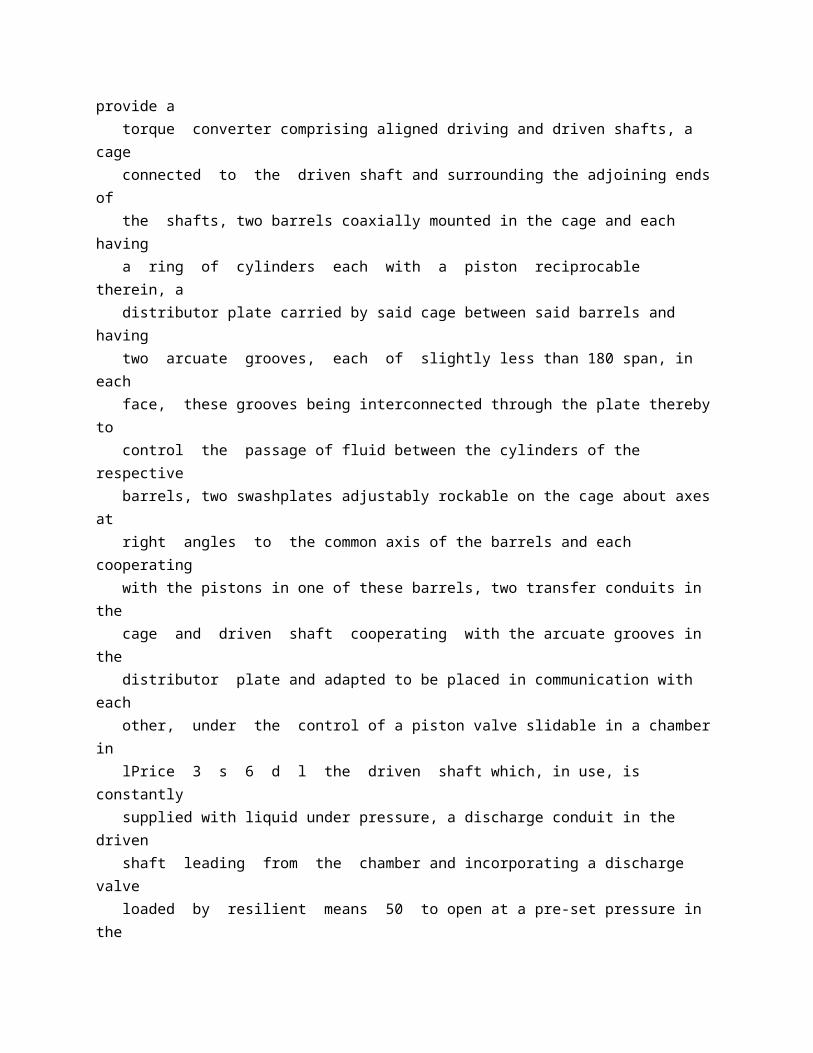
PATENT SPECIFICATION Date of Applic F S r > No 21566155. Application mc Complete Spec 785,846 ation and filing Complete Specification: July 26, 1955 lide in France on July 31, 1954. ification Published: Nov 6, 1957. Index at acceptance -Class 69 ( 2), 06 (C: E: H), 0100. International Classification:-FO 6 d. COMPLETE SPECIFICATION Improvements in Torque Converters We, SOCIETE DE FABRICATION D'ARMEMENTS ET DE MOTEURS S.O F A M, a Company organised and existing under the laws of the French Republic, of 136 Boulevard Hausmann, Paris (France), do hereby declare the invention, for which we pray that a patent may be granted to us, and the method by which it is to be performed, to be particularly described in and by the following statement: The present invention relates to torque converters of the type including two barrels fitted with cylinders interconnected by a valve plate and containing plunger pistons which cooperate with respective swafhplates of variable inclination. The object of this invention is to provide a torque converter of this type, especially for use on a motor vehicle, which is better adapted to meet the requirements of practice than those used at the present time. For this purpose, according to the present invention we provide a torque converter comprising aligned driving and driven shafts, a cage connected to the driven shaft and surrounding the adjoining ends of the shafts, two barrels coaxially mounted in the cage and each having a ring of cylinders each with a piston reciprocable therein, a distributor plate carried by said cage between said barrels and having two arcuate grooves, each of slightly less than 180 span, in each face, these grooves being interconnected through the plate thereby to control the passage of fluid between the cylinders of the respective barrels, two swashplates adjustably rockable on the cage about axes at right angles to the common axis of the barrels and each cooperating with the pistons in one of these barrels, two transfer conduits in the
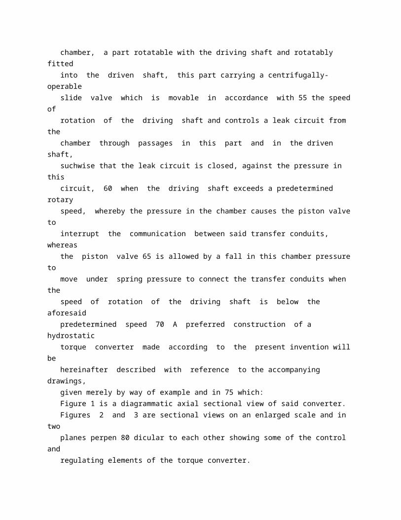
cage and driven shaft cooperating with the arcuate grooves in the distributor plate and adapted to be placed in communication with each other, under the control of a piston valve slidable in a chamber in lPrice 3 s 6 d l the driven shaft which, in use, is constantly supplied with liquid under pressure, a discharge conduit in the driven shaft leading from the chamber and incorporating a discharge valve loaded by resilient means 50 to open at a pre-set pressure in the chamber, a part rotatable with the driving shaft and rotatably fitted into the driven shaft, this part carrying a centrifugally-operable slide valve which is movable in accordance with 55 the speed of rotation of the driving shaft and controls a leak circuit from the chamber through passages in this part and in the driven shaft, suchwise that the leak circuit is closed, against the pressure in this circuit, 60 when the driving shaft exceeds a predetermined rotary speed, whereby the pressure in the chamber causes the piston valve to interrupt the communication between said transfer conduits, whereas the piston valve 65 is allowed by a fall in this chamber pressure to move under spring pressure to connect the transfer conduits when the speed of rotation of the driving shaft is below the aforesaid predetermined speed 70 A preferred construction of a hydrostatic torque converter made according to the present invention will be hereinafter described with reference to the accompanying drawings, given merely by way of example and in 75 which: Figure 1 is a diagrammatic axial sectional view of said converter. Figures 2 and 3 are sectional views on an enlarged scale and in two planes perpen 80 dicular to each other showing some of the control and regulating elements of the torque converter. Figure 4 shows the lay-out of the hydraulic circuits 85 Figure 5 is a developed section of a distribution plate used in this torque converter. The torque converter includes a fixed casing 1 in which are housed two barrels 2 90 k EW,0 cr785,846 and 3 each of which includes a plurality of plunger pistons For instance, barrel 2 includes nine pistons 4 disposed in cylinders in the barrel at equal intervals and barrel 3 also includes nine plungers 5 disposed in a similar fashion. The plungers 4 of barrel 2 cooperate with a swashplate 6 mounted with the interposition of ball bearings 7 on a support S the inclination of which can be modified as will be explained hereinafter The plungers 5 of barrel 3 cooperate with a swashplate 9 carried by a roekable support 10 similar to support S. The pivotal axes of supports S and 10 are diagrammatically shown on Figure 1 at 11 and 12 respectively. The respective cylinders 13 and 14 of barrels 2 and 3 are filled with a liquid and they are interconnected through a distributing plate 15
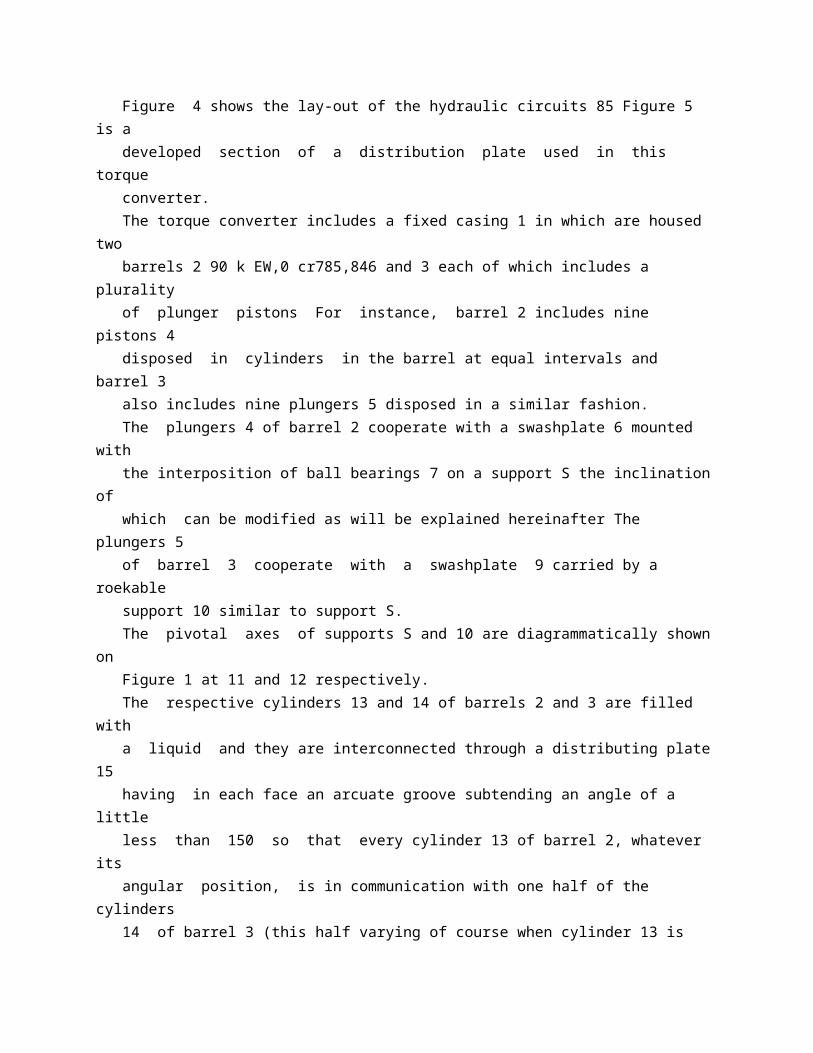
having in each face an arcuate groove subtending an angle of a little less than 150 so that every cylinder 13 of barrel 2, whatever its angular position, is in communication with one half of the cylinders 14 of barrel 3 (this half varying of course when cylinder 13 is moved angularly). The driving element of the torque converter is constituted by one of the barrels, i.e barrel 2, mounted on a rotating shaft 19 which constitutes the driving shaft of the torque converter The other barrel, to wit 3, is fixed in position, being secured to casing 1 through a tube 20 coaxially surrounding driving shaft 19. The oscillating supports S and 10 of swashplates 6 and 9 respectively are carried by a rotating cage 16 which constitutes the driven element of the device, said cage being fixed to a driven shaft 17 on which is for instance mounted a pinion 18 to transmit the movement thereof. The principle of operation of such a torque converter is as follows: It will first be supposed that swashplate 6 is given the maximum angle of inclination with respect to shaft 17 and that sw-ashplate 9 is at right angles to the axis of shaft 19 (this position being shown by Fig 1) Due to the rotating movement of barrel 2, plungers 4 should, due to their cooperation with swashplate 6, have reciprocating movements in their respective cylinders 13 which would result in a flow of liquid between the cylinders 14 of fixed barrel 3 and the cylinders 13 of rotating barrel 2 But since swashplate 9 is in a plane at right angles to the axis of rotation, plungers 5 are all in the same position in their respective cylinders 14 and cannot move therein so that no liquid flow is possible and plungers 4 cannot slide in cylinders 13 As a consequence of this, swashplate 6 is caused to rotate together with barrel 2 Since the support 8 of swashplate 6 can only pivot with respect to cage 16 about an axis 11 at right angles to the axes of the shafts 19 and 17 cage 16 is rotated by said support S. The rotational movement of driving shaft 19 is therefore directly transmitted to driven shaft 17 70 If now swashplate 9 is gradually inclined with respect to the axes of the shafts 19 and 17, the plungers 5 of fixed barrel 3 can reciprocate in the cylinders 14 of said barrel with an amplitude which depends upon the 75 inclination of said swashplate 9 A liquid flow then takes place between cylinders 13 and 14 and cage 16 is then rotated at a speed different from that of shaft 19 and which depends upon the ratio of the total variation SO of volume of cylinders 13 to the total variation of volume of cylinders 14 which finally depends upon the ratio of the inclinations of swashplates 6 and 9. Advantageously, the inclinations of these 85 two swashplates are interrelated and for instance for this purpose each of the oseillating supports S and 10 carries a finger 21.
these two fingers 21 moving in a control slideway 22 provided in a sliding sleeve 23 90 Thus, sleeve 23 controls, through slideway 22 the inclinations of the two swashplates, in accordance wvith the shape of said slidewav 22. Advantageously, sleeve 23 is automatically 95 positioned by a centrifugal governor 24 which controls the feed of a liquid under pressure to either of two annular chambers 25 and 26 disposed on either side of an annular flange 27 rigid with cage 16 and forming a 100 partition between said two chambers. For this purpose governor 24 actuates a slide valve 'N arrangijed to control the feed of said liquid under pressure to said chambers and 26 105 When the torque is to be transmitted from the driving shaft 19 to the driven shaft 17 the cylinders 13 located on one side of the axis of barrel 2 (that is to say the cylinders 13 the plungers 4 of' which move 110 outwardly) are directly connected through transfer conduits 48 and 49 and a valve 29 between these conduits with the cylinders 13 located on the other side of said axis (that is to say those of the plungers 4 of which 115 move inwardly) When this commumeation is established by said valve 29, the flow of liquid is short-circuited and there is no reaction from pistons 5 of the other barrel. Valve 29 is a piston valve subjected to the 120 action of the liquid pressure in the circuit including conduits 4 OS and 49 and cylinders 13 and 14 but essentially controlled by varying+ the pressure of a liquid present in a cylindrical chamber 31 in shaft 17 125 Such variations of the pressure of liquid in chamber 31 may be controlled manually by means of a valve 30 adapted to place said chamber 31 in comnmunnication either with a source of liquid under pressure, as 130 operated by a special valve 35 and capable, when said valve is operated, of driving sleeve 23 against an abutment the position of which is suitable to obtain reverse gear. Advantageously, the elements of the 70 hydraulic circuit of such torque converters are grouped in a single unit, for instance as shown by Figs 2 and 3. Valves 30 and 35 are controlled respectively by two cams 36 and 37 which act upon the 75 sliding elements of said valves through levers such as shown at 38 on Fig 3 for valve 30. These two cams 36 and 37 are fixed on the same shaft 39 operated by a crank 40 (Fig 2). This shaft 39 further carries a special cam 41 80 for temporarily bringing governor 24 out of action. Advantageously, another special cam 42 operative by the crank 40 is mounted on shaft 39 so as to enable the adjustment of 85 speed governor 24 to be modified at will to secure optimum operating conditions These cams are mounted so as to come into action for
different respective angular positions of crank 40 90 Advantageously, means are provided for automatically and permanently adjusting governor 24 in response to variations of the position of the accelerator throttle, in the case of an automobile vehicle For this 95 purpose, as shown by the drawings, there is provided a hollow shaft 43 coaxially surrounding shaft 39 and on which is fixed a cam 44 cooperating with the governor in the same manner as cam 42 Shaft 43 is 100 operated by a grooved pulley 45 itself driven by the accelerator throttle control cable. All these control elements are grouped in a common casing 46 which may be fixed to 105 the main casing of the torque converter. According to still another feature of the present invention, illustrated by Fig 5, the planes of swashplates 6 and 9, instead of containing the respective axes of oscillation 110 of said swashplates (constituted by lines at right angles to the plane of Fig 1 and passing through the centres of the circles marked 11 and 12 on said Fig) are slightly inclined with respect to said pivotal axes, 115 this inclination corresponding to a slight pivoting of the plane of each swashplate 6 or 9 about an axis at right angles both to the above mentioned pivotal axes and to the axis of rotation of the corresponding barrel, 120 from the position in which said plane of the swashplate would contain said pivotal axes. For instance, the axis of the housing in which is placed the ball bearing, such as 7, of each of said swashplates, instead of being 125 at right angles to the corresponding axis of oscillation is inclined thereto. This permits a smoother variation of the pressures in cylinders 13 and 14 when they pass from the position where they are coft 130 diagrammatically shown at R on Fig 4, or with a discharge circuit. Furthermore the position of valve 29 is controlled through automatic means responsive to variations of the speed of rotation of driving shaft 19, such means being adapted to open valve 29 when the speed of rotation of said shaft 19 is below a given value For this purpose, a slide valve 32 slidable in a direction at right angles,to the axis ofshaft 19 is mounted in a circuit connected with chamber 31 and through which liquid can leak out from said chamber, this slide valve being adapted, when the action of the centrifugal force is sufficiently high, to interrupt said circuit whereby no liquid can then flow from chamber 31 and the pressure in said chamber rises sufficiently to push valve 29 toward the right hand side of Figs 1 and 4, thus cutting off the short-circuit communication between the two portions of valve 15 located on opposite sides of the axis of shaft 19. Advantageously, similar means for controlling the position of valve 29
are mounted on the driven shaft 17 so as to cut off the above mentioned short-circuit connection when said driven shaft 17 is rotating at a sufficient speed Thus, torque is transmitted by the device even when the driving shaft is stationary but when the driven shaft is rotating at a sufficient speed (such as when the engine of a vehicle is started by letting said vehicle run down-hill under gravity) In this case, a second slide valve 33 is mounted across the leakage circuit in series with the first mentioned slide valve 32, slide valve 33 being mounted on the driven shaft 17. Escape from chamber 31 can take place through an axial channel provided with a suitably loaded discharge valve. Means, such for instance as a spring 33 a which urges slide valve 33 toward the leak circuit closing position, are provided to maintain a minimum pressure (intended for instance for lubrication of the apparatus). This minimum pressure is balanced, when no torque is transmitted by the device, by the return spring 29 a of valve 29. With such an arrangement, when the driving shaft 19 is running at idling speed, slide valves 32 and 33 are in positions such that liquid can leak out from chamber 31 and the return spring of valve 29 brings this valve in the open position When the speed of driving shaft 19 is increased, slide valve 32 closes the liquid leak circuit and therefore causes valve 29 to cut off the connection between the two ends of valve plate 15 The device then transmits torque from the driving shaft to the driven shaft. Reverse gear can be obtained by reversing the inclination of swashplate 6, for instance by means of a supplementary piston 34 785,846 nected with the low pressure section A to the high pressure section B of the hydraulic circuit Due to the above stated inclination of the swashplates, the pistons are given small displacements which achieve a smoother operation of the whole. As the working pressure of the liquid is variable in accordance with the position of the swashplates about their pivotal axes the above mentioned inclination is determined preferably in such manner that the optimum working conditions are obtained for the maximum working pressure of the liquid. For intermediate working pressures, a double discharge cheek valve 47 limits the increase of the pressures to the intermediate pressure that is required.
* Sitemap * Accessibility * Legal notice * Terms of use
* Last updated: 08.04.2015 * Worldwide Database * 5.8.23.4; 93p
* GB785847 (A)
Description: GB785847 (A) ? 1957-11-06
Photographic elements and processes
Description of GB785847 (A)
A high quality text as facsimile in your desired language may be available amongst the following family members:
BE542421 (A) DE1015682 (B) FR1138409 (A) US2878121 (A) BE542421 (A) DE1015682 (B) FR1138409 (A) US2878121 (A) less Translate this text into Tooltip
[84][(1)__Select language] Translate this text into
The EPO does not accept any responsibility for the accuracy of data and information originating from other authorities than the EPO; in particular, the EPO does not guarantee that they are complete, up-to-date or fit for specific purposes.
PATENT SPECIFICATION 785847 Date of Application and filing Complete Specification Aug 3, 1955. No 22266/55. Application made in United States of America on Nov 15, 1954. Complete Specification Published Nov 6, 1957. Index at Acceptance: -Class 98 ( 2), D 8. International Classification: -GO 3 c. COMPLETE SPECIFICATION Photographic Elernents and Processes We, E I DU PONT DE NEMOURS AND COMPANY, a corporation of the State of Delaware, United States of America, located at 1007 Market Street, Wilmington 98, State of Delaware, United States of America, do hereby declare the invention,
for which we pray that a patent may be granted to us, and the method by which it is to be performed, to be particularly described in and by the following statement:This invention relates to photography and more particularly to photographic image-receptive elements and to processes of forming positive photographic images in such elements. Still more particularly, it relates to lightinsensitive image-receptive films, plates and papers which have a water-permeable colloid layer having dispersed therethrough finely divided inert particles coated with a silicon compound containing at least one siliconhydrogen bond. It has been found according to the invention that a light-insensitive image-receptive element for an image-transfer photographic process can be prepared by providing a sheet support, e g, a film, foil, plate or paper with a light-insensitive, water-permeable colloid layer having dispersed theiethrough finely divided inert solid particles having an average diameter of from 0 001 to 10 0 microns coated with a siliconcontaining compound having at least one silicon-hydrogen bond, said compound constituting from 0 1 % to 100 % by weight of the total weight of the uncoated particles, said coated particles, being present in the amount of 0 1 mg to 100 grams per 100 mg of the colloid. Various types of water-permeable colloids can be used as the binding agents for the silicon-containing compound coated particles including the naturally occurring types, e g, gelatin, albumin, zein, agar-agar, alginic acid and casein; and synthetic types, e g, polyvinyl alcohol, partially hydrolyzed polyvinyl esters, hydrolysed ethylene/vinyl acetate copolymers; polyvinyl acetals, including sodium o-sulfobenzaldehyde polyvinyl acetal and benzaldelPrice Plr UIl 4 S 6 d hyde polyvinyl acetal; polyglycuronic acid and carboxymethyl cellulose. Suitable materials for the discrete inert 50 particles include colorless or white materials, e.g, silicon dioxide of the dense or solid type, inorganic silicates such as magnesium silicate, diatomaceous silicas, sodium aluminum silicate and calcium carbonate, barium sulfate and 55 titanium dioxide, or colored or black particles, e.g, carbon black or lamp black. The inert particles can be coated by adding an inert solvent solution or dispersion of the silicon-containing compound to the finely 60 divided particles The amount of silicon-containing compound used should in general constitute from 0 1 % to 100 % of the total weight of the uncoated particles In the case of liquid silicon-containing compounds, no solvent is 65 needed and the inert particles and liquid silicon-containing compound can be mixed in suitable proportions so that the latter are coated in an amount between 0 1 % and 100 % by weight based on the weight of the uncoated 70 particles.
In order that the coated particles may be dispersed readily throughout an aqueous solution or dispersion of the water-permeable colloid, it is desirable to use a wetting or dis 75 persing agent in an amount of 0 1 to 100 % by weight based on the total weight of the siliconcontaining compound coated inert particles. Suitable such agents include saponin and those described in British Patent Specification No 80 592,676, namely, the oxyalkylene ethers of hexitol ring dehydration products, e g, the polyoxyethylene sorbitan monolaurate, monostearate and monooleates which contain 2 to 20 oxyethylene groups divided in 3 chains; a salt 85 of an alkyl-substituted aryloxy alkylene ether sulfonate, e g sodium p-tertiary-octyl phenoxy ethoxy ethyl sulfonate as disclosed in British Patent Specification No 673,308; sodium dodecyl, tetradecyl and octadecyl sul 90 fate and the dioctyl ester of sodium sulfosuccinic acid. The light-insensitive image-receptive elements described above have an excellent light785,847 insensitive image-receptive layer for the inverse transfer of soluble silver complexes from the unexposed and undeveloped portions of a separate light-sensitive silver halide waterpermeable colloid layer, as more fully described below The silicon-containing compound coated particles not only act as nuclei for silver deposition in the light-insensitive water-permeable colloid layer containing them but accelerate the deposition Since the coated particles do not migrate from or in the layer, an excellent image is deposited in and on the surface of the image-receptive layer containing such particles A more dense image is formed than when uncoated particles (e g, silica) are used, due to the -Si H groupings in the siliconcontaining compounds which reduce the silver complexes to metallic silver. In the image-transfer process of this invention, a latent image of silver halide in a waterpermeable colloid layer is formed by the conventional method of exposure to an object field, e.g, an original scene, reproduction or to a photographic image The exposed layer is then placed in surface contact with the image-receptive layer of this invention either during or after the developiment of the latent silver image and in the presence of an aqueous solution of a silver halide solvent, e g, sodium thiosulfate, sodium thiocyanate and sodium sulfite or mixtures of two or more of such compounds, and the process proceeds, preferably in the absence of significant actinic radiations, while the lightsensitive layer is maintained in intimate surface contact with the image-receptive layer for a period of time sufficient to dissolve a small or large part of the undeveloped silver halide, e.g, from 5 to 600 seconds The silver complexes thus formed diffuse into the receptive layer containing the coated particles where the
silicon-containing compound and the photographic developer, which may contain the silver halide solvent, reduce the silver complexes and deposit metallic silver on the particles forming an image which is the reverse from the original latent image The original silver halide layer is then removed by separating the two layers Any residual stain in the image-receptive layer, which contains a deposited silver image, can be removed, if desired, by treatment with an aqueous solution of a fixing agent. The invention will be further illustrated but Image-receptive layer Gelatin (no particles) Gelatin+coated particles EXAMPLE IH One gram each of silicon-containing compound coated silica particles, types (a), (b) and (c), in the form of an ethanol dispersion (prepared as described in Example I) was added to separate 250 ml samples of aqueous gelatin ( 5 % by weight) containing 1 6 ml of saponin is not intended to be limited by the following examples: - EXAMPLE I To a liter of aqueous gelatin containing 5 % by weight of the latter, there was added 4 0 grams of silica particles having an average diameter of 0 015 microns which were coated with trichlorosilane that hydrolyzed to form a coating of (H Si O,,X) where N is 1 or more and the coating constituted 15 to 20 % of the total weight of the coated particles; said coated particles being added in the form of a dispersion in ethanol which was obtained by mixing in a high-speed blending mixer The resulting gelatin dispersion was coated on a paper sheet to form a thin layer which was dried A separate paper sheet was coated with a similar gelatin solution but free from coated particles to form a control sample The coatings were dried. Separate photographic contact printing paper samples bearing a chlorobromide gelatin emulsion layer were exposed to a transparent positive image in a film element and the resultant exposed element, samples of the light-insensitive papers bearing the gelatin layers containing the coated particles and samples of the light-insensitive papers free from such particles were separately immersed for 1 5 minutes in a developer solution at 68 F made by admixing the following components. N methyl para-aminophenol sulfate 1 0 grams Hydroquinone 4 0 grams Sodium sulfite (anhydrous) 15 0 grams Sodium carbonate (monohydrate) 22 5 grams Potassium bromide 0 63 grams Water to make 1 0 liter Sodium thiosulfate 1 0 gram The exposed printing paper samples were removed from the developer together with the developer impregnated gelatin coated elements and separate samples of exposed element and gelatin element pressed together tightly with their gelatin surfaces in contact for 10 minutes At the end of this period the layers were separated, fixed, washed and dried with the following
results:Resultant positive image Very faint Vigorous image with clean white areas and 15 ml of 10 25 % by weight aqueous 115 solution of chrom alum:(a) Silica particles having an average diameter of 0 015 micron coated with (Si HO,5)X where N is a positive integer of 1 or more in an amount of 15 to 20 % by weight of the 120 coated particles (Manufactured by Linde Air :2 785,847 Products Company as " Coated Silica 30 "). (b) Coated particles similar to (a) prepared by coating " Si-O Lite" particles with (Si HO J)1 (Made by Mallinchrodt Chemical Works). (c) Silica particles coated with 5 % by weight of HOl(C 2 H,)H Si Ol,IH where N may be from 6 to 20 The resulting gelatin dispersions were coated on a baryta coated paper stock and the coating dried The initial gelatin solution free of coated silica particles was coated on the same type of paper and the coating dried. Separate photographic contact printing Image-receptive layer Gelatin (no particles) Gelatin+ coated particles (a) ,1 +,,,, (b) , +,,,, (c) Each of the images in the papers of the foregoing table showed the same stain However, in similar experiments the stain in each image-bearing layer was eliminated by fixing the positive prints for 3 minutes in a fixer made by admixing the following ingredients: Sodium thiosulphate 5 H 20 240 grams Sodium sulfite, dessicated 15 grams Borax 10 H 20 18 grams Glacial acetic acid 12 ml. Potassium alum 24 H 20 20 grams Water to make 1 liter, and washing the treated elements with water and drying. EXAMPLE III One gram of silica coated particles in ethanol solution as described in Example I was added to a 250 ml sample of medium viscosity polyvinyl alcohol essentially completely hydrolyzed polyvinyl acetate, ethanol and water in the proportions of 5:5:90 % by weight, said solution containing 6 25 ml of a % by weight aqueous solution of cetyl betaine The resulting polyvinyl alcohol dispersion was coated onto a baryta coated paper stock and the thin layer dried An identical polyvinyl alcohol solution containing no coated silica particles was coated onto baryta coated paper in like manner and the coatings dried to form control paper samples. Samples of lithographic film having a gelatin silver chlorobromide emulsion layer on a cellulose acetate support were exposed in the manner described in Example T The emulsion surface of the exposed samples was brought Image-receptive layer Gelatin (no particles) Gelatin+coated particles (a) -I +5,, (b) , +,,,, (c) Polyvinyl alcohol (no particles) ,,, + coated particles (a) paper samples bearing a silver chlorobromide gelatin emulsion layer were exposed to a positive image in a film element and the papers together with samples of image-receptive papers (a), (b) and (c) were separately immersed for 1

5 minutes in a developer solution at 680 F, as described in Example I. The exposed impregnated photographic paper samples and impregnated samples (a), (b) and (c) were pressed together tightly with their gelatin surfaces in contact for 10 minutes At the end of this period, the layers were separated and dried with the following results:Resultant positive image Faint image Strong blue-black image into intimate contact with the coated surface of two papers described in the previous paragraph and with the coated papers described in Example II in a commercial developing apparatus (an " Autostat " sold by The American Photocopy Equipment Company) having means for bringing the surfaces in contact and containing a developer solution at 680 F of the following composition: Water at 1250 F 750 ml. Sodium sulfite (anhydrous) 45 0 grams Hydroquinone 16 0 grams Boric acid crystals 5 5 grams Potassium bromide 2 0 grams Sodium thiosulfate (anhydrous) 15 0 grams "S t erox " (Registered Trade Mark) CD ( 1/50, CQH OH, V/V) 5 0 ml. 1 phenyl 5 mercapto tetrazole 1 gm in 1000 cc CH,0 H) 6 0 ml. Sodium hydroxide 24 0 grams Cold water to make 1 0 liter a polyethylene ester of a tall oil acid 95 (sold by Monsanto Chemical Company). After 20 seconds of contact, the lithographic film samples were separated and the gelatin and polyvinyl alcohol image-receptive layers were treated in the fixing solution described 100 in Example II for 3 minutes and dried with the results given in the following table:Resultant positive image Faint gray Brown Brown Black Faint gray Brown-black 785,847 EXAMPLE IV The procedure set forth in Example II was repeated except that the control gelatin coatImage-receptive layer Gelatin+ silica particles (uncoated) Gelatin+ coated particles l(a) of Example II)l The invention is, of course, not limited to the use of the specific silicon-containing compounds mentioned in the foregoing examples nor to the specific amounts given in such examples A large number of other siliconcontaining compounds which possess at least one silicon-hydrogen bond can be substituted in like manner. The utility of any particular silicon-containing compound which contains a siliconhydrogen bond can be determined by testing whether it or its hydrolysis products are capable of exerting a reducing action on or nucleating silver halide The mechanism or theory as to why the silicon-containing compounds are effective as chemical sensitizers for silver halide emulsions is not completely understood but it is believed that the siliconhydrogen linkage must be capable of alkaline induced hydrolysis which is illustrated in the following equation for a useful class of siliconcontaining compounds: OHRn Si H 4,_ + HOH->-R Sii OH 1,-n + H 2 where R,, is hydrogen, halogen, e g,
Fl, Cl and Br; alkyl of 1 to 30 carbon atoms, alkoxy of 1 to 30 carbon atoms, aryl, e g, phenyl, tolyl, naphthyl, aryloxy, e g, phenoxy, naphthoxy, siloxy or combinations thereof, " N " being 1 to 3. Among the additional suitable specific silicon-containing compounds which can be used, there may be mentioned: alkyl silanes, e.g, methyl silane, dimethyl silane, trimethyl silane; ethyl silane, diethyl silane, triethyl silane, n-propyl silane, butyl silane; alkyl halogenosilanes, e g, dimethylchlorosilane, ethyl dichlorosilane, diethylchlorosilane, propyl dichlorosilane; aryl silanes, e g, diphenyl o silane, triphenyl silane and mixed alkyl aryl silanes, e g, ethyl diphenyl silane, methyl phenyl silane and dihexyl phenyl silane; alkoxy, aroxy, alkoxy halogeno, and aroxy halogeno silanes, e g, diethoxy silane, methyl chloro-ethyoxy silane and phenoxy silane; cyclic and linear polymeric siloxanes, e g, cyclic tetrameric methyl siloxane and its linear analogue HOlCH (H)Si O 1 l 1 H Hydrolysis products of the above listed silanes which retain a silicon-hydrogen bond may be used also. Mixtures of two or more silicon-containing compounds can be coated on the particles or mixtures of two differently coated particles can be dispersed in the aqueous colloid solution used to coat the image-receptive layers. ing contained uncoated silica particles of the same average diameter with the following results:Resultant positive image Faint Strong Different types of carrier particles coated with either the same or different silicon-containing compounds may also be used. The quantity of the coated particles used in 70 the water-permeable colloid may vary over a wide range of proportions from 0 1 mg to 100 g per 100 mg of colloid. Various types of supports may be used for the image-receptive layers containing silicon 75 containing compound coated particles Suitable supports include films and plates composed of cellulose derivatives, e g, cellulose acetate, propionate, butyrate, acetate-butyrate, and nitrate; superpolymers, e g, nylon, poly 80 vinyl chloride, poly(vinyl chloride co vinyl acetate), polystyrene, polymethylene terephthalates, polyethylene terephthalate; thin aluminum sheets; paper and cardboard Of course, various sublayers may be present to 85 anchor the layers to the base as is common in photographic film and plate manufacture. Any of the conventional photographic developing solutions can be used in carrying out the process Suitable developing agents 90 and solutions are described in Mees "The Theory of the Photographic Process" published by The Macmillan Company, New York ( 1946), pages 338-369 and particularly page 352 95 The novel light-insensitive image-receptive elements of this invention are useful in the reproduction of various images Thus, they are useful in copying
printed matter In this case a light-insensitive imag-receptive paper is 100 used with a separate exposed film bearing a light-sensitive silver halide latent image The image-receptive papers are especially useful in direct-positive photography The light-insensitive image-receptive paper and light-sensitive 105 film or paper being separate element but the development being completed in contact with simultaneous inverse-transfer. An advantage of the invention is that it provides new and practical light-insensitive 110 image-receptive films, sheets, plates and papers which are economical to make and simple to use The image-receptive elements are stable over long periods of time They give more dense images than when uncoated particles 115 are used The coated particles can be made long prior to coating operations and do not require storage in the absence of actinic radiations The preparation of silicon-containing compound coated particles is a simple 120 and inexpensive operation in contrast to the difficult operation of producing colloidal or -4 785,847 complex particles heretofore used A further advantage is that the particle size of the particles can easily be selected before the siliconcontaining compound coating operation, thus allowing a large selection of types of particles of reproducible and controlled sizes from the many such particles which are common items of commerce The silicon-containing compound coated particles are dry powders which are easily stored and handled and offer many other advantages such as ease of controlling concentration of active ingredient through changes in type and amount of silicon-containing compound coating.
* Sitemap * Accessibility * Legal notice * Terms of use * Last updated: 08.04.2015 * Worldwide Database * 5.8.23.4; 93p
* GB785848 (A)
Description: GB785848 (A) ? 1957-11-06
Improvements relating to lead-acid electric accumulators
Description of GB785848 (A) Translate this text into Tooltip
[75][(1)__Select language] Translate this text into
The EPO does not accept any responsibility for the accuracy of data and information originating from other authorities than the EPO; in particular, the EPO does not guarantee that they are complete, up-to-date or fit for specific purposes.
We, PRITCHETT & GOLD AND E P S. COMPANY LIMITED, a British Company, of Dagenham Dock, Essex, do hereby declare the invention, for which we pray that a patent may be granted to us, and the method by which it is to be performed, to be particularly described in and by the following statement - Dilute sulphuric acid, the electrolyte of the lead-acid storage battery, is a very corrosive and reactive substance, capable of causing damage if it should escape from the battery by spillage It is therefore desirable to retain it within the battery by immobilising or absorbing it in some suitable medium, especially if the battery is of portable type which may accidentally be tipped over or broken in use The corrosive and reactive nature of the dilute sulphuric acid electrolyte severely limits the range of materials which may be successfully employed for immobilising or absorbing the electrolyte and experience has shown that the materials which may be used are more or less confined to silica and the silicates. In experimental investigations into methods of absorbing dilute sulphuric acid electrolyte, using for our experiments a three-plate lead-acid cell having one positive plate and two negative plates, we found that under normal conditions, without the addition of absorbents, the electrolyte volume in a test cell amounted to 386 cubic centimetres, including that held in the Pores 3.5 of the plates The specific gravity of the electrolyte being 1 250 the weight of sulphuric acid corresponding to the formula 11,SO, amounted to 160 grams Discharging the cell at 0 2 ampere we obtained a canacity of 28 4 ampere hours When we filled the space between and around the plate lPrice 735,f 848 with tightly packed glass wool, the total volume of electrolyte was reduced to 353 cubic centrimetres, corresponding to a total of 147 grams of H 2 SO in the cell On discharge at 0 2 ampere we obtained a capacity of 21 4 ampere hours. Using diatomaceous earth instead of glass wool to fill the space between and around the plates, the total volume of electrolyte was
reduced to 327 cubic centimetres, which corresponds to a total of 136 grams of HSO 4 in the cell Our discharge test at 0 2 ampere gave a capacity of 20 ampere hours. The third method we employed was to replace the normal electrolyte with a mixture of sodium silicate and dilute sulphuric acid, which set within an hour to the well known "jelly electrolyte" The quantities and specific gravities of the sodium silicate and sulphuric acid solution were so chosen to provide the cell with 386 cubic centimetres of electrolyte containing a total of 158 grams of H 2 SO 4 On discharge at 0 2 ampere we obtained a capacity of 16 ampere hours. In the table below these results are set out with a final column showing the ampere hours obtained per gram of H 2 SO 4 in the electrolyte, and it will be seen that the jelly electrolyte result is anomalous Whereas the performance of the cell is roughly proportioned to the weight of sulphuric acid present in its electrolyte in the other combinations, the jelly electrolyte unduly affects the performance It is true that each one of the absorbed electrolytes does cut down the yield per gram of H SO 4, presumably because of the interference with diffusion, but the jelly acid cell, with the highest amount of Ho SO, except that present in the normal "free" electrolyte cell, has noticeably the lowest performance:PATENT SPECIFICATION Inventor:-ROBERT GEORGE ROBINSON. Date of filing Comjplete Specification: Aug 21, 1956. Application Date: Sept 9,1955 No 25836155. Complete Specification Published: Nov 6, 1957. Index at Acceptance:-Class 53, BSB(A 2: AX: C). International Classification -H Olm. COMPLETE SPECIFICATION. Improvements relating to Lead-Acid Electric Accumulators. 785,848 Electrolyte Normal "free" Glass wool Diatomaceous earth Jelly Total H.SO 4 grams 147 grams 136 grams 158 grams Ampere Hours 28.4 21.4 Ampere Hours per e gram H SO 4 0.178 0.146 20.0 0 147 16 0 111 The admixture of dilute sulphuric acid with sodium silicate causes the precipitation of hydrated silica, forming a stiff gel. Although at first sight an attractive method of providing an immobilised electrolyte, it entails an undue loss of battery performance. What is more, experience shows that after a few cycles of charge and discharge, the electrolyte tends to break up into fragments of stiff jelly floating in and surrounded by a "thin" liquid When this happens the battery ceases to be unspillable. The reduction in battery performance arising from the use of jelly electrolyte and the tendency of the jelly to break up in service both suggest that the gel structure is too rigid for its purpose In the
lead-acid battery, the charge and discharge currents are carried by ionic movements within the electrolyte, which also has to supply sulphuric acid to the plates on discharge in order to form the lead sulphate which is the chemical product of discharge at both the positive and the negative plates Correspondingly, on charge the electrolyte has to reabsorb the sulphuric acid given off by the plates by the reversal of the above chemical change Such massive movements of ions and molecules, which are essential if the battery is to function, tend to put a big strain upon any "inflexible" system of immobilised electrolyte The gas which is evolved from positive and negative plates at the end of charge also tends to break up the jelly, presumably for the same reason that the gel is too rigid while not possessing enough inherent strength. A gel may be regarded as a type of colloidal system behaving as a solid of very low tensile strength and low Young's Modulus By its method of formation the jelly electrolyte made by adding sodium silicate to dilute sulphuric acid is a true gel possessing these characteristics of weakness and rigidity, characteristics which are unsatisfactory for battery electrolyte uurposes. The object of our present invention is to overcome the unsatisfactory nerfornance of silica Drecipitated in situ within a battery in the form of silica gel In accordance with our present invention we employ fine particles of silica of sub-micron size, say 0.015 micron diameter and we mix for example, between 8 and 24 O/< such as about 12 % of this finely divided silica into dilute sulphuric acid to produce what is, to all 65 appearance, a "grease" and fill this mixture into the electrolyte space of the battery We find that this liquid suspension or colloidal solution of silica behaves as an immobile liquid rather than as a weak solid or true 70 gel It exhibits thixotrophy, showing a useful diminution in viscosity when subjected to mechanical work, and advantage can be taken of this by whisking the solution to lower its viscosity just before filling the 75 electrolyte space of the battery Again, when the battery plates are evolving gas at the end of charge, the mechanical disturbance caused by the gas bubbles reduces the viscosity sufficiently for the gas to pass up 8 O wards without difficulty, and there is consequently an absence of the cracking and shrinking noticeable with jelly electrolyte under these conditions Even if loss of water by evaporation andelectrolysis is not 55 made good at frequent intervals during the period of service, the colloidal electrolyte is able to absorb the added water quite readily. In contrast to the poor performance of a 90 battery having its electrolyte immobilised by the addition of sodium silicate, the liquid suspension of sub-micron silica in dilute sulphuric acid allows the battery to give a performance reasonably proportionate to 95 the
amount of sulphuric acid present A test cell such as previously described contains a total of 370 cubic centimetres of 1.250 S G dilute sulphuric acid when the volume outside the plates is a colloidal solu 100 tion of sub-micron silica in acid The total HSO, is 154 grams and the cell gives 24 6 ampere hours at a discharge rate of 0 2 amperes This capacity is equivalent to 0.16 ampere hours per gram of H 2 SO 105 It is surprising that the mere substitution of sub-micron silica for silica precipitated in situ within the cell can have such a markedly favourable result upon the electrical performance, but a study of the figures 110 as a whole seems to indicate that it is the jdlly electrolyte which is anomalous and that the colloidal solution of sub-micron silica behaves predictably in electrical performance per unit of weight of sulphuric 115 acid The explanation may be, as previously suggested, in the relative freedom of movement of molecules and ions in the two systems. Sub-micron silica powder is made by 120 various processes and is sold under a number of Registered Trade Marks, such as "Aerosil" and "Manosil VN 3 " A suitable colloidal electrolyte may be obtained by mixing 11 to 15 grams of "Aerosil" with 100 125 millilitres of dilute sulbburic acid or 30 to grams of "Manosil VN 3 " with that quantity of acid Filing tle electrolyte space is made easier if the viscosity of thfilling the electrolyte space of the battery with the mixture.
* Sitemap * Accessibility * Legal notice * Terms of use * Last updated: 08.04.2015 * Worldwide Database * 5.8.23.4; 93p