Embed Size (px)
Citation preview

Note: Within nine months of the publication of the mention of the grant of the European patent in the European PatentBulletin, any person may give notice to the European Patent Office of opposition to that patent, in accordance with theImplementing Regulations. Notice of opposition shall not be deemed to have been filed until the opposition fee has beenpaid. (Art. 99(1) European Patent Convention).
Printed by Jouve, 75001 PARIS (FR)
(19)E
P1
039
758
B1
TEPZZ_Z¥9758B_T(11) EP 1 039 758 B1
(12) EUROPEAN PATENT SPECIFICATION
(45) Date of publication and mention of the grant of the patent: 01.01.2014 Bulletin 2014/01
(21) Application number: 00302159.9
(22) Date of filing: 16.03.2000
(51) Int Cl.:H04N 7/26 (2006.01) H04N 7/24 (2011.01)
G06F 3/033 (2013.01) G06F 9/44 (2006.01)
(54) Apparatus for creating shared video scene content
Vorrichtung zur Erzeugung von gemeinsamen Videoszeneninhalt
Appareil pour créer un contenu de scène vidéo commun
(84) Designated Contracting States: DE FR GB
(30) Priority: 19.03.1999 JP 7659899
(43) Date of publication of application: 27.09.2000 Bulletin 2000/39
(73) Proprietor: Sony CorporationTokyo 141 (JP)
(72) Inventor: Fukuda, KazuhiroShinagawa-ku,Tokyo 141 (JP)
(74) Representative: Davies, Simon Robert et alD Young & Co LLP 120 HolbornLondon, EC1N 2DY (GB)
(56) References cited: EP-A- 0 827 112
• LEIDIG T ET AL: "Authoring MHEG presentations with GLASS-Studio" MULTIMEDIA SOFTWARE DEVELOPMENT, 1996. PROCEEDINGS., INTERNATIONAL WORKSHOP ON BERLIN, GERMANY 25-26 MARCH 1996, LOS ALAMITOS, CA, USA,IEEE COMPUT. SOC, US, 25 March 1996 (1996-03-25), pages 150-158, XP010200938 ISBN: 0-8186-7511-X
• VAZIRGIANNIS M ET AL: "AN OBJECT-ORIENTED MODEL FOR INTERACTIVE MULTIMEDIA PRESENTATIONS" COMPUTER JOURNAL, OXFORD UNIVERSITY PRESS, SURREY, GB, vol. 36, no. 1, 1993, pages 78-86, XP000360267 ISSN: 0010-4620
• SEUNGTAEK OH ET AL: "Experiments with MHEG Player/Studio: an interactive hypermedia visualization and authoring system" EUROMICRO CONFERENCE, 1998. PROCEEDINGS. 24TH VASTERAS, SWEDEN 25-27 AUG. 1998, LOS ALAMITOS, CA, USA,IEEE COMPUT. SOC, US, 25 August 1998 (1998-08-25), pages 610-615, XP010298027 ISBN: 0-8186-8646-4
• R. JOSEPH AND J. ROSENGREN: "MHEG-5: An Overview"[Online] 6 December 1995 (1995-12-06), XP002310910 Retrieved from the Internet: URL:http://www.mheg.org/users/mheg/archive s/doc/mheg-reader/rd1206.html> [retrieved on 2004-12-15]
• VAZIRGIANNIS M ET AL: "AN OBJECT-ORIENTED MODEL FOR INTERACTIVE MULTIMEDIA PRESENTATIONS", COMPUTER JOURNAL, OXFORD UNIVERSITY PRESS, SURREY, GB, vol. 36, no. 1, 1 January 1993 (1993-01-01), pages 78-86, XP000360267, ISSN: 0010-4620, DOI: 10.1093/COMJNL/36.1.78
• LEIDIG T ET AL: "Authoring MHEG presentations with GLASS-Studio", MULTIMEDIA SOFTWARE DEVELOPMENT, 1996. PROCEEDINGS., INTERNATIONAL WOR KSHOP ON BERLIN, GERMANY 25-26 MARCH 1996, LOS ALAMITOS, CA, USA,IEEE COMPUT. SOC, US, 25 March 1996 (1996-03-25), pages 150-158, XP010200938, DOI: 10.1109/MMSD.1996.557768 ISBN: 978-0-8186-7511-9

EP 1 039 758 B1
2
5
10
15
20
25
30
35
40
45
50
55
Description
[0001] The present invention relates to an informationprocessing apparatus.[0002] In recent years, the digital satellite broadcastinghas been becoming popular. In comparison with the con-temporary analog broadcasting, for example, the digitalsatellite broadcasting is well proof against noise and fad-ing, hence, being capable of transmitting a signal with ahigh quality. In addition, the frequency utilization rate isimproved and a multi-channel transmission can also beembraced. To put it concretely, in the case of the digitalsatellite broadcasting, several hundreds of channels canbe preserved by using one satellite. In such digital sat-ellite broadcasting, it is possible to provide a number ofspecial channels such as channels for sports, movies,music and news. Programs for special plans and con-tents of the channels are broadcasted through their re-spective channels.[0003] By utilizing such a digital broadcasting system,the user is capable of downloading musical data such asa piece of music, and there has been proposed a systemthat allows the user, for example, to make a purchasingcontract to buy some products while watching a broad-cast screen in the so-called television shopping. That isto say, the digital satellite broadcasting system broad-casts data services at the same time as an ordinarybroadcast program.[0004] In the case of an operation to download musicaldata, for example, the broadcasting station broadcaststhe musical data by multiplexing the data so as to syn-chronize the data with a broadcast program or video in-formation. In addition, in the operation to download mu-sical data, the user is capable of carrying out operationsinteractively while watching a displayed GUI (GraphicalUser Interface) screen which serves as a downloadingoperation screen. Data for displaying such a GUI screenis also broadcasted by multiplexing.[0005] Then, the user owning a reception apparatusselects a desired channel to display a GUI screen fordownloading musical data by carrying out a predeter-mined operation on the reception apparatus. The userthen carries out an operation for the GUI screen typicallyto supply the musical data to a digital audio apparatusconnected to the reception apparatus. Typically, the mu-sical data is recorded in the digital audio apparatus.[0006] Incidentally, with regard to a GUI screen fordownloading musical data described above, partial pic-ture data and text data which are used as elements toform the GUI screen and unit data (or files) such as audiodata to be output as a sound in accordance with a pre-determined operation are each handled as an object.There has been conceived a configuration to implementnecessary display formats and output formats of a soundand the like by controlling an output format of an objectby a scenario description according to a predeterminedsystem. That is to say, by broadcasting the so-called mul-timedia contents, a GUI screen described above is im-
plemented.[0007] It should be noted that a GUI screen for imple-menting a function to achieve a certain objective by pre-scription of described information is referred to as a"scene". A scene also includes an output such as asound. An "object" is defined as unit information such asa picture, a sound or a text with an output format thereofprescribed on the basis of described information. In ad-dition, during transmission, a data file of described infor-mation itself is also handled as one of objects.[0008] For example, as a system to prescribe a de-scription of a content for broadcasting a GUI screen likethe one described above, adoption of an MHEG (Multi-media Hypermedia Information Coding Experts Group)system is conceivable.[0009] In an MHEG prescription, one MHEG contentor one MHEG application file typically comprises one ormore scenes. A script is described to prescribe transi-tions between scenes and outputs synchronized with typ-ically broadcast pictures of the scenes. In addition, 1scene is controlled by a description of a script so that oneor more objects of the scene are displayed in a prede-termined display format.[0010] In the broadcasting station, the MHEG contentdescribed above is created in accordance with broadcastcontents by using typically a personal computer. On thepersonal computer, application software used as the so-called script creation tool or an authoring tool is activated.Such application software is referred to hereafter as anMHEG authoring tool, a generic name given to the soft-ware.[0011] Assume editing work carried out in typicallyscene units by using the MHEG authoring tool describedabove. In general, objects to be displayed for a sceneare selected, the editor then writes a description of a sce-nario so as to display the selected objects in desired dis-play formats in the scene. As an alternative, a scene iscreated by carrying out operations against a GUI screenused as an authoring tool and, finally, editing results aredescribed as a script.[0012] Incidentally, a concept known as a shared ob-ject is prescribed in an MHEG application.[0013] A shared object is a file used as an object whichis shared among scenes.[0014] With the contemporary MHEG authoring tool,however, there is provided only a function of merely se-lecting whether to use or disuse of a shared object for anMHEG application unit. To put it in detail, it is possibleonly to select an option to display or not to display ashared object as an object common to all scenes com-posing an MHEG application.[0015] Consider an attempt to effectively utilize ashared object. In this case, it is desirable to set any ar-bitrary shared object to be used or not to be used in eachof scenes composing an MHEG application.[0016] If any arbitrary shared object is to be assignedto a scene instead of being assigned to an MHEG appli-cation by using the contemporary MHEG authoring tool,
1 2
EP 1 039 758 B1
3
5
10
15
20
25
30
35
40
45
50
55
however, the option of using or the option of not using ashared object in a scene must be set by using typicallya description of an action to turn on or off individual ob-jects created for the object.[0017] In order to set the option by using a descriptionof such a script, it is necessary for the editor to sufficientlyunderstand the description language. Thus, the settingwork is a difficult job for the editor. In the end, it is quitewithin the bounds of possibility that the editor writes anincorrect description. For this reason, almost no editorsuse such a description to assign any arbitrary sharedobject to a scene in place of an MHEG application.[0018] In consequence, shared objects are not utilizedeffectively in the present state of the art. As a result, thereare hindrances to diversification of display formats ofMHEG contents.[0019] "Authoring MHEG Presentations with theGLASS-Studio", by Leidig and Rosch, 1996, Proceed-ings from the International Workshop on Multimedia Soft-ware Development, ISBN 0-8186-7511-X describes theMHEG standard, and the use of a composite class togroup objects of an MHEG application into fewer, largerparts.[0020] "An Object-Oriented Model for Interactive Mul-timedia Presentations", by Vazirgiannis and Mourlas,The Computer Journal, Vol 36/1, 1993, describes a ge-neric platform-independent design for interactive com-posite multimedia presentations. A script-based ap-proach is adopted for modelling presentation scenario.[0021] "Experiments with MHEG Player/Studio: An In-teractive Hypermedia Visualization and Authoring Sys-tem", by Seungtaek Oh et al, 1998, EuroMicro confer-erence, p610-615, ISBN 0-8186-8646-4, describes asystem for MHEG authoring. The system hides link ob-jects and any conditional link is shown to the user as anevent-method of a target object.[0022] EP-A 827112 discloses a method and systemfor compositing graphical images, in which an advancedadjustment layer may be applied to allow the user to applya large range of effects.[0023] MHEG-5: An Overview, by Joseph and Rosen-gren, December 1995, describes an MHEG applicationas made up of scenes and objects that are common toall scenes. It is possible to share objects between someor all scenes of an application. The objects contained inan application object are visible to each of its scenes.[0024] Various aspects and features of the present in-vention are defined in the appended claims.[0025] Embodiments of the present invention relate toinformation processing apparatus used as the so-calledauthoring tool for creating broadcast contents such asMHEG contents to be broadcasted along with video in-formation.[0026] Embodiments of the present invention addressthe problems described above, and can provide effectiveutilization of a shared object so as to allow the sharedobject to be handled with ease typically in creation ofMHEG contents.
[0027] According to the configuration described here-in, an information processing apparatus functioning asan authoring tool for creating content information con-forming to a predetermined specification defines ashared scene which is a virtual scene using a sharedobject usable as an object common to scenes. As sceneediting, an edit operation to set a shared scene to beused for scenes is carried out to allow an object sharedby a plurality of scenes to be handled.[0028] Then, after an object used in a shared scenehas been set as a shared object, control information forcontrolling a utilization state of a shared object to be usedfor scenes in accordance with results of setting theshared scene for each scene is described in a formatconforming to the predetermined specification describedabove.[0029] The invention will now be described by way ofexample with reference to the accompanying drawings,throughout which like parts are referred to by like refer-ences, and in which:
Fig. 1 is a block diagram showing a typical configu-ration of a digital satellite broadcasting/receptionsystem implemented by an embodiment of thepresent invention;Fig. 2 is a block diagram showing a typical configu-ration of a reception facility provided by the embod-iment;Fig. 3 is a front-view diagram showing the externalappearance of a remote controller for remotely op-erating an IRD;Figs. 4A and 4B are explanatory diagrams showingswitching from a broadcast screen to a GUI screenand vice versa;Fig. 5 is a block diagram showing a typical configu-ration of a ground station;Fig. 6 is a timing chart of data transmitted by theground station;Figs. 7A to 7H are explanatory diagrams showing atime-division multiplexed structure of transmitted da-ta;Figs. 8A to 8F are explanatory diagrams showing aDSM-CC transmission format;Fig. 9 is an explanatory diagram showing a typicaldirectory structure of data services;Figs. 10A to 10C are diagrams showing the datastructure of a transport stream;Figs. 11A to 11D are explanatory diagrams showinga table structure of a PSI;Fig. 12 is an explanatory diagram showing the con-figuration of the IRD;Fig. 13 is an explanatory diagram showing the struc-ture of an MHEG content;Fig. 14 is an explanatory diagram showing the struc-ture of an MHEG content;Fig. 15 is an explanatory diagram showing the con-cept of a shared object in an MHEG content;Figs. 16A to 16F are explanatory diagrams showing
3 4

EP 1 039 758 B1
4
5
10
15
20
25
30
35
40
45
50
55
an example of scene editing using shared scenes;Figs. 17A to 17D are explanatory diagrams showingan example of scene editing using shared scenes;Figs. 18A and 18B are explanatory diagrams show-ing the concept of processing embraced by anMHEG authoring tool provided by the embodiment;Fig. 19 is a block diagram showing functions of theMHEG authoring tool provided by the embodiment;Figs. 20A and 20B are explanatory diagrams show-ing a typical display format of an operation screenimplemented by MHEG authoring software providedby the embodiment;Fig. 21 is a flowchart representing processing oper-ations carried out to create a shared scene;Fig. 22 is a flowchart representing processing oper-ations carried out to set a shared scene for an MHEGscene;Fig. 23 is a flowchart representing processing oper-ations carried out to output shared scene setting dataas an MHEG script; andFig. 24 is a flowchart representing processing oper-ations carried out to output shared scene setting dataas an MHEG script.
[0030] The present invention will become more appar-ent from a careful study of the following detailed descrip-tion of a preferred embodiment with reference to accom-panying diagrams.[0031] An information processing apparatus providedby the present invention is based on the assumption thatthe apparatus is used in a system which allows a programto be broadcasted by means of digital satellite broadcast-ing and information such as musical data or audio datarelated to the program to be downloaded on the receiverside.[0032] To be more specific, the information processingapparatus provided by the present invention is an author-ing system for creating contents used by the broadcast-ing station as GUI data in a system for broadcasting theGUI data for typically a downloading operation screen asdata appended or synchronized to a program (or videoinformation) using digital satellite broadcasting.[0033] In addition, an authoring system implementedby this embodiment is a system for creating MHEG con-tents.[0034] It should be noted that the description is givenhereafter in the following order:
1 Digital Satellite Broadcasting System1-1 Overall Configuration1-2 Operations for a GUI Screen1-3 Ground Station1-4 Transmission Format1-5 IRD2 Authoring System2-1 Structure of an MHEG Content2-2 Concept of a Shared Scene2-3 Configuration of the MHEG Authoring System
2-4 Typical GUI Screens Displayed as Part of MHEGAuthoring Software2-5 Processing Operations
1 Digital Satellite Broadcasting System
1-1 overall Configuration
[0035] First of all, before explaining an MHEG author-ing system implemented by this embodiment, a digitalsatellite broadcasting system using MHEG contents cre-ated by using this MHEG authoring system is explained.[0036] Fig. 1 is a block diagram showing the overallconfiguration of the digital satellite broadcasting systemimplemented by this embodiment. As shown in the figure,a ground station 1 in the digital satellite broadcasting sys-tem receives a material for television program broadcast-ing from a television program material server 6, a materialof musical data from a musical data material server 7,audio additional information from an audio additional in-formation server 8 and GUI data from a GUI data server 9.[0037] The television program material server 6 is aserver for providing a material of an ordinary broadcastprogram. A material of a musical broadcast transmittedby this television program material server 6 includes mov-ing pictures and sounds. In the case of a musical broad-casting program, for example, a material of moving pic-tures and sounds broadcasted by the television programmaterial server 6 are used as moving pictures and soundstypically for promotion of new songs.[0038] The musical data material server 7 is a serverfor providing an audio program by using an audio chan-nel. The material of an audio program is limited to sounds.The musical data material server 7 transmits materialsof audio programs by way of a plurality of audio channels.[0039] In program broadcasting through audio chan-nels, a particular piece of music is broadcasted repeat-edly at unit time intervals. Audio channels are independ-ent of each other. A variety of ways to use the audiochannels are conceivable. For example, an audio chan-nel is used for broadcasting a number of most recentJapanese pops repeatedly at fixed intervals while anoth-er audio channel is used for broadcasting a number ofmost recent foreign pops repeatedly at fixed intervals.[0040] The audio additional information server 8 is aserver for providing information on times of music pro-vided by the musical data material server 7.[0041] The GUI data server 9 provides GUI data (ordata of broadcasting contents) used for forming a GUIscreen used in conjunction with operations carried outby the user. In the case of formation of a GUI screen fordownloading music as will be described later, for exam-ple, the GUI data server 9 provides, among other infor-mation, picture data and text data used for creating a listpage and an information page of pieces of music trans-mitted from the GUI data server 9 and data for creatinga still picture of an album jacket. In addition, the GUI dataserver 9 also provides EPG data used for displaying a
5 6

EP 1 039 758 B1
5
5
10
15
20
25
30
35
40
45
50
55
program known as the so-called EPG (Electrical ProgramGuide) in a reception facility 3.[0042] It should be noted that GUI data conforms totypically the MHEG (Multimedia Hypermedia InformationCoding Experts Group) system. The MHEG system is aninternational standard of scenario description for creationof a GUI screen. According to the MHEG system, multi-media information, procedures, operations and theircombination are each taken as an object and, after eachobject has been coded, a title (such as a GUI screen) iscreated. In the case of this embodiment, the MHEG-5system is adopted.[0043] The ground station 1 transmits pieces of infor-mation received from the television program materialserver 6, the musical data material server 7, the audioadditional information server 8 and the GUI data server9 by multiplexing the pieces of information with eachother.[0044] In this embodiment, video data and audio datareceived from the television program material server 6have been subjected to an compression encoding proc-ess according to the MPEG2 (Moving Picture ExpertsGroup 2) system and the MPEG2 audio system respec-tively. On the other hand, audio data received from themusical data material server 7 has been subjected to acompression encoding process according to typically ei-ther the MPEG2 audio system or the ATRAC (AdoptiveTransform Acoustic Coding) system depending on theaudio channel.[0045] In the multiplexing process of the pieces of datain the ground station 1, the data is encrypted by using akey received from a key information server 10.[0046] It should be noted that a typical internal config-uration of the ground station 1 will be described later.[0047] A signal transmitted by the ground station 1 byway of a satellite 2 is received by the reception facility 3of every home. The satellite 2 includes a plurality of trans-ponders mounted thereon. A transponder has a typicaltransmission power of 30 Mbps. The reception facility 3installed in a home comprises a parabola antenna 11, anIRD (Integrated Receiver Decoder) 12, a storage device13 and a monitor unit 14.[0048] A remote controller 64 shown in the figure isused to remotely operate the IRD 12.[0049] The parabola antenna 11 receives a signaltransmitted by the ground station 1 by way the satellite2. The received signal is converted into a signal havinga predetermined frequency by an LNB (Low Noise BlockDown Converter) 15 installed on the parabola antenna11. The signal generated by the LNB 15 is supplied tothe IRD 12.[0050] General operations carried out by the IRD 12include selection of a signal transmitted as a predeter-mined audio signal among signals received by the pa-rabola antenna 11 and demodulation of the selected sig-nal to extract video data and audio data as a programand output the video and audio data as video and audiosignals respectively. The IRD 12 also outputs a GUI
screen based on GUI data received as multiplexed datain a program. The monitor unit 14 displays a picture of aprogram and outputs sounds of the program which hasbeen selected by the IRD 12. In addition, the monitor unit14 is also capable of displaying a GUI screen in accord-ance with an operation carried out by the user as will bedescribed later.[0051] The storage device 13 is used for storing audiodata (or musical data) downloaded by the IRD 12. Notspecially limited to a particular storage type, the storagedevice 13 can be implemented by an MD (Mini Disc) re-corder/player, a DAT recorder/player and a DVD record-er/player. In addition, the storage device 13 can also beimplemented by a personal computer which is capableof storing audio data in recordable media such as therepresentative CD-R besides a hard disc.[0052] Furthermore, the reception facility 3 providedby this embodiment may also employs an MD recorder/player 13A as the storage device 13 shown in Fig. 1. Asshown in Fig. 2, the MD recorder/player 13A has a datainterface conforming to IEEE1394 data transmissionspecifications.[0053] The IEEE1394 MD recorder/player 13A shownin Fig. 2 is connected to the IRD 12 by an IEEE1394 bus16. Thus, audio data such as music received by the IRD12 in this embodiment, that is, downloaded data, can berecorded directly with its compressed/encoded state ofthe ATRAC system sustained as it is. In addition, withthe IEEE1394 MD recorder/player 13A connected to theIRD 12 by an IEEE1394 bus 16, it is also possible torecord jacket data (or still-picture data) of the album andtext data such as lyrics besides the audio data.[0054] The IRD 12 is capable of communicating withan accounting server 5 through typically a telephone line4. An IC card for recording various kinds of informationas will be described later is inserted into the IRD 12. Whenaudio data of music is downloaded, for example, historyinformation on the audio data is recorded onto the ICcard. The history information recorded on the IC card istransmitted to the accounting server 5 at predeterminedtimes and with predetermined timing by way of the tele-phone line 4. The accounting server 5 carries out charg-ing by setting a transmission fee according to the historyinformation received from the IRD 12. The transmissionfee is then charged to the user.[0055] As is obvious from the description given so far,in the system to which the present invention is applied,the ground station 1 transmits video and audio data usedas a material of a musical program broadcast from thetelevision program material server 6, audio data used asa material of the audio channel from the musical datamaterial server 7, audio data from the audio additionalinformation server 8 and GUI data from the GUI dataserver 9 by multiplexing the pieces of data with each oth-er.[0056] Then, when this broadcast is received by thereception facility 3 of a home, a program of a selectedchannel can be watched typically on the monitor unit 14.
7 8

EP 1 039 758 B1
6
5
10
15
20
25
30
35
40
45
50
55
In addition, as a GUI screen using GUI data receivedalong with data of a program, in the first place, an EPG(Electrical Program Guide) screen is displayed, allowingthe user to search the screen for a program. In the secondplace, by carrying out necessary operations for a screenfor a special service other than ordinary program broad-casts, for example, in the case of this embodiment, theuser is capable of receiving a service other than ordinaryprograms presented by the broadcasting system to theuser.[0057] By carrying out an operation for a displayed GUIscreen for providing a service of downloading audio (ormusical) data, for example, the user is capable of down-loading the audio data of a desired piece of music andstoring and keeping the data in the storage device 13.[0058] It should be noted that this embodiment exhibitsinteractiveness in a data service broadcasting system forrendering special services other than the ordinary pro-gram broadcasts given in response to operations carriedout for a GUI screen like the one described above. Suchan interactive data service broadcasting system is calledan interactive broadcasting system.
1-2 Operations for a GUI Screen
[0059] The following description briefly explains an ex-ample of the interactive broadcasting described above,that is, typical operations to be carried out for a GUIscreen, with reference to Figs. 3 and 4. In particular,downloading of musical data (or audio data) is explained.[0060] The description begins with an explanation ofoperation keys on the remote controller 64 for use by theuser to remotely carry out an operation on the IRD 12with reference to Fig. 3. Specially, main keys are ex-plained.[0061] Fig. 3 is a diagram showing an operation panelsurface of the remote controller 64. On the panel surface,a variety of switches are laid out. The keys include apower-supply key 101, numeric keys 102, a screen dis-play switching key 103, an interactive switching key 104,an EPG key panel unit 105 and a channel key 106 to beexplained as follows.[0062] The power-supply key 101 is operated to turnthe power supply of the IRD 12 on and off. A numeric key102 is operated to specify a channel or enter a digit of anumber to typically a GUI screen when a numeric inputis required.[0063] The screen display switching key 103 is oper-ated typically for switching the monitor display from anordinary broadcast screen to an EPG screen and viceversa. Assume that an EPG screen is called by operatingthe screen display switching key 103. With the EPGscreen displayed, a key provided on the EPG key panelunit 105 is operated to search the EPG screen for a pro-gram using a display screen of an electronic programguide. An arrow key 105a provided in the EPG key panelunit 105 can be operated also for moving a cursor on theGUI screen for rendering services to be described later.
[0064] The interactive switching key 104 is operatedfor switching the monitor display from an ordinary broad-cast screen to an GUI screen for rendering a service ap-pended to a broadcast program and vice versa.[0065] The channel key 106 is operated to incrementor decrement the number of a channel selected by theIRD 12.[0066] It should be noted that the remote controller 64provided this embodiment has a configuration that allowsa variety of operations to be carried out against the mon-itor unit 14 and includes a variety of keys for the opera-tions. However, description of the keys to be operatedfor the monitor unit 14 is omitted.[0067] Next, an example of operations carried out fora GUI screen is explained by referring to Figs. 4A and 4B.[0068] When a broadcast is received by the receptionfacility 3 and a desired channel is selected, a displayscreen like one shown in Fig. 4A appears on the monitorunit 14. As shown in the figure, the screen displays amoving picture based on a program material receivedfrom the television program material server 6. That is tosay, the contents of an ordinary program are displayed.In this example, a musical program is displayed. In ad-dition, appended to this musical program is an interactivebroadcast to render a service of downloading audio dataof music.[0069] With the musical program displayed on thescreen, assume for example that the user operates theinteractive switching key 104 of the remote controller 64.In this case, the monitor display is switched to a GUIscreen like one shown in Fig. 4B for downloading audiodata.[0070] In the first place, in a television program displayarea 21A on the left top corner of this GUI screen, a re-duced picture of video data of Fig. 4A received from thetelevision program material server 6 is displayed.[0071] In addition, on the right top corner of the GUIscreen, a list 21B of pieces of channel music broadcastedthrough audio channels is displayed. The left bottom cor-ner of the GUI screen is allocated as a text display area21C and a jacket display area 21D. On the right side ofthe GUI screen, there are displayed a lyrics display button22, a profile display button 23, an information displaybutton 24, a reservation-recording button 25, a complet-ed-reservation-table display button 26, a recording-his-tory-display button 27 and a download button 28.[0072] While looking at the names of the pieces of mu-sic on the list 21B, the user searches the list 21B for apiece of music which the user is interested in. If the userfinds a piece of music of interest, the user operates thearrow key 105a of the EPG key panel unit 105 on theremote controller 64 and, after moving the cursor to thedisplay position of the piece of music of interest, an enteroperation is carried out by typically pressing the centerposition of the arrow key 105a.[0073] By doing so, the user is capable of listening tothe piece of music indicated by the cursor on a trial basis.Since the same music is broadcasted repeatedly during
9 10

EP 1 039 758 B1
7
5
10
15
20
25
30
35
40
45
50
55
a predetermined unit period of time through any audiochannel, it is possible to output the sound of the musicof an audio channel selected by operating the IRD 12and to listen to the selected music by switching the mon-itor display from an original screen to the GUI screenwith the original screen kept in the television programarea 21A as it is. At that time, the still picture of the MDjacket of the selected music is also displayed on the jack-et display area 21D as well.[0074] In addition, if the user moves the cursor to thelyrics display button 22 and carries out an enter operationin this state, the lyrics of the selected music is displayedin the text display area 21C with timing synchronized tothe audio data. An operation to move the cursor to thedisplay position of a button and to carry out an enter op-eration is referred to hereafter simply as an operation topress the button. By the same token, if the profile displaybutton 23 is pressed, the profile of an artist for the musicis displayed in the text display area 21C. Likewise, if theinformation display button 24 is pressed, information onthe music such as a concert for the music is displayedon the text display area 21C. In this way, the user is ca-pable of knowing what music is broadcasted at thepresent time and, furthermore, detailed information oneach of the pieces of music.[0075] When the user wants to buy the piece of musicof interest to the user, the user presses the downloadbutton 28. As the download button 28 is pressed, theaudio data of the selected music is downloaded andstored in the storage device 13. It is also possible todownload other information such as the lyrics, the profileof the artist and the still picture of the jacket along withthe audio data of the music.[0076] Each time the audio data of music is download-ed in this way, its history information is stored in an ICcard inserted into the IRD 12. Information stored in theIC card is transmitted to the accounting server 5 typicallyonce a month to be used for computing a fee for dataservices rendered to the user. In this way, the copyrightfor the downloaded music can be protected.[0077] When the user wants to make an advance res-ervation for downloading, the user presses the reserva-tion recording button 25. As the reservation recordingbutton 25 is pressed, the monitor display is switched fromthe GUI screen to a screen fully used for displaying a listof all pieces of music which can be reserved. The listcomprises pieces of music obtained as a result of asearch operation carried out typically at hour or weekintervals and for each channel. The user then selects apiece of music to be subjected to reserved downloadingfrom the list. Its related information is stored in the IRD12. When the user wants to confirm a piece of musicalready subjected to reserved downloading, the userpresses the completed-reservation-table display button26 to use the entire screen for displaying a table of piecesof music already subjected to reserved downloading. Apiece of music subjected to reserved downloading as de-scribed above is downloaded to the IRD 12 and stored
in the storage device 13 at a reserved time.[0078] The user is also capable of confirming a pieceof music already downloaded. In this case the user press-es the recording history button 27 to use the entire screenfor displaying a list of already downloaded pieces of mu-sic.[0079] As described above, in the reception facility 3of the system to which the present invention is applied,a list of pieces of music is displayed on the GUI screenof the monitor unit 14. Then, by selecting a piece of musicfrom the list displayed on the GUI screen, the user iscapable of listening to the selected music on a trial basisand knowing the lyrics and the profile of the artist of themusic. The user is also capable of displaying a historyof reservation downloading showing a list of pieces ofmusic to be downloaded and a list of pieces of musicalready downloaded.[0080] As will be described in detail later, the displayof a GUI screen like the one shown in Fig. 4B, a changemade to the display on a GUI screen and a sound outputin response to an operation carried out by the user forthe GUI screen can be implemented by prescription of arelation among objects through description of a scenariobased on the MHEG system described earlier. In thiscase, an object is picture data serving as parts corre-sponding to the buttons or material data displayed in thedisplay areas displayed in Fig. 4B.[0081] In addition, in this specification, a scene is anenvironment in which a format to output information toachieve a certain purpose such as the display of a pictureor an operation to output a sound is implemented by pre-scription of a relation among objects through descriptionof a scenario. A file containing the description of a sce-nario itself is also handled as one of objects forming ascene.[0082] As described above, in a digital satellite broad-casting system to which the present invention is applied,a broadcast program is distributed by communication. Inaddition, audio data of music is also broadcasted througha plurality of audio channels. The user is allowed tosearch a list of distributed pieces of music for a desiredone and to store the audio data of the desired music inthe storage device 13 with ease.[0083] It should be noted that a variety of conceivableimplementations of services other than the service of pro-viding programs in the digital satellite broadcasting sys-tem are not limited to the service of downloading of mu-sical data described above. As a conceivable exampleof such implementation, there is provided the so-calledtelevision shopping whereby a products-introducing pro-gram is broadcasted and a GUI screen is used to makea purchasing contract.
1-3 Ground Station
[0084] An overview of the digital satellite broadcastingsystem implemented by an embodiment of the presentinvention has been described so far. The following de-
11 12

EP 1 039 758 B1
8
5
10
15
20
25
30
35
40
45
50
55
scription explains the system in more detail. The descrip-tion begins with an explanation of the configuration of theground station 1 with reference to Fig. 5.[0085] The explanation given thereafter is based onthe following assumption.[0086] In the transmission of data from the ground sta-tion 1 to the reception facility 3 by way of the satellite 2in this embodiment, a DSM-CC (Digital Storage Media-Command and Control) protocol is adopted.[0087] As is already known, the DSM-CC (MPEG-part6) system prescribes commands or a control system forretrieving an MPEG-encoded bit stream stored in DSM(Digital Storage Media) or storing such a stream in theDSM typically by way of some networks. In this embod-iment, the DSM-CC system is adopted as a transmissionstandard in the digital satellite broadcasting system.[0088] In order to transmit a content (that is, a set ofobjects) of a data broadcasting service such as a GUIscreen in accordance with the DSM-CC system, it is nec-essary to define the description format of the content. Inthis embodiment, for definition of this description format,the MHEG system explained earlier is embraced.[0089] In the configuration of the ground station 1shown in Fig. 5, a television program material catalogingsystem 31 catalogs material data obtained from the tel-evision program material server 6 in an AV server 35.The material data is supplied to a television program out-put system 39 in which video data is compressed in ac-cordance with typically the MPEG2 system while audiodata is converted into packets conforming to typically theMPEG2 audio system. Data output by the television pro-gram output system 39 is supplied to a multiplexer 45.[0090] A musical data material cataloging system 32receives material data from the musical data materialserver 7, supplying the material data, that is, audio data,to an MPEG2 audio encoder 36A and an ATRAC audioencoder 36B. In the MPEG audio encoder 36A, the audiodata is subjected to an encoding process or, to be morespecific, a compression-encoding process, before beingcataloged in an MPEG audio server 40A. By the sametoken, in the ATRAC audio encoder 36B, the audio datais subjected to an encoding process or, to be more spe-cific, a compression-encoding process, before being cat-aloged in an ATRAC audio server 40B.[0091] The MPEG audio data cataloged in the MPEGaudio server 40A is then supplied to an MPEG audiooutput system 43A to be converted into packets beforebeing supplied to the multiplexer 45. Likewise, the AT-RAC audio data cataloged in the ATRAC audio server40B is then supplied to an ATRAC audio output system43B as quadruple-speed ATRAC data to be convertedinto packets before being supplied to the multiplexer 45.[0092] An audio additional information cataloging sys-tem 33 catalogs material data, that is, audio additionalinformation, received from the audio additional informa-tion server 8 into an audio additional information database 37. The audio additional information cataloged inthe audio additional information data base 37 is then sup-
plied to an audio additional information output system 41to be converted into packets before being supplied to themultiplexer 45.[0093] A GUI material cataloging system 34 catalogsmaterial data, that is, GUI data, received from the GUIdata server 9 into a GUI material data base 38.[0094] The GUI material data cataloged in the GUI ma-terial data base 38 is then supplied to a GUI authoringsystem 42 for carrying out processing to convert the GUImaterial data into data of a format that can be output asa GUI screen, that is, a scene described earlier by refer-ring to Figs. 4A and 4B.[0095] That is to say, if the scene is a GUI screen fordownloading music, for example, data supplied to theGUI authoring system 42 is still picture data of an albumjacket, text data of lyrics or the like or sound data to beoutput in accordance with an operation.[0096] The pieces of data cited above are called mon-omedia data. In the GUI authoring system 42, an MHEGauthoring tool is used to encode the pieces of monomediadata so as to allow them to be handled as objects.[0097] Then, an MHEG-5 content is created along witha scenario description file (referred to as a script) pre-scribing a relation among objects so as to obtain a displayformat of a scene (that is, a GUI screen) like the oneexplained earlier by referring to Fig. 4B and a format ofpicture sounds output in response to an operation.[0098] As shown in Fig. 4B, the GUI screen also dis-plays picture/sound data (comprising MPEG video dataand MPEG audio data) based on material data receivedfrom the television program material server 6 and MPEGaudio data based on musical material data received fromthe musical data material server 7 in an output formataccording to an operation.[0099] Thus, as the aforementioned scenario descrip-tion files, the GUI authoring system 42 handles picture/sound data based on material data received from thetelevision program material server 6, MPEG audio databased on musical material data received from the musicaldata material server 7 and audio additional informationreceived from the audio additional information server 8as objects when necessary and creates an MHEG scriptfor prescribing the relation among the objects.[0100] It should be noted that data of an MHEG contenttransmitted by the GUI authoring system 42 includesscript files, a variety of still-picture data files each handledas an object and text files (and audio data files). The stillpicture data is data of 720 pixels X 480 pixels compressedin accordance with typically the JPEG (Joint PhotographExperts Group) system whereas the text data is a filewith a size not exceeding typically 800 characters.[0101] Data of an MHEG content obtained in the GUIauthoring system 42 is supplied to the DSM-CC encoder44.[0102] The DSM-CC encoder 44 converts the data re-ceived from the GUI authoring system 42 into a transportstream with a format that can be multiplexed into a datastream of video and audio data conforming to an MPEG2
13 14

EP 1 039 758 B1
9
5
10
15
20
25
30
35
40
45
50
55
format and packetizes the transport stream before sup-plying it to the multiplexer 45. It should be noted that thetransport stream is also hereafter abbreviated to a TS.[0103] The multiplexer 45 multiplexes video and audiopackets received from the television program output sys-tem 39, audio packets received from the MPEG audiooutput system 43A, quadruple-speed audio packets re-ceived from the ATRAC audio output system 43B, audioadditional information packets received from the audioadditional information output system 41 and GUI datapackets received from the GUI authoring system 42 alongthe time axis and encrypts them in accordance with keyinformation output by the key information server 10shown in Fig. 1.[0104] The multiplexed data output by the multiplexer45 is supplied to a wave output system 46 which typicallycarries out processing such as addition of error correctioncodes, modulation and frequency transformation beforesupplying the multiplexed data to the satellite 2 by wayof an antenna.
1-4 Transmission Format
[0105] The following description explains a transmis-sion format which is adopted by this embodiment andprescribed on the basis of the DSM-CC system.[0106] Fig. 6 is a diagram showing an example of datatransmitted by the ground station 1 to the satellite 2. Itshould be noted that, as described before, pieces of datashown in the figure are actually multiplexed along thetime axis. In Fig. 6, a period between points of time t1and t2 shown in the figure is defined as an event. In thecase of a musical-program channel, for example, anevent is a unit for changing a line-up of a plurality of piecesof music. In this case, the event has a length of approx-imately 30 minutes to 1 hour.[0107] As shown in Fig. 6, in the event between thepoints of time t1 and t2, a program having predeterminedcontents A1 is broadcasted as a broadcast of an ordinarymoving-picture program. In an event starting at the pointof time t2, contents A2 are broadcasted. In this ordinaryprogram, a moving picture and sounds are broadcasted.[0108] In this example, 10 channels, namely, CH1 toCH10, are provided to serve as MPEG audio channels(1) to (10). Through each of the audio channels CH1,CH2, CH3, ----, CH10, the same music is transmittedrepeatedly during the broadcasting time of an event. Tobe more specific, during the period of the event betweenthe points of time t1 to t2, music B1, music C1 and so onare transmitted repeatedly through audio channels CH1,CH2 and so on respectively. Through the last audio chan-nel CH10, music K1 is transmitted repeatedly. The re-peated transmission described is also carried out througheach of quadruple-speed ATRAC audio channels (1) to(10).[0109] That is to say, an MPEG audio channel indicat-ed by a number enclosed in parentheses ( ) as shown inthe timing diagram of Fig. 6 is used for transmitting the
same music as a quadruple-speed ATRAC audio chan-nel indicated by the same number enclosed in parenthe-ses ( ). In addition, audio additional information indicatedby a channel number enclosed in parentheses ( ) is add-ed to audio data transmitted through an audio channelindicated by the same number enclosed in parentheses( ). Furthermore, still-picture data and text data transmit-ted as GUI data are also formed for each audio channel.As shown in Figs. 7A to 7D, pieces of still-picture dataand text data are multiplexed in transmitted MPEG2transport packets on a time-division basis. As shown inFigs. 7E to 7H, the packets are demultiplexed in the IRD12 to reconstruct the original GUI data based on headerinformation of each of the packets.[0110] There is at least GUI data among pieces oftransmitted data shown in Figs. 6 and 7A to 7H. This GUIdata is used in data services, that is, broadcasting orinteractive broadcasting of MHEG contents synchro-nized with TV broadcasting or audio broadcasting. ThisGUI data is logically formed in accordance with the DSM-CC system as follows. The formation of the GUI data isexemplified only by data of a transport stream output bythe DSM-CC encoder 44.[0111] As shown in Fig. 8A, files to be transmitted in adata broadcasting service in this embodiment in accord-ance with the DSM-CC system are all included in a rootdirectory named Service Gateway. Types of objects con-tained in the Service Gateway include directories, files,streams and stream events.[0112] Files are individual data files for storing, amongother information, a still picture, a sound, a text and ascript described in conformity with the MHEG system.[0113] A stream typically includes information linkedto another data service and an AV stream such as MPEGvideo data used as a TV program material, audio data,MPEG audio data used as a musical material and ATRACaudio data.[0114] A stream event includes links and time informa-tion.[0115] A directory is a folder which is a collection ofpieces of data related to each other.[0116] As shown in Fig. 8B, in the DSM-CC system,these pieces of unit information and the Service Gatewayitself are each handled as a unit known as an object whichis converted into a format referred to as a BIOP message.[0117] It should be noted that, in the explanation of thepresent invention, the classification of objects into files,streams and stream events is not essential. Thus, in thefollowing description, the file is used as a representativeobject.[0118] In addition, in the DSM-CC system, a data unitknown as a module shown in Fig. 8C is generated. Themodule comprises one or more objects which are eachconverted into a BIOP message as shown in Fig. 8B. Themodule is a variable-length data unit including an addi-tional BIOP header. This data unit is a buffering unit ofdata received on the reception side to be described later.[0119] The DSM-CC system does not specially pre-
15 16

EP 1 039 758 B1
10
5
10
15
20
25
30
35
40
45
50
55
scribe nor limit a relation among objects in the case of amodule formed from a plurality of objects. In other words,speaking about an extreme case, a module can beformed from 2 or more objects in scenes not related toeach other at all without violating a prescription basedon the DSM-CC system whatsoever.[0120] In order to transmit data in the form of sectionsprescribed by an MPEG2 format, the module is split intodata units each basically having a fixed length as shownin Fig. 8D. This data unit is referred to as a mechanicalblock. It should be noted, however, that the last block inthe module is not necessarily required to have a fixedlength. The reason why the module is split into blocks inthis way is that, in the MPEG2 format, there is a prescrip-tion stating that 1 section shall not exceed 4 KB.[0121] In this case, what is meant by a section is a dataunit defined as a block as described above.[0122] As shown in Fig. 8E, a block obtained as a resultof division of a module described above is converted intoa message known as a DDB (Download Data Block) towhich a header is added.[0123] Concurrently with the conversion of a block intoa DDB described above, control messages called a DSI(Download Server Initiate) and a DII (Download Indica-tion Information) are generated.[0124] The DSI and the DII are information required inacquiring a module from data received by the IRD 12 onthe reception side. The DSI includes mainly an identifierof a carousel (module) and information on the carouselas a whole. The information on a carousel includes a timethe carousel takes to make 1 rotation and a time-out valueof the carousel rotation. The information may also includedata used for knowing where the root directory (ServiceGateway) of the data services exists in the case of anobject carousel system.[0125] The DII is information corresponding to eachmodule included in a carousel. To be more specific, theDII is information such as the size and the version of eachmodule and the time-out value of the module.[0126] Then, as shown in Fig. 8F, the 3 types of mes-sage, namely, the DDB, the DSI and the DII, are outputperiodically and repeatedly by associating the messageswith data units. In this way, the receiver is capable ofreceiving a module including an object required to obtaintypically the desired GUI screen (or scene) at any time.[0127] In this specification, the transmission system iscalled a carousel system if we compare the system witha merry-go-round. The data transmission technique rep-resenting by a model shown in Fig. 8F is known as acarousel.[0128] 1 carousel may include a plurality of modules.For example, a plurality of modules required in a dataservice can be transmitted by using a carousel.[0129] In addition, the carousel system is divided into2 levels, namely, a data carousel system and an objectcarousel system. Particularly, in the object carousel sys-tem is a system capable of handling a directory structurewherein an object having an attribute of a file, a directory,
a stream, a service gateway or the like is transmitted asdata by using a carousel, making a big difference fromthe data carousel system. In the system implemented bythis embodiment, the object carousel system is em-braced.[0130] Fig. 9 is a diagram showing a typical directorystructure of files (strictly speaking, MHEG applicationfiles) as a data service according to the MHEG system.As described above, the object carousel system is char-acterized in that the system is capable of handling a di-rectory structure.[0131] Normally, an MHEG application file serving asan entrance to a service domain is always a file calledapp0/startup placed right below the Service Gateway.[0132] Basically, beneath the service domain (ServiceGateway), application directories app0, app1, ---, appNexist. Beneath each of the application directories, an ap-plication file called startup and directories of scenes com-posing the application exist. The directories of scenesare scene0, scene1 and so on. Beneath each of thescene directories, an MHEG scene file and content filescomposing the scene exist.[0133] In addition, broadcast data including GUI datatransmitted by using a carousel as described above, thatis, data produced by the multiplexer 45 shown in Fig. 5,is output in the form of a transport stream which has atypical structure like one shown in Figs. 10A to 10C.[0134] Fig. 10A is a diagram showing a transportstream. This transport stream is a bit stream defined bythe MPEG system. As shown in the figure, the transportstream is a concatenation of packets (strictly speaking,transport packets) each having a fixed length of 188bytes.[0135] Each of the transport packets is shown in Fig.10B. As shown in the figure, a transport packet comprisesa header, an adaptation field for including additional in-formation in this particular individual packet and a pay-load (or a data area) representing contents of the packetincluding video and audio data.[0136] In actuality, the header is typically 4 bytes inlength. As shown in Fig. 10C, the header always includesa synchronization byte at the beginning. At predeter-mined positions behind the synchronization byte, thereare stored a PID (Packet_ID) serving as identificationinformation of the packet, scramble control informationindicating absence/presence of a scramble and adapta-tion field control information indicating, among others,absence/presence of the subsequent adaptation fieldand the payload.[0137] The reception apparatus carries out a descram-bling process based on these pieces of control informa-tion in packet units. Then, a demultiplexer can be usedfor separating and extracting needed packets such asvideo and audio data. In addition, it is also possible toreproduce time information used as a reference of a syn-chronous playback operation of video and audio data.[0138] As is obvious from the description given so far,a transport stream comprises multiplexed packets of au-
17 18

EP 1 039 758 B1
11
5
10
15
20
25
30
35
40
45
50
55
dio and video data pertaining to a plurality of channels.In addition, also multiplexed at the same time in the trans-port stream are a signal called PSI (Program SpecificInformation) for implementing selection of a station, in-formation (EMM/ECM) required for limited reception andSI (Service Information) for implementing services suchas an EPG. The limited reception is a reception functionfor determining whether or not it is possible to receivedata through a fee-charging channel in dependence onthe condition of a contract made with an individual.[0139] The PSI which comprises 4 tables is explainedby referring to Figs. 11A to 11D. Each of the tables isexpressed in a format conforming to an MPEG systemknown as a section format.[0140] Fig. 11A is a diagram showing an NIT (NetworkInformation Table) and a CAT (Conditional Access Ta-ble).[0141] The same contents of the NIT are multiplexedfor the entire carrier. The NIT includes transmission pa-rameters such as a plane of polarization, a carrier fre-quency and a convolution rate as well as a list of channelssuperposed thereon. The PID of the NIT is set at 0x0010.[0142] The same contents of the CAT are also multi-plexed for the entire carrier. The CAT includes the PIDof an EMM (Entitlement Management Message) packetwhich is individual data such as contract information andan identification of the limited-reception system. The PIDof the CAT is set at 0x0001.[0143] Fig. 11B is a diagram showing PATs which areeach provided for a carrier. A PAT is information havingcontents peculiar to the carrier for which the PAT is pro-vided. A PAT includes channel information in the asso-ciated carrier and the PID of a PMT representing contentsof channels. Its PID is set at 0x0000.[0144] Fig. 11C is a diagram showing PMTs (ProgramMap Table) which are each provided for a channel. APMT is information for a channel in the carrier.[0145] PMTs with contents varying from channel tochannel are multiplexed. For example, the PID of a PMTshown in Fig. 11D is specified by a PAT. As shown in thefigure, the PMT includes components (such as video andaudio data) composing the channel and the PID of anECM (Encryption Control Message) packet required fordescrambling.[0146] Shown in none of the figures, the SI is a tablewith a section format like the PSI. The table includes in-formation on an EPG. On the IRD side, necessary infor-mation is extracted from the table and displayed on ascreen.[0147] Representative tables of the PSI are an SDT(Service Description Table) and an EIT (Event Informa-tion Table).[0148] The SDT represents information on a channelincluding the number, the name and contents of the chan-nel. Its PID is set at 0x0011.[0149] On the other hand, the EIT represents informa-tion on a program including the name, the start time, theoutline of the program and a genre. Its PID is set at
0x0012.
1-5 IRD
[0150] Next, a typical configuration of the IRD 12 pro-vided in the reception facility 3 is explained by referringto Fig. 12.[0151] In the IRD 12 shown in the figure, a signal isreceived by an input terminal T1, being supplied to a tun-er/front-end unit 51. The signal has been subjected to apredetermined frequency-transformation process in theLNB 15 of the parabola antenna 11.[0152] The tuner/front-end unit 51 also receives a set-ting signal including transmission parameters from theCPU (Central Processing Unit) 80. The setting signal isused to determine the frequency of a carrier to be re-ceived. The tuner/front-end unit 51 then carries outprocessing such as bitabi demodulation and error cor-rection to obtain a transport stream.[0153] The transport stream obtained by the tuner/front-end unit 51 is supplied to a descrambler 52. In ad-dition, the tuner/front-end unit 51 also acquires a PSIpacket from the transport stream to update its informationon selection of a station. The tuner/front-end unit 51 sup-plies the component PID of each channel obtained fromthe transport stream to typically the CPU 80 which usesthe PID for processing the received signal.[0154] The descrambler 52 receives descrambler-keydata stored in an IC card 65 by way of the CPU 80. APID is set by the CPU 80. Then, the descrambler 52 car-ries out descramble processing based on this descram-ble key data and the PID, supplying a result of the de-scramble processing to a transport unit 53.[0155] The transport unit 53 comprises a demultiplexer70 and a queue 71 which is typically implemented by aDRAM or the like. The queue 71 is an array of a pluralityof memory areas each corresponding to a module unit.In the case of this embodiment, for example, the arraycomprises 32 memory areas. Thus, information of up to32 modules can be stored in the queue 71.[0156] The operation of the demultiplexer 70 is ex-plained briefly as follows. In accordance with a filter con-dition set by a DeMUX driver 82 employed in the CPU80, a necessary transport packet is extracted from thetransport stream received from the descrambler 52 and,if necessary, the queue 71 is used as a work area toobtain pieces of data with formats like the ones shownin Figs. 7E to 7H. The pieces of data are then suppliedto their respective functional circuits requiring them.[0157] The MPEG video data and the MPEG audio da-ta separated by the demultiplexer 70 are supplied to anMPEG2 video decoder 55 and the MPEG audio decoder54 respectively. Individual packets of the separated videoand audio data are supplied to their respective decodersin a format known as a PES (Packet Elementary Stream).[0158] As for data of MHEG contents in the transportstream, the demultiplexer 70 separates and extracts thedata from the transport stream in transport-packet units
19 20

EP 1 039 758 B1
12
5
10
15
20
25
30
35
40
45
50
55
and stores them in appropriate memory areas in thequeue 71 so as to collect the data for each module. Thedata of MHEG contents collected for each module is thenwritten into a DSM-CC buffer 91 of a main memory 90 tobe stored there by way of a data bus under control ex-ecuted by the CPU 80.[0159] In addition, also in the case of the quadruple-speed ATRAC data (that is, compressed audio data) ina transport stream, necessary data is separated and ex-tracted by the demultiplexer 70 typically in transport-packet units which are then output to an IEEE1394 inter-face 60. In addition to audio data, video data and a varietyof command signals or the like can also be output by wayof the IEEE1394 interface 60.[0160] The MPEG video data having a PES format sup-plied to the MPEG2 video decoder 55 is subjected to adecoding process according to the MPEG2 format witha memory 55A used as a work area. The decoded videodata is then supplied to a display processing unit 58.[0161] In addition to the decoded video data receivedfrom the MPEG2 video decoder 55, the display process-ing unit 58 also receives video data such as a GUI screenfor data services obtained from an MHEG buffer 92 ofthe main memory 90 as will be described later. In thedisplay processing unit 58, the video data received there-by is subjected to necessary signal processing for con-verting the data into an analog audio signal conformingto a predetermined television system. The analog audiosignal is then output to an analog video output terminalT2.[0162] By connecting the analog video output terminalT2 to a video input terminal of the monitor unit 14, ascreen like the one shown in Figs. 4A and 4B can bedisplayed on the monitor unit 14.[0163] The PES MPEG audio data supplied to theMPEG2 audio decoder 54 is subjected to a decodingprocess according to the MPEG2 format with the memory54A used as a work area. The decoded video data issupplied to a D/A converter 56 and an optical digital out-put interface 59.[0164] In the D/A converter 56, the decoded video datareceived thereby is converted into an analog audio signalwhich is then supplied to a switch circuit 57. The switchcircuit 57 switches the signal path so as to supply theanalog audio signal to either an analog audio output ter-minal T3 or an analog audio output terminal T4.[0165] The analog audio output terminal T3 is a termi-nal to be connected to an audio input terminal of the mon-itor unit 14. On the other hand, the analog audio outputterminal T4 is a terminal for outputting downloaded musicas an analog signal.[0166] In addition, the optical digital output interface59 converts digital audio data received thereby into anoutput optical digital signal. In this case, the optical digitaloutput interface 59 conforms typically to the IEC 958.[0167] The main memory 90 is used as a work area invarious kinds of control processing carried out by theCPU 80. In this embodiment, the main memory 90 in-
cludes areas used as the DSM-CC buffer 91 and theMHEG buffer 92 described earlier.[0168] The MHEG buffer 92 is a work area used forcreating picture data (such as picture data of a GUIscreen) generated in accordance with a script conformingto the MHEG system. The picture data generated by us-ing the MHEG buffer 92 is supplied to the display process-ing unit 58 by way of a bus line.[0169] The CPU 80 executes overall control in the IRD12. Thus, the CPU 80 also controls the separation andthe extraction of data in the demultiplexer 70.[0170] The CPU 80 also decodes data of MHEG con-tents acquired thereby in order to form a GUI screen (ora scene) in accordance with described contents of a scriptand output the screen.[0171] In order to accomplish the functions describedabove, the CPU 80 employed in this embodiment is typ-ically provided with at least the DeMUX driver 82, a DSM-CC decoder block 83 and an MHEG decoder block 84 inaddition to a control processing unit 81. In this embodi-ment, among components of the CPU 80, at least theDSM-CC decoder block 83 and the MHEG decoder block84 are implemented by software.[0172] The DeMUX driver 82 sets a filter condition inthe demultiplexer 70 on the basis of the PID of an inputtransport stream.[0173] The DSM-CC decoder block 83 functions as aDSM manager, reconstructing data of MHEG contentsfor of a module unit stored in the DSM-CC buffer 91. Inaddition, the DSM-CC decoder block 83 also carries outprocessing related to a necessary DSM-CC decodingprocess in accordance with accesses from the MHEGdecoder block 84.[0174] The MHEG decoder block 84 carries out decodeprocessing for outputting a scene by making an accessto data of MHEG contents obtained by the DSM-CC de-coder block 83, that is, data of an MHEG content obtainedin the DSM-CC buffer 91. That is to say, the MHEG de-coder block 84 creates a scene by implementing a rela-tion among objects prescribed by a script file of the MHEGcontent. In the creation of a GUI screen used as thescene, the MHEG buffer 92 is used to generate data ofa GUI screen in accordance with the contents of the scriptfile.[0175] As an interface between the DSM-CC decoderblock 83 and the MHEG decoder block 84, a U-U API(DSM-CC U-U API (Application Portability Interface)) isadopted.[0176] The U-U API is an interface used by a client (theMHEG decoder block 84) for making an access to a DSMManager object which is an object for implementing aDSM function (the DSM-CC decoder block 83). To bemore specific, the U-U API is an API for allowing an ac-cess to be made structurally so as to treat objects eachhaving an attribute like a file system. Examples of suchobjects are the Service Gateway, directories, files,streams and stream events which are included in thecarousel.
21 22

EP 1 039 758 B1
13
5
10
15
20
25
30
35
40
45
50
55
[0177] Thus, an access to an object included in thecarousel can be made through the API by merely spec-ifying a bus name without the necessity for a program (ora client) using the carousel to be concerned with a car-ousel reception operation.[0178] In addition, the U-U API is a set of interfacesprescribed to be usable without regard to a data transfersystem at a low layer. Thus, a program utilizing this APIhas a merit of an ability to use this API in any data transfersystem providing the U-U API.[0179] The following description explains a typical op-eration to extract a desired object required for creationof 1 scene from a transport stream in accordance withcontrol executed by the CPU 80.[0180] In the DSM-CC protocol, an IOR (InteroperableObject Reference) is used for indicating the location ofan object in a transport stream. An IOR includes an iden-tifier corresponding to a carousel for finding the object,an identifier of a module including the object, an identifierfor identifying the object in the module and a tag for iden-tifying a DII having information on the module includingthe object. The identifier of the module, the identifier ofthe object and the tag are referred to hereafter as amodule_id, an object_key and an association_tag re-spectively.[0181] The DII having information on the module in-cludes the module_id, the size and the version of themodule or a module_id, a size and a version for eachmodule in case there are a plurality of modules, and taginformation (referred to hereafter as an association_tag)for identifying a module.[0182] After an IOR extracted from a transport streamis identified by the CPU 80, the following processes arecarried out for receiving and separating objects indicatedby the IOR.[0183] Pr1: In the DeMUX driver82 employed in theCPU 80, an ES loop of a PMT in a carousel is searchedfor an elementary stream (abbreviated hereafter to anES) having the same value as the association_tag of theIOR to obtain a PID. The ES having this PID includes aDII.[0184] Pr2: This PID and a table_id_extension are setin the demultiplexer 70 as a filter condition. Under thiscondition, the demultiplexer 70 then separates the DIIand outputs it to the CPU 80.[0185] Pr3: In the DII, an association_tag of a moduleindicated by a module_id included in the aforementionedIOR is set.[0186] Pr4: The ES loop (the carousel) of the PMT issearched for an ES having the same value as theassociation_tag described above and a PID is obtained.The target module is included in an ES having this PID.[0187] Pr5: The demultiplexer 70 carries out filteringwith the PID and the module_id set as a filter condition.A transport packet separated and extracted in accord-ance with this filter condition is stored in a proper memoryarea (an array) in the queue 71 to form a target moduleeventually.
[0188] Pr6: An object corresponding to an object_keyincluded in the aforementioned IOR is taken out from thismodule. This object is the target object. The object ex-tracted from the module is written into a predeterminedarea of the DSM-CC buffer 91.[0189] Typically, the above operation is carried out re-peatedly to collect target objects and store them in theDSM-CC buffer 91. In this way, an MHEG content forcreating a required scene is obtained.[0190] The man-machine interface 61 receives a com-mand signal transmitted by the remote controller 64, sup-plying the signal to the CPU 80. The CPU 80 then carriesout necessary control processing so as to accomplish anapparatus operation according to the command signalreceived from the man-machine interface 61.[0191] An IC card 65 is inserted into the IC card slot62. The CPU 80 writes and reads out information intoand from the IC card 65.[0192] Connected to the accounting server 5 by a tel-ephone line 4, the modem 63 is controlled by the CPU80 to allow the IRD 12 to communicate with the account-ing server 5.[0193] The following description complementarily ex-plains the flow of a signal serving as a video/audio sourcein the IRD 12 with reference to the display format ex-plained earlier by referring to Figs. 4A and 4B.[0194] In processing to output an ordinary programshown in Fig. 4A, MPEG video data and MPEG audiodata required for the program are extracted from an inputtransport stream and then subjected to their respectivedecoding processes. Subsequently, the MPEG video da-ta and the MPEG audio data are output to the analogvideo output terminal T2 and the analog audio outputterminal T3 respectively to have the monitor unit 14 dis-play a picture and generate sounds of the broadcast pro-gram.[0195] In processing to output a GUI screen shown inFig. 4B, on the other hand, data of an MHEG contentrequired for the GUI screen (or a scene) is separated andextracted by a transport unit 53 from an input transportstream and supplied to the DSM-CC buffer 91. Then, theDSM-CC decoder block 83 and the MHEG decoder block84 function to create picture data of the scene (the GUIscreen) in the MHEG buffer 92 by using the extracteddata. Subsequently, the picture data is supplied to theanalog video output terminal T2 by way of a displayprocessing unit 58 to display the GUI screen on the mon-itor unit 14.[0196] Assume that a piece of music is selected fromthe musical list 21B displayed on the GUI screen shownin Fig. 4B and the audio data of the selected music islistened to by the user on a trial basis. In this case, theMPEG audio data of the selected music is generated bythe demultiplexer 70. The MPEG audio data is then out-put to the monitor unit 14 as an analog audio signal byway of an MPEG audio decoder 54, a D/A converter 56,a switch circuit 57 and the analog audio output terminalT3.
23 24

EP 1 039 758 B1
14
5
10
15
20
25
30
35
40
45
50
55
[0197] Assume that the download button 28 displayedon the GUI screen shown in Fig. 4B is pressed to down-load musical audio data. In this case, the musical audiodata to be downloaded is extracted by the demultiplexer70 and supplied to the analog audio output terminal T4,the optical digital output interface 59 or the IEEE1394interface 60.[0198] Assume that an MD recorder/player 13A of Fig.12 conforming to the IEEE1394 specifications is connect-ed to the IEEE1394 interface 60. In this particular case,the demultiplexer 70 extracts quadruple-speed ATRACdata of the downloaded music and outputs the data tothe IEEE1394 interface 60 to be recorded onto a discmounted on the MD recorder/player 13A. At the sametime, the demultiplexer 70 also extracts still picture dataof the album jacket and text data such as the lyrics andthe profile of an artist from the transport stream, and sup-plies the data to the MD recorder/player 13A by way ofthe IEEE1394 interface 60. It should be noted that thedata in the transport stream has been compressed inaccordance with typically the JPEG system. The still pic-ture data and the text data are recorded into a predeter-mined area in a disc mounted on the MD recorder/player13A.
2 Authoring System
2-1 Structure of MHEG Content
[0199] Next, an MHEG authoring system provided bythis embodiment is explained.[0200] In the case of Fig. 5, the MHEG authoring sys-tem of this embodiment explained below corresponds tothe GUI authoring system 42. It should be noted, how-ever, that since a personal computer is actually used forcreating or obtaining GUI material data (such as a textfile or a picture used as an object) in order to carry outauthoring work, functionally, the GUI material catalogingsystem 34 and the GUI material data base 38 can beconsidered to be also included in addition to the GUI au-thoring system 42.[0201] Figs. 13 and 14 are diagrams conceptuallyshowing the structure of an MHEG content created bythe MHEG authoring system provided by this embodi-ment.[0202] To be more specific, Fig. 13 is a diagram show-ing 3 scenes, namely, MHEG scene 1 to MHEG scene3. Each of the scenes is formed as a combination of ob-jects pasted on a picture area with a size of typically 1picture.[0203] It should be noted that an MHEG scene is ascene conforming to the MHEG system. In this specifi-cation, a scene is referred to as an MHEG scene in somecases in order to distinguish it from a shared scene to bedescribed later. Conversely speaking, in the following de-scription, by a scene, an MHEG scene is meant.[0204] As described earlier, an object is interpreted as,among other things, picture information such as a JPEG
or GIF still-picture file, text information, a part picture filesuch as an operation button and an audio data file. In thecase of this embodiment, the monitor display is switchedfrom one scene to another in synchronization with typi-cally a TV broadcast or switched by an operation of theswitch button. In this embodiment, switching of the mon-itor display from one scene to another is referred to as atransition.[0205] Assume for example that the 3 scenes, namelyMHEG scene 1 to MHEG scene 3, are related to eachother in accordance with a consistent relation such as arelation allowing a transition to occur between any twoof them. The relation among them is arranged into a sce-nario unit (or MHEG application unit).[0206] The scenario used in this case has a meaningdifferent from a description file used as a script. That isto say, a scenario implies a content unit at a hierarchicallayer of an MHEG application. Provided typically withpieces of information such as a data_type, a custmized_info and a scene_number in addition to information calledan es_name representing the name of an elementarystream to which the present scenario is output, a scenariounit is formed to include 1 or more MHEG scenes. Itshould be noted that the data_type is the data type of thepresent scenario. An example of the data type is "mheg".The custmized_info is customized information and thescene_number is the number of scenes included in thescenario.[0207] A set of scenarios which are each an arrange-ment of scenes forms an MHEG content as shown in Fig.14.[0208] In an example shown in the figure, the MHEGcontent comprises 3 scenarios, namely, scenarios SC1,SC2 and SC3. Scenario SC1 comprises 3 scenes, name-ly, scenes 1, 2 and 3. The remaining scenarios SC2 andSC3 comprise MHEG scenes 4 and 5 respectively.[0209] As shown in Fig. 13, objects are used for cre-ating a scene. According to MHEG specifications, ashared object can also be used.[0210] A shared object is an object that can be usedby being shared among a plurality of scenes forming anMHEG application.[0211] An example of shared objects is shown in Fig.15. As shown in the figure, 1 MHEG application compris-es 2 scenes, namely, MHEG scenes 1 and 2. The MHEGcontent includes 6 prepared objects, namely, objects 1to 3 and 4 to 6 in addition to 3 shared objects, namely,shared objects 1 to 3.[0212] Objects 1 to 3 are used for creating only MHEGscene 1 while objects 4 to 6 are used for creating onlyMHEG scene 2.[0213] On the other hand, shared objects 1 to 3 areeach an object that can be set as an object usable andsharable by both MHEG scenes 1 and 2.[0214] Thus, in the case of the example shown in Fig.15, MHEG scene 1 can be created by using objects 1 to3 and shared objects 1 to 3 while MHEG scene 2 can becreated by using objects 4 to 6 and shared objects 1 to 3.
25 26

EP 1 039 758 B1
15
5
10
15
20
25
30
35
40
45
50
55
[0215] As explained earlier in the description of theconventional apparatus, the interface of the contempo-rary MHEG authoring tool allows the user to carry outonly editing work of setting a flag indicating whether ornot a shared object is to be used for all of a plurality ofscenes constituting an MHEG application even if ashared object can be set.[0216] In the case of the example shown in Fig. 15, ifshared objects 1 to 3 are set for use, for instance, it ispossible to obtain only states in which shared objects 1to 3 are always used and displayed for MHEG scenes 1and 2. If shared objects 1 to 3 are set for no use, on theother hand, it is possible to obtain only states in whichshared objects 1 to 3 are not displayed for both MHEGscenes 1 and 2.[0217] Conversely speaking, it is impossible to set us-age of objects in which, for example, shared objects 1and 2 are selected for MHEG scene 1 whereas sharedobject 3 is selected for MHEG scene 2. In an attempt tocarry out editing work using a shared object with a highdegree of freedom, it becomes necessary to write a scriptfor controlling the shared objects themselves. For thisreason, the editor must be proficient in the script lan-guage as has been described earlier.[0218] As will be described below, the MHEG authoringtool provided by this embodiment is configured to providea simple interface which can be used by anybody butallows a shared object to be set for a scene with a highdegree of freedom.
2-2 Concept of a Shared Scene
[0219] In edit processing based on an internal formatof the MHEG authoring tool provided by this embodi-ment, a shared scene is prescribed.[0220] A shared scene is a virtual scene which is cre-ated by using one or more arbitrary objects. A sharedscene is handled as a layer-like edit material to be usedor displayed by superposition on a prepared MHEGscene. In addition, a shared scene is used by beingshared among MHEG scenes forming one MHEG appli-cation.[0221] Figs. 16A to 16F are explanatory diagramsshowing the concept of a basic edit operation usingshared scenes.[0222] Assume that shared scenes 1 and 2 shown inFigs. 16A and 16B have been created and prepared byusing the MHEG authoring tool provided by this embod-iment. In this case, shared scene 1 is created into a statein which object ob1 is displayed at a position shown inthe figure. Object ob1 used in shared scene 1 is a partpicture of an operation button marked with "Next". Onthe other hand, shared scene 2 is created into a state inwhich object ob2 is displayed at a position shown in thefigure. Object ob2 used in shared scene 2 is a part pictureof an operation button marked with "Return".[0223] It should be noted that a shared scene can becreated by carrying out necessary editing operations us-
ing a material comprising a variety of objects in an en-vironment of the MHEG authoring tool provided by thisembodiment.[0224] Shared scenes 1 and 2 are set so that they canbe used in an MHEG content provided with 4 scenes,namely, MHEG scenes 1 to 4 as shown in Figs. 16C to16F respectively. MHEG scenes 1 to 4 are edited to in-clude the operation buttons "Next" and/or "Return" dis-played on MHEG scenes 1 to 4 so as to allow transitionsdescribed later to take place as shown in Figs. 16C to16F.[0225] MHEG scene 1 shown in Fig. 16C is a sceneserving as a base point of the transitions. That is whyonly the Next operation button is displayed thereon.MHEG screen 1 is prescribed so that, when this Nextbutton is operated, a transition from MHEG scene 1 toMHEG scene 2 takes place.[0226] MHEG scene 2 shown in Fig. 16D displays boththe Next and Return operation buttons. MHEG screen 2is prescribed so that, when this Next button is operated,a transition from MHEG scene 2 to MHEG scene 3 takesplace and, when this Return button is operated, on theother hand, a transition from MHEG scene 2 back toMHEG scene 1 takes place.[0227] By the same token, MHEG scene 3 shown inFig. 16E displays both the Next and Return operationbuttons. MHEG screen 3 is prescribed so that, when thisNext button is operated, a transition from MHEG scene3 to MHEG scene 4 takes place and, when this Returnbutton is operated, on the other hand, a transition fromMHEG scene 3 back to MHEG scene 2 takes place.[0228] MHEG scene 4 shown in Fig. 16F is a sceneserving as the last scene of the transitions. That is whyonly the Return operation button is displayed thereon.MHEG screen 4 is prescribed so that, when this Returnbutton is operated, a transition from MHEG scene 4 backto MHEG scene 3 takes place.[0229] It should be noted that, in actuality, each ofMHEG scenes 1 to 4 generally displays scene objects atthe same time too. In this case, however, only objectsincluded in shared scenes are displayed for the sake ofexplanation simplicity. In addition, a shared scene pro-vided by this embodiment may be created in general touse a plurality of objects. In this example, however,shared scenes 1 and 2 are each created to include only1 object also in order to make the explanation easy tounderstand.[0230] As described above, MHEG scenes 1 to 4 areedited to include the operation buttons "Next" and/or "Re-turn" so as to allow the transitions to take place. In orderto display either or both of the operation buttons, a re-lation among MHEG scenes and shared scenes needsto be described.[0231] First of all, when MHEG scene 1 is edited,shared objects 1 and 2 are set at an ON (RUN) and OFF(STOP) states respectively as shown at the bottom ofMHEG scene 1 of Fig. 16C. In these states, only sharedobject ob1 is selected and used in MHEG scene 1. That
27 28

EP 1 039 758 B1
16
5
10
15
20
25
30
35
40
45
50
55
is to say, the editing work results in a state in which MHEGscene 1 displays shared object ob1 but not shared objectob2 as shown in Fig. 16C.[0232] Then, when MHEG scene 2 is edited, sharedobjects ob1 and ob2 are both set at an ON (RUN) stateas shown at the bottom of MHEG scene 2 of Fig. 16D.In this state, both shared objects ob1 and ob2 are select-ed and used in MHEG scene 2. That is to say, the editingwork results in a state in which MHEG scene 2 displaysboth shared object ob1 and shared object ob2 as shownin Fig. 16D. By the same token, when MHEG scene 3 isedited, shared objects ob1 and ob2 are both set at anON (RUN) state as shown at the bottom of MHEG scene3 of Fig. 16E. In this state, both shared objects ob1 andob2 are selected and used in MHEG scene 3. That is tosay, the editing work results in a state in which MHEGscene 3 displays both shared object ob1 and sharedobject ob2 as shown in Fig. 16E.[0233] Finally, when MHEG scene 4 is edited, sharedobjects ob2 and ob1 are set at an ON (RUN) and OFF(STOP) states respectively as shown at the bottom ofMHEG scene 4 of Fig. 16F. In these states, only sharedobject ob2 is selected and used in MHEG scene 4. Thatis to say, the editing work results in a state in which MHEGscene 4 displays shared object ob2 but not shared objectob1 as opposed to the display of MHEG scene 1.[0234] As described above, a shared scene is a virtualscene which can be used by being shared among MHEGscenes constituting an MHEG content. As a result, anobject used for such a shared scene is an object usedby being shared among MHEG scenes constituting anMHEG content. That is to say, an object used for such ashared scene is exactly a shared object defined in theMHEG specifications.[0235] In other words, shared objects are not controlledindividually in this embodiment. Instead, shared objectsare each controlled as an object included in a sharedscene.[0236] If a plurality of shared scenes are used for 1MHEG scene in this embodiment, an order of superpo-sition of the shared scenes on the MHEG scene can bespecified. As a rule, when a plurality of shared scenesare used for 1 MHEG scene in this embodiment, theshared scenes are superposed on each other in a spec-ified order of superposition to create a picture which isplaced in front of (on) the picture of the MHEG scene.[0237] Figs. 17A to 17D are explanatory diagramsshowing typical displays of scenes superposed in a spec-ified order.[0238] In the example shown in the figure, 2 sharedscenes, namely, shared scenes 3 and 4, are preparedas shown in Figs. 17A and 17B respectively. Sharedscene 3 is formed to include object ob3 of an ON buttonpicture displayed at a position shown in the figure. Onthe other hand, shared scene 4 is formed to include objectob4 of an OFF button picture displayed at a positionshown in the figure. The position of object ob3 on sharedscene 3 coincides with the position of object ob4 on
shared scene 4.[0239] The 2 shared scenes 3 and 4 are both used (putin an ON (RUN) state), being shared by the 2 scenes,namely, MHEG scenes 1 and 2. Fig. 17C is a diagramshowing MHEG scene 1 using the 2 shared scenes,namely shared scenes 3 and 4. On the other hand, Fig.17D is a diagram showing MHEG scene 2 using also the2 shared scenes, namely shared scenes 3 and 4.[0240] As shown at the bottom of Fig. 17C, in the orderof superposition of shared scenes 3 and 4, shared scenes3 and 4 are superposed on MHEG scene 1 with sharedscene 3 put at the front end and shared scene 4 put atthe rear end.[0241] As a result, only object ob3 representing the ONbutton picture is visible on MHEG scene 1 as shown inFig. 17C. On the other hand, object ob4 representing theOFF button picture is concealed behind object ob3 and,hence, invisible.[0242] Thus, MHEG scene 1 is a GUI screen enablingonly an ON operation to turn on something. That is tosay, MHEG scene 1 is prescribed as the GUI screenwhereby, when this ON button is operated to turn onsomething, a transition takes place to replace MHEGscene 1 by MHEG scene 2.[0243] In the case of MHEG scene 2, on the other hand,in the order of superposition of shared scenes 3 and 4,shared scenes 3 and 4 are superposed on MHEG scene2 with shared scene 4 put at the front end and sharedscene 3 put at the rear end as shown at the bottom ofFig. 17D.[0244] As a result, only object ob4 representing theOFF button picture is visible on MHEG scene 2 as shownin Fig. 17D. On the other hand, object ob3 representingthe ON button picture is concealed behind object ob4and, hence, invisible.[0245] Thus, MHEG scene 2 is a GUI screen enablingonly an OFF operation to turn off something which hasbeen turned on by using MHEG scene 1 described ear-lier. That is to say, MHEG scene 2 is prescribed as theGUI screen whereby, when this OFF button is operatedto turn off something, a transition takes place to replaceMHEG scene 2 by MHEG scene 1.[0246] Thus, when the user looks at the real GUIscreen, the screen is switched from a display of the ONbutton picture to a display of the OFF button picture orvice versa each time the ON or OFF button is operatedrespectively.[0247] As described above, shared objects are han-dled in the MHEG authoring tool provided by this embod-iment in a configuration wherein the shared objects arecontrolled by shared scenes. Thus, by setting whetheror not to use a shared scene in an MHEG scene as de-scribed by referring to Figs. 16A to 16F, shared objectsfor each MHEG scene can be selected for use in theMHEG scene. In addition, by specifying an order of su-perposition of shared scenes as described earlier by re-ferring to Figs. 17A to 17D, it is possible to provide anediting effect wherein, while shared objects are used by
29 30
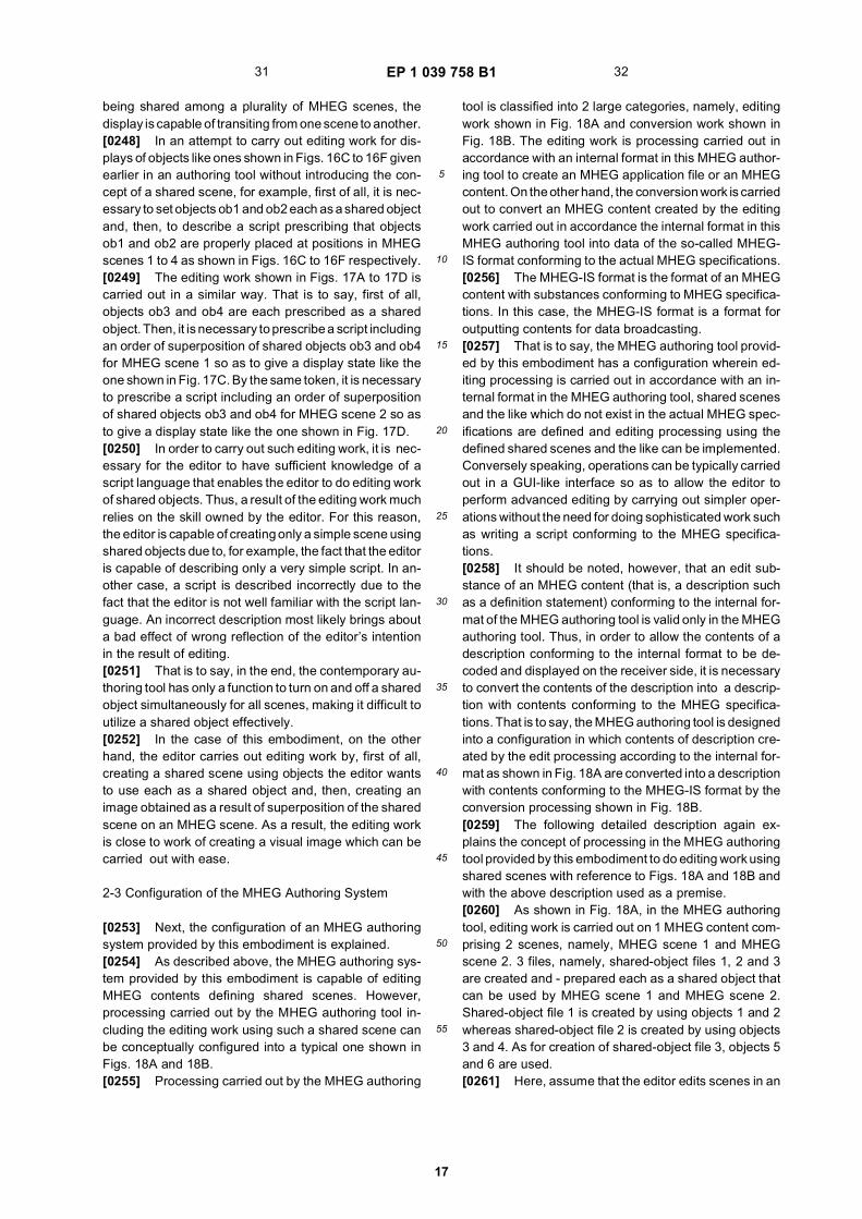
EP 1 039 758 B1
17
5
10
15
20
25
30
35
40
45
50
55
being shared among a plurality of MHEG scenes, thedisplay is capable of transiting from one scene to another.[0248] In an attempt to carry out editing work for dis-plays of objects like ones shown in Figs. 16C to 16F givenearlier in an authoring tool without introducing the con-cept of a shared scene, for example, first of all, it is nec-essary to set objects ob1 and ob2 each as a shared objectand, then, to describe a script prescribing that objectsob1 and ob2 are properly placed at positions in MHEGscenes 1 to 4 as shown in Figs. 16C to 16F respectively.[0249] The editing work shown in Figs. 17A to 17D iscarried out in a similar way. That is to say, first of all,objects ob3 and ob4 are each prescribed as a sharedobject. Then, it is necessary to prescribe a script includingan order of superposition of shared objects ob3 and ob4for MHEG scene 1 so as to give a display state like theone shown in Fig. 17C. By the same token, it is necessaryto prescribe a script including an order of superpositionof shared objects ob3 and ob4 for MHEG scene 2 so asto give a display state like the one shown in Fig. 17D.[0250] In order to carry out such editing work, it is nec-essary for the editor to have sufficient knowledge of ascript language that enables the editor to do editing workof shared objects. Thus, a result of the editing work muchrelies on the skill owned by the editor. For this reason,the editor is capable of creating only a simple scene usingshared objects due to, for example, the fact that the editoris capable of describing only a very simple script. In an-other case, a script is described incorrectly due to thefact that the editor is not well familiar with the script lan-guage. An incorrect description most likely brings abouta bad effect of wrong reflection of the editor’s intentionin the result of editing.[0251] That is to say, in the end, the contemporary au-thoring tool has only a function to turn on and off a sharedobject simultaneously for all scenes, making it difficult toutilize a shared object effectively.[0252] In the case of this embodiment, on the otherhand, the editor carries out editing work by, first of all,creating a shared scene using objects the editor wantsto use each as a shared object and, then, creating animage obtained as a result of superposition of the sharedscene on an MHEG scene. As a result, the editing workis close to work of creating a visual image which can becarried out with ease.
2-3 Configuration of the MHEG Authoring System
[0253] Next, the configuration of an MHEG authoringsystem provided by this embodiment is explained.[0254] As described above, the MHEG authoring sys-tem provided by this embodiment is capable of editingMHEG contents defining shared scenes. However,processing carried out by the MHEG authoring tool in-cluding the editing work using such a shared scene canbe conceptually configured into a typical one shown inFigs. 18A and 18B.[0255] Processing carried out by the MHEG authoring
tool is classified into 2 large categories, namely, editingwork shown in Fig. 18A and conversion work shown inFig. 18B. The editing work is processing carried out inaccordance with an internal format in this MHEG author-ing tool to create an MHEG application file or an MHEGcontent. On the other hand, the conversion work is carriedout to convert an MHEG content created by the editingwork carried out in accordance the internal format in thisMHEG authoring tool into data of the so-called MHEG-IS format conforming to the actual MHEG specifications.[0256] The MHEG-IS format is the format of an MHEGcontent with substances conforming to MHEG specifica-tions. In this case, the MHEG-IS format is a format foroutputting contents for data broadcasting.[0257] That is to say, the MHEG authoring tool provid-ed by this embodiment has a configuration wherein ed-iting processing is carried out in accordance with an in-ternal format in the MHEG authoring tool, shared scenesand the like which do not exist in the actual MHEG spec-ifications are defined and editing processing using thedefined shared scenes and the like can be implemented.Conversely speaking, operations can be typically carriedout in a GUI-like interface so as to allow the editor toperform advanced editing by carrying out simpler oper-ations without the need for doing sophisticated work suchas writing a script conforming to the MHEG specifica-tions.[0258] It should be noted, however, that an edit sub-stance of an MHEG content (that is, a description suchas a definition statement) conforming to the internal for-mat of the MHEG authoring tool is valid only in the MHEGauthoring tool. Thus, in order to allow the contents of adescription conforming to the internal format to be de-coded and displayed on the receiver side, it is necessaryto convert the contents of the description into a descrip-tion with contents conforming to the MHEG specifica-tions. That is to say, the MHEG authoring tool is designedinto a configuration in which contents of description cre-ated by the edit processing according to the internal for-mat as shown in Fig. 18A are converted into a descriptionwith contents conforming to the MHEG-IS format by theconversion processing shown in Fig. 18B.[0259] The following detailed description again ex-plains the concept of processing in the MHEG authoringtool provided by this embodiment to do editing work usingshared scenes with reference to Figs. 18A and 18B andwith the above description used as a premise.[0260] As shown in Fig. 18A, in the MHEG authoringtool, editing work is carried out on 1 MHEG content com-prising 2 scenes, namely, MHEG scene 1 and MHEGscene 2. 3 files, namely, shared-object files 1, 2 and 3are created and - prepared each as a shared object thatcan be used by MHEG scene 1 and MHEG scene 2.Shared-object file 1 is created by using objects 1 and 2whereas shared-object file 2 is created by using objects3 and 4. As for creation of shared-object file 3, objects 5and 6 are used.[0261] Here, assume that the editor edits scenes in an
31 32

EP 1 039 758 B1
18
5
10
15
20
25
30
35
40
45
50
55
environment of the MHEG authoring tool. In this case,MHEG scene 1 is edited by using shared-scene files 1and 2 to produce its desired display format whereasMHEG scene 2 is edited by using a shared-scene file 3to produce its desired display format.[0262] Then, in the MHEG authoring tool, a shared-scene definition statement 1 of shared-scene files 1 and2 is formed as "authoring control information" in accord-ance with actual results of the editing for MHEG scene1 whereas a shared-scene definition statement 2 ofshared-scene file 3 is formed as other "authoring controlinformation" in accordance with the actual results of theediting for MHEG scene 2.[0263] Here, the concept of a shared scene is pre-scribed in the MHEG authoring tool provided by this em-bodiment. However, the prescription itself is not includedin the brief description of the MHEG-IS format. On theother hand, the MHEG-IS system prescribes a descrip-tion format indicating how individual shared objects areused for each MHEG scene.[0264] For this reason, in the processing to output aresult of editing by using a shared scene in the MHEGauthoring tool provided by this embodiment as describedabove, that is, the processing to output a description ofauthoring control information (or shared-scene definitionstatements) in the MHEG-IS format, it is necessary toconvert the description into description contents of ascript (or control information) used in execution of controlin individual shared-object units in accordance with theMHEG description outline.[0265] Thus, in the MHEG authoring tool provided bythis embodiment, the description is converted into an out-put with the MHEG-IS format as shown in Fig. 18B.[0266] In this conversion, first of all, objects 1 to 6 usedin shared-scene files 1, 2 and 3 as shown in the left-hand-side diagram of Fig. 18B are prescribed in an MHEGcontent (or an MHEG application file) as shared objects1 to 6 and controlled as a set of shared objects.[0267] Then, for MHEG scene 1, a link for controllingshared objects 1 to 4 is described in a description filewhich is provided to the MHEG application file as shownin the right-hand-side diagram of Fig. 18B.[0268] By the same token, for MHEG scene 2, a linkfor controlling shared objects 5 and 6 is described in adescription file which is provided to the MHEG applicationfile.[0269] Then, the MHEG application file converted intothe MHEG-IS format as described above is output as acontent for a data broadcast multiplexed in a digital sat-ellite broadcast. If the configuration of the ground station1 shown in Fig. 5 is taken as an example, the MHEGapplication file converted into the MHEG-IS format is dataoutput from the MHEG authoring tool 42 to the DSM-CCencoder 44.[0270] In the reception facility 3, for example, the digitalsatellite broadcast with the content for a data broadcastmultiplexed therein is received by the IRD 12 and sub-jected to processing such as an MHEG decoding process
in the CPU 80 so as to allow the display of a GUI screento be controlled in accordance with the MHEG system.[0271] Let the MHEG contents of the MHEG scenesshown in Figs. 16A to 16F be edited in processing carriedout by using the MHEG authoring tool shown in Figs. 18Aand 18B and be broadcasted as a data broadcast. In thiscase, the IRD 12 outputs and displays an MHEG picturein display formats like the ones shown in Figs. 16C to 16F.[0272] Fig. 19 is a diagram showing a typical actualconfiguration of the MHEG authoring tool provided bythis embodiment.[0273] In actuality, the MHEG authoring tool 42 typi-cally comprises a personal computer 201 and MHEG au-thoring software 210 activated in the personal computer201.[0274] As shown in the figure, the personal computer201 of the MHEG authoring tool 42 physically includeshardware 202.[0275] The hardware 202 comprises a CPU (CentralProcessing Unit) 202a, a RAM (Random-Access Mem-ory) 202b, a ROM 202c and an interface 202d. The CPU202a executes various kinds of control and carries out avariety of operations. The RAM 202b is used for storinginformation such an application program executed by theCPU 202a and data generated as a result of processingcarried out by the CPU 202a. The ROM 202c is used forstoring information required for operations of the person-al computer 201. The interface 202d is provided for fa-cilitating exchanges of information between the hardware202 and external equipment and external operation unitsto be described later.[0276] It should be noted that the hardware 202 mayinclude a variety of other devices.[0277] A basic program is executed on this hardware202 as an operating system 203 to provide an environ-ment that allows MHEG authoring software of this em-bodiment to be executed.[0278] The external equipment and the external oper-ation units connected to the personal computer 201shown in the figure include a display unit 221, a mouse222, a keyboard 223, a speaker 224, a storage device225 and a video unit 226.[0279] The display unit 221 displays a picture outputby the personal computer 201. Specially, in the case ofthis embodiment, a GUI screen for editing work using theMHEG authoring software 210 to be described later isalso displayed.[0280] The mouse 222 and the keyboard 223 eachserve as an operator unit used by the editor for enteringoperation information to the personal computer 201.[0281] The speaker 224 is provided for outputting anaudio signal generated by the personal computer 201 tothe outside.[0282] The storage device 225 is used for storing in-formation required by the personal computer 201. Exam-ples of such information are the operating system 203and predetermined application software such as theMHEG authoring software 210 provided by this embod-
33 34

EP 1 039 758 B1
19
5
10
15
20
25
30
35
40
45
50
55
iment. In the case of this embodiment, the stored infor-mation also includes MHEG contents themselves andobjects used for forming each of the MHEG contents suchas picture files, sound files and text files. The MHEG au-thoring software 210 is executed to create files of theseobjects to be stored in the storage device 225 and tocarry out editing work by using the files of these objects.[0283] It should be noted that, as the storage device225, it is desirable to use a storage unit capable of ac-commodating a relatively large amount of data. A goodexample of such a storage unit is a hard-disc drive. How-ever, the storage device 225 does not have to be a hard-disc drive.[0284] A typical video unit 226 is a VTR which is ca-pable of recording and playing back video informationonto and from a video tape or a video disc.[0285] An example of an MHEG content is a scenechange synchronized with a broadcast program compris-ing pictures and sounds. In processing to edit an MHEGcontent synchronized with such a broadcast program,the video unit 226 can be used typically for playing backthe broadcast program comprising pictures and sounds.[0286] Next, the MHEG authoring software 210 is ex-plained.[0287] As described earlier, the MHEG authoring soft-ware 210 is an application software operating on the per-sonal computer 201. The program is stored in the storagedevice 225.[0288] After being read out from the storage device225 for activation as a program, the MHEG authoringsoftware 210 can be represented as functional blocksshown in the figure.[0289] It should be noted that, even though the figuredoes not explicitly shows relations among the functionalblocks of the MHEG authoring software 210, in actuality,the MHEG authoring software 210 has a configuration inwhich information is exchanged between the functionalblocks so as to allows required functions of the MHEGauthoring software 210 to be executed.[0290] In the MHEG authoring software 210, an objectcreation module 211 is a functional block comprising pro-grams used for creating a file used as an object. Forexample, the editor is capable of creating a file used asan object by using the keyboard 223, the mouse 222 andother components in conjunction with the programs ofthe object creation module 211 or a GUI screen displayedon the display unit 221. If the object created is a picture,for example, the editor is capable of creating the objectby rendering a picture file using functions of the objectcreation module 211. In addition to a picture file, accord-ing to the prescription, the created object may be a textfile or a sound file. In this case, of course, the objectcreation module 211 can be used for forming a text orsound file. An object file created by using the object cre-ation module 211 can be stored and retained in the stor-age device 225.[0291] A shared-scene creation module 212 compris-es programs for creating a shared scene by utilizing ob-
ject files created by using the object creation module 211.[0292] In this case, for example, the editor is capableof creating any arbitrary number of shared scenes aslong as the number is smaller than an upper limit pre-scribed by the MHEG authoring software 210. Much likean object file, a shared scene is created by operating thekeyboard 223, the mouse 222 and other componentswhich are used in conjunction with the programs of theshared-scene creation unit 212 to select any arbitrarynumber of object files created so far.[0293] An MHEG-scene creation module 213 is a func-tional block comprising programs used for creating anMHEG scene. The programs of the MHEG-scene crea-tion module 213 are used for selecting an object file cre-ated by using the object creation module 211 and theselected object file is used for creating an MHEG scene.[0294] Programs of a shared-scene processing mod-ule 216 are executed to perform processing to edit a re-lation between an MHEG scene and a shared scene inaccordance with an operation carried out by the editorfor the GUI screen thereof. To put it in detail, the shared-scene processing module 216 is programs for carryingout editing work such as setting a shared scene on anMHEG scene as shown in Figs. 16A to 16F and specifyingan order of superposing a plurality of shared scenes tobe used on an MHEG scene as shown in Figs. 17A to17D.[0295] For example, a result of editing work is createdby programs of an MHEG-application creation module215 to be explained next as a shared-scene definitionstatement explained earlier by referring to Fig. 18A.[0296] Details of an MHEG content creation module214 are not explained. Briefly speaking, the MHEG con-tent creation module 214 is used for creating a scenarioexplained earlier by referring to Fig. 14 in accordancewith a result of editing predetermined contents of typicallya scene.[0297] The MHEG-application creation module 215 in-tegrates results of editing work carried out by using theobject creation module 211, the shared-scene creationmodule 212, the MHEG-scene creation module 213, theMHEG content creation module 214 and the shared-scene processing module 216 described so far to createan MHEG-application file (or an MHEG content) control-led in accordance with an internal format. In order to im-plement this function, in the MHEG-application creationmodule 215 provided by this embodiment, a descriptionfile containing "authoring control information" also shownearlier in Fig. 18A is generated and an MHEG contentsis controlled in accordance with the internal format. Here,the authoring control information also includes a shared-scene definition statement created on the basis of anediting result produced by the shared-scene processingmodule 216 and a description file of a scenario createdby using the MHEG content creation module 214. In ad-dition, transitions among scenes can also be controlledin accordance with the internal format by using the au-thoring control information described by using the
35 36

EP 1 039 758 B1
20
5
10
15
20
25
30
35
40
45
50
55
MHEG-application creation module 215.[0298] Furthermore, in the case of an edited MHEGcontent for accomplishing switching of a scene output insynchronization with a broadcasting time of a broadcastprogram, control information for the synchronization isalso described as authoring control information. Whenthe authoring control information is converted into a de-scription in the MHEG-IS format as will be described later,the contents of the description of the control informationfor synchronization is also converted and output as well.[0299] Information obtained as an MHEG content cre-ated by using the MHEG-application creation module215 as described above is handled in accordance withan internal format by the MHEG authoring software asexplained earlier by referring to Figs. 18A and 18B.[0300] Then, in this embodiment, an MHEG applicationfile created in accordance with the internal format can beoutput to the external by processing carried out by aninternal-format-file output control module 217 as an in-ternal-format file with the internal format remaining un-changed as it is.[0301] For example, an internal-format file of an MHEGapplication output by the internal-format-file output con-trol module 217 can be stored and retained in the storagedevice 225. By doing so, the internal-format file stored inthe storage device 225 can be transferred later to thepersonal computer 201 which is capable of changing ed-iting contents by execution of the MHEG authoring soft-ware 210.[0302] An MHEG-script output control module 218 re-ceives data of an MHEG-application file created by theMHEG-application creation module 215 in the internalformat and converts the data into a description of a script(or control information) conforming to the actual MHEGspecifications, outputting the description to the external.That is to say, the MHEG-script output control module218 outputs a regular MHEG (MHEG-IS) application file.[0303] Typically, the output of the MHEG-script outputcontrol module 218 is supplied to the DSM-CC encoder44 shown in Fig. 5.[0304] It should be noted that an MHEG application fileof the MHEG-IS format produced by the MHEG-scriptoutput control module 218 can be stored and retained inthe storage device 225. In actuality, an application file ofthe MHEG-IS format stored and retained in the storagedevice 225 is supplied to the DSM-CC encoder 44 em-ployed in the ground station 1 when required.[0305] If the configuration of the MHEG authoring soft-ware explained so far is compared with the processingshown in Figs. 18A and 18B, the functional circuit blocksof the software correspond to the processing accordingto the internal format of the MHEG authoring tool shownin Fig. 18A. As described earlier, the functional circuitblocks are the object creation module 211, the shared-scene creation module 212, the MHEG scene creationmodule 213, the MHEG content creation module 214,the MHEG application creation module 215, the shared-scene processing module 216 and the internal-format file
output control module 217.[0306] In addition, the object creation module 211 cor-responds to the processing shown in Fig. 18B to convertMHEG application information expressed in the internalformat into an MHEG-IS output.
2-4 Typical GUI Screens Displayed as Part of MHEG Authoring Software
[0307] As described above, the MHEG authoring soft-ware 210 provided by this embodiment is application soft-ware running on the personal computer 201. The MHEGauthoring software 210 is also capable of carrying outthe so-called command-line editing typically for describ-ing a script conforming to the MHEG specifications. Inorder to allow a variety of editing operations includingmainly the editing of a shared scene described earlier tobe carried out as visually as possible, the MHEG author-ing software 210 has an operation style embracing theGUI. That is to say, much like various kinds of softwaredeveloped in recent years for personal computers, theMHEG authoring software 210 allows the editor to carryout editing operations by operating the mouse 222 andthe keyboard 223 while looking at an operation screenappearing on the display unit 212.[0308] It should be noted that an operation on an in-terface such as the GUI can be implemented with easeby typically carrying out edit processing according to theinternal format in the MHEG authoring software 210 asdescribed earlier.[0309] Figs. 20A and 20B are diagrams showing a typ-ical display format of a GUI screen for editing operationscarried out by using the MHEG authoring software 210provided by this embodiment. In particular, the figureshows a GUI screen related to shared-scene editingwhich is a characteristic of this embodiment.[0310] In particular, Fig. 20A is a diagram showing atypical basic display format of a GUI screen for creatingan MHEG application file. The picture of the GUI screenis displayed typically on the display unit 221.[0311] As shown in Fig. 20A, the screen displays anMHEG application window WD1 and a shared-scenecontrol window WD2.[0312] The MHEG application window WD1 is a win-dow for visually displaying the structure of an MHEG ap-plication created by the editor. For example, the windowhas a title of "MHEG Application".[0313] In the first place, on the left side of the MHEGapplication window WD1, a column with a title of "Scene"is displayed for presenting a list of MHEG scenes con-stituting this MHEG application. In this example, thescene column displays 5 MHEG scenes, namely MHEGscenes 1 to 5.[0314] It should be noted that, in case there are toomany MHEG scenes constituting 1 MHEG application sothat all the MHEG scenes can not be accommodated inthe display area of the MHEG application window WD1,the MHEG application window WD1 can be displayed for
37 38
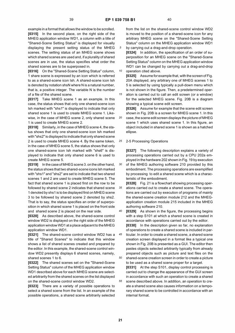
EP 1 039 758 B1
21
5
10
15
20
25
30
35
40
45
50
55
example in a format that allows the window to be scrolled.[0315] In the second place, on the right side of theMHEG application window WD1, a column with a title of"Shared-Scene Setting Status" is displayed for visuallydisplaying the present setting status of the MHEGscenes. The setting status of an MHEG scene showswhich shared scenes are used and, if a plurality of sharedscenes are in use, the status specifies what order theshared scenes are to be superposed in.[0316] On the "Shared-Scene Setting Status" column,1 share scene is expressed by an icon which is referredto as a shared-scene icon Ish. A shared-scene icon Ishis denoted by notation shsN where N is a natural number,that is, a positive integer. The variable N is the numberof a file of the shared scene.[0317] Take MHEG scene 1 as an example. In thiscase, the status shows that only one shared-scene iconIsh marked with "shs1" is displayed to indicate that onlyshared scene 1 is used to create MHEG scene 1. Like-wise, in the case of MHEG scene 2, only shared scene1 is used to create MHEG scene 2.[0318] Similarly, in the case of MHEG scene 4, the sta-tus shows that only one shared-scene icon Ish markedwith "shs2" is displayed to indicate that only shared scene2 is used to create MHEG scene 4. By the same token,in the case of MHEG scene 5, the status shows that onlyone shared-scene icon Ish marked with "shs6" is dis-played to indicate that only shared scene 6 is used tocreate MHEG scene 5.[0319] In the case of MHEG scene 3. on the other hand,the status shows that two shared-scene icons Ish markedwith "shs1" and "shs2" are set to indicate that two sharedscenes 1 and 2 are used to create MHEG scene 5. Thefact that shared scene 1 is placed first on the row to befollowed by shared scene 2 indicates that shared scene1 denoted by shs1 is to be displayed first on MHEG scene3 to be followed by shared scene 2 denoted by shs2.That is to say, the status specifies an order of superpo-sition in which shared scene 1 is placed on the front sideand shared scene 2 is placed on the rear side.[0320] As described above, the shared-scene controlwindow WD2 is displayed on the right side of the MHEGapplication window WD1 at a place adjacent to the MHEGapplication window WD1.[0321] The shared-scene control window WD2 has atitle of "Shared Scenes" to indicate that this windowshows a list of shared scenes created and prepared bythe editor. In this example, the shared-scene control win-dow WD2 presently displays 6 shared scenes, namely,shared scenes 1 to 6.[0322] The shared scenes set on the "Shared-SceneSetting Status" column of the MHEG application windowWD1 described above for each MHEG scene are select-ed arbitrarily from the shared scenes on the list displayedon the shared-scene control window WD2.[0323] There are a variety of possible operations toselect a shared scene from the list. In an example of thepossible operations, a shared scene arbitrarily selected
from the list on the shared-scene control window WD2is moved to the position of a shared-scene icon for anyarbitrary MHEG scene on the "Shared-Scene SettingStatus" column on the MHEG application window WD1by carrying out a drag-and-drop operation.[0324] In addition, the specification of an order of su-perposition for an MHEG scene on the "Shared-SceneSetting Status" column on the MHEG application windowWD1 can be changed by carrying out a drag-and-dropoperation cited above.[0325] Assume for example that, with the screen of Fig.20A displayed, any arbitrary one of MHEG scenes 1 to5 is selected by using typically a pull-down menu whichis not shown in the figure. Then, a predetermined oper-ation is carried out to call an edit screen (or a window)for the selected MHEG scene. Fig. 20B is a diagramshowing a typical scene edit screen.[0326] Assume for example that the scene edit screenshown in Fig. 20B is a screen for MHEG scene 1. In thiscase, the scene edit screen displays the picture of MHEGscene 1 which uses shared scene 1. In this figure, anobject included in shared scene 1 is shown as a hatchedellipse.
2-5 Processing Operations
[0327] The following description explains a variety ofprocessing operations carried out by a CPU 202a em-ployed in the hardware 202 shown in Fig. 19 by executionof the MHEG authoring software 210 provided by thisembodiment. The processing operations are exemplifiedby processing to edit a shared scene which is a charac-teristic of the embodiment.[0328] Fig. 21 is a flowchart showing processing oper-ations carried out to create a shared scene. The opera-tions are carried out by execution of programs of mainlythe shared-scene creation module 212 and the MHEG-application creation module 215 included in the MHEGauthoring software 210.[0329] As shown in the figure, the processing beginswith a step S101 at which a shared scene is created inaccordance with operations carried out by the editor.[0330] In the description given so far, no explanationof operations to create a shared scene is included in par-ticular. In order to create a shared scene, a shared scenecreation screen displayed in a format like a typical oneshown in Fig. 20B is presented as a GUI. The editor thenpastes objects selected arbitrarily typically from alreadyprepared objects such as picture and text files on theshared-scene creation screen in order to create a pictureto be used as a shared scene proper for a target.[0331] At the step S101, display control processing iscarried out to change the appearance of the GUI screenin accordance with such an operation to create a sharedscene described above. In addition, an operation to cre-ate a shared scene also causes information on a tempo-rary shared scene to be controlled in accordance with aninternal format.
39 40

EP 1 039 758 B1
22
5
10
15
20
25
30
35
40
45
50
55
[0332] In this embodiment, a variety of editing resultsfor an MHEG application typically including sharedscenes are controlled in the MHEG-application creationmodule 215 by being described as authoring control in-formation according to the internal format.[0333] Then, at a step S102, a description accordingto contents of the shared scene created at the step S101is written as the authoring control information accordingto the internal format.[0334] Subsequently, at a step S103, the shared scenecreated at the step S101 is controlled as a file. To put itconcretely, the shared scene is stored and retained typ-ically in the storage device 225. It should be noted, how-ever, that information contained in the stored file of theshared scene also conforms to the internal format.[0335] The processing up to this point is carried out tocreate a certain shared scene which can be stored as afile conforming to the internal format. Then, this proce-dure (or processing) is carried out for each shared sceneso as to allow shared-scene files required for creationof an MHEG scene to be prepared. It should be notedthat a directory of shared-scene files stored in this wayis controlled as authoring control information in theMHEG-application creation module 215.[0336] Fig. 22 is a diagram showing processing oper-ations so set a shared scene for an MHEG scene. Theoperations are carried out by execution of programs ofmainly the shared-scene processing module 216 and theMHEG-application creation module 215.[0337] At a stage prior to the processing shown in Fig.22, MHEG scenes and shared scenes are prepared tocreate 1 MHEG content. It should be noted that the cre-ation of an MHEG scene itself is not described before.The creation of an MHEG scene is implemented in a con-figuration in which an MHEG-scene creation screen hav-ing a format like the one shown in Fig. 20B describedbefore is displayed, and the editor then creates an MHEGscene on the screen. In the creation of an MHEG scene,the MHEG-scene creation module 213 functions.[0338] As shown in Fig. 22, the processing begins witha step S201 at which processing to set shared scenesfor each MHEG scene is carried out in accordance withan operation performed by the editor.[0339] That is to say, in accordance with an operationto set shared scenes for an MHEG scene as describedearlier, processing is carried out, for among other pur-poses, to output a GUI picture like the one shown in Figs.20A and 20B as a result of editing. In the operation to setshared scenes for an MHEG scene, shared scenes to beused for the MHEG scene and an order of superpositionof the shared scenes are specified.[0340] Then, when shared scenes are set for a certainMHEG scene as described above, the setting of theshared scenes for the MHEG scene is described as au-thoring control information at a step S202. To put it con-cretely, a shared-scene definition statement explainedearlier by referring to Figs. 18A and 18B is created.[0341] In actuality, the processing shown in Fig. 22 is
carried out for each MHEG scene. Then, the setting ofshared scenes for each MHEG scene obtained as a resultof operations carried out by the editor during suchprocessing is described by the MHEG-application crea-tion module 215 as authoring control information.[0342] The pieces of processing shown in Figs. 21 and22 are thus processing carried out by execution of theMHEG authoring software 210 in accordance with an in-ternal format to edit an MHEG application provided bythis embodiment by creation of shared scenes and set-ting the shared scenes for each MHEG scene.[0343] It should be noted that authoring control infor-mation created in the pieces of processing shown in Figs.21 and 22 can be stored in the storage device 225 asinformation on an MHEG application according to the in-ternal format along with typically a variety of files usedmainly as objects through processing of the internal-for-mat-file output control module 217. It is worth noting, how-ever, that operations of the processing of the internal-format-file output control module 217 are not shown ex-plicitly in Figs. 21 and 22.[0344] In order to output an MHEG application con-forming to the internal format as described above as adata content for broadcasting, that is, in order to outputcontent information controlled by authoring control infor-mation as a broadcasting data content, it is necessary toconvert the format of the MHEG application into anMHEG-IS format as has been described earlier by refer-ring to Figs. 18A and 18B. In the following description,description contents of a script conforming to the MHEG-IS format is referred to as an MHEG-IS script. The fol-lowing description explains processing to convert infor-mation on an MHEG application from the internal formatinto the MHEG-IS format of an MHEG script with refer-ence to Figs. 23 and 24. This conversion processing isprocessing to be carried out in an environment where theMHEG authoring software 210 is executed.[0345] It should be noted, however, that the explana-tion of the conversion processing is limited in this caseto a shared scene or a shared object which is a charac-teristic of this embodiment.[0346] In addition, the processing described below iscarried out by executing programs of the MHEG-scriptoutput control module 218.[0347] Fig. 23 is a diagram showing preparatoryprocessing to output a result of editing a shared sceneas an MHEG script. Typically, after this preparatoryprocessing is completed, the conversion processingshown in Fig. 24 is actually carried out to produce anMHEG script.[0348] As shown in Fig. 23, the processing begins witha step S301 to fetch information on an MHEG applicationdescribed in the internal format of the MHEG authoringsoftware 210. Here, for a purpose of confirmation, inprocessing conforming to the internal format, shared ob-jects are controlled in authoring control information asobjects forming a shared scene.[0349] Then, at a next step S302, the contents of the
41 42

EP 1 039 758 B1
23
5
10
15
20
25
30
35
40
45
50
55
MHEG application fetched at the step S301 are analyzedto acquire all shared scenes which are included in thisMHEG application and set for use in MHEG scenes ofthe MHEG application.[0350] Subsequently, at a step S303, processing iscarried out to set all the objects used in the shared scenesobtained at the step S302 in the MHEG application (orthe MHEG script) as shared objects.[0351] To put it concretely, the following MHEG scriptis described in this processing.[0352] In the MHEG script, a shared object is definedby a description of a "Shared" parameter which repre-sents an attribute of the object as follows.Shared = Trueindicates that the object is prescribed as a shared object.[0353] On the other hand,Shared = Falseindicates that the object is prescribed to be not a sharedobject.[0354] Thus, at the step S303, the attribute of eachobject used in the shared scenes obtained at the stepS302 is described as follows:Shared = True[0355] By describing the attribute in this way, all theobjects are each treated as a shared object.[0356] As another parameter of an object, Initially Ac-tive is defined. The Initially Active parameter is a param-eter set to indicate whether the object is active or inactivein an initial state in an MHEG scene or an MHEG appli-cation.Initially Active = Trueindicates that the object is active initially.[0357] On the other hand,Initially Active = Falseindicates that the object is inactive initially.[0358] Finally, at a step S304, for each of the sharedobjects set at the step S303, this parameter is set asfollows.Initially Active = FalseThat is to say, each of the shared objects is inactive ini-tially.[0359] Next, processing shown in Fig. 24 is explained.[0360] As shown in the figure, the processing beginswith a step S401 at which the preparatory processingexplained earlier by referring to Fig. 23 is carried out.[0361] When the preparatory processing is completed,the processing flow goes on to a step S402.[0362] At the step S402, a fetched MHEG applicationis examined to form a judgment as to whether or not oneor more MHEG scenes are set and used in the MHEGapplication. Typically, the judgment is formed by referringto authoring control information conforming to the internalformat.[0363] If the outcome of the judgment indicates thatMHEG scenes to be used are not set in the MHEG ap-plication, no processing is specially required for sharedscenes. In this case, the processing is ended. If the out-come of the judgment indicates that MHEG scenes to be
used are set in the MHEG application, on the other hand,the flow of the processing goes on to a step S403.[0364] At the step S403, the MHEG application ischecked to form a judgment as to whether or not thereis still an unselected MHEG scene which remains to besubjected to hereafter processing to convert a sharedscene into a shared object. Thus, when the flow goes onfrom the step S402 to the step S403 for the first time, theresult of the judgment formed at the step S403 certainlyindicates that there is an MHEG scene to be subjectedto such conversion processing. In this case, the flow ofthe processing proceeds to a step S404.[0365] At the step S404, one of presently set MHEGscenes is selected and the authoring control informationof the selected MHEG scene is fetched as an object ofprocessing. Typically, an MHEG scene is selected se-quentially according to an MHEG-scene sequencenumber.[0366] It should be noted that MHEG scenes once se-lected before at the step S404 are no longer subjectedto the subsequent processing.[0367] At the step S405, a link is described as anMHEG script to indicate that all shared objects are to bestopped (turned off) at activation of this MHEG scene.To put it concretely, for all shared objects included in theMHEG application, an MHEG script regarding shared ob-jects for this MHEG scene is described as follows:Initially Active = False[0368] The prescription obtained as an actual editingresult thus indicates that, in this MHEG scene, sharedobjects are not used at all.[0369] At a step S406, the authoring control informa-tion (or shared-scene definition statements) of the se-lected MHEG scene fetched at the step S404 is referredto in order to form a judgment as to whether or not thereis a shared scene set for the MHEG scene.[0370] If the result of the judgment formed at the stepS406 is a negation, that is, if there is no shared sceneset for the MHEG scene, the flow of the processing goesback to the step S403.[0371] If the result of the judgment formed at the stepS406 indicates that there is a shared scene set for theMHEG scene, on the other hand, the flow of the process-ing goes on to a step S407.[0372] At the step S407, the MHEG scene is checkedto form a judgment as to whether or not there is still anunselected shared scene which remains to be subjectedto the following processing to convert the shared sceneinto a shared object. Thus, when the flow goes on fromthe step S405 to the step S406 for the first time, the resultof the judgment formed at the step S407 certainly indi-cates that there is a shared scene to be subjected to suchconversion processing. In this case, the flow of theprocessing proceeds to a step S408.[0373] At the step S408, one of unselected MHEGscenes remaining as an object of the conversion process-ing is selected. To put it in detail, processing is carriedout to select and fetch the description contents such as
43 44

EP 1 039 758 B1
24
5
10
15
20
25
30
35
40
45
50
55
a shared-scene definition statement on a shared scenewhich has been specified placed at the rearmost end.[0374] It should be noted that shared scenes once se-lected before at the step S408 are no longer subjectedto the subsequent processing.[0375] Next, at a step S409, processing is carried outto describe a link as an MHEG script to run or turn onshared objects included in the shared scene fetched atthe step S408 at activation of the MHEG scene fetchedat the step S404 as a current processing object. In orderto describe a link to run shared objects, typically, the fol-lowing is described for each of the shared objects.Initially Active = True[0376] As a result, the MHEG script prescribes that theshared objects serving as a material of the shared scenefetched at the step S408 be put in an active state at ac-tivation of the MHEG scene and displayed at proper po-sitions on the display screen.[0377] As the processing of the step S409 is complet-ed, the flow goes back to the step S407. If the result ofthe judgment formed at the step S407 indicates that thereis a shared scene to be subjected to such conversionprocessing, the flow of the processing proceeds to thestep S408 to carry out the processing of the step S408and the subsequent processing.[0378] The pieces of processing of the steps S407 toS409 are carried out repeatedly for a selected andfetched MHEG scene as many times as shared scenesset for the MHEG scene.[0379] By carrying out the pieces of processing of thesteps S407 to S409 repeatedly, it is possible to obtaindescription contents of an MHEG script specifying utili-zation of shared objects in a certain MHEG scene in ac-cordance with results of work carried out earlier by theeditor to edit shared scenes. At the same time, it is alsopossible to obtain description contents of an MHEG scriptspecifying an order of superposition of the shared ob-jects.[0380] As described above, the pieces of processingof the steps S407 to S409 are carried out repeatedly foran MHEG scene as many times as shared scenes setfor the MHEG scene. As the result of the outcome formedat the step S407 indicates a negation, the flow of theprocessing goes back to the step S403.[0381] When the flow of the processing returns to thestep S403 from the step S409 or S406 and the result ofthe judgment formed at the step S403 indicates that thereis an MHEG scene left as an object of the conversionprocessing, the flow goes on to the step S404 to carryout the processing of the step 404 and the subsequentprocessing.[0382] That is to say, the pieces of processing of thesteps S403 to S409 are carried out repeatedly for anMHEG application file (or an MHEG content) as manytimes as MHEG scenes created for the MHEG content.[0383] After the pieces of processing of the steps S403to S409 have been carried out repeatedly for an MHEGcontent as many times as MHEG scenes created for the
MHEG content, the outcome of the judgment formed atthe step S403 indicates a negation. In this case, theprocessing is ended.[0384] In this way, at the stage the processing carriedout so far is ended, an internal-format result of editingwork performed by using the MHEG authoring softwarein accordance with operations carried out by the editorhas been converted into description contents of anMHEG script conforming to the MHEG-IS format.[0385] It should be noted that the pieces of processingshown in Figs. 23 and 24 are part of processing of theMHEG-script output control module 218 to convert theinternal format of a description of an MHEG content intothe MHEG-IS format. As described above, objects of thepieces of processing shown in Figs. 23 and 24 are limitedto shared objects only.[0386] Thus, in actuality, processing to convert the in-ternal format into the MHEG-IS format for an editing resultof an MHEG content other than the shared scene is car-ried out concurrently with the pieces of processing shownin Figs. 23 and 24.[0387] In addition, the pieces of processing shown inFigs. 23 and 24 are each typical processing to the bitterend. There are other conceivable processing proceduresfor converting description contents with the internal for-mat of the MHEG authoring software using the conceptof shared scenes into description contents with theMHEG-IS format based on the concept of shared objects.[0388] The above embodiment is exemplified by a casein which a data broadcast content in the digital satellitebroadcasting is created in accordance with the MHEGspecifications. In addition, a content created by thepresent invention can also be used in media other thanthe digital satellite broadcasting system. As for the media,a recording medium such as a CD-ROM can also be usedin addition to distribution through a broadcasting systemand a network.[0389] Furthermore, while the embodiment is exempli-fied by a case in which an MHEG content is edited, thepresent invention can also be applied to applications oth-er than the MHEG system provided that the other appli-cations conform to specifications for creating an interfacepicture (a content) introducing a concept similar to forexample the concept of a shared object.[0390] As described above, the present invention de-fines a shared scene that can be created by using anyarbitrary objects as a virtual scene usable as a scenecommon to scenes instead of directly handling the sharedobject on an authoring tool in editing work to create acontent conforming to typically the MHEG specifications.In addition, the present invention is used for editingscenes in shared-scene units. Then, a result of the editingwork using the shared scene is finally converted into de-scription contents for controlling a shared object itself inaccordance with specifications for a content for broad-casting.[0391] With such a configuration, an editor creating acontent is capable of handing a shared object by carrying
45 46
EP 1 039 758 B1
25
5
10
15
20
25
30
35
40
45
50
55
out operations to combine shared scenes created arbi-trarily for a scene at an editing-operation stage using theauthoring tool. Conversely speaking, it is not necessaryfor the editor to do work requiring advance knowledge ofan MHEG script such as description of an MHEG scriptfor specifying a display format of a shared object fromthe beginning by using the authoring tool.[0392] Thus, by virtue of the present invention, the ed-itor is capable of editing a scene using a shared objectwith ease and with a high degree of accuracy even if theeditor is not familiar with rules of an MHEG script, forexample. As a result, the present invention provides aneffect to give the editor a capability of creating a scenein a number of display formats through editing operationswhich are easy to understand.[0393] In addition, as described above, the present in-vention provides a system of editing operations in whicha shared object is handled for each shared scene and,in addition, an order of superposition of shared scenescan be specified. As a result, it is possible to simplify acomparatively complicated edit operation of specifyingan order of superposition of objects.[0394] In so far as the embodiments of the inventiondescribed above are implemented, at least in part, usingsoftware-controlled data processing apparatus, it will beappreciated that a computer program providing such soft-ware control and a storage medium by which such a com-puter program is stored are envisaged as aspects of thepresent invention.
Claims
1. An information processing apparatus (42) compris-ing an authoring tool arranged for a user to createmultimedia content which conforms to a predeter-mined specification such as MHEG, wherein the con-tent is formed of application scenes, wherein an ap-plication scene includes (i) one or more objects rep-resenting information such as a picture, sound ortext and (ii) control information for controlling an out-put format of the object(s) in the application scene,said predetermined specification defining a sharedobject which can be used by being shared among aplurality of application scenes;said authoring tool comprising:
a shared-scene creation means (212) for the us-er to create a shared scene by using an objectfile such as a picture, sound or text file, wherebya shared scene can be superimposed onto aplurality of screens, wherein a screen is createdfrom one or more object files such as a picture,sound or text file;a shared-scene setting means (216) for the userto set, for each of said screens, one or morespecific shared scenes to be used in that screen,wherein the specific shared scenes are selected
by the user from the shared scenes created bysaid shared-scene creation means;means (215,216) for producing a shared scenedefinition statement for each screen, whereinthe definition statement describes the setting ofthe specific shared scenes for the screen; andmeans (218) for converting an internal format ofthe multimedia content including said screens,shared scenes, and shared scene definitionstatements into the Multimedia content compris-ing application scenes with control informationin accordance with said predetermined specifi-cation by using said shared scene definitionstatements to:
set all objects used in said specific sharedscenes as shared objects; and control astate of utilization of the set shared objectsin the application scenes.
2. An information processing apparatus according toclaim 1, wherein:
in setting shared scenes for each of saidscreens, said shared-scene setting means canbe used for specifying an order of superpositionof a plurality of said set shared scenes; andsaid means (218) for converting outputs saidcontrol information for controlling an order of su-perposition of the set shared objects in the ap-plication scenes in accordance with said orderof superposition.
Patentansprüche
1. Informationsverarbeitungsvorrichtung (42), die einAuthoring-Tool umfasst, das ausgelegt ist, damit einBenutzer Multimedia-Inhalt erzeugt, der einer vor-bestimmten Spezifikation wie etwa MHEG ent-spricht, wobei der Inhalt aus Anwendungsszenenausgebildet ist, wobei eine Anwendungsszene (i) einoder mehrere Objekte, die Informationen wie etwaein Bild, Ton oder Text darstellen, und (ii) Steuerin-formationen zum Steuern eines Ausgabeformatsdes oder der Objekte in der Anwendungsszene ent-hält, wobei die vorbestimmte Spezifikation ein ge-meinsames Objekt definiert, das verwendet werdenkann, indem es unter mehreren Anwendungsszenengemeinsam verwendet wird;wobei das Authoring-Tool Folgendes umfasst:
ein Gemeinsame-Szene-Erzeugungsmittel(212), damit der Benutzer eine gemeinsameSzene durch Verwenden einer Objektdatei wieetwa einer Bild-, Ton- oder Textdatei erzeugenkann, wodurch eine gemeinsame Szene meh-reren Schirmen überlagert werden kann, wobei
47 48
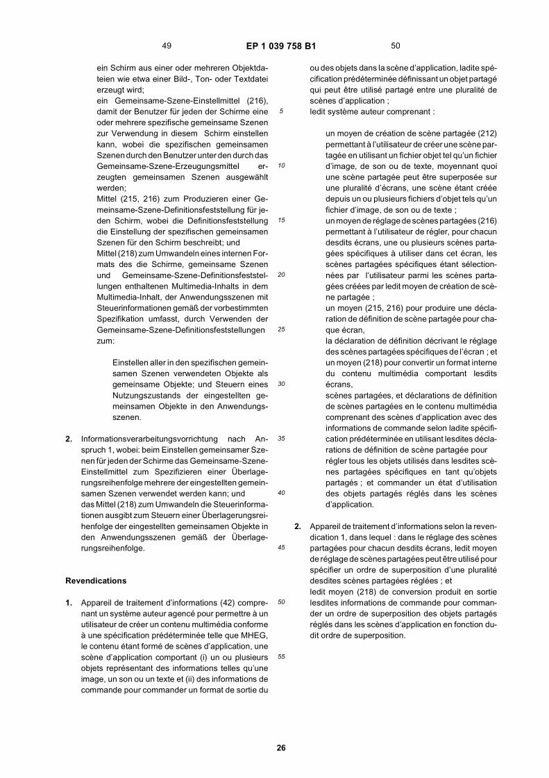
EP 1 039 758 B1
26
5
10
15
20
25
30
35
40
45
50
55
ein Schirm aus einer oder mehreren Objektda-teien wie etwa einer Bild-, Ton- oder Textdateierzeugt wird;ein Gemeinsame-Szene-Einstellmittel (216),damit der Benutzer für jeden der Schirme eineoder mehrere spezifische gemeinsame Szenenzur Verwendung in diesem Schirm einstellenkann, wobei die spezifischen gemeinsamenSzenen durch den Benutzer unter den durch dasGemeinsame-Szene-Erzeugungsmittel er-zeugten gemeinsamen Szenen ausgewähltwerden;Mittel (215, 216) zum Produzieren einer Ge-meinsame-Szene-Definitionsfeststellung für je-den Schirm, wobei die Definitionsfeststellungdie Einstellung der spezifischen gemeinsamenSzenen für den Schirm beschreibt; undMittel (218) zum Umwandeln eines internen For-mats des die Schirme, gemeinsame Szenenund Gemeinsame-Szene-Definitionsfeststel-lungen enthaltenen Multimedia-Inhalts in demMultimedia-Inhalt, der Anwendungsszenen mitSteuerinformationen gemäß der vorbestimmtenSpezifikation umfasst, durch Verwenden derGemeinsame-Szene-Definitionsfeststellungenzum:
Einstellen aller in den spezifischen gemein-samen Szenen verwendeten Objekte alsgemeinsame Objekte; und Steuern einesNutzungszustands der eingestellten ge-meinsamen Objekte in den Anwendungs-szenen.
2. Informationsverarbeitungsvorrichtung nach An-spruch 1, wobei: beim Einstellen gemeinsamer Sze-nen für jeden der Schirme das Gemeinsame-Szene-Einstellmittel zum Spezifizieren einer Überlage-rungsreihenfolge mehrere der eingestellten gemein-samen Szenen verwendet werden kann; unddas Mittel (218) zum Umwandeln die Steuerinforma-tionen ausgibt zum Steuern einer Überlagerungsrei-henfolge der eingestellten gemeinsamen Objekte inden Anwendungsszenen gemäß der Überlage-rungsreihenfolge.
Revendications
1. Appareil de traitement d’informations (42) compre-nant un système auteur agencé pour permettre à unutilisateur de créer un contenu multimédia conformeà une spécification prédéterminée telle que MHEG,le contenu étant formé de scènes d’application, unescène d’application comportant (i) un ou plusieursobjets représentant des informations telles qu’uneimage, un son ou un texte et (ii) des informations decommande pour commander un format de sortie du
ou des objets dans la scène d’application, ladite spé-cification prédéterminée définissant un objet partagéqui peut être utilisé partagé entre une pluralité descènes d’application ;ledit système auteur comprenant :
un moyen de création de scène partagée (212)permettant à l’utilisateur de créer une scène par-tagée en utilisant un fichier objet tel qu’un fichierd’image, de son ou de texte, moyennant quoiune scène partagée peut être superposée surune pluralité d’écrans, une scène étant crééedepuis un ou plusieurs fichiers d’objet tels qu’unfichier d’image, de son ou de texte ;un moyen de réglage de scènes partagées (216)permettant à l’utilisateur de régler, pour chacundesdits écrans, une ou plusieurs scènes parta-gées spécifiques à utiliser dans cet écran, lesscènes partagées spécifiques étant sélection-nées par l’utilisateur parmi les scènes parta-gées créées par ledit moyen de création de scè-ne partagée ;un moyen (215, 216) pour produire une décla-ration de définition de scène partagée pour cha-que écran,la déclaration de définition décrivant le réglagedes scènes partagées spécifiques de l’écran ; etun moyen (218) pour convertir un format internedu contenu multimédia comportant lesditsécrans,scènes partagées, et déclarations de définitionde scènes partagées en le contenu multimédiacomprenant des scènes d’application avec desinformations de commande selon ladite spécifi-cation prédéterminée en utilisant lesdites décla-rations de définition de scène partagée pourrégler tous les objets utilisés dans lesdites scè-nes partagées spécifiques en tant qu’objetspartagés ; et commander un état d’utilisationdes objets partagés réglés dans les scènesd’application.
2. Appareil de traitement d’informations selon la reven-dication 1, dans lequel : dans le réglage des scènespartagées pour chacun desdits écrans, ledit moyende réglage de scènes partagées peut être utilisé pourspécifier un ordre de superposition d’une pluralitédesdites scènes partagées réglées ; etledit moyen (218) de conversion produit en sortielesdites informations de commande pour comman-der un ordre de superposition des objets partagésréglés dans les scènes d’application en fonction du-dit ordre de superposition.
49 50

EP 1 039 758 B1
27

EP 1 039 758 B1
28

EP 1 039 758 B1
29

EP 1 039 758 B1
30

EP 1 039 758 B1
31

EP 1 039 758 B1
32
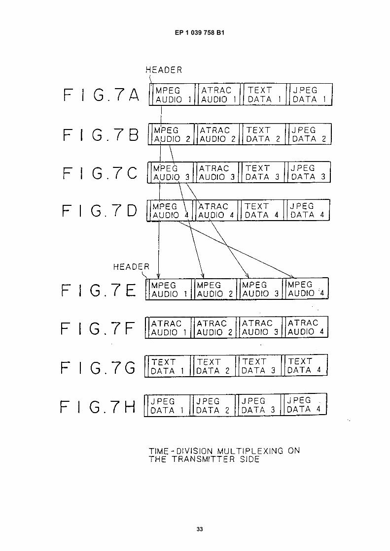
EP 1 039 758 B1
33
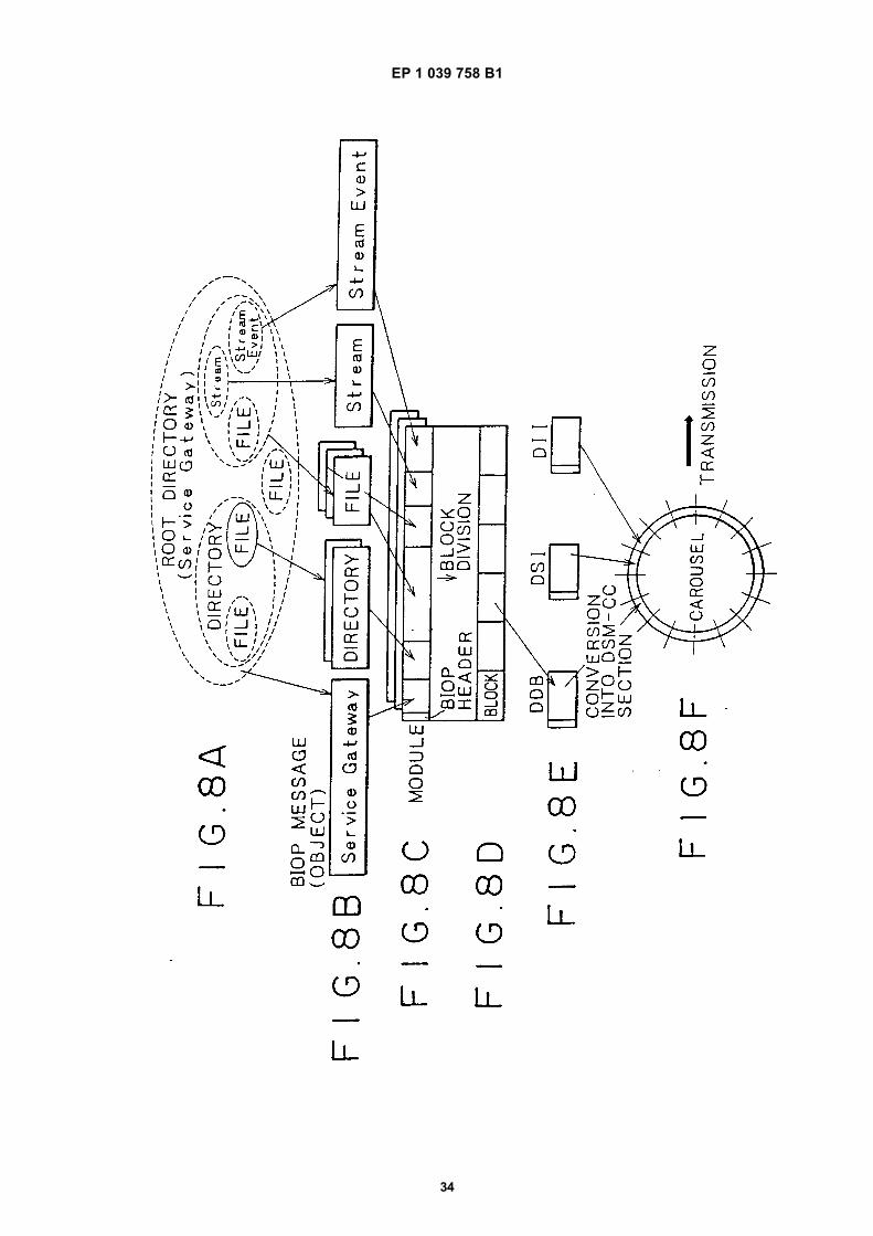
EP 1 039 758 B1
34

EP 1 039 758 B1
35

EP 1 039 758 B1
36

EP 1 039 758 B1
37

EP 1 039 758 B1
38
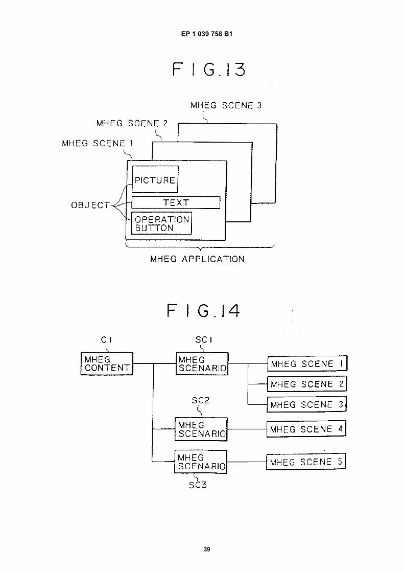
EP 1 039 758 B1
39

EP 1 039 758 B1
40

EP 1 039 758 B1
41

EP 1 039 758 B1
42
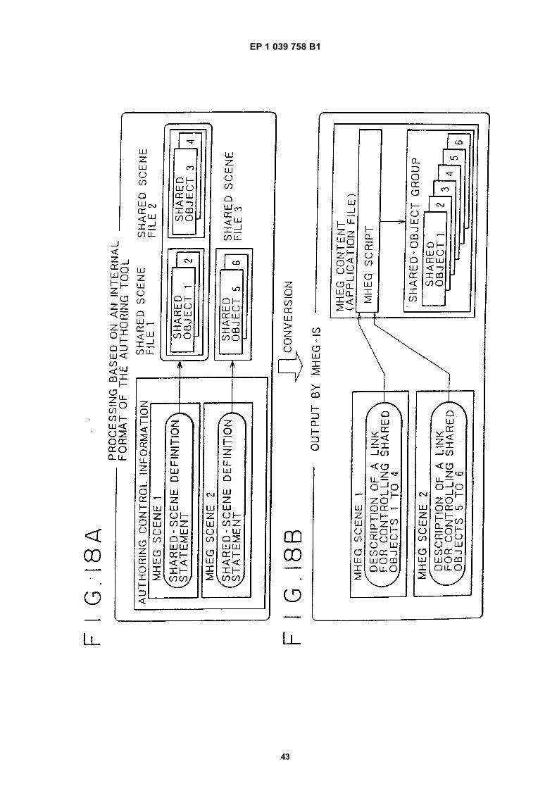
EP 1 039 758 B1
43

EP 1 039 758 B1
44

EP 1 039 758 B1
45

EP 1 039 758 B1
46

EP 1 039 758 B1
47

EP 1 039 758 B1
48

EP 1 039 758 B1
49

EP 1 039 758 B1
50
REFERENCES CITED IN THE DESCRIPTION
This list of references cited by the applicant is for the reader’s convenience only. It does not form part of the Europeanpatent document. Even though great care has been taken in compiling the references, errors or omissions cannot beexcluded and the EPO disclaims all liability in this regard.
Patent documents cited in the description
• EP 827112 A [0022]
Non-patent literature cited in the description
• LEIDIG ; ROSCH. Authoring MHEG Presentationswith the GLASS-Studio. Proceedings from the Inter-national Workshop on Multimedia Software Develop-ment, 1996, ISBN 0-8186-7511-X [0019]
• VAZIRGIANNIS ; MOURLAS. An Object-OrientedModel for Interactive Multimedia Presentations. TheComputer Journal, 1993, vol. 36-1 [0020]
• SEUNGTAEK OH et al. Experiments with MHEGPlayer/Studio: An Interactive Hypermedia Visualiza-tion and Authoring System. EuroMicro confererence,1998, ISBN 0-8186-8646-4, 610-615 [0021]