Embed Size (px)
Citation preview

by Greg Jankowski and Richard Doyle
SolidWorks®
FOR
DUMmIES‰
2ND EDITION
01_129784 ffirs.qxp 9/28/07 11:57 AM Page iii

01_129784 ffirs.qxp 9/28/07 11:57 AM Page ii

SolidWorks®
FOR
DUMmIES‰
2ND EDITION
01_129784 ffirs.qxp 9/28/07 11:57 AM Page i
Dow
nlo
ad fro
m W
ow
! eBook
<w
ww
.wow
ebook.
com
>

01_129784 ffirs.qxp 9/28/07 11:57 AM Page ii

by Greg Jankowski and Richard Doyle
SolidWorks®
FOR
DUMmIES‰
2ND EDITION
01_129784 ffirs.qxp 9/28/07 11:57 AM Page iii

SolidWorks® For Dummies®, 2nd EditionPublished byWiley Publishing, Inc.111 River StreetHoboken, NJ 07030-5774www.wiley.com
Copyright © 2008 by Wiley Publishing, Inc., Indianapolis, Indiana
Published by Wiley Publishing, Inc., Indianapolis, Indiana
Published simultaneously in Canada
No part of this publication may be reproduced, stored in a retrieval system or transmitted in any form orby any means, electronic, mechanical, photocopying, recording, scanning or otherwise, except as permit-ted under Sections 107 or 108 of the 1976 United States Copyright Act, without either the prior writtenpermission of the Publisher, or authorization through payment of the appropriate per-copy fee to theCopyright Clearance Center, 222 Rosewood Drive, Danvers, MA 01923, (978) 750-8400, fax (978) 646-8600.Requests to the Publisher for permission should be addressed to the Legal Department, Wiley Publishing,Inc., 10475 Crosspoint Blvd., Indianapolis, IN 46256, (317) 572-3447, fax (317) 572-4355, or online athttp://www.wiley.com/go/permissions.
Trademarks: Wiley, the Wiley Publishing logo, For Dummies, the Dummies Man logo, A Reference for theRest of Us!, The Dummies Way, Dummies Daily, The Fun and Easy Way, Dummies.com, and related tradedress are trademarks or registered trademarks of John Wiley & Sons, Inc. and/or its affiliates in the UnitedStates and other countries, and may not be used without written permission. SolidWorks is a registeredtrademark of SolidWorks Corporation. All other trademarks are the property of their respective owners.Wiley Publishing, Inc., is not associated with any product or vendor mentioned in this book.
LIMIT OF LIABILITY/DISCLAIMER OF WARRANTY: THE PUBLISHER AND THE AUTHOR MAKE NO REP-RESENTATIONS OR WARRANTIES WITH RESPECT TO THE ACCURACY OR COMPLETENESS OF THECONTENTS OF THIS WORK AND SPECIFICALLY DISCLAIM ALL WARRANTIES, INCLUDING WITHOUTLIMITATION WARRANTIES OF FITNESS FOR A PARTICULAR PURPOSE. NO WARRANTY MAY BE CRE-ATED OR EXTENDED BY SALES OR PROMOTIONAL MATERIALS. THE ADVICE AND STRATEGIES CON-TAINED HEREIN MAY NOT BE SUITABLE FOR EVERY SITUATION. THIS WORK IS SOLD WITH THEUNDERSTANDING THAT THE PUBLISHER IS NOT ENGAGED IN RENDERING LEGAL, ACCOUNTING, OROTHER PROFESSIONAL SERVICES. IF PROFESSIONAL ASSISTANCE IS REQUIRED, THE SERVICES OF ACOMPETENT PROFESSIONAL PERSON SHOULD BE SOUGHT. NEITHER THE PUBLISHER NOR THEAUTHOR SHALL BE LIABLE FOR DAMAGES ARISING HEREFROM. THE FACT THAT AN ORGANIZATIONOR WEBSITE IS REFERRED TO IN THIS WORK AS A CITATION AND/OR A POTENTIAL SOURCE OF FUR-THER INFORMATION DOES NOT MEAN THAT THE AUTHOR OR THE PUBLISHER ENDORSES THEINFORMATION THE ORGANIZATION OR WEBSITE MAY PROVIDE OR RECOMMENDATIONS IT MAYMAKE. FURTHER, READERS SHOULD BE AWARE THAT INTERNET WEBSITES LISTED IN THIS WORKMAY HAVE CHANGED OR DISAPPEARED BETWEEN WHEN THIS WORK WAS WRITTEN AND WHEN ITIS READ.
For general information on our other products and services, please contact our Customer CareDepartment within the U.S. at 800-762-2974, outside the U.S. at 317-572-3993, or fax 317-572-4002.
For technical support, please visit www.wiley.com/techsupport.
Wiley also publishes its books in a variety of electronic formats. Some content that appears in print maynot be available in electronic books.
Library of Congress Control Number: 2007936102ISBN: 978-0-470-12978-4
Manufactured in the United States of America
10 9 8 7 6 5 4 3 2 1
01_129784 ffirs.qxp 9/28/07 11:57 AM Page iv

About the AuthorsGreg Jankowski is the Customer Satisfaction Manager at SolidWorks corpo-ration. He is a veteran (translation: been doing this longer than he cares toadmit) in the CAD industry with experience using SolidWorks, ProEngineer,and Computervision CAD systems in a variety of mechanical design anddevelopmental positions. Greg was the Principal at CIMCO, a SolidWorksSolution Partner since SolidWorks 95.
Greg is the author of the book SolidWorks for AutoCAD Users and the e-bookExploring SolidWorks. In addition, he authored and developed the SolidWorksworkstation benchmark. He is also the author of the Cadalyst magazine column“Solid Thinking” and is a regular columnist for the SolidWorks Expressnewsletter.
Richard Doyle is the User Community Coordinator at SolidWorks, responsiblefor helping SolidWorks user groups grow and thrive. A SolidWorks user since1997, Richard has 29 years of experience in the field of mechanical drafting anddesign, including 22 years spent working with CAD. As one of the original foundingmembers of the SolidWorks User Group Network (SWUGN) committee, Richardhas spent a good deal of time helping to keep SolidWorks users informed andeducated and enjoying the benefits of working with 3D CAD.
01_129784 ffirs.qxp 9/28/07 11:57 AM Page v

01_129784 ffirs.qxp 9/28/07 11:57 AM Page vi

DedicationsGreg Jankowski: This book is dedicated to the three women in my life, mywife Sandy and daughters Alexis and Kaitlyn, who continue to put up with meand my crazy projects. I appreciate their patience, love, and understanding.
I also want to dedicate this book to all the hard-working folks at SolidWorks.It continues to be my pleasure to work with some of the best, hardest-working,and brightest folks in the industry.
Richard Doyle: This book is dedicated to the SolidWorks User GroupNetwork (SWUGN) committee and all the SolidWorks user group leaders.These hard-working volunteers spend a lot of their own time making surethat fellow SolidWorks users have an outlet for networking and learning andfor sharing information about SolidWorks and mechanical engineering.
01_129784 ffirs.qxp 9/28/07 11:57 AM Page vii

01_129784 ffirs.qxp 9/28/07 11:57 AM Page viii

Authors’ AcknowledgmentsThanks to Ricky Jordan, who did the technical editing for this edition. Ricky’scareful attention to detail and vast knowledge of SolidWorks made him theperfect choice.
Thanks to Greg Jankowski, who allowed me the opportunity to update thisbook for SolidWorks 2008.
Special thanks to Becky Huehls, project editor, who offered encouragementand advice and showed remarkable patience during this entire process.
01_129784 ffirs.qxp 9/28/07 11:57 AM Page ix

Publisher’s AcknowledgmentsWe’re proud of this book; please send us your comments through our online registration formlocated at www.dummies.com/register/.
Some of the people who helped bring this book to market include the following:
Acquisitions, Editorial, and Media Development
Project Editor: Rebecca Huehls
Acquisitions Editor: Kyle Looper
Copy Editor: Rebecca Whitney
Technical Editor: Ricky Jordan
Editorial Manager: Leah P. Cameron
Media Project Supervisor:Laura Moss-Hollister
Editorial Assistant: Amanda Foxworth
Sr. Editorial Assistant: Cherie Case
Cartoons: Rich Tennant(www.the5thwave.com)
Composition Services
Project Coordinator: Erin Smith
Layout and Graphics: Claudia Bell,Melissa K. Jester, Stephanie D. Jumper,Christine Williams
Proofreaders: ConText Editorial Services, Inc.,John Greenough
Indexer: Sherry Massey
Anniversary Logo Design: Richard Pacifico
Publishing and Editorial for Technology Dummies
Richard Swadley, Vice President and Executive Group Publisher
Andy Cummings, Vice President and Publisher
Mary Bednarek, Executive Acquisitions Director
Mary C. Corder, Editorial Director
Publishing for Consumer Dummies
Diane Graves Steele, Vice President and Publisher
Joyce Pepple, Acquisitions Director
Composition Services
Gerry Fahey, Vice President of Production Services
Debbie Stailey, Director of Composition Services
01_129784 ffirs.qxp 9/28/07 11:57 AM Page x
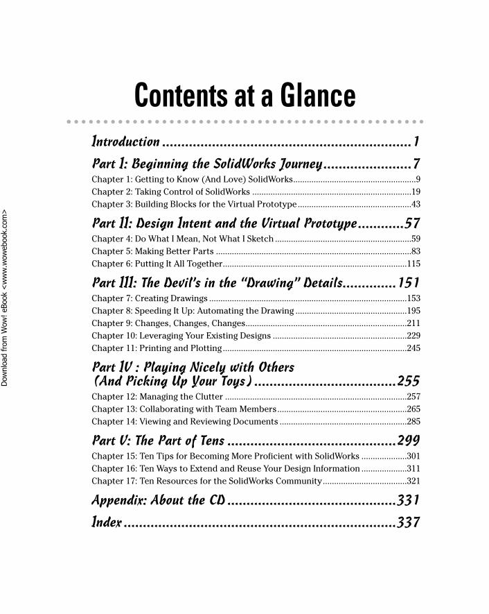
Contents at a GlanceIntroduction .................................................................1
Part I: Beginning the SolidWorks Journey.......................7Chapter 1: Getting to Know (And Love) SolidWorks......................................................9Chapter 2: Taking Control of SolidWorks ......................................................................19Chapter 3: Building Blocks for the Virtual Prototype..................................................43
Part II: Design Intent and the Virtual Prototype............57Chapter 4: Do What I Mean, Not What I Sketch ............................................................59Chapter 5: Making Better Parts ......................................................................................83Chapter 6: Putting It All Together.................................................................................115
Part III: The Devil’s in the “Drawing” Details..............151Chapter 7: Creating Drawings .......................................................................................153Chapter 8: Speeding It Up: Automating the Drawing .................................................195Chapter 9: Changes, Changes, Changes.......................................................................211Chapter 10: Leveraging Your Existing Designs ...........................................................229Chapter 11: Printing and Plotting.................................................................................245
Part IV : Playing Nicely with Others (And Picking Up Your Toys) .....................................255Chapter 12: Managing the Clutter ................................................................................257Chapter 13: Collaborating with Team Members.........................................................265Chapter 14: Viewing and Reviewing Documents ........................................................285
Part V: The Part of Tens ............................................299Chapter 15: Ten Tips for Becoming More Proficient with SolidWorks ....................301Chapter 16: Ten Ways to Extend and Reuse Your Design Information ....................311Chapter 17: Ten Resources for the SolidWorks Community.....................................321
Appendix: About the CD ............................................331
Index .......................................................................337
02_129784 ftoc.qxp 9/28/07 11:53 AM Page xi
Dow
nlo
ad fro
m W
ow
! eBook
<w
ww
.wow
ebook.
com
>

02_129784 ftoc.qxp 9/28/07 11:53 AM Page xii

Table of ContentsIntroduction..................................................................1
About This Book...............................................................................................1Conventions Used in This Book .....................................................................2What You’re Not to Read.................................................................................2Foolish Assumptions .......................................................................................2How This Book Is Organized...........................................................................3
Part I: Beginning the SolidWorks Journey ...........................................3Part II: Design Intent and the Virtual Prototype .................................3Part III: The Devil’s in the “Drawing” Details.......................................3Part IV: Playing Nicely with Others (And Picking Up Your Toys).....3Part V: The Part of Tens.........................................................................4About the CD-ROM .................................................................................4
Icons Used in This Book..................................................................................4Where to Go from Here....................................................................................5
Part I: Beginning the SolidWorks Journey .......................7
Chapter 1: Getting to Know (And Love) SolidWorks . . . . . . . . . . . . . . . .9Exploring the SolidWorks Advantage ............................................................9
Improving the way you work ..............................................................10Embracing the virtual prototype........................................................11
Getting Your System Ready for SolidWorks................................................12Keeping Your Computer Happy....................................................................13Starting Up SolidWorks the First Time ........................................................13Checking Out the Features............................................................................15
Finding help and tips ...........................................................................15Finding out what’s new in SolidWorks 2008 ......................................17
Chapter 2: Taking Control of SolidWorks . . . . . . . . . . . . . . . . . . . . . . . .19Working with SolidWorks Documents .........................................................19Creating and Opening a Document ..............................................................21Working with Templates................................................................................23Understanding the User Interface................................................................25
Touring the document window...........................................................25Selecting and editing with the FeatureManager design tree...........28Working with the CommandManager ................................................29Mousing around....................................................................................30
02_129784 ftoc.qxp 9/28/07 11:53 AM Page xiii

SolidWorks For Dummies, 2nd Edition xivGetting a Better View of Things....................................................................31
Zoom, pan, and rotate..........................................................................32Standard engineering views ................................................................32Display styles ........................................................................................33
Exploring the SolidWorks Help Menu..........................................................34Customizing the User Interface ....................................................................36
Adding flyout toolbars.........................................................................38Taking advantage of single-command mode.....................................39
Defining SolidWorks System Options ..........................................................39
Chapter 3: Building Blocks for the Virtual Prototype . . . . . . . . . . . . . .43Planning and Capturing Design Intent (Or, Think First and Then Do) ....44
Starting the design with a hand sketch .............................................44Using an engineering journal and the SolidWorks Design Binder ...46Capturing design intent: Brainstorming ............................................48Making a list and checking it twice ....................................................48
Applying Layouts and Design Skeletons .....................................................49Designing top down versus bottom up .............................................50Creating a design layout ......................................................................51Creating in-context parts in the assembly ........................................55Thinking about skeletons you want in your closet ..........................55
Part II: Design Intent and the Virtual Prototype ............57
Chapter 4: Do What I Mean, Not What I Sketch . . . . . . . . . . . . . . . . . . .59Making and Editing a Sketch.........................................................................59
Identifying the elements of a sketch ..................................................60Origins and orientation .......................................................................61Sketching with entities ........................................................................62Modifying sketch entities ....................................................................64Adding reference geometry.................................................................68
Defining the Sketch ........................................................................................72Working with relations.........................................................................74Creating simple dimensions................................................................79Marking a dimension for drawing reuse............................................81
Chapter 5: Making Better Parts . . . . . . . . . . . . . . . . . . . . . . . . . . . . . . . . .83Introducing Part Features .............................................................................83Working with the Features Toolbar .............................................................85Creating Sketched Features ..........................................................................86
Pulling and carving out extruded features........................................86Revolving features around an axis .....................................................88Sweeping features along a path ..........................................................90Lofted features: A sketch of many profiles........................................91
02_129784 ftoc.qxp 9/28/07 11:53 AM Page xiv
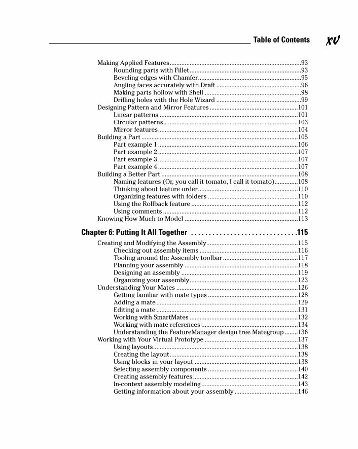
Making Applied Features...............................................................................93Rounding parts with Fillet ...................................................................93Beveling edges with Chamfer..............................................................95Angling faces accurately with Draft ...................................................96Making parts hollow with Shell ..........................................................98Drilling holes with the Hole Wizard ...................................................99
Designing Pattern and Mirror Features .....................................................101Linear patterns ...................................................................................101Circular patterns ................................................................................103Mirror features....................................................................................104
Building a Part ..............................................................................................105Part example 1 ....................................................................................106Part example 2 ....................................................................................107Part example 3 ....................................................................................107Part example 4 ....................................................................................107
Building a Better Part ..................................................................................108Naming features (Or, you call it tomato, I call it tomato)..............108Thinking about feature order............................................................110Organizing features with folders ......................................................110Using the Rollback feature ................................................................112Using comments .................................................................................112
Knowing How Much to Model ....................................................................113
Chapter 6: Putting It All Together . . . . . . . . . . . . . . . . . . . . . . . . . . . . . .115Creating and Modifying the Assembly.......................................................115
Checking out assembly items ...........................................................116Tooling around the Assembly toolbar .............................................117Planning your assembly ....................................................................118Designing an assembly ......................................................................119Organizing your assembly.................................................................123
Understanding Your Mates .........................................................................126Getting familiar with mate types ......................................................128Adding a mate .....................................................................................129Editing a mate .....................................................................................131Working with SmartMates .................................................................132Working with mate references ..........................................................134Understanding the FeatureManager design tree Mategroup........136
Working with Your Virtual Prototype ........................................................137Using layouts.......................................................................................138Creating the layout.............................................................................138Using blocks in your layout ..............................................................138Selecting assembly components ......................................................140Creating assembly features...............................................................142In-context assembly modeling ..........................................................143Getting information about your assembly ......................................146
xvTable of Contents
02_129784 ftoc.qxp 9/28/07 11:53 AM Page xv

Part III: The Devil’s in the “Drawing” Details ..............151
Chapter 7: Creating Drawings . . . . . . . . . . . . . . . . . . . . . . . . . . . . . . . . .153Becoming Familiar withDrawing Elements ...............................................153Opening a New Drawing Document ...........................................................156Editing the Drawing Sheet Format .............................................................159Placing the Drawing Views..........................................................................160
Model view ..........................................................................................161Standard 3 Views ................................................................................163Projected view ....................................................................................164Auxiliary view .....................................................................................164Section view ........................................................................................165Aligned Section view..........................................................................166Detail view...........................................................................................167Crop view.............................................................................................167
Changing View Properties...........................................................................168Creating Drawing Dimensions ....................................................................169
Smart Dimension ................................................................................171Ordinate and baseline dimensions...................................................172
Adding Reference Annotations...................................................................174Note......................................................................................................175Balloon.................................................................................................177Auto Balloon .......................................................................................178Surface finish ......................................................................................179Geometric tolerance ..........................................................................180Datum target .......................................................................................181Datum symbol.....................................................................................182Cosmetic thread .................................................................................183Center mark.........................................................................................183Centerline ............................................................................................184
Checking Spelling .........................................................................................185Defining Drawing Tables..............................................................................186
Bill of materials...................................................................................186Revision table .....................................................................................188Hole tables...........................................................................................190Changing and customizing tables ....................................................192
Chapter 8: Speeding It Up: Automating the Drawing . . . . . . . . . . . . .195Planning for the Drawing.............................................................................195Inserting Model Items..................................................................................196Managing Drawing Clutter with Layers .....................................................199
Creating layers....................................................................................200Working with layers ...........................................................................201
Automating Drawing Creation ....................................................................201Using custom properties ...................................................................202Setting up a drawing sheet format ...................................................204Using predefined views to start drawings.......................................206
SolidWorks For Dummies, 2nd Edition xvi
02_129784 ftoc.qxp 9/28/07 11:53 AM Page xvi
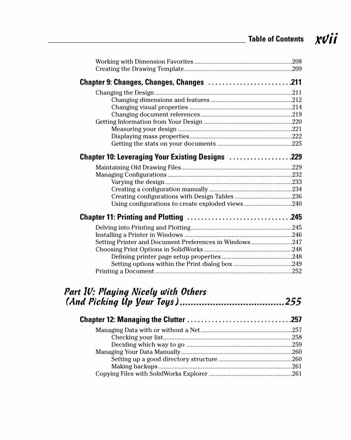
Working with Dimension Favorites ............................................................208Creating the Drawing Template..................................................................209
Chapter 9: Changes, Changes, Changes . . . . . . . . . . . . . . . . . . . . . . . .211Changing the Design ....................................................................................211
Changing dimensions and features ..................................................212Changing visual properties ...............................................................214Changing document references........................................................219
Getting Information from Your Design ......................................................220Measuring your design ......................................................................221Displaying mass properties...............................................................222Getting the stats on your documents ..............................................225
Chapter 10: Leveraging Your Existing Designs . . . . . . . . . . . . . . . . . .229Maintaining Old Drawing Files....................................................................229Managing Configurations ............................................................................232
Varying the design..............................................................................233Creating a configuration manually ...................................................234Creating configurations with Design Tables ...................................236Using configurations to create exploded views .............................240
Chapter 11: Printing and Plotting . . . . . . . . . . . . . . . . . . . . . . . . . . . . . .245Delving into Printing and Plotting..............................................................245Installing a Printer in Windows ..................................................................246Setting Printer and Document Preferences in Windows .........................247Choosing Print Options in SolidWorks ......................................................248
Defining printer page setup properties ...........................................248Setting options within the Print dialog box ....................................249
Printing a Document ....................................................................................252
Part IV: Playing Nicely with Others (And Picking Up Your Toys)......................................255
Chapter 12: Managing the Clutter . . . . . . . . . . . . . . . . . . . . . . . . . . . . . .257Managing Data with or without a Net........................................................257
Checking your list...............................................................................258Deciding which way to go .................................................................259
Managing Your Data Manually....................................................................260Setting up a good directory structure .............................................260Making backups..................................................................................261
Copying Files with SolidWorks Explorer ...................................................261
xviiTable of Contents
02_129784 ftoc.qxp 9/28/07 11:53 AM Page xvii
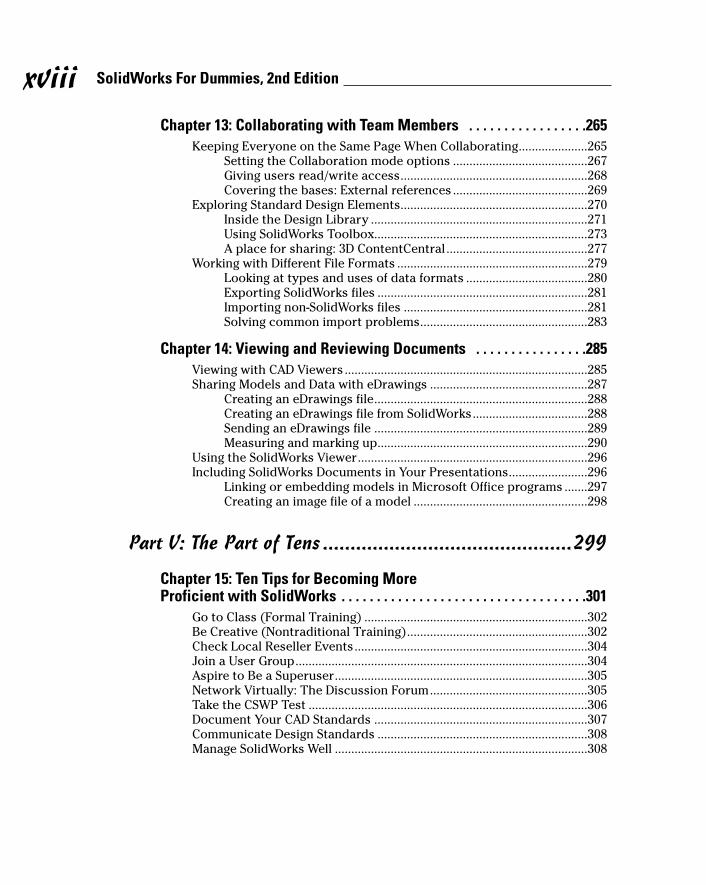
Chapter 13: Collaborating with Team Members . . . . . . . . . . . . . . . . .265Keeping Everyone on the Same Page When Collaborating.....................265
Setting the Collaboration mode options .........................................267Giving users read/write access.........................................................268Covering the bases: External references .........................................269
Exploring Standard Design Elements.........................................................270Inside the Design Library ..................................................................271Using SolidWorks Toolbox.................................................................273A place for sharing: 3D ContentCentral...........................................277
Working with Different File Formats ..........................................................279Looking at types and uses of data formats .....................................280Exporting SolidWorks files ................................................................281Importing non-SolidWorks files ........................................................281Solving common import problems...................................................283
Chapter 14: Viewing and Reviewing Documents . . . . . . . . . . . . . . . .285Viewing with CAD Viewers ..........................................................................285Sharing Models and Data with eDrawings ................................................287
Creating an eDrawings file.................................................................288Creating an eDrawings file from SolidWorks...................................288Sending an eDrawings file .................................................................289Measuring and marking up................................................................290
Using the SolidWorks Viewer......................................................................296Including SolidWorks Documents in Your Presentations........................296
Linking or embedding models in Microsoft Office programs .......297Creating an image file of a model .....................................................298
Part V: The Part of Tens .............................................299
Chapter 15: Ten Tips for Becoming More Proficient with SolidWorks . . . . . . . . . . . . . . . . . . . . . . . . . . . . . . . . . . .301
Go to Class (Formal Training) ....................................................................302Be Creative (Nontraditional Training).......................................................302Check Local Reseller Events.......................................................................304Join a User Group.........................................................................................304Aspire to Be a Superuser.............................................................................305Network Virtually: The Discussion Forum................................................305Take the CSWP Test .....................................................................................306Document Your CAD Standards .................................................................307Communicate Design Standards ................................................................308Manage SolidWorks Well .............................................................................308
SolidWorks For Dummies, 2nd Edition xviii
02_129784 ftoc.qxp 9/28/07 11:53 AM Page xviii

Chapter 16: Ten Ways to Extend and Reuse Your Design Information . . . . . . . . . . . . . . . . . . . . . . . . . . . . . . . . . . . . . .311
Show Off Your Model with Microsoft OLE ................................................312Share Models with SolidWorks 3D Instant Website .................................313Spice Up Model Images with PhotoWorks ................................................313Simulate Movement with SolidWorks Motion Studies.............................314Share Design Info with PDMWorks Workgroup ........................................315Test a Design with COSMOSWorks Analysis .............................................315Check Out Models’ Moves with COSMOSMotion.....................................316Automate Tasks with the API and Macros ................................................317Schedule the Intensive Work with SolidWorks Task Scheduler .............318Find Various Manufacturing Software .......................................................320
Chapter 17: Ten Resources for the SolidWorks Community . . . . . . .321SolidWorks and COSMOS User Groups .....................................................321The SolidWorks Web Site ............................................................................323The SolidWorks Express Newsletter..........................................................324The SolidWorks Customer Portal...............................................................324The Certified SolidWorks Professional Program......................................3263D ContentCentral........................................................................................326The SolidWorks Manufacturing Network ..................................................327SolidWorks Solution Partners.....................................................................327SolidWorks Resellers ...................................................................................328The SolidWorks Educational Community .................................................328
Appendix: About the CD.............................................331
Index........................................................................337
xixTable of Contents
02_129784 ftoc.qxp 9/28/07 11:53 AM Page xix

SolidWorks For Dummies, 2nd Edition xx
02_129784 ftoc.qxp 9/28/07 11:53 AM Page xx
Introduction
I started using SolidWorks when the first version, SolidWorks 95, came outon the market. It’s amazing to see how far solid modeling has come since
then. Working within a 3D environment has transformed the way I create,iterate, and document a design.
One reason I wrote this book is to help boil down much of the material that’sout there and focus on not only what I believe to be important from mydesign experience but also how I think the software should be used.
Although many things are similar to what was done ten years ago, manythings have changed. Even some of the saltier veterans out there can gainsomething from the ideas presented within this book.
SolidWorks is becoming a more mature application, and instead of gettingharder to use, it makes modeling easier and, quite frankly, more fun.
One concept that recurs throughout this book is the ability of SolidWorks toreuse design information, saving you from having to do things manually. Forexample, SolidWorks can use the information in your part or assembly modelto create manufacturing drawings automatically.
This way of creating products saves time and produces better results.SolidWorks For Dummies, 2nd Edition, shows you how.
Enjoy your journey with SolidWorks. You’ll love the experience.
About This BookThis book isn’t designed to be read from cover to cover, although it can be.SolidWorks For Dummies is designed as a reference book that you can use atany time.
This book isn’t meant to be a complete reference for SolidWorks. If it were,you probably wouldn’t want to drop it on your foot. Instead, I have focusedon the key and commonly used elements of SolidWorks.
03_129784 intro.qxp 9/28/07 12:01 PM Page 1

2 SolidWorks For Dummies, 2nd Edition
Conventions Used in This BookI use the following conventions throughout this book:
� I use the term document to refer to drawing, part, or assembly files inSolidWorks.
� The list of items across the top of the SolidWorks interface comprisesthe main menu. Each item on the main menu also has a hidden list, orpull-down menu. Whenever I want you to choose a series of commandsfrom the menu, I use the phrasing “Choose File➪Save,” for example.
What You’re Not to ReadSometimes this book can be a little bit technical. But because I’m a nice guy, Ialways warn you about the stuff you can skip, by planting a handy TechnicalStuff icon nearby. Although the information next to this icon is interesting, youdon’t have to read it. The same holds true for sidebars, which are the grayboxes that you see scattered throughout the book. Although the informationin the sidebars is interesting, it’s just extra information that’s nonessential tounderstanding the topic at hand.
Foolish AssumptionsWhen I wrote SolidWorks For Dummies, I assumed very little about you — justthat you’re somewhat familiar with a computer and the Windows operatingsystem. But I didn’t assume that you have any earlier SolidWorks experience.
If you’re not comfortable working with your computer, you may want to pickup a copy of PCs For Dummies, by Dan Gookin (Wiley), which walks youthrough the basics.
I also assume that you have a slight CAD system background. I counted onyour having a basic knowledge of geometry, lines, circles, and points, forexample. I don’t, however, assume that you can create these objects.
One other assumption I make is that you have some experience in engineeringor design or that you’re pursuing a career in a related field.
03_129784 intro.qxp 9/28/07 12:01 PM Page 2
How This Book Is OrganizedThis book has five major parts. Each part contains several chapters, andeach chapter contains several sections. You can read any section withoutreading the entire book or even without reading earlier sections within thatsame chapter. Here’s what you find in each part:
Part I: Beginning the SolidWorks JourneyThis part introduces SolidWorks and 3D design. You find out about the userinterface, SolidWorks file types, and system setup. I also highlight the newfeatures in SolidWorks 2008.
Part II: Design Intent and the VirtualPrototypeThis part contains the “beef” of the book. In this part, I talk about creatingsound, robust 2D sketches and examine design intent. (Do what I mean, notwhat I sketch!) I also talk about the many ways to design and model a partand the virtual prototype.
Part III: The Devil’s in the “Drawing” DetailsDrawings are a necessary part of the manufacturing process. In this part ofthe book, I talk about how SolidWorks uses information captured in themodel to create drawings automatically. I also cover several other SolidWorksdrawing features that make your life easier.
Part IV: Playing Nicely with Others (And Picking Up Your Toys)If you can’t find anything on your desk, this chapter may be a tough read.This part focuses on managing and sharing information with other teammembers so that your projects are more effective.
3Introduction
03_129784 intro.qxp 9/28/07 12:01 PM Page 3
Part V: The Part of TensThe Part of Tens provides examples, tips, and references for SolidWorks. Youdiscover how you can become more proficient in SolidWorks, as well as howyou can reuse design information and extend the capabilities of SolidWorks.Lastly, you find out about resources in the vast SolidWorks community.
About the CDThe CD included with SolidWorks For Dummies contains a product demo andadd-on solutions. For more information on the CD, see the “About the CD”appendix, at the back of this book.
Icons Used in This BookThroughout this book, I use icons to flag information. Some icons mark topicsthat are useful down the line, whereas others warn you of geek topics ahead.
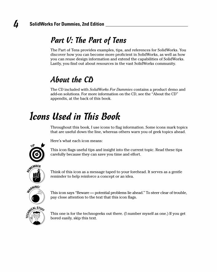
Here’s what each icon means:
This icon flags useful tips and insight into the current topic. Read these tipscarefully because they can save you time and effort.
Think of this icon as a message taped to your forehead. It serves as a gentlereminder to help reinforce a concept or an idea.
This icon says “Beware — potential problems lie ahead.” To steer clear of trouble,pay close attention to the text that this icon flags.
This one is for the technogeeks out there. (I number myself as one.) If you getbored easily, skip this text.
4 SolidWorks For Dummies, 2nd Edition
03_129784 intro.qxp 9/28/07 12:01 PM Page 4

Where to Go from HereIf you’re ready to get started, turn the page and keep reading or, better yet,review the table of contents or index to find topics that interest you. No matterwhich approach you choose, you’re well on your way to becoming a SolidWorksuser. Creating products in 3D is a fun and effective way to design. Enjoy!
5Introduction
03_129784 intro.qxp 9/28/07 12:01 PM Page 5

6 SolidWorks For Dummies, 2nd Edition
03_129784 intro.qxp 9/28/07 12:01 PM Page 6

Part IBeginning the
SolidWorksJourney
04_129784 pp01.qxp 9/28/07 12:03 PM Page 7
In this part . . .
Beginning the journey into 3D can seem daunting. It’snot that bad — honest. In fact, it can be fun. This part
introduces you to SolidWorks. You find out about some ofthe new features in SolidWorks 2008 as well as how to setup SolidWorks before you start your first design project.You also delve into the topics of design layout and intent.
04_129784 pp01.qxp 9/28/07 12:03 PM Page 8
Chapter 1
Getting to Know (And Love)SolidWorks
In This Chapter� Becoming familiar with SolidWorks
� Discovering the advantages of the virtual prototype
� Figuring out where to start with SolidWorks
� Getting acquainted with new features in SolidWorks 2008
SolidWorks is a tool that helps design engineers harness their imaginationsand add creativity to their designs. The true mark of a good tool is when
it becomes part of your process without getting in your way. When you design,you need to do just that — design!
When SolidWorks was created, the power of 3D wasn’t yet widespread. Thecompany’s original mission back in 1995 — and a goal it still pursues today —is to bring the power of 3D to every engineer’s desktop. Two early quotes ofSolidWorks founders that still hold true today are
� “No matter how easy it is to use, it is never easy enough.”
� “No matter how fast we make it, it is never fast enough.”
In this chapter, I introduce you to SolidWorks, the wonderful world of 3D, andthe virtual prototype. You discover the basic system requirements forSolidWorks and tips to keep the program running smoothly. I also give youthe lowdown on the newest features in SolidWorks 2008.
Exploring the SolidWorks AdvantageAs a design engineer, you need to be critical about how you work with yourcraft and to understand how you can do it better. As tools and technologycontinue to improve, you also need to evolve. That means staying abreast of
05_129784 ch01.qxp 9/28/07 12:32 PM Page 9
the latest design tool innovations. In this section, you find out how to takeadvantage of the benefits that 3D and SolidWorks offer.
Improving the way you workDesigning in SolidWorks may be different from how you designed in the past.My greatest satisfaction in my early days as a designer came from creating acomplex assembly on my computer and then watching the darn thing actu-ally come together on the shop floor just the way I designed it.
Without the ability to create 3D solid models and assemblies, however, yourgoal isn’t easily attainable. The following workflow example shows how mod-eling in SolidWorks enables you to achieve better results:
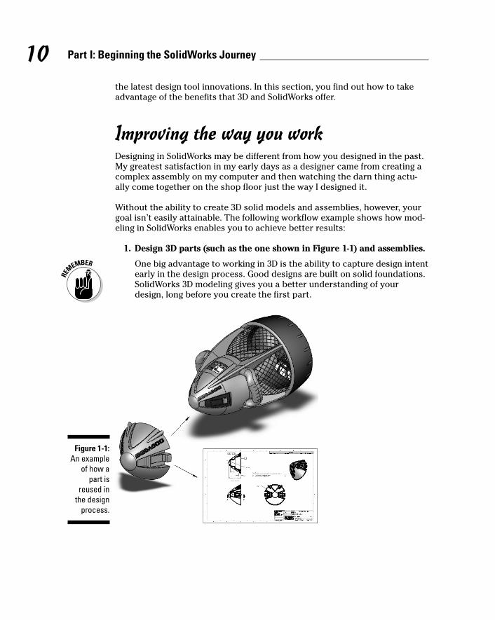
1. Design 3D parts (such as the one shown in Figure 1-1) and assemblies.
One big advantage to working in 3D is the ability to capture design intentearly in the design process. Good designs are built on solid foundations.SolidWorks 3D modeling gives you a better understanding of yourdesign, long before you create the first part.
Figure 1-1:An example
of how apart is
reused inthe design
process.
10 Part I: Beginning the SolidWorks Journey
05_129784 ch01.qxp 9/28/07 12:32 PM Page 10
Design intent is an intelligent arrangement of part features and dimensions,or in the case of assemblies, the location of parts and the interactionbetween them. Starting your designs by building in good design intentmakes reacting to future changes or additions easier.
2. Test your design as a virtual prototype, using advanced features inSolidWorks to test different ideas more quickly and easily than youcan with drawings or traditional prototypes.
A virtual prototype is such an important idea in using SolidWorks that Idiscuss it greater detail in the next section.
3. Generate 2D manufacturing drawings, based on the geometry definedin the original part or assembly.
Refer to Figure 1-1 for an example. You can find out more about generatingdrawings in Chapter 7.
Embracing the virtual prototypeIn the old days (more than 25 years ago), designers drew their designs on paper.When a designer was done drawing, he built a physical prototype to test hisdesign ideas in the real world. If things didn’t work quite right, he went back tothe drawing board. Building all those prototypes was time consuming.
Nowadays, you do all that testing and simulating on a virtual prototype, which isa concept I refer to throughout this book. When you design a product inSolidWorks, essentially you create a virtual prototype with all the characteristicsof the real thing (dimensions, mass properties, screws, and fittings, for example).Your virtual prototype behaves in the computer realm as it would in the real world.
The power of the virtual prototype is that it allows you to test countless designideas quickly on your computer. And although the physical prototype hasn’tvanished, at least you don’t need so many of them.
Figure 1-1 shows a virtual prototype. Imagine if you had to draw this baby fromscratch. In a drawing, changing the height from 100mm to 120mm requires majoreffort. In contrast, with a 3D virtual model, you can modify and update keydesign attributes with ease.
If you think you can work faster in a 2D environment, you’re probably right. Butthat’s only because you can’t include the detail required to fully manufacturethe part. When I made designs on a drawing board with paper and pencil, Icould easily add a radius to any corner because I had my trusty ellipsetemplate. In other words, I would “fudge” the corner geometry and let thetoolmaker properly fillet the corner. Sometimes this lack of detail is good, andsometimes it’s bad.
11Chapter 1: Getting to Know (And Love) SolidWorks
05_129784 ch01.qxp 9/28/07 12:32 PM Page 11
Dow
nlo
ad fro
m W
ow
! eBook
<w
ww
.wow
ebook.
com
>

People use SolidWorks because they can create 3D parts, place them inassemblies in the same way as though they were assembling physical parts,and then create 2D drawings directly from that information.
Getting Your System Ready for SolidWorks
SolidWorks comes to you on a single DVD. When you’re ready to install, put thedisc in your DVD drive and follow the instructions provided by the InstallationManager. During installation, you have the opportunity to activate your SolidWorkslicense automatically over the Internet. (You can also activate your license viae-mail, but that may take a few hours to a few days.) When you first installSolidWorks, you have up to 30 days to activate the license or the software willsimply stop working. For more information about activation, or if you experienceany difficulties, visit the SolidWorks Customer Portal site at https://customercenter.solidworks.com.
The minimum computer requirements boil down to the following:
� CPU: Get the fastest one you can afford. The performance of SolidWorksdepends on your CPU speed. If you get a CPU that’s too slow, you canadd a second one later. Although a second CPU adds some performanceincrease, it doesn’t come close to doubling performance, so it’s best tostart off big.
� RAM: Although SolidWorks lists the minimum requirements, a better wayto gauge how much RAM you need is to open SolidWorks on your computeralong with all the other applications you normally have open at one time,such as the ones you use for e-mail, word processing, and Web browsing.Then open a good sampling of SolidWorks documents. (You can find somein the Tutorials folder in the SolidWorks program folder.) Open WindowsTask Manager (press Ctrl+Alt+Delete) and click the Performance tab.Check the amount of available memory in the Physical Memory area. Ifthe amount of available memory isn’t greater than 0, you need more RAM.
RAM is cheap, so make sure that you have plenty. The amount of RAMyou have is important. If Windows runs out of physical memory, badthings happen. Your system becomes sluggish and less stable.
� Graphics card: Make sure that you have a certified graphics card anddriver version. The SolidWorks support Web site lists combinations ofcertified graphics cards and drivers. For a listing of supported graphicscards and drivers, visit the hardware page of the SolidWorks supportsite at https://customercenter.solidworks.com.
� Hard drive: Big and fast is where it’s at. These days, folks who useSolidWorks typically have 80 to 120GB hard drives.
12 Part I: Beginning the SolidWorks Journey
05_129784 ch01.qxp 9/28/07 12:32 PM Page 12
Keeping Your Computer HappyA commonly overlooked means of making sure that your computer stayshappy and healthy is regular system maintenance. Just as craftspeople takegood care of their tools, you should treat your computer in much the sameway. The two most important tasks are making sure you have sufficient diskspace and performing routine disk defragmentation.
You should also check the backup settings in SolidWorks by choosingTools➪Options➪System Options➪Backup/Recover.
The following settings are particularly important to check:
� The number of backup copies per document: If you set the number ofbackup copies, keep this number low (one or two) because SolidWorkscreates a copy of every document that’s opened.
� The location of the backups: You should store backups on a differentcomputer or at a different site. Remember to check your backup driveregularly to make sure that you have enough disk space. If you run lowon space, clean up your hard drive or buy a bigger one.
Even when you work normally on a computer, the disks become fragmented,which means that Windows can’t store all of a file in one contiguous spot, soit starts using a number of places on the hard drive to store documents. Asyou can imagine, fragmentation makes Windows run slower and causesstability issues with the system and the applications running on the computer.To alleviate this problem, use the Windows Disk Defragmenter (chooseStart➪All Programs➪Accessories➪System Tools). I run a complete scanweekly. It makes a difference.
For more information on many of these administrative tasks, check out theSolidWorks Express archive. SolidWorks Express is a bimonthly electronicnewsletter for the SolidWorks community. To view technical tips in thearchive, go to https://www.customercenter.solidworks.com.
Starting Up SolidWorks the First TimeThe first time you run SolidWorks, the Welcome to SolidWorks dialog boxappears (see Figure 1-2) and asks how you want to configure the help andworkflow customizations. You can set up SolidWorks based on your industryand skill level.
13Chapter 1: Getting to Know (And Love) SolidWorks
05_129784 ch01.qxp 9/28/07 12:32 PM Page 13
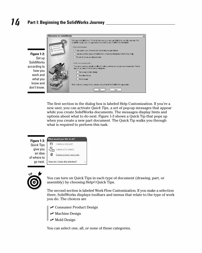
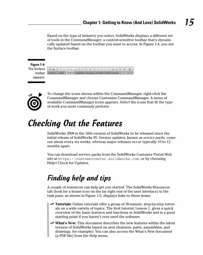
The first section in the dialog box is labeled Help Customization. If you’re anew user, you can activate Quick Tips, a set of pop-up messages that appearwhile you create SolidWorks documents. The messages display hints andoptions about what to do next. Figure 1-3 shows a Quick Tip that pops upwhen you create a new part document. The Quick Tip walks you throughwhat is required to perform this task.
You can turn on Quick Tips in each type of document (drawing, part, orassembly) by choosing Help➪Quick Tips.
The second section is labeled Work Flow Customization. If you make a selectionthere, SolidWorks displays toolbars and menus that relate to the type of workyou do. The choices are
� Consumer Product Design
� Machine Design
� Mold Design
You can select one, all, or none of these categories.
Figure 1-3:Quick Tips
give you an idea
of where togo next.
Figure 1-2:Set up
SolidWorksaccording to
how youwork andwhat youknow and
don’t know.
14 Part I: Beginning the SolidWorks Journey
05_129784 ch01.qxp 9/28/07 12:32 PM Page 14
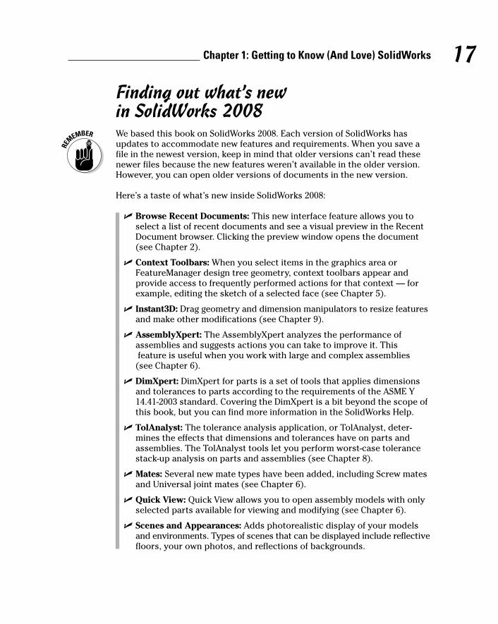
Based on the type of industry you select, SolidWorks displays a different setof tools in the CommandManager, a context-sensitive toolbar that’s dynami-cally updated based on the toolbar you want to access. In Figure 1-4, you seethe Surface toolbar.
To change the icons shown within the CommandManager, right-click theCommandManager and choose Customize CommandManager. A menu ofavailable CommandManager icons appears. Select the icons that fit the typeof work you most commonly perform.
Checking Out the FeaturesSolidWorks 2008 is the 16th version of SolidWorks to be released since theinitial release of SolidWorks 95. Version updates, known as service packs, comeout about every six weeks, whereas major releases occur typically 10 to 12months apart.
You can download service packs from the SolidWorks Customer Portal Website at https://customercenter.solidworks.com, or by choosingHelp➪Check for Updates.
Finding help and tipsA couple of resources can help get you started. The SolidWorks Resourcestab (look for a house icon on the far right end of the user interface) in thetask pane, as shown in Figure 1-5, displays links to these items:
� Tutorials: Online tutorials offer a group of 30-minute, step-by-step tutori-als on a wide variety of topics. The first tutorial, Lesson 1, gives a quickoverview of the basic features and functions in SolidWorks and is a goodstarting point if you haven’t ever used the software.
� What’s New: This document describes the new features within the latestversion of SolidWorks based on area (features, parts, assemblies, anddrawings, for example). You can also access the What’s New document(a PDF file) from the Help menu.
Figure 1-4:The Surface
toolbarappears.
15Chapter 1: Getting to Know (And Love) SolidWorks
05_129784 ch01.qxp 9/28/07 12:32 PM Page 15

� Machine Design, Mold Design, or Consumer Product Design: The titleand contents of this tab relate to the industry type you chose inWorkflow Customization. Figure 1-5 shows resources for machine design.If you chose mold design, other resources are displayed. On this tab,you find an overview of the industry and industry-specific tutorials.
� Tip of the Day: This tip changes each time you open SolidWorks.
You can also find the following references on the Help menu:
� SolidWorks Help: This option opens the SolidWorks Online User’s Guide.The guide is organized into chapters with an index you can browse. Asearch tool guides you to information on just about any feature inSolidWorks.
� Moving from AutoCAD: This online guide is designed to help you movefrom AutoCAD, a popular 2D design program, to SolidWorks. ManySolidWorks users come from AutoCAD backgrounds.
Figure 1-5:Inside the
SolidWorksResources
tab in thetask pane,you find a
plethora oflearning
resources.
16 Part I: Beginning the SolidWorks Journey
05_129784 ch01.qxp 9/28/07 12:32 PM Page 16
Finding out what’s new in SolidWorks 2008We based this book on SolidWorks 2008. Each version of SolidWorks hasupdates to accommodate new features and requirements. When you save afile in the newest version, keep in mind that older versions can’t read thesenewer files because the new features weren’t available in the older version.However, you can open older versions of documents in the new version.
Here’s a taste of what’s new inside SolidWorks 2008:
� Browse Recent Documents: This new interface feature allows you toselect a list of recent documents and see a visual preview in the RecentDocument browser. Clicking the preview window opens the document(see Chapter 2).
� Context Toolbars: When you select items in the graphics area orFeatureManager design tree geometry, context toolbars appear andprovide access to frequently performed actions for that context — forexample, editing the sketch of a selected face (see Chapter 5).
� Instant3D: Drag geometry and dimension manipulators to resize featuresand make other modifications (see Chapter 9).
� AssemblyXpert: The AssemblyXpert analyzes the performance ofassemblies and suggests actions you can take to improve it. Thisfeature is useful when you work with large and complex assemblies
(see Chapter 6).
� DimXpert: DimXpert for parts is a set of tools that applies dimensionsand tolerances to parts according to the requirements of the ASME Y14.41-2003 standard. Covering the DimXpert is a bit beyond the scope ofthis book, but you can find more information in the SolidWorks Help.
� TolAnalyst: The tolerance analysis application, or TolAnalyst, deter-mines the effects that dimensions and tolerances have on parts andassemblies. The TolAnalyst tools let you perform worst-case tolerancestack-up analysis on parts and assemblies (see Chapter 8).
� Mates: Several new mate types have been added, including Screw matesand Universal joint mates (see Chapter 6).
� Quick View: Quick View allows you to open assembly models with onlyselected parts available for viewing and modifying (see Chapter 6).
� Scenes and Appearances: Adds photorealistic display of your modelsand environments. Types of scenes that can be displayed include reflectivefloors, your own photos, and reflections of backgrounds.
17Chapter 1: Getting to Know (And Love) SolidWorks
05_129784 ch01.qxp 9/28/07 12:32 PM Page 17

18 Part I: Beginning the SolidWorks Journey
05_129784 ch01.qxp 9/28/07 12:32 PM Page 18
Chapter 2
Taking Control of SolidWorksIn This Chapter� Getting around (the user interface, that is)
� Creating a new SolidWorks document
� Understanding the different SolidWorks file types
� Structuring and streamlining SolidWorks
� Creating templates for parts, assemblies, and drawings
� Saving and sharing SolidWorks files
When 3D design programs first hit the market, they were complex tolearn and difficult to operate. Then SolidWorks came along and did
everything that the other programs did, except that it was less expensive andeasier to use, enabling design engineers to get up and running fast. What givesSolidWorks a familiar look and feel is its Windows-like user interface and theuse of other standard conventions, such as icon command buttons, menus,and toolbars.
This chapter describes the SolidWorks user interface: how to navigate it andhow to personalize it to fit your needs. In this chapter, you discover how toopen a new document and how to set up and maintain the SolidWorks program.Whether you work alone or in a group of 50 other engineers, the ability todefine, save, and share document templates and common SolidWorks set-tings makes you more effective in using SolidWorks.
Working with SolidWorks DocumentsSolidWorks is a multidocument system, which means that it uses different filetypes for different purposes. Part, drawing, and assembly files are someexamples.
Many SolidWorks file types link to other files. A drawing references a part tocreate the detail views. An assembly references parts and other assemblies.The different types of documents are fully associative within SolidWorks, so achange to a part propagates to any drawing or assembly that uses the part.
06_129784 ch02.qxp 9/28/07 12:33 PM Page 19
20 Part I: Beginning the SolidWorks Journey
Here’s a list of SolidWorks document types that appear throughout this book:
� Assembly: A collection of related parts saved in one document file withthe .sldasm extension. An assembly can contain from two to more thana thousand components, which can be parts or other assemblies calledsubassemblies.
� Block: A group of 2D entities (such as standard notes, title blocks, andlabel positions) that you can use in drawing files. Blocks can includetext, any type of sketch entity, balloons, and imported entities. You canattach blocks to geometry or to drawing views and insert them intosheet formats. Blocks have the extension .sldblk.
� Drawing: 2D documents that convey a design to manufacturing. A draw-ing file consists of one or more sheets that contain different views of themodel. SolidWorks gives drawing files the extension .slddrw.
� Drawing Sheet Format: You can save a border or a title block (whichincludes company name, material, sheet size, and other information) ofa drawing in the .slddrt format to use in creating new drawings.
� Library Feature: A frequently used part feature or combination of partfeatures that you create once and save in a library for future use (andreuse). You can use library features as building blocks to construct asingle part to ensure consistency and save time. Library features havethe extension .sldlfp.
� Macro: A set of keyboard commands that you can record and save in afile to automate redundant or menial tasks in SolidWorks. A macro is savedas a block of Microsoft Visual Basic for Applications (VBA) program code.SolidWorks macros have the file extension .swp.
� Part: The building block of every SolidWorks model. Each assembly anddrawing you create is made from parts. Part files consist of a collectionof part features (base, extrude, revolve, and loft, for example).SolidWorks attaches the extension .sldprt to part files.
� Templates: Documents that include user-defined parameters. When youopen a new part, drawing, or assembly, you select a template to use foryour new document. Templates have the extensions .drwdot, .prtdot,and .asmdot for drawing, part, and assembly documents.
Be sure to develop for your SolidWorks files a consistent naming method thateveryone on your design team can follow. SolidWorks follows the same file-naming conventions as Windows. As you develop your own naming style,here’s what to keep in mind:
� Filenames aren’t case sensitive. They can be upper- or lowercase.
� Filenames can include spaces.
06_129784 ch02.qxp 9/28/07 12:33 PM Page 20
� A filename can have up to 256 characters in front of the file extension.
� You can’t include special characters (*, /, or %, for example) within thefilename.
� Filenames that you store in the same data directory should be unique sothat you don’t accidentally choose the wrong file. For example, you don’tname a connector part connector.sldprt because someone might usethe same name for a part on another project. Filenames should includethe part number, the project name or number, and then a description.
Creating and Opening a DocumentBefore you explore the ins and outs of the SolidWorks user interface, youneed to understand how to create a new document in SolidWorks. When youcreate a new part, assembly, or drawing document, you select a template towork with. A template, which is the foundation of the SolidWorks document,stores the default document properties for each document. SolidWorks hasdefault part, assembly, and drawing templates, but you can create your owntemplates, and the next section, “Working with Templates,” tells you how.
To create a new SolidWorks document, follow these steps:
1. Choose File➪New.
The New SolidWorks Document dialog box appears.
The New SolidWorks Document dialog box has two versions: Novice andAdvanced. You can toggle between them by simply clicking the Noviceor Advanced button at the bottom of the dialog box.
• Novice is the simplified version of the dialog box. It’s also thedefault. In Novice mode, you have only three document templates(Part, Assembly, and Drawing) to choose from.
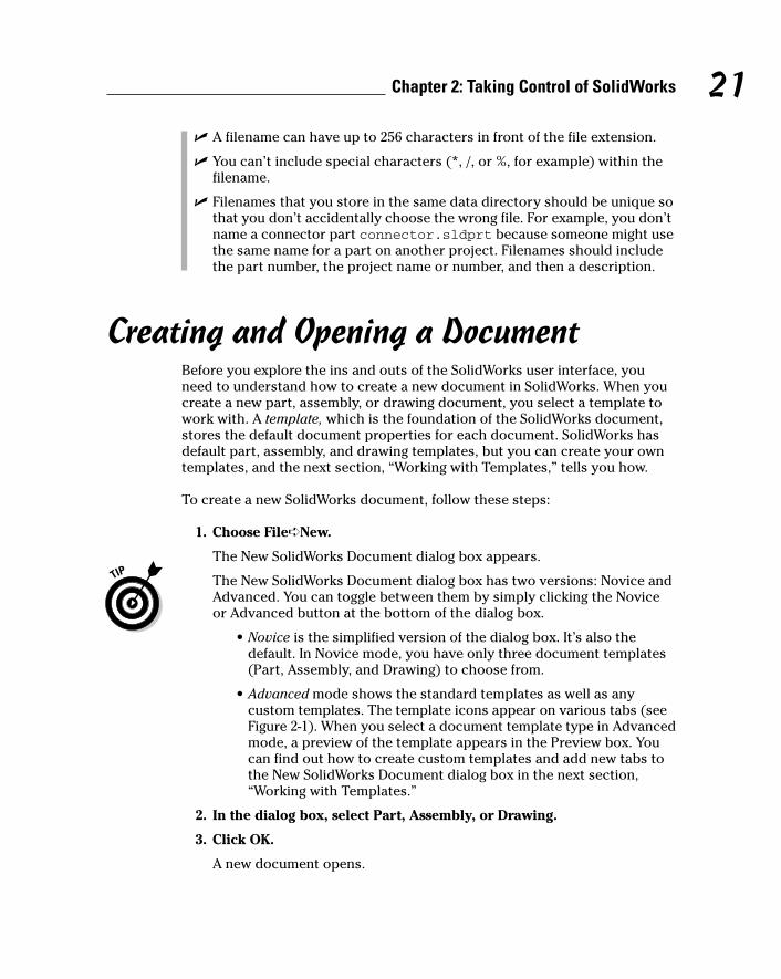
• Advanced mode shows the standard templates as well as anycustom templates. The template icons appear on various tabs (seeFigure 2-1). When you select a document template type in Advancedmode, a preview of the template appears in the Preview box. Youcan find out how to create custom templates and add new tabs tothe New SolidWorks Document dialog box in the next section,“Working with Templates.”
2. In the dialog box, select Part, Assembly, or Drawing.
3. Click OK.
A new document opens.
21Chapter 2: Taking Control of SolidWorks
06_129784 ch02.qxp 9/28/07 12:33 PM Page 21
To open an existing SolidWorks document, follow these steps:
1. Choose File➪Open.
The Open dialog box appears.
2. From the Files of Type drop-down list, select the type of document youwant to open (.sldprt, .sldasm, or .slddrw for part, assembly, ordrawing or a combination of SolidWorks files).
3. In the Look In drop-down list, find the folder that contains the docu-ment you want to open.
The files of that folder appear as a list in the middle of the dialog box.
4. Click the file you want to open.
A preview of the document appears on the preview screen.
5. Click Open.
The document opens in SolidWorks.
New in SolidWorks 2008 is the Recent Document browser, which is a handyway to open documents you accessed recently. To open an existing documentby using the Recent Document browser, follow these steps:
1. Choose File➪Browse Recent Documents.
The Recent Documents box appears.
2. In the browser, move the pointer over the preview to display the fullpath to the document.
3. To open the document, click the preview.
Figure 2-1:Advanced
mode of theNew
SolidWorksDocumentdialog box
showsdocumenttemplates
on tabs.
22 Part I: Beginning the SolidWorks Journey
06_129784 ch02.qxp 9/28/07 12:33 PM Page 22

Working with TemplatesA template is the foundation of a new SolidWorks document. Templates con-tain basic document information, such as document settings and customproperties. You can create a template from any SolidWorks document bysimply saving the document in a template format.
Templates are a good place to store company standards. For example, youcan create templates that use inches and millimeters. You can create drawingtemplates that include a custom Title Block that’s ready to go.
When you open a new document, the Advanced version of the New SolidWorksDocument dialog box has tabs for templates. The default tab is Templates, butyou can create your own tabs where you can add custom templates.
To create a new tab in the Advanced version of the New SolidWorksDocument dialog box, follow these steps:
1. In Windows Explorer, create a new folder.
For example, you can put a set of templates in a special folder named<SolidWorks install directory>\SolidWorks\data\templates\My Special Templates.
2. Choose Tools➪Options.
A dialog box appears, with tabs for Systems Options and DocumentProperties.
3. Click the Systems Option tab.
4. Click File Locations.
The File Location options appear.
5. In Show Folders For, click the arrow and from the drop-down list,click Document Templates.
Document Templates appears under Show Folders.
6. Next to the Folders box, click Add.
The Browse for Folder dialog box appears.
7. Browse for the folder you created in Step 1 and click to select it.
8. Click OK.
The Browse for Folder dialog box closes, and the new folder is addedunder Folders.
9. Click OK again to close the Options dialog box.
After you save a template to the new folder, a new tab with the name ofthe folder you created appears in the Advanced version of the New
23Chapter 2: Taking Control of SolidWorks
06_129784 ch02.qxp 9/28/07 12:33 PM Page 23
SolidWorks Document dialog box. You can add any number of templatesto the folder or add more tabs to keep different template sets organized.Keep in mind that empty folders don’t appear in the New SolidWorksDocument dialog box.
To create a template, follow these steps:
1. Choose File➪New.
The New SolidWorks Document dialog box appears.
2. In the dialog box, select Part, Assembly, or Drawing.
3. Click OK.
A new document opens.
4. Choose Tools➪Options.
A dialog box appears, with tabs for Systems Options and DocumentProperty.
5. On the Document Property tab, select the options you want to cus-tomize in your new document template.
The most important options are described in this list:
• Dimensions: Set options for how you want dimensions handled indocuments. Options include Snap to Grid, Arrow Style, and TextAlignment (horizontal or vertical).
• Notes: Select how you want drawing notes to appear. Optionsinclude Text Alignment, Leader Anchor, Leader Style, and Border.
• Annotation Font: You can select the type and style of font to showin drawing and model annotations.
• Units: Select the units for the document (IPS or MMGS, for exam-ple): Length Units, Dual Units, Angular Units, or Density Units.
6. Click OK.
7. Choose File➪Save As.
The Save As dialog box appears.
8. In the Save As Type drop-down list, select a template type (.prtdot,.asmdot, or .drwdot for part, assembly, or drawing).
You need to select the template type that matches the item you selectedin Step 2. Refer to “Working with SolidWorks Documents,” earlier in thischapter, for an introduction to the different document types.
9. In the File Name box, type a name for your new template.
SolidWorks adds the extension automatically.
24 Part I: Beginning the SolidWorks Journey
06_129784 ch02.qxp 9/28/07 12:33 PM Page 24
10. In the Save In box, click the drop-down arrow to browse to the folderwhere you want to save your template.
Save the template in the new template folder if you want the template toappear under a different tab in the Advanced mode of the New SolidWorksDocument dialog box.
11. Click Save.
The new template appears in the New SolidWorks Document dialog box,and you can use it the next time you create a new document.
Understanding the User InterfaceYou don’t feel like you’re on alien landscape when you open SolidWorks. In fact,if you know how to use Windows, you’re well on your way to understandingSolidWorks. SolidWorks has many familiar Windows functions, such as draggingand resizing windows. SolidWorks also uses Windows icons, such as Print,Open, Save, Cut, and Paste.
Touring the document windowWhen you open a document in SolidWorks, two important panels appear inthe user interface. The right panel is the graphics area, where your model ordrawing appears in all its glory. You can create and manipulate the documentin the graphics area. The left panel contains these SolidWorks managementtools: FeatureManager, PropertyManager, ConfigurationManager, andDimXpert.
Also in the document window, you can access commands by using menus andtoolbars and your mouse. The SolidWorks interface is dynamic: Differentmenus and toolbars appear depending on the active document type. Whenyou open a part, for example, the Feature toolbar appears with commands tobuild a part. Open an assembly, as shown in Figure 2-2, and you see assemblycommands.
The following list offers a more detailed tour of the main elements you see(refer to Figure 2-2 for the corresponding item numbers):
1 Menu bar: Displays the name of the active document and the active doc-ument window. Also displays a subset of tools from the standard menu,the SolidWorks menus, the SolidWorks Search Oval, and a flyout menu ofHelp options. If you haven’t saved changes in the document, you see anasterisk (*) after the document name.
25Chapter 2: Taking Control of SolidWorks
06_129784 ch02.qxp 9/28/07 12:33 PM Page 25

2 Standard toolbar: Appears next to the SolidWorks logo when the menubar menus are hidden. These buttons provide quick access to thecommands you use most often, such as New (to open a new document),Open (open an existing document), and Print (print the active document).
3 Menu bar menus (hidden by default): A set of items (File, Edit, andView, for example) across the top of the user interface. By default, themenus are hidden. To display them, either move the mouse over theSolidWorks logo or click it. Each menu bar item also has a pull-downmenu of functions and commands. The menu bar contents are task-dependent, based on the active document type. You find these functionson SolidWorks toolbars. Whereas the toolbars contain commands thatyou use more often, though, the menu bar contains the complete set.
4 FeatureManager design tree tab: Displays the FeatureManager designtree, similar to a Windows Explorer tree, where you can navigate thestructure of your SolidWorks document. You can expand or collapse the“tree” to see how a model or assembly is constructed or to examinesheets and views in a drawing.
1
10 11 12 13 14
151617182
3
97654
8
Figure 2-2:SolidWorks
displayscommandsrelevant to
thedocument
type.
26 Part I: Beginning the SolidWorks Journey
06_129784 ch02.qxp 9/28/07 12:33 PM Page 26
5 PropertyManager tab: Appears in the left panel when you select certainSolidWorks commands, such as sketches, fillet features, and assemblymates. The PropertyManager is a place for you to enter relevant com-mand options, such as design data and parameters. When you click thetab, you can also display the PropertyManager, where you enter theproperties and other options for a SolidWorks command.
6 ConfigurationManager tab: Displays the ConfigurationManager designtree, available for only parts and assemblies. You use this tab to create,select, and view multiple configurations, or variations, of parts andassemblies in a document. (You can find out more about how to manageconfigurations in Chapter 10.)
7 DimXpertManager: New in SolidWorks 2008; applies dimensions inparts, drawings, and assemblies so that manufacturing features are fullydefined.
8 FeatureManager design tree: Displays the structure of your drawing,part, or assembly document.
The Feature Manager and CommandManager are such important toolsthat they get their own sections a little later in this chapter. Flip to thesection “Selecting and editing with the FeatureManager design tree” or“Working with the CommandManager” if you’re looking for more detailsabout these tools.
9 Show Display pane: Expands or collapses the display pane.
10 Status bar: Gives a more complete explanation of the selected function.
11 Graphics area: Displays the part, assembly, or drawing. AlthoughSolidWorks allows you to open more than one document simultaneously,only one document is active at a time.
12 Status bar: Indicates the drawing, part, or assembly document thatyou’re editing and helps you keep track of where you are.
13 Quick Tips Help: Indicates with a question mark button whether QuickTips are turned on or off. Click the icon to toggle the state on or off.
14 Tags: Function as keywords you add to SolidWorks documents and fea-tures to make them easier to filter and search.
15 Design Library: Opens the Design Library. Inside, you see the DesignLibrary, Toolbox, and 3D Content Central, three resources that contain aplethora of standard design elements that you can drag and drop intoyour design. (Find out more about the Design Library in Chapter 13.)
16 SolidWorks Resources: Opens the SolidWorks Resources tab, which con-tains links to resources, tutorials, tips of the day, and also command but-tons to open or create SolidWorks documents.
17 CommandManager: A tabbed, dynamic toolbar, located beneath theStandard toolbar, that lists command buttons for the type of documentyou’re working on. (Read more in the upcoming section “Working withthe CommandManager.”)
27Chapter 2: Taking Control of SolidWorks
06_129784 ch02.qxp 9/28/07 12:33 PM Page 27
Dow
nlo
ad fro
m W
ow
! eBook
<w
ww
.wow
ebook.
com
>
18 Heads-up View toolbar: Features a series of commonly used commandbuttons that allow you to zoom, rotate, and view the part in different ori-entations. See the later section “Zoom, pan, and rotate” for more details.
I prefer to maximize the document window so that I get a full view of what I’mworking on. To ensure that SolidWorks uses this setting for all documents, chooseTools➪Options. In the dialog box that appears, click the Systems Options tab,select General, and select the Maximize Document on Open check box.
Selecting and editing with theFeatureManager design treeThe FeatureManager design tree is to the left of the graphics area when youopen a document in SolidWorks. You can think of the FeatureManager as com-mand central for your SolidWorks design. The FeatureManager providesselection and editing access, Windows Explorer style, to all entities in youractive document:
� In a part document, the FeatureManager displays part features, such asextrusions, fillets, and the boss.
� In an assembly, it gives you access to parts and subassembly components.
� In a drawing, it provides access to drawing views, annotations, andconstraints.
The FeatureManager offers several benefits:
� Shows the order in which the elements of a document were created:The oldest element is on the top, and the newest appears on the bottom.
� Links to the graphics area: You can select an object by clicking it in eitherthe FeatureManager design tree or the graphics area, and dynamic bidirectional highlighting occurs. That is, as you move the pointer overthe members of the tree, the objects are highlighted in the graphics area.Similarly, if you select an object from the graphics area, that item is high-lighted in the tree.
� Displays graphical feedback that describes feature or component char-acteristics: For example, if an assembly component is hidden, its relatedicon in the FeatureManager tree looks empty. If the component issuppressed (selectively removed from memory), it appears in gray.
� Allows you to see the contents of folders in the tree: You can click + or –to maximize or minimize a folder, respectively.
� Gives you access to quick functions when you right-click: The ContextToolbar and menu that appear change based on each type of documentand object (part feature, drawing view, or plane, for example).
28 Part I: Beginning the SolidWorks Journey
06_129784 ch02.qxp 9/28/07 12:33 PM Page 28

You can use arrow key navigation to walk through a design step-by-step if youenable this option: Choose Tools➪Options. In the dialog box that appears,click the Systems Options tab, select FeatureManager, and select the ArrowKey Navigation check box.
If you want to understand how a design was built, select the rollback bar (alight blue line that turns dark blue when you select it) in the FeatureManagerdesign tree. A rollback temporarily reverts the model to an earlier state, sup-pressing recently added features. Drag the bar up or down theFeatureManager design tree to step forward or backward through the regen-eration sequence.
If you’re using arrow key navigation, the up and down arrows move the rollback bar.
Working with the CommandManagerLocated in the upper left corner of the user interface, just below the Standardtoolbar, is the CommandManager, a smart toolbar that displays the menusyou need for the task at hand. If you’re editing an assembly, for example, theCommandManager shows the Assembly toolbar but hides the Feature toolbarbecause you can’t edit a part feature until you open a part file.
The CommandManager is an efficient way to display the numerousSolidWorks toolbars, which might otherwise clutter the screen and block thegraphics area. When you open a document, the CommandManager appearswith default tools for the file type you’re working on. Tabs on the left side ofthe CommandManager let you change the display of these commands.
The CommandManager is divided into two areas: tabs and the expanded toolbar.If you select a tab, the corresponding toolbar is displayed in the toolbar area.For example, when you open a part document, the Features and Sketch tabsand several others appear by default in the control area (see Figure 2-3). Ifyou click the Features tab, the Feature commands (Extruded Boss/Base orExtruded Cut, for example) are displayed in the toolbar area. If you clickSketch, the Sketch commands (Line and Rectangle, for example) appear.
Figure 2-3:The
CommandManager
displays thetools you
want to see.
29Chapter 2: Taking Control of SolidWorks
06_129784 ch02.qxp 9/28/07 12:33 PM Page 29
The CommandManager offers many benefits:
� Reduces toolbar clutter: Rather than place toolbars on the top, right,and left sides of the user interface, the CommandManager embeds themin a single toolbar and displays only the tools you need for a particulartask.
� Streamlines the work: CommandManager keeps your workspace neatand tidy so that you can find what you need fast and work efficiently.
� Minimizes mouse movements: You can move more efficiently across thescreen space because the CommandManager is at the top with the standardicons, the PropertyManager and FeatureManager design tree are on theleft side, and the rest of the screen is available for the graphics area.
� Minimizes the number of menu picks: CommandManager puts the com-mands you need at your fingertips so that you don’t have to navigatethrough menus and toolbars to find what you need.
If you find yourself squinting at the SolidWorks interface, try making thecommand buttons bigger. With a document open, choose Tools➪Customize.In the Customize dialog box, on the Toolbars tab, select Large icons. Click OK.
I also prefer to display the CommandManager without the descriptions belowthe command buttons, as shown in Figure 2-4. Using plain command buttonsgives the CommandManager a cleaner look and allows room for more but-tons. To turn off descriptions, right-click anywhere on the CommandManagerand deselect the Use Large Buttons with Text check box.
Mousing aroundOne of your most-used tools when working with SolidWorks is the mouse.SolidWorks uses three mouse buttons to access features, select objects, andperform tasks:
� Left: Selects items on the menu, entities in the graphics area, andobjects in the FeatureManager design tree. When you select entities inthe graphics area, or a feature from the FeatureManager tree, a context-sensitive toolbar appears, giving you immediate access to frequentlyperformed actions for that context.
� Right: Displays context-sensitive options and shortcut menus so thatyou don’t have to flounder around in a sea of menus looking for the rightoptions.
� Middle: Rotates, pans, and zooms a part or an assembly and scrolls indrawing documents.
30 Part I: Beginning the SolidWorks Journey
06_129784 ch02.qxp 9/28/07 12:33 PM Page 30

If you use a wheel-type mouse, you can push down on the wheel to rotate apart. Scroll the wheel to zoom in on a model. Simply position the pointer onthe object that you want a close-up of and spin the mouse wheel toward youto zoom in on the object.
Here are a few notes on selecting objects:
� To select a single entity: Click the entity in the graphics area or in theFeatureManager design tree. Selected objects become highlighted inboth the graphics area and FeatureManager tree.
� To select a group of objects: Hold down the left mouse button and draga window around the objects.
� To select more than one object: Hold down the Ctrl key while clickingeach object. If you want to deselect an object, click the object again.
� To deselect all selected objects: Click anywhere in the documentwindow or user interface outside the part or assembly.
Getting a Better View of ThingsOne of the real beauties of SolidWorks is that after you build your model inthree dimensions, you can move it around and play with it on-screen to oglethe design from a variety of angles. You can zoom in or out, turn the modelupside down, or slice it in half to see what’s inside. You can also vary thedisplay state. You can view your model in its wireframe rather than solidform to get a better look at dimensions, for example. The ability to view amodel in different ways gives you a better understanding of a design.
You control how a design appears on-screen by using the Heads-up View toolbar,which you find at the top of the graphics area. The Heads-up View toolbar hascommands for controlling orientation, display state, and display mode. Youalso see commands for hiding and showing items such as planes, origins, andsketches. Additional items include commands to set up scenes, shadows, and perspective views.
Figure 2-4:The
CommandManager
withoutbutton
descriptions.
31Chapter 2: Taking Control of SolidWorks
06_129784 ch02.qxp 9/28/07 12:33 PM Page 31
Zoom, pan, and rotateThe orientation section of the Heads-up View toolbar offers several tools thatallow you to move the model around on-screen, zoom in and out, pan, androtate, for example. These manipulation tools include
� Previous View: Switches back to the last view of the model. You canundo the last ten view changes.
� Zoom to Fit: Moves in or out so that your model or drawing fits entirelyinto the graphical display and you can see the whole thing.
� Zoom to Area: Lets you zero in on the area you want to see. Click thearea you want to view and drag the mouse to create a bounding boxaround the area. Let go of the mouse, and the area fills the screen.
� Zoom In/Out: Lets you move in close or far away. Drag the pointer up(toward the top of the screen) to zoom in or drag down to zoom out.
� Zoom to Selection: Zeroes in on a portion of a model or drawing thatyou select. Select an entity or hold down the Ctrl key to select multipleentities in the FeatureManager design tree and select Zoom to Selection.
� Rotate View: Allows you to rotate the model in space. Drag the pointeron the graphical display to rotate to the view you want.
� Pan: Scrolls the model or drawing in the document window. Drag thepointer in the direction you want to move the model across the screen.
Standard engineering viewsThe Standard Views toolbar is a flyout toolbar embedded in the Heads-up Viewtoolbar. (You can find out how to add flyouts to toolbars in the later section“Adding flyout toolbars.”) If you click the Standard View button on the View tool-bar, you see a pull-down menu of several commands that represent standardengineering views. You can orient your model to one of these views manuallyby using the orientation tools on the View toolbar, or you can save time andclick a Standard View command button.
Standard View commands include Side, Front, Top, Right, and Bottom. Youcan also choose the following perspectives: Isometric, Trimetric, andDimetric. The difference between the perspectives is basically the angle ofthe model. The best way to understand each view is to just click a button andsee what happens to your model or drawing.
32 Part I: Beginning the SolidWorks Journey
06_129784 ch02.qxp 9/28/07 12:33 PM Page 32
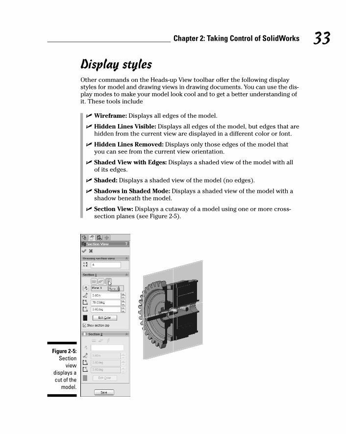
Display stylesOther commands on the Heads-up View toolbar offer the following displaystyles for model and drawing views in drawing documents. You can use the dis-play modes to make your model look cool and to get a better understanding ofit. These tools include
� Wireframe: Displays all edges of the model.
� Hidden Lines Visible: Displays all edges of the model, but edges that arehidden from the current view are displayed in a different color or font.
� Hidden Lines Removed: Displays only those edges of the model thatyou can see from the current view orientation.
� Shaded View with Edges: Displays a shaded view of the model with allof its edges.
� Shaded: Displays a shaded view of the model (no edges).
� Shadows in Shaded Mode: Displays a shaded view of the model with ashadow beneath the model.
� Section View: Displays a cutaway of a model using one or more cross-section planes (see Figure 2-5).
Figure 2-5:Section
viewdisplays acut of the
model.
33Chapter 2: Taking Control of SolidWorks
06_129784 ch02.qxp 9/28/07 12:33 PM Page 33

� RealView Graphics: Displays the model hardware accelerator shaders.Available with certain graphics cards, this mode uses realistic texturesand highlights. In others words, chrome looks like chrome. (See theSupport section of the SolidWorks Web site for details on graphic cards.)
You can set the default display mode of edges in all drawing documents. Todo so, choose Tools➪Options. On the Systems Options tab, under Drawings,select Display Style. From the options that appear, select the check box nextto the display mode you want under Display Style for New Views. Click OK.
Exploring the SolidWorks Help MenuIf you get stuck in your quest to master SolidWorks, have no fear. You cancheck the index of this book for more specific topics or check out theSolidWorks Help menu, which contains a plethora of information to get youback on track or point you in the right direction, at least.
Choose Help from the menu bar menus. A pull-down menu, shown in Figure 2-6, appears with these resources:
� SolidWorks Help: Takes you to the SolidWorks Online User’s Guide, whichaddresses all functions in the SolidWorks software. The guide includescontext-sensitive topics, which you access from the PropertyManager, aswell as additional topics and graphic examples. You can search the tableof contents or the index. A glossary of SolidWorks terminology is alsoavailable.
� SolidWorks Tutorials: Includes practical, step-by-step examples of morethan 20 models you can build. These tutorials cover part creation, assemblyoperations, drawings, and several of the SolidWorks add-in programs, andare a good starting point for finding out how to use the program.
Figure 2-6:The
SolidWorksHelp menu
offers acornucopiaof learning
tools.
34 Part I: Beginning the SolidWorks Journey
06_129784 ch02.qxp 9/28/07 12:33 PM Page 34

� Quick Reference Guide: Opens a 4-page guide that provides a handyreference for various program icons and a list of common keyboard short-cuts. Also available is a list of add-on programs and a brief description oftheir usage.
� API Help: Takes you to an online help resource for the SolidWorksApplication Programming Interface (API). The API lets you automate andcustomize SolidWorks software, and integrate your software withSolidWorks.
� Release Notes: Contains information on new SolidWorks features thatweren’t available when the documentation was completed. For the mostup-to-date information, refer to this document and to online help, whichis updated with each SolidWorks service pack. You can find the releasenotes on the SolidWorks support site at https://customercenter.solidworks.com.
� What’s New: Opens a printable PDF manual. The manual explains newfeatures and changes in the current version of SolidWorks.
� Interactive What’s New: Provides links to topics in the What’s NewManual on new menu items and new and changed PropertyManagers.The topics describe functionality added since the previous release ofSolidWorks and often include examples with sample files.
� Moving from AutoCAD: Takes you to the online guide Moving fromAutoCAD. Many new users switch from the 2D AutoCAD program toSolidWorks. This guide shows the differences between the two programsand helps to make the transition easier.
� Check for Updates: Sends a quick ping to the SolidWorks CustomerPortal Web site to make sure that you’re running the latest and greatestrelease of SolidWorks. If newer versions are available, you have theopportunity to upgrade.
� Activate Licenses: Launches the SolidWorks Product Activation program,which registers your SolidWorks software online.
� Transfer Licenses: Allows you to immediately deactivate and transferyour SolidWorks licenses for use on another computer. Use this optionwhen you upgrade or replace your existing computer hardware.
� Show Licenses: Shows your currently activated products and the expiration dates.
� About SolidWorks: Displays the version, service pack (minor version),and the serial number of your SolidWorks program. You can also accesssolidworks.com and the license agreement.
SolidWorks also offers context-sensitive help as you’re working on documents.When you’re working in the PropertyManager, for example, click the questionmark in the upper right corner (shown in Figure 2-8, later in this chapter) to linkto information about the active command in the SolidWorks Online User’s Guide.
35Chapter 2: Taking Control of SolidWorks
06_129784 ch02.qxp 9/28/07 12:33 PM Page 35
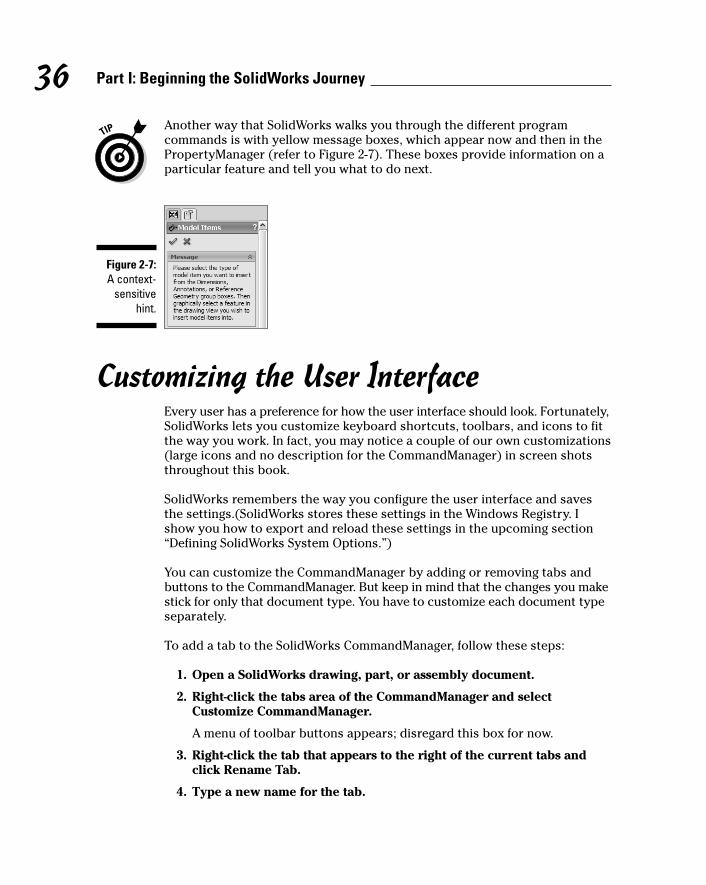
Another way that SolidWorks walks you through the different programcommands is with yellow message boxes, which appear now and then in thePropertyManager (refer to Figure 2-7). These boxes provide information on aparticular feature and tell you what to do next.
Customizing the User InterfaceEvery user has a preference for how the user interface should look. Fortunately,SolidWorks lets you customize keyboard shortcuts, toolbars, and icons to fitthe way you work. In fact, you may notice a couple of our own customizations(large icons and no description for the CommandManager) in screen shotsthroughout this book.
SolidWorks remembers the way you configure the user interface and savesthe settings.(SolidWorks stores these settings in the Windows Registry. Ishow you how to export and reload these settings in the upcoming section“Defining SolidWorks System Options.”)
You can customize the CommandManager by adding or removing tabs andbuttons to the CommandManager. But keep in mind that the changes you makestick for only that document type. You have to customize each document typeseparately.
To add a tab to the SolidWorks CommandManager, follow these steps:
1. Open a SolidWorks drawing, part, or assembly document.
2. Right-click the tabs area of the CommandManager and selectCustomize CommandManager.
A menu of toolbar buttons appears; disregard this box for now.
3. Right-click the tab that appears to the right of the current tabs andclick Rename Tab.
4. Type a new name for the tab.
Figure 2-7:A context-
sensitivehint.
36 Part I: Beginning the SolidWorks Journey
06_129784 ch02.qxp 9/28/07 12:33 PM Page 36
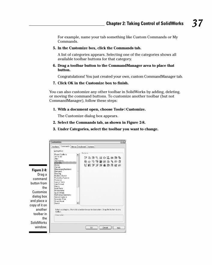
For example, name your tab something like Custom Commands or MyCommands.
5. In the Customize box, click the Commands tab.
A list of categories appears. Selecting one of the categories shows allavailable toolbar buttons for that category.
6. Drag a toolbar button to the CommandManager area to place thatbutton.
Congratulations! You just created your own, custom CommandManager tab.
7. Click OK in the Customize box to finish.
You can also customize any other toolbar in SolidWorks by adding, deleting,or moving the command buttons. To customize another toolbar (but notCommandManager), follow these steps:
1. With a document open, choose Tools➪Customize.
The Customize dialog box appears.
2. Select the Commands tab, as shown in Figure 2-8.
3. Under Categories, select the toolbar you want to change.
Figure 2-8:Drag a
commandbutton from
theCustomizedialog box
and place acopy of it on
anothertoolbar in
theSolidWorks
window.
37Chapter 2: Taking Control of SolidWorks
06_129784 ch02.qxp 9/28/07 12:33 PM Page 37
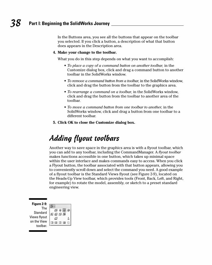
In the Buttons area, you see all the buttons that appear on the toolbaryou selected. If you click a button, a description of what that buttondoes appears in the Description area.
4. Make your change to the toolbar.
What you do in this step depends on what you want to accomplish:
• To place a copy of a command button on another toolbar, in theCustomize dialog box, click and drag a command button to anothertoolbar in the SolidWorks window.
• To remove a command button from a toolbar, in the SolidWorks window,click and drag the button from the toolbar to the graphics area.
• To rearrange a command on a toolbar, in the SolidWorks window,click and drag the button from the toolbar to another area of thetoolbar.
• To move a command button from one toolbar to another, in theSolidWorks window, click and drag a button from one toolbar to adifferent toolbar.
5. Click OK to close the Customize dialog box.
Adding flyout toolbarsAnother way to save space in the graphics area is with a flyout toolbar, whichyou can add to any toolbar, including the CommandManager. A flyout toolbarmakes functions accessible in one button, which takes up minimal spacewithin the user interface and makes commands easy to access. When you clicka Flyout button, the toolbar associated with that button appears, allowing youto conveniently scroll down and select the command you need. A good exampleof a flyout toolbar is the Standard Views flyout (see Figure 2-9), located onthe Heads-Up View toolbar, which provides tools (Front, Back, Left, and Right,for example) to rotate the model, assembly, or sketch to a preset standardengineering view.
Figure 2-9:The
StandardViews flyouton the View
toolbar.
38 Part I: Beginning the SolidWorks Journey
06_129784 ch02.qxp 9/28/07 12:33 PM Page 38

If you want to add a flyout toolbar button to another toolbar, follow these steps:
1. With a document open, choose Tools➪Customize.
The Customize dialog box appears.
2. Select the Commands tab.
3. Select Flyout Toolbars in the Categories area.
You see several buttons appear on the right, under buttons. These buttonsare flyout toolbars that you can add to any other toolbar, including theCommandManager. Click a button to see in the Description box adescription of what the button does.
4. In the Buttons area, drag a toolbar button to a toolbar in theSolidWorks window.
5. Click OK.
Taking advantage of single-commandmodeBy default, when you click a sketch or dimension tool, the command staysactive until you click it again, click another command, or press Escape on thekeyboard. You can set up SolidWorks to work in what’s known as single-command mode. This feature ensures that you’re not stuck in a command.After a command is set, if you want to keep it active for more than one use,double-click the icon when you select it.
To set single-command mode, follow these steps:
1. Choose Tools➪Options➪Systems Options.
The Systems Options dialog box appears.
2. Select General.
The General dialog box appears.
3. Select the Single Command Per Click check box.
4. Click OK.
Defining SolidWorks System OptionsUnlike document properties, the SolidWorks system options relate to thesystem, not to your document. Throughout this book, you find references onhow to change various system options.
39Chapter 2: Taking Control of SolidWorks
06_129784 ch02.qxp 9/28/07 12:33 PM Page 39

1. Click Tools➪Options.
A dialog box appears with two tabs: System Options and DocumentProperties. (The Document Properties tab appears only if you have adocument open.)
2. On the System Options tab, select General.
Several options become available, as shown in Figure 2-10.
The important ones to note are described in this list:
• Open Last Used Document(s) at Startup: Lets you select Always orNever. Select Always if you want the documents you used mostrecently to open automatically when you run SolidWorks again.
• Input Dimension Value: Specifies that the Modify dialog box isautomatically displayed when you create a new dimension. Otherwise,if you don’t check this option, you must double-click the dimensionto change its value.
Figure 2-10:Set thegeneralsystem
options onthe System
Options tab.
40 Part I: Beginning the SolidWorks Journey
06_129784 ch02.qxp 9/28/07 12:34 PM Page 40

• Single Command per Pick: Specifies that sketch and dimension toolsare cleared after each use. (Double-clicking a tool causes it to remainselected for additional use.)
• Show Dimension Names: Displays the dimension’s name as well asits value.
• Show Errors Every Rebuild: Displays an error message each timeyou rebuild the model, if errors are present.
• Maximize Document on Open: Opens each document to its largestsize within the SolidWorks window.
• Use Shaded Face Highlighting: Displays selected faces in a solidcolor (green by default). To specify a different highlight color, clickTools➪Options➪System Options➪Colors, and then select a differ-ent color for Selected Face, Shaded.
41Chapter 2: Taking Control of SolidWorks
06_129784 ch02.qxp 9/28/07 12:34 PM Page 41

42 Part I: Beginning the SolidWorks Journey
06_129784 ch02.qxp 9/28/07 12:34 PM Page 42
Chapter 3
Building Blocks for the Virtual Prototype
In This Chapter� Planning the design and designing the plan
� Sketching it on paper
� Developing mistake-proof checklists
� Creating a design structure
One great strength of SolidWorks is that it gives you the ability to create acomplete virtual product on your computer screen. But don’t let the word
virtual fool you. No one will ask you to wear some high-tech headgear or relivean old sci-fi film (although I like doing both).
By virtual, we mean that you can build a product in SolidWorks similarly tohow you do it in the real world, from drawing an initial sketch to putting togetherparts and subassemblies to creating the final product. You don’t get your handsdirty, and the final product you create looks as it would when rolling off theassembly line. Doing all this work in 3D has many advantages. You can
� See how components interact and ensure that parts don’t interfere witheach other as they move.
� Make sure that parts assemble properly on an assembly line and thatthey disassemble easily for maintenance.
� Show customers how final products will look even before they’re built.
This chapter covers the plan of your design, the importance of drawing ahand sketch, and the basic building blocks for creating a virtual prototype.As you read the sections on design layout sketches and skeletons, bear inmind that Chapter 4 (sketching) and Chapter 6 (assemblies) cover thesetopics in greater detail. Here, I introduce them only in the context of buildinga foundation for what’s ahead.
07_129784 ch03.qxp 9/28/07 12:34 PM Page 43

44 Part I: Beginning the SolidWorks Journey
Planning and Capturing Design Intent(Or, Think First and Then Do)
Although throwing ideas onto a computer screen is certainly an easy way tostart a project, starting with a plan is a better idea. The concept of “think firstand then design” is the key to building successful, reusable designs. Applyingsome discipline to the design process is a good thing. A clearly defined, well-communicated design intent — what you want a design to do, how you want itto move, and how you want it to update when you make changes — resultsnot only in a better design but also one that, in our experience, gets out thedoor faster.
Some designers may argue that planning is extra work. They would ratherplunge into the hands-on work and complete the job as soon as possible. Iwould argue that doing a job right the first time is worth the extra work up front.After all, everyone seems to make time to do the job right the second time! Justthink how many times a design changes, during not only its initial developmentbut also the life of the product. The ability to easily understand and change theimportant elements of the design makes “getting on with it” easier.
So think first and then do. But thinking can be hard work. To make this partof the job a bit easier, we came up with a handy list of tools to use wheneveryou set out to build the foundation of a design you’re working on:
� A hand sketch of your design intent
� An engineering journal
� Early brainstorm sessions
� Design reviews and checklists
These tools allow you to create a consistent and reusable design process,which helps you to define and document the key aspects of the initial designand to modify and create new versions of the product. They also can helpyou identify what you need to change and how the design will update as aresult.
Starting the design with a hand sketchWhen you start work on a design, you generally bump into more questionsthan answers, particularly when you’re working on an all-new product asopposed to an improved version of an existing one, about which you likelyhave information. So, assuming that you’re not clairvoyant, how do youcreate and document a design so that you can easily modify it when newinformation becomes available? The answer: Simply grab a pencil and paper
07_129784 ch03.qxp 9/28/07 12:34 PM Page 44
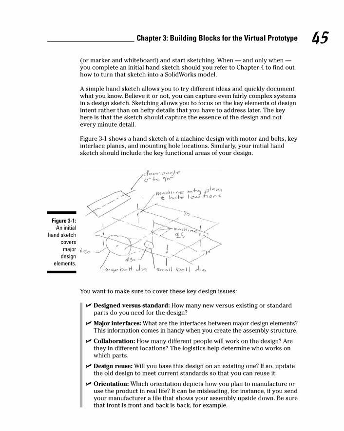
(or marker and whiteboard) and start sketching. When — and only when —you complete an initial hand sketch should you refer to Chapter 4 to find outhow to turn that sketch into a SolidWorks model.
A simple hand sketch allows you to try different ideas and quickly documentwhat you know. Believe it or not, you can capture even fairly complex systemsin a design sketch. Sketching allows you to focus on the key elements of designintent rather than on hefty details that you have to address later. The keyhere is that the sketch should capture the essence of the design and notevery minute detail.
Figure 3-1 shows a hand sketch of a machine design with motor and belts, keyinterface planes, and mounting hole locations. Similarly, your initial handsketch should include the key functional areas of your design.
You want to make sure to cover these key design issues:
� Designed versus standard: How many new versus existing or standardparts do you need for the design?
� Major interfaces: What are the interfaces between major design elements?This information comes in handy when you create the assembly structure.
� Collaboration: How many different people will work on the design? Arethey in different locations? The logistics help determine who works onwhich parts.
� Design reuse: Will you base this design on an existing one? If so, updatethe old design to meet current standards so that you can reuse it.
� Orientation: Which orientation depicts how you plan to manufacture oruse the product in real life? It can be misleading, for instance, if you sendyour manufacturer a file that shows your assembly upside down. Be surethat front is front and back is back, for example.
Figure 3-1:An initial
hand sketchcoversmajor
designelements.
45Chapter 3: Building Blocks for the Virtual Prototype
07_129784 ch03.qxp 9/28/07 12:34 PM Page 45
� Specifications: What information exists for the design? How big should itbe? What is it made of? Are any important elements missing?
� Manufacturing: Include any additional design accommodations that needto be made for assembly fixtures, manufacturing, and tooling, for example.
� Design notes and issues: What additional notes, comments, or issuesmight the design group bring up? Be sure to capture and track these items.
� Product life cycle: How long do you plan to sell and maintain the product?If the design has a long life cycle, it may undergo a number of revisionsin its lifetime, making design documents especially important.
Using an engineering journal and theSolidWorks Design BinderAs your design progresses, you need to answer several questions and makemany decisions. In the old days, before computers existed, engineers kept theirthoughts and notes and other scribbles in a spiral notebook, or engineeringjournal.
Nowadays, an engineering journal can be a Microsoft Word or Excel docu-ment. In SolidWorks, you have something even better, the Design Binder vir-tual design folder, where you can store links to documents that relate to theproject. You can never misplace your Design Binder because it’s attached toyour SolidWorks drawing, part, or assembly file — right in theFeatureManager design tree. To link or attach a document to the DesignBinder, follow these steps:
1. Open the SolidWorks drawing, part, or assembly document.
2. In the FeatureManager design tree, right-click Design Binder andchoose Add Attachment.
The Add Attachment dialog box appears.
By default, the Design Binder is hidden in the FeatureManager tree. Toshow the Design Binder, right-click the item at the top of the tree and select Hidden Tree Items➪Design Binder. The Design Binder can also beshown permanently by choosing Tools➪Options➪System Options➪FeatureManager and changing the Design Binder option to Show.
3. In the Add Attachment dialog box, type a path and filename or clickthe Browse button to navigate to the file you want to link or attach.
4. To link the file, select the Link check box.
This option allows you to include a link to a document. If you want toattach the physical document, leave this option blank.
46 Part I: Beginning the SolidWorks Journey
07_129784 ch03.qxp 9/28/07 12:34 PM Page 46
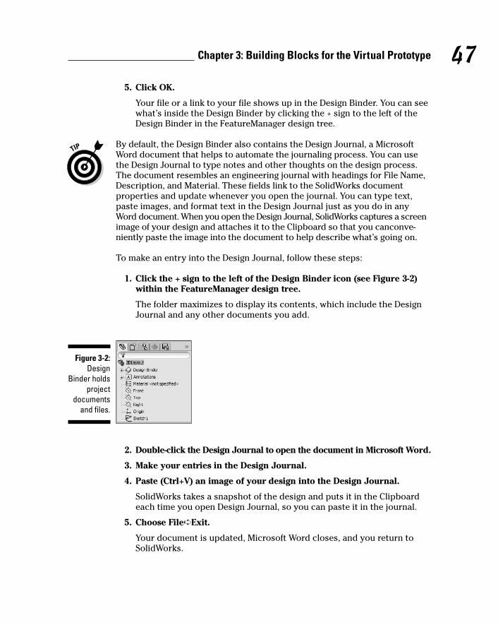
5. Click OK.
Your file or a link to your file shows up in the Design Binder. You can seewhat’s inside the Design Binder by clicking the + sign to the left of theDesign Binder in the FeatureManager design tree.
By default, the Design Binder also contains the Design Journal, a MicrosoftWord document that helps to automate the journaling process. You can usethe Design Journal to type notes and other thoughts on the design process.The document resembles an engineering journal with headings for File Name,Description, and Material. These fields link to the SolidWorks documentproperties and update whenever you open the journal. You can type text,paste images, and format text in the Design Journal just as you do in anyWord document. When you open the Design Journal, SolidWorks captures a screenimage of your design and attaches it to the Clipboard so that you canconve-niently paste the image into the document to help describe what’s going on.
To make an entry into the Design Journal, follow these steps:
1. Click the + sign to the left of the Design Binder icon (see Figure 3-2)within the FeatureManager design tree.
The folder maximizes to display its contents, which include the DesignJournal and any other documents you add.
2. Double-click the Design Journal to open the document in Microsoft Word.
3. Make your entries in the Design Journal.
4. Paste (Ctrl+V) an image of your design into the Design Journal.
SolidWorks takes a snapshot of the design and puts it in the Clipboardeach time you open Design Journal, so you can paste it in the journal.
5. Choose File➪Exit.
Your document is updated, Microsoft Word closes, and you return toSolidWorks.
Figure 3-2:Design
Binder holdsproject
documentsand files.
47Chapter 3: Building Blocks for the Virtual Prototype
07_129784 ch03.qxp 9/28/07 12:34 PM Page 47

You can use the Design Binder tool consistently throughout the designprocess to capture ideas, issues, and decisions. You also may want to storeengineering notes the old-fashioned way, in a good old spiral notebook. Findthe option that fits your requirements and working style.
Capturing design intent: BrainstormingBrainstorming is a fruitful approach when you need collective ideas from yourdesign team. Have a meeting early in the design process and map out thedesign intent — including all the big elements of your product design — on alarge whiteboard. Write down the ideas and functions that the design shouldinclude. Document how the product should move. Make notes on potentialissues and risks and include any other information that may be helpful.
These meetings are a great way to document some of the “tribal information”that lives quietly in everyone’s head. Get everyone’s ideas in writing. Thisreview provides a consistent foundation for the design. The more you canidentify before charging forward, the better.
By the way, don’t count on everyone to remember exactly what was said inthe meeting. If you’re using an electronic whiteboard, write a date over thetop and print a copy. Otherwise, take a picture with your digital camera andpop the image into your Design Binder.
Making a list and checking it twiceChecklists are valuable tools in the design process. After all, if a checklist worksfor Santa Claus, why not for a design team? The purpose of the checklist is toprovide a consistent basis or foundation for your design project and toreduce those (avoidable) simple mistakes.
Your checklist should list common questions that the design team needs toaddress early in the design process, such as these:
� Has anyone approved or sourced the material you want to use?
� Have you added engineering requirements to the request for quotation(RFQ)?
� Has your purchasing department submitted an RFQ?
� Have you completed and documented the design review?
� Have you checked design standards?
� Have you checked the assembly to ensure that the parts fit togetherproperly and do not clash, or interfere, with one another when they move?
48 Part I: Beginning the SolidWorks Journey
07_129784 ch03.qxp 9/28/07 12:34 PM Page 48
Dow
nlo
ad fro
m W
ow
! eBook
<w
ww
.wow
ebook.
com
>

� Are you using standard hardware for all fasteners? (If not, you should be,unless you want to design them all yourself.)
� Have you completed the drawing title block and revision block? Youshould include blocks in the drawing templates:
• Blocks include standard information that you insert into drawings.
• A title block lists your company name and other basic informationabout the project.
• A revision block includes the revision number of the document.
(See Chapter 7 for more information on blocks.)
� Have you added custom properties to the document? Custom propertiesinclude information that identifies the project and the document. You canlink custom property fields to the drawing title block so that informationis consistent in both areas. (You can find more information on customproperties in Chapter 10.)
� Is your testing and validation plan complete? This process should includea schedule of how and when you plan to optimize the design by usinganalysis software or physical prototypes or a combination of both.
Quite often, you can use the same checklist from design to design. In fact,having a standard checklist ensures consistency throughout your designprocesses and makes documenting the design easier. Remember: A pilot hasgood reason to go over a checklist every time he flies a plane, so why not reviewa checklist every time you design?
The process for starting and documenting a design should be a well-worn andfamiliar path, not something you think up out of the blue each time youdesign a new product. Build reviews (like the design intent brainstorm listedin the preceding section) into your design process and subsequent designmeetings. Planning for success is the best way to ensure that it happens.
Applying Layouts and Design SkeletonsAfter you come up with a hand sketch (see the section “Starting the designwith a hand sketch,” earlier in this chapter), you’re ready to translate it into adesign layout sketch. The design layout sketch is related to — and often asubset of — the design skeleton.
Here are a few working definitions:
� Assembly: A collection of parts and other assemblies, known as sub-assemblies. A SolidWorks assembly file has the .sldasm extension.
49Chapter 3: Building Blocks for the Virtual Prototype
07_129784 ch03.qxp 9/28/07 12:34 PM Page 49
� Design skeleton: A simple framework made up of design layout sketchesand simple reference geometry (planes and axes) that document theimportant elements of the design.
� Design layout: A 3D sketch that defines the key elements of the design.
This chapter describes how to create a framework for your SolidWorksassembly (your virtual prototype) using a design layout sketch or a skeleton.(For more information on layouts and skeletons, see Chapter 6.)
Your assembly can have anywhere from 2 to 1,000 or more components,which can be parts or other assemblies called subassemblies. Depending onhow complex your assembly is, your skeleton may include one or morelayout sketches.
The advantages of the skeleton include the ones in this list:
� It gives you a better grasp of the design you’re about to build. You cancreate and modify the assembly before you design any parts. Determiningthe most important aspects of the design early in the design processmakes for a better design. The skeleton is the electronic version of thehand sketch discussed early in this chapter. (See the section “Startingthe design with a hand sketch.”)
� You can capture design intent in the design layout sketch so that youcan collaborate better with team members. Then the designer whoworks on this assembly can immediately see how parts fit together.
� You can automatically update your design by using references. As youcreate components for your assembly, you can design them so that theyreference geometry in the layout sketch. If you change the layout sketch,the components that reference it update accordingly. A reference togeometry within the assembly (an in-context reference) is a way ofmaking sure that parts fit together correctly.
Designing top down versus bottom upYou can design an assembly in two ways: top down or bottom up. In top-downdesign, you build parts in the assembly, using the geometry of one part todesign the others. In other words, top-down design relies on in-context refer-ences. Bottom-up design is the opposite: You design each part individuallyand then assemble the components to make the assembly.
Which method is better — top-down or bottom-up design? In reality, a combination of both methods works best. By creating a skeleton first, youcan design parts to reference the skeleton rather than have them referenceother parts, thereby giving you more control over the design. Other benefitsinclude these:
50 Part I: Beginning the SolidWorks Journey
07_129784 ch03.qxp 9/28/07 12:34 PM Page 50
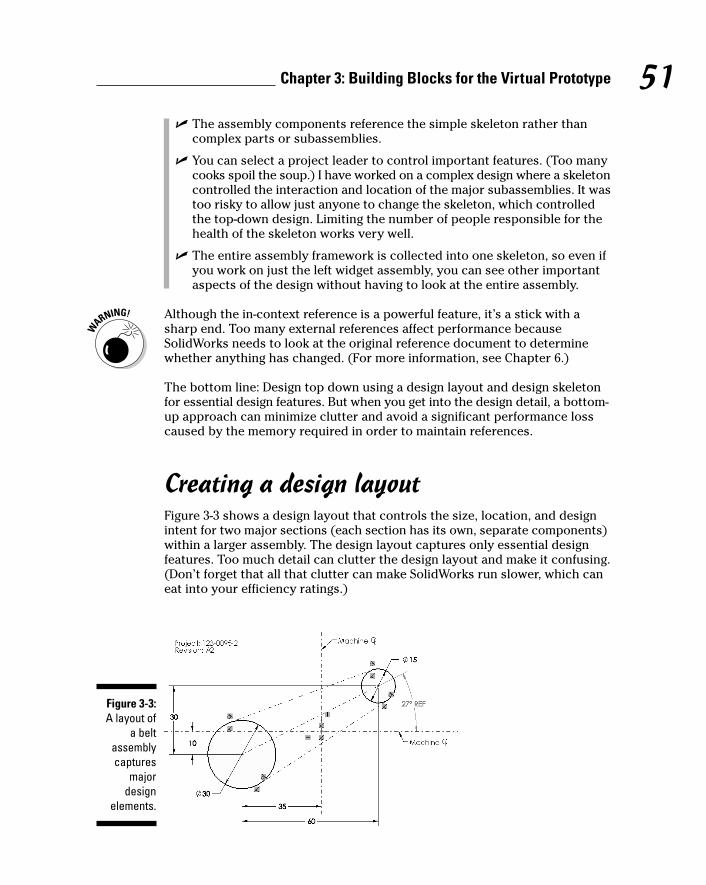
� The assembly components reference the simple skeleton rather thancomplex parts or subassemblies.
� You can select a project leader to control important features. (Too manycooks spoil the soup.) I have worked on a complex design where a skeletoncontrolled the interaction and location of the major subassemblies. It wastoo risky to allow just anyone to change the skeleton, which controlledthe top-down design. Limiting the number of people responsible for thehealth of the skeleton works very well.
� The entire assembly framework is collected into one skeleton, so even ifyou work on just the left widget assembly, you can see other importantaspects of the design without having to look at the entire assembly.
Although the in-context reference is a powerful feature, it’s a stick with asharp end. Too many external references affect performance becauseSolidWorks needs to look at the original reference document to determinewhether anything has changed. (For more information, see Chapter 6.)
The bottom line: Design top down using a design layout and design skeletonfor essential design features. But when you get into the design detail, a bottom-up approach can minimize clutter and avoid a significant performance losscaused by the memory required in order to maintain references.
Creating a design layoutFigure 3-3 shows a design layout that controls the size, location, and designintent for two major sections (each section has its own, separate components)within a larger assembly. The design layout captures only essential designfeatures. Too much detail can clutter the design layout and make it confusing.(Don’t forget that all that clutter can make SolidWorks run slower, which caneat into your efficiency ratings.)
Figure 3-3:A layout of
a beltassemblycaptures
majordesign
elements.
51Chapter 3: Building Blocks for the Virtual Prototype
07_129784 ch03.qxp 9/28/07 12:34 PM Page 51
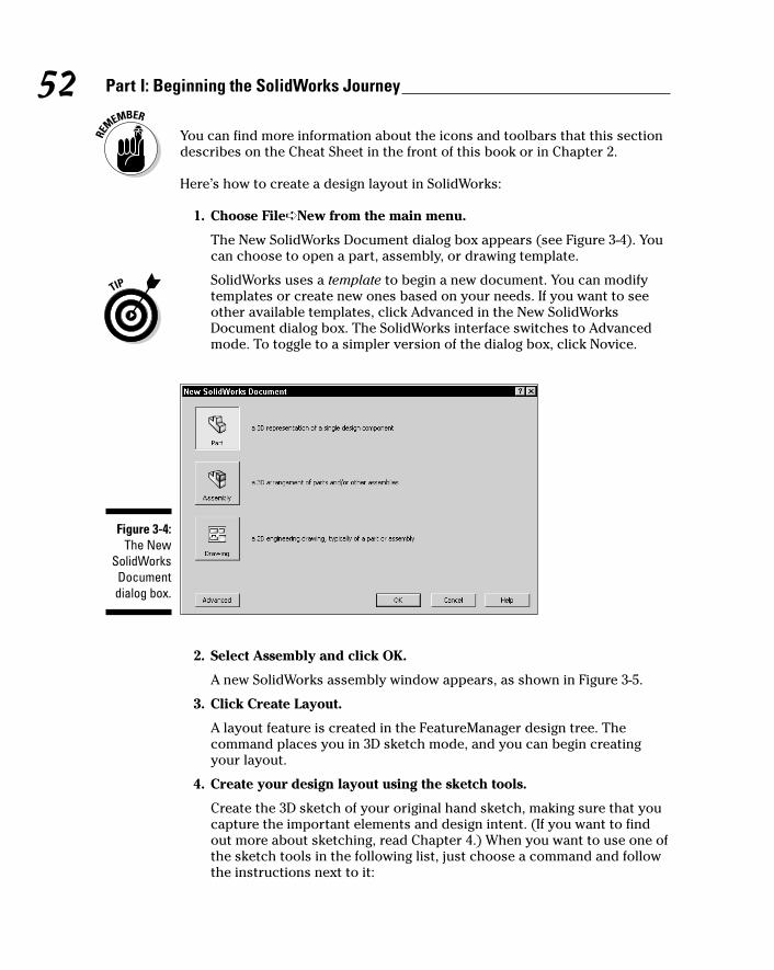
You can find more information about the icons and toolbars that this sectiondescribes on the Cheat Sheet in the front of this book or in Chapter 2.
Here’s how to create a design layout in SolidWorks:
1. Choose File➪New from the main menu.
The New SolidWorks Document dialog box appears (see Figure 3-4). Youcan choose to open a part, assembly, or drawing template.
SolidWorks uses a template to begin a new document. You can modifytemplates or create new ones based on your needs. If you want to seeother available templates, click Advanced in the New SolidWorksDocument dialog box. The SolidWorks interface switches to Advancedmode. To toggle to a simpler version of the dialog box, click Novice.
2. Select Assembly and click OK.
A new SolidWorks assembly window appears, as shown in Figure 3-5.
3. Click Create Layout.
A layout feature is created in the FeatureManager design tree. Thecommand places you in 3D sketch mode, and you can begin creatingyour layout.
4. Create your design layout using the sketch tools.
Create the 3D sketch of your original hand sketch, making sure that youcapture the important elements and design intent. (If you want to findout more about sketching, read Chapter 4.) When you want to use one ofthe sketch tools in the following list, just choose a command and followthe instructions next to it:
Figure 3-4:The New
SolidWorksDocumentdialog box.
52 Part I: Beginning the SolidWorks Journey
07_129784 ch03.qxp 9/28/07 12:34 PM Page 52
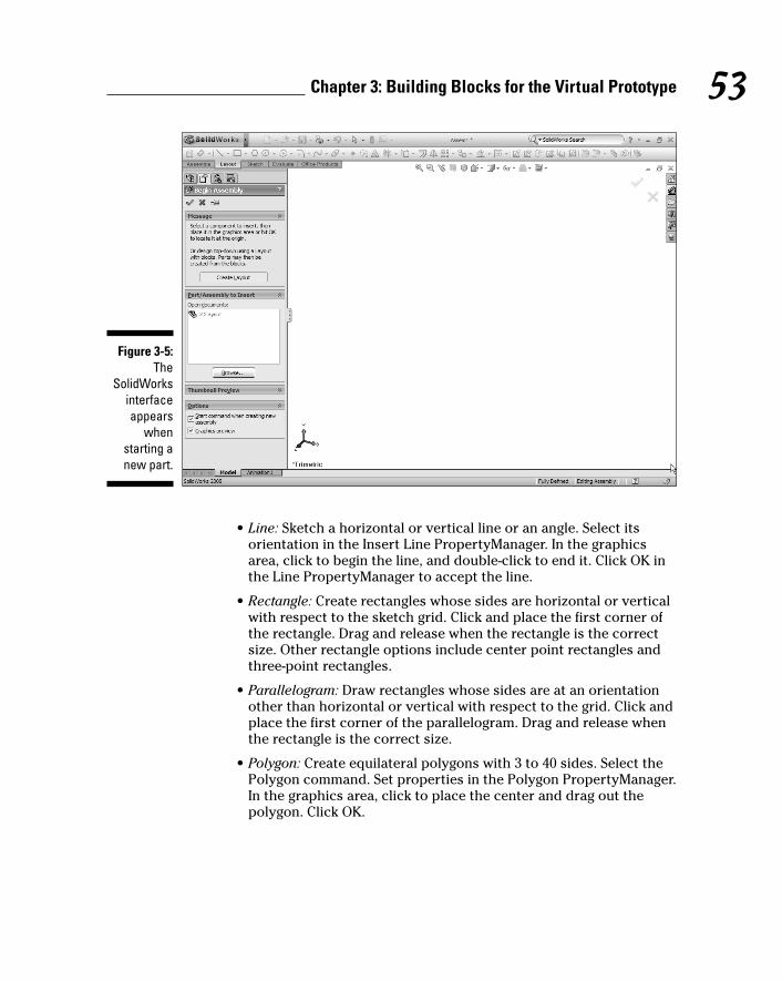
• Line: Sketch a horizontal or vertical line or an angle. Select itsorientation in the Insert Line PropertyManager. In the graphicsarea, click to begin the line, and double-click to end it. Click OK inthe Line PropertyManager to accept the line.
• Rectangle: Create rectangles whose sides are horizontal or verticalwith respect to the sketch grid. Click and place the first corner ofthe rectangle. Drag and release when the rectangle is the correctsize. Other rectangle options include center point rectangles andthree-point rectangles.
• Parallelogram: Draw rectangles whose sides are at an orientationother than horizontal or vertical with respect to the grid. Click andplace the first corner of the parallelogram. Drag and release whenthe rectangle is the correct size.
• Polygon: Create equilateral polygons with 3 to 40 sides. Select thePolygon command. Set properties in the Polygon PropertyManager.In the graphics area, click to place the center and drag out thepolygon. Click OK.
Figure 3-5:The
SolidWorksinterfaceappears
whenstarting anew part.
53Chapter 3: Building Blocks for the Virtual Prototype
07_129784 ch03.qxp 9/28/07 12:34 PM Page 53

• Circle: Sketch a center-based circle with this tool. Select the centeror perimeter orientation in the Circle PropertyManager. Click thegraphics area to place the center, move the point, and then click toset the radius. Click OK in the Circle PropertyManager.
• Partial Ellipse: Create a partial ellipse from a center point, a startpoint, and an end point. Click in the graphics area to place thecenter point. Drag and click to define one axis of the ellipse. Dragand click to define the second axis. Drag the pointer around thecircumference to define the extent of the ellipse and then click tocomplete the ellipse.
• Parabola: Create a parabolic curve. Click to place the focus of theparabola, and drag to enlarge the parabola, which outlines theparabola. Click the parabola to define the extent of the curve.
• Spline: Create a series of curves that run through points. Click toplace the first point and drag out the first segment. Click to the endpoint and drag out the second segment. Keep going until the splineis complete. Click OK.
• Point: Insert points into your sketch. Click in the graphics area toplace the point.
• Centerline: Create symmetrical sketch elements. Click to start thecenterline. Drag the pointer and click to set the end.
• Sketch Fillet: Trim away the corner at an intersection of two sketchentities to create a tangent arc. Click the Sketch Fillet tool and setthe properties in the PropertyManager. Select two sketch entitiesor select a corner. Click OK to accept the fillet.
• Sketch Chamfer: Apply a chamfer to adjacent sketch entities insketches. Click the chamfer tool. Set chamfer parameters in thePropertyManager. Select two sketch entities to chamfer, or select avertex. Click OK to accept the chamfer.
5. Click the Layout button on the Layout toolbar to close the layout andthe sketch.
6. Choose File➪Save to save the assembly.
Don’t forget to save your work. SolidWorks also asks whether you wantto save any work in progress before you close down the program.
The preceding method creates the design layout within the assembly, but that’snot the only way to go. You can also create a design layout sketch in a part fileand add the part to the assembly later. I cover this method in Chapter 6.
54 Part I: Beginning the SolidWorks Journey
07_129784 ch03.qxp 9/28/07 12:34 PM Page 54

Creating in-context parts in the assemblyAssembly components can reference information (size or location) in thedesign layout or in the skeleton, as described in the next section. In both theseexamples of in-context references, when you change the design layout or theskeleton, you change the geometry that references those updates accordingly.
To reference parts to other parts, use design layouts as in-context relations.Follow these steps:
1. Open the assembly file that contains the part to edit.
2. Click the part to edit within the FeatureManager design tree or in thegraphics area.
3. Click the Edit Component icon on the Assembly toolbar.
The part you select appears normally; the other assembly componentsare transparent.
4. Edit the part.
Make changes to the parts design. You can reference the assembly components to drive in-context relations.
5. Click the Edit Component icon within the Assembly toolbar to returnto the original assembly.
Thinking about skeletons you want in your closetNo, this section doesn’t talk about Uncle Bob at last year’s Christmas party,but rather about a SolidWorks feature you can use to depict and documentthe major design elements of the assembly.
Although a design layout works well, sometimes you want to use a skeletonwhen creating a large and complex element, such as a lawnmower. Similar to asketch, a skeleton is saved as a SolidWorks part document (.sldprt). However,a skeleton incorporates several design sketches and uses other elements (suchas planes and axes) that allow you to simulate the location, the importantinterfaces where parts fit together, and the motion of the assembly components.Figure 3-6 shows an example of how you can extend 2D layout sketches into a3D design skeleton.
55Chapter 3: Building Blocks for the Virtual Prototype
07_129784 ch03.qxp 9/28/07 12:34 PM Page 55
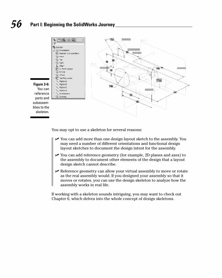
You may opt to use a skeleton for several reasons:
� You can add more than one design layout sketch to the assembly. Youmay need a number of different orientations and functional designlayout sketches to document the design intent for the assembly.
� You can add reference geometry (for example, 2D planes and axes) tothe assembly to document other elements of the design that a layoutdesign sketch cannot describe.
� Reference geometry can allow your virtual assembly to move or rotateas the real assembly would. If you designed your assembly so that itmoves or rotates, you can use the design skeleton to analyze how theassembly works in real life.
If working with a skeleton sounds intriguing, you may want to check outChapter 6, which delves into the whole concept of design skeletons.
Figure 3-6:You can
referenceparts and
subassem-blies to the
skeleton.
56 Part I: Beginning the SolidWorks Journey
07_129784 ch03.qxp 9/28/07 12:34 PM Page 56

Part IIDesign Intent and
the VirtualPrototype
08_129784 pp02.qxp 9/28/07 12:34 PM Page 57

In this part . . .
Easy-to-modify, or robust, designs provide a strongfoundation for the design because you can create
parts that are easy to understand and modify. You thenuse these parts to build functional assemblies. Thisdesign food chain is an effective means to build parts andassemblies.
It’s the small things that count during the design process.This part builds on two main ideas: design intent (fit,form, and function) and the virtual prototype. SolidWorkscreates the parts in 3D, which helps you get a betterunderstanding of your design, long before you ever manu-facture the first part.
08_129784 pp02.qxp 9/28/07 12:34 PM Page 58

Chapter 4
Do What I Mean, Not What I Sketch
In This Chapter� Getting started with sketches
� Creating reference geometry
� Capturing design intent up front
� Understanding geometric relationships
� Adding features by using sketches
Just like building a house, your design needs to start with a sound andsturdy foundation. Sketches are the building blocks for your design. Before
you start to build parts and assemblies, you need to know how to create a goodsketch and to understand how a sketch affects the rest of the design.
You may think it strange to talk about sketches before creating parts, but theability to create sketches that capture design intent makes it easier to createthe part. In other words, you need to walk before you run, so be sure that theseconcepts are clear before you go to other chapters in the book. Each step inthe sketch process helps you think about how to create a better design andtake full advantage of the SolidWorks 3D modeling system.
In this chapter, we introduce what makes up a sketch: sketch entities (linesand arcs, for example) and reference geometry (axes and planes). We alsoexamine how part features use these objects.
Making and Editing a SketchA sketch is a collection of simple elements, such as lines, rectangles, and circles.Sketches can be 2D or 3D and serve a number of uses within SolidWorks; mostimportant, they’re the basis for sketched features. Features (extruded bossesand cuts, for example) are the geometrical shapes you use to build parts. Amodel includes one or more sketches as well as one or more features (unless
09_129784 ch04.qxp 9/28/07 12:34 PM Page 59
60 Part II: Design Intent and the Virtual Prototype
the part was created from imported geometry). This section focuses on howto create 2D sketches to use as the bases of part features. Chapter 5 goes intodetail on all the part features.
Follow this order when you make a sketch:
1. Draw the sketch geometry.
2. Add relations.
3. Dimension the sketch.
Identifying the elements of a sketchBefore you find out how to draw the sketch, you should first become familiarwith the sketch lingo that appears throughout this chapter. Refer to thefollowing list of terms whenever you need to:
� Origin: Marks the center of the document. When a sketch is active,twored arrows appear in the middle of the graphical display and mark the(0,0,0) coordinate of the sketch. When you’re working on a part, the arrowsare blue. When a sketch is active, the origin is red. Each part and assemblyhas its own origin. You can’t delete the origin of a part or assembly.
� Construction geometry: Assists you in creating the sketch entities andgeometry that you ultimately incorporate into a part. Points and centerlinesare always construction geometry, but you can convert any other sketchentity into a construction geometry. Construction geometry appears as adashed line. SolidWorks doesn’t look at construction geometry when itcreates part features.
� Reference geometry: Defines the shape or form of a surface or solid inthe model. SolidWorks uses reference geometry (planes, axes, coordinatesystems, and points) as the basis for creating part features.
� Plane: Refers to flat reference geometry. In a part or an assemblydocument, SolidWorks provides three default planes (front, top, and right).You can create your own reference planes as well. You must begin a 2Dsketch on either a plane or the flat, planar face of a part.
� Axis: Refers to an infinite straight dashed line that you use to createmodel geometry, features, or patterns. You can create an axis in anumber of different ways, including by creating a line or a constructionline, or by intersecting two planes.
� Driving dimension (or model dimension): Defines the size of a sketch,which drives the shape of the model. When you change a sketch dimension,the rest of the sketch updates accordingly. (Chapter 3 covers design intentin detail.)
09_129784 ch04.qxp 9/28/07 12:34 PM Page 60
� Driven dimension (or reference dimension): Shows the measurementsof a model but doesn’t drive the model, and you can’t change it. You canadd driven dimensions to sketches and drawings.
� Sketch entity: Simple objects, such as lines, points, and circles, thatmake up a sketch.
� Relations: Establish geometric relations for a single sketch entity andbetween sketch entities. For example, a parallel relation makes two linesparallel to each other, and a tangent relation makes two lines tangent.Relations are an important method for capturing design intent.
Origins and orientationHow you kick off a sketch varies depending on how you want your design tolook and the type and order of the design’s features. Before you begin asketch, you want to decide on these elements:
� The reference plane or part face that you want to sketch on
� The origin of the sketch
� The relationships between the sketch entities
� The dimensions you need for the drawing
Every time you draw a sketch, you must first select a plane or a part face(such as the left side of a cube) to draw it on. The plane determines theorientation of your sketch. If you sketch on the front plane, you’re sketchingthe front of a part. You don’t want to end up with a part that’s upside down orsideways, so choosing the right plane or surface is important.
The origin is where you start your sketch. In most cases, the origin of the sketchcoincides with the origin of the document. The origin anchors yoursketch.Centers of mounting holes, axes of rotation, and the mounting face are alsogood choices for an origin. Figure 4-1 shows examples of parts with originsdefined with design intent in mind.
You can use the following list to determine the orientation or origin of your sketch:
� Part origin: Parts in an assembly can share a common origin. Parts arebuilt with this common assembly location in mind.
� Final assembly orientation: You can position a part based on how it fitsinto the assembly.
� Design layout: You can position a part based on a design layout sketchor a skeleton.
� Drawing views to create: You can design a part based on how you wantit projected in the drawing.
61Chapter 4: Do What I Mean, Not What I Sketch
09_129784 ch04.qxp 9/28/07 12:34 PM Page 61

Sketching with entitiesAfter you ponder over origins and orientation, you’re ready to take your mousein hand and draw. You begin a sketch in a part document by activating Sketchmode. You can switch back into Solid Modeling mode by exiting Sketch mode. Youuse sketch entities to build the sketch. The sketch entity commands are locatedon the Sketch toolbar, which appears by default in the CommandManager whenyou begin a sketch.
Here’s how to start a sketch:
1. Open a new part document in SolidWorks.
The origin appears in blue in the graphics area.
2. Choose Insert➪Sketch.
The Edit Sketch PropertyManager appears in the left pane. Three defaultplanes (Front, Top, and Right) appear in the graphics area. If you placethe pointer over a plane, the plane’s edges are highlighted in red.
3. Click an edge of a plane or anywhere on a part face to sketch in thegraphics area.
You can begin a sketch on a plane or a part face. You can select a defaultplane, or you can create your own. (See the section “Adding reference
Origin
Figure 4-1:Choose anorigin that
meanssomethingto the part.
62 Part II: Design Intent and the Virtual Prototype
09_129784 ch04.qxp 9/28/07 12:34 PM Page 62
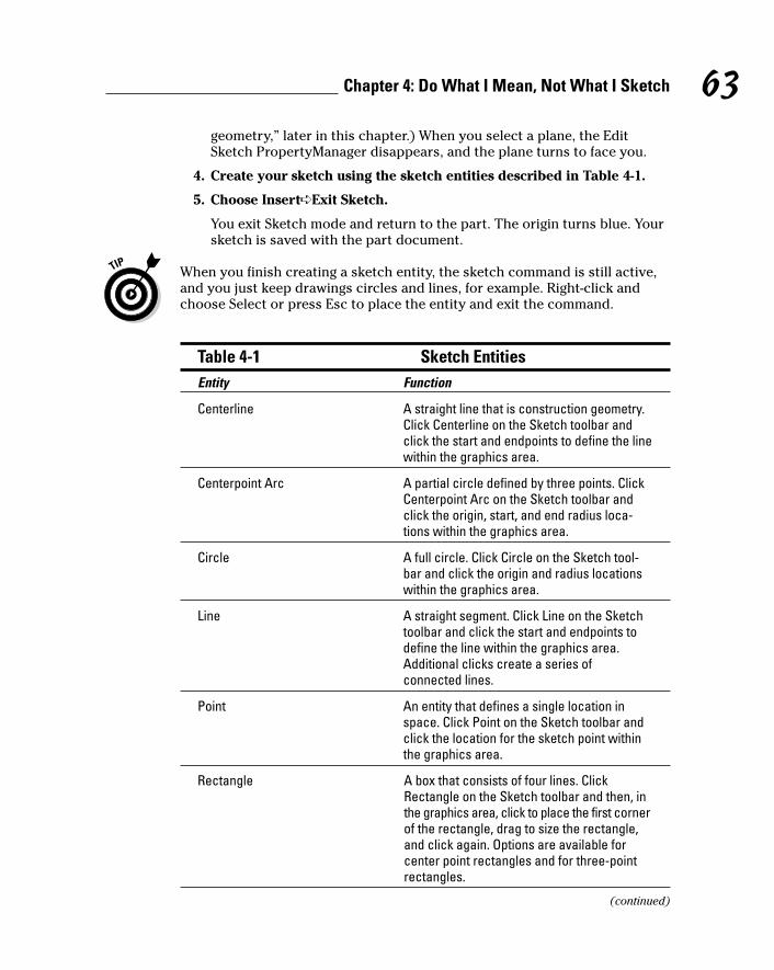
geometry,” later in this chapter.) When you select a plane, the EditSketch PropertyManager disappears, and the plane turns to face you.
4. Create your sketch using the sketch entities described in Table 4-1.
5. Choose Insert➪Exit Sketch.
You exit Sketch mode and return to the part. The origin turns blue. Yoursketch is saved with the part document.
When you finish creating a sketch entity, the sketch command is still active,and you just keep drawings circles and lines, for example. Right-click andchoose Select or press Esc to place the entity and exit the command.
Table 4-1 Sketch EntitiesEntity Function
Centerline A straight line that is construction geometry.Click Centerline on the Sketch toolbar andclick the start and endpoints to define the linewithin the graphics area.
Centerpoint Arc A partial circle defined by three points. ClickCenterpoint Arc on the Sketch toolbar andclick the origin, start, and end radius loca-tions within the graphics area.
Circle A full circle. Click Circle on the Sketch tool-bar and click the origin and radius locationswithin the graphics area.
Line A straight segment. Click Line on the Sketchtoolbar and click the start and endpoints todefine the line within the graphics area.Additional clicks create a series ofconnected lines.
Point An entity that defines a single location inspace. Click Point on the Sketch toolbar andclick the location for the sketch point withinthe graphics area.
Rectangle A box that consists of four lines. ClickRectangle on the Sketch toolbar and then, inthe graphics area, click to place the first cornerof the rectangle, drag to size the rectangle,and click again. Options are available forcenter point rectangles and for three-pointrectangles.
(continued)
63Chapter 4: Do What I Mean, Not What I Sketch
09_129784 ch04.qxp 9/28/07 12:34 PM Page 63

Table 4-1 (continued)Entity Function
Sketch Fillet A tangent arc between two intersectingentities. Click Sketch Fillet on the Sketch toolbarand set properties in the PropertyManager.Hold down the Ctrl key and select two sketchentities to fillet and select a corner.
Spline A curvy line defined by a set of points. ClickSpline on the Sketch toolbar and click thepoint locations within the graphics area todefine the spline.
Tangent Arc An arc tangent to a sketch entity. Click TangentArc on the Sketch toolbar and click the end-point of an existing tangent entity (line, arc,ellipse, or spline) and the endpoint for the arcwithin the graphics area.
Three Point Arc A partial circle. Click Three Point Arc on theSketch toolbar and click the three points onthe arc within the graphics area.
Modifying sketch entitiesSeveral additional commands on the Sketch toolbar allow you to makechanges to your sketch, if needed. For example, the Construction commandturns any sketch entity into construction geometry.
You create your sketch in a part or an assembly document. When you open adocument to edit a sketch, you need to switch back into Sketch mode. Toturn on sketching, choose Insert➪Sketch. When you want to go back to solidmodeling to create part features, choose Insert➪Exit Sketch. If the sketchalready exists, select the sketch in the FeatureManager design tree, right-click, and choose the Edit Sketch icon.
The following sections cover the sketch modification commands (see Figure 4-2),which are on the right side of the Sketch toolbar.
Figure 4-2:Sketch
modificationcommands.
64 Part II: Design Intent and the Virtual Prototype
09_129784 ch04.qxp 9/28/07 12:34 PM Page 64

Mirror entitiesWhen you create mirror entities, SolidWorks mirrors the entities that youselect about a centerline or line. If that sounds confusing, imagine that you’restanding on the edge of a pond. You see a reflection of yourself in the water.The reflection is your mirror image, and the centerline, which you mirrorabout, is the edge of the pond. In SolidWorks, if you change a mirrored entity,its mirror image also changes.
To mirror one or more existing sketch entities in a sketch:
1. Click Mirror Entities on the Sketch toolbar.
The Mirror PropertyManager appears, with the Entities to Mirror fieldactive.
2. In the graphics area, click the entities you want to mirror.
The entities are displayed in the Entities to Mirror field. If you want toremove an entity, select it in the field and press Delete on the keyboard.
3. Click inside the Mirror About field.
The field is highlighted, indicating that the next entity you select goes inthis field.
4. Select the Copy check box to include both the mirrored copy and theoriginal sketch entities. Clear the Copy check box to add a mirrorcopy of the selected entities and to remove the original sketch.
If you remove the original sketch, it’s like removing the original object ina mirror and leaving only a reflection.
5. Click the edge or line that you want to mirror about the centerline.
The edge or line appears in the Mirror About field.
6. Click OK.
A mirror image of the entities you selected appears on the other side ofthe line or edge.
Convert entitiesYou can create one or more curves in a sketch by projecting an edge, a loop,a face, a curve, an external sketch contour, a set of edges, or set of sketchcurves onto an existing sketch plane.
To convert sketch entities in an open sketch:
1. Click a model edge, loop, face, curve, external sketch contour, set ofedges, or set of curves.
65Chapter 4: Do What I Mean, Not What I Sketch
09_129784 ch04.qxp 9/28/07 12:34 PM Page 65

2. Click Convert Entities on the Sketch toolbar.
The new sketch entities appear on the sketch plane.
3. Click OK.
Offset entitiesYou can make a copy of a sketch entity so that the copy appears a specifieddistance on the sketch plane from the original object. To offset one or moresketch entities in an open sketch, follow these steps:
1. Click Offset Entities on the Sketch toolbar.
The Offset Entities PropertyManager appears.
2. In the Parameters section of the PropertyManager, type a value forthe offset distance.
3. In the graphics area, click the entity or entities to offset.
To see a dynamic preview, hold down the mouse button and drag thepointer in the graphics area. As you drag the pointer, the size of theoffset changes. When you release the mouse button, the Offset Entity iscomplete.
4. Click OK.
Trim entitiesYou can trim entities to your liking with the Trim Entities command. Thecommand allows you to create unusual shapes. For example, you can sketcha large circle with two small circles intersecting it at the top. You can thentrim away the crisscrossing arcs of the three circles to end up with a shapethat looks like Mickey Mouse. The Trim Property Manager has severaloptions: The Power Trim option is a quick way to trim or delete any sketchentity, and the Corner option lets you trim two entities to the nearest inter-section. Both options allow you to “clean up” a sketch.
To trim sketch entities by using the Power Trim option, follow these steps:
1. Right-click the sketch and choose Edit Sketch.
(For a new sketch, choose Insert➪Sketch.)
2. Click Trim Entities on the Sketch toolbar.
The Trim PropertyManager appears.
3. In the Options section of the PropertyManager, click the Power Trimbutton.
66 Part II: Design Intent and the Virtual Prototype
09_129784 ch04.qxp 9/28/07 12:34 PM Page 66
4. Click and drag your cursor across the entities you want to trim.
The sketch entity trims the portion of the sketch you drag over. If there’sno intersecting entity, the entity you select to trim is deleted.
5. Click OK.
To trim sketch entities using the Corner option, follow these steps:
1. Right-click the sketch and choose Edit Sketch.
(For a new sketch, choose Insert➪Sketch.)
2. Click Trim Entities on the Sketch toolbar.
The Trim PropertyManager appears.
3. In the Options section of the PropertyManager, select Corner.
This option trims two sketch entities to their intersection.
4. Click two entities to trim in the graphics area.
Click the portion you want to keep.
5. Click OK.
The two entities trim to the nearest corner.
Construction geometryYou can change any sketch geometry to construction geometry by using theConstruction Geometry command. Construction geometry serves as a guidelinefor creating the rest of the sketch and doesn’t show up in a part feature.
To change sketch geometry to construction geometry, follow these steps:
1. Click the sketch entity that you want to change to construction geometry.
To select multiple entities, hold Ctrl and click. A sketch entity turnsgreen when it’s selected.
2. Click Construction Geometry on the Sketch toolbar (or chooseInsert➪Reference Geometry).
The selected entities appear with a dashed line to indicate that they’reconstruction geometry. You can toggle back to sketch geometry byrepeating these two steps.
Move entitiesYou can move any sketch entity to a new location by using the Move or CopyEntities command.
67Chapter 4: Do What I Mean, Not What I Sketch
09_129784 ch04.qxp 9/28/07 12:34 PM Page 67
To reposition sketch geometry, follow these steps:
1. Click Move Entities on the Sketch toolbar.
The Move PropertyManager appears, with the Sketch Items orAnnotations field active.
2. Select the entities to move within the graphics area.
The entity names appear in the Sketch Items or Annotations field.
3. Click the From/To or X/Y option from the Parameters field.
The base point (From/To) or delta x/delta y (X/Y) fields, based on thisselection, appear.
4. Click inside the Base Point field (From/To) or enter the change in Xand Y coordinates (X/Y).
5. Click the start point for the move in the graphics area for the From/Tooption.
The entity is highlighted in green, and two green arrows indicating thebase point X, Y coordinates appear near the pointer. As you move thepointer, the entities move with it.
6. Drag the pointer and click to place the entity in its new location forthe X/Y option.
7. Click OK.
Adding reference geometryWhen you sketch, axes and planes serve as reference geometry for the partyou’re about to build. Planes are flat surfaces on which you draw your sketch.Axes are straight lines that serve as the center of rotation for some shapes. Youcan create axes in many ways. For example, you can create an axis from acenterline or the intersection of two planes.
SolidWorks also creates temporary axes for cones and cylinders in the model.Sometimes confusion occurs about the difference between centerlines andaxes. The difference is that a centerline is contained in a sketch, and an axisis in a part.
Here are a few other important aspects of reference geometry:
� To control the visibility for reference planes, axes, and temporaryaxes: Choose View from the main menu and select the reference type(Axes or Origin, for example) that you want to turn on or off. A checkmark next to a reference means that it’s turned on.
� To hide all types of reference geometry with a single selection: Fromthe main menu, choose View and select Hide All Types. To turn on the
68 Part II: Design Intent and the Virtual Prototype
09_129784 ch04.qxp 9/28/07 12:34 PM Page 68
display of all reference geometry, just deselect this option. A check marknext to Hide All Types means that all types are hidden. You can also usethe Hide/Show buttons on the Heads-Up View toolbar.
� To name a sketch entity: In the FeatureManager design tree, click theentity, press F2, and type a name. (When you create a plane or an axis,you should name it in the FeatureManager design tree to document howyou intend to use it.) Naming items in the FeatureManager design tree isa key concept of capturing design intent.
Creating planesIn a part or assembly document, SolidWorks gives you three default planes towork with: front, top, and right. You can create additional planes to serve asthe sketch planes or to create a section view of a model.
To create a reference plane, follow these steps:
1. Open a part or an assembly document.
2. Choose Insert➪Reference Geometry➪Plane.
The Plane PropertyManager appears, with the Reference Entities fieldactive.
3. In the PropertyManager, select the type of plane you want to create.
You have several options, as shown in Figure 4-3:
• Through Lines/Points: Creates a plane through a point and an edge,an axis, or a sketch line or through three points.
• Parallel Plane at Point: Creates a plane through a point parallel to aplane or face.
• At Angle: Creates a plane through an edge, an axis, or a sketch lineat an angle that you specify to a face or plane. (If you choose thisplane, enter the angle value into the spin box.)
• Offset Distance: Creates a plane parallel to a plane or a face, offsetby a distance you specify. This option is the default plane. (If youchoose this plane, enter the offset value in the spin box.)
• Normal to Curve: Creates a plane through a point and makes itperpendicular to an edge or a curve.
• On Surface: Creates a plane on a nonplanar face or an angular surface.
4. Click the items in the graphics area that you want to use to create theplane.
The items appear in the Reference Entities field. You must select validentities. For example, if you choose Normal to Curve, you must select apoint and an edge or a curve. If you want to remove a selection, selectthe item and press the Delete key.
A preview of the new plane appears in the graphics area.
69Chapter 4: Do What I Mean, Not What I Sketch
09_129784 ch04.qxp 9/28/07 12:34 PM Page 69
Dow
nlo
ad fro
m W
ow
! eBook
<w
ww
.wow
ebook.
com
>
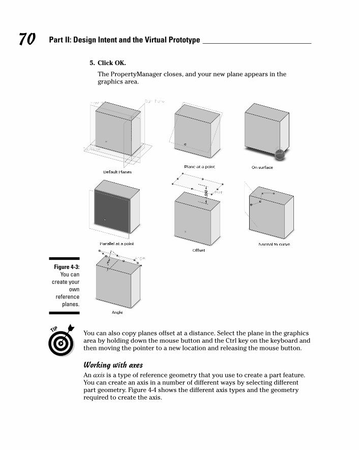
5. Click OK.
The PropertyManager closes, and your new plane appears in thegraphics area.
You can also copy planes offset at a distance. Select the plane in the graphicsarea by holding down the mouse button and the Ctrl key on the keyboard andthen moving the pointer to a new location and releasing the mouse button.
Working with axesAn axis is a type of reference geometry that you use to create a part feature.You can create an axis in a number of different ways by selecting differentpart geometry. Figure 4-4 shows the different axis types and the geometryrequired to create the axis.
Figure 4-3:You can
create yourown
referenceplanes.
70 Part II: Design Intent and the Virtual Prototype
09_129784 ch04.qxp 9/28/07 12:34 PM Page 70
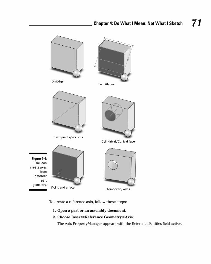
To create a reference axis, follow these steps:
1. Open a part or an assembly document.
2. Choose Insert➪Reference Geometry➪Axis.
The Axis PropertyManager appears with the Reference Entities field active.
Figure 4-4:You can
create axesfrom
differentpart
geometry.
71Chapter 4: Do What I Mean, Not What I Sketch
09_129784 ch04.qxp 9/28/07 12:34 PM Page 71
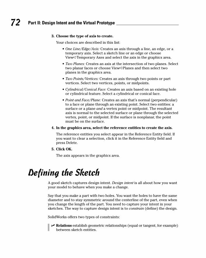
3. Choose the type of axis to create.
Your choices are described in this list:
• One Line/Edge/Axis: Creates an axis through a line, an edge, or atemporary axis. Select a sketch line or an edge or chooseView➪Temporary Axes and select the axis in the graphics area.
• Two Planes: Creates an axis at the intersection of two planes. Selecttwo planar faces or choose View➪Planes and then select twoplanes in the graphics area.
• Two Points/Vertices: Creates an axis through two points or partvertices. Select two vertices, points, or midpoints.
• Cylindrical/Conical Face: Creates an axis based on an existing holeor cylindrical feature. Select a cylindrical or conical face.
• Point and Face/Plane: Creates an axis that’s normal (perpendicular)to a face or plane through an existing point. Select two entities: asurface or a plane and a vertex point or midpoint. The resultantaxis is normal to the selected surface or plane through the selectedvertex, point, or midpoint. If the surface is nonplanar, the pointmust be on the surface.
4. In the graphics area, select the reference entities to create the axis.
The reference entities you select appear in the Reference Entity field. Ifyou want to clear a selection, click it in the Reference Entity field andpress Delete.
5. Click OK.
The axis appears in the graphics area.
Defining the SketchA good sketch captures design intent. Design intent is all about how you wantyour model to behave when you make a change.
Say that you make a part with two holes. You want the holes to have the samediameter and to stay symmetric around the centerline of the part, even whenyou change the length of the part. You need to capture your intent in yoursketches. The way to capture design intent is to constrain (define) the design.
SolidWorks offers two types of constraints:
� Relations establish geometric relationships (equal or tangent, for example)between sketch entities.
72 Part II: Design Intent and the Virtual Prototype
09_129784 ch04.qxp 9/28/07 12:34 PM Page 72
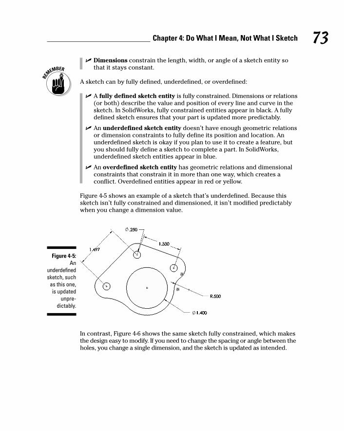
� Dimensions constrain the length, width, or angle of a sketch entity sothat it stays constant.
A sketch can by fully defined, underdefined, or overdefined:
� A fully defined sketch entity is fully constrained. Dimensions or relations(or both) describe the value and position of every line and curve in thesketch. In SolidWorks, fully constrained entities appear in black. A fullydefined sketch ensures that your part is updated more predictably.
� An underdefined sketch entity doesn’t have enough geometric relationsor dimension constraints to fully define its position and location. Anunderdefined sketch is okay if you plan to use it to create a feature, butyou should fully define a sketch to complete a part. In SolidWorks,underdefined sketch entities appear in blue.
� An overdefined sketch entity has geometric relations and dimensionalconstraints that constrain it in more than one way, which creates aconflict. Overdefined entities appear in red or yellow.
Figure 4-5 shows an example of a sketch that’s underdefined. Because thissketch isn’t fully constrained and dimensioned, it isn’t modified predictablywhen you change a dimension value.
In contrast, Figure 4-6 shows the same sketch fully constrained, which makesthe design easy to modify. If you need to change the spacing or angle between theholes, you change a single dimension, and the sketch is updated as intended.
Figure 4-5:An
underdefinedsketch, such
as this one,is updated
unpre-dictably.
73Chapter 4: Do What I Mean, Not What I Sketch
09_129784 ch04.qxp 9/28/07 12:34 PM Page 73
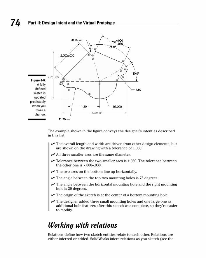
The example shown in the figure conveys the designer’s intent as describedin this list:
� The overall length and width are driven from other design elements, butare shown on the drawing with a tolerance of ±.030.
� All three smaller arcs are the same diameter.
� Tolerance between the two smaller arcs is ±.030. The tolerance betweenthe other one is +.000–.030.
� The two arcs on the bottom line up horizontally.
� The angle between the top two mounting holes is 75 degrees.
� The angle between the horizontal mounting hole and the right mountinghole is 30 degrees.
� The origin of the sketch is at the center of a bottom mounting hole.
� The designer added three small mounting holes and one large one asadditional hole features after this sketch was complete, so they’re easierto modify.
Working with relationsRelations define how two sketch entities relate to each other. Relations areeither inferred or added. SolidWorks infers relations as you sketch (see the
Figure 4-6:A fully
definedsketch isupdated
predictablywhen you
make achange.
74 Part II: Design Intent and the Virtual Prototype
09_129784 ch04.qxp 9/28/07 12:34 PM Page 74
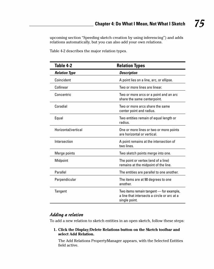
upcoming section “Speeding sketch creation by using inferencing”) and addsrelations automatically, but you can also add your own relations.
Table 4-2 describes the major relation types.
Table 4-2 Relation TypesRelation Type Description
Coincident A point lies on a line, arc, or ellipse.
Collinear Two or more lines are linear.
Concentric Two or more arcs or a point and an arcshare the same centerpoint.
Coradial Two or more arcs share the samecenter point and radius.
Equal Two entities remain of equal length orradius.
Horizontal/vertical One or more lines or two or more pointsare horizontal or vertical.
Intersection A point remains at the intersection oftwo lines.
Merge points Two sketch points merge into one.
Midpoint The point or vertex (end of a line)remains at the midpoint of the line.
Parallel The entities are parallel to one another.
Perpendicular The items are at 90 degrees to oneanother.
Tangent Two items remain tangent — for example,a line that intersects a circle or arc at asingle point.
Adding a relationTo add a new relation to sketch entities in an open sketch, follow these steps:
1. Click the Display/Delete Relations button on the Sketch toolbar andselect Add Relation.
The Add Relations PropertyManager appears, with the Selected Entitiesfield active.
75Chapter 4: Do What I Mean, Not What I Sketch
09_129784 ch04.qxp 9/28/07 12:34 PM Page 75
2. In the graphics area, select the entity or entities you want to relate.
The entities appear in the Selected Entities field. The Existing Relationsfield shows any relations that already exist for those entities. The AddRelations section shows only the relation types that are valid for the entityor entities you selected.
3. To delete an existing relation, select the relation in the ExistingRelations field and press Delete.
Use Display/Delete Relations to see all relations.
4. To add a new relation, select one of the relation types that appear inthe Add Relations box.
5. Click OK.
SolidWorks adds the relation to the entities.
SolidWorks places tiny icons in the graphics area to let you know which typeof relation exists between sketch entities. For example, if two arcs have anequal radial value, SolidWorks puts an equal sign next to them. If a sketch entity hasmore than one set of equal constraints, SolidWorks places an instance numberto the right side of the relation icon. The corresponding relation displays thesame number on the right side of the relation tag.
Using relation filtersIt’s useful to look at a sketch and tell at a glance which relations are where,especially when you need to edit a sketch that’s overdefined. But things canget crowded, especially when working on a large sketch, and that’s when you wantto use a relation filter. A relation filter shows only certain types of relations. TheDisplay/Delete Relations command on the Sketch toolbar, shown in Figure 4-7,lets you choose the relations types you want to see and makes it easy to deleterelations you don’t want.
To set a relations filter in a sketch, follow these steps:
1. Choose Tools➪Relations➪Display/Delete.
The Display/Delete Relations PropertyManager appears.
2. In the Filter area, select a relation to display in the drop-down list.
When you select a relation from the list, the appropriate sketch entitiesare highlighted in the graphics area. The options are described in this list:
• All in This Sketch: (Default) Displays all relations defined within thesketch. This list can be large based on the size and complexity ofthe sketch.
• Selected Entities: Displays relations for only the selected entities.This filter is the most commonly used.
• Dangling: Occurs when one of the references originally used tocreate the relation is missing (deleted entity).
76 Part II: Design Intent and the Virtual Prototype
09_129784 ch04.qxp 9/28/07 12:34 PM Page 76

• Overdefined/Not Solved: Indicates a redundant dimension or unnecessary relation.
• External: Displays relations created externally to the currentsketch. Referencing existing part geometry is often useful.
• Defined in Content: Displays relations defined in the context of theassembly. This powerful feature has a number of performanceconsiderations.
• Locked: Displays relations to locked external features or components.A locked external reference can no longer automatically update.Although not updating automatically can give you a performancegain, you still need to ensure that changes are made correctly.
• Broken: Displays relations with broken external references.
3. To delete a relation, highlight the entity in the graphics area and clickDelete in the PropertyManager.
The relation changes to green in the graphics area.
4. Click OK.
The PropertyManager closes.
Figure 4-7:The Display/
DeleteRelations
commandlets you
display onlythe relations
you want to see.
77Chapter 4: Do What I Mean, Not What I Sketch
09_129784 ch04.qxp 9/28/07 12:34 PM Page 77
Using Quick Snaps to create relationsWhen Quick Snaps are enabled, SolidWorks creates a relation (Nearest Snap,Tangent Snap, Perpendicular Snap, or Parallel Snap, for example) as youcreate the sketch geometry. SolidWorks creates relations automatically whensketching, but Quick Snaps give you more options and control.
For example, you may want a line to be as close as possible to another line.The nearest snap completes the line based on the closest distance to theselected line. Quick Snaps help you better define the attributes, or behaviors,of a sketch entity.
Available Quick Snaps are Point, Center (Arc/Circle), Mid-Points, Quadrants(circle), Intersection, Nearest, Tangent, Perpendicular, Parallel, Horizontal orVertical Lock, Horizontal or Vertical Point Snap, Length Snap, Grid Snap, andAngle Snap.
To create a sketch line by using a Quick Snap, follow these steps:
1. Open or create a sketch.
2. To display the Quick Snap toolbar, choose View➪Toolbars➪QuickSnaps.
The Quick Snap toolbar appears.
3. Click Line on the Sketch toolbar.
Quick Snap also works with other sketch geometry.
4. To define the starting point for the line, click the first point.
5. Click Tangent on the Quick Snap toolbar.
Only tangent selections are shown as the cursor moves within thegraphics area. Note that you can’t select a Quick Snap until after youclick to start sketching a new line, arc, circle, rectangle, spline, or point.
6. Click the endpoint for the line.
The line appears, and the selected relation is added.
Speeding sketch creation by using inferencingAs you sketch, SolidWorks infers and creates certain types of relations betweenentities in a sketch automatically. For example, when you sketch a horizontalline, SolidWorks adds a relation to keep the line horizontal. With automaticinferencing, inferencing lines work together with pointers, Quick Snaps, andrelations to graphically display how sketch entities affect each other andwhich type of relation SolidWorks will create.
Inferencing lines are dotted lines that appear when you sketch. When yourpointer approaches highlighted cues, such as a midpoint, blue dotted lines
78 Part II: Design Intent and the Virtual Prototype
09_129784 ch04.qxp 9/28/07 12:34 PM Page 78
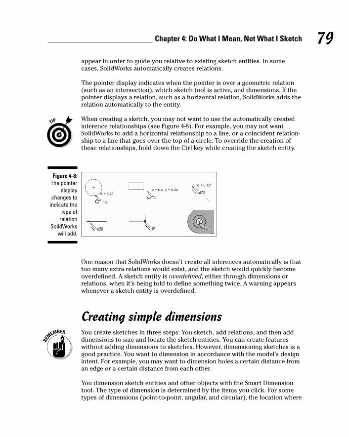
appear in order to guide you relative to existing sketch entities. In somecases, SolidWorks automatically creates relations.
The pointer display indicates when the pointer is over a geometric relation(such as an intersection), which sketch tool is active, and dimensions. If thepointer displays a relation, such as a horizontal relation, SolidWorks adds therelation automatically to the entity.
When creating a sketch, you may not want to use the automatically createdinference relationships (see Figure 4-8). For example, you may not wantSolidWorks to add a horizontal relationship to a line, or a coincident relation-ship to a line that goes over the top of a circle. To override the creation ofthese relationships, hold down the Ctrl key while creating the sketch entity.
One reason that SolidWorks doesn’t create all inferences automatically is thattoo many extra relations would exist, and the sketch would quickly becomeoverdefined. A sketch entity is overdefined, either through dimensions orrelations, when it’s being told to define something twice. A warning appearswhenever a sketch entity is overdefined.
Creating simple dimensionsYou create sketches in three steps: You sketch, add relations, and then adddimensions to size and locate the sketch entities. You can create featureswithout adding dimensions to sketches. However, dimensioning sketches is agood practice. You want to dimension in accordance with the model’s designintent. For example, you may want to dimension holes a certain distance froman edge or a certain distance from each other.
You dimension sketch entities and other objects with the Smart Dimensiontool. The type of dimension is determined by the items you click. For sometypes of dimensions (point-to-point, angular, and circular), the location where
Figure 4-8:The pointer
displaychanges to
indicate thetype of
relationSolidWorks
will add.
79Chapter 4: Do What I Mean, Not What I Sketch
09_129784 ch04.qxp 9/28/07 12:34 PM Page 79

you place the dimension also affects the type of dimension that SolidWorksadds. You can also drag or delete a dimension while the Smart Dimensiontool is active.
To dimension an entity in a sketch, follow these steps:
1. Click Smart Dimension on the Dimensions/Relations toolbar.
The pointer changes to a dimension icon.
2. Depending on the entity to dimension, select the items as indicated:
• Length of a line or edge: Click the line.
• Angle between two lines: Click two lines or a line and a model edge.How you place the dimension affects how the angle is measured.It’s based on which quadrant of an imaginary circle you place thefinal dimension text on.
• Distance between two lines: Click two parallel lines or a line and aparallel model edge.
• Perpendicular distance from a point to a line: Click the point and theline or model edge.
• Distance between two points: Click two points. One of the pointscan be a model vertex.
• Radius of an arc: Click the arc.
• True length of an arc: Click the arc and then the two endpoints.
• Diameter of a circle: Click the circumference. The dimension is displayed as linear or diameter, depending on where you place thepointer.
A preview of the dimension appears in the graphics area as a blue linewith arrows on either end and the measurement value on top. As youmove the pointer, the dimension moves with it.
3. Move the pointer and click to place the dimension.
The Modify dialog box appears.
4. Enter a value for the dimension in the Modify dialog box, as shown inFigure 4-9.
You don’t have to enter a value; you can accept the existing value.
5. Click Rebuild in the Modify dialog box to see the model updated withthe new value.
If the value isn’t correct or you want to change it, change the values andclick Rebuild in the Modify dialog box again.
6. Click OK.
The Modify dialog box closes, and the dimension appears in the graphicsarea. The model is updated accordingly.
80 Part II: Design Intent and the Virtual Prototype
09_129784 ch04.qxp 9/28/07 12:34 PM Page 80

Marking a dimension for drawing reuseWhen you create dimensions in part sketches, you can specify whether thedimension should be included in the drawing. In the Modify dialog box, afteryou enter the dimension value, the button Mark Dimension to Be Importedinto a Drawing is selected by default, as shown in Figure 4-10. Clicking thisoption flags the dimension for import into a drawing by using the InsertModel Items feature (see Chapter 8).
Because the dimensions are reused within your drawing, spend some extra effortpositioning the dimensions the way you want to see them in your drawing. Youshould also add any tolerances, notes, and symbols to the sketch dimensionsto eliminate duplicate work on the drawing and to include the information inthe part where it belongs. You can read more on how to add annotations tomodels in Chapter 7.
Before you finish your sketch, give it some exercise. Click and drag entities tosee whether the sketch is updated as you intend. If you resize an arc by drag-ging one of its endpoints, notice whether the attached lines stay tangent. Ifthe sketch doesn’t capture design intent, you may want to add constraints.
Figure 4-10:A dimension
valuemarked for
drawingimport.
Figure 4-9:Change a
dimensionby entering
a new valuein the
Modifydialog box.
81Chapter 4: Do What I Mean, Not What I Sketch
09_129784 ch04.qxp 9/28/07 12:34 PM Page 81

82 Part II: Design Intent and the Virtual Prototype
09_129784 ch04.qxp 9/28/07 12:34 PM Page 82

Chapter 5
Making Better PartsIn This Chapter� Familiarizing yourself with parts and features
� Creating sketched features and applied features
� Using pattern and mirror features
� Building a part
� Naming and organizing features and dimensions
� Making parts more robust by using function feature order
� Documenting designs by using comments
� Knowing what to model
Parts are the basis of drawings and assemblies. Just as assemblies aremade from individual parts, parts are made from individual features.
This chapter explains how to create a part and introduces the different typesof features you can use to construct that part. This chapter doesn’t coverevery feature type that SolidWorks offers. Instead, it focuses on the mostcommon ones.
Introducing Part FeaturesParts consist of features. Features, or shapes, are the building blocks of amodel. You begin a part with a flat sketch. You dimension the sketch to makesure that it’s the proper size and then you create features.
The first feature in a part is the base feature because it forms the base of thepart. Generally, but not always, the first feature is a base extrusion. An extrudeadds material by pulling the shape out. If you extrude a rectangle, for example,you get a cube. After you have a lump of material to work with, subsequentfeatures add or subtract material by scooping or rounding, for example.Eventually, your part takes shape.
10_129784 ch05.qxp 9/28/07 12:35 PM Page 83

A SolidWorks feature is one of two types:
� A sketched feature is based on a 2D sketch.
� An applied feature is one that you apply directly to the model.
The following list presents examples of these types of features:
� Boss/base features (sketched): Add material to the model (extrude,revolve, sweep, loft). The first feature is a base, and subsequent featuresare bosses.
� Cut features (sketched): Remove material from the model (extrude,revolve, sweep, loft).
� Model features (applied): Perform a specific modeling task (fillet, chamfer,draft, shell, hole, wizard hole, and more). Model features act on existinggeometry.
� Pattern and mirror features (applied): Act on existing geometry andcreate copies of existing features. You can create a linear, circular, orsketch-driven pattern. Mirror features create copies of existing featuresby using planes or faces to create symmetrical copies.
The examples in the figures throughout this chapter are meant to give yousome ideas for starting a part and crafting the final part design. Figure 5-1shows how part features produce a model. You can refine a design by adding,changing, or reordering features.
Here are the general steps to create the part example shown in the figure (thefeature name is in parentheses):
1. Create the sketch for the feature (Side Profile/Sketch1) and extrudethe profile by using Extruded Boss/Base.
2. Shape the profile (Shape Face) by using the Shape feature.
3. Round the four corners (Corners) by using a fillet.
Figure 5-1:Individual
featurescombine to
make a part.
84 Part II: Design Intent and the Virtual Prototype
10_129784 ch05.qxp 9/28/07 12:35 PM Page 84
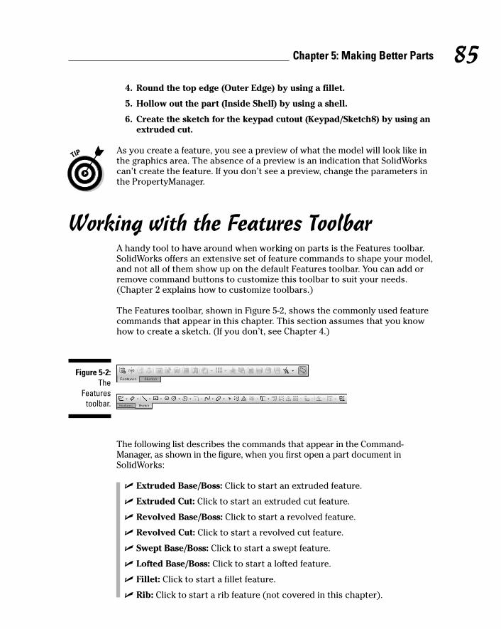
4. Round the top edge (Outer Edge) by using a fillet.
5. Hollow out the part (Inside Shell) by using a shell.
6. Create the sketch for the keypad cutout (Keypad/Sketch8) by using anextruded cut.
As you create a feature, you see a preview of what the model will look like inthe graphics area. The absence of a preview is an indication that SolidWorkscan’t create the feature. If you don’t see a preview, change the parameters inthe PropertyManager.
Working with the Features ToolbarA handy tool to have around when working on parts is the Features toolbar.SolidWorks offers an extensive set of feature commands to shape your model,and not all of them show up on the default Features toolbar. You can add orremove command buttons to customize this toolbar to suit your needs.(Chapter 2 explains how to customize toolbars.)
The Features toolbar, shown in Figure 5-2, shows the commonly used featurecommands that appear in this chapter. This section assumes that you knowhow to create a sketch. (If you don’t, see Chapter 4.)
The following list describes the commands that appear in the Command-Manager, as shown in the figure, when you first open a part document inSolidWorks:
� Extruded Base/Boss: Click to start an extruded feature.
� Extruded Cut: Click to start an extruded cut feature.
� Revolved Base/Boss: Click to start a revolved feature.
� Revolved Cut: Click to start a revolved cut feature.
� Swept Base/Boss: Click to start a swept feature.
� Lofted Base/Boss: Click to start a lofted feature.
� Fillet: Click to start a fillet feature.
� Rib: Click to start a rib feature (not covered in this chapter).
Figure 5-2:The
Featurestoolbar.
85Chapter 5: Making Better Parts
10_129784 ch05.qxp 9/28/07 12:35 PM Page 85

� Shell: Click to start a shell feature.
� Draft: Click to start a draft feature.
� Hole Wizard: Click to start the Hole Wizard feature.
� Linear Pattern: Click to start a pattern feature.
� Circular Pattern: Click to start a pattern feature.
� Mirror: Click to start a mirror feature.
� Reference Geometry: Click to display a menu of common referencegeometry features (not covered in this chapter).
� Curve: Click to display a menu of common curve features (not coveredin this chapter).
Creating Sketched FeaturesYou must create a 2D sketch as the basis for a sketched feature (extrude,revolve, sweep, or loft) in SolidWorks. Sketched features can add or removematerial from a part. A sketched feature that adds material is a base or a boss.A sketched feature that removes material is a cut.
When you design a part, imagine that you’re a machine tool cutting away at asolid hunk of metal. In SolidWorks, a base feature gives you that solid hunk.Pick the most prominent section of the part as a base and choose a shape tobest describe it. The most common base feature is a base extrude, but youcan also create base features with a sweep, revolve, or loft.
Your 2D outline for a sketched feature generally requires a profile. A profile,or sketch, is the flat shape that pulls out or revolves about, for example.
If you click a sketched feature before you sketch the profile, SolidWorks putsyou in Sketch mode automatically. For example, if you click ExtrudedBase/Boss before you sketch the extrude, SolidWorks puts you directly inSketch mode. When you complete the sketch, click the confirmation corner inthe upper-right corner of the graphics area. SolidWorks extrudes the part anddisplays the Extruded Cut PropertyManager.
Pulling and carving out extruded featuresUsing an extrusion is like making a cookie from a cookie press. You place ashape (or profile) in the press, and the dough comes out in that shape. Anextruded boss/base adds material; an extruded cut removes material. Thematerial that’s added is extruded along a specified direction. SolidWorksbases the direction of the extrusion on a distance normal (perpendicular) tothe plane of the 2D sketch or along a selected vector (direction).
86 Part II: Design Intent and the Virtual Prototype
10_129784 ch05.qxp 9/28/07 12:35 PM Page 86

The FeatureManager design tree displays the individual features of a part.You may find it easier to select the feature in the FeatureManager design treerather than in the graphics area, especially if it’s a tiny feature that you haveto zoom in on to spot. When you select a feature, the feature is highlighted inboth the graphics area and the FeatureManager design tree.
In the PropertyManager that appears for sketched features, a field turns lightblue to indicate that it’s active and waiting for you to select one or more entitiesin the graphics area. If the field accepts only one entity, the next field is activatedautomatically after you make a selection.
In some PropertyManagers and dialog boxes that appear when you choose acommand, you enter values for a distance or angle, for example, in a spinbox. You can click the up arrow or down arrow to increase or decrease thevalue incrementally. To change the default spin box increments, chooseTools➪Options. On the System Options tab, select Spin Box Increments andenter the new increment values.
To create an extruded-base/boss or cut feature, follow these steps:
1. Sketch the profile you want to extrude.
You can sketch on a plane or the face of a part.
2. Choose Insert➪Exit Sketch.
You exit Sketch mode.
3. In the FeatureManager design tree, select the sketch to extrude.
You can preselect a sketch.
4. Click either Extruded Boss/Base or Extruded Cut on the Features toolbar.
The Extrude PropertyManager appears (see Figure 5-3), and the shape isextruded by the amount that appears in the Depth field. SolidWorksprompts you for the parameters of the extrusion.
5. In the From pull-down list, select Sketch Plane.
The feature extrudes from the sketch plane. You can also set From sothat the feature extrudes from a surface, face, or vertex and offset. For abase extrude, extrude from the sketch plane.
6. Set the End Conditions option to Blind.
You use this setting to specify the exact depth of the extrusion. Click thearrows to the left of Blind to change the direction that the part extrudesfrom. You can also set end conditions so that the feature extrudes up tothe vertex or up to the surface, for example (see Figure 5-4).
7. Specify the width in the Depth field.
Enter a parameter for how far you want the shape to extrude.
8. Click OK.
87Chapter 5: Making Better Parts
10_129784 ch05.qxp 9/28/07 12:35 PM Page 87

Revolving features around an axisA revolve rotates a sketch profile around an axis to create a 3D shape. Doorknobs and bedposts are shapes you can create with a revolve. You can setthe angle of a revolve to 360 degrees for a full revolve or set it to less thanthat — for example, when you want only a quarter of a door knob.
The sketch you create for a revolve feature must include a centerline. Thecenterline serves as an axis of rotation. (The axis of rotation can be a center-line, a line, an edge, or an axis.) On one side of the centerline, you sketch theprofile of the revolve. Don’t let your sketch cross the centerline (see Figure 5-5).Otherwise, the profile may self-intersect, and SolidWorks then cannot createthe feature.
Figure 5-4:Select an end
conditiontype for
extrudedfeatures.
Figure 5-3:A
preview of this base
extrudefeature
appears inthe graphics
area.
88 Part II: Design Intent and the Virtual Prototype
10_129784 ch05.qxp 9/28/07 12:35 PM Page 88
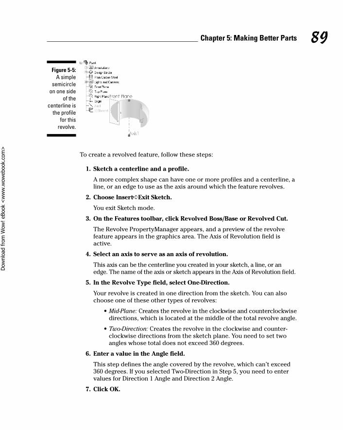
To create a revolved feature, follow these steps:
1. Sketch a centerline and a profile.
A more complex shape can have one or more profiles and a centerline, aline, or an edge to use as the axis around which the feature revolves.
2. Choose Insert➪Exit Sketch.
You exit Sketch mode.
3. On the Features toolbar, click Revolved Boss/Base or Revolved Cut.
The Revolve PropertyManager appears, and a preview of the revolvefeature appears in the graphics area. The Axis of Revolution field isactive.
4. Select an axis to serve as an axis of revolution.
This axis can be the centerline you created in your sketch, a line, or anedge. The name of the axis or sketch appears in the Axis of Revolution field.
5. In the Revolve Type field, select One-Direction.
Your revolve is created in one direction from the sketch. You can alsochoose one of these other types of revolves:
• Mid-Plane: Creates the revolve in the clockwise and counterclockwisedirections, which is located at the middle of the total revolve angle.
• Two-Direction: Creates the revolve in the clockwise and counter-clockwise directions from the sketch plane. You need to set twoangles whose total does not exceed 360 degrees.
6. Enter a value in the Angle field.
This step defines the angle covered by the revolve, which can’t exceed360 degrees. If you selected Two-Direction in Step 5, you need to entervalues for Direction 1 Angle and Direction 2 Angle.
7. Click OK.
Figure 5-5:A simple
semicircleon one side
of thecenterline is
the profilefor this
revolve.
89Chapter 5: Making Better Parts
10_129784 ch05.qxp 9/28/07 12:35 PM Page 89
Dow
nlo
ad fro
m W
ow
! eBook
<w
ww
.wow
ebook.
com
>
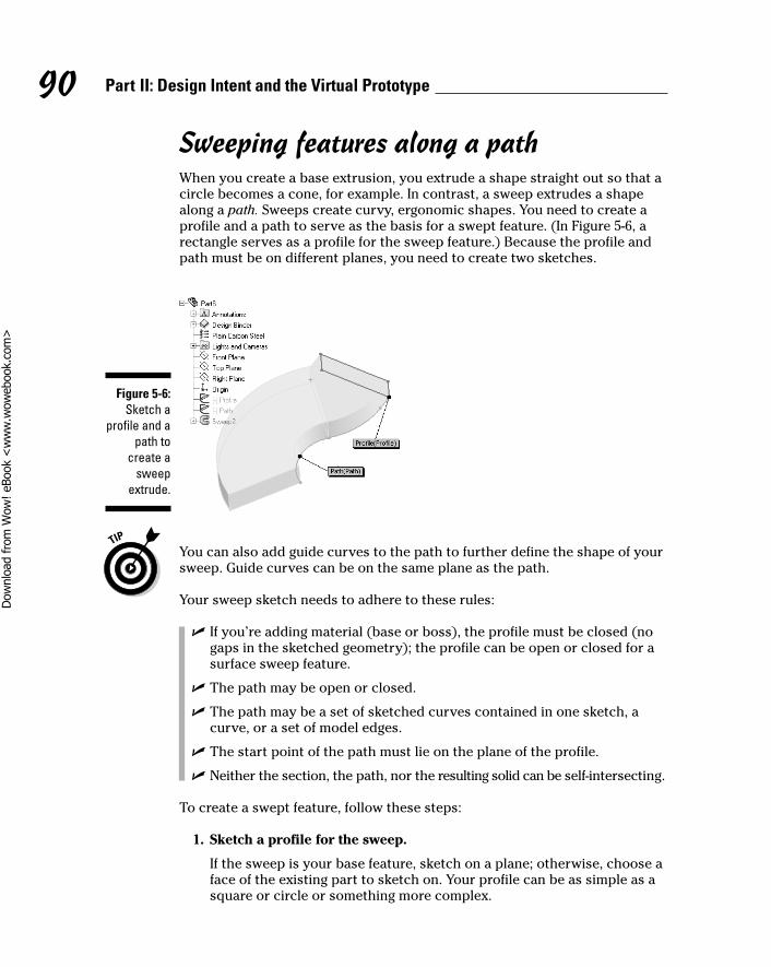
Sweeping features along a pathWhen you create a base extrusion, you extrude a shape straight out so that acircle becomes a cone, for example. In contrast, a sweep extrudes a shapealong a path. Sweeps create curvy, ergonomic shapes. You need to create aprofile and a path to serve as the basis for a swept feature. (In Figure 5-6, arectangle serves as a profile for the sweep feature.) Because the profile andpath must be on different planes, you need to create two sketches.
You can also add guide curves to the path to further define the shape of yoursweep. Guide curves can be on the same plane as the path.
Your sweep sketch needs to adhere to these rules:
� If you’re adding material (base or boss), the profile must be closed (nogaps in the sketched geometry); the profile can be open or closed for asurface sweep feature.
� The path may be open or closed.
� The path may be a set of sketched curves contained in one sketch, acurve, or a set of model edges.
� The start point of the path must lie on the plane of the profile.
� Neither the section, the path, nor the resulting solid can be self-intersecting.
To create a swept feature, follow these steps:
1. Sketch a profile for the sweep.
If the sweep is your base feature, sketch on a plane; otherwise, choose aface of the existing part to sketch on. Your profile can be as simple as asquare or circle or something more complex.
Figure 5-6:Sketch a
profile and apath to
create asweep
extrude.
90 Part II: Design Intent and the Virtual Prototype
10_129784 ch05.qxp 9/28/07 12:35 PM Page 90
Dow
nlo
ad fro
m W
ow
! eBook
<w
ww
.wow
ebook.
com
>

2. In a second sketch on a different plane, sketch a path for the sweep.
You can add guide curves for a more complex shape. If you add guidecurves, you need to create coincident or pierce relations between theguide curves and the profile.
3. Choose Insert➪Exit Sketch.
You switch to Part mode.
4. Select Swept Boss/Base or Swept Cut from the Features toolbar.
The Sweep PropertyManager appears with the Profile field activated.
5. Select the sketch to use for the profile.
The sketch appears in the Profile field. The Path field is activated.
6. Click a sketch to use for the path.
The sketch name appears in the Path field. A preview of the sweepappears in the graphics area.
7. If you’re using a guide curve, under Guide Curves, click the GuideCurves field.
The field is activated, turning light blue. If you’re not using a guidecurve, skip to Step 9.
8. In the FeatureManager design tree, select the sketch to use for theguide path curve.
The sketch name appears in the Guide Path Curve field.
9. Click the up or down arrows under guide path curve to indicate theorder in which the guide curves are evaluated.
10. Click OK.
Lofted features: A sketch of many profilesA loft feature is similar to a sweep, but rather than a single profile in thesketch, it has two or more profiles, and the loft transitions between them. Aloft can add material or take it away. If you want to create a more complexshape, you can include guide curves and end conditions in your sketch.
When you create your sketch for a loft:
� Only the first, last, or first and last profiles can be points.
� If you create a solid loft, the first and last profiles must be model facesor faces created by split lines, planar profiles, or surfaces.
91Chapter 5: Making Better Parts
10_129784 ch05.qxp 9/28/07 12:35 PM Page 91

Consider the following when creating lofts with guide curves:
� You can use any of the following items as a guide curve: sketchedcurves, model edges, or curves of any kind.
� Guide curves must intersect all the profiles.
� There’s no limit to the number of guide curves you can use.
� Guide curves can intersect at points.
Always select profiles on the same general area. In the example shown inFigure 5-7, the lower-right corner of each profile is selected. Otherwise, theresulting lofted feature twists in a way that you may not want. Always watchthe preview in the graphics area and reselect profiles if necessary.
To create a loft feature, follow these steps:
1. Sketch two profiles and any guide curves for the feature.
Faces, curves, and edges can serve as profiles. You don’t need to sketchtwo or more profiles if one is on the model.
2. Choose Insert➪Exit Sketch.
You exit Sketch mode and return to Part mode.
3. Click Lofted Base/Boss or Lofted Cut on the Features toolbar.
The Loft PropertyManager appears, with the Profile field active.
4. Select the two profiles in the graphics area.
The items appear in the Profile field. You can use the up and downarrows in the Profile section to switch the profile order.
Figure 5-7:A lofted
feature issimilar to asweep but
with twoprofiles.
92 Part II: Design Intent and the Virtual Prototype
10_129784 ch05.qxp 9/28/07 12:35 PM Page 92

5. Select the Guide Curve field.
The field is highlighted in light blue.
6. Select the guide curves in the graphics area.
The items appear in the Guide Curves field. A preview of the loft appearsin the graphics area. You can use the up and down arrows in the GuideCurves section to change the order of the guide curves.
7. Click OK.
Making Applied FeaturesAfter you create a base feature, a solid hunk of material sits in your graphicsarea. You can add some character to this hunk by using applied features(fillet, chamfer, shell, or draft). Unlike sketched features, applied featuresdon’t require sketches. You apply them directly to your part.
Imagine that the applied features described in this section are variousmachine tools drilling away at your part. One tool rounds off the edges, andanother scoops out the middle, leaving a hollow shell, for example. Your partis taking shape.
Rounding parts with FilletThe Fillet command rounds off the sharp corners of a part or adds volume byrounding off an inner corner. You can create many different types of fillets.The most common is the multiple fillet, shown in Figure 5-8.
Fillets aren’t functional design elements. Typically, you add them for cos-metic reasons — to “pretty up” the part. Add cosmetic fillets at the end of themodeling process to minimize unwanted parent/child relations and to pro-duce a more robust model. A parent/child relationship simply means that afillet that references an edge is a “child” of that edge. If you remove the edge,the child becomes “homeless” and fails when you rebuild the part.
SolidWorks displays heads-up labels (see Figure 5-8). The heads-up labelincludes the radius value (Radius: 01.in) and can be edited. Double-click thenumeric-text part of it to change the radius value.
93Chapter 5: Making Better Parts
10_129784 ch05.qxp 9/28/07 12:35 PM Page 93

To create a fillet feature in a part, follow these steps:
1. Open a part document.
2. Click Fillet on the Features toolbar.
3. Select the edges or faces on the part you want to fillet.
The Fillet PropertyManager appears, and you see a preview of the filletin the graphics area (refer to Figure 5-8).
The order in which you select multiple edges affects the way the filletblends (how it looks when finished) and its tangent propagation (how farit goes). For the example shown earlier, in Figure 5-8, the designerselected the larger 0.2 radius first. When the designer chose the smallerradii edges, those edges propagated all the way around the outside edgeof the part because they didn’t have to stop at the sharp corner.
4. Select the fillet type.
Your options include
• Constant Radius: The fillet has a constant radius for its entirelength. After you select Constant Radius, you can set parameters inthe PropertyManager to create multiple radius fillets, round cornerfillets, or setback fillets.
• Variable Radius: The fillet has variable radius values. Controlpoints allow you to define the fillet.
• Face Fillet: The fillet’s nonadjacent, noncontinuous faces are blended.
• Full Round Fillet: The fillet is tangent to three adjacent faces’ sets(with one or more faces’ tangents.)
Figure 5-8:Fillets
primarilyadd
cosmeticappeal to a
part.
94 Part II: Design Intent and the Virtual Prototype
10_129784 ch05.qxp 9/28/07 12:35 PM Page 94
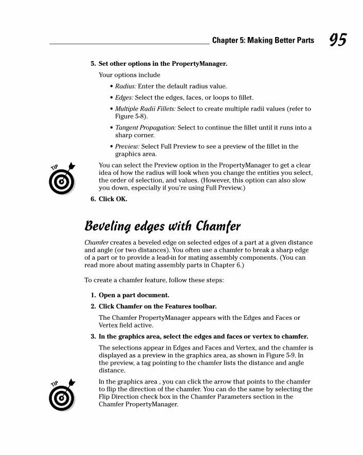
5. Set other options in the PropertyManager.
Your options include
• Radius: Enter the default radius value.
• Edges: Select the edges, faces, or loops to fillet.
• Multiple Radii Fillets: Select to create multiple radii values (refer toFigure 5-8).
• Tangent Propagation: Select to continue the fillet until it runs into asharp corner.
• Preview: Select Full Preview to see a preview of the fillet in thegraphics area.
You can select the Preview option in the PropertyManager to get a clearidea of how the radius will look when you change the entities you select,the order of selection, and values. (However, this option can also slowyou down, especially if you’re using Full Preview.)
6. Click OK.
Beveling edges with ChamferChamfer creates a beveled edge on selected edges of a part at a given distanceand angle (or two distances). You often use a chamfer to break a sharp edgeof a part or to provide a lead-in for mating assembly components. (You canread more about mating assembly parts in Chapter 6.)
To create a chamfer feature, follow these steps:
1. Open a part document.
2. Click Chamfer on the Features toolbar.
The Chamfer PropertyManager appears with the Edges and Faces orVertex field active.
3. In the graphics area, select the edges and faces or vertex to chamfer.
The selections appear in Edges and Faces and Vertex, and the chamfer isdisplayed as a preview in the graphics area, as shown in Figure 5-9. Inthe preview, a tag pointing to the chamfer lists the distance and angledistance.
In the graphics area , you can click the arrow that points to the chamferto flip the direction of the chamfer. You can do the same by selecting theFlip Direction check box in the Chamfer Parameters section in theChamfer PropertyManager.
95Chapter 5: Making Better Parts
10_129784 ch05.qxp 9/28/07 12:35 PM Page 95
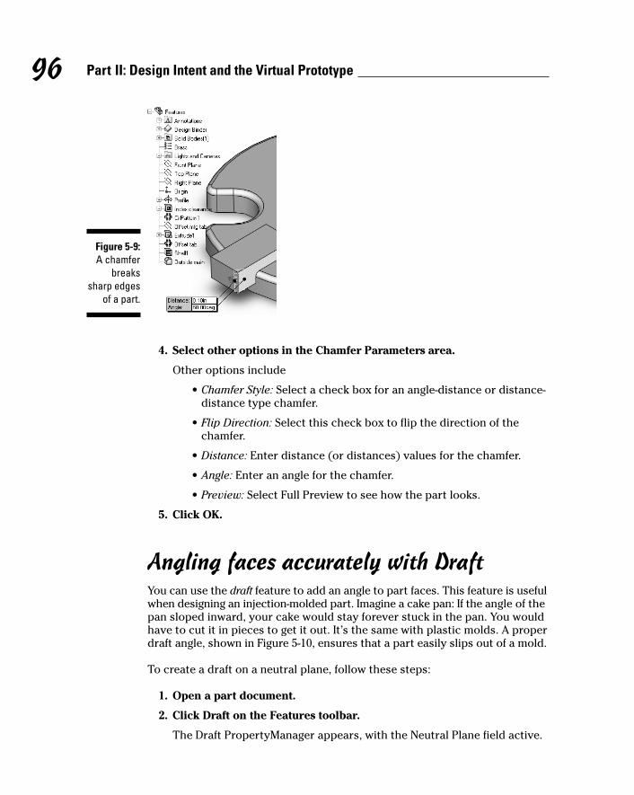
4. Select other options in the Chamfer Parameters area.
Other options include
• Chamfer Style: Select a check box for an angle-distance or distance-distance type chamfer.
• Flip Direction: Select this check box to flip the direction of thechamfer.
• Distance: Enter distance (or distances) values for the chamfer.
• Angle: Enter an angle for the chamfer.
• Preview: Select Full Preview to see how the part looks.
5. Click OK.
Angling faces accurately with DraftYou can use the draft feature to add an angle to part faces. This feature is usefulwhen designing an injection-molded part. Imagine a cake pan: If the angle of thepan sloped inward, your cake would stay forever stuck in the pan. You wouldhave to cut it in pieces to get it out. It’s the same with plastic molds. A properdraft angle, shown in Figure 5-10, ensures that a part easily slips out of a mold.
To create a draft on a neutral plane, follow these steps:
1. Open a part document.
2. Click Draft on the Features toolbar.
The Draft PropertyManager appears, with the Neutral Plane field active.
Figure 5-9:A chamfer
breakssharp edges
of a part.
96 Part II: Design Intent and the Virtual Prototype
10_129784 ch05.qxp 9/28/07 12:35 PM Page 96
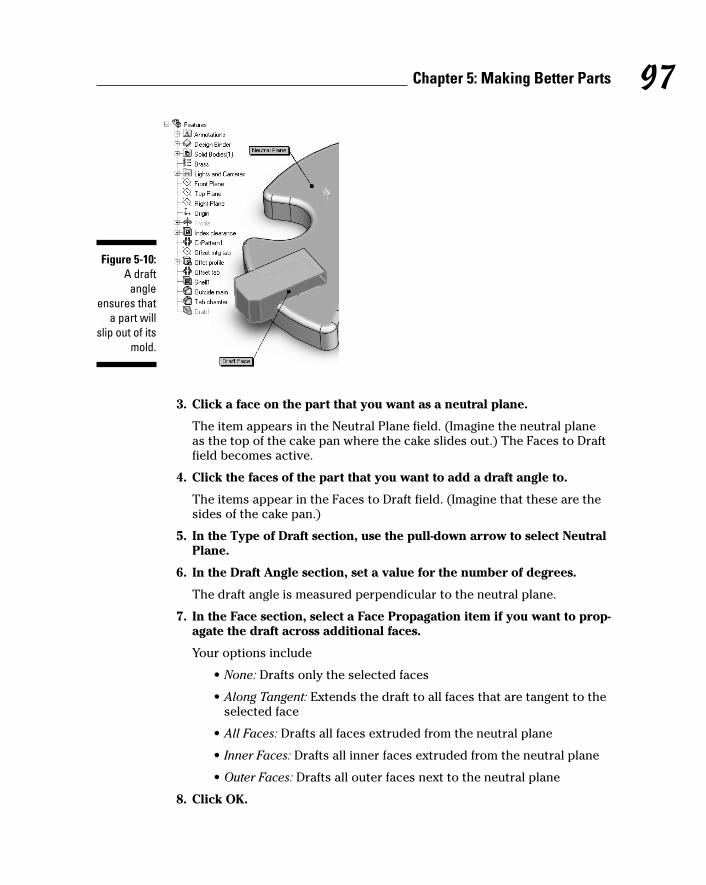
3. Click a face on the part that you want as a neutral plane.
The item appears in the Neutral Plane field. (Imagine the neutral planeas the top of the cake pan where the cake slides out.) The Faces to Draftfield becomes active.
4. Click the faces of the part that you want to add a draft angle to.
The items appear in the Faces to Draft field. (Imagine that these are thesides of the cake pan.)
5. In the Type of Draft section, use the pull-down arrow to select NeutralPlane.
6. In the Draft Angle section, set a value for the number of degrees.
The draft angle is measured perpendicular to the neutral plane.
7. In the Face section, select a Face Propagation item if you want to prop-agate the draft across additional faces.
Your options include
• None: Drafts only the selected faces
• Along Tangent: Extends the draft to all faces that are tangent to theselected face
• All Faces: Drafts all faces extruded from the neutral plane
• Inner Faces: Drafts all inner faces extruded from the neutral plane
• Outer Faces: Drafts all outer faces next to the neutral plane
8. Click OK.
Figure 5-10:A draft
angleensures that
a part willslip out of its
mold.
97Chapter 5: Making Better Parts
10_129784 ch05.qxp 9/28/07 12:35 PM Page 97
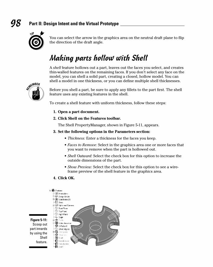
You can select the arrow in the graphics area on the neutral draft plane to flipthe direction of the draft angle.
Making parts hollow with ShellA shell feature hollows out a part, leaves out the faces you select, and createsthin-walled features on the remaining faces. If you don’t select any face on themodel, you can shell a solid part, creating a closed, hollow model. You canshell a model in one thickness, or you can define multiple shell thicknesses.
Before you shell a part, be sure to apply any fillets to the part first. The shellfeature uses any existing features in the shell.
To create a shell feature with uniform thickness, follow these steps:
1. Open a part document.
2. Click Shell on the Features toolbar.
The Shell PropertyManager, shown in Figure 5-11, appears.
3. Set the following options in the Parameters section:
• Thickness: Enter a thickness for the faces you keep.
• Faces to Remove: Select in the graphics area one or more faces thatyou want to remove when the part is hollowed out.
• Shell Outward: Select the check box for this option to increase theoutside dimensions of the part.
• Show Preview: Select the check box for this option to see a wire-frame preview of the shell feature in the graphics area.
4. Click OK.
Figure 5-11:Scoop out
part innardsby using the
Shellfeature.
98 Part II: Design Intent and the Virtual Prototype
10_129784 ch05.qxp 9/28/07 12:35 PM Page 98

If you run into trouble creating a shell, run Error Diagnostics in the ShellPropertyManager to pinpoint problems.
Drilling holes with the Hole WizardThe Hole Wizard lets you create holes in your part that you can use to insertfasteners. The Hole Wizard can create these hole types: Counterbore,Countersink, Hole (simple holes), Tap, Pipetap, and Legacy.
You don’t have to dig out the Machinery’s Handbook to figure out how big youneed to make the holes. The Hole Wizard creates the holes based on the typeof fastener you plan to put there.
To add a hole to a part by using the Hole Wizard, follow these steps:
1. Open a part document.
2. Select a face on the part in which you want to insert holes.
3. Click Hole Wizard on the Features toolbar.
The Hole Definition PropertyManager appears.
You can preselect or postselect a face when using the Hole Wizard.When you preselect a face and then click Hole Wizard on the Featurestoolbar, the resulting sketch is a 2D sketch. If you click Hole Wizard andthen select a face, the resulting sketch is 3D. Unlike with a 2D sketch,you cannot constrain a 3D sketch to a line. If the start of your hole isgoing to lie on a planar face, it must be stressed that preselection of thatface is highly recommended.
4. Select the Type tab to display the hole options.
In the Hole Type section, click the button for the type of hole you wantto create. Your choices are Counterbore, Countersink, Hole, Tap, PipeTap, and Legacy. (The Legacy option allows you to make holes for filescreated in older versions of SolidWorks.) You can use pull-down menusto automatically size a hole for a certain type of fastener. Use theStandard pull-down menu to specify your choice of several internation-ally recognized standards (ANSI inch, ANSI metric, or ISO, for example).Use the Type pull-down menu to choose the type of fastener you’redesigning the hole to accept.
Figure 5-12 shows a counterbore hole made for a #10 binding headmachine screw.
99Chapter 5: Making Better Parts
10_129784 ch05.qxp 9/28/07 12:35 PM Page 99

5. Set additional parameters for the type of fastener you chose. The sizeof the hole is created based on the size of the fastener you select.
You can use the pull-down arrows next to the parameters box to selectthe exact parameters you want.
For each hole type (except Legacy), you can create and save hole typesto include in your favorite property parameters. In the Hole Placementdialog box, after you select the parameters for a fastener, click SelectAdd in the Favorites area. The next time you want to add holes to amodel, click the arrow under Favorites to select the hole type to add.
6. Click the Positions tab.
The Hole Wizard closes, and the Hole Position dialog box appears andprompts you to enter the sketch points in the model where you want toplace the holes. (Figure 5-13 shows three points dimensioned to definethe three hole locations.) You switch to Sketch mode.
7. Use the Point tool to mark the spots in the model where you want holes.
You’re automatically using the Point tool on the Sketch toolbar to add theholes. If you preselected a planar face, the holes must be on the same face.
Figure 5-12:The Hole
Wizardcreates hole
sizes tomatch your
fastener.
100 Part II: Design Intent and the Virtual Prototype
10_129784 ch05.qxp 9/28/07 12:35 PM Page 100
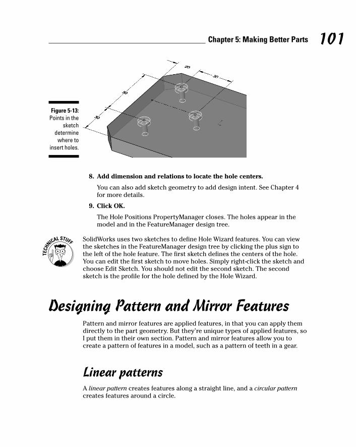
8. Add dimension and relations to locate the hole centers.
You can also add sketch geometry to add design intent. See Chapter 4for more details.
9. Click OK.
The Hole Positions PropertyManager closes. The holes appear in themodel and in the FeatureManager design tree.
SolidWorks uses two sketches to define Hole Wizard features. You can viewthe sketches in the FeatureManager design tree by clicking the plus sign tothe left of the hole feature. The first sketch defines the centers of the hole.You can edit the first sketch to move holes. Simply right-click the sketch andchoose Edit Sketch. You should not edit the second sketch. The secondsketch is the profile for the hole defined by the Hole Wizard.
Designing Pattern and Mirror FeaturesPattern and mirror features are applied features, in that you can apply themdirectly to the part geometry. But they’re unique types of applied features, soI put them in their own section. Pattern and mirror features allow you tocreate a pattern of features in a model, such as a pattern of teeth in a gear.
Linear patternsA linear pattern creates features along a straight line, and a circular patterncreates features around a circle.
Figure 5-13:Points in the
sketchdetermine
where toinsert holes.
101Chapter 5: Making Better Parts
10_129784 ch05.qxp 9/28/07 12:35 PM Page 101

To create a linear pattern feature, follow these steps:
1. Open a part document.
2. Click Linear Pattern on the Features toolbar.
The Linear Pattern PropertyManager, shown in Figure 5-14, appears withthe Pattern Direction selection field active.
3. Select an edge to define Direction 1.
The edge appears in Direction 1, and the Direction 2 box is active.
4. If needed, select an edge to define Direction 2.
The edge appears in Direction 2.
5. Set the remaining options in the PropertyManager.
Here’s what you do to select each option:
• Pattern Direction: If you want to change the direction of the pattern,select the Reverse Direction arrow next to the direction box.
• Spacing: Enter the distance between the pattern instances.
• Instances: Type the total number of pattern features, including theoriginal feature.
• Pattern Seed Only: Pattern only the original feature in the seconddirection.
• Features to Pattern: Choose the feature or features that you want topattern.
• Faces to Pattern: Choose to pattern selected faces or a combinationof features and faces.
• Bodies to Pattern: In some cases, you may want to pattern only individual bodies.
Figure 5-14:Linear
patternsrepeat
shapesalong a
straight line.
102 Part II: Design Intent and the Virtual Prototype
10_129784 ch05.qxp 9/28/07 12:35 PM Page 102
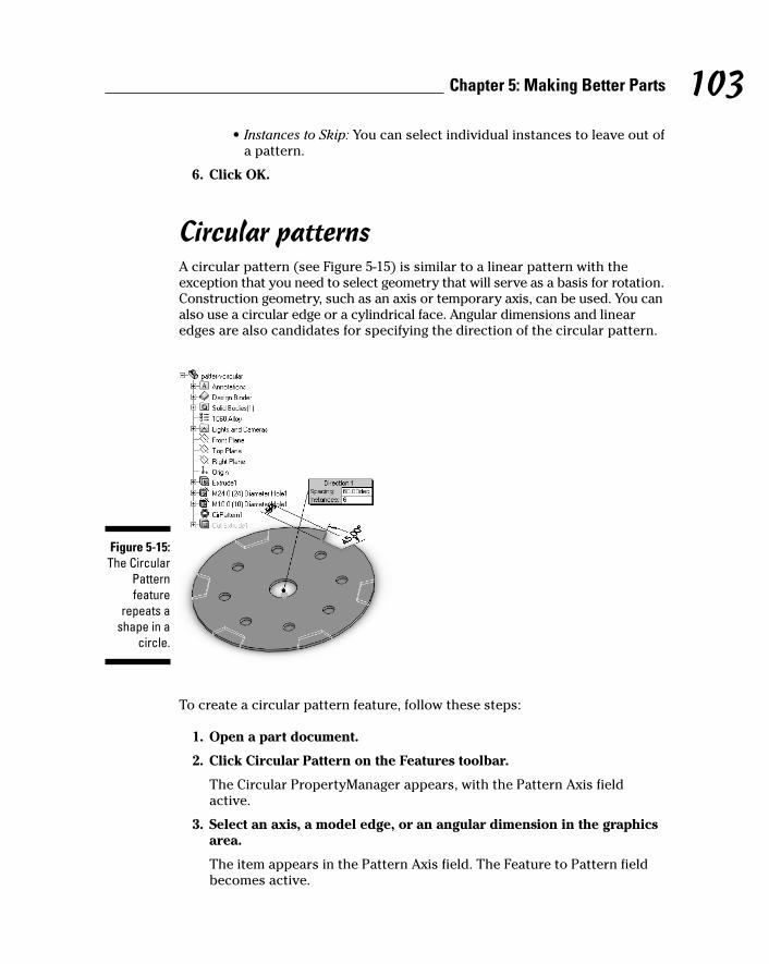
• Instances to Skip: You can select individual instances to leave out ofa pattern.
6. Click OK.
Circular patternsA circular pattern (see Figure 5-15) is similar to a linear pattern with theexception that you need to select geometry that will serve as a basis for rotation.Construction geometry, such as an axis or temporary axis, can be used. You canalso use a circular edge or a cylindrical face. Angular dimensions and linearedges are also candidates for specifying the direction of the circular pattern.
To create a circular pattern feature, follow these steps:
1. Open a part document.
2. Click Circular Pattern on the Features toolbar.
The Circular PropertyManager appears, with the Pattern Axis fieldactive.
3. Select an axis, a model edge, or an angular dimension in the graphicsarea.
The item appears in the Pattern Axis field. The Feature to Pattern fieldbecomes active.
Figure 5-15:The Circular
Patternfeature
repeats ashape in a
circle.
103Chapter 5: Making Better Parts
10_129784 ch05.qxp 9/28/07 12:35 PM Page 103
If you’re using an axis or a temporary axis, you must remember to displaythem first. From the main menu, choose View and then select Axes andTemporary Axes from the list. A check mark next to an item indicatesthat it’s already visible.
4. Select one or more features to pattern in the graphics area.
The features appear in the Feature to Pattern field. You can also repeatfaces or bodies. If you choose to repeat one of these, you can highlightfields for Faces to Pattern and Bodies to Pattern and click the graphicalimage to enter the items in those fields.
5. In the Parameters section, enter values for these two options:
• Number of Instances: Enter the number of times to repeat the pattern.
• Angle: Indicate the angle of the features.
Select the Equal Spacing check box to save time when creating a patternthat goes all the way around the part. This option automatically sets theangle based on the number of instances you select.
6. Click OK.
You can use the Geometry Pattern option in the Options section to create thepattern using only the geometry rather than the complete feature. ThePattern feature contains only the geometric representation of the feature(faces and edges). In most cases, this option speeds up the rebuilding of thepattern feature.
Mirror featuresYou can use the Mirror feature to create a copy of a feature (or a group offeatures) and mirror it around a plane or a part face. The advantage to mir-roring an object is that you can create symmetrically similar features. Youcan manipulate the features by changing the original (or parent) feature.
You can mirror the body of a part so that you don’t have to select individualfeatures or faces to mirror. A body is the entire solid body. In other words,Bodies to Mirror is used to mirror the part. Click the plus sign (+) next to theBodies folder to expand it within the FeatureManager design tree to see thebody or bodies within the part.
To create a mirror feature, follow these steps:
1. Open a part document.
2. Click Mirror on the Features toolbar.
The Mirror PropertyManager, shown in Figure 5-16, appears, with theMirror Face/Plane feature active.
104 Part II: Design Intent and the Virtual Prototype
10_129784 ch05.qxp 9/28/07 12:35 PM Page 104
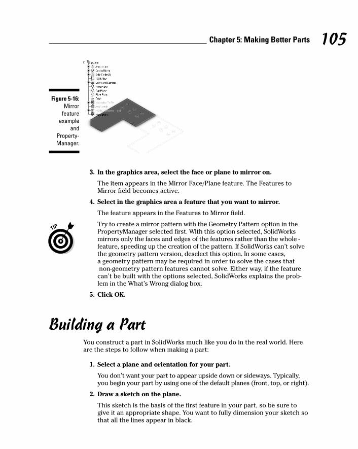
3. In the graphics area, select the face or plane to mirror on.
The item appears in the Mirror Face/Plane feature. The Features toMirror field becomes active.
4. Select in the graphics area a feature that you want to mirror.
The feature appears in the Features to Mirror field.
Try to create a mirror pattern with the Geometry Pattern option in thePropertyManager selected first. With this option selected, SolidWorksmirrors only the faces and edges of the features rather than the whole -feature, speeding up the creation of the pattern. If SolidWorks can’t solvethe geometry pattern version, deselect this option. In some cases, a geometry pattern may be required in order to solve the cases thatnon-geometry pattern features cannot solve. Either way, if the feature
can’t be built with the options selected, SolidWorks explains the prob-lem in the What’s Wrong dialog box.
5. Click OK.
Building a PartYou construct a part in SolidWorks much like you do in the real world. Hereare the steps to follow when making a part:
1. Select a plane and orientation for your part.
You don’t want your part to appear upside down or sideways. Typically,you begin your part by using one of the default planes (front, top, or right).
2. Draw a sketch on the plane.
This sketch is the basis of the first feature in your part, so be sure togive it an appropriate shape. You want to fully dimension your sketch sothat all the lines appear in black.
Figure 5-16:Mirror
featureexample
andProperty-Manager.
105Chapter 5: Making Better Parts
10_129784 ch05.qxp 9/28/07 12:35 PM Page 105
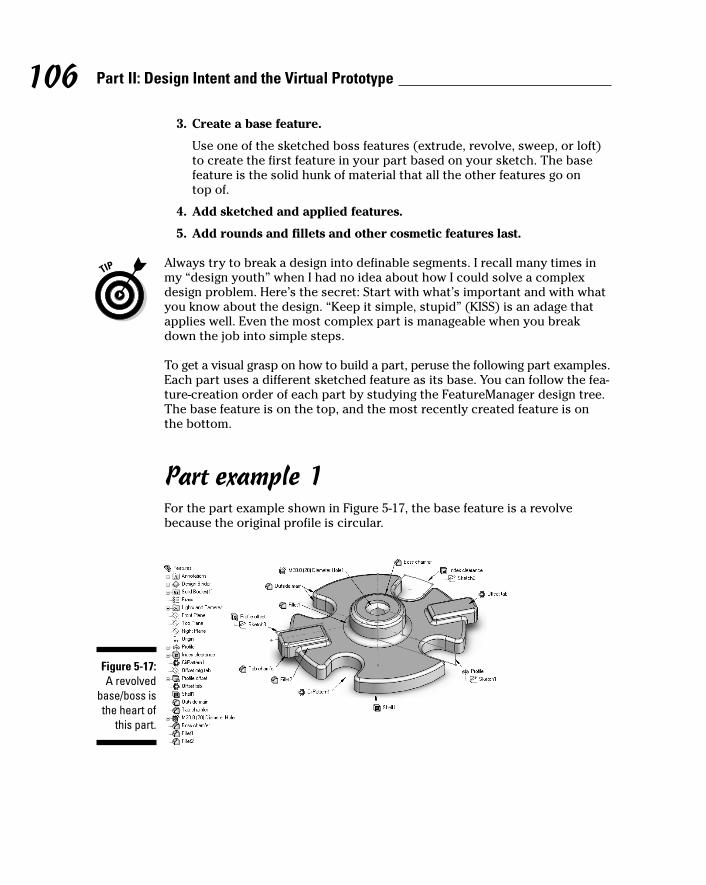
3. Create a base feature.
Use one of the sketched boss features (extrude, revolve, sweep, or loft)to create the first feature in your part based on your sketch. The basefeature is the solid hunk of material that all the other features go on top of.
4. Add sketched and applied features.
5. Add rounds and fillets and other cosmetic features last.
Always try to break a design into definable segments. I recall many times inmy “design youth” when I had no idea about how I could solve a complexdesign problem. Here’s the secret: Start with what’s important and with whatyou know about the design. “Keep it simple, stupid” (KISS) is an adage thatapplies well. Even the most complex part is manageable when you breakdown the job into simple steps.
To get a visual grasp on how to build a part, peruse the following part examples.Each part uses a different sketched feature as its base. You can follow the fea-ture-creation order of each part by studying the FeatureManager design tree.The base feature is on the top, and the most recently created feature is onthe bottom.
Part example 1For the part example shown in Figure 5-17, the base feature is a revolvebecause the original profile is circular.
Figure 5-17:A revolved
base/boss isthe heart of
this part.
106 Part II: Design Intent and the Virtual Prototype
10_129784 ch05.qxp 9/28/07 12:35 PM Page 106
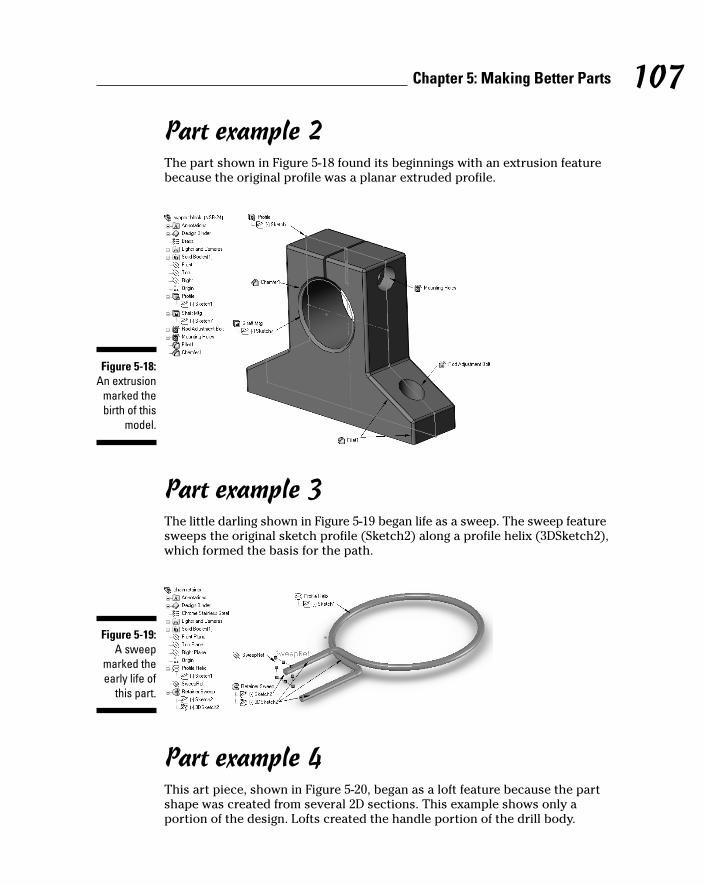
Part example 2The part shown in Figure 5-18 found its beginnings with an extrusion featurebecause the original profile was a planar extruded profile.
Part example 3The little darling shown in Figure 5-19 began life as a sweep. The sweep featuresweeps the original sketch profile (Sketch2) along a profile helix (3DSketch2),which formed the basis for the path.
Part example 4This art piece, shown in Figure 5-20, began as a loft feature because the partshape was created from several 2D sections. This example shows only aportion of the design. Lofts created the handle portion of the drill body.
Figure 5-19:A sweep
marked theearly life of
this part.
Figure 5-18:An extrusion
marked thebirth of this
model.
107Chapter 5: Making Better Parts
10_129784 ch05.qxp 9/28/07 12:35 PM Page 107
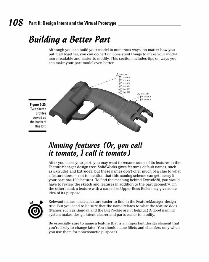
Building a Better PartAlthough you can build your model in numerous ways, no matter how youput it all together, you can do certain consistent things to make your modelmore readable and easier to modify. This section includes tips on ways youcan make your part model even better.
Naming features (Or, you call it tomato, I call it tomato)After you make your part, you may want to rename some of its features in theFeatureManager design tree. SolidWorks gives features default names, suchas Extrude1 and Extrude2, but these names don’t offer much of a clue to whata feature does — not to mention that this naming scheme can get messy ifyour part has 100 features. To find the meaning behind Extrude20, you wouldhave to review the sketch and features in addition to the part geometry. Onthe other hand, a feature with a name like Upper Boss Relief may give someidea of its purpose.
Relevant names make a feature easier to find in the FeatureManager designtree. But you need to be sure that the name relates to what the feature does.(Names such as Gandalf and the Big Pookie aren’t helpful.) A good namingsystem makes design intent clearer and parts easier to modify.
Be especially sure to name a feature that is an important design element thatyou’re likely to change later. You should name fillets and chamfers only whenyou use them for noncosmetic purposes.
Figure 5-20:Two sketch
profilesserved as
the basis ofthis loft.
108 Part II: Design Intent and the Virtual Prototype
10_129784 ch05.qxp 9/28/07 12:35 PM Page 108

SolidWorks offers a couple of different ways to rename features:
� To name the feature when you create it, choose Tools➪Options. On theSystems Options tab, select FeatureManager. In the options that appearon the right, select the Name Feature on Creation check box. Thismethod is my preference because I would rather name the feature as Icreate it than to have to go back and rename it later.
� To rename the feature within the FeatureManager design tree, double-click the feature in the FeatureManager design tree and type a newname. You can also right-click the feature in the tree and choose FeatureProperties from the menu that appears. This command gets you to theProperties dialog box, where the name is highlighted, and you canchange the name of the feature.
The best time to name a feature is right after you create it. If you don’t namea feature, most likely no one will do it for you when the project is complete.Make it a habit to name features and reinforce the habit by checking names inthe FeatureManager design tree at design checks.
Naming features is a way to organize a design. The example in Figure 5-21 showstwo versions of a FeatureManager design tree from the same part. One part(the left side) uses the default feature names, and the other (the right side)uses the named features. Which design would you rather work on when yourboss comes in and tells you to modify a design immediately?
Figure 5-21:You can
easily locateand modify
namedfeatures.
109Chapter 5: Making Better Parts
10_129784 ch05.qxp 9/28/07 12:35 PM Page 109

In addition to naming features, you should name some dimensions. If you usea dimension in a design table or if an equation references that dimension,give the dimension a meaningful name. To change the name of a sketchdimension, first make the dimension visible. In the FeatureManager designtree, right-click the feature and choose Edit Sketch. Then right-click thedimension you want to rename and choose Properties. In the Name field ofthe Properties dialog box, type a name for the dimension. The full dimensionname appears as <dimension name@feature name>. Rather than name adimension D2@Cut-Extrude1, you can rename the dimension outside andrename the feature MtgBoss so that the new dimension name is outsideDia@MtgBoss.
Thinking about feature orderAnother method of documenting a design is feature order. The FeatureManagerdesign tree shows features in the order in which they were made. The featureon the bottom is the newest. The order of features in the FeatureManagerdesign tree should communicate your design intent.
When you change a sketch, you need to rebuild to see how the change affectsthe model. You can press Ctrl+Q to completely rebuild all features in themodel. Click Rebuild on the Standard toolbar or press Ctrl+B to rebuild onlynew or changed features and their children.
You can change the order in which features are rebuilt by dragging them inthe FeatureManager design tree. Place the pointer on a feature name, pressthe left mouse button, and drag the feature to a new position in the list. (Asyou drag up or down the tree, each item that you drag over is highlighted. Thefeature name you’re moving drops immediately below the highlighted itemwhen you release the mouse button.)
Moving a feature or folder can cause the model to change. If you don’t like theresults, click the Undo button to return the feature to its original location.
Organizing features with foldersJust as you use folders and file cabinets to organize paperwork, you can usefolders in the FeatureManager design tree to organize your SolidWorks partand assembly data. The part features shown in Figure 5-22 are broken into fourmain functional areas based on their functions: Profile, Mounting, Molding, orCosmetic. When working on a specific area of the design, you can expand orcollapse a folder by clicking the plus symbol to the left of the folder name.
110 Part II: Design Intent and the Virtual Prototype
10_129784 ch05.qxp 9/28/07 12:35 PM Page 110

You can drag part features or assembly components in the FeatureManagerdesign tree to group them into functional folders. To add a new folder in theFeatureManager design tree, right-click a feature and choose Add to NewFolder. A new folder appears in the FeatureManager design tree. The featureyou right-clicked is now in the new folder. You can rename the folder anddrag additional features into the folder.
Name a folder according to its function or role in the model. You don’t have toput every part feature or assembly component in a folder. If you group featuresor components into a folder, you can act on them as a group. SolidWorks letsyou suppress part feature or assembly components in a folder as a group. Inthe example shown in Figure 5-22, you can turn off the mounting features byselecting the folder, right-clicking, and choosing Suppress. You can use theSuppress command for multiple versions of the same design or just forvisualization purposes.
When you select a folder in the FeatureManager design tree, the features inthe folder are highlighted in the graphics area. Similarly, when you select inthe graphics area a feature that’s in a folder you created, the folder is expandedto show the highlighted feature in the FeatureManager design tree.
Grouping features has a couple of benefits:
� It makes the design easier to read. You can look at the FeatureManagerdesign tree and find features by how they relate to function (mountinglocation or profile, for example) because they’re in the same area. Usingfolders also shortens the length of the features listed within theFeatureManager design tree.
� It enhances performance. When you work on larger parts, feature ordercan be a performance enhancer. For example, if you’re working on aparticular functional area, you can move that folder higher in theFeatureManager design tree so that those features are rebuilt first and see the changes in the model sooner.
Figure 5-22:Foldersmake a
FeatureManager design
tree moremanageable.
111Chapter 5: Making Better Parts
10_129784 ch05.qxp 9/28/07 12:35 PM Page 111

Using the Rollback featureThe Rollback bar, a yellow-and-black line in the FeatureManager design tree,turns blue when you select it. You can drag the bar up the FeatureManagerdesign tree to suppress features one by one and revert the model to variousearlier states.
The example shown in Figure 5-23 shows the part rolled back to show allfeatures up to the inner hinge. You see the model as it looked at the time thedesigner added the inner hinge. The features created after the inner hinge don’tappear in the model. In this case, the designer used the Rollback bar to goback and insert a new feature after the inner hinge.
Using commentsYou can add comments to the FeatureManager design tree to documentdesign intent. (See Figure 5-24.) These comments appear when you place thecursor over the feature name in the FeatureManager design tree.
Figure 5-24:Using
commentsis another
way todocument
designintent.
Figure 5-23:The
Rollback bartakes your
model backin time.
112 Part II: Design Intent and the Virtual Prototype
10_129784 ch05.qxp 9/28/07 12:35 PM Page 112
Dow
nlo
ad fro
m W
ow
! eBook
<w
ww
.wow
ebook.
com
>

To create and edit a feature comment
1. Open a part.
2. In the FeatureManager design tree, right-click a feature and chooseComment➪Add Comment, Edit Comment, or Delete Comment.
If a comment doesn’t already exist, you see Add Comment on the menu.If a comment exists, you see Edit Comment and Delete Comment. SelectDelete Comment to delete the existing comment.
A comment box, which resembles a yellow sticky note, appears. Thename of the item is at the top of the note. If you chose Edit Comment,you see the existing comment, and you can change or respond to it.
3. Click Date/Time Stamp at the bottom of the comment box.
The date and time and your name are added to the comment.
4. Type your comment.
5. Click Save and Close.
When you roll the pointer over the item in the FeatureManager designtree, the note appears.
Consider adding a comment to a folder so that you know the purpose of thefolder. Otherwise, you may have little indication of why the folder exists andwhat it contains.
Knowing How Much to ModelOne question that folks often ask is “How much detail should I include in mymodel?” For example, if you’re making a ruler, do you need to include themetal edge insert and then all the detailed text and ruler markings?
My answer is this: “Just because you can doesn’t mean you should.” Yes, youcan make parts look just like they would in real life, but you pay the piper atsome point in terms of assembly performance and the time it takes to main-tain that level of detail.
If you need all kinds of tiny details to document or manufacture the part, thenby all means add them to the model, particularly if it helps someone else tomake the part. However, you don’t need as much detail if you plan to makethe part yourself.
Use Feature Statistics to determine which features take the most time to openand rebuild. Choose Tools➪Feature Statistics.
113Chapter 5: Making Better Parts
10_129784 ch05.qxp 9/28/07 12:35 PM Page 113
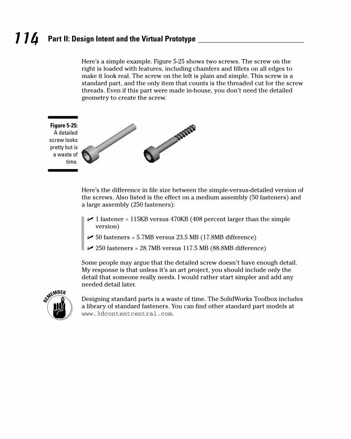
Here’s a simple example. Figure 5-25 shows two screws. The screw on theright is loaded with features, including chamfers and fillets on all edges tomake it look real. The screw on the left is plain and simple. This screw is astandard part, and the only item that counts is the threaded cut for the screwthreads. Even if this part were made in-house, you don’t need the detailedgeometry to create the screw.
Here’s the difference in file size between the simple-versus-detailed version ofthe screws. Also listed is the effect on a medium assembly (50 fasteners) anda large assembly (250 fasteners):
� 1 fastener = 115KB versus 470KB (408 percent larger than the simpleversion)
� 50 fasteners = 5.7MB versus 23.5 MB (17.8MB difference)
� 250 fasteners = 28.7MB versus 117.5 MB (88.8MB difference)
Some people may argue that the detailed screw doesn’t have enough detail.My response is that unless it’s an art project, you should include only thedetail that someone really needs. I would rather start simpler and add anyneeded detail later.
Designing standard parts is a waste of time. The SolidWorks Toolbox includesa library of standard fasteners. You can find other standard part models atwww.3dcontentcentral.com.
Figure 5-25:A detailed
screw lookspretty but is
a waste oftime.
114 Part II: Design Intent and the Virtual Prototype
10_129784 ch05.qxp 9/28/07 12:35 PM Page 114
Chapter 6
Putting It All TogetherIn This Chapter� Creating and organizing assemblies
� Connecting parts and subassemblies with mates
� Organizing the assembly by using layouts
� Getting more information from your assembly
One advantage of 3D design is that you can create a complete virtualproduct that you can assemble and analyze. SolidWorks lets you create
a functional assembly so that you can see how your design looks and worksbefore you build a single part. This way, you can quickly identify mistakesbefore spending time and resources to create the parts.
The SolidWorks virtual assembly mimics the location and movement of the components to determine their fit and function, and it lets you see how theassembly looks in its assembled and exploded states.
Creating and Modifying the AssemblyAn assembly is a collection of components that consists of parts and otherassemblies, called subassemblies. You create an assembly in SolidWorks thesame way you build a product in the real world. Mates position a component in anassembly precisely with respect to each other and define how the componentsmove and rotate together. Assembly reference geometry, such as sketches,planes, and axes, controls the shape and position of components.
Figure 6-1 shows a complete virtual assembly of a personal water propeller inits final stage before going to the manufacturer. In the sections that follow,you find an introduction to the tools used to work with assemblies as well astips that explain how to plan and design them.
11_129784 ch06.qxp 9/28/07 12:35 PM Page 115
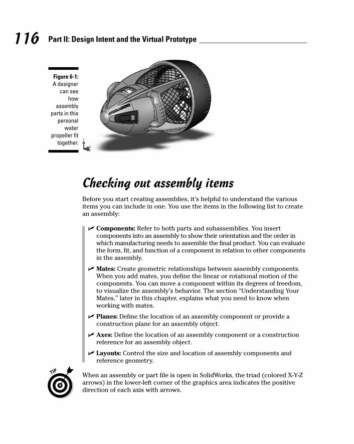
116 Part II: Design Intent and the Virtual Prototype
Checking out assembly itemsBefore you start creating assemblies, it’s helpful to understand the variousitems you can include in one. You use the items in the following list to createan assembly:
� Components: Refer to both parts and subassemblies. You insert components into an assembly to show their orientation and the order inwhich manufacturing needs to assemble the final product. You can evaluatethe form, fit, and function of a component in relation to other componentsin the assembly.
� Mates: Create geometric relationships between assembly components.When you add mates, you define the linear or rotational motion of thecomponents. You can move a component within its degrees of freedom,to visualize the assembly’s behavior. The section “Understanding YourMates,” later in this chapter, explains what you need to know whenworking with mates.
� Planes: Define the location of an assembly component or provide aconstruction plane for an assembly object.
� Axes: Define the location of an assembly component or a constructionreference for an assembly object.
� Layouts: Control the size and location of assembly components andreference geometry.
When an assembly or part file is open in SolidWorks, the triad (colored X-Y-Zarrows) in the lower-left corner of the graphics area indicates the positivedirection of each axis with arrows.
Figure 6-1:A designer
can seehow
assemblyparts in this
personalwater
propeller fittogether.
11_129784 ch06.qxp 9/28/07 12:35 PM Page 116
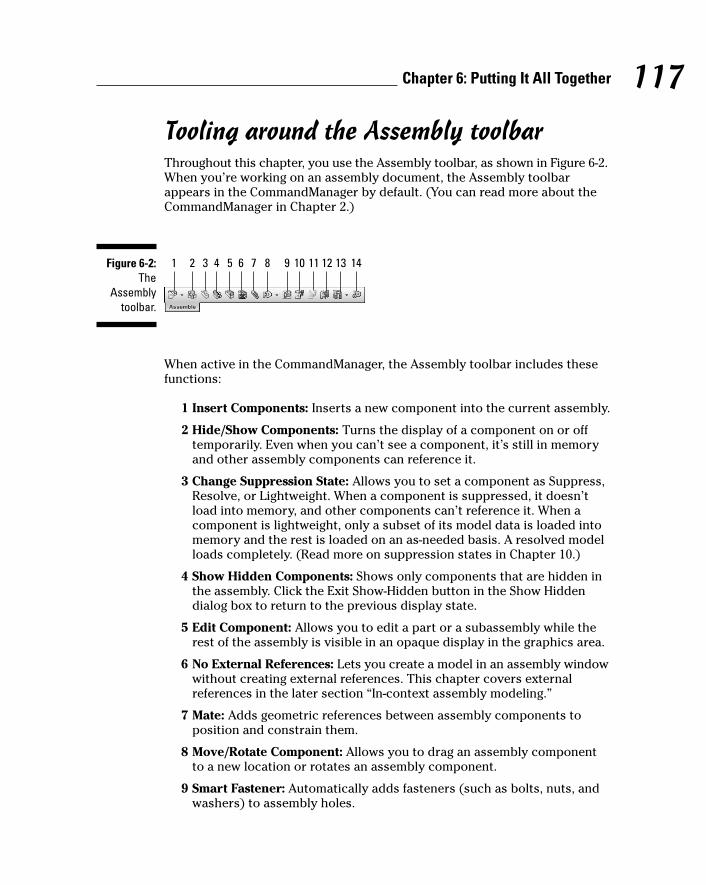
Tooling around the Assembly toolbarThroughout this chapter, you use the Assembly toolbar, as shown in Figure 6-2.When you’re working on an assembly document, the Assembly toolbarappears in the CommandManager by default. (You can read more about theCommandManager in Chapter 2.)
When active in the CommandManager, the Assembly toolbar includes thesefunctions:
1 Insert Components: Inserts a new component into the current assembly.
2 Hide/Show Components: Turns the display of a component on or offtemporarily. Even when you can’t see a component, it’s still in memoryand other assembly components can reference it.
3 Change Suppression State: Allows you to set a component as Suppress,Resolve, or Lightweight. When a component is suppressed, it doesn’tload into memory, and other components can’t reference it. When acomponent is lightweight, only a subset of its model data is loaded intomemory and the rest is loaded on an as-needed basis. A resolved modelloads completely. (Read more on suppression states in Chapter 10.)
4 Show Hidden Components: Shows only components that are hidden inthe assembly. Click the Exit Show-Hidden button in the Show Hiddendialog box to return to the previous display state.
5 Edit Component: Allows you to edit a part or a subassembly while therest of the assembly is visible in an opaque display in the graphics area.
6 No External References: Lets you create a model in an assembly windowwithout creating external references. This chapter covers externalreferences in the later section “In-context assembly modeling.”
7 Mate: Adds geometric references between assembly components toposition and constrain them.
8 Move/Rotate Component: Allows you to drag an assembly componentto a new location or rotates an assembly component.
9 Smart Fastener: Automatically adds fasteners (such as bolts, nuts, andwashers) to assembly holes.
1 2 3 4 5 6 7 8 9 10 11 12 13 14Figure 6-2:The
Assemblytoolbar.
117Chapter 6: Putting It All Together
11_129784 ch06.qxp 9/28/07 12:35 PM Page 117
10 Exploded View: Creates a view of the assembly showing the componentspulled apart so that you can see how components fit together. You canuse this view in assembly drawings and manuals.
11 Explode Line Sketch: Adds lines to components in an exploded view toshow the direction and final location of the exploded component.
12 Interference Detection: Checks the assembly to ensure that parts don’tclash into each other when they move.
13 Assembly Feature: Creates assembly-level features, such as ExtrudedCut and Hole Wizard. It features a flyout toolbar on the Assembly toolbarthat contains only the features you can use in an assembly.
14 New Motion Study: Performs a motion study by applying Linear Motor,Rotary Motor, Linear Spring, and Gravity to an assembly and animates theresults. Physical Simulation is a flyout toolbar on the Assembly toolbar.
Planning your assemblyA number of factors influence how you go about creating an assembly inSolidWorks. Resist the urge to start modeling immediately. Instead, step back and take time to plan your assembly. Planning pays off later in thedesign process.
The items in this list, each of which is covered in more detail in this chapter,help define the starting point of an assembly:
� Define what is known. Every project has certain requirements, such asthe product’s purpose, size, weight, and cost. Capture these requirementsbefore you start. Where you keep these requirements (for example, inMicrosoft Word or Microsoft Excel) doesn’t particularly matter, as longas you capture them consistently and store them in a shared location ifyou’re working with other designers.
Well-defined requirements ensure that you go in the right direction.They also save you time and let you know in advance whether you haveall the information you need to complete the project.
� Create the structure. Define the principal components of the assemblyand create configurations that show each major subassembly compo-nent and suppress everything else. Because a suppressed componentdoesn’t load into memory, these configurations allow other designers toexamine the major areas of an assembly without having to resolve theentire kit and kaboodle.
� Collaborate. Think about how to break up the assembly in order todistribute the workload if you plan to work with several designers on a project.
118 Part II: Design Intent and the Virtual Prototype
11_129784 ch06.qxp 9/28/07 12:35 PM Page 118

� Review and capture the design intent. Use a skeleton to capture andcontrol the functions of your design if you plan to create a complexassembly. Test the skeleton before you begin adding components.
� Review existing information. Check to see which designs and standardcomponents exist so that you can use them in your assembly design.
You can set document properties (dimensions, standards, text size, and unit ofmeasurement, for example) and custom properties in an assembly templatethat you can reuse. Defining custom properties in advance helps when youcreate the drawings. (To find out more about templates, see Chapter 2.)
Designing an assemblyYou can use two basic methods to design an assembly: top-down or bottom-up.With either method, your objective is to position and mate the components.Mates position the components and define how they move. (Read more onmates in the “Understanding Your Mates” section, later in this chapter.)
� In top-down design, you start work on the assembly and build parts tofit into the assembly. The geometry of one part defines the geometry ofothers. You start a top-down design with a skeleton that defines fixed partlocations and planes, for example, and then design the parts referencingthese positions.
� Bottom-up design is a good plan if all parts come from suppliers. Youdon’t need to create references that control the size and shapes of partsbecause the parts already exist. You simply insert them into the assemblyand mate them together. Because components are designed independently,their relationship to each other is simpler than in top-down design.
In most cases, you work with a mix of custom and standard parts, so the bestdesign method is a cross between top-down and bottom-up. Read the sections“Using layouts” and “In-context assembly modeling” for specific techniqueson how to design top-down.
The following sections give you three ways to begin work on an assembly.Depending on which documents you have open, one method may be morestraightforward than another. In other words, they all work, but the one thatworks best for you depends on the project you’re working on at the time.
Creating an assemblyYou can create an assembly by starting with an assembly document and thenadding parts one by one. Start with a component that doesn’t move with respect
119Chapter 6: Putting It All Together
11_129784 ch06.qxp 9/28/07 12:35 PM Page 119
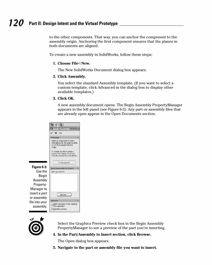
to the other components. That way, you can anchor the component to theassembly origin. Anchoring the first component ensures that the planes inboth documents are aligned.
To create a new assembly in SolidWorks, follow these steps:
1. Choose File➪New.
The New SolidWorks Document dialog box appears.
2. Click Assembly.
You select the standard Assembly template. (If you want to select acustom template, click Advanced in the dialog box to display otheravailable templates.)
3. Click OK.
A new assembly document opens. The Begin Assembly PropertyManagerappears in the left panel (see Figure 6-3). Any part or assembly files thatare already open appear in the Open Documents section.
Select the Graphics Preview check box in the Begin AssemblyPropertyManager to see a preview of the part you’re inserting.
4. In the Part/Assembly to Insert section, click Browse.
The Open dialog box appears.
5. Navigate to the part or assembly file you want to insert.
Figure 6-3:Use the
BeginAssemblyProperty-
Manager toinsert a partor assemblyfile into your
assembly.
120 Part II: Design Intent and the Virtual Prototype
11_129784 ch06.qxp 9/28/07 12:35 PM Page 120

A preview of the model appears in the Preview section of the dialog box.Any configurations appear in the Configurations box.
6. Select the file and configuration (if one exists) and click Open.
The Open dialog box closes, and the model appears in your assembly.The origin of the new component aligns with the assembly origin.
7. Click View and select the Origins check box to display the assemblyorigin.
The assembly origin appears in blue.
8. To anchor the part to the assembly origin, click OK.
The component anchors to the assembly origin. When you place acomponent this way, the component origin is located coincident withthe assembly origin, and the planes of the part and assembly arealigned, which helps establish an initial orientation for the assembly. An(f) appears next to the component in the FeatureManager design tree toindicate that the component is fixed into place.
Creating an assembly from a partYou don’t need to begin an assembly from an assembly document. In manycases, you may want to start building an assembly from an existing part. Tocreate an assembly from a part or assembly:
1. Open the model to use as the first assembly component.
2. Choose File➪Make Assembly from Part.
A new assembly document opens, and the Begin AssemblyPropertyManager appears.
3. From the main menu, choose View and select the Origins check box todisplay the origin in the graphics area.
The blue origin appears.
4. In the PropertyManager, in the Options section, select GraphicsPreview.
A preview of the model appears in the graphics area.
5. Move the pointer over the origin in the graphics area.
The model moves with your pointer, and the pointer changes to indicatean inference to the assembly origin.
6. Click to place the component.
The component anchors to the assembly origin.
121Chapter 6: Putting It All Together
11_129784 ch06.qxp 9/28/07 12:35 PM Page 121

Adding components to an assemblyAfter you begin building your assembly, you load additional components andposition them. You can position components anywhere in the graphics areaand then use the Move Components tool to drag each component closer tothe first anchored component. You should leave some space between thecomponents to view the relevant component areas. In many instances, you canuse the Rotate, View, and Pan tools on the View toolbar to change the orientationof the components, which simplifies selecting the edge, face, or other entityneeded to apply mates.
To insert a part or subassembly into an existing assembly, follow these steps:
1. Click Insert Components on the Assembly toolbar.
The Insert Component PropertyManager appears.
2. In the Part/Assembly to Insert section, click Browse.
The Open dialog box appears.
3. Navigate to the part or assembly file that you want to insert.
A preview of the model appears in the Preview section of the Opendialog box. Any configurations appear in the Configurations box.
4. Select the file and configuration (if one exists) and click Open.
The Open dialog box closes, and the model appears in your assembly.The origin of the new component aligns with the assembly origin.
5. To place the part in the center of the assembly, click OK.
The new component aligns with the origins of the assembly and adds afixed relation. (If you can’t see the blue origins, click View and select theOrigins check box.)
6. To place the part in a different location, move the pointer and click.
SolidWorks anchors the component into place. The new file appears inthe FeatureManager design tree.
If you click the pushpin in the Assembly FeatureManager window, thedialog box stays open and you can add several instances of the componentby clicking repeatedly in the graphics window.
After you insert a new component, you mate it to another component. Readthe section “Understanding Your Mates,” later in this chapter, to find out howto mate two components.
Another way to add components to the assembly is to drag them from FileExplorer in the SolidWorks task pane and place them into the assembly. Thismethod allows you to add several components quickly. You can use the Movecommand to position them later.
122 Part II: Design Intent and the Virtual Prototype
11_129784 ch06.qxp 9/28/07 12:35 PM Page 122
Organizing your assemblyWhen you’re creating a large assembly, you want to group components intomanageable subassemblies. The many benefits to breaking up the assemblythis way include the ones in the following list. Grouping components
� Distributes the work: Design team members can collaborate on thesame design by working on the subassemblies separately. Having anumber of designers in the same subassembly would create a huge trainwreck.
� Organizes the assembly based on manufacturing considerations: Youmay want the components to appear in the bill of materials list in thesame order in which you want to build them. (Find out more aboutinserting a bill or materials table into a drawing in Chapter 8.)
� Minimizes visual clutter: You can use the Change Suppression Statecommand to display only the subassemblies you’re working on in orderto minimize the visual clutter and the amount of information loaded intocomputer memory. Select a part or subassembly in the FeatureManagerdesign tree, and on the Assembly toolbar, click Change SuppressionState and select Suppress, Lightweight, or Resolve. A suppressed partdoesn’t load into memory. Only graphical information loads for a light-weight part, and a resolved part is fully loaded.
� Replaces a subassembly more easily: A subassembly behaves as asingle component. You can replace an entire subassembly with anotherone and fully constrain it with only three mates, making it easier to dealwith than lots of individual parts.
� Limits the number of top-level mates within the assembly: The moresubassemblies in a design, the fewer top-level mates. When SolidWorksopens an assembly, it solves mates at the top level first, so the more top-level mates, the longer it takes to open a file. By default, SolidWorksdoesn’t solve mates inside the subassemblies.
It takes 3 mates to fully constrain a part, so if you do the math, you needonly 15 mates to constrain an assembly of 150 parts, if you break theassembly into 5 subassemblies. In contrast, you need 450 mates to fullyconstrain that same assembly if it were flat (no subassemblies). You mayneed to wait a long time for the second one to load.
To illustrate how you can best organize an assembly, I created two designtrees for the RC car assembly shown in Figure 6-4.
123Chapter 6: Putting It All Together
11_129784 ch06.qxp 9/28/07 12:35 PM Page 123

Figure 6-5:This version
of the RCcar
assemblyshows aFeature-
Managerdesign treeusing a flat
assemblystructure.
Figure 6-4:Breaking a
largeassembly,
such as thisRC car
assembly,into sub-
assembliesmakes theassemblyeasier to
work with.
124 Part II: Design Intent and the Virtual Prototype
11_129784 ch06.qxp 9/28/07 12:35 PM Page 124

The following two FeatureManager design trees show different versions of theassembly. The design tree shown in Figure 6-5 shows parts and assemblies atthe top level, and the design tree shown in Figure 6-6 shows functionally groupedsubassemblies. The second assembly is easier to work on — for example, towork on the front suspension, you need to open only a subassembly ratherthan the entire assembly.
You can use the following commands to change the level and grouping ofassembly components at any time. You can access all these commands byright-clicking a component in the FeatureManager design tree:
� Insert New Sub-Assembly: Creates a new assembly at the level youselect. Select the top icon in the FeatureManager design tree, right-clickthe icon, and choose Insert New Sub-Assembly.
� Dissolve Sub-Assembly: Dissolves the subassembly you select andplaces the parts individually into the current FeatureManager designtree. Select the subassembly in the FeatureManager design tree, right-click, and choose Dissolve Sub-Assembly.
� Add to New Folder: Creates a new folder within the FeatureManagerdesign tree. To move the assembly component into the new folder, right-click the icon and choose Add to New Folder.
� Drag and drop: Selects parts and subassemblies. Hold down the mousebutton and drag the component to the new top-level assembly or assemblylocation.
Figure 6-6:This version
of the RCcar shows a Feature-Manager
design treebroken into
functionalsub-
assemblies.
125Chapter 6: Putting It All Together
11_129784 ch06.qxp 9/28/07 12:35 PM Page 125
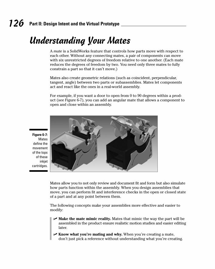
Understanding Your MatesA mate is a SolidWorks feature that controls how parts move with respect toeach other. Without any connecting mates, a pair of components can movewith six unrestricted degrees of freedom relative to one another. (Each matereduces the degrees of freedom by two. You need only three mates to fullyconstrain a part so that it can’t move.)
Mates also create geometric relations (such as coincident, perpendicular,tangent, angle) between two parts or subassemblies. Mates let componentsact and react like the ones in a real-world assembly.
For example, if you want a door to open from 0 to 90 degrees within a prod-uct (see Figure 6-7), you can add an angular mate that allows a component toopen and close within an assembly.
Mates allow you to not only review and document fit and form but also simulatehow parts function within the assembly. When you design assemblies thatmove, you can perform fit and interference checks in the open or closed stateof a part and at any point between them.
The following concepts make your assemblies more effective and easier tomodify:
� Make the mate mimic reality. Mates that mimic the way the part will beassembled in the product ensure realistic motion studies and easier editinglater.
� Know what you’re mating and why. When you’re creating a mate, don’t just pick a reference without understanding what you’re creating.
Figure 6-7:Mates
define themovementof the tops
of theseinkjet
cartridges.
126 Part II: Design Intent and the Virtual Prototype
11_129784 ch06.qxp 9/28/07 12:35 PM Page 126

Otherwise, you might create a mate reference that doesn’t reference whatyou really want. For example, if you want the top of the ink cartridgeholder (refer to Figure 6-7) to open at a specific angle from the inkcartridge itself, place an angle mate by using the two parts that willeventually come together.
� Mate as high as possible in the assembly structure. Again, try to keepthe references between components simple. Choose references formates that you plan to keep around. If you mate haphazardly, yourmates may end up referencing components that don’t exist in otherconfigurations of the assembly or that you may remove or change later.
� Name important mates. Names make mates easier to identify and tochange.
� Understand warnings and errors. The FeatureManager design treegives you feedback on problems with mates. Figure 6-8 shows examplesof a couple of mate issues: A warning icon appears next to Coincident2and Angle1. To understand a problem, in the FeatureManager designtree, right-click the mate and choose What’s Wrong. The What’s Wrongdialog box more completely describes the issue and indicates potentialsources of the problem.
� Troubleshoot with Mate Diagnostics. When problems occur with mates,as just shown in Figure 6-8, use Mate Diagnostics to review the mate errorsand warning. To diagnose mate issues, right-click the Mates icon andchoose Mate Diagnostics. Click Diagnose and review the mate issues.
� Constrain only the degrees of freedom required. For example, if youinsert a screw, you only need to mate the screw axis and the bottom ofthe screw head to the assembly component. You can leave the screwfree to turn in the hole. The screw appears as underconstrained in theFeatureManager design tree, but that’s okay.
Figure 6-8:The
Feature-Manager
design treelists errorsnext to the
mates.
127Chapter 6: Putting It All Together
11_129784 ch06.qxp 9/28/07 12:35 PM Page 127
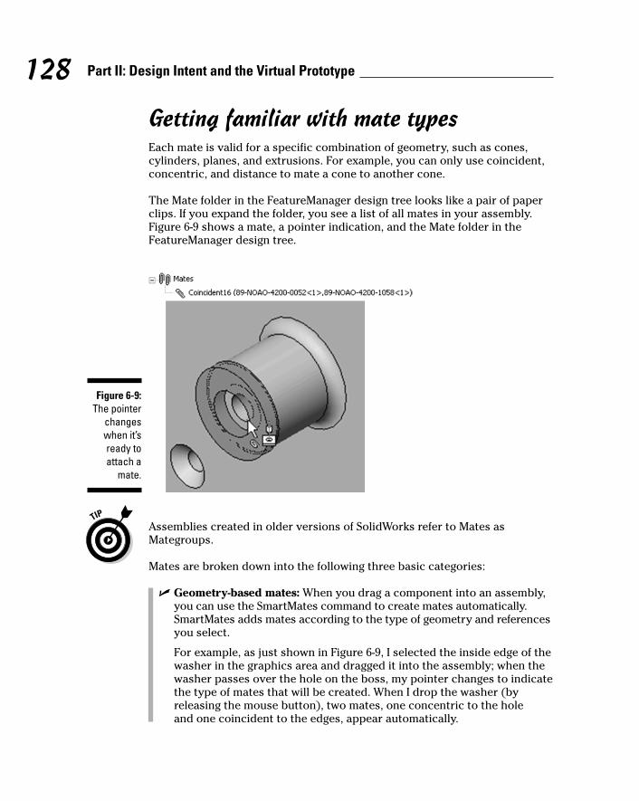
Getting familiar with mate typesEach mate is valid for a specific combination of geometry, such as cones,cylinders, planes, and extrusions. For example, you can only use coincident,concentric, and distance to mate a cone to another cone.
The Mate folder in the FeatureManager design tree looks like a pair of paperclips. If you expand the folder, you see a list of all mates in your assembly.Figure 6-9 shows a mate, a pointer indication, and the Mate folder in theFeatureManager design tree.
Assemblies created in older versions of SolidWorks refer to Mates asMategroups.
Mates are broken down into the following three basic categories:
� Geometry-based mates: When you drag a component into an assembly,you can use the SmartMates command to create mates automatically.SmartMates adds mates according to the type of geometry and referencesyou select.
For example, as just shown in Figure 6-9, I selected the inside edge of thewasher in the graphics area and dragged it into the assembly; when thewasher passes over the hole on the boss, my pointer changes to indicatethe type of mates that will be created. When I drop the washer (byreleasing the mouse button), two mates, one concentric to the hole and one coincident to the edges, appear automatically.
Figure 6-9:The pointer
changeswhen it’sready toattach a
mate.
128 Part II: Design Intent and the Virtual Prototype
11_129784 ch06.qxp 9/28/07 12:35 PM Page 128

� Feature-based mates: A feature-based mate is created between a bossand a hole. The example just shown in Figure 6-9 is a feature-based mate.(You know this because the pointer is over a cylindrical face.) Thepointer gives feedback based on the type of geometry and the referenceyou select. The pointer type shown in the figure indicates that a featurewill be used for the mate.
� Pattern-based mates: You can also create SmartMates by referencing acircular pattern of holes on a planar face. (These apply to only true patternfeatures, not those you create manually.) Align the component to thematch circular edge. Use the Tab key to align its patterns and release themouse button to drop the component into place.
For a pattern-based mate, you can create three mates: a concentric matebetween the circular edges, a coincident mate between the planar faces,and a concentric mate between the selected part and pattern within theassembly.
You can use feature-based and pattern-based mates to create SmartMates(see the “Working with SmartMates” section, later in this chapter). You usethe geometry-based mates to create basic mates. The types of basic matesare shown in this list:
� Coincident: Places two items (faces, edges, or planes in combinationwith each other or combined with a single vertex) so that they touch.
� Parallel: Places two items so that they remain parallel to one another.
� Perpendicular: Places two items so that they’re 90 degrees from oneanother.
� Tangent: Places a curve and another item so that they meet at a singlepoint. One of the selected items must be a cylindrical, conical, orspherical face.
� Concentric: Places two items so that they share the same center axis.
� Distance: Places two items at a specified distance from one another.
� Angle: Places two items at a specified angle to one another.
� Lock: Maintains the position and orientation between two components.
Adding a mateTo add a mate, follow these steps:
1. Open a SolidWorks assembly document.
2. Click Mate in the Assembly toolbar.
The Mates PropertyManager, shown in Figure 6-10, appears, with theMate Selections field active.
129Chapter 6: Putting It All Together
11_129784 ch06.qxp 9/28/07 12:35 PM Page 129
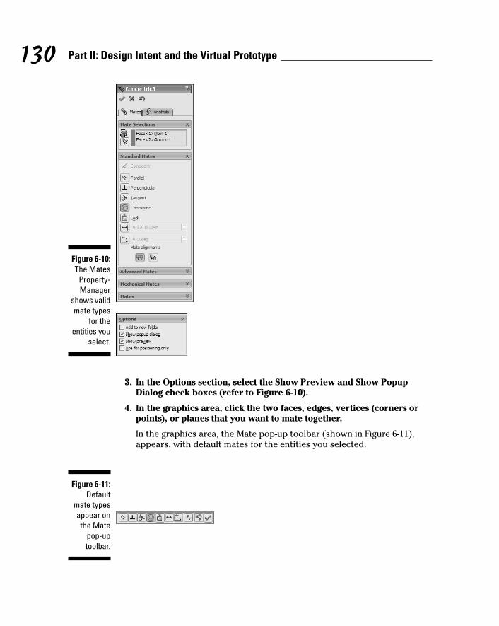
3. In the Options section, select the Show Preview and Show PopupDialog check boxes (refer to Figure 6-10).
4. In the graphics area, click the two faces, edges, vertices (corners orpoints), or planes that you want to mate together.
In the graphics area, the Mate pop-up toolbar (shown in Figure 6-11),appears, with default mates for the entities you selected.
Figure 6-11:Default
mate typesappear onthe Mate
pop-uptoolbar.
Figure 6-10:The Mates
Property-Manager
shows validmate types
for theentities you
select.
130 Part II: Design Intent and the Virtual Prototype
11_129784 ch06.qxp 9/28/07 12:35 PM Page 130
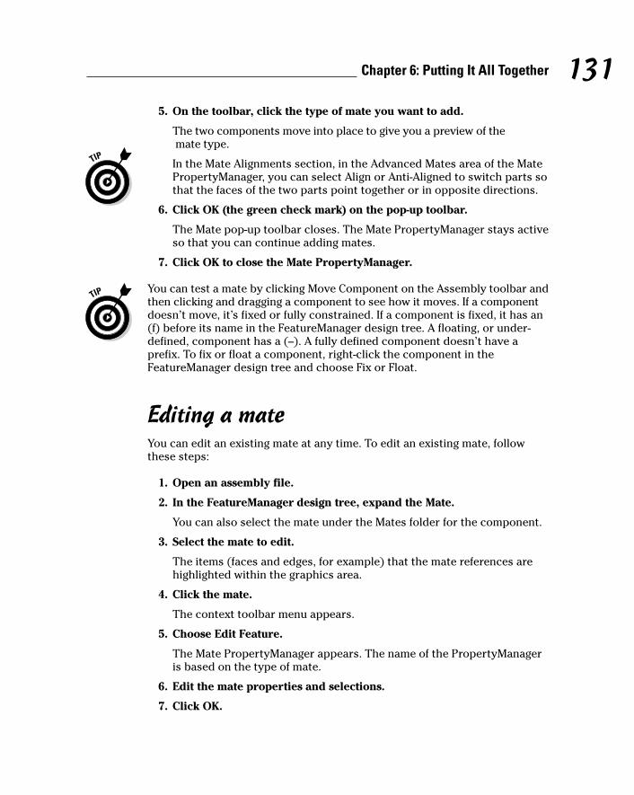
5. On the toolbar, click the type of mate you want to add.
The two components move into place to give you a preview of themate type.
In the Mate Alignments section, in the Advanced Mates area of the MatePropertyManager, you can select Align or Anti-Aligned to switch parts sothat the faces of the two parts point together or in opposite directions.
6. Click OK (the green check mark) on the pop-up toolbar.
The Mate pop-up toolbar closes. The Mate PropertyManager stays activeso that you can continue adding mates.
7. Click OK to close the Mate PropertyManager.
You can test a mate by clicking Move Component on the Assembly toolbar andthen clicking and dragging a component to see how it moves. If a componentdoesn’t move, it’s fixed or fully constrained. If a component is fixed, it has an(f) before its name in the FeatureManager design tree. A floating, or under-defined, component has a (–). A fully defined component doesn’t have aprefix. To fix or float a component, right-click the component in theFeatureManager design tree and choose Fix or Float.
Editing a mateYou can edit an existing mate at any time. To edit an existing mate, followthese steps:
1. Open an assembly file.
2. In the FeatureManager design tree, expand the Mate.
You can also select the mate under the Mates folder for the component.
3. Select the mate to edit.
The items (faces and edges, for example) that the mate references arehighlighted within the graphics area.
4. Click the mate.
The context toolbar menu appears.
5. Choose Edit Feature.
The Mate PropertyManager appears. The name of the PropertyManageris based on the type of mate.
6. Edit the mate properties and selections.
7. Click OK.
131Chapter 6: Putting It All Together
11_129784 ch06.qxp 9/28/07 12:35 PM Page 131
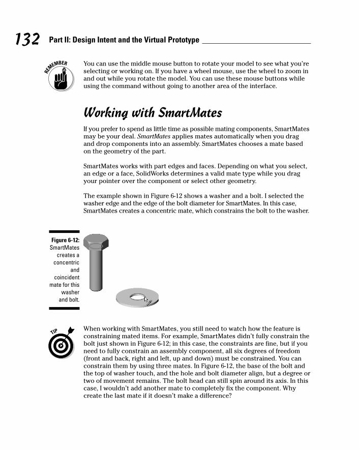
You can use the middle mouse button to rotate your model to see what you’reselecting or working on. If you have a wheel mouse, use the wheel to zoom inand out while you rotate the model. You can use these mouse buttons whileusing the command without going to another area of the interface.
Working with SmartMatesIf you prefer to spend as little time as possible mating components, SmartMatesmay be your deal. SmartMates applies mates automatically when you dragand drop components into an assembly. SmartMates chooses a mate basedon the geometry of the part.
SmartMates works with part edges and faces. Depending on what you select,an edge or a face, SolidWorks determines a valid mate type while you dragyour pointer over the component or select other geometry.
The example shown in Figure 6-12 shows a washer and a bolt. I selected thewasher edge and the edge of the bolt diameter for SmartMates. In this case,SmartMates creates a concentric mate, which constrains the bolt to the washer.
When working with SmartMates, you still need to watch how the feature isconstraining mated items. For example, SmartMates didn’t fully constrain thebolt just shown in Figure 6-12; in this case, the constraints are fine, but if youneed to fully constrain an assembly component, all six degrees of freedom(front and back, right and left, up and down) must be constrained. You canconstrain them by using three mates. In Figure 6-12, the base of the bolt andthe top of washer touch, and the hole and bolt diameter align, but a degree ortwo of movement remains. The bolt head can still spin around its axis. In thiscase, I wouldn’t add another mate to completely fix the component. Whycreate the last mate if it doesn’t make a difference?
Figure 6-12:SmartMates
creates aconcentric
andcoincident
mate for thiswasher
and bolt.
132 Part II: Design Intent and the Virtual Prototype
11_129784 ch06.qxp 9/28/07 12:35 PM Page 132
You can activate SmartMates when you drop an assembly component into theassembly, in order to eliminate the extra steps of first adding the assemblycomponent and then manually adding more mates.
To activate SmartMates when you pull a component into the assembly, holddown the Alt key and drag a component over potential mate partners. Thecomponent becomes transparent, and the pointer changes when it’s over avalid mate partner. Drop the component to apply the mate.
To add a SmartMate to an existing assembly component in a SolidWorksassembly, follow these steps:
1. Click Move Component on the Assembly toolbar.
The Move PropertyManager appears.
2. In the PropertyManager, in the Move area, click SmartMates.
3. Double-click a component and then select a valid mate partner.
The pointer turns into a paper clip, indicating that SmartMates is active.The Mate pop-up toolbar appears, with the default mate types to fit thegeometry you selected.
4. On the Mate pop-up toolbar, click a mate type.
5. Click OK on the Mate toolbar.
The components move into place, and the SmartMates PropertyManagerstays active for you to add other mates.
6. To add other mates, repeat Steps 3 through 5.
7. Click OK in the PropertyManager.
The SmartMates PropertyManager closes.
To add a SmartMate to a new component by dragging and dropping it into anexisting assembly, follow these steps:
1. Open a SolidWorks assembly document.
2. Open another SolidWorks part or assembly document.
3. Choose Windows➪Tile Vertical.
Both windows appear side by side so that you can see both open files atthe same time. You can zoom into either model to get a close look at theareas you want to mate.
4. Click the model, and drag it into the main assembly document towhere you want to mate it.
The pointer changes to a mate type when the parts are ready to mate.
133Chapter 6: Putting It All Together
11_129784 ch06.qxp 9/28/07 12:35 PM Page 133

5. Release the mouse button.
The Mate pop-up toolbar appears with the default mate types for thetwo parts.
6. Click a mate type on the toolbar.
7. Click OK.
The parts mate, and the toolbar closes.
After SmartMates mates your two components, you can flip a part if it doesn’tpoint in the right direction, by clicking the part and pressing the Tab key. Ifthe orientation isn’t what you want, press the Tab key again to flip the com-ponents back around without releasing the left mouse button. If you’remating a pattern feature, clicking the Tab rotates the part about the center ofthe pattern rather than flips the mate alignment (aligned or anti-aligned).
Working with mate referencesMate references specify one or more entities of a component to use for auto-matic mating. When you drag a component with a mate reference into anassembly, SolidWorks looks for other combinations of the same mate refer-ence name and mate type. If the name is the same but the type doesn’tmatch, SolidWorks doesn’t add the mate.
Here are a few concepts to keep in mind about mate references:
� Components: You can add mate references to parts and subassemblies.In subassemblies, you can select assembly geometry (such as a plane inthe assembly) or component geometry (such as the face of a compo-nent).
� Multiple mate references: A component can contain more than onemate reference. The MateReferences folder in the FeatureManager designtree holds all mate references. For example, you can have a componentin an assembly with two mate references: bolt and washer. When you draga fastener with a mate reference named bolt into the assembly, SolidWorksadds mates between the entities with the same mate reference name.
� Multiple mated entities: Each mate reference can contain as many asthree mated entities: primary, secondary, and tertiary reference entities.Each of these entities can have an assigned mate type and alignment. Theprimary reference entity on one component must mate to the primaryreference entity on another. For example, a shaft can have its cylindricalface assigned to a concentric mate and its planar end face assigned to acoincident mate. When you drag that component into an appropriatelocation in an assembly, SolidWorks adds both mates.
� SmartMates: When the SmartMates PropertyManager is open, SolidWorksadds mates by using mate references before it adds geometric SmartMates.
134 Part II: Design Intent and the Virtual Prototype
11_129784 ch06.qxp 9/28/07 12:35 PM Page 134

You have to set up the mate reference in the original document (part orassembly) before you plan to use it in your assemblies. You use mate referencesmainly in situations where you plan to use a common component often.
In Figure 6-13, the selected face is the primary reference. The axes namedAxis1 and Axis2 are the secondary and tertiary references. You can add thesethree references to the engine so that you can drag new exhaust systems intothe assembly and automatically mate them.
To define a mate reference, follow these steps:
1. Open a SolidWorks part or assembly document.
2. Choose Insert➪Reference Geometry➪Mate Reference.
The Mate Reference PropertyManager appears with the PrimaryReference Entity field active.
3. In the Reference Name area, type a name for the mate reference.
Always give the mate reference a meaningful name.
4. Select a face, an edge, a vertex, or a plane for the primary referenceentity.
The entity appears in the Primary Reference Entity field. Select the mostimportant mate for the primary reference. SolidWorks uses the entity forpotential mates when you drag a new component into the assembly.
5. For the Mate Reference type, use the pull-down menu to select adefault mate type for the primary reference.
6. In the Mate Reference Alignment area, use the pull-down menu toselect the default reference alignment for the primary entity.
Figure 6-13:The muffler
assemblyshows the
threereferences
(primary,secondary,
and tertiary)used to
mate to theengine
assembly.
135Chapter 6: Putting It All Together
11_129784 ch06.qxp 9/28/07 12:35 PM Page 135
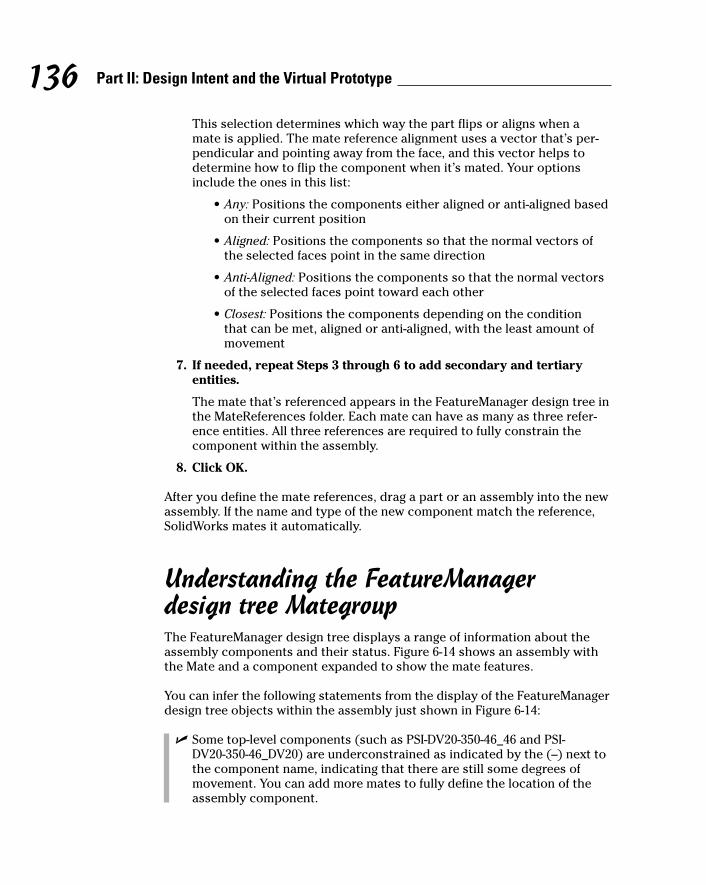
This selection determines which way the part flips or aligns when amate is applied. The mate reference alignment uses a vector that’s per-pendicular and pointing away from the face, and this vector helps todetermine how to flip the component when it’s mated. Your optionsinclude the ones in this list:
• Any: Positions the components either aligned or anti-aligned basedon their current position
• Aligned: Positions the components so that the normal vectors ofthe selected faces point in the same direction
• Anti-Aligned: Positions the components so that the normal vectorsof the selected faces point toward each other
• Closest: Positions the components depending on the condition that can be met, aligned or anti-aligned, with the least amount ofmovement
7. If needed, repeat Steps 3 through 6 to add secondary and tertiaryentities.
The mate that’s referenced appears in the FeatureManager design tree inthe MateReferences folder. Each mate can have as many as three refer-ence entities. All three references are required to fully constrain thecomponent within the assembly.
8. Click OK.
After you define the mate references, drag a part or an assembly into the newassembly. If the name and type of the new component match the reference,SolidWorks mates it automatically.
Understanding the FeatureManager design tree MategroupThe FeatureManager design tree displays a range of information about theassembly components and their status. Figure 6-14 shows an assembly withthe Mate and a component expanded to show the mate features.
You can infer the following statements from the display of the FeatureManagerdesign tree objects within the assembly just shown in Figure 6-14:
� Some top-level components (such as PSI-DV20-350-46_46 and PSI-DV20-350-46_DV20) are underconstrained as indicated by the (–) next tothe component name, indicating that there are still some degrees ofmovement. You can add more mates to fully define the location of theassembly component.
136 Part II: Design Intent and the Virtual Prototype
11_129784 ch06.qxp 9/28/07 12:35 PM Page 136
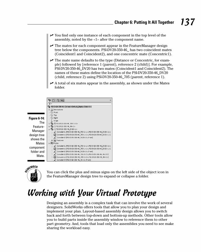
� You find only one instance of each component in the top level of theassembly, noted by the <1> after the component name.
� The mates for each component appear in the FeatureManager designtree below the components. PSI-DV20-350-46_ has two coincident mates(Coincident1 and Coincident2), and one concentric mate (Concentric1).
� The mate name defaults to the type (Distance or Concentric, for exam-ple) followed by [reference 1 (parent), reference 2 (child)]. For example,PSI-DV20-350-46_DV20 has two mates (Coincident1 and Coincident2). Thenames of these mates define the location of the PSI-DV20-350-46_DV20(child, reference 2) using PSI-DV20-350-46_705 (parent, reference 1).
� A total of six mates appear in the assembly, as shown under the Matesfolder.
You can click the plus and minus signs on the left side of the object icon inthe FeatureManager design tree to expand or collapse a folder.
Working with Your Virtual PrototypeDesigning an assembly is a complex task that can involve the work of severaldesigners. SolidWorks offers tools that allow you to plan your design andimplement your plan. Layout-based assembly design allows you to switchback and forth between top-down and bottom-up methods. Other tools allowyou to build parts inside the assembly window to reference them to otherpart geometry. And, tools that load only the assemblies you need to see makesharing the workload easy.
Figure 6-14:The
Feature-Manager
design treeshows the
Matescomponent
folder andMate.
137Chapter 6: Putting It All Together
11_129784 ch06.qxp 9/28/07 12:35 PM Page 137
Using layoutsYou can use layouts to define and control the location and orientation ofassembly components. Layouts are made up of 3D sketches and planes. Bothare important components in top-down design. (If you’re unfamiliar with top-down design, see the section “Designing an assembly,” earlier in this chapter.)With layouts, you construct a single 3D sketch to show where each componentbelongs. Then you can modify the sketch before you add any parts.
The major advantage of designing an assembly by using a layout is that if youchange the layout, the assembly and its parts update automatically.
Another benefit is that layouts reduce the amount of parent/child relation-ships. Components are related by one sketch in the assembly, so parts aremore robust and easier to change and redefine.
Creating the layoutTo create an assembly layout, follow these steps:
1. Open a new assembly document by choosing File➪New➪Assembly.
The Begin Assembly PropertyManager appears.
2. Press the Create Layout button in the PropertyManager.
A 3D sketch opens.
3. You can begin creating the various parts of your assembly by creatingblocks from the sketch geometry (see the next section, “Using blocksin your layout”).
You use these blocks to create individual parts within the assemblydocument. These parts can be saved as external files or used as virtualcomponents specific to only the current assembly.
Using blocks in your layoutIn SolidWorks 2008, you can create blocks from sketch entities and use themin your layout. Blocks let you group sketch geometry. The group updates andbehaves as a single entity. The layout sketch must be active in order to createor edit blocks. You save blocks with the .sldblk extension so that you caneasily import them into part or assembly or other block files later.
The Blocks toolbar, shown in Figure 6-15, lets you group blocks of sketchentities. To display it, choose View➪Toolbars➪Blocks.
138 Part II: Design Intent and the Virtual Prototype
11_129784 ch06.qxp 9/28/07 12:35 PM Page 138

The Blocks toolbar includes these functions:
� Make Block: Create a block from selected sketch geometry.
� Edit Block: Change dimensions and relations in a block.
� Insert Block: Insert a saved block into the current sketch.
� Save Block: Save a block to disk for reuse.
� Explode Block: Ungroup a block and convert to regular sketch entities.
You can use blocks to create parts in your assembly layout by selecting oneor more blocks and then right-clicking and choosing Make Part from Block.This function takes the sketch block names and creates components for theassembly.
To create an assembly from a layout, follow these steps:
1. Open an assembly that contains a layout.
See the earlier section “Creating the layout.”
2. Create or select existing blocks from the FeatureManager design tree:Right-click and choose Make Part from Block (see Figure 6-16).
The Make Part from Block PropertyManager appears, as shown in Figure 6-17.
3. In the Block to Part Constraint section of the PropertyManager, selecta constraint option.
The Project Constraint option allows your new part to move in a directionnormal to the sketch plane on which the block was created. The On Blockconstraint restricts all movement of the new part.
4. Click OK.
A part containing the selected block is created and appears in theFeatureManager design tree. The square brackets indicate that it’s a virtualcomponent. (It’s saved within the assembly file, not in an external partfile.) Later, if you want, you can save these virtual components as externalfiles: Right-click the Virtual Component in the FeatureManager designtree and choose Save Part (in External File).
Figure 6-15:The sketch
Blockstoolbar.
139Chapter 6: Putting It All Together
11_129784 ch06.qxp 9/28/07 12:35 PM Page 139
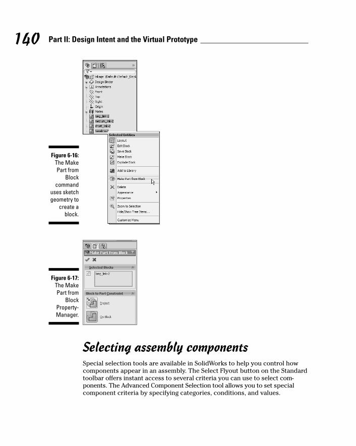
Selecting assembly componentsSpecial selection tools are available in SolidWorks to help you control howcomponents appear in an assembly. The Select Flyout button on the Standardtoolbar offers instant access to several criteria you can use to select com-ponents. The Advanced Component Selection tool allows you to set specialcomponent criteria by specifying categories, conditions, and values.
Figure 6-17:The MakePart from
BlockProperty-Manager.
Figure 6-16:The MakePart from
Blockcommand
uses sketchgeometry to
create ablock.
140 Part II: Design Intent and the Virtual Prototype
11_129784 ch06.qxp 9/28/07 12:35 PM Page 140

You can use these tools to create assembly configurations that hide or showcomponents based on the component’s mass properties (weight and volume,for example) and custom properties. The ability to control what you can andcan’t see in an assembly is another example of why custom properties areimportant to SolidWorks document types.
The example shown in Figure 6-18 indicates how you can use AdvancedComponent Selection to select all fasteners (nuts, pins, and washers, forexample) in an assembly based on the Fastener file type.
SolidWorks defines special properties (SW Special) to use within the selectioncriteria:
� Part Mass: How much it weighs (numeric)
� Part Volume: How big it is (numeric)
� Part Is Interior Detail: Whether you can see the part or whether it’sinside somewhere (Yes or No)
� Configuration Name: Configuration names you have defined (string)
� Document Name: The filename (string)
You can use Advanced Component Selection to specifically hide or showcomponents in an assembly configuration. For example, you may want tocreate a configuration that doesn’t show any of the standard hardware. Youcan use Advanced Component Selection to select the hardware based on acustom property and then set the components to be hidden or suppressed.
Figure 6-18:Use
AdvancedComponentSelection to
choose allfasteners in
an assemblybased on
their customproperty
values orfile types.
141Chapter 6: Putting It All Together
11_129784 ch06.qxp 9/28/07 12:35 PM Page 141

To show or hide components based on advanced selection criteria, followthese steps:
1. Click the ConfigurationManager tab at the top of the FeatureManagerdesign tree.
The FeatureManager design tree disappears, and the ConfigurationManager appears in its place. The ConfigurationManager lists the differentconfigurations in the assembly.
2. Right-click a configuration and choose Advanced Select.
The Advanced Component Selection dialog box appears.
3. Define the Property and Condition values.
You can apply more than one condition by using the Boolean values Andand Or.
4. Click Apply to run the query.
The components that meet the specified criteria are highlighted in theFeatureManager design tree.
5. (Optional) Hide, suppress, or even change the display state of theselected items.
You can choose these actions even though the Advanced ComponentSelection dialog box is still displayed.
6. Click the X Close box in the dialog box to close it.
You can save a performed search by adding a name in the Name of Searchpull-down list and selecting the Save icon. Then switch to the Manage Searchestab and use the Add to Favorites selection. This procedure adds your searchto the Select Flyout menu, making it available to you in later searches.
Creating assembly featuresSolidWorks allows you to create certain features (Extruded Cut, RevolvedCut, Hole Wizard, and Linear and Circular Patterns) in the assembly.
You can use these features when you’re modeling a cut or a hole at theassembly level. For example, in a welded assembly, you may want to add cutsand holes to the assembly after all assembly components are in place.
Assembly features are added at the assembly level, not to the individual com-ponents. You add these features the same way you add part features. (Youcan read about part features in Chapter 5.) You can access the commands onthe Features toolbar.
142 Part II: Design Intent and the Virtual Prototype
11_129784 ch06.qxp 9/28/07 12:35 PM Page 142
When adding an assembly feature, you can set the feature scope to specifywhich components should be taken into consideration when creating theassembly feature. So, if you want to cut only certain parts with an assemblycut, you can define the scope to only include those components.
To set the scope for an assembly feature, follow these steps:
1. In the Cut-Extrude PropertyManager, select the parameters for the cutfeatures (direction and distance, for example).
2. In the Feature Scope section of the Cut-Extrude PropertyManager,select either All Components or Selected Components.
If you choose Selected Components, deselect the Auto-Select radio button.
3. In the FeatureManager design tree or in the graphics area, select thecomponents that you want the assembly feature to affect.
The selected component names appear in the Feature Scope dialog box.
4. Click OK.
The feature is applied to the selected components. The default featurescope is updated.
In-context assembly modelingIn addition to creating or editing components in their own part windows, youcreate or edit components in the assembly window. The advantage to thismethod is that it allows you to build a part that references the geometry ofanother. If you update one part, the other one updates also, ensuring that thecomponents fit together correctly. This method of design is in-context designbecause you’re working in the context of the assembly.
When you create a part in an assembly window, the part appears in theFeatureManager design tree as though you created it in its own window.SolidWorks also adds an item to the FeatureManager design tree that lists information about the part, such as what was used to create it and thereferenced assembly component.
Parts created within the context of the assembly contain external references.SolidWorks creates an external reference when one document is dependenton another for its solution. The referenced document is the parent, and thedocument that references it is its child. If the parent document changes, itschildren update to reflect that change.
The ability to design in the context of the assembly is a powerful one. But iftoo many parts are tied to one another, managing the automatic update ofchanges to the original parts can be harder. I always like having more controlover what changes and when.
143Chapter 6: Putting It All Together
11_129784 ch06.qxp 9/28/07 12:35 PM Page 143

You can use the following commands to work on parts in the context of anassembly. You can access all these commands when you right-click a compo-nent name in the FeatureManager design tree:
� Edit Part: Allows you to edit a part in the assembly window while theassembly geometry is displayed in the background
� Edit In-Context: Recalls the assembly when only the part is active sothat you can change, add, or remove references
� List External References: Lists the references of a part and their currentstate (in or out of context)
� Display/Delete Relations: Allows you to list, review, delete, or replacean external reference
The FeatureManager design tree indicates that a feature has an external refer-ence by appending the -> symbol to the right of the feature name. If theexternal reference is locked, the symbol changes to ->*.
If you’re editing in context of the assembly and you don’t want to createexternal references, click No External References on the Assembly toolbar(see Figure 6-19).
Creating a part in an assemblyTo create a part while in the assembly, follow these steps:
1. Choose Insert➪Component➪New Part.
A new part appears in the FeatureManager design tree. The new partname is enclosed in brackets, signifying that it’s a virtual component.
2. Click a face or plane to begin sketching geometry for your new part.
Figure 6-19:You can edit
a part in the context
of theassembly.
144 Part II: Design Intent and the Virtual Prototype
11_129784 ch06.qxp 9/28/07 12:35 PM Page 144
Dow
nlo
ad fro
m W
ow
! eBook
<w
ww
.wow
ebook.
com
>
3. Construct the part features by using the same techniques you use tobuild a part on its own by using reference geometry from other com-ponents in the assembly as needed.
See Chapter 5 to brush up on your part-making skills.
4. Right-click the new part in the FeatureManager design tree andchoose Save Part (in External File).
This step saves the part file to your disk.
5. To return to editing the assembly, right-click anywhere in the graphicsarea and then choose either Edit Assembly:<assembly_name> or EditComponent.
Editing a part in an assemblyEditing a part while in an assembly allows you to modify a component with-out leaving the assembly. You can create sketches for the new features thatreference an edge or that you dimension to an edge in another part.
When you edit a part in the context of an assembly, the part turns blue andthe rest of the assembly turns gray.
To edit a part while in an assembly, follow these steps:
1. Click the part and then the Edit Part icon.
The rest of the assembly becomes transparent in the background.
You have several options for displaying component transparency whenyou edit a component in the context of an assembly. These settings affect only the component not being edited. Choose ToolsÍOptions. Onthe Systems Option tab, select Display/Selection. In the AssemblyTransparency for In-Context Edit area, select an option for the type of transparency.
The title bar shows the name of the part in the assembly that’s open forediting as <part_name> in <assembly_name>.sldasm. Note thatthe message on the status bar indicates that you’re now editing the partdocument even though the entire assembly is visible.
When you edit a part in the context of an assembly, the referencedconfiguration in the assembly becomes the active configuration in allopen windows (for example, if the part is open in its own window).
2. Make the necessary changes to the part.
You can read more about how to make a part in Chapter 5.
3. To return to editing the assembly, right-click the assembly name in theFeatureManager design tree, or right-click anywhere in the graphicsarea and choose Edit Assembly:<assembly_name> or click EditComponent.
145Chapter 6: Putting It All Together
11_129784 ch06.qxp 9/28/07 12:35 PM Page 145
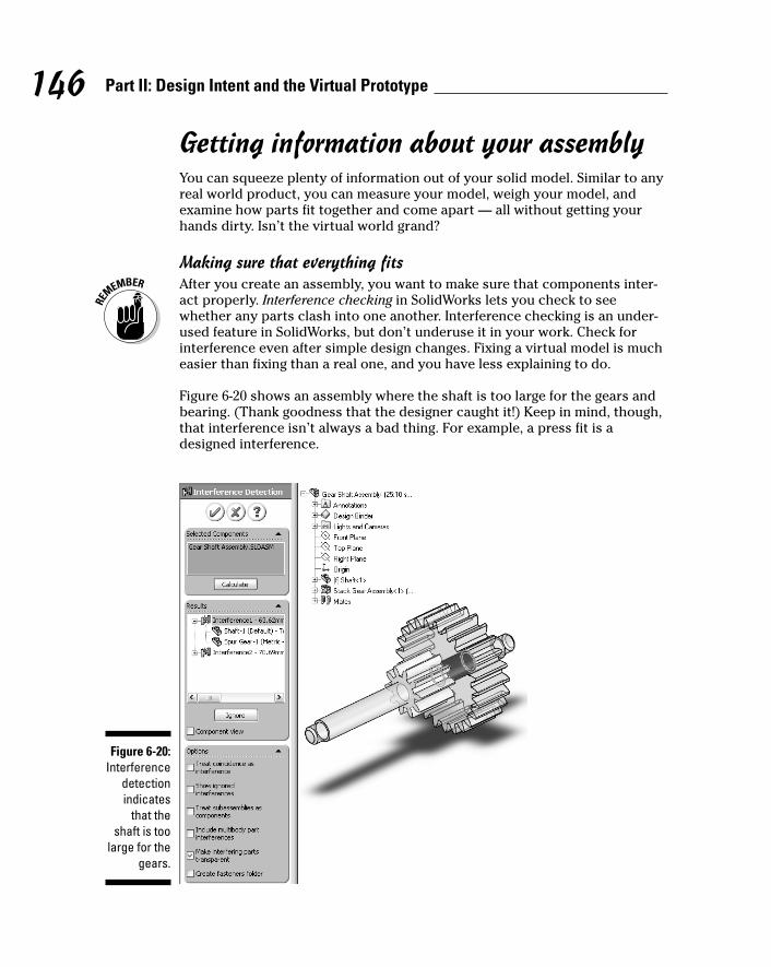
Getting information about your assemblyYou can squeeze plenty of information out of your solid model. Similar to anyreal world product, you can measure your model, weigh your model, andexamine how parts fit together and come apart — all without getting yourhands dirty. Isn’t the virtual world grand?
Making sure that everything fitsAfter you create an assembly, you want to make sure that components inter-act properly. Interference checking in SolidWorks lets you check to seewhether any parts clash into one another. Interference checking is an under-used feature in SolidWorks, but don’t underuse it in your work. Check forinterference even after simple design changes. Fixing a virtual model is mucheasier than fixing than a real one, and you have less explaining to do.
Figure 6-20 shows an assembly where the shaft is too large for the gears andbearing. (Thank goodness that the designer caught it!) Keep in mind, though,that interference isn’t always a bad thing. For example, a press fit is adesigned interference.
Figure 6-20:Interference
detectionindicates
that theshaft is too
large for thegears.
146 Part II: Design Intent and the Virtual Prototype
11_129784 ch06.qxp 9/28/07 12:35 PM Page 146
You can see two interferences in Figure 6-20 (Interference1 and Interference2).If you select the interference in the Results field of the Interference DetectionPropertyManager, the interference volume is highlighted as shown. Thenames of the interfering components also appear under the interference.
To check the assembly for interferences, follow these steps:
1. Open an assembly document.
2. Choose Interference Detection on the Evaluate tab.
The Interference Detection dialog box appears, with the SelectedComponents field active. The entire assembly appears in the field bydefault. You can clear the field and enter any subassemblies individually.
3. Select (or don’t select) the check boxes for these options:
• Treat Coincidence As Interference: Reports coincident entities asinterferences.
• Show Ignored Interference: Shows ignored interferences in theResults list, with a gray icon. When this option is cleared, ignoredinterferences aren’t listed.
• Treat Subassemblies As Components: Treats subassemblies assingle components so that interferences between a subassembly’scomponents aren’t reported.
• Include Multibody Part Interferences: Reports interferences betweenbodies within multibody parts. (A multibody is a part file with twoseparate solid bodies that don’t touch.)
• Make Interfering Parts Transparent: Displays the components of theselected interference in transparent mode.
• Create Fasteners Folder: Segregates interferences between fasteners(such as a nut and a bolt) into a separate folder in the Results area.
4. Select Component View in the Results area.
Any interferences are highlighted in the model.
5. Click Calculate.
The interference between components is calculated, and the resultsappear in the Results field.
6. Click OK.
Measure your designJust as with parts, you can measure the assembly by using the Measure tool.
To measure within an assembly, follow these steps:
1. Open an assembly document.
147Chapter 6: Putting It All Together
11_129784 ch06.qxp 9/28/07 12:35 PM Page 147
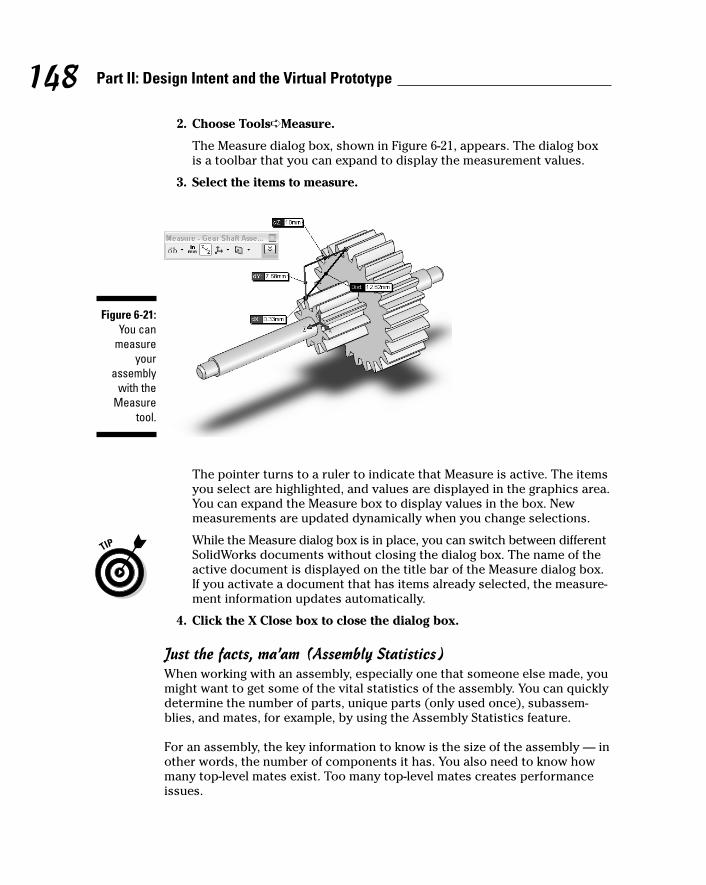
2. Choose Tools➪Measure.
The Measure dialog box, shown in Figure 6-21, appears. The dialog boxis a toolbar that you can expand to display the measurement values.
3. Select the items to measure.
The pointer turns to a ruler to indicate that Measure is active. The itemsyou select are highlighted, and values are displayed in the graphics area.You can expand the Measure box to display values in the box. Newmeasurements are updated dynamically when you change selections.
While the Measure dialog box is in place, you can switch between differentSolidWorks documents without closing the dialog box. The name of theactive document is displayed on the title bar of the Measure dialog box.If you activate a document that has items already selected, the measure-ment information updates automatically.
4. Click the X Close box to close the dialog box.
Just the facts, ma’am (Assembly Statistics)When working with an assembly, especially one that someone else made, youmight want to get some of the vital statistics of the assembly. You can quicklydetermine the number of parts, unique parts (only used once), subassem-blies, and mates, for example, by using the Assembly Statistics feature.
For an assembly, the key information to know is the size of the assembly — inother words, the number of components it has. You also need to know howmany top-level mates exist. Too many top-level mates creates performanceissues.
Figure 6-21:You can
measureyour
assemblywith the
Measuretool.
148 Part II: Design Intent and the Virtual Prototype
11_129784 ch06.qxp 9/28/07 12:35 PM Page 148
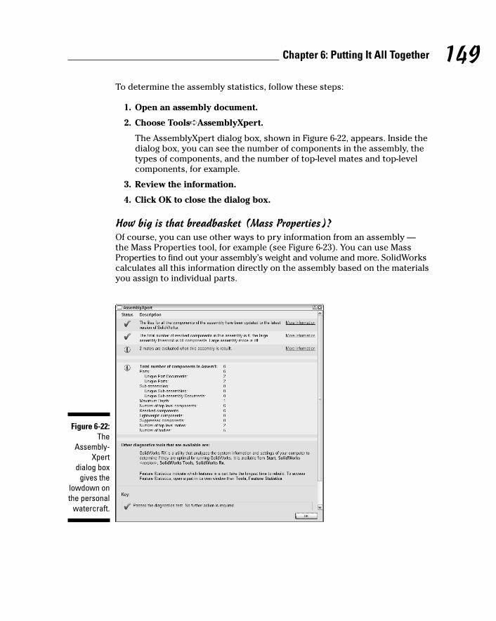
To determine the assembly statistics, follow these steps:
1. Open an assembly document.
2. Choose Tools➪AssemblyXpert.
The AssemblyXpert dialog box, shown in Figure 6-22, appears. Inside thedialog box, you can see the number of components in the assembly, thetypes of components, and the number of top-level mates and top-levelcomponents, for example.
3. Review the information.
4. Click OK to close the dialog box.
How big is that breadbasket (Mass Properties)?Of course, you can use other ways to pry information from an assembly —the Mass Properties tool, for example (see Figure 6-23). You can use MassProperties to find out your assembly’s weight and volume and more. SolidWorkscalculates all this information directly on the assembly based on the materialsyou assign to individual parts.
Figure 6-22:The
Assembly-Xpert
dialog boxgives the
lowdown onthe personal
watercraft.
149Chapter 6: Putting It All Together
11_129784 ch06.qxp 9/28/07 12:35 PM Page 149
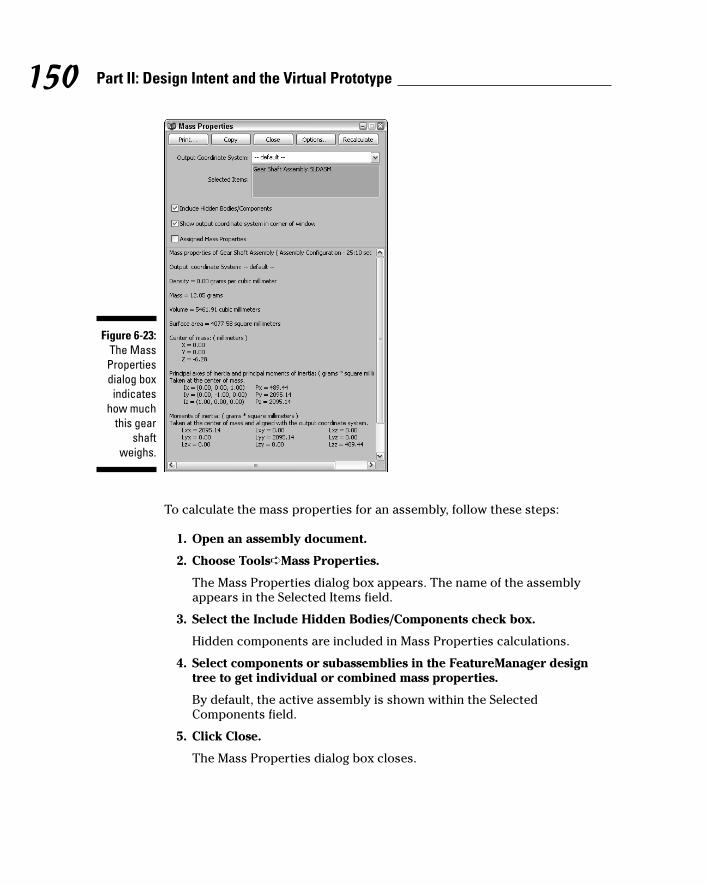
To calculate the mass properties for an assembly, follow these steps:
1. Open an assembly document.
2. Choose Tools➪Mass Properties.
The Mass Properties dialog box appears. The name of the assemblyappears in the Selected Items field.
3. Select the Include Hidden Bodies/Components check box.
Hidden components are included in Mass Properties calculations.
4. Select components or subassemblies in the FeatureManager designtree to get individual or combined mass properties.
By default, the active assembly is shown within the SelectedComponents field.
5. Click Close.
The Mass Properties dialog box closes.
Figure 6-23:The MassPropertiesdialog boxindicates
how muchthis gear
shaftweighs.
150 Part II: Design Intent and the Virtual Prototype
11_129784 ch06.qxp 9/28/07 12:35 PM Page 150

Part IIIThe Devil’s in the
“Drawing” Details
12_129784 pp03.qxp 9/28/07 12:36 PM Page 151
In this part . . .
After you create the parts and assemblies, you’reready to draw. Drawings are the means used to
document the design intent and requirements formanufacturing.
You can reuse the information that defines the part orassembly to help produce the drawing. When a changeoccurs (and it will), you can modify the dimension withinthe part/assembly or drawings, and both documents areupdated. Being able to easily change a design and haveyour changes updated in a related document illustratesthe power of 3D.
12_129784 pp03.qxp 9/28/07 12:36 PM Page 152
Chapter 7
Creating DrawingsIn This Chapter� Discovering the elements of a drawing
� Setting up and working with drawing formats
� Creating drawing views from the 3D model
� Making changes and modifying dimensions
� Working with annotations and tables
Drawings formally communicate your design to manufacturing. Althoughtechnology has come along promising to eliminate the need for drawings,
they continue to serve an important purpose in design. Manufacturers needdrawings to produce quotes, to determine the proper manufacturing processes,and to inspect parts to ensure that they meet the requirements set forth inthe drawings.
SolidWorks offers a number of different tools to automate the drawing processbased on information you capture in your 3D design. This chapter focuses onthe basics of drawing creation. Chapter 8 expands on these topics and offerssome insight on how to automate drawing functions.
Becoming Familiar withDrawing Elements
In essence, drawings are large sheets of paper that contain images of your model invarious views and orientations along with dimensions, manufacturing symbols,notes, and other annotations.
Back in the good old days, before CAD software, engineers created drawingson drawing boards with paper and pencil. First, they pulled out a preprinteddrawing sheet that fit the drawing size they wanted (A, B, or C, for example).
13_129784 ch07.qxp 9/28/07 12:36 PM Page 153
154 Part III: The Devil's in the "Drawing" Details
Then they created the drawing views that showed the part as it appearedfrom different angles (top, front, right, or isometric, for example). Finally,they inserted dimensions, filled in the title and revision blocks, and addednotes and other annotations.
SolidWorks follows this same process, only virtually, so that you don’t haveto physically stand up and sharpen your pencil or fumble with large drawingsheets. The software does the heavy lifting for you.
The best part of SolidWorks is that the drawing file is fully associative withthe model: If you change the part geometry after the fact, the drawing viewsare updated automatically so that you don’t have to redo them manually.Adding views is simple, and it’s all tied together.
The following elements, shown in Figure 7-1, make up a drawing:
1 Drawing sheet format: You can edit the drawing sheet format, which isthe predefined background for a drawing, directly. The predefined back-ground for a drawing can also contain title block text and other standardnotes. Read the section “Editing the Drawing Sheet Format,” later in thischapter, to find out how to change the drawing format.
2 Drawing sheet: A drawing in SolidWorks contains one or more sheets,like a set of drawings, allowing you to keep multisheet drawings in asingle file. SolidWorks uses a simple tab organization method for multi-sheet drawings. You can add sheets at any time, using any format. Selecta tab to activate a sheet. To add a new a new sheet, right-click a tab andchoose Add Sheet, or simply click the Add Sheet tab.
3 Drawing view (right): This view shows the model from the right.
4 Drawing view (front): This view shows the front of the model.
5 Title block: This area is where the information concerning title, revision,material, drawing size, part number, or drawn by, for example, appears.The title block is contained within the drawing format.
6 Drawing format text (dynamic): This text changes with every drawing.These values are linked to custom properties.
7 Drawing format text (static): Some text notes within the drawing formatare static and don’t change. The words, such as SIZE and REV, don’tchange from drawing to drawing.
8 Pointer: Other programs call the pointer a cursor. A tag next to thepointer tells you which drawing sheet is active.
9 Drawing view border: When you place a drawing view, a frame appearsaround the view.
10 Drawing view (isometric): Drawing views on drawing sheets show themodel in different orientations and include dimensions and annotations.
13_129784 ch07.qxp 9/28/07 12:36 PM Page 154
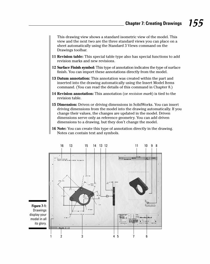
This drawing view shows a standard isometric view of the model. Thisview and the next two are the three standard views you can place on asheet automatically using the Standard 3 Views command on theDrawings toolbar.
11 Revision table: This special table type also has special functions to addrevision marks and new revisions.
12 Surface Finish symbol: This type of annotation indicates the type of surfacefinish. You can import these annotations directly from the model.
13 Datum annotation: This annotation was created within the part andinserted into the drawing automatically using the Insert Model Itemscommand. (You can read the details of this command in Chapter 8.)
14 Revision annotation: This annotation (or revision mark) is tied to therevision table.
15 Dimension: Driven or driving dimensions in SolidWorks. You can insertdriving dimensions from the model into the drawing automatically. If youchange their values, the changes are updated in the model. Drivendimensions serve only as reference geometry. You can add drivendimensions to a drawing, but they don’t change the model.
16 Note: You can create this type of annotation directly in the drawing.Notes can contain text and symbols.
16
1
13 15 14 13 12 11 10 9 8
2 3 4 5 67
Figure 7-1:Drawings
display yourmodel in all
its glory.
155Chapter 7: Creating Drawings
13_129784 ch07.qxp 9/28/07 12:36 PM Page 155

SolidWorks supports a number of drawing standards, including ISO, ANSI,DIN, JIS, BSI, GOST, and GB. The standard you choose affects the appearanceof drawing views. For example, if you choose ANSI, drawing view projectionsare third-angle, and the symbols meet the ANSI drafting standard. Likewise, ifyou choose DIN, the drawing view projections are first-angle, and the symbolscomply with the DIN drafting standard. The drawing shown in Figure 7-1 is setto the ANSI standard.
Default values and drawing standards are in the drawing template. You canchange the standard template or make your own. Read Chapter 2 for moreinformation on how to define, save, and share drawing templates.
Opening a New Drawing DocumentDrawings consist of one or more views generated from a part or an assembly.Views show the model in different orientations. SolidWorks lets you create adrawing from a drawing template or from within a part or assembly document.This chapter shows you how to make a drawing from a model.
Drawing files have the .slddrw extension. A new drawing takes the name ofthe first model you insert into it. The name appears on the menu bar. Whenyou save the drawing, the name of the model appears in the Save As dialogbox as the default filename, with the default extension .slddrw. You can editthe name before saving the drawing.
You can create a drawing in many ways. The following method is my preferencebecause it’s the most straightforward.
To create a new drawing, follow these steps:
1. Open the part or assembly document you want to use for the drawing.
2. Choose File➪Make Drawing from Part or Make Drawing fromAssembly.
A new SolidWorks drawing document appears. The Sheet/Format Sizedialog box appears.
3. If you don’t want to use any sheet format, click Cancel and continue toStep 7.
If you click Cancel, the Sheet/Format Size dialog box closes, and the ModelView PropertyManager, shown in Figure 7-2, appears in the left pane.
4. If you want to use a sheet, select the Standard Sheet Size radio button(or Custom Sheet Size if you want to make your own).
If you select Standard Sheet Size, the standard sheet sizes become visible.If you select Custom Sheet Size, the Width and Height fields become active,as shown in Figure 7-3).
156 Part III: The Devil's in the "Drawing" Details
13_129784 ch07.qxp 9/28/07 12:36 PM Page 156

5. Select a standard sheet size or type a width and height for the customsheet size.
6. Select the Display Sheet Format check box to display a border or titleblock, for example.
7. Click OK.
A new drawing appears in the graphics area, and the Model ViewPropertyManager appears.
Figure 7-3:The Sheet
Format/Sizedialog box.
Figure 7-2:Select a
single vieworientation
in theDrawing
ViewProperty-Manager.
157Chapter 7: Creating Drawings
13_129784 ch07.qxp 9/28/07 12:36 PM Page 157
If you’re in a hurry, you may want to place three standard views ratherthan a single model view. If so, when the Model PropertyManager appears,ignore it and click Standard 3 Views on the Drawings toolbar. The Standard3 Views PropertyManager appears, and the list of open documents isavailable. Click an open document, and three standard views (front,right, and isometric) of the model appear on the drawing sheet. Youdon’t need to select any other options.
8. In the Model View PropertyManager, select a named view underOrientation (Front or Back, for example).
If you select the Preview check box, you see a preview of the view nextto the pointer.
9. In the Model View PropertyManager, click a Display Style.
You can choose from an assortment of display styles, such as HiddenLines Removed or Hidden Lines Visible.
10. Select a scale.
You have three options:
• Use parent scale: This option is available only after the first view.When you add views, you can use the parent view parameters toapply the same scale to each child view. If you change the scale ofthe parent view, the child view updates.
• Use sheet scale: Your model appears scaled to fit the sheet you’reusing. SolidWorks selects a scale based on the default sheet templateand reduces the scale based on the model size.
• Use custom scale: Select a ratio from the drop-down list or enteryour own values.
11. In the Dimension Type section, select either the Projected check boxor the True check box.
The Projected option shows 2D dimensions, and True displays 3D spacedimensions. This option should be used for only isometric drawing views.
12. Click in the graphics area to place the view on the sheet.
As soon as you place the view, the Drawing View PropertyManagerreplaces the Model View PropertyManager. If you place an orthogonalview orientation, the Projected View PropertyManager appears, and youcan place any number of projected views for any orthogonal view. Butbefore you start placing more views, you may want to read the “Placingthe Drawing Views” section, later in this chapter.
13. Click OK in the Model View PropertyManager or in the Drawing ViewPropertyManager.
The PropertyManager closes, and the new drawing appears in thegraphics area.
158 Part III: The Devil's in the "Drawing" Details
13_129784 ch07.qxp 9/28/07 12:36 PM Page 158
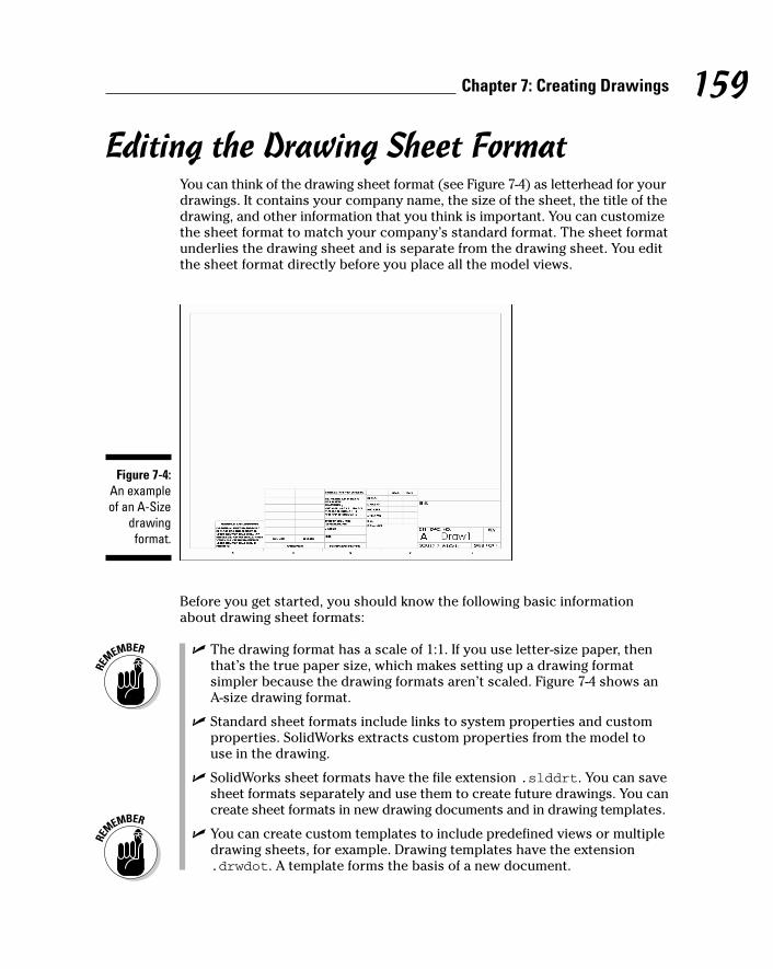
Editing the Drawing Sheet FormatYou can think of the drawing sheet format (see Figure 7-4) as letterhead for yourdrawings. It contains your company name, the size of the sheet, the title of thedrawing, and other information that you think is important. You can customizethe sheet format to match your company’s standard format. The sheet formatunderlies the drawing sheet and is separate from the drawing sheet. You editthe sheet format directly before you place all the model views.
Before you get started, you should know the following basic informationabout drawing sheet formats:
� The drawing format has a scale of 1:1. If you use letter-size paper, thenthat’s the true paper size, which makes setting up a drawing formatsimpler because the drawing formats aren’t scaled. Figure 7-4 shows anA-size drawing format.
� Standard sheet formats include links to system properties and customproperties. SolidWorks extracts custom properties from the model touse in the drawing.
� SolidWorks sheet formats have the file extension .slddrt. You can savesheet formats separately and use them to create future drawings. You cancreate sheet formats in new drawing documents and in drawing templates.
� You can create custom templates to include predefined views or multipledrawing sheets, for example. Drawing templates have the extension.drwdot. A template forms the basis of a new document.
Figure 7-4:An exampleof an A-Size
drawingformat.
159Chapter 7: Creating Drawings
13_129784 ch07.qxp 9/28/07 12:36 PM Page 159
When you open a drawing with an existing drawing sheet format, you can’tchange the information directly. When you edit the sheet format, the drawingviews and other non-drawing format items are no longer visible becauseyou’re editing the sheet format (drawing background), not the other drawinginformation (views, notes, and dimensions, for example).
To edit a drawing sheet format, follow these steps:
1. Open a drawing file or a drawing template file.
2. In the FeatureManager design tree, expand a sheet folder.
The sheet format and drawing views become visible.
3. Right-click the sheet format you want to edit, and choose Edit SheetFormat.
You’re now in Edit mode.
4. To edit the title blocks, in the graphics area, right-click the text andchoose Edit Text in Window.
The Edit Text Window dialog box opens.
5. Change any items in the Edit Text Window dialog box and then clickOK.
6. Move, delete, or add lines of text.
• To delete, click the line of text and press the Delete key.
• To move, click the line of text and drag it to a new location.
• To add lines, click the Line button on the Sketch toolbar.
7. To add text, click Note on the Annotation toolbar.
8. Specify the text properties and then click to place the text in the locationyou want.
9. When you’re done editing, in the FeatureManager design tree, right-click the sheet and select Edit Sheet.
You return to your drawing default edit sheet.
Placing the Drawing ViewsAfter you edit your sheet format, it’s time to place the model views on thedrawing sheets. A drawing view shows a model in a particular orientation,scale, and display state. Drawing views are important because they conveyinformation about how to build or assemble your model.
160 Part III: The Devil's in the "Drawing" Details
13_129784 ch07.qxp 9/28/07 12:36 PM Page 160

Your can create views of one or more parts and assemblies and include themin the same drawing. A perusal of the commands on the Drawings toolbargives you an idea of the multitude of views you can include on a sheet.
When you open a drawing document in SolidWorks, the Drawings toolbarappears by default in the CommandManager. (You can read more about theCommandManager in Chapter 2.) The Drawings toolbar contains commandsthat let you add various model views to your drawings.
Your first view must be a standard view, and from there you create otherviews that are based on the standard views (Section or Detail, for example.)The Model View command allows you to place any single standard view,whereas Standard 3 Views places three standard views automatically.
The following sections explain the Drawings toolbar view commands, includinghow to place each view. Remember that you need to have a drawing documentopen to use these commands.
When you place a view, you need to drag it into position. You can see a previewof a model view as you’re dragging it by setting this option: Choose Tools➪Options. On the Systems Options tab, select Drawings and select the ShowContents While Dragging Drawing View check box. (This option is generallyset as a default.)
Model viewYou can use the Model View command to place any standard view of yourmodel. Standard views are just that: standard engineering views, such as front,top, and isometric. Item 1 in Figure 7-5 shows an example of this view type.
To insert a model view into your drawing, follow these steps:
1. Click Model View on the Drawings toolbar, as shown in Item 2 inFigure 7-6.
The Model View PropertyManager appears, as shown in Figure 7-7. Anymodel that is active in SolidWorks appears in the Open Documents section.
2. Double-click the model listed in the Open Documents section to placea new view, or click Browse to locate a different part or assembly file.
3. Select a view (Front or Back, for example) in the Orientation section.
Select the Preview check box to see a preview of the model before youplace it.
4. Set the options for display style and scales in the PropertyManager.
161Chapter 7: Creating Drawings
13_129784 ch07.qxp 9/28/07 12:36 PM Page 161

(1)Standard3 Views
(2)Modelview
(3)Projected
view
(5)Section
view
(7)Cropview
(4)Auxiliary
view
(6)Detailview
Figure 7-6:The
Drawingstoolbar.
8 5 7 62 1
11 10 9 43
Figure 7-5:You can
placeseveral
model viewsin a
drawing.
162 Part III: The Devil's in the "Drawing" Details
13_129784 ch07.qxp 9/28/07 12:36 PM Page 162
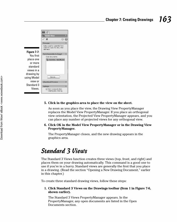
5. Click in the graphics area to place the view on the sheet.
As soon as you place the view, the Drawing View PropertyManagerreplaces the Model View PropertyManager. If you place an orthogonalview orientation, the Projected View PropertyManager appears, and youcan place any number of projected views for any orthogonal view.
6. Click OK in the Model View PropertyManager or in the Drawing ViewPropertyManager.
The PropertyManager closes, and the new drawing appears in thegraphics area.
Standard 3 ViewsThe Standard 3 Views function creates three views (top, front, and right) andplaces them on your drawing automatically. This command is a good one touse if you’re in a hurry. Standard views are generally the first that you placein a drawing. (Read the section “Opening a New Drawing Document,” earlierin this chapter.)
To create three standard drawing views, follow these steps:
1. Click Standard 3 Views on the Drawings toolbar (Item 1 in Figure 7-6,shown earlier).
The Standard 3 Views PropertyManager appears. In thePropertyManager, any open documents are listed in the OpenDocuments section.
Figure 7-7:You first
place one or more
standardviews in a
drawing byusing Model
view orStandard 3
Views.
163Chapter 7: Creating Drawings
13_129784 ch07.qxp 9/28/07 12:36 PM Page 163
Dow
nlo
ad fro
m W
ow
! eBook
<w
ww
.wow
ebook.
com
>
2. In the PropertyManager, double-click the model in the OpenDocuments section or choose Browse to locate a different one.
The three views appear in the drawing. The alignment of the top andside views is fixed in relation to the front view. You can move the topview vertically and the side view horizontally.
3. Click OK.
Projected viewThis view allows you to create a new orthographically projected view from anexisting, or parent, view. Refer to Item 2 in Figure 7-5 to see an example of thisview type.
To create a projected view, follow these steps:
1. Click Projected View on the Drawings toolbar (refer to Item 3 inFigure 7-6).
The Projected View PropertyManager appears.
2. Select an existing view from which to project.
The new view is projected as normal (90 degrees) to the selected drawingview.
3. Click in the graphics area to place the view.
The Projected View PropertyManager expands to include severaloptions. You can project the new view in any direction (up, down, right,left, or isometric) from the selected view.
4. Set options in the PropertyManager.
You can set the display style, scale, and dimension type. These optionsare the same ones covered in the earlier section “Opening a NewDrawing Document.”
5. Click OK.
Auxiliary viewThis view is defined by folding the new view perpendicular to an existingview’s part or assembly edge. Item 6 in Figure 7-5, shown earlier, shows anexample of this view type.
164 Part III: The Devil's in the "Drawing" Details
13_129784 ch07.qxp 9/28/07 12:36 PM Page 164

To create an auxiliary view, follow these steps:
1. Click Auxiliary View on the Drawings toolbar, shown in Item 4 inFigure 7-6, earlier in this chapter .
The Auxiliary View PropertyManager appears.
2. Select a reference edge.
Don’t select a horizontal or vertical edge, which create a standardProjection view.
You can use an edge of a part, a silhouette edge, an axis, or a sketchedline as a reference. If you sketch a line, activate the drawing view first.
3. Move the pointer until the view is where you want it, and then click toplace the view.
The PropertyManager for the drawing view appears.
4. Set options in the PropertyManager.
You can set the display style, scale, and dimension type. These optionsare the same ones covered in the earlier section “Opening a NewDrawing Document.”
5. Click OK.
To override the default alignment of any view type, hold down the Ctrl keywhile placing the view.
Section viewA section view shows the internal details of a part or assembly. Section viewsmake details easier to read than when you use hidden line views. You create asection view by drawing a line through the parent part. Item 9 in Figure 7-5shows an example of this view type.
To create a section view, follow these steps:
1. Click Section View on the Drawings toolbar (refer to Item 5 in Figure 7-6 ).
The Section View PropertyManager appears. The Line tool is active, andwhen you pass the pointer over an existing view, a box appears aroundthe view.
165Chapter 7: Creating Drawings
13_129784 ch07.qxp 9/28/07 12:36 PM Page 165
2. Sketch a section line through an existing view.
Draw the section line completely through the box of the model in theview. If the section line doesn’t completely cut through the box, you’reasked whether you want it to be a partial section cut. If you click Yes,the section view is created as a partial section view. If you click No, a fullsection view is created for you. After the line is complete, the sectionview appears as a preview.
3. Move the pointer until the view is where you want it, and click toplace the view.
The section view is aligned to the source, so you can only place the newview above or below the section line in the graphics area. After youplace the view, the PropertyManager for that view appears.
4. Set options in the PropertyManager.
You can set the display style, scale, and dimension type. These optionsare the same ones covered in the earlier section “Opening a NewDrawing Document.”
5. Click OK.
Aligned Section viewYou create an aligned section view similar to a section view, but rather thansketch a single line, you sketch a section line that consists of two linesconnected at an angle. The section view rotates the geometry on the angledsegment so that the section can be projected. Item 8 in Figure 7-5 shows anexample of this view type.
To create an aligned section view, follow these steps:
1. Select Aligned Section View from the drop-down icon on the Drawingstoolbar (refer to Item 5 in Figure 7-6).
The Aligned Section View PropertyManager appears. The Line tool isactive, and when you pass the pointer over an existing view, a boxappears around the view.
2. Sketch two lines to define the section cut in a drawing view.
The two lines must connect at an angle. After you draw the line, a previewof the section appears in the graphics area near the pointer.
3. Move the pointer until the view is where you want it, and click toplace the view.
The view is aligned to the sketch segment you selected when you createdthe section line; the cut faces from the other segments are projected intothe same plane.
166 Part III: The Devil's in the "Drawing" Details
13_129784 ch07.qxp 9/28/07 12:36 PM Page 166
4. Set options in the PropertyManager.
You can set the display style, scale, and dimension type. These optionsare the same ones covered in the earlier section “Opening a NewDrawing Document.”
5. Click OK.
Detail viewA detail view is a blown-up portion of a small section of an existing view,which you draw a circle around. Item 11 in Figure 7-5 shows an example ofthis view type.
To create a detail view, follow these steps:
1. Click Detail View on the Drawings toolbar (refer to Item 6 in Figure 7-6).
The Detail View PropertyManager appears, and the Circle tool is active.When you pass the pointer over a view, a box appears around the view.
2. Draw a circle around the area you want to blow up.
When you complete the circle, a preview of the view appears next toyour pointer, and the PropertyManager for the view appears. Click insidethe drawing area to place the view.
3. Set options in the PropertyManager.
You can set the display style, scale, and dimension type. These optionsare the same ones covered in the earlier section “Opening a NewDrawing Document.”
4. Click OK.
Crop viewA crop view displays only a portion of an existing view. Cropping a drawing issimilar to cropping a photo. If you don’t want to look at something in the photo(such as an ex-boyfriend or -girlfriend), you crop a rectangle around the partyou want and leave out everything else. SolidWorks lets you crop any drawingview except a detail view, a view from which a detail view was made, or anexploded view. Item 7 in Figure 7-5 shows an example of this view type.
To create a crop view, follow these steps:
1. Inside one of the drawing views, sketch a closed profile, such as acircle or a rectangle.
(You can read more on sketching in Chapter 3.)
167Chapter 7: Creating Drawings
13_129784 ch07.qxp 9/28/07 12:36 PM Page 167

2. In the graphics pane, select the sketch profile in the view you want tocrop.
The box is highlighted to show the selected view.
3. Click Crop View on the Drawings toolbar (refer to Item 7 in Figure 7-6).
The image is cropped. Only the area inside the sketch is displayed. Therest of the view disappears.
Changing View PropertiesSetting up drawing views is like arranging your living room: After you geteverything in place, it’s time to re-cover the sofa and move things around.Luckily, changing drawing views is easier than moving furniture. To edit adrawing view, click the view in the graphics area. The PropertyManager forthat drawing view appears, as shown in Figure 7-8.
The PropertyManager for drawing views comes in two versions, and whichone you see depends on whether the view is a child or a parent of anotherview. A child view, such as a detail or section view, references another viewthat is its parent.
Figure 7-8:The
DrawingView
Property-Manager.
168 Part III: The Devil's in the "Drawing" Details
13_129784 ch07.qxp 9/28/07 12:36 PM Page 168
If a view has a parent, the boundary box of the parent view is also highlightedwhen you select the child view.
The PropertyManager displays only the values you can change, whichinclude the following:
� The view’s display style (Wireframe or Hidden Lines Removed, forexample): You probably have a favorite display state. Mine is Shaded orShaded with Edges, which makes the drawing more readable. When youpick a display style, consider who is reading the drawing and the type ofprinter you’re using. Shaded views, for example, look better on higher-definition printers.
� The scale of a model: In the view’s PropertyManager, you can select UseSheet Scale, Use Parent Scale, or Use Custom Scale and then select adefault scale or enter your own value.
� The placement of the view: You can move a view by dragging the viewborder or a model edge. Some limitations exist. If a view is aligned to aparent view, you cannot move it out of alignment.
� The size of a drawing sheet: Right-click the sheet in the FeatureManagerdesign tree and choose Properties. In the Properties dialog box, select astandard size or select a custom sheet size and type the height andwidth values.
As you’re working with view properties, the yellow message box at the top ofthe PropertyManager and the status window in the lower-left corner of thescreen give clues to what is required for the current command.
Creating Drawing DimensionsDimensions are important in your drawings because they indicate the size ofa part or an assembly and list other critical measurements that the supplierneeds to know to make the product. Without dimensions, you don’t knowwhether you’re building a model airplane or the kind that people fly around in.
SolidWorks offers two types of dimensions: driving dimensions and drivendimensions. Driving dimensions, or model dimensions, control the size andshape of the model. Because driven dimensions are reference dimensions, theydon’t drive the size or location of features but instead help clarify the drawing.
You can change the display of any dimension type in the Dimension PropertyManager (see Figure 7-9), which appears when you insert a dimension.
169Chapter 7: Creating Drawings
13_129784 ch07.qxp 9/28/07 12:36 PM Page 169
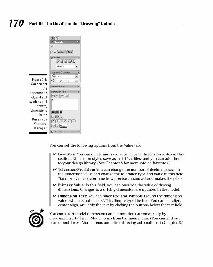
You can set the following options from the Value tab:
� Favorites: You can create and save your favorite dimension styles in thissection. Dimension styles save as .sldfvt files, and you can add themto your design library. (See Chapter 8 for more info on favorites.)
� Tolerance/Precision: You can change the number of decimal places inthe dimension value and change the tolerance type and value in this field.Tolerance values determine how precise a manufacturer makes the parts.
� Primary Value: In this field, you can override the value of drivingdimensions. Changes to a driving dimension are updated in the model.
� Dimension Text: You can place text and symbols around the dimensionvalue, which is noted as <DIM>. Simply type the text. You can left align,center align, or justify the text by clicking the buttons below the text field.
You can insert model dimensions and annotations automatically by choosing Insert➪Insert Model Items from the main menu. (You can find outmore about Insert Model Items and other drawing automations in Chapter 8.)
Figure 7-9:You can set
theappearanceof, and add
symbols andtext to,
dimensionsin the
DimensionProperty-Manager.
170 Part III: The Devil's in the "Drawing" Details
13_129784 ch07.qxp 9/28/07 12:36 PM Page 170
Smart DimensionYou can add dimensions to drawings in several ways. One way is by usingSmart Dimension on the Annotations toolbar. The Annotations toolbarappears by default in the CommandManager when you work on a drawing.You also find Smart Dimension on the Dimension/Relations toolbar.
You can add toolbar buttons to any toolbar. Right-click a tab in theCommandManager and choose Customize CommandManager. In theCustomize dialog box, select the Commands tab and then select a category.Drag a command button to any toolbar. Click OK to close the dialog box.
Smart Dimensions knows what type of dimension to add based on the entityyou select. If you select a line, Smart Dimension creates a dimension for thelength of the line. Likewise, if you select an arc or a circle, Smart Dimensionscreates a radial or diameter dimension.
To insert a model dimension in a drawing, follow these steps:
1. Click Smart Dimension on the Annotations toolbar.
The pointer changes to a dimensioning tool icon to let you know thatSmart Dimensions is active.
2. Click the object to dimension.
You may need to zoom in on the view first. An object turns red as thepointer moves over it and green when you select it. When you click anentity, the dimension values appear above it in gray.
3. Drag the dimension text for placement.
The dimension text follows the pointer, as shown in Figure 7-10.
4. Click to place the dimension.
The dimension is fixed in place, and the Dimension PropertyManagerappears.
5. Set display options in the PropertyManager.
The Smart Dimension tool stays active so that you can continue insertingdimensions.
6. Repeat Steps 2 through 5 to insert more dimensions.
7. Click OK when you’re done.
171Chapter 7: Creating Drawings
13_129784 ch07.qxp 9/28/07 12:36 PM Page 171

Ordinate and baseline dimensionsDriven dimensions are strictly reference geometry and appear in gray inparentheses by default. You cannot edit the values in reference dimensions.
Two types of driven dimensions that may come in handy as you delve furtherinto the world of drawings are ordinate and baseline dimensions:
� An ordinate set of dimensions is measured from a zero ordinate.
� A baseline set of dimensions is measured from an edge or a vertex.
Both ordinate and baseline dimensions are sets of entities that are grouped.When you drag any member of the group, all the members move together. Todisconnect a dimension from the alignment group, right-click the dimensionand select Break Alignment.
To create an ordinate dimension, follow these steps:
1. Choose Tools➪Dimensions➪Ordinate.
The pointer changes to indicate that the command is active.
2. Click the first item (edge or vertex, for example) from which all otherswill be measured to be the base (the 0.0 dimension).
3. Click again to place the dimension outside the model.
Figure 7-10:Text
placementcan change
thedimension
type.
172 Part III: The Devil's in the "Drawing" Details
13_129784 ch07.qxp 9/28/07 12:36 PM Page 172

4. Click the edges, vertices, or arcs you want to dimension using thesame ordinate.
As you click each item, the dimension is placed in the view and alignedto the zero ordinate, as shown in Figure 7-11. The DimensionPropertyManager appears.
5. Set display options in the PropertyManager.
6. Press Esc to exit from Ordinate mode.
Newly placed ordinate dimensions automatically jog to avoid overlappingtext. The size of the jog is determined by the size of the text and thepotentially overlapping area of the text.
To create a baseline dimension, follow these steps:
1. Choose Tools➪Dimensions➪Baseline.
The pointer changes to let you know that the command is active.
2. Click the edge or vertex you want to use as a baseline.
The edge or vertex turns green when you select it.
3. Click each of the edges or vertices you want to dimension.
Those items also turn green.
Figure 7-11:Ordinate
dimensionsare
measuredfrom a zero
ordinate.
173Chapter 7: Creating Drawings
13_129784 ch07.qxp 9/28/07 12:36 PM Page 173
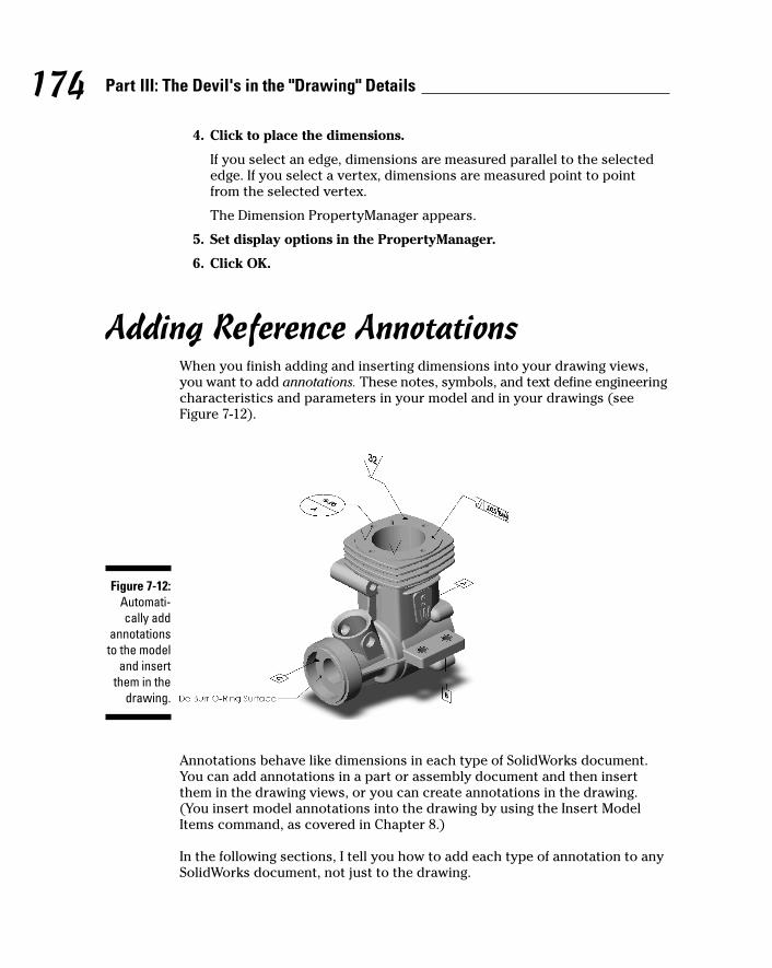
4. Click to place the dimensions.
If you select an edge, dimensions are measured parallel to the selectededge. If you select a vertex, dimensions are measured point to pointfrom the selected vertex.
The Dimension PropertyManager appears.
5. Set display options in the PropertyManager.
6. Click OK.
Adding Reference AnnotationsWhen you finish adding and inserting dimensions into your drawing views,you want to add annotations. These notes, symbols, and text define engineeringcharacteristics and parameters in your model and in your drawings (seeFigure 7-12).
Annotations behave like dimensions in each type of SolidWorks document.You can add annotations in a part or assembly document and then insertthem in the drawing views, or you can create annotations in the drawing.(You insert model annotations into the drawing by using the Insert ModelItems command, as covered in Chapter 8.)
In the following sections, I tell you how to add each type of annotation to anySolidWorks document, not just to the drawing.
Figure 7-12:Automati-cally add
annotationsto the model
and insertthem in the
drawing.
174 Part III: The Devil's in the "Drawing" Details
13_129784 ch07.qxp 9/28/07 12:36 PM Page 174

NoteNotes are virtual sticky notes with a little extra feature. A note can contain text,symbols, a border, parametric text, and hyperlinks. (That’s the extra feature).You can include or omit leaders in your notes. Leaders point to items in thedrawing. Notes can include multiple lines of text and multiple text styles (fonttype or bold, for example), in case you want to “fancy them up.”
To insert a note, follow these steps:
1. Click Note on the Annotation toolbar, shown in Figure 7-13.
The Note PropertyManager appears, and a small rectangle appears nearyour pointer. If you move the pointer over an object, the object turns redand a leader extends from the note to the object.
2. If you want a note with no leader, click in the graphics area to placethe note. If you want a note with a leader, click an object and thenclick again in the graphics area to place the note.
The Formatting dialog box appears, with tools that allow you to changethe font and style of the text.
3. Type your text.
Text doesn’t wrap automatically. To add multiple lines, press Enter.
4. Adjust text properties.
You can change the appearance (font, size, and color) of the text byselecting text and then clicking the format tools in the Formatting dialogbox (see Figure 7-14).
Figure 7-14:Text
formattingtools.
Figure 7-13:The
Annotationtoolbar.
175Chapter 7: Creating Drawings
13_129784 ch07.qxp 9/28/07 12:36 PM Page 175
5. Click the right corner of the Formatting dialog box to close the box.
The dialog box closes so that you can see more of the graphics area.
6. Add symbols or links to the note by using the buttons in the TextFormat section of the Note PropertyManager.
For symbols, place the pointer in the note text box where you want theitem to appear and then click a symbol. Hyperlinks and custom propertieslink to the entire note. Your choices include
• Insert Hyperlink: Click to include a hyperlink in the note. The textand characters in the note turn blue.
• Link to Property: Click to link to a custom property. Linking tocustom properties ensures that if the model changes, the note isupdated.
• Add Symbol: Insert a standard symbol from a symbol library. In the Symbols dialog box, select a library from the Symbol librarylist, then select a symbol name from the list, and click OK. Thesymbol’s name is displayed in the text box, and the actual symbolappears in the note.
• Anchor: Fixes the note in place to the current location.
• Geometric Tolerance: Insert a Geometric Tolerance symbol into thenote. The Geometric Tolerance PropertyManager and the Propertiesdialog box open so that you can define the symbol.
• Surface Finish: Insert a Surface Finish symbol into the note. TheSurface Finish PropertyManager opens so that you can define thesymbol.
• Datum Feature: Insert a datum feature symbol into the note. The Datum Feature PropertyManager opens so that you can define the symbol.
7. Set other options in the PropertyManager.
Here are your choices:
• Leader: Change the style and appearance of the leader.
• Border: Click the options in the Border section to change theborder around the note.
• Layer: Indicate which drawing layer you want to attach the note to.
8. Click OK.
You can edit notes. Click a note to display the Note PropertyManager. Double-click a note to display the Formatting dialog box and the NotePropertyManager.
176 Part III: The Devil's in the "Drawing" Details
13_129784 ch07.qxp 9/28/07 12:36 PM Page 176
BalloonYou can create balloons in a drawing document. The balloons label the partsin the assembly and relate them to item numbers on the bill of materials. (Youcan find out how to insert a bill of materials into a drawing by reading the“Bill of materials” section, later in this chapter.)
However, you don’t have to insert a bill of materials table into a drawing inorder to add balloons. If the drawing has no bill of materials, the item numbersare the default values that SolidWorks would use if you inserted a bill ofmaterials. If the active drawing sheet has no bill of materials but anothersheet does, SolidWorks uses the numbers from the other bill of materials.
You can also add balloons in assembly documents and then import thoseballoons from an assembly document into a drawing view. (Chapter 8explains more on how this process works.)
To insert a balloon, follow these steps:
1. Click Balloon on the Annotation toolbar.
The Balloon PropertyManager appears, and a small circle follows yourpointer around in the graphics area. If you move your pointer over anedge, the edge turns red. You can also place balloons on the surface ofan object; note that the leader changes from an arrow to a dot.
2. In the PropertyManager, in the Balloon Settings section, set the following:
• Style: Select from the list a style for the shape and border of theballoon. The style None displays the balloon text with no border.
• Size: Select a size from the list — either a specified number ofcharacters or Tight Fit, which adjusts automatically to the text.
• Balloon text: Select the type of text for the balloon. Custom allowsyou to type the text. Item Number puts the item number in the billof materials. Quantity adds the number of this part needed for theentire assembly.
3. In the PropertyManager, in the Layers section, select a named drawinglayer to add the balloon to.
The default is None. This option doesn’t appear if you’re adding balloonsto an assembly.
4. Click a part and then click to place the balloon.
A leader extends from the balloon to the part.
177Chapter 7: Creating Drawings
13_129784 ch07.qxp 9/28/07 12:36 PM Page 177
5. To add balloons, repeat Steps 2 through 4.
6. Click OK.
The Balloon PropertyManager closes.
You can edit any balloon by clicking it to display the BalloonPropertyManager or pressing Delete on the keyboard.
Auto BalloonYou can speed the process of adding balloons to drawing views by using theAuto Balloon command. The Auto Balloon command automatically insertsballoons for all the components in a selected drawing view. SolidWorksinserts the balloons into the appropriate views without duplicates.
To insert balloons into a drawing view, follow these steps:
1. Click Auto Balloon on the Annotation toolbar.
The Auto Balloon PropertyManager appears.
2. Click the drawing view that you want to add balloons to.
You see a preview of the balloons appear around the view.
3. In the PropertyManager, in the Balloon Layout section, specify howyou want the balloons to align around the view.
You can choose a square pattern, on the top or to the left, for example.The balloons are placed outside the view border, and the leaders do notintersect. At this point, you can change the placement of all balloons byselecting a balloon and dragging it to a new position. This actionchanges the distance of the placed balloons from the Model view.
4. In the Balloon Layout section, select the Ignore Multiple Instancescheck box.
When you select this option, balloons do not appear on multipleinstances of a part.
5. In the PropertyManager, in the Balloon Settings section, set theseoptions:
• Style: Select from the list a style for the shape and border of theballoon. The style None displays the balloon text with no border.
• Size: Select a size from the list — either a specified number ofcharacters or Tight Fit, which adjusts automatically to the text.
178 Part III: The Devil's in the "Drawing" Details
13_129784 ch07.qxp 9/28/07 12:36 PM Page 178
• Balloon text: Select the type of text for the balloon. Custom allowsyou to type the text. Item Number puts the item number in the billof materials. Quantity adds the number of this part needed for theentire assembly.
6. In the PropertyManager, in the In Layers section, select a nameddrawing layer to add the balloon to.
The default is None. This option doesn’t appear if you’re adding balloonsto an assembly.
7. Click OK.
After you close the PropertyManager, you cannot open it again to changethe orientation of the balloons. You can delete the balloons or undo theAuto Balloon command and then reinsert the balloons. You can drag agroup of balloons or a single balloon.
Surface finishYou can specify the surface finish and texture of a part face by using aSurface Finish symbol. You can select the face in a part, an assembly, or adrawing document.
To insert a Surface Finish symbol, follow these steps:
1. Click Surface Finish on the Annotation toolbar.
The Surface Finish PropertyManager appears.
2. Click a button for a symbol type in the PropertyManager.
3. Enter a symbol layout value.
Different symbol types require different codes to specify manufacturingmethod or texture requirements, for example. You can enter thesevalues, and they appear with the symbol in the graphics area.
4. Set other options in PropertyManager.
You have these options:
• Format: Use the document font or choose another font.
• Angle: Set the angle or rotation for the symbol.
• Leader: Select a leader style.
• Layer: Select a named layer (or none) if you’re adding symbols to adrawing.
179Chapter 7: Creating Drawings
13_129784 ch07.qxp 9/28/07 12:36 PM Page 179

5. Click the graphics area to add a symbol.
• Multi-jog Leader: A multi-jog leader adds bends to the normallystraight leader line. Before placing the symbol, right-click andchoose Use Multi-jog Leader to add a multi-jog leader. Click in thegraphics area to place the arrow end of the leader and then movethe pointer and click to add each jog point. To complete the leaderand place the symbol, either double-click or right-click and chooseEnd Leader.
• Multiple instances: Click as many times as necessary to place multiplecopies.
• Editing each instance: You can change text and other items in thedialog box for each instance of the symbol.
• Leaders: If the symbol has a leader, click once to place the leaderand then click a second time to place the symbol.
• Multiple leaders: While dragging the symbol and before placing it,press Ctrl. The note stops moving, and a second leader is added.While still holding Ctrl, click to place the leader. Click as manytimes as necessary to place additional leaders. Release Ctrl andclick to place the symbol.
6. Click OK.
To edit a Surface Finish symbol, click the symbol, and the PropertyManagerappears.
Geometric toleranceA slight variation always occurs in the manufacturing process. Tolerancingsymbols indicate how precisely the manufacturer needs to make a part. Youcan place Geometric Tolerancing symbols, with or without leaders, anywherein a drawing, a part, an assembly, or a sketch, and you can attach a symbolanywhere on a dimension line. The Properties dialog box for GeometricTolerance symbols offers selections based on the symbol you choose. Onlythe attributes that are appropriate for the selected symbol are available.
To add a Geometric Tolerance symbol, follow these steps:
1. Select the face or edge of a part for the tolerance symbol.
Preselecting the location makes placement easier.
2. Click Geometric Tolerance on the Annotation toolbar.
The Geometric Tolerance PropertyManager appears, and the Propertiesdialog box appears in the graphics area, where you can create a symbol.
180 Part III: The Devil's in the "Drawing" Details
13_129784 ch07.qxp 9/28/07 12:36 PM Page 180

3. In the Properties dialog box, create a symbol.
Select any symbol, tolerance, datum references, and material conditionsfor the geometric tolerance.
4. Set the display properties in the PropertyManager.
Choose the leader type, the font, and a named drawing layer (if you’reworking on a drawing) to apply the symbol to.
5. Click OK.
Datum targetDatum targets are used in conjunction with, and define the location and area for,Geometric Tolerance datum symbols. These annotations indicate how to set upthe datums to inspect for accuracy after the part is manufactured. You canattach a datum target and symbol to a model face or an edge of any document.
To create a datum target and symbol, follow these steps:
1. Click Datum Target on the Annotation toolbar.
The Datum Target PropertyManager appears.
2. Set the following properties in the Settings section of thePropertyManager:
• Styles: Select a target symbol style.
• Target Area: Select the target area display. You can choose an x, acircular or rectangular target area, or none.
• Target Area Size: Enter the width and height for rectangles or thediameter for Xs and circles.
• Leader: Select a leader style and an arrow style.
• Layer: In drawings with named layers, select a layer.
3. Click in the graphics area to place the target and then click again toplace the symbol. If you selected No Target Symbol in thePropertyManager, click only once to place the annotation.
The datum target appears in the drawing. The command stays active, soyou can place as many as you like.
4. Continue inserting as many symbols as needed.
5. Click OK.
The PropertyManager closes.
181Chapter 7: Creating Drawings
13_129784 ch07.qxp 9/28/07 12:36 PM Page 181
You can move a datum target symbol by selecting the symbol and draggingthe item. To edit the datum target symbol, select the symbol.
Datum symbolDatum Feature symbols are used in conjunction with Geometric Tolerancesymbols. These annotations indicate how inspection machines should checka part for accuracy after the part is manufactured. You can attach a Datumsymbol to the following items:
� In a part or assembly, you can attach a symbol to a planar model surfaceor a reference plane.
� In a drawing view, you can attach a Datum symbol to a surface thatappears as an edge (not a silhouette) or to a section view surface.
� If your model contains a Geometric Tolerance symbol frame, you canattach a Datum symbol to it.
� You can also put a Datum symbol in a note.
To add a datum feature, follow these steps:
1. Click Datum Symbol on the Annotation toolbar.
The Datum Symbol PropertyManager appears.
2. Edit the options in the Datum Symbol PropertyManager.
• Label: Enter the character to appear in the Datum Feature box.
• Use Document Style: Select this check box if you want to use thedocument style, which follows the standard (ANSI or ISO, for example) specified in the Document Properties section. (ChooseTools➪Options. On the Document Properties tab, select Detailingand set options.) If you deselect this check box, you can select adifferent style of box and attachment. Each box has a different setof attachment styles.
• Layer: In drawings with named layers, select a layer.
3. Click in the graphics area to place the leader and then click again toplace the symbol.
4. Continue inserting as many symbols as needed.
SolidWorks automatically increments the label in the datum feature box(A, B, and C, for example).
5. Click OK.
182 Part III: The Devil's in the "Drawing" Details
13_129784 ch07.qxp 9/28/07 12:36 PM Page 182
Dow
nlo
ad fro
m W
ow
! eBook
<w
ww
.wow
ebook.
com
>
Cosmetic threadA cosmetic thread represents the inner diameter of a thread on a boss (a boltis an example of a boss) or the outer diameter of a thread on a hole and caninclude a hole callout. If you add a cosmetic thread while working in a drawingview, the part or assembly is updated to include a cosmetic thread feature.
To add a cosmetic thread, follow these steps:
1. Choose Insert➪Annotations➪Cosmetic Thread.
The Cosmetic Thread PropertyManager appears.
2. Select the holes to add cosmetic threads.
On a cylindrical feature (a boss, a cut, or a hole), select the circular edgewhere the thread begins. If the feature is a conical hole, select the majordiameter. If the feature is a conical boss, select the minor diameter.
3. Set the options in the PropertyManager for the end conditions (howdeep) and enter the outer thread diameter.
4. Click OK.
Center markYou can place center marks in circles or arcs in drawings and use them as references for dimensioning. Center marks are available as single marks, inlinear patterns, or in circular patterns.
To add a center mark to a drawing, follow these steps:
1. Click Center Mark on the Annotation toolbar.
The Center Mark PropertyManager appears.
2. Set Options in the PropertyManager.
• Single Center Mark: Insert a center mark into a single circle or arc.You can change the display attributes and angle of the centermark.
• Linear Center Mark: Insert center marks into a linear pattern of circlesor arcs. You can select connection lines and display attributes forlinear patterns.
• Circular Center Mark: Insert center marks into a circular pattern ofcircles or arcs. You can select circular lines, radial lines, a basecenter mark, and display attributes for circular patterns.
183Chapter 7: Creating Drawings
13_129784 ch07.qxp 9/28/07 12:36 PM Page 183
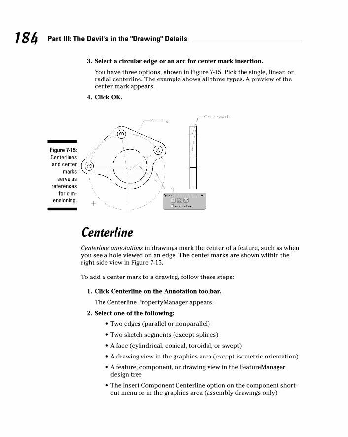
3. Select a circular edge or an arc for center mark insertion.
You have three options, shown in Figure 7-15. Pick the single, linear, orradial centerline. The example shows all three types. A preview of thecenter mark appears.
4. Click OK.
CenterlineCenterline annotations in drawings mark the center of a feature, such as whenyou see a hole viewed on an edge. The center marks are shown within theright side view in Figure 7-15.
To add a center mark to a drawing, follow these steps:
1. Click Centerline on the Annotation toolbar.
The Centerline PropertyManager appears.
2. Select one of the following:
• Two edges (parallel or nonparallel)
• Two sketch segments (except splines)
• A face (cylindrical, conical, toroidal, or swept)
• A drawing view in the graphics area (except isometric orientation)
• A feature, component, or drawing view in the FeatureManagerdesign tree
• The Insert Component Centerline option on the component short-cut menu or in the graphics area (assembly drawings only)
Figure 7-15:Centerlinesand center
marksserve as
referencesfor dim-
ensioning.
184 Part III: The Devil's in the "Drawing" Details
13_129784 ch07.qxp 9/28/07 12:36 PM Page 184
3. Click OK.
Centerlines appear in all appropriate segments of the selected entities.
To repeat any command, just press the Enter key, which restarts the last usedcommand.
The display of annotations is controlled through the FeatureManagerAnnotations folder:
� To turn the display of annotations on or off: Select the Annotationsfolder in the FeatureManager. Then right-click the folder and select ordeselect Display Annotations.
� To display only certain types of annotations: Select the Annotationsfolder. Then right-click it and choose Details. From there, you canchoose the annotations types to display.
You can define standard annotations once and then reuse them by storingthem in the Design Library. For example, you can create a standard note thatyou use often and save the annotation to the Design Library. To save the note(or any annotation) to the Design Library, right-click the item and choose Addto Design Library. When the Save As dialog box opens, type a name for theannotation, navigate to the proper folder, and click Save.
You can automatically insert centerlines and center marks when you createviews by choosing Tools➪Options. Then click the Document Properties tab.In the Detailing section, in the Auto Insert on View Creation field, select theCenterlines and Center Marks-Holes and Center Marks-Fillets check box.
Checking SpellingA helpful feature that works on drawings is the Spelling Check tool. It’s one ofmy favorite tools. (Just ask my editors.) This tool checks the spelling of notes,dimensions that include text, and drawing title blocks (when you’re in EditSheet Format mode). Spelling Check operates similarly to the spell checker inMicrosoft Office applications. SolidWorks identifies words that may be misspelledand provides suggested corrections based on a built-in dictionary. You canspecify to correct the word, ignore the word, or add it to the dictionary. In fact,this function uses the Microsoft Word dictionary, so you need to haveMicrosoft Word 2000 or higher loaded on your computer to use it. The toolalso has a special user dictionary (swengineering.dic) that picks up onSolidWorks terminology, and you can add custom dictionaries.
185Chapter 7: Creating Drawings
13_129784 ch07.qxp 9/28/07 12:36 PM Page 185
To check the spelling on a drawing, follow these steps:
1. Choose Tools➪Spelling.
The Spelling Check PropertyManager appears, and Spelling Checkbegins to scan your drawing. If it finds a misspelled word, the wordappears in the PropertyManager. In the Suggestions section, a list of pos-sible alternative spellings appears.
2. If you want to change the spelling, select an alternative and clickChange. Otherwise, click Ignore or Add to Dictionary.
Spelling Check continues to scan your document, picking up on anycuriously spelled words.
3. Continue until all misspellings are corrected.
4. Click OK.
Defining Drawing TablesTables are a wonderful way to keep track of information, and they proveuseful in SolidWorks drawings for a number of purposes. This section coversthe bill of materials, revisions, and hole tables.
When you insert a table, a section in the PropertyManager for that table asksyou to select a template. You can find standard templates for these items in<install_dir>\lang\<language>.
You can define many of the properties for tables described herein in theTables sections of the Document Properties tab. Choose Tools➪Options. Onthe Document Properties tab, select Detailing and then Tables.
Bill of materialsA bill of materials, generally referred to as simply BOM, lists all the parts andsubassemblies in an assembly. The BOM is an important piece of literature.Suppliers use the bill of materials to quote jobs and to order parts.
All companies have their own BOM formats that they like to use. In this section, Ifocus on creating a simple bill of materials table. The section “Changing and customizing tables,” at the end of this chapter, explains how to change and customize the different types of tables.
SolidWorks maintains a list of items that go into an assembly and tracks the part numbers, quantity, and other attributes. A drawing can contain a
186 Part III: The Devil's in the "Drawing" Details
13_129784 ch07.qxp 9/28/07 12:36 PM Page 186
table-based BOM or a Microsoft Excel–based bill of materials, but not both. Inthis chapter, I cover the table-based BOM.
You can use custom properties defined in the individual part and assemblydocuments to fill in the BOM table so that you don’t have to enter values inthe BOM table manually. You can make formatting changes to the table afteryou save it to a template. By doing this little bit of extra work up front, youmake inserting a BOM, as shown in Figure 7-16, into a drawing simple andstraightforward.
To insert a BOM table, follow these steps:
1. Choose Insert➪Table➪Bill of Materials.
The Bill of Materials Table PropertyManager appears, and a messageprompts you to select a view.
2. Click a drawing view to identify the assembly from which to extractthe BOM.
The PropertyManager expands to show several other options.
3. In the Table Template section, click the Open Table Template for Billof Materials button.
The Select BOM Template dialog box appears.
4. Select a table template and click Open.
The name of the template appears in the Table Template field.
5. In the Table Anchor section, select the Attach to Anchor check boxand click an option for the anchored corner.
This option determines which corner of the table is fixed to the drawing.
187Chapter 7: Creating Drawings
Anchors away!Anchors make tables easier to place in thedrawing. You can define anchors in the drawingformat by editing the sheet format. Right-click asheet in the FeatureManager design tree andchoose Edit Sheet Format. Right-click thecorner of the existing geometry within the sheetformat to use as an anchor in the graphics area
and choose the table type from the Set AsAnchor menu.
When you insert a table, set the Table Anchorcorner to use for the table. If you have a prede-fined anchor, select the Attach to Anchor checkbox to attach the table to the anchor within thetable’s PropertyManager.
13_129784 ch07.qxp 9/28/07 12:36 PM Page 187
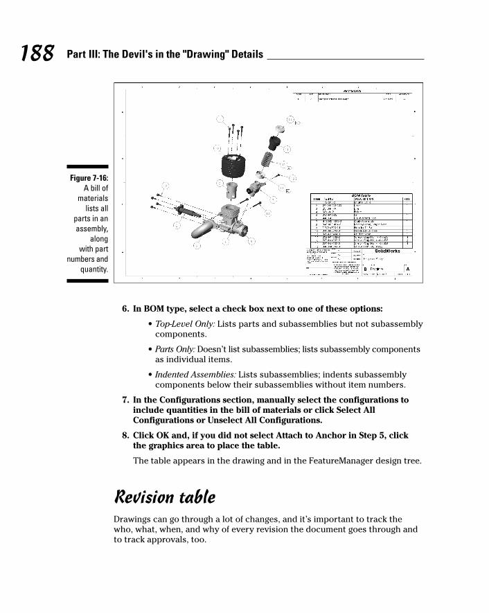
6. In BOM type, select a check box next to one of these options:
• Top-Level Only: Lists parts and subassemblies but not subassemblycomponents.
• Parts Only: Doesn’t list subassemblies; lists subassembly componentsas individual items.
• Indented Assemblies: Lists subassemblies; indents subassemblycomponents below their subassemblies without item numbers.
7. In the Configurations section, manually select the configurations toinclude quantities in the bill of materials or click Select AllConfigurations or Unselect All Configurations.
8. Click OK and, if you did not select Attach to Anchor in Step 5, clickthe graphics area to place the table.
The table appears in the drawing and in the FeatureManager design tree.
Revision tableDrawings can go through a lot of changes, and it’s important to track thewho, what, when, and why of every revision the document goes through andto track approvals, too.
Figure 7-16:A bill of
materialslists all
parts in anassembly,
along with part
numbers andquantity.
188 Part III: The Devil's in the "Drawing" Details
13_129784 ch07.qxp 9/28/07 12:36 PM Page 188

With this in mind, SolidWorks allows you to insert a revision table into adrawing. Figure 7-16 (refer to the preceding section) denotes the revisions withfive-sided flags (my personal preference). The revision table gives you a placeto track changes and revision numbers by date. You can type a description ofthe change, and the table has a column for approvals.
In Figure 7-16, you can take advantage of drawing layers for your revisionsymbols. Before you insert the revision table, define the layer for revisionmarks with a different color, which does two things:
� Highlights the revision marks in another color
� Lets you turn off the revision marks by turning off the layer
When creating the Revision symbol, select the layer used for Revision symbols.
If the layer doesn’t exist, open the Layer dialog box by selecting the Layertoolbar. Click New, enter the layer name in the Name field, and click OKwithin the Layer dialog box. If the Layer toolbar isn’t active, turn it on bychoosing View➪Toolbars➪Layer. (See Chapter 8 for more details on layers.)
To insert a revision table into your open drawing, follow these steps:
1. Choose Insert➪Tables➪Revision Table.
The Revision Table PropertyManager appears.
2. Set the following properties in the PropertyManager:
• Table Template: Browse for a template to choose a standard orcustom revision template.
• Table Anchor: Set the anchored corner.
• Attach to Anchor: Attach the specified corner to the table anchor.
• Revision Symbol Shapes: Select a border shape for a revisionsymbol.
• Options: Select a check box for the Enable symbol when adding anew revision. You can click in the graphics area to place Revisionsymbols when you add a revision table. If you clear this option oradd a symbol later, right-click in a row of the revision table, chooseRevisions➪Add Symbol, and then click in the graphics are to placesymbols. If you edit revision text, the symbols are updated.
3. Click OK and, if you did not select the Attach to Anchor option, clickthe graphics area to place the table.
The table appears in the drawing and in the FeatureManager design tree.
189Chapter 7: Creating Drawings
13_129784 ch07.qxp 9/28/07 12:36 PM Page 189
To add a revision to the table, follow these steps:
1. Right-click in the revision table and choose Revisions➪Add Revision.
If the Revision Symbol option is turned on, the symbol appears next tothe cursor after the table is placed. If you don’t want to place a symbolnow, press Esc before continuing to Step 2.
2. Double-click inside a revision field.
The field is highlighted, and the text inside the box is selected. The NotePropertyManager appears in the left pane.
3. Type the new text.
4. To change the style or justification of the text, highlight the text andenter the new style in the Note PropertyManager.
The text is updated in the revision table.
5. To add a Revision symbol, click where you want to add the symboland click Add Symbol in the Note PropertyManager.
The Symbols dialog box opens.
6. In the dialog box, select a symbol library by using the pull-downarrow.
A list of available symbols appears in the box below the Library field. Ifyou select a symbol, a preview appears in the dialog box.
7. Choose a symbol and click OK.
The symbol appears in the revision table.
8. Click OK in the Note PropertyManager.
The DrawCompare command compares all entities between two documents.The differences between the drawings are displayed in color codes. Whenyou use this command to compare two versions of a drawing, you can checkfor any design changes that were left unmarked in the revision table. ChooseTools➪DrawCompare. In the DrawCompare dialog box, browse to select adrawing for Drawing 1 and Drawing 2. In each of the fields, select a color. Thetwo drawings appear side by side. In the Differences field, you can see whatwas removed and what was added.
Hole tablesHole tables in drawings measure the positions of selected holes from a specifiedorigin. SolidWorks labels each hole with a tag that corresponds to a row inthe hole table (see Figure 7-17).
190 Part III: The Devil's in the "Drawing" Details
13_129784 ch07.qxp 9/28/07 12:36 PM Page 190

The Hole Table command creates a table that shows the XY coordinates andhole size for each hole you select. If you make a change to the model, thechange is reflected in the hole table.
To insert a hole table in an open drawing, follow these steps:
1. Choose Insert➪Tables➪Hole Table.
The Hole Table PropertyManager appears with the Origin field active.
2. In the graphics area, select a vertex to specify the origin datum.
You can select an X axis and a Y axis to define a vertex for the datum.You can also drag the origin into position after you place the table. TheEdges/Faces field becomes active.
3. Select hole edges or select a model face.
The holes are added to the Edges/Faces field. If you select a face, all theholes are added to the table.
4. In the PropertyManager, select a template or anchor.
5. Click OK and, if you did not select the Attach to Anchor option, clickthe graphics area to place the table.
The hole table appears in the drawing and in the FeatureManager design tree.
Figure 7-17:Hole tablesin drawingstrack holes
and areupdatedwith the
model.
191Chapter 7: Creating Drawings
13_129784 ch07.qxp 9/28/07 12:36 PM Page 191
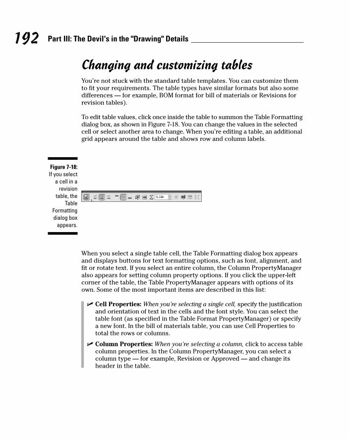
Changing and customizing tablesYou’re not stuck with the standard table templates. You can customize themto fit your requirements. The table types have similar formats but also somedifferences — for example, BOM format for bill of materials or Revisions forrevision tables).
To edit table values, click once inside the table to summon the Table Formattingdialog box, as shown in Figure 7-18. You can change the values in the selectedcell or select another area to change. When you’re editing a table, an additionalgrid appears around the table and shows row and column labels.
When you select a single table cell, the Table Formatting dialog box appearsand displays buttons for text formatting options, such as font, alignment, andfit or rotate text. If you select an entire column, the Column PropertyManageralso appears for setting column property options. If you click the upper-leftcorner of the table, the Table PropertyManager appears with options of itsown. Some of the most important items are described in this list:
� Cell Properties: When you’re selecting a single cell, specify the justificationand orientation of text in the cells and the font style. You can select thetable font (as specified in the Table Format PropertyManager) or specifya new font. In the bill of materials table, you can use Cell Properties tototal the rows or columns.
� Column Properties: When you’re selecting a column, click to access tablecolumn properties. In the Column PropertyManager, you can select acolumn type — for example, Revision or Approved — and change itsheader in the table.
Figure 7-18:If you select
a cell in arevision
table, theTable
Formattingdialog box
appears.
192 Part III: The Devil's in the "Drawing" Details
13_129784 ch07.qxp 9/28/07 12:36 PM Page 192
� Table Properties: When you’re selecting the upper-left corner, display theRevision Table PropertyManager, where you can choose a corner foranchoring the table. For the revision table, you can also select Revisionsymbol shapes, change the border around the table, and specify anamed layer to associate the table to.
You can move an entire table to a new position on your drawing sheet. Putyour pointer around the upper-right or -left corner of a table. When the pointerchanges to a set of four arrows pointing in each direction, click and drag thetable. Releasing the mouse sets the final position of the table.
You can customize your favorite table formats and save them as templates.Right-click a table and choose Save As Template. In the Save As dialog box,type a name for the template and browse to its saved location. Make surethat you store these templates in a common location for all users to access.To set the location for storing templates, choose Tool➪Options. On the SystemsOptions tab, select File Locations. Show folders for the template you want tosave, click Add, and browse for the folder location.
193Chapter 7: Creating Drawings
13_129784 ch07.qxp 9/28/07 12:36 PM Page 193

194 Part III: The Devil's in the "Drawing" Details
13_129784 ch07.qxp 9/28/07 12:36 PM Page 194
Chapter 8
Speeding It Up: Automating the Drawing
In This Chapter� Marking dimensions in the model for importing into the drawing
� Organizing drawing information with layers
� Picking favorites to speed drawing creation
� Linking the sheet format to custom properties
In this chapter, I give you hints, tips, and shortcuts that you can use tospeed up the drawing creation process. You discover how to import
dimensions, annotations, and reference geometry directly from the model.You also find out how to make the most of custom properties and how to createtemplates to jump-start your drawings. (For information on creating a drawing,see Chapter 7.)
Planning for the DrawingThe devil’s in the details, and this saying is especially true when you’re creatingmanufacturing drawings. The person who designs a product is the one whoknows the most about it. As the designer, you need to communicate that wealthof information in your head to the person making the product, by includingthe right amount of detail (not too much, and not too little) in your drawings.
SolidWorks lets you incorporate manufacturing details into your model. Youcan mark dimensions and add finishing symbols, geometric tolerances, andother annotations to the model that you want to import into the drawing. Yourmodel should contain all the information you need to create the drawings.
14_129784 ch08.qxp 9/28/07 12:36 PM Page 195

196 Part III: The Devil's in the "Drawing" Details
Here are the basic steps to follow as you design:
1. When you design the model, create the sketches the way you want themto show up in the drawing. Add annotations to the model and mark in theModify dialog box the dimensions you want to import into the drawing.(The next section explains how to do so.)
2. Set up your sheet formats and drawing templates in advance and putthem where they’re readily available to the design team. Include links tocustom properties and the drawing symbols you use most often.
3. After you place the drawing views, use the Model Items command toinsert dimensions, annotations, and reference geometry automatically.(See the next section for more on this command.)
Inserting Model ItemsIn Chapter 7, I tell you ways to insert dimensions and annotations manually inboth the model and the drawing. In this chapter, I introduce you to Model Items,a powerful command in SolidWorks that allows you to insert dimensions,annotations, and reference geometry into the drawing views automatically.
Here’s how it works: When you create a dimension in a model, you can markit for import into the drawing. This option is usually turned on by default, butif not, in the Modify dialog box, which appears when you add a dimension to amodel, click the Mark Dimension to Be Imported into Drawing icon. (To deselecta dimension for import, click the icon again.) Be sure to add any annotationsand symbols in the model that are important to the manufacturing process.
After you place all the drawing views, you can use the Model Items commandto automatically insert the dimensions, annotations, and reference geometryfrom the model. Model Items gives you the option to import all dimensionsor only those marked for import. You can also select the specific types ofannotations and reference geometry you want to import.
Model Items imports model dimensions, also known as driving dimensionsbecause they drive changes in the model geometry. SolidWorks shows modeldimensions in black. You can read more about dimension types in Chapter 7.
There are several advantages to using Model Items:
� You save time inserting items automatically. If you couldn’t insertdimensions automatically, you would first have to dimension thesketches to create the part features and then re-create those dimensionsagain in the drawing, creating twice the amount of work.
14_129784 ch08.qxp 9/28/07 12:36 PM Page 196

� You can capture design intent in the part, not as an afterthought whencreating a drawing. When you create the part features, why not spend alittle extra time adding the information you need in your drawings?
� If tolerance or dimension values change in the drawing, your part isupdated automatically. Conversely, any change to the model is updatedin the drawing. You don’t need to redo work on either side.
The example shown in Figure 8-1 shows how I used Insert Model for the pro-file feature and the holes. Model Items requires no extra cleanup. Simplydefine the placement and other dimension attributes in the sketch and markthe dimension for import. I also used Model Items to import surface-finishannotations.
Before using the Model Items command, you should place all your drawingviews. To insert Model Items into an open drawing, follow these steps:
1. Choose Insert➪Model Items.
The Model Items PropertyManager appears, as shown in Figure 8-2. Youshould carefully set all options in the PropertyManager.
2. In the Source/Destination area, select one of these options:
• Entire Model: Model Items inserts entities (dimensions, annotations,and reference geometry) from the entire model.
• Selected Feature: Model Items inserts entities from only the featuresor components you select in the graphics area.
Figure 8-1:The Model
Itemscommand
lets youselect thedimension
types toimport to the
drawing.
197Chapter 8: Speeding It Up: Automating the Drawing
14_129784 ch08.qxp 9/28/07 12:36 PM Page 197

If you want to import items into all views, select the Import Itemsinto All Views check box. Otherwise, deselect the option and selecta single model view.
If you select a model view, the items appear in that view.
3. In the Dimensions area, click the dimension type you want to insert:
• Marked for Drawing: Inserts only the dimensions marked for drawingin the Modify dialog box.
• Instance/Revolution Counts: Inserts only the number of instancesfor linear or circular patterns.
• Hole Wizard Profiles: Inserts only dimensions for Hole Wizardprofiles.
• Hole Wizard Locations: Inserts only dimensions for Hole Wizardlocations.
• Hole Callout: Inserts only dimensions for hole callouts.
• Eliminate Duplicates: Prevents duplicate dimensions from appearingin different drawing views.
Figure 8-2:Insert
Model ItemsProperty
Managersettings.
198 Part III: The Devil's in the "Drawing" Details
14_129784 ch08.qxp 9/28/07 12:36 PM Page 198
4. In the Annotations area, click Select All if you want to import all anno-tations in the model. Otherwise, click to select the specific types.
You can import notes, surface finishes, geometric tolerances, datums,datum targets, or welds. Cosmetic threads can be imported into assem-bly drawings only.
5. In the Reference Geometry area, select the Select All check box if youwant to import all reference geometry in the model. Otherwise, clickto select the specific types.
Selection options include planes, axis, points, origins, surfaces, curves,and routing points.
6. In the Options area, select the check box for the following options:
• Include Items from Hidden Features: Imports items that are in featuresor parts that are hidden.
• Use Dimension Placement in Sketch: Inserts model dimensions fromthe part in the same locations in the drawing.
7. In the Layer area, if the drawing has named layers, select one to addthe items to it.
8. Click OK.
The Model Items PropertyManager closes, and the dimensions andannotations appear in the drawing view or views.
If your drawing view is cluttered with dimensions after using model items, you can hide some dimensions so that they’re no longer visible. Right-click a dimension and choose Hide. You can click and drag to move a selecteddimension.
Managing Drawing Clutter with LayersLayers are a clever way to organize information in your drawings. Layers are“transparent” sheets that stack up to form the final drawing. You can createas many layers as you want, depending on how complex the drawing is, andgroup information on the various layers. One layer may contain all the holesin an assembly, and another may contain only dimensions and annotations.
You can turn layers on and off, depending on what you want to display or print,and you can move entities from one layer to another. And, so that you canfind your way around, SolidWorks lets you assign a line color, thickness, andstyle for the entities on the different layers.
199Chapter 8: Speeding It Up: Automating the Drawing
14_129784 ch08.qxp 9/28/07 12:36 PM Page 199
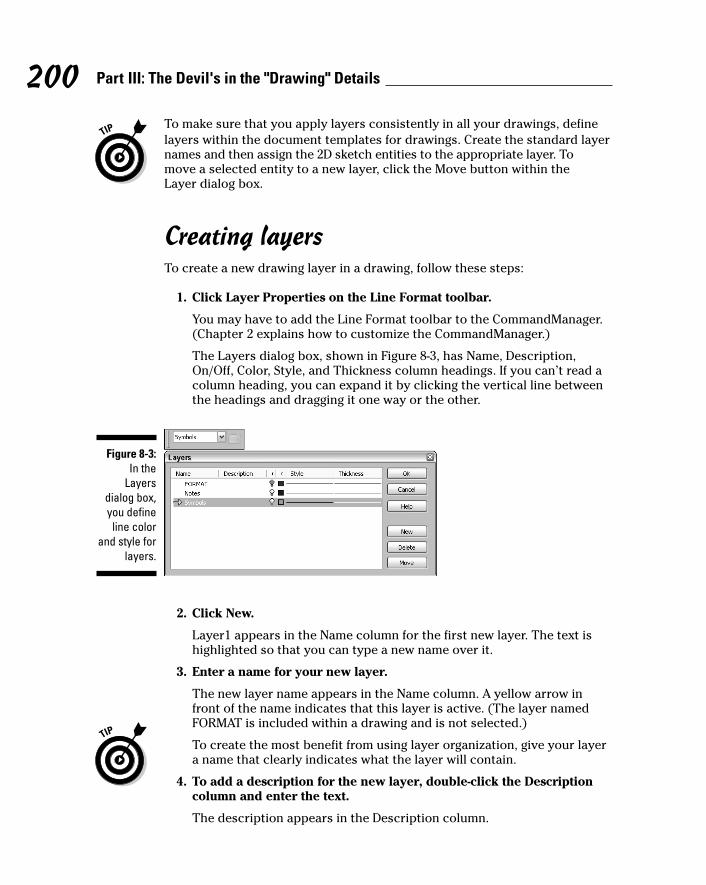
To make sure that you apply layers consistently in all your drawings, definelayers within the document templates for drawings. Create the standard layernames and then assign the 2D sketch entities to the appropriate layer. To move a selected entity to a new layer, click the Move button within the Layer dialog box.
Creating layersTo create a new drawing layer in a drawing, follow these steps:
1. Click Layer Properties on the Line Format toolbar.
You may have to add the Line Format toolbar to the CommandManager.(Chapter 2 explains how to customize the CommandManager.)
The Layers dialog box, shown in Figure 8-3, has Name, Description,On/Off, Color, Style, and Thickness column headings. If you can’t read acolumn heading, you can expand it by clicking the vertical line betweenthe headings and dragging it one way or the other.
2. Click New.
Layer1 appears in the Name column for the first new layer. The text ishighlighted so that you can type a new name over it.
3. Enter a name for your new layer.
The new layer name appears in the Name column. A yellow arrow infront of the name indicates that this layer is active. (The layer namedFORMAT is included within a drawing and is not selected.)
To create the most benefit from using layer organization, give your layera name that clearly indicates what the layer will contain.
4. To add a description for the new layer, double-click the Descriptioncolumn and enter the text.
The description appears in the Description column.
Figure 8-3:In the
Layersdialog box,you define
line colorand style for
layers.
200 Part III: The Devil's in the "Drawing" Details
14_129784 ch08.qxp 9/28/07 12:36 PM Page 200
5. To specify the line color for the parts on this layer, click the Colorbox, select a color in the Color dialog box, and then click OK.
The box is set to the new color. The Color dialog box also has a DefineCustom Colors option. You can use it to define and add custom coloroptions.
6. To specify a line style, click in the Style column and select the desiredline style from the list.
Style types include Solid, Dashed, and Phantom, for example.
7. To specify a line thickness, click in the Thickness column and select aline thickness from the list.
8. Repeat Steps 2 through 7 to add any other layers you need.
9. Click OK.
The Layers dialog box closes, and your new layers are created. Whenyou add new entities to a drawing, they appear on the active layer.
Working with layersYou can activate a layer, move layers, and maneuver between layers frominside the Layers dialog box. To activate or edit layers, click Layer Propertieson the Line Format toolbar. You can choose one of these options:
� Active: An arrow indicates which layer is active. To activate a layer, clicknext to the layer name, and an arrow appears.
� On/Off: A yellow light bulb appears when a layer is visible. To hide alayer, click its light bulb. The light bulb turns gray, and all entities on thelayer are hidden. To turn on the layer again, click the light bulb.
� Move: To move entities to the active layer, select the entities in thedrawing and click Move. You can select multiple items by holding downthe Ctrl key when you click them.
� Delete: To delete a layer, select the layer name and press Delete on yourkeyboard.
Automating Drawing CreationUnless you like repetition, you can work smarter when you’re creatingdrawings. This section covers various SolidWorks features that allow you toreuse information and churn out drawings faster.
201Chapter 8: Speeding It Up: Automating the Drawing
14_129784 ch08.qxp 9/28/07 12:36 PM Page 201
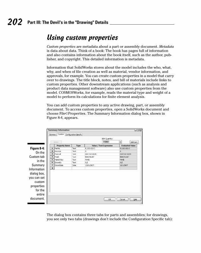
Using custom propertiesCustom properties are metadata about a part or assembly document. Metadatais data about data. Think of a book: The book has pages full of informationand also contains information about the book itself, such as the author, pub-lisher, and copyright. This detailed information is metadata.
Information that SolidWorks stores about the model includes the who, what,why, and when of file creation as well as material, vendor information, andapprovals, for example. You can create custom properties in a model that carryover to drawings. The title block, notes, and bill of materials include links tocustom properties. Other downstream applications (such as analysis andproduct data management software) also use custom properties from themodel. COSMOSWorks, for example, reads the material type and weight of amodel to perform its calculations for finite element analysis.
You can add custom properties to any active drawing, part, or assemblydocument. To access custom properties, open a SolidWorks document andchoose File➪Properties. The Summary Information dialog box, shown inFigure 8-4, appears.
The dialog box contains three tabs for parts and assemblies; for drawings,you see only two tabs (drawings don’t include the Configuration Specific tab):
Figure 8-4:On the
Custom tabin the
SummaryInformationdialog box,
you can setcustom
propertiesfor theentire
document.
202 Part III: The Devil's in the "Drawing" Details
14_129784 ch08.qxp 9/28/07 12:36 PM Page 202
� Summary: See a basic summary of the document, such as author, key-words, comments, title, and subject. This tab also has a Statistics boxthat tells you when the document was created and last saved and whosaved it last.
� Custom: Enter custom properties that apply to the entire document.These properties are document specific, which means they’re controlledby the SolidWorks document (part, assembly, and drawing) templatesand apply to all part and assembly configurations.
� Configuration Specific: Define custom properties that vary from oneconfiguration to another. Configurations are variations of a model storedin the same document. The table on the Configurations Specific tab hasthe same heading as the one on the Custom tab, but you can specifywhich configuration in the document it applies to.
To add custom or configuration properties to an open part or assemblydocument, follow these steps:
1. Choose File➪Properties.
The Summary Information dialog box appears. The dialog box has threetabs: Summary, Custom, and Configuration Specific.
2. Select the Custom or Configuration Specific tab.
A table appears with the following headings: Property Name, Type,Value/Text Expression, and Evaluated Value. The Configuration Specifictab has a field in which you can select the configuration to which youwant to apply the property.
3. If you are defining a property on the Configuration Specific tab, in theApplies To field, select a configuration from the drop-down list.
Now any custom properties you set in the table apply to only the config-uration that appears in the Applies To field.
4. Click the first blank cell in the Property Name column and then type aname or choose one from the list.
To move between cells in the table, press Tab or Enter, or click in thecell you want to move to.
To add custom properties to the drop-down list, click Edit List in theSummary Information dialog box, type a new name in the Edit CustomProperty List dialog box, and click Add. Select a property and click Delete,Move Up, or Move Down to delete or move a custom property in the list.
5. Select a type from the drop-down list.
Type describes the value you can enter in the Value/Text Expression cell.Type options include text, date, number, and yes or no. For example, if
203Chapter 8: Speeding It Up: Automating the Drawing
14_129784 ch08.qxp 9/28/07 12:36 PM Page 203
you want someone to be able to indicate whether a part is a fastener byusing the IsFastener custom property, select the Yes or No type option.
6. In the Value/Text Expression column, enter a custom-property valuethat’s compatible with the selection in the Type cell.
You can type a value, or you can select a value from a drop-down list ifit’s available. For example, if you select Yes or No for type, Yes or Noappears in the drop-down list in the Value/Text Expression cell. Youmust enter a valid type.
7. Press Tab or Enter.
The value of the property appears in the Evaluated Value column.
8. Repeat Steps 2 through 7 to add any other custom properties.
9. Click OK.
The Summary Information dialog box closes, and custom properties areadded to the model.
If you enter a date in the custom properties, it must be a valid date. Don’tenter a date that’s valid but inaccurate. For example, the created date isunlikely to be 10/12/1947.
To ensure that custom properties are available on each document, you shoulddefine the custom properties in the drawing, part, and assembly documenttemplates. (Chapter 2 explains how to create templates.)
Setting up a drawing sheet formatA drawing sheet is a page in a drawing document. A sheet format is the background for your drawing and typically includes elements such as pagesize, orientation, standard text, borders, and title block. Sheets in a drawingcan use different formats. You select a sheet format when you open a newdrawing.
Standard sheet formats in SolidWorks include links to custom properties. Youcan edit a title block in a sheet format by using the steps I outline in Chapter7. You can use the Note PropertyManager, which appears when you edit textin the title block, to edit or add links to custom properties in the drawingdocument or in the model. For example, you can include links to the modelthat include the author, comments, and filename. The links are populated ifthe information exists in the custom properties of the model.
One advantage to using custom properties to define the information in thetitle block is that after you set up the title block, you can use custom properties
204 Part III: The Devil's in the "Drawing" Details
14_129784 ch08.qxp 9/28/07 12:36 PM Page 204

to edit all the values, and you don’t have to use the Edit Sheet function.Figure 8-5 shows the custom properties used to automatically annotate thedrawing format.
The text notes link to the custom properties. The notes shown (with labels)link to custom properties defined in the drawing. These notes link to valuesby using the following formats:
� ($PRP:<value>): Links to the custom properties in the model used tocreate the drawing views
� ($PRPSHEET:<value>): Links to custom properties from the currentdrawing document
� ($PRP: “SW-Total Sheets”): Lists special SolidWorks system values (forexample, total sheets, sheet number, and filename)
The Link to Property feature links the contents of the text note to a customproperty, as shown in Figure 8-6.
SolidWorks lets you customize sheet formats and save them for future use asfiles with an .slddrt extension. You can store these files in the Design Library.You can also create drawing templates that use custom sheet formats.
Chapter 7 explains how to edit a drawing sheet format. The following stepstell you how to save a drawing sheet format for use in other drawings.
To save a new format as the standard A-Landscape format, follow these steps:
1. Choose File➪Save Sheet Format.
The Save Sheet Format dialog box opens. The Save As Type optiondefaults to Sheet format (*.slddrt).
Figure 8-5:You can link
to customproperties in
the titleblock.
205Chapter 8: Speeding It Up: Automating the Drawing
14_129784 ch08.qxp 9/28/07 12:36 PM Page 205
Dow
nlo
ad fro
m W
ow
! eBook
<w
ww
.wow
ebook.
com
>
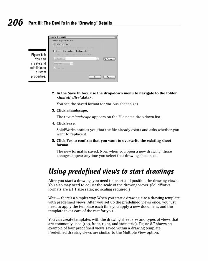
2. In the Save In box, use the drop-down menu to navigate to the folder<install_dir>\data\.
You see the saved format for various sheet sizes.
3. Click a-landscape.
The text a-landscape appears on the File name drop-down list.
4. Click Save.
SolidWorks notifies you that the file already exists and asks whether youwant to replace it.
5. Click Yes to confirm that you want to overwrite the existing sheetformat.
The new format is saved. Now, when you open a new drawing, thosechanges appear anytime you select that drawing sheet size.
Using predefined views to start drawingsAfter you start a drawing, you need to insert and position the drawing views.You also may need to adjust the scale of the drawing views. (SolidWorksformats are a 1:1 size ratio; no scaling required.)
Wait — there’s a simpler way. When you start a drawing, use a drawing templatewith predefined views. After you set up the predefined views once, you justneed to apply the template each time you apply a new document, and thetemplate takes care of the rest for you.
You can create templates with the drawing sheet size and types of views thatare commonly used (top, front, right, and isometric). Figure 8-7 shows anexample of four predefined views saved within a drawing template.Predefined drawing views are similar to the Multiple View option.
Figure 8-6:You can
create andedit links to
customproperties.
206 Part III: The Devil's in the "Drawing" Details
14_129784 ch08.qxp 9/28/07 12:36 PM Page 206
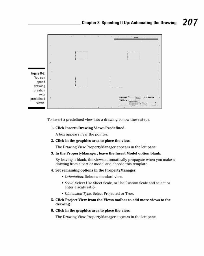
To insert a predefined view into a drawing, follow these steps:
1. Click Insert➪Drawing View➪Predefined.
A box appears near the pointer.
2. Click in the graphics area to place the view.
The Drawing View PropertyManager appears in the left pane.
3. In the PropertyManager, leave the Insert Model option blank.
By leaving it blank, the views automatically propagate when you make adrawing from a part or model and choose this template.
4. Set remaining options in the PropertyManager:
• Orientation: Select a standard view.
• Scale: Select Use Sheet Scale, or Use Custom Scale and select orenter a scale ratio.
• Dimension Type: Select Projected or True.
5. Click Project View from the Views toolbar to add more views to thedrawing.
6. Click in the graphics area to place the view.
The Drawing View PropertyManager appears in the left pane.
Figure 8-7:You can
speeddrawingcreation
withpredefined
views.
207Chapter 8: Speeding It Up: Automating the Drawing
14_129784 ch08.qxp 9/28/07 12:36 PM Page 207
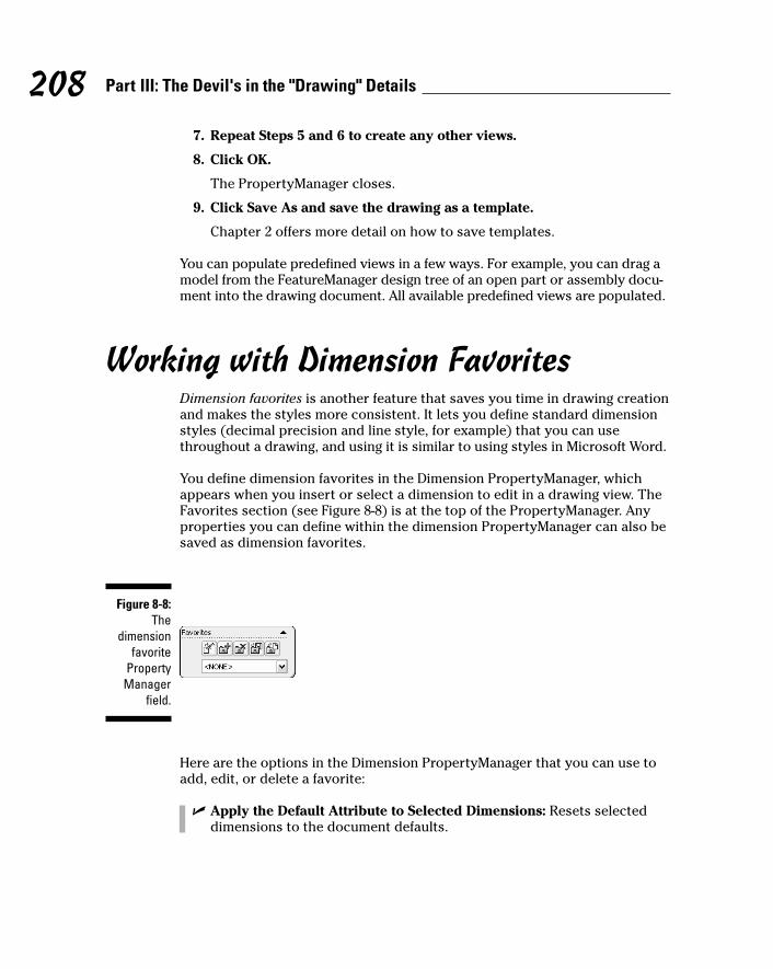
7. Repeat Steps 5 and 6 to create any other views.
8. Click OK.
The PropertyManager closes.
9. Click Save As and save the drawing as a template.
Chapter 2 offers more detail on how to save templates.
You can populate predefined views in a few ways. For example, you can drag amodel from the FeatureManager design tree of an open part or assembly docu-ment into the drawing document. All available predefined views are populated.
Working with Dimension FavoritesDimension favorites is another feature that saves you time in drawing creationand makes the styles more consistent. It lets you define standard dimensionstyles (decimal precision and line style, for example) that you can usethroughout a drawing, and using it is similar to using styles in Microsoft Word.
You define dimension favorites in the Dimension PropertyManager, whichappears when you insert or select a dimension to edit in a drawing view. TheFavorites section (see Figure 8-8) is at the top of the PropertyManager. Anyproperties you can define within the dimension PropertyManager can also besaved as dimension favorites.
Here are the options in the Dimension PropertyManager that you can use toadd, edit, or delete a favorite:
� Apply the Default Attribute to Selected Dimensions: Resets selecteddimensions to the document defaults.
Figure 8-8:The
dimensionfavorite
PropertyManager
field.
208 Part III: The Devil's in the "Drawing" Details
14_129784 ch08.qxp 9/28/07 12:36 PM Page 208
� Add or Update a Favorite: Opens the Favorite dialog box, where youcan type a name to add a new favorite to the current document. Or,choose a Favorite from the list to do either of the following:
• Update All Annotations Linked to This Favorite: All annotationsusing the selected favorite style are updated with the changes tothe selected annotation.
• Break All Links to This Favorite: All links between the selectedfavorite and annotations are broken. The annotations retain theattributes previously applied by the favorite unless the annotationsare subsequently reset to the document default.
� Delete a Favorite: Deletes the selected favorite in the document.
� Save a Favorite: Opens the Save As dialog box with Favorite (.sldfvt)as the default file type to save an existing favorite.
� Load Favorites: Opens the Open dialog box with Favorite (.sldfvt) asthe active file type. You can use Ctrl or Shift to select multiple files.
� Set a Current Favorite: Choose a favorite style from the list to apply toselected dimensions or to delete or save the favorite.
To ensure that dimension favorites are available in all document types, youshould define them within the document templates. You can define them bysetting them up from scratch or loading them from another drawing and thensaving the new drawing as a template file.
Creating the Drawing TemplateTemplates are important tools in creating drawings. You can use templates tocapture all your design standards and open one each time you start a newdrawing. Here are the basic steps for creating a drawing template. (SeeChapters 7 and the earlier sections in this chapter for all the details.) Youmay want to think of these steps as a sort of checklist:
1. Open a new drawing document.
This new document will become your custom template. After you makechanges to it, you should save this document in the template format sothat it appears in the Advanced mode of the New SolidWorks Documentdialog box. Chapter 2 provides details on how to create a template.
2. Define the custom properties.
Custom properties link to the sheet format. Read the section “Usingcustom properties,” earlier in this chapter, for details.
209Chapter 8: Speeding It Up: Automating the Drawing
14_129784 ch08.qxp 9/28/07 12:36 PM Page 209
3. Edit the sheet format.
The sheet format is the background of your drawing and contains thetitle block. You can link text in the title block to custom properties in the model, such as the author’s name and the revision date. (SeeChapter 7 for steps on how to edit a title block.)
4. Put the drawing format on its own layer.
This step allows you to easily turn on or off the drawing format so thatyou can see it.
5. Set options in Document Properties.
With a document active in SolidWorks, choose Tools➪Options and selectthe Document Properties tab. You can set all the standards for how youwant things in the document to look, from the font style for dimensionsto the units of measurement to use throughout the document. (You canread more about document properties in Chapter 2.)
6. Save the drawing as a document template.
In the Save As dialog box, select Save As Type .drwdot.
210 Part III: The Devil's in the "Drawing" Details
14_129784 ch08.qxp 9/28/07 12:36 PM Page 210
Chapter 9
Changes, Changes, ChangesIn This Chapter� Changing values in dimensions to update part features
� Defining or changing material and lighting properties
� Changing document references
� Getting measurements and mass properties
� Finding out how long it takes to rebuild a SolidWorks model
In the wonderful world of design, nothing stays the same. New informationrolls in, people change their minds, and the CAD model continually evolves.
The good news is that SolidWorks makes it easy to update designs. BecauseSolidWorks is a parametric software, changes you make in one area ripplethrough all other areas of your design automatically. You don’t have to manually update all the related geometry, assemblies, or drawings. If you did, you would probably consider a new line of work.
An added benefit to all this is that you can use SolidWorks to tinker withnumerous what-if design scenarios, such as “What if I add five inches to thisfan blade?” or “What if I make a bicycle with three wheels?”
In this chapter, I show you how to update SolidWorks documents so that you’realways working with the current document. I also show you how to query adesign for information, such as measurements, mass properties, and rebuildstatistics.
Changing the DesignNo matter how hard you try to be clairvoyant and figure out what a designwill ultimately look like, it just doesn’t happen. In the design world, change isthe name of the game. The three areas you can change in a design includepart features, visual properties, and document references. In the followingsections, you find out how to tinker with each area.
15_129784 ch09.qxp 9/28/07 12:36 PM Page 211

212 Part III: The Devil's in the "Drawing" Details
Changing dimensions and featuresYou change features in SolidWorks by modifying dimensions. Dimensionsdefine the size and the shape of a part.
Typically, you create dimensions as you create each part feature and theninsert those dimensions into drawing views. In SolidWorks, when you changea dimension in the model, the drawing is updated. By the same token, whenyou change a dimension in a drawing, the model is updated.
The way to change a part feature (a cut or an extrusion, for example) is tochange the model dimensions associated with that feature. You can changemodel dimensions in the part, the sketch, or the drawing.
Driving dimensions are sometimes called model dimensions. Driven dimensionsare another type of dimension used only for reference. In SolidWorks, drivingdimensions are black, and driven dimensions are gray. (You can find out moreabout dimensions in Chapter 3.)
When you double-click a dimension to change it, the Modify dialog boxappears (see Figure 9-1).
The following list describes the Modify dialog box functions.
1 OK: Saves the current value and closes the dialog box.
2 Cancel: Restores the original value and closes the dialog box.
3 Rebuild: Regenerates the model (shows the changes) with the currentvalue. You can use Rebuild to evaluate different values before closing theModify dialog box.
4 Spin box value: Sets the value for the spin increment (up and downarrows). To define the spin default value, choose Tools➪Options. On theSystem Options tab, select Spin Box Increments. Set the values in theSpin Box Increments dialog box.
6
1
8 7
2 3 4 5
Figure 9-1:The Modifydialog box.
15_129784 ch09.qxp 9/28/07 12:36 PM Page 212
5 Mark dimension to be imported into a drawing: Marks the dimensionsin part or assembly documents that you want to import into a drawingwhen you use the Model Insert command. (Read more about thiscommand in Chapter 8.)
6 Dimension value: Displays the current value, which you can change bytyping a new one or by sliding the nifty thumb wheels back and forth toincrease or decrease the values. The default units (inches) are shownafter the value.
7 Spin box: Increases or decreases the dimension value by a specifiedincrement when you click the up or down arrows.
8 Close: Closes the dialog box without saving changes.
When you change the value of a dimension within the Modify dialog box, thesize or shape of a part isn’t automatically updated. You need to rebuild themodel with any changes you made. To do so, simply click the Rebuild buttonin the Modify dialog box. Rebuilding a change while you’re still in the Modifydialog box allows you to play with a number of what-if scenarios and makeadditional adjustments, if necessary.
When you add a brand-new dimension, you typically go back and double-click it to display the Modify dialog box, where you enter an exact value. Ifyou want to save a bit of time, choose Tools➪Options. In the General sectionof the Systems Options tab, select the check box for Input Dimension Value.When you check this option, the Modify dialog box appears automaticallyeach time you insert a new dimension.
You can change a driving dimension in a part, a sketch, an assembly, or adrawing by completing the following steps:
1. Open a drawing, part, or assembly document.
2. Double-click the part feature you want to change in theFeatureManager design tree or within the graphics area.
The dimensions appear as lines with the values next to them. You canedit only driving dimensions, which appear in black. You can’t edit reference dimensions, which appear in gray.
3. Double-click the dimension you want to change.
The Modify dialog box appears.
4. Enter a new value in the dialog box.
5. Click Rebuild in the Modify dialog box.
The model is updated to reflect any changes.
6. Click OK.
The changes are saved, and the Modify dialog box closes.
213Chapter 9: Changes, Changes, Changes
15_129784 ch09.qxp 9/28/07 12:36 PM Page 213
You can also change the way you define a feature (extrusion or fillet, forexample). When you modify a feature, the original PropertyManager that you used to define the feature appears. You can change the values in thePropertyManager to change or redefine the feature.
To change the way an existing feature was defined, follow these steps:
1. Open a drawing, a part, or an assembly document.
2. In the FeatureManager design tree, right-click the feature you want tochange and choose the Edit Feature icon.
The feature’s PropertyManager appears.
3. Change the values and definition of the feature in thePropertyManager.
Each feature has a different PropertyManager. (Chapter 5 explains thedifferent types of features and how they’re defined.)
4. Click OK.
The value and property changes appear within the part.
Changing visual propertiesSolidWorks lets you create models that look and act like the real thing. Youcan assign materials, such as aluminum or cast iron, to parts. Each materialhas its own associated characteristics, such as density, color, and texture. Inparts and assemblies, you can adjust the direction, intensity, and color oflight in the shaded view of the model to create more realistic lighting effects.
Material properties stay with the model. Downstream applications, such asthe SolidWorks add-ins COSMOSWorks for analysis and PhotoWorks photo-rendering software, use these material properties to calculate their results. At times, however, you may need to edit the material properties.
You can create custom document templates with predefined materials andlighting and store these templates on a shared server for others to use. Tofind out more about how to create and save templates, see Chapter 2.
Setting materials propertiesSolidWorks lets you assign material properties to parts. This process isn’tautomatic; a part gets a material property only if you assign it one or if youpreset the material property in the document template. What’s more, onlyindividual parts can have material properties. You cannot assign a singlematerial property to an entire assembly, for example.
214 Part III: The Devil's in the "Drawing" Details
15_129784 ch09.qxp 9/28/07 12:36 PM Page 214
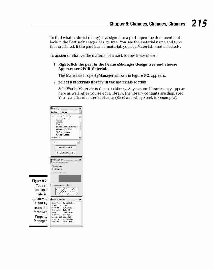
To find what material (if any) is assigned to a part, open the document andlook in the FeatureManager design tree. You see the material name and typethat are listed. If the part has no material, you see Materials <not selected>.
To assign or change the material of a part, follow these steps:
1. Right-click the part in the FeatureManager design tree and chooseAppearance➪Edit Material.
The Materials PropertyManager, shown in Figure 9-2, appears.
2. Select a materials library in the Materials section.
SolidWorks Materials is the main library. Any custom libraries may appearhere as well. After you select a library, the library contents are displayed.You see a list of material classes (Steel and Alloy Steel, for example).
Figure 9-2:You canassign amaterial
property toa part byusing theMaterialsProperty
Manager.
215Chapter 9: Changes, Changes, Changes
15_129784 ch09.qxp 9/28/07 12:36 PM Page 215
3. Select a material from the library contents.
Click the plus sign next to a material class to find the material type youwant.
4. Click OK.
The Materials Editor PropertyManager closes. The material is assignedto your part and shows up in the FeatureManager design tree. The visualappearance of the model is updated to reflect its material properties.
Let there be lightAnother way to change the visual appearance of a SolidWorks model is withlighting. Lighting applies to both part and assembly documents. Think oflighting like this: When a professional photographer prepares to take a portraitof your child, he tinkers with the lighting. He adds, directs, and adjusts the lightto create an overall good picture. You can make similar lighting adjustments inSolidWorks.
SolidWorks offers different lighting types that you can choose for your model.The properties of the light sources work together with the material propertiesof the model. If you change material properties of the model, you can enhanceor reduce the effect of the light properties.
You can choose several light sources in the same document. Here’s whatSolidWorks gives you to work with:
� Ambient light: Illuminates the model evenly from all directions. In aroom with white walls, the level of ambient light is high because thelight reflects off the walls and other objects.
� Directional light: Comes from a source that’s infinitely far away from themodel. It’s a columned light source consisting of parallel rays from asingle direction, like the sun.
� Point light: Comes from a very small light source located at a specificcoordinate in the model space. This type of light source emits light in alldirections. The effect is like a tiny light bulb floating in space.
� Spot light: Comes from a restricted, focused light with a cone-shapedbeam that is brightest at its center. You can aim a spot light at a specificarea of the model. You can adjust the position and distance of the lightsource relative to the model, and you can adjust the angle throughwhich the beam spreads.
You can define the following properties for a light source inside itsPropertyManager:
� On/Off: Turns the light source on or off.
� Color: You can also choose the color of light. The default is a white light,but you can use a different color to give the model more warmth.
216 Part III: The Devil's in the "Drawing" Details
15_129784 ch09.qxp 9/28/07 12:36 PM Page 216

� Ambient: Controls the intensity of the light source by using a valuebetween 0 and 1.
� Brightness: Controls the brightness of the light by using a value between0 and 1.
� Specularity: Controls the extent to which shiny surfaces exhibit brighthighlights where the light strikes them by using a value between 0 and 1.
� Light position: Controls the position of the light relative to the model.
To see the types of light in your model, open a part or assembly document inSolidWorks and double-click the Lighting folder in the FeatureManager designtree. The default lights are ambient and directional, but you can adjust themor add other lights. A few rules apply:
� You can turn the ambient light on or off, but you can’t delete it or addother ambient lights.
� You can turn the directional light on or off or delete it.
� You can add additional directional light sources.
� You can add point light and spot light sources.
� In any document, you can have up to nine light sources (the ambientlight and eight others in any combination).
To add a light source, follow these steps:
1. Right-click the Lighting folder in the FeatureManager design tree.
A menu appears with these choices:
• Add Directional Light
• Add Point Light
• Add Spot Light
2. Choose the type of light you want to add.
After you make a selection, the lighting type appears in the Lightingfolder immediately, as shown in Figure 9-3. You can add up to nine lightsources to the model.
You can also modify a light source. To modify the lighting properties, followthese steps:
1. Expand the Lighting folder in the FeatureManager design tree byclicking the plus sign next to the folder.
The contents of the Lighting folder appear.
217Chapter 9: Changes, Changes, Changes
15_129784 ch09.qxp 9/28/07 12:36 PM Page 217

2. Right-click a light source and choose Properties.
The PropertyManager for that light source appears.
3. Edit the properties to change light qualities.
The available light properties depend on the type of light source. Youcan move the slider on the bar to change the ambient, brightness, andspecularity properties from a value of 0 to 1.
As you edit, a graphical representation of the light source appears in thegraphics area to show the color and direction of the light.
4. Click OK.
To quickly edit the properties of a light source, in the FeatureManagerdesign tree, double-click the icon of the light source you want to modify.
To delete a light source, follow these steps:
1. Click the plus sign to expand the Lighting folder in theFeatureManager design tree.
2. Select the light source to delete and press the Delete key.
To turn off a light without deleting it, follow these steps:
1. Click + to expand the Lighting folder in the FeatureManager design tree.
Figure 9-3:You can addas many as
nine lightsources forany model.
218 Part III: The Devil's in the "Drawing" Details
15_129784 ch09.qxp 9/28/07 12:36 PM Page 218
2. Right-click the light source and choose Off.
This option toggles. If the light source is on, you turn it off, and vice versa.
Changing document referencesAn assembly may go through many revisions in its design life. Changes areespecially common in a multiuser environment where several users are work-ing on individual parts and subassemblies. You can change assembly compo-nents by using three methods:
� Add: You can add a new component to an assembly using the methods Icover in Chapter 6 of this book. You can drag a component from FileExplorer or use the Insert Component PropertyManager (chooseInsert➪Component).
� Delete: Deleting a component is as easy as 1-2-3. Open the assembly,select the component you want to delete in the FeatureManager designtree, and press the Delete key. SolidWorks asks you for confirmationbefore deleting the component.
� Replace: A safe, efficient way to update an assembly is to replace thecomponents or subassemblies when you need to.
To replace parts or components in an assembly, follow these steps:
1. Choose File➪Replace.
The Replace PropertyManager, shown in Figure 9-4, appears.
2. In the graphics area, click the component or components to replace.
The components you select appear in the Replace These Component(s)section of the Replace dialog box.
3. If you want to replace all copies of the part, select the All Instancescheck box.
This feature allows you to automatically replace all occurrences of apart within an assembly, without having to manually select every one.
4. Click Browse to locate the replacement component for the With ThisOne section.
The Open dialog box appears.
5. Locate the replacement part on your computer and click Open.
The Open dialog box closes, and a link to the replacement part appearsin the With This One section of the Replace dialog box.
219Chapter 9: Changes, Changes, Changes
15_129784 ch09.qxp 9/28/07 12:36 PM Page 219
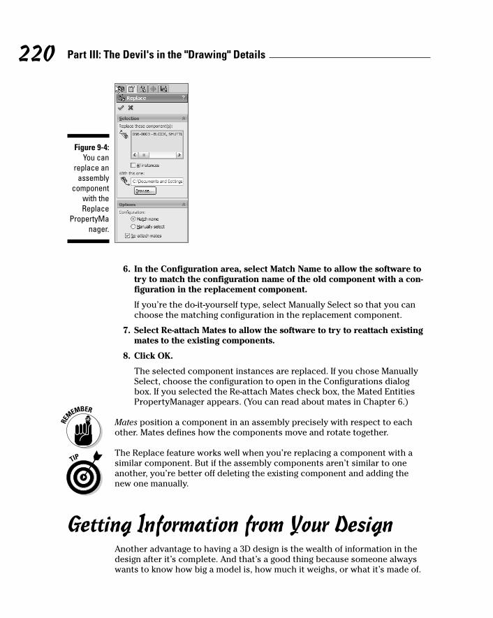
6. In the Configuration area, select Match Name to allow the software totry to match the configuration name of the old component with a con-figuration in the replacement component.
If you’re the do-it-yourself type, select Manually Select so that you canchoose the matching configuration in the replacement component.
7. Select Re-attach Mates to allow the software to try to reattach existingmates to the existing components.
8. Click OK.
The selected component instances are replaced. If you chose ManuallySelect, choose the configuration to open in the Configurations dialogbox. If you selected the Re-attach Mates check box, the Mated EntitiesPropertyManager appears. (You can read about mates in Chapter 6.)
Mates position a component in an assembly precisely with respect to eachother. Mates defines how the components move and rotate together.
The Replace feature works well when you’re replacing a component with asimilar component. But if the assembly components aren’t similar to oneanother, you’re better off deleting the existing component and adding thenew one manually.
Getting Information from Your DesignAnother advantage to having a 3D design is the wealth of information in thedesign after it’s complete. And that’s a good thing because someone alwayswants to know how big a model is, how much it weighs, or what it’s made of.
Figure 9-4:You can
replace anassembly
componentwith theReplace
PropertyManager.
220 Part III: The Devil's in the "Drawing" Details
15_129784 ch09.qxp 9/28/07 12:36 PM Page 220
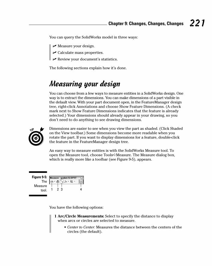
You can query the SolidWorks model in three ways:
� Measure your design.
� Calculate mass properties.
� Review your document’s statistics.
The following sections explain how it’s done.
Measuring your designYou can choose from a few ways to measure entities in a SolidWorks design. Oneway is to extract the dimensions. You can make dimensions of a part visible inthe default view. With your part document open, in the FeatureManager designtree, right-click Annotations and choose Show Feature Dimensions. (A checkmark next to Show Feature Dimensions indicates that the feature is alreadyselected.) Your dimensions should already appear in your drawing, so youdon’t need to do anything to see drawing dimensions.
Dimensions are easier to see when you view the part as shaded. (Click Shadedon the View toolbar.) Some dimensions become more readable when yourotate the part. If you want to display dimensions for a feature, double-clickthe feature in the FeatureManager design tree.
An easy way to measure entities is with the SolidWorks Measure tool. Toopen the Measure tool, choose Tools➪Measure. The Measure dialog box,which is really more like a toolbar (see Figure 9-5), appears.
You have the following options:
1 Arc/Circle Measurements: Select to specify the distance to displaywhen arcs or circles are selected to measure.
• Center to Center: Measures the distance between the centers of thecircles (the default).
1 2 3 4
Figure 9-5:The
Measuretool.
221Chapter 9: Changes, Changes, Changes
15_129784 ch09.qxp 9/28/07 12:36 PM Page 221
• Minimum Distance: Measures the distance between the closestpoints on the circles.
• Maximum Distance: Measures the distance between the farthestpoints on the circles.
2 Units/Precision: Select to display the Measure Units/Precision dialog box,where you can display the custom measurement units and precision.
3 Show XYZ Measurements: Select to display dX, dY, and dZ measure-ments between selected entities in the graphics area. Clear to displayonly the minimum distance between selected entities.
4 Expand or contract the information window: Use when you want tocopy the information to a clipboard.
In most cases, the Measurement tool is straightforward to use. Simply selectan entity to measure. To select more than one entity, just keep clicking. Tounselect an item, click it again.
As long as you select a valid measurement, SolidWorks displays the values inthe Measure dialog box and in the graphics area. If SolidWorks can’t take ameasurement, a message in the Measure dialog box says “Invalid combina-tion of selected entities.”
If you select too many items at one time, the Measure tool displays nothing,and you need to restart the Measure tool. You can clear the selections byclicking in an area of the graphics area where no geometry appears.
Figure 9-6 shows three examples of entities that I selected in a gasket partand used the Measure tool to measure:
� Arc selected: Displays the radius and center (X, Y, Z) values.
� Line selected: Displays the length of a line.
� Two circles selected: Displays the center distance, or the distancebetween the holes, and the dX and dY values. The dX, dY, and dZ valuesare the change (delta) in the distance along the X, Y, and Z axes.
Displaying mass propertiesSolidWorks calculates mass properties and section properties for parts andassemblies. These properties include density, mass, volume, and surfacearea, for example.
222 Part III: The Devil's in the "Drawing" Details
15_129784 ch09.qxp 9/28/07 12:36 PM Page 222

Mass properties look at the entire part or assembly, and section propertieslook at multiple faces that are in parallel planes. You can assign values formass and center of gravity to override the calculated values. The ability toassign values is useful when you want, for example, to assign the correctmass and center of gravity to a simplified representation of a component.
When either mass or section property is calculated, a tricolored reference 3Dtriad is displayed at the origin of the part or assembly along with the massproperties or section properties.
To display mass properties, follow these steps:
1. Choose Tools➪Mass Properties.
The Mass Properties dialog box appears, as shown in Figure 9-7.
2. Click a part or an assembly in the FeatureManager design tree.
The part or assembly name appears in the Selected Items area. If youchoose more than one entity, you see the calculated mass properties forthe combination of those entities.
3. Select from these options:
• Include Hidden Bodies/Components: Select to include hidden bodiesand components in the calculations.
• Show output Coordinate System in Corner of Window: Select to displaythe tricolored reference 3D triad in the corner of the graphics area,or clear to show the triad at its origin.
• Assigned Mass Properties: Select to assign values for mass andcenter of gravity to override the calculated values. You can assignproperties to only a single entity, not to a combination.
Figure 9-6:The best
way toextract
measure-ments iswith the
Measuretool.
223Chapter 9: Changes, Changes, Changes
15_129784 ch09.qxp 9/28/07 12:36 PM Page 223
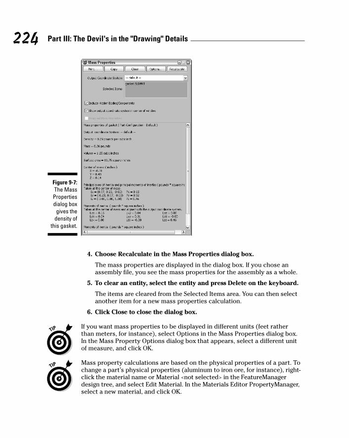
4. Choose Recalculate in the Mass Properties dialog box.
The mass properties are displayed in the dialog box. If you chose anassembly file, you see the mass properties for the assembly as a whole.
5. To clear an entity, select the entity and press Delete on the keyboard.
The items are cleared from the Selected Items area. You can then selectanother item for a new mass properties calculation.
6. Click Close to close the dialog box.
If you want mass properties to be displayed in different units (feet ratherthan meters, for instance), select Options in the Mass Properties dialog box.In the Mass Property Options dialog box that appears, select a different unitof measure, and click OK.
Mass property calculations are based on the physical properties of a part. Tochange a part’s physical properties (aluminum to iron ore, for instance), right-click the material name or Material <not selected> in the FeatureManagerdesign tree, and select Edit Material. In the Materials Editor PropertyManager,select a new material, and click OK.
Figure 9-7:The MassPropertiesdialog box
gives thedensity of
this gasket.
224 Part III: The Devil's in the "Drawing" Details
15_129784 ch09.qxp 9/28/07 12:36 PM Page 224
The default unit of measure for the mass property calculation is set in thedocument template. You can change the default unit of measure by choosingTools➪Options➪Document Properties➪Units in an open document. You canalso define default material properties in the template.
You can use the Section Property feature to display the area, centroid (sketchand part origin), and other information for a 2D sketch.
To display section properties for multiple entities, follow these steps:
1. Edit or create a sketch.
To edit an existing sketch, select the feature, right-click, and choose EditSketch.
2. Choose Tools➪Section Properties.
The results appear in the Section Properties dialog box.
3. Click Close to close the dialog box.
Getting the stats on your documentsUnderstanding what makes up a document from a feature, size, and complex-ity standpoint is useful information when you’re reviewing a design or work-ing on a new design. Each SolidWorks document type has statistics. No, thedocument statistics are not a description of how your drawing likes to takelong walks on the beach and is looking for a caring, sensitive partner tospend free time with. I’m talking about rebuild statistics.
When you make changes to a SolidWorks document, you need to rebuild themodel to check for geometry errors. In a large assembly, rebuilds can take alot of time. The Feature Statistics tool tells you how much time it takes torebuild each feature in a part or each part in an assembly.
Depending on the document type you have open, the Feature Statistics dialogbox displays different information and a different user interface. The followinginformation appears:
� Drawing statistics: The number of drawing sheets, number and types ofdrawing views, and number and types of drawing annotations (such asnotes, dimensions, and symbols).
� Feature statistics: In a part file, the Feature Statistics dialog box lists allfeatures in the part with their rebuild times in descending order (see Figure9-8). In the case of an unusually long rebuild time, you may considerreworking the geometry (so that the feature takes less time to rebuild)
225Chapter 9: Changes, Changes, Changes
15_129784 ch09.qxp 9/28/07 12:36 PM Page 225
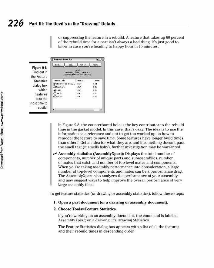
or suppressing the feature in a rebuild. A feature that takes up 60 percentof the rebuild time for a part isn’t always a bad thing. It’s just good toknow in case you’re heading to happy hour in 15 minutes.
In Figure 9-8, the counterbored hole is the key contributor to the rebuildtime in the gasket model. In this case, that’s okay. The idea is to use theinformation as a reference and not to get too worked up on how toremodel the feature to save time. Some features have longer build timesthan others. Get an idea for what they are, and if something doesn’t passthe smell test (it smells fishy), further investigation may be warranted.
� Assembly statistics (AssemblyXpert): Displays the total number ofcomponents, number of unique parts and subassemblies, number of mates that exist, and number of top-level mates and components.When you’re taking assembly performance into consideration, a largenumber of top-level components and mates can be a performance drag.The AssemblyXpert also analyzes the performance of your assembly,and may suggest ways to help improve the overall performance of verylarge assembly files.
To get feature statistics (or drawing or assembly statistics), follow these steps:
1. Open a part document (or a drawing or assembly document).
2. Choose Tools➪Feature Statistics.
If you’re working on an assembly document, the command is labeledAssemblyXpert; on a drawing, it’s Drawing Statistics.
The Feature Statistics dialog box appears with a list of all the featuresand their rebuild times in descending order.
Figure 9-8:Find out in
the FeatureStatistics
dialog boxwhich
featurestake the
most time torebuild.
226 Part III: The Devil's in the "Drawing" Details
15_129784 ch09.qxp 9/28/07 12:36 PM Page 226
Dow
nlo
ad fro
m W
ow
! eBook
<w
ww
.wow
ebook.
com
>Dow
nlo
ad fro
m W
ow
! eBook
<w
ww
.wow
ebook.
com
>
3. Click Feature Order to sort the features to match the FeatureManagerdesign tree.
4. Click one of the following:
• Print: Prints the statistics.
• Copy: Copies the statistics so that you can paste them into anotherfile.
• Refresh: Refreshes the feature statistics.
5. Click Close.
When displaying Feature Statistics for a part, the features (by default) appearin order of their rebuild times. You can reorder the list by clicking one of thecategory headings; for example, if you click Feature Order, the featuresappear in the same order as they do in the FeatureManager design tree.
227Chapter 9: Changes, Changes, Changes
15_129784 ch09.qxp 9/28/07 12:36 PM Page 227

228 Part III: The Devil's in the "Drawing" Details
15_129784 ch09.qxp 9/28/07 12:36 PM Page 228
Chapter 10
Leveraging Your Existing DesignsIn This Chapter� Working with legacy drawing files
� Driving multiple versions of the same design from a single file
� Creating exploded assembly views
SolidWorks offers several tools that let you get extra mileage out of existingdesigns. For example, many engineers have a stockpile of product designs
that exist as old (legacy) drawing files. With SolidWorks, you don’t have tothrow that 2D data in the trash and start from scratch. You can maintain thosefiles in their native formats or import them into SolidWorks and use them as abasis for 3D models.
Multiple configurations are another way to get more play out of designs.Configurations are variations of an existing design. Think of a screw that comesin different lengths. Rather than have to create 50 different files, you can createthose variations in SolidWorks in a single document. This way, you canmanage files more easily and edit all configurations consistently.
You also can use SolidWorks to create exploded views of an assembly that youcan use in technical documentation. The views show the assembly with thecomponents separated so that you can see how items fit together.
Maintaining Old Drawing FilesFew new products are totally new. More often, they’re built on existing designs.Many of these existing designs are in DWG or DXF drawing formats. Theseformats generally mean that someone created the drawings in AutoCAD, a 2Ddesign program that was popular before 3D modeling programs, such asSolidWorks, existed. Engineers often refer to DWG and DXF files as legacyprograms, even if the documents were created in recent versions of AutoCAD.Many SolidWorks users come from an AutoCAD background, and they stillhave a lot of AutoCAD files that they want to maintain.
16_129784 ch10.qxp 9/28/07 12:36 PM Page 229
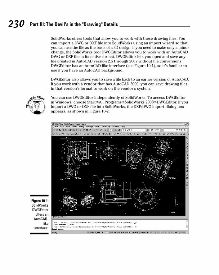
230 Part III: The Devil's in the "Drawing" Details
SolidWorks offers tools that allow you to work with these drawing files. Youcan import a DWG or DXF file into SolidWorks using an import wizard so thatyou can use the file as the basis of a 3D design. If you need to make only a minorchange, the SolidWorks tool DWGEditor allows you to work with an AutoCADDWG or DXF file in its native format. DWGEditor lets you open and save anyfile created in AutoCAD version 2.5 through 2007 without file conversions.DWGEditor has an AutoCAD-like interface (see Figure 10-1), so it’s familiar touse if you have an AutoCAD background.
DWGEditor also allows you to save a file back to an earlier version of AutoCAD.If you work with a vendor that has AutoCAD 2000, you can save drawing filesin that version’s format to work on the vendor’s system.
You can use DWGEditor independently of SolidWorks. To access DWGEditorin Windows, choose Start➪All Programs➪SolidWorks 2008➪DWGEditor. If youimport a DWG or DXF file into SolidWorks, the DXF/DWG Import dialog boxappears, as shown in Figure 10-2.
Figure 10-1:SolidWorksDWGEditor
offers anAutoCAD-
likeinterface.
16_129784 ch10.qxp 9/28/07 12:36 PM Page 230
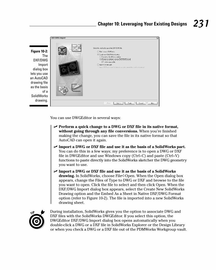
You can use DWGEditor in several ways:
� Perform a quick change to a DWG or DXF file in its native format,without going through any file conversions. When you’re finishedmaking the change, you can save the file in its native format so thatAutoCAD can open it again.
� Import a DWG or DXF file and use it as the basis of a SolidWorks part.You can do this in a few ways; my preference is to open a DWG or DXFfile in DWGEditor and use Windows copy (Ctrl+C) and paste (Ctrl+V)functions to paste directly into the SolidWorks sketcher the DWG geometryyou want to use.
� Import a DWG or DXF file and use it as the basis of a SolidWorksdrawing. In SolidWorks, choose File➪Open. When the Open dialog boxappears, change the Files of Type to DWG or DXF and browse to the fileyou want to open. Click the file to select and then click Open. When theDXF/DWG Import dialog box appears, select the Create New SolidWorksDrawing option and the Embed As a Sheet in Native DXF/DWG Formatoption (refer to Figure 10-2). The file is imported into a new SolidWorksdrawing sheet.
During installation, SolidWorks gives you the option to associate DWG andDXF files with the SolidWorks DWGEditor. If you select this option, theDWGEditor DXF/DWG Import dialog box opens automatically when youdouble-click a DWG or a DXF file in SolidWorks Explorer or the Design Libraryor when you check a DWG or a DXF file out of the PDMWorks Workgroup vault.
Figure 10-2:The
DXF/DWGImport
dialog boxlets you usean AutoCADdrawing fileas the basis
of aSolidWorks
drawing.
231Chapter 10: Leveraging Your Existing Designs
16_129784 ch10.qxp 9/28/07 12:36 PM Page 231
To edit a DWG or DXF file in its native format using DWGEditor, follow thesesteps:
1. In SolidWorks, choose File➪Open (or you can run the programindependently).
The Open dialog box appears.
2. Select DWG or DXF for Files of Type. Browse to the location of the fileyou want to open, click it, and select Open.
The DXF/DWG Import dialog box appears.
3. Check the option Edit/View in the DWGEditor and click Finish.
4. In the DWGEditor, make whatever changes to the drawing that youneed to make.
5. Choose File➪Save As.
The Save As dialog box appears. In the Save As Type box, you can specifywhether to save the file in the current version of AutoCAD or in an earlierversion.
6. Click Save to close the dialog box and save the file.
Managing ConfigurationsAt times, you need to create several variations of a design. For example, youmay want to create a family of screws, or you may want to create multipleconfigurations of a carburetor. After all, a single carburetor won’t fit all vehicletypes. If you have to create a different file for each design scenario, it willtake a lot of time — and patience. Even a simple geometry change may makefor a long day at the office.
Fortunately, there’s a better way. The ConfigurationManager in SolidWorksmanages multiple configurations of a part or an assembly in the same documentto save you time and reduce errors. And you don’t have to re-create the wheeleach time you create a smaller one. ConfigurationManager lets you createvarious design scenarios by simply suppressing part or assembly componentsand features, or in the case of that screw family, by varying dimensions andparameters.
You can create design variants in two ways: manually or with Design Tables. Youcan use a Design Table to build multiple configurations of parts or assembliesby applying the values in the table to the dimensions in the part. Design Tablesare the best way to create a family of screws that vary in width, length, andnumber of threads. If you want to show a door in open and closed positions,it’s easier to create those variations manually.
232 Part III: The Devil's in the "Drawing" Details
16_129784 ch10.qxp 9/28/07 12:37 PM Page 232

Some of the purposes of configurations are described in this list:
� Produce multiple versions of a model or to display optional featuresin a part or optional components in an assembly.
� Create a simplified part configuration to use in a large assembly sothat the assembly loads into memory faster. Smaller parts and assembliesrebuild more quickly when you use simplified configurations. Also, edit-ing a document is easier when you have less visual clutter.
� Create additional drawing views. A single drawing can display multipleconfigurations of a part or assembly in the different views.
� Create exploded views of assemblies. You can use different design con-figurations to document a multistep installation process.
� Define multiple positions of a part for motion studies. For example,you can show how a car door looks open and closed by creating oneconfiguration of the door at 0 degrees and another at 90 degrees.
� Define custom properties per configuration. A custom property is a fileattribute (such as the revision date or part number or a description ofthe document) defined within the original document template. You candefine these properties by choosing File➪Properties. In the SummaryInformation dialog box, click the Custom tab for properties that apply tothe entire document, or the Configuration Specific tab for propertiesthat vary from one configuration to another.
To view the different configurations in your document, click theConfigurationManager tab at the top of the FeatureManager design tree and double-click the configuration names.
Varying the designWhen you create variations of a design, the idea is to simply make yourchanges to the model and save those changes as a different configuration,rather than as a different document. The next two sections explain how to dothat. For the moment, here’s a list of ways that you can vary a part or anassembly design to create new configurations.
You can vary a part configuration by
� Modifying feature dimensions
� Suppressing features, equations, and end conditions
� Defining configuration-specific properties
233Chapter 10: Leveraging Your Existing Designs
16_129784 ch10.qxp 9/28/07 12:37 PM Page 233
You can vary an assembly configuration in several ways:
� Change the suppression state (Suppressed or Unsuppressed) or visibility(Hide or Show) to highlight different components.
� Change the referenced configuration of components.
� Change the dimensions of distance or angle mates or the suppressionstate of mates.
� Modify dimensions or other parameters of features that belong to theassembly (not to other components), including cuts and holes, compo-nent patterns, reference geometry, and sketches.
� Define configuration-specific properties, such as end conditions andsketch relations.
You can hide features or components to highlight other items in a document.When you hide an item, you make it “invisible.” (The item is still there — youjust can’t see it.)
You can use the suppressed state to temporarily remove a feature from a partor a component from an assembly, without deleting it. The item is no longer afunctional member of the part or assembly, so you can’t select, reference, oredit its children. And because SolidWorks removes the suppressed item frommemory, the document is loaded, rebuilt, and displayed faster.
To access the Hide/Show and Suppress/Resolved commands, in the FeatureManager design tree, right-click a feature in a part or component in an assemblyand choose the command. If a component is hidden, the word Show appearson the menu. If a component is suppressed, the word Unsuppressed appears.
Creating a configuration manuallyYou have two ways to create a configuration in SolidWorks: manually and withDesign Tables. If you want to make a few variations on a complex assembly,you should do it manually.
Here’s how to manually make a new configuration of a part or an assembly:
1. Open a part or assembly file in SolidWorks.
2. Click the ConfigurationManager tab at the top of the FeatureManagerdesign tree.
In place of the FeatureManager, you see the ConfigurationManager.
234 Part III: The Devil's in the "Drawing" Details
16_129784 ch10.qxp 9/28/07 12:37 PM Page 234
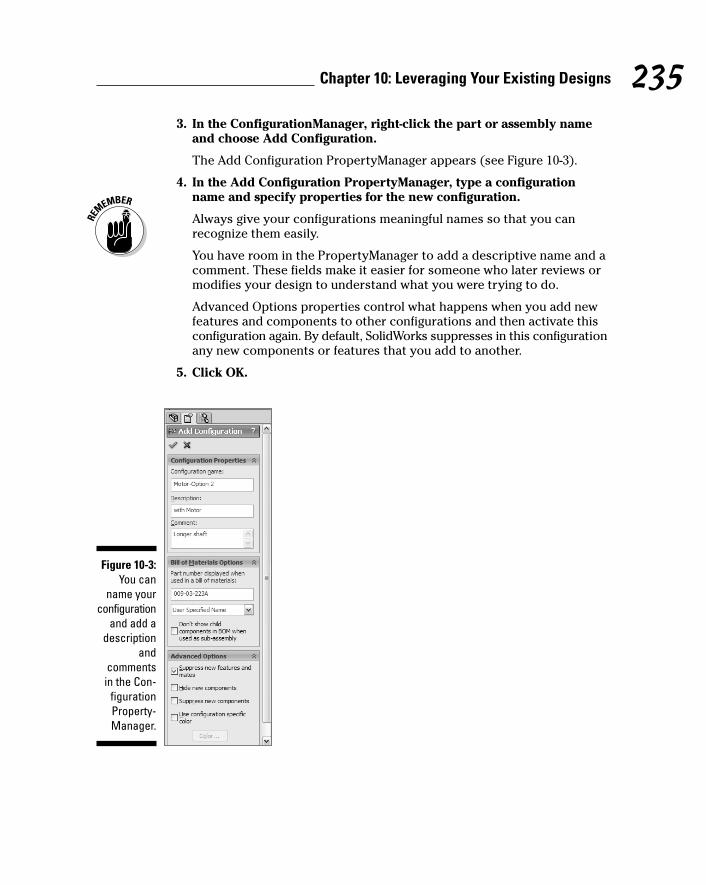
3. In the ConfigurationManager, right-click the part or assembly nameand choose Add Configuration.
The Add Configuration PropertyManager appears (see Figure 10-3).
4. In the Add Configuration PropertyManager, type a configurationname and specify properties for the new configuration.
Always give your configurations meaningful names so that you canrecognize them easily.
You have room in the PropertyManager to add a descriptive name and acomment. These fields make it easier for someone who later reviews ormodifies your design to understand what you were trying to do.
Advanced Options properties control what happens when you add newfeatures and components to other configurations and then activate thisconfiguration again. By default, SolidWorks suppresses in this configurationany new components or features that you add to another.
5. Click OK.
Figure 10-3:You can
name yourconfiguration
and add adescription
andcommentsin the Con-
figurationProperty-Manager.
235Chapter 10: Leveraging Your Existing Designs
16_129784 ch10.qxp 9/28/07 12:37 PM Page 235
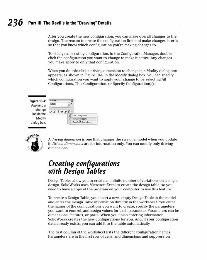
After you create the new configuration, you can make overall changes to thedesign. The reason to create the configuration first and make changes later isso that you know which configuration you’re making changes to.
To change an existing configuration, in the ConfigurationManager, double-click the configuration you want to change to make it active. Any changesyou make apply to only that configuration.
When you double-click a driving dimension to change it, a Modify dialog boxappears, as shown in Figure 10-4. In the Modify dialog box, you can specifywhich configuration you want to apply your change to by selecting AllConfigurations, This Configuration, or Specify Configuration(s).
A driving dimension is one that changes the size of a model when you updateit. Driven dimensions are for information only. You can modify only drivingdimensions.
Creating configurations with Design TablesDesign Tables allow you to create an infinite number of variations on a singledesign. SolidWorks uses Microsoft Excel to create the design table, so youneed to have a copy of the program on your computer to use this feature.
To create a Design Table, you insert a new, empty Design Table in the modeland enter the Design Table information directly in the worksheet. You enterthe names of the configurations you want to create, specify the parametersyou want to control, and assign values for each parameter. Parameters can bedimensions, features, or parts. When you finish entering information,SolidWorks creates the new configurations for you. And, if your configurationdata already exists, you can add it to the table automatically.
The first column of the worksheet lists the different configuration names.Parameters are in the first row of cells, and dimensions and suppression
Figure 10-4:Applying a
changeinside the
Modifydialog box.
236 Part III: The Devil's in the "Drawing" Details
16_129784 ch10.qxp 9/28/07 12:37 PM Page 236
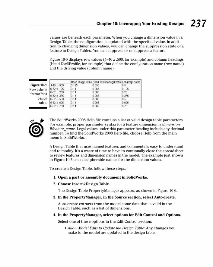
values are beneath each parameter. When you change a dimension value in aDesign Table, the configuration is updated with the specified value. In addi-tion to changing dimension values, you can change the suppression state of afeature in Design Tables. You can suppress or unsuppress a feature.
Figure 10-5 displays row values (4–40 x .500, for example) and column headings(Head Dia@Profile, for example) that define the configuration name (row name)and the driving value (column name).
The SolidWorks 2008 Help file contains a list of valid design table parameters.For example, proper parameter syntax for a feature dimension is dimension@feature_name. Legal values under this parameter heading include any decimalnumber. To find the SolidWorks 2008 Help file, choose Help from the mainmenu in SolidWorks.
A Design Table that uses named features and comments is easy to understandand to modify. It’s a waste of time to have to continually close the spreadsheetto review features and dimension names in the model. The example just shownin Figure 10-5 uses decipherable names for the dimension values.
To create a Design Table, follow these steps:
1. Open a part or assembly document in SolidWorks.
2. Choose Insert➪Design Table.
The Design Table PropertyManager appears, as shown in Figure 10-6.
3. In the PropertyManager, in the Source section, select Auto-create.
Auto-create extracts from the model some data that is valid in theDesign Table, such as a list of dimensions.
4. In the PropertyManager, select options for Edit Control and Options.
Select one of these options in the Edit Control section:
• Allow Model Edits to Update the Design Table: Any changes youmake to the model are updated in the design table.
Figure 10-5:Row columnformat for a
designtable.
237Chapter 10: Leveraging Your Existing Designs
16_129784 ch10.qxp 9/28/07 12:37 PM Page 237
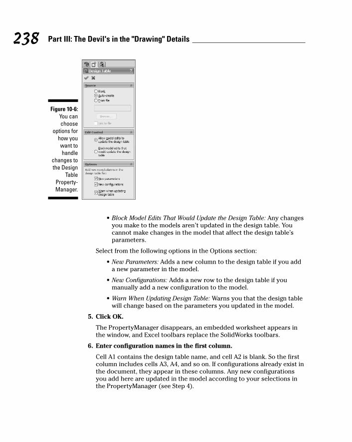
• Block Model Edits That Would Update the Design Table: Any changesyou make to the models aren’t updated in the design table. Youcannot make changes in the model that affect the design table’sparameters.
Select from the following options in the Options section:
• New Parameters: Adds a new column to the design table if you adda new parameter in the model.
• New Configurations: Adds a new row to the design table if youmanually add a new configuration to the model.
• Warn When Updating Design Table: Warns you that the design tablewill change based on the parameters you updated in the model.
5. Click OK.
The PropertyManager disappears, an embedded worksheet appears inthe window, and Excel toolbars replace the SolidWorks toolbars.
6. Enter configuration names in the first column.
Cell A1 contains the design table name, and cell A2 is blank. So the firstcolumn includes cells A3, A4, and so on. If configurations already exist inthe document, they appear in these columns. Any new configurationsyou add here are updated in the model according to your selections inthe PropertyManager (see Step 4).
Figure 10-6:You canchoose
options forhow youwant tohandle
changes tothe Design
TableProperty-Manager.
238 Part III: The Devil's in the "Drawing" Details
16_129784 ch10.qxp 9/28/07 12:37 PM Page 238

To add a new configuration, enter a new name in column A under thelast configuration.
7. Enter parameter names in the first-row columns.
Enter your parameter names in cells B2, C2, and so on. (The design tablename is in the first row.) Parameter names should reflect the feature ordimension in the model you want to vary. To add a parameter name tothe design table, place your pointer in a cell and then double-click thefeature or dimension you want to add in the FeatureManager design tree.
8. Enter dimension and suppression values in the appropriate cells.
You can enter dimension and suppression values beneath the parametername in the row of the corresponding configuration. Dimension valuesare decimal numbers. Suppression values are S (Suppressed) or U(Unsuppressed).
9. Click outside the Design Table window to close the design table.
Here are a few tips to keep in mind when working with a design table:
� To edit a design table, in the ConfigurationManager, right-click theDesign Table icon and choose Edit Table.
� Microsoft Excel lets you add comments. To add a comment in Excel,right-click the cell you want to comment on and choose Insert Comment.In the box, type the comment text.
� If you make an entry in a cell within the design table that doesn’t have acorresponding row (leftmost cell in the row) and column (topmost cellin column) heading, Design Table treats the cell contents as a comment.
239Chapter 10: Leveraging Your Existing Designs
Working with configurationsHere are some more useful notes and tips onconfigurations:
� You can’t delete an active configuration. To delete a configuration, make anotherconfiguration active and then delete the configuration.
� The comment field is a good place toinclude a description of the reasons for, and the function of, the configuration.
Comments help document the intent andthe purpose of the configuration.
� To activate a configuration, double-click the configuration name within theConfigurationManager.
� The FeatureManager displays the activeconfiguration to the right of the part namein the ConfigurationManager.
16_129784 ch10.qxp 9/28/07 12:37 PM Page 239
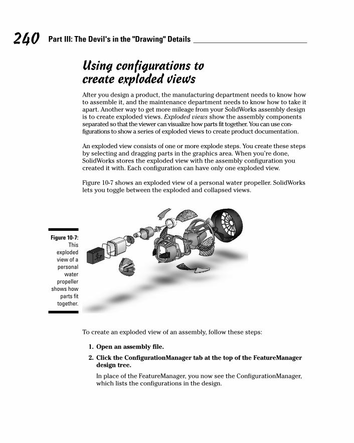
Using configurations to create exploded viewsAfter you design a product, the manufacturing department needs to know howto assemble it, and the maintenance department needs to know how to take itapart. Another way to get more mileage from your SolidWorks assembly designis to create exploded views. Exploded views show the assembly componentsseparated so that the viewer can visualize how parts fit together. You can use con-figurations to show a series of exploded views to create product documentation.
An exploded view consists of one or more explode steps. You create these stepsby selecting and dragging parts in the graphics area. When you’re done,SolidWorks stores the exploded view with the assembly configuration youcreated it with. Each configuration can have only one exploded view.
Figure 10-7 shows an exploded view of a personal water propeller. SolidWorkslets you toggle between the exploded and collapsed views.
To create an exploded view of an assembly, follow these steps:
1. Open an assembly file.
2. Click the ConfigurationManager tab at the top of the FeatureManagerdesign tree.
In place of the FeatureManager, you now see the ConfigurationManager,which lists the configurations in the design.
Figure 10-7:This
explodedview of apersonal
waterpropeller
shows howparts fit
together.
240 Part III: The Devil's in the "Drawing" Details
16_129784 ch10.qxp 9/28/07 12:37 PM Page 240
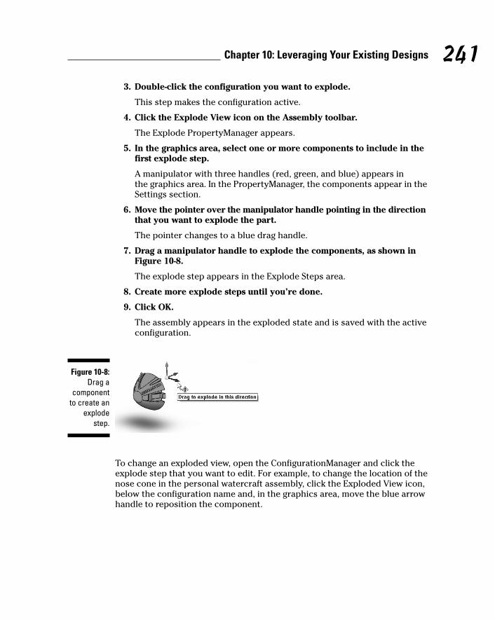
3. Double-click the configuration you want to explode.
This step makes the configuration active.
4. Click the Explode View icon on the Assembly toolbar.
The Explode PropertyManager appears.
5. In the graphics area, select one or more components to include in thefirst explode step.
A manipulator with three handles (red, green, and blue) appears in the graphics area. In the PropertyManager, the components appear in theSettings section.
6. Move the pointer over the manipulator handle pointing in the directionthat you want to explode the part.
The pointer changes to a blue drag handle.
7. Drag a manipulator handle to explode the components, as shown inFigure 10-8.
The explode step appears in the Explode Steps area.
8. Create more explode steps until you’re done.
9. Click OK.
The assembly appears in the exploded state and is saved with the activeconfiguration.
To change an exploded view, open the ConfigurationManager and click theexplode step that you want to edit. For example, to change the location of thenose cone in the personal watercraft assembly, click the Exploded View icon,below the configuration name and, in the graphics area, move the blue arrowhandle to reposition the component.
Figure 10-8:Drag a
componentto create an
explodestep.
241Chapter 10: Leveraging Your Existing Designs
16_129784 ch10.qxp 9/28/07 12:37 PM Page 241

Animating the explode or collapse sequenceYou can do more than just explode or collapse the assembly. You can animatethe explode or collapse sequence to show the assembly components moveapart and then move back together again. Figure 10-9 shows the AnimationController toolbar. The Save As AVI button on the toolbar lets you save theexplode sequence as an AVI file that you can send or include in an eDrawingsfile. (Chapter 14 offers more information on viewers.)
To animate the explode or collapse of an exploded view of an assembly,follow these steps:
1. Open an assembly file.
2. Click the ConfigurationManager tab on top of the FeatureManagerdesign tree.
In place of the FeatureManager, you now see the ConfigurationManager,which lists the configurations in the design.
3. Click the plus sign (+) beside the configuration that contains theexploded view you want to animate.
You see the Exp|View feature, which contains each step in the explodeprocess.
4. Right-click the Exp|View feature and choose Animate Collapse orAnimate Explode.
The assembly explodes or collapses, and the Animation Controller toolbarappears.
You can use the playback controls to animate the explode or collapse. Thetwo controls on the rightmost side of Figure 10-9 allow you to slow it down(x1/2) or speed it up (x2).
Figure 10-9:The
AnimationController
toolbar.
242 Part III: The Devil's in the "Drawing" Details
16_129784 ch10.qxp 9/28/07 12:37 PM Page 242
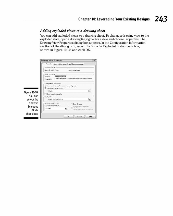
Adding exploded views to a drawing sheetYou can add exploded views to a drawing sheet. To change a drawing view to theexploded state, open a drawing file, right-click a view, and choose Properties. TheDrawing View Properties dialog box appears. In the Configuration Informationsection of the dialog box, select the Show in Exploded State check box,shown in Figure 10-10, and click OK.
Figure 10-10:You can
select theShow in
ExplodedState
check box.
243Chapter 10: Leveraging Your Existing Designs
16_129784 ch10.qxp 9/28/07 12:37 PM Page 243

244 Part III: The Devil's in the "Drawing" Details
16_129784 ch10.qxp 9/28/07 12:37 PM Page 244
Chapter 11
Printing and PlottingIn This Chapter� Adding a printer to the network
� Defining the SolidWorks document settings
� Printing SolidWorks parts, assemblies, and drawings
� Understanding the different printing methods
No matter what people say about a paperless workplace, sometimesnothing can replace a physical copy of a SolidWorks document. Hard
copies of large engineering drawings are easier to read than electronic copieson tiny computer screens. Some companies require printed copies for reviewsand recordkeeping. Other folks might not have the means to view electroniccopies. And, whereas CAD files contain proprietary information, hard copiesprotect your interests.
In this chapter, I take you through the steps of setting up your printer inWindows and show you the best ways to print SolidWorks documents.
Delving into Printing and PlottingYou can print flat images of parts and assembly models by using a regular officeprinter, but for high-quality, large-scale engineering drawings, a plotter is best. Aprinter simulates lines by printing a closely spaced series of dots, whereas aplotter uses a pen to draw continuous lines. A multicolored plotter uses differentcolored pens to draw different colored lines. Plotters are considerably moreexpensive than printers, but they’re called for when precision is mandatory.
You can access any printer or plotter, local or remote, by using the standardWindows operating system. Printing from SolidWorks is similar to printingfrom any Microsoft Office application, so if you know how to do that, you’rehalfway there.
17_129784 ch11.qxp 9/28/07 12:37 PM Page 245

246 Part III: The Devil's in the "Drawing" Details
You can print SolidWorks documents directly from SolidWorks or from theeDrawings Viewer or the SolidWorks Viewer, two free programs that let youview SolidWorks documents without the SolidWorks software. (Chapter 14offers more information on viewers.) You can download both viewers atwww.solidworks.com/pages/products/designtools.html.
Installing a Printer in WindowsIn a larger organization, the job of adding a printer to a network is one thatgenerally belongs to the IT group. In the case of a small business or homeoffice, that IT person may be you.
The good news is that most new printers and plotters support Plug and Playin Windows. If you have a plug-and-play printer (look for Plug and Play on theprinter’s list of features), just plug the printer into your computer, andWindows takes care of the setup.
If you have an older printer or you’re connecting your printer to a network,you need to take a few extra steps. First, make sure that you have handy theCDs that came with your printer. The Add Printer Wizard installs the printerdrivers from the CDs. If you don’t have the CDs, you can get the driver fromthe Web site of the printer manufacturer.
To install an older printer without plug-and-play technology on Windows XPor Windows Vista (the Windows operating systems now supported bySolidWorks), follow these steps:
1. Choose Start➪Settings➪Printers and Faxes or choose Start➪Printersand Faxes, depending on how your Start menu is configured.
A list of currently defined printers and fax devices appears.
2. Choose File➪Add Printer.
The Add Printer Wizard appears, to walk you through installing a printeror making a printer connection.
3. Click Next.
The next frame of the wizard asks whether you have a local or networkprinter.
4. Determine whether you have a local printer or a network printer.
Click the local printer option if the printer is attached to your computeror if it’s a network printer not attached to a print server.
If the printer is on a network, click the network printer option.
17_129784 ch11.qxp 9/28/07 12:37 PM Page 246
5. Click Next.
The Specify a Printer dialog box appears.
6. Specify a printer by checking one of these three options:
• Find a Printer in the Directory: Click this option to locate the printeron your computer.
• Connect to This Printer: Click this option and type the name of theprinter below it.
• Connect to a Printer on the Internet or on a Home or Office Network:Click this option if the computer is on a network, and type the URLfor the printer.
7. Click Next.
The Browse for Printer dialog box appears.
8. Set the printer as the Windows default.
Select either the Yes or No check box to indicate whether the printershould be the system default.
The default printer is the one your documents print to automaticallyunless you select another output device. To set a printer as a defaultprinter at any time, from the Windows Start menu, choose Settings➪Printers and Faxes. Right-click a printer and select Set As Default. Acheck mark appears next to the default printer icon in the Printers andFaxes section.
9. Click Next.
10. Click Finish.
The new printer is added to the system and is available for printing.
Setting Printer and DocumentPreferences in Windows
After you add a printer to your network (see the preceding section), Windowsallows you to change print preferences. Keep in mind that the preferences youset for a printer could become the default settings for any user who connectsto the printer. Some of the commands described in this section may not beavailable on every printer. If an option you want isn’t available (it appears ingray), see your system administrator.
247Chapter 11: Printing and Plotting
17_129784 ch11.qxp 9/28/07 12:37 PM Page 247
To access the following commands in Windows, choose Start➪ Settings➪Printers and Faxes. Then right-click your printer name and choose a command:
� Open opens the print queue for the printer, which shows active printjobs. Use this option to cancel, reprint, or pause a print job.
� Set As Default Printer sets the printer as the default printer for allapplications.
� Printing Preferences defines the default print quality, number of pagesper sheet, input and output paper trays, paper orientation.
� Pause Printing pauses any current print job. To resume, right-click theprinter icon again and choose Resume Printing.
� Sharing allows other users on the network to use the printer. When thisoption isn’t enabled, only you can use the printer.
� Rename, Delete, or create a Shortcut allows you to rename the printer,to delete it, or to create a shortcut on the desktop.
� Properties include the printer’s name, port, sharing, and security.
Choosing Print Options in SolidWorksYou can also set many print properties within the SolidWorks document, as I explain in the sections that follow. And, if you have a consistent way ofprinting — for example, you always print part documents in a landscape orientation scaled to 90 percent — you can set these preferences directly in the SolidWorks document template.
To save time, you can save a SolidWorks document (for example, a part, anassembly, or a drawing) as a template document for reuse. A template formsthe basis of a new SolidWorks document. SolidWorks saves these files by usinga different file extension, much like Microsoft Word templates do. SolidWorksassigns the extension .prtdot to a part template, .asmdot to an assemblytemplate, and .drwdot to a drawing template.
You can make a new template by saving any SolidWorks document as atemplate. To do so, select the appropriate file format in the Files As Typesection of the Save As dialog box. (See Chapter 2 for more details on documenttemplates in SolidWorks.)
Defining printer page setup propertiesIn the Page Setup dialog box, you can change printer settings, such as resolu-tion, scale, and paper size. The preferences are set automatically to those of
248 Part III: The Devil's in the "Drawing" Details
17_129784 ch11.qxp 9/28/07 12:37 PM Page 248
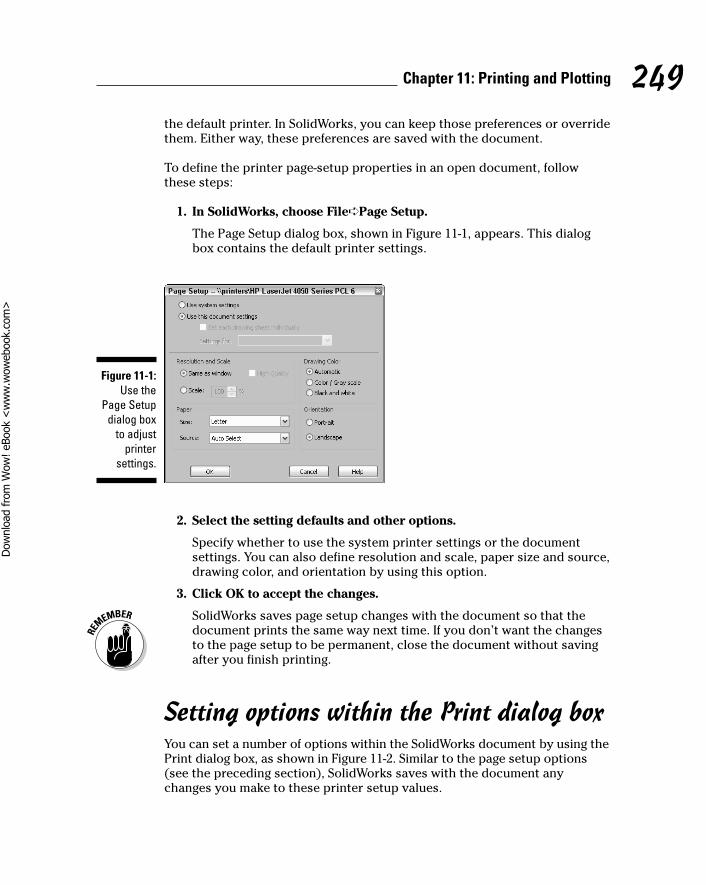
the default printer. In SolidWorks, you can keep those preferences or overridethem. Either way, these preferences are saved with the document.
To define the printer page-setup properties in an open document, followthese steps:
1. In SolidWorks, choose File➪Page Setup.
The Page Setup dialog box, shown in Figure 11-1, appears. This dialogbox contains the default printer settings.
2. Select the setting defaults and other options.
Specify whether to use the system printer settings or the documentsettings. You can also define resolution and scale, paper size and source,drawing color, and orientation by using this option.
3. Click OK to accept the changes.
SolidWorks saves page setup changes with the document so that thedocument prints the same way next time. If you don’t want the changesto the page setup to be permanent, close the document without savingafter you finish printing.
Setting options within the Print dialog boxYou can set a number of options within the SolidWorks document by using thePrint dialog box, as shown in Figure 11-2. Similar to the page setup options(see the preceding section), SolidWorks saves with the document anychanges you make to these printer setup values.
Figure 11-1:Use the
Page Setupdialog box
to adjustprinter
settings.
249Chapter 11: Printing and Plotting
17_129784 ch11.qxp 9/28/07 12:37 PM Page 249
Dow
nlo
ad fro
m W
ow
! eBook
<w
ww
.wow
ebook.
com
>

To access the Print dialog box in an open SolidWorks document, chooseFile➪Print. The dialog box contains these areas:
� Document Printer specifies these printer options:
• Name: Specifies the printer: The system provides read-only statusabout the printer’s status, type, and location.
• Properties: Specifies options specific to the selected printer.
• Page Setup: Specifies page setup options and advanced printeroptions, such as scale, orientation, and resolution.
� System Options defines the line weights (see Figure 11-3) and printermargins.
By default, the margin default values are set to the printer margin andrarely need to change. The line weights correspond to the thickness valuethat you set for line fonts. (To access line fonts in the open document,choose Tools➪Options. Look for the Line Font section on the DocumentProperties tab.)
Figure 11-3:Set printer
line weightsin the
SystemOptions
section ofthe Print
dialog box.
Figure 11-2:You selectoptions in
the Printdialog box.
250 Part III: The Devil's in the "Drawing" Details
17_129784 ch11.qxp 9/28/07 12:37 PM Page 250
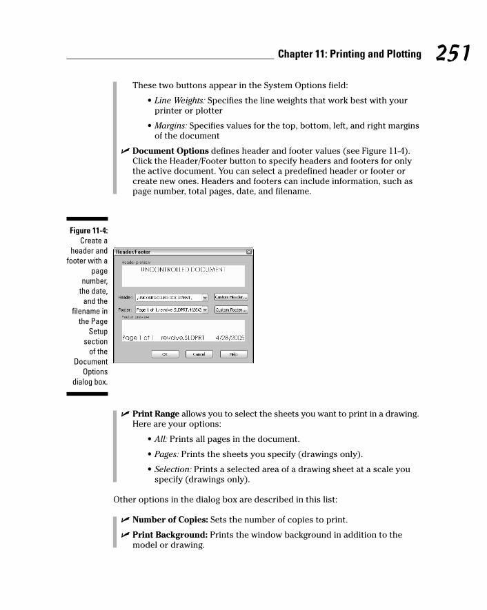
These two buttons appear in the System Options field:
• Line Weights: Specifies the line weights that work best with yourprinter or plotter
• Margins: Specifies values for the top, bottom, left, and right marginsof the document
� Document Options defines header and footer values (see Figure 11-4).Click the Header/Footer button to specify headers and footers for onlythe active document. You can select a predefined header or footer orcreate new ones. Headers and footers can include information, such aspage number, total pages, date, and filename.
� Print Range allows you to select the sheets you want to print in a drawing.Here are your options:
• All: Prints all pages in the document.
• Pages: Prints the sheets you specify (drawings only).
• Selection: Prints a selected area of a drawing sheet at a scale youspecify (drawings only).
Other options in the dialog box are described in this list:
� Number of Copies: Sets the number of copies to print.
� Print Background: Prints the window background in addition to themodel or drawing.
Figure 11-4:Create a
header andfooter with a
pagenumber,
the date,and the
filename inthe Page
Setupsection
of theDocument
Optionsdialog box.
251Chapter 11: Printing and Plotting
17_129784 ch11.qxp 9/28/07 12:37 PM Page 251
� Print to File: Prints to a file rather than to the printer. If you select thischeck box, you’re prompted to type a name for the file in the Print to Filedialog box.
� Convert Draft Quality Drawing Views to High Quality (Drawings Only):Converts the current draft quality view into high quality for printingpurposes only.
After setting the options, click OK to close the dialog box. The next time youprint the document, it uses the new settings.
Printing a DocumentAfter you configure the printing, you’re ready to print a document. The firstthing you should know is that not all SolidWorks documents print the sameway, and the way a document prints is based on its type:
� Parts: SolidWorks prints the active document on the screen, using thecurrent setting for zoom, view orientation (front, back, and isometric, forexample), and display mode (wire frame, hidden lines visible, or hiddenline removed).
� Assemblies: SolidWorks prints assemblies as it does parts, in the activedisplay setting and using the current zoom, orientation, and displaymode.
� Drawings: SolidWorks print a full-size copy of the active sheet, regard-less of the current zoom scale. You can print all the sheets in a multiplesheet drawing or specify selected sheets to be printed.
You can print a document in SolidWorks in one of three ways: from the PrintPreview screen, from the Print dialog box, or by using the Print icon at thetop of the menu bar.
Printing from the Print Preview screen is my favorite method. The PrintPreview feature shows you how a document will look when it prints. You canuse this preview to judge any necessary adjustments to the header, footer,and margins. A quick look at the print preview saves paper and time.
To preview the printed image of an active document, follow these steps:
1. Click the Print Preview icon.
A preview of the document appears. Use the command buttons at thetop of the window to scan different pages of a multipage document, zoomin and out, and print the document. If you want to make changes to whatyou see, click Cancel to close the window. Otherwise, continue to Step 2.
252 Part III: The Devil's in the "Drawing" Details
17_129784 ch11.qxp 9/28/07 12:37 PM Page 252
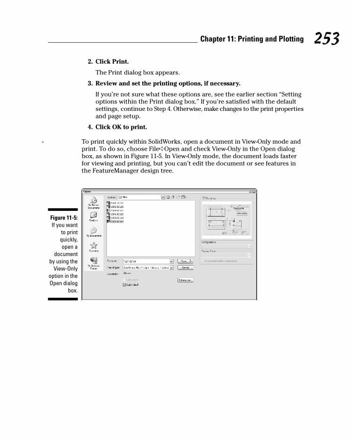
2. Click Print.
The Print dialog box appears.
3. Review and set the printing options, if necessary.
If you’re not sure what these options are, see the earlier section “Settingoptions within the Print dialog box.” If you’re satisfied with the defaultsettings, continue to Step 4. Otherwise, make changes to the print propertiesand page setup.
4. Click OK to print.
- To print quickly within SolidWorks, open a document in View-Only mode andprint. To do so, choose File➪Open and check View-Only in the Open dialogbox, as shown in Figure 11-5. In View-Only mode, the document loads fasterfor viewing and printing, but you can’t edit the document or see features inthe FeatureManager design tree.
Figure 11-5:If you want
to printquickly,open a
documentby using the
View-Onlyoption in theOpen dialog
box.
253Chapter 11: Printing and Plotting
17_129784 ch11.qxp 9/28/07 12:37 PM Page 253

254 Part III: The Devil's in the "Drawing" Details
17_129784 ch11.qxp 9/28/07 12:37 PM Page 254

Part IVPlaying Nicely
with Others (AndPicking Up Your Toys)
18_129784 pp04.qxp 9/28/07 12:37 PM Page 255

In this part . . .
Working well with others in the design process is akey to success. Your job of collaborating with team
members, vendors, and customers is easier and moreeffective when you know which data they need and howthey need it formatted. In this part, I tell you everythingyou need to know about working with others and introduceeDrawings.
18_129784 pp04.qxp 9/28/07 12:37 PM Page 256

Chapter 12
Managing the ClutterIn This Chapter� Exploring different data management options
� Setting up a file structure for data management
Data is one of your company’s most valuable assets. In an engineering -company, that data includes not just CAD files but also project
specifications, design review information, finite element analysis results, and engineering change orders. This data constitutes the basis of your products, so managing it properly is important.
You can manage design data in two ways: automatically, by using productdata management (PDM) software, or manually, by setting up a system of filestructures. This chapter tells you what to look for when you set up a PDMsystem and how to set up file directory structures to manage data manuallyin SolidWorks.
Managing Data with or without a NetOne of the most important decisions to make when you implement SolidWorksis how to manage the data. The safest bet (I call it “managing with a net”) isto implement product data management (PDM) software, which manages andtracks product data automatically. PDMWorks is the PDM software made towork with SolidWorks, but others on the market also work with SolidWorks.
However, if your design team is small, you can opt to organize your datamanually with a system of directories and file folders that you organize on ashared network server. You can also take advantage of SolidWorks collaborationsettings, which allow you to control who has access to which data so thatyou can be sure that one person doesn’t overwrite another’s changes. (SeeChapter 13 for more details on collaborating with others.)
19_129784 ch12.qxp 9/28/07 12:37 PM Page 257
Checking your listWhether you choose to implement a PDM system or you decide to manageyour data manually, consider this important checklist:
� Ease of use: I’m a firm believer that any system you want others to useshould follow this rule of automation: It needs to be easy, offer value,and save time. Otherwise, no one will use it, or if they do, they’ll use itso inconsistently that the value of the investment is lost.
� Data security: As anyone who has experienced a computer hard drivecrash knows, data is never as valuable as when it’s gone. In a multiuserenvironment, you want to put all your design data on a network server,develop a good backup plan, and stick to it.
� Performance: Working with large files over a network server can beslow. PDMWorks copies data to a local workspace (on the user’s com-puter) and updates the information to the server periodically. Do youhave a similar plan for your manual system?
� Search capabilities: The ability to quickly find data is one of the mostimportant features in a data management system. PDMWorks has searchtools built in. With a manual approach, the best way to find data is touse Windows Search to search by custom properties and filename.
� Product life cycle: Designs go through several revisions and changesthroughout their life cycles (sort of like software does). You need a systemfor tracking various versions and for storing documents that are in different development phases, such as in progress, released, or obsolete.
� Document access: When working with other users on the same designproject, you need to know who’s working on what and when a new revi-sion of a document is available. You also need a way to communicatethat information back to other team members.
� Metadata: These custom properties, used in drawing title blocks, arestored in the document. Choose File➪Properties and then click theCustom tab in the Summary Information dialog box to see which valuesare defined within each type of document. A good PDM system can gen-erate reports based on metadata stored in SolidWorks documents.
� File manipulation: How does the system copy, rename, archive, anddelete documents and projects?
� Tracking versions: How does the system handle legacy (old) versions ofdocuments? Does the system allow others to access old versions ofdrawings after a new change?
258 Part IV: Playing Nicely with Others (And Picking Up Your Toys)
19_129784 ch12.qxp 9/28/07 12:37 PM Page 258

Deciding which way to goThe ways that you can manage your CAD data can be divided into three categories:
� Manual, such as a system of file folders that contain project data. Youshould keep these types of folders on a shared network server.
� Workgroup-level PDM, such as PDMWorks Workgroup, is a simple,inexpensive, easy-to-deploy data management system.
� Enterprise-level PDM, such as PDMWorks Enterprise, providesadvanced data management tools, such as work flow and integrationinto other corporate computer systems.
Each of these categories has pros and cons, which I list in Table 12-1.
Table 12-1 Comparison of Data Management ToolsCategory Pros Cons
Manual Simple; no additional A manual, error-prone software required. process; lacks search
capabilities. It’s difficult totrack versions (Rev A,Rev B, and so on) andkeep old design history.
Workgroup-level PDM A less expensive Limited advanced application that’s easy capabilities, API, and to install. It has a vault, integration support.or central database.
Enterprise-level PDM Scalable (size of More expensive and installation and scope difficult to implement.of application). It has more advanced features.
The rest of this chapter covers manual data management. Although you don’tneed a PDM system to create great designs in SolidWorks, the process iseasier and more straightforward when you have one.
Managing your data manually is time consuming and can resemble runningaround with sharp sticks — you take the risk of falling and jabbing yourself.Similarly, at some point, trying to manage multiple documents manually is aproblem.
259Chapter 12: Managing the Clutter
19_129784 ch12.qxp 9/28/07 12:37 PM Page 259
For more information about PDMWorks, visit www.solidworks.com/pages/products/solutions/datamanagement.html.
Managing Your Data ManuallyWhether you work alone or with a team of designers, if you don’t have a PDMsystem, you need to manage files manually. For a manual system to be evenremotely workable, you need to define a meaningful directory structure forstoring projects and their related documents. You also need a strategy forcreating and storing backups.
Setting up a good directory structureHere’s an example of a directory structure setup in Windows:
� Main-level directories: Use these top-level directories to organize yourdata. You could have two top-level directories, one named Released (fordocuments that have been checked and approved) and one named WIP(for works in progress or copies of files being changed). When you’relooking for released files, you know to look in the Released directory.Likewise, files being worked on are in the WIP directory.
� Standard part directories: If a lot of your work entails the use of standardparts, put the standard part models in a shared network drive so thatothers can access the files and use them in designs. You may want tomake the directory read-only so that only the CAD administrator canmake changes or additions.
� Project-level directories: Below the main directories might be severallevels of folders, used to further organize the data. Examples of second-level directory folders are Standard (for standard parts), Projects(named project number), Part Numbers (setup directories based on partnumbers), and Part Type (motors and brackets, for example).
Having too many levels of directories and folders can make documents hardto find. Try to keep it simple so that everyone can quickly find what they’relooking for.
When you name SolidWorks documents, don’t include the revision number inthe filename. For example, don’t name a plate model plate-RevA, because anychanges in plate-RevB aren’t reflected in any drawing or assembly file whichreferences that part. You have broken the reference. Instead, create a separate
260 Part IV: Playing Nicely with Others (And Picking Up Your Toys)
19_129784 ch12.qxp 9/28/07 12:37 PM Page 260
directory where you keep original copies for later reference. By using a direc-tory structure like this one to store different versions, you more easily ensurethat you don’t edit the production copy. It’s a bad day when your boss asksfor Revision B and all you have to show her is Revision E.
Making backupsIn the area of manual data management, you have to remember to back upyour data regularly. At the office, you may work on a server for which the ITdepartment manages backups. If you’re part of a smaller operation, invest inlarge, external hard drives that connect to your computer via USB or look intoan online backup service for storing data. You need enough space to store yourlarge SolidWorks documents. In addition, you may want to back up data toanother building location, in case your office disappears in a flood, a fire, oran earthquake and you need to go to work the next day.
Keep non-SolidWorks copies (such as eDrawings or PDF files) of all your releaseddrawings. This way, you have a simple backup and additional references forall released drawings.
Copying Files with SolidWorks ExplorerWhen you start a new project or revise an existing project, you need to copyfiles. You’re better off making copies using SolidWorks Explorer, not WindowsExplorer. Windows Explorer isn’t SolidWorks-aware, which means that it can’tidentify document references. If you use Windows Explorer to copy aSolidWorks drawing, the next time you open the drawing, you see a messagetelling you that the file cannot locate its references.
SolidWorks Explorer has the following advantages over Windows Explorer:
� You can copy, replace, and rename SolidWorks documents withoutbreaking links to external reference documents. When you copy adrawing, for example, SolidWorks Explorer gives you the option to copyany part or assembly files that the drawing references.
� You can view and change the custom properties of a document.
� You can find out which other SolidWorks documents reference or usethe file. If the file is a model of a standard component, you can find outwhich assembly designs are using the component. The limitation is thatyou can search only one directory at a time. You may need to change thedirectory and run the search again several times.
261Chapter 12: Managing the Clutter
19_129784 ch12.qxp 9/28/07 12:37 PM Page 261
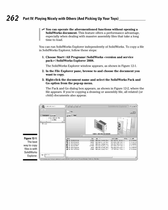
� You can operate the aforementioned functions without opening aSolidWorks document. This feature offers a performance advantage,especially when dealing with massive assembly files that take a longtime to load.
You can run SolidWorks Explorer independently of SolidWorks. To copy a filein SolidWorks Explorer, follow these steps:
1. Choose Start➪All Programs➪SolidWorks <version and servicepack>➪SolidWorks Explorer 2008.
The SolidWorks Explorer window appears, as shown in Figure 12-1.
2. In the File Explorer pane, browse to and choose the document youwant to copy.
3. Right-click the document name and select the SolidWorks Pack andGo option from the pop-up menu.
The Pack and Go dialog box appears, as shown in Figure 12-2, where thefile appears. If you’re copying a drawing or assembly file, all related (orchild) documents also appear.
Figure 12-1:The best
way to copyfiles is withSolidWorks
Explorer.
262 Part IV: Playing Nicely with Others (And Picking Up Your Toys)
19_129784 ch12.qxp 9/28/07 12:37 PM Page 262
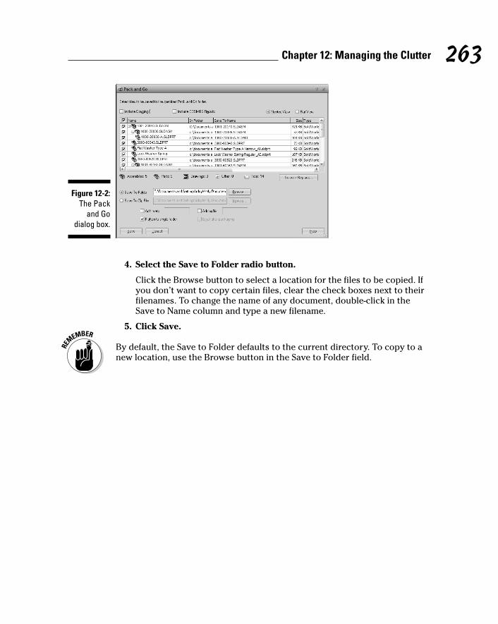
4. Select the Save to Folder radio button.
Click the Browse button to select a location for the files to be copied. Ifyou don’t want to copy certain files, clear the check boxes next to theirfilenames. To change the name of any document, double-click in theSave to Name column and type a new filename.
5. Click Save.
By default, the Save to Folder defaults to the current directory. To copy to anew location, use the Browse button in the Save to Folder field.
Figure 12-2:The Pack
and Godialog box.
263Chapter 12: Managing the Clutter
19_129784 ch12.qxp 9/28/07 12:37 PM Page 263

264 Part IV: Playing Nicely with Others (And Picking Up Your Toys)
19_129784 ch12.qxp 9/28/07 12:37 PM Page 264

Chapter 13
Collaborating with Team MembersIn This Chapter� Setting up SolidWorks for a multiuser environment
� Working with standard components
� Swapping data with other CAD systems
� Fixing models with import errors
As a designer, rarely do you work on a design alone. More likely, you’repart of an extended design team, with members spread out across the
country or around the world. In a multiuser environment, keeping projects ona network server allows everyone to access the files. At the same time, youneed to control who is working on what so that one person doesn’t overwriteanother’s changes. You also want to store common design elements in adesign library to save time and rework.
This chapter introduces SolidWorks tools that allow you to collaborate andwork with other designers in a multiuser environment.
Keeping Everyone on the Same PageWhen Collaborating
In a multiuser environment, multiple designers are accessing and revisingassembly files at the same time. One of the biggest issues in this type of situation is figuring out how to manage the data. A SolidWorks assembly caninclude hundreds of part and subassembly documents, manufacturing drawings,and other engineering material. To complicate things even more, manydocuments reference other documents, so one change can ripple throughthousands of other documents. For this reason, you need to keep a closewatch on who modifies what and when, or else an entire project can go down the gurgler.
20_129784 ch13.qxp 9/28/07 12:37 PM Page 265
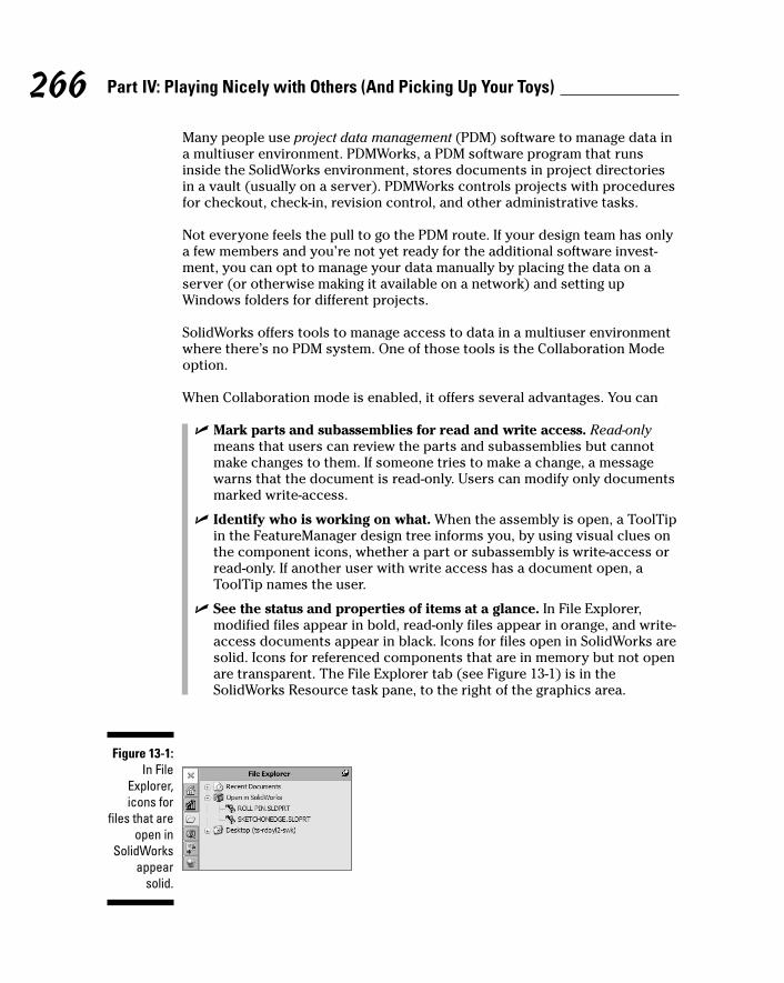
266 Part IV: Playing Nicely with Others (And Picking Up Your Toys)
Many people use project data management (PDM) software to manage data ina multiuser environment. PDMWorks, a PDM software program that runsinside the SolidWorks environment, stores documents in project directoriesin a vault (usually on a server). PDMWorks controls projects with proceduresfor checkout, check-in, revision control, and other administrative tasks.
Not everyone feels the pull to go the PDM route. If your design team has onlya few members and you’re not yet ready for the additional software invest-ment, you can opt to manage your data manually by placing the data on aserver (or otherwise making it available on a network) and setting upWindows folders for different projects.
SolidWorks offers tools to manage access to data in a multiuser environmentwhere there’s no PDM system. One of those tools is the Collaboration Modeoption.
When Collaboration mode is enabled, it offers several advantages. You can
� Mark parts and subassemblies for read and write access. Read-onlymeans that users can review the parts and subassemblies but cannotmake changes to them. If someone tries to make a change, a messagewarns that the document is read-only. Users can modify only documentsmarked write-access.
� Identify who is working on what. When the assembly is open, a ToolTipin the FeatureManager design tree informs you, by using visual clues onthe component icons, whether a part or subassembly is write-access orread-only. If another user with write access has a document open, aToolTip names the user.
� See the status and properties of items at a glance. In File Explorer,modified files appear in bold, read-only files appear in orange, and write-access documents appear in black. Icons for files open in SolidWorks aresolid. Icons for referenced components that are in memory but not openare transparent. The File Explorer tab (see Figure 13-1) is in theSolidWorks Resource task pane, to the right of the graphics area.
Figure 13-1:In File
Explorer,icons for
files that areopen in
SolidWorksappear
solid.
20_129784 ch13.qxp 9/28/07 12:37 PM Page 266
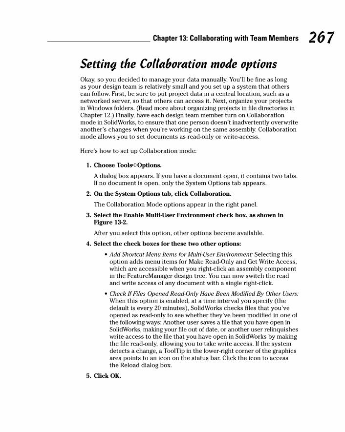
Setting the Collaboration mode optionsOkay, so you decided to manage your data manually. You’ll be fine as long as your design team is relatively small and you set up a system that others can follow. First, be sure to put project data in a central location, such as anetworked server, so that others can access it. Next, organize your projectsin Windows folders. (Read more about organizing projects in file directories inChapter 12.) Finally, have each design team member turn on Collaborationmode in SolidWorks, to ensure that one person doesn’t inadvertently overwriteanother’s changes when you’re working on the same assembly. Collaborationmode allows you to set documents as read-only or write-access.
Here’s how to set up Collaboration mode:
1. Choose Tools➪Options.
A dialog box appears. If you have a document open, it contains two tabs.If no document is open, only the System Options tab appears.
2. On the System Options tab, click Collaboration.
The Collaboration Mode options appear in the right panel.
3. Select the Enable Multi-User Environment check box, as shown inFigure 13-2.
After you select this option, other options become available.
4. Select the check boxes for these two other options:
• Add Shortcut Menu Items for Multi-User Environment: Selecting thisoption adds menu items for Make Read-Only and Get Write Access,which are accessible when you right-click an assembly componentin the FeatureManager design tree. You can now switch the readand write access of any document with a single right-click.
• Check If Files Opened Read-Only Have Been Modified By Other Users:When this option is enabled, at a time interval you specify (thedefault is every 20 minutes), SolidWorks checks files that you’veopened as read-only to see whether they’ve been modified in one ofthe following ways: Another user saves a file that you have open inSolidWorks, making your file out of date, or another user relinquisheswrite access to the file that you have open in SolidWorks by makingthe file read-only, allowing you to take write access. If the systemdetects a change, a ToolTip in the lower-right corner of the graphicsarea points to an icon on the status bar. Click the icon to accessthe Reload dialog box.
5. Click OK.
267Chapter 13: Collaborating with Team Members
20_129784 ch13.qxp 9/28/07 12:37 PM Page 267
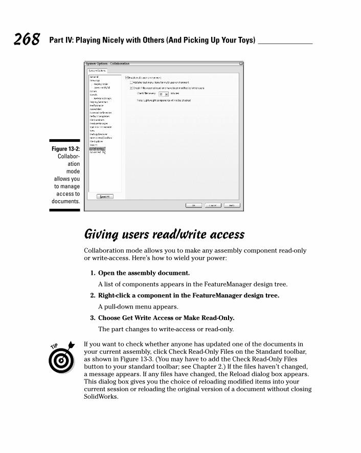
Giving users read/write accessCollaboration mode allows you to make any assembly component read-onlyor write-access. Here’s how to wield your power:
1. Open the assembly document.
A list of components appears in the FeatureManager design tree.
2. Right-click a component in the FeatureManager design tree.
A pull-down menu appears.
3. Choose Get Write Access or Make Read-Only.
The part changes to write-access or read-only.
If you want to check whether anyone has updated one of the documents inyour current assembly, click Check Read-Only Files on the Standard toolbar,as shown in Figure 13-3. (You may have to add the Check Read-Only Filesbutton to your standard toolbar; see Chapter 2.) If the files haven’t changed,a message appears. If any files have changed, the Reload dialog box appears.This dialog box gives you the choice of reloading modified items into yourcurrent session or reloading the original version of a document without closingSolidWorks.
Figure 13-2:Collabor-
ationmode
allows youto manageaccess to
documents.
268 Part IV: Playing Nicely with Others (And Picking Up Your Toys)
20_129784 ch13.qxp 9/28/07 12:37 PM Page 268
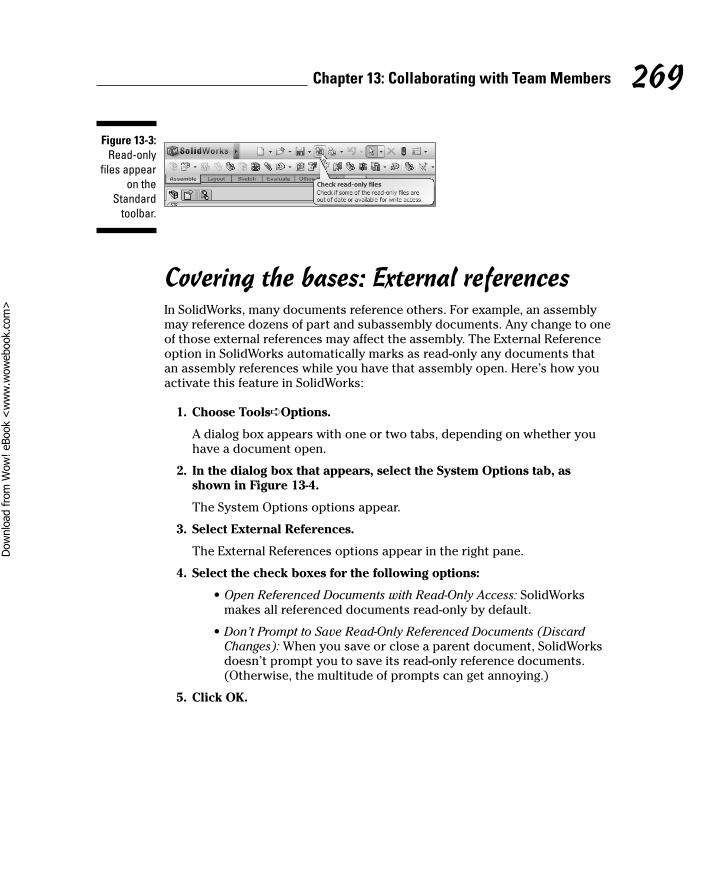
Covering the bases: External referencesIn SolidWorks, many documents reference others. For example, an assemblymay reference dozens of part and subassembly documents. Any change to oneof those external references may affect the assembly. The External Referenceoption in SolidWorks automatically marks as read-only any documents thatan assembly references while you have that assembly open. Here’s how youactivate this feature in SolidWorks:
1. Choose Tools➪Options.
A dialog box appears with one or two tabs, depending on whether youhave a document open.
2. In the dialog box that appears, select the System Options tab, asshown in Figure 13-4.
The System Options options appear.
3. Select External References.
The External References options appear in the right pane.
4. Select the check boxes for the following options:
• Open Referenced Documents with Read-Only Access: SolidWorksmakes all referenced documents read-only by default.
• Don’t Prompt to Save Read-Only Referenced Documents (DiscardChanges): When you save or close a parent document, SolidWorksdoesn’t prompt you to save its read-only reference documents.(Otherwise, the multitude of prompts can get annoying.)
5. Click OK.
Figure 13-3:Read-only
files appearon the
Standardtoolbar.
269Chapter 13: Collaborating with Team Members
20_129784 ch13.qxp 9/28/07 12:37 PM Page 269
Dow
nlo
ad fro
m W
ow
! eBook
<w
ww
.wow
ebook.
com
>
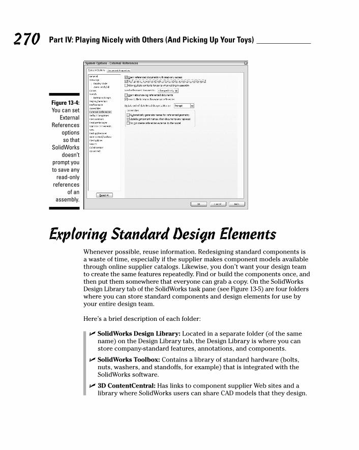
Exploring Standard Design ElementsWhenever possible, reuse information. Redesigning standard components isa waste of time, especially if the supplier makes component models availablethrough online supplier catalogs. Likewise, you don’t want your design teamto create the same features repeatedly. Find or build the components once, andthen put them somewhere that everyone can grab a copy. On the SolidWorksDesign Library tab of the SolidWorks task pane (see Figure 13-5) are four folderswhere you can store standard components and design elements for use byyour entire design team.
Here’s a brief description of each folder:
� SolidWorks Design Library: Located in a separate folder (of the samename) on the Design Library tab, the Design Library is where you canstore company-standard features, annotations, and components.
� SolidWorks Toolbox: Contains a library of standard hardware (bolts,nuts, washers, and standoffs, for example) that is integrated with theSolidWorks software.
� 3D ContentCentral: Has links to component supplier Web sites and alibrary where SolidWorks users can share CAD models that they design.
Figure 13-4:You can set
ExternalReferences
options so that
SolidWorksdoesn’t
prompt youto save any
read-onlyreferences
of anassembly.
270 Part IV: Playing Nicely with Others (And Picking Up Your Toys)
20_129784 ch13.qxp 9/28/07 12:37 PM Page 270
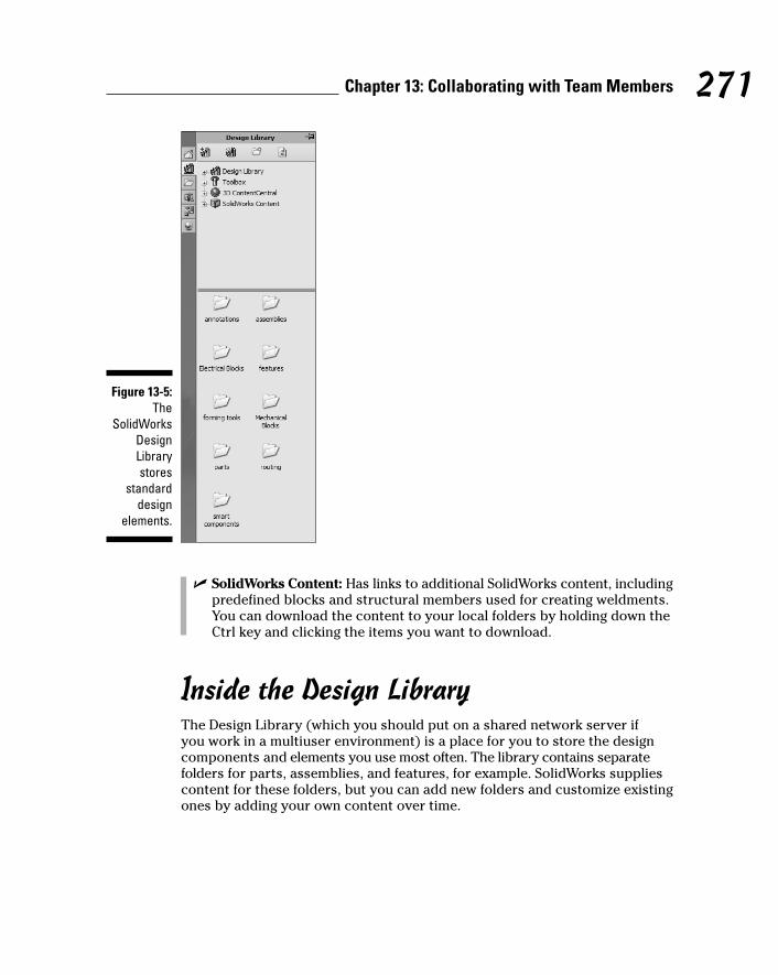
� SolidWorks Content: Has links to additional SolidWorks content, includingpredefined blocks and structural members used for creating weldments.You can download the content to your local folders by holding down theCtrl key and clicking the items you want to download.
Inside the Design LibraryThe Design Library (which you should put on a shared network server if you work in a multiuser environment) is a place for you to store the designcomponents and elements you use most often. The library contains separatefolders for parts, assemblies, and features, for example. SolidWorks suppliescontent for these folders, but you can add new folders and customize existingones by adding your own content over time.
Figure 13-5:The
SolidWorksDesignLibrarystores
standarddesign
elements.
271Chapter 13: Collaborating with Team Members
20_129784 ch13.qxp 9/28/07 12:37 PM Page 271

One criterion I use to decide whether a part belongs in the Design Library orin the PDM vault (if you use PDM software) is whether your organization hasdesign control over the part. If you designed the part and need to maintain a design history of it, put the part in the PDM vault. If the component is apurchased part, it’s a good candidate for the Design Library.
Finding your way around in the Design Library is straightforward. The followingcommand buttons are available on the Design Library tab:
� Add to Library: Adds content to the Design Library.
� Add File Location: Adds an existing folder to the Design Library.
� Create New Folder: Creates a new folder in the Design Library.
� Refresh: Refreshes the view of the Design Library tab.
If you want to use an item in the Design Library, simply select the item anddrag it onto your design. Similarly, you can also drag items from your designinto folders in the Design Library. When you drag an item into a folder, theSave As dialog box appears and lists the item’s default file type. You need totype only an optional part description and click Save.
Design Library folders accept all document types. You can save a part file in afolder marked Assemblies just as you can put socks in your underweardrawer. The folder names are there only to keep you organized.
Here are a few other ways to copy design elements into the Design Library:
� To copy an assembly or part into the Design Library: Select the item inthe FeatureManager design tree and drag it to an appropriate folder inthe lower pane of the Design Library tab.
� To copy annotations or blocks into the Design Library: Hold down theShift key on your keyboard and drag the annotation or block from thegraphics area to the lower pane of the Design Library.
� To copy a feature into the Design Library: Drag the feature from theFeatureManager design tree or the graphics area. Features are saved aslibrary feature parts with the extension .sldlfp.
By default, SolidWorks installs the Design Library in C:\Program Files\SolidWorks\data\design library. If you plan to use SolidWorks in amultiuser environment, copy the Design Library to a network directory andmake it read-only so that only the system administrator can make changes.
272 Part IV: Playing Nicely with Others (And Picking Up Your Toys)
20_129784 ch13.qxp 9/28/07 12:37 PM Page 272
Using SolidWorks ToolboxIf you’re like me, you keep a box of nails, screws, and other parts that you canreach into whenever you need to fix or build something at home. You don’t wantto run to the hardware store each time you need a nut or a bolt. SolidWorkshas something similar: a virtual toolbox.
SolidWorks Toolbox includes a library of standard fasteners (bolts, nuts, chainsprockets, and timing belts, for example) that you can add to your SolidWorksassembly. Here’s how Toolbox works: Say that you want to attach a hinge to adoor or fasten a waste pipe to a sink. Simply select the standard screws andwashers included in SolidWorks Toolbox and drag them into your design. Thisway, you don’t have to make additional parts to complete your assembly.
Searching for a bolt or a nut in Toolbox is like thumbing through the pages ofa part catalog. Similar to a catalog, SolidWorks Toolbox folders are divided bystandard (ANSI, BSI, or CISC, for example), category (washers, pins, screws),or type (lag screws, machine screws, miniature screws).
SolidWorks fills Toolbox folders with some standard items, but you cancustomize Toolbox to include those parts that you refer to most frequently.You can also make a copy of any Toolbox part and edit it as needed.
Because SolidWorks Toolbox is an add-in, it isn’t available with the standardSolidWorks program. You have to buy it separately or as part of the SolidWorksOffice Professional or SolidWorks Office Premium bundles. After you installToolbox, open SolidWorks and choose Tools➪Add Ins. In the Add-Ins dialogbox, select the SolidWorks Toolbox and the SolidWorks Toolbox Browseroptions. Click OK.
Inserting the hardwareYou can easily add fasteners to your assembly by dragging them out ofToolbox and dropping them into your model. You can also configure fasten-ers to your exact needs. Here’s how to edit a Toolbox fastener and insert itinto your open assembly:
1. Click the Design Library icon on the SolidWorks task pane.
The task pane displays the contents of the Design Library.
2. Click the Toolbox folder.
The Toolbox folder expands to reveal several folders that representstandard part catalogs.
273Chapter 13: Collaborating with Team Members
20_129784 ch13.qxp 9/28/07 12:37 PM Page 273

3. Click the plus sign (+) to the right of a standard folder.
The folder expands to reveal more folders.
4. Drill down through the folders (standards, categories, types, fasteners)to find the fastener you need.
5. Drag the part into your assembly.
A PropertyManager dialog box appears for the part you selected (seeFigure 13-6). You can use this dialog box to set the property values forthe part or to change the part number or to add a description beforeadding the part to the assembly.
6. Find the property you want to update and then select a value from thepull-down list next to it.
For parts included with SolidWorks Toolbox, the values in the list arevalid standards-based values for the selected part.
7. Continue to update the remaining properties and values until the sizeis correct.
8. Click the green check mark icon.
The part appears in the assembly.
Figure 13-6:You can use
Toolbox toinsert
standardfasteners
into anassembly.
274 Part IV: Playing Nicely with Others (And Picking Up Your Toys)
20_129784 ch13.qxp 9/28/07 12:37 PM Page 274
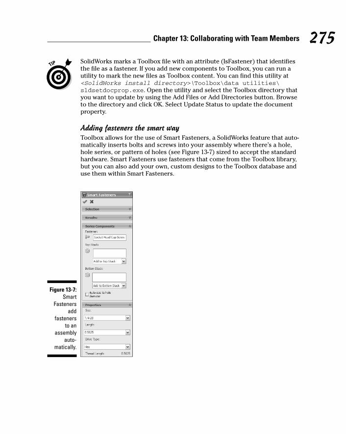
SolidWorks marks a Toolbox file with an attribute (IsFastener) that identifiesthe file as a fastener. If you add new components to Toolbox, you can run autility to mark the new files as Toolbox content. You can find this utility at<SolidWorks install directory>\Toolbox\data utilities\sldsetdocprop.exe. Open the utility and select the Toolbox directory thatyou want to update by using the Add Files or Add Directories button. Browseto the directory and click OK. Select Update Status to update the documentproperty.
Adding fasteners the smart wayToolbox allows for the use of Smart Fasteners, a SolidWorks feature that auto-matically inserts bolts and screws into your assembly where there’s a hole,hole series, or pattern of holes (see Figure 13-7) sized to accept the standardhardware. Smart Fasteners use fasteners that come from the Toolbox library,but you can also add your own, custom designs to the Toolbox database anduse them within Smart Fasteners.
Figure 13-7:Smart
Fastenersadd
fasteners to an
assemblyauto-
matically.
275Chapter 13: Collaborating with Team Members
20_129784 ch13.qxp 9/28/07 12:37 PM Page 275
Smart Fasteners can also add nuts and washers to your fasteners. Bolts andscrews can have an associated Top Stack (washers under the head of thefastener) and Bottom Stack (washers and nuts added to the end of the fastener).You can use Smart Fasteners to insert bolts, screws, nuts, and washers toyour assembly in a few simple steps (refer to Figure 13-7).
To add Smart Fasteners to an open assembly, follow these steps:
1. Choose Insert➪Smart Fasteners.
The Smart Fastener PropertyManager appears.
2. If you want to add fasteners to all holes in the assembly, in theSelection area, click Populate All.
Smart Fasteners fills the holes in your assembly with fasteners.
If you’re working on a very large assembly, SolidWorks may prompt youwith the message “This operation may take a long time. Do you want tocontinue?” If you have time on your hands, click Yes and skip to Step 5.Otherwise, click No and proceed to Step 3.
3. If you want to add fasteners to only certain areas of your assembly,select a hole (or holes), a face, or a component.
The selected items appear in the Selection area. If you want to removean item, select the item and press the Delete key.
4. To add fasteners to the items, select Add in the Selection area.
Fasteners are added to the items you selected. If you selected a compo-nent, Smart Fasteners finds all available holes in that component. If youselected a face, Smart Fasteners finds all available holes that passthrough the surface. Fastener types appear in the Fastener field.
5. If you want to change a fastener type or the top or bottom stacks, inthe Fastener field, right-click the item and choose Change FastenerType.
The Smart Fasteners dialog box for the fastener type is displayed.
6. Select a replacement fastener by using the pull-down menus in theStandard, Category, Type, and Fastener boxes.
7. Click OK.
The Smart Fasteners dialog box closes, and the model is updated withthe new fastener types.
8. Click OK (the green check mark).
The Smart Fastener PropertyManager closes.
276 Part IV: Playing Nicely with Others (And Picking Up Your Toys)
20_129784 ch13.qxp 9/28/07 12:37 PM Page 276
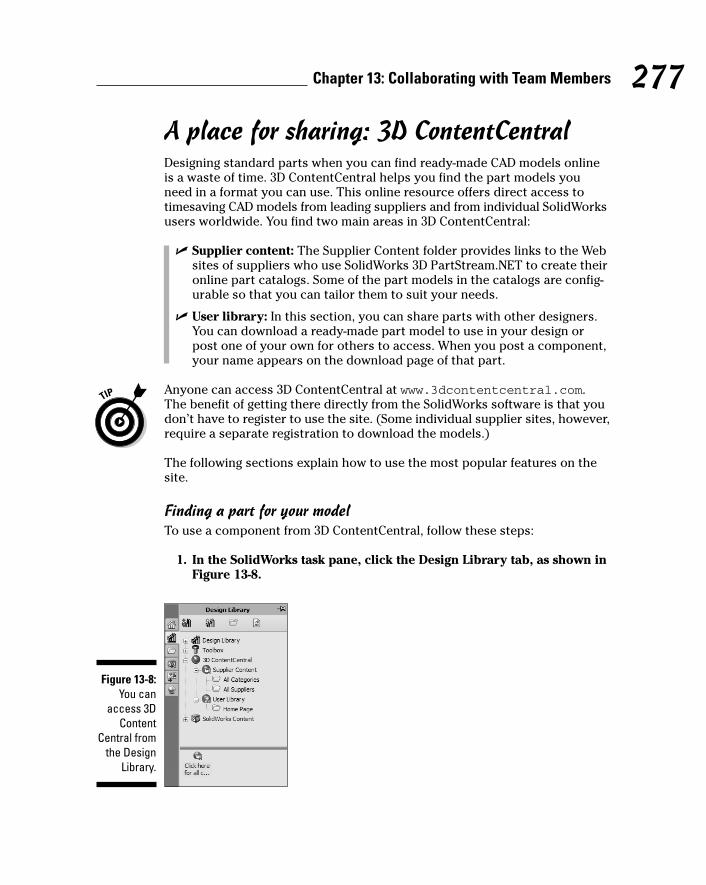
A place for sharing: 3D ContentCentralDesigning standard parts when you can find ready-made CAD models onlineis a waste of time. 3D ContentCentral helps you find the part models youneed in a format you can use. This online resource offers direct access totimesaving CAD models from leading suppliers and from individual SolidWorksusers worldwide. You find two main areas in 3D ContentCentral:
� Supplier content: The Supplier Content folder provides links to the Websites of suppliers who use SolidWorks 3D PartStream.NET to create theironline part catalogs. Some of the part models in the catalogs are config-urable so that you can tailor them to suit your needs.
� User library: In this section, you can share parts with other designers.You can download a ready-made part model to use in your design orpost one of your own for others to access. When you post a component,your name appears on the download page of that part.
Anyone can access 3D ContentCentral at www.3dcontentcentral.com.The benefit of getting there directly from the SolidWorks software is that youdon’t have to register to use the site. (Some individual supplier sites, however,require a separate registration to download the models.)
The following sections explain how to use the most popular features on thesite.
Finding a part for your modelTo use a component from 3D ContentCentral, follow these steps:
1. In the SolidWorks task pane, click the Design Library tab, as shown inFigure 13-8.
Figure 13-8:You can
access 3DContent
Central fromthe Design
Library.
277Chapter 13: Collaborating with Team Members
20_129784 ch13.qxp 9/28/07 12:37 PM Page 277

2. Click the plus sign (+) to expand the 3D Content Central folder.
Folders named Supplier Content and User Library appear.
3. Select Supplier Content or User Library.
In the lower pane, folders appear for All Categories and All Suppliers ifyou chose Supplier Content, or Home Page if you chose User Library.
4. Double-click a folder — All Categories, for example.
An icon appears that serves as a link to the 3D Content Central Web site.
5. Click the 3D Content Central icon to open the home page, where youcan begin your search for models.
6. Click to select a supplier name from the alphabetized list, or use theSearch bar to locate a specific part type.
If you click a supplier name, a Web browser opens in SolidWorks andtakes you to the supplier’s online part catalog, where you see a selectionof parts to peruse. Supplier sites vary slightly, and some allow you toconfigure components to your specifications (see Figure 13-9).
If you select User Library, you see a Web page that contains a gallery ofparts. Clicking a category opens another page that shows all part typesin that category. When you click the icon of the part type you’re looking for,a list of models appears. You also see a detailed description of the part,an image of the model, and the name of the user who designed thepart. Some users include their e-mail addresses. Click a model to download it.
Figure 13-9:Some
suppliersites allow
you toconfigure
componentsbefore youdownload
them.
278 Part IV: Playing Nicely with Others (And Picking Up Your Toys)
20_129784 ch13.qxp 9/28/07 12:37 PM Page 278
7. Locate a part and click its icon.
After you click the part icon , you can configure and download themodel. Some models let you choose the file format, although in the UserLibrary, the models are generally offered in only the SolidWorks format.
8. When the part is ready, click and drag the file into your assembly.
9. Close the Internet browser window.
Adding a model you want to shareIf you want to submit a model to the 3D ContentCentral User Library, right-click 3D ContentCentral and choose Share a Model. Follow the directions on-screen to enter your profile information and upload your model.SolidWorks Corporation reviews your model and informs you whether themodel has been accepted for sharing.
The SolidWorks Resources section of the Task Pane also has an engineeringsearch engine that you can use to locate engineering-related topics you wantto read about. The search is conducted by the GLOBALSPEC search engine.
Working with Different File FormatsAt times, you may need to exchange files with people who use other CADsystems — or no CAD system. For example, you may need to communicatewith a vendor who doesn’t accept native SolidWorks files or to show a designto a customer (or someone in your own, internal marketing department) whodoesn’t have access to a CAD system.
Become familiar with the different translation formats so that you can sendand receive information easily, without the extra work of having to verify andclean up imported documents.
In general, you need to be familiar with these four important topics:
� Types of formats: Knowing the different types of CAD and image formatsyou can use makes life easier when transferring SolidWorks documents.
� Exporting files: You need to know a few things about how to senddocuments to other systems.
� Importing files: The importing features enable you to you work withdocuments sent from other systems.
� Fixing import and export issues: When you have issues with importeddata, sometimes there’s an easy fix.
In the sections that follow, you find details about each of these topics.
279Chapter 13: Collaborating with Team Members
20_129784 ch13.qxp 9/28/07 12:37 PM Page 279
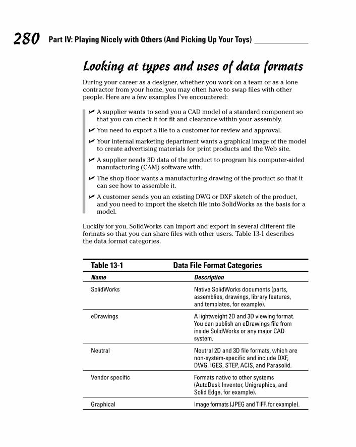
Looking at types and uses of data formatsDuring your career as a designer, whether you work on a team or as a lonecontractor from your home, you may often have to swap files with otherpeople. Here are a few examples I’ve encountered:
� A supplier wants to send you a CAD model of a standard component sothat you can check it for fit and clearance within your assembly.
� You need to export a file to a customer for review and approval.
� Your internal marketing department wants a graphical image of the modelto create advertising materials for print products and the Web site.
� A supplier needs 3D data of the product to program his computer-aidedmanufacturing (CAM) software with.
� The shop floor wants a manufacturing drawing of the product so that itcan see how to assemble it.
� A customer sends you an existing DWG or DXF sketch of the product,and you need to import the sketch file into SolidWorks as the basis for amodel.
Luckily for you, SolidWorks can import and export in several different fileformats so that you can share files with other users. Table 13-1 describes the data format categories.
Table 13-1 Data File Format CategoriesName Description
SolidWorks Native SolidWorks documents (parts,assemblies, drawings, library features,and templates, for example).
eDrawings A lightweight 2D and 3D viewing format.You can publish an eDrawings file frominside SolidWorks or any major CADsystem.
Neutral Neutral 2D and 3D file formats, which arenon-system-specific and include DXF,DWG, IGES, STEP, ACIS, and Parasolid.
Vendor specific Formats native to other systems(AutoDesk Inventor, Unigraphics, andSolid Edge, for example).
Graphical Image formats (JPEG and TIFF, for example).
280 Part IV: Playing Nicely with Others (And Picking Up Your Toys)
20_129784 ch13.qxp 9/28/07 12:37 PM Page 280

How you save your SolidWorks document depends on the recipient’s plansfor the document and his type of system. If the recipient uses SolidWorks,you can send him a native SolidWorks file. But, if you want him to get only ageneral idea of the model, you might send an eDrawings file. AlthoughSolidWorks supports many different file formats, keep these points in mind:
� Use SolidWorks native files whenever possible.
� If the other system is Parasolid-based (Unigraphics NX and Solid Edge),use the Parasolid format. Because SolidWorks is also built on the Parasolidkernel, it makes sense to send files in the neutral Parasolid format.
� Consider sending more than one neutral format (IGES and STEP) whenworking with a new supplier, to allow for troubleshooting in case one filedoesn’t convert properly.
Exporting SolidWorks filesWhen you export a SolidWorks document, all you’re really doing is saving itin a different format using the Save As dialog box. To export a file for use inanother program, follow these steps:
1. Open the file to export, and choose File➪Save As.
The Save As Document dialog box appears.
2. From the Save As Type drop-down list, choose the format in whichyou want to save the file.
If you’re not sure of the best format to use, refer to Table 13-1.
3. Click Save.
Your document is saved in the new format. The “exporting” part is up toyou. Depending on the size of the file and your time constraints, you cansend the file by e-mail or snail mail, post the file on an FTP site, or handthe job over to an overnight courier service.
Importing non-SolidWorks filesWhen you’re working with other members of your design team, importingfiles is no problem because they all use SolidWorks. Trouble arises when you receive non-native files, which are created in another system (such asMechanical Desktop, Pro/Engineer, or Solid Edge) or when you receive inter-mediary 3D file types, such as IGES or STEP.
281Chapter 13: Collaborating with Team Members
20_129784 ch13.qxp 9/28/07 12:37 PM Page 281
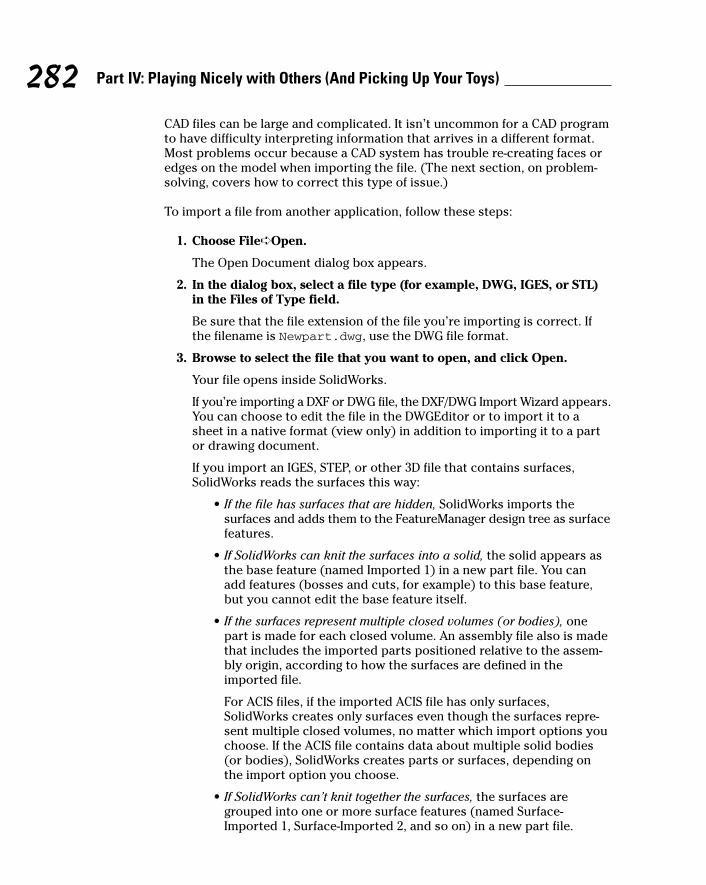
CAD files can be large and complicated. It isn’t uncommon for a CAD programto have difficulty interpreting information that arrives in a different format.Most problems occur because a CAD system has trouble re-creating faces oredges on the model when importing the file. (The next section, on problem-solving, covers how to correct this type of issue.)
To import a file from another application, follow these steps:
1. Choose File➪Open.
The Open Document dialog box appears.
2. In the dialog box, select a file type (for example, DWG, IGES, or STL)in the Files of Type field.
Be sure that the file extension of the file you’re importing is correct. Ifthe filename is Newpart.dwg, use the DWG file format.
3. Browse to select the file that you want to open, and click Open.
Your file opens inside SolidWorks.
If you’re importing a DXF or DWG file, the DXF/DWG Import Wizard appears.You can choose to edit the file in the DWGEditor or to import it to asheet in a native format (view only) in addition to importing it to a partor drawing document.
If you import an IGES, STEP, or other 3D file that contains surfaces,SolidWorks reads the surfaces this way:
• If the file has surfaces that are hidden, SolidWorks imports thesurfaces and adds them to the FeatureManager design tree as surfacefeatures.
• If SolidWorks can knit the surfaces into a solid, the solid appears asthe base feature (named Imported 1) in a new part file. You canadd features (bosses and cuts, for example) to this base feature,but you cannot edit the base feature itself.
• If the surfaces represent multiple closed volumes (or bodies), onepart is made for each closed volume. An assembly file also is madethat includes the imported parts positioned relative to the assem-bly origin, according to how the surfaces are defined in theimported file.
For ACIS files, if the imported ACIS file has only surfaces,SolidWorks creates only surfaces even though the surfaces repre-sent multiple closed volumes, no matter which import options youchoose. If the ACIS file contains data about multiple solid bodies(or bodies), SolidWorks creates parts or surfaces, depending onthe import option you choose.
• If SolidWorks can’t knit together the surfaces, the surfaces aregrouped into one or more surface features (named Surface-Imported 1, Surface-Imported 2, and so on) in a new part file.
282 Part IV: Playing Nicely with Others (And Picking Up Your Toys)
20_129784 ch13.qxp 9/28/07 12:37 PM Page 282
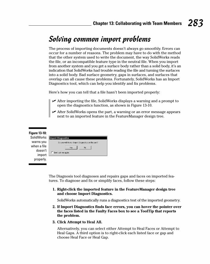
Solving common import problemsThe process of importing documents doesn’t always go smoothly. Errors canoccur for a number of reasons. The problem may have to do with the methodthat the other system used to write the document, the way SolidWorks readsthe file, or an incompatible feature type in the neutral file. When you importfrom another system and you get a surface body rather than a solid body, it’s anindication that SolidWorks had trouble reading the file and turning the surfacesinto a solid body. Bad surface geometry, gaps in surfaces, and surfaces thatoverlap can all cause these problems. Fortunately, SolidWorks has an ImportDiagnostics tool, which can help you identify and fix problems.
Here’s how you can tell that a file hasn’t been imported properly:
� After importing the file, SolidWorks displays a warning and a prompt toopen the diagnostics function, as shown in Figure 13-10.
� After SolidWorks opens the part, a warning or an error message appearsnext to an imported feature in the FeatureManager design tree.
The Diagnosis tool diagnoses and repairs gaps and faces on imported fea-tures. To diagnose and fix or simplify faces, follow these steps:
1. Right-click the imported feature in the FeatureManager design treeand choose Import Diagnostics.
SolidWorks automatically runs a diagnostics test of the imported geometry.
2. If Import Diagnostics finds face errors, you can hover the pointer overthe faces listed in the Faulty Faces box to see a ToolTip that reportsthe problem.
3. Click Attempt to Heal All.
Alternatively, you can select either Attempt to Heal Faces or Attempt toHeal Gaps. A third option is to right-click each listed face or gap andchoose Heal Face or Heal Gap.
Figure 13-10:SolidWorkswarns youwhen a file
doesn’timport
properly.
283Chapter 13: Collaborating with Team Members
20_129784 ch13.qxp 9/28/07 12:37 PM Page 283
To simplify entities with a tolerance greater than 1.0e-8 meters and less than1.0e-5 meters, you must manually select the relevant faces and then clickAttempt to Heal All Faces.
1. Select the two faces in the graphics area.
2. Click Attempt to Heal All Faces.
If the two faces are meant to be one (for example, the two halves of acylindrical face), the two faces merge. The diagnosis performs an in-depth check on all entities in a model.
3. Click OK.
If the imported body still shows rebuild error markers even though abody check and the Import Diagnosis PropertyManager report no sur-face problems, the body is probably valid.
4. Click Rebuild to clear the rebuild error markers.
You can merge multiple edges into a single edge by using Heal Edges onthe Features toolbar. To view and fix gaps, follow these steps:
a. Right-click the Imported feature in the FeatureManager design treeand choose Import Diagnostics. The PropertyManager reports thenumber of gaps found.
b. View and fix the gaps by using the Attempt to Heal All Gaps tool.
c. Click OK.
If you run into a dead end and, no matter how hard you try, the methods inthis section don’t seem to fix the problem, here are some ideas:
� Call the sender and ask him to send you a native format, if possible.
� Ask for another file type or another version of the file format.
� Use a direct translator (available through SolidWorks partners).
� Manually identify and clean up the problem areas by using the ImportDiagnostics tool described in this section. Then remove and re-createthe faces in question.
284 Part IV: Playing Nicely with Others (And Picking Up Your Toys)
20_129784 ch13.qxp 9/28/07 12:37 PM Page 284
Chapter 14
Viewing and ReviewingDocuments
In This Chapter� Understanding the benefits of the CAD viewer
� Using the collaboration tools in eDrawings
� Linking a SolidWorks model to a document by using OLE
Sharing your design with others doesn’t mean that you have to continuallysend huge CAD (computer-aided design) files via overnight courier ser-
vices. Instead, you can take advantage of CAD viewers to save time and bemore efficient. CAD viewers allow people without CAD licenses to view, markup, and measure your CAD design without having to own or operate expen-sive or complex software.
Imagine that you want to send a model of your stovetop espresso maker to avendor to see whether the vendor can manufacture it. You can e-mail a light-weight version of the model so that the vendor can take measurements andadd comments and then return it by e-mail to you the next day.
In this chapter, I introduce you to two CAD viewers that let you look atSolidWorks drawings, parts, and assembly documents: eDrawings and the SolidWorks Viewer.
I also briefly touch on graphics files and embedded and linked documents sothat you know how to include SolidWorks documents in your presentations.
Viewing with CAD ViewersWhen you work with other design team members, vendors, or customers, theability to communicate design ideas quickly is vital. But sometimes you don’twant to or need to, or simply cannot, send someone an entire SolidWorks file.
21_129784 ch14.qxp 9/28/07 12:38 PM Page 285
CAD files, for example, tend to be very large — a SolidWorks assembly caneasily reach 150MB — which makes them cumbersome and tricky to send. Andthey contain propriety information, so you don’t want to send your CAD filesto just anybody. You may want to send someone only enough information totake accurate measurements or to see how an assembly fits together.
CAD viewers help in this process. A CAD viewer lets you look at 2D and 3Ddesign data in its non-native format, without having to own or operate com-plicated or expensive CAD software. (Not that SolidWorks is either of thosethings, but a less technical person may consider it so.)
Two CAD viewers — eDrawings and the SolidWorks Viewer — allow you toreview and print SolidWorks documents in a non-native format. Both viewersare free and available at the SolidWorks Web site (www.solidworks.com/pages/products/designtools.html).
Here are a few scenarios where a CAD viewer may come in handy:
� Request quotes from vendors: You can send a compressed eDrawing file(see the later section “Communicating with eDrawings”) to a vendorwho can then use the markup tools in eDrawings to request changes oradditions.
� Perform virtual design reviews: What better way to distribute designdata than in an e-mail? CAD viewers give you that advantage. Yourdesign team can view a document and mark it up and then send backcomments.
� Make customer presentations: Your customers don’t want to invest inSolidWorks just to see your works of art. A CAD viewer lets a customerview a CAD file without having any special knowledge of CAD. If yousend your customer an eDrawings file, a special animation feature playsthe design so that it rotates automatically through different orientations.
� Send engineering change notices: Design engineers spend their entirecareers making changes to designs. A CAD viewer can make it easier tocheck and approve designs and send back comments.
Keep in mind that CAD viewers aren’t the only way to present your designbrilliance to people. Graphical formats (such as TIF, BMP, and JPEG) are greatfor sharing, too. The only problem is that they’re flat images that contain noreal CAD data, so you can’t measure them or check for mass properties.
286 Part IV: Playing Nicely with Others (And Picking Up Your Toys)
21_129784 ch14.qxp 9/28/07 12:38 PM Page 286
Dow
nlo
ad fro
m W
ow
! eBook
<w
ww
.wow
ebook.
com
>
Sharing Models and Data with eDrawings
eDrawings is a free e-mail–enabled program included with SolidWorks thatlets you share designs with the people who need to see them, no matter whichCAD program they have — or don’t have. eDrawings is easy to use and comesin two parts: Viewer and Publisher. A Professional version includes additionalcapabilities to mark up and measure a model. The standard Viewer andPublisher are free, but you have to pay for the Professional version.
You can download the standard eDrawings Viewer and Publisher or theProfessional version of eDrawings at www.eDrawingsViewer.com. If youdownload Publisher or the Professional version, the viewer downloads auto-matically, so you don’t have to download it again. You need the viewer tosave any eDrawings files you publish in your CAD system.
eDrawings Publishers are available for SolidWorks and most major CADsystems. Anyone with the eDrawing Viewer can read an eDrawing file.
Using eDrawings offers you many advantages:
� eDrawings Viewer reads and prints any eDrawings file; native SolidWorksdrawing, part, and assembly file; and also any DWG and DXF drawing files.
� eDrawings Publisher produces a lightweight, compressed format,making your CAD design small enough to send in an e-mail.
� Although an eDrawings file hides proprietary data, it retains externalgraphical details as well as the dimensions and mass properties of yourmodel. This feature makes eDrawings accurate enough for proper mea-surements.
� You can send an eDrawings file with a built-in viewer in a self-extractinge-mail. The recipient just double-clicks the attachment, and the CADmodel or drawing appears.
� With the extra collaboration features included in eDrawings Professional,you can measure and mark up files, add comments, and manage markupsfrom other design team members.
� eDrawings also offers several tools that give you a better understandingof the design. A Play button moves the model or drawing through differentviews automatically. You can interrogate the model and examine it upclose with zoom, rotate, and pan functions.
287Chapter 14: Viewing and Reviewing Documents
21_129784 ch14.qxp 9/28/07 12:38 PM Page 287
Creating an eDrawings fileWith eDrawings Publisher, you can publish native SolidWorks documents aseDrawings files, which anyone can view with the free eDrawings Viewer. BecauseeDrawing Publisher is a SolidWorks add-in, a Publish eDrawings 2008 Filecommand icon appears on the SolidWorks main toolbar.
eDrawings 2008 comes standard with SolidWorks, but just like with other add-ins, you need to select it in the Add-Ins dialog box so that it appears on theSolidWorks Standard toolbar. In SolidWorks, choose Tools➪Add-Ins. Whenthe Add-Ins dialog box appears, select eDrawings and click OK.
To publish an eDrawings file from within SolidWorks, follow these steps:
1. Open the drawing, part, or assembly file that you want to publish.
2. Choose File➪Publish eDrawings 2008 File.
The eDrawings Viewer appears, displaying the new eDrawings file youjust created.
Your file isn’t saved automatically. You must save it using eDrawingsViewer.
3. Within eDrawings Viewer, choose File➪Save As.
The Save As dialog box appears.
4. In the Save In drop-down list, browse to the location where you wantto save the document.
5. Enter the name for the file in the File Name field. The default name isbased on the original SolidWorks document. To change the name, type anew name for the file.
6. In the Save As Type field, select the file format in which you want tosave the file.
In addition to using the standard EDRW, EPRT, or EASM format, you canalso save your file as a 2D image file, such as a JPG, TIF, or PNG file.
7. Click Save.
Creating an eDrawings file from SolidWorksCreating an eDrawings file directly from SolidWorks allows some additionalcontrol over the model data. Using the Save As eDrawings option, you can
288 Part IV: Playing Nicely with Others (And Picking Up Your Toys)
21_129784 ch14.qxp 9/28/07 12:38 PM Page 288

allow the receiver to measure (or not measure), to output (or not output) asolid model or assembly to the STL format, view (or not view) the drawing inshaded mode, or view (or not view) any animations included in the file.
To create an eDrawings file, follow these steps:
1. Open the drawing, part, or assembly file that you want to publish.
2. Choose File➪Save As.
The Save As dialog box appears.
3. In the Save In drop-down list, browse to the location where you wantto save the document.
4. Enter the name for the file in the File Name field. The default name isbased on the original SolidWorks document. To change the name, typea new name for the file.
5. In the Save As Type field, select eDrawings.
6. Click the Options button, and select any other options you want toapply.
Depending on the file type you’re saving, other options include
• Okay to Measure This eDrawings File: By checking this option, if youhave eDrawings Professional, you enable the recipient to measureyour design.
• Save Shaded Data in Drawings(Drawings Only): This option savesthe shaded data from a drawing in the eDrawings file.
• Allow Export to STL for Parts and Assemblies (Parts and AssembliesOnly): This option allows the recipient to save the eDrawings fileas an STL (stereolithography) file for output on a rapid prototypemachine.
• Save Animator Animations to eDrawings File: This option saves anyanimations from the SolidWorks model and allows the receiver toplay them using eDrawings.
Sending an eDrawings fileA benefit that sets apart eDrawings is the ability to send a file with eDrawingsViewer encapsulated in an e-mail. This way, the receiver has nothing to down-load. He simply clicks the attachment, and the eDrawings drawing or modelappears. Firewalls don’t like executable files because they look like virusattachments; however, eDrawings offers several sending options to ensurethat your file gets through.
289Chapter 14: Viewing and Reviewing Documents
21_129784 ch14.qxp 9/28/07 12:38 PM Page 289
To send an eDrawings file, follow these steps:
1. Open the eDrawings file in eDrawings Viewer.
2. Choose File➪Send.
The Send As dialog box appears.
3. Choose how you want to save your file.
Your options include
• eDrawings File (.edrw, .eprt. or .easm): Allows you to send a file asan eDrawings file. The recipient needs to install eDrawings Viewer,but this option is best for the smallest file size.
• Zip File (.zip): Creates a firewall-friendly zip file that contains the self-extracting eDrawings Viewer; the recipient needs to have the softwareto unzip the viewer.
• HTML File (.htm): Displays the eDrawings file within a firewall-safeHTML Web page that the recipient can view with Internet Explorer.Installs Viewer automatically.
• Executable File (.exe): Creates a self-executable file with Viewerattached. The least firewall-friendly option, it’s also the most likelyto have the recipient’s antivirus program strip it from the e-mail.The file is larger (1.4MB) because of the embedded viewer.
4. Click Save.
eDrawings generates an outgoing e-mail with the file attached.
5. Type the recipient’s e-mail address and click Send.
Measuring and marking upThe standard version of the eDrawings Viewer includes interrogation tools(Spin, Pan, and Zoom) that allow you to get a closer look at a design. If youwant the collaboration tools, including the ability to mark up and measure,get your hands on the Professional version.
A unique feature of eDrawings Professional is that it automatically publisheseDrawings files as review-enabled. Anyone who receives a review-enabled file —whether that person has the Professional version or not — can use theMarkup and Measure functions in eDrawings Viewer. This feature lets otherdesigners, customers, or vendors use these advanced tools without having topurchase the Professional version.
290 Part IV: Playing Nicely with Others (And Picking Up Your Toys)
21_129784 ch14.qxp 9/28/07 12:38 PM Page 290

If you want the receiver to see only certain measurements and not others,you can disable the eDrawings Measure tool (in the SolidWorks Save As dialogbox options, deselect the Enable Measure option) and use basic dimensionsto indicate, for example, the length, width, and diameter of your model.
Measuring a modelThe Measure tool is a handy eDrawings feature. Vendors often need accuratemeasurements of your product. For example, a vendor who makes packagingmay need to measure your television design to make sure that it fits insidethe Styrofoam packaging he’s designing.
To measure a model, the eDrawings file you’re viewing must be Measure-enabled. Look for a measuring tape icon in the lower-right corner of the userinterface. A red line through it means that measurement is disabled.
To measure an eDrawings file in the eDrawings Viewer, follow these steps:
1. Choose File➪Open to open the eDrawings file you want to measure.
2. Choose Tools➪Measure.
The Measure tab appears in the eDrawings Manager.
3. Move the pointer to the graphics area.
The pointer changes to a measuring tool. When the pointer detects apotential measurement starting point, that starting point is highlighted.Points are highlighted with a dot; edges and the borders of faces arehighlighted with thick solid lines.
4. Click to set the measurement starting point.
Your starting point appears in the Selected Items box on the Measure tab.
5. Move the pointer over the second point, edge, or face.
A measure line appears as you drag the pointer.
6. Click again.
The measurement appears in the graphics area and in the Distance sectionin the Results box on the Measure tab. The second item appears in theSelected Items box. In the Units box, the unit of measurement defaults tothe file setting or to Millimeters if no file setting exists.
291Chapter 14: Viewing and Reviewing Documents
21_129784 ch14.qxp 9/28/07 12:38 PM Page 291
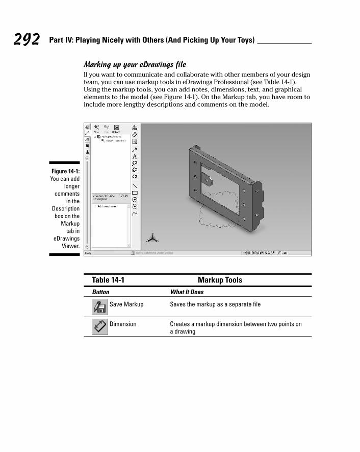
Marking up your eDrawings fileIf you want to communicate and collaborate with other members of your designteam, you can use markup tools in eDrawings Professional (see Table 14-1).Using the markup tools, you can add notes, dimensions, text, and graphicalelements to the model (see Figure 14-1). On the Markup tab, you have room toinclude more lengthy descriptions and comments on the model.
Table 14-1 Markup ToolsButton What It Does
Save Markup Saves the markup as a separate file
Dimension Creates a markup dimension between two points ona drawing
Figure 14-1:You can add
longercomments
in theDescriptionbox on the
Markup tab in
eDrawingsViewer.
292 Part IV: Playing Nicely with Others (And Picking Up Your Toys)
21_129784 ch14.qxp 9/28/07 12:38 PM Page 292
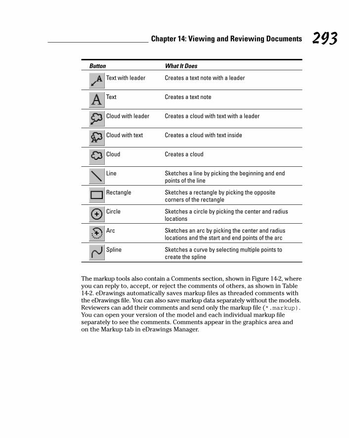
Button What It Does
Text with leader Creates a text note with a leader
Text Creates a text note
Cloud with leader Creates a cloud with text with a leader
Cloud with text Creates a cloud with text inside
Cloud Creates a cloud
Line Sketches a line by picking the beginning and endpoints of the line
Rectangle Sketches a rectangle by picking the opposite corners of the rectangle
Circle Sketches a circle by picking the center and radiuslocations
Arc Sketches an arc by picking the center and radiuslocations and the start and end points of the arc
Spline Sketches a curve by selecting multiple points tocreate the spline
The markup tools also contain a Comments section, shown in Figure 14-2, whereyou can reply to, accept, or reject the comments of others, as shown in Table14-2. eDrawings automatically saves markup files as threaded comments withthe eDrawings file. You can also save markup data separately without the models.Reviewers can add their comments and send only the markup file (*.markup).You can open your version of the model and each individual markup file separately to see the comments. Comments appear in the graphics area and on the Markup tab in eDrawings Manager.
293Chapter 14: Viewing and Reviewing Documents
21_129784 ch14.qxp 9/28/07 12:38 PM Page 293

Table 14-2 Markup Comments ToolsButton What It Does
New Comment Creates a new comment
Reply Replies to the selected, existing comment
Options Sets preferences for username, markupcolor, and other eDrawing configurationvalues
To mark up your eDrawings, follow these steps:
1. In eDrawings Viewer, open a document to mark up.
When you open a document, several tools appear in the eDrawings interface. eDrawings Manager, on the left side of the interface, displaystabs that let you manage eDrawings information. A complete set ofmarkup tools (refer to Table 14-1) appears to the right of the interface.
2. Click the Markup tab in eDrawings Manager.
You see the following icons appear in the tab window: New Comment,Reply, and Options (refer to Figure 14-2).
Figure 14-2:eDrawings
savesmarkup filesas threadedcomments.
294 Part IV: Playing Nicely with Others (And Picking Up Your Toys)
21_129784 ch14.qxp 9/28/07 12:38 PM Page 294
3. On the Markup tab, click Options.
The Options dialog box appears.
4. Select the Markup tab in the Options dialog box.
5. In the Comment Preferences section, type your name, phone number,and e-mail address and select a color and font for your comments.
This information identifies your comments to other reviewers.eDrawings now saves under your name any future comments you make.
6. Click OK to save the changes.
With your user preferences set, you’re ready to mark up your document.
7. To add a text element, skip to Step 8. To add a geometric element,click one of the following icons and use it as described:
• Line: To draw multiple lines connected with a vertex, click thegraphical image to start the line, move the mouse to draw a line,click to create a vertex, and then continue adding lines andvertices. Double-click in the graphics area to close this tool.
• Rectangle: Click the graphical image to set a corner of the rectan-gle, and then drag the mouse to create the rectangle size you want.Release the mouse to finish.
• Circle: Click to place the center point, drag the mouse outward, and then click again to draw a circle.
• Arc: Click to place the arc center point. Move the mouse and clickagain to set the radius. Move the mouse and click again to drawthe arc.
• Spline: Click, move the mouse, and then click multiple times todraw a spline. Double-click to exit this tool.
8. To add a text element, click the icon you want.
Your choices are Text, Text with Leader, Cloud, or Cloud with Leader.
9. Type your comment in the box that appears and click the green checkmark to accept your comment.
Clicking the red x cancels the comment.
10. Click in the graphical image where you want to insert the text element.
11. Add markups, if you want, by repeating Steps 7 through 10.
12. Choose File➪Save.
eDrawings saves your comments automatically with the eDrawings file.
295Chapter 14: Viewing and Reviewing Documents
21_129784 ch14.qxp 9/28/07 12:38 PM Page 295
Using the SolidWorks ViewerSimilar to eDrawings, SolidWorks Viewer opens native SolidWorks documentsand is available for free. And, like eDrawings Viewer, SolidWorks Viewer opensnative SolidWorks documents in read-only mode, which means that you cannotmodify the document but you can look at it. A benefit of read-only mode is thatit enables the file to open faster because only a subset of information is opened.You can download SolidWorks Viewer from the SolidWorks download Webpage at www.solidworks.com/pages/services/downloads.html.
To view a SolidWorks document by using SolidWorks Viewer, simply open thedocument as you would in most Microsoft programs.
Including SolidWorks Documents in Your Presentations
You can show off your SolidWorks designs in a few other ways. You candisplay your model inside a Microsoft application — such as Word, Excel, or PowerPoint — using a clever Microsoft technology known as object linkingand embedding (OLE). Or, you can make a 2D graphical image (JPG, TIF, BMP,or PDF) of your design and paste it in a document, presentation, or Web page.
Here are the advantages to using OLE:
� You can edit the object directly from within another application. Double-click the object or link, and the menus change to SolidWorks (as long asyou have SolidWorks installed on your computer).
� A linked object is updated when you make changes to the originaldocument.
� You can combine different document types and programs into onedocument. For example, you can embed a SolidWorks document into a Microsoft PowerPoint report.
� You can include and show the object without having the actual applicationfor the OLE object for viewing. The application that created the objectlaunches only if you double-click the OLE object.
The advantages to using images are listed here:
� They’re simple, typically small, file sizes.
� They’re easy to create as screen captures to edit and annotate.
� You don’t need to worry about the location of the actual file.
296 Part IV: Playing Nicely with Others (And Picking Up Your Toys)
21_129784 ch14.qxp 9/28/07 12:38 PM Page 296
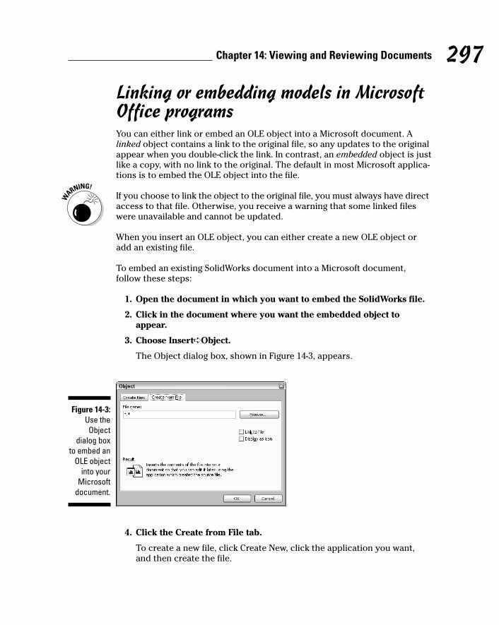
Linking or embedding models in MicrosoftOffice programsYou can either link or embed an OLE object into a Microsoft document. Alinked object contains a link to the original file, so any updates to the originalappear when you double-click the link. In contrast, an embedded object is justlike a copy, with no link to the original. The default in most Microsoft applica-tions is to embed the OLE object into the file.
If you choose to link the object to the original file, you must always have directaccess to that file. Otherwise, you receive a warning that some linked fileswere unavailable and cannot be updated.
When you insert an OLE object, you can either create a new OLE object oradd an existing file.
To embed an existing SolidWorks document into a Microsoft document,follow these steps:
1. Open the document in which you want to embed the SolidWorks file.
2. Click in the document where you want the embedded object toappear.
3. Choose Insert➪Object.
The Object dialog box, shown in Figure 14-3, appears.
4. Click the Create from File tab.
To create a new file, click Create New, click the application you want,and then create the file.
Figure 14-3:Use theObject
dialog boxto embed an
OLE objectinto your
Microsoftdocument.
297Chapter 14: Viewing and Reviewing Documents
21_129784 ch14.qxp 9/28/07 12:38 PM Page 297
5. In the Create from File dialog box, click the Browse button andbrowse to and select the file you want to embed.
6. Click one of these options to indicate how you want the file to be dis-played in your document:
• Link to File: Links the embedded file to the original. Any changes inthe original are reflected in the link.
• Display as Icon: Inserts an icon that represents the contents ofyour file.
7. Click OK.
You can make edits to OLE objects. To edit an OLE object, double-click theobject and make your changes. To return to the original Microsoft document,click outside the embedded document inside the original document.
Creating an image file of a modelYou can create a graphical image of your SolidWorks model in several ways.You can save an eDrawings file as a JPEG, TIFF, or BMP file by selecting one ofthose formats in the Save As Type field in the Save As dialog box. TheSolidWorks Save As dialog box offers similar options, including PDF.
You can take a snapshot of your SolidWorks model by using the ScreenCapture tool. Choose View➪Screen Capture➪Image Capture to copy theactive SolidWorks window to the Windows Clipboard. The image can then bepasted (press Ctrl+V) into another application.
298 Part IV: Playing Nicely with Others (And Picking Up Your Toys)
21_129784 ch14.qxp 9/28/07 12:38 PM Page 298

Part VThe Part of Tens
22_129784 pp05.qxp 9/28/07 12:38 PM Page 299
In this part . . .
No For Dummies book is complete without The Part ofTens. In this fun part, I provide information, tips,
resources, and links that make your SolidWorks experiencemore productive and enjoyable. Each of the three chap-ters in this section lists ten ways (imagine that!) tobecome more proficient with SolidWorks, extend andreuse your design, and introduce you to the SolidWorkscommunity.
22_129784 pp05.qxp 9/28/07 12:38 PM Page 300
Dow
nlo
ad fro
m W
ow
! eBook
<w
ww
.wow
ebook.
com
>
Chapter 15
Ten Tips for Becoming MoreProficient with SolidWorks
In This Chapter� Getting up to speed fast with classroom training
� Mixing it up with nontraditional training
� Leveraging books and online resources
� Developing and enforcing CAD design standards
� Managing a SolidWorks implementation more effectively
A craftsman is only as good as his tools, they say. But a tool is only as goodas its craftsman, I say. This saying is true of SolidWorks, a brilliant but
extensive design tool. To get the most from SolidWorks, you need to becomefamiliar with the nooks and crannies of the program — and there are a lot ofthem, not to mention the dozens of add-on programs (such as PhotoWorks,COSMOS, and Toolbox) that work inside SolidWorks. The more adept you areat SolidWorks, the more productive and efficient you’ll be at design. And theway to hone your SolidWorks skills is through practice and training.
You can follow plenty of other routes in mastering SolidWorks, such as readingbooks, checking out online sources, and joining SolidWorks user groups. Thebest way to stay on top of it all is to mix and match several training routinesand to stay current. SolidWorks issues a new release of its software everyyear, and there are always new features and functionality that you’ll want tokeep up with.
Your efficiency in using SolidWorks translates into the bottom line for youand your company. In this chapter, I cover ten ways that you can make surethat you get the most out of SolidWorks.
23_129784 ch15.qxp 9/28/07 12:38 PM Page 301
302 Part V: The Part of Tens
Go to Class (Formal Training)Through an extensive reseller network, SolidWorks offers a variety of trainingcourses in everything from the basics of part and assembly modeling toadvanced processes, such as sheet metal design and custom routines.
A word of advice: When you sign up for a class, do some prep work beforethe class begins. Don’t depend on your instructor to download knowledgeinto your brain. Read some articles about SolidWorks, tinker with the program,and try out the online tutorials located on the SolidWorks Help menu. If youwalk into a classroom never having looked at SolidWorks, you’ll have a longweek, and so will the instructor and the rest of the class. Be prepared. A fewwarm-up exercises ensure that you get the most out of a course.
You can find an up-to-date list of training courses on the SolidWorks Web site:www.solidworks.com/pages/services/Training/TrainingCourses.html.
Courses vary by reseller, but here’s an list of essential courses for new users:
� SolidWorks Essentials: This class takes you through the basics of creatingparts, assemblies, and drawings in SolidWorks.
� SolidWorks Drawings: After you have part and assembly design underyour belt, this class teaches you how to create manufacturing drawingsbased on your 3D design.
� Advanced Part Modeling: In this class, you discover how to useSolidWorks surfacing tools to create swoops, curves, cores, cavities, and other wacky freeform shapes that are now popular in designs.
� Advanced Assembly Modeling: This class teaches you advanced techniques for building complex assemblies.
� Sheet Metal: Discover how to build stand-alone sheet metal parts, convertparts to sheet metal, and model sheet metal parts in the context of anassembly.
� Weldments: Find out how to use the Weldment tools used to createwelded structures.
Be Creative (Nontraditional Training)You don’t have to go to class to become a SolidWorks whiz (see the preced-ing section). In fact, you can stay in your pajamas if you prefer. You can find aplethora of SolidWorks books and online training materials to satisfy all your
23_129784 ch15.qxp 9/28/07 12:38 PM Page 302
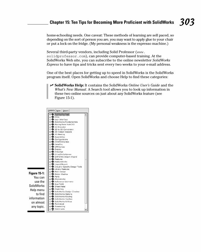
home-schooling needs. One caveat: These methods of learning are self paced, sodepending on the sort of person you are, you may want to apply glue to your chairor put a lock on the fridge. (My personal weakness is the espresso machine.)
Several third-party vendors, including Solid Professor (www.solidprofessor.com), can provide computer-based training. At theSolidWorks Web site, you can subscribe to the online newsletter SolidWorksExpress to have tips and tricks sent every two weeks to your e-mail address.
One of the best places for getting up to speed in SolidWorks is the SolidWorksprogram itself. Open SolidWorks and choose Help to find these categories:
� SolidWorks Help: It contains the SolidWorks Online User’s Guide and theWhat’s New Manual. A Search tool allows you to look up information inthese two online sources on just about any SolidWorks feature (see Figure 15-1).
Figure 15-1:You can use the
SolidWorksHelp menu
to findinformation
on almostany topic.
303Chapter 15: Ten Tips for Becoming More Proficient with SolidWorks
23_129784 ch15.qxp 9/28/07 12:38 PM Page 303

� Moving from AutoCAD: Many new SolidWorks users are switching overfrom the 2D AutoCAD program. This guide shows you the differencesbetween SolidWorks and AutoCAD and helps make the transition easier.
� SolidWorks Tutorials: SolidWorks includes more than 30 tutorials thatare a good launching point for learning how to use the program. Thesetutorials cover part creation, assembly operations, drawings, and severalof the SolidWorks add-in programs.
In SolidWorks, when a command is active, a question mark appears in thePropertyManager. Click the question mark to jump to the Help topic for thatcommand.
Check Local Reseller EventsIn addition to formal SolidWorks training courses, SolidWorks value-addedresellers (VARs) also hold special events to introduce new users to theSolidWorks program. These events include Night School, Lunch and Learn,and other special programs. At these events, you can find out more aboutSolidWorks and share your questions and experiences with other users.
Many VARs also hold the SolidWorks Personal Edition Hands-on Test Driveclass. After completing this free two- to three-hour seminar, which offersbasic instruction in SolidWorks, attendees receive a free copy of the Personal Edition software, which is a noncommercial version of SolidWorks. Personal Edition offers all the core features of SolidWorks, but anydesigns you create don’t transfer into SolidWorks.
The availability and scheduling of events varies from VAR to VAR. The bestway to find out more about these events is to contact your local VAR.
Join a User GroupMeeting and networking with other SolidWorks users is another great way todiscover more about SolidWorks and stay current with happenings in theCAD world. Located around the country and internationally, these usergroups are independent groups organized by SolidWorks users. You can finduser groups for both SolidWorks and the COSMOS line of analysis softwarethat works inside SolidWorks. Visit www.swugn.org.
Groups vary slightly in structure, but usually it costs nothing to join one.Anyone with an interest in SolidWorks is welcome. Groups meet periodically
304 Part V: The Part of Tens
23_129784 ch15.qxp 9/28/07 12:38 PM Page 304

to discuss and share what they know about SolidWorks. Meetings often offertechnical presentations, visits from local resellers, and case studies pre-sented by other users. Users also discuss the newest version of SolidWorksand technical tips. In addition to local meetings, user groups also sponsorregional events. The biggest annual user event is SolidWorks World, usuallyheld in January in a warm locale with a golf course nearby. At this annualconference, you can attend seminars; meet other SolidWorks users, partners,and personnel; and share ideas and find out more about SolidWorks.
Aspire to Be a SuperuserWithin every SolidWorks-using company lurks the superuser, the program guru(or geek, whichever you prefer) to whom everyone goes with their questions onthe inner workings of SolidWorks. This person saves you from calling technicalsupport or digging through user manuals to learn about a SolidWorks add-in.Some superusers get formal recognition. Others are quietly acknowledged forthe services they provide to coworkers.
You too can aspire to be a SolidWorks superuser, or — if you don’t have the timeto be one — you can cultivate one in your company. To become one, simply dowhatever is needed to learn more than anyone else about SolidWorks. Tocultivate a SolidWorks superuser, make every effort to recognize, encourage,and grow the SolidWorks geniuses in your organization. Encourage them totake the Certified SolidWorks Professional exam. (See the section “Take theCSWP Test,” later in this chapter.) Give them a business title that acknowledgestheir know-it-all status. Issue a certificate, plaque, or medal that they canproudly display in their cubicles. Send them to the mother of all SolidWorksuser group meetings: SolidWorks World. Whatever it is, find some imaginativeway to reward them, and they will take root and blossom.
Network Virtually: The Discussion ForumSolidWorks user groups are a great way to shake hands with other users. Ifyou’re not fond of shaking hands or rubbing elbows, though — or yourschedule won’t permit it — maybe discussion forums are the answer.
SolidWorks discussion forums are another way to exchange ideas with otherusers. The SolidWorks discussion forum is a threaded message board whereyou can submit questions (which can include document or image attachmentsthat illustrate your confusion) and wait for others to respond.
305Chapter 15: Ten Tips for Becoming More Proficient with SolidWorks
23_129784 ch15.qxp 9/28/07 12:38 PM Page 305

Of course, you don’t always have to be the one asking questions. You canalso submit advice based on your own experiences. SolidWorks forums aremoderated. Primarily, they consist of users talking to each another, butoccasionally someone from SolidWorks (myself included) chimes in.
SolidWorks discussion forums serve as a place where you can
� Discuss the design, drafting, programming, and administration ofSolidWorks CAD systems and SolidWorks-related products.
� Share ideas, information, and specific experiences regarding the use ofSolidWorks and SolidWorks-related products.
� Discuss third-party add-on products for SolidWorks.
� Discuss enhancements in SolidWorks and SolidWorks-related products.
� Educate and inform others about the strengths, weaknesses, and generaluse of SolidWorks and SolidWorks-related products.
Discussion forums are broken down into functional groups, such as parts,assemblies, drawings, installation, and sketching, for example. This structuremakes it easier to ask questions of the right people.
You can find SolidWorks discussion forums in the Support section of theSolidWorks Web site: www.solidworks.com/pages/services/Community.html, or click the Discussion Forum link in the SolidWorks task pane.
Take the CSWP TestIf you aspire to become the SolidWorks superuser in your office, considertaking the test! The Certified SolidWorks Professional (CSWP) program providesa standard measure of SolidWorks competency. CSWP recognizes the mostqualified and advanced SolidWorks professionals. Certification is a way to getrecognition from your company and your peers. Now no one will ever againdoubt your advanced knowledge.
The way to become a CSWP is to take a test, which is offered through partici-pating SolidWorks VARs. (Check the SolidWorks Web site.) The test has twoparts, in which you
� Answer a series of written questions that test your expertise in thedifferent areas of SolidWorks.
� Create a design in SolidWorks.
306 Part V: The Part of Tens
23_129784 ch15.qxp 9/28/07 12:38 PM Page 306

For more information, visit www.solidworks.com/pages/services/Training/CSWP.html.
Really, what’s the point of getting certified? Basically, it’s like putting fourstars across the top of your résumé. Certification acknowledges your skilllevel in SolidWorks. When companies look for new employees or consultants,they look for a CSWP. What’s more, employers can use certification to trainmore advanced users. Employers most likely will have more confidence inthe skills of someone who has passed CSWP certification.
Document Your CAD StandardsOne of the best ways to ensure productivity in SolidWorks for you and yourstaff (if you have one) is to create a CAD standard book. Your CAD standarddoesn’t have to be a tome — just a binder’s worth of documentation on howyou get your work done in SolidWorks. Documented CAD standards help newemployees get up to speed fast and bring projects to completion more quickly.
A well-defined CAD standard should document how you begin new parts anddrawings, which layers contain which information in a drawing, how youhandle design revisions, and where and how you manage standard parts, forexample. All these documents should be stored in a manual.
Defining a set of CAD standards can be, and should be, a simple process. Holda couple of meetings with key SolidWorks users, or even bring up standards as a topic for an internal user group meeting. One way I have found to be effective in ensuring attendance at this type of meeting is to offer food.(Rarely does an engineer turn down free pizza to talk about CAD.)
After the standards have been defined, you need to determine how to sharethis information. An effective means is to create an HTML or PDF document(that no one can mess with) and place it on a network drive where everyonecan reach it. I prefer HTML because it’s displayed faster in a Web browser.
Here’s a checklist of items to cover in your CAD standards:
� Data management, or how you create, store, and archive files
� Document templates
� SolidWorks settings
� Assembly structure
� Materials
� Standard parts
307Chapter 15: Ten Tips for Becoming More Proficient with SolidWorks
23_129784 ch15.qxp 9/28/07 12:38 PM Page 307

� Modeling practices, such as feature names and order and in-context references
� Drawing practices, such as standards notes, custom properties, and titleblocks
Communicate Design StandardsJust as important as creating a set of CAD standards is communicating whatthey are and how they’re used. You can communicate your design standardsby adding standards review to your design review or checking process, holdinginternal user group meetings, or conducting training classes on the standards.You may have a great set of nicely documented and detailed CAD standards, butwhat good are they if no one follows them?
The other advantage of this review is that the designers receive feedback sothat they can incorporate it into current and subsequent designs.
Make sure that the standards are located where all the designers can get tothe documents easily. Find a common location on the network and store theCAD standards there.
Manage SolidWorks WellA CAD system plays a major role in how your organization designs its products.How well you manage and implement your CAD system has a large effect onyour company’s productivity and success. A key to this success is how wellthis technology is managed. So, what makes a good CAD manager in aSolidWorks environment, and why is that role important to your company?
Most companies have some form of CAD manager, whether formal or informal,full- or part-time. In a SolidWorks environment, a CAD manager is usuallyresponsible for these tasks:
� Implement SolidWorks
� Manage SolidWorks
� Manage CAD data
� Handle training
� Implement the CAD standards
� Communicate among team members
308 Part V: The Part of Tens
23_129784 ch15.qxp 9/28/07 12:38 PM Page 308

If you’re a CAD manager, your goal should be twofold:
� Find ways to increase your company’s efficiency and effectiveness inusing SolidWorks software. Small productivity gains in these areas canyield significant gains in productivity in the long term, especially whenmultiplied across all the CAD users in your organization.
� Lower your organization’s total cost of ownership (TCO) in regard tousing SolidWorks.
309Chapter 15: Ten Tips for Becoming More Proficient with SolidWorks
23_129784 ch15.qxp 9/28/07 12:38 PM Page 309

310 Part V: The Part of Tens
23_129784 ch15.qxp 9/28/07 12:38 PM Page 310
Chapter 16
Ten Ways to Extend and ReuseYour Design Information
In This Chapter� Getting the most from your designs with SolidWorks add-ons
� Including SolidWorks designs in Microsoft applications
� Allowing others to view and print PDM data
The fun never ends when you design in 3D, even after your product designis complete. You’ll be pleased to know that literally dozens of other appli-
cations developed by SolidWorks and other companies enable you to reuseand show off your designs in many ways. These methods include add-in anddownstream applications.
A SolidWorks add-in is a separate program that works inside SolidWorks. Anadd-in shows up on the SolidWorks main menu, so it looks like it’s part ofSolidWorks. One example is SolidWorks Routing, which builds and documentselectrical cables in your assembly files. Another is PhotoWorks, which createsphotorealistic images of parts and assemblies. Analysis, simulation, andmanufacturing programs are considered downstream applications. The downstream programs I cover in this chapter work directly off the SolidWorksmodel, so data translation is never an issue.
In this chapter, I introduce you to ten add-ins and downstream applications.Keep in mind that my purpose is simply to make you aware of these programs,not to explain the details of how each program works.
SolidWorks add-in applications are available for purchase separately or as partof a SolidWorks package. Check with your SolidWorks reseller to see what’savailable. After you installed an add-in program, open SolidWorks and chooseTools➪Add-Ins to run the program inside SolidWorks.
24_129784 ch16.qxp 9/28/07 12:38 PM Page 311
312 Part V: The Part of Tens
Show Off Your Model with Microsoft OLE
The next time you want to add zest to a PowerPoint presentation, color to areport, or “oomph” to a ho-hum presentation, include a SolidWorks design.Your audience member can gain an instant understanding of the benefits ofyour two-seated lawnmower if you simply show them the actual model.
You can add a SolidWorks model to a presentation or document by usingobject linking and embedding (OLE) or by including an image of the model.
OLE technology lets you embed or link an object from another program into aMicrosoft document. When you embed an object, it’s like including a copy of thereal thing in the document. The embedded object has no link to the original. In contrast, a link is connected to its original and is updated whenever theoriginal document is updated.
To access an OLE embedded or linked SolidWorks document, simply double-click the link or the object in your Microsoft Office file. As long as you havethe SolidWorks program installed, the SolidWorks document opens. If theobject is a SolidWorks model, you can spin the model around, show differentviews, or make changes as desired. (See Chapter 14 for more about workingwith OLE and SolidWorks.)
Another way to include a SolidWorks model in a report or presentation oreven in a Web page is to include an image file of the model. One way to createan image is by using a Windows screen capture. To capture the current windowon your screen, press Alt+Print Screen, which places the image on the Clipboard.Open an application such as Microsoft Word and choose Edit➪Paste.
Another option is to save your SolidWorks model as a JPEG, TIFF, or PDF file.These options are available in the SolidWorks Save As dialog box. (Simplychoose File➪Save As to reach this dialog box.)
When you start working with graphical formats, you find that some fit yourneeds better than others. JPEG and GIF are generally safe bets. TIFF and BMPcreate larger files. My personal favorite is PNG. It’s a small-size format thatallows you to resize images without losing much quality.
24_129784 ch16.qxp 9/28/07 12:38 PM Page 312
Dow
nlo
ad fro
m W
ow
! eBook
<w
ww
.wow
ebook.
com
>
Share Models with SolidWorks 3D Instant Website
If you want to create as little work as possible for the receiver, SolidWorks 3DInstant Website is a great way to send someone a SolidWorks design. In justone mouse click, this SolidWorks add-in allows you to publish a Web page ofyour SolidWorks document on a local intranet or — if you don’t have an intranetor Web server to use — on a SolidWorks-hosted Web site. The Web page isbased on a template and a style that you can customize with limited HTMLprogramming experience.
By sending an e-mail with a link to the Web page, you can share SolidWorksmodels or drawings with anyone without requiring them to manually installany viewers or CAD software. An automatic wizard installs the necessaryviewing software for them.
Here’s an example of how this add-on can work. Say that your companymakes high-efficiency fan blades, and your suppliers are located around thecountry. Sending a link to a Web page of your design makes it easy for allyour suppliers to inspect your fans (they can rotate, zoom, and pan 3Dmodels) and add comments, for example. They also can print documentsfrom the Web page.
To start the 3D Instant Website Wizard, open your SolidWorks document andchoose Tools➪3D Instant Website.
Spice Up Model Images with PhotoWorksA 3D model of a toaster looks just like, well, a 3D model of a toaster. If youreally want to sell someone your design idea, show them how the toasterlooks sitting on a kitchen counter. PhotoWorks, a SolidWorks add-in, allowsyou to create photorealistic images of your SolidWorks model in the model’snatural (or unnatural) environment.
PhotoWorks lets you specify model surface properties, such as color, texture,reflectance, and transparency. You can also place the model in the settingyou want, as I did with my toaster, shown in Figure 16-1. Although I couldhave made my toaster purple, given it the texture of brushed aluminum, andset it inside a log cabin, I chose something more mainstream instead.
313Chapter 16: Ten Ways to Extend and Reuse Your Design Information
24_129784 ch16.qxp 9/28/07 12:38 PM Page 313

Photorealistic images lend impact to presentations and proposals and allowyou to present design concepts quickly. Rendering an image in PhotoWorks ismuch easier than creating a physical prototype of the product and thenhiring an expensive photographer to shoot it.
Simulate Movement with SolidWorksMotion Studies
What better way to demonstrate your SolidWorks assembly than to showhow it moves? SolidWorks motion studies generate AVI movies of yourSolidWorks part or assembly that play on any Windows-based computer.Motion studies show a viewer how a product is assembled and how it functions.In conjunction with PhotoWorks, motion studies can produce photorealisticanimations complete with lights, shadows, materials, and reflections.
Suppose that you want to impress a group of potential customers with yourdesign of a water filter that moves like a jellyfish around a swimming pool,sucking up debris with its mechanical tentacles. You can create AVI files thatshow how your product operates. This way, prospects can see how the poolfilter moves and watch its filtering mechanisms.
In motion studies, a wizard walks you through the process of recording a fly-around, an exploded view, or a collapsed view animation. After you create thebasic animation, you can edit or delete animation steps or play the animationa frame at a time using the MotionManager. The Motion Study tab is at thebottom of the graphics area. Click the tab to view the Animation FeatureManager and a timeline that shows the steps in the animation.
Figure 16-1:You can usePhotoWorks
to specifycolor,
texture, and even
setting.
314 Part V: The Part of Tens
24_129784 ch16.qxp 9/28/07 12:38 PM Page 314
To open an add-in product, choose Tools➪Add-ins and select the check boxnext to the add-in you want to use.
Share Design Info with PDMWorksWorkgroup
If, during a large design project, you need to give folks outside your designteam access to your SolidWorks data, you may find PDMWorks Workgroup ahandy add-in.
This add-in extends access to the design information stored in your PDMWorksdatabase. PDMWorks is the product data management (PDM) software thatworks with SolidWorks. (You can read more about PDM software in Chapter 13.)
PDMWorks Workgroup has two functions:
� Application Program Interface (API): Automate mundane PDMWorksfunctions to tailor PDMWorks to the specific needs of your organization.
� Event Triggers: Automate the execution of a task per a specificPDMWorks event. For example, you can set it up so that whenPDMWorks releases a drawing, PDM Workgroup creates a PDF file of thedrawing and sends the PDF to design team members by e-mail to notifythem that the drawing is available for use.
Test a Design with COSMOSWorksAnalysis
As a designer, you may be asked to do upfront finite element analysis (FEA)on your models. FEA shows you how your model holds up under real-worldconditions. The results of analysis allow you to make better decisions aboutthe types of material to use, the geometry of parts, and the interaction of theparts in an assembly. Analysis software helps to improve the quality andfunction of your design and to lower the cost of making it.
COSMOSWorks is a suite of four FEA programs that integrate tightly withSolidWorks and run directly on your SolidWorks model. COSMOSXpress
315Chapter 16: Ten Ways to Extend and Reuse Your Design Information
24_129784 ch16.qxp 9/28/07 12:38 PM Page 315
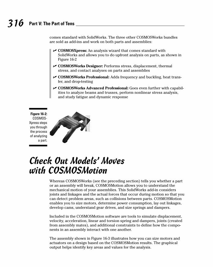
comes standard with SolidWorks. The three other COSMOSWorks bundles are sold as add-ins and work on both parts and assemblies:
� COSMOSXpress: An analysis wizard that comes standard withSolidWorks and allows you to do upfront analysis on parts, as shown inFigure 16-2
� COSMOSWorks Designer: Performs stress, displacement, thermalstress, and contact analyses on parts and assemblies
� COSMOSWorks Professional: Adds frequency and buckling, heat trans-fer, and drop-testing
� COSMOSWorks Advanced Professional: Goes even further with capabil-ities to analyze beams and trusses, perform nonlinear stress analysis,and study fatigue and dynamic response
Check Out Models’ Moves with COSMOSMotion
Whereas COSMOSWorks (see the preceding section) tells you whether a partor an assembly will break, COSMOSMotion allows you to understand themechanical motion of your assemblies. This SolidWorks add-in considersjoints and linkages and the actual forces that occur during motion so that youcan detect problem areas, such as collisions between parts. COSMOSMotionenables you to size motors, determine power consumption, lay out linkages,develop cams, understand gear drives, and size springs and dampers.
Included in the COSMOSMotion software are tools to simulate displacement,velocity, acceleration, linear and torsion spring and dampers, joints (createdfrom assembly mates), and additional constraints to define how the compo-nents in an assembly interact with one another.
The assembly shown in Figure 16-3 illustrates how you can size motors andactuators on a design based on the COSMOSMotion results. The graphicaloutput helps identify key areas and values for the analysis.
Figure 16-2:COSMOS-
Xpress stepsyou throughthe processof analyzing
a part.
316 Part V: The Part of Tens
24_129784 ch16.qxp 9/28/07 12:38 PM Page 316

Automate Tasks with the API and MacrosThe SolidWorks application programming interface (API) helps you recordmacros even if you don’t have much programming experience. Macros aresmall custom applications that automate a series of steps for a mundane taskin SolidWorks. For example, if you export designs for machine tooling, youcan create a macro that provides one-button export with all the options setinside the macro.
Macros are also a good way to maintain compliance with company standards.You can create a macro which ensures that specific settings are properly setand that a document complies with all the settings. You can even savemacros in the SolidWorks Design Library to share with other design teammembers. (To find out more about the Design Library, see Chapter 13.)
When you record a macro in SolidWorks, the SolidWorks API creates a filethat contains a record of all the commands (mouse clicks, menu choices, andkeystrokes) that take place from the time you start recording to when youstop. The commands are stored in the Microsoft Visual Basic program lan-guage. SolidWorks sets some limitations on what you can record in a macro,but most of the basic functions are automatic. SolidWorks saves macros withthe .swp extension. You can edit the files by using the Visual Basic Editor, soyou need a basic understanding of Visual Basic.
The commands to record a macro are on the Macro toolbar, shown in Figure16-4. To access the Macro toolbar, choose Tools➪Macro.
Figure 16-3:Use
COSMOS-Motion to
determinethe size andkilowatts of
the motoryou need for
the job.
317Chapter 16: Ten Ways to Extend and Reuse Your Design Information
24_129784 ch16.qxp 9/28/07 12:38 PM Page 317

� Run Macro: Opens the Run Macro dialog box. In the dialog box, browsefor the macro you want to run and click OK.
� Stop Macro: Stops the recording of the macro and opens the Save Asdialog box. Enter the name of the new macro in the dialog box and clickSave. The .swp extension is automatically added to the filename.
� Record/Pause Macro: Pauses the recording of a macro. Click again tobegin re-recording.
� New Macro: Creates a new macro. Begin entering the steps you want torecord. Click Stop Macro to save the file.
� Edit Macro: Allows you to edit or debug a macro that you alreadyrecorded. Click the Edit Macro button and browse to the macro to edit. The Microsoft Visual Basic Editor appears. Edit the macro andclose the editor.
For additional reference, the SolidWorks API support site, at www.solidworks.com/pages/services/APISupport.html, has a wealthof API examples, downloads, and tips.
Note that many of the Visual Basic application examples on the API-supportWeb site have the .bas file extension. To use one of these sample files, youneed to import it into VBA. To do so, create a new macro and import the fileby choosing Import File from the Microsoft Visual Basic File menu.
Schedule the Intensive Work withSolidWorks Task Scheduler
Labor-intensive tasks — such as batch importing, exporting, and plotting — cangobble up hours, if not days. Even though these jobs don’t require excessivebrain power, they still tie up your mind and computer. But now you can
Figure 16-4:The Macro
toolbarholds
commandsto run, stop,
record,create and
edit macros.
318 Part V: The Part of Tens
24_129784 ch16.qxp 9/28/07 12:38 PM Page 318
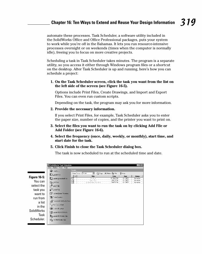
automate these processes. Task Scheduler, a software utility included in the SolidWorks Office and Office Professional packages, puts your system to work while you’re off in the Bahamas. It lets you run resource-intensiveprocesses overnight or on weekends (times when the computer is normallyidle), freeing you to focus on more creative projects.
Scheduling a task in Task Scheduler takes minutes. The program is a separateutility, so you access it either through Windows program files or a shortcuton the desktop. After Task Scheduler is up and running, here’s how you canschedule a project:
1. On the Task Scheduler screen, click the task you want from the list onthe left side of the screen (see Figure 16-5).
Options include Print Files, Create Drawings, and Import and ExportFiles. You can even run custom scripts.
Depending on the task, the program may ask you for more information.
2. Provide the necessary information.
If you select Print Files, for example, Task Scheduler asks you to enterthe paper size, number of copies, and the printer you want to print on.
3. Select the files you want to run the task on by clicking Add File orAdd Folder (see Figure 16-6).
4. Select the frequency (once, daily, weekly, or monthly), start time, andstart date for the task.
5. Click Finish to close the Task Scheduler dialog box.
The task is now scheduled to run at the scheduled time and date.
Figure 16-5:You can
select thetask youwant to
run from a list
in theSolidWorks
TaskScheduler.
319Chapter 16: Ten Ways to Extend and Reuse Your Design Information
24_129784 ch16.qxp 9/28/07 12:38 PM Page 319
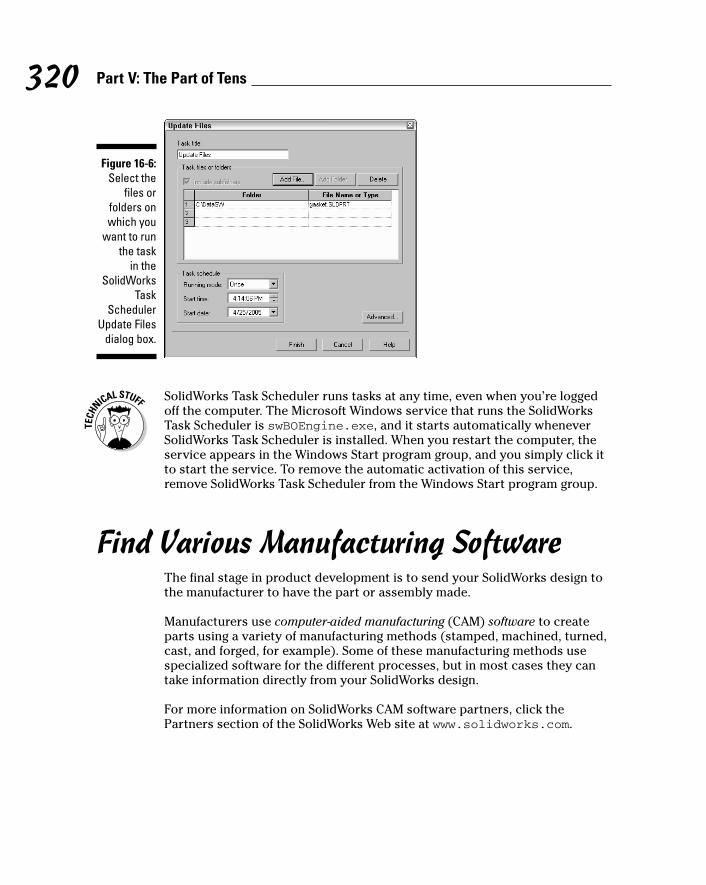
SolidWorks Task Scheduler runs tasks at any time, even when you’re loggedoff the computer. The Microsoft Windows service that runs the SolidWorksTask Scheduler is swBOEngine.exe, and it starts automatically wheneverSolidWorks Task Scheduler is installed. When you restart the computer, theservice appears in the Windows Start program group, and you simply click itto start the service. To remove the automatic activation of this service,remove SolidWorks Task Scheduler from the Windows Start program group.
Find Various Manufacturing SoftwareThe final stage in product development is to send your SolidWorks design tothe manufacturer to have the part or assembly made.
Manufacturers use computer-aided manufacturing (CAM) software to createparts using a variety of manufacturing methods (stamped, machined, turned,cast, and forged, for example). Some of these manufacturing methods usespecialized software for the different processes, but in most cases they cantake information directly from your SolidWorks design.
For more information on SolidWorks CAM software partners, click thePartners section of the SolidWorks Web site at www.solidworks.com.
Figure 16-6:Select the
files orfolders onwhich you
want to runthe task
in theSolidWorks
TaskScheduler
Update Filesdialog box.
320 Part V: The Part of Tens
24_129784 ch16.qxp 9/28/07 12:38 PM Page 320

Chapter 17
Ten Resources for the SolidWorks Community
In This Chapter� Getting familiar with the six groups that make up the SolidWorks community
� Getting to know the SolidWorks Web site
� Meeting like minds at a SolidWorks user group
� Searching for CAD models of standard parts
� Becoming a certified SolidWorks know-it-all
As a SolidWorks user, you can relax, knowing that you never have to go italone. You can find plenty of places (most of them on the Internet) to
meet up with other users, locate training and tech support, and get info onSolidWorks upgrades and add-on products.
In this chapter, you discover ten resources that are available from theSolidWorks community. Each element is a useful resource or reference as youbegin or continue your journey with SolidWorks.
SolidWorks and COSMOS User GroupsOne of the best ways to find out more about SolidWorks is to network withother users, which you can do by joining a user group. If you can’t find a usergroup in your area, you can always start one. These groups are beneficialbecause they give you an opportunity to swap stories and share softwareexperiences with other users.
User groups are a key component of the SolidWorks community. Figure 17-1shows how the user groups have links to each of the other major areas of theSolidWorks community.
25_129784 ch17.qxp 9/28/07 12:39 PM Page 321

322 Part V: The Part of Tens
You can find user groups for SolidWorks and for COSMOSWorks, the finiteelement analysis (FEA) program that works inside SolidWorks. These usergroups have local chapters all over the world. SolidWorks also hosts regionalevents and SolidWorks World, an annual international user group conventionthat changes location each year.
To find a group or to discover how to start one, go to www.swugn.org.
Figure 17-1:The
SolidWorkscommunity
offers acornucopia
ofresources.
It’s all about communityThe SolidWorks community is composed of sixgroups that work together and complement oneanother:
� Solution partners: Companies that offerhardware and software products certifiedto work with SolidWorks software
� SolidWorks Corporation: The company thatdevelops the software
� SolidWorks resellers: Organizations, some-times called value added resellers or VARs,
that sell SolidWorks products and providetraining and technical support
� The SolidWorks manufacturing network: Anetwork of manufacturers that accept yournative SolidWorks files to build parts with
� Educational institutions: Schools thatinclude SolidWorks in their curricula
� User groups: Groups of SolidWorks userswho meet to discuss SolidWorks and itsproducts
25_129784 ch17.qxp 9/28/07 12:39 PM Page 322

The SolidWorks Web SiteTo get the latest on SolidWorks, your first stop should be the SolidWorks Website (www.solidworks.com), shown in Figure 17-2.
The site has six main sections, which you can access by using the menu barat the top:
� Products: Offers information on SolidWorks products, which includeCAD, analysis, and data management software.
� Services: Divided into the categories Support, Subscription Services,Training and Certification, and Services and Consulting Partners. Thelater section “The SolidWorks Customer Portal” covers the Support(technical support) category in more detail. Training and Certificationoffers information on software courses available at SolidWorks trainingcenters and on how to become a certified SolidWorks know-it-all. (Readthe upcoming section “Certified SolidWorks Professional Program.”)Subscription Services shows you all the benefits of maintaining yourlicense subscription. Services and Consulting Partners provides asearchable index of SolidWorks partner companies that offer productsand services that can help your organization.
� Customer Successes: Includes links to customer success stories catego-rized by industry and by SolidWorks add-on.
Figure 17-2:The
SolidWorksWeb site
offersinformation
on products,services,partners,
news andevents, and
successstories.
323Chapter 17: Ten Resources for the SolidWorks Community
25_129784 ch17.qxp 9/28/07 12:39 PM Page 323
� News and Events: Offers the lowdown on what’s happening inSolidWorks. This category includes press releases, seminars, trade showschedules, and user group meetings and has a link to the SolidWorksExpress newsletter.
� Partners: Includes information on SolidWorks solution partners and themanufacturing network. (For more on the latter, see the “SolidWorksManufacturing Network” section, later in this chapter.)
� Company: Lists the latest information on SolidWorks the company, suchas who’s running the show, directions to the office, and a list of internalemployment opportunities (in case you’re looking for a job).
The SolidWorks Express NewsletterThe SolidWorks Express online newsletter for SolidWorks customers arrivesevery two weeks (and sometimes more often). Each issue features technicaltips, news on the latest happenings at SolidWorks, and real customer stories.
You can subscribe for free at www.solidworks.com/swexpress. To sign upfor e-mail notification for new issues, click Subscribe at the top of the currentissue of SolidWorks Express and complete the form. After you sign up, ane-mail notifies you that a new edition of the newsletter is available, and youcan click the URL that takes you to the site.
The SolidWorks Customer PortalOne of the most important resources for SolidWorks users is technical sup-port. Everyone needs a hand now and again. Look on the SolidWorks cus-tomer portal to find online technical support, software to download, and aslew of additional resources. To access the customer portal, you need to pur-chase an annual maintenance contract (about $1,200 for SolidWorks). Don’thave one? Talk to your local reseller and have someone explain the features,benefits, and costs of the subscription service program.
Access the customer portal support section at https://customercenter.solidworks.com (see Figure 17-3).
The support section includes this information:
� Links to download the latest version or service pack for SolidWorks soft-ware, including COSMOSWorks, PDMWorks, and eDrawings
� The latest news and technical bulletins
324 Part V: The Part of Tens
25_129784 ch17.qxp 9/28/07 12:39 PM Page 324
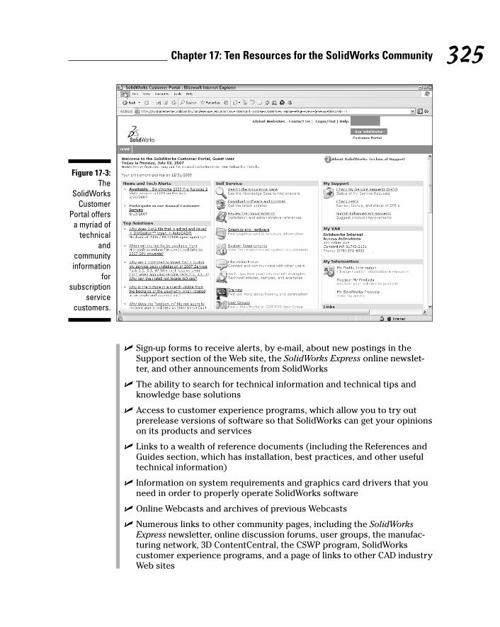
� Sign-up forms to receive alerts, by e-mail, about new postings in theSupport section of the Web site, the SolidWorks Express online newslet-ter, and other announcements from SolidWorks
� The ability to search for technical information and technical tips andknowledge base solutions
� Access to customer experience programs, which allow you to try outprerelease versions of software so that SolidWorks can get your opinionson its products and services
� Links to a wealth of reference documents (including the References andGuides section, which has installation, best practices, and other usefultechnical information)
� Information on system requirements and graphics card drivers that youneed in order to properly operate SolidWorks software
� Online Webcasts and archives of previous Webcasts
� Numerous links to other community pages, including the SolidWorksExpress newsletter, online discussion forums, user groups, the manufac-turing network, 3D ContentCentral, the CSWP program, SolidWorkscustomer experience programs, and a page of links to other CAD industryWeb sites
Figure 17-3:The
SolidWorksCustomer
Portal offersa myriad of
technicaland
communityinformation
forsubscription
servicecustomers.
325Chapter 17: Ten Resources for the SolidWorks Community
25_129784 ch17.qxp 9/28/07 12:39 PM Page 325
The Certified SolidWorks Professional Program
Another resource is the Certified SolidWorks Professional (CSWP) program. ACSWP is a person who knows SolidWorks like the back of his hand. But notjust anyone can become a CSWP. You have to first pass a test, which is givenat an authorized testing center, such as a reseller office. Being a CSWP enti-tles you to member-only privileges, including a special logo that you can puton your business card and invitations to exclusive CSWP-only events.
What’s more (this is the best part), your name is put on a searchable certifiedprofessional directory on the SolidWorks Web site. If anyone in your areaneeds to hire someone who’s quick on her feet with SolidWorks, he may giveyou a call.
From a company perspective, having a CSWP in the office is an advantage.You become the office guru, someone that other SolidWorks users can lookup to and go to for software support. The certification enables you to helpyour company identify qualified new hires, consultants, or contractors thatunderstand SolidWorks.
For more information on this resource, visit the CSWP section of the SolidWorksWeb site at www.solidworks.com/pages/services/training/CSWP.html.
3D ContentCentralOften, designs call for standard parts. Modeling those parts from scratch is awaste of time. 3D ContentCentral (www.3dcontentcentral.com) is a freeWeb site by SolidWorks that offers millions of supplier-certified and user-contributed part models in a number of different formats that you can down-load and drop into your SolidWorks designs.
The site has two sections:
� Supplier Certified Parts: Contains standard part models certified by thevendor to be accurate
� User Library: Lets designers upload CAD models to share with other users
To get started using 3D ContentCentral, all you need to do is register with thesite and create an account. The process takes about a minute. After you’re
326 Part V: The Part of Tens
25_129784 ch17.qxp 9/28/07 12:39 PM Page 326

onboard, 3D ContentCentral makes searching for standard components easy.After you find what you need, you can download the model and request aquote from the vendor. Some online catalogs allow you to configure parts toyour unique specifications.
The SolidWorks Manufacturing NetworkWhen you need to work with a vendor or a manufacturer, it’s a heck of a loteasier if the company can just accept your native SolidWorks data. Otherwise,you end up hassling with intermediary exchange formats, such as STEP andIGES, which can add extra steps to the process and put your data at risk.
If you need to find a company that will take your data “straight up,” check theSolidWorks manufacturing network. This free online directory of contractengineering, CNC (computer numerical controls) machining, mold making,industrial design, machine design, rapid prototyping, and other types of com-panies accepts native SolidWorks files. When you work with a company in themanufacturing network, there’s no stressing over file transfer issues.
Use the manufacturing network Web site (see the URL at the end of this sec-tion) to search for a designer, manufacturer, or supplier by name or by areaof expertise, such as industrial design, metal stamping, rapid prototyping, oreven reverse engineering.
If your organization provides services to the SolidWorks community, considerjoining the manufacturing network yourself. Sign-up is free, and you get a freelisting on the manufacturing network Web site.
For more information on this SolidWorks community resource, visitwww.solidworks.com/pages/partners/mfgnetwork.html.
SolidWorks Solution PartnersOne strength of SolidWorks is its Solution Partner program. Solution partnersare companies that develop best-in-class software and hardware that work withSolidWorks software. Look for logos on products to identify these certificationlevels:
� Research Associate: A company that has the intent or is in the processof developing a product for the SolidWorks market.
327Chapter 17: Ten Resources for the SolidWorks Community
25_129784 ch17.qxp 9/28/07 12:39 PM Page 327
Dow
nlo
ad fro
m W
ow
! eBook
<w
ww
.wow
ebook.
com
>
� Solution Partner: A company that has successfully released aSolidWorks-compatible product and has a minimum of two SolidWorkscustomers.
� Certified Gold Product: A software product that carries the CertifiedGold logo and is directly integrated with SolidWorks. Certified Goldproducts are designed to work well with SolidWorks.
� Certified CAM Product: A best-in-class computer-aided manufacturingor CNC machine software that works well with SolidWorks geometry.
For more information on this SolidWorks community resource, visitwww.solidworks.com/pages/partners/partners.html.
SolidWorks ResellersWhen you’re ready to purchase SolidWorks, you can go to your local SolidWorksvalue-added reseller (VAR). SolidWorks has hundreds of VARs throughout theworld. You can find one near you on the SolidWorks Web site by going to www.solidworks.com/pages/company/solidworksofficeworldwide.html,where you can find out who to contact for a current list of VARs in your area.
VARs do more than push a product. They offer a number of other services,including product demonstrations, technical support, and training programs.Among the clever and entertaining training courses they offer are nightclasses, lunch-and-learn workshops, and SolidWorks test drives. Check withyour local VAR to see what it has to offer.
The SolidWorks Educational CommunityIf you’re in college, keep your eyes peeled for SolidWorks in the classroom.SolidWorks develops a special educational edition of its software for use inhigh schools, colleges, and universities. Students who learn with SolidWorksget practical training and real experience. The Education Edition also comeswith a teacher’s guide, curriculum ideas, courseware, and sample part files.
Maybe you’re not a student. You’re thinking “What does this have to do withme?” If you’re about to hire an intern or college graduate, post your ad at colleges and universities that offer SolidWorks in their curriculums. Because
328 Part V: The Part of Tens
25_129784 ch17.qxp 9/28/07 12:39 PM Page 328

students from these schools are ready to start designing tomorrow, you don’thave to spend heaps of money to train them.
For more information, visit the SolidWorks educational Web site at www.solidworks.com/pages/products/edu. Also available on the Website are a list of events and associations and a newsletter for the educationalcommunity.
329Chapter 17: Ten Resources for the SolidWorks Community
25_129784 ch17.qxp 9/28/07 12:39 PM Page 329

330 Part V: The Part of Tens
25_129784 ch17.qxp 9/28/07 12:39 PM Page 330
Appendix
About the CDIn This Appendix� Discovering your system requirements
� Using the CD
� Finding out what’s on the CD
� Troubleshooting
This CD contains demos on how SolidWorks works, information about add-on solutions for SolidWorks, and examples of how other companies use
SolidWorks within different industries. The CD runs on its own, so all you needto do is stick it in the CD drive.
System RequirementsMake sure that your computer meets the minimum system requirementsshown in the following list; if your computer doesn’t match up to most ofthese requirements, you may have problems using the software and files onthe CD:
� A PC with a Pentium or faster processor
� Microsoft Windows Vista or Windows XP Professional
� At least 512MB of total RAM installed on your computer
� A CD-ROM drive
� A sound card for PCs
� A monitor capable of displaying at least 256 colors or grayscale
� A Flash-compatible Web browser
� A pointing device (mouse)
26_129784 app.qxp 9/28/07 12:39 PM Page 331

If you need more information on the basics, check out these books publishedby Wiley Publishing, Inc.: PCs For Dummies, by Dan Gookin, or Windows XPFor Dummies, 2nd Edition, or Windows Vista For Dummies, both by AndyRathbone.
Using the CDTo run the Interactive Tour CD, follow these steps.
1. Insert the CD into your computer’s CD-ROM drive.
The CD’s introduction page appears. You see links to interviews discussingthe focus, innovation, and use of SolidWorks.
Note: The interface doesn’t launch if you have Autorun disabled. In thatcase, choose Start➪Run. In the dialog box that appears, type D:\start.exe.(Replace D with the proper letter if your CD-ROM drive uses a differentletter. If you don’t know the letter, see how your CD-ROM drive is listedunder My Computer.) Click OK.
2. Click the Start Tour button in the lower-left corner of the main page tocontinue.
The product demo section appears on the left side of the screen.
3. Select which area to review by clicking the Product Demos, Add-OnSolutions, or Case Studies tab at the top of the window.
After you select a tab, the menu on the left of the window changes toreflect the selected area.
4. Click the topic category to view.
For example, when you click Drawing Creation within the productdemos, the demos Create Drawings, Revise Drawings, and RevisionTables appear.
5. Click the specific topic to view.
The main screen changes to show the selected demo, solution, or casestudy.
6. Click the View button within the main window.
The View button says View Demo for product demos, View Add-On Infofor add-on solutions, and View Video for case studies.
7. To exit the tour, choose File➪Exit.
332 SolidWorks For Dummies, 2nd Edition
26_129784 app.qxp 9/28/07 12:39 PM Page 332
What You Find on the CDI organized the following sections by category to provide a summary of thesoftware and other goodies on the CD. If you need help with installing the itemsprovided on the CD, refer to the installation instructions in the preceding section.
Shareware programs are fully functional, free, trial versions of copyrightedprograms. If you like particular programs, register with their authors for anominal fee and receive licenses, enhanced versions, and technical support.
Freeware programs are free, copyrighted games, applications, and utilities.You can copy them to as many PCs as you like — for free — but they offer notechnical support.
GNU software is governed by its own license, which is included inside thefolder of the GNU software. There are no restrictions on the distribution ofGNU software. See the GNU license at the root of the CD for more details.
Trial, demo, or evaluation versions of software are usually limited by eithertime or functionality (and therefore might not let you save a project after youcreate it).
Product Demos tabThe Product Demos tab has links to demonstrations of SolidWorks featuresand functions. These video demonstrations show you how to use many of thefeatures within SolidWorks.
The Product Demos tab is divided into different categories, such as Time-Saving Innovations, Drawing Creation, Part Modeling, Assembly Design,Product Data Management, Design Communications, and CAD Productivity.The links appear on the left side of the window.
Add-on Solutions tabOne strength of SolidWorks is the breadth and quality of the solution partnersthat add functionality and extend the reach of SolidWorks into other areas,such as electronic design, computer-aided manufacturing, and optical design.
333Appendix: About the CD
26_129784 app.qxp 9/28/07 12:39 PM Page 333
The Add-on Solutions tab has links and references for a wide variety ofSolidWorks add-on products divided into different categories, includingAnalysis, Communication, Component Libraries, Data Management, Design,Manufacturing, and Mold Making.
Case Studies tabOne way to discover more about SolidWorks is to see how other companiesuse and apply SolidWorks in their design environments. The Case Studies tabhas industry-segmented case studies of SolidWorks customers.
Sales and Support tabIf you want more information about SolidWorks, the Sales and Support tabdisplays contact information for SolidWorks offices worldwide.
TroubleshootingThis CD is self contained and self running, so it doesn’t need to be installedon your computer.
If the CD doesn’t work properly, the two likeliest problems are that you don’thave the CD set up to play Macromedia Flash within your browser or the CDdoesn’t autoplay the tour application.
If you see an error message, such as Not enough memory or Setupcannot continue, try one or more of the following suggestions and thentry using the software again:
� Make sure that you have a Flash-compatible Web browser. CurrentWeb browsers come with the ability to play Flash content. You can alsovisit the Macromedia Flash Player Download Web site at www.adobe.com/shockwave/download/download.cgi?P1_Prod_Version=ShockwaveFlash for more details.
� Close all running programs. The more programs you have running, theless memory is available to other programs. Installation programs typicallyupdate files and programs, so if you keep other programs running, theinstallation may not work properly.
334 SolidWorks For Dummies, 2nd Edition
26_129784 app.qxp 9/28/07 12:39 PM Page 334

� Try running the application on another computer. This is a simple wayto see whether the problem is just a setup issue on your computer. If theCD runs fine on another computer, you may have a CD driver or Flashcompatibility issue.
� Reboot your computer. Restart your computer and see whether theproblem clears up.
If you still have trouble with the CD, please call the Customer Care phonenumber: (800) 762-2974. Outside the United States, call 1 (317) 572-3994. You can also contact Customer Service by visiting our Web site atwww.wiley.com/techsupport. Wiley Publishing, Inc. provides technicalsupport only for installation and other general quality control items; for tech-nical support on the applications themselves, consult the program’s vendoror author.
To place additional orders or to request information about other Wiley products,please call (877) 762-2974.
335Appendix: About the CD
26_129784 app.qxp 9/28/07 12:39 PM Page 335

336 SolidWorks For Dummies, 2nd Edition
26_129784 app.qxp 9/28/07 12:39 PM Page 336

• A •active layer, arrow indicator, 201Advanced Component Selection tool,
140–142Advanced mode, New SolidWorks dialog
box display, 21aligned section view, 166–167ambient light, visual properties, 216–219anchors, 176, 187, 189angle mates, uses, 129Angle Snap, Quick Snaps type, 78angles
dimensioning, 80draft, 96–98plane creation, 69–70Surface Finish symbol, 179
Animation Controller toolbar, 242animations, 242annotations. See reference annotationsAnnotations toolbar, 171–172, 174–185annual maintenance contract, 324ANSI, supported drawing standard, 156appearances, photorealistic display, 17Application Programming Interface
(API) 35, 317–318applied features. See also features
chamfers, 95–96circular patterns, 103–104draft angles, 96–98fillets, 93–95Hole Wizard, 99–101linear patterns, 102–103Mirror feature, 104–105model application, 84shells, 98–99
approvals, metadata information, 202arcs, 80, 221–222arrow keys, FeatureManager
navigation, 29.asmdot extension, 20assemblies
Assembly toolbar, 117–118AssemblyXpert performance
analysis, 17AssemblyXpert statistics,
148–149, 226–227axes, 116blocks, 138–140bottom-down design, 119bottom-up design, 50component editing, 117component insertion, 116–117, 122component organization, 123–125component selections, 140–142configuration variations, 234creating, 119–121creating from a layout, 139–140custom property addition, 203–204Design Library addition, 272disabling external references, 117displaying/deleting relations, 144dissolving a sub-assembly, 125exploded lines, 118exploded views, 118, 240–243external references, 143–144feature creation, 142–143features, 118folder creation, 125grouping components, 123–125hiding/showing components, 117in-context modeling, 143–145
Index
27_129784 bindex.qxp 9/28/07 12:39 PM Page 337
Dow
nlo
ad fro
m W
ow
! eBook
<w
ww
.wow
ebook.
com
>

assemblies (continued)
in-context reference, 50, 51, 55interference checking, 118, 146–147layouts, 116, 138Mass Properties tool, 149–150mates, 116, 126–137Measure tool, 147–148mechanical motions, 316–317motion studies, 118moving/rotating components, 117new sub-assembly insertion, 125part creation, 144–145part editing, 144–145planes, 116planning process, 118–119positive direction indicator, 116printing, 252–253Quick View parts display, 17scope definition, 143showing hidden components, 117smart fasteners, 117SmartMates, 128, 132–134statistics, 226–227subassemblies, 49, 50, 115suppression states, 117top-down design, 50, 119
assembly documents, .sldasm extension, 20
Assembly toolbar, functions, 117–118assembly, defined, 49AssemblyXpert, 17, 146, 226–227asterisk (*) character, 25–26attachments
Datum symbol/layer, 182datum target/layer, 181Design Binder documents, 46–48note/layer, 176Surface Finish symbol/layer, 179
Auto Balloon, 178–179AutoCAD
Help system resources, 16, 35legacy file incorporation, 229–232moving to SolidWorks, 304
Auxiliary view, 164–165
AVI files, exploded view animations, 242axes
assembly element, 116axis of rotation, 88–89creating, 70–72creation methods, 68cylindrical/conical face, 71–72infinite straight dashed line, 60on edge, 71–72one line/edge/axis, 72point and a face/plane, 71–72reference geometry, 60, 68, 70–72revolving features around, 88–89sketch element, 60temporary, 71–72two planes, 71–72two points/vertices, 71–72versus centerlines, 68
• B •backgrounds, 204–206, 251backups, 13, 261balloons, 177–178base, adding material, 86base extrusion, part feature, 83, 86base features, 83–84baseline dimensions, drawings, 172–174beveled edges, chamfers, 95–96bill of materials (BOM), 186–188, 202blocks, 20, 138–140, 272Blocks toolbar, functions, 139bolts, cosmetic threads, 183borders, 154–155, 176boss, 86, 183boss features, sketched type, 84bottom-down design, 119bottom-up design, 50–51brainstorming, design planning
process, 48brightness, light sources, 217BSI, supported drawing standard, 156buttons, 30–31, 36–38
338 SolidWorks For Dummies, 2nd Edition
27_129784 bindex.qxp 9/28/07 12:39 PM Page 338
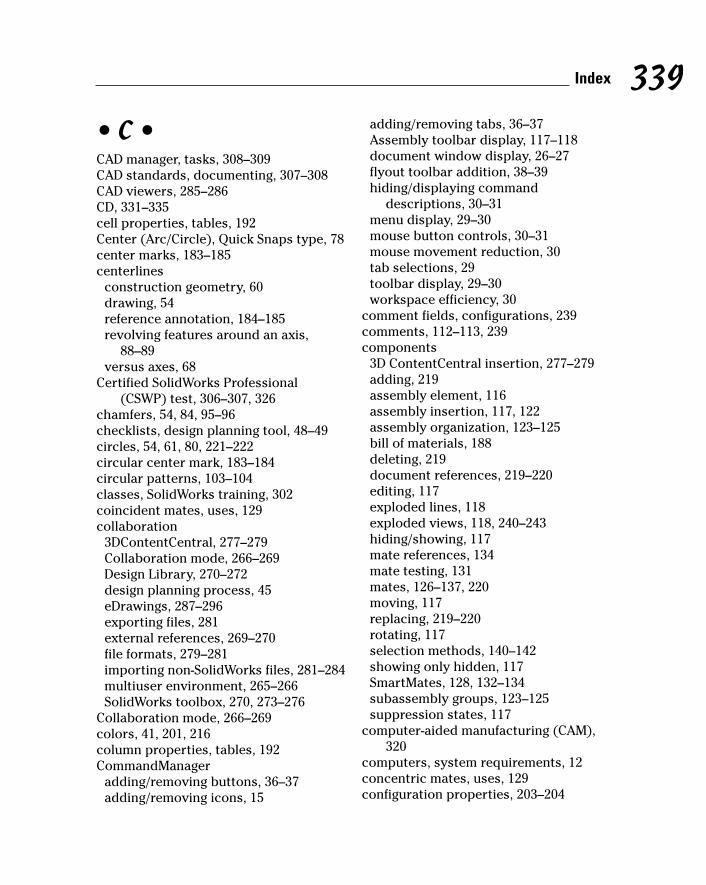
• C •CAD manager, tasks, 308–309CAD standards, documenting, 307–308CAD viewers, 285–286CD, 331–335cell properties, tables, 192Center (Arc/Circle), Quick Snaps type, 78center marks, 183–185centerlines
construction geometry, 60drawing, 54reference annotation, 184–185revolving features around an axis,
88–89versus axes, 68
Certified SolidWorks Professional(CSWP) test, 306–307, 326
chamfers, 54, 84, 95–96checklists, design planning tool, 48–49circles, 54, 61, 80, 221–222circular center mark, 183–184circular patterns, 103–104classes, SolidWorks training, 302coincident mates, uses, 129collaboration
3DContentCentral, 277–279Collaboration mode, 266–269Design Library, 270–272design planning process, 45eDrawings, 287–296exporting files, 281external references, 269–270file formats, 279–281importing non-SolidWorks files, 281–284multiuser environment, 265–266SolidWorks toolbox, 270, 273–276
Collaboration mode, 266–269colors, 41, 201, 216column properties, tables, 192CommandManager
adding/removing buttons, 36–37adding/removing icons, 15
adding/removing tabs, 36–37Assembly toolbar display, 117–118document window display, 26–27flyout toolbar addition, 38–39hiding/displaying command
descriptions, 30–31menu display, 29–30mouse button controls, 30–31mouse movement reduction, 30tab selections, 29toolbar display, 29–30workspace efficiency, 30
comment fields, configurations, 239comments, 112–113, 239components
3D ContentCentral insertion, 277–279adding, 219assembly element, 116assembly insertion, 117, 122assembly organization, 123–125bill of materials, 188deleting, 219document references, 219–220editing, 117exploded lines, 118exploded views, 118, 240–243hiding/showing, 117mate references, 134mate testing, 131mates, 126–137, 220moving, 117replacing, 219–220rotating, 117selection methods, 140–142showing only hidden, 117SmartMates, 128, 132–134subassembly groups, 123–125suppression states, 117
computer-aided manufacturing (CAM),320
computers, system requirements, 12concentric mates, uses, 129configuration properties, 203–204
339Index
27_129784 bindex.qxp 9/28/07 12:39 PM Page 339
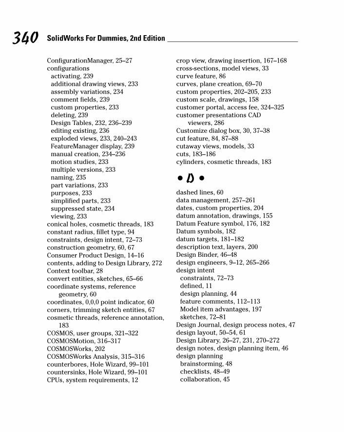
ConfigurationManager, 25–27configurations
activating, 239additional drawing views, 233assembly variations, 234comment fields, 239custom properties, 233deleting, 239Design Tables, 232, 236–239editing existing, 236exploded views, 233, 240–243FeatureManager display, 239manual creation, 234–236motion studies, 233multiple versions, 233naming, 235part variations, 233purposes, 233simplified parts, 233suppressed state, 234viewing, 233
conical holes, cosmetic threads, 183constant radius, fillet type, 94constraints, design intent, 72–73construction geometry, 60, 67Consumer Product Design, 14–16contents, adding to Design Library, 272Context toolbar, 28convert entities, sketches, 65–66coordinate systems, reference
geometry, 60coordinates, 0,0,0 point indicator, 60corners, trimming sketch entities, 67cosmetic threads, reference annotation,
183COSMOS, user groups, 321–322COSMOSMotion, 316–317COSMOSWorks, 202COSMOSWorks Analysis, 315–316counterbores, Hole Wizard, 99–101countersinks, Hole Wizard, 99–101CPUs, system requirements, 12
crop view, drawing insertion, 167–168cross-sections, model views, 33curve feature, 86curves, plane creation, 69–70custom properties, 202–205, 233custom scale, drawings, 158customer portal, access fee, 324–325customer presentations CAD
viewers, 286Customize dialog box, 30, 37–38cut feature, 84, 87–88cutaway views, models, 33cuts, 183–186cylinders, cosmetic threads, 183
• D •dashed lines, 60data management, 257–261dates, custom properties, 204datum annotation, drawings, 155Datum Feature symbol, 176, 182Datum symbols, 182datum targets, 181–182description text, layers, 200Design Binder, 46–48design engineers, 9–12, 265–266design intent
constraints, 72–73defined, 11design planning, 44feature comments, 112–113Model item advantages, 197sketches, 72–81
Design Journal, design process notes, 47design layout, 50–54, 61Design Library, 26–27, 231, 270–272design notes, design planning item, 46design planning
brainstorming, 48checklists, 48–49collaboration, 45
340 SolidWorks For Dummies, 2nd Edition
27_129784 bindex.qxp 9/28/07 12:39 PM Page 340
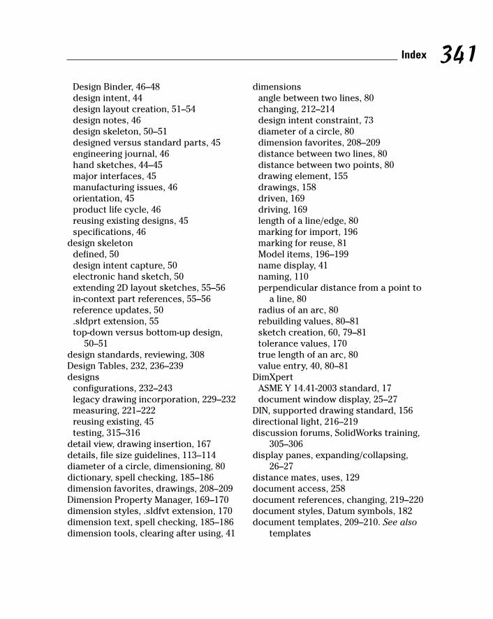
Design Binder, 46–48design intent, 44design layout creation, 51–54design notes, 46design skeleton, 50–51designed versus standard parts, 45engineering journal, 46hand sketches, 44–45major interfaces, 45manufacturing issues, 46orientation, 45product life cycle, 46reusing existing designs, 45specifications, 46
design skeletondefined, 50design intent capture, 50electronic hand sketch, 50extending 2D layout sketches, 55–56in-context part references, 55–56reference updates, 50.sldprt extension, 55top-down versus bottom-up design,
50–51design standards, reviewing, 308Design Tables, 232, 236–239designs
configurations, 232–243legacy drawing incorporation, 229–232measuring, 221–222reusing existing, 45testing, 315–316
detail view, drawing insertion, 167details, file size guidelines, 113–114diameter of a circle, dimensioning, 80dictionary, spell checking, 185–186dimension favorites, drawings, 208–209Dimension Property Manager, 169–170dimension styles, .sldfvt extension, 170dimension text, spell checking, 185–186dimension tools, clearing after using, 41
dimensionsangle between two lines, 80changing, 212–214design intent constraint, 73diameter of a circle, 80dimension favorites, 208–209distance between two lines, 80distance between two points, 80drawing element, 155drawings, 158driven, 169driving, 169length of a line/edge, 80marking for import, 196marking for reuse, 81Model items, 196–199name display, 41naming, 110perpendicular distance from a point to
a line, 80radius of an arc, 80rebuilding values, 80–81sketch creation, 60, 79–81tolerance values, 170true length of an arc, 80value entry, 40, 80–81
DimXpertASME Y 14.41-2003 standard, 17document window display, 25–27
DIN, supported drawing standard, 156directional light, 216–219discussion forums, SolidWorks training,
305–306display panes, expanding/collapsing,
26–27distance mates, uses, 129document access, 258document references, changing, 219–220document styles, Datum symbols, 182document templates, 209–210. See also
templates
341Index
27_129784 bindex.qxp 9/28/07 12:39 PM Page 341
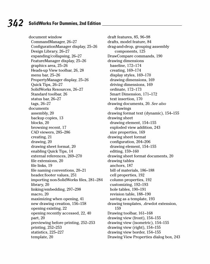
document windowCommandManager, 26–27ConfigurationManager display, 25–26Design Library, 26–27expanding/collapsing, 26–27FeatureManager display, 25–26graphics area, 25–26Heads-up View toolbar, 26, 28menu bar, 25–26PropertyManager display, 25–26Quick Tips, 26–27SolidWorks Resources, 26–27Standard toolbar, 26status bar, 26–27tags, 26–27
documentsassembly, 20backup copies, 13blocks, 20browsing recent, 17CAD viewers, 285–286creating, 21drawing, 20drawing sheet format, 20enabling Quick Tips, 14external references, 269–270file extensions, 20file links, 19file naming conventions, 20–21header/footer values, 251importing non-SolidWorks files, 281–284library, 20linking/embedding, 297–298macro, 20maximizing when opening, 41new drawing creation, 156–158opening existing, 22opening recently accessed, 22, 40part, 20previewing before printing, 252–253printing, 252–253statistics, 225–227template, 20
draft features, 85, 96–98drafts, model feature, 84drag-and-drop, grouping assembly
components, 125DrawCompare commands, 190drawing dimensions
baseline, 172–174creating, 169–174display styles, 169–170drawing dimensions, 169driving dimensions, 169ordinate, 172–173Smart Dimension, 171–172text insertion, 170
drawing documents, 20. See alsodrawings
drawing format text (dynamic), 154–155drawing sheet
drawing element, 154–155exploded view addition, 243size properties, 169
drawing sheet formatconfiguration, 204–206drawing element, 154–155editing, 159–160
drawing sheet format documents, 20drawing tables
anchors, 187bill of materials, 186–188cell properties, 192column properties, 192customizing, 192–193hole tables, 190–191revision table, 188–190saving as a template, 193
drawing templates, .drwdot extension,159
Drawing toolbar, 161–168drawing view (front), 154–155drawing view (isometric), 154–155drawing view (right), 154–155drawing view border, 154–155Drawing View Properties dialog box, 243
342 SolidWorks For Dummies, 2nd Edition
27_129784 bindex.qxp 9/28/07 12:39 PM Page 342
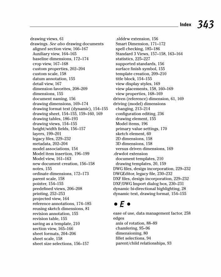
drawing views, 61drawings. See also drawing documents
aligned section view, 166–167Auxiliary view, 164–165baseline dimensions, 172–174crop view, 167–168custom properties, 202–204custom scale, 158datum annotation, 155detail view, 167dimension favorites, 208–209dimensions, 155document naming, 156drawing dimensions, 169–174drawing format text (dynamic), 154–155drawing sheet, 154–155, 159–160, 169drawing tables, 186–193drawing views, 154–155height/width fields, 156–157layers, 199–201legacy files, 229–232metadata, 202–204model associations, 154Model item insertion, 196–199Model view, 161–163new document creation, 156–158notes, 155ordinate dimensions, 172–173parent scale, 158pointer, 154–155predefined views, 206–208printing, 252–253projected view, 164reference annotations, 174–185reusing sketch dimensions, 81revision annotation, 155revision table, 155saving as a template, 210section view, 165–166sheet formats, 204–206sheet scale, 158sheet size selections, 156–157
.slddrw extension, 156Smart Dimension, 171–172spell checking, 185–186Standard 3 Views, 157–158, 163–164statistics, 225–227supported standards, 156surface finish symbol, 155template creation, 209–210title block, 154–155view display styles, 169view placements, 158, 160–169view properties, 168–169
driven (reference) dimension, 61, 169driving (model) dimensions
changing, 213–214configuration editing, 236drawing element, 155Model items, 196primary value settings, 170sketch element, 602D dimensions, 1583D dimensions, 158versus driven dimensions, 169
.drwdot extensiondocument templates, 210drawing templates, 20, 159
DWG files, design incorporation, 229–232DWGEditor, legacy file, 230–232DXF files, design incorporation, 229–232DXF/DWG Import dialog box, 230–231dynamic bi-directional highlighting, 28dynamic text, drawing format, 154–155
• E •ease of use, data management factor, 258edges
axis of rotation, 88–89chamfering, 95–96dimensioning, 80fillet selections, 94parent/child relationships, 93
343Index
27_129784 bindex.qxp 9/28/07 12:39 PM Page 343
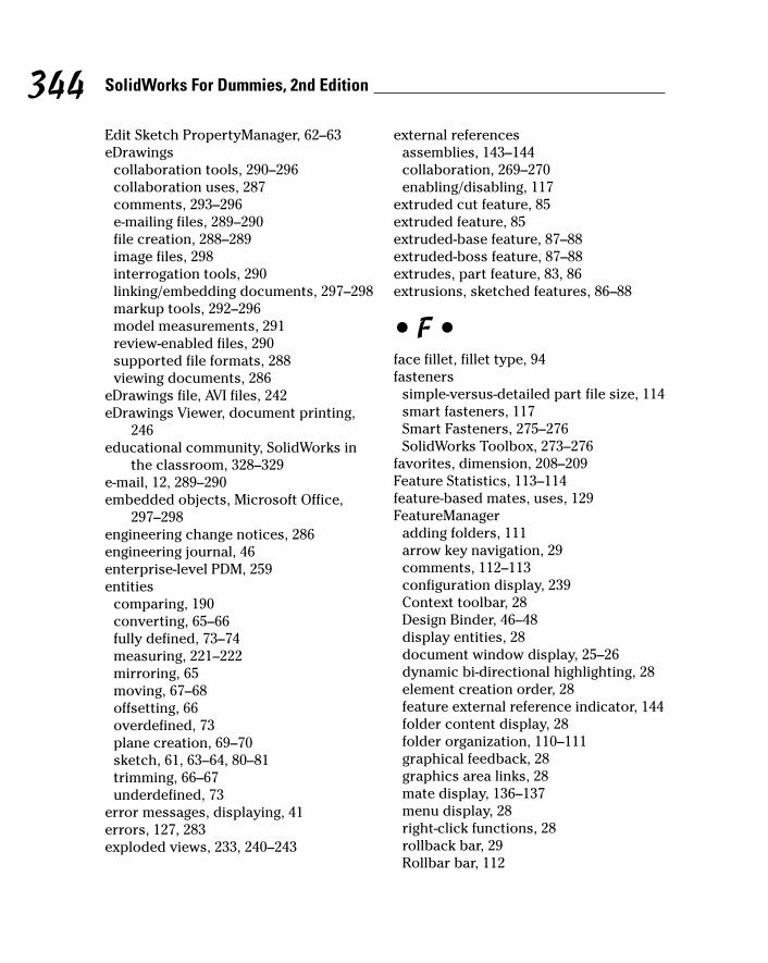
Edit Sketch PropertyManager, 62–63eDrawings
collaboration tools, 290–296collaboration uses, 287comments, 293–296e-mailing files, 289–290file creation, 288–289image files, 298interrogation tools, 290linking/embedding documents, 297–298markup tools, 292–296model measurements, 291review-enabled files, 290supported file formats, 288viewing documents, 286
eDrawings file, AVI files, 242eDrawings Viewer, document printing,
246educational community, SolidWorks in
the classroom, 328–329e-mail, 12, 289–290embedded objects, Microsoft Office,
297–298engineering change notices, 286engineering journal, 46enterprise-level PDM, 259entities
comparing, 190converting, 65–66fully defined, 73–74measuring, 221–222mirroring, 65moving, 67–68offsetting, 66overdefined, 73plane creation, 69–70sketch, 61, 63–64, 80–81trimming, 66–67underdefined, 73
error messages, displaying, 41errors, 127, 283exploded views, 233, 240–243
external referencesassemblies, 143–144collaboration, 269–270enabling/disabling, 117
extruded cut feature, 85extruded feature, 85extruded-base feature, 87–88extruded-boss feature, 87–88extrudes, part feature, 83, 86extrusions, sketched features, 86–88
• F •face fillet, fillet type, 94fasteners
simple-versus-detailed part file size, 114smart fasteners, 117Smart Fasteners, 275–276SolidWorks Toolbox, 273–276
favorites, dimension, 208–209Feature Statistics, 113–114feature-based mates, uses, 129FeatureManager
adding folders, 111arrow key navigation, 29comments, 112–113configuration display, 239Context toolbar, 28Design Binder, 46–48display entities, 28document window display, 25–26dynamic bi-directional highlighting, 28element creation order, 28feature external reference indicator, 144folder content display, 28folder organization, 110–111graphical feedback, 28graphics area links, 28mate display, 136–137menu display, 28right-click functions, 28rollback bar, 29Rollbar bar, 112
344 SolidWorks For Dummies, 2nd Edition
27_129784 bindex.qxp 9/28/07 12:39 PM Page 344
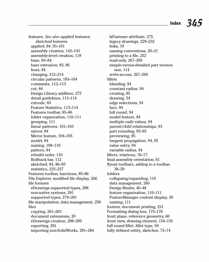
features. See also applied features;sketched features
applied, 84, 93–101assembly creation, 142–143assembly-level creation, 118base, 83–84base extrusion, 83, 86boss, 84changing, 212–214circular patterns, 103–104comments, 112–113cut, 84Design Library addition, 272detail guidelines, 113–114extrude, 83Feature Statistics, 113–114Features toolbar, 85–86folder organization, 110–111grouping, 111linear patterns, 101–103mirror, 84Mirror feature, 104–105model, 84naming, 108–110pattern, 84rebuild order, 110Rollback bar, 112sketched, 84, 86–93statistics, 225–227
Features toolbar, functions, 85–86File Explorer, modified file display, 266file formats
eDrawings supported types, 288non-native systems, 281supported types, 279–281
file manipulation, data management, 258files
copying, 261–263document extensions, 20eDrawings creation, 288–289exporting, 281importing non-SolidWorks, 281–284
IsFastener attribute, 275legacy drawings, 229–232links, 19naming conventions, 20–21printing to a file, 252read-only, 267–269simple-versus-detailed part version
size, 114write-access, 267–269
filletsblending, 94constant radius, 94creating, 85drawing, 54edge selections, 94face, 94full round, 94model feature, 84multiple radii values, 94parent/child relationships, 93part rounding, 93–95previewing, 95tangent propagation, 94, 95value entry, 94variable radius, 94
filters, relations, 76–77final assembly orientation, 61flyout toolbars, adding to a toolbar,
38–39folders
collapsing/expanding, 110data management, 260Design Binder, 46–48feature organization, 110–111FeatureManager content display, 28naming, 111
footers, document printing, 251Formatting dialog box, 175–176front plane, reference geometry, 60front view, drawing element, 154–155full round fillet, fillet type, 94fully defined entity, sketches, 73–74
345Index
27_129784 bindex.qxp 9/28/07 12:39 PM Page 345

• G •GB, supported drawing standard, 156Geometric Tolerance symbol
datum targets, 181–182note insertion, 176reference annotation, 180–181
geometry, sketch creation order, 60geometry-based mates, uses, 128Gookin, Dan (PCs For Dummies), 2GOST, supported drawing standard, 156graphical feedback, FeatureManager, 28graphics area, 25–26, 69–70graphics cards, 12, 34Grid Snap, Quick Snaps type, 78groups
components, 123–125features, 111object selections, 31
guide curves, 90, 92
• H •hand sketch, 44–45. See also sketcheshard drives, 12–13hardware accelerator shaders, 34hardware, SolidWorks Toolbox insertion,
273–275headers, document printing, 251Heads-up View toolbar
display styles, 33–34document window display, 26, 28modeling tools, 31–32Standard Views toolbar, 32
height/width fields, drawings, 156–157Help menu, user resources, 34–36Help system
AutoCAD help, 16, 35Consumer Product Design resources, 16Help menu resources, 34–36Machine Design resources, 16menu bar display, 25–26
Mold Design resources, 16Online User’s Guide, 16, 34Quick Reference Guide, 35Quick Tips, 14SolidWorks training uses, 303–304Tip of the Day, 16tutorials, 15, 34What’s New documents, 15, 35
hidden lines, displaying/hiding, 33highlights
color settings, 41model display, 34
hole callouts, Model item insertion, 198hole tables, revision tables, 190–191Hole Wizard
drilling holes, 99–101feature creation, 85Model item insertion, 198
holescosmetic threads, 183hole tables, 190–191Hole Wizard, 99–101model feature, 84
Horizontal Point Snap, Quick Snaps, 78Horizontal Snap, Quick Snap, 78hyperlinks, notes, 176
• I •icons
CommandManager display, 15toolbar display size, 30
image files, 298Import Diagnostics, 283–284in-context design, 143–145in-context reference
assemblies, 50, 51, 55–56performance factors, 51top-down design, 50–51
indented assemblies, bill of materials,188
346 SolidWorks For Dummies, 2nd Edition
27_129784 bindex.qxp 9/28/07 12:39 PM Page 346
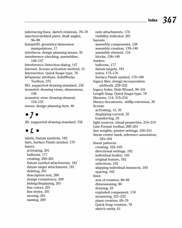
inferencing lines, sketch relations, 78–79injection-molded parts, draft angles,
96–98Instant3D, geometry/dimension
manipulators, 17interfaces, design planning issues, 45interference checking, assemblies,
146–147Interference Detection dialog, 147Internet, license activation method, 12Intersection, Quick Snaps type, 78IsFastener attribute, SolidWorks
Toolbox, 275ISO, supported drawing standard, 156isometric drawing views, dimensions,
158isometric view, drawing element,
154–155issues, design planning item, 46
• J •JIS, supported drawing standard, 156
• L •labels, Datum symbols, 182lairs, Surface Finish symbol, 179layers
activating, 201balloons, 177creating, 200–201Datum symbol attachments, 182datum target attachments, 181deleting, 201description text, 200design consistency, 200hiding/displaying, 201line colors, 201line styles, 201moving, 201naming, 200
note attachments, 176visibility indicator, 201
layoutsassembly components, 138assembly creation, 139–140assembly element, 116blocks, 138–140
leadersballoons, 177datum targets, 181notes, 175–176Surface Finish symbol, 179–180
legacy files, design incorporationmethods, 229–232
legacy holes, Hole Wizard, 99–101Length Snap, Quick Snaps type, 78libraries, 114, 215–216library documents, .sldlfp extension, 20license
activating, 12, 35displaying current, 35transferring, 35
light sources, visual properties, 216–219Line Format toolbar, 200–201line weights, printer settings, 250–251linear center mark, reference annotation,
183–184linear patterns
creating, 102–103directional settings, 102individual bodies, 102original feature, 102selections, 102skipping individual instances, 103spacing, 102
linesaxis of rotation, 88–89dimensioning, 80drawing, 53exploded component, 118measuring, 221–222plane creation, 69–70Quick Snap creation, 78sketch entity, 61
347Index
27_129784 bindex.qxp 9/28/07 12:39 PM Page 347
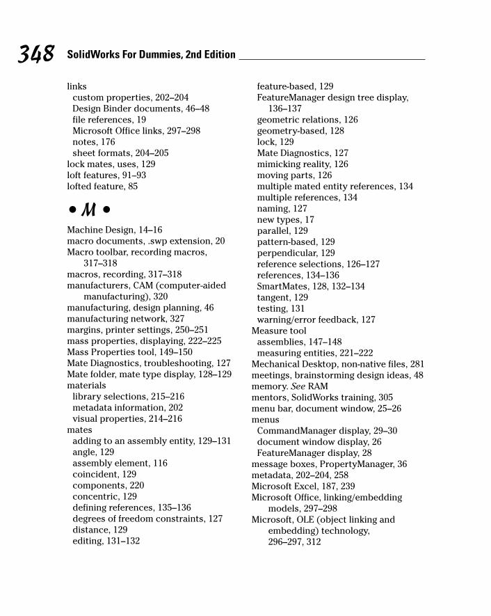
linkscustom properties, 202–204Design Binder documents, 46–48file references, 19Microsoft Office links, 297–298notes, 176sheet formats, 204–205
lock mates, uses, 129loft features, 91–93lofted feature, 85
• M •Machine Design, 14–16macro documents, .swp extension, 20Macro toolbar, recording macros,
317–318macros, recording, 317–318manufacturers, CAM (computer-aided
manufacturing), 320manufacturing, design planning, 46manufacturing network, 327margins, printer settings, 250–251mass properties, displaying, 222–225Mass Properties tool, 149–150Mate Diagnostics, troubleshooting, 127Mate folder, mate type display, 128–129materials
library selections, 215–216metadata information, 202visual properties, 214–216
matesadding to an assembly entity, 129–131angle, 129assembly element, 116coincident, 129components, 220concentric, 129defining references, 135–136degrees of freedom constraints, 127distance, 129editing, 131–132
feature-based, 129FeatureManager design tree display,
136–137geometric relations, 126geometry-based, 128lock, 129Mate Diagnostics, 127mimicking reality, 126moving parts, 126multiple mated entity references, 134multiple references, 134naming, 127new types, 17parallel, 129pattern-based, 129perpendicular, 129reference selections, 126–127references, 134–136SmartMates, 128, 132–134tangent, 129testing, 131warning/error feedback, 127
Measure toolassemblies, 147–148measuring entities, 221–222
Mechanical Desktop, non-native files, 281meetings, brainstorming design ideas, 48memory. See RAMmentors, SolidWorks training, 305menu bar, document window, 25–26menus
CommandManager display, 29–30document window display, 26FeatureManager display, 28
message boxes, PropertyManager, 36metadata, 202–204, 258Microsoft Excel, 187, 239Microsoft Office, linking/embedding
models, 297–298Microsoft, OLE (object linking and
embedding) technology, 296–297, 312
348 SolidWorks For Dummies, 2nd Edition
27_129784 bindex.qxp 9/28/07 12:39 PM Page 348

Microsoft Word, Design Journal, 47Mid-Points, Quick Snaps type, 78mirror entities, sketches, 65mirror feature
applied type, 84creating, 86, 104–105
model (driving) dimension, 60model faces, lofted features, 91model features, applied type, 84Model items
dimension placement, 199drawing advantages, 196–197drawing insertion, 196–199driving dimensions, 196eliminating duplicates, 198hidden feature inclusion, 199hole callouts, 198Hole Wizard, 198surface-finish annotations, 197
Model view, drawing insertion, 161–163models
area zooms, 32configurations, 203detail guidelines, 113–114drawing associations, 154error message display when
rebuilding, 41hardware accelerator shaders, 34hidden line display, 33image files, 298linking/embedding, 297–298metadata, 202–204panning, 32rotating in space, 32section view, 33shaded view, 33shaded view w/edges, 33shadow display, 33standard engineering views, 32switching between views, 323D ContentCentral, 279wireframe display, 33
zooming, 32Modify dialog box, 212–214, 236Mold Design, 14–16motion studies
assemblies, 118configurations, 233movement simulations, 314–315
mouse, button controls, 30–31multi-jog leader, Surface Finish symbol,
180
• N •Nearest Snap, Quick Snaps type, 78New SolidWorks Document dialog box
assembly creation, 120–121design layout creation, 51–54document creation, 21tab creation, 23–24
nontraditional training, SolidWorks,302–304
notesanchors, 176borders, 176custom property links, 202Datum Feature symbol insertion, 176Design Journal, 47drawing element, 155editing, 176Geometric Tolerance symbol insertion,
176layer attachments, 176leaders, 175–176links, 176property links, 176reference annotation, 175–176spell checking, 185–186Surface Finish symbol insertion, 176symbols, 176text formatting, 175–176
Novice mode, New SolidWorks dialogbox display, 21
349Index
27_129784 bindex.qxp 9/28/07 12:39 PM Page 349
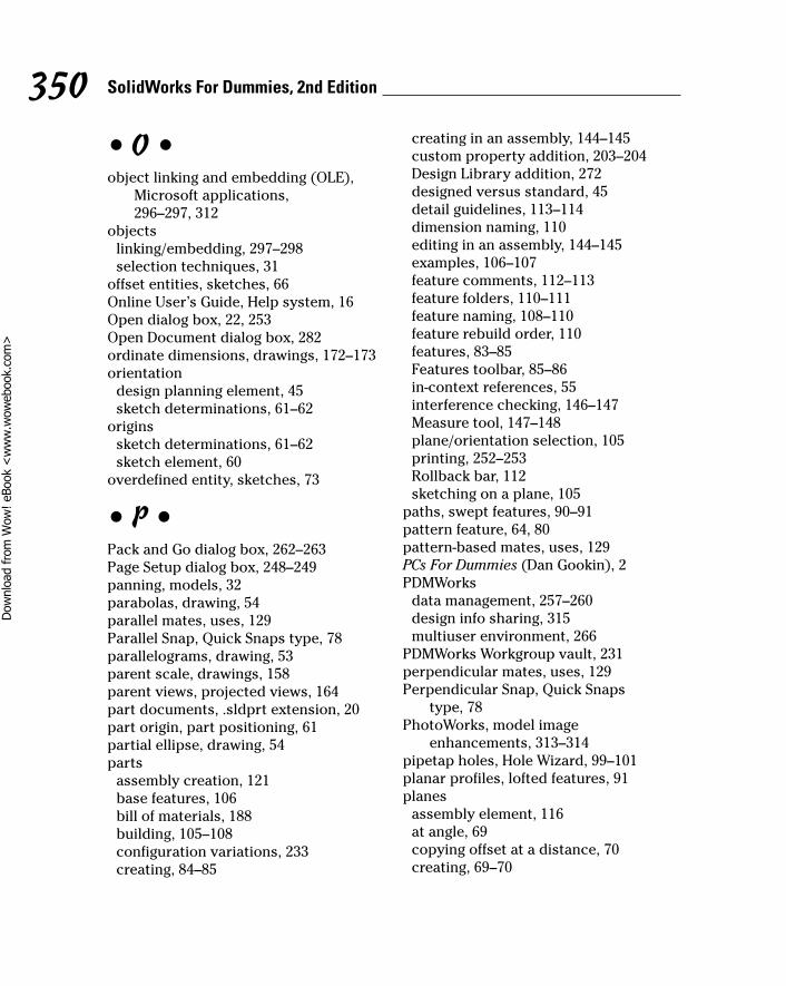
• O •object linking and embedding (OLE),
Microsoft applications, 296–297, 312
objectslinking/embedding, 297–298selection techniques, 31
offset entities, sketches, 66Online User’s Guide, Help system, 16Open dialog box, 22, 253Open Document dialog box, 282ordinate dimensions, drawings, 172–173orientation
design planning element, 45sketch determinations, 61–62
originssketch determinations, 61–62sketch element, 60
overdefined entity, sketches, 73
• P •Pack and Go dialog box, 262–263Page Setup dialog box, 248–249panning, models, 32parabolas, drawing, 54parallel mates, uses, 129Parallel Snap, Quick Snaps type, 78parallelograms, drawing, 53parent scale, drawings, 158parent views, projected views, 164part documents, .sldprt extension, 20part origin, part positioning, 61partial ellipse, drawing, 54parts
assembly creation, 121base features, 106bill of materials, 188building, 105–108configuration variations, 233creating, 84–85
creating in an assembly, 144–145custom property addition, 203–204Design Library addition, 272designed versus standard, 45detail guidelines, 113–114dimension naming, 110editing in an assembly, 144–145examples, 106–107feature comments, 112–113feature folders, 110–111feature naming, 108–110feature rebuild order, 110features, 83–85Features toolbar, 85–86in-context references, 55interference checking, 146–147Measure tool, 147–148plane/orientation selection, 105printing, 252–253Rollback bar, 112sketching on a plane, 105
paths, swept features, 90–91pattern feature, 64, 80pattern-based mates, uses, 129PCs For Dummies (Dan Gookin), 2PDMWorks
data management, 257–260design info sharing, 315multiuser environment, 266
PDMWorks Workgroup vault, 231perpendicular mates, uses, 129Perpendicular Snap, Quick Snaps
type, 78PhotoWorks, model image
enhancements, 313–314pipetap holes, Hole Wizard, 99–101planar profiles, lofted features, 91planes
assembly element, 116at angle, 69copying offset at a distance, 70creating, 69–70
350 SolidWorks For Dummies, 2nd Edition
27_129784 bindex.qxp 9/28/07 12:39 PM Page 350
Dow
nlo
ad fro
m W
ow
! eBook
<w
ww
.wow
ebook.
com
>
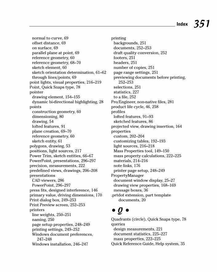
normal to curve, 69offset distance, 69on surface, 69parallel plane at point, 69reference geometry, 60reference geometry, 68–70sketch element, 60sketch orientation determination, 61–62through lines/points, 69
point lights, visual properties, 216–219Point, Quick Snaps type, 78pointer
drawing element, 154–155dynamic bi-directional highlighting, 28
pointsconstruction geometry, 60dimensioning, 80drawing, 54lofted features, 91plane creation, 69–70reference geometry, 60sketch entity, 61
polygons, drawing, 53positions, light sources, 217Power Trim, sketch entities, 66–67PowerPoint, presentations, 296–297precision, measurements, 222predefined views, drawings, 206–208presentations
CAD viewers, 286PowerPoint, 296–297
press fits, designed interference, 146primary value, driving dimensions, 170Print dialog box, 249–253Print Preview screen, 252–253printers
line weights, 250–251naming, 250page setup properties, 248–249printing settings, 249–252Windows document preferences,
247–248Windows installation, 246–247
printingbackgrounds, 251documents, 252–253draft quality conversion, 252footers, 251headers, 251number of copies, 251page range settings, 251previewing documents before printing,
252–253selections, 251statistics, 227to a file, 252
Pro/Engineer, non-native files, 281product life cycle, 46, 258profiles
lofted features, 91–93sketched features, 86
projected view, drawing insertion, 164properties
custom, 202–204customizing tables, 192–193light sources, 216–218Mass Properties tool, 149–150mass property calculations, 222–225materials, 214–216note links, 176printer page setup, 248–249
PropertyManagerdocument window display, 25–27drawing view properties, 168–169message boxes, 36
.prtdot extension, part templatedocuments, 20
• Q •Quadrants (circle), Quick Snaps type, 78queries
design measurements, 221document statistics, 225–227mass properties, 222–225
Quick Reference Guide, Help system, 35
351Index
27_129784 bindex.qxp 9/28/07 12:39 PM Page 351
Quick Snaps, 78Quick Tips
document window display, 26–27enabling, 14
Quick View, assembly model parts, 17
• R •radius of an arc, dimensioning, 80RAM (random access memory), 12read-only files, Collaboration mode,
267–269RealView Graphics mode, model
hardware accelerator shaders, 34Recent Document browser, 22rectangles, drawing, 53reference (driven) dimension, 61reference annotations
Auto Balloon, 178–179balloons, 177–178center marks, 183–185centerlines, 184–185circular center mark, 183–184cosmetic threads, 183Datum Feature symbols, 182Datum symbols, 182datum targets, 181–182Design Library addition, 272drawing notes, 155Geometric Tolerance symbol, 180–181linear center mark, 183–184mates, 134–136marking for import, 196Model items, 196–199notes, 175–176revision marks, 155single center mark, 183–184SmartMates, 134surface finish, 179–180surface finish symbol, 155tolerancing symbols, 180–181
reference geometryadding to a sketch, 68–72axes, 60, 68, 70–72coordinate systems, 60hiding/displaying, 68–69marking for import, 196Model items, 196–199planes, 60, 68–70points, 60sketch element, 60sketch entity names, 69visibility controls, 68
relationsadding to a sketch, 75–76all in this sketch, 76broken, 77dangling, 76defined in content, 77deleting, 77design intent constraint, 72–73displaying/deleting in an assembly, 144external, 77filters, 76–77inferencing lines, 78–79locked, 77overdefined/not solved, 77parent/child, 93Quick Snaps creation, 78selected entities, 76sketch creation order, 60sketch element, 61type listing, 75
release notes, SolidWorks featureinformation, 35
reseller events, SolidWorks training, 304revision annotation, drawing element,
155revision marks, drawings, 155revision tables
anchors, 189drawing element, 155
352 SolidWorks For Dummies, 2nd Edition
27_129784 bindex.qxp 9/28/07 12:39 PM Page 352

revision marks, 155symbol shapes, 189templates, 189
revolve featurescreating, 88–89mid-plane direction, 89two-direction, 89
revolved cut feature, 85revolved feature, 85rib feature, 85right plane, reference geometry, 60right view, drawing element, 154–155Rollback bar, features, 29, 112rotation
models, 32Surface Finish symbol, 179
• S •Save As dialog box, exporting files, 281Save Sheet Format dialog box, 205–206scale
drawing sheet format, 159drawing views, 169drawings, 158
scenes, photorealistic display, 17scope, assembly definition, 143Screen Capture tool, snapshots, 298searches, data management factor, 258section properties, displaying, 222, 225section views
drawing insertion, 165–166models, 33
security, data management factor, 258selections
assembly components, 140–142printing, 251properties, 141zooming, 32
serial number, displaying, 35service packs
current version display, 35SolidWorks updates, 15
shadows, model display, 33shapes, 177, 189sheet formats
custom property links, 204–205drawings, 204–206saving, 205–206.slddrt extension, 159, 205
sheet scale, drawings, 158sheet sizes, drawings, 156–157shell feature
creating, 86, 98–99faces to remove, 98outside dimensions, 98previewing, 98thickness settings, 98
shells, model feature, 84single center mark, reference annotation,
183–184single-command mode, activating, 39skeletons. See design skeletonsSketch mode, starting a sketch, 62–63Sketch toolbar
modifying sketch entities, 64–68starting a sketch, 62–63
sketch tools, clearing after using, 41sketched features. See also features
creating, 86–93cuts, 87–88extruded-base/boss, 87–88extrusions, 86–88lofted features, 91–93profiles, 86revolving around an axis, 88–89sweeping along a path, 90–912D sketch basis, 84
sketches. See also hand sketchesaxis, 60block insertion, 139construction geometry, 60, 67converting entities, 65–66creation order, 59–60design intent, 72–81dimension marking for reuse, 81
353Index
27_129784 bindex.qxp 9/28/07 12:39 PM Page 353
sketches (continued)
dimensions constraint, 73driven (reference) dimension, 61driving (model) dimension, 60entities, 62–68entity, 61fully defined entity, 73–74inferencing lines, 78–79mirror entities, 65moving entities, 67–68offsetting entities, 66orientation, 61–62origins, 60–62overdefined entity, 73planes, 60reference geometry, 60, 68–72relation filters, 76–77relations, 61, 72–79simple dimension creation, 79–81starting, 63–64trimming entities, 66–67underdefined entity, 73
.sldasm extension, assembly documents, 20
.sldblk extensionblocks, 138drawing documents, 20
.slddrt extensiondrawing sheet format documents, 20sheet formats, 159, 205
.slddrw extension, drawing documents,156
.sldfvt extension, dimension styles, 170
.sldlfp extension, library documents, 20
.sldprt extension, design skeletons, 55Smart Dimension, drawings, 171–172Smart Fasteners, SolidWorks Toolbox
insertion, 275–276SmartMates
automatic mate creation, 128, 132–134feature-based mates, 129pattern-based mates, 129references, 134
snapshots, Screen Capture tool, 298Solid Edge
non-native files, 281Parasolid-based system, 281
Solid Professor, computer-basedtraining, 303
SolidWorksdynamic interface, 25eDrawing file creation, 288–289first time startup, 13–15manufacturing network, 327multidocument system, 19service packs, 15supported drawing standards, 156system requirements, 12
SolidWorks Explorercopying files, 261–263legacy file associations, 231Pack and Go dialog box, 262–263versus Windows Explorer, 261–262
SolidWorks Express, online newsletter, 13, 303, 324
SolidWorks menu, 25–26SolidWorks Resources, document
window display, 26–27SolidWorks Search Oval, menu bar
display, 25–26SolidWorks Toolbox
hardware insertion, 273–275IsFastener attribute, 275Smart Fasteners, 275–276standard fastener storage, 273
SolidWorks Viewerdocument printing, 246document viewing, 296viewing documents, 286
Solution Partner, certification levels,327–328
special characters, filename exclusions, 21
specifications, design planning issues, 46specularity, light sources, 217Spelling Check tool, drawings, 185–186
354 SolidWorks For Dummies, 2nd Edition
27_129784 bindex.qxp 9/28/07 12:39 PM Page 354

splines, drawing, 54split lines, lofted features, 91spot lights, 216–219Standard 3 Views, drawings,
157–158, 163–164standard engineering views, 32Standard toolbar
document window display, 26read-only file display, 268–269
Standard Views toolbar, standardengineering views, 32
standards, supported types, 156static text, drawing format, 154–155statistics
assemblies, 148–149AssemblyXpert, 226–227copying, 227documents, 225–227drawings, 225–227features, 225–227printing, 227refreshing, 227
status bar, document window, 26–27sticky notes, note annotations, 175styles
Auto Balloon, 178balloon shapes, 177datum targets, 181drawing dimensions, 169–170layer lines, 201
subassembliesassembly components, 115–116bill of materials, 188component groups, 123–125defined, 49
Summary Information dialog box,202–204
supplier content, 3D ContentCentral, 277suppression states, 117Surface Finish symbol
angle/rotation, 179drawing element, 155instance editing, 180
layer attachment, 179leader style, 179–180Model items, 197multi-jog leader, 180multiple instances, 180note insertion, 176reference annotation, 179–180text formatting, 179
surfaces, 69–70, 91swept feature, 85, 90–91.swp extension, macro documents, 20symbols
Datum, 182datum targets, 181–182dimension values, 170notes, 176revision table shapes, 189Surface Finish, 155, 179–180, 197tolerancing, 180–181
system requirements, 12, 331–332
• T •Table formatting dialog box, 192–193table-based BOM, 186–188tables, anchors, 187tabs, 23–24, 29, 36–37tags, document window display, 26–27tangent mates, uses, 129tangent propagation, fillets, 94, 95Tangent Snap, Quick Snaps type, 78tapped holes, Hole Wizard, 99–101Task Scheduler, scheduling tasks,
318–320tasks, scheduling, 318–320templates. See also document templates
.asmdot extension, 20BOM (bill of materials), 187–188creating, 24, 209–210.drwdot extension, 20.prtdot extension, 20revision tables, 189saving table formats as, 193
355Index
27_129784 bindex.qxp 9/28/07 12:39 PM Page 355
text formatting, 170, 175–177, 179textures, model display, 34threads, cosmetic threads, 1833D ContentCentral
component insertion, 277–279models, 279part models, 326–327supplier content, 277User Library, 277–278
3D dimensions, drawings, 1583D Instant Website, sharing models, 3133D modeling, design advantages, 10–11Tip of the Day, Help system, 16title block
custom properties, 204–205drawing element, 154–155property links, 202spell checking, 185–186
TolAnalyst, tolerance analysis, 17tolerances
dimension values, 170Model item advantages, 197TolAnalyst analysis, 17
tolerancing symbols, drawing, 180–181toolbars
adding/deleting command buttons,37–38
Animation Controller, 242Annotations, 171–172, 174–185Assembly, 117–118Blocks, 138–139CommandManager display, 29–30creating, 37–38Drawing, 161–168flyout, 32, 38–39frequently performed actions
display, 17Heads-up View, 31–34icon display size, 30Line Format, 200Macro, 317–318moving buttons between, 37–38Standard, 268–269Standard Views, 32
top plane, reference geometry, 60top-down design, 50–51, 119triad, assembly direction indicator, 116trim entities, sketches, 66–67tutorials, 15, 34, 3042D dimensions, drawings, 1582D layout sketches, extending, 55–56
• U •underdefined entity, sketches, 73Unigraphics NX, 281units, measurements, 222updates, 15, 35user dictionary, spell checking, 185–186user groups, 304–305, 321–322user interface, 25–28, 36–39User Library, 3D ContentCentral, 277–278
• V •value-added resellers (VARs), 304, 328variable radius, fillet type, 94vendors
CAD viewers, 286computer-based training, 303metadata information, 202
version tracking, data management, 258Vertical Lock Snap, Quick Snaps type, 78Vertical Point Snap, Quick Snaps type, 78View-Only mode, document printing, 253views
drawing placements, 158, 160–168predefined drawing views, 206–208
virtual design, CAD viewers, 286virtual prototypes, design testing, 11–12visual properties, 214–219
• W •warnings, 127, 283Web sites
3D ContentCentral, 277, 326API information, 318
356 SolidWorks For Dummies, 2nd Edition
27_129784 bindex.qxp 9/28/07 12:39 PM Page 356

CAD viewers, 286CAM software, 320COSMOS user groups, 322CSWP (Certified SolidWorks
Professional), 307, 326discussion forums, 306eDrawings, 287educational community, 329manufacturing network, 327PDMWorks, 260Solid Professor, 303SolidWorks Customer Portal, 12, 324SolidWorks document viewers, 246SolidWorks Express, 324SolidWorks sections, 323–324SolidWorks Viewer, 296Solution Partner, 328standard part models, 114training courses, 302user groups, 304VARs (value-added resellers), 328Wiley Customer Service, 335
Welcome to SolidWorks dialog box,13–15
What’s New documents, 15, 35
wheel-type mouse, button controls,30–31
Windows Clipboard, 298Windows Disk Defragmenter, 13Windows Explorer, versus SolidWorks
Explorer, 261–262Windows XP/Vist
data management directories, 260printer/document preferences, 247–248printer installation, 246–247
wireframe, 33, 169wizard hole, model feature, 84, 99–101workflow, configuration settings, 14–15workgroup-level PDM, 259write-access files, 267–269
• X •XY coordinates, hole tables, 191XYZ measurements, displaying, 222
• Z •zero ordinate, ordinate dimensions, 173zooms, Heads-up View toolbar, 32
357Index
27_129784 bindex.qxp 9/28/07 12:39 PM Page 357

Notes____________________________________________________________________________________________________________________________________________________________________________________________________________________________________________________________________________________________________________________________________________________________________________________________________________________________________________________________________________________________________________________________________________________________________________________________________________________________________________________________________________________________________________________________________________________________________________________________________________________________________________________________________________________________________________________________________________________________________________________________________________________________
27_129784 bindex.qxp 9/28/07 12:39 PM Page 358

Notes____________________________________________________________________________________________________________________________________________________________________________________________________________________________________________________________________________________________________________________________________________________________________________________________________________________________________________________________________________________________________________________________________________________________________________________________________________________________________________________________________________________________________________________________________________________________________________________________________________________________________________________________________________________________________________________________________________________________________________________________________________________________
27_129784 bindex.qxp 9/28/07 12:39 PM Page 359
Dow
nlo
ad fro
m W
ow
! eBook
<w
ww
.wow
ebook.
com
>

Notes____________________________________________________________________________________________________________________________________________________________________________________________________________________________________________________________________________________________________________________________________________________________________________________________________________________________________________________________________________________________________________________________________________________________________________________________________________________________________________________________________________________________________________________________________________________________________________________________________________________________________________________________________________________________________________________________________________________________________________________________________________________________
27_129784 bindex.qxp 9/28/07 12:39 PM Page 360

BUSINESS, CAREERS & PERSONAL FINANCE
Also available:Business Plans Kit For Dummies 0-7645-9794-9Economics For Dummies 0-7645-5726-2Grant Writing For Dummies0-7645-8416-2Home Buying For Dummies 0-7645-5331-3Managing For Dummies 0-7645-1771-6Marketing For Dummies 0-7645-5600-2
Personal Finance For Dummies 0-7645-2590-5*Resumes For Dummies 0-7645-5471-9Selling For Dummies 0-7645-5363-1Six Sigma For Dummies 0-7645-6798-5Small Business Kit For Dummies 0-7645-5984-2Starting an eBay Business For Dummies 0-7645-6924-4Your Dream Career For Dummies 0-7645-9795-7
0-7645-9847-3 0-7645-2431-3
Also available:Candy Making For Dummies0-7645-9734-5Card Games For Dummies 0-7645-9910-0Crocheting For Dummies 0-7645-4151-XDog Training For Dummies 0-7645-8418-9Healthy Carb Cookbook For Dummies 0-7645-8476-6Home Maintenance For Dummies 0-7645-5215-5
Horses For Dummies 0-7645-9797-3Jewelry Making & Beading For Dummies 0-7645-2571-9Orchids For Dummies 0-7645-6759-4Puppies For Dummies 0-7645-5255-4Rock Guitar For Dummies 0-7645-5356-9Sewing For Dummies 0-7645-6847-7Singing For Dummies 0-7645-2475-5
FOOD, HOME, GARDEN, HOBBIES, MUSIC & PETS
0-7645-8404-9 0-7645-9904-6
Available wherever books are sold. For more information or to order direct: U.S. customers visit www.dummies.com or call 1-877-762-2974. U.K. customers visit www.wileyeurope.com or call 0800 243407. Canadian customers visit www.wiley.ca or call 1-800-567-4797.
HOME & BUSINESS COMPUTER BASICS
Also available:Cleaning Windows Vista For Dummies 0-471-78293-9Excel 2007 For Dummies0-470-03737-7Mac OS X Tiger For Dummies 0-7645-7675-5MacBook For Dummies 0-470-04859-XMacs For Dummies 0-470-04849-2Office 2007 For Dummies0-470-00923-3
Outlook 2007 For Dummies0-470-03830-6PCs For Dummies 0-7645-8958-XSalesforce.com For Dummies 0-470-04893-XUpgrading & Fixing Laptops For Dummies 0-7645-8959-8Word 2007 For Dummies 0-470-03658-3Quicken 2007 For Dummies 0-470-04600-7
0-470-05432-8 0-471-75421-8
Also available:Blogging For Dummies 0-471-77084-1Digital Photography For Dummies0-7645-9802-3Digital Photography All-in-One Desk Reference For Dummies0-470-03743-1Digital SLR Cameras and Photography For Dummies0-7645-9803-1eBay Business All-in-One Desk Reference For Dummies0-7645-8438-3HDTV For Dummies 0-470-09673-X
Home Entertainment PCs For Dummies 0-470-05523-5MySpace For Dummies 0-470-09529-6Search Engine Optimization For Dummies0-471-97998-8Skype For Dummies 0-470-04891-3The Internet For Dummies 0-7645-8996-2Wiring Your Digital Home For Dummies 0-471-91830-X
INTERNET & DIGITAL MEDIA
0-470-04529-9 0-470-04894-8
* Separate Canadian edition also available† Separate U.K. edition also available
28_129784 bob.qxp 9/28/07 9:43 AM Page 361

Also available:3D Game Animation For Dummies 0-7645-8789-7AutoCAD 2006 For Dummies 0-7645-8925-3Building a Web Site For Dummies 0-7645-7144-3Creating Web Pages For Dummies 0-470-08030-2Creating Web Pages All-in-One Desk Reference For Dummies 0-7645-4345-8Dreamweaver 8 For Dummies 0-7645-9649-7
InDesign CS2 For Dummies 0-7645-9572-5Macromedia Flash 8 For Dummies 0-7645-9691-8Photoshop CS2 and Digital Photography For Dummies 0-7645-9580-6Photoshop Elements 4 For Dummies 0-471-77483-9Syndicating Web Sites with RSS Feeds For Dummies 0-7645-8848-6Yahoo! SiteBuilder For Dummies 0-7645-9800-7
SPORTS, FITNESS, PARENTING, RELIGION & SPIRITUALITY
Also available:Catholicism For Dummies 0-7645-5391-7Exercise Balls For Dummies 0-7645-5623-1Fitness For Dummies 0-7645-7851-0Football For Dummies 0-7645-3936-1Judaism For Dummies 0-7645-5299-6Potty Training For Dummies 0-7645-5417-4Buddhism For Dummies 0-7645-5359-3
Pregnancy For Dummies 0-7645-4483-7 †Ten Minute Tone-Ups For Dummies 0-7645-7207-5NASCAR For Dummies 0-7645-7681-XReligion For Dummies 0-7645-5264-3Soccer For Dummies 0-7645-5229-5Women in the Bible For Dummies 0-7645-8475-8
Also available:Alaska For Dummies 0-7645-7746-8Cruise Vacations For Dummies 0-7645-6941-4England For Dummies 0-7645-4276-1Europe For Dummies 0-7645-7529-5Germany For Dummies 0-7645-7823-5Hawaii For Dummies 0-7645-7402-7
Italy For Dummies 0-7645-7386-1Las Vegas For Dummies 0-7645-7382-9London For Dummies 0-7645-4277-XParis For Dummies 0-7645-7630-5RV Vacations For Dummies 0-7645-4442-XWalt Disney World & Orlando For Dummies 0-7645-9660-8
TRAVEL
GRAPHICS, DESIGN & WEB DEVELOPMENT
0-471-76871-5 0-7645-7841-3
0-7645-7749-2 0-7645-6945-7
0-7645-8815-X 0-7645-9571-7
Also available:Access 2007 For Dummies 0-470-04612-0ASP.NET 2 For Dummies 0-7645-7907-XC# 2005 For Dummies 0-7645-9704-3Hacking For Dummies 0-470-05235-XHacking Wireless Networks For Dummies 0-7645-9730-2Java For Dummies 0-470-08716-1
Microsoft SQL Server 2005 For Dummies 0-7645-7755-7Networking All-in-One Desk Reference For Dummies 0-7645-9939-9Preventing Identity Theft For Dummies 0-7645-7336-5Telecom For Dummies 0-471-77085-XVisual Studio 2005 All-in-One Desk Reference For Dummies 0-7645-9775-2XML For Dummies 0-7645-8845-1
NETWORKING, SECURITY, PROGRAMMING & DATABASES
0-7645-7728-X 0-471-74940-0
28_129784 bob.qxp 9/28/07 9:43 AM Page 362

Available wherever books are sold. For more information or to order direct: U.S. customers visit www.dummies.com or call 1-877-762-2974. U.K. customers visit www.wileyeurope.com or call 0800 243407. Canadian customers visit www.wiley.ca or call 1-800-567-4797.
Get smart @ dummies.com®• Find a full list of Dummies titles
• Look into loads of FREE on-site articles
• Sign up for FREE eTips e-mailed to you weekly
• See what other products carry the Dummies name
• Shop directly from the Dummies bookstore
• Enter to win new prizes every month!
Also available:Bipolar Disorder For Dummies 0-7645-8451-0Chemotherapy and Radiation For Dummies 0-7645-7832-4Controlling Cholesterol For Dummies 0-7645-5440-9Diabetes For Dummies 0-7645-6820-5* † Divorce For Dummies 0-7645-8417-0 †
Fibromyalgia For Dummies 0-7645-5441-7Low-Calorie Dieting For Dummies 0-7645-9905-4Meditation For Dummies 0-471-77774-9Osteoporosis For Dummies 0-7645-7621-6Overcoming Anxiety For Dummies 0-7645-5447-6Reiki For Dummies 0-7645-9907-0Stress Management For Dummies 0-7645-5144-2
HEALTH & SELF-HELP
0-7645-8450-2 0-7645-4149-8
Also available:The ACT For Dummies 0-7645-9652-7Algebra For Dummies 0-7645-5325-9Algebra Workbook For Dummies 0-7645-8467-7Astronomy For Dummies 0-7645-8465-0Calculus For Dummies 0-7645-2498-4Chemistry For Dummies 0-7645-5430-1Forensics For Dummies 0-7645-5580-4
Freemasons For Dummies 0-7645-9796-5French For Dummies 0-7645-5193-0Geometry For Dummies 0-7645-5324-0Organic Chemistry I For Dummies 0-7645-6902-3The SAT I For Dummies 0-7645-7193-1Spanish For Dummies 0-7645-5194-9Statistics For Dummies 0-7645-5423-9
EDUCATION, HISTORY, REFERENCE & TEST PREPARATION
0-7645-8381-6 0-7645-9554-7
* Separate Canadian edition also available† Separate U.K. edition also available
28_129784 bob.qxp 9/28/07 9:43 AM Page 363

Check out the Dummies Specialty Shop at www.dummies.com for more information!
Do More with Dummies
Instructional DVDs • Music Compilations Games & Novelties • Culinary Kits Crafts & Sewing PatternsHome Improvement/DIY Kits • and more!
28_129784 bob.qxp 9/28/07 9:43 AM Page 364
Dow
nlo
ad fro
m W
ow
! eBook
<w
ww
.wow
ebook.
com
>
![[XLS] Object Summary.xlsx · Web view5/26/2010 5/26/2010. 5/2/2011 5/2/2011. 9/30/2011 9/30/2011. 7/6/2011 7/6/2011. 11/28/2011 11/28/2011. 12/6/2011 12/6/2011. 11/28/2011 11/28/2011](https://img.pdfslide.net/doc/110x75/5ae744ba7f8b9a87048f0cd5/xls-object-summaryxlsxweb-view5262010-5262010-522011-522011-9302011.jpg)