Embed Size (px)
Citation preview

Understanding 5G

Understanding 5G
Introduction ............................................................................................................................. 1
5G Mobile Broadband Objective .......................................................................................... 2
Capacity ................................................................................................................... 2
Coverage ................................................................................................................. 3
Convenience ........................................................................................................... 3
Looking in the past - Cellular generations ............................................................. 5
5G Project Summary ........................................................................................................... 8
ITUprojecttodefinespectrumusageworldwide................................................9
5G Requirements ................................................................................................................ 12
Technical challenges and targets ....................................................................... 12
Internet of Things (IoT) capacity requirements ............................................ 15
Volume of data .................................................................................................. 15
Types of data ........................................................................................................ 16
New types of services ...................................................................................... 17
Research subjects ................................................................................................. 21
Extremedensification.........................................................................................21
Air interfaces for higher data rates and capacity ........................................................ 23
Cell coverage improvements ............................................................................ 25
Key technologies ................................................................................................. 25
Networkdesign....................................................................................................26
Newfrequenciesforradioaccess.....................................................................31
Air access and modulation schemes ............................................................ 33
In-band fullduplex ............................................................................................ 37
Massive MIMO ..................................................................................................... 41
Trafficmanagement............................................................................................43
Future Testing for 5G .......................................................................................................... 44
Test & measurement challenges ...................................................................... 41
FutureTestInstruments.....................................................................................................49
Networktest.........................................................................................................49
RFcomponentandmoduletest...........................................................................49

www.anritsu.com
User device/terminal test .................................................................................... 50
Devicecertification&carrieraggregation ....................................................51
Field test ................................................................................................................ 52
Current test technology ....................................................................................... 50
Introduction to 5G Waveforms ......................................................................................... 56
Detailed Analysis of an Example FBMC Waveform ...................................................... 61
FBMC concepts .................................................................................................... 61
FBMC modulator in Matlab ............................................................................... 64
FBMCwaveform inMS2830A ......................................................................... 67
Conclusion...........................................................................................................................75

1 | Understanding 5G
Introduction
Makingupnewdefinitions inthetelecomsmarket isgenerallyfrowneduponand
inmany cases the technical definitions are overtakenbymarketing andpublicity
definitions: ITUdefined4G tobe IMT-Advanced (100Mbpswhenuser ismoving,
1 Gbps when stationary) but the market decided otherwise. LTE, and even LTE-
Advanced, did not fully meet these requirements, but on the other hand, some
operators called HSPA+ a “4G” technology or Long Term HSPA Evolution as a 4G
technology,bothformarketingandcompetitivereasons.
Anewmobilenetwork“generation”usuallyreferstoacompletelynewarchitecture,
whichhastraditionallybeenidentifiedbytheradioaccess:AnalogtoTDMA(GSM)to
CDMA/W-CDMAandfinallytoOFDMA(LTE).Sotheindustryhasstartednowtorefer
tothenextfundamentalstepbeyondfourthgenerationOFDMA(LTE)networksas
being“5G”.Itisclearthat5Gwillrequireanewradioaccesstechnology,andanew
standard to address current subscriber demands that previous technologies cannot
answer. However, 5G research is driven by current traffic trends and requires a
completenetworkoverhaulthatcannotbeachievedonlythroughgradualevolution.
Software-driven architectures, fluid networks that are extremely dense, higher
frequencyandwiderspectrum,billionsofdevicesandGbpsofcapacityareafewof
the requirements that cannot be achieved by LTE and LTE-Advanced.
Thispaperwillreviewthetechnologyandusecasesthataredrivingthefutureof
mobilebroadbandnetworks,andderivefromhereasetoffuturerequirements.We
willthenlookatthekeytechnicalchallengesandsomeoftheresearchsubjectsthat
areaddressingthese.Examplesofthis includeCloud-RAN,massiveMIMO,mmW
access, and new air interface waveforms optimized for HetNet and super-dense
networks.
Thepaperwill then review the impactof these5Gdevelopments to the test and
measurement industry.Wewill look at both how the 5G technology will change
the requirements and parameters we will need to test, and also at how the 5G
technology will be used by Test andMeasurement to align the testmethods to
networkevolutions.

www.anritsu.com|2
The final section of the paper will take amore in-depth review of some specific
waveformsbeingevaluated forair interfaceaccess.Wewill study the theoryand
objectivesforthewaveforms,andthenseehowthewaveformscanbesimulatedand
analyzedusingtestequipment.Suchanexerciseisimportantasthesetestsneedto
bemadeearlyinR&Dtoevaluatetheimpactandinter-actionofthewaveformsonto
realdevicetechnology,toevaluatetherealperformance.Thiswillalsoinformclosely
the level of device technology development needed to support the widespread
deploymentofthedifferenttypesofwaveforms.
5G Mobile Broadband Objectives
The definitions of “5G”, like the previous “4G” networks, is asmuch amarketing
activityasitisaplatformfortheintroductionofnewtechnologiesintothenetworks.
Thispaperwillstudythedifferenttechnologiesandconceptsbeingproposedfor5G
networks,andreviewthemtogetherwiththedifferenttestmethodsandtechniques
thatmayberequiredtosupportthem.Thispaperwillnotcoverindetailthebusiness
caseorinvestmentjustificationsfor5G,beyondthesimpleneedtoreducecostsfor
anoperatorandtomatchthecostofaserviceofferedtothevaluethattheuserwill
perceivefromtheservice.Equally,thestrictdefinitions(suchasthosefromITU)of
5Gnetworkswillnotbedebatedindetail,butratherthegeneralindustrytrendsand
activitiesthathavebeenassociatedwith“5G”willbecovered.
Theconceptfor“5G”isbothanevolutionofwirelessnetworkstomeetfuturedemands
fordata,andarevolutioninarchitecturetoenableaflexibleandcostefficientnetwork
thatcanbeefficientlyscaled.Thesearethenetworkoperatoroperationaldemands
onthenetworkandtechnology,buttheyaredrivenbythedemandsforthetypeuser
experiencewhichshouldbeoffered.Theseuserexperiencedemandsthatprovide
theunderlyingrequirementfor“5G”are:
Capacity
Aperceptionofaninfiniteinternet:The5Gnetworkshouldgivetheuseraperception
thatthecapacityofthenetworkisinfinite,thatisthereisalwaysenoughdatacapacity
available for whatever data transfer is required. This means in effect that there
shouldbeenoughbandwidthfortheservicesbeingrun,atthetimeandplacethat

3 | Understanding 5G
theserviceisbeingused.Soifthenetworkisflexibleinhowthelimitedresources/
capacityaredeployedinbothtimeandspace,thenthenetworkcanreacttolocal
datademandsandgiveenoughcapacity.Thusthenetworkdoesnotneedtohavean
infinitecapacity,butenoughfinitecapacityandflexibilitytomeettherealtimeneeds
of the services being run.
Intermsoftargetsandheadlinefigures,thegeneralconsensusis10Gb/speakdata
rateforstaticusers (i.e. indoorareas)and1Gb/sfor lowmobilityusers.Asa low
endlimit,nolessthan100Mb/sshallbereachedinurbanareas.Massivescalability
formillionsofdevicesbelongingtothewidelyknownIoTorM2Mmarketswillbe
demanded,whichwillconsequentlybeleadingtoacapacityintermsofnumberof
connecteddeviceswhichis1000xtimesbiggerthancurrentnetworks.
Coverage
A consistent user experience at any time/place is needed. This means that in effect
thenetworkcoveragecanprovidealwaysenoughperformance for theusecases
atanylocation.Asthenetworkisexpectedtohaveflexibilityinhowresourcesare
configuredanddeployed,thedynamicselectionofdifferentradioresourceswillbe
used to provide coverage based on service needs.
Convenience
Theparametersdefiningconveniencearesplitintotwokeytypes,dependingonwhat
type of interaction is taking place; either human interaction of machine interaction.
For human interaction the requirement is for a “Tactile internet”, providing real
time inter-activeapplications (1mSresponse/latency,RoundTripTimeRTT)where
the response time of a cloud based service is real time to the user. This is required
todeliveratrue“multiuser”experiencewhereseveralusersinter-actonthesame
servicesimultaneously(.e.multi-usergames,augmentedreality).Averyoptimistic
targetthatrequireshighlevelsofintegrationbetweenthe5Gaccessnetwork,core
networks,andapplicationserversandenvironments.
Formachinetomachineinteraction,oneofthekeyrequirementsisforalongbattery
life for embedded machines (typically required 10 years). This is required to support
the typical operational life of embedded “smart meters” and monitoring applications.

www.anritsu.com|4
Toachievethis,newtechniquestominimizethe“on”timeofthepowerconsuming
radiocircuitsisrequired,plussimplifiedandrobustaccessandprotocolprocedures
tominimizeprocessingrequirements.
Inoverall,5Gwillstronglyhighlightitselfasagreenertechnology,aimingtoreduce
upto90%ofthepowerconsumptionindevicesandnetworkcenters.Thisisavery
optimistictargetthatwillrequireastrongeffort fromOEMsandmobilefirmware
developers.Thereisstronguserdemandtoreducepowerconsumptionofdevices,
toextendnormalbatterylifebeyondjustaday.Butincreasinglytherewillbedemand
toreducepowerconsumptionforthenetwork,bothfromanenvironmentalpoint
andalsofromacostofenergypointthatdrivescostofrunningthenetworks.
CapacityLatency
Energyconsumption
Cost
User data rates
Coverage
Physical limits
1000010-100
110
M2M
10
100 Mbit/s
Gbit/s
millisecond
Low-end data rates
Ultra reliability
data rates
Ultra low cost
Years batteryfor M2M
latency
x more devices
x more traffic
Fig 1 - 5G Mobile Broadband Objectives
5 | Understanding 5G
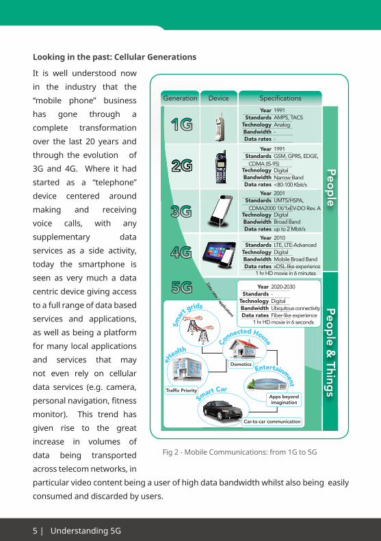
Looking in the past: Cellular Generations
It is well understood now
in the industry that the
“mobile phone” business
has gone through a
complete transformation
over the last 20 years and
through the evolution of
3G and 4G. Where it had
started as a “telephone”
device centered around
making and receiving
voice calls, with any
supplementary data
services as a side activity,
today the smartphone is
seen as very much a data
centric device giving access
to a full range of data based
services and applications,
aswellasbeingaplatform
for many local applications
and services that may
not even rely on cellular
data services (e.g. camera,
personalnavigation,fitness
monitor). This trend has
given rise to the great
increase in volumes of
data being transported
acrosstelecomnetworks,in
particularvideocontentbeingauserofhighdatabandwidthwhilstalsobeingeasily
consumed and discarded by users.
Fig2-MobileCommunications:from1Gto5G
Peo
ple
Peo
ple &
Things
Device SpecificationsDevice S
Smar
t grids
Smart Car
Co
nnected HouseYear
StandardsTechnologyBandwidthData rates
1991AMPS, TACSAnalog--
YearStandards
1991GSM, GPRS, EDGE,
DigitalNarrow Band<80-100 Kbit/s
YearStandards
2001UMTS/HSPA,
DigitalBroad Bandup to 2 Mbit/s
YearStandards
TechnologyBandwidthData rates
2010LTE, LTE-AdvancedDigitalMobile Broad BandxDSL-like experience
1 hr HD movie in 6 minutes
YearStandards
TechnologyBandwidthData rates
2020-2030-DigitalUbiquitous connectivityFiber-like experience
1 hr HD movie in 6 seconds
Entertainment
eH
ealth
Data rates / applications
Generation
Traffic Priority
Car-to-car communication
Apps beyondimagination
Domotics
TechnologyBandwidthData rates
TechnologyBandwidthData rates
CDMA2000 1X/1xEV-DO Rev. A
CDMA (IS-95)

www.anritsu.com|6
1979
1991
2001
2009
1G- Basic Mobility- Basic Services- Incompatibility- Analog
- Advanced Mobility (Roaming)- More Services (data presence)- Toward Global Solution - Digital System
First Commercial deployment
- Seamless Roaming- Service Concept & Models- Global Solution- High Data Rate
- IP Based Mobility- Very high Data Rate- Convergence
2G
3G
4G
5G
Analog Voice
Digital voice +simple data
Data +Position
Video
Fig 3 - Evolution of standards in mobile technology
From1979withthe1Gcommercialdeployments,anewtechnologyhasemerged
every 10 years. The second generation, first digital mobile technology and first
approachtoaglobalsolutionwascommerciallylaunchedontheGSMstandardin
Finlandin1991,introducingrelevantbenefitssuchasasignificantlymoreefficient
spectrumornewdataserviceslikeSMStextmessages.
Nevertheless,thissecondgenerationdidnotfulfilltheemergingdemandforInternet
access inmobilephones. This reason lead to thedevelopmentof3G, released in
2001,whichwasspecifiedfromITU-R(IMT-2000)andwasconsideredasarevolution
inmobiledatarates,seamlessroamingandnewserviceconceptsandmodels.
1
11
10
10
10
100
100
100
1000
1000
1000
Low
Med
high
perfect
1000
User data rate(Mbps)
Mobility (km/h)Coverage/Availability
End to Endlatency
2G focused onvoice availabilityand basic SMSsupport
2G Target
1
11
10
10
10
100
100
100
1000
1000
1000
Low
Med
high
perfect
1000
User data rate(Mbps)
Mobility (km/h)Coverage/Availability
End to Endlatency
2.5G focused ondata trading offwith efficiency/availability
2.5G Targets
Introductionof data packet(GPRS/EDGE)
Fig 4 - 2G Target Fig 5 - 2.5G Targets

7|Understanding5G
Thelaststepwasheldin2009,with4Gtechnologyprincipallyaimingfortheall-IP
mobilebroadbandnetwork,averyhighdatarateandtheconvergenceofallservices
intoamuchsimplerarchitecture.4Gwasaimingverymuchonhigherdata rates
andlowerlatencycomparedto3G,andalsotothesimplifiedallIParchitecturethat
gavemore deployment flexibility compared to 3G. However, 4G did not address
theneedsfordensernetworksandcapacitydemandsexplodingatanunforeseen
rate,asthe“smartphonerevolution”hadnotstartedwhenthe4Grequirementsand
technologieswerefirstspecifiedandselected.
So “5G” is setting out to provide a technical solution to the problems of todays 4G
networksthatcannotbeeasilyaddressedusingtheexistingtechnology,problems
thathavearisenfromthechangingdemandsonthetelecomnetworkoverthelast8
yearsas4Gwasdefinedanddeveloped.Butalso,5Gisattemptingtolook8yearsinto
thefuture(year2022isatypicalscheduleforwhen5Gnetworksmaybedeployedin
largescale)andtryingtopredictboththerequirementsontelecomnetworksatthis
time,andthetechnologieswhichmayberequiredtomeetthis.
11
10
10
100
100 1000
1000
User data rate(Mbps)
Mobility (km/h)The requirementsfro high mobility3G from ITU-R (IMT-2000) focusedon mobility and bitrate
3G Targets
1
11
10
10
10
100
100
100
1000
1000
1000
User data rate(Mbps)
Mobility (km/h)
End to Endlatency
Clear requirementsfrom ITU-RMore requirementsto define 4G
4G Targets
Fig 6 - 3G Targets Fig7-4GTargets

www.anritsu.com|8
5G Project Summary
2014 2015 2016 2017 2018 2019 202120202014 2015 2016 2017CORE TECHNOLOGY
STANDARDIZATION
COMMERCIAL R&D
TRIALS COMMERCIAL
DEPLOYMENTJapan OlympicsKorea WinterOlympics
WRC-15WRC-18
5G PPPMETIS5GIC
NGMN (requirements)ITU3GPP (beyond Rel 12/13)IETFIEEE
WRC-15 - more mobile broadband frequencies - Harmonize 700 MHz bands
WRC-18 - more bands needed for 5GIndustry R&D
Technology Standardization New Spectrum Allocations
Fig 8 - Expected timeframe for 5G
5Gdevelopment,asanyothertechnology,canbescheduledinto3mainstages:firstly,
the definition of requirements and key technologies, secondly the development
and standardization processes, and eventually real demonstrations plus further
commercial deployments.
During2015,concepts,visionandrequirementsfor5Ghavebeendefined.Selection
of key technologies, and demonstrations as proof of concepts have emerged as
well. R&D on the core technology will continue evolving from the work pieces
carriedoutduringpreviousyearsandmay lastuntil thefirsthalfof2017.Within
this period, international groups such as 5G Public Private Partnership (5G PPP)
belongingtoHorizon2020Europeanresearchprogram,ARIB2020adhocgroupin
JapanorIMT2020andBeyondpromotiongroupinChinawilldrivethebasisforthe
newtechnology.Othernationalgroups like5GInnovationCenterbasedatSurrey
University in UK or New YorkWireless University consortium are also important
technology hubs contributing in the 5G approach.

9|Understanding5G
Thestandardizationprocess startedduring2015, to layoutaplanofactivities to
review requirementsand technologiesand thenproducea setof standards. This
activity is taking theguidance fromWRC15 in termsof candidatenew frequency
bands tostudy for5G,andre-useofexistingmobilebroadband frequencies.The
3GPPschedule fordevelopment,writingandapprovalofstandardsmay lastuntil
thesecondhalfof2019,soinparallelwewillseeahugeeffortinR&Dagainstthese
emergingstandards.WeexpecttoseefirstdeploymentsbasedonthepartialRelease
15 standards in mid-2018.
Aswith2G,3Gand4G,theremaybeseveraldifferentcompetingstandardsforthe
networks,comingfromdifferentstandardsbodies,aswellassomemoreproprietary
technologieslookingtobedefinedwithinthestandards.Itisthereforepossiblethat
severalstandardsappearinparallelattheearlystage,andnodominantstandardmay
appearforsometime(e.g.GSMvsIS-54vsIS95,UMTSvsCDMA2000,LTEvsWiMAX).
Theinterestingnoteisthatfor4Gtheindustrywasmuchquickertosettleontoa
single standardand therewas less interest inmultiple standards simultaneously.
Thevariousfactorsinfluencingthisincludethecostscalesofvolumeandtheneed
for global roaming. If this remains true for 5G thenwe are likely to see a quick
convergence onto a single set of 5G standards rather than several different sets of
standards.As3GPPisusedforalmostall4Gnetworks,itcouldbeexpectedthatthe
4Gto5Gevolutionof3GPPwouldbethemostnaturalrouteformostoperators.
In2018,theWinterOlympicstakingplaceinSouthKoreapresentsagoodchance
tolaunchtrialsordemonstrationsofstandardsbasednetworksinrealscenarios.A
secondWRCmeetingwillbeheldinthebeginningof2019,whichwillalsoaddressthe
discussionsfornewglobalfrequencybandsallocations.Finally,theJapanSummer
Olympics in 2020 looks set to become a starting point for a live demonstration of 5G
that could be based on a commercial deployment.
ITU project to define spectrum usage worldwide, WRC15 and WRC19.
Oneofthefundamentalneedsof5GistherequirementformoreRFspectrum,tobe
abletocarrytheeverincreasingvolumeofdatabeingtransmittedwirelesslyacross
thenetworks.Thisappliestotheneedforwirelessbackhaul(akeyenablerforsome
ofthedeploymentscenarios),aswellastothewell-publicizedneedformorecapacity

www.anritsu.com|10
on the air interface for delivery of data to the terminals/devices. Global spectrum
usage and allocations are agreed under the World Radio Council (WRC) as part of the
InternationalTelecomsUnion(ITU).Inthisforum,globalagreementontheallocation
andpurposeofdifferentfrequencybandsismade.Withinthepurpose,thereisthen
definedlimitationsonthelicensing,typesofwaveforms(butnotspecificselectionof
particularstandards),andusage.Thiscoversalltypesofapplicationssuchaspublic
broadcast,mobilephoneanddataservices,militaryuse(radio,radar,etc.),satellite
services, public emergency services, unlicensed services (e.g. Wi-Fi, garage door
openers,remotecontroltoys,walkie-talkie).Thechangeofmosttypesofbroadcast
from analogue to digital broadcast has freed up much spectrum due to the higher
spectralefficiencyofdigitalformats.However,theamountoffreedspectrumisnot
enough tomeet the growing data capacity needs of telecoms networks. Hence,
there is a need to allocate (or re-allocate) some other spectrum bands to the purpose
ofmobilephonenetworks. Telecomnetwork serviceshave traditionallypreferred
frequencybandsintherange450MHzto2.6GHz,asthisgivesthebestperformance
in terms of range (propagation through atmosphere and buildings) and cost of
technologytoimplementit.However,suchlowfrequencieshavelimitedamountof
MHzofbandwidthavailable.Tofindmorebandwidthrequiresthemovetohigher
frequencies, where more spectrum is available, but with the trade-off of lower
coverage and higher cost technology in the terminals/devices.
So a number of research projects are looking at re-using the lower frequency
spectrum to get more capacity from these preferred frequency bands. Other
projectsarelookingathowtoovercomethepropagationandcostbarrierstousing
thehigherfrequencyspectrum.Inparallel,thehigherfrequencyspectrumisalready
usedforwirelessbackhaul links(wheredirectionalantennaareusedtoovercome
propagationissues),andfurtherresearchisbeingmadetoincreasecapacityofthese
links. A key factor for this research is the modeling and understanding of propagation
andreflectionsatthesefrequencies,toseeiftheyaresuitableforbothindooruse
andnonlineofsight,andtounderstandhowwellMIMOcanbeappliedtoincrease
capacity.

11 | Understanding 5G
There is also research to implement “non line of sight” data links to overcome one of
theprincipleweaknessescurrentlyinhighfrequencybackhaullinks,thatofrequiring
directlineofsightbetweenthetwoantennasinthedatalink.Thisobviouslylimits
the deployment scenarios that are possible, making indoor or city/urban use
almostimpossible,andrequiringspecificantennamaststobeerectedinalmostall
deployments today.

www.anritsu.com|12
5G Requirements
There are several projects and groups working worldwide to define 5G needs,
technologyrequirements,userrequirements,andotherviewsonwhat5Gshouldbe.
ThemobilenetworkoperatorshavebuiltupanecosystemcommunitycalledNext
GenerationMobileNetworks (NGMN)which iscreatinga requirementsdocument
fromtheperspectiveofwirelessnetworkoperators.NGMNhadpreviouslyagreed
requirements for 4G networks, and selected LTE as a preferred technology. The
NGMNisanoperatorledforum,butwithparticipationfromtheequipment/network
vendorsandsupplychain,totryandaligntheindustryneeds.
Technical Challenges and Targets
Thereareseveralkeychallengestobemetwithfuture5Gnetworks,lookingatthe
performance needs of future networks and identifying affordable technologies
whichmaybedevelopedtosupportthese.
1
1
10
100
1000
User data rate(Mbps)
Mobility (km/h)Coverage/Availability
End to Endlatency
5G Targetsby use case
1
10
1000
1
100
10
1000
1 10 100 500500.5
Low
perfect
Battery life(days)
Cost(Euro)
TrafficVolume density
(Tbps/km2)
Connection density(Users/km2)
Optimised for
Optimised for
Optimised for
Optimised for
1
102
104
106
Med
10
5
100
100
1000
1000
high
Fig9-5GTargetsbyusecase
13 | Understanding 5G
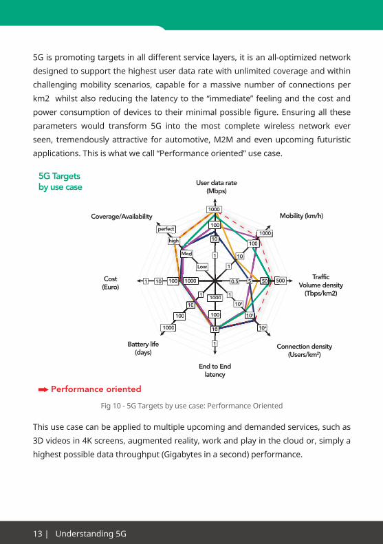
5Gispromotingtargetsinalldifferentservicelayers,itisanall-optimizednetwork
designedtosupportthehighestuserdataratewithunlimitedcoverageandwithin
challengingmobility scenarios, capable foramassivenumberof connectionsper
km2whilstalsoreducingthelatencytothe“immediate”feelingandthecostand
powerconsumptionofdevicestotheirminimalpossiblefigure.Ensuringall these
parameters would transform 5G into the most complete wireless network ever
seen, tremendouslyattractive forautomotive,M2Mandevenupcoming futuristic
applications.Thisiswhatwecall“Performanceoriented”usecase.
1
1
10
100
1000
User data rate(Mbps)
Mobility (km/h)Coverage/Availability
End to Endlatency
5G Targetsby use case
1
10
1000
1
100
10
1000
1 10 100 500500.5
Low
perfect
Battery life(days)
Cost(Euro)
TrafficVolume density
(Tbps/km2)
Connection density(Users/km2)
1
102
104
106
Med
5
100
100
1000
1000
5050
0010
ct100
10
Me
100
100010
1
100
0
00000 1
10
1000
high
104
1
100
10
Performance oriented
Fig10-5GTargetsbyusecase:PerformanceOriented
Thisusecasecanbeappliedtomultipleupcominganddemandedservices,suchas
3Dvideosin4Kscreens,augmentedreality,workandplayinthecloudor,simplya
highest possible data throughput (Gigabytes in a second) performance.

www.anritsu.com|14
1
10
100
User data rate(Mbps)
Mobility (km/h)Coverage/Availability
End to Endlatency
5G Targetsby use case
1
10
1000
1
100
10
1 500500.5
Low
Battery life(days)
Cost(Euro)
TrafficVolume density
(Tbps/km2)
Connection density(Users/km2)
1
102
106
5
100
1000
10
100
100
10
1
100
0001
10
1000
high
Reliability/latencyoriented
Cost and Powerconsumption oriented
perfect
100
1
1000
10
104
Med
1000
5050
1000
100
Fig11-5GTargetsbyusecase:Reliability/LatencyandCostandPoweroriented
5Gwill also lookata “Reliability/latencyoriented”usecase,whichwillfit into the
needs of services like Industry automation, critical information broadcast or self-
driving cars. In this case, 5G technology shouldadapt itself to amuchoptimized
network in terms of coverage, latency and mobility. The connection density for
Industryautomationorcriticalinformationbroadcastisnotimportant,astheywill
notrepresentahighamountofusersconcentratedinaspecificarea.Evenforself-
drivingapplications,shouldnotbearestrictingparameterbecausetheseuserswill
bemoving,thusdrivingimportancetomobilityoptimization.
Eventually,thereisathirdusecaseinwhichthelowcostandlongbatterylifearethe
mostimportantpremises.5Gwillfulfilltherequirementsformillionsofsmartdevices
enteringintothenetworkandbuildingahuge“Sensornetwork”interconnectingthe
citiesaroundtheglobe.Thisusecasewillhavetoconsiderahighconnectiondensity

15 | Understanding 5G
profileaswell,assomeurbanareascouldbeintensivelyinvadedbythousandsof
devices.
From the different key targets and use cases, some of the targets creating the
technicalchallengesareasfollows:
Internet of Things (IoT) capacity requirements
The IoT is predicted to create a massive increase in the number of devices/
connectionsacrosswirelessnetworks.Itisenvisagedthatmanybillionsofdevices
will be connected to thenetworks, althoughmanyof themwill beonly sending/
receivingdataonanintermittentofverylowdatarate.Thiswillcreatenewdemands
in termsof the capacityof thenetwork to transmitdata,butalso the capacity in
termsofnumberofconnectedusersthatcanbemanagedbythenetwork.Incurrent
3GPPbasednetworkstherearelimitsonnumbersofusersthatcanbeconnected
tospecificnetworknodes,andthis limitmaybe insufficientforfutureneeds.The
capacity requirement is expressed both in terms of number of users connected
(registered) to thenetwork,andalso in termsofnumberofusersactive (making
simultaneousdatatransactions)onaspecificnetworknode.
Volume of data
Datawillbeoneofthekeydriversfor5G.Firstly,continuingthelegacyfromLTE,voice
willbetotallyhandledasanapplicationsimplyusingthedataconnectivityprovided
by the communication system and not as a dedicated service. This is an additional
increaseinadatagrowingpaceofbetween25%and50%annuallyandisexpected
tocontinuetowards2030duetotheincreaseinsizeofcontentandthenumberof
mobileapplicationsrequiringhighdatarates,theriseinscreenresolutionwiththe
recent introduction of 4K (8K already in development and expected beyond 2020)
and the developments in 3D video.

www.anritsu.com|16
Traffic growth towards 2030
Rel
ativ
e g
row
th100,000
10,000
1,000
100
10
1
2010 2012 2014 2016 2018 2020 2022 2024 2026 2028 2030
Year
Up to 1000x trafficgrowth may be met through LTE-A evolution
5G will see up to 10000xtraffic growth and requiredisruptive technologycomponents
Traffic volume per subscriber
+ 50% per year+ 25% per year
Traffic subscriber base
+ 10% per year
Mobile broadband penetration
reaching 100% by 2020
Fig12-Predictedtrafficvolumetowards2030*(FigurefromNokia5Gwhitepaper)
Types of data
Ithasbeenwidelydiscussedandseenintheindustryoverthelast5yearsthatthere
isaneedtoincreasethecapacityofthenetworkwithoutincreasingthecost.Users
are consuming increasingly more volume of data (mainly through video services)
but are reluctant to pay 100x more subscription costs to cover the 100x volume of
datatheyuse.Sothereisamajorchallengetoincreasethecapacityofthenetwork
(bothvolumeofuserplanedata,andvolumeof controlplanedataandattached
devices to be managed). One technology already being developed in 3GPP for LTE
networksistoseparatethedistributionofcontrolanduserdataplanestoalignto
data requirements. One typical example is to provide the control plane signaling
toawideareausingamacrocell,andthenuserplanedataviasmallcellswithin
the coverage of the macrocell. This enables a higher capacity of user plane data
withinthearea,duetohigherfrequencyre-useofthesmallcells,withouttheadded
complexity of requiring control plane function and co-ordination across many small
cells(whichthenrequiresahighamountofbackhaulcapacitytocarrythisinter-cell
control information).

17|Understanding5G
Asecondevolutioninthenetworkdesign,complementarytotheuser/controlplane
separation,isthemovetowardscloudservicesandcloudRAN.Inthisconcept,some
ofthefunctionoftheRANnetwork(e.g.eNodeBinLTEnetworks)ismovedfromthe
cell site or eNodeB back into a cloud service. This provides a key technology platform
to support scaling and economy, leading to deployment flexibility, and easier re-
configuration.Thisisbecausenowthecoresignalingandintelligenceisheldwithin
thecloud,andtheonlylocalizedphysicalelementsaretheRFtransceiverstoconnect
tousers.Thisreducesthecost/complexityof the localizedelements,givingbetter
flexibilityandcostefficientscalabilityofdeployment.
New types of services
Highly reliable communications links are an emerging trend for cellular network
systems.Medicalmonitoringsolutionsarealsomovingincreasinglytousewireless
networks,toprovideremotepatientmonitoring/careaswellasgreateraccessfor
remotesupport tomedicalstaff.Emergencyservices, (e.g.police/fire/ambulance)
providecriticalservicesthatrequirehighreliabilityvoicelinks,withoutissuesofcall
drop,busynetworketc.Today’ssolutionsprovidehighreliabilitybyhavingdedicated
networks,butwith limiteddata capacityorperformance,and requiringhighcost
investments to provide even reasonable coverage. Future requirements are for high
datarate,andrealtimeinteraction,sothesecriticalservicescanrespondfasterand
withmoreimmediateremoteconnections.
Real time and Virtual Reality services. As augmented reality becomes deployed into
portable/personaldevices,sothedemandonnetworkperformanceisdramatically
increased. One key aspect is that the latency (delay) must be very small to enable
trueinter-actionbetweentherealandvirtualenvironments.Thehumanbrainisvery
sensitive to timedelayswhenprocessingvisualdata,due to theprocesses in the
braintoconverteyeimagepatternsintoimageswe“see”inourmind.Ifthenetwork
cannot interactwith our eye/brain process in real time then a true virtual reality
servicecannotbedelivered.Thekeytodeliveryofsuchaserviceislatency,andso
eachstepinthelinkbetweendeviceasservermustbeoptimizedforlatency,and
weneedtotest/measurenotonlytheendtoendlatency(RoundTripTime,RTT)but
alsothelatencyineachlink,andhavemethodstoinvestigatethecauseofexcessive
delays/failures.

www.anritsu.com|18
ThereismuchdiscussioninthewirelesscommunicationsindustryaboutMachineto
Machine(M2M)communicationbeingabigdriverforfuturegrowth,asanenabling
transport technology for the Internet of Things (IoT). Although there are many case
studiesandpotentialbusinessmodelsbeingdeveloped, there isone segmentof
theindustrywhichisalreadypushingforwardinthisarea,theautomotivebusiness.
There are a number of automotive applications already under development or in
earlytrials/deployment:
•In-Vehicleinfotainmentdrivesmobilewirelesslinkcapacitytothe“vehicleasahub”.
•Useofvehicleasbasestationorrelaynodeduetoenoughbatterypower.
•IntelligentTransportSystems(ITS)creatingdemandforVehicletoVehicle(V2V),vehicletoInfrastructure(V2I),andgenericVehicletootherdevices(V2x).
•Autonomousdriving,convoydriving,safetyalertandtrafficmanagement.
Oneareathathasbeentraditionallyoutsideofcellularnetworkcommunicationsis
DevicetoDevicecommunications,whichisdirectlinkswithoutrelayofinformation
throughthebase-stationornetwork.Suchtraditional“walkietalkie”systemshave
beeninexistenceforalongtime,usinglimitedaccesscontroltopreventinterference
or overlapping of messages. However, the ability to transmit data is severely
limited,andtheneedtohaveaseparatedeviceforthiswalkietalkiemodeversus
aconventionalcellulardevicehasbecomeauserissue.Previouscellularnetworks
havedeveloped“pushtotalk,PTT”technologytodeliverasimilaruserexperience
whereavoicemessageisdeliveredtoallusersonthesamefrequency/network(like
awalkietalkie),andthishasbeenshowntobetechnicallyfeasible.Thelimitationis
stillthatthecellularinfra-structureisrequiredtorelaythemessages,andforcritical
communications (e.g. emergency services) then it can not be relied that there is
workinginfra-structurewithsufficientcoveragewhenitisneeded(e.g.earthquake
disaster zone). Hence the development of Device to Device (D2D) to allow direct
communications.ThistechnologyisalreadybeingdevelopedinLTE-A(e.g.‘SideLink’),
butisexpectedtohaveamuchmorerobustimplementationin5Gwherethenetwork
isalreadydesigned/optimizedtocarrythistypeofcommunications.

19|Understanding5G
5Gwillintroducemorerequirementsofthetransportnetworkandoverallarchitecture
in order to ensure support for any-to-any communication, so not only device to
device but also node to node self-backhauling. Intelligent Transport Systems (ITS)
fortrafficcontrolandpassengersafetypurposescouldalsobenefitfromthiskindof
communication technology.
Fig13-DevicetoDeviceCommunication*(PicturefromEricssonResearchBlog:“D2DCommunications – What Part Will It Play in 5G?”)
5G architecture will support D2D better than LTE can do nowadays. However,
D2D communication still implies new challenges for devices design, security or
interferenceandmobilitymanagement,betweenothers.D2Dwouldalsoinfluence
newbreakthroughsinbackhauldesign,whichwillberequiredtoenableverydense
networkingofradionodes.Nodeswith‘plug-and-play’techniquestoaccessandself-
organizeavailable spectrumblocks forbackhaulingwillbekey forenablinghigh-
frequency spectrum radio access.

www.anritsu.com|20
CellularCommunication
Network Control
Direct (D2D)Communication
Fig 14 - Device to Device and Cellular communications share the same radio resources
*(PicturefromEricssonResearchBlog:“D2DCommunications–WhatPartWillItPlay
in5G?”-ThenetworkcontrolsandoptimizestheuseoftheresourcesforbothCellular
communicationandD2D,resultinginenhancedperformanceandqualityofservice.)
All of the above challenges are now starting to drive the areas of research,
highlightingthelimitationsofcurrentnetworksandtheenvisagedrequirementsof
futurenetworks.Currenttechnologydevelopmentsanduserdemandsaremerely
providing a glimpse of the nature of 5G networks. At themoment, cost is not a
majordriverof5Gtechnologydiscussions,allowingamuchwiderlistofcandidate
technologiestobeconsidered.Inordertodiscussthesetechnologiesmeaningfully,
cost analysis is also not a key factor in this article. It is the radical and disruptive
changestotheexistingnetworkthatareoutlined.
Itisclearthatanewairinterfacewillbeneeded.CurrentR&Dworksuggeststhat
a5Gnetworkwillconsistofseveralair interfacescoexisting inthesamenetwork.
Fromatheoreticalperspective,thisisideal(e.g.OFDMdoesnotlenditselftosmall
cellsandHetNetsandthereareother,bettercandidates),butfromanoperational
and economic perspective, this would mean significant development costs and
deployment effort.
Sotheresearchissplitintonewwaveformsbelow6GHzfordeploymentintoexisting
radio bands to increase efficiency and overcome interference issues, and new
waveformsabove24GHzwhichareoptimizedforthehigherfrequencyandwider
bandwidthsavailable.

21 | Understanding 5G
Research subjects
Theacademiccommunity,andindustryresearchprograms,arecurrentlyinvestigating
a number of subjects to identify and develop key technologies. The research subjects
are based around the generic technical needs for 5G to meet the objectives and
targets previously outlined.
Low powerconsumption
Up to mmWavecommunication
FlexibleSpectrum Use
Always ON,low overhead
Flexible UL/DLduplexing
1 ms RTT
10 GBps
Low cost
Native supportfor Access, Self-
Backhauling, D2D
Internet Cloud
Fig 15 - Research Subjects for 5G
Extreme densification
Networkdensificationisnotnew.Assoonas3Gnetworkswerecongested,mobile
operatorsrealizedtheneedtointroduceeithernewcells intothesystemormore
sectors. This has evolved to includemanyflavors of small cells,which essentially
movetheaccesspointmuchclosertotheenduser.Thereissimplynootherwayto
increasetheoverallsystemcapacityofamobilenetworksignificantly.5Gnetworks
are likely to consist of the several layers of connectivity that HetNet architecture is
currentlysuggesting:amacrolayerforlowerdataspeedconnectivity;averygranular
www.anritsu.com|22
layerforveryhighdataspeeds;andmanylayersinbetween.Networkdeployment
and coordination are major challenges to be addressed here, as they increase
exponentiallywithrespecttothenumberofnetworklayers.
As we have indicated already, 5G networks would be principally designed
for data-centric applications rather than voice-centric applications. Network
densificationisverysuitableforincreasingthecapacityanddataratetomeetthe
future demands.With the increasing density of networks, also the backhaul will
become more heterogeneous and possibly also scenario dependent. The high data
ratesof5Gwouldimplythatthebackhaul/fronthaulwouldneedtobefiberopticto
achievethedataratesrequired(i.e.1-10Gb/spersector).Nevertheless,Millimeter
wavebackhaul/fronthaulisanotherattractiveoption,probablycheaperandsurely
easiertodeploythanfiber,buttechnologicalandregulatorychallengesareyettobe
addressed.Inaddition,theconnectivityamongthenetworknodesshouldallowfor
fastdirectexchangeofdatabetweenthem,whichwillbechallenginginUltraDense
Network (UDN)deployments. The radioaccessnetworkswill alsobe impactedby
theheterogeneousbackhaulstructure,e.g.latencydifferencesondifferenttypesof
backhaullinkswillimpactintercellcoordinationandcooperationalgorithms.
Itislikelythatthecostimplicationsofdevelopinganentirelynewbackhaulnetwork
willinsteaddrivetheindustrytodevelopnewtechnologythatisabletouseexisting
IPnetworktechnologyandinfrastructureinabetterway.Alreadyin4Gtherewasa
migrationto“allIP”networksandsupportofIPv6signaling.Thishasalsoevolvedto
providebetteruseofMPLStechnologyforIProutinginthenetwork,andOTNfor
corenetworks.Ascloudservices,NFVandSDNeachevolveincurrentIPnetworks,
it isexpectedthatthesebecomekeytechnologiestoresolvethegapbetweenthe
costandperformanceofcurrentmobilenetworkbackhaulversustheidealnew5G
backhaul.
Thenewnetworkarchitecturemaybefocusedalso intothepublicconcernabout
EMF induced by wireless networks. By reducing the distance between receivers
andtransmitters,smallcellsenabletheminimizationofthepoweremittedbythe
mobilesdevicesandthetotalEMFexposure.5Garchitecturecombiningsmallcells,
heterogeneousnetworksandoffloadingshouldinherentlyenableminimizingboth
thehumanEMFexposureandthepowerconsumptionofthenetwork.
23 | Understanding 5G
Air interfaces for higher data rates and higher capacity
Incurrent4GLTE(OFDMA)networkswerequireself-interferenceavoidance,which
isstrictlyatimingbasedapproach,andthiscauseshigherpowerconsumptionand
significantwasteofcontrolplanesignalingresources.Interferenceresistantaccess
schemes in 5G that could replace the currently used OFDM are under intensive
evaluation.MoreefficientorthogonalschemessuchasFBMC,UFMCorGFMD,which
introduce a better use of the spectrum are excellent candidates for the upcoming 5G
accesswaveform.Generally,orthogonaltransmissioncanavoidself-interferenceand
thisleadstoahighersystemcapacity.However,forrapidaccessofsmallpayloads,the
procedure to assign orthogonal resources to different users may require extensive
signalingandleadtoadditionallatency.Thussupportfornon-orthogonalaccess,as
acomplementtoorthogonalaccess,isbeingconsideredaswell.Examplesinclude
Non-Orthogonal Multiple Access (NOMA) and Sparse- Code Multiple Access (SCMA).
Orthogonalmulti-carrierwaveformswillstillremainasthepreferredschemebecause
theyfitverywellwithMIMOtechniques,whichwillbemassivelydeployed.UL/DL
fullduplexandsimultaneoustransmission,alongwithwiderbandwidthsfrom100
MHzonwards,willdrivetheairinterfacetosupporthigherdatarates.Itisexpected
thatmulti-carrier schemes will usemultiple carriers of either 20MHz or 100MHz
bandwidth,togivescalableRFbandwidth.
Ontheotherside,millionsoflowdataratedevicesforMachineTypeCommunications
(MTC) may require new interfaces with much lower network capacity demand,
buthighrobustness, inordertoensureconnectivityatanytime.DevicetoDevice
communications, especially thought for public safety and services applications,
wouldalso join thisgroup.Thefirst steps to thisarebeing taken in LTE-A,being
categorizedas“CategoryM”devices,wheretheairinterfaceandnetworksignaling
andsupported features/data rateareminimized inorder toprovide lowerpower
consumptionofdevicesandlowercostofdevices.
A further development for the air interface is the area of Cognitive Radio. This is the
capabilityforadevicetosensetheRFenvironmentandmakeconfigurationdecisions
based on the local RF characteristics. Examples of such functionality are the sensing

www.anritsu.com|24
ofunusedRFspectrum(socalled‘whitespaces’)andthenthetemporaryuseofthese
unused“whitespace”frequenciesfordatatransmission.Amoreadvancedexample
is intheareaofSoftwareDefinedRadio (SDR),wheretheradiomodemisableto
re-configureitselftosupporttheprotocolsandRFtransmissionformatsbeingused
locally,basicongenericTx/Rxcircuitsandthensoftwarebasedmodemfunctions
thataredynamicallysettomatchlocalprotocols.Thedevicewillfirstsamplethelocal
RFenvironment,andthenbasedonevaluationoftheRFcharacteristics,asuitable
modemconfigurationandprotocolstackisloadedfrommemory(orfromthecloud)
tosupportthelocalnetwork.
Cell coverage improvements
TheconceptsofMacrocellandSmallcelloverlays,emergingpreviouslyin3Gand
LTE-A,willgrowinimportancefor5G.Complexheterogeneousnetworkswillappear
asahighnumberofsmallcellsthatoperateonasinglefrequencyband,eachserving
small areas.Wewill seemultiple-antenna systems providing SpatialMultiplexing
techniques, i.e. transmitting different data streams through each element and,
consequentlyincreasingthedatarate,andalsobeamformingantennatechniques
for improving the quality of transmission or the signal-to- interference-plus-noise
ratio(SINR),whichhavealreadybecomepopularfromTD-LTEdeployment.“Massive
MIMO”ordenseantennaarrayscomposedby,forexample,64x64elements,willsuit
tommWsystemsduetothesmallphysicalsizeandprecisefocusingtheycanoffer.
Co-operative antenna techniques refers to the capability of handling the information
received from spatial distributed antennas belonging to different nodes in a
wirelessnetwork.ApplicationintoSingleUserMIMO(SU-MIMO)hasbeenthefirst
appearanceofthesetechniquesinLTE-Advance.Inthenextstep,co-operativeMIMO
ordistributedMIMOwillgroupmultipleradiodevices(includingusers’devices)to
formvirtualantennaarrayssothattheycancooperatewitheachotherbyexploiting
the spatial domain and improving coverage and cell edge throughput. Some devices
canalsobetreatedasrelaystohelpthecommunicationbetweenthenetworkand
device.Thisisconsideredasoneofthenewemergingtechnologiesin5G,thusmany
researchchallengesincooperativeantennashavetobeaddressedbeforethewide
deployment.

25 | Understanding 5G
Key technologies
Basedupon the research subjectareasdiscussed, thereareanumberof specific
technologyneedswhicharecurrentlybeinginvestigatedtoidentifyspecificsolutions
andcandidatetechnologiestobeusedwithin5Gnetworks.
Microwave highpower BS
Sensors
Downlink
Uplink
Microwave lowpower BS
Control
Data
mmWave RS
mmWaveindoor
MobileDevice
D2D
Centralizedbase-band
Fig 16 - Key Technologies for 5G

www.anritsu.com|26
Network design
A parallel evolutionary trend to 5G is software virtualization and cloud services,
wherethecorenetworkisimplementedontoadistributedsetofdatacentersthat
provideserviceagility,centralizedcontrol,andsoftwareupgrades.SDN,NFV,cloud,
and open ecosystems are likely to be the foundations of 5G and there is an ongoing
discussionabouthowtotakeadvantageoftheseintonewnetworkarchitectures.
An adaptive network solution framework will become a necessity for interfacing
withboth LTE andnewair interface evolution: Cloud, SDNandNFV technologies
willreshapetheentiremobilenetworkdesignprinciples.Asthethree-tierhierarchy
(access, forwarding, and control) of network architecture is being replaced by
flatter architectures, virtualizedapplication software is replacingdiscretenetwork
elements,andnetworkinfrastructureisbecomingmore‘programmable’.WithSDN
thenetworkwilldynamicallyadaptitselftoprovidetheconnectivityservicesthatbest
servetheapplication,andabetterapproachwilleventuallyproducenetworksthat
aremuchmoreflexible inprovidingnewservicesandmonetizingthenetwork,as
wellasbeingmoreefficientintheiruseofresources.Suchacapabilityisnowbeing
introducedundertheconceptofnetwork“slicing”,whereasliceismadeacrossthe
differentdomainsofthenetworktoconfigureforaspecificservice.
Access Plane Forwarding Plane
Control Plane
WiFiCentralization
Mesh
Ad-Hocnetwork
Edgecaching
CentricDC
Servicesteering
Distributed GW
Network Controller
Infra-structure Pipeline Value-added
services Context
OTT MVNO Enterprise
Radio MM Policy O&M Orches-tration
Serviceexposure
Controllermodular
API
Figure 17 - Three-planes based 5g network architecture

27|Understanding5G
NetworkFunctionVirtualization(NFV)worksbyvirtualizing intosoftwaretheroles
ofthevariousnetworkfunctionelementsintoaseriesofVirtualNetworkFunctions
(VNF). These different VNFs run on standardized hardware (servers), leading to
the virtualization of the physical network infrastructure that provides a seamless
deployment. VNFs are then linked together to provide a specific service for the
customer, using service chaining which is configured, managed, and monitored
through the operators service orchestration function. Service providers can now
integrate this optimized virtual infrastructure with their service orchestration
systems.ThisallowsthemtointegratetheirOSS/BSSimplementationfordynamic
routing,billinganddeliveryofservices.
Current mobile networks have evolved from a traditional Datacom network
architecture,wherethedataflowiscentralizedandtheaccesscontrol is localized
at the access point. This means in effect that all user data travels from one access
point(whereitentersthenetwork)toacentralizedlocation(gateways)andthenback
outtotheaccessplanewhereitisdeliveredtotherecipientaccesspoint.Similarly,
accessiscontrolledlocallyatanaccesspoint(e.g.eNodeB),butneedstobecentrally
co-ordinatedso controlplanemessagesmustpass through thenetwork.Bothof
thesephenomenaareincreasingthevolumeoftrafficthatmustbecarriedacross
thenetwork.Thereisnowresearchintonewarchitecturesthatreversebothofthese
designs. Firstly then, user plane data is now considered to flowdirectly between
accessnodes,andnot througha centralhub, so itonly travelsonce through the
network.Sothemovetoacentralizedcontrolplaneandadistributeddataplanecan
offerareductioninnetworktrafficloadforagivenvolumeofcustomerdatabeing
carried.Toachievethishoweverdoesrequiresignificantlyhigherconnectivityand
lowlatencylinksbetweenallnodes,butcelldensificationandNFV/SDNtechnologies
are already driving in this direction so it may be that 5G can leverage directly from
this.TheconceptofNFViswellsuitedtothis,asthenetworkcontrolfunctionscan
be virtualized and housed centrally in servers tominimize traffic flow across the
network.Similarly,userplanedatacanenter/leavethenetwork,andcanroutetoany
accesspoint,byusingvirtualizedgatewayfunctionsratherthanneedingtoberouted
to/fromacentralizedgatewayphysicalelement.

www.anritsu.com|28
A parallel technology/architecture development alongside the User Plane and
Control Plane routing, is also the separation of these two data types at the air
interface.IncurrentLTEnetworks,thereisachallengeinmanagingthecontrolplane
signalingin“smallcells”duetotheinterferenceofcellswithoverlappingcoverage
(the challenge and implementation of eICIC and derivatives). But this overlapping
coverage and deployment of many small cells is required to provide enough capacity
intheUserPlaneforthe largevolumesofdata.SoweseethattheControlPlane
andUser Plane have different requirements and different restrictions, which are
clashingwitheachother.Soonepossiblesolutionistoseparatethemondifferent
airinterfacelinks.ThustheControlPlanecanberoutedtoawidecoverageMacro
cell, providingunifiedand co-ordinated scheduling and control information to all
usersinaparticularregion,whilstthecorrespondinguserplanedataiscarriedon
localizedsmallcellsclosetotheuser.Thisgivesgreateruserplanecapacitywithout
interference problems on the control plane. This concept is a natural extension of
the principles of Carrier Aggregation and Cross-Carrier Scheduling that are already
introduced intoLTE-Advancednetworks.A secondevolutionof this concept is to
separate downlink and uplink transmissions to separate cell sites. This has the
advantageofallowingthedownlinkdatatoberoutedbythenetworktoacellthat
hasenoughcapacityforthedata,butallowstheuserdevicetosenduplinktoacell
thatislocatedcloseby,andhencereducetheamountoftransmitpowerrequiredby
theuseruplinktransmission.Thiswillreduceinterferenceontheuplink,andallow
a longer battery life “talk time” for the user device. Whilst all of these technologies
offergreatbenefits, theydodemandsignificantly largervolumesofcontrolplane
datainthenetwork,toensureallcellsitesrelatedtoasingleuserdatatransmission
areco-ordinatedandlinkedtogether.CurrentLTE-Anetworkswerenotdesignedfor
suchhighcapacityandlowlatencycontrolplanedata,andaskdiscussedpreviously
theNFV/SDNarchitectureconceptmaybebettersuitedtothisnetworkdesignidea.
SowecanseethatSDN,NFV,andcloudarchitectureswillplayavitalrole innext
generationofnetworkarchitecture. It canprovidean implementationmodel that
easilyandcosteffectivelyscaleswiththevolumeofdataandvastincreaseexpectedin
connecteddevices.Secondly,itallowsserviceproviderstomoreeasilyandefficiently
manage a dynamic network, with great flexibility to re-configure the network

29|Understanding5G
functions and capacity. Thirdly, SDN/NFV provides a practical implementation for
moreefficient routingofbothUserPlaneandControlPlanedata, to reduce total
datavolumetravellingacrossthenetwork,andtoreducelatencieswithmoredirect
routingthananarchitecturebasedoncentralizedhardwarefunctions.Thiswillbetter
supporttheseparationofControlPlaneandUserPlanedata,andtheseparationof
downlinkanduplinkdata.
Figure 18 - NGMN 5G architecture (Source NGMN)
CloudRAN isa specific concept that is rapidlybeingdevelopedandprepared for
commercialdeployment.ThisaimstocentralizethefunctionsoftheRANnetwork
(e.g.eNodeBforLTE,NodeB&RNCfor3G)withinthecloudservers,suchthatonly
the physical transceiver and antenna elements of the eNodeB need to be physically
locatedatthecellsite.Thisprovidesforamorecostefficientdeployment,especially
for“smallcells”orlocalcellsitesusedtoboostcapacityorfillgapsincoverage.The
CloudRANconceptistakingadvantageoftechnologiessuchasCPRI,thatallowthe
basebandtoTRXlinkofthebasestationtobecarriedondedicatedhighspeedoptical
fiberlinks.ThistechnologyhasalreadybeendevelopedforRemoteRadioHeaduse
(RRH), where the TRX/ Antenna is separated from the base station baseband by
several meters (top and bottom of cell site mast) up to separation of hundreds of
metersorofkilometers(e.g.forinbuildingorshoppingmalldeployment,wherea
www.anritsu.com|30
singlebasebandservesallTRX/antennasites).SoCloudRANisextendingthesame
conceptfurthersuchthatallTRX/Antennasitesinanetworkregioncanbeconnected
byafiberringtoacentralizedbasebandserver.Ofcoursethistechnologycurrently
reliesonhavingdedicatedfiberaccesstoeachcellsite,andthiscanlimitdeployment
in some scenarios.Wewill see later therefore that there is parallel research into
providingasuitablewirelessbackhaulforCloudRAN.Thekeychallengehereisto
havelowenoughlatencyandhighavailabilityacrossawirelessbackhaul,because
thebasebandalgorithms in theNodeB require latenciesof very fewmilliseconds
in order to meet the timing requirements of the scheduler and re-transmission
functions in the basestation.
Severalnetworksarecurrentlyprovidingconnectivityforend-userdevices:cellular,
Wi-Fi,mm-wave,anddevice-to-deviceareafewexamples.5Gsystemsarelikelyto
tightly coordinate the integration of these domains to provide an uninterrupted user
experience.However,bringingthesedifferentdomainstogetherhasproventobe
aconsiderablechallengeandHotspot2.0 isperhapsthefirstexampleofcellular/
Wi-Fiintegration.Whethera5Gdevicewillbeabletoconnecttoseveralconnectivity
domains remains to be seen, and amajor challenge is the ability to successfully
switchfromonetoanother.
Themigrationto5Gnetworksmaybedoneina“stepbystep”approach,withexisting
4G operators looking to boost the capacity/data rates to 5G levels by using a 5G air
interfaceworkingontoanexisting4Gcorenetwork.Withsuchadeployment, the
5Gairinterfaceiseffectivelyanchoredtoexisting4Gnetwork.Soitislikelythatwe
willfirstsee5Gairinterfacedeployedwitha4Gcorenetworkanchor,andthenin
asecondphasethecorenetworkcouldbeupgradedtoa5Garchitectureandthen
boththe4Gand5Gcouldbedeliveredfroma5Gcorenetworkanchor.Oneofthe
mainconcernpointshereistheabilityoftheanchornetworktosupporthand-over
to other access technologies, as this capability is a fundamental requirement for
launchinganetwork.Sotheinter-RATrequirementsofthespecificoperator,andthe
technicalabilitiesofthecorenetworkanchorfunctionwilltogetherdeterminehow
eachnetworkisupgradedto5G.

31 | Understanding 5G
New frequencies for radio access
As the RF spectrum up to 6 GHz has been fully allocated to different uses and
services, the need for wider bandwidth of radio to support higher capacity data
links is pushing the industry to investigate higher frequencies. Even if additional
frequency bands below 6 GHz weremade available formobile communications,
therearestill fundamental limitsontheamountofbandwidththatcouldpossibly
becomeavailable.Thereare,however,muchwiderbandwidthsofspectruminthe
higherfrequencybands,whichreachashighas100GHz.Thefundamentalphysicsof
RFpropagationmeansthatnetworkdesignforsuchhighfrequenciesismuchmore
complicated than network planners are accustomed to, as the center frequency
increasesthenbuildingpenetrationbecomesmoredifficultuptothepointwherea
buildingbecomesanopaquebarrierformillimeterwavesignals.However,thereis
significantspectrumthatcouldbeavailableinthesebands,andthismaybeusedfor
short-range,point-to-point,line-of-sightconnections,providinghighspeedandhigh
capacitywirelessconnectivity.
Mm-wavecouldbeusedbyindoorsmallcellstoprovideveryhigh-speedconnectivity
inconfinedareas.Thehigh-frequencynatureofmm-wavemeansantennascanbe
verysmallwithonlyasmallimpactondeviceformfactor.Anumberofmarketanalysts
stillbelievemm-waveisaradicaltechnologyandmayrequiremanyyearsofR&Dto
becost-effectiveforthemassmarket.Therearestillkeyissueswiththeperformance
of semiconductors at these frequencies, givingan impacton the cost andpower
consumptionofdevicessuchasamplifiersandmixers,which fundamentally limit
the range/sensitivity of radio transceivers. This technology is now evolving from
specialisthighcostmarketstobecomingaffordableforhighvolumeandlowcost
massed markets as the semiconductor technology is further developed.
It is interesting to note that developments inmm-wave are not new: theWiGig
allianceisfocusingon60GHzspectrum.Overthelastfewyearstherehavealsobeen
a number of acquisitions of specialist mm-Wave technology companies by major
telecomplayers,astheyseektoincreasetechnologycapabilityandIPRinthisarea.
Aprimetargetwerethecompanieswhichhaveemergedoverthelast10yearsto
useadvancesinsemiconductortechnologytorealizecostefficientmm-Wavecircuit
technologyforthe60GHzband

www.anritsu.com|32
Itisclearthat5GwillneedGbitsbackhauland,sofar,onlyfiberopticsandwireless
canprovidethisservice.Ononeside,thedrawbacksoffiberarethecostandthe
difficultiesforinstallationinurbanlocations.Ontheotherside,wirelesswouldneed
mm-Wave band to meet the high data rate requirements. The disadvantage here
isthatmm-WaveneedsLineofSight(LOS)operation.Technicallyspeaking,itcould
be overcome by electrically steerable antennas and directional mesh for a true SON
backhaulinaNonLineofSight(NLOS)environment.Insupportofthis,thereisnow
agrowingareaof research forNLOSmm-Wave links,whichuseadvancedMIMO
toenablehighdataratelinksintoadenseurbanenvironmentwherethecomplex
multipathenvironmentmaybeusedtosynthesizemanydifferentspatialpathsto
support a dense backhaul.
Meshnetworkingreferstoanetworktopologyinwhicheachnode(calledamesh
node)relaysdataforthenetwork.Allnodescooperateinthedistributionofdatainthe
network.InaSmallCellmeshbackhaul,mm-Waveisavaluabletechnologybecause
longbackhaul linksarenotrequiredandLOScanbesatisfied. Inthesenetworks,
each node establishes optimal paths to its neighbors using self- configuration
techniques.WhenlinkcongestionordeterioratingRFconditionsoccur,newpaths
aredeterminedbasedonQoSrequirementssuchaslatency,throughputandpacket-
error rate and the mesh self-tunes itself to achieve optimal performance. Such a
densenetworkisconfiguredtohaveredundantlinksandmanypossiblenodes,and
itisthisdifferencetoconventionalbackhaulthatgivestheflexibilityandenablesthe
self-configurationcapability.
Wecaneasilyseethat thecombinationofmm-WaveNLOSandmeshnetworking
givesaveryattractiveconceptforfuturedensecitydeployments.Itallowsforgreat
capacity,dynamicmanagementofcapacity,andavoidstheneedforextensivefiber
deploymentsandsignificant infra-structureprojects. Instead the infra-structure is
flexiblydeployedandconfigured,andnolongerisalimitingissueonthelocationand
deployment of cells sites.
33 | Understanding 5G
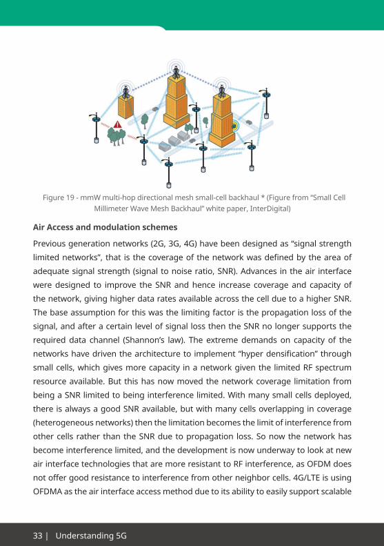
Figure19-mmWmulti-hopdirectionalmeshsmall-cellbackhaul*(Figurefrom“SmallCellMillimeterWaveMeshBackhaul”whitepaper,InterDigital)
Air Access and modulation schemes
Previousgenerationnetworks(2G,3G,4G)havebeendesignedas“signalstrength
limitednetworks”, that isthecoverageofthenetworkwasdefinedbytheareaof
adequatesignalstrength(signaltonoiseratio,SNR).Advancesintheair interface
weredesigned to improve the SNRandhence increase coverageand capacity of
thenetwork,givinghigherdataratesavailableacrossthecellduetoahigherSNR.
Thebaseassumptionforthiswasthelimitingfactoristhepropagationlossofthe
signal,andafteracertainlevelofsignallossthentheSNRnolongersupportsthe
requireddata channel (Shannon’s law). The extremedemands on capacity of the
networkshavedriventhearchitecturetoimplement“hyperdensification”through
smallcells,whichgivesmorecapacity inanetworkgiventhe limitedRFspectrum
resourceavailable.But thishasnowmovedthenetworkcoverage limitationfrom
beingaSNRlimitedtobeinginterferencelimited.Withmanysmallcellsdeployed,
thereisalwaysagoodSNRavailable,butwithmanycellsoverlappingincoverage
(heterogeneousnetworks)thenthelimitationbecomesthelimitofinterferencefrom
othercellsrather thantheSNRduetopropagation loss.Sonowthenetworkhas
becomeinterferencelimited,andthedevelopmentisnowunderwaytolookatnew
airinterfacetechnologiesthataremoreresistanttoRFinterference,asOFDMdoes
not offer good resistance to interference from other neighbor cells. 4G/LTE is using
OFDMA as the air interface access method due to its ability to easily support scalable

www.anritsu.com|34
bandwidth,leadingtoflexibleglobaldeploymentandscalabilitytosupporthigher
bandwidthsforhigherdatarates.Akeyissueforhighbandwidthsystemsislinearity
and distortion across the band. OFDM overcomes this by using many highly linear
andhighlyefficientsmallersub-bands.
A key weakness has come with OFDMA however, that is not aligned with the
capacity and density explosion that has hit the cellular industry. OFDMA does not
readilymanage interference,eitherexternal interferenceorself-interferencefrom
neighbor cells or overlapping coverage from small cells or local capacity hotspots.
LTE(Release8&9)hasabasicfrequencydomainmanagementtechniquecalledICIC
tomanagethisproblemforuserdatainoverlappingcells,butthisdoesnotmanage
the overlapping control plane data and cell broadcast/sync channels of adjacent
cells.Toovercomethis,LTE-Ahasintroducedatimedomainmanagementforthis
control signaling called eICIC and feICIC. Whilst these can succeed to manage the
control/broadcastinterferenceduetooverlappingcells,theydosobylimitingtimes
fortransmissionandhencereducecapacityofthenetwork.
So,thekeyresearchthemefornewmodulation/accessschemesistoallowtheflexible/
scalable bandwidth of OFDMA, but to overcome the interference management
issues in dense networks and Heterogeneous Network (HetNet) architectures
expected for5Gwithoutsacrificingcapacityorspectralefficiency.Thisproblem is
eventually leading tonewair interface technologiesormodulationschemessuch
asFBMC(FilterBankMulti-Carrier),whichimprovesthespectralefficiencyandcan
dramaticallyreduceinterference,UF-OFDM(UniversalFiltered-OFDM),whichshows
upmoreflexibletocombineMTCorTDD/FDDschemeswithwiderbandwidthsto
increasepeakdatarates,andGFDM(GeneralizedFrequencyDivisionMultiplexing)
whichisaflexiblemulti-carriertransmissiontechniquewhichbearsmanysimilarities
to OFDM but the main difference is that the carriers are not orthogonal to each
other for better control of the out-of-band emissions and the reduces the peak to
averagepowerratio,PAPR.Amoredetailedanalysisofsomecandidatewaveforms
ispresentedinthelaterchapterwherecandidatesaresimulatedandthenanalyzed.
Alongwith the newOFDMbasedwaveforms (which by definition are orthogonal
waveforms for each user) there is also research into non-orthogonalwaveforms,

35 | Understanding 5G
whereusersdonothaveseparatetime/frequencyplotsbutsharetheresource in
another(noorthogonalway).TheprincipleofNon-orthogonalaccesswasusedin3G,
whichusesCDMAaccess,whereeachuserorcellhasauniquespreading/scrambling
codetoseparatethesignals,buttheysharethesametime/frequencyspace.CDMA
wasshowntohavelimitationsinspectralefficiencyandimplementationissuesfor
widerbandwidthhighdata rateapplications.Nowtherearenewaccessmethods
being evaluated that enable such non-orthogonal access to be applied to increase
capacity or flexibility of the network. The leading research includes NOMA with
SuccessiveInterferenceCancellation(SIC)whichalsocalledSemiOrthogonalAccess
(SOMA),SparseCodeMultipleAccess(SCMA),andInterleaveDivisionMultipleAccess
(IDMA).
SOMA expands the radio resource allocation for the frequency and time domains
usedinOFDMAbysuper-imposingmultipleusersignalsusingthepowerdomain,
toincreasethespectrumefficiencyevenfurtherandtoincreasethecapacity.Figure
1showsanexampleoffrequencyre-usage.Multipleusersinthepowerdomainare
superposedatthesymbollevel.Figure2showsanexampleofsuperpositioncoding
where theUser2propagationchannel loss is lower than theUser1propagation
channelloss.WhenusingQPSKasthemodulationmethodforeachuser,thesymbol
constellation after superposition approaches a constellation like that of 16QAM.

www.anritsu.com|36
Figure 20 -
Q
I
Q
I
Q
I+ =
x2
x1 x1
x2
User 2 (QPSK) User 1 (QPSK) Superposition User 1 & 2
Frequency domainFrequency domain
Pow
er d
omai
n
Pow
er d
omai
n
NOMA/SOMAOFDMA
User 1 User 2 User 3
Superposition Encoding Example
The receiver circuits are built using successive interference cancellation (SIC). As
User2hasbetterChannelgainthanUser1(lownoise,andsobothUser1andUser
2signals canbeclearly received), theUser2desiredownsignal isdecodedafter
subtractingtheeffectofUser1(usingSICtofirstsubtractoutUser1signal)from
thereceivedsignal.Ontheotherhand,User1decodes itsownsignalbytreating
theUser2signalasnoise.User2withlowchannellossisassignedthelowerpower
modulationpatternandtheUser1withthehighchannellossisassignedthehigher
powermodulationpattern tooptimize thesignalquality forallusers, resulting in
improvedspectrumefficiency.
SCMA isa relativelynewwirelessmulti-accessmethod. Itavoids theQAMsymbol
mapping used by conventional CDMA coding technologies and implements each
binarydatawordbycodingitdirectlyintomultidimensionalcodewords.Eachuser
or layer assigns the binary data output from the encoder directly to the complex
codeword (physical resources dimensions) according to a predefined spreading
code of an SCMA codebook. Multi-user connections are implemented by assigning a
different unique code book to each user or layer.

37|Understanding5G
A message parsing algorithm is used because the SCMA codebook contains sparse
code words, this achieves near-optimal detection of multiplexed data without
increasing the complexity of processing at the receiver side.
IDMA is a multi-access method which is very new to the industry. In IoT/M2M
communications there are expected to be a large number of connected devices
sendingsmallnumbersofpackets,and insteadofusingpacketschedulingbased
on OMA the NOMA method is being considered because it has good robustness to
interference and does not require scheduling (this helps extend battery life of devices).
IDMAwithinNOMA is shown tohaveexcellentuserdiscriminationcharacteristics
and using a multi-user interference canceled can achieve a higher throughput
comparedtothesametypeoftrafficonOFDMA.Additionally,IDMAiswellsuitedto
low-coding-rateerrorcorrectionandisconsideredappropriatefortransmittingthe
largenumberofmultiplexedsmall-packetsignalsusedbyIoT,M2M,etc.
In Band Full duplex
Allmobilecommunicationnetworkshavereliedonaduplexmodetomanagethe
isolationbetweentheuplinkanddownlink.Therearefrequencyduplex–FDD(such
asLTE,whereuplinkanddownlinkareseparatedinfrequencyandoperateatthe
sametime)–andtimeduplexschemes–TDD(wherethetransmitterandreceiver
transmitatdifferenttimesbutusethesamefrequency,asinTD-LTE).Aduplexmode
isnecessarytocoordinateuplinkanddownlinktopreventthetransmittersaturating
the receiver and blocking any signal reception, but now full duplex technologies
arenowbeingresearched.Inthisfullduplexschemeadevicebothtransmitsand
receivesatthesametime,thusachievingalmostdoublethecapacityofanFDDor
TDD system.

www.anritsu.com|38
TX Data
RX Data
Modulator(BB)
Demodulator(BB)
DAC
ADC
PA
LNA
Duplexer
f1
LO
LO
TX Signal
RX Signal
ANT
Post-LNA digital cancellation
(Subtract a digital TX copy
from the RX input signal at the
demodulator).
Shall account for both linear
and non-linear TX distortions.
Pre-LNA analogue cancellation
(Subtract an analogue TX copy
from the RX input signal at the
LNA).
Shall account for the ADC
resolution to avoid saturation.
Antenna and Duplexer design
to minimize leakage and
antenna reflection.
DigitalCancellation
AnalogueCancellation
Isolation
20-30 dB 20-30 dB 25-40 dB
Both use knowledge of TX signal
Fig 21 - Sources of Interference
There are major technology challenges to achieving what is essentially self-
interference cancellation, and major changes in both networks and devices are
requiredforfullduplexoperation.However,thepotentialincreaseinoverallcapacity
issubstantial,makingfullduplexaveryimportanttechnologyforthefutureofmobile
networks.InacurrentLTEnetwork,thetransmitteratthedeviceendmaybeupto
23dBmoutputpower,andrequiresbelow-113dBmreceiversensitivity,soatotal
of136dBisolationwouldberequiredintheextremecase.Wecanseethatcurrent
researchhasreported110dBisolation,soitisimprovingbutstillsomewayoff.Itis
thereforeunderstudytoseeifausefulfigurecouldbeachievedinthetimeframeof
5G deployment.
Sothekeytoachievinghighercapacity (spectrumefficiency)via“fullduplex” is to
solvethetransmit–receiveisolationproblem,protectingthereceiverfromsaturation
by the transmitter. The traditional approach is to use normal circuit design principles
forbestpossibleisolation(worksforduplexorleakageandantennareflection),but
thisdoesnotgiveenough isolation for therequiredreceiversensitivity,anddoes
not protect againstmultipath reflections beyond the antenna that create strong
interference.Sothenewapproachtosolvethisprobleminvolvesaddedinterference
cancellation, so that any residual interference can be removed and the required

39|Understanding5G
sensitivity achieved. This cancellation is required at both the analogue stage and the
digitalstage,togiveenoughperformanceatanaffordablesize/price.
Duplexer Leakage Antenna Reflection Multipath Reflections
TX Data
RX Data
Modulator(BB)
Demodulator(BB)
DAC
ADC
PA
LNA
Duplexerf1
LO
LO
TX Signal
RX Signal
ANT
Due to practical limitations
in the duplexer design
and additional mismatch at
the duplexer’s output
connection to the transmission
line connecting it to the
antenna.
Due to mismatch between the
transmission line impedance and
the antenna’s input impedance.
Due to reflection in the
surrounding environment.
+ +20-30 dB 20-30 dB 24-40 dB
Figure 22 - Cancellation of Interference
AlongsidetheTx-Rxisolationproblemateachradio,thereisalsotheneedforproper
access co-ordination for themultipledevices in thenetwork.Suchschemes, such
asTDMA,CDMA,OFDMAarealreadyexisting.Butasnewandmoreefficientaccess
schemesaredevelopedfor5G,theymayalsohavetotakeintoaccountthefullduplex
modewhentheaccessco-ordinationmethodsarebeingevaluated.Differentaccess
schemeswillchangetherequirementsforchannelmeasurementsandcancellation
algorithms,andthiswoulddirectlyaffecttherealworldperformanceandefficiency
of any full duplex modes.
One use case that is attracting attention is the use of full duplex to enable “self
backhaul” in a small cell environment. This effectively means that a small cell can
use theair interface toprovidebackhaul toamacrocell,andsimultaneouslyuse
the same air interface to provide service to a local small cell. This enables simple
placementofsmallcellsintothenetworkasrangeextenderstoimprovecoveragein
indoor conditions. The small cell is able to simultaneously communicate to devices
inthecellandtothemacrocell,withbothTxandRxrunningsimultaneously.The

www.anritsu.com|40
scheduling algorithms of the macro cell and small cell need to be carefully aligned
suchthatanyUE’sinthecellarenotsubjecttointerferencebetweenmacroandsmall
cell(asthedevicesdonothavefullduplexcapability),andalsoprovideinterference
cancellation information to devices and the macro cell receivers.
Fig 23 - Reported Performance of Interference Cancellation
Antenna CancellationTX 1 TX 2RX
d d + λ/2
Power SplitterRF Analog
Baseband RF
DAC
Encoder
noise canceller chipInput
OutputRF Analog
RF Baseband
RF Interference Cancellation
RFInterferenceReference
Digital InterferenceCancellation
DecoderDigital
InterferenceReference
ADC
TX Signal Path RX Signal Path
1
2
3T
∑∑
Analog Cancellation Circuit
DAC
C
Tb
Digital Cancellation
TX
RX
PA
ADC
∑
R
Sing
le A
nten
naD
esig
n
Attenuation& Delay
R + iT
xx
R + aTCirculator
d1a1
dNaN
controlalgorithm
Eliminates all linear andnon-linear distortion
fixeddelays
variableattenu-ators
RSSIRF Reference
Balun
Balun Cancellation
Baseband RF
DAC
RF Baseband
∑
ADC
Decoder Encoder
FIR filter
Digital Interference Cancellation
Digital InterferenceReference
ControlFeedback
ChannelEstimate
TX Signal Path RX Signal Path
DAC
DAC
ADC
TxRadio
RxRadio
TxRadio
+
RF
RF
RF
BB
BB
BB
x1
c1
y1
Node 1 Node 2
hz
hab hAB
+
Antenna a Antenna A
Antenna b Antenna B
haBhAb
D
hZ
TxRadio
RxRadio
TxRadio
RF
RF
RF
DAC
DAC
ADC
BB
BB
BB
x2
c2
y2
60 dB 73dB
~80 dB
110 dB!
Cancellation
Stanford
RiceStanford2010
SICapproaches
2013
20112010

41 | Understanding 5G
Massive MIMO
MIMO has been deployed in LTE and LTE-Advanced
networks, where the base station and user equipment
usemultipleantennastoincreaselinkefficiency.Massive
MIMO refers to the technique where the base station
employs a much higher number of antennas that create
localized beams towards each device. The gains in
capacity are enormous but so are the technical challenges
associatedwith this technology.Abasic formof thishas
beenintroducedinLTE-A,calledbeamforming,butisonly
operationaltoasingledeviceatanyonetime,andhasonly
limited directivity/gains due to the limited number of base-
station antenna supported in LTE-A.
Massive MIMO is building upon previous research and development in phased array
antennasthatwasprincipallydevelopedforelectronicallysteeredradarsystems.The
basicconceptisthatanarrayoflowgainandlowdirectivityantennasarebuilt,and
thenthephaserelationshipbetweenthesignalsoneachantennacarefullymanaged
Fig 24 - 128 port antenna
RF/Antennas
Baseband
IP
LTE Infrastructure
CPRI
Full Dimension MIMO (Rel-13)
FD MIMO eNB
Highly directional streams and special multiplexing
High order MU-MIMO transmissionto more than 10 EUs
Fig 25 - Full Dimension MIMO

www.anritsu.com|42
such that the composite signal from all the sub-antennas gives a high gain and
directional beam that is controlled by electronically adjustable phase shifters. This
conceptisnowcombinedwiththeMIMOconcept,thatusesbasebandprocessingto
exploitmultiplespatialpathsbetweensetsofantennassuchthatmultiplechannels
ofdatacanbetransmittedsimultaneously,anduseMIMOspatialcodingtoseparate
the channels of data to different users according to their spatial position and the
unique channel propagation characteristics of each Tx-Rx combination.
SomassiveMIMOwillsupportmanyseparatedatachannels,basedonthewidespatial
diversityoftheTx-Rxlinks,andthecapacityhereisincreasedbyhavingmanyTxand
Rxantennas.SowherecurrentMIMOuses2or4antennasforTxandRx,massive
MIMOmaybeusingupto128antennas.Thiswillleadtomuchhigherdatacapacity
inamassiveMIMOcell,duetotheabilitytosynthesizemanyseparatesimultaneous
datapathstoindividualusers.Thisiscombinedwiththeenhancedbeamformingthat
ispossiblewithmanymoreantennas,toprovidehighlydirectionalbeams(reducing
interference and enhancing signal to noise ratio) and even 3D beamforming that
enablesthenetworktomanagebothnearandfarawaydevicesatthesametime
withoutsaturatingorblockingsignals.
As5Gisnowbeinginvestigatedforhigherfrequencybands(24-86GHz)thenatthese
higher frequencies the large arrays can be implemented into a smaller form factor
bytakingadvantageofthehigherfrequency(shorterwavelength).Thisenablesthe
scalingoftheantennasizedowntoamuchsmallersizewhilststillmaintainingthe
correctproportionsinrelationtowavelength.(e.g.correctseparationofantennaand
correctantennapatchsize), such thatanarraywith tensorhundredsofantenna
elementscouldberealizedintoapracticalformfactor.
ThebasicphysicsprinciplesformassiveMIMOarenowproven,andexperimental
systemsarebeingdeployed.Twoofthekeychallengestomaturethetechnologynow
aretomanagetheamountofcomputingpowerrequired,andtocreatestandardized
orinter-operablealgorithmssothatmulti-vendorandglobalsolutionscanberealized.
Todate, theprocessingpower requiredmeans themassiveMIMOdeployment is
notsuitableforportabledevicesduetosizeandpowerconsumption,andsofirst
deploymentsarefocusedmoretofixedwirelessaccessschemesandprovisioning
43 | Understanding 5G
ofwireless backhaul to a dense deployment of small cells inNLOS scenarios. As
processingpoweravailableindevicesisincreased,andimplementationofmassive
MMO algorithms is optimized to reduce receiver processing requirements, then
massive MIMO is expected to be deployed into the access scheme for user devices.
Inaddition,thealgorithmsusedsofarareproprietaryandverycomplex,andassuch
are only deployed into proprietary systems. To be included into a global telecoms
standard then there needs to be open information on implementations such that any
supplier can build either basestation or user device and be sure of interoperability of
equipment coming from different suppliers.
Traffic Management
Asthedeploymentofall-IPbasednetworksisbeingrolledoutalreadyin4Gnetworks
usingIPv6,thentheabilitytoofferdifferentiatedtrafficqualityaccordingtotheneeds
of theservice isbeingdeployed. Aswireless servicesexpand,andamuchwider
rangeofservicesaredeliveredacross thenetwork, thenanendtoendcapability
to support quality of service is required to ensure the required performance level
foreachservice.Asmanymorerealtimeservicesaredeployed,takingaccountof
thepossiblelowlatencycapability,thenensuringthequalityofserviceiscriticalfor
theapplicationsandservicestosucceed.Thetrafficmanagementwillberequired
tomanagetheexpectedveryhighvolumeoftrafficacrossthenetwork,andmust
beintegratedtothephysicallayercontrolproceduresforeachlinkinthenetwork
toensurethetrafficiscorrectlymanaged.Thiswillmeanthatallphysicallinkswill
needsuitablecontrolmechanisms,andthenetworkwillrequiremethodstoinform
the individual physical links of the required quality of service. Although this capability
is includedincurrentpacketdatanetworkssuchasHSPAandLTE,thescheduling
of data ismade locally and not co-ordinated across the network in an optimum
way.SoNFVandC-RANmayoffermoreefficientplatformsonwhichtheendtoend
quality canbemanaged,asallnetworkmanagementandschedulingcontrol can
be centralized and shared across different network functions. So one part of 5G
networkresearchanddefinitionwillbe lookingat theoptimizationof trafficflow,
andend-to-endQualityofService,inordertoensurethatthenetworkisdelivering
the required performance. Such a control system must be fully integrated to each
newnetworkelementinaseamlessandunifiedwaytoprovideanefficientnetwork
control function.

www.anritsu.com|44
Future Testing for 5G
As thenetwork concepts and technologies develop for 5G, so the corresponding
testmethodsandprocesseswillevolvetomatchthis.Future5Gtestmethodswill
needtoprovideahighconfidencetooperatorsthatthetechnologyandservicesare
implementedaccordingtospecification,andthatthequalityofserviceismatchingto
the requirements of the application or service being delivered.
Afullydata-centric5Gnetworkwithaverywideanddiversesetofapplicationstotest
wouldrequireamassiveeffortinstandalonetesting.Testautomation,monitoring
andbuilt in test systemswillbeessential foranalyzingproperly theperformance
ofsuchanetwork.Inaddition,theemergentsolutiontouseUltraDenseNetworks
(UDN)forinterconnectingtheradioaccesselementswiththebackhaularchitecture
usingcloudnetworkswillenablethedevelopmentofcloudbasedtestservicesfor
testingeverythingfromeverywhere.So,although5Gwillintroducemanynewtest
requirementsandchallengesbytheuseofSDN/NFVandcloudservices,thissame
technology can also be used for creating new test solutions that address these
needs.Withthisinmind,cloudsolutionsareseenasboththenewdemandandthe
newsolutionfor5Gnetworktesting.
Test and Measurement challenges
Oneaspect that is expected to characterize 5Gnetworks is that it is not a single
technologyorfeature,butthatitisanintegratedsetoftechnologiesandfeatures
designtoworktogetherinanoptimumwaytosupportawiderangeofapplications
andusecases.Fromatestingpointofview,thismeansthataswellastestingofthe
newtechnologiesbeingimplemented,therewillbemoreofaneedtotestthemany
different combinations of technologies and network elements to ensure correct
interoperability.Thisisfurthercomplicatedby“virtualization”andthefactthatspecific
networkfunctions(thenormalwayinwhichnetworkelementsaretested)mayno
longer be physically realized in a specific piece of hardware, butmay bemoved
aroundthenetworkorsplitacrossdifferentpartsofthenetwork.Thisvirtualization
of thenetworkand its functionswill requireacorrespondingvirtualizationof the
testing methods and tools to be used.

45 | Understanding 5G
Wehave seen in the earlier chapters the requirements on 5Gnetworks in terms
of target performance. These targets then lead us to a set of network KPI’s and
performance attributes to measure.
Key parameters for testing 5G.
•TrafficdensityTbps/km2.
•ConnectionDensity.Connectedusersandactiveusers.Connections/km2.
•Userdatathroughputatapplicationlevel,bothpeakandaverage.
•Latencyendtoendthroughnetwork,androundtriptime(RTT).
•Reliability(errorrates)
•Availability(coverage,handovers,mobility,capacity).
•Battery Life (mobile devices) andpower consumption/power saving (network elements).
•Waveform/accessspectralefficiency.
•Resourceandsignalingefficiencyandoverheadratio.
Whendesigning the testmethods for 5G, it is necessary topay special attention
formobilitytests.There isaneedtospecifywhichpartsofthenetworkaretobe
usedduringmobility/roamingprocedures,toensurewetestonlytheseandlimitthe
mobility combinations. This is due to the high complexity of different carriers and
datalinkswithintheHetNet,meaningthatnotallpossibledatabearercombinations
should be supported in all mobility test combinations. By reducing the mobility
combinations,thevolumeoftestingcouldbesignificantlyreducedandmaintained
at amanageable level. In addition, we can see thatmany use cases (e.g. smart
meters)willhavelowornomobilityrequirements,butthedynamicchangingofthe
networkmay result in suchdevices still requiringmobilityacrossdifferentaccess
mediumsdependingonthestatusofthenetwork.Somobilitytestingduetonetwork
configurationchangesratherthandevicelocationchangesmayberequired.
Whenwelookattheareaofdevicetesting,wemustnowevaluatehowthenetwork
simulatortechnologymustevolvetosimulatesucha5Gnetwork.
DuetothelackofavailableRFspectrumtomeetcapacityneeds,thereisnowastrong
push to utilize higher frequencies and themore availablemillimeterwavebands

www.anritsu.com|46
(currently looking at 24 - 86 GHz frequencies). Although individual regions have
specific licensing conditions, it is generally accepted that there ismore spectrum
likelytobeavailable,andspecificallymorecontiguousbandwidthavailable,atthese
higherfrequencybands.Utilizationofthesehigherfrequencybandswillputfurther
demands on the test equipment to provide corresponding support.
The test industry already has available basic RF measurement tools (spectrum
analyzersetc)thatsupportthedesignandtestofradiounitsatthesefrequencies,
andtheyarealreadyinuseintheindustry.But,cellularnetworktestingintroduces
needsformorecomplexnetworksimulators,andthesehavenotyetbeendeveloped
formillimeterwavebands.Oneofthekeychallengesinthisareaisthatitisexpected
that a 5G networkwill use awide range of operating frequency bands, and
may dynamically switch between them,butmostuserdevicesareexpected to
beoptimizedforspecificusecasescenarios.Thereforethedeviceswillnothavea
standardizedorcompletesetofradiointerfacetechnologies,insteadeachdevicewill
supportaspecificsubsetoftechnologies.Thisissimilartothe4Gsituationofdevices
having specific radio band support rather than support for all 40+ standardized
frequency bands, but now with an added second dimension of millimeter wave
bandsandtechnologiestosupport.Networksimulatorshavesupportedthisissuein
thebelow6GHzbandbyusingaflexibleopenRFarchitecture,butthismaynotscale
uptomillimeterwavebandsandtodifferentaccesstechnologies.
Alongwiththeneedformorefrequencybandstosupport,thereisalsoatrendtowards
widerbandwidthchannelstosupporthigherdatarates.Whilst itcanbeexpected
thatthecoretechnologyforsuchwidebandwidthswillnaturallybedevelopedforthe
networkelements(e.g.basestationtransceivertechnology),therearespecificissues
fornetworksimulatortechnologyintermsofhavingagenericimplementationthat
scalesfordifferentnetworks,ratherthanaspecificimplementationthatisneeded
forrealnetworkelements.Thisrequirementforadditionalflexibilityinconfiguration
becomes a key challenge in designing the RF performance and connectivity in a
network simulator, being able to support thewide range ofmulti-carrier signals
expectedfroma5Gnetwork.
MassiveMIMOhasbecomeakey termandattractive technology for5G,offering
significantgainsintrafficdensityaswellasdatathroughputpeakrates.Withthis

47|Understanding5G
technology then come some key challenges for testing. A MIMO system comprises
oftwomainelements,thebasebandprocessingalgorithmsandtheRFchannel.The
MIMOsystemworksbyhavingthebasebandalgorithmrespondtotheRFchannel
characteristics.Asthebaseband issplitbetweenthetransmitterandthereceiver,
andforacellularnetworkthesetwoelementscomefromdifferentsuppliers(infra
vendoranddevicevendorareoftendifferent), then the fulldetailedoperationof
the parameters required for the algorithm must be specified in the technology
standards documents. For massive MIMO this is likely to be a very complex and
detailed specification to ensure full interoperability. So in themassiveMIMO test
weneedtoreplicateeachoftheconditionsinthemassiveMIMOspecification,by
usinga fadingsimulator toreplicatetheRFchannel inacontrolledwayandthen
test the performance of the system (i.e. verify the data throughput rate achieved).
Whenweare testing thenetwork thenwemusthaveacontrolledreferenceuser
device,andwhen testing theuserdeviceweneed tohaveacontrolled reference
network.Asusually themost complexalgorithmprocessinganddecisionmaking
isinthenetwork(topreservepowerinmobiledevices,andreducecostimpacton
userdevices),thenthebiggestchallengecomeswhencreatingareferencenetwork
simulatortotestthemobile,asitmusthaveafullyopenandflexibleimplementation
forconfiguringandcontrollingtheprocessingalgorithms.
Asecondchallengerelatedtothisarea is the issueof “connector-lessdevices”,as
large arrays required formassiveMIMO and designs formillimeterwavewill be
constructedintocompactformtobecost/deploymentefficient.Thiscompactform
means that there is unlikely to be space for RF connectors or test ports to attach test
equipment.Sotheexpectedscenarioisfor“connectorless”testing,andhencethe
needformore“overtheair”OTAtesting.OTAisanestablishedtechniquecurrently,
but uses large and expensive RF chambers, and is a relatively slow process. The
industry challenge is to introduce more compact and cost effective OTA test solutions
thatarescalableforbothRF(below6GHz)andmillimeterwaveband(24-86GHz)
use. Massive MIMO also introduces further challenges in terms of compact and
affordable test systems tomeasurebeam forming,beamshape, compositegain,
andotherantennaparametersrelatedtothesynthesizedelectronicbeams.Studies
arecurrentlyunderwaytoevaluatenearfieldmeasurementtechniquestoenable

www.anritsu.com|48
a compact test system, whilst being able to extrapolate to the far field antenna
performance.
Wehaveseenthatnotonlyishigherdatarateandwiderbandwidthakeyfeaturefor
5G,buthyperdensenetworksarealsorequired.Thelimitingfactorforsuchhyper
dense deployments is the signal to noise ratio due to interference from neighboring or
co-located cells. And so the ability to accurately re-create and measure performance
insuchadenseandcomplexRFenvironmentbecomesakeynewtestitemfor5G.
AlongsidethecreationofthecomplexRFenvironment,thehyperdensecellnetwork
testingwillalsorequiredetailedtestingoftheRFmeasurementsandreportsfrom
bothnetworkanddevices,thesearerequiredtoenableasmartaccesssystemand
operation in a complex RF interference environment. This then leads to a massive
increaseintestingoftheRFmeasurementandreportingfunctionsofthenetwork/
devices,asthisisthekeyinformationusedtoinformthenetwork/devicealgorithms
onhowtooptimizenetworkaccess.
One of the most challenging technologies discussed for 5G is the concept of full RF
duplex,wherethetime/frequencyseparationbetweentransmitandreceivepathis
changedtosimultaneoususe.Thisoffersaveryattractivebenefitintermsofavailable
capacity,butintroducessomekeychallengesfortestingandsimulating.Aswehave
seeninearlierchapters,thekeytosuccessforthistechnologyissufficientisolation
betweenTxandRxpaths.ThisisachievedwithacombinationofbothRFisolation
methods and IF/baseband compensation algorithms. So for testing we need to
provide a very high isolation test environment that is capable to measure beyond the
designspecificationsofthe5Gsystem.Thecoretechnologyrequiredtoimplement
thefullRFduplexconceptisexpectedtogiveenoughperformanceforthis.However,
thechallengecomesinthatthetestequipmentmustusuallybeflexibleforusein
differentRFbands,whereasfullRFduplextechnologyisexpectedtobeoptimized
forspecificfrequencybands.Thereforethetestequipmentmustmeetacriticalcost/
performancepointintryingtoimplementacosteffectivetestsolution,balancingthe
bandspecificRFneedsversusthecosteffectivenessofageneralsolution.Without
suchacosteffectivetestsolution,therecanbesignificantcostbarriertohavinga
widedeploymentofthetechnologyintheindustry.

49|Understanding5G
Future Test Instruments
Network test
Inahighlevelperspective,NFVandcloudwillrequiremoreintelligenceandanalysis
inthetestinstrumentsasthenetworkbecomesmoredynamicoralive.Thephysical
elements in thenetworkwill bedivided into specific/dedicatedhardware suchas
antennas and radio transceivers, and general purpose hardware such as server/
computingplatforms.Eachofthesewillhavespecifichardwarerelatedcharacteristics
tobetested,suchasradioemissionsorsensitivity,orprocessordatarateorlatency.
Theprotocolaspectswillbetestedseparately,initiallyinavirtualenvironment(i.e.
inter-actionofprotocolstackshousedonsoftwareplatformsratherthanontarget
hardware).Finally,theintegrationofsoftware/protocolontothehardwareplatform
needstobetested.InSDN/NFV,thisthenbecomesmorechallengingasthehardware
platformwillnotbeaspecificplatformoptimizedfortherequiredprotocol.Thiswill
meanthattheperformanceofthenetworkwillneedtobeconstantlyverifiedaseach
virtualizednetwork function is locatedormoved todifferent hardware elements.
This type of monitoring is expected to be made using independent probes in the
network,whichareindependentofthenetworkhardwareplatformsandcanquickly
detect any performance issues.
Aswithcurrentnetworks,itwillbenecessarytotestandmonitorthedifferentdata
links,toidentifyanybottlenecksorrestrictionsindatacapacity,sotheoverallcapacity
canbeoptimizedandmaintainedattherequired levels.ButwithSDN/NFVthese
statisticsneedtobeprovidedinrealtimesothatanydynamiceffectsduetosoftware
configurationalgorithmscanbedetected.This isbecausenetwork functions (and
henceanyproblems)maynotstaticallylieonaspecifichardwarecomponentoruse
specificnetworklinksbutcouldbesoftwareredefinedbythenetwork,andsoareal-
timemonitoringsystemwillberequiredtoidentifywhenaconfigurationisusedthat
does not meet the performance requirements.
RF component and module test
5Gwillbringdevicesoperatinginmuchhigherfrequencybands,widerbandwidths
andmulti-carrierdesigns.Moreandmoreintegratedtechnologyisexpected,which
will produce amore complex analysis for interference limited devices. Generally

www.anritsu.com|50
speaking, the futureRFdevice testing ischallenging,andwillask forveryprecise
instrumentation in order to deal with millimeter wave transceivers and better
intelligence for Massive MIMO or AESA (Active electronically scanned array) radios.
Inaddition,thenearfieldeffectsandloadpullonmassiveMIMOantennasinuser
deviceswillneedtobefullycharacterized.Ingeneral,itisexpectedthat5GRFdevices
willbewiderbandwidth,lowdistortion,andlowpower,tosupportthewidebandand
densespectralefficiencyof5Gwaveforms.TheuseoffullduplexRFwouldrequire
significantworkinthetestandcharacterizationofRFisolationandcouplingbetween
devices.ThesemoredemandingRFrequirementswillneedtobeaddressedwhilst
aimingforhigherlevelsofRFcircuitintegrationtoreducecost,andinmanycases
theseareconflictingrequirements.
User device / terminal test
Testinga5Gfull-capablehandsetwillbecomeaveryextensiveprocessifweextend
current handset test procedures. We can expect many more band combinations
or RF duplex scenarios,massive number of transmitters and increasing types of
receivers, leading tomanyvariations indevices thatwill constantlybe increasing.
Userdevicesprobablywillnolongerbetestedusingcablesbecause‘OverTheAir’
(OTA)performancewillbeessential inthetestingprocess,forexampleinMassive
MIMO testing. More complex shield boxes and chambers will be required, even
tunabletoverydifferentfrequencybands.Alongsidethis,thesimulationofmultipath
using fadingsimulatorswillgrow further in importance,andalso in the technical
demands and capability required in such equipment. As the MIMO and HetNet
algorithms becomemore complex and powerful, then correspondingly powerful
fading simulators are required to test and verify the algorithms. The integration of
thenetwork simulator and the fading simulator thenbecomesa critical issue, to
enable accurate set-up of required scenarios.
Applicationtestingwithinanend-to-endenvironmentwillincreaseincomplexityand
customerexperiencetestingmaybecomeembeddedintothenetworksanddevices,
forexampleusingsmartsoftwareagents.Findingthebottleneckinthethroughput,
incomplexQoSandmulti-linktransmissions,becomesfarmorechallenging.Asthe
uplinkanddownlink,controlanduserplanes,areeachseparated,thenthelimitation

51 | Understanding 5G
indatathroughputcancomefromanyoftheseareas.Soevenwhenthedownlink
user plane has enough capacity to deliver the required data rates, the downlink
controlplaneneedscorrespondingcapacityandlatencytoscheduleit,andtheuplink
needslowenoughlatencytocarrythefastHARQfeedbackandMIMOreports(or
similar control loop data) to maintain the high throughput.
Oneareaofdevicetestingthathasgrownsignificantlyin4GisUserExperienceTests,
andthisisexpectedtogrowfurtherastherangeofuserexperiencesandusecases
growbasedon5Gtechnology.Oneareaofbigconcernfrom4Gisthebatterylife,
whereasmartphonecannotbeused forasingle fulldayandusersneedregular
accesstochargingpoints.Itisexpectedthat5Gwillneedtoofferbetterbatterylife,
butwithmoredataprocessing.Testsystemshaveevolvedinrecentyearstoprovide
specificandrepeatablerealworldscenarios(e.g.browsing,email,chat)toevaluate
batterylifeversusareferencedailysetofactivities.For5G,theexpectedlowlatency
of“tactileinternet”isexpectedtogiveamoredirectinter-actionbetweenuserand
apps/services,soevaluatinghowtheair interfaceandmodemlinkenablesthisor
impairsthiswillbeanimportantuserexperiencetest.
Device certification and approval, and Carrier Acceptance Testing
Withthelaunchof3Gnetworks,therewasanindustryinitiativetoreducethevolume
ofhandsettesting,andavoidrepeatedorredundanttesting,byintroducingindustry
forumssuchasGCFwith theconceptof “testonce,useanywhere”basedaround
standardizedandagreedtesting.Withthelaunchof4G,ithasbeenseenthatthe
testneedsfordevicesaredivergingascarriershavesignificantlydifferentnetwork
architecturesdue to thewide rangeofoptions.Also,4Gnetworksarenow inter-
workingwithnon3GPPnetworks(e.g.IMS,WiFi)andtheseparatetestingregimes
ofeachnetworktechnologyarenotaligned,soasingletestplancannotcoverthis.
So some major operators have introduced more operator specific test plans to
ensurecompliancetotheirspecificnetworkneeds.Lookingforwardto5G,withthe
muchmorediversesetofnetworkconnectivity fromHetNet’s, thenextrapolating
thecurrenttestmethodswillleadtoalargeincreaseinvolumeoftesting.Thekey
challengeinthis isthatthewiderangeofnetworkflexibility/diversityrequiredfor
managingawide rangeofdiverseuse caseswould lead toa verywide rangeof
industry standard test cases and scenarios. But moving away from an industry

www.anritsu.com|52
standardizedregimetoindividualtestplanswillalsoincreasedrasticallythevolume
oftesting.Sothistrade-offofdeploymentflexibilityversusstandardizedtestingwill
beakeyitemtoaddressin5Gnetworkdefinitions.
The divergent range of device types, M2M, Augmented Reality, smart meters
etc. expected on the network will also lead to divergent test needs and critical
functionality. Some smartmeter applicationsmay prioritize battery life and cost,
tradingoffversusdatarate,latencyandconnectionavailability.Equally,augmented
realitywouldprioritizedatarateandlatencyaboveall,andcriticalcommunications
(e.g. first responder, health & monitoring) may prioritize connection availability
ashighestpriority.Tohandlethesedivergentneedsandcharacteristics, it is likely
thatfurtherclassesor“classtypes”ofuserdeviceswillneedtobespecifiedin5G
standards,sothatcorrespondingtestregimesandmethodscanbedefinedtomatch
the different needs or classes of user devices.
Anotherareaofdevelopment that isbecomingmore relevantnow in theareaof
5G is that of Cognitive Radio, and SoftwareDefined Radios.When such a device
usesageneralpurposeRFtransceiver,itisessentialtoensureitmeetstherequired
RF performance for the specific protocols and modulation schemes being used.
Withoutsuchtests,theSDRdevicemayproduceexcess interferencethatdisrupts
thenetwork,orsufferfromexcessdistortion/non-linearitythatmeansdatalossand
communication failures. For the Protocol part of such a modem a key test is to ensure
thetimingrequirementscanbemaintained,asitisimplementedinnon-optimized
circuitsandsomaysufferfromslowprocessing/responsetomessages.
Field Test
Testinginthefieldwillalsogrowincomplexity.Findingthesuitabletestlocationsina
HetNetmaybecomeadifficultordynamicprocess,notonlyforcapturingthetarget
ULorDLstreambutalsofortheseparationbetweenControlandUserplanes.This
isbecausetheHetNetitselfwillbedynamicinitsuseofavailableresources,andthe
available resources may also be a dynamic parameter.
Aswehaveconsideredintheearliertechnicaldiscussions,a5GHetNetmayoperate
in an interference limited scenario (i.e. data rates and Signal to Noise Ratio are limited
byinterferenceratherthanpropagationlosses).Thiswillleadtoaparadigmshiftin

53 | Understanding 5G
hownetworkcoverageisdefinedandmeasured.Traditionalcoveragemappingat
themodeling,planninganddesignstages,infieldtrials,andduringdrivetesting,is
all based upon signal strength and assumes noise limited effects due to propagation
losses. In 5G, we can predict that installation tests, coverage mapping, and de-
buggingofissueswillbemuchmorefocusedontheinterferenceenvironment.
LoadtestforHetNet,lookingatcapacity,throughputandlatencyasthemainKPI’s
willbecomeanevermorecomplexissue.Wemaystillusetraditionaldrivetest,and
probebasednetworkmonitoring,togatherthesebasicuserKPI’s.Butaswehave
seen,theseparametersarehighlyvariabledependingonconditionsintheHetNet
and results can not be simply interpreted to establish performance and capability
of the network. This is because such capabilities are the result of the complex
algorithms tobeused forschedulingandroutingofdata.So, tomoreaccurately
evaluatethenetworkcapability,wemayneedtomeasureandrecordthevaluesof
theparametersgoingintothesealgorithms,andnotonlytheresultingperformance.
Sokeyparameterslikethroughputandlatencywillneedtobedefinedinrelationto
networkload,capacity,andinterferencelevels.
Current test technology examples in early 5G development
Evenintheearlystageof5Gdevelopment,
there are already test systems capable for
evaluating the upcoming technologies.
Amongst these, wide band Capture and
Replay systems for RF and I/Q signal
generation and analysis are important
in the development of new transmitters
andreceivers.Usingmodelingsoftwareto
createnewwaveformsandthenrealizingandevaluatingperformanceinrealdevices
isthefirststepbeforethestandardizationstage.ThiswillFig23-MS2830ASpectrum/
SignalAnalyzer+VectorSignalGeneratorbelookedatasaworkedexampleinthe
nextchapter.Itisusedfortheinvestigationofnewwaveforms,toseethespectral
properties,andthentoseehowthewaveformsareperformingonrealdevicesand
circuits(e.g.harmonicdistortion,non-linearitydistortionetc).Similarly,newdevice
technologyisevaluatedwithnewwaveformstoseetheRFperformance.
Fig 26 - MS2830A Spectrum/Signal Analyzer+VectorSignalGenerator

www.anritsu.com|54
Broadbandmulti-port VNA’s will continue
addressing the characterization of new
mmW devices and MMIC’s. Especially for
massiveMIMO,thereistheneedtoensure
thatrelativelylowcostandcompactdevices
and antennaswill have sufficiently stable
and repeatable RF/phase characteristics.
Also,asnewtechnologiesinsemiconductor
gates and processing enable lower cost
mmWdevices,thesedevicesneeddetailed
evaluation to ensure the RF performance
is not compromised by lower cost manufacturing. In addition, there is industry
activity now to change themethod of device characterization from narrow band
CWmeasurementstowidebandmodulatedmeasurements.Particularlyforactive
devicesitisimportanttoseethedevicebehaviorunderwidebandmodulatedsignal
conditions.Sofartheindustryhasonlymeasureddevices(e.g.Sparameters,load
pull, compressionetc)underCWconditionsandextrapolatedbymodeling to the
widebandmodulatedperformance.Withsophisticatednew5Gwaveformsthenitwill
beimportanttocharacterizetheseparameterswithdevicesdirectlyunderwideband
modulatedconditions.Thisrequirestheuseofnewgenerationwidebandmodulated
VectorNetworkAnalyzers(VNA’s)thatarecapabletosupportnewrequirementssuch
as “modulated S parameters”.
Inthenetworkside,highspeedBERTS(64
GB/channel) are used for testing next
generationopticaldevicesinfiberlinksand
data centers. As the processing power in
datacentersandserverfarmsisincreased,
to support cloud computing, then the
inter-connect between individual server
blades and server stacks needs to be high
speed,lowlatency,andlowdistortion.New
modulation schemes are being introduced
Fig27-ME7838A/E/DVectorStarBroadband VNA
Fig 28 - MP1800A Signal Quality Analyzer

55 | Understanding 5G
intohighspeedopticalcommunications,suchasPhaseAmplitudeModulation(PAM),
withPAM4andPAM8having4or8differentstatespossibleandhenceincreasethe
datarateversuspuredigital (2state,on/off) transmission.But toenable this, the
linearityofthemodulatorsandde-modulatorsneedstobeverified,andthisisdone
using Eye diagrams and Bit Error Rate Tester (BERT).
100 Gb/s link analysis, traffic flow, and
OTN mappings for cloud networks are also
available solutions these days. It is expected
that the key parameters of delay, jitter, and
bandwidth will remain as in today’s testing,
butwiththecorrespondingnewtargetvalues.
Fig29-MT1100ANetworkMasterFlex - All-in-one transport tester

www.anritsu.com|56
Introduction to 5G Waveforms
Thissectionintroducesthereadertothreeofthedifferentwaveformsthatarebeing
consideredtobepartof5G,andhighlightsthedifferencesofFBMC,GFDMandUF-
OFDMversustoday’sOFDMusedin4G.
The5Gradioaccesstechnology(RAT)mustfulfillthedatatrafficdemandinthenext
yearswith rates above 10 Gbps and sub-millisecond latency. These rates can be
achieved,principally,withbandwidthsofatleast200MHz,andusingmultiple-input
multiple- output (MIMO) antenna techniques and interference rejection combining
(IRC)receivers.Ideally,thewaveformtobeusedshouldhavegoodimplementation
properties,suchaslimitedcomputationalcomplexityforthegeneration/detection,
limitedtime/frequencyoverhead,goodlocalizationintime,goodspectralcontainment
andsimpleextensiontoMIMO,amongstothers.Ithasbeenshownin4GthatOFDM
is suitable for both the good MIMO implementation and also the simple processor
implementationintheuserdevices,andso5Gwaveformsarelookingtobuildonthis
and further evolve OFDM to overcome the current limitations.
FBMC, Filter Bank Multi-Carrier: FBMC has gained a high degree of interest as
a potential 5G waveform candidate. This modulation scheme provides many
advantages.FBMChasmanysimilaritiestoCP-OFDM,(OFDMusingacyclicprefix,
whichisthespecificvariantusedasthe4Gwaveform).Insteadoffilteringthewhole
bandas in thecaseofCP-OFDM,FBMCfilterseachsub-carrier individually.FBMC
doesnothaveacyclicprefixandasaresult it isable toprovideaveryhigh level
ofspectralefficiency.Thesub-carrierfiltersareverynarrowandrequirelongfilter
timeconstants,typicallythetimeconstantisfourtimesthatofthebasicmulti-carrier
symbollengthandasaresult,singlesymbolsoverlapintime.Thisalsomeansthat
FBMCisnotsuitedtolowlatencyshortburstdatatraffic,nortoconventionalMIMO.
Toachieveorthogonality,offset-QAMisusedasthemodulationscheme.
UF-OFDM, Universal Filtered OFDM: This waveform can be considered as an
enhancementofCP-OFDM.ItdiffersfromFBMCinthatinsteadoffilteringeachsub-
carrierindividually,UF-OFDMsplitsthesignalintoanumberofsub-bandswhichit
thenfilters.UF-OFDMdoesnothavetouseacyclicprefixsocanachievehighspectral

57|Understanding5G
efficiency, although one can be used to improve the inter-symbol interference
protection,andcanbesuitableforconventionalMIMO.
GFDM,GeneralizedFrequencyDivisionMultiplexing:GFDMisaflexiblemulti-carrier
transmission techniquewhich bearsmany similarities to OFDM and can support
conventional MIMO. The main difference is that the carriers are not orthogonal to
each other. GFDM provides better control of the out-of-band emissions and reduced
peaktoaveragepowerratio,PAPR.Bothoftheseissuesarethemajordrawbacksof
OFDMtechnology.Inaddition,asitcansupportamixofinter-leavedsub-carriers,
soitcansupportlowlatencyandshortbursttrafficdata.Thetrade-offforGFDMis
not so good sidelobes and out of band emissions compared to FBMC and UF-OFDM.
Wecanbuildamathematicalmodelofeachoftheabovewaveforms,andcompare
themtoCyclicPrefixOFDM(CP-OFDM)whichisthewaveformusedcurrentlyin4G.We
canthenexperimenttoseetheperformanceofeachwaveform,andalsoanalyzethe
co-existenceofeachwaveformtoseehowtheycanbedeployedalongsideexisting
4Gwaveformswithoutcausingorsufferingfrominterference.Astheexpecteduse
case for thesewaveforms is below6GHz, for deployment alongside or on topof
existing4Gnetworks,thentheco-existencepropertiesbecomeanimportantfactor.
WecanbuildsuchatestenvironmentusingVectorSignalGenerator,VectorSignal
Analyzer,andmathematicalmodelingandanalysistools.Theset-upisshownbelow:
Fig30-Configurationofwaveformtestenvironment
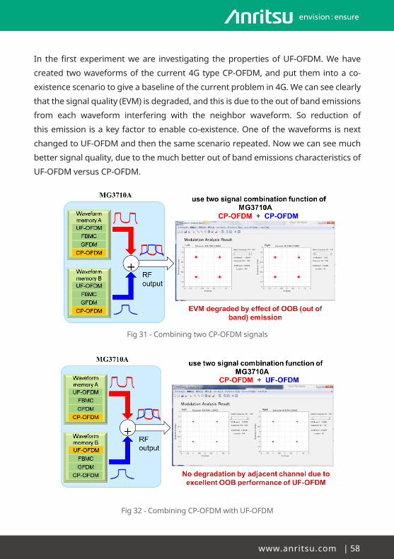
www.anritsu.com|58
In thefirstexperimentweare investigating thepropertiesofUF-OFDM.Wehave
createdtwowaveformsofthecurrent4GtypeCP-OFDM,andputthemintoaco-
existence scenario to give a baseline of the current problem in 4G. We can see clearly
thatthesignalquality(EVM)isdegraded,andthisisduetotheoutofbandemissions
from each waveform interfering with the neighbor waveform. So reduction of
thisemission isakeyfactortoenableco-existence.Oneofthewaveformsisnext
changedtoUF-OFDMandthenthesamescenariorepeated.Nowwecanseemuch
bettersignalquality,duetothemuchbetteroutofbandemissionscharacteristicsof
UF-OFDM versus CP-OFDM.
Fig31-CombiningtwoCP-OFDMsignals
Fig32-CombiningCP-OFDMwithUF-OFDM

59|Understanding5G
InthesecondexperimentweareinvestigatingthepropertiesofFBMCandtheissue
of inter-symbol interferencedueto lackofcyclicprefix.TheSymbolTimingOffset
(STO)mustbecarefullyselectedtoavoidinter-symbolinterferencewithintheoffset
QAM scheme. We see in the next figure the performance/degradation of signal
qualitywithtwodifferentvaluesofSTO,withthelargerSTOof0.2causingsevere
loss of signal quality.
Fig 33 - The effect of timing offset for FBMC
InthethirdexperimentweareinvestigatingthepropertiesofGFDM,specificallythe
flexibilitytosupportdifferentsub-carrierswithinasingleradioframe(e.g.highdata
rateand lowdata rateusers). In the testwecansee that receiverneeds tohave
special processing to handle the inter-symbol interference and that a conventional
receiver is not able to properly decode the signal. This is due to the non-orthogonal
interleavedsub-carriersthatgivetheextraflexibilitybutcauseinterferencetothefull
sub-carriers. We can see that the received constellation diagram is not matching the
transmittedconstellationdiagram,andthataspecialstageofadditionalsub-carrier
filteringisrequiredtomanagethesenon-orthogonalsub-carriers.
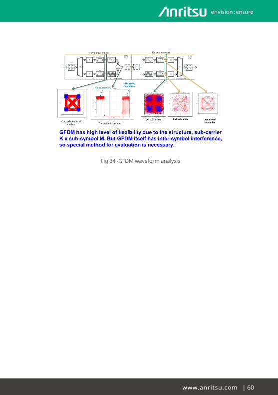
www.anritsu.com|60
Fig34-GFDMwaveformanalysis

61 | Understanding 5G
Detailed analysis of an example FBMC waveform.
This section introduces the reader to a more detailed analysis of the FBMC
waveformsthatareconsideredfor5Gandthedetailedanalysismethod.Ithighlights
theadvantagesof FBMCversusOFDM,providesbasic concepts about FBMCand
demonstrateshowwe can load these signals intoAnritsu’s SignalGenerators for
immediate evaluation on real devices.
Orthogonal Frequency Division Multiplexing (OFDM) derived waveforms such as
Filter Bank Multi-carrier (FBMC) are considered as the most attractive candidates for
a5Gwaveform.ThemaindifferencebetweenOFDMandFBMCisthepulseshaping
appliedateachsub-carrier.Ononehand,OFDMusesthesimplesquarewindowin
thetimedomain,whichleadstoaveryefficientimplementationbasedontheInverse
Fast Fourier Transform (IFFT) spreading of the original block of data symbols and
gettingthesub-carriersorthogonal.Ontheotherhand,inFBMC,thepulseshaping
ateachsub-carrierisdesignedinawaythatsomeoftheOFDMlimitationscanbe
circumvented,likeabetterfrequencycontainmentandimprovedsystemoverhead
(noneedsofcyclicprefix),butitismorecomplexduetotheusageoflongprototype
filters.
InthisanalysisispresentedthemostcommonFBMCprinciple,whichistheOFDM/
OQAMmodel.Itmeansthat,apartfromtheFBMCprototypefilterappliedateach
sub-carrier,themodulationschemeusedisoftheoffset-QAMtype,whichgivesasa
result the elimination of the Inter-Symbol Interference (ISI).
Filter Bank Multi-Carrier (FBMC) Concepts
TheschemeofaFBMCtransmitterappearsinthefollowingfigure.Itcanbeobserved
thatitissimplyformedbyaSynthesisFilterBank,whosefiltersareofFiniteImpulse
Response(FIR)type.Furthermore,onlyasingleprototypefilterisneeded,soeach
sub-channel is filterer by same form and BW. Basically, the input information is
divided in N sub-channels (typically a power of 2) and, after applying a possibly
needed oversampling, are passed through the correspondent prototype filter,
centered in one of the sub-carriers inside the band.

www.anritsu.com|62
K
K
K
s0(n)
s1(n)
sN1(n)
Transmittedsymbols areOffset QAM
H(f)
H(f)
H(f)
e j2�f0n
e j2�f1n
e j2�fxn-1n
Sub-channels Filters: All ofthem have the same BW asthe Prototype Filter H(f)
Output signal
f
Synthesis Filter Bank - Finite Impulse Response (FIR) filter banks - Orthogonal filter banks -> a single Prototype Filter H(f) is needed
: info divided in N sub-channels(typically a power of 2)
Fig 35 - Synthesis Filter Bank for FBMC Transmitters
As we introduced before, the key feature of FBMC modulators is the prototype
filterappliedateachsub-carrier.Thus,thedefinitionofthisfilterisrelevantinthe
designofthesesystems.Inourcase,wehavechosenthePhydyas(PHYsical layer
forDYnamicAccesSandcognitiveradio)prototypefilter[3].Thisfilterisdesignedin
suchamannerthatonly immediatelyadjacentsub-channelfiltersaresignificantly
overlappingwitheachotherinthefrequencydomain.
Thenextfigurerepresentsamorerealisticwayofoursystem. In thiscase, itcan
already be seen the OQAM modulation and the combination of the IFFT (for splitting
the symbol energy into the different sub-carriers) and the impulse response of the
prototypefilterapplied.OQAMmakesthesymbolsbeingtransmittedalternativelyon
therealpartandtheimaginarypart,soIn-phase(I)andQuadrature(Q)components
haveatimeoffsetofhalfsymbolinterval(T/2).Oncewehavethebasebandsignal,we
modulate it to RF band (fc) and transmit the real part to the channel.
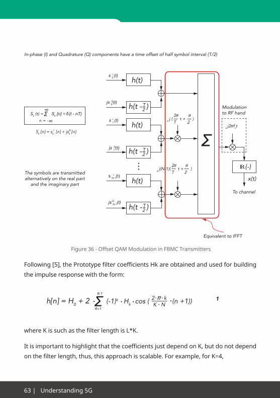
63 | Understanding 5G
The symbols are transmittedalternatively on the real part
and the imaginary part
e j2�fct
In-phase (I) and Quadrature (Q) components have a time offset of half symbol interval (T/2)
Modulationto RF hand
Equivalent to IFFT
To channel
h(t)
h(t - )T2
h(t)
h(t - )T2
h(t)
h(t - )T2
Σ
x(t)
{-}
s N-1(t)I
js 0 (t)Q
s 1 (t)I
js 1 (t)Q
s 0 (t)I
js N-1(t)Q
Sk (t) = Σ∞
n = -∞Sk [n] = (t - nT)δ
Sk [n] = sk [n] + jsk [n]QI
2�Te j(N-1)( t + )
�2
2�Te j ( t + )
�2
Figure 36 - Offset QAM Modulation in FBMC Transmitters
Following[5],thePrototypefiltercoefficientsHkareobtainedandusedforbuilding
theimpulseresponsewiththeform:
whereKissuchasthefilterlengthisL*K.
ItisimportanttohighlightthatthecoefficientsjustdependonK,butdonotdepend
onthefilterlength,thus,thisapproachisscalable.Forexample,forK=4,
ΣR-1
R=1
(-1)k Hk cos ( (n +1)) 2 � kK Nh[n] = H0 + 2 1

www.anritsu.com|64
H0=1
H1=0.97160
H2=√2/2
H3=0.235147
and these values give an iterative procedure that can be used for K>4.
NotethatthebiggerK,themorerejectionbetweenadjacentsub-channelsandthe
biggersystemdelay.Consequently,acomprehensivevalueshouldbechosen.Inour
case,wewillworkwithK=4,whichwillproduceadifferenceof40dBbetweenthe
mainandsecondlobesofthefilter’sfrequencyresponse.
FBMC Modulator in Matlab
Once we have chosen Matlab as the
mathematical software for programming
the FMBC signals, the first target is to
implement the Prototype filter based on
thedesignwecouldseeabove.
The Prototype filter can be easily
programmedinMatlab, justselectingthe
number of sub-carriers N and applying the
impulseresponseformulawiththefilter’s
coefficients.Then,thetimeandfrequency
responsesappearrespectivelyinfigures29
and 30.
In figure 29 (Prototype filter’s time
response)wecanappreciatethealmost
40 dB rejection between the main and
second lobes, which principally achieves
thedesiredfrequencycontainmentthatwe
need for future communications.
Samples
Time domain
Am
plit
ude
1.2
1
0.8
0.6
0.4
0.2
0
-0.210 20 30 40 50 60
h [n]
Fig37-Prototypefilter’stimeresponse
Normalized Frequency (x � rad/sample)
Frequency domain
No
rmal
ized
Mag
nitu
de
(dB
)
0.50.1 0.80.60.40.2
0
0.3
-120
-20
-100
-40
-80
-60
-140
-160
-1800 0.7 0.9
Relative Side-lobe Attenuation: -39.9 dBH [f]
Fig38-Prototypefilter’stimeresponse

65 | Understanding 5G
The next stepwould be building the FBMCmodulator. Our approach provides a
tuning variable that permits the repetition of a certain number of random FBMC
symbolstobetransmitted.Inthisway,wecananalyzeafterwardsthedifferencein
thespectrumbetweenasignalformedwithfewsymbolsandanotheronewithmany
symbols.
Time (ns)
Time domain
Am
plit
ude
150
0.1
250
0.4
0.2
0
0.3
50
-0.1
100 200
-0.2
-0.3350
real (f_signal) for 1 FBMC symbol (rep=1)fs=200 MHz
Figure39-FBMCSymbolinTimeDomain
Firstly,wecanobservethetimeformofasingle-FBMC-symbolsignal.Ifweanalyzeit
in the frequency domain.
Frequency (MHz)
Frequency domain
Mag
nitu
de
(dB
)
5010 80604020
0
30
-120
-20
-100
-40
-80
-60
-140
-1600 70 90
Spectrum (f_signal, rep=1fs=200 MHz
Energy divided incertain sub-carriers
Fig 40 - FBMC Symbol in Frequency Domain

www.anritsu.com|66
Itcanbeobservedthat,withjustoneFBMCsymboltransmitted,notallsub-carriers
havebeenexcited,butonlytheonesappearingingreen.Thedifferentsub-carriers
willberandomlyexcited,dependingontheresultoftheIFFTovertheO-QAMsignal.
Itcanalsoberealizedthatonlyadjacentsub-carriersimpactsontheircorrespondent
neighbors,i.e.onlythesumofthemainlobesofadjacentsub-carriersarerelevantin
thespectrum.Thisisveryimportant,becausewecouldseparatedifferentsignalsby
justonesub-carrierspacingbetweenthemandstillbeingeasilyrecognizable.
Only the sum of the main lobes of the adjacent sub-
carriers are relevant in the spectrum
Fig41-FrequencyrelationshipbetweenFMBCsignallobes
The next scenario consists in creating a 100-FBMC-symbols signal for appreciating
thedifferenceinthespectrumwiththepreviousone.Inthiscase,onecouldexpect
thatwith100symbolswewillhaveallthesub-carriersexcited,thus,wewillhaveto
obtainaflatspectrum.Inthenextfigure
Time (ns)
Time domain
Am
plit
ude
1.5-0.8
2.5
0.4
0.2
0
0.6
0.5
-0.4
1 2
-0.2
-0.6
3
real (f_signal) for 100 FBMC symbols (rep=100)fs=200 MHz
x104
Fig 42 - 100-FBMC-Symbols signal in Time Domain

67|Understanding5G
…itisdemonstratedthatafterusing100FBMCsymbolsthespectrumbecomesflat,
i.e.thesignalenergyhasbeendividedbetweenallthesub-carriers.
Frequency (MHz)
Frequency domainN
orm
aliz
ed M
agni
tud
e (d
B)
5010 80604020
0
30
-120
-20
-100
-40
-80
-60
-140
-160
0 70 90-180
Spectrum (f_signal, rep=100fs=200 MHz
Spectrumbecomes flat.
Energy divided inall sub-carriers
Fig 43 - 100-FBMC-Symbols signal in Frequency Domain
FBMC Waveform in MS2830A
After successfully testing the FBMCmodulator inMatlab, it is time to send these
signalstoourSGinternalmemory,sowecanreproducethemandusethemwith
realdevices.Inthiscase,theall-in-oneSignalGenerator+SignalAnalyzer+Spectrum
AnalyzerMS2830Ahasbeenchosenforourexperiment.
Fig 44 - Anritsu IQProducer

www.anritsu.com|68
TheMS2830ASGcanreadexternalIQwaveformsfileswithextensions.wvdand.wvi,
whichleadstotheneedofusingAnritsuIQProducerforconvertingthedatafrom
Matlabintothesetypeoffiles.ItwillconsistinsavingthewaveformdatafromMatlab
intoaComma-SeparatedValuesfile(.csv)and,then,usingIQProducerforconverting
itintothereadablewaveformfiles.
This isthestageoftheprocesswhentheuserwillselectthesamplingfrequency,
which will determine the signal bandwidth at RF frequencies. The software IQ
ProducerforMS2830Aallowsamaximumsamplingfrequencyof160MHz,sothe
widestsignalwillhaveexactlythatbandwidth.
Fig 45 - Convert tool in Anritsu IQProducer
WecanusetheIQProducerTimeDomainapplicationforviewingthesignalloaded:
Fig 46 - IQProducer Time Domain Application
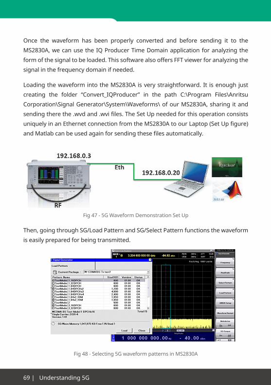
69|Understanding5G
Once the waveform has been properly converted and before sending it to the
MS2830A,wecanusetheIQProducerTimeDomainapplicationforanalyzingthe
formofthesignaltobeloaded.ThissoftwarealsooffersFFTviewerforanalyzingthe
signal in the frequency domain if needed.
LoadingthewaveformintotheMS2830Aisverystraightforward.It isenoughjust
creating the folder “Convert_IQProducer” in the path C:\Program Files\Anritsu
Corporation\SignalGenerator\System\Waveforms\ofourMS2830A,sharing itand
sendingtherethe.wvdand.wvifiles.TheSetUpneededforthisoperationconsists
uniquelyinanEthernetconnectionfromtheMS2830AtoourLaptop(SetUpfigure)
andMatlabcanbeusedagainforsendingthesefilesautomatically.
Fig47-5GWaveformDemonstrationSetUp
Then,goingthroughSG/LoadPatternandSG/SelectPatternfunctionsthewaveform
is easily prepared for being transmitted.
Fig48-Selecting5GwaveformpatternsinMS2830A

www.anritsu.com|70
ConnectingtheoutputtotheinputofourMS2830A,wecanusetheSPAforviewing
the signal transmitted. In this first example, a single-FBMC-symbol signal with a
bandwidthof20MHzcanbeappreciatedinthefigure.Agoodrejectionatbothsides
ofthesignalisachieved,asitwasexpected.
ThenextfigureshowsthesignalfromtheSAfunction,showingmoreclearlythesub-
carriers that have been excited for this FMBC symbol.
Fig49-5GWaveformSpectruminSpectrumAnalyzermode
•ConnecttheOutputtotheInput•SPA•SignalBW=20MHz•Clearlydistinguishedsub-carrier
•ConnecttheOutputtotheInput•SA•SignalBW=20MHz•Clearlydistinguishedsub-carrier
Fig50-5GWaveformSpectruminSignalAnalyzermode
20 MHz
2.5 MHz
20 MHz
14 MHz

71|Understanding5G
Following the same procedure with a 100-FBMC-symbols signal, we can observe
theproperconversionofthesignalusingIQProducer,bothintimeandfrequency
domain.
Signal with 100 FBMC Symbolsfs=20 MHz
Fig 51 - IQProducer Analysis on 100-FBMC-Symbols signal
Then, once loaded into the MS2830A SG and analyzed with the SPA, the highly
contained flat spectrumwithmore than 30 dB of rejection at both sides can be
observedinthisfigure.
Afurtherexampleconsistsinsimulatinga100MHzsignalformedby5FBMCcarriers.
Fig 52 - Spectrum design of 5-carriers FBMC signal
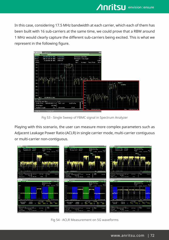
www.anritsu.com|72
Inthiscase,considering17.5MHzbandwidthateachcarrier,whicheachofthemhas
beenbuiltwith16sub-carriersatthesametime,wecouldprovethataRBWaround
1MHzwouldclearlycapturethedifferentsub-carriersbeingexcited.Thisiswhatwe
representinthefollowingfigure.
Fig53-SingleSweepofFBMCsignalinSpectrumAnalyzer
Playingwiththisscenario,theusercanmeasuremorecomplexparameterssuchas
AdjacentLeakagePowerRatio(ACLR)insinglecarriermode,multi-carriercontiguous
or multi-carrier non-contiguous.
Fig54-ACLRMeasurementon5Gwaveforms

73|Understanding5G
Apartfromthesefunctionalities,MS2830Acandigitizetheserealsignals intodata
filesthatcanbesentbacktoMatlab,wheretheycanbeprocessedandcompared
withtheoriginalsignals.
Fig55-Capturingreal5GwaveformswithMS2830A
Asanexample,inthenextfigure,wecaneasilynoticehowthenoisefloorlevelofthe
signalcomingfromtheMS2830Ahasincreasedincomparisonwiththeonecreated
originallyinMatlab,mainlycausedbytheeffectofthesignalgenerator.
Fig56-Comparisonofcapturedwaveformwithsimulatedwaveform

www.anritsu.com|74
In summary, it is possible to create almost anywaveform desiredwithoutmuch
difficultyandgivethedesignersthechancetoevaluatetheperformanceofpossible
5Gcommunicationstechnology.Wehavedemonstratedhowtoeasilyload,reproduce
andanalyzenewkindsofsignalsinourMS2830A.

75|Understanding5G
Conclusions
Wehaveseeninthisguidethatthenextgeneration5Gcellularwirelessnetworksare
aimingataverydiversesetofusecasesandapplicationsforwirelessconnectivity
withinsociety.Aswellasmeetingtheconstantdemandformorebandwidth,higher
datarates,andwidercoverage,thenew5Gnetworkswillaimtoopenupmoreuse
casessuchasSmartMeters,FirstResponder,CriticalHealthCare,andMachineto
Machine(M2M)applicationsbyofferinganetworkandtechnologysuitableforthis
muchwidersetofusecases.Thereareanumberofkeynewperformancetargets
beingsetfor5G,matchingtotheseenvisagedusecases.
Severalkeynewtechnologiesareemergingaskeybuildingblocksfor5G.Wehave
seen that cloud services, Network Function Visualization, and Software Defined
Networks,willbethekeyelementstothenetworkinfra-structure,providingamore
flexible,scalable,anddynamicnetwork infrastructurethatcanadapttousecases
and requirements ina fasterandcosteffectiveway.Thiswill lead to theconcept
ofnetwork“slicing”tomanageanddeliverservices.HeterogeneousNetworks(Het
Net)areexpected tobeakeyelement foraccessnetworkarchitecture.Thisuses
amulti-layerapproachtocoverageandcapacity,combiningmacrocellsandsmall
cells,usingdifferentaccessinterfacessimultaneously,andselectingaccessmethods
basedonvariousparameterssuchastraffictype,congestion,latencyetc.Theresult
of the development of HetNet technology is that 5G is expected to not be a single
access technology, but a combination of different legacy and new technologies
whichcomplementeachother.
Ontheairinterface,thekeychallengeistofindenoughavailablebandwidthtomeet
thedata capacity andperformance requirementswhicharepredictedby theuse
cases.Lookingfornewbandwidththatmaybecomeavailableisdrivingtheindustry
tohigherfrequency,andtomillimeterwavesolutions.Heretherearepropagation
andtechnologycostissuesthatneedtobeovercome.Atthesametime,“Massive
MIMO”isbeingdevelopedasanimprovementtotheairinterfacethatwillgivehigher
capacityduetobetterspectralefficiencyandspectrumre-usewithinacell.Thereare
implementationissuesformassiveMIMOrelatingtosizeandcost,butmaturingof
millimeterwavetechnologyishelpinghere.Fortheairaccessmethod,theindustry
hasseen thatOFDMA,used inLTE,doesnotmeet the interferencehandlingand

www.anritsu.com|76
thespectrumdensitydemandsoffutureHetNet.So,newaccesswaveformsbased
onimprovedspectrumorthogonality,orusingnon-orthogonalwaveforms,arenow
beinginvestigatedforanewairaccessmethod.
For the test andmonitoring industry, 5G is presentingmany new challenges as
wellasopportunities.Testingofthecoreandaccessnetworkelementsischanging
asSDN/NFVaredeployed,asthetestofthephysicalentityandtestofthe logical
functionare separated rather than testedasan integratednetworkelement. 5G.
RF andmillimeterwave component testingwill evolve tomeasure characteristics
using modulated wideband signals, to more accurately determine performance
whenusingnextgenerationwaveformsthatwillhaveverystringentperformance
requirements, leading to the need for broadbandmeasurement equipment and
the need forOTA test fixtures and chamberswhich are compact and affordable.
Devicetestingandcertificationislikelytobesignificantlyimpactedbythechanges
in5G.Withsuchadiverserangeofdevicetypes,ofaccessmethods,andusecases,
then the standardized testingmethods based around “test once, use anywhere”
willneed toevolve togiveacostefficientway tocover thismuchwider rangeof
test requirements. In field testing and monitoring, we can see that HetNet and
interference limitednetworkperformancewillbring inanewsetofrequirements
formeasuringnetworkperformance,coverage,capacityetc, inordertorelatethe
networkconditionstotheuserexperience.Alongsidethesenewtestdemands,we
can also see that 5G technology may also bring to the test and monitoring industry
somenewtechnologiesthatcanalsobeusedtoimplementtestsolutions.Socloud
based systems and visualizationmay also be used to create innovative new test
methods and solutions.
Anritsu Company 1155 East Collins Blvd., Suite 100, Richardson, TX 75081, U.S.A.Toll Free: 1-800-267-4878Phone: +1-972-644-1777Fax: +1-972-671-1877
• CanadaAnritsu Electronics Ltd.700 Silver Seven Road, Suite 120, Kanata, Ontario K2V 1C3, CanadaPhone: +1-613-591-2003 Fax: +1-613-591-1006
• Brazil Anritsu Eletrônica Ltda.Praça Amadeu Amaral, 27 - 1 Andar01327-010 - Bela Vista - São Paulo - SP - BrazilPhone: +55-11-3283-2511Fax: +55-11-3288-6940
• MexicoAnritsu Company, S.A. de C.V.Av. Ejército Nacional No. 579 Piso 9, Col. Granada11520 México, D.F., MéxicoPhone: +52-55-1101-2370Fax: +52-55-5254-3147
• United KingdomAnritsu EMEA Ltd. 200 Capability Green, Luton, Bedfordshire, LU1 3LU, U.K.Phone: +44-1582-433200 Fax: +44-1582-731303
• FranceAnritsu S.A. 12 avenue du Québec, Bâtiment Iris 1- Silic 612,91140 VILLEBON SUR YVETTE, FrancePhone: +33-1-60-92-15-50Fax: +33-1-64-46-10-65
• GermanyAnritsu GmbHNemetschek Haus, Konrad-Zuse-Platz 1 81829 München, Germany Phone: +49-89-442308-0Fax: +49-89-442308-55
• ItalyAnritsu S.r.l.Via Elio Vittorini 129, 00144 Roma, ItalyPhone: +39-6-509-9711 Fax: +39-6-502-2425
• SwedenAnritsu ABKistagången 20B, 164 40 KISTA, SwedenPhone: +46-8-534-707-00Fax: +46-8-534-707-30
• FinlandAnritsu ABTeknobulevardi 3-5, FI-01530 VANTAA, FinlandPhone: +358-20-741-8100Fax: +358-20-741-8111
• DenmarkAnritsu A/SKay Fiskers Plads 9, 2300 Copenhagen S, DenmarkPhone: +45-7211-2200Fax: +45-7211-2210
• RussiaAnritsu EMEA Ltd. Representation Office in RussiaTverskaya str. 16/2, bld. 1, 7th floor.Moscow, 125009, RussiaPhone: +7-495-363-1694Fax: +7-495-935-8962
• SpainAnritsu EMEA Ltd. Representation Office in SpainEdificio Cuzco IV, Po. de la Castellana, 141, Pta. 828046, Madrid, SpainPhone: +34-915-726-761Fax: +34-915-726-621
• United Arab EmiratesAnritsu EMEA Ltd. Dubai Liaison OfficeP O Box 500413 - Dubai Internet CityAl Thuraya Building, Tower 1, Suit 701, 7th FloorDubai, United Arab EmiratesPhone: +971-4-3670352Fax: +971-4-3688460
• P.R. China (Shanghai)Anritsu (China) Co., Ltd.Room 2701-2705, Tower A, New Caohejing International Business CenterNo. 391 Gui Ping Road Shanghai, 200233, P.R. ChinaPhone: +86-21-6237-0898Fax: +86-21-6237-0899
• P.R. China (Hong Kong)Anritsu Company Ltd.Unit 1006-7, 10/F., Greenfield Tower, Concordia Plaza,No. 1 Science Museum Road, Tsim Sha Tsui East, Kowloon, Hong Kong, P.R. ChinaPhone: +852-2301-4980Fax: +852-2301-3545
• JapanAnritsu Corporation
Phone: +81-46-296-6509Fax: +81-46-225-8359
8-5, Tamura-cho, Atsugi-shi, Kanagawa, 243-0016 Japan
• KoreaAnritsu Corporation, Ltd.5FL, 235 Pangyoyeok-ro, Bundang-gu, Seongnam-si, Gyeonggi-do, 463-400 KoreaPhone: +82-31-696-7750Fax: +82-31-696-7751
• AustraliaAnritsu Pty. Ltd.
Phone: +61-3-9558-8177Fax: +61-3-9558-8255
• TaiwanAnritsu Company Inc.7F, No. 316, Sec. 1, NeiHu Rd., Taipei 114, TaiwanPhone: +886-2-8751-1816Fax: +886-2-8751-1817
1602
Printed on Recycled Paper Printed in Japan 01/FEB/2016 ddc/CDT Catalog No. MX0000A-E-A-1-(1.00)
• SingaporeAnritsu Pte. Ltd.11 Chang Charn Road, #04-01, Shriro HouseSingapore 159640Phone: +65-6282-2400Fax: +65-6282-2533
• IndiaAnritsu India Private Limited2nd & 3rd Floor, #837/1, Binnamangla 1st Stage,Indiranagar, 100ft Road, Bangalore - 560038, IndiaPhone: +91-80-4058-1300Fax: +91-80-4058-1301
Specifications are subject to change without notice.
• United States
Unit 20, 21-35 Ricketts Road, Mount Waverley, Victoria 3149, Australia
Rev1 02/16® Anritsu trademarks are registered trademarks of their respective owners.Datasubjecttochangewithoutnotice.Forthemostrecentspecificationvisit:www.anritsu.com