Embed Size (px)
DESCRIPTION
important
Citation preview
G.U. Journal of Science
22(1): 21-32 (2009)
www.gujs.org
♠Corresponding author, e-mail: [email protected]
Experimental Studies on Turning of Discontinuously
Reinforced Aluminium Composites under Dry, Oil
Water Emulsion and Steam Lubricated Conditions Using
TAGUCHI’s Technique
Raviraj Shetty 1♠, R. Pai
1, S.S.Rao
2
1 Manipal Institute of Technology, Department of Mechanical and Manufacturing Engineering, Karnataka, India 2 National Institute of Technology, Department of Mechanical Engineering, Karnataka, India
Received: 31.10.2007 Revised: 09.07.2008 Accepted: 0.3.12.2008
ABSTRACT
This paper reports on the experimental investigations carried out under dry, oil water emulsion and steam lubricated conditions in turning of DRACs. The measured results were then collected and analyzed with the
help of the commercial software package MINITAB15. The experiments were planned on orthogonal arrays,
made with prefixed cutting parameters and different lubricated conditions. An analysis of variance (ANOVA) was carried out to check the validity of the proposed parameters and also their percentage contributions. The
results of the tests show that with proper selection of the range of cutting parameters, it is possible to obtain
better performance under steam lubricated condition.
Key Words: DRACs, Cutting force, Cutting temperature, Design of experiments, ANOVA, Hystrix cristata.
1. INTRODUCTION
Discontinuously reinforced Aluminium composites
(DRACs) is one of the important composites among the
metal matrix composites, which have SiC particles in an
aluminium matrix; this is harder than tungsten carbide
(WC), which pose many problems in machining. When
DRACs are being chosen for high volume and machine-
intensive components, it is crucial that the
machinability of the materials be understood. The
machinability of DRACs has been investigated actively
worldwide since the 1980s, and most researchers have
found that polycrystalline diamond (PCD) or cubic
boron nitride tools can be used to machine DRACs
effectively. Driven by the high cost of these tools, it is
still desirable to optimize the cutting conditions, such as
the effect of cutting fluid, since there has been no
comprehensive study undertaken in this area.
A Discontinuously Reinforced Aluminium Composites
(DRACs) can be described as a material which is made
up of a continuous metallic phase (the matrix) into
which a second phase (or phases) has been artificially
introduced. Early DRACs had their application
confined to military and aerospace applications, their
extensive usage was hindered due to their high
production costs, limited production methods, and
restricted product forms [1].
Machining of Discontinuously reinforced Aluminium
composites (DRACs) presents a significant challenge to
the industry since a number of reinforcement materials
are significantly harder than the commonly used high
speed steel (HSS) tools and carbide tools [2]. The
reinforcement phase causes rapid abrasive tool wear;
thus the widespread usage of DRACs is considerably
impeded by their poor machinability and high
machining costs. Based on the available literature on
DRACs it is clear that the morphology, distribution and
volume fraction of the reinforcement phase, as well as
the matrix properties are all factors that affect the
overall cutting process [2-3], but as yet relatively few
published reports are related to the optimization of the
cutting process.
22 G.U. J. Sci., 22(1):21-32 (2009)/ Raviraj Shetty ♠, R. Pai, S.S.Rao
The positive effect of the use of cutting fluids in metal
cutting was first reported in 1894 by F.Taylor, who
noticed that by applying large amounts of water in the
cutting area, the cutting speed could be increased up to
33% without reducing tool life. Since then, cutting
fluids have been developed resulting in an extensive
range of products covering most workpiece materials
and operations.
As research shows, the application of gases as cutting
fluids has been used since 1930s. [4,5] reported the
experimental results of carbon dioxide gas application
in machining. It was noticed that application of carbon
dioxide gas as coolants and lubricants reduced the
cutting force and obtained a higher tool life. [6–10] also
deeply studied application of oxygen gas as cutting
fluids in cutting process . [10] observed these results
were promising that the application of oxygen gas was
an effective agent to reduce contact length of tool–chip .
However, In the 1990s, [11-13] used water vapor as
coolants and lubricants in turning and milling operation.
The results showed water vapor lubrication in
comparison with liquid one ensures more uniform
cooling and the application of vaporous lubrication
allows increasing the carbide cutting tools lifetime
about 2–2.5 times in turning and 2–4 times in milling
carbon and stainless steels. In 2007 [14] used
pressurized steam jet approach in turning of
discontinuously reinforced aluminium composites. The
result showed the steam pressure as the dominant
parameter for surface roughness followed by feed. [15]
also carried out experimental investigations under dry,
oil water emulsion and steam lubricated conditions
using orthogonal array in turning of DRACs, he
concluded that the tool wear and surface roughness
were found to be lesser for steam cutting, where as
these two parameters showed much variation during oil
water emulsion and dry cutting. [16] used a pressurized
steam jet approach to tool wear minimization in cutting
of metal matrix composites by full factorial design of
experiments, he concluded that the effect of the
pressured steam jet plays a significant role on the tool
wear followed by tool inserts and depth of cut. Further,
fluid jet assisted machining as a highly effective method
for cutting of conventional materials has been well
explored [17–30], in which fluids, such as air, water or
steam, mainly act as transportation carriers carrying the
heat away from the cutting region, and the efficiency of
such a cooling method largely depends on the jet
pressure. Therefore, it is necessary to understand the
relationship among the various controllable parameters
and to identify the important parameters that influence
the quality of turning. Moreover, it is necessary to
optimize [31-33] the cutting parameters to obtain an
extended tool life and better productivity, which are
influenced by cutting force and cutting temperature.
Design of experiment [DOE] is a statistical-based
approach to analyze the influence of known process
variables over unknown process variables. The current
article investigates the influence of cutting parameters
and lubricating conditions on cutting force and cutting
temperature in turning of DRACs with Cubic boron
nitride inserts (CBN) KB-90 grade.
2. METHODOLOGY
2.1 Material
Al–SiC MMC workpiece specimens popularly known
as DRACs having aluminum alloy 6061 as the matrix
and containing 15 vol. % of silicon carbide particles of
mean diameter 25µm in the form of cylindrical bars of
length 120mm and diameter 40mm manufactured in
Vikram Sarbhai Space Centre (VSSC) Trivandrum by
stir casting process with pouring temperature 700-
710°C, stirring rate 195 rpm, extrusion at 457°C,
extrusion ratio 30:1, direct extrusion speed 6.1m/min to
produce Ø40mm cylindrical bars. The specimen were
solution treated for 2h at a temperature of 540oC in a
muffle furnace, temperatures were accurate to within
±2oC and quench delays in all cases were within 20s.
after solutionising, the samples were water quenched to
room temperature, and subsequently aged for six
different times to obtain samples with different Brinell
hardness number (BHN), out of which one samples
were selected, one with 94 BHN obtained at peakage
condition i.e 2h at 220oC respectively. Sample selected
were kept in a refrigerator right after the heat
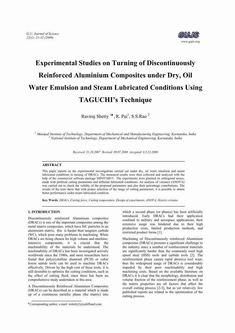
treatments. Figure 1 shows the microstructure of
DRACs.
Figure 1. A microstructure of an DRACs (6061 Al/ 15%
SiC 25p).
2.2 Machining Test
The chemical composition of the specimen is given in
Table 1. Turning, as a machining process was selected.
The experimental study was carried out in PSG A141
lathe (2.2 KW) with different cutting speeds, feeds and
a constant depth of cut. The selected cutting tool was
cubic boron nitride insert KB-90 (ISO code), for
machining of DRACs. The ISO code of cutting tool
inserts and tool holder are shown in Table 2. The level
of variables used in the experiment is given in Table 3.
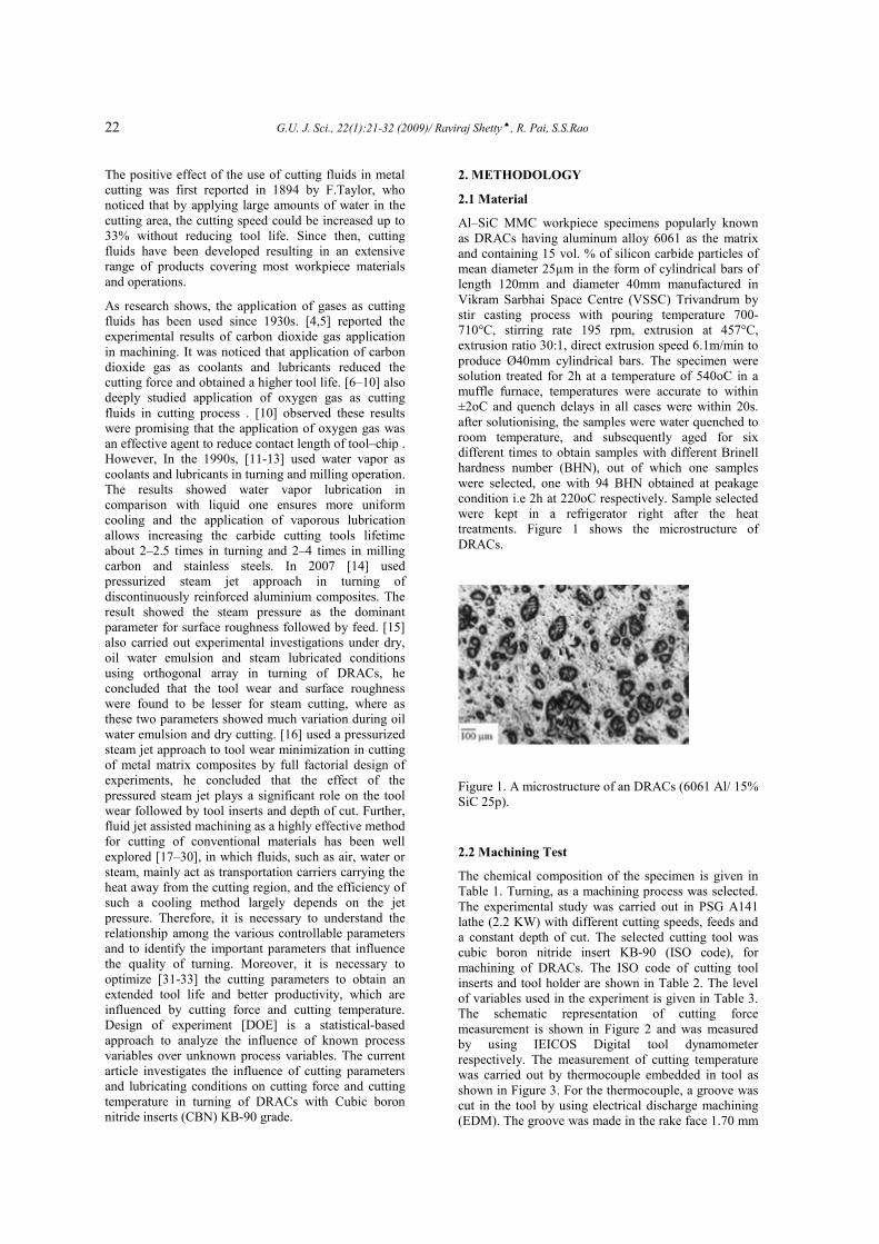
The schematic representation of cutting force
measurement is shown in Figure 2 and was measured
by using IEICOS Digital tool dynamometer
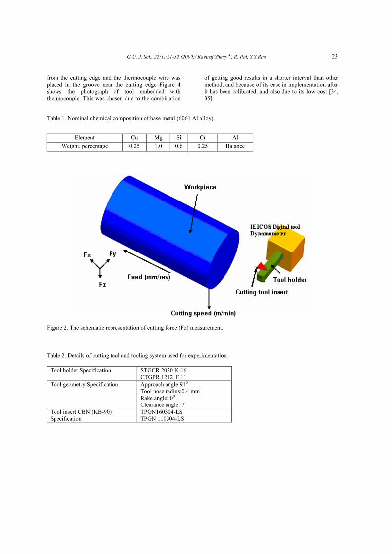
respectively. The measurement of cutting temperature
was carried out by thermocouple embedded in tool as
shown in Figure 3. For the thermocouple, a groove was
cut in the tool by using electrical discharge machining
(EDM). The groove was made in the rake face 1.70 mm
G.U. J. Sci., 22(1):21-32 (2009)/ Raviraj Shetty ♠, R. Pai, S.S.Rao 23
from the cutting edge and the thermocouple wire was
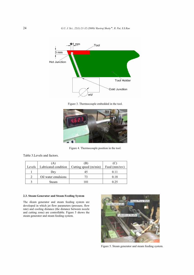
placed in the groove near the cutting edge Figure 4
shows the photograph of tool embedded with
thermocouple. This was chosen due to the combination
of getting good results in a shorter interval than other
method, and because of its ease in implementation after
it has been calibrated, and also due to its low cost [34,
35].
Table 1. Nominal chemical composition of base metal (6061 Al alloy).
Figure 2. The schematic representation of cutting force (Fz) measurement.
Table 2. Details of cutting tool and tooling system used for experimentation.
Tool holder Specification STGCR 2020 K-16
CTGPR 1212 F 11
Tool geometry Specification Approach angle:910
Tool nose radius:0.4 mm
Rake angle: 00
Clearance angle: 70
Tool insert CBN (KB-90)
Specification
TPGN160304-LS
TPGN 110304-LS
Element Cu Mg Si Cr Al
Weight. percentage 0.25 1.0 0.6 0.25 Balance
24 G.U. J. Sci., 22(1):21-32 (2009)/ Raviraj Shetty ♠, R. Pai, S.S.Rao
Figure 3. Thermocouple embedded in the tool.
Figure 4. Thermocouple position in the tool.
Table 3.Levels and factors.
Levels
(A)
Lubricated condition
(B)
Cutting speed (m/min)
(C)
Feed (mm/rev)
1 Dry 45 0.11
2 Oil water emulsions 73 0.18
3 Steam 101 0.25
2.3. Steam Generator and Steam Feeding System
The steam generator and steam feeding system are developed in which jet flow parameters (pressure, flow
rate) and cooling distance (the distance between nozzle
and cutting zone) are controllable. Figure 5 shows the
steam generator and steam feeding system.
Figure 5. Steam generator and steam feeding system.
G.U. J. Sci., 22(1):21-32 (2009)/ Raviraj Shetty ♠, R. Pai, S.S.Rao 25
3. TAGUCHI’S METHOD
Taguchi techniques have been used widely in
engineering design [36, 37]. The main trust of the
Taguchi techniques is the use of parameter design,
which is an engineering method for product or process
design that focuses on determining the parameter
(factor) settings producing the best levels of a quality
characteristic (performance measure) with minimum
variation. Taguchi designs provide a powerful and
efficient method for designing processes that operate
consistently and optimally over a variety of conditions.
To determine the best design requires the use of a
strategically designed experiment which exposes the
process to various levels of design parameters.
Experimental design methods were developed in the
early years of 20th century and have been extensively
studied by statisticians since then, but they were not
easy to use by practitioners [37]. Taguchi’s approach to
design of experiments is easy to adopt and apply for
users with limited knowledge of statistics, hence it has
gained a wide popularity in the engineering and
scientific community. There have been plenty of recent
applications of Taguchi techniques to materials
processing for process optimization. Some of the
previous works are listed in [38–43]. In particular, it is
recommended for analyzing metal cutting problems for
finding the optimal combination of parameters [43].
3.1. Design of Experiments
The orthogonal array for two factors at three levels was
used for the elaboration of the plan of experiments the
array L27 was selected, which has 27 rows
corresponding to the number of tests (26 degrees of
freedom) with 13 columns at three levels. The factors
and the interactions are assigned to the columns.
The first column was assigned to the lubrication
condition (A), the second column to cutting speed (B),
the fifth column to the feed (C) and remaining were
assigned to interactions. The outputs to be studied were
the cutting temperature and the cutting force. Further,
an analysis of variance (ANOVA) was carried out
separately for each response.
4. RESULTS AND DISCUSSION
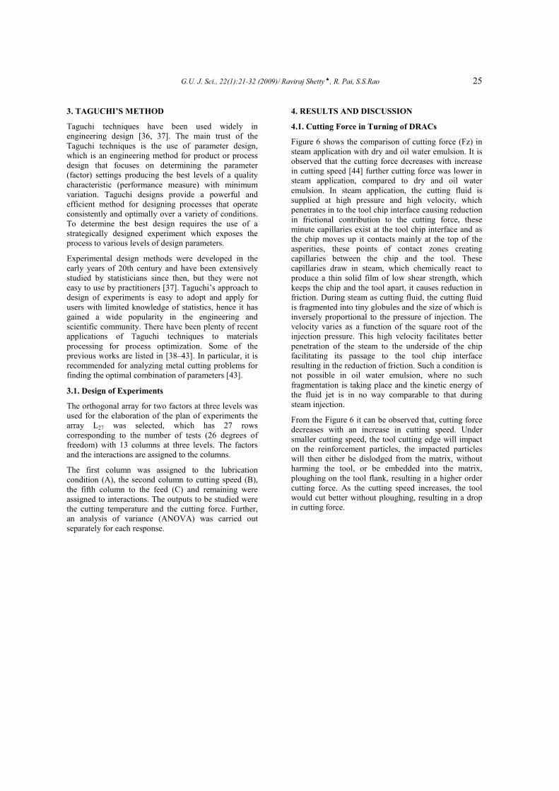
4.1. Cutting Force in Turning of DRACs
Figure 6 shows the comparison of cutting force (Fz) in
steam application with dry and oil water emulsion. It is
observed that the cutting force decreases with increase
in cutting speed [44] further cutting force was lower in
steam application, compared to dry and oil water
emulsion. In steam application, the cutting fluid is
supplied at high pressure and high velocity, which
penetrates in to the tool chip interface causing reduction
in frictional contribution to the cutting force, these
minute capillaries exist at the tool chip interface and as
the chip moves up it contacts mainly at the top of the
asperities, these points of contact zones creating
capillaries between the chip and the tool. These
capillaries draw in steam, which chemically react to
produce a thin solid film of low shear strength, which
keeps the chip and the tool apart, it causes reduction in
friction. During steam as cutting fluid, the cutting fluid
is fragmented into tiny globules and the size of which is
inversely proportional to the pressure of injection. The
velocity varies as a function of the square root of the
injection pressure. This high velocity facilitates better
penetration of the steam to the underside of the chip
facilitating its passage to the tool chip interface
resulting in the reduction of friction. Such a condition is
not possible in oil water emulsion, where no such
fragmentation is taking place and the kinetic energy of
the fluid jet is in no way comparable to that during
steam injection.
From the Figure 6 it can be observed that, cutting force
decreases with an increase in cutting speed. Under
smaller cutting speed, the tool cutting edge will impact
on the reinforcement particles, the impacted particles
will then either be dislodged from the matrix, without
harming the tool, or be embedded into the matrix,
ploughing on the tool flank, resulting in a higher order
cutting force. As the cutting speed increases, the tool
would cut better without ploughing, resulting in a drop
in cutting force.
26 G.U. J. Sci., 22(1):21-32 (2009)/ Raviraj Shetty ♠, R. Pai, S.S.Rao
Figure 6. Variation of cutting force with cutting speed for different lubrication conditions (a) feed (0.11mm/rev) (b) feed
(0.18mm/rev) (c) feed (0.25 mm/rev).
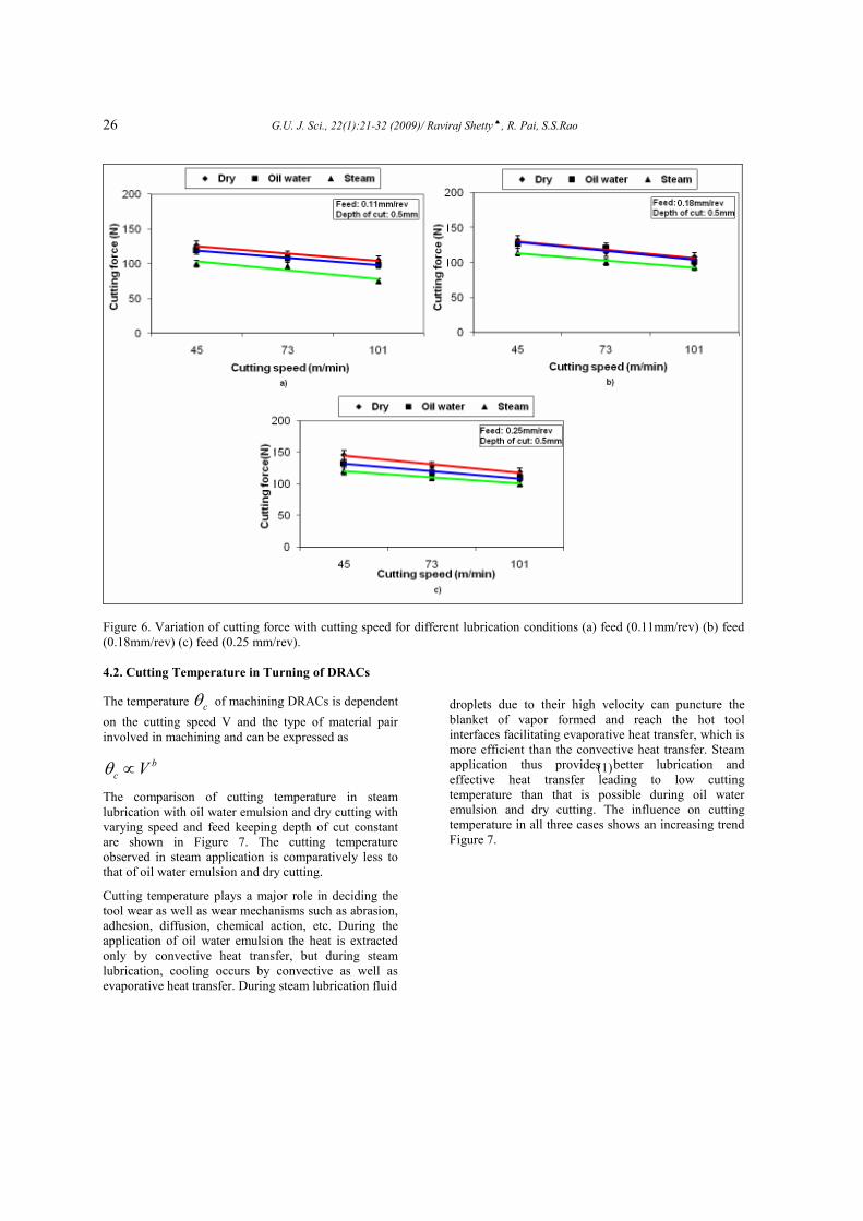
4.2. Cutting Temperature in Turning of DRACs
The temperature cθ of machining DRACs is dependent
on the cutting speed V and the type of material pair
involved in machining and can be expressed as
b
c Vθ ∝ (1)
The comparison of cutting temperature in steam
lubrication with oil water emulsion and dry cutting with
varying speed and feed keeping depth of cut constant
are shown in Figure 7. The cutting temperature
observed in steam application is comparatively less to
that of oil water emulsion and dry cutting.
Cutting temperature plays a major role in deciding the
tool wear as well as wear mechanisms such as abrasion,
adhesion, diffusion, chemical action, etc. During the
application of oil water emulsion the heat is extracted
only by convective heat transfer, but during steam
lubrication, cooling occurs by convective as well as
evaporative heat transfer. During steam lubrication fluid
droplets due to their high velocity can puncture the
blanket of vapor formed and reach the hot tool
interfaces facilitating evaporative heat transfer, which is
more efficient than the convective heat transfer. Steam
application thus provides better lubrication and
effective heat transfer leading to low cutting
temperature than that is possible during oil water
emulsion and dry cutting. The influence on cutting
temperature in all three cases shows an increasing trend
Figure 7.
G.U. J. Sci., 22(1):21-32 (2009)/ Raviraj Shetty ♠, R. Pai, S.S.Rao 27
Figure 7. Variation of cutting temperature with cutting speed for different lubrication conditions (a) feed (0.11mm/rev) (b)
feed (0.18mm/rev) (c) feed (0.25 mm/rev).
4.3. Analysis of Variance (ANOVA) and Factor
Effects for Cutting Force and Cutting Temperature
In Taguchi’s DOE method, the term “signal” represents
the desirable value and "noise" represents the
undesirable value. The objective of using S/N ratio is to
obtain a measure of performance to develop products
and processes insensitive to noise factors. The S/N ratio
indicates the degree of the predictable performance of a
product or process in the presence of noise factors.
Process parameter settings with the highest S/N ratio
always yield the optimum quality with minimum
variance. The S/N ratio for each parameter level is
calculated by averaging the S/N ratios obtained when
the parameter is maintained at that level. Table 4 and
Table 5 shows the S/N ratios obtained for different
parameter levels.
Table 4. Response table for signal to noise ratios smaller is better cutting force (N).
Level Lubrication condition Cutting speed (m/min)
Feed(mm/rev)
1 -41.64 -41.84 -40.31
2 -41.18 -40.98 -40.99
3 -40.05 -40.05 -41.57
Delta 1.59 1.79 1.26
Rank 2 1 3
28 G.U. J. Sci., 22(1):21-32 (2009)/ Raviraj Shetty ♠, R. Pai, S.S.Rao
Table 5. Response table for signal to noise ratios smaller is better (cutting temperature).
Level Lubrication condition Cutting speed (m/min)
Feed(mm/rev)
1 -53.09 -50.76 -50.82
2 -51.50 -51.23 -51.16
3 -48.92 -51.53 -51.53
Delta 4.17 0.77 0.71
Rank 1 2 3
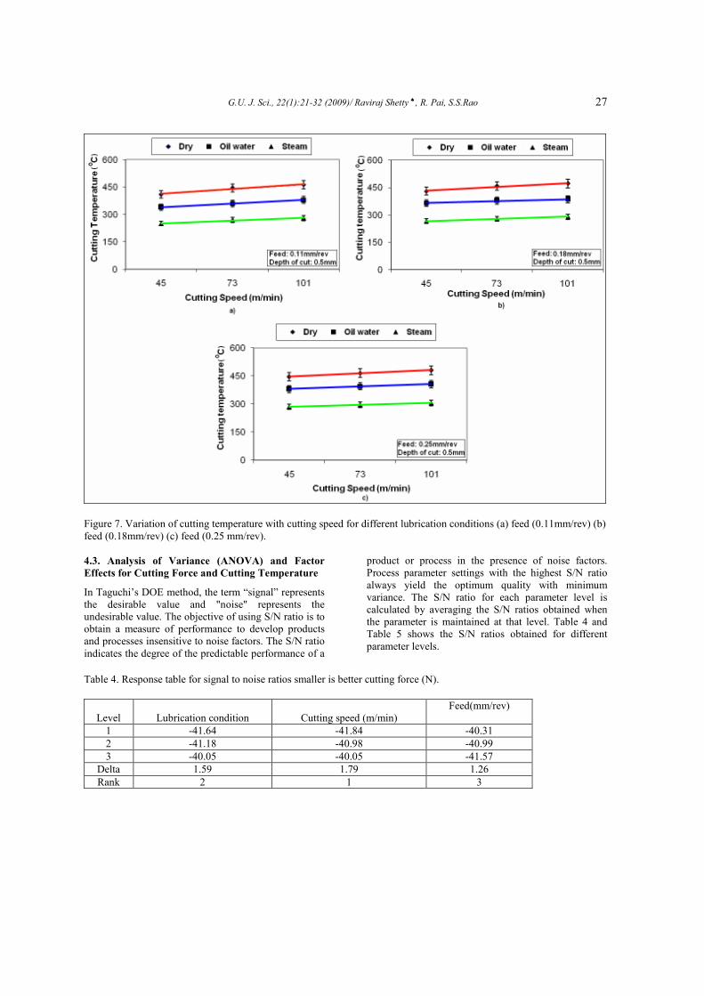
The calculated S/N ratio for three factors on the cutting
force and cutting temperature during machining of
DRACs for each level is shown in Figures 8-9. As
shown in Table 4 and Figure 8 steam is a dominant
parameter on the cutting force followed by cutting
speed and feed. Hence from mean S/N graph for
Cutting force from quality characteristic considered in
the investigation “smaller the better” we can conclude
that selection of steam lubrication,101m/min cutting
speed and 0.11 depth of cut would be ideal for
machining of DRACs. Similarly for cutting
temperature, from mean S/N graph we can conclude
that selection of steam lubrication, 45m/min cutting
speed and 0.11mm/rev feed would be ideal for
machining of DRACs.
Figure 8. Mean S/N graph for cutting force (N).
G.U. J. Sci., 22(1):21-32 (2009)/ Raviraj Shetty ♠, R. Pai, S.S.Rao 29
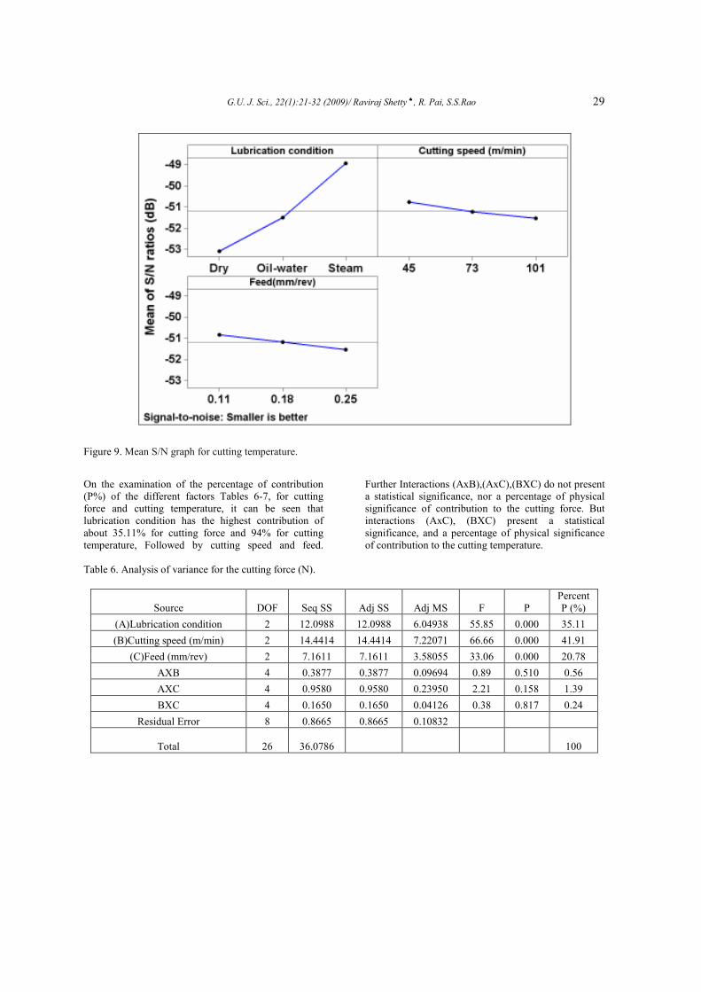
Figure 9. Mean S/N graph for cutting temperature.
On the examination of the percentage of contribution
(P%) of the different factors Tables 6-7, for cutting
force and cutting temperature, it can be seen that
lubrication condition has the highest contribution of
about 35.11% for cutting force and 94% for cutting
temperature, Followed by cutting speed and feed.
Further Interactions (AxB),(AxC),(BXC) do not present
a statistical significance, nor a percentage of physical
significance of contribution to the cutting force. But
interactions (AxC), (BXC) present a statistical
significance, and a percentage of physical significance
of contribution to the cutting temperature.
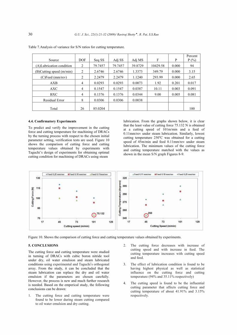
Table 6. Analysis of variance for the cutting force (N).
Source DOF Seq SS Adj SS Adj MS F P
Percent
P (%)
(A)Lubrication condition 2 12.0988 12.0988 6.04938 55.85 0.000 35.11
(B)Cutting speed (m/min) 2 14.4414 14.4414 7.22071 66.66 0.000 41.91
(C)Feed (mm/rev) 2 7.1611 7.1611 3.58055 33.06 0.000 20.78
AXB 4 0.3877 0.3877 0.09694 0.89 0.510 0.56
AXC 4 0.9580 0.9580 0.23950 2.21 0.158 1.39
BXC 4 0.1650 0.1650 0.04126 0.38 0.817 0.24
Residual Error 8 0.8665 0.8665 0.10832
Total 26
36.0786 100
30 G.U. J. Sci., 22(1):21-32 (2009)/ Raviraj Shetty ♠, R. Pai, S.S.Rao
Table 7.Analysis of variance for S/N ratios for cutting temperature.
Source DOF Seq SS Adj SS Adj MS F P
Percent
P (%)
(A)Lubrication condition 2 79.7457 79.7457 39.8729 10429.58 0.000 94
(B)Cutting speed (m/min) 2 2.6746 2.6746 1.3373 349.79 0.000 3.15
(C)Feed (mm/rev) 2 2.2479 2.2479 1.1240 293.99 0.000 2.65
AXB 4 0.0293 0.0293 0.0073 1.92 0.201 0.017
AXC 4 0.1547 0.1547 0.0387 10.11 0.003 0.091
BXC 4 0.1376 0.1376 0.0344 9.00 0.005 0.081
Residual Error 8 0.0306 0.0306 0.0038
Total 26
85.0204 100
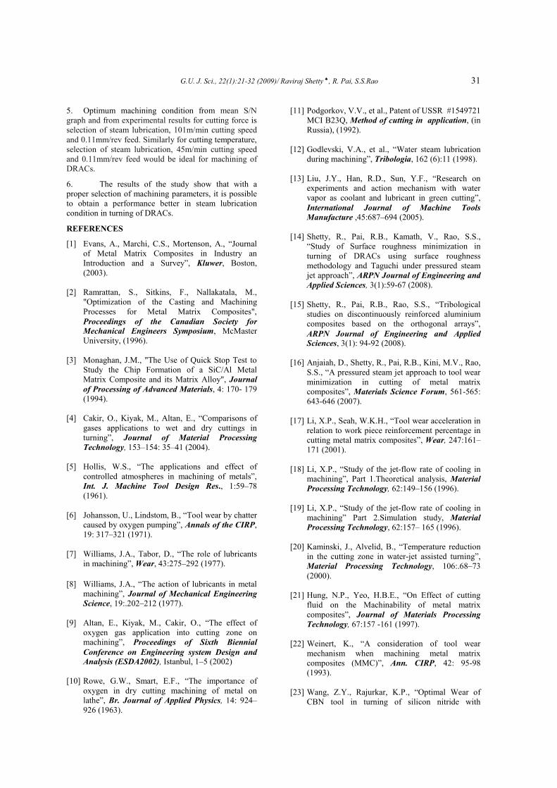
4.4. Confirmatory Experiments
To predict and verify the improvement in the cutting
force and cutting temperature for machining of DRACs
by the turning process with respect to the chosen initial
parameter setting, verification tests are used. Figure 10
shows the comparison of cutting force and cutting
temperature values obtained by experiments with
Taguchi’s design of experiments for obtaining optimal
cutting condition for machining of DRACs using steam
lubrication. From the graphs shown below, it is clear
that the least value of cutting force 75.132 N is obtained
at a cutting speed of 101m/min and a feed of
0.11mm/rev under steam lubrication. Similarly, lowest
cutting temperature 250oC was obtained for a cutting
speed of 45m/min and feed 0.11mm/rev under steam
lubrication. The minimum values of the cutting force
and cutting temperature matched with the values as
shown in the mean S/N graph Figures 8-9.
Figure 10. Shows the comparison of cutting force and cutting temperature values obtained by experiments.
5. CONCLUSIONS
The cutting force and cutting temperature were studied
in turning of DRACs with cubic boron nitride tool
under dry, oil water emulsion and steam lubricated
conditions using experimental and Taguchi’s orthogonal
array. From the study, it can be concluded that the
steam lubrication can replace the dry and oil water
emulsion if the parameters are chosen carefully.
However, the process is new and much further research
is needed. Based on the emperical study, the following
conclusions can be drawn:
1. The cutting force and cutting temperature were
found to be lower during steam cutting compared
to oil water emulsion and dry cutting.
2. The cutting force decreases with increase of
cutting speed and with increase in feed. The
cutting temperature increases with cutting speed
and feed.
3. The effect of lubrication condition is found to be
having highest physical as well as statistical
influence on the cutting force and cutting
temperature (94% and 35.11% respectively)
4. The cutting speed is found to be the influential
cutting parameter that affects cutting force and
cutting temperature of about 41.91% and 3.15%
respectively.
G.U. J. Sci., 22(1):21-32 (2009)/ Raviraj Shetty ♠, R. Pai, S.S.Rao 31
5. Optimum machining condition from mean S/N
graph and from experimental results for cutting force is
selection of steam lubrication, 101m/min cutting speed
and 0.11mm/rev feed. Similarly for cutting temperature,
selection of steam lubrication, 45m/min cutting speed
and 0.11mm/rev feed would be ideal for machining of
DRACs.
6. The results of the study show that with a
proper selection of machining parameters, it is possible
to obtain a performance better in steam lubrication
condition in turning of DRACs.
REFERENCES
[1] Evans, A., Marchi, C.S., Mortenson, A., “Journal
of Metal Matrix Composites in Industry an
Introduction and a Survey”, Kluwer, Boston,
(2003).
[2] Ramrattan, S., Sitkins, F., Nallakatala, M.,
"Optimization of the Casting and Machining
Processes for Metal Matrix Composites",
Proceedings of the Canadian Society for
Mechanical Engineers Symposium, McMaster
University, (1996).
[3] Monaghan, J.M., "The Use of Quick Stop Test to
Study the Chip Formation of a SiC/Al Metal
Matrix Composite and its Matrix Alloy", Journal
of Processing of Advanced Materials, 4: 170- 179
(1994).
[4] Cakir, O., Kiyak, M., Altan, E., “Comparisons of
gases applications to wet and dry cuttings in
turning”, Journal of Material Processing
Technology, 153–154: 35–41 (2004).
[5] Hollis, W.S., “The applications and effect of
controlled atmospheres in machining of metals”,
Int. J. Machine Tool Design Res., 1:59–78
(1961).
[6] Johansson, U., Lindstom, B., “Tool wear by chatter
caused by oxygen pumping”, Annals of the CIRP,
19: 317–321 (1971).
[7] Williams, J.A., Tabor, D., “The role of lubricants
in machining”, Wear, 43:275–292 (1977).
[8] Williams, J.A., “The action of lubricants in metal
machining”, Journal of Mechanical Engineering
Science, 19:.202–212 (1977).
[9] Altan, E., Kiyak, M., Cakir, O., “The effect of
oxygen gas application into cutting zone on
machining”, Proceedings of Sixth Biennial
Conference on Engineering system Design and
Analysis (ESDA2002), Istanbul, 1–5 (2002)
[10] Rowe, G.W., Smart, E.F., “The importance of
oxygen in dry cutting machining of metal on
lathe”, Br. Journal of Applied Physics, 14: 924–
926 (1963).
[11] Podgorkov, V.V., et al., Patent of USSR #1549721
MCI B23Q, Method of cutting in application, (in
Russia), (1992).
[12] Godlevski, V.A., et al., “Water steam lubrication
during machining”, Tribologia, 162 (6):11 (1998).
[13] Liu, J.Y., Han, R.D., Sun, Y.F., “Research on
experiments and action mechanism with water
vapor as coolant and lubricant in green cutting”,
International Journal of Machine Tools
Manufacture ,45:687–694 (2005).
[14] Shetty, R., Pai, R.B., Kamath, V., Rao, S.S.,
“Study of Surface roughness minimization in
turning of DRACs using surface roughness
methodology and Taguchi under pressured steam
jet approach”, ARPN Journal of Engineering and
Applied Sciences, 3(1):59-67 (2008).
[15] Shetty, R., Pai, R.B., Rao, S.S., “Tribological
studies on discontinuously reinforced aluminium
composites based on the orthogonal arrays”,
ARPN Journal of Engineering and Applied
Sciences, 3(1): 94-92 (2008).
[16] Anjaiah, D., Shetty, R., Pai, R.B., Kini, M.V., Rao,
S.S., “A pressured steam jet approach to tool wear
minimization in cutting of metal matrix
composites”, Materials Science Forum, 561-565:
643-646 (2007).
[17] Li, X.P., Seah, W.K.H., “Tool wear acceleration in
relation to work piece reinforcement percentage in
cutting metal matrix composites”, Wear, 247:161–
171 (2001).
[18] Li, X.P., “Study of the jet-flow rate of cooling in
machining”, Part 1.Theoretical analysis, Material
Processing Technology, 62:149–156 (1996).
[19] Li, X.P., “Study of the jet-flow rate of cooling in
machining” Part 2.Simulation study, Material
Processing Technology, 62:157– 165 (1996).
[20] Kaminski, J., Alvelid, B., “Temperature reduction
in the cutting zone in water-jet assisted turning”,
Material Processing Technology, 106:.68–73
(2000).
[21] Hung, N.P., Yeo, H.B.E., “On Effect of cutting
fluid on the Machinability of metal matrix
composites”, Journal of Materials Processing
Technology, 67:157 -161 (1997).
[22] Weinert, K., “A consideration of tool wear
mechanism when machining metal matrix
composites (MMC)”, Ann. CIRP, 42: 95-98
(1993).
[23] Wang, Z.Y., Rajurkar, K.P., “Optimal Wear of
CBN tool in turning of silicon nitride with
32 G.U. J. Sci., 22(1):21-32 (2009)/ Raviraj Shetty ♠, R. Pai, S.S.Rao
cryogenic cooling”, Machine Tools and
Manufacturing, 37(3): 319-326 (1997).
[24] Mazurkiewicz, M., Kubala, Z., Chow, J., “Metal
machining with high pressure water-jet cooling
assistance—a new possibility”, Engineering
Industries, 111: 7–12 (1989).
[25] Shetty, R., Pai, R.B., Rao, S.S., Shenoy, B.S.,
“Study of tool wear in turning 15% SiCp
reinforced 6061 aluminium metal matrix
composite with steam as coolant”, Proceedings of
International conference on Advanced Material
processing and characterization,(APMC 2006),
Chennai, India,(2006).
[26] Shetty, R., Pai, R.B., Rao, S.S., Barboza, A.B.V.,
“Tribological studies on PCBN tool in turning
metal matrix composites with Steam as coolant”,
Proceedings of International Tribological
conference (AUSTRIB 2006), Brisbane, Australia
(2006).
[27] Shetty, R., Pai, R.B., Rao, S.S., “Kumar D.,Chip
and built-up edge formation in turning age
hardened AA6061/15 vol. % SiCp composites with
steam as coolant” , Proceedings of Second
International conference on recent advances in
composite materials, (ICRAM 2007), New Delhi,
India (2007).
[28] Shetty, R., Pai, R.B., Rao, S.S., Nayak
Rajesh.,”Tribological studies of steam penetration
in different directions in turning of metal matrix
composites using steam as coolant”, Proceedings
of International conference on Industrial
tribology, (ICIT-2006) held at Bangalore, India
(2006).
[29] Shetty, R., Pai, R.B., Rao, S.S., Vasudev, M.,
“Influence of lubrication condition on surface
roughness in turning of metal matrix composites”;
Proceedings of Sixth International Conference
on composite science and technology, (ICCST/6)
Durban , South Africa (2007).
[30] Sales, W.F., Guimara, G., Machado, A.R., Ezugwu
E.O., “Cooling ability of cutting fluids and
measurement of the chip-tool interface
temperatures”, Industrial Lubrication and
Tribology, 54(2): 57–68 (2002).
[31] Singh, H., Kumar, P., “Tool wear optimization in
turning operation by Taguchi method”, Indian
Journal of Engineering Material Science, 11: 19–
24 (2004).
[32] Singh, H., Kumar, P., “Optimizing cutting force
for turned parts using Taguchi’s parameter design
approach”, Indian Journal of Engineering
Material Science, 12: 97–103 (2005).
[33] Paulo Davim, J., “A note on the determination of
optimal cutting conditions for surface finish
obtained in turning using design of experiments”,
Journal of Material Processing Technology, 116:
305–308 (2001).
[34] O’Sullivan, D., Cotterell, M., “Temperature
measurement in single point turning”, Journal of
Materials Processing Technology, 118 (1–3):
301–308 (2001).
[35] Dewes, R.C., Ng, E., Chua, K.S., “Newton P.G.,
Aspinwall, D.K, Temperature measurement when
high speed machining hardened mould/die steel”,
Journal of Materials Processing Technology, 92–
93:.93–301 (1999).
[36] Ross, P.J., “Taguchi techniques for quality
engineering: loss function, orthogonal experiments,
parameter and tolerance design”, 2nd ed., New
York, NY: McGraw-Hill, (1996).
[37] Phadke, M.S., “Quality engineering using robust
design”, Englewood Cliffs, NJ: Prentice-Hall,
(1989).
[38] Yang, W.H., Tarng, Y.S., “Design optimization of
cutting parameters for turning operations based on
the Taguchi method”, Journal of Material
Processing Technology, 84: 122–129 (1998).
[39] Su, Y.L., Yao, S.H., Wei, C.S., Kao, W.H., Wu,
C.T., “Design and performance analysis of TiCN-
coated cemented carbide milling cutters”, Journal
of Material Processing Technology, 87: 82–89
(1999).
[40] Nian, C.Y., Yang, W.H., Tarng, Y.S.,
“Optimization of turning operations with multiple
performance characteristics”, Journal of Material
Processing Technology, 95:.90–96 (1999).
[41] Lin, T.R., “Experimental design and performance
analysis of TiNcoated carbide tool in face milling
stainless steel”, Journal of Material Processing
Technology, 127:.1–7 (2002).
[42] Davim, J.P., “Design optimization of cutting
parameters for turning metal matrix composites
based on the orthogonal arrays”, Journal of
Material Processing Technology, 132: 340–344
(2003).
[43] Ghani, J.A., Choudhury, I.A, Hassan, H.H.,
“Application of Taguchi method in the
optimization of end milling operations”, Journal
of Material Processing Technology, 145: 84–
92(2004).
[44] Varadarajan, A.S., Philip, P.K., “Ramamoorthy B.,
Investigations on hard turning with minimal
cutting fluid application (HTMF) and its
comparison with dry and wet turning”,
International Journal of Machine Tools &
Manufacture, 42: 193–200 (2002).