Embed Size (px)
Citation preview
A P P R O V E D S C H E M A T I C D E S I G N - P O W E L L E L E M E N T A R Y S C H O O L ISTUDIOarchitecture | design | planning
2.June.2013
2
| C
on
ten
ts
A Existing Site _ Neighborhood Analysis _ Site Analysis _ Site Drawings _ Floor Plans _ Architectural Assessment _ Engineering Assessment
B Proposed Plans _ Concept Studies _ Preferred Concept _ Master Plan - Site Plan _ Master Plan - Floor Plans _ Program Comparison _ Plan to Program Comparison
C Design Narrative _ Building Concepts _ Sustainability _ Perspectives _ Classrooms _ Building Systems
D Detailed Reports _ Civil Assessment _ Structural Assessment _ Mechanical Assessment _ Electrical Assessment _ Plumbing Assessment _ IT / Security Assessment _ Food Service Assessment
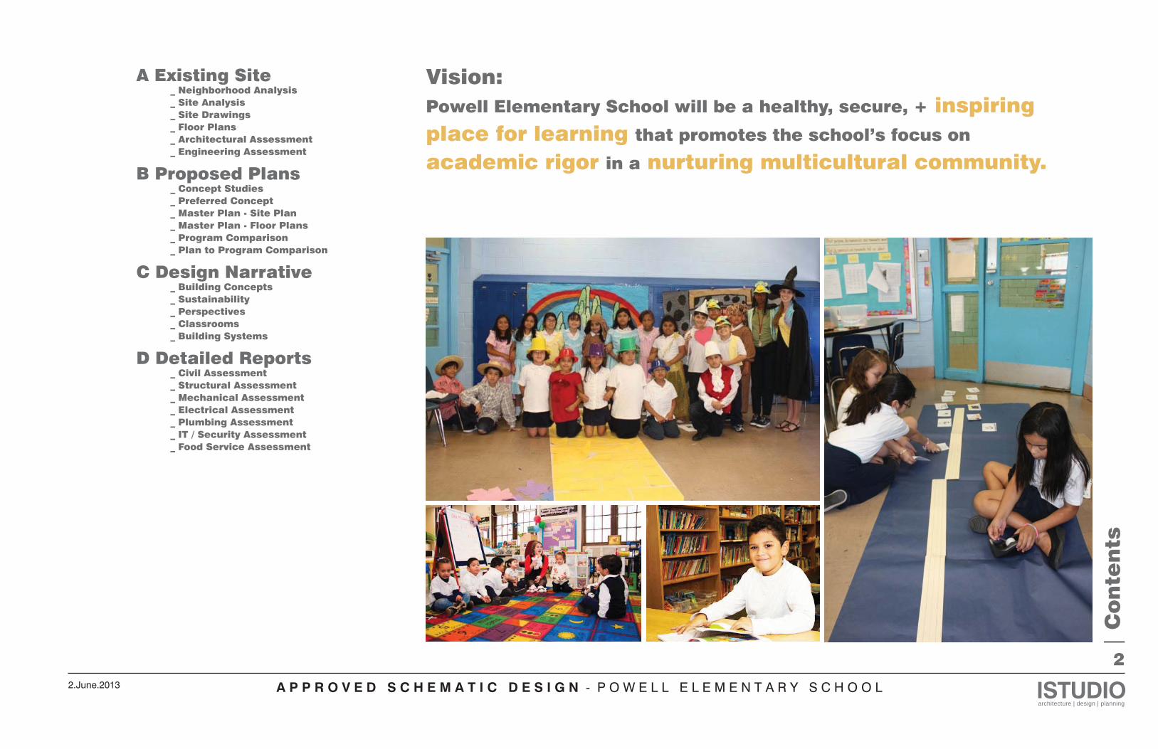
Vision:Powell Elementary School will be a healthy, secure, + inspiring place for learning that promotes the school’s focus on academic rigor in a nurturing multicultural community.
A P P R O V E D S C H E M A T I C D E S I G N - P O W E L L E L E M E N T A R Y S C H O O L ISTUDIOarchitecture | design | planning
2.June.2013
A1
| E
xisti
ng
Sit
e |
Ne
igh
borh
ood
An
aly
sis
Corner of 14th St NW and Upshur St NW
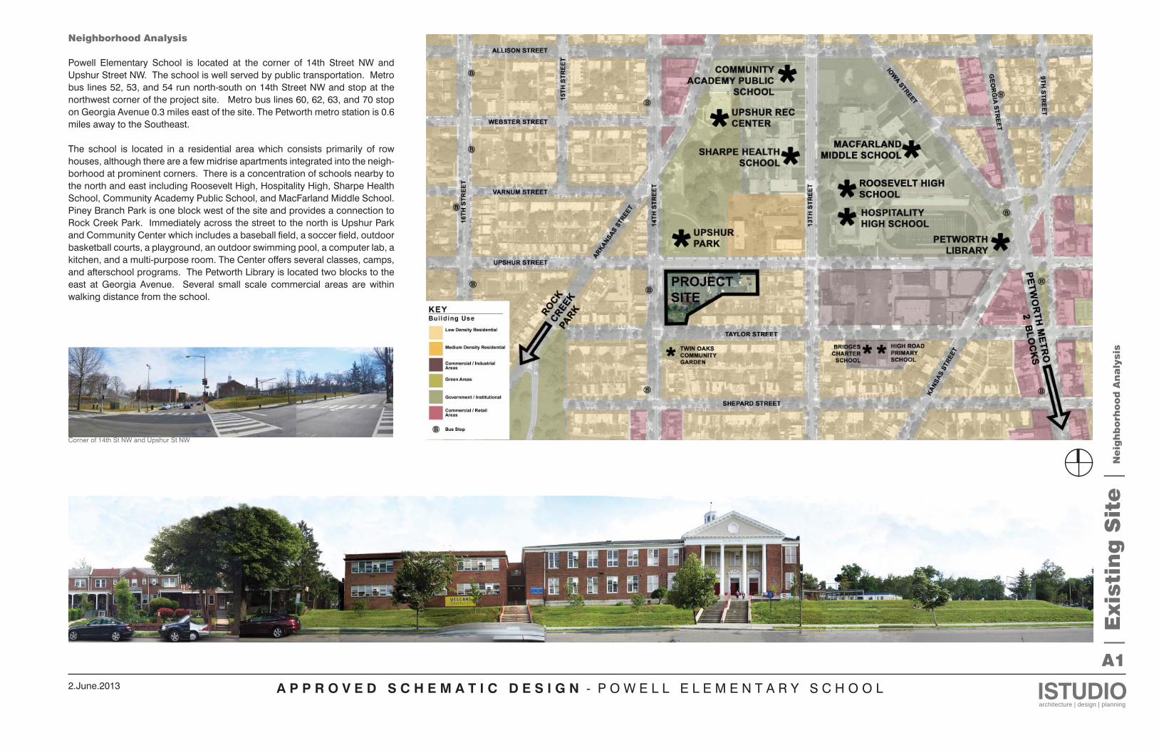
Neighborhood Analysis
Powell Elementary School is located at the corner of 14th Street NW and Upshur Street NW. The school is well served by public transportation. Metro bus lines 52, 53, and 54 run north-south on 14th Street NW and stop at the northwest corner of the project site. Metro bus lines 60, 62, 63, and 70 stop on Georgia Avenue 0.3 miles east of the site. The Petworth metro station is 0.6 miles away to the Southeast.
The school is located in a residential area which consists primarily of row houses, although there are a few midrise apartments integrated into the neigh-borhood at prominent corners. There is a concentration of schools nearby to the north and east including Roosevelt High, Hospitality High, Sharpe Health School, Community Academy Public School, and MacFarland Middle School. Piney Branch Park is one block west of the site and provides a connection to Rock Creek Park. Immediately across the street to the north is Upshur Park and Community Center which includes a baseball field, a soccer field, outdoor basketball courts, a playground, an outdoor swimming pool, a computer lab, a kitchen, and a multi-purpose room. The Center offers several classes, camps, and afterschool programs. The Petworth Library is located two blocks to the east at Georgia Avenue. Several small scale commercial areas are within walking distance from the school.
A P P R O V E D S C H E M A T I C D E S I G N - P O W E L L E L E M E N T A R Y S C H O O L ISTUDIOarchitecture | design | planning
2.June.2013
A2
| E
xisti
ng
Sit
e |
Sit
e A
na
lysis
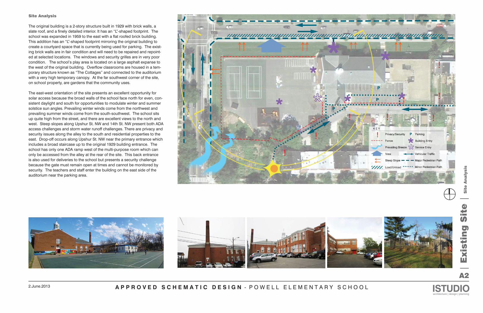
Site Analysis
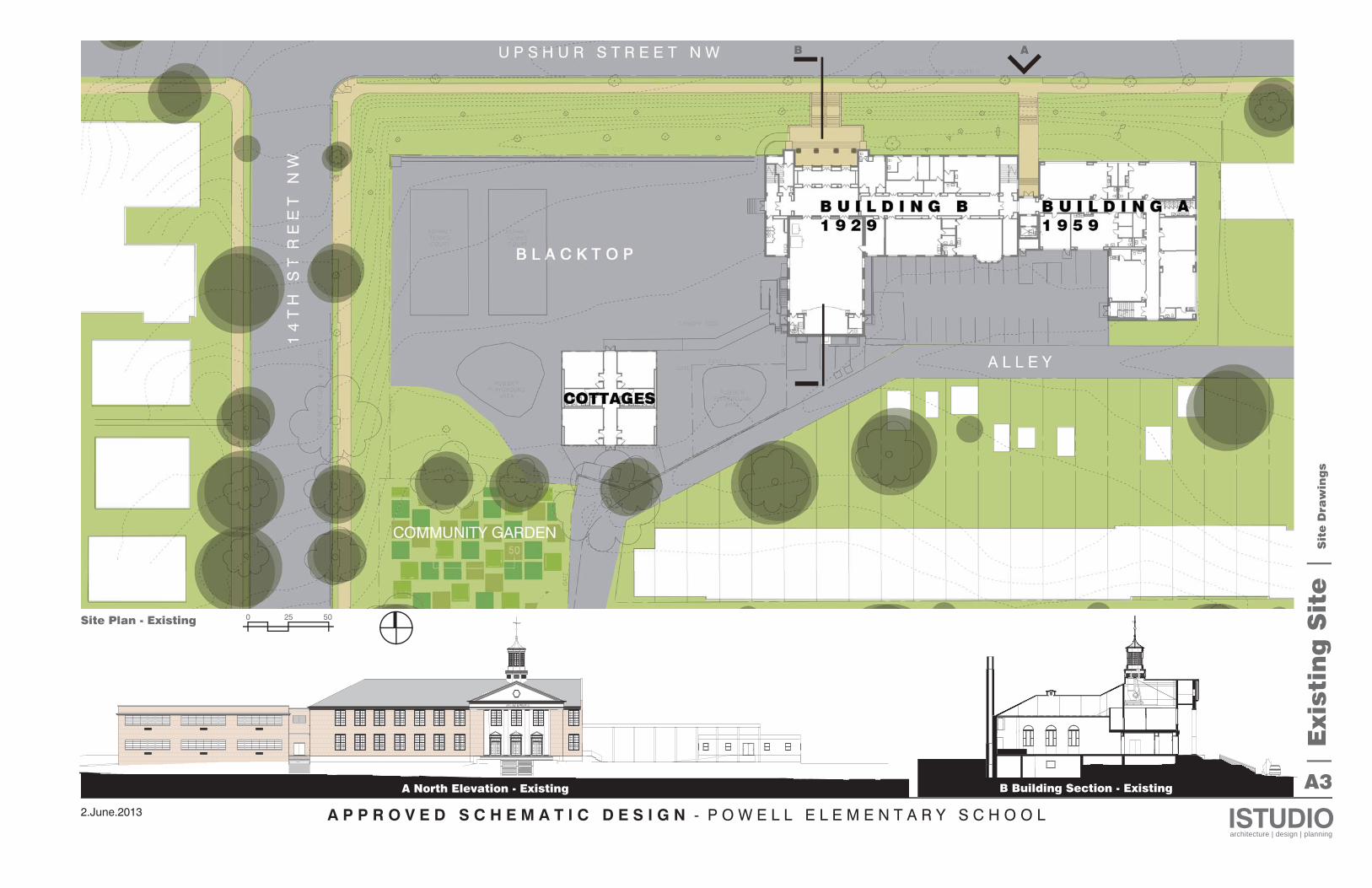
The original building is a 2-story structure built in 1929 with brick walls, a slate roof, and a finely detailed interior. It has an “L”-shaped footprint. The school was expanded in 1959 to the east with a flat roofed brick building. This addition has an “L”-shaped footprint mirroring the original building to create a courtyard space that is currently being used for parking. The exist-ing brick walls are in fair condition and will need to be repaired and repoint-ed at selected locations. The windows and security grilles are in very poor condition. The school’s play area is located on a large asphalt expanse to the west of the original building. Overflow classrooms are housed in a tem-porary structure known as “The Cottages” and connected to the auditorium with a very high temporary canopy. At the far southwest corner of the site, on school property, are gardens that the community uses.
The east-west orientation of the site presents an excellent opportunity for solar access because the broad walls of the school face north for even, con-sistent daylight and south for opportunities to modulate winter and summer solstice sun angles. Prevailing winter winds come from the northwest and prevailing summer winds come from the south-southwest. The school sits up quite high from the street, and there are excellent views to the north and west. Steep slopes along Upshur St. NW and 14th St. NW present both ADA access challenges and storm water runoff challenges. There are privacy and security issues along the alley to the south and residential properties to the east. Drop-off occurs along Upshur St. NW near the primary entrance which includes a broad staircase up to the original 1929 building entrance. The school has only one ADA ramp west of the multi-purpose room which can only be accessed from the alley at the rear of the site. This back entrance is also used for deliveries to the school but presents a security challenge because the gate must remain open at times and cannot be monitored by security. The teachers and staff enter the building on the east side of the auditorium near the parking area.
Load/Unload
A P P R O V E D S C H E M A T I C D E S I G N - P O W E L L E L E M E N T A R Y S C H O O L ISTUDIOarchitecture | design | planning
2.June.2013
A3
| E
xisti
ng
Sit
e |
Sit
e D
raw
ing
s
0 25 50Site Plan - Existing
A North Elevation - Existing B Building Section - Existing
B A
A P P R O V E D S C H E M A T I C D E S I G N - P O W E L L E L E M E N T A R Y S C H O O L ISTUDIOarchitecture | design | planning
2.June.2013
A4
DN
T
914 SFPRE-K683 SF
KINDERGARTEN
463 SF
STUDENTSUPPORTCENTER
GIRLS
1043 SFKINDERGARTEN
1024 SFPRE-KINDERGARTEN
783 SFKINDERGARTEN 103 SF
BK. RM.
401 SF
COUNSELINGRM.ELEV.
CORRIDOR
197 SFPRINC. OFF778 SF
PRE-KINDERGARTEN
810 SFPRE-SCHOOL
CORRIDOR
754 SFPRE-SCHOOL
335 SF
WEL.CENTER
VESTIBULE224 SF
MAINT.LOUNGE
BOYS
2957 SFDINING/AUDITORIUM
272 SFKITCHEN
LOBBY
VEST.VEST.
HEALTHSUITE
ADMIN. WK.
VP OFF.
508 SF
FOURTHGRADE
509 SF
FIFTHGRADE
536 SF
FOURTHGRADE
536 SF
THIRDGRADE
CORRIDORGIRLS BOYS
DN DN
DN
| E
xisti
ng
Sit
e |
Flo
or
Pla
ns
MECH. RM STO.
BOILERROOM
CUST.OFFICE
UP
CRAWL SPACE
Basement Plan - Existing
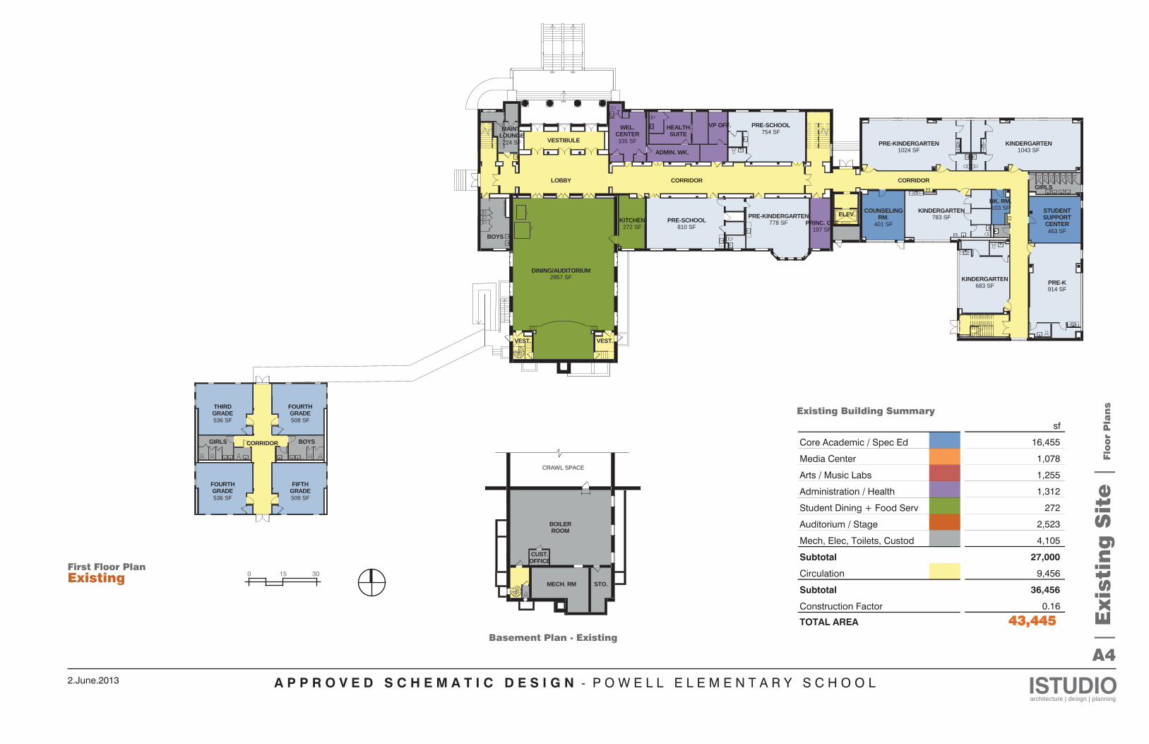
First Floor PlanExisting 0 15 30
sf
16,455
1,078
1,255
1,312
272
2,523
4,105
27,000
9,456
36,456
0.16
443,445 68,244 73,047
Core Academic / Spec Ed
Media Center
Arts / Music Labs
Administration / Health
Student Dining + Food Serv
Auditorium / Stage
Mech, Elec, Toilets, Custod
Subtotal
Circulation
Subtotal
Construction Factor
TOTAL AREA 43,445 68,244 73,047
Existing Building Summary
A P P R O V E D S C H E M A T I C D E S I G N - P O W E L L E L E M E N T A R Y S C H O O L ISTUDIOarchitecture | design | planning
2.June.2013
A5
DN
DN
676 SFMUSIC LAB 377 SF
TEACHER'SLOUNGE
760 SF
THIRDGRADE
773 SF
FIFTHGRADE
CORRIDOR
1078 SFLIBRARY
773 SF
COLLABORATIONROOM
GIRLSBOYS
109 SFBK. RM.
84 SFBK. RM.
112 SFBK. RM.
JAN. CL.
CORRIDOR
697 SF
FIRSTGRADE
685 SF
FIRSTGRADE
683 SF
SECONDGRADE
698 SF
FIRSTGRADE
689 SF
SECONDGRADE
692 SF
SECONDGRADE
502 SF
COMPUTERLAB666 SF
ARTELEV.
BOYS
81 SFSTAGE STO.
80 SFSTAGE STO.
DN
EDU. COTTAGEROOF
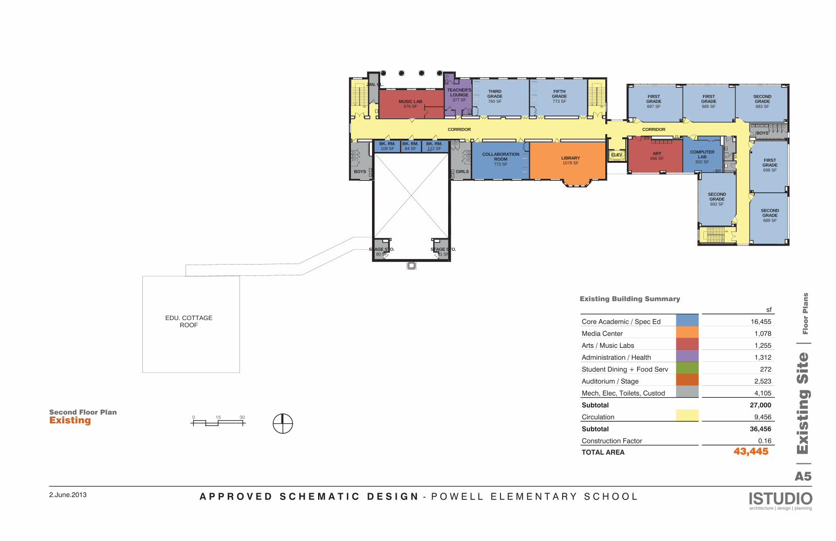
sf
16,455
1,078
1,255
1,312
272
2,523
4,105
27,000
9,456
36,456
0.16
443,445 68,244 73,047
Core Academic / Spec Ed
Media Center
Arts / Music Labs
Administration / Health
Student Dining + Food Serv
Auditorium / Stage
Mech, Elec, Toilets, Custod
Subtotal
Circulation
Subtotal
Construction Factor
TOTAL AREA 43,445 68,244 73,047
| E
xisti
ng
Sit
e |
Flo
or
Pla
ns
Existing Building Summary
Second Floor Plan Existing 0 15 30
A P P R O V E D S C H E M A T I C D E S I G N - P O W E L L E L E M E N T A R Y S C H O O L ISTUDIOarchitecture | design | planning
2.June.2013
A6
| E
xisti
ng
Sit
e |
Arc
hit
ectu
ral
Asse
ssm
en
t
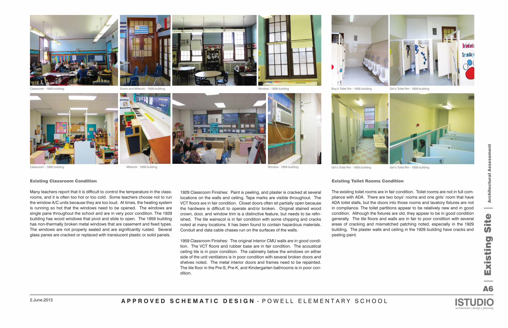
Existing Classroom Condition
Many teachers report that it is difficult to control the temperature in the class-rooms, and it is often too hot or too cold. Some teachers choose not to run the window A/C units because they are too loud. At times, the heating system is running so hot that the windows need to be opened. The windows are single pane throughout the school and are in very poor condition. The 1929 building has wood windows that pivot and slide to open. The 1959 building has non-thermally broken metal windows that are casement and fixed types. The windows are not properly sealed and are significantly rusted. Several glass panes are cracked or replaced with translucent plastic or solid panels.
Classroom - 1929 building Window - 1929 buildingDoors and Millwork - 1929 building
Classroom - 1959 building Window - 1959 buildingMillwork - 1959 building
Boy’s Toilet Rm - 1929 building Girl’s Toilet Rm - 1929 building
Girl’s Toilet Rm - 1959 buildingGirl’s Toilet Rm - 1959 building
Existing Toilet Rooms Condition
The existing toilet rooms are in fair condition. Toilet rooms are not in full com-pliance with ADA. There are two boys’ rooms and one girls’ room that have ADA toilet stalls, but the doors into those rooms and lavatory fixtures are not in compliance. The toilet partitions appear to be relatively new and in good condition. Although the fixtures are old, they appear to be in good condition generally. The tile floors and walls are in fair to poor condition with several areas of cracking and mismatched patching noted, especially in the 1929 building. The plaster walls and ceiling in the 1929 building have cracks and peeling paint.
1929 Classroom Finishes: Paint is peeling, and plaster is cracked at several locations on the walls and ceiling. Tape marks are visible throughout. The VCT floors are in fair condition. Closet doors often sit partially open because the hardware is difficult to operate and/or broken. Original stained wood crown, door, and window trim is a distinctive feature, but needs to be refin-ished. The tile wainscot is in fair condition with some chipping and cracks noted at many locations. It has been found to contain hazardous materials. Conduit and data cable chases run on the surfaces of the walls.
1959 Classroom Finishes: The original interior CMU walls are in good condi-tion. The VCT floors and rubber base are in fair condition. The acoustical ceiling tile is in poor condition. The cabinetry below the windows on either side of the unit ventilators is in poor condition with several broken doors and shelves noted. The metal interior doors and frames need to be repainted. The tile floor in the Pre-S, Pre-K, and Kindergarten bathrooms is in poor con-dition.
A P P R O V E D S C H E M A T I C D E S I G N - P O W E L L E L E M E N T A R Y S C H O O L ISTUDIOarchitecture | design | planning
2.June.2013
A7
| E
xisti
ng
Sit
e |
Arc
hit
ectu
ral
Asse
ssm
en
t
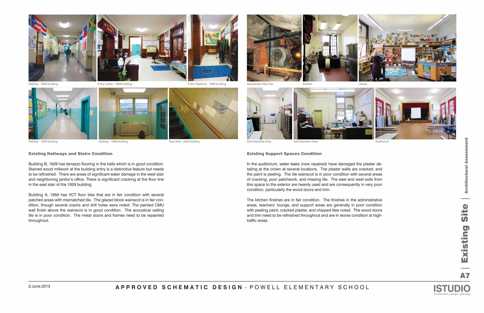
Kitchen Library
Administrative Area Auditorium
Abandoned Attic Fan
Administrative Area
Existing Support Spaces Condition
In the auditorium, water leaks (now repaired) have damaged the plaster de-tailing at the crown at several locations. The plaster walls are cracked, and the paint is peeling. The tile wainscot is in poor condition with several areas of cracking, poor patchwork, and missing tile. The east and west exits from this space to the exterior are heavily used and are consequently in very poor condition, particularly the wood doors and trim.
The kitchen finishes are in fair condition. The finishes in the administrative areas, teachers’ lounge, and support areas are generally in poor condition with peeling paint, cracked plaster, and chipped tiles noted. The wood doors and trim need to be refinished throughout and are in worse condition at high-traffic areas.
Hallway - 1959 building Hallway - 1959 building East Stair- 1929 building
Hallway - 1929 building Entry Lobby - 1929 building Entry Vestibule - 1929 building
Existing Hallways and Stairs Condition
Building B, 1929 has terrazzo flooring in the halls which is in good condition. Stained wood millwork at the building entry is a distinctive feature but needs to be refinished. There are areas of significant water damage in the west stair and neighboring janitor’s office. There is significant cracking at the floor line in the east stair of the 1929 building.
Building A, 1959 has VCT floor tiles that are in fair condition with several patched areas with mismatched tile. The glazed block wainscot is in fair con-dition, though several cracks and drill holes were noted. The painted CMU wall finish above the wainscot is in good condition. The acoustical ceiling tile is in poor condition. The metal doors and frames need to be repainted throughout.
A P P R O V E D S C H E M A T I C D E S I G N - P O W E L L E L E M E N T A R Y S C H O O L ISTUDIOarchitecture | design | planning
2.June.2013
A8
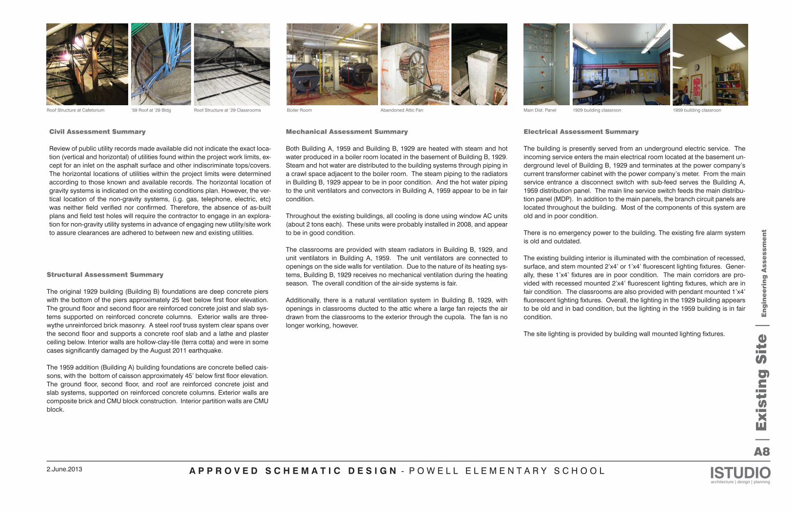
Main Dist. PanelBoiler Room Abandoned Attic FanRoof Structure at Cafetorium ‘59 Roof at ‘29 Bldg Roof Structure at ‘29 Classrooms
| E
xisti
ng
Sit
e |
En
gin
ee
rin
g A
sse
ssm
en
t
Structural Assessment Summary
The original 1929 building (Building B) foundations are deep concrete piers with the bottom of the piers approximately 25 feet below first floor elevation. The ground floor and second floor are reinforced concrete joist and slab sys-tems supported on reinforced concrete columns. Exterior walls are three-wythe unreinforced brick masonry. A steel roof truss system clear spans over the second floor and supports a concrete roof slab and a lathe and plaster ceiling below. Interior walls are hollow-clay-tile (terra cotta) and were in some cases significantly damaged by the August 2011 earthquake.
The 1959 addition (Building A) building foundations are concrete belled cais-sons, with the bottom of caisson approximately 45’ below first floor elevation. The ground floor, second floor, and roof are reinforced concrete joist and slab systems, supported on reinforced concrete columns. Exterior walls are composite brick and CMU block construction. Interior partition walls are CMU block.
Mechanical Assessment Summary
Both Building A, 1959 and Building B, 1929 are heated with steam and hot water produced in a boiler room located in the basement of Building B, 1929. Steam and hot water are distributed to the building systems through piping in a crawl space adjacent to the boiler room. The steam piping to the radiators in Building B, 1929 appear to be in poor condition. And the hot water piping to the unit ventilators and convectors in Building A, 1959 appear to be in fair condition.
Throughout the existing buildings, all cooling is done using window AC units (about 2 tons each). These units were probably installed in 2008, and appear to be in good condition.
The classrooms are provided with steam radiators in Building B, 1929, and unit ventilators in Building A, 1959. The unit ventilators are connected to openings on the side walls for ventilation. Due to the nature of its heating sys-tems, Building B, 1929 receives no mechanical ventilation during the heating season. The overall condition of the air-side systems is fair.
Additionally, there is a natural ventilation system in Building B, 1929, with openings in classrooms ducted to the attic where a large fan rejects the air drawn from the classrooms to the exterior through the cupola. The fan is no longer working, however.
Electrical Assessment Summary
The building is presently served from an underground electric service. The incoming service enters the main electrical room located at the basement un-derground level of Building B, 1929 and terminates at the power company’s current transformer cabinet with the power company’s meter. From the main service entrance a disconnect switch with sub-feed serves the Building A, 1959 distribution panel. The main line service switch feeds the main distribu-tion panel (MDP). In addition to the main panels, the branch circuit panels are located throughout the building. Most of the components of this system are old and in poor condition.
There is no emergency power to the building. The existing fire alarm system is old and outdated.
The existing building interior is illuminated with the combination of recessed, surface, and stem mounted 2’x4’ or 1’x4’ fluorescent lighting fixtures. Gener-ally, these 1’x4’ fixtures are in poor condition. The main corridors are pro-vided with recessed mounted 2’x4’ fluorescent lighting fixtures, which are in fair condition. The classrooms are also provided with pendant mounted 1’x4’ fluorescent lighting fixtures. Overall, the lighting in the 1929 building appears to be old and in bad condition, but the lighting in the 1959 building is in fair condition.
The site lighting is provided by building wall mounted lighting fixtures.
1929 building classroon 1959 building classroon
Civil Assessment Summary
Review of public utility records made available did not indicate the exact loca-tion (vertical and horizontal) of utilities found within the project work limits, ex-cept for an inlet on the asphalt surface and other indiscriminate tops/covers. The horizontal locations of utilities within the project limits were determined according to those known and available records. The horizontal location of gravity systems is indicated on the existing conditions plan. However, the ver-tical location of the non-gravity systems, (i.g. gas, telephone, electric, etc) was neither field verified nor confirmed. Therefore, the absence of as-built plans and field test holes will require the contractor to engage in an explora-tion for non-gravity utility systems in advance of engaging new utility/site work to assure clearances are adhered to between new and existing utilities.
A P P R O V E D S C H E M A T I C D E S I G N - P O W E L L E L E M E N T A R Y S C H O O L ISTUDIOarchitecture | design | planning
2.June.2013
A9
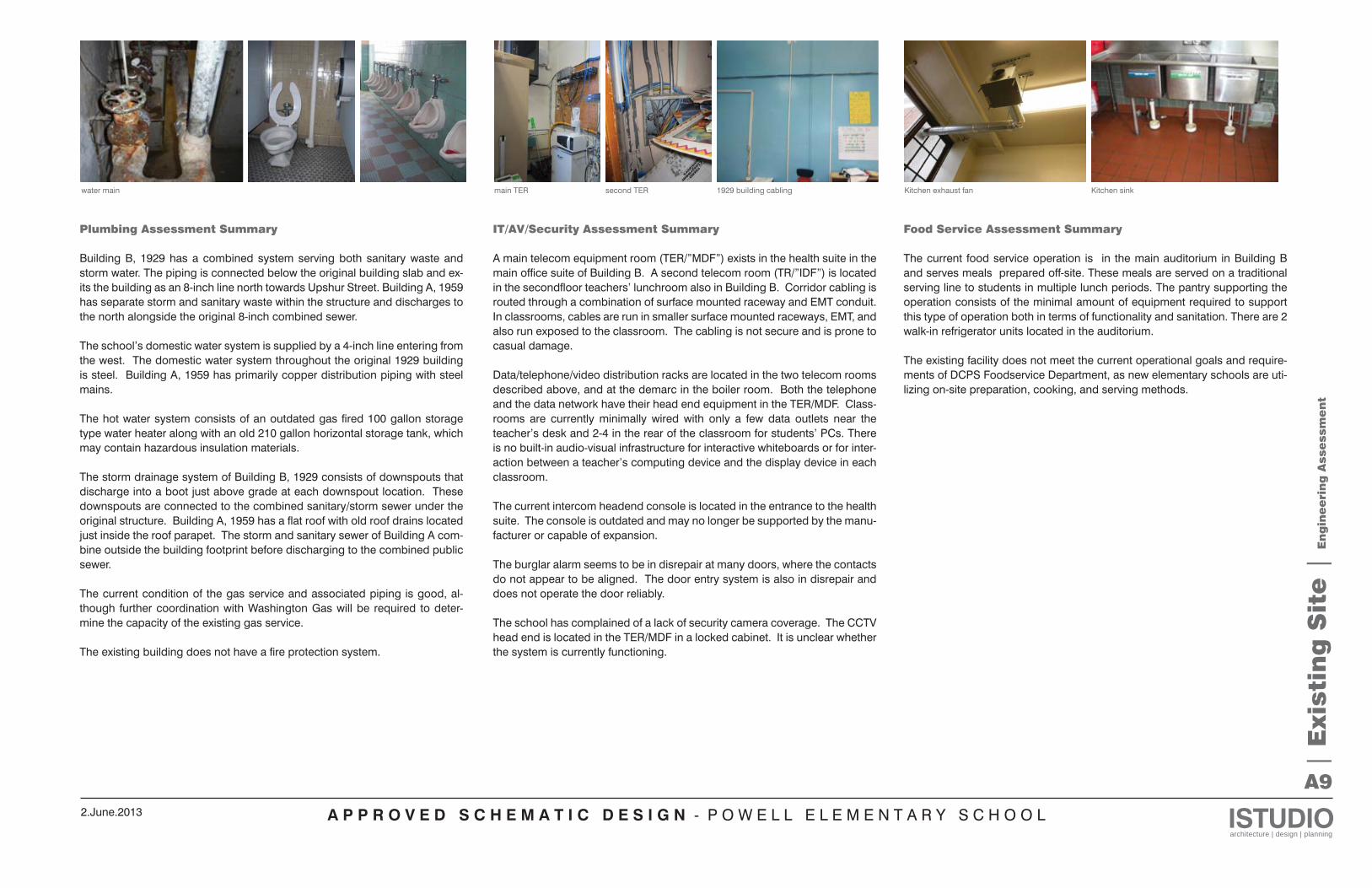
water main main TER second TER
| E
xisti
ng
Sit
e |
En
gin
ee
rin
g A
sse
ssm
en
t
Plumbing Assessment Summary
Building B, 1929 has a combined system serving both sanitary waste and storm water. The piping is connected below the original building slab and ex-its the building as an 8-inch line north towards Upshur Street. Building A, 1959 has separate storm and sanitary waste within the structure and discharges to the north alongside the original 8-inch combined sewer.
The school’s domestic water system is supplied by a 4-inch line entering from the west. The domestic water system throughout the original 1929 building is steel. Building A, 1959 has primarily copper distribution piping with steel mains.
The hot water system consists of an outdated gas fired 100 gallon storage type water heater along with an old 210 gallon horizontal storage tank, which may contain hazardous insulation materials.
The storm drainage system of Building B, 1929 consists of downspouts that discharge into a boot just above grade at each downspout location. These downspouts are connected to the combined sanitary/storm sewer under the original structure. Building A, 1959 has a flat roof with old roof drains located just inside the roof parapet. The storm and sanitary sewer of Building A com-bine outside the building footprint before discharging to the combined public sewer.
The current condition of the gas service and associated piping is good, al-though further coordination with Washington Gas will be required to deter-mine the capacity of the existing gas service.
The existing building does not have a fire protection system.
IT/AV/Security Assessment Summary
A main telecom equipment room (TER/”MDF”) exists in the health suite in the main office suite of Building B. A second telecom room (TR/”IDF”) is located in the secondfloor teachers’ lunchroom also in Building B. Corridor cabling is routed through a combination of surface mounted raceway and EMT conduit. In classrooms, cables are run in smaller surface mounted raceways, EMT, and also run exposed to the classroom. The cabling is not secure and is prone to casual damage. Data/telephone/video distribution racks are located in the two telecom rooms described above, and at the demarc in the boiler room. Both the telephone and the data network have their head end equipment in the TER/MDF. Class-rooms are currently minimally wired with only a few data outlets near the teacher’s desk and 2-4 in the rear of the classroom for students’ PCs. There is no built-in audio-visual infrastructure for interactive whiteboards or for inter-action between a teacher’s computing device and the display device in each classroom.
The current intercom headend console is located in the entrance to the health suite. The console is outdated and may no longer be supported by the manu-facturer or capable of expansion.
The burglar alarm seems to be in disrepair at many doors, where the contacts do not appear to be aligned. The door entry system is also in disrepair and does not operate the door reliably.
The school has complained of a lack of security camera coverage. The CCTV head end is located in the TER/MDF in a locked cabinet. It is unclear whether the system is currently functioning.
Food Service Assessment Summary
The current food service operation is in the main auditorium in Building B and serves meals prepared off-site. These meals are served on a traditional serving line to students in multiple lunch periods. The pantry supporting the operation consists of the minimal amount of equipment required to support this type of operation both in terms of functionality and sanitation. There are 2 walk-in refrigerator units located in the auditorium.
The existing facility does not meet the current operational goals and require-ments of DCPS Foodservice Department, as new elementary schools are uti-lizing on-site preparation, cooking, and serving methods.
1929 building cabling Kitchen exhaust fan Kitchen sink
A P P R O V E D S C H E M A T I C D E S I G N - P O W E L L E L E M E N T A R Y S C H O O L ISTUDIOarchitecture | design | planning
2.June.2013
B1
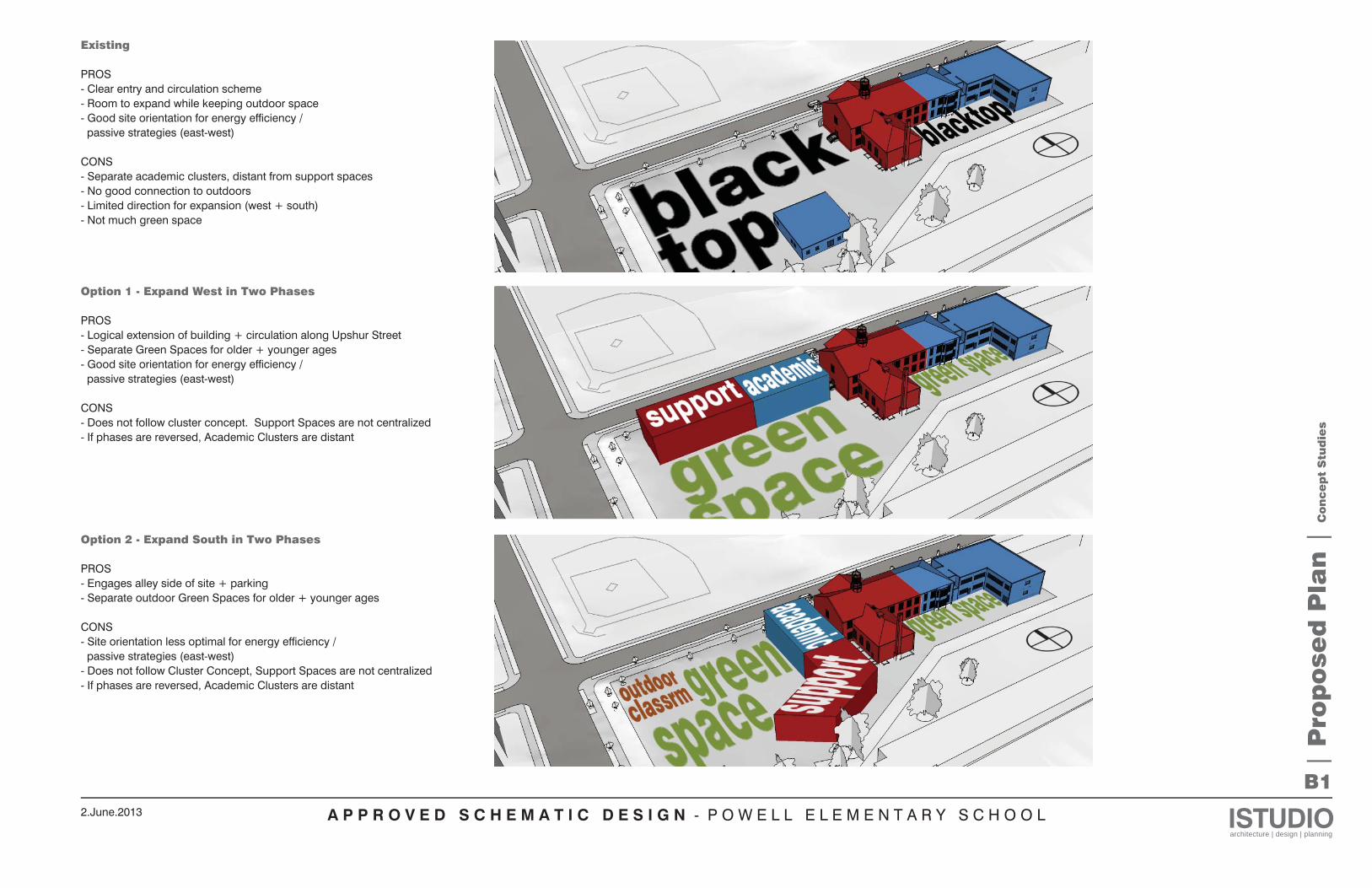
Existing
PROS- Clear entry and circulation scheme- Room to expand while keeping outdoor space- Good site orientation for energy efficiency / passive strategies (east-west)
CONS- Separate academic clusters, distant from support spaces- No good connection to outdoors- Limited direction for expansion (west + south)- Not much green space
Option 1 - Expand West in Two Phases
PROS- Logical extension of building + circulation along Upshur Street- Separate Green Spaces for older + younger ages- Good site orientation for energy efficiency / passive strategies (east-west)
CONS- Does not follow cluster concept. Support Spaces are not centralized- If phases are reversed, Academic Clusters are distant
| P
rop
ose
d P
lan
| C
on
ce
pt
Stu
die
s
Option 2 - Expand South in Two Phases
PROS- Engages alley side of site + parking- Separate outdoor Green Spaces for older + younger ages
CONS- Site orientation less optimal for energy efficiency / passive strategies (east-west)- Does not follow Cluster Concept, Support Spaces are not centralized- If phases are reversed, Academic Clusters are distant
A P P R O V E D S C H E M A T I C D E S I G N - P O W E L L E L E M E N T A R Y S C H O O L ISTUDIOarchitecture | design | planning
2.June.2013
B2
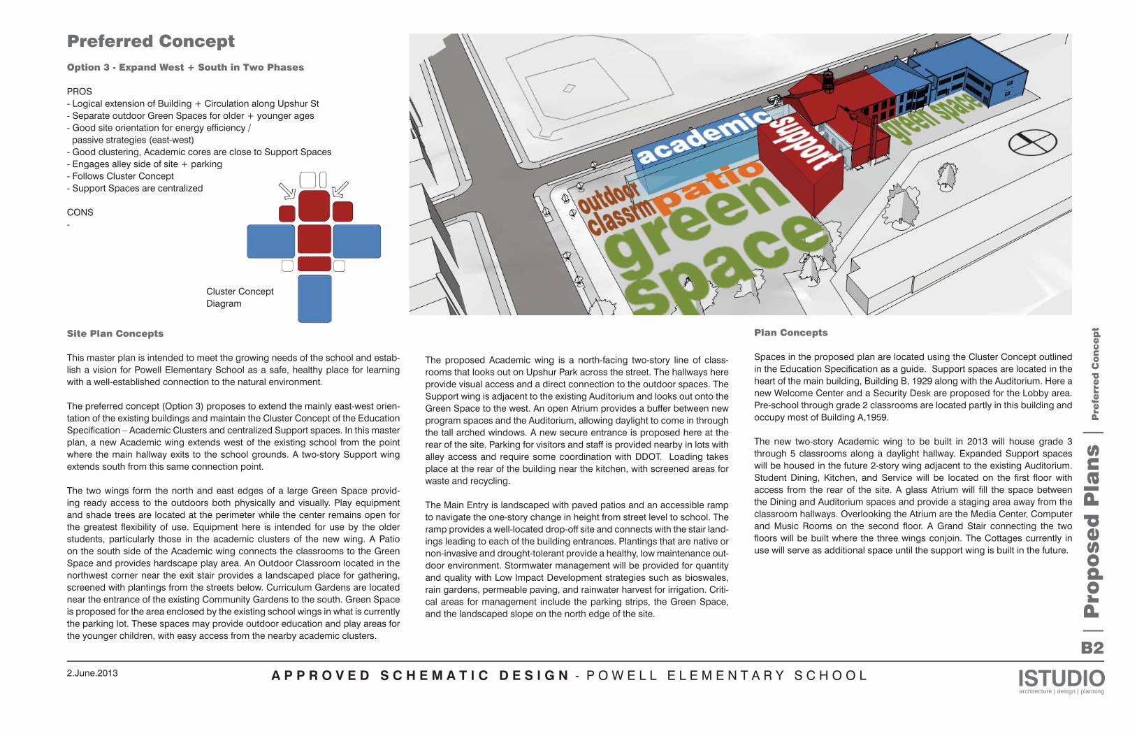
Option 3 - Expand West + South in Two Phases
PROS- Logical extension of Building + Circulation along Upshur St- Separate outdoor Green Spaces for older + younger ages- Good site orientation for energy efficiency / passive strategies (east-west)- Good clustering, Academic cores are close to Support Spaces- Engages alley side of site + parking- Follows Cluster Concept- Support Spaces are centralized
CONS-
| P
rop
ose
d P
lan
s |
Pre
ferr
ed
Con
ce
pt
Preferred Concept
Cluster Concept Diagram
Site Plan Concepts
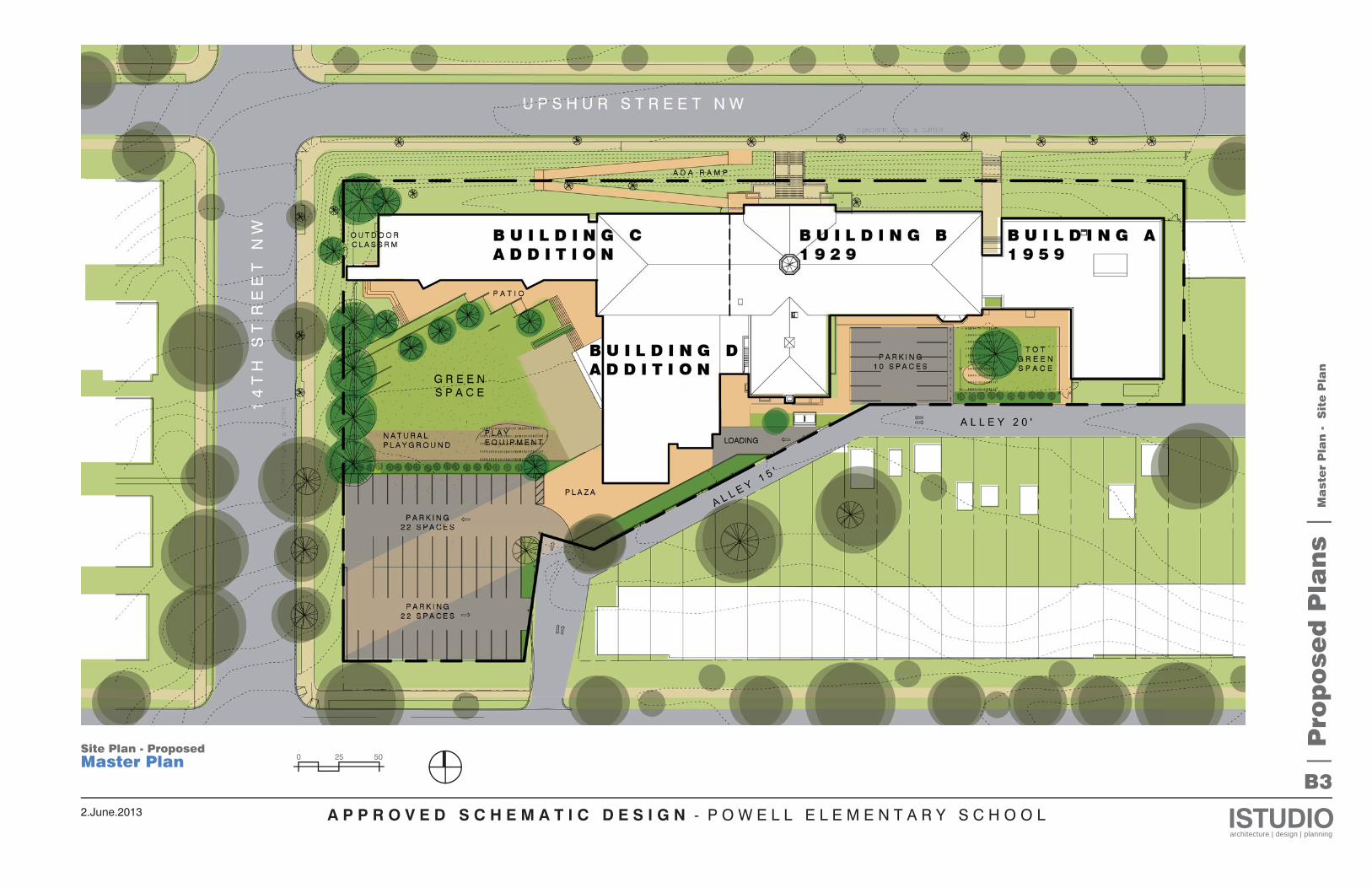
This master plan is intended to meet the growing needs of the school and estab-lish a vision for Powell Elementary School as a safe, healthy place for learning with a well-established connection to the natural environment.
The preferred concept (Option 3) proposes to extend the mainly east-west orien-tation of the existing buildings and maintain the Cluster Concept of the Education Specification – Academic Clusters and centralized Support spaces. In this master plan, a new Academic wing extends west of the existing school from the point where the main hallway exits to the school grounds. A two-story Support wing extends south from this same connection point.
The two wings form the north and east edges of a large Green Space provid-ing ready access to the outdoors both physically and visually. Play equipment and shade trees are located at the perimeter while the center remains open for the greatest flexibility of use. Equipment here is intended for use by the older students, particularly those in the academic clusters of the new wing. A Patio on the south side of the Academic wing connects the classrooms to the Green Space and provides hardscape play area. An Outdoor Classroom located in the northwest corner near the exit stair provides a landscaped place for gathering, screened with plantings from the streets below. Curriculum Gardens are located near the entrance of the existing Community Gardens to the south. Green Space is proposed for the area enclosed by the existing school wings in what is currently the parking lot. These spaces may provide outdoor education and play areas for the younger children, with easy access from the nearby academic clusters.
Plan Concepts
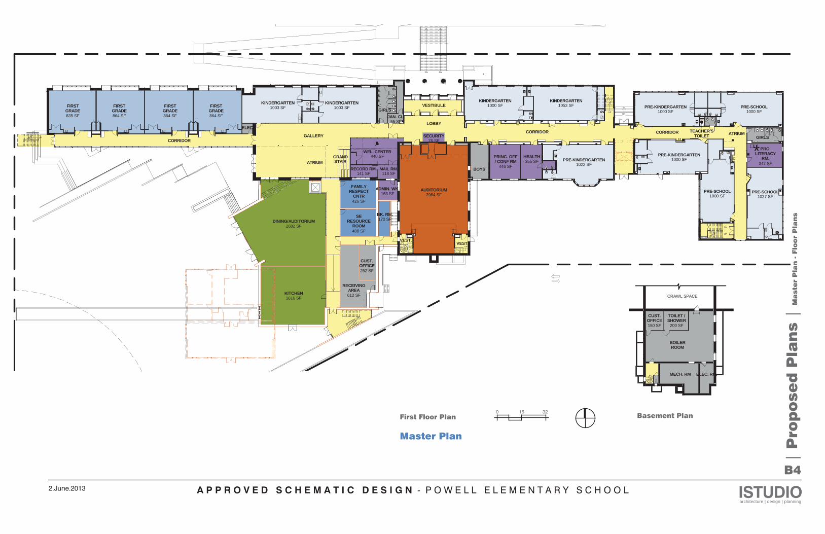
Spaces in the proposed plan are located using the Cluster Concept outlined in the Education Specification as a guide. Support spaces are located in the heart of the main building, Building B, 1929 along with the Auditorium. Here a new Welcome Center and a Security Desk are proposed for the Lobby area. Pre-school through grade 2 classrooms are located partly in this building and occupy most of Building A,1959.
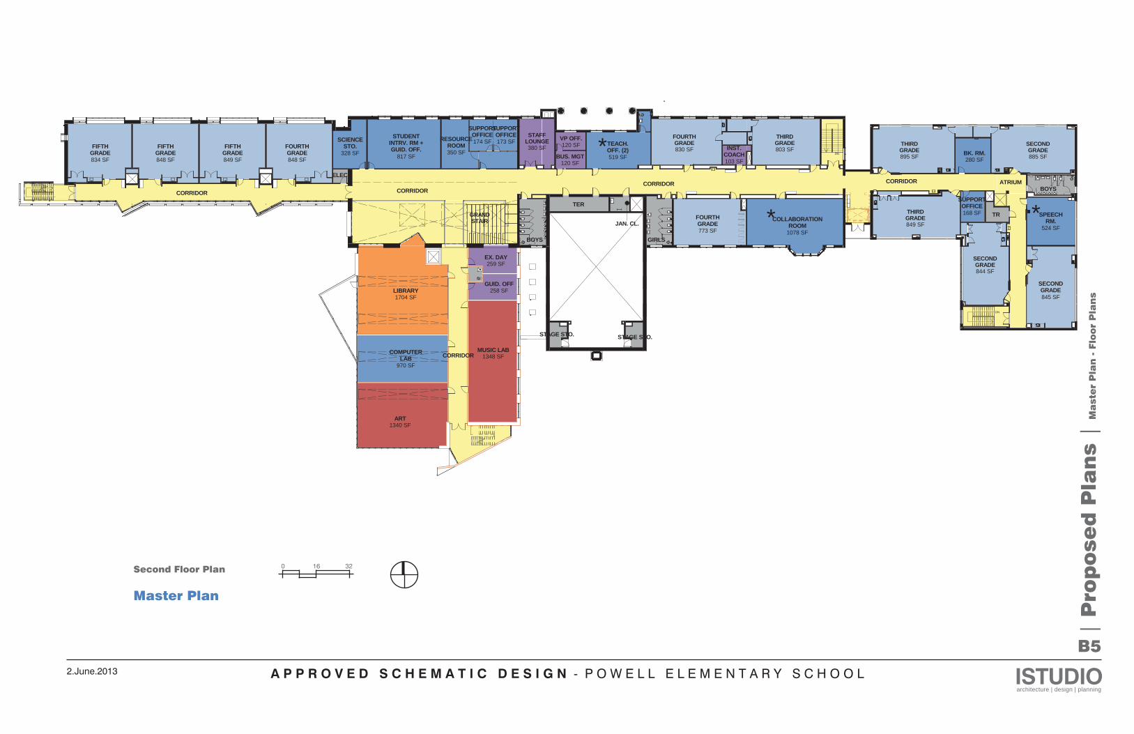
The new two-story Academic wing to be built in 2013 will house grade 3 through 5 classrooms along a daylight hallway. Expanded Support spaces will be housed in the future 2-story wing adjacent to the existing Auditorium. Student Dining, Kitchen, and Service will be located on the first floor with access from the rear of the site. A glass Atrium will fill the space between the Dining and Auditorium spaces and provide a staging area away from the classroom hallways. Overlooking the Atrium are the Media Center, Computer and Music Rooms on the second floor. A Grand Stair connecting the two floors will be built where the three wings conjoin. The Cottages currently in use will serve as additional space until the support wing is built in the future.
The proposed Academic wing is a north-facing two-story line of class-rooms that looks out on Upshur Park across the street. The hallways here provide visual access and a direct connection to the outdoor spaces. The Support wing is adjacent to the existing Auditorium and looks out onto the Green Space to the west. An open Atrium provides a buffer between new program spaces and the Auditorium, allowing daylight to come in through the tall arched windows. A new secure entrance is proposed here at the rear of the site. Parking for visitors and staff is provided nearby in lots with alley access and require some coordination with DDOT. Loading takes place at the rear of the building near the kitchen, with screened areas for waste and recycling.
The Main Entry is landscaped with paved patios and an accessible ramp to navigate the one-story change in height from street level to school. The ramp provides a well-located drop-off site and connects with the stair land-ings leading to each of the building entrances. Plantings that are native or non-invasive and drought-tolerant provide a healthy, low maintenance out-door environment. Stormwater management will be provided for quantity and quality with Low Impact Development strategies such as bioswales, rain gardens, permeable paving, and rainwater harvest for irrigation. Criti-cal areas for management include the parking strips, the Green Space, and the landscaped slope on the north edge of the site.
A P P R O V E D S C H E M A T I C D E S I G N - P O W E L L E L E M E N T A R Y S C H O O L ISTUDIOarchitecture | design | planning
2.June.2013
B3
| P
rop
ose
d P
lan
s |
Ma
ste
r P
lan
-
Sit
e P
lan
Site Plan - ProposedMaster Plan 0 25 50
A P P R O V E D S C H E M A T I C D E S I G N - P O W E L L E L E M E N T A R Y S C H O O L ISTUDIOarchitecture | design | planning
2.June.2013
B4
DN
UP
UP
UP
DN
UP
DN
DN DN
GRANDSTAIR 347 SF
PRO.LITERACY
RM.
CORRIDORGIRLS
2964 SFAUDITORIUM
VESTIBULE
LOBBY
GIRLS
CORRIDOR
VEST.
1003 SFKINDERGARTEN
1003 SFKINDERGARTEN
76 SFSECURITY
ATRIUM
TEACHER'STOILET
1616 SFKITCHEN
864 SF
FIRSTGRADE
864 SF
FIRSTGRADE
864 SF
FIRSTGRADE
835 SF
FIRSTGRADE
CORRIDOR
446 SF
PRINC. OFF/ CONF RM 355 SF
HEALTH
BOYS
VEST.
ATRIUM
KINDERGARTEN1000 SF
408 SF
SERESOURCE
ROOM
PRE-KINDERGARTEN1000 SF
PRE-SCHOOL1000 SF
PRE-KINDERGARTEN1000 SF
PRE-SCHOOL1000 SF
PRE-SCHOOL1027 SF
KINDERGARTEN1053 SF
*
252 SF
CUST.OFFICE
612 SF
RECEIVINGAREA
163 SFADMIN. WK.
170 SFBK. RM.
426 SF
FAMILYRESPECT
CNTR
WEL. CENTER440 SF
GALLERY
55 SFJAN. CL.
PRE-KINDERGARTEN1022 SF
RECORD RM.141 SF
MAIL RM.118 SF
ELEC.
2682 SFDINING/AUDITORIUM
| P
rop
ose
d P
lan
s |
Ma
ste
r P
lan
- F
loor
Pla
ns
0 16 32Basement PlanFirst Floor Plan
Master Plan
MECH. RM ELEC. RM.
BOILERROOM
UP
CRAWL SPACE
200 SF
TOILET /SHOWER
150 SF
CUST.OFFICE
A P P R O V E D S C H E M A T I C D E S I G N - P O W E L L E L E M E N T A R Y S C H O O L ISTUDIOarchitecture | design | planning
2.June.2013
B5
DN
DN
GRANDSTAIR
BOYS
524 SF
SPEECHRM.
845 SF
SECONDGRADE
CORRIDOR
BOYS
TER
JAN. CL.
GIRLS773 SF
FOURTHGRADE
1078 SF
COLLABORATIONROOM
CORRIDOR
STAGE STO. STAGE STO.
328 SF
SCIENCESTO.
519 SF
TEACH.OFF. (2)
168 SF
SUPPORTOFFICE
TR
1704 SFLIBRARY
970 SF
COMPUTERLAB
848 SF
FOURTHGRADE
848 SF
FIFTHGRADE
834 SF
FIFTHGRADE
849 SF
FIFTHGRADE
CORRIDORATRIUM
1340 SFART
1348 SFMUSIC LAB
THIRDGRADE803 SF
280 SFBK. RM.
THIRDGRADE849 SF
SECONDGRADE844 SF
THIRDGRADE895 SF
SECONDGRADE885 SF
120 SFVP OFF. *
**
258 SFGUID. OFF
817 SF
STUDENTINTRV. RM +GUID. OFF. 350 SF
RESOURCEROOM 174 SF
SUPPORTOFFICE
173 SF
SUPPORTOFFICE
ELEC.
259 SFEX. DAY
CORRIDOR
120 SFBUS. MGT
103 SF
INST.COACH
CORRIDOR
FOURTHGRADE830 SF
STAFFLOUNGE380 SF
| P
rop
ose
d P
lan
s |
Ma
ste
r P
lan
- F
loor
Pla
ns
0 16 32Second Floor Plan
Master Plan
A P P R O V E D S C H E M A T I C D E S I G N - P O W E L L E L E M E N T A R Y S C H O O L ISTUDIOarchitecture | design | planning
2.June.2013
B6
| P
rop
ose
d P
lan
s |
Pla
n t
o P
rog
ram
Com
pa
rison
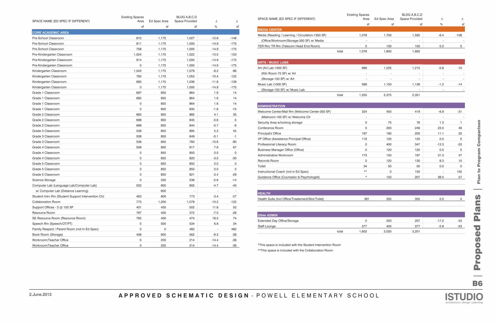
SPACE NAME (ED SPEC IF DIFFERENT)Existing Spaces
Area Ed Spec AreaBLDG A,B,C,D
Space Provided
sf sf sf % sf
CORE ACADEMIC AREA
Pre-School Classroom 810 1,175 1,027 -12.6 -148
Pre-School Classroom 811 1,175 1,000 -14.9 -175
Pre-School Classroom 758 1,175 1,000 -14.9 -175
Pre-Kindergarten Classroom 1,024 1,175 1,022 -13.0 -153
Pre-Kindergarten Classroom 914 1,175 1,000 -14.9 -175
Pre-Kindergarten Classroom 0 1,175 1,000 -14.9 -175
Kindergarten Classroom 1,043 1,175 1,079 -8.2 -96
Kindergarten Classroom 783 1,175 1,053 -10.4 -122
Kindergarten Classroom 693 1,175 1,036 -11.8 -139
Kindergarten Classroom 0 1,175 1,000 -14.9 -175
Grade 1 Classroom 697 850 864 1.6 14
Grade 1 Classroom 685 850 864 1.6 14
Grade 1 Classroom 0 850 864 1.6 14
Grade 1 Classroom 0 850 835 -1.8 -15
Grade 2 Classroom 683 850 885 4.1 35
Grade 2 Classroom 698 850 845 -0.6 -5
Grade 2 Classroom 689 850 844 -0.7 -6
Grade 3 Classroom 536 850 895 5.3 45
Grade 3 Classroom 508 850 849 -0.1 -1
Grade 3 Classroom 536 850 760 -10.6 -90
Grade 4 Classroom 508 850 917 7.9 67
Grade 4 Classroom 0 850 850 0.0 0
Grade 4 Classroom 0 850 820 -3.5 -30
Grade 5 Classroom 0 850 850 0.0 0
Grade 5 Classroom 0 850 850 0.0 0
Grade 5 Classroom 0 850 821 -3.4 -29
Science Storage 0 250 236 -5.6 -14
Computer Lab (Language Lab/Computer Lab) 502 950 905 -4.7 -45
w/ Computer Lab (Distance Learning) 600 - - -
Student Intrv Rm (Student Support Intervention Ctr) 463 800 773 -3.4 -27
Collaboration Room 773 1,200 1,078 -10.2 -122
Support Offices - 3 @ 150 SF 401 450 502 11.6 52
Resource Room 767 400 372 -7.0 -28
SE Resource Room (Resource Room) 765 400 474 18.5 74
Speech Rm (Speech/OT/PT) 0 500 534 6.8 34
Family Respect / Parent Room (not in Ed Spec) 0 0 482 - 482
Book Room (Storage) 408 600 562 -6.3 -38
Workroom/Teacher Office 0 250 214 -14.4 -36
Workroom/Teacher Office 0 250 214 -14.4 -36
SPACE NAME (ED SPEC IF DIFFERENT)Existing Spaces
Area Ed Spec AreaBLDG A,B,C,D
Space Provided
sf sf sf % sf
MEDIA CENTER
Media (Reading / Learning / Circulation-1350 SF) 1,078 1,700 1,592 -6.4 -108
(Office/Workroom/Storage-350 SF) w/ Media - - - - -
TER Rm/ TR Rm (Telecom Head End Room) 0 100 100 0.0 0
total 1,078 1,800 1,692
ARTS / MUSIC LABS
Art (Art Lab-1000 SF) 666 1,225 1,215 -0.8 -10
(Kiln Room-75 SF) w/ Art - - - - -
(Storage-150 SF) w/ Art - - - - -
Music Lab (1000 SF) 589 1,150 1,136 -1.2 -14
(Storage-150 SF) w/ Music Lab - - - - -
total 1,255 2,375 2,351
ADMINISTRATION
Welcome Center/Mail Rm (Welcome Center-350 SF) 324 450 419 -6.9 -31
(Mailroom-100 SF) w/ Welcome Ctr - - - - -
Security Area w/locking storage 0 75 76 1.3 1
Conference Room 0 200 246 23.0 46
Principal's Office 197 180 200 11.1 20
VP Office (Assistance Principal Office) 116 120 120 0.0 0
Professional Literacy Room 0 400 347 -13.3 -53
Business Manager Office (Office) 0 120 120 0.0 0
Administrative Workroom 173 150 197 31.3 47
Records Room 0 120 130 8.3 10
Toilet 34 50 50 0.0 0
Instructional Coach (not in Ed Spec) ** 0 150 - 150
Guidance Office (Counselor & Psychologist) * 150 207 38.0 57
HEALTH
Health Suite (incl Office/Treatement/Stor/Toilet) 381 355 355 0.0 0
Other ADMIN
Extended Day Office/Storage 0 250 207 -17.2 -43
Staff Lounge 377 400 377 -5.8 -23
total 1,602 3,020 3,201
*This space is included with the Student Intervention Room
**This space is included with the Collaboration Room
A P P R O V E D S C H E M A T I C D E S I G N - P O W E L L E L E M E N T A R Y S C H O O L ISTUDIOarchitecture | design | planning
2.June.2013
B7
| P
rop
ose
d P
lan
s |
Pla
n t
o P
rog
ram
Com
pa
rison
SPACE NAME (ED SPEC IF DIFFERENT)Existing Spaces
Area Ed Spec AreaBLDG A,B,C,D
Space Provided
sf sf sf % sf
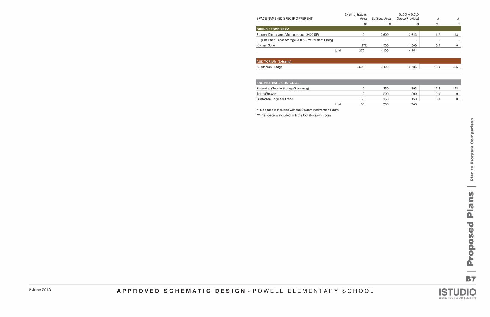
DINING / FOOD SERV
Student Dining Area/Multi-purpose (2400 SF) 0 2,600 2,643 1.7 43
(Chair and Table Storage-200 SF) w/ Student Dining - - - - -
Kitchen Suite 272 1,500 1,508 0.5 8
total 272 4,100 4,151
AUDITORIUM (Existing)
Auditorium / Stage 2,523 2,400 2,785 16.0 385
ENGINEERING / CUSTODIAL
Receiving (Supply Storage/Receiving) 0 350 393 12.3 43
Toilet/Shower 0 200 200 0.0 0
Custodian Engineer Office 58 150 150 0.0 0
total 58 700 743
*This space is included with the Student Intervention Room
**This space is included with the Collaboration Room
A P P R O V E D S C H E M A T I C D E S I G N - P O W E L L E L E M E N T A R Y S C H O O L ISTUDIOarchitecture | design | planning
2.June.2013
C1
| D
esig
n N
arr
ati
ve |
Bu
ild
ing
Con
ce
pts
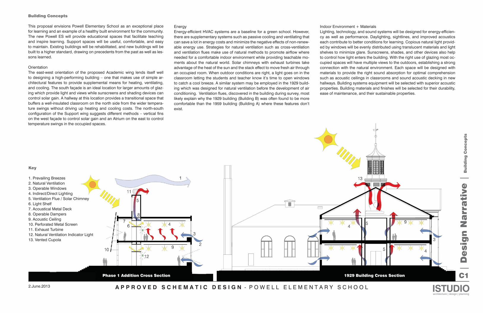
Building Concepts
This proposal envisions Powell Elementary School as an exceptional place for learning and an example of a healthy built environment for the community. The new Powell ES will provide educational spaces that facilitate teaching and inspire learning. Support spaces will be useful, comfortable, and easy to maintain. Existing buildings will be rehabilitated, and new buildings will be built to a higher standard, drawing on precedents from the past as well as les-sons learned.
OrientationThe east-west orientation of the proposed Academic wing lends itself well to designing a high-performing building – one that makes use of simple ar-chitectural features to provide supplemental means for heating, ventilating, and cooling. The south façade is an ideal location for larger amounts of glaz-ing which provide light and views while sunscreens and shading devices can control solar gain. A hallway at this location provides a transitional space that buffers a well-insulated classroom on the north side from the wider tempera-ture swings without driving up heating and cooling costs. The north-south configuration of the Support wing suggests different methods – vertical fins on the west façade to control solar gain and an Atrium on the east to control temperature swings in the occupied spaces.
Key
1. Prevailing Breezes2. Natural Ventilation3. Operable Windows4. Indirect/Direct Lighting5. Ventilation Flue / Solar Chimney6. Light Shelf7. Acoustical Metal Deck8. Operable Dampers9. Acoustic Ceiling10. Perforated Metal Screen11. Exhaust Turbine12. Natural Ventilation Indicator Light13. Vented Cupola
Phase 1 Addition Cross Section 1929 Building Cross Section
EnergyEnergy-efficient HVAC systems are a baseline for a green school. However, there are supplementary systems such as passive cooling and ventilating that can save a lot in energy costs and minimize the negative effects of non-renew-able energy use. Strategies for natural ventilation such as cross-ventilation and ventilation flues make use of natural methods to promote airflow where needed for a comfortable indoor environment while providing teachable mo-ments about the natural world. Solar chimneys with exhaust turbines take advantage of the heat of the sun and the stack effect to move fresh air through an occupied room. When outdoor conditions are right, a light goes on in the classroom letting the students and teacher know it’s time to open windows to catch a cool breeze. A similar system may be employed in the 1929 build-ing which was designed for natural ventilation before the development of air conditioning. Ventilation flues, discovered in the building during survey, most likely explain why the 1929 building (Building B) was often found to be more comfortable than the 1959 building (Building A) where these features don’t exist.
Indoor Environment + MaterialsLighting, technology, and sound systems will be designed for energy-efficien-cy as well as performance. Daylighting, sightlines, and improved acoustics each contribute to better conditions for learning. Copious natural light provid-ed by windows will be evenly distributed using translucent materials and light shelves to minimize glare. Sunscreens, shades, and other devices also help to control how light enters the building. With the right use of glazing most oc-cupied spaces will have multiple views to the outdoors, establishing a strong connection with the natural environment. Each space will be designed with materials to provide the right sound absorption for optimal comprehension such as acoustic ceilings in classrooms and sound acoustic decking in new hallways. Building systems equipment will be selected with superior acoustic properties. Building materials and finishes will be selected for their durability, ease of maintenance, and their sustainable properties.
A P P R O V E D S C H E M A T I C D E S I G N - P O W E L L E L E M E N T A R Y S C H O O L ISTUDIOarchitecture | design | planning
2.June.2013
C2
| D
esig
n N
arr
ati
ve |
Su
sta
ina
bil
ity
LEED 2009 for Schools New Construction and Major Renovations Powell Elementary
Project Checklist
9 12 3 Possible Points: 24Y ? N Y ? N
Y Prereq 1 2 Credit 3 1 to 2Y Prereq 2 Environmental Site Assessment 2 Credit 4 1 to 21 Credit 1 1 2 Credit 5 1 to 22 2 Credit 2 4 1 Credit 6 Rapidly Renewable Materials 1
1 Credit 3 Brownfield Redevelopment 1 1 Credit 7 12 2 Credit 4.1 41 Credit 4.2 1 16 3 Possible Points: 19
2 Credit 4.3 Alternative Transportation—Low-Emitting and Fuel-Efficient Vehicles 22 Credit 4.4 2 Y Prereq 1
1 Credit 5.1 Site Development—Protect or Restore Habitat 1 Y Prereq 2
1 Credit 5.2 Site Development—Maximize Open Space 1 Y Prereq 3 Minimum Acoustical Performance1 Credit 6.1 Stormwater Design—Quantity Control 1 1 Credit 1 1
1 Credit 6.2 Stormwater Design—Quality Control 1 1 Credit 2 11 Credit 7.1 Heat Island Effect—Non-roof 1 1 Credit 3.1 11 Credit 7.2 1 1 Credit 3.2 11 Credit 8 Light Pollution Reduction 1 2 2 Credit 4 1 to 4
1 Credit 9 Site Master Plan 1 1 Credit 5 1 1 Credit 10 Joint Use of Facilities 1 1 Credit 6.1 Controllability of Systems—Lighting 1
1 Credit 6.2 12 2 7 Possible Points: 11 1 Credit 7.1 1
1 Credit 7.2 Thermal Comfort—Verification 1Y Prereq 1 3 Credit 8.1 1 to 32 2 Credit 1 Water Efficient Landscaping 2 to 4 1 Credit 8.2 1
2 Credit 2 Innovative Wastewater Technologies 2 1 Credit 9 Enhanced Acoustical Performance 14 Credit 3 2 to 4 1 Credit 10 Mold Prevention 11 Credit 3 Process Water Use Reduction 1
3 3 Possible Points: 613 11 9 Possible Points: 33
1 Credit 1.1 1Y Prereq 1 1 Credit 1.2 1Y Prereq 2 1 Credit 1.3 1Y Prereq 3 1 Credit 1.4 112 7 Credit 1 1 to 19 1 Credit 2 1
7 Credit 2 1 to 7 1 Credit 3 12 Credit 3 2
1 Credit 4 1 Possible Points: 42 Credit 5 2
2 Credit 6 2 Credit 1.1 1Credit 1.2 1
10 3 Possible Points: 13 Credit 1.3 1Credit 1.4 1
Y Prereq 1
2 Credit 1.1 1 to 2 53 31 22 Possible Points: 1101 Credit 1.2 Building Reuse—Maintain 50% of Interior Non-Structural Elements 12 Credit 2 1 to 2
Regional Priority: Specific CreditGreen Power Regional Priority: Specific Credit
Construction Waste ManagementCertified 40 to 49 points Silver 50 to 59 points Gold 60 to 79 points Platinum 80 to 110
Regional Priority: Specific CreditRegional Priority: Specific Credit
Total
Materials and Resources
Storage and Collection of RecyclablesBuilding Reuse—Maintain Existing Walls, Floors, and Roof
Alternative Transportation—Bicycle Storage and Changing Rooms
Increased Ventilation
Materials and Resources, Continued
LEED Accredited Professional
Innovation in Design: Specific TitleInnovation in Design: Specific TitleInnovation in Design: Specific Title
Indoor Chemical and Pollutant Source Control
Thermal Comfort—Design
Indoor Environmental Quality
Minimum Indoor Air Quality Performance
Recycled ContentRegional Materials
Water Use Reduction—20% Reduction
Water Use Reduction
Sustainable Sites
Alternative Transportation—Public Transportation Access
Site SelectionDevelopment Density and Community Connectivity
Construction Activity Pollution Prevention
Measurement and Verification
Water Efficiency
Alternative Transportation—Parking Capacity
Heat Island Effect—Roof
Fundamental Commissioning of Building Energy Systems
Enhanced CommissioningOn-Site Renewable Energy
Enhanced Refrigerant Management
Minimum Energy PerformanceFundamental Refrigerant Management
Regional Priority Credits
Innovation and Design Process
Daylight and Views—Views
Materials Reuse
Certified Wood
Environmental Tobacco Smoke (ETS) Control
Low-Emitting Materials
Construction IAQ Management Plan—During Construction
Daylight and Views—Daylight
Outdoor Air Delivery Monitoring
Controllability of Systems—Thermal Comfort
Optimize Energy Performance
Energy and Atmosphere
Innovation in Design: Specific Title
Construction IAQ Management Plan—Before Occupancy
The School as a Teaching Tool
Sustainability
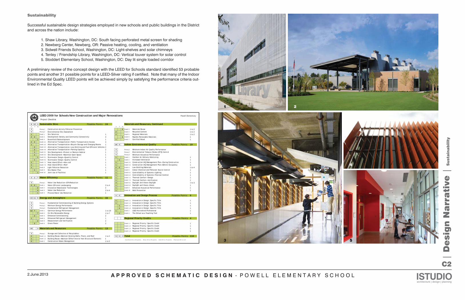
Successful sustainable design strategies employed in new schools and public buildings in the District and across the nation include: 1. Shaw Library, Washington, DC: South facing perforated metal screen for shading 2. Newberg Center, Newberg, OR: Passive heating, cooling, and ventilation 3. Sidwell Friends School, Washington, DC: Light-shelves and solar chimneys 4. Tenley / Friendship Library, Washington, DC: Vertical louver system for solar control 5. Stoddert Elementary School, Washington, DC: Day lit single loaded corridor A preliminary review of the concept design with the LEED for Schools standard identified 53 probable points and another 31 possible points for a LEED-Silver rating if certified. Note that many of the Indoor Environmental Quality LEED points will be achieved simply by satisfying the performance criteria out-lined in the Ed Spec.
3
4
2
5
1
A P P R O V E D S C H E M A T I C D E S I G N - P O W E L L E L E M E N T A R Y S C H O O L ISTUDIOarchitecture | design | planning
2.June.2013
C3
| D
esig
n N
arr
ati
ve |
Pe
rsp
ecti
ves
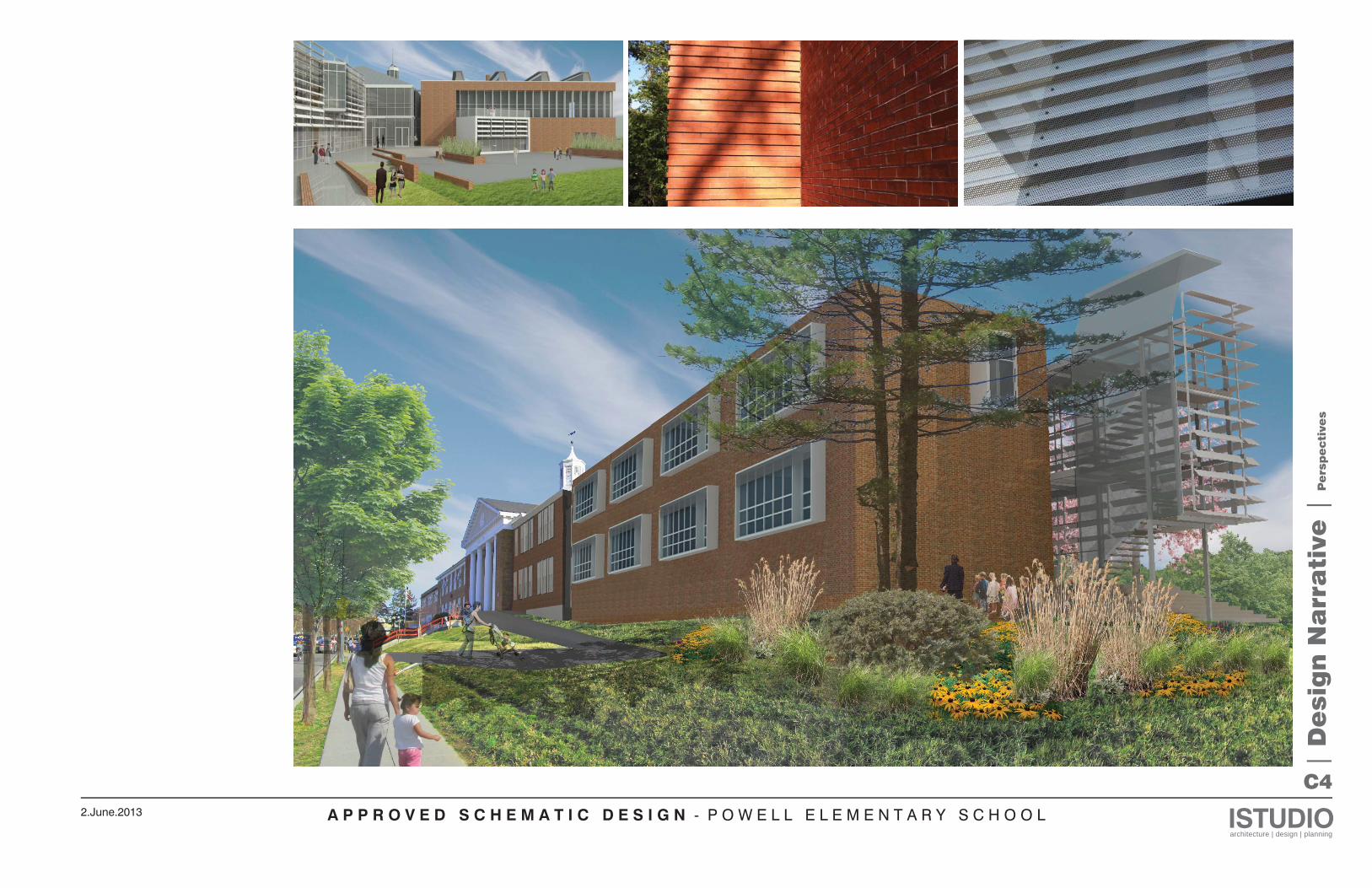
A P P R O V E D S C H E M A T I C D E S I G N - P O W E L L E L E M E N T A R Y S C H O O L ISTUDIOarchitecture | design | planning
2.June.2013
C4
| D
esig
n N
arr
ati
ve |
Pe
rsp
ecti
ves
A P P R O V E D S C H E M A T I C D E S I G N - P O W E L L E L E M E N T A R Y S C H O O L ISTUDIOarchitecture | design | planning
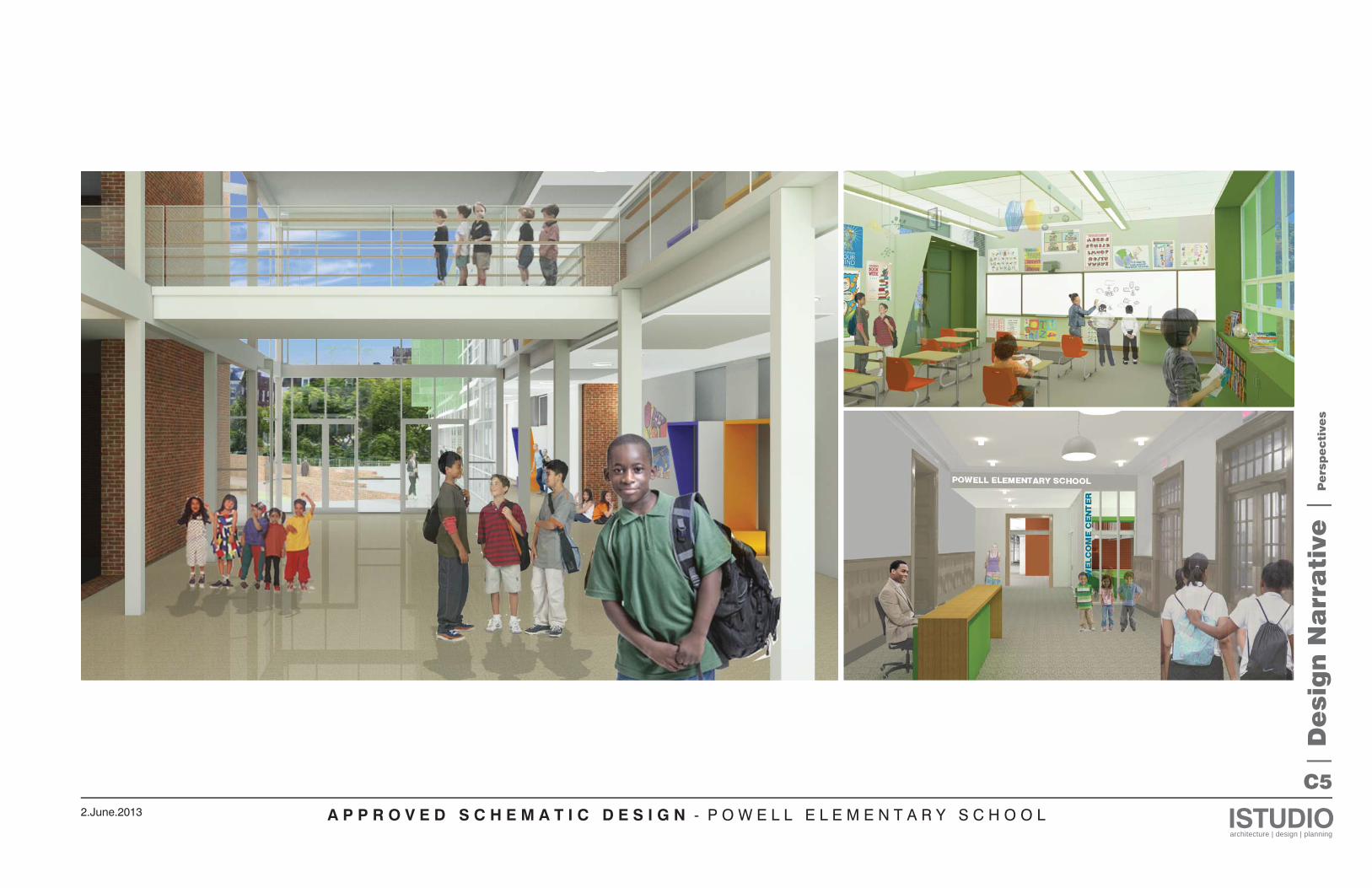
2.June.2013
C5
| D
esig
n N
arr
ati
ve |
Pe
rsp
ecti
ves
A P P R O V E D S C H E M A T I C D E S I G N - P O W E L L E L E M E N T A R Y S C H O O L ISTUDIOarchitecture | design | planning
2.June.2013
C6
L9B
L1
L3
F6
F4A
L4B
L5
L4A
L9BL2
L9B L9B
F4A
?
F4B
F3 F3 F3 F3 F3
CL.
F4B
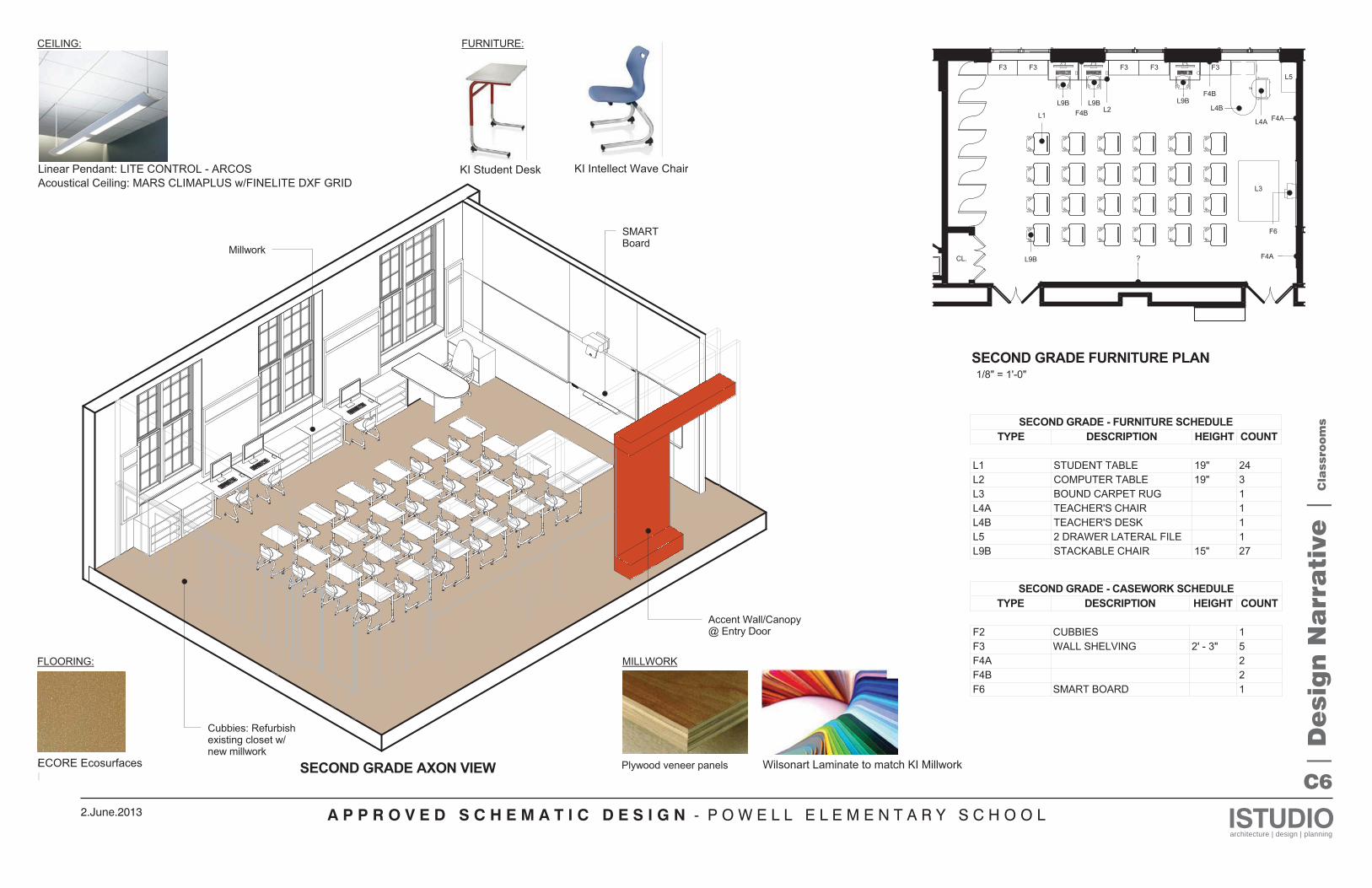
SECOND GRADE AXON VIEW
1/8" = 1'-0"SECOND GRADE FURNITURE PLAN
SECOND GRADE - FURNITURE SCHEDULETYPE DESCRIPTION HEIGHT COUNT
L1 STUDENT TABLE 19" 24L2 COMPUTER TABLE 19" 3L3 BOUND CARPET RUG 1L4A TEACHER'S CHAIR 1L4B TEACHER'S DESK 1L5 2 DRAWER LATERAL FILE 1L9B STACKABLE CHAIR 15" 27
SECOND GRADE - CASEWORK SCHEDULETYPE DESCRIPTION HEIGHT COUNT
F2 CUBBIES 1F3 WALL SHELVING 2' - 3" 5F4A 2F4B 2F6 SMART BOARD 1
CEILING:
Linear Pendant Fixture + Acoustical Ceiling
FURNITURE:
Student Desk Student Chair
FLOORING:
Cork/Rubber flooring (Option 1)Refinish existing floor (Option 2)
MILLWORK
Plywood veneer panels Laminate Countertop colors
Accent Wall/Canopy@ Entry Door
Millwork
SMARTBoard
Cubbies: Refurbishexisting closet w/new millwork
Linear Pendant: LITE CONTROL - ARCOS Acoustical Ceiling: MARS CLIMAPLUS w/FINELITE DXF GRID
KI Student Desk KI Intellect Wave Chair
Wilsonart Laminate to match KI MillworkECORE Ecosurfaces | D
esig
n N
arr
ati
ve |
Cla
ssro
om
s
A P P R O V E D S C H E M A T I C D E S I G N - P O W E L L E L E M E N T A R Y S C H O O L ISTUDIOarchitecture | design | planning
2.June.2013
C7
L3L4A
L5
L3
L4B
L1B
L1B
L9C
L1BL1B
L9C
L1B
L9C
L9B
L9C
L9C
F3 F3
F3 F3
F1B F1B F1B
L8L8
F6
F4A
F4A
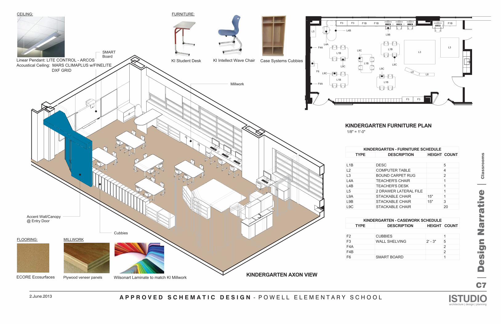
1/8" = 1'-0"KINDERGARTEN FURNITURE PLAN
KINDERGARTEN AXON VIEW
KINDERGARTEN - FURNITURE SCHEDULETYPE DESCRIPTION HEIGHT COUNT
L1B DESC 5L2 COMPUTER TABLE 4L3 BOUND CARPET RUG 2L4A TEACHER'S CHAIR 1L4B TEACHER'S DESK 1L5 2 DRAWER LATERAL FILE 1L9A STACKABLE CHAIR 15" 1L9B STACKABLE CHAIR 15" 3L9C STACKABLE CHAIR 20
KINDERGARTEN - CASEWORK SCHEDULETYPE DESCRIPTION HEIGHT COUNT
F2 CUBBIES 1F3 WALL SHELVING 2' - 3" 5F4A 2F4B 2F6 SMART BOARD 1
CEILING:
Linear Pendant Fixture + Acoustical Ceiling
Accent Wall/Canopy@ Entry Door
FLOORING:
FURNITURE:
Student Desk Student Chair
Cork/Rubber flooring
Cubbies
MILLWORK
Plywood veneer panels Laminate Countertop colors
Millwork
SMARTBoard
Cubbies
Linear Pendant: LITE CONTROL - ARCOS Acoustical Ceiling: MARS CLIMAPLUS w/FINELITE DXF GRID
KI Student Desk KI Intellect Wave Chair Case Systems Cubbies
ECORE Ecosurfaces Wilsonart Laminate to match KI Millwork | D
esig
n N
arr
ati
ve |
Cla
ssro
om
s
A P P R O V E D S C H E M A T I C D E S I G N - P O W E L L E L E M E N T A R Y S C H O O L ISTUDIOarchitecture | design | planning
2.June.2013
C8
L1
L9A
L5
L4B
L3
L3
L4AL9A
F3 F3 F3 F1 F1
F6
F4A
F4A
F2
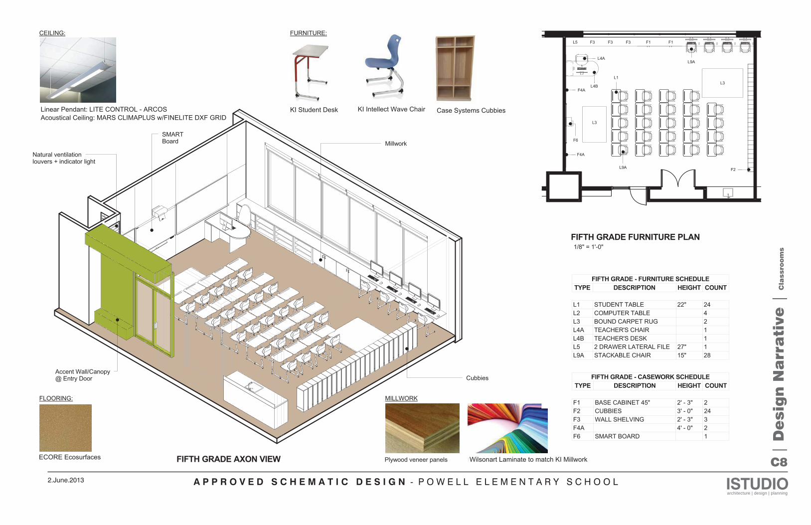
FIFTH GRADE AXON VIEW
1/8" = 1'-0"FIFTH GRADE FURNITURE PLAN
FIFTH GRADE - FURNITURE SCHEDULETYPE DESCRIPTION HEIGHT COUNT
L1 STUDENT TABLE 22" 24L2 COMPUTER TABLE 4L3 BOUND CARPET RUG 2L4A TEACHER'S CHAIR 1L4B TEACHER'S DESK 1L5 2 DRAWER LATERAL FILE 27" 1L9A STACKABLE CHAIR 15" 28
FIFTH GRADE - CASEWORK SCHEDULETYPE DESCRIPTION HEIGHT COUNT
F1 BASE CABINET 45" 2' - 3" 2F2 CUBBIES 3' - 0" 24F3 WALL SHELVING 2' - 3" 3F4A 4' - 0" 2F6 SMART BOARD 1
CEILING:
Linear Pendant Fixture + Acoustical Ceiling
Accent Wall/Canopy@ Entry Door
FLOORING:
Natural ventilationlouvers + indicator light
FURNITURE:
Student Desk Student Chair
Cork/Rubber flooring
Cubbies
MILLWORK
Plywood veneer panels Laminate Countertop colors
MillworkSMARTBoard
Cubbies
Linear Pendant: LITE CONTROL - ARCOS Acoustical Ceiling: MARS CLIMAPLUS w/FINELITE DXF GRID
KI Student Desk KI Intellect Wave Chair Case Systems Cubbies
Wilsonart Laminate to match KI MillworkECORE Ecosurfaces
| D
esig
n N
arr
ati
ve |
Cla
ssro
om
s
A P P R O V E D S C H E M A T I C D E S I G N - P O W E L L E L E M E N T A R Y S C H O O L ISTUDIOarchitecture | design | planning
2.June.2013
C9
| D
esig
n N
arr
ati
ve |
Bu
ild
ing
Sys
tem
s
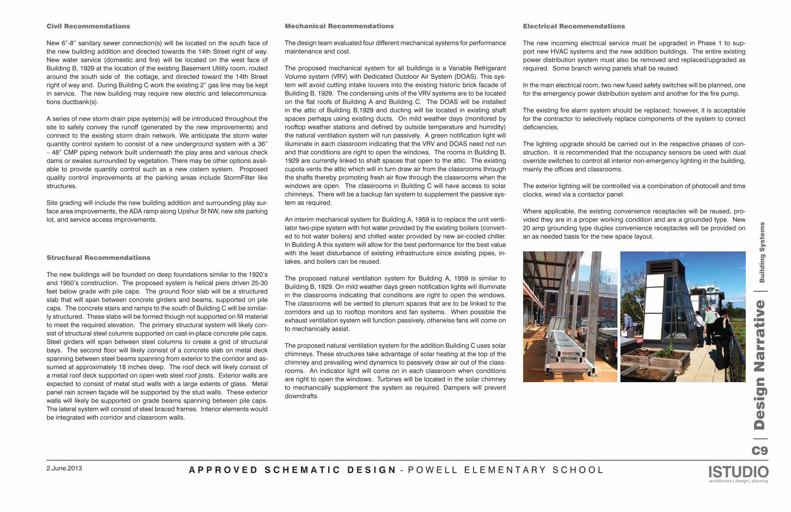
Structural Recommendations
The new buildings will be founded on deep foundations similar to the 1920’s and 1950’s construction. The proposed system is helical piers driven 25-30 feet below grade with pile caps. The ground floor slab will be a structured slab that will span between concrete girders and beams, supported on pile caps. The concrete stairs and ramps to the south of Building C will be similar-ly structured. These slabs will be formed though not supported on fill material to meet the required elevation. The primary structural system will likely con-sist of structural steel columns supported on cast-in-place concrete pile caps. Steel girders will span between steel columns to create a grid of structural bays. The second floor will likely consist of a concrete slab on metal deck spanning between steel beams spanning from exterior to the corridor and as-sumed at approximately 18 inches deep. The roof deck will likely consist of a metal roof deck supported on open-web steel roof joists. Exterior walls are expected to consist of metal stud walls with a large extents of glass. Metal panel rain screen façade will be supported by the stud walls. These exterior walls will likely be supported on grade beams spanning between pile caps. The lateral system will consist of steel braced frames. Interior elements would be integrated with corridor and classroom walls.
Electrical Recommendations
The new incoming electrical service must be upgraded in Phase 1 to sup-port new HVAC systems and the new addition buildings. The entire existing power distribution system must also be removed and replaced/upgraded as required. Some branch wiring panels shall be reused.
In the main electrical room, two new fused safety switches will be planned, one for the emergency power distribution system and another for the fire pump. The existing fire alarm system should be replaced; however, it is acceptable for the contractor to selectively replace components of the system to correct deficiencies.
The lighting upgrade should be carried out in the respective phases of con-struction. It is recommended that the occupancy sensors be used with dual override switches to control all interior non-emergency lighting in the building, mainly the offices and classrooms.
The exterior lighting will be controlled via a combination of photocell and time clocks, wired via a contactor panel.
Where applicable, the existing convenience receptacles will be reused, pro-vided they are in a proper working condition and are a grounded type. New 20 amp grounding type duplex convenience receptacles will be provided on an as needed basis for the new space layout.
Mechanical Recommendations
The design team evaluated four different mechanical systems for performance maintenance and cost.
The proposed mechanical system for all buildings is a Variable Refrigerant Volume system (VRV) with Dedicated Outdoor Air System (DOAS). This sys-tem will avoid cutting intake louvers into the existing historic brick facade of Building B, 1929. The condensing units of the VRV systems are to be located on the flat roofs of Building A and Building C. The DOAS will be installed in the attic of Building B,1929 and ducting will be located in existing shaft spaces perhaps using existing ducts. On mild weather days (monitored by rooftop weather stations and defined by outside temperature and humidity) the natural ventilation system will run passively. A green notification light will illuminate in each classroom indicating that the VRV and DOAS need not run and that conditions are right to open the windows. The rooms in Building B, 1929 are currently linked to shaft spaces that open to the attic. The existing cupola vents the attic which will in turn draw air from the classrooms through the shafts thereby promoting fresh air flow through the classrooms when the windows are open. The classrooms in Building C will have access to solar chimneys. There will be a backup fan system to supplement the passive sys-tem as required.
An interim mechanical system for Building A, 1959 is to replace the unit venti-lator two-pipe system with hot water provided by the existing boilers (convert-ed to hot water boilers) and chilled water provided by new air-cooled chiller. In Building A this system will allow for the best performance for the best value with the least disturbance of existing infrastructure since existing pipes, in-takes, and boilers can be reused.
The proposed natural ventilation system for Building A, 1959 is similar to Building B, 1929. On mild weather days green notification lights will illuminate in the classrooms indicating that conditions are right to open the windows. The classrooms will be vented to plenum spaces that are to be linked to the corridors and up to rooftop monitors and fan systems. When possible the exhaust ventilation system will function passively, otherwise fans will come on to mechanically assist.
The proposed natural ventilation system for the addition Building C uses solar chimneys. These structures take advantage of solar heating at the top of the chimney and prevailing wind dynamics to passively draw air out of the class-rooms. An indicator light will come on in each classroom when conditions are right to open the windows. Turbines will be located in the solar chimney to mechanically supplement the system as required. Dampers will prevent downdrafts.
Civil Recommendations
New 6”-8” sanitary sewer connection(s) will be located on the south face of the new building addition and directed towards the 14th Street right of way. New water service (domestic and fire) will be located on the west face of Building B, 1929 at the location of the existing Basement Utility room, routed around the south side of the cottage, and directed toward the 14th Street right of way and. During Building C work the existing 2” gas line may be kept in service. The new building may require new electric and telecommunica-tions ductbank(s).
A series of new storm drain pipe system(s) will be introduced throughout the site to safely convey the runoff (generated by the new improvements) and connect to the existing storm drain network. We anticipate the storm water quantity control system to consist of a new underground system with a 36” – 48” CMP piping network built underneath the play area and various check dams or swales surrounded by vegetation. There may be other options avail-able to provide quantity control such as a new cistern system. Proposed quality control improvements at the parking areas include StormFilter like structures.
Site grading will include the new building addition and surrounding play sur-face area improvements, the ADA ramp along Upshur St NW, new site parking lot, and service access improvements.
A P P R O V E D S C H E M A T I C D E S I G N - P O W E L L E L E M E N T A R Y S C H O O L ISTUDIOarchitecture | design | planning
2.June.2013
C10
| D
esig
n N
arr
ati
ve |
Bu
ild
ing
Sys
tem
s
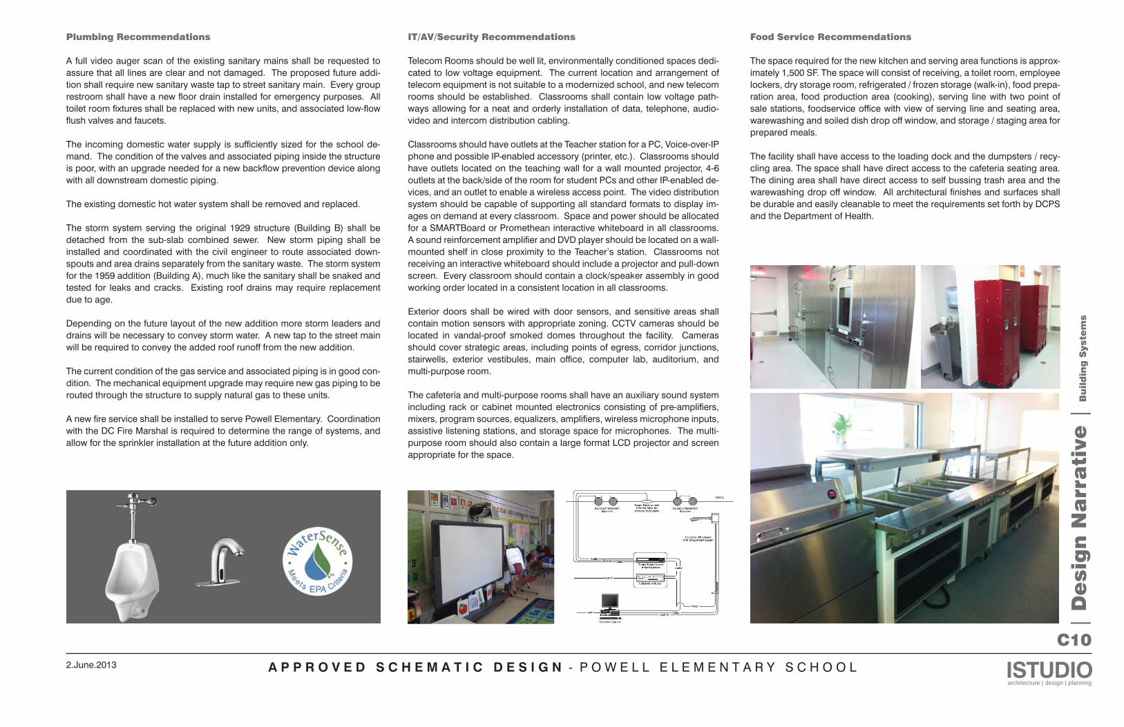
Plumbing Recommendations
A full video auger scan of the existing sanitary mains shall be requested to assure that all lines are clear and not damaged. The proposed future addi-tion shall require new sanitary waste tap to street sanitary main. Every group restroom shall have a new floor drain installed for emergency purposes. All toilet room fixtures shall be replaced with new units, and associated low-flow flush valves and faucets.
The incoming domestic water supply is sufficiently sized for the school de-mand. The condition of the valves and associated piping inside the structure is poor, with an upgrade needed for a new backflow prevention device along with all downstream domestic piping.
The existing domestic hot water system shall be removed and replaced.
The storm system serving the original 1929 structure (Building B) shall be detached from the sub-slab combined sewer. New storm piping shall be installed and coordinated with the civil engineer to route associated down-spouts and area drains separately from the sanitary waste. The storm system for the 1959 addition (Building A), much like the sanitary shall be snaked and tested for leaks and cracks. Existing roof drains may require replacement due to age.
Depending on the future layout of the new addition more storm leaders and drains will be necessary to convey storm water. A new tap to the street main will be required to convey the added roof runoff from the new addition. The current condition of the gas service and associated piping is in good con-dition. The mechanical equipment upgrade may require new gas piping to be routed through the structure to supply natural gas to these units.
A new fire service shall be installed to serve Powell Elementary. Coordination with the DC Fire Marshal is required to determine the range of systems, and allow for the sprinkler installation at the future addition only.
Food Service Recommendations
The space required for the new kitchen and serving area functions is approx-imately 1,500 SF. The space will consist of receiving, a toilet room, employee lockers, dry storage room, refrigerated / frozen storage (walk-in), food prepa-ration area, food production area (cooking), serving line with two point of sale stations, foodservice office with view of serving line and seating area, warewashing and soiled dish drop off window, and storage / staging area for prepared meals.
The facility shall have access to the loading dock and the dumpsters / recy-cling area. The space shall have direct access to the cafeteria seating area. The dining area shall have direct access to self bussing trash area and the warewashing drop off window. All architectural finishes and surfaces shall be durable and easily cleanable to meet the requirements set forth by DCPS and the Department of Health.
IT/AV/Security Recommendations
Telecom Rooms should be well lit, environmentally conditioned spaces dedi-cated to low voltage equipment. The current location and arrangement of telecom equipment is not suitable to a modernized school, and new telecom rooms should be established. Classrooms shall contain low voltage path-ways allowing for a neat and orderly installation of data, telephone, audio-video and intercom distribution cabling.
Classrooms should have outlets at the Teacher station for a PC, Voice-over-IP phone and possible IP-enabled accessory (printer, etc.). Classrooms should have outlets located on the teaching wall for a wall mounted projector, 4-6 outlets at the back/side of the room for student PCs and other IP-enabled de-vices, and an outlet to enable a wireless access point. The video distribution system should be capable of supporting all standard formats to display im-ages on demand at every classroom. Space and power should be allocated for a SMARTBoard or Promethean interactive whiteboard in all classrooms. A sound reinforcement amplifier and DVD player should be located on a wall-mounted shelf in close proximity to the Teacher’s station. Classrooms not receiving an interactive whiteboard should include a projector and pull-down screen. Every classroom should contain a clock/speaker assembly in good working order located in a consistent location in all classrooms.
Exterior doors shall be wired with door sensors, and sensitive areas shall contain motion sensors with appropriate zoning. CCTV cameras should be located in vandal-proof smoked domes throughout the facility. Cameras should cover strategic areas, including points of egress, corridor junctions, stairwells, exterior vestibules, main office, computer lab, auditorium, and multi-purpose room.
The cafeteria and multi-purpose rooms shall have an auxiliary sound system including rack or cabinet mounted electronics consisting of pre-amplifiers, mixers, program sources, equalizers, amplifiers, wireless microphone inputs, assistive listening stations, and storage space for microphones. The multi-purpose room should also contain a large format LCD projector and screen appropriate for the space.
A P P R O V E D S C H E M A T I C D E S I G N - P O W E L L E L E M E N T A R Y S C H O O L ISTUDIOarchitecture | design | planning
2.June.2013
D1
1. PROJECT INTRODUCTION
The project scope calls for the existing Powell Elementary School Building to be expanded to include a new addition to be built on the west side of the existing Building B, 1929 building. This work will be performed in phases as part of the Master Plan in which the first addition will consist of a 13,500 s.f. building addition (Building C Addition). The second building addition will occur in the future and will consist of a 24,000s.f. building addition (Building D addition). There will be other site improvements made to enhance the uses of the existing and new work being built. The improvements include but are not limited to a new ADA accessibility path along the front entrance from Upshur Street, N.W. Underground utility improvements will also be included as part of the improvements for this school.
2. EXISTING BUILDING STRUCTURE/FOUNDATION
The existing building B, 1929 and the existing Building A 1959 additions will be maintained as part of these improvements. There will be minor exterior modifications required for the new Building C addition to be made. The location of the existing school structure will create a challenge in terms of having adequate access for the contractor to use. Direct vehicle access from any of the two main streets will not be possible due to the significant grade changes. The existing temporary classrooms currently located on the asphalt play area will remain in operation during this first building C addition.
3. SITE UTILITIES
The adjacent roads and driveways are currently improved with the utilities required for construction, (i.e. sanitary sewer, water, storm drains, gas and electric). The new water service (domestic and fire services) will be made to the existing water line on 14th Street, N.W. The new sanitary service lateral will also be made to the existing system on 14th Street N.W. The new storm drain pipe connection(s) needed to discharge the onsite runoff will be made to the system on 14th Street N.W. The other utility connections for telephone, electric and gas will be made toward the public alley (south side of property).We do not anticipate a new utility connections to be made to the Upshur Street right of way.
Review of public utility records made available did not indicate the exact location (vertical and horizontal) of utilities found within the project work limits, except for an inlet on the asphalt surface and other indiscriminant tops/covers. The horizontal location of utilities within the project limits were located and shown on the plans according to available records. The horizontal location of gravity systems is indicated on the existing conditions plan based on record data and/or field observation. However, the vertical location of the non-gravity
systems, (i.e. gas, telephone, electric, etc) was not field verified and are only shown per records made available. Therefore, the absence of either as-built plans or field test holes will require the contractor to engage in some type of exploration for non-gravity utility systems in advance of engaging new utility/site work. The contractor will need to get involved in conducting test pit(s) to determine the actual depth of the non-gravity systems located within the project work limits. This is needed in order to assure clearances are adhered between new and existing utilities. The following is a summary of utility services and how they will be implemented: Sanitary Sewer – New 6”-8” sanitary sewer connection(s) will be located on the south face of the new building C addition and directed towards 14th Street right of way. The 6”-8” PVC lateral connection(s) will be made to the existing 15” sanitary sewer line that runs in a north-south direction along 14th Street. The length of run for the sanitary service(s) is anticipated to be 250l.f. Water Line–New water service (Domestic and Fire) will be located on the south face of the new building addition and directed toward the 14th Street right of way. The alignment of the new water tap will be made so as to not impact the existing temporary trailers. Therefore the new water service lines will run in an east-west direction to allow the waterline to enter the current water meter area inside the building B 1929 basement. The size of the domestic water service is anticipated to be 4” DIP Class 52. The size of the fire water service is shown to be 8” DIP Class 52. Other water line work may also be needed as it relates to new fire hydrant(s) to new locations that are better suited with the new improvements. The length of run for the water service(s) is anticipated to be 250l.f. A water meter vault as well as a back flow preventer(s) will be installed as part of the new water line improvements. Gas Line – The existing gas service that originates along 14th Street may need to be rerouted as part of the improvements indicated on the Master Plan. However, during the first addition work this existing 2” gas line may be kept in service. The existing gas main runs east to west from 14th Street directly into the existing building B. The point of connection for the new gas service is not known at this time. We are in the process of determining if it is a high or low pressure system. Electric Service – There are various electric ductbanks that run along the rear public alley which serve the light poles and building main service. The existing electric service is believed to be routed toward the public alley where the underground ductbanks and electric manholes are found to exist. This system will remain in operation during the building C addition phase of work. The new building will require new electric ductbank(s) primary and secondary to and from new pad mounted electric transformer(s). The location of these electrical systems is not known at this time. New light poles may be required to provide adequate safe areas around the site. Refer to electrical engineers narrative for more detailed information. |
De
tail
ed
Re
po
rts |
Civ
il A
sse
ssm
en
t
Civil Assessment
A P P R O V E D S C H E M A T I C D E S I G N - P O W E L L E L E M E N T A R Y S C H O O L ISTUDIOarchitecture | design | planning
2.June.2013
D2
Telecommunications – A new telecommunications ductbank running parallel with the new electrical ductbank will be required as part of this construction. A new telephone manhole may be required to be constructed near the elec. /telephone room. The location of an existing telephone manhole is not yet known but, further investigation will be required to confirm the existing service location.
4. EROSION AND SEDIMENT CONTROL
A full engineered sediment control application will be required to be filed to the DDOE for review and approval.
5. STORM DRAINAGE
A series of new storm drain pipe(s) system(s) will be introduced throughout the site to safely convey the runoff (generated by the new improvements) and connect to the existing storm drain network. The pipe sizes will vary from 6” to 18” Dia. depending on the drainage area and purpose of the pipe(s). There is an existing storm drain grate inlet located along the northern edge of the asphalt play area that accepting runoff which has filled up with silt/debris and outlet pipe cannot be determined. We intend to keep this inlet in place and use it as our point of discharge provided it has the adequate inverts to discharge properly. The point of connection for the new storm drainage system will be this structure unless field conditions dictate otherwise. It is very possible that a new storm drain connection to the existing 18” Sewer located in public will be required.
The new ADA handicap ramps and other impervious surface improvements will require the installation of trench drains to receive the runoff and will be directed toward a nearby LID system or small quality treatment structure (WQS-1) consisting of StormFilter MH type of device to treat the localized runoff. The main parking area and service access will need to be graded to drain to a low point where a series of trench/inlet type structures will direct the runoff towards another localized LID system or Stormfilter MH type structure. The top/slab(s) of the storm structures will need to be designed to allow H-20 type loads. There are very limited inlets/structures found within the parking lot and play surface areas. The new building C addition area as well as the remaining play areas may be subject to localized ponding whenever storm events occur that are greater than the 15yr storm event. In such instances new structure(s) will be introduced at key locations to serve as an emergency spillway to convey surface runoff and direct it away from the building and toward the nearby stormwater system(s) of adequate capacity to handle the additional runoff. The public alley located in the back of the site will present a challenge in terms of providing adequate surface drainage relief. The current site conditions indicate the surfaces to be inadequate and in need of maintenance/repair. Unfortunately the cost for such effort may prove too high to include it as part of the first addition work. Our recommendations will include minimal repairs and
overlay to minimize low ponding areas. Any new parking that may be sited along the alley will be evaluated to make sure it meets DDOT and DCRA regulations.
6. STORMWATER MANAGEMENT
A review of the District of Columbia’s Department of the Environment (DDOE) related to the Stormwater Management (SWM) requirements for this project will require SWM Quantity &Quality Control for the impervious area created by the proposed building and associated improvements. We anticipate the quantity control system to provide for this project to consist of a new underground system consisting of 36” – 48” CMP piping network built underneath the play area. There may be other options available to provide the quantity control required by DDOE including but not limited to surface check dams along the perimeter of the site which may be surrounded by vegetation. Another method to provide some quantity control could be the use of a new cistern system that will be used to service the building. It is our understanding based on recent experience that DDOE will allow a cistern to hold the required volume provided it does not receive any untreated runoff from parking lots/streets/driveways that may be carrying grit and oils. We primarily intend to direct the drainage of any driveway/parking areas to a water quality treatment structure before it is piped into the cistern. DDOE views any parking/loading surfaces as the primary target areas that are subject to many types of pollutants and forms of debris (solids as well as in liquid form such as oil, chemicals) that will enter the trench drain. To minimize the impact the runoff will have on the new WQS structure, a pre-treatment structure will be introduced to treat oil and grit being generated. The manhole structure will have a permanent 3’ deep water pool at the bottom.
As previously mentioned the storm quality treatment will be provided by introducing StormFilter like structures along the asphalt pavement surfaces that are subject to vehicular traffic. One main structure (Stormfilter type) is anticipated to be sited to handle most of the new impervious work. It will be placed at a location sufficiently enough to enable a gravity system to discharge into the existing sewer system. The StormFilter structures will be sized to meet the minimum requirements of the DDOE regulations. The preliminary size of each of these precast treatment structures is 9’ wide x 17’ long and 8’ high. Each structure will contain approx. 8-18 cartridges filled with selected materials for treatment purposes.
The StormFilter structures will be sized to not only meet the minimum requirement of the DDOE but, also meet the LEED certification criteria. Some of the roof areas may be green and may receive some form of irrigation from a new cistern. It is not clear at the moment what percentage of the roof may be green but if is feasible a cistern will be sited for irrigation purposes. A preliminary size of the cistern is anything between a 15,000 - 30,000 gallon tank.
7. SITE GRADING & AMENITIES |
De
tail
ed
Re
po
rts |
Civ
il A
sse
ssm
en
t
A P P R O V E D S C H E M A T I C D E S I G N - P O W E L L E L E M E N T A R Y S C H O O L ISTUDIOarchitecture | design | planning
2.June.2013
D3
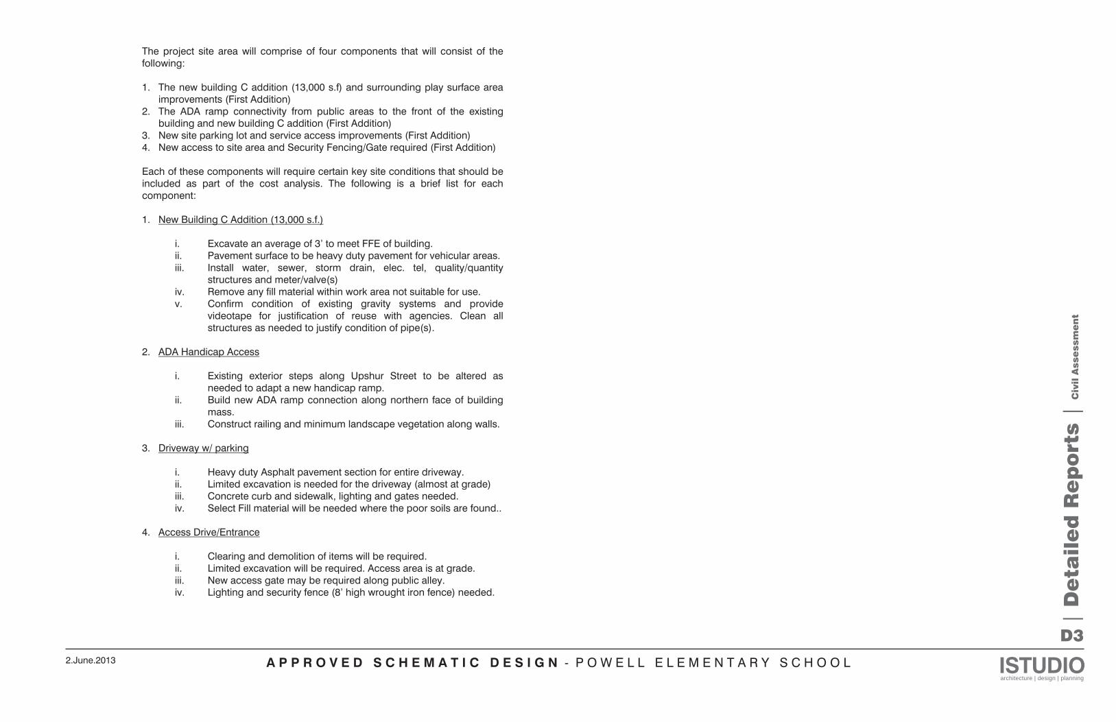
The project site area will comprise of four components that will consist of the following: 1. The new building C addition (13,000 s.f) and surrounding play surface area
improvements (First Addition) 2. The ADA ramp connectivity from public areas to the front of the existing
building and new building C addition (First Addition) 3. New site parking lot and service access improvements (First Addition) 4. New access to site area and Security Fencing/Gate required (First Addition)
Each of these components will require certain key site conditions that should be included as part of the cost analysis. The following is a brief list for each component: 1. New Building C Addition (13,000 s.f.)
i. Excavate an average of 3’ to meet FFE of building. ii. Pavement surface to be heavy duty pavement for vehicular areas. iii. Install water, sewer, storm drain, elec. tel, quality/quantity
structures and meter/valve(s) iv. Remove any fill material within work area not suitable for use. v. Confirm condition of existing gravity systems and provide
videotape for justification of reuse with agencies. Clean all structures as needed to justify condition of pipe(s).
2. ADA Handicap Access
i. Existing exterior steps along Upshur Street to be altered as
needed to adapt a new handicap ramp. ii. Build new ADA ramp connection along northern face of building
mass. iii. Construct railing and minimum landscape vegetation along walls.
3. Driveway w/ parking
i. Heavy duty Asphalt pavement section for entire driveway. ii. Limited excavation is needed for the driveway (almost at grade) iii. Concrete curb and sidewalk, lighting and gates needed. iv. Select Fill material will be needed where the poor soils are found..
4. Access Drive/Entrance
i. Clearing and demolition of items will be required. ii. Limited excavation will be required. Access area is at grade. iii. New access gate may be required along public alley. iv. Lighting and security fence (8’ high wrought iron fence) needed.
| D
eta
ile
d R
ep
ort
s |
Civ
il A
sse
ssm
en
t
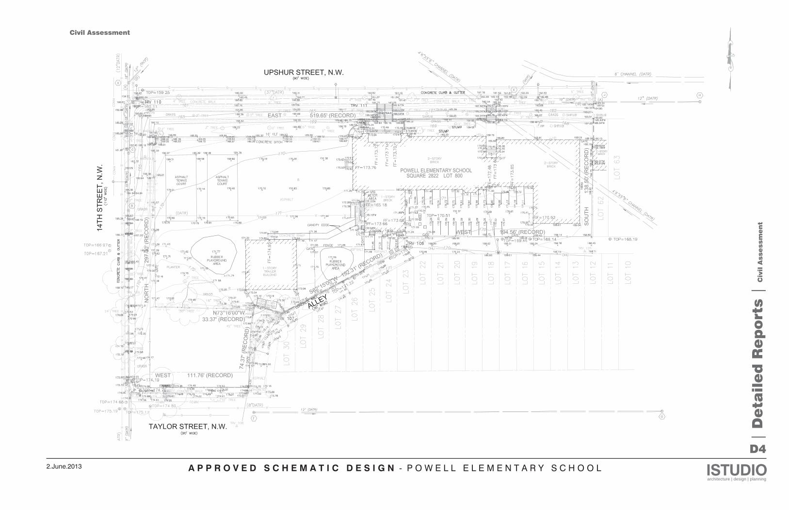
A P P R O V E D S C H E M A T I C D E S I G N - P O W E L L E L E M E N T A R Y S C H O O L ISTUDIOarchitecture | design | planning
2.June.2013
D4
Civil Assessment
| D
eta
ile
d R
ep
ort
s |
Civ
il A
sse
ssm
en
t
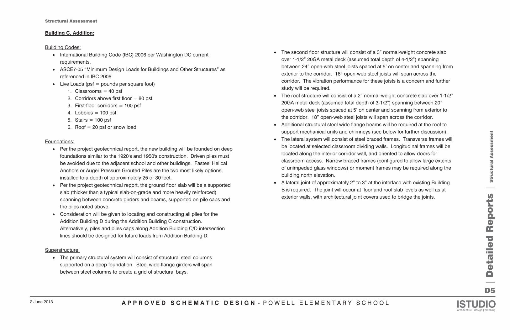
A P P R O V E D S C H E M A T I C D E S I G N - P O W E L L E L E M E N T A R Y S C H O O L ISTUDIOarchitecture | design | planning
2.June.2013
D5
| D
eta
ile
d R
ep
ort
s |
Str
uctu
ral
Asse
ssm
en
t
Structural Assessment Building C, Addition: Building Codes:
International Building Code (IBC) 2006 per Washington DC current requirements. ASCE7-05 “Minimum Design Loads for Buildings and Other Structures” as referenced in IBC 2006 Live Loads (psf = pounds per square foot)
1. Classrooms = 40 psf 2. Corridors above first floor = 80 psf 3. First-floor corridors = 100 psf 4. Lobbies = 100 psf 5. Stairs = 100 psf 6. Roof = 20 psf or snow load
Foundations:
Per the project geotechnical report, the new building will be founded on deep foundations similar to the 1920's and 1950's construction. Driven piles must be avoided due to the adjacent school and other buildings. Fasteel Helical Anchors or Auger Pressure Grouted Piles are the two most likely options, installed to a depth of approximately 25 or 30 feet. Per the project geotechnical report, the ground floor slab will be a supported slab (thicker than a typical slab-on-grade and more heavily reinforced) spanning between concrete girders and beams, supported on pile caps and the piles noted above. Consideration will be given to locating and constructing all piles for the Addition Building D during the Addition Building C construction. Alternatively, piles and piles caps along Addition Building C/D intersection lines should be designed for future loads from Addition Building D.
Superstructure:
The primary structural system will consist of structural steel columns supported on a deep foundation. Steel wide-flange girders will span between steel columns to create a grid of structural bays.
The second floor structure will consist of a 3” normal-weight concrete slab over 1-1/2” 20GA metal deck (assumed total depth of 4-1/2”) spanning between 24” open-web steel joists spaced at 5’ on center and spanning from exterior to the corridor. 18” open-web steel joists will span across the corridor. The vibration performance for these joists is a concern and further study will be required. The roof structure will consist of a 2” normal-weight concrete slab over 1-1/2” 20GA metal deck (assumed total depth of 3-1/2”) spanning between 20” open-web steel joists spaced at 5’ on center and spanning from exterior to the corridor. 18” open-web steel joists will span across the corridor. Additional structural steel wide-flange beams will be required at the roof to support mechanical units and chimneys (see below for further discussion). The lateral system will consist of steel braced frames. Transverse frames will be located at selected classroom dividing walls. Longitudinal frames will be located along the interior corridor wall, and oriented to allow doors for classroom access. Narrow braced frames (configured to allow large extents of unimpeded glass windows) or moment frames may be required along the building north elevation. A lateral joint of approximately 2” to 3” at the interface with existing Building B is required. The joint will occur at floor and roof slab levels as well as at exterior walls, with architectural joint covers used to bridge the joints.
A P P R O V E D S C H E M A T I C D E S I G N - P O W E L L E L E M E N T A R Y S C H O O L ISTUDIOarchitecture | design | planning
2.June.2013
D6
| D
eta
ile
d R
ep
ort
s |
Str
uctu
ral
Asse
ssm
en
t
Site Exterior Slab/Stair/Ramp The proposed patio, stair, and ramp located between Addition Building C and Addition Building D will be a concrete slab supported on concrete piles, similar to the building ground floor slab, as described above. Alternatively, provided that minor settlement can be allowed for this patio, an alternate system without deep foundations can be constructed. The process is further described in the project geotechnical report, but can be summarized as removal of approximately 2.5 feet of soil and replacement with a geogrid mat and various of layers of graded stone up to the slab sub-grade level.
Non-Structural Elements:
Exterior walls are expected to consist of cold-formed steel (metal stud) framing with large extents of glass. At heavier brick cladding (potentially along the north face of the building to match the existing structures), masonry backing walls may be used. Two or three solar chimneys are expected to be located at the roof, constructed of a structural steel angle braced frame and clad with cold-formed steel “furring” and architectural finishes. The chimneys are expected to be squares with sides of 2’ to 3’ and extend approximately 10’ above the roof level. New mechanical units will be located at grade, not on the roof of Building C. The majority of the remaining roof area will be a green roof. At present the green roof system is assumed to weigh approximately 40 pounds per square foot (psf). At the building’s south elevation, a perforated metal panel solar screen is to be constructed. The screen would be supported by a structural steel frame cantilevering out at floor and roof levels of the building. Thermal isolation/break would be provided by using bolted connections and a product similar to Fabreeka’s Thermal Insulation Material. New open stairs are to be constructed at the west end of the addition.
Addition Building D: Building Codes:
See Building C, above. Slight modifications may be required as the local authority having jurisdiction prepares to move to a new version of the IBC.
Foundations:
Similar to Addition Building C, the new building is expected to be founded on deep foundations (see above for further information) Similar to Addition Building C, the ground floor will require a supported slab (see above for further information). Consideration should be given to the interface between Addition Building C and Addition Building D with respect to prior design consideration of Addition Building D pile locations and design loads.
Superstructure:
The primary structural system is expected to consist of structural steel columns supported on a deep foundation. Steel wide-flange girders will span between steel columns to create a grid of structural bays. The second floor structure will consist of a 3” normal-weight concrete slab over 1-1/2” 20GA metal deck (assumed total depth of 4-1/2”) spanning between open-web steel joists spaced at approximately 5’-0” on center. The vibration performance for these joists is a concern and further study will be required. The roof structure will consist of a 2” normal-weight concrete slab over 1-1/2” 20GA metal deck (assumed total depth of 3-1/2”) spanning between open-web steel joists spaced at approximately 5’-0” on center. Additional structural steel wide-flange beams will be required at the roof to support mechanical units. The lateral system will consist of transverse and longitudinal steel braced frames, locations to be determined. Narrow braced frames (configured to allow large extents of unimpeded glass windows) or moment frames may be required along the exterior building elevations.
A P P R O V E D S C H E M A T I C D E S I G N - P O W E L L E L E M E N T A R Y S C H O O L ISTUDIOarchitecture | design | planning
2.June.2013
D7
| D
eta
ile
d R
ep
ort
s |
Str
uctu
ral
Asse
ssm
en
t
A lateral joint of approximately 2” to 3” at the interface with existing Building B and with Addition Building C will be required. The joint will occur at floor and roof slab levels as well as at exterior walls, with architectural joint covers used to bridge the joints.
“Non-Structural” Elements: Exterior walls are expected to consist of cold-formed steel (metal stud) framing with large extents of glass. At heavier brick cladding, masonry backing walls may be used.
Phase 1 Modernization:
No structural work anticipated. Phase 2 Modernization:
No structural work anticipated. Phase 3 Modernization:
Stairs at the northwest corner (adjacent to the new addition’s interior stair) of Building B (constructed 1929) are expected to be infilled to create additional floor space. Infill framing would consist of concrete fill on metal deck spanning between steel beams anchored into the existing structure. The roof structure (including attic space) of Building B may have capacity for isolated light-weight units only. VRV cassettes will be supported at and penetrate the existing plaster ceiling. The existing mechanical unit located in the Building B attic directly below the cupola is expected to be replaced with a DOAS (dedicated outdoor air system) unit of approximately the same size and weight. The capacity of the existing framing to support this load is to be verified. A fan may be located at part of the cupola opening as part of the Phase 1 renovation, before the DOAS is added in a later phase.
Due to the DOAS’ large dimensions, careful consideration should be given to the method for placing it in the existing attic space. Assembling from smaller components within the attic may be necessary and/or a new opening in the gable end wall of the existing brick masonry may be provided. This opening would likely be required as a louver in any case. VRV condensers (approximately 6’ by 6’ and weighing 1500 pounds) may need to be located at the roof of Building A (constructed 1959). It is expected that the units could be located directly over concrete columns to avoid the need for strengthening of the existing slab. Alternatively, steel platforms could be constructed to span between existing concrete columns and avoid loading the existing roof structure at all. New openings through existing concrete floor and roof slabs should be sized and located to avoid concrete joists. New openings through existing hollow-clay tile partitions walls are also possible, but may turn out to be troublesome due to the weak (and often damaged) nature of these walls. Replacement of some or all of the walls (at least at the 2nd floor where damaged) with new metal stud partitions may be worth considering. Careful study should be made as to the insulation of the existing brick walls due to potential negative effects on masonry.
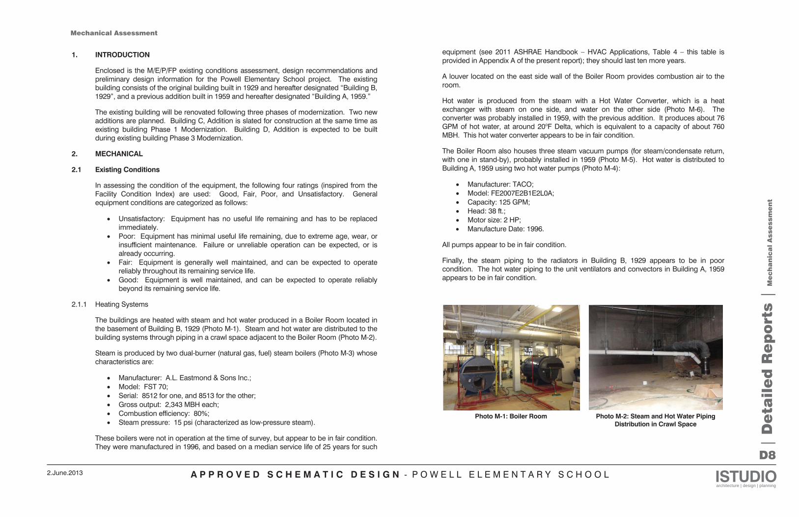
A P P R O V E D S C H E M A T I C D E S I G N - P O W E L L E L E M E N T A R Y S C H O O L ISTUDIOarchitecture | design | planning
2.June.2013
D8
| D
eta
ile
d R
ep
ort
s |
Me
ch
an
ica
l A
sse
ssm
en
t
1. INTRODUCTION
Enclosed is the M/E/P/FP existing conditions assessment, design recommendations and preliminary design information for the Powell Elementary School project. The existing building consists of the original building built in 1929 and hereafter designated “Building B, 1929”, and a previous addition built in 1959 and hereafter designated “Building A, 1959.”
The existing building will be renovated following three phases of modernization. Two new additions are planned. Building C, Addition is slated for construction at the same time as existing building Phase 1 Modernization. Building D, Addition is expected to be built during existing building Phase 3 Modernization.
2. MECHANICAL
2.1 Existing Conditions
In assessing the condition of the equipment, the following four ratings (inspired from the Facility Condition Index) are used: Good, Fair, Poor, and Unsatisfactory. General equipment conditions are categorized as follows:
Unsatisfactory: Equipment has no useful life remaining and has to be replaced immediately. Poor: Equipment has minimal useful life remaining, due to extreme age, wear, or insufficient maintenance. Failure or unreliable operation can be expected, or is already occurring. Fair: Equipment is generally well maintained, and can be expected to operate reliably throughout its remaining service life. Good: Equipment is well maintained, and can be expected to operate reliably beyond its remaining service life.
2.1.1 Heating Systems
The buildings are heated with steam and hot water produced in a Boiler Room located in the basement of Building B, 1929 (Photo M-1). Steam and hot water are distributed to the building systems through piping in a crawl space adjacent to the Boiler Room (Photo M-2).
Steam is produced by two dual-burner (natural gas, fuel) steam boilers (Photo M-3) whose characteristics are:
Manufacturer: A.L. Eastmond & Sons Inc.; Model: FST 70; Serial: 8512 for one, and 8513 for the other; Gross output: 2,343 MBH each; Combustion efficiency: 80%; Steam pressure: 15 psi (characterized as low-pressure steam).
These boilers were not in operation at the time of survey, but appear to be in fair condition. They were manufactured in 1996, and based on a median service life of 25 years for such
equipment (see 2011 ASHRAE Handbook – HVAC Applications, Table 4 – this table is provided in Appendix A of the present report); they should last ten more years.
A louver located on the east side wall of the Boiler Room provides combustion air to the room.
Hot water is produced from the steam with a Hot Water Converter, which is a heat exchanger with steam on one side, and water on the other side (Photo M-6). The converter was probably installed in 1959, with the previous addition. It produces about 76 GPM of hot water, at around 20oF Delta, which is equivalent to a capacity of about 760 MBH. This hot water converter appears to be in fair condition.
The Boiler Room also houses three steam vacuum pumps (for steam/condensate return, with one in stand-by), probably installed in 1959 (Photo M-5). Hot water is distributed to Building A, 1959 using two hot water pumps (Photo M-4):
Manufacturer: TACO; Model: FE2007E2B1E2L0A; Capacity: 125 GPM; Head: 38 ft.; Motor size: 2 HP; Manufacture Date: 1996.
All pumps appear to be in fair condition.
Finally, the steam piping to the radiators in Building B, 1929 appears to be in poor condition. The hot water piping to the unit ventilators and convectors in Building A, 1959 appears to be in fair condition.
Photo M-1: Boiler Room Photo M-2: Steam and Hot Water Piping
Distribution in Crawl Space
Mechanical Assessment
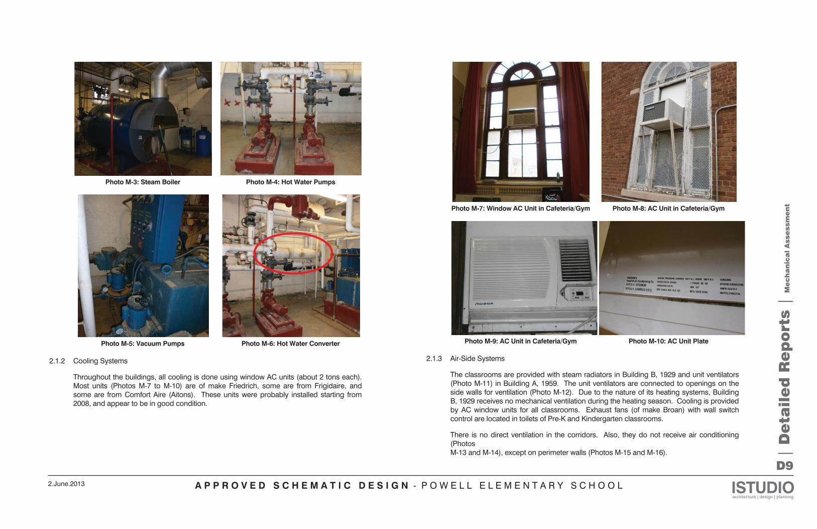
A P P R O V E D S C H E M A T I C D E S I G N - P O W E L L E L E M E N T A R Y S C H O O L ISTUDIOarchitecture | design | planning
2.June.2013
D9
| D
eta
ile
d R
ep
ort
s |
Me
ch
an
ica
l A
sse
ssm
en
t
Photo M-3: Steam Boiler Photo M-4: Hot Water Pumps
Photo M-5: Vacuum Pumps Photo M-6: Hot Water Converter 2.1.2 Cooling Systems
Throughout the buildings, all cooling is done using window AC units (about 2 tons each). Most units (Photos M-7 to M-10) are of make Friedrich, some are from Frigidaire, and some are from Comfort Aire (Aitons). These units were probably installed starting from 2008, and appear to be in good condition.
Photo M-7: Window AC Unit in Cafeteria/Gym Photo M-8: AC Unit in Cafeteria/Gym
Photo M-9: AC Unit in Cafeteria/Gym Photo M-10: AC Unit Plate 2.1.3 Air-Side Systems
The classrooms are provided with steam radiators in Building B, 1929 and unit ventilators (Photo M-11) in Building A, 1959. The unit ventilators are connected to openings on the side walls for ventilation (Photo M-12). Due to the nature of its heating systems, Building B, 1929 receives no mechanical ventilation during the heating season. Cooling is provided by AC window units for all classrooms. Exhaust fans (of make Broan) with wall switch control are located in toilets of Pre-K and Kindergarten classrooms.
There is no direct ventilation in the corridors. Also, they do not receive air conditioning (Photos M-13 and M-14), except on perimeter walls (Photos M-15 and M-16).
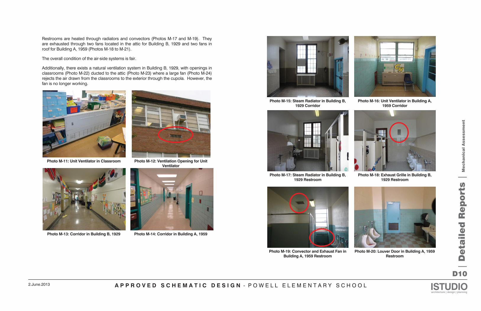
A P P R O V E D S C H E M A T I C D E S I G N - P O W E L L E L E M E N T A R Y S C H O O L ISTUDIOarchitecture | design | planning
2.June.2013
D10
| D
eta
ile
d R
ep
ort
s |
Me
ch
an
ica
l A
sse
ssm
en
t
Restrooms are heated through radiators and convectors (Photos M-17 and M-19). They are exhausted through two fans located in the attic for Building B, 1929 and two fans in roof for Building A, 1959 (Photos M-18 to M-21).
The overall condition of the air-side systems is fair.
Additionally, there exists a natural ventilation system in Building B, 1929, with openings in classrooms (Photo M-22) ducted to the attic (Photo M-23) where a large fan (Photo M-24) rejects the air drawn from the classrooms to the exterior through the cupola. However, the fan is no longer working.
Photo M-11: Unit Ventilator in Classroom Photo M-12: Ventilation Opening for Unit
Ventilator
Photo M-13: Corridor in Building B, 1929 Photo M-14: Corridor in Building A, 1959
Photo M-15: Steam Radiator in Building B,
1929 Corridor Photo M-16: Unit Ventilator in Building A,
1959 Corridor
Photo M-17: Steam Radiator in Building B,
1929 Restroom Photo M-18: Exhaust Grille in Building B,
1929 Restroom
Photo M-19: Convector and Exhaust Fan in
Building A, 1959 Restroom Photo M-20: Louver Door in Building A, 1959
Restroom
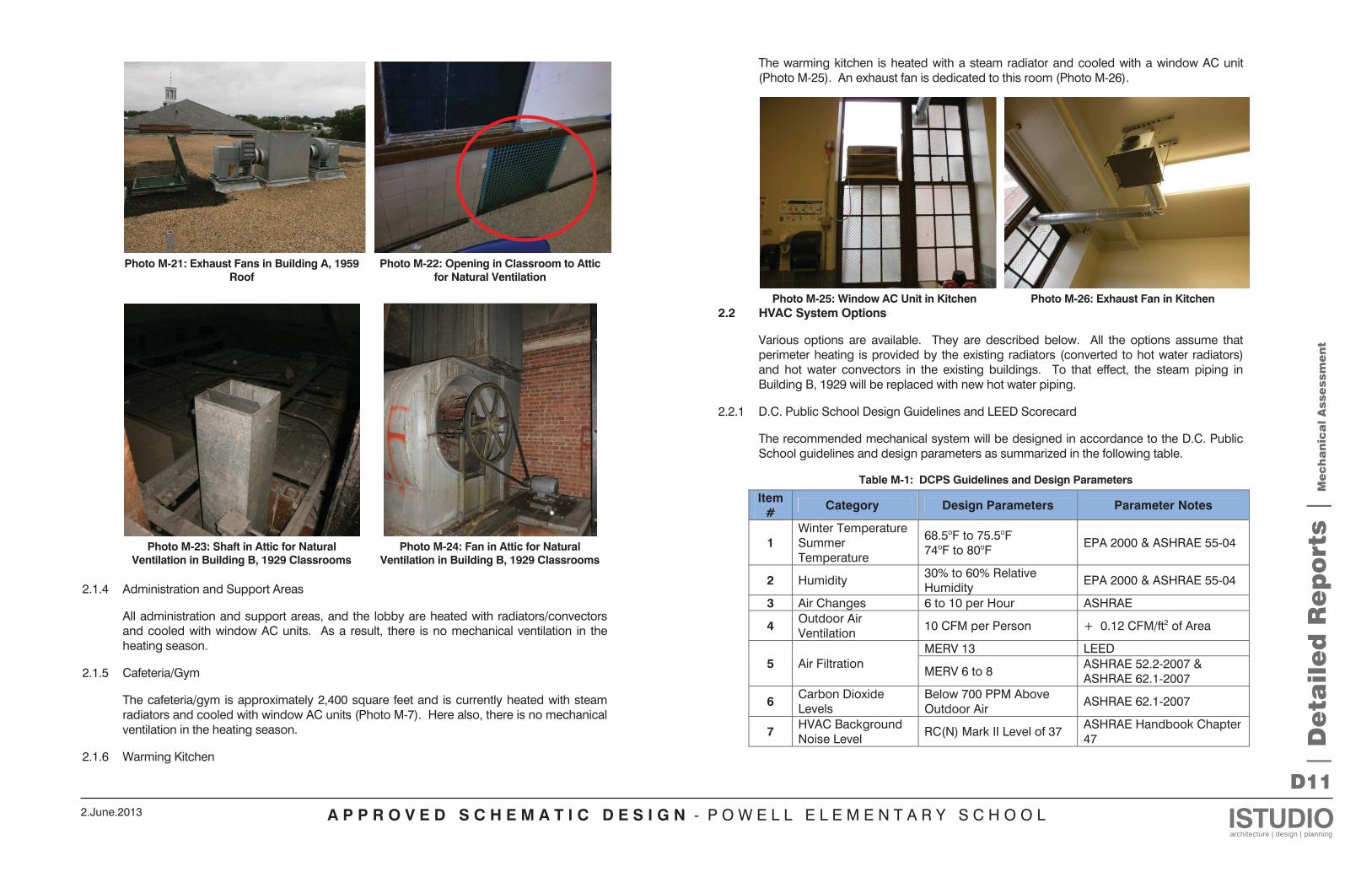
A P P R O V E D S C H E M A T I C D E S I G N - P O W E L L E L E M E N T A R Y S C H O O L ISTUDIOarchitecture | design | planning
2.June.2013
D11
Photo M-21: Exhaust Fans in Building A, 1959
Roof Photo M-22: Opening in Classroom to Attic
for Natural Ventilation
Photo M-23: Shaft in Attic for Natural
Ventilation in Building B, 1929 Classrooms Photo M-24: Fan in Attic for Natural
Ventilation in Building B, 1929 Classrooms
2.1.4 Administration and Support Areas
All administration and support areas, and the lobby are heated with radiators/convectors and cooled with window AC units. As a result, there is no mechanical ventilation in the heating season.
2.1.5 Cafeteria/Gym
The cafeteria/gym is approximately 2,400 square feet and is currently heated with steam radiators and cooled with window AC units (Photo M-7). Here also, there is no mechanical ventilation in the heating season.
2.1.6 Warming Kitchen
The warming kitchen is heated with a steam radiator and cooled with a window AC unit (Photo M-25). An exhaust fan is dedicated to this room (Photo M-26).
Photo M-25: Window AC Unit in Kitchen Photo M-26: Exhaust Fan in Kitchen 2.2 HVAC System Options
Various options are available. They are described below. All the options assume that perimeter heating is provided by the existing radiators (converted to hot water radiators) and hot water convectors in the existing buildings. To that effect, the steam piping in Building B, 1929 will be replaced with new hot water piping.
2.2.1 D.C. Public School Design Guidelines and LEED Scorecard
The recommended mechanical system will be designed in accordance to the D.C. Public School guidelines and design parameters as summarized in the following table.
Table M-1: DCPS Guidelines and Design Parameters
Item #
Category Design Parameters Parameter Notes
1 Winter Temperature Summer Temperature
68.5oF to 75.5oF 74oF to 80oF
EPA 2000 & ASHRAE 55-04
2 Humidity 30% to 60% Relative Humidity EPA 2000 & ASHRAE 55-04
3 Air Changes 6 to 10 per Hour ASHRAE
4 Outdoor Air Ventilation 10 CFM per Person + 0.12 CFM/ft2 of Area
5 Air Filtration MERV 13 LEED
MERV 6 to 8 ASHRAE 52.2-2007 & ASHRAE 62.1-2007
6 Carbon Dioxide Levels
Below 700 PPM Above Outdoor Air
ASHRAE 62.1-2007
7 HVAC Background Noise Level
RC(N) Mark II Level of 37 ASHRAE Handbook Chapter 47
| D
eta
ile
d R
ep
ort
s |
Me
ch
an
ica
l A
sse
ssm
en
t
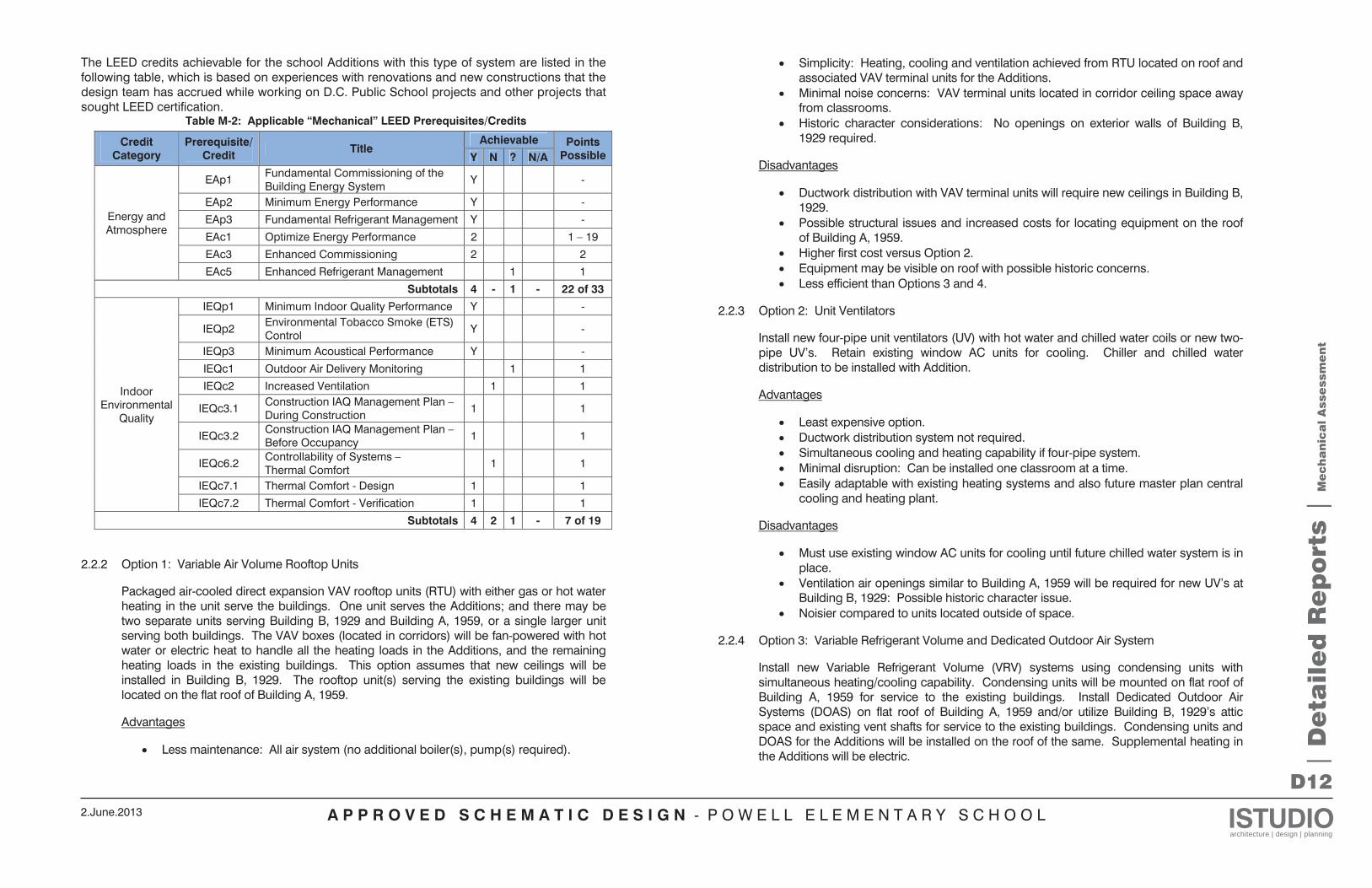
A P P R O V E D S C H E M A T I C D E S I G N - P O W E L L E L E M E N T A R Y S C H O O L ISTUDIOarchitecture | design | planning
2.June.2013
D12
The LEED credits achievable for the school Additions with this type of system are listed in the following table, which is based on experiences with renovations and new constructions that the design team has accrued while working on D.C. Public School projects and other projects that sought LEED certification.
Table M-2: Applicable “Mechanical” LEED Prerequisites/Credits
Credit Category
Prerequisite/ Credit Title
Achievable Points Possible Y N ? N/A
Energy and Atmosphere
EAp1 Fundamental Commissioning of the Building Energy System Y -
EAp2 Minimum Energy Performance Y -
EAp3 Fundamental Refrigerant Management Y -
EAc1 Optimize Energy Performance 2 1 – 19
EAc3 Enhanced Commissioning 2 2
EAc5 Enhanced Refrigerant Management 1 1
Subtotals 4 - 1 - 22 of 33
Indoor Environmental
Quality
IEQp1 Minimum Indoor Quality Performance Y -
IEQp2 Environmental Tobacco Smoke (ETS) Control Y -
IEQp3 Minimum Acoustical Performance Y -
IEQc1 Outdoor Air Delivery Monitoring 1 1
IEQc2 Increased Ventilation 1 1
IEQc3.1 Construction IAQ Management Plan – During Construction 1 1
IEQc3.2 Construction IAQ Management Plan – Before Occupancy 1 1
IEQc6.2 Controllability of Systems – Thermal Comfort 1 1
IEQc7.1 Thermal Comfort - Design 1 1
IEQc7.2 Thermal Comfort - Verification 1 1
Subtotals 4 2 1 - 7 of 19
2.2.2 Option 1: Variable Air Volume Rooftop Units
Packaged air-cooled direct expansion VAV rooftop units (RTU) with either gas or hot water heating in the unit serve the buildings. One unit serves the Additions; and there may be two separate units serving Building B, 1929 and Building A, 1959, or a single larger unit serving both buildings. The VAV boxes (located in corridors) will be fan-powered with hot water or electric heat to handle all the heating loads in the Additions, and the remaining heating loads in the existing buildings. This option assumes that new ceilings will be installed in Building B, 1929. The rooftop unit(s) serving the existing buildings will be located on the flat roof of Building A, 1959.
Advantages
Less maintenance: All air system (no additional boiler(s), pump(s) required).
Simplicity: Heating, cooling and ventilation achieved from RTU located on roof and associated VAV terminal units for the Additions. Minimal noise concerns: VAV terminal units located in corridor ceiling space away from classrooms. Historic character considerations: No openings on exterior walls of Building B, 1929 required.
Disadvantages
Ductwork distribution with VAV terminal units will require new ceilings in Building B, 1929. Possible structural issues and increased costs for locating equipment on the roof of Building A, 1959. Higher first cost versus Option 2. Equipment may be visible on roof with possible historic concerns. Less efficient than Options 3 and 4.
2.2.3 Option 2: Unit Ventilators
Install new four-pipe unit ventilators (UV) with hot water and chilled water coils or new two-pipe UV’s. Retain existing window AC units for cooling. Chiller and chilled water distribution to be installed with Addition.
Advantages
Least expensive option. Ductwork distribution system not required. Simultaneous cooling and heating capability if four-pipe system. Minimal disruption: Can be installed one classroom at a time. Easily adaptable with existing heating systems and also future master plan central cooling and heating plant.
Disadvantages
Must use existing window AC units for cooling until future chilled water system is in place. Ventilation air openings similar to Building A, 1959 will be required for new UV’s at Building B, 1929: Possible historic character issue. Noisier compared to units located outside of space.
2.2.4 Option 3: Variable Refrigerant Volume and Dedicated Outdoor Air System
Install new Variable Refrigerant Volume (VRV) systems using condensing units with simultaneous heating/cooling capability. Condensing units will be mounted on flat roof of Building A, 1959 for service to the existing buildings. Install Dedicated Outdoor Air Systems (DOAS) on flat roof of Building A, 1959 and/or utilize Building B, 1929’s attic space and existing vent shafts for service to the existing buildings. Condensing units and DOAS for the Additions will be installed on the roof of the same. Supplemental heating in the Additions will be electric. |
De
tail
ed
Re
po
rts |
Me
ch
an
ica
l A
sse
ssm
en
t
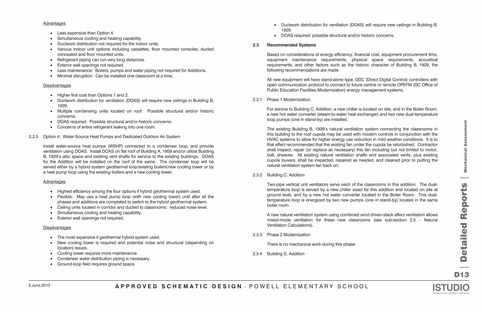
A P P R O V E D S C H E M A T I C D E S I G N - P O W E L L E L E M E N T A R Y S C H O O L ISTUDIOarchitecture | design | planning
2.June.2013
D13
Advantages
Less expensive than Option 4. Simultaneous cooling and heating capability. Ductwork distribution not required for the indoor units. Various indoor unit options including cassettes, floor mounted consoles, ducted concealed and floor mounted units. Refrigerant piping can run very long distances. Exterior wall openings not required. Less maintenance: Boilers, pumps and water piping not required for Additions. Minimal disruption: Can be installed one classroom at a time.
Disadvantages
Higher first cost than Options 1 and 2. Ductwork distribution for ventilation (DOAS) will require new ceilings in Building B, 1929. Multiple condensing units located on roof: Possible structural and/or historic concerns. DOAS required: Possible structural and/or historic concerns. Concerns of entire refrigerant leaking into one room.
2.2.5 Option 4: Water-Source Heat Pumps and Dedicated Outdoor Air System
Install water-source heat pumps (WSHP) connected to a condenser loop, and provide ventilation using DOAS. Install DOAS on flat roof of Building A, 1959 and/or utilize Building B, 1929’s attic space and existing vent shafts for service to the existing buildings. DOAS for the Addition will be installed on the roof of the same. The condenser loop will be served either by a hybrid system geothermal loop/existing boilers/new cooling tower or by a heat pump loop using the existing boilers and a new cooling tower.
Advantages
Highest efficiency among the four options if hybrid geothermal system used. Flexible: May use a heat pump loop (with new cooling tower) until after all the phases and additions are completed to switch to the hybrid geothermal system. Ceiling units located in corridor and ducted to classrooms: reduced noise level. Simultaneous cooling and heating capability. Exterior wall openings not required.
Disadvantages
The most expensive if geothermal hybrid system used. New cooling tower is required and potential noise and structural (depending on location) issues. Cooling tower requires more maintenance. Condenser water distribution piping is necessary. Ground-loop field requires ground space.
Ductwork distribution for ventilation (DOAS) will require new ceilings in Building B, 1929. DOAS required: possible structural and/or historic concerns.
2.3 Recommended Systems
Based on considerations of energy efficiency, financial cost, equipment procurement time, equipment maintenance requirements, physical space requirements, acoustical requirements, and other factors such as the historic character of Building B, 1929, the following recommendations are made.
All new equipment will have stand-alone type, DDC (Direct Digital Control) controllers with open communication protocol to connect to future central or remote OPEFM (DC Office of Public Education Facilities Modernization) energy management systems.
2.3.1 Phase 1 Modernization
For service to Building C, Addition, a new chiller is located on site, and in the Boiler Room, a new hot water converter (steam-to-water heat exchanger) and two new dual-temperature loop pumps (one in stand-by) are installed.
The existing Building B, 1929’s natural ventilation system connecting the classrooms in this building to the roof cupola may be used with modern controls in conjunction with the HVAC systems to allow for higher energy use reduction in mild weather conditions. It is to that effect recommended that the existing fan under the cupola be refurbished. Contractor shall inspect, repair (or replace as necessary) this fan including but not limited to motor, belt, sheaves. All existing natural ventilation shafts and associated vents, plus existing cupola louvers, shall be inspected, repaired as needed, and cleaned prior to putting the natural ventilation system fan back on.
2.3.2 Building C, Addition
Two-pipe vertical unit ventilators serve each of the classrooms in this addition. The dual-temperature loop is served by a new chiller sized for this addition and located on site at ground level, and by a new hot water converter located in the Boiler Room. This dual-temperature loop is energized by two new pumps (one in stand-by) located in the same boiler room.
A new natural ventilation system using combined wind driven-stack effect ventilation allows mixed-mode ventilation for these new classrooms (see sub-section 2.5 – Natural Ventilation Calculations).
2.3.3 Phase 2 Modernization
There is no mechanical work during this phase.
2.3.4 Building D, Addition
| D
eta
ile
d R
ep
ort
s |
Me
ch
an
ica
l A
sse
ssm
en
t

A P P R O V E D S C H E M A T I C D E S I G N - P O W E L L E L E M E N T A R Y S C H O O L ISTUDIOarchitecture | design | planning
2.June.2013
D14
This addition necessitates the installation of a second chiller on site and another hot water converter in the Boiler Room, along with a new set of dual-temperature loop pumps (one in stand-by). This equipment is sized for this addition and the existing buildings.
Two-pipe unit ventilators serve the spaces, except for the cafeteria and kitchen. Some of the UV’s are vertical, the others are horizontal and ducted for spaces with no perimeter wall (see sketches in Appendix D – Schematic Drawings).
Due to its location, size and peak load, the cafeteria and kitchen space is served by a packaged direct expansion rooftop unit located on the roof of this building, with hot water coils. A kitchen hood exhaust fan with associated gas-fired make-up air unit, along with a dishwasher exhaust fan completes this package.
2.3.5 Phase 3 Modernization
Building B, 1929, including the Auditorium and Administration/Support Area, is served by a new variable refrigerant volume (VRV) system with dedicated outdoor air system (DOAS). The condensing units of the VRV are to be located on the flat roof of Building A, 1959. The branch selector units of the VRV system are installed in the attic. The DOAS is a direct expansion split system with hot water heating. Its indoor unit is located in the attic and its condenser, on the roof of Building D, Addition. Ventilation air is served to the spaces below through variable air volume boxes connected to CO2 sensors located in the spaces in a demand-controlled ventilation scheme. VRV ceiling cassette units in each space handle the cooling and heating loads. The existing steam radiators are converted to hot water radiators (with complete replacement of the steam piping) to handle the perimeter heating in this building. Restrooms are provided with new hot convectors.
Building A, 1959 is served by new two-pipe vertical unit ventilators. Restrooms in this building are served by new hot water convectors.
2.4 Load Calculations
2.4.1 Assumptions
Load calculations are based on the following assumptions:
Outdoor design conditions: 95°F DB/78°F WB summer design conditions, 10°F DB winter design conditions. Indoor design conditions: 75°F summer, 70°F winter. Ventilation: ASHRAE 62.1-2007. Infiltration: 0.5 air-changes per hour (ACH) in perimeter zones and 0.3 ACH in core zones for existing buildings, 0.2 ACH in perimeter zones and 0.1 ACH in core zones for Additions. Perimeter heat loss (slab-on-grade): 0.73 Btu/h.°F.ft. Exterior walls: brick for the existing buildings, ASHRAE 90.1-2007 Baseline (R-13 + R-7.5 c.i.) for Additions. Roof: non-insulated attic for Building B, 1929 built-up with rigid insulation (R-6) for Building A, 1959 ASHRAE 90.1-2007 Baseline (R-20 c.i.) for Additions.
Glass: single pane/clear for the existing buildings, ASHRAE 90.1-2007 Baseline (U-0.55 & SHGC-0.40) for Additions.
For the Additions, the following window-to-wall ratios (WWR) were assumed:
Corridor: 60% on the south. Student Dining Area: 50% on the west. Kitchen: 30% on the west and southeast. Media Center/Library: 60% on the west, 50% on the southeast. Computer Lab: 50% on the southeast, and 40% on the east.
Table M-3 lists other assumptions.
Table M-3: Internal Load and Ventilation Assumptions for Load Calculations
Space Type
Occupancy
(ft2/person)
Lighting Load
(W/ft2)
Miscellaneous Load
(W/ft2)
Ventilation
(cfm/person)
(cfm/ft2
)
Auditorium 06.7 2.6 0.5 5.0 0.06 Cafeteria 10.0 0.9 0.5 7.5 0.18 Classroom 28.6 1.4 1.0 10.0 0.12 Computer Lab
33.3 1.4 3.0 10.0 0.12
Corridor 00.0 0.5 0.0 0.0 0.06 Library 100 1.7 0.5 5.0 0.12 Lobby 06.7 1.3 0.5 5.0 0.06 Music 33.3 1.4 3.0 10.0 0.06 Office 200 1.1 1.5 5.0 0.06 Reception 16.7 1.3 1.0 5.0 0.06 Restroom 00.0 0.9 0.1 / / Storage 00.0 0.8 0.3 0.0 0.12
2.4.2 Main Results
Total peak cooling load is 254 tons, for a maximum block cooling load of 249 tons, including the VRV systems. The VRV system (Building B, 1929) represents a cooling load of 45 tons, the DOAS is 30 tons, and the rooftop unit serving the dining area is 28 tons, leaving 150 tons to be handled by the chillers (60 tons for the first and 90 tons for the second).
Total peak heating load is 3,338 MBH. The existing boilers (which output a total of 4,686 MBH) can handle this load.
The unit ventilators in Building A, 1959 represent a total cooling load of 62 tons, and a heating load of 730 MBH, whereas the unit ventilators in the Additions represent a cooling load of 88 tons and a heating load of 1,140 MBH.
Appendix C lists the detailed loads per system and per room as follows: | D
eta
ile
d R
ep
ort
s |
Me
ch
an
ica
l A
sse
ssm
en
t
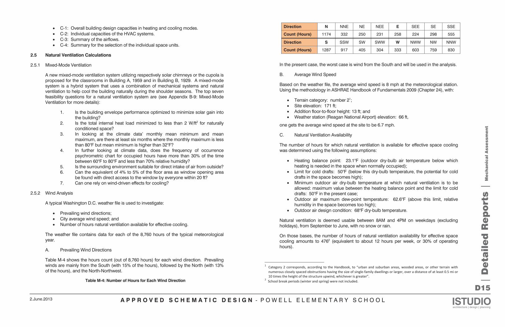
A P P R O V E D S C H E M A T I C D E S I G N - P O W E L L E L E M E N T A R Y S C H O O L ISTUDIOarchitecture | design | planning
2.June.2013
D15
C-1: Overall building design capacities in heating and cooling modes. C-2: Individual capacities of the HVAC systems. C-3: Summary of the airflows. C-4: Summary for the selection of the individual space units.
2.5 Natural Ventilation Calculations
2.5.1 Mixed-Mode Ventilation
A new mixed-mode ventilation system utilizing respectively solar chimneys or the cupola is proposed for the classrooms in Building A, 1959 and in Building B, 1929. A mixed-mode system is a hybrid system that uses a combination of mechanical systems and natural ventilation to help cool the building naturally during the shoulder seasons. The top seven feasibility questions for a natural ventilation system are (see Appendix B-9: Mixed-Mode Ventilation for more details):
1. Is the building envelope performance optimized to minimize solar gain into the building?
2. Is the total internal heat load minimized to less than 2 W/ft2 for naturally conditioned space?
3. In looking at the climate data’ monthly mean minimum and mean maximum, are there at least six months where the monthly maximum is less than 80°F but mean minimum is higher than 32°F?
4. In further looking at climate data, does the frequency of occurrence psychrometric chart for occupied hours have more than 30% of the time between 60°F to 80°F and less than 70% relative humidity?
5. Is the surrounding environment suitable for direct intake of air from outside? 6. Can the equivalent of 4% to 5% of the floor area as window opening area
be found with direct access to the window by everyone within 20 ft? 7. Can one rely on wind-driven effects for cooling?
2.5.2 Wind Analysis
A typical Washington D.C. weather file is used to investigate:
Prevailing wind directions; City average wind speed; and Number of hours natural ventilation available for effective cooling.
The weather file contains data for each of the 8,760 hours of the typical meteorological year.
A. Prevailing Wind Directions
Table M-4 shows the hours count (out of 8,760 hours) for each wind direction. Prevailing winds are mainly from the South (with 15% of the hours), followed by the North (with 13% of the hours), and the North-Northwest.
Table M-4: Number of Hours for Each Wind Direction
Direction N NNE NE NEE E SEE SE SSE
Count (Hours) 1174 332 250 231 258 224 298 555
Direction S SSW SW SWW W NWW NW NNW
Count (Hours) 1287 917 405 304 333 603 759 830
In the present case, the worst case is wind from the South and will be used in the analysis.
B. Average Wind Speed
Based on the weather file, the average wind speed is 8 mph at the meteorological station. Using the methodology in ASHRAE Handbook of Fundamentals 2009 (Chapter 24), with:
Terrain category: number 21; Site elevation: 171 ft; Addition floor-to-floor height: 13 ft; and Weather station (Reagan National Airport) elevation: 66 ft,
one gets the average wind speed at the site to be 6.7 mph.
C. Natural Ventilation Availability
The number of hours for which natural ventilation is available for effective space cooling was determined using the following assumptions:
Heating balance point: 23.1°F (outdoor dry-bulb air temperature below which heating is needed in the space when normally occupied); Limit for cold drafts: 50°F (below this dry-bulb temperature, the potential for cold drafts in the space becomes high); Minimum outdoor air dry-bulb temperature at which natural ventilation is to be allowed: maximum value between the heating balance point and the limit for cold drafts: 50°F in the present case; Outdoor air maximum dew-point temperature: 62.6°F (above this limit, relative humidity in the space becomes too high); Outdoor air design condition: 68°F dry-bulb temperature.
Natural ventilation is deemed usable between 8AM and 4PM on weekdays (excluding holidays), from September to June, with no snow or rain.
On those bases, the number of hours of natural ventilation availability for effective space cooling amounts to 4762 (equivalent to about 12 hours per week, or 30% of operating hours).
1 Category 2 corresponds, according to the Handbook, to “urban and suburban areas, wooded areas, or other terrain withnumerous closely spaced obstructions having the size of single family dwellings or larger, over a distance of at least 0.5 mi or10 times the height of the structure upwind, whichever is greater”.
2 School break periods (winter and spring) were not included. | D
eta
ile
d R
ep
ort
s |
Me
ch
an
ica
l A
sse
ssm
en
t
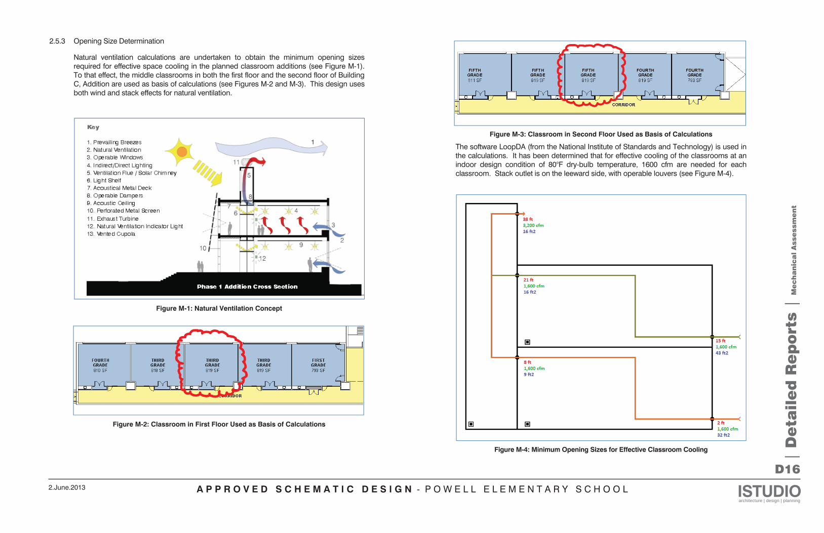
A P P R O V E D S C H E M A T I C D E S I G N - P O W E L L E L E M E N T A R Y S C H O O L ISTUDIOarchitecture | design | planning
2.June.2013
D16
2.5.3 Opening Size Determination
Natural ventilation calculations are undertaken to obtain the minimum opening sizes required for effective space cooling in the planned classroom additions (see Figure M-1). To that effect, the middle classrooms in both the first floor and the second floor of Building C, Addition are used as basis of calculations (see Figures M-2 and M-3). This design uses both wind and stack effects for natural ventilation.
Figure M-1: Natural Ventilation Concept
Figure M-2: Classroom in First Floor Used as Basis of Calculations
Figure M-3: Classroom in Second Floor Used as Basis of Calculations
The software LoopDA (from the National Institute of Standards and Technology) is used in the calculations. It has been determined that for effective cooling of the classrooms at an indoor design condition of 80°F dry-bulb temperature, 1600 cfm are needed for each classroom. Stack outlet is on the leeward side, with operable louvers (see Figure M-4).
Figure M-4: Minimum Opening Sizes for Effective Classroom Cooling |
De
tail
ed
Re
po
rts |
Me
ch
an
ica
l A
sse
ssm
en
t
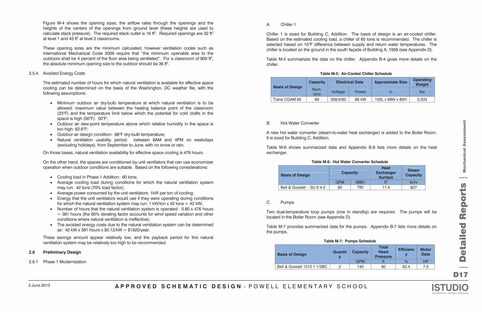
A P P R O V E D S C H E M A T I C D E S I G N - P O W E L L E L E M E N T A R Y S C H O O L ISTUDIOarchitecture | design | planning
2.June.2013
D17
| D
eta
ile
d R
ep
ort
s |
Me
ch
an
ica
l A
sse
ssm
en
t
Figure M-4 shows the opening sizes, the airflow rates through the openings and the heights of the centers of the openings from ground level (these heights are used to calculate stack pressure). The required stack outlet is 16 ft2. Required openings are 32 ft2 at level 1 and 43 ft2 at level 2 classrooms.
These opening sizes are the minimum calculated, however ventilation codes such as International Mechanical Code 2009 require that “the minimum openable area to the outdoors shall be 4 percent of the floor area being ventilated”. For a classroom of 900 ft2, the absolute minimum opening size to the outdoor should be 36 ft2.
2.5.4 Avoided Energy Costs
The estimated number of hours for which natural ventilation is available for effective space cooling can be determined on the basis of the Washington, DC weather file, with the following assumptions:
Minimum outdoor air dry-bulb temperature at which natural ventilation is to be allowed: maximum value between the heating balance point of the classroom (23°F) and the temperature limit below which the potential for cold drafts in the space is high (50°F): 50°F; Outdoor air dew-point temperature above which relative humidity in the space is too high: 62.6°F; Outdoor air design condition: 68°F dry-bulb temperature; Natural ventilation usability period: between 8AM and 4PM on weekdays (excluding holidays), from September to June, with no snow or rain.
On those bases, natural ventilation availability for effective space cooling is 476 hours.
On the other hand, the spaces are conditioned by unit ventilators that can use economizer operation when outdoor conditions are suitable. Based on the following considerations:
Cooling load in Phase 1 Addition: 60 tons; Average cooling load during conditions for which the natural ventilation system may run: 42 tons (70% load factor); Average power consumed by the unit ventilators: 1kW per ton of cooling; Energy that the unit ventilators would use if they were operating during conditions for which the natural ventilation system may run: 1 kW/ton x 42 tons = 42 kW; Number of hours that the natural ventilation system is operated: 0.80 x 476 hours = 381 hours (the 80% derating factor accounts for wind speed variation and other conditions where natural ventilation is ineffective); The avoided energy costs due to the natural ventilation system can be determined as: 42 kW x 381 hours x $0.12/kW = $1920/year.
These savings amount appear relatively low, and the payback period for this natural ventilation system may be relatively too high to be recommended.
2.6 Preliminary Design
2.6.1 Phase 1 Modernization
A. Chiller 1
Chiller 1 is sized for Building C, Addition. The basis of design is an air-cooled chiller. Based on the estimated cooling load, a chiller of 60 tons is recommended. The chiller is selected based on 10°F difference between supply and return water temperatures. The chiller is located on the ground in the south façade of Building A, 1959 (see Appendix D).
Table M-5 summarizes the data on the chiller. Appendix B-4 gives more details on the chiller.
Table M-5: Air-Cooled Chiller Schedule
Basis of Design Capacity Electrical Data Approximate Size Operating
Weight Nom. tons Voltage Power in lbs
Trane CGAM 60 60 208/3/60 66 kW 150L x 89W x 85H 5,033
B. Hot Water Converter
A new hot water converter (steam-to-water heat exchanger) is added to the Boiler Room. It is sized for Building C, Addition.
Table M-6 shows summarized data and Appendix B-8 lists more details on the heat exchanger.
Table M-6: Hot Water Converter Schedule
Basis of Design Capacity
Heat Exchanger
Surface
Steam Capacity
GPM MBH ft2 lb/hr Bell & Gossett - SU 6 4-2 80 782 17.4 827
C. Pumps
Two dual-temperature loop pumps (one in standby) are required. The pumps will be located in the Boiler Room (see Appendix D).
Table M-7 provides summarized data for the pumps. Appendix B-7 lists more details on the pumps.
Table M-7: Pumps Schedule
Basis of Design Quantity
Capacity Total Head
Pressure
Efficiency
Motor Data
GPM ft % HP Bell & Gossett 1510 1-1/2BC 2 140 90 62.4 7.5
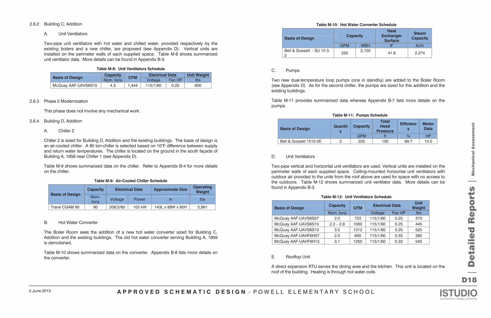
A P P R O V E D S C H E M A T I C D E S I G N - P O W E L L E L E M E N T A R Y S C H O O L ISTUDIOarchitecture | design | planning
2.June.2013
D18
| D
eta
ile
d R
ep
ort
s |
Me
ch
an
ica
l A
sse
ssm
en
t
2.6.2 Building C, Addition
A. Unit Ventilators
Two-pipe unit ventilators with hot water and chilled water, provided respectively by the existing boilers and a new chiller, are proposed (see Appendix D). Vertical units are installed on the perimeter walls of each supplied space. Table M-8 shows summarized unit ventilator data. More details can be found in Appendix B-3.
Table M-8: Unit Ventilators Schedule
Basis of Design Capacity
CFM Electrical Data Unit Weight
Nom. tons Voltage Fan HP lbs McQuay AAF-UAVS6S15 4.3 1,444 115/1/60 0.25 600
2.6.3 Phase 2 Modernization
This phase does not involve any mechanical work.
2.6.4 Building D, Addition
A. Chiller 2
Chiller 2 is sized for Building D, Addition and the existing buildings. The basis of design is an air-cooled chiller. A 90 ton-chiller is selected based on 10°F difference between supply and return water temperatures. The chiller is located on the ground in the south façade of Building A, 1959 near Chiller 1 (see Appendix D).
Table M-9 shows summarized data on the chiller. Refer to Appendix B-4 for more details on the chiller.
Table M-9: Air-Cooled Chiller Schedule
Basis of Design Capacity Electrical Data Approximate Size Operating
Weight Nom. tons Voltage Power in lbs
Trane CGAM 90 90 208/3/60 102 kW 143L x 89W x 92H 5,961
B. Hot Water Converter
The Boiler Room sees the addition of a new hot water converter sized for Building C, Addition and the existing buildings. The old hot water converter serving Building A, 1959 is demolished.
Table M-10 shows summarized data on the converter. Appendix B-8 lists more details on the converter.
Table M-10: Hot Water Converter Schedule
Basis of Design Capacity
Heat Exchanger
Surface
Steam Capacity
GPM MBH ft2 lb/hr Bell & Gossett - SU 10 3-2 220 2,150 41.9 2,274
C. Pumps
Two new dual-temperature loop pumps (one in standby) are added to the Boiler Room (see Appendix D). As for the second chiller, the pumps are sized for this addition and the existing buildings.
Table M-11 provides summarized data whereas Appendix B-7 lists more details on the pumps.
Table M-11: Pumps Schedule
Basis of Design Quantity
Capacity Total Head
Pressure
Efficiency
Motor Data
GPM ft % HP Bell & Gossett 1510-2E 2 220 100 69.7 10.0
D. Unit Ventilators
Two-pipe vertical and horizontal unit ventilators are used. Vertical units are installed on the perimeter walls of each supplied space. Ceiling-mounted horizontal unit ventilators with outdoor air provided to the units from the roof above are used for space with no access to the outdoors. Table M-12 shows summarized unit ventilator data. More details can be found in Appendix B-3.
Table M-12: Unit Ventilators Schedule
Basis of Design Capacity
CFM Electrical Data Unit
Weight Nom. tons Voltage Fan HP lbs
McQuay AAF-UAVS6S07 2.0 753 115/1/60 0.25 370 McQuay AAF-UAVS6S10 2.2 – 2.8 1000 115/1/60 0.25 445 McQuay AAF-UAVS6S13 3.5 1212 115/1/60 0.25 525 McQuay AAF-UAHF6H07 2.0 600 115/1/60 0.33 385 McQuay AAF-UAHF6H13 3.1 1250 115/1/60 0.33 540
E. Rooftop Unit
A direct expansion RTU serves the dining area and the kitchen. This unit is located on the roof of the building. Heating is through hot water coils.
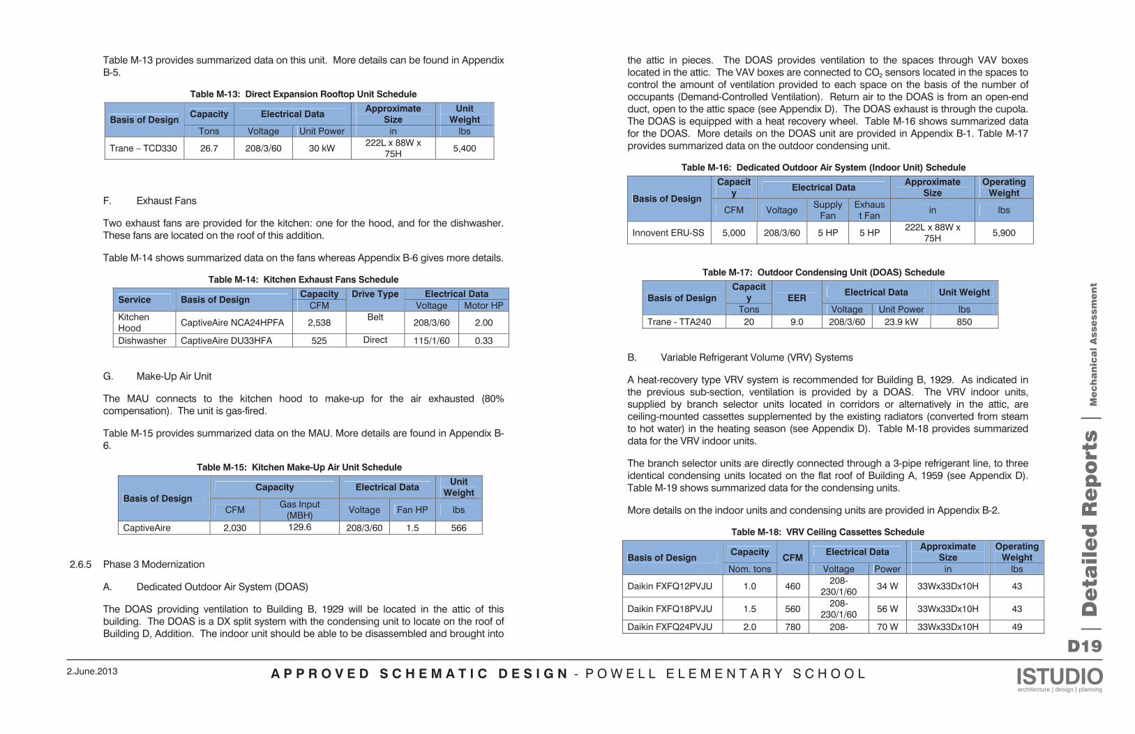
A P P R O V E D S C H E M A T I C D E S I G N - P O W E L L E L E M E N T A R Y S C H O O L ISTUDIOarchitecture | design | planning
2.June.2013
D19
| D
eta
ile
d R
ep
ort
s |
Me
ch
an
ica
l A
sse
ssm
en
t
Table M-13 provides summarized data on this unit. More details can be found in Appendix B-5.
Table M-13: Direct Expansion Rooftop Unit Schedule
Basis of Design Capacity Electrical Data Approximate
Size Unit
Weight Tons Voltage Unit Power in lbs
Trane – TCD330 26.7 208/3/60 30 kW 222L x 88W x 75H 5,400
F. Exhaust Fans
Two exhaust fans are provided for the kitchen: one for the hood, and for the dishwasher. These fans are located on the roof of this addition.
Table M-14 shows summarized data on the fans whereas Appendix B-6 gives more details.
Table M-14: Kitchen Exhaust Fans Schedule
Service Basis of Design Capacity Drive Type Electrical Data
CFM Voltage Motor HP Kitchen Hood CaptiveAire NCA24HPFA 2,538 Belt 208/3/60 2.00
Dishwasher CaptiveAire DU33HFA 525 Direct 115/1/60 0.33
G. Make-Up Air Unit
The MAU connects to the kitchen hood to make-up for the air exhausted (80% compensation). The unit is gas-fired.
Table M-15 provides summarized data on the MAU. More details are found in Appendix B-6.
Table M-15: Kitchen Make-Up Air Unit Schedule
Basis of Design Capacity Electrical Data Unit
Weight
CFM Gas Input (MBH) Voltage Fan HP lbs
CaptiveAire 2,030 129.6 208/3/60 1.5 566
2.6.5 Phase 3 Modernization
A. Dedicated Outdoor Air System (DOAS)
The DOAS providing ventilation to Building B, 1929 will be located in the attic of this building. The DOAS is a DX split system with the condensing unit to locate on the roof of Building D, Addition. The indoor unit should be able to be disassembled and brought into
the attic in pieces. The DOAS provides ventilation to the spaces through VAV boxes located in the attic. The VAV boxes are connected to CO2 sensors located in the spaces to control the amount of ventilation provided to each space on the basis of the number of occupants (Demand-Controlled Ventilation). Return air to the DOAS is from an open-end duct, open to the attic space (see Appendix D). The DOAS exhaust is through the cupola. The DOAS is equipped with a heat recovery wheel. Table M-16 shows summarized data for the DOAS. More details on the DOAS unit are provided in Appendix B-1. Table M-17 provides summarized data on the outdoor condensing unit.
Table M-16: Dedicated Outdoor Air System (Indoor Unit) Schedule
Basis of Design
Capacity Electrical Data Approximate
Size Operating
Weight
CFM Voltage Supply Fan
Exhaust Fan in lbs
Innovent ERU-SS 5,000 208/3/60 5 HP 5 HP 222L x 88W x 75H 5,900
Table M-17: Outdoor Condensing Unit (DOAS) Schedule
Basis of Design Capacit
y EER Electrical Data Unit Weight
Tons Voltage Unit Power lbs Trane - TTA240 20 9.0 208/3/60 23.9 kW 850
B. Variable Refrigerant Volume (VRV) Systems
A heat-recovery type VRV system is recommended for Building B, 1929. As indicated in the previous sub-section, ventilation is provided by a DOAS. The VRV indoor units, supplied by branch selector units located in corridors or alternatively in the attic, are ceiling-mounted cassettes supplemented by the existing radiators (converted from steam to hot water) in the heating season (see Appendix D). Table M-18 provides summarized data for the VRV indoor units.
The branch selector units are directly connected through a 3-pipe refrigerant line, to three identical condensing units located on the flat roof of Building A, 1959 (see Appendix D). Table M-19 shows summarized data for the condensing units.
More details on the indoor units and condensing units are provided in Appendix B-2.
Table M-18: VRV Ceiling Cassettes Schedule
Basis of Design Capacity
CFM Electrical Data Approximate
Size Operating
Weight Nom. tons Voltage Power in lbs
Daikin FXFQ12PVJU 1.0 460 208-230/1/60 34 W 33Wx33Dx10H 43
Daikin FXFQ18PVJU 1.5 560 208-230/1/60 56 W 33Wx33Dx10H 43
Daikin FXFQ24PVJU 2.0 780 208- 70 W 33Wx33Dx10H 49
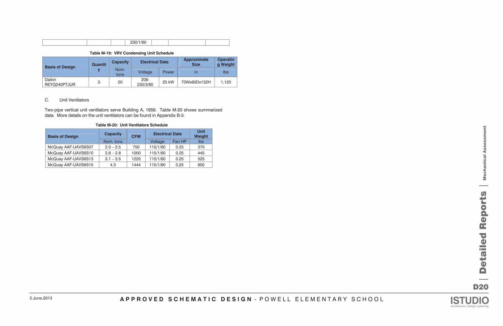
A P P R O V E D S C H E M A T I C D E S I G N - P O W E L L E L E M E N T A R Y S C H O O L ISTUDIOarchitecture | design | planning
2.June.2013
D20
| D
eta
ile
d R
ep
ort
s |
Me
ch
an
ica
l A
sse
ssm
en
t
230/1/60
Table M-19: VRV Condensing Unit Schedule
Basis of Design Quantity
Capacity Electrical Data Approximate Size
Operating Weight
Nom. tons Voltage Power in lbs
Daikin REYQ240PTJUR 3 20 208-
230/3/60 25 kW 73Wx60Dx132H 1,120
C. Unit Ventilators
Two-pipe vertical unit ventilators serve Building A, 1959. Table M-20 shows summarized data. More details on the unit ventilators can be found in Appendix B-3.
Table M-20: Unit Ventilators Schedule
Basis of Design Capacity
CFM Electrical Data Unit
Weight Nom. tons Voltage Fan HP lbs
McQuay AAF-UAVS6S07 2.0 – 2.5 750 115/1/60 0.25 370 McQuay AAF-UAVS6S10 2.6 – 2.8 1000 115/1/60 0.25 445 McQuay AAF-UAVS6S13 3.1 – 3.5 1220 115/1/60 0.25 525 McQuay AAF-UAVS6S15 4.3 1444 115/1/60 0.25 600
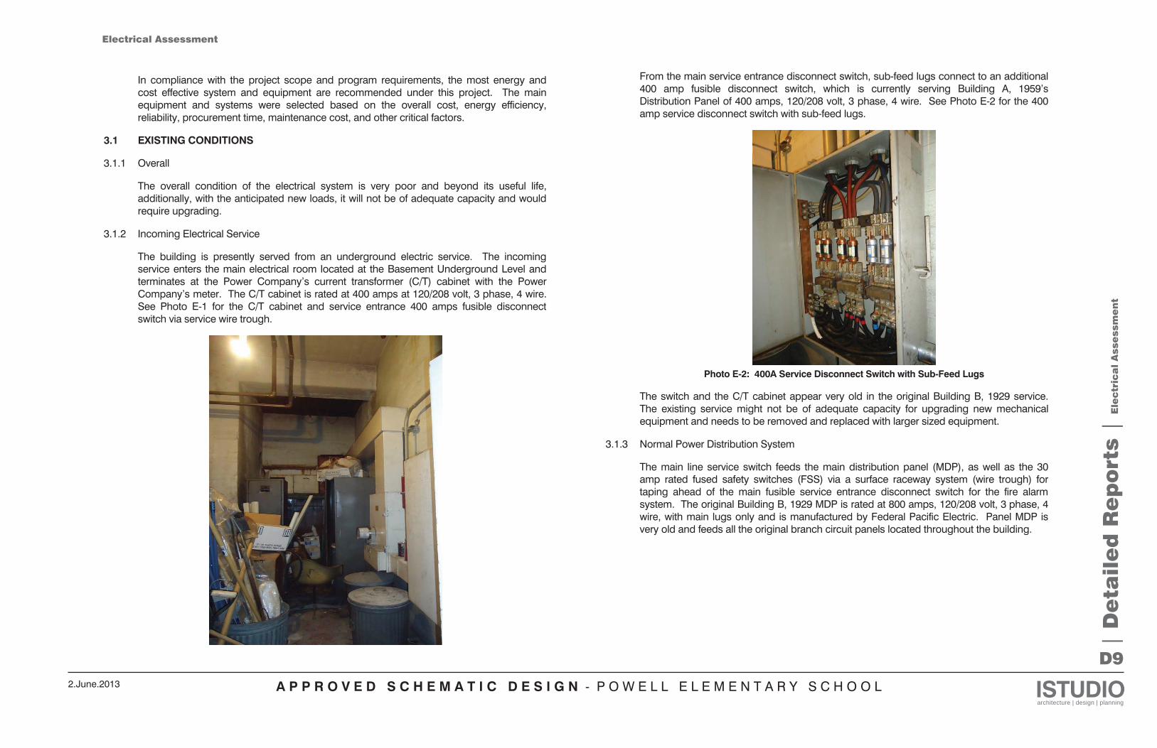
A P P R O V E D S C H E M A T I C D E S I G N - P O W E L L E L E M E N T A R Y S C H O O L ISTUDIOarchitecture | design | planning
2.June.2013
D9
In compliance with the project scope and program requirements, the most energy and cost effective system and equipment are recommended under this project. The main equipment and systems were selected based on the overall cost, energy efficiency, reliability, procurement time, maintenance cost, and other critical factors.
3.1 EXISTING CONDITIONS
3.1.1 Overall
The overall condition of the electrical system is very poor and beyond its useful life, additionally, with the anticipated new loads, it will not be of adequate capacity and would require upgrading.
3.1.2 Incoming Electrical Service
The building is presently served from an underground electric service. The incoming service enters the main electrical room located at the Basement Underground Level and terminates at the Power Company’s current transformer (C/T) cabinet with the Power Company’s meter. The C/T cabinet is rated at 400 amps at 120/208 volt, 3 phase, 4 wire. See Photo E-1 for the C/T cabinet and service entrance 400 amps fusible disconnect switch via service wire trough.
From the main service entrance disconnect switch, sub-feed lugs connect to an additional 400 amp fusible disconnect switch, which is currently serving Building A, 1959’s Distribution Panel of 400 amps, 120/208 volt, 3 phase, 4 wire. See Photo E-2 for the 400 amp service disconnect switch with sub-feed lugs.
Photo E-2: 400A Service Disconnect Switch with Sub-Feed Lugs
The switch and the C/T cabinet appear very old in the original Building B, 1929 service. The existing service might not be of adequate capacity for upgrading new mechanical equipment and needs to be removed and replaced with larger sized equipment.
3.1.3 Normal Power Distribution System
The main line service switch feeds the main distribution panel (MDP), as well as the 30 amp rated fused safety switches (FSS) via a surface raceway system (wire trough) for taping ahead of the main fusible service entrance disconnect switch for the fire alarm system. The original Building B, 1929 MDP is rated at 800 amps, 120/208 volt, 3 phase, 4 wire, with main lugs only and is manufactured by Federal Pacific Electric. Panel MDP is very old and feeds all the original branch circuit panels located throughout the building.
| D
eta
ile
d R
ep
ort
s |
Ele
ctr
ica
l A
sse
ssm
en
t
Electrical Assessment
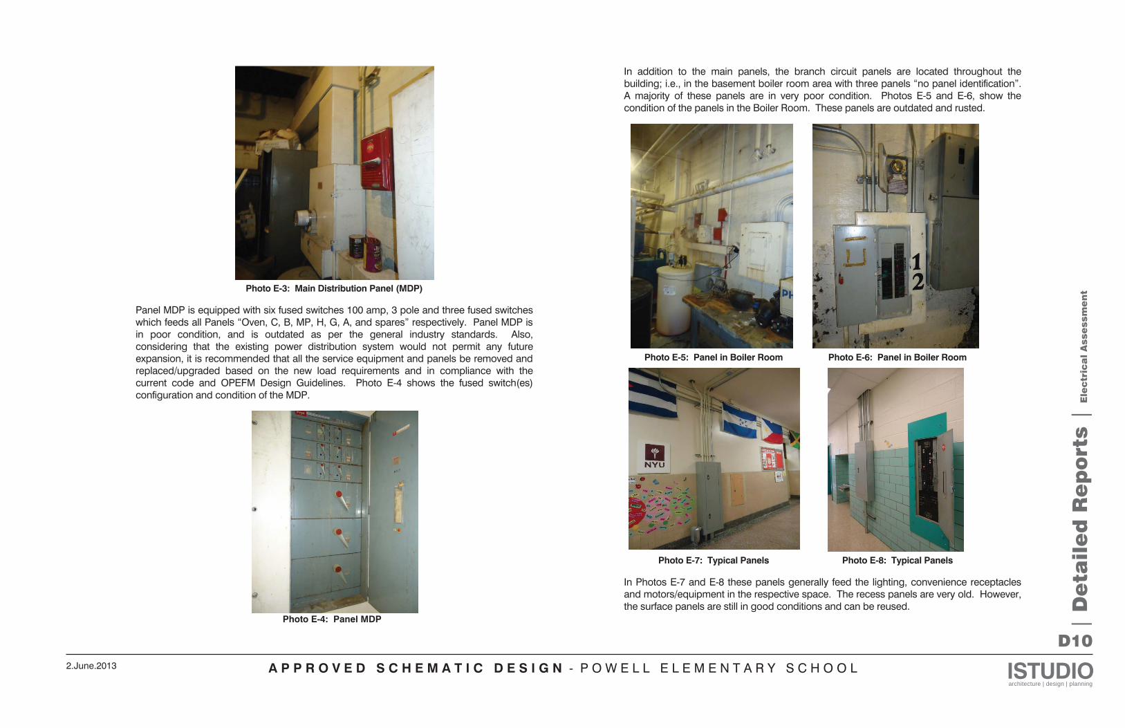
A P P R O V E D S C H E M A T I C D E S I G N - P O W E L L E L E M E N T A R Y S C H O O L ISTUDIOarchitecture | design | planning
2.June.2013
D10
Photo E-3: Main Distribution Panel (MDP)
Panel MDP is equipped with six fused switches 100 amp, 3 pole and three fused switches which feeds all Panels “Oven, C, B, MP, H, G, A, and spares” respectively. Panel MDP is in poor condition, and is outdated as per the general industry standards. Also, considering that the existing power distribution system would not permit any future expansion, it is recommended that all the service equipment and panels be removed and replaced/upgraded based on the new load requirements and in compliance with the current code and OPEFM Design Guidelines. Photo E-4 shows the fused switch(es) configuration and condition of the MDP.
Photo E-4: Panel MDP
In addition to the main panels, the branch circuit panels are located throughout the building; i.e., in the basement boiler room area with three panels “no panel identification”. A majority of these panels are in very poor condition. Photos E-5 and E-6, show the condition of the panels in the Boiler Room. These panels are outdated and rusted.
Photo E-5: Panel in Boiler Room Photo E-6: Panel in Boiler Room
Photo E-7: Typical Panels Photo E-8: Typical Panels
In Photos E-7 and E-8 these panels generally feed the lighting, convenience receptacles and motors/equipment in the respective space. The recess panels are very old. However, the surface panels are still in good conditions and can be reused.
| D
eta
ile
d R
ep
ort
s |
Ele
ctr
ica
l A
sse
ssm
en
t
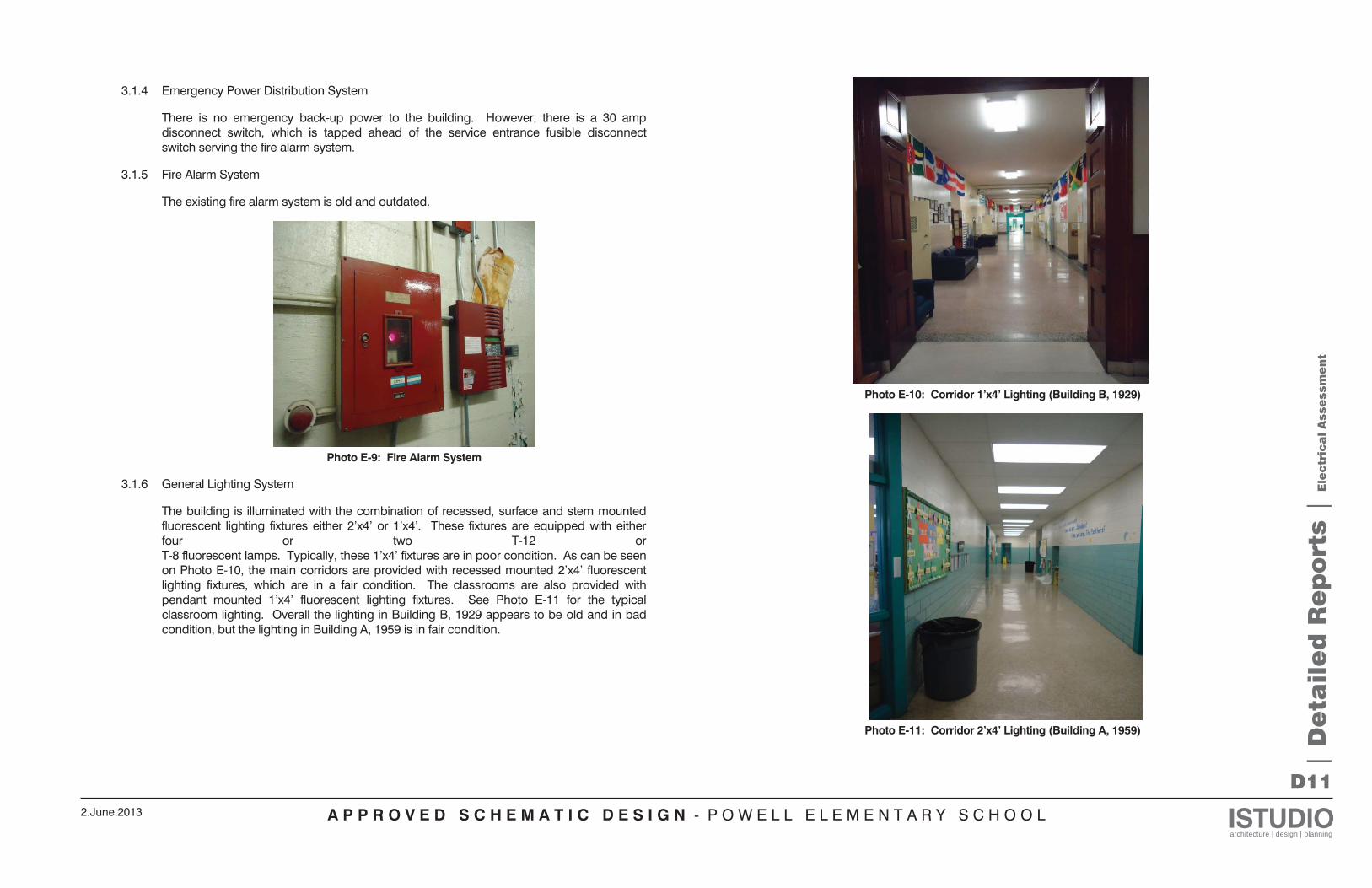
A P P R O V E D S C H E M A T I C D E S I G N - P O W E L L E L E M E N T A R Y S C H O O L ISTUDIOarchitecture | design | planning
2.June.2013
D11
3.1.4 Emergency Power Distribution System
There is no emergency back-up power to the building. However, there is a 30 amp disconnect switch, which is tapped ahead of the service entrance fusible disconnect switch serving the fire alarm system.
3.1.5 Fire Alarm System
The existing fire alarm system is old and outdated.
Photo E-9: Fire Alarm System
3.1.6 General Lighting System
The building is illuminated with the combination of recessed, surface and stem mounted fluorescent lighting fixtures either 2’x4’ or 1’x4’. These fixtures are equipped with either four or two T-12 or T-8 fluorescent lamps. Typically, these 1’x4’ fixtures are in poor condition. As can be seen on Photo E-10, the main corridors are provided with recessed mounted 2’x4’ fluorescent lighting fixtures, which are in a fair condition. The classrooms are also provided with pendant mounted 1’x4’ fluorescent lighting fixtures. See Photo E-11 for the typical classroom lighting. Overall the lighting in Building B, 1929 appears to be old and in bad condition, but the lighting in Building A, 1959 is in fair condition.
Photo E-10: Corridor 1’x4’ Lighting (Building B, 1929)
Photo E-11: Corridor 2’x4’ Lighting (Building A, 1959)
| D
eta
ile
d R
ep
ort
s |
Ele
ctr
ica
l A
sse
ssm
en
t
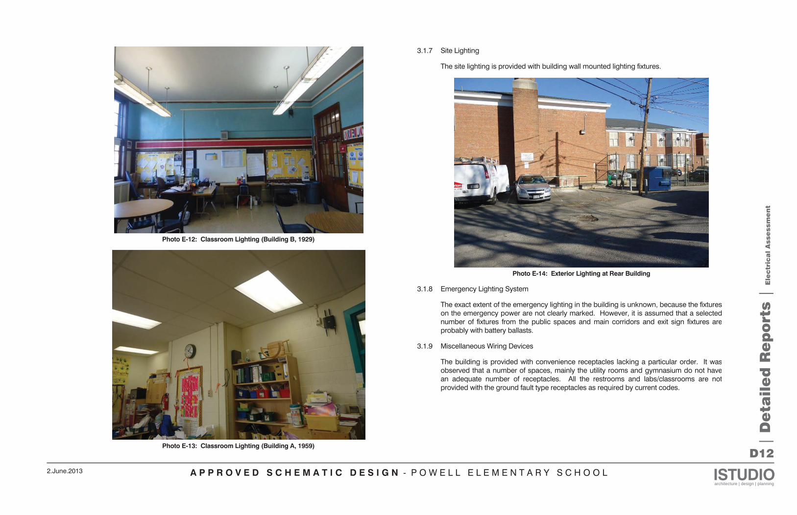
A P P R O V E D S C H E M A T I C D E S I G N - P O W E L L E L E M E N T A R Y S C H O O L ISTUDIOarchitecture | design | planning
2.June.2013
D12
Photo E-12: Classroom Lighting (Building B, 1929)
Photo E-13: Classroom Lighting (Building A, 1959)
3.1.7 Site Lighting
The site lighting is provided with building wall mounted lighting fixtures.
Photo E-14: Exterior Lighting at Rear Building
3.1.8 Emergency Lighting System
The exact extent of the emergency lighting in the building is unknown, because the fixtureson the emergency power are not clearly marked. However, it is assumed that a selectednumber of fixtures from the public spaces and main corridors and exit sign fixtures areprobably with battery ballasts.
3.1.9 Miscellaneous Wiring Devices
The building is provided with convenience receptacles lacking a particular order. It wasobserved that a number of spaces, mainly the utility rooms and gymnasium do not havean adequate number of receptacles. All the restrooms and labs/classrooms are notprovided with the ground fault type receptacles as required by current codes.
| D
eta
ile
d R
ep
ort
s |
Ele
ctr
ica
l A
sse
ssm
en
t
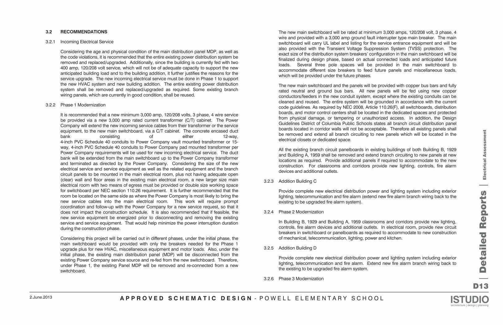
A P P R O V E D S C H E M A T I C D E S I G N - P O W E L L E L E M E N T A R Y S C H O O L ISTUDIOarchitecture | design | planning
2.June.2013
D13
3.2 RECOMMENDATIONS
3.2.1 Incoming Electrical Service
Considering the age and physical condition of the main distribution panel MDP, as well as the code violations, it is recommended that the entire existing power distribution system be removed and replaced/upgraded. Additionally, since the building is currently fed with two 400 amp, 120/208 volt service, which will not be of adequate capacity to support the new anticipated building load and to the building addition, it further justifies the reasons for the service upgrade. The new incoming electrical service must be done in Phase 1 to support the new HVAC system and new building addition. The entire existing power distribution system shall be removed and replaced/upgraded as required. Some existing branch wiring panels, which are currently in good condition, shall be reused.
3.2.2 Phase 1 Modernization
It is recommended that a new minimum 3,000 amp, 120/208 volts, 3 phase, 4 wire service be provided via a new 3,000 amp rated current transformer (C/T) cabinet. The Power Company will extend the new incoming service cables from their transformer or the service equipment, to the new main switchboard, via a C/T cabinet. The concrete encased duct bank consisting of either 12-way, 4-inch PVC Schedule 40 conduits to Power Company vault mounted transformer or 15-way, 4-inch PVC Schedule 40 conduits to Power Company pad mounted transformer per Power Company requirements will be used for new incoming electrical service. The duct bank will be extended from the main switchboard up to the Power Company transformer and terminated as directed by the Power Company. Considering the size of the new electrical service and service equipment as well as the related equipment and the branch circuit panels to be mounted in the main electrical room, plus not having adequate open (clear) wall and floor areas in the existing main electrical room, a new larger size main electrical room with two means of egress must be provided or double size working space for switchboard per NEC section 110.26 requirement. It is further recommended that the room be located on the same side as where the Power Company is most likely to bring the new service cables into the main electrical room. This work will require prompt coordination and follow-up with the Power Company for a new service request, so that it does not impact the construction schedule. It is also recommended that if feasible, the new service equipment be energized prior to disconnecting and removing the existing service and service equipment. That would help minimize the power interruption duration during the construction phase.
Considering this project will be carried out in different phases, under the initial phase, the main switchboard would be provided with only the breakers needed for the Phase 1 upgrade plus for new HVAC, miscellaneous equipment and motor loads. Also, under the initial phase, the existing main distribution panel (MDP) will be disconnected from the existing Power Company service source and re-fed from the new switchboard. Therefore, under Phase 1, the existing Panel MDP will be removed and re-connected from a new switchboard.
The new main switchboard will be rated at minimum 3,000 amps, 120/208 volt, 3 phase, 4 wire and provided with a 3,000 amp ground fault interrupter type main breaker. The main switchboard will carry UL label and listing for the service entrance equipment and will be also provided with the Transient Voltage Suppression System (TVSS) protection. The exact size of the distribution system breakers’ configuration in the main switchboard will be finalized during design phase, based on actual connected loads and anticipated future loads. Several three pole spaces will be provided in the main switchboard to accommodate different size breakers to feed future panels and miscellaneous loads, which will be provided under the future phases.
The new main switchboard and the panels will be provided with copper bus bars and fully rated neutral and ground bus bars. All new panels will be fed using new copper conductors/feeders in the new conduit system, except where the existing conduits can be cleaned and reused. The entire system will be grounded in accordance with the current code guidelines. As required by NEC 2008, Article 110.26(F), all switchboards, distribution boards, and motor control centers shall be located in the dedicated spaces and protected from physical damage, or tampering or unauthorized access. In addition, the Design Guidelines District of Columbia Public Schools states all branch circuit distribution panel boards located in corridor walls will not be acceptable. Therefore all existing panels shall be removed and extend all branch circuiting to new panels which will be located in the electrical closets or dedicated space.
All the existing branch circuit panelboards in existing buildings of both Building B, 1929 and Building A, 1959 shall be removed and extend branch circuiting to new panels at new locations as required. Provide additional panels if required to accommodate to the new construction. For classrooms and corridors provide new lighting, controls, fire alarm devices and additional outlets.
3.2.3 Addition Building C
Provide complete new electrical distribution power and lighting system including exterior lighting, telecommunication and fire alarm (extend new fire alarm branch wiring back to the existing to be upgraded fire alarm system).
3.2.4 Phase 2 Modernization
In Building B, 1929 and Building A, 1959 classrooms and corridors provide new lighting, controls, fire alarm devices and additional outlets. In electrical room, provide new circuit breakers in switchboard or panelboards as required to accommodate to new construction of mechanical, telecommunication, lighting, power and kitchen.
3.2.5 Addition Building D
Provide complete new electrical distribution power and lighting system including exterior lighting, telecommunication and fire alarm. Extend new fire alarm branch wiring back to the existing to be upgraded fire alarm system.
3.2.6 Phase 3 Modernization | D
eta
ile
d R
ep
ort
s |
Ele
ctr
ica
l A
sse
ssm
en
t
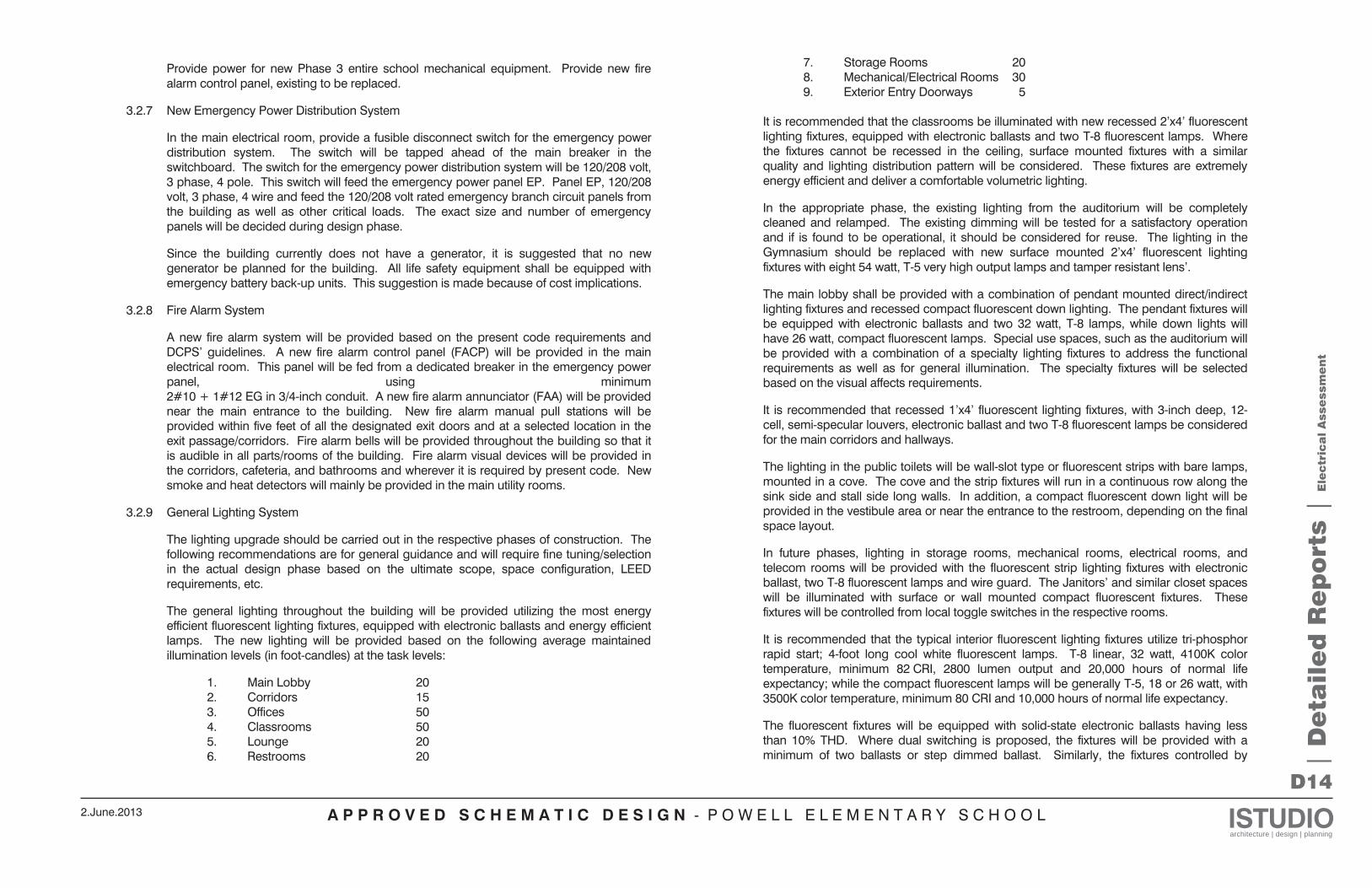
A P P R O V E D S C H E M A T I C D E S I G N - P O W E L L E L E M E N T A R Y S C H O O L ISTUDIOarchitecture | design | planning
2.June.2013
D14
Provide power for new Phase 3 entire school mechanical equipment. Provide new fire alarm control panel, existing to be replaced.
3.2.7 New Emergency Power Distribution System
In the main electrical room, provide a fusible disconnect switch for the emergency power distribution system. The switch will be tapped ahead of the main breaker in the switchboard. The switch for the emergency power distribution system will be 120/208 volt, 3 phase, 4 pole. This switch will feed the emergency power panel EP. Panel EP, 120/208 volt, 3 phase, 4 wire and feed the 120/208 volt rated emergency branch circuit panels from the building as well as other critical loads. The exact size and number of emergency panels will be decided during design phase.
Since the building currently does not have a generator, it is suggested that no new generator be planned for the building. All life safety equipment shall be equipped with emergency battery back-up units. This suggestion is made because of cost implications.
3.2.8 Fire Alarm System
A new fire alarm system will be provided based on the present code requirements and DCPS’ guidelines. A new fire alarm control panel (FACP) will be provided in the main electrical room. This panel will be fed from a dedicated breaker in the emergency power panel, using minimum 2#10 + 1#12 EG in 3/4-inch conduit. A new fire alarm annunciator (FAA) will be provided near the main entrance to the building. New fire alarm manual pull stations will be provided within five feet of all the designated exit doors and at a selected location in the exit passage/corridors. Fire alarm bells will be provided throughout the building so that it is audible in all parts/rooms of the building. Fire alarm visual devices will be provided in the corridors, cafeteria, and bathrooms and wherever it is required by present code. New smoke and heat detectors will mainly be provided in the main utility rooms.
3.2.9 General Lighting System
The lighting upgrade should be carried out in the respective phases of construction. The following recommendations are for general guidance and will require fine tuning/selection in the actual design phase based on the ultimate scope, space configuration, LEED requirements, etc.
The general lighting throughout the building will be provided utilizing the most energy efficient fluorescent lighting fixtures, equipped with electronic ballasts and energy efficient lamps. The new lighting will be provided based on the following average maintained illumination levels (in foot-candles) at the task levels:
1. Main Lobby 20 2. Corridors 15 3. Offices 50 4. Classrooms 50 5. Lounge 20 6. Restrooms 20
7. Storage Rooms 20 8. Mechanical/Electrical Rooms 30 9. Exterior Entry Doorways 5
It is recommended that the classrooms be illuminated with new recessed 2’x4’ fluorescent lighting fixtures, equipped with electronic ballasts and two T-8 fluorescent lamps. Where the fixtures cannot be recessed in the ceiling, surface mounted fixtures with a similar quality and lighting distribution pattern will be considered. These fixtures are extremely energy efficient and deliver a comfortable volumetric lighting.
In the appropriate phase, the existing lighting from the auditorium will be completely cleaned and relamped. The existing dimming will be tested for a satisfactory operation and if is found to be operational, it should be considered for reuse. The lighting in the Gymnasium should be replaced with new surface mounted 2’x4’ fluorescent lighting fixtures with eight 54 watt, T-5 very high output lamps and tamper resistant lens’.
The main lobby shall be provided with a combination of pendant mounted direct/indirect lighting fixtures and recessed compact fluorescent down lighting. The pendant fixtures will be equipped with electronic ballasts and two 32 watt, T-8 lamps, while down lights will have 26 watt, compact fluorescent lamps. Special use spaces, such as the auditorium will be provided with a combination of a specialty lighting fixtures to address the functional requirements as well as for general illumination. The specialty fixtures will be selected based on the visual affects requirements.
It is recommended that recessed 1’x4’ fluorescent lighting fixtures, with 3-inch deep, 12-cell, semi-specular louvers, electronic ballast and two T-8 fluorescent lamps be considered for the main corridors and hallways.
The lighting in the public toilets will be wall-slot type or fluorescent strips with bare lamps, mounted in a cove. The cove and the strip fixtures will run in a continuous row along the sink side and stall side long walls. In addition, a compact fluorescent down light will be provided in the vestibule area or near the entrance to the restroom, depending on the final space layout.
In future phases, lighting in storage rooms, mechanical rooms, electrical rooms, and telecom rooms will be provided with the fluorescent strip lighting fixtures with electronic ballast, two T-8 fluorescent lamps and wire guard. The Janitors’ and similar closet spaces will be illuminated with surface or wall mounted compact fluorescent fixtures. These fixtures will be controlled from local toggle switches in the respective rooms.
It is recommended that the typical interior fluorescent lighting fixtures utilize tri-phosphor rapid start; 4-foot long cool white fluorescent lamps. T-8 linear, 32 watt, 4100K color temperature, minimum 82 CRI, 2800 lumen output and 20,000 hours of normal life expectancy; while the compact fluorescent lamps will be generally T-5, 18 or 26 watt, with 3500K color temperature, minimum 80 CRI and 10,000 hours of normal life expectancy.
The fluorescent fixtures will be equipped with solid-state electronic ballasts having less than 10% THD. Where dual switching is proposed, the fixtures will be provided with a minimum of two ballasts or step dimmed ballast. Similarly, the fixtures controlled by |
De
tail
ed
Re
po
rts |
Ele
ctr
ica
l A
sse
ssm
en
t
A P P R O V E D S C H E M A T I C D E S I G N - P O W E L L E L E M E N T A R Y S C H O O L ISTUDIOarchitecture | design | planning
2.June.2013
D15
dimmer switches will be provided with the dimming ballasts, as recommended by the fixture manufacturer.
The existing exterior/site lighting will be reused, provided they are in a proper working order. These fixtures will be completely cleaned, re-lamped with the matching size and type lamps, and then tested for a safe and satisfactory operation. Where the existing fixtures are found to be non-operational or defective, repair and/or replace the fixture with similar type and quality fixtures. New matching type of lighting fixtures will be provided on an as needed basis, if the existing site lighting is less than needed by the IES standards or per the DC School System’s (OPEFM) guidelines. The site lighting fixtures will be controlled by a combination of the photocell and time clock, wired via a contactor panel.
3.2.10 Emergency Lighting System
Emergency lighting will be provided throughout the building in accordance with current codes. New emergency lighting with battery ballast will be provided in public corridors, stairs, cafeteria, auditorium, gymnasium, public restrooms and other public spaces.
Similarly, exit lighting fixtures will be provided throughout public corridors, near stairways, in the auditorium, gymnasium and cafeteria and at all designated exit doors leading out of the building. Exit fixtures will be of the die-cast aluminum type with LED lamps.
3.2.11 Miscellaneous Wiring Devices
It is recommended that the occupancy sensors be used with dual override switches to control all interior non-emergency lighting in the building, mainly the offices and classrooms. The occupancy sensors will consist of ceiling mounted sensor devices that operate in conjunction with relay units. These sensors send the signals to the respective relay units in the space to turn the associated lighting fixtures on and off.
Similarly, the occupancy sensors utilizing the ultrasonic technology will be considered for all the restrooms. Ultrasonic sensors typically detect changes in air pressure produced by the occupants in the space and do not need to “see” the occupants for activation.
The sensors using a combination of ultrasonic and passive-infrared technology will be used in all other interior spaces. The passive-infrared technology detects heat motion and needs to “see” the person moving for activation. The sensors incorporating dual technology will be used to prevent false activation, which may result from air motion produced by HVAC systems. The dual technology sensors also limit inappropriate deactivation, which may result when small movements are not detected. All sensors will be equipped with time delay, sensitivity adjustment, and daylight compensation features.
All the classrooms and offices, which are controlled by occupancy sensors, will also be provided with local wall switches to override the occupancy sensors, so that room lighting levels can be manually overridden, if so desired by the teachers or the occupants. The implementation of occupancy sensors will also help with LEED points. In the auditorium, gymnasium, utility rooms, computer classrooms and conference rooms, etc., luminaries/lamp switching, and toggle switches will be employed. Special task/function areas, such as auditorium lighting will be controlled from the existing dimmer
switches/systems, if operational; otherwise a new dimming system will be provided in the respective phase.
The exterior lighting will be controlled via a combination of photocell and time clocks, wired via a contactor panel.
Where applicable, the existing convenience receptacles will be reused, provided they are in a proper working condition and are grounded. New 20 amp grounding type duplex convenience receptacles will be provided on an as needed basis in the new space layout. All corridors will have duplex outlets a minimum 50 feet on center. A minimum one duplex receptacle will be provided in each utility and storage room. Also 20 amp duplex receptacles will be provided within 25 feet of mechanical equipment, which are mounted on the roof or outside the building. All receptacles exposed to the weather will be in NEMA 3R enclosures and protected by ground fault interrupter type breakers. The ground fault interrupter type receptacles will be provided within 6 feet of sink areas, in kitchen, private bathrooms, and where required by code. In the labs, receptacles will be mounted on or near the counter tops, whichever is practical.
The new kitchen equipment will be wired as per the manufacturer’s requirements and recommendations. All HVAC motors and equipment will also be wired based on the manufacturers’ requirements and recommendations. All the motors will be provided with motor controllers and disconnect switches. All major equipment will be provided with either fused or non-fused safety switches, based on the actual name plate data. All motor controllers/starters will be a minimum NEMA Size 1, unless required otherwise due to the environmental conditions. All disconnect switches will be heavy duty, either NEMA Type 1 or 3R, depending on the environment conditions at the installed location. All fans with fractional HP motors will be wired via motor rated switches with thermal overload protection.
All branch circuit wiring will be copper, type THHN or THWN, minimum #12 AWG in minimum 3/4-inch conduits. All the circuits serving the computer room outlets will have isolated ground wires, which will be connected to the dedicated grounding system/rod. All interior conduits will be EMT (Electrical Metallic Tubing) unless required otherwise by code. All exterior exposed conduits will be GRS (Galvanized Rigid Steel) and all exterior underground conduits will be PVC Schedule 40, unless required otherwise by code or DCPS criteria.
In all of the offices and computer labs, a combination of voice and data outlets will also be provided, on an as needed basis. These outlets will be wired back to the respective communication systems’ service equipment. In offices, the outlets will be provided next to the desk or work station. As a minimum, junction boxes will be provided at each data communication outlet location and a minimum 1-inch empty conduit with a pull wire will be extended back to the nearest service equipment or rack.
3.2.12 Grounding and Lightning Protection System
A complete grounding and lightning protection system will be provided under an alternate bid, should the DCPS request such a system for the building. The design will include a grounding grid around the building, consisting of a number of 3/4-inch diameter by 10-foot
| D
eta
ile
d R
ep
ort
s |
Ele
ctr
ica
l A
sse
ssm
en
t
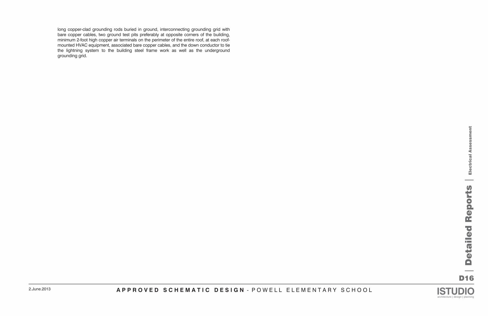
A P P R O V E D S C H E M A T I C D E S I G N - P O W E L L E L E M E N T A R Y S C H O O L ISTUDIOarchitecture | design | planning
2.June.2013
D16
long copper-clad grounding rods buried in ground, interconnecting grounding grid with bare copper cables, two ground test pits preferably at opposite corners of the building, minimum 2-foot high copper air terminals on the perimeter of the entire roof, at each roof-mounted HVAC equipment, associated bare copper cables, and the down conductor to tie the lightning system to the building steel frame work as well as the underground grounding grid.
| D
eta
ile
d R
ep
ort
s |
Ele
ctr
ica
l A
sse
ssm
en
t
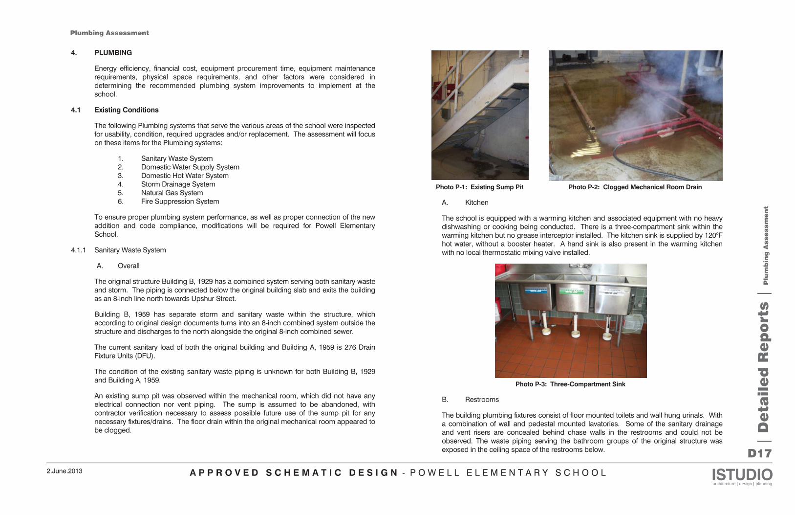
A P P R O V E D S C H E M A T I C D E S I G N - P O W E L L E L E M E N T A R Y S C H O O L ISTUDIOarchitecture | design | planning
2.June.2013
D17
4. PLUMBING
Energy efficiency, financial cost, equipment procurement time, equipment maintenance requirements, physical space requirements, and other factors were considered in determining the recommended plumbing system improvements to implement at the school.
4.1 Existing Conditions
The following Plumbing systems that serve the various areas of the school were inspected for usability, condition, required upgrades and/or replacement. The assessment will focus on these items for the Plumbing systems:
1. Sanitary Waste System 2. Domestic Water Supply System 3. Domestic Hot Water System 4. Storm Drainage System 5. Natural Gas System 6. Fire Suppression System
To ensure proper plumbing system performance, as well as proper connection of the new addition and code compliance, modifications will be required for Powell Elementary School.
4.1.1 Sanitary Waste System
A. Overall
The original structure Building B, 1929 has a combined system serving both sanitary waste and storm. The piping is connected below the original building slab and exits the building as an 8-inch line north towards Upshur Street.
Building B, 1959 has separate storm and sanitary waste within the structure, which according to original design documents turns into an 8-inch combined system outside the structure and discharges to the north alongside the original 8-inch combined sewer.
The current sanitary load of both the original building and Building A, 1959 is 276 Drain Fixture Units (DFU).
The condition of the existing sanitary waste piping is unknown for both Building B, 1929 and Building A, 1959.
An existing sump pit was observed within the mechanical room, which did not have any electrical connection nor vent piping. The sump is assumed to be abandoned, with contractor verification necessary to assess possible future use of the sump pit for any necessary fixtures/drains. The floor drain within the original mechanical room appeared to be clogged.
Photo P-1: Existing Sump Pit Photo P-2: Clogged Mechanical Room Drain
A. Kitchen
The school is equipped with a warming kitchen and associated equipment with no heavy dishwashing or cooking being conducted. There is a three-compartment sink within the warming kitchen but no grease interceptor installed. The kitchen sink is supplied by 120oF hot water, without a booster heater. A hand sink is also present in the warming kitchen with no local thermostatic mixing valve installed.
Photo P-3: Three-Compartment Sink
B. Restrooms
The building plumbing fixtures consist of floor mounted toilets and wall hung urinals. With a combination of wall and pedestal mounted lavatories. Some of the sanitary drainage and vent risers are concealed behind chase walls in the restrooms and could not be observed. The waste piping serving the bathroom groups of the original structure was exposed in the ceiling space of the restrooms below.
| D
eta
ile
d R
ep
ort
s |
Plu
mb
ing
Asse
ssm
en
t
Plumbing Assessment
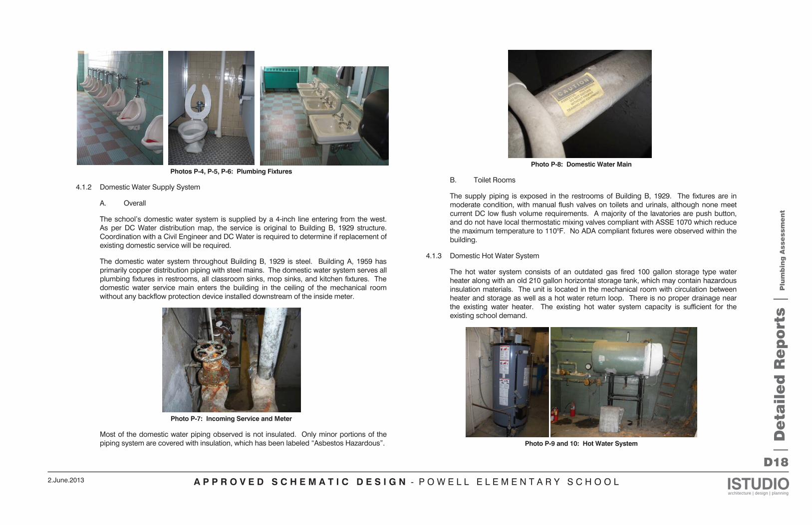
A P P R O V E D S C H E M A T I C D E S I G N - P O W E L L E L E M E N T A R Y S C H O O L ISTUDIOarchitecture | design | planning
2.June.2013
D18
Photos P-4, P-5, P-6: Plumbing Fixtures
4.1.2 Domestic Water Supply System
A. Overall
The school’s domestic water system is supplied by a 4-inch line entering from the west. As per DC Water distribution map, the service is original to Building B, 1929 structure. Coordination with a Civil Engineer and DC Water is required to determine if replacement of existing domestic service will be required.
The domestic water system throughout Building B, 1929 is steel. Building A, 1959 has primarily copper distribution piping with steel mains. The domestic water system serves all plumbing fixtures in restrooms, all classroom sinks, mop sinks, and kitchen fixtures. The domestic water service main enters the building in the ceiling of the mechanical room without any backflow protection device installed downstream of the inside meter.
Photo P-7: Incoming Service and Meter
Most of the domestic water piping observed is not insulated. Only minor portions of the piping system are covered with insulation, which has been labeled “Asbestos Hazardous”.
Photo P-8: Domestic Water Main
B. Toilet Rooms
The supply piping is exposed in the restrooms of Building B, 1929. The fixtures are in moderate condition, with manual flush valves on toilets and urinals, although none meet current DC low flush volume requirements. A majority of the lavatories are push button, and do not have local thermostatic mixing valves compliant with ASSE 1070 which reduce the maximum temperature to 110oF. No ADA compliant fixtures were observed within the building.
4.1.3 Domestic Hot Water System
The hot water system consists of an outdated gas fired 100 gallon storage type water heater along with an old 210 gallon horizontal storage tank, which may contain hazardous insulation materials. The unit is located in the mechanical room with circulation between heater and storage as well as a hot water return loop. There is no proper drainage near the existing water heater. The existing hot water system capacity is sufficient for the existing school demand.
Photo P-9 and 10: Hot Water System
| D
eta
ile
d R
ep
ort
s |
Plu
mb
ing
Asse
ssm
en
t
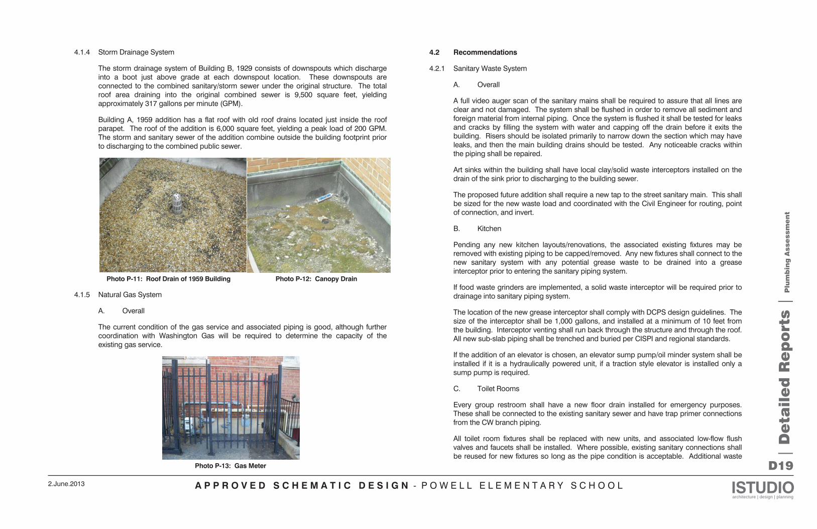
A P P R O V E D S C H E M A T I C D E S I G N - P O W E L L E L E M E N T A R Y S C H O O L ISTUDIOarchitecture | design | planning
2.June.2013
D19
4.1.4 Storm Drainage System
The storm drainage system of Building B, 1929 consists of downspouts which discharge into a boot just above grade at each downspout location. These downspouts are connected to the combined sanitary/storm sewer under the original structure. The total roof area draining into the original combined sewer is 9,500 square feet, yielding approximately 317 gallons per minute (GPM).
Building A, 1959 addition has a flat roof with old roof drains located just inside the roof parapet. The roof of the addition is 6,000 square feet, yielding a peak load of 200 GPM. The storm and sanitary sewer of the addition combine outside the building footprint prior to discharging to the combined public sewer.
Photo P-11: Roof Drain of 1959 Building Photo P-12: Canopy Drain
4.1.5 Natural Gas System
A. Overall
The current condition of the gas service and associated piping is good, although further coordination with Washington Gas will be required to determine the capacity of the existing gas service.
Photo P-13: Gas Meter
4.2 Recommendations
4.2.1 Sanitary Waste System
A. Overall
A full video auger scan of the sanitary mains shall be required to assure that all lines are clear and not damaged. The system shall be flushed in order to remove all sediment and foreign material from internal piping. Once the system is flushed it shall be tested for leaks and cracks by filling the system with water and capping off the drain before it exits the building. Risers should be isolated primarily to narrow down the section which may have leaks, and then the main building drains should be tested. Any noticeable cracks within the piping shall be repaired.
Art sinks within the building shall have local clay/solid waste interceptors installed on the drain of the sink prior to discharging to the building sewer.
The proposed future addition shall require a new tap to the street sanitary main. This shall be sized for the new waste load and coordinated with the Civil Engineer for routing, point of connection, and invert.
B. Kitchen
Pending any new kitchen layouts/renovations, the associated existing fixtures may be removed with existing piping to be capped/removed. Any new fixtures shall connect to the new sanitary system with any potential grease waste to be drained into a grease interceptor prior to entering the sanitary piping system.
If food waste grinders are implemented, a solid waste interceptor will be required prior to drainage into sanitary piping system.
The location of the new grease interceptor shall comply with DCPS design guidelines. The size of the interceptor shall be 1,000 gallons, and installed at a minimum of 10 feet from the building. Interceptor venting shall run back through the structure and through the roof. All new sub-slab piping shall be trenched and buried per CISPI and regional standards.
If the addition of an elevator is chosen, an elevator sump pump/oil minder system shall be installed if it is a hydraulically powered unit, if a traction style elevator is installed only a sump pump is required.
C. Toilet Rooms
Every group restroom shall have a new floor drain installed for emergency purposes. These shall be connected to the existing sanitary sewer and have trap primer connections from the CW branch piping.
All toilet room fixtures shall be replaced with new units, and associated low-flow flush valves and faucets shall be installed. Where possible, existing sanitary connections shall be reused for new fixtures so long as the pipe condition is acceptable. Additional waste |
De
tail
ed
Re
po
rts |
Plu
mb
ing
Asse
ssm
en
t
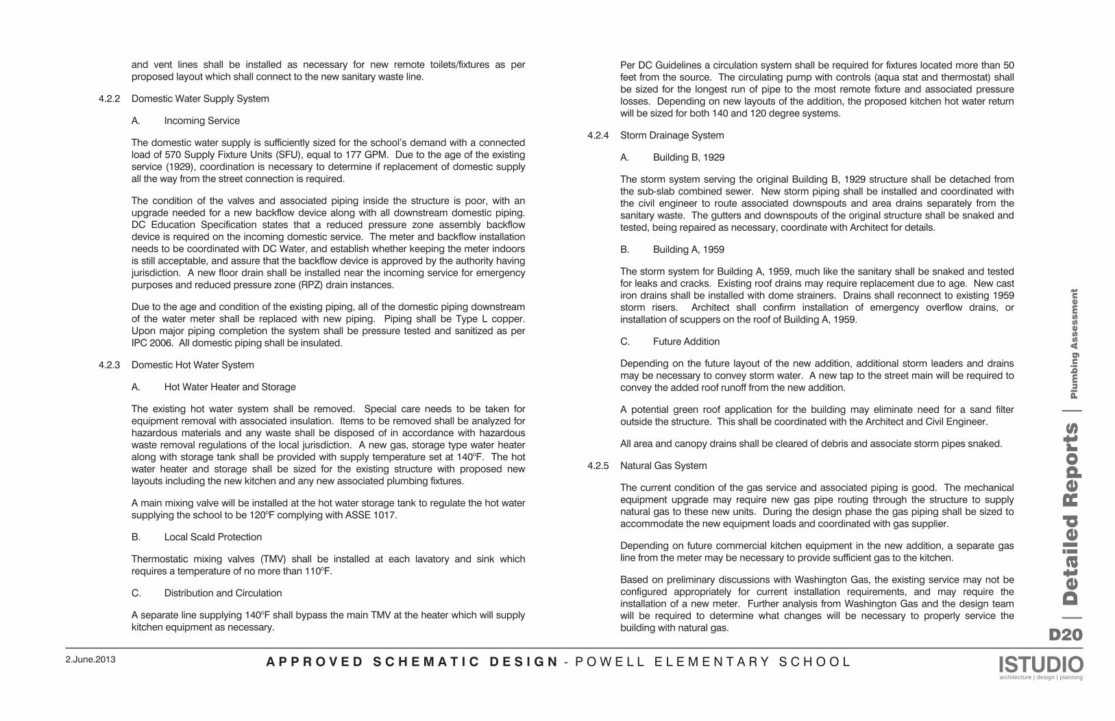
A P P R O V E D S C H E M A T I C D E S I G N - P O W E L L E L E M E N T A R Y S C H O O L ISTUDIOarchitecture | design | planning
2.June.2013
D20
and vent lines shall be installed as necessary for new remote toilets/fixtures as per proposed layout which shall connect to the new sanitary waste line.
4.2.2 Domestic Water Supply System
A. Incoming Service
The domestic water supply is sufficiently sized for the school’s demand with a connected load of 570 Supply Fixture Units (SFU), equal to 177 GPM. Due to the age of the existing service (1929), coordination is necessary to determine if replacement of domestic supply all the way from the street connection is required.
The condition of the valves and associated piping inside the structure is poor, with an upgrade needed for a new backflow device along with all downstream domestic piping. DC Education Specification states that a reduced pressure zone assembly backflow device is required on the incoming domestic service. The meter and backflow installation needs to be coordinated with DC Water, and establish whether keeping the meter indoors is still acceptable, and assure that the backflow device is approved by the authority having jurisdiction. A new floor drain shall be installed near the incoming service for emergency purposes and reduced pressure zone (RPZ) drain instances.
Due to the age and condition of the existing piping, all of the domestic piping downstream of the water meter shall be replaced with new piping. Piping shall be Type L copper. Upon major piping completion the system shall be pressure tested and sanitized as per IPC 2006. All domestic piping shall be insulated.
4.2.3 Domestic Hot Water System
A. Hot Water Heater and Storage
The existing hot water system shall be removed. Special care needs to be taken for equipment removal with associated insulation. Items to be removed shall be analyzed for hazardous materials and any waste shall be disposed of in accordance with hazardous waste removal regulations of the local jurisdiction. A new gas, storage type water heater along with storage tank shall be provided with supply temperature set at 140oF. The hot water heater and storage shall be sized for the existing structure with proposed new layouts including the new kitchen and any new associated plumbing fixtures.
A main mixing valve will be installed at the hot water storage tank to regulate the hot water supplying the school to be 120oF complying with ASSE 1017.
B. Local Scald Protection
Thermostatic mixing valves (TMV) shall be installed at each lavatory and sink which requires a temperature of no more than 110oF.
C. Distribution and Circulation
A separate line supplying 140oF shall bypass the main TMV at the heater which will supply kitchen equipment as necessary.
Per DC Guidelines a circulation system shall be required for fixtures located more than 50 feet from the source. The circulating pump with controls (aqua stat and thermostat) shall be sized for the longest run of pipe to the most remote fixture and associated pressure losses. Depending on new layouts of the addition, the proposed kitchen hot water return will be sized for both 140 and 120 degree systems.
4.2.4 Storm Drainage System
A. Building B, 1929
The storm system serving the original Building B, 1929 structure shall be detached from the sub-slab combined sewer. New storm piping shall be installed and coordinated with the civil engineer to route associated downspouts and area drains separately from the sanitary waste. The gutters and downspouts of the original structure shall be snaked and tested, being repaired as necessary, coordinate with Architect for details.
B. Building A, 1959
The storm system for Building A, 1959, much like the sanitary shall be snaked and tested for leaks and cracks. Existing roof drains may require replacement due to age. New cast iron drains shall be installed with dome strainers. Drains shall reconnect to existing 1959 storm risers. Architect shall confirm installation of emergency overflow drains, or installation of scuppers on the roof of Building A, 1959.
C. Future Addition
Depending on the future layout of the new addition, additional storm leaders and drains may be necessary to convey storm water. A new tap to the street main will be required to convey the added roof runoff from the new addition.
A potential green roof application for the building may eliminate need for a sand filter outside the structure. This shall be coordinated with the Architect and Civil Engineer.
All area and canopy drains shall be cleared of debris and associate storm pipes snaked.
4.2.5 Natural Gas System
The current condition of the gas service and associated piping is good. The mechanical equipment upgrade may require new gas pipe routing through the structure to supply natural gas to these new units. During the design phase the gas piping shall be sized to accommodate the new equipment loads and coordinated with gas supplier.
Depending on future commercial kitchen equipment in the new addition, a separate gas line from the meter may be necessary to provide sufficient gas to the kitchen.
Based on preliminary discussions with Washington Gas, the existing service may not be configured appropriately for current installation requirements, and may require the installation of a new meter. Further analysis from Washington Gas and the design team will be required to determine what changes will be necessary to properly service the building with natural gas.
| D
eta
ile
d R
ep
ort
s |
Plu
mb
ing
Asse
ssm
en
t
A P P R O V E D S C H E M A T I C D E S I G N - P O W E L L E L E M E N T A R Y S C H O O L ISTUDIOarchitecture | design | planning
2.June.2013
D21
4.2.6 Plumbing Fixtures
Depending on the new architectural layout as well as requirements for ADA and LEED, new fixtures will be provided which meet local plumbing codes and DC Public School Guidelines. The DC Education Specifications require wall mounted water closets and urinals for the restrooms. Since the majority of the older schools have floor mounted toilets, a variance will be required from DGS to allow for the installation of new floor mounted units and the reuse of existing piping connections. All bathroom fixtures shall be vitreous china white, with flush valves on toilets and push button faucets on lavatories. Wall hydrants shall be lockable fully recessed 3/4-inch with integral vacuum breaker and frost protection. These units shall be located in all group restrooms (less frost protection) as well as on the outside of the structure. All restroom groups shall have floor drains with trap primers. Art classrooms shall have sinks with clay/solid waste interceptors installed. Science rooms shall have acid neutralizers installed under the sinks prior to discharge to the sanitary system.
All new and relocated restrooms shall have infrastructure added to accommodate the fixtures. Also added fixtures in classrooms shall be evaluated for closest connection points to building domestic and sanitary system.
All water closets should be 1.28 gallons per flush (GPF). The urinals should utilize the “pint” technology offered by several manufacturers only consuming 0.125 GPF. All lavatories should have 0.5 GPM aerators installed, and if metering faucets are selected then only 0.25 gallons per cycle.
5. FIRE PROTECTION
5.1 Existing Conditions
The existing building does not have a fire protection system.
5.2 Recommendations
A new fire service shall be installed to serve Powell Elementary School. Coordination with the DC Fire Marshal is required to determine range of system, and allow for only partial sprinkler installation of the future addition. The design documents will have performance specifications for the new fire protection system. The sprinkler system shall be fully designed by the sprinkler contractor in strict compliance with NFPA-13, and Fire Safety Codes of the Authority having Jurisdiction.
The sprinkler system will include electric valve supervision (i.e., tamper valve switches and all sprinkler control valves will be connected to the building fire alarm system). There will have to be an installation of a Double Check Detector Assembly (DCDA) at the service entrance which will protect the city supply. This backflow device will need to be installed immediately as the service enters the structure.
New sprinkler heads will be standard orifice (1/2-inch), quick response dry type. The temperature ratings will be 135oF in all areas except where higher temperature ratings are required by NFPA 13. Communication rooms, electrical rooms, control rooms, computer rooms, mechanical rooms and telephone rooms will be 165oF and 200oF in possible future elevator machine rooms.
The installation of the sprinkler system shall be coordinated with the phasing of the building schedule and other interior renovations.
| D
eta
ile
d R
ep
ort
s |
Plu
mb
ing
Asse
ssm
en
t
A P P R O V E D S C H E M A T I C D E S I G N - P O W E L L E L E M E N T A R Y S C H O O L ISTUDIOarchitecture | design | planning
2.June.2013
D22
3. IT/AV/SECURITY SYSTEMS
3.1 Telecom Rooms and Distribution Pathways
3.1.1 New Telecom Rooms should be built out in the areas designated on the Architectural floorplans. All new telecommunications cabling should run to the telecom room serving that area. The new Telecom Equipment Room (TER) will be located on the Ground Floor, adjacent to the abandoned Boiler Room. A second telecom room will be located on the 2nd Floor. Rooms will be environmentally conditioned for IT equipment and provided with ladder-rack style cable tray from the room entry to each rack location. The two new telecom rooms will also provide service for the Additions.
The cabling from service providers shall be extended into the new TER. New telecom rooms should be connected to the TER with 12-strand multimode fiber optic cabling and 50-pair twisted pair copper cabling. Sufficient power should be provided at rack locations for distribution equipment and UPS electronics, suitable for the amount of network electronics present in each rack. Special electrical receptacles may be required for the UPS equipment. Existing telecom distribution racks and cabinets should be repositioned in the new telecom rooms, preserving as much of the original equipment as possible. All new cabling should enter and exit rooms through sleeves above the doorway to each room. Space shall be allocated for proper clearances from equipment and management panels and Velcro cable ties will ensure a neat and orderly installation.
A corridor distribution pathway should be provided for low voltage cabling suitable for future growth of systems. In a suspended ceiling environment, J-hook supports are acceptable. In an open ceiling environment, enclosed cable tray, conduit or raceway should be used.
3.2 Data/Telephone/Video Distribution
3.2.1 All data and telephone distribution should originate at a rack-mounted patch panel and terminate in a faceplate assembly at the workstation. Classrooms should have 3 category 6 outlets at the Teacher station for a PC, Voice-over-IP phone and possible IP-enabled accessory (printer, etc.). Classrooms should have 6 category 6 outlets at the back/side of the room for student PCs and other IP-enabled devices. Two category 6 data outlets should be provided 6-8 inches below the suspended ceiling on opposing walls of the classroom to enable a wireless access point. An additional data outlet should be located at the projector. All cabling should be tested and documented to meet Gigabit speeds. Offices and other areas will receive data, telephone and video outlets based upon furniture configuration. Analog phone lines will be routed to fax locations and the elevator machine room.
The video distribution system will consist of a limited number of coaxial cables run to the main office, multi-purpose room and lobby from the Telecom Equipment Room (TER). A data outlet should be co-located with each coax outlet, for future migration to an IP video distribution network. The system is intended to function as a pass-through video distribution network, with the 3 cable boxes received from the TV service provider, allowed
under the Comcast franchise agreement. Video monitors should be located in the main office and lobby to correspond to the coaxial outlets.
Value Engineering Recommendation: Reduce the number of data outlets provided in classrooms to 2 data outlets at the teaching station, 2 data outlets for wireless and 4 data outlets for student locations.
3.3 Classroom Audio-Visual System
3.3.1 Space and power should be allocated for an interactive whiteboard with integrated projector in all classrooms, at the teaching wall. A sound reinforcement amplifier and DVD player should be located on a wall-mounted shelf or cabinet in close proximity to the Teacher’s station. An infrared receiver and speakers for the sound reinforcement system should be located above the classroom seating area. A cable harness should be provided to allow HDMI, SVGA, USB, RGB and 3.5mm audio signals between faceplates at the Teacher’s Station, projector and amplifier locations.
Value Engineering Recommendation: Replace the interactive whiteboard with integrated projector with a wall- or ceiling-mounted projector and pull-down screen.
3.4 Intercom/Master Clock Systems:
3.4.1 Every classroom should contain a clock/speaker assembly in good working order located in a consistent location in all classrooms. The clock should have be analog style with hour, minute and second hands. Clocks shall be controlled and unified across the building. A call-switch with emergency override setting should be provided in each classroom in a consistent location near the corridor doorway. The intercom and master clock system should be improved to a hybrid system, to align with current DCPS and OCTO-DCNET requirements.
Value Engineering Recommendation: Maintain and improve the existing analog intercom system to support the modernization of existing classrooms and the new additions.
3.5 Intrusion/Burglar Alarm System:
3.5.1 The existing intrusion detection system shall be improved as part of the Project. New exterior doors shall be wired with door sensors, and sensitive areas shall contain motion sensors with appropriate zoning, where not already present. New alarm panels will be installed in the addition, tying back to the existing system. Motion sensors should be located in corridors and common areas around the building, where not currently present. Keypads should be located at main entrances and points of egress. The door entry video intercom (Aiphone type) system shall be repaired to allow administrators to prevent or allow access to the facility. The exterior station shall be located at the front entry and the interior station shall be located in the main office.
| D
eta
ile
d R
ep
ort
s |
Tech
nolo
gy
an
d S
ecu
rity
Asse
ssm
en
t
Technology and Security Assessment
A P P R O V E D S C H E M A T I C D E S I G N - P O W E L L E L E M E N T A R Y S C H O O L ISTUDIOarchitecture | design | planning
2.June.2013
D23
3.7 CCTV Surveillance System:
3.7.1 The existing CCTV surveillance system shall be maintained and improved to allow for monitoring of the addition, based upon current DCPS standards. Existing cameras should be repositioned to ensure usable footage is being captured. CCTV cameras should be located in vandal-proof smoked domes throughout the facility. Cameras should cover strategic areas, including points of egress, corridor junctions, stairwells, exterior vestibules, main office, computer lab corridor, gymnasium, auditoriums and multi-purpose rooms. Video footage should be recorded and kept a minimum of 30 days in networked DVR (digital video recording) equipment.
| D
eta
ile
d R
ep
ort
s |
Tech
nolo
gy
an
d S
ecu
rity
Asse
ssm
en
t
A P P R O V E D S C H E M A T I C D E S I G N - P O W E L L E L E M E N T A R Y S C H O O L ISTUDIOarchitecture | design | planning
2.June.2013
D24
Existing Conditions The current foodservice operation is located in the main auditorium and serves meals that are prepared off site. These meals are served on a traditional serving line to students in multiple lunch periods. The pantry supporting the operation consists of the minimal amount of equipment required to support this type of operation both in term of functionality and sanitation. There are 2 walk in refrigerator units located in the auditorium that support the operation. It has been determined that the existing facility does not meet the current operational goals and requirements of DCPS Foodservice Department due to the fact that new elementary schools are utilizing on site preparation, cooking and serving methods. Therefore, the existing facility will be replaced with a new kitchen and servery. The new facility will be constructed as part of the addition phase of the renovation process. Proposed New Kitchen and Servery The new kitchen and servery area shall meet the requirements set forth by DCPS Foodservice Department for a facility that will prepare, cook and serve meals to students on premise. Dialogue with DCPS Foodservice Department is required to confirm the program and project methodology. A proposed menu is also required for analysis and coordination. The space required for the new kitchen and serving area functions is approximately 1,500 SF. The space will consist of the following areas:
Receiving Toilet (1) Employee lockers Dry storage room Refrigerated / frozen storage (walk-in) Food preparation area Food production area (cooking) Serving line with two point of sale stations Foodservice Office with view of serving line and seating area Warewashing and soiled dish drop off window Storage / staging area for prepared meals for pre-K – kindergarten students
The space shall be lockable / securable. Sample equipment list The following list of equipment is a sample of the equipment required for an operation of this type:
Dry storage shelving Mop sink and chemical storage Walk in refrigerator / freezer complex with refrigeration systems Food preparation sink (two compartment) Work tables
Hand sinks (multiple – adequate number to provide easy access for all foodservice employees and at least one in each work area) Cookline:
o Convection oven o Convection steamer o Range with oven base o Tilt skillet o Type I exhaust hood with fire suppression (wet chemical)
Pass through single section full height hot holding cabinet (adjacent to hot food serving station Pass through 2 section full height reach in refrigerator (adjacent to cold food station) Serving equipment
o Milk carton case o Hot food station with auto fill hot wells o Cold food station o Dry food station o Salad bar o Point of Sale Station (two)
Staff Lockers (number to be confirmed) Warewashing facility with drop off window 3 compartment pot sink Pot and pan storage racks
Adjacencies
The facility shall have access to the loading dock and the dumpsters / recycling area. The space shall have direct access to the cafeteria seating area. The dining area shall have direct access to self bussing trash area and the warewashing drop off window.
Finishes All architectural finishes and surfaces shall be durable and easily cleanable to meet the requirements set forth by DCPS, as well as meet the approval of the Department of Health. Utilities / MEP The new facility will require new utility service for the new kitchen and cafeteria. END OF FOODSERVICE NARRATIVE
| D
eta
ile
d R
ep
ort
s |
Food
Se
rvic
e A
sse
ssm
en
t
Food Service Assessment