Embed Size (px)
Citation preview
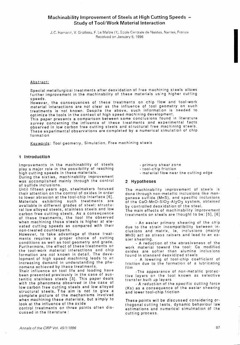
Machinability Improvement of Steels at High Cutting Speeds - Study of TooVWork Material Interaction
J. C. Hamann, V. Grolleau, F. Le MaCtre ( I ) , Ecole Centrale de Nantes, Nantes, France Received on January 6,1996
Spec ia l me ta l l u rg i ca l t rea tmen ts a f te r deox ida t i on of f r e e machin ing s t e e l s al lows fu r the r improvement in the machinabi l i ty of t h e s e mater ia ls us ing h igher c u t t i n g speeds . However, t h e consequences of t h e s e t rea tmen ts o n c h i p f l ow and too l -work mater ia l i n te rac t i ons are not c lea r as t h e i n f l uence of t oo l geometry o n s u c h t rea tmen ts i s not known. Despi te the above, s u c h in fo rma t ion is needed t o op t im ize t h e too ls i n t h e c o n t e x t of h igh speed machin ing development . This paper p r e s e n t s a compar i son between some conc lus ions found i n l i t e ra tu re s u r v e y concern ing t h e i n f l uence of t h e s e t rea tmen ts and exper imen ta l f a c t s o b s e r v e d i n low ca rbon f ree c u t t i n g s tee l s and s t r u c t u r a l f ree machin ing s t e e l s . These exper imen ta l obse rva t i ons are comp le ted by a numer ica l s imu la t i on of c h i p format i on
Kevwords : Tool geomet ry , S imulat ion, Free machin ing s tee l s
I Introduction
Improvemen ts i n t h e machinabi l i ty of s tee l s p lay a major ro le in t h e poss ib i l i t y of reaching h igh c u t t i n g speeds i n t h e s e mater ia ls . Dur ing t h e s i x t i e s , machinabi l i ty improvement was accomp l i shed mainly th rough the c o n t r o l of su l f i de i nc lus ions . Un t i l f i f t e e n y e a r s ago, s tee lmakers f o c u s e d the i r a t ten t i on o n t h e c o n t r o l of ox ides in order t o lower ab ras ion at t h e t o o l - c h i p i n te r face [ 6 ] . Mater ia ls exh ib i t i ng s u c h t rea tmen ts are ava i l ab le i n d i f f e ren t grades of s tee l : s t r u c t u - ra l low a l l oyed s t e e l s , s t a i n l e s s s tee l s and low c a r b o n f r e e c u t t i n g s t e e l s . A s a consequence of t h e s e t rea tmen ts , t h e tool l i fe obse rved w h e n machin ing t h o s e s tee l s is h igher at e le - v a t e d c u t t i n g s p e e d s as compared with the i r non- t reat ed coun te rpa r t s . However , t o t a k e advan tage of t h e s e t rea t - ments requi res a proper c h o i c e of c u t t i n g cond i t i ons as wel l as t o o l geometry and grade. Fur thermore, t h e e f f e c t of t h e s e t rea tmen ts on t h e too l -work ma te r ia l i n te rac t i ons and ch ip fo rma t ion are not known i n deta i l . The deve - lopment of h igh s p e e d machin ing leads t o an i nc reas ing demand i n unders tand ing t h e phe- nomena a c h i e v e d by t h e s e t rea tmen ts . Their i n f l uence o n too l l i fe and loading have been p resen ted p rev ious l y in t h e c a s e of aus - t e n i t i c s ta in less s t e e l s [3] . This paper deals wi th t h e phenomena o b s e r v e d in t h e c a s e of low ca rbon f r e e c u t t i n g s tee l s and low a l loyed s t r u c t u r a l s t e e l s . T h e aim is not to g ive a comp le te p i c t u r e of t h e mechanisms invo lved when machin ing t h e s e mater ia ls , but s imply t o look at t h e i n f l uence of t h e ox ide c o n t r o l t rea tmen ts on th ree po in ts o f t e n d i s - c u s s e d in t h e l i t e ra tu re :
- pr imary shear z o n e - t oo l - ch ip f r i c t i o n - mater ia l f l o w near t h e c u t t i n g edge
2 Hypotheses
The machinabi l i ty improvement of s tee ls is done th rough non-meta l l ic i nc lus ions l i ke man- ganese su l f i de (MnS), and spec i f ic inc lus ions of t h e C a O - M n O - S i 0 2 - A I 2 0 3 s y s t e m , obta ined by con t ro l l ed deox ida t i on of t h e s tee l . The main e f f e c t s of machinabi l i ty improvement t rea tmen ts o n s tee l s are though t t o be: [ 5 ] , [ 6 ]
- An eas ie r pr imary shear ing of t he c h i p due t o t h e s t ra in i ncompa t ib i l i t y between in- c lus ions and matr ix , ie, i nc lus ions (mainly MnS) ac t as s t r e s s ra i se rs and lead t o an ea- s ie r s h-earing.
- A reduc t i on of t h e ab ras i veness of t h e work mater ia l toward t h e too l : Ca modif ied ox ides are s o f t e r t h a n a lumina inc lus ions f o u n d i n s tandard deox id i zed s t e e l s
- A lower ing of t o o l - c h i p coe f f i c i en t of f r i c t i o n due t o t h e fo rma t ion of a lubr icat ing f i lm
-The appearance of non-meta l l ic p ro tec - t i v e l aye rs on t h e t o o l known as se lec t i ve t r a n s f e r bu i l t u p l aye rs
- A reduc t i on of t h e s p e c i f i c c u t t i n g fo rce (Ks) as a consequence of t h e eas ier shear ing and lower t o o l - c h i p f r i c t i o n
These points wi l l be d i s c u s s e d cons ide r ing o r - t hogona l c u t t i n g t e s t s , dynamic behaviour law es t imat ions and numer ica l s imulmat ion of t h e c u t t i n g p r o c e s s .
Annals of the ClRP Vol. 45/1/1996 87
.
c Mn S S i S 3 0 0 0, l 1,43 0,36 0,005 S3OOSi 0,073 0,11 0,294 0,177
3 Materials
Ca 0 0,001
Table 4 : C o n s t a n t s of t h e c o n s t i t u t i v e mode l
C Cr Mo 0,41 1,044 0,16 S i S C a
Four s t e e l s are c o n s i d e r e d in t h i s s t u d y : - Two low c a r b o n f r e e c u t t i n g s t e e l s . The f i r s t one is a s t a n d a r d 0,3% su lphu r c o n t e n t f ree c u t t i n g s t e e l (S300) , t h e s e c o n d one has t h e same ca rbon a n d su lphu r c o n t e n t bu t r e c e i v e d a s p e c i a l S iCa b a s e d t r e a t m e n t a f t e r d e o x i d a - t i on (S3OOSi).
Mn 0,784
- Two low a l l o y e d s t r u c t u r a l f r e e mach in ing s t e e l s . They are b a s e d o n t h e 4142 A l S l s t a n - da rd grade, w i t h an improved mach inab i l i t y and a su lphu r c o n t e n t of app rox ima t l y 0 ,025%.The f i r s t one (42CD4 U), i s a s t a n d a r d s t r u c t u r a l f r e e mach in ing s t e e l , and t h e s e c o n d (42CD4 Ca) r e c e i v e d a Ca t rea tmen t a f t e r deox ida t i on .
Tab le 2 : Chemica l c o m p o s i t i o n of t h e 42CD4 U
- . I
0,339 1 0,022 I 0,0003 1 Tab le 3 : Chemica l c o m p o s i t i o n of t h e 42CD4
0,027 0,0054
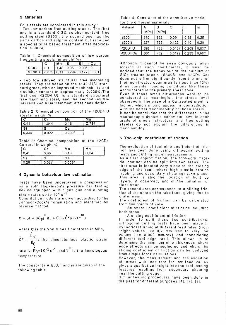
4 Dynamic behaviour law estimation
Tes ts h a v e b e e n u n d e r t a k e n in c o m p r e s s i o n on a sp l i t Hopk inson ' s p r e s s u r e ba r t e s t i n g d e v i c e equ ipped w i th a gas gun and a l low ing s t r a i n r a t e s u p t o 104 s - 1 C o n s t i t u t i v e mode ls a re g i v e n acco rd ing t o t h e Johnson-Cook ' s f o r m u l a t i o n and iden t i f i ed by r e v e r s e me thod :
where (r i s t h e Von M ises f l o w s t r e s s in MPa,
6 * = 4 s t h e d imens ion less p l a s t i c s t r a i n 6 &O *
ra te for &=l O-3s-l , and T i s t h e homologous tempera tu re
The c o n s t a n t s A ,B,C,n and m are g i ven in t h e fo l low ing tab le .
f o r t h e d i f f e r e n t ma te r ia l s
A l though it c a n n o t b e s e e n obv ious l y when look ing at s u c h c o e f f i c i e n t s , it must b e n o t i c e d t h a t t h e b e h a v i o u r of t h e c a l c i u m o r S iCa t r e a t e d s t e e l s (S3OOSi and 42C04 Ca) does no t d i f f e r s i g n i f i c a n t l y f r o m t h e one of t he i r non t r e a t e d c o u n t e r p a r t s ( l e s s t h a n 10%) if we c o n s i d e r l oad ing c o n d i t i o n s l i ke t h o s e e n c o u n t e r e d i n t h e p r imary s h e a r zone . E v e n i f t h e s e sma l l d i f f e r e n c e s were t o be c o n s i d e r e d as mean ing fu l , t h e s t r e s s l eve l o b s e r v e d in t h e c a s e of a Ca t r e a t e d s t e e l is h igher , wh ich s h o u l d appear in c o n t r a d i c t i o n w i th t h e b e t t e r mach inab i l i t y of t h o s e s t e e l s . I t c a n b e c o n c l u d e d t h a t t h e d i f f e r e n c e s in t h e m a c r o s c o p i c dynamic behav iou r laws in e a c h g rade of s t e e l s ( s t r u c t u r a l and f ree c u t t i n g s t e e l s ) d o no t exp la in t h e d i f f e r e n c e s in mac h inab i l i t y .
5 Tool-chip coefficient of friction
The e v a l u a t i o n of t o o l - c h i p c o e f f i c i e n t o f f r i c - t i o n has been done u s i n g o r thogona l c u t t i n g t e s t s and c u t t i n g f o r c e measuremen ts . A s a f i r s t app rox ima t ion , t h e too l -work mate- r ia l c o n t a c t c a n b e sp l i t i n t o two a reas . The f i r s t a rea i s l o c a t e d ve ry c l o s e t o t h e c u t t i n g edge of t h e tool , where h igh p l a s t i c s t ra ins ( rubb ing and s e c o n d a r y shear ing ) t a k e p l a c e . This a rea i s a l so t h e l o c a t i o n of bu i l t u p l aye rs , if o b s e r v e d , and of t h e i n i t i a t i on of f l ank wear. The s e c o n d a rea c o r r e s p o n d s t o a s l i d ing f r i c - t i o n of t h e c h i p on t h e r a k e f a c e , g i v ing r i se t o c r a t e r wear . The c o e f f i c i e n t of f r i c t i o n c a n b e c a l c u l a t e d f r o m two p o i n t s of v iew :
- An o v e r a l l c o e f f i c i e n t of f r i c t i o n i nc lud ing b o t h a reas
- A s l i d ing c o e f f i c i e n t of f r i c t i o n I n o rder t o sp l i t t h e s e two c o n t r i b u t i o n s , o r thogona l c u t t i n g t e s t s h a v e been made in c y i i n d r i c a l t u rn ing at d i f f e r e n t f e e d ra tes ( f rom "h igh" v a l u e s l i k e 0 ,7 mm / r e v t o ve ry low va lues l i k e 0 ,002 mm/ rev ) and cons ide r ing d i f f e ren t t oo l edge rad i i . This al lows u s t o de te rm ine t h e min imum c h i p t h i c k n e s s where edge e f f e c t s c a n b e n e g l e c t e d and where t h e s l i d ing c o e f f i c i e n t of f r i c t i o n c a n b e deduced f r o m s imp le f o r c e c a l c u l a t i o n s . However , t h e measuremen t and t h e evo lu t i on of f o r c e s w i th f e e d r a t e f o r l ow f e e d va lues g i v e s a q u a l i t a t i v e i ns igh t i n t o t h e t o o l load ing f e a t u r e s r e s u l t i n g f r o m s e c o n d a r y shear ing near t h e c u t t i n g edge. S imi la r t e s t i n g p r o c e d u r e s h a v e been done in t h e pas t f o r d i f f e r e n t p u r p o s e s [ 4 ] , [ 7 ] , [8] .
88
5.1 Testing procedure is g i ven in f i gu re 2, in t h e c a s e of coa ted ca rb ide tools .
In each case a P10 grade carbide tool is used with cutting angles given as follows:
y ["I 1 s ["I K r ["I +6 0 90
The cho ice of a non -coa ted too l is d i c t a t e d by t h e abi l i ty of hav ing d i f f e ren t and reproducib le c u t t i n g edge rad i i wi th a s imple honing of t he tool. Befo re each t e s t t h e c u t t i n g edge radius ( r p ) of t he tool i s measured us ing a non -con tac t i ng l a s e r beam prof i lometer . The dep th of cu t was 3mm and t h e c u t t i n g speed 200 and 300 m/min i n t h e c a s e of low c a r b o n f ree c u t t i n g s tee l s and 100 m/min in t h e c a s e of t h e 4142 g rade s tee l s . These c u t t i n g speeds have been c h o s e n f o r t h e fo l lowing reasons :
- I n t h e c a s e of low carbon f r e e cutt ing s t e e l s , machin ing at 200 m/min g i ves r i se t o a ve ry smal l bu i l t up edge in t h e two t y p e s of s t e e l s , s imi lar in s i z e bu t d i f f e ren t in shape as c a n b e seen on qu ick s t o p t e s t s [2 ] .Th i s smal l and s tab le bu i l t u p edge (BUE) is supposed t o p r o t e c t t he c u t t i n g edge f rom wear. For higher c u t t i n g speeds t h e BUE d i sappears in bo th s t e e l s , however the S3OOSi grade exh ib i t s a s e l e c t i v e t r a n s f e r bu i l t u p l aye r (BUL) whose maximum t h i c k n e s s is reached at 300 m/min. A f u r the r i nc reas ing i n t h e c u t t i n g speed leads t o a loss of s tab i l i t y of t h i s BUL and at 400 m/min t h e t o o l l i f e is s imi lar f o r b o t h s tee l s ( f i gu re 1 ) .
u 5000 t cu n I I >
0 4000 k 5 2000
3000 m
1000
0
S300
S ~ O O S ~
0 0 0 0 m o o 0 l - n l m d -
Cutting speed [m/min] Fiaure 1: Evolution of tool life expressed in amount of metal removed in the case of low carbon free cutting
steels
- I n t h e c a s e of structural f ree machining s t e e l s t h e c h o i c e of s u c h a low c u t t i n g speed is expla ined f i r s t by t h e need t o have a con t inuous ( r i bbon l i ke ) c h i p i n order t o apply ca l cu la t i on . Second ly , f o r h igher c u t t i n g speeds , t h e t o o l l i f e w i th a non -coa ted tool i s t o o low and t h e wear ing of t h e tool dur ing the t e s t shou ld lead t o er roneous in te rp re ta t i on . Tool l i f e t e s t s us ing des igned exper iments h a v e been under taken us ing c o a t e d ( i ndus t r i a l c h o i c e ) and n o n - c o a t e d tools and have shown a s imi lar behav iou r i n t h e two c a s e s wi th t h e c u t t i n g speed . The evo lu t i on of t o o l l i f e wi th t h e c u t t i n g s p e e d in t h e two s t r u c t u r a l s tee l s
2500T n 2000
' 1500
2
E
-8
CI) 1000 z 0
500
0
42CD4U
0 4 2 ~ ~ 4 c a
i 0 0 0 0 m a * m ? ? N n l
Cutting speed [m/min] Fiaure 7: Evolution of tool life expressed in amount of metal removed in the case of the4 142 grade of structural free machining steels
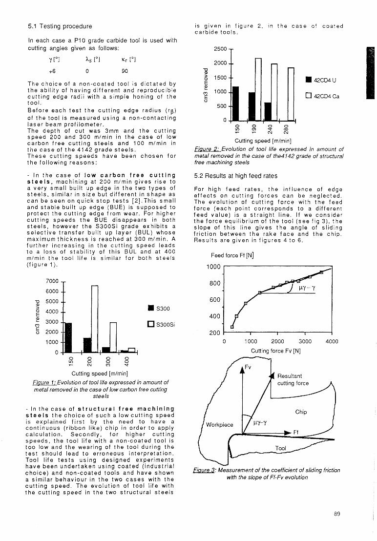
5.2 Results at high feed rates
For high f e e d ra tes , t h e i n f l uence of edge e f f e c t s o n c u t t i n g f o r c e s c a n b e neglected. The evo lu t i on of c u t t i n g f o r c e wi th t h e feed f o r c e ( e a c h point co r responds t o a d i f ferent f e e d va lue ) is a s t ra igh t l ine. If we cons ide r t h e f o r c e equi l ibr ium of t h e t o o l ( s e e f i g 3), t he s lope of t h i s l ine g i ves t h e angle of s l id ing f r i c t i o n between t h e rake f a c e and t h e ch ip. Resu l t s are g i ven in f i gu res 4 t o 6.
Feed force Ff IN]
1000
800
600
400
200 1 I I I 1 0 1000 2000 3000 4000
Cutting force Fv [N] - f fFv 1 Resultant
Fiutlre 3: Measurement of the coefficient of sliding friction with the slope of Ff-Fv evolution
89
Cutting force Fv [N]
40008
400
300'
200-
100-
0
2000-
1000-
*
4 S300 -300m/min f S300-200m/min -B- S3OOSi - 300m/min -0. S3OOSi - 200m/min
I I I I I I
Ca
800 *
600 - 400 - 200 -
Low carbon free cutting steels
J
Y
I I I
I
Tool geometry at feed scale 'P -
0
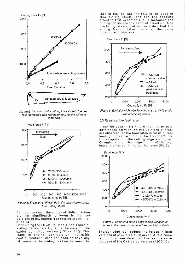
Fiaure 4: Evolution of the cutting force Fv with the feed rate (compared with tool geometry) for the different
mate rials
I I I
A s i t c a n be seen , t h e angles of s l id ing f r i c t i o n are not s ign i f i can t l y d i f f e ren t in the two ve rs ions of low c a r b o n f r e e c u t t i n g s tee l s ( i . e . c i r c a 1 4 O ) .
Concern ing t h e s t r u c t u r a l s t e e l s , t h e angles of s l i d ing f r i c t i o n are h igher in t h e c a s e of t h e ox ides con t ro l l ed ve rs ion (13 " v s 14"). Th is leads t o ano the r c o n t r a d i c t i o n : t h e o x i d e c o n t r o l t rea tmen t does not seem t o have any i n f l uence on t h e s l id ing f r i c t i o n between t h e
f a c e of t he t o o l and the c h i p i n t h e c a s e of f ree c u t t i n g s tee l s , and has t h e oppos i te e f f e c t t o that e x p e c t e d ( i .e. i t i nc reases the s l id ing f r i c t i o n ) in t h e c a s e of s t r u c t u r a l f ree machin ing s t e e l s . Let us remember tha t t he s l i d ing f r i c t i o n t a k e s p l a c e at t h e same loca t i on as c ra te r wear
Feed force Ff [N]
increasing feed
600 8 o o ~ J
400, a peek value at beginning
I I I
-a- 42CD4Ca
* 42C04U 4 42CD4C
standard value
0 1000 2000 3000 4000 Cutting force Fv [N]
Fiaure 6: Evolution of Ff with Fv in the case of 4142 grade free machining steels
5.3 Results at low feed rates
I t c a n be s e e n in f i g 4 t o 6 t h a t t h e pr imary d i f f e rences between t h e two ve rs ions of s t e e l are obse rved f o r low f e e d ra tes in te rms of t o o l loading f o r c e s . Wi thout a Ca t rea tmen t the f o r c e s appl ied on t h e c u t t i n g edge are h igher . Changing t h e c u t t i n g edge rad ius of t he t o o l leads t o an o f f s e t in t h e c u t t i n g f o r c e (Fig 7).
Feed force Ff [N] 1200 1
1000 -1
-8- 42CD4U-O,039mm -6- 42 CD4 U-O,026m -0- 42CD4Ca-O,026mm
0 1000 2000 3000 4000
Cutting force Fv [N]
Fiaure 7: Effect of a cutting edge radius variation on forces in the case of structural free machining steels
Sharper edge rad i i r educe t h e f o r c e s in bo th ve rs ions of 4142 s tee l s . However , i f t h i s f o r c e reduc t i on is s e n s i t i v e f rom low f e e d rates in t h e c a s e of t h e Ca t r e a t e d ve rs ion (42CD4 Ca),
90
i t i s obse rved only at h igh f e e d ra tes i n the c a s e of the 42CD4 U, when c u t t i n g edge e f - f e c t s are weak.
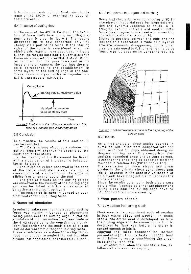
5.4 Influence of cutting timr?
I n the c a s e of t h e 42CD4 Ca s tee l , t he evo lu - t i o n of f o rces wi th t ime dur ing an o r thogona l c u t t i n g t e s t is g i ven in f i g Q r e 8. The resu l t s d i s c u s s e d u p t o now concerned only the s teady s t a t e part of t h e f o r c e . I f t h e s ta r t i ng va lue of t he f o r c e is cons ide red when ma- ch in ing th is mater ia l , one obse rves , in f igura 5, t ha t t h e resu l t s ob ta ined are ve ry s imi lar t o t h o s e obse rved wi th the 42CD4 U s tee l . I t c a n be deduced tha t t h e peek o b s e r v e d in the f o r c e at the en t rance of t h e tool i n t o the m a - te r i a l co r respcnds t o the es tab l i shmen t of some layers on t h e c u t t i n g edge of t h e tool. These layers, ana lyzed wi th a microprobe on a S.E. M. , are made of (Mn,Ca)S.
Cutting force I starting value= maximum value In
t standard value=mean value at steady state
I [ 2s Time
Fiaure 8: Evolution of the cutting force with time in the case of structural free machining steels
5.5 Conclusion
To summar ize t h e resu l t s of t h i s sec t i on , i t c a n b e sa id tha t :
- The Ca t rea tmen t e f f e c t i v e l y reduces the c u t t i n g fo rce (Fv) and t h u s t h e s p e c i f i c c u t t i n g c o e f f i c e n t of t he s t e e l s
- The lower ing of t h e K s canno t b e l i nked wi th a mod i f i ca t i on of t h e dynamic behaviour law of t he s tee l s
- The lower K s va lues o b s e r v e d in t h e c a s e of t h e ox ide con t ro l l ed s tee l s are not a consequence of a reduc t i on of t h e angle of s l id ing f r i c t i o n on t h e f a c e of t he tool
- The greater e f f e c t s o n t h e c u t t i n g fo rces are obse rved in t h e v i c in i t y of t he c u t t i n g edge and c a n be l i nked wi th t h e appearance of s e l e c t i v e t r a n s f e r bu i l t up l aye rs
- The f e e d f o r c e is more i n f l uenced by s u c h t rea tmen ts t h a n t h e c u t t i n g f o r c e
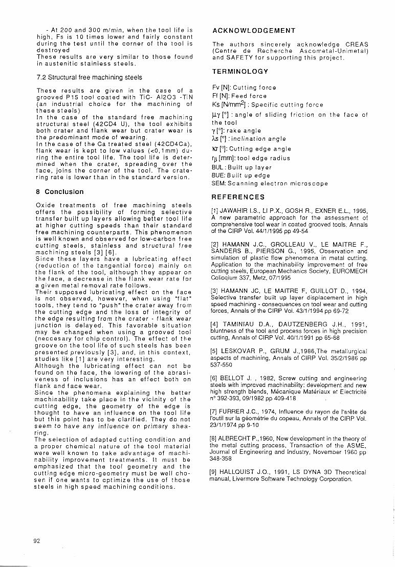
6.1 Finite elements progam and meshing
Numer ica l s imu la t i on was done us ing a 3 0 f i - n i t e element i ndus t r i a l code fo r large deforma- t i on and dynamic response of so l i ds . A la- grangian exp l i c i t ana lys i s and c e n t r a l d i f f e - rence t ime in teg ra t i on are used wi th a meshing of t h e tool and t h e workpiece [ 9 ] . S l id ing is p o s s i b l e between t h e c h i p and the t o o l and c h i p separa t i on is made by a layer of er ros i ve e lements d i sappear ing fo r a g i ven p l a s t i c s t r a i n equa l t o 0 , 8 ( chang ing t h i s va lue f rom 0 , 6 t o 1 , 0 does not i n f l uence t h e resu l t s ) .
fiaure 9: Tool and workpisce mesh at the beginning of the steady state
6.2 Results
As a f i r s t ana lys i s , shear angles oberved in numer ica l s i rnulat ion were compared wi th the ones measured o n ch ips ob ta ined dur ing o r - t hogona l c u t t i n g t e s t s . This compar i son sho - wed tha t numer i ca l shear angles were co r rec t , lower t h a n t h e shear angles e x p e c t e d f rom t h e Merchant 's re la t i onsh ip (28 " t o 3 0 " v s 40"). The e v a l u a t i o n of shear stress and shear s t ra ins i n the pr imary shear z o n e shows tha t t h e d i f f e r e n c e s in t h e c o n s t i t u t i v e models of b o t h s t e e l s h a v e a neglect ib le i n f l uence on t h e pr imary shear ing . S ince t h e r e s u l t s obta ined i n b o t h s tee l s were ve ry s imi lar , it c a n b e s a i d tha t t h e phenomena t a k i n g p l a c e near t h e c u t t i n g edge have no i n f l uence o n the pr imary shear ing.
7 Wear pattern of tools 6 Numerical simulation
7.1 Low carbon free cutting steels I n order t o make su re tha t t he spec i f i c c u t t i n g f o r c e was main ly i n f l u e n c e d by phenomena t a k i n g p lace near t h e c u t t i n g edge, numer ica l s imulat ion of c h i p fo rma t ion has been made in t h e 4142 s t e e l s u s i n g t h e c o n s t i t u t i v e models i den t i f i ed ear l ier and t h e coe f f i c i en t of s l id ing f r i c t i o n de r i ved f rom o r thogona l c u t t i n g t e s t s . These s imulat ions were done fo r a c h i p t h i c k - ness h igh enough t o neg lec t t h e c u t t i n g edge e f f e c t s , not cons ide red fo r t h e s e ca l cu la t i ons .
Flank wear is t he predominant mode of wear ing in b o t h c a s e s (S300 and S3OOSi). i n t h e s e s t e e l s , t h e c r a t e r wear is deve loped f a r f rom t h e c u t t i n g edge and t h e co rne r of t h e tool is d e s t r o y e d by f l ank wear be fo re t h e c r a t e r i s sp read enough t o jo in i t . Apply ing t h e fo rce decompos i t i on met hod p r e s e n t e d in [ 3 ] , t o o l l i fe t e s t s of S3OOSi lead t o t h e fo l lowing resu l t s cons ide r ing the shear fo rce o n t h e f lank ( F s ) :
- At 400m/min, when the too l l i f e is low, Fs fo l lows a f l ank wear l i ke evo lu t i on
91
- At 200 and 3 0 0 m/rnin, when t h e tool l i f e is h igh, Fs is 10 t imes lower and fa i r l y c o n s t a n t dur ing t h e t e s t u n t i l t h e co rne r of t h e t o o l is d e s t r o y e d These resu l t s are very s imi lar t o t h o s e f o u n d i n aus ten i t i c s t a i n l e s s s tee l s .
ACKNOWLODGEMENT
The au tho rs s ince re l y acknow ledge CREAS (Centre de Recherche Ascometa l -Un ime ta l ) and SAFETY f o r suppor t i ng th i s p r o j e c t .
TERMINOLOGY 7.2 Structural free machining steels
These resu l t s are g i v e n in t h e c a s e of a g rooved P15 t o o l c o a t e d wi th T i c - A1203 -T iN (an i ndus t r i a l c h o i c e f o r t he machin ing of t h e s e s t e e l s ) I n t h e c a s e of t h e s tandard f ree machin ing s t r u c t u r a l s t e e l (42CD4 U), t h e too l exh ib i t s b o t h c r a t e r and f l ank wear but c r a t e r wear is t h e predominant mode of wear ing. I n t h e c a s e of t h e Ca t r e a t e d s t e e l (42CD4Ca), f l ank wear is k e p t t o low va lues ( e 0 , l m m ) du - r ing t h e en t i re too l l i fe . The t o o l l i f e is de te r - mined when t h e c r a t e r , sp read ing ove r t h e f a c e , jo ins t h e co rne r of t h e tool. The c r a t e - r ing ra te is lower t h a n in the s tandard ve rs ion .
8 Conclusion
O x i d e t rea tmen ts of f r e e machin ing s tee l s o f f e r s t h e p o s s i b i l i t y of forming s e l e c t i v e t r a n s f e r bu i l t u p l aye rs al lowing be t te r t o o l l i f e at h igher c u t t i n g speeds t h a n the i r s t a n d a r d f r e e machin ing coun te rpa r t s . This phenomenon i s wel l known and o b s e r v e d f o r low-carbon f r e e c u t t i n g s tee l s , s t a i n l e s s and s t r u c t u r a l f ree machin ing s t e e l s [3 ] [S]. Since t h e s e laye rs have a l ub r i ca t i ng e f f e c t ( reduc t i on of t h e tangen t ia l f o r c e ) mainly o n t h e f l ank of t h e too l , a l t hough they appear o n t h e f a c e , a d e c r e a s e in t h e f l ank wear ra te fo r a g i ven meta l remova l ra te fo l lows. Their supposed lub r i ca t i ng e f f e c t on t h e f a c e is not obse rved , however , when us ing " f l a t " t oo l s , t hey t e n d t o "push'" t he c ra te r away f r o m t h e c u t t i n g edge and t h e l oss of i n teg r i t y of t h e edge resu l t i ng f r o m the c r a t e r - f lank wear j unc t i on is de layed . This favo rab le s i t u a t i o n may be c h a n g e d when us ing a g rooved t o o l (neccesary fo r c h i p con t ro l ) . The e f fec t of t h e g roove o n t h e t o o l l i f e of s u c h s tee l s has been p r e s e n t e d p r e v i o u s l y [3 ] , and, in th i s c o n t e x t , s tud ies l i ke [ I ] are ve ry i n te res t i ng . A l though t h e l ub r i ca t i ng e f f e c t c a n not b e f o u n d o n t h e f a c e , t h e lowering of t h e ab ras i - veness of i nc lus ions has an e f fec t b o t h on f l ank and f a c e wear. S ince t h e phenomena expla in ing the b e t t e r machinabi l i ty t a k e p l a c e i n t h e v i c in i t y of t h e c u t t i n g edge, t h e geometry of t h e edge is t hough t t o h a v e an i n f l uence o n t h e too l l i f e but t h i s po int has t o be c lar i f ied. They d o not seem t o h a v e any i n f l uence o n pr imary s h e a - r ing. The se lec t i on of adap ted c u t t i n g cond i t i on and a proper c h e m i c a l na tu re of t he t o o l mater ia l were well k n o w n t o t a k e advan tage of machi - nabi l i ty improvement t rea tmen ts . I t must be emphas ized t h a t t h e t o o l geometry and t h e c u t t i n g edge micro-geometry must be wel l c h o - s e n i f one wants t o op t im ize the use of t h o s e s tee l s in h igh s p e e d machin ing cond i t i ons .
FV EN]: Cut t i ng f o r c e Ff [N]: Feed f o r c e Ks[N/mm2] : Spec i f i c c u t t i n g f o r c e
py[* ] : a n g l e of s l id ing f r i c t i o n on the f a c e of t h e tool y["]: rake angle hs ["I : i nc l i na t i on ang le
K T [ O ] : Cut t i ng edge angle rp [mm}: too l edge rad ius BUL: Bui l t u p l aye r BUE:BuiIt up edge SEM: Scanning e lec t ron m ic roscope
REFERENCES
[ l ] JAWAHIR I.S., LI P.X., GOSH R., EXNER E.L., 1995, A new parametric approach for the assessment of comprehensive tool wear in coated grooved tools, Annals of the ClRP Vol. 44/1/1995 pp 49-54
[2] HAMANN J.C., GROLLEAU V., LE MAITRE F., SANDERS B., PIERSON G., 1995, Observation and simulation of plastic flow phenomena in metal cutting. Application to the machinability improvement of free cutting steels, European Mechanics Society, EUROMECH Colloqium 337, Metz, 07/1995
[3] HAMANN JC, LE MAITRE F, GUILLOT D., 1994, Selective transfer built up layer displacement in high speed machining - consequences on tool wear and cutting forces, Annals of the ClRP Voi. 43/1/1994 pp 69-72
[4] TAMlNlAU D.A., DAUTZENBERG J.H., 1991, bluntness of the tool and process forces in high precision cutting, Annals of ClRP Vol. 40/1/1991 pp 65-68
[5] LESKOVAR P., GRUM J.,1986,The metallurgical aspects of machining, Annals of ClRP Vol. 35/2/1986 pp 537-550
[6] BELLOT J. , 1982, Screw cutting and engineering steels with improved machinability: development and new high strength blends, Mecanique Materiaux et Electricite no 392-393, 09/1982 pp 409-41 8
[7] FURRER J.C., 1974, Influence du rayon de I'arGte de I'outil sur la geometrie du copeau, Annals of the ClRP Vol. 23/1/1974 pp 9-1 0
[8] ALBRECHT P.,1960, New development in the theory of the metal cutting process, Transaction of the ASME, Journal of Engineering and Industry, November 1960 pp 348-35 8
[9] HALLQUIST J.O., 1991, LS DYNA 3D Theoretical manual, Liver more Software Tech no logy Corporation.
92