Embed Size (px)
Citation preview
OBJECT ORIENTED S/W
ENGINEERING WITH UML
(Assignment –I)
Submitted in partial fulfilment of the requirements for the degree of
Master of Technology in Information Technology
by
Vijayananda D Mohire
(Enrolment No.921DMTE0113)
Information Technology Department
Karnataka State Open University
Manasagangotri, Mysore – 570006
Karnataka, India
(2010)

MT21-I
2
OBJECT ORIENTED S/W ENGINEERING WITH UML
MT21-I
3
CERTIFICATE
This is to certify that the Assignment-I entitled OBJECT ORIENTED S/W
ENGINEERING WITH UML, subject code: MT21 submitted by Vijayananda D Mohire
having Roll Number 921DMTE0113 for the partial fulfilment of the requirements of
Master of Technology in Information Technology degree of Karnataka State Open
University, Mysore, embodies the bonafide work done by him under my
supervision.
Place: ________________ Signature of the Internal Supervisor
Name
Date: ________________ Designation
MT21-I
4
For Evaluation
Question
Number
Maximum Marks Marks awarded Comments, if any
1 1
2 1
3 1
4 1
5 1
6 1
7 1
8 1
9 1
10 1
TOTAL 10
Evaluator’s Name and Signature Date

MT21-I
5
Preface
This document has been prepared specially for the assignments of M.Tech – IT II
Semester. This is mainly intended for evaluation of assignment of the academic
M.Tech - IT, II semester. I have made a sincere attempt to gather and study the
best answers to the assignment questions and have attempted the responses to
the questions. I am confident that the evaluator’s will find this submission
informative and evaluate based on the provide content.
For clarity and ease of use there is a Table of contents and Evaluators section to
make easier navigation and recording of the marks. Evaluator’s are welcome to
provide the necessary comments against each response; suitable space has been
provided at the end of each response.
I am grateful to the Infysys academy, Koramangala, Bangalore in making this a big
success. Many thanks for the timely help and attention in making this possible
within specified timeframe. Special thanks to Mr. Vivek and Mr. Prakash for their
timely help and guidance.
Candidate’s Name and Signature Date

MT21-I
6
Table of Contents
For Evalua tion................................................................................................................................ 4
Preface.......................................................................................................................................... 5
Question 1..................................................................................................................................... 9
Answer 1 ....................................................................................................................................... 9
Question 2................................................................................................................................... 10
Answer 2 ..................................................................................................................................... 10
Question 3................................................................................................................................... 14
Answer 3 ..................................................................................................................................... 14
Question 4................................................................................................................................... 17
Answer 4 ..................................................................................................................................... 17
Question 5................................................................................................................................... 18
Answer 5 ..................................................................................................................................... 18
Question 6................................................................................................................................... 21
Answer 6 ..................................................................................................................................... 21
Question 7................................................................................................................................... 22
Answer 7 ..................................................................................................................................... 22
Question 8................................................................................................................................... 25
Answer 8 ..................................................................................................................................... 25
Question 9................................................................................................................................... 27
Answer 9 ..................................................................................................................................... 28
Question 10 ................................................................................................................................. 30
Answer 10 ................................................................................................................................... 30
MT21-I
7
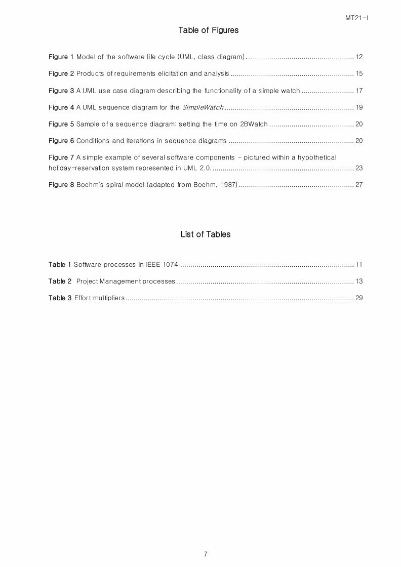
Table of Figures
Figure 1 Model of the software life cycle (UML, class diagram). .................................................... 12
Figure 2 Products of requirements elicitation and analysis ............................................................. 15
Figure 3 A UML use case diagram describing the functionality of a simple watch .......................... 17
Figure 4 A UML sequence diagram for the SimpleWatch ................................................................ 19
Figure 5 Sample of a sequence diagram: setting the time on 2BWatch .......................................... 20
Figure 6 Conditions and Iterations in sequence diagrams .............................................................. 20
Figure 7 A simple example of several software components - pic tured within a hypothetical
holiday-reservation system represented in UML 2.0....................................................................... 23
Figure 8 Boehm’s spiral model (adapted from Boehm, 1987) ......................................................... 27
List of Tables
Table 1 Software processes in IEEE 1074 ...................................................................................... 11
Table 2 Project Management processes ........................................................................................ 13
Table 3 Effor t multipliers ................................................................................................................. 29

MT21-I
8
OBJECT ORIENTED S/W ENGINEERING WITH UML
RESPONSE TO ASSIGNMENT – I
MT21-I
9
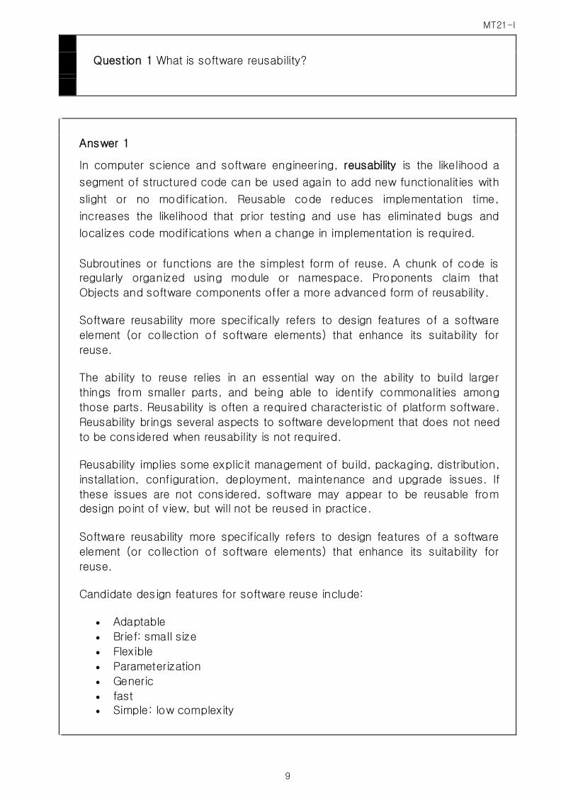
Question 1 What is software reusability?
Answer 1
In computer science and software engineering, reusability is the likelihood a
segment of structured code can be used again to add new functionalities with
slight or no modification. Reusable code reduces implementation time,
increases the likelihood that prior testing and use has eliminated bugs and
localizes code modifications when a change in implementation is required.
Subroutines or functions are the simplest form of reuse. A chunk of code is
regularly organized using module or namespace. Proponents claim that
Objects and software components offer a more advanced form of reusability.
Software reusability more specifically refers to design features of a software
element (or collection of software elements) that enhance its suitability for
reuse.
The ability to reuse relies in an essential way on the ability to build larger
things from smaller parts, and being able to identify commonalities among
those parts. Reusability is often a required characteristic of platform software.
Reusability brings several aspects to software development that does not need
to be considered when reusability is not required.
Reusability implies some explicit management of build, packaging, distribution,
installation, configuration, deployment, maintenance and upgrade issues. If
these issues are not considered, software may appear to be reusable from
design point of view, but will not be reused in practice.
Software reusability more specifically refers to design features of a software
element (or collection of software elements) that enhance its suitability for
reuse.
Candidate design features for software reuse include:
Adaptable
Brief: small size
Flexible
Parameterization
Generic
fast Simple: low complexity
MT21-I
10
Localization of volatile (changeable) design assumptions
Evaluator’s Comments if any:
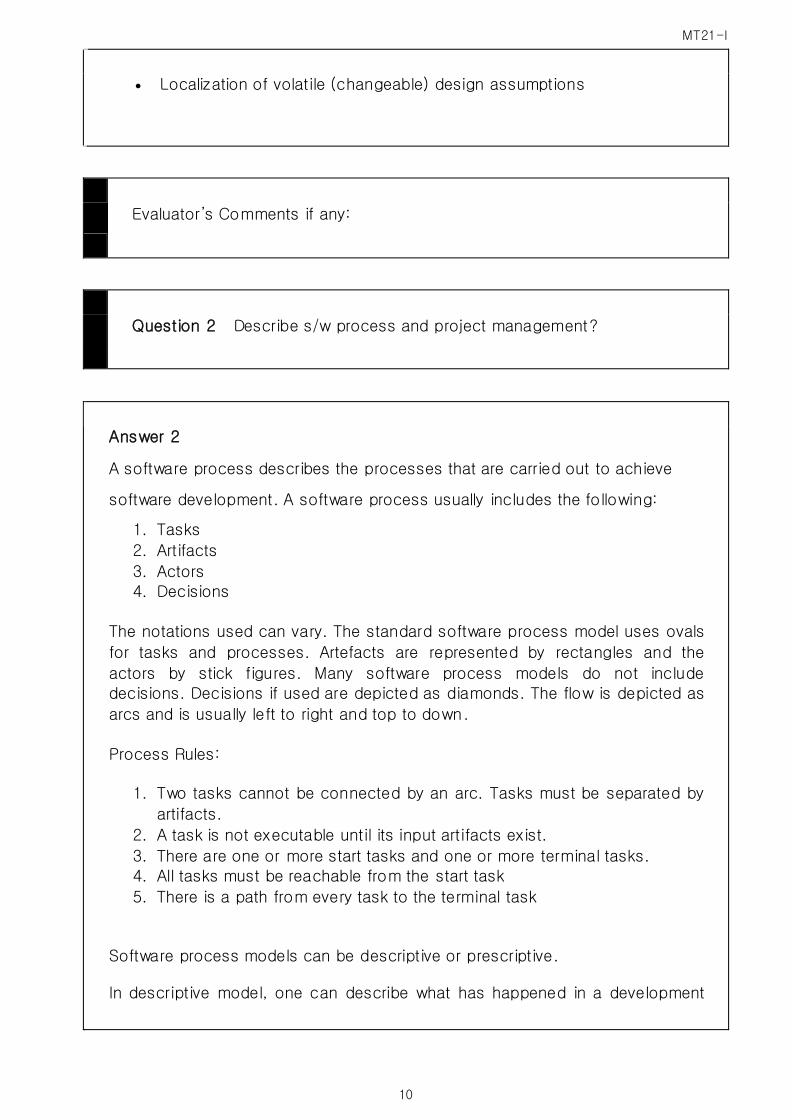
Question 2 Describe s/w process and project management?
Answer 2
A software process describes the processes that are carried out to achieve
software development. A software process usually includes the following:
1. Tasks
2. Artifacts
3. Actors 4. Decisions
The notations used can vary. The standard software process model uses ovals
for tasks and processes. Artefacts are represented by rectangles and the
actors by stick figures. Many software process models do not include
decisions. Decisions if used are depicted as diamonds. The flow is depicted as
arcs and is usually left to right and top to down.
Process Rules:
1. Two tasks cannot be connected by an arc. Tasks must be separated by
artifacts.
2. A task is not executable until its input artifacts exist.
3. There are one or more start tasks and one or more terminal tasks.
4. All tasks must be reachable from the start task
5. There is a path from every task to the terminal task
Software process models can be descriptive or prescriptive.
In descriptive model, one can describe what has happened in a development
MT21-I
11
project post implementation. This can help in understanding and identifying
problems in the development process.
In prescriptive model, one can describe what is supposed to happen. It is used
for training new hires, documenting uncommon occurrences and the purpose
of the model.
IEEE broadly defines software process in terms of activities, detailed below.
Software Process:
A process is a set of activities that is performed toward a specific purpose
(e.g., requirements, management, and delivery). The IEEE standard lists a total
of 17 processes, grouped into higher levels of abstractions called process
groups (Table 01).Examples of process groups are project management, pre-
development and post development. Examples of processes in the
development group include
The requirements process during which the developers develop the
system models
The design process during which the developers decompose the system
into components
The Implementation process during which developers realize each
component.
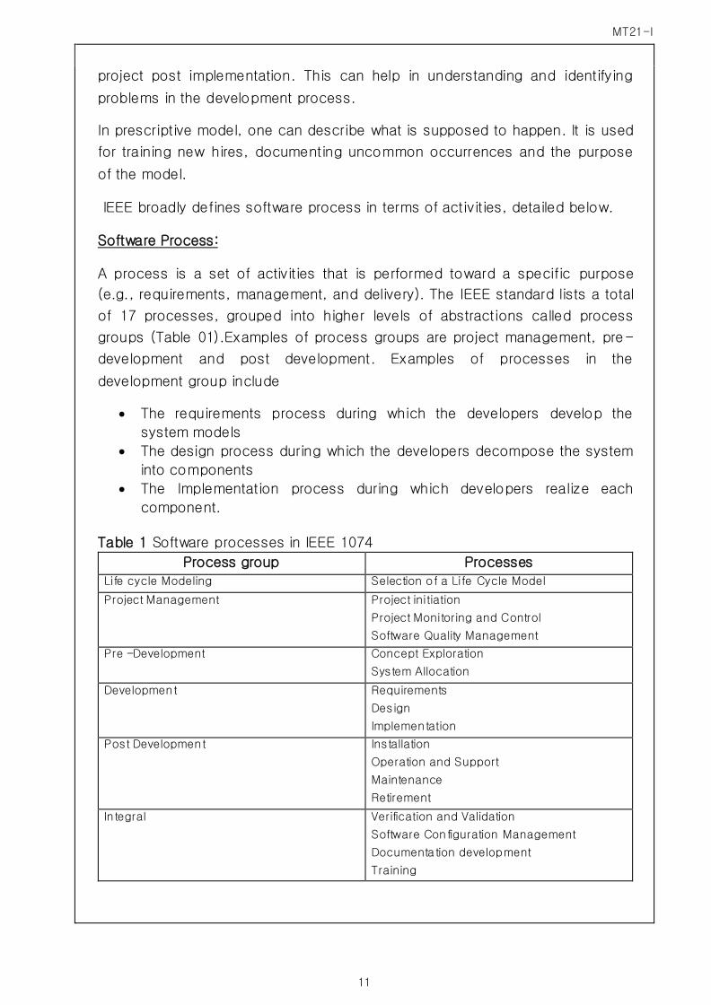
Table 1 Software processes in IEEE 1074
Process group Processes
Life cycle Modeling Selection of a Life Cycle Model
Project Management Project initiation
Project Monitoring and Control
Software Quality Management
Pre –Development Concept Exploration
System Allocation
Development Requirements
Design
Implementation
Post Development Installation
Operation and Support
Maintenance
Retirement
Integral Verification and Validation
Software Configuration Management
Documenta tion development
Training
MT21-I
12
Each process is composed of activities. An activity is a task or group of sub
activities that are assigned to a team or a project participant to achieve a
specific purpose. The requirements process, for example, is composed of
three activities:
Define and Develop Software requirements during which the functionality
of the system is defined precisely
Define Interface Requirements during which the interactions between the
systems and user are defined precisely
Prioritize and Integrate Software Requirements during which all
requirements are integrated for consistency and prioritised by client
preference.
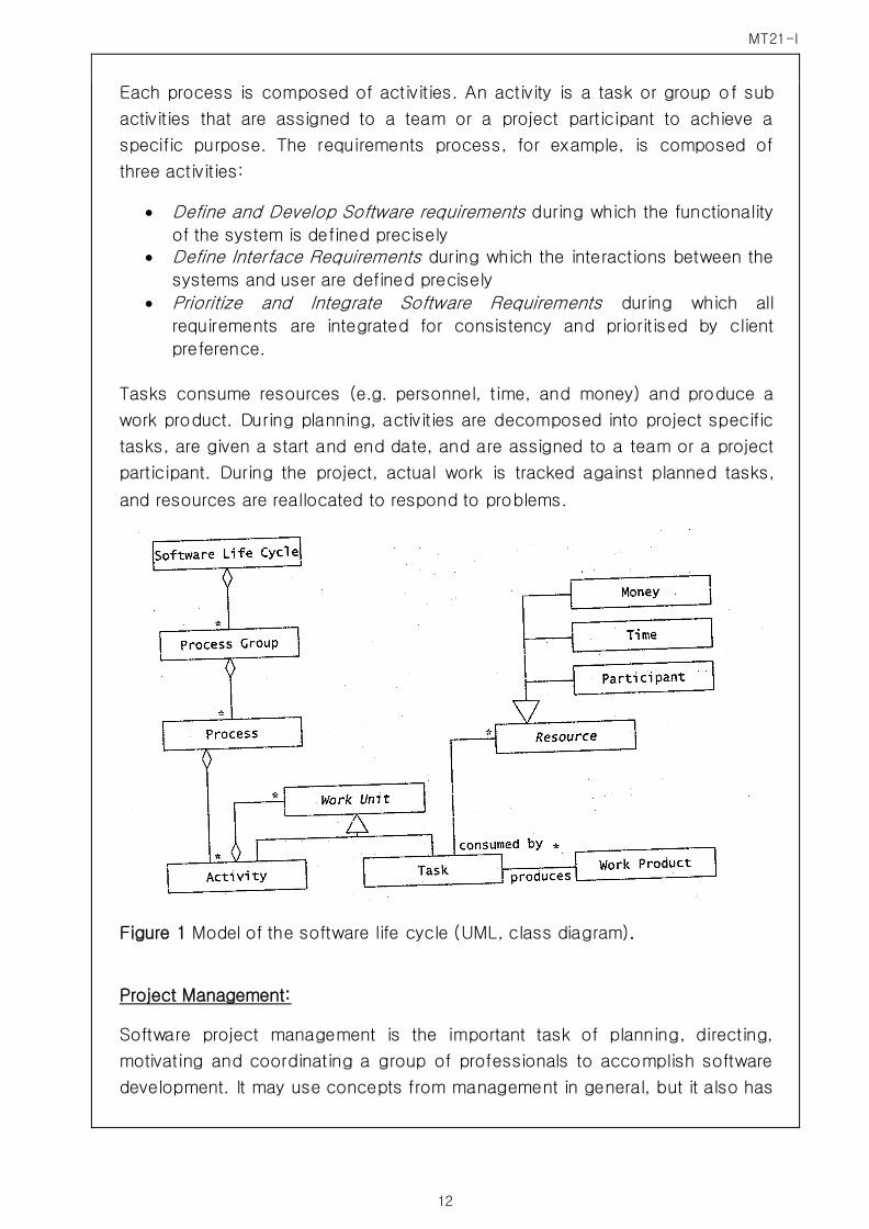
Tasks consume resources (e.g. personnel, time, and money) and produce a
work product. During planning, activities are decomposed into project specific
tasks, are given a start and end date, and are assigned to a team or a project
participant. During the project, actual work is tracked against planned tasks,
and resources are reallocated to respond to problems.
Figure 1 Model of the software life cycle (UML, class diagram).
Project Management:
Software project management is the important task of planning, directing,
motivating and coordinating a group of professionals to accomplish software
development. It may use concepts from management in general, but it also has
MT21-I
13
some concerns like project visibility. Lack of visibility makes it hard to manage.
Many projects get stalled at 90% mark. Many of the project management tools
help in resolving such issues.
PM is a type of process as described in Table 02.
During Project Management, the project manager initiates, monitors, and
controls the project throughout the software life cycle. Project Management
consists of three processes.
The Project Initiation Process creates the infrastructure for the project. During
this process, the task plan, schedule, budget, organization and project
environment are defined. The project environment includes project standards,
communication infrastructure, meeting and reporting procedures, development
methodologies, and development tools.
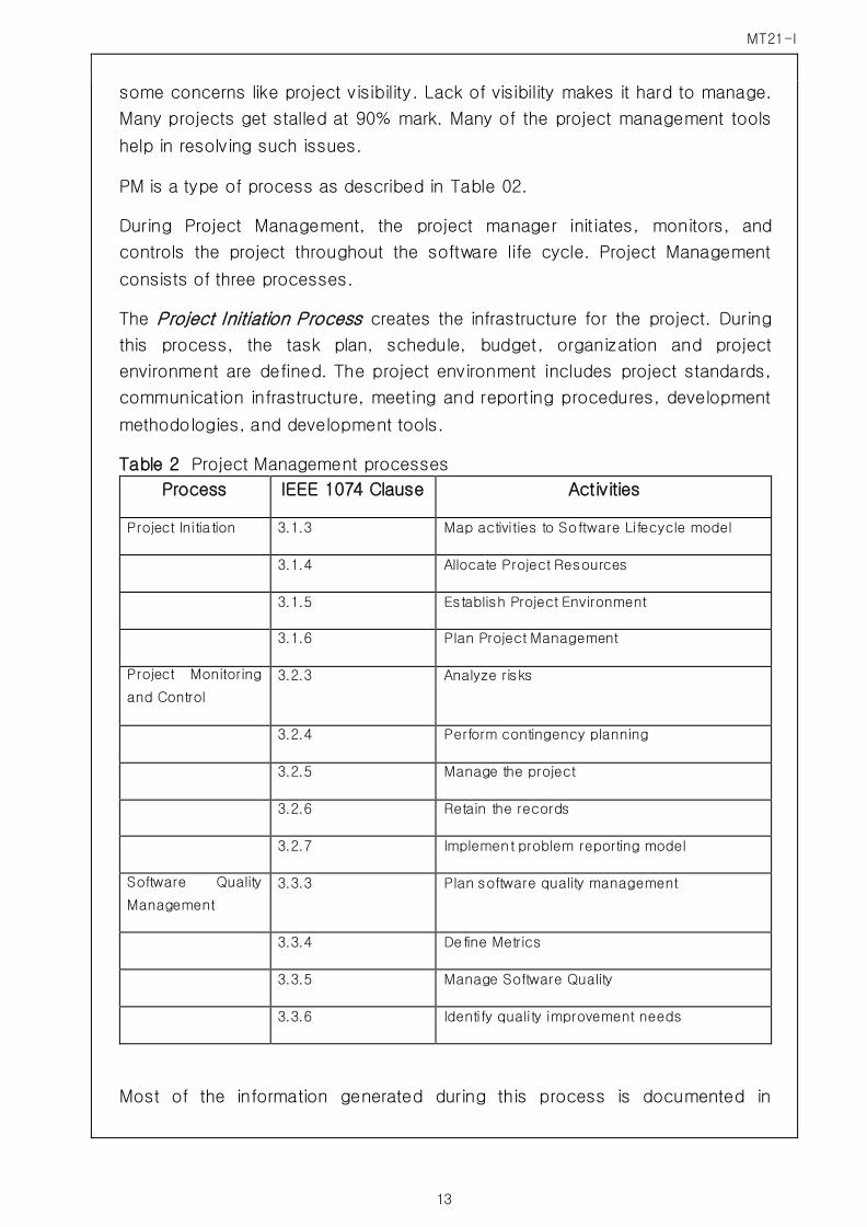
Table 2 Project Management processes
Process IEEE 1074 Clause Activities
Project Initia tion 3.1.3 Map activities to Software Lifecycle model
3.1.4 Allocate Project Resources
3.1.5 Establish Project Environment
3.1.6 Plan Project Management
Project Monitoring
and Control
3.2.3 Analyze risks
3.2.4 Perform contingency planning
3.2.5 Manage the project
3.2.6 Retain the records
3.2.7 Implement problem reporting model
Software Quality
Management
3.3.3 Plan software quality management
3.3.4 Define Metrics
3.3.5 Manage Software Quality
3.3.6 Identify quality improvement needs
Most of the information generated during this process is documented in
MT21-I
14
Software Project Management plan (SPMP). The project initiation process is
complete as soon as a stable environment is established.
The Project Monitoring and control process ensures that the project is executed
according to the task plan and budget. If the project manager observers any
deviation from the schedule, she will take corrective action such as reallocating
some of the resources, changing procedures, or replanning the schedule. The
SPMP is updated to reflect any of these changes. The Project Monitoring and
Control Process is active throughout the lifecycle.
The Software Quality Management Process ensures that the system under
construction meets the required quality standards (which were selected during
Project Initiation). This process is executed by a separate quality management
team to avoid conflicts of interest( i.e. the goal of the developers is to
complete the system on time, and the goal of the quality management team is
to ensure that the system is not considered as complete until it meets the
required quality standard). The Software Quality Management Process is active
throughout most of the lifecycle.
The activity Establish Project Environment requires particular attention in the
context of a team based project. One of the critical parts of the project
environment is the communication infrastructure that will support the
dissemination of information among the participants.
Evaluator’s Comments if any:
Question 3 What do you understand by Requirement Elicitation?
Answer 3
Requirements elicitation can be described as eliciting a specification of what is
required by allowing experts in the problem domain to describe the goals to be
reached during the problem resolution. It also captures the needs of a layman

MT21-I
15
user of the system so that the end users needs are well understood.
The end results of eliciting requirements needs to be a compromise among
competing requirements. Everyone in the group may wish to have a voice, but
this may leave us with mishmash. A way to avoid this is not to allow
inconsistent requirements to propagate in parallel for long time.
Requirements elicitation focuses on describing the purpose of the system. The
client, the developers, and the users identify a problem area and define a
system that addresses the problem. Such a definition is called a requirements
specification and serves as a contract between the client and the developers.
The requirements specification is structured and formalized during analysis to
produce an analysis model. Both requirements specification and analysis
model represent the same information. They differ only in the language and
notation they use, requirements specification is written in natural language,
where as the analysis model is usually expressed in a formal or semiformal
notation. The requirements specification supports the communication with
clients and users. The analysis model supports the communication among
developers.
Requirements elicitation and analysis focus only on the user’s view of the
system. For example, the system functionality, the interaction between the user
and the system, the errors that the system can detect and handle, and the
environmental conditions in which the system functions are part of the
requirements. The system structure, the implementation technology selected to
build the system, the system design, the development methodology, and other
aspects not directly visible to the use are not part of the requirements.
Figure 2 Products of requirements elicitation and analysis

MT21-I
16
Requirements elicitation includes the following activities:
Identifying the actors. During this activity, developers identify the different types
of users the future system will support
Identifying scenarios. During this activity, developers observe users and
develop a set of detailed scenarios for typical functionality provided by the
future system. Scenarios are concrete examples of the future system in use.
Developers use these scenarios to communicate with the user and deepen
their understanding of the application domain.
Identifying the use cases. Once the developers and users agree on a set of
scenarios, developers derive from the scenarios a set of use cases that
completely represent the future system. Whereas scenarios are concrete
examples illustrating a single case, use cases are abstractions describing all
possible cases. When describing use cases, developers determine the scope
of the system.
Refining use cases. During this activity, developers ensure that the
requirements specification is complete by detailing each use case and
describing the behavior of the system in the presence of errors and exceptional
conditions.
Identifying relationships among use cases . During this activity, developers
identify dependencies among use cases. They also consolidate the use case
model by factoring out common functionality. This ensures that the
requirements specification is consistent.
Identify non functional requirements . During this activity, developers, users and
clients agree on aspects that are visible to the users, but not directly related to
functionality. These include constraints on the performance of the system, its
documentation, the resources it consume, its security and its quality.
Evaluator’s Comments if any:
MT21-I
17
Question 4 What is role of use case diagrams in UML?
Answer 4
Use cases are used during requirements elicitation and analysis to represent
the functionality of the system. Use cases focus on the behavior of the system
from an external point of view. A use case describes a function provided by
the system that yields a visible result for an actor. An actor describes any entity
that interacts with the system. The identification of actors and use cases
results in the definition of the boundary of the system that is, in differentiating
the tasks accomplished by the system and the tasks accomplished by the
environment. The actors are outside the boundary of the system, whereas the
use case is inside the boundary.
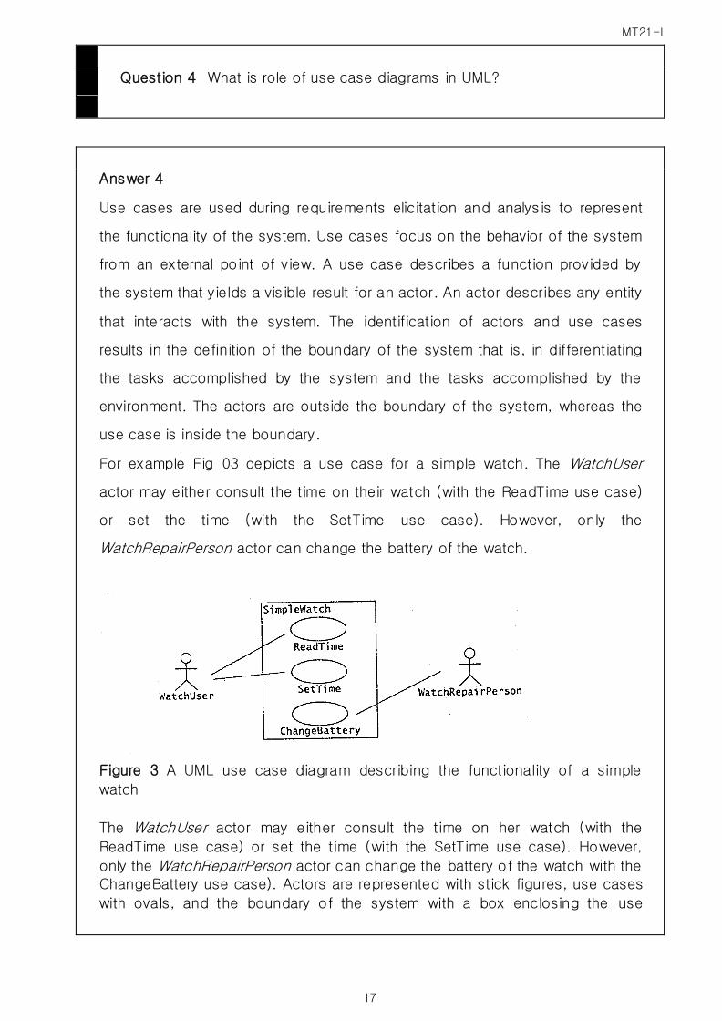
For example Fig 03 depicts a use case for a simple watch. The WatchUser
actor may either consult the time on their watch (with the ReadTime use case)
or set the time (with the SetTime use case). However, only the
WatchRepairPerson actor can change the battery of the watch.
Figure 3 A UML use case diagram describing the functionality of a simple
watch
The WatchUser actor may either consult the time on her watch (with the
ReadTime use case) or set the time (with the SetTime use case). However,
only the WatchRepairPerson actor can change the battery of the watch with the ChangeBattery use case). Actors are represented with stick figures, use cases
with ovals, and the boundary of the system with a box enclosing the use
MT21-I
18
cases.
Use cases use UML notations to describe various requirements in form of
Activity diagram, Interaction diagram and Class diagrams. Activity diagrams
describe workflows and the processes captured during the requirements.
Interaction diagrams define the scenarios of the requirements. Class diagram
define the structure and attributes of the objects. Hence Use cases play an
important role in capturing the requirements by using UML.
Evaluator’s Comments if any:
Question 5 What is sequence diagram?
Answer 5
Sequence diagrams are special type of Interaction diagrams.
Interaction diagrams are used to formalize the dynamic behavior of the
system and to visualize the communication among the objects. They are
useful for identifying additional objects that participate in the sue cases. We
can objects involved in a use case participating objects. An interaction
diagram represents the interactions that take place among these objects.
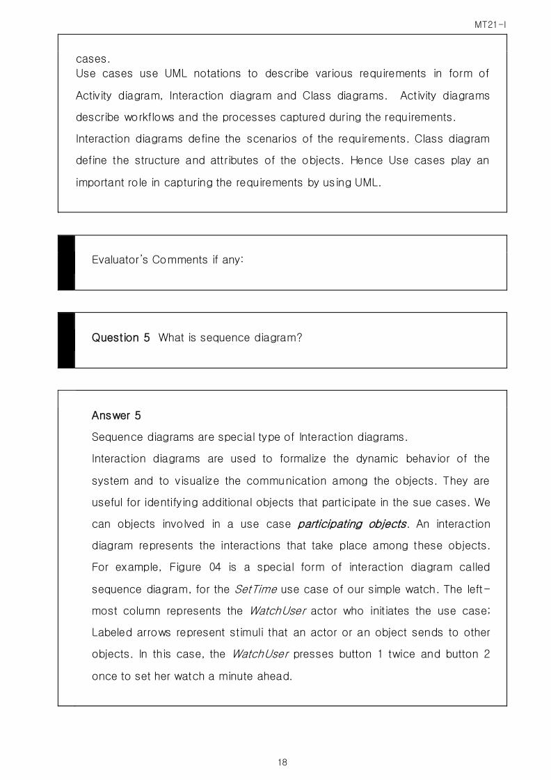
For example, Figure 04 is a special form of interaction diagram called
sequence diagram, for the SetTime use case of our simple watch. The left-
most column represents the WatchUser actor who initiates the use case;
Labeled arrows represent stimuli that an actor or an object sends to other
objects. In this case, the WatchUser presses button 1 twice and button 2
once to set her watch a minute ahead.

MT21-I
19
Figure 4 A UML sequence diagram for the SimpleWatch
The left-most column represents the timeline of the WatchUser actor who
initiates the use case. The other columns represent the timeline of the
objects that participate in this use case. Object names are underlined to
denote that they are instances (as opposed to classes). Labeled arrows are
stimuli that an actor or an object sends to other objects.
The SetTime use case terminates when the WatchUser presses both buttons
simultaneously.
Sequence diagrams represent the objects participating in the interaction
horizontally and time vertically. For example, consider a watch with two
buttons (hereafter called 2BWatch). Setting the time on 2BWatch requires
the actor 2BwatchOwner to first press both the buttons simultaneously after
which 2BWatch enters the set time mode. In the set time mode, 2BWatch
blinks the number being changed (e.g. the hours, minutes, seconds, day,
month or year). Initially, when the 2BWatchOwner enters the set time mode,
the hour blinks. If the actor presses the first button, the next numbers
blinks. If the actor presses the second button, the blinking number is
incremented by one unit. If the blinking number reaches the end of the
range, it is reset to the beginning. The actor exits the set time mode by
pressing both buttons simultaneously. Figure 05 depicts a sequence
diagram for an actor setting his 2BWatch one minute ahead. Each column
represents an object that participates in the interaction. Messages are
shown by solid arrows. Labels on solid arrows represent message names
and may contain arguments. Activations (i.e. executing methods) are
depicted by vertical rectangles. The actor who initiates the interactions is
shown in the left-most column. The messages coming from the actor
represents the interactions described in the use case diagrams. If other

MT21-I
20
actors communicate with the system during the use case, these actors are
represented on the right hand side and can receive messages.
Sequence diagrams can be used to describe either an abstract sequence
(all possible interactions) or concrete sequences (one possible interaction,
as in Figure 5). When describing all possible interactions, sequence
diagrams also provide notations for conditionals and iterators. A condition
on a message is denoted by an expression in brackets before the message
name (see [i>0] op1 () and [i<=0] op2 ()) in Figure 06]. If the expression
is true, the message is sent. Repetitive invocation of a message is denoted
by a “*” before the message name( see *op3 in Figure 06)
Figure 5 Sample of a sequence diagram: setting the time on 2BWatch
Figure 6 Conditions and Iterations in sequence diagrams
Evaluator’s Comments if any:

MT21-I
21
Question 6 What do you understand by terms software reliability?
Answer 6
The reliability of software refers to its capability to maintain its specified
level of performance under the specified conditions. The three elements of
reliability mirror the prevention, mitigation, and recovery concepts we use
for dealing with crises and natural disasters. Maturity refers to the absence
of faults in the software, whereas fault tolerance is associated with the
capacity of the software to continue functioning despite some faults, and
recoverability deals with software functions that allow it to get back the data
and continue operation after a failure.
Also associated with a system's reliability are such attributes as service
capacity (for example, number of clients the system can support), precision
and accuracy of its results, security, interoperability and portability, and
reasonable time and space requirements. Finally, many reliability problems
can be efficiently located through rigorous and appropriate testing.
Software reliability has been defined as the probability that a software fault
which causes deviation from the required output by more than the specified
tolerances, in a specified environment, do not occur during a specified
exposure period. Thus, the software needs to be correct only for inputs for
which it is designed (specified environment). Also, if the output is correct
within the specified tolerances in spite of an error, then the error is ignored.
This may happen in the evaluation of complicated floating point expressions
where many approximations are used (e.g., polynomial approximations for
cosine, sine, etc.). It is possible that a failure may be due to errors in the
compiler, operating system, microcode or even the hardware. These failures
are ignored in estimating the reliability of the application program. However,
the estimation of the overall system reliability will include the correctness of
the supporting software and the reliability of the hardware.
We can define the reliability, R, as follows:

MT21-I
22
where n = number of runs and nf--- number of failures in n runs.
This is the operational definition of software reliability. We can estimate the
reliability of a program by observing the outcomes (success/failure) of a
number of runs under its operating environment. If we observe nf failures
out of n runs, the estimate of R, denoted by R, is:
This method of estimating R is the basis of the Nelson model.
Evaluator’s Comments if any:
Question 7 What is component based s/w engineering?
Answer 7
Component-based software engineering (CBSE) (also known as
component-based development (CBD)) is a branch of software engineering
which emphasizes the separation of concerns in respect of the wide-
ranging functionality available throughout a given software system. This
practice aims to bring about an equally wide-ranging degree of benefits in
both the short-term and the long-term for the software itself and for
organizations that sponsor such software.
Software engineers regard components as part of the starting platform for
service orientation. Components play this role, for example, in Web
Services, and more recently, in Service-Oriented Architecture (SOA) -
whereby a component is converted[by whom?] into a service and subsequently inherits further characteristics beyond that of an ordinary
component.
MT21-I
23
Components can produce events or consume events and can be used for
event driven architecture (EDA).
Component details:
An individual component is a software package or a module that
encapsulates a set of related functions (or data).
All system processes are placed into separate components so that all of the data and functions inside each component are semantically related (just as
with the contents of classes). Because of this principle, it is often said that
components are modular and cohesive.
With regard to system-wide co-ordination, components communicate with
each other via interfaces. When a component offers services to the rest of
the system, it adopts a provided interface which specifies the services that
can be utilized by other components and how. This interface can be seen
as a signature of the component - the client does not need to know about the inner workings of the component (implementation) in order to make use
of it. This principle results in components referred to as encapsulated. The
UML illustrations within this article represent provided interfaces by a
lollipop-symbol attached to the outer edge of the component.
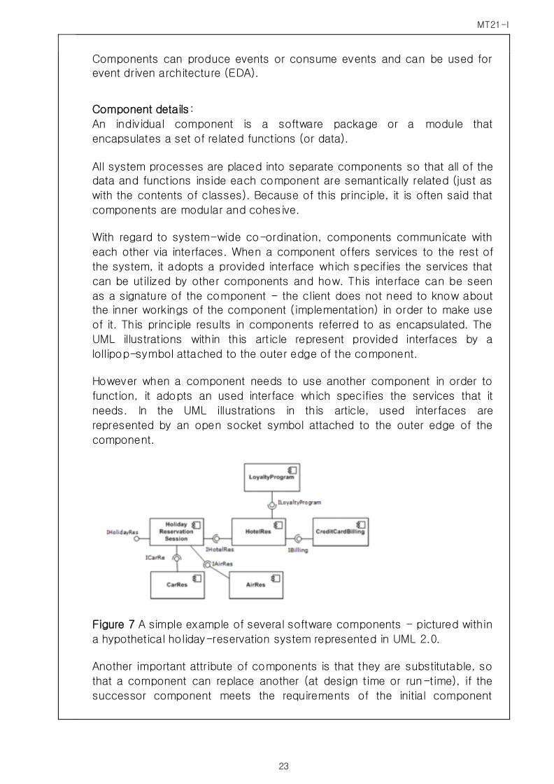
However when a component needs to use another component in order to
function, it adopts an used interface which specifies the services that it
needs. In the UML illustrations in this article, used interfaces are
represented by an open socket symbol attached to the outer edge of the
component.
Figure 7 A simple example of several software components - pictured within
a hypothetical holiday-reservation system represented in UML 2.0.
Another important attribute of components is that they are substitutable, so
that a component can replace another (at design time or run-time), if the
successor component meets the requirements of the initial component

MT21-I
24
(expressed via the interfaces). Consequently, components can be replaced
with either an updated version or an alternative for example, without
breaking the system in which the component operates.
As a general rule of thumb for engineers substituting components,
component B can immediately replace component A, if component B
provides at least what component A provided, and uses no more than what
component A used.
Software components often take the form of objects or collections of
objects (from object-oriented programming), in some binary or textual form,
adhering to some interface description language (IDL) so that the
component may exist autonomously from other components in a computer.
When a component is to be accessed or shared across execution contexts
or network links, techniques such as serialization or marshalling are often
employed to deliver the component to its destination.
Reusability is an important characteristic of a high-quality software
component. A software component should be designed and implemented so that it can be reused in many different programs.
It takes significant effort and awareness to write a software component that
is effectively reusable. The component needs to be:
fully documented
thoroughly tested
o robust - with comprehensive input-validity checking
o able to pass back appropriate error messages or return codes designed with an awareness that it will be put to unforeseen uses
In the 1960s, programmers built scientific subroutine libraries that were
reusable in a broad array of engineering and scientific applications. Though
these subroutine libraries reused well-defined algorithms in an effective
manner, they had a limited domain of application. Commercial sites
routinely created application programs from reusable modules written in
Assembler, COBOL, PL/1 and other second- and third-generation
languages using both System and user application libraries.
As of 2010, modern reusable components encapsulate both data structures
and the algorithms that are applied to the data structures. It builds on prior
theories of software objects, software architectures, software frameworks
and software design patterns, and the extensive theory of object-oriented programming and design. It claims that software components, like the idea
of hardware components, used for example in telecommunications, can
ultimately be made interchangeable and reliable.
MT21-I
25
Evaluator’s Comments if any:
Question 8 Describe the spiral model?
Answer 8
Spiral model:
Boehm’s spiral model is an activity –centered life cycle model that was devised
to address the source of weakness in the waterfall model, in particular, to
accommodate infrequent change during the software development. It is based
on the same activities as the waterfall model; however it adds several activities
such as risk management, reuse, and prototyping to each activity. These
extended activities are called cycles or rounds.
The spiral model focuses on addressing risks incrementally, in order of priority.
Each round is composed of four phases (Figure 8). During the first phase
upper left quadrant), developers explore alternatives, define constraints and
identify objectives. During the second phase (upper right quadrant), developers
manage risks associated with the solutions defined in the first phase. During
the third phase (lower right quadrant), developers realize and validate a
prototype or the part of the system associated with the risks addresses in this
round. The fourth phase (lower left quadrant) focuses on planning the next
round based on the results of current round. The last phase of the round is
usually conducted as a review involving the project participants, including
developers, clients and users. This review covers the products developed
during the previous and current rounds and the plans for the next round.
Boehm’s spiral model distinguishes the following rounds: Concept of
Operation, Software requirements, Software Product design, detailed Design,
MT21-I
26
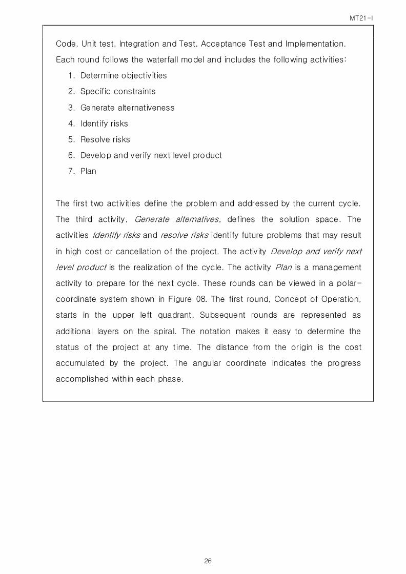
Code, Unit test, Integration and Test, Acceptance Test and Implementation.
Each round follows the waterfall model and includes the following activities:
1. Determine objectivities
2. Specific constraints
3. Generate alternativeness
4. Identify risks
5. Resolve risks
6. Develop and verify next level product
7. Plan
The first two activities define the problem and addressed by the current cycle.
The third activity, Generate alternatives, defines the solution space. The
activities Identify risks and resolve risks identify future problems that may result
in high cost or cancellation of the project. The activity Develop and verify next
level product is the realization of the cycle. The activity Plan is a management
activity to prepare for the next cycle. These rounds can be viewed in a polar-
coordinate system shown in Figure 08. The first round, Concept of Operation,
starts in the upper left quadrant. Subsequent rounds are represented as
additional layers on the spiral. The notation makes it easy to determine the
status of the project at any time. The distance from the origin is the cost
accumulated by the project. The angular coordinate indicates the progress
accomplished within each phase.

MT21-I
27
Figure 8 Boehm’s spiral model (adapted from Boehm, 1987)
The distance from the origin represents the cost accumulated by the project. The angle from the horizontal represents the type of activity. For example, the
project P1 is currently in the risk analysis activity associated with software
requirements. The project P2 is in the development of the system product
design.
Evaluator’s Comments if any:
Question 9 Write a short note on –
COCOMO model?

MT21-I
28
Answer 9
COCOMO actually is a series of three models, ranging from the macro
estimation model that treats the products as a whole to a micro estimation
model that treats the product in detail.
Computing development time using COCOMO is done in two stages. First, a
rough estimate of the development effort is provided. Two parameters have
to be estimated: The length of the product in KDSI (Kilo Data source
Instructions, aka, KLOC) and the product’s development mode, a measure
of intrinsic level of difficulty of developing that product. There are three
modes: organic (small and straightforward), semidetached (medium sized),
and embedded (complex).
From these two parameters, the nominal effort can be calculated. For
example, if the project is judged essentially straightforward( organic), then
the nominal effort (in person months) is given by the equation
Nominal effort = 3.2 * ( KDSI)1.05 person months
The constant 3.2 and 1.05 are the values that best fitted the data on the
organic mode products used by Boehm to develop COCOMO.
For example, if the product is to be build is organic and 12,000 delivered
source statements then nominal effort is
3.2 * ( 12)1.05 = 43 person months
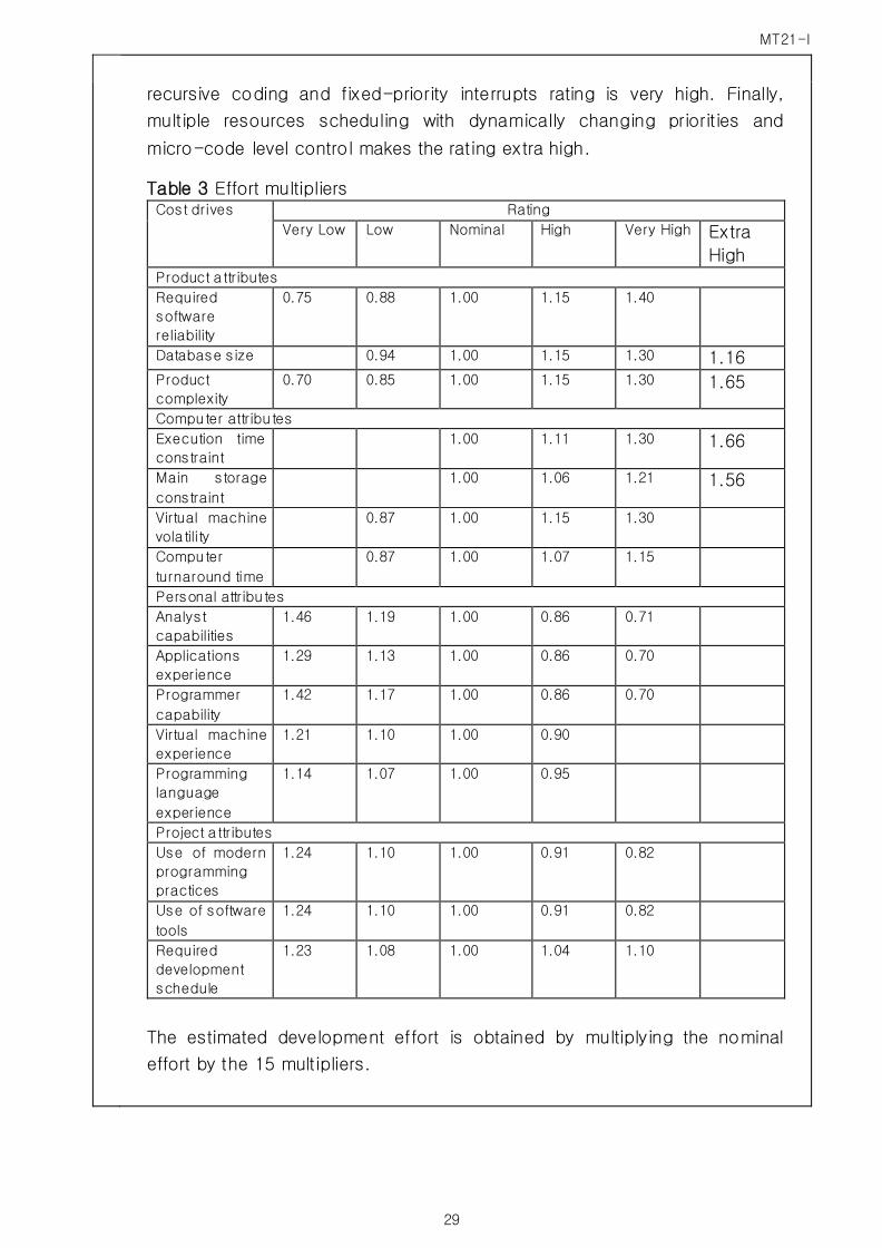
Next, this nominal value must be multiplied by 15 software development
effort multipliers. These multipliers and their values are given in Table 3.
Each multiplier can have upto six values. For example, the product
complexity multiplier is assigned the values 0.70, 0.85, 1.00, 1.15, 1.30 or
1.65 according to whether the developers rate the project complexity as
very low, low, nominal, high, very high or extra high. As can be seen from
Table 3, all 15 multipliers take on the value 1.00 when the corresponding
parameter is nominal.
Boehm has provided guidelines to help the developer determine whether the
parameter should indeed be rated nominal or whether the rating is lower or
higher. For if-then-else, do-while cases, the complexity is rated very low.
For nested loops rating is low, adding intermodule control increases rating
to nominal. For highly nested operators with compound predicates, with
queues and stack operations rating is high. The presence of reentrant and
MT21-I
29
recursive coding and fixed-priority interrupts rating is very high. Finally,
multiple resources scheduling with dynamically changing priorities and
micro-code level control makes the rating extra high.
Table 3 Effort multipliers Cost drives Rating
Very Low Low Nominal High Very High Extra
High Product a ttributes
Required
software
reliability
0.75 0.88 1.00 1.15 1.40
Database size 0.94 1.00 1.15 1.30 1.16 Product
complexity
0.70 0.85 1.00 1.15 1.30 1.65
Computer attributes
Execution time
constraint
1.00 1.11 1.30 1.66
Main storage
constraint
1.00 1.06 1.21 1.56
Virtual machine
vola tility
0.87 1.00 1.15 1.30
Computer
turnaround time
0.87 1.00 1.07 1.15
Personal attributes
Analyst
capabilities
1.46 1.19 1.00 0.86 0.71
Applications
experience
1.29 1.13 1.00 0.86 0.70
Programmer
capability
1.42 1.17 1.00 0.86 0.70
Virtual machine
experience
1.21 1.10 1.00 0.90
Programming
language
experience
1.14 1.07 1.00 0.95
Project a ttributes
Use of modern
programming
practices
1.24 1.10 1.00 0.91 0.82
Use of software
tools
1.24 1.10 1.00 0.91 0.82
Required
development
schedule
1.23 1.08 1.00 1.04 1.10
The estimated development effort is obtained by multiplying the nominal
effort by the 15 multipliers.
MT21-I
30
Evaluator’s Comments if any:
Question 10 What are the characteristics of s/w process?
Answer 10
Characteristics of Software Process consists of:
1. Understandability, making the process explicitly defined and how it
so easy to understand the definition of the process
2. Visibility, Activity process produces a clear result so that the stage of
the process is seen
3. Supportability, process activity can be supported on the Case tools
4. Acceptability, acceptance of a defined process and is used by the
Engineer during Software product development.
5. Reliability, Process design in a method for avoided the mistakes
6. Robustness, process can be continued under issue
7. Maintainability, which reflect the process of change or request an eye
for process improvements identified
8. Rapidity, how fast can run the process delivery or implementation of a
system of Existing specifications to completion
Evaluator’s Comments if any: