Embed Size (px)
Citation preview
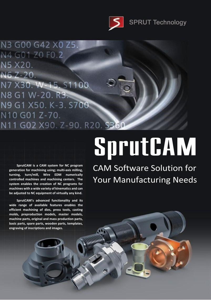
SprutCAM is a CAM system for NC program
generation for machining using; multi-axis milling,
turning, turn/mill, Wire EDM numerically
controlled machines and machining centers. The
system enables the creation of NC programs for
machines with a wide variety of kinematics and can
be adjusted to NC equipment of virtually any kind.
SprutCAM’s advanced functionality and its
wide range of available features enables the
efficient machining of dies, press tools, casting
molds, preproduction models, master models,
machine parts, original and mass production parts,
basic parts, spare parts, wooden parts, templates,
engraving of inscriptions and images.

The calculation of CNC tool-paths within SprutCAM is carried out taking into account the kinematics (structure) of the selected NC machine. Using this method, the tool-path calculations for machines with a wide variety of configurations are easily undertaken and the existing machining operations do not require any further editing, simply select the required (alternative) NC machine.
In addition to integrated NC devices such as lathe steady, tail-stock, revolving table, various fixtures and tooling equipment can now be integrated within the kinematic scheme for an NC machine.
Today, the SprutCAM equipment library contains a wide variety of market leading NC machines.
A new machine configuration can be created based upon an existing library machine configuration.
EQUIPMENT New in SprutCAM
New types of tools for ‘undercut’ machining are added:
circular groove cutting,
sharp and rounded edge double-sided chamfer,
replaceable-insert double-sided chamfer.
FBM Shaped cutters. In FBM the ability to use shaped tools created by the end-user is added. Thus, if the machining of any feature type requires a special tool which does not exist within the system, the user can draw the parameterized tool contour and save it as a new type of tool.
TOOLING Different knife cutting tools can be combined into a tool
library or user defined libraries that can be associated with a
corresponding machine. It is possible to use tool libraries
provided by tooling suppliers. The user can further modify
these to suit the particular requirements of a machine or for
a particular task.
By using this QR code, you can install SprutCAM Brochure
application onto your smartphone.
Move the lens of smartphone onto the pictures of this
brochure marked with a sign:
The drawings come to life on the screen!

2.5D MACHINING
SprutCAM features several 2.5D machining
strategies for the machining of multi-level 2D
parts. Available strategies include calculations
for roughing and finishing tool paths. Machining
parts of any level of complexity is achieved using
strategies for machining: along a contour, island
machining, vertical walls, slots & pockets with
islands. SprutCAM has the ability to
automatically recognize horizontal surfaces as
well as holes. The system supports all types of
hole machining including tapping and thread
milling. The automatic recognition of rest
material and the full control of machining
accuracy is included.
Facts and figures
Over 600 post-processors More than 500 kinematic schemes 80 resellers worldwide 10 localization languages (including main European languages, Chinese, Japanese, Korean)
New in SprutCAM
"Stepover by scallop height”
Milling type
Allows the milling of 3D curved
surfaces using a constant step
height
3D MACHINING
SprutCAM includes a wide range of 3D
machining strategies which enables the
machining of parts with complex freeform
surfaces using both conventional and high
speed. The user has the capability to create tool
paths that are defined by the scallop height;
which ensures achievement of the required
surface accuracy and quality. A real labor saving
feature is the automatic recognition of
remaining material for rest milling. The wide
range of available strategies for roughing and
finishing provides high quality machining for 3D
parts.

4-AXIS ROTARY MACHINING
Rotary machining within SprutCAM is a milling
process that, when a linear movement is aligned
with one of the standard axis X, Y, Z, it can be
transposed into a rotational movement. This
method of machining is ideally suited for the
machining of; axles, crankshafts, camshafts, oil-well
and gas industry tooling equipment, augers. Rotary
machining reduces the complexity of
manufacturing parts while increasing the quality by
eliminating positioning errors between part set-
ups. SprutCAM contains a wide range of strategies
for the calculation of rotary machining programs.
New in SprutCAM
The Rotary Machining
operation now includes a
‘Flexible’ rotation axis. This
substantially extends the
machining for artistic items
such as furniture elements, and
sculptures.
MULTI - AXIS INDEXED MACHINING
When doing multi-axis machining, the required rotation angle of the part can be applied interactively by simply clicking on the required part of the 3D model surface, which will automatically orientate the tool / part. SprutCAM automatically calculates the necessary rotation angles and generates the NC program. The tool path is calculated taking into account the predefined machine kinematics (structure) for index machining for 4-5 and more axes. Multi-axes machining comprises 2.5, 3 and 4 axis milling strategies. NC programs are calculated taking into account any transformations of the working CS. To carry out machining of the same part on a machine with another kinematics scheme, it only requires selection of the required machine and recalculation of the existing operations. Multi-axis machining significantly reduces the number of required processes, improves the quality of machining while labor involvement is also reduced.

SprutCAM has strategies for 5-axis
machining that allows the development of
control programs for all types of multi-axis
milling machines, including multi-task
machining centres. The NC program is created
taking into consideration the CNC machine
model which enables collision avoidance of any
type during machining. SprutCAM fully
supports toolpath calculation based on rotating
coordinate systems e.g. TCPM. SprutCAM
includes market leading strategies for collision
avoidance and full control of tool orientation.
5-AXIS CONTINUOUS MACHINING MULTITASK MACHINING
New in SprutCAM
Programming of multi-task turning center
with sub spindle(s) / turret(s) is available in
SprutCAM (MTM). This makes it possible to
generate NC programs for concurrent
machining (all turrets / spindles) of several
parts using multiple tools.
Facts and figures
SprutCAM is the leader in the North American market *(in the category of Tier-Price, according to 2013 – CNCCookbook, Inc.) SprutCAM has headed the TOP-10 of the fastest growing CAM vendors in the world market for 2013 *(according to the 'CAD/CAM/CAE Observer’ analytical magazine on the basis of CIMdata)
High-speed milling in waterline
roughing operation is
improved. Smooth path and
smooth transition are formed
based on a constant cross
sectional area of material
removal.
HIGH SPEED MACHINING
SprutCAM milling strategies include
features for creating ‘High-Speed’
milling tool paths. Trochoidal
‘penetration’ tool paths, smoothing of
sharp corners, arc approach and
retraction. These all help to ensure
smooth tool paths and a consistent area
of cut, which, together with the
calculated lead in / out moves enables
the use of high-speed milling. All of
these features help to reduce the
dynamic stresses which are placed on
the machine during the high-speed
machining process.

LATHE
SprutCAM includes a full range of
strategies for the turning of both simple and
complex parts. Included are rough and finish
turning and boring (both radial and axial)
operations, grooving, axial bore machining and
threading of all types are standard. SprutCAM
supports all known turning cycles. It is also
possible to program lathes with a ‘live’ B axis.
All tool paths can be calculated taking into
account any remaining material. Machining
options are set automatically based on the
selected tool library. SprutCAM enables the
control of any ‘driven’ feature of the machine:
steadies, tail-stock, chuck, parts catcher etc.
TURN/MILL MACHINING
SprutCAM enables the
creation of NC programs for all
types of turn/mill machines.
Machines can be programmed with
any number and arrangement of
turrets equipped with driven tools
using the C, Y and B axes. CNC
machine tool types that can include
tooling systems with any tool
position (turret / holder) and
number are supported; hence, the
NC program can include a
combination of both lathe and
milling abilities. All strategies for
the lathe and 2.5-5 axes milling
machining are available.
Synchronization of turrets on Multi-
turret machines is also available.
New in SprutCAM
“FaceMilling” operation. Multi-level automatic
milling of flat end surfaces of the workpiece.
WIRE EDM SprutCAM wire EDM operations
enable the creation of 2 axis internal and external vertical contour machining. There are also 4-axis machining strategies with automatic, interactive and precise synchronization working with either 2D (curves) or 3D models. A cutting parameter databases can be defined for each individual machine and the many possibilities for multiple profile machining ensure excellent surface accuracy with minimum user input. Automatic, interactive and precise placement of 'bridges’ for connected features prevents parts dropping out of the material. Hole position for wire feed are transferred to the holes machining operation in order to create the NC program for hole drilling.
Facts and figures
2014 – a new SprutCAM training center in the USA was opened. 2015 – a new SprutCAM training center in Germany was opened. Throughout the world, a new copy of SprutCAM is installed every 40 minutes.

"Knife cutting operation” allows knife cutting the
edges of curvilinear 3D surfaces with constant
orientation of the knife along the cutting line. For
example, for cutting cast interior parts of the car
from soft materials.
New opportunities in ‘Feature recognition’
processing. Automatic recognition of grooves
within holes added. The following strategies for
grooving are now available: drilling cycle, rough
and finish milling grooves, chamfering grooves all
linked with the automatic Feature recognition of
structural elements.
CUTTING
SprutCAM has a module for sheet material cutting (profiling). Users have complete control over the sequence of the machining strategies and operations. Bridges can optionally be placed in order to reduce the risk of deformation of thin parts and avoid break-offs. Rapid moves of the cutting head can be specified to be only above areas of scrap / waste material.
SprutCAM enables the development of NC programs for plasma, laser, OXY-FUEL and WaterJet cutters.
AUTOMATIC FEATURE MACHINING BASED ON THE PART MODELS STRUCTURAL ELEMENTS
SprutCAM makes an opportunity of automatic formation processing technology on CNC machines based on engineering and design elements of the 3D model. Formation of technology involves three stages:
FBM recognition standard;
Sorting and formation of machining operations by defined conditions (by features, by plane and tool, etc.)
NC generation
New in SprutCAM
MACHINING ON INDUSTRIAL ROBOTS
SprutCAM - work integrated environment that allows to develop NC programs for a variety of types of machining using industrial robots. The system comprises the following machining modules:
Milling;
Plasma arc cutting;
WaterJet cutting;
Laser cutting;
Knife cutting;
Welding (arc, laser);
Surface grinding;
Deburring edges of details;
Area cladding;
Thermal strengthening of the surface. The calculation of the tool path along part features
is made while taking into account:
Robot kinematics;
Singularity area;
Coverage area;
The range of allowable angular rotation of the joints of the robot;
Collision control;
Control of additional axes of the robotic cell. The Robot control program is generated taking into
account the currently selected robot type. SprutCAM outputs the technological commands inherent to the selected robot type within the created control program.
New in SprutCAM
In the ‘robot axes map’, control
over encounters with any
features of the cell; fixtures and
non-machining workpiece area, is
added.

New in SprutCAM
Advanced collision monitoring. All types of collisions are checked for, not only cutting tools, also toolholder, adaptors, reduction sleeves, etc. are all monitored. Function of automatic collision avoidance is added for obstacle avoidance by the tool axis. Associativity support of 3D model import in STEP or Parasolid formats. If an already used 3D model is edited outside of SprutCAM and re-imported into the project. This is automatically ‘matched’ with the existing project model, so no re-selection of model features is required.
MACHINING SIMULATION
SprutCAM includes a powerful machining simulation module, which allows the user to simulate the machining of the part using any machine already installed within SprutCAM; using the full machine kinematics and 3D model. The machining simulation enables the machining technology to be optimized for maximum efficiency, tooling and machine life etc. While simulating the machining process, SprutCAM automatically takes into account both the machine and auxiliary equipment travel limits. The standard SprutCAM installer includes a variety of machines for practically all types of metal-cutting machinery.
Facts and figures
20 stands annually at trade shows and events worldwide. More than 3000 commercial users worldwide. More than 3000 learning licenses installed in educational institutions worldwide.
Machine module simulation is:
Multi-axis machining simulation
taking into account the movement of
all the axes of the machine according
to its kinematics scheme;
Realistic machining simulation;
High authenticity of the machined
part model allows visual examination
of the machining quality to detect
possible problem area’s;
Visualization of zones with remaining
material and gouges, e.g.: in case of
negative stock or low precision
machining;
Comparison of the machined part to
the original model;
Visual control of the remaining
material;
Control of the tool radius and length
during the simulation.
SprutCAM Europe
Theodor-Heuss-Allee 112
60486 Frankfurt am Main
+49 (0) 69-667741-282
www.sprutcam.com


![Ac Brochure 2009 Brochure]](https://img.pdfslide.net/doc/110x75/577d2f551a28ab4e1eb16a35/ac-brochure-2009-brochure.jpg)