Embed Size (px)
Citation preview

Revit MEP
Metric Tutorial
April 2008

© 2008 Autodesk, Inc. All Rights Reserved. Except as otherwise permitted by Autodesk, Inc., this publication, or parts thereof, may not bereproduced in any form, by any method, for any purpose.
Certain materials included in this publication are reprinted with the permission of the copyright holder.
DisclaimerTHIS PUBLICATION AND THE INFORMATION CONTAINED HEREIN IS MADE AVAILABLE BY AUTODESK, INC. "AS IS." AUTODESK, INC. DISCLAIMSALL WARRANTIES, EITHER EXPRESS OR IMPLIED, INCLUDING BUT NOT LIMITED TO ANY IMPLIED WARRANTIES OF MERCHANTABILITY ORFITNESS FOR A PARTICULAR PURPOSE REGARDING THESE MATERIALS.
TrademarksThe following are registered trademarks or trademarks of Autodesk, Inc., in the USA and other countries: 3DEC (design/logo), 3December,3December.com, 3ds Max, ActiveShapes, Actrix, ADI, Alias, Alias (swirl design/logo), AliasStudio, Alias|Wavefront (design/logo), ATC, AUGI,AutoCAD, AutoCAD Learning Assistance, AutoCAD LT, AutoCAD Simulator, AutoCAD SQL Extension, AutoCAD SQL Interface, Autodesk, AutodeskEnvision, Autodesk Insight, Autodesk Intent, Autodesk Inventor, Autodesk Map, Autodesk MapGuide, Autodesk Streamline, AutoLISP, AutoSnap,AutoSketch, AutoTrack, Backdraft, Built with ObjectARX (logo), Burn, Buzzsaw, CAiCE, Can You Imagine, Character Studio, Cinestream, Civil3D, Cleaner, Cleaner Central, ClearScale, Colour Warper, Combustion, Communication Specification, Constructware, Content Explorer,Create>what's>Next> (design/logo), Dancing Baby (image), DesignCenter, Design Doctor, Designer's Toolkit, DesignKids, DesignProf, DesignServer,DesignStudio, Design|Studio (design/logo), Design Your World, Design Your World (design/logo), DWF, DWG, DWG (logo), DWG TrueConvert,DWG TrueView, DXF, EditDV, Education by Design, Exposure, Extending the Design Team, FBX, Filmbox, FMDesktop, Freewheel, GDX Driver,Gmax, Heads-up Design, Heidi, HOOPS, HumanIK, i-drop, iMOUT, Incinerator, IntroDV, Inventor, Inventor LT, Kaydara, Kaydara (design/logo),LocationLogic, Lustre, Maya, Mechanical Desktop, MotionBuilder, Mudbox, NavisWorks, ObjectARX, ObjectDBX, Open Reality, Opticore,Opticore Opus, PolarSnap, PortfolioWall, Powered with Autodesk Technology, Productstream, ProjectPoint, ProMaterials, Reactor, RealDWG,Real-time Roto, Recognize, Render Queue, Reveal, Revit, Showcase, ShowMotion, SketchBook, SteeringWheels, StudioTools, Topobase, Toxik,ViewCube, Visual, Visual Bridge, Visual Construction, Visual Drainage, Visual Hydro, Visual Landscape, Visual Roads, Visual Survey, Visual Syllabus,Visual Toolbox, Visual Tugboat, Visual LISP, Voice Reality, Volo, Wiretap, and WiretapCentral
The following are registered trademarks or trademarks of Autodesk Canada Co. in the USA and/or Canada and other countries: Backburner,Discreet, Fire, Flame, Flint, Frost, Inferno, Multi-Master Editing, River, Smoke, Sparks, Stone, and Wire
All other brand names, product names or trademarks belong to their respective holders.
Third Party Software Program CreditsACIS Copyright© 1989-2001 Spatial Corp. Portions Copyright© 2002 Autodesk, Inc.Flash ® is a registered trademark of Macromedia, Inc. in the United States and/or other countries.International CorrectSpell™ Spelling Correction System© 1995 by Lernout & Hauspie Speech Products, N.V. All rights reserved.InstallShield™ 3.0. Copyright© 1997 InstallShield Software Corporation. All rights reserved.PANTONE® Colors displayed in the software application or in the user documentation may not match PANTONE-identified standards. Consultcurrent PANTONE Color Publications for accurate color. PANTONE Color Data and/or Software shall not be copied onto another disk or intomemory unless as part of the execution of this Autodesk software product.Portions Copyright© 1991-1996 Arthur D. Applegate. All rights reserved.Portions of this software are based on the work of the Independent JPEG Group.RAL DESIGN© RAL, Sankt Augustin, 2002RAL CLASSIC© RAL, Sankt Augustin, 2002Representation of the RAL Colors is done with the approval of RAL Deutsches Institut für Gütesicherung und Kennzeichnung e.V. (RAL GermanInstitute for Quality Assurance and Certification, re. Assoc.), D-53757 Sankt Augustin.Typefaces from the Bitstream® typeface library copyright 1992.Typefaces from Payne Loving Trust© 1996. All rights reserved.Printed manual and help produced with Idiom WorldServer™.WindowBlinds: DirectSkin™ OCX © Stardock®
AnswerWorks 4.0 ©; 1997-2003 WexTech Systems, Inc. Portions of this software © Vantage-Knexys. All rights reserved.The Director General of the Geographic Survey Institute has issued the approval for the coordinates exchange numbered TKY2JGD for JapanGeodetic Datum 2000, also known as technical information No H1-N0.2 of the Geographic Survey Institute, to be installed and used withinthis software product (Approval No.: 646 issued by GSI, April 8, 2002).Portions of this computer program are copyright © 1995-1999 LizardTech, Inc. All rights reserved. MrSID is protected by U.S. Patent No.5,710,835. Foreign Patents Pending.Portions of this computer program are Copyright ©; 2000 Earth Resource Mapping, Inc.OSTN97 © Crown Copyright 1997. All rights reserved.OSTN02 © Crown copyright 2002. All rights reserved.OSGM02 © Crown copyright 2002, © Ordnance Survey Ireland, 2002.FME Objects Engine © 2005 SAFE Software. All rights reserved.ETABS is a registered trademark of Computers and Structures, Inc. ETABS © copyright 1984-2005 Computers and Structures, Inc. All rightsreserved.RISA is a trademark of RISA Technologies. RISA-3D copyright © 1993-2005 RISA Technologies. All rights reserved.

Portions relating to JPEG © Copyright 1991-1998 Thomas G. Lane. All rights reserved. This software is based in part on the work of the IndependentJPEG Group.Portions relating to TIFF © Copyright 1997-1998 Sam Leffler. © Copyright 1991-1997 Silicon Graphics, Inc. All rights reserved. The Tiff portionsof this software are provided by the copyright holders and contributors “as is” and any express or implied warranties, including, but not limitedto, the implied warranties or merchantability and fitness for a particular purpose are disclaimed. In no event shall the copyright owner orcontributors of the TIFF portions be liable for any direct, indirect, incidental, special, exemplary, or consequential damages (including, but notlimited to, procurement of substitute goods or services; loss of use, data, or profits; or business interruption) however caused and on any theoryof liability, whether in contract, strict liability, or tort (including negligence or otherwise) arising in any way out of the use of the TIFF portionsof this software, even if advised of the possibility of such damage. Portions of Libtiff 3.5.7 Copyright © 1988-1997 Sam Leffler. Copyright ©1991-1997 Silicon Graphics, Inc. Permission to use, copy, modify, distribute, and sell this software and its documentation for any purpose ishereby granted without fee, provided that (i) the above copyright notices and this permission notice appear in all copies of the software andrelated documentation, and (ii) the names of Sam Leffler and Silicon Graphics may not be used in any advertising or publicity relating to thesoftware without the specific, prior written permission of Sam Leffler and Silicon Graphics.Portions of Libxml2 2.6.4 Copyright © 1998-2003 Daniel Veillard. All Rights Reserved. Permission is hereby granted, free of charge, to any personobtaining a copy of this software and associated documentation files (the “Software”), to deal in the Software without restriction, includingwithout limitation the rights to use, copy, modify, merge, publish, distribute, sublicense, and/or sell copies of the Software, and to permitpersons to whom the Software is furnished to do so, subject to the following conditions: The above copyright notices and this permission noticeshall be included in all copies or substantial portions of the Software.
Government UseUse, duplication, or disclosure by the U.S. Government is subject to restrictions as set forth in FAR 12.212 (Commercial ComputerSoftware-Restricted Rights) and DFAR 227.7202 (Rights in Technical Data and Computer Software), as applicable.


Contents
Getting Started . . . . . . . . . . . . . . . . . . . . . . . . . . . . . . . . . . . . . . . . . 1
Chapter 1 Introduction . . . . . . . . . . . . . . . . . . . . . . . . . . . . . . . . . . . . . . . . . . . 3Using the Tutorials . . . . . . . . . . . . . . . . . . . . . . . . . . . . . . . . . . . . . . . . . . . . . 3
Accessing Training Files . . . . . . . . . . . . . . . . . . . . . . . . . . . . . . . . . . . . . . . . 3Understanding the Basics . . . . . . . . . . . . . . . . . . . . . . . . . . . . . . . . . . . . . . . . . . 5
Navigating the User Interface . . . . . . . . . . . . . . . . . . . . . . . . . . . . . . . . . . . . . 9Performing Common Tasks in Revit MEP . . . . . . . . . . . . . . . . . . . . . . . . . . . . . . 17
Express Workshop . . . . . . . . . . . . . . . . . . . . . . . . . . . . . . . . . . . . . . . 23
Chapter 2 Express Workshop . . . . . . . . . . . . . . . . . . . . . . . . . . . . . . . . . . . . . . . 25Creating a Supply Air System . . . . . . . . . . . . . . . . . . . . . . . . . . . . . . . . . . . . . . . 25
Creating a Secondary Supply Air System . . . . . . . . . . . . . . . . . . . . . . . . . . . . . . 25Creating Ductwork for the Secondary Supply Air System . . . . . . . . . . . . . . . . . . . . . . 31Creating the Primary System Ductwork . . . . . . . . . . . . . . . . . . . . . . . . . . . . . . . 34Adding the Primary System Equipment . . . . . . . . . . . . . . . . . . . . . . . . . . . . . . 39Inspecting and Color Coding the System . . . . . . . . . . . . . . . . . . . . . . . . . . . . . . 45
Creating Electrical Systems . . . . . . . . . . . . . . . . . . . . . . . . . . . . . . . . . . . . . . . . 47Creating Lighting Circuits . . . . . . . . . . . . . . . . . . . . . . . . . . . . . . . . . . . . . . 47Creating Switch Systems . . . . . . . . . . . . . . . . . . . . . . . . . . . . . . . . . . . . . . . 56Tagging Lighting Fixtures . . . . . . . . . . . . . . . . . . . . . . . . . . . . . . . . . . . . . . 59Creating Power Circuits . . . . . . . . . . . . . . . . . . . . . . . . . . . . . . . . . . . . . . . 62Balancing Electrical Loads . . . . . . . . . . . . . . . . . . . . . . . . . . . . . . . . . . . . . . 70
Developing Your MEP Designs . . . . . . . . . . . . . . . . . . . . . . . . . . . . . . . . . 73
Chapter 3 Mechanical Systems . . . . . . . . . . . . . . . . . . . . . . . . . . . . . . . . . . . . . . 75Planning Mechanical Systems . . . . . . . . . . . . . . . . . . . . . . . . . . . . . . . . . . . . . . . 75
v

Placing Spaces . . . . . . . . . . . . . . . . . . . . . . . . . . . . . . . . . . . . . . . . . . . . 75Creating Zones . . . . . . . . . . . . . . . . . . . . . . . . . . . . . . . . . . . . . . . . . . . . 85Assigning a Color Scheme to Zones . . . . . . . . . . . . . . . . . . . . . . . . . . . . . . . . . 91Performing a Heating and Cooling Loads Analysis . . . . . . . . . . . . . . . . . . . . . . . . . 92
Chapter 4 Mechanical Systems: Air . . . . . . . . . . . . . . . . . . . . . . . . . . . . . . . . . . . . 99Designing Air Systems . . . . . . . . . . . . . . . . . . . . . . . . . . . . . . . . . . . . . . . . . . . 99
Placing Air Terminals . . . . . . . . . . . . . . . . . . . . . . . . . . . . . . . . . . . . . . . . 99Using a Schedule as an Air Systems Design Tool . . . . . . . . . . . . . . . . . . . . . . . . . . 106Creating Secondary Supply Air Systems . . . . . . . . . . . . . . . . . . . . . . . . . . . . . . 110Using Views to Validate Duct Geometry . . . . . . . . . . . . . . . . . . . . . . . . . . . . . . 134Drawing the Primary Supply Air Duct . . . . . . . . . . . . . . . . . . . . . . . . . . . . . . . 139Sizing the Primary Duct: Velocity Method . . . . . . . . . . . . . . . . . . . . . . . . . . . . . 146Assigning a Color Scheme to Duct . . . . . . . . . . . . . . . . . . . . . . . . . . . . . . . . . 151Sizing the Secondary Air System Duct: Equal Friction Method . . . . . . . . . . . . . . . . . . 154Inspecting Air Systems . . . . . . . . . . . . . . . . . . . . . . . . . . . . . . . . . . . . . . . 158Placing Air Conditioning Units . . . . . . . . . . . . . . . . . . . . . . . . . . . . . . . . . . 160Completing the Supply Air Systems . . . . . . . . . . . . . . . . . . . . . . . . . . . . . . . . 166Checking Air Systems . . . . . . . . . . . . . . . . . . . . . . . . . . . . . . . . . . . . . . . 184
Chapter 5 Mechanical Systems: Piping . . . . . . . . . . . . . . . . . . . . . . . . . . . . . . . . . . 187Designing Piping Systems . . . . . . . . . . . . . . . . . . . . . . . . . . . . . . . . . . . . . . . . 187
Creating Piping Views . . . . . . . . . . . . . . . . . . . . . . . . . . . . . . . . . . . . . . . 187Placing Radiators and a Boiler . . . . . . . . . . . . . . . . . . . . . . . . . . . . . . . . . . . 194Creating the Piping Systems . . . . . . . . . . . . . . . . . . . . . . . . . . . . . . . . . . . . 198Creating Pipe Runs . . . . . . . . . . . . . . . . . . . . . . . . . . . . . . . . . . . . . . . . . 202Resolving Pipe Interference . . . . . . . . . . . . . . . . . . . . . . . . . . . . . . . . . . . . 215Connecting the Boiler . . . . . . . . . . . . . . . . . . . . . . . . . . . . . . . . . . . . . . . 229Sizing the Pipe Runs: Friction & Velocity Methods . . . . . . . . . . . . . . . . . . . . . . . . 248Placing Circulator Pumps . . . . . . . . . . . . . . . . . . . . . . . . . . . . . . . . . . . . . 251Inspecting Piping Systems . . . . . . . . . . . . . . . . . . . . . . . . . . . . . . . . . . . . . 259Checking Piping Systems . . . . . . . . . . . . . . . . . . . . . . . . . . . . . . . . . . . . . . 262
Chapter 6 Electrical Systems . . . . . . . . . . . . . . . . . . . . . . . . . . . . . . . . . . . . . . . 267Planning Electrical Systems . . . . . . . . . . . . . . . . . . . . . . . . . . . . . . . . . . . . . . . 267
Preparing the Electrical Plan . . . . . . . . . . . . . . . . . . . . . . . . . . . . . . . . . . . . 267Defining Required Lighting Levels . . . . . . . . . . . . . . . . . . . . . . . . . . . . . . . . . 272Assigning Space Color Fills According to Required Lighting Levels . . . . . . . . . . . . . . . . 278Creating a Space Schedule to Check Required Lighting Levels . . . . . . . . . . . . . . . . . . 279
Designing the Electrical System . . . . . . . . . . . . . . . . . . . . . . . . . . . . . . . . . . . . . 282Adding Lighting Fixtures . . . . . . . . . . . . . . . . . . . . . . . . . . . . . . . . . . . . . . 282Placing Lighting Switches . . . . . . . . . . . . . . . . . . . . . . . . . . . . . . . . . . . . . 288Placing Power Receptacles . . . . . . . . . . . . . . . . . . . . . . . . . . . . . . . . . . . . . 293Creating Power & Lighting Usage Reports . . . . . . . . . . . . . . . . . . . . . . . . . . . . . 300Placing Electrical Equipment . . . . . . . . . . . . . . . . . . . . . . . . . . . . . . . . . . . . 301Creating Power Circuitry . . . . . . . . . . . . . . . . . . . . . . . . . . . . . . . . . . . . . . 306Creating Lighting Circuitry and Wires . . . . . . . . . . . . . . . . . . . . . . . . . . . . . . . 311Creating Switch Systems . . . . . . . . . . . . . . . . . . . . . . . . . . . . . . . . . . . . . . 317Creating Multi-Circuit Wire Runs . . . . . . . . . . . . . . . . . . . . . . . . . . . . . . . . . 322Checking Your Design . . . . . . . . . . . . . . . . . . . . . . . . . . . . . . . . . . . . . . . 329Defining Circuit Loads . . . . . . . . . . . . . . . . . . . . . . . . . . . . . . . . . . . . . . . 335
Chapter 7 Plumbing Systems . . . . . . . . . . . . . . . . . . . . . . . . . . . . . . . . . . . . . . . 341Planning Plumbing Systems . . . . . . . . . . . . . . . . . . . . . . . . . . . . . . . . . . . . . . . 342
Preparing the Plumbing Plan . . . . . . . . . . . . . . . . . . . . . . . . . . . . . . . . . . . . 342Configuring Plumbing and Piping Systems . . . . . . . . . . . . . . . . . . . . . . . . . . . . 343
Designing Plumbing Systems . . . . . . . . . . . . . . . . . . . . . . . . . . . . . . . . . . . . . . . 344
vi | Contents

Add Plumbing Fixtures . . . . . . . . . . . . . . . . . . . . . . . . . . . . . . . . . . . . . . . 344Begin Creating the Sanitary System . . . . . . . . . . . . . . . . . . . . . . . . . . . . . . . . 350Connecting Sinks to the Sanitary System . . . . . . . . . . . . . . . . . . . . . . . . . . . . . 357Refining the Sanitary Stack . . . . . . . . . . . . . . . . . . . . . . . . . . . . . . . . . . . . . 369Refining the Urinal Lines . . . . . . . . . . . . . . . . . . . . . . . . . . . . . . . . . . . . . . 373Adding Vents to the System . . . . . . . . . . . . . . . . . . . . . . . . . . . . . . . . . . . . 379Create the Cold Water System . . . . . . . . . . . . . . . . . . . . . . . . . . . . . . . . . . . 386Create the Hot Water System . . . . . . . . . . . . . . . . . . . . . . . . . . . . . . . . . . . . 394
Chapter 8 Fire Protection Systems . . . . . . . . . . . . . . . . . . . . . . . . . . . . . . . . . . . . 401Designing Fire Protection Systems . . . . . . . . . . . . . . . . . . . . . . . . . . . . . . . . . . . . 401
Starting the Fire Protection Project . . . . . . . . . . . . . . . . . . . . . . . . . . . . . . . . 402Placing Sprinklers . . . . . . . . . . . . . . . . . . . . . . . . . . . . . . . . . . . . . . . . . . 406Connecting the Sprinklers . . . . . . . . . . . . . . . . . . . . . . . . . . . . . . . . . . . . . 427Completing the Fire Protection Wet System . . . . . . . . . . . . . . . . . . . . . . . . . . . . 440Creating the Fire Protection Dry System . . . . . . . . . . . . . . . . . . . . . . . . . . . . . . 446Modifying Pipe Diameters . . . . . . . . . . . . . . . . . . . . . . . . . . . . . . . . . . . . . 452
Chapter 9 Creating Revit MEP Content . . . . . . . . . . . . . . . . . . . . . . . . . . . . . . . . . 463Modifying Families . . . . . . . . . . . . . . . . . . . . . . . . . . . . . . . . . . . . . . . . . . . . 464
Modifying a Fan Family . . . . . . . . . . . . . . . . . . . . . . . . . . . . . . . . . . . . . . 464Modifying Fan Powered VAV Box with Electric Heat Family . . . . . . . . . . . . . . . . . . . 469Modifying Electrical Equipment . . . . . . . . . . . . . . . . . . . . . . . . . . . . . . . . . . 477Modifying a Water Closet . . . . . . . . . . . . . . . . . . . . . . . . . . . . . . . . . . . . . 482Modifying a Diffuser Annotation Tag Family . . . . . . . . . . . . . . . . . . . . . . . . . . . 485Modifying a Light Fixture Annotation Tag Family . . . . . . . . . . . . . . . . . . . . . . . . 487
Creating Families . . . . . . . . . . . . . . . . . . . . . . . . . . . . . . . . . . . . . . . . . . . . . 492Creating a Light Fixture Family . . . . . . . . . . . . . . . . . . . . . . . . . . . . . . . . . . 492Flange Family . . . . . . . . . . . . . . . . . . . . . . . . . . . . . . . . . . . . . . . . . . . . 502Creating an Elbow Pipe Fitting Family . . . . . . . . . . . . . . . . . . . . . . . . . . . . . . . 512Creating an Annotation Symbol Family . . . . . . . . . . . . . . . . . . . . . . . . . . . . . . 548
Revit MEP Family Editor Concepts . . . . . . . . . . . . . . . . . . . . . . . . . . . . . . . . . . . . 555Connectors . . . . . . . . . . . . . . . . . . . . . . . . . . . . . . . . . . . . . . . . . . . . . 555Hosts . . . . . . . . . . . . . . . . . . . . . . . . . . . . . . . . . . . . . . . . . . . . . . . . 562Templates . . . . . . . . . . . . . . . . . . . . . . . . . . . . . . . . . . . . . . . . . . . . . . 562Lookup Tables . . . . . . . . . . . . . . . . . . . . . . . . . . . . . . . . . . . . . . . . . . . 562Parameter Mapping . . . . . . . . . . . . . . . . . . . . . . . . . . . . . . . . . . . . . . . . . 563Category . . . . . . . . . . . . . . . . . . . . . . . . . . . . . . . . . . . . . . . . . . . . . . 564Light Source . . . . . . . . . . . . . . . . . . . . . . . . . . . . . . . . . . . . . . . . . . . . 565Part Types . . . . . . . . . . . . . . . . . . . . . . . . . . . . . . . . . . . . . . . . . . . . . . 565
Documenting Your Projects . . . . . . . . . . . . . . . . . . . . . . . . . . . . . . . . . . 569
Chapter 10 Adding Views and Sheets to a Project . . . . . . . . . . . . . . . . . . . . . . . . . . . . 571Creating Views . . . . . . . . . . . . . . . . . . . . . . . . . . . . . . . . . . . . . . . . . . . . . . 571
Duplicating Plan Views . . . . . . . . . . . . . . . . . . . . . . . . . . . . . . . . . . . . . . . 571Creating Elevation and Section Views . . . . . . . . . . . . . . . . . . . . . . . . . . . . . . . 575Creating Callout Views . . . . . . . . . . . . . . . . . . . . . . . . . . . . . . . . . . . . . . . 582Modifying View Tag Appearance . . . . . . . . . . . . . . . . . . . . . . . . . . . . . . . . . . 588
Setting Visibility and Graphics Options in Views . . . . . . . . . . . . . . . . . . . . . . . . . . . . 591Creating a View Template . . . . . . . . . . . . . . . . . . . . . . . . . . . . . . . . . . . . . 592View Range and Plan Regions . . . . . . . . . . . . . . . . . . . . . . . . . . . . . . . . . . . 595Using Filters to Control Visibility . . . . . . . . . . . . . . . . . . . . . . . . . . . . . . . . . 598Masking Portions of a View . . . . . . . . . . . . . . . . . . . . . . . . . . . . . . . . . . . . 600Working with Visual Overrides . . . . . . . . . . . . . . . . . . . . . . . . . . . . . . . . . . . 603
Creating Drawing Sheets in a Project . . . . . . . . . . . . . . . . . . . . . . . . . . . . . . . . . . 608Creating Drawing Sheets . . . . . . . . . . . . . . . . . . . . . . . . . . . . . . . . . . . . . . 608
Contents | vii

Adding Views to Sheets . . . . . . . . . . . . . . . . . . . . . . . . . . . . . . . . . . . . . . . 612Modifying the Building Model from a Sheet View . . . . . . . . . . . . . . . . . . . . . . . . . 617Creating and Modifying a Title Sheet . . . . . . . . . . . . . . . . . . . . . . . . . . . . . . . 618
Chapter 11 Tagging and Scheduling . . . . . . . . . . . . . . . . . . . . . . . . . . . . . . . . . . . 623Tagging Objects . . . . . . . . . . . . . . . . . . . . . . . . . . . . . . . . . . . . . . . . . . . . . . 623
Sequentially Placing and Tagging Rooms . . . . . . . . . . . . . . . . . . . . . . . . . . . . . 623Tagging Doors and Windows . . . . . . . . . . . . . . . . . . . . . . . . . . . . . . . . . . . . 629Tagging Other Objects . . . . . . . . . . . . . . . . . . . . . . . . . . . . . . . . . . . . . . . 633
Defining Schedules and Color Diagrams . . . . . . . . . . . . . . . . . . . . . . . . . . . . . . . . . 636Creating a Window Schedule . . . . . . . . . . . . . . . . . . . . . . . . . . . . . . . . . . . 637Adding Project Parameters to a Window Schedule . . . . . . . . . . . . . . . . . . . . . . . . 642Creating a Unit-Based Door Schedule with a Filter . . . . . . . . . . . . . . . . . . . . . . . . 644Creating a Room Schedule . . . . . . . . . . . . . . . . . . . . . . . . . . . . . . . . . . . . . 646Scheduling Rooms from a Program List . . . . . . . . . . . . . . . . . . . . . . . . . . . . . . 648Creating a Room Color Diagram . . . . . . . . . . . . . . . . . . . . . . . . . . . . . . . . . . 654Creating a Material Takeoff . . . . . . . . . . . . . . . . . . . . . . . . . . . . . . . . . . . . . 662
Scheduling Shared Parameters . . . . . . . . . . . . . . . . . . . . . . . . . . . . . . . . . . . . . . 665Creating a Shared Parameter File . . . . . . . . . . . . . . . . . . . . . . . . . . . . . . . . . . 665Adding Shared Parameters to a Family . . . . . . . . . . . . . . . . . . . . . . . . . . . . . . . 667Placing, Tagging, and Scheduling a Family with Shared Parameters . . . . . . . . . . . . . . . 670
Scheduling Uniformat Assembly Codes . . . . . . . . . . . . . . . . . . . . . . . . . . . . . . . . . 674Scheduling Uniformat Assembly Codes and Descriptions . . . . . . . . . . . . . . . . . . . . . 674
Exporting Project Information with ODBC . . . . . . . . . . . . . . . . . . . . . . . . . . . . . . . 676Exporting Schedule Information to Microsoft Access . . . . . . . . . . . . . . . . . . . . . . . 676
Chapter 12 Annotating and Dimensioning . . . . . . . . . . . . . . . . . . . . . . . . . . . . . . . . 679Changing the Base Elevation of a Project . . . . . . . . . . . . . . . . . . . . . . . . . . . . . . . . 679
Relocating a Project . . . . . . . . . . . . . . . . . . . . . . . . . . . . . . . . . . . . . . . . 681Dimensioning . . . . . . . . . . . . . . . . . . . . . . . . . . . . . . . . . . . . . . . . . . . . . . 686
Creating Dimensions . . . . . . . . . . . . . . . . . . . . . . . . . . . . . . . . . . . . . . . . 686Creating Automatic Wall Dimensions . . . . . . . . . . . . . . . . . . . . . . . . . . . . . . . 695Controlling Witness Lines . . . . . . . . . . . . . . . . . . . . . . . . . . . . . . . . . . . . . 697Creating an Office Standard Dimension Type from Existing Dimensions . . . . . . . . . . . . 702
Creating Text Annotation . . . . . . . . . . . . . . . . . . . . . . . . . . . . . . . . . . . . . . . . 705Adding Text Notes to the Floor Plan . . . . . . . . . . . . . . . . . . . . . . . . . . . . . . . 706
Chapter 13 Detailing . . . . . . . . . . . . . . . . . . . . . . . . . . . . . . . . . . . . . . . . . . . . 713Creating a Detail from a Building Model . . . . . . . . . . . . . . . . . . . . . . . . . . . . . . . . 713
Detailing the View . . . . . . . . . . . . . . . . . . . . . . . . . . . . . . . . . . . . . . . . . 714Adding Detail Lines . . . . . . . . . . . . . . . . . . . . . . . . . . . . . . . . . . . . . . . . 720Adding Text Notes . . . . . . . . . . . . . . . . . . . . . . . . . . . . . . . . . . . . . . . . . 724Creating Detail Components . . . . . . . . . . . . . . . . . . . . . . . . . . . . . . . . . . . . 726Adding Keynotes . . . . . . . . . . . . . . . . . . . . . . . . . . . . . . . . . . . . . . . . . . 728Creating Line-based Detail Components . . . . . . . . . . . . . . . . . . . . . . . . . . . . . 730Modifying a Keynote Database . . . . . . . . . . . . . . . . . . . . . . . . . . . . . . . . . . . 735
Creating a Drafted Detail . . . . . . . . . . . . . . . . . . . . . . . . . . . . . . . . . . . . . . . . . 736Importing a Detail into a Drafting View . . . . . . . . . . . . . . . . . . . . . . . . . . . . . . 737Creating a Reference Callout . . . . . . . . . . . . . . . . . . . . . . . . . . . . . . . . . . . . 737Creating a Detail in a Drafting View . . . . . . . . . . . . . . . . . . . . . . . . . . . . . . . . 739
Chapter 14 Finishing the Sheets . . . . . . . . . . . . . . . . . . . . . . . . . . . . . . . . . . . . . . 755Using Note Blocks . . . . . . . . . . . . . . . . . . . . . . . . . . . . . . . . . . . . . . . . . . . . 755
Creating a Note Block . . . . . . . . . . . . . . . . . . . . . . . . . . . . . . . . . . . . . . . 755Using Drawing Lists . . . . . . . . . . . . . . . . . . . . . . . . . . . . . . . . . . . . . . . . . . . 761
Creating a Drawing List . . . . . . . . . . . . . . . . . . . . . . . . . . . . . . . . . . . . . . 761Using Legends . . . . . . . . . . . . . . . . . . . . . . . . . . . . . . . . . . . . . . . . . . . . . . 763
viii | Contents

Creating a Symbol Legend . . . . . . . . . . . . . . . . . . . . . . . . . . . . . . . . . . . . . 763Creating a Component Legend . . . . . . . . . . . . . . . . . . . . . . . . . . . . . . . . . . 767
Using Revision Tracking . . . . . . . . . . . . . . . . . . . . . . . . . . . . . . . . . . . . . . . . . 772Setting Up a Revision Table . . . . . . . . . . . . . . . . . . . . . . . . . . . . . . . . . . . . 772Sketching Revision Clouds . . . . . . . . . . . . . . . . . . . . . . . . . . . . . . . . . . . . . 774Tagging Revision Clouds . . . . . . . . . . . . . . . . . . . . . . . . . . . . . . . . . . . . . . 776Working with Revisions . . . . . . . . . . . . . . . . . . . . . . . . . . . . . . . . . . . . . . 777
Importing from Other Applications . . . . . . . . . . . . . . . . . . . . . . . . . . . . . . . . . . . 783Importing Image Files . . . . . . . . . . . . . . . . . . . . . . . . . . . . . . . . . . . . . . . 784Importing Text Documents . . . . . . . . . . . . . . . . . . . . . . . . . . . . . . . . . . . . 784Importing Spreadsheets . . . . . . . . . . . . . . . . . . . . . . . . . . . . . . . . . . . . . . 785
Chapter 15 Using Dependent Views . . . . . . . . . . . . . . . . . . . . . . . . . . . . . . . . . . . . 787Using Dependent Views in Documentation . . . . . . . . . . . . . . . . . . . . . . . . . . . . . . . 789
Using Dependent Views for Floor Plan Views . . . . . . . . . . . . . . . . . . . . . . . . . . . 789Using Dependent Views for Elevation Views . . . . . . . . . . . . . . . . . . . . . . . . . . . 800
Using Advanced Features . . . . . . . . . . . . . . . . . . . . . . . . . . . . . . . . . . . 805
Chapter 16 Grouping . . . . . . . . . . . . . . . . . . . . . . . . . . . . . . . . . . . . . . . . . . . 807Creating, Modifying, and Nesting Groups . . . . . . . . . . . . . . . . . . . . . . . . . . . . . . . . 807
Creating and Placing a Group . . . . . . . . . . . . . . . . . . . . . . . . . . . . . . . . . . . 807Modifying a Group . . . . . . . . . . . . . . . . . . . . . . . . . . . . . . . . . . . . . . . . . 815Nesting Groups . . . . . . . . . . . . . . . . . . . . . . . . . . . . . . . . . . . . . . . . . . . 819
Working with Detail Groups . . . . . . . . . . . . . . . . . . . . . . . . . . . . . . . . . . . . . . . 822Creating a Detail Group . . . . . . . . . . . . . . . . . . . . . . . . . . . . . . . . . . . . . . 822Using Attached Detail Groups . . . . . . . . . . . . . . . . . . . . . . . . . . . . . . . . . . . 825
Saving and Loading Groups . . . . . . . . . . . . . . . . . . . . . . . . . . . . . . . . . . . . . . . 828Saving and Loading Groups . . . . . . . . . . . . . . . . . . . . . . . . . . . . . . . . . . . . 828
Chapter 17 Sharing Projects . . . . . . . . . . . . . . . . . . . . . . . . . . . . . . . . . . . . . . . . 831Overview . . . . . . . . . . . . . . . . . . . . . . . . . . . . . . . . . . . . . . . . . . . . . . . . . 831Using Worksharing in a Project . . . . . . . . . . . . . . . . . . . . . . . . . . . . . . . . . . . . . 832
Understanding Worksharing Fundamentals . . . . . . . . . . . . . . . . . . . . . . . . . . . . 832Enabling Worksharing and Setting Up Worksets . . . . . . . . . . . . . . . . . . . . . . . . . 836Working Individually with Worksets . . . . . . . . . . . . . . . . . . . . . . . . . . . . . . . . 840Using Worksets with Multiple Users . . . . . . . . . . . . . . . . . . . . . . . . . . . . . . . . 843Borrowing Elements from the Worksets of Other Users . . . . . . . . . . . . . . . . . . . . . . 848
Chapter 18 Creating Multiple Design Options . . . . . . . . . . . . . . . . . . . . . . . . . . . . . . 853Creating Multiple Design Options in a Project . . . . . . . . . . . . . . . . . . . . . . . . . . . . . 853
Creating the Structural Design Options . . . . . . . . . . . . . . . . . . . . . . . . . . . . . . 854Creating the Roof System Design Options . . . . . . . . . . . . . . . . . . . . . . . . . . . . . 864Managing Design Options . . . . . . . . . . . . . . . . . . . . . . . . . . . . . . . . . . . . . 871
Chapter 19 Project Phasing . . . . . . . . . . . . . . . . . . . . . . . . . . . . . . . . . . . . . . . . 875Using Phasing . . . . . . . . . . . . . . . . . . . . . . . . . . . . . . . . . . . . . . . . . . . . . . . 875
Phasing Your Model . . . . . . . . . . . . . . . . . . . . . . . . . . . . . . . . . . . . . . . . 876Using Phase-Specific Room Tags . . . . . . . . . . . . . . . . . . . . . . . . . . . . . . . . . . 882
Chapter 20 Linking Building Models and Sharing Coordinates . . . . . . . . . . . . . . . . . . . . . . 885Linking Building Models . . . . . . . . . . . . . . . . . . . . . . . . . . . . . . . . . . . . . . . . . 886
Linking Building Models from Different Project Files . . . . . . . . . . . . . . . . . . . . . . . 886Repositioning Linked Building Models . . . . . . . . . . . . . . . . . . . . . . . . . . . . . . 895Controlling Linked Building Model Visibility . . . . . . . . . . . . . . . . . . . . . . . . . . . 898
Contents | ix

Managing Linked Building Models . . . . . . . . . . . . . . . . . . . . . . . . . . . . . . . . . 900Sharing Coordinates Between Building Models . . . . . . . . . . . . . . . . . . . . . . . . . . . . . 903
Acquiring and Publishing Coordinates . . . . . . . . . . . . . . . . . . . . . . . . . . . . . . 903Relocating a Project with Shared Coordinates . . . . . . . . . . . . . . . . . . . . . . . . . . . 905Working with a Linked Building Model . . . . . . . . . . . . . . . . . . . . . . . . . . . . . . 908Managing Shared Locations . . . . . . . . . . . . . . . . . . . . . . . . . . . . . . . . . . . . 910Scheduling Components of Linked Files . . . . . . . . . . . . . . . . . . . . . . . . . . . . . . 911
Customizing Project Settings and Templates . . . . . . . . . . . . . . . . . . . . . . . . . 915
Chapter 21 Modifying Project and System Settings . . . . . . . . . . . . . . . . . . . . . . . . . . . 917Modifying System Settings . . . . . . . . . . . . . . . . . . . . . . . . . . . . . . . . . . . . . . . . 917
Modifying General System Options . . . . . . . . . . . . . . . . . . . . . . . . . . . . . . . . 917Specifying File Locations . . . . . . . . . . . . . . . . . . . . . . . . . . . . . . . . . . . . . . 919Specifying Spelling Options . . . . . . . . . . . . . . . . . . . . . . . . . . . . . . . . . . . . 921Modifying Snap Settings . . . . . . . . . . . . . . . . . . . . . . . . . . . . . . . . . . . . . . 922
Modifying Project Settings . . . . . . . . . . . . . . . . . . . . . . . . . . . . . . . . . . . . . . . . 925Creating and Applying Materials . . . . . . . . . . . . . . . . . . . . . . . . . . . . . . . . . . 925Creating and Applying Fill Patterns . . . . . . . . . . . . . . . . . . . . . . . . . . . . . . . . 929Controlling Object Styles . . . . . . . . . . . . . . . . . . . . . . . . . . . . . . . . . . . . . . 931Modifying Line Patterns and Styles . . . . . . . . . . . . . . . . . . . . . . . . . . . . . . . . 934Modifying Annotations . . . . . . . . . . . . . . . . . . . . . . . . . . . . . . . . . . . . . . 939Specifying Units of Measurement, Temporary Dimensions, and Detail Level Options . . . . . . 941Modifying Project Browser Organization . . . . . . . . . . . . . . . . . . . . . . . . . . . . . 942
Creating an Office Template . . . . . . . . . . . . . . . . . . . . . . . . . . . . . . . . . . . . . . . 945Choosing the Base Template . . . . . . . . . . . . . . . . . . . . . . . . . . . . . . . . . . . . 945Modifying Project Settings . . . . . . . . . . . . . . . . . . . . . . . . . . . . . . . . . . . . . 946Loading and Modifying Families and Groups . . . . . . . . . . . . . . . . . . . . . . . . . . . 951Modifying Views and View Templates . . . . . . . . . . . . . . . . . . . . . . . . . . . . . . . 953Modifying Import/Export Settings . . . . . . . . . . . . . . . . . . . . . . . . . . . . . . . . . 956Setting up Shared and Project Parameters . . . . . . . . . . . . . . . . . . . . . . . . . . . . . 957Creating Named Print Settings . . . . . . . . . . . . . . . . . . . . . . . . . . . . . . . . . . . 959
x | Contents

Getting Started
1

2

Introduction
This introduction helps you get started with the Revit MEP 2009 tutorials and presents the fundamental concepts of theproduct, including:
■ how Revit MEP works.
■ the terms used when working with the product.
■ how to navigate the user interface.
■ how to perform some common tasks in the product.
Using the Tutorials
In this lesson, you learn how to use the Revit MEP tutorials, including where to find the training files andhow to create a new Revit MEP project from a template file.
The Contents tab of the Revit MEP Tutorials window displays the available tutorial titles. Expand a title fora list of lessons in the tutorial. Expand a lesson title for a list of exercises in the lesson.
NOTE You may find it helpful to print a tutorial to make it easier to reference the instructions as you work in RevitMEP. The tutorials are also available in PDF format by clicking Help menu ➤ Documents on the Web in Revit MEP.
Accessing Training Files
Training files are Revit MEP projects, templates, and families that were created specifically for use with thetutorials. In this exercise, you learn where the training files are located, as well as how to open and savethem.
Where are the training files located?
Training files, by default, are located in C:\Documents and Settings\All Users\ApplicationData\Autodesk\RME 2009\Training. Training files are grouped into 3 folders within the training folder:
■ Common: generic files often used to teach a concept. These files are not dependent on imperial or metricunits. Common file names have a c_ prefix.
1
3

■ Imperial: files for users working with imperial units. Imperial file names have an i_ prefix.
■ Metric: files for users working with metric units. Metric file names have an m_ prefix.
NOTE Depending on your installation, your training folder may be in a different location. Contact your CADmanager for more information.
IMPORTANT Content used in the tutorials, such as templates and families, is located and accessed in the trainingfiles location. Although this content may be installed in other locations on your system, all content used in thetutorials is included in the training files location to ensure that all audiences access the correct files.
What is a training file?
A training file is a Revit MEP project that defines a building information model and views of the model thatare used to complete the steps in a tutorial. Many tutorials include a Training File section that referencesthe training file to be used with the tutorial. In other tutorials, you create a project from a template, ratherthan opening an existing training file.
Open a training file
1 Click File menu ➤ Open.
2 In the left pane of the Open dialog, scroll down, and click the Training Files icon.
3 In the right pane, double-click Common, Imperial, or Metric, depending on the type of trainingfile.
4 Click the training file name, and click Open.
Save a training file
5 To save a training file with a new name, click File menu ➤ Save As.
In many cases, the work you do in a project during a tutorial exercise becomes the starting pointfor the next exercise. In many tutorials, you create a project or modify an existing project, savethe changes, and use the saved version of the file to begin the next exercise or lesson.
6 Complete the information in the Save As dialog:
■ For Save in, select the folder in which to save the new file.You can save the file in the appropriate Training Files folder or in another location. Notewhere you save the file so you can open it for additional exercises as required.
4 | Chapter 1 Introduction

■ For File name, enter the new file name.A good practice is to save the training file with a unique name after you have made changes.For example, if you open c_settings.rvt and make changes, you should save this file with anew name such as c_settings_modified.rvt.
■ For Files of type, verify that Project Files (*.rvt) is selected, and then click Save.
Create a project from a template
7 To create a project from a template, rather than using an existing training file, click Filemenu ➤ New ➤ Project.
8 In the New Project dialog, under Create new, select Project.
9 Under Template file, verify the second option is selected, and click Browse.
10 In the left pane of the Choose Template dialog, click Training Files, and open Metric\Templates.
11 In the Choose Template dialog, review the Revit MEP templates.
Templates are available for specific building types: commercial, construction, and residential.Each template contains predefined settings and views appropriate for the corresponding buildingtype. For most tutorial projects, you will use the default template, and customize the project asnecessary.
12 Select DefaultMetric.rte, and click Open.
13 Click OK.
Understanding the Basics
In this lesson, you learn what Revit MEP is and how its parametric change engine benefits you and yourwork. You begin with the fundamental concepts on which Revit MEP is built. You learn the terminology,the hierarchy of elements, how to navigate the user interface, and how to perform some common tasks inthe product.
What is Revit MEP 2009?
The Revit MEP platform for building information modelling is a design and documentation system thatsupports the design, drawings, and schedules required for a building project. Building information modelling(BIM) delivers information about project design, scope, quantities, and phases when you need it.
In the Revit MEP model, every drawing sheet, 2D and 3D view, and schedule is a presentation of informationfrom the same underlying building model database. As you work in drawing and schedule views, Revit MEPcollects information about the building project and coordinates this information across all otherrepresentations of the project. The Revit MEP parametric change engine automatically coordinates changesmade anywhere—in model views, drawing sheets, schedules, sections, and plans.
Understanding the Basics | 5

What is meant by parametric?
The term parametric refers to the relationships among all elements of the model that enable the coordinationand change management that Revit MEP provides. These relationships are created either automatically bythe software or by you as you work. In mathematics and mechanical CAD, the numbers or characteristicsthat define these kinds of relationships are called parameters; hence, the operation of the software isparametric. This capability delivers the fundamental coordination and productivity benefits of Revit MEP:Change anything at any time anywhere in the project, and Revit MEP coordinates that change through theentire project.
The following are examples of these element relationships:
■ The outside of a door frame is a fixed dimension on the hinge side from a perpendicular partition. If youmove the partition, the door retains this relationship to the partition.
■ Windows or pilasters are spaced equally across a given elevation. If the length of the elevation is changed,the relationship of equal spacing is maintained. In this case, the parameter is not a number but aproportional characteristic.
■ The edge of a floor or roof is related to the exterior wall such that when the exterior wall is moved, thefloor or roof remains connected. In this case, the parameter is one of association or connection.
How does Revit MEP 2009 keep things updated?
A fundamental characteristic of a building information modelling application is the ability to coordinatechanges and maintain consistency at all times. You do not have to intervene to update drawings or links.When you change something, Revit MEP immediately determines what is affected by the change and reflectsthat change to any affected elements.
Revit MEP uses 2 key concepts that make it especially powerful and easy to use. The first is the capturing ofrelationships while the designer works. The second is its approach to propagating building changes. Theresult of these concepts is software that works like you do, without requiring entry of data that is unimportantto your design.
Element behavior in a parametric modeler
In projects, Revit MEP uses 3 types of elements:
■ Model elements represent the actual 3D geometry of the building. They display in relevant views of themodel. For example, walls, windows, doors, and roofs are model elements.
■ Datum elements help to define project context. For example, grids, levels, and reference planes are datumelements.
■ View-specific elements display only in the views in which they are placed. They help to describe ordocument the model. For example, dimensions, tags, and 2D detail components are view-specific elements.
6 | Chapter 1 Introduction

There are 2 types of model elements:
■ Hosts (or host elements) are generally built in place at the construction site. For example, walls and roofsare hosts.
■ Model components are all the other types of elements in the building model. For example, windows,doors, and cabinets are model components.
There are 2 types of view-specific elements:
■ Annotation elements are 2D components that document the model and maintain scale on paper. Forexample, dimensions, tags, and keynotes are annotation elements.
■ Details are 2D items that provide details about the building model in a particular view. Examples includedetail lines, filled regions, and 2D detail components.
This implementation provides flexibility for designers. Revit MEP elements are designed to be created andmodified by you directly; programming is not required. If you can draw, you can define new parametricelements in Revit MEP.
In Revit MEP, the elements determine their behavior largely from their context in the building. The contextis determined by how you draw the component and the constraint relationships that are established withother components. Often, you do nothing to establish these relationships; they are implied by what you doand how you draw. In other cases, you can explicitly control them, by locking a dimension or aligning 2walls, for example.
Understanding Revit MEP 2009 terms
Most of the terms used to identify objects in Revit MEP are common, industry-standard terms familiar tomost architects. However, some terms are unique to Revit MEP. Understanding the following terms is crucialto understanding the software.
Project: In Revit MEP, the project is the single database of information for your design—the buildinginformation model. The project file contains all information for the building design, from geometry toconstruction data. This information includes components used to design the model, views of the project,and drawings of the design. By using a single project file, Revit MEP makes it easy for you to alter the designand have changes reflected in all associated areas (plan views, elevation views, section views, schedules, andso forth). Having only one file to track also makes it easier to manage the project.
Level: Levels are infinite horizontal planes that act as a reference for level-hosted elements, such as roofs,floors, and ceilings. Most often, you use levels to define a vertical height or story within a building. You
Understanding the Basics | 7

create a level for each known story or other needed reference of the building; for example, first floor, top ofwall, or bottom of foundation. To place levels, you must be in a section or elevation view.
Level 2 work plane cutting through the 3D view with the corresponding floor plannext to it
Element: When creating a project, you add Revit MEP parametric building elements to the design. RevitMEP classifies elements by categories, families, and types.
Category: A category is a group of elements that you use to model or document a building design. Forexample, categories of model elements include walls and beams. Categories of annotation elements includetags and text notes.
Family: Families are classes of elements in a category. A family groups elements with a common set ofparameters (properties), identical use, and similar graphical representation. Different elements in a familymay have different values for some or all properties, but the set of properties—their names and meaning—isthe same. For example, 6-panel colonial doors could be considered one family, although the doors thatcompose the family come in different sizes and materials.
Families are either component families or system families:
■ Component families can be loaded into a project and created from family templates. You can determinethe set of properties and the graphical representation of the family.
8 | Chapter 1 Introduction

■ System families include walls, dimensions, ceilings, roofs, floors, and levels. They are not available forloading or creating as separate files.
■ Revit MEP predefines the set of properties and the graphical representation of system families.
■ You can use the predefined types to generate new types that belong to this family within the project.For example, the behavior of a wall is predefined in the system. However, you can create differenttypes of walls with different compositions.
■ System families can be transferred between projects.
Type: Each family can have several types. A type can be a specific size of a family, such as a A0 title blockor a 910 x 2110 door. A type can also be a style, such as default aligned or default angular style for dimensions.
Instance: Instances are the actual items (individual elements) that are placed in the project and have specificlocations in the building (model instances) or on a drawing sheet (annotation instances).
Navigating the User Interface
One of the advantages of Revit MEP is its ease of use, specifically its clear user interface. The Revit MEPwindow is arranged to make navigation easy. Even the toolbar buttons are labeled, making it easy tounderstand what each button represents. Revit MEP uses standard Microsoft® Windows® conventions. Ifyou have used any other product that follows these conventions, learning Revit MEP is much easier.
In the following illustration, the user interface is labeled. In the steps that follow, you navigate and becomefamiliar with the user interface.
Navigating the User Interface | 9

Start a new project
1 On the Standard toolbar, click (New).
This creates a new project based on the default template.
The Title Bar
2 Place the cursor at the top of the user interface.
The title bar contains the name of the project and the view that is currently open.
By default, new projects are numbered consecutively until saved with a new name. In addition,the Level 1 floor plan view is the default open view.
TIP The view opened and the view names are dependent on the template on which the project isbased.
The Menu Bar
3 The menu bar across the top of the window includes standard menu names such as File, Edit,and View. Click View menu ➤ Zoom.
Many of the commands have shortcut keys, which are listed on the menu. For example, theshortcut key for Zoom in Region is ZR. While working in the drawing area, you type the requiredkey combination to perform the command.
Another time-saving tool for selecting commands is to place the cursor in the drawing area andright-click. A shortcut menu displays a list of available commands, depending on the functionyou are performing and what is currently selected.
The Toolbar
4 Click Window menu ➤ Toolbar.
There are several toolbars across the top of the window beneath the menu bar. The toolbarbuttons represent common commands. You can control the visibility of the toolbars and turn
10 | Chapter 1 Introduction

the text labels on or off using the Window ➤ Toolbar menu. You can use the toolbar grips toresize and move each toolbar.
The Options Bar
5 Click Modelling menu ➤ Wall.
The bar beneath the toolbars contains wall design options. The Options Bar is context-sensitiveand varies depending on the tool or selected component.
6 Click Modelling menu ➤ Door.
The design options available on the Options Bar are now applicable to doors. On the left sideof the Options Bar, a door type is specified.
The Type Selector
7 The drop-down list on the left side of the Options Bar is called the Type Selector. Select thedrop-down list to view the list of doors.
The Type Selector is a context-sensitive drop-down list. When you select the Door tool, the TypeSelector displays a list of doors available in the project. The list of elements in the Type Selectoris identical to the elements listed in the Families branch of the Project Browser under therespective category.
Navigating the User Interface | 11

8 Click Modelling menu ➤ Wall.
9 In the Type Selector, select the drop-down list to see the walls that are available.You can use the Type Selector in 2 ways:
■ You can select an element type before you add the element to the building model. Forexample, when you add a door, the door type that displays in the Type Selector is the doortype that will be added to the building model.
■ You can use the Type Selector to change an element type after it has been added to thebuilding model. In the drawing area, you can select any element and then change its typeusing the Type Selector.
The Design Bar
10 Click Window menu ➤ Design Bars.
The Show Design Bars dialog displays.
12 | Chapter 1 Introduction

The Design Bar is located on the left side of the interface, immediately below the Type Selector.There are 10 tabs in the Design Bar, containing buttons grouped by function. You can controlwhich tabs display by selecting them in the Show Design Bars dialog.
11 Click OK.
Each tab contains frequently used commands that are also available from the menu bar.
■ Basics tab: commands for creating most basic building model components
■ View tab: commands for creating different views in the project
■ Modelling tab: commands to create model elements
■ Drafting tab: commands for adding annotation symbols and creating sheet details forconstruction documents
■ Rendering tab: commands for creating rendered images
■ Site tab: commands for adding site components and producing site plans
■ Massing tab: commands for creating conceptual designs with masses
■ Room and Area tab: commands for making room and area schemes and plans
■ Structural tab: commands for adding structural components to the project
■ Construction tab: commands for creating construction industry information
To access the commands in a tab, click the tab in the Design Bar. The respective commandsdisplay on the Design Bar.
Navigating the User Interface | 13

TIP You can control the visibility of each tab by right-clicking on the Design Bar and selecting thetab from the shortcut menu.
The Project Browser
12 To the right of the Design Bar is the Project Browser. In the Project Browser, select Views (all).
You can use the Project Browser to quickly manage the views, schedules, sheets, reports, families,and groups of your current project:
■ Right-click in the browser to add, delete, and rename views, families, and groups.
14 | Chapter 1 Introduction

■ The browser is organized by view type (floor plans, elevations, 3D), family category (doors,walls, windows), and group name. Expand or collapse the browser list by clicking the + or –next to the name.
■ To open a view, double-click its name.
■ You can also drag and drop from the browser into the drawing area, making it easy to adda family or group to the project or add a view to a sheet.
■ The browser is dockable, so you can reposition it by dragging the Project Browser title barto a new location.
13 In the Type Selector, scroll through the sorting options available for the Project Browser.
14 Click Settings menu ➤ Browser Organization.
You can create and modify Project Browser organization schemes for views and sheets. Aftercreating a browser organization scheme, you can instantly change the sorting within the ProjectBrowser by selecting the scheme in the Type Selector.
15 In the Browser Organization dialog, click Cancel.
The Status Bar
16 On the Basics tab of the Design Bar, click Wall.
17 Place the cursor near the center of the drawing area. Do not click.
The cursor displays as a pencil.
Navigating the User Interface | 15

In the bottom left corner of the window, the status bar provides information regarding whatyou should do next. In this case, it tells you to "Click to enter wall start point."
TIP The tooltip that displays is identical to the note in the status bar.
18 On the Design Bar, click Modify to end the Wall command.
You can control the status bar visibility from the Window menu. The status bar also providesinformation, in conjunction with tooltips, regarding selected elements in a view. When youplace the cursor over an element, it highlights and the status bar displays the element name.
19 Place the cursor over the elevation symbol arrow on the left side of the drawing area.
The elevation symbol consists of two parts: the main symbol and the elevation directional arrow(a triangle). Make sure you place the cursor over the elevation directional arrow. It highlightswhen the cursor is over it.
In the status bar, notice that the name of the highlighted element is Views : Elevation : West.
20 Press TAB, and notice that the highlighted element switches to the main elevation symbol,Elevations : Elevation : Elevation 5.
When attempting to select a specific element in a complex or crowded view, you can use thestatus bar and TAB to switch between elements and select the desired element.
Revit MEP 2009 Help
21 Click Help menu ➤ Revit MEP 2009 Help.
Help is available online at all times during a Revit MEP session. You can use this tri-pane, HTMLhelp window to search for information and quickly display it to read or print. There are severaltools that help you find information. You can select a topic on the Contents tab, find a keywordon the Index tab, search for all instances of a word or phrase on the Search tab, or save commonlyused pages on the Favorites tab.
16 | Chapter 1 Introduction
In addition, context-sensitive help is available for many parts of the user interface. You canaccess context-sensitive help in the following ways:
■ Dialogs: Many dialogs include Help buttons. Click the Help button, and the topic specificto the dialog opens. If no Help button displays, press F1 for context-sensitive help.
■ Windows: From any window, press F1 for help.
■ Toolbar: From the toolbar, click on the Standard toolbar, and then click a specific menucommand or button for help. You can also press SHIFT+F1.
■ Tooltips: To see tooltips, rest the cursor over the Toolbar button until the tooltip displays.
TIP You can control the level of tooltip assistance using Settings menu ➤ Options.
22 Close the Revit MEP Help window.
Performing Common Tasks in Revit MEP
In this exercise, you learn to perform some of the common Revit MEP tasks that are included in the tutorials.After you are familiar with these tasks, it will be easier to work in Revit MEP and focus on the lessons of eachtutorial.
Use zoom commands to adjust the view
In the tutorials, you are instructed to use a zoom command to adjust the viewable area in the window. Forexample, you may be asked to zoom to a specific region of a view or to zoom to fit the entire building orfloor plan in the view. Understanding how to adjust the view will make it easier to work with the buildingmodel in the window.
There are several ways to access zoom options. In the following steps, you open a training file and practiceadjusting the view with the different zoom commands.
1 Click File menu ➤ Open.
2 In the left pane of the Open dialog, click Training Files, and open Metric\m_Cohouse.rvt.
The 3D isometric view displays:
3 Click View menu ➤ Zoom to display the zoom menu.
Performing Common Tasks in Revit MEP | 17

The zoom menu lists the zoom options and their shortcut keys.
4 Click Zoom Out (2x).
In the drawing area, the view zooms out from the building model.
5 On the View toolbar, click the drop-down menu next to the Zoom command to display thezoom options.
NOTE Clicking the Zoom icon itself activates the Zoom In Region command.
6 Click Zoom To Fit.
The view of the building model is sized to fit the available window.
7 Click in the drawing area, and type the shortcut ZR to zoom in on a region.
The cursor becomes a magnifying glass.
8 Click the upper left corner and lower right corner of the region to magnify; this is referred toas a crossing selection.
When you release the mouse button, the view zooms in on the selected area.
18 | Chapter 1 Introduction

9 If you use a mouse that has a wheel as the middle button, you can roll the wheel to zoom theview. Use the wheel mouse to zoom out to see the entire building again.
If you do not have a wheel mouse, use a zoom menu command or the toolbar option to zoomout.
NOTE As you zoom in and out, Revit MEP uses the largest snap increment that represents less than2mm in the drawing area. To modify or add snap increments, click Settings menu ➤ Snaps.
Zoom is also available using SteeringWheels. SteeringWheels provide 2D and 3D navigationtools.
10 To display SteeringWheels, on the View toolbar, click .
The Full Navigation wheel displays in the drawing area.
As you move the mouse, the wheel follows the cursor around the drawing area.
11 Move the cursor over the Zoom wedge of the wheel so that it highlights.
12 Click and hold the mouse button.
The cursor displays a pivot point for the Zoom tool.
13 Drag the cursor down or left to zoom out.
14 Drag the cursor up or right to zoom in.
You can change the pivot point by releasing the mouse button, moving the wheel to the desiredlocation, and then using the Zoom tool again.
For more information about SteeringWheels, click the pull-down menu on the Full Navigationwheel, and click Help. To define settings for SteeringWheels, click Settings menu ➤ Options,and click the SteeringWheels tab.
15 To exit the wheel, press ESC.
Performing Common Tasks in Revit MEP | 19

Resize elements using drag controls
16 In the Project Browser, expand Views (all), expand Floor Plans, and double-click 2nd Flr. Cnst.
When drawing or modifying a building model, it is important to understand how to adjust thesize of components in the drawing area. Small blue dots, called drag controls, display at theends of selected lines and walls in a plan view. Similar controls, referred to as shape handles,display along the ends, bottoms, and tops of selected walls in elevation views and 3D views.
17 Type ZR, zoom in on the upper-left corner of the floor plan, and select the wall, as shown.
Notice the small blue dots that display at both ends of the wall. These are the drag controls.
18 Click and drag the left control, moving the cursor to the left horizontally, to lengthen the wall.
19 Click in the drawing area to deselect the wall.
Move an element
20 Scroll the view down so you can see the couch and table in the floor plan.
21 Select the Craftsman02 table, and on the Tools toolbar, click (Move).
20 | Chapter 1 Introduction

Some commands, such as Move and Copy, require 2 clicks to complete the command. Afterselecting the element to move, for example, click to specify the starting position, and click againto specify the ending position. In this case, you want to move the table closer to the wall.
22 Click the lower-left endpoint of the table.
23 Click next to the lower wall, as shown.
The table moves down, and the lower-left corner is placed at the move endpoint.
Another way to move an element is to select it and drag it to a new location.
24 Select the plant, and drag it on top of the table.
Performing Common Tasks in Revit MEP | 21

Undo commands
25 On the Standard toolbar, click the drop-down menu next to (Undo).
All changes you make to a project are tracked. The Undo command allows you to reverse theeffects of one or more commands. In this example, you decide that you prefer the table in itsoriginal position.
26 On the Undo menu, select the second item in the list, Move.
Selecting the second item in the list will undo the last 2 actions. All commands are canceled upto and including the selected command. The table and plant are returned to their originallocations.
NOTE To quickly undo the previous action, on the Standard toolbar, click the Undo command, orpress CTRL+Z.
End a command
27 On the Basics tab of the Design Bar, click Lines.
Some commands, such as the Lines command, stay active or current until you choose anothercommand or end the current command.
28 Click in the drawing area to start the line, and click again to end it.
Notice that the Lines command is still active and you could continue to draw lines.
29 To end the command, use one of the following methods:
■ Choose another command.
■ On the Design Bar, click Modify.
■ Press ESC twice.
30 Close the file without saving your changes.
22 | Chapter 1 Introduction

Express Workshop
23

24

Express Workshop
The Express Workshop tutorials focus on specific areas of Revit MEP functionality and highlight powerful features thatare integral to the most common MEP workflows. Each tutorial demonstrates tools you can use to complete tasks that arecommon to an overall workflow. When you have finished these tutorials, you will have a basic understanding of RevitMEP design and documentation tools, as well as some of the best practices that help you efficiently design and developan MEP project.
Creating a Supply Air System
In this lesson, you create a supply air system that consists of 2 low pressure, secondary supply air systemsand a primary, high pressure system.
In Revit MEP, an HVAC system is a logical connection between air terminals and HVAC mechanicalequipment. After air terminals and mechanical equipment are placed in a model, you can create supply,return, and exhaust systems using these components. The systems are used to perform calculations andanalysis, and to place and size ductwork, which is the physical representation of the system.
The model you use in this lesson contains the secondary system Mechanical Supply Air 1. To create MechanicalSupply Air 2, you place the variable air volume (VAV) box, connect it to existing air terminals, and size theductwork. You then create the main trunk line for Mechanical Supply Air 3 and connect it to the 2 secondarysystems. Finally, you add and connect the air handler, creating the primary supply system.
Creating a Secondary Supply Air System
In this exercise, you place a parallel, fan-powered, VAV box in the model. You then define a logical connectionbetween the VAV box and 4 existing air terminals, creating a secondary supply system.
2
25

At the beginning of this exercise, the model contains one completed secondary supply air system. In thisexercise, you create the logical system shown above on the left.
Dataset
■ Click File menu ➤ Open.
■ In the left pane of the Open dialog, click Training Files.
If necessary, scroll until the folder is displayed.
■ Open the m Express Workshop Supply Air System.rvt file located in the Metric folder.
Display the Mechanical commands
1 On the Design Bar in the lower-left corner of the screen, click the Mechanical tab.
The Mechanical commands are displayed.
2 If the Mechanical tab is not displayed on the Design Bar, right-click the Design Bar, and clickMechanical.
In this tutorial, when you are instructed to click a command on the Design Bar, you find thecommand at the far left of the screen.
Adjust the zoom for the model
3 Type ZE to zoom out to the extents of the model.
26 | Chapter 2 Express Workshop

The entire model displays on the screen.
4 Type ZR, which is the keyboard shortcut for the Zoom in Region command.
The cursor displays as a magnifying glass.
5 Click as shown to specify the upper-left corner of the zoom region.
6 Click to specify the lower-right corner of the zoom region.
The model zooms to the specified area. In this tutorial, when you want to change the area ofthe model you are working on, you can enter ZE to zoom out. Then, enter ZR and specify azoom region to zoom in.
You can also zoom and pan using the mouse wheel. To zoom in and out, roll the wheel. To pan,hold the wheel down and drag.
Add a VAV box
7 On the Mechanical tab of the Design Bar, click Mechanical Equipment.
Creating a Secondary Supply Air System | 27

Directly above the Design Bar, on the Options Bar, the Type Selector displays the mechanicalequipment that is pre-loaded in the model.
8 In the Type Selector, select M_VAV - Unit Parallel Fan Powered : Size 3 - 200 mm Inlet.
9 Move the cursor to the area near the interior door of the room between grid lines 3 and 4, butdo not click.
The cursor displays as the VAV box outline.
10 Press SPACEBAR once to rotate the VAV box 90 degrees.
11 Click to place the VAV box in the location shown.
12 On the Design Bar, click Modify to end the command.
13 Right-click the VAV box, and click Element Properties.
28 | Chapter 2 Express Workshop

14 In the Element Properties dialog:
■ Under Constraints, for Offset, enter 3048.0 mm.You do not need to enter the units or the decimal point; you can enter just 3048.
This value places the VAV box in the plenum space (between the Level 1 ceiling and theLevel 2 floor.)
■ Under Mechanical - Airflow, verify that SupplyAirFlow is set to 425.00 L/s.This value is built into the family type for the VAV box. After the system is created, this valueis automatically updated to reflect the supply airflow requirement.
■ Verify that the PrimaryToSupplyRatio is 0.200000 (20%).This value is built into the family type for the VAV box.
15 Click OK.
16 Press ESC to clear the selection of the VAV box.
Create the system
17 Move the cursor over the leftmost supply air terminal in the model to highlight it.
18 Click to select the air terminal.
19 Move the cursor off the air terminal.
The air terminal turns red, indicating that it has been selected.
20 While pressing CTRL, move the cursor over the supply air terminal to the right, and click toselect it.
Creating a Secondary Supply Air System | 29

21 While pressing CTRL, select the 2 supply air terminals to the right.
When you release CTRL and move the cursor away from the 4 selected air terminals, the airterminals display in red, indicating that they are selected.
22 On the Options Bar directly above the drawing area, click (Create Supply Air System).
23 On the Options Bar, click (Select Equipment For System).
24 Select the VAV box you just placed.
The red sketch graphics show the logical connection between the components of the system.
25 On the Design Bar, click Modify to end the command.
You have created a secondary supply air system that includes 4 air terminals and a VAV box.
Verify the elements of the system
26 Select an air terminal that is an element of the system you just created.
27 On the Options bar, click (Edit System).
The Options Bar displays system information such as the system name, the equipment supplyingthe system, and the number of elements that make up the system.
Revit MEP automatically named the system Mechanical Supply Air 2. You could change thename by overwriting it. In this tutorial, however, you leave it unchanged.
28 In the Supply Air : Mechanical Supply Air 2 dialog, click Finish.
Verify the connections between the system elements
29 Move the cursor over an air terminal in the system to highlight it. Do not click.
30 | Chapter 2 Express Workshop

30 Press TAB.
The sketch graphics highlight, showing the logical connection between the components of thesystem.
31 Move the cursor off the air terminal.
Next, you complete the secondary system by adding ductwork.
Creating Ductwork for the Secondary Supply Air System
The model now contains the logical connection for Mechanical Supply Air System 2, the secondary supplyair system shown below on the left. In this exercise, you create the physical connection for the system, theductwork.
Dataset
Continue to use the dataset you used in the previous exercise, m Express Workshop Supply Air System.rvt.
Specify the layout
1 Select an air terminal in the system you created.
2 On the Options Bar, click (Layout Path).
3 On the Options Bar, for Solution Type, select Network.
A network layout solution displays with main segments in blue and branch segments in green.
Creating Ductwork for the Secondary Supply Air System | 31

4 On the Options Bar, click (Show Next Solution) to display other suggested networksolutions.
5 Click until the network solution shown below displays.
Specify the layout path settings
6 On the Options Bar, click Settings.
Configuring the layout path settings is usually a one-time process unless you need to changethem during the project. The layout path settings determine the behavior and appearance ofthe ductwork and piping for mechanical, piping, plumbing, and fire protection systems, thusmaintaining the consistency of these systems within the project.
7 In the left pane of the Duct Conversion Settings dialog, select Main.
8 In the right pane of the Duct Conversion Settings dialog:
■ Under System Type: Supply Air, for Duct Type, verify that Round Duct: Tees is selected.
■ Verify that Offset is 3048.0 mm.
9 In the left pane of the Duct Conversion Settings dialog, select Branch.
■ Under System Type: Supply Air, for Duct Type, verify that Round Duct: Tees is selected.
■ Verify that Offset is 3048.0 mm.
■ Verify that Flex Duct Type is set to Flex Duct Round : Flex - Round.
■ Verify that the Maximum Flex Duct Length is 609.6 mm.
10 Click OK.
11 On the Design Bar, which is located to the far left of the drawing area, click Finish Layout.
Revit MEP automatically creates and initially sizes all of the ducts and fittings required to connectthe components of the system.
12 If the ductwork displays in wireframe instead of with shading, click View menu ➤ Shading withEdges, or click in an empty part of the drawing area, and type SD.
Check the connectivity of the system
You can check the connectivity of ducts and fittings using the TAB key.
13 Highlight a segment of the newly created ductwork by moving the cursor over it. Do not click.
You will use TAB to examine the hierarchy of the system components.
32 | Chapter 2 Express Workshop
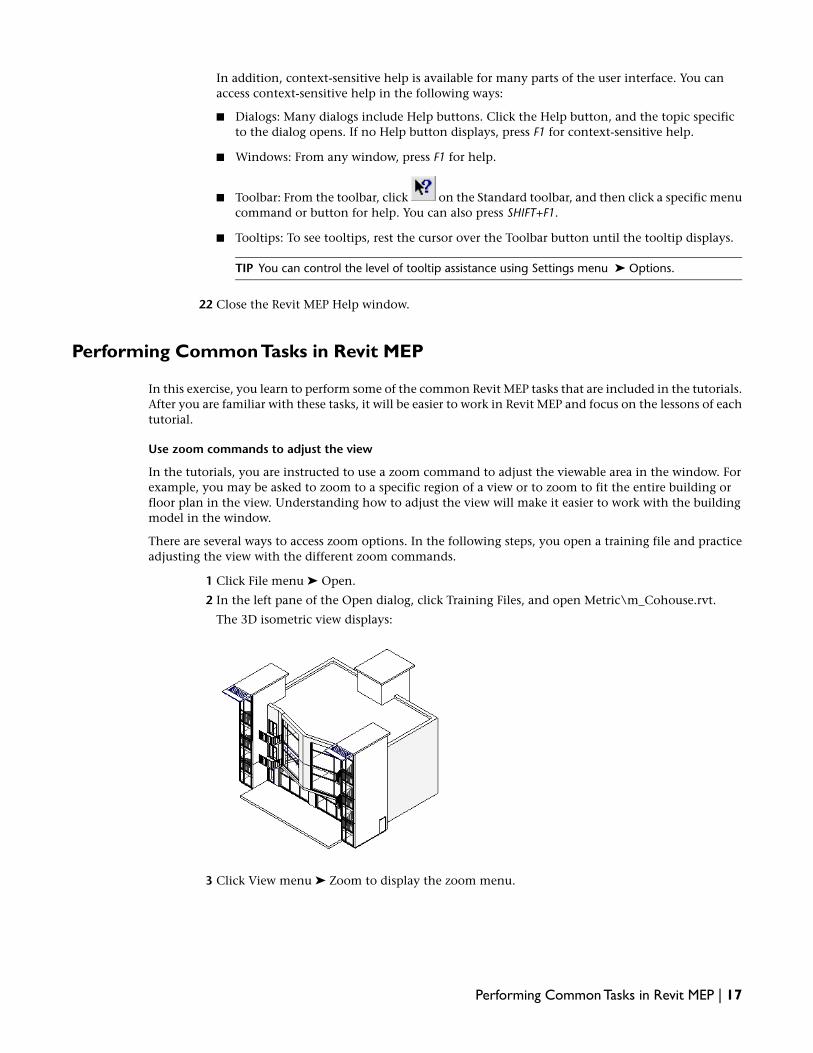
14 Press TAB.
The branch to which the duct is connected highlights.
15 Press TAB again to highlight the next level of connections.
16 Press TAB until the entire hierarchy of connected ducts, fittings, and equipment is highlighted.
If the entire network does not highlight, the system has not been created properly, and adisconnection exists at the point where the highlighting stops. A disconnection will negativelyimpact calculations involving this system.
17 Click to select the highlighted system.
18 On the Options Bar, click (Filter Selection).
19 In the Filter dialog:
■ Click Check None.
■ Select Duct Fittings.
■ Select Ducts.
■ Select Flex Ducts.
20 Click OK.
Size the duct system
21 On the Options Bar, click Sizing.
Revit MEP supports 4 of the most common sizing methods: Friction, Velocity, Equal Friction,and Static Regain.
22 In the Duct Sizing dialog:
■ Under Sizing Method, select Friction, and enter .065 Pa/m.
■ Verify that Only is selected.
■ Under Constraints, for Branch Sizing, select Calculated Size Only.
23 Click OK.
The ductwork is sized using the friction method at .065 Pascals per meter of ductwork. Theductwork is automatically updated with all the necessary fittings.
24 On the Design Bar, click Modify to end the command.
Verify the sizing
25 In the system you created, select the segment of duct shown.
Creating Ductwork for the Secondary Supply Air System | 33

26 On the Options Bar, click (Element Properties).
27 In the Element Properties dialog, scroll to Mechanical - Airflow.
The Flow value of 235.00 L/s matches the required flow for the air terminal.
28 Click OK.
29 Press ESC to clear the selection.
30 Select the segment of duct shown.
31 On the Options Bar, click (Element Properties).
32 In the Element Properties dialog, scroll to Mechanical - Airflow.
The Flow value of 470 L/s is the sum of the 2 air terminals.
33 Click OK.
34 Press ESC to clear the selection.
Verify the calculated airflow value for the VAV box.
35 Select the VAV box in the system.
36 On the Options Bar, click (Element Properties).
In the Element Properties dialog, under Mechanical - Airflow, the adjusted SupplyAirFlow valueof 940 L/s for the VAV reflects the supply airflow values calculated for the system.
37 Click OK.
38 Press ESC to clear the selection.
Next, you create the ductwork for the primary system and connect it to the 2 secondary systems.
Creating the Primary System Ductwork
In this exercise, you create the main trunk line for the primary system and connect the 2 secondary systems.
34 | Chapter 2 Express Workshop

Dataset
Continue to use the dataset you used in the previous exercise, m Express Workshop Supply Air System.rvt.
Create the primary air duct
1 On the Design Bar, click Duct.
2 On the Options Bar:
■ In the Type Selector, select Round Duct : Taps.
■ For D:, select 300 mm.This specifies the duct diameter.
■ For Offset, select 3048 mm.
The cursor displays as a pencil.
3 To start the duct run, click near the door in the room to the left of the secondary systems, inthe location shown by the pencil.
4 Click in the location shown to end the first segment of ductwork.
5 Move the cursor past the rightmost VAV, and click to place the second segment of ductworkand end the run.
6 Press ESC twice to end the command.
The ductwork and the proper fittings are automatically created.
Creating the Primary System Ductwork | 35

7 If your trunk line does not match the above illustration and you want to draw it again, do thefollowing:
■ On the toolbar above the Options Bar, click (Undo) to undo the last segment of duct.
■ Click again to undo to first section of duct.
■ Draw the main trunk line again, as described above.
Add an end cap
Before you size the ductwork for a system, you must place end caps on all open ends of the ductwork exceptfor the end that connects to the air source. This determines airflow direction and ensures accurate ductsizing.
8 Type ZR, and specify a zoom region at the end of the trunk line.
The model is zoomed to the end of the duct.
9 On the Design Bar, click Duct Fitting.
10 In the Type Selector, select Round Duct Endcap : Standard.
11 Place the cursor over the end of the duct to display an endpoint snap point.
36 | Chapter 2 Express Workshop
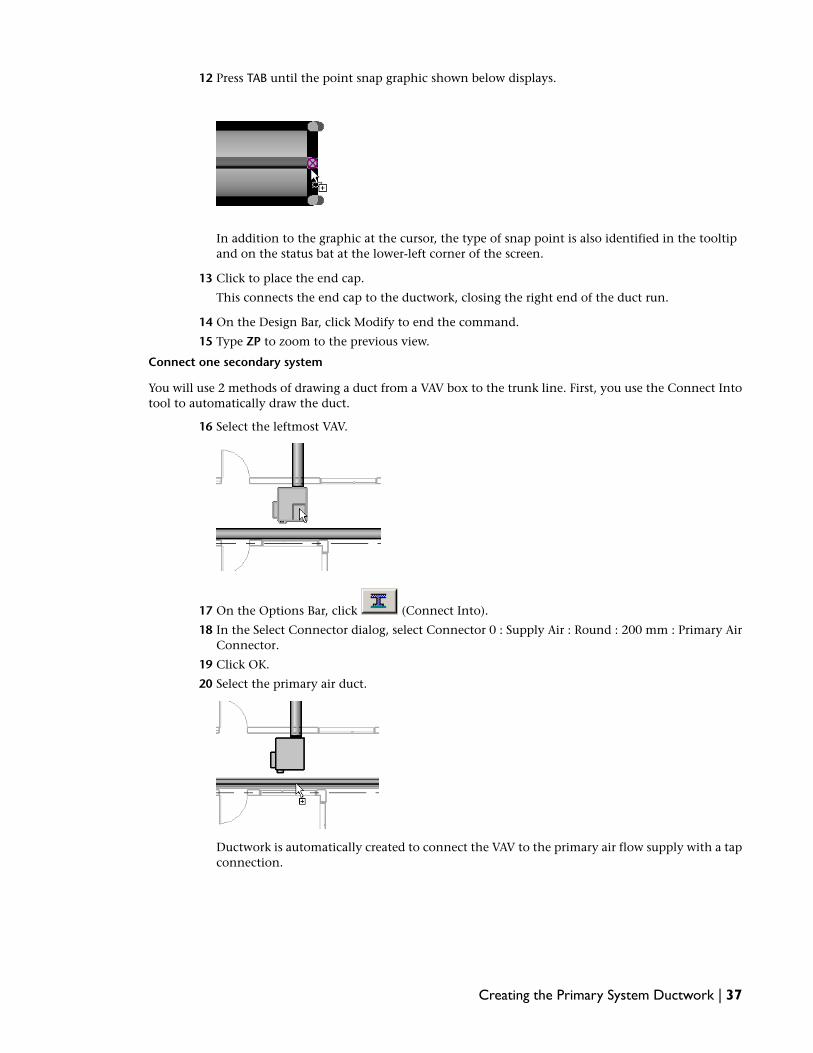
12 Press TAB until the point snap graphic shown below displays.
In addition to the graphic at the cursor, the type of snap point is also identified in the tooltipand on the status bat at the lower-left corner of the screen.
13 Click to place the end cap.
This connects the end cap to the ductwork, closing the right end of the duct run.
14 On the Design Bar, click Modify to end the command.
15 Type ZP to zoom to the previous view.
Connect one secondary system
You will use 2 methods of drawing a duct from a VAV box to the trunk line. First, you use the Connect Intotool to automatically draw the duct.
16 Select the leftmost VAV.
17 On the Options Bar, click (Connect Into).
18 In the Select Connector dialog, select Connector 0 : Supply Air : Round : 200 mm : Primary AirConnector.
19 Click OK.
20 Select the primary air duct.
Ductwork is automatically created to connect the VAV to the primary air flow supply with a tapconnection.
Creating the Primary System Ductwork | 37
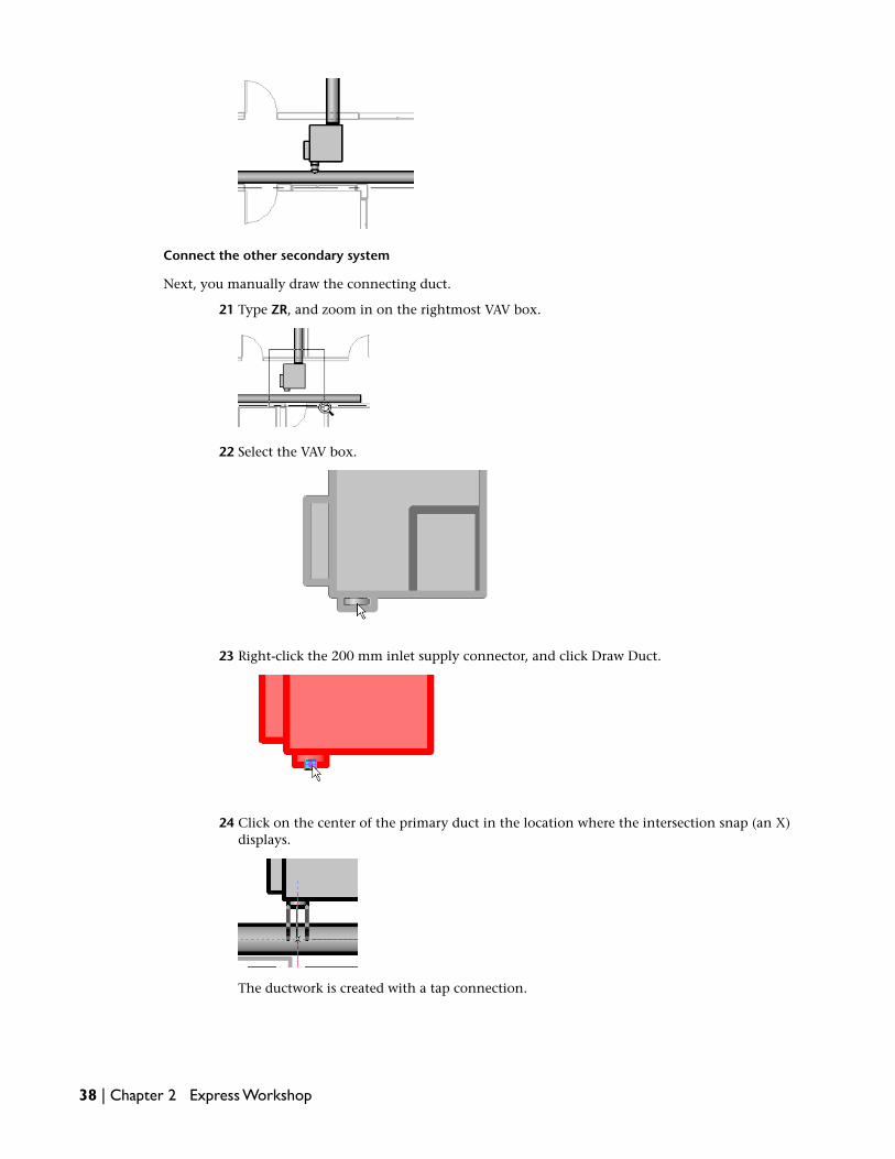
Connect the other secondary system
Next, you manually draw the connecting duct.
21 Type ZR, and zoom in on the rightmost VAV box.
22 Select the VAV box.
23 Right-click the 200 mm inlet supply connector, and click Draw Duct.
24 Click on the center of the primary duct in the location where the intersection snap (an X)displays.
The ductwork is created with a tap connection.
38 | Chapter 2 Express Workshop

25 On the Design Bar, click Modify to end the command.
26 Type ZP to zoom to the previous view.
Next, you add and connect the air handler for the primary system.
Adding the Primary System Equipment
In this exercise, you place an air handler and connect it to the main trunk line to complete the high pressure,primary system.
Dataset
Continue to use the dataset you used in the previous exercise, m Express Workshop Supply Air System.rvt.
Place the air handler
1 On the Design Bar, click Mechanical Equipment.
2 In the Type Selector, select Air Handler : Metric.
3 Move the cursor to the location shown. Do not click.
The cursor displays as the air handler outline.
4 Press SPACE BAR as needed to rotate the air handler 90 degrees. Do not click.
Adding the Primary System Equipment | 39

5 Move the air handler to the location shown.
6 Click to place the air handler.
7 On the Design Bar, click Modify to end the command.
Create a vertical section of duct
8 Move the cursor over an edge of the air handler to highlight it.
9 Click to select the air handler.
40 | Chapter 2 Express Workshop

The connectors on the top of the unit are displayed. These are the connectors for the air handlersupply, return, intake, and exhaust. The connectors on the front of the unit, for the hydronicsupply and return, are also visible.
10 Move the cursor over the 609.6 mm x 609.6 mm supply connector.
11 Right-click the connector, and click Draw Duct.
12 On the Options Bar:
■ In the Type Selector, select Rectangular Duct/Radius Elbows Tees.
■ Under Offset, select 3048 mm.
■ On the Options Bar, click (Apply Current Offset).
A vertical section of duct is created.
13 Press ESC.
14 In the Project Browser, which is located directly to the left of the drawing area, expandMechanical ➤ 3D Views.
Adding the Primary System Equipment | 41

15 Double-click 3D HVAC.
The vertical section of duct you just created is visible.
16 Close the 3D HVAC view.
Attach a rectangular duct
17 Select the vertical duct you just created.
18 Right-click the center point of the duct, and click Draw Duct.
19 Move the cursor to the right, past the end of the primary duct, and click.
20 Press ESC twice to end the command.
42 | Chapter 2 Express Workshop

Create the main system logical connection
21 While pressing CTRL, select the leftmost VAV box, and then select the rightmost VAV box.
22 On the Options bar:
■ Click (Create Supply Air System).
■ Click (Select Equipment for System).
23 Select the air handler.
The sketch graphics show the logical connection between the components.
24 Press ESC.
25 Select the air handler.
26 On the Options Bar, click (Element Properties).
In the Element Properties dialog, under Mechanical - Airflow, notice that the value forSupplyAirFlow is 15486.96 L/s. This is the capacity of the air handler.
27 Click OK.
28 Click in an empty part of the drawing area to clear the selection.
Connect the ductwork
29 On the Tools toolbar located above the Options Bar, click (Trim/Extend).
30 On the Options Bar, verify that (Trim/Extend to Corner) is selected.
Adding the Primary System Equipment | 43

31 Select the 609.6 mm x 609.6 mm rectangular supply duct by clicking a point on the duct betweenthe air handler and the primary trunk line.
32 Select the primary 300 mm round duct.
The ducts are trimmed and connected with the proper fittings.
33 On the Design Bar, click Modify to end the command.
34 Select the air handler.
35 On the Options Bar, click (Element Properties).
In the Element Properties dialog, under Mechanical - Airflow, the value for SupplyAirFlow hasbeen updated based upon the primary to supply ratio you specified in the element propertiesof the 2 VAV boxes.
36 Click OK.
37 Press ESC to clear the selection.
View the system components
38 On the Design Bar, click System Browser.
The System Browser is a tool that displays a hierarchical, discipline-specific list of all thecomponents in the model. Elements are listed by the system they belong to. Elements that donot belong to a system are listed as unassigned elements.
The browser displays 3 mechanical systems: the primary system that you just created, thesecondary system that you created in an earlier exercise, and the secondary system that wasalready in the model when you opened it.
39 In the System Browser, expand Mechanical (3 systems).
40 Expand any Supply Air system to view its HVAC components.
41 When you are done, close the System Browser.
44 | Chapter 2 Express Workshop

Next, you inspect the system and color code the ductwork.
Inspecting and Color Coding the System
In this exercise, you inspect part of the system you created. You then add a legend to automatically colorcode the ductwork based on specific calculated values.
Dataset
Continue to use the dataset you used in the previous exercise, m Express Workshop Supply Air System.rvt.
Inspect the completed supply air system
1 In the Project Browser, expand Mechanical ➤ 3D Views, and double-click 3D HVAC.
2 Select a section of a secondary system.
3 On the Options Bar, click (System Inspect).
The selected system maintains its appearance; the other systems are displayed in half tone.
4 On the Design Bar, click Inspect.
5 Move the cursor over a section of the system.
Inspecting and Color Coding the System | 45

The inspection tag describes the section that is being inspected, including flow, static pressure,and pressure loss. The flow arrows indicate flow direction; the red arrows indicate critical flowpath.
6 On the Design Bar, click Cancel Inspector.
7 Close the 3D HVAC view.
Place a legend and color code the ductwork
Color coding the ductwork provides a quick, visual indication of a system’s air flow.
8 On the Design Bar, click Duct Color Scheme Legend.
9 Click in the drawing area to place the legend to the left of the air handler.
10 In the Choose Color Scheme dialog, under Color Scheme, select Duct Color Fill - Flow.
11 Click OK.
The legend is added and the ductwork is automatically color coded based on the actual flowvalues.
Delete the legend and remove color coding from the ductwork
12 Select the legend.
13 On the Options Bar, click .
14 In the Edit Color Scheme dialog, under Schemes, select none.
15 Click OK.
46 | Chapter 2 Express Workshop

The color is removed from the ductwork, and the color scheme is removed from the legend.The legend remains selected.
16 On the Standard toolbar at the top of the window, click (Delete) to delete the legend.
17 Click File menu ➤ Close.
18 When prompted to save the model, click No.
You have completed the first Express Workshop lesson, Creating a Supply Air System.
Creating Electrical Systems
In this lesson, you create electrical systems (including lighting circuits, power circuits, and switch systems)by establishing logical connections between electrical components. After creating the logical connections,you create the physical connections between the components: the wiring. You then automatically balancethe electrical loads on a panelboard.
The model already contains the electrical components you use to create the systems, including power panels,lighting fixtures, junction boxes, receptacles, and switches.
Electrical settings have already been specified for the model. Wiring types (including material, temperaturerating, and insulation type), voltage definitions, distribution systems, and demand factors have been defined.As you create circuits, Revit MEP ensures that components are compatible with the specified voltages anddistribution systems.
Creating Lighting Circuits
In this exercise, you create 2 lighting circuits using lighting fixtures, junction boxes, and a 480V panelboardthat have already been placed in the model. One circuit connects the 4 lighting fixtures on one side of aroom in the model; the other circuit connects the 4 lighting fixtures on the other side of the room.
You use the System Browser to view the created circuits.
Dataset
■ Click File menu ➤ Open.
■ In the left pane of the Open dialog, click Training Files.
Creating Electrical Systems | 47

If necessary, scroll until the folder is displayed.
■ Open the m Express Workshop Electrical Systems.rvt file located in the Metric folder.
Display the Electrical commands
1 On the Design Bar in the lower-left corner of the screen, click the Electrical tab.
The Electrical commands are displayed.
2 If the Electrical tab is not displayed on the Design Bar, right-click the Design Bar, and clickElectrical.
In this tutorial, when you are instructed to click a command on the Design Bar, you find thecommand at the far left of the screen.
Adjust the zoom for the model
3 Type ZE to zoom out to the extents of the model.
The entire model displays on the screen.
4 Type ZR, which is the keyboard shortcut for the Zoom in Region command.
The cursor displays as a magnifying glass.
48 | Chapter 2 Express Workshop

5 Click as shown to specify the upper-left corner of the zoom region.
6 Click to specify the lower-right corner of the zoom region.
The model zooms to the specified area. In this tutorial, when you want to change the area ofthe model you are working on, you can enter ZE to zoom out. Then, enter ZR and specify azoom region to zoom in.
You can also zoom and pan using the mouse wheel. To zoom in and out, roll the wheel. To pan,hold the wheel down and drag.
Create a lighting circuit
7 Move the cursor over the lighting fixture in the upper-left corner of the large room in the model.
The lighting fixture highlights.
8 Click to select the lighting fixture.
Creating Lighting Circuits | 49

9 Move the cursor off the lighting fixture.
The lighting fixture turns red, indicating that it has been selected.
10 While pressing CTRL, move the cursor over the lighting fixture below the selected lighting fixture,and click to select it.
11 While pressing CTRL, select the 2 lighting fixtures that are located immediately to the right ofthe previously selected 2 lighting fixtures.
When you release CTRL and move the cursor away from the 4 selected lighting fixtures, theydisplay in red, indicating that they are selected.
12 On the Options Bar directly above the drawing area, click (Create Power Circuit).
The red sketch graphics show the created circuit, which is the logical connection between theelements.
13 On the Options Bar, click (Select a Panel for the Circuit).
14 Select lighting panel LP-1.
50 | Chapter 2 Express Workshop

The red sketch graphics show the logical circuit with the home run pointing toward the selectedpanel.
15 Press ESC to clear the sketch graphics.
Create a second lighting circuit
16 Place the cursor above and to the left of the 4 lighting fixtures on the right side of the room,and then drag diagonally to create a selection window that includes all 4 lighting fixtures asshown.
17 When you release the mouse button, all the elements within the window are selected.
Creating Lighting Circuits | 51

18 On the Options Bar, click (Filter Selection).
19 In the Filter dialog:
■ Click Check None.
■ Select Lighting Fixtures.
■ Click OK.
The lighting fixtures remain selected.
20 While pressing CTRL, click the junction box located among the lighting fixtures to select it.
21 On the Options Bar, click (Create Power Circuit).
The sketch graphics show the created circuit, which is the logical connection between theelements.
52 | Chapter 2 Express Workshop

22 On the Options Bar, click (Select a Panel for the Circuit).
23 Select lighting panel LP-1.
The sketch graphics show the logical circuit with a home run. The components include the 4lighting fixtures and the junction box.
24 Press ESC to clear the sketch graphics.
Modify a circuit
At this point, you have created 2 lighting circuits.
25 Move the cursor over a lighting fixture in the leftmost circuit so that the lighting fixturehighlights. Do not click.
26 Press TAB to display the circuit.
Creating Lighting Circuits | 53

The circuit includes 4 lighting fixtures.
27 Click to select the highlighted circuit.
28 On the Options Bar, click (Edit Circuit).
29 In the Power : 1 dialog, click (Add To Circuit).
30 Select the junction box located among the lighting fixtures.
31 In the Power : 1 dialog, click Finish.
Verify the modified circuit
32 Highlight the junction box in the circuit and press TAB.
54 | Chapter 2 Express Workshop

The modified circuit is highlighted.
33 Move the cursor away from the circuit to remove the highlighting.
Display the electrical systems
The lighting circuits you created are called electrical systems in Revit MEP. At this point, only the logicalconnections between the elements exist. The circuits become visible when the physical connections, thewiring, are created. You can display the logical connections using the TAB key, and you can view the systemcomponents using the System Browser.
34 Select lighting panel LP-1.
35 On the Design Bar, click System Browser.
The System Browser is a tool that displays a hierarchical, discipline-specific list of all thecomponents in the model. Elements are listed by the system they belong to. Elements that donot belong to a system are listed as unassigned elements.
36 In the System Browser, expand Electrical (7 Systems) ➤ Power ➤ LP-1.
37 Expand the 2 circuits to view their electrical components.
38 When you are done, close the System Browser.
Next, you assign switches to control the lighting fixtures.
Creating Lighting Circuits | 55

Creating Switch Systems
In this exercise, you create switch systems to define switching behavior. The 4 lighting fixtures on the leftof the room are controlled by one switch, and the 4 lighting fixtures on the right are controlled by anotherswitch. The switches have already been placed in the model.
Dataset
Continue to use the dataset you used in the previous exercise, m Express Workshop Electrical Systems.rvt.
Create a switch system
1 Select the lighting fixture in the upper-left corner of the room.
2 On the Options Bar, click (Create Switch System).
The sketch graphics show the only currently selected component of the system.
3 On the Options Bar, click (Edit Switch System).
All elements in the drawing except the selected lighting fixture display in halftone.
4 In the Switch System dialog, click (Select Switch).
5 Select the switch as shown.
56 | Chapter 2 Express Workshop

The Options Bar displays the selected switch and the number of lighting fixtures currentlyselected (1).
6 In the Switch System dialog, click (Add to System).
7 One by one, select the 3 remaining lighting fixtures on the left side of the room.
As you select each lighting fixture, the Number of Fixtures count on the Options Bar is updated,and the lighting fixture displays in full tone in the drawing area.
Assign an identifier to the switch
8 In the Switch System dialog, click (Switch Properties).
9 In the Element Properties dialog, under Electrical - Lighting, for Switch ID, enter A.
The identifier A is assigned to the switch for reference purposes.
10 Click OK.
11 In the Switch System (A) dialog, click Finish.
Verify the switch system
12 Move the cursor over the switch to highlight it.
13 Press TAB.
The switch system highlights.
Creating Switch Systems | 57

14 Move the cursor away from the switch system to remove the highlighting.
Create a second switch system
15 Drag to draw a selection window that includes the 4 lighting fixtures on the right side of theroom.
16 On the Options Bar, click (Filter Selection).
17 In the Filter dialog:
■ Click Check None.
■ Select Lighting Fixtures.
■ Click OK.
The selection is filtered. The 4 lighting fixtures remain selected.
18 On the Options Bar, click (Create Switch System).
19 On the Options Bar, click (Edit Switch System).
20 In the Switch System dialog, click (Select Switch).
21 Select the switch as shown.
Assign an identifier to the switch
22 In the Switch System dialog, click (Switch Properties).
23 In the Element Properties dialog, under Electrical - Lighting, for Switch ID, enter B.
The identifier B is assigned to the switch for reference purposes.
24 Click OK.
25 In the Switch System (B) dialog, click Finish.
58 | Chapter 2 Express Workshop

Verify the switch system
26 Move the cursor over the switch and press TAB to highlight the switch system.
Next, you define lighting fixture types and tag the lighting fixtures.
Tagging Lighting Fixtures
In this exercise, you define the lighting fixture types for the room. Then, you add a tag to each lightingfixture that identifies its type and the switch that controls it.
The lighting requirements for the left side of the room are different from the lighting requirements for theright side of the room, so each side of the room requires a different lighting fixture type.
Dataset
Continue to use the dataset you used in the previous exercise, m Express Workshop Electrical Systems.rvt.
Tag the lighting fixtures
1 On the Design Bar, click Tag ➤ By Category.
2 On the Options Bar, clear Leader.
3 Select the upper-left lighting fixture.
The lighting fixture is labeled with an automatically generated tag.
Tagging Lighting Fixtures | 59

The bottom part of the tag displays the identifier (A) for the switch that controls the lightingfixture. The top part of the tag displays the identifier for the lighting fixture type, which youhave not yet defined.
4 One by one, select the remaining 7 lighting fixtures in the room.
The selected lighting fixtures are tagged.
5 Press ESC to end the command.
Create a new lighting fixture type
6 Select the upper-left lighting fixture.
7 On the Options Bar, select (Element Properties).
8 In the Element Properties dialog, click Edit/New.
9 In the Type Properties dialog, click Duplicate.
10 In the Name dialog:
■ Enter M_600x1200 3Lamp A.
■ Click OK.
11 In the Type Properties dialog, under Identity Data, for Type Mark, enter A.
12 Click OK.
13 In the Element Properties dialog, click OK.
14 Press ESC to clear the selection.
60 | Chapter 2 Express Workshop

The top part of the tag for the lighting fixture with the new type (M_Troffer Corner Insert :M_600x1200 3Lamp A) is automatically updated to display type mark A.
Change the type for some lighting fixtures
15 On the Tools toolbar, click (Match Type).
The cursor displays as an eyedropper.
16 Select the lighting fixture shown to specify the lighting fixture type to be matched.
17 Select the other 3 lighting fixtures on the left side of the room.
For each lighting fixture, the type is changed, and the tag is updated.
18 Press ESC twice to end the command.
Change the type for the remaining lighting fixtures
19 While pressing CTRL, select the 4 lighting fixtures on the right side of the room.
20 On the Options Bar, in the Type Selector, select M_Troffer Corner Insert : M_600x1200 3LampB.
The 4 selected lighting fixtures are changed to the specified type, and their tags are automaticallyupdated.
Tagging Lighting Fixtures | 61

21 Press ESC to clear the selection.
Turn off the tags
22 Click View menu ➤ Visibility/Graphics.
23 In the Visibility/Graphics Overrides dialog, on the Annotation Categories tab, scroll to LightingFixture Tags.
24 Clear Lighting Fixture Tags.
25 Click OK.
The lighting fixture tags are no longer displayed in the model.
Next, you create electrical circuits with wiring.
Creating Power Circuits
In this exercise, you use electrical receptacles and a 208 volt panelboard that have already been placed inthe model to create 2 electrical circuits with arc type wiring. One circuit connects 2 electrical receptacles ina small room, while the other connects the 8 receptacles in the adjoining large room. You then connect the2 circuits to create a multi-circuit home run.
Dataset
Continue to use the dataset you used in the previous exercise, m Express Workshop Electrical Systems.rvt.
Create a power circuit with wiring
1 While holding down CTRL, select the 2 receptacles in the small room.
62 | Chapter 2 Express Workshop

2 On the Options Bar, click (Create Power Circuit).
The sketch graphics show the logical created circuit.
3 On the Options Bar, click (Select a Panel for the Circuit).
4 Select power panel PP-1.
The sketch graphics show the created circuit home run.
Creating Power Circuits | 63

5 In the drawing area near the created circuit, click as shown to create arc type wiring.
The circuit wiring with a homerun is created.
6 Press ESC to clear the selection.
View conductor information
7 Type ZR, which is the keyboard shortcut for the Zoom to Region command.
The cursor displays as a magnifying glass.
8 Click to specify the upper-left and lower-right corners of the zoom region shown.
You can also specify the zoom region by clicking in one corner and dragging to the other corner.
9 Select the wire shown.
64 | Chapter 2 Express Workshop

The tick marks indicate the number of conductors (3) for the wire.
10 On the Options Bar, click (Element Properties).
11 In the Element Properties dialog, under Electrical - Loads, verify the number of conductors ofeach type (hot, neutral, and ground).
12 Click OK.
13 Press ESC to clear the selection.
14 Type ZP to zoom to the previous view.
Create a second circuit with wiring
15 In the large room, select the receptacle as shown.
16 While pressing CTRL, select the remaining receptacles in the large room, for a total of 8 receptacles.
17 On the Options Bar, click (Create Power Circuit).
Creating Power Circuits | 65

The sketch graphics show the circuit.
18 On the Options Bar, click (Select a Panel for the Circuit).
19 Select power panel PP-1.
The sketch graphics show the circuit and home run.
20 In the drawing area near the created circuit, click as shown to create arc type wiring.
66 | Chapter 2 Express Workshop

The circuit wiring with a homerun is created.
The single arrow at the end of the home run wire indicates a single-circuit home run.
21 Press ESC to clear the selection.
Rewire a circuit
22 Select the home run wire for the small circuit.
23 Right-click, and click Delete.
Creating Power Circuits | 67

The wire is deleted.
24 Type ZR, and zoom in on the region shown.
25 On the Design Bar, click Wire.
The cursor displays as a pencil with arc type wiring.
26 Move the cursor to the location shown.
The cursor is correctly positioned when the point snap graphic displays. If the cursor ispositioned as shown, but the point snap graphic is not displayed, press TAB until the graphicdisplays.
In addition to the graphic in the drawing, the displayed snap point is also identified in thetooltip and on the status bar at the lower-left corner of the screen.
27 With the point snap graphic displayed, click to place the end of the wire.
28 Move the cursor to the location shown.
68 | Chapter 2 Express Workshop

If the cursor is positioned as shown, but the point snap graphic is not displayed, press TAB untilthe graphic displays.
29 With the point snap graphic displayed, click to place the end of the wire.
The two circuits are automatically connected, creating a multi-circuit home run.
30 On the Design Bar, click Modify to end the command.
View the multi-circuit home run
31 Type ZP to zoom to the previous view.
Creating Power Circuits | 69

The 2 arrows on the large circuit home run indicate that it is now a multi-circuit home run.
The wires in the circuit have been automatically resized to accommodate the demand createdby the new multi-circuit home run.
Tag the wires
32 On the Design Bar, click Tag ➤ By Category.
33 On the Options Bar, select Leader.
34 Highlight a wire in the small circuit as shown.
The temporary label shows the circuit the circuit number (5) and the power panel name (PP-1).
35 Click to place the label.
36 Highlight a wire in the large circuit as shown.
The temporary label shows the 2 circuits (5 and 6) and the power panel name (PP-1).
37 Click to place the label.
38 On the Design Bar, click Modify to end the command.
Next, you balance the electrical loads on panelboard PP-1.
Balancing Electrical Loads
In this exercise, you view the panel schedule report for panelboard PP-1 and balance the electrical loads onthis panel.
Dataset
Continue to use the dataset you used in the previous exercise, m Express Workshop Electrical Systems.rvt.
View the panel schedule report
1 Select power panel PP-1.
70 | Chapter 2 Express Workshop

2 On the Options Bar, click (Panel Schedule Report).
The Panel Schedule Report view opens.
3 In the Project Browser, which is located directly to the left of the drawing area, scroll down asneeded, and expand Reports ➤ Panel Schedule.
PP-1 is highlighted to show that it is the currently displayed view.
4 In the Project Browser, under Panel Schedule, right-click PP-1, and click Properties.
5 In the Element Properties dialog, under Other, for Appearance on Sheet, click Edit.
The Panel Report Appearance dialog displays. This dialog allows you to control how the panelschedule report displays when it is included on a sheet.
6 In the Panel Report Appearance dialog, click OK.
7 In the Element Properties dialog, click OK.
8 Close the Panel Schedule Report view.
Balance the loads on the panel
9 Select power panel PP-1.
10 On the Options Bar, click (Edit Circuits on Panel).
The Edit Circuits dialog displays.
All the circuits connected to the panel are listed, and the current loads on phases, A, B, and C,are shown.
11 In the Edit Circuits dialog, click Rebalance Loads.
Balancing Electrical Loads | 71

The loads are balanced across each phase, and the circuit structure is automatically reorganized.
12 Click OK.
The reorganized circuit structure is reflected in the wire labels.
13 Click File menu ➤ Close.
14 When prompted to save the model, click No.
You have completed the Express Workshop lesson Creating Electrical Systems.
72 | Chapter 2 Express Workshop

Developing Your MEPDesigns
73

74

Mechanical Systems
In this tutorial, you design a mechanical system for an office building. This system consists of a VAV duct system and ahydronic piping system. As you create the mechanical system, you follow a series of lessons and exercises that teach therecommended system design workflow for Revit MEP 2009. This workflow begins with system planning and concludeswith system designing. By following the recommended workflow, you learn system design best practices while understandinghow Revit MEP makes systems design more efficient.
The goal of this tutorial is to teach you to design a mechanical system using Revit MEP 2009. At the end of this tutorial,you will understand the process, methodology, and specific techniques for designing mechanical systems.
NOTE All exercises in this tutorial are designed to be completed sequentially; each exercise is dependent on thecompletion of the previous exercise. After finishing each exercise, you can choose to save your work. However, it ishighly recommended that you always begin an exercise by opening the provided dataset. This dataset includes thework from the previous exercise(s) and ensures a seamless training session. The datasets that you use to completethis tutorial are located in the Training FilesMetric directory. You can search this directory to verify that the datasetshave been downloaded. If the tutorial datasets are not present, go to http://www.autodesk.com/revitmep-documentationand download them.
Planning Mechanical Systems
To create a mechanical system in Revit MEP, as with any design project, you first carefully plan the system.In this lesson, you plan the system by first placing spaces in the building. Then you assign zones to thespaces in order to control the spacial environment. After applying a color scheme to the zones, you performa heating and cooling load analysis to determine the heating and cooling requirements for the building.
Placing Spaces
Spaces allow you to calculate the volume of the areas in the building, and contain information about thelocations in which they are placed. This information is used for heating and cooling load analysis. In thisexercise, you place spaces in the areas of the building model. First, you configure the linked architecturalmodel, as most MEP engineers work with a linked model during system design. Then, you create a plenumlevel and place various types of spaces.
Dataset
■ Click File menu ➤ Open.
3
75

■ In the left pane of the Open dialog, click the Training Files icon.
■ Open the m Spaces.rvt file located in the Metric ➤ Mechanical folder.
Configure the linked model
The most common method of designing systems in Revit MEP is to work within a linked architecturalbuilding model. In this section, you configure a linked model in order to begin designing systems in it.
1 In the Project Browser, expand Views (Discipline) ➤ Mechanical ➤ HVAC ➤ Floor Plans ➤ 1 -Mech.
The level 1 floor plan of the linked model displays.
2 Place the cursor over the linked model, and after the linked model highlights, right-click, andclick Element Properties.
The Status Bar located below the Design Bar and a tooltip indicate the Linked Revit Model.
3 In the Element Properties dialog, click Edit/New.
4 In the Type Properties dialog, select Room Bounding, and click OK twice.
This makes the architectural components (such as walls and floors) room-bounding so that theyare recognized as boundaries for spaces.
NOTE When working with a linked file, make certain that the roof is defined as room-bounding, andthat the ceiling is defined as non room-bounding. These components are defined in the architecturaldataset, not in the MEP dataset.
5 On the Basics tab of the Design bar, click Modify.
The linked model is configured. Next, you add a level for plenums.
Add a Plenum level
You create plenum levels to place spaces in the plenum areas (between the ceiling and the floor) of thebuilding. You must place spaces in all areas (occupied and unoccupied) of the building to achieve an accurateheating and cooling load analysis.
6 In the Project Browser, expand Mechanical ➤ HVAC ➤ Elevations (Building Elevation), anddouble-click East - Mech.
The elevation view opens.
76 | Chapter 3 Mechanical Systems

7 On the Basic tab of the Design Bar, click Level.
8 In the Type Selector, verify that Level : Plenum is selected.
9 On the Options Bar, do the following:
■ Verify that (Draw) is selected.
■ Verify that Make Plan View is selected.
■ Click Plan View Types, and in the Plan View Types dialog clear Ceiling Plan, and click OK.This creates only a floor plan after the level is added.
■ For Offset, verify that 0.00mm is specified.
10 Draw a plenum level 2600mm above Level 1.
A new plenum floor plan view named Level 7 is created, and its listed in the Project Browserunder Mechanical ➤ ???.
11 In the Project Browser, expand Mechanical ➤ ??? ➤ Floor Plans, right-click Level 7, and clickProperties.
12 In the Element Properties dialog, do the following:
■ Under Graphics, select HVAC for Sub Discipline.
■ Under Identity Data, enter Level 1 Plenum for View Name, and press ENTER.If asked to rename the corresponding level and views, click Yes.
■ Scroll down to the Extents category, and click Edit for View Range.
■ In the View Range dialog, do the following:
■ Under Primary Range, for Top, select Level Above (Level 2), and enter an Offset value of0.00.
■ For Cut plane, enter an Offset of 300mm
■ For Bottom, verify that Associated Level (Level 1 Plenum) is specified with a 0.00 offset.
■ Under View Depth, for Level, verify that Associated Level (Level 1 Plenum) is specifiedwith a 0.00 offset.
■ Click OK twice.
The Level 1 Plenum floor plan is now listed under HVAC ➤ Floor Plans in the Project Browser.Notice that the level is renamed in the elevation view.
Place a space in an office area and in an open area
13 In the Project Browser, under Floor Plans, double-click 1 - Mech, and maximize the window.
14 Click Windows menu ➤ Close Hidden Windows to close the elevation view.
If Close Hidden Windows is unavailable, the 1 - Mech view is not maximized or the elevationview was closed.
15 Use the mouse scroll wheel, and zoom the office area located in the upper-left corner of thebuilding.
16 On the Basic tab of the Design Bar, click Space.
The Space tool is also on MEP-specific Design Bar tabs.
17 Verify that Space Tag is selected in the Type Selector.
18 On the Options Bar, do the following:
■ Verify that Tag on placement is selected.
Placing Spaces | 77

■ For Upper Limit, select Level 1 Plenum.This action specifies the vertical extent of the space.
■ For Offset, enter 0.00.
■ Verify that Horizontal is selected in the tag location box.
■ Verify that Leader is cleared.
■ In the Space box, verify that New is selected.The Space box contains all unplaced spaces (spaces that were placed in unbounded areas).New indicates that a new space is being placed.
19 Place the cursor in the office area located in the upper-left corner of the building until the spacesnaps to the room-bounding elements.
20 Click to place the space.
Only the space tag displays because the visibility for the interior fill and reference lines is notactivated.
78 | Chapter 3 Mechanical Systems

You activate this visibility later in this exercise.
21 With the Space tool open, enter ZF to zoom the view to fit the drawing area.
This displays the entire floor plan and centers it in the drawing area.
TIP You can also right-click in the drawing area, and click Zoom to Fit.
22 Move the cursor to the large open area in the center of the floor plan, and after the space snapsto the room-bounding elements, click to place a space as shown.
Make certain that you place the space to the center-right of the open space as shown. Later inthe exercise, you will separate the open space near the entrance and place a space there.
23 Click Modify.
Placing Spaces | 79

Next, you rename the 2 spaces.
24 Zoom in on the space tag in the upper left hand corner office.
25 Click the space tag name.
A text box appears.
Enter Office, and press ENTER.
26 Double-click the space tag number, enter 101 in the text box, and click in the drawing area.
27 Repeat this method, and rename the space in the open area, Open 104.
80 | Chapter 3 Mechanical Systems
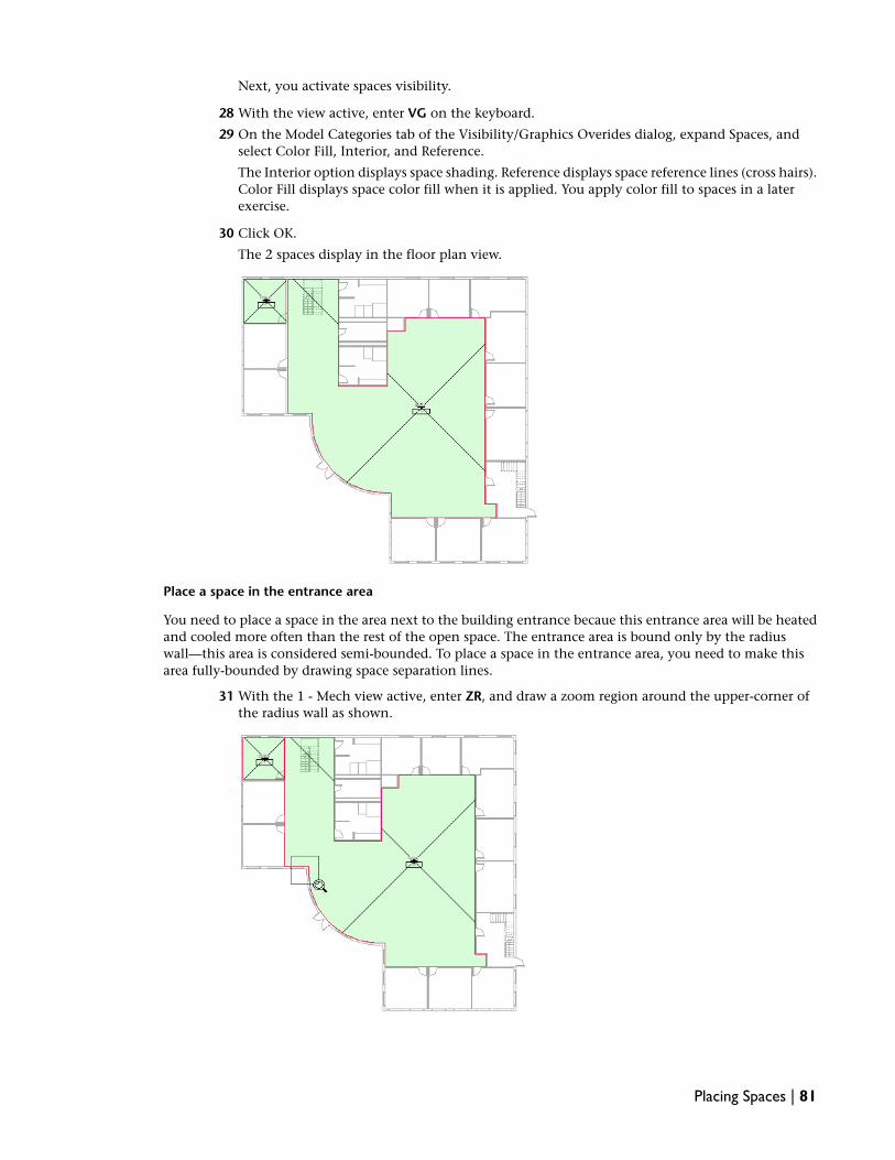
Next, you activate spaces visibility.
28 With the view active, enter VG on the keyboard.
29 On the Model Categories tab of the Visibility/Graphics Overides dialog, expand Spaces, andselect Color Fill, Interior, and Reference.
The Interior option displays space shading. Reference displays space reference lines (cross hairs).Color Fill displays space color fill when it is applied. You apply color fill to spaces in a laterexercise.
30 Click OK.
The 2 spaces display in the floor plan view.
Place a space in the entrance area
You need to place a space in the area next to the building entrance becaue this entrance area will be heatedand cooled more often than the rest of the open space. The entrance area is bound only by the radiuswall—this area is considered semi-bounded. To place a space in the entrance area, you need to make thisarea fully-bounded by drawing space separation lines.
31 With the 1 - Mech view active, enter ZR, and draw a zoom region around the upper-corner ofthe radius wall as shown.
Placing Spaces | 81

32 On the Mechanical tab of the Design Bar, click Space Separation.
NOTE If the Mechanical tab is not available on the Design Bar, right-click the Design Bar, and clickMechanical.
33 On the Options Bar, do the following:
■ Verify that (Draw), Chain, and (Line) are selected.
■ For Offset, verify that 0.00mm is specified.
■ Verify that Radius is cleared.
34 Place the cursor over the upper-corner of the radius wall, and after the end point snap displays,click to specify the start point for the first space separation line segment.
35 Use the mouse scroll wheel to zoom out the view.
36 Draw the line up, and type 1200mm (notice the text entry box called a dimension listener thatpops up), and press ENTER to specify the end point for the first line segment.
The Draw tool remains open.
37 Move the cursor to the right to draw a horizontal line 9800mm, and click to specify the endpoint for the second line segment.
38 Draw the line down 9800mm, and click to specify the end point of the third line segment.
39 Move the cursor to the left 1200mm (which is located over the lower-end of the radius wall),and after the end point snap displays, click to specify the end point for the last line segment.
If you see a warning that the space tag is outside of its space, click Move to Space.
40 Press ESC twice to close the Draw tool.
Notice that the Open 104 space adjusted its boundaries so that it is not in the new area. Thespace separation line created a new fully-bounded area within the large open area.
NOTE If the space or the space tag is inside the smaller area, select the space (reference line) or thespace tag, and drag it to the larger open area. If the space and space tag are inside the new area,select and drag both of them.
82 | Chapter 3 Mechanical Systems

NOTE Space separation lines are MEP-specific room-bounding lines that separate areas where a wallis not desired or not possible. After the areas are separated, spaces can be placed in them. Althoughroom separation lines are recognized in Revit MEP, space separation lines are not recognized in RevitArchitecture.
Next, you place a space in the entrance area.
41 On the Mechanical tab of the Design Bar, click Space.
42 On the Options Bar, select Level 1 Plenum for Upper Limit, enter 0.00 for Offset, verify thatHorizontal is selected in the tag location box, verify that Leader is cleared, and verify that Newis slected in the Space box.
43 Place a space in the entrance area.
44 Click Modify.
45 Place the cursor over the space, after the space reference lines highlight, right-click and clickElement Properties.
46 In the Element Properties dialog, under Identity Data, do the following:
■ For Number, enter 121.
■ For Name, enter Entrance.
Placing Spaces | 83
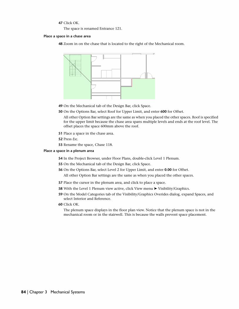
47 Click OK.
The space is renamed Entrance 121.
Place a space in a chase area
48 Zoom in on the chase that is located to the right of the Mechanical room.
49 On the Mechanical tab of the Design Bar, click Space.
50 On the Options Bar, select Roof for Upper Limit, and enter 600 for Offset.
All other Option Bar settings are the same as when you placed the other spaces. Roof is specifiedfor the upper limit because the chase area spans multiple levels and ends at the roof level. Theoffset places the space 600mm above the roof.
51 Place a space in the chase area.
52 Press Esc.
53 Rename the space, Chase 118.
Place a space in a plenum area
54 In the Project Browser, under Floor Plans, double-click Level 1 Plenum.
55 On the Mechanical tab of the Design Bar, click Space.
56 On the Options Bar, select Level 2 for Upper Limit, and enter 0.00 for Offset.
All other Option Bar settings are the same as when you placed the other spaces.
57 Place the cursor in the plenum area, and click to place a space.
58 With the Level 1 Plenum view active, click View menu ➤ Visibility/Graphics.
59 On the Model Categories tab of the Visibility/Graphics Overides dialog, expand Spaces, andselect Interior and Reference.
60 Click OK.
The plenum space displays in the floor plan view. Notice that the plenum space is not in themechanical room or in the stairwell. This is because the walls prevent space placement.
84 | Chapter 3 Mechanical Systems

61 If you want to save your work, click File menu ➤ Save. Otherwise, close the file.
62 In the Save As dialog, enter Spaces Training for File name, navigate to the folder of your choice,and click Save.
NOTE After finishing each exercise, you can choose to save your work. However, it is highlyrecommended that you always begin each exercise by opening the dataset that Autodesk provides.This dataset includes the work from the previous exercise(s) and ensures a seamless training session.
In this exercise, you created a plenum level and a corresponding floor plan view. You used space separationlines to create a new fully-bounded area that was part of a larger area, and you placed spaces for varioustypes of areas. Finally, you modified the spaces visibility for the views. In the next exercise, you add spacesto zones in order to control the spacial environment and perform an accurate heating and cooling loadsanalysis.
Creating Zones
After spaces are placed in the building, Revit MEP immediately adds them to the Default zone. When youadd a space to a zone, that action removes the space from the Default zone. In this exercise, you assignspaces to zones in the building, and verify the zones in the System Browser. Zones allow you to control thespacial environment and to perform an accurate heating and cooling loads analysis.
Dataset
■ Click File menu ➤ Open.
■ In the left pane of the Open dialog, click the Training Files icon.
■ Open the m Zones.rvt file located in the Metric ➤ Mechanical folder.
NOTE All space reference lines have been hidden in the dataset to provide a clearer view of the floor plan. Spaceshading and the space tags indicate spaces. You can click Reference under Spaces on the Model Categories tabof the Visibility/Graphics dialog (View menu ➤ Visibility/Graphics) to display space reference lines.
1 In the Project Browser, expand Views (Discipline) ➤ Mechanical ➤ HVAC ➤ Floor Plans, anddouble-click 1 - Mech to make it the active view.
2 On the Mechanical tab of the Design Bar, click System Browser.
The System Browser opens and docks to the right of the drawing area.
Creating Zones | 85

NOTE You can also press F9 (with the drawing area active) or click Window menu ➤ System Browserto open the System Browser.
3 Right-click in Systems Browser, and click View ➤ Zones.
4 Double-click Default to display a list of the spaces in the building model.
This is a hierarchical list of spaces and the zones to which they have been assigned. Notice thatDefault is currently the only zone.
NOTE A space cannot be placed into an area without being added to a zone. After a space is placedin an area, it is automatically added to the Default zone. The recommended workflow is to add eachspace to a zone that you create. This removes the space from the Default zone.
Next, you assign spaces to a zone. As you do this, you will use the System Browser to confirmthat the spaces are in the new zone.
Assign a zone to spaces on the same level
5 On the Mechanical tab of the Design Bar, click Zone.
The Zone tool opens, the Zone toolbar displays, and a new zone is created. The new zone islisted in the System Browser.
NOTE The Zone toolbar provides zone tools and information. The title bar displays the name of thenew zone. You work with one zone until you click Finish. Using the Zone toolbar, you can add orremove a space from the zone, and modify the zone properties.
6 On the Zone toolbar, verify that (Add a Space to the Zone) is selected.
7 In the drawing area, place the cursor on Office 101 located in the upper-left corner of the buildinguntil the space highlights.
86 | Chapter 3 Mechanical Systems

8 Click the space to add it to the zone.
In the System Browser, expand the new zone and notice that the Office 101 space is added toit and removed from the Default zone. To view the zone in the drawing area, you need to activatethe zone visibility which you do next.
9 With the drawing area active, enter VG.
10 On the Model Categories tab of the Visibility/Graphics Overides dialog, expand HVAC Zones,click Interior Fill and Reference Lines, and click OK.
The new zone displays.
11 With the Zone toolbar open, add the Office 102 and Office 103 spaces to the zone.
Notice that the zone reference line indicates that the 3 spaces are in the zone.
TIP You can drag the zone reference line to relocate it and better view the spaces that are in thezone.
Next, you rename the zone.
12 On the Zone toolbar, click (Zone Properties).
13 In the Element Properties dialog, under Identity Data, for Name enter 1 - West Offices, and clickOK.
The new zone name displays in the Zone toolbar and the space is renamed in the System Browser.
14 Expand the 1 - West Offices zone in the System Browser to confirm that the 3 spaces are in it.
Creating Zones | 87

15 On the Zone toolbar, click Finish.
Assign a zone for spaces on different levels
16 In the Project Browser, expand Views (Discipline) ➤ Mechanical ➤ HVAC ➤ Floor Plans, anddouble-click Level 1 Plenum to open the view.
Next, you activate zones visibility for the view.
17 With the drawing area active, enter VG.
18 On the Model Categories tab of the Visibility/Graphics Overides dialog, expand HVAC Zones,click Interior Fill and Reference Lines, and click OK.
19 Click Windows menu ➤ Floor Plan: 1 - Mech to make it the active view.
20 Enter WT to tile the 2 windows.
21 Zoom in on each floor plan.
22 On the Mechanical tab of the Design Bar, click Zone.
23 On the Zone toolbar, verify that (Add a Space to the Zone) is selected.
24 On the 1 - Mech floor plan, add the following level 1 spaces to the zone:
■ Open 104
■ Men’s Room 105
■ Mech/Elec 106
■ Ladies Room 107.
25 With the Zone toolbar open, click in the Level 1 Plenum view to make it active.
26 Add the L1 Plenum 122 space to the zone.
27 On the Zone toolbar, click Finish.
88 | Chapter 3 Mechanical Systems

You need to rename the zone. However, you cannot open the Zone tool as this will create a newzone. Next, you edit the zone to rename it.
28 In either view, select the reference line to the zone that you created.
29 On the Options Bar, click Edit Zone.
The Zone tool opens. Notice that the Zone toolbar displays the name of the zone that you areediting.
30 On the Zone toolbar, click (Zone Properties).
TIP You can also access zone properties by right-clicking the zone in the System Browser, and clickProperties.
31 In the Element Properties dialog, under Identity Data, for Name, enter 1 - Open Offices, andclick OK.
Creating Zones | 89

The new zone name displays in the Zone toolbar and the space is renamed in the System Browser.You can expand the 1 - Open Offices zone in the System Browser to view the 5 spaces in it.
32 On the Zone toolbar, click Finish.
Complete the zones for the building
33 For additional practice, use the methods that you learned and assign zones for all the spaces inthe building. The table below lists all spaces and the zones. Make certain that you verify thespaces in the floor plan views and in the System Browser
If you prefer not to continue with this practice, proceed to the next step. All zones will beprovided in the dataset for the next exercise.
ZonesSpaces
1 - East OfficesOffices 111, 112, 113
1 - EntranceEntrance 121
1 - North OfficesOffices 108, 109, 110
1 - Open OfficesOpen 104, Men’s Room 105, Elec/Mech 106, Ladies’Room 107, L1 Plenum 122
1 - South OfficesOffices 115, 116, 117
1 - West OfficesOffices 101, 102, 103
StairwellsStairwells 114, 213
2 - Conference RoomConference 214
2 - East OfficesOffices 210, 211, 212
2 - North OfficesLounge 208, Office 209
2 - Open OfficesOpen 204, Men’s Room 205, Elec/Mech 206, LadiesRoom 207, L2 Plenum 217
2 - South OfficesOffices 215, 216
2 - West OfficesOffices 201, 202, 203
ChasesChases 118, 119, 120
34 If you want to save your work, click File menu ➤ Save. Otherwise, close the file.
35 In the Save As dialog, enter Zones Training for File name, navigate to the folder of your choice,and click Save.
In this exercise, you assigned zones to the spaces that were on the same level and on different levels of thebuilding, You activated zone visibility in the views, and verified the zones in both the floor plan views and
90 | Chapter 3 Mechanical Systems

in the System Browser. In the next exercise, you assign a color scheme to these zones in preparation forlaying out a VAV duct system.
Assigning a Color Scheme to Zones
In this exercise, you apply a color scheme to the zones that you created in the previous exercise. A colorscheme allows you to communicate and identify parameters visually and spatially rather than you usingspace schedules or accessing element properties.
Dataset
■ Click File menu ➤ Open.
■ In the left pane of the Open dialog, click the Training Files icon.
■ Open the m Zone Color Scheme.rvt file located in the Metric ➤ Mechanical folder.
NOTE All zone reference lines and shading have been hidden in this dataset to provide a clearer view of the floorplan. You can click Reference Lines and Interior Fill under HVAC Zones on the Model Categories tab of theVisibility/Graphics Overides dialog (View menu ➤ Visibility/Graphics) to display zone reference lines and shading.The zones are also listed in the System Browser.
Create a new color scheme legend type
1 In the Project Browser, expand Views (Discipline) ➤ Mechanical ➤ HVAC ➤ Floor Plans, anddouble-click 1 - Mech to make it the active view.
2 Enter ZF to zoom the view to fit the drawing area.
3 On the Drafting tab of the Design Bar, click Color Scheme Legend.
NOTE If the Drafting tab is not available on the Design Bar, right-click the Design Bar, and clickDrafting.
4 In the Type Selector, verify that Color Scheme Legend : 1 is selected.
Apply the color scheme
5 Move the cursor in the drawing area and notice that the color scheme legend outline indicatesthat no color scheme has been assigned to the view.
The color scheme outline follows the cursor movement to help you accurately position thelegend.
6 Position the color scheme legend outline at the top-right corner of the floor plan, and click toplace the legend.
7 In the Choose Space Type and Color Scheme dialog, do the following:
■ Select HVAC Zones for Space Type.
■ Verify that Schema 1 is selected for Color Scheme.
■ Click OK.
The color scheme is applied to the zones in the 1 - Mech view.
Assigning a Color Scheme to Zones | 91

8 For additional practice, use the method that you learned and add a color scheme for the zoneson the 2 - Mech, Level 1 Plenum, and Level 2 Plenum floor plan views.
If you prefer not to continue with this practice, proceed to the next step. All color schemes willbe provided in the dataset for the next exercise.
9 If you want to save your work, click File menu ➤ Save As.
10 In the Save As dialog, enter Zone Color Scheme Training for File name, navigate to the folderof your choice, and click Save.
In this exercise, you applied a color scheme to the zones in your building. In the next exercise, you performa heating and cooling loads analysis to determine the heating and cooling demands of the building.
Performing a Heating and Cooling Loads Analysis
In this exercise, you verify the building, space, and zone information, and view the spaces in the previewpane to verify space boundaries and volumes. You then perform a heating and cooling loads analysis onyour building to determine the heating and cooling demands of the building, and view the loads report.
Dataset
■ Click File menu ➤ Open.
■ In the left pane of the Open dialog, click the Training Files icon.
■ Open the m Energy Analysis.rvt file located in the Metric ➤ Mechanical folder.
Specify Project Settings
1 Click Settings menu ➤ Project Information.
2 In the Element Properties dialog under Energy Analysis, click Edit for Energy Data.
3 In the Type Properties dialog, do the following:
■ Verify that Office is specified for Building Type.
■ For Postal Code, enter 03101.
■ Click for Location, and on the Place tab of the Manage Place and Locations dialog,select Manchester, NH for City, and click OK.
92 | Chapter 3 Mechanical Systems

■ Verify that VAV - Single Duct is specified for Building Service.
■ For Ground Plane, select Level 1.
■ Verify that <Building> is specified for Building Construction.
■ Verify that Shading surfaces is selected.
■ Verify that New Construction is selected for Project Phase.
■ Verify that 300mm is specified for Sliver Space Tolerance.
■ Click OK twice.
Verify area and volume setting
4 Click Settings menu ➤ Area and Volume Computations.
5 On the Computations tab of the Area and Volume Computations dialog, verify that Areas andVolumes is selected (default setting), and click OK.
NOTE The Areas and Volumes option must be selected to perform an accurate heating and coolingloads analysis. After opening the Heating and Cooling Loads tool, if you receive a message that theAreas and Volumes option is not checked and that the space volumes will be approximate, you needto select this option.
Verify building information
6 On the Mechanical tab of the Design Bar, click Heating and Cooling Loads.
A preview pane displays the model and 2 tabs contain heating and cooling information for thebuilding.
7 Click the Building tab of the Heating and Cooling Loads dialog, and do the following:
■ For Building Type, verify that Office is selected.
■ For Building Construction, Default Space Construction, verify that <Building> is selected.
You can view the building materials for this construction type by clicking (BuildingConstruction Settings).
■ For Building Service (Default Space Service), verify that VAV - Single Duct is selected.
■ For Place and Location, verify that Manchester, NH is selected.
IMPORTANT The Heating and Cooling Loads dialog contains building information that only affectsthe heating and cooling loads analysis. Revit MEP stores this information as project information. Youcan also access the building information by clicking Settings menu ➤ Project Information. Then,under Energy Analysis, click Edit for Energy Data.
You have verified the building information. Next, you view the space and zone volumes in thebuilding model.
Performing a Heating and Cooling Loads Analysis | 93

View a space
8 In the preview pane, while pressing SHIFT and the mouse scroll wheel, spin the model as shown.
9 In the Heating and Cooling Loads dialog, click the Spaces/Zones tab.
The Spaces and Zones tab contains a hierarchical list of spaces and the zones that have beenassigned to them.
10 On the View Selector (located below the preview pane), verify that Wireframe is selected (defaultsetting).
NOTE Wireframe displays the analytical volume of a space. The analytical volume is bounded by thecenter plane of walls and the top plane of roofs and floors.
11 Expand the 1 - East Offices zone, and select Office 111.
12 Click (Highlight).
The space for Office 111 highlights in red. The Highlight tool allows you to verify that the spaceboundaries are as you defined them. You can also view a space in relation to the other spacesor architecture in the entire building.
TIP You can use the View Cube mouse to spin, pan, and zoom the model to better view the space.
13 Click to deactivate the Highlight tool.
Next, you isolate a space.
94 | Chapter 3 Mechanical Systems
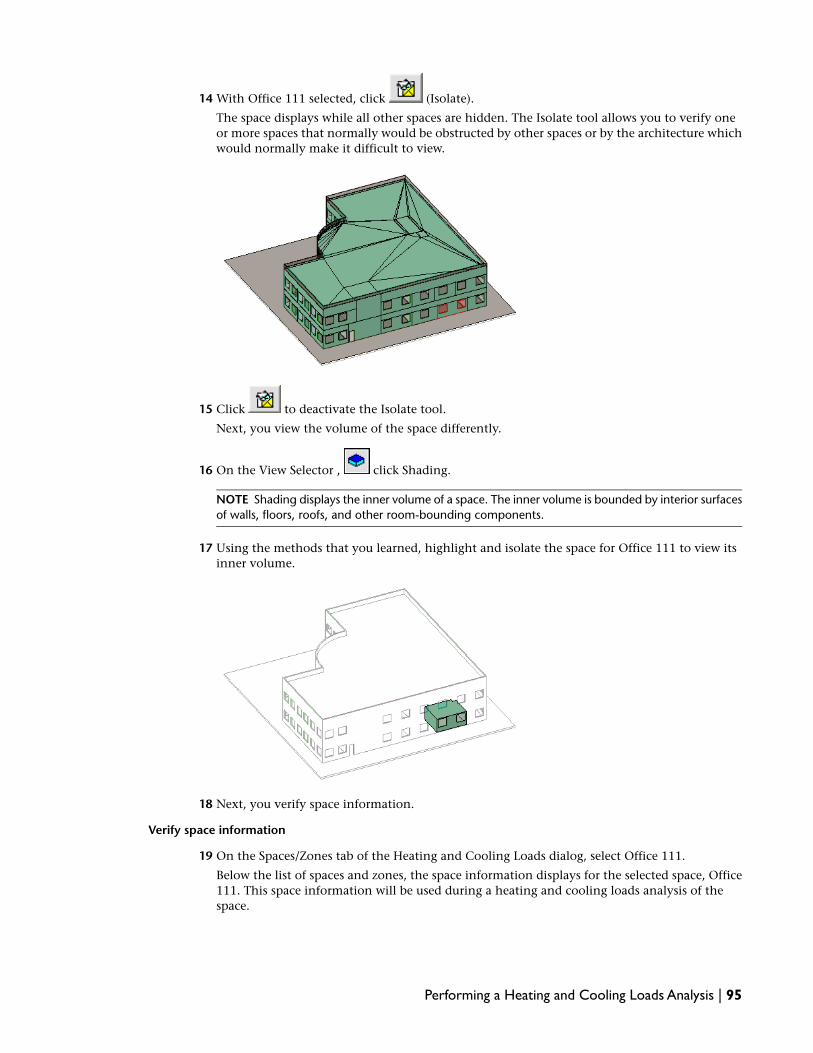
14 With Office 111 selected, click (Isolate).
The space displays while all other spaces are hidden. The Isolate tool allows you to verify oneor more spaces that normally would be obstructed by other spaces or by the architecture whichwould normally make it difficult to view.
15 Click to deactivate the Isolate tool.
Next, you view the volume of the space differently.
16 On the View Selector , click Shading.
NOTE Shading displays the inner volume of a space. The inner volume is bounded by interior surfacesof walls, floors, roofs, and other room-bounding components.
17 Using the methods that you learned, highlight and isolate the space for Office 111 to view itsinner volume.
18 Next, you verify space information.
Verify space information
19 On the Spaces/Zones tab of the Heating and Cooling Loads dialog, select Office 111.
Below the list of spaces and zones, the space information displays for the selected space, Office111. This space information will be used during a heating and cooling loads analysis of thespace.
Performing a Heating and Cooling Loads Analysis | 95

20 Under the list of spaces and zones, verify the following space information:
■ <Building> is specified for Space Type and Construction Type.These specify the space usage and construction materials for the space.
■ <Default> is specified for People Data.This specified the number of people or the area per person for the space.
■ Lighting Loads: <Default> : Power Loads: <Default> is specified for Electrical Data.This specifies the lighting and power loads for the space.
View a zone and zone information
21 On the View Selector , click Wireframe.
This displays the analytical volume of the spaces in the selected zone.
22 On the Spaces/Zones tab, select 1 - East Offices.
This zone contains 3 spaces, including Office 111.
23 As you did earlier, use the (Highlight) and (Isolate) tools to view the analyticalvolume of the spaces in the selected zone.
24 Click (Shading), and repeat the above steps to view the inner volumes of the spaces in the1 -East Offices zone.
Next, you verify the zone information.
25 Click 1 - East Offices.
Below the list of spaces and zones, the zone information displays for the selected zone, 1 - EastOffices. This zone information will be used during a heating and cooling loads analysis of thespaces in the zone.
26 Verify the following zone information for the 1 - East Offices zone:
■ <Building> is specified for Service Type.
■ 21.00 °C : 32.00 °C : N/A for Heating Information.This specifies the heating set point, heating air temperature, and humidification set point.
■ 23.00 °C : 12.00 °C : N/A for Cooling Information.This specifies the cooling set point, cooling air temperature, and dehumidification set point.
■ N/A : N/A : N/A is specified for Outdoor Air Information.This specifies the outdoor air per person, outdoor air per area, and air changes per hour.
IMPORTANT The Heating and Cooling Loads dialog contains space and zone information that onlyaffects the heating and cooling loads analysis. Revit MEP stores this space and zone information asspace and zone properties, respectively. You can also access the space and zone information byselecting a space or zone in the drawing area or System Browser, right-clicking, and clicking Element
Properties. You can also click (Zone Properties) on the Zone toolbar to access the zoneinformation. The space and zone information is located under Energy Analysis in the Element Propertiesdialog.
View other spaces and zones
27 Using the methods that you learned, view other spaces and zones in the building model, andverify the space and zone information.
96 | Chapter 3 Mechanical Systems

You may need to spin, pan, or zoom the view to see the selected space or zone.
TIP You can select multiple spaces or zones by pressing CTRL and selecting them, or by pressingSHIFT to select a range of spaces or zones.
NOTE If you select multiple spaces or zones that contain different information, that information doesnot display. For example, if 2 spaces are selected each having different people data, the People Dataoption becomes blank.
Now that the project, building, space, and zone information has been verified, you can performa heating and cooling loads analysis.
Perform a heating and cooling loads analysis
28 On the Heating and Cooling Loads dialog, click Calculate.
Revit MEP performs a heating and cooling loads analysis using the integrated heating and coolingloads analysis tool that was developed in partnership with IES (Integrated EnvironmentalSolutions). Various factors are analyzed including analytical and inner volumes of the spaces.See Help for more information about the integrated heating and cooling loads analysis tool andits calculation methods.
RELATED <Virtual Environment> allows you to either export the building and space information tothe IES <Virtual Environment> program to perform an energy analysis and create an IES model, orimport the IES model that has already been created. You must have IES <VE> installed. This productis not included with Revit MEP.
After the heating and cooling loads analysis is completed, the Heating and Cooling Loads dialogcloses, and a loads report displays.
29 Review the loads report, this report includes project, weather, space, and zone information forthe building model.
NOTE You must perform a new heating and cooling loads analysis each time you modify building,space, or zone information, or make any changes to the model, otherwise the loads report or scheduleswill not reflect your changes.
TIP You can find all generated Loads Reports in the Project Browser under Reports.
30 If you want to save your work, click File menu ➤ Save. Otherwise, close the file.
31 In the Save As dialog, enter Energy Analysis Training for File name, navigate to the folder ofyour choice, and click Save.
In this exercise, you verified building, space, and zone information, and viewed the spaces in the previewpane to verify space boundaries and volumes. You then performed a heating and cooling loads analysis onyour building and viewed the loads report. This concludes the planning stage of the systems project. In thenext lesson, you begin the designing phase by placing air terminals in the spaces.
Performing a Heating and Cooling Loads Analysis | 97

98

Mechanical Systems:Air
Designing Air Systems
Designing air systems in Revit MEP is a straightforward and intuitive process. In this lesson, you will createsupply air systems. You begin your supply air systems design by placing air terminals in rooms and addingthe VAV boxes. Then, you create the secondary and primary supply air system and ductwork to connect thecomponents that you added. After system creation, you continue designing by resolving routing conflicts,sizing ductwork, adding AC units, and then you validate your air system design.
IMPORTANT It is highly recommended that you complete Designing Air Systems before starting Designing PipingSystems. After completing the air systems lesson, you will have been introduced to concepts and practices thatyou will use to design the piping systems.
Placing Air Terminals
In this exercise, you place air terminals in the ceiling of the rooms. As you place the air terminals, you createnew views, modify air terminal parameters, and learn a method to precisely place air terminals into theceiling plan.
Dataset
■ Click File menu ➤ Open.
■ In the left pane of the Open dialog, click the Training Files icon.
■ Open the m Air Terminals.rvt file located in the Metric ➤ Mechanical folder.
Modify a ceiling plan view
1 In the Project Browser, expand Views (Discipline) ➤ Mechanical ➤ HVAC ➤ Ceiling Plans, anddouble-click 1 - Ceiling Mech to make it the active view.
2 Right-click in the drawing area, and click View Properties.
You can also select the 1 - Ceiling Mech view in the Project Browser and click (Properties).
4
99

3 In the Element Properties dialog, under Graphics, do the following:
■ Select Level 1 for Underlay.
■ Verify that Reflected Ceiling Plan is selected for Underlay Orientation.
4 Scroll down to the Extents category and click Edit for View Range.
5 In the View Range dialog, specify the following:
■ Under Primary Range, for the Top parameter, verify that Associated Level (Level 1) is selected,and enter 2615 mm for Offset.You specify 2615mm so that your view captures the air terminals (which will be located atthe ceiling height of 2600mm) and not other system components that may be above the airterminals and in the same level. These components would obstruct your view of the airterminals.
■ Under Primary Range, for the Cut plane parameter, enter 0 for Offset.
■ Under View Depth, for the Level parameter, verify that Associated Level (Level 1) is selected,and enter 2615 for Offset.
NOTE When entering a value, you do not need to type measurement symbols instead, enter thevalue, and press Tab. For example, you can enter 2600 and press Tab for 2600mm.
6 Click OK twice.
You will now use this ceiling plan to place the level 1 air terminals.
Add a supply air terminal
7 Verify that 1 - Ceiling Mech is the active view.
8 On the Mechanical tab of the Design Bar, click Air Terminal.
9 In the Type Selector, select M_Supply Diffuser - Hosted: Workplane-based Supply Diffuser.
10 On the Options bar, make sure that Place on Face is selected.
11 Click to place the supply air terminal in the upper left office as shown.
NOTE The ceiling hosts the diffuser.
100 | Chapter 4 Mechanical Systems:Air

12 On the Mechanical tab of the Design Bar, click Modify.
TIP When you click Modify, the command in progress terminates. You can also press Esc to accomplishthis result.
Modify the supply air terminal flow and offset parameters
13 Select the supply air terminal that you just placed.
Notice that the selected air terminal turns red.
14 On the Options Bar, enter 150 L/s for Flow.
Move the supply air terminal
15 With the air terminal selected, click (Move) on the Edit toolbar.
TIP To use the Move tool, you first specify a start point on the component that you want to moveand then you specify an end point for the destination. The start point aligns with the end point whenthe move is completed.
16 Move the cursor to the bottom right corner of the air terminal, and after the (geometry) endpoint snap displays, click to specify the move start point.
17 Move the air terminal to the location shown.
Move the diffuser so that it fits squarely inside a ceiling tile. Since snaps are not available here,you may have to move it to center it -- use the arrow keys for fine movement control.
Copy the supply air terminal
18 With the Office 101 air terminal selected, click (Copy) on the Edit toolbar.
TIP You use the same procedure with the Copy tool as with the Move tool. First specify a copy startpoint on the component that you want to copy and then specify the copy end point (or destination).
19 On the Options Bar, verify that Constrain is cleared and Copy is selected, then select Multiple.
Multiple allows you to place multiple copies of the air terminal without reactivating the Copytool after each placement.
20 Select the bottom-right corner of the air terminal as the copy start point, and then click themidpoint of the Office 102 and then of the Office 103 ceiling grids to specify copy end points,and then click Modify.
Placing Air Terminals | 101

Copies of the air terminal are placed immediately after you specify each end point. Notice thatafter you specify the copy start point, listening dimensions display to aid placement.
TIP You can enter SM to override all other snaps and display midpoint snaps only. Note that snapoverrides deactivate after you make a selection.
Add exhaust air grills and return air terminals
21 On the Mechanical tab on the Design Bar, click Air Terminal.
22 In the Type Selector, select M_Exhaust Diffuser - Hosted: Worplane-based Exhaust Diffuser.
23 Using the add-move-copy placement method, place an exhaust air grill in the Ladies’ Room(upper restroom), and then copy it to the Men’s Room (lower restroom) as shown.
102 | Chapter 4 Mechanical Systems:Air

Before you copy the exhaust diffuser, make certain that you specify the airflow parameter to120 L/s.
24 In the Type Selector, select M_Return Diffuser - Hosted: Worplane-based Return Diffuser.
25 Using the same placement method, place 3 return air terminals in the open space to the left ofthe restrooms, and specify a 150 L/s airflow for each of them.
Placing Air Terminals | 103

26 On the Mechanical tab of the Design Bar, click Modify.
TIP Notice that each air terminal type is identified by a different symbol.
Modify the airflow display arrows
27 Select the Office 101 supply air terminal and use the Copy tool to place a copy below the Men’sRoom in the Open 1 area.
28 Select the air terminal that you just placed, right-click, and click Element Properties.
29 In the Element Properties dialog, under Mechanical, clear the UpArrow check box, and clickOK.
104 | Chapter 4 Mechanical Systems:Air

Optional: Complete the level 1 supply air terminal layout
For additional practice of the techniques you have learned so far, continue laying out the level 1 supplysystem. You can safely skip this section if you have mastered the design process. The next exercise startswith a completed drawing.
30 Select the Office 101 air terminal, click on the Edit toolbar.
31 Place copies of this supply air terminal at the ceiling grid intersections as shown below.
After you place the supply air terminals, remember to modify the airflow display arrows for airterminals that need 2-way and 3-way blow patterns.
Optional: Create the level 2 air terminal layout
For additional practice of the techniques you have learned so far, create the level 2 supply system. You cansafely skip this section if you have mastered the design process. The next exercise starts with a completeddrawing.
32 Using the placement method that you learned for level 1, do the following for level 2:
■ Make 2 - Ceiling Mech the active view.
Placing Air Terminals | 105

■ In the Element Properties dialog, specify the same view parameters as 1 - Ceiling Mech butuse Level 2 as an Underlay and verify that Associate Level (Level 2) is set for the view rangeparameters.
■ Use the add-move-copy placement method to place the same type of air terminals on level2 that you did on level 1. Specify 150 L/s airflow for the supply and return diffusers, and 120L/s airflow for the exhaust diffusers.
■ Modify the airflow display arrows for air terminals that need 2-way and 3-way blow patterns.
After you finish the level 2 air terminal layout, collapse the ceiling plan views in the ProjectBrowser. You will be using different views to design the systems. The completed level 2 airterminal layout is as shown.
33 If you want to save your work, click File menu ➤ Save.
34 In the Save As dialog, enter Air Terminals Training for File name, navigate to the folder of yourchoice, and click Save.
In this exercise, you placed air terminals in the ceiling of the rooms, modified the air terminal parameters,and learned a method for precise placement. In the next exercise, you create the air systems. In the nextexercise, you create schedules and use them as not only as documents but as design tools.
Using a Schedule as an Air Systems Design Tool
Schedules allow you to document the mechanical system components and heating and cooling requirements.More importantly, you can modify this information directly within a schedule making the schedule a designtool. The schedule as a dynamic design tool is a very powerful method to monitor system requirements, andto quickly and accurately make real-time system modifications across the entire Revit MEP project.
In this exercise, you create a schedule for the supply air system project. Instead of placing this schedule onsheets as a construction document, you use it as a design tool to determine whether the correct amount ofairflow is being supplied to each of the rooms in the model. You then use the schedule to adjust the airterminal airflow properties to more closely meet design requirements.
Dataset
■ Click File menu ➤ Open.
■ In the left pane of the Open dialog, click the Training Files icon.
106 | Chapter 4 Mechanical Systems:Air

■ Open the m Air System Schedules.rvt file located in the Metric ➤ Mechanical folder.
1 On the Mechanical tab of the Design Bar, click Schedule/Quantities.
Define schedule type
2 In the New Schedule dialog, do the following:
■ Under Category, select Air Terminals.Notice that the schedule name and the phase is automatically added.
■ Verify that Schedule building components is selected, and that Show categories from alldisciplines is cleared.
■ Click OK.
Define columns
3 On the Fields tab of the Schedule Properties dialog, under Available fields, select Flow, and clickAdd to add the Flow field to the list of scheduled fields to include in the schedule.
4 Add Mark and System Type.
5 Under Select available fields from, select Space.
Notice that the content of the Available fields list changes to fields associated with spaces.
6 While pressing Ctrl, select the following fields from the Available fields list:
■ Space: Actual Supply Airflow
■ Space: Calculated Supply Airflow
■ Space: Name
■ Space: Number
7 Click Add to add them to the Scheduled fields list.
8 Select a field and click Move Up and Move Down to arrange the Scheduled fields list as follows:
■ Space: Number
■ Space: Name
■ Mark
■ System Type
■ Flow
■ Space: Actual Supply Airflow
■ Space: Calculated Supply AirflowIf you need to remove a field, select the field and click Remove.
Create a calculated value parameter
9 Click Calculated Value.
10 In the Calculated Value dialog, do the following:
■ Enter Actual Calculated Airflow for Name.
■ Verify that Formula is selected.
■ Select HVAC for Discipline.
■ Select Air Flow for Type.
Using a Schedule as an Air Systems Design Tool | 107

■ Use the button on the right to enter Space: Actual Supply Airflow - Space: Calculated SupplyAirflow for Formula.
11 Click OK.
The Actual Calculated Airflow calculated value is added to the scheduled fields (at the bottomof the list) and will display as a column in the schedule.
Format the calculated value parameter
12 On the Formatting tab of the Schedule Properties dialog, in the Fields list, select Actual CalculatedAirflow, and click Conditional Format.
13 In the Conditional Formatting dialog, do the following:
■ Verify that Actual Calculated Airflow is selected for Field.
■ Select Not Between for Test.
■ Enter -35 L/s and 35 L/s for Value.Notice that the conditions that you specified display under Conditions to Use.
■ Click the Background Color and select Red in the Color dialog.
■ Click OK twice.
The Actual Calculated Airflow calculated value parameter allows you to immediately determinewhat rooms do not meet the design requirements as they are red in the schedule.
Organize the data
14 On the Sorting/Grouping tab of the Schedule Properties dialog, do the following:
■ Select Space: Number for Sort by.
■ Verify that Ascending is selected.
■ Select Footer, and Count and totals.
■ Select Blank line.
■ Verify that (none) is selected for Then by.
■ Verify that Grand totals is cleared, and Itemize every instance is selected.
■ On the Filter tab, select System Type for Filter by, equals, and select Supply Air.
■ Click OK.
A new view opens called Air Terminal Schedule and is located under Schedules/Quantities inthe Project Browser. Notice that the data is sorted according to room number. The red valuesin the Actual Calculated Airflow column immediately report that the actual amount of air beingsupplied to the room does not yet meet the design airflow requirements within the range ofplus or minus 35 L/s.
This schedule is not only a construction document but also a design tool. You can change oneor more entries in the schedule to modify your system. Each change is dynamic and immediatelypropagates throughout your project. This is because you are modifying the digital database ofbuilding information. This digital database information source is the integral concept of BuildingInformation Modeling (BIM).
Next, you use the schedule as a design tool to modify the airflow for an air terminal to satisfythe design requirements.
Use the schedule as a design tool
15 With the Air Terminal Schedule view active, click Window menu ➤ Close Hidden Windows.
108 | Chapter 4 Mechanical Systems:Air

This closes all open windows that are hidden by the schedule.
NOTE If a different project is also open, click Window menu and select the project to make it theactive view, and click File menu ➤ Close to close the project.
16 In the Project Browser, under Views ➤ Mechanical ➤ HVAC ➤ Floor Plans, double-click 1 -Mech to make it the active view.
17 Enter ZR, and draw a zoom region around Office 101 located on the left outer wall of the floorplan.
18 Enter WT to tile the 2 views.
The schedule and the floor plan display simultaneously in the drawing area.
19 In the schedule, select the 150 L/s Flow parameter (in the Flow column) for the Office 101 airterminal.
A cursor displays in the selected cell in the schedule enabling you to modify the parameter, andif you click in the floor plan to make it active, the selected air terminal displays in red.
Notice that the Flow column parameters are the only parameters that you can define in theschedule. The other parameters are design or calculated parameters.
20 Delete 150 L/s enter 120, and press Tab.
The Actual Calculated Airflow value displays in white indicating that it now complies with theOffice 101 airflow design requirements.
NOTE After you select and modify data in a schedule, the associated system component is immediatelyselected and modified in the project as if you used the Element Properties dialog. This allows you touse schedules to make multiple modifications in one view. These changes dynamically propagatethroughout your project because you are changing the digital database of building information.
Tagging an Air Diffuser
21 Select Tag from the Mechanical tab on the Design bar.
22 Select By Category.
23 On the Options bar, click Leader to clear this option.
24 Click on a diffuser to add a tag.
TIP Editing diffuser tags in schedules, rather than one by one in a drawing, speeds the design process.
Optional: Modifying Other Parameters
The drawing for the next exercise provides completed values.
25 Modify the other supply air terminal Flow parameters for both floors so that the airflow designrequirements are met.
Using a Schedule as an Air Systems Design Tool | 109

NOTE Do not modify the return or exhaust air terminals as these are not supply air terminals and donot affect the supply airflow.
After you modify the airflow parameters, all Actual Calculated Airflow parameters display inwhite.
IMPORTANT By modifying each supply air terminal airflow parameter, you are changing the airterminal connector size. Air terminal connector sizes are used to calculate airflow but are also usedto calculate ductwork sizing.
26 Close the schedule view, and maximize the 1 - Mech floor plan view.
27 If you want to save your work, click File menu ➤ Save.
28 In the Save As dialog, enter Using Schedules Training for File name, navigate to the folder ofyour choice, and click Save.
In this exercise, you created a schedule to assess airflow for each room in the building. You then used thisschedule as a design tool to modify the airflow so that it meets the design requirements. You modified theairflow parameters directly in the schedule and all changes occurred dynamically and propagated throughoutthe project. This occurred because you were modifying the digital database of building information that theproject sources. This is the power of BIM.
In the next exercise, you create air systems.
Creating Secondary Supply Air Systems
In this exercise, you create low pressure secondary supply air systems. A system is the logical connectionbetween system components such as air terminals and mechanical equipment. This logical connectionallows Revit MEP to perform various analyses including energy analysis. You create air systems by placingair terminals and mechanical equipment, and then create the logical connection between the systemcomponents. After creating the logical connection, you then create ductwork to physically connect thesystem components. This is the Revit MEP recommended workflow or best practice for systems creation.During this exercise, you also use the System Browser to validate your systems.
IMPORTANT All system components are logically connected either to a system that you create or to a defaultsystem. Unlike logical connections, physical connections (ductwork) are not required for systems designing.However, they are necessary to perform calculations that reference the physical geometry such as sizing.
Dataset
■ Click File menu ➤ Open.
■ In the left pane of the Open dialog, click the Training Files icon.
■ Open the m Creating Secondary Supply Air Systems.rvt file located in the Metric ➤ Mechanical folder.
Modify a floor plan view
1 In the Project Browser, expand Views (Discipline) ➤ Mechanical ➤ HVAC ➤ Floor Plans, anddouble-click 1 - Mech to make it the active view.
2 Right-click in the drawing window, and click View Properties.
3 In the Element Properties dialog, under Extents, click Edit for View Range.
4 In the View Range dialog, do the following:
■ Verify that Associated Level (Level 1) is selected for the view range parameters.
■ Under Primary Range, for the Top parameter, enter an Offset value of 3000.
110 | Chapter 4 Mechanical Systems:Air

5 Click OK twice.
6 Type VG on the keyboard.
7 On the Annotation Categories tab of the Visibility/Graphics Overides window, uncheck AirTerminal tags, and click OK.
You use multiple views to clearly and effectively communicate different systems information.Different building professionals use different views during the course of the building project.You will create the level 1 supply air systems in the 1 - Mech view.
Explore the System Browser
8 On the Mechanical tab of the Design Bar, click System Browser.
TIP You can also press F9 (Window menu ➤ System Browser) to open or close the System Browser.If the System Browser does not respond, click in the drawing area to make it active, then press F9.
9 If the System Browser title says Zones, right-click the title and select View ➤ Systems.
10 Expand the Unassigned systems folder, and expand each default systems to view all of the airterminals that you placed in the building.
IMPORTANT In the System Browser, all system components are organized in a folder tree hierarchyaccording to the system that you assigned to them. You assign a system component (mechanicalequipment, air terminals, and so on) to a system either by creating a logical connection (or system)between the system components or by assigning a system component to an existing system. Youwill learn more about systems in this exercise. For now, notice that all of the diffusers (air terminals)that you added are located under default systems categories in the Unassigned folder. This assignmentoccurred because each system component must be assigned to a system after it is placed. So, afteryou placed the diffusers, Revit MEP immediately assigned them to the Default Supply Air systemcategory located in the Unassigned folder. They remain in the default systems category until youassign them to their proper system. As you assign diffusers to systems, the assigned diffusers movefrom the Unassigned folder to their respective assigned system folder. Thus, if all system componentsare assigned, each default system category would not contain any system components and wouldbe considered empty. The System Browser is a powerful tool that allows you to validate and confirmair systems.
Keep the System Browser open and refer to it as you create your systems.
Place a VAV (variable air volume) box
11 With the view active, enter ZR, and sketch a zoom region around Office 101 located in thetop-left corner of the floor plan.
The cursor changes to a magnifying glass when Zoom in Region is activated.
Creating Secondary Supply Air Systems | 111

TIP Although this view does not contain room tags, you can identify a room by placing the cursorover the room component. A tooltip and the Status Bar (located at the lower left under the DesignBar) confirm the room name and number. If desired, you can add room tags to the mechanical floorplans using the Room Tag tool on the Mechanical tab of the Design Bar.
12 On the Mechanical tab of the Design Bar, click Mechanical Equipment.
13 In the Type Selector, select M_VAV Unit Parallel Fan Powered: M_Size 3 - 200mm Inlet.
14 Move the cursor to the right of the office door, press Spacebar twice to rotate VAV box 180degrees, click to place the VAV box, and press Esc twice.
Modify VAV box parameters
15 Right-click the VAV box, and click Element Properties.
16 In the Element Properties dialog, do the following:
■ Under Constraints, enter 2900 for Offset.Note that the VAV will detect the downstream airflow when connected to diffusers.
■ Click OK.
The offset value places the VAV box in the plenum space (between the level 1 ceiling and thelevel 2 floor and above the level 1 air terminals). This VAV box services only Office 101 so theVAV airflow equals that of the air terminal. Notice that the VAV box listing is placed in theUnassigned folder under the Default Supply Air system in the System Browser. This is becauseyou have yet to assign it to a system.
Create a secondary air system containing one diffuser
17 Select the Office 101 rectangular diffuser.
18 On the Options Bar, click (Create Supply Air System).
You created a system that includes the air terminal. Next, you add the VAV to this system.
IMPORTANT After you select a system component, system specific tools display on the Options Bar.
19 On the Options Bar, click (Select Equipment for System), and select the VAV box.
112 | Chapter 4 Mechanical Systems:Air

Notice that only mechanical equipment highlight and can be selected when using the SelectEquipment for System tool.
TIP If you clicked outside of the drawing area, and cleared from the Options Bar, select anair terminal that you added to the system. This system tool displays along with the other Options Barsystem tools.
The newly created system that logically connects the air terminal to the VAV box displays inred. This display indicates that the new system is selected. It does not indicate a ductwork layoutpath.
Next you create the ductwork to physically connect the air system components (air terminaland VAV).
IMPORTANT The new system named Mechanical Supply Air 1 is now listed in the System Browserunder Supply Air in the Mechanical folder. The organization is from upstream, the VAV (the parent)to downstream, the air terminal (the child) with the system between (connecting) them. Notice thatthe air terminal listing moved to the assigned system but the VAV box is also listed under Unassigned.This is because you have yet to assign the VAV primary and return air connections to their systems.They remain assign to their respective default systems, Default Supply Air and Default Return Air.
TIP If you click in the drawing area and the highlighted system clears, place the cursor over the Office101 air terminal and press Tab, and select the system. You can also right-click the Mechanical SupplyAir 1 listing in the System Browser, and click Select to select the system.
Create the ductwork
20 With the new system selected, click (Layout Path) on the Options Bar.
Creating Secondary Supply Air Systems | 113

The Layout Path tab appears on the Design Bar providing various layout tools. Notice thatSolutions is selected.
21 On the Options Bar, do the following:
22 Verify that Network is selected for Solution Type.■
■ Click (Next Solution), and select solution 2.The layout path solution displays with the main in blue and the branch in green.
You can also view possible layout path solutions by pressing the left and right arrow keys onyour keyboard.
23 On the Options Bar, click Settings.
24 In the left pane of the Duct Conversion Settings dialog, select Main.
25 Under System Type: Supply Air, do the following:
■ Verify that Rectangular Duct: Radius Elbows / Taps is selected for Duct Type.
■ Enter 2900mm for Offset.
26 In the left pane of the Duct Conversion Settings dialog, select Branch.
27 Under System Type: Supply Air, do the following:
■ Verify that Rectangular Duct: Radius Elbows / Taps is selected for Duct Type.
■ Enter 2900 for Offset.
■ Select Flex Duct Round : Flex - Round for Flex Duct Type.
■ Verify that 1800 is selected for Maximum Flex Duct Length.
28 Click OK.
NOTE Configuring the duct conversion settings is usually a one-time process unless you need tochange them during your project. You can also configure these settings in the Mechanical Settingsdialog by clicking Mechanical Settings on the Mechanical tab of the Design Bar (orSettings ➤ Mechanical Settings) before beginning your project. For more information, refer to Help.
29 On the Layout Paths tab of the Design Bar, click Finish Layout.
114 | Chapter 4 Mechanical Systems:Air

The physical connection composed of ducts and fittings is created.
NOTE All fittings required to connect the duct system to system components are automatically added.For example, a transition connecting the elbow was automatically added, as was the elbow itself.
IMPORTANT Notice that the ductwork is not listed in the System Browser. This is because the SystemBrowser lists system components and systems. The ductwork is a physical not a logical connection,thus it is not part of the system. For example, you can delete ductwork and the system remains.
Change the geometry display
30 On the View Control Bar located below the bottom left of the drawing area, select Medium forDetail Level.
The duct geometry now displays in 2-line enabling you to better view the ductwork.
TIP You can easily change the duct geometry representation. On the View Control Bar, select Coarsedetail level for single line, and Medium or Fine detail level for 2-line.
Note that the arrow over the duct is the diffuser airflow display arrow and not the supply airflowdirection in the duct.
Check duct connectivity
31 Place the cursor over the VAV box and after it highlights, and press Tab twice.
Creating Secondary Supply Air Systems | 115

The system components and ductwork highlight indicating that they are physically connected.
IMPORTANT When multiple ducts and fittings are connected, you check connectivity by movingthe cursor over a segment of ductwork so that it highlights and then press Tab. The first time youpress Tab, the branch to which the duct is connected highlights. Press Tab a second time to highlightthe entire network of connected ducts up to the first piece of connected equipment. Press Tab a thirdtime to highlight the entire network of connected ducts, fittings, and equipment. If the entire networkdoes not highlight, then you know that a disconnection exists. This disconnection will be located atthe point where the highlighting stops. You can repair the connection by dragging the duct segmentend point away from its current connection point and then dragging it back again to reconnect.Typically the disconnect results from not having enough room between the components that makethe connection. Rerouting usually correct this issue.
Size the duct
32 Place the cursor over the duct, and press Tab twice to highlight the duct and the air terminal,and click to select them.
Do not highlight or select the VAV box.
33 On the Options Bar, click Sizing.
34 In the Duct Sizing dialog, under Sizing Method, do the following:
■ Select Friction, and enter .65 Pa/m.
■ Verify that Only is selected.
■ Under Constraints, verify that Calculated Size Only is selected for Branch Sizing, and thatRestrict Height and Restrict Width are cleared.
■ Click OK.
The Office 101 low pressure secondary air system ductwork is sized using the Friction methodat .65 Pascals per one meter of ductwork. Other sizing methods and values can also be used aswell.
116 | Chapter 4 Mechanical Systems:Air

IMPORTANT The Duct Sizing dialog displays the sizing settings that were last used. It does not reportthe sizing settings of the selected duct.
35 With the VAV selected, right-click and select Element Properties.
Note that the airflow is set to 120 L/s, the required airflow for the space and the airflow assignedto the diffusers.
36 Click Cancel.
Create a secondary air system containing 2 diffusers
37 Click in the drawing area, enter ZR, and sketch a zoom region around Offices 102 and 103 (theoffices immediately below Office 101).
38 On the Mechanical tab of the Design Bar, click Mechanical Equipment.
39 In the Type Selector, select VAV Unit - M_Parallel Fan Powered VAV : M_Size 3 - 200mm Inlet.
40 Move the cursor to the right of the Office 102 door, press Spacebar twice to rotate VAV box 180degrees, click to place the VAV box, and click Modify on the Basics tab of the Design Bar.
41 In the left column of the System Browser, in the Unassigned folder under Default Supply Air,double-click the second VAV box listed.
You can also right-click the second VAV box listed, and click Element Properties.
Creating Secondary Supply Air Systems | 117

IMPORTANT Remember that all system components that you have not assigned to a system areplaced in the Unassigned folder in the System Browser.
TIP To locate a system component in the System Browser, right-click the component in the leftcolumn, and click Select from the context menu. The component highlights in the drawing area.Note that the correct view must be active to see the highlighted component. If not, click Show fromthe context menu to open the appropriate window and zoom in on the selected system component.
42 In the Element Properties dialog, under Constraints, enter 2900mm for Offset, and click OK.
TIP You can verify the airflow for the air terminals by opening the Air Terminal Schedule that youcreated in a past exercise, or select an air terminal and the airflow displays on the Options Bar.
43 Select the Office 102 rectangular diffuser.
The selected diffuser and its connector highlights.
NOTE After you select a system component, the selected component and its connector(s) highlight.
44 Place the cursor over the diffuser connector, right-click, and click Create Supply Air System fromthe context menu.
You can also select the diffuser and click (Create Supply Air System) on the Options Bar.
NOTE Remember that after select Create Supply Air System from the context menu or click on the Options Bar, a new system is immediately created. This system includes the selected systemcomponent(s). You can verify this new system in the System Browser.
45 Click (Edit System).
The Edit System tab appears on the Design Bar providing various system editing tools. Noticethat the Options Bar allows you to verify or modify the system name, system equipment, andnumber of elements in the active being edited.
46 On the Edit System tab of the Design Bar, click Add To System.
System components that were not selected for this system are grayed out.
47 Place the cursor over the Office 103 rectangular diffuser.
118 | Chapter 4 Mechanical Systems:Air

48 Notice that the cursor changes to indicate that Add To System is active.
49 Select the Office 103 rectangular diffuser.
The bottom diffuser is no longer grayed out as it is now part of the system. On the Options Bar,the number of elements has increased to 2.
50 On the Edit System tab of the Design Bar, click (Select Equipment).
51 Place the cursor over the VAV box located outside Office 102.
Notice that the cursor changes indicating that Select Equipment is active.
52 Select the VAV box.
Creating Secondary Supply Air Systems | 119

On the Options Bar, the selected VAV is listed for System Equipment.
53 On the Edit System toolbar, click Finish.
54 Place your cursor over the Office 102 rectangular diffuser and press Tab to display the newsystem.
If you leave the mouse stationary, a tooltip displays the system name as Duct Systems :Mechanical Supply Air 2.
55 Click to select the system.
The system displays in red.
120 | Chapter 4 Mechanical Systems:Air

Modify the layout path and create the ductwork
56 On the Options Bar, click Layout Path.
57 On the Options Bar, verify that Network is selected for Solution Type.
58 Use the left or right arrow keys on your keyboard to view the various layout solutions, and selectsolution 3.
The layout path solution displays with the main in blue and the branch in green.
You already configured the duct conversion settings for the first system. These settings remainthe same and do not need to be changed.
59 On the Layout Paths tab of the Design Bar, click Finish Layout.
Ignore the warning reporting that no auto-route solution was found. You can click in the drawingarea to close the warning.
Creating Secondary Supply Air Systems | 121

The ductwork physically connecting the system components is created.
Notice that the main is open and an endcap is needed to close the duct. This was the reason forthe warning message.
IMPORTANT When creating layouts, you are creating the physical duct and not altering the logicalsystem. So, if a layout solution causes errors (not warnings) while attempting create duct, it is becausethe duct usually has insufficient space to be created. You can either relocate the VAV box, select ormodify a different layout solution using the Layout Path tool, or modify the duct manually. Rememberto check duct connectivity after modifying ductwork. If a warning occurs, you can review it and takeaction if necessary, or click in the drawing area to close the warning and continue your work.
Add an endcap
60 Zoom in on the open (left) end of the main duct in Office 102.
NOTE It is highly recommended to zoom the view to accurately place an endcap.
61 On the Mechanical tab of the Design Bar, click Duct Fitting.
62 In the Type Selector, select M_Rectangular Duct Endcap : Standard.
63 Move the cursor over the end of the main, and after the end point snap displays, click to placethe endcap.
122 | Chapter 4 Mechanical Systems:Air

Notice that the centerline snap displays to aid in fitting placement.
64 Click Modify on the Design Bar to deactivate the Duct Fitting tool.
65 With the VAV selected, right-click and select Element Properties.
Notice the airflow value of 530 CFM.
66 Click Cancel.
Size the duct
67 Place the cursor over the duct, and press Tab twice to highlight the duct and the air terminals,and click to select them.
Do not highlight or select the VAV box.
68 On the Options Bar, click Sizing.
69 In the Duct Sizing dialog, under Sizing Method, do the following:
■ Select Friction, and enter .65 Pa/m.
■ Verify that Only is selected.
■ Under Constraints, verify that Calculated Size Only is selected for Branch Sizing, and thatRestrict Height and Restrict Width are cleared.
■ Click OK.
Creating Secondary Supply Air Systems | 123

The low pressure secondary air system ductwork for Offices 102 and 103 is sized using the Frictionmethod at .65 Pascals per one meter of ductwork.
IMPORTANT Remember that the Duct Sizing dialog displays the sizing settings that were last used.It does not report the sizing settings of the selected duct.
Check duct connectivity
70 Place the cursor over the VAV box and after it highlights, and press Tab twice.
The VAV box, air terminals, and ductwork highlight indicating that they are physically connected.
124 | Chapter 4 Mechanical Systems:Air

Next, you create a low pressure secondary air system in which you modify the layout path andadd a new system component to it. However, this time you will add the component after theductwork has been created.
Create and modify a secondary supply air system containing multiple diffusers
71 Right-click in the drawing area, click Zoom in Region from the context menu.
72 In the 1 - Mech view, sketch a zoom region around the air terminals in Open 1 (the large openspace).
73 Use your mouse scroll wheel to adjust the view as shown below.
74 On the Mechanical tab of the Design Bar, click Mechanical Equipment.
75 In the Type Selector, select M_VAV Unit - Parallel Fan Powered Size 3 - 200mm Inlet.
76 Move the cursor to the left of the air terminals, and click to place the VAV box.
Creating Secondary Supply Air Systems | 125

77 Click Modify on the Basics tab of the Design Bar.
78 Select the VAV, and on the Options Bar, click (Element Properties).
79 In the Element Properties dialog, under Constraints, enter 2900 for Offset, and click OK, andclick again to deselect the VAV.
80 While pressing CTRL, select the 4 air terminals above and to the right of the VAV.
Do not select the air terminal in the upper-right corner. You will add this later.
The selected diffusers highlight in red (shown here as circled).
81 On the Options Bar, click (Create Air Supply System).
The new supply air system displays in red.
126 | Chapter 4 Mechanical Systems:Air

The new system named Mechanical Supply Air 3 is now listed in the System Browser underSupply Air in the Mechanical folder. Notice that the selected diffusers are included in the system.
TIP If you clicked outside of the drawing area, and the red system display cleared, place the cursorover one of the air terminals in the system, and press TAB once to highlight the system. Then, clickto select the system.
82 On the Options Bar, click (Select Equipment for System).
83 Select the VAV to add it to the system.
The system displays in red and now includes the VAV. Remember that this display indicatesthat the new system is selected. It does not indicate a ductwork layout path.
You have logically connected the air system components. Next, you create the ductwork tophysically the system components.
Modify the layout path and create the ductwork
84 With the system selected, click Layout Path on the Options Bar.
85 On the Options Bar, do the following:
■ Verify that Network is selected for Solution Type.
■ Click , and select solution 1.The layout path solution displays with the main in blue and the branch in green.
86 On the Layout Paths tab of the Design Bar, click Modify.
Creating Secondary Supply Air Systems | 127

87 In the drawing area, select the left section of the branch.
After you select the branch, notice that drag controls display.
IMPORTANT Layout Path provides 2 drag controls enabling you to modify the layout. The parallelcontrol (horizontal and vertical arrows) move the layout horizontally and vertically. The end controlpoints (dots) moves the layout ends in any direction.
88 Click the parallel drag control and drag the left section of the branch to the right until it snapscreating a straight path to the VAV.
89 Repeat this procedure and move the connection to the upper right branch, and then snap andmove down the right section of the main to create a straight main to the VAV.
90 On the Layout Paths tab of the Design Bar, click Finish Layout.
128 | Chapter 4 Mechanical Systems:Air
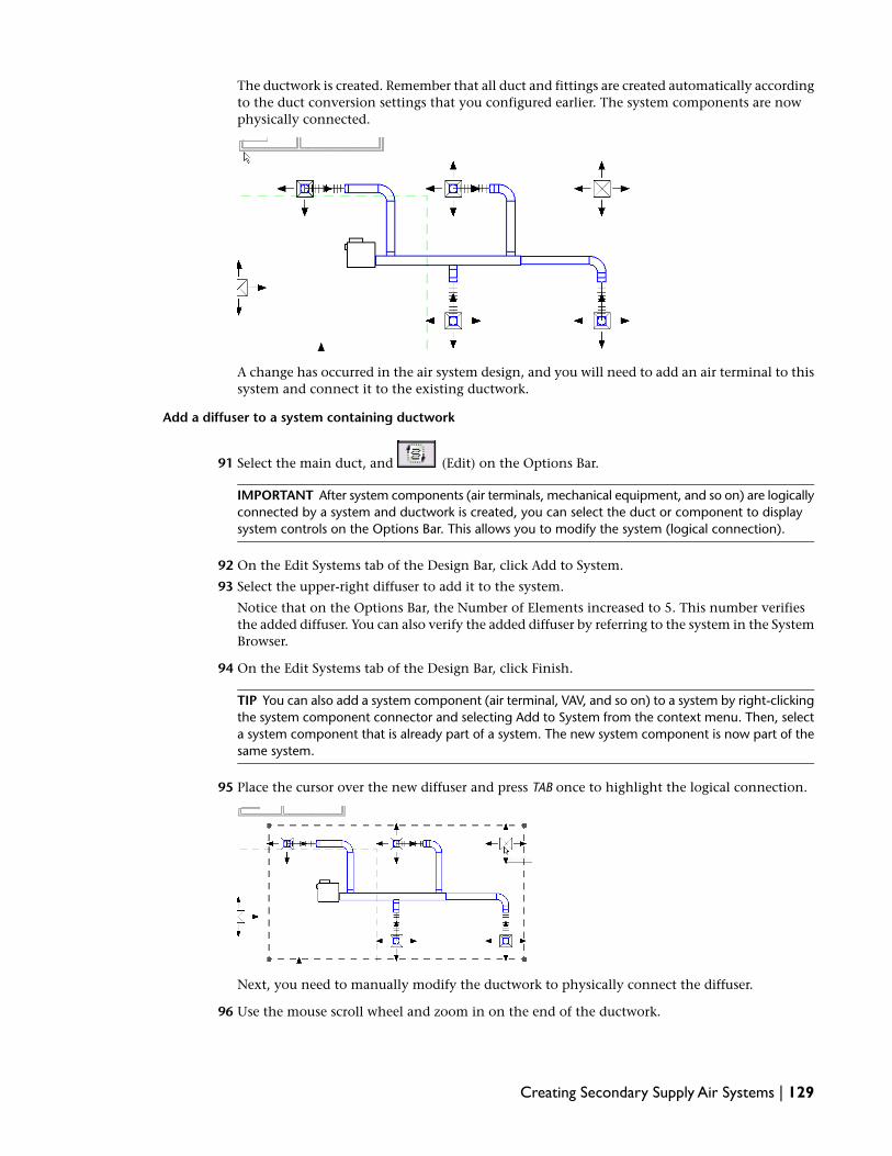
The ductwork is created. Remember that all duct and fittings are created automatically accordingto the duct conversion settings that you configured earlier. The system components are nowphysically connected.
A change has occurred in the air system design, and you will need to add an air terminal to thissystem and connect it to the existing ductwork.
Add a diffuser to a system containing ductwork
91 Select the main duct, and (Edit) on the Options Bar.
IMPORTANT After system components (air terminals, mechanical equipment, and so on) are logicallyconnected by a system and ductwork is created, you can select the duct or component to displaysystem controls on the Options Bar. This allows you to modify the system (logical connection).
92 On the Edit Systems tab of the Design Bar, click Add to System.
93 Select the upper-right diffuser to add it to the system.
Notice that on the Options Bar, the Number of Elements increased to 5. This number verifiesthe added diffuser. You can also verify the added diffuser by referring to the system in the SystemBrowser.
94 On the Edit Systems tab of the Design Bar, click Finish.
TIP You can also add a system component (air terminal, VAV, and so on) to a system by right-clickingthe system component connector and selecting Add to System from the context menu. Then, selecta system component that is already part of a system. The new system component is now part of thesame system.
95 Place the cursor over the new diffuser and press TAB once to highlight the logical connection.
Next, you need to manually modify the ductwork to physically connect the diffuser.
96 Use the mouse scroll wheel and zoom in on the end of the ductwork.
Creating Secondary Supply Air Systems | 129
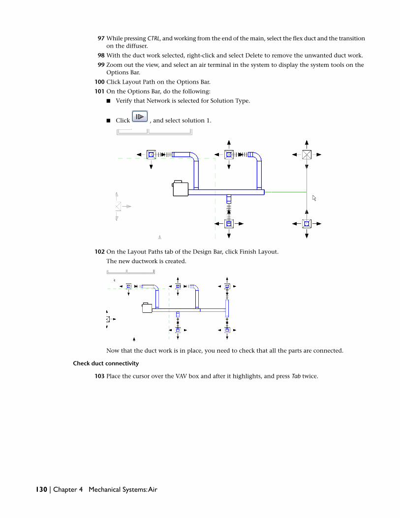
97 While pressing CTRL, and working from the end of the main, select the flex duct and the transitionon the diffuser.
98 With the duct work selected, right-click and select Delete to remove the unwanted duct work.
99 Zoom out the view, and select an air terminal in the system to display the system tools on theOptions Bar.
100 Click Layout Path on the Options Bar.
101 On the Options Bar, do the following:
■ Verify that Network is selected for Solution Type.
■ Click , and select solution 1.
102 On the Layout Paths tab of the Design Bar, click Finish Layout.
The new ductwork is created.
Now that the duct work is in place, you need to check that all the parts are connected.
Check duct connectivity
103 Place the cursor over the VAV box and after it highlights, and press Tab twice.
130 | Chapter 4 Mechanical Systems:Air

The system components and ductwork highlight indicating that they are physically connected.
TIP Depending on your ductwork layout, you may need to press TAB 2 or 3 times to check connectivity.
Size the duct
104 Place the cursor over the main duct, and click TAB twice to highlight the duct and diffusers butnot the VAV, and click to select them.
The selection displays in red.
105 On the Options Bar, click Sizing.
106 In the Duct Sizing dialog, under Sizing Method, do the following:
■ Select Friction, and enter .65 Pa/m.
■ Verify that Only is selected.
■ Under Constraints, verify that Calculated Size Only is selected for Branch Sizing, and thatRestrict Height and Restrict Width are cleared.
■ Click OK.
Creating Secondary Supply Air Systems | 131

This low pressure secondary air system ductwork is sized using the Friction method at .65 Pascalsper one meter of ductwork. Other sizing methods and values can also be used as well.
IMPORTANT Remember that the Duct Sizing dialog displays the sizing settings that were last used.It does not report the sizing settings of the selected duct.
Next, you complete the low pressure secondary supply air systems for level 1.
Optional: Complete the level 1 secondary supply air systems
(See the next exercise for a completed drawing.)
107 In the Project Browser, under Mechanical, double-click 1 - Mech floor plan to make it the activeview.
108 Using the systems creation methods that you learned, complete the level 1 system layoutaccording to the following specifications and floor plan layout:
■ M_Parallel Fan Powered VAV : M_Size 3 - 200mm Inlet with a 2900mm offset. Repositionand rotate if necessary.
■ Select and modify a Network layout path solution. You may experience cases where youneed to modify the duct manually such as a drag flex duct segment to connect it. Do notchange the duct conversion settings. Review the no auto-route solution warnings as somemay be caused by disconnected diffusers due to proximity issues and others due to the needfor endcap fittings. If you receive errors, see the note below.
■ Add M_Rectangular Duct Endcap : Standard fittings where needed. Remember to zoom theview for accurate placement.
■ Size the duct using the Friction sizing method at .65 Pa/m and select Only. Select CalculatedSize Only for Branch Sizing. Verify that all Other options are cleared. If you receive errors,see the note below.
■ Use TAB to check duct connectivity after creating ductwork and after performing sizing.
IMPORTANT Remember that when creating layouts and sizing duct, you are creating and sizing thephysical duct and not altering the logical system. So, if a layout solution or duct sizing causes errorsor it seems incorrect, it is because either the duct usually has insufficient space, an offset elevation isincorrectly specified, or the duct or duct fittings are not connected properly. You can either relocatethe VAV box, modify the layout, select a different layout solution using the Layout Path tool, modifythe duct manually, or reinsert duct fittings. You should always check duct connectivity after modifyingductwork.
132 | Chapter 4 Mechanical Systems:Air

The completed level 1 secondary supply air systems are shown below. Note that created ductworkmay vary slightly from the illustration.
Next, you create the low pressure secondary supply air systems for level 2.
Optional: Create the level 2 secondary supply air systems
109 Use the 2 - Mech mechanical floor plan view. Verify that Associate Level (Level 2) is selected forall View Range parameters, set the Primary Range Top Offset to 3000mm and the Detail Levelto Medium.
110 On the Annotations tab of the Visibility Graphics window, turn off Air Terminal tags.
111 Using the systems creation methods that you learned for level 1, create the level 2 system andduct layout according to the following specifications and floor plan layout:
■ M_Parallel Fan Powered VAV : M_Size 3 - 200mm Inlet with a 2900mm offset. Repositionand rotate if necessary.
■ For VAV airflow, specify the air terminal airflow. If multiple air terminals are connected toa system, specify the total air terminal airflow for VAV airflow.
■ Select and modify a Network layout path solution. You may experience cases where youneed to modify the duct manually such as a drag flex duct segment to connect it. Do notchange the duct conversion settings. Review the no auto-route solution warnings as somemay be caused by disconnected diffusers due to proximity issues and others due to the needfor endcap fittings. If you receive errors, see the note above.
■ Add M_Rectangular Duct Endcap : Standard fittings where needed. Remember to zoom theview for accurate placement.
■ Size the duct using the Friction method at .65 Pa/m and select Only. Select Calculated SizeOnly for Branch Sizing. Verify that all Other options are cleared. If you receive errors, seethe note above.
■ Use TAB to check duct connectivity after creating ductwork and after performing sizing.
Creating Secondary Supply Air Systems | 133

The completed level 2 secondary supply air systems are shown below. Again note that the createdductwork may vary slightly from the illustration.
112 If you want to save your work, click File menu ➤ Save.
113 In the Save As dialog, enter Creating Secondary Supply Air Systems Training for File name,navigate to the folder of your choice, and click Save.
In this exercise, you created low pressure secondary supply air systems for the building. You used the CreateSupply Air Systems tool to logically connect the air terminals to the VAV boxes. You also modified a systemby adding an air terminal to an existing system. After creating each system, you used the Layout Path toolto create and modify duct layouts to physically connect the system components. You also specified VAVairflow, checked duct connectivity, sized the ductwork, and validated the systems in the System Browser.In the next exercise, you create 2 different views to validate the ductwork geometry.
Using Views to Validate Duct Geometry
In this exercise, you use 2 different types of views to validate the duct geometry of the secondary supply airsystems that you created. Although you already checked duct connectivity, it is recommended to validatethe duct geometry to confirm that the geometry corresponds to your design intent.
Dataset
■ Click File menu ➤ Open.
■ In the left pane of the Open dialog, click the Training Files icon.
■ Open the m Using Views for Duct Validation.rvt file located in the Metric ➤ Mechanical folder.
1 In the Project Browser, expand Views (Discipline) ➤ Mechanical ➤ HVAC ➤ Floor Plans, anddouble-click 1 - Mech to make it the active view.
134 | Chapter 4 Mechanical Systems:Air

Create and use a section view to validate duct geometry
2 Right-click in the empty space of the drawing area, and click Zoom to Fit.
This zooms the view to fit the drawing area.
3 Place the cursor in the drawing area, enter ZR, and sketch a zoom region around Offices 101 -103.
TIP Although room tags were not copied when you created this view, you can identify a room byplacing the cursor over the room component. A tooltip and the Status Bar (located at the lower leftunder the Design Bar) confirm the room name and number.
4 On the Basics tab of the Design Bar, click Section.
Adding a section view is a 2-click process. The first click specifies the section head, and thesecond click specifies the section tail. After you add the section, you can flip the view directionor modify the extents of the view.
5 Place the cursor just above the Office 101 air terminal and click to set the start point for thesection, move the cursor down and click just below the Office 103 air terminal to set the endpoint.
A new section view named Section 1 is created and located in the Project Browser under ???.
6 In the Project Browser, expand Mechanical ➤ ??? ➤ Sections (Building Section), right-clickSection 1, and click Properties.
7 In the Element Properties dialog, under Graphics, select HVAC for Sub Discipline, and click OK.
The section relocates under HVAC.
8 In the drawing area, click the section.
The selected section displays in red.
9 Using the shape handles (triangles) on the far right, drag the clip planes of the view so that youcapture only the systems that you created and set the depth just past the VAV boxes as shown.
Using Views to Validate Duct Geometry | 135

You many need to zoom out to view the shape handles.
10 On the Design Bar, click Modify.
The section head displays in blue, similar to the level heads in the elevation view. All sectionheads are linked directly to their corresponding section view.
11 Double-click the section head to open the Section 1 view.
12 On the View Control Bar, select Medium for Detail Level, and Shading with Edges for ModelGraphics Style.
The system geometry displays with shading and outlined edges.
13 Use the mouse scroll wheel and zoom in on the bottom-right duct servicing offices 102 and103, and verify that the geometry and location of the duct that you created is as you expect itto be.
136 | Chapter 4 Mechanical Systems:Air

14 Continue to validate the duct geometry of the other secondary supply air systems in the Sectionview.
15 Sections are extremely useful in visualizing the detailed connections between ductwork andequipment in a vertical space. They offer easy and immediate accessibility to all floors. You willcreate a number of sections to both inspect and modify the duct layouts that you create.
Modify and use a 3D view to validate duct geometry
16 On the Design Bar, click Modify.
17 In the Project Browser, expand Views (Discipline) ➤ Mechanical ➤ HVAC ➤ 3D Views, anddouble-click {3D} to make it the active view.
18 On the View Control Bar, select Shading with Edges for Model Graphics Style.
Notice that in the 3D view, all of the mechanical elements display as shaded with edges but allarchitectural elements displays as halftone underlays that highlight when you move the cursorover them. This allows you to quickly and easily target your mechanical systems without thearchitecture obstructing the mechanical design.
19 Right-click in the drawing area, and click View Properties.
20 In the Element Properties dialog, under Extents, select Section Box, and click OK.
A section box displays around the building model.
Using Views to Validate Duct Geometry | 137

NOTE A section box allows you to limit the view so that you can target only the geometry that youwant to view. It is especially helpful in 3D views in which the three dimensional space makes it difficultto view some geometry.
21 In the drawing area, click the section box and locate the top center drag handle.
22 Zoom in on the view and slowly drag the top center drag handle down to adjust the cropboundary until the plenum space for the level 1 ceiling is exposed.
TIP Release the drag handle at certain points to see a preview of the section at the current cropboundary position.
23 Click in the drawing area to deactivate the crop boundary.
24 Use the ViewCube in the upper right corner of the drawing area to rotate the image so that youcan verify that the Office 101, 102, and 103 duct geometry is as you expected.
25 Zoom in on each air system to verify that the geometry and location of the systems that youcreated are as you expect them to be.
3D views allow you to validate geometry of multiple duct runs in a three dimensional space byusing the zoom and spin controls. You will use both section and 3D views during your systemsdesigning.
26 If you want to save your work, click File menu ➤ Save.
138 | Chapter 4 Mechanical Systems:Air

27 In the Save As dialog, enter Using Views for Duct Validation Training for File name, navigate tothe folder of your choice, and click Save.
In this exercise you created a section view and used a 3D view to validate the secondary supply air systemduct geometry. In the next exercise, you draw the primary supply air system ductwork.
Drawing the Primary Supply Air Duct
In this exercise, you draw the high pressure primary supply air ductwork and connect the primary to theVAV boxes. Unlike the previous exercise in which you created the systems first and then selected from aseries of duct layouts, you manually draw the primary duct and connect to the VAVs. You will create theprimary systems in a later exercise. This exercise allows you to become familiar with manually drawing andmodifying ductwork which is very important for resolving duct layout errors caused by insufficient space.
Dataset
■ Click File menu ➤ Open.
■ In the left pane of the Open dialog, click the Training Files icon.
■ Open the m Drawing Primary Supply Air Duct.rvt file located in the Metric ➤ Mechanical folder.
Draw the primary duct
1 In the Project Browser, expand Views (Discipline) ➤ Mechanical ➤ HVAC ➤ Floor Plans, anddouble-click 1 - Mech to make it the active view.
2 Enter ZR, and sketch a zoom region around Mechanical/Electrical room.
3 On the Mechanical tab of the Design Bar, click Duct.
4 In the Type Selector, select Round Duct : Taps.
5 On the Options Bar, do the following;
■ Verify that 300 is selected for diameter (D:).
■ Verify that Auto Connect is selected.
■ Enter 2900 for Offset.
6 Place the cursor in the Mechanical/Electrical room in the approximate location shown, andclick to specify the start point.
Drawing the Primary Supply Air Duct | 139

7 Draw duct as shown in the following image. After placing the duct, you can select individualsegments and use the arrow keys to adjust location.
Connect the VAV boxes to the primary duct
8 Enter ZR, and sketch a zoom region around the VAV box outside of Office 101.
9 Click on the VAV, right-click on the air connection, and click Draw Duct.
140 | Chapter 4 Mechanical Systems:Air

NOTE You must place the cursor over the connector to connect to the VAV primary. When drawing
duct, use the connector snap to quickly and accurately locate a connector. If you pause briefly,a tooltip appears confirming the connector.
10 Move the cursor to the right to begin drawing duct, and press Spacebar to automatically changethe duct diameter and offset to match the 200mm VAV primary connector diameter.
You can also change the duct diameter from the Options Bar.
TIP When drawing duct, press the Spacebar after you specify your start point and move the cursorto begin drawing duct. This automatically specifies the duct diameter or width and height, and offsetparameter to match that of the selected start point object. If a warning appears informing you thatthe line is too short, you pressed Spacebar before you began drawing duct. Note that the Spacebardoes not automatically specify the duct type. You should always verify the duct type in the TypeSelector.
11 Draw the first duct segment 600mm to the right, and click to specify the end point.
12 Move the cursor down and draw an approximate 2300mm vertical second duct segment, andclick or press Enter to specify the end point.
Drawing the Primary Supply Air Duct | 141

13 Move the cursor to the right and over the primary duct, and click after the centerline snapdisplays to specify the end point for the third duct segment.
TIP When connecting duct to the centerline of another duct, the centerline snap makes the processquick and easy.
After you click to specify the end point, the duct run connecting the Office 101 VAV to theprimary is complete.
14 With the Draw tool open, zoom in on the VAV box outside of Office 102.
142 | Chapter 4 Mechanical Systems:Air

TIP When zooming or reorienting a view that uses Medium or Fine for Detail Level, you may experienceperformance issues depending on the size and complexity of the system geometry. On the ViewControl Bar, change the Model Graphics Style to Wireframe to improve performance. This allows youto continue to use the 2-line display. You can also specify the Detail Level to Coarse for viewing asingle line display
15 Place the cursor over the Office 102 VAV box supply air connection, and after the connectorsnap displays, click to specify the start point.
16 Draw the duct to the right and connect it to the centerline of the primary.
17 Connect the other three VAVs to the primary duct as shown.
18 Using the draw duct methods that you learned, zoom the view to the right of the primary, andconnect the 2 VAVs in Open 1 to the primary duct as shown.
Check connectivity
19 Place the cursor over the primary duct and press Tab twice to check connectivity up to but notincluding the VAV boxes.
Drawing the Primary Supply Air Duct | 143

You can press TAB 3 times to check connectivity including the VAVs and secondary systemductwork.
20 Validate the primary duct geometry using the Section 1 and 3D views.
NOTE Do not size the primary at this time, you will do that in a later exercise.
IMPORTANT Notice that the VAV boxes are still listed in the Unassigned folder under Default SupplyAir because you physically connected the VAVs to the primary duct, but you have not logicallyconnected the VAVs with a system. You will create a system for the primary and add the VAVs to itin a later exercise.
Optional: Complete the level 1 primary duct
(See next exercise for a completed drawing.)
21 In the Project Browser, expand Views (Discipline) ➤ Mechanical ➤ HVAC ➤ Floor Plans, anddouble-click 1-Mech to make it the active view.
22 Using the duct drawing methods that you learned, complete the level 1 primary duct accordingto the following specifications and floor plan layout:
■ Draw the primary duct using Round Duct : Taps. The main has a 300mm diameter and theconnections to the VAV boxes have a diameter of 200mm. On the Options Bar, specify a2900mm offset, and verify that Auto Connect is selected, and Angle is cleared. Useapproximate duct segment lengths from the layout below.
■ Do not size the primary. You will size the primary in a later exercise.
■ Check connectivity, and use the Section 1 and 3D views for duct geometry validation.
IMPORTANT Remember that when drawing duct, you may encounter errors when connecting tothe primary duct or a VAV. This is usually caused by insufficient space preventing duct creation orfitting insertion. Modify the duct length or relocate the VAV box to make sufficient space, and usethe Draw Duct tool to reconnect. Finally, remember to always check connectivity and validate theduct geometry.
144 | Chapter 4 Mechanical Systems:Air

The completed level 1 air system layout is shown below.
Optional: Draw the level 2 primary duct
23 In the Project Browser, expand Views (Discipline) ➤ Mechanical ➤ HVAC ➤ Floor Plans, anddouble-click 2 - Mech to make it the active view.
24 Using the duct drawing methods that you learned, complete the level 2 primary duct accordingto the following specifications and floor plan layout:
■ Draw the primary duct using Round Duct : Taps. The main has a 300mm diameter and theconnections to the VAV boxes have a diameter of 200mm. On the Options Bar, specify a2900mm offset, and verify that Auto Connect is selected, and Angle is cleared. Useapproximate duct segment lengths from the layout below.
■ Do not size the primary. You will size the primary in a later exercise.
■ Check connectivity, and use the Section 1 and 3D views for duct geometry validation.
Drawing the Primary Supply Air Duct | 145

The completed level 2 air system layout is shown below.
25 If you want to save your work, click File menu ➤ Save.
26 In the Save As dialog, enter Drawing Primary Supply Air Duct Training for File name, navigateto the folder of your choice, and click Save.
In this exercise, you used the Duct tool to manually draw the high pressure primary supply air duct andphysically connect the VAV boxes to the primary duct. You will connect the primary duct to AC units in alater exercise. While drawing duct, you learned how to use connectors to create ductwork. Finally, youchecked duct connectivity and validated duct geometry using different views. In the next exercise, youresolve routing conflicts with the primary duct.
Sizing the Primary Duct:Velocity Method
In a previous exercise, you created the high pressure primary duct that supplies air to the VAV boxes, butyou have yet to size the primary. In this exercise, you size the primary to meet airflow requirements usingthe same sizing tool that you previously used to size the low pressure secondary supply air ductwork. However,you use the Velocity sizing method rather than the Friction method. Before sizing the primary, you mustfirst determine the direction of the airflow in the primary duct.
The airflow direction inside the primary must be determined to accurately size the primary duct run.Considering that both ends of the primary are open, you place an endcap where no further connections areplanned. This determines the airflow direction.
Dataset
■ Click File menu ➤ Open.
■ In the left pane of the Open dialog, click the Training Files icon.
■ Open the m Duct Sizing - Velocity.rvt file located in the Metric ➤ Mechanical folder.
146 | Chapter 4 Mechanical Systems:Air

Place an endcap on the level 1 primary to determine airflow
1 In the Project Browser, expand Views (Discipline) ➤ Mechanical ➤ HVAC ➤ Floor Plans, anddouble-click 1 - Mech to make it the active view.
2 Zoom in on the lower end of the left primary located near the wall between Offices 117 and116.
The upper end of the primary duct run will connect to a rooftop AC unit.
NOTE It is highly recommended to zoom the view to accurately place the endcap.
3 On the Mechanical tab of the Design Bar, click Duct Fitting.
NOTE If the Mechanical tab is not available on the Design Bar, right-click the Design Bar, and clickMechanical.
4 In the Type Selector, select M_Round Duct Endcap : Standard.
5 Move the cursor over the end of the left primary duct run, and after the end point snap displays,click to place the endcap.
Notice that the centerline snap displays to aid in fitting placement.
6 Click Modify on the Design Bar to deactivate the Duct Fitting tool.
IMPORTANT When sizing duct that has multiple open ends, you must place endcaps to close allopen ends except the one that connects to the air source. This determines the airflow direction andthe duct will size accurately.
7 Enter ZF to zoom the view to fit the drawing area.
Sizing the Primary Duct:Velocity Method | 147

Size the level 1 primary duct
8 Place the cursor on the left primary duct run and press Tab twice to highlight the entire runincluding the VAV connections but not the VAV boxes, and click to select it.
The selected primary displays in red.
9 On the Options Bar, click Sizing.
IMPORTANT Remember that the Duct Sizing dialog displays the sizing settings that were last used.It does not report the sizing settings of the selected duct.
10 In the Duct Sizing dialog, under Sizing Method, do the following:
■ Select Velocity, and enter 12.5 m/s.
■ Verify that Only is selected.
■ Under Constraints, verify that Calculated Size Only is selected for Branch Sizing, and thatRestrict Height and Restrict Width are cleared.
■ Click OK.
148 | Chapter 4 Mechanical Systems:Air
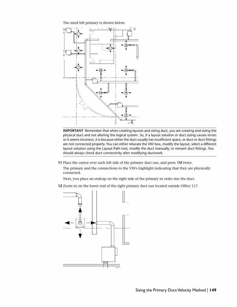
The sized left primary is shown below.
IMPORTANT Remember that when creating layouts and sizing duct, you are creating and sizing thephysical duct and not altering the logical system. So, if a layout solution or duct sizing causes errorsor it seems incorrect, it is because either the duct usually has insufficient space, or duct or duct fittingsare not connected properly. You can either relocate the VAV box, modify the layout, select a differentlayout solution using the Layout Path tool, modify the duct manually, or reinsert duct fittings. Youshould always check duct connectivity after modifying ductwork.
11 Place the cursor over each left side of the primary duct run, and press TAB twice.
The primary and the connections to the VAVs highlight indicating that they are physicallyconnected.
Next, you place an endcap on the right side of the primary in order size the duct.
12 Zoom in on the lower end of the right primary duct run located outside Office 117.
Sizing the Primary Duct:Velocity Method | 149

13 Using the process that you just learned, place a round duct endcap at the lower end of the rightprimary duct run, and size this primary using the same sizing method and parameters that youused for the left primary.
The sized right primary is shown below.
14 Using the method you have learned, check the connectivity of the right side of the primaryduct run.
Optional: Size the level 2 primary duct run
(See the next exercise for a completed dawing.)
15 In the Project Browser, expand Views (Discipline) ➤ Mechanical ➤ HVAC ➤ Floor Plans, anddouble-click 2 - Mech to make it the active view.
16 Using the process that you learned for the level 1 primary duct run, place a round duct endcapon the lower end of the left and right side of the primary duct run to determine airflow direction.
As in level 1, the upper ends of the primary duct run will connect to a rooftop AC unit.
17 Size both the left and right sides of the primary duct run using the same sizing method andparameters that you used for the level 1 primary duct run.
18 Check connectivity for both sides of the primary duct.
150 | Chapter 4 Mechanical Systems:Air

The completed level 2 primary duct run is shown below.
19 If you want to save your work, click File menu ➤ Save.
20 In the Save As dialog, enter Duct Sizing - Velocity Training for File name, navigate to the folderof your choice, and click Save.
In this exercise, you sized the primary duct for the building. First, you placed an endcap at the end of eachside of the primary duct run where no connection was planned. This determined the airflow direction insidethe primary. Then, you used the Duct Sizing tool to size the primary using the Velocity sizing method. Inthe next exercise, you assign a color fill to the ductwork.
Assigning a Color Scheme to Duct
In this exercise, you assign a color scheme to the ductwork in your project. This procedure is similar to theone that you used for rooms in a previous exercise. Like room color scheme, duct color scheme can helpyou communicate your design immediately and effectively. This makes it much easier to determine whetherthe plan meets your requirements.
Dataset
■ Click File menu ➤ Open.
■ In the left pane of the Open dialog, click the Training Files icon.
■ Open the m Duct Color Scheme.rvt file located in the Metric ➤ Mechanical folder.
Create a new view
1 In the Project Browser, expand Views (Discipline) ➤ Mechanical ➤ HVAC ➤ Floor Plans,right-click 1 - Mech, and click Duplicate View ➤ Duplicate.
A new floor plan view called Copy of 1 - Mech is created and becomes the active view.
2 In the Project Browser, right-click Copy of 1 - Mech, and click Rename.
3 In the Rename View dialog, enter 1 - Mech Duct Classes for Name, and click OK.
Assigning a Color Scheme to Duct | 151

Apply the color scheme
4 On the Mechanical tab of the Design Bar, click Duct Color Scheme Legend.
NOTE If the Mechanical tab is not available on the Design Bar, right-click the Design Bar, and clickMechanical.
5 In the Type Selector, verify that Color Scheme Legend : 1 is selected for color scheme legendtype.
6 Move the cursor in the drawing area and notice that an outline of the color scheme legendindicates that no color scheme has been assigned to the view displays.
7 Position the color scheme legend outline at the top-right corner of the floor plan, and click toplace the legend.
The color scheme outline follows the cursor movement to help you accurately position thelegend.
8 In the Choose Color Scheme dialog, verify that Duct Color Fill - Flow is selected for Color Scheme,and click OK.
Next, you change the color scheme.
NOTE Elevations have been hidden for legend clarity.
Edit the color scheme
9 In the Drawing area, select the duct color scheme legend that you placed, and on the OptionsBar, click Edit Color Scheme.
10 In the Edit Color Scheme dialog, do the following:
■ Select Velocity for Color, and click OK after a warning indicates that colors are not preserved.
■ Select By range.
■ In the At Least column, click in the second row, and enter 7.5 m/s.
■ In the Caption column, delete the existing text, and enter low velocity for the first row, andenter high velocity for the second row.
■ In the Color column, click in the first row and select Green from the Basic colors in the Colorbox.
■ In the Color column, click in the second row and select Red from the Basic colors in theColor box.
152 | Chapter 4 Mechanical Systems:Air
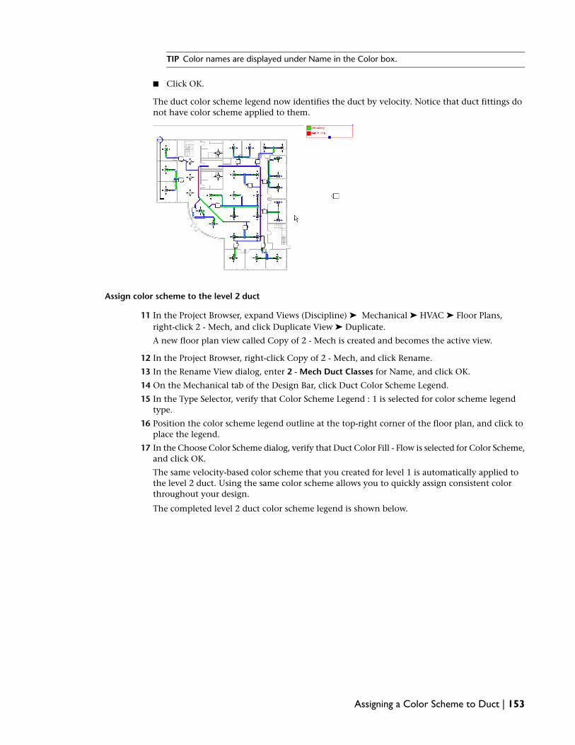
TIP Color names are displayed under Name in the Color box.
■ Click OK.
The duct color scheme legend now identifies the duct by velocity. Notice that duct fittings donot have color scheme applied to them.
Assign color scheme to the level 2 duct
11 In the Project Browser, expand Views (Discipline) ➤ Mechanical ➤ HVAC ➤ Floor Plans,right-click 2 - Mech, and click Duplicate View ➤ Duplicate.
A new floor plan view called Copy of 2 - Mech is created and becomes the active view.
12 In the Project Browser, right-click Copy of 2 - Mech, and click Rename.
13 In the Rename View dialog, enter 2 - Mech Duct Classes for Name, and click OK.
14 On the Mechanical tab of the Design Bar, click Duct Color Scheme Legend.
15 In the Type Selector, verify that Color Scheme Legend : 1 is selected for color scheme legendtype.
16 Position the color scheme legend outline at the top-right corner of the floor plan, and click toplace the legend.
17 In the Choose Color Scheme dialog, verify that Duct Color Fill - Flow is selected for Color Scheme,and click OK.
The same velocity-based color scheme that you created for level 1 is automatically applied tothe level 2 duct. Using the same color scheme allows you to quickly assign consistent colorthroughout your design.
The completed level 2 duct color scheme legend is shown below.
Assigning a Color Scheme to Duct | 153

18 If you want to save your work, click File menu ➤ Save.
19 In the Save As dialog, enter Duct Color Fill Training for File name, navigate to the folder of yourchoice, and click Save.
In this exercise, you added duct color scheme legends to both levels of ductwork in your project. You editedthe color scheme by associating colors to velocity parameters and changed the caption text. In the nextexercise, you size one of the secondary supply air system duct runs using the Equal Friction sizing method.
Sizing the Secondary Air System Duct: Equal Friction Method
In 2 previous exercises, you sized the secondary air system ductwork using the Friction sizing method andthen you sized the primary duct run using the Velocity method. In this exercise, you size the duct for oneof the secondary air systems that you previously sized. This allows you to more closely meet airflowrequirements for that system. First, you split the duct main into multiple pieces, and then you size the ductrun using the Equal Friction method. Finally, you tag the main duct of the secondary air system to annotatethe duct segment sizes.
Dataset
■ Click File menu ➤ Open.
■ In the left pane of the Open dialog, click the Training Files icon.
■ Open the m Duct Sizing - Equal Friction.rvt file located in the Metric ➤ Mechanical folder.
Locate the secondary air system
1 In the Project Browser, expand Views (Discipline) ➤ Mechanical ➤ HVAC ➤ Floor Plans, anddouble-click 1 - Mech to make it the active view.
2 In the System Browser, expand the Mechanical systems folder.
TIP If the System Browser is closed, press F9 (or Window menu ➤ System Browser) to open or closeit. If the System Browser does not respond, click in the drawing area to make it active, then press F9.
All mechanical systems that have been created for the project are organized by system type inthe Mechanical folder. Remember that only systems (logical connections) and the assignedsystem components are in the System Browser, not ductwork (physical connections).
154 | Chapter 4 Mechanical Systems:Air

3 Right-click Supply Air, and click Expand All.
Every supply air system that you created is listed. Notice that each system listing consists of asystem name and number, such as Mechanical Supply Air 6, and a hierarchy of systemcomponents that you assigned to each system, such as a VAV box and diffusers.
4 Right-click Mechanical Supply Air 3, and click Show.
The 1 - Mech view automatically zooms on the selected system, and the system including theassigned components and the ductwork displays in red.
5 In the Show Element(s) In View dialog, click Close to deactivate the Show tool.
Notice that the main duct connecting the VAV box to the diffusers is one size.
You need to reduce the size of the main to ensure that the air pressure meets airflow requirements.To accomplish this reduction, you split the main into multiple duct segments and then sizeeach segment.
Split the main
6 On the Tools toolbar, click (Split).
7 Move the cursor along the top edge of the main and to the right of the 2 middle diffusers.
8 Watch the listening dimensions, and split the main about 3400mm from the end of the main.
TIP When splitting duct in 2-line display, move the cursor along the top or bottom edge of the ductto view the split line and the listening dimensions.
9 With the Split tool open, split the main to the right of the second branch as shown.
Sizing the Secondary Air System Duct: Equal Friction Method | 155

10 Press Esc twice to deactivate the Split tool.
Notice that a Rectangular Duct Union fitting is automatically inserted to connect the duct ateach split. You can place the cursor over the union and both a tooltip and the Status Bar confirmthe fitting.
Size the system
11 Move the cursor over the main, and press Tab twice to highlight the ductwork and air terminalslocated downstream from the VAV box, and click to select them. Note that the VAV box is notselected.
12 On the Options Bar, click Sizing.
13 In the Duct Sizing dialog, under Sizing Method, do the following:
■ Select Equal Friction, and enter .65 Pa/m.
■ Under Constraints, verify that Calculated Size Only is selected for Branch Sizing, and thatRestrict Height and Restrict Width are cleared.
■ Click OK.
IMPORTANT Equal Friction sizing is an iterative process. The completion time varies according tothe speed of your computer.
NOTE If a Warning dialog opens alerting you that there is no loss defined, ignore this warning. Youcan click anywhere in the drawing area to close it.
156 | Chapter 4 Mechanical Systems:Air

The low pressure secondary air system ductwork is sized using the Equal Friction method at .65Pascals per one meter of ductwork.
Notice that as the airflow decreases, transitions are automatically added to reduce duct size andmaintain air pressure. Next, you tag the main to annotate the duct segment sizes.
Tag the main
14 On the Mechanical tab of the Design Bar, click Tag ➤ By Category.
15 On the Options Bar, do the following:
■ Verify that Horizontal is selected.
■ Clear Leader.
■ Click Tags.
16 In the Tags dialog, under Category, for Ducts, verify that M_Duct Size Tag is loaded, and clickCancel.
17 Move the cursor over the 3 segments of the main, and notice that the tag outline dynamicallydisplays the size of each segment.
18 Position the tag outline in the center of each segment, and click to place each tag.
TIP To reposition a tag, select the tag and drag it to a new location. You may want to zoom the viewfor accurate placement.
19 Click Modify on the Mechanical tab to deactivate the Tag tool.
The low pressure secondary air system duct run is sized and tagged.
20 If you want to save your work, click File menu ➤ Save.
21 In the Save As dialog, enter Duct Sizing - Equal Friction Training for File name, navigate to thefolder of your choice, and click Save.
In this exercise, you sized low pressure secondary air system ductwork to more closely meet airflowrequirements. First, you used the Split tool to split the main into multiple segments, and then you sized theduct run using the Equal Friction sizing method. Finally, you tagged the main to annotate the duct segment
Sizing the Secondary Air System Duct: Equal Friction Method | 157

sizes. In the next exercise, you use the System Inspector to check flow and pressure in the secondary airsystem that you just sized.
Inspecting Air Systems
In this exercise, you use the System Inspector to inspect the low pressure secondary air systems. The SystemInspector is a unique tool enabling you to inspect each system for airflow, pressure, and pressure loss byplacing the cursor over it. Using this tool, you can target problem areas directly in your design and resolvethem.
Dataset
■ Click File menu ➤ Open.
■ In the left pane of the Open dialog, click the Training Files icon.
■ Open the m Inspecting Air Systems.rvt file located in the Metric ➤ Mechanical folder.
1 In the Project Browser, expand Views (Discipline) ➤ Mechanical ➤ HVAC ➤ Floor Plans, anddouble-click 2 - Mech to make it the active view.
2 Right-click in the view, click Zoom in Region from the context menu.
3 Draw a zoom region around the lower-right secondary air system in Open 2.
You will inspect this system.
4 Select the VAV box that you assigned to the secondary air system.
IMPORTANT To select a system, select any duct segment, duct fitting, diffuser, or mechanicalequipment that you have assigned to a system. System tools display on the Options Bar.
5 On the Options Bar, select (Inspect).
The System Inspector tab opens providing system inspection tools on the Design Bar.
RELATED If you select a system component that has been assigned to more than one system such
as an AC unit or a VAV box and click , the Select System dialog opens enabling you to selecta system to inspect. Each selected system highlights in red enabling you to preview it.
158 | Chapter 4 Mechanical Systems:Air

6 On the System Inspector tab of the Design Bar, click Inspect.
NOTE You can also use System Inspector from in the System Browser. Right-click a system from theSystem Browser, and click Inspect from the context menu. After the System Inspector opens, clickInspect from the System Inspector tab on the Design Bar.
7 Place the cursor over the upper-left flex duct branch of the secondary air system to highlight it.
An inspection flag dynamically reports the airflow, pressure, and pressure loss in the highlightedduct segment. Arrows display on the duct indicating the airflow direction for both the mainand the branches in the air system. A tooltip also displays the system information.
IMPORTANT As you inspect a system, remember that all information is color coded according topressure. Red information and arrows indicate the highest percentage of pressure loss due to friction,also known as the critical path.
Notice that the secondary air system and the assigned system components highlight and canbe selected, but you cannot select other secondary air systems or the primary duct run. Theseare not logically connected to this system.
Next, you inspect 2 areas of the air system to compare information.
Compare system information
8 With the cursor over the upper-left duct segment, click to temporarily place the inspection flagon the segment.
9 Place the cursor over the middle duct segment to compare the airflow and pressure informationwith that of the upper-left duct segment.
Inspecting Air Systems | 159

10 Click to place the current inspection flag and close the prior one.
11 Move the cursor over the upper-right air terminal to compare its information with that of themiddle duct segment.
You can continue to use this method to compare inspection information for system componentsor duct across the selected system.
12 Click a blank space in the view to close the current inspection flag.
13 Continue to inspect the remaining secondary air systems in the building.
TIP You can also inspect systems in a 3D view.
14 On the System Inspector tab of the Design Bar, click Finish Inspector to deactivate the SystemInspector.
15 Use the System Inspector to inspect other secondary air systems in the project.
NOTE To use the System Inspector to inspect airflow and pressure inside ductwork, the selectedsystem components or duct must be logically and physically connected. Ductwork and systemcomponents must be connected to a system (logical connection) and a system must contain ductwork(physical connection). For example, you cannot inspect the primary high pressure duct run becauseyou have not created a system for it. The primary is physically but not logically connected. In a laterexercise, you will create a system for the primary and then you can inspect the primary duct run.
16 If you want to save your work, click File menu ➤ Save.
17 In the Save As dialog, enter Inspecting Air Systems Training for File name, navigate to the folderof your choice, and click Save.
In this exercise, you used the System Inspector to inspect the airflow direction, airflow, and pressureinformation for various systems in the project. You learned that airflow and pressure information is specificto the selected system component, and that all system information is color-coded for either the duct mainor the branch. You also compared system information across a system. In the next exercise, you place 2 ACunits.
Placing Air Conditioning Units
In this exercise, you place 2 air conditioning roof top units (RTU) on the building. You also use create anduse new views to precisely locate the AC units.
160 | Chapter 4 Mechanical Systems:Air

Dataset
■ Click File menu ➤ Open.
■ In the left pane of the Open dialog, click the Training Files icon.
■ Open the m Placing AC Units.rvt file located in the Metric ➤ Mechanical folder.
Create a new roof plan view
1 Click the View menu ➤ New ➤ Floor Plan.
2 Select Roof and click OK.
3 In the Project Browser, expand Views (Discipline) ➤ Mechanical ➤ HVAC ➤ Floor Plans ➤ Roof.
4 Right-click Roof, and click Rename.
5 Enter Roof Mech for Name, and click OK.
6 Click Yes to rename corresponding views.
Ignore the warning about the name changing.
7 Right-click in the drawing area of the new view, and click View Properties.
8 In the Element Properties dialog, under Graphics, select Mechanical for Discipline, and HVACfor Sub-Discipline.
9 Under Extents, click Edit for View Range and select Level 2 for View Depth: Level. Click OKtwice.
10 Change the Graphics Style to Wireframe.
11 Set the Detail Level to Medium.
This action specifies halftone for all architectural elements in the Roof Mech view. Notice thatthe level 2 system components and ductwork display as an underlay. Also notice that the RoofMech view is now located under the Mechanical HVAC floor plans in the Project Browser.
Add the AC Unit that services level 2
12 In the Roof Mechanical view, enter ZR, and sketch a zoom region around Men’s Room (locatedbelow the Mechanical/Electrical room).
You need to place the AC unit that services level 2 on the roof above the Men’s Room.
13 On the Mechanical tab of the Design Bar, click Mechanical Equipment.
Placing Air Conditioning Units | 161

14 In the Type Selector, select M_Rooftop AC Unit 53-88 KW - Bottom Return Connection : M_53KW.
15 Move the cursor over the Men’s Room, and press Spacebar 3 times to rotate the unit.
The AC unit supply connection is now located at the top.
16 Place the unit in the approximate location shown below.
17 Click to place the AC unit, and then click Modify on the Design Bar.
Next, you create a section view to precisely relocate the AC unit.
Create a new section view
18 Enter ZF to zoom the view to fit the drawing area.
19 On the Basics tab of the Design Bar, click Section.
20 Place the cursor below the AC unit and over the Office 203 VAV box, and click to specify thesection start point.
162 | Chapter 4 Mechanical Systems:Air

21 Move the cursor to the right, and after the cursor is past the AC unit, click to specify the sectionend point.
A new section view named Section 2 is created and located in the Project Browser under ???.
22 In the Project Browser, expand Mechanical ➤ ??? ➤ Sections (Building Section), right-clickSection 2, and click Properties.
23 In the Element Properties dialog, under Graphics, select HVAC for Sub Discipline, and click OK.
The section relocates under HVAC ➤ Sections (Building Section).
24 Select the section tail to display the drag handles.
25 Drag the top shape handle to adjust the depth view clip plane just past the AC unit. You mayneed to scroll the view up to access the top shape handle.
The section should partially capture the VAV on the left.
26 On the Design Bar, click Modify.
Relocate the AC unit to the roof surface
27 Double-click the section head to open the Section 2 view.
28 On the View Control Bar, click Medium for Detail Level.
This changes the duct display from single line to 2-line. You may need to adjust the top borderto see all of the AC unit.
Placing Air Conditioning Units | 163

29 Zoom in on the AC unit and watch the level indicators, notice that the unit is located on theroof level and not on the roof surface.
NOTE As with air terminals and VAV boxes, AC units are level-based components. Notice that theroof level is not referencing the roof surface but the underside of the roof. To place the AC unit onthe roof surface, you must relocate it.
30 Select the AC unit, and click (Move) on the Edit toolbar.
31 Move the cursor over the bottom-left corner of the AC unit, and after the end point snap displays,click to specify the move start point.
32 Move the cursor up along the left edge of the AC unit, and after the intersection and centerlinesnaps display at the roof surface, (300mm directly above the start point), click to specify themove end point.
164 | Chapter 4 Mechanical Systems:Air

This specifies the AC unit offset level of 300mm which moves the AC unit to the roof surface.
TIP You can also specify the offset level in the Element Properties dialog.
Place the level 1 AC unit
33 Using the methods that you learned, place an AC unit for the level 1 supply air system accordingto the following specifications and procedures (see the next exercise for approximate locations):
■ Work in the Roof Mech view, and place a M_Rooftop AC Unit 15 - 25 Ton - Bottom ReturnConnection : M_15 Ton above the Mechanical/Electrical room. First rotate the unit so thatthe return connection is at the top.
TIP You can copy the first AC unit you placed. Copying eliminates the elevation adjustment.
Note that you must locate this AC unit above the Mechanical/Electrical room to allow thesupply and return air duct riser to pass through the level 2 Mechanical/Electrical room andinto the level 1 plenum space below.
Placing Air Conditioning Units | 165

■ The 2 AC units and the section headers are as shown.
34 If you want to save your work, click File menu ➤ Save.
35 In the Save As dialog, enter Placing AC Units Training for File name, navigate to the folder ofyour choice, and click Save.
In this exercise, you added 2 rooftop AC units to the design. You created 2 section views and used the Moveand the Align tools to relocate the AC units to the roof surface. In the next exercise, you connect the ACunits to the high pressure primary supply air ductwork.
Completing the Supply Air Systems
In this exercise, you complete the supply air systems that you began in previous exercises. First, you drawthe duct to physically connect AC units to the high pressure primary supply air ductwork. Then, you createthe systems to logically connect the VAV boxes to the AC units.
Dataset
■ Click File menu ➤ Open.
■ In the left pane of the Open dialog, click the Training Files icon.
■ Open the m Completing Supply Air Systems.rvt file located in the Metric ➤ Mechanical folder.
Modify the 3D view
1 In the Project Browser, expand Views (Discipline) ➤ Mechanical ➤ HVAC ➤ 3D Views, anddouble-click {3D} to make the view active.
2 Select the section box, and drag the center drag handle up to move the crop boundary past theroof.
166 | Chapter 4 Mechanical Systems:Air

The entire building including the AC units display.
If you like, you can drag the bottom set of drag handles up above the level 1 system to hide thatsystem. Remember that, if you do this, you will need to reset this boundary to validate the level1 supply air system later.
3 Use the ViewCube in the upper right corner of the drawing area to rotate the image so that itdisplays as shown below.
Next, you tile the Roof Mech and the 3D views so that you can work on and validate your systemdesign simultaneously.
Tile the views
4 With the 3D view active, click Window menu ➤ Close Hidden Windows.
This closes all windows that you previously opened during the current design session. Note thatif this option is unavailable, the active view is the only open window.
5 In the Project Browser, under Mechanical, double-click Roof Mech to make it the active view.
6 Enter WT to tile both windows.
Completing the Supply Air Systems | 167

TIP When tiling 2 views, the active view is tiled to the left.
7 Zoom the view in both windows as shown.
You are ready to create the duct riser for the level 2 supply air system.
Draw the supply duct riser from the AC Unit to the level 2 plenum space
8 On the Mechanical tab of the Design Bar, click Duct.
9 In the Type Selector, select Rectangular Duct : Mitered Elbows / Taps.
10 In the Roof Mech view, place the cursor over the center of the level 2 AC unit (lower unit) supplyduct connection, the connector snap displays.
11 Click to specify the duct riser start point.
12 On the Options Bar, do the following:
■ Enter 1700 for W: (width), and 500 for H: (height).This specifies the proper dimensions for the duct.
■ Verify that Auto Connect is selected.
■ Enter -750 for Offset, and press Tab.
The -750mm offset creates the supply duct riser from the Roof reference level down into thelevel 2 plenum space and places the riser at the same level as the level 2 supply air system,2900mm. Notice that the duct riser is offset from the Roof reference level and not from the roofsurface which is the location of the AC unit.
IMPORTANT When setting offset parameters for system components, Revit MEP offsets the selectedcomponent from the reference level and not its location. If the 2 are different, connections areautomatically created. Note that Auto Connect must be selected on the Options Bar.
13 Move the cursor up, and after listing dimensions display, enter 1050 and press Enter to specifythe end point.
168 | Chapter 4 Mechanical Systems:Air

The duct riser is drawn down from the AC unit to 2900mm from level 2, and then the ductcontinues horizontally for 1050mm.
Notice that a green supply duct riser symbol displays to indicate that a supply duct riser exists.
14 Click Modify on the Design Bar.
15 Validate the duct riser geometry in the 3D view.
Notice that the mitered elbow fitting is automatically inserted.
16 Close the Roof Mech view.
You now switch to the 2 - Mech view to more accurately draw the duct in order to connect theprimary supply duct to the duct riser.
Completing the Supply Air Systems | 169

Connect the primary duct to the duct riser
17 In the Project Browser, double-click 2 - Mech to make it the active view.
18 Click Window menu ➤ Tile to tile the 2 views, and zoom in on the duct riser in the 2 - Mechview.
TIP When zooming or reorienting a view that uses Medium or Fine for Detail Level, you may experienceperformance issues depending on the size and complexity of the system geometry. On the ViewControl Bar, change the Model Graphics Style to Wireframe to improve performance. This allows youto continue to use the 2-line display. You can also specify the Detail Level to Coarse for viewing asingle line display.
Notice that only the duct riser displays. This is because the AC unit is beyond the top view rangeof the 2 - Mech view. You can change the Top view parameter to see the AC unit, but for thisexercise you only need to see the riser. You can also validate the duct riser geometry in the 3Dview.
19 Zoom out the view to show the duct riser and the left primary duct segment.
The horizontal primary duct segment needs to be removed as it was an approximate locationand it is no longer needed.
20 In the 2 Mech view, select the horizontal primary segment, and while pressing CTRL, select theadjoining elbow.
The selected items display in red.
21 Press DELETE to delete the selected duct segment and elbow.
170 | Chapter 4 Mechanical Systems:Air
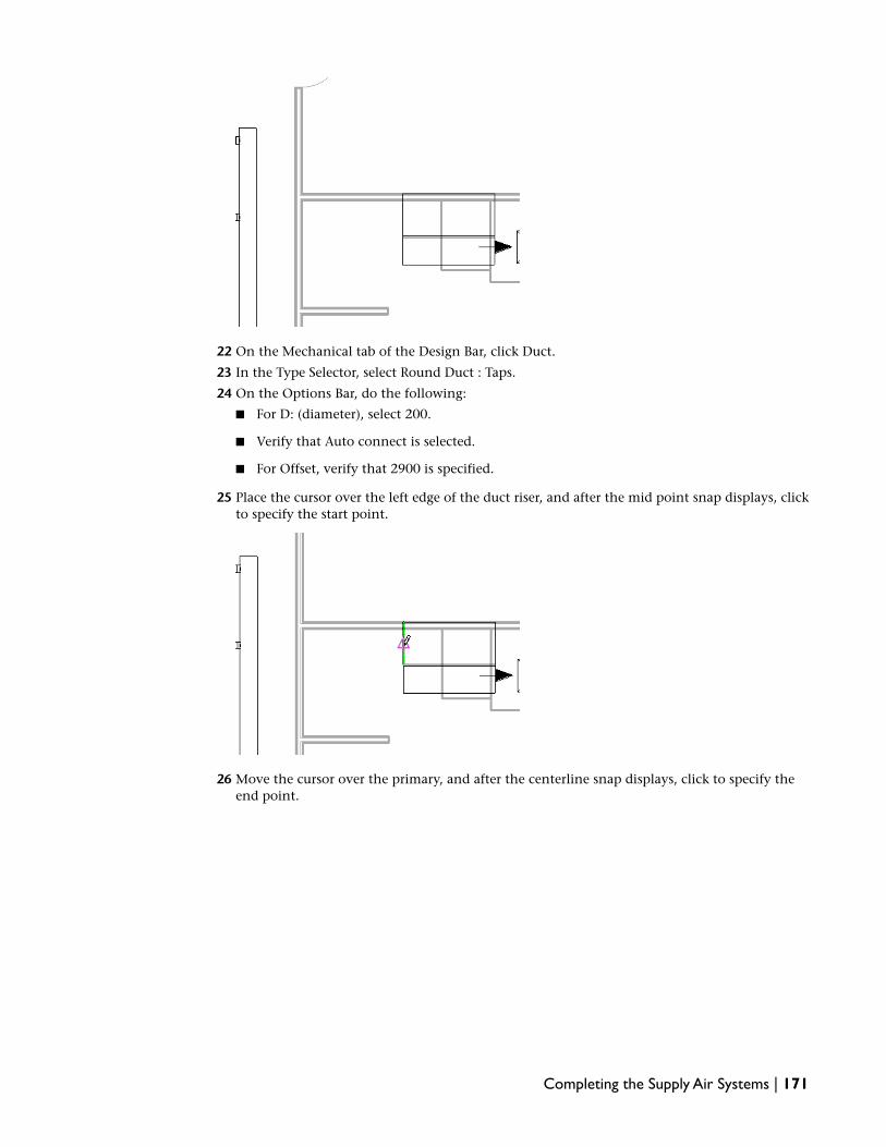
22 On the Mechanical tab of the Design Bar, click Duct.
23 In the Type Selector, select Round Duct : Taps.
24 On the Options Bar, do the following:
■ For D: (diameter), select 200.
■ Verify that Auto connect is selected.
■ For Offset, verify that 2900 is specified.
25 Place the cursor over the left edge of the duct riser, and after the mid point snap displays, clickto specify the start point.
26 Move the cursor over the primary, and after the centerline snap displays, click to specify theend point.
Completing the Supply Air Systems | 171

The left primary is connected to the AC unit.
27 Press ESC to deactivate the Draw tool.
28 Validate the geometry in the 3D view.
Next, you connect the right primary duct to the AC unit.
29 Spin the 3D view around and zoom as shown to validate the right primary connection.
172 | Chapter 4 Mechanical Systems:Air

You will also use this view to validate endcap placement.
30 In the 2 - Mech view, pan the view to the right to show the duct riser and the right primarysegment.
31 Select the right primary duct, and place the cursor over the end connector.
32 Drag the connector down and to the right, and past the Mechanical/Electrical room wall.
Notice that the Draw tool opens (pencil icon) as you drag the duct and closes after you releasethe mouse button to specify the end point.
33 Select the right primary duct, right-click and select Draw Duct.
34 Draw a short run of duct with a downward 30 degree angle and click to set the endpoint.
Completing the Supply Air Systems | 173

35 With the draw tool still active, draw a horizontal run and connect it to the midpoint snap ofthe riser
.
36 Click Modify on the Design Bar to deactivate the Draw Duct tool.
37 Validate the geometry in the 3D view.
You physically connected the primary duct to the AC unit. However, you still need to checkconnectivity to make certain that all duct and duct fittings are connected.
Check connectivity
38 In the 2 - Mech view, place the cursor over the duct riser and press Tab twice.
174 | Chapter 4 Mechanical Systems:Air

The entire primary supply air duct run including the VAV box connections highlight indicatingthat they are connected. You may want to zoom out to see the entire primary duct run.
You now need to add endcaps to the left primary and to the duct riser to close the ductwork.
Add endcaps
39 In the 2 - Mech view, zoom in on the duct riser.
40 On the Mechanical Tab of the Design Bar, click Duct Fitting.
41 In the Type Selector, select M_Rectangular Duct Endcap : Standard.
Notice that the endcap snap follows the cursor.
42 Place your cursor over the top edge, after the endcap snap aligns to the duct edge and thecenterline snap displays, click to add the endcap.
Completing the Supply Air Systems | 175

43 With the Duct Fitting tool open, move the view to the left to show the end of the primary whereyou deleted the duct segment and elbow.
44 In the Type Selector., select M_Round Duct Endcap : Standard.
TIP It is a best practice to zoom in close for accurate endcap placement. The endcap snap alignswith the duct edge to indicate proper placement.
45 Place the cursor over the end of the primary duct segment and after the endcap snap aligns andthe centerline snaps displays, click to add the endcap.
46 Press Esc twice to deactivate the Duct Fitting tool.
Verify endcap placement
47 Place the cursor over the primary duct round endcap to verify endcap placement.
176 | Chapter 4 Mechanical Systems:Air

A tooltip and the Status Bar (located at the lower left under the Design Bar) confirm the endcap.Additionally endcap edges display enabling you identify the endcap.
48 In the 3D view, use the same method to validate the endcap geometry.
49 Using the 2 views, verify the duct riser endcap, and then validate its geometry.
50 Press Tab to check connectivity.
You physically connected the AC unit to the level 2 VAV boxes by drawing ductwork. Next, youfinish the level 2 supply air system by creating a system to logically connect the level 2 VAVboxes to the AC unit.
Create the high pressure supply air system.
51 With the 2 views tiled, click in the 2 - Mech view to make it active, and enter ZF to zoom theview to fit the window.
52 Place the cursor outside of the building at the upper left corner, drag the cursor to the lowerright corner to draw a pick box around the entire level 2 floor plan.
Completing the Supply Air Systems | 177

Notice that all of the selected elements highlight.
53 On the Options Bar, click (Filter Selection) to filter the selected elements.
54 In the Filter dialog, click Check None, and then select Mechanical Equipment, and click OK.
All level 2 VAV boxes are selected. This is because they are the only mechanical equipment onlevel 2. You can verify the selected VAV boxes in the 3D view. Remember that when drawing apick box or using cross-picking (right to left dragging) all elements visible in the view range ofthe current view are selected. In this case, only the level 2 VAV boxes are within the 2 - Mechview range.
55 On the Options Bar, click (Create Supply Air System) to create a supply air system andassign the selected VAV boxes to it.
56 Click (Select Equipment for System) to assign the AC unit to the system.
57 Click the 3D view title bar to make the window active, and select the level 2 AC unit.
178 | Chapter 4 Mechanical Systems:Air

You just created the high pressure primary supply air system to logically connect the level 2VAV boxes to the rooftop AC unit.
58 Press Esc or click in the drawing area to deactivate the Create Supply Air System tool.
IMPORTANT Although you can draw duct to physically connect system components, all systemcomponents must be logically connected by a system. Remember that systems can be created beforeor after you draw ductwork, or even without ductwork. However, ductwork must exist for Revit MEPto perform system calculations such as airflow and pressure. These calculations are used during ductsizing and can be viewed using the System Inspector.
Validate the primary supply air system
59 Press F9 to open the System Browser.
60 In the System Browser, expand Mechanical, Supply Air, and notice that the rooftop AC unit islisted.
61 Expand M_Rooftop AC Unit 53-88 KW - Bottom Return Connection : M_53 KW to display theMechanical Supply Air 25 system listing.
This is the system that you just created.
62 Expand Mechanical Supply Air 25 to view the VAV boxes.
IMPORTANT The system components (air terminals and VAV box) that you assigned to a system areorganized in a hierarchy from upstream (parent) to downstream (child). In the Unassigned folder,notice that only level 1 VAV boxes are listed in the Default Supply Air category. This is because youhave assigned all level 2 VAV supply air connectors to the secondary and primary supply air systems.After you assign the level 1 system components to a primary supply air system, all supply air systemcomponents will be assigned and the Default Supply Air category will be empty.
63 Right-click Mechanical Supply Air 25, and click Select.
Completing the Supply Air Systems | 179

The new level 2 primary supply air system highlights in red.
Next, you inspect the system.
Inspect the primary supply air system
64 In the System Browser, right-click Mechanical Supply Air 25, and click Inspect.
IMPORTANT Another way to select a system is to select any duct segment, duct fitting, diffuser, ormechanical equipment that has been assigned to a system. You can then use system tools from theOptions Bar. Ductwork must exist to access the System Inspector. If you select a system componentthat has been assigned to multiple systems such as an AC unit or a VAV box, the Select System dialogopens enabling you to select the system to inspect.
65 On the System Inspector tab of the Design Bar, click Inspect.
The System Inspector tool opens.
66 On the System Inspector tab of the Design Bar, click Inspect.
67 Click a blank space in the 2 - Mech drawing area to make the view active.
68 Move the cursor over the primary supply air system duct run to inspect the air flow and pressurewithin the duct.
Remember that you can click to place a temporary inspection flag in the view enabling you tocompare inspection information.
69 Make the 3D view active and continue to inspect the primary supply air system.
70 On the System Inspector tab of the Design Bar, click Finish Inspector to deactivate the tool.
71 You have completed the level 2 high pressure primary supply air system. Next, you completethe level 1 primary supply air system.
Optional: Complete the level 1 supply air system
72 Using the methods that you learned in this exercise, complete the level 1 primary supply airsystem to the following specifications:
■ In the Roof Mechanical view, draw the supply duct riser using Rectangular Duct : MiteredElbows / Taps and specify a 1700mm width, and a 500mm height.
■ Specify the offset to -4400mm. This offset routes the duct through the level 2Mechanical/Electrical room and into the level 1 plenum space terminating at the same levelas the level 1 supply air system, 2900mm.
■ Click the supply connector, move the cursor down, and enter 1050mm, and press Enter tospecify the duct end point. Verify the duct riser geometry in the 3D view.
180 | Chapter 4 Mechanical Systems:Air

This is the opposite of what you did with the level 2 AC unit. This is because the locationof the supply and return connections are reversed due to rotating the AC units at placement.Notice that the duct riser passes through level 2 as confirmed by the green supply riser symbolin the 2 -Mech view.
■ Close the Roof Mech view and the 2 - Mech view (if open), open the 1 - Mech view, and tileit to the left of the 3D view.
■ In the 1 - Mech view, select the left primary horizontal duct segment and elbow, and dragthem down to align with the centerline of the right primary duct. Watch for the centerlinesnap as shown.
Completing the Supply Air Systems | 181

■ Connect the primary to the AC. Instead of drawing duct, select the left primary duct segment,and drag the end connector over the left edge of the duct riser to open the Draw tool. Theedge snap displays when the connector is over the edge.
■ Drag the right primary duct connector to the right edge of the AC duct riser, and after theedge highlights, release the mouse button.The level 1 primary duct run is connected to the AC unit.
■ In the 1 - Mech view, add an endcap on the end of the duct riser. Use M_Rectangular DuctEndcap : Standard, and remember to zoom the view.
■ Use Tab to check duct connectivity, and validate the duct geometry in the 3D view.
182 | Chapter 4 Mechanical Systems:Air

■ Create a system for the level 1 primary supply air system, and assign the VAV boxes and theAC unit to it.
■ Validate the system using the System Browser, and inspect the system with the SystemInspector.The completed level 1 primary supply air system is as shown.
73 If you want to save your work, click File menu ➤ Save.
74 In the Save As dialog, enter Completing Supply Air Systems Training for File name, navigate tothe folder of your choice, and click Save.
In this exercise, you connected the level 1 and level 2 high pressure primary supply air duct runs to separaterooftop AC units. Using tiled windows, you drew the AC duct risers and then you physically connected eachAC unit to its respective primary duct run. You then created 2 systems to logically connect the AC units totheir VAV boxes, and validated these logical connections. These systems allow Revit MEP to performcalculations such as flow and pressure on the primary supply air systems. You have completed the high andlow pressure (primary and secondary) supply air systems for the building. In the next exercise, you checkthe systems in your project.
Completing the Supply Air Systems | 183

Checking Air Systems
Revit MEP uses both the duct geometry and logical system to perform calculations such as airflow andpressure, and for duct sizing. Because both the logical (system) and physical (ductwork) connections play avital role in the overall systems design, you need to validate them. In this exercise, you use the Check DuctSystems tool to immediately check these connections for all systems throughout your project, and quicklytarget those systems that need attention.
Dataset
■ Click File menu ➤ Open.
■ In the left pane of the Open dialog, click the Training Files icon.
■ Open the m Checking Air Systems.rvt file located in the Metric ➤ Mechanical folder.
Perform a systems check
1 On the Mechanical tab of the Design Bar, click Check Duct Systems.
Revit MEP checks both the logical (system) and the physical (duct) connections of each systemthroughout the project. Warnings report that the Default Exhaust Air and Default Return Airsystems (for levels 1 and 2) and are not empty. These warnings direct you to check the Unassignedfolder in the System Browser. As you view the warnings, Revit MEP lists the system componentsthat are associated with each warning. Notice that no warnings refer to the supply air systemsindicating that they are valid.
NOTE The Check Duct Systems warnings contain a system type and a description. These warningscan refer to both physical connection issues (such as a disconnected or problematic duct) or logicalconnection issues (such as an improperly assigned system) in a system. Remember that after youcreate ductwork to physically connect a system, the duct is now associated with that system. Theduct geometry is used for system airflow and pressure calculations, and for duct sizing. Note thatonly physical connections associated with an assigned system are checked. Ductwork that is associatedwith a default system (located in the Unassigned folder) is not checked.
IMPORTANT The most common Check Duct Systems warning is the “default system is not empty”warning. As you learned when placing air terminals and VAV boxes, all system components must beassigned to a system immediately after placement. If you place air terminals and VAV boxes withoutassigning them to a system, Revit MEP creates a default system and assigns them to it in order toperform system calculations. The default system is placed in the Unassigned folder until you selectthe system components and create a system for them, thus assigning the components to a system.After you assign the system components to a system, Revit MEP places them in their assigned systemsfolder and removes them from the Unassigned folder. After you have assigned all system componentsfor the project to their systems, the Unassigned folder will be empty and Check Duct Systems will nolonger display “not empty” warnings. Note that a system component may be listed in both its assignedsystem and in the Unassigned folder. This occurs because the assigned system component can beconnected to multiple systems (it contains different system connectors), and you have not assignedthe component to the other systems. For example, you assigned a VAV to a supply air system butthe same VAV has a return air and another supply air connector that you have not assigned to system.In the System Browser, the VAV is listed in the assigned system and associated with the Default ReturnAir system in the Unassigned folder.
These Check Duct System warnings refer to different systems that you have yet to design. So,you can click in the drawing area to close the message window and continue designing othersystems. However, as a tutorial exercise, you open the System Browser to view the unassignedsystem components in the Unassigned folder. Then, you confirm that the assigned systemcomponents are in their proper systems.
184 | Chapter 4 Mechanical Systems:Air

Use the System Browser to confirm duct system assignments
2 Click Window menu ➤ System Browser to open the System Browser.
3 Expand the Unassigned folder and notice that both Default Return Air and Default Exhaust Airsystems are listed.
4 Expand Default Return Air and notice the air terminals and mechanical equipment that wereautomatically assigned to the Default Return Air system.
5 Right-click Default Return Air, and click Select to view all of the unassigned system components.
The red lines represent the default logical connection.
TIP If you have multiple views open, you can click Show in the Show Element(s) In View dialog toswitch between views, otherwise click Close.
6 Using the same methods, confirm the unassigned system components in the Default ExhaustAir system.
You confirmed all of the unassigned default systems in the Unassigned systems folder. You nowconfirm the systems that you created.
7 Collapse the Unassigned folder and expand the Mechanical systems folder.
8 Right-click Supply Air, and click Expand All to view all systems that you created including theirassigned diffusers (air terminals) and mechanical equipment.
Notice that each system contains a system type and an assigned number, such as MechanicalSupply Air 3.
9 Right-click a system, and click Select to view it and its assigned system components.
You have validated both the unassigned and the assigned system components and their systems.
10 If you want to save your work, click File menu ➤ Save.
11 In the Save As dialog, enter Checking Air Systems Training for File name, navigate to the folderof your choice, and click Save.
In this exercise, you used the Check Duct Systems tool and the System Browser to validate the supply airsystems that you created. You also confirmed that the air terminals and mechanical equipment for the returnand exhaust air systems were unassigned as they were located in their respective default systems in theSystem Browser and “not empty” warnings were generated by Check Duct Systems. Depending on your airsystems design, you may need to assign these system components to their proper systems. You have completedthe supply air systems for the building. To view the completed mechanical systems for this tutorial including
Checking Air Systems | 185

the supply air system, open the m Completed Mechanical Systems.rvt file located in the Metric ➤ Mechanicalfolder under Training Files. In the next lesson, you design a hydronic piping system for the building.
186 | Chapter 4 Mechanical Systems:Air

Mechanical Systems:Piping
Designing Piping Systems
As with designing air systems, designing piping systems in Revit MEP is a straightforward and intuitiveprocess. You will use many of the same methods and practices that you learned while designing the airsystems. In this lesson, you create hydronic piping systems. You begin your piping systems design by placingfin-tube radiators in rooms and adding a boiler. Then, you create the systems and pipe runs to logically andphysically connect the system components. You continue designing by resolving pipe interference, placinga circulator pump, and inspecting the piping system.
IMPORTANT It is highly recommended that you complete the air systems part of this tutorial before creatinghydronic piping systems. After completing the air systems lesson, you will have been introduced to concepts andpractices that you will use to design the hydronic piping systems.
Creating Piping Views
In this exercise, you begin designing the level 2 hydronic piping systems for the building. The hydronicpiping systems consist of wall mounted hydronic fin-tube radiators, a boiler, circulator pump, pipes, andthe systems to logically connect the system components. First, you create new views in which to design thepiping system.
Dataset
■ Click File menu ➤ Open.
■ In the left pane of the Open dialog, click the Training Files icon.
■ Open the m Creating Piping Views.rvt file located in the Metric ➤ Mechanical folder.
Create the level 2 piping floor plan view
1 In the Project Browser, expand Views (Discipline) ➤ Mechanical ➤ HVAC ➤ Floor Plans,right-click 2 - Mech, and click Duplicate View ➤ Duplicate.
A new view called Copy of 2 - Mech is created and becomes the active view.
5
187

2 In the Project Browser, right-click Copy of 2 - Mech, and click Rename.
3 In the Rename View dialog, enter 2 - Piping for Name, and click OK.
Modify the view properties
4 With the 2 - Piping view selected in the Project Browser, click (Properties) to modify theview properties.
5 In the Element Properties dialog, under Graphics, do the following:
■ Verify that Mechanical is specified for Discipline.
■ Delete HVAC and enter Piping for Sub-Discipline.
Next, you change the view range.
6 In the Element Properties dialog, scroll down to the Extents category, and click Edit for ViewRange.
7 In the View Range dialog, under Primary Range do the following:
■ For Top, verify that Associated Level (Level 2) is selected, and enter 950mm for Offset.
■ Enter 950 for Cut plane Offset.
■ For Bottom, verify that Associated Level (Level 2) is selected, and enter -3500mm for Offset.
■ Under View Depth, for Level, verify that Associated Level (Level 2) is selected, and enter-3500 for Offset.
This specifies the top view range above the radiators on level 2 and a bottom view range belowthe return connection of the boiler on level 1. This allows you locate the boiler and connect toit from one view.
TIP When entering a value, you do not need to type measurement symbols, just enter the value, andpress Tab. For example, you can enter 2600 and press Tab for 2600mm.
8 Click OK twice.
The 2 - Piping view displays all architectural elements in halftone and it displays the level 1 airsystems. Also notice that 2 - Piping is now located under Mechanical ➤ Piping ➤ Floor Plans inthe Project Browser.
188 | Chapter 5 Mechanical Systems: Piping

You use this view to create the pipe run that services level 2. You can use the level 1 ductwork as a referenceto avoid interference with the level 2 pipe run. However, the pipe run will be located near the outer walls,and the vertical pipe run from the boiler will be routed in the Mechanical /Electrical room. So the pipe willnot interfere with the duct. Considering this, you can hide the level 1 duct and system components to makeit easier to view the pipe run.
Next you create a series of filters to hide the level 1 duct and system components. You can then use thesefilters to hide or show objects in other views.
Create and define filters
9 In the 2 - Piping view, click in the drawing area to make the view active, and enter VG.
10 In the Visibility Graphics dialog, click the Filters tab.
On the Filters tab, you can add and activate filters. Notice that some predefined filters are listedunder Name.
11 Click Edit/New.
IMPORTANT You can create and define filters in the Filters dialog. Notice that filters are alreadycreated and listed under Filters. These system filters show or hide certain system elements that sharethe same system type. You could use the system filters to filter some duct and duct fittings, however,they will not filter all system elements needed. So, it will be best to create filters. You can use thesystem filters for tasks such as color-coding your systems. In this lesson, the system filters are notused.
12 In the Filters dialog, under Filters, click (New).
13 Enter VAV Boxes for Name, and click OK.
14 Under Categories, select Mechanical Equipment.
15 Under Filter Rules, do the following:
■ Select Family Name for Filter by, and verify that equals is selected.
■ Select M_VAV Unit - Parallel Fan Powered for the family name.
■ Verify that none is selected for And.
■ Click Apply.
IMPORTANT You can filter by many types of criteria, such as family name, type name, system type,or even a description that you define. You can create filters that are either general or specific in scopedepending on the filter criteria. Note that if you are filtering multiple categories or multiple types inone category, you must select filter criteria that is common and shared by all selected componentsthat you want to filter. A quick way to determine common filter criteria is to draw a pick box around
all components in a view, and click on the Options Bar to view certain components. Then youcan view the common filter criteria from the Element Properties dialog. Note that if at least one typeparameter is different amongst the selected components, then no type parameter will display in theType Properties dialog. However, common (shared) instance parameters will display even if otherinstance parameters are different (the different instance parameters do not display). Depending onthe filter criteria, you may want to select each component type separately.
The new VAV Boxes filter is listed in the Filters list. This filter will hide all parallel fan poweredVAVs in the view after it is added and activated.
Next, you create a filter to hide all 3 types of air terminals. To do this, you need a define commonfilter criteria.
Creating Piping Views | 189

16 In the Filters dialog, under Filters, click .
17 Enter Air Terminals for Name, and click OK.
18 Under Categories, click Air Terminals.
19 Under Filter Rules, select Description for Filter by, and verify that equals is selected.
You do not have common filter criteria for the supply, return, and exhaust air terminals butthey all have a Description type parameter. So, you create a description as the common filtercriteria.
NOTE The Description type parameter is applied to all components of that type. This is differentfrom the Comment instance parameter which only affects the selected component (or instance).
20 Enter Air Terminal for the description, and click OK twice.
Next, you need to assign the new description to all 3 air terminal types that you use in theproject.
21 On the Mechanical tab of the Design Bar, click Air Terminal.
22 In the Type Selector, select M_Exhaust Diffuser - Hosted: Workplane-based Exhaust Diffuser.
23 On the Options Bar, click (Properties).
24 In the Element Properties dialog, click Edit/New.
25 In the Type Properties dialog, under Identity Data, enter Air Terminal for Description.
26 Click Apply.
This action adds a description for all Exhaust Diffuser air terminals. It also creates commoncriteria that associates all of these exhaust air terminal types to the Air Terminal filter.
NOTE When entering filter criteria and assigning it to a family, you must spell both verbatim, otherwisethe filter will not work. This is the same rule for using formulae.
Next, you add a description for the supply air diffusers.
27 In the Type Properties dialog, do the following:
■ For Family, select M_Supply Diffuser - Hosted.
■ For Type, select Workplane-based Supply Diffuser.
28 Under Identity Data, click in the Value column for Description, and select Air Terminal, andclick Apply.
Because you already entered the description, you can select it.
29 Repeat the method that you learned to add a description to the Return air diffusers.
Remember to click Apply.
30 Click OK twice.
31 Click Modify on the Design Bar to deactivate the Air Terminal tool.
NOTE If you drew a pick box and filtered to select all air terminals, you will not see the Descriptiontype parameter. This is because the selected supply, return, and exhaust air terminals have at leastone different type parameter. Remember, if differences exist in the selected elements, then the typeparameters will not display. By selecting each air terminal type separately, you can view the Descriptiontype parameter and identify it as common to all air terminal types.
Next, you continue to create and define the filters.
32 Click in the 2 - Piping view to make it active, and enter VG.
190 | Chapter 5 Mechanical Systems: Piping

33 In the Visibility Graphics dialog, click the Filters tab.
34 On the Filters tab, click Edit/New.
35 Using the methods that you just learned, create the following new filters according to thespecifications, and remember to click Apply in the Filters dialog after you define each filter tocreate it:
■ Supply Air - Duct Fittings. Category: Duct Fittings; Filter by: System Type, verify that equalsis selected, and enter Supply Air for system type name.To filter multiple duct fitting types, you need a common filter criteria. All duct fittings inyour project have a System Type instance parameter defined as Supply Air in the elementproperties. So, you filter duct fittings by system type.
■ Flex Ducts - Round. Category: Flex Ducts; Filter by: Family Name, verify that equals is selected,and select Flex Duct Round for the family name.
■ Round Ducts. Category: Ducts; Filter by: Family Name, verify that equals is selected, andselect Round Duct for the family name.Next, you have 2 types of rectangular duct. You want to view only the rectangular duct withmitered elbows because this the duct riser which is in the Mechanical /Electrical rooms andyou want to avoid it when routing the pipe from the boiler. So, you specify a family and atype name.
■ Rectangular Ducts Radius Elbows/Taps. Category: Ducts, Filter by: Family Name, verify thatequals is selected, and select Rectangular Duct for the family name; And: Type Name, verifythat equals is selected, and select Radius Elbows / Taps for the type name.
■ Rectangular Ducts Mitered Elbows/Taps. Category: Ducts, Filter by: Family Name, verifythat equals is selected, and select Rectangular Duct for the family name; And: Type Name,verify that equals is selected, and select Mitered Elbows / Taps for the type name.
Remember that you must click Apply after defining each filter and before defining the next onein order to create the filter. If you did not click Apply, you need to define the filter again.
36 Click OK.
You defined and created all of the filters that you will need to create the hydronic piping system.Notice that the Filters tab in the Visibility Graphics dialog does not list the new filters eventhough you created them. This is because you have not added them. Next, you add and activatethe filters.
Add and activate filters
37 In the Visibility Graphics dialog, click Add.
38 In the Add Filters dialog, select all of the filters that you created, and click OK.
The new filters are listed on the Filters tab of the Visibility Graphics dialog. Notice that you havevisibility controls similar to visibility categories on other Visibility Graphics dialog tabs.
Next, you activate the filters.
39 Under Visibility, clear all check boxes except for Mechanical - Supply and Rectangular DuctsMitered Elbows/Taps.
You used this duct to create the duct riser. You will use the duct riser as a reference to avoidinterfering with it when routing the pipe run from the boiler.
40 Click OK twice.
Creating Piping Views | 191

All filtered components hide from view except for the duct riser in the Mechanical/Electricalroom.
TIP Filters allow you hide geometry making visibility clearer. It also improves viewing performancebecause geometry that would normally be regenerated is hidden. You can also set the Detail Levelto Wireframe to increase viewing performance.
Next, you create the level 1 piping view in order to place the boiler.
Create the level 1 piping view
41 In the Project Browser, expand Views (Discipline) ➤ Mechanical ➤ HVAC ➤ Floor Plans,right-click 1 - Mech, and click Duplicate View ➤ Duplicate.
A new view called Copy of 1 - Mech is created and becomes the active view.
42 In the Project Browser, right-click Copy of 1 - Mech, and click Rename.
43 Enter 1 - Piping for Name, and click OK.
You now define the view properties.
44 Right-click in the drawing area, and click View Properties.
45 In the Element Properties dialog, under Graphics, do the following:
■ Verify that Mechanical is specified for Discipline.
■ Select Piping for Sub-Discipline.
Next, you change the view range.
46 In the Element Properties dialog, scroll down to the Extents category, and click Edit for ViewRange.
47 In the View Range dialog, under Primary Range, verify that Associated Level (Level 1) is selectedand that 3000 is specified for Top Offset.
48 Click OK twice.
The 1 - Piping view displays the new view settings. Unlike the 2 - Piping view, this view onlydisplays ducts and pipes on its level. The 3000mm top offset prevents the level 2 pipes (except
192 | Chapter 5 Mechanical Systems: Piping

for the boiler pipe connection), ducts, and fin-tub radiators from displaying. You use this viewto place the boiler that services level 2, and to create the level 1 piping system.
As you create the pipe runs, you will want to validate the geometry. Next, you create the 3Dpiping view to be able to validate this geometry.
Create the 3D Piping view
49 In the Project Browser, expand Views (Discipline) ➤ Mechanical ➤ HVAC ➤ 3D Views, right-click3D, and click Duplicate View ➤ Duplicate.
The new view is created using the view properties from the 3D Mech view, such as halftonearchitecture.
50 In the Project Browser, right-click Copy of 3D Mech, and click Rename.
51 Enter 3D Piping for Name, and click OK.
52 Right-click in the drawing area, and click View Properties.
53 In the Element Properties dialog, under Graphics, do the following:
■ Verify that Mechanical is selected for Discipline.
■ Select Piping for Sub-Discipline.
■ Click Edit for Visibility/Graphics Overrides.You need to use the filters that you created earlier so that you can view only the pipes andthe level 1 duct riser. If you turn off ducts visibility, you will be unable to view the duct riser.
54 In the Visibility Graphics dialog, click the Filters tab.
55 On the Filters tab, click Add.
56 In the Add Filters dialog, select all of the filters that you created, and click OK.
The selected filters are listed on the Filters tab.
57 Under Visibility, clear all check boxes except for Rectangular Ducts Mitered Elbows/Taps.
You used this duct to create the duct riser. You want to view it to avoid interfering with it whenrouting the pipe run from the boiler.
58 Click OK.
59 In the Element Properties dialog, under Extents, clear Section Box to turn it off.
Creating Piping Views | 193

60 Click OK.
The duct risers and AC units display in the view. The AC units display because you did not createa filter to hide them. Notice that the duct fittings are filtered. This is fine because you are usingthe riser as a reference to avoid interference with the boiler piping.
61 If you want to save your work, click File menu ➤ Save.
62 In the Save As dialog, enter Creating Piping Views Training for File name, navigate to the folderof your choice, and click Save.
In this exercise, you created and modified 2 floor plans and a 3D view. You also created filters to displaycertain system components. In the next exercise, you place the radiators and a boiler.
Placing Radiators and a Boiler
In this exercise, you place the fin-tube radiators on level 2 and the boiler on level 1 that services the level 2radiators.
Dataset
■ Click File menu ➤ Open.
■ In the left pane of the Open dialog, click the Training Files icon.
■ Open the m Placing Radiators and Boiler.rvt file located in the Metric ➤ Mechanical folder.
1 In the Project Browser, expand Views (Discipline) ➤ Mechanical ➤ Piping ➤ Floor Plans, anddouble-click 2 - Piping to make it the active view.
2 Enter ZF to zoom the view to fit the drawing area.
3 On the Piping tab of the Design Bar, click Mechanical Equipment.
NOTE If the Piping tab is not available on the Design Bar, right-click the Design Bar, and click Piping.
4 In the Type Selector, select M_Radiator - Hosted: 25.
5 Move the cursor over a wall and notice that an outline of the radiator and listening dimensionsdisplay only if the cursor is over the wall.
This is because the fin-tube radiator is a wall-hosted family and can only be placed on a wall.
6 Zoom in on Office 201 located in the upper-left corner of the floor plan.
TIP Although room tags were not copied when you created this view, you can identify a room byplacing the cursor over the room component. A tooltip and the Status Bar (located at the lower leftunder the Design Bar) confirm the room name and number.
194 | Chapter 5 Mechanical Systems: Piping

7 Place the cursor over the top exterior wall, and center a fin-tube radiator under the upper-rightwindow as shown.
8 Click to place the radiator, and notice that the connectors display.
To place the radiator precisely under the window, select it and use the arrow keys to move itinto position.
9 Continue placing radiators centered under all windows on level 2 as shown, except for thewindows on the radius wall.
Placing Radiators and a Boiler | 195

You may need to move the Section 1 head and tail to place the Office 6 upper-left radiator. Ifso, drag the section tail. Do not delete the section as you will reuse it later in this lesson.
TIP Remember to zoom the view to accurately place the radiators.
10 Click Modify on the Design Bar to deactivate the Mechanical Equipment tool.
Next, you modify the radiator flow rate.
Modify radiator flow rate
11 In the drawing area, right-click a radiator, and click Select All Instances.
All level 2 radiators display in red.
NOTE Note that Select All Instances selects all components of the same type in the entire model. Ifthe same type of component exists on another level, and you do not want to include it, then it wouldbe better to use other selection methods such as drawing a pick box.
12 On the Options Bar, click (Element Properties).
13 In the resulting dialog, under Mechanical Loads, for Flow, verify that 15.30 L/s is specified forall of the selected radiators.
IMPORTANT If you select multiple objects and then view their properties, the parameters that displayare common to all of the selected objects. If parameters are blank, then these are different across theselected objects.
Your design specification recommends a flow rate of 0.25 L/s for all fin-tube radiators in thebuilding. The existing radiator flow rate needs to be changed.
14 Enter .25 for Flow, and click OK.
The flow rate changes for all radiators on level 2. You selected all instances of the level 2 radiatorsbecause Flow is an instance parameter and must be applied to each instance that you want tomodify. Next, you place the boiler.
Place the boiler
15 In the Project Browser, double-click 1 - Piping to make this the active view.
The boiler that services the level 2 radiators will be located on level 1.
196 | Chapter 5 Mechanical Systems: Piping

16 Enter ZR, and sketch a zoom region around Mechanical/Electrical room.
17 On the Piping tab of the Design Bar, click Mechanical Equipment, and select M_Boiler : Standardfrom the Type Selector.
18 Move the cursor to the right of the duct riser, watch the listening dimensions, and click to placethe boiler approximately as shown.
Notice that the connectors display after you place the boiler.
19 Press Esc twice to deactivate the Mechanical Equipment tool.
Next, you verify the boiler flow rate.
Placing Radiators and a Boiler | 197

20 In the drawing area, right-click the boiler, and click Element Properties.
21 In the Element Properties dialog, under Type Parameters, verify that 14.50 L/s is set for MaxFlow.
The boiler maximum flow rate complies with the design specification.
22 Click OK.
23 If you want to save your work, click File menu ➤ Save.
24 In the Save As dialog, enter Placing Radiators and Boiler Training for File name, navigate to thefolder of your choice, and click Save.
In this exercise, you placed wall mounted fin-tube radiators on level 2, and the boiler that services thoseradiators on level 1. You also modified the radiator flow rate and verified the boiler flow rate so that theycomplied with design specifications. In the next exercise, you create the systems to logically connect thesystem components.
Creating the Piping Systems
In this exercise, you create the supply and return piping systems. A system is the logical connection betweensystem components such as fin-tube radiators and a boiler. This logical connection allows Revit MEP toperform various analyses including flow and pressure. You create piping systems by placing mechanicalequipment and other system components, and then create the logical connection between these systemcomponents. After creating the logical connection, you then create pipes to physically connect the systemcomponents. This is the recommended workflow or best practice for systems creation. During this exercise,you also use the System Browser to confirm your systems.
IMPORTANT All system components are logically connected either by a system that you create or by a defaultsystem. Unlike logical connections (systems), physical connections (pipes) are not required for systems creation.You can create pipes to connect system components but without a corresponding system, analyses cannot beperformed. It is not a pipe system but only a physical connection.
Dataset
■ Click File menu ➤ Open.
■ In the left pane of the Open dialog, click the Training Files icon.
■ Open the m Creating Piping Systems.rvt file located in the Metric ➤ Mechanical folder.
1 In the Project Browser, expand Views (Discipline) ➤ Mechanical ➤ Piping ➤ Floor Plans, anddouble-click 2 - Piping to make it the active view.
2 Enter ZF to zoom the view to fit the window.
Explore the System Browser
3 On the Piping tab of the Design Bar, click System Browser.
TIP You can also press F9 (or Window menu ➤ System Browser) to open or close the System Browser.If the System Browser does not respond, click in the drawing area to make it active, then press F9.
4 Expand the Unassigned folder, and expand the Default Hydronic Supply and the Default HydronicReturn systems to view the level 2 radiators and the boiler that you placed in the building.
198 | Chapter 5 Mechanical Systems: Piping

IMPORTANT In the System Browser, all system components are organized in a folder tree hierarchyaccording to the system that you assigned to them. You assign a system component (mechanicalequipment, and so on) to a system either by creating a logical connection (or system) between thesystem components or by assigning a system component to an existing system. Notice that all of themechanical equipment that you added are located under Default systems categories in the Unassignedfolder. This occurred because each system component must be assigned to a system after it is placed.So, after you placed the radiators and boiler, Revit MEP immediately assigned them to the DefaultHydronic Supply and Default Hydronic Return system category located in the Unassigned folder. Theyremain in the Default systems category until you assign them to their proper system. As you assignradiators to systems, the assigned radiators move from the Unassigned folder to their respectiveassigned system folder. Thus, if all system components are assigned, each Default system categorywould not contain any system components and would be considered empty. The System Browser isa powerful tool that allows you to validate and confirm systems.
Keep the System Browser open and refer to it as you create your systems.
Create the supply hydronic piping system
5 Select a fin-tube radiator, right-click, and click Select All Instances.
All level 2 radiators display in red.
6 On the Options Bar, click (Create Hydronic Supply System).
Notice that after you click , the hydronic supply system is immediately created and listedin the System Browser along with the fin-tube radiators that were assigned to it.
7 On the Options Bar, click (Select Equipment for System), and select the boiler to assignit to the supply system.
Creating the Piping Systems | 199

TIP If you have trouble selecting the boiler, click the Edit Systems button and then choose Boiler:Standard from the System Equipment drop-down list on the Options bar.
Notice that you can select only valid system components, all other components are unavailable.
The supply system that logically connects the radiators to the boiler displays in red. This displayindicates that the new system is selected. It does not indicate a pipe layout path.
TIP If you click in the drawing area and the red system display clears, place the cursor over a radiatoror the boiler, press Tab, and select the system. You can also right-click the Hydronic Supply 1 listingin the System Browser, and click Select to select the system.
IMPORTANT The new system named Hydronic Supply 1 is now listed in the System Browser underHydronic Supply in the Piping folder. The organization is from upstream, the boiler (the parent) todownstream, the radiator (the child) with the connecting system between them. Notice that theDefault Hydronic Supply category no longer displays. This indicates that you have assigned all hydronicsupply system components in the model. Thus, the Default Hydronic Supply system is empty anddoes not display.
Next, you create the return piping system.
200 | Chapter 5 Mechanical Systems: Piping
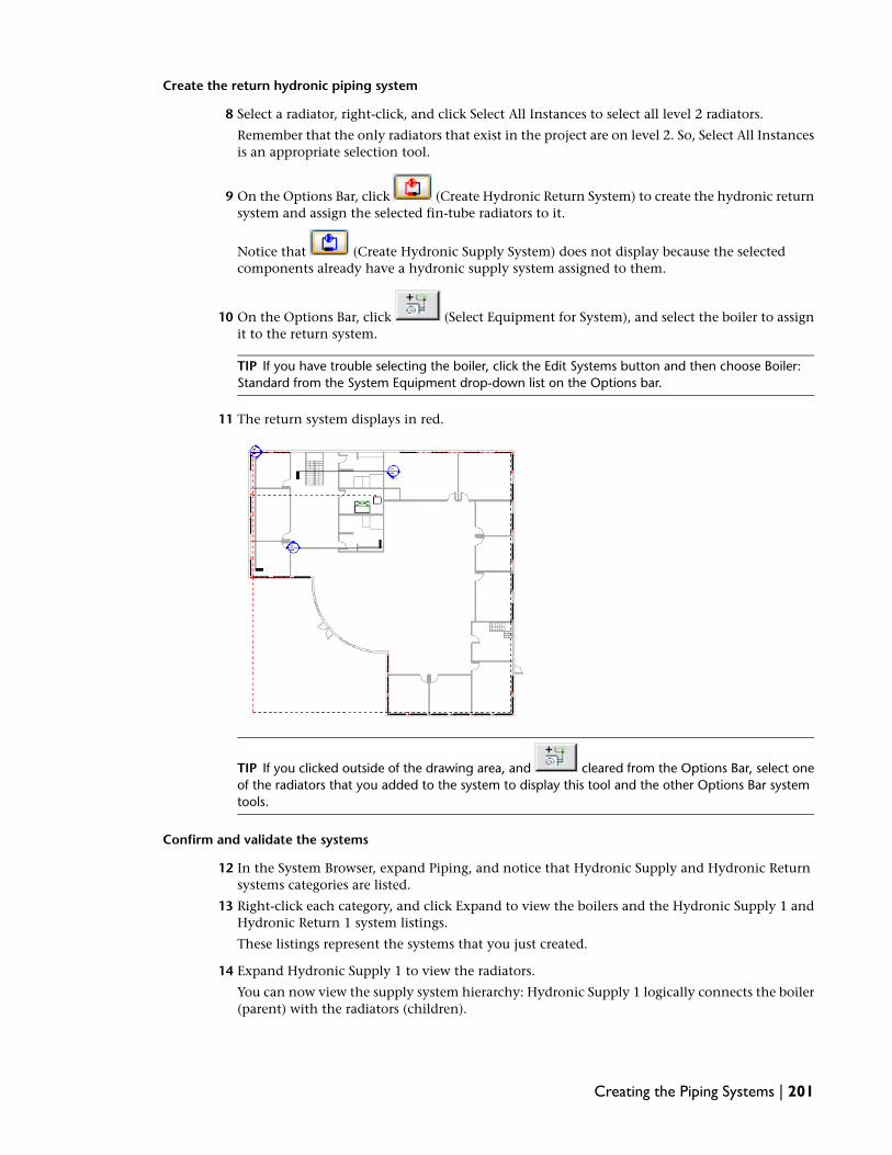
Create the return hydronic piping system
8 Select a radiator, right-click, and click Select All Instances to select all level 2 radiators.
Remember that the only radiators that exist in the project are on level 2. So, Select All Instancesis an appropriate selection tool.
9 On the Options Bar, click (Create Hydronic Return System) to create the hydronic returnsystem and assign the selected fin-tube radiators to it.
Notice that (Create Hydronic Supply System) does not display because the selectedcomponents already have a hydronic supply system assigned to them.
10 On the Options Bar, click (Select Equipment for System), and select the boiler to assignit to the return system.
TIP If you have trouble selecting the boiler, click the Edit Systems button and then choose Boiler:Standard from the System Equipment drop-down list on the Options bar.
11 The return system displays in red.
TIP If you clicked outside of the drawing area, and cleared from the Options Bar, select oneof the radiators that you added to the system to display this tool and the other Options Bar systemtools.
Confirm and validate the systems
12 In the System Browser, expand Piping, and notice that Hydronic Supply and Hydronic Returnsystems categories are listed.
13 Right-click each category, and click Expand to view the boilers and the Hydronic Supply 1 andHydronic Return 1 system listings.
These listings represent the systems that you just created.
14 Expand Hydronic Supply 1 to view the radiators.
You can now view the supply system hierarchy: Hydronic Supply 1 logically connects the boiler(parent) with the radiators (children).
Creating the Piping Systems | 201

15 Right-click Hydronic Supply 1, and click Select.
The hydronic supply system highlights in red indicating the logical connection.
IMPORTANT Although you can draw pipe to create the physical pipe connections, you must createa system for Revit MEP to perform calculations such as flow and pressure. Remember that systemscan be created before or after pipe, or even without pipe being drawn.
16 Repeat this method to validate the Hydronic Return System logical connection.
17 If you want to save your work, click File menu ➤ Save.
18 In the Save As dialog, enter Creating Piping Systems Training for File name, navigate to thefolder of your choice, and click Save.
In this exercise, you created the supply and return piping systems to logically connect the radiators andboiler. You learned how the System Browser organizes system components and systems, and you used theSystem Browser to confirm and validate the newly created systems. Now that you logically connected thepiping system components, in the next exercise, you create the level 2 pipe runs to physically connect thesystem components.
Creating Pipe Runs
In this exercise, you design 2 pipe layouts and then create the supply and return pipe runs based on theselayouts. The pipe runs physically connect the level 2 radiators. In a later exercise, you connect the boiler tothe pipe runs.
Dataset
■ Click File menu ➤ Open.
■ In the left pane of the Open dialog, click the Training Files icon.
■ Open the m Creating Pipe Runs.rvt file located in the Metric ➤ Mechanical folder.
1 In the Project Browser, expand Views (Discipline) ➤ Mechanical ➤ Piping ➤ Floor Plans, anddouble-click 2 - Piping to make it the active view.
Create the level 2 supply pipe layout
2 Place the cursor outside of the building at the upper left corner, drag the cursor to the lowerright corner to draw a pick box around the entire floor plan.
202 | Chapter 5 Mechanical Systems: Piping

Notice that all components that are in the 2 - Piping view range highlight.
3 On the Options Bar, click (Filter Selection) to filter the selected elements.
4 In the Filter dialog, click Check None, and then select Mechanical Equipment, and click OK.
The level 2 radiators and the level 1 boiler are selected (and display in red). This occurs becausewhen you draw a pick box to select components, you are selecting all components within theview range of the active view. (You can see the level 1 boiler in the 2 - Piping view).
TIP Instead of selecting all components and filtering, you can place the cursor over a radiator, pressTab to highlight the system and select it. Then, you can click Layout Path on the Options Bar.
5 On the Options Bar, click Layout Path.
The Layout Path tool and the Select a System dialog open. Notice that the radiators, the boiler,the return system that logically connects the components display in red. You can click eachsystem in the Select a System dialog to view it.
Creating Pipe Runs | 203

IMPORTANT If you select system components to create a pipe layout and the selected systemcomponents are already connected to more than one system (because they have multiple systemconnectors), then the Select a System dialog will open. You will need to select a system to create thelayout. You can select each system in the dialog to view it.
6 In the Select a System dialog, select Hydronic Supply 1 and click OK.
The system displays in red.
The Layout Path tool activates providing various layout tools.
7 On the Layout Paths tab of the Design Bar, verify that Solutions is selected.
8 On the Options Bar, do the following:
■ Select Perimeter for Solution Type.You want the pipes to run along the perimeter of the radiators.
NOTE The Perimeter solution creates a layout that runs parallel (along a perimeter) to theconnectors of the selected system components. It does not reference the architecture.
■ Click (Next Solution), and select solution 4 of 4.You can also view all possible layout path solutions by pressing the left and right arrow keyson your keyboard.
The layout path solution displays with the main in blue and the branch in green.
■ Verify that 0.00° is specified for Slope.This option slopes the entire pipe layout.
■ Enter 300 for Inset.
204 | Chapter 5 Mechanical Systems: Piping

The inset is the distance from the pipe to the connection on the selected system component.Using this inset, you create the supply pipe run 300mm from the radiator pipe connections(not from the outside wall).
NOTE Notice that the Perimeter layout solution inset modifies the layout path. Later in thisexercise, you modify the layout segments that are tangent to the radius wall.
Next, you specify the pipe conversion settings that you use to convert the layout path to apipe run.
9 On the Options Bar, click Settings.
10 In the left pane of the Pipe Conversion Settings dialog, verify that Main is selected.
11 Under System Type: Hydronic Supply do the following:
■ Verify that Pipe Types: Standard is selected for Pipe Type.
■ Enter -375mm for Offset.This negative offset elevation places the pipe main at 3275mm in the level 1 plenum space.Remember that you are working in the level 2 piping view.
12 In the left pane of the Pipe Conversion Settings dialog, select Branch.
13 Under System Type: Hydronic Supply, do the following:
■ Verify that Pipe Types: Standard is selected for Pipe Type.
■ Enter -375 for Offset.
IMPORTANT The branch offset allows you to automatically create branches that run above orbelow the main, and other obstacles. This is useful for avoiding interference with pipes, duct,structural beams, or architecture.
14 Click OK.
NOTE Configuring the pipe conversion settings is usually a one-time process unless you need tochange them during your project. You can also configure these settings by clicking MechanicalSettings on the Piping tab of the Design Bar (or Settings ➤ Mechanical Settings). For more information,refer to Help.
After configuring the pipe conversion settings, you now modify the layout path.
Creating Pipe Runs | 205

Modify the level 2 supply pipe layout
15 On the Layout Paths tab of the Design Bar, click Modify.
You now modify the layout paths that are tangent to the radius wall. The layout path is locatedunder the radiators.
16 In the drawing area, zoom the view, and select the lower layout path main that is tangent tothe radius wall.
A drag control displays.
17 Using the drag control, drag the main to the right at approximately the same inset as the layoutpath.
206 | Chapter 5 Mechanical Systems: Piping

18 Repeat the process to modify the upper layout path tangent to the radius wall.
TIP Use the Ctrl key to select both the main and the branch line.
19 On the Layout Paths tab of the Design Bar, click Finish Layout.
Ignore the no auto-route solution warning. You will address the cause of this warning later inthis exercise. The supply pipe run (main and branches) is created and all required pipe fittings
Creating Pipe Runs | 207

are automatically inserted. This pipe run physically connects the supply side (supply connectors)of the system components.
Notice that the pipes are not listed in the System Browser. This is because the System Browserlists system components and systems. Pipes are a physical not a logical connection, and is notpart of the system. For example, you can delete pipes and pipe fittings and the system remainsunaffected.
IMPORTANT Errors may occur while attempting to create pipe geometry as a result of convertinga layout or during sizing. The most common cause of these errors is that the pipe usually has insufficientspace to be created, or offset elevations are incorrect. Either relocate the system components, selecta different layout solution, or manually modify the pipe. Remember to always check pipe connectivityafter modification.
Change the geometry display
20 Enter ZR and draw a zoom region around the Office 201.
208 | Chapter 5 Mechanical Systems: Piping

Notice that the pipes and symbolic fittings display in single line. Also notice that a rise/dropsymbol displays indicating the pipe riser. Some pipes are hidden causing a gap. This is causedby the hidden line setting.
IMPORTANT Creating Hydronic Piping Systems uses a hidden (haloed) line display. If a pipe is hiddenby an object, a gap displays indicating the hidden geometry. To turn off hidden lines, click MechanicalSettings on the Piping tab of the Design Bar (or click Settings menu ➤ Mechanical Settings). In theMechanical Settings dialog, select Hidden Line and specify the inside and outside gap to 0. TheHidden Line mechanical setting is not to be confused with the Hidden Lines Model Graphics Stylelocated on the View Control Bar.
21 On the View Control Bar (located at the lower left of the drawing area), select Fine for DetailLevel.
The pipe geometry displays in 2-line enabling you to better see it.
22 Zoom the view and notice that the symbolic fittings and rise/drop symbol have been replacedby fitting geometry and a green pipe riser symbol.
You use the 2-line display to design the piping system.
Creating Pipe Runs | 209

TIP You can easily change the pipe geometry representation by changing the Detail Level. On theView Control Bar, select Coarse for single line display, Medium for 2-line duct display, or Fine for2-line pipe display. If you experience slower viewing performance while using the higher detailsettings, change the Model Graphics Style to Wireframe and/or turn off component visibility in theVisibility Graphics dialog.
Next, you modify the pipe run so that it better fits in with the design. The design requires 2zones. So, you will need 2 pipes connecting the boiler to the supply pipe run. A single pipe doesnot conform to the hydronic piping design. Instead of moving the pipe, it is easier to delete thepipe and fittings and draw a new one later. The deletion also divides the pipe run into left andright sides. Additionally, the pipe run needs to be changed to a 25mm diameter.
Modify the pipe run
23 Zoom in on the pipe connecting the boiler to the supply pipe run.
24 Place the cursor over the pipe, and press TAB twice to highlight the pipe and the adjacent pipefittings, and click to select them.
The selected pipe and pipe fittings display in red.
25 Press Delete to delete the selection.
210 | Chapter 5 Mechanical Systems: Piping
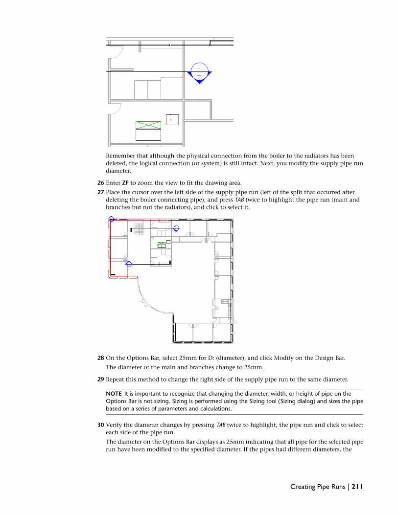
Remember that although the physical connection from the boiler to the radiators has beendeleted, the logical connection (or system) is still intact. Next, you modify the supply pipe rundiameter.
26 Enter ZF to zoom the view to fit the drawing area.
27 Place the cursor over the left side of the supply pipe run (left of the split that occurred afterdeleting the boiler connecting pipe), and press TAB twice to highlight the pipe run (main andbranches but not the radiators), and click to select it.
28 On the Options Bar, select 25mm for D: (diameter), and click Modify on the Design Bar.
The diameter of the main and branches change to 25mm.
29 Repeat this method to change the right side of the supply pipe run to the same diameter.
NOTE It is important to recognize that changing the diameter, width, or height of pipe on theOptions Bar is not sizing. Sizing is performed using the Sizing tool (Sizing dialog) and sizes the pipebased on a series of parameters and calculations.
30 Verify the diameter changes by pressing TAB twice to highlight, the pipe run and click to selecteach side of the pipe run.
The diameter on the Options Bar displays as 25mm indicating that all pipe for the selected piperun have been modified to the specified diameter. If the pipes had different diameters, the
Creating Pipe Runs | 211

diameter would not display. Next, you check to make certain that the pipe run is physicallyconnected to the radiators.
Check connectivity
31 Right-click in the view and click Zoom to Fit from the context menu.
32 Place the cursor over the right side of the supply pipe run and after it highlights, press Tab 3times.
All radiators and pipe highlight indicating that they are physically connected.
IMPORTANT When pipes and fittings are connected, you check connectivity by moving the cursorover a segment of pipe so that it highlights and then press Tab. The first time you press Tab, thebranch to which the pipe is connected highlights. Press Tab a second time to highlight the entirenetwork of connected pipe and pipe fittings up to the first piece of connected equipment. Press Taba third time to highlight the entire network of connected pipes, fittings, and equipment. If the entirenetwork does not highlight, then you know that a disconnect exists. This disconnect will be locatedat the point where the highlighting stops. You can repair the connection by dragging the pipesegment end point away from its current connection point and then dragging it back again toreconnect, or you may need to convert a fitting and draw pipe. Typically the disconnect results fromnot having sufficient room to make the connection.
212 | Chapter 5 Mechanical Systems: Piping

After the pipe run and radiators are highlighted, you can click to select them. This allows youto better see disconnects.
33 Repeat this method to check the connectivity of the left supply pipe run.
Next, you create the return pipe run.
Create the level 2 return pipe run
34 Using the methods that you learned to create the supply pipe run, create the level 2 return piperun according to the following specifications:
■ In the 2 - Piping view, create a layout for the Hydronic Return 1 system.
■ Select Perimeter solution 4.
■ Enter 600 for Inset.
■ Verify that 0.00° is specified for Slope.
■ For pipe conversion settings, verify that Pipe Types: Standard is selected, and enter -525mmfor both the main and branch offsets.This places the pipes at a 3125mm elevation in the level 1 plenum space.
Creating Pipe Runs | 213

■ In the Layout Path tool, modify the 2 layout path mains that are tangent to the radius wallto approximately the same inset as the other sides of the return layout path.
■ Delete the pipe and the 2 fittings that connect the boiler to the return pipe run. The deletedpipe divides the return pipe run into left and right sides.
■ Change the diameter of each return pipe run side to 25mm. Remember, do not select theradiators when selecting the return pipe runs.
■ Check connectivity and inspect the corner connections for disconnects.
■ Use the same method to correct any disconnects.
■ Validate the pipe geometry using the 3D Piping view.
The level 2 return pipe run is as shown.
35 If you want to save your work, click File menu ➤ Save.
36 In the Save As dialog, enter Creating Pipe Runs Training for File name, navigate to the folder ofyour choice, and click Save.
214 | Chapter 5 Mechanical Systems: Piping

In this exercise, you used the Layout Path tool to design the supply and return pipe layouts. You thenconverted these layouts to create the supply and return pipe runs that physically connect the radiators. Youalso modified the pipe runs so that they were a better fit with the systems design. You checked connectivity,converted fittings, corrected disconnects, and validated the pipe geometry in the 3D view. In the nextexercise, you resolve interference issues with the new pipe runs.
Resolving Pipe Interference
The supply and return pipe runs that you created seem to interfere with the 2 staircases in the building. Inthis exercise, you create new views to confirm this interference and then modify the pipe run to resolve it.
Dataset
■ Click File menu ➤ Open.
■ In the left pane of the Open dialog, click the Training Files icon.
■ Open the m Resolving Pipe Interference.rvt file located in the Metric ➤ Mechanical folder.
1 In the Project Browser, expand Views (Discipline) ➤ Mechanical ➤ Piping ➤ Floor Plans, anddouble-click 2 - Piping to make it the active view.
Notice that the supply and return pipe runs seem to interfere with the 2 staircases.
Resolving Pipe Interference | 215

Resolve pipe interference with the lower staircase
2 Right-click in the drawing area, click Zoom in Region, and draw a zoom region around the rightstairwell.
You need to create a section view to confirm pipe interference.
Create a section view to confirm interference
3 On the Basics tab of the Design Bar, click Section.
Adding a section view is a 2-click process. The first click specifies the section head, and thesecond click specifies the section tail. After you add the section, you can flip the view directionor modify the extents of the view.
4 Place the cursor over the left wall of the room that is below the stairwell and click to specify thesection head location.
5 Move the cursor to the right and click just past the exterior wall of the building to specify thesection tail.
216 | Chapter 5 Mechanical Systems: Piping

A new section view named Section 3 is created and located in the Project Browser under ???.
6 Use the drag handles to modify the clip planes so that you capture the pipe run and the stairwell.
NOTE Make certain that the clip planes do not capture the pipe branch above.
7 On the Design Bar, click Modify.
Resolving Pipe Interference | 217

The section head and tail display, similar to the level heads in the elevation view.
8 In the Project Browser, expand Mechanical ➤ ??? ➤ Sections (Building Section), right-clickSection 3, and click Properties.
9 In the Element Properties dialog, under Graphics, select Piping for Sub Discipline, and click OK.
The section relocates under Piping.
10 Double-click the section head to open the Section 3 view.
All section heads link directly to their corresponding section view. You can also open the sectionview from the Project Browser under Sections.
11 On the View Control Bar, select Fine for Detail Level, and Wireframe for Model Graphics Style.
The geometry displays with shading and outlined edges.
12 Draw a zoom region around the staircase.
218 | Chapter 5 Mechanical Systems: Piping

The section view confirms that the pipe runs do interfere with the right staircase.
TIP Sections are very useful in visualizing and validating your designs. They offer immediate accessibilityto all floors and areas. You will usually create many sections to both inspect and modify pipe runs,mechanical equipment placement, and other aspects of your systems design.
Next, you modify the pipe runs around the staircase.
Modify the pipe runs around the staircase
13 Click Window menu ➤ Floor Plan: 2 - Piping to make it the active view.
14 Zoom in on the stairwell.
15 Click the return pipe segment that is interfering with the stairs, and after the connectors display,place the cursor over the top connector.
These connectors connect to the tee fittings. The tees connect the radiator return branches tothe return pipe run.
16 Zoom in on the top pipe connector to view the tee fitting.
17 Drag the top pipe connector down and notice that the cursor changes to a pencil to indicatethat the Draw tool is active.
Resolving Pipe Interference | 219

18 Drag the pipe connector up to the tee fitting, and after the fitting end point snap displays,release the mouse button to reconnect it.
This is another way to use the Draw tool to create pipe.
NOTE When modifying pipe, always connect to pipe segments, fittings, or mechanical equipmentafter a snap displays. Usually a connector snap displays but other snaps may display such as an endpoint snap. Remember to always check connectivity after connecting.
19 Zoom out, and select the return pipe segment again.
20 Drag the top pipe segment connector down to the area outside the stairwell as shown.
220 | Chapter 5 Mechanical Systems: Piping

You drag the pipe segment instead of splitting it because you will convert the vertical tee fittingto a horizontal tee fitting. If you split the pipe, a small pipe segment will be created that willneed to be removed.
Next, you split the supply pipe segment.
21 On the Edit toolbar, click (Split).
The cursor changes to a knife to indicate that the Split tool is open.
22 Place the cursor over the supply pipe run above the stairwell.
23 Watch the listening dimensions, and click to split the pipe approximately as shown.
You may need to zoom the view to get the correct snap dimensions.
Resolving Pipe Interference | 221

Zoom the split and notice that a line displays across the pipe. This indicates that a pipe fittingwas automatically inserted at the split. You can place your cursor over the fitting and a tooltipand the Status Bar confirm the pipe fitting. Zoom out the view.
24 Click Modify on the Design Bar to deactivate the Split tool.
25 Select the pipe segment that is over the staircase, and press Delete to delete it.
Notice that the fittings that were inserted at the splits have been deleted.
Next, you convert a tee fitting, and draw the pipe around the stairs.
26 Zoom in the return tee fitting above the stairs.
27 Select the tee, right-click and select Delete.
28 Select Trim, and then select the two adjacent pipes to add an elbow, and then click Modify.
29 Select the elbow and click on the upper plus (+) sign to convert the elbow to a tee.
The new tee has a horizontal, not vertical, orientation.
222 | Chapter 5 Mechanical Systems: Piping

30
Notice that the return pipe is hidden under the supply pipe due to the hidden (haloed) linemechanical setting.
On the Piping tab of the Design Bar, click Pipe to open the Draw tool.
31 In the Type Selector, verify that Pipe Types : Standard is selected.
32 Place the cursor over the end of the return tee fitting that you just converted, and after the endpoint connector snap displays, click to specify the start point for the first pipe segment.
33 Zoom out the view, and move the cursor to the left, and press Spacebar to automatically specifythe pipe diameter and offset to that of the pipe run.
34 Draw the pipe 4000mm to the left outside the stairwell, and click to specify the pipe segmentend point and specify the start point for the second pipe segment.
Resolving Pipe Interference | 223

35 Draw the pipe down, and after a snap displays aligning with end of the return pipe run, clickto specify the end point and the start point of the third segment.
NOTE When drawing pipe, always make certain that you provide sufficient space for segment andfitting geometry, especially when connecting to mechanical equipment. Consider that pipe geometrymay be larger and additional fittings may be inserted after performing sizing.
36 Draw the pipe to the return pipe run on the right, and after the connector snap displays, clickto specify the segment end point.
224 | Chapter 5 Mechanical Systems: Piping

The return pipe run is connected as shown.
37 Press Esc to deactivate the Draw tool.
38 Select the supply pipe segment above the stairs to display its connectors.
39 Right-click the lower connector, and click Draw Pipe from the context menu.
Resolving Pipe Interference | 225

This activates the Draw tool, and automatically matches the pipe diameter and offset of theselected pipe.
40 In the Type Selector, verify that Pipe Types : Standard is selected.
NOTE If you right-click a connector and click Draw Pipe on the context menu, the pipe diameter,or width and height, and offset automatically match that of the selected connector. However, youshould always verify the pipe type in the Type Selector.
41 Using the pipe drawing methods that you learned, draw the supply pipe run around the stairsas shown.
If necessary, use the arrow keys to move pipes to the exact location required. The amount of movement thatthese keys provide depends upon the zoom factor.
Optional: Resolve pipe interference with the upper staircase
42 Click the Section 1 tail (located on the upper-left of the building).
The section displays in red.
43 Drag Section 1 to the left of the stairwell, and adjust the view clip planes as shown.
226 | Chapter 5 Mechanical Systems: Piping

Although this section was used for air systems, you reuse it to confirm pipe interference withthe stairs instead of creating a new section.
NOTE If you use a section view to check pipe interference, you must adjust the section view clipplanes to capture only the stairs and not the pipes beyond the stairs. Otherwise, you may get a falsepositive result.
44 Press ESC, and double-click the section head to open the section view.
45 On the View Control Bar, select Fine for Detail Level.
46 Zoom in on the staircase and notice that the pipes do interfere with the stairs.
47 Click Window menu ➤ Floor Plan: 2 - Piping to make it the active view.
48 Zoom in on the stairwell.
49 On the Edit toolbar, click (Split).
50 Move the cursor to the left of the stairs and over the supply pipe, watch the listening dimensions,and split the supply pipe at 3600mm from its left connector.
51 Use the same procedure to split the return pipe run at 1500mm from its left connector.
52 Using the methods that you learned, modify the supply and return pipe segments as shown.
Resolving Pipe Interference | 227

You can either drag the pipe segments to the right past the stairs or split and delete them.
53 Again, using the methods that you learned, draw the supply and return pipe segments as shown.
Remember to watch for connector snaps.
228 | Chapter 5 Mechanical Systems: Piping

54 The level 2 supply and return pipe runs are as shown.
IMPORTANT You have learned 3 different methods to create pipe using the Draw tool. You can clickPipe from the Design Bar and press Spacebar to match the diameter (or width and height), and offsetelevation to that of the selected pipe connector. You can right-click a connector and click Draw Pipefrom the context menu. You can also drag a pipe connector to modify a segment. Using these 2methods, the start point, diameter (or width and height), and offset are automatically specified.
Another method to create pipe is to select the pipe to create, and click (Create Similar) on theEdit toolbar. Using Create Similar, the pipe type is also matched. Remember that after you createpipe, always: (1) Provide sufficient space for segment and fitting geometry, (2) Connect to a snap,preferably a connector snap, (3) Verify the pipe type in the Type Selector (not necessary with CreateSimilar), and (4) Check connectivity after making a connection.
55 If you want to save your work, click File menu ➤ Save.
56 In the Save As dialog, enter Resolving Pipe Interference Training for File name, navigate to thefolder of your choice, and click Save.
In this exercise, you used section views to confirm pipe interference with the stairs. Then, you used the Split,Draw, and Move tools to modify the pipes that interfered with the stairs, and rerouted pipes to resolve theinterference. In the next exercise, you connect the boiler to the pipe runs.
Connecting the Boiler
In this exercise, you connect the boiler to the level 2 supply and return pipe runs. You also tile 2 views tosimultaneously create the pipe connections and validate the pipe geometry.
Dataset
■ Click File menu ➤ Open.
■ In the left pane of the Open dialog, click the Training Files icon.
■ Open the m Connecting Boiler.rvt file located in the Metric ➤ Mechanical folder.
1 In the Project Browser, expand Views (Discipline) ➤ Mechanical ➤ Piping ➤ 3D Views, anddouble-click 3D Piping to make it the active view.
Connecting the Boiler | 229

Tile the views
2 With the 3D Piping view active, click Window menu ➤ Close Hidden Windows.
This closes all windows that you previously opened during the current design session. Note thatif this option is unavailable, the active view is the only open window.
3 In the Project Browser, expand Views (Discipline) ➤ Mechanical ➤ Piping ➤ Floor Plans, anddouble-click 2 - Piping to make it the active view.
4 Enter WT to tile both windows.
TIP When tiling 2 views, the active view is tiled to the left.
5 Adjust the view in both windows to view the boiler and the pipe runs as shown.
You will design in the 2 - Piping view and validate the pipe geometry in the 3D Piping view.You are ready to connect the boiler to the supply and return pipe runs.
Connect the boiler to the supply pipe run
6 Zoom in on the split supply and return pipe runs located above the boiler.
Remember that these pipe runs split as a result of deleting the pipe that connected the boilerto the pipe runs.
7 Click each pipe segment and drag the connectors to adjust the pipe segments to provide amplespace to connected the boiler connector pipes as shown.
230 | Chapter 5 Mechanical Systems: Piping

8 Zoom in on the boiler.
9 On the Piping tab of the Design Bar, click Pipe.
10 In the Type Selector, verify that Pipe Types : Standard is selected.
11 Place the cursor over the supply connection on the boiler, and after the connector snap displays,click to specify the first pipe segment start point.
12 Draw the pipe to the left, and press Spacebar to match the pipe diameter and the offset elevationto that of the boiler connector.
13 On the Options Bar, do the following:
■ Verify that 80mm is specified for D: (diameter)
■ Verify that Auto Connect is selected.
■ Enter -1500 for Offset.This offset places the horizontal pipe segment at 2150mm from level 1.
14 Move the cursor to the left, watch the listening dimensions, and click to specify the pipe segmentend point at approximately 450mm from the boiler connection.
Connecting the Boiler | 231

A green pipe riser symbol displays to indicate a pipe riser.
TIP If the exact dimension snap increment does not display, zoom the view and try again. You canalso add a dimension snap increment in the Snaps dialog (click Settings menu ➤ Snaps). Rememberto always use a semi-colon (;) to separate snap increments.
15 Draw the pipe up to 600mm, and click to specify the end point.
In a later exercise, you will place a circulator pump on this pipe segment.
TIP When drawing pipe, after listening dimensions display, you can enter a dimension and pressEnter instead of drawing to the preferred dimension.
16 On the Options Bar, enter -375 for Offset.
This creates a pipe segment at the same offset as the supply pipe run, 3275mm from level 1.
TIP After entering a value in Options Bar, you may need to press TAB to make the drawing areaactive.
232 | Chapter 5 Mechanical Systems: Piping

17 Draw the pipe segment straight up toward the supply pipe run, and after the centerline andintersection snaps display, click to specify the pipe segment end point.
The boiler supply connector pipe is created.
18 Click Modify on the Design Bar.
19 Zoom in on the left supply pipe run segment and the boiler connector pipe.
20 Click the left supply pipe run segment to display the connectors.
21 Drag the right connector toward the boiler connector pipe, and after the connector snap displays,release the mouse button to connect to it.
Connecting the Boiler | 233

The boiler is connected to the left supply pipe run.
22 Place the cursor over the boiler connector pipe and press Tab.
The connector pipe and the left supply pipe run segment highlight indicating that they arephysically connected.
23 Validate the geometry in the 3D Piping view.
234 | Chapter 5 Mechanical Systems: Piping

Next, you connect the boiler to the right supply pipe run.
24 With the windows tiled, click in the 3D Piping view to make it active.
25 Zoom in on the elbow fitting above the boiler.
26 Use the selection tool to draw a box around the tee to select it.
27 Click on the lower of the two plus (+) signs to convert the elbow to a horizontal tee.
Connecting the Boiler | 235

28 In the 3D Piping view, select the tee to display the connectors.
29 Click in the 2 - Piping view to make it active.
Notice that the fitting is selected in the floor plan view and remains selected in the 3D view.
30 Zoom in on the tee, right-click the right connector, and click Draw Pipe from the context menu.
The pipe diameter and offset are specified to that of the selected connector, and the start pointis automatically specified.
31 In the Type Selector, verify that Pipe Types : Standard is selected.
32 On the Options Bar, do the following:
■ Verify that Auto Connect is selected.
■ Verify that -1500 is specified for Offset.
33 Draw the pipe 600mm to the right and click to specify the segment end point.
34 Draw the pipe up, and after listening dimensions display, enter 600 and press Enter.
236 | Chapter 5 Mechanical Systems: Piping

This creates a 600mm pipe segment. In a later exercise, you will place a circulator pump on thissegment.
35 On the Options Bar, enter -375 for Offset.
36 With the Draw tool activated, draw the pipe segment straight up toward the supply pipe run,and after the intersection and centerline snaps display, click to specify the end point.
37 Press ESC twice to deactivate the Draw tool.
38 Using the same method that you used to connect the left supply pipe run, connect the rightsupply pipe run.
Connecting the Boiler | 237

The right supply pipe run is connected to the boiler.
39 Check connectivity.
40 Validate the pipe geometry.
238 | Chapter 5 Mechanical Systems: Piping

Next, you connect the boiler to the return pipe run.
Optional: Connect the boiler to the return pipe run
41 With the windows tiled, and the 2 - Piping the active view, zoom in on the boiler.
42 Select the boiler, and right-click the return connector, and click Draw Pipe.
43 In the Type Selector, verify that Pipe Types : Standard is selected.
44 On the Options Bar, verify that 80mm is specified for D: (diameter), and that Auto Connect isselected.
Notice that the return connection is at an offset elevation of -3396mm from level 2. This placesthe return connection 250mm above level 1. Next, you draw a 150mm pipe segment at thiselevation and then create a pipe riser.
45 Move the cursor up, and enter 150 and press Enter.
46 On the Options Bar, enter -525 for Offset.
This places the next pipe segment at an elevation of 3125mm from level 1.
Connecting the Boiler | 239

47 Draw the pipe to the left, and after pipe segment aligns with end of the left return pipe runlocated above, click the specify the end point.
48 Draw the pipe up toward the return pipe run, and after the connector snap displays, click toconnect to the left return pipe run.
240 | Chapter 5 Mechanical Systems: Piping

The boiler is connected to the left side of the return pipe run.
49 Press ESC to deactivate the Draw tool.
50 Zoom in on the boiler, and click the elbow fitting on the return pipe above the boiler to displaythe fitting conversion controls.
51 Using the fitting conversion methods that you learned, convert the elbow to a tee with ahorizontal orientation.
52 Select the tee fitting, right-click the right connector, and click Draw Pipe.
53 Draw the pipe 300mm to the right, and click to specify the end point.
Connecting the Boiler | 241

54 Draw the pipe toward the return pipe run, and after the intersection and centerline snaps display,click to specify the end point.
242 | Chapter 5 Mechanical Systems: Piping

55 Using the method that you learned, drag the right return pipe segment and connect it to theboiler connector pipe.
The boiler is connected to the right side of the return pipe run. Remember that hidden linesdisplay when the pipe display is obstructed.
56 Click Modify on the Design Bar.
Check connectivity and validate pipe geometry
57 Place the cursor over the return pipe before the tee fitting, and press TAB 3 times to checkconnectivity for both sides of the return pipe.
The return pipes highlight indicating that they are physically connected.
Connecting the Boiler | 243

58 Validate the return pipe geometry in the 3D Piping view.
Next, you align the boiler return connector pipes with the supply connector pipes.
Align the boiler supply and return connector pipes.
59 With the 2 - Piping and the 3D Piping views tiled, in the 2 - Piping view, zoom in on the boilerand supply and return connector pipes.
60 On the Tools toolbar, click (Align).
If the Tools toolbar is not available, click Window menu ➤ Toolbar ➤ Tools.
IMPORTANT Using the Align tool is a 2-click process. First, select the reference point where youwant to align, and then you select the point to align.
61 Place the cursor over the left supply pipe, and after highlights, click to specify the alignmentreference point.
244 | Chapter 5 Mechanical Systems: Piping

NOTE Make certain to click the supply pipe and not the return.
62 Move the cursor over the left return pipe, and after the centerline highlights, click to specifythe point to align.
Connecting the Boiler | 245
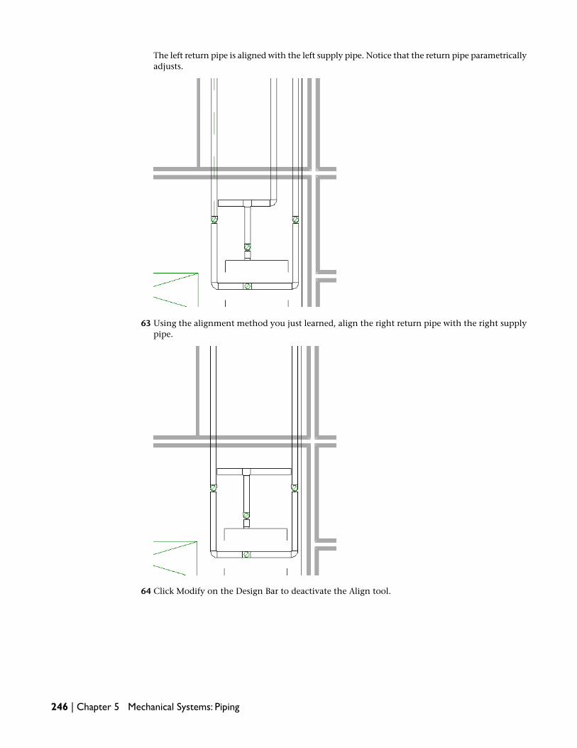
The left return pipe is aligned with the left supply pipe. Notice that the return pipe parametricallyadjusts.
63 Using the alignment method you just learned, align the right return pipe with the right supplypipe.
64 Click Modify on the Design Bar to deactivate the Align tool.
246 | Chapter 5 Mechanical Systems: Piping

The aligned return pipes are as shown. Notice that the return pipe runs also are parametricallyadjusted. This situation results because they are connected to the return boiler connector pipesthat you aligned.
65 Place the cursor below the tee fitting, and press Tab 3 times to check connectivity.
66 Validate the geometry in the 3D Piping view.
Connecting the Boiler | 247

The boiler is physically connected to the radiators and the hydronic piping system is now aclosed loop.
67 If you want to save your work, click File menu ➤ Save.
68 In the Save As dialog, enter Connecting the Boiler Training for File name, navigate to the folderof your choice, and click Save.
In this exercise, connected the boiler to the supply and return pipe runs. You used the Split tool to create 2separate supply and return pipe runs. You then drew pipes that had different offset elevations to connectthe boiler to the supply and return pipe runs. You worked in 2 tiled views enabling you to design and validategeometry simultaneously. It also allowed you to better understand the Auto Connect behavior. Finally, youused the Align tool to align the return pipes to the supply pipes. In the next exercise, you size the supplyand return piping runs.
Sizing the Pipe Runs: Friction & Velocity Methods
You created the level 2 supply and return pipe runs to physically connect the boiler to the radiators. Next,you size the pipe runs using both Friction and Velocity sizing methods.
Dataset
■ Click File menu ➤ Open.
■ In the left pane of the Open dialog, click the Training Files icon.
■ Open the m Pipe Sizing - Friction & Velocity.rvt file located in the Metric ➤ Mechanical folder.
1 In the Project Browser, expand Views (Discipline) ➤ Mechanical ➤ Piping ➤ Floor Plans, anddouble-click 2 - Piping to make it the active view.
2 Place the cursor over the boiler, and after it highlights, press Tab 4 times to highlight both thesupply and return pipe runs including the radiators and the boiler, and click to select them.
248 | Chapter 5 Mechanical Systems: Piping

The selected pipe runs and mechanical equipment display in red.
3 On the Options Bar, click Sizing.
IMPORTANT Remember that the Pipe Sizing dialog displays the sizing settings that were last used.It does not report the sizing settings of the selected pipe segment or pipe run.
4 In the Pipe Sizing dialog, do the following:
■ Under Sizing Method, select Friction, and enter 250.00 Pa/m.
■ Select And, and enter 2.5 m/s for Velocity.
■ Under Constraints, select Match Connector Size for Branch Sizing, and that Restrict Size iscleared.Match Connector Size matches the pipe to the connector size of the mechanical equipmentto which the branch is connected.
■ Click OK.
The sized pipe runs are sized.
IMPORTANT Errors may occur while attempting to create pipe geometry as a result of convertinga layout or during sizing. The most common cause of these errors is that the pipe usually has insufficientspace to be created. Either relocate the system components, select a different layout solution, ormanually modify the pipe. Remember to always check pipe connectivity after modification.
5 Zoom in and confirm the pipe sizing.
Sizing the Pipe Runs: Friction & Velocity Methods | 249

Notice that the branch sizing used the size information from the connector on the fin-tuberadiator and not from the connector on the main pipe. This is because you selected MatchConnector Size for branch sizing.
6 In the Project Browser, expand Views (Discipline) ➤ Mechanical ➤ Piping ➤ 3D Views, anddouble-click 3D Piping to make it the active view.
7 Validate the sized pipe geometry.
8 If you want to save your work, click File menu ➤ Save.
9 In the Save As dialog, enter Pipe Sizing - Friction & Velocity Training for File name, navigate tothe folder of your choice, and click Save.
In this exercise, you sized the supply and return pipe runs using both the Friction and Velocity sizingmethods. You also specified branch sizing that was different than the main pipe sizing. In the next exercise,you place the circulator pumps for the supply pipe runs.
250 | Chapter 5 Mechanical Systems: Piping

Placing Circulator Pumps
In this exercise, you place 2 in-line circulator pumps on the hydronic supply pipe runs that you sized.
Dataset
■ Click File menu ➤ Open.
■ In the left pane of the Open dialog, click the Training Files icon.
■ Open the m Placing Circulator Pumps.rvt file located in the Metric ➤ Mechanical folder.
1 In the Project Browser, expand Views (Discipline) ➤ Mechanical ➤ Piping ➤ 3D Views, anddouble-click 3D Piping to make it the active view.
Tile the views
2 With the 3D Piping view active, click Window menu ➤ Close Hidden Windows.
This closes all windows that you previously opened during the current design session. Note thatif this option is unavailable, the active view is the only open window.
3 In the Project Browser, expand Views (Discipline) ➤ Mechanical ➤ Piping ➤ Floor Plans, anddouble-click 2 - Piping to make it the active view.
4 Enter WT to tile both windows.
TIP When tiling 2 views, the active view is tiled to the left.
5 Adjust the view in both windows to view the boiler and connecting pipes as shown.
You place the pumps in the 2 - Piping view and validate the geometry and rotate the pumps inthe 3D Piping view.
Place in-line circulator pumps
6 In the 2 - Piping view, zoom in on the boiler and the 2 supply pipes to the left and right of theboiler.
7 On the Edit toolbar, click (Split).
8 Watch the listening dimensions, and make 2 splits on the left pipe 160mm from the upper andthe lower elbow fittings as shown.
Placing Circulator Pumps | 251

Notice that a pipe fitting is automatically inserted at each split. You can place your cursor overone and a tooltip and the Status Bar confirm the fitting.
9 Click Modify on the Design Bar to deactivate the Split tool.
10 Click the pipe segment between the 2 splits.
The selected pipe segment displays in red.
11 Press Delete to delete the pipe segment.
Notice that the pipe fittings that were automatically inserted are also deleted.
12 On the Piping tab of the Design Bar, click Mechanical Equipment.
13 In the Type Selector, select M_In-line Circulator : M_Standard.
14 Place the cursor between the pipe openings and click to place the circulator pump.
15 Select the pump and click Rotate on the toolbar.
16 Flip the pump so that the motor is on the left.
17 Click Align on the toolbar and select the middle of the pipe above and the middle of the circulatorconnector.
NOTE You must align the pump correctly in order to connect it to the pipes above and below.
252 | Chapter 5 Mechanical Systems: Piping

18
TIP If you need to reposition the circulator pump, drag the pump away from the pipe, and thenmove it over the pipe opening, and watch for the centerline snaps. You can also use the cursor keysor the Move tool for precise placement.
19 Press ESC twice.
20 In the 3D Piping view, notice that the pump is not located near the selection point.
Actually, the pump is on the selection point but at the default offset elevation. You need tospecify the pump offset.
21 In the 2 - Piping view, click the pump.
The selected pump displays in red.
22 On the Options Bar, click .
You can also right-click the pump, and select Element Properties.
23 In the Element Properties dialog, under Constraints, enter -1500 for Offset.
This is the offset elevation of the horizontal pipe on which you are placing the pump.
TIP To quickly view the pipe offset value, click the pipe segment. The offset appears on the OptionsBar and in the drawing area. You can also open the Element Properties dialog to view the offset.
Placing Circulator Pumps | 253

24 Click OK.
The circulator pump is placed at the same offset as the horizontal pipe segment.
If the pump remains selected, click in the drawing area to clear the selection. Next, you connectthe pump.
TIP Sometimes a selected object remains selected (displays in red) after an action upon it has finished.To clear the selection, you can click in the drawing area, click Modify on the Design Bar, or press ESC.
25 In the 2 - Piping view, click the upper pipe segment to display the connectors.
26 Drag the pipe connector down toward the pump, and after the connector snap displays, releasethe mouse button to connect the pipe to the pump.
Notice that the necessary pipe fittings are automatically inserted. Also notice that the modifiedpipe segment remains selected after connecting to the pump.
27 Press ESC to clear the selection.
254 | Chapter 5 Mechanical Systems: Piping

28 Repeat this method to connect the lower pipe segment to the pump above.
After connecting the pump, you need to check connectivity.
29 Place the cursor over the pump, and press TAB.
The pump and the pipe segments highlight indicating that they are physically connected.
30 Using the methods that you just learned, connect the circulator pump the services the rightside of the supply pipe, and check connectivity.
Make certain that you align the right pump to the left.
Next, you rotate the pumps so that the motor is located as the top.
Placing Circulator Pumps | 255

31 With the 2 - Piping and the 3D Piping views tiled, click in the 3D Piping view to make it active.
32 Adjust the view so that both circulator pumps are in the view.
33 Click the left pump to display rotation controls.
34 Click the rotation control on the right.
256 | Chapter 5 Mechanical Systems: Piping

The pump rotates 90 degrees to the right.
35 Using the method that you just learned, rotate the right pump so that motor is at the top.
The in-line circulator pumps are rotated.
Assign the pumps to the supply system
36 On the Piping tab of the Design Bar, click System Browser.
You can also press F9.
37 In the System Browser, do the following:
■ Expand the Unassigned folder.
■ Expand the Piping folder, right-click Hydronic Supply and click Expand All to view all ofthe system components assigned to Hydronic Supply 1 system.
Notice that the 2 circulator pumps are in the Unassigned folder. As you learned in previousexercises, you must assign all system components (mechanical equipment, and so on) that youplaced to a system. Immediately after placement, Revit MEP associates the unassigned componentswith a default system in order to perform calculations. These unassigned components are located
Placing Circulator Pumps | 257

in the Unassigned folder in the System Browser. After you assign the components to a system,they move to their respective system folder.
You need to assign the 2 circulator pumps to the hydronic supply system.
38 In the 3D Piping view, select the left supply pipe riser.
System tools display on the Options Bar.
TIP You can select any system component or piping that has been assigned to a system to accesssystem tools on the Options Bar.
39 On the Options Bar, click (Edit System).
The Edit System tab appears on the Design Bar providing various system editing tools.
NOTE Do not click . You use this tool to add mechanical equipment that is located upstreamin a system, such as VAV boxes, boilers and AC units. If you use this tool, the boiler will be consideredunassigned and it will move to the Unassigned folder.
40 On the Edit System tab of the Design Bar, click Add To System.
System components that were not assigned for this system are grayed out. Notice that the cursorchanges to indicate that Add To System is active.
41 Click the left and right circulator pumps to add them to the supply hydronic system.
258 | Chapter 5 Mechanical Systems: Piping

Notice that the pumps moved from the Unassigned folder in the System Browser to the HydronicSupply 1 system listing in the Piping folder. This indicates that the pumps have been assignedto the supply hydronic system. They are now logically connected to the boiler and radiators.
42 On the Edit System tab of the Design Bar, click Finish System.
43 If you want to save your work, click File menu ➤ Save.
44 In the Save As dialog, enter Placing Circulator Pumps Training for File name, navigate to thefolder of your choice, and click Save.
In this exercise, you used tiled floor plan and 3D views to place 2 in-line circulator pumps for the hydronicsupply piping system. You used the Split tool to open the pipe segments to accommodate the pumps andthen you connected the pumps. You rotated the pumps in 2 different ways by pressing the Spacebar, andby clicking the rotation controls. Finally, you assigned the circulator pumps to the supply hydronic systemand confirmed the assignments in the System Browser. In the next exercise, you inspect the hydronic pipingsystems for flow and pressure.
Inspecting Piping Systems
In this exercise, you use the System Inspector to inspect the level 2 hydronic piping system. The SystemInspector is a unique tool enabling you to inspect each piping system for flow, pressure, and pressure lossby placing the cursor over a pipe or mechanical equipment that you assigned to the system. Using the SystemInspector, you can immediately target problem areas directly in your design and resolve them.
Dataset
■ Click File menu ➤ Open.
■ In the left pane of the Open dialog, click the Training Files icon.
■ Open the m Inspecting Piping Systems.rvt file located in the Metric ➤ Mechanical folder.
1 In the Project Browser, expand Views (Discipline) ➤ Mechanical ➤ Piping ➤ Floor Plans, anddouble-click 2 - Piping to make it the active view.
2 Right-click in the view, click Zoom in Region from the context menu.
3 Draw a zoom on the boiler in the Mechanical/Electrical room.
You will inspect the hydronic supply system.
4 Select the boiler.
System tools appear on the Options Bar. You select the boiler because you assigned it to thehydronic supply system.
NOTE To select a system, select any pipe segment, fitting, mechanical equipment, and so on thatyou have assigned to a system. System tools display on the Options Bar.
5 On the Options Bar, click (Inspect).
6 In the Select a System dialog, select Hydronic Supply 1, and click OK.
The System Inspector tab opens providing inspection tools on the Design Bar.
IMPORTANT If you select a system component that has been assigned to multiple systems such asa boiler, the Select System dialog opens enabling you to select the system to inspect. You can clicka system in the dialog and the system highlights in red enabling you to preview it.
7 On the System Inspector tab of the Design Bar, click Inspect.
Inspecting Piping Systems | 259

NOTE You can also use System Inspector from within the System Browser. Right-click a system fromthe System Browser, and click Inspect from the context menu. After the System Inspector activates,click Inspect from the System Inspector tab on the Design Bar.
8 Place the cursor over the boiler to inspect system information pertaining to the boiler.
The boiler highlights and an inspection flag dynamically reports the section number, flow, andpressure information including pressure loss. A tooltip also displays this system information.Arrows display on the pipe indicating the flow direction for both the main and the branches inthe pipe system.
IMPORTANT As you inspect a system, remember that all information is color coded according topressure. Red information and arrows indicate the highest percentage of pressure loss due to friction,also known as the critical path.
As you inspect, notice that the assigned system components highlight and can be inspected butyou cannot inspect system components that have not been assigned to the selected system.
Next, you inspect 2 areas of the selected piping system to compare system information.
Compare system information
9 Place the cursor over the left pipe segment above the pump, and click to temporarily place theinspection flag on the segment.
10 Move the cursor over the right pipe segment above the pump to compare the flow and pressureinformation with that of the left pipe segment.
260 | Chapter 5 Mechanical Systems: Piping

11 Click to place the current inspection flag and close the prior one.
12 Move the cursor over one of the circulation pumps, click and compare its information with thatof the right pipe segment.
13 Click in the view to close the current inspection flag.
You can also inspect systems in a 3D view.
14 With the System Inspector activated and the Hydronic Supply 1 system selected, double-clickthe 3D Piping view, and inspect a fin-tube radiator.
Continue to use this method to inspect and compare inspection information for systemcomponents and pipe across the selected Hydronic Supply 1 system. Remember that you canswitch between the floor plan and 3D views without closing the System Inspector.
Inspecting Piping Systems | 261
15 On the System Inspector tab of the Design Bar, click Finish Inspector to deactivate the SystemInspector.
16 Using the methods that you learned, use the System Inspector and inspect the return pipingsystems in the project.
NOTE To use the System Inspector to inspect flow and pressure inside pipe, the selected systemcomponents and pipe must be logically and physically connected. The pipe and the systemcomponents must be connected to a system (logical connection) and a system must contain pipe(physical connection).
17 If you want to save your work, click File menu ➤ Save.
18 In the Save As dialog, enter Inspecting Piping Systems Training for File name, navigate to thefolder of your choice, and click Save.
In this exercise, you used the System Inspector to inspect the flow direction, flow, and pressure informationfor the hydronic supply system in the project. You noticed that flow and pressure information is specific tothe selected system component, and that all system information is color-coded for either the main or thebranch. You also compared system information across a system. In the next exercise, you check the pipingsystems.
Checking Piping Systems
Revit MEP uses both the pipe geometry and the system to perform calculations such as flow and pressure,and for pipe sizing. Because both the logical (system) and physical (pipe) connections play a vital role inthe overall systems design, you need to validate them. In this exercise, you use the Check Pipe Systems toolto immediately check these connections for all systems throughout your project, and quickly target thosesystems that need attention.
Dataset
■ Click File menu ➤ Open.
■ In the left pane of the Open dialog, click the Training Files icon.
■ Open the m Checking Piping Systems.rvt file located in the Metric ➤ Mechanical folder.
Perform a systems check
1 In the Project Browser, expand Views (Discipline) ➤ Mechanical ➤ Piping ➤ Floor Plans,double-click the 2 - Piping to make it the active view.
2 On the Piping tab of the Design Bar, click Check Pipe Systems.
Revit MEP checks both the logical (system) and the physical (pipe) connections of each pipingsystem throughout the project. A warning appears, but does apply to the piping system. Thepiping system is logically and physically valid.
However, check system warnings may occur. As a tutorial exercise, you check the air systems toview check systems warnings.
NOTE If the Piping tab is not available on the Design Bar, right-click the Design Bar, and click Piping.
3 On the Mechanical tab of the Design Bar, click Check Duct Systems.
Warnings display. Notice that these warnings indicate that the default systems are “not empty.”
262 | Chapter 5 Mechanical Systems: Piping

4 NOTE The check systems warnings contain a system type and a description. These warnings canrefer to both physical connection issues (such as a disconnected or problematic pipe) or logicalconnection issues (such as an improperly assigned system). Remember that after you create pipe tophysically connect a system, the pipe is now associated with that system. Pipe geometry is used forsystem flow and pressure calculations, and for pipe sizing. Note that only physical connectionsassociated with an assigned system are checked. Pipe that is associated with a default system (locatedin the Unassigned folder) is not checked.
IMPORTANT The most common check systems warning is the “default system is not empty” warning.As you learned when placing fin-tube radiators, all system components must be assigned to a systemimmediately after placement. If you place radiators without assigning them to a system, Revit MEPcreates a default system and assigns them to it in order to perform system calculations. The defaultsystem is placed in the Unassigned folder until you select the system components and create a systemfor them, thus assigning the components to a system. After you assign the system components to asystem, Revit MEP places them in their assigned systems folder and removes them from the Unassignedfolder. After you have assigned all system components for the project to their systems, the Unassignedfolder will be empty and Check Pipe Systems will no longer display “not empty” warnings. Note thata system component may be listed in both its assigned system and in the Unassigned folder. Thisoccurs because the assigned system component can be connected to multiple systems (it containsdifferent system connectors), and you have not yet assigned the component to the other systems.For example, you assigned a fin-tube radiator to a supply hydronic system but the same radiator hasa return system connector that you have not assigned to a system. In the System Browser, the fin-tuberadiator is listed in the assigned system and assigned to the Default Hydronic Return system in theUnassigned folder.
Next, you open the System Browser to view the unassigned air system components and theassociated default air systems. Then, you confirm the validity of the assigned piping systemcomponents and systems. Next, you confirm the system component assignments.
Use the System Browser to confirm piping system assignments
5 Click Window menu ➤ System Browser to open the System Browser.
TIP You can press F9 (or Window menu ➤ System Browser) to open or close the System Browser. Ifthe System Browser does not respond, click in the drawing area to make it active, then press F9.
Because you assigned all piping components, you will check the unassigned air systemcomponents to learn how to use the System Browser to confirm default system assignments.
6 In the Project Browser, expand Views (Discipline) ➤ Mechanical ➤ HVAC ➤ Floor Plans,double-click 2 - Mech to make it the active view.
7 Expand the Unassigned folder and notice that both Default Return Air and Default Exhaust Airsystems are listed.
8 Expand Default Return Air and notice the air terminals and mechanical equipment that wereautomatically assigned to the Default Return Air system.
9 Right-click Default Return Air, and click Show to view all of the unassigned system components.
Checking Piping Systems | 263

The red lines represent the default logical connection. A dialog lets you click Show multipletimes for different views.
TIP If you have multiple views open, you can click Show in the Show Element(s) In View dialog toswitch between views, otherwise, click Close.
10 Using the same methods, confirm the unassigned system components in the Default ExhaustAir system.
Now that you confirmed all of the unassigned component for the default air systems, youconfirm the piping system assignments.
11 Click Window menu ➤ Floor Plan: 2 - Piping to make it the active view.
12 In the System Browser, collapse the Unassigned folder and expand the Piping folder.
13 Right-click Hydronic Supply, and click Expand All.
The supply system that you created, Hydronic Supply 1 is listed along with the boiler, fin-tuberadiators and the circulator pumps that you assigned to this system. Notice that the systemcontains a system type and an assigned number.
264 | Chapter 5 Mechanical Systems: Piping

14 Right-click Hydronic Supply 1, and click Select to confirm this system and the assigned systemcomponents.
15 Using the methods that you learned, confirm the system and the system assignments for thehydronic return system.
You have confirmed and validated both unassigned and assigned system components and theirsystems.
16 If you want to save your work, click File menu ➤ Save.
17 In the Save As dialog, enter Checking Piping Systems Training for File name, navigate to thefolder of your choice, and click Save.
In this exercise, you used the Check Pipe Systems tool and the System Browser to validate the level 2 supplyand return hydronic piping systems that you created. You also confirmed that the air terminals and mechanicalequipment for the return and exhaust air systems were unassigned as they were located in their respectivedefault systems in the System Browser and “not empty” warnings were generated by Check Duct Systems.Depending on your air systems design, you may need to assign these system components to their propersystems. The piping system that you designed did not return any check system warnings; it is a valid systemwithout problems. You have completed the level 2 piping systems for the building. To view the completedmechanical systems for the tutorial including the level 2 hydronic piping system, open the m CompletedMechanical Systems.rvt file located in the Metric ➤ Mechanical folder under Training Files.
For additional practice, use the methods that you learned and create the level 1 hydronic piping system.Design the system in the 1 - Piping view and filter the visibility of objects as needed. Use the same pipingsystem components that you used for level 2. For pipe offset, specify 2975mm for the supply and 2825mmfor the return pipe offset elevation.
In the lesson, you created a hydronic piping system consisting of a supply and return pipe runs, circulatorpumps, a boiler, and fin-tube radiators. You validated rigid pipe connections and geometry using floor plan,3D, and section views. You inspected the logical systems using System Inspector and the System Browser.Finally, you checked the logical and physical connections for the system using Check Pipe Systems. Thiscompletes the Designing Piping Systems lesson.
In this tutorial, you created a supply air system and a hydronic piping system, Each was a completely differentmechanical system that consisted of different system components however, the creation and modificationmethods remained the same. You also learned the difference between creating rigid physical duct or pipe
Checking Piping Systems | 265

connections and creating logical systems. The completed mechanical systems are included in the m CompletedMechanical Systems.rvt file located in the Metric ➤ Mechanical folder under Training Files. Feel free tomodify the systems or create entirely new mechanical systems. Explore different system designs, parametricallymodify those designs, and see the results dynamically in views and design documents. This is the powerBIM (Building Information Modeling). This is the future of systems designing—Revit MEP 2009.
266 | Chapter 5 Mechanical Systems: Piping

Electrical Systems
In this tutorial, you learn to create electrical systems using a linked architectural model of a building project. The buildingcontains a variety of spaces where you will design lighting and power systems. The first lesson consists of exercises thatprepare your project for the types of systems that you will design in the following lesson.
NOTE The architectural model used with this tutorial is in the Architectural folder. You should maintain the relativepath to the architectural model. However, if the link is lost, you can click File menu ➤ Manage Links to reload thelinked model. On the Revit tab on the Manage Links dialog, click Reload From, navigate to TrainingFiles ➤ Metric ➤ Electrical ➤ Metric_Arch_Model, and select m Office Building.rvt.
The datasets that you use to complete these exercises are located in the Training Files directory. You can search the TrainingFiles ➤ Metric directory to verify that the datasets have been downloaded. If the tutorial datasets are not present, go tohttp://www.autodesk.com/revitmep-documentation and download them.
NOTE All exercises in this tutorial are designed to be completed sequentially; each exercise is dependent on thecompletion of the previous exercise. After finishing each exercise, you can choose to save your work. However, it ishighly recommended that you always begin an exercise by opening the dataset that Autodesk provides. This datasetincludes the work from the previous exercise(s) and ensures a seamless training session.
Planning Electrical Systems
The most common method of designing systems in Revit MEP is to work within a linked architecturalbuilding model. In this tutorial, you will use a project file that has already been linked to an architecturalmodel, with Space components placed in the areas throughout the model. To learn more about linking andpreparing an architectural model, see Planning Mechanical Systems in the Mechanical Systems tutorial.
In this lesson you specify electrical settings, load the families containing the electrical components that willmake up your electrical system, and create schedules that you will need to design the electrical systems foryour project.
Preparing the Electrical Plan
In this exercise you define the basic parameters for your electrical system, and select the component familiesthat you will use in the plan.
6
267

The electrical settings determine the voltages, wiring, distribution systems, and demand factors that areapplied in the design.
Lighting, power, and ceiling plans for each have been prepared by duplicating architectural views, thenapplying the appropriate template to each plan:
■ Power plans where you will place electrical devices and equipment and design power circuits.
■ Electrical Ceiling Plans where you will place lighting fixtures.
■ Lighting Plans where you will design lighting circuits.
Revit MEP provides families of common electrical components that you place in your power and lightingplans. You load the families that comprise the specific components that will be used in your electrical system.As you develop more advanced skills working with Revit MEP, you can customize components and expandthe library of electrical families.
All of Revit MEP’s electrical (and mechanical) components are designed with connectors. Connectors allowRevit MEP to maintain information about the systems that you create, and make it possible for Revit MEPto perform calculations to assist you with your design. It is important that the connectors associated withcomponents that you place in a view are within the View Range or level offset. For example, the connectorsfor the ceiling-hosted lighting fixtures that you will place in spaces are above the ceiling level. For this reason,the Limit Offset, in the Element Properties dialog for Spaces, has been set to 2300 mm for the building usedwith these exercises. This allows the illuminance of the lighting fixtures to be considered when calculatingrequired lighting levels.
Dataset:
■ Click File menu ➤ Open.
■ In the left pane of the Open dialog, click the Training Files icon.
■ Open Metric ➤ Electrical ➤ m Creating Electrical Views.rvt.
Specify Electrical Settings
1 Electrical settings let you specify the voltages, power distribution systems, wiring, and demandfactors that you will use in your project. Later, as you place components and create circuits inyour electrical plan, Revit MEP checks to assure that those components are compatible withvoltages and distribution systems that you specify here.
Click Settings menu ➤ Electrical Settings.
2 In the Electrical Settings dialog, in the left pane, expand Wiring.
3 Click Wiring Types, and in the right pane, click Add (below the table).
4 Specify the following parameters for this wire type as follows:
ValueParameter
CU-THWNName
CopperMaterial
75Temperature Rating
THWNInsulation
500Max Size
268 | Chapter 6 Electrical Systems
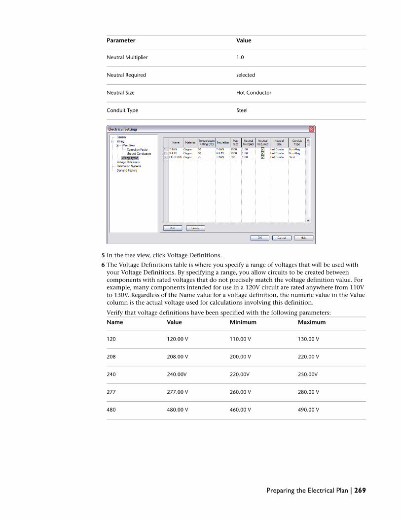
ValueParameter
1.0Neutral Multiplier
selectedNeutral Required
Hot ConductorNeutral Size
SteelConduit Type
5 In the tree view, click Voltage Definitions.
6 The Voltage Definitions table is where you specify a range of voltages that will be used withyour Voltage Definitions. By specifying a range, you allow circuits to be created betweencomponents with rated voltages that do not precisely match the voltage definition value. Forexample, many components intended for use in a 120V circuit are rated anywhere from 110Vto 130V. Regardless of the Name value for a voltage definition, the numeric value in the Valuecolumn is the actual voltage used for calculations involving this definition.
Verify that voltage definitions have been specified with the following parameters:
MaximumMinimumValueName
130.00 V110.00 V120.00 V120
220.00 V200.00 V208.00 V208
250.00V220.00V240.00V240
280.00 V260.00 V277.00 V277
490.00 V460.00 V480.00 V480
Preparing the Electrical Plan | 269

Voltage definitions can be deleted only if they are not currently in use with any distributionsystem.
NOTE Revit MEP does not prevent specifying unfeasible voltage values. For example, you couldspecify a distribution system with a L-L Voltage value of 120 and an L-G Voltage value of 480, eventhough this is physically impossible.
7 In left pane of the Electrical Settings dialog, click Distribution Systems.
8 In the right pane, verify that distribution systems have been specified with the followingparameters:
L-GL-LWiresConfigurationPhaseName
1202084WyeThree120/208 Wye
1202403NoneSingle120/240 Single
2774804WyeThree480/277 Wye
Distribution systems can be deleted only if they are not currently assigned to any devices.
270 | Chapter 6 Electrical Systems

NOTE Although it is possible to specify a distribution system with a Configuration value of Delta anda Wire value of 4, this type of system (High, Red, or Wild leg) is currently not supported in Revit MEPbecause there is no way to specify the high leg voltage.
9 Click Demand Factors.
Demand factors let you adjust the rating of the main service for a building based on theexpectation that, at any given time, only a portion of the electrical equipment will be drawingat its full rated load. You can specify one or more Demand Factors, applying different DemandFactors to Lighting, Power, HVAC, or Other systems in your project based on their load. Theparticular system for which Demand Factors are applied is selected from the Load Classificationdrop-down list.
More Than and Less Than values define the range for the associated Demand Factor:
■ More Than specifies the lower limit of a range of loads.
■ Less Than specifies the upper limit of a range of loads.
■ Demand Factor (%) specifies the anticipated a percentage of full rated load that will exist atany given time for the specified range.
You can Split the default range to create several load ranges for a particular system and apply adifferent demand factor to each range. For example, you can specify the following parametersfor a building lighting system:
Demand FactorLess ThanMore Than
100%3,000VA
50%10,000VA3,000VA
30%10,000VA
The settings in this example apply a 100% demand factor to loads less than 3000VA, a 50%demand factor to loads between 3000VA and 10,000VA, and a 30% demand factor for loadsgreater than 10,000VA.
For this exercise, leave the default settings as shown here.
10 Click OK.
Preparing the Electrical Plan | 271
Load component families
11 NOTE The components used throughout this tutorial have been copied from the Metric Library tothe m families sub-folder. As an alternative, you can load from the components from that location.
Click File menu ➤ Load from Library ➤ Load Family.
12 In the Open dialog, expand Electrical Components ➤ Lighting Devices.
13 Select M_Lighting Switches.rfa, and click Open.
14 Using the same method, reopen Electrical Components ➤ Power Devices, and load M_DuplexReceptacle.rfa.
15 Click Open.
16 In the Project Browser, expand Families.
An Electrical Fixtures ➤ M_Receptacle folder containing receptacles has been added to thefamilies currently available for your design. A Lighting Devices ➤ M_Lighting Switches folder,containing several switch types, has also been added under Lighting Device.
17 Using the same method, reopen Electrical Components ➤ Electrical Equipment ➤ Panelboardfolder, and load the following families:
■ M_Lighting and Appliance Panelboard - 480V MCB - Surface.rfa
■ M_Lighting and Appliance Panelboard - 208V MLO - Surface.rfa
18 Using the same method, reopen Electrical Components ➤ Electrical Equipment ➤ Transformerfolder, and load M_Dry Type Transformer - 480-208Y120 - NEMA Type 2.rfa.
19 Open the Electrical Components ➤ Lighting Fixtures folder and load the M_Troffer CornerInsert.rfa family.
As you loaded each of the component families, they were added to the Families in the ProjectBrowser.
20 You can save the open file if you wish; a new dataset is supplied in the next exercise.
21 Click File menu ➤ Close.
NOTE Do not overwrite the original dataset.
22 Proceed to the next exercise, Defining Required Lighting Levels on page 272.
In this exercise, you prepared views specifically for your power and lighting plans, selected components foryour electrical systems, and established the parameters for your wiring, voltages, distribution systems, anddemand factors.
Defining Required Lighting Levels
In this exercise you specify the lighting levels that are required for the different spaces within the building.Particular lighting levels are generally specified for different types of spaces (offices, restrooms, conferencerooms, and so on). You begin by adding a new Project Parameter (Required Lighting Level), then you createa Key Schedule that links your new parameter to the various types of spaces in your project. Key schedulesprovide an efficient way to create an instance parameter that can be used to map specific parameter valuesto particular key styles. In this case the key style is the type of space and, because the key is linked to yournew project parameter, its value becomes to the Required Lighting Level.
Later, in the Creating a Space Schedule to Check Required Lighting Levels exercise, you will use the newparameter again to compare the value for Required Lighting Level against the actual illumination providedby fixtures that you place in the plan.
272 | Chapter 6 Electrical Systems

Open the provided dataset, as described below.
Dataset:
■ Click File menu ➤ Open.
■ In the left pane of the Open dialog, click the Training Files icon.
■ Open Metric ➤ Electrical ➤ m Defining Lighting Levels.rvt.
Before you can specify a lighting requirement for the spaces within your project, you must first create aparameter that will hold the value for the lighting requirement.
Create a Required Lighting Level parameter
1 Click Settings menu ➤ Project Parameters.
2 In the Project Parameters dialog, click Add.
3 In the Parameter Properties dialog:
■ Verify that Project parameter is selected for Parameter Type.
■ Under Parameter Data, enter Required Lighting Level for Name.
■ For Discipline, select Electrical.
■ For Type, select Illuminance.
■ For Group, select Electrical-Lighting.
■ Select Instance.
■ Under Categories, select Spaces.
4 Click OK twice.
The new Required Lighting Level parameter is added to the list in the Project Parameters dialogand is now an instance parameter for Spaces under Electrical - Lighting in the Space ElementProperties dialog.
The new parameter you have just created applies to all spaces in the project. To verify this, youcan look at the properties for one of the spaces.
Verify the new parameter
5 In the Project Browser, expand Views (Discipline) ➤ Electrical ➤ Lighting ➤ Floor Plans,double-click 1 - Lighting to make it the active view.
6 Zoom in on the upper-left corner of the plan, move the cursor over the office in the upper-leftcorner, and when the cross-hairs display, click to select the space.
Defining Required Lighting Levels | 273

7 On the Options Bar, click (Properties).
In the Element Properties dialog, your new Required Lighting Level parameter is now listedunder Instance Parameters in the Electrical - Lighting category.
You could use your new parameter to enter a Required Lighting Level value in the ElementProperties dialog for each space. However, there are many spaces in this project that have similarlighting requirements, and it is more efficient to create a key schedule and use it to assignRequired Lighting Level values based on space type.
8 Click Cancel.
Create a key schedule
9 Click View menu ➤ New ➤ Schedule/Quantities.
10 In the New Schedule dialog:
■ Select Spaces for Category.
■ For Name, enter Space Lighting Requirements.This name will appear as the title for the resulting schedule.
■ Click Schedule keys.
■ For Key Name, enter Lighting Levels.Lighting Levels is added as a new instance parameter for the space component. The valuethat you specify for each Key Name in the schedule will be used to determine the requiredlighting level for each space type.
■ Click OK.
The Shedule Properties dialog displays.
NOTE Schedules can be used as a design interface (Key schedule) as well as a documentation tool(Schedule building components). You determine the type of schedule by clicking Schedule buildingcomponents or Schedule keys in the New Schedule dialog when creating a new Schedule/Quantitiesview.
11 On the Fields tab of the Schedule Properties dialog, select Required Lighting Level from theAvailable fields list, and click Add to add this field to the Scheduled fields (in order) list.
12 Click OK.
The key schedule displays in the drawing area.
13 Drag column borders horizontally to the desired column width.
NOTE You can double-click column dividers to auto-fit column width to its content.
Enter lighting level requirements in the key schedule
14 On the Options Bar, click New 8 times to add 8 rows in the key schedule, one for each type ofspace in the building.
The new rows are added with 1 through 8 as the default Key Names.
274 | Chapter 6 Electrical Systems

Enter a space type in the Key Name column and a corresponding lighting level in the RequiredLighting Level column for the different types of spaces in the project, according to the valuesin the following table:
Required Lighting Level (lx)Space Type
325Private Office
485Open Office
485Main Entrance
270Lounge
325Restroom
375Conference
215Elec/Mech
225Stair/Circulation
When completed, the Key Schedule should looks like this:
TIP Your entries are automatically sorted alphabetically by Key Name. You can change the sort keysfor the schedule. In the Project Browser, right-click in the Space Lighting Requirements schedule,click View Properties and, in the Element Properties dialog, under Instance Parameters edit theSort/Grouping parameter.
Assign space keys to the spaces in the project
15 In the Project Browser, expand Views (Discipline) ➤ Electrical ➤ Lighting ➤ Floor Plans,double-click the 1 - Lighting floor plan to make it the active view.
16 Zoom in on the large open area (not the main entrance) in the center of the floor plan.
17 Move the cursor over the space until a cross-hair displays, then right-click, and click ElementProperties.
18 In the Element Properties dialog, under Instance Parameters, scroll down to the Identity Data
category, and for Lighting Levels parameter, click , and select Open Office.
19 Scroll up to the Electrical - Lighting category, and notice that the value for Required LightingLevel is now 485 lx, the value that you entered for this space type in the key schedule. The value
Defining Required Lighting Levels | 275

is grayed out and cannot be edited because you associated this parameter with the Key Namespecified by the Space Lighting Requirements key schedule.
20 Click OK.
21 Using the same method, continue applying Lighting Level keys to the remaining spaces in1 - Lighting, then open 2 - Lighting and apply Lighting Level keys to the remaining spaces inthe project according to the following table:
TIP You can select multiple spaces of the same type and set the Lighting Level parameter from thesame Element Properties dialog. While pressing Ctrl, select multiple spaces of the same type (forexample, Office), then right-click one of the selections, and click Element Properties to open theElement Properties for the selected spaces.
Key NameNameNumberLevel
Private OfficeOffice 1011011 - Lighting
Private OfficeOffice 1021021 - Lighting
Private OfficeOffice 1031031 - Lighting
Private OfficeOpen 1041041 - Lighting
RestroomMens Room 1051051 - Lighting
Mech/ElecElec/Mech 1061061 - Lighting
RestroomLadies Room 1071071 - Lighting
Private OfficeOffice 1081081 - Lighting
Private OfficeOffice 1091091 - Lighting
Private OfficeOffice 1101101 - Lighting
Private OfficeOffice 1111111 - Lighting
Private OfficeOffice 1121121 - Lighting
Private OfficeOffice 1131131 - Lighting
Stair/CirculationStairwell 1141141 - Lighting
Private OfficeOffice 1151151 - Lighting
Private OfficeOffice 1161161 - Lighting
Private OfficeOffice 1171171 - Lighting
Main EntranceMain Entrance 1211211 - Lighting
276 | Chapter 6 Electrical Systems

Key NameNameNumberLevel
Private OfficeOffice 2012012 - Lighting
Private OfficeOffice 2022022 - Lighting
Private OfficeOffice 2032032 - Lighting
Private OfficeOpen 2042042 - Lighting
RestroomMens Room 2052052 - Lighting
Mech/ElecElec/Mech 2062062 - Lighting
RestroomLadies Room 2072072 - Lighting
LoungeLounge 2082082 - Lighting
Private OfficeOffice 2092092 - Lighting
Private OfficeOffice 2102102 - Lighting
Private OfficeOffice 2112112 - Lighting
Private OfficeOffice 2122122 - Lighting
Stair/CirculationStairwell 2132132 - Lighting
ConferenceConference Room 2142142 - Lighting
Private OfficeOffice 2152152 - Lighting
Private OfficeOffice 2162162 - Lighting
22 You can save the open file if you wish; a new dataset is supplied in the next exercise.
23 Click File menu ➤ Close.
NOTE Do not overwrite the original dataset.
24 Proceed to the next exercise, Assigning Space Color Fills According to Required Lighting Levelson page 278.
In this exercise you created a new project parameter and used it in a key schedule to specify a parametervalue (Required Lighting Level) for the spaces in your project. You can use a key schedule to specify morethan one parameter for a component, if required. For example, you could create a key schedule named SpaceVariables, and select both Required Lighting Level and Temperature as parameters. Now the key schedulewill have one column for Required Lighting Level and another for Temperature where you can specify valuesaccording to space type. Consequently, selecting a space type for your new Space Variables parameter in aspace’s Element Properties dialog will specify values for both parameters according to the key schedule.
Defining Required Lighting Levels | 277

Assigning Space Color Fills According to Required Lighting Levels
Revit MEP lets you add color fills to spaces based on specific space parameters. Space color fills can be helpfulas a design tool and as a design communications document. In this exercise you will create a space color fillusing the lighting levels that you specified in the previous exercise. Space color fills can be used with anyparameter that exists on the space components.
Open the provided dataset, as described below.
Dataset:
■ Click File menu ➤ Open.
■ In the left pane of the Open dialog, click the Training Files icon.
■ Open Metric ➤ Electrical ➤ m Space Color Fills.rvt.
Activate color fill
1 In the Project Browser, expand Views (Discipline) ➤ Electrical ➤ Lighting ➤ Floor Plans,double-click the 1 - Lighting floor plan to make it the active view.
2 Click Settings menu ➤ Color Fill Schemes.
3 In the Edit Color Scheme dialog, select Spaces for Category, and click (Duplicate).
4 In the New Color Scheme dialog, for Name, enter Required Lighting, and click OK.
5 In the Edit Color Scheme dialog, for Title, enter Required Lighting Levels.
6 For Color, select Required Lighting Level, and click OK to dismiss the alert message.
7 Click OK.
8 On the Drafting tab on the Design Bar, click Color Scheme Legend, and place it in the drawing.
9 In the Choose Color Scheme dialog:
■ For Space Type, select Spaces,
■ For Color Scheme, select Required Lighting
10 Click OK.
11 Right-click the color scheme legend, and click Element Properties.
12 In the Element Properties dialog, click Edit/New.
13 In the Type Properties dialog, specify the following Type Parameters:
■ Under Graphics, select Show Title.
■ Under Title Text, select Underline.
14 Click OK twice.
15 Drag the color scheme legend preview to the lower-left corner of the plan.
The color scheme for the Level 1 floor plan should now look something like the image below.
278 | Chapter 6 Electrical Systems

16 Make the 2 - Lighting floor plan the active view.
17 Using the same method, activate the color scheme as you did for 1 - Lighting.
Notice that the color scheme you created is still in effect. This is because the color scheme is atype within the project. You can have more than one color scheme in the project, but only oneper view.
18 You can save the open file if you wish; a new dataset is supplied in the next exercise.
19 Click File menu ➤ Close.
NOTE Do not overwrite the original dataset.
20 Proceed to the next exercise, Creating a Space Schedule to Check Required Lighting Levels onpage 279.
Color fill plans can be useful as design documents and as communication documents to show other teammembers design intent while the project is in the design phases. Color fills can be applied for any parameterthat already exists for spaces, or for any parameter that you want to create for a space (such as the RequiredLighting Level parameter you created in the previous exercise).
Creating a Space Schedule to Check Required Lighting Levels
In this exercise you create a space lighting analysis schedule that you will use as a check document ratherthan as a construction document. Your schedule will compare the actual lighting levels in each space againstthe required lighting levels that you specified in the Defining Required Lighting Levels exercise. As you placelighting fixtures in the spaces in your project, you will refer to the schedule to assure that the lighting levelfalls within the +/- 55 lx range specified in the schedule.
Creating a Space Schedule to Check Required Lighting Levels | 279

Open the provided dataset, as described below.
Dataset:
■ Click File menu ➤ Open.
■ In the left pane of the Open dialog, click the Training Files icon.
■ Open Metric ➤ Electrical ➤ m Space Schedule Lighting Requirements.rvt.
Create space lighting analysis schedule
1 Click View menu ➤ New ➤ Schedule/Quantities.
2 In the New Schedule dialog:
■ Under Category, select Spaces.
■ For Name, enter Space Lighting Analysis
■ Verify that Schedule building components is selected.
■ Click OK.
3 On the Fields tab of the Schedule Properties dialog, scroll down the Available fields list,double-click the following fields to add them to the Scheduled fields (in order) list:
■ Number
■ Name
■ Required Lighting Level
■ Average Estimated Illumination
■ Ceiling Reflectance
■ Wall Reflectance
■ Floor Reflectance
■ Lighting Calculation Workplane
Create a new schedule parameter
4 In the middle of the Schedule Properties dialog, click Calculated Value.
5 In the Calculated Value dialog:
■ For Name, enter Lighting Delta.
■ For Discipline, select Electrical.
■ For Type, select Illuminance.
■ For Formula, enter Average Estimated Illumination - Required Lighting Level.
NOTE Formulas are case sensitive
6 Click OK.
The Lighting Delta parameter is added to the Scheduled fields list.
7 On the Sorting/Grouping tab:
■ For Sort by, select Number.
■ Verify that Ascending is selected.
280 | Chapter 6 Electrical Systems

■ Verify that Itemize every instance is selected.
8 On the Formatting tab, under fields, select Lighting Delta.
9 Click Conditional Format.
10 In the Conditional Formatting dialog:
■ For Field, select Lighting Delta.
■ For Test, select Not Between.
■ For Value, enter -55 lx and 55 lx in the text boxes.
11 Click the Background Color chip.
12 In the Color dialog, under Basic colors, click the red color chip.
13 Click OK twice.
14 On the Formatting tab, under Fields, select Ceiling Reflectance, and click Field Format.
15 In the Format dialog:
■ Clear Use default settings.
■ For Units, verify that Fixed is selected.
■ For Rounding, select 2 decimal places.
16 Click OK.
17 Using the same method, specify rounding to 2 decimal places for the Wall Reflectance and FloorReflectance fields.
18 Click OK.
19 You can save the open file if you wish; a new dataset is supplied in the next exercise.
20 Click File menu ➤ Close.
Creating a Space Schedule to Check Required Lighting Levels | 281

NOTE Do not overwrite the original dataset.
21 Proceed to the next lesson, Designing the Electrical System on page 282.
The schedule that you have just created shows the Average Estimated Illumination level for all of the spacesas 0. This is because you have not yet added lighting fixtures to any of the spaces. You can also see that theLighting Delta has been calculated for each of the occupied spaces, and in every case the Lighting Delta fieldis red. This is because the value is not within the range that you specified in the Conditional Formattingdialog.
NOTE Space components are placed in chases and plenums to permit reliable heating and cooling load analysis.As a result, these spaces appear in the Space Lighting Analysis schedule. However, there is no required lightinglevel specified, and these areas will not be lighted.
In this exercise, you created a schedule that you will refer to as you add lighting fixtures to the project. Theschedule will be used to check the actual design against the design requirements that were specified in aprevious exercise. This type of schedule can be useful as a method for checking design components in theproject.
Designing the Electrical System
In this lesson you use the views and schedules that you created in Lesson 1 to place electrical devices, electricalequipment, and lighting fixtures throughout your building project. Once the equipment is in place, youwill create power and lighting circuits, and make connections to electrical equipment.
Adding Lighting Fixtures
In this exercise you add lighting fixtures throughout your project. As you select and place lighting fixtures,the key schedule that you created in the previous lesson serves as a tool to verify that the design meets eachspace’s lighting requirement.
Open the provided dataset, as described below.
Dataset:
■ Click File menu ➤ Open.
■ In the left pane of the Open dialog, click the Training Files icon.
■ Open Metric ➤ Electrical ➤ m Adding Lighting Fixtures.rvt.
Place the initial lighting fixture
1 In the Project Browser, expand Schedules/Quantities, and double-click Space Lighting Analysisto open the schedule created in the previous lesson.
2 Right click in the Required Lighting Level column, and click Hide Column(s) to hide that column.
3 Repeat the previous step to hide the Ceiling Reflectance, Wall Reflectance, Floor Reflectance,and Lighting Calculation Workplane columns.
Only the Number, Name, Average Estimated Lighting, and Lighting Delta columns shouldremain visible in the schedule.
NOTE Right-click a heading, and click Unhide All Columns to restore the hidden columns.
4 On the Windows menu, click Close Hidden Windows.
282 | Chapter 6 Electrical Systems

5 Resize the view containing the schedule to show only the 4 remaining columns.
6 In the Project Browser, under Electrical ➤ Lighting ➤ Ceiling Plans, double-click 1 - Ceiling Electo make it the active view.
You need to add lighting fixtures in a ceiling plan because you want to align the lighting fixturesto the ceiling grid, and the ceiling grid is not visible in a floor plan view.
7 On the Windows menu, click Tile, and arrange the windows as shown.
8 In the 1 - Ceiling Elec view, zoom in to the upper-left corner of the plan.
9 On the Electrical tab on the Design Bar, click Lighting Fixture.
10 In the Type Selector, select M_Troffer Corner Insert : M_600x1200 3 Lamp, and move the cursorinto the ceiling plan view.
NOTE A preview of the lighting fixture is not displayed until you move the cursor over a ceiling. Youcannot place this type of lighting fixture in a non-ceiling location.
11 With the cursor in the space in the upper-left corner of the plan, click to place the lightingfixture in the ceiling as shown.
It is not necessary to align the lighting fixture to the grid in this step. In the next step you willuse the Move command to snap the fixture to a ceiling grid intersection.
Adding Lighting Fixtures | 283

12 Click Modify.
13 Zoom in on the lighting fixture, select it, and on the Toolbar, click (Move).
14 Move the cursor over the lower-left corner of the lighting fixture, and when Endpoint displays,click to specify the start point.
15 Move the cursor over an intersection of the ceiling grid lines where you want to place the fixture,and click when Intersection displays.
284 | Chapter 6 Electrical Systems

In the Space Lighting Analysis schedule, the Lighting Delta for Office 101 is closer to the required+/- 55 lx.
Copy and place additional lighting fixtures
16 Select the lighting fixture, and on the toolbar, click (Copy).
17 On the Options Bar, select Multiple.
This will let you place multiple copies of the lighting fixture after selecting a start point.
18 Select the lower-left Endpoint of the lighting fixture as the start point, and then select ceilinggrid intersections as the destination move endpoints to place 5 copies of this fixture in the 3offices in the upper left area of level 1, as shown.
Adding Lighting Fixtures | 285

Check the illumination levels against the Space Lighting Analysis schedule
19 Check the Average Estimated Illumination and Lighting Delta in the Space Lighting Analysisschedule.
The Average Estimated Illumination for Office 101, 102, and 103 is now nearer the requiredlighting level target of 325 lx, but is still not within the +/- 55 lx range, so the Lighting Deltacolumn remains red for these spaces.
To adjust the illumination level downward, you decide to replace one of the 3-lamp fixtures ineach space with a 2-lamp fixture.
NOTE Average Estimated Illumination levels are calculated using the lumen method for lightingcalculations. Point by point analysis is not currently supported.
Change lighting fixture type
20 In 1 - Ceiling Elec, select one of the lighting fixtures in each space, and in the Type Selector,select M_Troffer Corner Insert : M_600x1200 2Lamp.
TIP You can select multiple components by pressing Ctrl while selecting components in a drawing.If you select a component inadvertently, press Shift while clicking the component to remove it as aselection.
21 Again, check the Average Estimated Illumination and Lighting Delta in the Space LightingAnalysis schedule, and verify that the lighting levels are now within the specified range.
The Average Estimated Illumination is now within the +/- 55 lx range.
You can perform the following steps to complete this exercise, placing lighting fixtures in the remainingLevel 1 and Level 2 spaces or you can close this dataset, and go on to the next exercise. The lighting fixturesare all placed in the next dataset.
22 Using the same method, continue placing 2-lamp and 3-lamp lighting fixtures in the remainingspaces in the 1 - Ceiling Elec and 2 - Ceiling Elec views. Use the Space Lighting Analysis scheduleto determine when the lighting levels are within the specified range.
When you are finished, only the Mechanical/Electrical spaces (without ceilings) will have a redbackground in the Space Lighting Analysis schedule. Plenum and chase spaces will be blank.Completed lighting layouts for Level 1 and Level 2 should appear similar to those shown belowalong with the Space Lighting Analysis schedule.
286 | Chapter 6 Electrical Systems

Level 1
NOTE Lighting fixtures were not added to the Mechanical/Electrical spaces.
Level 2
Adding Lighting Fixtures | 287
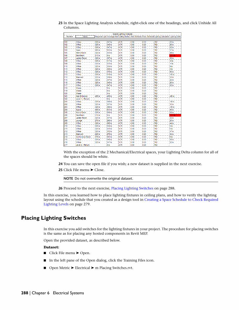
23 In the Space Lighting Analysis schedule, right-click one of the headings, and click Unhide AllColumns.
With the exception of the 2 Mechanical/Electrical spaces, your Lighting Delta column for all ofthe spaces should be white.
24 You can save the open file if you wish; a new dataset is supplied in the next exercise.
25 Click File menu ➤ Close.
NOTE Do not overwrite the original dataset.
26 Proceed to the next exercise, Placing Lighting Switches on page 288.
In this exercise, you learned how to place lighting fixtures in ceiling plans, and how to verify the lightinglayout using the schedule that you created as a design tool in Creating a Space Schedule to Check RequiredLighting Levels on page 279.
Placing Lighting Switches
In this exercise you add switches for the lighting fixtures in your project. The procedure for placing switchesis the same as for placing any hosted components in Revit MEP.
Open the provided dataset, as described below.
Dataset:
■ Click File menu ➤ Open.
■ In the left pane of the Open dialog, click the Training Files icon.
■ Open Metric ➤ Electrical ➤ m Placing Switches.rvt.
288 | Chapter 6 Electrical Systems

Turn off the color scheme
1 In the Project Browser, right-click 1 - Lighting, and click Properties.
2 In the Element Properties dialog, under Instance Parameters, click in the Value column for ColorScheme.
3 In the Edit Color Scheme dialog, under Schemes for the Spaces Category, click (none).
4 Click OK twice.
5 Using the same method, turn off the color scheme on level 2.
Place switches in spaces
6 In the Project Browser, double-click 1 - Lighting to make it the active view.
7 On the Electrical tab on the Design Bar, click Device.
8 In the Type Selector, select M_Lighting Switches : M_Single Pole.
9 On the Options Bar, verify that (Place on Vertical Face) is selected.
10 Zoom in on the upper-left corner of the building and move the cursor along the right wall ofspace 101.
Because the switch requires a wall to serve as the host, it is only previewed when the cursor isover a wall.
11 Position the switch preview on the interior wall of the space as shown, and click to place theswitch.
12 Continue placing switches of this type in the remaining spaces in the 1 - Lighting view as shown.
Level 1
Placing Lighting Switches | 289

13 On the Electrical tab on the Design Bar, click Device, and in the Type Selector, select M_LightingSwitches : M_Three Way.
14 Zoom in on the upper-left corner of the plan, and place a 3-way switch on the open office sideof the upper restroom wall as shown.
15 Zoom in on the stairwell at the lower-right corner of the plan, and place one 3-way switch onthe wall inside the stairwell near the door to the open office, and place another 3-way switchon the wall of the open office outside of the stairwell, as shown.
16 In the Type Selector, select M_Lighting Switches : M_Four Way.
17 Place a 4-way switch near the exit door on the right side of the stairwell as shown.
290 | Chapter 6 Electrical Systems

18 In the open office area, place a 4-way switch near each end of the curved wall as shown.
19 Click Modify.
20 In the Project Browser, double-click 2 - Lighting to make it the active view.
21 On the Design Bar, click Device, and in the Type Selector, select M_Lighting Switches : M_ThreeWay.
22 Place a 3-way switch on the open office wall near the stairwell in the upper-left corner of theplan as shown.
Placing Lighting Switches | 291

23 Zoom in on the stairwell at the lower-right corner of the plan, and place a 3-way switch on thewall inside the stairwell near the door to the open office, and place another 3-way switch onthe wall of the open office outside of the stairwell, as shown.
24 You can perform the following steps to complete this exercise, placing lighting switches in theremaining Level 1 and Level 2 spaces or you can close this dataset, and go on to the next exercise.The lighting switches are all placed in the next dataset.
On the Electrical tab on the Design Bar, click Device, in the Type Selector, select M_LightingSwitches : M_Single Pole, and place single pole switches in second-floor offices and restroomsas shown.
292 | Chapter 6 Electrical Systems

Level 2
25 You can save the open file if you wish; a new dataset is supplied in the next exercise.
26 Click File menu ➤ Close.
NOTE Do not overwrite the original dataset.
27 Proceed to the next exercise, Placing Power Receptacles on page 293.
Placing Power Receptacles
In this exercise you will be placing receptacles that will be hosted by architectural components in the project.The process is similar to placing switches as you did in the previous exercise.
Open the provided dataset, as described below.
Dataset:
■ Click File menu ➤ Open.
■ In the left pane of the Open dialog, click the Training Files icon.
■ Open Metric ➤ Electrical ➤ m Placing Receptacles.rvt.
1 In the Project Browser, expand Views (Discipline) ➤ Electrical ➤ Power ➤ Floor Plans, anddouble-click 1 - Power to make it the active view.
Hide lighting components and specify view ranges
2 Right-click in the drawing area, and click View Properties.
Placing Power Receptacles | 293
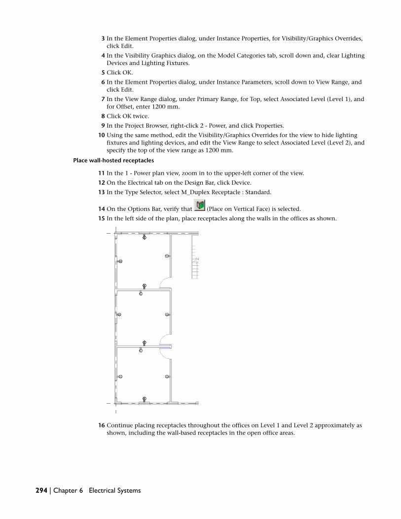
3 In the Element Properties dialog, under Instance Properties, for Visibility/Graphics Overrides,click Edit.
4 In the Visibility Graphics dialog, on the Model Categories tab, scroll down and, clear LightingDevices and Lighting Fixtures.
5 Click OK.
6 In the Element Properties dialog, under Instance Parameters, scroll down to View Range, andclick Edit.
7 In the View Range dialog, under Primary Range, for Top, select Associated Level (Level 1), andfor Offset, enter 1200 mm.
8 Click OK twice.
9 In the Project Browser, right-click 2 - Power, and click Properties.
10 Using the same method, edit the Visibility/Graphics Overrides for the view to hide lightingfixtures and lighting devices, and edit the View Range to select Associated Level (Level 2), andspecify the top of the view range as 1200 mm.
Place wall-hosted receptacles
11 In the 1 - Power plan view, zoom in to the upper-left corner of the view.
12 On the Electrical tab on the Design Bar, click Device.
13 In the Type Selector, select M_Duplex Receptacle : Standard.
14 On the Options Bar, verify that (Place on Vertical Face) is selected.
15 In the left side of the plan, place receptacles along the walls in the offices as shown.
16 Continue placing receptacles throughout the offices on Level 1 and Level 2 approximately asshown, including the wall-based receptacles in the open office areas.
294 | Chapter 6 Electrical Systems

1-Power
Placing Power Receptacles | 295

2-Power
Place floor-hosted receptacles
17 In the Project Browser, double-click 1 - Power.
18 On the Electrical tab on the Design Bar, click Device.
19 In the Type Selector, select M_Duplex Receptacle : Standard.
20 On the Options Bar, click (Place on Work Plane), and verify that Level : Level 1 is selectedfor Plane.
NOTE You can select a work plane from the Plane drop-down list on the Options Bar. The currentlevel is selected by default.
21 Zoom in on the upper-right corner of the Open Office, and place a receptacle on the floor asshown.
296 | Chapter 6 Electrical Systems

22 Click Modify.
When placing a receptacle on a work plane, its connector is located below the level of the workplane. Just as it was for ceiling hosted lighting fixtures, it is important that the connector bewithin the space to allow Revit MEP to maintain information about the electrical system andperform calculations for spaces in your design. In the next steps, you will flip the work planeof the receptacle to locate the connector above the work plane. Then you will create copies ofthe flipped receptacle to place the remaining floor-based receptacles.
23 Select the receptacle and click (Flip WorkPlane) to locate the connector above the workplane (within the space).
24 On the Toolbar, click (Copy).
25 On the Options Bar, select Multiple.
This will let you place multiple copies of the receptacle after selecting a start point.
26 Select an Endpoint on the receptacle as the start point, and then place 3 copies of the receptaclein the upper right area of the first floor, as shown.
27 Draw a pick box around the 4 floor-based receptacles, click , select Multiple on the OptionsBar and using the previous procedure, place 2 copies of the flipped receptacles along the rightside of the Level 1 open office, as shown.
Placing Power Receptacles | 297

28 Draw a pick box around the 2 floor-based receptacles, as shown, and click , select Multipleon the Options Bar.
29 Using the previous procedure, place 2 copies of the flipped receptacles below, and to the left ofthe men’s restroom, as shown.
298 | Chapter 6 Electrical Systems

30 Using the same procedure, place receptacles on the floor of the open office in 2 - Power as shown.
TIP You can select all of the floor-hosted receptacles in the 1 - Power view, then copy and paste themin the 2 - Power view. Select all 1 - Power floor receptacles, click Edit menu ➤ Copy to Clipboard,open 2 - Power, and click Edit ➤ Paste Aligned ➤ Current View.
31 You can save the open file if you wish; a new dataset is supplied in the next exercise.
32 Click File menu ➤ Close.
NOTE Do not overwrite the original dataset.
33 Proceed to the next exercise, Creating Power & Lighting Usage Reports on page 300.
Placing Power Receptacles | 299
In this exercise you placed wall-hosted receptacles on the walls and floor-hosted receptacles on the floor. Itis good to be familiar with this concept of placing hosted components, because it is quite common in RevitMEP.
Creating Power & Lighting Usage Reports
In this exercise you will create a consumption usage report for power and lighting in this project. With theintroduction of local energy codes, the amount of electricity consumed by different systems within thebuilding is becoming increasingly important to the design. When the HVAC designer asks what the wattage/SFamounts are for different spaces, you can refer to this report rather than having to measure spaces and countfixtures.
Open the provided dataset, as described below.
Dataset:
■ Click File menu ➤ Open.
■ In the left pane of the Open dialog, click the Training Files icon.
■ Open Metric ➤ Electrical ➤ m Creating Usage Reports.rvt.
1 Click View menu ➤ New ➤ Schedule/Quantities.
2 In the New Schedule dialog, scroll down the Category list, and select Spaces.
3 Verify that Schedule building components is selected, and for Name, enter Power & LightingUsage.
4 Click OK.
5 On the Fields tab of the Schedule Properties dialog, under Available Fields, select and add thefollowing fields to the Scheduled fields (in order) list in the order shown:
■ Number
■ Name
■ Area
■ Actual Lighting Load
■ Actual Power Load
■ Actual Lighting Load/Area
■ Actual Power Load/Area
6 Click OK.
A schedule is created similar to the one shown.
300 | Chapter 6 Electrical Systems

7 You can save the open file if you wish; a new dataset is supplied in the next exercise.
8 Click File menu ➤ Close.
NOTE Do not overwrite the original dataset.
9 Proceed to the next exercise, Placing Electrical Equipment on page 301.
In this exercise you created a schedule that can be used as input for the HVAC engineers or as input forenergy analysis and code review. The information in this schedule was produced using the data that youentered into the model.
Placing Electrical Equipment
In this exercise you add the electrical equipment for the distribution systems in your plan. Although theconnections between this type of equipment are not typically shown on plans, you need to create logicalconnections to define the topology. The following diagram shows the connectivity for your electricalequipment. You start at the low voltage panels (L-1 and L-2), and work toward the higher voltage, maindistribution panels (H-2 and MDP).
Placing Electrical Equipment | 301

Open the provided dataset, as described below.
Dataset:
■ Click File menu ➤ Open.
■ In the left pane of the Open dialog, click the Training Files icon.
■ Open Metric ➤ Electrical ➤ m Placing Electrical Equipment.rvt.
Add a panel
1 In the Project Browser, expand Views (Discipline) ➤ Electrical ➤ Power ➤ Floor Plans, anddouble-click 1 - Power.
2 Zoom in on the Mechanical/Electrical space between the 2 restrooms.
3 On the Electrical tab on the Design Bar, click Electrical Equipment.
4 In the Type Selector, select M_Lighting and Appliance Panelboard 480V MCB - Surface : 250 A,and click to place the panel as shown.
5 On the Design Bar, click Modify and select the panel you just placed.
6 On the Options Bar, for Distribution Sys, select 480/277 Wye.
TIP The Distribution System Types parameter is also accessible in the Element Properties dialog.Right-click the panel, click Element Properties, scroll down the Instance Parameters and, under Electrical- Loads, select 480/277 Wye for Distribution System Types.
Name the new panel
7 With the panel still selected, click .
8 In the Element Properties dialog, under Instance Parameters, scroll down to the Electrical - Loadscategory, and for Panel Name, enter MDP to indicate Main Distribution Panel.
302 | Chapter 6 Electrical Systems

This will be where the primary electrical service enters the building.
9 Click OK.
Add a transformer
10 On the Electrical tab on the Design Bar, select Electrical Equipment.
11 In the Type Selector, select M_Dry Type Transformer - 480-208Y-120 - NEMA Type 2 : 45kVA,and place the transformer in the Mechanical/Electrical space to the right of the panel as shown.
12 Click Modify
13 Select the transformer, and on the Options Bar, for Distribution Sys, select 480/277 Wye.
14 On the Options Bar, click .
Since this is a transformer, you must also specify a Secondary Distribution System parameter.
15 In the Element Properties dialog, under Instance Parameters, scroll down to the Electrical - Loadscategory, and specify the following:
■ For Secondary Distribution System, select 120/208 Wye.
■ For Panel Name, enter T1.
16 Click OK.
Add another panel
17 On the Design Bar, select Electrical Equipment.
18 In the Type Selector, select M_Lighting and Appliance Panelboard - 208V MLO - Surface : 100A, and place the panel to the right of the transformer.
19 Click Modify.
Placing Electrical Equipment | 303

20 Select the panel you just placed, and on the Options Bar, for Distribution Sys, select 120/208Wye.
21 On the Options Bar, click .
22 In the Element Properties dialog, under Instance Parameters, scroll down to the Electrical - Loadscategory, and for Panel Name, enter L-1.
23 Click OK.
Add panels and a transformer to second floor
24 Using the same method, add the following components in the Mechanical/Electrical space inthe 2-Power view:
■ M_Lighting and Appliance Panelboard 480V MCB - Surface : 250 A named H-2
■ M_480-120-208V Dry Type Transformers: M_45kVA named T2
■ M_Lighting and Appliance Panelboard - 208V MLO - Surface : 100 A named L-2
NOTE Remember to select the appropriate Distribution System Types parameter values for eachequipment component, including the Secondary Distribution System for T2.
Create logical circuits between equipment
25 In the 2-Power view, select panel L-2.
26 On the Options Bar, click (Create Power Circuit).
A Bounding Box displays as a dashed box surrounding the components that make up the circuit.
27 Click (Select Panel).
In this case you are going to select something other than a panel, because the circuit on themains of this panel is connected to a transformer rather than to another panel.
28 On the Options Bar, select T2 for Panel to establish the connection between the L-2 panel andT2 transformer.
The Bounding Box expands to enclose the transformer and panel L-2 and you will see temporarycircuit indicating that the panel has been connected to the transformer.
29 Select the transformer T2, and click .
304 | Chapter 6 Electrical Systems

30 On the Options Bar, click , and select panel H-2 for Panel. The temporary circuit displaysas shown.
31 Close all open views except 1-Power and 2-Power
32 Click Window menu ➤ Tile to display both views in the drawing area.
33 Zoom in on each view and scroll as necessary to display the Level 1 and Level 2Mechanical/Electrical spaces side-by-side.
34 In the 2-Power view, select the H-2 panel, and on the Options Bar, click .
35 On the Option Bar, click .
36 Click anywhere in 1-Power view to make it the active view, and select the MDP panel.
The temporary circuit is displayed as shown, indicating that a connection has been made betweenH-2 and MDP.
A circuit is created between H-2 and MDP.
37 Close the 2-Power view, and maximize the 1-Power view to make it easier to work with.
38 On the Options Bar, select the L-1 panel, and click .
39 Click , and select the T1 transformer as the panel.
Placing Electrical Equipment | 305

40 Select the T1 transformer, and click .
41 On the Options Bar, click , and select the MDP panel.
42 You can save the open file if you wish; a new dataset is supplied in the next exercise.
43 Click File menu ➤ Close.
NOTE Do not overwrite the original dataset.
44 Proceed to the next exercise, Creating Power Circuitry on page 306.
In this exercise you placed the electrical distribution equipment required for the project. You also definedhow the pieces of electrical equipment are connected by creating logical connections between the differentpieces of equipment.
Creating Power Circuitry
In this exercise you will learn methods for creating power circuits (circuit groups). Circuits are used forpower, lighting, and data systems. The concept of grouping similar functions into systems is used to showlogical connections between different components in the system.
Open the provided dataset, as described below.
Dataset:
■ Click File menu ➤ Open.
■ In the left pane of the Open dialog, click the Training Files icon.
306 | Chapter 6 Electrical Systems

■ Open Metric ➤ Electrical ➤ m Creating Power Circuitry.rvt.
1 In the Project Browser, expand Views (Discipline) ➤ Electrical ➤ Power ➤ Floor Plans, anddouble-click 1 - Power to make it the active view.
2 Zoom in on the upper-left corner of the plan.
Creating an electrical circuit to connect the devices (receptacles) in this view is similar to creatingthe electrical circuits in the previous exercise. The difference here is that you will have severalcomponents in the circuit.
3 While pressing Ctrl, select all the receptacles in the corner office.
4 On the Options Bar, click .
Temporary circuits are display as dashed lines between the components to indicate theinterconnection of the devices that you selected for this circuit.
The generate wiring controls ( ) let you create permanent wiring for the circuit. For now,leave the circuit as a temporary logical circuit. You will add permanent wiring in a later exercise.
5 Select one of the receptacles in the corner office, and observe that the information displayedindicates the number of poles (#1), load (180 VA), and voltage (120 V).
Creating Power Circuitry | 307

A question mark is displayed for this receptacle because no Label has been specified in the TypeProperties for this particular receptacle type.
Revit MEP will only let you make a connection between compatible components. You cannotconnect components having a different number of poles or a different voltage specified for thedistribution system types.
NOTE When all of the devices for the circuit have their distribution system specified as instanceparameters, the Specify Circuit Information dialog is displayed. You use the Specify Circuit Informationto specify the distribution system parameters for the circuit.
6 Click Modify.
7 Move the cursor over one of the receptacles in the corner office so that it is highlighted, pressTab, and click to select the circuit again.
8 On the Options Bar, click (Select a Panel for the Circuit), and select panel L-1 as the panelfor this circuit.
NOTE You can click a panel in the drawing area or select the panel name from the drop-down liston the Options Bar. The drop-down list on the Option Bar lists only those panels that are compatiblewith the circuit’s distribution system and have an available circuit.
9 Highlight one of the receptacles in the office, and press Tab.
308 | Chapter 6 Electrical Systems

10 Click to select the circuit and all of the devices on the circuit.
11 On the Options Bar, click (Edit Circuit).
The Edit Circuit tab is activated on the Design Bar. When editing a circuit, all but the componentsin the circuit are dimmed, making it easy to identify the components that are part of the circuitgroup.
12 On the Edit Circuit toolbar, click (Circuit Properties).
In the Element Properties dialog for this circuit, notice that most of the Instance Parametervalues are grayed out. They cannot be edited because they are calculated according to thecomponents in the circuit. The Voltage value for the circuit is 120V because all the receptaclesand the panel in the circuit are 120V components. The editable parameters, Wire Type andRating, will be discussed in a later exercise. In the next 2 steps you will see how parametersinteract as Revit MEP calculates values for the circuit.
13 Scroll down to the Wire Size parameter.
The currently specified values are 1-#12, 1-#12, 1-#12, which are the wire sizes for the load,neutral, and ground wiring, respectively for this circuit. These values are calculated based onthe Rating and Voltage Drop values.
14 Scroll back up to the Rating parameter, change the value from 20A to 50A, and then scroll backdown to Wire Size.
Notice that the Wire Size values have changed to 1-#6, 1-#6, 1-#10.
Creating Power Circuitry | 309

15 Click Cancel to close the Element Properties dialog and cancel your changes.
16 On the Edit Circuit toolbar, click Cancel.
17 Continue selecting receptacles, creating power circuits, and assigning them to panel L-1 on aspace-by-space basis for all of the offices around the perimeter of the building.
18 Select the receptacle in the stair well, click , click , and try to select panel L-1.
Panel L-1 is not listed on the drop-down list. If you select L-1 in the drawing, Revit MEP displaysa warning message indicating that adding this circuit group exceeds the number of availableslots on panel L-1.
19 Close the warning message.
Add additional slots to panel
20 Right-click panel L-1, and click Element Properties.
21 In the Element Properties dialog, under Instance Parameters, scroll down to the Electrical - Loadscategory, and change the value for Max #1 Pole Breakers from 12 to 18.
22 Click OK.
You should now be able to create the circuit for the stairwell, and add it to panel L-1.
23 Select the receptacle in the stairwell again, click , and select panel L-1.
The circuit is created.
24 After circuits have been created and assigned for all of the individual offices, zoom in to theupper part of the large open office, and select the 4 floor-mounted receptacles as shown.
25 On the Options Bar, click , click , and then select panel L-1.
26 Continue creating circuits, as previously described, for the remaining groups of 4 floor-hostedreceptacles.
NOTE Do not create a circuit for the 5 wall-hosted receptacles on the walls in the large open areaat this time. These will be connected in a later exercise.
310 | Chapter 6 Electrical Systems

27 Using the same procedures, create circuits in the 2 - Power view and assign them to panel L-2.
Increase the number of circuits on panel L-2 to 18.
NOTE Do not create a circuit for the 5 wall-hosted receptacles on the walls in the large open areaof Level 2 at this time. These will be connected in a later exercise.
28 Double-click 1 - Power to make it the active view.
29 Select the L-1 panel, and on the Options Bar, click (Edit Circuits on Panel).
In the Edit Circuits dialog, notice that circuit descriptions have been automatically created basedon information from the devices themselves. Notice also that all the circuits have been assignedto a location on the panel. Although this panel is currently capable of supporting 18 circuits,you have assigned only 17.
30 Click OK.
31 You can save the open file if you wish; a new dataset is supplied in the next exercise.
32 Click File menu ➤ Close.
NOTE Do not overwrite the original dataset.
33 Proceed to the next exercise, Creating Lighting Circuitry and Wires on page 311.
In this exercise you learned how to create circuit groups (circuits) and assign the circuits to panels. You alsolearned how voltage definitions and distribution systems determine the kinds of electrical systems that youcan define for your project. Finally, you learned how to add slots to a panel to accommodate circuits.
Creating Lighting Circuitry and Wires
In this exercise you become more familiar with the wiring settings, then create lighting circuitry and addwiring as the circuits are created. Adding wiring to a project is optional. As you saw in the previous exercise,you can create circuits and maintain the information associated with them without adding wiring to theproject.
Creating Lighting Circuitry and Wires | 311

Open the provided dataset, as described below.
Dataset:
■ Click File menu ➤ Open.
■ In the left pane of the Open dialog, click the Training Files icon.
■ Open Metric ➤ Electrical ➤ m Creating Lighting Circuitry and Wires.rvt.
Create an Electrical Lighting Plan template for Lighting Views
1 Click Settings menu ➤ View Templates.
2 In the View Templates dialog:
■ For Show Type, select <all>.
■ For Names, select Electrical Plan
Click , and in the New View Template dialog, enter Electrical Lighting Plan.
3 In the right pane, under View Properties, for View Range, click Edit in the Value column.
4 In View Range dialog:
■ Under Primary Range, for Top, select Level Above, and for Offset, enter -100
■ For Bottom, select Associated Level, and for Offset, enter 800
■ Under View Depth, for Level, select Associated Level, and for Offset, enter 800
5 Click OK.
6 Scroll down to Sub-Discipline, in the Value column, select Lighting, and click OK.
7 In the Project Browser, expand Views (Discipline) ➤ Electrical ➤ Lighting ➤ Floor Plans, right-click1 - Lighting, and click Apply View Template.
8 In the Apply View Template dialog, under Names, select Electrical Lighting Plan, and click OK.
Create lighting circuits
9 In the Project Browser, double-click 1 - Lighting to make it the active view.
10 Zoom out so that the entire plan is visible.
11 Draw a pick box around the plan to select everything.
12 On the Options Bar, click (Filter).
13 In the Filter dialog, click Check None to clear all the check boxes, re-select Lighting Devices andLighting Fixtures, and click OK.
Only the lighting fixtures and switches on Level 1 should now be selected, as shown.
312 | Chapter 6 Electrical Systems

14 On the Options Bar, click .
This should generate a Warning message indicating that the load for the circuit exceeds 80% ofthe defined rating (20A).
15 Close the message window and, click (Undo) to undo the circuit creation.
16 Select all the light fixtures and switches in the large open office (Open 1) as shown.
Creating Lighting Circuitry and Wires | 313

17 On the Options Bar, click , click , and then select panel MDP as the panel for thecircuit.
18 On the Options Bar, click .
This changes the temporary wiring graphics into permanent wiring graphics as shown.
314 | Chapter 6 Electrical Systems

When creating wires, as in this step, you can choose to create either arc or chamfered wiring.Arc wiring is sometimes used to indicate wiring that is concealed within walls, ceilings, or floors.Chamfered wiring can be used to indicate wiring that is exposed.
In this step, you created arc type wiring. Later, when you create wiring manually, you can specifysplined wiring. Splined wiring is similar to arc, but with an additional vertex. You can add orremove vertices from wires by right-clicking the wire and clicking Insert Vertex or Delete Vertex.
Tick marks (the short lines that intersect a wire run) indicate the number and type of conductors(load, neutral, ground) in the wire run. The meaning for each tick mark varies according to thestyle of the tick mark selected on the Wiring panel in the Electrical Settings dialog.
In the next steps, you add a conductor in the wiring path between the 3-way and 4-way switchesto allow switching the lights on or off from any of the switches in the open office area.
Adjust the number of conductors in a path between switches
19 Select the 4-way switch at the left end of the curved wall, move the cursor to highlight the 4-wayswitch at the right end of the curved wall, press Tab, and click the switch to select the switches,lighting fixtures, and wire segments on the path between the 2 switches.
20 On the Options Bar, click (Filter).
21 In the Filter dialog, click Check None, select Wires, and click OK.
Only the wire segments are selected in the path between the switches.
22 On the Options Bar, click .
23 In the Element Properties dialog, under Instance Parameters, for Hot Conductors, enter 2, andclick OK.
Notice that there are now 4 tick marks on the wire segments on the path between the switches(2 hot conductors, one neutral conductor, and one ground conductor).
24 Using the same method, add a hot conductor to the wire segments between the remainingswitches in the open office and between the 2 switches in the Level 1 stairwell.
NOTE The Hot Conductors parameter value will be blank if the path being selected contains wiresegments with a combination of both 1 and 2 specified as the value for Hot Conductors. When thisoccurs, enter 2 as the value, and click OK.
25 In the Mech/Elec space, right-click the MDP panel, and click Element Properties.
26 In the Element Properties dialog, under Instance Parameters, scroll down to the Electrical - Loadscategory, change the value for Max #1 Pole Breakers from 12 to 22, and click OK.
Creating Lighting Circuitry and Wires | 315

27 Create lighting circuits for the private offices, restrooms and stairwell on Level 1, and assigneach circuits to panel MDP.
28 Create permanent wiring for each circuit.
The wiring layout should look similar to the following:
29 For more practice, continue performing the steps in this exercise using the procedures and toolsdescribed previously to create another lighting circuit for the rest of the lighting fixtures andswitches on the 1 - Lighting view, then creating lighting circuits in 2 - Lighting.
Otherwise, close the dataset and go on to the next exercise, Creating Switch Systems on page317.
30 Right-click panel H-2, and in the Element Properties dialog, under Instance Parameters, scrolldown to the Electrical - Loads category, change the value for Max #1 Pole Breakers from 12 to18, and click OK.
31 Create a lighting circuit for the open area on Level 2, assign the circuit to panel H-2.
32 Create lighting circuits and wiring for the private offices, lounge, conference room, and restroomsin the 2 - Lighting view, and assign each circuit to panel H-2.
NOTE Do not include the two lighting fixtures and 3-way switch in the stairwell in either circuit.These will be connected in a later exercise.
The wiring layout should look similar to the following:
316 | Chapter 6 Electrical Systems

33 You can save the open file if you wish; a new dataset is supplied in the next exercise.
34 Click File menu ➤ Close.
NOTE Do not overwrite the original dataset.
35 Proceed to the next exercise, Creating Switch Systems on page 317.
In this exercise you learned how to create lighting circuitry and used the basic methods for adding andediting wires. You also learned about the settings that control how Revit MEP performs wire sizing. You alsosaw that the Revit MEP warns you when you try to put too much load on a circuit, but does not preventyou from doing so.
Creating Switch Systems
You create switch systems to specify switches that control groups of lighting fixtures in a project. In thisexercise you will create switch systems on Level 1 and Level 2, assign lighting fixtures to switches, and specifyswitch IDs for switches. After creating the switch systems on Level 1, you will create a space schedule withan embedded schedule listing switch IDs, fixtures, and panel information.
Open the provided dataset, as described below.
Dataset:
■ Click File menu ➤ Open.
■ In the left pane of the Open dialog, click the Training Files icon.
■ Open Metric ➤ Electrical ➤ m Creating Switch Systems.rvt.
1 In the Project Browser, expand Views (Discipline) ➤ Electrical ➤ Lighting ➤ Floor Plans, anddouble-click 1 - Lighting to make it the active view.
Creating Switch Systems | 317

2 Select all the lighting fixtures in the large open office (Open 1).
TIP Because all of the lighting fixtures in the open office are part of the same lighting system, youcan highlight one of the lighting fixtures, press Tab, and click to select everything in the system.
Then, click (Filter) to select only the lighting fixtures.
3 On the Options Bar, click (Create Switch System).
4 Click (Select Switch for System), and click the 4-way switch at the left end of the curvedwall to designate the switch controlling the fixtures.
After creating the switch system, you decide to assign several fixtures to a different switch inthe large open area.
5 With the switch system still selected, on the Options Bar, click (Edit Switch System).
The Switch System toolbar is activated.
6 On the it Switch System toolbar, click Remove From System, and on the Options Bar,select Multiple.
The Options Bar provides the following information about the currently selected switch system.
■ Switch ID: the identifier for the switch that is currently assigned to the system.
■ Number of Fixtures: the number of components in the system (excluding switches).
With Multiple selected on the Options Bar, you can use a pick box to select several fixtures.When you have selected as many fixtures as you want, click Finish to confirm your selections.
7 Draw a pick box around the 6 lighting fixtures to the left of the restrooms.
318 | Chapter 6 Electrical Systems

8 On the Options Bar, click Finish.
The Number of Fixtures field now displays 27 fixtures remaining in the system.
9 Click (Switch Properties).
10 In the Element Properties dialog, under Instance Properties, for Switch ID, enter Main Entrance- West, and click OK.
The Switch ID is updated on the Options Bar.
11 On the Switch System toolbar, click Finish.
12 Select the 6 lighting fixtures to the left of the restrooms.
13 On the Options Bar, click .
14 On the Switch System toolbar, click (Select Switch), and select the switch on the walloutside the ladies’ restroom.
15 Click .
16 Click (Switch Properties).
17 In the Element Properties dialog, under Instance Properties, for Switch ID, enter North Stairwell- 1st Floor, and click OK.
18 On the Switch System toolbar, click Finish.
Creating Switch Systems | 319

19 Zoom in on the upper-left corner of the plan, select both lighting fixtures in the corner office,
and on the Options Bar, click .
20 Click , and click the single-pole switch on the right wall of the office to designate theswitch controlling the fixtures in the office.
21 Using the same method, create switch systems for the remaining private offices, stairwell, andrestrooms in the 1 - Lighting view.
Create a switch system schedule
22 Click View menu ➤ New ➤ Schedule/Quantities.
23 In the New Schedule dialog:
■ Under Category, select Spaces.
■ For Name, enter Switch Systems.
■ Verify that Schedule building components is selected.
■ Click OK.
24 On the Fields tab of the Schedule Properties dialog, scroll down the Available fields list,double-click the following fields—in the order shown—to add them to the Scheduled fields (inorder) list:
■ Number
■ Name
25 On the Sorting/Grouping tab:
■ For Sort by, select Number.
■ Verify that Ascending is selected.
■ Verify that Itemize every instance is selected.
26 On the Formatting tab, select Number from the Fields list, and for Heading, enter Space Number.
27 On the Embedded Schedule tab:
■ Select Embedded Schedule
■ Under Categories, select Lighting Fixtures
■ Click Embedded Schedule Properties.
320 | Chapter 6 Electrical Systems

28 On the Fields tab of the Schedule Properties dialog, scroll down the Available fields list,double-click the following fields—in the order shown—to add them to the Scheduled fields (inorder) list:
■ Switch Id
■ Type
■ Panel
■ Circuit Number
29 Click OK twice.
The Switch System schedule displays in the drawing area, and is added to the Project Browserunder Schedules/Quantities. The embedded lighting fixture content is arranged so that theinformation about a switch system displays below the space containing that system.
30 For more practice, continue creating switch systems in the 2 - Lighting view. Create separatesystems for the lounge, restrooms, conference room, and private offices. Create a system for allthe lighting fixtures in the large open area and assign them to the switch near the east stairwell.Specify Open Area - 2nd Floor for the switch ID.
The Switch Systems schedule is automatically updated as you specify switch IDs or make changesto the lighting.
Otherwise, close the dataset and go on to the next exercise, Creating Multi-Circuit Wire Runson page 322.
31 You can save the open file if you wish; a new dataset is supplied in the next exercise.
Creating Switch Systems | 321

32 Click File menu ➤ Close.
NOTE Do not overwrite the original dataset.
33 Proceed to the next exercise, Creating Multi-Circuit Wire Runs on page 322.
Creating Multi-Circuit Wire Runs
In this exercise you will see how Revit MEP deals with wiring runs that contain more than a single circuit.You will design the power wiring for the 3 offices in the upper-left portion of 1-Power view to serve as anexample of the multi-circuit wiring run.
Open the provided dataset, as described below.
Dataset:
■ Click File menu ➤ Open.
■ In the left pane of the Open dialog, click the Training Files icon.
■ Open Metric ➤ Electrical ➤ m Creating Multi-Circuit Wiring.rvt.
1 In the Project Browser, expand Views (Discipline) ➤ Electrical ➤ Power ➤ Floor Plans, anddouble-click 1 - Power to make it the active view.
2 Zoom in on the office at the upper-left corner of the plan.
3 In the corner office, move the cursor over one of the receptacles to highlight it, press Tab tohighlight the entire circuit, and click to select the circuit and all of the components connectedto it.
4 On the Options Bar, click to generate arc type wiring for the selected circuit.
5 Using the same method, generate permanent wiring for the circuits in the remaining spacesalong the left side of the plan.
322 | Chapter 6 Electrical Systems

6 Select the home runs that extend out into the open office from the 2 upper offices, and deleteboth home runs.
7 Adjust the view so that the 2 upper offices are visible.
8 On the Electrical tab on the Design Bar, click Wire.
9 On the Options Bar, verify that (Arced Wire) is selected.
10 Click the connector for the receptacle on the east wall of the top office to specify the start pointfor the wire.
Creating Multi-Circuit Wire Runs | 323

11 Click in the open area near the door for the office to specify the second point for the wire, asshown.
12 Click the connector for the receptacle on the east wall of the middle office to specify the endpointfor the wire.
324 | Chapter 6 Electrical Systems

NOTE When neither of the 2 groups of components on the circuit has a free home run, Revit MEPtemporarily assigns a direction to the home run. The direction will be corrected, if necessary, whenthe wiring is completed.
13 Adjust the view so that the 2 lower offices are visible, and using the same method, create wiringbetween receptacles in the 2 lower offices.
When completed, your layout should look similar to the following:
Creating Multi-Circuit Wire Runs | 325

Home run arrows are used to indicate that a wiring run is returning to a panel. Multi-circuitwiring runs appear with multiple arrows on the home run. As wiring runs are collected into amulti-circuit wiring run, the number of tick marks is increased to show the increase in thenumber of hot conductors. In the previous steps, as the circuits in each office was added to thewiring run, the number of tick marks and home run arrows is increased such that the final homerun has 3 home run arrows and 5 tick marks (3 hot conductors, a shared neutral, and a sharedsafety ground).
14 Click Modify.
Adjust the home run routing
15 Select the home run extending from the lower office, and notice the vertex controls at each endof the wire and another in the center.
326 | Chapter 6 Electrical Systems

16 Drag the center vertex to the left so that it is closer to the receptacle in the lower office as shown.
17 Right click the wire run, select Insert Vertex, drag the new vertex along the wire run to a pointmidway between the other vertex and the connector, and click.
18 Drag the vertex at the end of the home run toward the lower restroom, and drag the new vertexup and to the left to arrange the wire run so that it looks similar to the following image.
Creating Multi-Circuit Wire Runs | 327

Vertices let you route wires in your project views. The wire behaves like a spline, adjusting itsshape according to the vertex location.
19 For additional practice, you can continue creating permanent wiring for the circuits in the1 - Power and 2 - Power views, or you can close this dataset and go on to the next exercise.Examples of completed plans are provided below for reference.
Completed 1-Power
328 | Chapter 6 Electrical Systems

Completed 2-Power
20 You can save the open file if you wish; a new dataset is supplied in the next exercise.
21 Click File menu ➤ Close.
NOTE Do not overwrite the original dataset.
22 Proceed to the next exercise, Checking Your Design on page 329.
In this exercise, you created wiring runs from the circuits that you created in a previous exercise and combinedthese to form multi-circuit wiring runs. You also learned how to adjust the layout of wiring runs and interprettick marks and home run arrows.
Checking Your Design
In this exercise you learn how to use the System Browser to examine the circuitry that you created in previousexercises. The System Browser is a useful tool for checking the design and locating components in yourproject. You also learn to use the Check Circuits tool to verify that all of the circuits in your plan areconnected.
Open the provided dataset, as described below.
Dataset:
■ Click File menu ➤ Open.
■ In the left pane of the Open dialog, click the Training Files icon.
■ Open Metric ➤ Electrical ➤ m Checking Your Design.rvt.
1 In the Project Browser, expand Views (Discipline) ➤ Electrical ➤ Power ➤ Floor Plans, anddouble-click 1 - Power to make it the active view.
Checking Your Design | 329

2 Zoom in on the upper-left corner of the drawing so that the corner office is visible.
3 Click Window menu ➤ Systems Browser.
The System Browser is displayed to right of the drawing area.
4 Click and hold the Title Bar of the System Browser, drag it to the bottom of the drawing area,and when the preview expands to the width of the window, release the mouse button.
5 Right-click a column heading, and click View ➤ Electrical to limit the information displayed tothe electrical discipline.
6 Right-click a column heading in the System Browser, and click AutoFit All Columns to resizethe columns in the System Browser.
7 In the System Browser, expand Power ➤ L-1 ➤ circuit 1.
The System Browser provides another way of viewing information about the circuits that areconnected to panel L-1. There are 4 devices connected to circuit 1, each with a load of 180VA.The System Browser also provides the name and number of the space in which the devices arelocated.
8 In the System Browser, right-click one of the devices under circuit 1, and click Select.
The device you selected in the System Browser is also selected in 1 - Power.
Resolve unassigned electrical components
9 In the System Browser, collapse Power, and expand Unassigned.
330 | Chapter 6 Electrical Systems
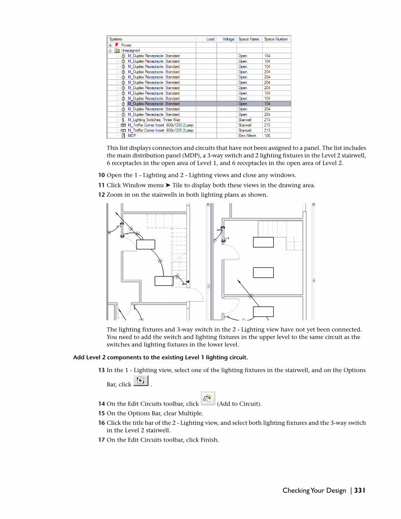
This list displays connectors and circuits that have not been assigned to a panel. The list includesthe main distribution panel (MDP), a 3-way switch and 2 lighting fixtures in the Level 2 stairwell,6 receptacles in the open area of Level 1, and 6 receptacles in the open area of Level 2.
10 Open the 1 - Lighting and 2 - Lighting views and close any windows.
11 Click Window menu ➤ Tile to display both these views in the drawing area.
12 Zoom in on the stairwells in both lighting plans as shown.
The lighting fixtures and 3-way switch in the 2 - Lighting view have not yet been connected.You need to add the switch and lighting fixtures in the upper level to the same circuit as theswitches and lighting fixtures in the lower level.
Add Level 2 components to the existing Level 1 lighting circuit.
13 In the 1 - Lighting view, select one of the lighting fixtures in the stairwell, and on the Options
Bar, click .
14 On the Edit Circuits toolbar, click (Add to Circuit).
15 On the Options Bar, clear Multiple.
16 Click the title bar of the 2 - Lighting view, and select both lighting fixtures and the 3-way switchin the Level 2 stairwell.
17 On the Edit Circuits toolbar, click Finish.
Checking Your Design | 331

In the System Browser, the 2 lighting fixtures and 3-way switch have been moved from theUnassigned folder to Power ➤ MDP ➤ Circuit 2.
18 Highlight one of the lighting fixtures in the Level 2 stairwell, press Tab several times, until the
power circuit is previewed, click to select the circuit, and on the Options Bar, click tocreate permanent wiring.
Add a Hot Conductor to the wiring for the stairwell lighting circuit.
19 In the 1 - Lighting view, select the 3-way switch in the stairwell, click the title bar of the2 - Lighting view, highlight the 3-way switch in the Level 2 stairwell, press Tab, and click toselect all of the components in the path between the 2 switches.
20 On the Options Bar, click .
21 In the Filter dialog, click Check None, select Wires, and click OK.
Only the wire segments are selected in the path between the switches.
22 Click .
23 In the Element Properties dialog, under Instance Parameters, for Hot Conductors, enter 2, andclick OK.
332 | Chapter 6 Electrical Systems

In the System Browser, the only remaining unassigned components should be the MDP and thereceptacles in the 2 open areas.
Assign remaining receptacles to circuits
24 In the Project Browser, double-click 1-Power to make it the active view, arrange the view so thatthe System Browser and the 5 unassigned receptacles are visible.
25 In the drawing area, select the unassigned receptacles in the open area.
26 On the Options Bar, click to create a power circuit for these receptacles.
27 On the Options Bar, click , and in the Mechanical/Electrical space, select panel L-1.
28 Click to create permanent wiring.
Checking Your Design | 333

29 Using the same method, create a power circuit for the 6 unassigned receptacles in Open 2 inthe 2-Power view.
The MDP panel is now the only component listed in the Unassigned category.
Check Circuits
30 On the Electrical tab on the Design Bar, click Check Circuits.
31 In the warning window that is displayed indicating an unconnected power connector.
32 Click to view details of the warning.
33 Expand the warning categories until you can see that the piece of equipment that is not connectedis the MDP panel.
334 | Chapter 6 Electrical Systems

This warning refers to the feed from the outside power service and can be ignored.
34 Close the Warning dialog.
35 You can save the open file if you wish; a new dataset is supplied in the next exercise.
36 Click File menu ➤ Close.
NOTE Do not overwrite the original dataset.
37 Proceed to the next exercise, Defining Circuit Loads on page 335.
In this exercise, you learned how to use the System Browser to examine electrical components in your projectand resolve unassigned and unnamed circuits. You also learned how to use the Check Circuits tool to verifythat all of the circuits in your project were connected.
Defining Circuit Loads
In this exercise you begin by balancing the loads at the Level 1 and Level 2 panels, then you examine theloads presented at the panels to set your final breaker sizes. Finally, you verify and adjust wire sizes thatRevit MEP recommends for handling the loads on those circuits.
Open the provided dataset, as described below.
Dataset:
■ Click File menu ➤ Open.
■ In the left pane of the Open dialog, click the Training Files icon.
■ Open Metric ➤ Electrical ➤ m Defining Circuit Loads.rvt.
Balance circuit loads
1 Circuit loads should be balanced to present as nearly as possible an equal load to each phase.This will reduce neutral current as well as prevent an excess voltage drop due to one phase beingoverloaded. Balancing loads begins with adjusting the loads at the panels farthest from thepower source.
In the Project Browser, expand Views (Discipline) ➤ Electrical ➤ Power ➤ Floor Plans, anddouble-click 2 - Power.
2 In the Mechanical/Electrical space, select panel L-2.
Defining Circuit Loads | 335

3 On the Options Bar, click .
Examination of the loads on Phase A, B, and C shows a slight imbalance with the heaviest loadon Phase B (4860 VA), while Phase A provides 4500 VA, and Phase C provides 4320 VA.
4 In the Edit Circuits dialog, click Rebalance Loads.
After re-balancing loads, the distribution is shifted, but the overall load on the three phasesremains the same. Had there been a greater imbalance, the loads would have been moved todifferent circuits to achieve better balance.
5 Click OK.
336 | Chapter 6 Electrical Systems

6 Select panel H-2, and on the Options Bar, click .
7 Click Rebalance Loads to adjust the loads on panel H-2.
8 In the Project Browser, double-click 1 - Power.
9 Repeat the previous procedures to balance the loads on the Level 1 panels, L-1 and MDP.
Adjust circuit breaker sizes
10 Select panel MDP, and on the Options Bar, click .
NOTE If you have continued to save and use your own dataset throughout these tutorials, you maysee different values for the loads. This is because you may have selected a different mix of lightingfixtures to attain the required lighting levels.
Transformer T1 was specified as a 45kVA transformer but, the actual load connected to it(12960 VA) is less than 15kVA. Therefore, you can use a 30kVA transformer, which will requirea 40A circuit breaker.
11 In the Edit Circuits dialog, for panel H-2, enter 100A for the Trip value, and for T1, enter 40Afor the Trip value.
The lighting circuits connected to MDP are already specified as 20A circuits, so no further changesare required.
12 Click OK.
13 In the 1 - Power view, in the Mechanical/Electrical space, select the T1 transformer.
14 In the Type Selector, select M_480-120-208V Phase Dry Type Transformer: M_30kVA.
Now that you have specified transformer T1 as a 30kVA transformer and restored it to the circuit,you should verify that the wire sizes for panel L-1 is set correctly.
Verify/adjust wire sizes
15 Right-click panel L-1, and click Element Properties.
Defining Circuit Loads | 337

16 In the Element Properties dialog, under Instance Parameters, scroll down to the Electrical-Loadscategory, and notice that the current value for Mains is 100.00A.
100.00A is the correct size panel for a 30kVA transformer.
17 Click OK.
18 With panel L-1 selected, on the Options Bar, click (Circuit Properties).
19 In the Element Properties dialog for the circuit, scroll down and verify that the current valuefor the Wire Size parameter is 3-#12, 1-#12, 1-#12.
20 Under Electrical-Loads, enter 100A for Rating.
Revit MEP automatically calculates wire sizes based on circuit rating.
21 Scroll down, and click the value for the Wire Size parameter.
Notice that it changes to 3-#1, 1-#1, 1-#8.
22 Click OK.
23 In the Project Browser, double-click 2 - Power to make it the active view.
24 In the Mechanical/Electrical space, select panel H-2, and on the Options Bar, click .
Similar to the situation you observed for transformer T1, the load presented by T2 is less than14kVA and you decide to change the transformer from 45kVA to 30kVA, which will require a40A circuit breaker.
25 In the Edit Circuits dialog, for transformer T2, enter 40A for the Trip value.
26 Click OK.
27 In the 2 - Power view, in the Mechanical/Electrical space, select the T2 transformer.
28 In the Type Selector, selectM_480-120-208V Phase Dry Type Transformer: M_30kVA.
Now that you have set transformer T2 to be a 30kVA transformer and restored it to the circuit,you should verify that the size of panel L-2 is set correctly.
29 Right click panel L-2 and click Element Properties.
338 | Chapter 6 Electrical Systems

30 In the Element Properties dialog, under Instance Parameters, scroll down to the Electrical-Loads,and verify that the current value for Mains is 100.00A.
31 Click OK.
Size the service entrance conductors
32 In the Project Browser, double-click 1 - Power to make it the active view.
33 With the MDP panel selected, click .
A warning indicates that the total connected load exceeds 80% of the defined value of 20A forthe circuit you are creating.
34 Close the Warning.
35 On the Options Bar, click .
36 In the Element Properties dialog for the circuit, under Electrical Loads, enter 225A for the Ratingparameter. Notice that the value for the Wire Size parameter changes appropriately.
37 You can save the open file if you wish.
38 Click File menu ➤ Close.
NOTE Do not overwrite the original dataset.
This completes the Electrical Tutorial.
Defining Circuit Loads | 339

340

Plumbing Systems
The most common method of designing systems in Revit MEP is to work within a linked architectural building model. Inthis tutorial, you will use a project file that has already been linked to an architectural model, with Space componentsplaced in the areas throughout the model.
NOTE The architectural model used with this tutorial is in the Architectural folder. You should maintain the relativepath to the architectural model. However, if the link is lost, you can click File menu ➤ Manage Links to reload thelinked model. On the Revit tab on the Manage Links dialog, click Reload From, navigate to TrainingFiles ➤ Architectural, and select m Office Building.rvt.
In this tutorial, you create the plumbing systems for the second floor men’s room in an office building, including plumbingfixtures, hot and cold water piping, and sanitary piping. As you create the plumbing system, you follow a series of lessonsand exercises that teach the recommended systems design workflow for Revit MEP 2009. By following this workflow, youlearn system design best practices while understanding how Revit MEP makes systems designing more efficient.
The goal of this tutorial is to teach you to design plumbing systems using Revit MEP 2009. At the end of this tutorial, youwill understand the process, methodology, and specific techniques for designing plumbing systems.
The datasets that you use to complete these exercises are located in the Training Files directory. You can search the TrainingFiles ➤ Metric directory to verify that the datasets have been downloaded. If the tutorial datasets are not present, go tohttp://www.autodesk.com/revitmep-documentation and download them.
NOTE All exercises in this tutorial are designed to be completed sequentially; each exercise is dependent on thecompletion of the previous exercise. After finishing each exercise, you can choose to save your work. However, it ishighly recommended that you always begin an exercise by opening the dataset that Autodesk provides. This datasetincludes the work from the previous exercise(s) and ensures a seamless training session.
7
341
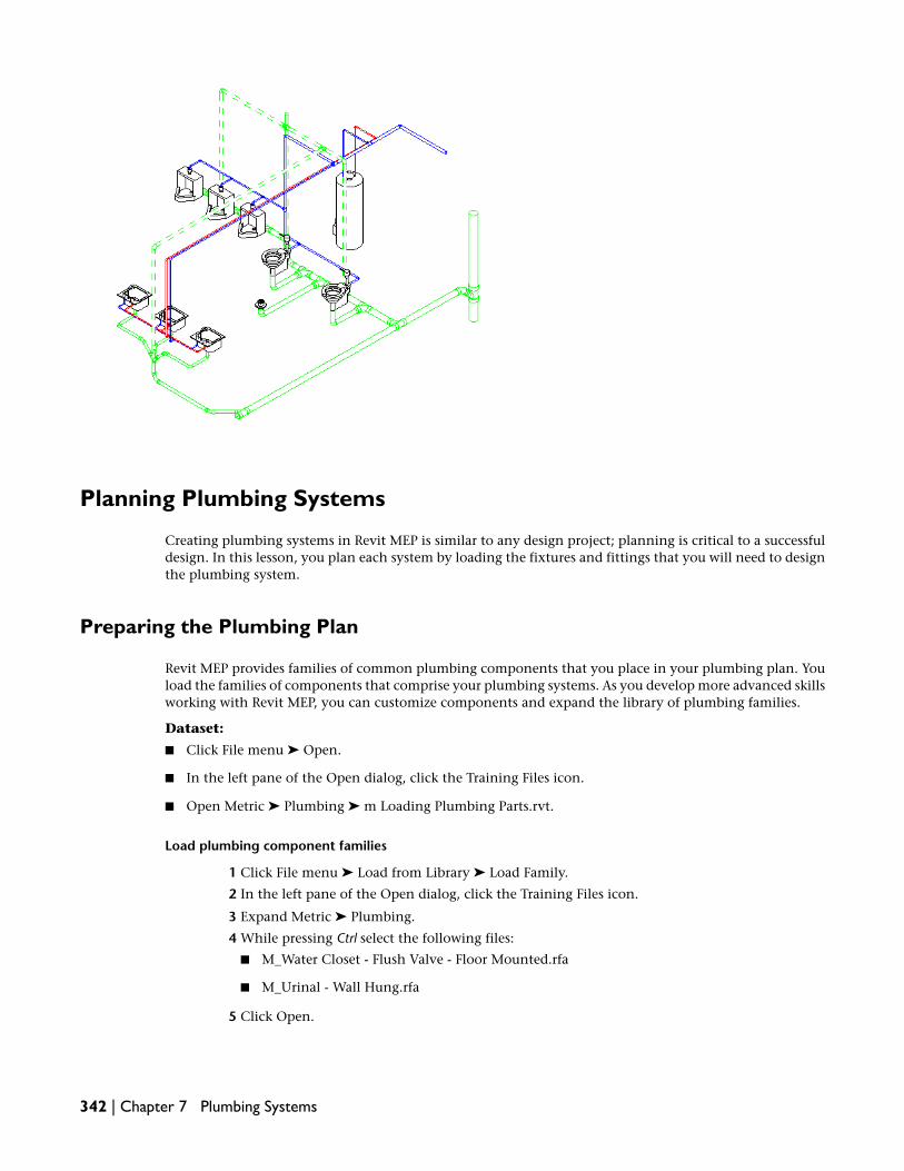
Planning Plumbing Systems
Creating plumbing systems in Revit MEP is similar to any design project; planning is critical to a successfuldesign. In this lesson, you plan each system by loading the fixtures and fittings that you will need to designthe plumbing system.
Preparing the Plumbing Plan
Revit MEP provides families of common plumbing components that you place in your plumbing plan. Youload the families of components that comprise your plumbing systems. As you develop more advanced skillsworking with Revit MEP, you can customize components and expand the library of plumbing families.
Dataset:
■ Click File menu ➤ Open.
■ In the left pane of the Open dialog, click the Training Files icon.
■ Open Metric ➤ Plumbing ➤ m Loading Plumbing Parts.rvt.
Load plumbing component families
1 Click File menu ➤ Load from Library ➤ Load Family.
2 In the left pane of the Open dialog, click the Training Files icon.
3 Expand Metric ➤ Plumbing.
4 While pressing Ctrl select the following files:
■ M_Water Closet - Flush Valve - Floor Mounted.rfa
■ M_Urinal - Wall Hung.rfa
5 Click Open.
342 | Chapter 7 Plumbing Systems

6 In the Project Browser, expand Families ➤ Plumbing Fixtures.
Notice that 2 folders have been added to the families currently available for your design: M_WaterCloset - Flush Valve - Floor Mounted and M_Urinal - Wall Hung.
Load piping component families
7 Click File menu ➤ Load from Library ➤ Load Family.
8 In the left pane of the Open dialog, click the Training Files icon.
9 Expand Metric ➤ Plumbing.
10 While pressing Ctrl select the following files:
■ M_Pipe Bend - DWV - Glued.rfa
■ M_Pipe Reducing Short Tee - Sanitary - Glued.rfa
11 Click Open.
The selected component families are loaded into the project. All of the loaded families, are addedunder Families in the Project Browser.
12 You can save the open file if you wish; a new dataset is supplied in the next exercise.
13 Click File menu ➤ Close.
NOTE Do not overwrite the original dataset.
14 Proceed to the next exercise, Configuring Plumbing and Piping Systems on page 343.
Configuring Plumbing and Piping Systems
In this exercise, you create new PVC pipe types and specify the default fittings that will be used with them.
Dataset:
■ Click File menu ➤ Open.
■ In the left pane of the Open dialog, click the Training Files icon.
■ Open Metric ➤ Plumbing ➤ m Configuring Plumbing and Pipe Systems.rvt.
Create new pipe types and specify default pipe fittings
1 In the Project Browser, expand Families ➤ Pipes ➤ Pipe Types.
2 Right-click PVC, and click Duplicate.
3 Right-click PVC 2, and click Properties.
4 In the Type Properties dialog, click Rename.
5 In the Rename dialog, for New, enter PVC Sanitary, and click OK.
6 Under Mechanical, do the following:
■ For Elbow, select M_Pipe Bend - PVC: Standard
■ For Preferred Junction Type, select Tee
■ For Tee, select M_Pipe Short Tee - Sanitary - PVC: Standard
■ For Tap, select None
■ For Cross, select M_Pipe Cross - PVC - Glued: Standard
■ For Transition, select M_Pipe Transition - PVC: Standard
Configuring Plumbing and Piping Systems | 343

■ For Union, select M_Pipe Coupling - PVC: Standard
7 Click Apply, then click Duplicate.
8 In the Name dialog, for Name, enter PVC Sanitary Vent, and click OK.
9 Under Mechanical, do the following:
■ For Elbow, verify that M_Pipe Bend - PVC : Standard is selected
■ For Preferred Junction Type, select Tee
■ For Tee, select M_Pipe Tee - Vent - PVC : Standard
■ For Tap, select None
■ For Cross, verify that M_Pipe Cross - PVC - Glued : Standard is selected
■ For Transition, verify that M_Pipe Transition - PVC : Standard is selected
■ For Union, verify that M_Pipe Coupling - PVC : Standard is selected
10 Click OK to close the Type Properties dialog.
11 You can save the open file if you wish; a new dataset is supplied in the next exercise.
12 Click File menu ➤ Close.
NOTE Do not overwrite the original dataset.
13 Proceed to the next exercise, Add Plumbing Fixtures on page 344.
Designing Plumbing Systems
Designing plumbing systems in Revit MEP is a straightforward process. In this lesson, you add plumbingfixtures to physically connect them with piping. You then modify the piping. Finally, you create systemsto logically connect the fixtures.
Add Plumbing Fixtures
In this exercise, you add 2 toilets, 3 urinals, 3 sinks, and a floor drain to the second floor men’s room.
Dataset:
■ Click File menu ➤ Open.
■ In the left pane of the Open dialog, click the Training Files icon.
■ Open Metric ➤ Plumbing ➤ m Adding Plumbing Fixtures.rvt.
Place floor-mounted toilets
1 In the Project Browser, expand Mechanical ➤ Plumbing ➤ Floor Plans, and double-click 2 -Plumbing to make it the active view.
2 Enter the keyboard shortcut, ZR (Zoom Region), and draw a left-to-right pick box around thesecond floor men’s room.
344 | Chapter 7 Plumbing Systems

The men’s room is partitioned for 2 toilet stalls, 3 wall-mounted urinals, and 3 sinks.
3 On the Plumbing tab on the Design Bar, click Plumbing Fixture.
4 Select M_Water Closet - Flush Valve - Floor Mounted : Private 6.1 Lpf in the Type Selector.
5 Move the cursor over the upper-right corner of the men’s room, and click to place the toilet inthe approximate location shown.
6 Click Modify.
Position the first toilet
7 Position the toilet 160 mm from the upper wall, and 460 mm from the right wall.
a On the Design Bar, click Dimension.
Add Plumbing Fixtures | 345

b On the Options Bar, verify that (Aligned) is selected, Wall faces is selected for Prefer,and Individual References is selected for Pick.
c Click the face of the right wall, move the cursor over the center of the toilet, and click.
d Move the cursor down, and click to place the dimension annotation.
e Using the same method, place a dimension annotation between the upper wall and theback of the toilet.
f Click Modify.
g Select the toilet, click the value for the blue dimension to the right, enter 160, and pressEnter.
The toilet is placed 160 mm from the upper wall of the toilet stall.
h Click the value for the blue dimension below the toilet, enter 460, and press Enter.
The toilet is placed 460 mm from the right wall.
i Click Modify.
j Delete both dimension annotations.
Add a second toilet
8 Select the toilet, and on the Edit toolbar, click (Copy).
9 On the Options Bar, do the following:
■ Clear Constrain
■ Verify that Copy is selected
■ Clear Multiple
10 Click the center line of the toilet to establish a start point.
11 Move the preview of the toilet 1500 mm to the left (into the left stall), and when the alignmentsnap displays and the preview is from the original toilet, click to place the toilet as shown.
346 | Chapter 7 Plumbing Systems

Place wall-mounted urinals
12 On the Plumbing tab on the Design Bar, click Plumbing Fixture.
13 Select M_Urinal - Wall Hung : 20mm Flush Valve in the Type Selector, and on the Options Bar,
verify that (Place on Vertical Face) is selected.
14 Move the cursor over the upper-left corner of the men’s room, and place 3 urinals approximatelyas shown.
15 Click Modify.
16 On the Design Bar, click Dimension, and on the Options Bar, do the following.
■ Verify that (Aligned) is selected
■ For Prefer, select Wall centerlines
■ Verify that Individual References is selected for Pick
17 Click the centerline of the left wall, move the cursor over the center of the leftmost urinal, andclick.
18 Move the cursor down, and click to place the dimension annotation.
Add Plumbing Fixtures | 347

19 Using the same method, place a dimension annotation for the rightmost toilet.
20 Working from left to right, click the centerline of each urinal in succession, then move thecursor up, and click to place the dimensions annotation.
21 Select the rightmost urinal, click the value for the blue dimension, and enter 500.
The urinal is placed 500 from the wall of the toilet stall.
22 Using the same method, place the leftmost urinal 500 from the left wall.
23 Select the dimension annotation above the urinals, and click the blue (Equal Control)above the dimension values to space the urinals evenly along the wall.
24 Press Delete to remove the dimension from the drawing, and click Unconstrain in the warningdialog.
25 While pressing Ctrl, select the 2 remaining dimension annotations, and press Delete.
348 | Chapter 7 Plumbing Systems

Place sinks
26 On the Plumbing tab on the Design Bar, click Plumbing Fixture, and in the Type Selector, selectM_Sink - Island - Single : 455mmx455mm - Private.
27 On the Options Bar click (Place on Face).
28 In the drawing area, select the counter top.
29 Move the cursor over the counter top in the lower-right corner of the men’s room, and pressthe Space Bar twice to rotate the sink into the proper orientation.
30 Place 3 sinks, approximately as shown.
31 Click Modify.
32 On the Design Bar, click Dimension.
33 Using the same method you used to evenly space the urinals, specify the distance between thecenter line of the outer sinks and the center line of the walls as 560, specify the distance betweenthe drain center line and the lower wall as 460mm, then equalize the space between sinks.
34 Delete the dimension annotations.
Place the floor drain
35 On the Plumbing tab on the Design Bar, click Plumbing Fixture, and in the Type selector, selectM_Floor Drain - Round : : 125mm Stainer - 80mm Drain.
36 On the Option Bar click (Place on Work Plane), and for Plane, select Level : Level 2.
37 Move the cursor to a point where the walls for the toilet stalls meet, as shown, and click to placethe floor drain.
38 Click Modify.
Add Plumbing Fixtures | 349

39 You can save the open file if you wish; a new dataset is supplied in the next exercise.
40 Click File menu ➤ Close.
NOTE Do not overwrite the original dataset.
41 Proceed to the next exercise, Begin Creating the Sanitary System on page 350.
Begin Creating the Sanitary System
This is the first of 3 exercises that will guide you through creating the piping for the men’s room sanitaryplumbing system. In this exercise, you create a sanitary system consisting of the toilets, urinals, and floordrain. You then use Revit MEP‘s Layout Path tools to create sloped piping to connect the fixtures to a sanitaryoutlet.
Dataset:
■ Click File menu ➤ Open.
■ In the left pane of the Open dialog, click the Training Files icon.
■ Open Metric ➤ Plumbing ➤ m Starting the Sanitary Piping System.rvt.
Prepare for sanitary piping
1 In the Project Browser, expand Mechanical ➤ Plumbing ➤ Floor Plans, and double-click 2 -Plumbing to make it the active view.
Because most of the piping for the sanitary system will be placed below the floor level, you needto adjust the view depth to make the piping visible in the view.
2 Right-click in the drawing area, and click View Properties.
3 In the Element Properties dialog, under Extents, scroll down to View Range, and click Edit.
4 In the View Range dialog, verify the view range settings:
■ Under Primary Range, specify Associated Level (Level 2) and -1500 for Bottom Offset
■ Under View Depth, specify Associated Level (Level 2) and -1500 for Level Offset
5 Click OK twice.
6 On the View Control Bar, specify Fine for Detail Level, and Wireframe for Model Graphics Style.
The fine setting displays 2-line piping and plumbing components, while coarse and mediumdisplay plumbing components as 1-line symbols.
Specify mechanical settings for piping
7 On the Plumbing tab on the Design Bar, click Mechanical Settings.
8 In the left pane of the Mechanical Settings dialog, expand Pipe Settings ➤ Conversion, and clickMain.
9 In the right panel, select Sanitary from the System Type list.
10 In the table:
■ For Pipe Type, specify Pipe Types : PVC Sanitary
■ For Offset, specify -300
11 In the left panel, click Branch, and select Sanitary from the System Type list.
12 In the table:
■ For Pipe Type, specify Pipe Types : PVC Sanitary
350 | Chapter 7 Plumbing Systems

■ For Offset, specify -300
13 Click OK.
Create the sanitary plumbing system
14 When you are creating systems the System Browser can help you identify components that havenot been added to a system.
Click Window ➤ System Browser.
TIP You can also access the system browser using the F9 keyboard shortcut.
15 Click the title bar for the browser, and dock it by dragging it to the bottom of the drawing area.
16 Right-click in the system browser table heading, click View ➤ Piping.
17 Expand the Unassigned folder, and notice that all of the plumbing fixtures are currentlyunassigned.
18 Zoom in on the men’s room, and draw a left-to-right pick box around the urinals, toilets, andfloor drain, as shown.
19 On the Options Bar, click (Create Sanitary System).
The urinals, toilets and the floor drain are moved from the Unassigned folder to the newlycreated Sanitary ➤ Sanitary 1 folder in the System Browser.
20 Zoom out to include the chase near the top-right corner of the second floor men’s room in theview.
21 Click (Thin Lines) on the toolbar.
22 Select one of the components in the newly created sanitary system, and on the Options Bar,
click (Layout Path).
23 In the Select a System dialog, click Sanitary 1, and click OK.
The Layout Paths tab is activated on the Design Bar, and a preview of the piping layout displays.
24 On the Layout Paths tab on the Design Bar, click Place Base.
25 Move the cursor over the chase, and click to place the base approximately as shown.
Begin Creating the Sanitary System | 351

26 On the Options Bar, for Offset, specify -1200 and for D, select 100 mm.
The elevation of the base with relation to the other components in the system is critical. Theelevation is specified low enough to allow sloping the sanitary piping in the system.
27 On the Design Bar, click Solutions, and on the Options Bar, enter 1.00% for Slope.
28 Verify that Network is selected for Solution Type.
Up to 6 piping layout solutions are suggested on the Options Bar. You can click (Previous)
and (Next Solution), as needed, to view them. The layout preview displays the main pipingas blue lines and the branch piping as green lines.
29 Select solution 1, and on the Design Bar, click Modify.
352 | Chapter 7 Plumbing Systems

Customize the layout
30 The alignment of segments is critical when customizing a layout. It’s easier if each segment canbe moved to a snap. Review the following steps prior to using them to customize the layout.
Select the horizontal main segment above the rightmost urinals and toilets, and do the following:
a Use the (Parallel Movement Control) control to drag the segment down into the middleof the chase above the urinals.
b Move the cursor to the left to the junction between the main and the branch to therightmost toilet. This makes it easier to locate a snap. Snap the main in the middle of thechase.
Begin Creating the Sanitary System | 353

c Using the same method, select the horizontal branch segment above the leftmost urinal,and drag the segment down into the chase.
d Move the cursor to the right to locate the snap above the center urinal, and click to alignthe branch to the main segment.
NOTE You press Ctrl to select multiple segments when you want to move more than one segmentto the same location.
31 Click Finish Layout.
354 | Chapter 7 Plumbing Systems

32 Examine the piping that was automatically created, checking for the proper connectivity, slope,and orientation of fittings:
a Highlight one of the plumbing fixtures, and press Tab 3 times to check connectivity. Thefirst tab highlights the fixture and the branch. The second tab highlights the fixture, branchand the fixture connecting it to the main segment. The third tab should highlight the entiresystem.
b Select each pipe segment in the system, and check the slope control. The slope control forevery segment should indicate that the slope is toward the sanitary outlet, as shown.
c Examine the sanitary tees to assure proper orientation. When a fitting is reversed, select
the fitting and click (Flip) to reorient it.
Begin Creating the Sanitary System | 355

33 In the Project Browser, expand Plumbing ➤ 3D Views, and double-click 3D Plumbing.
34 It is easier to work with Revit MEP components if model categories from other disciplines arehidden in the view.
Enter the keyboard shortcut, VG (Visibility/Graphics).
35 In the Visibility/Graphic Overrides dialog, click Show categories from all disciplines, and on theModel Categories tab clear the following categories:
■ Casework
■ Ceilings
■ Columns
■ Curtain Panels
■ Curtain Systems
■ Curtain Wall Mullions
■ Doors
■ Floors
■ Lines
■ Railings
■ Roofs
■ Shaft Openings
■ Stairs
■ Walls
■ Windows
36 Click OK.
37 On the View Control Bar, specify Fine for Detail Level, and Hidden Line for Model GraphicsStyle.
356 | Chapter 7 Plumbing Systems

38 You can save the open file if you wish; a new dataset is supplied in the next exercise.
39 Click File menu ➤ Close.
NOTE Do not overwrite the original dataset.
40 Proceed to the next exercise, Connecting Sinks to the Sanitary System on page 357 to continuecreating the sanitary system.
Connecting Sinks to the Sanitary System
In this exercise you continue with the work from the last exercise, adding the sinks in the men’s room, andcreating the piping that connects them to the sanitary system.
Dataset:
■ Click File menu ➤ Open.
■ In the left pane of the Open dialog, click the Training Files icon.
■ Open Metric ➤ Plumbing ➤ m Connecting Sink Drain Lines.rvt.
1 In the Project Browser, expand Mechanical ➤ Plumbing ➤ Floor Plans, and double-click 2 -Plumbing to make it the active view.
2 Zoom in on the piping to the right of the men’s room.
3 Select the sanitary elbow to the right of the rightmost toilet, and click the plus sign below thefitting to upgrade the fitting to a tee.
Connecting Sinks to the Sanitary System | 357

4 Select the tee, right-click the connector on the open leg, and click Draw Pipe.
5 Verify that Pipe Types : PVC Sanitary is selected in the Type Selector, and on the Options Bar,verify that 1.00 is specified for the slope.
6 Drag the preview of the pipe down parallel to the wall, press the Space Bar once, enter 3950, andpress Enter.
When you press the space bar, the pipe being drawn automatically assumes the size and elevationof the fitting. Entering a length dimension while drawing pipes activates Revit MEP’s listeningdimension tool, which automatically sets the length of the pipe to the value entered. PressingReturn completes the dimensioning.
7 Click Modify.
358 | Chapter 7 Plumbing Systems

If you select the pipe, you can verify that the slope has been applied in the correct direction:toward the sanitary outlet.
8 On the Plumbing tab on the Design Bar, click Pipe Fitting, and select M_Pipe ReducingWye - DWV - Glued : Standard in the Type Selector.
9 Move the cursor over the open end of the pipe, and when the snap displays, click to place thefitting.
10 Click Modify.
11 Select the fitting, click the blue size control for the wye leg, enter 50, and press Enter.
12 On the Plumbing tab on the Design Bar, click Pipe Fitting, and select M_Pipe Plug-PVC : Standardin the Type Selector.
13 Move the cursor over the straight leg of the reducing wye, and when the extension snap displays,click to place the fitting.
Connecting Sinks to the Sanitary System | 359

14 Click Modify.
15 Using the method learned earlier, highlight the wye, and press Tab 3 times to check connectivity.
16 Select the wye fitting, right-click the connector on the open leg, and click Draw Pipe.
17 Verify that the Pipe Types : PVC Sanitary is selected in the Type Selector, and on the OptionsBar, verify that Auto Connect is selected, and that 1.00% is specified for slope.
18 Drag the end of the pipe to the left and down to a point approximately even with the centerlineof the wall below the sinks, press the Space Bar once so that the pipe assumes the size andelevation of the fitting, and when the end of the pipe is even with wall centerline, click to specifythe end of the first segment of pipe.
19 Continue this section of pipe by dragging the preview along the centerline of the wall, andwhen the snap for the center point of the middle sink displays, click to specify the end of thepipe.
360 | Chapter 7 Plumbing Systems

20 On the Options Bar, enter 150 for Offset, click Apply, and click Modify.
Changing the Offset while drawing pipe creates a vertical segment. In this case, the vertical pipeextends 150 mm above the level of the floor.
21 In the Project Browser, expand Plumbing ➤ 3D Views and double-click 3D Plumbing to viewthe piping just added.
If necessary, clear unwanted components from the 3D view using the Visibility/Graphic Overridesdialog as described in the previous exercise.
22 In the 3D view, check the slope and connectivity for the added piping as described previously.
23 Zoom in on the vertical segment behind the middle sink.
24 On the Plumbing tab, click Pipe Fitting, and in the Type Selector select M_Pipe DoubleWye - DWV - Glued : Standard.
25 Move the cursor near the open end of the vertical pipe, and when the Extension snap displaysand the end is outlined in blue, press Space, and click to place the fitting.
Connecting Sinks to the Sanitary System | 361

The double wye is added to the vertical segment. If necessary, click to orient the fitting, asshown above.
26 Click Modify.
27 Select the double wye fitting, and on the Options Bar, specify 200 for Offset.
Add pipe stubs to the double wye
28 Double-click 2 - Plumbing to make it the active view.
29 On the View tab Design Bar, click Section, and in the drawing area, place a section below thesinks as shown.
In the next steps you add 2 short pipe segments to the double wye.
30 Double-click the head of the section to open the section view.
31 On the View Control Bar, for Detail Level, specify Fine, and for Model Graphics Style, specifyHidden Line.
32 Enter the keyboard shortcut, VG (Visibility/Graphics) to hide architectural components that willinterfere with selecting plumbing components.
33 In the Visibility/Graphic Overrides dialog, do the following:
a Click Show categories from all disciplines
b Click All, and clear the check from any category
362 | Chapter 7 Plumbing Systems

c Clear Show categories from all disciplines, and click All again
d Select any category, click None, then clear the check from Lines
e Click OK
34 NOTE There is a known issue when connecting piping to the double-wye. The fitting moves to theleft when pipe is connected to the left leg, then to the right when pipe is connected to the right leg.After adding the piping to the right and left leg, it is necessary to restore the offset for the fitting.
On the Plumbing tab on the Design Bar, click Pipe.
35 Click the connector snap on the left leg, draw the pipe up to the left, in line with the angle forthe leg, press the Space Bar so that the pipe assumes the size and enter 300 and press Enter.
36 Click Modify.
37 Using the same method, draw a 300mm pipe from the right leg of the double-wye.
38 Click the connector snap on the center leg, draw the pipe up, press the Space Bar so that thepipe assumes the size and enter 150 and press Enter.
39 Click Modify.
40 Select the double-wye fitting again, and on the Options Bar, for Offset, specify 150.
41 Click Modify.
Connecting Sinks to the Sanitary System | 363

42 In the Project Browser, expand Plumbing ➤ Floor Plans, and double-click 2 - Plumbing.
43 Zoom to a level that lets you view all 3 sinks, and select the leftmost sink.
44 Right-click the connector for the sink drain, and click Draw Pipe, and in the Type Selector, selectPipe Types : PVC Sanitary.
45 Drag the pipe preview a short distance from the drain, press the Space Bar so that the pipe assumesthe size and elevation of the sink drain, and on the Options Bar, do the following:
■ For Offset, enter 450, and click Apply
■ Verify 1.00% is specified for slope
46 Drag the pipe preview down to a point between the sink and the wall, and click to specify theend of the pipe.
47 Click Modify.
48 Using the same method, connect drain pipes to the other 2 sinks.
49 In the Project Browser, expand Plumbing ➤ 3D Views, double-click 3D Plumbing.
50 Zoom in to a level that allows you to view all 3 sinks and the double wye fitting.
364 | Chapter 7 Plumbing Systems

Using Routing Solutions to finish the sanitary piping
51 Routing Solutions works best when the segments being routed are the same size.
While pressing Ctrl, select the double-wye and the 3 short segments of pipe connected to it, andon the Options Bar, for D, specify 40 mm.
52 Click Modify.
53 While pressing Ctrl, select the short pipe connected to the right leg of the double wye and thehorizontal pipe from the drain of the rightmost sink.
54 On the Options Bar, click Routing Solutions.
Routing Solution tools are activated on the Options Bar that let you (Add Control Points)
or (Remove Control Points), and select a proposed solution. You use the plus and minusbuttons to add vertex controls to pipe segments. Transitions and fittings are automatically added
to maintain connections. You use (Previous) and (Next) buttons to cycle throughthe proposed solutions.
55 Select solution 9 of 16, and click Finish to create piping for that solution.
56 While pressing Ctrl, select the short pipe connected to the center leg of the double wye and thehorizontal pipe from the drain of the middle sink, and on the Options Bar, click RoutingSolutions.
57 Select solution 8 of 8, and click Finish to create piping for the middle sink.
58 Click Modify.
59 Using the same method, select the pipe from the left sink and the pipe connected to the left legand create the piping by selecting solution 9 of 16.
60 Click Finish to create piping for the third sink.
61 Select the double-wye, and on the Options Bar, for D, specify 50 mm.
Connecting Sinks to the Sanitary System | 365

Specify slope for the sink sanitary piping
62 Draw a right-to-left pick box to select the elbow and adjoining 2 pipes between the double wyeand the sink drain for the rightmost sink as shown.
63 Click Window ➤ Toolbar ➤ Routing Modify to place the Slope and Justify tool on the toolbar.
64 On the toolbar, click (Slope) to activate the slope tools on the Options Bar.
65 On the Options Bar, for Slope, enter 1.00 , and click Finish.
A warning displays and the pipe from the leg of the double-wye is highlighted to indicate thesegment where the slope could not be applied. This is to be expected. Close the warning.
366 | Chapter 7 Plumbing Systems
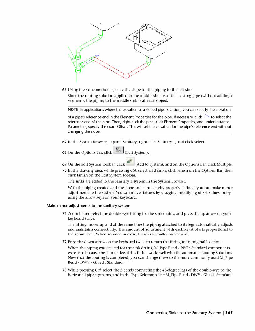
66 Using the same method, specify the slope for the piping to the left sink.
Since the routing solution applied to the middle sink used the existing pipe (without adding asegment), the piping to the middle sink is already sloped.
NOTE In applications where the elevation of a sloped pipe is critical, you can specify the elevation
of a pipe’s reference end in the Element Properties for the pipe. If necessary, click to select thereference end of the pipe. Then, right-click the pipe, click Element Properties, and under InstanceParameters, specify the exact Offset. This will set the elevation for the pipe’s reference end withoutchanging the slope.
67 In the System Browser, expand Sanitary, right-click Sanitary 1, and click Select.
68 On the Options Bar, click (Edit System).
69 On the Edit System toolbar, click (Add to System), and on the Options Bar, click Multiple.
70 In the drawing area, while pressing Ctrl, select all 3 sinks, click Finish on the Options Bar, thenclick Finish on the Edit System toolbar.
The sinks are added to the Sanitary 1 system in the System Browser.
With the piping created and the slope and connectivity properly defined, you can make minoradjustments to the system. You can move fixtures by dragging, modifying offset values, or byusing the arrow keys on your keyboard.
Make minor adjustments to the sanitary system
71 Zoom in and select the double wye fitting for the sink drains, and press the up arrow on yourkeyboard twice.
The fitting moves up and at the same time the piping attached to its legs automatically adjustsand maintains connectivity. The amount of adjustment with each keystroke is proportional tothe zoom level. When zoomed in close, there is a smaller movement.
72 Press the down arrow on the keyboard twice to return the fitting to its original location.
When the piping was created for the sink drains, M_Pipe Bend - PVC : Standard componentswere used because the shorter size of this fitting works well with the automated Routing Solutions.Now that the routing is completed, you can change these to the more commonly used M_PipeBend - DWV - Glued : Standard.
73 While pressing Ctrl, select the 2 bends connecting the 45-degree legs of the double-wye to thehorizontal pipe segments, and in the Type Selector, select M_Pipe Bend - DWV - Glued : Standard.
Connecting Sinks to the Sanitary System | 367

74 Select the 2 elbows in the section of piping between the double wye fitting and the reducingsanitary wye, and select M_Pipe Bend - DWV - Glued : Standard in the Type Selector.
75 Using the method learned earlier, highlight the leftmost sink, and press Tab 3 times to checkconnectivity. (After the third tab, the entire system should be highlighted.)
76 If you want to save your work, click File menu ➤ Save As; otherwise, skip the next 2 steps.
77 You can save the open file if you wish; a new dataset is supplied in the next exercise.
78 Click File menu ➤ Close.
368 | Chapter 7 Plumbing Systems

NOTE Do not overwrite the original dataset.
79 Proceed to the next exercise, Refining the Sanitary Stack on page 369 to continue creating thesanitary system.
Refining the Sanitary Stack
In this exercise you continue with the work on the sanitary system, adjusting the sanitary stack.
Dataset:
■ Click File menu ➤ Open.
■ In the left pane of the Open dialog, click the Training Files icon.
■ Open Metric ➤ Plumbing ➤ m Refining Waste Stack Connection.rvt.
1 In the Project Browser, expand Mechanical ➤ Plumbing ➤ 3D Views, and double-click 3DPlumbing to make it the active view.
2 Zoom in on the elbow at the upper end of the vertical pipe connected to the sanitary outlet,and select the horizontal pipe.
3 Click the pipe’s connector snap at the elbow, and carefully drag it away from the elbow, whilemaintaining the same angle.
4 Select the elbow, and press Delete.
5 Select the vertical pipe segment, and on the Options Bar, specify 150 mm for D (diameter).
Refining the Sanitary Stack | 369

Add a reducing wye to the stack
6 On the Plumbing tab on the Design Bar, click Pipe Fitting, and select M_Pipe Reducing Wye -DWV - Glued : Standard.
7 Move the cursor over the center of the open end of the vertical pipe, and when the Extensionsnap displays, press the Space Bar once (so that the fitting assumes the elevation of the end ofthe pipe), and click to place the fitting.
8 Click Modify.
The wye is added to the vertical segment.
If necessary, select the wye, and click to rotate the 45 degree leg until it is pointing towardthe sanitary piping.
9 Select the wye, click the value for the 45 degree leg, enter 100 to change its size, and press Enter.
370 | Chapter 7 Plumbing Systems

Create a Section view to complete the stack connections
10 Expand Views (Discipline) ➤ Mechanical ➤ Plumbing ➤ Floor Plans, double-click 2 - Plumbing,and zoom in on the sanitary outlet.
11 On the View tab on the Design Bar, click Section, draw a section to the right of the sanitaryoutlet as shown, and click Modify.
12 Double-click the section view symbol in the drawing area to open the new section view.
13 On the View Control Bar, for Detail Level, specify Fine.
14 Zoom in, and select the reducing wye fitting.
15 On the Options Bar, enter -750 for Offset, and press Enter.
This places the wye at a level that will allow creating a routing solution that will not changethe slope of the main segment.
16 Right-click the connector on the 45 degree leg, click Draw Pipe, press Space so that the pipeassumes the size and elevation of the fitting, and draw the pipe in line with 45 degree leg andwhen the center line for the main segment displays, click to specify the end of the pipe.
Refining the Sanitary Stack | 371

NOTE There is a known issue when connecting piping to the reducing tee. The fitting moves towardthe pipe being added after the pipe is drawn. The exact position of the riser is not critical in thisapplication. However, when the location is critical, it will be necessary to move the piping after makingthe connection.
17 Click Modify.
This adds a short segment of pipe (from the wye).
18 While pressing Ctrl, select the short pipe segment and the main pipe, and on the Options Bar,click Routing Solutions.
19 On the Options Bar, select solution 3 of 3, and click Finish to create piping for that solution.
20 Select the bend created by the routing solution tool, and in the Type Selector select M_PipeBend - DWV - Glued : Standard.
21 Right-click the open connector on the reducing wye, click Draw Pipe, and in the Type Selector,select Pipe Types : PVC Sanitary Vent.
22 Move the cursor up and press Space to assume the size and elevation of the fitting, then enter1200 and press Enter to add a 1200 mm vertical vent pipe.
23 Click Modify.
24 Check slope and connectivity as described previously.
372 | Chapter 7 Plumbing Systems

25 You can save the open file if you wish; a new dataset is supplied in the next exercise.
26 Click File menu ➤ Close.
NOTE Do not overwrite the original dataset.
27 Proceed to the next exercise, Refining the Urinal Lines on page 373 to continue creating theplumbing system.
Refining the Urinal Lines
The waste piping from the urinal extends down through floor directly beneath the urinals before connectingto the sanitary main piping. In this exercise you change the routing for the waste piping from the urinals,running it inside the wall, then down to connect with the sanitary main.
Dataset:
■ Click File menu ➤ Open.
■ In the left pane of the Open dialog, click the Training Files icon.
■ Open Metric ➤ Plumbing ➤ m Refining Urinal Waste Lines.rvt.
1 In the Project Browser, expand Mechanical ➤ Plumbing ➤ Floor Plans, and double-click 2 -Plumbing to make it the active view.
2 Zoom in on the piping behind the urinals, and draw a left-to-right pick box around the pipingabove the urinals as shown. (If necessary, use the Filter tool to select only piping and fittings.)
Refining the Urinal Lines | 373

3 Press Delete.
4 Select the pipe connected to the wye above the leftmost toilet, click the connector snap, anddrag it to the right to a point midway between the toilet and urinal.
The next 4 steps draw a series of pipe segments, starting at the level of the original pipe, thenplacing a vertical segment and continuing the run at 150, and finally connecting to the sanitarydrain on the left urinal.
5 Right-click the connector at the open end of the shortened pipe, click Draw Pipe, press the Spaceso that the pipe assumes the size and elevation of the existing pipe.
6 On the Options Bar, do the following:
■ Verify that Pipe Types : PVC Sanitary is selected in the Type Selector
■ For D, specify 50 mm
■ Click (Auto Connect)
■ For slope, specify 1.00
7 Drag the preview to the left approximately 200 mm, and click to specify the end of the pipe.
8 On the Options Bar, for Offset, enter 150 and press Tab.
9 Continue drawing the pipe run to the left, and when the snap for the center line of the leftmosturinal displays, click to specify the end of the pipe.
10 Click Modify.
374 | Chapter 7 Plumbing Systems

11 Select the leftmost urinal, and on the Options Bar, click (Connect Into).
12 In the Select Connector dialog, click Connector 2 : Sanitrary Round : 50mm Out, and click OK.
13 In the drawing area, click the pipe above the urinal.
14 Using the same method, connect the remaining urinals to the sanitary main.
15 Draw a pick box around the 3 urinals and the horizontal 50 mm piping just added as shown,
and on the Options Bar, click (Filter Selection). Do not include the riser and fitting.
16 In the Filter dialog, clear Plumbing Fixtures and click OK.
17 On the Routing Modify toolbar, click (Slope).
18 On the Options Bar, verify that 1.00 for Slope, and click Finish.
Refining the Urinal Lines | 375

The slope is applied to the selected piping.
19 In the Project Browser, expand Mechanical ➤ Plumbing ➤ 3D Views, double-click 3D- Plumbingto make it the active view, and check the slope and connectivity as described previously.
Resize pipes
20 In the Project Browser, double-click 2 - Plumbing to make it the active view.
21 Zoom in on the piping above the urinals, and draw a left-to-right pick box around only themain piping (including the short 100 mm segment) as shown.
22 On the Options Bar, specify 80 mm for D (diameter).
376 | Chapter 7 Plumbing Systems

In the next steps you will change the elbow behind the left urinal to a tee to create the cleanout.However, you cannot upgrade an elbow to a tee unless all of the connections are the same size.So, first you must temporarily resize the pipe to the urinal.
Add a cleanout
23 Select the pipe between the 80 mm elbow and the left urinal, and on the Options Bar, specify80 mm for D (diameter).
24 Select the elbow, and click the + control on the left to add a leg for the cleanout.
25 On the Plumbing tab on the Design Bar, click Pipe Fitting, and in the Type Selector, select M_PipePlug - PVC : Standard.
26 Move the cursor over the open connector on the sanitary tee above the leftmost urinal, andwhen the extension snap displays, click to place the plug on the tee.
27 Select the pipe to the urinal again, and on the Options Bar, specify 50 mm for D.
Redefine fittings
28 Select the 3 sanitary tees behind the urinals, and in the Type Selector, verify that M_Pipe ReducingShort Tee - Sanitary - Glued : Standard is selected.
29 Select the 50 pipes connecting the urinal drains to the main, and on the Options Bar, for D,select 80 mm, then select 50 mm.
This eliminates the need for transitions between the pipes and the tees.
30 In the Project Browser, expand Mechanical ➤ Plumbing ➤ 3D Views, double-click 3D- Plumbingto make it the active view.
31 Click View menu ➤ Orient ➤ North, and zoom in on the area between the toilet and the leftmosturinal.
32 Select the vertical pipe segment between the toilets and the urinals, and drag it to a point midwaybetween the 2 sanitary tees.
Refining the Urinal Lines | 377

This will provide the space required to change the short elbows to the DWV Bends that allowbetter sanitary waste flow.
33 Click View menu ➤ Orient ➤ Northeast, and zoom in on the area between the toilet and theleftmost urinal.
34 Select the elbows at each end of the vertical pipe, and select M_Pipe Bend - DVW - Glued :Standard.
35 Check slope and connectivity as described previously.
378 | Chapter 7 Plumbing Systems

36 You can save the open file if you wish; a new dataset is supplied in the next exercise.
37 Click File menu ➤ Close.
NOTE Do not overwrite the original dataset.
38 Proceed to the next exercise, Adding Vents to the System on page 379 to continue creating theplumbing system.
Adding Vents to the System
In this exercise you finish the work on the sanitary system, adding the vent piping at several points in thewaste piping.
Dataset:
■ Click File menu ➤ Open.
■ In the left pane of the Open dialog, click the Training Files icon.
■ Open Metric ➤ Plumbing ➤ m Creating Sanitary Vent Piping.rvt.
1 In the Project Browser, expand Plumbing ➤ 3D Views and double-click 3D Plumbing to viewthe piping just added.
If necessary, clear unwanted components from the 3D view using the Visibility/Graphic Overridesdialog as described previously.
2 Click View menu ➤ Orient ➤ Northeast, and zoom in on the area between the toilets and theurinals.
3 Select the elbow at the upper end of the vertical pipe segment, and click the + control above itto change the fitting to a tee.
4 On the Plumbing tab on the Design Bar, click Pipe, and in the Type Selector, select Pipe Types: PVC Sanitary Vent.
5 Click the connector at the upper end of the tee to specify the start of the pipe.
6 On the Options Bar, specify 50 mm for D (diameter), and specify 4000 for Offset, specify 0.00for Slope Angle.
Adding Vents to the System | 379

NOTE You must press Tab or move the cursor into the drawing area for the new offset value to berecognized.
7 Click Apply.
8 Click Modify.
Apply a filter to the vent piping
9 Enter the keyboard shortcut, VG (Visibility/Graphics).
10 On the Filters tab in the Visibility/Graphic Overrides dialog, do the following:
a Click Edit/New.
b In the Filters dialog, select Sanitary from the Filters list, and click (Duplicate).
c Right-click Sanitary 1, click Rename, rename the filter Sanitary Vent, and click OK.
d Under the Filter Rules, specify Filter by as System Type ➤ contains ➤ Sanitary Vent, andclick OK.
e In the Visibility/Graphic Overrides dialog, click Add.
f In the Add Filters dialog, select Sanitary Vent, and click OK.
g For Sanitary Vent, click the Lines column, and click Override.
h In the Line Graphics dialog, click the Color button, and in the Color dialog, select (green), and click OK.
i In the Line Graphics dialog, for Pattern, select IMPORT-DASHED (2)
j Click OK twice.
380 | Chapter 7 Plumbing Systems

Vent piping throughout the plan appear as dashed green lines.
Create additional vents
11 Double-click Plumbing ➤ Floor Plans ➤ 2 - Plumbing to make it the active view, and zoom into view the urinals and toilets.
12 On the View tab on the Design Bar, click Section, and place a section above the urinals andtoilets as shown.
13 Double-click the section symbol to open the section view, and enter the keyboard shortcut VG.
14 In the Visibility/Graphic Overrides dialog, clear unwanted architectural components from theview as described previously.
15 On the View Control Bar, for Detail Level, specify Fine, and for Model Graphics Style, specifyWireframe.
16 On the Plumbing tab on the Design Bar, click Pipe, and verify that Pipe Types : PVC SanitaryVent is selected in the Type Selector.
17 On the Options Bar, verify the (Auto Connect) is selected, and enter for slope.
18 Click a point midway between the tees connecting the first toilet and floor drain to specify thestart of the pipe.
Adding Vents to the System | 381

19 Begin drawing the vertical pipe, and on the Options Bar, specify 50 mm for D (diameter).
20 At a point above the toilets, click to specify the end of the first pipe section, then drag thepreview to the right and when the center snap for the previously created vent displays, click tomake the connection to the vent as shown.
21 Click Modify.
The vent is automatically created and connected with the earlier vent pipe.
22 Right-click the new horizontal pipe, and click Element Properties.
23 In the Element Properties dialog, under Instance Parameters, for Offset, enter 2800 to specifythe elevation for the reference end of the pipe, and click OK.
24 Select the tee that was inserted when you connected the vents, and click the + control to updatethe tee to a cross.
25 Place another vent between the two rightmost urinals:
a Click the midpoint of the pipe between the urinals.
b Begin the vertical pipe.
c For D, specify 50 mm.
d When the snap for the center line for the cross displays, draw the pipe to the left to theopen leg of the cross.
e If necessary, press Tab to display the connector, and click to make the connection.
382 | Chapter 7 Plumbing Systems

f Click Modify.
26 Double-click 3D - Plumbing to make it the active view.
27 If either of the tees that were added need to be reoriented according to the slope of the piping,use the Flip control to make the adjustment.
Adding Vents to the System | 383

Add a vent to the sinks
28 Click View menu ➤ Orient ➤ Southeast, and zoom in on the area of the double wye behind thesinks.
29 Select the elbow above the double wye for the drain section to the middle sink, and click the +control above the elbow to change it to a tee.
30 While pressing Ctrl, select the tee and the short pipe segment that connects it to the double wye,and on the Options Bar, specify 50 mm for D (diameter).
31 Right-click the tee, click Draw Pipe, verify that Pipe Types : PVC Sanitary Vent is selected in theType Selector, and begin drawing a vertical vent pipe.
32 On the Options Bar, specify 50 mm for D (diameter), and specify 2800 for Offset, move thecursor into the drawing area, then click Apply.
33 Click Modify.
384 | Chapter 7 Plumbing Systems
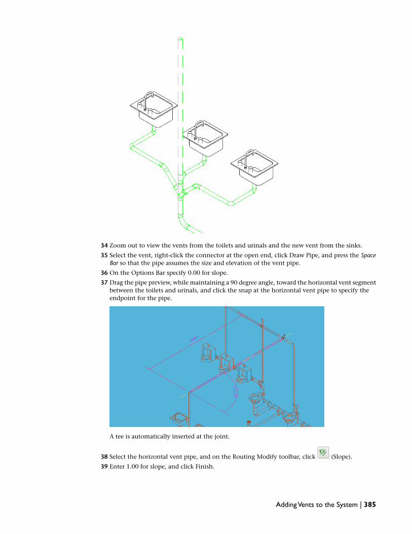
34 Zoom out to view the vents from the toilets and urinals and the new vent from the sinks.
35 Select the vent, right-click the connector at the open end, click Draw Pipe, and press the SpaceBar so that the pipe assumes the size and elevation of the vent pipe.
36 On the Options Bar specify 0.00 for slope.
37 Drag the pipe preview, while maintaining a 90 degree angle, toward the horizontal vent segmentbetween the toilets and urinals, and click the snap at the horizontal vent pipe to specify theendpoint for the pipe.
A tee is automatically inserted at the joint.
38 Select the horizontal vent pipe, and on the Routing Modify toolbar, click (Slope).
39 Enter 1.00 for slope, and click Finish.
Adding Vents to the System | 385

40 Highlight any component in the system and press Tab 3 times to check the connectivity of thesystem as described previously.
41 You can save the open file if you wish; a new dataset is supplied in the next exercise.
42 Click File menu ➤ Close.
NOTE Do not overwrite the original dataset.
43 Proceed to the next exercise, Create the Cold Water System on page 386 to continue creating theplumbing system.
Create the Cold Water System
In this exercise you create the cold water system and add piping to connect all of the fixtures in the men’sroom to the system.
Dataset:
■ Click File menu ➤ Open.
■ In the left pane of the Open dialog, click the Training Files icon.
■ Open Metric ➤ Plumbing ➤ m Creating Cold Water Piping.rvt.
Create new pipe types and specify default pipe fittings
1 In the Project Browser, expand Families ➤ Pipes ➤ Pipe Types, right-click Standard, and clickDuplicate.
2 Right-click Standard 1, click Properties.
3 In the Type Properties dialog, click Rename.
4 In the Rename dialog, for New, enter Cold Water, and click OK.
386 | Chapter 7 Plumbing Systems

5 In the Type Properties dialog, in the Type Parameters under Mechanical, verify that the followingdefault fittings are specified:
■ For Elbow, specify M_Pipe Elbow : Standard
■ For Preferred Junction Type, specify Tee
■ For Tee, specify M_Pipe Tee: Standard
■ For Tap, specify None
■ For Cross, specify M_Pipe Cross: Standard
■ For Transition, specify M_Pipe Transition : Standard
■ For Union, specify M_Pipe Straight Coupling: Standard
6 Click Apply, then click Duplicate, and in the Name dialog, for Name, enter Hot Water, and clickOK twice.
The default fittings for the hot water pipe are the same as those specified for the cold water pipe.
Specify Mechanical Settings for the cold and hot water systems
7 On the Plumbing tab on the Design Bar, click Mechanical Settings.
8 In the left pane of the Mechanical Settings dialog, expand Pipe Settings ➤ Conversion, clickMain, and in the right pane, select Domestic Cold Water from the System Type list.
9 In the table, specify Pipe Types : Cold Water for Pipe Type and 2700 for Offset.
10 In the left pane, click Branch, in the right pane, select Domestic Cold Water from the SystemType list, and specify Pipe Types : Cold Water for Pipe Type and 2700 for Offset.
11 In the left pane, click Main, and in the right pane, select Domestic Hot Water from the SystemType list.
12 In the table, specify Pipe Types : Hot Water for Pipe Type and 2650 for Offset.
13 In the left panel, click Branch, in the right pane, select Domestic Hot Water from the SystemType list, and specify Pipe Types : Hot Water for Pipe Type and 2650 for Offset.
You now have the cold water piping at 2700 and the hot water piping at 2650, which placesthe piping above the ceiling, and avoids potential obstructions and conflicts between systems.
14 Click OK.
Create the cold water system
15 In the Project Browser, expand Mechanical ➤ Plumbing ➤ Floor Plans, and double-click2 - Plumbing to make it the active view.
16 Press F9 to open the System Browser, click the title bar for the browser and dock it by draggingit to the bottom of the drawing area.
17 Right-click a table heading in the system browser, click View ➤ Piping.
18 Draw a left-to-right pick box around all of the plumbing fixtures in the men’s room, and on the
Options Bar click (Filter Selection).
19 In the Filter dialog, click Check None, then select Plumbing Fixtures, and click OK.
20 While pressing Shift, click the floor drain.
The floor drain has neither a hot or cold water connector, and as long as there is a fixture withouta common connector type, the Options Bar will not have active tools for creating a system.
21 On the Options Bar, click (Create Domestic Cold Water System).
Create the Cold Water System | 387

The Domestic Cold Water folder is added in the system browser and all of the fixtures have beenadded to the Domestic Cold Water 1 system.
Create piping for the cold water system
22 Zoom in on the area below the sinks.
23 On the Plumbing tab on the Design Bar, click Pipe, and in the Type Selector, select Pipe Types: Cold Water.
24 On the Option Bar, specify 0.00 for Slope.
25 Move the cursor over the cold water connector on the leftmost sink, click to specify the startingpoint for the pipe, and press the Space Bar so that the pipe assumes the size and elevation of theconnector.
26 On the Options Bar, specify 750 for Offset, click a point between the sink and the wall to specifythe endpoint for the pipe.
27 Drag the preview to the right until the snap for the cold water connector for the rightmost sinkdisplays, and click to specify the end the segment.
28 Move the preview up to the cold water connector on the sink, and click to end the run as shown.
29 Click Modify.
30 Enter the keyboard shortcut VG.
31 In the Visibility/Graphic dialog, click Show categories from all disciplines, clear Casework, andclick OK.
32 Select the middle sink in the view, and on the Options Bar, click (Connect Into).
33 In the Select Connector dialog, select the domestic cold water connector, click OK, and clickthe cold water pipe behind the sinks.
Piping is added to connect the sink to the cold water system.
34 Zoom in on the area between the middle and rightmost sink.
35 On the Plumbing tab, click Pipe.
388 | Chapter 7 Plumbing Systems

36 Move the cursor over the cold water pipe at a point between the sinks.
37 Click to specify the starting point for the pipe as shown, drag the preview into the center of thewall behind the sinks, press Tab to avoid connecting to the sanitary piping, and click to endthat segment.
38 On the Options Bar, specify 2700 for Offset, drag the preview up and into the mechanical roomabove the men’s room, and click to specify an endpoint for the pipe.
39 Click Modify.
40 Zoom in on the area between the toilets, and verify that the cold water pipe is not obstructedby the vertical vent. (If necessary, select the cold water pipe, and use the keyboard left arrow tomove the pipe to the left.)
41 On the Plumbing tab, click Pipe.
42 Move the cursor over a point on the cold water pipe in the chase, just above the wall, click thesnap on the cold water pipe, and press the Space Bar so that the pipe assumes the size andelevation of the existing pipe.
43 Drag the preview to the left, and at a point near the vent that rises between the toilets andurinals, click to specify the end of the pipe.
44 On the Options Bar, specify 356 for Offset, press Tab, and click Apply.
Create the Cold Water System | 389

45 Click Modify.
46 In the Project Browser, expand Mechanical ➤ Plumbing ➤ 3D Views, double-click 3D- Plumbing,and click View menu ➤ Orient ➤ Northeast.
47 Zoom in on the area behind the toilets, select the rightmost toilet.
48 On the Options Bar click (Connect Into), and then click the vertical cold water pipe.
Piping is automatically created between the vertical pipe and the toilet cold water connector.
49 Select the elbow behind the toilet, and click the + control to change it to a tee.
50 On the Plumbing tab, click Pipe.
51 Select the tee, right-click the open connector, click Draw Pipe, and press the Space Bar so thatthe pipe assumes the size and elevation of the fixture.
52 Drag the preview to the left while maintaining the same angle, and when the center line forthe left toilet displays, click to specify the endpoint as shown.
390 | Chapter 7 Plumbing Systems

53 Click Modify.
54 Select the leftmost toilet, and on the Options Bar click , and click the horizontal coldwater pipe that you added to the tee.
Piping is automatically created between the vertical pipe and the toilet cold water connector.
55 Select the rightmost urinal, and on the Options Bar click , and click the vertical cold waterpipe.
Piping is automatically created between the vertical pipe and the toilet cold water connector.
56 Use the same method, connect the remaining urinals to the horizontal cold water pipe.
Create the Cold Water System | 391

All of the cold water piping is in place. The final steps in this exercise adjust the size of severalsections of the piping.
Adjust cold water pipe sizes
57 Use the View Cube in the upper-right corner of the view to spin the 3D - Plumbing view asshown.
58 Select the main cold water piping from the mechanical room, the tee, and the horizontal segmentto the sinks, as shown.
392 | Chapter 7 Plumbing Systems

59 On the Options Bar, specify 50 mm for D (diameter).
60 Select the cold water branch piping from the main, feeding the toilets and urinals (includingthe tees, but leaving the branch to the urinals as is), as shown.
61 On the Options Bar, specify 40 mm for D (diameter).
62 Spin the 3D Plumbing view as needed to see the piping behind the sinks.
63 Select the main and branch pipe segments as shown (including the tee behind the middle sink).
Create the Cold Water System | 393

64 On the Options Bar, specify 20 mm for D (diameter).
65 Highlight a segment of cold water pipe in the system and press Tab to check the connectivityof the system as described previously.
66 You can save the open file if you wish; a new dataset is supplied in the next exercise.
67 Click File menu ➤ Close.
NOTE Do not overwrite the original dataset.
68 Proceed to the next exercise, Create the Hot Water System on page 394.
Create the Hot Water System
In this exercise you add a water heater, create the hot water system, and add piping to connect the sinks inthe men’s room to the system.
Dataset:
■ Click File menu ➤ Open.
■ In the left pane of the Open dialog, click the Training Files icon.
■ Open Metric ➤ Plumbing ➤ m Creating Hot Water Piping.rvt.
Create the hot water system
1 In the Project Browser, expand Mechanical ➤ Plumbing ➤ Floor Plans, double-click 2 - Plumbing,and zoom in on the sinks.
394 | Chapter 7 Plumbing Systems

2 Press F9 to open the System Browser, click the title bar for the browser, and dock it by draggingit to the bottom of the drawing area.
3 Right-click a table heading in the System Browser, and click View ➤ Piping.
4 Draw a left-to-right pick box around the 3 sinks in the men’s room, and on the Options Bar,
click (Filter Selection).
5 In the Filter dialog, click Check None, select Plumbing Fixtures, and click OK.
6 On the Options Bar, click (Create Domestic Hot Water System).
The Domestic Hot Water folder is added in the system browser and all of the fixtures have beenadded to the Domestic Hot Water 1 system.
Add a water heater to the hot and cold water systems
7 Click File menu ➤ Load from Library ➤ Load Family.
8 In the left pane of the Open dialog, click the Training Files icon.
9 Expand Metric ➤ Plumbing.
10 Double-click M_Water Heater.rfa.
11 Zoom in on the mechanical room above the men’s room.
12 On the Mechanical tab on the Design Bar, click Mechanical Equipment, and in the Type Selector,select M_Water Heater :152L.
13 Move the water heater preview into the mechanical room, to the left of the main cold waterpipe, press the Space Bar 3 times to orient the water heater with the electrical connections tothe left, and click to place the water heater as shown.
14 In the System Browser, expand Domestic Hot Water, right-click Domestic Hot Water 1, and clickSelect.
15 On the Options Bar, click (Edit System).
The Edit System toolbar is activated.
16 On the Edit System toolbar, click (Add to System), click the water heater, and on the EditSystem toolbar, click Finish.
17 In the System Browser, expand Domestic Cold Water, right-click Domestic Cold Water 1, andclick Select.
Create the Hot Water System | 395

18 On the Options Bar, click (Edit System).
19 Using the same method, add the water heater to the cold water system.
20 Select the water heater in the view, and on the Options Bar, click (Connect Into).
21 In the Select Connector dialog, select the domestic cold water connector, click OK, and clickthe main cold water pipe.
A segment of pipe is added connecting the water heater to the cold water system.
22 Select the open end of the main cold water pipe, right-click the connector, click Draw Pipe, andadd 2 segments extending the main cold water piping into the chase.
23 On the Plumbing tab, click Pipe, and in the Type Selector, select Pipe Types : Hot Water.
24 Move the cursor over the water heater, click when the hot water connector displays, and pressthe Space Bar so that the pipe assumes the size and elevation of the connector.
25 On the Options Bar, specify 2650 for Offset.
26 Specify an end point for the pipe between the water heater and the cold water pipe to the right,and then drag the pipe preview down to a point to the right and just above the middle sink.
396 | Chapter 7 Plumbing Systems

27 Click Modify.
28 On the Plumbing tab, click Pipe, and in the Type Selector, select Pipe Types : Hot Water.
29 Move the cursor over the hot water connector on the leftmost sink, click to specify the startingpoint for the pipe, and press the Space Bar so that the pipe assumes the size and elevation of theconnector.
30 On the Options Bar, specify 800 for Offset.
31 Click a point between the cold water piping and the wall to specify the endpoint for the pipe,drag the preview to the right until the snap below the hot water connector for the rightmostsink displays, and click to specify the end of the segment.
32 Move the preview up to the hot water connector on the sink and click to end the run as shown.
33 Click Modify.
Create the Hot Water System | 397

34 Select the middle sink in the view, and on the Options Bar, click (Connect Into), andclick the hot water pipe below the sinks.
In this case, the Select Connector dialog was not displayed because the only possible connectionwas to the hot water system.
35 Select the hot water piping from the water heater.
36 Right-click the open connector, click Draw Pipe, and press the Space Bar so that the pipe assumesthe size and elevation of the connector.
37 Drag the preview down into the center of the wall below the sinks, and click to end that segment.
38 On the Options Bar, specify 800 for Offset, click Apply.
39 Click Modify.
40 In the Project Browser, expand Mechanical ➤ Plumbing ➤ 3D Views, double-click 3D- Plumbing,click View menu ➤ Orient ➤ Southeast, and zoom in on the area behind the sinks.
41 On the Plumbing tab, click Pipe, click the connector at the open end of the vertical hot waterpipe, press the Space Bar so that the pipe assumes the size and elevation of the connector.
398 | Chapter 7 Plumbing Systems

42 While maintaining a 90 degree angle, drag the preview to the piping connecting the hot waterconnectors for the sinks, and click.
43 Click Modify.
44 In the Project Browser, expand Mechanical ➤ Plumbing ➤ Floor Plans, double-click 2 - Plumbing.
45 Highlight a fixture in the view, press Tab 3 times to check connectivity as described previously.
46 You can save the open file if you wish.
47 Click File menu ➤ Close.
NOTE Do not overwrite the original dataset.
This concludes the tutorial for plumbing systems.
Create the Hot Water System | 399

400

Fire Protection Systems
In this tutorial, you create a wet and dry fire protection system using a linked architectural model of a building project.As you create the systems, you follow a series of exercises that teach the recommended systems design workflow for RevitMEP 2009. By following the recommended workflow, you learn the best practices for designing systems with Revit MEP.
The goal of this tutorial is to teach you to create a fire protection system using Revit MEP 2009. At the end of this tutorial,you will understand the process, methodology, and specific techniques for designing fire protection systems.
NOTE All exercises in this tutorial are designed to be completed sequentially; each exercise is dependent on thecompletion of the previous exercise. After finishing each exercise, you can choose to save your work. However, it ishighly recommended that you always begin an exercise by opening the provided dataset. This dataset includes thework from the previous exercise(s) and ensures a seamless training session. The datasets that you use to completethis tutorial are located in the Training Files ➤ Metric directory. You can search this directory to verify that thedatasets have been downloaded. If the tutorial datasets are not present, go tohttp://www.autodesk.com/revitmep-documentation and download them.
Designing Fire Protection Systems
The most common method of designing systems in Revit MEP is to work within a linked architecturalbuilding model. In this tutorial, you will use a project file that has already been linked to an architecturalmodel, with Space components placed in the areas throughout the model. To learn more about linking andpreparing an architectural model, see Planning Mechanical Systems in the Mechanical Systems tutorial.
NOTE The architectural model used with this tutorial is in the Architectural folder. You should maintain the relativepath to the architectural model. However, if the link is lost, you can click File menu ➤ Manage Links to reload thelinked model. On the Revit tab on the Manage Links dialog, click Reload From, navigate to TrainingFiles ➤ Metric ➤ Fire Protection ➤ Metric_Arch_Model, and select m Office Building.rvt.
In this lesson, you will create both wet and dry fire protection systems for the second floor of an officebuilding. You begin each fire protection system design by placing sprinklers in the rooms. Then, you createa system to logically connect the sprinklers, and finally, you create piping to physically connect the sprinklers.During the fire protection design process, you create views and pipe types, manually modify the pipes andfittings, insert fittings, create schedules, and size and tag the pipes.
8
401

Starting the Fire Protection Project
In this exercise, you begin work on the project that contains both the wet and dry fire protection systems.You create new pipe types, and then you configure conversion settings that you will use when you createpiping to physically connect the sprinklers. You will also check a Space Schedule that you can use to assessthe coverage for the fire protection systems.
Dataset
■ Click File menu ➤ Open.
■ In the left pane of the Open dialog, click the Training Files icon.
■ Open the m Starting the Fire Protection Project.rvt file located in the Metric ➤ Fire Protection ➤ folder.
Create new pipe types
1 In the Project Browser, expand Families ➤ Pipes ➤ Pipe Types.
2 Right-click Standard, and click Duplicate.
A copy is made of the Standard pipe type.
3 Right-click the copy, and click Properties.
4 In the Element Properties dialog, click Rename.
5 In the Rename dialog, for New, enter Fire Protection Wet, and click OK.
The new pipe type is created based on the Standard pipe type. Next, you modify the pipe typeproperties.
6 In the Type Properties dialog, under Mechanical, for Material, select Carbon Steel.
Next, you create another pipe type based on the new pipe type that you created.
7 With the Type Properties dialog open, click Duplicate, and enter Fire Protection Dry for the newpipe type name, and click OK.
Notice that the new dry pipe type inherits the same type properties from the wet pipe type,including the new material property.
8 Click OK twice to create the new wet and dry pipe types.
9 In the Type Selector, verify that Pipe Types : Fire Protection Wet and Pipe Types : Fire ProtectionDry are listed.
Next, you need to configure the pipe conversion settings.
Configure pipe conversion settings
10 On the Fire Protection tab of the Design Bar, click Mechanical Settings.
NOTE If the Fire Protection tab is not available on the Design Bar, right-click the Design Bar, andclick Fire Protection.
You can also click Settings menu ➤ Mechanical Settings.
11 In the left pane of the Mechanical Settings dialog, under Pipe Settings ➤ Conversion, selectMain.
12 For System Type, select Fire Protection Wet.
The conversion settings for the Fire Protection Wet system type display.
13 Under System Type, do the following:
■ For Pipe Type, select Pipe Types : Fire Protection Wet.
402 | Chapter 8 Fire Protection Systems

■ For Offset, verify that 2800 is selected.This offset elevation places the pipe main at 2800 mm above the referenced level for theviews. Level 2 is the referenced level for the views where you will be designing. So, the pipemain will be offset from level 2. You now specify the conversion settings for the pipe branches.
14 In the left pane of the Mechanical Settings dialog, select Branch.
15 For System Type, select Fire Protection Wet.
16 Under System Type, do the following:
■ For Pipe Type, select Pipe Types : Fire Protection Wet.
■ For Offset, verify that 2800 is specified.This offset elevation places the pipe branches at 2800 mm above the referenced level for theviews.
IMPORTANT The branch offset allows you to automatically create branches that run above or belowthe main and other obstacles. This is useful for avoiding interference with pipes, duct, structuralbeams, or architectural components.
17 Using the same method, for System Type Fire Protection Dry, for Offset verify 2800, and specifyPipe Types : Fire Protection Dry for the Main and Branch piping.
18 Click OK.
NOTE Conversion settings are applied when you convert the pipe layout path to physical piping.You can configure the Conversion settings at the beginning or during your project. However, youshould configure or verify the Conversion settings before you convert a layout path. Configuring theConversion settings is usually a one-time process unless you need to change them during your project.You can also configure these settings by clicking Settings on the Options Bar when the Layout Pathtool is open.
Create a Space Schedule
19 On the Fire Protection tab of the Design Bar, click Schedule/Quantities.
20 In the New Schedule dialog, do the following:
■ Under Category, select Spaces.Notice that the schedule name and the phase are automatically added.
■ Verify that Schedule building components is selected.
■ Click OK.
Define columns
21 On the Fields tab of the Schedule Properties dialog, under Available fields, select Area, and clickAdd.
This adds the Area field to the list of scheduled fields to include in the schedule. Scheduled fieldsdisplay as columns in the schedule.
22 While pressing Ctrl, select the following fields from the Available fields list:
■ Level
■ Name
■ Number
23 Click Add to add the fields to the Scheduled fields list.
To remove a field, select it, and click Remove.
Starting the Fire Protection Project | 403

24 Select a field, and use the Move Up and Move Down buttons to arrange the Scheduled fields listas follows:
■ Number
■ Name
■ Level
■ Area
Next, you create a calculated value parameter to indicate the minimum number of sprinklersrequired for each space. This information is based on the project specification and the fireprotection codes.
Create a calculated value parameter
25 Click Calculated Value.
26 In the Calculated Value dialog, do the following:
■ For Name, enter Minimum Sprinklers.
■ Verify that Formula is selected.
■ For Discipline, verify that Common is selected.
■ For Type, verify that Number is selected.
■ For Formula, enter Area/12.1.The fire protection code requires one sprinkler for every 12.1 square meters.
NOTE Formulas are case sensitive.
27 Click OK.
The Minimum Sprinklers calculated value is added to the scheduled fields (at the bottom of thelist). This calculated value parameter allows you to immediately determine what spaces meetthe sprinkler design and code requirements.
Organize the data
28 On the Filter tab of the Schedule Properties dialog, do the following:
■ For Filter by, select Level.
■ Verify that equals is selected.
■ Under Level, select Level 2.
■ For And, verify that (none) is selected.
29 On the Sorting/Grouping tab of the Schedule Properties dialog, do the following:
■ For Sort by, select Number.
■ Verify that Ascending is selected.
■ For Then by, verify that (none) is selected.
■ Verify that Grand totals is cleared and Itemize every instance is selected.
30 On the Formatting tab of the Schedule Properties dialog, do the following:
■ Under Fields, select Minimum Sprinklers.
■ For Field formatting, click Field Format.
404 | Chapter 8 Fire Protection Systems

31 In the Format dialog, do the following:
■ Clear Use default settings.
■ For Units, select Fixed.
■ For Rounding, select 2 decimal places.
■ Click OK twice.
A new view called Space Schedule opens and is located under Schedules/Quantities in the ProjectBrowser. Notice that only the data for the level 2 spaces displays, sorted according to spacenumber. You can refer to the minimum number of sprinklers per space data as you place sprinklersin order to satisfy the design and code requirements. Although you rounded the data to 2 decimalplaces, you will want to round all decimals up to the next whole number.
IMPORTANT A schedule in Revit MEP is not only a construction document but also a design tool.When you change editable entries in the schedule to modify your system, you are actually editinginformation in a database of building information. As a result, each change is dynamic and immediatelypropagates throughout your project. This digital database information source is the central conceptof Building Information Modeling (BIM).
Next, you place the wet system sprinklers in the level 2 spaces.
32 You can save the open file if you wish; a new dataset is supplied in the next exercise.
33 Click File menu ➤ Close.
NOTE Do not overwrite the original dataset.
34 Proceed to the next exercise, Placing Sprinklers on page 406.
In this exercise, you created new views and modified view properties. You then created 2 new pipe types forthe wet and dry fire protection systems and modified their type properties. The conversion settings for bothwet and dry fire protection systems were also configured. Finally, you created a Space Schedule for fireprotection systems. In the next exercise, you place the wet system sprinklers.
Starting the Fire Protection Project | 405

Placing Sprinklers
In this exercise, you place the fire protection wet system sprinklers in the ceilings of the spaces on level 2.You will use the schedule that you created in the previous exercise to identify the required number ofsprinklers per room. As you place the sprinklers, you will learn various methods to quickly and preciselyplace sprinklers into the ceiling plan.
Dataset
■ Click File menu ➤ Open.
■ In the left pane of the Open dialog, click the Training Files icon.
■ Open the m Placing Sprinklers.rvt file located in the Metric ➤ Fire Protection ➤ folder.
Place a sprinkler
1 In the Project Browser, expand Views (Discipline) ➤ Mechanical ➤ Fire Protection ➤ CeilingPlans, and double-click 2 - Ceiling Fire Prot to make it the active view.
2 Enter ZR, and sketch a zoom region around Office 201 (located in the upper-left corner of thebuilding).
After placing the initial sprinkler, you copy and array sprinklers referencing the intersection ofceiling grids. This action aligns sprinklers so that the piping layout is more efficient.
IMPORTANT The alignment of sprinklers is critical and will affect the conversion or a layout path tophysical piping in later exercises. Sprinklers should either be aligned to each other or sufficientlyseparated to allow space for fittings. When there is a small misalignment, the layout path feature willattempt to create separate piping paths to the sprinklers. When this happens, there is insufficientspace between the 2 branches to place fittings and the conversion will fail.
3 On the Fire Protection tab of the Design Bar, click Sprinkler.
4 In the Type Selector, select M_Sprinkler-Pendent-Hosted : 15mm Pendent.
5 On the Options Bar, click (Place on Face) to place the sprinkler on the ceiling tile face.
406 | Chapter 8 Fire Protection Systems

6 With the view zoomed, place the cursor over the approximate center of the ceiling tile as shown,and click to place the sprinkler.
7 Click Modify on the Design Bar.
You copy this sprinkler to place the other sprinklers.
Continue placing sprinklers
8 In the drawing area, select the sprinkler that you placed.
The selected sprinkler displays in red.
9 On the Edit toolbar, click (Copy).
Notice that a border displays to indicate the copy selection. Also the cursor changes indicatingthat the Copy tool is open.
TIP Using the Copy tool is a 2-click process. First specify the start point on the element that you wantto copy and then specify the end point (or destination). You can also enter CO to activate the Copytool.
10 On the Options Bar, verify that Constrain and Multiple are cleared, and that Copy is selected.
11 Select the upper-left corner of the ceiling grid, and after the intersection snap displays, click tospecify the copy start point.
Placing Sprinklers | 407

12 Move the cursor diagonally to the lower-right as shown, and after the intersection snap displays,click to specify the copy end point.
The copy selection border follows the cursor, and listening dimensions display to aid inplacement.
TIP If you have difficulty displaying an intersection snap because of other snaps interfering, you canenter SI to override all other snaps and display only intersection snaps. Note that snap overridesdeactivate after you make a selection. You can also deactivate snaps in the Snaps dialog (click Settingsmenu ➤ Snaps).
408 | Chapter 8 Fire Protection Systems

A copy of the sprinkler is immediately placed after you specify the end point. Next, you copyand array sprinklers in Office 202.
Copy and array sprinklers
13 Zoom out to view the region around Office 201 and Office 202 (Office 202 is located immediatelybelow Office 201).
14 Select the lower-right sprinkler in Office 201.
15 On the Edit toolbar, click (Copy).
16 On the Options Bar, verify Constrain is cleared, Copy is selected, and select Multiple.
This allows you to place multiple copies of an object without reactivating the Copy tool aftereach placement.
17 In Office 201, place the cursor over the upper-left ceiling grid intersection immediately abovethe sprinkler that you selected, and after the intersection snap displays, click to specify the copystart point.
Placing Sprinklers | 409

18 Move the cursor down and to the right into Office 202, and after the intersection snap displays,click to specify the copy end point for the first sprinkler.
410 | Chapter 8 Fire Protection Systems

19 Move the cursor directly down, and after the intersection snap displays, click to specify the copyend point for the second sprinkler.
Placing Sprinklers | 411

The sprinklers are placed.
412 | Chapter 8 Fire Protection Systems

20 On the Design Bar, click Modify.
Next, you array the other Office 202 sprinklers. Rather than copy and place the rest of thesprinklers, you can use the Array tool to finish the job. Furthermore, because all of the sprinklersin Office 202 are equally spaced, it is an ideal situation to use an array.
21 While pressing CTRL, select the 2 sprinklers that you placed in Office 202.
22 On the Edit toolbar, click (Array).
A border displays around the 2 sprinklers.
TIP You can also enter AR to activate the Array tool.
23 On the Options Bar, do the following:
■ Verify that (Linear) is selected for a linear array.
■ Clear Group And Associate.
■ Verify that 2 is specified for Number (of arrays).
■ For Move To, select Last.
■ Verify that Constrain is cleared.
Placing Sprinklers | 413

NOTE Similar to the Move or Copy tool, creating an array is a 2-step process. You first specify anarray start point, then you move the cursor to the second or last location (if you have more than 2arrays), to specify array end point.
24 Move the cursor over the upper-left ceiling grid intersection directly above the upper Office 202sprinkler, and after the intersection snap displays, click to specify the array start point.
25 Move the cursor to the left along the same horizontal ceiling grid, and after the intersectionsnap displays, click to specify the array end point as shown.
An outline follows the cursor to aid in placement.
414 | Chapter 8 Fire Protection Systems

The Office 202 sprinklers are placed.
Placing Sprinklers | 415

Next, you place sprinklers in Office 203.
26 Zoom out to view all 3 offices along the left wall.
27 While pressing Ctrl, select both sprinklers in the corner office (Office 201).
28 On the Edit toolbar, click (Copy).
A border displays around the selected sprinklers indicating the copy selection.
29 On the Options Bar, clear Multiple.
30 Place the cursor in the center of the selection border, and after the mid point snap displays,click to specify the copy start point.
416 | Chapter 8 Fire Protection Systems

31 Move the cursor directly down along the same vertical ceiling grid and into the center of Office203, and after the mid point snap displays, click to specify the copy end point.
Placing Sprinklers | 417

NOTE If you have difficulty locating the mid point snap, enter SM to override all other snaps anddisplay only mid point snaps.
418 | Chapter 8 Fire Protection Systems

You have now placed the sprinklers for 3 offices. Next, you place sprinklers in the large commonspace, Open 204.
32 Click Modify.
Create multiple sprinkler arrays
33 Zoom in to view Office 203 and part of the adjacent common area, Open 204.
34 Select the lower-right Office 203 sprinkler.
You copy this sprinkler to Open 204 and use it to create a sprinkler array.
35 On the Edit toolbar, click (Copy).
36 On the Options Bar, verify that Multiple is cleared.
37 Specify the copy start point at the upper-left ceiling grid intersection directly above the sprinkler.
Placing Sprinklers | 419

38 Move the cursor to the right into Open 204 as shown, and after the intersection snap displays,click to place the sprinkler.
The Office 203 sprinkler is copied to Open 204.
39 Click Modify.
Next, you array this sprinkler to place multiple sprinklers in the lower section of Open 204. Youcould copy sprinklers, but creating an array is quicker.
40 Select the sprinkler that you copied.
41 On the Edit toolbar, click (Array).
42 On the Options Bar, do the following:
■ Verify that (Linear) is selected for a linear array.
■ Verify that Group And Associate is cleared.
■ For Number, enter 6 for the number of arrays.
■ For Move To, select 2nd.
■ Verify that Constrain is cleared.
43 Specify the ceiling grid intersection to the upper-right of the sprinkler as the array start point.
420 | Chapter 8 Fire Protection Systems

44 Move the cursor along the same horizontal ceiling grid to the right, and after the intersectionsnap displays, click to specify the array end point as shown.
The array is created. Zoom out to display the array.
Placing Sprinklers | 421

IMPORTANT When specifying array start and end points make certain that the array is placedaccurately. Any misplacement has a multiplier effect as the array propagates. If you make a mistakeplacing the array, undo the step and try again.
Next, you create multiple arrays based on this array.
45 While pressing CTRL, select all the sprinklers except for the far left sprinkler in the Open 204space.
46 On the Edit toolbar, click (Array).
47 On the Options Bar, do the following:
■ Verify that (Linear) is selected for a linear array.
■ Verify that Group And Associate is cleared.
■ For Number, enter 4 for number of arrays.
■ For Move To, verify that 2nd is selected.
■ Verify that Constrain is cleared.
48 Specify the array start point at the ceiling grid intersection directly to the upper-left of the leftsprinkler as shown.
49 Move the cursor directly down along the same vertical ceiling grid, and after the intersectionsnap displays, click to specify end point for the second array.
422 | Chapter 8 Fire Protection Systems

The arrays are created, and an error message displays informing you that 3 sprinklers do not lieon the host face (ceiling tiles). Notice that 3 sprinklers are located outside of the building. Youneed to remove these sprinklers to resolve the errors.
50 In the Revit MEP 2009 dialog, click Expand.
51 Expand the 3 Warnings, click the check box associated with each warning, and click DeleteChecked to delete the 3 sprinklers.
Sprinkler placement for the lower section of Open 204 is complete
Placing Sprinklers | 423

Next, you place a sprinkler in the Mechanical/Electrical space. Because this space does not havea ceiling, you will use a non-hosted sprinkler. However, first, you need to load them in theproject.
Load a new sprinkler family
52 Click File menu ➤ Load from Library ➤ Load Family.
53 In the left pane of the Open dialog, click the Training Files icon.
54 Open the M_Sprinkler -Upright.rfa file located in the Metric ➤ Fire Protection folder.
The sprinkler family loads into the project.
IMPORTANT A family contains one or more family types (different sizes, and so on) in the RFA (RevitFamily) file. These family types can be selected in the Type Selector or under Families in the ProjectBrowser. Families are loaded and saved in the current project (dataset). To modify a family type,select an instance of the family type in the drawing area, click Edit Family on the Options Bar, andthen to edit the family in the Family Editor.
Place non-hosted sprinklers
55 In the Project Browser, expand Views (Discipline) ➤ Mechanical ➤ Fire Protection ➤ Floor Plans,and double-click 2 - Fire Prot to make it the active view.
56 Enter ZR, and sketch a zoom region around the Mechanical/Electrical space (located betweenthe Men’s and the Ladies’ rooms).
57 On the Fire Protection tab of the Design Bar, click Sprinkler.
58 In the Type Selector, select M_Sprinkler-Upright : 15mm Upright.
59 In the Mechanical/Electrical space, move the cursor to the approximate center of the space, clickto place the sprinkler, and click Modify.
The sprinkler is added to the space at an offset of 0.0. Next you adjust the offset.
60 Right-click the sprinkler, and click Element Properties.
61 In the Element Properties dialog, under Instance Parameters, for Offset, enter 2900 mm.
This specifies an elevation for the sprinkler that makes it visible in the 2 - Ceiling Fire Prot view,and because this is an upright sprinkler with its connector facing down, it must be positionedabove the piping to which it will be connected.
62 Click OK.
424 | Chapter 8 Fire Protection Systems

63 In the Project Browser, double-click 2 - Ceiling Fire Prot, and notice that the sprinkler displaysin the Mechanical/Electrical space.
64 On the Design Bar, click Dimension, and on the Options Bar, do the following:
■ Verify that (Aligned) is selected
■ For Prefer, select Wall Faces
65 Click the upper wall face, click the center of the sprinkler, then click the wall face of the lowerwall, and move the dimension to the left.
NOTE Click the center of the sprinkler, and when a dot displays click to specify the center. Do notclick the vertical line that displays as the reference.
66 Click to center the sprinkler between the upper and lower wall, as shown.
67 Select the dimension, and press Delete.
Unconstrain the sprinkler when deleting the dimension.
68 Using the same method, center the sprinkler between the right and left walls, then click Modify.
Complete the level 2 sprinkler placement
69 Using the placement methods that you have learned, complete the level 2 sprinkler placementaccording to the following criteria and floor plan:
■ Refer to the room schedule to verify the required number of sprinklers for each room. Rounddecimals up to the next whole number.
■ Use sprinkler type: M_Sprinkler-Pendent-Plane_Hosted : 15mm Pendent for all rooms.
■ Click to place the sprinklers on ceiling tile faces.
NOTE When placing sprinklers, snap to the ceiling grid intersections rather than entering placementdimensions. Grid snapping ensures accurate placement.
NOTE Do not place sprinklers in the stairwell or Server Room 215. You will create a Fire ProtectionDry System in Server Room 215 in a later exercise.
Placing Sprinklers | 425

70 In the Project Browser, double-click 2 - Fire Prot.
71 Draw a pick box around the entire model, and click (Filter).
72 In the Filter dialog, click Check None, then select Sprinklers, and on the toolbar, click (Pin)to prevent further movement of the sprinklers that would cause misalignment.
73 You can save the open file if you wish; a new dataset is supplied in the next exercise.
426 | Chapter 8 Fire Protection Systems

74 Click File menu ➤ Close.
NOTE Do not overwrite the original dataset.
75 Proceed to the next exercise, Connecting the Sprinklers on page 427.
In this exercise, you placed 2 types of sprinklers using various placement methods and loaded a new sprinklerfamily into the project. In the next exercise, you connect the sprinklers both logically by creating a system,and physically with piping.
Connecting the Sprinklers
In this exercise, you create a wet sprinkler system and add piping to connect the sprinklers that you placed.A system is the logical connection between system components such as sprinklers. This logical connectionallows Revit MEP to perform various analyses including flow and pressure. You create fire protection systemsby placing sprinklers, and then creating the logical connection between these system components.
After creating the logical connection, you use the Layout Path tools to create the initial layout for the piping.Then you simplify the layout using tools from the Layout Paths tab on the Design Bar to modify pipe branchesafter converting the initial layout to piping. This is the recommended workflow or best practice for systemscreation in Revit MEP.
IMPORTANT All system components are logically connected either by a system that you create or by a defaultsystem. Unlike logical connections (systems), physical connections (piping) are not required for systems designing.However, piping is necessary to perform calculations that reference the physical pipe geometry such as sizing.
Dataset
■ Click File menu ➤ Open.
■ In the left pane of the Open dialog, click the Training Files icon.
■ Open the m Connecting Sprinklers.rvt file located in the Metric ➤ Fire Protection ➤ folder.
1 In the Project Browser, expand Views (Discipline) ➤ Mechanical ➤ Fire Protection ➤ Floor Plans,and double-click 2 - Fire Prot to make it the active view.
2 Enter ZF to zoom the view to fit the window.
Connecting the Sprinklers | 427

Explore the System Browser
3 On the Fire Protection tab of the Design Bar, click System Browser.
TIP You can also press F9 (or click Window menu ➤ System Browser) to open or close the SystemBrowser. If the System Browser does not respond, click in the drawing area to make it active, thenpress F9.
4 Expand the Unassigned ➤ Default Fire Protection Wet system to view the level 2 sprinklers thatyou placed in the building.
IMPORTANT System components that you place are initially located under a default system categoryin the Unassigned folder. This occurs because each system component must be assigned to a systemafter it is placed in order to perform calculations such as flow. As you assign sprinklers to systems,they are moved from the Unassigned folder to their respective assigned system folder.
Keep the System Browser open and refer to it as you create your systems.
Connect sprinklers with a system
5 Draw a pick box (from left to right) around the lower half of the building as shown.
Make certain to include the lower sprinklers in Office 203 and Office 211. You select only halfof the sprinklers on level 2 because it makes connecting the sprinklers more manageable, andprovides more layout path solutions to choose from when creating pipes.
6 On the Options Bar, click (Filter Selection) to filter the selected elements.
7 In the Filter box, click Check None, select Sprinklers, and click OK.
All sprinklers in the lower half of the building are selected, and display pinned and in red.
Notice that system tools display on the Options Bar.
8 On the Options Bar, click (Create Fire Protection Wet System) to create a fire protectionwet system, and assign the selected sprinklers to it.
428 | Chapter 8 Fire Protection Systems

The Fire Protection Wet system is created and listed in the System Browser. The wet system thatlogically connects the sprinklers displays in red to indicate that the new system is selected. Itdoes not indicate a pipe layout path.
In the System Browser, all of the sprinklers in the system have been moved from the DefaultFire Protection Wet folder to the new system folder, named Fire Protection Wet 1, under FireProtection Wet in the Piping folder.
Now that the sprinklers are logically connected, you use the System Browser to confirm andvalidate the system.
TIP If you click in the drawing area and the red system display clears, place the cursor over a sprinkler,press Tab, and select the system or select the Fire Protection Wet 1 again in the System Browser.
Confirm and validate the system
9 In the System Browser, expand Piping, right-click Fire Protection Wet, and click Expand to viewthe Fire Protection Wet 1 system listing.
10 Double-click the Fire Protection Wet 1 system listing to view the sprinklers.
You can now view the fire protection system hierarchy: the Fire Protection Wet 1 system logicallyconnects the sprinklers.
11 Right-click Fire Protection Wet 1, and click Select.
The selected fire protection wet system highlights in red indicating the logical connection.
Next, you create piping to physically connect the sprinklers.
Create the initial layout
The Layout Paths tools let you specify a source for the system, select an initial piping layout, and makepreliminary modifications to simplify the piping layout. You also verify the pipe conversion settings thatyou configured earlier in this tutorial. Revit MEP uses these settings to convert the preview layout path tophysical piping.
12 With the Fire Protection Wet 1 system selected, click (Layout Path) on the Options Bar.
The Layout Paths tools are activated on the Design Bar and Options Bar, and a piping layoutpreview displays.
Connecting the Sprinklers | 429

NOTE The (Layout Path) button is available on the Options Bar whenever a system componentis selected.
13 On the Design Bar, click Solutions, and on the Options Bar, click Settings.
14 In the left pane of the Pipe Conversion Settings dialog, verify that Main is selected.
15 Under System Type: Fire Protection Wet, do the following:
■ For Pipe Type, verify that Pipe Types: Fire Protection Wet is selected.
■ For Offset, verify that 2800.0 is specified.This offset elevation places the pipe main at 2800 mm above level 2.
16 In the left pane of the Pipe Conversion Settings dialog, select Branch.
17 Verify that the above pipe type and offset settings are the same for Branch.
IMPORTANT The branch offset allows you to automatically create branches that run above or belowthe main and other obstacles.
18 Click OK.
19 On the Layout Paths tab of the Design Bar, click Place Base.
20 Zoom in on the stairway at the right side of the model.
21 Move the cursor over the lower-left corner of the stairwell, and click to place the base componentas shown.
The base component provides a source for the fire protection system.
22 On the Options Bar, verify that is specified for D, and for Offset, enter -3650.
When the layout is finished, these settings will convert the base component to a riser thatextends from the bottom of Level 1 up to the connection with the level 2 sprinklers (2800 mm).
23 On the Design Bar, click Solutions, and on the Options Bar, do the following:
■ Verify that Network is selected for Solution Type.
■ Click (Previous Solution), and select solution 4.You can also view possible layout path solutions by pressing the left and right keyboardarrow keys.
The main piping preview connects to the base component in the stairwell. The layout pathsolution displays.
430 | Chapter 8 Fire Protection Systems

Next, you modify the selected layout.
Modify the layout
24 You use the Modify tool to customize and simplify the layout. In general, the method for movingsegments in a layout depends on the type of connection between a branch and the main piping:
■ Use (parallel movement control) to move the branch when an (elbow control)displays at the junction.
■ Move each end separately when either a (tee junction control) or (cross junctioncontrol) displays at the junction. First drag the tee or cross junction control to the desired
location, then drag the (elbow junction control) to merge the piping preview.
On the Layout Paths tab of the Design Bar, click Modify.
25 Zoom in on the vertical main.
26 Select the vertical layout path segment.
A (parallel movement control) displays.
Connecting the Sprinklers | 431

27 Drag the parallel movement control to the left to a point to the right of the doorway for Office216, and midway between the sprinklers above the office as shown.
28 Select the horizontal branch pipe to the lower sprinkler in Office 211.
432 | Chapter 8 Fire Protection Systems

29 Drag the parallel movement control down until the pipe merges with the horizontal piping tothe left.
30 Select the horizontal branch pipe, feeding the sprinkler in Office 203, as shown.
31 Drag the (tee junction control) down to the intersection with the main piping just belowit.
32 Scroll to the left, select the horizontal branch again, and drag the (elbow junction control)down to merge it with the horizontal piping below.
The piping for Office 203 is reconnected to the branch in the open area.
Connecting the Sprinklers | 433

33 Zoom in on the 3 offices at the bottom of the model.
34 Select the piping feeding the lower sprinkler in the left office.
Drag the lower branch piping up to merge it with the branch piping, as shown.
So far, you have been using parallel movements to combine piping. Next you combine thepiping for the sprinklers in Office 216 by dragging each end of the pipe separately. In general,whenever there is a branch feeding a single sprinkler, it is an opportunity to merge the pipinginto a shared branch. You can make many of these modifications using the Layout Paths tools.However, there are situations where you must make modifications outside of the Layout Paths.
35 On the toolbar, click (Thin Lines).
Thin lines make it easier to see the various drag controls when using junction and elbow controls.
36 Select the horizontal branch feeding the lower sprinkler in Office 211.
37 Drag the (tee junction control) up to the intersection of main and the branch above.
434 | Chapter 8 Fire Protection Systems

38 Select the horizontal branch again, and drag the (elbow junction control) up to combinethe branch piping.
39 On the Layout Paths tab of the Design Bar, click Finish Layout.
The pipe run geometry (main and branches) is created. All of the fittings required to connectthe pipes to the system components are automatically inserted. This pipe run physically connectsthe wet system sprinklers for the lower half of level 2.
IMPORTANT Errors may occur when you attempt to create pipe geometry during layout pathconversion or pipe sizing. The most common causes of these errors are that there is insufficient spaceto create a pipe or a fitting, or that offset elevations are incorrect. Either relocate the systemcomponents, select a different layout solution, or manually modify the pipe.
Connecting the Sprinklers | 435

Continue combining piping
40 Zoom in on Office 211, draw a pick box to select the piping feeding the lower sprinkler in Office211, and the sprinkler in the open area, including the cross and transitions from the mainpiping, as shown.
41 On the Options Bar, click (Filter).
42 In the Filter dialog, clear Sprinklers, and click OK.
43 Press Delete.
44 Select the horizontal pipe, as shown, right-click the connector at the open end, click draw pipe,
and verify that (Auto Connect) is selected on the Options Bar.
45 Draw the pipe to the right and when the snap below the sprinkler in Office 211 displays, clickto specify the end point, then continue drawing the pipe up to connect the sprinkler.
46 Select the sprinkler that was disconnected in the open area when the piping was deleted, on
the Options Bar, click (Connect Into), and click the horizontal pipe feeding the sprinklerin Office 211.
47 Drag the open end of the main piping up to connect with the horizontal piping as shown.
436 | Chapter 8 Fire Protection Systems

48 Zoom in on the 3 offices at the bottom of the model.
49 Draw a pick box around the horizontal piping and fittings between the sprinklers in Office 216and the main in Server Room 215, as shown, and press Delete.
50 While pressing Ctrl, select all the piping to the 2 lower sprinklers in Office 214, including thepipe and the tee as shown.
51 Press Delete.
Reconnect the sprinklers in Office 214 and 216
52 Select the vertical pipe in Office 216, and drag the top connector up to connect with thehorizontal piping in the open area.
53 Select the horizontal pipe in Office 216, and drag the connector to the right to connect withthe vertical pipe as shown.
Connecting the Sprinklers | 437

54 Zoom in on the office in the lower-right corner.
55 On the Design Bar, click Pipe, and do the following:
■ On the Options Bar, verify that (Auto Connect) is selected.
■ Click the horizontal pipe between the left wall of Office 214 and the upper-left sprinkler.
■ Drag the preview down, and press Space to assume the size and elevation of the horizontalpipe.
■ Continue dragging the preview down until aligned with the 2 lower sprinklers, click tospecify the end point for the pipe, then drag the preview to the connector snap on theright-most sprinkler, and click to make the connection to the sprinkler.
■ Click Modify.
438 | Chapter 8 Fire Protection Systems

■ Select the sprinkler to the left.
■ On the Options Bar, click (Connect Into), and click the horizontal pipe as shown.
Reconnect the piping for Office 214 to the main
56 Zoom in on the open piping above Server Room 215, and on the toolbar click (Trim/Extend).
57 Click each of the open-ended pipes.
Connecting the Sprinklers | 439

An elbow is inserted to complete the connection.
58 Click Modify.
Check pipe connectivity
59 Highlight a pipe in the main for the system, and press Tab twice.
The entire system should be highlighted, indicating connectivity throughout the system.
60 You can save the open file if you wish; a new dataset is supplied in the next exercise.
61 Click File menu ➤ Close.
NOTE Do not overwrite the original dataset.
62 Proceed to the next exercise, Completing the Fire Protection Wet System on page 440.
Next, you complete the level 2 wet fire protection system. You add the remaining sprinklers to the currentwet system to logically connect them, and then you create piping to physically connect them.
In this exercise, you created a system to logically connect the sprinklers. You confirmed the system and theassigned sprinklers in the System Browser. After creating the system, you created piping to physically connectthe sprinklers, checked connectivity, and converted pipe fittings. In the next exercise, you create the dryfire protection system.
Completing the Fire Protection Wet System
In this exercise, you add the sprinklers in the upper half of the model to the existing wet system.
Dataset
■ Click File menu ➤ Open.
■ In the left pane of the Open dialog, click the Training Files icon.
■ Open the m Completing the Wet System.rvt file located in the Metric ➤ Fire Protection ➤ folder.
1 In the Project Browser, expand Mechanical ➤ Fire Protection ➤ Floor Plans, and double-clickthe 2 - Fire Prot view.
2 Zoom in, and select the tee fitting connecting the main to the upper horizontal branch piping.
440 | Chapter 8 Fire Protection Systems

3 Click the plus sign to upgrade the fitting to a cross.
The cross provides an open connector that will serve as a base when laying out the piping forthe sprinklers in the upper half of the model.
4 In the 2 - Fire Prot view, select a pipe segment, fitting, or sprinkler in the current wet system.
System tools display on the Options Bar.
IMPORTANT After system components (sprinklers, air terminals, radiators, mechanical equipment,and so on) are logically connected by a system, and pipe or duct is created, you can select the pipeor duct, or a system component to display system tools on the Options Bar. This allows you to modifythe system (logical connection).
5 Click (Edit System) to edit the selected system.
The Edit System toolbar displays providing system editing tools. Notice that the Options Barallows you to verify or modify the system name, system equipment, and number of elementsin the system.
NOTE Do not click (Select Equipment for System). You use this tool to add mechanicalequipment that is located upstream in a system, such as VAV boxes, boilers, and AC units.
Completing the Fire Protection Wet System | 441

6 On the Edit System toolbar, click (Add To System).
7 On the Options Bar, do the following:
■ For System Name, verify that Fire Protection Wet 1 is specified.
■ For System Equipment, verify that None is specified.
■ For Number of Elements, verify that 30 is specified.
■ Select Multiple.
This information reports that there are 30 sprinklers currently connected to the wet system. Youare going to select multiple elements to include into the wet system. Notice that systemcomponents that are not connected to the Fire Protection Wet 1 system display as an underlay(they are grayed out).
8 Place the cursor outside Office 201 in the upper-left corner of the building.
Notice that the cursor has changed to indicate that Add To System is active.
9 Draw a pick box from upper-left to lower-right around all of the sprinklers that need to beconnected.
Do not worry about including sprinklers that are already connected. You cannot select them.
442 | Chapter 8 Fire Protection Systems

The selected sprinklers display in red.
10 NOTE When you use multiple selections, you must click Finish on the Options bar to complete theselections. This is separate from the Finish for the System Editor.
On the Options Bar, click Finish to finish your selection of the sprinklers being added to thesystem.
The sprinklers in the upper half of the building are assigned to the Fire Protection Wet 1 andno longer display as an underlay. On the Options Bar, Number of Elements now displays as 65(sprinklers) in the system. You can confirm the sprinkler system assignment in the floor planview or in the System Browser.
11 On the Edit System toolbar, click Finish to finish editing the system.
12 Select a sprinkler in the upper half of the model, and on the Options Bar, click (LayoutPaths).
13 On the Layout Paths tab on the Design Bar, verify that Solutions is selected.
14 On the Options Bar, for Solution Type, select Network, solution 1 3, and click Modify.
Completing the Fire Protection Wet System | 443

The layout automatically provides a path from the upper layout to the cross created earlier.
15 Zoom in on the upper left corner of the model.
16 Select the vertical pipe to the lower sprinkler in the corner office (201), and drag the tee junctioncontrol to the intersection to the left as shown.
17 Select the vertical branch again, and drag the elbow junction control to the left to combine thebranch piping as shown.
444 | Chapter 8 Fire Protection Systems

18 Scroll to the right and select the branch to the lower-right sprinkler in Office 208.
19 Using the same method, drag each end of the branch to the left to combine it with the pipingto the sprinkler just to above, as shown. The tee junction control will stop at the junction ofthe tee from the main piping. Click the tee junction control again and continue the adjustment.
20 On the Design Bar, click Finish Layout.
The piping for the upper half of the model displays.
Completing the Fire Protection Wet System | 445

Check pipe connectivity
21 Highlight the pipe from the riser in the stairwell, and press Tab 3 times.
The entire system should be highlighted, indicating connectivity throughout the system.
22 You can save the open file if you wish; a new dataset is supplied in the next exercise.
23 Click File menu ➤ Close.
NOTE Do not overwrite the original dataset.
24 Proceed to the next exercise, Creating the Fire Protection Dry System on page 446.
In this exercise, you added the remaining wet system sprinklers and logically connected them to the existingsystem. After creating the system, you created piping to physically connect the sprinklers, and checkedconnectivity. In the next exercise, you create the dry fire protection system.
Creating the Fire Protection Dry System
In this exercise, you create a dry fire protection system for Server Room 215. The dry system prevents anywater discharge onto sensitive computer equipment. In an actual dry system, a valve would isolate the drysystem from the wet system, and the pipes for this system would not contain water until a valve opensenabling water flow through the pipes to the sprinklers in order to extinguish the fire. For this exercise, itis enough show how the system is created without adding a valve. As with the wet system, you create thedry system by placing sprinklers, and then you create a system and piping to logically and physically connectthe sprinklers.
446 | Chapter 8 Fire Protection Systems

Dataset
■ Click File menu ➤ Open.
■ In the left pane of the Open dialog, click the Training Files icon.
■ Open the m Creating the Dry System.rvt file located in the Metric ➤ Fire Protection ➤ folder.
1 In the Project Browser, expand Views (Discipline) ➤ Mechanical ➤ Fire Protection ➤ Floor Plans,and double-click 2 - Ceiling Fire Prot to make the view active.
Place sprinklers
2 Zoom in to view the 3 spaces at the bottom of the model.
3 Select the lower sprinkler in Office 216.
Be careful to select only the sprinkler. If necessary, press Tab until the sprinkler displays on thestatus bar at the lower left corner of the window.
Creating the Fire Protection Dry System | 447

4 On the Edit toolbar, click (Copy).
Notice that a border around the selected sprinklers displays indicating the copy selection.
TIP You can also enter CO to activate the Copy tool.
5 On the Options Bar, do the following:
■ Verify that Constrain is cleared.
■ Verify that Copy is selected.
■ Select Multiple to place multiple sprinkler copies in the ceiling.
6 Move the cursor to the upper-left corner directly above the sprinkler, and after the ceiling gridintersection snap displays, click to specify the copy start point.
7 Move the cursor to the right into Server Room 215, along the same horizontal ceiling grid, clickto specify the copy end point for the first sprinkler, then move the cursor diagonally to theupper-right, and click to specify the copy end point for the second sprinkler, as shown.
8 Click Modify.
The sprinklers are placed in the ceiling.
448 | Chapter 8 Fire Protection Systems

Next, you change the sprinkler type.
Create the dry system
9 While pressing CTRL, select both Server Room 215 sprinklers.
10 In the Type Selector, select M_Sprinkler - Dry - Pendent - Hosted : 15mm Dry Pendent.
11 On the Options Bar, click (Create Fire Protection Dry System) to create the dry systemand assign the sprinklers to it.
The system is created and listed in the System Browser. The dry system that logically connectsthe sprinklers displays in red.
Confirm and validate the system
12 On the Fire Protection tab of the Design Bar, click System Browser.
The System Browser opens.
13 In the System Browser, expand Piping ➤ Fire Protection Dry.
14 Right-click the Fire Protection Dry 1 system category, and click Select
The selected system displays in red.
Create the dry system piping
15 In the Project Browser, double-click 2 - Fire Prot to make it the active view.
16 Zoom in on Server Room 215.
17 On the Fire Protection tab of the Design Bar, click Pipe.
18 In the Type Selector, select Pipe Types : Fire Protection Dry.
19 On the Options Bar, do the following:
■ For D: (diameter), verify that 15mm is selected.
■ For Offset, verify that 2800.0 is specified.
■ Verify that Auto Connect is selected.
■ For Slope, enter 0.15.
This creates a slight slope for the dry system pipe run.
Creating the Fire Protection Dry System | 449

20 Click the horizontal pipe directly above the upper-right sprinkler, as shown, to specify a startingpoint for the piping
21 Draw the pipe preview straight down to a point even with the lower-left sprinkler, and click.Do not connect to the upper right sprinkler.
22 Continue to draw the pipe to the left and, when the snap for the lower-left sprinkler displays,click to connect the pipe.
23 Press ESC to exit the Draw tool.
The pipe passed over but did not connect to the upper-right sprinkler. You can confirm this inthe 3D view or by checking connectivity. Next, you connect the upper sprinkler to the pipe.
450 | Chapter 8 Fire Protection Systems

24 In the Project Browser, expand Fire Protection ➤ Floor Plans ➤ 3D Views, and double-click 3D.
25 Right-click an empty area in the drawing area, and click View Properties.
26 In the Element Properties dialog, under Instance Parameters, for Visibility/Graphics Overrides,click Edit.
27 In the Visibility/Graphics Overrides dialog, on the Model Categories tab, select Show categoriesfrom all disciplines, click All, and clear a check mark from any category.
All categories are cleared.
28 Clear Show categories from all disciplines, click All, select any category, click None, and clearthe Lines category.
All categories are selected except the Lines category.
Click OK twice.
Only the sprinklers and piping are visible in the view.
29 Click View menu ➤ Orient ➤ Southwest, and zoom in on the dry fire protection system, asshown.
30 Select the unconnected sprinkler.
31 On the Options Bar, click , and select the pipe segment above the sprinkler.
The sprinkler connects into the pipe, and all pipe fittings are automatically added.
32 Zoom the view, and select each pipe segment to verify the slope.
Creating the Fire Protection Dry System | 451

The slope value displays next to the slope control. You can click the slope control to changethe reference end for the slope. To follow good design practice, the pipe is sloped toward themain for drainage purposes.
Check connectivity and validate pipe geometry
33 Zoom out to display the entire model, highlight a pipe segment in the dry system, and pressTAB 3 times.
The dry system pipe run and the wet system pipe run highlight, indicating that they areconnected.
You have completed the dry fire protection system.
34 You can save the open file if you wish; a new dataset is supplied in the next exercise.
35 Click File menu ➤ Close.
NOTE Do not overwrite the original dataset.
36 Proceed to the next exercise, Modifying Pipe Diameters on page 452.
In this exercise, you created the fire protection dry system that services Server Room 215. First, you placeddry system sprinklers. Then, you created the dry system and a pipe run to logically and physically connectthe sprinklers. Additionally, you confirmed the systems in the System Browser, checked pipe connectivity,and validated the pipe geometry in the 3D view.
Modifying Pipe Diameters
In this exercise, you modify the diameter of the pipes so that the pipes are a better fit with the designspecifications. Because the pipe diameters depend on the number of sprinklers, you also create a sprinklerschedule to report the number of level 2 sprinklers.
Dataset
■ Click File menu ➤ Open.
■ In the left pane of the Open dialog, click the Training Files icon.
■ Open the m Modifying Pipe Diameters.rvt file located in the Metric ➤ Fire Protection ➤ folder.
452 | Chapter 8 Fire Protection Systems

Tile the views
1 In the Project Browser, expand Views (Discipline) ➤ Mechanical ➤ Fire Protection ➤ 3D views,and double-click 3D to make the view active.
2 If necessary, click Window menu ➤ Close Hidden Windows.
This closes all windows previously opened during the current design session.
3 In the Project Browser, expand Views (Discipline) ➤ Mechanical ➤ Fire Protection ➤ Floor Plans,and double-click 2- Fire Prot to make the view active.
4 Enter WT to tile both windows.
TIP When you tile 2 views, the active view is tiled to the left.
5 Adjust the view in both windows to view the entire fire protection pipe run as shown.
You will work mainly in the floor plan view and validate the pipe geometry in the 3D view.
NOTE It is important to recognize the distinction between sizing and manually changing the diameter,height, or width. Changing the diameter, width, or height of pipe on the Options Bar is not consideredsizing in Revit MEP. Sizing is performed using the Sizing tool (Sizing dialog) to size the pipe basedon a series of parameters and calculations. The calculated size of a pipe is the result of the Sizing tooland not the result of a manual change of diameter, width, or height.
Modify the diameter of the fire protection pipe run
6 The majority of the pipe segments service no more than 2 sprinklers, and because the designspecifications require a 25mm diameter for pipes servicing 2 sprinklers, it’s more efficient tospecify 25mm diameter for all pipe runs, and then adjust branches servicing more than 2sprinklers separately.
In the 2- Fire Prot view, starting at the upper-left corner of the building, draw a pick box aroundthe entire level 2 fire protection piping.
7 On the Options Bar, click .
8 In the Filter dialog, click Check None, select Pipe Fittings and Pipes, and click OK.
This selects the entire level 2 pipe run.
Modifying Pipe Diameters | 453

9 Click in the 3D view to make it active, zoom in on the supply pipe in the stairwell, and whilepressing SHIFT, select the supply pipe in the stairwell, the elbow and the horizontal pipe to themain piping to remove them from the selection.
10 On the Options Bar, for D: (diameter), select 25mm.
All pipes and pipe fittings change to a 25mm diameter except for the supply piping.
11 Select any pipe segment and verify the 25mm diameter on the Options Bar.
12 Place the cursor over a main pipe segment, and press TAB twice.
The entire fire protection pipe run highlights, verifying that it is connected.
454 | Chapter 8 Fire Protection Systems

Modify the diameter of the main
13 In the 2 -Fire Prot view, draw a narrow pick box around the main pipe.
NOTE Do not include branch pipe segments. If branch segments are selected, you can SHIFT-selectto remove them from the selection.
TIP If you have difficulty selecting piping segments without moving the linked architectural model,
select the model, and on the toolbar, click (Pin) to prevent the linked model from moving.
Modifying Pipe Diameters | 455

14 With the main selected, while pressing CTRL, draw a pick box around the horizontal main, thepipe fittings, and the supply pipe.
456 | Chapter 8 Fire Protection Systems

The main piping is selected and displays in red.
NOTE If you select sprinklers with the pipes and pipe fittings, use the (Filter) to select onlypipes and pipe fittings.
15 On the Options Bar, for D, select 100mm.
The diameter of the fire protection main piping changes.
16 Double-click the 3D view, and on the View Control Bar, for Detail Level, select Fine, and forModel Graphics Style, select Shading with Edges.
17 In the 3D view, select the tee connecting the supply piping to the main.
18 On the Options Bar, for D: 150mm.
19 Validate the pipe run geometry, especially around the pipe fittings.
Modify the diameter of branch pipes
20 The number of sprinklers serviced by a branch determines the pipe size used for that branch.The following table shows the pipe diameter that will be used for each branch in the fireprotection systems.
Pipe DiameterSprinklers Serviced
25mm1, 2
32mm3
40mm4, 5
50mm6-10
Modifying Pipe Diameters | 457

21 Click in the 2 - Fire Prot view to make it active.
22 Enter ZR, and draw a zoom region around the lower 3 offices in the building.
Notice that some branch pipe segments service more than 2 sprinklers. You need to change thediameters of these segments to conform to the requirements.
23 On the View Control Bar, for Detail, select Fine and for Model Graphics Style, select Shadingwith Edges.
24 Select the pipe segments and fittings that connect Office 214 and 215 directly to the main asshown.
Be sure to include the tee at the right end of the pipe run in your selection.
This piping services 6 sprinklers (4 in the corner office, and the 2 dry sprinklers in Office 215).The specifications requires a diameter of 50mm for this pipe segment.
25 On the Options Bar, for D:, select 50mm.
The pipe diameter is modified.
26 Select the next pipe segment and tee to the right.
This segment services 4 sprinklers.
27 On the Options Bar, for D:, select 40mm.
458 | Chapter 8 Fire Protection Systems

Next, you continue to modify the pipe branch.
28 Double-click 3D to make it the active view, zoom in on the piping to Office 216.
It’s easier to select the fitting above the first sprinkler in this branch from a 3D view.
29 Select the pipe and tee that connects the first sprinkler on the branch, and on the Options Bar,for D: select 40mm.
30 Select the segment and fitting to the remaining sprinklers on this branch, and on the OptionsBar, for D: select 32mm.
Modifying Pipe Diameters | 459

Tag the pipes
31 In the 2 Fire Prot view, zoom in on the branch that you modified in the preceding step.
32 On the Fire Protection tab of the Design Bar, click Tag ➤ By Category.
33 On the Options Bar, do the following:
■ Verify that Horizontal is selected.
■ Clear Leader.
■ Click Tags.
34 In the Tag dialog, under Category, for Pipes, verify that M_Pipe Size Tag is loaded.
35 Click OK.
36 Place the cursor over the first pipe segment that connecting the branch to the main, and afterthe segment highlights, click to place the tag.
Notice that an outline of the tag displays and follows the cursor for accurate placement.
NOTE Tags are view specific. They display only in the view in which they were placed.
Next, you place a tag and include a leader line.
37 On the Options Bar, select Leader.
38 Place the cursor over the vertical supply pipe in the stairwell, press Tab until the pipe ishighlighted place a tag on the supply pipe in the stairwell.
39 Click the tag to display end controls (blue dots) and horizontal controls (arrows).
40 Drag the horizontal control to the upper-left to relocate the tag.
460 | Chapter 8 Fire Protection Systems

Next, you finish modifying the pipe run diameters, and finish placing the pipe tags.
Complete pipe diameter modification and tag placement
41 For more practice use the methods that you learned in this exercise to finish modifying piperun diameters according to the following criteria, and finish tagging the pipes.
Pipe DiameterSprinklers Serviced
25mm1, 2
32mm3
40mm4, 5
50mm6-10
Modifying Pipe Diameters | 461

42 This completes the Fire Protection tutorial. You can save the open file if you wish.
43 Click File menu ➤ Close.
NOTE Do not overwrite the original dataset.
In this exercise, you used various selection methods to modify the level 2 fire protection pipe run diameters.You added tags the pipes, allowing you to immediately verify the pipe diameters. The pipe run now complieswith the design criteria. You learned the difference between pipe sizing and manually changing the diameterof a pipe.
For additional practice, use the methods that you learned and create the level 1 fire protection wet and drysystems. Use the same system components and parameters as you did for level 2.
In this tutorial, you created a wet and a dry fire protection system. You also learned the difference betweencreating rigid physical pipe connections and creating logical systems, and sizing as opposed to manuallymodifying a pipe diameter. The completed fire protection system is included in the m Completed FireProtection System.rvt file located in the Metric ➤ Fire Protection folder under Training Files. Feel free tomodify the systems or create entirely new fire protection systems. Explore different system designs anddiscover the power of Revit MEP.
462 | Chapter 8 Fire Protection Systems

Creating Revit MEPContent
This tutorial expands your knowledge of the Family Editor by introducing several unique features in Revit MEP. Beforeusing this tutorial, you should have already completed the Family Editor tutorials, About Families and the Family Editor,Parametric Component Design Techniques, and Creating Familiesto gain a basic understanding of the solid modelingconcepts involved in creating Revit MEP content. You should also have a working knowledge of Revit MEP and experiencewith the actual components that you will be modeling. Revit MEP operation and the behavior of your components dependsto a great extent on how you create specific components.
In this tutorial, you begin by modifying existing families to create new types. After learning to modify an existing family,you create a new lighting fixture and 2 pipe fittings. In the third lesson, you use the Family Editor to modify and createtags and annotation symbols.
Revit MEP Content
The primary difference between content for Revit MEP and content for Revit Architecture or Revit Structure is the conceptof connectors. All Revit MEP content requires connectors for to be intelligent Revit MEP components. Components createdwithout connectors cannot participate in a system topology.
Three disciplines can be assigned to connectors that are added to a family.
■ Duct connectors are associated with ductwork, duct fittings, and other elements that are part of the air handlingsystems.
■ Electrical connectors are used for any type of electrical connections, including power, telephone, alarm systems andothers.
■ Pipe connectors are used for piping, pipe fittings, and other components that are meant for transmitting fluids.
NOTE The term fluid does not necessarily limit the use of piping systems to liquids. Steam, medical gases and other non-fluidmaterials are often transmitted using piping systems.
The discipline assigned to a connector determines its behavior and the types of systems with which it can interact.Connectors are primarily logical entities that allow calculating loads within the building. Selecting the correct disciplineis critical to the content working correctly, as after this selection is made, it cannot be changed without first deleting theconnector and adding it again with the correct discipline.
9
463

Family Editor
Creating a family requires careful thought, not only for the geometry, but also to understand how the settings in theFamily Editor affect the family. Although the exercises in this tutorial describe settings that are specific to a particularmechanical, electrical, or plumbing component, it is important to recognize how components interact to affect the overalldesign. For example, the heat released by a light fixture affects the cooling requirements for a space.
There are several ways to create a family with the Family Editor. You can modify an existing component. You can createa component from scratch. At times, it is easier to modify a component, instead of creating a new one. If you can find acomponent that is similar to the family that you want, open it in the Family Editor, modify it as needed, and then loadit into the project. If a family you are creating is very similar to an existing family, you may want to create multiple typeswithin the existing family instead of creating a new family.
The process you use to create the family will determine how a part flexes as geometric parameters are modified. Finally,although it may be easier to modify an existing family, there are times when it is best to create a new family instead ofattempting to create a single family with types to address every application.
Modifying Families
In this lesson, you modify existing components to create new types and build custom component families.
Modifying a Fan Family
In this exercise you:
■ Modify an existing family.
■ Define shared parameters.
■ Create formulas for parameters.
■ Place connectors.
■ Map parameters
■ Create multiple types within a family.
Dataset:
■ Click File menu ➤ Open.
■ In the left pane of the Open dialog, click the Training Files icon.
■ Open Metric ➤ Family Editor M_Exhaust Ventilator - Downblast.rfa.
Save a copy of the family
1 Click File ➤ Save As.
2 In the Save As dialog, navigate to a folder of your choice, and save the family as M_ExhaustVentilator - Downblast .rfa.
Set project units
3 Click Settings menu ➤ Project Units.
4 In the Project Units dialog, for Discipline, select Electrical, and for Current, click the Formatcolumn.
464 | Chapter 9 Creating Revit MEP Content

5 In the Format dialog, for Rounding, select 1 decimal place, and click OK.
6 Click OK to close the Project Units window.
7 Save the family.
Create Shared Parameters
8 On the Design Bar, click Family Types
9 In the Family Types dialog, under Parameters, click Add.
10 In the Parameter Properties dialog, click the Shared parameter option, and click Select.
11 If you have not already created a shared parameter file, you will be prompted to choose a filefrom another project or to create a new file.
Click Yes.
12 In the Edit Shared Parameters dialog, and click Create.
13 Browse to a folder, enter a File name (for example, Shared_Parameters) for the shared parameterfile, and click Save.
NOTE The parameter values stored in the shared parameter file will remain after completing thistutorial. To reuse this tutorial, you must remove the shared parameter text file created in the previousstep.
14 In the Edit Shared Parameters dialog, under Groups, click New.
15 For Name, enter MEP, and click OK.
16 Under Parameters, click New.
17 In the Parameter Properties dialog, specify the following:
■ For Name, enter Motor HP
■ For Discipline, enter Common
■ For Type, enter Text
18 Click OK.
19 Using the same method, create additional shared parameters with the following properties:
TypeDisciplineName
Electrical PotentialElectricalVoltage
CurrentElectricalMotor FLA
PowerElectricalPower
IntegerCommonPhase
Number of PolesElectricalNumber of Poles
20 Click OK.
Add shared parameters to the Family Type
21 In the Shared Parameters dialog, under Parameters, select Motor FLA, and click OK.
22 In the Parameter Properties dialog, for Group parameter under, select the Electrical Engineering,select the Type option, and click OK.
The new parameter is added to the Family Types dialog under the Electrical Engineering category.
Modifying a Fan Family | 465

23 In the Family Types dialog, under Parameters, click Add.
24 In the Parameter Properties dialog, select the Shared parameter option, and click Select.
25 In the Shared Parameters dialog, for Parameter Group, select MEP, under Parameters, selectVoltage, and click OK.
26 In the Parameter Properties, under Parameter Data, for Group parameter under, select ElectricalEngineering, select the Type option, and click OK.
27 Using the same method, add the following shared parameters to the family type, as definedbelow:
Instance/TypeGroupParameter
TypeElectrical EngineeringPhase
TypeElectrical EngineeringNumber of Poles
TypeMechanicalMotor HP
TypeElectrical EngineeringPower
Create a parameter formula to calculate power
28 In the Formula column for Power, enter the following formula:
Voltage * Motor FLA * sqrt(if(Phase = 3, 3, 1))
NOTE Formulas are case sensitive… make sure you use the same case as the names of the parametersyou created.
Create New Family Types
29 Under Family Types, click New.
30 For Name, enter 1/6 HP - 115 V - 1 Ph.
31 Click OK.
32 Specify the following values for the shared parameters in the Family Types dialog:
■ Voltage = 115
■ Phase = 1
■ Number of Poles = 1
■ Motor FLA = 4.4
■ Motor HP = 1/6
The value for Power is calculated from the parameter values specified.
33 Using the same method, create additional Family Types with the following parameter values:
Motor HPMotor FLANumber of PolesPhaseVoltageName
18.8212081 HP - 208 V - 1 Ph
27.5332082 HP - 208 V - 3 Ph
34.8334603 HP - 460 V - 3 Ph
466 | Chapter 9 Creating Revit MEP Content

34 Click OK.
35 Save the family.
Add an electrical connector
36 Electrical connectors are used for a variety of electrical systems, including power, telephone,alarm systems and others. The electrical connector that you add here will ultimately be used ina power system. Connections between components in a power system must have connectorswith the same, system type, number of poles and the same voltage specified. See Connectorson page 555.
Click and drag the View Cube at the upper right corner of the view to spin the ventilator asshown.
TIP You can also hold the right mouse button, while pressing Shift, and dragging the cursor to spina model.
37 On the Design Bar, click Electrical Connector.
38 On the Options Bar, select Power - Balanced, and verify that is selected.
Connectors can be placed on a Face or on a Work Plane. See Connector Placement on page 561.
39 Highlight the narrow face at the base of the fan housing and click to place the connector onthe center of the face.
NOTE If necessary, press Tab to cycle through the active faces until the narrow face at the base ofthe fan is highlighted.
40 Click Modify
Modifying a Fan Family | 467

Map Parameter Values to Connector
41 On the Design Bar, click Family Types.
42 In the Family Types dialog, for Name, select 3 HP - 460 V - 3 Ph, and click OK.
43 Select the Electrical connector created in the previous section.
44 On the Options Bar, click .
45 In the Element Properties dialog, for Voltage, click in the = column.
46 In the Associate Family Parameter dialog, select Voltage, and click OK.
47 Using the same method, specify an associated family parameter for the following parameters:
Associated (shared) ParameterParameter
Number of PolesNumber of Poles
PowerApparent Load
48 Under Electrical Loads, for Load Classification, select HVAC.
49 Click OK.
50 Save the family.
Flex the part
51 Click File menu ➤ Open.
52 In the left pane of the Open dialog, click the Training Files icon.
53 Open Metric ➤ Family Editor ➤ m Sample Project.rvt.
54 Click Window menu ➤ M_Exhaust Ventilator - Downblast.rfa to make the family the activeview.
55 On the Design Bar, click Load into Projects.
56 The m Sample Project.rvt displays in the drawing area.
57 In the Project Browser, expand Views (Discipline) ➤ Mechanical ➤ HVAC ➤ Floor Plans, anddouble-click 2 - Mech.
58 On the Mechanical Design Bar, click Mechanical Equipment, and in the Type Selector, selectM_Exhaust Ventilator Downblast : 1/6 HP-115 V-1 Ph.
59 Move the cursor into the drawing area and click to add the M_Exhaust Ventilator Downblast :1/6 HP-115 V-1 Ph. (The exact location is not important.)
60 Click Modify.
61 Select the fan, and on the Options Bar, click , and observe the values in the Type Parameterslist.
62 For Type, select 1 HP-208V-1 Ph, and again observe the Type Parameter values.
The values should correspond to the values entered when you created the new family types.
63 Click OK.
64 Save the family. (It is not necessary to save the m Sample Project.rvt file.)
468 | Chapter 9 Creating Revit MEP Content

Modifying Fan Powered VAV Box with Electric Heat Family
This exercise demonstrates using various settings on the electrical connector to define a fan powered boxwith variable power requirements for electric heat and motor size. It also demonstrates the use of sharedparameters and parameter mapping.
Dataset:
■ Click File menu ➤ Open.
■ In the left pane of the Open dialog, click the Training Files icon.
■ Open Metric ➤ Family Editor ➤ m Sample Project.rvt.
NOTE If you have not already completed the previous exercise, you will need to complete that exercise to createshared parameters that are used in this exercise. See Modifying a Fan Family on page 464.
Open the family and create parameters
1 In the Project Browser, expand Views (Discipline) ➤ Electrical ➤ Power ➤ Floor Plans, anddouble-click 1 - Power.
2 Select the VAV box.
3 On the Options Bar, click Edit Family.
4 Click Yes when prompted to open the family for editing.
5 Click Family Types.
6 In the Family Types dialog, under Parameters, click Add.
7 In the Parameter Properties dialog, select the Shared parameter option, and click Select.
8 In the Shared Parameters dialog, for Parameter group, select MEP.
The MEP group was created in the Modifying a Fan Family exercise and the parameters createdin that exercise are listed under Parameters. It this is not the case, go back and complete theprevious Modifying a Fan Family exercise.
9 Click Edit.
10 In the Edit Shared Parameters dialog, for Parameter group, select MEP.
11 Under Parameters, click New.
12 In the Parameter Properties dialog:
■ For Name, enter Apparent Power Phase 1.
Modifying Fan Powered VAV Box with Electric Heat Family | 469
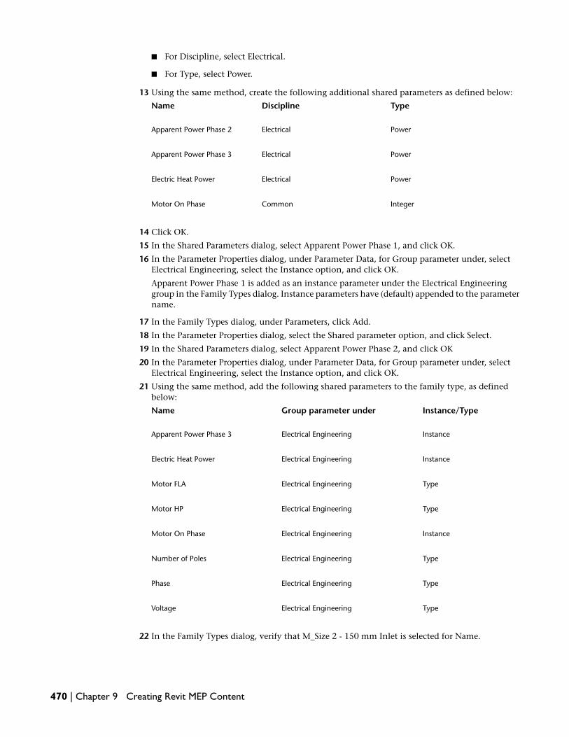
■ For Discipline, select Electrical.
■ For Type, select Power.
13 Using the same method, create the following additional shared parameters as defined below:
TypeDisciplineName
PowerElectricalApparent Power Phase 2
PowerElectricalApparent Power Phase 3
PowerElectricalElectric Heat Power
IntegerCommonMotor On Phase
14 Click OK.
15 In the Shared Parameters dialog, select Apparent Power Phase 1, and click OK.
16 In the Parameter Properties dialog, under Parameter Data, for Group parameter under, selectElectrical Engineering, select the Instance option, and click OK.
Apparent Power Phase 1 is added as an instance parameter under the Electrical Engineeringgroup in the Family Types dialog. Instance parameters have (default) appended to the parametername.
17 In the Family Types dialog, under Parameters, click Add.
18 In the Parameter Properties dialog, select the Shared parameter option, and click Select.
19 In the Shared Parameters dialog, select Apparent Power Phase 2, and click OK
20 In the Parameter Properties dialog, under Parameter Data, for Group parameter under, selectElectrical Engineering, select the Instance option, and click OK.
21 Using the same method, add the following shared parameters to the family type, as definedbelow:
Instance/TypeGroup parameter underName
InstanceElectrical EngineeringApparent Power Phase 3
InstanceElectrical EngineeringElectric Heat Power
TypeElectrical EngineeringMotor FLA
TypeElectrical EngineeringMotor HP
InstanceElectrical EngineeringMotor On Phase
TypeElectrical EngineeringNumber of Poles
TypeElectrical EngineeringPhase
TypeElectrical EngineeringVoltage
22 In the Family Types dialog, verify that M_Size 2 - 150 mm Inlet is selected for Name.
470 | Chapter 9 Creating Revit MEP Content

23 In the Formula column, specify formulas for the following parameters:
■ For Voltage, enter 480.
■ For Phase, enter 3.
■ For Apparent Power Phase 1, enter Electric Heat Power / 3 + if(Motor On Phase = 1, MotorFLA * 277 V, 0 VA).
■ For Apparent Power Phase 2, enter Electric Heat Power / 3 + if(Motor On Phase = 2, MotorFLA * 277 V, 0 VA).
■ For Apparent Power Phase 3, enter Electric Heat Power / 3 + if(Motor On Phase = 3, MotorFLA * 277 V, 0 VA).
NOTE Formulas are case sensitive. Use the same case for the names in formulas as the names enteredwhen you created the parameters.
24 Under Electrical Engineering, in the Value column, specify the following parameter values forthe M_Size 2 - 150 mm Inlet VAV:
■ For Number of Poles, enter 3.
■ For Motor On Phase, enter 1.
■ For Motor HP, enter 1/6.
■ For Motor FLA, enter 1.3.
25 Under Family Types, click new.
26 In the Name dialog, enter M_Size 3 - 200mm Inlet, and click OK.
27 In the Family Types dialog, specify the following parameters for the M_Size 3 - 200mm Inlettype:
■ For Number of Poles, enter 3.
■ For Motor On Phase, enter 1.
■ For Motor HP, enter 1/4.
■ For Motor FLA, enter 2.2.
28 Using the same method, create additional types, and specify the parameters for each size listedbelow:
Motor FLAMotor HPMotor OnPhase (Default)
Number ofPoles
Name
2.91/313M_Size 4 – 250mm Inlet
3.21/213M_Size 5 – 300mm Inlet
5.43/413M_Size 6 – 350mm Inlet
29 Click OK to close the Family Types dialog.
30 Save the family as Parallel Fan Powered VAV.rfa.
Place connector and map parameters
31 Click and drag the view cube to spin the model around so you can see the controls box as shown.
Modifying Fan Powered VAV Box with Electric Heat Family | 471

32 On the Design Bar, click Electrical Connector.
33 On the Options Bar, select Power - Unbalanced, and verify that is selected.
34 Highlight the large face on the controls box, and click to add the connector on the face.
35 Click Modify.
36 Select the connector, and on the Options Bar, click .
37 In the Element Properties dialog, specify values for the following parameters:
■ For Number of Poles, click in the column, and in the Associate Family Parameterdialog, select Number of Poles, and click OK.
■ For Voltage, click in the column, and in the Associate Family Parameter dialog, selectVoltage, and click OK.
■ For Apparent Load Phase 1, click in the column, and in the Associate Family Parameterdialog, select Apparent Power Phase 1, and click OK.
■ For Apparent Load Phase 2, click in the column, and in the Associate Family Parameterdialog, select Apparent Power Phase 2, and click OK.
472 | Chapter 9 Creating Revit MEP Content
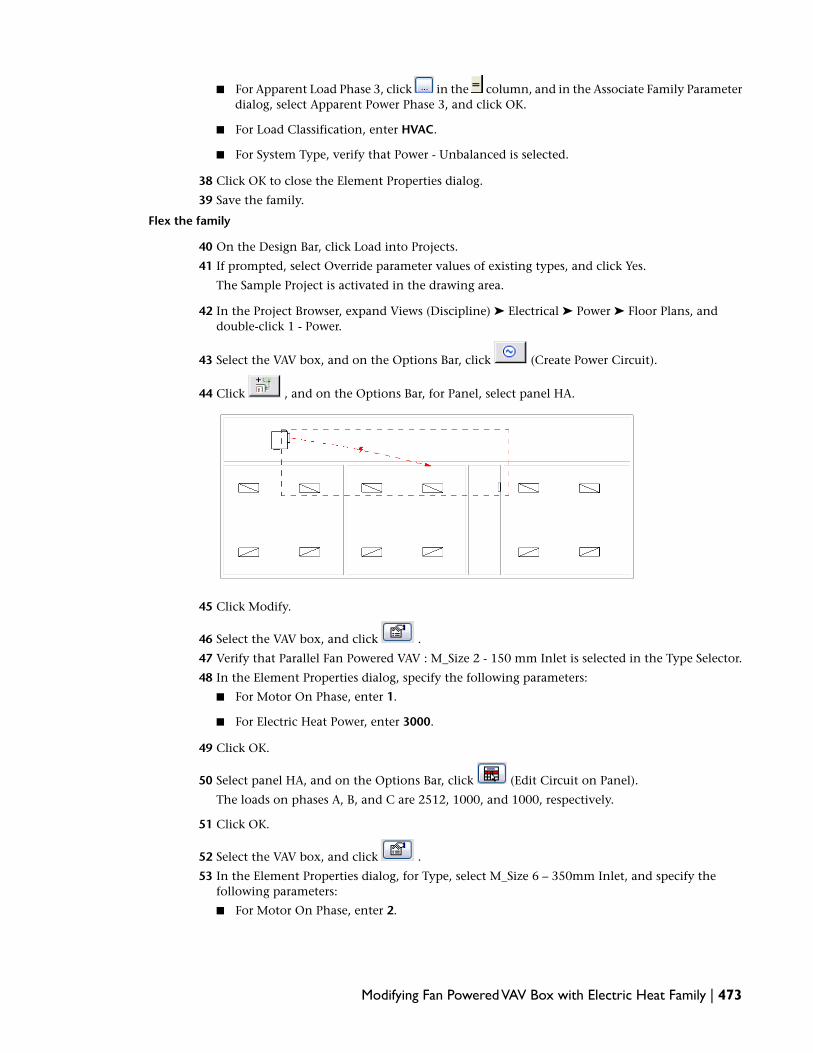
■ For Apparent Load Phase 3, click in the column, and in the Associate Family Parameterdialog, select Apparent Power Phase 3, and click OK.
■ For Load Classification, enter HVAC.
■ For System Type, verify that Power - Unbalanced is selected.
38 Click OK to close the Element Properties dialog.
39 Save the family.
Flex the family
40 On the Design Bar, click Load into Projects.
41 If prompted, select Override parameter values of existing types, and click Yes.
The Sample Project is activated in the drawing area.
42 In the Project Browser, expand Views (Discipline) ➤ Electrical ➤ Power ➤ Floor Plans, anddouble-click 1 - Power.
43 Select the VAV box, and on the Options Bar, click (Create Power Circuit).
44 Click , and on the Options Bar, for Panel, select panel HA.
45 Click Modify.
46 Select the VAV box, and click .
47 Verify that Parallel Fan Powered VAV : M_Size 2 - 150 mm Inlet is selected in the Type Selector.
48 In the Element Properties dialog, specify the following parameters:
■ For Motor On Phase, enter 1.
■ For Electric Heat Power, enter 3000.
49 Click OK.
50 Select panel HA, and on the Options Bar, click (Edit Circuit on Panel).
The loads on phases A, B, and C are 2512, 1000, and 1000, respectively.
51 Click OK.
52 Select the VAV box, and click .
53 In the Element Properties dialog, for Type, select M_Size 6 – 350mm Inlet, and specify thefollowing parameters:
■ For Motor On Phase, enter 2.
Modifying Fan Powered VAV Box with Electric Heat Family | 473

■ For Electric Heat Power, enter 11000.
54 Click OK.
55 Click Modify.
56 Select panel HA, and on the Options Bar, click .
The loads on phases A, B, and C have updated to 4819, 4027, and 3667, respectively.
57 Click OK.
Specify Flow Configuration for the VAV
58 Click Window menu ➤ M_Parallel Fan Powered VAV.rfa.
59 Use the view cube in the upper right corner of the view to spin the model around so you cansee the air supply connector, as shown.
60 Select the supply air connector, and on the Options Bar, click .
61 In the Element Properties dialog, under Mechanical, verify that Calculated is selected for FlowConfiguration.
When the Flow Configuration for the connector is set to Calculated, the air flow value forSupplyAirflow is the aggregate air flow for the downstream components.
62 Click OK.
63 On the Design Bar, click Load into Projects.
64 If prompted, select Override parameter values of existing types, and click Yes.
The Sample Project is activated in the drawing area.
Create a supply air system
65 In the Project Browser, expand Views (Discipline) ➤ Mechanical ➤ HVAC ➤ Floor Plans, anddouble-click 1 - Mech.
66 Select the 4 supply air terminals in the left room, and on the Options Bar click (CreateSupply Air System).
67 On the Options Bar, click (Select Equipment for System), and in the drawing area, selectthe VAV box.
68 Click (Layout Paths), and click Settings.
474 | Chapter 9 Creating Revit MEP Content

69 In the Duct Conversion Settings dialog, verify the following Main and Branch settings:
Main
■ For Duct Type, verify that Rectangular Duct: Mitered Elbows/Taps is selected.
■ For Offset enter 3750 mm.
Branch
■ For Duct Type, verify that Rectangular Duct: Mitered Elbows/Taps is selected.
■ For Offset enter 3750 mm.
■ For Flex Duct Type, verify that Flex Duct Round : Flex - Round is selected.
■ For Maximum Flex Duct Length, enter 1800 mm.
70 Click OK
71 Verify that Network is selected for Solution Type, click to select layout 6 of 6, and on theDesign Bar, click Finish Layout.
Ductwork is created for the selected solution.
Modifying Fan Powered VAV Box with Electric Heat Family | 475

72 Click Window menu ➤ System Browser.
73 In the System Browser, expand Mechanical (1 systems) ➤ Supply Air ➤ M_Parallel Fan PoweredVAV: M_Size 2 - 150 mm Inlet VAV.
74 Right-click Mechanical Supply Air 1, and select Properties.
75 In the Element Properties dialog, scroll down to Mechanical Airflow, and notice that theSupplyAirFlow parameter value is 280 L/s.
Because the Flow Configuration for the connector is set to Calculated, the air flow value forSupplyAirflow is the sum of the air flow for the downstream air terminals—in this case 280 L/s(4 X 70 L/s).
76 Click OK.
77 Double-click a tag associated with one of the air terminals supplied by the VAV, enter 100, andpress Enter to modify the air flow for the air terminal.
78 Again, right-click Mechanical Supply Air 1, and select Properties.
79 In the Element Properties dialog, scroll down to Mechanical Airflow and notice that theSupplyAirFlow parameter value is updated to 310 L/s, the new sum of the air flow for thedownstream air terminals.
80 Click OK.
The Preset and System settings for Flow Configuration are used together to allow specifying apercentage of the system flow to be allocated to each downstream component. This allowsspecifying a different portion of the system flow to each downstream subsystem. When FlowConfiguration is set to System the Flow Factor parameter is active. The Flow Factor parameteris specified as a value between 0 and 1, with the total for all downstream components equal to1.
For example, a boiler may have its supply preset to 70 L/s (system supply = 70 L/s) and theconnectors at 2 downstream zone valves set to System, but one with 0.4 specified for Flow andthe other with 0.6 specified for Flow. In this case the first downstream zone would receive aflow of 28 L/s (0.4 X 70 L/s), and the other would receive a flow of 42 L/s (0.6 X 70 L/s). Using
476 | Chapter 9 Creating Revit MEP Content

the combination of Preset and System settings on connectors lets you distribute flow accordingto the demands of a particular space.
NOTE Because Flow Factor and Flow Configuration are properties of the connector, all instances ofthe family in a project will have the same factor. To create unequal percentages for several downstreamsubsystems, you must create 2 additional instance parameters for the component family, and thenmap the Flow Factor to the value specified for each instance of the component used in the project.
81 Close the Family and m Sample Project files.
Modifying Electrical Equipment
In this exercise, you modify existing electrical equipment families to create new families, and then you usethe new families in a project. In the first section, you modify a 208V/3Ph panel to create a 240V/3Ph family,and in the following section you modify a 480V/3Ph primary transformer to create a 480V/1Ph to 240V/1Phsecondary transformer. The final section demonstrates how to load, insert, and connect components of thenewly created families in a simple project.
Dataset:
■ Click File menu ➤ Open.
■ In the left pane of the Open dialog, click the Training Files icon.
■ Open Metric ➤ Family EditorM_Lighting and Appliance Panelboard - 208V MCB - Surface.rfa.
Modify an existing panel family
1 In the Project Browser, expand Views (Discipline) ➤ 3D Views, and double-click {3D} to makeit the active view.
2 In the drawing area, select the connector.
3 On the Options Bar, click .
4 In the Element Properties dialog, under Electrical - Loads, specify values for the followingparameters:
■ For Number of Poles, enter 2.
■ For Voltage, enter 240.
5 Click OK.
Modifying Electrical Equipment | 477

6 Click File menu ➤ Save As.
7 In the Save As dialog, navigate to a folder of your choice and save the family as M_Lighting andAppliance Panelboard - 240V MCB - Surface.rfa.
8 Click File menu ➤ Close.
Modify an existing transformer family
9 Click File menu ➤ Open.
10 In the left pane of the Open dialog, click the Training Files icon.
11 Open Metric ➤ Family EditorM_Dry Type Transformers - 480-208-120V - NEMA Type 2.rfa.
12 On the Family tab of the Design Bar, click Family Types.
13 For Name, select 112.5 kVA.
14 Under Family Types, click Delete.
15 Using the same method, delete all of the remaining types, except for 15 kVA.
Next, you modify an existing family type.
16 In the Family Types dialog, for Name, verify that 15 kVA is selected.
17 Under Electrical, for Primary Number of Poles, enter 2.
18 Click Apply.
Next, you create a new family type.
19 Under Family Types, click New.
20 In the Name dialog, for Name, enter 3 kVA, and click OK.
Notice that the new family type is selected for Name.
21 Under Electrical, verify the following:
■ Primary Voltage is 480.00 V.
■ Primary Number of Poles is 2.
22 Under Dimensions, do the following:
■ For Length, enter 165 mm
■ For Height, enter 265 mm
■ For Width, enter 220
23 Click OK.
24 Click File ➤ Save As.
25 In the Save As dialog, navigate to a folder of your choice and save the family as M_Single PhaseTransformer - 480V Primary.rfa.
26 Click File menu ➤ Close.
In the following sections, you use the modified families in a project.
Load the new panel and transformer families into a project
27 Click File menu ➤ Open.
28 In the left pane of the Open dialog, click the Training Files icon.
29 Open Metric ➤ Family Editor ➤ m Simple Room.rvt.
30 On the Electrical tab of the Design Bar, click Electrical Equipment.
NOTE If the Electrical tab is not available on the Design Bar, right-click the Design Bar, and clickElectrical.
478 | Chapter 9 Creating Revit MEP Content

31 On the Options Bar, click Load.
You can also click File menu ➤ Load from Library ➤ Load Family.
32 In the Open dialog, navigate to the folder where you saved the new families, then while pressingCTRL, select M_Lighting and Appliance Panelboard - 240V MCB - Surface.rfa and M_Single PhaseTransformer - 480V Primary.rfa, and click Open.
The new families are loaded into the project.
TIP You can verify that the electrical families were loaded by expanding Families ➤ Electrical Equipmentin the Project Browser.
Test the new electrical equipment in a project
33 In the Project Browser, expand Views (Discipline) ➤ Electrical ➤ Power ➤ Floor Plans, anddouble-click 1 - Power to make it the active view.
34 On the Electrical tab of the Design Bar, click Electrical Equipment.
35 In the Type Selector, select M_Lighting and Appliance Panelboard - 240V MCB - Surface : M_100A.
36 Move the cursor over the wall, and after panel snaps to the inside face of the wall, click to placethe panel on the wall as shown.
NOTE The panel is a wall-hosted family—it can only be placed on a wall.
37 Using the same method, do the following:
■ Place a M_Lighting and Appliance Panelboard 480V MLO : 125A panel on the wall to theright of the first panel.
TIP You can press Spacebar to rotate a family if placement seems difficult.
Modifying Electrical Equipment | 479

■ Place a M_Single Phase Transformer - 480V Primary : 15kVA transformer on the wall betweenthe panels.
38 Click Modify.
Next, you create a system to logically connect the panels to the transformer.
Create a system
39 Select the M_Lighting and Appliance Panelboard 480V MLO : 125A panel.
40 On the Options Bar, for Distribution Sys, select 480/277 Wye.
41 With the panel selected, click .
42 In the Element Properties dialog, under Electrical - Loads, for Panel Name, enter DP, and clickOK.
Create a new distribution system
43 On the Electrical tab of the Design Bar, click Electrical Settings.
You can also click Settings menu ➤ Electrical Settings.
44 In the left pane of the Electrical Settings dialog, select Distribution Systems.
45 Click Add.
A new row is added in the right pane.
46 In the right pane, do the following:
■ For Name, enter 480 Wye.
■ For Phase, verify that Single is selected.
■ For Wires, select 3.
■ For L-L Voltage, select 480.
■ L-G Voltage, select 277.
47 Click OK.
48 In the drawing area, select the Single Phase Transformer,
49 On the Options Bar, click .
50 In the Element Properties dialog, under Electrical - Loads, do the following:
■ For Secondary Distribution System, select 120/240 Single.
■ For Panel Name, enter T-LC.
■ For Distribution System Types, select 480 Wye.
■ Click OK.
480 | Chapter 9 Creating Revit MEP Content
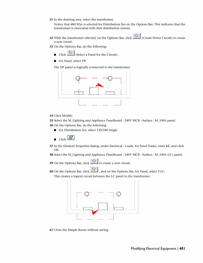
51 In the drawing area, select the transformer.
Notice that 480 Wye is selected for Distribution Sys on the Options Bar. This indicates that thetransformer is associated with that distribution system.
52 With the transformer selected, on the Options Bar, click (Create Power Circuit) to createa new circuit.
53 On the Options Bar, do the following:
■ Click (Select a Panel for the Circuit).
■ For Panel, select DP.
The DP panel is logically connected to the transformer
54 Click Modify.
55 Select the M_Lighting and Appliance Panelboard - 240V MCB - Surface : M_100A panel.
56 On the Options Bar, do the following:
■ For Distribution Sys, select 120/240 Single.
■ Click .
57 In the Element Properties dialog, under Electrical - Loads, for Panel Name, enter LC, and clickOK.
58 Select the M_Lighting and Appliance Panelboard - 240V MCB - Surface : M_100A (LC) panel.
59 On the Options Bar, click to create a new circuit.
60 On the Options Bar, click , and on the Options Bar, for Panel, select T-LC.
This creates a logical circuit between the LC panel to the transformer.
61 Close the Simple Room without saving.
Modifying Electrical Equipment | 481

Modifying a Water Closet
This exercise demonstrates adding piping connectors to a water closet family and setting typical connectorproperties for domestic cold water and sanitary systems.
Dataset:
■ Click File menu ➤ Open.
■ In the left pane of the Open dialog, click the Training Files icon.
■ Open Metric ➤ Family EditorM_Commercial - Toilet - Wall Mount Flush Valve.rfa.
1 The toilet is a wall-hosted component, and the extrusion that represents the wall is visible inthe view. However, you will be working at the back of the toilet, so you must hide the wall inthe view.
Select the wall, and on the View Control Bar, click (Temporary Hide/Isolate) ➤ Hide Element.
2 On the View Control Bar, click (Model Graphics Style) ➤ Hidden Line.
3 Use the view cube in the upper right corner of the view to spin the model around so it is orientedas shown.
4 On the Design Bar, click Pipe Connector.
5 On the Options Bar, for System Type, select Sanitary, and verify that is selected.
482 | Chapter 9 Creating Revit MEP Content

6 Zoom in, and move the cursor over the larger of the 2 round extrusions at the back of the toiletas shown, highlight the round face, and click to add the connector.
7 Click Modify.
8 Select the connector.
9 If the arrow is pointing in toward the toilet bowl, click so that the connector direction ispointing away from the bowl.
The arrow indicates the connector direction, not the flow direction. The connector directiondetermines the direction from which it will accept connections from other components.
10 Click .
11 In the Element Properties dialog, specify values for the following parameters:
■ For Radius, enter 40 mm.
■ For Flow Direction, select Out.
■ For Flow Configuration, select Fixture Units.
■ Select Allow Slope Adjustments
■ For Fixture Units, enter 4.
12 Click OK.
Modifying a Water Closet | 483

13 Using the same method, add a Domestic Cold Water system Piping Connector, in the locationshown, and click Modify.
14 Select the connector, click to specify connector direction.
15 On the Options Bar, click .
16 In the Element Properties dialog, specify values for the following parameters:
■ For Radius, enter 20 mm.
■ For Flow Direction, select In.
■ Clear Allow Slope Adjustments
■ For Flow Configuration, select Fixture Units.
■ For Fixture Units, enter 2.5.
17 Click OK.
484 | Chapter 9 Creating Revit MEP Content

18 Click File ➤ Save As, and in the Save As dialog, navigate to a folder of your choice and save thefamily as M_Toilet - Commercial Wall Mount Flush Valve.rfa.
Modifying a Diffuser Annotation Tag Family
In this exercise, you modify a diffuser tag family to provide a type mark instead of the default instance mark.
Dataset:
■ Click File menu ➤ Open.
■ In the left pane of the Open dialog, click the Training Files icon.
■ Open Metric ➤ Family Editor ➤ m Sample Project.rvt.
1 In the Project Browser, expand Views (Discipline) ➤ Mechanical ➤ HVAC ➤ Ceiling Plans, anddouble-click 1 - Ceiling Mech.
2 In the drawing area, select a diffuser tag.
Modifying a Diffuser Annotation Tag Family | 485

3 On the Options Bar, click Edit Family, and click Yes when asked to open the diffuser tag forediting.
The Family Editor opens.
The diffuser tag is composed of two labels separated by a horizontal line. Each label is associatedwith a parameter.
4 Select the top label (1i), and on the Options Bar, click Edit Label.
5 In the Edit Label dialog, under Label Parameters, select Mark, and click (Remove parameterfrom label).
6 Under Category Parameters, select Type Mark, and click (Add parameter to label).
7 Click OK.
The sample text changes to 1t.
486 | Chapter 9 Creating Revit MEP Content

8 On the Design Bar, click Load into Projects.
If more than one project is open, in the Load into Projects dialog, select m Sample Project.rvt,and click OK.
9 When prompted to overwrite the existing Diffuser Tag, click Yes.
The project becomes active and the diffuser tag updates to display the supply air terminal type,S-1, and the return air diffuser type, R-1.
10 Click File menu ➤ Close as you do not need to save the project.
11 Click File menu ➤ Close again to close the tag family, without saving.
Modifying a Light Fixture Annotation Tag Family
In this exercise, you modify a light fixture tag family to include panel and circuit information.
Dataset:
■ Click File menu ➤ Open.
■ In the left pane of the Open dialog, click the Training Files icon.
■ Open Metric ➤ Family Editor ➤ m Sample Project.rvt.
Modifying a Light Fixture Annotation Tag Family | 487

1 In the Project Browser, expand Views (Discipline) ➤ Electrical ➤ Lighting ➤ Floor Plans, anddouble-click 1 - Lighting.
2 In the drawing area, select a light fixture tag.
3 On the Options Bar, click Edit Family, and click Yes when asked to open the light fixture tagfor editing.
The Family Editor opens.
The light fixture tag is composed of a label that is associated with a parameter.
4 In the drawing area, select the 1i label.
5 On the Edit toolbar, click (Copy).
6 On the Options Bar, click Multiple.
7 Click the midpoint of the label to specify the copy start point.
8 Move the cursor straight down, and after listening dimensions display, enter 3 mm, and pressEnter to specify the copy end point.
488 | Chapter 9 Creating Revit MEP Content

The label is copied.
9 Repeat the previous steps to create a second copy of the label.
Modifying a Light Fixture Annotation Tag Family | 489

10 Click Modify.
Notice that the bounding box contains only the first label. You need to modify this box.
11 Select the bottom line of the box, and drag it down so that the box contains all 3 labels.
Next, you modify 2 labels.
12 Select the middle label, and on the Options Bar, click Edit Label.
13 In the Edit Label dialog, under Label Parameters, select Type Mark, and click (Removeparameter from label).
14 Under Category Parameters, select Panel, and click (Add parameter to label).
15 Under Label Parameters, for the Panel parameter, enter PNL in the Sample Value column.
The sample value is the text that identifies this label in the Family Editor.
16 Click OK.
The middle label text changes to PNL and the label is associated with the Panel parameter.
490 | Chapter 9 Creating Revit MEP Content

17 Using the same method, modify the bottom label with the following Edit Label dialog:
■ Under Label Parameters, select Type Mark, and click (Remove parameter from label)
■ Under Category Parameters, select Circuit Number, and click (Add parameter to label).
■ For the Circuit Number parameter, enter CKT in the Sample Value column
The 3 light fixture labels are as shown.
Load the light fixture tag family into a project
18 On the Family tab of the Design Bar, click Load into Projects.
If more than one project is open, in the Load into Projects dialog, select m Sample Project.rvt,and click OK.
19 If prompted, select Override parameter values of existing types, and click Yes.
The Sample Project is activated in the drawing are, and the light fixture tags update to displaythe panel and circuit information.
Modifying a Light Fixture Annotation Tag Family | 491

20 Click File menu ➤ Close as you do not need to save the project.
21 Click File menu ➤ Close again to close the tag family, without saving.
Creating Families
In this lesson you learn how features of the Family Editor allow you to build custom component families.
The process of creating a component family includes the following steps:
1 Select the appropriate family template.
The hosting of a component is defined by the template used when the family is originally created.Templates also define the type of family (annotation, model, titleblock, or profile). In some cases, thetemplate also defines characteristics of how the family works, such as linear versus spot lightingcharacteristics. You cannot change these characteristics after you have created the family. For example,you cannot change a linear lighting fixture into a spot lighting fixture.
2 Define sub-categories for the family to aid in controlling visibility of the object.
3 Lay out reference planes to aid in drawing component geometry.
4 Add dimensions to specify parametric component geometry.
5 Add label dimensions to create type or instance parameters.
6 Flex the new model to verify correct component behavior.
7 Specify 2D and 3D geometry display characteristics with sub-category and entity visibility settings.
8 Define family type variations by specifying different parameters.
9 Save the newly-defined family, and then load it into a new project and see how it performs.
Creating a Light Fixture Family
In this exercise you create an ceiling hosted recessed downlight.
There are various light fixture family templates available in Revit MEP. If you expect to render your lightingdesigns, it is important that you start your lighting family with one of these templates, as they have reference
492 | Chapter 9 Creating Revit MEP Content

planes that define the location of the light source. For generic (Lighting Fixture*.rft) and linear (LinearLighting Fixture*.rft) lighting templates, these planes are Light Source Axis (F/B), Light Source Axis (L/R),and Light Source Elevation. For spot light templates (Spot Lighting Fixture*.rft), these planes are Light SourceAxis (L/R), Tilt Plane, and Light Source Elevation. Each family has additional parameters depending onwhether it is a linear fixture, a spot fixture, or a generic fixture.
When you use a spot light template, the family will have the additional parameters: Spot Beam Angle, SpotSpread Angle, Spot Tilt Angle. The Linear template contains a model line representing the light source alongthe F/B axis. This can be shortened or lengthened as necessary to model the linear lighting fixture.Additionally, there are lighting templates for non-hosted, ceiling hosted, and wall hosted objects.
When working in a linked file environment, you may use a non-lighting family template, such as GenericModel face based.rft. Using this face hosted family provides the ability for the fixture to be hosted by, andmove with, objects in the linked file. Using the generic face hosted and non-hosted lighting fixtures has thelimitation that the hosting geometry cannot be cut.
When creating a lighting family, you can also specify a .ies file. This file contains engineering data that canbe used to calculate the coefficient of utilization of the fixture. The .ies file is not used for rendering. Lightingmanufacturers often allow you to download .ies files from the Web for their fixtures.
Locate IES data file
1 Using Windows Explorer, navigate to C:\Documents and Settings\All Users\ApplicationData\Autodesk\RME 2009\Training\Imperial\Tutorials\Family Editor, and copy the Ltl9815.iesfile, and paste it into the C:\Documents and Settings\All Users\Application Data\Autodesk\RME2009\IES folder. (This is the location from which the .ies files are retrieved if Revit MEP isinstalled in the default path.)
NOTE If Revit MEP was not installed in the default path, you must determine the correct path to theIES file as defined by the IESFileLocation parameter in the Revit.ini file (within the<install_path>\RME2009\Program folder).
Create a new lighting family
2 Click File menu ➤ New ➤ Family.
3 In the New dialog, navigate to the Metric Templates folder, select Metric Linear Lighting Fixtureceiling based.rft, and click Open.
4 Click Settings menu ➤ Family Category and Parameters.
5 Under Family Category, select Lighting Fixtures.
6 Specify the following settings under Family Parameters:
■ Select the Always Vertical option
■ Select Light Source
■ For Part Type, select the Normal option
■ Clear the Shared option
NOTE Family Category and Parameters settings determine the component type and provide a setof parameters that affect its behavior within Revit MEP. See Part Types on page 565 and Category onpage 564 for a complete list of Revit MEP categories and parameters.
7 Click OK.
8 In the Project Browser, expand Views (Discipline) ➤ Elevations (Elevation 1), and double-clickFront.
Creating a Light Fixture Family | 493

TIP You may want set the scale to 1 : 5 and zoom in very close to create the Solid Form ➤ SolidRevolve.
9 Select the Light Source Elevation Plane, and drag it up to a point 75 mm above the Basic Ceilingand Ceiling Plane as shown.
10 Click File menu ➤ Save As.
11 In the Save As dialog, for File name, enter 200mm Open Downlight 42w TRT.rfa, and click OK.
Define the fixture geometry
12 On the Design Bar, click Solid Form ➤ Solid Revolve.
13 On the Sketch tab on the Design Bar, click Lines.
14 On the Options Bar, click , , and Chain, and for Offset, specify 0.0.
15 Zoom in on the Light Source Elevation, and sketch the shape of the fixture as shown.
Start at the Center (Left/Right) vertical reference plane, 125 mm above the Light Source referenceplane, and draw a 100 mm horizontal line to the left of the center, then draw a vertical linesegment down to the ceiling (200 mm), and finish with a 25 mm horizontal line segment tothe left.
494 | Chapter 9 Creating Revit MEP Content

Next you will duplicate the original outline, offset by 1.5 mm to define the thickness of the light fixturehousing.
16 Click Lines.
17 On the Options Bar, click , and for Offset, enter 1.5 mm.
18 Click just above the upper horizontal line to add a line 1.5 mm above the existing line as shown.
19 Using the same method, click just to the left of the vertical line and just above the lowerhorizontal line to define the thickness for the fixture as shown.
Creating a Light Fixture Family | 495

NOTE If you have difficulty selecting the short horizontal line at the base, move the cursor over theline, press Tab to highlight the short line, then click just above the line.
20 On the Design Bar, click Lines.
21 On the Options Bar, click and , clear Chain, and for Offset, enter 0.0.
22 Draw lines to close the outline at the top right and lower left as shown.
496 | Chapter 9 Creating Revit MEP Content

23 Click Modify.
24 On the toolbar, click (Trim), and clean up the inside corner as shown.
25 On the Design Bar, click Axis, and sketch the axis line for the revolve as indicated below by thedark line.
Creating a Light Fixture Family | 497

The length of the line and its exact location are not important, but make sure it is coincidentwith the vertical plane.
26 Click Finish Sketch.
27 Save the family.
Define family and connector properties
28 In the drawing area, select the (yellow) Light Source, and on the Options Bar, click Light SourceDefinition.
29 In the Light Source Definition dialog, for Emit from Shape, click (Point), for Light
distribution, click (Photometric Web), and click OK.
498 | Chapter 9 Creating Revit MEP Content

30 On the Design Bar, click Family Types.
31 In the Family Types dialog, specify values for the following parameters:
Under Electrical - Lighting
■ For Calculate Coefficient of Utilization, select true (green check, not grey)
Under Electrical Loads
■ For Apparent Load, enter 44.21 VA
Under Electrical
■ For Lamp, enter CF42TRT
Under Photometrics
■ For Tilt Angle, enter 90
■ For Photometric Web File, click the Value column, click , and select M_Ltl9815.iesin thefile browser
■ For Light Loss Factor, click the Value column, and in the Light Loss Factor dialog, click Simplefor Method, enter 0.85 for Value, and click OK.
■ For Initial Intensity, click the Value column, and in the Initial Intensity dialog, click LuminousFlux, enter 3200, and click OK.
■ For Initial Color, click the Value column, and in the Initial Color dialog, for Color Preset,select <Custom>, for Color Temperature, enter 3000 K and click OK.
A fixture’s Coefficient of Utilization may be calculated based on the geometry of the space, ora static value may be entered. Lighting objects in a space contribute to the room’s AverageEstimated Illumination. This illumination is based on the lumen method using the total lumenoutput of the lighting fixtures in the room, and is affected by the following fixture properties:
■ Coefficient of Utilization (Instance)
■ Initial Intensity (Type)
■ Light Loss Factor (Type)
32 Click OK.
Creating a Light Fixture Family | 499

33 In the Project Browser, expand View (All) ➤ 3D Views, and double-click View 1.
34 Use the view cube in the upper right corner of the view to spin the model to view the top ofthe fixture.
35 On the Design Bar, click Electrical Connector, and on the Options Bar, select Power - Balanced,
and verify that (Place on Face) is selected.
36 Highlight the face at the top of the fixture, and click to place the connector on the top of thefixture.
37 Click Modify, select the connector, and click .
38 In the Element Properties dialog, specify values for the following parameters:
■ For Power Factor, enter 0.95
■ For System Type, verify that Power - Balanced is specified
■ For Apparent Load, click in the column, and in the Associated Family Parameter dialog,select Apparent Load from the list, and click OK.
■ For Voltage, enter 277
■ For Load Classification, enter Lighting
39 Click OK.
40 Save the family
Cut a hole in the ceiling
41 Next you cut a hole in the ceiling. Although the hole is not necessary for construction documents,it permits light to function as expected in renderings. (Light at the intersection of planes is ableto pass through the ceiling.)
500 | Chapter 9 Creating Revit MEP Content

In the Project Browser, expand Views (Discipline) ➤ 3D Views, and double-click View 1.
42 Spin the model to view the bottom of the ceiling.
43 Select the yellow Light Source, and on the View Control Bar, click (Temporary Hide/Isolate),and select Hide Element.
44 On the Design Bar, click Opening.
45 On the Options Bar, click , and select the 2 arcs that make up the outside edge of the trimring as shown.
46 Click Finish Sketch.On the View Control Bar, click
47 On the View Control Bar, click (Temporary Hide/Isolate), and select Reset TemporaryHide/Isolate.
48 Save the family.
Flex the light fixture
49 Click File menu ➤ Open.
50 In the left pane of the Open dialog, click the Training Files icon.
51 Open Metric ➤ Family Editor ➤ m Simple Room.rvt.
52 In the Project Browser, expand Views (Discipline) ➤ Electrical ➤ Lighting ➤ Ceiling Plans, anddouble-click 1 - Ceiling Elec.
The space tag indicates 212 lx and 135 W.
53 Click Window menu ➤ 200 mm Open Downlight 42w TRT.rfa to make the family the activeview.
54 On the Design Bar, click Load into Projects.
The new lighting fixture is loaded into the project.
55 Select the 4 downlights in the room, and in the Type Selector, select 200 mm Open Downlight42w TRT.rfa.
The lighting level increases to 325 lx, and the wattage increases to 168.
In this exercise, you learned:
■ The basics of how lighting families work
■ How to create a lighting family from a template
■ Where to place IES files for use by lighting families
Creating a Light Fixture Family | 501

Flange Family
In this exercise, you will create a flange connector to model pipe flanges for model coordination. The flangewill be based on a 1 Mpa pressure class slip on flange, and use a Lookup Table to define several sizes for theflange.
Lookup tables are used to define parameter values in an external .csv file. This lets you specify multiple partsizes that are based on a table without creating a separate family type for each size. Revit MEP provides atext_file_lookup function that can be used to read the necessary values from a comma-separated values (.csv)file. The location of Lookup Table files is defined by the LookupTableLocation parameter in the Revit.inifile.
The M_Generic 1 Mpa Slip Flange.csv file defines multiple sizes for this flange. When installed in the defaultpath, Revit MEP looks in C:\Documents and Settings\All Users\Application Data\Autodesk\RME2009\LookupTables to retrieve size information. See Lookup Tables on page 562 and CSV File Structure onpage 563.
1 Click File menu ➤ New ➤ Family.
2 In the New dialog, navigate to the Metric Templates folder, select Metric Generic Model.rft, andclick OK.
3 Click Settings menu ➤ Family Category and Parameters.
NOTE Family Category and Parameters settings determine the component type and provide a setof parameters that affect its behavior within Revit MEP. See Part Types on page 565 and Category onpage 564 for a complete list of Revit MEP categories and parameters.
4 Under Family Category, select Pipe Fittings.
5 Specify the following settings under Family Parameters:
■ Clear the Work Plane-Based option.
■ Select the Always Vertical option.
■ For Part Type, select the Transition option.
■ Clear the Shared option.
6 Click OK.
7 Click File ➤ Save, and in the Save As dialog, navigate to a folder of your choice and save thefamily as M_Generic 1 Mpa Slip Flange.fla.
8 Using Windows Explorer, navigate to C:\Documents and Settings\All Users\ApplicationData\Autodesk\RME 2009\Training\Imperial\Tutorials\Family Editor, and copy the M_Generic1 Mpa Slip Flange.csv file, and paste it into the C:\Documents and Settings\All Users\ApplicationData\Autodesk\RME 2009\LookupTables folder. (This is the location from which theLookupTable files are retrieved if Revit MEP is installed in the default path.)
NOTE If Revit MEP was not installed in the default path, you must determine the correct path to theLookup Table file as defined by the LookupTableLocation parameter in the Revit.ini file (within the<install_path>\RME2009\Program folder).
Create parameters
9 Click Family Types.
10 Under Parameters, click Add.
502 | Chapter 9 Creating Revit MEP Content

11 In the Parameter Properties dialog, verify that Family parameter is selected for Parameter Typeand specify the following parameter data:
■ For Name, enter NR
■ For Discipline, select Piping
■ For Type, select Pipe Size
■ For Group parameter under, select Dimensions
■ Select Type
12 Click OK.
13 Using the same method, create Instance parameters named D1, D2, LenA1, LenA2, LenA3, ND,R1, R2 and specify the following parameters for each one:
■ For Parameter Type, select the Family parameter option
■ For Discipline, select Piping.
■ For Type, select Pipe Size.
■ For Group parameter under, select Dimensions.
■ Select the Instance option
14 In the Family Types dialog, specify values for the following parameters:
■ For NR, enter 150 mm
■ For Lookup Table Name = M_Generic 1 Mpa Slip Flange.csv
15 Specify formulae for the following parameters:
■ ND, enter NR * 2
■ For R1, enter D1 / 2
■ For R2, enter D2 / 2
■ For LenA3, enter LenA2 – LenA1
■ For D1, enter text_file_lookup(Lookup Table Name, "D1", 0’, ND)
■ For D2, enter text_file_lookup(Lookup Table Name, "D2", 0’, ND)
■ For LenA1, enter text_file_lookup(Lookup Table Name, "LenA1", 0’, ND)
■ For LenA2, enter text_file_lookup(Lookup Table Name, "LenA2", 0’, ND)
16 Click OK.
17 Save the family.
Define work planes
18 In the Project Browser, expand Views (Discipline) ➤ Floor Plans, and double-click Ref. Level.
19 Click the scale on the View Control Bar, and select 1 : 5.
20 On the Design Bar, click Ref Plane.
21 On the Options Bar, click , and for Offset, enter 50 mm.
22 Click to the right of the Center (Left/Right) reference plane to add a reference plane 50 mm tothe right of the center line.
23 Click again to the left of the Center (Left/Right) reference plane to add a reference plane 50 mmto the left of the center line as shown.
Flange Family | 503

24 Click Modify
25 Select the left plane and, click .
26 In the Element Properties dialog, under Identity Data, for Name, enter Pipe.
27 Using the same method, enter Connector for the Name of the right plane.
28 On the Design Bar, click Dimension, and on the Options Bar, click (Aligned).
29 Create a dimension between the Center (Left/Right) plane and the Connector (right) plane.
30 Create another dimension between the Center (Left/Right) plane and the Pipe (left) plane.
31 Click Modify.
504 | Chapter 9 Creating Revit MEP Content

32 Select the dimension between the Center (Left/Right) plane and right plane (Connector) and
click .
33 In the Element Properties, under Other, click the Value column for Label, click , and selectLenA1 from the list.
34 Using the same method, select the dimension between the left (Pipe) plane and Center (Left/Right)plane, and label it LenA2.
35 Select the horizontal reference plane and the 3 vertical reference planes.
36 Click .
37 In the Element Properties dialog, under Other, for Is Reference, click the Value column, andselect Not a Reference.
This option disables grips at the intersection of reference planes and specifies that the referenceplane cannot be dimensioned to when you place a family into a project.
38 Click OK.
39 Save the family.
Define geometry
40 Click View menu ➤ Visibility/Graphics.
41 On the Model Categories tab, click Object Styles, and set the Projection Line weight of eachcategory to 5.
42 Click OK twice.
43 On the Design Bar, click Model Lines, and on the Options Bar, clear Chain, click and .
44 Draw a vertical line on both the left (Pipe) and the right (Connector) vertical reference planes.
The length is not important, but be careful to sketch them on the reference planes.
45 Draw a horizontal line on the horizontal plane, between the intersections with the right andleft vertical planes as shown.
46 Click Modify.
47 Select the 3 model lines, and on the Options Bar, click Visibility.
48 In the Family Element Visibility Settings dialog, clear Fine, and click OK.
Flange Family | 505

NOTE Piping objects generally show as linework in Coarse and Medium view, and in Fine view thesolid model elements are shown. Thus, we shut off the linework in Fine view.
49 With all 3 lines still selected, click .
50 In the Element Properties dialog, under Other, for Reference, click the Value column, and selectNot a Reference.
51 Click OK.
52 On the Design Bar, click Dimension, and on the Options Bar, click .
53 Move the cursor over an endpoint on the left vertical line, press Tab to highlight the endpoint,and click to specify the endpoint for the dimension.
54 Select the horizontal reference plane, then select the other endpoint, move the cursor to theleft, and click to place the dimension.
55 Click .
56 Using the same method, create dimensions for the right vertical line.
57 On the Design Bar, click Dimension, and on the Options Bar, click .
58 Using the same method, create dimensions for the overall length of each vertical line, fromendpoint to endpoint.
59 Click Modify.
506 | Chapter 9 Creating Revit MEP Content

60 Select the dimension for the overall length of the left line, and on the Options Bar, click .
61 In the Element Properties dialog, under Other, for Label, click the Value column, and select D2.
62 Using the same method, select the dimension for the right line and label it D1.
Create the first extrusion
63 In the Project Browser, expand Elevations (Elevation 1), and double-click Left.
64 On the Design Bar, click Solid Form ➤ Solid Extrusion.
65 On the Sketch tab on the Design Bar, click Set Work Plane.
66 In the Work Plane dialog, specify Reference Plane : Pipe, and click OK.
67 Click Lines.
68 On the Options Bar, click and , click Radius, and enter 125 mm.
69 Place the circle on the intersection of the horizontal and vertical reference planes.
70 Click Modify.
71 Select the circle, and in the drawing area, click .
72 Select the dimension line, and click .
73 In the Element Properties dialog, under Other, for Label, click the Value column, and select R2.
74 Click OK.
Flange Family | 507

75 Click Extrusion Properties.
76 In the Element Properties dialog, under Constraints, for Extrusion End, click in the column.
77 In the Associate Family Parameter dialog, select LenA2, and click OK.
78 Under Graphics, for Visibility/Graphics, click Edit.
79 In the Family Element Visibility Settings dialog, clear Coarse and Medium, and click OK twice.
80 Click Finish Sketch.
Create the second extrusion
81 On the Design Bar, click Solid Form ➤ Solid Extrusion.
82 On the Sketch Editor tab on the Design Bar, click Set Work Plane.
83 In the Work Plane dialog, specify Reference Plane : Center (Left/Right), and click OK.
84 Click Lines.
85 On the Options Bar, click and , click Radius, and enter 250 mm.
86 Place the circle on the intersection of the horizontal and vertical reference planes.
87 Click Modify.
88 Select the circle, and in the drawing area, click .
89 Select the dimension line, and click .
90 In the Element Properties, under Other, for Label, click the Value column, and select R1.
91 Click OK.
508 | Chapter 9 Creating Revit MEP Content

92 Click Extrusion Properties.
93 In the Element Properties dialog, under Constraints, for Extrusion End, click in the column.
94 In the Associate Family Parameter dialog, select LenA1, and click OK.
95 Under Graphics, for Visibility, click Edit.
96 In the Family Element Visibility Settings dialog, clear Coarse and Medium, and click OK twice.
97 Click Finish Sketch.
98 Save the family.
Add connectors
99 In the Project Browser, expand 3D Views, and double-click View 1.
100 Click the scale on the View Control Bar, and select 1 : 2.
101 On the View Control Bar, click (Model Graphics Style), and select Wireframe to view bothextrusions.
102 Spin the flange to view the face of both extrusions as shown.
103 On the Design Bar, click Pipe Connector.
104 On the Options Bar, verify that is selected, and for System Type, select Fitting.
105 Highlight the large diameter face of the flange, where the 2 extrusions meet.
Flange Family | 509

106 Click to add the connector.
107 Click Modify.
108 Select the connector, click and, if necessary, to change the direction of flow.
The arrow indicating the connector direction should be pointing toward the smaller diameterface.
109 With the connector selected, click .
110 In the Element Properties dialog, under Dimensions, for Radius, enter 250 mm, and click OK.
510 | Chapter 9 Creating Revit MEP Content

111 Spin the flange to view the back of the larger extrusion.
112 Click Pipe Connector, and using the same method, add a connector to the larger extrusion.
Flange Family | 511

113 Click Modify.
114 Select the connector, click and, if necessary, to change the direction of flow.
The arrow indicating the connector direction should be pointing toward the smaller diameterface.
115 Select the first connector, click Link Connector on the Options Bar, and click the secondconnector.
116 Click Modify.
117 Select both connectors, and on the Options Bar, click .
118 In the Element Properties dialog, under Dimensions, for Radius, click in the column.
119 In the Associate Family Parameter dialog, select NR, and click OK twice.
120 Save the family
Creating an Elbow Pipe Fitting Family
In this exercise, you create an elbow pipe fitting family. First, you create the physical fitting geometry byusing reference planes and lines, and by defining fitting size parameters. You then create single line geometryfor the elbow, test the fitting geometry, and set the object visibility. After completing the pipe fitting family,you can use the same method to create a duct fitting family for air systems.
512 | Chapter 9 Creating Revit MEP Content

NOTE Fittings are among the most complex families to create. It is recommended that you methodically followthe steps and periodically check your work against the exercise. It may take a longer to complete this exercise ascompared to other exercises in this tutorial. Even if you have created parametric families before, creating systemfamilies typically takes more time to complete.
1 Click File menu ➤ New ➤ Family.
2 In the New dialog, do the following:
■ For Look in, verify that Metric Templates is selected.
■ Select Metric Generic Model.rft.
■ Click Open.
A new family file is created and new views open.
Configure the elbow pipe fitting family
3 Click Settings menu ➤ Family Category and Parameters.
4 In the Family Category and Parameters dialog, under Family Category, select Pipe Fittings:
5 Under Family Parameters, do the following:
■ Verify that Work Plane-Based is cleared.
■ Verify that Always vertical is selected.
■ For Part Type, select Elbow.
■ Verify that Shared is cleared.
6 Click OK.
7 Click File ➤ Save.
You can also press CTRL+S.
8 In the Save As dialog, navigate to a folder of your choice, and save the family as M_Threaded -Generic Elbow.
Define reference planes
Reference planes are used to define relationships between the geometric components within the FamilyEditor. They are not displayed when the family is used in a building model.
9 In the Project Browser, expand Views (Discipline) ➤ Floor Plans, and double-click Ref. Level tomake it the active view.
10 Maximize the Ref. Level floor plan window.
11 Click Window menu ➤ Close Hidden Windows.
Close Hidden Windows closes all of the hidden windows for a project. However, if you haveother projects open during a session, one window for each open project remains open.
12 Enter ZF to zoom the view to fit the window.
13 On the View Control Bar, click the current scale value, and select 1 : 2.
14 Select the 2 reference planes, and verify that both reference planes have been pinned. If necessary,
on the Edit toolbar, click .
Creating an Elbow Pipe Fitting Family | 513

Pinning prevents accidentally moving the reference planes.
15 On the Family tab of the Design Bar, click Ref Plane.
16 On the Options Bar, click , and for Offset, enter 25.
17 Click to the left the vertical Center (Left/Right) reference plane to place a new reference line tothe left of the vertical Center (Left/Right) reference plane.
TIP You can identify an object in the drawing area by placing the cursor over the object. A tooltipand the Status Bar (which is located below the Design Bar) displays the object’s name.
18 Click Modify.
19 Select the left plane, and on the Options Bar, click .
20 In the Element Properties dialog, under Identity Data, for Name, enter Fitting, and click OK.
21 Using the same method, add another vertical plane 50 mm to the left of the left (Fitting) plane,and in the Element Properties dialog, for Name, enter Coupling.
22 Select the horizontal Center (Front/Back) reference plane.
23 Add new reference plane 50 mm above the Center (Front/Back) reference plane as shown.
514 | Chapter 9 Creating Revit MEP Content

24 Click Modify.
25 Right-click the new reference plane, and click Element Properties.
26 In the Element Properties dialog, for Name, enter Radius, and click OK.
27 Click File menu ➤ Save to save the family.
Create reference lines and dimension them
Reference lines are used to define the basic geometry of the family. They are not displayed when the familyis used in a project. You create reference lines in order to create sweeps for the fitting geometry.
28 On the Design Bar, click Reference Lines.
29 On the Options Bar, do the following:
■ Verify that (Draw) is selected.
■ Verify that (Line) is selected.
■ For Offset, verify that 0.0 is specified.
■ Verify that Radius is cleared.
Creating an Elbow Pipe Fitting Family | 515

30 In the drawing area, draw a horizontal line of the approximate length and location as shown.
31 On the Edit toolbar, click (Align).
32 Select the middle vertical reference plane (Fitting), and click the right end of the reference lineto align the right end of the reference line to the Fitting reference plane.
33 Click to lock the end of the reference line to the Fitting plane.
34 Using the same method, align and lock the left end of the reference line to the left verticalreference plane (Coupling).
35 Align and lock the reference line to the Center (Front/Back) reference plane as shown.
36 Using the same method, draw another reference line to the right of the Center (Left/Right)reference plane as shown.
37 Align and lock the left end of the right reference line to the Center (Left/Right) reference plane.
38 Align and lock the right reference line to the Center (Front/Back) reference plane as shown.
Next, you draw an arced reference line.
516 | Chapter 9 Creating Revit MEP Content

39 On the Design Bar, click Reference Lines.
40 On the Options Bar, do the following:
■ Verify that (Draw) is selected.
■ Select (Arc from center and endpoints).
You may need to click and, select this sketching option from the list.
■ For Offset, verify that 0.0 is specified.
■ Verify that Radius is cleared.
41 In the drawing area, click the intersection of the Fitting and the Radius reference planes tospecify the center of the arc.
42 Move the cursor directly down, and after the endpoint snap displays, click the right end of theleft reference line to specify the first endpoint of the arc.
43 Move the cursor to the right to begin drawing the arc, enter 45, and press Enter to specify a 45degree radius for the arc.
44 Click Modify.
45 Select the arc reference line, and zoom out to view 2 dimension controls ( ).
Creating an Elbow Pipe Fitting Family | 517

NOTE Temporary dimensions have two dimension controls that allow you to convert the temporarydimension to a permanent dimension. By default, dimensions are temporary—they only display whenselected. The dimension control that is located perpendicular to the line being dimensioned representsthe overall length of that line. The dimension control located near the reference plane represents theprojected length of that line relative to the reference plane.
46 Click the dimension control that controls the overall dimension (located to the lower-right ofthe arc).
47 Drag the permanent dimension annotation away from the arc reference line, and adjust thelength of the witness lines as shown.
Next, you draw a diagonal reference line.
48 On the Design Bar, click Reference Lines.
49 On the Options Bar, do the following:
■ Verify that (Draw) is selected.
■ Verify that (Line) is selected.
■ For Offset, verify that 0.0 is specified.
■ Verify that Radius is cleared.
50 Click the right end of the arced reference line to specify the diagonal reference line start point.
51 Draw a diagonal reference line to extend the arc at a 45 degree angle toward the Radius referenceplane, and click to specify the reference line end point at an approximate line length as shown.
518 | Chapter 9 Creating Revit MEP Content

While drawing the diagonal reference line, the Tangent Extension tooltip may display to indicatethat the diagonal reference line is tangent to the arced reference line.
52 Click Modify.
53 Select the diagonal reference line, zoom the view to display the 2 dimension controls.
54 Using the same method, convert the temporary dimension for the overall length of the diagonalreference line to a permanent dimension.
55 Drag the dimension line down and to the right to move it out of the way, and clean up thewitness lines as necessary.
56 On the Design Bar, click Dimension.
57 In the Type Selector, verify that Linear Dimension Style : Default linear style is selected.
58 On the Options Bar, verify that (Aligned) is selected.
59 Add the following aligned dimensions:
■ Between the Radius and the Center (Front/Back) horizontal reference planes.
■ Between the Coupling and the Fitting vertical reference planes.
■ Between the Fitting and the Center vertical reference planes.
60 With the Dimension tool active, on the Options Bar, click (Angular), and add an angulardimension between the diagonal reference line and the right horizontal reference line (whichis located below the diagonal reference line).
61 Position the dimension annotations and witness lines as shown.
Creating an Elbow Pipe Fitting Family | 519

62 Click File menu ➤ Save to save the family.
Create family parameters and assign them to dimensions
63 On the Design Bar, click Family Types.
64 In the Family Types dialog, under Parameters, click Add.
65 In the Parameter Properties dialog, under Parameter Type, verify that Family parameter is selected.
66 Under Parameter Data, do the following:
■ For Name, enter LenA1.
■ For Discipline, select Piping.
■ For Type of Parameter, select Pipe Size.
■ For Group parameter under, select Dimensions.
■ Select Instance to create an Instance Parameter.
67 Click OK.
The new family parameter, LenA1, is listed under Dimensions in the Family Types dialog.
68 Using the same method, create the following family parameters:
In-stance/Type
Group parameterunder
Type of ParameterDisciplineName
InstanceDimensionsPipe SizePipingLenA2
InstanceDimensionsPipe SizePipingBdyRad
InstanceDimensionsPipe SizePipingCplRad
InstanceDimensionsPipe SizePipingNomDia
InstanceDimensionsPipe SizePipingNomRad
520 | Chapter 9 Creating Revit MEP Content

In-stance/Type
Group parameterunder
Type of ParameterDisciplineName
InstanceDimensionsAngleCommonAng
Next, you specify values and formulae for the family parameters that you added.
69 In the Family Types dialog, specify that following values and formulae:
■ For CplRad, in the Value column, enter 30 mm.
■ For NomRad, in the Value column, enter 50 mm.
■ For LenA2, in the Formula column, enter LenA1 * tan(Ang / 2).
■ NomDia, in the Formula column, enter NomRad * 2.
NOTE When specifying formulae, the calculated length defines the geometry. Fittings must havetheir connectors (which you place later in this exercise) on lines that intersect the Center (Left/Right)and Center (Front/Back) reference planes.
70 Click OK.
71 In the drawing area, select the (left) dimension that is dimensioning the Center (Front/Back)and Radius reference planes.
72 On the Options Bar, for Label, select the LenA1 family parameter.
The dimension is associated and controlled by the LenA1 family parameter. Notice that theparameter name displays as part of the dimension annotation.
73 Using the same method, select each dimension and associate it to a family parameter as shown.
NOTE Associate each dimension separately. Do not select multiple dimensions and associate themto a parameter as this will cause errors.
74 Press CTRL+S.
Creating an Elbow Pipe Fitting Family | 521

Use a lookup table file to define multiple sizes
A lookup table file is a CSV (comma separated value) text file that contains pipe size information. Revit MEPuses this pipe size information to define pipe fitting size after you specify a pipe diameter. Lookup tables arenot used to determine pipe sizes as a result of using the Pipe Sizing tool—these pipe sizes are determined byvarious project-specific factors.
75 Using Windows Explorer, navigate to C:\Documents and Settings\All Users\ApplicationData\Autodesk\RME 2009\Training\Metric\Tutorials\Family Editor, and copy the M_ThreadedGeneric Elbow.csv lookup table file, and paste it into the C:\Documents and Settings\AllUsers\Application Data\Autodesk\RME 2009\LookupTables folder. This is the default path.
NOTE If Revit MEP was not installed in the default path, you must determine the correct path to theLookup Table file as defined by the LookupTableLocation parameter in the Revit.ini file (within the<install_path>\RME2009\Program folder).
Next, you specify formulae that use the lookup table file to determine pipe size.
76 On the Family tab of the Design Bar, click Family Types.
77 In the Family Types dialog, in the Value column, for Lookup Table Name, enter M_ThreadedGeneric Elbow.csv.
78 In the Formula column, enter the following formulae:
■ For LenA1, enter text_file_lookup(Lookup Table Name, "LenA1", 0, NomDia).
■ For CplRad, enter text_file_lookup(Lookup Table Name, "CplRad", 0, NomDia).
■ For BdyRad, enter text_file_lookup(Lookup Table Name, "BdyRad", 0, NomDia).
79 Click OK.
The formulae are applied and the dimensions are adjusted.
80 Press CTRL+S to save the family.
522 | Chapter 9 Creating Revit MEP Content

RELATED During fitting creation, if specific pipe sizes that you need are not present in the lookuptable file by default, you can add them according to manufacturers’ specifications. However, youmust save the lookup table file in a plain text format. If the file is saved in a proprietary format, RevitMEP may not be able to read it and any family type parameter formulae that refer to that lookuptable will most likely return a value of 0 and errors will occur. If you encounter this type of issue, copythe lookup table data from the problematic lookup table file and paste it into a new text file. Savethe text file with the file name including the .csv file extension and copy it to the LookupTables folder.
Next, you begin creating the fitting geometry.
Create a fitting profile
You create a fitting profile in order to provide a geometrical shape for the sweep extrusion. This sweep usesthe profile and the reference lines to create the elbow fitting geometry.
81 Click File menu ➤ New ➤ Family.
82 In the New dialog, select Metric Profile.rft, and click Open.
83 In the Project Browser, verify that the Ref. Level floor plan is the active view.
84 On the Family tab of the Design Bar, click Lines.
85 In the Type Selector, verify that Profiles is selected.
86 On the Options Bar, do the following:
■ Verify that (Draw) is selected.
■ Select (Circle).
You may need to click and select this sketching option from the list.
■ For Offset, verify that 0.0 is specified.
■ Verify that Radius is cleared.
87 In the drawing area, draw a circle with any radius in the approximate location as shown.
88 Click Modify.
89 Select the circle, and on the Options Bar, click .
90 In the Element Properties dialog, under Graphics, select Center Mark Visible, and click OK.
The center mark displays allowing you to align the circle to the reference planes.
Creating an Elbow Pipe Fitting Family | 523

91 On the Edit toolbar, click (Align).
92 Click the Center (Front/Back) reference plane, and then click the circle center mark to align thecircle horizontally.
93 Click to lock the circle to the horizontally.
94 Using the same method, align and lock the circle vertically.
95 Select the circle, zoom out, and click the dimension control ( ).
The temporary dimension converts to a permanent dimension.
96 Click the dimension value, enter 25 mm, and press ENTER.
97 On the View Control Bar, click the current scale, and select 1 : 2.
98 Zoom in to view the sketch.
99 On the Design Bar, click Family Types.
100 In the Family Types dialog, under Parameters, click Add.
101 In the Parameter Properties dialog, under Parameter Data, do the following:
■ For Name, enter Rad.
■ For Discipline, select Piping.
■ For Type of Parameter, select Pipe Size.
■ For Group parameter under, select Dimensions.
■ Verify that the Type option is selected to create a Type parameter.
■ Click OK.
The new family parameter is listed under Dimensions.
Next, you create a new family type.
102 In the Family Types dialog, under Family Types, click New.
103 Name the new family type, Fitting, and click OK.
The new family type is listed in the Name list.
104 Using the same method, create a family type named Coupling.
105 In the Family Types dialog, click OK.
106 In the drawing area, select the dimension.
107 On the Options Bar, for Label, select Rad.
524 | Chapter 9 Creating Revit MEP Content

The dimension is now associated to and controlled by the Rad family parameter. Notice thatthe parameter name displays as part of the dimension annotation.
108 Click File ➤ Save, and save the family as M_Threaded Pipe Profile.rfa.
Next, you load the fitting profile into the project.
109 On the Design Bar, click Load into Projects to load the M_Threaded Pipe Profile into theM_Threaded – Generic Elbow family.
Notice that the M_Threaded - Generic Elbow project becomes active.
Associate family parameters to a profile parameter
You associate family parameters to the Rad profile parameter for each family type in order to control theradius of the elbow fitting geometry. This allows for parametric changes in the fitting geometry to occur.
110 In the Project Browser, expand Families ➤ Profiles ➤ M_Threaded Pipe Profile, right clickCoupling, and click Properties.
111 In the Type Properties dialog, under Dimensions, for Rad, click .
112 In the Associate Family Parameter, under Existing family parameters of compatible type, selectCplRad, and click OK.
113 In the Type Properties dialog, click Apply.
114 For Type, select Fitting.
115 Under Dimensions, for Rad, click .
116 In the Associate Family Parameter, under Existing family parameters of compatible type, selectBdyRad, and click OK twice.
117 Click File menu ➤ Save to save the family.
Next, you create the fitting geometry.
Create sweeps using reference lines
The elbow fitting geometry consists of 2 couplings connected by the fitting body. You create sweeps usingthe reference lines as sweep paths to create the fitting geometry. Each sweep is based on the profile that youcreated and loaded into the project.
118 In the drawing area, cross-pick (drag from right to left) to select everything in the drawing.
Creating an Elbow Pipe Fitting Family | 525

TIP Remember that when you use cross-picking (drag right to left) to select an object, the cross-pickingborder only needs to intersect an object in order to select it. The object does not need to be fullycontained within the border. In contrast, an object must be fully contained when using a pick box(drag left to right).
119 On the Options Bar, click (Filter Selection).
120 In the Filter dialog, clear Reference Lines and Reference Planes, and click OK.
121 On the View Control Bar, click Temporary Hide/Isolate ➤ Hide Element.
Only the reference lines and reference planes display.
122 On the Design Bar, click Solid Form ➤ Solid Sweep.
123 On the Sketch tab of the Design Bar, click Pick Path.
124 In the drawing area, select the left horizontal reference line.
125 On the Pick Path tab of the Design Bar, click Finish Path.
126 In the drawing area, click the red dot on the horizontal reference line.
526 | Chapter 9 Creating Revit MEP Content

127 On the Options Bar, do the following:
■ Select M_Threaded Pipe Profile: Coupling from the profile list.
■ Verify that the X, Y, and Angle options are specified at 0.
128 On the Sketch tab of the Design Bar, click Finish Sweep.
The geometry for the left coupling is created.
Next, you create the geometry for the fitting body.
129 On the Family tab of the Design Bar, click Solid Form ➤ Solid Sweep.
130 On the Sketch tab of the Design Bar, click Pick Path.
131 In the drawing area, select the arced reference line.
132 On the Pick Path tab of the Design Bar, click Finish Path.
133 In the drawing area, click the red dot on the arced reference line.
134 On the Options Bar, do the following:
■ Select M_Threaded Pipe Profile: Fitting from the profile list.
■ Verify that the X, Y, and Angle options are specified at 0.
Creating an Elbow Pipe Fitting Family | 527

135 On the Sketch tab of the Design Bar, click Finish Sweep.
The geometry for the fitting body is created.
Next, you create the right coupling geometry for the elbow fitting.
136 Using the same method, add a solid sweep, and select M_Threaded Pipe Profile: Coupling fromthe profile list to the right reference line to create the geometry for the right coupling.
The elbow fitting geometry is created.
Next, you verify the fitting geometry.
137 In the Project Browser, expand Views (Discipline) ➤ 3D Views ➤ View1 to make the 3D viewactive.
138 With the 3D view active, enter VG.
139 On the Annotation Categories tab of the Visibility Graphics Overrides dialog, clear all annotationcategories, and click OK.
The fitting geometry displays.
528 | Chapter 9 Creating Revit MEP Content

140 While pressing SHIFT and the middle mouse button, drag the cursor to spin the model, andverify the fitting geometry.
141 In the Project Browser, double-click Floor Plans ➤ Ref. Level to make it the active view.
142 Press CTRL+S to save the family.
Create detail level geometry
Detail level geometry is the geometry that displays when you select a detail level. In Revit MEP, Coarse andMedium detail levels display pipe and pipe fittings as single line. The Fine detail level displays pipe and pipefittings as double line.
In this section, you draw model lines to create the single line fitting geometry. This fitting geometry displayswhen the Coarse and Medium detail level settings are used. First, you need to hide some of the geometryin the family to make it easier to create model lines for the single-line display.
143 In the drawing area, cross-pick (drag from right to left) to select everything in the drawing.
144 On the Options Bar, click (Filter Selection).
145 In the Filter dialog, click Check None, select Other, and click OK.
The 3 sweeps are selected.
146 On the View Control Bar, click Temporary Hide/Isolate ➤ Hide Element.
Creating an Elbow Pipe Fitting Family | 529

Only the reference planes and reference lines display.
147 On the Design Bar, click Model Lines.
148 In the Type Selector, verify that Pipe Fittings is selected.
149 On the Options Bar, do the following:
■ For Plane, verify that Level : Ref Level is selected.
■ Select (Pick Lines).
■ For Offset, verify that 0.0 is specified.
■ Verify that Lock is cleared.
150 In the drawing area, select the left horizontal reference line.
530 | Chapter 9 Creating Revit MEP Content

A model line is created over the reference line.
151 With the model line selected, click to lock the model line to the reference line.
TIP You can identify objects that are located under other objects by placing the cursor over an objectand press Tab. Each time you press Tab, you highlight through the vertical hierarchy of objects (fromtop to bottom). A tooltip and the Status Bar display the name of the object.
152 With the Model Lines tool active and using the same method, select the arced reference line tocreate an arced model line, and lock the model line to the arced reference line.
153 Click Modify.
154 Select the arced model line to display its temporary dimension.
155 Zoom out, and click the dimension control ( ) that is located at the lower-right.
This converts the overall angle temporary dimension to a permanent dimension.
156 Click Modify.
157 Select the permanent dimension, and on the Options Bar, for Label, select Ang.
This associates the angle dimension of the arced model line to the Ang family parameter.
Creating an Elbow Pipe Fitting Family | 531

158 Relocate the dimension annotation, and modify the witness lines as shown.
159 Using the same method, create a diagonal model line by picking the diagonal reference line(located at the right end of the arced model line).
NOTE Do not lock the diagonal model line. If you lock it, Revit MEP warns you that locking thealignment would over constrain the sketch.
160 Click Modify.
161 Select the diagonal model line.
162 Using the same method, convert the diagonal model line overall length temporary dimensionto a permanent dimension, and associate it to the LenA1 family parameter.
Next, you dimension the diagonal model line.
163 On the Family tab of the Design Bar, click Dimension.
164 On the Options Bar, click (Angular).
165 In the Type Selector, verify that Angular Dimension Style : Linear angular style is selected.
166 In the drawing area, click the diagonal model line, then click the Center (Front/Back) referenceplane, and finally move the cursor and click to place the dimension.
NOTE Make certain that you select the model line and not the reference line. If necessary, press Tabto locate the model line.
167 Click Modify.
168 Using the same method, associate the new angular dimension to the Ang family parameter.
169 Relocate the dimension annotations, and modify the witness lines as shown.
532 | Chapter 9 Creating Revit MEP Content

170 On the View Control Bar, click Temporary Hide/Isolate ➤ Reset Temporary Hide/Isolate.
171 Press CTRL+S.
Next, you flex the part to validate the design.
Flex the part
172 On the Design Bar, click Family Types.
173 In the Family Types dialog, under Dimensions, for Ang, enter 90, and click Apply.
The part flexes to become a 90 degree elbow fitting.
Creating an Elbow Pipe Fitting Family | 533

NOTE If the part does not flex and errors occur, this is usually caused by a constraint issue. Checkall constraints and verify that model lines were created and properly constrained.
174 Restore the Ang parameter to 45, and click OK.
Next, you create tick marks.
Add tick marks and dimension them
You create tick marks to indicate the end of the fitting when viewing the fitting in either the Coarse orMedium (single line) detail level.
175 In the drawing area, cross-pick (drag from right to left) to select everything in view.
176 On the Options Bar, click (Filter Selection).
177 In the Filter dialog, clear Lines (Pipe Fitting) and Reference Planes, and click OK.
Everything except for model lines and reference planes are selected. Lines (Pipe Fittings) are themodel lines.
178 On the View Control Bar, click Temporary Hide/Isolate ➤ Hide Element.
Only model lines and reference planes display.
179 On the Family tab of the Design Bar, click Model Lines.
180 In the Type Selector, verify that Pipe Fittings is selected.
181 On the Options Bar, do the following:
■ For Plane, verify that Level : Ref Level is selected.
■ Verify that (Draw) and (Line) are selected.
■ For Offset, verify that 0.0 is specified.
■ Verify that Radius is cleared.
182 At the left end of the fitting, draw a model line that is perpendicular and tangent to the end ofthe horizontal model line as shown.
Line length is approximate.
534 | Chapter 9 Creating Revit MEP Content

TIP You draw this model line on top of the Coupling reference plane.
183 At the right end of the fitting, draw another model line that is perpendicular and tangent tothe end of the diagonal model line as shown.
Again, length is approximate.
Creating an Elbow Pipe Fitting Family | 535

The 2 tick marks are drawn.
Next, you dimension each side of the 2 tick marks.
184 On the Design Bar, click Dimension.
185 In the Type Selector, verify that Linear Dimension Style : Linear is selected.
186 On the Options Bar, verify that (Aligned) is selected.
187 On the left end of the fitting, click the Center (Front/Back) reference plane and click the topend point of the model line (tick mark), then move the cursor to the left and click to place thedimension.
NOTE You must click the reference plane first to dimension this model line.
The top half of the model line (tick mark) is dimensioned.
188 Using the same method, dimension the bottom half of the left model line.
189 Using the same method, dimension both halves of the right model line (tick mark) by clickingthe diagonal model line first, and then clicking an endpoint of the model line (tick mark).
You place 2 dimensions for the right model line.
190 Click Modify.
191 Select the lower dimension for the left model line, and on the Options Bar, for Label, selectCplRad
This associates that dimension to the CplRad family parameter.
192 Using the same method, associate the other 3 model line dimensions to the CplRad parameter.
NOTE You must associate each dimension separately. You cannot select multiple dimensions andassociate them to a parameter.
The dimension are as shown.
536 | Chapter 9 Creating Revit MEP Content

Next, you create an angular dimension between the diagonal model line and the right modelline tick mark.
193 On the Family tab of the Design Bar, click Dimension.
194 On the Options Bar, click (Angular).
195 Click the diagonal model line and then click the right model line tick mark, move the cursordown and click to place the dimension.
196 Click Modify.
197 Select the angular dimension, and lock it to 90 degrees.
You may need to zoom out to locate the lock.
198 Relocate the dimension annotations, and modify the witness lines as shown.
199 On the View Control Bar, click Temporary Hide/Isolate ➤ ,Reset Temporary Hide/Isolate.
200 Press CTRL+S to save the family.
Creating an Elbow Pipe Fitting Family | 537

Flex the part
201 On the Family tab of the Design Bar, click Family Types.
202 In the Family Types dialog, for Ang, enter 90, and for NomRad enter 25 mm, and click Apply.
The elbow fitting flexes into a 90 degree elbow that has a 50 mm diameter.
203 Continue to flex the fitting by changing the Ang and NomRad parameter values.
NOTE If errors occur while flexing the fitting, the NomRad value that you specified required a pipediameter that is not included in the lookup table file. You may want to refer to the M_ThreadedGeneric Elbow.csv lookup table file for the valid pipe diameters or add new pipe diameters based onthe manufacturers’ specifications.
You created the detail level geometry for the elbow fitting and flexed this geometry to validateit. Next, you set object visibility.
Specify object visibility
You specify object visibility to determine the type of elbow fitting geometry that displays for each detaillevel setting.
204 In the drawing area, cross-pick (drag from right to left) to select everything in the drawing.
205 On the Options Bar, click (Filter Selection).
206 In the Filter dialog, click Check None, select Lines (Pipe Fittings), and click OK.
Only model lines are selected. Next, you specify this single line geometry to a detail level setting.
207 With the model lines selected, on the Options Bar, click Visibility.
538 | Chapter 9 Creating Revit MEP Content

208 In the Family Element Visibility Settings dialog, verify that Coarse and Medium are selected,clear Fine, and click OK.
This specifies that the single-line fitting geometry will display when only the Coarse and Mediumdetail level settings are selected. Next, you specify the 2-line geometry for the Fine detail levelsetting.
209 In the drawing area, cross-pick (drag from right to left) to select everything in the drawing.
210 On the Options Bar, click (Filter Selection).
211 In the Filter dialog, click None, select Other, and click OK.
Only the 3 sweeps are selected.
212 With the sweeps selected, on the Options Bar, click Visibility.
213 In the Family Element Visibility Settings dialog, clear Coarse and Medium, verify that Fine isselected, and click OK.
The 2-line fitting geometry will display only when the Fine detail level setting is selected.
214 Press CTRL+S.
Next, you add connectors to the elbow fitting family.
Add connectors
215 In the Project Browser, expand Views (Discipline) ➤ 3D Views ➤ View1 to make the 3D viewactive.
216 In the drawing area, cross-pick (drag from right to left) to select everything in the view.
217 On the Options Bar, click (Filter Selection).
218 In the Filter dialog, click None, select Dimensions, and click OK.
219 On the View Control Bar, click Temporary Hide/Isolate ➤ Hide Element.
The fitting displays.
220 Spin the model to view the faces at the ends of the fitting.
221 On the Design Bar, click Pipe Connector.
222 On the Options Bar, select Fitting from the system type list, and verify that (Place onFace) is selected.
You begin by placing the primary connector.
223 Place the cursor on the edge of the right face of the fitting, and after the edge highlights, clickto place the primary connector.
Creating an Elbow Pipe Fitting Family | 539

The primary connector is placed.
You place the primary connector on the right face because this face is on the X-axis. Notice thatcrosshairs display indicating that this is the primary connector.
NOTE When you place fitting connectors, the primary connector must be placed on the face that ison the X-axis. You can verify this by viewing the face in a floor plan view. Unexpected behavior canresult if the primary connector is not properly placed relative to the other connectors, and that if allconnectors are not properly rotated and linked.
224 Using the same method, place a connector on the left face of the fitting.
540 | Chapter 9 Creating Revit MEP Content

225 Click Modify.
Next, you link both connectors.
226 Select the primary connector (indicated by crosshairs).
227 On the Options Bar, click Link Connector, and click the other connector.
The 2 connectors are linked. Next, you specify connector properties.
228 In the drawing area, select the 2 connectors.
The 2 selected connectors display in red.
229 On the Options Bar, select .
230 In the Element Properties dialog, under Instance Parameters, do the following:
■ For System Type, verify that Fitting is selected.
■ For Angle, click , in the Associate Family Parameter dialog, select Ang, and click OK.
■ For Radius, click , in the Associate Family Parameter dialog, select NomRad, and clickOK.The connector angle constraint and radius dimension are now associated to parameters. Thisallows the fitting radius to change after you specify a pipe diameter or perform pipe sizing.It also allows the fitting angle to change as a result of modifications to the pipe layout. Noticethat values are assigned to both associated parameters, and that these parameters cannot beedited in the Element Properties dialog.
■ In the Element Properties dialog, click OK.
The connector radii change.
Creating an Elbow Pipe Fitting Family | 541

Next, you rotate the connectors.
Rotate connectors
231 In the 3D view, enter ZF to zoom the view to fit the window.
Notice that the connectors are oriented horizontally.
Although the connectors are round, it is the recommended that you rotate them so that theyare oriented vertically.
IMPORTANT Connector rotation is a critical part of connector placement. The connector orientationdetermines the correct orientation of the objects that are automatically inserted on the part. Althoughthis is not as important for round connectors, it is extremely important for rectangular connectorssuch as those on rectangular duct fittings. Remember that for rectangular connectors, the rectangularconnector must be oriented so that the width is assigned to the face that is on the X and Y axes. Theheight is not on these axes. If rectangular connectors are not rotated properly, the rectangular ductfitting will be inserted improperly, creating an unexpected result. You may find it easier to rotateconnectors in a 3D view, where the part geometry is clearly visible.
232 Spin the fitting to view the entire primary connector.
542 | Chapter 9 Creating Revit MEP Content

233 Select the connector, and on the Options Bar, click (Rotate).
234 Move the cursor over the model line and to the left of the connector arrow, and after theintersection snap displays, click to specify the rotation start point.
235 Move the cursor clockwise 90 degrees, and click to specify the rotation end point.
NOTE Do not use the flip arrows to flip the connector with respect to its reference plane. This alsoflips the connector arrow. You will learn more about connector arrows in the next section.
Creating an Elbow Pipe Fitting Family | 543

The primary connector is rotated and now has a vertical orientation.
236 Using the same method, rotate the secondary connector so that it has a vertical orientation.
237 Press CTRL+S to save the family.
Next, you verify the connector arrow direction.
Verify connector arrow direction
238 In the 3D view, verify that each connector arrow indicates an outward direction from itsconnector as shown.
IMPORTANT Connector arrows indicate the direction of a duct or pipe (extrusion) when it is beingcreated to complete a connection. It does not indicate flow direction. In most instances, a connectorarrow points outward away from the object to which the connector is associated. Otherwise, theduct or pipe when created will pass through the object geometry instead of away from it. You canmodify the connector arrow direction by selecting the connector and clicking the flip arrows.
239 Press CTRL+S.
544 | Chapter 9 Creating Revit MEP Content

Test the elbow fitting in a project
240 Click File menu ➤ New ➤ Project.
NOTE If you click on the Standard toolbar, a new project is created based on the current projecttemplate. This template may not be the Systems-Default_Metric template. The Systems-Default_Metrictemplate creates views for all system types allowing you to model different systems in one project.
241 In the New Project dialog, do the following:
■ Under Template file, verify that the path points to the Systems-Default_Metric.rte templatefile.
■ Under Create New, verify that Project is selected.
■ Click OK.If the template file path does not point to the Systems-Default_Metric.rte template, thenclick Browse, and locate this template file.
TIP You can also set the project template file path for all new projects on the File Locations tab ofthe Options dialog (click Settings menu ➤ Options).
Next, you load the threaded elbow family into the new project.
242 Click Window menu ➤ M_Threaded Generic Elbow.rfa - 3D View to switch back to the threadedcoupling family.
243 On the Design Bar, click Load into Projects.
If more than one project is open, select the project that you just created from the Load intoProjects dialog, and click OK.
The elbow family is loaded into the new project and the new project becomes active.
244 In the Project Browser, verify that the 1 - Mech mechanical floor plan is the active view.
This is the default view when a project, based on the systems default template, opens. The1 - Mech view is located under Mechanical ➤ HVAC ➤ Floor Plans in the Project Browser. Becauseit is associated with the mechanical discipline, both ducts and pipe can be created in the 1 - Mechview.
245 On the Piping tab of the Design Bar, click Pipe.
NOTE If the Piping tab is not available on the Design Bar, right-click the Design Bar, and click Piping.
Next, you assign the new threaded generic elbow fitting to a pipe type.
246 In the Type Selector, verify that Pipe Types: Standard is selected.
247 On the Options Bar, click .
248 In the Element Properties dialog, click Edit/New.
249 In the Type Properties dialog, under Mechanical, for Elbow, select M_Threaded – Generic Elbow:M_Threaded – Generic Elbow, and click OK twice.
250 On the Options Bar, do the following:
■ For D: (diameter) select 80 mm.
■ Verify that Auto Connect is selected.
■ Verify that the Offset elevation is specified at 2750.0 mm
Creating an Elbow Pipe Fitting Family | 545

251 In the drawing area, draw some piping, using various angles and offset elevations.
NOTE Remember that if errors occur during fitting insertion, it is usually because the specified pipediameter was not in the Threaded Generic Elbow lookup table file.
252 On the View Control Bar, for Detail Level, click Coarse, Medium, and Fine to see how the newelbow fitting geometry displays in both the floor pan and the 3D views.
You have verified that the threaded elbow fitting was correctly inserted, that the pipe was createdin the correct direction away from the elbow, and that the detail level geometry displayedproperly. Next, you check connectivity.
Check connectivity
253 Place the cursor over the piping, and press Tab to check connectivity.
The piping highlights indicating that it is connected.
254 Click Modify.
Hide shape handles
255 In the Project Browser, double-click the 1 - Mech view to make it the active view.
256 In the drawing area, select an elbow from your test piping layout.
257 Enter ZR, and draw a zoom region around the elbow.
Notice that triangular and dot shape handles display on the elbow along with the 2 connectors.
258 Drag the upper triangular shape handle upward as shown.
546 | Chapter 9 Creating Revit MEP Content

Notice that this shape handle modified the fitting geometry.
Other shape handles can modify aspects of the fitting such as location. These modifications canviolate the design intent of the elbow fitting.
IMPORTANT Shape handles are not used for Revit MEP system families but they display by defaultwhen you create a new family. If shape handles are not hidden and they are inadvertently draggedduring your modeling session, the geometry or placement of the family will be adversely affected.This can create unexpected results, especially for duct fittings. This is because, unlike pipe fittings,duct fittings use formulae that reside in the family rather than in an external lookup table file todetermine size. It is highly recommended that you hide all shape handles for Revit MEP families beforeusing them in a project. To hide the shape handles in a system family, you need to open the familyin the Family Editor and specify the Is Reference instance parameter as Not a Reference for all referencelines and all reference planes that are used for that family.
259 Press CTRL+Z to undo the modification.
260 Click Window menu ➤ M_Threaded - Generic Elbow.rfa - Floor Plan: Ref. Level to switch to theelbow family floor plan view.
261 In the drawing area, cross-pick (drag from right to left) to select everything in the drawing,including reference planes.
262 On the Options Bar, click (Filter Selection).
263 In the Filter dialog, click Check None, select Reference Planes, and click OK.
Creating an Elbow Pipe Fitting Family | 547

Only the reference planes are selected.
264 On the Options Bar, click .
265 In the Element Properties dialog, under Other, for Is Reference, select Not a Reference, and clickOK.
266 Using the same method, specify Not a Reference for all reference lines.
267 Press CTRL+S to save the family.
268 On the Family tab of the Design Bar, click Load into Projects.
If more than one project is open, in the Load into Projects dialog, select the test project in whichyou tested the elbow fitting, and click OK.
269 After a message informs you to overwrite the existing version of the threaded generic elbow,click Override parameter values of existing types, and click Yes.
The test project becomes active.
270 In the 1 - Mech floor plan view, zoom in and select an elbow from your piping layout.
Notice that all shape handles are hidden.
The threaded elbow is ready to be used in a project.
RELATED Although the physical geometry of this fitting is accurate, it is inconsistent with a real-worldthreaded elbow in that the connectors on this elbow fitting are on the outer face of the threadedportion of the fitting. This prevents the pipe from engaging the fitting. You can use the Hidden Linemodel graphics style to verify this. If the part were modeled so that the pipe engaged the fitting,proper performance of Revit MEP would be impacted due to the way hidden lines are calculated anddrawn.
Creating an Annotation Symbol Family
It is likely that you will need to create annotation symbols that are not part of a building model. For example,a common symbol in MEP drawings is a New to Existing Connection callout. In this exercise, you createsuch an annotation.
1 Click File menu ➤ New ➤ Annotation Symbol.
2 In the New dialog, select M_Generic Annotation.rft, and click Open.
3 Maximize the window, and in the drawing area, zoom in to view the note (located near theintersection of the reference planes).
548 | Chapter 9 Creating Revit MEP Content

This note contains key points to remember when creating an annotation family.
4 Select the note and delete it.
5 Enter ZR, and draw a zoom region around the intersection of the 2 reference planes.
Draw lines
6 On the Design Bar, click Lines.
7 In the Type Selector, verify that Generic Annotations is selected.
8 On the Options Bar, do the following:
■ Verify that (Draw), and (Line) are selected.
■ Clear Chain.
■ For Offset, verify that 0.0 is specified.
■ Verify that Radius is cleared.
9 Click the intersection of the 2 reference planes to specify the line start point, move the mouseto the right, and after listening dimensions appear, enter 3, and press Enter.
This creates a 3 mm line to the right of the intersection. The line is over the reference line.
10 Using the same method, draw 3 more 3 mm lines located above, below, and to the left of theintersection as shown.
TIP You can also mirror the opposite lines instead of drawing them.
11 In the drawing area, while pressing CTRL, select the 2 reference planes.
12 On the View Control Bar (located at the lower-left under the drawing area), click TemporaryHide/Isolate ➤ Hide Element.
Creating an Annotation Symbol Family | 549

This hides the reference planes allowing you to better view the lines.
Next, you create the filled regions.
Create filled regions
13 On the toolbar, click (Fine Lines).
14 On the Family tab of the Design Bar, click Filled Region.
15 On the Sketch tab of the Design, verify that Lines is selected.
16 In the Type Selector, verify that Generic Annotations is selected.
17 On the Options Bar, do the following:
■ Verify that (Draw) is selected.
■ Select (Arc from center and endpoints).
You may need to click and, select this sketching option from the list.
■ Click Radius, and enter 2.5 mm.
18 Zoom the view, place the cursor over the intersection of the 4 lines, and after the end pointsnap displays, click to specify the center of the arc.
19 Move the cursor directly up and over the end of the upper vertical line, and after the end pointsnap displays, click to specify the start point of the arc.
550 | Chapter 9 Creating Revit MEP Content

20 Move the cursor over the right horizontal line, and after the intersection snap displays, click tospecify the end point of the arc.
An arced line is drawn.
21 With the Lines tool active, on the Options Bar, do the following:
■ Verify that (Draw) and Chain are selected.
■ Click (Line).
■ For Offset, verify that 0.0 is specified.
■ Verify that Radius is cleared.
Creating an Annotation Symbol Family | 551

22 In the drawing area, click the upper end point of the arced line, then click the intersection ofthe 4 lines, and finally click the lower end point of the arced line.
A chain of 2 lines is drawn.
23 On the Sketch tab of the Design Bar, click Finish Sketch.
552 | Chapter 9 Creating Revit MEP Content

This filled region is created.
24 Using the same method, draw a filled region on the opposite lower-left quadrant.
Next, you draw a circle around the 2 filled regions.
25 On the Family tab of the Design Bar, click Lines.
26 On the Options Bar, do the following:
■ Verify that (Draw) is selected.
■ Click (Circle).
■ For Offset, verify that 0.0 is specified.
■ Click Radius, and verify that 2.5 is specified.
27 In the drawing area, place the cursor over the intersection of the 4 lines, and after the end pointsnap displays, click to specify the center of the circle.
28 Click Modify.
Creating an Annotation Symbol Family | 553

29 Click File ➤ Save, and save the family as M_New to Existing.rfa
Test the annotation symbol in a project
30 Click File menu ➤ Open.
31 In the left pane of the Open dialog, click the Training Files icon.
32 Open Metric ➤ Family Editor ➤ m Sample Project.rvt.
33 Click Window menu ➤ M_New to Existing.rfa - Drawing Sheet to switch to the new annotationsymbol family.
34 On the Design Bar, click Load into Projects.
35 In the Project Browser, expand Views (Discipline) ➤ Mechanical ➤ HVAC ➤ Floor Plans, anddouble-click 1 - Mech to make it the active view.
36 On the Drafting tab on the Design Bar, click Symbol.
37 In the Type Selector, verify that M_New to Existing is selected.
38 On the Options Bar, click .
39 In the Element Properties dialog, click Edit/New.
40 In the Type Properties dialog, under Graphics, for Leader Arrowhead, select Arrow Filled 15Degree, and click OK twice.
41 On the Options Bar, for Number of Leaders, enter 1.
42 In the drawing area, zoom in, and click to place the annotation symbol in the project.
43 Press ESC twice.
Next, you modify the symbol leader.
44 Select the leader to display shape handles.
45 Drag the middle shape handle up to modify the middle of the leader.
554 | Chapter 9 Creating Revit MEP Content

46 Drag the end shape handle to modify the annotation symbol as shown.
47 Select the symbol, and drag the cross-arrows to relocate the symbol.
48 Click File menu ➤ Close. You do not need to save the project.
Revit MEP Family Editor Concepts
A defining feature of Revit MEP content is the concept of connectors. Connectors allow Revit MEP contentto participate in specific systems and facilitate calculations for a variety of parameters.
Connectors
The primary difference between content for Revit MEP and content for Revit Architecture or Revit Structureis the concept of connectors. All Revit MEP content requires connectors for to be intelligent Revit MEPcomponents. Components created without connectors cannot participate in a system topology.
Three disciplines can be assigned to connectors that are added to a family.
■ Duct connectors are associated with ductwork, duct fittings, and other elements that are part of the airhandling systems.
■ Electrical connectors are used for any type of electrical connections, including power, telephone, alarmsystems and others.
■ Pipe connectors are used for piping, pipe fittings, and other components that are meant for transmittingfluids.
The discipline assigned to a connector determines its behavior and the types of systems with which it caninteract. Connectors are primarily logical entities that allow calculating loads within the building.
NOTE The term fluid does not necessarily limit the use of piping systems to liquids. Steam, medical gases andother non-fluid materials are often transmitted using piping systems.
Selecting the correct discipline is critical to the content working correctly, as after this selection is made, itcannot be changed without first deleting the connector and adding it again with the correct discipline.
Revit MEP Family Editor Concepts | 555

Connector Properties
The discipline assigned to a connector determines the connector’s properties. The following tables show thedifferent connector parameters, by property group, for each discipline and a brief description of theirfunctionality.
Electrical
Constraints
Connector placement method (read only).Edge loop centered
Graphics
Size of the connector display inside the Family Editor.Size on screen
Electrical - Loads
Calculated based on (Apparent Load Phase 3) x (PowerFactor).
True Load Phase 3
Calculated based on (Apparent Load Phase 2) x (PowerFactor).
True Load Phase 2
Calculated based on (Apparent Load Phase 1) x (PowerFactor).
True Load Phase 1
Percentage of power attributed to this connector. Active onlywhen Power is specified as System Type.
Power Factor
Calculated based on (Voltage) x (Current - Phase 3). Activeonly when Balanced Load is False and System Type is Power,and Number of Poles >2.
Apparent Load Phase 3
Calculated based on (Voltage) x (Current - Phase 2). Activeonly when Balanced Load is False and System Type is Power,and Number of Poles >1.
Apparent Load Phase 2
Calculated based on (Voltage) x (Current - Phase 1). Activeonly when Balanced Load is False and System Type is Power.
Apparent Load Phase 1
Calculated based on (Voltage) x (Current). Active only whenBalanced Load is True and System Type is Power.
Apparent Load
The voltage specified on the connector. Active only whenthe System Type is Power.
Voltage
556 | Chapter 9 Creating Revit MEP Content

Possible values are: Data, Power - Balanced, Power - Unbal-anced, Telephone, Security, Fire Alarm, Nurse Call, Controls,Communication.
System Type
Possible values are: HVAC, Lighting, Power, Other.Load Classification
Possible values are: Lagging, Leading.Power Factor State
Possible values are: 1, 2, or 3.Number of Poles
Identity Data
A unique identifier for a connector in a family (read only).Index
Possible values are: True or False (read only). A single connect-or of each discipline is allowed to be primary in each family.
Primary Connector
The family’s electrical data that displays in a schedule is de-rived from the primary connector.
A description of the connectorConnector Description
Mechanical (HVAC)
Constraints
Connector placement method (read only)Edge loop centered
Used for adjustable angle families (such as elbows and ad-justable tees) to push the angle value into the family fromconnected components
Angle
Graphics
Size of the connector display inside the Family Editor.Size on screen
Mechanical
Percentage of the system flow attributed to this connector.Active only when the Flow Configuration is System.
Flow Factor
Active only when the Loss Method is Coefficient.Loss Coefficient
Possible values are: Calculated, Preset, System.Flow Configuration
Possible values are: In, Out, Bidirectional.Flow Direction
Connectors | 557

Possible values are: Supply, Return, Exhaust, Other, Un-defined.
System Type
Possible values are: Not Defined, Coefficient, Specific Loss.Loss Method
Mechanical - Airflow
Active only when the Loss Method is Specific Loss.Pressure Drop
The amount of air flowing at this connector.Flow
Dimensions
Possible values are: Rectangular or Round.Shape
The height of the connector when the Shape is defined tobe rectangular.
Height
The width of the connector when the Shape is defined to berectangular.
Width
The radius of the connector when the Shape is defined to beround.
Radius
Identity Data
A unique identifier for a connector in a family (read only).Index
Possible values are: True or False (read only). A single connect-or of each discipline is allowed to be primary in each family.
Primary Connector
The family’s HVAC data that displays in a schedule is derivedfrom the primary connector.
The index of the linked connector, -1 if none. (read only)Link Connector Index
A description of the connectorConnector Description
Mechanical (Piping)
Constraints
Connector placement method (read only).Edge loop centered
Used for adjustable angle families (such as elbows and ad-justable tees) to push the angle value into the family fromconnected components
Angle
558 | Chapter 9 Creating Revit MEP Content

Graphics
Size of the connector display inside the Family Editor.Size on screen
Mechanical
Active only when the System Type is Sanitary, Domestic HotWater, or Domestic Cold Water and the Flow Configurationis Fixture Units.
Fixture Units
K Coefficient (K Factor) is only editable if Loss Method isspecified as “K Coefficient”.
K Coefficient
Percentage of the system flow attributed to this connector.Active only when the Flow Configuration is System.
Flow Factor
Volumetric flow rate of fluid through connector.Flow
Active only when the Loss Method is Specific LossPressure Drop
Possible values are: Calculated, Preset, System.Flow Configuration
Possible values are: In, Out, Bidirectional. Bidirectional isactive only when the Flow Configuration is Calculated.
Flow Direction
Possible values are: Not Defined, K Coefficient from Table, KCoefficient, Specific Loss.
Loss Method
Possible values are: Checked or unchecked.Allow Slope Adjustments
Possible values are: Undefined, Hydronic Supply, HydronicReturn, Sanitary, Domestic Cold Water, Domestic Hot Water,Fire Protection, Other.
System Type
Possible values are: Bell Mouth Inlet or Reducer, Inward Pro-jecting Pipe, Outlet, Square Edged Inlet. Active only whenthe Loss Method is K Coefficient from Table.
K Coefficient Table
Dimensions
The nominal size of the connector.Radius
Identity Data
A unique identifier for a connector in a family (read only).Index
Possible values are: True or False (read only). A single connect-or of each discipline is allowed to be primary in each family.
Primary Connector
Connectors | 559

The family’s piping data that displays in a schedule is derivedfrom the primary connector.
The index of the linked connector, -1 if none. (read only).Link Connector Index
A description of the connector.Connector Description
System Types
When a Revit MEP component that is not a member in a system is selected in a building model, the OptionsBar displays create system buttons. The specific buttons depend on the component and the type(s) ofconnectors in the family. If there are multiple connectors of the same type and you want to connect to a
specific connector, you can right-click on the connector control to create the appropriate type.
Electrical
When a component with an electrical connector is selected, the Options Bar displays one or more of thefollowing buttons, which allow you to create a specific electrical system (from left to right: Power, Data,Telephone, Fire Alarm, Nurse Call, Communication.
Duct
When a component with an Duct connector is selected, the Options Bar displays one or more of the followingbuttons, which allow you to create a specific HVAC system (from left to right: Air Supply, Air Return, Exhaust).
Pipe Connector
Pipe connectors are used with hydronic systems, plumbing systems, fire protection systems.
When a component with a hydronic pipe connector is selected, the Options Bar displays one or more of thefollowing buttons, which allow you to create a specific hydronic piping system (from left to right: Supply,Return, Other.
When a component with a plumbing (pipe) connector is selected, the Options Bar displays one or more ofthe following buttons, which allow you to create a specific electrical system (from left to right: Sanitary,Domestic Hot Water, Domestic Cold Water, Other).
When a component with a fire protection (pipe) connector is selected, the Options Bar displays one or moreof the following buttons, which allow you to create a specific electrical system (from left to right: WetSprinkler, Dry Sprinkler, Other).
560 | Chapter 9 Creating Revit MEP Content

Load Classifications
Revit MEP maintains information about loads associated with the rooms in a project. As devices andequipment are placed in rooms, Revit MEP keeps track of the loads based on load type: HVAC, Lighting,Power, Other. The loads associated with the room can be view in the Element Properties for each room, anddisplayed in schedules.
Connector Placement
Connector placement options allow you to specify two basic connector placement methods:
■ Place on FaceThis option (Edge loop centered=true) will maintain its point at the center of the edge loop. In mostcases this is the preferable method for placing a connector. Typically the Place on Face option is easierto use, and is suitable for most cases.
■ Place on Work PlaneThis option allows placement of the connector on a selected plane. For many cases it would be possibleto imitate the place on face option by specifying a plane and using dimensions to constrain the connectorto the desired location. However, this method generally requires additional parameters and constraintsto be used effectively.
Connectors | 561

NOTE Fittings (pipe and duct fittings) expect the instance origin of the family to be the intersection of theconnectors. In most cases for fittings, there is a point on the fitting where all of the connectors (if extended intothe fitting) will collide. Fittings expect this collision to be placed at the original intersection of the Center (Front/ Back), Center (Left / Right), and Reference Level work planes. For this reason, it is good practice to pin thesereference planes before beginning to build the family. Do this by selecting the reference plane(s) and clicking the
Pin icon on the Edit toolbar.
Hosts
Objects that are placed in a model are often hosted by other components. Hosting components includeceilings, floors, roofs, and walls, as well as lines, and faces. Even components that are not hosted by one ofthese components are still hosted by the level on which they reside.
When creating a family from a template, it is important that you consider what type of hosting behavioryou want for the family. For example, you may intuitively think that a new light fixture should be ceilinghosted. However, there may be cases where you want to use that family in a wall mount configuration, oreven freely suspended. You cannot change the hosting of a family after it is created; the hosting setting ishard-set based on the template from which the family originated. Plane hosting provides the ability for thefamily to be hosted by walls, floors, or ceilings, and provides a high level of flexibility. Plane hosted elementswill even move with their hosting elements through linked models. Non-hosted families are actually hostedby the level they are inserted on and provide the ability for the element to be placed anywhere. Their heightis defined relative to their level, but there is no association established with elements, linked models orotherwise.
When using linked files, only face-hosted families will be able to be hosted by the linked file’s geometry.
Templates
As described above, the hosting of an element is defined based on the template that is used when the familyis originally created. Templates also determine the type of family as an annotation family, model family,titleblock family, or a profile family. In some cases, the template also defines particular characteristics ofhow the family works, such as linear versus spot lighting characteristics.
NOTE You cannot change these characteristics once you have created the family. For example, you cannot changea linear lighting fixture into a spot lighting fixture, or redefine an annotation symbol to be a model element. Youmust start the family with the appropriate template.
Lookup Tables
Lookup tables are used to define parameter values in an external .csv file. This lets you specify multiple partsizes that are based on a table without creating a separate family type for each size. Revit MEP provides atext_file_lookup function that can be used to read the necessary values from a comma-separated values (.csv)file. The location of Lookup Table files is defined by the LookupTableLocation parameter in the Revit.inifile.
The syntax for the text_file_lookup function uses the following format:
result=text_file_lookup(LookupTableName, LookupColumn, DefaultIfNotFound, LookupValue)
Is:Where:
562 | Chapter 9 Creating Revit MEP Content

the returned value.result
the name of the CSV file to lookup.LookupTableName
the name of the column from which the result value is to bereturned.
LookupColumn
the value that will be returned if LookupValue is not found.DefaultIfNotFound
the value to find in the first column of the table.LookupValue
CSV File Structure
The first row of values in the CSV file is for header information, to describe the contents of subsequentcolumns. The headers are of the format ParameterName##ParameterType##ParameterUnits
Acceptable parameter types are: NUMBER, LENGTH, AREA, VOLUME, ANGLE, and OTHER
For example, a column may have the following header: TotalArea##AREA##INCHES to represent the totalarea in square inches.
Parameter Mapping
Many properties for objects, such as the depth of an extrusion and the voltage of a connector, can be mapped(associated) to a family parameter or to a shared parameter to provide flexibility to the family. The associatedparameter can be defined as an instance parameter or a type parameter. Parameters are mapped by clicking
(small button) in the column in the Element Properties dialog for the object. When an object’s parameteris mapped to another parameter, its Value column cannot be edited.
The example below shows that the Power Factor and Number of Poles parameters are currently not mappedto a parameter. Their values can be edited directly in the Value column. The Apparent Load Phase 1 andVoltage parameters are mapped to other parameters, and their values assume the values specified for theparameters to which they have been mapped.
Parameter Mapping | 563

Category
Revit MEP components fall into general categories (pipe fittings, lighting fixtures, and so on). The FamilyCategory specified when a family is created determines which Family Parameters are activated. The settingsfor these family parameters affect the behavior for the part and identifies the type of component. In FamilyEditor, the Family Category and Parameters settings are found in the Settings menu. Depending on theFamily Category and the type of template that the family was derived from (host-based, generic model,detail component, generic tag, and so on), different Family Parameters apply. The following table lists eachFamily Category, and indicates the applicable Family Parameters.
Family ParameterFamily Category
SharedMaintainAnnotationOrientation
Part TypeLightSource
Always Ver-tical **
Work PlaneBased
XXXXAir Terminals
XXXXXCommunications Devices
XXXXXData Devices
XXXXDuct Accessories
XXXXDuct Fittings
XXXXElectrical Equipment
XXXXXElectrical Fixtures
XXXXXFire Alarm Devices
XXXGeneric Models
XXXXXLighting Devices
XXXXXLighting Fixtures
XXXXMechanical Equipment
XXXXNurse Call Devices
XXXXPipe Accessories
XXXXPipe Fittings
XXXXXPlumbing Fixtures
XXXXXSecurity Devices
564 | Chapter 9 Creating Revit MEP Content

Family ParameterFamily Category
SharedMaintainAnnotationOrientation
Part TypeLightSource
Always Ver-tical **
Work PlaneBased
XXXXSprinklers
XXXXXTelephone Devices
Family Parameters
■ Work Plane Based: See Specifying the Work Plane-Based Parameter. Available only for non-hosted families.
■ Always Vertical: See Creating Vertical Families. Not available for face-based families.
■ Light Source: See Light Source.
■ Part Type: See Part Types on page 565.
■ Maintain Annotation Orientation: Use this option when the family has a nested annotation family, asis the case with receptacles and switches.
■ Shared: See Shared Families.
Light Source
A light source is the part of a lighting fixture that emits light (such as a light bulb). In general, each lightingfixture family has one light source. To create a lighting fixture that uses multiple light sources (such as achandelier or a set of track lights), create a nested family.
When light source is selected in the Family Category and Parameters dialog, you can specify the shape ofthe light element (point, line, rectangle, circle), and the light distribution (spherical, hemispherical, spot,or photometric web). You can also define photometric characteristics, such as Light Loss Factor, InitialIntensity, and Initial Color Control. In a project, you can adjust the position and brightness of each lightsource to achieve the desired lighting effects.
Part Types
The Part Type parameter provides additional subclassification of a family categories, and determines thebehavior for the parts in the family. The part type serves 2 functions:
■ To only allow replacing a particular part with a similar part in a building project. Generally the TypeSelector allows you to replace a family of one category with any other family of the same category.However, there are times when this is not appropriate. For example, for fittings it would not be valid toreplace a cross with a transition. So there is a level of filtering built into the Type Selector for Revit MEP.
■ To determine the part type family. The ASHRAE Duct Fitting database is integrated with Revit MEP. Thisallows calculating fitting losses based on a loss table. To accurately look up the correct fitting in thedatabase, the part type must be defined.
Light Source | 565

If a family category provides a Part Type parameter, the Part Type values available depends on the familycategory. The following table shows which part types apply to which family categories:
Part TypesFamily Categories
Damper, Duct Mounted Equipment, Elbow, Entry, Exit,Equipment, Fan and System Interaction, Hood, Junction,Obstruction, Transition, Undefined, Valve
Air Terminals, Duct Accessories, Duct Fittings, MechanicalEquipment, Pipe Accessories, Pipe Fittings, Plumbing Fixture
Normal, Panelboard, Transformer, Switchboard, Data Panel,Switch Junction Box
Communication Devices, Data Devices, Electrical Equipment,Electrical Fixtures, Fire Alarm Devices, Lighting Devices,Lighting Fixtures, Nurse Call Devices, Security Devices, Tele-phone Devices
■ Damper: Used to control flow volume.
■ Duct Mounted Equipment: Smoke detectors, steam generators
■ Elbow: A bend or elbow type fitting
■ Entry: Point at which fluid enters the system: louvers, grills, grates
■ Exit: Point at which fluid leaves the system
■ Equipment: Generic equipment
■ Fan and System Interaction AHUs, inline fans
■ Hood: Kitchen, lab or other exhaust hoods
■ Junction: Intersection of 3 or more segments (tee, cross, wye)
■ Obstruction: Anything that causes a pressure drop, such as an inline filter
■ Transition: Shape or size change
■ Undefined: No specific functionality
■ Valve: Valves and similar accessories
■ Data Panel: Panels used to connect devices with connectors of System Type Data, Telephone, Security,Fire Alarm, Nurse Call, Controls, and Communication.
■ Normal: Devices such as receptacles, fire alarm components, and light fixtures.
■ Panelboard: Used to connect devices/equipment with connectors with a System Type value of Powerand to generate branch circuit type schedules.
■ Switch: Control device such as a switch where wiring is typically not drawn through the devices. Asindicated in the image, the automatically generated wiring branches to the switch.
■ Junction Box: Wire management devices through which wiring is generally drawn through the device.As indicated in the image, the automatically generated wiring branches through the junction box.
566 | Chapter 9 Creating Revit MEP Content

■ Switchboard: Used to connect devices/equipment with connectors with a System Type value of Powerand to generate branch circuit type schedules.
■ Transformer: Used to interconnect Panelboards and/or Switchboards of differing voltages.
Part Behavior
The Part Type parameter determines how a part behaves when placed and moved in a project, and determinesthe behavior-specific Family parameters that are added to the family. For example, if the behavior type isspecified as Inline Eccentric, additional parameters are added to the family to control the offset between the2 different connectors (both horizontally and vertically). The following Behavior Types are used:
■ Invalid Behavior Type: No specific behavior. A type needs to be selected
■ Bend: Elbows, and other fittings that may behave like elbows
■ Branch: Similar to a junction, where more than 3 segments intersect
■ Eccentric Inline: Causing an offset to the centerline of the segments
■ Inline: Maintains position along the curve of the segments
■ Intersection: For cross type fittings
■ Normal: No specific behavior
■ Orient to Center Line: Constrain to the centerline of the segment (for takeoff fittings only)
■ Orient to Face: For takeoff fittings
■ Orient to Object: Constrain to the face of the segment (for takeoff fittings only)
■ Break Into: Break the segment, and act as inline
Part Types | 567

568

Documenting YourProjects
In this section of the tutorials, you learn to create construction documentation in Revit MEP 2009. We wish to thankBNIM Architects, a Kansas city based architectural firm for providing their Freighthouse Flats renovation project to usefor the tutorial datasets in this section.
Located in Kansas City’s popular Crossroads Arts District, the Freighthouse Flats project is an exciting renovation of anhistoric three-story warehouse into new urban luxury loft living spaces. BNIM Architects was selected to convert theexisting building into a 22-unit condominium featuring concrete floors, lofty ceilings, balconies, and a roof garden. Asthe building is slated to receive historic tax credits, the existing building shell will be maintained and restored. Theadditional 4th floor and non-historic north facade will be modernized to include a 4th floor penthouse, exterior fire stairs,and north facing balconies for the 2nd and 3rd floor units.
NOTE For training purposes, slight modifications to the building design have been made.
569

570

Adding Views and Sheetsto a Project
In this tutorial, you begin the construction documentation for the Freighthouse Flats project. You learn to:
■ Create new project views, including plan, elevation, section, and detail views
■ Modify the appearance of tags and other annotation on plans
■ Set visibility and graphic controls in views to produce different presentation effects
■ Create projects sheets that contain project views
Creating Views
In this lesson, you learn how to create views from a building model. You learn how to create new viewsfrom existing views, how to create section and elevation views, and how to create views from callouts thatyou place in other views.
Duplicating Plan Views
In this exercise, you create new plan views of the building model by copying existing views and thenmodifying the copied views. You duplicate the Level 1 and Level 2 floor plans to create Level 1 and Level 2furniture plans. You also duplicate the project site plan to create a vicinity plan.
10
571

Level 1 Furniture Plan created from the Level 1 floor plan
Vicinity Plan created from the Site plan
Training File
■ Click File menu ➤ Open.
■ In the left pane of the Open dialog, click Training Files, and open Metric\m_Freighthouse_Flats-CreatingViews.rvt.
Duplicate the Level 1 floor plan to create a Level 1 furniture plan
1 In the Project Browser, expand Floor Plans, and right-click Level 1 ➤ Duplicate View ➤ Duplicate.
572 | Chapter 10 Adding Views and Sheets to a Project

2 In the Project Browser, under Floor Plans, right-click Copy of Level 1 ➤ Rename.
3 In the Rename View dialog, enter Level 1 Furniture Plan, and click OK.
4 In the Project Browser, double-click Level 1 Furniture Plan.
Use an alternate method of view duplication to create a Level 2 furniture plan
5 In the Project Browser, under Floor Plans, select Level 2.
6 Click View menu ➤ Duplicate View ➤ Duplicate.
7 In the Project Browser, right-click Copy of Level 2 ➤ Rename.
8 In the Rename View dialog, enter Level 2 Furniture Plan, and click OK.
9 In the Project Browser, double-click Level 2 Furniture Plan.
Duplicating Plan Views | 573

Duplicate a view and change the scale as required
10 In the Project Browser, under Floor Plans, right-click Site ➤ Duplicate View ➤ Duplicate.
11 Under Floor Plans, right-click Copy of Site ➤ Rename.
12 In the Rename View dialog, enter Vicinity Plan, and click OK.
13 In the Project Browser, double-click Vicinity Plan.
14 On the View Control Bar, click the current scale, and click 1: 1000.
Next, hide the display of the elevation markers in the view.
574 | Chapter 10 Adding Views and Sheets to a Project

15 Select the body of the south elevation marker.
16 Right-click, and click Hide in view ➤ Category.
All of the elevation markers on the plan are hidden.
17 Click File menu ➤ Save As.
18 Save the file as Metric\m_Freighthouse_Flats-Creating Views_in_progress.rvt.
Creating Elevation and Section Views
In this exercise, you create an additional section and elevation view of the building model.
Creating Elevation and Section Views | 575

South East elevation view
Section view
Training File
Continue to use the training file you used in the previous lesson, Metric\m_Freighthouse_Flats-CreatingViews_in_progress.rvt.
Add an elevation marker to the Level 1 floor plan
1 In the Project Browser, under Floor Plans, double-click Level 1.
2 On the View tab of the Design Bar, click Elevation.
3 In the Type Selector, select Elevation: Building Elevation.
4 On the Options Bar, for Scale, select 1:100.
5 Specify a point in the drawing in front of the angular wall to place an elevation marker.
NOTE Elevation markers are context sensitive and will automatically try to align parallel to modelgeometry.
576 | Chapter 10 Adding Views and Sheets to a Project

Modify the elevation extents
6 On the Design Bar, click Modify, and select the head of the elevation marker that you just placed.
7 Select and drag the upper horizontal line of the elevation until it extends past the upper-leftcorner of the building.
8 On the Design Bar, click Modify.
Creating Elevation and Section Views | 577

Rename and view the new elevation
9 In the Project Browser, under Elevations (Building Elevation), right-click Elevation 1-a ➤ Rename.
10 In the Rename View dialog, enter South East, and click OK.
11 In the Project Browser, under Elevations, double-click South East.
Draw a section line on the Level 1 floor plan
12 In the Project Browser, under Views (all), expand Floor Plans, and double-click Level 1.
13 On the View tab of the Design Bar, click Section.
14 In the Type Selector, select Section: Building Section.
15 On the Options Bar, for Scale, select 1:100.
16 Draw a section line through the building:
■ Specify a point above the top wall of the building between grid lines 2 and 3.
■ Move the cursor down, and specify the section line endpoint between the endpoints of gridlines 2 and 3.
578 | Chapter 10 Adding Views and Sheets to a Project

Modify the section line
17 Click the blue arrows below the section line head to reverse the direction in which the sectionis cut through the building.
18 Select the blue triangular grips on the left side of the section extents, and move them to justoutside of the left side of the building.
Creating Elevation and Section Views | 579

19 Click the blue arrows below the section tail twice to cycle through the section tail options andadd a section head to the section line endpoint.
20 Add a jog to the section line:
■ On the Options Bar, click Split Segment.
■ Click the midpoint of the section line, drag it to the right (keeping it below the split) untilit cuts through the stair, and click to place it.
580 | Chapter 10 Adding Views and Sheets to a Project

21 On the Design Bar, click Modify.
View the new section
22 In the Project Browser, expand Sections (Building Section), and double-click Section 1.
23 On the View Control Bar, click Detail Level: Coarse ➤ Medium.
24 Select gridline F, select the blue break mark that displays under the grid bubble, and drag thetop segment of gridline F to the right, using the blue circular drag grip.
Creating Elevation and Section Views | 581

25 On the Design Bar, click Modify.
26 Click File menu ➤ Save.
Creating Callout Views
In this exercise, you create new views: an enlarged stair plan view and a detail view. To create each view,you draw a callout around the geometry in another view to specify the contents of each new callout view.
Stair callout on the Level 1 floor plan
582 | Chapter 10 Adding Views and Sheets to a Project

Resulting callout view - Enlarged Stair Plan
Training File
Continue to use the training file you used in the previous lesson, Metric\m_Freighthouse_Flats-CreatingViews_in_progress.rvt.
Create a floor plan callout
1 In the Project Browser, under Floor Plans, double-click Level 1.
2 On the View tab of the Design Bar, click Callout.
3 In the Type Selector, select Floor Plan.
4 On the Options Bar, for Scale, select 1:50.
5 Draw the callout around the large stairs in the center of the plan:
■ Click to specify a point to the upper-right of the stair.
■ Move the cursor to the lower-left of the stair, and click to specify a point to complete thecallout.
Creating Callout Views | 583

6 Modify the callout leader:
■ On the Design Bar, click Modify, and select the callout boundary.
■ Select the grip on the leader line that is closest to the callout head, and move it to the leftside of the callout boundary.
■ Select the middle grip, and drag it down slightly to create a jog in the leader line.
584 | Chapter 10 Adding Views and Sheets to a Project

7 On the Design Bar, click Modify.
8 In the Project Browser under Floor Plans, right-click Callout of Level 1 ➤ Rename.
9 In the Rename View dialog, enter Enlarged Stair Plan, and click OK.
Open the callout view
10 Double-click the callout head.
The Enlarged Stair Plan view displays.
Create a detail view callout
11 In the Project Browser, under Sections (Building Sections), double-click Section 1.
12 On the View tab of the Design Bar, click Callout.
13 In the Type Selector, select Detail View: Detail.
14 On the Options Bar, for Scale, select 1:50.
15 Create the callout:
■ Zoom in to the upper-left corner of the building, and click to specify a point above and tothe right of the roof overhang.
Creating Callout Views | 585

■ Move the cursor diagonally down, and click to specify a point to the left and below the roofoverhang.
16 Modify the callout leader as shown.
586 | Chapter 10 Adding Views and Sheets to a Project

17 In the Project Browser, expand Detail Views (Details), and right-click Detail 0 ➤ Rename.
18 In the Rename View dialog, enter Roof Overhang Detail, and click OK.
Open the detail callout view
19 In the Project Browser, under Detail Views (Details), double-click Roof Overhang Detail.
20 Click File menu ➤ Save.
Creating Callout Views | 587

Modifying View Tag Appearance
In this exercise, you modify the appearance of tags in a view so that they conform to office CAD standards.You change the appearance of the section mark head, the elevation markers, and the callout head andboundary that you placed in previous exercises.
Existing stair callout head and boundary
Modified stair callout head and boundary
Training File
Continue to use the training file you used in the previous lesson, Metric\m_Freighthouse_Flats-CreatingViews_in_progress.rvt.
Modify the section mark head
1 In the Project Browser, under Floor Plans, double-click Level 1.
2 Click File menu ➤ Open.
3 In the left pane of the Open dialog, click Training Files, open Metric\Families\Annotations,select Custom-Section Head.rfa, and click Open.
588 | Chapter 10 Adding Views and Sheets to a Project

The new section mark head that you want to apply to either endpoint of the section line displays.
4 On the Design Bar, click Load into Project.
5 In the Load into Projects dialog, select the current project, clear any others, and click OK.
The Custom-Section Head family is now loaded in the project, and can be applied to the sectionline.
6 Click Settings menu ➤ View Tags ➤ Section Tags.
7 In the Type Properties dialog, click Duplicate.
8 In the Name dialog, enter Section Head – Custom, Section Tail – Filled, and click OK.
9 In the Type Properties dialog, for Section Head, select Custom-Section Head: Section Head –Open, and click OK.
10 On the floor plan, select the section line, and click .
11 In the Element Properties dialog, click Edit/New.
12 For Section Tag, select Section Head - Custom, Section Tail - Filled, and click OK twice.
Modify the line weight of the section line and mark
13 Click Settings menu ➤ Object Styles.
14 In the Object Styles dialog, click the Annotation Objects tab.
15 Under Category, scroll to Section Line.
16 Click in the Line Weight/Projection field, and select 3.
17 Under Category, scroll to Section Marks.
18 Click in the Line Weight/Projection field, and select 2.
19 Click OK.
On the floor plan, notice the updated section marks that display at each endpoint of the sectionline.
Modify the shape and weight of the elevation markers
20 Click Settings menu ➤ View Tags ➤ Elevation Tags.
21 In the Type Properties dialog, click Duplicate.
22 In the Name dialog, enter 12.5mm Square, and click OK.
Modifying View Tag Appearance | 589

23 In the Type Properties dialog, under Graphics:
■ For Shape, select Square.
■ For Line Weight, select 3.
■ For Dimensions ➤ Width, enter 12.5 mm.
■ Click OK.
24 Select an elevation marker in the drawing, and on the Options Bar, click .
25 In the Element Properties dialog, click Edit/New.
26 In the Type Properties dialog, for Elevation Tag, select 12.5mm Square.
27 Click OK twice.
On the floor plan, notice the square elevation markers that display.
Modify the callout head
28 Click File menu ➤ Open.
29 In the left pane of the Open dialog, click Training Files, open Metric\Families\Annotations,select Custom-Callout Head.rfa, and click Open.
The new callout head that you want to apply to the callout displays.
30 On the Design Bar, click Load into Project.
31 In the Load into Projects dialog, select the current project, clear all others, and click OK.
32 Click Settings menu ➤ View Tags ➤ Callout Tags.
33 In the Type Properties dialog, click Duplicate.
34 In the Name dialog, enter Custom – Callout Head w/ 6mm Corner Radius, and click OK.
35 In the Type Properties dialog:
■ For Callout Head, select Custom – Callout Head: Callout Head.
■ For Corner Radius, enter 6 mm.
■ Click OK.
36 In the drawing, select the callout, and on the Options Bar, click .
37 In the Element Properties dialog, click Edit/New.
38 In the Type Properties dialog, for Callout Tag, select Custom – Callout Head w/ 6mm CornerRadius.
39 Click OK twice.
40 Press ESC.
The custom callout head displays on the floor plan.
590 | Chapter 10 Adding Views and Sheets to a Project

Modify the callout boundary
41 Click Settings menu ➤ Object Styles.
42 In the Objects Styles dialog, click the Annotation Objects tab.
43 Under Category, scroll down to Callout Boundary.
44 Click in the Line Weight/Projection field, and select 7.
45 For Line Pattern, select Dash.
46 Under Category, expand Callout Boundary.
47 Select Callout Leader Line.
48 Click in the Line Weight/Projection field, and select 4.
49 Click OK.
The new callout boundary displays on the floor plan.
50 Click File menu ➤ Save.
Setting Visibility and Graphics Options in Views
In this lesson, you learn how to control the visibility and graphic characteristics of elements in views. Youlearn to create view templates, view regions, filters, masking regions, and visual overrides.
Setting Visibility and Graphics Options in Views | 591

Creating a View Template
In this exercise, you create presentation views that feature elevations of the building. To accomplish this,you create a view template containing specific presentation quality visibility settings, and apply it to multipleelevation views. View templates provide an easy way to transfer visibility settings to multiple drawings.
Presentation view
Training File
■ Click File menu ➤ Open.
■ In the left pane of the Open dialog, click Training Files, and open Metric\m_Freighthouse_Flats-VG.rvt.
Set a crop region for the view
1 In the Project Browser, under Elevations, and double-click East.
2 On the View Control Bar, click (Show Crop Region).
3 Select the outer crop region that displays around the view.
The crop region displays as red, and features blue triangular grips and break marks.
4 Select and move the blue triangular grips to resize the crop region as shown.
5 On the View Control Bar, click (Hide Crop Region).
6 On the View Toolbar, click Zoom to Fit.
592 | Chapter 10 Adding Views and Sheets to a Project

Create and apply a view template to an elevation drawing
7 On the View Control bar, click Detail Level: Coarse ➤ Medium.
8 Click View menu ➤ Visibility/Graphics.
9 In the Visibility/Graphic Overrides dialog, under Visibility, clear Entourage.
10 Click the Annotation Categories tab.
11 Under Visibility, clear:
■ Callouts
■ Elevations
■ Grids
■ Levels
■ Sections
12 Click OK.
Callouts, elevation markers, grids, levels, and section lines are now hidden in the view.
13 On the View Control bar, click Shadows Off ➤ Shadows On.
Creating a View Template | 593

14 In the Project Browser, under Elevations, right-click East, and click Create View Template FromView.
15 In the New View Template dialog, enter Black and White Presentation Elevation, and click OK.
16 In the View Templates dialog, click OK.
17 In the Project Browser, under Elevations, double-click North.
18 In the Project Browser, right-click North, and click Apply View Template.
19 In the Select View Template dialog, select Black and White Presentation Elevation, click Apply,and click OK.
20 Using the same method, edit the crop region as before.
The settings in the view template create a presentation-quality elevation view.
21 Click File menu ➤ Save As.
22 Save the file as Metric\m_Freighthouse_Flats-VG_in_progress.rvt.
594 | Chapter 10 Adding Views and Sheets to a Project

View Range and Plan Regions
In this exercise, you modify the view range and create view plan regions to adjust the display of elementsin the building Penthouse and Roof Plan. You want to display the exterior roof terraces from Level 4 on thepenthouse and roof plan, and the exterior area on the south side of the building, as this structure has notyet been documented in any of the views.
Training File
Continue to use the training file you used in the previous lesson,Metric\m_Freighthouse_Flats-VG_in_progress.rvt.
Adjust the view range of the Penthouse plan
1 In the Project Browser, under Floor Plans, double-click Penthouse.
2 In the Project Browser, select Penthouse, right-click, and click Properties.
3 In the Element Properties dialog, under Extents, for View Range, click Edit.
4 In the View Range dialog:
■ Under Primary Range, for Bottom, select Level Below (Level 4).
■ Under View Depth, for Level, select Level Below (Level 4).
■ Click OK twice.
NOTE The Penthouse plan now shows the level below to provide additional context to the view.
View Range and Plan Regions | 595

Adjust the view range of the Roof plan
5 In the Project Browser, under Floor Plans, double-click Roof Plan.
6 In the Project Browser, select Roof Plan, right-click, and click Properties.
7 In the Element Properties dialog, under Extents, for View Range, click Edit.
8 In the View Range dialog:
■ Under Primary Range, for Bottom, select Level 4.
■ Under View Depth, for Level, select Level 4.
■ Click OK twice.
596 | Chapter 10 Adding Views and Sheets to a Project

Create a plan region to show exterior space on the south side of the building
9 On the View tab of the Design Bar, click Plan Region.
NOTE A Plan Region allows you to modify the view range of a specified area defined by the extentsof the Plan Region.
10 On the Design Bar, click Lines.
11 On the Options Bar, click (Rectangle).
12 Sketch a plan region:
■ In the left corner of the building, select the left endpoint of the outer wall.
■ Move you cursor diagonally, and select the endpoint the gridline shown below.
13 On the Design Bar, click Region Properties.
14 In the Element Properties dialog, under Extents, for View Range, click Edit.
15 In the View Range dialog:
■ Under Primary Range, for Bottom, select Unlimited.
■ Under View Depth, for Level, select Unlimited.
■ Click OK twice.
16 On the Design Bar, click Finish Sketch.
View Range and Plan Regions | 597

17 On the Design Bar, click Modify.
18 Click File menu ➤ Save.
Using Filters to Control Visibility
In this exercise, you visually audit the drawing to make sure the fire-rated walls are placed correctly. Youuse a filter to quickly apply visual changes to the walls based on defined parameters, in this case, the firerating of the walls. After you apply the filter, the fire-rated walls on the floor plan display with a solid redfill.
Training File
Continue to use the training file you used in the previous lesson,Metric\m_Freighthouse_Flats-VG_in_progress.rvt.
1 In the Project Browser, under Views (all), expand Floor Plans, and double-click Level 1.
2 Click View menu ➤ Visibility/Graphics.
3 In the Visibility/Graphics dialog, click the Filters tab.
598 | Chapter 10 Adding Views and Sheets to a Project

4 At the bottom of the Visibility/Graphics dialog, click Edit/New.
5 In the Filters dialog, under Filters, click (New).
6 In the Filter Name dialog, enter Rated Walls, and click OK.
7 In the Filters dialog, under Categories, select Walls.
8 Under Filter Rules:
■ For Filter by, select Fire Rating.
■ Select contains.
■ Enter Hr.
9 Click OK.
10 On the Filter tab, click Add.
11 Select Rated Walls, and click OK.
12 On the Filter tab, for Rated Walls, under Projection/Surface, click Override under Patterns.
13 In the Fill Pattern Graphics dialog, for Color, click <No Override>.
You click the current color value to open the Color dialog, and apply a color.
14 In the Color dialog, under Basic colors, select the red color, and click OK.
15 In the Fill Pattern Graphics dialog, for Pattern, select Solid Fill.
16 Click OK.
17 Using the same method, apply the red solid fill override to Cut Patterns as well.
18 In the Visibility/Graphics Overrides dialog, click OK.
19 Remove the filter:
■ Click View menu ➤ Visibility/Graphics.
■ On the Filters tab of the Visibility Graphics dialog, click Remove, and click OK.
The fire-rated walls now display without the solid red fill. The Rated Walls filter can be reappliedto the drawing at any time, but the overrides associated with the filter must be reapplied as well.
Using Filters to Control Visibility | 599

20 Click File menu ➤ Save.
Masking Portions of a View
In this exercise, you obscure geometry in portions of a view. To accomplish this, you use masking regionsthat you sketch over the areas that you want to hide.
Masking regions sketched over the upper corners of a view
Unit plan view with upper corners masked
600 | Chapter 10 Adding Views and Sheets to a Project

Training File
Continue to use the training file you used in the previous lesson,Metric\m_Freighthouse_Flats-VG_in_progress.rvt.
1 In the Project Browser, under Floor Plans, right-click Level 1 ➤ Duplicate View ➤ Duplicate.
2 Select Copy of Level 1, right-click, and click Rename.
3 In the Rename View dialog, enter Unit 18 Plan – Level 1, and click OK.
4 On the View Control Bar, click Show Crop Region.
5 On the View menu, click Zoom ➤ Zoom to Fit.
6 Modify the crop region to get close to the desired view at the bottom left, as shown.
7 On the View menu, click Zoom ➤ Zoom to Fit.
8 Select the crop region, and adjust the view again until it displays as shown.
9 On the View Control Bar, click Show Crop Region ➤ Hide Crop Region.
Use a masking region to hide additional model geometry that does not need to be shown
10 On the Drafting tab of the Design Bar, click Masking Region.
11 In the Type Selector, select Invisible lines.
NOTE This specifies the line type for the border of the masking region.
Masking Portions of a View | 601

12 On the Options Bar, click (Rectangle).
13 Sketch 2 masking regions as shown.
14 On the Design Bar, click Finish Sketch.
15 View the effects of the masking regions on the floor plan.
16 Click File menu ➤ Save.
602 | Chapter 10 Adding Views and Sheets to a Project

Working with Visual Overrides
In this exercise, you create a presentation plan of one of the residential units on the Level 1 floor plan, andapply different visual overrides to create presentation effects. You create poche for the walls and you hideand modify the display of certain elements on the presentation plan.
Training File
Continue to use the training file you used in the previous lesson,Metric\m_Freighthouse_Flats-VG_in_progress.rvt.
1 In the Project Browser, under Floor Plans, right-click Unit 18 Plan - Level 1, and click DuplicateView ➤ Duplicate with Detailing.
NOTE Duplicate with Detailing is selected so that the masking regions are retained in the new view.
2 Select the Copy of Unit 18 Plan – Level 1, right-click, and click Rename.
3 In the Rename View dialog, enter Presentation Unit 18 Plan – Level 1, and click OK.
4 On the View Control Bar, click the current scale, and click 1: 50.
Create poche for walls
5 Select the diagonal bottom wall, right-click, and click Override Graphics in View ➤ By Category.
6 In the Visibility/Graphic Overrides dialog, under Visibility, select Walls.
7 Under Cut, click in the Patterns field, and click Override.
8 In the Fill Pattern Graphics dialog, under Pattern Overrides, for Color, click <No Override> toapply a color.
9 On the left side of the Color dialog, click black, and click OK.
10 In the Fill Pattern Graphics dialog, for Pattern, select Solid fill.
11 Click OK twice.
Working with Visual Overrides | 603

Set the visibility and graphics of other categories in the view
12 On the Design Bar, click Modify.
13 Click View menu ➤ Visibility/Graphics.
14 In the Visibility/Graphic Overrides dialog, under Visibility, clear Floors.
15 Click the Annotation Categories tab.
16 Under Visibility, clear Grids, and click OK.
Hide elements in the view by category
17 Select the lamp on the table on the floor plan as shown.
604 | Chapter 10 Adding Views and Sheets to a Project

18 Right-click, and click Hide in View ➤ Category.
19 Select 1 of the chairs around the long table on the floor plan as shown.
Working with Visual Overrides | 605

20 Right-click, and click Override Graphics in View ➤ By Category.
By using the previous method to make the selection, the Visibility/Graphics dialog opens to thecategory of the object (Furniture) selected by default.
21 Under Projection/Surface, under Lines, click Override.
22 In the Line Graphics dialog, for Color, click <No Override> to apply a color.
23 In the Color dialog, click a purple color, and click OK.
24 In the Line Graphics dialog, for Pattern, select Dash.
25 Click OK twice.
Modify visibility and graphics by element
26 On the floor plan, select the sofa, right-click, and click Override Graphics in View ➤ By Element.
27 In the View-Specific Element Graphics dialog, click Projection Lines.
606 | Chapter 10 Adding Views and Sheets to a Project

28 For Color, click By Category Override.
29 In the Color dialog, select a bright green color, and click OK twice.
30 On the Design Bar, click Modify.
Reveal hidden elements in a view
31 On the View Control Bar, click .
The lighting fixtures and grid lines that you hid previously display in a dark red color.
32 Select one of the lamps, right-click, and click Unhide in view ➤ Category.
Working with Visual Overrides | 607

33 On the View Control Bar, click .
34 Click File menu ➤ Save.
Creating Drawing Sheets in a Project
In this lesson, you learn how to create sheets within a Revit MEP project, how to add views to the sheets,and how to make changes to the building model from a view on a sheet.
Creating Drawing Sheets
In this exercise, you create project drawing sheets that report the project information in the sheet titleblocks.
Training File
■ Click File menu ➤ Open.
608 | Chapter 10 Adding Views and Sheets to a Project

■ In the left pane of the Open dialog, click Training Files, and open Metric\m_Freighthouse_Flats- CreatingSheets.rvt.
Create a project sheet
1 On View tab of the Design Bar, click Sheet.
TIP If the View tab is not displayed in the Design Bar, right-click, and click View.
2 In the Select a Titleblock dialog, select A0 metric, and click OK.
A title block and drawing borders are displayed on the drawing sheet.
The title block that you selected is a family that has already been loaded into the project. Thetext fields in the titleblock family (shown below) contain labels that associate the projectinformation parameters with the appropriate text fields.
Creating Drawing Sheets | 609

NOTE The vertical time and date stamp in the lower-right corner of the sheet view automaticallyupdates every time the project file is saved.
3 In the Project Browser, expand Sheets (all).
The new sheet is displayed in the Project Browser with the name A102 - Unnamed.
Change the sheet name and number
4 On the Design Bar, click Modify, and select the title block.
5 When the title block highlights, on the Options Bar, click (Properties).
6 In the Element Properties dialog, under Identity Data:
■ For Sheet Name, enter Site Plan.
■ For Sheet Number, enter A101.
■ Click OK.
7 On the Design Bar, click Modify.
8 Zoom in to the lower-right corner of the title block.
Site Plan displays in the title block as the sheet name and is appended to the sheet name in theProject Browser. The Sheet Number has been updated to display A101.
610 | Chapter 10 Adding Views and Sheets to a Project

Display additional project information in the sheet title block
9 Click Settings menu ➤ Project Information.
10 In the Element Properties dialog, under Other, for Project Address, click Edit.
11 In the Edit Text dialog, enter the following address:
■ 123 Main Street
■ Anytown, MA 12345
12 Click OK.
13 In the Element Properties dialog, continue to add project information:
■ For Project Issue Date, enter 15 May, 2009.
■ For Project Status, enter For Approval.
■ For Client Name, enter J. Smith.
■ For Project Name, enter Freighthouse Flats.
■ For Project Number, enter 2009-1.
14 Click OK.
The new project information displays in the titleblock.
NOTE Text size is determined within the sheet family.
Creating Drawing Sheets | 611

Create a floor plan sheet
15 In the Project Browser, right-click Sheets (all) ➤ New Sheet.
16 In the Select a Titleblock dialog, select A0 metric, and click OK.
17 In the Project Browser, select the new sheet name, right-click, and click Rename.
18 In the Sheet Title dialog, for Name, enter Floor Plan, and click OK.
Create additional sheets
19 Using the same method as you did in the previous steps, create the following new project sheets:
■ A103 - Layout Plan
■ A104 - Elevations
■ A105 - Elevations
■ A106 - Elevations
■ A107 - Sections
■ A108 - Stairs
In the following exercise, you add views to these sheets.
20 Click File menu ➤ Save As.
21 Save the file as Metric\m_Freighthouse_Flats-Creating Sheets_in_progress.rvt, and click Save.
Adding Views to Sheets
In this exercise, you add views to the sheets that you created in the previous exercise.
612 | Chapter 10 Adding Views and Sheets to a Project

Training File
■ Continue to use the training file you used in the previous lesson, Metric\m_Freighthouse_Flats-CreatingSheets_in_progress.rvt.
Drag the Level 1 floor plan onto a sheet to create a floor plan
1 In the Project Browser, under Sheets (all), double-click A102 - Floor Plan.
2 In the Project Browser, under Floor Plans, select Level 1, and drag it to the sheet.
3 Move the cursor to position the lower-right corner of the view in the lower-right corner of thesheet, and click to place the view.
The border of the view displays as red to indicate that you can reposition it on the sheet.
4 On the Design Bar, click Modify.
The red border around the view no longer displays.
Add elevation views to the A104-Elevation sheet
5 In the Project Browser, under Sheets (all), double-click A104 - Elevations.
6 In the Project Browser, under Elevations (Building Elevation), drag East to the upper-right cornerof the sheet, and click to place it.
Adding Views to Sheets | 613

7 Drag the North elevation to the lower-right corner of the sheet, align it with the East elevation,and click to place it.
8 On the Design Bar, click Modify.
Add the Building Section view to the A107-Sections sheet
9 In the Project Browser, under Sheets (all), double-click A107 - Sections.
10 Under Sections (Building Sections), drag Building Section to the upper-right corner of the sheet,and click to place it.
11 Under Detail Views (Detail), drag Roof Overhang Detail to the left of the Building Section viewon the sheet, and click to place it.
12 On the Design Bar, click Modify.
614 | Chapter 10 Adding Views and Sheets to a Project

Change the scale of the detail view
13 Select the Roof Overhang Detail on the sheet, and on the Options Bar, click .
14 In the Element Properties dialog, for View Scale, select 1:5, and click OK.
15 Drag the view to reposition it next to the Building Section view.
Notice the title bar also needs to be resized.
16 Select title bar, and use the blue endpoint grips to resize it so that it spans the length of theview.
NOTE If you find it difficult to select the left grip on the title bar, zoom in to the grip, move thecursor over it, and press TAB until it highlights.
Adding Views to Sheets | 615

Create a sheet with stair and stair detail views
17 In the Project Browser, under Sheets (all), double-click A108 - Stairs.
18 Under Floor Plans, drag Enlarged Stair Plan to the upper-right corner of the sheet, and click toplace it.
19 On the Design Bar, click Modify.
View updated annotation on referenced views
20 In the Project Browser, under Floor Plans, double-click Level 1.
21 Zoom to the stair callout.
Notice that the callout tag has been automatically updated to reference the correct sheet.
22 Zoom in to the section line heads and the east and north elevation markers, and notice theyalso reference the correct sheet numbers.
23 Click File menu ➤ Save.
616 | Chapter 10 Adding Views and Sheets to a Project

Modifying the Building Model from a Sheet View
In this exercise, you learn how to modify a building model directly from the drawing sheets that you createdfrom its views. In order to do this, you must first activate the view on the sheet, and then make changesand deactivate the view.
Training File
■ Continue to use the training file you used in the previous lesson, Metric\m_Freighthouse_Flats-CreatingSheets_in_progress.rvt.
Change the roof elevation
1 In the Project Browser, under Sheets (all), double-click A107 - Sections.
2 Select the building section view, right-click, and click Activate View.
3 At the right end of the Roof level line, zoom in to the name and elevation of the level.
4 Double-click the Roof elevation height, enter 16700 mm, and press ENTER.
5 On the Design Bar, click Modify.
Modifying the Building Model from a Sheet View | 617

6 Right-click, and click Deactivate View.
7 In the Project Browser, under Elevations (Building Elevation), double-click North.
Notice that the Roof Plan elevation has been updated.
8 Click File menu ➤ Save.
Creating and Modifying a Title Sheet
In this exercise, you create a title sheet for your drawing set. After you create the sheet, you create a perspectiveview of the building and place it on the sheet. You modify the view to hide the view title, as it is not necessaryto display it on the title sheet.
Training File
■ Continue to use the training file you used in the previous lesson, Metric\m_Freighthouse_Flats-CreatingSheets_in_progress.rvt.
618 | Chapter 10 Adding Views and Sheets to a Project

Create a new sheet
1 In the Project Browser, right-click Sheets (all) ➤ New Sheet.
2 In the Select a Titleblock dialog, select A0 metric, and click OK.
3 In the Project Browser, select the new sheet name, right-click, and click Properties.
4 In the Element Properties dialog:
■ For Sheet Number, enter T.
■ For Sheet Name, enter Title Sheet.
■ Click OK.
Create a view of the building to place on the title sheet
5 In the Project Browser, under Floor Plans, double-click Level 1.
6 On the View tab of the Design Bar, click Camera.
7 Place the camera as shown.
The camera view displays.
Creating and Modifying a Title Sheet | 619

8 On the Options Bar, click .
9 In the Element Properties dialog:
■ Under Extents, select Far Clip Active.
■ For Far Clip Offset, enter 100000 mm.
■ Under Camera, for Eye Elevation, enter 18000 mm.
■ For Target Elevation, enter 1500 mm.
■ Click OK.
10 Select the crop region and adjust the view to fit the building.
11 On the View Control Bar, click Shadows off ➤ Shadows on.
12 On the View Control Bar, click Show Crop Region ➤ Hide Crop Region.
13 In the Project Browser, under Sheets (all), double-click T - Title Sheet.
14 Under 3D Views, drag 3D View 1 onto the sheet, and click to place it in the center of the sheet.
620 | Chapter 10 Adding Views and Sheets to a Project

15 With the view selected, on the Options Bar, click Size.
16 In the Crop Region Size dialog:
■ Under Change, select Scale (locked proportions).
■ Under Model Crop Size, for Height, enter 635 mm.
■ Click Apply, and then click OK.
17 Reposition the view on the title sheet.
Remove the title bar on the view
18 On the Design Bar, click Modify.
19 Select the view on the sheet, and on the Options Bar, click .
20 In the Element Properties dialog, click Edit/New.
21 In the Type Properties dialog, click Duplicate.
22 In the Name dialog, enter Viewport/no title mark, and click OK.
23 In the Type Properties dialog, under Graphics, for Show title, select No.
24 Click OK twice.
25 On the Design Bar, click Modify.
The title bar no longer displays on the sheet.
Creating and Modifying a Title Sheet | 621

26 Click File menu ➤ Save, and close the exercise file.
622 | Chapter 10 Adding Views and Sheets to a Project

Tagging and Scheduling
In this tutorial, you learn how to tag rooms and other components of floor plans, such as doors and windows. You alsolearn to create different types of schedules, such as room and window schedules, in your Revit MEP 2009 projects.
Tagging Objects
In this lesson, you learn how to use some of the annotation features included in Revit MEP. You learn howto
■ Sequentially tag rooms on a floor plan
■ Tag doors and windows
■ Modify tag placement and mark text
■ Tag other objects, such as furniture
Sequentially Placing and Tagging Rooms
In this exercise, you sequentially place and tag the rooms on the floor plan. Because of the open style floorplan, you need to create room separation lines to define the rooms to be tagged. The Room command withthe Tag on placement option selected allows you to place and tag rooms with one command.
Training File
■ Click File menu ➤ Open.
■ In the left pane of the Open dialog, click Training Files, and open Metric\m_Freighthouse_Flats-TaggingObjects.rvt.
Add room separations
1 In the Project Browser, expand Floor Plans, and double-click Unit 18 Plan - Level 1.
11
623

2 Zoom in to the upper area of the floor plan.
3 On the Room and Area tab of the Design Bar, click Room Separation.
Adding room separation lines breaks up an open space to make it easier to add rooms.
NOTE If the Room and Area tab of the Design Bar is not active, right-click in the Design Bar, andclick Room and Area.
4 Click the endpoint of the short horizontal wall on the left, move the cursor to the right, andclick the opposite wall to create a horizontal room separation dividing the kitchen from thedining area (top area of the drawing), as shown:
5 Using the same method, create a vertical separation to divide the kitchen from the entry areaon the right, as shown:
624 | Chapter 11 Tagging and Scheduling
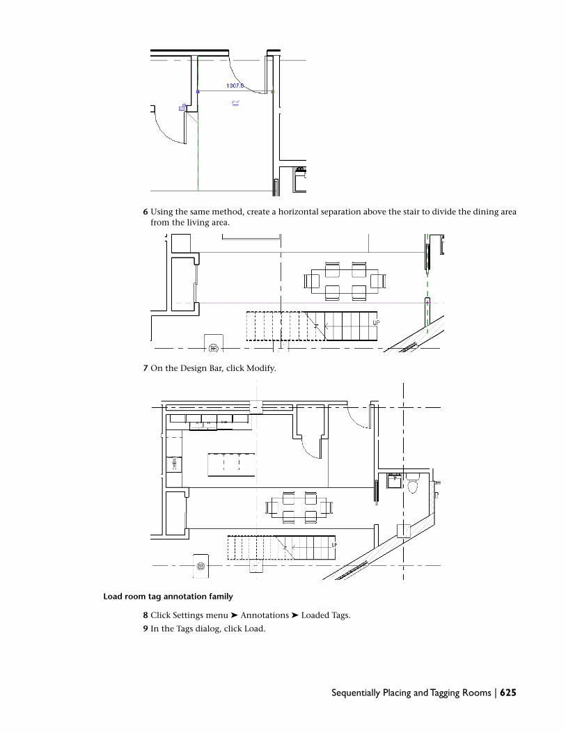
6 Using the same method, create a horizontal separation above the stair to divide the dining areafrom the living area.
7 On the Design Bar, click Modify.
Load room tag annotation family
8 Click Settings menu ➤ Annotations ➤ Loaded Tags.
9 In the Tags dialog, click Load.
Sequentially Placing and Tagging Rooms | 625

10 In the left pane of the Load Family dialog, click Training Files, and openMetric\Families\Annotations\M_Room Tag.rfa.
11 In the Tags dialog, click OK.
Tag rooms sequentially
12 On the Room and Area tab of the Design Bar, click Room.
13 On the Options Bar, verify that Tag on placement is selected.
14 For Offset, type 2400 mm.
15 Move the cursor to the room at the upper right of the plan view, and click to place the roomand tag.
The crosshair graphic represents the room area being tagged, and the rectangle contains theroom tag.
16 On the Design Bar, click Modify, and select the room tag.
The room tag number displays in blue, indicating that it can be edited.
17 Zoom in on the tag number, click it, type U18-1, and press ENTER.
626 | Chapter 11 Tagging and Scheduling

18 Click the room text label, type Entry, and press ENTER.
19 On the Design Bar, click Modify.
20 Place another room and tag:
■ On the Design Bar, click Room.
■ Move the cursor into the room to the left of the one previously tagged.
■ Align the tags by moving the cursor until a dashed green line displays between the placedtag and the one that displays at the tip of the cursor.
■ Click to place the new room and tag.
NOTE The second tag that you place displays the sequential number U18-2. Sequential lettersare also supported.
21 On the Design Bar, click Modify.
22 Click the room text label, type Kitchen, and press ENTER.
23 Using the same method, place rooms and tags, and edit the tags as shown (Toilet, Dining, andLiving):
Sequentially Placing and Tagging Rooms | 627

Hide the room separations
24 Click View menu ➤ Visibility/Graphics.
25 In the Visibility/Graphics Overrides dialog, on the Model Categories tab, expand Lines, clearRoom Separation, and click OK.
Tag rooms on upper level
26 In the Project Browser, under Floor Plans, double-click Unit 18 Plan - Level 2.
27 On the Design Bar, click Room Tag.
The rooms are already placed, but they need to be tagged.
28 Starting with the Balcony (area near the stair), and moving clockwise, click to place a room tagin each of the 5 rooms.
29 On the Design Bar, click Modify.
628 | Chapter 11 Tagging and Scheduling

30 Click File menu ➤ Save As.
31 Save the file as Metric\m_Freighthouse_Flats-Tagging Objects_in_progress.rvt.
Tagging Doors and Windows
In this exercise, you learn how to place door and window tags. You learn how to add tags to the floor planand how to simultaneously tag multiple untagged doors and windows.
Training File
Continue using the training file you saved in the previous exercise, Metric\m_Freighthouse_Flats-TaggingObjects_in_progress.rvt.
Tag Level 1 doors
1 If necessary, in the Project Browser, expand Floor Plans, and double-click Unit 18 Plan - Level1.
2 On the Drafting tab of the Design Bar, click Tag ➤ By Category.
3 On the Options Bar, clear Leader.
4 Select 5 doors in the upper area of the floor plan:
■ Entry door
■ Kitchen pantry door
■ Pocket door in toilet
■ Closet door in dining room
Tagging Doors and Windows | 629

■ Closet door in living room
5 On the Design Bar, click Modify.
6 Click the door tag for the entry door, type U18-1, and press ENTER.
NOTE The tag symbol and text size are determined by the tag family.
7 Select the kitchen pantry door to the left, and on the Options Bar, click (ElementProperties).
8 In the Element Properties dialog, under Identify Data, for Mark, type U18-2, and click OK.
630 | Chapter 11 Tagging and Scheduling

9 Using one of the methods you just learned, rename the other 3 door tags to match thecorresponding room tags.
10 Select the tag for the pocket door on the right, and drag it down to center it in the doorway.
11 Select the tag for the closet door and move it to the right of the door.
Tagging Doors and Windows | 631

Tag Level 2 doors
12 In the Project Browser, double-click Unit 18 Plan - Level 2.
13 On the Design Bar, click Tag All Not Tagged.
14 In the Tag All Not Tagged dialog, verify that All objects in current view is selected.
15 Under Category, select Door Tags, and click OK.
16 Move the door tags to center them in the doorway.
17 Edit the numbers of the door tags as shown:
Place window tags
18 In the Project Browser, expand Floor Plans, and double-click Level 1.
19 Click Settings menu ➤ Annotations ➤ Loaded Tags.
20 In the Tags dialog, click Load.
21 In the left pane of the Load Family dialog, click Training Files, and openMetric\Families\Annotations\M_Window Tag.rfa.
22 In the Tags dialog, click OK.
23 On the Drafting tab of the Design Bar, click Tag All Not Tagged.
24 In the Tag All Not Tagged dialog, select Window Tags, and click OK.
632 | Chapter 11 Tagging and Scheduling

25 Zoom to the lower-right area of the drawing to view the window tags.
26 Under Floor Plans, double-click Level 2.
27 Zoom to the drawing extents.
28 Using the same method, tag all untagged windows.
29 Save the file.
Tagging Other Objects
In this exercise, you learn how to tag furniture objects, and modify the tag placement and display.
Training File
Continue using the training file you saved in the previous exercise, Metric\m_Freighthouse_Flats-TaggingObjects_in_progress.rvt.
Add furniture tags
1 In the Project Browser, expand Floor Plans, and double-click Unit 18 Plan - Level 1.
2 On the Drafting tab of the Design Bar, click Tag ➤ By Category.
3 On the Options Bar, select Leader.
4 Select a dining room chair.
5 At the confirmation prompt, click Yes to load a tag.
6 In the left pane of the Open dialog, click Training Files, and openMetric\Families\Annotations\M_Furniture Tag.rfa.
7 Select each of the chairs and the table to place tags; select the edge to which the leader connects.
Tagging Other Objects | 633

8 Select the furniture in the living room.
9 Click Modify.
Modify tag placement
10 Zoom to the dining table.
Notice that the chair and table tags overlap.
11 Select the tag for the table, and drag it above the chair tag.
634 | Chapter 11 Tagging and Scheduling

12 Click the elbow control, and drag it up to form an angled leader.
13 Optionally, modify the position of the chair tags to move them closer to the chairs.
14 Click Modify.
15 Select the tag for the table (TBL-1), and on the Options Bar, clear Leader.
16 Drag the table tag to the center of the table, and on the Design Bar, click Modify.
Tag furniture on Level 2
17 In the Project Browser, under Floor Plans, double-click Unit 18 Plan - Level 2.
18 On the Design Bar, click Tag All Not Tagged, select M_Furniture Tag : Standard, and click OK.
All furniture in the floor plan is tagged.
Tagging Other Objects | 635

Change tag style
19 Draw a selection box around the top area of the drawing to select the furniture.
20 On the Options Bar, click (Filter Selection).
21 In the Filter dialog, click Check None, select Furniture Tags, and click OK.
22 In the Type Selector, select Furniture Tag: Boxed, and click Modify.
23 Save the file.
Defining Schedules and Color Diagrams
In this lesson, you learn to add schedules. You also learn to add schedule keys to a project by creating aroom schedule and room color diagram. Schedule keys allow you to define common items that can be usedby multiple objects within a schedule.
636 | Chapter 11 Tagging and Scheduling

Creating a Window Schedule
In this exercise, you create a window schedule for the building model shown below.
You begin by creating a window instance schedule; that is, a schedule that lists every window in the building.
Creating a Window Schedule | 637
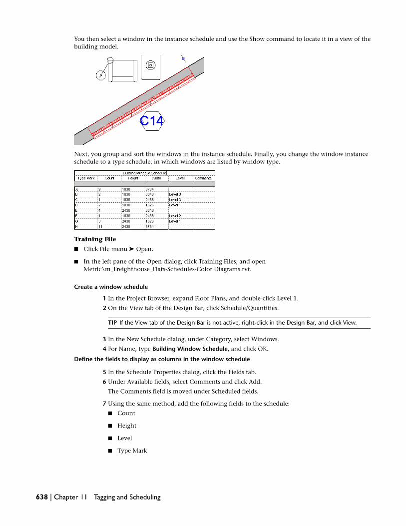
You then select a window in the instance schedule and use the Show command to locate it in a view of thebuilding model.
Next, you group and sort the windows in the instance schedule. Finally, you change the window instanceschedule to a type schedule, in which windows are listed by window type.
Training File
■ Click File menu ➤ Open.
■ In the left pane of the Open dialog, click Training Files, and openMetric\m_Freighthouse_Flats-Schedules-Color Diagrams.rvt.
Create a window schedule
1 In the Project Browser, expand Floor Plans, and double-click Level 1.
2 On the View tab of the Design Bar, click Schedule/Quantities.
TIP If the View tab of the Design Bar is not active, right-click in the Design Bar, and click View.
3 In the New Schedule dialog, under Category, select Windows.
4 For Name, type Building Window Schedule, and click OK.
Define the fields to display as columns in the window schedule
5 In the Schedule Properties dialog, click the Fields tab.
6 Under Available fields, select Comments and click Add.
The Comments field is moved under Scheduled fields.
7 Using the same method, add the following fields to the schedule:
■ Count
■ Height
■ Level
■ Type Mark
638 | Chapter 11 Tagging and Scheduling

■ Width
8 Under Scheduled fields, order the fields as shown in the following illustration by selecting themand clicking Move Up or Move Down.
9 Click OK.
A schedule is created that contains every window in the building model.
Select a window in the schedule and locate it in the building model
10 Select a cell in the window schedule with the C14 Type Mark, and on the Options Bar, clickShow.
If no open view shows the selected element, you are prompted to open one that does.
11 If the confirmation dialog displays, click OK to search through relevant views of the buildingmodel.
Creating a Window Schedule | 639

The window that corresponds to the information in the schedule row is displayed in a relevantview of the building model.
12 In the Show Element(s) in View dialog, click Close.
NOTE By clicking Show, you can display other views of the building model that include the selectedwindow. However, in large building models with many views, this can be a time-consuming process.
13 In the Project Browser, expand Schedules/Quantities, and double-click Building Window Scheduleto redisplay the window instance schedule.
Group and sort the window schedule by type mark
14 In the drawing area, right-click the schedule, and click View Properties.
15 In the Element Properties dialog, under Other, for Sorting/Grouping, click Edit.
16 On the Sorting/Grouping tab of the Schedule Properties dialog, for Sort by, select Type Mark
17 Click OK twice.
The window schedule is displayed, sorted by type mark.
Change type mark from the schedule
18 In the window schedule, change the Type Mark in the first row from 19 to A, and press ENTER.
19 Click OK to confirm that you want to change the type mark for all windows of this type.
640 | Chapter 11 Tagging and Scheduling

The type mark is changed to A and the schedule is resorted.
Change the schedule from an instance schedule to a type schedule
20 Right-click on the schedule, and click View Properties.
21 In the Element Properties dialog, under Other, for Sorting/Grouping, click Edit.
22 In the Schedule Properties dialog, clear Itemize every instance.
23 Click OK twice.
The window type schedule is displayed.
24 Change the Type Mark for the other window types, so that the types are sequentially namedfrom A to H, as shown:
25 In the Project Browser, under Floor Plans, double-click Level 2.
26 Zoom to the lower area of the floor plan to see that the window tags have changed.
27 Click File menu ➤ Save As, and save the exercise file as m_Freighthouse_Flats-Schedules-ColorDiagrams_in_progress.rvt.
Creating a Window Schedule | 641

Adding Project Parameters to a Window Schedule
In this lesson, you add schedule columns for parameters that are not standard for the scheduled object. Inthis case, you want to add columns to the window schedule to describe the detail where head, jamb, andsill conditions for a window can be found. These parameters cannot be shared with other projects and,unlike shared parameters, you cannot use them to tag objects.
Training File
Continue using the training file you saved in the previous exercise, m_Freighthouse_Flats-Schedules-ColorDiagrams_in_progress.rvt.
Create project parameters
1 In the Project Browser, expand Schedules/Quantities, and double-click Building Window Schedule.
2 Click Settings menu ➤ Project Parameters.
3 In the Project Parameters dialog, click Add to create the new parameter.
4 In the Parameter Properties dialog:
■ Under Categories, select Windows to associate the parameter with the Windows category.
■ Under Parameter Data, for Name, type Head Detail.
■ For Group parameter under, select Construction.
■ Select Type.
5 Click OK.
The new project parameter Head Detail is displayed in the Project Parameters dialog.
6 Using the same method, create 2 more window parameters: Jamb Detail and Sill Detail.
7 In the Project Parameter dialog, click OK.
Add project parameters to the schedule
8 In the Project Browser, right-click Building Window Schedule, and click Properties.
9 In the Element Properties dialog, under Other, for Fields, click Edit.
10 On the Fields tab of the Schedule Properties dialog, under Available fields, select the followingfields, and click Add to add them to the schedule in order:
■ Head Detail
■ Jamb Detail
■ Sill Detail
11 Use the Move Up control to move the new parameters up in the list, so that they are listed beforeComments.
642 | Chapter 11 Tagging and Scheduling

12 Click OK twice.
Group headers in the schedule
13 In the schedule, select Head Detail, Jamb Detail, and Sill Detail.
TIP To select all 3 headers, click in the Head Detail header, and without releasing the left mousebutton, move the cursor over the Jamb Detail and Sill Detail headers.
14 On the Options Bar, click Group.
15 In the grouping field above the detail headers in the schedule, type Window Details.
16 You can add values for the new project parameters directly in the schedule. For example, underType Mark A, for Head Detail, type 1/A107; for Jamb Detail, type 2/A107; and for Sill Detail,type 3/A107.
17 Save the file.
Adding Project Parameters to a Window Schedule | 643

Creating a Unit-Based Door Schedule with a Filter
In this exercise, you create a unit-based door schedule and use a filter to limit the selection of doors to asingle unit. You then hide the column used for the filter, and place the unit-based door schedule on a sheetwith the unit plans.
Training File
Continue using the training file you saved in the previous exercise, m_Freighthouse_Flats-Schedules-ColorDiagrams_in_progress.rvt.
View Level 1 of the building
1 In the Project Browser, expand Floor Plans, and double-click Unit 18 Plan - Level 1.
Create a new door schedule for Unit 18
2 On the View tab of the Design Bar, click Schedule/Quantities.
3 In the New Schedule dialog:
■ Under Category, select Doors.
■ Under Name, type Unit 18 - Door Schedule.
■ Verify that Schedule building components is selected.
■ For Phase, verify that Phase 1 is selected.
4 Click OK.
5 In the Schedule Properties dialog, click the Fields tab.
6 Under Available fields, select the following fields, and click Add to add them to the schedule inorder:
■ Count
■ Family and Type
■ Head Height
■ Sill Height
■ Width
■ Mark
7 Click the Filter tab, and specify the following values for Filter by:
■ Select Mark in the first field.
■ Select contains in the second field.
■ Type U18 in the third field.
This filter checks each door in the project to see which unit it is associated with, and producesa schedule that includes only the doors in Unit 18.
8 Click the Sorting/Grouping tab, and specify the following options:
■ For Sort by, select Family and Type.
■ Clear Itemize every instance (to group the like door types into one row).
9 Click the Formatting tab.
10 Under Fields, select Mark.
11 Under Field formatting, select Hidden field, and click OK.
644 | Chapter 11 Tagging and Scheduling

The schedule includes the count and type for doors in Unit 18 only. The Mark field is used tofilter the entries in the schedule, but is not included as a column in the schedule.
Place the schedule on a sheet
12 In the Project Browser, expand Sheets (all), and double-click A102 - Unit 18.
13 In the Project Browser, click Unit 18 - Door Schedule, and drag it to the sheet.
14 Click to place the schedule in the upper left corner of the sheet.
15 On the Design Bar, click Modify.
16 Zoom in to see the details of the door schedule.
Modify the width of a schedule column on the sheet
17 Select the door schedule on the sheet.
18 Select the control at the top of the schedule for the Family and Type column and drag it to theright to expand the column width.
The wider column makes it easier to read the door descriptions.
Creating a Unit-Based Door Schedule with a Filter | 645

19 On the Design Bar, click Modify.
20 Save the file.
Creating a Room Schedule
In this exercise, you create a room schedule for the first floor plan. You also add programmed rooms to theschedule for the public spaces in the building.
NOTE In some cases in this tutorial, partial schedules are shown for illustration purposes.
Training File
Continue using the training file you saved in the previous exercise, m_Freighthouse_Flats-Schedules-ColorDiagrams_in_progress.rvt.
Create a room schedule
1 In the Project Browser, under Floor Plans, double-click Level 1.
Notice that several rooms have been defined in the floor plan.
2 On the View tab of the Design Bar, click Schedule/Quantities.
TIP If the View tab of the Design Bar is not active, right-click in the Design Bar, and click View.
3 In the New Schedule dialog, under Category, select Rooms, and click OK.
Select the fields to display as columns in the room schedule
4 On the Fields tab of the Schedule Properties dialog, under Available fields, select Number, andclick Add.
The Number field is moved under Scheduled fields.
5 Using the same method, add the following fields to the schedule in order:
■ Name
■ Level
■ Area
6 Click the Appearance tab.
7 Under Text, to the right of Header text, select Bold.
8 Click OK.
NOTE The Appearance settings only take effect when the schedule is placed on a drawing sheet.The bold header is not noticeable until you place the schedule on a drawing sheet.
646 | Chapter 11 Tagging and Scheduling

Add new rooms to the schedule
9 On the Options Bar, next to Rows, click New.
A new row is displayed at the bottom of the schedule. The room Number is U17-46, and theLevel and Area values are displayed as Not Placed because the room is not placed in the floorplan.
10 Edit the number to be 101.
11 Using the same method, add 5 more rooms.
The rooms are displayed at the bottom of the list and numbered sequentially, 101-106.
12 Edit the room names in the schedule:
■ In the schedule, for room 101, for Name, type Building Entry, and press ENTER.
■ For 102, type Storage, and press ENTER.
■ For 103, type Corridor, and press ENTER.
■ For 104, select Corridor.
■ For 105, select Storage.
Creating a Room Schedule | 647

■ For 106, type Stair, and press ENTER.
13 Save the file.
Scheduling Rooms from a Program List
In this exercise, you add room separation lines, place rooms from a program list, and modify room names.You also change the bounding behavior of walls in the storage areas of the plan.
Training File
Continue using the training file you saved in the previous exercise, m_Freighthouse_Flats-Schedules-ColorDiagrams_in_progress.rvt.
Specify style for room separation lines
1 In the Project Browser, under Floor Plans, double-click Level 1.
2 Click View menu ➤ Visibility/Graphics.
3 Change the display of room separation lines:
■ On the Model Categories tab of the Visibility/Graphics dialog, under Visibility, expand Lines.
■ For Room Separation, under Projection/Surface, click the Lines field.
■ In the Lines field, click Override.
■ In the Line Graphics dialog, click the Color field.
■ Under Custom colors, click the bright green swatch, and click OK.
■ For Weight, select 9.
4 Click OK twice.
648 | Chapter 11 Tagging and Scheduling

Add room separation lines
5 Zoom in to the center of the building.
6 On the Room and Area tab of the Design Bar, click Room Separation.
7 Click to add 2 room separation lines in the corridor at the right side of the drawing. First, drawthe horizontal line.
8 Draw a vertical separation line from the wall endpoint to the new corridor separation line.
9 On the Design Bar, click Modify.
Place rooms from a program list
10 On the Design Bar, click Room.
Scheduling Rooms from a Program List | 649

Placed rooms are indicated with a crosshair graphic in the drawing.
11 On the Options Bar, for Room, select 101 Building Entry.
12 Click to place the room in the newly defined entry area (lower right).
13 On the Options Bar, for Room, select 102 Storage.
14 For Offset, type 2400 mm.
650 | Chapter 11 Tagging and Scheduling
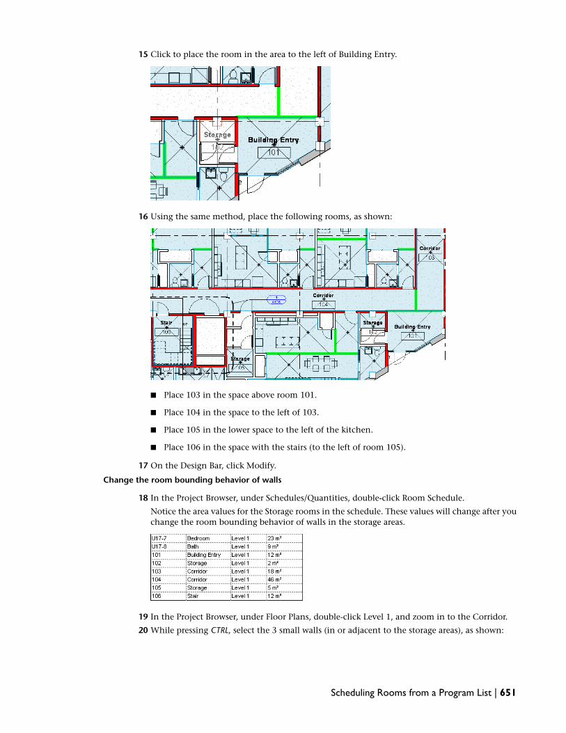
15 Click to place the room in the area to the left of Building Entry.
16 Using the same method, place the following rooms, as shown:
■ Place 103 in the space above room 101.
■ Place 104 in the space to the left of 103.
■ Place 105 in the lower space to the left of the kitchen.
■ Place 106 in the space with the stairs (to the left of room 105).
17 On the Design Bar, click Modify.
Change the room bounding behavior of walls
18 In the Project Browser, under Schedules/Quantities, double-click Room Schedule.
Notice the area values for the Storage rooms in the schedule. These values will change after youchange the room bounding behavior of walls in the storage areas.
19 In the Project Browser, under Floor Plans, double-click Level 1, and zoom in to the Corridor.
20 While pressing CTRL, select the 3 small walls (in or adjacent to the storage areas), as shown:
Scheduling Rooms from a Program List | 651

21 On the Options Bar, click (Element Properties).
22 In the Element Properties dialog, under Constraints, clear Room Bounding, and click OK.
23 On the Design Bar, click Modify.
24 Open the Room Schedule.
Notice that the area for the storage rooms has increased as a result of the change in the roombounding behavior of the walls.
Create key schedule
25 On the View tab of the Design Bar, click Schedule/Quantities.
26 In the New Schedule dialog, under Category, select Rooms.
27 Select Schedule keys, and click OK.
28 In the Schedule Properties dialog, under Available fields, while pressing CTRL, select Base Finish,Floor Finish, and Wall Finish, and click Add.
29 Click OK to create the new room style schedule.
The Room Style Schedule displays without data.
30 On the Options Bar, for Rows, click New.
31 For Key Name, type Units, and for all 3 finishes, type As Selected.
652 | Chapter 11 Tagging and Scheduling

32 Using the same method, add 2 more key names: Service and Public.
33 In the Project Browser, under Schedules/Quantities, right-click Room Schedule, and clickProperties.
34 In the Element Properties dialog, under Other, for Fields, click Edit.
35 In the Schedule Properties dialog, for Available fields, select Room Style, and click Add.
36 Click OK twice.
37 Open the Room Schedule.
The Room Style column is added to the Room Schedule.
38 Under U17-8, for Room Style, select Units.
Specify the Room Style for Level 1 rooms
39 In the Project Browser, under Floor Plans, double-click Level 1.
40 Zoom to the drawing extents.
41 Draw a selection box around floor plan.
42 On the Options Bar, click (Filter Selection).
43 In the Filter dialog, click Check None, select Rooms, and click OK.
All rooms are selected in the floor plan.
44 On the Options Bar, click (Element Properties).
45 In the Element Properties dialog, under Identity Data, for Room Style, select Units, and clickOK.
Scheduling Rooms from a Program List | 653

46 Open the Room Schedule.
Notice that the Room Style is Units for all rooms on Level 1.
47 Edit the Room Style for rooms 101 through 106:
■ For rooms 101, 103, 104, and 106, select Public.
■ For rooms 102 and 105, select Service.
All rooms on Level 1 now have the room style defined. The Room Style specification will beused later to determine color fill in a room color diagram.
48 Save the file.
Creating a Room Color Diagram
In this exercise, you create a room color scheme (based on the type of the rooms in the floor plan), andapply it to the Level 1 view. You also edit the colors used in the color scheme and modify the properties ofthe color scheme legend.
Training File
Continue using the training file you saved in the previous exercise, m_Freighthouse_Flats-Schedules-ColorDiagrams_in_progress.rvt.
Create a room color scheme
1 In the Project Browser, under Views (all), expand Floor Plans, and double-click Level 1.
2 Click Settings menu ➤ Color Fill Schemes.
3 In the Edit Color Scheme dialog, click (Duplicate).
4 In the New color scheme dialog, for Name, type Room Type, and click OK.
5 For Title, type Room Type.
6 In the Edit Color Scheme dialog, for Color, select Room Style.
7 Because you are creating a new color scheme, at the warning prompt, click OK.
8 In the Edit Color Scheme dialog, click OK.
9 In the Project Browser, under Floor Plans, right-click Level 1, and click Properties.
10 In the Element Properties dialog, under Graphics, click the Color Scheme field.
654 | Chapter 11 Tagging and Scheduling

11 In the Edit Color Scheme dialog, under Schemes, select Room Type, and click OK.
12 In the Element Properties dialog, for Visibility/Graphics Overrides, click Edit.
13 In the Visibility/Graphics Overrides dialog, under Visibility, expand Lines, and clear RoomSeparation.
14 Click OK twice.
Add a color scheme legend
15 On the Drafting tab of the Design Bar, click Color Scheme Legend.
When you move the cursor over the drawing area, a legend displays at the tip of the cursor.
16 Click in the lower right of the drawing area to place the legend.
17 On the Design Bar, click Modify.
Change the fill colors applied to the rooms
18 In the drawing area, select the color legend.
19 On the Options Bar, click Edit Color Scheme.
20 In the Edit Color Scheme dialog, in the first row of the Scheme Definition table (none), clearVisible.
21 In the second row of the table (Public), click the value in the Color column.
Creating a Room Color Diagram | 655

22 In the Color dialog, under Custom color, select blue, and click OK.
23 Using the same method, change the colors for Service and Units to cyan and gray, respectively.
24 Click OK.
Specify properties for the legend colors and title
25 With the legend still selected, on the Options Bar, click (Element Properties).
26 In the Element Properties dialog, click Edit/New.
27 In the Type Properties dialog, under Graphics, for Swatch Width, type 25 mm.
28 Under Title Text, for Size, type 5 mm.
29 Click OK twice.
30 On the Design Bar, click Modify.
656 | Chapter 11 Tagging and Scheduling

Create a section color diagram
31 In the Project Browser, under Sections, double-click Building Section.
NOTE In order for color fills to be displayed in section, volume computations must be enabled fromSettings menu ➤ Area and Volume Computations. Calculation of room volumes can affect projectperformance.
Turn on the visibility of rooms in the building section view
32 In the Project Browser, under Sections, right-click Building Section, and select Properties.
33 In the Element Properties dialog, under Graphics, for Visibility/Graphics Overrides, click Edit.
34 On the Model Categories tab of the Visibility/Graphic Overrides dialog, under Visibility, selectRooms.
35 Click OK twice.
Place the color scheme legend on the section
36 On the Room and Area tab of the Design Bar, click Color Scheme Legend.
As you move the cursor over the drawing area, the legend displays at the tip of the cursor.
37 Click to place the legend on the drawing.
38 In the Choose Space Type and Color Scheme dialog, for Color Scheme, select Room Type, andclick OK.
39 Using the grip at the bottom of the legend, position the legend horizontally across the bottomof the section view.
Creating a Room Color Diagram | 657

40 Draw a selection box around the entire drawing.
41 On the Options Bar, click (Filter Selection).
42 In the Filter dialog, click Check None, select Rooms, and click OK.
Assign all rooms the Units room style
43 On the Options Bar, click .
44 In the Element Properties dialog, under Identity Data, for Room Style, select Units, and clickOK.
45 While pressing CTRL, select all the rooms in the stairwell, and the room to the right of the stairon level 1 (Corridor 104).
46 Click .
47 In the Element Properties dialog, under Identity Data, for Room Style, select Public, and clickOK.
658 | Chapter 11 Tagging and Scheduling
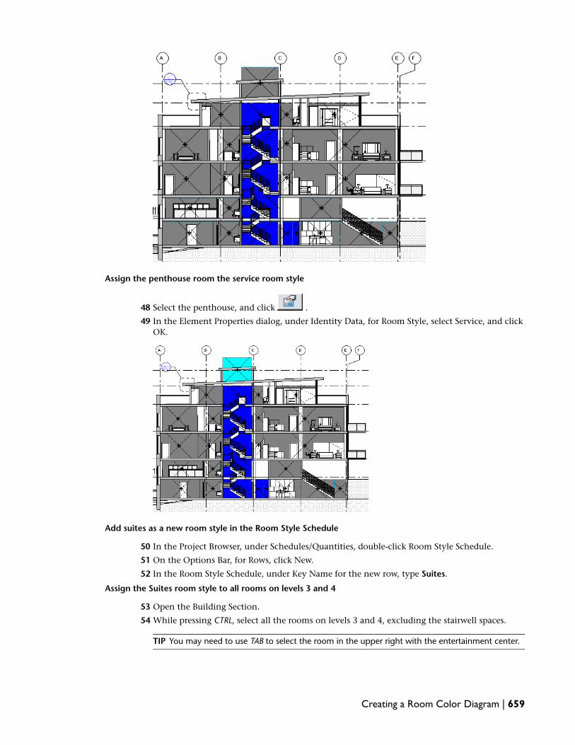
Assign the penthouse room the service room style
48 Select the penthouse, and click .
49 In the Element Properties dialog, under Identity Data, for Room Style, select Service, and clickOK.
Add suites as a new room style in the Room Style Schedule
50 In the Project Browser, under Schedules/Quantities, double-click Room Style Schedule.
51 On the Options Bar, for Rows, click New.
52 In the Room Style Schedule, under Key Name for the new row, type Suites.
Assign the Suites room style to all rooms on levels 3 and 4
53 Open the Building Section.
54 While pressing CTRL, select all the rooms on levels 3 and 4, excluding the stairwell spaces.
TIP You may need to use TAB to select the room in the upper right with the entertainment center.
Creating a Room Color Diagram | 659

55 Click .
56 In the Element Properties dialog, under Identity Data, for Room Style, select Suites, and clickOK.
A new Suites key is added to the color scheme legend.
Use volume calculations to control color fills
57 Click Settings menu ➤ Area and Volume Computations.
58 In the Area and Volume Computations dialog, under Volume Computations, select Areas andVolumes.
59 Under Room Area Computation, verify that At wall finish is selected, and click OK.
The color fill will extend to the roof, but not beyond it.
Change room heights
60 In the drawing area, select the room on the left side of the top floor.
61 Drag the top Control grip above the bounding roof.
The color fill extends to the roof.
62 Repeat this process for all rooms that are bounded by the sloping roof: the remaining suites andthe public stairs on the top floor.
660 | Chapter 11 Tagging and Scheduling

Assign the correct heights to the rooms on the first level
63 On the first level, select the stairwell room, and click .
64 In the Element Properties dialog, under Constraints, for Upper Limit, select Loft.
65 For Limit Offset, type 0.0.
66 Click OK.
67 On the first level, select the public room next to the stairs (Corridor 104), the dining room, andthe living room.
68 Click .
69 In the Element Properties dialog, under Constraints, for Upper Limit, select Level 2.
70 For Limit Offset, type -254 mm.
71 Click OK.
72 On the Design Bar, click Modify.
Creating a Room Color Diagram | 661

73 Save the file.
Creating a Material Takeoff
In this exercise, you have already determined the roof configuration for the building. You learn to changethe roof family type and create a material takeoff schedule for the roofing materials. You then add formulasto the material takeoff to produce cost estimates.
Training File
Continue using the training file you saved in the previous exercise, m_Freighthouse_Flats-Schedules-ColorDiagrams_in_progress.rvt.
Create a material takeoff
1 In the Project Browser, under 3D Views, double-click {3D}.
662 | Chapter 11 Tagging and Scheduling
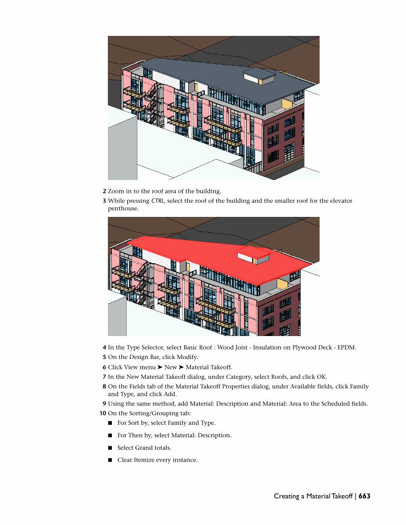
2 Zoom in to the roof area of the building.
3 While pressing CTRL, select the roof of the building and the smaller roof for the elevatorpenthouse.
4 In the Type Selector, select Basic Roof : Wood Joist - Insulation on Plywood Deck - EPDM.
5 On the Design Bar, click Modify.
6 Click View menu ➤ New ➤ Material Takeoff.
7 In the New Material Takeoff dialog, under Category, select Roofs, and click OK.
8 On the Fields tab of the Material Takeoff Properties dialog, under Available fields, click Familyand Type, and click Add.
9 Using the same method, add Material: Description and Material: Area to the Scheduled fields.
10 On the Sorting/Grouping tab:
■ For Sort by, select Family and Type.
■ For Then by, select Material: Description.
■ Select Grand totals.
■ Clear Itemize every instance.
Creating a Material Takeoff | 663

11 On the Formatting tab:
■ Under Fields, select Material: Area.
■ Under Field formatting, select Calculate totals.
12 Click OK.
The Roof Material Takeoff Schedule displays.
13 Expand the column widths to see all of the information.
TIP Double-click the column dividers to expand the columns to fit the text.
Add cost information and a formula to calculate estimated cost
14 In the Project Browser, right-click Roof Material Takeoff, and click Properties.
15 In the Element Properties dialog, under Other, for Fields, click Edit.
16 In the Material Takeoff Properties dialog, under Available fields, select Material: Cost, and clickAdd.
17 Click Calculated Value.
18 In the Calculated Value dialog, for Name, type Estimated Cost.
19 For Type, select Currency.
20 For Formula, type Material: Area*Material: Cost /(1000mm^2).
The /(1000mm^2) is required to remove the formatting of the fields so that the cost estimatevalue can be calculated.
21 Click OK.
22 In the Material Takeoff Properties dialog, click the Formatting tab, and under Fields, clickEstimated Cost.
23 For Field formatting, select Calculate totals, and click OK twice.
24 In the Roof Material Takeoff, for Material: Cost, type the following values:
Material: CostMaterial: Description
16EPDM
13.40Plywood
50.80Rigid Insulation
664 | Chapter 11 Tagging and Scheduling

Material: CostMaterial: Description
5.35Wood Joist
The Estimated cost is calculated.
Add currency formatting to the schedule
25 Click Settings menu ➤ Project Units.
26 In the Project Units dialog, for Currency, click the Format value.
27 In the Format dialog, for Rounding, verify that 2 decimal places is selected.
28 For Unit symbol, select $.
29 Select Use digit grouping.
Digit grouping, which inserts commas after every three digits, can be used for any number-basedparameter, not just for currency.
30 Click OK twice.
The cost fields are formatted correctly.
31 Save the file.
Scheduling Shared Parameters
In this lesson, you learn how to use shared parameters to define additional parameters that are not includedin predefined instance and type parameters, either within family components or within the project template.These shared parameters can be added to any family, regardless of category, and are defined and stored inan external file, ensuring consistency across families and projects. Their values may also be aggregated andreported within Revit MEP multi-category schedules.
An example of the use of shared parameters is the need to add specific parameters to a family componentfor scheduling and tagging when those parameters are not present by default. This lesson demonstrates thesolution for this situation and covers the process of setting up shared parameters, adding the shared parametersto a family, creating a generic tag to tag the family, and reporting the shared parameters.
In this lesson, you create an exiting plan for the building. You draw a travel path line, tag the line, andschedule the total distance of each path. Adding shared parameters to a family allows you to create a tagand schedule to track this specific information.
Creating a Shared Parameter File
In this exercise, you create a shared parameter file.
Scheduling Shared Parameters | 665

Training File
■ Click File menu ➤ Open.
■ In the left pane of the Open dialog, click Training Files, and open Metric\m_Freighthouse_Flats-SharedParameters.rvt.
1 In the Project Browser, under Floor Plans, double-click Exiting Plan-Level 1.
2 Click File menu ➤ Shared Parameters.
3 In the Edit Shared Parameters dialog, click Create.
4 In the left pane of the Create Shared Parameter File dialog, click Training Files, for File name,type OfficeStandardsParameters.txt, and click Save.
NOTE Shared parameter files are typically stored at a network location for use in all projects.
5 In the Edit Shared Parameters dialog, under Groups, click New.
6 In the New Parameter Group dialog, for Name, type Exiting, and click OK.
7 Under Parameters, click New.
8 In the Parameter Properties dialog, for Name, type Path ID, and click OK.
9 Under Parameters, click New.
10 In the Parameter Properties dialog, for Name, type Travel Distance, for Type of Parameter, selectLength.
11 Click OK twice.
12 Click File menu ➤ Save As, and save the exercise file as m_Freighthouse_Flats-SharedParameters_in_progress.rvt.
666 | Chapter 11 Tagging and Scheduling

Adding Shared Parameters to a Family
In this exercise, you add the shared parameters you created to a family file. You then create a generic tag totag the family.
Training File
Continue using the training file you saved in the previous exercise, m_Freighthouse_Flats-Schedules-SharedParameters_in_progress.rvt.
1 Click File menu ➤ Open.
2 In the Left pane of the Open dialog, Click Training Files, and openMetric\Families\Annotations\M_Travel Line.rfa.
3 On the Design Bar, click Family Types.
The Family Types dialog displays the parameters that are currently available for this familycategory.
4 In the Family Types dialog, under Parameters, click Add.
5 In the Parameter Properties dialog, under Parameter Type, select Shared parameter, and clickSelect.
6 In the Shared Parameters dialog, verify that Parameter group is Exiting and that Path ID isselected, and click OK.
7 In the Parameter Properties dialog, under Parameter Data, for Group parameter under, selectConstraints.
8 Select Instance, and click OK.
9 In the Family Types dialog, under Parameters, click Add.
10 Using the same method, add Travel Distance as a shared parameter, group it under Dimensions,and select Instance.
11 Click OK.
12 In the Family Types dialog, under Dimensions, for Travel Distance Formula, following the equalssymbol (=), type Length.
13 Click Apply, and click OK.
14 On the Design Bar, click Load into Projects.
If you have multiple projects open, the Load into Projects dialog displays for you to select theproject, otherwise the family loads into the current project.
15 If necessary, in the Load into Projects dialog, select m_Freighthouse_Flats-SharedParameters_in_progress.rvt, and click OK.
Create a tag using shared parameters
16 Click File menu ➤ New ➤ Annotation Symbol.
Adding Shared Parameters to a Family | 667

17 In the left pane of the New Annotation Symbol dialog, click Training Files, and openMetric\Templates\M_Generic Tag.rft.
18 Zoom in to the intersection of the reference planes.
19 On the Design Bar, click Label.
20 Click the intersection of the reference planes.
21 In the Edit Label dialog, click (Add Parameter).
22 In the Parameter Properties dialog, click Select.
23 In the Shared Parameters dialog, under Parameters, select Travel Distance.
24 Click OK twice.
25 In the Edit Label dialog, under Category Parameters, select Travel Distance, click (Addparameter(s) to label), and click OK.
26 On the Design Bar, click Label.
27 Click above the intersection of the reference planes, and use the same method to select the PathID parameter.
668 | Chapter 11 Tagging and Scheduling

28 On the Design Bar, click Modify.
29 In the drawing window, select Path ID, and move it down, so that it is positioned just aboveTravel Distance.
30 Select the Note in the upper left area of the drawing window, and press DELETE.
31 Click File ➤ Save As.
32 In the Save As dialog, for File Name, type M_Travel Distance Tag.rfa, and click Save.
33 On the Design Bar, click Load into Projects.
34 On the Load into Projects dialog, verify that m_Freighthouse_Flats-SharedParameters_in_Progress.rvt is selected, and click OK.
35 Save the file.
Adding Shared Parameters to a Family | 669

Placing,Tagging, and Scheduling a Family with Shared Parameters
In this exercise, you place the travel line family in the Level 1 and Level 2 exiting plans. You then tag thetravel lines and give them a path ID. After the lines are tagged, you create a schedule that totals the traveldistances in each exiting plan for each path ID.
Training File
Continue using the training file you saved in the previous exercise, m_Freighthouse_Flats-Schedules-SharedParameters_in_progress.rvt.
Create Level 1 exiting travel path
1 In the Project Browser, under Floor Plans, double-click Exiting Plan - Level 1.
2 Zoom in to the corridor.
3 On the Basics tab of the Design Bar, click Component.
4 On the Options Bar, select Chain.
5 Specify a start point for the path at the left end of the corridor as shown.
6 Move the cursor to the right, and click in the center of the corridor, above the exterior door asshown.
670 | Chapter 11 Tagging and Scheduling

7 Move the cursor down, through the door, and click outside of the building.
8 On the Design Bar, click Modify.
9 On the Drafting tab of the Design Bar, click Tag ➤ By Category.
10 On the Options Bar, clear Leader.
11 Select each of the travel path lines.
12 On the Design Bar, click Modify.
13 While pressing CTRL, select the 2 dashed travel lines, and click (Element Properties).
14 In the Element Properties dialog, under Constraints, for Path ID, type 1-1, and click OK.
Create Level 2 exiting travel path
15 In the Project Browser, under Floor Plans, double click Exiting Plan - Level 2.
16 On the Basics tab of the Design Bar, click Component.
17 On the Options Bar, verify that Chain is selected.
18 Click in the horizontal corridor below the door on the right side of the floor plan, move thecursor near the right corner, and click to specify the first segment of the path as shown.
Placing,Tagging, and Scheduling a Family with Shared Parameters | 671

19 Move the cursor up through the door, and click.
20 On the Design Bar, click Modify.
21 On the Design Bar, click Component.
22 Click at the starting point of the previous path, move the cursor to the left, and click above thedoor to the stair.
23 Move the cursor down, and click in the stair.
672 | Chapter 11 Tagging and Scheduling

24 On the Design Bar, click Modify.
25 On the Drafting tab of the Design Bar, click Tag ➤ By Category.
26 Select each of the travel path lines.
27 On the Design Bar, click Modify.
28 While pressing CTRL, select the 2 dashed travel lines for the left exit path, and click .
29 In the Element Properties dialog, under Constraints, for Path ID, type 2-1, and click OK.
30 Using the same method, specify the Path ID for the right exit path to 2-2.
Create a schedule to total the paths on each plan
31 Click View menu ➤ New ➤ Schedule/Quantities.
32 In the New Schedule dialog, under Category, verify that <Multi-Category> is selected.
33 For Name, type Level 1 Exit Distance, and click OK.
Placing,Tagging, and Scheduling a Family with Shared Parameters | 673

34 On the Fields tab of the Schedule Properties dialog, under Available fields, while pressing CTRL,select Path ID and Travel Distance, and click Add.
35 Click the Filter tab.
36 For Filter by, in the first field, select Path ID; in the second field, select contains; and in the thirdfield, type 1-.
37 Click the Sorting/Grouping tab.
38 For Sort by, select Path ID.
39 Clear Itemize every instance.
40 Click the Formatting tab.
41 Under Fields, select Travel Distance, and under Field formatting, select Calculate totals.
42 Click OK.
The Level 1 Exit Distance schedule displays.
43 In the Project Browser, under Schedules/Quantities, right-click Level 1 Exit Distance, and clickDuplicate View ➤ Duplicate.
44 In the Project Browser, right-click Copy of Level 1 Exit Distance, and click Rename.
45 In the Rename View dialog, type Level 2 Exit Distance, and click OK.
46 In the Project Browser, right-click Level 2 Exit Distance, and click Properties.
47 In the Element Properties dialog, under Other, for Filter, click Edit.
48 In the Schedule Properties dialog, for Filter by, in the third field, type 2-.
49 Click OK twice.
The Level 2 Exit Distance schedule displays.
50 Save the file.
Scheduling Uniformat Assembly Codes
In this lesson, you schedule Uniformat Assembly Codes as they are applied to Revit MEP components.
Scheduling Uniformat Assembly Codes and Descriptions
In this exercise, you create a wall schedule that includes columns for the Uniformat Assembly Codes andassembly descriptions of the scheduled walls.
Training File
■ Click File menu ➤ Open.
■ In the left pane of the Open dialog, click Training Files, and openMetric\m_Freighthouse_Flats-Uni-Format.rvt.
674 | Chapter 11 Tagging and Scheduling

Create a wall schedule
1 On the View tab of the Design Bar, click Schedule/Quantities.
TIP If the View tab of the Design Bar is not active, right-click the Design Bar, and click View.
2 In the New Schedule dialog, under Categories, select Walls, and click OK.
3 In the Schedule Properties dialog, click the Fields tab.
4 Under Available fields, select the following fields, and click Add to add them to the schedule inorder:
■ Area
■ Volume
■ Width
■ Length
■ Assembly Code
■ Assembly Description
5 Click OK to complete the schedule.
Assign an assembly code to a wall type in the project
6 In the Project Browser, expand Families ➤ Walls ➤ Basic Wall, right-click Generic - 152 mm,and click Properties.
7 In the Type Properties dialog, under Identity Data, for Assembly Code, click the Value field, and
click .
8 In the Choose Assembly Code dialog, expand C - Interiors ➤ C10 - Interior Construction ➤ C1010- Partitions ➤ C1010100 - Fixed Partitions, and select C1010145 - Partitions - Drywall w/ MetalStud.
9 Click OK twice.
10 In the schedule, expand the Assembly Description column to see the description.
Scheduling Uniformat Assembly Codes and Descriptions | 675

11 Close the exercise file.
Exporting Project Information with ODBC
In this lesson, you learn how to export project information to an ODBC (Open DataBase Connectivity)compatible database.
Exporting Schedule Information to Microsoft Access
In this exercise, you learn how to export project information into a Microsoft® Access 2000 database. Theprocess that you use to export the database is similar for any other ODBC-compliant database.
Training File
■ Click File menu ➤ Open.
■ In the left pane of the Open dialog, click Training Files, and openMetric\m_Freighthouse_Flats-Uni-Format.rvt.
1 On the File menu, click Export ➤ ODBC Database.
2 In the Select Data Source dialog, click the File Data Source tab.
3 Click New.
4 In the Create New Data Source dialog, select the Microsoft Access Driver (*.mdb), and click Next.
5 Type RevitDSN for the name of the file data source, and click Next.
6 Click Finish.
7 In the ODBC Microsoft Access Setup dialog, under Database, click Create.
8 In the New Database dialog, for Database Name, type Revit_Project.mdb.
9 Under Directories, select a location for the database file, and click OK to create the database.
10 When the confirmation dialog displays, click OK.
11 Click OK 3 times.
12 Open the database in Microsoft Access.
NOTE Depending on your version of Microsoft Access, the database display may be different thanthat shown.
676 | Chapter 11 Tagging and Scheduling

Revit MEP creates 2 tables for the following categories of elements (see below): one that lists allof the element instances in a project and one that lists all of the element types in a project.Additionally, tables that list instances only are created for levels and rooms because thesecategories do not have types.
A unique element ID is used to identify exported elements, so that each table of elements includesan Id column. Elements IDs are also used to establish relationships between elements in differenttables. For example, instance tables include a TypeId column containing the ID of the instance’stype, and some instance tables include a RoomId column containing the ID of the room thatthe instance is in.
In addition to the tables for instances and types in a category, a table is also created for eachkey schedule in a project, as long as the category is one of the categories that Revit MEP exports.The exported columns are the same as the columns in the key schedule, in addition to the Idcolumn. Each key schedule gives elements in its category a new parameter, which is used forchoosing one of the keys from the key schedule. These parameters are also exported and containthe ID of the key element.
One final table is also exported: Assembly Codes. This table contains one row for each UniformatAssembly Code. The columns of the table are Assembly Code and Assembly Description. Thetable of types includes an Assembly Code column that references the Assembly Codes table.
13 Close the exercise file.
Exporting Schedule Information to Microsoft Access | 677

678

Annotating andDimensioning
In this tutorial, you learn how to change the base elevation of a project, and how to annotate and dimension your RevitMEP 2009 projects.
Changing the Base Elevation of a Project
In this lesson, you learn how to relocate the base elevation of a project, as the base elevation of most projectsis rarely at 0 mm. You can change the base elevation without changing the elevation value of every otherlevel in the project, or you can change the base elevation and add its value to the levels above it. Youaccomplish this in Revit MEP by defining levels as either project or shared levels.
12
679

Project levels report elevation relative to other levels in the project
680 | Chapter 12 Annotating and Dimensioning

Shared levels report elevation relative to the base height
Relocating a Project
In this exercise, you relocate the base elevation of a building from 0 m to 10000 m. After you define thebuilding levels as shared and relocate the project, the height of the elevations above Level 1 report heightrelative to Level 1.
Relocating a Project | 681

Training File
■ Click File menu ➤ Open.
■ In the left pane of the Open dialog, click Training Files, and open m_Freighthouse_Flats-Anno_Dim.rvt.
Define Level 1 as a shared level
1 In the Project Browser, expand Views (all), expand Elevations (Building Elevation), anddouble-click South.
Level 1 displays an elevation value of 0 mm. The levels in the project are not shared, so changingthe height Level 1 would change it only in relation to the other levels in the project.
682 | Chapter 12 Annotating and Dimensioning

2 Select the Level 1 line to display it as red.
3 On the Options Bar, click (Element Properties).
4 In the Element Properties dialog, click Edit/New.
In order for the levels to report height relative to the new base elevation after the project isrelocated, you must set the Elevation Base parameter to Shared. If you did that now, the parameterfor all the levels in the project would change. However, to better demonstrate how shared levelswork, only the Elevation Base parameter of Level 1 is shared at this time, and you create a newshared level type for only Level 1.
5 In the Type Properties dialog:
■ Click Duplicate.
■ In the Name dialog, type 8 mm Head - Shared Elevation, and click OK.
■ Under Constraints, for Elevation Base, select Shared.
6 Click OK twice.
Relocate the project
7 Click Tools menu ➤ Project Position/Orientation ➤ Relocate this Project.
8 Select the Level 1 line.
By selecting the Level 1 line, you specify the point (0 mm) from which you want to relocate theproject.
9 Move the cursor above the elevation line, type 10000 mm, and press ENTER.
By typing 10000 mm in this step, you specify the new location of the project.
10 On the View menu, click Zoom ➤ Zoom All To Fit.
The south elevation is displayed. The base elevation now reads 10000 mm. The elevation of theother levels remains the same.
Relocating a Project | 683

Define the remaining project levels as shared
11 Select the Loft level line.
12 In the Type Selector, select Level : 8 mm Head - Shared Elevation.
13 On the Design Bar, click Modify.
The reported value of the Loft level changes to take the new base elevation value intoconsideration.
14 In the Project Browser, under Elevations, double-click North.
The changes in elevation have propagated to this view, as well as other views of the buildingmodel.
684 | Chapter 12 Annotating and Dimensioning

15 Define the remaining levels as shared:
■ While pressing CTRL, select Levels 2-4, the Penthouse level, and the Roof Plan level.
■ In the Type Selector, select Level : 8 mm Head - Shared Elevation.
■ On the Design Bar, click Modify.All the building levels now report elevations relative to the base elevation.
Relocating a Project | 685

16 If you want to save your changes, click File menu ➤ Save As, and save the exercise file with aunique name.
17 Proceed to the next lesson, Dimensioning on page 686.
Dimensioning
In this lesson, you learn how to create permanent dimensions to control and document your buildingmodels. In Revit MEP, there are 2 types of dimensions: temporary and permanent. Temporary dimensionsdisplay automatically when you create and insert components. Permanent dimensions must be explicitlycreated, except when you sketch profiles to complete families. In this case, permanent dimensions are createdautomatically, although you must turn on their visibility to view them.
Creating Dimensions
In this exercise, you learn how to use dimensioning tools and constraints in Revit MEP to dimension andspace planter boxes on the north side of the building. You place linear, multi-segmented, radial, and angulardimensions, and learn to work with dimensioning constraints to control placement of elements in themodel.
686 | Chapter 12 Annotating and Dimensioning

Linear and multi-segmented dimensions
Training File
Continue to use the training file you used in the previous exercise,Metric\m_Freighthouse_Flats-Anno_Dim.rvt
Place an overall linear dimension
1 In the Project Browser, expand Views (all), expand Floor Plans, and double-click Level 1.
2 On the Basics tab of the Design Bar, click Dimension.
The default dimensioning options display on the Options Bar. By default, dimensions are aligned,snap to wall centerlines, and are created by selecting individual reference points.
3 Move the cursor over the curtain wall on the top left side of the view, and when a blue dashedline displays along the left side of the curtain wall, select it.
Creating Dimensions | 687

4 Move the cursor over the curtain wall on the top right side of the view, and when a blue dashedline displays along the right side of the curtain wall, select it.
5 Move the cursor above the view, and click to place the dimension.
688 | Chapter 12 Annotating and Dimensioning

6 Click the lock that displays on the dimension string to lock the dimension.
The lock displays as locked, indicating that you cannot change the distance between the curtainwalls without first unlocking the dimension. Only aligned and angular permanent dimensionscan be constrained in this way.
7 On the Design Bar, click Modify.
Place a multi-segmented dimension
8 On the Design Bar, click Dimension.
9 Select the left side of the left curtain wall as you did in a previous step, and move the cursorover the left endpoint of the first planter to the right.
10 Press TAB until the left endpoint of the planter displays, and select it.
11 Using the same method, select the right endpoint of the planter.
Creating Dimensions | 689

12 On the Options Bar, for Prefer, select Wall Faces.
13 Move the cursor to the planter on the right, and select its left exterior face.
14 Move the cursor to the right, and continue to select the endpoints and faces of the planters.
15 After you select the reference points on the final planter, select the right side of the curtain wall.
16 Move the cursor up, above the plan view of the building, but below the first dimension thatyou placed, and click to place the multi-segmented dimension.
Make the dimension segments equal to space the planters at equal distances
17 With the multi-segmented dimension selected, click to make all the dimension segmentsequal and reposition the planters equal distances apart from one another.
18 On the Basics tab, click Modify.
690 | Chapter 12 Annotating and Dimensioning

Create a baseline dimension style
19 Select the dimension string, and on the Options Bar, click .
20 In the Element Properties dialog, click Edit/New.
21 In the Type Properties dialog, click Duplicate.
22 In the Name dialog, enter Linear - 2.5 mm Arial - Baseline, and click OK.
23 In the Type Properties dialog, under Graphics, for Dimension String Type, select Baseline.
Create an ordinate dimension style
24 In the Type Properties dialog, click Duplicate.
25 In the Name dialog, enter Linear - 2.5 mm Arial - Ordinate, and click OK.
26 In the Type Properties dialog, for Dimension String Type, select Ordinate.
27 Click OK twice.
View and apply the new dimension styles
28 Zoom in to the dimension string.
The dimensions start from 0 mm and increase moving away from the origin.
29 Select the dimension string, and in the Type Selector, select Linear - 2.5 mm Arial - Baseline.
The dimensions are stacked and measure from the same baseline.
Creating Dimensions | 691

30 In the Type Selector, select Linear - 2.5 mm Arial to return to the original dimension style.
Add text below a permanent dimension
You can add supplemental text above, below, to the left, or to the right of a permanent dimension value.
31 Click the dimension value to which you want to add text, for example . The DimensionText dialog displays.
32 In the Dimension Text dialog, under Dimension Value, verify that Use Actual Value is selected.
33 Under Text Fields, for Below, enter Planter.
34 Click OK.
35 On the Design Bar, click Modify.
Place a radial dimension with a Typ. suffix
36 Zoom to the planter between grid lines 3 and 4.
692 | Chapter 12 Annotating and Dimensioning

37 On the Design Bar, click Dimension.
38 On the Options Bar:
■ Click (Radial).
■ For Prefer, select Wall faces.
39 Move the cursor over the left exterior curved face of the planter until it highlights, and selectit.
40 Move the cursor outside the wall, and specify a point to place the dimension.
41 On the Basics tab of the Design Bar, click Modify.
42 Select the radial dimension.
43 Select the blue square grip that displays under the dimension value and drag it slightly up andto the right.
44 With the dimension still selected, click the dimension text.
45 In the Dimension Text dialog, for Suffix, type Typ., and click OK.
46 On the Basics tab, click Modify.
Creating Dimensions | 693

Place an angular dimension
47 Zoom to the planter near grid line 5.
48 On the Basics tab of the Design Bar, click Dimension.
49 On the Options Bar:
■ Click (Angular).
■ For Prefer, verify that Wall faces is selected.
50 Select the horizontal line.
This line is the edge of a mass that represents the neighboring building.
694 | Chapter 12 Annotating and Dimensioning

51 Select the left exterior face of the planter.
52 Move the cursor to the left to resize the dimension arc, and click to place the dimension.
53 On the Basics tab, click Modify.
54 Proceed to the next exercise, Creating Automatic Wall Dimensions on page 695.
Creating Automatic Wall Dimensions
In this exercise, you learn to automatically dimension a linear wall and its openings (windows) on the Level3 floor plan of the building. When you dimension the wall, you select only the wall, instead of the wall andeach individual opening reference point. This automatic dimensioning option provides a convenient wayto quickly dimension walls with multiple openings.
Creating Automatic Wall Dimensions | 695

Automatic wall dimension
Training File
Continue to use the training file you used in the previous exercise,Metric\m_Freighthouse_Flats-Anno_Dim.rvt
Open the Level 3 floor plan view
1 In the Project Browser, expand Views (all), expand Floor Plans, and double-click Level 3.
You will dimension the short bottom horizontal wall that includes 3 windows.
Select automatic dimensioning options
2 On the Basics tab of the Design Bar, click Dimension.
3 On the Options Bar:
■ For Prefer, select Wall centerlines.
■ For Pick, select Entire Walls.
■ Click Options.
4 In the Auto Dimension Options dialog:
■ Under Select references, select Openings, and select Widths.
696 | Chapter 12 Annotating and Dimensioning

■ Click OK.These options ensure that the wall dimension includes the openings, and that the openingwidths are referenced in the overall dimension string.
Place the dimension
5 Select the bottom exterior wall.
6 Move the cursor down below the plan view, and click to place the automatic dimension string.
7 On the Basics tab, click Modify.
8 Proceed to the next exercise, Controlling Witness Lines on page 697.
Controlling Witness Lines
In this exercise, you learn to override dimension witness line settings as you place dimensions, and learnhow to change the location of witness lines after you place dimensions.
When you place dimensions, you specify their origin on the Options Bar. However, in some cases, you mayneed to override their settings on an instance basis. For example, for a multi-segmented dimension, youmay want to locate the two outermost witness lines on the exterior face of each wall, where the witness linesreferring to interior walls would be located on the centerline of each wall.
Training File
Controlling Witness Lines | 697

Continue to use the training file you used in the previous exercise,Metric\m_Freighthouse_Flats-Anno_Dim.rvt
Override default dimension witness lines
1 In the Project Browser, expand Views (all), expand Floor Plans, and double-click Level 1.
2 Zoom to the planter on which you placed a radial dimension.
3 On the Basics tab of the Design Bar, click Dimension.
4 On the Options Bar:
■ For Prefer, verify Wall centerlines is selected.
■ For Pick, select Individual References.
5 Move the cursor over the left side of the planter.
6 Press TAB to cycle through the selection options until the left face of the planter highlights, andselect it.
698 | Chapter 12 Annotating and Dimensioning

7 Using the same method, select the right edge of the planter, move the cursor down, and clickto place the dimension.
8 Move the cursor over the bottom of the planter on which you placed the angular dimension.
9 Press TAB until the bottom left endpoint is highlighted, and select it.
10 Using the same method, select the bottom right endpoint.
11 Move the cursor down, and specify a point to place the dimension.
Controlling Witness Lines | 699

Dimension the partition walls to centerlines
12 On the Basics tab, click Dimension.
13 On the Options Bar, for Prefer, select Wall centerlines.
14 Move the cursor over the left partition wall in the top left corner of the plan, and when the wallcenterline highlights, select it.
700 | Chapter 12 Annotating and Dimensioning

15 Moving the cursor to the right, select the centerline of each of the 6 remaining partition walls,and click to place the dimension.
16 On the Design Bar, click Modify.
Adjust the witness line location on the end dimensions to align them to the faces of wall
17 Select the dimension that you just placed, and zoom in on the right end of the dimension.
18 While pressing SHIFT, select the green grip that displays in the middle of the tick mark, and dragthe dimension down the wall.
Controlling Witness Lines | 701

19 Release SHIFT, select the top blue grip and drag it up to create a witness line gap.
20 Click the blue middle grip, drag it to the right, and press TAB until the dimension aligns withthe outer face of the partition wall.
21 Zoom to the partition wall on the left side of the plan, and using the same methods, create awitness line gap and align the dimension to the outer left face of the wall.
22 On the Basics tab, click Modify.
23 Proceed to the next exercise, Creating an Office Standard Dimension Type from ExistingDimensions on page 702.
Creating an Office Standard Dimension Type from Existing Dimensions
In this exercise, you learn how to duplicate the dimension family type of dimension on the floor plan andthen modify its parameters to create an office standard dimension style. After you create the new familytype, you change the dimension tick mark, text font, and text size parameters to create dimensions thatbetter conform to your office standards.
702 | Chapter 12 Annotating and Dimensioning

Angular and linear dimensions with office standardtext and arrows
Training File
Continue to use the training file you used in the previous exercise,Metric\m_Freighthouse_Flats-Anno_Dim.rvt
Duplicate an existing dimension type
1 On the Level 1 floor plan, zoom to the planter between grid lines 3 and 4, and select the lowerdimension.
2 Click (Element Properties).
3 In the Element Properties dialog, click Edit/New.
4 In the Type Properties dialog, click Duplicate.
5 In the Name dialog, type Office Standard, and click OK.
Modify the parameters of the new Office Standard type
6 In the Type Properties dialog:
■ Under Graphics, for Tick Mark, select Arrow 30 Degree.
■ Under Text, for Text Size, type 3.2 mm.
Creating an Office Standard Dimension Type from Existing Dimensions | 703

■ For Text Font, select CityBlueprint.
NOTE Fonts that are available in this list are the Windows fonts installed on your system. IfCityBlueprint does not display in the list, select another font.
■ Click OK twice.
7 On the Basics tab, click Modify.
The dimension that you selected previously now displays the new Office Standard family type.
8 Move the cursor to the planter on the right, and select the bottom dimension.
9 In the Type Selector, select Linear Dimension Style: Office Standard.
10 On the Basics tab, click Modify.
704 | Chapter 12 Annotating and Dimensioning

11 Using the same method, select the angular dimension on the planter, create a new angulardimension type, and modify it to use the office standard parameters.
12 Proceed to the next lesson, Creating Text Annotation on page 705.
Creating Text Annotation
In this lesson, you add text notes on the Level 1 floor plan of the building. You create a new office standardtext note type by duplicating the family type of a note on the floor plan. You learn how to change the textfont and size of text notes, and how to add leaders to the text notes.
Creating Text Annotation | 705

Adding Text Notes to the Floor Plan
In this exercise, you add text notes to the Level 1 floor plan.
Training File
Continue to use the training file you used in the previous exercise,Metric\m_Freighthouse_Flats-Anno_Dim.rvt
Add a text note
1 On the Level 1 floor plan, zoom to the planter near grid line 5.
2 On the Basics tab of the Design Bar, click Text.
3 On the Options Bar, for Leader, click (None).
4 Move the cursor above grid line 4, but below the upper dimension string, and click and drag tocreate a text box.
706 | Chapter 12 Annotating and Dimensioning

5 In the text box, type EXISTING BUILDING.
Create a new text note family type by duplicating the existing type
6 On the Design Bar, click Modify.
7 Select the text box, and click .
8 In the Element Properties dialog box, click Edit/New.
9 In the Type Properties dialog, click Duplicate.
10 In the Name dialog box, type 6 mm Arial Notes, and click OK.
11 Under Text, for Text Size, type 6 mm, and click OK.
12 In the Element Properties dialog, under Graphics, select Arc Leaders, and click OK.
Adding Text Notes to the Floor Plan | 707

You may have to move the text box to avoid overlapping other elements on the floor plan. Ifso, select and drag the top left blue symbol to relocate the text box.
Create a text box with leaders
13 On the Design Bar, click Text.
14 Create another text box to the right of grid line 4, and type Planting Bed.
15 On the Design Bar, click Modify.
16 Select the Planting Bed text box.
708 | Chapter 12 Annotating and Dimensioning

17 On the Options Bar:
■ Click (Add Right Arc Leader).A downward pointing leader displays on the right side of the Planting Bed text box.
■ Click (Add Left Arc Leader).Another leader displays on the left side of the Planting Bed text box.
Reposition the leaders
18 Select the blue grip at the end of the right leader, and drag it down to point to the bottom ofthe planter.
19 Select the blue grip at the end of the left leader, and drag it down to point to the bottom of theplanter.
20 On the Design Bar, click Modify.
21 Select the Planting Bed text box to select both the text and leaders, and click .
22 In the Element Properties dialog, click Edit/New.
23 In the Type Properties dialog:
■ Click Rename.
■ In the Rename dialog, for New, type Standard Notes, and click OK.
■ Under Text, for Text Font, select CityBlueprint.
■ Under Graphics, for Leader Arrowhead, select Arrow 30 Degree.
■ Click OK twice.
24 On the Design Bar, click Modify.
Adding Text Notes to the Floor Plan | 709

Add another note using the Standard Note type
25 On the Design Bar, click Text.
26 In the Type Selector, select Text: Standard Notes.
27 On the Options Bar, for Leader, click (Arc).
28 Click the inside bottom face of the rounded planter near grid line 3.
29 Move the cursor up and to the right, over the Planting Bed text.
30 When blue dashed lines that indicate it is aligned with the Planting Bed text, click to place thetext box.
710 | Chapter 12 Annotating and Dimensioning

31 Click in the text box, and type 457 mm Conc. Wall, and click Modify.
32 If you want to save your changes, click File menu ➤ Save As, and save the exercise file with aunique name.
33 Close the exercise file without saving your changes.
Adding Text Notes to the Floor Plan | 711

712

Detailing
In this tutorial, you learn how to create details in Revit MEP 2009. You can detail directly in a view of the buildinginformation model, using detail components to represent materials like lumber, plywood, and metal studs. Thesecomponents display at the required scale. For a detail that you do not want to associate with the model, like a standarddoor header condition, you use a separate drafting view in which to create the detail. The "drafted" detail that you createis not parametrically linked to the building model.
Creating a Detail from a Building Model
In this lesson, you detail the roof overhang of a project building.
In order to detail from the building model, you must define the view in which you want to create a detail.You define that view by creating a callout view within a section view. In the callout view, you trace overthe building model geometry, add detail components, and then complete the detail by adding break linesand text notes.
13
713

Detailing the View
In this exercise, you detail the view of the roof edge. You load detail components, and use the model as anunderlay for the detail. After you add components, you add notes and dimensions to the detail view.
The detail components that you add to the view are two-dimensional family objects. They are also viewspecific, which means that all detail components, as well as detail lines, region objects, and insulation objects,that you add to the view are visible only in this view.
Training File
■ Click File menu ➤ Open.
■ In the left pane of the Open dialog, click Training Files, and openMetric\m_Freighthouse_Flats-Detailing.rvt.
Display a detail view
1 In the upper left corner of the building model, double-click the detail callout head.
The roof overhang detail displays.
2 Click View menu ➤ View Properties.
3 In the Element Properties dialog, for Graphics ➤ Display Model, select As underlay, and clickOK.
Load and place a detail component
4 On the Drafting tab of the Design Bar, click Detail Component.
5 In the alert dialog, click Yes to load a Detail Items family.
6 In the left pane of the Open dialog, click Training Files, navigate toMetric\Families\m_Corrugated Metal.rfa, and click Open.
7 In the drawing area, click in the space below the roof overhang to place the component. Exactlocation is not important.
714 | Chapter 13 Detailing

8 Delete the component.
You load and place the component so that it is in the project to use in a repeating detail.
Place a repeating detail
9 On the Design Bar, click Repeating Detail.
10 On the Options Bar, click (Element Properties).
11 In the Element Properties dialog, click Edit/New.
12 In the Type Properties dialog, click Duplicate.
13 In the Name dialog, enter Corrugated Metal Siding, and click OK.
14 In the Type Properties dialog, for Pattern ➤ Detail, select Corrugated Metal.
15 For Spacing, enter 406.5mm.
16 Click OK twice.
17 In the drawing area, click the bottom of the exterior wall to select the start point.
18 Move the cursor up to generate the graphics for the repeating detail. Specify a point high enoughso the siding reaches the underside of the roof overhang.
NOTE The detail component endpoint may not coincide with the geometry extents.
19 On the Design Bar, click Modify.
Detailing the View | 715

20 Move the component end point:
■ Select the corrugated metal component, and on the Edit toolbar, click (Move).
■ Select the endpoint of the geometry of the corrugated metal component as the move startpoint.
■ Select the bottom edge of the roof joist as the move end point.
■ Click Modify.
Add lumber detail components
21 On the Design Bar, click Detail Component.
22 On the Options Bar, click Load.
23 In the left pane of the Load Family dialog, click Training Files, navigate to Metric\Families\DetailComponents\Div 06-Wood and Plastic\06100-RoughCarpentry\06160-Sheathing\M_Plywood-Section.rfa, and click Open.
24 In the Type Selector, verify that M_Plywood-Section 19mm is selected.
25 Place the plywood component to the right of the metal component as shown in the followingillustration.
TIP You may need to use the Move command to adjust the position of the plywood.
716 | Chapter 13 Detailing

Because you still have several components to load, you load them as a group from a single file.
Load components as a group
26 Click File menu ➤ Load from Library ➤ Load File as Group.
27 In the left pane of the Load File as Group dialog, click Training Files, navigate toMetric\Families\Detail Components\m_Roof Edge Components.rvt, and click Open.
28 In the Duplicate Types dialog, click OK.
29 On the Design Bar, click Detail Component.
30 In the Type Selector, select M_Nominal Cut Lumber-Section : 50 x 150mm Nominal.
31 To properly orient the component, press SPACEBAR 3 times.
32 Click the top right corner of the plywood to select the insertion point.
33 In the Type Selector, select M_Nominal Cut Lumber-Section : 50 x 200mm Nominal, and placeit in the detail view as shown.
Detailing the View | 717

Add wallboard detail component
34 In the Type Selector, select M_Gypsum Wallboard-Section : 16mm.
35 On the Options Bar, select Chain.
36 Place the wallboard component as shown.
37 Click Modify.
38 Select the horizontal segment, click the Flip instance arrows, and click Modify.
The wallboard segment is now on the underside of the roof joist.
NOTE You can also press SPACEBAR as you place the component to flip the justification.
718 | Chapter 13 Detailing

Add insulation
39 On the Design Bar, click Insulation.
40 On the Options Bar:
■ For Width, enter 140mm.
■ For Offset, select to near side.
41 Place 2 segments of insulation, as shown.
42 Click Modify.
43 Move the upper segment:
■ Select the upper segment of insulation, and on the Edit toolbar, click (Move).
■ Select the left midpoint of the 50 x 200mm component as the move start point.
■ Select the right midpoint of the 50 x 200mm component as the move end point.
■ Click Modify.
Add lumber components
44 On the Design Bar, click Detail Component.
Detailing the View | 719

45 In the Type Selector, select M_Nominal Cut Lumber-Section : 50 x 300mm Nominal.
46 Click to place the component at the lower left corner of the roof overhang as shown.
47 In the Type Selector, select M_Plywood-Section : 19mm.
48 Place the component directly above the 50 x 200mm component, as shown.
Add rigid insulation
49 In the Type Selector, select M_Rigid Insulation-Section : 63mm.
50 Add the insulation above the plywood you just placed, and lock the component.
51 Click Modify.
52 Proceed to the next exercise, Adding Detail Lines on page 720.
Adding Detail Lines
In this exercise, you add lines to your detail. Like detail components, they are view specific, meaning theydisplay only in this view.
Training File
Continue to use the training file you used in the previous exercise, m_Freighthouse_Flats-Detailing.rvt.
Add detail lines
1 On the Design Bar, click Detail Lines.
2 In the Type Selector, select Thin Lines.
3 Sketch a detail line from the lower right corner of the 50 x 300mm component to the lower leftcorner of the 50 x 200mm component.
720 | Chapter 13 Detailing

4 Click Modify.
5 Select the vertical plywood component; drag the endpoint up to the top of the 50 x 200mmcomponent.
Add offset lines
6 On the Design Bar, click Detail Lines.
7 In the Type Selector, select Thin Lines.
8 On the Options Bar:
■ Click (Pick Lines).
■ For Offset, enter 10mm, and press ENTER.
9 Select the lines at the top of the 50 x 300mm component and the roof joist, as shown.
Trim and extend the lines as necessary to get the desired result.
10 On the Design Bar, click Detail Lines.
11 In the Type Selector, select Medium Lines.
12 On the Options Bar:
■ Click (Pick Lines).
■ For Offset, enter 10mm, and press ENTER.
13 Add detail lines around the 50 x 300mm component, as shown.
Adding Detail Lines | 721

Draw detail lines
14 On the Options Bar, click (Draw), and clear Chain.
15 Draw a small diagonal line at the bottom left corner of the 50 x 300mm component, as shown.
16 On the Options Bar, select Chain, and draw the detail lines as shown.
17 Draw a horizontal line as shown.
722 | Chapter 13 Detailing

18 In the Type Selector, select Thin Lines.
19 Zoom in to the area where the roof joist and the corrugated metal component abut; draw thedetail lines as shown.
20 Move the top horizontal line down so that it overlays the Penthouse level line.
Modify display properties
21 In the drawing area, select the Penthouse level line, right-click, and click Hide in view ➤ Elements.
22 In the Project Browser, under Views ➤ Detail Views (Detail), right-click Roof Overhang Detail,and click Properties.
23 In the Element Properties dialog, for Graphics ➤ Display Model, select Do not display, and clickOK.
When you turn the display model off, the model elements such as walls and floors no longerdisplay in this view. What remains are the detail components and lines that you added.
24 On the View Control Bar, click ➤ Hide Crop Region.
Add a vapor barrier
25 On the Design Bar, click Detail Lines.
26 In the Type Selector, select Vapor Barrier.
27 On the Options Bar:
■ Click (Pick Lines).
■ For Offset, enter 10mm, and press ENTER.
28 Select the interior edge of the vertical segment of gypsum wallboard, and then select the interioredge of the horizontal segment.
Adding Detail Lines | 723

29 On the Design Bar, click Detail Component.
30 In the Type Selector, select M_Break Line.
31 Add break lines at the bottom and the right of the detail.
TIP To rotate the break line as you place it, press SPACEBAR as necessary.
32 Click Modify.
33 If a break line does not completely mask the portion of the detail that it is intended to mask,select the break line and use the shape handle grips to modify it.
34 Proceed to the next exercise, Adding Text Notes on page 724.
Adding Text Notes
In this exercise, you add text notes to complete the detail.
Training File
724 | Chapter 13 Detailing

Continue to use the training file you used in the previous exercise, m_Freighthouse_Flats-Detailing.rvt.
Add text notes to the detail
1 On the Drafting tab of the Design Bar, click Text.
2 On the Options Bar, click (Arc) to create an arced leader.
3 Add the leaders and notes as shown:
■ Click in the detail to specify the location of the arrow.
■ Click again to specify the location of the text box.
■ Enter the text.
■ Click in the drawing area to end the text insertion command.
Add a dimension to the detail
4 On the Design Bar, click Dimension.
5 Click the left outer edge of the 50 x 300mm component, click the left edge of the corrugatedmetal component, and click to place the dimension.
6 Click Modify.
Adding Text Notes | 725

7 Select the dimension line, and click the dimension text.
8 In the Dimension Text dialog, under Text Fields, for Suffix, enter Typ., and click OK.
9 Click File menu ➤ Save, and save the exercise file.
10 Proceed to the next exercise, Creating Detail Components on page 726.
Creating Detail Components
In this exercise, you modify the previously drawn detail so that you can annotate it with keynotes ratherthan text notes.
Training File
Continue to use the training file you used in the previous exercise, m_Freighthouse_Flats-Detailing.rvt.
Create a duplicate drawing
1 In the Project Browser, under Views (all) ➤ Detail Views (Detail), click Roof Overhang Detail,right-click, and click Duplicate View ➤ Duplicate with Detailing.
2 Select Copy of Roof Overhang Detail, right-click, and click Rename.
3 In the Rename View dialog, enter Roof Overhang Detail - Keynotes, and click OK.
Remove text notes
4 In the drawing area, select a text note, right-click, click Select All Instances, and press DELETE.
Convert detail lines to components
5 Use a window to select the entire roof detail; on the Options Bar, click (Filter Selection).
6 In the Filter dialog, clear Detail Items and Dimensions, and click OK.
The selected lines need to be replaced with detail components in order for them to accept akeynote.
726 | Chapter 13 Detailing

7 Click Modify.
8 Zoom in to the metal coping; while pressing CTRL, select all the coping linework.
You can also select all the linework by highlighting a segment, pressing TAB, and selecting thechain.
9 Click Edit menu ➤ Copy to Clipboard.
10 Click File menu ➤ New ➤ Family.
11 In the left pane of the New Family dialog, click Training Files, navigate toMetric\Templates\Metric Detail Component.rft, and click Open.
12 Click Edit menu ➤ Paste from Clipboard.
13 Click the intersection of the reference planes to place the linework.
14 Click Modify.
15 Use a window to select all linework; in the Type Selector, select Medium Lines.
16 Click Modify.
17 Click File menu ➤ Save As.
Creating Detail Components | 727

18 In the Save As dialog, navigate to your preferred location; for File name, enter Roof Edge, andclick Save.
Add components to the detail
19 On the Family tab of the Design Bar, click Load into Projects.
The component family is now part of the roof overhang detail, and the component can beplaced in the detail.
NOTE If the Roof Overhang Detail - Keynotes view is not the open view, double-click it in the ProjectBrowser.
20 On the Drafting tab of the Design Bar, click Detail Component.
21 To place the component, click the bottom left endpoint of the metal coping.
22 Click Modify.
23 Using a window, select the coping.
While pressing SHIFT, deselect any extraneous lines that are also selected.
24 On the Options Bar, click .
25 In the Filter dialog, clear Detail Items, and click OK.
The original linework remains selected.
26 Press DELETE.
The underlying linework is deleted and the detail component remains in the drawing.
27 On the Design Bar, click Detail Component.
28 On the Options Bar, click Load.
29 In the left pane of the Open dialog, click Training Files, navigate to Metric\Families\DetailComponents\m_Metal Fascia w_Drip Edge.rfa, and click Open.
30 In the drawing area, click on the upper end point of the drip edge to place the component.
31 Using the same method used previously, delete the underlying linework.
32 Proceed to the next exercise, Adding Keynotes on page 728.
Adding Keynotes
In this exercise, you place keynotes on objects, and add keynote data to components that do not have dataassociated with them.
Training File
728 | Chapter 13 Detailing

Continue to use the training file you used in the previous exercise, m_Freighthouse_Flats-Detailing.rvt.
Add keynotes to components
1 On the Drafting tab of the Design Bar, click Keynote ➤ Element.
2 In the alert dialog, click Yes to load a Keynote Tag family to the project.
3 In the left pane of the Load Family dialog, click Training Files, navigate toMetric\Families\Annotations\M_Keynote Tag.rfa, and click Open.
4 Add the tag:
■ In the drawing area, select the rigid insulation as the object to tag.
■ Click to place the leader arm.
■ Click the rigid insulation on the roof to place the tag.
■ In the Keynotes dialog, navigate to 07000 ➤ 07200 ➤ 07210 ➤ 07210.B5, 63mm RigidInsulation, and click OK.
5 Tag additional components:
■ For the plywood decking, use keynote 06160.D11, 19mm Plywood.
■ For the metal coping, use keynote 07645.C1, Roof Edge4.
6 Click Modify.
Assign keynote parameter to a component
7 In the drawing area, select the metal fascia with drip edge, and click (Element Properties).
8 In the Element Properties dialog, click Edit/New.
Adding Keynotes | 729

9 In the Type Properties dialog, for Identity Data ➤ Keynote, click in the Value column, and click
.
10 In the Keynotes dialog, navigate to 07645.F1, FasciaProfile_1.
11 Click OK 3 times.
12 On the Design Bar, click Keynote ➤ Element.
13 Tag components:
■ Tag the metal fascia with drip edge.Because you defined the keynote parameter as part of the component properties, the keynoteis automatically read when you place the tag.
■ For the 50 x 300, use keynote 06110.I1.
■ For the 50 x 200, use keynote 06110.G1.
■ For the 50 x 150, use keynote 06110.F1.
■ For the 19mm Plywood Siding, use keynote 06160.D11.
■ For the 2 instances of the 16mm Gypsum Wallboard, use keynote 09250.D1.
14 On the Design Bar, click Detail Component.
15 In the Type Selector, select Corrugated Metal.
16 Place an instance of the component directly on top of the bottom segment of the corrugatedmetal repeating component.
You do this in order to keynote the component; a repeating detail cannot be keynoted.
17 Keynote the component, using keynote 07460.A8, 22mm Corrugated Steel - 20 Ga.
18 Save the file.
19 Proceed to the next exercise, Creating Line-based Detail Components on page 730.
Creating Line-based Detail Components
In this exercise, you convert detail lines to detail components so that you can add keynotes to them.
730 | Chapter 13 Detailing

Training File
Continue to use the training file you used in the previous exercise, m_Freighthouse_Flats-Detailing.rvt.
Create a detail component
1 Click File menu ➤ New ➤ Family.
2 In the left pane of the New Family dialog, click Training Files, navigate toMetric\Templates\Metric Detail Component line based.rft, and click Open.
3 On the Family tab of the Design Bar, click Lines.
4 In the Type Selector, select Medium Lines.
5 In the drawing area, select the left end point of the reference line, and select the right end point.
6 Lock the line, and click Modify.
7 Click File menu ➤ Save As.
8 In the Save As dialog, navigate to your preferred location; for File name, enter m_Medium LineDetail Component, and click Save.
9 On the Design Bar, click Load into Projects.
Convert detail lines to components
10 In the drawing area, select the horizontal line under the roof overhang as shown.
11 Press DELETE.
12 On the Drafting tab of the Design Bar, click Detail Component.
The deleted line needs to be replaced with a detail component in order for it to accept a keynote.
13 In the Type Selector, select Medium Line Detail Component.
14 Add the component in the location of the previously deleted horizontal line.
15 Click Modify.
16 Select the component, and click (Element Properties).
17 In the Element Properties dialog, click Edit/New.
18 In the Type Properties dialog, click Duplicate.
19 In the Name dialog, enter Prefinished Metal Soffit Panel.
20 Click OK 3 times.
Load line-based detail components
21 On the Design Bar, click Detail Component.
22 On the Options Bar, click Load.
23 In the left pane of the Load Family dialog, click Training Files, navigate to Metric\Families\DetailComponents.
24 While pressing CTRL, select m_Hidden Line Detail Component, m_Invisible Line DetailComponent, and m_Light Line Detail Component, and click Open.
Creating Line-based Detail Components | 731

25 Next, you create line-based detail components for other line weights (light, invisible, and hidden)used in the view. You add the components to the project and keynote them.
Add light line components
26 Zoom to the roof overhang.
27 On the Design Bar, click Detail Component.
28 In the Type Selector, select m_Light Line Detail Component.
29 In the drawing area, click the end points of the long detail line above the roof.
30 Click Modify.
31 Select the component, and click .
32 In the Element Properties dialog, click Edit/New.
33 In the Type Properties dialog, click Duplicate.
34 In the Name dialog, enter EPDM Membrane, and click OK.
35 In the Type Properties dialog, for Identity Data ➤ Keynote, click in the Value column, and click
.
36 In the Keynotes dialog, navigate to 07000 ➤ 07500 ➤ 07530 ➤ 07530.A1, Single-Ply MembraneRoofing.
37 Click OK 3 times.
38 On the Design Bar, click Detail Component.
39 Add the Light Line Detail Component to the underside of the overhang.
40 Click Modify.
41 Select the component just added, and click .
42 Using the same method used previously, name the component 50 x 200 Framing, and assign itkeynote 06110.G1.
43 Zoom to the repeating component.
44 On the Design Bar, click Detail Component.
45 Click the upper end of the repeating detail, and click the lower end at the break line.
46 Click Modify.
47 Select the component, and click .
48 Using the same method used previously, name the component Air Barrier, and assign it keynote07260.A5.
49 With the component selected, on the Edit toolbar, click (Move).
50 Move the air barrier to the right, against the 19mm plywood.
732 | Chapter 13 Detailing

Add a vapor barrier component
51 On the Design Bar, click Detail Component.
52 In the Type Selector, select m_Hidden Line Detail Component.
53 On the Options Bar, select Chain.
54 Create the component by drawing over the vertical and horizontal dashed detail lines thatrepresent the vapor barrier.
55 Click Modify.
56 Delete both dashed detail lines, leaving the detail component lines.
57 Select the vertical hidden line component, and click .
Creating Line-based Detail Components | 733

58 Using the method used previously, name the component Vapor Barrier, and assign it keynote07260.A4.
Add keynotes
59 Zoom to the drawing extents.
60 On the Design Bar, click Keynote ➤ Element.
61 In the drawing area, add keynotes for the EPDM Membrane, Air Barrier, 50 x 200 Framing, andVapor Barrier.
Create an invisible line component
62 Click Window menu ➤ m_Medium Line Detail Component.rfa.
63 In the drawing area, select the component; in the Type Selector, select Invisible Lines.
64 Save the file as m_Invisible Line Detail Component.rfa.
65 On the Family tab of the Design Bar, click Load into Projects.
66 On the Drafting tab of the Design Bar, click Detail Component.
67 In the Type Selector, select m_Invisible Line Detail Component.
68 In the drawing area, draw a line in the center of the large vertical segment of insulation.
734 | Chapter 13 Detailing
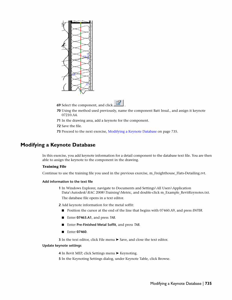
69 Select the component, and click .
70 Using the method used previously, name the component Batt Insul., and assign it keynote07210.A4.
71 In the drawing area, add a keynote for the component.
72 Save the file.
73 Proceed to the next exercise, Modifying a Keynote Database on page 735.
Modifying a Keynote Database
In this exercise, you add keynote information for a detail component to the database text file. You are thenable to assign the keynote to the component in the drawing.
Training File
Continue to use the training file you used in the previous exercise, m_Freighthouse_Flats-Detailing.rvt.
Add information to the text file
1 In Windows Explorer, navigate to Documents and Settings\All Users\ApplicationData\Autodesk\RAC 2008\Training\Metric, and double-click m_Example_RevitKeynotes.txt.
The database file opens in a text editor.
2 Add keynote information for the metal soffit:
■ Position the cursor at the end of the line that begins with 07460.A9, and press ENTER.
■ Enter 07463.A1, and press TAB.
■ Enter Pre-Finished Metal Soffit, and press TAB.
■ Enter 07460.
3 In the text editor, click File menu ➤ Save, and close the text editor.
Update keynote settings
4 In Revit MEP, click Settings menu ➤ Keynoting.
5 In the Keynoting Settings dialog, under Keynote Table, click Browse.
Modifying a Keynote Database | 735

6 In the Browse for Keynote File dialog, navigate to m_Example_RevitKeynotes.txt, and click Open.
7 In the Keynoting Settings dialog, under Path Type, select Absolute, and click OK.
Work with keynotes
8 On the Design Bar, click Keynote ➤ Element.
9 In the drawing area, select the metal soffit (horizontal line under the overhang); click to placethe leader, and click to place the note.
10 In the Keynotes dialog, navigate to 07463.A1, and click OK.
11 Click Modify.
12 Apply various keynote styles:
■ In the drawing area, select all the keynotes.
■ In the Type Selector, select M_Keynote Tag : Keynote Number.Each keynote displays as a simple number.
■ Select Keynote Tag : Keynote Text.The descriptive text for each keynote displays.
■ Change the keynote style back to the boxed number type.
13 Click Modify.
14 Save the file.
Creating a Drafted Detail
In this lesson, you learn how to create a drafted detail. Drafted details are created in drafting views and arenot directly based on building model geometry. These details do not update with changes to the buildingmodel, as there is no parametric linkage to any building model components.
You can create details in drafting views when you do not need to create callout views from the buildingmodel. You can create drafted details using the drafting tools in Revit MEP or by importing details from anexisting detail library. After you create a drafting view, you can reference it within the model and place iton a sheet.
736 | Chapter 13 Detailing

Importing a Detail into a Drafting View
In this exercise, you place an existing detail in a new drafting view to create a drafted detail. The detail thatyou import is in DWG format.
Training File
Use the training file you used in a previous exercise, m_Freighthouse_Flats-Detailing.rvt.
Create a new drafting view
1 Click View menu ➤ New ➤ Drafting View.
2 In the New Drafting View dialog, for Scale, select 1 : 5, and click OK.
Import a complete detail in DWG format
3 Click File menu ➤ Import/Link ➤ CAD Formats.
4 In the Import/Link CAD Formats dialog:
■ In the left pane, click Training Files.
■ Navigate to Metric\m_Roof Edge Detail.dwg.
■ For Colors, select Black and White.
■ For Positioning, verify that Auto - Center to Center is selected.
■ Click Open.
5 Enter zf to zoom to the detail.
The detail is imported as an import symbol.
6 In the Project Browser, expand Views (all) ➤ Drafting Views (Detail), right-click Drafting 1, andclick Rename.
7 In the Rename View dialog, enter EPDM Metal Coping, and click OK.
8 Proceed to the next exercise, Creating a Reference Callout on page 737.
Creating a Reference Callout
In this exercise, you create a callout in the section view of the building model to reference the metal copingdetail that you previously imported.
Training File
Continue to use the training file you used in the previous exercise, m_Freighthouse_Flats-Detailing.rvt.
Importing a Detail into a Drafting View | 737

Create the callout view
1 In the Project Browser, under Views (all) ➤ Detail Views (Detail), double-click Roof OverhangDetail to open it in the drawing area.
2 On the View tab of the Design Bar, click Callout.
3 On the Options Bar, select Reference other view, and select Drafting View: EPDM Metal Coping.
4 Add the callout bubble by dragging a rectangular bubble around the metal coping.
5 Click Modify.
6 Select the callout, and use the callout grips to move the callout head.
Modify detail view properties
7 In the Project Browser, right-click EPDM Metal Coping, and click Properties.
8 In the Element Properties dialog, click Edit/New.
9 In the Type Properties dialog, click Rename.
10 In the Rename dialog, for New, enter Detail - No Reference, and click OK.
11 In the Type Properties dialog, for Graphics ➤ Reference Label, delete the existing value.
12 Click OK twice.
The callout head no longer displays a reference label.
738 | Chapter 13 Detailing

Display the reference view
13 On the Design Bar, click Modify, and double-click the callout.
The metal coping detail that you imported previously displays.
Add the drafting view to a sheet
14 In the Project Browser, under Views (all) ➤ Sheets (all), double-click A105 - Elev./Sect./Det.
15 Under Drafting Views (Detail - No Reference), drag EPDM Metal Coping onto the sheet.
16 Click on the sheet above the Roof Overhang Detail to place the drafting view.
17 Click Window menu ➤ Detail View: Roof Overhang Detail.
The callout is updated with the sheet information.
18 Save the file.
19 Proceed to the next exercise, Creating a Detail in a Drafting View on page 739
Creating a Detail in a Drafting View
In this exercise, you create a door head condition in the new drafting view. There is no existing DWG filefor this door detail. Modeling elements at this level of detail may be time consuming and can reduce theoverall performance of the product, so you use Revit MEP tools to draft the detail.
Creating a Detail in a Drafting View | 739

Training File
Continue to use the training file you used in the previous exercise, m_Freighthouse_Flats-Detailing.rvt.
Create a drafting view
1 Click View menu ➤ New ➤ Drafting View.
2 In the New Drafting View dialog, for Name, enter Header @ Sliding Door, and click OK.
3 On the View Control Bar, verify that the scale is 1 : 5.
Add a detail component
4 On the Drafting tab of the Design Bar, click Detail Component.
5 In the Type Selector, select M_Nominal Cut Lumber-Section : 50 x 150mm Nominal.
6 Click in the drawing area to place 2 instances as shown.
Press SPACEBAR to rotate the component as you place it.
Create a filled region
7 On the Design Bar, click Filled Region.
You sketch filled regions to represent gypsum wall board.
8 On the Sketch tab of the Design Bar, click Region Properties.
9 In the Element Properties dialog, click Edit/New.
10 In the Type Properties dialog, click Duplicate.
11 In the Name dialog, enter Gyp. Board, and click OK.
12 In the Type Properties dialog, for Graphics ➤ Fill Pattern, click .
13 In the Fill Patterns dialog, for Name, select Gypsum-Plaster.
14 Click OK 3 times.
740 | Chapter 13 Detailing

15 Draw the region:
■ On the Options Bar, click .
■ Select the lower left corner of the 50 x 150 lumber as the start point.
■ Draw a rectangle as shown.
16 Select the left edge of the region, select the width dimension, and enter 20.5mm.
17 Click Modify.
18 While pressing CTRL, select the left and bottom edges of the region.
19 In the Type Selector, select Wide Lines.
20 On the Design Bar, click Finish Sketch.
Mirror the region
21 Select the filled region, and on the Edit toolbar, click (Mirror).
22 On the Options Bar, click (Draw).
Creating a Detail in a Drafting View | 741

23 Draw the mirror line:
■ Select the midpoint of the upper 50 x 150 as the start point.
■ Move the cursor up, and click above the top of the region as the end point.
24 Select the mirrored region, and drag the bottom up to just below the top of the upper 50 x 150.
25 Click Modify.
Add wood filled regions
26 On the Design Bar, click Filled Region.
27 On the Sketch tab of the Design Bar, click Region Properties.
28 In the Element Properties dialog, click Edit/New.
29 In the Type Properties dialog, click Duplicate.
30 In the Name dialog, enter Wood - Finish, and click OK.
31 In the Type Properties dialog, for Graphics ➤ Fill Pattern, click .
32 In the Fill Patterns dialog, for Name, select Wood - Finish.
33 Click OK 3 times.
742 | Chapter 13 Detailing

34 Draw the region:
■ On the Options Bar, click (Rectangle).
■ Select the lower left corner of the left gypsum board region as the start point.
■ Draw a rectangle as shown; verify that the thickness is 19mm.
35 Select all the linework for the wood region; in the Type Selector, select Medium Lines.
36 Align the wood region to the 50 x 150:
■ On the Tools toolbar, click (Align).
■ Select the right edge of the lower 50 x 150, and select the right edge of the wood region.
37 On the Design Bar, click Finish Sketch.
38 On the Design Bar, click Filled Region.
39 In the Type Selector, select Medium Lines.
40 On the Options Bar, click .
41 Beginning at the lower right of the wood region, sketch the new region as shown; verify thatthe width is 19mm and the height is 63.5mm.
Creating a Detail in a Drafting View | 743

42 On the Design Bar, click Finish Sketch.
Add a reference plane
43 On the Design Bar, click Ref Plane.
44 On the Options Bar:
■ Click (Pick Lines).
■ For Offset, enter 6mm, and press ENTER.
45 Select the top of the vertical wood region to place the reference plane above it.
You use the reference plane as an alignment reference for the gypsum board region above it.
46 On the Tools toolbar, click (Align).
47 Click the reference plane, and click the bottom of the gypsum board region.
48 Click Modify.
Add a door panel
49 On the Design Bar, click Filled Region.
50 On the Options Bar:
■ Click (Pick Lines).
■ For Offset, enter 10mm, and press ENTER.
51 Select the left edge of the horizontal wood region.
744 | Chapter 13 Detailing

52 On the Options Bar:
■ Click (Draw).
■ For Offset, enter 0, and press ENTER.
■ Select Chain.
53 Draw the door panel outline:
■ Click the top endpoint of the offset line.
■ Move the cursor left 25mm, and click to select the point.
■ Move the cursor down 305mm, and click to select the point.
■ Move the cursor right 25mm, and click to select the point.
54 On the Tools toolbar, click (Trim/Extend).
55 Select the small vertical line of the door panel sketch, and select the bottom horizontal line.
56 On the Design Bar, click Finish Sketch.
Creating a Detail in a Drafting View | 745

Add detail lines for mounting/sliding hardware
57 On the Design Bar, click Detail Lines.
58 In the Type Selector, select Medium Lines.
59 On the Options Bar:
■ Click (Pick Lines).
■ For Offset, enter 3mm, and press ENTER.
60 Select the left, top, and right edges of the door panel region.
61 Click Modify.
62 Select the left detail line, select the height dimension, enter 76.2mm, and press ENTER.
63 Repeat for the right detail line.
Add mounting/sliding hardware
64 On the Drafting tab of the Design Bar, click Detail Component.
65 On the Options Bar, click Load.
66 In the left pane of the Load Family dialog, click Training Files, navigate to Metric\Families\DetailComponents\Div 05-Metals\05090-Metal Fastenings\M_A307 Bolts-Side.rfa, and click Open.
67 Add the bolt to the right side of the lower wood region as shown.
TIP Press the SPACEBAR as necessary to rotate the bolt to the correct orientation.
68 Click Modify.
69 Select the bolt; drag the left shape handle until the nut is against the detail line.
746 | Chapter 13 Detailing

70 On the Design Bar, click Detail Component.
71 On the Options Bar, click Load.
72 In the left pane of the Load Family dialog, click Training Files, navigate to Metric\Families\DetailComponents\Div 05-Metals\05090-Metal Fastenings\M_Expansion Bolts-Side.rfa, and clickOpen.
73 Add the component to the left side of the lower 50 x 150.
NOTE Exact sizes and positioning are not critical when creating the remainder of the detail; use theimages as a guide.
74 Select the expansion bolt; drag the right shape handle until the bolt end is just past the midpointof the 50 x 150.
Add detail lines
75 On the Design Bar, click Detail Lines.
76 In the Type Selector, select Wide Lines.
77 Draw a line at the base of the bolt head as shown.
Creating a Detail in a Drafting View | 747

78 On the Design Bar, click Detail Lines.
79 In the Type Selector, select Thin Lines.
80 On the Options Bar, click .
81 Draw the rectangle to the left of the wide line as shown.
82 Select the rectangle, and on the Edit toolbar, click (Mirror).
83 Select the wide detail line as the axis of reflection.
84 On the Design Bar, click Detail Lines.
85 On the Options Bar, click .
86 Draw a small rectangle between the mirrored rectangles as shown.
87 Click Modify.
748 | Chapter 13 Detailing

88 Select the detail line to the left of the lower wood region; drag the top end above the mirroredrectangles as shown.
89 On the Design Bar, click Detail Lines.
90 In the Type Selector, select Medium Lines.
91 Draw a small line from the midpoint of the left mirrored rectangle to the left, as shown.
Do not extend the line to the vertical detail line.
92 Select the line, and on the Edit toolbar, click (Mirror).
93 Select the wide detail line as the axis of reflection.
Creating a Detail in a Drafting View | 749

94 Select the mirrored line on the right, select the length dimension, enter 3mm, and press ENTER.
95 On the Design Bar, click Detail Lines.
96 Beginning at the end of the 3mm line, draw a line up to the height of the other detail line.
97 On the Options Bar, click .
98 Click the end of the detail line on the left, and click to place the arc as shown.
99 Click Modify.
Add two break lines
100 Zoom to the drawing extents.
101 On the Design Bar, click Detail Component.
102 In the Type Selector, select M_Break Line.
103 Add two break lines as shown.
TIP Rotate and move the break lines as necessary to adjust the masking elements.
750 | Chapter 13 Detailing

Add dimensions
104 On the Design Bar, click Dimension.
105 In the drawing area, select the left edge of the horizontal wood region, and select the right edgeof the adjoining vertical region.
106 Click to place the dimension, and click Modify.
107 On the Design Bar, click Dimension.
108 In the Type Selector, select Linear Dimension Style : Linear 2.5mm Arial.
109 Add a multi-segment dimension line as shown, and click Modify.
110 Select the dimension line; using the Drag Text grip, drag the text for the smaller dimension.
Creating a Detail in a Drafting View | 751

Add dimension overrides to represent different wall types
111 Select the wall dimension, and then click the dimension text.
112 In the Dimension Text dialog, under Dimension Value, select Replace With Text, and enterVaries.
113 Under Text Fields, for Below, enter See Schedule.
114 Click OK.
Add dimension strings based on the wall type
115 On the Design Bar, click Dimension.
116 In the Type Selector select Linear Dimension Style: Detail Linear - 2.5mmArial.
117 Click to place additional dimensions on the wall as shown.
118 Select Modify to end the command.
Add dimension overrides to represent different wall types.
119 Select the topmost of the 3 wall dimensions, and click the dimension text.
120 In the Dimension Text dialog, under Dimension Value, select Replace With Text, and enter 175mm @ Type A.
752 | Chapter 13 Detailing

121 Click OK.
122 Repeat this process for the next 2 dimensions:
■ Enter 200 mm @ Type B.
■ Enter 225 mm @ Type C.
123 Click OK.
Add text notes to complete the detail
124 On the Design Bar, click Text.
125 In the Options Bar, click to create an arced leader.
126 In the drawing area, select the gypsum board region on the left, and click to place the text.
127 Enter Gyp. Board, and click Modify.
128 Select the note, and on the Options Bar, click (Add Right Arc Leader).
129 Drag the end of the new leader to the other gypsum board region.
130 Add leaders and text notes to the detail as shown.
Creating a Detail in a Drafting View | 753

131 On the Design Bar, click Modify to end the command.
132 Save the file.
754 | Chapter 13 Detailing

Finishing the Sheets
In this tutorial, you perform tasks to provide finishing touches on your project documentation, including:
■ Creating a note block that contains typical construction notes
■ Creating a drawing list that is automatically populated based on filter selections
■ Creating the 2 most common types of legends produced for construction: annotation legends and building componentlegends
■ Tracking and documenting revisions in the project
■ Importing resources (images and text) from other applications into project sheets
Using Note Blocks
In this lesson, you create a typical note block to annotate repairs and renovations to the exterior of thebuilding.
Creating a Note Block
In this exercise, you add typical construction notes to sheets and then create a note block to expose the notetext. The note block can be used to schedule parameters assigned to a generic annotation family.
Training File
■ Click File menu ➤ Open.
■ In the left pane of the Open dialog, click Training Files, and open Metric\m_Freighthouse_Flats-Finishing-Sheets.rvt.
Load a generic annotation family
1 In the Project Browser, expand Elevations (Building Elevation), and double-click East.
14
755

2 On the Drafting tab of the Design Bar, click Symbol.
3 Click Yes to load a generic annotation family into the project.
4 In the left pane of the Open dialog, click Training Files, and openMetric\Families\Annotations\Sheet Keynote - Hexagon.rfa.
5 On the Options Bar, for Number of Leaders, type 1.
6 Click in the drawing area to the right of the building to place a hexagon tag.
7 On the Design Bar, click Modify.
8 Select the keynote, and drag the endpoint of the leader to position it on the right front door.
756 | Chapter 14 Finishing the Sheets

9 Drag the midpoint of the leader to position it as shown:
Create annotation marks for items requiring notes
10 With the tag selected, on the Options Bar, click (Element Properties).
11 In the Element Properties dialog, under Identity Data, for Text, type Seal existing doors andinsulate, and click OK.
12 On the Edit toolbar, click (Copy).
13 Select the tag, and click above the tag to place the copy.
Creating a Note Block | 757

14 With the copy selected, on the Options Bar, click (Element Properties).
15 For Text, type Repair existing door surround. Contact Historic Preservation District official forspecific requirements.
16 For Tag, type B.
17 Click OK.
18 Using the same method, make another copy of the tag and place it on the left side of the building.
19 With the tag selected, on the Edit toolbar, click (Mirror), and on the Options Bar, clearCopy.
20 To create a vertical mirror image of the tag so the leader points toward the building, positionthe cursor over the hexagon tag until a vertical bar displays, and click.
758 | Chapter 14 Finishing the Sheets

21 On the Design Bar, click Modify.
22 Optionally, using the table as a reference, and moving counter-clockwise, continue tagging thebuilding as shown in the following illustration:
TextTag
Seal existing doors and insulate.A
Repair existing door surround. Contact Histor-ic Preservation District official for specific re-quirements.
B
Clean and repair stone parapet cap as re-quired.
C
Clean and repair existing stone trim as re-quired.
D
Remove all existing windows. Clean openingand repair as required for new window install-ation.
E
Clean exterior brick wall. Tuckpoint as re-quired.
F
Clean existing concrete loading dock. Repairas required.
G
Creating a Note Block | 759

TextTag
Saw cut existing brick wall. Clean cut andrepair wall as required.
H
Create, format, and place a note block on a sheet
23 Click View menu ➤ New ➤ Note Block.
24 In the New Note Block dialog, for Note block name, type Exterior Construction Notes, and clickOK.
25 Specify values in the Note Block Properties dialog:
■ On the Fields tab, under Available fields, select Tag, and click Add.
■ Select Text, and click Add.
■ On the Sorting/Grouping tab, for Sort by, select Tag.
■ On the Formatting tab, for Heading, type Mark, and for Alignment, select Center.
■ On the Appearance tab, for Header text, verify that Arial is selected, for the value, type 6mm, and select Bold.
26 Click OK.
The Exterior Construction Notes block displays.
27 In the column header (text), type Description.
28 In the Project Browser, expand Sheets (all), and double-click A103 - Elevations.
29 In the Project Browser, expand Schedules/Quantities, select Exterior Construction Notes, anddrag it to the sheet.
30 Click to place the block in the upper left corner of the sheet, and drag the right column controlto expand the column to display the note text.
760 | Chapter 14 Finishing the Sheets

31 On the Design Bar, click Modify.
32 Zoom in to see the note block.
33 Save the file as Metric\m_Freighthouse_Flats-Finishing-Sheets_in_progress.rvt.
Using Drawing Lists
In this lesson, you quickly create a drawing list that is automatically generated from the drawings availablein the project.
Creating a Drawing List
In this exercise, you create an automatically populated drawing list for placement on the title sheet of theproject.
Training File
Continue to use the training file you used in the previous lesson, Metric\m_Freighthouse_Flats-Finishing-Sheets_in_progress.rvt.
1 In the Project Browser, under Sheets (all), double-click T - Title Sheet.
Using Drawing Lists | 761

2 Click View menu ➤ New ➤ Drawing List.
3 Specify values in the Drawing List Properties dialog:
■ On the Fields tab, under Available fields, select Sheet Number, and click Add.
■ Select Sheet Name, and click Add.
■ On the Filter tab, for Filter by, in the first field, select Sheet Number, in the second field,select does not equal, and in the third field, type T.
■ On the Sorting/Grouping tab, for Sort by, select Sheet Number.
4 Click OK.
The drawing list displays.
5 In the list title field, change Drawing List to Sheet Index.
6 In the Project Browser, under Sheets (all), double-click T - Title Sheet.
7 In the Project Browser, expand Schedules/Quantities, select Sheet Index, and drag it to the sheet.
8 Click to place it on the sheet in the lower right corner, and expand the right column toaccommodate the text.
762 | Chapter 14 Finishing the Sheets

9 On the Design Bar, click Modify.
10 Zoom in to the drawing list.
11 Save the file.
Using Legends
Legends provide a way to display a list of the various building components and annotations used in a project.The two most common types of legends produced for construction documents are annotation legends andbuilding component legends.
Annotation legends are made up of components (such as section markers and door tags) that are paired withtext that identifies them. On construction documents, annotation legends are often referred to as symbollegends.
Building component legends list and identify components such as walls, windows, doors, and door frames.On construction documents, building component legends are often called schedules (wall type schedule,door frame schedule, and so on).
NOTE A component that is placed in a legend does not count as an additional instance of the component in theRevit MEP building model, and thus is not added to the number of instances of that component listed on a scheduleor note block.
Creating a Symbol Legend
In this exercise, you create a legend view and add symbols and text to it. For the text, you use a text typeyou create by duplicating an existing text type and modifying the type properties. Finally, you add thecompleted symbol legend to multiple sheets for easy reference.
Training File
Using Legends | 763

Continue to use the training file you used in the previous lesson, Metric\m_Freighthouse_Flats-Finishing-Sheets_in_progress.rvt.
Create a legend view
1 Click View menu ➤ New ➤ Legend.
2 In the New Legend View dialog, for Name, type Typical Symbol Legend, and click OK.
Add symbols to the legend
3 On the Drafting tab of the Design Bar, click Symbol.
4 Add the following symbols to the legend view, selecting each from the Type Selector and placingit in the legend as shown.
■ Custom-Section Head: Section Head - Open
■ Level Head - Circle
■ M_Door Tag
■ M_Window Tag
■ Sheet Keynote - Hexagon : Tag
Create a text type
5 On the Design Bar, click Text.
Because the text size for the symbol legend is not available in the Type Selector, you create atext type with the necessary size. You do this by duplicating the standard text type and modifyingthe type properties.
6 On the Options Bar, click .
7 In the Element Properties dialog, click Edit/New.
8 In the Type Properties dialog, click Duplicate, for Name, type Legend Text, and click OK.
9 For Text Font, select Arial.
10 For Text Size, type 3mm, and click OK twice.
764 | Chapter 14 Finishing the Sheets

Add text to the legend
11 In the Type Selector, verify that Text : Legend Text is selected, and for Leader, verify that is selected.
12 Click to the right of the first symbol to specify the text start point.
13 Type Detail Callout for the text note.
14 Working from the top down, type the following text for the remaining symbols in the legend:
■ Level Indicator
■ Door Tag
■ Window Tag
■ Sheet Keynote
Place the symbol legend on a sheet
15 In the Project Browser, expand Sheets (all), and double-click A101 - Site Plan/Floor Plan.
16 In the Project Browser, expand Legends, click Typical Symbol Legend, drag it to the lower rightcorner of the sheet, and click to place it.
Creating a Symbol Legend | 765

17 In the Type Selector, select Viewport : No Titlemark.
18 On the Design Bar, click Modify.
The symbol legend is added to the project sheet.
19 In the Project Browser, under Sheets, double-click A102 - Unit 18.
20 Drag Typical Symbol Legend to the lower right corner of the sheet, and click to place it.
21 In the Type Selector, select Viewport : No Titlemark.
22 On the Design Bar, click Modify.
A legend view is unlike any other view and can be placed onto multiple sheets for referencewhere required.
23 Save the file.
766 | Chapter 14 Finishing the Sheets

Creating a Component Legend
In this exercise, you create a building component legend for the wall types in the building model. You usethe text type that you created in a previous exercise to create annotations that identify the material used ineach wall component. You then add the completed legend to a project sheet.
Training File
Continue to use the training file you used in the previous exercise,m_Freighthouse_Flats-Finishing-Sheets_in_progress.rvt.
Create a legend view
1 Click View menu ➤ New ➤ Legend.
2 In the New Legend View dialog, for Name, type 4th Floor Wall Types.
3 For Scale, select 1 : 50, and click OK.
Add components to the legend
4 On the Drafting tab of the Design Bar, click Legend Component.
5 On the View Control Bar, select Medium for Detail Level.
6 On the Options Bar:
■ For Family, select Walls: Basic Wall: 4th Floor Balcony Divider.
■ For View, select Section.
■ For Host length, type 900 mm, and press ENTER.
7 Click near the top left of the drawing area to specify the insertion point for the wall.
8 Click directly below the first wall to place a second wall.
Creating a Component Legend | 767

9 On the Design Bar, click Modify.
10 Select the second wall, and on the Options Bar, for Family, select Walls : Basic wall : 4th FloorExterior.
Add titles to the legend components
11 On the Drafting tab of the Design Bar, click Text.
12 In the Type Selector, verify that Text : Legend Text is selected.
13 On the Options Bar, for Leader, click to add text without a leader.
14 Click below the upper wall component to specify the start point for the text, and type Wall Type1 Patio Divider.
NOTE Press ENTER to force the text to start on the next line, for example to force a line break between''Wall Type 1'' and ''Patio Divider.''
15 Click below the lower wall and type Wall Type 2 Exterior Wall.
768 | Chapter 14 Finishing the Sheets

Add text to the legend
16 On the Options Bar, click to add text with a single-segment leader.
17 Click the right side of the Wall Type 1 component to specify the leader start point.
18 Click to the right of the wall to end the leader and specify the text start point.
19 Type the following text, pressing ENTER between component descriptions, and click Modify onthe Design Bar: 33mm Decking 50x100 Stud 33mm Decking.
The text note with leader is added to the legend.
20 Use the following illustration as a guide for entering the text annotations on the lower wallcomponent.
Place the legend on a sheet
21 In the Project Browser, right-click Sheets (all), and click New Sheet.
22 In the Select a Titleblock dialog, click OK to accept the default titleblock.
23 In the Project Browser, under Floor Plans, select Level 4, and drag it to the new sheet.
24 Click to place the floor plan on the right side of the sheet.
Creating a Component Legend | 769

25 In the Project Browser, under Legends, select 4th Floor Wall Types, drag it onto the sheet, andclick to place it in the upper left corner of the sheet.
26 On the Design Bar, click Modify to end the command.
The floor plan and legend are added to the new sheet.
Tile views in the drawing window
27 In the Project Browser, double-click 4th Floor Wall Types.
28 Click Window menu ➤ Close Hidden Windows.
29 In the Project Browser, under Floor Plans, double-click Level 4.
30 Click Window menu ➤ Tile.
The open drawings are both visible, allowing you to select a component type in one drawingand then apply the type in the second drawing.
770 | Chapter 14 Finishing the Sheets

Match a component type
31 On the Tools toolbar, click (Match Type).
32 In the 4th Floor Wall Types Legend view, select the Wall Type 2 component.
Notice that the eyedropper changes to filled, indicating that it captured the wall type properties.
33 In the floor plan view, zoom to the lower right area of the floor plan including the patio dividerwall.
34 Select the patio divider wall.
35 On the View Control Bar, select Detail Level: Medium.
Changing the detail level displays the hatching for each material of the wall component. Thewall type in the floor plan matches wall type 2 from the Wall Type Legend.
Creating a Component Legend | 771

36 Optionally, click if you do not want to save the change to the wall type.
37 Save the file.
Using Revision Tracking
Revit MEP provides tools that enable you to track revisions to your project. You can create a sequence ofrevisions, and you can draw revision clouds around elements in your project that have changed. You canuse revision tags to notate the revision clouds, and can then display the revisions in schedules that appearin the titleblock of each project sheet.
Setting Up a Revision Table
There are likely to be changes to your construction documents after you have issued the original set ofdocuments for bid or after you have received a signed contract. These changes can be due to owner requests,contractor inquiries, unanticipated changes in construction conditions, or changes in building materialavailability. In this exercise, you open a revision table in which you can add rows that represent a sequenceof revisions. Using the table, you can specify the numbering method for revisions in a project, and you canadd data such as release date and description to each revision.
Training File
Continue to use the training file you used in the previous lesson,m_Freighthouse_Flats-Finishing-Sheets_in_progress.rvt.
Specify a revision numbering method
1 In the Project Browser, under Floor Plans, double-click Level 4.
772 | Chapter 14 Finishing the Sheets

2 Click Settings menu ➤ Revisions.
3 On the right side of the Sheet Issues/Revisions dialog, for Numbering, verify that Per Project isselected.
When you use this option, the revisions are numbered according to the sequence of revisionsin the Revisions dialog. For example, if the active revision is number 1, all tags and schedulesdisplay the numeral 1. If you select Per Sheet, the revisions are numbered according to thesequence in which they are added to a sheet.
Add a revision to the project
4 For Date, type a date.
This is the date the revisions are sent out for review.
5 For Description, type Relocate 4th floor partition dividing walls.
In general, revision descriptions should be comprehensive, yet as concise as possible.
6 Verify that Issued is cleared.
When Issued is selected, the revision is locked and issued to the field.
7 Under Show, verify that Cloud and Tag is selected.
If Visible is not selected, any revision cloud you draw to indicate this particular revision is notvisible in the view in which you create it. In most instances, you would turn off visibility onlyafter a revision was issued.
Setting Up a Revision Table | 773

8 Click OK.
9 Save the file.
Sketching Revision Clouds
In this exercise, you make changes to the project floor plan, and then indicate the changes graphically witha revision cloud. Revision clouds have read-only properties, including revision number and revision date,which are inherited from the revision table you created for the project.
You can sketch revision clouds in all views except 3D views, but each cloud is visible only in the view inwhich it is sketched. You can draw multiple revision clouds for each revision.
Training File
Continue to use the training file you used in the previous exercise,m_Freighthouse_Flats-Finishing-Sheets_in_progress.rvt.
Modify a wall
1 In the Project Browser, under Floor Plans, double-click Level 4.
2 Zoom in to the left area of the drawing to see the 4th Floor Balcony Divider.
3 Select the divider.
4 On the Edit toolbar, click (Move).
5 Select the divider, move the cursor up, and click to reposition the divider closer to the upperwall.
6 On the Design Bar, click Modify.
774 | Chapter 14 Finishing the Sheets

Add a revision cloud
7 On the Drafting tab of the Design Bar, click Revision Cloud.
Revit MEP is now in sketch mode.
NOTE To turn off snaps when drawing a revision cloud, click Settings menu ➤ Snaps. In the Snapsdialog, select Snaps Off, and click OK.
8 In the drawing area, click near the partition you moved, and move the cursor clockwise to createa segment of the revision cloud.
9 Click to end that segment and begin a new segment.
10 Continue adding segments until the cloud encompasses the area that you changed.
11 On the Design Bar, click Finish Sketch.
The revision cloud is displayed around the modified partition.
Sketching Revision Clouds | 775

Modify revision cloud style
12 Select the revision cloud.
13 Click Settings menu ➤ Object Styles.
14 In the Object Styles dialog, click the Annotation Objects tab.
15 Under the Revision Clouds category, for Line Weight, select 6.
16 Click OK.
17 Save the file.
Tagging Revision Clouds
In this exercise, you load a revision tag into the project, and then apply the tag to the revision cloud in thecurrent drawing. The tag number that is displayed in the drawing is based on the numbering method youspecified when you set up the revision table in a previous exercise.
Training File
776 | Chapter 14 Finishing the Sheets

Continue to use the training file you used in the previous exercise,m_Freighthouse_Flats-Finishing-Sheets_in_progress.rvt.
Load a revision tag
1 In the Project Browser, under Floor Plans, double-click Level 4.
2 Zoom in to the area with the revision cloud.
3 On the Drafting tab of the Design Bar, click Tag ➤ By Category.
4 On the Options Bar, click Tags.
5 In the Tags dialog, scroll down to Revision Clouds.
Because there are no tags loaded for revision clouds, you need to add one.
6 Click Load.
7 In the left pane of the dialog, click Training Files, and openMetric\Families\Annotations\M_Revision Tag.rfa.
8 In the Tags dialog, notice that M_Revision Tag is the loaded tag for Revision Clouds; click OK.
Tag a revision cloud
9 On the Options Bar, select Leader.
10 In the drawing area, position the cursor just outside the revision cloud to the left.
If the cursor is just inside the cloud, the tag is displayed inside the cloud.
11 Click to place the tag.
The tag displays the revision number of the cloud. The number is based on the numberingmethod you specified when you set up the revision table. Because you chose to number byproject, and because the revision is the first in the project, the cloud is tagged as number 1.
12 Save the file.
Working with Revisions
In this exercise, you view a sheet on which you place a revised view. You then issue a revision, which createsa record of the revision and locks it from further changes. Because a real-world project can undergo severalrevisions before it is completed, you create additional revisions in the revision table.
Training File
Working with Revisions | 777

Continue to use the training file you used in the previous exercise,m_Freighthouse_Flats-Finishing-Sheets_in_progress.rvt.
View the revision schedule on a sheet
1 In the Project Browser, under Sheets, double-click A107 - Unnamed.
2 Zoom to the revision schedule in the sheet titleblock.
The information you added to the revision table in a previous exercise is displayed in the revisionschedule.
After you make the necessary changes to the project and add the revised views to a sheet, youprevent further changes to the revision. You do this by issuing the revision.
Issue a revision
3 Click Settings menu ➤ Revisions.
4 For the Sequence 1 revision, select Issued, and click OK.
NOTE After you issue a revision, you can no longer modify it. You cannot add revision clouds to therevision in the drawing area, nor can you edit the sketch of the existing clouds.
Create additional revisions
5 Click Settings menu ➤ Revisions.
Your project may have several revisions before it is completed. You can continue to add revisions.
6 In the Sheet Issues/Revisions dialog, click Add.
A new row is added below the existing rows in the revision table.
7 For Description, type Modify Paving Area, and enter a date for the revision.
8 Add another revision row, with the description Relocate Door, and enter a date.
9 Click OK.
778 | Chapter 14 Finishing the Sheets

Change revision scheme from numeric to alphabetic
You place the new revisions on a sheet, and then specify the revision table sequence to alphabetic.
10 In the Project Browser, under Floor Plans, double-click Level 4.
11 On the Drafting tab, select Revision Cloud.
12 In the drawing area, click to add a revision clouds.
13 Click Finish Sketch.
Apply revisions to revision clouds
14 In the drawing area, select the revision cloud.
15 On the Options Bar, for Revision, select Seq. 2 - Modify Paving Area.
16 Add another revision cloud as shown.
17 Using the same method learned previously, apply Seq. 3 - Relocate Door to the revision cloud.
Tag the revision clouds
18 On the Drafting tab, select Tag ➤ By Category.
19 To add tags, in the drawing area, click outside each of the two revision clouds you just drew.
20 On the Project Browser, under Sheets (all), double-click A107 - Unnamed.
21 Zoom in to the revision schedule in the titleblock.
Information for all tagged revisions displays in the schedule.
Working with Revisions | 779

Change the sequencing of revision to use alpha characters
22 Click Settings menu ➤ Revisions.
23 In the Sheet Issues/Revisions dialog:
■ For Sequence 1, clear Issued.You do this so that the revision can be changed. You want to change the numbering valuefrom numeric to alphabetic for all sequences.
■ For each revision, for Numbering, select Alphabetic.
■ Click Options.You can modify the sequence of characters used for the alphabetic numbering scheme.
24 In the Sequence Options dialog, for Sequence, delete the first 3 characters.
25 Click OK twice.
The revision schedule now uses alphabetic characters, beginning with "D".
Edit the titleblock family
The revision schedule is part of the titleblock family. In order to make formatting changes (appearance,height, and rotation) to the revision schedule, you edit the titleblock family.
26 In the drawing area, select the titleblock.
780 | Chapter 14 Finishing the Sheets

27 On the Options Bar, click Edit Family.
28 In the alert dialog, click Yes, and then zoom in to the revision schedule.
Modify the revision schedule properties
29 In the Project Browser, expand Views (all) ➤ Schedules, right-click Revision Schedule, and clickProperties.
30 In the Element Properties dialog, under Other, for Appearance, click Edit.
31 In the Revision Properties dialog, on the Appearance tab:
■ Under Graphics, for Build Schedule, select Bottom-up.
■ Select Grid lines.Grid lines will now be dynamically added as the revision schedule is built.
■ Select Outline, and select Wide Lines for the outline type.
■ Clear Blank row before data.
32 Click OK twice.
Relocate revision schedule
You relocate the revision schedule to the bottom of the revision area, and delete the schedule lines becausethe table will be dynamically built.
33 Select the schedule header, and drag it above the schedule area.
34 On the Design Bar, click Modify.
35 Select the existing schedule lines, and press DELETE.
36 Drag the header to the bottom of the revision schedule area.
Reload the titleblock family into the project
Because you changed the titleblock family, all sheets that use this titleblock in the project will be affected.
37 On the Family tab of the Design Bar, click Load into Projects.
38 In the Reload Family dialog, click Yes.
Working with Revisions | 781

The revision schedule is now shown in a bottom-up format.
Rotate revision schedule to display it vertically
39 Using the same method learned previously, open the titleblock family for editing.
40 Select the revision schedule header, and on the Options Bar, for Rotation on Sheet, select 90°Counterclockwise.
41 Drag the header to the right side of the titleblock.
Modify the properties of the revision schedule
42 In the Project Browser, right-click Revision Schedule, and click Properties.
43 In the Element Properties dialog, under Other, for Formatting, click Edit.
44 On the Formatting tab of the Revision Properties dialog, for Heading, enter Rev..
45 On the Appearance tab, for Height, select User defined.
When the height property is variable, the schedule continues to add rows as revisions are created.With a user-defined height, the schedule is restricted to a specific size, and the most currentrevisions display in the available rows.
46 Click OK twice.
Use grip editing to resize the revision schedule
47 In the drawing area, select the revision schedule.
48 Click the circular grip and drag it so that the schedule fills the revision area.
782 | Chapter 14 Finishing the Sheets

Load revised schedule into the project
49 On the Family tab of the Design Bar, click Load into Projects.
50 In the Reload Family dialog, click Yes.
The modified revision schedule displays on the project sheet.
51 Save the file.
Importing from Other Applications
In this lesson, you learn to import information (such as images, text, and spreadsheets) from other applicationsinto a project.
Importing from Other Applications | 783

Importing Image Files
In this exercise, you import a logo image in JPG format into a project, and place it on a sheet.
Training File
Continue to use the training file you used in the previous lesson,m_Freighthouse_Flats-Finishing-Sheets_in_progress.rvt.
1 In the Project Browser, under Sheets, double-click T - Title Sheet.
2 Click File menu ➤ Import/Link ➤ Image.
3 In the left pane of the Open dialog, click Training Files, and open Common\FreighthouseLogo.JPG.
4 Click in the upper right area of the sheet to place the logo.
5 On the Design Bar, click Modify.
6 Click File menu ➤ Save.
Importing Text Documents
In this exercise, you import text from another application using a cut and paste function to populate a textobject on a sheet.
Training File
Continue to use the training file you used in the previous exercise,m_Freighthouse_Flats-Finishing-Sheets_in_progress.rvt.
Create a text element on the title sheet
1 In the Project Browser, under Sheets, double-click T - Title Sheet.
2 On the Basics tab of the Design Bar, click Text.
3 On the Options Bar, for Leader, click to add text without a leader.
4 Click and drag to place a text box on the right side of the sheet.
784 | Chapter 14 Finishing the Sheets

Copy the text
5 Open the Training Files\Common\Bidding Statement.doc text file in another window.
6 Select the text.
7 Click Edit menu ➤ Copy.
Paste the text on the sheet
8 In the Revit MEP window, with the new text box still selected, click Edit menu ➤ Paste fromClipboard.
The text is pasted into the new text box on the sheet.
9 On the Design Bar, click Modify.
10 Zoom in to view the pasted text.
NOTE Some formatting may be required after the text is placed in Revit MEP.
11 Save the file.
Importing Spreadsheets
In this exercise, you have existing information in a spreadsheet format and would like to use it in the project.The only way to do this is to convert the spreadsheet file to a raster format (JPG or BMP) and import it asan image.
Training File
Importing Spreadsheets | 785

Continue to use the training file you used in the previous exercise,m_Freighthouse_Flats-Finishing-Sheets_in_progress.rvt.
1 In the Project Browser, under Sheets, double-click A102 - Unit 18.
2 Open the Microsoft Excel worksheet, Training Files\Common\Lighting Fixtures.xls.
NOTE You need to print/export the spreadsheet to a raster format. This process may vary from systemto system. This exercise demonstrates a common method.
3 In Microsoft Excel, click File menu ➤ Print.
4 Under Printer, for Name, select the document writer.
5 Click OK.
6 In the left pane of the Save the file as dialog, click Desktop, for File name, type FixtureSchedule.mdi, and click Save.
Now that you have the worksheet in a raster format, you could use a screen capture utility tosave the worksheet in BMP or JPG format. This step has been completed for you, and saved asFixture Schedule.JPG.
7 In the Revit MEP window, click File menu ➤ Import/Link ➤ Image.
8 In the left pane of the Import Image dialog, click Training Files, and open Common\FixtureSchedule.JPG.
9 Click to place the image on the sheet.
10 On the Design Bar, click Modify.
11 Zoom in to see the Fixture Schedule.
12 Save the file.
786 | Chapter 14 Finishing the Sheets

Using Dependent Views
In this tutorial, you work with a large project for a bird sanctuary.
The drawings include the aviary and observation area of the site, as well as a large lab building.
The large floor plan, or footprint, for the sanctuary will not fit onto a plotted sheet as one plan. To effectively documentthis project, you break up the plan into sections, called dependent views.
15
787

Dependent view of lab building
Dependent view of aviary and observation platforms
Dependent views can be placed on sheets for documentation purposes.
788 | Chapter 15 Using Dependent Views

Using Dependent Views in Documentation
In this lesson, you
■ Create split dependent views of a large floor plan and elevation
■ Annotate the primary view to indicate where the view is split and to provide links to the dependentviews
■ Apply the specifications of the dependent views to other views in the project
■ Add dependent views to sheets for documentation
Using Dependent Views for Floor Plan Views
In this exercise, you
■ Create split dependent views of a large floor plan view
■ Add a matchline to the primary view to indicate where the view is split
■ Place dependent views on sheets
■ Add view references to the primary view to link to dependent views
■ Apply dependent view specifications to other views
Training File
■ Click File menu ➤ Open.
■ In the left pane of the Open dialog, click Training Files, and open Metric\m_Dependent_Views.rvt
Using Dependent Views in Documentation | 789

Create dependent views
1 In the Project Browser, under Floor Plans, double-click Level 2.
2 In the Project Browser, right-click Level 2, and click Duplicate View ➤ Duplicate as a Dependent.
The dependent view opens.
3 In the Project Browser, under Level 2, right-click Dependent on Level 2, and click Rename.
4 In the Rename View dialog, for Name, enter Level 2 - Aviary, and click OK.
5 Click in the drawing area, and on the Zoom flyout of the View toolbar, click Zoom To Fit.
6 In the drawing area, select the crop region.
The following image shows a plan view with the model and annotation crop regions visible.The annotation crop is the exterior crop region, and the model crop is the interior crop region.
7 Select the inside (model crop) control on the right and drag it toward the center of the view tocrop out the lab building.
790 | Chapter 15 Using Dependent Views

8 Click the inside control on the bottom and drag it up, confining the view to the upper-left areaof the drawing (the aviary).
9 On the View Control Bar, click (Hide Crop Region).
Using Dependent Views for Floor Plan Views | 791

10 Click in the drawing area, and on the Zoom flyout, click Zoom To Fit.
11 In the Project Browser, right-click Level 2, and click Duplicate View ➤ Duplicate as a Dependent.
12 In the Project Browser, right-click Dependent on Level 2, and click Rename.
13 In the Rename View dialog, for Name, enter Level 2 - Labs, and click OK.
14 Click in the drawing area, and on the Zoom flyout, click Zoom To Fit.
15 Select the crop region.
16 Use the inside controls to crop the view to the lower-right building (the labs).
17 Select the outside control on the left and drag it to the left to reveal the notes.
792 | Chapter 15 Using Dependent Views

The outside controls adjust the annotation crop region.
18 On the Design Bar, click Modify.
19 On the View Control Bar, click (Hide Crop Region).
20 Click in the drawing area, and on the Zoom flyout, click Zoom To Fit.
Add matchline to indicate split view
21 In the Project Browser, under Floor Plans, double-click Level 2.
22 On the Drafting tab of the Design Bar, click Matchline.
Matchlines are annotation lines that you add to a view to indicate where a view is split fordependent views.
23 Draw the matchline by specifying the following points:
■ Click above and to the right of the intersection of the lab building and the aviary. (Alignwith the second column of lab cubicles.)
Using Dependent Views for Floor Plan Views | 793

■ Move the cursor down and click just above the lab building.
■ Click above the left corner of the lab building.
■ Click just below the lower intersection of the lab building and the aviary.
■ Move the cursor left about 4800 mm, and click.
24 On the Design Bar, click Finish Sketch.
794 | Chapter 15 Using Dependent Views

25 Click Settings menu ➤ Object Styles.
26 In the Object Styles dialog, click the Annotation Objects tab.
27 Under Matchline, for Line Weight, select 9.
28 For Line Pattern, select Double Dash, and click OK.
Create sheets and place dependent views
29 Click View menu ➤ New ➤ Sheet.
30 In the Select a Titleblock dialog, click OK to accept the default titleblock.
31 In the Project Browser, expand Sheets, right-click A101 - Unnamed, and click Rename.
32 In the Sheet Title dialog, for Name, enter Level 2 Aviary, and click OK.
33 In the Project Browser, under Floor Plans, click Level 2 - Aviary, and drag it onto the sheet.
34 Click to place the view in the center of the sheet.
Using Dependent Views for Floor Plan Views | 795

35 On the Design Bar, click Modify.
36 Use the same method to create another sheet, rename the sheet Level 2 Labs, and place the Level2 - Labs dependent view on the sheet.
Add reference annotations to sheets
37 In the Project Browser, under Floor Plans, double-click Level 2.
38 On the Drafting tab of the Design Bar, click View Reference.
You add view references near the matchline to annotate and link to the dependent views.
39 On the Options Bar, for Target view, verify that Floor Plan: Level 2 - Aviary is selected.
40 Click to the left of the top of the matchline.
796 | Chapter 15 Using Dependent Views

The Sheet number of the dependent view displays to the left of the matchline.
41 On the Options Bar, for Target view, select Floor Plan: Level 2 - Labs.
42 Click to the right of the top of the matchline.
43 Use the same method to add View References above (A101) and below (A102) the lower-left endof the matchline.
NOTE Double-clicking a view reference opens the dependent view that it references.
44 On the Design Bar, click Modify.
45 On the Zoom flyout, click Zoom To Fit.
Using Dependent Views for Floor Plan Views | 797

46 In the Project Browser, under Floor Plans, double-click Level 2 - Aviary.
47 On the View Control Bar, click (Show Crop Region).
48 Select the crop region, click the far right control, and drag it slightly to the right to expand theannotation region so you can see the view reference.
NOTE View references display in all views except for the view that it is referencing. Notice that theview reference for the aviary does not display in the aviary dependent view.
49 If, after modifying the annotation crop region, the tags for Cubicles 3 and 14 display, select theroom tag for Cubicle 3 (upper-right room tag) in the annotation area, right-click, and click Hidein view ➤ Elements.
798 | Chapter 15 Using Dependent Views

50 Use the same method to hide Cubicle 14 (directly below Cubicle 3), leaving 4 rooms visible inthe view.
51 On the View Control Bar, click (Hide Crop Region).
Apply dependent view settings to other plans
52 In the Project Browser, under Floor Plans, right-click Level 2, and click Apply Dependent Views.
After you have set up dependent view configuration for one view, you can apply the view andcrop region specifications to parallel views of the same scale.
53 In the Select Views dialog, select all views in the list, and click OK.
New dependent views display in the Project Browser under the primary view, but are not placedon sheets.
54 In the Project Browser, expand Level 1, and double-click Dependent (2) on Level 1.
55 On the Zoom flyout, click Zoom To Fit.
Notice that the matchline and crop regions from Level 2 are applied to Level 1.
56 Double-click Dependent on Level 1.
Using Dependent Views for Floor Plan Views | 799

57 On the Zoom flyout, click Zoom To Fit.
Using Dependent Views for Elevation Views
In this exercise, you
■ Create dependent split views of an elevation view
■ Annotate the primary view to indicate where the view is split
■ Place dependent views on a sheet
■ Add view references to the primary view to link to dependent views
Training File
■ Click File menu ➤ Open.
■ In the left pane of the Open dialog, click Training Files, and open Metric\m_Dependent_Views.rvt
Create dependent views
1 In the Project Browser, expand Elevations (Building Elevation), and double-click South Elevation.
The matchline is already placed in the view.
2 In the Project Browser, right-click South Elevation, and click Duplicate View ➤ Duplicate as aDependent.
800 | Chapter 15 Using Dependent Views

The dependent view opens.
3 In the Project Browser, expand South Elevation, right-click Dependent on South Elevation, andclick Rename.
4 In the Rename View dialog, for Name, enter South Elevation - Left, and click OK.
5 In the drawing area, select the Crop Region.
6 Select the inside crop region control on the right, and drag it toward the center of the view,cropping the view to the aviary.
7 On the View Control Bar, click (Hide Crop Region).
8 In the Project Browser, right-click South Elevation, and click Duplicate View ➤ Duplicate as aDependent.
9 In the Project Browser, right-click Dependent on South Elevation, and click Rename.
10 In the Rename View dialog, for Name, enter South Elevation - Right, and click OK.
11 Select the crop region.
12 Select the inside crop region control on the left, and drag it toward the center of the drawing,cropping the view to the lab building.
Using Dependent Views for Elevation Views | 801

13 On the View Control Bar, click (Hide Crop Region).
Create a sheet and place both dependent views on the sheet
14 Click View menu ➤ New ➤ Sheet.
15 In the Select a Titleblock dialog, click OK to accept the default titleblock.
16 In the Project Browser, under Sheets, right-click A103 Unnamed, and click Rename.
17 In the Sheet Title dialog, for Name, enter South Elevation, and click OK.
18 In the Project Browser, under Elevations, click South Elevation - Left, and drag it onto the sheet.
19 Click to place the elevation view at the top of the sheet.
20 In the Project Browser, under Elevations, click South Elevation - Right, and drag it onto thesheet.
21 Click to place the elevation view at the bottom of the sheet.
802 | Chapter 15 Using Dependent Views

22 On the Design Bar, click Modify.
23 In the Project Browser, under Elevations, double-click South Elevation.
24 On the Views tab of the Design Bar, click View Reference.
25 On the Options Bar, for Target view, verify that Elevation: South Elevation - Left is selected.
26 Click to the left of the top of the matchline at the center of the elevation.
27 Click to the left of the bottom of the matchline.
28 On the Options Bar, for Target view, select Elevation: South Elevation - Right.
29 Click to the right of the top and the bottom of the matchline.
Using Dependent Views for Elevation Views | 803

30 On the Design Bar, click Modify.
31 In the Project Browser, under Sheets (all), double-click A103 - South Elevation.
NOTE If the view references are not visible, you can modify the annotation region for the dependentview from the sheet. Right-click the view, and click Activate View. Select the crop region, and use theannotation crop controls to modify it.
804 | Chapter 15 Using Dependent Views

Using Advanced Features
805

806

Grouping
Using the grouping functionality in Revit® Architecture 2009, you can create reusable entities that represent layoutscommon to many building projects. By grouping objects, you not only simplify their placement, you also simplify themodification process. For example, when you make changes to a single instance of a model group, all instances in thebuilding model are updated, and all new instances that you place contain the modifications.
You can also nest groups within other groups. In this tutorial, you create a model group for a typical kitchen, and thenyou nest the kitchen in a 2 bedroom condominium unit group. Modifications to the nested group are automaticallyincluded in the host group.
Saving a group to a library gives you the ability to share the group with other team members working on the same project,or with those working on a different project. This functionality ensures consistency within and across projects. It alsogives all those with access to the library the ability to load any group from the library into their project drawing. Becauseexisting groups can be duplicated and then customized for another purpose, creating a library of groups for your officecan reduce the amount of work needed to create, place, and modify repetitive units.
Creating, Modifying, and Nesting Groups
In this lesson, you learn how to use model groups to collect related elements to simplify placement ofrepetitive units. Examples of the types of units for which groups are intended include condominium units,hotel rooms, and typical office layouts.
After you create a model group, you can place instances of the group in the building model using variousmethods. You can also update all instances of a group in the building model by editing a single instance ofthe group and saving the changes.
In another exercise, you add the new model group to a previously created group. The new group is considerednested within the host group, and is contained in every instance of the host group that you place in thebuilding model. When you make changes to a nested group, the host group is also updated automatically.
Creating and Placing a Group
In this exercise, you create a model group for a typical kitchen for a condominium unit. You create the groupby selecting drawing objects and grouping them as a single entity.
In this exercise, you place 2 new instances of the kitchen group in the floor plan. You mirror one instanceof the group, and rotate the other instance to modify the layout position.
16
807

Training File
■ Click File menu ➤ Open.
■ In the left pane of the Open dialog, click Training Files, and open Metric\m_Groups-Condominium.rvt.
NOTE You may need to scroll the left pane to see the Training Files folder.
Create a group for the typical kitchen layout
1 In the Project Browser, expand Views (all), expand Floor Plans, and double-click First Floor.
2 Click in the drawing area, enter ZR, and zoom to the kitchen in the upper-left area of the floorplan.
808 | Chapter 16 Grouping

3 Draw a selection box (lower-right corner to upper-left corner) around the kitchen.
4 On the Edit toolbar, click (Group).
5 In the Create Model Group dialog, enter Typical Kitchen, and click OK.
The objects are now grouped and can be placed in the drawing as a single entity.
Creating and Placing a Group | 809

Change the origin point for the group
6 In the drawing area, select the center control for the group origin, and drag it to the upper-rightcorner of the kitchen.
7 On the Design Bar, click Modify.
8 Click View menu ➤ Zoom ➤ Zoom To Fit.
810 | Chapter 16 Grouping

Place instances of the group
9 In the Project Browser, under Groups, expand Model, right-click Typical Kitchen, and clickCreate Instance.
10 Zoom to the center of the floor plan, and click the upper-left corner of the lower unit to placethe kitchen group.
11 Click in the upper-right corner of the stairwell to place a second instance.
12 On the Design Bar, click Modify.
13 Select the first instance of the Typical Kitchen group that you just placed.
Creating and Placing a Group | 811

14 On the Edit toolbar, click (Mirror).
15 On the Options Bar, clear Copy.
16 Select the adjacent wall near the sink as the axis of reflection.
The kitchen is now positioned correctly in the floor plan.
NOTE If the kitchen is not placed exactly as shown in the following image, select the group and usethe arrow keys on your keyboard to make any minor adjustments.
812 | Chapter 16 Grouping

17 Select the kitchen in the stairwell, and on the Edit toolbar, click (Rotate).
18 Click in the drawing area to the left of the kitchen.
19 Click above the right area of the kitchen to rotate the placement.
Creating and Placing a Group | 813

NOTE If the kitchen is not placed exactly as shown in the following images, select the group anduse the arrow keys on your keyboard to make any minor adjustments.
20 On the Design Bar, click Modify.
21 Click View menu ➤ Zoom ➤ Zoom To Fit.
You should now have three instances of the Typical Kitchen group in your model: one with theoriginal orientation, one mirrored, and one rotated, as shown.
814 | Chapter 16 Grouping

Save the training file
22 On the File menu, click Save As.
23 Navigate to your preferred directory, name the file m_Groups-Condominium_in_progress.rvt,and click Save.
Modifying a Group
In this exercise, you make changes to an instance of a group. When you finish editing, all instances of thesame group in the drawing are updated.
Training File
Continue using the training file saved at the end of the previous exercise,m_Groups-Condominium_in_progress.rvt.
Modify visibility of elements in a group
1 Zoom in to the kitchen on the right above the stair.
2 Move the cursor over the wall to the left of the kitchen, press TAB to highlight the wall, andclick to select it.
Modifying a Group | 815

3 Click (Group Member. Click icon to exclude in this group instance.).
This element remains in the group but is not visible in the project view for this group instance.
NOTE To display an excluded element, select the element, and click (Restore excluded groupmember to group instance.).
4 Move the cursor over the door, press TAB, and click to select the door.
5 Click (Group Member. Click icon to exclude in this group instance.).
6 Move the cursor over the horizontal wall, press TAB, and click to select the wall.
7 Click (Group Member. Click icon to exclude in this group instance.).
816 | Chapter 16 Grouping

8 On the Design Bar, click Modify.
Add elements for a unique condition
9 On the Basics tab of the Design Bar, click Wall.
10 In the Type Selector, select Basic Wall : Generic - 127mm.
11 Click at the endpoint of the short vertical wall in the kitchen entrance, move the cursor to theleft, and click to draw a horizontal wall that extends to the left vertical wall.
12 On the Design Bar, click Modify.
13 On the Design Bar, click Door.
14 In the Type Selector, select Bifold-4 Panel : 1220 x 2134mm.
15 On the Options Bar, clear Tag on Placement.
16 Click in the new wall on the left and on the right to place 2 sets of folding doors for a closet.
Modifying a Group | 817

17 On the Design Bar, click Modify.
18 Click View menu ➤ Zoom ➤ Zoom To Fit.
Modify geometry of a group and have changes display in all group instances
19 Zoom in to the kitchen in the left area of the floor plan.
20 Select the Typical Kitchen group.
21 On the Options Bar, click Edit Group.
In edit group mode, the background color of the drawing area is pale yellow, and the groupeditor toolbar initially displays in the upper left corner. The elements in this instance of thegroup remain displayed in their object style. All other elements in the model are grayed out.
22 On the Modelling tab of the Design Bar, select Opening ➤ Wall Opening.
23 In the drawing area, select the vertical wall to the left of the long counter top.
24 Click near the bottom corner of the wall, move the cursor up, and click near the top corner ofthe wall to create an opening.
818 | Chapter 16 Grouping

25 On the Design Bar, click Modify.
26 Select the opening, and on the Options Bar, click (Element Properties).
27 In the Element Properties dialog, under Constraints, for Unconnected Height, enter 2134.
28 For Base Offset, enter 1000, and click OK.
29 On the group editor toolbar, click Finish.
All instances of the Typical Kitchen are updated to reflect the change.
30 Click File menu ➤ Save.
Nesting Groups
In this exercise, you add the Typical Kitchen group, created in an earlier lesson, and the wall and foldingdoors for the closet, to the 2 Bedroom Unit group. The kitchen group is then nested within the 2 bedroomunit group, which acts as the host. When you nest the kitchen in the 2 bedroom unit, all instances of thehost group are updated to contain the nested group.
Nesting Groups | 819

Training File
Continue using the training file saved at the end of the previous exercise,m_Groups-Condominium_in_progress.rvt.
Add elements to an existing group
1 If necessary, in the Project Browser, under Floor Plans, double-click First Floor.
2 Select the 2 Bedroom Unit group in the top area of the floor plan.
3 On the Options Bar, click Edit Group.
4 On the group editor toolbar, click (Add to Group).
5 In the drawing area, select the Typical Kitchen group.
820 | Chapter 16 Grouping

6 Press TAB, select the wall between the folding doors, and each of the bifold doors.
7 On the group editor toolbar, click Finish.
8 In the Project Browser, under Floor Plans, double-click Second Floor.
9 Select the 2 bedroom group.
Notice that the Typical Kitchen and pantry are nested within the 2 bedroom group.
Nesting Groups | 821

10 Click File menu ➤ Save.
Working with Detail Groups
In this lesson, you work with groups in order to use them in the most efficient manner within and acrossprojects. Detail groups are created when you group view-specific elements, such as text, and filled regions.You create a detail group in the First Floor plan and add the group to the Second Floor plan of the buildingmodel.
Attached detail groups are created when you group view-specific elements that are associated with a specificmodel group, such as door and window tags. In the next exercise, you add door tags to a group, and createan attached detail group containing the tags. You work with the attached detail group in a different waythan you had previously worked with host and nested groups because attached detail groups require moremanual manipulation.
Creating a Detail Group
In this exercise, you sketch and annotate a rectangular filled region that represents an area of tiled flooringin front of the elevators in the building model. You then save the region and the text note as a detail group.You can add the detail group to other views of the building model.
Training File
Continue using the training file saved at the end of the previous exercise,m_Groups-Condominium_in_progress.rvt.
Draw a filled region
1 In the Project Browser, under Floor Plans, double-click First Floor.
2 Zoom in to the stair area in the center of the floor plan.
822 | Chapter 16 Grouping

3 On the Drafting tab of the Design Bar, click Filled Region.
4 On the Options Bar, click to draw a rectangular region.
5 Click the upper-right endpoint below the elevators as the start point of the rectangle.
6 Move the cursor down and to the left, and select a point below the left elevator.
7 On the Design Bar, click Finish Sketch.
A rectangular region with a diagonal cross hatch pattern is added in front of the elevator doors.
Creating a Detail Group | 823

Add a text note
8 On the Drafting tab of the Design Bar, click Text.
9 On the Options Bar, click to add an arc leader.
10 Click in the filled region to specify the leader start point.
11 Click below the filled region to end the leader and specify the text start point.
12 Enter Tile, and on the Design Bar, click Modify.
The text note with arc leader is added to the building model.
Create a detail group
13 Press and hold CTRL, and select the text note and the filled region.
14 On the Edit toolbar, click (Group).
15 In the Create Detail Group dialog, enter Elevator Lobby Tile, and click OK.
16 In the drawing area, select the instance of the Elevator lobby tile group.
17 Move the origin of the group to the corner of the elevator shaft, as shown.
824 | Chapter 16 Grouping

18 On the Design Bar, click Modify.
Add a group instance to a different view
19 In the Project Browser, under Floor Plans, double-click Second Floor.
20 In the Project Browser, under Groups, expand Detail, right-click Elevator Lobby Tile, and clickCreate Instance.
21 In the drawing area, click to place the detail group in front of the elevators.
22 On the Design Bar, click Modify
23 Click View menu ➤ Zoom ➤ Zoom To Fit.
24 Click File menu ➤ Save.
Using Attached Detail Groups
In this exercise, you add door tags to the 2 Bedroom Unit group, and then use the door tags to create anattached detail group. Because the detail group contains variables, it cannot be added to a group in the same
Using Attached Detail Groups | 825

manner that a drawing component can be added; you must manually attach it to each instance of the 2Bedroom Unit group.
Training File
Continue using the training file saved at the end of the previous exercise,m_Groups-Condominium_in_progress.rvt.
Place door tags
1 In the Project Browser, under Floor Plans, double-click First Floor.
2 On the Drafting tab of the Design Bar, click Tag ➤ By Category.
3 On the Options Bar, clear Leader.
4 Place door tags (10 total) in the original instance of the 2 Bedroom Unit, as shown.
NOTE Your door tag numbers may be different.
5 On the Design Bar, click Modify.
Create an attached detail group
6 In the drawing area, draw a selection box (lower-right corner to upper-left corner) around theright area of the floor plan including the door tags.
826 | Chapter 16 Grouping

7 On the Options Bar, click (Filter Selection).
8 In the Filter dialog, click Check None, select Door Tags, and click OK.
9 On the Edit toolbar, click (Group).
10 In the Create Model Group and Attached Detail Group dialog, for Attached Detail Group Name,enter 2 Bedroom Door Tags, and click OK.
11 In the Project Browser, expand Groups\Model\2 Bedroom Unit, and view that Floor Plan: 2Bedroom Door Tags is attached.
Place a detail group in another group instance
12 In the Project Browser, under Floor Plans, double-click Second Floor.
Using Attached Detail Groups | 827

13 Select the model group 2 Bedroom Unit.
14 On the Options Bar, click Place Detail.
15 In the Attached Detail Group Placement dialog, select Floor Plan: 2 Bedroom Door Tags, andclick OK.
Door Tags are placed on the Second Floor instance of the 2 Bedroom Unit group.
NOTE Component instance numbering is sequential; therefore, the doors are numbered based uponthe order in which you placed each group.
16 On the Design Bar, click Modify.
17 Click File menu ➤ Save.
Saving and Loading Groups
In this lesson, you save a typical condominium layout to a library where it can be accessed by other teammembers for use in other projects. When you load the group from the library into a new project, you canthen work with it in the context of the new project. You also convert the group instance to a linked file toreplace the group with an alternative unit layout.
Saving and Loading Groups
In this exercise, you save a group to a library so that you can use the group in a new project. This enablesyou to create a library of groups that can be shared with other team members and used on multiple projects.Using groups from a library ensures consistency and increases productivity for projects that reuse similartypical layouts for repetitive units.
Training File
828 | Chapter 16 Grouping

Continue using the training file saved at the end of the previous exercise,m_Groups-Condominium_in_progress.rvt.
Save a group to a library
1 In the Project Browser, under Groups\Model, right-click 2 Bedroom Unit, and click Save Group.
2 In the left pane of the Save Group dialog, click Desktop.
3 For File name, verify that Same as group name is selected, and click Save.
You can save a group as a Revit project file (RVT) if you are working in a project, or a Revit familyfile (RFA) if you are working in the Family Editor. In this case, the file is saved as a Revit projectfile (RVT).
Load the group in a new project
4 Click File menu ➤ New ➤ Project.
5 In the New Project dialog, accept the default template file, for Create new, verify that Project isselected, and click OK.
6 Click File menu ➤ Load from Library ➤ Load File as Group.
7 In the Load File as Group dialog, browse to the Desktop, select 2 Bedroom Unit.rvt, and clickOpen.
8 In the Duplicate Types dialog, click OK.
A warning dialog displays, explaining that duplicate types were found and the types from thenew project will be used.
Place an instance of the loaded group
9 In the Project Browser, expand Groups, and expand Model.
10 Right-click 2 Bedroom Unit, and click Create Instance.
11 Click in the drawing area to place the group instance.
12 On the Design Bar, click Modify.
13 Zoom in to the 2 Bedroom Unit group.
Saving and Loading Groups | 829
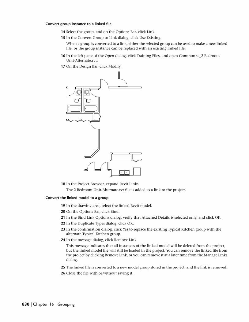
Convert group instance to a linked file
14 Select the group, and on the Options Bar, click Link.
15 In the Convert Group to Link dialog, click Use Existing.
When a group is converted to a link, either the selected group can be used to make a new linkedfile, or the group instance can be replaced with an existing linked file.
16 In the left pane of the Open dialog, click Training Files, and open Common\c_2 BedroomUnit-Alternate.rvt.
17 On the Design Bar, click Modify.
18 In the Project Browser, expand Revit Links.
The 2 Bedroom Unit-Alternate.rvt file is added as a link to the project.
Convert the linked model to a group
19 In the drawing area, select the linked Revit model.
20 On the Options Bar, click Bind.
21 In the Bind Link Options dialog, verify that Attached Details is selected only, and click OK.
22 In the Duplicate Types dialog, click OK.
23 In the confirmation dialog, click Yes to replace the existing Typical Kitchen group with thealternate Typical Kitchen group.
24 In the message dialog, click Remove Link.
This message indicates that all instances of the linked model will be deleted from the project,but the linked model file will still be loaded in the project. You can remove the linked file fromthe project by clicking Remove Link, or you can remove it at a later time from the Manage Linksdialog.
25 The linked file is converted to a new model group stored in the project, and the link is removed.
26 Close the file with or without saving it.
830 | Chapter 16 Grouping

Sharing Projects
When working with large building projects, architects commonly work in teams with each person assigned to a specificfunctional area. This involves simultaneously working on and saving different portions of the project at the same time,called Worksharing. In this tutorial, you learn how to use Worksharing to divide a project into worksets so multiple userscan access the project and have all their changes coordinated by Revit MEP 2009.
You can enable Worksharing for any project. A workset is a collection of building elements, such as walls, doors, floors,stairs, and so on. Only one user can edit each workset at a given time. All other team members can view this workset;however, they cannot make changes to it. This prevents possible conflicts within the project. If you need to modify anelement that belongs to a workset that someone else is actively working on, you can borrow that element without requiringthe workset owner to relinquish control of the entire workset.
Using Worksharing, team members adding and changing elements in worksets can save their work to a local file on thenetwork or their own hard drive and publish work to a central file whenever they choose. They can update their localfiles at any time in order to see the changes other team members have published.
Overview
Sharing a project for the first time
To share a project, you must first enable Worksharing. The first time you activate worksets within a project,a dialog displays allowing you to set up the initial sharing of the project. After the project is shared, eachbuilding element in the project is contained in exactly one workset. You can change the workset assignmentof any modeling element within the property dialog for that element.
Working in a shared project
In a shared project, you can only make changes to the worksets that are editable by you. To make a workseteditable, go to the Worksets dialog, select the desired workset, and click Editable. Each workset can only beeditable by one user at a time. If you only need to modify a single element within a workset that someoneelse has checked out, use Element Borrowing.
When you are working on a shared project, you specify an active workset. Any new model elements areautomatically assigned to the active workset. Elements specific to a view, such as annotations and dimensions,are automatically assigned to the view workset of the current view.
17
831

Increasing performance using selective open
When opening a Worksharing-enabled project, you can select which worksets are open or closed. Elementsin closed worksets are not read from disk until they are required. This reduces the time it takes to open thefile and the amount of memory it uses. You can close or open worksets at any time using the Worksetsdialog. You can improve the display-related performance of Revit MEP by opening only those worksetsrequired for your work.
In the lessons and exercises that follow, you learn some of the strategies that maximize your use of worksets.You gain valuable practical experience setting up a project for worksets and working within that project.
Using Worksharing in a Project
In this lesson, you learn the fundamentals of Worksharing. This includes how to plan and execute the useof worksets in a project in order to maximize project and team performance. After learning the fundamentals,you enable Worksharing within a project and set up the initial workset environment. In the next exercise,you learn how to work as an individual with the central and local project files. You then learn how to workwithin a Worksharing-enabled project with multiple users and borrow particular elements from other users.
Understanding Worksharing Fundamentals
In this conceptual exercise, you learn the fundamentals of Worksharing application. You learn what toconsider before enabling and using Worksharing. You learn the basic steps of project sharing as well as tipsfor dealing with common workplace scenarios.
When planning a Worksharing-enabled project
The decisions you make when sharing a project and setting up its worksets can have long-lasting effects onthe project team. When setting up Worksharing, you should take several considerations into account:
General Considerations:
■ Project size
■ Team size
■ Team member roles
■ Default workset visibility
You can maximize long-term project performance more easily if you plan Worksharing appropriately anduse the feature correctly. Establishing practical policies on how all team members access and create newworksets in the project will maintain performance for existing users and ease the process of introducing newteam members to the project.
Project sizeThe size of your building may affect the way you decide to segment the worksets for your team. UnlikeAutoCAD Xrefs, you do not need to make separate worksets for each floor of the building. Instead, youshould separate the project into worksets that allow team members to work without interfering witheach other. In a multi-story structure, you could create separate worksets for a set of building elementsthat will only appear on one floor, such as a tenant interior. If the project floor plan is so large that youneed to split it with match lines to fit it on sheets, you may want to create separate worksets for eachportion.
Team size
832 | Chapter 17 Sharing Projects

You should take into consideration the size of the project team at the time you enable Worksharing. Youshould have at least one workset for each person, not including the Project Standards, Shared Levels andGrids, and View worksets. In most projects, greater subdivision improves workflow by reducing interferencebetween team members. Experience has shown that, for a typical project, the optimum number ofworksets is approximately four for each team member.
Team member rolesTypically, designers work in teams, with each assigned a specific functional task. By subdividing theproject based on these task roles, each team member has control over a portion of the design. A typicalscenario for a multi-story commercial building is shown in the following illustration. Notice that theworkset names refer to functional roles.
TIP As new team members create new worksets for their own use, make sure visibility defaults are setappropriately.
Default workset visibilityAfter a project has been shared, a Worksets tab displays on the Visibility/Graphics dialog. On this tab,you control workset visibility on a per view basis. If you are sure that the elements of a particular worksetshould not appear in a view, you can turn off the visibility of that workset within that view. This allowsRevit MEP to display the view faster because computing time is not spent figuring out if the elementbelongs to a workset that should be displayed.
When you create a new workset, you decide whether or not the elements in that workset are visible bydefault in each view. Regardless of the default setting, you can change the visibility setting in theVisibility/Graphics dialog. Long-term performance is improved if new worksets are not visible by defaultunless they need to be. Team size usually increases as the project progresses from the design stage to thedocumentation stage. As new members create worksets for their own use, the worksets they add oftendo not need to be visible by default.
Conceptual stages of project sharing
The following steps explain the basic stages of project sharing.
Step 1: Start the project with one user
One user starts to work on the project. This project file should incorporate as many office/project standardsas possible and it should include many of the families required by the project. The building model shouldalso reach a reasonable point of development before you enable Worksharing.
Step 2:Activate Worksharing
After the building model is ready for multiple user access, the project coordinator should enable Worksharing.
Step 3: Create additional worksets
After enabling Worksharing, the project coordinator should create the additional worksets required by theteam. When creating the new worksets, remember to create worksets for functional roles and properly assigndefault visibility.
Understanding Worksharing Fundamentals | 833

Step 4: Subdivide the building model into worksets
After you have created the initial worksets, you must assign building model elements to their respectiveworkset. For example, if a workset named Interior was created, you would want to assign the interior wallsand other interior components to that workset.
Step 5: Create the central file
The first time you save a project after Worksharing has been enabled, the file is saved as the central file. Thecentral file coordinates and propagates the changes of each user and keeps track of which worksets areavailable. Therefore, it is essential that you save the central file to a location accessible to all team members.Generally, the central file is not a file that a team member would open and work in directly.
Step 6: Create local files
Each team member creates a local file that makes it possible to check out worksets and work on their respectiveportion of the building model. When finished or at regular intervals, each user saves their changes back tothe central file where the changes can be propagated to all team members. You create a local file by openingthe central file and using “Save As” to create a local copy of the central file. Local files are user-specific andcan only be accessed by the users that created them.
Step 7: Open worksets
Whenever you open a central or local file, you have the option to choose which worksets to open. This iscalled “Selective Open.” When opening a Worksharing-enabled project, you can shorten the time requiredto open the file by selecting to open only the worksets required to complete your assigned tasks.
Step 8: Check out worksets from the central file
When you “check out” a workset, you make that workset editable by you. This gives you the right to makechanges to the elements in the workset and to add to the workset. There is no limit to the number of worksetsyou can have editable at one time. However, no other users can make modifications to any elements inthose worksets until you check them back into the central file.
Step 9:Work on the project
Work on the project, within the local file, proceeds as usual. As you work, new building elements are assignedto the workset that is active at the moment. On the Options Bar, you can select which workset is active. Youcan make a workset active only if it is editable by you.
Step 10: Saving your changes
As you work on the project throughout the day, you should save the file locally and to the central file atregular intervals. When you save locally (to your local file), your changes are saved; however, they are notpropagated to the rest of the team. When you save to the central file, your changes propagate to the entireteam. When you save to the central file, you should relinquish any worksets that you no longer need. Thismakes them available to other team members. Any changes that other users have made to the buildingmodel become visible to you after you save to the central file or when you select Reload Latest.
Step 11: Closing a local file
At the end of a work session, you should save to the central file and relinquish control of all worksets thatyou set as editable. After saving to the central file, you should then save to your local file. This ensures thatyour local file is synchronized with the central file.
834 | Chapter 17 Sharing Projects

Tips and common scenarios
1 When working on a Worksharing-enabled project, you can still work remotely as an individualand as a team. The tips discussed below provide useful information for working creatively withworksets.
Taking your computer to a remote location with the project
2 You do not need to have access to the central file in order to work on the project. You can workon the project from a remote location by doing the following:
■ Before leaving the office and disconnecting from the networked access to the central file,make any required worksets editable, save to the central file, and then save the local file.
■ When working remotely, you work no differently then you would in the office. You canmodify any elements in an editable workset and all new elements are added to the activeworkset. You can also add new elements to any View or Project Standards workset even ifthey are not editable.
If you realize that you need to modify elements in a workset that you did not make editablebefore going remote, you can make the workset Editable at Risk. In this situation, you will notbe able to save your changes back to the central file if another user has changed the same worksetand already published those changes back to the central file. In this instance, if you know whochecked out the required workset, you may want to phone them and make arrangements ratherthan waste valuable work time. If you choose Editable at Risk and the owner of the at-risk worksethas already published their files to the central file, you will not only lose the changes to thatworkset, you will lose the changes you made to all your worksets. If the owner of the at-riskworkset agrees to relinquish editability of the contested workset, you can save your changesback to the central file but then the other owner loses all their work.
Since making a workset Editable at Risk carries a high risk that work will be lost, you should useit only when:
■ You do not intend to save your changes back to the central file, or
■ You are very confident that no other user will make that workset editable in your absence.If you have a colleague who is in the office with access to the central file, you may want torequest that someone start a session of Revit MEP, change the username to your name underSettings ➤ Options, and make that workset editable. This will guarantee that no other usercan make it editable during the remainder of your absence.
WARNING You should avoid editing a workset “at risk” whenever possible.
Multiple users working remotely
3 Users can work remotely provided the remote users have high-speed network access to the centralfile; for instance, using VPN. Alternatively, a user can transfer a local file to someone withnetwork access who can then publish the changes back to the central file, reload the latestchanges from the central file, and transfer the updated local file back to the remote user.
Remote rendering
4 While rendering remotely is supported, it is not recommended unless you understand theimplications for the rest of the team. If you intend to render the building model while awayfrom the office, you will probably be changing material definitions and other project settings.To do this, you should check out the Materials workset. This means that other team memberswill not be able to change any materials while you have the Materials workset checked out.
In this conceptual exercise, you learned what to consider before enabling Worksharing. You learned thebasic steps of project sharing as well as tips for dealing with common workplace scenarios.
Understanding Worksharing Fundamentals | 835

In the next exercise, you enable Worksharing in a project and set up some initial worksets.
Enabling Worksharing and Setting Up Worksets
In this exercise, you enable Worksharing within an existing project. You subdivide the project into worksetsand save the project as the "Central File."
Training File
■ Click File menu ➤ Open.
■ In the left pane of the Open dialog, click Training Files, and open Common\c_Worksets.rvt.
Enable Worksharing
1 On the File menu, click Worksets.
A confirmation dialog displays indicating that you are about to enable Worksharing. It alsoinforms you that existing elements in your project move to a default workset.
2 Click OK to accept the default workset names.
The Worksets dialog displays.
Notice that all worksets are open and editable by you.
Your username displays as the present owner.
TIP You can change your username by selecting Options under the Settings menu. You cannotchange your username with an unsaved Worksharing-enabled project open. Do not change yourusername during this exercise unless explicitly instructed to do so.
3 In the Worksets dialog, under Show, select:
■ Families
■ Project Standards
■ Views
4 Scroll down the list of workset names, and notice all are editable by you.
836 | Chapter 17 Sharing Projects

When you enable worksharing, Revit MEP creates new worksets and moves project elementsand settings into the new worksets:
■ Families: Loaded families in the project move into separate worksets.
■ Project Standards: All project-wide settings defined from the Settings menu move to ProjectStandards worksets.
■ Views: Each view moves into a separate View workset. For example, Floor Plan Level 1 viewmoves into a workset called View: "Floor Plan Level 1".
5 Under Show, clear Families, Project Standards, and Views.
Only User-Created worksets should display.
In this simple training project, a small number of team members are working on the buildingmodel. For training purposes, imagine four users including yourself. The project must besubdivided in such a way as to reflect the tasks of each user. In this case, one user is assigned tothe development of the exterior, another is assigned the interior layout, a third team memberis assigned furniture placement, and the remainder of the team must work on wall sectiondetails.
Therefore, you must create worksets that allow each team member to work independently.
Creating new worksets
6 In the Worksets dialog, click New.
7 Enter the name Interior Layout.
Notice that Visible by default in all views is checked. Because the interior walls appear in manyviews, it is better to make them visible by default.
8 Click OK.
The next workset you create is for the furniture layout. Because furniture should only be visiblein specific views, you should turn off Visible by default in all views. This improves performancesince fewer components need to be generated in each view.
9 Click New.
10 Enter Furniture Layout, clear Visible by default in all views, and click OK.
The final new workset is for the exterior shell of the building model. Rather than create a newworkset for these elements, you can rename the default workset, currently named Workset1.
11 In the Worksets dialog, select Workset1.
12 Click Rename.
13 In the Rename dialog, type the name Exterior Shell, and click OK
You have created the required worksets for each team member working on this project. Thenext step is to assign elements within the building model to specific worksets. This is why allworksets are editable immediately after you enable worksets.
14 In the Worksets dialog, click OK.
When you initially activate Worksharing, all building model elements are placed into Workset1by default. Because you renamed Workset1 to Exterior Shell, all building model elements areassigned to that workset. In this training file, furniture components have not been added to thebuilding model and therefore do not need to be moved to the respective workset. You do,however, need to reassign the interior elements to the Interior Layout workset.
Subdividing the project into worksets
15 In the Project Browser, expand Views (all), expand Floor Plans, and double-click Level 1.
16 In the drawing area, select any of the exterior walls of the building model.
Enabling Worksharing and Setting Up Worksets | 837

17 On the Options Bar, click .
18 In the Element Properties dialog, under Identity Data, notice that the Workset parameter is setto Exterior Shell.
19 Click OK.
20 Select one of the interior walls.
21 On the Options Bar, click .
22 In the Element Properties dialog, under Identity Data, select Interior Layout for Workset, andclick OK.
23 Select all of the interior elements, including the interior doors, stairs, and walls.
The easiest way to do this is to drag a pick box beginning inside the lower right corner and upto the upper left corner.
TIP You can also hold CTRL down to select multiple elements. Hold Shift down to deselect an element.
24 On the Options Bar, click .
25 In the Element Properties dialog, under Identity Data, select Interior Layout for Workset, andclick OK.
You can verify that all interior elements have been reassigned to the Interior Layout workset byturning off the visibility of that workset.
26 On the View menu, click Visibility/Graphics.
27 In the Visibility/Graphics dialog, click the Worksets tab.
Notice that the visibility of the Furniture Layout workset is turned off in this view. This is becauseyou turned off “Visible by default in all views” when you created the workset.
28 Clear Interior Layout to turn off the visibility of that workset in the view.
29 Click OK.
838 | Chapter 17 Sharing Projects

The Level 1 floor plan should display with only the exterior shell visible. If any interior elementsremain, select them and change their workset assignment to Interior Layout.
30 On the View menu, click Visibility/Graphics.
31 In the Visibility/Graphics dialog, click the Worksets tab.
32 Select Interior Layout, and click OK.
33 In the Project Browser, under Views (all), under Floor Plans, double-click Level 2.
34 In the drawing area, select all of the interior elements of the building model.
35 On the Options Bar, click .
36 In the Element Properties dialog, under Identity Data, select Interior Layout for Workset, andclick OK.
Create the central file
37 On the File menu, click Save As.
The central file is created automatically the first time you save the project after enabling worksets.
Navigate to a location on a network drive that all team members have access to, but be sure notto save the file in the training files location. This is imperative if you and another user intendto complete the multi-user exercise later in this tutorial. If you do not have access to a networkand still want to complete that exercise, this can be accomplished by saving the central file toyour hard drive and changing your user name before accessing the project.
38 In the Save As dialog, enter Worksets Project-Central as the file name.
39 Click Save.
Now that you have created the central file, you must relinquish workset editability so that otherusers can have access to the worksets they need.
Checking in the worksets
40 On the File menu, click Worksets.
41 In the Worksets dialog, select all the User-Created worksets by pressing CTRL + A.
42 On the right side of the dialog, click Non Editable.
Notice that your name has been removed as the owner of the worksets and all Editable valuesare set to No.
43 Click OK.
44 On the File menu, click Close.
If you intend on completing the remaining exercises in this tutorial, make sure you rememberthe location of this central file. You must access it in each of the remaining exercises.
In this exercise, you enabled Worksharing on a project, created new worksets to accommodate each teammember, and then assigned building model elements to the worksets. You then created the central file andchecked in all worksets. This project is now ready for individuals to access it and check out their requiredworksets.
Enabling Worksharing and Setting Up Worksets | 839

Working Individually with Worksets
In this exercise, you create your local file, check out worksets, make modifications to the building model,and publish your changes back to the central file where other team members can see them.
This exercise requires the completion of the previous exercise and access to the resulting central file. If youhave not yet completed the exercise, Enabling Worksharing and Setting Up Worksets on page 836, please doso before continuing.
Creating a local file
1 On the File menu, click Open, and navigate to the location where you saved the central filecreated in the previous exercise.
2 In the Open dialog, select the central file.
3 Click the arrow next to the Open button, and select Specify.
4 Click Open.
Using selective open allows you to choose which worksets you want to open. Only the worksetsyou select and any worksets already editable by you are opened. In addition, any referencedworkset is opened but hidden. This reduces the amount of time required to open very largeproject files and increases performance while you work.
5 In the Opening Worksets dialog, select all the User-Created worksets, and click OK.
6 On the File menu, click Save As.
7 In the Save As dialog, click Options.
8 In the File Save Options dialog, verify that Make this a Central File after save is not selected,and click OK.
9 Navigate to a directory on your hard drive, name the file Worksets Project_Local-User1, andclick Save.
You have created a local file which is for your use only. Next, you check out worksets so youcan modify the building model.
Checking out worksets
10 On the File menu, click Worksets.
The project sharing environment allows you to choose which worksets are opened during aworking session. Only the worksets that are opened are visible during that session. In this case,you are assigned the task of designing the interior layout of the building model.
11 In the Worksets dialog, select Interior Layout for Name, and select Yes for Editable.
Your name displays as the owner of the Interior Layout workset.
12 Click OK.
You are now ready to modify the interior layout of the building model. Before working on themodel, you should activate the Worksets toolbar.
13 On the Window menu, click Toolbar ➤ Worksets.
The Worksets toolbar displays with a drop-down list that allows you to specify the active workset.
14 On the Worksets toolbar, select Interior Layout.
Any new elements that you add to the building model are automatically assigned to the activeworkset.
15 In the Project Browser, expand Views (all), expand Floor Plans, and double-click Level 1.
840 | Chapter 17 Sharing Projects

16 On the Basics tab of the Design Bar, click Modify.
On the Options Bar, notice the Editable Only option. If this is selected, you can only selecteditable elements within the drawing area. Verify that it is cleared.
17 Select the upper exterior wall and notice a symbol displays indicating that the element belongsto a workset that is not currently editable.
18 On the Options Bar, click .
19 In the Element Properties dialog, under Identity Data, notice that this element is assigned tothe Exterior Shell workset and that the Edited by value is blank.
Even though you have not checked out the Exterior Shell workset, you can still edit this wall.
20 Under Constraints, select Finish Face: Exterior for Location Line, and click OK.
Because this element is not owned by another user, Revit MEP borrows it for you and appliesyour changes. If it was owned by another user, a message would display and you would havethe option to cancel the change or make the element editable.
The upper exterior wall should still be selected.
21 On the Options Bar, click .
Notice that the wall still belongs to the Exterior Shell workset; however, the Edited by value isnow assigned to you.
22 Click OK.
23 On the File menu, click Worksets.
In the Worksets dialog, notice that you do not own the Exterior Shell workset, but you are listedas a borrower of that workset. In this case, you have borrowed the ownership of the upperexterior wall.
24 Click OK.
Working Individually with Worksets | 841

Modify the building model
25 Select the door on the right side of the corridor.
26 Delete the door.
27 Select the wall that hosted the deleted door, and modify the length so that the corridor is open.
28 On the Architectural tab of the Design Bar, click Wall.
29 In the Type Selector, select Basic Wall: Interior - 126mm Partition (2-hr).
30 Using the following illustration as a guide, add a horizontal wall in the lower right corner. Theprecise location is not important.
31 On the Design Bar, click Modify.
32 Select the vertical interior wall in the upper right corner, and extend the lower end until itintersects the horizontal wall you added previously.
33 On the Architectural tab of the Design Bar, click Door.
34 In the Type Selector, select M_Sgl Flush: 864 x 2032mm.
842 | Chapter 17 Sharing Projects

35 Using the following illustration as a guide, add two door openings into the rooms you created.
All of the new elements that you added were automatically assigned to the Interior Layoutworkset. If you click Modify on the Design Bar and then place the cursor over any of the newelements, a tooltip, which matches the information in the Status Bar, displays the workset aswell as the element type.
When working in your local file, you should perform regular saves. It is recommended that youlocally save your work approximately every 30 minutes and save to central every 1-2 hours.
Saving your work
36 On the File menu, click Save to Central.
The Save to Central dialog displays with the path to the central file automatically filled in.Whenever you save, you can relinquish the user-created worksets as well as any borrowedelements. By default, Borrowed Elements is selected. In this particular case, you borrowed theupper exterior wall in order to modify it. You should check this element back into central sothat others can use it if necessary.
In addition, notice that there is an option to save the local file immediately after the save tocentral. Although this is not a necessary option if you are in the middle of a work session, it isrecommended. At the end of a work session, you should relinquish all worksets, save to central,and save locally immediately afterward.
37 In the Save to Central dialog, select:
■ Borrowed Elements
■ User-created Worksets
■ Save the Local File after “Save to Central”
38 Click OK.
If you intend to complete the remainder of this tutorial by proceeding to the multi-user exercise,leave this file open in its current state.
In this exercise, you created your local file, checked out worksets, and borrowed an element from a worksetyou did not own. You modified the building model, and published your changes back to the central filewhere other team members can see them.
Using Worksets with Multiple Users
In this exercise, two users access the central file through a network connection. For training purposes, theyare referred to as User 1 and User 2. Each modifies the building model within their local file and publishesit back to the central file where the other user can see the changes. Throughout the process, each user mustcheck out worksets, make elements editable, and reload the latest changes.
This exercise requires the completion of the previous workset exercises and access to the resulting local andcentral files. If you have not yet completed these exercises, please do so before continuing.
Using Worksets with Multiple Users | 843

Although this exercise is designed specifically for two separate users with network access to the central file,a single user can complete this exercise by opening up an additional session of Revit MEP and setting theusername to User 2. In the following section of this exercise, instructions are provided on how to accomplishthis.
NOTE If you are working with a second user (User 2), skip the following section, and proceed to Creating a localcopy.
Using a second Revit MEP session to mimic User 2
1 Minimize the current Revit MEP window.
2 Start a new Revit MEP session by double-clicking the Revit MEP icon on the desktop or byselecting it from the Start menu.
3 On the Settings menu, click Options.
4 Click the General Tab and, under Username, enter User 2, and click OK.
WARNING After completing this tutorial and closing the project file, return to the Settings dialog,and reset the Username to your computer login name. This is a system setting.
Creating a local copy
5 In this exercise, two users work on the building model residing in the central file you createdand saved in a previous exercise. If both users have completed the previous worksets exercisesand created central files on the network, select one of those central files to be used in thisexercise.
Regardless of which central file you choose to use, one user has already created a local file. Fortraining purposes, consider that person to be User 1. The user who has not yet created a localfile for the chosen central file is User 2. The next series of steps create a local file for User 2.Throughout the remainder of this exercise, instructions are staggered, specifically sequenced,and refer explicitly to User 1 and User 2.
User 2: Create a local file, and check out worksets
6 On the File menu, click Open, and navigate to the location where you saved the central filenamed Worksets Project-Central.rvt.
7 In the Open dialog, select the central file.
8 Click the arrow next to the Open button, and select Specify.
9 Click Open.
Using selective open allows you to choose which worksets you want to open. Only the worksetsyou select and any worksets already editable by you are opened. In addition, any referencedworkset is opened but hidden. This reduces the amount of time required to open very largeproject files and increases performance while you work.
10 In the Opening Worksets dialog, select all the User-Created worksets, and click OK.
11 On the File menu, click Save As.
12 In the Save As dialog, click Options.
13 In the File Save Options dialog, verify that Make this a Central File after save is not selected,and click OK.
14 Navigate to your preferred location on the hard drive, name the file Worksets Project_Local-User2,and click Save.
You now have a local copy of the project. This file is for your use only.
15 On the File menu, click Worksets.
16 Select the Exterior Shell workset, and select Yes for Editable.
844 | Chapter 17 Sharing Projects

You are now the owner of that workset.
17 Click OK.
User 1: Check out worksets, modify the building model, and publish changes
18 User 1 should still have the local file open. If it is not open, open it now.
19 On the File menu, click Worksets.
Notice that the Exterior Shell workset is checked out by User 2.
20 Try to change the Editable status for Exterior Shell to Yes.
A warning is displayed informing you that you cannot check out this workset because it isalready checked out by another user.
21 Click OK to return to the Worksets dialog.
22 Select the Interior Layout workset, and select Yes for Editable.
Notice that you own this workset and the active workset is now Interior Layout. If you onlyhave one workset checked out, it becomes the active workset.
23 Click OK.
24 In the Project Browser, expand Views (all), expand Floor Plans, and double-click Level 1.
25 Select the vertical interior wall shown in the following illustration, and move it to the left untilit approaches the centerline of the exterior double door on the south wall.
A warning is displayed informing you that a conflict exists.
26 Click anywhere in the empty drawing area to ignore the warning.
27 On the File menu, click Save to Central.
28 In the Save to Central dialog, select Save the Local File after “Save to Central.”
29 Click OK.
User 2: Modify the building model and publish changes
30 In the Project Browser, expand Views (all), expand Floor Plans, and double-click Level 1.
Notice that the changes made by User 1 do not immediately display in the local file of User 2.That is because changes made to the central file display in local files only when the worksetsare explicitly updated.
31 Using the following illustration as a guide, select the lower exterior wall, and move it upwardapproximately 2 meters.
Using Worksets with Multiple Users | 845

A message displays warning you that several windows are not cutting anything. This is becausewindows are wall-hosted components and cannot float in the air without a wall to host them.
32 Click Delete Instances to delete the windows.
33 On the File menu, click Save to Central.
34 In the Save to Central dialog, select Save the Local File after “Save to Central.”
35 Click OK.
When you save to central, you publish your changes and load the changes other users havemade to the building model. The wall conflict with the door opening that User 1 introducednow displays.
36 Using the following illustration as a guide, delete the left window on the lower exterior wall,and move the door to the right in order to avoid the conflict.
37 On the File menu, click Save to Central.
38 In the Save to Central dialog, select Save the Local File after “Save to Central.”
39 Click OK.
User 1: Reload latest worksets, and check out additional worksets
40 On the File menu, click Reload Latest.
The changes User 2 made are apparent.
41 On the File menu, click Worksets.
42 Select Furniture Layout, select Yes for Editable, and click OK.
Because you now have more than one workset checked out, you are asked if you want to makethe Furniture Layout workset the active workset. Click Yes.
Even though the Furniture Layout workset is active, you still have complete access to the elementsbelonging to the Interior Layout workset. However, any elements added to the building modelare automatically assigned to the active workset.
Before adding any furniture, you should create a furniture plan view.
43 In the Project Browser, under Views (all), under Floor Plans, right-click Level 1, and click DuplicateView ➤ Duplicate.
44 In the Project Browser, under Floor Plans, right-click Copy of Level 1, and click Rename.
45 In the Rename View dialog, enter Level 1 Furniture Plan, and click OK.
46 In the Project Browser, under Floor Plans, double-click Level 1 Furniture Plan.
846 | Chapter 17 Sharing Projects

47 On the Modelling tab of the Design Bar, click Component.
48 In the Type Selector, choose any desk, and click inside any room.
A message displays informing you that the component you are trying to place is not visible inthat view. This is because when the Furniture Layout workset was created, the Visible by defaultoption was not selected. Therefore, the visibility of the workset is not turned on even thoughit is checked out and is the active workset. You should turn on the visibility before addingfurniture.
49 On the Design Bar, click Modify.
50 On the View menu, click Visibility/Graphics.
51 In the Visibility/Graphics dialog, click the Worksets tab, select Furniture Layout to turn on itsvisibility, and click OK.
52 Notice that the desk you added previously now displays.
53 On the File menu, click Save to Central.
54 In the Save to Central dialog, select Save the Local File after “Save to Central.”
55 Click OK.
User 2: Make an element editable on the fly
56 On the File menu, click Reload Latest.
Notice the new Level 1 Furniture Plan view in the Project Browser.
57 Right-click the upper exterior wall, and click Element Properties.
58 In the Element Properties dialog, click Edit/New.
59 In the Type Properties dialog, click Rename.
60 In the Rename dialog, enter Exterior Wall - 200mm, and click OK.
61 Click OK 2 times.
62 On the File menu, click Worksets.
63 In the Worksets dialog, under Show, select Project Standards.
64 Scroll down to the bottom of the list until you see Wall Types.
Notice you have borrowed a portion of the workset.
NOTE System families, such as Wall Types, are placed under Project Standards, rather than Families.
65 Click OK.
66 On the File menu, click Save to Central.
67 In the Save to Central dialog, select:
■ Borrowed Elements
■ User-created Worksets
■ Save the Local File after “Save to Central”
68 Click OK.
Using Worksets with Multiple Users | 847

If you intend to complete the final portion of this tutorial by proceeding to the ElementBorrowing exercise, leave this file open in its current state.
User 1: Reload latest, and save
69 On the File menu, select Reload Latest.
70 On the File menu, select Save to Central.
71 In the Save to Central dialog, select the following, and click OK.
■ User-created Worksets
■ Save the Local File after “Save to Central”
In this exercise, two users worked on the same building model using worksets. Each user checked out worksets,modified the building model, and published their changes back to the central file.
In the final exercise of this tutorial, you learn how to borrow elements from worksets that other users areactively working on.
If you intend to complete the final exercise of this tutorial, Borrowing Elements from the Worksets of OtherUsers on page 848, leave this file open in its current state. This exercise also requires two users and you canskip the first sections of the exercise and proceed directly to the section, Checking out worksets.
Borrowing Elements from the Worksets of Other Users
In this exercise, two users are working on the same project with separate local files. As each of you work,you must borrow elements that belong to worksets that the other user has checked out. You learn how tomake borrowing requests and how to grant them.
This exercise requires two users and, throughout this training, they are referred to as User 1 and User 2.There are specific instructions for each user. Each user must have network access to the central file.
Although this exercise is designed specifically for two separate users with network access to the central file,a single user can complete this exercise by opening up an additional session of Revit MEP and setting theusername to User 2. At the appropriate point in this exercise, instructions are provided on how to accomplishthis.
NOTE If you are working with a second user (User 2), finished the previous workset exercises, and still have yourlocal files open, proceed directly to the section Checking out worksets.
If you have not completed the previous workset exercises, you need to set up your central and local files.Only one user needs to open the training file and save the central file to a network location.
NOTE When you open the training file for this tutorial, you may receive a message informing you that the centralfile has been relocated. Click OK to this message and subsequent messages. These messages are a result of thecentral file being relocated (to your PC). In subsequent steps, you save the training file as a central file, and theseproblems are rectified.
Training File
■ Click File menu ➤ Open.
■ In the left pane of the Open dialog, click Training Files, and open Common\c_Worksets Project-Central.rvt.
Save the training file as the central file on the network
1 On the File menu, click Save As.
2 Navigate to a directory on the network that both users have access to.
3 In the Save As dialog, click Options.
848 | Chapter 17 Sharing Projects

4 In the File Save Options dialog, select Make this a Central File after save, and click OK.
5 Click Save.
You have created a new central file for User 1 and User 2.
User 1: Create local file
For the sake of simplicity, the user that saved the central file should be User 1. The central file should stillbe open.
6 On the File menu, click Save As.
7 Navigate to a directory on your hard drive.
8 In the Save As dialog, click Options.
9 In the File Save Options dialog, verify that Make this a Central File after save is not selected,and click OK.
10 Name the file Worksets Project_Local-User1, and click Save.
This is the local file for User 1.
User 2: Create local file
11 If you are a single user and want to replicate the multi-user experience, perform the followingsteps to create a session for User 2:
■ Start a second session of Revit MEP by double-clicking the icon on the desktop or by selectingit from the Start menu.
■ On the Settings menu, click Options.
■ Click the General tab of the Options dialog.
■ Set the Username to User 2, and click OK.
This Revit MEP session is now set up for User 2.
WARNING After completing this tutorial and closing the project file, return to the Settings dialog,and reset the Username to your computer login name. This is a system setting.
12 On the File menu, click Open, and navigate to the network location where User 1 saved thecentral file.
13 In the Open dialog, select the central file.
14 Click the arrow next to the Open button, and select Specify.
15 Click Open.
Using selective open allows you to choose which worksets you want to open. Only the worksetsyou select and any worksets already editable by you are opened. In addition, any referencedworkset is opened but hidden. This reduces the amount of time required to open very largeproject files and increases performance while you work.
16 Select all the User-Created worksets, and click OK.
17 On the File menu, click Save As.
18 In the Save As dialog, click Options.
19 In the File Save Options dialog, verify that Make this a Central File after save is not selected,and click OK.
20 Navigate to a directory on your hard drive, name the file Worksets Project_Local-User2, andclick Save.
You have created a local file which is for your use only. Next, you check out worksets so youcan modify the building model.
Borrowing Elements from the Worksets of Other Users | 849

Checking out worksets
Both User 1 and User 2 can check out their worksets at the same time. Afterwards, the steps for each userhave to be followed in sequence.
User 1: Check out worksets
21 On the File menu, click Worksets.
22 In the Worksets dialog, if any User-Created worksets are not open, select them, and click Open.
23 Select the Exterior Shell workset, and select Yes for Editable.
You are now the owner of that workset.
24 Under Active Workset, select Exterior Shell, and then click OK.
User 2: Check out worksets
25 On the File menu, click Worksets.
26 In the Worksets dialog, select the Interior Layout workset, and select Yes for Editable.
You are now the owner of that workset.
27 Under Active Workset, select Interior Layout, and then click OK.
User 2: Borrow an element from User 1
28 In the Project Browser, under Floor Plans, double-click Level 1.
29 On the Options Bar, verify that Editable Only is cleared.
This allows you to select elements that belong to worksets that you do not own.
30 On the left exterior wall, select the second window from the top.
A symbol appears letting you know that it belongs to a workset you do not own.
31 Move the window 500 mm toward the upper exterior wall. You can do this by dragging thewindow or by modifying one of the temporary dimension values.
A warning message informs you that you must obtain permission from User 1.
32 Click Place Request to ask User 1 for permission to edit the window.
After you submit the request, a message informs you that you are waiting for permission fromUser 1.
At this point, you should inform User 1 that you are waiting for permission to edit a borrowedelement. Leave this dialog open until User 1 grants permission.
User 1: Grant User 2 permission to borrow element
33 When User 2 contacts you and informs you that a borrowing request is pending yourauthorization, click the File menu, and click Editing Requests.
850 | Chapter 17 Sharing Projects
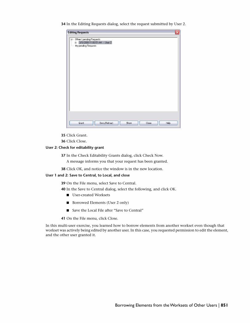
34 In the Editing Requests dialog, select the request submitted by User 2.
35 Click Grant.
36 Click Close.
User 2: Check for editability grant
37 In the Check Editability Grants dialog, click Check Now.
A message informs you that your request has been granted.
38 Click OK, and notice the window is in the new location.
User 1 and 2: Save to Central, to Local, and close
39 On the File menu, select Save to Central.
40 In the Save to Central dialog, select the following, and click OK.
■ User-created Worksets
■ Borrowed Elements (User 2 only)
■ Save the Local File after “Save to Central”
41 On the File menu, click Close.
In this multi-user exercise, you learned how to borrow elements from another workset even though thatworkset was actively being edited by another user. In this case, you requested permission to edit the element,and the other user granted it.
Borrowing Elements from the Worksets of Other Users | 851

852

Creating Multiple DesignOptions
When working with a building model, it is common to explore multiple design schemes as the project develops. Theseschemes can be conceptual or can be detailed engineering designs. Using design options, you create multiple designschemes within a single project file. Because all design options coexist in the project with the main model (the mainmodel consists of elements not specifically assigned to a design option), you can study and modify each design optionand present the options to the client.
In this tutorial, you learn how to create and manage multiple design sets and options within a single building model.
Creating Multiple Design Options in a Project
You can use design options to explore multiple design schemes as the project develops. At any time in thedesign process, you can have multiple sets of design options, and each option set can have multiple schemes.For example, you can have an option set called roofing with multiple subordinate roofing schemes. Inaddition, you can have an option set for the roof structure with multiple subordinate structural designschemes. After you and the client agree on the final design, you can designate a primary design scheme foreach option set.
18
853

In this particular case, the task is to develop two roof schemes for an addition to an existing house. Theclient is interested in a pergola and sunshade for the roof terrace but is not sure of the specific layout ormaterials. The client has asked you to create various options.
In the first exercise in this lesson, you set up the design option names and add the modeling elements tothe structural design option set. In the second exercise, you create two roof system design options that workwith the structural options. In the final exercise of this lesson, you learn how to manage and organize thedesign options, make your final design decision, and delete the unwanted options from the project. Thesethree exercises are designed to be completed sequentially with the second and third exercises dependent onthe completion of the previous exercise.
Creating the Structural Design Options
In this exercise, you set up multiple design option sets, each with multiple design options. After setting upthe design option sets and their subordinate options, you design each of the structural options. The firstoption is a simple combination of columns and beams. With the second option, you create a unique in-placefamily as the structural system.
Training File
■ Click File menu ➤ Open.
■ In the left pane of the Open dialog, click Training Files, and open Metric\m_Urban_House.rvt.
Create first design option
1 On the Tools menu, click Design Options ➤ Design Options.
The first time you open the Design Options dialog within a project, the only available commandis to create a new option set. There is no limit to the number of option sets you can create. Eachoption set represents a portion of the building model wherein design alternatives are beingconsidered. After you create a design option, you can edit it. Any new elements introduced atthat time become part of that option.
2 In the Design Options dialog, under Option Set, click New.
Notice Option Set 1 has been created with a design option: Option 1 (primary). This option willbe the first structural scheme consisting of 75 mm round columns and 50 mm round bars.
TIP In this exercise, the roof and structure systems must work together; therefore, each is constructedfor interchangeability.
854 | Chapter 18 Creating Multiple Design Options

3 Select Option 1 (primary), click Edit Selected, and click Close.
Any new elements introduced to the building model are added to this option.
4 In the Project Browser, expand Views (all), expand Floor Plans, and double-click ROOF TERRACE.
5 On the View menu, click Zoom ➤ Zoom in Region, and zoom in on the upper half of the buildingmodel.
6 On the Architectural tab of the Design Bar, click Column.
7 In the Type Selector, select Round Column: 75mm Diameter.
8 Using the following illustration as a guide, add three columns. Arrows and the dimension lineshave been added for training purposes only. The left column should be centered at theintersection of the notch and the wall, the second column directly across from it at theintersection of the two walls, and the third column centered between the two.
TIP To center the middle column, either add a centered reference plane and snap the column to it,or add a dimension string between the columns, and click the EQ symbol to equalize the segments.You should delete the dimension and unconstrain after adding the column.
9 On the Design Bar, click Modify.
10 Select the three columns either by dragging a pick box around them or by selecting themindividually while holding CTRL.
11 On the Edit toolbar, click .
12 On the Options Bar, select:
■ Constrain
■ Copy
■ Multiple
The Copy command is a two-click process. The first click specifies the reference point on theelement to be copied, and the second click specifies the point on the building model the referencepoint is copied to. In this case, the three columns need to be copied three times to create a 3 x4 grid of 12 columns. By selecting Multiple, you can continue adding new copies withoutreselecting the reference point (the first click). Selecting Constrain limits the movement andhelps ensure the post-copy alignment of the columns.
13 Zoom in around the left column that is embedded in the notch.
Creating the Structural Design Options | 855

14 Click at an identifiable part of the notch construction. Because it is important that you selectthe same location on the notches you copy to, make sure you select a point that is easilyrecognizable. In the following illustration, the midpoint of the lower notch line is selected.
TIP You can zoom in and out easily during this process using the wheel on your wheel mouse.
15 Zoom out and move downward to the notch just below this one.
16 Zoom in around the notch construction, and click in the same location as you did for theprevious notch.
A copy of the three selected columns is added.
17 Zoom out and, using the same technique, add a copy of the columns to the next two notchesbelow this one. When you are finished, click Modify on the Design Bar to end the copy process.
Because of the size of the columns, they are difficult to see in this view.
18 On the View toolbar, click .
856 | Chapter 18 Creating Multiple Design Options

Notice the 12 columns that you added.
Next, you add the beams that span the columns.
19 In the Project Browser, under Floor Plans, double-click TOP OF CORE.
20 On the Structural tab of the Design Bar, click Beam.
Adding a beam is a two-click process. The first click specifies the beam start point. The secondclick specifies the end of the beam.
21 In the Type Selector, select Round Bar : 50mm.
22 Add the first beam between the upper left and right columns by using the following steps:
■ Zoom in on the upper-left column, and click at its center to set the beam start point.
■ Zoom out and move the cursor over the upper right column.
■ Zoom in on the upper right column, and click on the center to set the beam endpoint.
Use the following illustration as a guide. In it, two callouts with thin lines have been added toclarify the location of the start and end points of the beam.
23 On the Design Bar, click Modify.
24 Select the Beam you added previously.
The beam needs to be added between the remaining columns. You can do this manually or usethe Copy command.
Creating the Structural Design Options | 857

25 On the Edit toolbar, click .
26 On the Options Bar, select:
■ Constrain
■ Copy
■ Multiple
27 Zoom in around the upper left column that is embedded in the notch, and click the centerpoint.
This is the reference point for the subsequent copies.
28 Zoom out, move down to the next set of columns, zoom into the left column, and select thecenter of the column to add a copy.
29 Repeat this step twice more until a beam is added to each set of columns.
30 On the View toolbar, click .
858 | Chapter 18 Creating Multiple Design Options

Notice that the beams complete the bracket structure for the proposed roof.
Organize design option sets and subordinate options
31 On the Tools menu, click Design Options ➤ Design Options.
32 In the Design Options dialog, notice that you are still editing Option Set 1: Option 1 (primary).
33 Click Finish Editing.
34 In the Design Options dialog, under Option, click New.
NOTE Be sure you are creating a new option, not a new option set.
35 Select Option 1 (primary) and, under Option, click Rename.
36 In the Rename dialog, enter Brackets for New, and click OK.
37 Select Option 2 and, under Option, click Rename.
38 In the Rename dialog, enter Beam for New, and click OK.
39 Select Option Set 1 and, under Option Set, click Rename.
40 In the Rename dialog, enter Structure for New, and click OK.
Logically naming the option sets and relative options allows you to more easily manage them.
41 Under Option Set, click New.
42 Select Option Set 1 and, under Option Set, click Rename.
43 In the Rename dialog, enter Roofing for New, and click OK.
44 Select the option set Roofing and, under Option, click New.
There should now be two roofing design options.
45 Under Roofing, select Option 1 (primary).
46 Under Option, click Rename, name the option Louvers, and click OK.
Creating the Structural Design Options | 859

47 Under Roofing, select Option 2.
48 Under Option, click Rename, name the option Sunscreen, and click OK.
You have completed the initial setup of the design option sets and their subordinate designoption names. This allows you to more easily manage the project.
Design the second structural design option
49 In this section of the exercise, you create the second design option. When finished, it willresemble the following illustration.
50 In the Design Options dialog, under Structure, select Beam.
51 Under Edit, select Edit Selected.
Under Now Editing, notice that Structure: Beam is displayed.
52 Click Close.
Notice that the columns added to the Brackets design option do not display.
53 In the Project Browser, under Floor Plans, double-click ROOF TERRACE.
54 Zoom in toward the top of the roof terrace near the stairs.
860 | Chapter 18 Creating Multiple Design Options

55 On the Basics tab of the Design Bar, click Component.
56 In the Type Selector, select M_Roof Beam.
57 Place a roof beam into the drawing area as shown.
58 On the Tools menu, click Align.
Using the Align tool requires two clicks. The first click sets the plane that the object will bealigned to. The second click represents the plane that is moved.
59 Align the roof beam by clicking the lower edge of the adjacent horizontal wall and then clickingthe lower edge of the roof beam. Refer to the following illustration.
Creating the Structural Design Options | 861

60 After aligning the beam, click the padlock that displays to lock the alignment.
61 On the Design Bar, click Modify.
62 Select the beam and, on the Edit toolbar, click .
63 On the Options Bar:
■ Clear Group and Associate
■ Enter 4 for number
■ Select 2nd for Move To:
■ Select Constrain
Using the Array tool requires two clicks. The first click sets the move start point. The secondclick represents the move end point.
64 Click the start point at the alignment of the beam and wall as shown.
65 Move the cursor down to the next intersection of the lower edge of the horizontal wall and thebeam. Click to indicate the end point of the move.
862 | Chapter 18 Creating Multiple Design Options

Three more roof beams are placed at the same intersection as the first beam.
66 On the View toolbar, click .
Notice the new design option for the structural elements supporting the roof system.
67 On the Tools menu, click Design Options ➤ Design Options.
68 In the Design Options dialog, click Finish Editing.
Notice that even before you close the dialog, the 3D view has reverted back to the brackets ratherthan the structural beams you just created.
That is because the brackets option is set to primary, which is visible by default. Design optionvisibility is covered in more detail later in the tutorial.
69 Click Close.
70 On the File menu, click Save As.
71 Navigate to your preferred directory, name the file, m_Urban_House-in progress.rvt, and click Save.
NOTE If you intend to continue with the next exercise, you need this file in its current state. You canleave it open and proceed immediately to the next exercise.
Creating the Structural Design Options | 863

In this exercise, you set up multiple design option sets, each with multiple design options to pick from. Aftersetting up the design option sets and their subordinate options, you designed each of the structural options:one for brackets, the other for beams. The first option is a simple combination of columns and beams. Withthe second option, you created a unique in-place family as the structural system.
In the next exercise, you create the roof systems that compliment these structural design options.
Creating the Roof System Design Options
In this exercise, you design each of the roofing options. The first option, a Louver system, is constructed of50 mm x 250 mm rafters and 50 mm x 150 mm louvers. The second roofing system, Sunscreen, is a simplefabric roof created using an extrusion. Both of these options are designed to work in conjunction with eachof the structural design options.
This exercise is designed to work in conjunction with the other exercises in this tutorial. All are sequentialand dependent on the previous exercise. If you have not completed the first exercise in this tutorial, do sonow.
Create the first roofing design option
1 If you do not have the project file that you saved at the end of the previous exercise open, openit now. You should have named it m_Urban_House-in progress.rvt.
2 On the Tools menu, click Design Options ➤ Design Options.
3 In the Design Options dialog, under Roofing, select Louvers (primary).
4 Under Edit, click Edit Selected.
Under Now Editing, Roofing: Louvers (primary) should display.
5 Click Close.
6 In the Project Browser, expand Views (all), expand Floor Plans, and double-click TOP OF CORE.
7 On the Basics tab of the Design Bar, click Component.
8 In the Type Selector, select Rafter 50mm x 250mm.
9 Zoom in on the lower half of the building model until you can see the bottom set of columnsand the beam traversing the span.
10 Referring to the following illustration, place the rafter 900 mm inside the wall shown and overlapthe horizontal beam 900 mm.
The dimensions shown are for training purposes. If you need to add dimensions, delete themafter the rafter is in place.
864 | Chapter 18 Creating Multiple Design Options

11 On the Basics tab of the Design Bar, click Modify.
12 Select the rafter you added previously.
13 On the Options Bar, click .
14 In the Element Properties dialog, under Other, enter 11750 mm for Length, and click OK.
The rafter should now span the entire vertical length of the proposed roof system.
15 On the Edit menu, click Array.
16 On the Options Bar, specify the following:
■ Clear Group and Associate.
■ Enter 5 for Number.
■ Select 2nd for Move To.
■ Select Constrain.
You are creating an array of five rafters that are 990 mm apart.
17 Zoom in on the intersection of the lower end of the rafter and the intersecting beam; click inthe center of the intersection to specify the array start point.
Creating the Roof System Design Options | 865

18 Move the cursor horizontally to the right and, when the listening dimension displays, enter990, and press ENTER.
Zoom out to see that the rafter array is created.
866 | Chapter 18 Creating Multiple Design Options

Add the louvers to the design option
19 On the Basics tab of the Design Bar, click Component.
20 In the Type Selector, select Louver 50mm x 150mm.
21 Place the first horizontal louver in the upper left corner according to the following illustration.
22 On the Design Bar, click Modify, and select the louver you just placed.
23 On the Options Bar, click .
24 In the Element Properties dialog, under Other, enter 5475 mm for Length, and click OK.
The louver now spans the horizontal plane of the roof system.
25 With the louver still selected, click the Edit menu, and click Array.
26 On the Options Bar, specify the following:
■ Clear Group and Associate.
■ Enter 34 for Number.
■ Select 2nd for Move To.
■ Select Constrain.
27 For the array starting point, click in the center of any intersection between the louver and thebeam.
Creating the Roof System Design Options | 867

28 Move the cursor vertically downward, and, when the listening dimension displays, enter 300,and press Enter.
Zoom out to see that the 34 louvers array 300 mm apart.
29 On the View toolbar, click .
868 | Chapter 18 Creating Multiple Design Options

The louver roof system is complete.
30 On the Tools menu, click Design Options ➤ Design Options.
31 In the Design Options dialog, under Edit, click Finish Editing.
The louver roof system still displays in the 3D view because it is the primary option.
Create sunscreen roof system
32 In the Design Options dialog, under Roofing, select Sunscreen.
33 Under Editing, click Edit Selected, and then click Close.
Notice that the louver roof system no longer displays.
34 In the Project Browser, expand Elevations, and double-click West.
35 Zoom in on the upper level where the roof design is taking place.
36 On the Architectural tab of the Design Bar, click Roof ➤ Roof by Extrusion.
37 In the Work Plane dialog, select Reference Plane : Roof Extrusion for Name, and click OK.
The roof extrusion reference plane has been added to the training file specifically for this purposeand is hidden in all views.
38 You are prompted to verify the roof level and offset. Click OK.
Because an extruded roof has a roof type associated with it, you only need to sketch a singleline or a string of lines to define the shape of the extruded roof. In this case, you must create adraped canvas sunscreen. Therefore, the sketch should be a series of arcs connected at the endswhere they connect to the columns.
39 On the Design Bar, click Lines.
40 On the Options Bar, click .
Creating the Roof System Design Options | 869

This tool allows you to sketch an arc line using three points. The first two points define the endsof the line, and the third point defines the arc.
41 Select the top of the left column, the top of the next column on the right, and then adjust thedip of the arc until it is 60 degrees. You can adjust the degrees by clicking the blue temporarydimension value immediately after you create the line.
42 Repeat the previous step and create two more arcs between the columns.
NOTE As you sketch the arcs, try to get the angle value as close to 60 degrees as possible, then youcan modify it through the dimension. Do not be too concerned if your sketch lines do not exactlyconnect. You will fix this in a later step.
43 On the Design Bar, click Properties.
44 In the Element Properties dialog, specify the following:
■ Select Sunscreen Fabric for Type.
■ Under Constraints, enter 300 mm for Extrusion Start.
■ Under Constraints, enter 5800 mm for Extrusion End.
45 Click OK.
The roof sketch must be a continuous line. You must make sure the arcs are connected wherethey connect to the columns. The easiest way to accomplish this is to use the Trim tool.
46 On the Tools menu, click Trim/Extend.
47 Select the left arc and then the center arc. Select the right arc, then the center arc.
The arcs should connect.
48 On the Design Bar, click Finish Sketch.
49 On the View toolbar, click .
870 | Chapter 18 Creating Multiple Design Options

The louver roof system is complete.
You have completed the sunscreen roof system.
50 On the Tools menu, click Design Options ➤ Design Options.
51 In the Design Options dialog, under Edit, click Finish Editing, and then click Close.
52 On the File menu, click Save.
NOTE If you intend to continue with the final exercise, you need this file in its current state. You canleave it open and proceed immediately to the next exercise.
In this exercise, you designed each of the roofing options. The first option, a Louver system, was constructedof 50 mm x 250 mm rafters and 50 mm x 150 mm louvers. The second roofing system, Sunscreen, was asimple fabric roof created using an extrusion. Both of these options are designed to work in conjunctionwith each of the structural design options.
Managing Design Options
In this exercise, you explore how to present each of the design options by creating multiple views to displaythe various combinations. After exploring the combinations, you select a design, make it part of the buildingmodel, and delete the discarded design options.
This exercise is designed to work in conjunction with the other exercises in this tutorial. All are sequentialand dependent on the previous exercise. If you have not completed the previous exercises in this tutorial,do so now.
Create new views for each design option
1 In the Project Browser, under Views (all), expand 3D Views.
Because the client wants to see 3D building models of each of the designs, you must create anamed 3D view for the primary, secondary, tertiary, and last options.
2 In the Project Browser, under Views (all), under 3D Views, right-click {3D}, and click Rename.
3 In the Rename View dialog, enter Primary Option, and click OK.
4 In the Project Browser, right-click the 3D View Primary Option, and click Duplicate. Repeat thisstep two more times until you have three copies of the view.
Managing Design Options | 871

5 Right-click each of the copies, and click Rename. Rename the three copies as follows:
■ Secondary Option
■ Tertiary Option
■ Last Option
6 In the Project Browser, under Views (all), under 3D Views, double-click Primary Option.
7 On the View menu, click Visibility/Graphics.
8 In the Visibility/Graphics dialog, click the Design Options tab.
Notice that both option sets are set to automatic. This ensures that the primaries (currentlybracket and louver) are visible.
9 Click OK.
10 In the Project Browser, under Views (all), under 3D Views, double-click Secondary Option.
11 On the View menu, click Visibility/Graphics.
12 In the Visibility/Graphics dialog, click the Design Options tab.
13 Specify Beam for the Structure design option, and click OK.
872 | Chapter 18 Creating Multiple Design Options
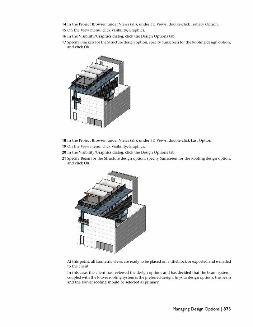
14 In the Project Browser, under Views (all), under 3D Views, double-click Tertiary Option.
15 On the View menu, click Visibility/Graphics.
16 In the Visibility/Graphics dialog, click the Design Options tab.
17 Specify Brackets for the Structure design option, specify Sunscreen for the Roofing design option,and click OK.
18 In the Project Browser, under Views (all), under 3D Views, double-click Last Option.
19 On the View menu, click Visibility/Graphics.
20 In the Visibility/Graphics dialog, click the Design Options tab.
21 Specify Beam for the Structure design option, specify Sunscreen for the Roofing design option,and click OK.
At this point, all isometric views are ready to be placed on a titleblock or exported and e-mailedto the client.
In this case, the client has reviewed the design options and has decided that the beam systemcoupled with the louver roofing system is the preferred design. In your design options, the beamand the louver roofing should be selected as primary.
Managing Design Options | 873

22 On the Tools menu, click Design Options ➤ Design Options.
23 In the Design Options dialog, under Structure, select Beam.
24 Under Option, select Make Primary. This was the client choice for structural.
Because the client has selected the design option, the current primaries are no longer options;but should be accepted as part of the building model.
25 Select Structure.
26 Under Option Set, click Accept Primary.
An alert is displayed, asking if you are sure you want to delete all elements of secondary optionsin this option set and remove the option set.
27 In the alert dialog, click Yes.
The set is deleted, the beam option becomes part of the model, and you get a dialog asking ifyou want to delete dedicated option views.
28 In the Delete Dedicated Option Views dialog, click Delete to remove the views that used options,since you no longer need them.
29 Select Roofing.
30 Under Option Set, click Accept Primary to take the louvers into the model, delete the otherdesign option geometry and any dedicated option views.
31 In the alert dialog, click Yes.
32 In the Delete Dedicated Option Views dialog, click Delete.
33 In the Design Options dialog, click Close.
34 In the Project Browser under 3D Views, double-click Primary Option. The other options wereremoved along with any dedicated option views.
The beam and louver systems are now part of the building model.
35 On the File menu, click Save.
In this exercise, you learned how to present each of the design options by creating multiple views to displaythe various combinations. After exploring the combinations, you selected a design, made it part of thebuilding model, and deleted the discarded design options.
874 | Chapter 18 Creating Multiple Design Options

Project Phasing
In any project, you or the client may want to view the model according to phases. Phases represent distinct time periodsover the duration of a project. You can create as many phases as necessary and assign building model elements to specificphases. You can use phase filters to control the flow of building model information into views and schedules. This allowsyou to create phase-specific project documentation, complete with schedules. For the client, you can create a visual timeline of phase-specific 3D views.
In the lesson and exercises that follow, you work in a simple building model that requires renovation. You create newphases, demolish existing construction, and then add new building model elements. In the second exercise, you applyphase-specific room tags to rooms that vary with each phase.
Using Phasing
In the lesson and exercises that follow, you work in a simple building model that requires renovation. Youcreate new phases, demolish existing walls and doors, then add new walls and doors in a different location.This changes room definition and total building model area.
In the second exercise, you apply phase-specific room tags to rooms that vary with each phase and observethe differences in the phase-specific room schedules.
19
875

Phasing Your Model
In this exercise, you work in a simple model that requires renovation. You create new phases and phasefilters and modify graphic overrides. During the demolition and renovation process, you create newphase-specific views in order to visualize the changes that you make to the model.
Training File
■ Click File menu ➤ Open.
■ In the left pane of the Open dialog, click Training Files, and open Common\c_Phasing.rvt.
NOTE The units of measurement in this project file are imperial. Because units of measurement have little bearingon the goals of this tutorial, you do not need to change the project units to metric. If you wish to do so, go tothe Settings menu, click Project Units, define the units, and click OK.
View current phase conditions
1 In the Project Browser, expand Views (all), expand Floor Plans, and double-click Level 1.
When you create a new project, two phases exist by default: Existing and New Construction.As you add new elements to the building model, they are assigned to the New Constructionphase by default. This phase assignment is controlled by a setting within the view properties.
You can control the default phases and view phase setting by changing the settings within atemplate. If you change the view property settings and the phase definitions within a templatefile, then new building model elements are assigned to a phase according to those settings.
2 Click View menu ➤ View Properties.
3 In the Element Properties dialog, under Phasing, notice that Show All is selected for Phase Filterand New Construction is selected for Phase.
This means that all building model elements, regardless of phase, are visible in this view. Anynew elements that you add to the building model are assigned to the New Construction phase.
4 Click Cancel.
5 Select any of the exterior walls.
6 On the Options Bar, click (Element Properties).
In the Element Properties dialog, under Phasing, notice that New Construction is selected forPhase Created, and None is selected for Phase Demolished.
7 Click Cancel.
8 On the Basics tab of the Design Bar, click Modify.
876 | Chapter 19 Project Phasing

Change the phase of the existing building model elements
9 In the drawing area, draw a selection window around the entire building model to select all ofthe elements in it.
TIP If this were a multi-story building, you may want to select the building model in a 3D view toensure you capture all of the components.
After you release the mouse button, all of the building model elements, including the door tags,are highlighted in red. Door tags are not phase-specific and must be filtered from the selection.
10 On the Options Bar, click (Filter Selection).
11 In the Filter dialog, clear Door Tags, and click OK.
12 On the Options Bar, click .
13 In the Element Properties dialog, under Phasing, for Phase Created, select Existing, and clickOK.
14 On the Design Bar, click Modify.
Notice that the line style of the walls and doors is displayed as gray rather than black becauseof the phase and phase filter settings in the view properties.
Because this is a renovation project, it requires a plan view for demolition and for newconstruction. After you create the views, you modify their view properties to make each viewphase specific.
Create phase-specific views
15 In the Project Browser, under Floor Plans, right-click Level 1, and click Rename.
16 In the Rename dialog, enter Level 1 - Existing, and click OK.
You are asked if you want to rename corresponding level and views. This refers to the ceilingplan and the level line visible in any of the elevation views. Because this is a phase-specific view,you do not want to rename the corresponding views and level.
17 Click No.
18 In the Project Browser, under Floor Plans, right-click Level 1 - Existing, and click DuplicateView ➤ Duplicate.
19 In the Project Browser, under Floor Plans, right-click Copy of Level 1 - Existing, and click Rename.
20 In the Rename dialog, enter Level 1 - Demo, and click OK.
Phasing Your Model | 877

You should now have a separate floor plan for the existing building model and the planneddemolition.
21 In the Project Browser, under Floor Plans, double-click Level 1 - Existing.
22 Click View menu ➤ View Properties.
23 In the Element Properties dialog, under Phasing, for Phase, select Existing, and click OK.
The line style of the walls and doors returns to black.
24 In the Project Browser, under Floor Plans, double-click Level 1 - Demo.
Notice that the line pattern is still gray. You may need to zoom in to see this.
This view uses a different line style because the phase property of this view is set to NewConstruction. On a logical time line, new construction occurs after existing construction, towhich all the building model elements belong. Because of this time relationship, a graphicoverride is used to make “older” elements use the gray line style. Later in this exercise, youmodify these settings.
Next, you use phase filters to define which building model elements display in a particular view.
Define phase filters
25 Click Settings menu ➤ Phases.
26 In the Phasing dialog, click the Phase Filters tab.
There are five default phase filters. In this case, however, you need a filter that takes all of thephases into account with a particular graphic override.
27 Click New.
A new phase filter is displayed at the bottom of the Filter Name list.
28 Under Filter Name, enter Composite Plan.
29 For Composite Plan, under New, select Overridden.
This new filter uses graphic overrides to set the display of all building model elements: New,Existing, Demolished, and Temporary.
View graphic overrides
30 Click the Graphic Overrides tab.
Graphic Overrides define the appearance of building model elements according to their phasestatus. Phase status is time-dependent. You can change the cut and projection line color for ademolished object.
878 | Chapter 19 Project Phasing

31 Under Phase Status, select Demolished.
32 In the Demolished row, under Cut ➤ Lines, select the line style.
33 In the Line Graphics dialog, click the value for Color.
34 In the Color dialog, select red.
35 Click OK twice.
36 Using the same method, specify red for the Projection/Surface line style for the Demolishedphase.
Change cut lines and patterns for new objects
37 Change the line style for New ➤ Cut ➤ Lines to blue.
38 For New ➤ Cut ➤ Patterns, select a lighter blue.
39 In the Phasing dialog, click OK.
Next, you begin demolition. There are two ways to demolish an element. You can select it andchange its Phase parameter to Demolished, or you can use the demolish tool.
Demolish building model elements
40 On the Tools toolbar, click (Demolish).
The cursor is displayed as a hammer.
41 Referring to the walls that display as dashed lines in the following illustration, select the interiorwalls one at a time.
As you click each wall, its display changes to a red dashed line. This was the display overridethat was set for demolished objects in the previous steps.
Notice that the doors display as demolished even though you did not specifically demolishthem. That is because doors are wall-hosted elements. When you demolish the host, you demolishall elements hosted by it.
42 In the Project Browser, under Floor Plans, double-click Level 1 - Existing.
Notice that the demolished walls continue to display. This is because the view phase filter is setto Show All.
Add new construction
43 In the Project Browser, under Floor Plans, double-click Level 1 - Demo.
Phasing Your Model | 879

44 Click View menu ➤ View Properties.
45 In the Element Properties dialog, under Phasing, for Phase Filter, select Show Previous + New,and click OK.
The demolished walls no longer display.
46 On the Architectural tab of the Design Bar, click Wall.
47 In the Type Selector, select Basic Wall: Interior - 4 7/8" Partition (1-hr).
48 Using the following illustration as a guide, add a long horizontal wall, and then add four shortvertical walls between it and the upper exterior wall.
49 On the Design Bar, click Door.
50 In the Type Selector, select Sgl Flush: 34" x 84".
51 Add a door leading into each room. Click the control arrows to adjust the opening and facedirections.
52 Open Level 1 - Existing.
Notice this view still displays the original walls and doors.
53 Open Level 1 - Demo.
54 Click View menu ➤ View Properties.
55 In the Element Properties dialog, under Phasing, for Phase Filter, select Composite Plan for PhaseFilter, and click OK.
880 | Chapter 19 Project Phasing

The composite plan phase filter uses graphic overrides and shows demolished as red dashed,new is shown in blue, and existing shows as half-tone.
Notice that all building model elements display using the composite filter.
Create a new construction view
56 Change the Phase Filter to Show Previous + Demo.
57 In the Project Browser, right-click Level 1 - Demo, and click Duplicate View ➤ Duplicate.
58 Rename the copy to Level 1 - New.
59 Open Level 1 - New, and change the Phase Filter to Show Previous + New.
The renovated building model plan is displayed. This filter displays all original componentsthat were not demolished (Show Previous) and all new components added to the building model(+ New).
60 On the View toolbar, click (Default 3D View).
61 On the View Control Bar, click Model Graphics Style ➤ Shading with Edges.
All elements are displayed in this view, regardless of phase, because the phase filter is set toShow All. You could create multiple 3D views that display each phase just as you did with thefloor plans.
62 If necessary, spin the building model so you can see the demolished walls, which are displayedas red.
Phasing Your Model | 881

Notice that all the elements are displayed using the material defined by the graphic overrides.
63 Close the file.
If you wish to save this file, you can do so at this time.
In this exercise, you created a building model with three distinct phases and created views with appropriatephase filters to display each phase.
In the next exercise, you learn how to use phase-specific room tags.
Using Phase-Specific Room Tags
In this exercise, you add room tags to a building model that has multiple phases. Floor plans have beencreated to display each phase of the project: existing conditions, demolition, and new construction. As therenovation process continues, the rooms change in both definition and size, and the information that eachroom tag reports adjusts accordingly.
Training File
■ Click File menu ➤ Open.
■ In the left pane of the Open dialog, click Training Files, and openCommon\c_Phase_Specific_Room-tags.rvt.
NOTE The units of measurement in this project file are imperial. Because units of measurement have little bearingon the goals of this tutorial, you do not need to change the project units to metric. If you wish to do so, go tothe Settings menu, click Project Units, define the units, and click OK.
Add room tags
1 In the Project Browser, expand Views (all), expand Floor Plans, and double-click Level 1 - Existing.
Notice that this view is the original building model.
2 Open Level 1 - Demo.
In this view, the walls marked for demolition display using a dashed line style. They are thesame walls that display as red in the 3D view.
3 Open Level 1 - New.
In this view, you can see the new walls added to the building model. The three level 1 floor planviews show the progression of the renovation. You can also see that the room quantities, sizes,and locations change depending on the phase of the project.
All room boundaries are phase-specific; therefore, room tags report information based on thephase of the view in which the rooms were added.
882 | Chapter 19 Project Phasing

4 Click Settings menu ➤ Phases.
In the Phasing dialog, notice that there are two phases defined in this project. Phase 0 is forexisting conditions and Phase 1 is for demolition and new construction.
5 Click OK.
6 Open Level 1 - Existing, and maximize the view.
7 On the Basics tab of the Design Bar, click Room.
8 Using the following illustration as a guide, click in each room to create a room and place a roomtag.
9 On the Design Bar, click Modify.
10 Open Level 1 - New.
11 On the Design Bar, click Room.
12 Starting in the room in the upper left corner, click in each room as you move to the right. Usethe following illustration as a guide.
Notice that the two rooms in the lower corners are identical to both the existing phase and thenew phase, yet they have different room numbers.
13 Open Level 1 - Demo.
14 On the Room and Area tab of the Design Bar, click Room Tag.
Using Phase-Specific Room Tags | 883

15 Using the following illustration as a guide, add a room tag to the three rooms adjacent to thelower exterior wall. The room tag command allows you to tag existing rooms.
Notice the room tags in this view get the same room tag numbers as the tags in the viewdisplaying new construction. That is because the same phase is assigned to both views. In thiscase, both views are assigned the same phase yet have different phase filters.
View phase-specific room schedules.
16 In the Project Browser, expand Schedules/Quantities, and double-click Room Schedule - Existing.
17 On the Window menu, click Close Hidden Windows.
18 Open Room Schedule - New Construction.
19 On the Window menu, click Tile.
The two schedule views tile.
Notice that in each phase-specific schedule, room information differs based upon the phase ofthe view the tags are in. In addition, notice the new construction has 25 less total square feetthan the original building model. This is because the additional interior walls in the newconstruction occupy more space than the original.
20 Close the file.
In this exercise, you added room tags to various floor plans that are assigned different phases. You alsoopened two schedules to observe how the room information is reported by phase.
884 | Chapter 19 Project Phasing

Linking Building Modelsand Sharing Coordinates
Many projects consist of disparate buildings in an overall campus, or of a group of related but semi-independent sub-projects.In these situations, you can use model linking and shared coordinates to create the campus within one project file whileallowing work to proceed on the individual building models in other project files. This maximizes efficiency, performance,and productivity by working in a smaller project file while retaining the ability to place that building model into a largercontext.
Specific examples when you may want to use model linking and shared coordinates:
■ A campus plan that contains links to several structures.
■ A residential development in which a few different prototypes are configured differently in an area.
■ Comparison of alternatives on a site.
In this tutorial, you link several building models within a single project file in which only a site plan has been developed.You position the building models on the site plan, modify their visibility, and manage the links throughout the project.In the final lesson, you share the coordinates so that the linked files remember their location within the host project.
20
885

Linking Building Models
In this lesson, you work within a project in which only the site components have been developed. You linkmultiple instances of one building model and a single instance of another. You position the building modelson the site, modify their visibility, and manage their locations in coordination with their originating projectfiles.
NOTE You must complete the exercises in this lesson in sequence.
Linking Building Models from Different Project Files
In this exercise, you open a project in which only site components have been developed. You link twobuilding models to the project. One building model is a condominium, and the other is a townhouse.
Placement options when linking building models
When you link a building model in a project, you have the option to manually place the linked buildingmodel or allow Revit MEP 2009 to automatically place it.
Automatic placement options:
■ Auto - Center to Center: Revit MEP places the center of the imported geometry at the center of the model.
NOTE The center of a Revit MEP model is the center of the model geometry. This center changes as thefootprint of your model changes.
886 | Chapter 20 Linking Building Models and Sharing Coordinates

■ Auto - Origin to Origin: The origin of the imported geometry is placed at the invisible origin of the RevitMEP model.
■ Auto - By Shared Coordinates: When using Model Linking in conjunction with Shared Coordinates, thisoption will place the link at a predefined location.
RELATED See the lesson, Sharing Coordinates Between Building Models on page 903.
Manual placement options:
■ Manual - Origin: The origin of the linked document is centered on the cursor.
NOTE Revit MEP projects have an internal coordinate system; however, this system is not exposed to the user.
■ Manual - Base Point: Not applicable for linked Revit MEP Files. This option is grayed out.
■ Manual - Center: The geometric center of the linked document is at the cursor location.
This tutorial requires write permission to all the training files used. Because training files are used in multipletutorials and are normally installed as read-only, you need to copy the three training files to a differentdirectory and make them writable. If you are comfortable doing this using Windows Explorer, you can doso. The required files can be found in the Common folder of the Training files: c_Site, c_Townhouse,c_Condo_Complex. Otherwise, use the following steps to copy the training files to a new location.
Save training files to different folder
1 Create a new folder on your hard drive called Model Linking.
2 On the File menu, click Open.
3 In the left pane of the Open dialog, click Training Files, and open Common\c_Site.rvt.
NOTE You may need to scroll down in the left pane to see the Training Files folder.
4 On the File menu, click Save As, navigate to the Model Linking folder you created in the first step,and save the file there.
5 On the File menu, click Close.
6 Repeat the previous five steps for the following files:
■ c_Townhouse
■ c_Condo_Complex
7 Open the Model Linking folder, select the three files, right-click, and click Properties.
8 Clear Read-only, and click OK.
All three files now reside, with write permission, in the Model Linking folder that you created.
Link condo complex into site project
9 On the File menu, click Open.
■ Navigate to the Model Linking folder.
■ Select c_Site.
■ Click Open.
Linking Building Models from Different Project Files | 887

NOTE The three project files used in this lesson use imperial units of measurement. Because modellinking and sharing coordinates are not dependent on project units, you do not need to change theproject units to metric. If you wish to do so, you can go to the Settings menu, click Project Units, andmake your changes.
10 In the Project Browser, expand Views (all), expand Floor Plans, and double-click Level 1.
Notice the blue detail lines. These represent the footprint outlines of the three building modelsites.
11 On the File menu, click Import/Link ➤ Revit.
12 In the Import/Link RVT dialog:
■ Navigate to the Model Linking folder and select c_Condo_Complex.
■ For Positioning, select Auto - Origin to Origin.
13 Click Open.
888 | Chapter 20 Linking Building Models and Sharing Coordinates

The condo complex building model is placed approximately at the center of the site model.
Move the condo complex building model
14 Select the linked building model.
After you select it, Linked Revit Model: c_Condo_Complex.rvt displays in the Type Selector.
Standard move commands work with linked building models. The linked model moves as oneobject, similar to the behavior of imported DWG objects.
15 On the Edit toolbar, click (Move).
The Move command requires two clicks. The first click specifies the move start point. The secondclick specifies the move endpoint.
16 For the move start point, click the upper-left corner of the linked condo complex building model.
17 For the move endpoint, click the upper-left corner of the matching blue detail lines above it.
Linking Building Models from Different Project Files | 889

After you specify the location to move to, the linked file displays within the confines of theblue detail lines.
18 On the View menu, click Zoom ➤ Zoom To Fit.
Link the townhouse building model
19 On the File menu, click Import/Link ➤ Revit.
20 In the Import/Link RVT dialog:
■ Navigate to the Model Linking folder, and select c_Townhouse.
■ For Positioning, select Auto - Origin to Origin.
21 Click Open.
890 | Chapter 20 Linking Building Models and Sharing Coordinates

The townhouse building model displays above the site model.
Rotate the townhouse
22 Zoom in around the townhouse model and select it.
23 On the Edit toolbar, click (Rotate).
To rotate an object, you first specify the rotation start point, and then click to specify the endof the rotation. In this case, the townhouse must be rotated 90 degrees clockwise.
24 Place the cursor just north of the townhouse and, when the vertical line displays, click to specifythe rotation start point.
25 Move the cursor 90 degrees clockwise, and click to specify the end of the rotation.
Linking Building Models from Different Project Files | 891

The rotated townhouse should resemble the following illustration.
Move the townhouse
26 On the Edit toolbar, click (Move).
This townhouse building model needs to be moved inside the blue detail lines in the lower-leftcorner of the site model. Do not be concerned if the detail lines do not match the exact footprintof the townhouse.
27 Click the lower-left corner of the townhouse building model as the move start point.
28 Select the lower-left corner of the lower-left set of blue detail lines as the move endpoint.
892 | Chapter 20 Linking Building Models and Sharing Coordinates

The townhouse is located within its required footprint.
Copy the townhouse
29 On the Edit toolbar, click (Copy).
The Copy command works much like the Move command. The first click specifies the startpoint, and the second click specifies the copy-to point.
30 For the starting point, select the upper-right corner of the townhouse.
31 Select the upper-right corner of the blue detail lines on the right to specify the copy-to point.
Linking Building Models from Different Project Files | 893

A copy of the townhouse displays on the right side of the site project.
32 On the Edit menu, click Rotate, and rotate the townhouse 180 degrees.
NOTE After you rotate the townhouse, if it does not fit reasonably well within the detail lines, usethe Move command to make any adjustments.
33 Click the first instance of the townhouse on the left.
34 On the Options Bar, click .
35 In the Element Properties dialog, under Identity data, for Name, enter Townhouse A, and clickOK.
36 Use the same technique to name the instance of the Townhouse on the right to Townhouse B.
37 On the View toolbar, click (Default 3D View).
894 | Chapter 20 Linking Building Models and Sharing Coordinates

38 On the File menu, click Save.
NOTE If you intend to complete the next exercise of this tutorial, you need this project file open andin this view.
In this exercise, you linked two separate Revit MEP 2009 models into a site model. After linking the files,you rotated and moved the building models to fit them into their designated positions within the sitedevelopment.
In the next exercise, you modify the elevation of the townhouses.
Repositioning Linked Building Models
In this exercise, you reposition the townhouses in respect to their elevation. When you originally linkedthe files, they were placed too low within the site topography. In this exercise, you modify their verticalposition so that the townhouses sit correctly on the site.
NOTE This exercise requires the completion of the previous exercise in this tutorial and the resulting project files.If you have not completed the previous exercise, do so before continuing.
Modify the vertical position of the townhouses
1 On the View toolbar, click (SteeringWheels).
2 On the SteeringWheels, click and hold Orbit, and then spin the model until it resembles thefollowing illustration.
NOTE If this is the first time you are using the SteeringWheels, click Try Me for the Full Nav LargeWheel.
Repositioning Linked Building Models | 895

Notice that the townhouse is not at the proper elevation in relationship to the site toposurface.This is apparent because there is a planter below ground level that was designed to sit on topof the site surface.
3 In the Project Browser, under Views (all), expand Elevations, and double-click South.
4 Zoom in around the townhouse on the left.
5 Place the cursor over the townhouse and notice that, when it highlights, the status bar displaysthe name of the linked file.
6 Zoom in closer on the lower half of the townhouse and notice the ground floor level of thetownhouse is 11 feet below Level 1 of the site project.
In the steps that follow, you use the Align command to reposition the linked model within thisproject. When using the Align command, you first select the plane you want to align to, andthen select the plane that you want to align. In this case, you align the Ground Floor level toLevel 1 of the site plan.
7 On the Tools toolbar, click (Align).
8 Select the Level 1 line of the Site project, move the cursor over the Ground Floor level of theTownhouse project, and click to select it.
TIP Place the cursor over the Level 1 line of the Site project, press TAB until Level 1 : Reference displaysin the status bar, and click to select the line. This process ensures that you are aligning to the levelmarker in the site project and not to the linked condo complex project. If you experience difficultyfinding the Level1 : Reference, you may want to hide the Condo Complex from the view. To do this,click View menu ➤ Visibility/Graphics. Click the Revit Links tab, clear Visibility for thec_Condo_Complex.rvt, and click OK. Remember to turn on visibility of the Condo Complex after youhave completed this task.
896 | Chapter 20 Linking Building Models and Sharing Coordinates

Notice that the townhouse is now at the proper height within this project. Also notice the optiondisplays for you to lock the alignment. Do not lock the alignment of the linked file. This wouldover-constrain the model.
9 In the Project Browser, under Elevations, double-click North.
10 Using the same technique learned in the previous steps, align the Ground Floor level of theremaining townhouse to Level 1 of the Site project.
11 Return to the South elevation view.
Both townhouses should be at the proper level.
12 On the View toolbar, click (Default 3D View).
13 On the View toolbar, click (SteeringWheels).
14 On the SteeringWheels, click and hold Orbit, and then spin the model until it resembles thefollowing illustration.
15 On the File menu, click Save.
Repositioning Linked Building Models | 897

NOTE If you intend to complete the next exercise of this tutorial, you need this project file open andin this view.
In this exercise, you changed the elevation of the townhouses relative to the host project. As you can see,each linked file can have a separate set of levels and relative heights and you can accommodate thosedifferences within the host project.
In the next exercise, you modify how the linked files display within the host project.
Controlling Linked Building Model Visibility
In this exercise, you modify the visibility settings of the linked files within the site project. After you link aRevit MEP 2009 project file within another project, you can independently control the visibility settings,detail level, display settings, and the halftone settings for each linked project.
NOTE This exercise requires the completion of the previous exercises in this tutorial and the resulting project files.If you have not completed the previous exercise, do so before continuing.
Modify visibility settings
1 In the Project Browser, under Elevations, double-click South.
2 On the View menu, click Visibility/Graphics.
3 In the Visibility/Graphics dialog, click the Revit Links tab.
4 Under Visibility, expand c_Townhouse.rvt.
Notice that you can change visibility settings of an entire linked file or selected instances of alinked file.
NOTE You have three options for controlling visibility settings of a linked file. By host view matchesthe display to the settings of the current active project view. By linked view matches the display tothe settings of the linked project view. Custom allows you to override specific visibility settings for alinked project or an instance of the linked project. When you link a file, the defaults are set to By hostview for all options.
5 Under Display Settings for c_Townhouse.rvt, click By Host View.
6 On the Basics tab of the RVT Link Display Settings dialog, click Custom.
If the Basics page is set to Custom, then the other pages on the RVT Link Display Settings dialogmay be set to By host View, By linked view, or Custom.
7 Click the Annotations Categories tab.
8 For Annotation Categories, select <Custom>.
9 Under Visibility, scroll down and clear Levels.
10 Click OK.
11 In the Visibility/Graphics dialog, click OK.
Notice the Level lines for both townhouses no longer display.
NOTE Changes to Visibility/Graphics are per view only. The townhouse level lines still display in theremaining elevation views.
898 | Chapter 20 Linking Building Models and Sharing Coordinates

12 Using the same technique learned in the previous steps, clear the Levels display forc_Condo_Complex.rvt.
Apply halftone
13 In the Project Browser, under Floor Plans, double-click Level 1.
14 On the View menu, click Visibility/Graphics.
15 In the Visibility/Graphics dialog, click the Revit Links tab.
16 Under Visibility, expand c_Townhouse.rvt.
Notice the option to halftone individual instances of the townhouse model.
17 Select Halftone for the Townhouse project, and click OK.
Halftone displays objects with half their normal darkness. With linked files, you can applyhalftone to the entire linked project or individual instances of the model. Using the Customoption, you can also apply halftone to individual categories. Notice both townhouses displayin halftone.
Detail levels of a linked file
18 On the View menu, click Visibility/Graphics.
19 In the Visibility/Graphics dialog, click the Revit Links tab.
20 For c_Townhouse.rvt, under Display Settings, click By Host View.
21 In the RVT Link Display Settings dialog, on the Basics tab, select Custom.
22 Click the Model Categories tab.
23 In the Model categories list, select <Custom>.
By default, the detail level for the linked townhouse project is set to By Host View. This meansthat the detail level of the linked file is matched to the detail level of the current active projectview. By selecting custom under Model Categories, you can independently set the detail levelfor each model category for each link on a per view basis. You can click the value for DetailLevel, and then set the detail level to coarse, medium, or fine.
In this case, no detail level changes are required.
24 Click OK.
Controlling Linked Building Model Visibility | 899

Modify display settings of linked files
You can use display settings to control the view range, phase, and phase filter of a specific link.
25 On the Revit Links tab, under Visibility, select c_Townhouse.rvt.
Notice that the Custom button displays under Display Settings.
26 Under Display Settings, click Custom for the Townhouse link.
27 In the RVT Link Display Settings dialog, select Floor Plan: Ground Floor for Linked view.
By default, the view range of a linked project uses the current view of the host project to defineits view range. In most cases, this is preferable. However, there are situations, on a sloped sitefor instance, where you need to specify a different view range so that all the building modelplan views cut at the same height. In this case, the townhouse view range now uses the sameview range defined within the Floor Plan: Ground Floor of the original linked file.
28 Select By linked view for View range.
Notice the Phase and Phase filter specified are By host view. In this case, the host view specifiesNew Construction for the Phase and Show All for the phase filter.
This means that the phase named New Construction for the linked building model is displayed,with Show All as the phase filter applied to the link. With the Show All filter applied, all new,existing, demolished, and temporary components in that particular phase (New Construction)are displayed. All other components are grayed out.
29 Click OK.
30 In the Visibility/Graphics dialog, click OK.
31 On the File menu, click Save.
NOTE If you intend to complete the next exercise of this tutorial, you need this project file open andin this view.
In this exercise, you modified the visibility settings of the townhouse link by turning off the visibility of thelevel lines and applying halftone in a plan view. You also changed the view range of the townhouse so itwould cut through the building model at the same height as the other linked building model.
In the next exercise, you manage the linked files.
Managing Linked Building Models
In this exercise, you manage the links within the host project by unloading and reloading the linked projects.After you link a Revit MEP 2009 project into another project, a connection to the linked project continuesto exist. If the host file is closed and one of the linked files is modified, those modifications are reloadedinto the host project when it is reopened.
900 | Chapter 20 Linking Building Models and Sharing Coordinates

NOTE This exercise requires the completion of the previous exercises in this tutorial and the resulting project files.If you have not completed the previous exercise, do so before continuing.
Unload and reload links
1 On the File menu, click Manage Links.
2 In the Manage Links dialog, click the Revit tab.
Notice the Loaded, Locations Not Saved, and Saved Path fields are read only. They supplyinformation regarding the links.
NOTE The Locations Not Saved field is only relevant for links with shared coordinates. In a sharedcoordinate environment, any changes made to the locations of a linked file are saved within the linkedfile rather than the host project. As links are moved to new locations in the host project, you can usethe Save Locations command to save the new locations to the linked project. You learn more aboutthis in the next lesson, Sharing Coordinates Between Building Models.
3 Under Path Type, notice that you have a choice between Relative and Absolute.
The default path type is Relative. In general, you should use a relative path rather than anabsolute. If you use a relative path and move the project and linked file together to a newdirectory, the link is maintained. If you use an absolute path and move the project and linkedfile to a new location, the link is broken because the host project continues to look for the linkin the absolute path specified. The most common scenario for using Absolute is when the linkedfile is on a network where multiple users need access to it.
4 Under Linked File, select c_Condo_Complex.rvt.
The buttons at the bottom of the dialog are now active.
5 Click Unload.
NOTE Unloading linked projects may increase performance by reducing the quantity of componentsthat must be opened and drawn.
6 At the confirmation prompt, click Yes.
The Loaded option for that linked file is now clear.
7 Click OK.
Notice that the condo complex link no longer displays in the host project.
Managing Linked Building Models | 901

TIP In the Manage Links dialog, you can also remove a link completely or reload the link from adifferent location.
Linking building models with Worksharing enabled
In some cases, you may need to link projects that have Worksharing enabled. In these cases,you should consider the following:
■ Selective open of worksets: When linking a Worksharing-enabled building model, you canspecify which worksets to open after the link is made. In the Import/Link RVT dialog, clickthe arrow next to the Open button, and select Specify. This enhances performance by reducingthe quantity of components that must be opened and drawn.
■ Changing the linked worksets: While working in a host file with Worksharing-enabled linkedfiles, you may decide that you need to see additional worksets of one of those linked files.To do this, go to the Manage Links dialog and use the Reload From command. You can thenspecify the additional worksets you need opened.
■ Linking a building model into multiple host projects: Although the same Worksharing-enabledbuilding model can be linked within multiple host projects, the specific worksets opened ineach host project must be identical. The user who creates the first link determines the statusfor all other linked files.
■ Host files with Worksharing enabled: When the host file has Worksharing activated, youmust keep in mind which workset the link is placed in. Links consist of two parts: the linksymbol and the link instance. When you initially place the link, both the link symbol andthe link instance are placed in the active workset. However, link instances can be reassignedto different worksets. In general, you should try to keep all instances of a link on the sameworkset.
TIP When opening a Worksharing-enabled host file, it is possible to specify which links are loadedwhen the host file opens. A link is only loaded if the workset that the link instance is assigned toopens. If you choose not to open that workset, the link is not loaded.
8 In the Project Browser, expand Revit Links, right-click c_Condo_Complex.rvt, and click Reload.
NOTE Some of the more frequently-used commands from the Manage Links dialog can be accessedby right-clicking the link in the Project Browser.
Notice the condo complex building model has been reloaded into its previous location.
9 On the File menu, click Save As.
902 | Chapter 20 Linking Building Models and Sharing Coordinates

10 In the Save As dialog, navigate to the Model Linking folder you created in the first exercise, namethe file Site_Project, and save it as an RVT file.
NOTE If you intend to complete the next lesson, Sharing Coordinates Between Building Models, itis important that this file exist in the same directory as the condo complex and townhouse projects.
In this exercise, you managed the linked files by unloading and reloading the townhouse project. In thenext lesson, you learn how to share the coordinates between the host and linked projects.
If you intend to complete the next lesson now, leave the project file open in its current view.
Sharing Coordinates Between Building Models
In this lesson, you learn how to share coordinates between project files so that you can correctly locatebuilding models with respect to each other. When used in conjunction with model linking, you can keeptrack of the multiple locations in which a linked building model may reside.
When you share coordinates between projects, you are deciding which coordinate system will be used bythe two files. In essence, you are establishing a shared origin point.
TIP You can also use shared coordinates with linked DWG files. When Revit project views are exported to DWG,project or shared coordinates can be specified in the Export Options dialog.
This lesson requires the completion of the lesson Linking Building Models on page 886, and the resultingproject files. If you have not completed the previous lesson, do so before continuing.
Acquiring and Publishing Coordinates
In this exercise, you publish the coordinates from a host project file to two different buildings that are linkedto that project. The host file consists primarily of site components.
When you link a Revit MEP 2009 project into another project (the host project), you can choose to use thecoordinates of either the host project or the linked project. In most cases where the host project consistsprimarily of site components and the linked projects contain the building models, the host project coordinatesare used. This ensures all the linked building models define their position with respect to the site data.
Sharing Coordinates Between Building Models | 903

When you are working in the host project, you can publish the coordinates of the linked files. This sendsthe coordinate information to the linked project so that its internal coordinate system matches the hostproject.
You can also acquire coordinates when working in the host project. In this case, the host file acquires thecoordinates of a specified linked file. You may want to do this in a case when the link refers to a DWG thathas an established coordinate system that you want the host project to adopt.
NOTE This exercise requires the completion of the previous lesson, Linking Building Models on page 886, and theresulting project files. If you have not completed the lesson, do so before continuing. If you have closed the project,open it before continuing.
Training File
■ On the File menu, click Open.
■ Navigate to the Model Linking folder you created in the first exercise of this tutorial.
■ Select Site_Project.rvt and click Open.
Publish coordinates
1 Verify that the floor plan Level 1 is the active view.
2 On the Tools menu, click Shared Coordinates ➤ Publish Coordinates.
As indicated in the Status Bar, you must now select a linked project to publish coordinates to.
3 In the drawing area, click the Condo Complex. It is the building model in the upper center ofthe host project.
904 | Chapter 20 Linking Building Models and Sharing Coordinates

4 In the Manage Place and Locations dialog, select Location 1, and click OK.
On the Status Bar, notice you are still in Publish Coordinates mode and Revit MEP is waitingfor you to select another link.
5 On the Design Bar, click Modify to end the Publish Coordinates process.
NOTE If you intend to complete the next exercise of this lesson, you need this project file open andin this view.
You have published the coordinates of the host project to the linked project. Both projects now share acoordinate system and can be linked to one another using this common coordinate system.
Relocating a Project with Shared Coordinates
When a Revit MEP 2009 model is linked into a host project, it is placed at a specific location. Until coordinatesare shared between the link and the host, this location is not saved outside of the host project. However, ifcoordinates are published from the host to the linked project, then the location becomes saved in the linkedfile. This location is defined as being a specified location with respect to the origin of the Host.
Linked files using shared coordinates must have at least one defined location, but can have multiple additionallocations. An example of a linked file with many locations is a prototype model of a house that is placedon 3 different lots. These three locations can be named Lot A, Lot B, and Lot C. Each of these lots is simplya different position for the same house design. Each of the locations can then be saved within the linkedfile for reference. This makes it possible to use the same building file to represent identical buildings on asite.
In this exercise, you specify and save the two townhouse locations, even though both models originate fromone linked file. You also relocate the shared origin of the project.
NOTE This exercise requires the completion of the previous exercise within this lesson and the resulting projectfiles. If you have not completed the exercise, do so before continuing.
Specify a townhouse location
1 In the drawing area of the floor plan Level 1, move the cursor over the left townhouse and,when the edges highlight, click to select it.
2 On the Options Bar, click .
Relocating a Project with Shared Coordinates | 905

3 In the Element Properties dialog, under Instance Parameters, notice the Shared Location valueis Not Shared.
4 Under Value, click Not Shared for Shared Location.
Because this is the first time you are setting up the shared coordinates between the host and thelinked models, a dialog displays telling you to reconcile the coordinates. This means that youneed to choose which coordinate system will be shared by both files. This is a one-time operation.
5 In the Share Coordinates dialog:
■ Select Publish the shared coordinate system.
■ Under Record selected instance as being positioned at location, click Change.
6 In the Manage Place and Locations dialog, click Rename.
7 In the Rename dialog, enter Lot A for New, and click OK.
8 In the Manage Place and Locations dialog, click OK.
9 In the Select Location dialog, click Reconcile.
10 In the Element Properties dialog, notice the Shared Location value is now Lot A, and click OK.
Constrain a link to a specific location
11 Select the townhouse building model on the right side of the host project.
After a link instance is assigned a shared location, changing the position of that instance canaffect the definition of the location that is saved with the linked file. When constraining a linkto a location, you have only two choices:
■ Move the instance to an existing location that is not already in use.
■ Record the current position as a location.
12 On the Options Bar, click .
13 In the Element Properties dialog, under Instance Parameters, click Not Shared for Shared Location.
In the Choose Location dialog, notice that you do not have an option to acquire or publishcoordinates. This is because the coordinates for this linked file have already been shared. It isonly necessary to reconcile coordinates once.
14 In the Choose Location dialog, select Move instance to.
Notice the OK button is not active. This is because you cannot choose a location where aninstance link already exists. You created the Lot A location in previous steps, and the lefttownhouse resides at that location.
15 In the Choose Location dialog, select the second option, Record current position as.
Notice the OK button is still not active. Because Lot A is currently in use, you cannot redefineits location.
16 Click Change.
17 In the Manage Place and Locations dialog, click Duplicate, enter Lot B for Name, and click OK.
18 In the Manage Place and Locations dialog, make sure Lot B is selected, and click OK.
19 In the Select Location dialog, click OK.
20 In the Element Properties dialog, click OK.
You now have two different locations for the townhouse building model: Lot A and Lot B.
Save locations
21 On the File menu, click Manage Links.
22 In the Manage Links dialog, click the Revit tab, and then select the townhouse project.
906 | Chapter 20 Linking Building Models and Sharing Coordinates

23 Click Save Locations.
24 In the Save Modified Linked Model dialog, select Save, and click OK.
When you create a location, it is not automatically saved within the linked file. To explicitlysave a location, you must go to the Manage Links dialog and save the locations there.
NOTE If you attempt to close a host file without saving location changes made to linked files, youare prompted to save the locations to the linked files.
25 In the Manage Links dialog, notice the Locations Not Saved option for the townhouse projectis no longer selected.
26 Click OK.
27 Select the townhouse on the right in Lot B and drag it a short distance in any direction. Whenyou release the mouse button, a warning displays.
You are informed that you have attempted to move a linked file that has been saved to a specificlocation. You are given the opportunity to save the new location, ignore the warning, or cancelthe action.
28 Click Cancel to return the townhouse to Lot B.
You can relocate an entire project with respect to all the linked files that are shared with it.When you relocate a project, the active location position is moved, although it may appear thatthe linked files are moving. By relocating a project, you essentially move the origin of the sharedcoordinates.
Relocate a project
29 On the View menu, click Zoom ➤ Zoom to Fit.
30 On the Tools menu, click Project Position/Orientation ➤ Relocate this Project.
This is a two-click process. The first click specifies the move start point. The second click specifiesthe move endpoint.
31 Click just north of the site topography and just below the North elevation symbol.
32 Move the cursor horizontally to the left approximately 40' and click to relocate the shared origin.
Relocating a Project with Shared Coordinates | 907
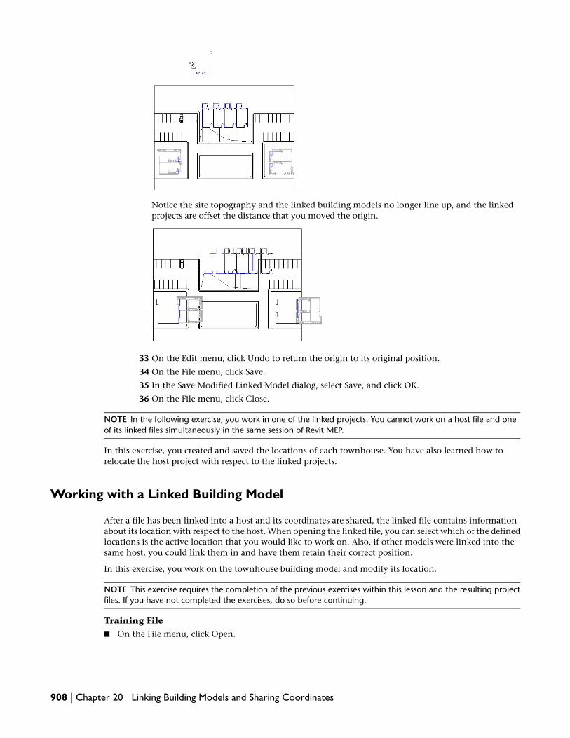
Notice the site topography and the linked building models no longer line up, and the linkedprojects are offset the distance that you moved the origin.
33 On the Edit menu, click Undo to return the origin to its original position.
34 On the File menu, click Save.
35 In the Save Modified Linked Model dialog, select Save, and click OK.
36 On the File menu, click Close.
NOTE In the following exercise, you work in one of the linked projects. You cannot work on a host file and oneof its linked files simultaneously in the same session of Revit MEP.
In this exercise, you created and saved the locations of each townhouse. You have also learned how torelocate the host project with respect to the linked projects.
Working with a Linked Building Model
After a file has been linked into a host and its coordinates are shared, the linked file contains informationabout its location with respect to the host. When opening the linked file, you can select which of the definedlocations is the active location that you would like to work on. Also, if other models were linked into thesame host, you could link them in and have them retain their correct position.
In this exercise, you work on the townhouse building model and modify its location.
NOTE This exercise requires the completion of the previous exercises within this lesson and the resulting projectfiles. If you have not completed the exercises, do so before continuing.
Training File
■ On the File menu, click Open.
908 | Chapter 20 Linking Building Models and Sharing Coordinates

■ Navigate to the Model Linking folder you created in the first exercise of this tutorial.
■ Select c_Townhouse and click Open.
Link a project
1 In the Project Browser, under Floor Plans, double-click 1st Floor.
This project is currently linked to the Site_Project.rvt file. It is located in Lot A and Lot B withinthat project file. In addition, the condo complex is linked within the Site_Project.rvt file.
2 On the File menu, click Import/Link ➤ Revit.
3 In the Import/Link RVT dialog:
■ Navigate to the Model Linking folder you created in the first exercise of this tutorial.
■ Select c_Condo_Complex.
■ For Positioning, select Auto - By Shared Coordinates.
■ Click Open.
Because this building model only has one named location, it is placed automatically within thehost project.
4 Zoom out to see the condo complex building model.
The condo complex is positioned relative to the active location of the townhouse buildingmodel. The current active location is Lot A.
Change the active location
5 On the Settings menu, click Manage Place and Locations.
Notice that Lot A is the current active location.
6 Select Lot B, and click Make Current.
7 Click OK.
Notice that the condo complex link has repositioned itself as though the townhouse was onLot B.
Working with a Linked Building Model | 909

NOTE If you intend to complete the next exercise of this lesson, you need this project file open andin this view.
In this exercise, you worked within a project that is linked within another project. You loaded a linked fileinto the townhouse project and then changed the active location to see how the project reacts to the changes.
In the next exercise, you manage the shared locations.
Managing Shared Locations
The Manage Place and Locations command allows you to quickly create new location names or renameexisting ones. These new locations can be assigned later within a host file. In this exercise, you create a newlocation, orient a view to true north, and use the Report Shared Coordinates tool.
NOTE This exercise requires the completion of the previous exercises within this lesson and the resulting projectfiles. If you have not completed the exercises, do so before continuing.
Manage locations
1 On the Settings menu, click Manage Place and Locations.
2 In the Manage Place and Locations dialog, click Duplicate.
3 In the Name dialog, enter Lot C, and click OK.
4 In the Manage Place and Locations dialog, click OK.
Lot C now exists as a location although it has not been specified as an instance. In the host file,you can select Lot C if necessary.
Orient a view to true north
5 On the View menu, click View Properties.
6 In the Element Properties dialog, under Graphics, select True North for Orientation, and clickOK.
7 Click View menu ➤ Zoom ➤ Zoom to Fit.
Notice that the orientation of the model resembles the site project.
910 | Chapter 20 Linking Building Models and Sharing Coordinates

Report shared coordinates
8 On the Tools menu, click Shared Coordinates ➤ Report Shared Coordinates.
This command allows you to determine the location of elements and points in the model withrespect to the shared coordinate origin.
9 Click any component or in any location on the drawing area.
On the Options Bar, notice the coordinates display in regards to the direction and distance tothe origin.
10 On the File menu, click Close. You can save the file if you wish.
In this exercise, you created a new location using the Manage Place and Locations tool. You rotated a viewto true north and used the Report Shared Coordinates tool to locate components in regards to the origin.
Scheduling Components of Linked Files
In this exercise, you schedule components of the host file and of all linked files.
NOTE This exercise requires the completion of the previous exercises within this lesson and the resulting projectfiles. If you have not completed the exercise, do so before continuing.
Training File
■ On the File menu, click Open.
■ Navigate to the Model Linking folder you created in the first exercise of this tutorial.
■ Select Site_Project.rvt and click Open.
Create a door schedule
1 Verify that the floor plan Level 1 is the active view.
Scheduling Components of Linked Files | 911

2 On the View tab of the Design Bar, click Schedule/Quantities.
3 In the New Schedule dialog, under Category, select Doors, and click OK.
Select the fields to display in the door schedule
4 In the Schedule Properties dialog, click the Fields tab.
5 Under Available fields, select Count, and click Add.
6 Add the remaining fields in the following order:
■ Family and Type
■ Comments
■ Cost
7 Select Include elements in linked files.
912 | Chapter 20 Linking Building Models and Sharing Coordinates

8 Click OK.
In order to see a concise listing of all the doors in the campus project, you can sort the scheduledata and display a single table entry per door type.
Sort schedule data
9 In the Project Browser, expand Schedules/Quantities, right-click Door Schedule, and clickProperties.
10 In the Element Properties dialog, under Other, click Edit for Sorting/Grouping.
11 In the Schedule Properties dialog, select Family and Type for Sort by.
12 Select Grand totals, clear Itemize every instance, and then click OK twice.
Because you did not itemize every instance of each door type, the schedule lists the total countfor each door type, and a grand total for the number of doors in the project buildings.
13 On the File menu, click Save.
14 On the File menu, click Close.
In this exercise, you created a schedule of doors in the host file and all linked files of a project. You alsosorted the schedule data to produce a consolidated listing of the components.
You have completed this tutorial.
Scheduling Components of Linked Files | 913

914

Customizing ProjectSettings and Templates
915

916

Modifying Project andSystem Settings
In this tutorial, you learn how to modify your Revit MEP 2009 working environment. In the first lesson, you modify thesystem environment, which is independent of the project settings. In the second lesson, you modify project settings tocontrol the appearance of components and subcomponents within that project. Finally, you create an office template,and set it as your default template.
Modifying System Settings
In this lesson, you learn how to control the system settings for Revit MEP. System settings are local to eachcomputer and applied to all projects; they are not saved to project files or template files.
Modifying General System Options
In this exercise, you modify the settings that control your local Revit MEP working environment. Thesesettings control the graphics, selection default options, notification preferences, journal cleanup options,and your username when using worksets.
Set graphics settings
1 Click File menu ➤ Close to close all open projects.
2 Click Settings menu ➤ Options.
3 In the Options dialog, click the Graphics tab.
4 Under Colors, select Invert background color, and click OK.
5 Click File menu ➤ New ➤ Project to open a new Revit MEP project.
6 In the New Project dialog, under Template file, click Browse.
7 In the left pane of the Choose Template dialog, click Training Files, and openMetric\Templates\m_Tutorial_Default.rte.
8 In the New Project dialog, click OK.
Notice that the drawing area is black.
9 Click Settings menu ➤ Options.
21
917

10 In the Options dialog, click the Graphics tab.
11 Under Colors, click the value for Selection color.
12 In the Color dialog, select yellow, and click OK.
NOTE You can also specify the Alert Color. When an error occurs, the elements causing the errordisplay using this color.
13 Click the General tab.
14 Under Notifications, specify the following options:
■ For Save reminder interval, select One hour.
■ For Tooltip assistance, select None.
15 Click OK.
16 On the Basics tab of the Design Bar, click Wall.
17 Sketch a straight horizontal wall in the center of the drawing area.
18 On the Design Bar, click Modify, and select the wall.
Notice the selected wall is yellow rather than the default red.
19 On the Design Bar, click Modify.
20 Place the cursor over the wall but do not select it.
Notice that a tooltip is not displayed. However, the status bar displays information about thehighlighted element.
21 Click File menu ➤ Close.
22 When prompted to save changes, click No.
23 Click File menu ➤ Open.
24 In the left pane of the Open dialog, click Training Files, and open Metric\m_Settings.rvt.
Notice that the system settings apply to this project.
25 Click Settings menu ➤ Options.
26 In the Options dialog, click the Graphics tab, and make the following changes:
■ Under Colors, clear Invert background color.
■ For Selection color, select red.
918 | Chapter 21 Modifying Project and System Settings

27 Click the General tab, and make the following changes:
■ Under Notifications, select your preferred Save reminder interval. For Tooltip assistance,select Normal.
■ Under Username, enter the name you want to use during worksharing. Your login namedisplays by default.
■ Under Journal File Cleanup, select values for When number of journals exceeds and Deletejournals older than (days).Journal files are deleted automatically after their number exceeds the value you specify.Journal files are text documents that record each step during your Revit MEP sessions. Thesefiles are used in the software support process. Journals can be run to detect a problem orrecreate lost steps or files. They are saved at the termination of each Revit MEP session.
28 Click OK.
Notice that the drawing area background colors are no longer inverted and that tooltips displaywhen you place the cursor over any building component.
29 Click File menu ➤ Close. If prompted, do not save the changes.
30 Proceed to the next exercise, Specifying File Locations on page 919.
Specifying File Locations
In this exercise, you specify default file locations. These settings control locations of important Revit MEPfiles, including your default project template, family template files, and family libraries.
Set file locations
1 Click Settings menu ➤ Options.
2 In the Options dialog, click the File Locations tab.
3 Under Default template file, click Browse.
Notice that you can choose an industry-specific template as your default template.
TIP To view a template, you can start a new project with that template. Click Filemenu ➤ New ➤ Project, and click Browse to select a template.
4 Click Cancel.
5 Under Default path for user files, click Browse.
6 In the Browse For Folder dialog, select the folder to save your files to by default, and click Open.
7 In the Options dialog, under Default path for family template files, click Browse.
This path is set automatically during the installation process. These are the family templatesthat you use to create new families. It is unlikely that you would ever want to modify this path.However, there are some circumstances where you may need to modify the path, such as in alarge, centralized, architectural firm where customized templates reside on a network drive.
8 Click Cancel.
Specify library settings and create a new library
9 In the Options dialog, click Places.
10 In the Places dialog, notice the list of library names.
The list is dependent on the options that you selected during installation. Each library pathpoints Revit MEP to a folder of families or training files. You can modify the existing library
Specifying File Locations | 919

names and path, and you can create new libraries. An icon for each library displays in the leftpane of all Revit MEP Open, Save, Load, and Import dialogs.
When you are opening, saving, or loading a Revit MEP file, you can click on the library folderlocated in the left pane of the dialog. In the following illustration, notice that the librariesdisplay as icons in the left pane of the dialog.
11 In the Places dialog, under Libraries, click (Add Value).
12 Click in the Library Name field of the new library, and change the name to My Library.
13 Click in the Library Path field for My Library, and click the icon that displays on the rightside of the field.
14 Navigate to C:\My Documents or a folder where you want to create a personal library of RevitMEP projects, templates, or families, and click Open.
TIP You may want to create a new folder first, and select it as the library path.
920 | Chapter 21 Modifying Project and System Settings

The new library displays in the left pane of all Revit MEP Open, Save, Load, and Import dialogs.The library icons display in the order in which they are listed in the Options dialog.
15 Under Library Name, click My Library.
16 Click (Move Rows Up) until My Library is at the top of the list, and click OK twice.
17 Click File menu ➤ Open.
18 In the left pane of the Open dialog, click the My Library icon.
Notice that Revit MEP navigates directly to the library path. If you work in a large office, youmay want to set up an office library on a network path to increase productivity and maintainoffice standards.
19 Click Cancel.
20 Click Settings menu ➤ Options.
21 Click the File Locations tab.
22 Click Places.
23 Select My Library.
24 Click (Remove Value) to delete the library.
25 Click OK.
Specify rendering settings
26 Click the Rendering tab.
27 Under Render Appearance Library Location, view the current path.
This path specifies the location of the Render Appearance Library. This path is determined duringinstallation. If you want to relocate this path, specify the new location here.
Under Additional Render Appearance Paths, you can specify the locations of other files used todefine render appearances, such as bump maps, custom color files, and decal image files.
28 Click OK.
29 Proceed to the next exercise, Specifying Spelling Options on page 921.
Specifying Spelling Options
In this exercise, you modify the spelling settings and the custom dictionaries for Revit MEP.
Modify spelling settings
1 Click Settings menu ➤ Options.
2 In the Options dialog, click the Spelling tab.
3 Under Settings, select Ignore words in UPPERCASE.
4 Under Personal dictionary contains words added during spell check, click Edit.
The custom dictionary opens in your default text editor.
5 In the text editor, enter sheetmtl-Cu.
6 Click File menu ➤ Save.
7 Click File menu ➤ Exit.
8 Under Building industry dictionary, click Edit.
9 In the text editor, scroll down the list of building industry terms.
10 Click File menu ➤ Exit.
Specifying Spelling Options | 921

11 In the Options dialog, click OK.
12 On the Standard toolbar, click (New) to open a new Revit MEP project using the defaulttemplate.
13 On the Basics tab of the Design Bar, click Text.
14 Click in the drawing area, and enter This is sheetmtl-Cu and SHTMTL-CU.
15 On the Basics tab of the Design Bar, click Modify.
16 Click Tools menu ➤ Spelling.
Notice that the spell checker allowed sheetmtl-Cu because you added it to the custom dictionary.It allowed SHTMTL-CU because you set the spelling options to ignore words in uppercase.
17 Click Settings menu ➤ Options.
18 In the Options dialog, click the Spelling tab.
19 Under Settings, click Restore Defaults.
This command resets the spelling settings to their original configuration.
20 Under Personal dictionary, click Edit.
The custom dictionary opens in your default text editor.
21 In the text editor, delete sheetmtl-CU.
22 In the text editor, click File menu ➤ Save, and then click File menu ➤ Exit.
23 In the Options dialog, click OK.
24 Click File menu ➤ Close. If prompted, do not save the changes.
25 Proceed to the next exercise, Modifying Snap Settings on page 922.
Modifying Snap Settings
In this exercise, you modify snap settings. Snap settings are system settings that are applied to all projectsand not saved within a project file. You can turn snap settings on and off, or use the shortcut keys to forcea particular snap method. In this exercise, you modify snap increments, work with snapping turned off, anduse shortcut keys to control snapping on an instance basis.
Modify snap increments
1 Click File menu ➤ New ➤ Project to open a new Revit MEP project.
2 In the New Project dialog, under Template file, click Browse.
3 In the left pane of the Choose Template dialog, click Training Files, and openMetric\Templates\m_Tutorial_Default.rte.
4 In the New Project dialog, click OK.
5 Click Settings menu ➤ Snaps.
Notice that you can modify both length and angular snap increments. As you zoom in and outwithin a view, Revit MEP uses the largest increment that represents less than 2mm in the drawingarea. You can add an increment by entering the value with a semicolon after it.
922 | Chapter 21 Modifying Project and System Settings

6 Under Dimension Snaps, click in the Length dimension snap increments box following thevalue 1000 ; and enter 500 ;.
7 Under Object Snaps, notice the 2-letter acronyms next to each object snap option.
You can use these shortcut keys at any time when working on the design. For example, if youwant to snap an object to a wall midpoint, enter SM, and only midpoint snaps are recognizeduntil you commit an action. After you click to place the object at the midpoint, snapping revertsto the system default settings.
8 In the Snaps dialog, click OK.
9 On the Basics tab of the Design Bar, click Wall.
10 On the Options Bar, clear Chain.
11 Click in the center of the drawing area, and move the cursor to the right.
Notice that the listening dimension snaps at 1000 mm increments. If it does not, zoom outuntil it does so.
A listening dimension refers to the dimension that displays while you are sketching. Thisdimension reacts to the movement of the cursor and numerical keyboard entries.
TIP To zoom while sketching, use the wheel button on your mouse. If you do not have a wheelbutton, you can right-click and select a zoom option from the shortcut menu. While sketching, youcan also use the zoom shortcut keys, such as ZO to zoom out.
Modifying Snap Settings | 923

12 While sketching a generic straight wall, zoom in until the listening dimension snap incrementshifts to 500 mm.
This is the increment that you added previously.
Sketch without snapping
13 While sketching the wall, enter the shortcut key SO to turn snaps off.
Notice that when snapping is turned off completely, the listening dimension reflects the exactlength of the wall as you move the cursor to the left or right.
14 Click to set the wall endpoint.
15 Click in the drawing area to start a second wall, and move the cursor to the right. Do not setthe wall end point.
Notice that snapping is once again active. When you use shortcut keys to control snapping, thecommand is only active for one click of the mouse.
Use snapping shortcut keys
16 On the Design Bar, click Modify, and click Wall.
17 Place the cursor over the horizontal wall you added previously.
Notice that the cursor snaps to various points on the wall. If you move the cursor along thewall, it will snap to the endpoints, the midpoint, and the wall edges.
18 Enter SM.
This is the snap shortcut key that restricts all snapping to midpoints.
19 Notice that the cursor now snaps only to the midpoint of the wall.
20 Click to start the wall at the midpoint.
21 Move the cursor downward, and specify the wall endpoint.
22 Click Settings menu ➤ Snaps.
23 Under Dimension Snaps, click in the Length dimension snap increments box, and delete thevalue 500 ;.
Make sure you also delete the semicolon.
24 Click OK.
25 Click File menu ➤ Close, and do not save the file.
26 Proceed to the next lesson, Modifying Project Settings on page 925.
924 | Chapter 21 Modifying Project and System Settings

Modifying Project Settings
In this lesson, you learn how to control the project environment by using the options available on theSettings menu. Using these options, you modify the appearance of components and subcomponents in aproject. You create and modify materials, annotations, lines, fill patterns, and object styles. Finally, youmodify the way the Project Browser organizes the project.
The exercises in this lesson should be done sequentially using the same project file. If you cannot completethe exercises in their entirety, save the project file with a unique name, and use it to complete the remainingexercises.
Creating and Applying Materials
In this exercise, you create a new material and apply it to a model element. When you apply a material toan element, it defines the appearance of that element in shaded and rendered views. Well designed materialsprovide the foundation for photorealistic renderings.
In the steps that follow, you begin with a simple building model consisting of brick on CMU exterior walls.
This building model has a generic roof and generic floor. After you create a new fieldstone material andapply it to the exterior wall face, you render a region to observe the changes.
Training File
■ Click File menu ➤ Open.
■ In the left pane of the Open dialog, click Training Files, and open Metric\m_Settings.rvt.
Create a new material
1 Click Settings menu ➤ Materials.
Modifying Project Settings | 925
Notice the materials listed on the left side of the dialog. This list includes all materials availablefor use on model elements. When a model element is loaded into a project, all materials thatare part of that family are also loaded into the project.
2 Scroll down the materials list, and select Masonry - Stone.
Notice that no surface pattern is defined for this material. However, this material provides astarting point for the new material, Masonry - Fieldstone.
3 Click (Duplicate).
This command creates a new material using the selected material settings as the starting point.
4 In the Duplicate Revit Material dialog, enter Masonry - Fieldstone, and click OK.
You have created a new material that can be applied to any model element in this project. Noticethat the material settings have not changed from the material that you duplicated. In the stepsthat follow, you modify the material so that it displays correctly in a shaded or rendered view.
Change the render appearance
5 Click the Render Appearance tab.
The properties describe the color, scale, and texture of the material. These details will displayin rendered images.
6 Click Replace.
The Render Appearance Library is a local, read-only library for render appearances. When youchange properties of a render appearance, the modified render appearance is stored as part ofthe project file. It is not stored in the read-only Render Appearance Library.
7 In the Render Appearance Library dialog, for Class, select Stone.
The list displays only render appearances that belong to the stone class.
8 Select Riverstone Blue, and click OK.
In the Materials dialog, the Render Appearance tab updates to display properties for the selectedstone.
9 Click Apply.
10 Click the Graphics tab.
Notice that the surface pattern is still blank. In the next exercise, you create a fieldstone patternand apply it to the Masonry - Fieldstone material.
11 Click OK.
Apply the new material
12 In the Project Browser, expand Views (all) ➤ Floor Plans, and double-click 02 Entry Level.
13 Select the lower exterior wall, and click (Element Properties).
926 | Chapter 21 Modifying Project and System Settings

14 In the Element Properties dialog, click Edit/New.
15 Click Duplicate.
16 Enter the new wall name, Fieldstone on CMU, and click OK.
17 For Structure, click Edit.
18 For Finish 1, click in the Material field.
Layer #1 is the exterior finish of the wall. It is currently assigned the material Masonry - Brick.
19 On the right side of the Material field, click .
20 In the Materials dialog, select Masonry - Fieldstone, and click OK.
This is the material that you created.
21 Click OK three times.
When you render a 3D view that includes the lower wall, the wall will display the renderappearance specified for Masonry - Fieldstone.
22 Select the left exterior wall.
23 While pressing CTRL, select the rear exterior wall.
24 In the Type Selector, select Basic Wall: Fieldstone on CMU.
All of the exterior walls of this project are now Fieldstone on CMU.
25 On the View toolbar, click (Default 3D View).
26 On the View Control Bar, click Model Graphics Style, and verify that Shading with Edges isselected.
Creating and Applying Materials | 927

Notice that the exterior walls are no longer brick, and there is no stone pattern applied in thisview. This is because a surface pattern was not selected when the fieldstone material was defined.In the following exercise, Creating and Applying Fill Patterns on page 929, you create a fieldstonepattern and apply it to this material.
27 On the Rendering tab of the Design Bar, click Rendering Dialog.
TIP If the Rendering tab is not available on the Design Bar, right-click the Design Bar, and clickRendering.
28 In the Rendering dialog, select Region.
29 In the 3D view, select the render region (a red rectangle), and drag its blue grips to adjust therender region around the building.
30 Zoom in on the render region so you can see the building more clearly in the drawing area.
31 In the Rendering dialog, under Quality, for Setting, select Low or Medium.
Higher quality renderings require more time to generate.
32 In the Rendering dialog, click Render.
The rendering process begins. When finished, the rendered image displays fieldstone walls.
928 | Chapter 21 Modifying Project and System Settings

TIP If you want to see the material in greater detail, in the Rendering dialog, click Show the model.Zoom into the model, and adjust the boundaries of the render region to describe a smaller area.Then click Render again.
33 In the Rendering dialog, click Show the model, and clear Region.
34 Close the Rendering dialog.
35 Click File menu ➤ Save As.
36 Navigate to a folder of your preference, and save the file as m_Settings-in progress.rvt.
37 Proceed to the next exercise, Creating and Applying Fill Patterns on page 929.
Creating and Applying Fill Patterns
In this exercise, you create a new pattern called Fieldstone and apply it to the material you created in theprevious exercise.
There are 2 types of fill patterns: model and drafting. Model patterns represent actual element appearanceon a building, such as brick coursing or ceramic tile on a wall. Model patterns are fixed and scale with themodel. Drafting patterns represent material in symbolic form, such as steel, which consists of adouble-diagonal hatching pattern. Drafting pattern density is fixed. Both pattern types are created andapplied in a similar way.
NOTE This exercise requires the completion of the previous exercise. Use the project file that you saved at theend of that exercise, m_Settings-in progress.rvt.
Create a new fill pattern
1 In the Project Browser, expand Elevations, and double-click West.
Notice that no model surface pattern displays on the fieldstone wall.
2 Click Settings menu ➤ Fill Patterns.
3 Under Pattern Type, choose Model.
4 Scroll down the list of patterns.
Notice that a fieldstone pattern is not available.
5 Click New.
6 In the Add Surface Pattern dialog, select Custom.
7 Under Custom, click Import.
Creating and Applying Fill Patterns | 929

8 In the left pane of the Import Fill Pattern dialog, click Training Files, and openCommon\Fieldstone_Model.pat.
9 Under Custom, select fldstn, and for Import scale, enter .56.
10 For Name, enter Fieldstone, and click OK.
The new model pattern is available in the Fill Patterns dialog.
11 Click OK.
Apply the fieldstone pattern
12 Select the west exterior wall with windows.
13 On the Options Bar, click (Element Properties).
14 In the Element Properties dialog, click Edit/New.
15 For Structure, click Edit.
16 In the Edit Assembly dialog, for Finish 1, click in the Material field.
Finish 1 is the exterior finish of the wall. It is currently assigned the material Masonry - Fieldstone.
17 On the right side of the Materials field, click .
In the Materials dialog, notice that no surface pattern is applied to the Masonry - Fieldstonematerial.
18 Under Surface Pattern, click to select a fill pattern.
19 In the Fill Patterns dialog, under Pattern Type, select Model.
20 Select the Fieldstone model pattern, and click OK.
21 In the Materials dialog, click OK.
22 Click OK three times.
The west wall of the building displays as solid fill.
23 On the Design Bar, click Modify.
24 Zoom into the model until the fill pattern appears.
930 | Chapter 21 Modifying Project and System Settings

25 On the View toolbar, click (Default 3D View).
TIP If the pattern does not display, adjust your zoom settings as needed.
26 Click File menu ➤ Save.
27 Proceed to the next exercise, Controlling Object Styles on page 931.
Controlling Object Styles
You can use object styles to control the appearance of components and subcomponents. Object styles areapplied in every view and can be overridden in a particular view by modifying the Visibility/Graphics settings.Object styles allow you to control the appearance of multiple component types.
For example, there are often multiple window types within a project. The client may not be certain of theexact window frame color to use and may want to see renderings of various options. Rather than continuallymodify the type properties of each window type, you can set the window frame material to By Category.You can then change the material in the Object Styles dialog and apply it to all window types.
NOTE This exercise requires the completion of the previous exercise. Use the project file that you saved at theend of that exercise, m_Settings-in progress.rvt.
Apply object styles by category
1 In the Project Browser, expand 3D Views, and double-click 3 Windows.
2 On the keyboard, use the shortcut keys ZR (Zoom in Region), and drag a rectangle around the3 windows facing you.
Controlling Object Styles | 931

3 On the View Control Bar, click Model Graphics Style ➤ Shading with Edges.
4 Select one of the rectangular windows.
5 On the Options Bar, click (Element Properties).
6 In the Element Properties dialog, click Edit/New.
7 In the Type Properties dialog, under Materials and Finishes, for Trim Exterior Material, click in
the Value column, and click .
8 In the Materials dialog, click By Category (located under the materials list).
This means that the material is assigned by the Object Styles setting.
9 Click OK twice.
10 Select the arched window.
11 On the Options Bar, click (Element Properties).
12 In the Element Properties dialog, click Edit/New.
13 In the Type Properties dialog, under Materials and Finishes, for Trim Exterior Material, click in
the Value column, and click .
14 In the Materials dialog, click By Category.
15 Click OK twice.
16 On the Design Bar, click Modify.
Notice the exterior frames of all the windows are now gray.
932 | Chapter 21 Modifying Project and System Settings

Change the render appearance
17 Click Settings menu ➤ Object Styles.
18 On the Model Objects tab, expand Windows, and select Trim.
19 For Trim, click in the Material column, and click .
20 In the Materials dialog, select Trim, and click (Duplicate).
21 In the Duplicate Revit Material dialog, for Name, enter Trim - red paint, and click OK.
22 Click the Render Appearance tab.
23 Click Replace.
24 In the Render Appearance Library dialog, for Class, select Paint.
25 In the search field, type red.
The list displays render appearances that belong to the Paint class and whose names, descriptions,or keywords include the word red.
26 Select Paint Dark Red Glossy, and click OK.
When you render a 3D view, the rendered image will show dark red paint for the window trim.
Change the color in shaded views
27 Click the Graphics tab.
28 Under Shading, select Use Render Appearance for Shading.
Revit MEP determines the average color for the render appearance. It uses this color to representthe material in 2D and 3D views whose model graphics style is Shading or Shading with Edges.
29 In the Materials dialog, click OK.
30 In the Object Styles dialog, click OK.
Notice that the red paint trim material is applied to all windows regardless of their type.
31 On the View toolbar, click (Default 3D view).
Controlling Object Styles | 933

32 Click File menu ➤ Save.
33 Proceed to the next exercise, Modifying Line Patterns and Styles on page 934.
Modifying Line Patterns and Styles
In this exercise, you create a new line pattern and apply it to the fascia of the roof. You then create a newline style to mark the zoning setback from the property line.
NOTE This exercise requires the completion of the previous exercise. Use the project file that you saved at theend of that exercise, m_Settings-in progress.rvt.
Create a new line pattern
1 Verify that the project from the previous exercise, m_Settings-in progress.rvt, is open with the 3Dview active.
2 Click Settings menu ➤ Line Patterns.
3 In the Line Patterns dialog, click New.
4 In the Line Pattern Properties dialog, for Name, enter Roof Line.
5 Enter the Types and Values shown in the following illustration:
6 Click OK twice.Now that you have created a line pattern, you can apply it using either of the following methods:
■ Use Visibility/Graphics settings to modify the roof appearance in a specific view.
■ Use object styles to apply the change to all views.
7 On the View Control Bar, click Model Graphics Style ➤ Hidden Line.
8 Click Settings menu ➤ Object Styles.
9 In the Object Styles dialog, under Category, select Roofs.
10 For Line Color, select Red.
11 For Line Pattern, select Roof Line.
934 | Chapter 21 Modifying Project and System Settings

12 Click OK.
The line style is applied to the roof in the view.
13 In the Project Browser, under 3D Views, double-click to Building.
14 On the View Control Bar, click Model Graphics Style, and verify that Hidden Line is selected.
Notice that the line color displays in this view, but not the line pattern.
Modifying Line Patterns and Styles | 935

NOTE The line pattern is most appropriate in plan views. The pattern is not applied in a perspectiveor camera view where you expect to see a solid line. Plans, sections, elevations, and orthogonal 3Dviews show line color and pattern.
15 In the Project Browser, under Floor Plans, double-click 03 Roof.
16 Click Settings menu ➤ Object Styles.
17 In the Object Styles dialog, under Category, select Roofs.
18 For Line Color, select Black.
19 For Line Pattern, select Solid.
20 Click OK.
21 Click View menu ➤ Visibility/Graphics.
22 On the Model Categories tab, for Visibility, select Roofs.
23 For Projection/Surface Lines, click Override.
This setting overrides the appearance of the roof only in the current view.
24 In the Line Graphics dialog, specify the following options:
■ For Weight, select 5.
■ For Color, select Blue.
■ For Pattern, select Roof Line.
936 | Chapter 21 Modifying Project and System Settings

25 Click OK twice.
Create a new line style
26 In the Project Browser, under Floor Plans, double-click Site.
Notice the site topography and the property lines.
27 Click Settings menu ➤ Line Styles.
28 In the Line Styles dialog, under Modify Subcategories, click New.
29 For Name, enter Zoning Setback, and click OK.
30 For the Zoning Setback category, specify the following values:
■ For Line Weight Projection, select 2.
■ For Line Color, select Red.
■ For Line Pattern, select Double dash.
31 Click OK.
32 On the Basics tab of the Design Bar, click Lines.
33 In the Type Selector, select Zoning Setback.
34 On the Options Bar, specify the following:
■ For Plane, select Level: 02 Entry Level.This places the line above the topography.
■ Click (Draw).
■ Click (Line).
35 Draw lines for the setback approximately as shown:
Modifying Line Patterns and Styles | 937

NOTE If you only want the setback to display on the site view, use the Detail Lines command on theDrafting tab of the Design Bar. Detail lines only show in the view where they are created, as if theyare placed on an overlay of the view.
36 On the View toolbar, click (Default 3D View).
Notice that the Zoning Setback lines display in this view.
37 Click View menu ➤ Visibility/Graphics.
38 On the Model Categories tab, expand Lines, and clear Zoning Setback.
This turns off the visibility of the Zoning Setback lines only in this view.
39 Click OK.
40 In the Project Browser, under Floor Plans, double-click 02 Entry Level.
41 Click View menu ➤ Visibility/Graphics.
42 On the Model Categories tab:
■ Expand Lines, and clear Zoning Setback.
■ Expand Site, and clear Property Lines.
NOTE If Site is not selected, select it, and then clear Property Lines.
43 Click OK.
44 On the View toolbar, click (Default 3D View).
45 Click File menu ➤ Save.
46 Proceed to the next exercise, Modifying Annotations on page 939.
938 | Chapter 21 Modifying Project and System Settings

Modifying Annotations
In this exercise, you create a new dimension style using units of measurement that differ from the projectsettings. You also load a new window annotation symbol and apply it to show the window instance numberrather than the window type.
NOTE This exercise requires the completion of the previous exercise. Use the project file that you saved at theend of that exercise, m_Settings-in progress.rvt.
Create a new dimension style
1 Verify that the project from the previous exercise, m_Settings-in progress.rvt, is open with the 02Entry Level floor plan active.
2 Click Settings menu ➤ Annotations ➤ Dimensions ➤ Linear.
3 In the Type Properties dialog, click Duplicate.
4 Enter the name Linear - Imperial and click OK.
5 Under Text, for Units Format, click the default value.
6 In the Format dialog:
■ Clear Use project settings.
■ For Units, select Feet and fractional inches.
7 Click OK twice.
You have created a new dimension style.
8 On the Basics tab of the Design Bar, click Dimension.
9 In the Type Selector, select Linear - Imperial, and place a dimension on the floor plan.
To place a dimension, click one wall, click another wall, and then click outside the second wall.
10 On the Standard toolbar, click (Undo).
11 On the Basics tab of the Design Bar, click Modify.
Load a new window tag
12 In the Project Browser, under Floor Plans, double-click 02 Entry Level.
Notice that the windows on the west wall are tagged, and that the tags display the window typerather than the window instance number.
13 Select a tagged window in the west wall.
Modifying Annotations | 939

14 On the Options Bar, click (Element Properties).
15 In the Element Properties dialog, notice the Mark value differs from the window tag value.
The window tag used in this project is designed to display the type. In the steps that follow,you load a new window tag that displays the window instance mark.
16 Click Cancel.
17 Click Settings menu ➤ Annotations ➤ Loaded Tags.
18 In the Tags dialog, under Category, scroll down to Windows.
Notice that there is a window tag loaded and applied to windows.
19 Click Load.
20 In the left pane of the Open dialog, click Training Files, and openMetric\Families\Annotations\M_Window Tag - Number.rfa.
In the preview image, notice that the label displays 1i. This indicates this tag is designed todisplay the window instance value rather than the type value.
21 In the Tags dialog, scroll to Windows and notice that M_Window Tag - Number is now theassigned tag.
This tag is used when tagging windows By Category.
22 Under Loaded Tags, click M_Window Tag - Number, and select the drop-down arrow thatdisplays.
Notice that you can choose between the two window tag types loaded into this project. LeaveM_Window Tag - Number as the assigned tag.
23 Click OK.
24 While pressing CTRL, select the 3 window tags. Then press Delete.
25 On the Drafting tab of the Design Bar, click Tag ➤ By Category.
26 On the Options Bar, clear Leader.
27 On the west wall, click the bottom window.
A window instance tag displays on the selected window.
28 On the Design Bar, click Tag All Not Tagged.
940 | Chapter 21 Modifying Project and System Settings

Under Category, notice Window Tags appears twice. Each Window Tag category has a differentloaded tag: one displays the type value, the other displays the instance value.
29 Select the Window Tag category with the loaded tag, M_Window Tag - Number.
30 Under Leader, verify that Create is clear, and click OK.
The remaining untagged windows are tagged by instance value. Both window tag types cancoexist within the same view.
31 On the Design Bar, click Modify.
TIP Using the techniques learned in the previous steps, you can have multiple views: one displayingwindow type tags and the other displaying window instance values.
32 On the View toolbar, click (Default 3D View).
33 Click File menu ➤ Save.
34 Proceed to the next exercise, Specifying Units of Measurement, Temporary Dimensions, andDetail Level Options on page 941.
Specifying Units of Measurement,Temporary Dimensions, and Detail LevelOptions
In this exercise, you modify 3 settings that have a broad impact on the project. In the first section, youspecify the project units of measurements. Unless overridden, dimension values display using this setting.In the second section, you modify the temporary dimension settings. In the final section, you modify thedetail level assignments.
NOTE This exercise requires the completion of the previous exercise. Use the project file that you saved at theend of that exercise, m_Settings-in progress.rvt.
Set units of measurement
1 Click Settings menu ➤ Project Units.
2 In the Project Units dialog, for Length, click the default value.
3 In the Format dialog, for Rounding, select To the nearest 100, and click OK.
4 In the Project Units dialog, for Area, click the default value.
5 In the Format dialog:
■ For Rounding, select 0 decimal places.
■ For Unit symbol, select meters squared.
■ Click OK.
Modifications to area rounding are displayed in schedules and area tags.
6 Click OK.
Unless overridden, dimensions use these project settings.
Specify temporary dimension properties
7 Click Settings menu ➤ Temporary Dimensions.
8 Under Walls, select Faces.
9 Under Doors and Windows, select Openings, and click OK.
Specifying Units of Measurement,Temporary Dimensions, and Detail Level Options | 941

In this project, temporary dimensions now snap to the wall faces and to the door and windowopenings. The location of temporary witness lines can be changed by clicking their controls.
Specify detail levels
10 Click Settings menu ➤ Detail Level.
When you create a new view and specify its view scale, the detail level is specified automaticallyaccording to the arrangement in the table.
TIP You can override the detail level at any time by specifying the Detail Level parameter in the ViewProperties dialog or the Detail Level icon on the View Control Bar.
In this table, you use the arrows between the columns to move view scales from one detail levelto another. You do not select a view scale to move it. The view scale moves either from thebottom or the top of the column based on the direction.
11 Between the columns Coarse and Medium, click .
Notice the 1 : 50 view scale moved to the Medium column. Any new view created using thisscale is automatically assigned the detail level Medium.
12 Click OK.
13 Click File menu ➤ Save.
14 Click File menu ➤ Close.
15 Proceed to the next exercise, Modifying Project Browser Organization on page 942.
Modifying Project Browser Organization
In a typical project, you often produce multiple packages of related drawings. These drawings and sheetscan become so numerous that navigating a lengthy Project Browser list can be cumbersome. To organizethe views and sheets into sets of deliverables, you can use the Project Browser settings to instantly modifyhow the Project Browser groups and sorts.
In this exercise, you modify the Project Browser organization and create new methods of grouping andsorting the views and sheets.
Training File
■ Click File menu ➤ Open.
■ In the left pane of the Open dialog, click Training Files, and open Common\c_Project_Browser.rvt.
Organize the Project Browser by views
1 In the Project Browser, expand Views (all), expand Floor Plans, and expand 3D Views.
942 | Chapter 21 Modifying Project and System Settings

Notice that the views are listed alphabetically.
2 In the Project Browser, expand Sheets (all).
Notice that the sheets are listed alphanumerically based on the sheet number.
3 Open each of the 3D views in the following order, and notice the progression of each view:
■ Main Bldg - Phase 1-Structure
■ East Wing - Phase 2-Structure
■ West Wing - Phase 3-Structure
■ Completed Project-Structure
■ Completed Structure w/ Roof&Floors
■ Completed Project
Each of the 3D views varies by phase and discipline.
4 Click Settings menu ➤ Browser Organization.
5 On the Views tab, select Discipline, and click OK.
In the Project Browser, notice that Views are divided into Architectural and Structural disciplines.
6 In the Project Browser, expand both the Architectural and Structural views.
7 Click Settings menu ➤ Browser Organization.
8 Select Phase, and click Apply.
In the Project Browser, notice that views are grouped by phase.
9 In the Browser Organization dialog, select Type/Discipline, and click OK.
10 In the Project Browser, expand each view type, and notice that each is grouped by discipline.
Modifying Project Browser Organization | 943

Organize Project Browser by sheets
11 Click Settings menu ➤ Browser Organization.
12 Click the Sheets tab.
13 Select Sheet Prefix, and click OK.
14 In the Project Browser, under Sheets, expand each sheet set.
Create a new browser organization name
15 Click Settings menu ➤ Browser Organization.
16 Click the Views tab, and click New.
17 Enter Phase/Type/Discipline, and click OK.
18 In the Browser Organization Properties dialog, click the Folders tab, and specify the following:
■ Group by: Phase
■ Then by: Family and Type
■ Then by: Discipline
19 Click OK.
944 | Chapter 21 Modifying Project and System Settings

20 In the Browser Organization dialog, select Phase/Type/Discipline as the current browserorganization, and click OK.
21 In the Project Browser, under Views, expand Complete, expand 3D Views, and expand bothArchitectural and Structural.
Notice that the Project Browser has reorganized all the views within this project according toPhase, View Type (Family and Type), and Discipline.
22 Click File menu ➤ Close.
If you want to save this file, navigate to your preferred directory, enter a unique file name, andclick OK.
Proceed to the next lesson, Creating an Office Template on page 945.
In this lesson, you modified various project settings that affect project appearance and organization. All thesettings that you changed in this lesson are saved with the project. You can also save these settings in atemplate file. By saving these settings as a template and using it throughout the office, you maintain consistentstandards and reduce the amount of repetitive work. In the lesson that follows, you create an office template.
Creating an Office Template
In this lesson, you create a Revit MEP template file and specify it as your default template. When you createnew projects, the project template is used to provide the initial project settings such as materials, dimensionsstyles, levels, and view names. You can save Project Browser organization schemes and named print settingsin a template. Although Revit MEP provides many templates to choose from, you may decide to modify oneor more of these templates to the specific needs of your company. A well designed template will ensure thatoffice standards are maintained and will reduce repetitive work.
The lesson begins with choosing the correct base template and progresses through many of the most commonmodifications that you should consider to make a template unique to your situation.
Choosing the Base Template
In this exercise, you select the starting point for your office template.
Whenever you create a new project or template, a group of settings is used to specify the project environment.For example, when you create a new project, you can select an existing template or begin the project withno template. Even if you choose not to base that project on a template, certain baseline settings are stillassigned to the new project. When you create a new template based on an existing template, the same rulesapply. You can use an existing template as the baseline or use no template at all. You should choose theoption that will help you develop the best template with the least amount of work.
Review existing templates
1 Click File menu ➤ New ➤ Project.
2 Under Template file, click Browse.
3 In the left pane of the Choose Template dialog, click Training Files, and open Metric\Templates.
You can choose from several templates. The template selection may vary depending on yourinstallation.
The first step in creating your office template is deciding which template to use as your startingpoint. You may need to have a variety of office templates if your work requires it. In that case,you can modify one template and use Transfer Project Standards to copy the changes to othertemplates.
4 Select the Construction-DefaultMetric.rte template, and click Open.
Creating an Office Template | 945

5 In the New Project dialog, for Create new, select Project.
6 Click OK.
7 In the Project Browser, expand Views (all) ➤ Elevations, and double-click North.
8 Click View menu ➤ Zoom ➤ Zoom in Region and, in the drawing area, drag a zoom regionaround the level heads.
Notice that there are more predefined levels than you normally see in the default template.
9 In the Project Browser, navigate throughout the various views and schedules.
Notice that the construction template is more complex than the default template. Other templatesare simple in respect to the predefined views and schedules, but the view properties have beenmodified to maximize the use of various tools.
10 Click File menu ➤ Close.
If you have additional projects open, close them.
11 Click File menu ➤ New ➤ Project.
12 Under Template File, click Browse.
13 Select the default template.
TIP This template is the starting point for your new template. If you want to use a template otherthan the default, you can select it now.
14 Click Open.
15 Under Create new, select Project template, and click OK.
16 Proceed to the next exercise, Modifying Project Settings on page 946.
Modifying Project Settings
In this exercise, you modify the project settings for your new template. These settings control the appearanceof components and their subcomponents within a project. To maintain office standards and reduce rework,you can establish settings that are common to most projects. For example, you can create the materialscommonly used in most projects. When you create the material, you can dictate its appearance in all viewsand when rendered.
In this exercise, you modify the following:
■ Materials
■ Fill patterns
■ Object styles
■ Line styles, weights, and patterns
■ Annotations
■ Project units
■ Temporary dimensions
■ Detail levels
■ Project Browser organization
In addition to the list above, there are additional commands under the Settings menu that allow modificationsthat can be saved in a template. The specifics regarding each of these are addressed at the end of this exercise.
946 | Chapter 21 Modifying Project and System Settings

During this exercise, specific modifications are not dictated. You are merely pointed to each area where youcan adapt the template to your needs. For more details on modifying these settings, see the previous lesson,Modifying System Settings on page 917, or refer to the online help.
Create and modify materials
1 Click Settings menu ➤ Materials.
2 Scroll down the materials list.
Observe the materials that are already defined. You may want to rename or modify some of theexisting materials. If certain materials are commonly used in your office or industry, create andmodify them as needed.
TIP For more information about creating new materials, see Modifying Project Settings on page 925,or refer to the online help.
When you create or modify a material, you can specify its appearance in rendered images,including color, texture, transparency, and similar attributes. You do this by defining the renderappearance.
3 Click the Render Appearance tab.
You can assign a different render appearance to a material, see a preview of the rendered material,and change render appearance properties.
4 Click Replace.
If you change render appearance properties, the changes are saved as part of the project template,not in the read-only Render Appearance Library. Any related files (such as image files or bumpmaps) should be stored in a location that is accessible to all users of the template. For moreinformation, see Specifying File Locations on page 919.
5 Click OK twice to close the Render Appearance Library and Materials dialogs.
Create and modify fill patterns
6 Click Settings menu ➤ Fill Patterns.
7 Scroll through the list of model patterns and drafting patterns.
Drafting patterns represent materials in symbolic form. Model patterns represent actual elementappearance on a building. You can align, rotate, and move model patterns. You can alsodimension to model pattern lines.
8 Create new fill patterns as needed, or modify existing patterns.
See Modifying Project Settings on page 925 for more information on creating new fill patterns.
9 Click OK when finished.
Specify object styles
10 Click Settings menu ➤ Object Styles.
In the Object Styles dialog, you can set line weights, line colors, line patterns, and materials formodel objects, annotation objects, and imported objects.
TIP When the material of an object is set to by category, it adopts the material assigned to its objectstyles category.
11 Click the Model Objects tab, and scroll through the list of categories.
12 Modify the properties of any existing categories as needed.
13 If necessary, create new subcategories.
14 Click the Annotation Objects tab.
Modifying Project Settings | 947

15 Modify categories, and create new subcategories as needed.
16 Click OK to close the Object Styles dialog.
Modify line styles
17 Click Settings menu ➤ Line Styles.
18 For existing line categories, modify the line weight, line color, or line pattern as needed.
19 If necessary, create new line subcategories.
20 Click OK.
Modify line weights
21 Click Settings menu ➤ Line Weights.
The Line Weights command controls the display of line widths for each scale of a view. Youcan add and delete view scales.
The dialog has 3 tabs:
■ The Model Line Weights tab controls the line width of model elements (such as walls andwindows) in orthographic views. The widths are dependent on the scale of the design. Youcan define the widths of 16 different pens for 6 different drawing scales.
■ The Perspective Line Weights tab controls the line width of model elements in perspectiveviews.
■ The Annotation Line Weights tab controls the line width of annotation symbols, such assection lines and dimension lines. Annotation line widths are independent of the view scale.
22 Click the Model Line Weights tab.
23 Modify existing line weights as needed.
24 Add and delete view scales as needed.
25 Click the Perspective Line Weights tab.
26 Modify existing line weights as needed.
27 Click the Annotation Line Weights tab.
28 Modify existing line weights as needed.
29 Click OK.
Modify line patterns
30 Click Settings menu ➤ Line Patterns.
31 Scroll through the list of line patterns.
32 To modify a line pattern, select it, and click Edit.
33 Add and delete line patterns as needed.
34 Click OK.
Modify arrowheads
35 Click Settings menu ➤ Annotations ➤ Arrowheads.
The arrowheads configured within this dialog can be applied to text notes, tags, and dimensions.
36 Select the Type drop-down list, and notice the list of existing arrowhead styles.
To see the details of a particular style, select it from this list.
37 Modify the properties of existing arrowhead styles if necessary.
38 Click Rename if you want to rename an existing arrowhead.
39 If you need to create a new arrowhead style, click Duplicate, name the style, and specify theproperties.
948 | Chapter 21 Modifying Project and System Settings

40 Click OK.
Modify dimension styles
41 Click Settings menu ➤ Annotations ➤ Dimensions ➤ Linear.
Linear, angular, and radial dimensions are modified separately.
42 Select the Type drop-down list, and notice the list of existing linear dimension styles.
To see the details of a particular style, select it from this list.
43 Modify the properties of existing linear dimension styles if necessary.
44 Click Rename if you want to rename an existing style.
45 If you need to create a new linear dimension style, click Duplicate, name the style, and specifythe properties.
46 Click OK.
47 Repeat the previous 5 steps for angular and radial dimensions.
■ Click Settings menu ➤ Annotations ➤ Dimensions ➤ Angular.
■ Click Settings menu ➤ Annotations ➤ Dimensions ➤ Radial.
Modify loaded tags
48 Click Settings menu ➤ Annotations ➤ Loaded Tags.
The tag assignments in this dialog dictate the default tag for each category. For example, whenyou add a door with the tag option selected, the door is tagged using the tag assigned to theDoors category in this dialog. You can override tag assignment using the Type Selector.
49 Scroll through the list of loaded tags.
Notice many categories do not have loaded tags. You can have multiple tags loaded for anycategory. When more than one tag has been loaded for a category, the last loaded tag becomesthe default tag. In the Tags dialog, you can override the assignment by selecting a different tagfrom the drop-down list.
50 To load new annotation tags, click Load.
51 After you have loaded the necessary tags, make sure each category is assigned the desired tag,and click OK.
Specify project units
52 Click Settings menu ➤ Project Units.
53 For Length, click Format.
54 Modify the unit settings if necessary.
55 Click OK.
56 Repeat the previous two steps for the Area, Volume, and Angle settings.
57 Specify the Slope option, and choose a decimal symbol.
58 Click OK.
Specify temporary dimensions
59 Click Settings menu ➤ Temporary Dimensions.
60 Under Walls, specify where you want the temporary dimensions to measure from by default.
TIP In the drawing area, you can modify the location of temporary dimension witness lines.
61 Under Doors and Windows, specify the default location for temporary dimensions.
62 Click OK.
Modifying Project Settings | 949

Specify detail levels
63 Click Settings menu ➤ Detail Level.
When you create a new view, the detail level of that view is automatically assigned using thistable. The detail level is based on view scale. You can override the detail level at any time byspecifying the Detail Level parameter in the View Properties command.
View scales are organized under the detail level headings Coarse, Medium, or Fine. Using thearrows between the columns, you can move view scales from one detail level to another.
64 Review the table, and move view scales as needed.
NOTE You cannot select specific scales in this dialog. To move the view scales, click the arrowsbetween columns. The view scales move from the lower-left to the upper-right and vice-versa.
65 Click OK.
Modify project browser organization
66 Click Settings menu ➤ Browser Organization.
In a typical project, you often produce multiple packages of related drawings. These views andsheets can become so numerous that navigating a lengthy Project Browser list can be cumbersome.To organize the views and sheets into sets of deliverables, you can use the Project Browser settingsto instantly modify the grouping and sorting within the Project Browser. If you routinely createthe same documentation sets, you may want to modify the browser organization settings withinthe template.
RELATED For more information on modifying browser organization, see Modifying Project BrowserOrganization on page 942.
67 In the Browser Organization dialog, click the Views tab.
68 Delete, rename, or edit existing organization types.
69 If necessary, create new browser organization types.
70 Click the Sheets tab.
71 Delete, rename, or edit existing organization types.
72 If necessary, create new browser organization types.
73 Click OK.
Additional project settings
74 The Settings menu offers several additional commands that control the project environment.Although these settings can be saved within a template, you should consider each carefullybefore applying changes to a template.
For example, you can save phases or named print settings in a template. However, you mayonly want to add generic settings that would be applicable to most projects. In such a case, youmust decide if the time investment is offset later by the reduction in repetitive work.
Each of these areas is covered later in this lesson or in other tutorials. Use the table below as achecklist, and make modifications in each area as necessary. Links to associated tutorials areprovided. You can find additional information in Help. Each command is available on theSettings menu.
ConsiderationsAssociated TutorialSettings MenuCommand
If necessary, you can add project (and shared)parameters to a template. This could be useful
This command is covered in an exer-cise later in this lesson. See Setting up
Project Parameters
950 | Chapter 21 Modifying Project and System Settings

ConsiderationsAssociated TutorialSettings MenuCommand
for things such as hardware, furniture, or elec-trical fixtures.
Shared and Project Parameters onpage 957.
If necessary, you can set up the phases, phasefilters, and graphic overrides applicable to mostprojects.
Project Phasing on page 875Phases
You can create area schemes if default settingsapply to most projects. You can also specify howroom volumes are computed.
Area AnalysisArea and VolumeComputations
Create and modify the view templates to controlthe appearance of default views and renderedimages.
This command is covered in an exer-cise later in this lesson. See ModifyingViews and View Templates on page953.
View Templates
If necessary, you can set the default contour lineinterval, the section cut material, and the pochedepth.
Modifying Contour Visibility and SiteSettings
Site Settings
75 Proceed to the next exercise, Loading and Modifying Families and Groups on page 951.
Loading and Modifying Families and Groups
In this exercise, you load and modify families or groups into the template started in the previous exercise.If you have not completed the previous exercise, do so before starting this exercise. Depending on theintended use of this template, you may want to load families into the template to save time later or ensureconsistency throughout the office.
You can load any family or group into a template. You should only load components that tend to be usedin every project and are not likely to change. For example, you could load detail components, title blocks,and electrical fixtures. You may want to modify wall types to add a more diverse selection within the template.Although the options are endless, there are some important thoughts to consider.
You should not load every conceivable family into a template file. Although this is possible, it is notrecommended because it would increase the file size significantly before the first component was added tothe project. In addition, each component loaded will add to the length of the relative Type Selector list. Forexample, if you load every available window type, you must scroll through a lengthy list of windows everytime you change a window in a project. This would be cumbersome and counterproductive. You shouldthink very carefully about what families or groups to load and modify within a template.
Load and modify families
1 Use the project started in the previous exercise, and in the Basics tab of the Design Bar, clickDoor.
2 In the Type Selector, notice the list of doors already loaded.
If this selection is satisfactory, you can move onto the next component type. However, you maywant to delete, modify, or add to this selection. You can do this in several ways: select acomponent type and click Properties, or use the Project Browser. In the steps that follow, youdo both.
Loading and Modifying Families and Groups | 951

3 To modify, create, or load a new door type, click (Element Properties) on the OptionsBar.
Use the instructions in the table below to load, create, or modify a door.
Steps:Goal:
In the Element Properties dialog, click Load. Navigate to the directory con-taining the door type. Select it, and click Open.
Load new door type
In the Element Properties dialog, click Edit/New. Make modifications, andclick OK.
Modify door type
In the Element Properties dialog, click Edit/New. Click Duplicate. Enter aname, and click OK. Modify type properties, and click OK.
Create new door type
4 Click OK.
5 Repeat the process for any component type that you want to modify.
You may want to open other Design Bar tabs and make modifications to components notavailable on this tab.
You can also load families and groups from the File menu.
6 Click File menu ➤ Load from Library.
Notice that you have the option to Load Family or Load File as Group. Loading from the libraryis the quickest when you know exactly what families you want to load.
7 Press ESC twice to return to the template.
Use the Project Browser to modify families
8 In the Project Browser, expand Families.
Notice that each family category is listed. You can use the Project Browser to modify familytypes.
952 | Chapter 21 Modifying Project and System Settings

9 Expand Annotation Symbols.
Notice that a title block symbol is loaded. (The title block name may vary depending on thetemplate you started with.)
10 Expand the title block, and select the title block type.
11 On the Options Bar, click (Element Properties).
12 Click Preview.
This title block is currently part of the template. Notice it has Autodesk Revit in the upper-rightcorner. You may want to load a title block applicable to your office and then delete this titleblock.
To load a title block, click Load. For more information, see Creating a Titleblock Family.
13 Click OK.
You can use the Project Browser to delete a component from the project or template. To do so,right-click the component, and click Delete.
14 Using any of the techniques learned in previous steps, load, create, or modify any componentfamilies or groups as necessary.
15 Proceed to the next exercise, Modifying Views and View Templates on page 953.
Modifying Views and View Templates
At the beginning of this lesson, you created new projects using different templates, and you noticed thateach template had a unique set of predefined views. In this exercise, you create the views required for yourtemplate. In addition, you create and apply the underlying view templates that control their initial appearance.
View templates help standardize the look of all views by providing the initial settings for a view. In addition,you can apply a template to an existing view at any time using the Apply View Template command. Theview inherits view properties such as View Scale, View Range, Discipline, Detail Level, and the visibility
Modifying Views and View Templates | 953

settings of categories and subcategories. In this exercise, you will first modify view templates, and then createnew views that will automatically use those templates.
Create and modify view templates
1 Click Settings menu ➤ View Templates.
2 Under Names, select Architectural Plan.
These settings are applied when you create a new plan view by adding a new level. At any time,you can apply a view template to any view. These values represent the starting point for eachplan view.
By modifying the view templates according to your specific needs, you reduce rework andincrease consistency across projects.
3 Specify each value according to your needs. Keep in mind that these settings are the defaultsettings for this view type.
4 If necessary, rename or duplicate the view template and make modifications.
5 Repeat the steps above for each of the view templates in the list.
6 Click OK.
Apply view templates
7 In the Project Browser, expand Views ➤ Floor Plans, and double-click Level 1.
8 Click View menu ➤ Apply View Template.
Applying a view template to a view is a one-time action. The view properties of the target vieware instantly reset to match those of the template.
After applying the template, the view is not linked to the template in any way. Subsequentmodifications to the view template do not affect any current views unless you reapply the viewtemplate.
There is no limit to the number of times you can apply a view template to a view. In addition,there is no limit to the number of view templates that you can apply.
9 Select the Architectural Plan template.
10 Select Apply automatically to new views of same type.
Every time a new plan view is created, it will use this view template to set the initial viewproperties.
11 Click Apply, and click OK.
12 In the Project Browser, under Floor Plans, double-click Level 2.
13 Click View menu ➤ Apply View Template.
14 Select the Architectural Plan template, click Apply, and click OK.
15 In the Project Browser, under Floor Plans, double-click Site.
16 Click View menu ➤ Apply View Template.
17 If you made modifications to the Site Plan template, select Site Plan, click Apply, and then clickOK.
NOTE Do not select Apply automatically to new views of same type. This would result in the SitePlan view template becoming the default template for all new plan views.
18 If you modified any other view templates, open the view from the Project Browser, and applythe appropriate template.
Create and modify views
19 In the Project Browser, under Elevations, double-click South.
954 | Chapter 21 Modifying Project and System Settings

Notice the level names. Blue level heads have associated plan views. Black level heads have noassociated views.
20 In the Project Browser, under Floor Plans, review the existing floor plans.
21 In the Project Browser, under Floor Plans, right-click Level 1, and, in the shortcut menu, noticethat you have the option to rename, duplicate, or delete this view.
22 In the Project Browser, review the floor plans, ceiling plans, and elevations. Rename, duplicate,or delete them as needed.
23 To add more levels to the template, on the Basics tab of the Design Bar, click Level.
Make sure you are still in the South elevation view.
24 On the Options Bar, select Make Plan View.
25 Add the new level within the elevation view.
The associated floor plan will use the Architectural Plan view template to set its initial viewproperties.
26 Rename and reposition the level as needed.
27 Create additional levels as needed.
Create 3D views
28 To add 3D views to the template, on the View toolbar, click (Default 3D View).
29 In the Project Browser, expand 3D Views.
30 In the Project Browser, under 3D Views, right-click {3D}, and click Rename.
31 Rename the 3D View.
If you want to modify view properties, in the Project Browser, right-click the view name, andclick Properties.
32 (Optional) To change the orientation of the 3D view, use the ViewCube.
By default, the ViewCube displays in the upper right corner of the drawing area for 3D views.If it does not display, click Window menu ➤ ViewCube.
You can change the view orientation in many ways:
■ Click a corner, a face, or an edge of the ViewCube.
■ To orient the 3D view to another view, right-click the ViewCube, click Orient to View, andselect the desired view.
■ To orient the 3D view to a direction, right-click the ViewCube, click Orient to a Direction,and select the desired direction.
33 To save the re-oriented view, right-click the ViewCube, and click Save View. If prompted, entera view name.
The view is listed in the Project Browser under Views (all) ➤ 3D Views.
Create and modify schedules
34 On the View tab of the Design Bar, click Schedule/Quantities.
Modifying Views and View Templates | 955

You can add schedules to a template. You may want to consider adding the schedules that youuse most often, and modify their properties accordingly. This can save significant time andensure that office standards are maintained.
35 If you want to add schedules to your template, select the category type, and click OK.
36 In the Schedule Properties dialog, make the following modifications as needed:
■ On the Fields tab, select and order required fields.
■ On the Filter tab, assign filters.
■ On the Sorting/Grouping tab, modify settings as needed.
■ On the Formatting tab, modify settings as needed.
■ On the Appearance tab, modify settings as needed.
37 Click OK.
38 Repeat the steps above for each schedule type you add to the template.
Add sheets to the template
39 On the View tab of the Design Bar, click Sheet.
You are prompted to select a title block. If you have already loaded your office title blocks intothe template, select one, and click OK.
TIP You can add sheets to the template and delete the title block. To do so, select the default titleblock, and click OK. After the sheet is created, select the title block and delete it. You can still addviews to the sheet. To later add a title block to a sheet, click View menu ➤ New ➤ Place Titleblock.
40 To add views to the sheet, on the View tab of the Design Bar, click Add View. Select a view, andclick Add View to Sheet.
TIP You can also drag and drop views directly from the Project Browser onto the sheet.
41 To rename or renumber the sheet, in the Project Browser, expand Sheets (all). Right-click thesheet name, and click Rename.
42 Create new sheets as needed.
Subsequent sheets are numbered consecutively based on the previous sheet.
43 Proceed to the next exercise, Modifying Import/Export Settings on page 956.
Modifying Import/Export Settings
In this exercise, you modify the export layer settings for DWG/DXF and DGN files. You then set the importline weights for DWG/DXF. When you import a DWG or DXF file, each layer in the file is assigned a lineweight based on the pen number/line weight settings you created.
Modify export layers for DWG and DXF
1 Click File menu ➤ Import/Export Settings ➤ Export Layers DWG/DXF.
The Export Layers command maps Revit MEP categories and subcategories to specific layer namesthat are available after exporting to other CAD programs. Revit MEP presets the layer names toAmerican Institute of Architects (AIA) industry standards. The layer names are stored in a textfile (exportlayers.txt for AutoCAD, or exportlayersdgn.txt for MicroStation), and then are exportedalong with your project into the appropriate CAD program. The layer mapping files reside inthe Data folder of the Revit MEP program installation directory.
956 | Chapter 21 Modifying Project and System Settings

TIP In the Export Layers dialog, Color ID corresponds to an AutoCAD or MicroStation color ID. Layername corresponds to level name for MicroStation.
2 For each category, specify the following:
■ Projection Layer name and Color ID
■ Cut Layer name and Color ID
3 If you modified the settings in this dialog, click Save As, name the file, and click Save.
Modify export layers for DGN
4 Click File menu ➤ Import/Export Settings ➤ Export Layers DGN.
5 For each category, specify the following:
■ Projection Level Number and Color ID
■ Cut Level Number and Color ID
6 If you modified the settings in this dialog, select Save As, name the file, and click Save.
Modify import line weights
7 Click File menu ➤ Import/Export Settings ➤ Import Line Weights DWG/DXF.
You can import pen numbers from a DWG or DXF file and map them to a Revit MEP line weight.You can save these mappings to a text file, and they become the set mappings for the project.These settings are retained within the project template; therefore, you do not need to worryabout where the text file is saved.
8 In the dialog, match the pen (DWG/DXF Color Number) to the appropriate line weight, forexample, Pen Number 1 to Line Weight Number 1, Pen Number 2 to Line Weight Number 2,and so on. Set as many pen-line weight mappings as desired.
9 Click Save As, name the file, and click Save.
When you import a DWG or DXF file, each layer in the file is assigned a line weight based onthe pen number/line weight settings you created.
10 Proceed to the next exercise, Setting up Shared and Project Parameters on page 957.
Setting up Shared and Project Parameters
In this exercise, you continue the refinement of the template by setting up shared parameters, projectparameters, and related multi-category tags and schedules.
Using shared parameters, you can define additional parameters that are not included in the pre-definedinstance and type parameters within family components or within the project template. You can add theseshared parameters to any family regardless of category. Their definitions are stored in an external file ensuringconsistency across families and projects. Their values may also be aggregated and reported using multi-categoryschedules. For example, you can use shared parameters to add specific parameters to an existing familycomponent for scheduling and tagging when those parameters are not initially present by default.
Project parameters are parameters (either instance or type) that are used within a single project for thepurposes of scheduling information specific to that project. They cannot be shared with other projects, andthey cannot be used to tag objects (as with shared parameters).
Multi-category tags use shared parameters to permit tagging of any family component regardless of category.When scheduling, you normally schedule a single category: rooms, doors, windows, and so on. When youcreate a multi-category schedule, it lists components regardless of category by using an external parameteras a filter.
Setting up Shared and Project Parameters | 957

This exercise does not provide detailed instructions, because each office has a unique set of needs. If youare unfamiliar with shared parameters, project parameters, and the creation of multi-category tags andschedules, see Scheduling Shared Parameters on page 665 or Adding Project Parameters to a Window Scheduleon page 642. If you do not need to make changes to shared or project parameters, you can skip this exerciseand move onto the last exercise of this lesson, Creating Named Print Settings on page 959.
Set up shared parameters
1 Click File menu ➤ Shared Parameters.
NOTE This procedure is for creating a new shared parameter file. If a file already exists, you canbrowse to that file and modify it as needed.
2 Click Create.
3 Name and save the file.
If this template will be used by multiple team members, you may want to save the file to anetwork location.
Create parameter groups
4 In the Edit Shared Parameters dialog, under Groups, click New.
5 Enter the group name, and click OK.
6 Create as many groups as needed.
For each parameter group, you can create a list of parameters.
Create shared parameters
7 Under Parameter group, select a group to add parameters to.
8 Under Parameters, click New.
9 Name the parameter, and specify its discipline and type.
10 Click OK.
11 For each parameter group, add required parameters.
12 Click OK when you have finished creating shared parameters.
Set up project parameters
13 Click Settings menu ➤ Project Parameters.
14 Click Add.
15 In the Parameter Properties dialog, select Project parameter.
16 Under Parameter Data, for Name, enter a parameter name.
17 Under Discipline, select a parameter discipline type.
18 Under Type of Parameter, select a parameter value type.
19 Under Group parameter under, select the group you want the parameter to be listed with in theElement Properties dialog.
20 Choose whether the parameter is stored by instance or type.
21 Under Categories, select the element categories to which this parameter applies.
22 Click OK.
23 Add project parameters as needed.
24 To add a shared project parameter, click Add, and select Shared Parameter.
25 Click Select, and choose a shared parameter.
26 Click OK.
958 | Chapter 21 Modifying Project and System Settings

27 Choose whether you want the shared parameter to be an instance parameter or a type parameter,indicate the group to which the parameter belongs, and assign the categories to which thisparameter applies.
28 Click OK.
29 Add shared project parameters as needed. Click OK.
Create and load multi-category tags
30 Create required multi-category tags in the Family Editor.
For information on creating multi-category tags, see the tutorial referenced in the introductionof this exercise, or refer to the online help.
After you have created the multi-category tags in the Family Editor, you can load them into thetemplate.
31 Click File menu ➤ Load from Library ➤ Load Family.
32 Navigate to the directory, select the tag, and click Open.
The tag is now part of the template.
Create multi-category schedules
33 On the View tab of the Design Bar, click Schedule/Quantities.
34 For Category, select Multi-Category.
35 For Name, enter a name for the schedule, and click OK.
36 Create the schedule as you did in the previous exercise.
Notice that the shared parameters created in previous steps are available within the list ofavailable fields.
37 When you have completed the schedule, click OK.
38 Create additional multi-category schedules as needed.
39 Proceed to the final exercise, Creating Named Print Settings on page 959.
Creating Named Print Settings
Depending on your office environment, you may find it beneficial to add named print settings to thetemplate. This is especially true if you have numerous printers in a large networked office. For each printer,you can set options such as sheet sizes, paper placement, and the percent of actual size. You can also createnamed settings for printing to DWF and to a PDF writer. By creating named settings within the template,you need only select a setting, make minor modifications if necessary, and print.
In this exercise, you create named print settings, save the file as a template, and make it your default templatefile.
Create named print settings
1 Click File menu ➤ Print.
By going first to the Print command, you can select the printer for each set of named settingsin the Print Setup dialog.
2 Under Printer, for Name, select a printer for which you want to create named settings.
3 Under Settings, click Setup.
4 Modify the printer settings.
5 Click Save As.
6 In the New dialog, enter a name for the print setting and click OK.
Creating Named Print Settings | 959

7 If you want to have multiple settings for this printer, modify the printer settings, click Save as,enter a new name for the printer, and click OK. Create additional settings as needed.
8 Click OK when you have finished creating named settings for this printer.
9 In the Print dialog, select a different printer, click Setup, and create new settings for this printer.
10 Repeat these steps as needed.
TIP You can also create named settings for your DWF and PDF writer.
11 Click Close when finished.
Your template is complete. The only remaining task is to save it.
Save the template
12 Click File menu ➤ Save.
13 Navigate to the directory where you want to save the template.
If you need to share this file with others, save it in a network location.
14 Under Save as type, select Template Files (*.rte).
15 Name the template, and click Save.
16 Click File menu ➤ Close.
Use the template
17 Click File menu ➤ New ➤ Project.
18 Click Browse, and navigate to the location where you saved the template.
19 Select the template, and click Open.
20 Click OK.
The changes you made to the template are now the starting point for this project.
You can also set this template as your default template.
Set the template as your default template file
21 Click Settings menu ➤ Options.
22 Click the File Locations tab.
23 For Default template file, click Browse.
24 Navigate to the template location, select it, and click Open.
25 Click OK.
TIP There are other ways you can create a template. If you have a project, you can delete the modelgeometry and save the empty project as a template file. This can provide a good starting point for atemplate. In addition, you can use the Transfer Project Standards tool to move standards from oneproject to another.
In this lesson, you modified settings, loaded components, and saved them to a template. By investing thetime to individualize your template, you ensure that office standards are maintained. In addition, yousignificantly reduce the amount of repetitive work that would be done by each employee for each project.
960 | Chapter 21 Modifying Project and System Settings