Embed Size (px)
Citation preview
Printed Optics: 3D Printing of Embedded Optical Elementsfor Interactive Devices
Karl D.D. Willis1,2 Eric Brockmeyer1
Disney Research Pittsburgh1
4720 Forbes AvenuePittsburgh, PA 15213
{karl, eric.brockmeyer, ivan.poupyrev}@disneyresearch.com
Scott E. Hudson1,3 Ivan Poupyrev1
Computational Design Lab2, HCI Institute3
Carnegie Mellon University5000 Forbes AvenuePittsburgh, PA 15213
aa b c d
Figure 1: Custom optical elements are fabricated with 3D printing and embedded in interactive devices, opening upnew possibilities for interaction including: unique display surfaces made from 3D printed ‘light pipes’ (a), novel internalillumination techniques (b), custom optical sensors (c), and embedded optoelectronics (d).
ABSTRACT
We present an approach to 3D printing custom optical ele-ments for interactive devices labelled Printed Optics. PrintedOptics enable sensing, display, and illumination elements tobe directly embedded in the casing or mechanical structure ofan interactive device. Using these elements, unique displaysurfaces, novel illumination techniques, custom optical sen-sors, and embedded optoelectronic components can be dig-itally fabricated for rapid, high fidelity, highly customizedinteractive devices. Printed Optics is part of our long termvision for interactive devices that are 3D printed in their en-tirety. In this paper we explore the possibilities for this visionafforded by fabrication of custom optical elements using to-day’s 3D printing technology.
ACM Classification: H.5.2 [Information Interfaces and Pre-sentation]: User Interfaces.
Keywords: 3D printing; optics; light; sensing; projection;display; rapid prototyping; additive manufacturing.
Permission to make digital or hard copies of all or part of this work forpersonal or classroom use is granted without fee provided that copies arenot made or distributed for profit or commercial advantage and that copiesbear this notice and the full citation on the first page. To copy otherwise, orrepublish, to post on servers or to redistribute to lists, requires prior specificpermission and/or a fee.UIST’12, October 7–10, 2012, Cambridge, Massachusetts, USA.Copyright 2012 ACM 9781450315807/12/10...$15.00.
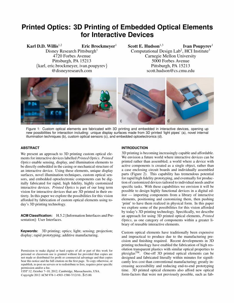
INTRODUCTION3D printing is becoming increasingly capable and affordable.We envision a future world where interactive devices can beprinted rather than assembled; a world where a device withactive components is created as a single object, rather thana case enclosing circuit boards and individually assembledparts (Figure 2). This capability has tremendous potentialfor rapid high fidelity prototyping, and eventually for produc-tion of customized devices tailored to individual needs and/orspecific tasks. With these capabilities we envision it will bepossible to design highly functional devices in a digital ed-itor — importing components from a library of interactiveelements, positioning and customizing them, then pushing‘print’ to have them realized in physical form. In this paperwe explore some of the possibilities for this vision affordedby today’s 3D printing technology. Specifically, we describean approach for using 3D printed optical elements, PrintedOptics, as one category of components within a greater li-brary of reusable interactive elements.
Custom optical elements have traditionally been expensiveand impractical to produce due to the manufacturing pre-cision and finishing required. Recent developments in 3Dprinting technology have enabled the fabrication of high res-olution transparent plastics with similar optical properties toplexiglasTM. One-off 3D printed optical elements can bedesigned and fabricated literally within minutes for signifi-cantly less cost than conventional manufacturing; greatly in-creasing accessibility and reducing end-to-end prototypingtime. 3D printed optical elements also afford new opticalform-factors that were not previously possible, such as fab-
a bFigure 2: We envision future interactive devices thatare 3D printed from individual layers (a) rather thanassembled from individual parts (b). These deviceswill be fabricated from multiple materials to form activefunctional components within a single 3D print.
ricating structures within other structures, printing multiplematerials within a single optical element, and combining me-chanical and optical structures in the same design.
Printed Optics opens up new possibilities for interaction.Display surfaces can be created on arbitrary shaped objectsusing 3D printed ‘light pipes’ (Figure 1a). Novel illumina-tion techniques allow the internal space within a 3D printedobject to be used for illumination and display purposes (Fig-ure 1b). Custom optical sensors can be 3D printed withthe structure of interactive devices to sense user input (Fig-ure 1c). Optoelectronic components can be completely en-closed inside optical elements to produce highly customiz-able and robust interactive devices (Figure 1d).
Our long term vision to digitally fabricate high fidelity, highlycustomized, ‘ready-to-go’ devices will be a powerful en-abling technology for HCI research. Although much of thisnovel technology is still in the research stage [7, 26, 33],the simplest forms of 3D printing are rapidly entering themainstream. A recent cover story in The Economist suggests3D printing is the manufacturing technology to “change theworld” [32]. A host of consumer-level 3D printing devicesare now available and the fundamental photopolymer print-ing technology behind Printed Optics has been demonstratedfor less than $200 parts cost [21]. It is reasonable to expectthat inexpensive optical 3D printers will be available to re-searchers in the very near future.
Using today’s 3D printing technology we aim to demonstratethat the design of optical systems for interactive devices canbe greatly enhanced. We present the following contributions:
1. A general approach for using 3D printed optical elements,Printed Optics, embedded in interactive devices to displayinformation and sense user input.
2. Techniques for displaying information using 3D printedoptical elements, including the use of 3D printed ‘lightpipes’ and internal air pockets.
3. Techniques for sensing user input with 3D printed opticalelements, including touch input with embedded sensors,mechanical displacement of 3D printed light guides, andmovement sensed along 3D printed mask patterns.
4. Example applications that demonstrate how Printed Opticscan be implemented and used in interactive devices.
In the remainder of this paper we introduce the technologythat enables us to create Printed Optics and outline the fab-rication process and its capabilities. We then describe fourcategories of fabrication techniques for Printed Optics: LightPipes, Internal Illumination, Sensing Mechanical Movement,and Embedded Components. We conclude with discussion oflimitations and future research directions. With the continu-ing emergence of 3D printing technology, we believe now isan ideal time to explore the unique capabilities of 3D printedoptical elements for interactive devices.
PRINTED OPTICS3D printing allows digital geometry to be rapidly fabricatedinto physical form with micron accuracy. Usable optical el-ements can be designed and simulated in software, then 3Dprinted from transparent material with surprising ease andaffordability. In this section of the paper we describe the fab-rication process for 3D printing optical elements and discussthe unique capabilities that this technology enables.
FabricationThe fabrication process begins with a digital geometric modelthat is converted into a series of slices to be physically fabri-cated layer-by-layer. 3D printing of optical quality materialstypically requires a photopolymer-based process. Each layeris fabricated in sequence by selectively exposing a liquidphotopolymer material to an ultra-violet (UV) light source,causing the material to cure into a solid state. Tradition-ally this has been achieved using ‘stereolithography’, wherea precise laser is traced through a vat of liquid photopolymer.Other approaches include controlled exposure to UV lightusing a projector, or physical deposition of liquid photopoly-mer in the presence of a UV light source. The fundamentalprocess of layer-by-layer fabrication with photopolymer ma-terials is common throughout each approach.
The range of photopolymer materials for 3D printing is rapidlyexpanding, with optical-quality transparent plastic, deformable‘rubber’, and biocompatible polymers available on the mar-ket. In this work we used an Objet Eden260V 3D printerand Objet VeroClear transparent material to fabricate opti-cal elements. VeroClear has similar optical properties toPoly(methyl methacrylate) (PMMA), commonly known asplexiglasTM, with a refractive index of 1.47 (650nm lightsource). Several other manufacturers also provide similartransparent materials, including DSM Somos’ Watershed XC11122 and 3D Systems’ Accura ClearVue.
The Objet Eden260V has a print resolution of 600 dpi (42 mi-crons) that is significantly higher than fused deposition mod-eling (FDM) 3D printers (e.g. Stratasys Dimension, Maker-Bot, or RepRap) that are typically around 100 dpi (254 mi-crons). High resolution printing allows the creation of visiblysmooth models without internal gaps. Model surfaces can befurther enhanced with a manual finishing process to achieveoptical clarity. This process consists of removing supportmaterial, sanding the surfaces with incrementally finer sand-paper, and then buffing.
Capabilities3D printing technology enables the fabrication of custom 3Dprinted optical elements with unique capabilities that are oth-erwise difficult to achieve.
Multiple Materials Optical elements can be fabricated thatcombine multiple chemically disparate materials in a singlemodel. 3D printers can often use at least two materials si-multaneously: model material and support material. Modelmaterial constitutes the main model itself and support mate-rial is used as a sacrificial material to provide structural sup-port under model overhangs and in hollow areas. Typically,support material is removed and disposed of once the print-ing process is finished, but can also be embedded inside themodel to guide, block, and diffuse light. A third ‘material’that can be utilized is air, hollow pockets of air can be usedto guide and reflect light in a similar manner to mirrors andbeamsplitters. Advanced 3D printers can combine opaquematerials with optical quality transparent materials to maskand block light.
Structures within Structures As the 3D printing process isperformed additively layer by layer, geometric structures canbe fabricated inside other structures to create optical ele-ments. For example, areas of transparent material can besurrounded by a material with a different refractive index,to transmit light from point to point using total internal re-flection (TIR) through the inside of a model. Opaque mate-rials printed within or around a transparent material can beused to block the transmittance of light from one section ofthe model to another. This can be used to seal internal com-partments and avoid optical crosstalk, or to minimize lightleakage from the model that may be distracting to the user.
Combined MechanicalOptical Design 3D printed opticalelements can be designed hand-in-hand with the mechani-cal design of a device. For example, optical elements can beintegrated into the body of a device to guide light through themodel, act as lenses, or house optical sensors. This combinedapproach enables a rich new space for prototyping physicalinterfaces with low-cost optical sensors, such as buttons, slid-ers, dials, and accelerometers. A single mechanical-opticaldesign can greatly reduce the number of individual parts andthe manual labor required for assembly. Optical fiber bun-dles, that are typically made up of 100s of individual fiberstrands, can be 3D printed in a single pass with a solid me-chanical structure.
3D printed optical elements currently have some limitations.These include issues of light transmission, surface finishing,clarity, and hollow area fabrication. We describe each ofthese limitations in the Discussion section. We now intro-duce four categories of fabrication techniques that demon-strate the wide range of uses for Printed Optics.
LIGHT PIPES‘Light pipes’ are 3D printed optical elements, similar to op-tical fiber, that can be used to guide light from point to point.Optical fiber has been used in interactive systems for bothdisplay [3, 10, 18] and sensing purposes [3, 12, 20, 23, 34,39]. Unlike conventional optical fiber, 3D printed light pipesallow arbitrary geometries to be created in software and then
fabricated in a single 3D print. Simply by changing softwareparameters, light pipes can be created with variable widths,rounded caps, and joints with other light pipes. In contrastconventional manufacturing requires considerable effort forindividual fiber optic strands to be mechanically assembled,fused/deformed with heat, or chemically bonded.
Internal light pipe geometry can be embedded inside a largermodel that has its own independent form-factor, such as acharacter (Figure 3), mobile device (Figure 4), or tangiblechess piece (Figure 5). As each light pipe can be preciselyfabricated at a given location, the process of light pipe rout-ing to avoid intersections becomes a well defined softwareproblem. One current limitation of 3D printed light pipesfabricated on the machine we have available is imperfectlight transmission with longer pipes or pipes that curve sig-nificantly. We outline the characteristics of this light loss inthe Discussion section. We have designed around this limita-tion to produce functional prototypes, but envision our tech-niques can be expanded using future 3D printers that are op-timized for optical performance.
Example ApplicationsWe outline several example applications that demonstrateuses for 3D printed light pipes.
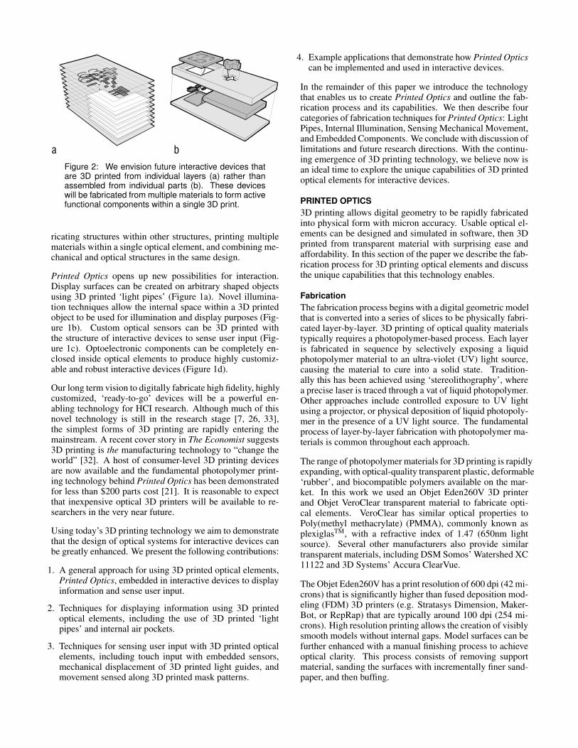
Mobile Projector Displays Mobile projectors have enabled arange of new interactive systems [6, 30, 38]. The small form-factor of mobile projectors makes them well suited to tangi-ble accessories that can map the projector display onto arbi-trary surfaces. We have developed a character accessory thatuses 3D printed light pipes to guide projected light throughthe inside of the model and onto outer surfaces. The charac-ter is 3D printed with a grid of �0.5 mm light pipes leadingfrom its feet to its eyes (Figure 3a). We paint the outer area ofthe character except for the ends of the light pipes. When thefeet are attached to a mobile projector, the character’s eyesbecome a display surface, responding to user interaction suchas sound or physical movement (Figure 3b).
Mobile Touch Sensing Sensing touch has become an im-portant part of interaction with many computing devices [16,17, 27]. 3D printing is well suited to implement touch [5] andgrasp [39] sensing on and around mobile devices. 3D printedlight pipes can sense touch by guiding light from arbitrary
3D PrintedLight Pipes
Mobile Projector
Tangible Display Surface
a b
Figure 3: A 3D printed mobile projector accessoryusing embedded light pipes (a) to map a projectedimage onto a characters eyes (b).
Linear SensorArray
Optical Fibers
IR Emitters
Touch Points
a bb
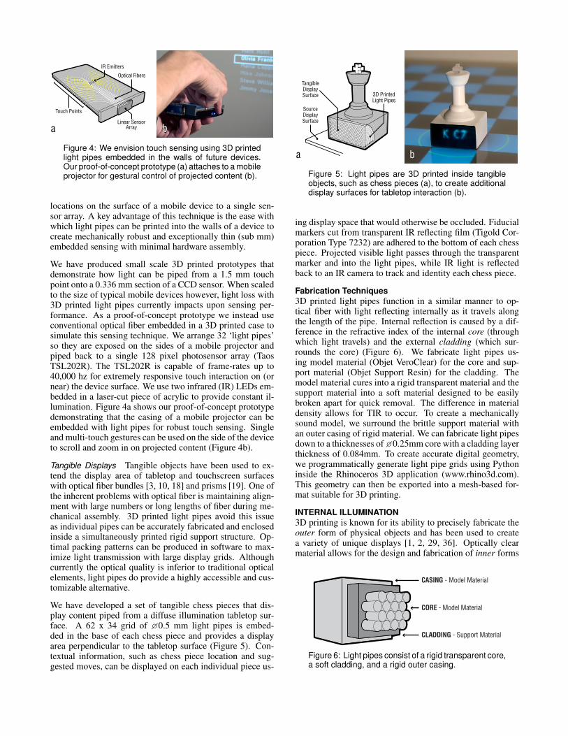
Figure 4: We envision touch sensing using 3D printedlight pipes embedded in the walls of future devices.Our proofofconcept prototype (a) attaches to a mobileprojector for gestural control of projected content (b).
locations on the surface of a mobile device to a single sen-sor array. A key advantage of this technique is the ease withwhich light pipes can be printed into the walls of a device tocreate mechanically robust and exceptionally thin (sub mm)embedded sensing with minimal hardware assembly.
We have produced small scale 3D printed prototypes thatdemonstrate how light can be piped from a 1.5 mm touchpoint onto a 0.336 mm section of a CCD sensor. When scaledto the size of typical mobile devices however, light loss with3D printed light pipes currently impacts upon sensing per-formance. As a proof-of-concept prototype we instead useconventional optical fiber embedded in a 3D printed case tosimulate this sensing technique. We arrange 32 ‘light pipes’so they are exposed on the sides of a mobile projector andpiped back to a single 128 pixel photosensor array (TaosTSL202R). The TSL202R is capable of frame-rates up to40,000 hz for extremely responsive touch interaction on (ornear) the device surface. We use two infrared (IR) LEDs em-bedded in a laser-cut piece of acrylic to provide constant il-lumination. Figure 4a shows our proof-of-concept prototypedemonstrating that the casing of a mobile projector can beembedded with light pipes for robust touch sensing. Singleand multi-touch gestures can be used on the side of the deviceto scroll and zoom in on projected content (Figure 4b).
Tangible Displays Tangible objects have been used to ex-tend the display area of tabletop and touchscreen surfaceswith optical fiber bundles [3, 10, 18] and prisms [19]. One ofthe inherent problems with optical fiber is maintaining align-ment with large numbers or long lengths of fiber during me-chanical assembly. 3D printed light pipes avoid this issueas individual pipes can be accurately fabricated and enclosedinside a simultaneously printed rigid support structure. Op-timal packing patterns can be produced in software to max-imize light transmission with large display grids. Althoughcurrently the optical quality is inferior to traditional opticalelements, light pipes do provide a highly accessible and cus-tomizable alternative.
We have developed a set of tangible chess pieces that dis-play content piped from a diffuse illumination tabletop sur-face. A 62 x 34 grid of �0.5 mm light pipes is embed-ded in the base of each chess piece and provides a displayarea perpendicular to the tabletop surface (Figure 5). Con-textual information, such as chess piece location and sug-gested moves, can be displayed on each individual piece us-
3D PrintedLight Pipes
SourceDisplaySurface
TangibleDisplaySurface
a b
Figure 5: Light pipes are 3D printed inside tangibleobjects, such as chess pieces (a), to create additionaldisplay surfaces for tabletop interaction (b).
ing display space that would otherwise be occluded. Fiducialmarkers cut from transparent IR reflecting film (Tigold Cor-poration Type 7232) are adhered to the bottom of each chesspiece. Projected visible light passes through the transparentmarker and into the light pipes, while IR light is reflectedback to an IR camera to track and identity each chess piece.
Fabrication Techniques3D printed light pipes function in a similar manner to op-tical fiber with light reflecting internally as it travels alongthe length of the pipe. Internal reflection is caused by a dif-ference in the refractive index of the internal core (throughwhich light travels) and the external cladding (which sur-rounds the core) (Figure 6). We fabricate light pipes us-ing model material (Objet VeroClear) for the core and sup-port material (Objet Support Resin) for the cladding. Themodel material cures into a rigid transparent material and thesupport material into a soft material designed to be easilybroken apart for quick removal. The difference in materialdensity allows for TIR to occur. To create a mechanicallysound model, we surround the brittle support material withan outer casing of rigid material. We can fabricate light pipesdown to a thicknesses of �0.25mm core with a cladding layerthickness of 0.084mm. To create accurate digital geometry,we programmatically generate light pipe grids using Pythoninside the Rhinoceros 3D application (www.rhino3d.com).This geometry can then be exported into a mesh-based for-mat suitable for 3D printing.
INTERNAL ILLUMINATION3D printing is known for its ability to precisely fabricate theouter form of physical objects and has been used to createa variety of unique displays [1, 2, 29, 36]. Optically clearmaterial allows for the design and fabrication of inner forms
CLADDING - Support Material
CASING - Model Material
CORE - Model Material
Figure 6: Light pipes consist of a rigid transparent core,a soft cladding, and a rigid outer casing.
Sheet
Tube
Dot
a b
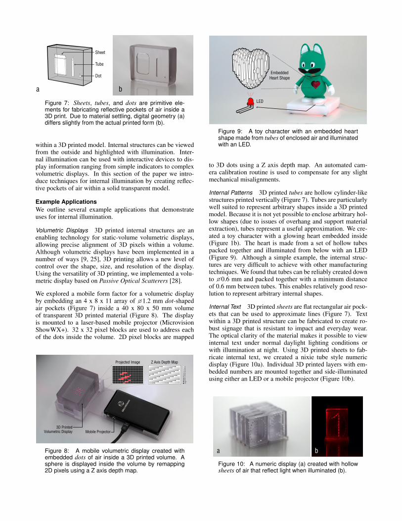
Figure 7: Sheets, tubes, and dots are primitive elements for fabricating reflective pockets of air inside a3D print. Due to material settling, digital geometry (a)differs slightly from the actual printed form (b).
within a 3D printed model. Internal structures can be viewedfrom the outside and highlighted with illumination. Inter-nal illumination can be used with interactive devices to dis-play information ranging from simple indicators to complexvolumetric displays. In this section of the paper we intro-duce techniques for internal illumination by creating reflec-tive pockets of air within a solid transparent model.
Example ApplicationsWe outline several example applications that demonstrateuses for internal illumination.
Volumetric Displays 3D printed internal structures are anenabling technology for static-volume volumetric displays,allowing precise alignment of 3D pixels within a volume.Although volumetric displays have been implemented in anumber of ways [9, 25], 3D printing allows a new level ofcontrol over the shape, size, and resolution of the display.Using the versatility of 3D printing, we implemented a volu-metric display based on Passive Optical Scatterers [28].
We explored a mobile form factor for a volumetric displayby embedding an 4 x 8 x 11 array of �1.2 mm dot-shapedair pockets (Figure 7) inside a 40 x 80 x 50 mm volumeof transparent 3D printed material (Figure 8). The displayis mounted to a laser-based mobile projector (MicrovisionShowWX+). 32 x 32 pixel blocks are used to address eachof the dots inside the volume. 2D pixel blocks are mapped
Mobile Projector
Projected Image Z Axis Depth Map
3D PrintedVolumetric Display
1234567891011
Figure 8: A mobile volumetric display created withembedded dots of air inside a 3D printed volume. Asphere is displayed inside the volume by remapping2D pixels using a Z axis depth map.
LED
EmbeddedHeart Shape
Figure 9: A toy character with an embedded heartshape made from tubes of enclosed air and illuminatedwith an LED.
to 3D dots using a Z axis depth map. An automated cam-era calibration routine is used to compensate for any slightmechanical misalignments.
Internal Patterns 3D printed tubes are hollow cylinder-likestructures printed vertically (Figure 7). Tubes are particularlywell suited to represent arbitrary shapes inside a 3D printedmodel. Because it is not yet possible to enclose arbitrary hol-low shapes (due to issues of overhang and support materialextraction), tubes represent a useful approximation. We cre-ated a toy character with a glowing heart embedded inside(Figure 1b). The heart is made from a set of hollow tubespacked together and illuminated from below with an LED(Figure 9). Although a simple example, the internal struc-tures are very difficult to achieve with other manufacturingtechniques. We found that tubes can be reliably created downto �0.6 mm and packed together with a minimum distanceof 0.6 mm between tubes. This enables relatively good reso-lution to represent arbitrary internal shapes.
Internal Text 3D printed sheets are flat rectangular air pock-ets that can be used to approximate lines (Figure 7). Textwithin a 3D printed structure can be fabricated to create ro-bust signage that is resistant to impact and everyday wear.The optical clarity of the material makes it possible to viewinternal text under normal daylight lighting conditions orwith illumination at night. Using 3D printed sheets to fab-ricate internal text, we created a nixie tube style numericdisplay (Figure 10a). Individual 3D printed layers with em-bedded numbers are mounted together and side-illuminatedusing either an LED or a mobile projector (Figure 10b).
a b
Figure 10: A numeric display (a) created with hollowsheets of air that reflect light when illuminated (b).
Fabrication TechniquesBy creating enclosed pockets of air within a solid transpar-ent model, light intersects with these air pockets and is trans-mitted or reflected depending on the angle of incidence. Bycarefully designing the geometry of the air pockets light canbe guided internally within the model or externally out to-wards the users eye. Air pockets can be created using 3Dprinters that deposit small beads of material layer-by-layerto build up a model. As individual beads of material are de-posited, they must have a supporting surface beneath themor they fall down with gravity. However, a small amountof step-over (overhang) from layer to layer allows for hol-low areas to be slowly closed. In practice a step-over angleequivalent to 14◦from vertical allows air pockets to be reli-ably closed with minimum shape distortion. Greater step-over angles cause the material to fall into the air pocket andslowly raise the air pocket location vertically or fill it en-tirely. Figure 7 shows a series of primitive elements that canbe fabricated from air pockets. The digital geometry sent tothe printer (left) differs from the actual air pocket shape fab-ricated (right). This difference is due to beads of materialsettling without direct support structure during the fabrica-tion process. To programmatically generate patterns from thedot, tube, and sheet primitives, we use the Grasshopper envi-ronment (www.grasshopper3d.com) inside Rhinoceros. Thisallows primitive elements to be mapped to lines, enclosedwithin solids, or aligned with illumination sources.
SENSING MECHANICAL MOVEMENTOptical sensing of mechanical movement has been achievedin a number of form-factors [8, 15, 31, 35, 37]. Our approachuses 3D printing to create custom optical sensing embeddedin interactive devices. We use low-cost IR emitter/receiverpairs, to sense common user inputs such as rotation, push,linear movement, and acceleration. Our approach offers sev-eral benefits. Firstly, custom sensors can be designed andprototyped with minimal effort. 3D printed sensors allowconvenient, fast, accurate, and repeatable sensor fabrication.In many cases only a generic IR emitter-receiver pair are re-quired on the electronics side. Secondly, custom sensors canbe embedded in the casing or mechanical structure of a de-vice. This enables sensing of user input through the walls ofa device, greatly simplifies hardware assembly, and producesrobust high fidelity prototypes.
Example ApplicationsWe introduce example applications that demonstrate how 3Dprinted optical elements can be used to detect common me-chanical movements.
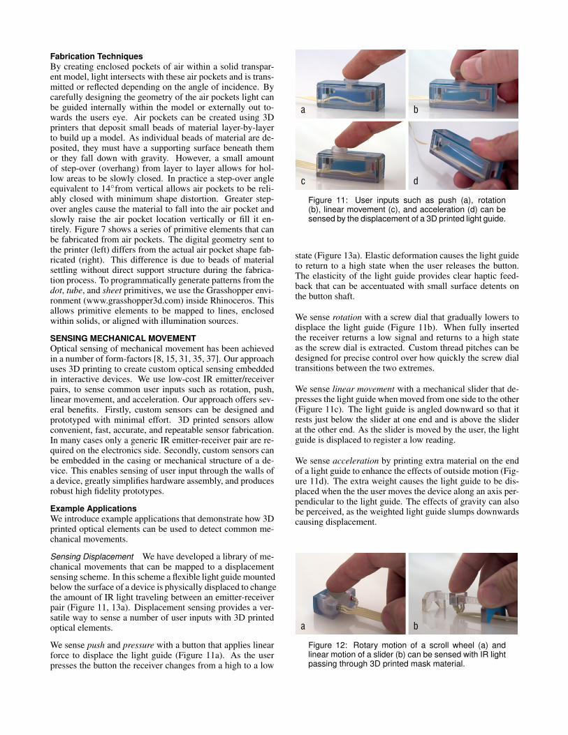
Sensing Displacement We have developed a library of me-chanical movements that can be mapped to a displacementsensing scheme. In this scheme a flexible light guide mountedbelow the surface of a device is physically displaced to changethe amount of IR light traveling between an emitter-receiverpair (Figure 11, 13a). Displacement sensing provides a ver-satile way to sense a number of user inputs with 3D printedoptical elements.
We sense push and pressure with a button that applies linearforce to displace the light guide (Figure 11a). As the userpresses the button the receiver changes from a high to a low
a b
c d
Figure 11: User inputs such as push (a), rotation(b), linear movement (c), and acceleration (d) can besensed by the displacement of a 3D printed light guide.
state (Figure 13a). Elastic deformation causes the light guideto return to a high state when the user releases the button.The elasticity of the light guide provides clear haptic feed-back that can be accentuated with small surface detents onthe button shaft.
We sense rotation with a screw dial that gradually lowers todisplace the light guide (Figure 11b). When fully insertedthe receiver returns a low signal and returns to a high stateas the screw dial is extracted. Custom thread pitches can bedesigned for precise control over how quickly the screw dialtransitions between the two extremes.
We sense linear movement with a mechanical slider that de-presses the light guide when moved from one side to the other(Figure 11c). The light guide is angled downward so that itrests just below the slider at one end and is above the sliderat the other end. As the slider is moved by the user, the lightguide is displaced to register a low reading.
We sense acceleration by printing extra material on the endof a light guide to enhance the effects of outside motion (Fig-ure 11d). The extra weight causes the light guide to be dis-placed when the the user moves the device along an axis per-pendicular to the light guide. The effects of gravity can alsobe perceived, as the weighted light guide slumps downwardscausing displacement.
a b
Figure 12: Rotary motion of a scroll wheel (a) andlinear motion of a slider (b) can be sensed with IR lightpassing through 3D printed mask material.
ButtonIR Receiver
Light Guide
HIGH
STA
TELO
W S
TATE
HIGH
STA
TELO
W S
TATE
IR Emitter
Mask Material
Mask Material
IR Receiver IR EmitterScroll Wheel
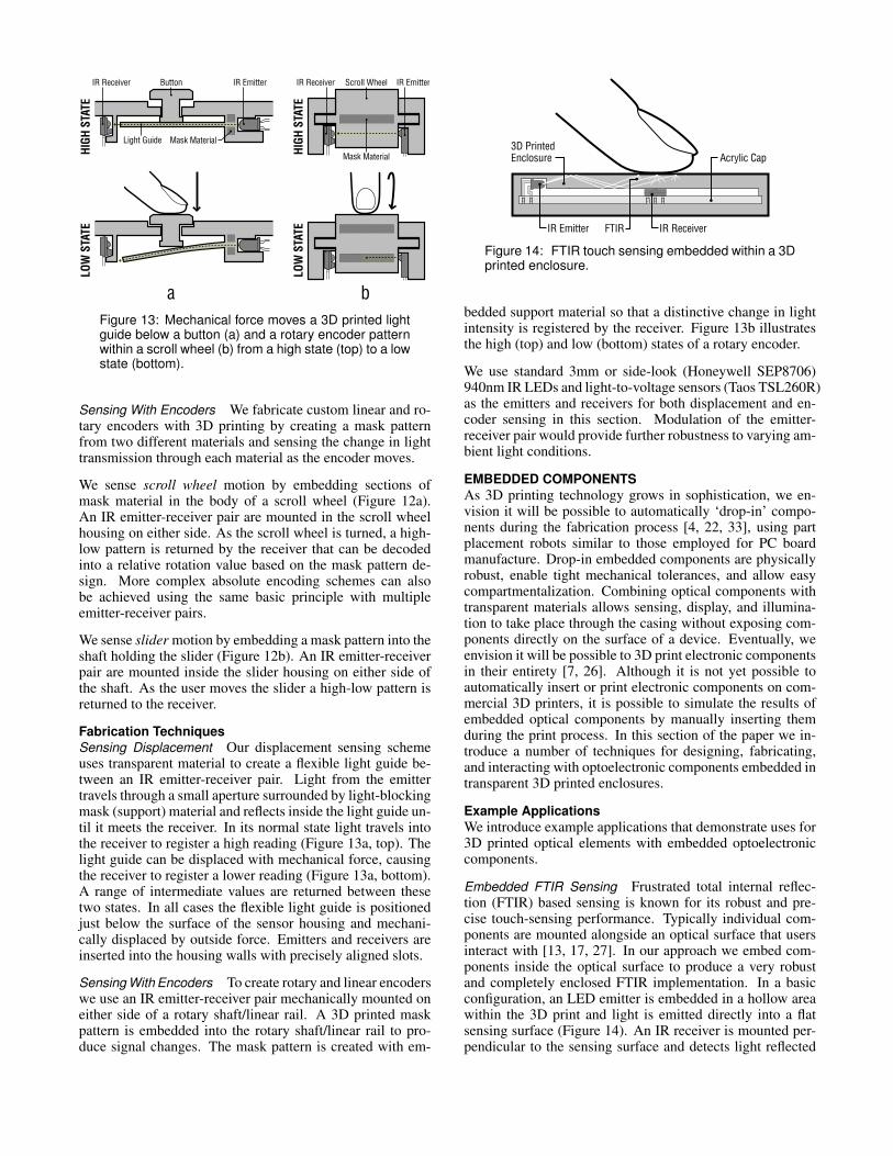
a bFigure 13: Mechanical force moves a 3D printed lightguide below a button (a) and a rotary encoder patternwithin a scroll wheel (b) from a high state (top) to a lowstate (bottom).
Sensing With Encoders We fabricate custom linear and ro-tary encoders with 3D printing by creating a mask patternfrom two different materials and sensing the change in lighttransmission through each material as the encoder moves.
We sense scroll wheel motion by embedding sections ofmask material in the body of a scroll wheel (Figure 12a).An IR emitter-receiver pair are mounted in the scroll wheelhousing on either side. As the scroll wheel is turned, a high-low pattern is returned by the receiver that can be decodedinto a relative rotation value based on the mask pattern de-sign. More complex absolute encoding schemes can alsobe achieved using the same basic principle with multipleemitter-receiver pairs.
We sense slider motion by embedding a mask pattern into theshaft holding the slider (Figure 12b). An IR emitter-receiverpair are mounted inside the slider housing on either side ofthe shaft. As the user moves the slider a high-low pattern isreturned to the receiver.
Fabrication TechniquesSensing Displacement Our displacement sensing schemeuses transparent material to create a flexible light guide be-tween an IR emitter-receiver pair. Light from the emittertravels through a small aperture surrounded by light-blockingmask (support) material and reflects inside the light guide un-til it meets the receiver. In its normal state light travels intothe receiver to register a high reading (Figure 13a, top). Thelight guide can be displaced with mechanical force, causingthe receiver to register a lower reading (Figure 13a, bottom).A range of intermediate values are returned between thesetwo states. In all cases the flexible light guide is positionedjust below the surface of the sensor housing and mechani-cally displaced by outside force. Emitters and receivers areinserted into the housing walls with precisely aligned slots.
Sensing With Encoders To create rotary and linear encoderswe use an IR emitter-receiver pair mechanically mounted oneither side of a rotary shaft/linear rail. A 3D printed maskpattern is embedded into the rotary shaft/linear rail to pro-duce signal changes. The mask pattern is created with em-
IR ReceiverIR Emitter
3D Printed Enclosure
FTIR
Acrylic Cap
Figure 14: FTIR touch sensing embedded within a 3Dprinted enclosure.
bedded support material so that a distinctive change in lightintensity is registered by the receiver. Figure 13b illustratesthe high (top) and low (bottom) states of a rotary encoder.
We use standard 3mm or side-look (Honeywell SEP8706)940nm IR LEDs and light-to-voltage sensors (Taos TSL260R)as the emitters and receivers for both displacement and en-coder sensing in this section. Modulation of the emitter-receiver pair would provide further robustness to varying am-bient light conditions.
EMBEDDED COMPONENTSAs 3D printing technology grows in sophistication, we en-vision it will be possible to automatically ‘drop-in’ compo-nents during the fabrication process [4, 22, 33], using partplacement robots similar to those employed for PC boardmanufacture. Drop-in embedded components are physicallyrobust, enable tight mechanical tolerances, and allow easycompartmentalization. Combining optical components withtransparent materials allows sensing, display, and illumina-tion to take place through the casing without exposing com-ponents directly on the surface of a device. Eventually, weenvision it will be possible to 3D print electronic componentsin their entirety [7, 26]. Although it is not yet possible toautomatically insert or print electronic components on com-mercial 3D printers, it is possible to simulate the results ofembedded optical components by manually inserting themduring the print process. In this section of the paper we in-troduce a number of techniques for designing, fabricating,and interacting with optoelectronic components embedded intransparent 3D printed enclosures.
Example ApplicationsWe introduce example applications that demonstrate uses for3D printed optical elements with embedded optoelectroniccomponents.
Embedded FTIR Sensing Frustrated total internal reflec-tion (FTIR) based sensing is known for its robust and pre-cise touch-sensing performance. Typically individual com-ponents are mounted alongside an optical surface that usersinteract with [13, 17, 27]. In our approach we embed com-ponents inside the optical surface to produce a very robustand completely enclosed FTIR implementation. In a basicconfiguration, an LED emitter is embedded in a hollow areawithin the 3D print and light is emitted directly into a flatsensing surface (Figure 14). An IR receiver is mounted per-pendicular to the sensing surface and detects light reflected
3D Printed Cap
FTIR Touch Surface
IR Emitter
IR Receiver
3D Printed 4-Way Reflector
Acrylic Cap Insert
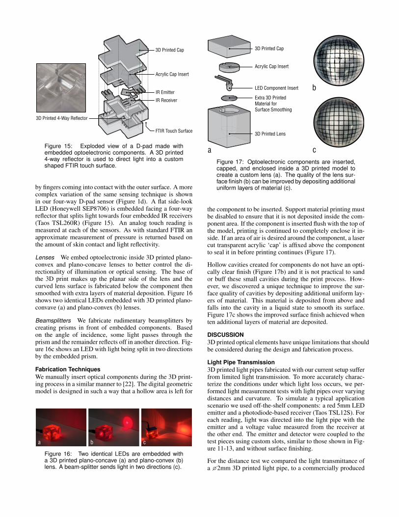
Figure 15: Exploded view of a Dpad made withembedded optoelectronic components. A 3D printed4way reflector is used to direct light into a customshaped FTIR touch surface.
by fingers coming into contact with the outer surface. A morecomplex variation of the same sensing technique is shownin our four-way D-pad sensor (Figure 1d). A flat side-lookLED (Honeywell SEP8706) is embedded facing a four-wayreflector that splits light towards four embedded IR receivers(Taos TSL260R) (Figure 15). An analog touch reading ismeasured at each of the sensors. As with standard FTIR anapproximate measurement of pressure is returned based onthe amount of skin contact and light reflectivity.
Lenses We embed optoelectronic inside 3D printed plano-convex and plano-concave lenses to better control the di-rectionality of illumination or optical sensing. The base ofthe 3D print makes up the planar side of the lens and thecurved lens surface is fabricated below the component thensmoothed with extra layers of material deposition. Figure 16shows two identical LEDs embedded with 3D printed plano-convave (a) and plano-convex (b) lenses.
Beamsplitters We fabricate rudimentary beamsplitters bycreating prisms in front of embedded components. Basedon the angle of incidence, some light passes through theprism and the remainder reflects off in another direction. Fig-ure 16c shows an LED with light being split in two directionsby the embedded prism.
Fabrication TechniquesWe manually insert optical components during the 3D print-ing process in a similar manner to [22]. The digital geometricmodel is designed in such a way that a hollow area is left for
a b c
Figure 16: Two identical LEDs are embedded witha 3D printed planoconcave (a) and planoconvex (b)lens. A beamsplitter sends light in two directions (c).
3D Printed Cap
Acrylic Cap Insert
LED Component Insert
Extra 3D PrintedMaterial for Surface Smoothing
3D Printed Lens
a
b
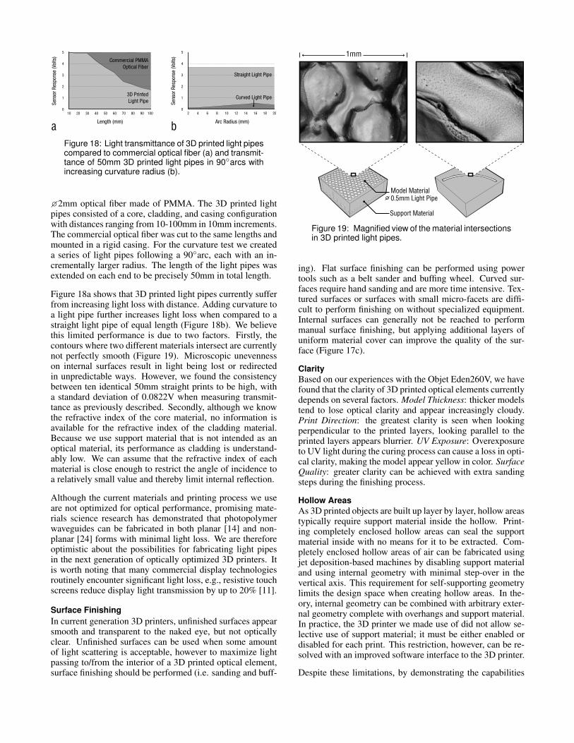
cFigure 17: Optoelectronic components are inserted,capped, and enclosed inside a 3D printed model tocreate a custom lens (a). The quality of the lens surface finish (b) can be improved by depositing additionaluniform layers of material (c).
the component to be inserted. Support material printing mustbe disabled to ensure that it is not deposited inside the com-ponent area. If the component is inserted flush with the top ofthe model, printing is continued to completely enclose it in-side. If an area of air is desired around the component, a lasercut transparent acrylic ‘cap’ is affixed above the componentto seal it in before printing continues (Figure 17).
Hollow cavities created for components do not have an opti-cally clear finish (Figure 17b) and it is not practical to sandor buff these small cavities during the print process. How-ever, we discovered a unique technique to improve the sur-face quality of cavities by depositing additional uniform lay-ers of material. This material is deposited from above andfalls into the cavity in a liquid state to smooth its surface.Figure 17c shows the improved surface finish achieved whenten additional layers of material are deposited.
DISCUSSION3D printed optical elements have unique limitations that shouldbe considered during the design and fabrication process.
Light Pipe Transmission3D printed light pipes fabricated with our current setup sufferfrom limited light transmission. To more accurately charac-terize the conditions under which light loss occurs, we per-formed light measurement tests with light pipes over varyingdistances and curvature. To simulate a typical applicationscenario we used off-the-shelf components: a red 5mm LEDemitter and a photodiode-based receiver (Taos TSL12S). Foreach reading, light was directed into the light pipe with theemitter and a voltage value measured from the receiver atthe other end. The emitter and detector were coupled to thetest pieces using custom slots, similar to those shown in Fig-ure 11-13, and without surface finishing.
For the distance test we compared the light transmittance ofa �2mm 3D printed light pipe, to a commercially produced
a b
0
1
2
3
4
5
10 20 30 40 50 60 70 80 90 100
Length (mm)
Sens
or R
espo
nse
(Vol
ts)
3D PrintedLight Pipe
Commercial PMMAOptical Fiber
0
1
2
3
4
5
2 4 6 8 10 12 14 16 18 20
Arc Radius (mm)
Sens
or R
espo
nse
(Vol
ts)
Straight Light Pipe
Curved Light Pipe
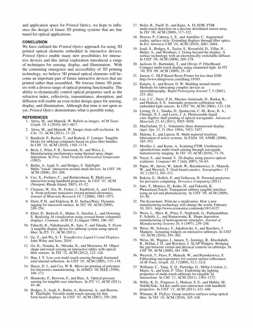
Figure 18: Light transmittance of 3D printed light pipescompared to commercial optical fiber (a) and transmittance of 50mm 3D printed light pipes in 90◦arcs withincreasing curvature radius (b).
�2mm optical fiber made of PMMA. The 3D printed lightpipes consisted of a core, cladding, and casing configurationwith distances ranging from 10-100mm in 10mm increments.The commercial optical fiber was cut to the same lengths andmounted in a rigid casing. For the curvature test we createda series of light pipes following a 90◦arc, each with an in-crementally larger radius. The length of the light pipes wasextended on each end to be precisely 50mm in total length.
Figure 18a shows that 3D printed light pipes currently sufferfrom increasing light loss with distance. Adding curvature toa light pipe further increases light loss when compared to astraight light pipe of equal length (Figure 18b). We believethis limited performance is due to two factors. Firstly, thecontours where two different materials intersect are currentlynot perfectly smooth (Figure 19). Microscopic unevennesson internal surfaces result in light being lost or redirectedin unpredictable ways. However, we found the consistencybetween ten identical 50mm straight prints to be high, witha standard deviation of 0.0822V when measuring transmit-tance as previously described. Secondly, although we knowthe refractive index of the core material, no information isavailable for the refractive index of the cladding material.Because we use support material that is not intended as anoptical material, its performance as cladding is understand-ably low. We can assume that the refractive index of eachmaterial is close enough to restrict the angle of incidence toa relatively small value and thereby limit internal reflection.
Although the current materials and printing process we useare not optimized for optical performance, promising mate-rials science research has demonstrated that photopolymerwaveguides can be fabricated in both planar [14] and non-planar [24] forms with minimal light loss. We are thereforeoptimistic about the possibilities for fabricating light pipesin the next generation of optically optimized 3D printers. Itis worth noting that many commercial display technologiesroutinely encounter significant light loss, e.g., resistive touchscreens reduce display light transmission by up to 20% [11].
Surface FinishingIn current generation 3D printers, unfinished surfaces appearsmooth and transparent to the naked eye, but not opticallyclear. Unfinished surfaces can be used when some amountof light scattering is acceptable, however to maximize lightpassing to/from the interior of a 3D printed optical element,surface finishing should be performed (i.e. sanding and buff-
1mm
Model Material0.5mm Light Pipe
Support Material
Figure 19: Magnified view of the material intersectionsin 3D printed light pipes.
ing). Flat surface finishing can be performed using powertools such as a belt sander and buffing wheel. Curved sur-faces require hand sanding and are more time intensive. Tex-tured surfaces or surfaces with small micro-facets are diffi-cult to perform finishing on without specialized equipment.Internal surfaces can generally not be reached to performmanual surface finishing, but applying additional layers ofuniform material cover can improve the quality of the sur-face (Figure 17c).
ClarityBased on our experiences with the Objet Eden260V, we havefound that the clarity of 3D printed optical elements currentlydepends on several factors. Model Thickness: thicker modelstend to lose optical clarity and appear increasingly cloudy.Print Direction: the greatest clarity is seen when lookingperpendicular to the printed layers, looking parallel to theprinted layers appears blurrier. UV Exposure: Overexposureto UV light during the curing process can cause a loss in opti-cal clarity, making the model appear yellow in color. SurfaceQuality: greater clarity can be achieved with extra sandingsteps during the finishing process.
Hollow AreasAs 3D printed objects are built up layer by layer, hollow areastypically require support material inside the hollow. Print-ing completely enclosed hollow areas can seal the supportmaterial inside with no means for it to be extracted. Com-pletely enclosed hollow areas of air can be fabricated usingjet deposition-based machines by disabling support materialand using internal geometry with minimal step-over in thevertical axis. This requirement for self-supporting geometrylimits the design space when creating hollow areas. In the-ory, internal geometry can be combined with arbitrary exter-nal geometry complete with overhangs and support material.In practice, the 3D printer we made use of did not allow se-lective use of support material; it must be either enabled ordisabled for each print. This restriction, however, can be re-solved with an improved software interface to the 3D printer.
Despite these limitations, by demonstrating the capabilities
and application space for Printed Optics, we hope to influ-ence the design of future 3D printing systems that are finetuned for optical applications.
CONCLUSIONWe have outlined the Printed Optics approach for using 3Dprinted optical elements embedded in interactive devices.Printed Optics enable many new possibilities for interac-tive devices and this initial exploration introduced a rangeof techniques for sensing, display, and illumination. Withthe continuing emergence and accessibility of 3D printingtechnology, we believe 3D printed optical elements will be-come an important part of future interactive devices that areprinted rather than assembled. We foresee future 3D print-ers with a diverse range of optical printing functionality. Theability to dynamically control optical properties such as therefractive index, reflectivity, transmittance, absorption, anddiffusion will enable an even richer design space for sensing,display, and illumination. Although that time is not upon usyet, Printed Optics demonstrates what is possible today.
REFERENCES1. Alexa, M., and Matusik, W. Reliefs as images. ACM Trans.
Graph. 29, 4 (2010), 60:1–60:7.2. Alexa, M., and Matusik, W. Images from self-occlusion. In
CAe ’11, ACM (2011), 17–24.3. Baudisch, P., Becker, T., and Rudeck, F. Lumino: Tangible
blocks for tabletop computers based on glass fiber bundles.In CHI ’10, ACM (2010), 1165–1174.
4. Beck, J., Prinz, F. B., Siewiorek, D., and Weiss, L.Manufacturing mechatronics using thermal spray shapedeposition. In Proc. Solid Freeform Fabrication Symposium(1992).
5. Butler, A., Izadi, S., and Hodges, S. SideSight:Multi-”touch” interaction around small devices. In UIST ’08,ACM (2008), 201–204.
6. Cao, X., Forlines, C., and Balakrishnan, R. Multi-userinteraction using handheld projectors. In UIST ’07, ACM(Newport, Rhode Island, 2007), 43–52.
7. Clemens, W., Fix, W., Ficker, J., Knobloch, A., and Ullmann,A. From polymer transistors toward printed electronics.Journal of Materials Research 19, 7 (2004), 1963–1973.
8. Dietz, P. H., and Eidelson, B. D. SurfaceWare: Dynamictagging for microsoft surface. In TEI ’09, ACM (2009),249–254.
9. Ebert, D., Bedwell, E., Maher, S., Smoliar, L., and Downing,E. Realizing 3d visualization using crossed-beam volumetricdisplays. Commun. ACM 42, 8 (August 1999), 100–107.
10. Fukuchi, K., Nakabayashi, R., Sato, T., and Takada, Y. Ficon:A tangible display device for tabletop system using opticalfiber. In ITS ’11, ACM (2011).
11. Ge, Z., and Wu, S.-T. Transflective Liquid Crystal Displays.John Wiley and Sons, 2010.
12. Go, K., Nonaka, K., Mitsuke, K., and Morisawa, M. Objectshape and touch sensing on interactive tables with opticalfiber sensors. In TEI ’12, ACM (2012), 123–126.
13. Han, J. Y. Low-cost multi-touch sensing through frustratedtotal internal reflection. In UIST ’05, ACM (2005), 115–118.
14. Hayes, D. J., and Cox, W. R. Micro-jet printing of polymersfor electronics manufacturing. In ADHES ’98, IEEE (1998),168–173.
15. Hennecke, F., Berwein, F., and Butz, A. Optical pressuresensing for tangible user interfaces. In ITS ’11, ACM (2011),45–48.
16. Hodges, S., Izadi, S., Butler, A., Rrustemi, A., and Buxton,B. ThinSight: Versatile multi-touch sensing for thinform-factor displays. In UIST ’07, ACM (2007), 259–268.
17. Hofer, R., Naeff, D., and Kunz, A. FLATIR: FTIRmulti-touch detection on a discrete distributed sensor array.In TEI ’09, ACM (2009), 317–322.
18. Hoover, P., Cabrera, L. E., and Aumiller, C. Augmentedreality, surface style: Extending displays through fiber optics.In Ext. Abstracts CHI ’10, ACM (2010), 2681–2684.
19. Izadi, S., Hodges, S., Taylor, S., Rosenfeld, D., Villar, N.,Butler, A., and Westhues, J. Going beyond the display: Asurface technology with an electronically switchable diffuser.In UIST ’08, ACM (2008), 269–278.
20. Jackson, D., Bartindale, T., and Olivier, P. FiberBoard:Compact multi-touch display using channeled light. In ITS’09, ITS ’09, ACM (2009), 25–28.
21. Jansen, C. DLP-Based Resin Printer for less than $200.http://www.thingiverse.com/thing:19185.
22. Kataria, A., and Rosen, D. W. Building around inserts:Methods for fabricating complex devices instereolithography. Rapid Prototyping Journal 7, 5 (2001),253–262.
23. Lee, J. C., Dietz, P. H., Maynes-Aminzade, D., Raskar, R.,and Hudson, S. E. Automatic projector calibration withembedded light sensors. In UIST ’04, ACM (2004), 123–126.
24. Lorang, D. J., Tanaka, D., Spadaccini, C. M., Rose, K. A.,Cherepy, N. J., and Lewis, J. A. Photocurable liquidcore–fugitive shell printing of optical waveguides. AdvancedMaterials 23, 43 (2011), 5055–5058.
25. MacFarlane, D. L. Volumetric three-dimensional display.Appl. Opt. 33, 31 (Nov 1994), 7453–7457.
26. Malone, E., and Lipson, H. Multi-material freeformfabrication of active systems. In ESDA ’08, ASME (2008),345–353.
27. Moeller, J., and Kerne, A. Scanning FTIR: Unobtrusiveoptoelectronic multi-touch sensing through waveguidetransmissivity imaging. In TEI ’10, ACM (2010), 73–76.
28. Nayar, S., and Anand, V. 3D display using passive opticalscatterers. Computer 40, 7 (July 2007), 54–63.
29. Papas, M., Jarosz, W., Jakob, W., Rusinkiewicz, S., Matusik,W., and Weyrich, T. Goal-based caustics. Eurographics ’1130, 2 (2011), 503–511.
30. Rukzio, E., Hollels, P., and Gellersen, H. Personal projectorsfor pervasive computing. Pervasive Computing (2011).
31. Sato, T., Mamiya, H., Koike, H., and Fukuchi, K.PhotoelasticTouch: Transparent rubbery tangible interfaceusing an lcd and photoelasticity. In UIST ’09, ACM (2009),43–50.
32. The Economist. Print me a stradivarius: How a newmanufacturing technology will change the world, February10, 2011. http://www.economist.com/node/18114327.
33. Weiss, L., Merz, R., Prinz, F., Neplotnik, G., Padmanabhan,P., Schultz, L., and Ramaswami, K. Shape depositionmanufacturing of heterogeneous structures. Journal ofManufacturing Systems 16, 4 (1997), 239–248.
34. Weiss, M., Schwarz, F., Jakubowski, S., and Borchers, J.Madgets: Actuating widgets on interactive tabletops. In UIST’10, ACM (2010), 293–302.
35. Weiss, M., Wagner, J., Jansen, Y., Jennings, R., Khoshabeh,R., Hollan, J. D., and Borchers, J. SLAP Widgets: Bridgingthe gap between virtual and physical controls on tabletops. InCHI ’09, ACM (2009), 481–490.
36. Weyrich, T., Peers, P., Matusik, W., and Rusinkiewicz, S.Fabricating microgeometry for custom surface reflectance.ACM Trans. Graph. 28, 3 (2009), 32:1–32:6.
37. Williams, C., Yang, X. D., Partridge, G., Millar-Usiskin, J.,Major, A., and Irani, P. TZee: Exploiting the lightingproperties of multi-touch tabletops for tangible 3dinteractions. In CHI ’11, ACM (2011), 1363–1372.
38. Willis, K. D., Poupyrev, I., Hudson, S. E., and Mahler, M.SideBySide: Ad-hoc multi-user interaction with handheldprojectors. In UIST ’11, ACM (2011), 431–440.
39. Wimmer, R. FlyEye: Grasp-sensitive surfaces using opticalfiber. In TEI ’10, ACM (2010), 245–248.