Embed Size (px)
Citation preview

What is Arduino? What can I make with Arduino? Getting started Digital Inputs and Outputs Analog Inputs and Outputs Motors Putting It All Together Summary
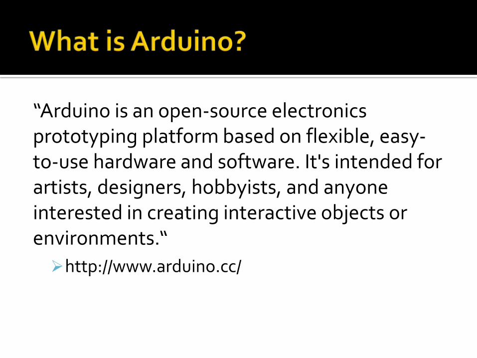
“Arduino is an open-source electronics prototyping platform based on flexible, easy-to-use hardware and software. It's intended for artists, designers, hobbyists, and anyone interested in creating interactive objects or environments.“
http://www.arduino.cc/

A programming environment for Windows, Mac or Linux
A hardware specification Software libraries that can be reused in your
programs
All for FREE!*
* Except the price of the hardware you purchase
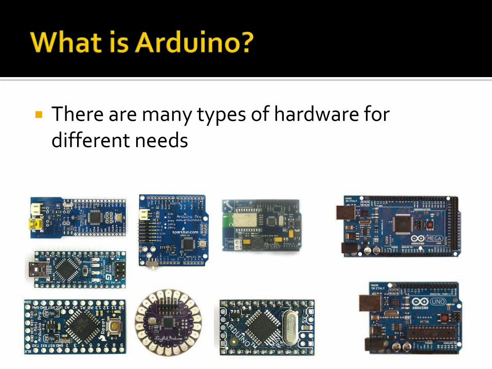
There are many types of hardware for different needs
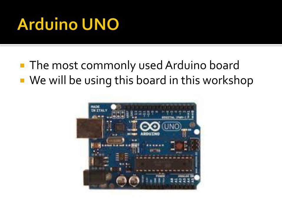
The most commonly used Arduino board We will be using this board in this workshop
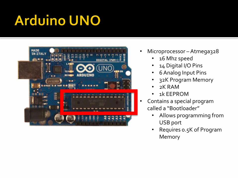
• Microprocessor – Atmega328• 16 Mhz speed• 14 Digital I/O Pins• 6 Analog Input Pins• 32K Program Memory• 2K RAM• 1k EEPROM
• Contains a special program called a “Bootloader”• Allows programming from
USB port• Requires 0.5K of Program
Memory
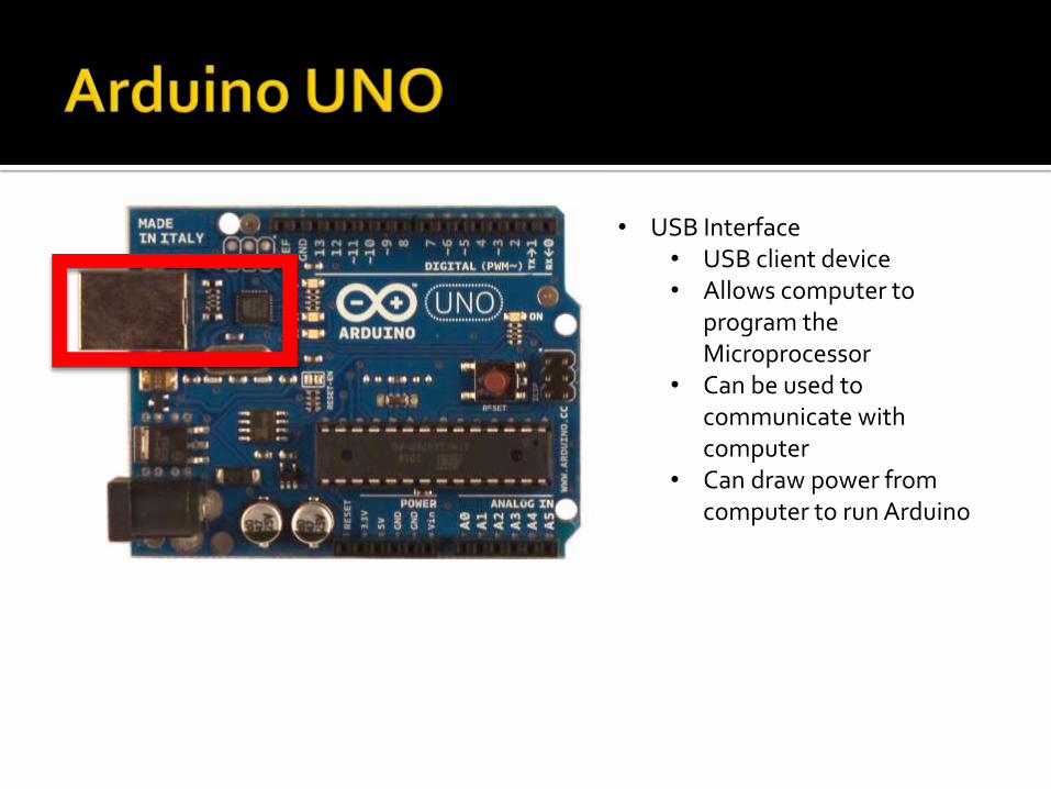
• USB Interface• USB client device• Allows computer to
program the Microprocessor
• Can be used to communicate with computer
• Can draw power from computer to run Arduino
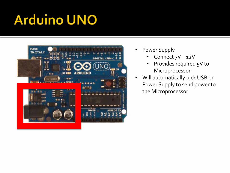
• Power Supply• Connect 7V – 12V• Provides required 5V to
Microprocessor• Will automatically pick USB or
Power Supply to send power to the Microprocessor
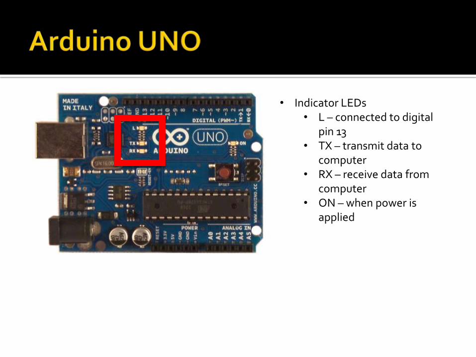
• Indicator LEDs• L – connected to digital
pin 13• TX – transmit data to
computer• RX – receive data from
computer• ON – when power is
applied
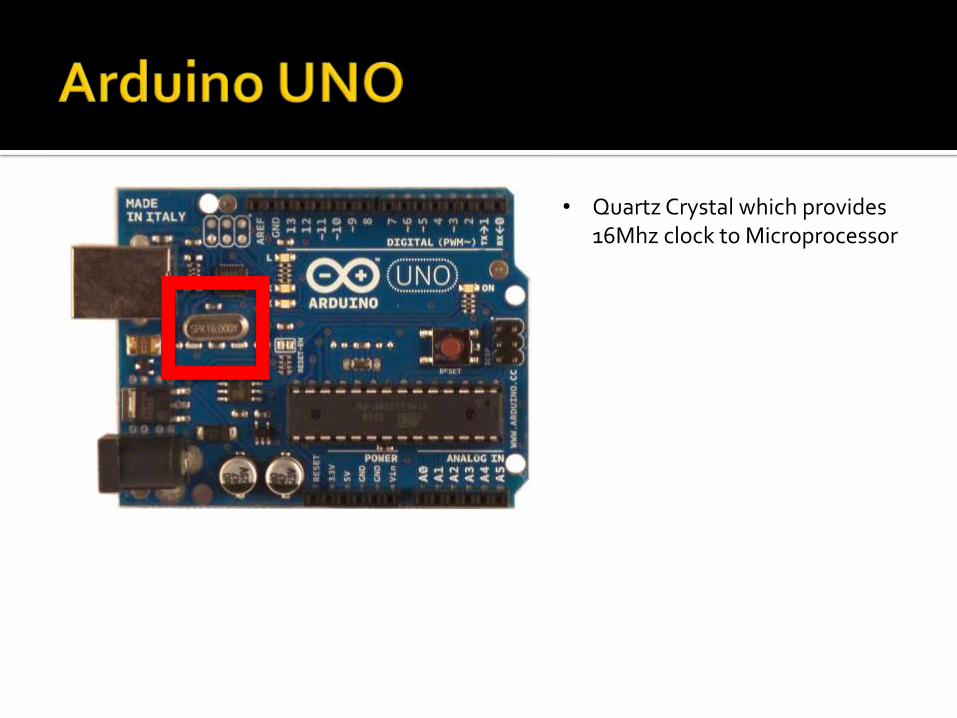
• Quartz Crystal which provides 16Mhz clock to Microprocessor
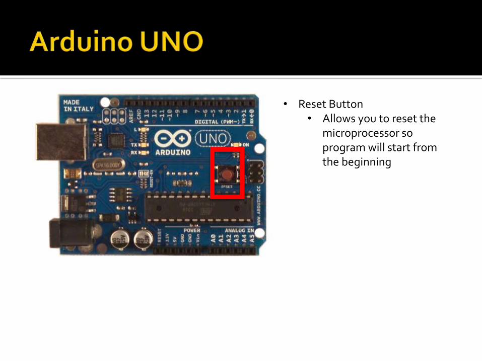
• Reset Button• Allows you to reset the
microprocessor so program will start from the beginning
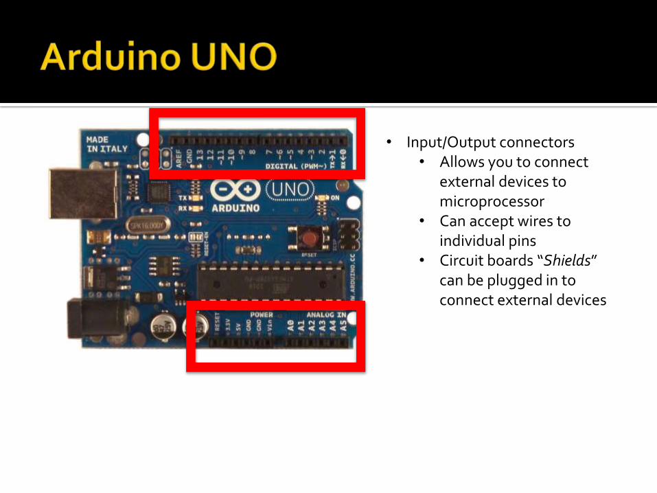
• Input/Output connectors• Allows you to connect
external devices to microprocessor
• Can accept wires to individual pins
• Circuit boards “Shields” can be plugged in to connect external devices
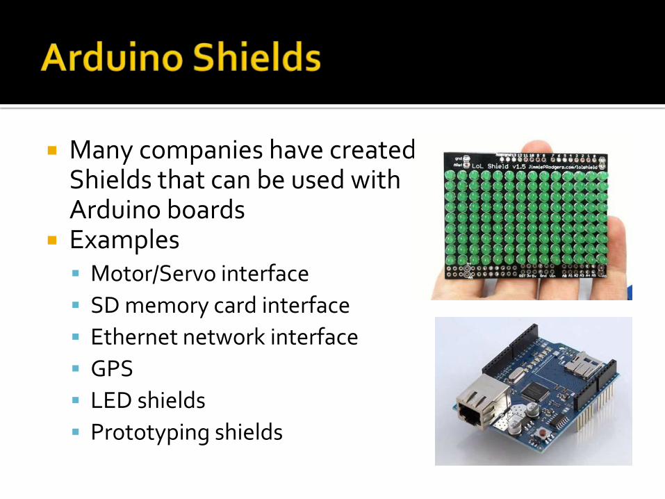
Many companies have created Shields that can be used with Arduino boards
Examples Motor/Servo interface
SD memory card interface
Ethernet network interface
GPS
LED shields
Prototyping shields
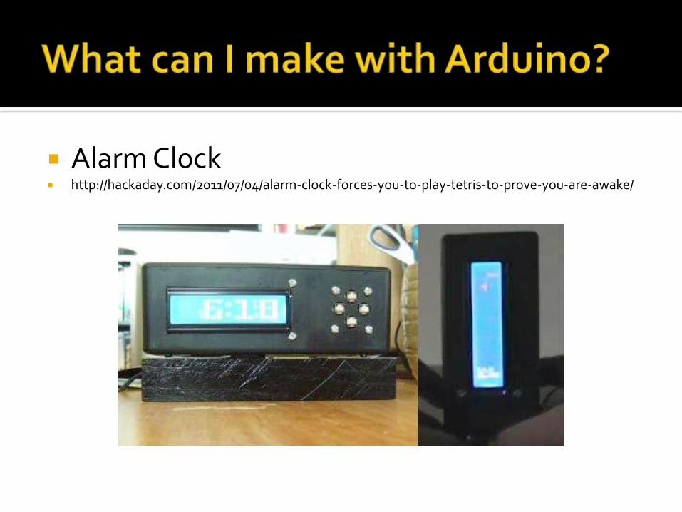
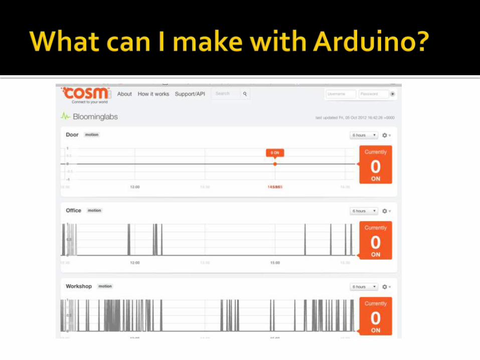
Alarm Clock http://hackaday.com/2011/07/04/alarm-clock-forces-you-to-play-tetris-to-prove-you-are-awake/

Textpresso http://www.geekwire.com/2012/greatest-invention-textspresso-machine-change-coffee-
ordering/
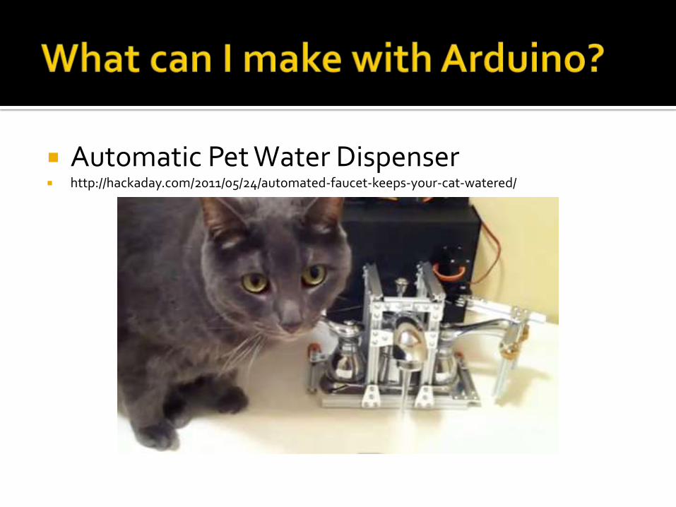
Automatic Pet Water Dispenser http://hackaday.com/2011/05/24/automated-faucet-keeps-your-cat-watered/
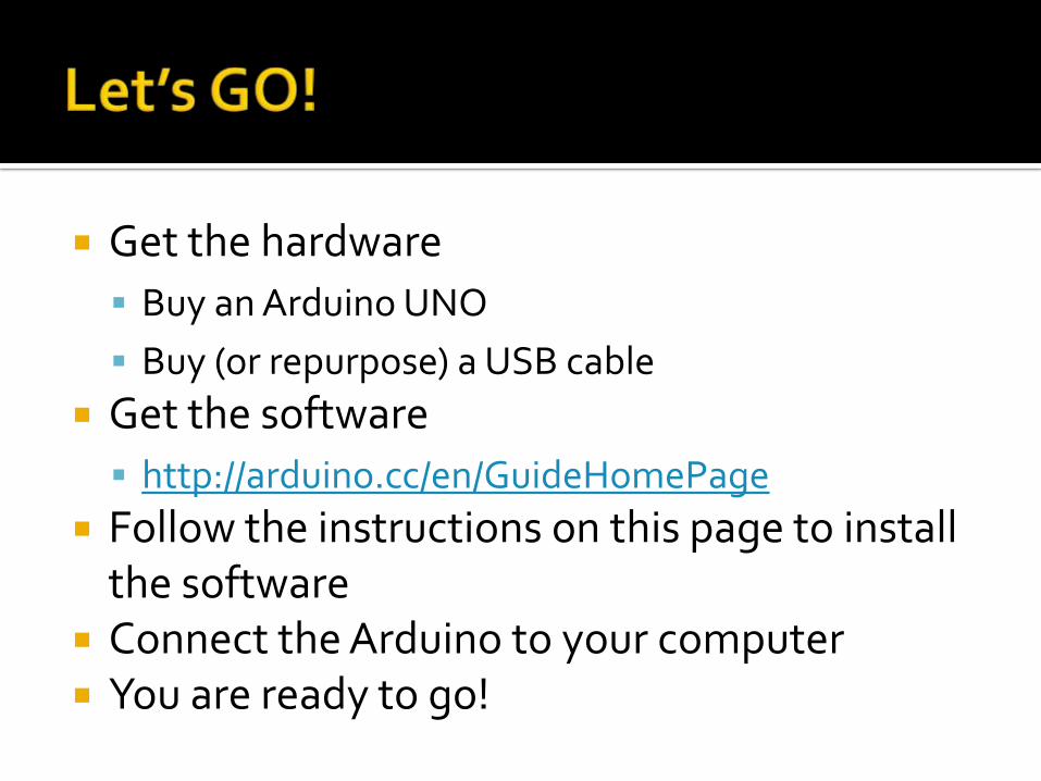
Get the hardware
Buy an Arduino UNO
Buy (or repurpose) a USB cable
Get the software
http://arduino.cc/en/GuideHomePage
Follow the instructions on this page to install the software
Connect the Arduino to your computer You are ready to go!
Blink the onboard LED
Congratulations!!!
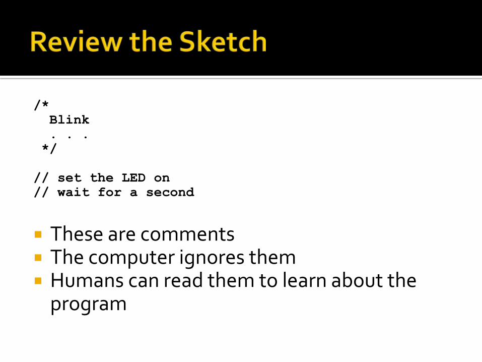
/*
Blink
. . .
*/
// set the LED on
// wait for a second
These are comments The computer ignores them Humans can read them to learn about the
program
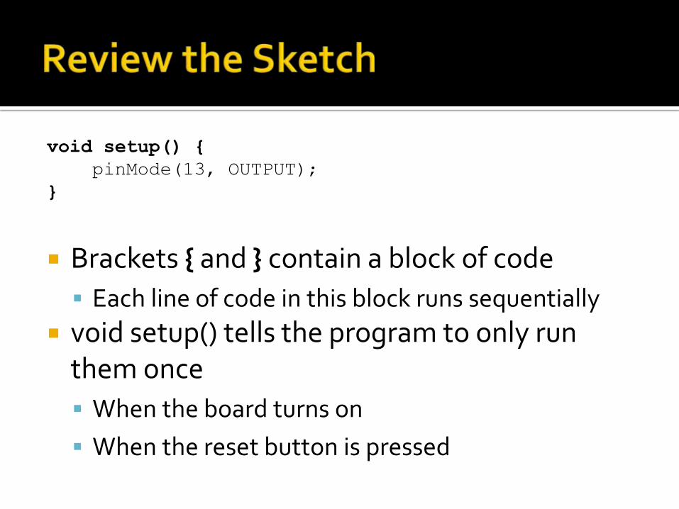
void setup() {
pinMode(13, OUTPUT);
}
Brackets { and } contain a block of code
Each line of code in this block runs sequentially
void setup() tells the program to only run them once
When the board turns on
When the reset button is pressed
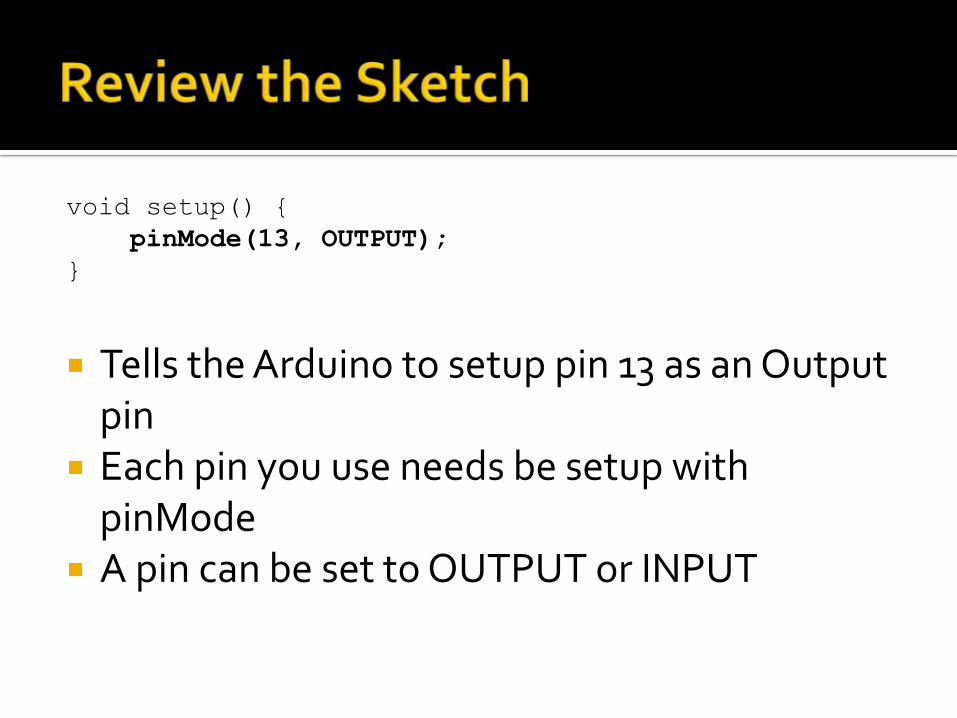
void setup() {
pinMode(13, OUTPUT);
}
Tells the Arduino to setup pin 13 as an Output pin
Each pin you use needs be setup with pinMode
A pin can be set to OUTPUT or INPUT
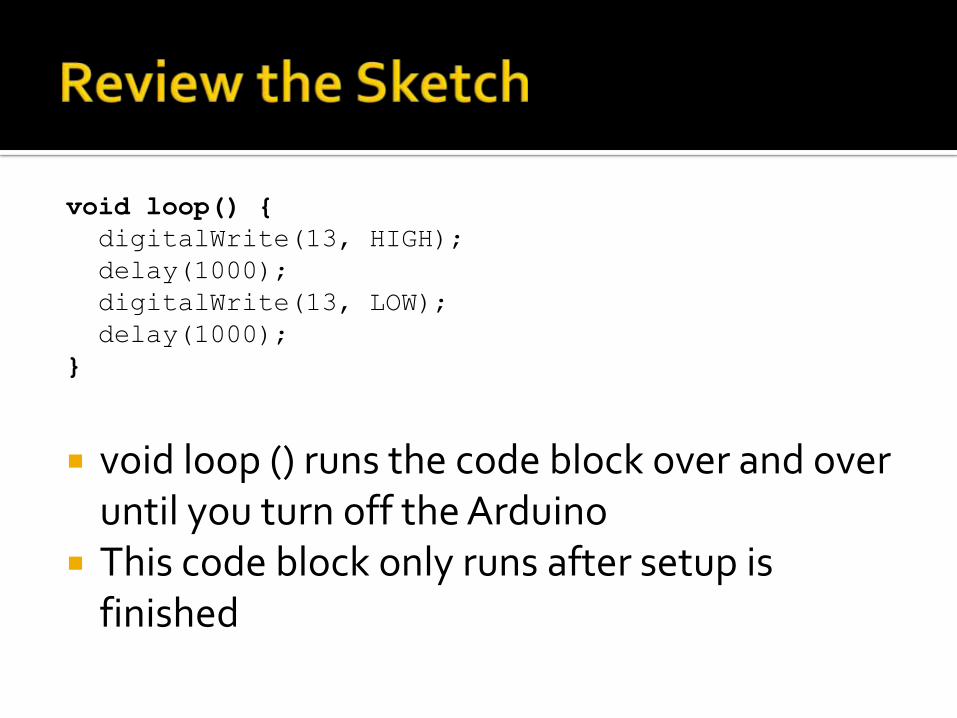
void loop() {
digitalWrite(13, HIGH);
delay(1000);
digitalWrite(13, LOW);
delay(1000);
}
void loop () runs the code block over and over until you turn off the Arduino
This code block only runs after setup is finished
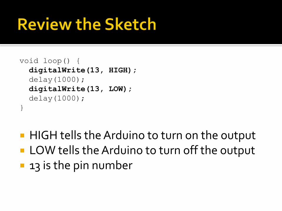
void loop() {
digitalWrite(13, HIGH);
delay(1000);
digitalWrite(13, LOW);
delay(1000);
}
HIGH tells the Arduino to turn on the output LOW tells the Arduino to turn off the output 13 is the pin number
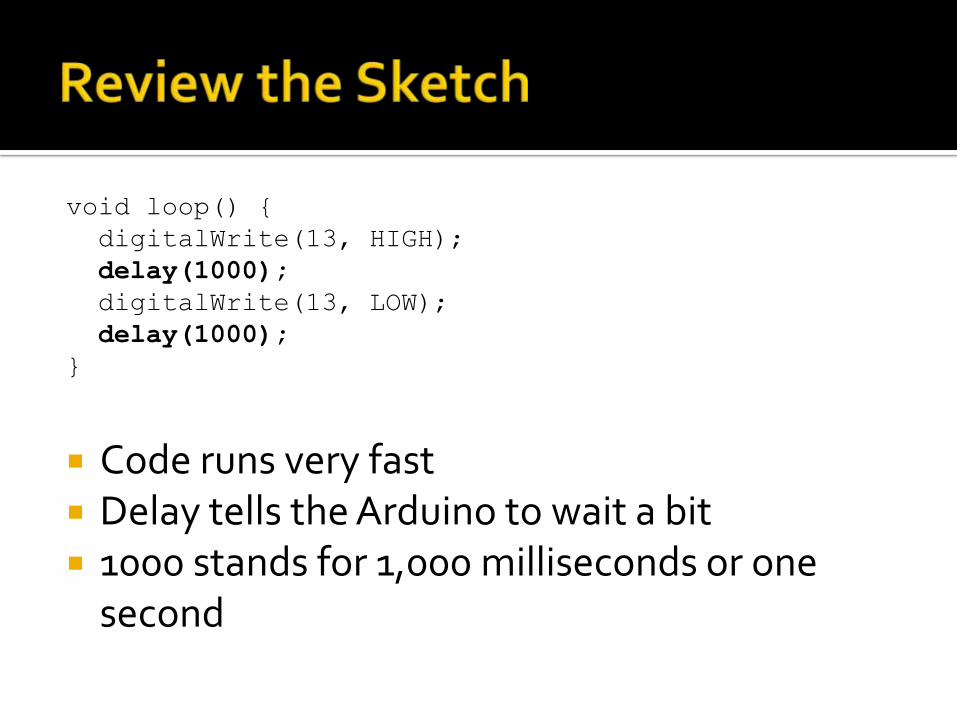
void loop() {
digitalWrite(13, HIGH);
delay(1000);
digitalWrite(13, LOW);
delay(1000);
}
Code runs very fast Delay tells the Arduino to wait a bit 1000 stands for 1,000 milliseconds or one
second
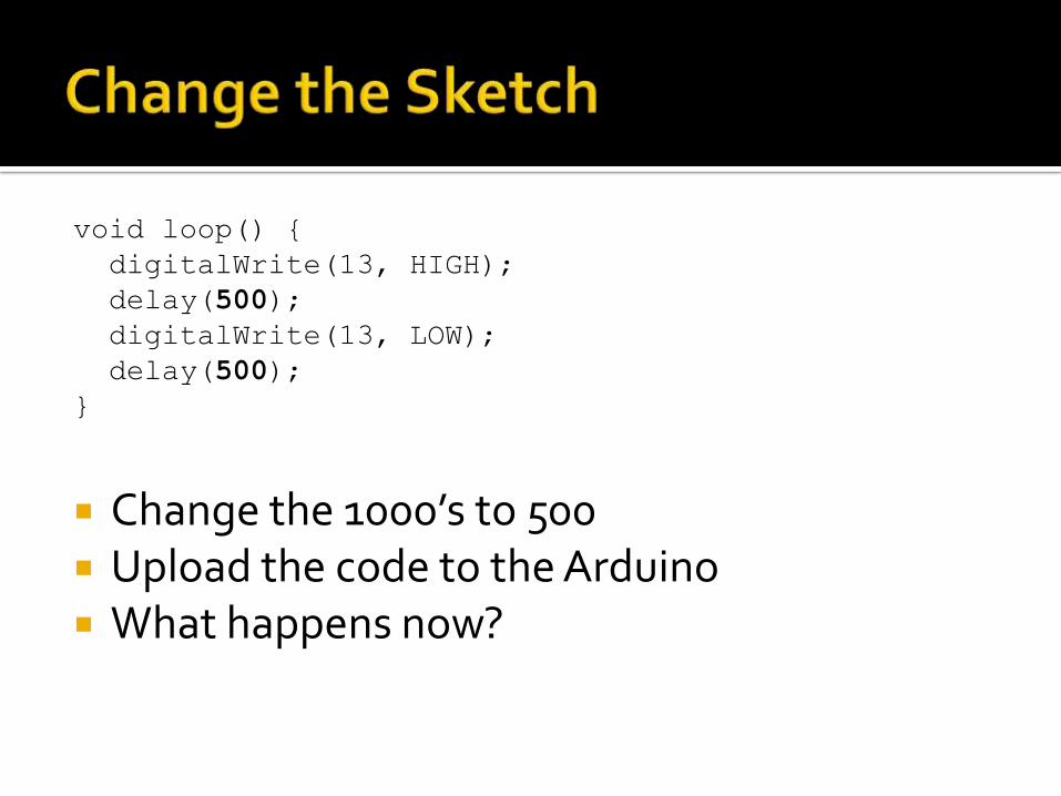
void loop() {
digitalWrite(13, HIGH);
delay(500);
digitalWrite(13, LOW);
delay(500);
}
Change the 1000’s to 500 Upload the code to the Arduino What happens now?
These pins are used to communicate with the outside world
When an output pin is HIGH, it can provide 5V at 40mA maximum Trying to get more than 40mA out of the pin will
destroy the Microprocessor! When the output pin is LOW, it provides no
current You can use a transistor and/or a relay to
provide a higher voltage or more current
Most LEDs will work with 5V at 20mA or 30mA
Make sure to check them before connecting to your Arduino! – Use your volt meter
An LED requires a resistor to limit the current
Without the resistor, the LED will draw too much current and burn itself out
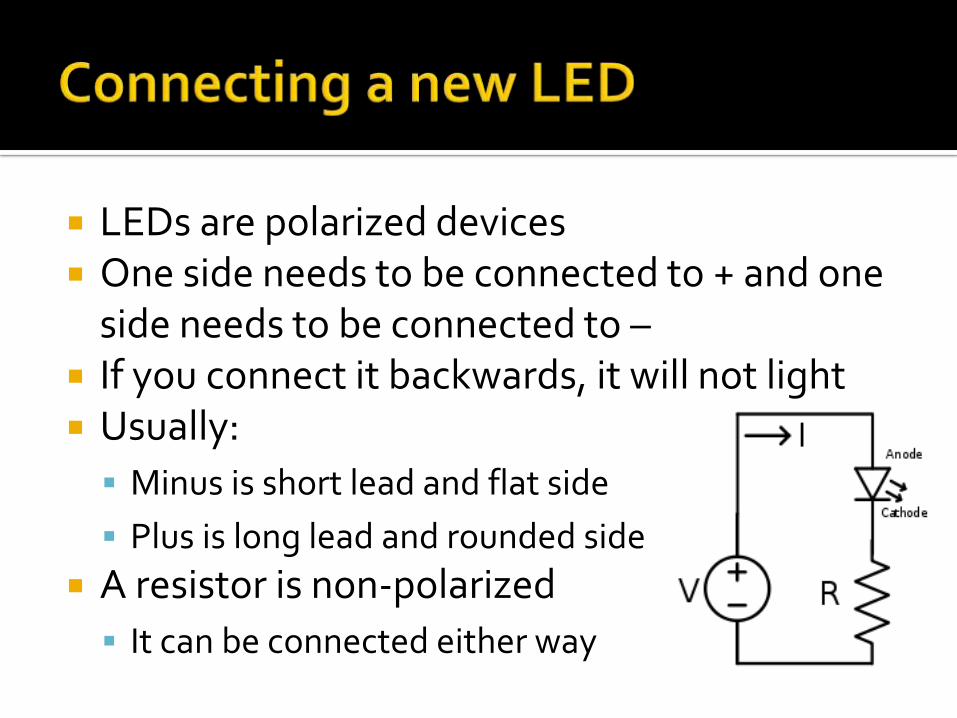
LEDs are polarized devices One side needs to be connected to + and one
side needs to be connected to – If you connect it backwards, it will not light Usually:
Minus is short lead and flat side
Plus is long lead and rounded side
A resistor is non-polarized
It can be connected either way
Connect the two LEDs on the breadboard Modify the code to blink the second LED, too Blink them all
The pins can be used to accept an input also Digital pins can read a voltage (1) or no
voltage (0) Analog pins can read voltage between 0V and
5V. You will read a value of 0 and 1023. Both of these return a value you can put into
a variable and/or make decisions based on the value
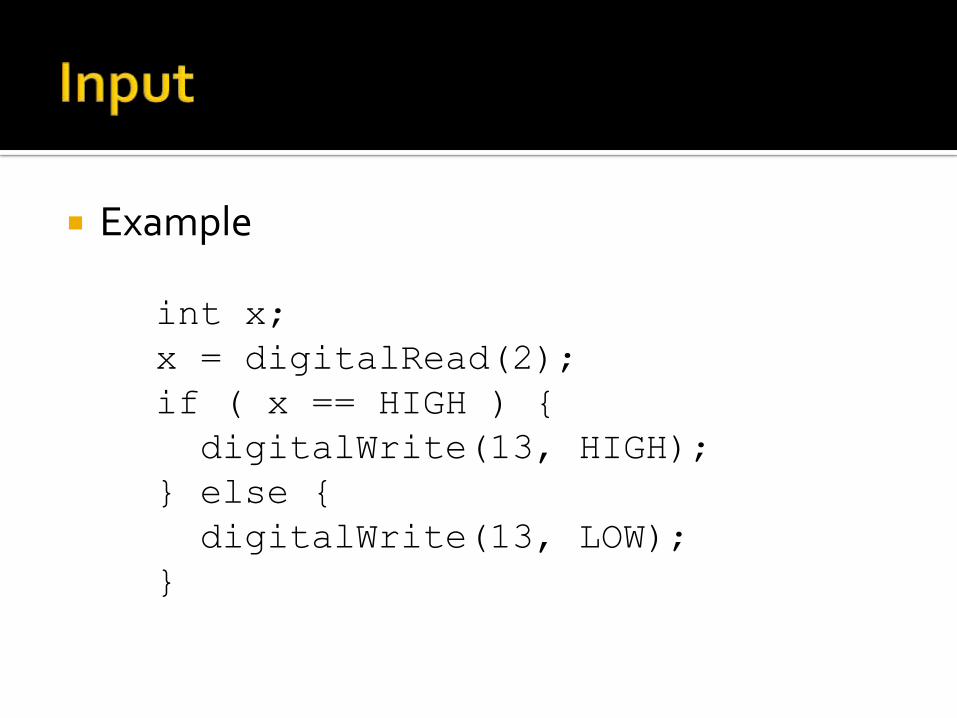
Example
int x;
x = digitalRead(2);
if ( x == HIGH ) {
digitalWrite(13, HIGH);
} else {
digitalWrite(13, LOW);
}
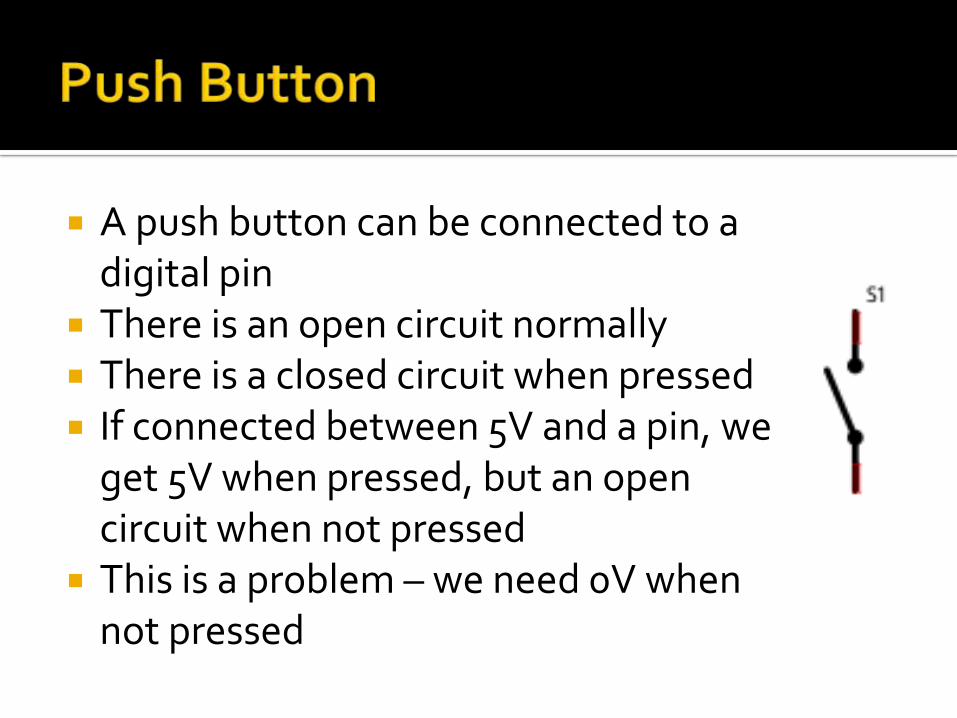
A push button can be connected to a digital pin
There is an open circuit normally There is a closed circuit when pressed If connected between 5V and a pin, we
get 5V when pressed, but an open circuit when not pressed
This is a problem – we need 0V when not pressed
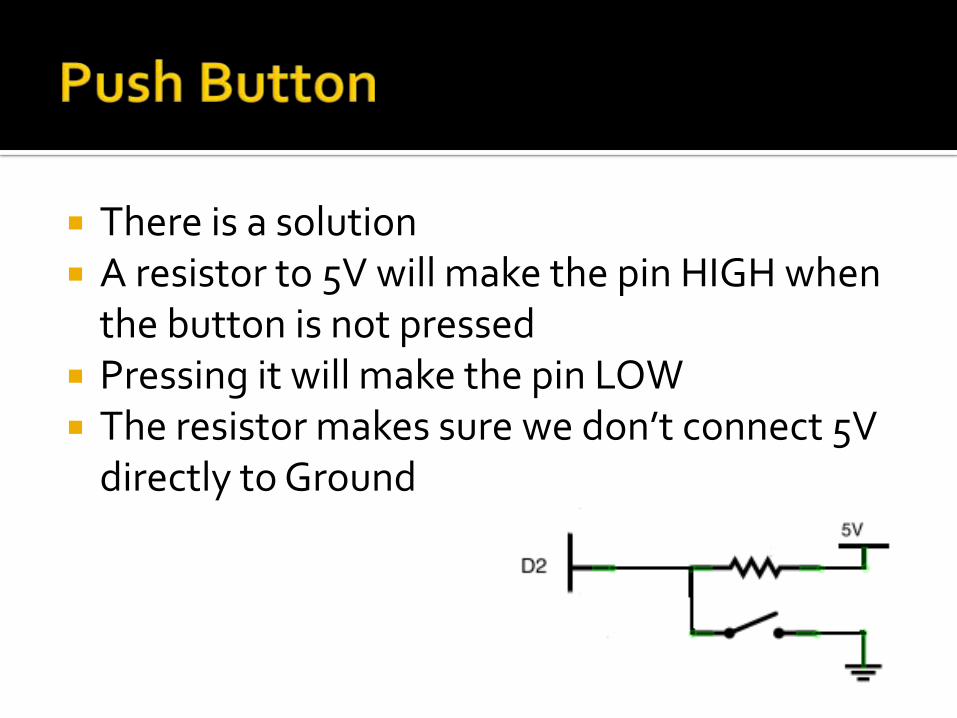
There is a solution A resistor to 5V will make the pin HIGH when
the button is not pressed Pressing it will make the pin LOW The resistor makes sure we don’t connect 5V
directly to Ground
This is a common method for using push buttons
The resistor is called a “Pull Up Resistor” The Arduino has built in pull up resistors on
the digital pins We need to enable them when we need them
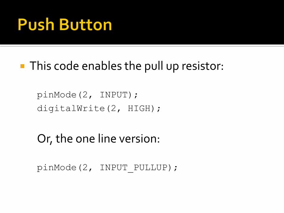
This code enables the pull up resistor:
pinMode(2, INPUT);
digitalWrite(2, HIGH);
Or, the one line version:
pinMode(2, INPUT_PULLUP);
Connect a push button Load the basic button code Turn LEDs on/off based on button press Load the toggle code. Pay attention to
reactions to your button presses, and count in the Serial terminal.
Try again with the debounce code. Did that help?
There are many other devices you can connect to an Arduino Servos to move things
GPS to determine location/time
Real Time Clock to know what time it is
Accelerometers, Chemical detectors…
LCD displays
Memory cards
More!
So far we’ve dealt with the on/off digital world.
Many interesting things we want to measure (temperature, light, pressure, etc) have a range of values.
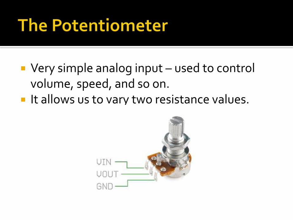
Very simple analog input – used to control volume, speed, and so on.
It allows us to vary two resistance values.
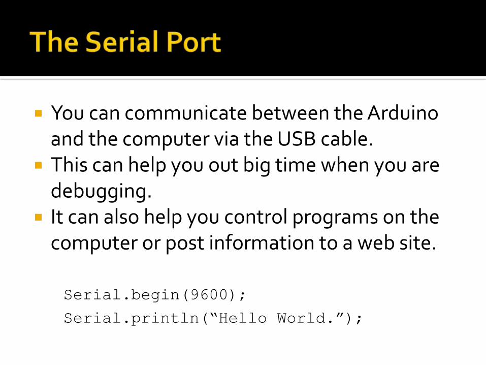
You can communicate between the Arduinoand the computer via the USB cable.
This can help you out big time when you are debugging.
It can also help you control programs on the computer or post information to a web site.
Serial.begin(9600);
Serial.println(“Hello World.”);
Connect potentiometer Upload and run code Turn the knob Watch the value change in the Serial Monitor
There are many, many sensors based on varying resistance: force sensors, light dependent resistors, flex sensors, and more
To use these you need to create a ‘voltage divider’.
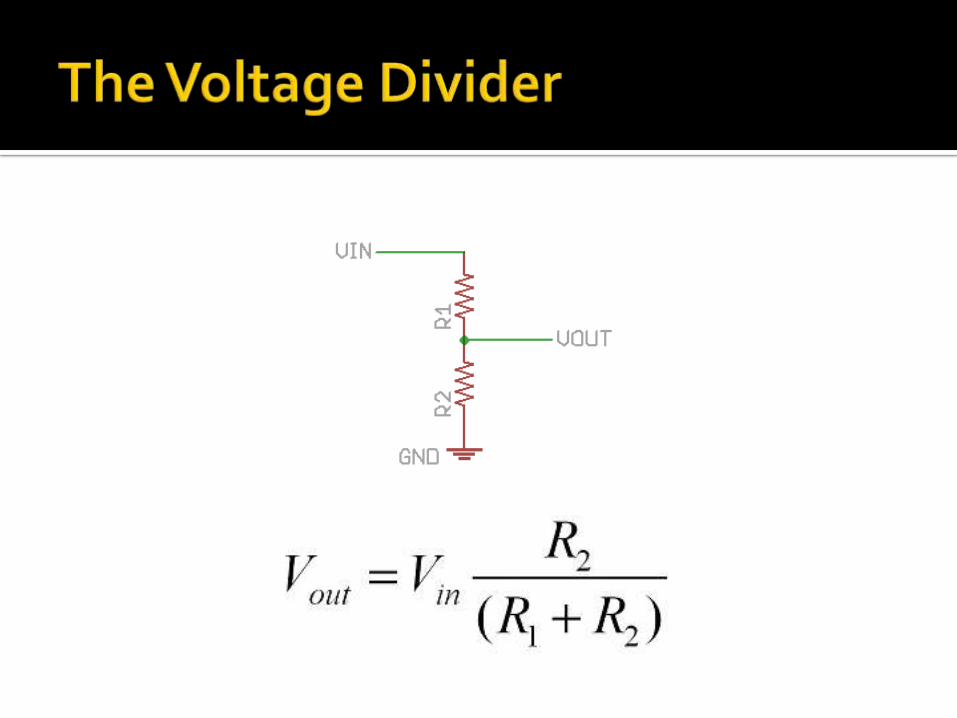
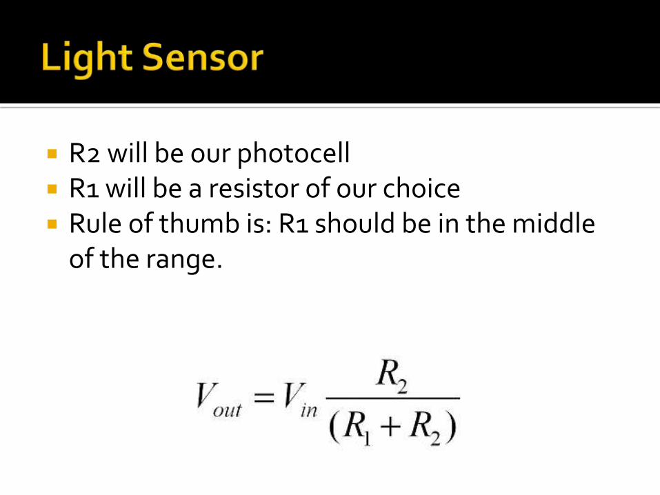
R2 will be our photocell R1 will be a resistor of our choice Rule of thumb is: R1 should be in the middle
of the range.
Wire up the photocell Same code as Lab 3 Take note of the max and min values Try to pick a value for a dark/light threshold.
Flashing a light is neat, but what about fading one in and out?
Or changing the color of an RGB LED? Or changing the speed of a motor?

Wire up the Breadboard Load the code. Take note of the for loop. Watch the light fade in and out Experiment with the code to get different
effects
So far we’ve communicated with the world by blinking or writing to Serial
Let’s make things move!
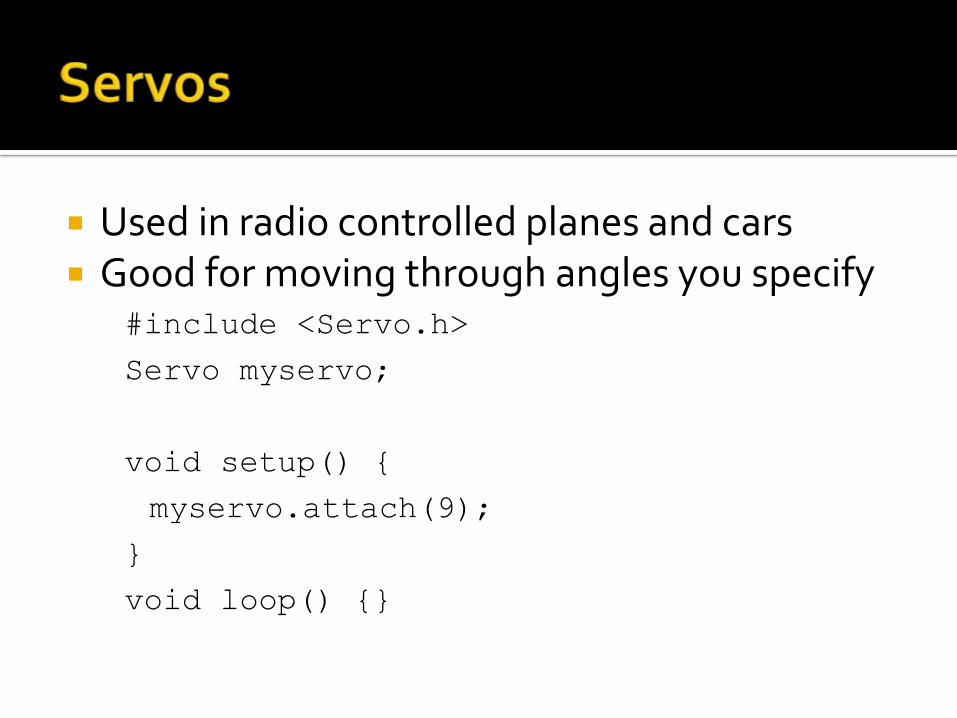
Used in radio controlled planes and cars Good for moving through angles you specify
#include <Servo.h>
Servo myservo;
void setup() {
myservo.attach(9);
}
void loop() {}
Wire up the breadboard Upload the code Check it out, you can control the servo! The map function makes life easy and is very,
very handy:
map(value, fromLow, fromHigh, toLow,
toHigh);
Upload the code for random movement. Watch the values in the Serial monitor. Run
the program multiple times. Is it really random?
Try it with ‘randomSeed’, see what happens.
For moving and spinning things Are cheap and can often be taken from old
and neglected toys (or toys from Goodwill) Here we learn three things:
Transistors
Using PWM to control speed
Why you don’t directly attach a motor
Wire it up Speed it up, slow it down (rawhide!)
With a piezo or small speaker, your Arduinocan make some noise, or music (or ‘music’).
As with game controllers, vibrating motors can stimulate the sense of touch.
Arduino projects exist that involve smell (breathalyzer, scent generators).
For taste…KegBot? ZipWhip’s cappuccino robot?
Combine previous projects (photocell and the piezo playing music) to create an instrument that generates a pitch based on how much light is hitting the photocell
Feel free to get really creative with this.
We have learned
The Arduino platform components
how to connect an Arduino board to the computer
How to connect LEDs, buttons, a light sensor, a piezo buzzer, and motors
How to send information back to the computer
http://www.arduino.cc Getting Started With Arduino (Make:
Projects) book Beginning Arduino book Arduino: A Quick Start Guide book The adafruit learning system:
https://learn.adafruit.com/

Adafruit http://www.adafruit.com/ Spark Fun http://www.sparkfun.com/ Maker Shed http://www.makershed.com/ Digikey http://www.digikey.com/ Mouser http://www.mouser.com/ Radio Shack http://www.radioshack.com/ Find parts: http://www.octopart.com/ Sometimes Amazon has parts too Ebay can have deals but usually the parts are
shipped from overseas and take a long time
Electronic devices depend on the movement of electrons
The amount of electrons moving from one molecule to another is called Current which is measured in Amps
Batteries provide a lot of electrons that are ready to move
The difference in potential (the number of free electrons) between two points is called Electromotive Force which is measured in Volts
Materials that allow easy movement of electrons are called Conductors
Copper, silver, gold, aluminum are examples
Materials that do not allow easy movement of electrons are called Insulators
Glass, paper, rubber are examples
Some materials are poor conductors and poor insulators.
Carbon is an example
Materials that aren’t good conductors or good inductors provide Resistance to the movement of electrons
Resistance is measured in Ohms
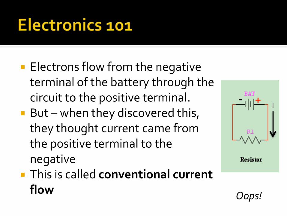
Electrons flow from the negative terminal of the battery through the circuit to the positive terminal.
But – when they discovered this, they thought current came from the positive terminal to the negative
This is called conventional current flow
I
Oops!
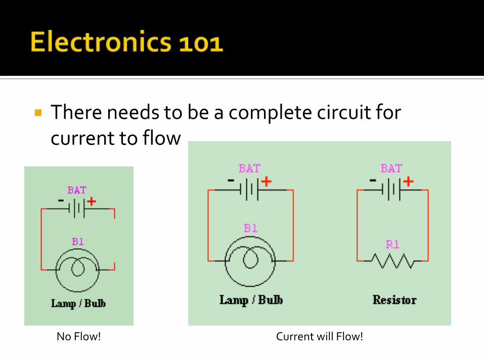
There needs to be a complete circuit for current to flow
No Flow! Current will Flow!
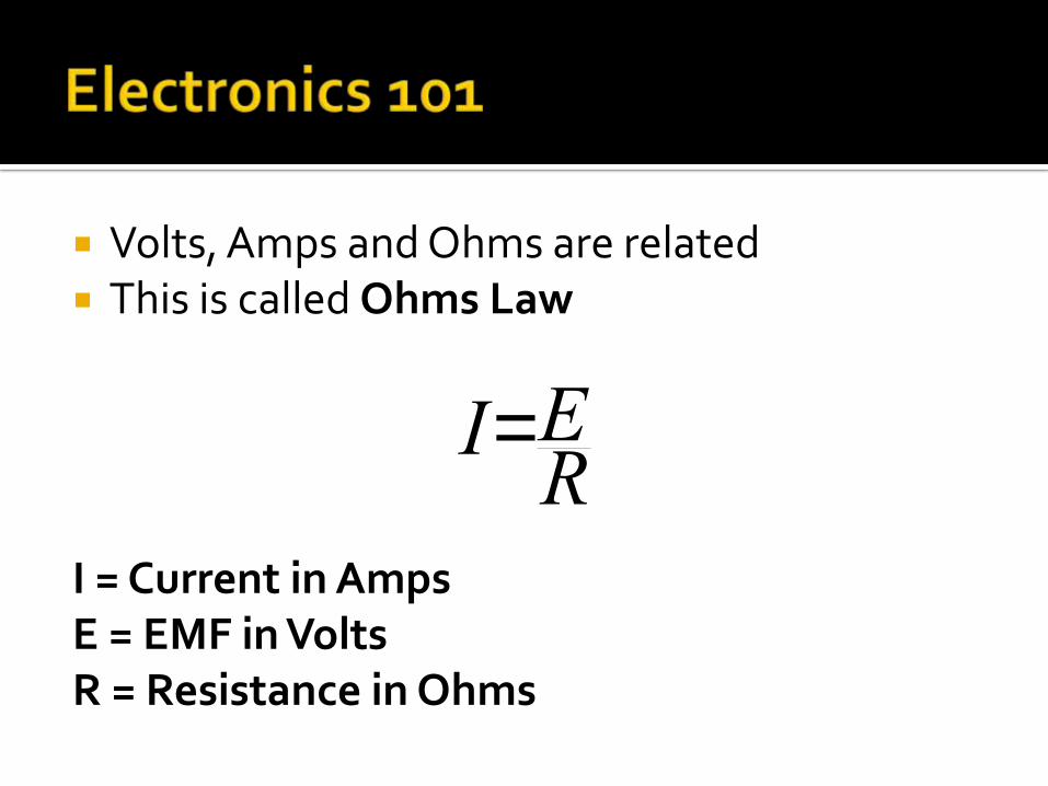
Volts, Amps and Ohms are related This is called Ohms Law
I = Current in AmpsE = EMF in VoltsR = Resistance in Ohms
I=ER
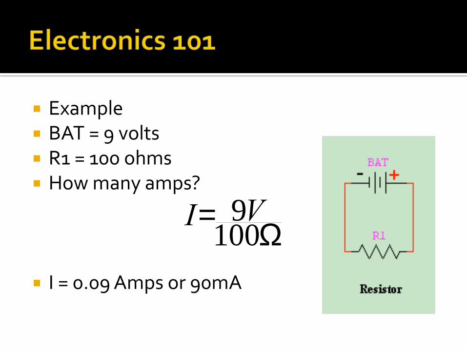
Example BAT = 9 volts R1 = 100 ohms How many amps?
I = 0.09 Amps or 90mA
I= 9V100W
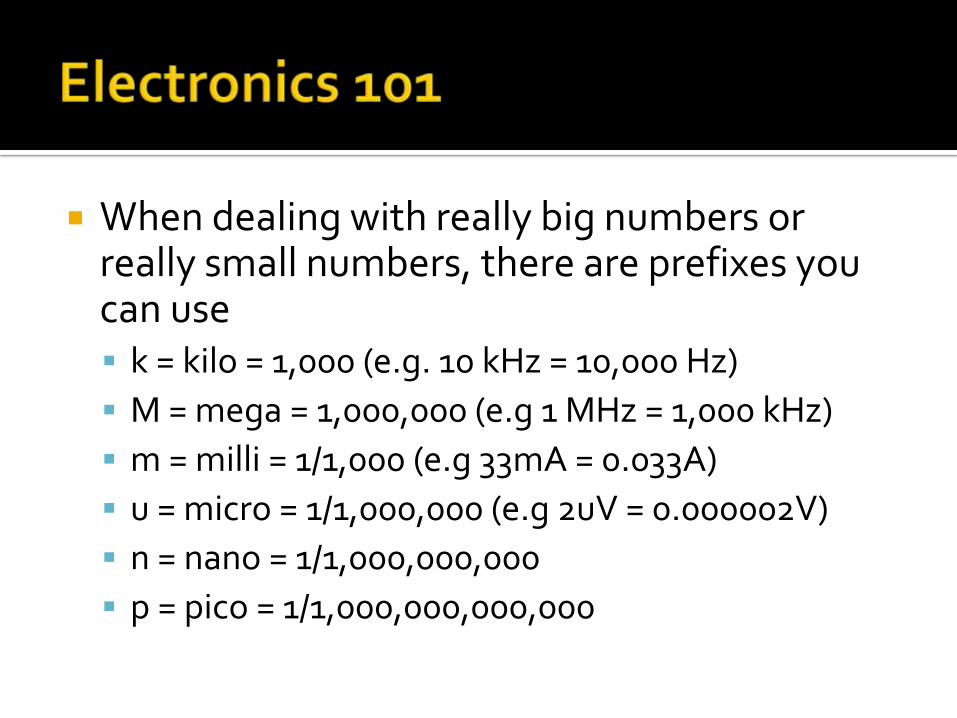
When dealing with really big numbers or really small numbers, there are prefixes you can use k = kilo = 1,000 (e.g. 10 kHz = 10,000 Hz)
M = mega = 1,000,000 (e.g 1 MHz = 1,000 kHz)
m = milli = 1/1,000 (e.g 33mA = 0.033A)
u = micro = 1/1,000,000 (e.g 2uV = 0.000002V)
n = nano = 1/1,000,000,000
p = pico = 1/1,000,000,000,000