Embed Size (px)
Citation preview
NOTICE OF INCORPORATIONUnited States Legal Document
≠ All citizens and residents are hereby advised that this is a legally binding document duly incorporated by reference and that failure to comply with such requirements as hereby detailed within may subject you to criminal or civil penalties under the law. Ignorance of the law shall not excuse noncompliance and it is the responsibility of the citizens to inform themselves as to the laws that are enacted in the United States of America and in the states and cities contained therein. ±
«
ASME B&PVC VII (2010), Boiler and Pressure Vessel Code, Part VII, Recommended Guidelines for the Care of Power Boilers, as required by the States of Connecticut, Nevada, North Carolina, Oklahoma, Rhode Island, Tennessee, et. alia.

2010
8
ASME Boiler and Pressure Vessel Code AN INTERNATIONAL CODE
VII Recommended Guidelines for the
-Care of Power Boilers
S ETTING THE S T '( NDA R D

I ELI
IL ASME Boiler and Pressure Vessel Committee on Power Boilers
11II111111111111111111111111111111111111
X07011
Date of Issuance: July 1, 2011
This international code or standard was developed under procedures accredited as meeting the criteria for American National Standards and it is an American National Standard. The Standards Committee that approved the code or standard was balanced to assure that individuals from competent and concerned interests have had an opportunity to participate. The proposed code or standard was made available for public review and comment that provides an opportunity for additional public input from industry, academia, regulatory agencies, and the public-at-large.
ASME does not "approve," "rate," or "endorse" any item, construction, proprietary device, or activity. ASME does not take any position with respect to the validity of any patent rights asserted in connection with any items
mentioned in this document, and does not undertake to insure anyone utilizing a standard against liability for infringement of any applicable letters patent, nor assume any such liability. Users of a code or standard are expressly advised that determination of the validity of any such patent rights, and the risk of infringement of such rights, is entirely their own responsibility.
Participation by federal agency representative(s) or person(s) affiliated with industry is not to be interpreted as government or industry endorsement of this code or standard.
ASME accepts responsibility for only those interpretations of this document issued in accordance with the established ASME procedures and policies, which precludes the issuance of interpretations by individuals.
The footnotes in this document are part of this American National Standard.
No part of this document may be reproduced in any form, in an electronic retrieval system or otherwise, without the prior written permission of the publisher.
Library of Congress Catalog Card Number: 56-3934 Printed in the United States of America
The American Society of Mechanical Engineers Three Park Avenue, New York, NY 10016-5990
Copyright © 2011 by THE AMERICAN SOCIETY OF MECHANICAL ENGINEERS
All rights resenJed
CONTENTS
List of Sections ......................................................................... vii Foreword . . . . . . . . . . . . . . . . . . . . . . . . . . . . . . . . . . . . . . . . . . . . . . . . . . . . . . . . . . . . . . . . . . . . . . . . . . . . . . . IX
Statement of Policy on the Use of the Certification Mark and Code Authorization in Advertising . . . . . . . . . . . . . . . . . . . . . . . . . . . . . . . . . . . . . . . . . . . . . . . . . . . . . . . . . . . . . . . . . . . . . . . . . . . Xl
Statement of Policy on the Use of ASME Marking to Identify Manufactured Items. . . . . . . . . . . . xi Submittal of Technical Inquiries to the Boiler and Pressure Vessel
Committee - Mandatory .............................................................. XlI
Personnel .............................................................................. xi v Introduction ............................................................................ XXVlI
Summary of Changes. . . . . . . . . . . . . . . . . . . . . . . . . . . . . . . . . . . . . . . . . . . . . . . . . . . . . . . . . . . . . . . . . . . . xxviii List of Changes in Record Number Order ................................................. xxx
Subsection C 1 Fundamentals ............................................................ .
Cl.IOO Cl.200 Cl.300 Cl.400 Cl.500 C1.600
Figures C1.2-1 C1.2-2 Cl.2-3a C1.2-3b
Subsection C2
C2.IOO C2.200 C2.300 C2.400 C2.500
Subsection C3
C3.100 C3.200 C3.300 C3.400 C3.500 C3.600 C3.700 C3.800
Steam Generation ......................................................... . Boiler Types .............................................................. . Package Boilers ........................................................... . Field-Assembled Boilers ................................................... . Combustion .............................................................. . Boiler Efficiency .......................................................... .
Simple Steam Drum ....................................................... . Steam Drum With Tubes .................................................. . Steam Drum Internals - Baffle Type ....................................... . Steam Drum Internals - Double-Row Arrangement, Cyclone
Separator Type ......................................................... .
Boiler Operation ......................................................... .
General Guidelines ........................................................ . Preparing for Operation .................................................... . Starting Up ............................................................... . On-Line Operation ........................................................ . Out-of-Service Operation .................................................. .
Boiler Auxiliaries ........................................................ .
Preparation of Auxiliaries for Service ....................................... . Fuel-Burning Equipment ................................................... . Air Heaters ............................................................... . Economizers .............................................................. . Boiler Feed Pumps ........................................................ . Auxiliary Drives .......................................................... . Draft Fans .............. , ................................................. . Dampers ................................................................. .
iii
2 2 2 4
2 2 3
3
5
5 6 9
11 15
18
18 18 31 34 36 36 40 40
Figures C3.2-1 C3.2-2 C3.2-3 C3.2-4 C3.2-5 C3.2-6 C3.2-7 C3.2-8 C3.2-9 C3.3-1 C3.3-2 C3.3-3 C3.4-1 C3.5-1 C3.6-1 C3.6-2 C3.6-3 C3.7-1 C3.8-1
Subsection C4
C4.100 C4.200 C4.300 C4.400 C4.500 C4.600 C4.700
Figures C4.1-1 C4.1-2 C4.1-3 C4.1-4 C4.1-5 C4.2-1
Table C4.2-1
Subsection CS
C5.100 C5.200 C5.300
Subsection C6
C6.100 C6.200 C6.300 C6.400
Typical Pilot and Gas Piping Arrangement .................................. . Typical Fuel Oil Train ..................................................... . Typical Underfeed Stoker. ................................................. . Feeder-Distributor for Firing of Coal on a Spreader Stoker .................... . Spreader Stoker, Continuous Ash Discharge Grate ............................ . Typical Bowl Mill ........................................................ . Typical Impact Mill ....................................................... . Arrangement of Ball-Tube Mill ............................................. . Burner for Horizontal Firing of Coal ........................................ . Typical Tubular Air Heater ................................................ . Typical Regenerative Air Heater ............................................ . Details of Regenerative Air Preheater, Bisector Type ......................... . Typical Economizer ....................................................... . Typical Centrifugal Boiler Feed Pump, Water Connections .................... . Typical Motor Drive ...................................................... . Typical Single Stage Turbine Drive ......................................... . Typical Turbine Drive Arrangement ........................................ . Airfoil Blade Centrifugal Fan With Inlet Vane Control ....................... . Typical Outlet Fan Dampers (Multilouver) ................................... .
Appurtenances ........................................................... .
Safety Valves ............................................................. . Safety Relief Valves or Relief Valves ....................................... . Pressure Gages ........................................................... . Fusible Plugs ............................................................. . Feedwater Regulator Valve ................................................. . Blowdown ................................................................ . Soot Blowers ............................................................. .
Safety Valve Nameplate ................................................... . Typical Safety Valve ...................................................... . Recommended Safety Valve Installation ..................................... . Application of Test Gag ................................................... . Hydraulic Lift Assist Device ............................................... . Test Apparatus for Seat Tightness ........................................... .
Leakage Rates for Safety Relief Valves for Set Procedures to 1,000 psig (7 MPa) ..................................................... .
Instrumentation, Controls, and Interlocks ................................. .
General .................................................................. . Indicators and Recorders ................................................... . Controls and Interlocks .................................................... .
Inspection ............................................................... .
Scope .................................................................... . Inspection Frequency ...................................................... . Preparation for Inspection .................................................. . Inspection of Internal Surfaces and Parts .................................... .
IV
18 21 23 23 24 26 27 28 28 32 33 34 35 37 38 38 39 41 42
43
43 50 52 53 53 53 53
43 45 46 48 49 51
51
55
55 55 56
58
58 58 59 59
C6.500 C6.600 C6.700 C6.800 C6.900 C6.l000
Figures C6.1-1 C6.3-1 C6.4-1 C6.4-2
Subsection C7
C7.100 C7.200 C7.300 C7.400
Subsection C8
C8.100 C8.200 C8.300 C8.400 C8.500 C8.600 C8.700 C8.800 C8.900
Figures C8.4-1 C8.4-2 C8.5-1 C8.5-2 C8.5-3 C8.5-4 C8.5-5 C8.6-1
Tables C8.8-1 C8.8-2 C8.8-3
Subsection C9
C9.100 C9.200 C9.300 C9.400
Inspection of Extemal Surfaces and Parts .................................... . Care and Maintenance ..................................................... . Repairs ............................ " .................................... . Hydrostatic Test. .......................................................... . Boilers - General ........................................................ . Authorized Inspector ...................................................... .
Typical Boiler Water Level Gage Installation ................................ . Typical Valve Lineup Prior to Inspection .................................... . Typical Stays ............................................................. . Typical Forms of Fusible Plugs ............................................. .
Repairs, Alterations, and Maintenance .................................... .
Repairs and Alterations .................................................... . Maintenance .............................................................. . Boiler Maintenance Programs .............................................. . Steam Boilers ............................................................. .
Control of Internal Chemical Conditions .................................. .
General ................................................. , ................ . Intemal Cleaning of Boilers ................................................ . Laying Up of Boilers ...................................................... . Deposits ................................................................. . Internal Corrosion ......................................................... . Corrosion Cracking of Boiler Steel ......................................... . Steam Contamination ...................................................... . Sampling, Testing, Controlling, and Reporting of Analyses of Water ........... . Fire-Side Conditions ....................................................... .
Scale Causing Overheating and Tube Failure ................................ . Deposit Effect on Boiler Tube Versus Tube Temperature ..................... . Oxygen Corrosion in an Economizer Tube ................................... . Caustic Gouge-Type Attack on Boiler Tube ................................. . Chelate Attack Caused by Excessive Feed of Chemical ....................... . CO2 Carbonic Acid Attack on Condensate Pipe .............................. . Oxygen Attack on Condensate Pipe ......................................... . H+ Damage on Boiler Tube ................................................ .
Methods for Sampling of Water and Steam .................................. . Methods of Analysis for the Control of Water for Boilers ..................... . Useful Tests for the Control of Water for Boilers ............................. .
Preventing Boiler Failures ................................................ .
General .................................................................. . Overpressure ............................................................. . Weakening of Structure .................................................... . Operation of Combustion Equipment ........................................ .
v
64 65 66 66 66 67
58 60 62 63
68
68 68 69 70
76
76 76 77 78 80 84 85 87 87
79 79 81 81 82 83 83 86
87 88 89
91
91 91 93 96
C9.500 C9.600
Furnace Explosions Furnace Implosions
Mandatory Appendices I Submittal of Technical Inquiries to the Boiler and Pressure
97 97
Vessel Committee. . . . . . . . . . . . . . . . . . . . . . . . . . . . . . . . . . . . . . . . . . . . . . . . . . . . . . . . 99 II Standard Units for Use in Equations. . . . . . . . . . . . . . . . . . . . . . . . . . . . . . . . . . . . . . . .. 100
Nonmandatory Appendices A Procedures for Care and Maintenance of Package Boilers . . . . . . . . . . . . . . . . . . . . .. 101 B Watertube Boilers - Maintenance Checks. . . . . . . . . . . . . . . . . . . . . . . . . . . . . . . . . . .. 102 C Watertube Boilers - Operating Checks Relating to Maintenance. . . . . . . . . . . . . .. 109 D Firetube Boilers - Maintenance Checks . . . . . . . . . . . . . . . . . . . . . . . . . . . . . . . . . . . .. III E Firetube Boilers - Operating Checks Relating to Maintenance. . . . . . . . . . . . . . . .. 112 F Guidance for the Use of U.S. Customary and SI Units in the
ASME Boiler and Pressure Vessel Code . . . . . . . . . . . . . . . . . . . . . . . . . . . . . . . . . .. 113
Glossary ............................................................................... 116
vi
2010 ASME BOILER AND PRESSURE VESSEL CODE
SECTIONS
Rules for Construction of Power Boilers
II Materials Part A - Ferrous Material Specifications Part B - Nonferrous Material Specifications Pat1 C - Specifications for Welding Rods, Electrodes, and Filler Metals Part D - Properties (Customary) Part D - Properties (Metric)
III Rules for Construction of Nuclear Facility Components Subsection NCA - General Requirements for Division 1 and Division 2 Division 1
Subsection NB - Class I Components Subsection NC - Class 2 Components Subsection ND - Class 3 Components Subsection NE - Class MC Components Subsection NF - Supports Subsection NG - Core Support Structures Subsection NH - Class 1 Components in Elevated Temperature Service Appendices
Division 2 - Code for Concrete Containments
Division 3 - Containments for Transportation and Storage of Spent Nuclear Fuel and High Level Radioactive Material and Waste
IV Rules for Construction of Heating Boilers
V Nondestructive Examination
VI Recommended Rules for the Care and Operation of Heating Boilers
VII Recommended Guidelines for the CatOe of Power Boilers
VIII Rules for Construction of Pressure Vessels Division) Division 2 - Alternative Rules Division 3 Alternative Rules for Construction of High Pressure Vessels
IX Welding and Brazing Qualifications
X Fiber-Reinforced Plastic Pressure Vessels
XI Rules for Inservice Inspection of Nuclear Power Plant Components
XII Rules for Construction and Continued Service of Transport Tanks
vii
(10)
ADDENDA
Addenda, which include additions and revisions to individual Sections of the Code, will be sent automatically to purchasers of the applicable Sections up to the publication of the 2013 Code. The 2010 Code is available only in the loose-leaf format; accordingly, the Addenda will be issued in the loose-leaf format.
INTERPRETATIONS
ASME issues written replies to inquiries concerning interpretation of technical aspects of the Code. The Interpretations for each individual Section will be published separately and will be included as part of the update service to that Section. Interpretations of Section III, Divisions 1 and 2, will be included with the update service to Subsection NCA.
viii
Interpretations of the Code are posted in January and July at http://cstools.asme.orgiinterpretations.cfm.
CODE CASES
The Boiler and Pressure Vessel Committee meets regularly to consider proposed additions and revisions to the Code and to formulate Cases to clarify the intent of existing requirements or provide, when the need is urgent, rules for materials or constructions not covered by existing Code rules. Those Cases that have been adopted will appear in the appropriate 2010 Code Cases book: "Boilers and Pressure Vessels" and "Nuclear Components." Supplements will be sent automatically to the purchasers of the Code Cases books up to the publication of the 2013 Code.
FOREWORD
The American Society of Mechanical Engineers set up a committee in 1911 for the purpose of formulating standard rules for the construction of steam boilers and other pressure vessels. This committee is now called the Boiler and Pressure Vessel Committee.
The Committee's function is to establish rules of safety, relating only to pressure integrity, governing the construction 1 of boilers, pressure vessels, transport tanks and nuclear components, and inservice inspection for pressure integrity of nuclear components and transport tanks, and to interpret these rules when questions arise regarding their intent. This Code does not address other safety issues relating to the construction of boilers, pressure vessels, transport tanks and nuclear components, and the inservice inspection of nuclear components and transport tanks. The user of the Code should refer to other pertinent codes, standards, laws, regulations, or other relevant documents. With few exceptions, the rules do not, of practical necessity, reflect the likelihood and consequences of deterioration in service related to specific service fluids or external operating environments. Recognizing this, the Committee has approved a wide variety of construction rules in this Section to allow the user or his designee to select those which will provide a pressure vessel having a margin for deterioration in service so as to give a reasonably long, safe period of usefulness. Accordingly, it is not intended that this Section be used as a design handbook; rather, engineering judgment must be employed in the selection of those sets of Code rules suitable to any specific service or need.
This Code contains mandatory requirements, specific prohibitions, and nonmandatory guidance for construction activities. The Code does not address all aspects of these activities and those aspects that are not specifically addressed should not be considered prohibited. The Code is not a handbook and cannot replace education, experience, and the use of engineering judgment. The phrase engineering judgment refers to technical judgments made by knowledgeable designers experienced in the application of the Code. Engineering judgments must be consistent with Code philosophy and such judgments must never be used to overrule mandatory requirements or specific prohibitions of the Code.
1 Construction. as used in this Foreword, is an all-inclusive tenn comprising materials, design, fabrication, examination, inspection, testing, certification, and pressure relief.
ix
The Committee recognizes that tools and techniques used for design and analysis change as technology progresses and expects engineers to use good judgment in the application of these tools. The designer is responsible for complying with Code rules and demonstrating compliance with Code equations when such equations are mandatory. The Code neither requires nor prohibits the use of computers for the design or analysis of components constructed to the requirements of the Code. However, designers and engineers using computer programs for design or analysis are cautioned that they are responsible for all technical assumptions inherent in the programs they use and they are responsible for the application of these programs to their design.
The Code does not fully address tolerances. When dimensions, sizes, or other parameters are not specified with tolerances, the values of these parameters are considered nominal and allowable tolerances or local variances may be considered acceptable when based on engineering judgment and standard practices as determined by the designer.
The Boiler and Pressure Vessel Committee deals with the care and inspection of boilers and pressure vessels in service only to the extent of providing suggested rules of good practice as an aid to owners and their inspectors.
The rules established by the Committee are not to be interpreted as approving, recommending, or endorsing any proprietary or specific design or as limiting in any way the manufacturer's freedom to choose any method of design or any form of construction that conforms to the Code rules.
The Boiler and Pressure Vessel Committee meets regularly to consider revisions of the rules, new rules as dictated by technological development, Code Cases, and requests for interpretations. Only the Boiler and Pressure Vessel Committee has the authority to provide official interpretations of this Code. Requests for revisions, new rules, Code Cases, or interpretations shall be addressed to the Secretary in writing and shall give full particulars in order to receive consideration and action (see Submittal of Technical Inquiries to the Boiler and Pressure Vessel Committee). Proposed revisions to the Code resulting from inquiries will be presented to the Standards Committees for appropriate action. The action of the Standards Committees becomes effective only after confirmation by letter ballot of the Committees and approval by ASME.
(10) (a)
Proposed revisions to the Code approved by the Committee are submitted to the American National Standards Institute and published at http://cstoo[s. asme.org!csconnectlpubliclindex.cfm? PublicReview = Revisions to invite comments from all interested persons. After the allotted time for public review and final approval by ASME, revisions are published in updates to the Code.
Code Cases may be used in the construction of components to be stamped with the Certification Mark beginning with the date of their approval by ASME.
After Code revisions are approved by ASME, they may be used beginning with the date of issuance. Revisions, except for revisions to material specifications in Section II, Parts A and B, become mandatory six months after such date of issuance, except for boilers or pressure vessels contracted for prior to the end of the six-month period. Revisions to material specifications are originated by the American Society for Testing and Materials (ASTM) and other recognized national or international organizations, and are usually adopted by ASME. However, those revisions mayor may not have any effect on the suitability of material, produced to earlier editions of specifications, for use in AS ME construction. ASME material specifications approved for use in each construction Code are listed in the Guideline for Acceptable ASTM Editions and in the Guideline for Acceptable Non-ASTM Editions, in Section II, Parts A and B. These Guidelines list, for each specification, the latest edition adopted by ASME, and earlier and later editions considered by ASME to be identical for ASME construction.
The Boiler and Pressure Vessel Committee in the formulation of its rules and in the establishment of maximum design and operating pressures considers materials, construction, method of fabrication, inspection, and safety devices.
The Code Committee does not rule on whether a component shall or shall not be constructed to the provisions of the Code. The Scope of each Section has been established to identify the components and parameters considered by the Committee in formulating the Code rules.
Questions or issues regarding compliance of a specific component with the Code rules are to be directed to the AS ME Certificate Holder (Manufacturer). Inquiries concerning the interpretation of the Code are to be directed
x
to the ASME Boiler and Pressure Vessel Committee. ASME is to be notified should questions arise concerning improper use of the Certification Mark.
The specifications for materials given in Section II are identical with or similar to those of specifications published by ASTM, A WS, and other recognized national or international organizations. When reference is made in an ASME material specification to a non-ASME specification for which a companion ASME specification exists, the reference shall be interpreted as applying to the ASME material specification. Not all materials included in the material specifications in Section II have been adopted for Code use. Usage is limited to those materials and grades adopted by at least one of the other Sections of the Code for application under rules of that Section. All materials allowed by these various Sections and used for construction within the scope of their rules shall be furnished in accordance with material specifications contained in Section II or referenced in the Guidelines for Acceptable Editions in Section II, Parts A and B, except where otherwise provided in Code Cases or in the applicable Section of the Code. Materials covered by these specifications are acceptable for use in items covered by the Code Sections only to the degree indicated in the applicable Section. Materials for Code use should preferably be ordered, produced, and documented on this basis; Guidelines for Acceptable Editions in Section II, Parts A and B list editions of ASME and year dates of specifications that meet ASME requirements and which may be used in Code construction. Material produced to an acceptable specification with requirements different from the requirements of the corresponding specifications listed in the Guidelines for Acceptable Editions in Part A or Part B may also be used in accordance with the above, provided the material manufacturer or vessel manufacturer certifies with evidence acceptable to the Authorized Inspector that the corresponding requirements of specifications listed in the Guidelines for Acceptable Editions in Part A or Part B have been met. Material produced to an acceptable material specification is not limited as to country of origin.
When required by context in this Section, the singular shall be interpreted as the plural, and vice-versa; and the feminine, masculine, or neuter gender shall be treated as such other gender as appropriate.
STATEMENT
ON THE USE OF THE CERTIFICATION MA AND
CODE AUTHO ZATION IN ADVERTISING
ASME has established procedures to authorize qualified organizations to perform various activities in accordance with the requirements of the ASME Boiler and Pressure Vessel Code. It is the aim of the Society to provide recognition of organizations so authorized. An organization holding authorization to perform various activities in accordance with the requirements of the Code may state this capability in its advertising literature.
Organizations that are authorized to use the Certification Mark for marking items or constructions that have been constructed and inspected in compliance with the ASME Boiler and Pressure Vessel Code are issued Certificates of Authorization. It is the aim of the Society to maintain the standing of the Certification Mark for the benefit of the users, the enforcement jurisdictions, and the holders of the Certification Mark who comply with all requirements.
Based on these objectives, the following policy has been established on the usage in advertising of facsimiles of the Certification Mark, Certificates of Authorization, and reference to Code construction. The American Society of
Mechanical Engineers does not "approve," "certify," "rate," or "endorse" any item, construction, or activity and there shall be no statements or implications that might so indicate. An organization holding the Certification Mark and/or a Certificate of Authorization may state in advertising literature that items, constructions, or activities "are built (produced or performed) or activities conducted in accordance with the requirements of the ASME Boiler and Pressure Vessel Code," or "meet the requirements of the ASME Boiler and Pressure Vessel Code." An ASME corporate logo shall not be used by any organization other than ASME.
The Certification Mark shall be used only for stamping and nameplates as specifically provided in the Code. However, facsimiles may be used for the purpose of fostering the use of such construction. Such usage may be by an association or a society, or by a holder of the Certification Mark who may also use the facsimile in advertising to show that clearly specified items will carry the Certification Mark. General usage is permitted only when all of a manufacturer's items are constructed under the rules.
STATEMENT OF POLICY
ON THE USE OF ASME MARKING
TO IDENTIFY MANUFACTURED ITEMS
The ASME Boiler and Pressure Vessel Code provides rules for the construction of boilers, pressure vessels, and nuclear components. This includes requirements for materials, design, fabrication, examination, inspection, and stamping. Items constructed in accordance with all of the applicable rules of the Code are identified with the official Certification Mark described in the governing Section of the Code.
Markings such as "ASME," "ASME Standard," or any other marking including "AS ME" or the Certification Mark
xi
shall not be used on any item that is not constructed in accordance with all of the applicable requirements of the Code.
Items shall not be described on ASME Data Report Forms nor on similar forms referring to ASME that tend to imply that all Code requirements have been met when, in fact, they have not been. Data Report Forms covering items not fully complying with ASME requirements should not refer to ASME or they should clearly identify all exceptions to the ASME requirements.
(10)
(a)
(a)
(a) SUBMITTAL OF TECHNICAL INQUIRIES TO THE BOILER AND PRESSURE VESSEL COMMITTEE -
MANDATORY
1 INTRODUCTION
(a) The following information provides guidance to Code users for submitting technical inquiries to the Committee. See Guideline on the Approval of New Materials Under the ASME Boiler and Pressure Vessel Code in Section II, Parts C and D for additional requirements for requests involving adding new materials to the Code. Technical inquiries include requests for revisions or additions to the Code rules, requests for Code Cases, and requests for Code interpretations, as described below.
( J) Code Revisions. Code revisions are considered to accommodate technological developments, address administrati ve requirements, incorporate Code Cases, or to clarify Code intent.
(2) Code Cases. Code Cases represent alternatives or additions to existing Code rules. Code Cases are written as a question and reply, and are usually intended to be incorporated into the Code at a later date. When used, Code Cases prescribe mandatory requirements in the same sense as the text of the Code. However, users are cautioned that not all jurisdictions or owners automatically accept Code Cases. The most common applications for Code Cases are:
(a) to permit eady implementation of an approved Code revision based on an urgent need
(b) to permit the use of a new material for Code construction
(c) to gain experience with new materials or alternative rules prior to incorporation directly into the Code
(3) Code Interpretations. Code Interpretations provide clarification of the meaning of existing rules in the Code, and are also presented in question and reply format. Interpretations do not introduce new requirements. In cases where existing Code text does not fully convey the meaning that was intended, and revision of the rules is required to support an interpretation, an Intent Interpretation will be issued and the Code will be revised.
(b) The Code rules, Code Cases, and Code Interpretations established by the Committee are not to be considered as approving, recommending, certifying, or endorsing any proprietary or specific design, or as limiting
xii
in any way the freedom of manufacturers, constructors, or owners to choose any method of design or any form of construction that conforms to the Code rules.
( c) Inquiries that do not comply with these provisions or that do not provide sufficient information for the Committee's full understanding may result in the request being returned to the inquirer with no action.
2 INQUIRY FORMAT
Submittals to the Committee shall include: (a) Purpose. Specify one of the following:
( 1) revision of present Code rules (2) new or additional Code rules (3) Code Case (4) Code Interpretation
(b) Background. Provide the information needed for the Committee's understanding of the inquiry, being sure to include reference to the applicable Code Section, Division, Edition, Addenda (if applicable), paragraphs, figures, and tables. Preferably, provide a copy of the specific referenced portions of the Code.
(c) Presentations. The inquirer may desire or be asked to attend a meeting of the Committee to make a formal presentation or to answer questions from the Committee members with regard to the inquiry. Attendance at a Committee meeting shall be at the expense of the inquirer. The inquirer's attendance or lack of attendance at a meeting shall not be a basis for acceptance or rejection of the inquiry by the Committee.
3 CODE REVISIONS OR ADDITIONS
Requests for Code revisions or additions shall provide the following:
(a) Proposed Revisions or Additions. For revisions, identify the rules of the Code that require revision and submit a copy of the appropriate rules as they appear in the Code, marked up with the proposed revision. For additions, provide the recommended wording referenced to the existing Code rules.
(b) Statement of Need. Provide a brief explanation of the need for the revision or addition.
( c) Background Information. Provide background information to support the revision or addition, including any data or changes in technology that form the basis for the request that will allow the Committee to adequately evaluate the proposed revision or addition. Sketches, tables, figures, and graphs should be submitted as appropriate. When applicable, identify any pertinent paragraph in the Code that would be affected by the revision or addition and identify paragraphs in the Code that reference the paragraphs that are to be revised or added.
4 CODE CASES
Requests for Code Cases shall provide a Statement of Need and Background Information similar to that defined in 3(b) and 3(c), respectively, for Code revisions or additions. The urgency of the Code Case (e.g., project underway or imminent, new procedure, etc.) must be defined and it must be confirmed that the request is in connection with equipment that will bear the Certification Mark, with the exception of Section XI applications. The proposed Code Case should identify the Code Section and Division, and be written as a Question and a Reply in the same format as existing Code Cases. Requests for Code Cases should also indicate the applicable Code Editions and Addenda (if applicable) to which the proposed Code Case applies.
5 CODE INTERPRETATIONS
(a) Requests for Code Interpretations shall provide the following:
( 1) Inquiry. Provide a condensed and precise question, omitting superfluous background information and, when possible, composed in such a way that a "yes" or a "no" Reply, with brief provisos if needed, is acceptable. The question should be technically and editorially correct.
(2) Reply. Provide a proposed Reply that will clearly and concisely answer the Inquiry question. Preferably, the
xiii
Reply should be "yes" or "no," with brief provisos if needed.
(3) Background Information. Provide any background information that will assist the Committee in understanding the proposed inquiry and Reply.
(b) Requests for Code Interpretations must be limited to an interpretation of a particular requirement in the Code or a Code Case. The Committee cannot consider consulting type requests such as the following:
( 1) a review of calculations, design drawings, welding qualifications, or descriptions of equipment or parts to determine compliance with Code requirements;
(2) a request for assistance in performing any Codeprescribed functions relating to, but not limited to, material selection, designs, calculations, fabrication, inspection, pressure testing, or instal1ation;
(3) a request seeking the rationale for Code requirements.
6 SUBMITTALS
Submittals to and responses from the Committee shall meet the following:
(a) Submittal. Inquiries from Code users shall be in English and preferably be submitted in typewritten form; however, legible handwritten inquiries will also be considered. They shall include the name, address, telephone number, fax number, and e-mail address, if available, of the inquirer and be mailed to the following address:
Secretary ASME Boiler and Pressure Vessel Committee Three Park Avenue New York, NY 10016-5990
As an alternative, inquiries may be submitted via e-mail to: [email protected].
(b) Response. The Secretary of the ASME Boiler and Pressure Vessel Committee or of the appropriate Subcommittee shall acknowledge receipt of each properly prepared inquiry and shall provide a written response to the inquirer upon completion of the requested action by the Code Committee.
(a) PERSONNEL ASME Boiler and Pressure Vessel Standards Committees,
Subgroups, and Working Groups As of January 1, 2011
TECHNICAL OVERSIGHT MANAGEMENT COMMITTEE (TOMC)
J. G. Feldstein, Chair T. P. Pastor, Vice Chair J. S. Brzuszkiewicz, Staff
Secretary R. W. Barnes R. J. Basile J. E. Batey T. L. Bedeaux D. L. Berger M. N. Bressler D. A. Canonico A. Chaudouet R. P. Deubler D. A. Douin D. Eisberg R. E. Gimple M. Gold
T. E. Hansen J. F. Henry C. L. Hoffmann G. G. Karcher W. M. Lundy J. R. MacKay U. R. Miller W. E. Norris G. C. Park M. D. Rana B. W. Roberts S. C. Roberts F. J. Schaaf, Jr. A. Selz B. F. Shelley W. J. Sperko R. W. Swayne
HONORARY MEMBERS (MAIN COMMITTEE)
F. P. Barton L. J. Chockie T. M. Cullen W. D. Doty J. R. Farr G. E. Feigel R. C. Griffin O. F. Hedden E. J. Hemzy
M. H. Jawad A. J. Justin W. G. Knecht J. LeCoff T. G. McCarty G. C. Millman R. A. Moen R. F. Reedy K. K. Tam
ADMINISTRATIVE COMMITTEE
J. G. Feldstein, Chair J. S. Brzuszkiewicz, Staff
Secretary R. W. Barnes J. E. Batey T. L. Bedeaux D. L. Berger
J. F. Henry U. R. Miller G. C. Park M. D. Rana B. F. Shelley W. J. Sperko
MARINE CONFERENCE GROUP
H. N. Patel, Chair J. S. Brzuszkiewicz, Staff
Secretary
J. G. Hungerbuhler, Jr. G. Pallichadath J. D. Reynolds
xiv
CONFERENCE COMMITTEE
J. M. Given, Jr. - North Carolina (Chair)
J. T. Amato - Minnesota (Vice Chair)
D. A. Douin - Ohio (Secretary)
B. P. Anthony - Rhode Island R. D. Austin - Arizona B. F. Bailey - Illinois J. E. Bell - Michigan W. K. Brigham - New
Hampshire C. W. Bryan - Tennessee M. A. Burns - Florida J. H. Burpee - Maine C. B. Cantrell - Nebraska D. C. Cook - California E. L. Creaser - New
Brunswick, Canada W. E. Crider, Jr. - Vermont P. L. Dodge - Nova Scotia,
Canada S. Donovan - Northwest
Territories, Canada D. Eastman - Newfoundland
and Labrador, Canada C. Fulton - Alaska M. Graham - Oregon R. J. Handy - Kentucky D. R. Hannon - Arkansas E. G. Hilton - Virginia K. Hynes - Prince Edward
Island, Canada D. T. Jagger - Ohio D. J. Jenkins - Kansas E. S. Kawa, Jr. -
Massachusetts
M. R. Klosterman - Iowa M. Kotb - Quebec, Canada K. J. Kraft - Maryland B. L. Krasiun -
Saskatchewan, Canada K. T. Lau - Alberta, Canada W. McGivney - New York T. J. Monroe - Oklahoma S. V. Nelson - Colorado W. R. Owens - Louisiana R. P. Pate - Alabama R. L. Perry - Nevada H. D. Pfaff - South Dakota J. F. Porcella - West Virginia R. S. Pucek - Wisconsin R. D. Reetz - North Dakota C. F. Reyes - California T. W. Rieger - Manitoba,
Canada K. A. Rudolph - Hawaii M. J. Ryan - Illinois T. S. Scholl - Ontario,
Canada G. Scribner - Missouri R. Spiker - North Carolina T. Stewart - Montana R. K. Sturm - Utah w. Vallance - Michigan M. J. Verhagen - Wisconsin P. L. Vescio, Jr. - New York M. Washington - New Jersey K. L. Watson - Mississippi P. J. Welch - Georgia L. Williamson - Washington D. J. Willis - Indiana
INTERNATIONAL INTEREST REVIEW GROUP
V. Felix Y.-G. Kim S. H. Leong W. Lin O. F. Manafa
C. Minu Y.-W. Park R. Reynaga P. Williamson
PROJECT TEAM ON HYDROGEN TANKS
M. D. Rana, Chair A. P. Amato, Staff Secretary F. L. Brown D. A. Canonico D. C. Cook J. Coursen J. W. Felbaum B. D. Hawkes N. L. Newhouse K. Nibur A. S. Olivares G. B. Rawls, Jr. B. F. Shelley J. R. Sims, Jr. N. Sirosh J. H. Smith S. Staniszewski R. Subramanian T. Tahara D. W. Treadwell E. Upitis Y. Wada
C. T. I. Webster R. C. Biel, Contributing
Member J. Birdsall, Contributing
Member M. Duncan, Contributing
Member D. R. Frikken, Contributing
Member L. E. Hayden, Jr., Contributing
Member K. T. Lau, Contributing
Member K. Oyamada, Contributing
Member C. H. Rivkin, Contributing
Member C. San Marchi, Contributing
Member B. Somerday, Contributing
Member
COMMITTEE ON POWER BOilERS (BPV I)
D. L. Berger, Chair R. E. McLaughlin, Vice Chair U. D'Urso, Staff Secretary J. L. Arnold S. W. Cameron D. A. Canonico K. K. Coleman P. D. Edwards P. Fallouey J. G. Feldstein G. W. Galanes T. E. Hansen J. F. Henry J. S. Hunter W. L. Lowry J. R. MacKay F. Massi
T. C. McGough P. A. Molvie Y. Oishi J. T. Pillow B. W. Roberts R. D. Schueler, Jr. J. P. Swezy, Jr. J. M. Tanzosh R. V. Wielgoszinski D.J. Willis G. Ardizzoia, Delegate H. Michael, Delegate E. M. Ortman, Alternate D. N. French, Honorary
Member R. L. Williams, Honorary
Member
Subgroup on Design (BPV I)
P. A. Molvie, Chair J. Vattappilly, Secretary D. I. Anderson P. Dhorajia J. P. Glaspie G. B. Komora J. C. Light B. W. Moore
R. D. Schueler, Jr. J. P. Swezy, Jr. S. V. Torkildson M. Wadkinson G. Ardizzoia, Delegate C. F. Jeerings, Contributing
Member
Subgroup on fabrication and Examination (BPV I)
J. T. Pillow, Chair G. W. Galanes, Secretary J. L. Arnold D. L. Berger S. W. Cameron G. Dunker P. F. Gilston J. Hainsworth
T. E. Hansen C. T. McDaris T. C. McGough R. E. McLaughlin R. J. Newell Y. Oishi J. P. Swezy, Jr. R. V. Wielgoszinski
xv
Subgroup on General Requirements (BPV I)
R. E. McLaughlin, Chair T. E. Hansen, Vice Chair F. Massi, Secretary P. D. Edwards W. L. Lowry T. C. McGough E. M. Ortman J. T. Pillow
D. Tompkins S. V. Torkildson D. E. Tuttle M. Wadkinson R. V. Wielgoszinski D.J. Willis C. F. Jeerings, Contributing
Member
Subgroup on Heat Recovery Steam Generators (BPV I)
T. E. Hansen, Chair D. Dziubinski, Secretary J. P. Bell L. R. Douglas J. Gertz G. B. Komora C. T. McDaris B. W. Moore
Y. Oishi E. M. Ortman R. D. Schueler, Jr. J. C. Steverman, Jr. D. Tompkins s. V. Torkildson B. C. Turczynski
Subgroup on locomotive Boilers (BPV I)
L. Moedinger, Chair S. M. Butler, Secretary P. Boschan J. Braun J. D. Conrad R. C. Franzen, Jr. D. W. Griner S. D. Jackson M. A. Janssen
S. A. Lee G. M. Ray G. L. Scerbo R. D. Schueler, Jr. R. B. Stone M. W. Westland W. L. Withuhn R. Yuill
Subgroup on Materials (BPV I)
B. W. Roberts, Chair J. S. Hunter, Secretary S. H. Bowes D. A. Canonico K. K. Coleman P. Fallouey G. W. Galanes
K. L. Hayes J. F. Henry O. X. Li J. R. MacKay F. Masuyama D. W. Rahoi J. M. Tanzosh
Subgroup on Piping (BPV I)
T. E. Hansen, Chair D. Tompkins, Secretary D. L. Berger P. D. Edwards G. W. Galanes
T. G. Kosmatka W. L. Lowry F. Massi T. C. McGough E. A. Whittle
Subgroup on Solar Boilers (BPV I)
J. S. Hunter, Chair J. R. Briggs G. W. Galanes R. E. Hearne P. L. Johnson D. J. Koza
J. C. Light Y. Magen F. Massi S. V. Torkildson J. T. Trimble, Jr.
COMMITTEE ON MATERIALS (SPY II)
J. F. Henry, Chair D. W. Rahoi, Vice Chair N. Lobo, Staff Secretary F. Abe A. Appleton J. Cameron D. A. Canonico A. Chaudouet P. Fallouey J. R. Foulds D. W. Gandy M. H. Gilkey M. Gold J. F. Grubb J. A. Hall C. L. Hoffmann M. Katcher F. Masuyama R. K. Nanstad M. L. Nayyar B. W. Roberts E. Shapiro M. H. Skillingberg R. C. Sutherlin R. W. Swindeman J. M. Tanzosh
D. Tyler D. Kwon, Delegate O. Oldani, Delegate W. R. Apblett, Jr., Contributing
Member M. N. Bressler, Contributing
Member H. D. Bushfield, Contributing
Member E. G. Nisbett, Contributing
Member E. Upitis, Contributing
Member T. M. Cullen, Honorary
Member W. D. Doty, Honorary
Member W. D. Edsall, Honorary
Member G. C. Hsu, Honorary Member R. A. Moen, Honorary
Member C. E. Spaeder, Jr., Honorary
Member A. W. Zeuthen, Honorary
Member
Subgroup on External Pressure (Spy II)
R. W. Mikitka, Chair J. A. A. Morrow, Secretary L. F. Campbell D. S. Griffin J. F. Grubb J. R. Harris III
M. Katcher D. L. Kurle C. R. Thomas C. H. Sturgeon, Contributing
Member
Subgroup on Ferrous Specifications (Spy II)
A. Appleton, Chair R. M. Davison B. M. Dingman M. J. Dosdourian P. Fallouey T. Graham J. M. Grocki J. F. Grubb K. M. Hottle D. S. Janikowski D. C. Krouse
L. J. Lavezzi W. C. Mack J. K. Mahaney R. J. Marciniec A. S. Melilli E. G. Nisbett K. E. Orie J. Shick E. Upitis R. Zawierucha
Subgroup on International Material Specifications (Spy II)
A. Chaudouet, Chair D. Dziubinski, Secretary S. W. Cameron D. A. Canonico P. Fallouey A. F. Garbolevsky O. O. Henry M. Ishikawa O. X. Li
W. M. Lundy T. F. Miskell A. R. Nywening R. O. Schueler, Jr. E. Upitis D. Kwon, Delegate O. Oldani, Delegate H. Lorenz, Contributing
Member
xvi
Subgroup on Nonferrous Alloys (Spy II)
M. Katcher, Chair R. C. Sutherlin, Secretary W. R. Apblett, Jr. M. H. Gilkey J. F. Grubb A. Heino J. Kissell T. M. Malota S. Matsumoto
H. Matsuo J. A. McMaster O. W. Rahoi E. Shapiro M. H. Ski II i ngberg O. Tyler R. Zawierucha H. D. Bushfield, Contributing
Member
Subgroup on Physical Properties (SPY II)
J. F. Grubb, Chair H. D. Bushfield
P. Fallouey E. Shapiro
Subgroup on Strength, Ferrous Alloys (BPY II)
C. L. Hoffmann, Chair J. M. Tanzosh, Secretary F. Abe W. R. Apblett, Jr. D. A. Canonico A. Oi Rienzo P. Fallouey J. R. Foulds M. Gold J. A. Hall J. F. Henry K. Kimura
F. Masuyama S. Matsumoto D. W. Rahoi B. W. Roberts M. S. Shelton J. P. Shingledecker M. J. Slater R. W. Swindeman T. P. Vassallo, Jr. H. Murakami, Contributing
Member
Subgroup on Strength of Weldments (Spy II & SPY IX)
J. M. Tanzosh, Chair W. F. Newell, Jr., Secretary S. H. Bowes K. K. Coleman P. D. Flenner J. R. Foulds D. W. Gandy M. Gold
K. L. Hayes J. F. Henry O. W. Rahoi B. W. Roberts J. P. Shingledecker W. J. Sperko J. P. Swezy, Jr.
Special Working Group on Nonmetallic Materials (Spy II)
c. W. Rowley, Chair W. I. Adams F. L. Brown A. Crabtree S. R. Frost
M. Golliet P. S. Hill M. R. Kessler E. Lever F. Worth
COMMITTEE ON CONSTRUCTION OF NUCLEAR FACILITY COMPONENTS (Spy III)
R. W. Barnes, Chair J. R. Cole, Vice Chair M. L. Vazquez, Staff Secretary W. H. Borter M. N. Bressler T. D. Burchell R. P. Deubler A. C. Eberhardt B. A. Erler G. M. Foster R. S. Hill III C. L. Hoffmann R. M. Jessee V. Kostarev W. C. LaRochelle K. A. Manoly W. N. McLean M. N. Mitchell D. K. Morton R. F. Reedy J. D. Stevenson
K. R. Wichman C. S. Withers Y. H. Choi, Delegate T. Ius, Delegate H.-T. Wang, Delegate C. C. Kim, Contributing
Member E. B. Branch, Honorary
Member P. Chilukuri, Honorary
Member G. D. Cooper, Honorary
Member W. D. Doty, Honorary
Member D. F. Landers, Honorary
Member R. A. Moen, Honorary
Member C. J. Pieper, Honorary
Member
Subgroup on Containment Systems for Spent Fuel and High-level Waste Transport Packagings (Spy III)
G. M. Foster, Chair G. J. Solovey, Vice Chair D. K. Morton, Secretary D. J. Ammerman W. G. Beach G. Bjorkman W. H. Borter G. R. Cannell J. L. Gorczyca R. S. Hill III S. Horowitz D. W. Lewis
C. G. May P. E. McConnell I. D. Mcinnes A. B. Meichler R. E. Nickell E. L. Pleins T. Saegusa H. P. Shrivastava N. M. Simpson R. H. Smith J. D. Stevenson C. J. Temus
Subgroup on Component Design (SPY III)
R. S. Hill III, Chair T. M. Adams, Vice Chair A. N. Nguyen, Secretary S. Asada C. W. Bruny J. R. Cole R. E. Cornman, Jr. A. A. Dermenjian R. P. Deubler P. Hirschberg R. I. Jetter R. B. Keating H. Kobayashi D. F. Landers K. A. Manoly
R. J. Masterson D. E. Matthews W. N. McLean J. C. Minichiello T. Nagata E. L. Pleins I. Saito G. C. Siagis J. D. Stevenson J. P. Tucker K. R. Wichman J. Yang T. Ius, Delegate M. N. Bressler, Contributing
Member
Working Group on Supports (SG-D) (SPY III)
R. J. Masterson, Chair F. J. Birch, Secretary K. Avrithi T. H. Baker U. S. Bandyopadhyay R. P. Deubler W. P. Golini
A. N. Nguyen I. Saito J. R. Sti nson T. G. Terryah G. Z. Tokarski c.-I. Wu
xvii
Working Group on Core Support Structures (SG-D) (Spy III)
J. Yang, Chair J. F. Kielb, Secretary F. G. AI-Chammas H. S. Mehta
A. Tsirigotis J. T. Land, Contributing
Member
Working Group on Design Methodology (SG-D) (SPY III)
R. B. Keating, Chair S. D. Snow, Secretary K. Avrithi M. Basal R. D. Blevins D. L. Caldwell H. T. Harrison III P. Hirschberg H. Kobayashi H. Lockert J. F. McCabe A. N. Nguyen
D. H. Roarty E. A. Rodriguez J. D. Stevenson A. Tsirigotis T. M. Wiger J. Yang D. F. Landers, Corresponding
Member M. K. Au-Yang, Contributing
Member W. S. Lapay, Contributing
Member
Working Group on Design of Division 3 Containments (SG-D) (SPY III)
E. L. Pleins, Chair D. J. Ammerman G. Bjorkman S. Horowitz D. W. Lewis J. C. Minichiello D. K. Morton
H. P. Shrivastava C. J. Temus I. D. Mcinnes, Contributing
Member R. E. Nickell, Contributing
Member
Working Group on Piping (SG-D) (SPY III)
P. Hirschberg, Chair G. Z. Tokarski, Secretary T. M. Adams G. A. Antaki C. Basavaraju J. Catalano F. Claeys J. R. Cole M. A. Gray R. W. Haupt J. Kawahata R. B. Keating V. Kostarev Y. Liu J. F. McCabe J. C. Minichiello
I. K. Nam E. R. Nelson A. N. Nguyen N. J. Shah M. S. Sills G. C. Siagis N. C. Sutherland E. A. Wais c.-I. Wu D. F. Landers, Corresponding
Member R. D. Patel, Contributing
Member E. C. Rodabaugh, Honorary
Member
Working Group on Probabilistic Methods in Design (SC-D) (SPY III)
R. S. Hill III, Chair N. A. Palm, Secretary T. Asayama K. Avrithi B. M. Ayyub A. A. Dermenjian M. R. Graybeal D.O. Henry S. D. Kulat
A. McNeill III M. Morishita P. J. O'Regan I. Saito M. E. Schmidt A. Tsirigotis J. P. Tucker R. M. Wilson
Working Group on Pumps (SG-D) (BPV III)
R. E. Cornman, Jr., Chair P. W. Behnke M. D. Eftychiou A. Fraser R. Ghanbari M. Higuchi
R. A. Ladefian J. W. Leavitt R. A. Patrick R. Udo A. G. Washburn
Working Group on Valves (SG-D) (DPV III)
J. P. Tucker, Chair J. O'Caliaghan, Secretary G. A. Jolly W. N. McLean T. A. McMahon C. A. Mizer
J. D. Page K. E. Reid /I
S. N. Shields H. R. Sonderegger P. Vock
Working Group on Vessels (SG-D) (DPV III)
D. E. Matthews, Chair R. M. Wilson, Secretary C. Basavaraju C. W. Bruny
J. V. Gregg, Jr. W. J. Heilker A. Kalnins
R. B. Keating 0.-5. Kim K. Matsunaga P. K. Shah C. Turylo D. Vlaicu W. F. Weitze
Special Working Group on Environmental Effects (SG-D) (DPV III)
W. Z. Novak, Chair R. S. Hill III
C. L. Hoffmann Y. H. Choi, Delegate
Subgroup on General Requirements (DPV III & 3C)
W. C. LaRochelle, Chair L. M. Plante, Secretary A. Appleton J. R. Berry M. N. Bressler J. V. Gardiner W. P. Golini J. W. Highlands
G. L. Hollinger R. P. Mcintyre M. R. Minick C. T. Smith W. K. Sowder, Jr. D. M. Vickery C. s. Withers H. Michael, Delegate
Working Group on Duties and Responsibilities (SG-GR) (DPV III)
J. V. Gardiner, Chair G. L. Hollinger, Secretary J. R. Berry Y. Diaz-Castillo G. Gratti M. E. Jennings
K. A. Kavanagh M. A. Lockwood L. M. Plante D. J. Roszman S. Scardigno
Working Group on Quality Assurance, Certification, and Stamping (SG-GR) (DPV III)
C. T. Smith, Chair C. s. Withers, Secretary A. Appleton B. K. Bobo S. M. Goodwin J. W. Highlands R. P. Mcintyre M. R. Minick
R. B. Patel E. C. Renaud s. J. Salvador W. K. Sowder, Jr. J. F. Strunk M. F. Sullivan G. E. Szabatura D. M. Vickery
Subgroup on Materials, Fabrication, and Examination (DPV III)
C. L. Hoffmann, Chair W. G. Beach W. H. Borter G. R. Cannell R. H. Davis G. M. Foster B. D. Frew G. B. Georgiev S. E. Gingrich R. M. Jessee
c. C. Kim M. Lau H. Murakami J.Ossmann N. M. Simpson W. J. Sperko J. R. Stinson J. F. Strunk K. B. Stuckey H. Michael, Delegate
Subgroup on Pressure Relief (DPV III)
J. F. Ball, Chair E. M. Petrosky
A. L. Szeglin D. G. Thibault
Executive Committee on Strategy and Management (DPV III, Divisions 1 and 2)
J. R. Cole, Chair C. A. Sanna, Staff Secretary R. W. Barnes B. K. Bobo N. Broom B. A. Erler C. M. Faidy J. M. Helmey R. S. Hill III E. V. Imbro
R. M. Jessee K. A. Manoly D. K. Morton J. Ramirez R. F. Reedy C. T. Smith W. K. Sowder, Jr. Y. Urabe M. F. Sullivan, Contributing
Member
China International Group (DPV III)
xviii
C. A. Sanna, Staff Secretary Y. Chen G. Tang
J. Van Z. Van Z. Zhong
Special Working Group for New Advanced light Water Reactor Plant Construction Issues (DPV III)
C. A. Sanna, Chair A. Cardillo J. Honcharik E. V. Imbro
E. L. Pleins J. A. Schulz M. C. Scott R. R. Stevenson
Subgroup on Editing and Review (DPV III)
D. K. Morton, Chair W. H. Borter M. N. Bressler R. P. Deubler
B. A. Erler W. C. LaRochelle R. F. Reedy J. D. Stevenson
Subgroup on Management Resources (DPV III)
R. M. Jessee, Chair V. Broz I. I. Jeong
J. McLean B. s. Sandhu
Subgroup on Polyethylene Pipe (SPV III)
J. C. Minichiello, Chair R. S. Hill III T. M. Adams P. Krishnaswamy W. I. Adams E. Lever G. A. Antaki E. W. McElroy C. Basavaraju D. P. Munson S. J. Boros T. M. Musto D. Burwell L. J. Petroff A. Crabtree C. W. Rowley J. M. Craig F. J. Schaaf, Jr. R. R. Croft C. T. Smith E. L. Farrow E. M. Focht M. Golliet A. N. Haddad
H. E. Svetlik D. M. Vickery Z. J. Zhou
Working Group on Nuclear High-Temperature Gas-Cooled Reactors (SPV III)
N. Broom, Chair J. E. Nestell, Secretary T. D. Burchell R. S. Hill III W. Hoffelner E. V. Imbro R. I. Jetter
Y. W. Kim T. R. Lupoid D. L. Marriott D. K. Morton T.-L. Sham Y. Tachibana T. Yuhara
Subgroup on Graphite Core Components (SPV III)
T. D. Burchell, Chair G. O. Hayner C. A. Sanna, Staff Secretary M. P. Hindley A. Appleton Y. Katoh R. L. Bratton M. N. Mitchell S.-H. Chi N. N. Nemeth M. W. Davies T. Oku S. W. Doms J. Ossmann S. F. Duffy T. Shibata B. D. Frew M. Srinivasan O. Gelineau A. G. Steer S. T. Gonczy S. Yu
Subgroup on Industry Experience for New Plants (SPV III & SPV XI)
G. M. Foster, Chair J. T. Lindberg, Chair H. L. Gustin, Secretary V. L. Armentrout T. L. Chan M. L. Coats A. A. Dermenjian J. Fletcher E. B. Gerlach D. O. Henry J. Honcharik E. V. Imbro C. C. Kim
0.-5. Kim K. Matsunaga D. E. Matthews R. E. Mclaughlin J. Ossmann R. D. Patel J. c. Poehler D. W. Sandusky R. R. Schaefer D. M. Swann T. Tsuruta E. R. Willis S. M. Vee
Subgroup on Fusion Energy Devices (SPV III)
W. K. Sowder, Jr., Chair D. Andrei, Staff Secretary R. W. Barnes M. Higuchi G. Holtmeier K. A. Kavanagh H.-J. Kim
S. Lee G. Li X. Li P. Mokaria D. J. Roszman S. J. Salvador
XIX
Subgroup on High-Temperature Reactors (SPV III)
M. Morishita, Chair R. I. Jetter, Vice Chair T.-L. Sham, Secretary N. Broom T. D. Burchell
W. Hoffelner G. H. Koo D. K. Morton
J. E. Nestell N. N. Ray
Working Group on Liquid Metal Reactors (SPV III)
T.-L. Sham, Chair T. Asayama, Secretary R. W. Barnes P. Carter C. M. Faidy W. Hoffelner
R. I. Jetter G. H. Koo M. Li S. Majumdar M. Morishita J. E. Nestell
Subgroup on Design Analysis (SPV III)
G. L. Hollinger, Chair W. F. Weitze, Secretary S. A. Adams M. R. Breach R. G. Brown T. M. Damiani B. F. Hantz C. F. Heberling II C. E. Hinnant D. P. Jones A. Kalnins
W. J. Koves K. Matsunaga G. A. Miller W. D. Reinhardt D. H. Roarty G. Sannazzaro T. G. Seipp G. Taxacher R. A. Whipple K. Wright
Subgroup on Elevated Temperature Design (SPV III)
R. I. Jetter, Chair T.-L. Sham, Secretary J. J. Abou-Hanna T. Asayama C. Becht IV F. W. Brust P. Carter J. F. Cervenka B. Dogan D. S. Griffin B. F. Hantz W. Hoffelner
A. B. Hull M. H. Jawad G. H. Koo W. J. Koves M. Li S. Majumdar D. L. Marriott T. E. McGreevy l. E. Nestell W. J. O'Donnell R. W. Swindeman
Subgroup on Fatigue Strength (SPV III)
W. J. O'Donnell, Chair S. A. Adams G. S. Chakrabarti T. M. Damiani P. R. Donavin R. J. Gurdal C. F. Heberling II C. E. Hinnant P. Hirschberg D. P. Jones
G. Kharshafdjian S. Majumdar S. N. Malik R. Nayal D. H. Roarty M. S. Shelton G. Taxacher A. Tsirigotis K. Wright H. H. Ziada
JOINT ACI-ASME COMMITTEE ON
CONCRETE COMPONENTS FOR NUCLEAR SERVICE (BPV 3C)
A. C. Eberhardt, Chair C. T. Smith, Vice Chair M. L. Vazquez, Staff Secretary N. Alchaar J. F. Artuso C. J. Bang F. Farzam P. S. Ghosal J. Gutierrez J. K. Harrold G. A. Harstead M. F. Hessheimer T. C. Inman O. Jovall N.-H. Lee J. Munshi N.Orbovic
B. B. Scott R. E. Shewmaker J. D. Stevenson M. L. Williams T. D. AI-Shawaf, Contributing
Member B. A. Erler, Contributing
Member T. E. Johnson, Contributing
Member T. Muraki, Contributing
Member M. R. Senecal, Contributing
Member M. K. Thumm, Contributing
Member
Working Group on Design (BPV 3C)
J. Munshi, Chair N. Alchaar L. J. Colarusso A. C. Eberhardt F. Farzam P. S. Ghosal J. K. Harrold G. A. Harstead
M. F. Hessheimer T. C. Inman T. E. Johnson O. Jovall N.-H. Lee J. D. Stevenson M. K. Thumm
Working Group on Materials, Fabrication, and Examination (BPV 3C)
J. F. Artuso, Chair P. S. Ghosal, Vice Chair M. L. Williams, Secretary A. C. Eberhardt
J. Gutierrez B. B. Scott C. T. Smith J. F. Strunk
Working Group on Modernization (BPV 3C)
N. Alchaar, Chair O. Jovall, Vice Chair C. T. Smith, Secretary J. F. Artuso
J. K. Harrold N.Orbovic M. A. Ugalde
COMMITTEE ON HEATING BOILERS (BPV IV)
T. L. Bedeaux, Chair J. A. Hall, Vice Chair G. Moino, Staff Secretary J. Calland ). P. Chicoine C. M. Dove B. G. French
W. L. Haag, Jr. A. Heino B. J. Iske D. J. Jenkins
J. L. Kleiss M. R. Klosterman K. M. McTague P. A. Molvie B. W. Moore R. E. Olson T. M. Parks R. V. Wielgoszinski H. Michael, Delegate D. Picart, Delegate E. A. Nordstrom, Alternate
xx
Subgroup on Care and Operation of Heating Boilers (BPV IV)
P. A. Molvie
Subgroup on Cast Iron Boilers (BPV IV)
K. M. McTague, Chair T. L. Bcdeaux, Vice Chair J. P. Chicoine B. G. French J. A. Hall
V. G. Kleftis J. L. Kliess E. A. Nordstrom
M. T. Roby, Alternate
Subgroup on Materials (BPV IV)
J. A. Hall, Chair M. Wadkinson, Vice Chair J. Calland
A. Heino B. J. Iske J. L. Kliess
Subgroup on Water Heaters (BPV IV)
J. Calland, Chair J. P. Chicoine B. G. French T. D. Gantt B. J. Iske K. M. McTague
O. A. Missoum R. E. Olson F. J. Schreiner M. A. Taylor T. E. Trant M. T. Roby, Alternate
Subgroup on Welded Boilers (BPV IV)
J. Calland, Chair T. L. Bedeaux C. M. Dove B. G. French E. A. Nordstrom R. E. Olson
M. Wadkinson R. V. Wielgoszinski H. Michael, Delegate J.-M. Andre, Contributing
Member
COMMITTEE ON NONDESTRUCTIVE EXAMINATION (BPV V)
J. E. Batey, Chair F. B. Kovacs, Vice Chair J. S. Brzuszkiewicz, Staff
Secretary S. J. Akrin C. A. Anderson J. E. Aycock A. S. Birks P. L. Brown M. A. Burns N. Y. Faransso A. F. Garbolevsky G. W. Hembree R. W. Kruzic J. R. McGimpsey
M. D. Moles
A. B. Nagel T. L. Plasek
F. J. Sattler G. M. Gatti, Delegate B. H. Clark, Jr., Honorary
Member H. C. Graber, Honorary
Member O. F. Hedden, Honorary
Member J. R. MacKay, Honorary
Member T. G. McCarty, Honorary
Member
Subgroup on General Requirements/ Personnel Qualifications and Inquiries (BPV V)
F. B. Kovacs, Chair C. A. Anderson
J. E. Aycock J. E. Batey A. S. Birks
N. Y. Faransso
G. W. Hembree
J. W. Houf J. R. MacKay J. P. Swezy, Jr.
Subgroup on Surface Examination Methods (BPV V)
J. E. Aycock, Chair S. J. Akrin A. S. Birks P. L. Brown B. Caccamise N. Y. Faransso
N. Farrenbaugh N. A. Finney G. W. Hembree R. W. Kruzic F. J. Sattler G. M. Gatti,
Subgroup on Volumetric Methods (BPV V)
G. W. Hembree, Chair R. W. Hardy S. J. Akrin F. B. Kovacs J. E. Aycock R. W. Kruzic J. E. Batey J. R. McGimpsey P. L. Brown M. D. Moles B. Caccamise A. B. Nagel N. Y. Faransso T. L. Plasek A. F. Garbolevsky F. J. Sattler J. F. Halley G. M. Gatti,
Working Group on Acoustic Emissions (SG-VM) (BPV V)
N. Y. Faransso, Chair J. E. Batey J. E. Aycock R. K. Miller
Working Group on Radiography (SG-VM) (BPV V)
F. B. Kovacs, Chair R. W. Hardy S. J. Akrin G. W. Hembree J. E. Aycock R. W. Kruzic J. E. Batey J. R. McGimpsey P. L. Brown R. J. Mills B. Caccamise A. B. Nagel N. Y. Faransso T. L. Plasek A. F. Garbolevsky D. E. Williams
Working Group on Ultrasonics (SG-VM) (BPV V)
R. W. Kruzic, Chair J. F. Halley J. E. Aycock O. F. Hedden B. Caccamise M. D. Moles K. J. Chizen A. B. Nagel N. Y. Faransso F. J. Sattler N. A. Finney
Working Group on Guided Wave Ultrasonic Testing (SG-VM) (BPV V)
N. Y. Faransso, Chair M. D. Moles J. F. Halley
COMMITTEE ON PRESSURE VESSELS (DPV VIII)
U. R. Miller, Chair R. J. Basile, Vice Chair S. J. Rossi, Staff Secretary T. Schellens, Staff Secretary V. Bogosian J. Cameron A. Chaudouet D. B. DeMichael J. P. Glaspie M. Gold J. F. Grubb L. E. Hayden, Jr. G. G. Karcher K. T. Lau J. S. Lee R. Mahadeen R. W. Mikitka K. Mokhtarian C C Neely T. W. Norton T. P. Pastor
D. T. Peters M. J. Pischke M. D. Rana G. B. Rawls, Jr. S. C Roberts C D. Rodery A. Selz J. R. Sims, Jr. E. Soltow D. A. Swanson K. K. Tam S. Terada E. Upitis P. A. McGowan, Delegate H. Michael, Delegate K. Oyamada, Delegate M. E. Papponetti, Delegate D. Rui, Delegate T. Tahara, Delegate W. S. Jacobs, Contributing
Member
xxi
Subgroup on Design (BPV VIII)
R. J. Chair M. D. Lower, Secretary O. A. Barsky F. L. Brown J. R. Farr C E. Hinnant M. H. Jawad R. W. Mikitka U. R. Miller K. Mokhtarian T. P. Pastor M. D. Rana G. B. Rawls, Jr. S. C Roberts C D. Rodery
A. Selz S. C Shah J. C Sowinski C H. Sturgeon D. A. Swanson K. K. Tam J. Vattappilly R. A. Whipple A. A. Gibbs, Delegate K. Oyamada, Delegate M. E. Papponetti, Delegate W. S. Jacobs, Corresponding
Member E. L. Thomas, Jr., Honorary
Member
Subgroup on Fabrication and inspection (BPV VIII)
C D. Rodery, Chair J. P. Swezy, Jr., Vice Chair B. R. Morelock, Secretary J. L. Arnold W. J. Bees L. F. Campbell H. E. Gordon D. J. Kreft J. S. Lee D. I. Morris
M. J. Pischke M. J. Rice B. F. Shelley P. L. Sturgill T. Tahara K. Oyamada, L./ele><a.e::
R. Uebel, Delegate W. S. Jacobs, Contributing
Member
Subgroup on General Requirements (BPV VIII)
S. C Roberts, Chair D. B. DeMichael, Vice Chair F. L. Richter, Secretary R. J. Basile V. Bogosian D. T. Davis J. P. Glaspie L. E. Hayden, Jr. K. T. Lau M. D. Lower
c. C. Neely A. S. Olivares J. C. Sowinski D. B. Stewart D. A. Swanson K. K. Tam A. A. Gibbs, Delegate K. Oyamada, Delegate R. Uebel, Delegate
Subgroup on Heat Transfer Equipment (BPV VIII)
R. Mahadeen, Chair T. W. Norton, Vice Chair G. Aurioles, Sr., Secretary S. R. Babka J. H. Barbee O. A. Barsky I. G. Campbell A. Chaudouet M. D. Clark J. I. Gordon M. J. Holtz F. E. Jehrio G. G. Karcher
D. L. Kurle B. J. Lerch S. Mayeux U. R. Miller R. J. Stastny R. P. Wiberg K. Oyamada, Delegate F. Osweiller, Corresponding
Member S. Yoke II, Corresponding
Member S. M. Caldwell, Honorary
Member
Subgroup on High-Pressure Vessels (BPV VIII)
D. T. Peters, Chair A. P. Maslowski, Staff
Secretary L. P. Antalffy R. C. Biel P. N. Chaku R. Cordes R. D. Dixon L. Fridlund D. M. Fryer R. T. Hallman A. H. Honza M. M. James P. Jansson J. A. Kapp J. Keltjens D. P. Kendall A. K. Khare S. C. Mordre
E. A. Rodriguez E. D. Roll J. R. Sims, Jr. D. L. Stang F. W. Tatar S. Terada J. L. Traud R. Wink K. Oyamada, Delegate R. M. Hoshman, Contributing
Member M. D. Mann, Contributing
Member G. J. Mraz, Contributing
Member D. J. Burns, Honorary Member E. H. Perez, Honorary
Member
Subgroup on Materials (BPV VIII)
J. F. Grubb, Chair J. Cameron, Vice Chair P. G. Witten bach, Secretary A. Di Rienzo M. Gold M. Katcher W. M. Lundy D. W. Rahoi R. C. Sutherlin E. Upitis
K. Oyamada, Delegate E. E. Morgenegg,
Corresponding Member E. G. Nisbett, Corresponding
Member G. S. Dixit, Contributing
Member J. A. McMaster, Contributing
Member
Subgroup on Toughness (BPV II & BPV VIII)
D. A. Swanson, Chair J. L. Arnold R. J. Basile J. Cameron H. E. Gordon W. S. Jacobs D. L. Kurle K. Mokhtarian
c. C. Neely M. D. Rana F. L. Richter J. P. Swezy, Jr. E. Upitis J. Vattappilly K. Oyamada, Delegate
Special Working Group on Graphite Pressure Equipment (BPV VIII)
E. Soltow, Chair T. F. Bonn F. L. Brown R. W. Dickerson
B. Lukasch S. Malone M. R. Minick A. A. Stupica
Special Working Group on Bolted Flanged Joints (BPV VIII)
R. W. Mikitka, Chair G. D. Bibel W. Brown
W. J. Koves M. S. Shelton
xxii
Task Group on Design (BPV VIII)
J. Keltjens, Chair R. C. Biel D. J. Burns R. Cordes R. D. Dixon L. Fridlund D. M. Fryer R. T. Hallman D. P. Kendall S. C. Mordre
G. T. Nelson E. H. Perez D. T. Peters E. D. Roll J. R. Sims, Jr. D. L. Stang S. Terada J. L. Traud R. Wink
Task Group on Materials (BPV VIII)
F. W. Tatar, Chair L. P. Antalffy P. N. Chaku
M. M. James J. A. Kapp A. K. Khare
Task Group on Impulsively loaded Vessels (BPV VIII)
R. E. Nickell, Chair E. A. Rodriguez, Vice Chair P. O. Leslie, Secretary G. A. Antaki J. K. Asahina D. D. Barker D. W. Bowman A. M. Clayton J. E. Didlake, Jr. T. A. Duffey B. L. Haroldsen H. L. Heaton
D. Hilding K. W. King R. Kitamura R. A. Leishear F. Ohlson C. Romero J. E. Shepherd Q. Dong, Corresponding
Member M. Yip, Corresponding
Member C. R. Vaught, Alternate
COMMITTEE ON WElDING AND BRAZING (BPV IX)
W. J. Sperko, Chair D. A. Bowers, Vice Chair S. J. Rossi, Staff Secretary M. Bernasek R. K. Brown, Jr. M. L. Carpenter J. G. Feldstein P. D. Flenner R. M. Jessee J. S. Lee W. M. Lundy T. Melfi W. F. Newell, Jr. B. R. Newmark A. S. Olivares
M. J. Pischke M. J. Rice M. B. Sims M. J. Stanko J. P. Swezy, Jr. P. L. Van Fosson R. R. Young S. A. Jones, Contributing
Member S. Raghunathan, Contributing
Member W. D. Doty, Honorary
Member S. D. Reynolds, Jr., Honorary
Member
Subgroup on Brazing (BPV IX)
M. J. Pischke, Chair E. W. Beckman L. F. Campbell
M. L. Carpenter A. F. Garbolevsky J. P. Swezy, Jr.
Subgroup on General Requirements (BPV IX)
B. R. Newmark, Chair E. W. Beckman P. R. Evans A. Howard R. M. Jessee A. S. Olivares
H. B. Porter P. L. Sturgill K. R. Willens E. W. Woelfel E. Molina, Delegate
Subgroup on Materials (SPV IX)
M. L. Carpenter, Chair S. D. Reynolds, Jr.
J. L. Arnold C. E. Sainz M. Bernasek W. J. Sperko S. E. Gingrich M. J. Stanko R. M. Jessee P. L. Sturgill C. C. Kim R. R. Young T. Melfi V. G. V. Giunto, Delegate
Subgroup on Performance Qualification (SPV IX)
D. A. Bowers, Chair K. L. Hayes V. A. Bell J. S. Lee M. A. Boring W. M. Lundy R. B. Corbit E. G. Reichelt P. R. Evans M. B. Sims P. D. Flenner
Subgroup on Procedure Qualification (SPV IX)
D. A. Bowers, Chair M. B. Sims M. J. Rice, Secretary W. J. Sperko M. Bernasek S. A. Sprague M. A. Boring J. P. Swezy, Jr. R. K. Brown, Jr. P. L. Van Fosson J. R. McGimpsey T. C. Wiesner W. F. Newell, Jr. E. Molina, Delegate A. S. Olivares
COMMITTEE ON FIBER-REINFORCED PLASTIC PRESSURE VESSELS (SPV X)
D. Eisberg, Chair P. D. Stumpf, Staff Secretary F. L. Brown J. L. Bustillos T. W. Cowley I. L. Dinovo T. J. Fowler M. R. Gorman D. H. Hodgkinson L. E. Hunt D. L. Keeler
B. M. Linnemann N. L. Newhouse D. J. Painter G. Ramirez J. R. Richter J. A. Rolston B. F. Shelley F. W. Van Name D. O. Yancey, Jr. P. H. Ziehl
COMMITTEE ON NUCLEAR INSERVICE INSPECTION (SPV XI)
G. C. Park, Chair R. K. Rhyne R. W. Swayne, Vice Chair D. A. Scarth R. L. Crane, Staff Secretary F. J. Schaaf, Jr. V. L. Armentrout J. C. Spanner, Jr. W. H. Bamford, Jr. K. B. Thomas T. L. Chan D. E. Was key R. C. Cipolla R. A. West D. D. Davis C. J. Wirtz G. H. DeBoo R. A. Yonekawa R. L. Dyle T. Yuhara E. L. Farrow H. D. Chung, Delegate J. Fletcher J. T. Lindberg, Alternate E. B. Gerlach G. L. Stevens, Alternate R. E. Gimple L. J. Chockie, Honorary T. J. Griesbach Member K. Hasegawa D.O. Henry R. D. Kerr S. D. Kulat G. L. Lagleder D. W. Lamond G. A. Lofthus W. E. Norris J. E. O'Sullivan A. S. Reed
C. D. Cowfer, Honorary Member
F. E. Gregor, Honorary Member
O. F. Hedden, Honorary Member
P. C. Riccardella, Honorary Member
K. K. Yoon, Honorary Member
XXlll
Executive Committee (SPV XI)
R. W. Swayne, Chair
G. C. Park, Vice Chair R. L. Crane, Staff Secretary W. H. Bamford, Jr. R. L. Dyle R. E. Gimple J. T. Lindberg
W. E. Norris
R. K. Rhyne J. c. Spanner, Jr. K. B. Thomas R. A. West R. A. Yonekawa
Subgroup on Evaluation Standards (SG-ES) (SPV XI)
W. H. Bamford, Jr., Chair G. L. Stevens, Secretary H. D. Chung R. C. Cipolla G. H. DeBoo R. L. Dyle B. R. Ganta T. J. Griesbach K. Hasegawa K. Hojo D. N. Hopkins Y. Imamura
K. Koyama D. R. Lee H. S. Mehta J. G. Merkle M. A. Mitchell K. Miyazaki S. Ranganath D. A. Scarth T.-L. Sham T. V. Vo K. R. Wichman
Working Group on Flaw Evaluation (SG-ES) (SPV XI)
R. C. Cipolla, Chair J. G. Merkle G. H. DeBoo, Secretary G. A. Miessi W. H. Bamford, Jr. K. Miyazaki M. Basol R. K. Qashu B. Bezensek S. Ranganath H. D. Chung D. L. Rudland B. R. Ganta P. J. Rush R. G. Gilada D. A. Scarth H. L. Gustin F. D. Hayes P. H. Hoang K. Hojo D. N. Hopkins K. Koyama D. R. Lee H. S. Mehta
W. L. Server N. J. Shah T. V. Vo K. R. Wichman G. M. Wilkowski S. X. Xu K. K. Yoon V. A. Zilberstein
Working Group on Operating Plant Criteria (SG-ES) (BPV XI)
T. J. Griesbach, Chair H. S. Mehta D. V. Sommerville, Secretary M. A. Mitchell W. H. Bamford, Jr. R. Pace H. Behnke N. A. Palm T. L. Dickson R. L. Dyle S. R. Gosselin M. Hayashi
S. Ranganath W. L. Server D. P. Weakland
Working Group on Pipe Flaw Evaluation (SG-ES) (BPV XI)
D. A. Scarth, Chair K. Hojo G. M. Wilkowski, Secretary D. N. Hopkins T. A. Bacon K. Kashima W. H. Bamford, Jr. R. O. McGill B. Bezensek H. S. Mehta H. D. Chung K. Miyazaki R. C. Cipolla D. L. Rudland N. G. Cofie P. J. Rush J. M. Davis T.-L. Sham G. H. DeBoo D. J. Shim B. Dogan T. V. Vo B. R. Ganta B. S. Wasiluk L. F. Goyette S. X. Xu K. Hasegawa K. K. Yoon P. H. Hoang V. A. Zilberstein
Subgroup on Nondestructive Examination (SG·NDE) (OPV XI)
J. C. Spanner, Jr., Chair G. A. Lofthus, Secretary C. A. Anderson T. L. Chan C. B. Cheezem D. R. Cordes F. E. Dohmen M. E. Gothard D.O. Henry
G. L. Lagleder J. T. Lindberg T. R. Lupoid G. R. Perkins A. S. Reed S. A. Sabo
F. J. Schaaf, Jr. C. J. Wirtz
Working Group on Personnel Qualification and Surface Visual and Eddy Current Examination (SG·NDE) (OPV XI)
A. S. Reed, Chair D. R. Cordes, Secretary C. A. Anderson B. L. Curtis N. Farenbaugh D.O. Henry K. M. Hoffman
J. W. Houf
J. T. Lindberg D. R. Quattlebaum, Jr. D. Spake J. C. Spanner, Jr. M. C. Weatherly M. L. Whytsell C. J. Wirtz
Working Group on Procedure Qualification and Volumetric Examination (SG·NDE) (OPV XI)
M. E. Gothard, Chair G. R. Perkins, Secretary M. T. Anderson C. B. Cheezem A. D. Chockie S. R. Doctor F. E. Dohmen
K. J. Hacker G. A. Lofthus C. A. Nove S. A. Sabo R. V. Swain
B. A. Thigpen S. J. Todd
Subgroup on Repair/Replacement Activities (SG-RRA) (OPV XI)
R. A. Yonekawa, Chair E. V. Farrell, Jr., Secretary S. B. Brown R. E. Cantrell P. D. Fisher J. M. Gamber E. B. Gerlach R. E. Gimple D. R. Graham R. A. Hermann
K. J. Karwoski R. D. Kerr S. L. McCracken B. R. Newton J. E. O'Sullivan R. R. Stevenson R. W. Swayne D. E. Waskey J. G. Weicks E. G. Reichelt, Alternate
Working Group on Welding and Special Repair Processes (SG-RRA) (OPV Xi)
D. E. Waskey, Chair D. J. Tilly, Secretary R. E. Cantrell
S. J. Findlan P. D. Fisher M. L. Hall R. A. Hermann K. J. Karwoski C. C. Kim
M. Lau S. L. McCracken D. B. Meredith B. R. Newton
J. E. O'Sullivan R. E. Smith J. G. Weicks K. R. Willens
xxiv
Working Group on Design and Programs (SG-RRA) (OPV XI)
E. B. Gerlach, Chair S. B. Brown, Secretary O. Bhatty J. W. Collins R. R. Croft G. G. Elder E. V. Farrell, Jr. S. K. Fisher J. M. Gamber
D. R. Graham G. F. Harttraft T. E. Hiss M. A. Pyne R. R. Stevenson R. W. Swayne A. H. Taufique T. P. Vassallo, Jr. R. A. Yonekawa
Subgroup on Water-Cooled Systems (SG-WCS) (OPV XI)
K. B. Thomas, Chair N. A. Palm, Secretary J. M. Agold V. L. Armentrout J. M. Boughman S. T. Chesworth D. D. Davis H. Q. Do E. L. Farrow M. J. Ferlisi O. F. Hedden P. J. Hennessey
S. D. Kulat D. W. Lamond A. McNeill III T. Nomura W. E. Norris G. C. Park J. E. Staffiera H. M. Stephens, Jr. R. A. West G. E. Whitman
H. L. Graves III, Alternate
Working Group on Containment (SG-WCS) (BPV XI)
J. E. Staffiera, Chair H. M. Stephens, Jr., Secretary S. G. Brown
J. W. Crider P. S. Ghosal D. H. Goche H. L. Graves III
H. T. Hill R. D. Hough C. N. Krishnaswamy
D. J. Naus F. Poteet III G. Thomas W. E. Norris, Alternate
Working Group on lSI Optimization (SG-WCS) (OPV XI)
D. R. Cordes, Chair S. A. Norman, '<:>,'r<:>f';:}rl/
W. H. Bamford, Jr. J. M. Boughman J. W. Collins M. E. Gothard R. E. Hall
A. H. Mahindrakar E. L. McClain F. Poteet III S. A. Sabo K. B. Thomas G. E. Whitman Y. Yuguchi
Working Group on Implementation of Risk-Based Examination (SG-WCS) (OPV XI)
S. D. Kulat, Chair S. T. Chesworth, Secretary J. M. Agold C. Cueto-Felgueroso H.Q. Do R. Fougerousse
M. R. Graybeal R. Haessler J. Hakii K. W. Hall
K. M. Hoffman D. W. Lamond J. T. Lewis R. K. Mattu A. McNeill III
P. J. O'Regan N. A. Palm M. A. Pyne J. C. Younger
Working Group on Inspection of Systems and Components (SG-WCS) (SPV XI)
J. M. Agold, Chair V. L. Armentrout, Secretary C. Cueto-Felgueroso
R. E. Day
H.Q. Do M. J. Ferlisi
R. Fougerousse K. W. Hall
S. D. Kulat T. A. Meyer
D. G. Naujock
T. Nomura
J. c. Nygaard C. M. Ross
K. B. Thomas G. E. Whitman
Working Group on Pressure Testing (SG-WCS) (SPV XI)
D. W. Lamond, Chair J. M. Boughman, Secretary Y.-K. Chung J. J. Churchwell T. Coste J. A. Doughty
R. E. Hall T. R. Lupoid J. K. McClanahan B. L. Montgomery P. N. Passalugo
Special Working Group on Editing and Review (SPV XI)
R. W. Swayne, Chair C. E. Moyer K. R. Rao
J. E. Staffiera D. J. Tilly C. J. Wirtz
Special Working Group on Nuclear Plant Aging Management (SPV XI)
T. A. Meyer, Chair D. V. Burgess, Secretary S. Asada Y.-K. Chung
B. Clark III D. D. Davis A. L. Hiser, Jr.
A. B. Meichler R. E. Nickell
K. Sakamoto W. L. Server R. L. Turner
G. G. Young C. E. Carpenter, Alternate
Special Working Group on High-Temperature Gas-Cooled Reactors (SPV XI)
J. Fletcher, Chair F. J. Schaaf, Jr., Vice Chair M. A. Lockwood, Secretary N. Broom C. Cueto-Felgueroso S. R. Doctor
M. R. Graybeal A. B. Hull R. K. Miller
M. N. Mitchell T. Roney
R. W. Swayne
Working Group on General Requirements (SPV XI)
R. K. Rhyne, Chair E. J. Maloney, Secretary G. P. Alexander
T. L. Chan M. L. Coats
E. L. Farrow
R. Fox
P. J. Hennessey R. K. Mattu
C. E. Moyer R. L. Williams
COMMITTEE ON TRANSPORT TANKS (SPV XII)
M. D. Rana, Chair S. Staniszewski, Vice Chair D. R. Sharp, Staff Secretary A. N. Antoniou C. H. Hochman G. G. Karcher
N. J. Paulick
M. D. Pham M. Pitts T. A. Rogers A. Selz A. P. Varghese M. R. Ward
xxv
Subgroup on Design and Materials (BPV XII)
A. P. Varghese, Chair R. C. Sallash, Secretary D. K. Chandiramani
P. Chilukuri
T. Hitchcock G. G. Karcher
T. P. Lokey
S. L. McWilliams
N. J. Paulick
M. D. Pham M. D. Rana
T. A. Rogers
A. Selz M. R. Ward
K. Xu
Subgroup on Fabrication, Inspection, and Continued Service (SPV XII)
M. Pitts, Chair P. Chilukuri, Secretary J. A. Byers W. L. Garfield
D. J. Kreft
T. P. Lokey A. S. Olivares R. C. Sallash S. Staniszewski L. H. Strouse
Subgroup on General Requirements (BPV XII)
C. H. Hochman, Chair A. N. Antoniou, Secretary T. W. Alexander S. E. Benet J. L. Freiler
W. L. Garfield K. L. Gilmore
B. F. Pittel M. Pitts T. Rummel
R. C. Sallash S. Staniszewski
L. H. Strouse
Subgroup on Nonmandatory Appendices (SPV XII)
T. A. Rogers, Chair S. Staniszewski, Secretary S. E. Benet P. Chilukuri
S. L. McWilliams M. Pitts
A. Selz D. G. Shelton A. P. Varghese M. R. Ward
D. D. Brusewitz, Contributing Member
J. L. Conley, Contributing Member
T. Eubanks, Contributing Member
T. Hitchcock, Contributing Member
N. J. Paulick, Contributing Member
COMMITTEE ON BOILER AND PRESSURE VESSEL CONFORMITY ASSESSMENT (CBPVCA)
W. C. LaRochelle, Chair P. D. Edwards, Vice Chair K. I. Baron, Staff Secretary W. J. Bees
S. W. Cameron T. E. Hansen
D. J. Jenkins K. T. Lau
L. E. McDonald K. M. McTague D. Miller B. R. Morelock J. D. O'Leary T. M. Parks B. C. Turczynski
D. E. Tuttle E. A. Whittle S. F. Harrison, Jr., Contributing
Member
V. Bogosian, Alternate D. C. Cook, Alternate R. D. Danzy, Alternate M. A. DeVries, Alternate G. L. Hollinger, Alternate D. W. King, Alternate B. L. Krasiun, Alternate P. F. Martin, Alternate K. McPhie, Alternate G. P. Milley, Alternate M. R. Minick, Alternate T. W. Norton, Alternate F. J. Pavlovicz, Alternate M. T. Roby, Alternate J. A. West, Alternate R. V. Wielgoszinski, Alternate A. J. Spencer, Honorary
Member
COMMITTEE ON NUCLEAR CERTIFICATION (CNC)
R. R. Stevenson, Chair W. C. LaRochelle, Vice Chair P. Camurati, Staff Secretary M. N. Bressler G. Deily S. M. Goodwin K. A. Huber M. Kotb J. C. Krane R. P. Mcintyre M. R. Minick H. B. Prasse T. E. Quaka D. M. Vickery C. S. Withers M. F. Sullivan, Contributing
Member
V. Bogosian, Alternate P. D. Edwards, Alternate D. P. Gobbi, Alternate J. W. Highlands, Alternate K. M. Hottle, Alternate K. A. Kavanagh, Alternate B. G. Kovarik, Alternate B. L. Krasiun, Alternate M. A. Lockwood, Alternate R. J. Luymes, Alternate L. M. Plante, Alternate D. W. Stepp, Alternate E. A. Whittle, Alternate H. L. Wiger, Alternate
COMMITTEE ON SAFETY VALVE REQUIREMENTS (BPV-SVR)
J. A. West, Chair D. B. DeMichael, Vice Chair C. E. O'Brien, Staff Secretary J. F. Ball S. Cammeresi J. A. Cox R. D. Danzy R. J. Doelling J. P. Glaspie
S. F. Harrison, Jr. W. F. Hart D. Miller D. K. Parrish T. Patel D. J. Scallan T. R. Tarbay Z. Wang
xxvi
Subgroup on Design (BPV-SVR)
R. D. Danzy, Chair C. E. Beair J. A. Conley R. J. Doelling
D. Miller T. Patel T. R. Tarbay J. A. West
Subgroup on General Requirements (BPV-SVR)
D. B. DeMichael, Chair J. F. Ball G. Brazier J. P. Glaspie D. K. Parrish
B. F. Pittel J. W. Ramsey J. W. Richardson D. E. Tuttle S. T. French, Alternate
Subgroup on Testing (BPV-SVR)
J. A. Cox, Chair J. E. Britt S. Cammeresi G. D. Goodson W. F. Hart
B. K. Nutter D. J. Scallan C. Sharpe Z. Wang
U.S. Technical Advisory Group ISOITC 185 Safety Relief Valves
T. J. Bevilacqua, Chair C. E. O'Brien, Staff Secretary J. F. Ball G. Brazier
D. B. DeMichael D. Miller B. K. Nutter J. A. West
INTRODUCTION
The purpose of these recommended guidelines is to promote safety in the use of power boilers. These guidelines are intended for use by those directly responsible for operating, maintaining, and inspecting power boilers.
With respect to the application of these guidelines, a power boiler is a pressure vessel constructed in compliance with Section I in which steam is generated for use external to the boiler at a pressure exceeding 15 psig (l00 kPa) due to the application of heat. This heat may be derived from the combustion of fuel (solids, liquids, or gases), from the hot waste gases of other chemical reactions, or from the application of electrical energy. The term power boiler in this Section includes stationary, portable, and traction types, but does not include locomotive and high temperature water boilers (Section I), nuclear power plant boilers (Section III), heating boilers (Section IV), miniature boilers (Section I), pressure vessels (Section VIII), or marine boilers.
These guidelines apply to the boiler proper and to pipe connections up to and including the valve or valves as required by the Code. Superheaters, reheaters, economizers, or other pressure parts connected directly to the boiler without intervening valves should be considered as part of the boiler. Guidelines are also provided for operation of auxiliary equipment and appliances that affect the safe and reliable operation of power boilers.
Previous editions of these guidelines covered the full range of power boilers from small capacity, low pressure, and low temperature to once-through units. Specific references to the once-through units have been deleted. Emphasis has been placed on industrial-type boilers because of their extensive use.
The difficulty in formulating a set of guidelines that may be applied to all sites and types of plants is recognized; therefore, it may be advisable to depart from them in specific cases. Manufacturer's operating instructions should always be adhered to. Other recommended procedures such as National Fire Protection Association's Codes covering prevention of furnace explosions are suggested for additional guidance.
DESCRIPTION OF GUIDELINES Cl Fundamentals - a general description of boiler fun
damentals including steam generation, combustion, and types of boilers
C2 Boiler Operation - guidelines for routine boiler operation including startup, normal operation, and shutdown, as well as operator training for safe and reliable operation
C3 Boiler Auxiliaries - guidelines for normal and emergency operation of fuel handling equipment, boiler feedpumps, fans, and other auxiliaries commonly used in the operation of boilers. Emphasis is placed on operating the auxiliaries to avoid an unsafe condition in the boilers.
C4 Appurtenances - operating guidelines and descriptions for frequently used boiler appurtenances such as safety valves, safety relief valves, pressure gages, feedwater regulator valves, blowdown systems, and soot blowers
C5 Instrumentation, Controls, and Interlocks - brief description of recommended instrumentation for monitoring boiler status, controls for boiler operation, and interlocks to prevent unsafe conditions
C6 Inspection - guidelines for inspection of boilers to ensure that the boiler is capable of safe and reliable operation. These guidelines apply only to those who are responsible for the inspection and operation of boiler plants and must not be considered as applying to the state, municipal, or insurance companies' inspectors. Consideration should be given to the importance of continual inspection as compared with periodic inspection. These guidelines are not intended to define or limit the extent of inspection
by the Authorized Inspector. C7 Repairs, Alterations, and Maintenance - guidelines
for making boiler repairs and alterations; recommended routine maintenance programs to improve boiler availability and keep power boilers in a safe
operating condition C8 Control of Internal Chemical Conditions - guide
lines address internal cleaning, laying up, deposits, corrosion, steam contami nation, water chemistry, and fire side conditions
C9 Preventing Boiler Failures - guidelines for operation of protective equipment and precautions to prevent causes of boiler failures, such as overpressure, weakening of structure, explosions, and implosions
xxvii
SUMMARY Of CHANGES
The 2011 Code, which includes Addenda changes, is being issued in its entirety. While the pages of the Code are printed in loose-leaf format for the users' convenience, it is advisable that the existing 201 0 pages be retained for reference. The next Edition of the Code will be published in 2013.
A Special Notice may be posted on the ASME Web site in advance of the next edition of the Boiler and Pressure Vessel Code to provide approved revisions to Code requirements. Such revisions may be used on the date posted and will become mandatory 6 months after the date of issuance in the next edition. A Special Notice may also include a revision to a Code Case. The superseded version of the Code Case shall not be used.
Errata to the BPV Code may be posted on the ASME Web site to provide corrections to incorrectly published items, or to correct typographical or grammatical errors in BPV Codes. Such errata shall be used on the date posted.
Information regarding Special Notices and Errata is published on the ASME Web site under the Boiler and Pressure Vessel Code Resources Page at http://www.asme.org/kb/standards/publications/bpvc-resources.
Changes in this Addenda, given below, are identified on the pages by a margin note, (a), placed next to the affected area. Revisions to the 2010 Edition are indicated by (10). For the listing below, the Page references the affected area. A margin note, (a), placed next to the heading indicates Location. Revisions are listed under Change.
The Record Numbers listed below are explained in more detail in "List of Changes in Record Number Order" following the Summary of Changes.
Page
ix, x
xi
xi
xii, xiii
xiv-xxvi
18
20
22, 24
Location
Foreword
Statement of Policy on the Use of the Certification Mark and Code Authorization in Advertising
Statement of Pol icy on the Use of ASME Marking to Identify Manufactured Items
Submittal of Technical Inquiries to the Boiler and Pressure Vessel Committee -Mandatory
Personnel
C3.220
C3.242
C3.251
Change (Record Number)
Tenth and fourteenth paragraphs revised
Revised
Revised
Moved from Appendix I and revised
Updated
Reference to Fig. C3.2-1 inserted in the second paragraph (10-7548)
Reference to Fig. C3.2-2 inserted in the first paragraph (70-1548)
Reference to Figs. C3.2-3 and C3.2-4 inserted in the second paragraph (10- 7 548)
XXV11I
Page
25
31
34
36
40,42
43
99
Location
C3.253
C3.262
C3.263
C3.310
C3.410
C3.520
C3.600
C3.710
C3.S00
Change (Record Number)
Reference to Fig. C3.2-5 inserted in the sixth paragraph (10-1548)
Reference to Figs. C3.2-6, C3.2-7, and C3.2-S inserted in the first paragraph (70-1548)
Reference to Fig. C3.2-9 inserted in the first paragraph (70-1548)
Reference to Figs. C3.3-1, C3.3-2, and C3.3-3 inserted in the first paragraph (10-1548)
Reference to Fig. C3.4-1 inserted in the first paragraph (70-1548)
Reference to C3.5-1 inserted (70-1548)
Reference to Figs. C3.6-1, (10-1548)
and C3.6-3 inserted
Reference to Fig. C3.7-1 inserted in the first paragraph (10-7548)
Reference to Fig. C3.S-1 inserted in the first paragraph (10-1548)
C4.120 (1) In subpara. (b), reference to Fig. C4.1-1 inserted in the first sentence (10-7548)
(2) In subpara. (b), 0.4 MPa corrected to 4.1 MPa by errata (10-810)
Mandatory Appendix Moved to the front matter and revised I
xxix
LIST Of CHANGES IN RECORD NUMBER ORDER
Record Number
10-810 10-1548
Change
Corrected by errata. Created figure citations for 20 figures to go in 12 locations in Subsections C3 and C4.
xxx
2011a SECTION VII
SUBSECTION Cl FUNDAMENTALS
Cl.lOO STEAM GENERATION
The primary function of a boiler is to generate steam. This is done by applying heat to the water in the boiler. This can be done electrically or by burning fuel in a furnace, allowing the heat of combustion to be conducted through the metal to the water.
In the electric boiler, steam is generated by resistance heaters immersed in the boiler water or by passing current between electrodes immersed in the boiler water. The resistance heater method is typically used by small capacity heating boilers operating at low pressures. The electrode method is used with capacities exceeding 100,000 lb/hr (45000 kg/hr) and pressures up to 125 psig (900 kPa).
In the fuel burning method, the heat generated by the burning of fuel is conducted through the metal of the boiler or boiler tubes to the water on the other side.
C1.200 BOILER TYPES
There are three basic types of boilers: firetube, watertube, and electric.
Cl.210 FIRETUBE BOILERS
In the firetube boiler, gases of combustion pass through the inside of the tubes with water surrounding the outside of the tubes. The advantages of a firetube boiler are its simple construction and less rigid water treatment requirements. The disadvantages are the excessive weight per pound of steam generated, excessive time required to raise steam pressure because of the relatively large volume of water, and the inability of the firetube boiler to respond quickly to load changes, again due to the large water volume. These boilers are commonly used for small capacity, low pressure applications in industrial process plants. Steam capacity ranges up to 200,000 lb/hr (90000 kg/hr) and design pressures usually fall below 1,000 psig (7 MPa).
Circulation in a firetube boiler is established when steam bubbles are formed on the outside of the tubes and break away from the hot metal to rise to the surface. Water replaces these bubbles and circulation begins.
C1.220 WATERTUBE BOILERS
In the watertube boiler, the water is inside the tubes and gases of combustion pass around the outside of the tubes. The advantages of a watertube boiler are a lower unit weight per pound of steam generated, less time required to raise steam pressure, a greater flexibility for responding to load changes, and a greater ability to operate at high rates of steam generation. (This is due to the better circulation of water that carries heat away from the heating surfaces.)
Steam bubbles that are lighter than the water are formed inside the tubes. Breaking away from the hot metal, they rise to the surface. This is the same principle as in the firetube boiler, except that the tubes in a watertube boiler provide a path that accommodates this natural tendency.
The natural circulation of water through a watertube boiler depends solely on the difference in weight of the steam and water mixture in the generating or heated tubes, compared to the weight of water in the downcomers. As the water is heated in the generating tubes, steam bubbles are formed and the heated mixture of steam and water rises as the weight of the denser water in the downcomers forces the heated mixture up the tubes, establishing circulation. To ensure that this circulation continues unimpaired, it is essential that the required level of water be maintained in the steam drum at all times.
In operation, the function ofthe steam drum is to separate the steam from the mixture of water and steam entering the drum (see Figs. C1.2-l and C1.2-2). A considerable variety of drum internals (baffles, moisture separators, screens, dryers) may be used to aid this separation. In a baffle-type drum (Fig. Cl.2-3a) the deflection baffle directs the water to the downcomers as free from steam bubbles as possible. Screens separate the moisture from the steam before the steam leaves the drum.
Incoming feedwater, which is usually below boiling temperature, is directed to the downcomers to prevent carrying any steam bubbles into the downcomers, which would reduce the head available to maintain natural circulation.
The steam drum also contains a continuous blowdown pipe that can reduce the total of dissolved and suspended solids in the water by replacing the water blown down (removed) with feedwater containing fewer impurities. The term total solids is used to describe the sum of dissol ved
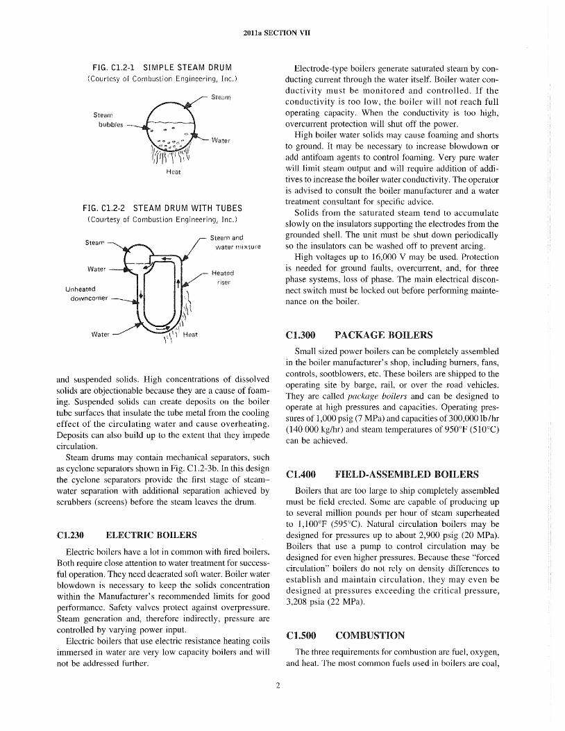
20lla SECTION VII
FIG. Cl.2-1 SIMPLE STEAM DRU M (Courtesy of Combustion Engineering, Inc.)
Steam
bubbles
Heat
FIG. Cl.2-2 STEAM DRUM WITH TUBES (Courtesy of Combustion Engineering, Inc.)
Steam and water mixture
Heated riser
and suspended solids. High concentrations of dissolved solids are objectionable because they are a cause of foaming. Suspended solids can create deposits on the boiler tube surfaces that insulate the tube metal from the cooling effect of the circulating water and cause overheating. Deposits can also build up to the extent that they impede circulation.
Steam drums may contain mechanical separators, such as cyclone separators shown in Fig. C1.2-3b. In this design the cyclone separators provide the first stage of steamwater separation with additional separation achieved by scrubbers (screens) before the steam leaves the drum.
Cl.230 ELECTRIC BOILERS
Electric boilers have a lot in common with fired boilers. Both require close attention to water treatment for successful operation. They need de aerated soft water. Boiler water blowdown is necessary to keep the solids concentration within the Manufacturer's recommended limits for good performance. Safety valves protect against overpressure. Steam generation and, therefore indirectly, pressure are controlled by varying power input.
Electric boilers that use electric resistance heating coils immersed in water are very low capacity boilers and will not be addressed further.
2
Electrode-type boilers generate saturated steam by conducting current through the water itself. Boiler water conductivity must be monitored and controlled. If the conductivity is too low, the boiler will not reach full operating capacity. When the conductivity is too high, overcurrent protection will shut off the power.
High boiler water solids may cause foaming and shorts to ground. It may be necessary to increase blowdown or add antifoam agents to control foaming. Very pure water will limit steam output and will require addition of additives to increase the boiler water conductivity. The operator is advised to consult the boiler manufacturer and a water treatment consultant for specific advice.
Solids from the saturated steam tend to accumulate slowly on the insulators supporting the electrodes from the grounded shell. The unit must be shut down periodically so the insulators can be washed off to prevent arcing.
High voltages up to 16,000 V may be used. Protection is needed for ground faults, overcurrent, and, for three phase systems, loss of phase. The main electrical disconnect switch must be locked out before performing maintenance on the boiler.
Cl.300 PACKAGE BOILERS
Small sized power boilers can be completely assembled in the boiler manufacturer's shop, including burners, fans, controls, sootblowers, etc. These boilers are shipped to the operating site by barge, rail, or over the road vehicles. They are called package boilers and can be designed to operate at high pressures and capacities. Operating pressures of 1,000 psig (7 MPa) and capacities of 300,000 lb/hr (140000 kg/hr) and steam temperatures of 950°F (510°C) can be achieved.
Cl.400 FIELD-ASSEMBLED BOILERS
Boilers that are too large to ship completely assembled must be field erected. Some are capable of producing up to several million pounds per hour of steam superheated to ],1 OO°F (595°C). Natural circulation boilers may be designed for pressures up to about 2,900 psig (20 MPa). Boilers that use a pump to control circulation may be designed for even higher pressures. Because these "forced circulation" boilers do not rely on density differences to establish and maintain circulation, they may even be designed at pressures exceeding the critical pressure, 3,208 psia (22 MPa).
C1.500 COMBUSTION
The three requirements for combustion are fuel, oxygen, and heat. The most common fuels used in boilers are coal,
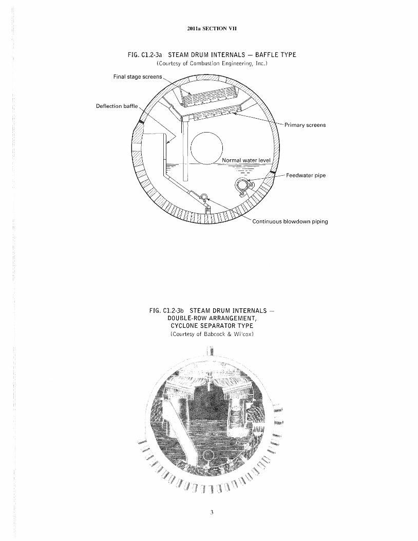
2011a SECTION VII
FIG. C1.2-3a STEAM DRUM INTERNALS - BAFFLE TYPE (Courtesy of Combustion Engineering, Inc.)
Final stage screens
Deflection baffle
Primary screens
Feedwater pipe
Continuous blowdown piping
FIG. C1.2-3b STEAM DRUM INTERNALS DOUBLE-ROW ARRANGEMENT,
CYCLONE SEPARATOR TYPE (Courtesy of Babcock & Wilcox)
3
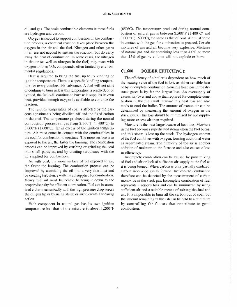
2011a SECTION VII
oil, and gas. The basic combustible elements in these fuels are hydrogen and carbon.
Oxygen is needed to support combustion. In the combustion process, a chemical reaction takes place between the oxygen in the air and the fuel. Nitrogen and other gases in air are not needed to sustain the reaction, but do carry away the heat of combustion. In some cases, the nitrogen in the air (as well as nitrogen in the fuel) may react with oxygen to form NOx compounds, often limited by environmental regulations.
Heat is required to bring the fuel up to its kindling or ignition temperature. There is a specific kindling temperature for every combustible substance. A fuel will not start or continue to burn unless this temperature is reached; once ignited, the fuel will continue to burn as it supplies its own heat, provided enough oxygen is available to continue the reaction.
The ignition temperature of coal is affected by the gaseous constituents being distilled off and the fixed carbon in the coal. The temperature produced during the normal combustion process ranges from 2,500o P (1 400°C) to 3,000°F (I 600°C), far in excess of the ignition temperature. Air must come in contact with the combustibles in the coal for combustion to continue. The more surface area exposed to the air, the faster the burning. The combustion process can be improved by crushing or grinding the coal into small particles, and by creating turbulence with the air supplied for combustion.
As with coal, the more surface of oil exposed to air, the faster the burning. The combustion process can be improved by atomizing the oil into a very fine mist and by creating turbulence with the air supplied for combustion. Heavy fuel oil must be heated to bring it down to the proper viscosity for efficient atomization. Fuel can be atomized either mechanically with the high pressure drop across the oil gun tip or by using steam or air to create a shearing action.
Each component in natural gas has its own ignition temperature but that of the mixture is about 1,200°F
4
(650°C). The temperature produced during normal combustion of natural gas is between 2,500°F (I 400°C) and 3,000°F (I 600°C), the same as that of coal. Air must come in contact with the gas for combustion to proceed. Certain mixtures of gas and air become very explosive. Mixtures of natural gas and air containing less than 4.0% or more than 15% of gas by volume will not explode or burn.
Cl.600 BOILER EFFICIENCY
The efficiency of a boiler is dependent on how much of the heating value of the fuel is lost, as either sensible heat or by incomplete combustion. Sensible heat loss in the dry stack gases is by far the largest loss. An oversupply of excess air (over and above that required for complete combustion of the fuel) will increase this heat loss and also tends to cool the boiler. The amount of excess air can be determined by measuring the amount of oxygen in the stack gases. This loss should be minimized by not supplying more excess air than required.
Moisture is the next largest cause of heat loss. Moisture in the fuel becomes superheated steam when the fuel burns, and this steam is lost up the stack. The hydrogen content ofthe fuel combines with oxygen, forming additional water as superheated steam. The humidity of the air is another addition of moisture to the furnace and also causes a loss in efficiency.
Incomplete combustion can be caused by poor mixing of fuel and air or lack of sufficient air supply to the fuel as it is being burned. When carbon is only partially oxidized, carbon monoxide gas is formed. Incomplete combustion therefore can be detected by the measurement of carbon monoxide in the stack gas. Incomplete combustion of fuel represents a serious loss and can be minimized by using sufficient air and a suitable means of mixing the fuel and air. It is impossible to burn all the carbon out of coal, but the amount remaining in the ash can be held to a minimum by controlling the factors that contribute to good combustion.
2011a SECTION VII
SUBSECTION C2 BOILER OPERATION
C2.100
C2.110
GENERAL GUIDELINES
OPERATOR TRAINING
Safe and reliable operation is dependent to a large extent upon the skill and attentiveness of the operator and the maintenance personnel. Operating skill implies the following:
(a) knowledge of fundamentals (b) familiarity with equipment (c) suitable background of training and experience Full and effective use should be made of manufacturer's
instruction books on operation and maintenance. Of special importance are written procedures prepared expressly for each installation by the manufacturers' service engineers and qualified personnel from the operating organization before and during the commissioning period. These procedures are based on actual experience and often include invaluable information on what the equipment is expected to do. Limitations critical to safe and reliable operation are also given.
Control systems vary in complexity from computer control to manual operation. Regardless of the type of system used, the operators should be thoroughly trained so that they can maintain safe and continuous operation during changeover from automatic to manual control as well as to continue operation by manual control if the automatic systems are out of service. The operator should have instrumentation at the point of manual operation to permit him to be aware of operating conditions at all times. Regularly scheduled auto-manual changeover, manual operation, and emergency drills to prevent loss of these skills are recommended.
C2.120 PREVENTING EXPLOSIONS
Interlocks should be established that ensure operation is within safe limits as described in the National Fire Protection Association documents listed under Reference Sources in this Subsection. Startup and shutdown events should be performed to satisfy the interlock system. This will prevent potentially dangerous moves during mental lapses or moments of crisis.
One of the most common causes of furnace explosions is failure to purge the boiler furnace prior to startup. The
5
boiler furnace, generating bank, economizer, air heater, and ducts should be adequately purged before any source of ignition (igniter, pilot flame) is introduced into the furnace to ensure that no fuel gas has accumulated in the unit. The purge, usually air, should be at a sufficient rate to provide adequate velocity to clear dead spots in the entire unit. This precaution should always be observed after an accidental loss of ignition. Purge interlock systems equipped with timers, when properly installed and adjusted, ensure that purging will be adequate and effective. Such interlocks should not be bypassed or defeated. Purge times and flows should be observed by the operator to verify the purge sequence is complete. Air flow rates may be checked on the air flow recorder or by relation to draft loss differential across part or all of the boiler system.
C2.130 MAINTAINING PROPER WATER LEVEL
Boiler water level control and furnace pressure control, where required, are subsystems of combustion control. Every effort should be made to place these on automatic operation as soon as possible during startup because they require constant operator attention otherwise.
Operating without sufficient water to cool pressure parts is the most common way to destroy a boiler. The best, safest, and only advice is
C2.140
IF IN DOUBT - SHUT IT DOWN
MAINTAINING PROPER FURNACE PRESSURE
Boilers are designed so that furnace pressure is negative or positive with respect to atmospheric pressure. Negative pressure furnaces are commonly cal1ed balanced draft because the induced draft (ID) fan is removing flue gas at the same rate the forced draft (FD) fan is adding combustion air. With furnace pressure controlled slightly negative at -0.1 in. (-3 mm) to -0.5 in. (-13 mm) of water, flue gas leaks from the boiler are eliminated and ambient air infiltration, which can lower boiler efficiency, is minimized.
2011a SECTION VII
Furnace implosions can occur in very large boilers with balanced draft furnaces if the unit is subjected to the full ID fan suction capability at low flow conditions. Sudden loss of fuel can cause rapid decrease in furnace temperature, which can also contribute to a sudden reduction in furnace pressure.
Boilers with positive pressure furnaces have forced draft fans only. Furnace pressure varies from 5 in. to 25 in. of water (1.3 kPa to 6.2 kPa) as the boiler operates from minimum to maximum. Design pressure of furnaces rarely exceeds 28 in. of water [about 1 psig (7 kPa)] because of the cost of reinforcing the furnace wall support system.
With pressurized furnaces, the use of portable hand torches for ignition is impractical; therefore, electrically actuated ignitors should be provided.
Compressed air should be available to actuate the shielding or aspirating air jets that permit safe opening of the observation doors and the openings through which oil burner guns are inserted. Mechanical interlocks are recommended to prevent opening observation doors or burner openings unless compressed air is available at the aspirating jets. Fly ash should not be allowed to accumulate on observation door sills. Access doors should be bolted or locked closed to prevent accidental opening when under pressure.
Inner casing leakage may cause rapid overheating and failure of the outer casing; therefore, the operators should make periodic inspections for hot spots and be instructed to shut down the unit if overheating of the outer casing is detected.
Coal fired pressurized furnaces introduce the problem of sealing off the pressurized feeders from the coal bunkers. This is usually done by a column of coal between each bunker outlet and the feeders. No-coal-flow alarms should be provided to guard against loss of the seal, which could result in a fire in the bunker.
C2.1S0 MAINTAINING CLEARANCE FOR EXPANSION
All boilers expand when they are heated from ambient temperature. Expansion is provided for within the boiler itself by the Manufacturer. It is necessary to maintain expansion clearance between the boiler, its associated piping and ductwork, and other parts of the installation.
Generally, gas, oil, and coal fired boilers of 50,000 lb/hr to 400,000 lb/hr (23 000 kglhr to 180000 kglhr) capacity are bottom supported so they expand upward. Larger capacity boilers hang from structural steel and therefore expand downward. The support method chosen is based on the most economical means of providing for thermal expansion.
6
C2.160 REFERENCE SOURCES
Several organizations publish valuable operational guidelines. Some of these guides are general in nature and others go into great detail on specific topics or equipment related to power boiler operation. Most power boiler operational problems have already been discovered and can be avoided by learning from the combined knowledge and experience of others, such as the following:
(a) National Fire Protection Association (1) 8501 Single B umer Boiler Operation (2) 8502 Prevention of Furnace Explosions/
Implosions in Multiple Burner Boilers (3) 8503 Pulverized Fuel Systems (4) 8504 Automatic Fluidized-Bed Boiler Operation (5) 8505 Stoker Operation (6) 8506 Heat Recovery Steam Generator Systems
(b) American Society of Mechanical Engineers ( 1) ASME Boiler and Pressure Vessel Code -
Section I, Rules for Construction of Power Boilers (2) ASME Consensus on Operating Practices for the
Control of Feedwater Chemistry in Modern Industrial Boilers
(3) ASME PTC 4.1, Steam-Generating Units Efficiency testing of boilers by the heat loss and inputoutput methods is fully described
( c) boiler manufacturers ( 1) equipment operation and maintenance manuals (2) feedwater and boiler water quality requirements
(d) fuel equipment manufacturers ( 1) equipment operation and maintenance manuals (2) fuel handling, preparation, and burning (3) combustion safeguard systems
( e) boiler insurance companies ( 1) Boiler Code compliance questions (2) inspection service (3) operation and inspection guide publications (4) accident or failure statistics
(/) state and local agencies: rules and regulations for design or operation
C2.200
C2.210
PREPARING FOR OPERATION
INSPECTION
A new or relocated power boiler should not be put into operation until it has been inspected by an Authorized Inspector for the jurisdiction or insurance company and the required certificates have been issued.
C2.220 CHEMICAL CLEANING
New power boilers are generally cleaned internally by a boiling out procedure using a chemical solution. The
20na SECTION VII
cleaning of existing boilers may be done mechanically, chemically, or by both methods, depending on the arrangement and accessibility of the heating surfaces and the type of deposits. Acid cleaning, if used, should be done under the supervision of experienced personnel thoroughly familiar with the hazards of such operations. Chemical cleaning contractors can provide specialized equipment and trained manpower.
C2.230 SAFETY CHECKLIST FOR INSPECTION
(a) Before entering any boiler, lock out and tag all equipment items with movable parts connected to the boiler and fuel system and place a sign at the operating controls indicating that a workman is in the boiler.
(b) Before entering any power boiler, make sure it is properly isolated at ALL fuel, flue gas, steam and water sources; make sure it is properly vented and obtain an air sample to check for breathing quality. Use low voltage lights or explosion proof flashlights inside the boiler. See C6.310 for more details.
(c) Notify the person in charge at the site when beginning and upon completion of the inspection.
(d) Inspect with another person so if assistance is required help will be close at hand.
(e) Always be aware of the nearest escape routes. (f) Before closing drum manholes and furnace doors, it
is essential to ensure that all personnel are out of the boiler.
C2.240 WATER-SIDE CHECKLIST
(a) The water side, including drums, tubes, and headers, should be free of extraneous material such as dirt, tools, rags, wood, or trash.
(b) All internal fittings should be in serviceable condition and securely installed in the correct position.
( c) Look for evidence of corrosion on pressure parts. (d) Look for erosion at mating surfaces of manways,
handhole caps, and flanges. (e) Note location and type of deposits in boilers that
have previously been in operation and collect samples for analysis.
C2.2S0 FIRE-SIDE CHECKLIST
(a) All combustion air and flue gas passages such as the furnace, convection bank, ductwork, ash hoppers, and fans should be free of extraneous material.
(b) It is especially important to remove all combustible material that might ignite, bum, and trigger the explosion of unburned fuel if ignition is lost or interrupted at the burners.
7
(c) Dampers and burner registers should be operated to confirm that they are free to travel from fully closed to wide open.
(d) Check to verify that the refractory is correctly located and properly installed. Burner orifices, overfire air nozzles, observation ports, and instrument taps must not be covered or plugged. Repairs should be made if refractory is missing or significantly damaged. Slag should not be removed from the surface of the refractory unless it interferes with normal operation. It is very likely that chunks of refractory will be removed with the slag.
( e) Tum off the light occasionally while inside the unit and look about for daylight shining through holes that indicate air or flue gas leaks.
(j) Always carry a note pad and pencil and make notes of conditions found to avoid reliance on memory. Sometimes a photograph or sketch will be valuable as a reference base for future inspections.
(g) Look for corrosion of pressure parts (1) under deposits (2) at tube-to-tubesheet joints (3) where the flue gas may have been below its
dew point (4) under refractory or insulation if it has been water
soaked for a period of time (h) Look for erosion
( 1) of induced draft fan housings and wheels handling dirty gas
(2) in the vicinity of soot blowers (3) at sharp turns or points where dirty gas flow may
concentrate (4) in areas near where any steam or water leaks have
occurred (i) Look for overheating
(1) of tubes in the areas of high heat application, especially if there is evidence of deposits inside the tubes. Often minor swelling of tubes is easier to feel than it is to see. A flashlight beam may be used to detect blistering.
(2) at the top end of tubes in boilers that may have experienced operation at low water level.
(3) whenever tubes are warped or otherwise physically distorted. A flashlight beam parallel to the furnace wall highlights out-of-plane tubes.
(4) on the fire side face of headers close to stokers or burners (thermal fatigue cracking has the appearance of a jigsaw puzzle made up of very small pieces).
(5) on the front row of superheater tubes. Nondrainable superheaters often boil out unevenly across the width of the boiler. Tubes may be overheated if the flue gas temperature exceeds the metallurgical limit before steam flow is established in all the tubes. Tubes near the sidewalls are usually the last to boil out because the temperature of the flue gas passing over them is lower. Overheating can also occur during periods of operation other than startup.
2011a SECTION VII
Maintaining high steam temperatures at loads below the design steam temperature control point may overheat some superheater tubes. Swelling may not be very evident, so micrometer measurements are recommended to compare against the original tube diameter.
C2.260 EXTERNAL CHECKLIST
(a) Free access should be provided to the burner fronts, observation ports, and operating valves.
(b) Shipping pins or temporary construction restraints should be removed to permit free thermal expansion. Check drawings and operating instructions for location of factory installed restraints.
(c) Top supported power boilers should have expansion indicators installed so actual movement can be compared to expected movement. Piping should be free to move from the cold to hot position.
(d) All instrumentation and controls should be complete, operational, and checked for proper calibration and action.
(e) External indicators permanently marked or installed on damper shafts and registers are necessary for positive determination of position while the boiler is in service.
(f) Personnel protection from hot surfaces should be provided by restricting access or by covering the hot surfaces with insulation.
(g) Find potential air or flue gas leaks in the furnace of out of service boilers operated with positive furnace pressure by operating the forced draft fan at high flow rates. Leaks that can be felt or heard should be repaired before returning the boiler to service. Boilers normally operated with negative furnace pressure can be leak checked at low air flow rates by pressurizing the furnace slightly or by pulling a slightly negative pressure. Precautions must be taken to prevent overpressurizing the furnace, both internally and externally.
(h) Safety and relief valve outlets should be piped so they cannot discharge on people or any property that may be damaged. The discharge piping should be supported so that loads (piping weights and dynamic forces during operation) transmitted to the relief valves are minimized. The weight supported by the valve should not exceed the weight of a short elbow and drip pan or comparable weight of a direct connected free hanging discharge pipe. Installations requiring long discharge piping runs should not have those discharge piping runs directly connected to the valve. The valve manufacturer should be consulted if the weight to be loaded on a valve outlet exceeds a short elbow with a drip pan.
8
C2.270
C2.271
HYDROSTATIC TESTING
General
New power boilers or boilers that have been out of service for an extended period of time should be subjected to a hydrostatic test of 1.5 times the design pressure. For new field erected units this is normally conducted by the boiler manufacturer as soon as the pressure parts are assembled. Shop fabricated units are tested in the shop. In either case, the test should be witnessed by an Authorized Inspector.
A hydrostatic test at normal operating pressure may be adequate for existing units after an outage if no major pressure part repairs were made during the outage. This test need not be witnessed by the Authorized Inspector unless he specifically requests it.
C2.272 Pretest
Before the test, the boiler pressure parts should be closed using new gaskets at any access points that were open during the shutdown. Feedwater, steam, blowdown, gage glass, drain, and vent valves should be operational so the boiler can be filled, vented, and drained.
A recently calibrated pressure gage must be visible to the person responsible for controlling the application of pressure during the test. The range and spacing between numbers on the gage face must permit the accurate determination that the test pressure has been reached. Location of the pressure gage on boilers must consider the water leg before the gage so readings can be compensated for this hydrostatic head.
Safety valves must be gagged or have hydrostatic test plugs installed. Test plugs are recommended, especially on boilers over 2,000 psig (14 MPa) design pressure where misapplication of gags can result in safety valve seat or spindle damage. The valve manufacturer's recommendation for applying gags or plugs should be followed. Usually gags are not fully tightened until the hydrostatic pressure is 80% of operating pressure. All gags and test plugs must be removed qfter testing is completed.
C2.273 Testing
Fill the boiler and superheaters with clean water. The water temperature should not be less than the ambient temperature, but in no case less than 70°F (20°C). The test should not be performed until all pressure parts being tested have metal temperatures of at least 70°F (200e).
Nondrainable sections such as superheaters should be filled with de aerated distilled water, polished condensate, or demineralized water. Solids may be deposited in the superheater as it boils dry if soft water is used. Nondrainable stainless steel tubing must not be exposed to water containing chlorides or strong alkalis that concentrate as
2011a SECTION VII
the water is evaporated, which could cause stress con-osion cracking.
Vents should be left open until water flows from them and air has been removed from the boiler. The hydrostatic test will take a long time, be difficult to control and could be dangerous to inspecting personnel if air is trapped in any part of the boiler.
On higher pressure boilers, the initial application of pressure may be from high speed, high pressure pumps. Provisions must be made so the rate is controllable and the test pressure is not exceeded.
The pressure parts should be visually inspected for leaks while the boiler is subjected to the hydrostatic pressure. Loss of pressure may be due to leaking valves. A pressure increase may occur if the ambient temperature increases during the test. Any leaks must be repaired after draining the boiler. Another hydrostatic test is then required to check the repair.
Always open the vents to speed draining the boiler, especially where atmospheric pressure may hold some water in the boiler. If freezing is a possibility, the boiler should be drained and the nondrainable sections should be kept heated to prevent freezing.
At the end of a successful hydrostatic test the safety and relief valves must be returned to normal operating condition.
C2.300
C2.310
STARTING UP
GENERAL
All instrumentation and protective devices that provide the required margins of safe operation should be checked and operable prior to starting the boiler.
At least one recently calibrated steam pressure gage should be properly mounted and ready for service. Pressure transmitters should also be calibrated and ready to transmit pressure indication to the control center.
Blowoff valves, including continuous blowdown valves, water column drain valves, gage glass drain valves, gage cocks, feedwater supply valves, and feed water control valves should be closed and in good working order. Valves, if any, between the steam drum and water column and gage glass shutoff valves should be locked or sealed open. Gage glass and furnace television gear, water level indicators, and recorders should be ready for use. Gage glass illumination, periscope ducts, and mirrors should be properly installed and usable. During initial operation of a new boiler and until instrumentation has been proved, it may be advantageous and safer to station an operator at the gage glass with telephone communication to the control room or control center for feed pumps and water level control. A positive check should be made of gage glass elevation whenever there is any reason to doubt that the
9
glass is not properly located. This can be done by actual visual comparison of water level in the drum through an open manhole and water level in the gage glass prior to closing the manhole opening. The water level in the drum should be lowered by draining water from the boiler to check the action of the water level in the gage glass. Pressure- and temperature-compensating devices for water level recorders and indicators should be ready for operation.
Gage glasses that are located more than 8 ft (2.4 m) away from the drum and that are independently supported should be conected for any movement of the drum from cold to hot positions.
Safety valves should be inspected externally to see that they are free to operate and that their discharge piping and drain piping are open to atmosphere and free to expand without imposing loads on the safety valve bodies.
Manual or motor operated main steam stop valve stems can be eased up just enough to reduce thermal expansion stresses which could result as they go from cold to hot. If the header system is not under stearn pressure, the main steam stop valve can be actually unseated and rec10sed gently.
In the case of a single boiler turbine system it is advisable, before lighting off, to open the main steam stop valve wide to simultaneously warm up the boiler and the main steam and auxiliary steam piping all the way to the turbine.
Fans and boiler feed pumps should be checked to ensure they are ready for service.
Chemical injection equipment should be checked by actually pumping a small amount of water into the drum.
C2.320 ESTABLISH WATER LEVEL
The drum vent should be open. All drum header and economizer drains should be closed. Superheater and main steam line drains should be open. The header vents should be open to properly vent the header and superheater. The boiler should be filled through the normal feedwater lines to test their operating condition and so the operators become familiar with their use.
Power boilers should be filled with water at a temperature as close as possible to the metal temperature of the drums and headers; the deviation should not exceed that specified by the boiler manufacturer. This precaution is necessary to protect thick walled drums from excessi ve temperature stresses and to prevent leaks in rolled tube joints.
Water levels should be established at the safe observable minimum level. As the water heats up, it will rise to the normal operating level. This will reduce blowdown losses and help prevent canyover of water into the steam headers.
Circulating pumps for forced circulation boilers should be prepared for service by opening suction valves, backing
2011a SECTION VII
off the stems of combined discharge stop-and-check valves, and venting air from the pump casings. The thorough venting of canned motor pumps and submerged motor pumps is of special importance because of the danger of damage to the motor capsule and motor bearings from entrapped air. After the first circulating pump is put in service and before lighting off a burner, the low pump differential pressure fuel trip should be checked by actually tripping off the circulating pump. Manufacturer's recommendations must be followed.
C2.330 LIGHT-OFF
Water level should be maintained within safe limits by feeding or blowing down while pressure is being raised.
The rate at which a boiler may be brought up to pressure depends on its design. The Manufacturer's detailed instructions should be followed closely. These instructions typically specify maximum temperature gradients for thickwalled drums and maximum metal temperatures for superheater elements.
During warm-up of a large multiple-burner unit, operate those burners that will produce the most uniform gas temperature distribution leaving the furnace.
New refractory settings or those that have been extensively rebuilt should be dried out thoroughly and slowly. During this period, the firing rate should be sufficient to produce a light flow of vapor from the open drum vent. The drying out period may be from 48 hr to I week in duration, depending on the design of the setting and the moisture content of the refractories. The precautions regarding safe minimum firing rates and the necessity to ensure that combustion is complete apply especially to the drying out period.
The drum vent or vents should be closed when steam pressure reaches 25 psig (170 kPa). The firing rate should be regulated so that safe limits of gas temperature are not exceeded at the furnace exit, as specified in the Manufacturer's instructions. Drainable superheaters do not require venting if firing rate is carefully regulated. Nondrainable superheaters should be vented to permit boiling out of condensate trapped in the elements. In order to warm up a single boiler and turbine system expeditiously, the venting should be done at the drain connections just upstream of the turbine stop valves. Excessive venting of superheaters is wasteful of both water and heat; consequently, the regulation of the firing rate is an important factor in reducing such losses.
During the period when steam pressure is initially being raised, the boiler should be checked carefully to see that it expands freely in the manner and direction intended in its design.
Gage cocks and water column and gage glass drains may now be operated for test.
10
As steam pressure is increased, the water level should be carefully controlled within normal limits. Prior to picking up load, it is desirable to keep the water level near the lowest safe level to allow for thermal expansion of the water as the steam generation rate increases.
Hand lifting of safety valves on boilers operating below 600 psig (4 MPa) may be employed to see that they will operate. If necessary, hand lifting of safety valves on boilers operating above 600 psig (4 MPa) may be attempted provided that adequate precautions are taken to prevent personnel injury and equipment damage. Care should be taken to hold the valve open wide and release the hand lever briskly so that the valve closes cleanly with a snap. For such a test, the steam pressure in the boiler should be at not less than 75% of the set pressure of the lowest-set safety valve.
Before releasing a boiler for normal service, new or rebuilt safety valves should be tested to verify that they pop and reseat at the correct pressures. Adjustments should be made only by qualified personnel. On many large, hightemperature boilers, final adjustments to the safety valves are typically made a few days or weeks after the boiler has been brought up to temperature. After final adjustment, the settings should be sealed with tamper-proof seals that identify the organization that set the valves.
C2.340 GOING ON-LINE
In bringing a boiler on-line with other boilers on a header system, certain precautions are necessary to avoid water hammer and excessive temperature gradients in the piping. Adequate drainage and warming of the piping will eliminate the risk of water hammer. The judicious use of bypass valves around main header valves will avoid steep temperature gradients. Header drains should be operated. The steam line from the boiler to the header should be brought up to temperature by operating bypass and drain valves to create a backflow of steam from the header. When up to temperature and line pressure, the header valve may be opened wide and the bypass closed. The stem of the nonreturn valve should be backed off to a position corresponding to about 25% open until the boiler begins to supply steam to the header, after which the stem should be backed off to the wide open position. In the absence of a nonreturn valve, the boiler stop valve should be opened slowly when the pressures in the boiler and header are approximately equal.
With two manually operated stop valves, equalize the pressure between the two valves as above by the use of a bypass valve around the stop valve near the header, and then slowly open that valve wide. When the pressure in the header and boiler are approximately equal, slowly open the stop valve near the boiler.
When raising steam pressure on a boiler not connected to a header system, it is desirable to warm up the boiler
2011a SECTION VII
and steam line together by appropriate operation of the drain valves to remove condensation and create the desired flow of warming steam.
In the case of a boiler having two steam outlets, each equipped with a nonreturn valve, use the following procedure. After it is on-line, ascertain if possible, by the use of a listening stick, whether steam is flowing through both outlets. This may also be checked by operation of each nonreturn valve stem in the closing direction.
C2.400
C2.410
ON-LINE OPERATION
OPERATING DATA
Whenever a new boiler is placed in service, operating data should be recorded, compared to predicted performance, and saved for future reference. This information is extremely valuable for diagnosing problems if abnormal operation occurs. Record all operating parameters such as pressures, temperatures, flows, draft losses, motor amps, turbine speeds, damper positions, and interlock set points.
Routine operating data is normally logged in most power plants. This data assists operators to spot trends and take corrective action. Maintenance plans can be made by comparing the routine logs to the base data.
For operating data to be meaningful, the instruments and controls must be well maintained and properly calibrated.
C2.420
C2.421
WATER-SIDE OPERATIONS
Feedwater Treatment
Instructions for feedwater treatment prepared by a competent feedwater chemist should be followed. It is inadvisable to experiment with "homemade" treating methods or compounds. Representative samples of feedwater and boiler water need to be analyzed frequently to ensure they are within specifications.
C2.422 Oil in Boiler
Every effort should be made to prevent oil from getting into the water side of boilers. Oil causes foaming or combines with suspended matter to form a sludge that, in tum, can cause overheating of pressure parts through its insulating effect.
Oil gets into boilers usually in the form of contaminated condensate from fuel oil heaters or from leaking valves in lines providing steam to the oil burner system. Occasionally, lubricating oil will leak from turbine bearings and pollute the gland-steam-leakoff condensate. It is, therefore, important to continuously monitor the quality of condensate returned and discard it whenever contamination is detected.
11
If oil does get into a boiler, the boiler should be taken out of service immediately and thoroughly cleaned.
C2.423 Water Level
Maintenance of water at a safe level in the boiler is of vital importance. It must not be allowed to go low enough to endanger the boiler through overheating or to go high enough to interfere with correct functioning of steam and water separation devices. Automatic level control devices and low and high level alarms should be considered solely as operating aids and should not be relied upon entirely. Water level, as indicated by two or more devices, should be frequently compared. Important differences in level indications should be promptly investigated and reconciled.
Water gage glasses should be well illuminated and should be kept clean. Dirt on or in a gage glass may be mistaken for the water level. Do not allow steam or water to leak from the water gage glass, water column, or its connections, as this may affect the accuracy of the level indication. The first duty on taking over a shift is to ascertain the operating status of the boiler(s). This includes the load, water level controls, water level indicators, and water level recorders. Water column and gage glass accuracies should be checked by blowing down the water columns and water glasses and noting the promptness with which the water level is restored. Where water columns are equipped with automatic low water boiler trips, suitable operating procedures should be developed to preclude tripping the boiler while determining that the water column is functional and in good operating condition. In case the water gage glasses are the flat glass or the round glass mica protected types, follow the Manufacturer's instructions for blowing. Indiscriminate operation of the drain valves and excessive blowing will damage the glasses and mica protectors, resulting in excessive maintenance.
C2.424 Low Water Level
When the level of water is not visible in the gage glass, blow down the water column or gage glass to determine whether the level is above or below the visible range of the gage glass. If a water level indicator and a water level recorder are available and their indications are in agreement, blowing down the gage glass should not be necessary to determine the level.
If the water level is below the gage glass, the safest and most conservative action is to shut off fuel and air but continue to feed water slowly until the normal water level is restored.
If the boiler has sufficient indicators and/or recorders and the operator can readily establish that the drum water level is stabilized just below the visible range of the gage glass, operation of the unit can be maintained provided immediate action is taken to restore the water level in the
2011a SECTION VII
drum to normal level. This should be done with care, using all indicators available, such as feed water flow meter, steam flow meter, drum level recorder, and all other instruments that properly sense the operating conditions of the boiler.
In case of low water, if there is any possibility that the boiler has been damaged, it should be cooled down and thoroughly inspected for damage due to overheating.
C2.425 High Water Level
If the water level is above the visible range of the gage glass, shut off the feed water, fuel, and combustion air in that order. For hand fired boilers, smother fire by covering grate with green coal or wet ashes. For stoker fired boilers, shut down the stoker, cut off air supply, and open furnace doors. If water level does not recede into the visible range of gage glass within 2 min, operate main blowdown valves as required to lower the water level. A sudden steep drop in steam temperature at the superheater outlet usually means that water has carried over from the drum, and the same action should be taken as for high water level.
With a multiple boiler header system, open the drain valve on the boiler side of the header valve and all superheater drain valves, then close the main steam valve at the header. For a single boiler-turbine system, the prudent course of action is to trip the turbine stop valves, then open superheater drain valves and steam line drain valves.
In the case of either low or high water, the underlying cause should be determined and the appropriate conective action taken before attempting to resume normal operation. The water level should be controlled manually until the automatic control is known to be functioning conectly and normally.
C2.426 Boiler Water Blowdown
(a) It is important that the concentration of solids in the water be determined at least daily, and the blow down (continuous or intermittent) should be regulated to control the concentration within prescribed limits. A safe maximum water concentration in boilers can best be maintained by adjusting the continuous blowdown frequently on the basis of water analysis.
(b) If the boiler is not fitted with sampling connections, the boiler should be blown down at least once every 24 hr by slowly operating the blowdown valves through a full open and close cycle. Waterwall drain or blow off valves should not be operated except when the boiler is banked or in accordance with specific instructions from the Manufacturer of the boiler.
( 1) During blowdown, unless the operator can clearly see the steam drum gage glass, an assistant should be stationed to watch the gage and positioned to signal the operator. Never permit an operator at the blowoff valve to
12
leave until blowdown operation is completed and blowdown valves are closed.
(2) No other duty should be performed during blowdown.
(3) Open and close blowoff valves or cocks slowly. (4) Only one boiler should be blown down at a time. (5) With the boiler in service, schedule blowoff at
reduced or moderate rates of steaming. (6) Section I describes various blowoff valve combi
nations, allowable for different classes and boiler sizes. Operation of these valves therefore should follow the Manufacturer's instructions. In general, however, the valve next to the boiler is normally always protected; hence, this valve is not throttled but is always opened first and closed last. Throttling is done with the outboard valve.
(7) A boiler should not remain in service if the drum water level cannot be maintained.
C2.427 Blowoff Valve Sequencing
If a quick opening valve and a slow opening valve are in combination, the quick opening valve would normally be opened first and closed last, and blowing down is accomplished with the slow opening valve.
In the case of a hard-seat valve followed by a seatless valve, the hard-seat valve should be opened last and closed first.
In the case of two seatless valves where the plunger continues to move after port closure, the valve nearest the boiler should be opened last and closed first. If this is not done, the water trapped between the outer and inner valves would be placed under compression by the plunger travel after port closure.
In any other combination of two identical valves, the sequence of operation should provide that the same valve is always opened last and closed first to save the other valve from throttling service and ensure tight closing of the combined system.
When a large amount of blowing down is necessary, open the cock or quick opening valve first until it is half open and leave it in that position; open globe-type or slow opening valve until water is lowered about 1/2 in. (13 mm) in the gage glass; then open both valves wide until blowing down is completed. See that the cock and valve shut off tight and remain tight. Leaking blowoff valves should be repaired at the first opportunity.
C2.428 Water Carryover
Wet steam or carryover from the steam drum is undesirable and in boilers with superheaters can be very serious, so it should be avoided. The causes of canyover are many, such as inadequate drum internals, foaming, and high drum water level.
2011a SECTION VII
Foaming may be caused by a high concentration of dissolved solids and suspended matter in the boiler water. Blowing down and feeding fresh feedwater should be effective in reducing the boiler water concentration and thereby stopping the foaming, if this is the cause. Contaminants in the feedwater can also cause foaming regardless of the boiler water concentration and antifoaming agents can be introduced to aid in reducing the foaming tendency. Improper drum internals, limited separation volume, and sloping drum level in large shop assembled boilers are possible causes of carryover, and tests should be made on all new installations to establish whether the boiler has a carryover problem.
High carryover problems show up as steep downward swings in superheat temperature or as water hammer in saturated steam headers. Deposits will be found in steam traps, on control valves, and on turbine blades eventually at even minor carryover rates.
Spray water used to control steam temperature must be of very good quality, or it can be a source of steam system deposits.
C2.430 SAFETY VALVES
Check periodically to see that the safety valves are free to operate and are not leaking. Minor leaks should be noted for future repair. Major leaks will rapidly destroy the valve's ability to function, so they should be repaired as soon as possible. A gag must not be applied on a safety valve of an operating unit unless the capacity of the remaining operable safety valves equals or exceeds the Code requirement.
C2.440 LEAKS
Periodic inspections are necessary to locate and tag water, steam, air, and flue gas leaks that can be repaired when the boiler is removed from service. If a serious leak occurs, shut down the boiler immediately. Many people have been injured and much property damage has resulted from attempting to repair boilers,piping, and auxiliaries under pressure. Repairs should not be permitted except on properly depressurized, deenergized, and isolated equipment. Such repairs should be made before returning the equipment to service (see Subsection C7).
In the case of tube failure in a watertube boiler fired with pulverized coal, oil, or gas, shut off the fuel flow, shut down forced draft fans, primary air fans, and mill exhausters. Shut off supply of feedwater. Adjust flow of air to the minimum required to prevent steam from flowing into the operating area. When steam pressure has dropped to 0 psig (0 kPa), continue cooling procedure as in a normal scheduled shutdown. The entire boiler should be carefully inspected to determine extent of damage. In the case of
13
thick walled welded drums, careful examination should be made for incipient cracks. Small leaks in the waterwall areas may allow the unit to remain in service until peak load demands have passed, provided makeup water is sufficient.
For boilers fired by stokers or other fuel burning equipment that prevents almost instantaneous stopping of combustion, shut off air flow and fuel flow but continue to operate the grate to remove the heat source. Use all available means to smother the fire without risk of subsequent explosion. Shut off any steam output from the boiler so as to minimize the rate of steam pressure reduction and consequent temperature drop. Adjust feedwater flow to the boiler to the maximum consistent with protection of supply to other associated boilers, and attempt to maintain a normal water level. As soon as the hazard of overheating pressure parts from combustion of fuel ceases to exist, shut off supply of feedwater and then proceed as described for pulverized coal, oil, or gas fired boilers.
Tube leaks may be present if leakage is visible from outside the boiler or through observation ports, if feedwater flow exceeds steam flow by a wider margin than normal, or if water treatment chemicals have been used excessively.
Water may be observed in the ash hoppers or running out of the boiler setting. Don't be fooled by water coming out of insulation after a storm or on a new unit during startup. Confirm the leak by other means or wait a few days to see if it disappears.
White vapor stack plumes may indicate a leak. On cold days, gas burning units frequently have white vapor stack discharges. A lot of water vapor is formed when burning gas because it has a high hydrogen content. This water vapor condenses when it contacts cold air.
If water level in the boiler cannot be maintained, the cause could be a massive leak. Fuel input to the unit should be stopped when a massive leak exists.
C2.450 SOOT BLOWING
All heating surfaces should be kept free from soot to maintain efficiency and reliability of the boiler. Cleanliness of heating surfaces and effectiveness of soot blowing should be checked by observing changes in flue gas temperature and draft loss. Soot blowers, except in air heaters, should be operated only when the load on the boiler is above 50% of rated output, unless it has been demonstrated that there is no effect on flame stability due to soot blowing at loads below 50% of rated output.
On small balanced-draft boilers, it is advisable to change to manual control and increase the furnace draft enough to avoid positive furnace pressures while operating a soot blower. When operating soot blowers on small pressurizedfurnace boilers, it may be necessary to change from automatic to manual control to avoid upsetting the air flow control. On larger boilers with either balanced-draft or
2011a SECTION VII
pressurized furnaces, soot blower operation does not create a significant disturbance in furnace draft or air flow. In this case, the controls can be kept on automatic while operating soot blowers.
Steam soot blower piping should be thoroughly warmed and drained to prevent wet steam from quenching hot soot blower elements. Automatic soot blowing systems should be checked frequently to avoid repeated malfunctioning as exemplified by skipping, short blowing cycle, inadequate pressure at elements, sticking of elements, leaking source valves, and so forth. Any unusual noise or vibration of soot blower elements should be investigated promptly.
Alignment of soot blowers should be checked at regular intervals. Tubes adjacent to soot blowers should be inspected for possible cutting from soot blowing. Tenacious soot deposits may be removed by mechanical or hydraulic means after the boiler is shut down and cooled.
C2.460 C2.461
ASH REMOVAL General
Regular and reliable removal of bottom ash is an essential part of operating solid fuel fired boilers. Ash removal systems are usually pneumatic (air conveying) or hydraulic (water conveying). Boilers with steam capacities above 250,000 lb/hr (110000 kg/hr) generally use hydraulic systems. Pneumatic systems are normally used on boilers with a steaming capacity of 250,000 lb/hr (110 000 kg/hr) or less.
Ash is very abrasive, so the piping in both types of systems needs to be inspected and maintained frequently. Leaks will reduce performance of the system and create a housekeeping mess. Operation of hopper shutoff valves and isolation valves in system branches should be observed to confirm full opening and tight shutoff. Solid material, other than ash, can jam these valves or obstruct flow through them.
Conveying pressure and flow should be checked on pressurized air or hydraulic systems to ensure adequate system capacity. Periodic or recorded vacuum readings can be used to detect piping leaks and monitor performance of the vacuum source on pneumatic systems.
On large top supported boilers, adequate water level and flow must be maintained in the trough that forms the seal for the furnace enclosure at the point where the boiler and ash hopper meet.
Frequent inspections for ash buildup in the throat of dry bottom furnaces or slag accumulations on the floor of wet bottom furnaces are necessary. Structural design loading of the furnace may be exceeded by the weight of the ash.
Occasionally, large ash deposits form high up in the furnace especially when burning low ash fusion temperature coal. If one of these large deposits falls, it can usually be heard. The furnace floor area should then be inspected for damage that may force an outage for repairs.
14
Pulverizer reject hoppers must be emptied routinely to avoid damage to the rotating parts. The frequency should be based on experience or known upsets, such as pulverizers tripping out full of coal.
C2.462 Bottom Ash Wet Removal
Adequate water level should be maintained in the ash hopper or slag tank to cool the ash as it enters the hopper so it will not agglomerate. Sluice nozzles should all be operated and have enough power to jet the ash to the clinker grinder for crushing before it is conveyed.
Slag tap furnaces, where the ash is in the molten state, have special requirements. The water supply to cooling coils surrounding slag openings should be constantly monitored; a low flow condition should preferably trigger an alarm. Care should be exercised to prevent water temperature at inlet to cooling coils decreasing below that recommended by the Manufacturer to avoid corrosion of the coil. Use of deaerated and treated water or condensate for cooling or an alloy cooling coil should be considered. The slag opening should be checked periodically to ensure that slag does not congeal and bridge over the opening. Mechanical slag breakers should be maintained in good order and used regularly to keep the slag opening clear. Freezing of the slag at the slag opening should be overcome promptly after detection by raising the furnace temperature sufficiently to thaw out the slag opening. Reduction of the ashfusion temperature may be possible by feeding limestone into the furnace.
A slag leak from the furnace or around the cooling coil usually requires a reasonably prompt shutdown to prevent more serious damage to the unit. A running slag leak can cut through steel, including pressure parts, in a very short time and should therefore be repaired as soon as possible.
C2.463 Bottom Ash Dry Removal
Cool ash with low carbon content is relatively easy to handle. The ash hopper may only need to be emptied once per shift. Continuous ash discharge stokers should be operated so the ash falling into the hopper is not glowing. If glowing ash or unburned fuel is dumped into the ash hopper, it should be emptied continuously to avoid damage to the stoker, clinker grinder, and ash hopper. Ash hopper doors should fit tightly to cut off air infiltration that could support combustion in the ash hopper.
Extreme caution must be exercised if a decision is made to convey burning material and unburned fuel to the ash silo. There is a possibility of fire or explosion in the silo. Filter bags in the dust collector protecting mechanical exhausters can also be destroyed. More work is involved, but it is safer to rake the material out on the floor, quench it, and then shovel it back into the ash intakes. Spray-line waterflow on dump grate equipment should be established
2011a SECTION VII
before dumping and maintained until ashes are cooled sufficiently to protect the ashpit and the operators removing ash from the pit. Spray-line water flow should be regulated so as to protect clinker-grinder rolls, hopper gates, and spray lines from being burned. Operators should be cautioned to stand well clear when opening ash hopper gates, or when barring clinkers which clog gate openings, to avoid being burned by a sudden flow of hot ashes or entrapped water.
C2.464 Fly Ash Removal
Fly ash hoppers should be emptied frequently to protect the equipment and to keep the hoppers from plugging. Rod out ports and ash valves should close tightly to keep air out on negative pressure units and fly ash in on pressurized units. Air infiltration can cause fires, chill the ash, and carry moisture which will condense, causing wet ash. Rod ports should only be opened with extreme caution. Serious injuries have occurred when hot fly ash has been loosened and flowed freely out of opened ports.
Many types of mechanical, hydraulic, pneumatic, or vacuum operated equipment, or combinations of these are available to remove fly ash and dust from hoppers beneath a boiler, air heater, dust collector, or stack.
When burned, all but a few fuels have solid residues. Following combustion of ash bearing fuels, the ash is either entrapped and carried along with the products of combustion as fly ash or falls out into ash pits or hoppers. Fly ash that ultimately passes from a stack is then termed particulate. Thus, in order to comply with air pollution regulations, particulate levels must be reduced to acceptable levels in the boiler and flue gas system.
Some fly ash separation occurs during direction changes, impingement, or during a sudden reduction of velocity within the boiler convection passes, air heater, or stack. Equipment installed to reduce fly ash and dust levels may include mechanical dust collectors, electrostatic precipitators, fabric bag collectors, and other water scrubbers.
Once separated from the products of combustion, fly ash, dust, and soot drop into hoppers. Depending on design, a hopper may serve as interim storage space with associated periodic removal systems or otherwise may serve as the funnel with a continuous removal system.
With interim storage hoppers, the material is retained by various types of shutoff valves including slide valves, star valves, and sequential balanced blade types.
Hoppers should be emptied at scheduled intervals. A high level of fly ash in a hopper leaves the deposited material subject to reentrainment in the flue gases. This effect of reentrainment is most commonly the case with electrostatic precipitator installations.
Frequently, dust collectors and precipitators are installed outdoors. In these cases with a periodic removal system,
15
heat tracing may be needed on the lower portion of the ash hopper, including the shutoff valve, to help keep the ash free flowing. Hopper insulation should be in good condition. These precautions prevent condensation in the hopper and thus minimize removal problems.
It is not uncommon for fly ash to bridge or "rat hole" in a hopper. To break these obstructions, frequently the sides of the hopper are pounded with a sledge. Repeated pounding causes the hopper sides to deform, thus bridging or "rat holing" may become a more frequent occurrence. If, due to the hopper design, pounding is necessary, then pad plates should be welded on the hopper as a pounding surface.
Methods that can be employed to minimize or to eliminate packing of material in a hopper include increasing the hopper slope, rounding out hopper internal corners, providing a larger discharge opening, and installing rappers on the hopper sides. Hopper vibrators or mechanical rappers should only be operated with the ash discharge valve already open, otherwise the ash may merely be compacted.
At times rapping alone will not break a bridge, hence the bridge may be loosened or broken by rodding through poke holes installed above the hopper outlet.
The ash from stoker and fluidized bed fired boilers may contain a reusable portion of unburned carbon. If this material is reinjected into the furnace, care should be exercised to ensure that the reinjected material is fed in proportion to the firing rate. This precaution will avoid pileups which can impair effective air distribution and thus reduce combustion efficiency.
If reinjection nozzles are placed too high above the bed, some reentrainment and thus a potential for subsequent tube erosion may result. On the other hand, if they are too close to the bed, a pileup of unconsumed residue may occur.
C2.S00
C2.510
OUT-OF-SERVICE OPERATION
SHUTDOWN
When shutting down, reduce the load on the boiler to minimum stable firing rate. With pulverized coal, the ignitors should be placed in operation before the fuel supply to the mills is cut off. The mills should then be run until empty. With oil firing or gas firing, fuel shutoff va]ves should be tripped at the appropriate time and all manual valves or cocks at the burners closed immediately. With stoker fired boilers, the stoker hoppers should be run empty and the fuel bed in the furnace should be burned out by admitting sufficient air flow through the furnace and setting to prevent the accumulation of combustible gas. A minimum-opening limit stop should be fitted to the main damper for this purpose.
2011a SECTION VII
As the boiler stearn flow drops toward zero, it will probably be necessary to close the main feedwater isolation valve and manually regulate drum water level with the bypass valve. Most feedwater flow control valves will not shut off tightly. When the boiler pressure falls below the header pressure and the drum level stabilizes with no feedwater flowing, the boiler may be isolated. When the nonreturn valve, if any, on the steam outlet has closed, close feedwater valves and main steam stop valve. Run down the stem on the nonreturn valve to hold the disk on its seat. Where two stop valves are used, open the drain between and see that it is clear and bleeds off the pressure in the line. When steam pressure falls to 25 psig (170 kPa), open the drum vents to prevent formation of a vacuum that might cause subsequent leakage at gasketed joints.
The boiler should be cooled down by controlling the rate of cooling so it does not exceed the maximum prescribed by the Manufacturer. As a general rule, it is advisable to wait until furnace refractory is black before using high rates of air flow for cooling. On large high pressure boilers, it is advisable to install thermocouples on the pressure parts and use them to determine the cooling rate.
C2.520 DRAINING
To prevent baking-on of sludge, it is recommended that draining of the boiler be deferred until it has cooled down sufficiently so that personnel can safely enter and remain in the furnace. When the boiler to be drained is one of a battery, be sure that blowoff valves are opened only on the boiler that is to be drained. As soon as the boiler is empty, close and lock the blowoff valves, including the continuous blowdown valves.
C2.530 ISOLATION
If the fire side or water side of the boiler is to be inspected, it will be necessary to completely isolate the boiler for personnel safety. Close off and lock out all sources of steam and water. Oil burner guns should be disconnected and removed. On gas burning boilers, the gas should be shut off by at least two valves in series with an open valve vent between them discharging to a safe area. Disconnect and lock out electrical power to fans, pulverizers, stokers, and flame safeguard systems. Lock out the steam supply and exhaust val ves of turbine driven auxiliaries.
Drum manways, handhole caps, and fire side access doors may be opened after the boiler and setting have cooled. All dampers and burner registers should be left open so natural draft can continuously purge the setting. The drums of a watertube boiler or the shell of a firetube boiler should be well ventilated before anyone enters them
16
to guard against injury from toxic or inflammable atmosphere or insufficient oxygen content.
C2.540 WATER-SIDE CLEANING
Examination of the boiler before cleaning should include special attention to conditions by which to judge the adequacy of the feedwater and water treatment in preventing scale formation, corrosion, or excessive accumulation of sludge, as well as the adequacy of the cleaning schedule being employed. Collect samples of scale or sludge for possible future analysis. Record observations in the unit log for future reference. Loose deposits should be hosed out with high pressure water. It is advisable to disconnect the blowoff openings to prevent foreign matter from lodging in blowoff piping and valves. The tubes of horizontalreturn-tubular boilers should be washed from below as well as above. Adherent deposits should be removed by mechanical means or by chemical methods. Many of the internal surfaces of modem boilers cannot be cleaned properly by mechanical means. When such surfaces require cleaning, it is necessary to resort to chemical cleaning.
C2.550 FIRE-SIDE CLEANING
(a) Useful information can be obtained by inspecting the unit before any cleaning is done. Burner performance, distribution of air and flue gas flow, and soot blower effectiveness can be evaluated based on physical conditions found inside the unit. A thorough inspection starts at the source of combustion air and includes entering every accessible cavity from there to the stack.
(b) Normal removal of ash and soot deposits to maintain boiler performance is adequate if the boiler will be returned to service in the near future. A more complete cleaning is necessary for long term storage because some ash deposits become acidic and corrode steel when wet. Moisture condensed out of ambient air can supply the water to cause such corrosion. Units burning coal with high calcium content in the ash should be washed with care to do a thorough job. Wet fly ash with appreciable quantities of calcium can set like concrete.
(c) If water is used to clean off deposits, the boiler should be returned to service as soon as possible to dry it out. Oxygen pitting of pressure parts can occur at the air /water interface.
(d) Personnel precautions should include, where applicable, the following:
(1) Slice bars or other tools operated only from outside the setting should be used to dislodge overhanging slag before anyone enters the furnace or ashpit.
(2) Boiler cleaners should preferably work in pairs. (3) Boiler cleaners should be provided with protective
clothing, goggles, and respirators when necessary.
2011a SECTION VII
(4) Cleaners should avoid stepping into flue dust until it is definitely known to be cooled to a safe temperature. They should be warned of hazards of bums from hot soot, dust, and slag.
(5) Hose streams of water should be used prudently to prevent dangerous generation of steam by hot flue dust. Blowing or lancing of heating surface should not be attempted until the boiler and furnace have cooled down sufficiently so that there is no hazard of dust explosion. A high rate of air flow should be maintained through the furnace while handlancing or soot blowing is underway.
(6) Where possible, portable lamps of 12 V or less with current supplied from transformers or batteries should be used. Only approved, properly guarded extension cords with waterproof fittings should be used, and all connections should be made external to the boiler. Light fixtures should be equipped with explosion proof guards. Sockets, light guards, and fittings should be properly grounded. Where it is necessary to use higher voltage supplies, all sockets, guards, and fittings should be properly grounded and the circuit provided with appropriate ground fault service interrupters. Equipment should be suitable for use in the boiler or furnace to prevent explosion and ignition of combustible materials (coal dust, soot, oil, etc.).
(7) Power for operating mechanical cleaning tools used in removing scale or slag from boilers should be generated outside of the boilers being cleaned.
C2.560 STORAGE
Boiler pressure parts may be stored wet or dry. Wet storage is normally short term because the boiler may need to be returned to service quickly. See CS.300 for more details.
17
C2.561 Wet Storage
Fill the boiler completely with deaerated feedwater that contains some residual oxygen scavenger. Wherever possible, fill nondrainable superheaters with demineralized water or condensate. Otherwise, dissolved solids will remain in the superheater when it is boiled out. A low pressure [5 psig (35 kPa)] nitrogen source should be connected to the vent line. A conservation vent should be used so that the water can expand and contract as the temperature changes. If the boiler is large and wide swings in ambient temperature are expected, it may be necessary to install a temporary water expansion tank on the vent so the boiler will be completely filled at all times. Routine inspections should confirm that the boiler is full of water and under nitrogen pressure.
In locations where low atmospheric temperatures may be expected, the boiler must be protected from freezing either by lowering the water level to normal operating condition and firing the unit or by supplying an external heat source.
C2.562 Dry Storage
The boiler must be completely dry. Residual heat can be used to evaporate any water left in the boiler if the boiler is shut down and drained when the pressure falls to about 5 psig (35 kPa). Manways should be opened to let the water vapor out. After the boiler is dry and cool, noncorrosive desiccant, in pans deep enough to contain desiccant swelling, should be placed in the steam drum. Seal up the unit except for a nitrogen connection to the vent line. Maintain nitrogen pressure at 5 psig (35 kPa) and check the nitrogen supply frequently.
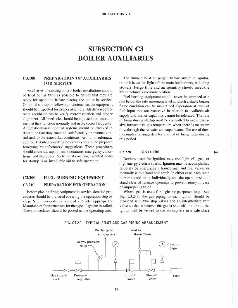
2011a SECTION VII
SUBSECTION C3 BOILER AUXILIARIES
C3.100 PREPARATION OF AUXILIARIES FOR SERVICE
Auxiliaries of existing or new boiler installations should be tried out as fully as possible to ensure that they are ready for operation before placing the boiler in service. On initial startup or following maintenance, the equipment should be inspected for proper assembly. All driven equipment should be run to verify correct rotation and proper alignment. All interlocks should be adjusted and tested to see that they function normally and in the con-ect sequence. Automatic-manual control systems should be checked to determine that they function satisfactorily on manual control and, to the extent that conditions permit, on automatic control. Detailed operating procedures should be prepared following Manufacturers' suggestions. These procedures should cover startup, normal operations, emergency conditions, and shutdown. A checklist covering essential items for startup is an invaluable aid to safe operation.
C3.200
C3.210
FUEL-BURNING EQUIPMENT
PREPARATION FOR OPERATION
Before placing firing equipment in service, detailed procedures should be prepared covering the operation step by step. Such procedures should include appropriate Manufacturer's instructions for the type of system installed. These procedures should be posted in the operating area.
The furnace must be purged before any pilot, ignitor, or torch is used to light-off the main fuel burners, including stokers. Purge time and air quantity should meet the Manufacturer's recommendation.
Fuel-burning equipment should never be operated at a rate below the safe minimum level at which a stable burner flame condition can be maintained. Operation at rates of fuel input that are excessive in relation to available air supply and burner capability cannot be tolerated. The rate of firing during startup must be controlled to avoid excessive furnace exit gas temperature when there is no steam flow through the reheater and superheater. The use of thermocouples is suggested for control of firing rates during this period.
C3.220 IGNITORS
Devices used for ignition may use light oil, gas, or high energy electric sparks. Ignition may be accomplished remotely by energizing a transformer and fuel valves or manually with a hand held torch. In either case, each main burner should be lit individually and the operator should stand clear of furnace openings to prevent injury in case of improper ignition.
Where gas is used for lighting purposes (e.g., see Fig. C3.2-l), the gas piping to each ignitor should be provided with two stop valves and an intermediate vent valve so that whenever the gas is shut off, the line to the ignitor will be vented to the atmosphere in a safe place
FIG. C3.2-1 TYPICAL PILOT AND GAS PIPING ARRANGEM ENT
Gas supply cock
Pressure regulator
Discharge to atmosphere
18
Vent to atmosphere
Shutoff valve
Shutoff valve
Pilot
(a)
2011a SECTION VII
and thus eliminate the possibility of gas leakage into the furnace through idle ignitors. These gas stop valves should be closed and the vent valves opened whenever it is desired to discontinue the pilot light and also whenever a shutdown occurs. The use of a fine mesh strainer and/ or sediment trap ahead of the control valves is desirable to trap extraneous material that may foul the valves or the ignitors.
Ignition transformers have high voltage secondaries but very seldom will the spark jump more than a 1/4 in. (6 mm) gap. The secondary discharge wire must not be grounded through broken insulators or carbon deposits across the air gap to the ground.
The ignition spark must occur in a fuel and air mixture to light the ignitor. A spark surrounded only by fuel will not ignite the fuel.
Fuel pressure to ignitors must be pressure controlled within the satisfactory range specified by the Manufacturer. Multiple burner oil fired ignitor systems may need control valves installed at each level, or accumulators installed at a high point in the piping downstream of the pressure regulating valve, to smooth out pressure fluctuations as successive ignitors are lit.
Presence of ignitor flames should be confirmed visually or by flame detecting devices immediately prior to lighting the main burners.
C3.230
C3.231
GAS SYSTEMS
Preparation for Service
Gas requires less operating labor than most other fuels, but more caution is required to fire it safely because leakage is not visually evident and gas readily mixes with air to become an explosive mixture. The greatest hazard in fuel gas firing is when a furnace contains an explosive mixture and a possible source of ignition. All operating procedures and designs should be directed toward preventing such a condition from occurring. Fuel gas not normally having a distinctive odor should be odorized to aid in prompt detection of leaks.
Bodies, bonnets, and glands of all cocks and valves and all threaded or flanged joints in the gas system should be checked with a soap solution prior to initial startup and periodically thereafter to detect any leaks. Any leaks should be promptly repaired.
Prior to initial startup and before the gas lines to the furnace are connected to the gas supply, the lines should be blown out with air or nitrogen at a sufficient velocity to remove foreign particles and clean the system. All regulating valves should be bypassed during the system cleaning to avoid damage. To fill the lines with gas, the gas lines should be purged through vent lines that exhaust to the atmosphere at a safe location. During the early periods of operation, fine mesh screens should be inserted in the lines ahead of control valves.
19
Before starting the light -off procedure, all main burner cocks should be checked to see that they are closed tight. Use of interlocks and double block and bleed cocks is recommended. All interlocks should be checked out by simulation of fan failure, flame failure, and abnormally high or low fuel gas pressure.
C3.232 Gas Burning
The furnace should be purged for at least 5 min with a volume change of no less than 5 times with an air flow equal to or greater than 25% of full load volumetric air flow. It is recommended that the furnace be purged with the same burners open to the firing position that will be used when the boiler is on line carrying the initial required load. If experience shows that positive ignition and a stable flame cannot be maintained, then one or more idle burner registers may be opened.
On multiple burner installations to ensure a uniform light-off gas pressure, a bypass gas pressure regulator should be installed around the main flow control valve. The ignitor for each burner to be lit should be energized and proven. The ignitor should be of sufficient size to readily ignite the burner. Ignition of the first or only burner should be accomplished within 10 sec after the gas supply cock is opened. If ignition is delayed longer than lOsee, fuel to that burner and ignitor should be shut off immediately. If the ignitor fails on the first burner, a furnace repurge is required. Should ignition fail on subsequent burners, there should be no attempt to relight the burner for at least one minute. As the need for cutting in additional burners develops, care should be taken to ensure that the air and fuel gas to the operating burner or burners is not adversely affected.
C3.240
C3.241
OIL SYSTEMS
Preparation for Service
Prior to startup, the fuel oil system, including storage tanks, heaters, pumps, strainers, piping, and relief valves, should be checked to permit safe operation. The system piping should then be blown free of all foreign material with steam. Oil pumps and burners should be protected by strainers. Strainers should be selected with orifices that are smaller than the drillings in the burner tips to prevent possible plugging. Such strainers should be cleaned at regular intervals and maintained in good condition. An oil leak inspection of the complete system should be made at startup and any time repairs are made to the system.
Oil storage tanks should be checked for water and / or sludge accumulation. Water and sludge accumulations should be removed before they build up to the proximity of the lowest suction line to the pumps. If heated fuel is
(a)
2011a SECTION VII
returned to the storage tanks, care should be taken to prevent excessive temperature rise of the oil in the storage tank to prevent vaporization in suction lines which could result in damage to the pump or severe pressure pulsations in the fuel oil supply to the burners. During cold weather, care should be gi ven to tank vents that may freeze up due to normal "breathing" during filling and pumping.
C3.242 Oil Atomization
Oil is more difficult to burn than gas and must be atomized before it can be efficiently burned. Light oil is less complicated to burn than heavy oil, which requires heating (e.g., see Fig. C3.2-2) to lower the viscosity for easy pumping and good atomization. Improper oil combustion can cause air heater fires and rapidly creates smoke which is easily visible.
Lightweight liquids or oils such as #2 fuel oil are relatively easy to atomize because their viscosity is below 100 Saybolt Seconds Universal (SSU) in the normal range of ambient temperatures. Heavy oils, tar streams, petroleum pitch, or similar products must be heated to achieve the correct viscosity for proper atomization. The required viscosity is usually specified in the burner manufacturer's literature. Generally, the viscosity should be between 100 SSU and 150 SSU.
It should be recognized that viscosity-temperature characteristics for heavy fuels can vary considerably, and periodic checks of the actual fuel being burned should be made as a guide for establishing the optimum operating temperature. Continuous oil viscosity measurements may be advisable where oil characteristics change rapidly or where low excess air operation is practiced.
Heating to a higher temperature than necessary for good atomization is of no benefit. Overheating of the oil can increase fouling of the heat transfer surface in the fuel heaters and may affect burner flame stability due to possible vaporization in the supply lines to the burner or in the burner. Features should be provided to maintain spare idle fuel pumps sufficiently warm to start readily. Recirculation lines should be routed well away from the pump suction to avoid damage (overheating, cavitation, etc.) to the pump.
Methods of atomization commonly in use are listed below in order of increasing effectiveness
(a) mechanical, such as shearing off a rotary cup burner. ( b) high pressure spray through fixed orifices. (c) steam- or air-assisted pressurized spray through
fixed orifices. Normally the steam or air pressure is controlled to maintain a 20 psig (140 kPa) differential above the oil pressure at the burner. However, outside mix tips use constant steam pressure. The mass flow of atomizing fluid is usually between 0.1 lb/lb (0.05 kg/kg) and 0.5Ib/lb (0.2 kg/kg) of oil. The lower mass ratio is the more economical to operate. The choice between air or steam
20
depends on economics, fuel volatility, fuel water content, and tendency of the fuel to coke burner tips. Air should be used for atomization of light oil and low pressure heavy oil. Stearn used to atomize heavy oil should be dry or slightly superheated to achieve proper atomization.
C3.243 Oil Burning
The furnace should be purged at least 5 min with a volume change of no less than 5 times with an air flow equal to or greater than 25% of full load volumetric air flow. It is recommended that the furnace be purged with the same burners open to the firing position that will be used when the boiler is on line carrying the initial required load. If experience shows that positive ignition and a stable flame cannot be maintained, then one or more idle burner registers may be opened. On multiple burner installations, a fuel pressure control valve in parallel with the flow control valve will ensure proper oil pressure for light-off. A hydraulic accumulator may be needed to prevent spurious low oil pressure trips if the oil pressure regulator cannot respond fast enough to control the pressure during successive burner light-offs. Alternate solutions include a snubber orifice in the low oil pressure switch sensing line or a short 1 sec to 3 sec time delay in the low oil pressure trip circuit. Burner flame stability must be observed during these quick pressure excursions.
Automatic ignitors or ignitors operated in groups for the selected burners should be put in service. Ignitors operated from a control station remote from the boiler must have dependable flame detectors and flame failure interlocks. These must be frequently checked for dependable operation. Ignition of the first or only oil burner should be accomplished within 10 sec for light oils or gas and 15 sec for heavy oils after the fuel supply valve is opened. A longer time delay may be necessary to compensate for slow opening automatic valves, but time periods in excess of 15 sec are unacceptable. If ignition is delayed longer than 10 sec for light oils (15 sec for heavy oils), oil to the burner should be shut off immediately, the hand torch removed, or the ignitor shut off so there is no source of ignition in the furnace. The furnace should be repurged before light-off is again attempted. If ignition for the second or subsequent burner is delayed longer than 10 sec to 15 sec, oil to the burner should be shut off immediately, the hand torch removed, or the ignitor shut off so there is no source of ignition at the burner. No attempt should be made to relight the burner for at least 1 min. As the need for cutting in additional burners develops, care should be taken to ensure that the air and oil flows to the operating burner (or burners) is not adversely affected. On any changes of oil flow to the burner (or burners), care should be taken to prevent the possibility of a fuel rich mixture in the furnace. Air flow should increase before oil flow on
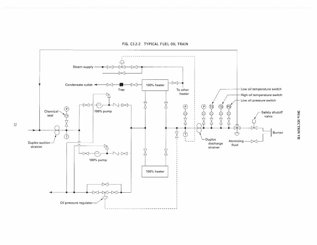
tv .......
Duplex suction strainer
FIG. C3.2-2 TYPICAL FUEL OIL TRAIN
r------------------------------------~
I
Steam supply .. I
Condensate outlet ... '41(11--------1
100% pump
100% pump
100% heater
Oil pressure regUlator~ I ~-----------------------------------~
~---+- Low oil temperature switch
,----t- High oil temperature switch
Duplex discharge strainer
Low oil pressure switch
Atomizing fluid
r Safety shutoff ;I valve
Burner
N o --~ 'JJ. ~ (1 >--3
S Z -< ...... ......
2011a SECTION VII
an increase in load, and oil flow should decrease before air flow on a decrease in load.
Strainers and burners should be examined for cleanliness at startup and periodically during operation. Oil spray should not be permitted to strike burner throats, furnace walls, or the furnace floor. If refractory tile is not uniform in temperature around the periphery, it is an indication of poor fuel or air distribution in the burner. On multiple burner units, all active burners should have the same tip sizes from the standpoint of good fuel/air distribution among the burners. Worn burner tips should be discarded promptly and replaced with new ones. Dirty burners should be replaced promptly with clean spare burners. They should then be cleaned and stored in the spare burner rack. Where both steam atomizing and mechanical atomizing oil guns are used, it is very important that assemblies be kept separate and properl y marked so that steam atomizers are not mistakenly used in place of mechanical atomizers and vice versa.
It is important that the oil gun be assembled with the tip for the type of oil being burned and that the oil gun be properly connected to the yoke. It is important that the gasket at this interface be properly seated and compressed to make a tight seal. The position of the oil gun should be far enough into the furnace so that no oil drips into the wind box. Oil saturated insulation should be cleaned or removed and no oil puddles should be left standing in catch pans.
Where steam atomized oil burners are used, every effort should be made to prevent the contamination of the steam system with oil so that the possibility of oil entering the condensate system and then the boiler is reduced to an absolute minimum. The atomizing steam to the burner should be dry steam not greater than 75°F (2YC) superheat. This prevents the formation of deposits in the burner gun.
In systems using both light and heavy oils, adequate means, either manual or automatic, should be installed to keep the two grades separated. Where both light and heavy oil are connected to the same burners, three-way valves should be used to ensure isolation and to avoid short circuits.
One hazard when burning light oil in large water cooled furnaces at low load is incomplete combustion followed by condensation of light fractions in vapor form on the cold areas of the boilers, economizers, and air heaters with consequent danger of fire when the firing rate is increased. This hazard can be reduced by the use of well adjusted burners (set by visual observation of the fires), extensive use of air heater soot blowers, and by minimizing low load operating time.
C3.2S0 STOKERS (a) C3.2S1 General
Stoker fired fuels include all coals from anthracite to lignite, coke, wood, sawmill refuse, bark, bagasse, and other burnable solid matter.
22
There are many different types of stokers in service (e.g., see Figs. C3.2-3 and C3.2-4). They include single retort underfeed, multiple retort underfeed, chain grates, vi bragrates, and spreaders. Stoker firing has a very low furnace explosion potential. Stokers have numerous operating adjustments that must be understood and used in conjunction with furnace observations to attain good performance. Consult Manufacturer's instructions for specific operating and maintenance directions.
C3.2S2 Preparation for Service
Prior to startup, the stoker facilities should be inspected for complete and proper assembly, debris should be removed, and the motor drive should be run to check motor amps and correct rotation. Fuel bunkers, shutoff gates, ash hoppers, and feeders should be checked for cleanliness. The fuel equipment, combustion air fan, overfire air fan, induced draft fan, and combustion controls should be operational.
C3.2S3 Stoker Firing
Dumping grates, shaking grates, and stoker mechanisms should be checked to see that they are free to function correctly before introduction of fuel. The grates or stoker bed should be lightly covered with fuel. Kindling in the form of wood shavings, fuel ignitor jelly, excelsior, or similar material may be used to ignite the fuel; or live coals from an adjacent furnace may be employed. Gasoline, naphtha, or other highly flammable liquids should never be used as kindling. The draft equipment should be operated and regulated to produce a slight negative pressure in the furnace prior to lighting off. A negative pressure must be maintained in the furnace at all times to avoid overheating the stoker and to prevent exposure of personnel to fire and flue gas.
Overfire air systems should be in service to reduce smoking. Penetration into the furnace creating turbulence is more important than volume for overfire air. Overfire air may be 15% of the total combustion air required.
Fly ash reinjection air, if required, should be flowing to keep the nozzles cool and to avoid plugging at the hopper discharges. Normally, spreader stokers have this feature because a high percentage of small particles is carried out of the furnace into the boiler where it is collected and returned to the furnace.
Fuel feed and grate speed are controlled to match load requirements and to protect the grate from radiant heat by maintaining an ash layer on it. Normally 3 in. (75 mm) to 6 in. (150 mm) of ash is adequate for protection. Excessive grate speed will cause a thin ash bed and may result in a high grate temperature and high grate maintenance. Ash coming off the grate should not be actively burning, and any clinkers should be removed from the firing bed.
(a)
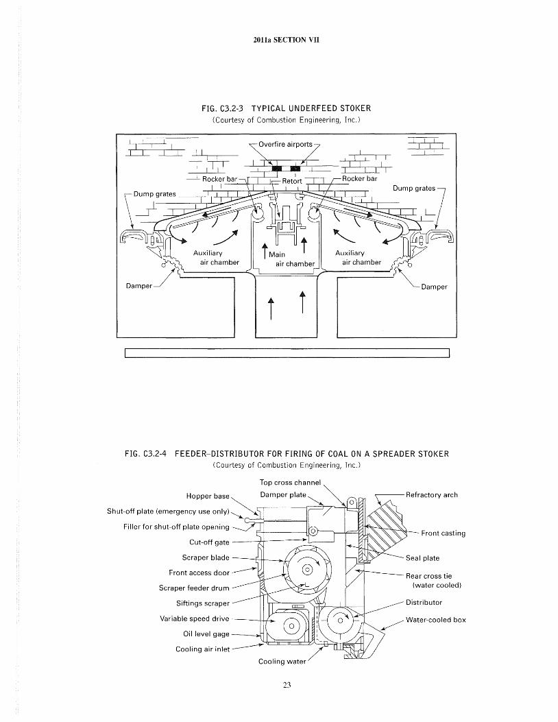
2011a SECTION VII
FIG. C3.2-3 TYPICAL UNDERFEED STOKER (Courtesy of Combustion Engineering, Inc.)
I I I~
11
11
'
_I Rocker bar I -~--','--,,-l-----,-\:--
Auxiliary Auxiliary
Dump grates
air chamber air chamber air chamber
Damper
i i
FIG. C3.2-4 FEEDER-DISTRIBUTOR FOR FIRING OF COAL ON A SPREADER STOKER (Courtesy of Combustion Engineering, Inc.)
Top cross channel
Hopper base Damper plate ~ 0
Shut~off plate (emergency use only) ~--'---------f----r Filler for shut-off plate opening
Cut-off gate --~4------l
Scraper blade ---t-f+----lI .. Li
Scraper feeder drum
Siftings scraper
Variable speed drive ---I-!-.L.->o-
Oil level gage ----w
~~:::kI::~~~~ Cooling air inlet ~ /
Cooling water
23
.,---- Refractory arch
Front casting
Rear cross tie (water cooled)
Distributor
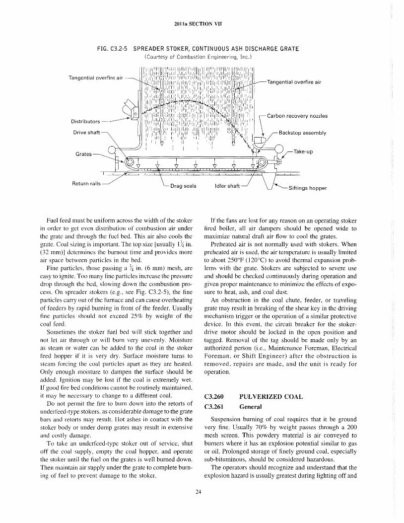
2011a SECTION VII
FIG. C3.2-5 SPREADER STOKER, CONTINUOUS ASH DISCHARGE GRATE (Courtesy of Combustion Engineering, Inc.)
Tangential overfire air
Drive shaft
Grates
Return rails Drag seals
Fuel feed must be uniform across the width of the stoker in order to get even distribution of combustion air under the grate and through the fuel bed. This air also cools the grate. Coal sizing is important. The top size [usually l/,t in. (32 mm)] determines the burnout time and provides more air space between particles in the bed.
Fine particles, those passing a /,t in. (6 mm) mesh, are easy to ignite. Too many fine particles increase the pressure drop through the bed, slowing down the combustion process. On spreader stokers (e.g., see Fig. C3.2-5), the fine particles carry out of the furnace and can cause overheating of feeders by rapid burning in front of the feeder. Usually fine particles should not exceed 25% by weight of the coal feed.
Sometimes the stoker fuel bed will stick together and not let air through or will burn very unevenly. Moisture as steam or water can be added to the coal in the stoker feed hopper if it is very dry. Surface moisture turns to steam forcing the coal particles apart as they are heated. Only enough moisture to dampen the surface should be added. Ignition may be lost if the coal is extremely wet. If good fire bed conditions cannot be routinely maintained, it may be necessary to change to a different coal.
Do not permit the fire to burn down into the retorts of underfeed-type stokers, as considerable damage to the grate bars and retorts may result. Hot ashes in contact with the stoker body or under dump grates may result in extensive and costly damage.
To take an underfeed-type stoker out of service, shut off the coal supply, empty the coal hopper, and operate the stoker until the fuel on the grates is well burned down. Then maintain air supply under the grate to complete burning of fuel to prevent damage to the stoker.
24
Tangential overfire air
If the fans are lost for any reason on an operating stoker tired boiler, all air dampers should be opened wide to maximize natural draft air flow to cool the grates.
Preheated air is not normally used with stokers. When preheated air is used, the air temperature is usually limited to about 250°F (l20°C) to avoid thermal expansion problems with the grate. Stokers are subjected to severe use and should be checked continuously during operation and given proper maintenance to minimize the effects of exposure to heat, ash, and coal dust.
An obstruction in the coal chute, feeder, or traveling grate may result in breaking of the shear key in the driving mechanism trigger or the operation of a similar protective device. In this event, the circuit breaker for the stokerdrive motor should be locked in the open position and tagged. Removal of the tag should be made only by an authorized person (i.e., Maintenance Foreman, Electrical Foreman, or Shift Engineer) after the obstruction is removed, repairs are made, and the unit is ready for operation.
C3.260
C3.261
PUL VERIZED COAL
General
Suspension burning of coal requires that it be ground very fine. Usually 70% by weight passes through a 200 mesh screen. This powdery material is air conveyed to burners where it has an explosion potential similar to gas or oil. Prolonged storage of finely ground coal, especially sub-bituminous, should be considered hazardous.
The operators should recognize and understand that the explosion hazard is usually greatest during lighting off and
(a)
(a)
20113 SECTION VII
while operating at low load. Every effort should be made to establish and maintain conditions favorable to flame stability. This should actually start back at the coal storage yard, which should be managed to minimize pickup of moisture and extraneous matter that may interfere with steady flow from the bunkers or silos to the pulverizers.
C3.262 Preparation for Service
Coal bunkers, chutes, shutoff gates, and feeders should be checked for cleanliness before introducing coal (e.g., see Figs. C3.2-6, C3.2-7, and C3.2-8). The fuel handling and fuel burning equipment should be checked out by actual operation up to, but not including, actual admission of combustibles to the furnace. The draft equipment and combustion control equipment should be checked to see that the dampers, inlet vanes, burner register vanes, burner valves, control drives, ignitors, and all other components are free to operate and are in serviceable condition. Gas recirculating fan dampers and steam temperature control dampers should be set in accordance with the Manufacturer's instructions.
Pulverizers and associated equipment should be lubricated, internally inspected, and adjusted to deliver the proper coal fineness and primary air flow. Manufacturer's instructions provide specific information for the various types of pulverizers.
Electrical and mechanical interlocks should be checked for the effectiveness of intended protection. Furnace television, flame scanners, oxygen and combustible recorders, steam flow / air flow meters, draft gages, fuel flow failure alarms, and opacity meters are useful operating aids, but none of them should be considered as absolving the operators from the responsibility of making a firsthand visual check of furnace conditions. A competent operator also, when practical, will observe the stack discharge as an additional check on combustion conditions.
C3.263 Pulverized Coal Firing
Before lighting off a pulverized fuel burner (e.g., see Fig. C3.2-9), the furnace must be purged for at least 5 min with a volume change of no less than 5 times with an air flow equal to or greater than 25% of full load volumetric air flow. The purge flow rate should not exceed 40% of full load volumetric air flow on furnaces that may contain smoldering combustible material. Almost without exception, modern pulverized fuel installations are equipped with ignitors that may be oil or gas for light-off and stabilizing. An auxiliary oil or gas burner may be employed for carrying loads up to the safe minimum load for one pulverizer. The operators should be completely familiar with pulverizer characteristics so that they do not attempt to operate pulverizers below their safe minimum loads and so that they will carefully proportion the number of active burners
25
and pulverizers to suit the load to avoid operating at dangerously low coal-air mixture velocities and excessively lean or rich mixtures of coal and primary air. For maximum safety and reliability it is recommended that stabilizing oil or gas burners be in service when only one pulverizer is in service.
Pulverized coal may be fired for warmup if the mill size and feed rate, plus the auxiliary oil or gas stabilizing burners can be safely controlled at the required rate for continuous firing during warmup. In general, it is preferable initially to use the burners that are furthest from the furnace outlet so that, for any limiting furnace exit gas temperature, the maximum firing rate may be employed.
Air heaters should be put in service to supply heated air to the first pulverizer used. If the boiler is served by more than one pulverizer, the coal valves in lines to burners of idle pulverizers containing coal should be kept shut to prevent fires in the pulverizers.
Should the fuel from the first pulverizer fail to ignite immediately, shut off the fuel feeder, pulverizer, pul verizer fan, and ignition torch, close the coal burner valve, and repurge the furnace. Failure to light the second or additional burners requires shutting off the fuel to that burner and reestablishing proper firing conditions in the furnace.
When there is more than one pulverized fuel burner connected to the furnace and it is desired to place any additional burners in service, the lighting torch or ignitor should be applied to each burner to be lighted. Burners should always be lighted individually by ignitors, never from hot brickwork or from adjacent load carrying burners. If the burner to be lighted is a burner connected to a pulverizer in operation, then the valve in the burner line should be opened very slowly to prevent injection into the furnace of any accumulation of pulverized fuel that may be in the burner line. During this operation, the burner flame should be observed closely to ensure that the burner is operating properly. Even with pulverized fuel flame monitoring, close attention must be paid to pulverized coal flames, especially during startup and under low load operation. Extra precautions must be used when a pulverized fuel fired furnace is operated at low load. Operation below the safe minimum load should not be permitted.
In the case of boilers served by a number of coal burners, it is of special importance that the number of burners in operation be proportioned to the load carried in order to prevent loss of ignition and possibly filling the furnace with an explosive mixture of unburned fuel and air. The air damper drives on the air supply to pulverizers should be provided with safe minimum-opening stops. When operating with less than the full number of pulverized coal burners, it is recommended that the active burners be so selected that they provide the best obtainable stability of ignition. Every effort must be made to ensure a continuous uniform rate of fuel flow to and from the pulverizer. If
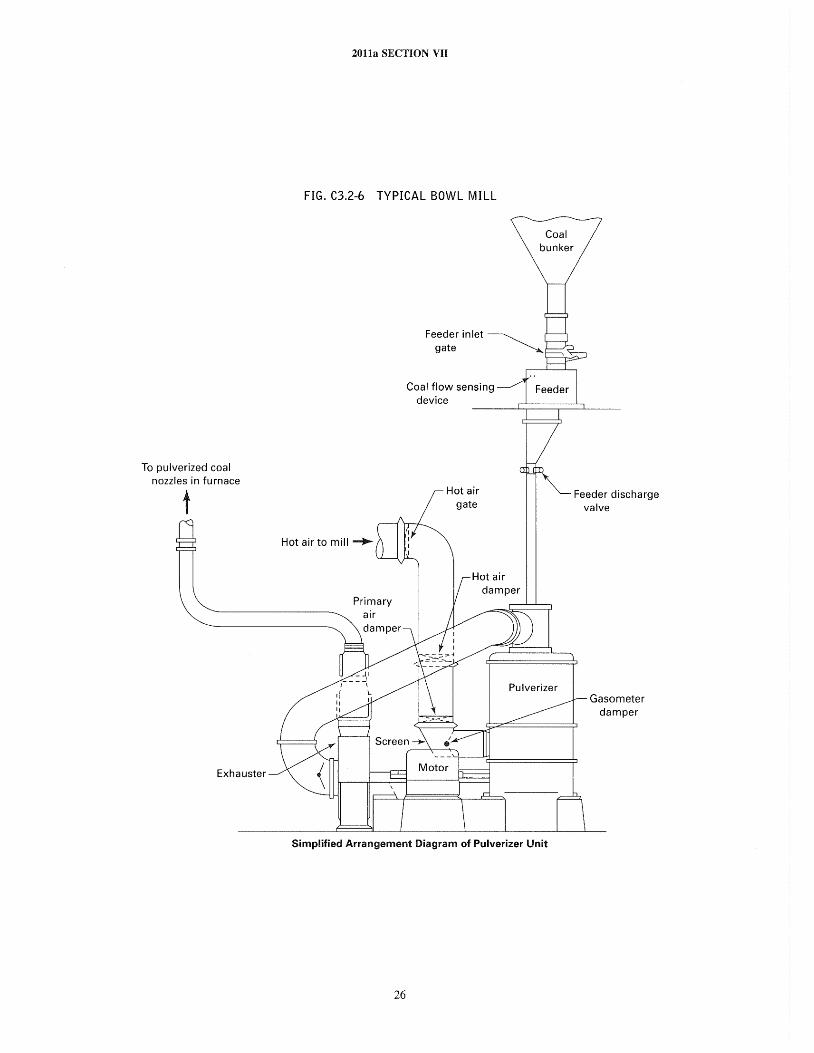
To pulverized coal nozzles in furnace
t
Exhauster
2011a SECTION VII
FIG. C3.2-6 TYPICAL BOWL MILL
Hot air to mill ~
Primary
Coal flow sensing device
Hot air gate
Pulverizer
Simplified Arrangement Diagram of Pulverizer Unit
26
Feeder discharge valve
Gasometer damper
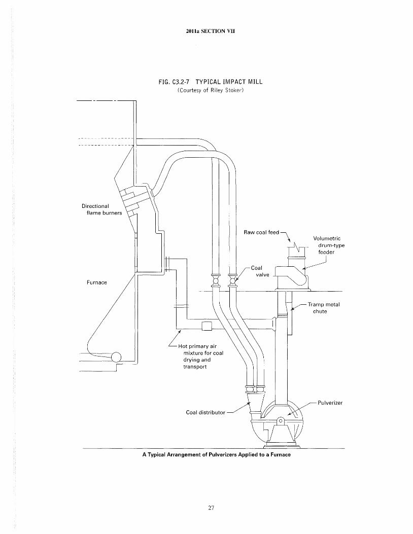
Directional flame burners
Furnace
2011a SECTION VII
FIG. C3.2-7 TYPICAL IMPACT MILL (Courtesy of Riley Stoker)
Lot primary air mixture for coal drying and transport
Coal distributor
Raw coal feed \
A Typical Arrangement of Pulverizers Applied to a Furnace
27
Volumetric drum-type feeder
Tramp metal chute
Pulverizer
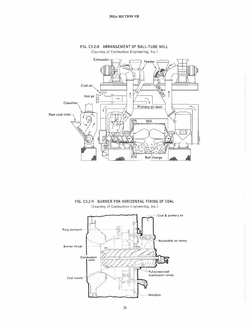
2011a SECTION VII
FIG. C3.2-8 ARRANGEMENT OF BALL-TUBE MILL (Courtesy of Combustion Engineering, Inc.)
FIG. C3.2-9 BURNER FOR HORIZONTAL FIRING OF COAL (Courtesy of Combustion Engineering, Inc.)
Coal & primary air
Ring dampers
Adjustable air vanes
zone
distribution vanes Coal
Windbox
28
201la SECTION VII
only one pulverizer of a multiple pulverizer system is in service, supplementary fuel (oil or gas) may be used to stabilize the coal burner flames. Where only one pulverizer exists on a boiler, flame stability will depend on the pulverizer load and manufacturer's instructions should be followed.
Operation of recirculation fans at low firing rates may contribute to ignition instability by adversely affecting mixing at the fuel burners and by recycling partially burned fuel to the furnace at a time when the intermixing of the fuel and air may be less than normally effective. Warmup by intermittent firing should be avoided. Intermittent operation of pulverizers has usually proven to be unsatisfactory and, in some instances, definitely hazardous because of unstable ignition and incomplete combustion of a large fraction of the pulverized coal. Should ignition be lost, prompt action must be taken to stop flow of all fuel to the furnace. After all fuel has been cut off, the furnace should be purged.
Load changes on pulverized fuel fired boilers should be made smoothly. This will reduce the possibility of setting up disturbances in the furnace which might cause sudden ignition of combustible deposits. A constant burning gas or oil ignitor is recommended where such conditions may arise. Every effort should be made at all times to stay within a safe range of fuel-air ratios. During load increases, the air flow increase should always lead the fuel flow increase, and during load reduction, the air flow reduction should always slightly follow the fuel flow reduction. This avoids the possibility of a fuel rich mixture. Should unsafe ratios develop, as evidenced by oxygen meters or stack opacity monitors, corrective changes in air and fuel flow rates should be made gradually except when ignition has been lost, in which instance all fuel flow should be cut off instantly and the furnace purged.
When routinely taking a pulverizer out of service, start an ignitor at each burner associated with that pulverizer to stabilize burning, shut off the coal supply, and be sure to empty the mill and coal pipes by increasing air flow through them to the maximum attainable. Failure to empty a pulverizer before shutting down may result in a fire in the pulverizer. If a pulverizer trips before a normal shutdown sequence can be completed, follow the Manufacturer's instructions for safely isolating the unit. The ignitor(s) should be turned off after all coal burning ceases.
The pulverized fuel preparation and feeding equipment must be kept in a condition that will ensure an uninterrupted flow of properly conditioned pulverized fuel to the burners in the amount required for the boiler load. The pulverized fuel should be routinely checked for fineness. The maximum permissible temperature of the pulverized fuel-air mixture leaving the pulverizer outlet should never exceed that speci ficall y approved by the Manufacturer. A high temperature alarm set to operate at this temperature should
29
be provided. This is necessary to prevent overheating the pulverizer lubricants, and it also reduces the potential for pulverizer fires. Carbon monoxide monitors should be considered as a means of detecting unsafe pulverizer conditions.
Mill outlet temperature should not drop below the recommended range. Low mill outlet temperature can cause plastering of the coal in the mill or coal pipes and can lead to fires.
C3.270 CYCLONE FURNACES
The high heat release burners or "single burner furnaces" that burn crushed coal rather than pulverized coal require somewhat the same treatment as pulverized coal fired furnaces. Maintenance of a layer of slag on the inside of the cyclone is necessary to provide a "flypaper" effect, to trap the larger coal particles so that they can be completely burned in the furnace and to protect the metallic parts of the furnace from erosion, heat, and corrosion. If ignition is lost in one cyclone and one or more adjacent cyclones remain lighted, it is not necessary to trip off all the fuel and purge the boiler furnace. However, if the ignition is lost on all of the cyclones, it is necessary to purge the boiler furnace before relighting any of the cyclones. On pressure fired units the sealing coal in each cyclone must be maintained or rotary or mechanical seals must be used. No-coal-flow alarms should be provided to warn of impending loss of seal. In addition, a high temperature alarm device between the feeder and the cyclone may be used to indicate loss of seal.
When burning oil or gas but no coal in a cyclone, it is necessary to provide some form of cooling of the furnace metallic parts. The form of cooling used will be dependent upon the type of oil or gas burners, and the Manufacturer's recommendation for each specific installation should be followed.
C3.280
C3.281
EMERGENCY OPERATION
Fire in Nonoperating Pulverizers
A pulverizer stopped in an emergency is likely to have a considerable amount of partially pulverized fuel in it, and if the pulverizer is hot and allowed to stand in this condition, the fuel may ignite. To reduce this possibility, it is recommended that the equipment should be put into service as soon as possible after a shutdown. As each pulverizer is placed in service the pulverizers not operating should be isolated from the furnace. This is necessary to prevent explosions of these pulverizers due to their containing coal and volatile matter if and when the furnace pressurizes on lighting off. If it is not possible to restart and run the pulverizer until empty, proceed as follows:
2011a SECTION vn
(a) If the shutdown occurred while the temperature of the air and fuel mixture leaving the pulverizer was at or over 1600 P (70°C) and there is no fire in the pulverizer, clean out the pulverizer by hand as soon after the shutdown as possible.
(b) If the shutdown occurred while the air and fuel mixture leaving the pulverizer was less than 160°F (70°C), the partly pulverized fuel may be left in the pulverizer provided operation will be resumed within several hours.
(c) Ball or tube mills cannot be cleaned out because coal being pulverized is intermixed with the grinding elements. To avoid fires in the mills of this class, drench the contents with water. Operation of these mills can be reestablished by rotating the mills for several minutes without coal feed and with hot air passing through them. The mill manufacturer should be consulted regarding the proper procedure to follow in such instances.
(d) To extinguish a fire in a shut down pulverizer, close valves in all connecting lines to the pulverizer through which air might enter. Admit CO2 gas and maintain required concentration or drench interior of pulverizer with the discharge from a chemical fire extinguisher or fire hose, directed through the access openings. The operator should stay out of direct line of the openings, especially if the fire is being extinguished by the use of water from a fire hose. A permanently installed water connection may be advisable, depending upon pulverizer design and the amount of coal retained in an emergency shutdown. Water and/or steam in contact with hot carbon forms methane, an explosive gas, and therefore this method should only be used with great care or as a last resort. Manufacturers' recommended procedures should always be followed under these conditions.
(e) The pulverizer plenum chamber, air inlet ducts, outlet pipes, pulverizer fan (if located after the pulvelizer), and feeder should also be c.leaned of any residual fire and combustible material.
(fJ When it is certain that the pulverizer and related equipment are clean of all traces of fire, the equipment may again be put into operation according to the normal procedures.
(g) Welding or burning operations inside any piece of pulverized fuel equipment should be avoided if at all possible. But if such operations are necessary, they should not be started without first ensuring that no dust is present or wetting down the interior of all the equipment in close proximity of the working area with water. Water-wetting may not be effective if pockets of dust are present. Hence, the only safe procedure is to clean out all dust accumulations before applying water.
(h) Compressed air should never be used for cleaning pulverized fuel equipment suspected of containing fire. Always avoid stirring up dust in cleaning pulverized fuel equipment because of the possible ignition of the dust
30
by sparks from the cleaning tools or from unsuspected smoldering fires. Vacuum cleaning systems with nonmetallic nozzles and with well-grounded hoses, when correctly used, provide a safe means of cleaning the equipment.
C3.282 Fire in Operating Pulverizers
(a) Fires in operating pulverizers are infrequent and are usually put out without damage or without interrupting operation. Pires must be looked upon as serious and should be dealt with promptly and adequately.
(b) The object of all methods of dealing with this class of fire is to smother it by reducing the oxygen (air) to a point where combustion ceases and cannot restart.
(c) A fire in an operating pulverizer usually makes its presence known by an increase in the outlet fuel air temperature that cannot be accounted for by changes either in the raw fuel moisture or the inlet air temperature. Moreover, this increase in outlet temperature is sudden and large, usually 1000 P (56°C) or more.
(d) If a fire is suspected in an operating pulverizer, the operator should proceed as follows:
(1) Change from hot to cold air operation. Avoid increasing or making sudden changes in the air flow through the pulverizer and boiler. It is desirable from a safety standpoint to put ignitors in service. Increase the raw fuel feed to the pulverizer to the maximum pulverizer capacity. If the pulverizer is already operating at maximum capacity, be sure that the fuel feed rate is maintained. If the low air temperature and increased fuel feed do not correct the situation, water may be added to the fuel to increase the cooling effect. Care must be taken to avoid coal flow interruptions during this procedure.
(2) If the temperature of the outlet air starts to return toward normal in a few minutes, continue operation until the normal outlet temperature is restored. The pulverizer load may then be reduced according to operating demands. However, if the pulverizer load is reduced, be sure that the air flow through the pulverizer is also reduced to keep a rich fuel-air mixture in the pulverizer.
(3) If the temperature rise of the outlet air does not start to return toward normal in 15 mi n after having changed from hot to cold air, proceed to take care of the fires as described in C3.281 for fires in nonoperating pulverizers.
(4) Special precautions should be taken to see that the fuel feed is not interrupted during the entire time that a fire is suspected. If the fuel feed should be interrupted, immediately shut down the pulverizer motive air supply, the pulverizer, and the feeder, and close all valves connected to the pulverizer.
C3.283 Fires in Pulverized Fuel Systems
A fire found in any part of the pulverized fuel system should be smothered and drenched with a discharge from
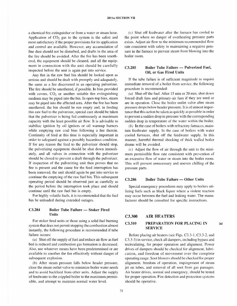
2011a SECTION VII
a chemical fire extinguisher or from a water or steam hose. Application of CO2 gas to the system is the safest and most satisfactory if the proper provisions for its application and control are available. However, any accumulation of fine dust should not be disturbed, and drafts in the area of the fire should be avoided. After the fire has been smothered, the equipment should be cleaned, and all the equipment in connection with the unit should be carefully inspected before the unit is again put into service.
Any fire in the raw fuel bin should be looked upon as serious and should be dealt with promptly and adequately, the same as a fire discovered in an operating pulverizer. The fire should be smothered, if possible. In bins provided with covers, CO2 or another suitable fire extinguishing medium may be piped into the bin. In open-top bins, steam may be piped into the affected area. After the fire has been smothered, the bin should be run empty and, in feeding this raw fuel to the pulverizer, special care should be taken that the pulverizer is being fed continuously at maximum capacity with the least possible air flow. It is advisable to stabilize ignition by oil ignitors or oil warmup burners while emptying raw coal bins following a fire therein. Continuity of feed at this time is especially important in order to safeguard against a possibly hazardous condition. If for any reason the feed to the pulverizer should stop, the pulverizing equipment should be shut down immediately, and all valves in connection with the pulverizer should be closed to prevent a draft through the pulverizer. If inspection of the pulverizing unit then proves that no fire is present and the cause for the feed interruption has been removed, the unit should again be put into service to continue the emptying of the raw fuel bin. This subsequent operating period should be observed just as carefully as the period before the interruption took place and should continue until the raw fuel bin is empty.
For highly volatile fuels, it is recommended that the fuel bin be unloaded during extended outages.
C3.284 Boiler Tube Failure - Stoker Fired Units
For stoker fired units or those using a solid fuel burning system that does not pennit stopping the combustion almost instantly, the following procedure is recommended if tube failure occurs:
(a) Shut off the supply of fuel and reduce air flow as fuel bed is reduced and combustion gas formation is decreased. Also, use whatever means have been predetennined or are available to smother the fire effectively without danger of subsequent explosion.
(b) After steam pressure falls below header pressure, close the steam outlet valve to minimize boiler water needs and to avoid backfeed from other units. Adjust the supply of feedwater to the crippled boiler to the maximum permissible, and attempt to maintain nonnal water level.
31
(c) Shut off feedwater after the furnace has cooled to the point where no danger of overheating pressure parts exists. Adjust air flow to the minimum recommended flow rate consistent with safety in maintaining a negative pressure in the furnace to prevent steam from blowing into the boiler room.
C3.285 Boiler Tube Failure - Pulverized Fuel, Oil, or Gas Fired Units
If the tube failure is of sufficient magnitude to require immediate removal of a boiler from service, the following procedure is recommended:
(a) Shut off the fuel. After 15 min or 20 min, shut down forced draft fans and primary-air fans if they are used or are in operation. Close the boiler outlet valve after steam pressure drops below header pressure. It is of utmost importance that this action be taken as quickly as possible in order to prevent a sudden drop in pressure with the corresponding sudden drop in temperature of the water within the boiler.
(b) In the case of boilers with refractory furnaces, maintain feedwater supply. In the case of boilers with water cooled furnaces, shut off the feedwater supply. In this manner, harmful thermal shocking of thick walled boiler drums will be avoided.
(c) Adjust the flow of air through the unit to the minimum permissible flow rate consistent with prevention of an excessive flow of water or steam into the boiler room. This will prevent unnecessary and uneven chilling of the pressure parts.
C3.286 Boiler Tube Failure - Other Units
Special emergency procedures may apply to boilers utilizing fuels such as black liquor where a violent reaction may occur between the fuel and leaking water. The manufacturer should be consulted for specific instructions.
C3.300
C3.310
AIR HEATERS
PREPARATION FOR PLACING IN SERVICE
Before placing air heaters (see Figs. C3.3-1, C3.3-2, and C3.3-3) in service, check all dampers, including bypass and recirculating, for proper operation and alignment. Power drives of dampers should be checked for alignment, lubrication, and freedom of movement over the complete operating range. Soot blowers should be checked for proper alignment, freedom of operation, impingement of steam jet on tubes, and removal of all soot from gas passages. Air heater drives, normal and emergency, should be tested for proper operation. Fire detection and protection systems should be operative.
(a)
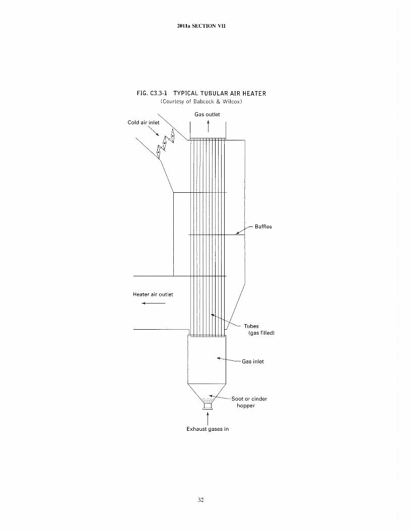
ZOlla SECTION VII
FIG. C3.3-1 TYPICAL TUBULAR AIR HEATER (Courtesy of Babcock & Wilcox)
Cold air inlet
~
Heater air outlet
Gas out et
t I
I
V Baffles /
Tubes (gas filled)
~-Gasinlet
t Exhaust gases in
32
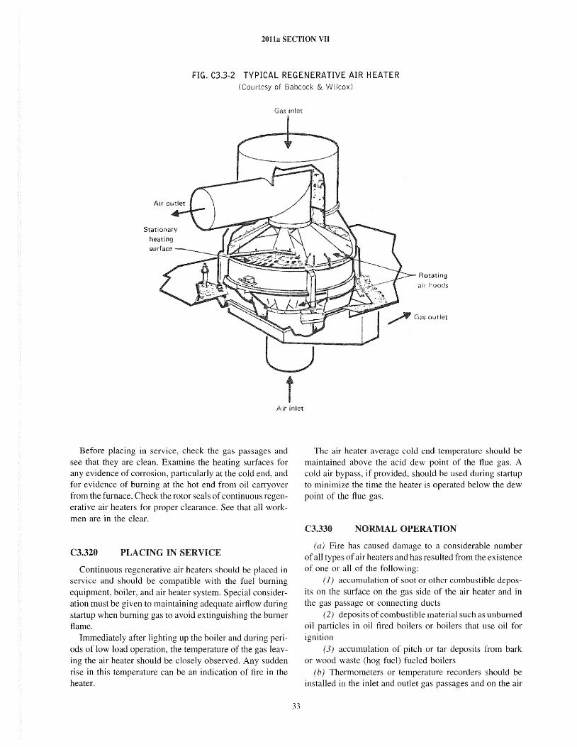
201la SECTION VII
FIG. C3.3-2 TYPICAL REGENERATIVE AIR HEATER (Courtesy of Babcock & Wilcox)
Air inlet
Before placing in service, check the gas passages and see that they are clean. Examine the heating surfaces for any evidence of corrosion, particularly at the cold end, and for evidence of burning at the hot end from oil carryover from the furnace. Check the rotor seals of continuous regenerative air heaters for proper clearance. See that all workmen are in the clear.
C3.320 PLACING IN SERVICE
Continuous regenerative air heaters should be placed in service and should be compatible with the fuel burning equipment, boiler, and air heater system. Special consideration must be given to maintaining adequate airflow during startup when burning gas to avoid extinguishing the burner flame.
Immediately after lighting up the boiler and during periods of low load operation, the temperature of the gas leaving the air heater should be closely observed. Any sudden rise in this temperature can be an indication of fire in the heater.
33
Rotating
hoods
The air heater average cold end temperature should be maintained above the acid dew point of the flue gas. A cold air bypass, if provided, should be used during startup to minimize the time the heater is operated below the dew point of the flue gas.
C3.330 NORMAL OPERATION
(a) Fire has caused damage to a considerable number of all types of air heaters and has resulted from the existence of one or all of the following:
( 1) accumulation of soot or other combustible deposits on the surface on the gas side of the air heater and in the gas passage or connecting ducts
(2) deposits of combustible material such as unburned oil particles in oil fired boilers or boilers that use oil for ignition
(3) accumulation of pitch or tar deposits from bark or wood waste (hog fuel) fueled boilers
(b) Thermometers or temperature recorders should be installed in the inlet and outlet gas passages and on the air
2011a SECTION VII
FIG. C3.3-3 DETAILS OF REGENERATIVE AIR PREHEATER, BISECTOR TYPE (Courtesy of Combustion Engineering, Inc.)
Heating surface
Rotor
Rotation
Hot gas inlet
inlet and outlet to assist in the detection of any abnormal condition or malfunction.
(c) The precautions to be observed for the avoidance of air heater fires include the following:
( 1) Deposition of unburned combustible material on the gas-swept heating surfaces and in ash hoppers should be prevented by proper operation of the firing equipment to ensure good combustion. The combustible material is more likely to leave the furnace and deposit on the heating surfaces and in fly ash hoppers during the firing of a cold unit and during low load operation than when the unit is being operated at higher rates of output.
(2) Soot blowers installed on air heaters should be operated as required to keep the heating surfaces clean. When starting a cold boiler, it is advisable to operate the air heater soot blowers immediately after steam at the required blowing pressure is available. Operate the air heater soot blower again before starting to pick up load on the boiler. Operate air heater soot blowers at frequent intervals if the boiler is being operated for a prolonged period at low load.
(3) Soot hoppers should be emptied frequently to avoid overfilling and compacting the ash.
(4) The gas temperatures through the air heater should be checked frequently. Any rapid change or abnormal reading in temperature should be investigated immediately.
34
C3.340
Hot
Housing
Air inlet
EMERGENCY OPERATION DUE TO FIRE
In the event that a fire occurs in the gas passages, stop the stoker or shut off the supply of pulverized coal, oil, or gas at all burners, torches, and pilot lighters; shut down the forced and induced draft fans and close all air inlet dampers; determine the location of the fire and spray the area with water. Do not use the soot blowers when it is suspected that there is a fire in the gas passages, for such action may lead to a serious explosion.
After the fire has been extinguished and the unit has been cooled, thoroughly clean the unit and make such repairs as may be necessary to place the equipment in condition for continued safe operation.
C3.400
C3.410
ECONOMIZERS
PREPARATION FOR PLACING IN SERVICE
The economizer heating surface (e.g., see Fig. C3.4-1) is comparatively closely spaced and must be kept clean to maintain good heat transfer.
The soot blower adjustment of fixed position rotary-type blower elements must be carefully checked to maintain the correct position of the nozzles in relation to the tubes to avoid cutting of the tubes by soot blower jet impingement.
(a)
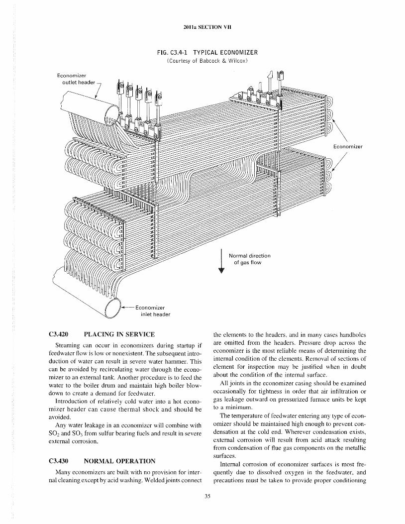
2011a SECTION VII
FIG. C3.4-1 TYPICAL ECONOMIZER (Courtesy of Babcock & Wilcox)
Economizer
outlet header?
~ Economizer inlet header
C3.420 PLACING IN SERVICE
Steaming can occur in economizers during startup if feedwater flow is low or nonexistent. The subsequent introduction of water can result in severe water hammer. This can be avoided by recirculating water through the economizer to an external tank. Another procedure is to feed the water to the boiler drum and maintain high boiler blowdown to create a demand for feedwater.
Introduction of relati vel y cold water into a hot economizer header can cause thermal shock and should be avoided.
Any water leakage in an economizer will combine with S02 and S03 from sulfur bearing fuels and result in severe external corrosion.
C3.430 NORMAL OPERATION
Many economizers are built with no provision for internal cleaning except by acid washing. Welded joints connect
35
I Normal direction t- of gas flow
the elements to the headers, and in many cases handholes are omitted from the headers. Pressure drop across the economizer is the most reliable means of determining the internal condition of the elements. Removal of sections of element for inspection may be justified when in doubt about the condition of the internal surface.
All joints in the economizer casing should be examined occasionally for tightness in order that air infiltration or gas leakage outward on pressurized furnace units be kept to a minimum.
The temperature of feedwater entering any type of economizer should be maintained high enough to prevent condensation at the cold end. Wherever condensation exists, external corrosion will result from acid attack resulting from condensation of flue gas components on the metallic surfaces.
Internal corrosion of economizer surfaces is most frequently due to dissolved oxygen in the feedwater, and precautions must be taken to provide proper conditioning
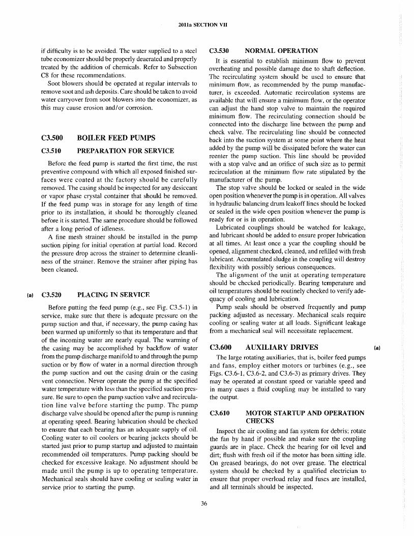
(a)
2011a SECTION VII
if difficulty is to be avoided. The water supplied to a steel tube economizer should be properly deaerated and properly treated by the addition of chemicals. Refer to Subsection C8 for these recommendations.
Soot blowers should be operated at regular intervals to remove soot and ash deposits. Care should be taken to avoid water carryover from soot blowers into the economizer, as this may cause erosion andlor corrosion.
C3.S00
C3.510
BOILER FEED PUMPS
PREPARATION FOR SERVICE
Before the feed pump is started the first time, the rust preventive compound with which all exposed finished surfaces were coated at the factory should be carefully removed. The casing should be inspected for any desiccant or vapor phase crystal container that should be removed. If the feed pump was in storage for any length of time prior to its installation, it should be thoroughly cleaned before it is started. The same procedure should be followed after a long period of idleness.
A fine mesh strainer should be installed in the pump suction piping for initial operation at partial load. Record the pressure drop across the strainer to determine cleanliness of the strainer. Remove the strainer after piping has been cleaned.
C3.520 PLACING IN SERVICE
Before putting the feed pump (e.g., see Fig. C3.5-I) in service, make sure that there is adequate pressure on the pump suction and that, if necessary, the pump casing has been warmed up uniformly so that its temperature and that of the incoming water are nearly equal. The warming of the casing may be accomplished by backflow of water from the pump discharge manifold to and through the pump suction or by flow of water in a normal direction through the pump suction and out the casing drain or the casing vent connection. Never operate the pump at the specified water temperature with less than the specified suction pressure. Be sure to open the pump suction valve and recirculation line valve before starting the pump. The pump discharge valve should be opened after the pump is running at operating speed. Bearing lubrication should be checked to ensure that each bearing has an adequate supply of oil. Cooling water to oil coolers or bearing jackets should be started just prior to pump startup and adjusted to maintain recommended oil temperatures. Pump packing should be checked for excessive leakage. No adjustment should be made until the pump is up to operating temperature. Mechanical seals should have cooling or sealing water in service prior to starting the pump.
36
C3.530 NORMAL OPERATION
It is essential to establish minimum flow to prevent overheating and possible damage due to shaft deflection. The recirculating system should be used to ensure that minimum flow, as recommended by the pump manufacturer, is exceeded. Automatic recirculation systems are available that will ensure a minimum flow, or the operator can adjust the hand stop valve to maintain the required minimum flow. The recirculating connection should be connected into the discharge line between the pump and check valve. The recirculating line should be connected back into the suction system at some point where the heat added by the pump will be dissipated before the water can reenter the pump suction. This line should be provided with a stop valve and an orifice of such size as to permit recirculation at the minimum flow rate stipulated by the manufacturer of the pump.
The stop valve should be locked or sealed in the wide open position whenever the pump is in operation. All valves in hydraulic balancing drum leakoff lines should be locked or sealed in the wide open position whenever the pump is ready for or is in operation.
Lubricated couplings should be watched for leakage, and lubricant should be added to ensure proper lubrication at all times. At least once a year the coupling should be opened, alignment checked, cleaned, and refilled with fresh lubricant. Accumulated sludge in the coupling will destroy flexibility with possibly serious consequences.
The alignment of the unit at operating temperature should be checked periodically. Bearing temperature and oil temperatures should be routinely checked to verify adequacy of cooling and lubrication.
Pump seals should be observed frequently and pump packing adjusted as necessary. Mechanical seals require cooling or sealing water at all loads. Significant leakage from a mechanical seal will necessitate replacement.
C3.600 AUXILIARY DRIVES The large rotating auxiliaries, that is, boiler feed pumps
and fans, employ either motors or turbines (e.g., see Figs. C3.6-1, C3.6-2, and C3.6-3) as primary drives. They may be operated at constant speed or variable speed and in many cases a fluid coupling may be installed to vary the output.
C3.610 MOTOR STARTUP AND OPERATION CHECKS
Inspect the air cooling and fan system for debris; rotate the fan by hand if possible and make sure the coupling guards are in place. Check the bearing for oil level and dirt; flush with fresh oil if the motor has been sitting idle. On greased bearings, do not over grease. The electrical system should be checked by a qualified electrician to ensure that proper overload relay and fuses are installed, and all terminals should be inspected.
(a)
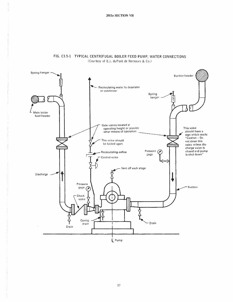
~ ! Ma;n bo;ler
feed header
2011a SECTION VII
FIG. C3.5-1 TYPICAL CENTRIFUGAL BOILER FEED PUMP, WATER CONNECTIONS (Courtesy of E.I. duPont de Nemours & Co.)
"IIJ........-- Recirculating water to deaerator or condenser
Gate valves located at operating height or provide other means of operation
Pressure gage
Suction header
This valve should have a sign which reads: "Caution - 00 not close this valve unless discharge valve is closed and pump is shut down"
D;schargc ~ t ~Suction
'i. Pump
37
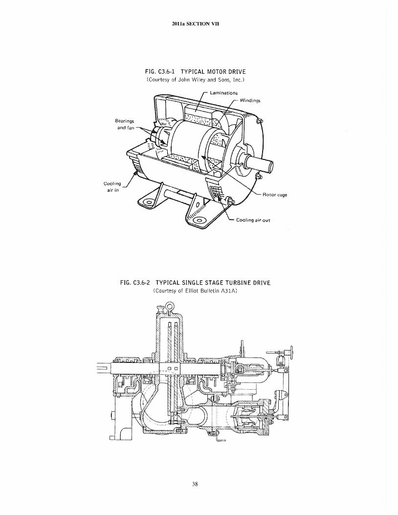
2011a SECTION VII
FIG. C3.6-1 TYPICAL MOTOR DRIVE (Courtesy of John Wiley and Sons, Inc.)
Cooling akin
Cooling air out
FIG. C3.6-2 TYPICAL SINGLE STAGE TURBINE DRIVE (Courtesy of Elliot Bulletin A31A)
38
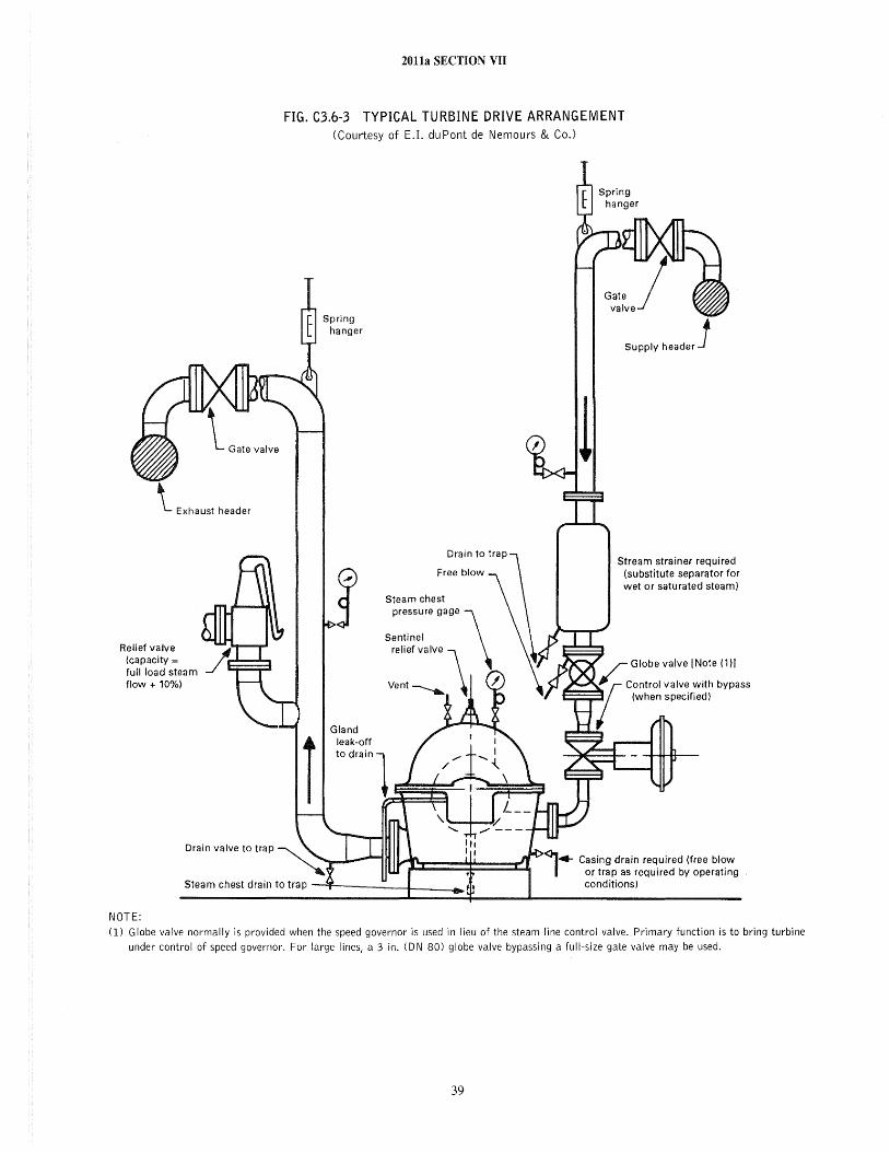
'- Exhaust header
Relief valve (capacity = full load steam flow + 10%)
Drain valve to trap
2011a SECTION VII
FIG. C3.6-3 TYPICAL TURBINE DRIVE ARRANGEMENT (Courtesy of E.!. du Pont de Nemours & Co.)
Spring hanger
Steam chest pressure gage
Supply h"de< J
Stream strainer required (substitute separator for wet or saturated steam)
Globe valve [Note (1)1
Steam chest drain to trap ---''1'-.-----+ ___ .... Casing drain required (free blow
or trap as required by operating conditions)
NOTE: 0) Globe valve normally is provided when the speed governor is used in lieu of the steam line control valve. Primary function is to bring turbine
under control of speed governor. For large lines, a 3 in. (ON 80) globe valve bypassing a full-size gate valve may be used.
39
(a)
2011a SECTION VII
On initial startup, check for proper rotation and observe bearing temperature carefully until equilibrium temperature is achieved. Also check to see that the oil level remains adequate at each bearing. Unusual loss of oil along the shaft may necessitate a shutdown and modifications to the oil seals.
Routine inspection of the motor should include oil level and temperature in bearings, vibration and noise, and winding temperature. Larger motors may have cooling air systems that involve filters. These will require periodic cleaning to maintain adequate air flow.
C3.620 MECHANICAL DRIVE TURBINE STARTUP AND OPERATION CHECKS
Mechanical drive turbines are frequently single stage, single valve units with hand valves for part load economy. Prior to startup, check to make sure that the trip valve operates freely and that all hand valves are free to operate. Exercise the throttle valve mechanism. Inspect the bearings and be sure they are clean and have adequate oil. Flush with oil if any question exists. Check to see that oil rings are free to rotate on bearings equipped with them, rotate by hand, and make sure coupling guards are in place. On startup, make sure that the trip valve mechanism operates properly and will shut off steam supply (thus stopping the turbine) before opening the throttle valve fully and putting the unit on speed control. After being out of service or after overhaul, the functioning of the trip valve should be checked before the unit is put on line.
Observe the seal leakoff steam or the sealing system to determine whether seals are seating. Start cooling water through oil cooler or bearing jackets and observe that bearing oil temperature stabilizes at the temperature recommended by the Manufacturer. Observe the nozzle ring steam pressure, and adjust hand valves to obtain the most efficient operation for the operating load. Check governor response by varying the load on the unit.
During normal operation, observe the unit for vibration, oil supply to the bearings, and cooling water supply and temperature to oil cooler and bearings. Leakoff should be observed as an indication of seal wear and need for maintenance.
C3.700 C3.710
DRAFT FANS PREPARATION FOR SERVICE
Before the unit is started, the rotor (e.g., see Fig. C3.7-l) should be turned over by hand to detect the possible presence of foreign materials. If the unit has been idle for a long period, the oil reservoirs should be flushed thoroughly with light oil and then filled with the recommended lubricant.
On sleeve bearing units, oil should be poured on the shaft in the bearing sleeve to prevent scoring during the first turning of the shaft.
40
Trial operation is recommended to check vibration, especially that caused by rotor imbalance. Special attention should be given to those cases where eroded parts have been built up with welding material.
Vibration of bearing cooling medium piping should be checked to avoid fatigue failure. Proper supports and flexible connections aid in preventing failures of this type.
Extreme care should be exercised in rigging and handling the rotor assembly to avoid damaging the shaft or distorting the fan parts.
C3.720 PLACING IN SERVICE
Make sure that dampers and vanes are closed to minimize the starting load on the drive. If speed control is provided, starting should be done at the lowest speed.
The cooling water or cooling oil supply and drains on liquid cooled bearings should be checked for proper functioning. Cooling air flow should be checked, where this medium is used, to see that it is adequate.
C3.730 NORMAL OPERATION
Since draft fans are often located at a considerable distance from the boiler control board, special precautions must be taken to ensure that frequent inspections during operation are made. Manual inspection can be supplemented by vibration monitors and oil temperature indicators at the control board.
Lubricated couplings should be watched for leakage and lubricant added regularly to ensure proper lubrication at all times. At least once a year the coupling should be opened, cleaned, and refilled with fresh lubricant. Accumulated sludge in the coupling will destroy flexibility with possibly serious consequences.
The alignment of the unit at operating temperature should be checked periodically.
C3.740 EMERGENCY OPERATION
An independent source of bearing cooling water is recommended for use during emergency operation of water cooled bearings when the normal source may not be available. An auxiliary oil pump for emergency service on oil cooled bearings is recommended.
C3.800 DAMPERS
Dampers are installed in the ducts, flues, fans, and boiler convection passes, as required, to adjust, regulate, bypass, or shut off the flow of combustion air or flue gases. Depending on function, dampers may be either hand
(a)
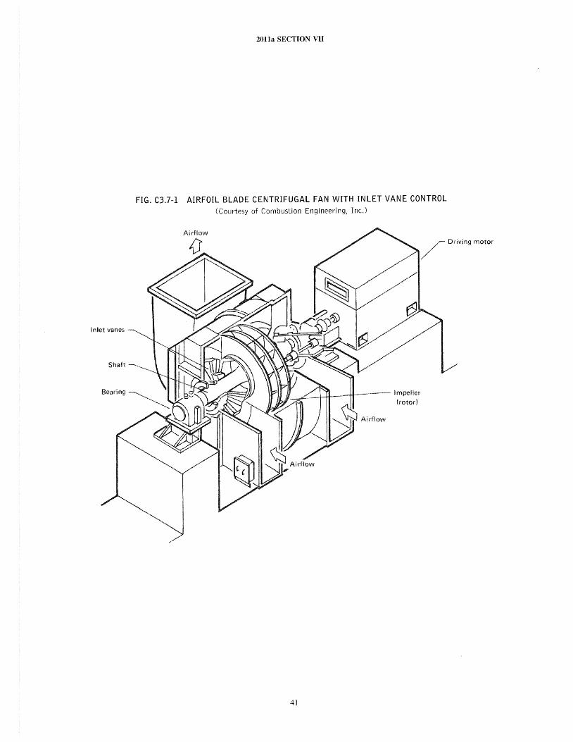
2011a SECTION VII
FIG. C3.7-1 AIRFOIL BLADE CENTRIFUGAL FAN WITH INLET VANE CONTROL (Courtesy of Combustion Engineering, Inc.)
/ Driving motor
41
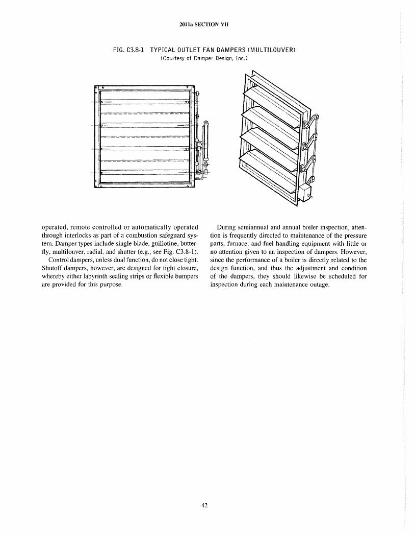
2011a SECTION VII
FIG. C3.8-1 TYPICAL OUTLET FAN DAMPERS (MU L TILOUVER) (Courtesy of Damper Design, Inc.>
operated, remote controlled or automatically operated through interlocks as part of a combustion safeguard system. Damper types include single blade, guillotine, butterfly, multi louver, radial, and shutter (e.g., see Fig. C3.8-1).
Control dampers, unless dual function, do not close tight. Shutoff dampers, however, are designed for tight closure, whereby either labyrinth sealing strips or flexible bumpers are provided for this purpose.
42
During semiannual and annual boiler inspection, attention is frequently directed to maintenance of the pressure parts, furnace, and fuel handling equipment with little or no attention given to an inspection of dampers. However, since the performance of a boiler is directly related to the design function, and thus the adjustment and condition of the dampers, they should likewise be scheduled for inspection during each maintenance outage.
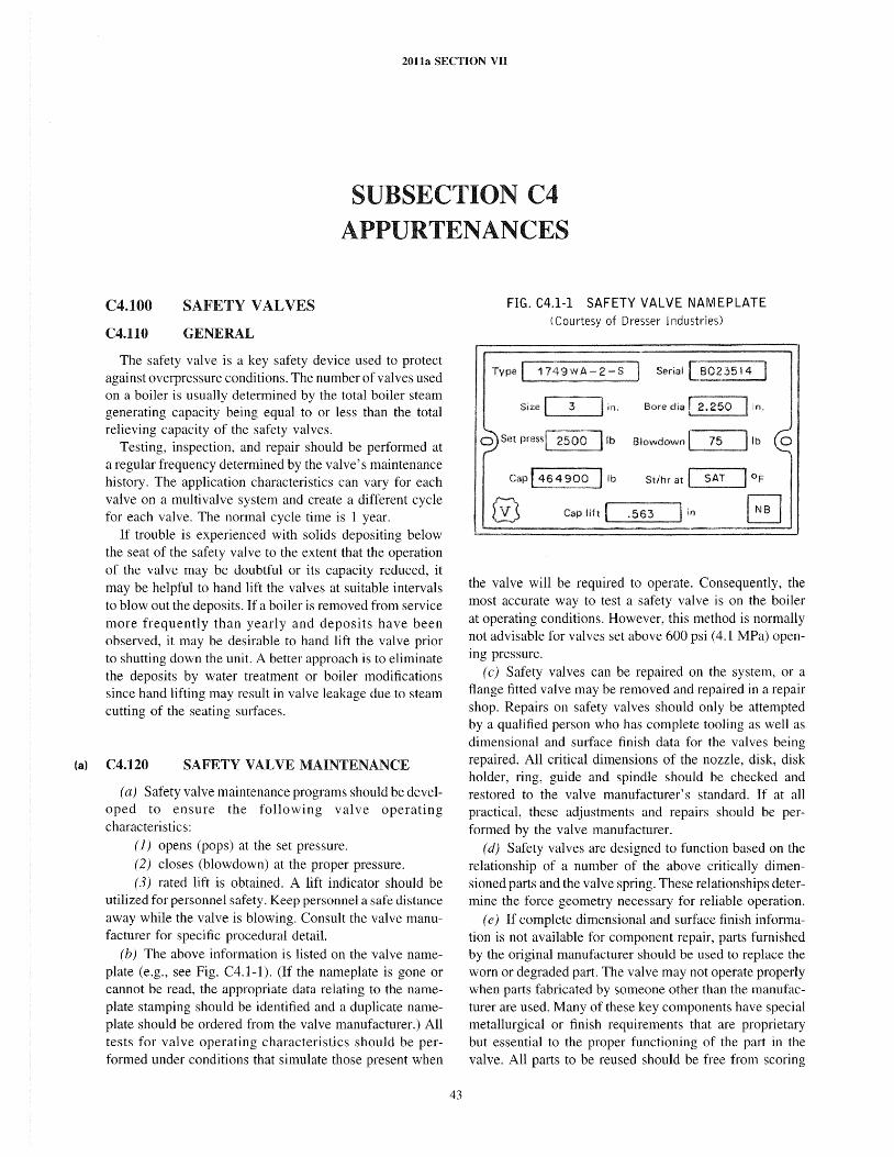
(a)
2011a SECTION VII
SUBSECTION C4 APPURTENANCES
C4.100
C4.110
SAFETY VALVES
GENERAL
The safety valve is a key safety device used to protect against overpressure conditions. The number of valves used on a boiler is usually determined by the total boiler steam generating capacity being equal to or less than the total relieving capacity of the safety valves.
Testing, inspection, and repair should be performed at a regular frequency determined by the valve's maintenance history. The application characteristics can vary for each valve on a muItivalve system and create a different cycle for each valve. The normal cycle time is 1 year.
If trouble is experienced with solids depositing below the seat of the safety valve to the extent that the operation of the valve may be doubtful or its capacity reduced, it may be helpful to hand lift the valves at suitable intervals to blowout the deposits. If a boiler is removed from service more frequently than yearly and deposits have been observed, it may be desirable to hand lift the valve prior to shutting down the unit. A better approach is to eliminate the deposits by water treatment or boiler modifications since hand lifting may result in valve leakage due to steam cutting of the seating surfaces.
C4.120 SAFETY VALVE MAINTENANCE
(a) Safety valve maintenance programs should be developed to ensure the following valve operating characteristi cs:
(1) opens (pops) at the set pressure. (2) closes (blowdown) at the proper pressure. (3) rated lift is obtained. A lift indicator should be
utilized for personnel safety. Keep personnel a safe distance away while the valve is blowing. Consult the valve manufacturer for specific procedural detail.
(b) The above information is listed on the valve nameplate (e.g., see Fig. C4.1-l). (If the nameplate is gone or cannot be read, the appropriate data relating to the nameplate stamping should be identified and a duplicate nameplate should be ordered from the valve manufacturer.) All tests for valve operating characteristics should be performed under conditions that simulate those present when
43
FIG. C4.1-1 SAFETY VALVE NAMEPLATE (Courtesy of Dresser Industries)
Serial ~023514 I
Size ( :3 I in. Bore dia I 2.250
o Set press Ib Slowdown I 75 ........... _______ 11 b 0
Cap 1464900 J Ib St/hr at I SAT I OF
Cap lift I .563
the valve will be required to operate. Consequently, the most accurate way to test a safety valve is on the boiler at operating conditions. However, this method is normally not advisable for valves set above 600 psi (4.1 MPa) opening pressure.
(c) Safety valves can be repaired on the system, or a flange fitted valve may be removed and repaired in a repair shop. Repairs on safety valves should only be attempted by a qualified person who has complete tooling as well as dimensional and surface finish data for the valves being repaired. All critical dimensions of the nozzle, disk, disk holder, ring, guide and spindle should be checked and restored to the valve manufacturer's standard. If at a1l practical, these adjustments and repairs should be performed by the valve manufacturer.
(d) Safety valves are designed to function based on the relationship of a number of the above critically dimensioned parts and the valve spring. These relationships determine the force geometry necessary for reliable operation.
( e) If complete dimensional and surface finish information is not available for component repair, parts furnished by the original manufacturer should be used to replace the worn or degraded part. The valve may not operate properly when parts fabricated by someone other than the manufacturer are used. Many of these key components have special metallurgical or finish requirements that are proprietary but essential to the proper functioning of the part in the valve. All parts to be reused should be free from scoring
2011a SECTION VII
damage to critical guiding surfaces. Paint should never be applied to valve interals.
(f) A repair nameplate identifying the repairer and date of repair should be attached to the valve after repair. If the set pressure has been changed, the new set pressure as well as the new capacity should be indicated with the old set pressure and capacity marked out but left legible on the original nameplate or stamping. The new capacity should be based on that for which the valve was originally certified. Before changes are made that affect opening or closing pressures, the revised values should be reviewed with the valve manufacturer to ensure proper valve performance and ASME Code compliance. Any change in these operating characteristics should be reported to the Authorized Inspector and the jurisdictional authority of the state or province in which the boiler is used.
(g) Individual records should be maintained on each safety valve to provide an accurate history of the activities related to that valve
( 1) date and results of inspections (2) date and results of operation (3) date and results of testing (4) date of repairs and nature of repair work, includ
ing any changes in the set pressure or capacity (5) operating and design parameters of the boiler on
which the valve is installed (h) Upon completion of all repairs, the valve should be
tested and adjustments sealed to ensure that no unauthorized adjustments are made. Most test facilities operated in conjunction with a valve repair shop have test capacities inadequate to check anything except the safety valve opening pressure. If the valve operating characteristics identified on the nameplate cannot be tested by the valve repair shop, they should be verified when the boiler is coming on line.
( i) If a val ve is repaired and tested off the boiler, care should be taken not to disturb the vertical alignment of the valve while transporting or installing. The valve should not be laid on its side. Flanged valves should be given special attention when torquing the inlet and outlet nuts and bolts. Uniform torque values should be used on all nuts and bolts, and the tightening should be done in a way that minimizes internal stresses in the valve body.
(j) Since many safety val ves never operate except during a test and may be exposed to contaminating elements, a thorough visual inspection should be made before the valve is tested (see Fig. C4.1-2). The following observations should be recorded (valves should be gagged if any close inspection is performed).
(1) Is the valve gagged? (2) Is there evidence of corrosion or pitting? (3) Is the valve leaking?
(4) Are gravity drain lines from discharge pipe (or drip pan) and valve casing (body) connected, free from
44
flow obstructions, and piped to a safe area? (See Section I, PG-71.3.)
(5) Are cap and lever installed on the valve? (6) Is the valve properly sealed (to ensure that no
unauthorized adjustments have occurred)? (7) Are exhaust piping and muffler flow paths free
and open (only check when unit is down or valve is gagged)? (See Fig. C4.l-3.)
(8) Is there a residue buildup on the valve? (9) Are all valves installed in an upright position with
spindle vertical? (See Section I, PG-71.2.) (k) After a thorough visual inspection ofthe above listed
items has been completed, the gag should be removed and necessary connections made.
(l) To hand lift test the valve operation with the boiler operating at design pressure, raise the lift lever to the fullopen position, then release to allow the valve to snap closed as it would have if it had opened automatically. A safety valve should not be opened with the hand lifting gear when the steam pressure is less than 75% of the set pressure of the lowest set valve on the boiler. To facilitate hand lifting or hand lifting from a remote location, small chains or wires may be attached to the levers of safety valves and extended so the weight of the chain or wire will exert no pull on the lever. Use a retracting spring, if necessary, to counterbalance the chain weight.
(m) Ensure that all personnel are cleared from the area near the valve before hand lifting because there may be a large amount of overflow steam (steam that does not stay confined to the outlet and exhaust piping).
C4.130 SAFETY VALVE TESTING
After visual examination and successful hand lift operation, each valve should be tested for the following operating characteristics.
(a) Opening Pressure. The following variation in the set popping pressure, as defined in PG-72.2 of Section I, is permissible. Care must be taken that the system pressure gage is accurate. The gage calibration should be noted and recorded.
Stipulated Pressure, psig (kPa)
15 to 70 (100 to 500) Over 70 to 300 (500 to 2000) Over 300 to 1,000 (2 000 to 7 000) Over 1,000 (7 000)
Permissible Variation
±2 psi (15 kPa) ±3% ±1O psi (70 kPa) ±1%
( b) Closing Pressure. Section I, PG-72. 1, requires valve closure at specific closing points, depending upon the unit design. The valve may perform inconsistently, chatter, or damage itself if the closing pressure is too close to the popping pressure.
(c) Capacity. Measurement of the spindle travel (lift) can be used to determine whether a valve designed to
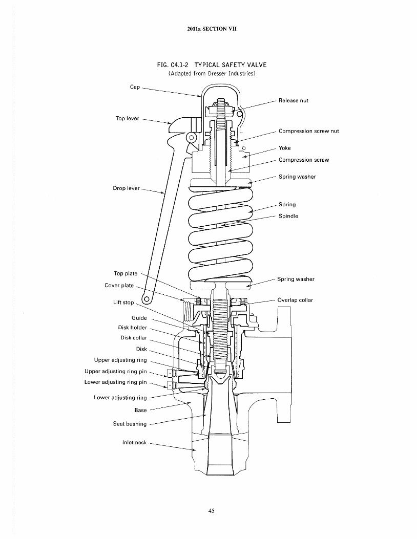
Cover plate
Lift stop
Guide
Disk holder
Disk collar
Disk
Upper adjusting ring
Upper adjusting ring pin
Lower adjusting ring pin
Lower adjusting ring
Seat bushing
Inlet neck
2011a SECTION VII
FIG. C4.1-2 TYPICAL SAFETY VALVE (Adapted from Dresser Industries)
45
Release nut
Compression screw nut
Yoke
Compression screw
Spring washer
Spring
Spindle
Spring washer
Overlap collar
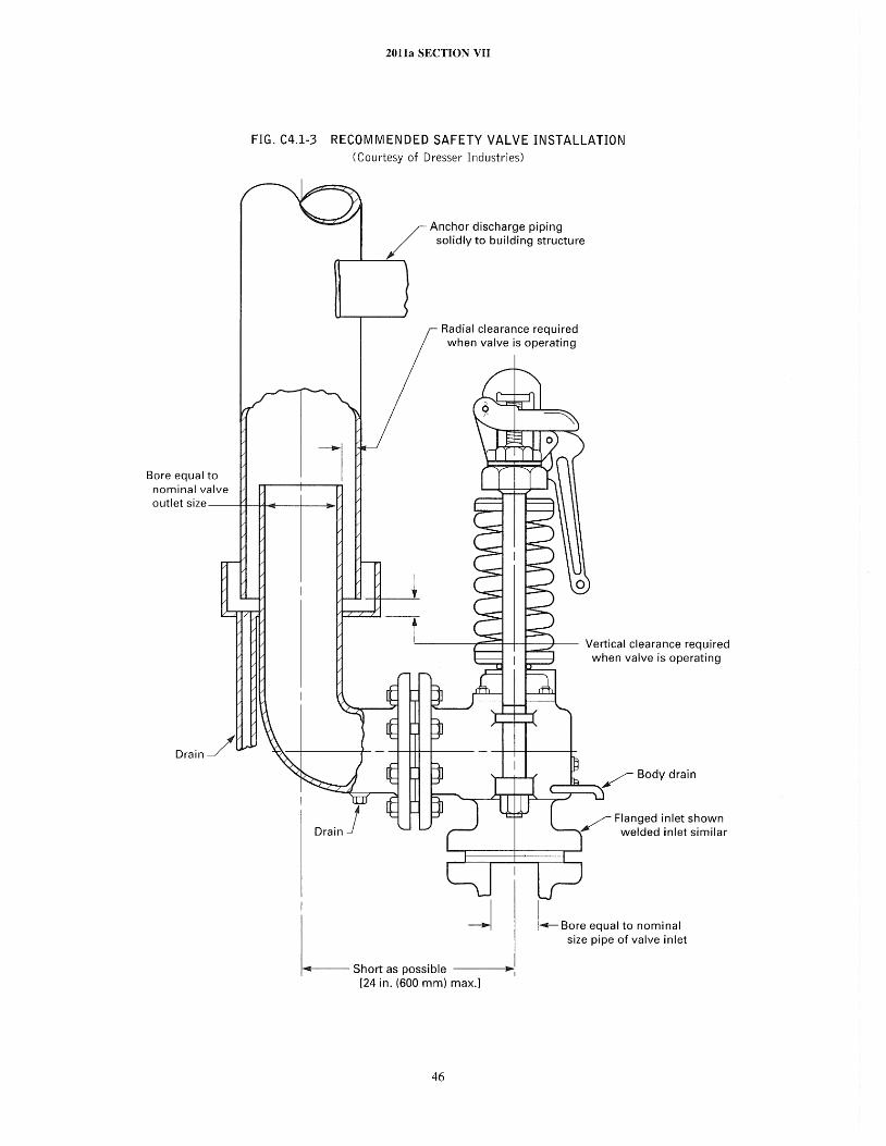
Bore equal to nominal valve
2011a SECTION VII
FIG. C4.1-3 RECOMMENDED SAFETY VALVE INSTALLATION (Courtesy of Dresser Industries)
--I
Anchor discharge piping solidly to building structure
Radial clearance required when valve is operating
a utlet size ---I+-l4 ........ -+-----;~Ll
DrainJ
L----7""""=l-l--I---J-- Vertical clearance required when valve is operating
/ Flanged inlet shown welded inlet similar
j I~ Bore equal to nominal size pipe of valve inlet
1 .... 0lIl(11---- Short as possible ----lJPo~1 [24 in. (600 mm) max.J
46
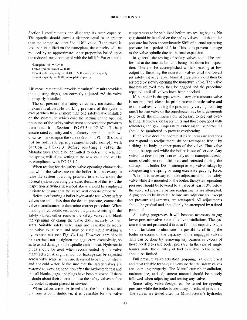
2011a SECTION VII
Section I requirements can discharge its rated capacity. The spindle should travel a distance equal to or greater than the nameplate identified "Lift" value. If the travel is less than identified on the nameplate, the capacity will be reduced by an approximate linear proportion based upon the reduced travel compared with the fullhft. For example:
Nameplate lift = 0.500 Tested spindle travel = 0.400
Present valve capacity = 0.40010.500 nameplate capacity Present capacity = 0.800 nameplate capacity
Lift measurement will provide meaningful results provided the adjusting ring(s) are correctly adjusted and the valve is properly installed.
The set pressure of a safety valve may not exceed the maximum allowable working pressure of the system, except when there is more than one safety valve installed on the system, in which case the setting of the opening pressures of the safety valves must not exceed the pressures determined from Section I, PG-67.3 or PG-67.4. To help ensure rated capacity and satisfactory operation, the blowdown as marked upon the valve (Section I, PO-1I 0) should not be reduced. Spring ranges should comply with Section I, PG-72.3. Before resetting a valve, the Manufacturer should be consulted to determine whether the spring will allow setting at the new value and still be in compliance with PG-73.1.2.
When testing for the safety valve operating characteristics while the valves are on the boiler, it is necessary to raise the system operating pressure to a value above the normal system operating pressure. Because of the risks, the inspection activities described above should be employed initially to ensure that the valve will operate properly.
Before performing a boiler hydrostatic test where safety valves are set at less than the design pressure, contact the valve manufacturer to determine correct procedure. When making a hydrostatic test above the pressure setting of the safety valves, either remove the safety valves and blank the openings or clamp the valve disks securely to their seats. Suitable safety valve gags are available to secure the valve to its seat and may be used while making a hydrostatic test (see Fig. C4.1-4). However, care should be exercised not to tighten the gag screw excessively, so as to avoid damage to the spindle and/or seat. Hydrostatic plugs should be used when recommended by the valve manufacturer. A slight amount of leakage can be expected across valve seats, as they are designed to be tight on steam and not cold water. ~lake sure that the safety valves are restored to working condition after the hydrostatic test and that all blanks, gags, and plugs have been removed. If there is doubt about their operation, test the safety valves before the boiler is again placed in service.
When valves are to be tested after the boiler is started up from a cold shutdown, it is desirable for the valve
47
temperatures to be stabilized before any testing begins. No gag should be installed on the safety valves until the boiler pressure has been approximately 80% of normal operating pressure for a period of 2 hr. This is to prevent damage to the valve spindle due to thermal expansion.
In general, the testing of safety valves should be performed at the time the boiler is being shut down for inspection. This can be accomplished while operating at low output by throttling the nonreturn valves until the lowest set safety valve relieves. Normal pressure should then be restored by slowly opening the nonreturn valve. The valve that has relieved may then be gagged and the procedure repeated until all valves have been checked.
If the boiler is the type where a stop or nonreturn valve is not required, close the prime mover throttle valve and test the valves by raising the pressure by varying the firing rate. The vent valve on the superheater may be large enough to provide the minimum flow necessary to prevent overheating. However, on larger units and those equipped with reheaters, the gas temperature entering the superheater should be monitored to prevent overheating.
If the valve does not operate at its set pressure and does not respond to readjustment, do not attempt to free it by striking the body or other parts of the valve. That valve should be repaired while the boiler is out of service. Any valve that does not perform exactly as the nameplate designates should be reconditioned and retested during the startup of the boiler. Do not attempt to stop valve leakage by compressing the spring or using excessive gagging force.
When it is necessary to make adjustments on the safety valve while it is mounted on the boiler, the system operating pressure should be lowered to a value at least 10% below the valve set pressure before readjustments are attempted. A gag should be installed before any adjustments, except set pressure adjustments, are attempted. All adjustments should be gradual and should only be attempted by trained personnel.
As testing progresses, it will become necessary to gag lower pressure valves on multivalve installations. The system is then not protected if fired at full load capacity. Steps should be taken to eliminate the possibility of firing the boiler in excess of the capacity of the ungagged valves. This can be done by removing any burners in excess of those needed to raise boiler pressure. In the case of single burner units, the quantity of fuel available to the burner should be limited.
Full pressure valve actuation (popping) is the preferred and most reliable technique to ensure that the safety valves are operating properly. The Manufacturer's installation, maintenance, and adjustment manual should be closely followed when adjusting and testing any valve.
Some safety valve designs can be tested for opening pressure while the boiler is operating at reduced pressures. The valves are tested after the Manufacturer's hydraulic
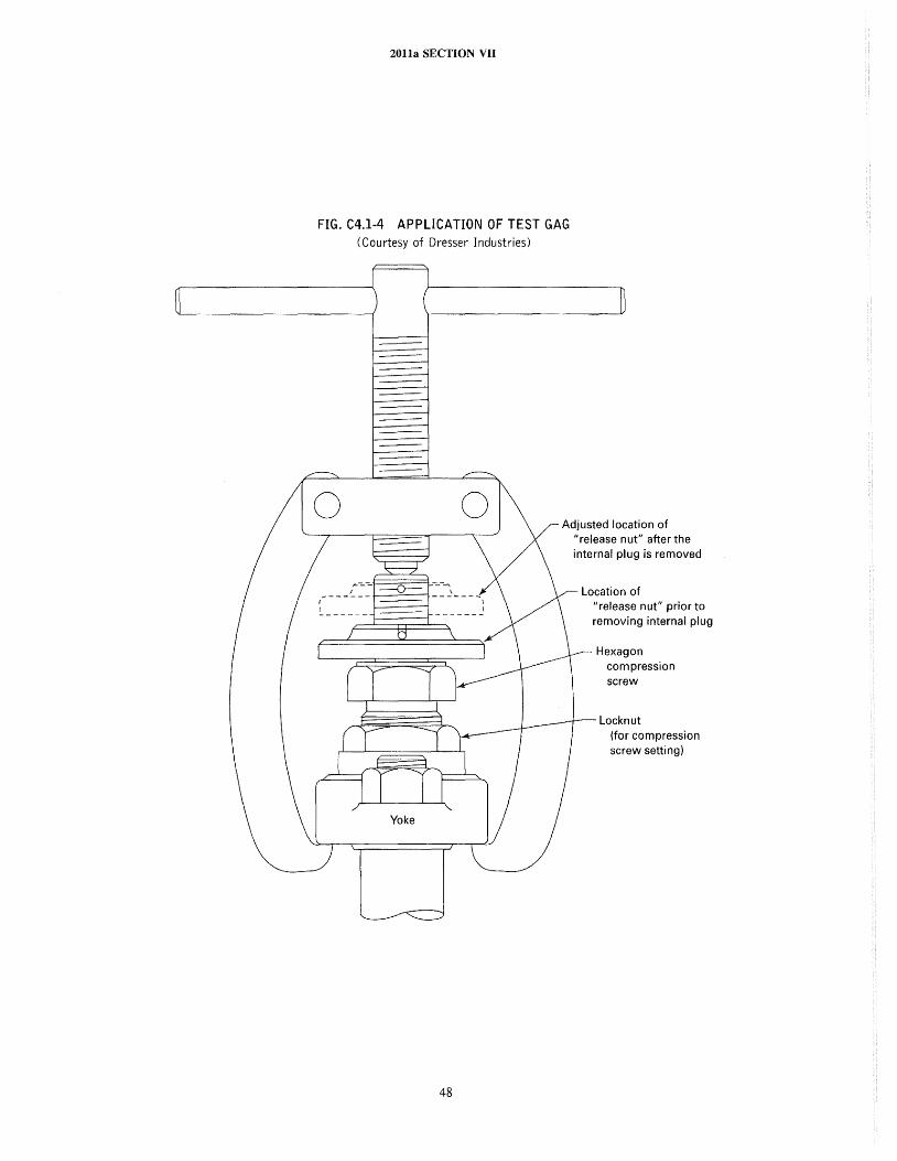
2011a SECTION VII
FIG. C4.1-4 APPLICATION OF TEST GAG (Courtesy of Dresser Industries)
o
48
Adjusted location of "release nut" after the internal plug is removed
Location of "release nut" prior to removing internal plug
Hexagon compression screw
Locknut (for compression screw setting)
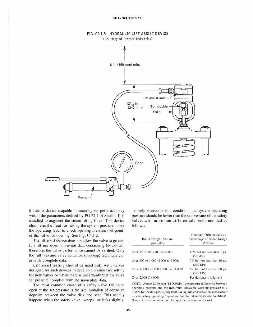
2011a SECTION vn
FIG. C4.1-5 HYDRAULIC LIFT ASSIST DEVICE (Courtesy of Dresser Industries)
6 in. (150 mm) min.
lift assist device (capable of ensuring set point accuracy within the parameters defined by PG-72.2 of Section I) is installed to augment the steam lifting force. This device eliminates the need for raising the system pressure above the operating level to check opening pressure (set point) of the valve for opening. See Fig. C4.1-S.
The lift assist device does not allow the valve to go into full lift nor does it provide data concerning blowdown; therefore, the valve performance cannot be verified. Only the full pressure valve actuation (popping) technique can provide complete data.
Lift assist testing should be used only with valves designed for such devices to develop a preliminary setting for new valves or when there is uncertainty that the valve set pressure complies with the nameplate data.
The most common cause of a safety valve failing to open at the set pressure is the accumulation of corrosive deposits between the valve disk and seat. This usually happens when the safety valve "weeps" or leaks slightly.
131/2 in. (340 mm)
49
i
To help overcome this condition, the system operating pressure should be lower than the set pressure of the safety val ve, with minimum differenti als recommended as follows:
Boiler Design Pressure, psig (kPa)
Over 15 to 300 (100 to 2000)
Over 300 to 1,000 (2 000 to 7 000)
Over 1,000 to 2,000 (7000 to 14000)
Over 2,000 (14 000)
Minimum Differential as a Percentage of Boiler Design
Pressure
10% but not less than 7 psi (50 kPa)
7% but not less than 30 psi (200 kPa)
5% but not less than 70 psi (500 kPa)
Per designer's judgment
NOTE: Above 2,000 psig (14 000 kPa), the pressure differential between operating pressure and the maximum allowable working pressure is a matter for the designer's judgment, taking into consideration such factors as satisfactory operating experience and the intended service conditions. (Consult valve manufacturer for specific recommendations.)
2011a SECTION VII
It is preferable for each safety valve to have a separate discharge pipe, which should be as short as possible to avoid excessive stress in the valve and piping. If a manifold must be used, it should be sized to limit back pressure to within Manufacturer's recommendations. It also should have provision for inspection and cleanout.
Keep the drains in the safety valve body and discharge pipes open. When using a wire to ascertain if drains are clear, be careful that the wire does not move scale that may faIl over the drain opening when the wire is removed.
The proper positions of all supports and anchors, particularly those to which the escape pipe is attached, must be maintained at all times. The valve manufacturer should be consulted if the weight to be loaded on a valve outlet exceeds a short elbow with drip pan.
C4.200
C4.210
SAFETY RELIEF VALVES OR RELIEF VALVES
GENERAL
In addition to the pressure relief valves on the steam supply system (safety valves) that protect against overpressure conditions, spring loaded valves (safety relief valves and relief valves) are frequently used on the auxiliary systems such as heaters, condensate returns, boiler feedpump turbines, evaporators, economizers, compressors, pumps, etc.
C4.220 INSPECTION AND MAINTENANCE
(a) A periodic inspection, testing, and maintenance program is recommended to ensure proper valve function. This program should include valve removal to a shop testing environment for
( 1) verification of set pressure (2) a valve tightness test (3) a test of valve lift (for compressible fluids only)
( b) Safety relief and relief valves are generally manufactured to meet Section VIn requirements. However, valves for certain applications, (e.g., fired economizers, organic vapor generators, high temperature water boilers, etc.), must meet the requirements of Section I.
(c) The corrosiveness of the media, the application, and the trim component metallurgy are primary elements that determine frequency of testing and maintenance. The frequency can be as short as 6 months or as long as 2 years for an individual safety relief or relief valve. The frequency for each valve should be established based upon operating and maintenance experience. Several variations of safety relief or relief valves exist that require special maintenance considerations
( 1) pilot operated safety relief valve
50
(2) balanced safety relief valve (3) bellows safety relief valve (4) power actuated safety relief valve (5) O-ring safety relief valve
The valve manufacturer's service manuals should be carefully consulted for the maintenance of these spring-loaded safety relief valves and relief valves.
(d) Valve inspection should include factors that could affect valve performance. Important among these are
( 1) temperature variation, both system and ambient (2) vibration (3) residue on valve internal parts (4) valve body mechanical stresses (5) line turbulence (6) sizing and configuration of discharge piping (7) sizing and configuration of inlet piping (8) bore diameter
Any program of troubleshooting or preventive maintenance should consider each of the above for each valve.
(e) Safety relief and relief valves are typically flanged or have screw connections to facilitate removal for inspection, cleaning, testing, and maintenance. A maintenance program for these valves should restore them to appropriate Code standards.
C4.221 Valve Tightness
There should be limited leakage after a valve lifts and reseats. Refer to the valve manufacturer's instruction manual for test pressure, duration of test, and acceptable leakage rate for each type and size. API (American Petroleum Institute) Standard 527 provides the table for leakage in a special bubble test when the pressure under the valve seat is 90% of the cold differential test pressure (see Fig. C4.2-1 and Table C4.2-l). This type of test would only be applicable to pressure tight bonnet design valves.
Another common leak test is performed by placing a wet paper towel over the outlet flange of the valve with the pressure under the valve seat at 90% of the cold differential test pressure and observing if the towel ruptures. This unsophisticated test is used to verify tightness in noncritical applications. This type of test is only applicable to pressure tight bonnet design valves. Exposed spring or nonpressuretight bonnet design valves on steam service should receive a cold rod test to detect seat leakage. A cold rod test is performed by removing the valve discharge pipe and placing a cold rod near the valve seat. The formation of condensate on the rod indicates valve leakage.
C4.222 Lift and Blowdown
Lift is an important characteristic because full relieving capacity of the valve can only be achieved at full rated
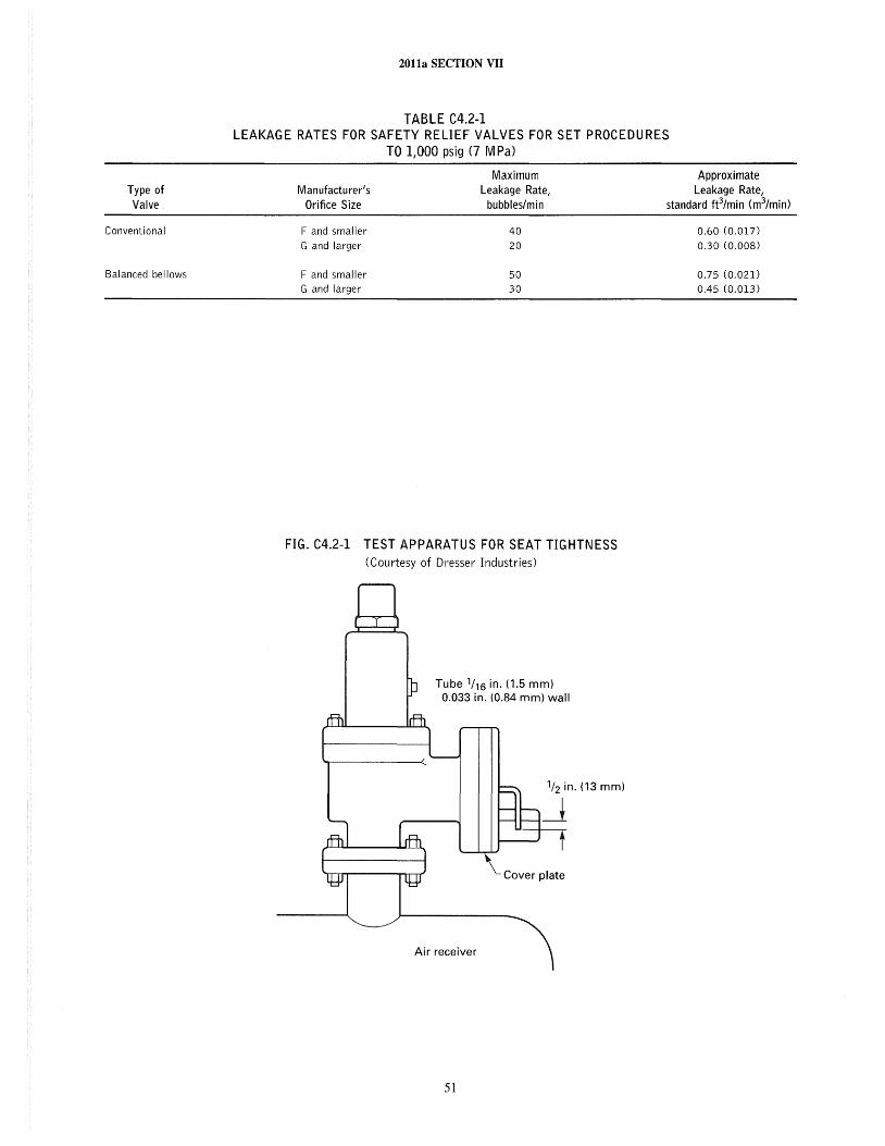
Type of Valve
Conventional
Balanced bellows
20lla SECTION VII
TABLE C4.2·1 LEAKAGE RATES FOR SAFETY RELIEF VALVES FOR SET PROCEDURES
TO 1,000 psig (7 M Pa)
Maximum Manufacturer's Leakage Rate,
Approximate Leakage Rate,
Orifice Size bubbles/min standard ft3/min (m3/min)
F and smaller 40
G and larger 20
F and smaller 50 G and larger 30
FIG. C4.2-1 TEST APPARATUS FOR SEAT TIGHTNESS (Courtesy of Dresser Industries)
Tube 1/16 in. (1.5 mm) 0.033 in. (0.84 mm) wall
'-Cover plate
Air receiver
51
0.60 (0.017)
0.30 (0.008)
0.75 (0.021) 0.45 (0.013)
2011a SECTION VII
lift. Blowdown is the difference between the set pressure and the closing pressure of the valve. The system operating pressure should be below the valve closing pressure. Blowdown is only a meaningful characteristic for gas, steam, or air applications. Only valves for compressible fluids on Section I applications require lift and blowdown values to be provided on the nameplate.
Valve internal dimensions have critical relationships, and the surface finishes must be carefully maintained as recommended by the Manufacturer for the valve to perform properly. Any part repair should be approved by the valve manufacturer to ensure that the valve will continue to function properly. Any parts being replaced should come from a Manufacturer who understands the valve design, construction, and application and meets the original valve manufacturer's specification.
C4.230 TESTING
A safety relief valve should always be tested after any maintenance work. This testing can usually be best accomplished on a test stand operating on compressed air (for air or gas applications) or pressurized water (for liquid applications). Test stands can typically verify the quality of workmanship for all functions except lift or blowdown (the capacity of the test stand determines the maximum size of valve that can be lift and blowdown tested).
Upon conclusion of repair, testing, and acceptance, a repair nametag should be attached to the valve identifying who repaired the val ve and the date of repair. If the operating characteristics were changed, the new characteristics should be provided on the nameplate. The original nameplate should never be removed from the valve. Records for each valve should be maintained, showing the results of any preventive maintenance or repair activity on the valve and identifying who performed the repairs. All valves should be sealed after testing to ensure that no further adjustments are made. Repairs and testing of safety relief valves should only be performed by qualified personnel.
C4.240 TRANSPORTATION AND INSTALLATION
Care should be taken not to disturb the vertical alignments of the valve while transporting or installing. The valve should not be laid on its side after assembly and test. Special attention should be given to torquing of inlet and outlet nuts and bolts. Uniform torque values should be used on all nuts and bolts, and the tightening should be done in a way that will not impart internal stresses to the valve body.
52
C4.300 PRESSURE GAGES
(a) The pressure gage is a key means of determining the operational status of the boiler system. The installation of the proper gage in the proper location is extremely important to the safety and the efficient operation of the boiler system. A pressure gage is a sensitive instrument and can be affected by
( 1) ambient temperature variation (2) vibration (3) location (4) installation methods (5) rough or careless handling
(b) Pressure gages should be inspected and recalibrated on a routine basis depending on the type of boiler system and the operating conditions, or whenever there is any question of accuracy. The normal cycle for removal, inspection, and recalibration is once every 12 months.
( c) Inspection and application of the proper gage should consider the following factors:
( 1) Since gages are instruments, they should be handled carefully.
(2) The dial of the pressure gage should be graduated to approximately double the pressure at which the safety valve is set, but in no case to less than 1 ~ times this pressure.
(3) Make sure that the proper pressure sensing element materials and joining methods are used for the application.
(4) Dial diameter should be determined based upon location to provide good visual indication for easy operator reading.
(5) While NPS ~ (DN 8) and NPS ~ (DN 15) connections are available, ~ in. (6 mm) connections should only be used for gages under 4~ in. (114 mm) and NPS ~ (DN 15) used for gages over 4~ in. (114 mm). Lower connection should be used for stem installations and back connection for panel mounting.
(6) Available accuracies are: ANSI Or. A ±2~% of full scale; ANSI Or. 2A ±~% of full scale.
(d) Always use a wrench on the shank of the gage socket to screw the gage in place. Never apply force against the gage case. Hold a wrench on the socket flats to screw a fitting to the gage. Do not twist against the gage socket screws which hold the gage mechanism in the case.
(e) The use of a gage siphon, sometimes known as a pigtail because of its shape, is a good practice on gages installed in steam service. The siphon reduces the temperature at the gage below that of the steam being measured. The gage block valve should be opened slowly to avoid overheating of the gage. The gage should be installed to eliminate piping strains. The installation of flexible tubing for the last section of piping leading to the gage can be used to minimize potential problems.
2011a SECTION VII
C4.400 FUSIBLE PLUGS
Fusible plugs are seldom used on modem boilers. Fire actuated fusible plugs, if used, are located at the lowest permissible water level as determined by the boiler manufacturer. Stearn actuated plugs, if used, are so located that they will operate when the water level is at the point where a fire actuated fusible plug would be located.
Section I requires that fusible plugs be renewed at least once each year. Fusible plug casings which have been used should not be refilled. Details are covered in Section I, PWT-9.3, A-19 through A-21, and A-IO.
C4.S00 FEED WATER REGULATOR VALVE
Depending on the boiler type, size, and intended service the feedwater regulator may be operated by either a single, two or three element control. Single element control is usually based on level only. Two element control is based on level and steam flow, and three element control is based on level, stearn flow, and feedwater flow. In any case a feedwater regulator is strongly recommended for all boilers. Normally these valves cannot be considered to be tight shutoff valves. In addition, these regulators may not operate properly until they are up to their operating temperatures.
A feedwater regulator valve should have design features to allow emergency manual operation. It should be provided with a full capacity manual bypass. These valves should be at locations which permit observation of the water level. For existing installations. unless the operator can see the stearn drum gage glass whenever it is necessary to operate the feedwater flow manually, an assistant should be stationed to watch the gage and be able to signal the operator.
The importance of maintaining the proper water level in the boiler cannot be overemphasized. Off-normal operation of boiler water level controls should, therefore, be promptly attended to by qualified personnel following the regulator manufacturer's recommendations for servicing.
During each annual boiler inspection, the condition of the boiler feedwater piping and the feedwater control valve(s) should be determined. Typical conditions to look for include
(a) accumulations resulting from the feed of phosphate into the system upstream of the feed water regulator. Any deposits found from this source are predominantly white.
(b) wire drawing of the regulator. This is caused by the valve operating in the nearly closed position. Thus, the regulator rarely opens to its design position and water level control is usually erratic.
(c) erosion or corrosion of the feedwater piping and the regulator valve. This may be caused by high or low pH and/or high oxygen levels in the feedwater.
53
C4.600 BLOWDOWN
Boiler water dissolved solids concentrations can readily be maintained within limits with a continuous blowdown system. For industrial boilers, a small diameter line, usually a perforated pipe, extends inside the steam drum below the water level to blow down the concentrated boiler water from along the length of the drum. External to the drum, the rate of flow is manually or automatically adjustable through a flow control valve. With this arrangement, since a small quanti ty of water is discharged continuously, adjustments in the flow rate for boiler water concentration control overcomes the disadvantages of using the bottom blowoff where a Jarge quantity of water is discharged intermittently with consequently less precise water chemistry control.
From a branch upstream of the flow control valve, a second flow control valve and a sample cooler, if installed, serve to provide a cooled boiler water sample for manual or automatic chemical testing. Care should be taken to obtain the sample from the source intended when using manifold sampling systems.
Heat recovery equipment, such as a flash tank or shell and tube heat exchanger installed in the continuous blowdown system, will result in energy savings.
With a continuous blowdown system installed. the boiler bottom blowoff located in the bottom of the lower drum or the lowest point in the circulation system serves only to remove sludge that may have collected. If a continuous blowdown system is not provided and it is necessary to regulate boiler water concentrations by intermittent blowdown, the length and frequency of blowing down (in this case) should be scheduled so that the boiler water chemical control is maintained within recommended limits. The period between blows will be related to the quantity of stearn generated and the corresponding percentage of makeup water admitted to the system. However, even under ideal conditions, the boiler should be blown down at least every 24 hr.
Waterwall drain or blowoff valves should not be operated except when the boiler is banked or in accordance with specific instructions from the Manufacturer of the boiler.
Recognizing the fact that there are many types of boiler designs, these guidelines represent conventionally accepted practice for intermittent blowdown. Nevertheless, there may be special considerations not covered herein, and reference should be made to the boiler and valve manufacturer's instmction manuals.
C4.700 SOOT BLOWERS
Boiler performance and reliability are directly related to the cleanliness of the heat transfer surfaces. Thus, when firing ash bearing fuels such as coal or heavy fuel oil, ash or slag deposits must be controlled by soot blowing.
2011a SECTION VII
Depending on the type of fuel fired, equipment arrangement, and operating conditions, soot blowers may be installed to control ash or slag deposits on furnace walls, slag screen, superheater, reheater, convection pass, air heater, and economizer.
Typically, in the high temperature zones such as at the slag screen and ahead of the superheater, retractable blowers are installed. During the blowing period, as the element travels into and retracts from the furnace, it is cooled by the steam. In the lower temperature zones, where blower elements are not subject to warpage or cracks during idle periods, the elements are permanently installed within the enclosure.
The medium for soot blowing can be either steam or compressed air. Blowing pressures are recommended by the Manufacturer.
On smaller boilers, soot should be blown only when the unit is operating at a steaming capacity of over 50% with stable combustion conditions. For units with an induced draft fan, the furnace draft should be increased. Thus, if a slag fall occurs, the additional draft reduces the possibility of flameout or furnace puff. With larger capacity boilers, the furnace volume is normally large enough that the cleaning medium passing into it is a small percentage of the gas flow. Nevertheless, prudent operation suggests that soot blowing commence only at those loads at which burner stability is ensured, particularly when a heavy slag fall is anticipated.
54
With small boilers operating with natural or balanced draft and automatic control, it is advisable to change to manual control and increase the furnace draft enough to avoid a positive furnace pressure while operating a soot blower. For pressure fired boilers, it is likewise desirable to change from automatic to manual control to avoid upsetting the air flow control.
Based on experience, the controls of large boilers, operated either balanced draft or with positive furnace pressure, may be kept on automatic control while operating soot blowers.
Normal practice is to clean the furnace from the top down. Blowing in the convection passes may vary with the arrangement of surface, but generally it is in the direction of gas flow. Blowers in different areas may be operated on different schedules depending on the need in a particular area.
The need for blowing can be based on the draft loss across the various boiler, superheater, air heater, and economizer passes. Successful cleaning will return these differentials to expected conditions. Gas and steam temperatures throughout the unit can also be used as guides in soot blowing.
During soot blowing, the performance of each blower should be monitored so that abnormal conditions can be detected. Before a blower employing steam is placed in service, the piping should be warmed and the moisture drained.
2011a SECTION VII
SUBSECTION C5 INSTRUMENTATION, CONTROLS, AND INTERLOCKS
CS.I00 GENERAL
Indicating and recording devices and associated instruments are the operator's basic tools for monitoring and controlling boiler operation; they may include steam, air, and feedwater flowmeters, thermometers, draft and pressure gages, and analyzers. These devices are installed to monitor normal and abnormal conditions and are important for equipment operation, safety, and energy conservation. Therefore, these devices should be maintained in calibration at all times.
Modern boilers that are in compliance with accepted practice for safe operation include interlock systems. The interlocks establish the safe sequence for startup and provide for a safe shutdown. They should never be bypassed or jumpered.
Older boilers that do not include interlock safety systems require that the operator carefully follow the manufacturer's instructions when placing a boiler in and taking it out of service. During startup and shutdown all interlocks including the low water fuel cutoffs and the flame failure devices, where installed, should be checked for proper functioning. It is recommended that each automatically fired boiler have two independent low water cutoffs. Moreover, at each annual outage, the low water cutoffs should be dismantled, inspected, cleaned, and checked for proper calibration and performance.
On older units, the meter and control boards were located on the operating floor so that the operator could observe firsthand the critical operating functions: namely, proper combustion and the water level. On modern units designed with centralized control rooms including complex instruments, controls, and data loggers, the firsthand observation feature is unrealistic under normal operating conditions. In these cases redundancy must be provided in the instrumentation so that the operator is ensured of accuracy and reliability.
CS.200 INDICATORS AND RECORDERS
Operation of a boiler requires proper regulation of feedwater flow, air flow, and fuel flow. Instrumentation should be provided so that the operator may have an awareness
55
of the operating conditions within the boiler that affect these functions. In order to ensure safe, efficient, and reliable operation, a list of basic instmmentation is provided below.
(a) Indicating devices may include the following, if applicable:
( 1) water level indicator (2) steam drum pressure gage (3) superheater outlet pressure gage ( 4) feedwater pressure (5) furnace draft or pressure (6) boiler outlet draft or pressure (7) forced draft fan discharge and induced draft fan
inlet pressure or draft (8) windbox pressure or windbox furnace differential
for pressurized systems (9) economizer inlet and outlet draft or pressure ( 10) air heater inlet and outlet draft or pressure, both
flue gas and air side ( 11) fuel supply and burner pressure for oil or gas
firing (12) atomizing supply and differential pressure and
oil temperature for heavy oil systems (b) Recording devices may include the following, if
applicable: ( 1) steam flow (2) air flow (3) feedwater flow (4) dnull level (5) steam temperatures leaving superheater and
attemperator
units
(6) air and flue gas temperatures as follows: (a) air to air heater (b) air to burners (c) flue gas leaving boiler (d) flue gas leaving economizer (e) flue gas leaving air heater
(7) smoke or opacity indicator for coal or oil fired
(8) flue gas analyzer, such as an O2, CO, or CO2 meter (c) Pulverized Fuel Operation. Pulverized fuel fired
boilers require instruments for operation of the pulverizers. The instrument requirements depend on pulverizer design.
2011a SECTION VII
Instrument requirements common to all pulverizer designs include the following:
(J) recorder, with high alarm, for the coal/air mixture temperature
(2) pressure indicator for coall air mixture to the burners
(3) flow device for primary air flow (4) pulverizer drive motor ammeter
Additional instruments may be required for special equipment or fuels when recommended by the equipment manufacturer.
CS.210 PREPARATION FOR AND PLACING IN SERVICE
All essential instruments must be installed, calibrated, and ready for operation before the boiler or any of the major equipment is placed in service, This procedure will not only aid the operators of the boiler and fuel burning apparatus in getting the equipment properly adjusted, but it will also provide for a record of perfom1ance during the period when equipment is being placed in service.
Records of instrument readings are often invaluable in preventing failures and determining the causes of failures or emergency conditions after their occurrence, A checklist of all important items to be acknowledged by the operator during the startup provides assurance that essentials are not overlooked in preparation for service,
CS.220 CHECKING AND TESTING
A complete conditional and operations check of all instruments and interlocks should be made by a competent person at least once each year. Pertinent information and dates of the operational checks should be entered in the operating log.
CS.300
CS.310
CONTROLS AND INTERLOCKS
CONTROLS
Boiler controls are used to maintain steam pressure, load, drum water level, and fuel/air ratios at selected conditions. Some elements may be omitted from small installations and still provide adequate protection, Basic to the boiler control is the control of combustion and feedwater.
(a) Combustion Control
(l) A simple combustion control system should have as a minimum the following controls:
(a) a steam pressure control (b) a subsystem for proportioning air and fuel flows
in the proper ratio to maintain safe and efficient combustion
56
(c) a furnace pressure control for balanced draft units
(2) More extensive systems may have additional control subloops and manual-automatic selector stations, There are many different arrangements by which elements of a combustion control system may be assembled and still give the required control, but the function of each element should be carefully checked to ensure that adequate protection of the instal1ation is obtained,
(b) Feedwater Control. Automatic control of the feedwater supply for maintaining the proper steam drum water level must be provided on modem steam generating units where water volume is comparatively small, and it is recommended for all natural and controlled circulation boilers regardless of size. The type of feedwater regulation selected should be governed by the boiler design, operating pressure, type of fuel used, method of firing, and load characteristics.
( c) Control of Superheat
( 1) Steam temperature control is very important, not only for protection of the superheater but also for the equipment served by the boiler. Factors that affect steam temperature are as follows:
( a) excess air
(b) type of fuel burned ( c) slagging conditions
(d) feedwater temperature
(e) load
(2) Steam temperature control can be either by the use of attemperators, steam bypasses, or gas proportioning dampers as well as by gas recirculation, high excess air, or burner selection. The method utilized will depend on the design of the particular boiler and superheater.
(a) Attemperators. Spray attemperation is a method of steam temperature control of superheated steam. This method regulates steam temperature by diluting high temperature steam with makeup water or condensate, Utilization of the spray attemperators is not recommended below 10% steam flow. A temperature detector with a low temperature alarm should be installed at the attemperator outlet to safeguard against water entering the downstream superheater sections.
( b) Steam Bypass, Spray attemperators at the superheater inlet are not effective during startup or at low loads. The steam bypass system performs three functions during startup and low loads the following:
( 1) drum pressure control by a superheater bypass to the condenser
(2) main steam temperature control with steam attemperation
The bypass system is used to control throttle pressure and steam temperature to meet the turbine manufacturer's conditions during startup, shutdown, and over the load
20lla SECTION VII
range. The unit can, however, be started and operated without use of the bypass system.
(d) Control Device Features ( 1) Automatic devices for both combustion and feed
water control should be arranged to failsafe in case of failure of the control signal, driving medium, or mechanical failure. Locking systems that maintain feed water control valves at the position that existed just prior to the control failure are recommended.
(2) Remote manual control of feedwater and combustion control should be provided to supplement automatic regulation so that the operator may control drive elements during startup and during periods of maintenance and emergencies. When combustion controls are on manual, both the fuel and air flow should also be on manual control.
C5.320 INTERLOCKS
(a) Interlocks or safety controls, as they are sometimes called, are provided to interrupt fuel flow to the boiler and shut down equipment in the event that unsafe conditions develop. These conditions could include the following:
( 1) loss of FD Fan (2) loss of ID Fan (3) furnace pressure (4) low water level (5) loss of flame (6) fuel supply out of normal range (7) atomizing fluid pressure or temperature out of
normal range (8) steam temperature out of normal range
(b) The permanent installation of cutout devices to render the interlocks inoperative and to permit the operation of individual pieces of equipment should not be provided.
57
Temporary arrangements can readily be installed for the purpose of testing individual pieces of equipment.
( c) Aspirating -air or other types of lockout are required on all observation doors, soot blower wall boxes, and oil or gas burner withdrawal openings on pressurized furnace boilers.
CS.330 PREPARATION FOR AND PLACING IN SERVICE
All controls and interlocks should be carefully checked for ability to perform as intended with equipment being controlled, such as dampers and valves, so that any condition of the equipment that would make the controller or interlock inoperable may be detected and corrected before putting the boiler in operation. The original control setting should be made by a controls and instrument engineer and/ or Manufacturer's serviceman.
Boilers should be operated on manual control during startup and promptly shifted over to automatic after steadystate conditions have been reached. Manual operation under these conditions assists in training operators for this mode of operation and for transferring from manual to automatic control and vice versa.
Some package boilers are equipped only with automatic controls, in which case the procedure in the preceding paragraph will not apply.
CS.340 CHECKING AND TESTING
A complete check and test of all controls and interlocks is recommended at least once a year. An actual operating check on interlocks can best be done during a scheduled startup and shutdown of a boiler.
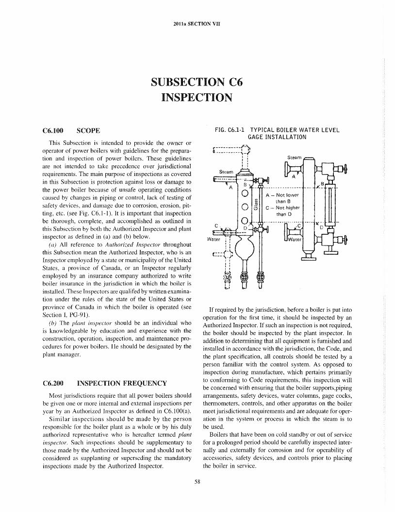
2011a SECTION VII
SUBSECTION C6 INSPECTION
C6.100 SCOPE
This Subsection is intended to provide the owner or operator of power boilers with guidelines for the preparation and inspection of power boilers. These guidelines are not intended to take precedence over jurisdictional requirements. The main purpose of inspections as covered in this Subsection is protection against loss or damage to the power boiler because of unsafe operating conditions caused by changes in piping or control, lack of testing of safety devices, and damage due to corrosion, erosion, pitting, etc. (see Fig. C6.1-1). It is important that inspection be thorough, complete, and accomplished as outlined in this Subsection by both the Authorized Inspector and plant inspector as defined in (a) and (b) below.
(a) An reference to Authorized Inspector throughout this Subsection mean the Authorized Inspector, who is an Inspector employed by a state or municipality of the United States, a province of Canada, or an Inspector regularly employed by an insurance company authorized to write boiler insurance in the jurisdiction in which the boiler is installed. These Inspectors are qualifed by written examination under the rules of the state of the United States or province of Canada in which the boiler is operated (see Section I, PG-9 J).
(b) The plant inspector should be an individual who is knowledgeable by education and experience with the construction, operation, inspection, and maintenance procedures for power boilers. He should be designated by the plant manager.
C6.200 INSPECTION FREQUENCY
Most jurisdictions require that all power boilers should be given one or more internal and external inspections per year by an Authorized Inspector as defined in C6.100(a).
Similar inspections should be made by the person responsible for the boiler plant as a whole or by his duly authorized representative who is hereafter termed plant inspector. Such inspections should be supplementary to those made by the Authorized Inspector and should not be considered as supplanting or superseding the mandatory inspections made by the Authorized Inspector.
58
FIG. C6.1-1 TYPICAL BOILER WATER LEVEL GAGE INSTALLATION
A - Not lower than B Not higher than 0
If required by the jurisdiction, before a boiler is put into operation for the first time, it should be inspected by an Authorized Inspector. If such an inspection is not required, the boiler should be inspected by the plant inspector. In addition to determining that all equipment is furnished and installed in accordance with the jurisdiction, the Code, and the plant specification, all controls should be tested by a person familiar with the control system. As opposed to inspection during manufacture, which pertains primarily to conforming to Code requirements, this inspection will be concerned with ensuring that the boiler supports,piping arrangements, safety devices, water columns, gage cocks, thermometers, controls, and other apparatus on the boiler meet jurisdictional requirements and are adequate for operation in the system or process in which the steam is to be used.
Boilers that have been on cold standby or out of service for a prolonged period should be carefully inspected internally and externally for corrosion and for operability of accessories, safety devices, and controls prior to placing the boiler in service.
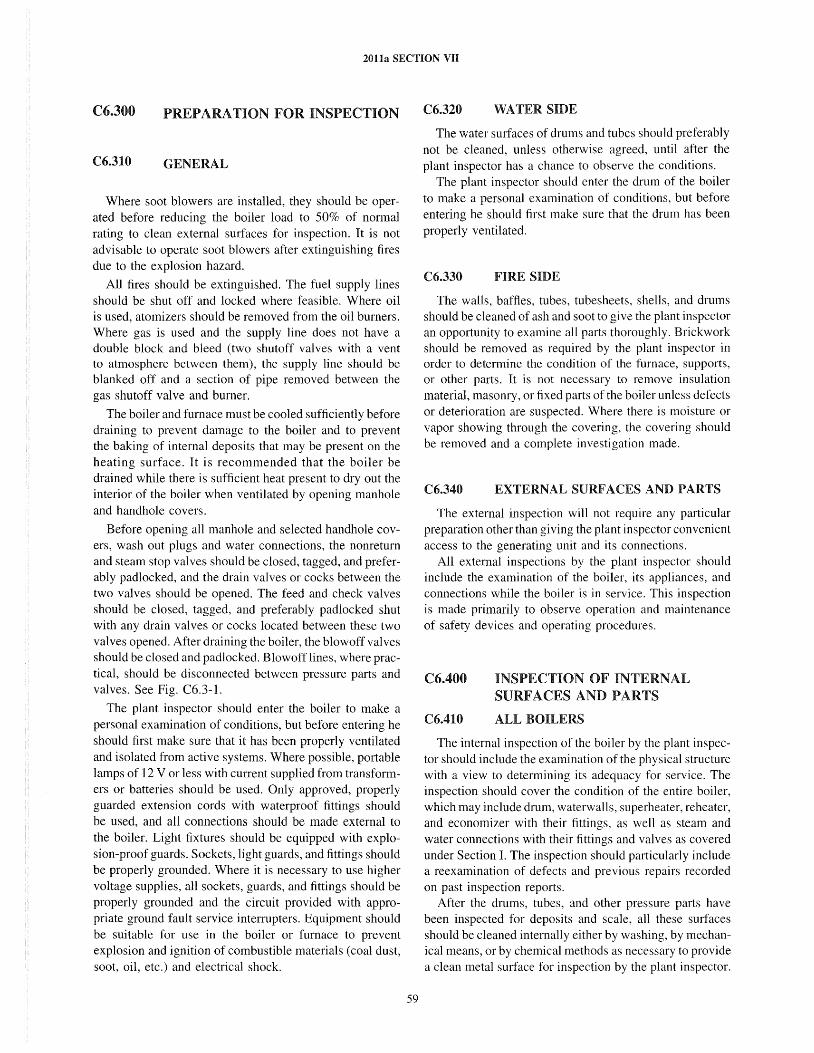
20t1a SECTION VII
C6.300 PREPARATION FOR INSPECTION
C6.310 GENERAL
Where soot blowers are installed, they should be operated before reducing the boiler load to 50% of normal rating to clean external surfaces for inspection. It is not advisable to operate soot blowers after extinguishing fires due to the explosion hazard.
All fires should be extinguished. The fuel supply lines should be shut off and locked where feasible. Where oil is used, atomizers should be removed from the oil burners. Where gas is used and the supply line does not have a double block and bleed (two shutoff valves with a vent to atmosphere between them), the supply line should be blanked off and a section of pipe removed between the gas shutoff valve and burner.
The boiler and furnace must be cooled sufficiently before draining to prevent damage to the boiler and to prevent the baking of internal deposits that may be present on the heating surface. It is recommended that the boiler be drained while there is sufficient heat present to dry out the interior of the boiler when ventilated by opening manhole and handhole covers.
Before opening all manhole and selected handhole covers, wash out plugs and water connections, the nonreturn and steam stop valves should be closed, tagged, and preferably padlocked, and the drain valves or cocks between the two valves should be opened. The feed and check valves should be closed, tagged, and preferably padlocked shut with any drain valves or cocks located between these two valves opened. After draining the boiler, the blowoff valves should be closed and padlocked. Blowofflines, where practical, should be disconnected between pressure parts and valves. See Fig. C6.3-1.
The plant inspector should enter the boiler to make a personal examination of conditions, but before entering he should first make sure that it has been properly ventilated and isolated from active systems. Where possible, portable lamps of 12 V or less with current supplied from transformers or batteries should be used. Only approved, properly guarded extension cords with waterproof fittings should be used, and all connections should be made external to the boiler. Light fixtures should be equipped with explosion-proof guards. Sockets, light guards, and fittings should be properly grounded. Where it is necessary to use higher voltage supplies, all sockets, guards, and fittings should be properly grounded and the circuit provided with appropriate ground fault service interrupters. Equipment should be suitable for use in the boiler or furnace to prevent explosion and ignition of combustible materials (coal dust, soot, oil, etc.) and electrical shock.
59
C6.320 WATER SIDE
The water surfaces of drums and tubes should preferably not be cleaned, unless otherwise agreed, until after the plant inspector has a chance to observe the conditions.
The plant inspector should enter the drum of the boiler to make a personal examination of conditions, but before entering he should first make sure that the drum has been properly ventilated.
C6.330 FIRE SIDE
The walls, baffles, tubes, tubesheets, shells, and drums should be cleaned of ash and soot to give the plant inspector an opportunity to examine all parts thoroughly. Brickwork should be removed as required by the plant inspector in order to detennine the condition of the furnace, supports, or other parts. It is not necessary to remove insulation material, masonry, or fixed parts of the boiler unless defects or deterioration are suspected. Where there is moisture or vapor showing through the covering, the covering should be removed and a complete investigation made.
C6.340 EXTERNAL SURFACES AND PARTS
The external inspection will not require any particular preparation other than gi ving the plant inspector convenient access to the generating unit and its connections.
All external inspections by the plant inspector should include the examination of the boiler, its appliances, and connections while the boiler is in service. This inspection is made primarily to observe operation and maintenance of safety devices and operating procedures.
C6.400
C6.410
INSPECTION OF INTERNAL SURFACES AND PARTS
ALL BOILERS
The internal inspection of the boiler by the plant inspector should include the examination of the physical structure with a view to determining its adequacy for service. The inspection should cover the condition of the entire boiler, which may include drum, waterwalls, superheater, reheater, and economizer with their fittings, as well as steam and water connections with their fittings and valves as covered under Section 1. The inspection should paliicularly include a reexamination of defects and previous repairs recorded on past inspection reports.
After the drums, tubes, and other pressure parts have been inspected for deposits and scale, all these surfaces should be cleaned internally either by washing, by mechanical means, or by chemical methods as necessary to provide a clean metal surface for inspection by the plant inspector.
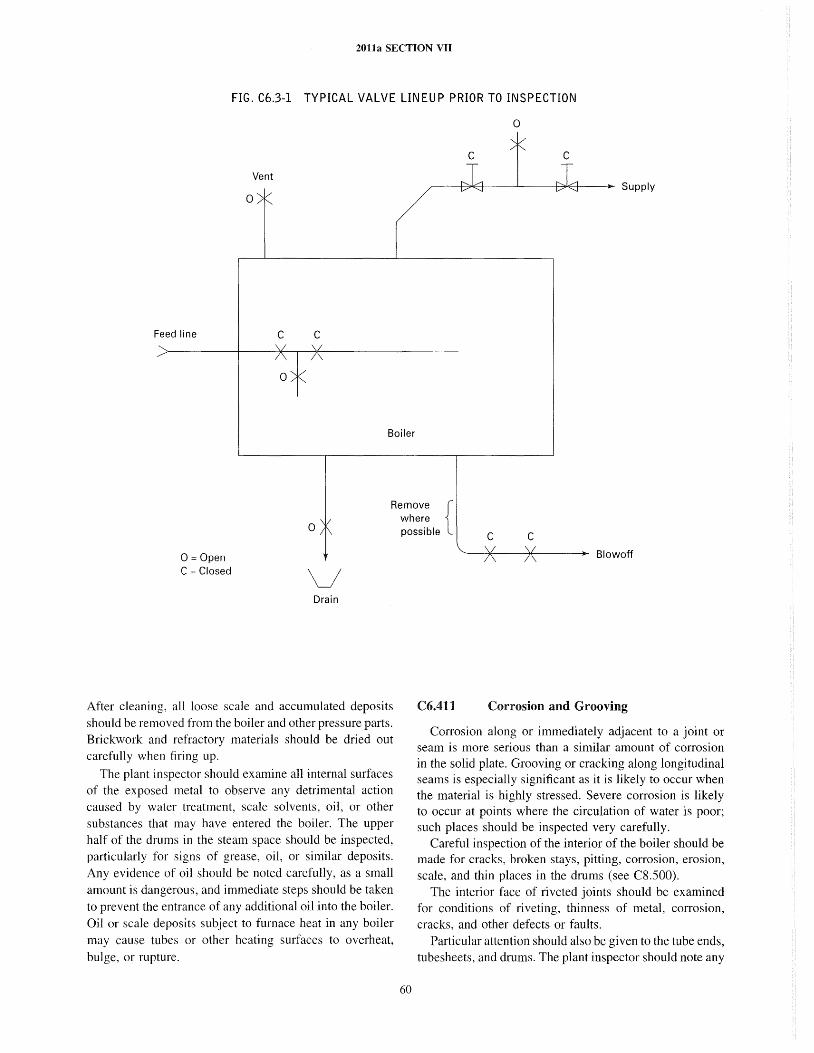
2011a SECTION VII
FIG. C6.3-1 TYPICAL VALVE LINEUP PRIOR TO INSPECTION
o
C C
Vent r------t-::;*E-t----i---B"E.:t--»- Supply
o
Feed line C C
Boiler
o
Remove { where possible C C
0= Open C = Closed v
Drain
After cleaning, all loose scale and accumulated deposits should be removed from the boiler and other pressure parts. Brickwork and refractory materials should be dried out carefully when firing up.
The plant inspector should examine all internal surfaces of the exposed metal to observe any detrimental action caused by water treatment, scale solvents, oil, or other substances that may have entered the boiler. The upper half of the drums in the steam space should be inspected, particularly for signs of grease, oil, or similar deposits. Any evidence of oil should be noted carefully, as a small amount is dangerous, and immediate steps should be taken to prevent the entrance of any additional oil into the boiler. Oil or scale deposits subject to furnace heat in any boiler may cause tubes or other heating surfaces to overheat, bulge, or rupture.
60
Blowoff
C6.411 Corrosion and Grooving
COlTosion along or immediately adjacent to a joint or seam is more serious than a similar amount of cOlTosion in the solid plate. Grooving or cracking along longitudinal seams is especially significant as it is likely to occur when the material is highly stressed. Severe corrosion is likely to occur at points where the circulation of water is poor; such places should be inspected very carefully.
Careful inspection of the interior of the boiler should be made for cracks, broken stays, pitting, corrosion, erosion, scale, and thin places in the drums (see CS.500).
The interior face of riveted joints should be examined for conditions of riveting, thinness of metal, corrosion, cracks, and other defects or faults.
Particular attention should also be given to the tube ends, tubesheets, and drums. The plant inspector should note any
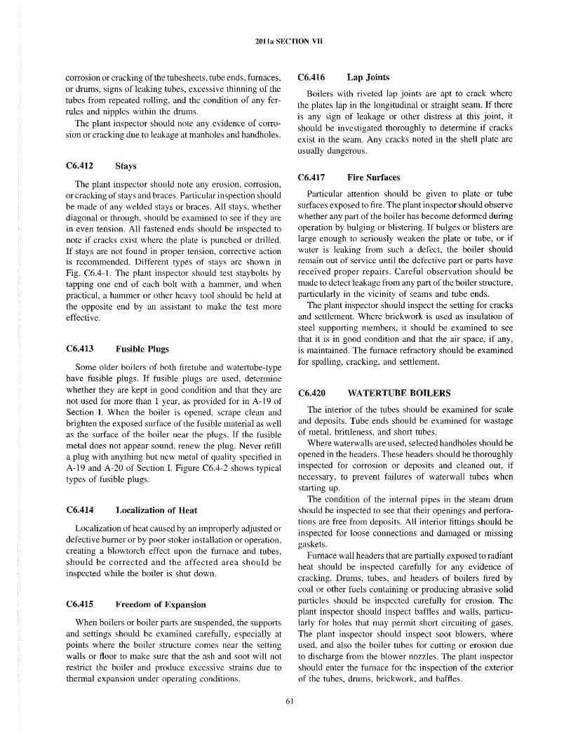
2011a SECTION VII
corrosion or cracking of the tubesheets, tube ends, furnaces, or drums, signs of leaking tubes, excessive thinning of the tubes from repeated rolling, and the condition of any ferrules and nipples within the drums.
The plant inspector should note any evidence of corrosion or cracking due to leakage at manholes and handholes.
C6.412 Stays
The plant inspector should note any erosion, corrosion, or cracking of stays and braces. Particular inspection should be made of any welded stays or braces. All stays, whether diagonal or through, should be examined to see if they are in even tension. All fastened ends should be inspected to note if cracks exist where the plate is punched or drilled. If stays are not found in proper tension, corrective action is recommended. Different types of stays are shown in Fig. C6.4-1. The plant inspector should test staybolts by tapping one end of each bolt with a hammer, and when practical, a hammer or other heavy tool should be held at the opposite end by an assistant to make the test more effective.
C6.413 Fusible Plugs
Some older boilers of both firetube and watertube-type have fusible plugs. If fusible plugs are used, determine whether they are kept in good condition and that they are not used for more than 1 year, as provided for in A -19 of Section I. When the boiler is opened, scrape clean and brighten the exposed surface of the fusible material as well as the surface of the boiler near the plugs. If the fusible metal does not appear sound, renew the plug. Never refill a plug with anything but new metal of quality specified in A-19 and A-20 of Section I. Figure C6.4-2 shows typical types of fusible plugs.
C6.414 Localization of Heat
Localization of heat caused by an improperly adjusted or defective burner or by poor stoker installation or operation, creating a blowtorch effect upon the furnace and tubes, should be corrected and the affected area should be inspected while the boiler is shut down.
C6.41S Freedom of Expansion
When boilers or boiler parts are suspended, the supports and settings should be examined carefully, especially at points where the boiler structure comes near the setting walls or floor to make sure that the ash and soot will not restrict the boiler and produce excessive strains due to thermal expansion under operating conditions.
61
C6.416 Lap Joints
Boilers with riveted lap joints are apt to crack where the plates lap in the longitudinal or straight seam. If there is any sign of leakage or other distress at this joint, it should be investigated thoroughly to determine if cracks exist in the seam. Any cracks noted in the shel1 plate are usually dangerous.
C6.417 Fire Surfaces
Particular attention should be given to plate or tube surfaces exposed to fire. The plant inspector should observe whether any part of the boiler has become deformed during operation by bulging or blistering. If bulges or blisters are large enough to seriously weaken the plate or tube, or if water is leaking from such a defect, the boiler should remain out of service until the defective part or parts have received proper repairs. Careful observation should be made to detect leakage from any part of the boiler structure, particularly in the vicinity of seams and tube ends.
The plant inspector should inspect the setting for cracks and settlement. Where brickwork is used as insulation of steel supporting members, it should be examined to see that it is in good condition and that the air space, if any, is maintained. The furnace refractory should be examined for spalling, cracking, and settlement.
C6.420 WATERTUBE BOILERS
The interior of the tubes should be examined for scale and deposits. Tube ends should be examined for wastage of metal, brittleness, and short tubes.
Where waterwalls are used, selected handholes should be opened in the headers. These headers should be thoroughly inspected for corrosion or deposits and cleaned out, if necessary, to prevent failures of waterwall tubes when starting up.
The condition of the internal pipes in the steam drum should be inspected to see that their openings and perforations are free from deposits. All interior fittings should be inspected for loose connections and damaged or missing gaskets.
Furnace wall headers that are partially exposed to radiant heat should be inspected carefully for any evidence of cracking. Drums, tubes, and headers of boilers fired by coal or other fuels containing or producing abrasive solid particles should be inspected carefully for erosion. The plant inspector should inspect baffles and walls, particularly for holes that may permit short circuiting of gases. The plant inspector should inspect soot blowers, where used, and also the boiler tubes for cutting or erosion due to discharge from the blower nozzles. The plant inspector should enter the furnace for the inspection of the exterior of the tubes, drums, brickwork, and baffles.
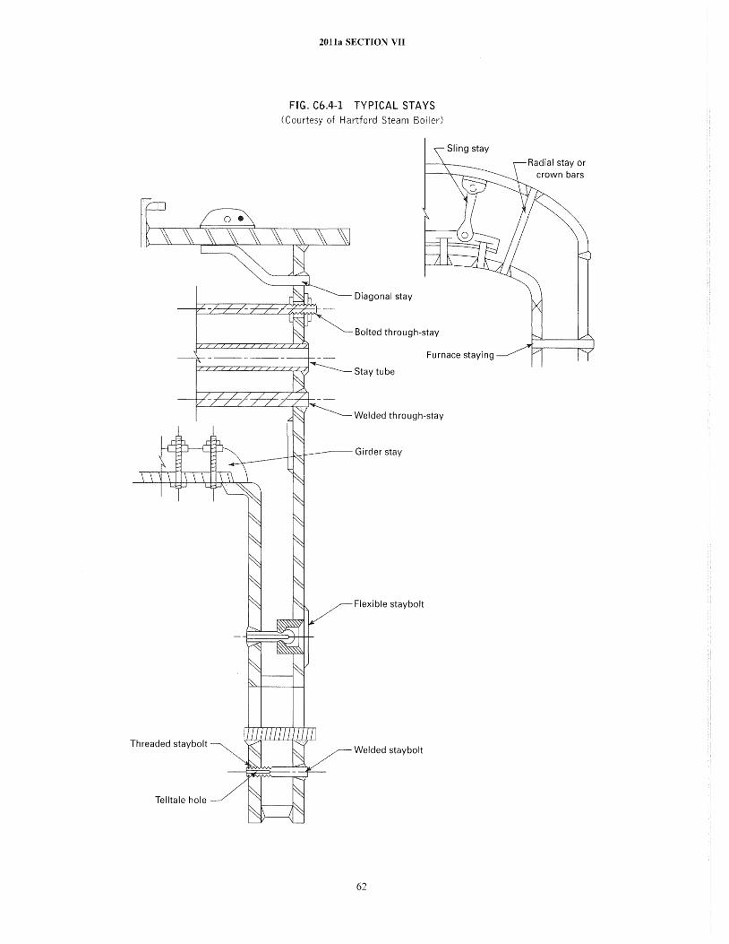
Threaded staybolt
Telltale hole
2011a SECTION VII
FIG. C6.4-1 TYPICAL STAYS (Courtesy of Hartford Steam Boiler)
Diagonal stay
Bolted through-stay
Sling stay
Furnace staying
Stay tube
Welded through-stay
Girder stay
Flexible staybolt
Welded staybolt
62
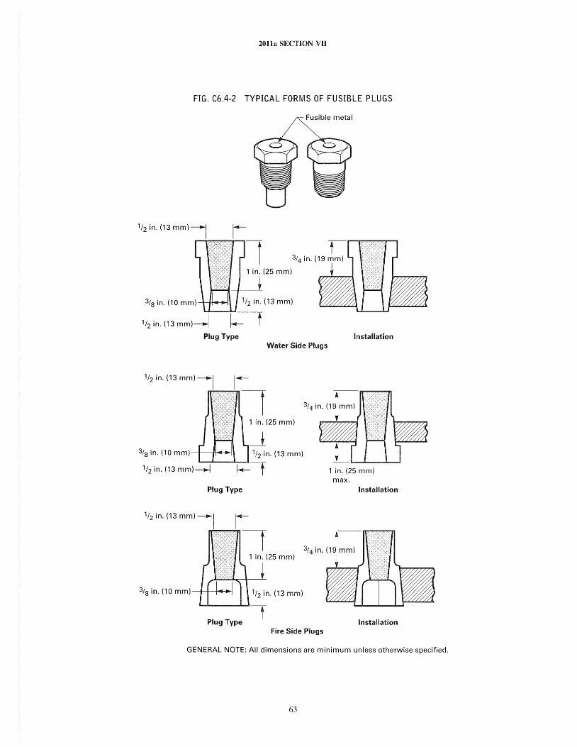
2011a SECTION VII
FIG. C6.4-2 TYPICAL FORMS OF FUSIBLE PLUGS
Fusible metal
1/2 in. (13 mm)-------I
..--~~~., t 3/4 in. (19 mm)
1 in. (25 mm)
3/8 in. (10 mm)--t-1ft-o!l--:~1
1/2 in. (13 mm)-------I
Plug Type Installation Water Side Plugs
1/2 in. (13 mm) -------I 1------
~-r 1 in. (25 mm)
_t 3/8 in. (10m m ) -+----jlf-Of-..
1 in. (25 mm) max.
Plug Type Installation
1/2 in. (13 mm) -------I r-~-t
3/8 in. (10 mm) ---t-+-~ .. 1/2 in. (13 mm)
Plug Type Installation Fire Side Plugs
GENERAL NOTE: All dimensions are minimum unless otherwise specified.
63
2011a SECTION VII
In watertube boilers, it should be noted whether the proper flue gas baffling is in place. The deterioration of baffling often causes high temperatures on portions of the boiler structure that are not intended for such temperatures and may result in a dangerous condition. The location of combustion arches with respect to tube sUliaces should be noted to make sure they do not cause the flame to impinge on a particular part of the boiler and produce overheating.
In vertical watertube boilers, the bridge walls should be inspected to see that the mud drum is properly protected. In sectional and nonsectional header-type watertube boilers, the front and rear walls should be examined to make sure that the bottoms of the headers are properly protected. Tile or refractory for protection of drums should be examined carefully to make sure that dlUm plates are not exposed directly to furnace flames or gases. A defective condition of refractory and/or insulation can be detected during operation by location of hot spots on the casing or other outer coverings of the furnace and boiler.
C6.430
C6.431
FIRETUBE BOILERS
Tube Defects
Tubes in horizontal firetube boilers deteriorate more rapidly at the ends toward the fire. They should be carefully tapped with a light hammer on their outer surface to determine if there has been a serious reduction in thickness. They should be inspected as far as possible either through the handholes, if any, or inspected at the ends.
The surface of tubes should be carefully inspected to detect bulges, cracks, or any evidence of defective welds. Where there is a high gas velocity, the tubes may become eroded by the impingement by particles of fuel and ash. A leak from a tube frequently causes serious erosion action on a number of tubes in its immediate vicinity. The exterior of the tubes should be inspected for scale and deposits. The space between the tubes should be made visible by lowering a small light between them for the purpose of making sure that there is no restriction of circulation.
C6.432 Ligaments Between Tube Holes
The ligaments between tube holes in the heads of all firetube boilers should be inspected. If leakage is noted, broken ligaments could be the reason.
C6.433 Manholes and Other Openings
The manholes and other reinforcing plates, as well as nozzles and other flanged or screwed connections on the boiler, should be inspected internally and externally to see that they are not cracked or deformed. Manhole ring surfaces should be examined for erosion and cOlTosion. Particular attention should be given to areas of the shell
64
where feedwater piping terminates. Whenever possible, observation should be made from inside the boiler to check soundness of pipe connections to the boiler. All openings to external attachments, such as connections to the low water cutoff and openings to safety relief devices, should be inspected to see that they are free from obstruction.
C6.434 Fire Surfaces
Firetubes sometimes blister but rarely collapse. The plant inspector should examine the tubes for such defects; if they are found to have sufficient distortion to walTant it, they should be replaced.
Inspection of firetube boilers should include a check for any impingement of flame on dry sheets, particularly at the back arch of return tubular boilers. The arch should be entirely clear of the rear tubesheet with sheet metal or asbestos rope closing the gap.
C6.500
C6.510
INSPECTION OF EXTERNAL SURFACES AND PARTS
GENERAL
The plant inspector should inspect the boiler for alignment, settling, loss of plumb, or abnormal movement such as displacement of drums or other pressure parts. He should ensure that provisions are made for expansion and contraction of the boiler and setting, that external clearances for boiler expansion are unobstructed, and that all supports are in proper condition to carry loads imposed on them. Permanent reference marks or indicators on drums and headers are recommended to enable rechecking their position (both hot and cold). The plant inspector should verify that proper expansion movement occurs as the boiler is returned to service after an outage. Water sealed expansion joints between the furnace and ashpit should be examined for leaks in the baffle and for accumulation of sludge.
Inspection should be made for evidence of corrosion of the exterior of drums or tubes and a check made for leaks from roofs, stacks, valves, or pipes. Riveted joints, butt straps, and riveted heads should be examined for leaks or wastage. If telltale holes are provided on stays, they should be kept clean. If there is evidence of leakage, the stay should be replaced. Where butt straps are covered by masonry or insulation, periodic testing and inspection for expansion is recommended. Supporting steel, buckstays, and tie rods should be inspected for condition and possible shifting from place.
C6.520 PIPING
The condition of the main stearn header, its connections to the boiler, and its support units should be inspected to
2011a SECTION vn
determine that it is properly supported, that allowance is made for expansion and contraction without exerting excessive stress or strain on the pressure parts of the boiler, and that the nonreturn and stop valves are in good working condition.
All piping should be inspected for leaks; if any are found, it should be determined whether they are the result of excessive strains due to expansion or contraction, or other causes. The general anangement of the piping in regard to the provisions for expansion and drainage, as well as adequate support at the proper points, should be carefully noted. There should be no pockets in the connecting piping that can hold water unless they can be drained or equipped with steam traps.
The connections between individual boilers and the supply and return headers should be especially noted to see that any change of position of the boiler due to settling or other causes has not placed an undue strain on the piping.
The plant inspector should also determine that no parts, including all water pipes, are subject to undue vibration. Special attention should be given to blowoff pipes, connections, and fittings because expansion and contraction due to rapid changes in temperature and water hammer action cause strain upon the entire blow off system. Whenever possible, the freedom of the blowoff and drain connection on each boiler should be tested by opening the valve for a few seconds to determine whether there is excessive vibration.
The blowoff connections should be inspected carefully for conosion and weakness where they connect with the boiler. The protective cover of brick or tile should be intact and not intelfere in any way with the expansion of the boiler or pipe. Blowoff lines, if embedded in masonry, should be periodically exposed for inspection. Blowoff piping should be supported externally, if necessary, in such a manner that it will drain properly and will not impose excessive stress on the drum connection while either cold or hot and during blowdown.
C6.530 SAFETY VALVES
As the safety valve is the most important safety device on the power boiler, it should be inspected with the utmost care. Safety valves should be inspected and tested as prescribed in C4.100.
C6.540 BOILER APPLIANCES
Boiler appliances such as gage glasses, gage cocks, water columns, water level controls, high and low water alarms or cutoffs, blowoff valves, feed valves, and nonreturn valves should be inspected and tested at regular intervals and during external inspections or as required by the Authorized Inspector. Boiler pressure gages and master
65
gages should be checked with other reliable gages in the same system or be compared with a properly calibrated test gage.
C6.600 CARE AND MAINTENANCE
Safety is very important and should be foremost in the minds of those who are assigned to inspect, operate, and maintain power boilers. Only properly trained qualified personnel should inspect, operate, and repair power boilers.
C6.610 HOUSEKEEPING
Generally, a neat boiler room indicates a well-run plant. The boiler room should be kept free of all material and equipment not necessary to operate the power boiler. Good housekeeping should be encouraged, and procedures should include routine inspection to maintain a desired level of cleanliness.
The plant inspector should report improper housekeeping to his immediate supervisor. Materials for repair or maintenance should not be stored in a manner that will obstruct proper access to the boiler, furnace, or firing equipment. Any steam or water leaks should be reported to his supervisor. If the leak is from the she]], drum, or other than from a tube or pipe joint, it may be cause for immediate shutdown for investigation.
C6.620 CERTIFICATES AND/OR LICENSES
Many jurisdictions require licensing or certification of personnel who operate or maintain power boilers. Also, some jurisdictions require the posting of inspection certificates and licenses or certification of personnel. The engineer in charge should ensure that all jurisdictional requirements are met and, where required, that permits and certificates are posted.
C6.630
C6.631
RECORD KEEPING AND LOGS
General
All drawings, wiring diagrams, schematic anangements, Manufacturer's descriptive literature, spare parts list, written operating instructions, Manufacturer's suggested care and maintenance, and other pertinent data should be kept permanently in the boiler room or other suitable locations so it will be readily available to those who operate and maintain the power boiler. When changes or additions are made, the data and drawings should be revised accordingly.
The plant inspector should have available for the benefit of the Inspector all pertinent data on the boiler uni t as to design, dimensions, age, particulars about previous defects, modifications, or repairs.
ZOlla SECTION VII
A record of each inspection should be kept in a uniform manner so that any change of condition can be definitely noted and compared, especially with reference to the thickness of scale, corrosion, erosion, cracks, and other unusual conditions. Between periodic inspections by the Authorized Inspector, the plant inspector should closely observe the operation and condition of the boiler and should report immediately to the plant engineer or plant management any serious defects, doubtful conditions, or unusual occurrences.
C6.632 Permanent Logbook
A permanent logbook should be provided for each power boiler in the plant to record maintenance work, inspections, tests, repairs, and other pertinent data. Brief details of repairs and other work performed on the boiler should be recorded. Performance of tests and inspections required by jurisdictions or insurance companies should also be recorded.
C6.633 Daily Log
A daily log for scheduling and recording work performed and maintenance, testing, and inspection is recommended. The routine work normally performed on power boilers is listed. As each portion of the work is completed, the person performing the work should enter the date and his initials in the appropriate spaces.
The plant inspector should note particularly any evidence of carelessness in the maintenance and operation of the the boiler and related equipment.
The plant inspector should recommend immediate correction of any unsafe conditions or undesirable practices that may be discovered and should report promptly and fully on the results of his inspection to his immediate superiors.
The plant inspector should be furnished a copy of all reports of inspections made by an Authorized Inspector and should see that all recommendations in such reports are promptly and carefully considered.
C6.700 REPAIRS
When repairs have been made, especially tube replacements, the plant inspector should observe whether the work has been done properly. Excessive rolling of tubes, where they are accessible, is a common fault of inexperienced workmen. However, when it is difficult to reach the tube end and observe the extent of rolling, they are frequently under-rolled. This inadvertently results in separation of the parts and leakage.
When damage to pressure parts is encountered, requiring repairs by processes such as welding, the review and
66
acceptance of an Authorized Inspector should be obtained on the manner in which the repair is to be made. It may also be necessary to contact the Authorized Inspector prior to retubing and rerolling of tubes. A hydrostatic test may be required if repairs are made, as required by the Authorized Inspector. See Subsection C7 for more detailed information on repairs.
C6.800 HYDROSTATIC TEST
When there is a question or doubt about the extent of a defect found in a boiler, the Authorized Inspector, in order to more fully decide upon its seriousness, may request the application of a hydrostatic test.
Hydrostatic test pressure should not exceed 1 ~ times the maximum allowable working pressure. During the test the safety valves should be gagged or removed from the boiler as should all controls and appurtenances unable to withstand the test pressure without damage. It is suggested that the minimum temperature of the water be 700 P (20°C) and a maximum of 1200 P (50°C).
C6.900 C6.910
BOILERS - GENERAL ALL INSPECTIONS
The following features of all boilers should be checked during each inspection:
(a) safety/relief valve nameplate capacity, set pressure, connection to boiler, discharge line, testing
(b) low water fuel supply cut-out, level control or regulator, water feeder controls combined/separate, stop valves in connection lines, testing
( c) controls operative, control maintenance (d) flue and damper arrangement, combustion
safeguards (e) burner refractory, flame impingement, baffles,
lining, supports (f) source of feedwater, condition of feedpump, feed-
water treatment (g) condensate return system, amount returned (h) review of boiler maintenance and operating logs ( i) buried lines, line leakage (j) steam pipe supports, piping free to expand and
contract (k) evidence of corrosion or erosion (l) blowoff piping and valves (m) pressure gage, gage cocks/water glass
C6.920 INTERNAL INSPECTIONS
Examine the following: (a) internal surfaces for scale deposits, oil deposits,
other deposits, active/inactive corrosion, erosion, grooving, bulging, warping, cracking, defective rivets, bowed, loose or broken stays, water feed line obstructed
2011a SECTION VII
(b) low water fuel supply cut-out, dismantled, float condition, bellows, electrical connections, mercury switches, probe-type porcelains
C6.1000 AUTHORIZED INSPECTOR
Authorized Inspector is defined in C6.100(a). When certification and/or licensing are required by the jurisdictional authorities, the Authorized Inspector is normally the individual who will make the required inspections for the issuance of the certificate and/or license to operate.
When required by the jurisdictional authority, the Authorized Inspector should make an internal and external inspection of all power boilers at least once each year and any additional inspections that the Authorized Inspector may deem necessary. In some jurisdictions, the annual
67
internal inspection may be extended, if certain conditions are met.
When required by the jurisdictional authority, the Authorized Inspector should make an inspection prior to placing boilers in service for the first time. This inspection should be as outlined in C6.200.
The Authorized Inspector should review, for acceptance, the manner in which repairs or alterations are to be made to ensure that Code integrity of the power boiler is maintained (see C7.100).
The Authorized Inspector may require and witness a hydrostatic test whenever repairs have been made, or when there is a question or doubt about the extent of a defect found during inspection of a power boiler.
The plant inspector should accompany the Authorized Inspector during his inspections.
2011a SECTION VII
SUBSECTION C7 REPAIRS, ALTERATIONS, AND MAINTENANCE
C7.100 REPAIRS AND ALTERATIONS
This Subsection provides guidance to the owner or user of power boilers for welded repairs and alterations to boiler pressure parts, in accordance with most jurisdictional authority requirements. Welded repairs and alterations should be in accordance with the rules of the National Board Inspection Code. I For the purpose of this Subsection, mechanical joints are not considered as a repair.
No welded repairs to a boiler pressure part should be initiated without the authorization of the Authorized Inspector who should satisfy himself that the welding procedures and welders are qualified and that the repair methods are acceptable. Subject to the administrative procedures of the jurisdiction, the Authorized Inspector may give prior approval for limited repairs provided he has ensured himself that the repair organization has acceptable procedures covering the repairs.
Each welded repair should be made by an appropriate Certificate Holder or other organization recognized by the jurisdictional authority.
Alterations to boiler pressure parts should be made by an organization that holds a valid ASME Certification of Authorization provided the alterations are within the scope of such authorization.
No alteration to boiler pressure parts should be initiated without the authorization of the Authorized Inspector, who should satisfy himself that the welding procedures and welders are qualified, that the alteration methods are acceptable, and that all applicable calculations are available.
Each owner or user of a boiler should verify with the jurisdictional authorities at the location of the power boiler that welded repair or alteration in accordance with the National Board Inspection Code is acceptable to the jurisdictional authorities.
The welded repair or alteration should be documented on the appropriate form shown in the National Board Inspection Code. I
I This document may be ordered from the National Board of Boiler and Pressure Vessel Inspectors, 1055 Crupper Avenue, Columbus, OH 43229.
68
Caution is recommended in the following regard: an unauthorized welded repair or alteration may make continued use of the boiler unsafe as well as il1ega] in many jurisdictions.
C7.200 MAINTENANCE
C7.210 GENERAL
Unscheduled outages of power equipment can result in production losses and an increase in power maintenance costs. This Subsection has been prepared to assist in the prevention of unscheduled outages by defining in general terms the potentia] trouble spots and conditions that should be checked during regularly scheduled maintenance outages. A thorough check of these critical parts will ensure that the equipment is put into sound operating condition before being returned to service and will help to eliminate the causes of unscheduled outages.
Due to the multiplicity of equipment types and plant layouts, the following is in sufficiently general terms to ensure that it is applicable to equipment types and not to Manufacturer's individual products. This makes it necessary to advise reference to individual Manufacturer's instruction books for data on clearances, part construction, controls, etc., when applying the information given in the guide to specific plant installations. Manufacturers should be contacted personally when required information is not given in instruction books.
C7.220 INFORMA TION TO ASSIST IN MAINTENANCE
The ability to symptoms of impending equip-ment failure and to identify the faulty part is an important requirement in preventing complete equipment failure without previous warning. Information given in this Subsection can assist the operator in recognizing and identifying faulty equipment parts, so he can have sufficient warning of impending failure to schedule a shutdown in advance.
2011a SECTION VII
C7.230 MAINTENANCE CHECKS
Maintenance checks have been designed to give a listing of those parts that are subject to wear, corrosion, erosion, etc., and are most likely to be the cause of equipment failure. Some of the undesirable conditions that can be expected when making an inspection of these parts are also noted.
C7.240 OPERATING CHECKS RELATING TO MAINTENANCE
The prevention of unscheduled shutdowns can best be aided by frequent observation of the equipment while in service for signs of deterioration in physical condition. Most deterioration can be noted before it becomes serious and repair orders can be written that, together with other pertinent data, will aid in scheduling the next overhaul and estimating the required downtime.
As an aid to operators, this guide lists conditions that should be looked for during the normal performance of their duties to determine the physical condition of the equipment and its forthcoming maintenance requirements.
C7.300 BOILER MAINTENANCE PROGRAMS
The maintenance of boiler equipment should be controlled by a planned program. The component parts of any program will vary in complexity and extent in a direct relationship to the quantity and complexity of the equipment, but in general, the program should consist of the following basic parts:
(a) inspection and overhaul procedures (b) overhaul scheduling (c) equipment histories and spare parts inventories (d) personnel training ( e) equipment improvement
C7.310 INSPECTION AND OVERHAUL PROCEDURES
(a) The information given in this Subsection can provide the base on which to prepare a set of inspection and overhaul procedures for a specific location. A procedure can usually be designed for each of the following operations during partial or complete overhauls:
( 1) equipment in service prior to overhaul (2) equipment out of service (3) equipment in service following an overhaul
(b) Partial overhauls are usually confined to rotating or reciprocating equipment and consist of an inspection of critical wearing parts. Such overhauls do not necessitate
69
major dismantling. A complete overhaul is a complete dismantling performed to examine every possible cause of future equipment failure or to verify the capability of the equipment to perform its function.
(c) In addition to the above overhauls, a third investigation can be made during normal operation to check performance as it may indicate physical condition.
C7.320 OVERHAUL SCHEDULING
Every maintenance program should include a comprehensive equipment overhaul schedule. This schedule should be based upon such considerations as production requirements, equipment capacities, operating experience, and equipment performance. This schedule should be flexible, and intervals between inspections should be subject to constant review.
C7.330 EQUIPMENT HISTORIES AND SPARE PARTS INVENTORIES
The function of an equipment history is to make available the information required to determine equipment maintenance performance. Its form will vary with size and equipment complexity. The information in the history can be used to spot those maintenance items requiring frequent attention and will also be of assistance in preparing or modifying the equipment overhaul schedule. The equipment history should list the major parts repaired or replaced during an overhaul so that spare parts inventories can be intelligently reviewed and capital investment in spare parts kept to a reasonable minimum.
C7.340 PERSONNEL TRAINING
Training and encouragement of both operating and maintenance men to be able to recognize, identify, and report the danger signals of impending equipment failure can be a valuable tool in averting unscheduled shutdowns. In the majority of cases these danger signals are apparent; for instance, a declining head capacity on boiler feedwater pumps. Danger signals must be recorded in the operator's log, interpreted, and used not only in deciding immediate action but as bases for future overhauls.
C7.350 EQUIPMENT IMPROVEMENT
For every equipment failure and during every overhaul, an effort must be made to improve any inherent equipment defects by a change of material, lubrication, environment, temperature, pressure, or any other means. Such changes must be justified economically or in the interests of safety.
2011a SECTION VII
C7.400 STEAM BOILERS
(a) Steam boilers may be classified by the relative position of the water and hot gases into the following types:
(1) watertube boilers (2) firetube boilers
(b) This Subsection describes the maintenance of each of these types of steam boilers. The maintenance checks suggested here are general in nature due to the multiplicity of boiler designs for different pressures, temperatures, capacities, fuels, feedwaters, etc. These checks should be used as a broad base from which to build a thorough maintenance program for individual boilers. Those items that are not appJicable should be disregarded, and any feature of a particular boiler which is not discussed should be covered by the plant maintenance program.
C7.410
C7.411
WATERTUBE BOILERS
Discussion
The maintenance information in this Subsection is intended to be applicable to all types of watertube boilers, both "field erected" and "package." The various methods of firing are discussed separately. Subsection C6 provides guidance for inspection of boller pressure parts that is intended to reinforce the guidance given below.
C7.412 Maintenance Checks
(a) Drums, Headers, and n{bes - Water Side (1) Check steam drums(s) for corrosion, scale, pit
ting, or other metal reduction. (2) Clean manhole seats, resurface if necessary, and
replace ,..., .. ~, .. _"v.
(3) Check steam scrubber and dryer in steam drum (if applicable) for corrosion, deposits, erosion, security, and tightness of joints.
(4) Check condition of all chemical feed and blowdown lines inside pressure parts for plugging, security, leaks, and orientation.
(5) Check for freedom of expansion for drums and headers.
(6) Inspect tubes for corrosion, excessive deposits, flare cracking, and pitting.
(7) RepJace a11 handhole gaskets on headers. Inspect handhole plates and stud threads.
(8) Make a complete water side examination and check for scale buildup as necessary. Measure scale thickness by using commercially available gages.
(b) Drums. Headers, and Tubes Gas Side (1) Check exterior of drums for signs of tube roll
leakage, corrosion, fly ash erosion, or overheating. (2) Check condition of outside drum insulation and
repl.ace or repair as necessary.
70
(3) Check drum seals for signs of air leakage. (4) Inspect drum supports for condition and check
expansion clearance. (5) Check all blowdown connections for expansion
and flexibility of support. Inspect all piping and valves for leaks.
(6) Visually check water wall tubes and fins (if applicable) for cracks.
(7) Check exterior of all tubes for corrosion, buildUp, erosion, blisters, and sagging.
(8) Inspect tubes at soot blower for signs of steam impingement.
(9) Check header seals for signs of air leakage. (10) Examine exterior of headers for corrosion, ero
sion, thermal cracking, and condition of insulation. (c) Superheater
( 1) Inspect superheater header and tubes for corrosion, erosion, and overheating.
(2) Check for steam impingement on tubes at soot blower location.
(3) Check superheater header and tubes for complete freedom of expansion.
(4) Check for cleanliness and security of superheater vent and drain.
(5) Examine superheater header and tube supports for security.
(d) Economizer
( 1) Check interior of tubes and headers where possible for corrosion, oxygen pitting, and scale.
(2) Check exterior of tubes and headers for corrosion, erosion, and deposits. Check particularly at soot blower locations for impingement and leakage.
(3) Check for cleanliness and security of vent and drain connections and valves.
(4) Check exterior of economizer casing for leaks and tightness of access doors.
(5) Check condition of casing insulation.
(6) Overhaul all water valves. Check for leaks. (7) Check condition of supporting steel.
(e) Reji'actory, Casing, and Baffles
(1) Check furnace tile, brick, and castable refractory for loose, spalled, or missing pieces.
(2) Examine soot and ash hoppers for eroded refractory and condition of seals.
(3) Check particularly for deterioration of burner tile and signs of flame impingement.
(4) Inspect condition of supporting steelwork where visible.
(5) Visually check exterior of furnace casing for bent, broken, or bowed sheets. Patch or repair as necessary.
(6) Check all access doors, lancing doors, etc., for tightness. Renew gaskets as required.
2011a SECTION VII
(7) Test unit for air leaks with a suitable method consistent with design. This could be done by pressurizing and using a sonic detector or a smoke detector, or by feeling for air leaks.
(8) Check condition of all baffle tile and caulking with particular attention to signs of leakage and check for security of supports.
(f) Water Columns
( 1) Check gage glasses for leaks, cleanliness, and visibility.
(2) Check illuminators, reflectors, and mirrors for cleanliness and breakage.
(3) Check operation and condition of gage cocks and valves. Inspect chains and pulleys ifused. Repair or replace as necessary.
(4) Ensure that water column is free to expand with boiler.
(5) Check water column piping to drums for leaks, internal deposits, and missing insulation.
(6) Check condition of high and low water alarms and trips.
(g) Feedwater Regulator
(1) Examine valve externally for leaks, operability, and cleanliness. Do not dismantle if operation has been satisfactory. Check connecting lines and mechanisms for proper function.
(2) If overhaul is necessary, consult manufacturer's instructions before proceeding.
(h) Soot Blowers
( 1) Check alignment of all soot blower hangers and check tightness of hanger bolts.
(2) Check soot blower elements for distortion, worn hanger bearings, tube rubbing, condition of element nozzles, element breakage or cracking, freedom of movement, effective lubrication, correct adjustment, and travel.
(3) Check condition of wall boxes. They should be sealed and secure.
(4) Check condition of moving parts, valves, and packing in soot blower head. Replace packing.
(5) Check position of elements for signs of steam impingement on tubes.
(6) Check each soot blower for correct blowing arc and direction of rotation.
(7) Pack the swivel tube gland and check swivel tubes for erosion and corrosion.
(8) Check gooseneck fittings for erosion and corrosion.
(9) Check steam supply piping and valves for evidence of leaks.
(10) Check condition of drain piping and valves. Ensure that supply piping slopes away from soot blower head.
( 11) Check for evidence of overheating.
71
(12) Check that blowing medium for retractable blowers is not on unless the nozzle is clear of the wall box and adjacent wall tubes.
(0 Valves. Check condition and operation of all feedwater, blow down, drain, and other miscellaneous valves. Replace parts as necessary and repack.
(j) Safety Valves. If a safety valve was found to malfunction during the pre-shutdown test, the following operations should be conducted by qualified craftsmen (see C4.120).
(1) Check condition of valve nozzle and disk seats. Lap seats, if required, in accordance with Manufacturer's instructions.
(2) Check condition of valve internal parts for corrosion, galling, and wear. Recondition or replace according to Manufacturer's instmctions, if necessary.
(3) Check for pitting, cracking, resiliency, and end coil squareness of valve springs.
(4) Check spindle for straightness and adjusting ring threads for freedom of movement.
(5) Check discharge and drain piping for security, condition, and allowance for boiler expansion.
(6) Test operation of valves by steam pressure (on the boiler if necessary) and adjust them to open and close at the proper pressures. Record set pressures and blowdown.
(k) Windbox ( 1) Check air dampers and vanes in windbox for cor
rosion and erosion. Check damper and vane operating mechanism.
(2) Check windbox insulation and repair as necessary.
(3) Check condition and operation of all of windbox access doors, peep holes and cover plates. Check for air leaks.
(I) Pulverized Coal Firing (1) Feeder. Specific maintenance checks will vary
with Manufacturer's type, but in general check for: (a) condition of drive (b) erosion and corrosion of feeder shaft and roll (c) erosion and leakage of feeder housing (d) general fit of all bushings, pins, etc.
(2) Pulverizer. Pulverizers may be classified into four types: ball-race mills, bowl mills, impact or attrition mills, and ball mills. They have some features in common for maintenance purposes, and checks are gi ven below. Manufacturer's instructions should be consulted for specific details.
(a) Check the exterior and interior of classifier housing for corrosion and leaks.
(b) Check the condition and operation of the classifier adjusting mechanism.
(c) Check condition of grinding surfaces for excessive wear and erosion.
(d) Check the condition and operation of the grinding mechanism adjustment.
2011a SECTION VII
( e) Check the condition of pressure springs. (f) Check the condition of all shaft journals and
bearings in the rotating parts. (g) Check the operation of the lubrication system. (h) Check condition of all liners and scrapers, and
repair or replace as necessary. (3) Exhauster
(a) Check coupling alignment and drive. (b) Check bearings and lubrication system. (c) Check wheel and wheel liners for erosion, cor
rosion, and out of balance condition. (d) Check exhauster housing and liners for erosion,
corrosion, and signs of leakage. (4) Burner
(a) Check the condition of the coal nozzle for erosion, burning, and location in refractory opening.
( b) Check deflectors, impellers, and pulverized coal passage for erosion and corrosion.
(c) Check condition of the refractory throat for burned, spalled, or missing tiles.
(d) Check all coal and air piping and flanges for leaks.
(m) Stoker Coal Firing ( 1) Undofeed Stoker. The following general remarks
apply to all underfeed stokers. Consult Manufacturer's instruction books for complete details of individual units.
(a) Check the driving mechanism of the main ram and distributing rams.
(b) Check the condition and operation of the main ram, distributing rams, and the connecting linkage.
(c) Check the condition of the grate, and the condition and operation of reciprocating grates.
(d) Check the tuyeres for blockage and erosion and for freedom of movement, where applicable.
(e) Check the condition of retort channels. (r) Check condition and operation of windbox and
dampers. (g) Check the condition and operation of clinker
and ash grinding mechanism, if applicable. (h) Check the condition and operation of controls
on rams and windbox dampers. (2) Spreader Stoker. The following general remarks
apply to all spreader units. Consult Manufacturer's instruction books for complete details of individual units.
(a) Check clearance between the distributor blades and distributor tray.
(b) Check for wear on distributor blade shaft and bearings.
(c) Check wear on feeder and lining. (d) Clean and check all gear cases and drives. ( e) Check chains and sprockets for wear. (f) Check for misalignment and condition of all
line shaft bearings, where applicable.
72
(g) Check flow and effectiveness of cooling water through jackets on end frames.
(h) Check condition of overfire air fan and distribution nozzles.
(3) Dump Grates. The following general remarks apply to all dump grates. Consult Manufacturer's instruction books for complete details of individual units.
(a) Check for condition of all grate bars and room for expansion.
(b) Check condition of supporting steel for grate. (c) Check condition of grate dumping mechanism.
Replace parts as necessary. Check for excessive play in linkage.
(d) Check condition of dampers and frames, and operation of mechanism.
( e) Check condition of fire door liners and overfire tuyeres for burning or blistering.
(4) Travelling Grates. The following general remarks apply to both chain grates and bar and key grates. Consult Manufacturer's instruction books for complete details of individual units.
(a) Clean grate and check metal parts for corrosion and erosion.
(b) Check condition of air seals. (c) Check condition of return wearing surfaces. (d) Check for air leakage from windbox. (e) Check air dampers for operability and seating. (/) Check damper operating mechanism for wear
or excessive play. (g) Check condition of all stationary parts exposed
to the fire for burning, blistering, etc. (h) Check condition of shear pin mechanism for
freedom of action. (0 Inspect grate drive mechanism and overhaul as
necessary. (j) Inspect all furnace arches, walls, brick, and tile
for burning, spalling, and cracking. (n) Oil Firing
( 1) Fuel Oil Pumps
(a) Check condition of motor and turbine drive gear-type pumps. Check for
( 1) excessive clearances (2) excessive backlash (3) worn bearings (4) leakage
(b) Check condition of steam driven reciprocating pumps. Check for
rings
( 1) wear in steam cylinder and piston
(2) wear in oil cylinder and piston ( 3) condition of oil and steam cylinder pi ston
(4) setting, operating, and wear of steam valves (5) condition and seating of oil valves
2011a SECTION VII
(6) leaks from stuffing boxes and scoring of piston rods
(7) condition of steam strainers (8) leaks at all connections
(2) Fuel Oil Heaters
(a) Check tube bundle and clean off deposits on oil side.
(b) Inspect steam and oil side for corrosion and erosion.
(c) Check freedom of vents and drains. (d) Check condition of insulation and repair as
necessary. (e) Check for tubesheet and tube leaks. (f) Check condition, operation, and setting of relief
valves. (3) Burners, Valves, and Piping
(a) Check setting and operation of pump discharge pressure regulators.
(b) Check setting and operation of pressure relief valves on pump discharge.
(c) Check condition and operation of steam pressure reducing valve on oil heater.
(d) Clean and check oil suction strainer. (e) Check and calibrate pressure gages and
thermometers. (f) Clean and check steam strainer. (g) Check operation of oil heater condensate
steam trap. (h) Recondition all shutoff and adjusting valves as
necessary. Perform leak check on safety shutoff valves after reconditioning.
(i) Clean and inspect oil burners. Check for leaks, erosion, and carbonization of burner nozzle, especially at the joint between gun and permanent piping.
(j) Check for leaks at all connections. (0) Gas Firing
( i) Check condition of gas nozzles for erosion, burning, or plugging.
(2) Check operation of air control damper mechanism.
(3) Check setting and operation of pressure regulating valve.
(4) Check all piping and valves for leaks. (5) Check safety shutoff valves for leakage; repair as
necessary. (p) Ash Removal Systern
( i) The following system types are in use: (a) hydraulic sluice including slag-tap (b) pneumatic conveying
(2) During an overhaul, all parts of any particular system should be thoroughly inspected for the following conditions:
(a) wear, erosion, corrosion, and leaks
73
(b) effective operation of sluicing mechanisms (c) condition of ash pits and sumps including
refractory (d) operation of vacuum systems and centrifugal
collectors ( e) wear in transport piping, particularly at bends
and elbows (f) condition of ash pumps
(q) Air Preheater ( 1) Tubular or Plate Type
(a) Check gas side for plugging and buildup at inlet, and for corrosion and erosion at outlet.
(b) Check air side for corrosion and leaks. ( c) Remove all gas side deposits. If washed use an
alkali rinse; if firing use sulfur-bearing fuels. (2) Regenerative or Ljungstrom Type
(a) Check cold end section of heater surface for wear, plugging, and corrosion.
(b) Check condition of radial and circumferential seals on both hot and cold ends.
(c) Check condition of gear drive. (d) Check operation and condition of soot blower
(if fitted). (e) Check effectiveness of bearing cooling.
(r) Fans
(1) Forced Draft and Primary Air Fans
(a) Check fan housing and rotor for corrosion, erosion, and signs of housing leaks. Check rotor for loose rivets or welds.
(b) Check clearance between rotor and fan housing.
(c) Check condition and operation of inlet vane operating mechanism.
(d) Check bearings for wear, clearance, lubrication, and cooling.
(e) Check coupling alignment at operating temperature.
(2) induced Draft Fans
(a) Check fan housing and housing liners for erosion, corrosion, fly-ash deposit, and housing leakage.
(b) Check fan rotor and liners for erosion, corro-sion, fly-ash deposit, and weakening of rivets and welds.
(c) Check clearance between rotor and fan housing. (d) Check condition of shaft seals. (e) Check condition of inlet vanes and operating
mechanism. (f) Check bearings for wear, clearance, lubrication,
and cooling. (g) Check coupling alignment at operating
temperature. (s) Dampers
( 1) Check to ensure that linkage arms are secure on the blade shafts.
2011a SECTION VII
(2) Check to see that the blade(s) follow through the open to closed position as indicated on the linkage arm sector plate, or other external indicator.
(3) Check for indications of in service binding, and ensure that clearances are adequate for expansion.
(4) Check to see that minimum stops, where required, are in place.
(5) Check that seali ng strips on tight closure dampers are not deteriorated or worn.
(6) Check that damper blades are commercially clean, and the metal is not corroded or eroded.
(7) Check to see that bearings are lubricated. (8) Check for wear of internal bearings or link joints. (9) Check to see that flues and ducts are free of debris. (10) With remote controlled dampers, check to see
that the drive strokes through the full range without binding.
( 1 1) As applicable during purging at startup and at shutdown of a unit, check to see that the stroking of the induced and forced draft dampers that are activated by the safeguard permissive and interlock circuitry are operating properly.
C7.413 Operating Checks Relating to Maintenance
(a) Leakage
(J) Check for any flue gas, steam, or water leaks. (2) Check for steam leaks at superheater headers and
tube joints. (3) Check for air leaks around doors, seals, and
furnace. (b) Refractol)l
(1) Check condition of burner throat refractory.
(2) Check condition of ash pit refractory (if applicable).
(3) Check for slag buildup on refractory.
(4) Check for missing insulation on headers and drum.
(c) Burners
(1) Check for burner wear by noting flame shape and completeness of combustion.
(2) Check ease of operation of burner vanes. This will indicate burner mechanism condition.
(d) Superheater Tubes. Check for a change in pressure drop through the superheater, indicating internal condition of the tubes.
(e) Drums
(1) Check the steam quality. This will indicate the condition of steam scrubbers and separators.
(2) Check for noises in drums. This may be caused by loose connections of drum internal piping.
cr) Soot Blowers
74
( I) Check steam pressure to soot blowers and blowing pressure.
(2) Check for a decrease in steam pressure at soot blower inlet during operation, indicating a breakage of the element or missing nozzles.
(3) Check pressure in supply piping with main supply valved out. This will indicate leaking of shutoff valve.
(g) Econ01nizer andAir Preheater. Check for a variation in temperature differences over both units at constant load, indicating deposits or bypassing.
(h) Pressure Variations
( 1) Check for an increase in pressure drop over any part of the system at constant load, indicating deposits or buildUp.
(2) Check for a decrease in pressure drop over any part of the system at constant load, indicating a misplaced or bypassed baffle.
(i) Furnace and Casing
(l) Check the extent of expansion and contraction of pressure parts during startup and shutdown.
(2) Check that header support hangers are always in tension. Looseness will indicate an obstruction to free expansion and contraction.
C7.420
C7.421
FIRETUBE BOILERS
Discussion
The maintenance of auxiliary equipment for firetube boilers is identical with that for watertube boilers. This paragraph will only discuss those items peculiar to the maintenance of firetube boilers as listed below
(a) combustion chamber or grate (b) tubes - gas side (c) tubes and shell - water side
C7.422 Information to Assist in Maintenance
Appendix A contains some service hints and checks for a typical firetube package unit. The information is principally concerned with maintenance around 011 burning equipment.
C7.423 Maintenance Checks
(a) Combustion Chamber
( 1) Check the refractory and brickwork for burning, spalling, erosion, and deterioration. Repair or replace as necessary.
(2) Check for bending and sagging of metal parts of chamber or grate.
(3) Check for leaks around the seal between the combustion chamber and front and rear tubesheets.
(b) Tubes - Gas Side
20t1a SECTION VII
(1) Clean and inspect tubes on gas side. Note the amount of soot deposit as a check on burner operation.
(2) Check for signs of overheating in initial tube passes.
(3) Check for signs of tube leaks.
(4) Check gas distribution partitions and flanges and gaskets on front and rear heads for signs of gas bypassing or leakage.
(5) Clean out and inspect refractory in gas side of boiler heads. Check for burnt and spalled refractory that could block tube passes and also cause hot spots on water side.
(6) Check for signs of water leaks around stay bolt and brace connections.
(7) Check for cracks and signs of water leakage at rolled tube ends.
(c) Tubes and Shell - Water Side
( 1) Check for scale and corrosion on tubes, tubesheets, staybolts, and braces.
75
(2) Clean water side and take samples of excessive scaling for analysis and determination of further treatment.
(3) Check for bent, sagging, or warped tubes or tubesheets due to overheating or hot spots.
C7.424 Operating Checks Relating to Maintenance
(a) Check pressure drop over gas passes and compare with previous readings at similar loads to determine cleanliness.
(b) Check for sagging or "bagging" of tubes above grate on H.R.T. boilers.
(c) Check exit gas temperature and compare with steam temperature at normal loading to determine the extent of any fouling of heat exchange surface.
(d) Check for hot spots in refractory, flame conditions, and general conditions as visible through front and rear peep holes.
(e) Check for any visible water leaks from boiler drum. (f) Whenever possible, check the operation of safety
features on combustion controls and water level.
2011a SECTION VII
SUBSECTION C8 CONTROL OF INTERNAL CHEMICAL CONDITIONS
C8.100 GENERAL
(a) The information presented in this Subsection pertains to the control of chemical conditions within steam boilers to promote safety in operation and is organized under eight general headings
(l) Internal Cleaning of Boilers (2) Laying Up of Boilers (3) Deposits (4) Internal Corrosion (5) Corrosion Cracking of Boiler Steel (6) Steam Contamination (7) Sampling, Testing, Controlling, and Reporting of
Analyses of Water (8) Fire Side Conditions
In each case an attempt has been made to state in simple, explicit, and concise form the problems, the characteristics by which they may be recognized, and the principles by which they may be corrected.
(b) To safeguard life and property, it is recommended that the chemical cleaning of boilers and the control of all boiler water conditions be established and supervised by personnel qualified by training and experience in these highly technical fields.
CS.200 INTERNAL CLEANING OF BOILERS
New boilers should be reasonably free from mill scale, corrosion products, and other foreign matter. Before a new boiler is placed in service, it should be cleaned thoroughly in order to remove grease and other organic matter, rust and loose mill scale, protective coatings applied by the Manufacturer to prevent atmospheric corrosion, welding flux, and a11 other foreign matter normally incident to fabrication and erection. The purpose of cleaning a new boiler is to remove harmful deposits from all parts of the boiler that come into contact with water or stearn during operation. All foreign materials, fatty acids, oils and grease, loose mill scale, rust, paint, and similar materials should be removed. Any solution employed should be a good cleaning agent for these purposes and should be compatible with the materials of construction.
76
A detergent cleaning is conducted with alkaline detergent solution to remove foreign material, particularly oil and grease, from the internal surfaces of the boiler and economizer. (The lack of drainability and/or the presence of austenitic stainless steel in the superheater usually precludes the use of a strong alkaline solution or any water containing solids in this section of the boiler.) Subsequent chemical cleaning may be less effective if the detergent cleaning does not remove the oily material.
Chemical cleaning is conducted with solvent solution primarily for the purpose of removing mill scale and products of corrosion. The solvent solution may be acidic or basic, or successive solutions of differing character may be employed. Because of the chemical control required to ensure a successful cleaning, to avoid damage to both ferrous and nonferrous materials through improper use of the solvent, and because of the potential dangers involved in dealing with corrosive solutions and possibly explosive and toxic products of the cleaning process, work of this kind should be performed and supervised by personnel qualified by training and experience in this highly technical field. Usually boilers that operate under 900 psig (6 MPa) are not chemically cleaned to remove mill scale but are only cleaned by an alkaline bailout. Chemical analysis of the material to be removed is desirable for an inservice boiler to determine the program of chemical cleaning and the composition of the solutions to be employed. In some cases, as determined by qualified personnel, it may be necessary to try various cleaning solutions on samples of tube removed from the boiler to determine the best possible solution to remove the deposit present.
In most cases, low pressure [below 300 psig (2 MPa)] and shop assembled boilers do not require an acid cleaning before operation. An alkaline bailout is sufficient. However, if the boiler or boiler components have been stored for substantial periods of time in corrosive conditions or transported across salt water, an acid cleaning may be required after the alkaline bailout.
Subsequent to returning to operation, whenever a boiler is taken out of service for a scheduled or extended outage, it should be internally clean when put back into service. Loose material in the form of dirt, trash, mill scale, or deposits should be removed by washing or mechanical methods.
2011a SECTION VII
CS.300
C8.310
LA YING UP OF BOILERS
WATER SIDE
When a boiler is taken out of service, the boiler should be cooled down to 10 psig (70 kPa) and drained. An inspection should be made to determine what repair work is necessary and what mechanical and chemical cleaning should be done. A decision should then be made on whether to employ dry storage or wet storage. Wet storage is preferred if freezing can be prevented. Since freshly cleaned metal surfaces are much more vulnerable to storage corrosion than surfaces that have operational oxides on them, it is much preferred to delay chemical cleaning until the boiler is ready to be returned to service.
A dry storage procedure may be preferable for boilers out of service in locations where freezing temperatures may be expected during standby.
The boiler should be thoroughly dried since any moisture left on the metal surface would cause corrosion to occur on long standing. After drying, precautions should be taken to preclude entry of moisture in any form from steam lines, feed lines, or air. For this purpose, moisture absorbing material, such as quicklime at the rate of 7 lb (3.2 kg) or silica gel at the rate of 8 Ib (3.6 kg) for 100 ft3 (2.83 m3
)
of boiler volume, may be placed on trays inside the drums to absorb moisture from the air. The manholes should then be closed and all connections on the boiler should be tightly blanked. The effectiveness of the materials for such purposes and need for their renewal may be determined through regular internal boiler inspections.
Alternatively, air dried externally to the boiler may be circulated through it. The distribution should be carefully checked to ensure that the air flows over all areas.
It is usualJy acceptable in the case of large industrial or utility boilers to simply drain the boiler while feeding nitrogen to the boiler vents and to maintain a 5 psig (40 kPa) nitrogen pressure during the storage period.
A wet storage procedure may be used for a boiler to be placed in standby condition. Wet storage is particularly useful if the standby boiler may be required for service at short notice. This method is not generally employed for reheaters or for boilers that may be SUbjected to freezing temperatures.
The empty boiler should be closed and filled to the top with water that has been conditioned chemically to minimize corrosion during standby. Water pressure greater than atmospheric should be maintained within the boiler during the storage period. A head tank may be connected to the highest vent of the boiler to maintain pressure above that of the atmosphere, or 5 psig (40 kPa) nitrogen overpressure may be used.
For a short storage period on boilers below 1,000 psig (7 MPa), condensate or feedwater containing approximately 200 ppm of sodium sulfite may be used for filling
77
the boiler, adjusting the pH to 10 with any convenient alkali. If the superheater is of the drainable type, it can also be filled with the same treated water by overflowing from the boiler. Superheater tubes must be completely drained and flushed with condensate before restarting the boiler.
If the superheater is nondrainable, it should be filled only with condensate or demineralized water containing a minimum of dissolved solids, not more than I ppm. Before introducing the water into the superheater, mix in uniformly about 200 ppm of hydrazine and sufficient volatile alkali, such as ammonia, cyclohexylamine, or morpholine, to produce a pH of 10. The treated water may be introduced into the superheater through an outlet header drain or the attemperator spray waterline until the water overflows into the boiler. When the superheater is filled, close the drains and vents.
The boiler can now be filled through the feedwater or other filling line with condensate or with feedwater treated with hydrazine and additional volatile alkali. If the storage period is expected to exceed 3 months, the concentration of hydrazine should be doubled.
If preferred, on boilers below 100 psig (700 kPa), the boiler may be filled using feedwater or condensate treated with sodium sulfite or hydrazine as described above after the superheater is first filled with condensate treated with hydrazine and additional volatile alkali. On boilers above 1,000 psig (7 MPa), hydrazine and volatile alkali must be used to prevent any solids deposition in the boiler after storage.
As an alternative, the boiler may be stored with treated boiler water at normal operating level in the drum and nitrogen maintained at 5 psig (40 kPa) pressure in all vapor spaces. To prevent in-leakage of air, it is necessary to supply nitrogen at the vents before the boiler pressure falls to zero as the boiler is coming off the line. If boiler pressure falls to zero, the boiler should be fired to reestablish pressure, and superheaters and reheaters should be thoroughly vented to remove air before nitrogen is admitted. All partly filled steam drums and superheater and reheater headers should be connected in parallel to the nitrogen supply. If nitrogen is supplied only to the steam drum, nitrogen pressure should be greater than the hydrostatic head of the longest vertical column of condensate that could be produced in the superheater.
Rather than maintaining the water in the boiler at normal operating level with a nitrogen blanket, it is sometimes preferred to drain the boiler completely, applying nitrogen continuously during the draining operation and maintaining a pressure of nitrogen greater than atmospheric throughout the draining and subsequent storage.
WARNING: If the boiler is drained under nitrogen, place warning signs on all drum manheads since entry by personnel could be fatal. Fresh air
must be circulated before any entry is attempted.
2011a SECTION VII
C8.320 FIRE SIDE
Fire-side layup procedures are used to protect the fire side of a boiler during storage. The intent of fire-side protection is not radically different from water-side protection. The major problem on the fire side is to maintain dry and clean surfaces and to avoid conditions where moisture can condense on metal surfaces and produce low pH acidic areas. Sulfur-bearing fuels can produce ash deposits that are acidic in nature and can corrode external surfaces. These deposits can be hygroscopic, and in addition, if the temperature is below the dew point and condensation takes place, low pH conditions can occur in crevices formed by slag deposits on the waterwall tubes of the unit. It has been shown by some writers that the relative humidity offurnace air should be kept below 50% during idle periods. Low relative humidities can be obtained by the use of heat lamps, dehumidification with circulation fans, and circulation of warm air. If the unit has a steam coil air heater, operation of this equipment is the safest and most effective way to furnish low humidity air.
Acidic-type external deposits should be removed from all surfaces prior to long term outages. Normally, highpressure water or steam lances are necessary to properly clean the tube surfaces.
After the tube surfaces are cleaned, they should be rinsed with an alkaline compound (I % Na2C03) to neutralize any residual acidic components from the ash deposits. After the final rinse, it is very important that all tube surfaces be thoroughly dried.
C8.400 DEPOSITS
Solid material found on the internal surfaces of a boiler after operation may include both scale and sludge as well as corrosion products. Oil may be present on the boiler surfaces either with or without deposits of solid material.
C8.410 SCALE
Scale is inorganic mineral matter precipitated from the boiler water directly on the boiler surfaces. It is usually crystalline and dense and frequently is laminated. Scale may or may not be accompanied by the deposition of sludge (see Fig. CS.4-1).
Scale is objectionable because it interferes with normal heat flow through the boiler metal and may lead to overheating. This may result in bulging or actual failure. The amount of water-side scale that can be tolerated decreases as the rate of heat input increases. Very thin water-side deposits can result in damage to heating surfaces exposed to radiant heat from the furnace (see Fig. CS.4-2).
The prevention of scale requires proper water treatment before and / or after introduction of the water into the boiler.
78
The chemical water treatment selected, whether internal or external with respect to the boiler, should be regulated by means of periodic analyses of water from as many of the following points as may be significant in the specific system: raw water, effluent from external treatment, feedwater, boiler water, saturated steam, and condensate. The minimum sampling program should include feedwater, boiler water, and condensate.
The kind and frequency of such control analyses should depend upon the specific character of the water supply, its variability, the amount of water consumed, and the physical characteristics ofthe plant. No general limits for the various constituents can be set for universal application. Refer to the "Consensus on Operating Practices for the Control of Feedwater and Boiler Water Quality in Modern Industrial Boilers" (ASME, 1979).
Any attempt to remove appreciable scale deposits with a chemical application while the boiler is still operating can be dangerous. Scale deposits can chip off, causing large quantities of chip scale in the unit. This can affect boiler water circulation by causing overheated tubes and drums.
C8.420 SLUDGE
Sludge is a sedimentary deposit formed either by suspended matter in the feedwater or by precipitation from the boiler water. It may result from internal chemical treatment reacting with hardness salts contained in the feedwater. It is usually soft and less adherent than scale, and in low pressure boilers, some can be carried off in the blowdown. Modern high duty boilers can be expected to accumulate some sludge deposits on the high heat transfer surfaces if sludge forming materials (hardness) and/or metal oxides are introduced with the feedwater.
The maintenance of sludge in a favorable less adherent state can usually be effected by means of proper water treatment. Its accumulation should be regulated by minimizing the quantity of hardness and metal oxides entering the boiler and by blowdown.
Oil in the boiler water is very undesirable as it may deposit, particularly in conjunction with sludge, and impair heat transfer to such an extent that damage may result. Oil by itself can form a hard, dense carbonaceous deposit which is virtually impossible to remove by chemical cleaning. Oil may also cause priming and excessive steam contamination. It is very important that entry of oil into the feedwater be avoided.
C8.430 INTERNAL DEPOSIT MONITORING
Internal deposit buildup and its effect on heat transfer can be monitored by the installation of chordal thermocouple tubes in the highest heat transfer areas of the furnace
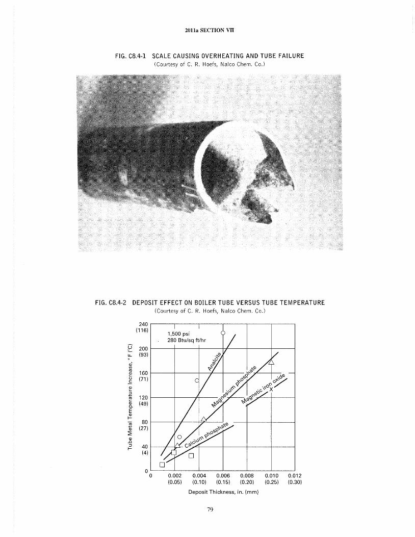
2011a SECTION VII
FIG. CB.4-1 SCALE CAUSING OVERHEATING AND TUBE FAILURE (Courtesy of C. R. Hoefs, Nalco Chem. Co.)
FIG. CB.4-2 DEPOSIT EFFECT ON BOILER TUBE VERSUS TUBE TEMPERATURE (Courtesy of C. R. Hoefs, Nalco Chem. Co.)
240 (116)
e 200 u.. (93) 0
(J)~
If)
co 160 ~
u (71 ) .E ~ .a
120 co Ci:i (49) 0.
E (J) I-
~ 80
(J) (27) ~ (J)
..a ::J 40 I-
(4)
0 0 0.002 0.004 0.006 0.008 0.010 0.012
(0.05) (0.10) (0.15) (0.20) (0.25) (0.30)
Deposit Thickness, in. (mm)
79
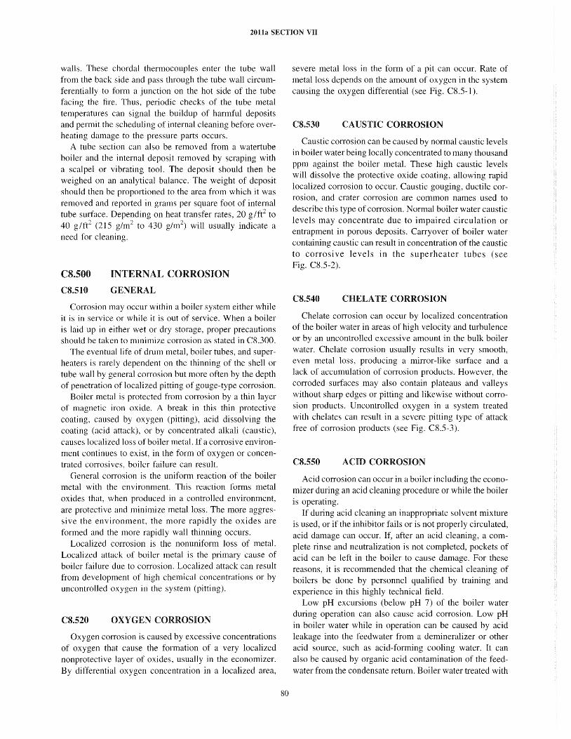
2011a SECTION VII
walls. These chordal thermocouples enter the tube wall from the back side and pass through the tube wall circumferentially to form a junction on the hot side of the tube facing the fire. Thus, periodic checks of the tube metal temperatures can signal the buildup of harmful deposits and permit the schedul ing of internal cleaning before overheating damage to the pressure parts occurs.
A tube section can also be removed from a watertube boiler and the internal deposit removed by scraping with a scalpel or vibrating tool. The deposit should then be weighed on an analytical balance. The weight of deposit should then be proportioned to the area from which it was removed and reported in grams per square foot of internal tube surface. Depending on heat transfer rates, 20 g/ft2 to 40 g/ft2 (215 g/m2 to 430 g/m2) will usually indicate a need for cleaning.
cs.soo CS.510
INTERNAL CORROSION
GENERAL
Corrosion may occur within a boiler system either while it is in service or while it is out of service. When a boiler is laid up in either wet or dry storage, proper precautions should be taken to minimize corrosion as stated in CS.300.
The eventual life of drum metal, boiler tubes, and superheaters is rarely dependent on the thinning of the shell or tube wall by general corrosion but more often by the depth of penetration of localized pitting of gouge-type corrosion.
Boiler metal is protected from corrosion by a thin layer of magnetic iron oxide. A break in this thin protective coating, caused by oxygen (pitting), acid dissolving the coating (acid attack), or by concentrated alkali (caustic), causes localized loss of boiler metal. If a corrosive environment continues to exist, in the form of oxygen or concentrated corrosives, boiler failure can result.
General corrosion is the uniform reaction of the boiler metal with the environment. This reaction forms metal oxides that, when produced in a controlled environment, are protective and minimize metal loss. The more aggressive the environment, the more rapidly the oxides are formed and the more rapidly wall thinning occurs.
Localized corrosion is the nonuniform loss of metal. Localized attack of boiler metal is the primary cause of boi ler fai lure due to corrosion. Localized attack can result from development of high chemical concentrations or by uncontrolled oxygen in the system (pitting).
CS.520 OXYGEN CORROSION
Oxygen corrosion is caused by excessive concentrations of oxygen that cause the formation of a very localized nonprotective layer of oxides, usually in the economizer. By differential oxygen concentration in a localized area,
80
severe metal loss in the form of a pit can occur. Rate of metal loss depends on the amount of oxygen in the system causing the oxygen differential (see Fig. CS.S-l).
CS.530 CAUSTIC CORROSION
Caustic corrosion can be caused by normal caustic levels in boiler water being locally concentrated to many thousand ppm against the boiler metal. These high caustic levels will dissolve the protective oxide coating, allowing rapid localized corrosion to occur. Caustic gouging, ductile corrosion, and crater corrosion are common names used to describe this type of corrosion. Normal boiler water caustic levels may concentrate due to impaired circulation or entrapment in porous deposits. Carryover of boiler water containing caustic can result in concentration of the caustic to corrosive levels in the superheater tubes (see Fig. CS.S-2).
CS.540 CHELATE CORROSION
Chelate corrosion can occur by localized concentration of the boiler water in areas of high velocity and turbulence or by an uncontrolled excessive amount in the bulk boiler water. Chelate corrosion usually results in very smooth, even metal loss, producing a mirror-like surface and a lack of accumulation of corrosion products. However, the corroded surfaces may also contain plateaus and valleys without sharp edges or pitting and likewise without corrosion products. Uncontrolled oxygen in a system treated with chelates can result in a severe pitting type of attack free of corrosion products (see Fig. CS.S-3).
CS.S50 ACID CORROSION
Acid corrosion can occur in a boiler including the economizer during an acid cleaning procedure or while the boiler is operating.
If during acid cleaning an inappropriate solvent mixture is used, or if the inhibitor fails or is not properly circulated, acid damage can occur. If, after an acid cleaning, a complete rinse and neutralization is not completed, pockets of acid can be left in the boiler to cause damage. For these reasons, it is recommended that the chemical cleaning of boilers be done by personnel qualified by training and experience in this highly technical field.
Low pH excursions (below pH 7) of the boiler water during operation can also cause acid corrosion. Low pH in boiler water while in operation can be caused by acid leakage into the feedwater from a demineralizer or other acid source, such as acid-forming cooling water. It can also be caused by organic acid contamination of the feedwater from the condensate return. Boiler water treated with
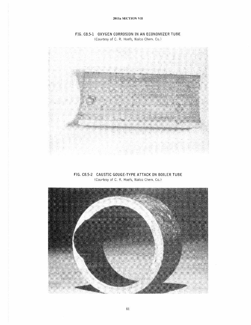
2011a SECTION VII
FIG. C8.5-1 OXYGEN CORROSION IN AN ECONOMIZER TUBE (Courtesy of C. R. Hoefs, Nalco Chem. Co.)
FIG. C8.5-2 CAUSTIC GOUGE-TYPE ATTACK ON BOILER TUBE (Courtesy of C. R. Hoefs, Nalco Chem. Co.)
81
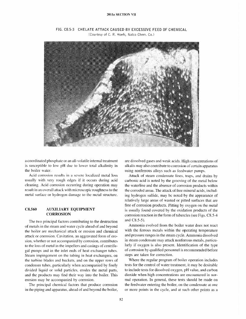
2011a SECTION VII
FIG. C8.5-3 CHELATE ATTACK CAUSED BY EXCESSIVE FEED OF CHEMICAL (Courtesy of C. R. Hoefs, Nalco Chem. Co.)
a coordinated phosphate or an all-volatile internal treatment is susceptible to low pH due to lower total alkalinity in the boiler water.
Acid corrosion results in a severe localized metal loss usually with very rough edges if it occurs during acid cleaning. Acid corrosion occurring during operation may result in an overall attack with microscopic roughness to the metal surface or hydrogen damage to the metal structure.
CS.S60 AUXILIARY EQUIPMENT CORROSION
The two principal factors contributing to the destruction of metals in the steam and water cycle ahead of and beyond the boiler are mechanical attack or erosion and chemical attack or corrosion. Cavitation, an aggravated form of erosion, whether or not accompanied by corrosion, contributes to the loss of metal in the impellers and casings of centrifugal pumps and in the inlet ends of heat exchanger tubes. Steam impingement on the tubing in heat exchangers, on the turbine blades and buckets, and on the upper rows of condenser tubes, particularly when accompanied by finely divided liquid or solid particles, erodes the metal parts, and the products may find their way into the boiler. This erosion may be accompanied by corrosion.
The principal chemical factors that produce corrosion in the piping and apparatus, ahead of and beyond the boiler,
82
are dissolved gases and weak acids. High concentrations of alkalis may also contribute to corrosion of certain apparatus using nonferrous alloys such as feedwater pumps.
Attack of steam condensate lines, traps, and drains by carbonic acid is noted by the grooving of the metal below the waterline and the absence of cOITosion products within the corroded areas. The attack of free mineral acids, including hydrogen sulfide, may be noted by the appearance of relatively large areas of wasted or pitted surfaces that are free of corrosion products. Pitting by oxygen on the metal is usually found covered by the oxidation products of the corrosion reaction in the form of tubercles (see Figs. CS.S-4 and CS.S-S).
Ammonia evolved from the boiler water does not react with the ferrous metals within the operating temperature and pressure ranges in the steam cycle. Ammonia dissolved in steam condensate may attack nonferrous metals, particularly if oxygen is also present. Identification of the type of corrosion by qualified personnel is recommended before steps are taken for correction.
Where the regular program of boiler operation includes tests for the control of water treatment, it may be desirable to include tests for dissolved oxygen, pH value, and carbon dioxide when high concentrations are encountered in normal operation. In general, these tests should be made on the feedwater entering the boiler, on the condensate at one or more points in the cycle, and at such other points as a
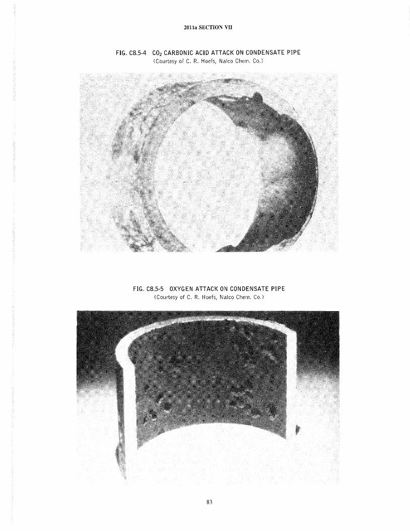
2011a SECTION VII
FIG. C8.5-4 CO2 CARBONIC ACID ATTACK ON CONDENSATE PIPE (Courtesy of C. R. Hoefs, Nalco Chem. Co.)
FIG. C8.5-5 OXYGEN ATTACK ON CONDENSATE PIPE (Courtesy of C. R. Hoefs, Nalco Chem. Co.)
83
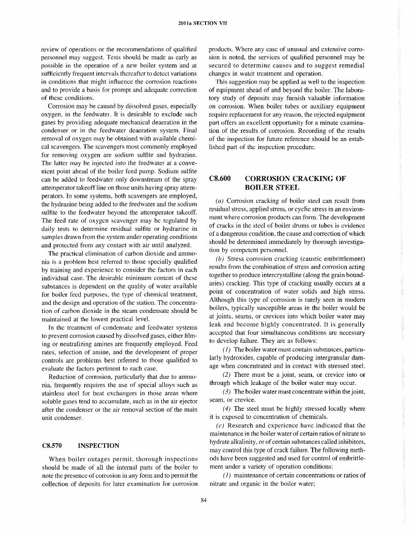
2011a SECTION VII
review of operations or the recommendations of qualified personnel may suggest. Tests should be made as early as possible in the operation of a new boiler system and at sufficiently frequent intervals thereafter to detect variations in conditions that might influence the corrosion reactions and to provide a basis for prompt and adequate correction of these conditions.
Corrosion may be caused by dissolved gases, especially oxygen, in the feed water. It is desirable to exclude such gases by providing adequate mechanical deaeration in the condenser or in the feed water deaeration system. Final removal of oxygen may be obtained with available chemical scavengers. The scavengers most commonly employed for removing oxygen are sodium sulfite and hydrazine. The latter may be injected into the feed water at a convenient point ahead of the boiler feed pump. Sodium sulfite can be added to feedwater only downstream of the spray attemperator takeoff line on those units having spray attemperators. In some systems, both scavengers are employed, the hydrazine being added to the feedwater and the sodium sulfite to the feedwater beyond the attemperator takeoff. The feed rate of oxygen scavenger may be regulated by daily tests to determine residual sulfite or hydrazine in samples drawn from the system under operating conditions and protected from any contact with air until analyzed.
The practical elimination of carbon dioxide and ammonia is a problem best referred to those specially qualified by training and experience to consider the factors in each individual case. The desirable minimum content of these substances is dependent on the quality of water available for boiler feed purposes, the type of chemical treatment, and the design and operation of the station. The concentration of carbon dioxide in the steam condensate should be maintained at the lowest practical level.
In the treatment of condensate and feedwater systems to prevent corrosion caused by dissolved gases, either filming or neutralizing amines are frequently employed. Feed rates, selection of amine, and the development of proper control s are problems best referred to those qualified to evaluate the factors pertinent to each case.
Reduction of corrosion, particularly that due to ammonia, frequently requires the use of special alloys such as stainless steel for heat exchangers in those areas where soluble gases tend to accumulate, such as in the air ejector after the condenser or the air removal section of the main unit condenser.
C8.570 INSPECTION
When boiler outages permit, thorough inspections should be made of all the internal parts of the boiler to note the presence of corrosion in any form and to permit the collection of deposits for later examination for corrosion
84
products. Where any case of unusual and extensive corrosion is noted, the services of qualified personnel may be secured to determine causes and to suggest remedial changes in water treatment and operation.
This suggestion may be applied as well to the inspection of equipment ahead of and beyond the boiler. The laboratory study of deposits may furnish valuable information on corrosion. When boiler tubes or auxiliary equipment require replacement for any reason, the rejected equipment part offers an excellent opportunity for a minute examination of the results of corrosion. Recording of the results of the inspection for future reference should be an established part of the inspection procedure.
CS.600 CORROSION CRACKING OF BOILER STEEL
(a) Corrosion cracking of boiler steel can result from residual stress, applied stress, or cyclic stress in an environment where corrosion products can form. The development of cracks in the steel of boiler drums or tubes is evidence of a dangerous condition, the cause and correction of which should be determined immediately by thorough investigation by competent personnel.
(b) Stress corrosion cracking (caustic embrittlement) results from the combination of stress and corrosion acting together to produce intercrystalline (along the grain boundaries) cracking. This type of cracking usually occurs at a point of concentration of water solids and high stress. Although this type of corrosion is rarely seen in modern boilers, typically susceptible areas in the boiler would be at joints, seams, or crevices into which boiler water may leak and become highly concentrated. It is generally accepted that four simultaneous conditions are necessary to develop failure. They are as follows:
(1) The boiler water must contain substances, particularly hydroxides, capable of producing intergranular damage when concentrated and in contact with stressed steel.
(2) There must be a joint, seam, or crevice into or through which leakage of the boiler water may occur.
(3) The boiler water must concentrate within the joint, seam, or crevice.
(4) The steel must be highly stressed locally where it is exposed to concentration of chemicals.
( c) Research and experience have indicated that the maintenance in the boiler water of certain ratios of nitrate to hydrate alkalinity, or of certain substances called inhibitors, may control this type of crack failure. The following methods have been suggested and used for control of embrittlement under a variety of operation conditions:
( 1) maintenance of certain concentrations or ratios of nitrate and organic in the boiler water;
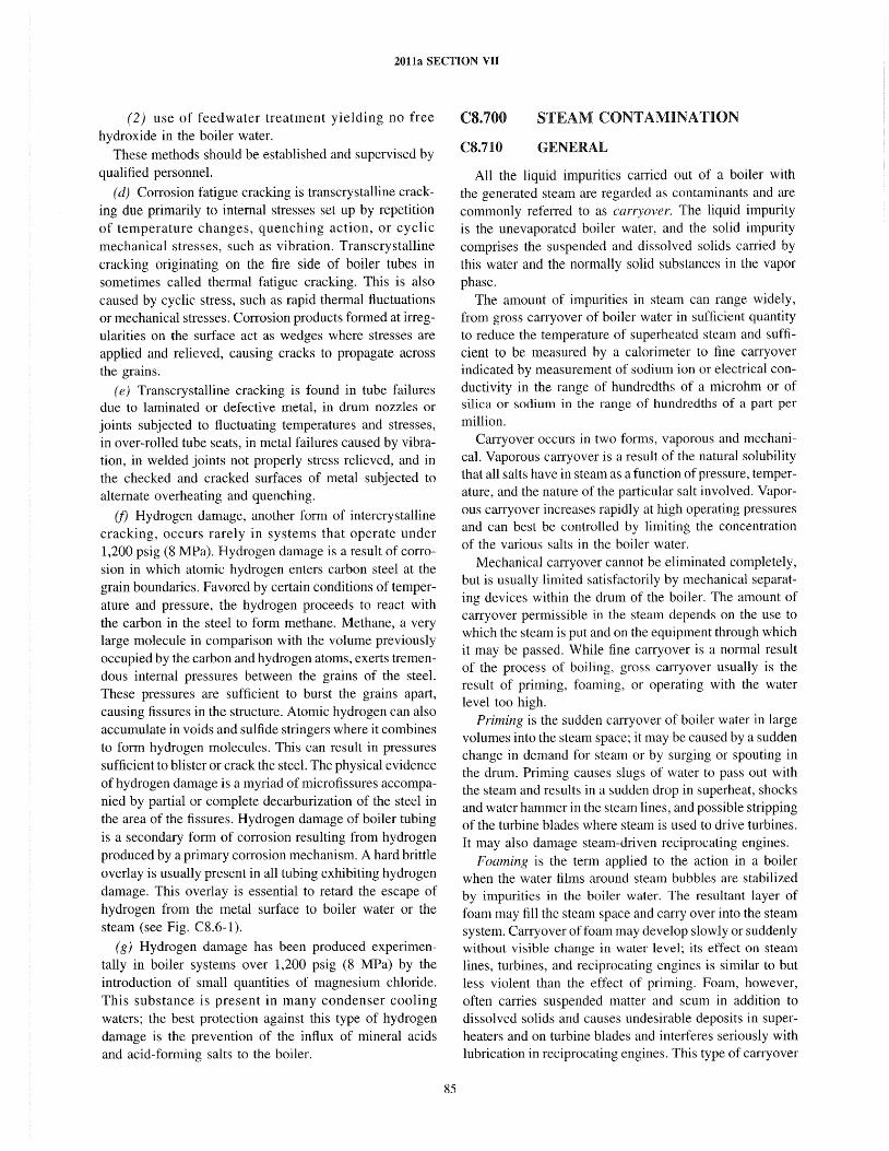
2011a SECTION VII
(2) use of feedwater treatment yielding no free hydroxide in the boiler water.
These methods should be established and supervised by qualified personnel.
(d) Corrosion fatigue cracking is transcrystal1ine cracking due primarily to internal stresses set up by repetition of temperature changes, quenching action, or cyclic mechanical stresses, such as vibration. Transcrystalline cracking originating on the fire side of boiler tubes in sometimes called thermal fatigue cracking. This is also caused by cyclic stress, such as rapid thermal fluctuations or mechanical stresses. Corrosion products formed at irregularities on the surface act as wedges where stresses are applied and relieved, causing cracks to propagate across the grains.
( e) Transcrystalline cracking is found in tube failures due to laminated or defective metal, in drum nozzles or joints subjected to fluctuating temperatures and stresses, in over-rolled tube seats, in metal failures caused by vibration, in welded joints not properly stress relieved, and in the checked and cracked surfaces of metal subjected to alternate overheating and quenching.
(f) Hydrogen damage, another form of intercrystalline cracking, occurs rarely in systems that operate under 1,200 psig (8 MPa). Hydrogen damage is a result of corrosion in which atomic hydrogen enters carbon steel at the grain boundaries. Favored by certain conditions of temperature and pressure, the hydrogen proceeds to react with the carbon in the steel to form methane. Methane, a very large molecule in comparison with the volume previously occupied by the carbon and hydrogen atoms, exerts tremendous internal pressures between the grains of the steel. These pressures are sufficient to burst the grains apart, causing fissures in the structure. Atomic hydrogen can also accumulate in voids and sulfide stringers where it combines to form hydrogen molecules. This can result in pressures sufficient to blister or crack the steel. The physical evidence of hydrogen damage is a myriad of microfissures accompanied by partial or complete decarburization of the steel in the area of the fissures. Hydrogen damage of boiler tubing is a secondary form of corrosion resulting from hydrogen produced by a primary corrosion mechanism. A hard brittle overlay is usually present in all tubing exhibiting hydrogen damage. This overlay is essential to retard the escape of hydrogen from the metal surface to boiler water or the steam (see Fig. C8.6-1).
(g) Hydrogen damage has been produced experimentally in boiler systems over 1,200 psig (8 MPa) by the introduction of small quantities of magnesium chloride. This substance is present in many condenser cooling waters; the best protection against this type of hydrogen damage is the prevention of the influx of mineral acids and acid-forming salts to the boiler.
85
CS.700
CS.710
STEAM CONTAMINATION
GENERAL
All the liquid impurities carried out of a boiler with the generated steam are regarded as contaminants and are commonly referred to as carryover. The liquid impurity is the unevaporated boiler water, and the solid impurity comprises the suspended and dissolved solids carried by this water and the normally solid substances in the vapor phase.
The amount of impurities in steam can range widely, from gross carryover of boiler water in sufficient quantity to reduce the temperature of superheated steam and sufficient to be measured by a calorimeter to fine carryover indicated by measurement of sodium ion or electrical conductivity in the range of hundredths of a microhm or of silica or sodium in the range of hundredths of a part per million.
Carryover occurs in two forms, vaporous and mechanical. Vaporous canyover is a result of the natural solubility that all salts have in steam as a function of pressure, temperature, and the nature of the particular salt involved. Vaporous carryover increases rapidly at high operating pressures and can best be contro11ed by limiting the concentration of the various salts in the boiler water.
Mechanical canyover cannot be eliminated completely, but is usually limited satisfactorily by mechanical separating devices within the drum of the boiler. The amount of canyover permissible in the steam depends on the use to which the steam is put and on the equipment through which it may be passed. While fine canyover is a normal result of the process of boiling, gross canyover usually is the result of priming, foaming, or operating with the water level too high.
Priming is the sudden canyover of boiler water in large volumes into the steam space; it may be caused by a sudden change in demand for steam or by surging or spouting in the drum. Priming causes slugs of water to pass out with the steam and results in a sudden drop in superheat, shocks and water hammer in the steam lines, and possible stripping of the turbine blades where steam is used to drive turbines. It may also damage steam-driven reciprocating engines.
Foaming is the term applied to the action in a boiler when the water films around steam bubbles are stabilized by impurities in the boiler water. The resultant layer of foam may fill the steam space and cany over into the steam system. Carryover of foam may develop slowly or suddenly without visible change in water level; its effect on steam lines, turbines, and reciprocating engines is similar to but less violent than the effect of priming. Foam, however, often carries suspended matter and scum in addition to dissolved solids and causes undesirable deposits in superheaters and on turbine blades and interferes seriously with lubrication in reciprocating engines. This type of carryover
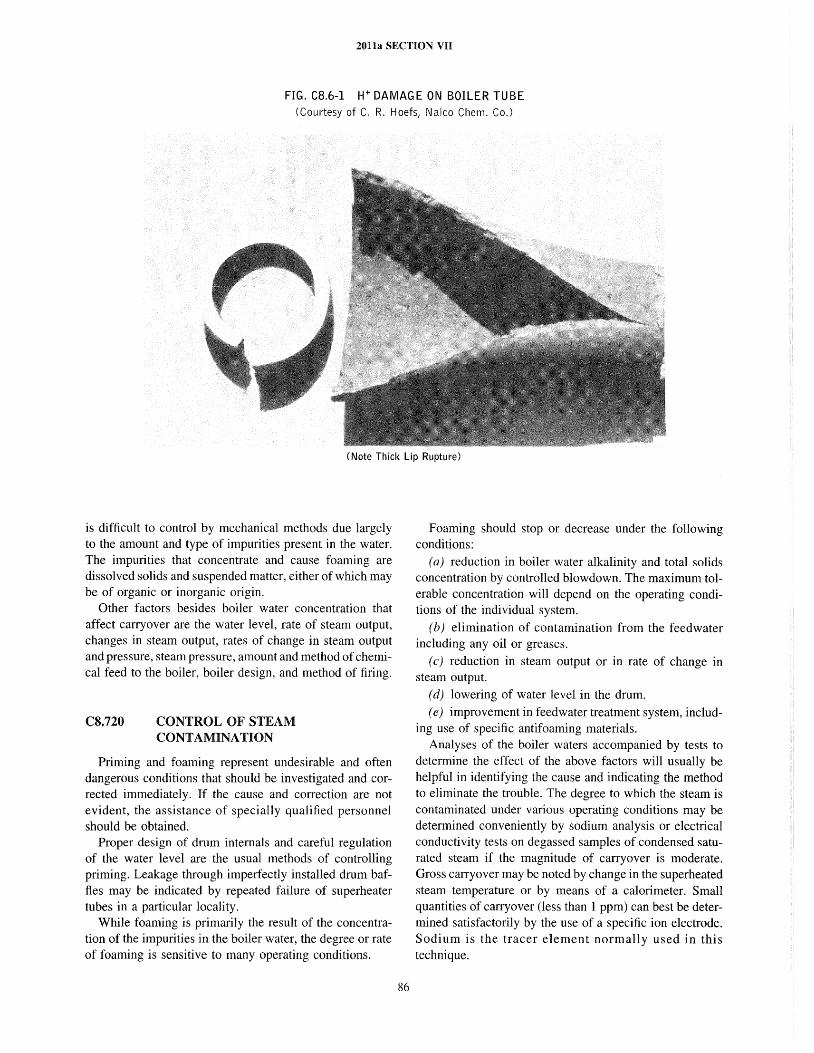
2011a SECTION VII
FIG. CS.6-1 H+ DAMAG E ON BOILER TU BE (Courtesy of C. R. Hoefs, Nalco Chem. Co,)
(Note Thick Lip Rupture)
is difficult to control by mechanical methods due largely to the amount and type of impurities present in the water. The impurities that concentrate and cause foaming are dissolved solids and suspended matter, either of which may be of organic or inorganic origin.
Other factors besides boiler water concentration that affect carryover are the water level, rate of steam output, changes in steam output, rates of change in steam output and pressure, steam pressure, amount and method of chemical feed to the boiler, boiler design, and method of firing.
CS.720 CONTROL OF STEAM CONTAMINATION
Priming and foaming represent undesirable and often dangerous conditions that should be investigated and corrected immediately. If the cause and correction are not evident, the assistance of specially qualified personnel should be obtained.
Proper design of drum internals and careful regulation of the water level are the usual methods of controlling priming. Leakage through imperfectly installed drum baffles may be indicated by repeated failure of superheater tubes in a particular locality.
While foaming is primarily the result of the concentration of the impurities in the boiler water, the degree or rate of foaming is sensitive to many operating conditions.
86
Foaming should stop or decrease under the following conditions:
(a) reduction in boiler water alkalinity and total solids concentration by controlled blowdown. The maximum tolerable concentration will depend on the operating conditions of the individual system.
(b) elimination of contamination from the feedwater including any oil or greases.
(c) reduction in steam output or in rate of change in steam output.
(d) lowering of water level in the drum. (e) improvement in feedwater treatment system, includ
ing use of specific antifoaming materials. Analyses of the boiler waters accompanied by tests to
determine the effect of the above factors will usually be helpful in identifying the cause and indicating the method to eliminate the trouble. The degree to which the steam is contaminated under various operating conditions may be determined conveniently by sodium analysis or electrical conductivity tests on degassed samples of condensed saturated steam if the magnitude of carryover is moderate. Gross carryover may be noted by change in the superheated steam temperature or by means of a calorimeter. Small quantities of carryover (less than 1 ppm) can best be determined satisfactorily by the use of a specific ion electrode. Sodium is the tracer element normally used in this technique.
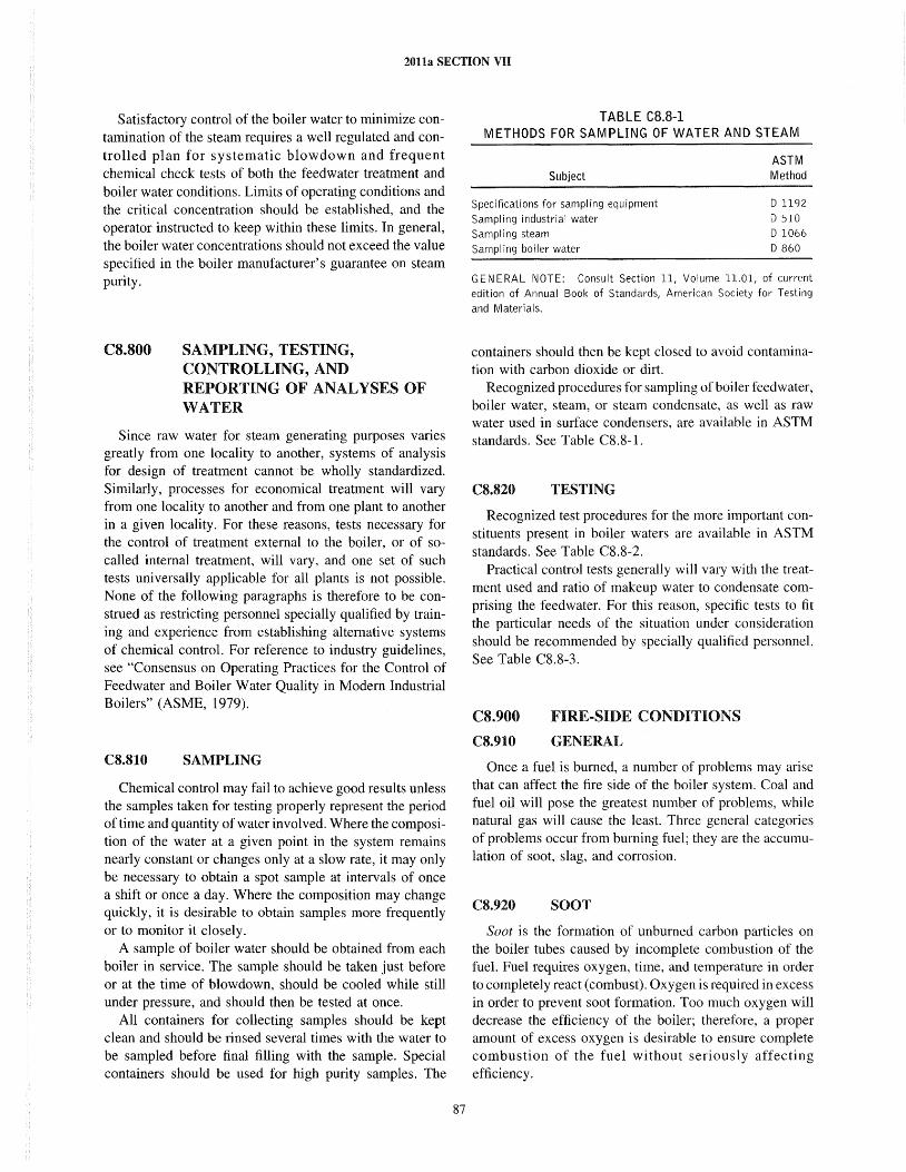
2011a SECTION VII
Satisfactory control of the boiler water to minimize contamination of the steam requires a well regulated and controlled plan for systematic blowdown and frequent chemical check tests of both the feedwater treatment and boiler water conditions. Limits of operating conditions and the critical concentration should be established, and the operator instructed to keep within these limits. In general, the boiler water concentrations should not exceed the value specified in the boiler manufacturer's guarantee on steam purity.
CS.SOO SAMPLING, TESTING, CONTROLLING, AND REPORTING OF ANALYSES OF WATER
Since raw water for steam generating purposes varies greatly from one locality to another, systems of analysis for design of treatment cannot be wholly standardized. Similarly, processes for economical treatment will vary from one locality to another and from one plant to another in a given locality. For these reasons, tests necessary for the control of treatment external to the boiler, or of socalled internal treatment, will vary, and one set of such tests universally applicable for all plants is not possible. None of the following paragraphs is therefore to be construed as restricting personnel specially qualified by training and experience from establishing alternative systems of chemical control. For reference to industry guidelines, see "Consensus on Operating Practices for the Control of Feedwater and Boiler Water Quality in Modem Industrial Boilers" (ASME, 1979).
C8.810 SAMPLING
Chemical control may fail to achieve good results unless the samples taken for testing properly represent the period of time and quantity of water involved. Where the composition of the water at a given point in the system remains nearly constant or changes only at a slow rate, it may only be necessary to obtain a spot sample at intervals of once a shift or once a day. Where the composition may change quickly, it is desirable to obtain samples more frequently or to monitor it closely.
A sample of boiler water should be obtained from each boiler in service. The sample should be taken just before or at the time of blowdown, should be cooled while still under pressure, and should then be tested at once.
All containers for collecting samples should be kept clean and should be rinsed several times with the water to be sampled before final filling with the sample. Special containers should be used for high purity samples. The
87
TABLE CB.B-l METHODS FOR SAMPLING OF WATER AND STEAM
Subject
Specifications for sampling equipment Sampling industrial water
Sampling steam
boiler water
ASTM Method
D 1192
D 510 D 1066 D 860
GENERAL NOTE: Consult Section 11, Volume 11.01, of current edition of Annual Book of Standards, American Society for Testing
and Materials.
containers should then be kept closed to avoid contamination with carbon dioxide or dirt.
Recognized procedures for sampling of boiler feedwater, boiler water, steam, or steam condensate, as well as raw water used in surface condensers, are available in ASTM standards. See Table C8.8-1.
C8.820 TESTING
Recognized test procedures for the more important constituents present in boiler waters are available in ASTM standards. See Table C8.8-2.
Practical control tests generally will vary with the treatment used and ratio of makeup water to condensate comprising the feedwater. For this reason, specific tests to fit the particular needs of the situation under consideration should be recommended by specially qualified personnel. See Table C8.8-3.
CS.900
C8.910
FIRE-SIDE CONDITIONS
GENERAL
Once a fuel is burned, a number of problems may arise that can affect the fire side of the boiler system. Coal and fuel oil will pose the greatest number of problems, while natural gas will cause the least. Three general categories of problems occur from burning fuel; they are the accumulation of soot, slag, and corrosion.
C8.920 SOOT
Soot is the formation of unburned carbon particles on the boiler tubes caused by incomplete combustion of the fuel. Fuel requires oxygen, time, and temperature in order to completely react (combust). Oxygen is required in excess in order to prevent soot fomlation. Too much oxygen will decrease the efficiency of the boiler; therefore, a proper amount of excess oxygen is desirable to ensure complete combustion of the fuel without seriously affecting efficiency.
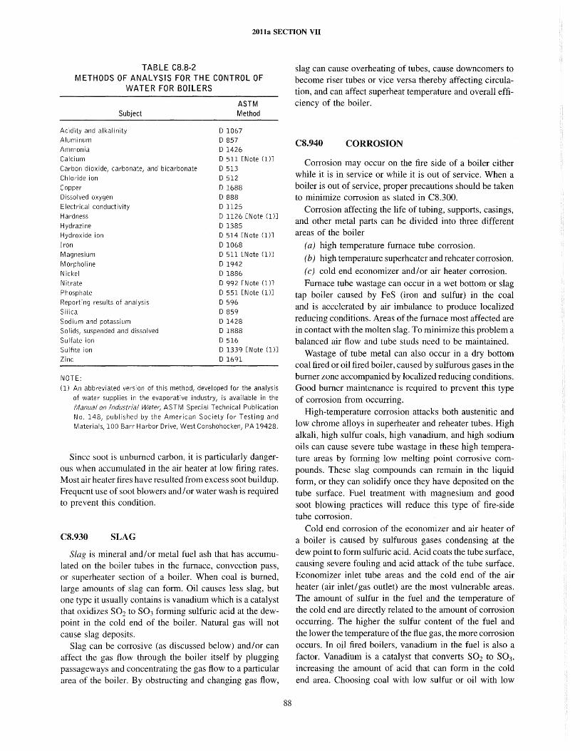
2011a SECTION VII
TABLE CB.B-2 METHODS OF ANALYSIS FOR THE CONTROL OF
WATER FOR BOILERS
Subject
Acidity and alkalinity Aluminum
Ammonia Calcium
Carbon dioxide, carbonate, and bicarbonate
Chloride ion
Copper
Dissolved oxygen
Electrical conductivity
Hardness
Hydrazine
Hydroxide ion
Iron
Magnesium
Morpholine Nickel
Nitrate
Phosphate
Reporting results of analysis
Silica
Sodium and potassium
Solids, suspended and dissolved
Sulfate ion
Sulfite ion
Zinc
NOTE:
ASTM Method
D 1067 D 857
D 1426 D 511 [N ate (1)J
D 513
D 512
D 1688
D 888
D 1125 D 1126 [Note (1)]
D 1385 D 514 [Note (1)J
D 1068 D 511 [Note (1)]
D 1942
D 1886 D 992 [Note (1)]
D 551 [Note (1)J
D 596 D 859
D 1428
D 1888
D 516 D 1339 [Note (1)]
D 1691
(1) An abbreviated version of this method, developed for the analysis
of water supplies in the evaporative industry, is available in the
Manual on Industrial Water; ASTM Special Technical Publication
No. 148, published by the American Society for Testing and
Materials,100 Barr Harbor Drive, West Conshohocken, PA 19428.
Since soot is unburned carbon, it is particularly dangerous when accumulated in the air heater at low firing rates. Most air heater fires have resulted from excess soot buildup. Frequent use of soot blowers and/or water wash is required to prevent this condition.
CS.930 SLAG
Slag is mineral and/or metal fuel ash that has accumulated on the boiler tubes in the furnace, convection pass, or superheater section of a boiler. When coal is burned, large amounts of slag can form. Oil causes less slag, but one type it usually contains is vanadium which is a catalyst that oxidizes S02 to S03 forming sulfuric acid at the dewpoint in the cold end of the boiler. Natural gas will not cause slag deposits.
Slag can be corrosive (as discussed below) and/or can affect the gas flow through the boiler itself by plugging passageways and concentrating the gas flow to a particular area of the boiler. By obstructing and changing gas flow,
88
slag can cause overheating of tubes, cause down comers to become riser tubes or vice versa thereby affecting circulation, and can affect superheat temperature and overall efficiency of the boiler.
CS.940 CORROSION
Corrosion may occur on the fire side of a boiler either while it is in service or while it is out of service. When a boiler is out of service, proper precautions should be taken to minimize corrosion as stated in C8.300.
Corrosion affecting the life of tubing, supports, casings, and other metal parts can be divided into three different areas of the boiler
(a) high temperature furnace tube corrosion.
(b) high temperature superheater and reheater corrosion.
(c) cold end economizer and/or air heater corrosion. Furnace tube wastage can occur in a wet bottom or slag
tap boiler caused by FeS (iron and sulfur) in the coal and is accelerated by air imbalance to produce localized reducing conditions. Areas of the furnace most affected are in contact with the molten slag. To minimize this problem a balanced air flow and tube studs need to be maintained.
Wastage of tube metal can also occur in a dry bottom coal fired or oil fired boiler, caused by sulfurous gases in the burner zone accompanied by localized reducing conditions. Good burner maintenance is required to prevent this type of corrosion from occurring.
High-temperature corrosion attacks both austenitic and low chrome alloys in superheater and reheater tubes. High alkali, high sulfur coals, high vanadium, and high sodium oils can cause severe tube wastage in these high temperature areas by forming low melting point corrosive compounds. These slag compounds can remain in the liquid form, or they can solidify once they have deposited on the tube surface. Fuel treatment with magnesium and good soot blowing practices will reduce this type of fire-side tube corrosion.
Cold end corrosion of the economizer and air heater of a boiler is caused by sulfurous gases condensing at the dew point to form sulfuric acid. Acid coats the tube surface, causing severe fouling and acid attack of the tube surface. Economizer inlet tube areas and the cold end of the air heater (air inlet/gas outlet) are the most vulnerable areas. The amount of sulfur in the fuel and the temperature of the cold end are directly related to the amount of corrosion occurring. The higher the sulfur content of the fuel and the lower the temperature of the flue gas, the more corrosion occurs. In oil fired boilers, vanadium in the fuel is also a factor. Vanadium is a catalyst that converts S02 to S03, increasing the amount of acid that can form in the cold end area. Choosing coal with low sulfur or oil with low
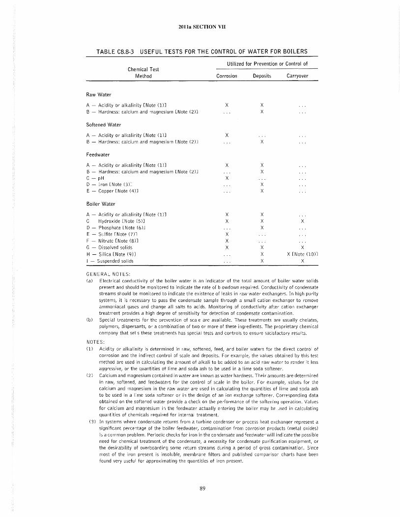
2011a SECTION VII
TABLE CS.S-3 USEFUL TESTS FOR THE CONTROL OF WATER FOR BOILERS
Raw Water
Chemical Test
Method
A - Acidity or alkalinity [Note (1)J
B - Hardness: calcium and magnesium [Note (2)J
Softened Water
A - Acidity or alkalinity [Note (1)]
B - Hardness: calcium and magnesium [Note (2)J
Feedwater
A - Acidity or alkalinity [Note (1)]
B - Hardness: calcium and magnesium [Note (2)J
C - pH D - Iron [Note (3)]
E - Copper [Note (4)J
Boiler Water
A - Acidity or alkalinity [Note (1)]
C - Hydroxide [Note (5)J
D - Phosphate [Note (6)J
E - Sulfite [Note (7)J
F - Nitrate [Note (8)]
G - Dissolved solids
H - Silica [Note (9)J
I - Suspended solids
GENERAL NOTES:
Utilized for Prevention or Control of
Corrosion
x
X
X
X
X X
X X X
Deposits
x X
X
X X
X X
X X X
X X X
Carryover
X
X X [Note (10)]
X
(a) Electrical conductivity of the boiler water is an indicator of the total amount of boiler water solids
present and should be monitored to indicate the rate of blowdown required. Conductivity of condensate streams should be monitored to indicate the existence of leaks in raw water exchangers. In high purity
systems, it is necessary to pass the condensate sample through a small cation exchanger to remove ammoniacal gases and change all salts to acids. Monitoring of conductivity after cation exchanger
treatment provides a high degree of sensitivity for detection of condensate contamination.
(b) Special treatments for the prevention of scale are available. These treatments are usually chelates,
polymers, dispersants, or a combination of two or more of these ingredients. The proprietary chemical
company that sells these treatments has special tests and controls to ensure satisfactory results.
NOTES:
(1) Acidity or alkalinity is determined in raw, softened, feed, and boiler waters for the direct control of
corrosion and the indirect control of scale and deposits. For example, the values obtained by this test
method are used in calculating the amount of alkali to be added to an acid raw water to render it less
aggressive, or the quantities of lime and soda ash to be used in a lime soda softener.
(2) Calcium and magnesium contained in water are known as water hardness. Their amounts are determined
in raw, softened, and feedwaters for the control of scale in the boiler. For example, values for the
calcium and magnesium in the raw water are used in calculating the quantities of lime and soda ash
to be used in a lime soda softener or in the design of an ion exchange softener. Corresponding data obtained on the softened water provide a check on the pel-formance of the softening operation. Values
for calcium and magnesium in the feedwater actually entering the boiler may be used in calculating quantities of chemicals required for internal treatment.
(3) In systems where condensate retu rns from a turbi ne condenser or process heat exchanger represent a significant percentage of the boiler feedwater, contamination from corrosion products (metal oxides)
is a common problem. Periodic checks for iron in the condensate and feedwater will indicate the possible need for chemical treatment of the condensate, a necessity for condensate purification equipment, or
the desirability of overboarding some return streams during a period of gross contamination. Since
most of the iron present is insoluble, membrane filters and published comparison charts have been
found very useful for approximating the quantities of iron present.
89
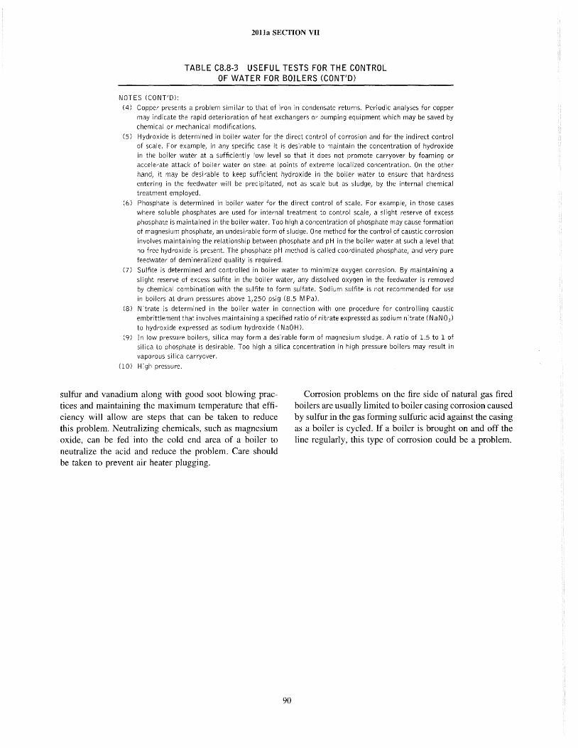
2011a SECTION VII
TABLE CS.S-3 USEFUL TESTS FOR THE CONTROL OF WATER FOR BOILERS (CONT/D)
NOTES (CONT'D):
(4) Copper presents a problem similar to that of iron in condensate returns. Periodic analyses for copper
may indicate the rapid deterioration of heat exchangers or pumping equipment which may be saved by
chemical or mechanical modifications.
(5) Hydroxide is determined in boiler water for the direct control of corrosion and for the indirect control of scale. For example, in any specific case it is desirable to maintain the concentration of hydroxide
in the boiler water at a sufficiently low level so that it does not promote carryover by foaming or
accelerate attack of boiler water on steel at points of extreme localized concentration. On the other
hand, it may be desirable to keep sufficient hydroxide in the boiler water to ensure that hardness
entering in the feedwater will be precipitated, not as scale but as sludge, by the internal chemical
treatment employed.
(6) Phosphate is determined in boiler water for the direct control of scale. For example, in those cases
where soluble phosphates are used for internal treatment to control scale, a slight reserve of excess
phosphate is maintained in the boiler water. Too high a concentration of phosphate may cause formation
of magnesium phosphate, an undesirable form of sludge. One method for the control of caustic corrosion
involves maintaining the relationship between phosphate and pH in the boiler water at such a level that
no free hydroxide is present. The phosphate pH method is called coordinated phosphate, and very pure
feedwater of demineralized quality is required.
(7) Sulfite is determined and controlled in boiler water to minimize oxygen corrosion. By maintaining a
slight reserve of excess sulfite in the boiler water, any dissolved oxygen in the feedwater is removed
by chemical combination with the sulfite to form sulfate. Sodium sulfite is not recommended for use
in boilers at drum pressures above 1,250 psig (8.5 M PaL
(8) Nitrate is determined in the boiler water in connection with one procedure for controlling caustic
embrittlement that involves maintaining a specified ratio of nitrate expressed as sodium nitrate (NaN03 )
to hydroxide expressed as sodium hydroxide (NaO H)'
(9) In low pressure boilers, silica may form a desirable form of magnesium sludge. A ratio of 1.5 to 1 of
silica to phosphate is desirable. Too high a silica concentration in high pressure boilers may result in
vaporous silica carryover.
(0) High pressure.
sulfur and vanadium along with good soot blowing practices and maintaining the maximum temperature that efficiency will allow are steps that can be taken to reduce this problem. Neutralizing chemicals, such as magnesium oxide, can be fed into the cold end area of a boiler to neutralize the acid and reduce the problem. Care should be taken to prevent air heater plugging.
90
Corrosion problems on the fire side of natural gas fired boilers are usually limited to boiler casing corrosion caused by sulfur in the gas forming sulfuric acid against the casing as a boiler is cycled. If a boiler is brought on and off the line regularly, this type of corrosion could be a problem.
2011a SECTION VII
SUBSECTION C9 PREVENTING BOILER
C9.100 GENERAL
(a) The many causes of boiler failures may be listed under three general classifications
( 1) those that are the result of overpressure (2) those caused by weakening of the structure (3) those that may result from errors in operation of
the combustion equipment (b) This Subsection discusses equipment required for a
boiler to prevent failures due to these causes and errors in operation and maintenance of such devices. Also discussed are precautions to be taken against conditions that cannot be controlled by protective devices but that can lead to boiler failure.
C9.200
C9.210
OVERPRESSURE
INDICATORS - STEAM PRESSURE GAGES
These instruments are important operating guides available to the boiler operator and should be treated with care and periodically tested for accuracy.
A steam pressure gage should be tested by comparison with a deadweight testing device or a test gage which has been so tested. The readings of both test gage and instrument to be calibrated should be corrected for any existing hydrostatic head pressure. When testing, place the steam gage in the same position it is in when in normal use.
To ensure an accurate basis for comparison, the test gage should be made expressly for test purposes and used solely for that function, its accuracy maintained by frequent periodic comparison with a deadweight testing device. When compensation for the static head pressure has been made, an equivalent allowance should be made in the reading of the test gage or the deadweight testing device.
Compare the boiler steam gages with one another frequently. Test at times of external inspection, when the boiler is placed in service after periods of shutdown for internal inspection or repairs, and after an extended period of shutdown. See that the gages are tested when trouble is experienced with boiler compounds, foaming, priming, and other feedwater troubles that are liable to cause plugging of the gage connections.
91
Before testing a steam pressure gage, if instrument piping connections are not provided for testing in place or for blowing out the connections, shut off source valves and disconnect the gage at the union. Flush the piping, cock, and siphon with water and reconnect the gage. Do not admit steam directly into the gage, and be sure that at all times the siphon is fined with water. If steam has entered the gage, it must be retested.
Keep the gages wen lighted at all times and the dials and glass covers clean. See that the glass cover is maintained tight, and whenever the glass is broken, replace it as soon as possible to prevent dirt from fouling the mechanism.
When a boiler steam gage is not in use and may be subjected to freezing temperatures, drain the connections and gage or provide heat.
C9.220 INDICATORS - WATER GLASSES
A very important duty of the boiler operator is to see that the proper level of water is maintained in the boiler under all operating conditions. High water level will cause carryover of water into the superheater steam line and turbine. This can cause severe damage due to the carryover of boiler water solids. Higher levels will cause a rapid quenching that may result in cracking of the superheater tubing, main steam line, and turbine casing and cause damage to turbine rotating and stationary components. Low water level will result in poor circulation through the generating tubes and may cause them to tupture due to overheating. Low water in a firetube boiler may cause loosening of the tube joints and possible bagging of the furnace, tupture of the furnace, tubesheets, and shelL The water level is considered proper when it is within the operating range prescribed by the boiler manufacturer. The water glass is provided for this purpose and should be maintained in perfect condition at all times even though reliable remote level indicating instruments are installed.
Keep the piping and valves between the boiler and water column and water glass free and clear. Test by blowing down the water column and water glass, noting the promptness of the return of the water to the water column and glass and trying the gage cocks, where installed, until sure of the water level.
2011a SECTION VII
All water columns and water glasses should be tested by the operator directly responsible for the level of the water in the boiler at the beginning of each shift or daily work period and preferably before the relieved shift has gone off duty. Where water columns are equipped with automatic low water boiler trips, suitable operating procedures should be developed to preclude tripping the boiler while determining that the water column is functional and in good operating condition.
For steam pressure above 400 psig (3 MPa), the frequency and method to be followed in testing water gage glasses may vary with the type of gage glass. The manufacturer should be consulted for a testing schedule to ensure proper functioning of the column without excessive maintenance and replacement.
Water glasses should be tested after replacing, and all water glasses on a boiler should be tested when the boiler is placed in service and whenever trouble is experienced with boiler compounds, foaming, priming, or other feedwater troubles that are liable to cause clogging of the connections.
Water glasses and their connections should be kept free from leaks, and no connections should be made that will allow a flow of water or steam piping from the column or water glass and the boiler, except in accordance with PG-60.4 of Section I, as such leaks or flow of water or steam will cause a false indication of the water level in the boiler. See PG-60.1.6 and PG-60.2.5 of Section 1.
The outlet ends of the discharge pipes from water columns, water glasses, and gage cocks should be kept free from obstructions, discharging to a safe point in sight or hearing of the operator while blowing down. Where the pipes discharge into the blowdown lines, the operator wil1 depend upon hearing. Precautions should be taken to prevent a blowback from the blowdown lines into idle boilers or equipment connected into these lines.
Water glasses should be well lighted and kept clean. When they need cleaning, replace them with clean glasses. Do not attempt to clean glasses in place as this can lead to possible cracking of the glass or clogging of the glass by pieces of cloth or waste. Protect the water glass, if necessary, from drafts, rain, or snow by means of a baffle or a suitable weatherproof hood. If drains are exposed to freezing temperatures, protect with an electrical heating cable or a small steam line buried in insulation.
When a water gage glass has broken, replacement should be made carefully and in stl;ct conformity to the instructions of the gage manufacturer. Care should be taken to ensure that no broken pieces of glass or other debris lodges in the gage glass connections.
After the new gage glass has been installed, the glass should be warmed by opening the top valve to the gage glass and the drain valve slightly to let a small flow of steam through the glass. This is a particularly successful cut-in procedure when an open blow drain is available.
92
The open blow makes it possible to set the drain valve for a small flow and thereby obtain a gentle warmup. Close the drain valve or cock after the glass is sufficiently warmed, and open the bottom valve to the gage glass slight! y. When the level of the water in the glass has become stable, open the bottom valve wide and then open the top valve wide.
On boilers equipped with more than one gage glass, the glass may be replaced with the boiler under pressure provided that the water glass is supplied with a guard to protect the operator, or the operator wears a mask. The valves should be operated only by remote control.
C9.230 INDICATORS - AUTOMATIC HIGH AND LOW LEVEL ALARMS
Where automatic alarms for indicating low or high water levels are used, they should at all times be kept in good working order and should be tested when the water columns and gage glasses are tested. The proper level of water in the glass should be maintained at all times without waiting for automatic alarms to indicate unusually high or low water levels. Drum level alarms should be set to sound when the level in the glass gets to within 1 ~ in. to 2~ in. (38 mm to 64 mm) from the limit of visibility of the gage glass. When an automatic alarm sounds and the level of water is not visible in the glass, the operator should immediately stop the supply of fuel and air. He should blow down the column and glass to determine whether the connections are clear and whether any false indication of low water is being given. He may then test gage cocks, if available, to determine the water level before deciding the correct operation of the feedwater valves.
C9.240 AUTOMATIC TRIP
Automatic drum level trips should be set to trip the fuel supply to the boiler when the water level reaches the low limit of the visibility of the gage glass. An adjustable time delay should be provided with a maximum permissible setting of 10 sec.
C9.2S0 RELIEF EQUIPMENT - SAFETY VALVES
Refer to C4.1 00 for the important considerations related to safety valves.
C9.260 RELIEF EQUIPMENT - FUSIBLE PLUGS
If fusible plugs are used, see that they are kept in good condition and that they are not used for more than one
2011a SECTION VII
year. When the boiler is open, clean and examine the plugs. If the fusible metal does not appear sound, renew the plug regardless of the length of time it has been installed. Never refill a plug with anything but new metal of a quality specified in A-19 and A-20 of Section I.
C9.300 WEAKENING OF STRUCTURE
Weakening of structure may be divided into three some-what overlapping categories
( a) weakening of pressure parts
(b) failure of supports ( c) mechanical damage
The various conditions that may cause the weakening of boiler pressure parts, such as overheating, loss of metal due to corrosion, weakening of the furnace because of improper combustion or flame impingement, and soot blower erosion are discussed in the following paragraphs.
C9.310 BOILER STARTUP
It is important in starting a boiler that a proper starting procedure be established to prevent overheating or overstressing of thick walled drums, superheaters, reheaters, riveting and expanded joints, and uneven expansion of the component parts of the boiler. Instructions of the Manufacturer should be followed.
All expansion joints and supports of piping that move as the boiler expands must be permitted free movement prior to an initial start, particularly following hydrostatic testing.
A checklist of every step in preparing a boiler unit for startup and of the actual start-up procedure should be prepared and strictly followed by the operators during every startup. The list should include the steps specified by the boiler manufacturer, as well as any that are peculiar to the specific installation.
Ample time should be allowed for raising the steam pressure to prevent uneven heating of the furnace and boiler. Uneven heating of the furnace may result in cracking the lining, particularly new brickwork, thereby destroying its value as an insulator and support. Uneven heating of the boiler will cause unequal expansion that may result in distorted tubes and opening of seams, especially where the circulation of water may be sluggish. In starting high pressure boilers equipped with heavy drums, the maximum rate of pressure increase, or maximum drum metal temperature differential as recommended by the Manufacturer, should not be exceeded.
In boilers equipped with refractory settings, care should be used to prevent excessive furnace temperature that can result in overheating of tubes or that will cause melting of
93
the furnace lining, destroying its value as an insulating protector of boiler parts and supports.
Spalling or wasting away of side walls, bridge walls, and arches, which may be caused by the impingement of oil flames, contact of fuel bed, and other causes, should be guarded against as far as possible to maintain the safety of the structure.
Positive pressure in the furnace should be avoided as far as practicable, except in boiler units specifically designed for pressure furnace operation. Unless the furnace has been specifically designed for pressure operation, pressure in a furnace will cause hot gases to leak out through any crevices in the furnace, causing deterioration as well as hazardous pollution of the air in the illllnediate vicinity
of the boiler. Where refractories are provided to protect the surfaces
of the steam space of a boiler that is not designed to withstand direct impingement of hot gases, such protective refractories should be maintained in good condition.
Gas baffles should be maintained in good order to prevent the bypassing of gas that may cause localized overheating, ash erosion of the tubes, and reduction in operating efficiency.
The localized buildup of slag should be prevented by the installation and adequate operation of soot blowers and/or by manual cleaning with air or steam lances or other means, if required, to eliminate high gas velocities that may cause overheating and erosion.
Excessive slag accumulation could be followed by a slag drop that might damage refractories, tubes, and grates. Some control of slag accumulation can be obtained by careful regulation of firing conditions affecting furnace temperatures and/or by purchase of fuel with higher ash fusion temperature.
The accumulation of unburned fuel within the furnace is an explosive mixture and must be prevented. Properly purge the furnace prior to relighting burners after any loss of flame, accidental or planned, regardless of time interval between loss and attempt to relight. Provide adequate excess air during light-off. Observe furnace conditions continuously by visual attention of operators, by proven flame monitoring devices, or by combustibles-in-flue-gas detectors. It is essential that operators have a thorough understanding of the explosion hazards that result from lack of adequate precautions. Loss of life as well as of equipment may result from lack of proper supervision of furnace conditions. The boiler and burner manufacturers should be consulted concerning the proper steps to be taken, conditions to be maintained, and observations to be made during the light-off, firing, and any emergency periods of boiler operation. A checklist will help in ensuring that the proper procedure is followed. See Subsection C3 for further detail. In boiler furnaces with multiple oil or gas burners, NEVER
2011a SECTION VII
attempt to light additional burners from burners in use or from hot brickwork.
Drum and header supports should be checked to determine that they permit proper expansion.
Expansion joints should be properly maintained to prevent restriction of movement of furnace wall tubes and headers.
If it is necessary to blow down the boiler to maintain boiler water chemistry, first open the shutoff valve wide and then the blowing valve until it is half open and leave it in that position until the water is lowered about 0.5 in. (13 mm) in the water glass; then open the blowing valve wide until blowdown is completed. After blowdown is completed, close the blowing valve first and then the shutoff valve.
On high pressure boilers equipped with blowdown valves on waterwall headers, care must be exercised in blowing down to prevent undue header movement. Likewise, the use of waterwall blowdown valves while the boiler is in service may interfere with circulation and cause tube failures. The Manufacturer's recommendations should be followed on the use of such valves.
Soot and ash should not be allowed to accumulate around drums, tubes, headers, or other boiler parts. Reaction of moisture with the sulfur compounds in these materials will promote corrosion. Any washing of external boiler parts or heat exchanger surfaces should be followed by a drying out fire unless the boiler is placed in service immediately after such cleaning.
Fuel-burning equipment should be operated so that combustible gas does not enter the convection areas of the boiler. Combustible gas in this area can cause secondary combustion that may result in localized high temperature, oxidation, and wasting away of boiler tubes. Unignited combustible gas formed by improperly operated fuelburning equipment is an explosion hazard.
C9.320 CONTROL OF WATER LEVEL
Special and constant care should be exercised to maintain a proper water level in the boiler and to provide a continuous, rather than an intermittent, supply of water to the boiler. Never depend entirely upon automatic alarms or feedwater regulators, no matter how effective or valuable those devices may be.
When the operator is blowing down a boiler and cannot see the water glass, another operator should be placed to watch the water glass and signal to the operator blowing down the boiler. Only one boiler at a time should be blown down by anyone operator. When blowing down the boiler, the operator should give his entire attention to that duty and should not perform any other.
94
If feedwater regulators are used, see that they are maintained in good working condition. They should be provided with a manual regulating device.
If difficulty is experienced in maintaining the proper water level in the boiler, the firing rate should be reduced until the cause is eliminated. If the correction can be made with the boiler in service, the firing rate should be maintained at a level at which the boiler can be safely operated with a satisfactory water level.
If the condition causing the abnormal water level requires that the boiler be taken out of service, it should be shut down in as nearly a normal manner as is possible under the existing conditions.
Give operators positive instructions as to absolute safe high and low operating water levels and step-by-step instructions for proper procedure when abnormal levels are approached or exceeded.
When the level of water is not visible in the gage glass, blow down the water column or gage glass to deternline whether the level is above or below the visible range of the gage glass. If a water level indicator and a water level recorder are available and their indications are in agreement, blowing down the gage glass should not be necessary to determine where the level is. If the water level is below the gage glass, the safest and most conservative action is to shut off fuel and air but continue to feed water slowly until the normal water level is restored.
If the boiler has sufficient indicators and/or recorders and the operator can readily establish that the drum water level is stabilized just below the visible range of the gage glass, operation of the unit can be maintained provided immediate action is taken to restore the water level in the drum to normal level. This should be done with care, caution, and understanding using all indicators available, such as feedwater flow meter, steam flow meter, drum level recorder, and all other instruments that properly sense the operating conditions of the boiler.
In case of low water level, if there is any possibility that the boiler has been damaged, it should be cooled down and thoroughly inspected for indication of overheating.
C9.330 EROSION
Steam soot blowers should be supplied with practically dry steam; they should be well drained before using. Care should be taken to prevent direct impingement of a steam jet upon the tubes, tubesheets, or baffles. Care should be taken with the alignment of the nozzles of nonretractable rotary soot blowers so that the jets from them will not impinge on the tubes.
In using a steam lance, care should be taken not to blow with too much force or for too long a period upon anyone point, particularly about the lower end of vertical water
2011a SECTION VII
tubes. The cooling effect of such prolonged and concentrated blowing on a generating tube can cause a reduction of circulation in that tube, which could result in overheating and failure.
C9.340 INTERNAL CORROSION
Internal corrosion may occur in a boiler if proper chemical control of the boiler water is not maintained at all times. It may also occur in an idle boiler if proper care is not exercised in the laying up procedure. See Subsection CS.
Internal corrosion can result from improper methods of chemical cleaning. Such work should be done only under the supervision of qualified personnel.
C9.350 EXTERNAL CORROSION
Boilers in or out of service may be exposed to external corrosion caused by moisture from outside sources. This moisture, especially if it comes in contact with sulfur deposits from the fuel burned, will tend to corrode pressure parts. The operator should guard against leaky safety valves and steam line connections which drip condensate on boiler pressure parts, especially where the water may run under protective coverings where the moisture will be retained.
Leaky manhole and handhole cover joints, particularly where ash and soot can collect, are especially dangerous as they can corrode pressure parts rapidly. Such places should be kept clean and tight.
Any blowoff pipe nipple screwed into the mud drum or shell of a boiler should be periodically examined, with particular attention given to the area adjacent to the point of connection. Any evidence of corrosion leading to failure requires prompt corrective action.
The roof over boilers designed for indoor installation should be maintained in good condition, as roof water leaking down on settings tends to destroy them as well as to corrode the boiler itself.
Where there are leaks at rolled joints, the tubes should be reexpanded or replaced promptly to avoid possible corrosion and erosion to the tube sheet, drum wall, or header wall.
Structural members and pressure parts, particularly tubes in the gas stream, are subject to external corrosion within certain ranges of gas and metal temperatures. When metal temperatures are above 1 ,OOO°F (540°C), tubes and hangers may be subject to severe loss of metal as the result of contact with the products of combustion of both coal and oil, particularly when the fuel has a high sulfur content. This type of external attack usually occurs in superheaters or reheaters operating at steam temperatures in excess of 900°F (4S0°C). Periodic surveys of tubes in such areas should be made to determine the rate of metal wastage and the amount of tube wall remaining so that the planned
95
replacement of damaged tubes may be scheduled. Failure to make such surveys may result in unexpected forced outages due to failure of undetected thin walled tubes. On each inspection, repeat outside diameter measurements of selected tubes at selected points on each tube. Maintain a record of measurements for comparison with previous surveys, together with notes of general conditions. Removal of tube sections for measurement of actual wall thicknesses may also be done.
External corrosion due to chemical attack from low fusion temperature ash should be suspected if there is a layer of dense, tenacious slag remaining on superheater and reheater tubes after the boiler has been cooled. Presence of such slag deposits should be a cause of concern, and close inspection of tubing should be made. The cause of external corrosion may be
(a) a fuel with constituents that produce low melting temperature slag such as residual fuel oil containing sodium and vanadium; coal with ash containing sodium, potassium, iron and sulfur; by-product fuels containing sodium and/or sulfur
(b) operation at overloads for extended periods
(c) internal deposits causing an increase in tube surface temperatures
(d) slag deposits partially plugging gas passes, which cause high gas velocities and localized high tube temperatures in other areas
Under some conditions, external wastage of wall tubes can also occur beneath slag deposits when the temperature of the metal is less than SOO°F (42SOC), particularly when there is a possibility of a reducing atmosphere. Wall tubes also should be checked for wastage if there is any indication of unusual deposits on the tube metal beneath the normal layer of slag.
Where metal temperatures are below the acid dew point of the flue gases, severe external corrosion may occur, especially with high sulfur bearing fuels. Periodic checks of tubes in such areas should be made to determine the rate of loss of tube metal and the amount of tube wall left so that planned replacement may be scheduled.
C9.360 BOILER SHUTDOWN
When a boiler is being shut down, back the load off gradually and allow the setting and boiler to cool at a rate which will avoid damage from high temperature differentials. Failure to do this could cause harmful stresses and weaken the structure.
Boilers should not normally be emptied until all pressure is relieved and temperatures throughout the boiler are nearly uniform, as uneven contraction may take place causing expanded tube joints to leak.
2011a SECTION VII
In cases where it is desirable to begin draining above atmospheric pressure, it should be done according to instructions from the boiler manufacturer.
C9.370 BOILER OUT OF SERVICE
When the boiler is taken out of service, it should be cleaned externally, and special care should be taken to remove all ash and soot.
When any boiler is to be out of service for a long period, the shell and tube surfaces that come in contact with the products of combustion should be cleaned and kept dry above the acid dew point, and other openings into the furnaces should be closed.
When a boiler is taken off the line for an idle period, make certain that all feedwater and steam valves are shut and do not leak. Layup of the boiler, whether wet or dry, should be in accordance with good engineering practice. See C8.300 for further guidance.
C9.380 FAILURE OF SUPPORTS
When boilers are set in a battery of two or more and the foundations are not tied together by reinforcement, the flanged joints of connecting pipelines should be opened occasionally, or other reliable means employed, to check possible differential settlement.
Steel structures supporting boilers should be examined periodically for fire hazards, such as the nearby storage of flammable materials.
Where structures surrounding boilers are designed to provide for expansion of boilers, they should be examined periodically to maintain the full amount of clearance required.
On suspended boilers, care should be taken to see that the load is properly distributed over all points of the suspension.
Pipeline supports and braces should be examined periodically and as far as practicable should be maintained under their normal stress. Rollers in pipeline supports should be maintained in place and kept free to roll.
When stacks are supported from structures directly above the boilers or upon the boilers themselves, care should be taken to maintain in satisfactory condition all safeguards installed for the protection of all steelwork against corrosion caused by water running down the stack exterior or from the roof.
Supports over the boiler for auxiliary or adjacent equipment should be maintained in good condition so that there is no danger of this equipment falling or sagging in such a manner as to endanger or hamper safe operation of the boiler.
Supports of safety valve escape pipes should be maintained in proper alignment, good condition, and under
96
proper tension loadings; they should be examined periodically. Drains on flexible connections in closed system and on drip elbows should be checked periodically. Inspect all valve restraining members.
Where supporting columns are installed between settings or near boilers and are encased in concrete, the concrete should be maintained in good condition and periodically examined. If the columns are exposed, they should be kept well painted and the air space about them maintained free from accumulation of dirt, rubbish, or other objectionable materials. When supporting columns are installed in the furnace wall separating the furnaces of boilers in a battery, the protective refractory should be checked periodically to be sure that the columns are not being subjected to the products of combustion.
All structures over boilers, whether they are part of the boiler installation or building structure, should be inspected periodically to see that deterioration does not occur.
Supports of blowoff lines should be maintained in good condition, proper alignment, and should be examined periodically.
Blowoff and drain lines should be designed with enough flexibility to accommodate expansion movements of the boiler and piping without overstressing the connections on the boiler. They should be inspected periodically to see that this flexibility is not restricted by obstructions, hanger failures, or any other causes.
C9.390 MECHANICAL DAMAGE
(a) Cleaning and Scaling. Power for operating mechanical hammers and cleaners used in removing scale or slag from firetube boilers should be generated outside of the boilers being cleaned. When such tools are actuated by air, steam, or water, they should be operated at the lowest pressure sufficient to accomplish the work. When these tools are actuated by hot water or steam which exhausts within the tube, care should be taken not to heat the tube to the extent of causing undue strains by expansion. In removing slag from the the exterior surfaces of a boiler or its tubes, care should be exercised not to damage the metal. Mechanical hammers and cleaners should not be operated for more than a few seconds at a time at anyone spot.
(b) Loose Connections. The fastenings of all interior drum fittings, such as devices for purifying steam, braces, baffles, feed troughs, and pipes, should be maintained securely.
C9.400 OPERATION OF COMBUSTION EQUIPMENT
In the burning of all fuels there is an element of hazard from explosion in the setting, furnace, breeching, and/or
2011a SECTION VII
other gas passages that may severely damage the boiler or other structure. Only properly trained operators who are familiar with the fuel-burning equipment being operated should be in charge of the boiler units.
This Subsection is not intended to provide detailed safety rules governing the design, installation, operation, and maintenance of fuel-burning systems. Other sources, such as manufacturer's operating instructions, standards covering the prevention of furnace explosions published by the National Fire Protection Association, and other recognized authorities, should be consulted.
General recommendations and precautions that should be followed in handling fuel-burning equipment are given in Subsection C3.
The firing rate should be regulated to avoid sudden, abrupt changes by gradually increasing or decreasing the fuel and air simultaneously to all operating burners to maintain the fuel-air ratio for complete combustion. However, an air lead over the fuel during firing rate increase and decrease should be established.
Safety devices, such as fan interlocks, fuel shutoffs, and the like, should be examined and tested frequently to ensure that they are in operating condition.
On boilers equipped with automatic combustion systems, the operators should be familiar with both automatic and manual operation. Periodic refresher training for manual operation should be mandatory for boiler operators.
Instruments used to maintain proper combustion conditions should be calibrated periodically to ensure that they are in good working order.
Should it ever be necessary, as a last resort, to use water to extinguish hand or stoker fires, the furnace and setting should be thoroughly purged afterward to prevent gas accumulation. Water in contact with incandescent coke will produce gas that can explode if it is not purged.
In removing ashes, care should be used to prevent injury to the operating personnel from stearn or hot water that may be present when ash gates are open.
Where excess carbon is present in ashpits and not properly wetted down, gas explosions can result when gates are opened, allowing air to enter the ashpit creating a combustible atmosphere.
C9.S00 FURNACE EXPLOSIONS
Furnace explosions may be averted if proper precautions are taken to prevent the admission of unburned fuel into the furnace. This fuel will vaporize from the heat in the furnace and form a combustible mixture when mixed with air. The fuel causing the hazard may enter the furnace through leaking fuel valves to burners that have lost ignition or are not completely burning the fuel. In these cases, the operator has no control over the mixing of fuel with the air in the furnace.
97
In such cases, the safe procedure is to remove the explosive mixture by purging the furnace with air. The hot refractory or the inadvertent application of an igniting device can ignite the combustible mixture if it is not removed.
Be sure that inlet valves on idle burners are closed tightly and do not leak. It is advisable to remove atomizer guns on idle oil burners to avoid dripping. Oil burners should not be connected to oil supply lines until just before they are put in service. Combustion of the fuel should be carefully observed so that the fuel may be shut off without delay if fires are extinguished unexpectedly. On loss of ignition, immediately stop the fuel supply and purge the furnace.
In starting up, if ignition is not established in a few seconds, purge the furnace before inserting an ignition torch when a boiler has been idle. Be sure that the torch is large enough to produce a flame not easily extinguished. With oil firing, be sure that the atomizing air or steam is dry and that the oil is heated and circulated to give the desired viscosity at the burner. Oil at the burner should be free from dirt, sludge, water, and other foreign matter. Refer to standards for prevention of furnace explosions in boilers published by the National Fire Protection Association (NFPA).
C9.600 FURNACE IMPLOSIONS
A /ilrnace implosion is the establishment of a sufficient negative pressure in a furnace to produce damage to the furnace structure. Large utility boilers are more susceptible to implosions due to their large furnace wall area and the high suction head capacity of their induced draft (ID) fans.
Two basic mechanisms can cause a furnace implosion; a rapid drop in the temperature of gas in the furnace and the gas passages on flameout, and a high suction heat capability of the ID fan.
During firing, tripping of the fuel will result in a mass temperature reduction, which will in turn produce a decrease in furnace pressure. The negative pressure is caused, in essence, by the interaction of the termination of the heat of combustion, and the too rapid evacuation of the previously heated gases by the ID fan.
The most severe furnace implosions can occur on oil or gas fired balanced draft units. With pulverized coal, a master fuel trip results in a relatively gradual reduction of fuel input due to the inherent characteristics of pulverizers. The magnitude of the negative pressure excursion is therefore much less than it is with gas or oil. Sequential tripping of gas or oil valves can achieve a similar cutoff characteristic. Keeping secondary air dampers in the as-tripped position rather than running them closed on a fuel trip will also reduce the magnitude of the negative pressure, as it allows a flow of air into the furnace to replace the gases being evacuated by the ID fans.
2011a SECTION VII
When considering the prevention of excessive negative pressure excursions during main fuel firing, one should keep in mind the related possibility of a furnace explosion and not negate any control function used in their prevention. The effects of a fire-side explosion are potentially more damaging to equipment and carry a much greater risk of injury to personnel. It is therefore essential to examine any condition, operation, or control action in light of any potential increase in the risk of furnace explosion.
Because of the extremely fast time interval sUlTounding furnace implosions, their prevention has to be approached from an automatic control response rather than operator action. The following features should be provided in any furnace draft and combustion control system.
98
(a) The airflow to a furnace must be maintained at its pre-trip value and must not be prevented from increasing by following natural fan curves; but positive control action to increase air flow is not allowed by the NFP A.
(b) The flow of combustion products from a furnace must be reduced as quickly as possible following a unit trip.
( c) If the removal of fuel from the furnace can be over a 5 sec to 10 sec period (rather than instantaneously), there will be a reduction in the magnitude of the furnace negative pressure excursion that follows a unit trip.
It is essential that protective control systems for large high draft loss boilers be properly installed, tested, and maintained, and that plant operators consider these control systems to be vital for safe operation of the boiler.
2011a SECTION VII
MANDATORY APPENDIX I (a)
SUBMITTAL OF TECHNICAL INQUIRIES TO THE BOILER AND PRESSURE VESSEL COMMITTEE
This material has been moved to the front matter and shall be treated as mandatory.
99
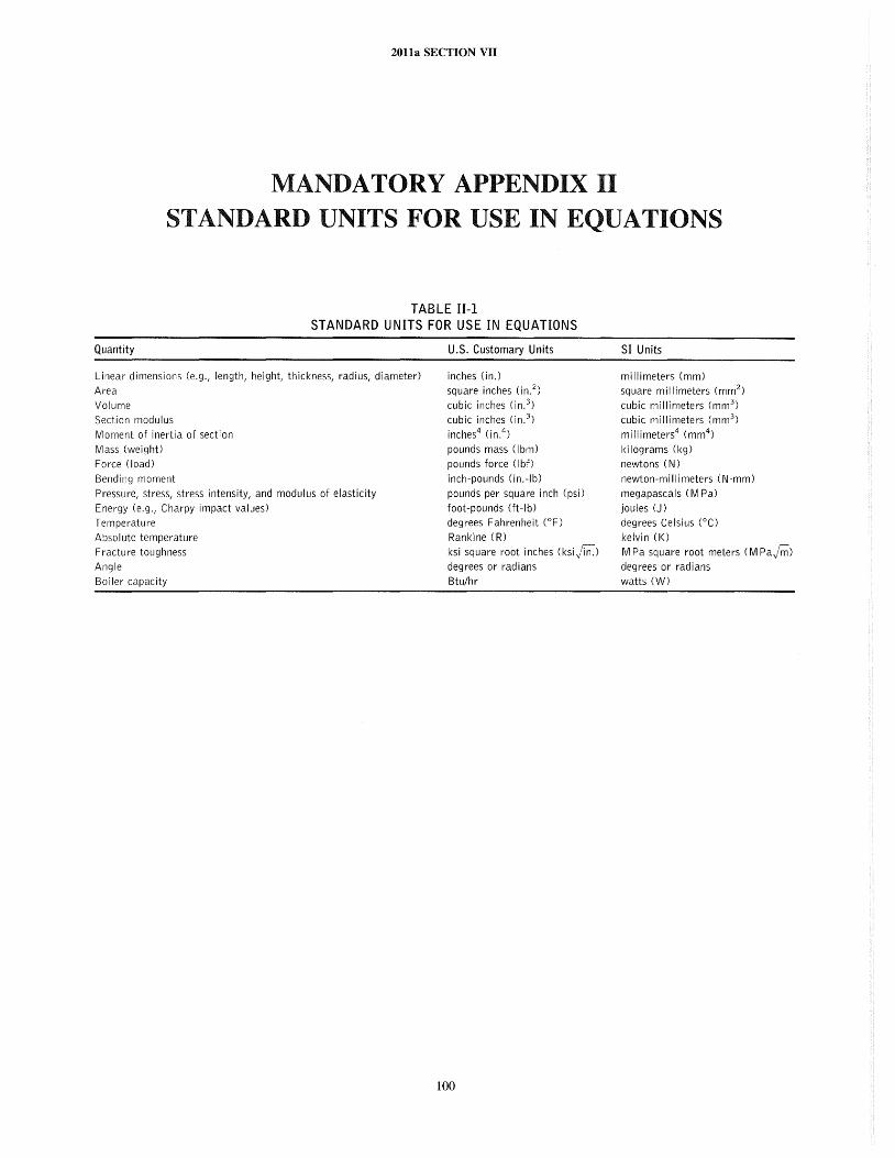
2011a SECTION VII
MANDATORY APPENDIX II STANDARD UNITS FOR USE IN EQUATIONS
TABLE II-I STANDARD UNITS FOR USE IN EQUATIONS
Quantity
Linear dimensions (e.g., length, height, thickness, radius, diameter)
Area
Volume
Section modulus
Moment of inertia of section
Mass (weight)
Force (load)
Bending moment
Pressure, stress, stress intensity, and modulus of elasticity
Energy (e.g., Charpy impact values)
Temperature
Absolute temperature
Fracture toughness
Angle
Boiler capacity
U.S. Customary Units
inches (in.)
square inches (in. 2)
cubic inches (in.3) cubic inches (in.3)
inches4 (in.4)
pounds mass (Ibm)
pounds force (Ibf)
inch-pounds (in.-Ib)
pounds per square inch (psi)
foot-pounds (ft-Ib) degrees Fahrenheit (OF)
Rankine (R)
ksi square root inches (ksijin.)
degrees or radians
Btu/hr
100
SI Units
millimeters (mm)
square millimeters (mm 2)
cubic millimeters (mm3 )
cubic millimeters (mm3 )
millimeters4 (mm4)
kilograms (kg)
newtons (N)
newton-millimeters (N·mm)
megapascals (M Pa)
joules (J)
degrees Celsius (0C)
kelvi n (I()
M Pa square root meters (M Pajri1)
degrees or radians watts (W)
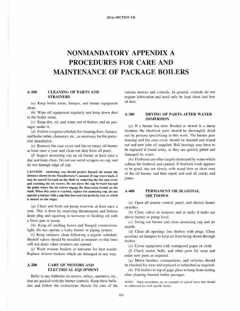
2011a SECTION VII
NONMANDATORY APPENDIX A PROCEDURES FOR CARE AND
MAINTENANCE OF PACKAGE BOILERS
A-tOO CLEANING OF PARTS AND STRAINERS
(a) Keep boiler room, furnace, and burner equipment clean.
(b) Wipe off equipment regularly and keep down dust in the boiler room.
( c) Keep dirt, oil, and water out of firebox and air passages under it.
(d) Follow a regular schedule for cleaning flues, furnace, and boiler tubes, chimneys, etc., as necessary for the particular installation.
( e) Remove fan case cover and fan on rotary oil burner at least once a year and clean out dust from all parts.
(f) Inspect atomizing cup on oil burner at least once a day and keep clean. Do not use metal scrapers on cup, and do not damage edge of cup.
CAUTION: Atomizing cup should project beyond air nozzle the distance shown in the Manufacturer's manual. If cup wears back, it may be moved forward on the shaft by removing the fan case cover and resetting the set screws. Do not move the cup forward beyond the point where the set screws engage the depression turned on the shaft. When this point is reached, replace the atomizing cup. Do not operate a burner with a cup that does not run perfectly true or which is nicked on the edges.
(g) Clean and flush out pump reservoir at least once a year. This is done by removing thermometer and bottom drain plug and squirting in kerosene or flushing oil with a force gun or pump.
(h) Keep all stuffing boxes and flanged connections tight. Do not operate a leaky burner or piping system.
(i) Keep strainers clean following a regular schedule. Shutoff valves should be installed at strainers so that lines will not drain when strainers are opened.
(j) Wash strainer baskets in kerosene for best results. Replace strainer baskets which are damaged in any way.
A-200 CARE OF MOTORS AND ELECTRICAL EQUIPMENT
Refer to any bulletins on motors, relays, operators, etc., that are packed with the burner controls. Keep these bulletins and follow the instructions therein for care of the
101
various motors and controls. In general, controls do not require lubrication and need only be kept clean and free of dust.
A-300 DRYING OF PARTS AFTER WATER IMMERSION
(a) If a burner has been flooded or stored in a damp location, the electrical parts should be thoroughly dried out by persons specializing in this work. The burner gear housing and fan case cover should be drained and wiped out and new lube oil supplied. Ball bearings may have to be replaced if found noisy, as they are quickly pitted and damaged by water.
(b) Fireboxes are often largely destroyed by water which softens the firebrick and cement. If firebrick work appears to be good, dry out slowly with wood fires or short runs of the oil burner, and then repair and seal all cracks and joints.
A-400 PERMANENT OR SEASONAL SHUTDOWN
(a) Open all remote control, panel, and electric heater switches.
(b) Close valves at strainers and at tanks if tanks are above burner or pump level.
( c) Swing out burner and clean atomizing cup and air nozzle.
(d) Close all openings into firebox with plugs. Close auxiliary air dampers to keep air from being drawn through firebox.
(e) Cover equipment with waterproof paper or cloth. (f) Check motor, belts, and other parts for wear and
order new parts as required. (g) Motor brushes, commutators, and switches should
be checked for wear and replaced or refinished as required. (h) Fill boilers to top of gage glass to keep from rusting
after cleaning internal boiler passages.
NOTE: These procedures are an example of typical items that should be addressed for each specific boiler.
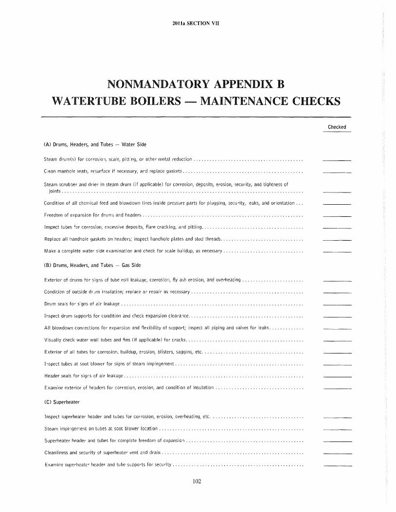
2011a SECTION VII
NONMANDATORY APPENDIX B
WATERTUBE BOILERS - MAINTENANCE CHECKS
Checked
(A) Drums, Headers, and Tubes Water Side
Steam drum(s) for corrosion, scale, pitting, or other metal reduction ........................................ .
Clean manhole seats, resurface if necessary, and replace gaskets ............................................ .
Steam scrubber and drier in steam drum (if applicable) for corrosion, deposits, erosion, security, and tightness of joints. . . . . . . . . . . . . . . . . . . . . . . . . . . . . . . . . . . . . . . . . . . . . . . . . . . . . . . . . . . . . . . . . . . . . . . . . . . .. . .......... .
Condition of all chemical feed and blowdown lines inside pressure parts for plugging, security, leaks, and orientation ...
Freedom of expansion for drums and headers. . . . . . . . . . . . . . . .. . ........................................ .
Inspect tubes for corrosion, excessive deposits, flare cracking, and pitting ..................................... .
Replace all handhole gaskets on headers; inspect handhole plates and stud threads .............................. .
Make a complete water side examination and check for scale buildup, as necessary ............................. .
(B) Drums, Headers, and Tubes - Gas Side
Exterior of drums for signs of tube roll leakage, corrosion, fly ash erosion, and overheating ...................... .
Condition of outside drum insulation; replace or repair as necessary. . . . . . . . . . . .. . .......................... .
Drum seals for signs of air leakage ................................................................... .
Inspect drum supports for condition and check expansion clearance. . . . . . . . . . . . . . . . . . . . . . . . . . . . . . . . .. . ...... .
All blowdown connections for expansion and flexibility of support; inspect all piping and valves for leaks ............ .
Visually check water wall tubes and fins (if applicable) for cracks. . ........................................ .
Exterior of all tubes for corrosion, buildup, erosion, blisters, sagging, etc ..................................... .
Inspect tubes at soot blower for signs of steam impingement. . .. . ......................................... .
Header seals for signs of air leakage. . . . . . . . . . . . . . . . . . . . . . . . . . . . . . . . . . . . . . . . . . . . .. . .................. .
Examine exterior of headers for cOrt'osion, erosion, and condition of insulation ................................ .
(C) Superheater
Inspect superheater header and tubes for corrosion, erosion, overheating, etc.
Steam impingement on tubes at soot blower location ..................................................... .
Superheater header and tubes for complete freedom of expansion. . . . . . . . . . . . . . . . . . . . . . . . . . . . . . . . . . . .. . .....
Cleanliness and security of superheater vent and drain. . . . . . .. . .......................................... .
Examine superheater header and tube supports for security. . . . . .. . ....................................... .
102
2011a SECTION VII
(0) Economizer
Interior of tubes and headers (where possible) for corrosion, oxygen pitting, and scale
Exterior of tubes and headers for corrosion, erosion, and deposits; check particularly at soot blower locations for
impingement and leakage ......................................................................... .
Cleanliness and security of vent and drain connections and valves ........................................... .
Exterior of economizer casing for leaks and tightness of access doors ........................................ .
Condition of casing insulation ....................................................................... .
Overhau I all water valves for leaks .................................................................... .
Condition of supporting steel ........................................................................ .
(E) RefractorYI Casingl and Baffles
Furnace tile, brick, and castable refractory for loose, spalled, or missing pieces ................................ .
Examine soot and ash hoppers for eroded refractory and condition of seals ................................... .
Deterioration of burner tile and signs of ftame impingement. ............................................... .
Inspect condition of supporting steelwork where visible ................................................... .
Exterior of furnace casing for bent, broken, or bowed sheets; patch Or repair as necessary ....................... .
All access doors, lancing doors, etc., for tightness; renew gaskets as required .................................. .
Test furnace for ai r leaks; seal up all leaks ............................................................. .
Check condition of all baffte tile and caulking with particular attention to signs of leakage and security of supports ....
(F) Water Columns
Gage glasses for leaks, cleanliness, and visibility ......................................................... .
Illuminators, reftectors, and mirrors for cleanliness and breakage ........................................... .
Operation and condition of gage cocks and valves; inspect chains and pulleys if used; repair or replace as necessary ....
Ensure that water column is free to expand with boiler ................................................... .
Water column connections to drums for leaks, internal deposits, and missing insulation .......................... .
Condition of high and low water alarms
(G) Feedwater Regulator
Examine valve for leaks, operability, and cleanliness; do not dismantle if operation has been satisfactory; check
connecting lines and mechanisms for functionality ...................................................... .
If overhaul is necessary, consult manufacturer's instructions before proceeding ................................. .
(H) Soot Blowers
Check alignment of all soot blower hangers and tightness of hanger bolts ..................................... .
Soot blower elements for distortion, worn hanger bearings, tube rubbing, condition of element nozzles, element
breakage, or cracking ............................................................................ .
Condition of wall boxes; they should be sealed and secure ................................................. .
Condition of moving parts, valves, and packing in soot blower head; replace packing ............................ .
Position of elements for signs of steam impingement on tubes .............................................. .
103
2011a SECTION VII
(H) Soot Blowers (Cont'd)
Each soot blower for correct blowing arc and direction of rotation .......................................... .
Pack the swivel tube gland and check swivel tubes for erosion and corrosion .................................. .
Gooseneck fittings for erosion and corrosion ............................................................ .
Supply piping and valves for leaks and general condition .................................................. .
Condition of drain piping and valves; ensure that supply piping slopes away from soot blower head ................. .
(J) Valves
Condition and operation of all feedwater, blowdown, drain, and other miscellaneous valves; replace parts as necessary and repack ..................................................................................... .
(J) Safety Valves
(The first four items should be performed only if the valve failed to perform properly during testing. Repairs must be
conducted by a qualified craftsman in accordance with manufacturer's instructions.)
Condition of valve nozzle and disk seats; lap seats in accordance with manufacturer's instructions, if required ........ .
Condition of valve internal parts for corrosion, galling, and wear; recondition or replace according to manufacturer's
instructions, if necessary .......................................................................... .
Condition of valve springs for cracking, pitting, resiliency, and end coil squareness ............................. .
Spindle for straightness and adjusting ring threads for freedom of movement .................................. .
Test operation of valves by steam pressure (on the boiler if necessary), and adjust to open and close at proper
pressures; record set pressures and blowdown ......................................................... .
Discharge and drain piping for security, condition, and allowance for boiler expansion ........................... .
(K) Windbox
Air dampers and vanes in windbox for corrosion and erosion; damper and vane operating mechanism ............... .
Windbox insulation; repair as necessary ............................................................... .
Condition and operation of all of windbox access doors, peep holes, and cover plates; check for air leaks ............ .
(U Pulverized Coal Firing
(1) Feeder
Condition of drive ................................................................................. .
Erosion and corrosion of feeder shaft and roll .......................................................... .
Erosion and leakage of feeder housing ................................................................. .
General fit of all bushings, pins, etc ................................................................... .
(2) Pulverizer
The exterior and interior of classifier housing for corrosion and leaks ........................................ .
The condition and operation of the classifier adjusting mechanism ........................................... .
Condition of grinding surfaces for excessive wear and erosion .............................................. .
The condition and operation of the grinding mechanism adjustment. ......................................... .
The condition of pressure springs ..................................................................... .
The condition of all shaft journals and bearings in the rotating parts ........................................ .
104
2011a SECTION VII
(U Pulverized Coal Firing (Cont'd) (2) Pulverizer (Cont'd)
The operation of the lubrication system ................................................................ .
Condition and repair or replace as necessary all liners and scrapers
(3) Exhauster
Coupling alignment and drive ........................................................................ .
Bearings and lubrication system ...................................................................... .
Wheel and wheel liners for erosion, corrosion, and out-of-balance condition ................................... .
Exhauster housing and liners for erosion, corrosion, and signs of leakage ..................................... .
(4) Burner
The condition of the coal nozzle for erosion, burning, and location in refractory opening ......................... .
Defiectors, impellers, and pulverized coal passage for erosion and corrosion ................................... .
Condition of the refractory throat for burned, spalled, or missing tiles ....................................... .
All coal and air piping and fianges for leaks ............................................................ .
(M) Stoker Coal Firing
(1) Underfeed Stoker
The driving mechanism of the main ram and distributing rams
The condition and operation of the main ram and distributing rams and the connecting linkage .................... .
The condition of the grate and the condition and operation of reciprocating grates .............................. .
The tuyeres for blockage and erosion and for freedom of movement where applicable ........................... .
The condition of retort channels ...................................................................... .
Condition and operation of windbox and dampers ........................................................ .
The condition and operation of clinker and ash grinding mechanism if applicable ............................... .
The condition and operation of controls on rams and windbox dampers ....................................... .
(2) Spreader Stoker
Clearance between the distributor blades and distributor tray ............................................... .
Wear on distributor blade shaft and bearings ........................................................... .
Wear on feeder and lining .......................................................................... .
C lean and check all gear cases and drives .............................................................. .
Chains and sprockets for wear ....................................................................... .
Misalignment and condition of all line shaft bearings, where applicable ...................................... .
Flow and effectiveness of cooling water through jackets on end frames ....................................... .
Condition of overfire air fan and distributor nozzles ...................................................... .
(3) Dump Grates
Condition of all grate bars and room for expansion
Condition of supporting steel for grate ................................................................. .
105
(M) Stoker Coal Firing (Cont'd)
(3) Dump Grates (Cont'd)
2011a SECTION VII
Condition of grate dumping mechanism; replace parts as necessary; check for excessive play in linkage ............. .
Condition of dampers and frames and operation of mechanism ............................................. .
Condition of fire door liners and overfire tuyeres for burning or blistering ..................................... .
(4) Traveling Grates
Clean grate and check metal parts for corrosion and erosion ............................................... .
Condition of air seals .............................................................................. .
Condition of return wearing surfaces .................................................................. .
Air leakage from windbox .......................................................................... .
Air dampers for operability and seating ................................................................ .
Damper operating mechanism for wear or excessive play .................................................. .
Condition of all stationary parts exposed to the fire for burning, blistering, etc ................................. .
Condition of shear pin mechanism for freedom of action .................................................. .
Inspect grate drive mechanism; overhaul as necessary .................................................... .
Inspect all furnace arches, walls, brick, and tile for burning, spalling, and cracking ............................. .
(N) Oil Firing
(1) Fuel Oil Pumps
Excessive clearances in driver ....................................................................... .
Excessive backlash of driver ......................................................................... .
Worn bearings in driver ............................................................................ .
Leakage ......................................................................................... .
Wear in steam cylinder and piston .................................................................... .
Wear in oil cylinder and piston ...................................................................... .
Condition of oil and steam cylinder piston rings ......................................................... .
Setting, operating, and wear of steam valves ............................................................ .
Condition and seating of oil valves .................................................................... .
Leaks from stuffing boxes and scoring of piston rods ..................................................... .
Condition of steam strainers ......................................................................... .
(2) Fuel Oil Heaters
Remove tube bundle if possible and clean off deposits on oil side ............................................ .
Inspect steam and oi I side for corrosion and erosion ...................................................... .
Freedom of vents and drains ........................................................................ .
Condition of insulation; repair as necessary .............. , .............................................. .
For tubesheet and tube leaks ........................................................................ .
Condition, operation, and setting of relief valves ......................................................... .
106
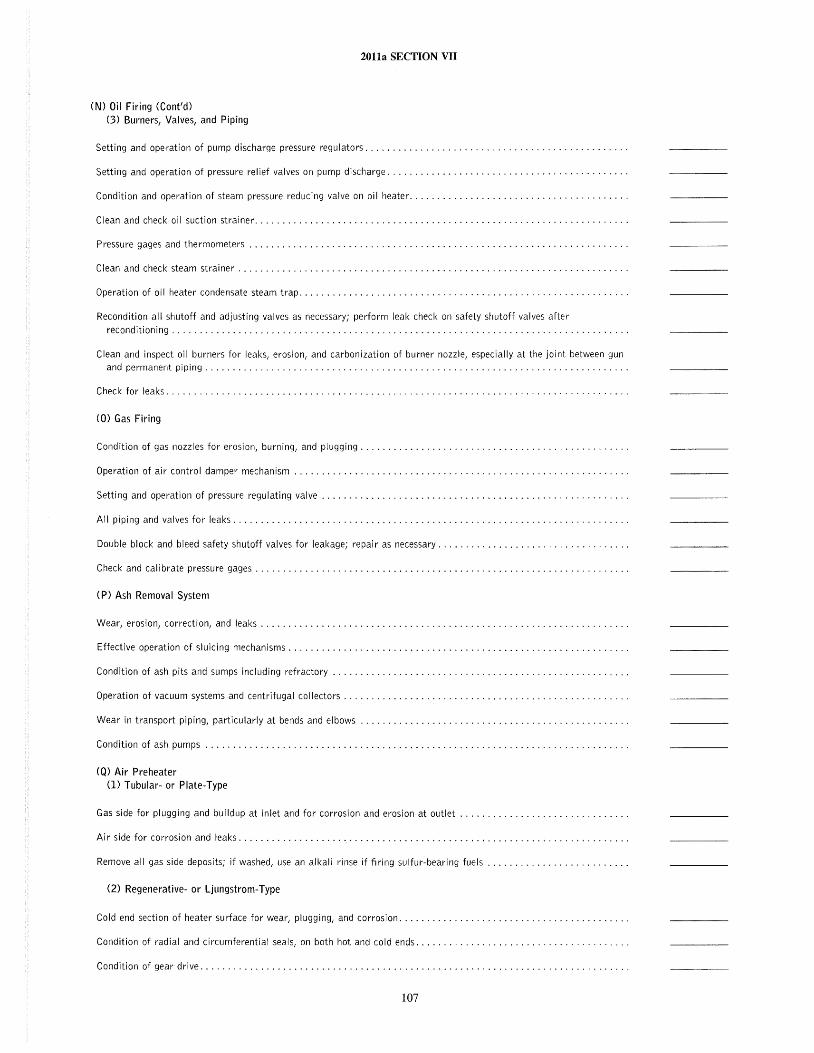
2011a SECTION VII
(N) Oil Firing (Cont'd) (3) BUl'ners, Valves, and Piping
Setting and operation of pump discharge pressure regulators ............................................... .
Setting and operation of pressure relief valves on pump discharge ........................................... .
Condition and operation of steam pressure reducing valve on oil heater ....................................... .
Clean and check oil suction strainer ................................................................... .
Pressure gages and thermometers .................................................................... .
Clean and check steam strainer ...................................................................... .
Operation of oil heater condensate steam trap ........................................................... .
Recondition all shutoff and adjusting valves as necessary; perform leak check on safety shutoff valves after
reconditioning .................................................................................. .
Clean and inspect oil burners for leaks, erosion, and carbonization of burner nozzle, especially at the joint between gun and permanent piping ............................................................................ .
Check for leaks ................................................................................... .
(0) Gas Firing
Condition of gas nozzles for erosion, burning, and plugging ........... .
Operation of air control damper mechanism. . . . . . . . . . . . . . . . . . . . . . . . . . .. . .............................. .
Setting and operation of pressure regulating valve. . . . . . . . . . . . . . . . . . . . . . . . . . . . . . . . . . . . . . . . . . . . . . . .. . .....
All piping and valves for leaks. . . . . . . . . . . . . . . . . . . . . . . . . . . . . . . . . . .. ............................... . ..
Double block and bleed safety shutoff valves for leakage; repair as necessary .................................. .
Check and calibrate pressure gages ...... .
(P) Ash Removal System
Wear, erosion, correction, and leaks .................................................................. .
Effective operation of sluicing mechanisms ............................................................. .
Condition of ash pits and sumps including refractory ..................................................... .
Operation of vacuum systems and centrifugal co Ilectors ................................................... .
Wear in transport piping, particularly at bends and elbows ................................................ .
Condition of ash pumps
(Q) Air Preheater (1) Tubular- or Plate-Type
Gas side for plugging and buildup at inlet and for corrosion and erosion at outlet .............................. .
Air side for corrosion and leaks ...................................................................... .
Remove all gas side deposits; if washed, use an alkali rinse if firing sulfur-bearing fuels ......................... .
(2) Regenerative- or Ljungstrom-Type
Cold end section of heater surface for wear, plugging, and corrosion ........... .
Condition of radial and circumferential seals, on both hot and cold ends ...................................... .
Condition of gear drive.
107
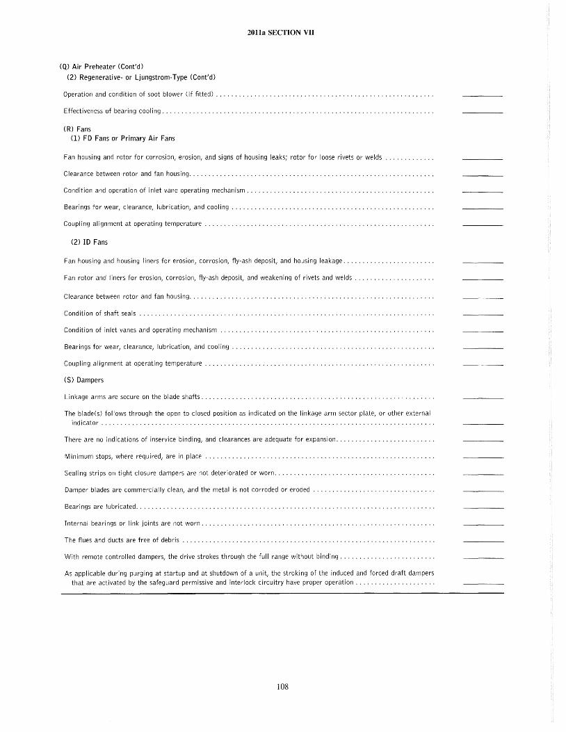
20lla SECTION VII
(Q) Air Preheater (Cont'd)
(2) Regenerative- or Ljungstrom-Type (Cont'd)
Operation and condition of soot blower (if fitted) ........................................................ .
Effectiveness of bearing cooling ...................................................................... .
(R) Fans
(1) FD Fans or Primary Air Fans
Fan housing and rotor for corrosion, erosion, and signs of housing leaks; rotor for loose rivets or welds
Clearance between rotor and fan housing ............................................................... .
Condition and operation of inlet vane operating mechanism ................................................ .
Bearings for wear, clearance, lubrication, and cooling .................................................... .
Coupling alignment at operating temperature ........................................................... .
(2) ID Fans
Fan housing and housing liners for erosion, corrosion, fty-ash deposit, and housing leakage ....................... .
Fan rotor and liners for erosion, corrosion, fty-ash deposit, and weakening of rivets and welds .................... .
Clearance between rotor and fan housing ............................................................... .
Condition of shaft seals ............................................................................ .
Condition of inlet vanes and operating mechanism ....................................................... .
Bearings for wear, clearance, lubrication, and cooling .................................................... .
Coupling alignment at operating temperature ........................................................... .
(S) Dampers
Linkage arms are secure on the blade shafts ............................................................ .
The blade(s) follows through the open to closed position as indicated on the linkage arm sector plate, or other external
indicator ...................................................................................... .
There are no indications of inservice binding, and clearances are adequate for expansion ......................... .
Minimum stops, where required, are in place ........................................................... .
Sealing strips on tight closure dampers are not deteriorated or worn ......................................... .
Damper blades are commercially clean, and the metal is not corroded or eroded ............................... .
Bearings are lubricated ............................................................................. .
Internal bearings or link joints are not worn ............................................................ .
The ftues and ducts are free of debris ................................................................. .
With remote controlled dampers, the drive strokes through the full range without binding ........................ .
As applicable during purging at startup and at shutdown of a unit, the stroking of the induced and forced draft dampers that are activated by the safeguard permissive and interlock circuitry have proper operation .................... .
108
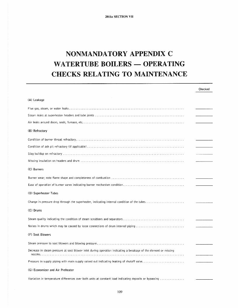
2011a SECTION VII
NONMANDATORY APPENDIX C
W ATERTUBE BOILERS - OPERATING
CHECKS RELATING TO MAINTENANCE
Checked
(A) Leakage
Flue gas, steam, or water leaks ...................................................................... .
Steam leaks at superheater headers and tube joints ...................................................... .
Air leaks around doors, seals, furnace, etc .............................................................. .
(B) Refractory
Condition of burner throat refractory .................................................................. .
Condition of ash pit refractory (if applicable) ........................................................... .
Slag buildup on refractory .......................................................................... .
Missing insulation on headers and drum
(C) Burners
Burner wear; note flame shape and completeness of combustion
Ease of operation of burner vanes indicating burner mechanism condition ..................................... .
(0) Superheater Tubes
Change in pressure drop through the superheater, indicating internal condition of the tubes ....................... .
(E) Drums
Steam quality indicating the condition of steam scrubbers and separators ..................................... .
Noises in drums which may be caused by loose connections of drum internal piping ............................. .
(F) Soot Blowers
Steam pressure to soot blowers and blowing pressure ..................................................... .
Decrease in steam pressure at soot blower inlet during operation indicating a breakage of the element or missing nozzles ........................................................................................ .
Pressure in supply piping with main supply valved out indicating leaking of shutoff valve ......................... .
(G) Economizer and Air Preheater
Variation in temperature differences over both units at constant load indicating deposits or bypassing .............. .
109
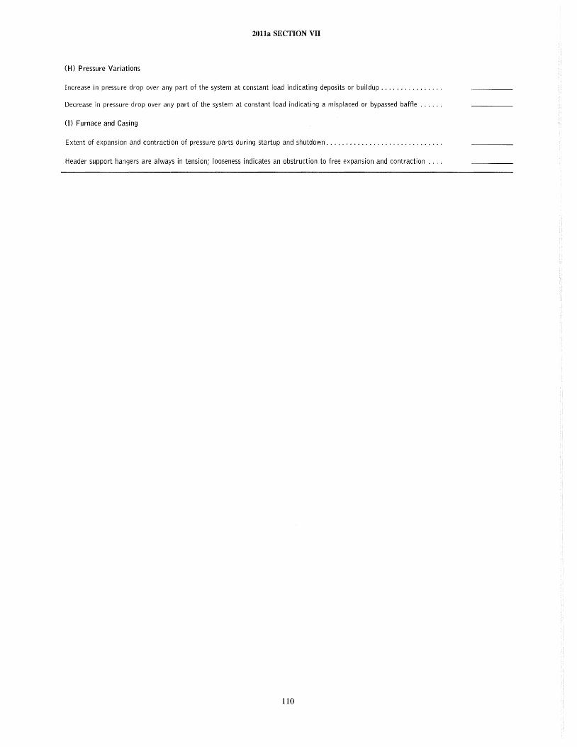
2011a SECTION VII
(H) Pressure Variations
Increase in pressure drop over any part of the system at constant load indicating deposits or buildup ............... .
Decrease in pressure drop over any part of the system at constant load indicating a misplaced or bypassed baffte ..... .
(I) Furnace and Casing
Extent of expansion and contraction of pressure parts during startup and shutdown ............................. .
Header support hangers are always in tension; looseness indicates an obstruction to free expansion and contraction ... .
110
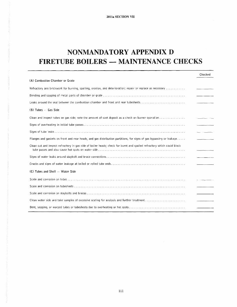
2011a SECTION VII
NONMANDATORY APPENDIX D FIRETUBE BOILERS - MAINTENANCE CHECKS
Checked
(A) Combustion Chamber or Grate
Refractory and brickwork for burning, spalling, erosion, and deterioration; repair or replace as necessary ........... .
Bending and sagging of metal parts of chamber or grate .................................................. .
Leaks around the seal between the combustion chamber and front and rear tubesheets ........................... .
(B) Tubes - Gas Side
Clean and inspect tubes on gas side; note the amount of soot deposit as a check on burner operation ............... .
Signs of overheating in initial tube passes .............................................................. .
Signs of tube leaks ................................................................................ .
Flanges and gaskets on front and rear heads, and gas distribution partitions, for signs of gas bypassing or leakage .....
Clean out and inspect refractory in gas side of boiler heads; check for burnt and spalled refractory which could block
tube passes and also cause hot spots on water side ..................................................... .
Signs of water leaks around staybolt and brace connections ................................................ .
Cracks and signs of water leakage at belled or rolled tube ends ............................................. .
(C) Tubes and Shell - Water Side
Scale and corrosion on tubes ........................................................................ .
Scale and corrosion on tubesheets .................................................................... .
Scale and corrosion on staybolts and braces ............................................................ .
Clean water side and take samples of excessive scaling for analysis and further treatment ........................ .
Bent, sagging, or warped tubes or tubesheets due to overheating or hot spots .................................. .
111
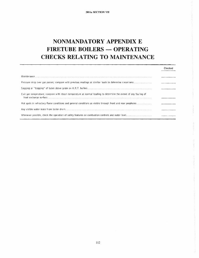
2011a SECTION VII
NONMANDATORY APPENDIX E FIRETUBE BOILERS - OPERATING
CHECKS RELATING TO MAINTENANCE
Maintenance ..................................................................................... .
Pressure drop over gas passes; compare with previous readings at similar loads to determine cleanliness ............ .
Sagging or "bagging" of tubes above grate on H.R.T. boilers ... , ............... , .......................... .
Exit gas temperature; compare with steam temperature at normal loading to determine the extent of any fouling of
heat exchange surface ............................................................................ .
Hot spots in refractory fiame conditions and general conditions as visible through front and rear peepholes .......... .
Any visible water leaks from boiler drum ............................................................... .
Whenever possible, check the operation of safety features on combustion controls and water level .................. .
112
Checked
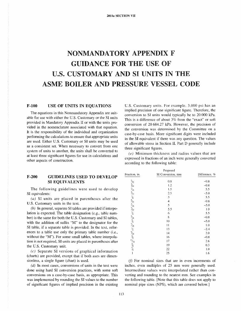
20lla SECTION VII
NONMANDATORY APPENDIX F
GUIDANCE FOR THE USE OF
U.S. CUSTOMARY AND SI UNITS IN
ASME BOILER AND P
F-I00 USE OF UNITS IN EQUATIONS
The equations in this Nonmandatory Appendix are suitable for use with either the U.S. Customary or the SI units provided in Mandatory Appendix II or with the units provided in the nomenclature associated with that equation. It is the responsibility of the individual and organization performing the calculations to ensure that appropriate units are used. Either U.S. Customary or SI units may be used as a consistent set. When necessary to convert from one system of units to another, the units shall be converted to at least three significant figures for use in calculations and other aspects of construction.
F-200 GUIDELINES USED TO DEVELOP SI EQUIVALENTS
The following guidelines were used to develop SI equivalents:
(a) SI units are placed in parentheses after the U.S. Customary units in the text.
(b) In general, separate SI tables are provided if interpolation is expected. The table designation (e.g., table number) is the same for both the U.S. Customary and SI tables, with the addition of suffix "M" to the designator for the SI table, if a separate table is provided. In the text, references to a table use only the primary table number (i.e., without the "M"). For some small tables, where interpolation is not required, SI units are placed in parentheses after the U.S. Customary unit.
(c) Separate SI versions of graphical information (charts) are provided, except that if both axes are dimensionless, a single figure (chart) is used.
(d) In most cases, conversions of units in the text were done using hard SI conversion practices, with some soft conversions on a case-by-case basis, as appropriate. This was implemented by rounding the SI values to the number of significant figures of implied precision in the existing
113
SSURE VESSEL CODE
U.S. Customary units. For example, 3,000 psi has an implied precision of one significant figure. Therefore, the conversion to SI units would typically be to 20 000 kPa. This is a difference of about 3% from the "exact" or soft conversion of 20 684.27 kPa. However, the precision of the conversion was determined by the Committee on a case-by-case basis. More significant digits were included in the SI equivalent if there was any question. The values of allowable stress in Section II, Part D generally include three significant figures.
(e) Minimum thickness and radius values that are expressed in fractions of an inch were generally converted according to the following table:
Proposed Fraction, in. SI Conversion, mm Difference, %
0.8 -0.8 1.2 -0.8 1.5 5.5 2.5 -5.0 3 5.5 4 -0.8 5 -5.0 5.5 1.0 6 5.5 8 -0.8
10 -5.0 11 1.0 13 -2.4 14 2.0 16 -0.8 17 2.6 19 0.3 22 1.0 25 1.6
(f) For nominal sizes that are in even increments of inches, even multiples of 25 mm were generally used. Intermediate values were interpolated rather than converting and rounding to the nearest mm. See examples in the following table. [Note that this table does not apply to nominal pipe sizes (NPS), which are covered below.]
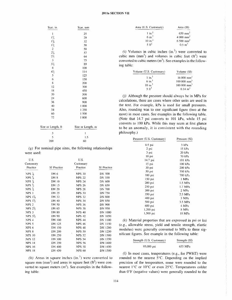
2011a SECTION VII
Size, in. Size, mm
25
1Ys 29 1~ 32 l~ 38 2 50 2~ 57 2~ 64 3 75 3~ 89 4 100 4~ 114 5 125 6 150 8 200 12 300 18 450 20 500 24 600 36 900 40 1000 54 1350 60 1500 72 1800
Size or Length, ft Size or Length, m
3 5 1.5
200 60
(g) For nominal pipe sizes, the following relationships were used:
U.S. Customary
Practice
NPS Ys NPS ~ NPS Ys NPS ),s NPS ~ NPS I NPS 1%t NPS 1~ NPS 2 NPS 2~ NPS 3 NPS 3~ NPS 4 NPS 5 NPS 6 NPS 8 NPS 10 NPS 12 NPS 14 NPS 16 NPS 18
S] Practice
ON 6 ON 8 ON 10 ON 15 ON 20 ON 25 ON 32 ON 40 ON 50 ON 65 ON 80 ON 90 ON 100 ON 125 ON ISO ON 200 ON 250 ON 300 ON 350 ON 400 ON 450
U.S. Customary
Practice SI Practice
NPS 20 ON 500 NPS 22 ON 550 NPS 24 ON 600 NPS 26 ON 650 NPS 28 ON 700 NPS 30 ON 750 NPS 32 ON 800 NPS 34 ON 850 NPS 36 ON 900 NPS 38 ON 950 NPS 40 ON 1000 NPS 42 ON 1050 NPS 44 ON 1100 NPS 46 ON 1150 NPS 48 ON 1200 NPS 50 ON 1250 NPS 52 ON 1300 NPS 54 ON 1350 NPS 56 ON 1400 NPS 58 ON 1450 NPS 60 ON 1500
(h) Areas in square inches (in. 2) were converted to
square mm (mm2) and areas in square feet (ft2) were conveIted to square meters (m2
). See examples in the following tab1e:
114
Area (U.S. Customary)
1 in? 6 in.2
10 in. 2
5 ft2
Area (Sf)
650 mm2
4000 mm2
6500 mm2
0.5 m2
(i) Volumes in cubic inches (in?) were converted to cubic mm (mm3) and volumes in cubic feet (ft3) were converted to cubic meters (m\ See examples in the following table:
Volume (U.S. Customary)
1 in.3
6 in? 10 in.3
5 fe
Volume (SI)
16000 mm3
100000 mm3
160000 mm3
0.14 m3
(j) Although the pressure should always be in MPa for calculations, there are cases where other units are used in the text. For example, kPa is used for small pressures. Also, rounding was to one significant figure (two at the most) in most cases. See examples in the following table. (Note that 14.7 psi converts to 101 kPa, while 15 psi converts to 100 kPa. While this may seem at first glance to be an anomaly, it is consi stent with the rounding philosophy.)
Pressure (U.S. Customary) Pressure (SI)
0.5 psi 3 kPa 2 psi 15 kPa 3 psi 20 kPa 10 psi 70 kPa
14.7 psi 101 kPa 15 psi 100 kPa 30 psi 200 kPa 50 psi 350 kPa 100 psi 700 kPa 150 psi 1 MPa 200 psi L.5 MPa 250 psi 1.7 MPa 300 psi 2 MPa 350 psi 2.5 MPa 400 psi 3 MPa 500 psi 3.5 MPa 600 psi 4MPa
1,200 psi 8 MPa 1,500 psi 10 MPa
(k) Material properties that are expressed in psi or ksi (e.g., allowable stress, yield and tensile strength, elastic modulus) were generally converted to MPa to three significant figures. See example in the following table:
Strength (U.S. Customary)
95,000 psi
Strength (SI)
655 MPa
(l) In most cases, temperatures (e.g., for PWHT) were rounded to the nearest 5°C. Depending on the implied precision of the temperature, some were rounded to the nearest 1°C or 10°C or even 25°C. Temperatures colder than O°F (negative values) were generally rounded to the
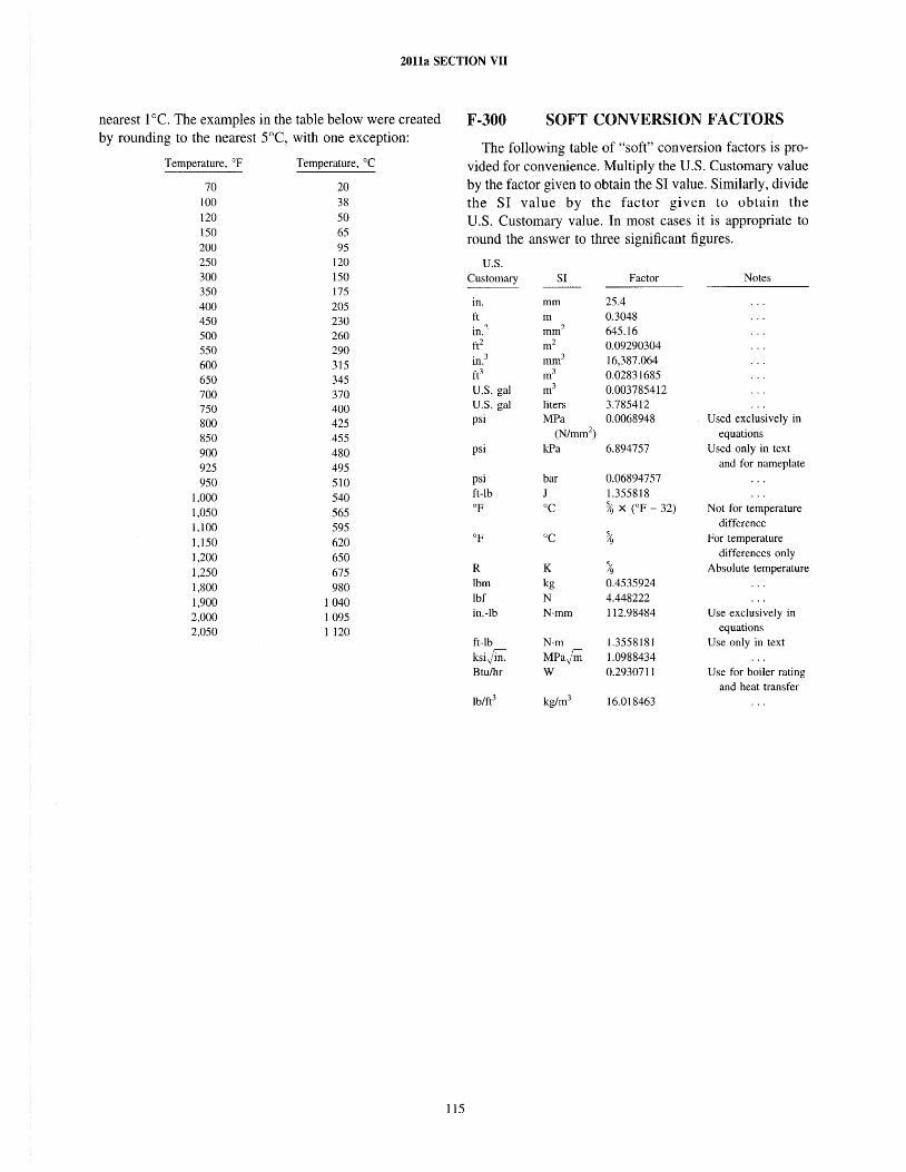
2011a SECTION VII
nearest laC. The examples in the table below were created by rounding to the nearest SoC, with one exception:
Temperature, of
70
100
120 150 200 250 300 350 400 450 500 550 600 650 700 750 800 850
900 925 950
1,000
1,050 1,100
1,150 1,200 1,250 1,800 1,900 2,000 2,050
Temperature, °C
20 38
50 65 95
120 150 175 205 230 260 290 315 345 370 400 425 455
480 495
510 540
565 595 620 650 675 980
1040 1095 1 120
115
F-300 SOFT CONVERSION FACTORS
The following table of "soft" conversion factors is provided for convenience. Multiply the U.S. Customary value by the factor given to obtain the SI value. Similarly, divide the SI value by the factor given to obtain the U.S. Customary value. In most cases it is appropriate to round the answer to three significant figures.
u.s. Customary
in. ft in.2
ft2
in.3
ft3
U.S. gal U.S. gal psi
psi
psi ft-lb OF
R Ibm lbf in.-Ib
ft-Ib
ksi~ Btu/hr
SI
mm m mm2
m2
mm3
m3
m3
liters MPa
(N/mm2)
kPa
bar J °C
K kg N N'mm
N·m
MParm W
Factor
25.4 0.3048 645.16 0.09290304 16,387.064 0.02831685 0.003785412 3.785412 0.0068948
6.894757
0.06894757 1.355818 % x (OF - 32)
% 0.4535924 4.448222 112.98484
1.3558181
1.0988434 0.2930711
16.018463
Notes
Used exclusively in
equations Used only in text
and for nameplate
Not for temperature difference
For temperature differences only
Absolute temperature
Use exclusively in
equations Use only in text
Use for boiler rating and heat transfer
2011a SECTION VII
GLOSSARY
(A) Boilers and General Terms
absolute pressure: pressure above zero pressure, the sum of the gage and atmospheric pressures.
air purge: the removal of undesired gaseous matter by replacement with air.
alteration: a change in any item described in the original Manufacturer's Data Report that affects the pressure containing capability of the boiler.
ambient temperature: the temperature of the air surrounding the equipment.
Authorized Inspection Agency: a jurisdiction that has adopted and does administer one or more Sections of the ASME Boiler and Pressure Vessel Code as a legal requirement and has a representative serving as a member of the ASME Conference Committee, or an insurance company that has been licensed or registered by appropriate authority of a state of the United States or a province of Canada to write boiler and pressure vessel insurance in such a state or province.
Authorized Inspector: an Inspector who holds a valid National Board Commission, who has qualified by written examination under the laws, rules, and regulations of a jurisdiction of a state of the United States or a province of Canada, and who is regularly employed as an Inspector by an Authorized Inspection Agency.
baffle: a plate or wall for deflecting gases or liquids.
beaded tube end: the rounded exposed end of a rolled tube when the tube metal is formed over against the sheet in which the tube is rolled.
blowdown: the water removed under pressure from the boiler to eliminate sediment and reduce total solids. Normally this is a continuous process.
blowoff: a pipe connection provided with valves located in the boiler external piping through which the water in the boiler may be blown out under pressure.
boiler: a vessel in which steam or other vapor is generated for use external to itself.
(a) firetube: a boiler with straight tubes that are surrounded by water and steam and through which the products of combustion pass.
116
(b) watertube: a boiler in which the tubes contain water and steam, the heat being applied to the outside surface.
boiler layup: any extended period of time during which the boiler is not expected to operate and suitable precautions are made to protect it against corrosion, scaling, pitting, etc., on the water and fire sides.
boiler trim: piping on or near the boiler that is used for safety, limit and operating controls, gages, water column, etc.
breeching: a duct for the transport of the products of combustion between the boiler and the stack.
buckstay: a structural member placed against a furnace or boiler wall to restrain the motion of the wall.
buckstay spacer: a spacer for separating a pair of channels that are used as a buckstay.
casing: a covering of sheets of metal or other material, such as fire-resistant composition board, used to enclose all or a portion of a boiler or furnace.
cleanout door: a door placed so that accumulated refuse may be removed from a boiler setting.
condensate: condensed water resulting from the removal of latent heat from steam.
control: any manual or automatic device for the regulation of a machine to keep it at normal operation. If automatic, the device is motivated by variations in temperature, pressure, water level, time, light, or other influences.
convection: the transmission of heat by the circulation of a liquid or a gas such as air. Convection may be natural or forced.
damper: a device for introducing a variable resistance for regulating the volumetric flow of gas or air.
(a) butterfly type: a blade damper pivoted about its center.
(b) curtain type: a damper composed of flexible material moving in a vertical plane as it is rolled.
( c) flap type: a damper consisting of one or more blades each pivoted about one edge.
2011a SECTION VII
(d) louver type: a damper consisting of several blades each pivoted about its center and linked together for simultaneous operation.
(e) slide type: a damper consisting of a single blade that moves substantially normal to the flow.
design load: the load [lb/hr (kg/hr)] for which a boiler is designed, usually considered the maximum load to be carried.
design pressure: the maximum allowable working pressure permitted under the rules of Section 1.
diaphragm: a partition of metal or other material placed in a header, duct, or pipe to separate portions thereof.
downcomer: a tube in a boiler or waterwall system through which fluid flows downward.
drain: a valved connection at the lowest point for the removal of water.
drum: a cylindrical shell closed at both ends designed to withstand internal pressure.
drum baffle: a plate or series of screens placed within a drum to divert or change the direction of the flow of water or water and steam.
drum head: a plate closing the end of a boiler drum or shell.
efficiency: the ratio of output to the input. The efficiency of a boiler is the ratio of the heat absorbed by water and steam to the heat in the fuel fired.
ejector: a device that utilizes the kinetic energy in a jet of water or other fluid to remove a fluid or fluent material from tanks or hoppers.
electric boiler: a boiler in which the electric heating serves as the source of heat.
equalizer line: piping between parts of a boiler to equalize pressures.
expander: the tool used to expand tubes.
expansion joint: a joint that permits movement due to expansion without undue stress.
extended sulface: metallic heat absorbing surface protruding beyond the tube walL
feed pipe: a pipe through which water is conducted into a boiler.
ferrule: a short metallic ring rolled into a tube hole to decrease its diameter; also, a short metallic ring rolled inside of a rolled tube end; also, a short metallic ring for making up handhole joints.
117
fin: a strip of steel welded longitudinally to a tube.
fin tube: a tube with one or more fins.
firetube: a tube in a boiler having water on the outside and carrying the products of combustion on the inside.
flame plate: a baffle of metal or other material for directing gages of combustion.
flared tube end: the projecting end of a rolled tube that is expanded or rolled to a conical shape.
float switch: a float operated switch that makes and breaks an electric circuit in accordance with a change in a predetermined water level.
furnace: an enclosed space provided for the combustion of fuel.
fusible plug: a hollowed threaded plug having the hollowed portion filled with a low melting point material, usually located at the lowest permissible water level.
gage cock: a valve attached to a water column or drum for checking the water level.
gage glass: the transparent part of a water gage assembly connected directly or through a water column to the boiler, below and above the waterline, to indicate the water level in the boiler.
gage pressure: the pressure above atmospheric pressure.
generating tube: a tube in which steam is generated.
grooved tube seat: a tube seat having one or more shallow grooves into which the tube may be forced by the expander.
hairpin tube: a tube bent to the shape of a hairpin.
handhole: an opening in a pressure part for access, usually not exceeding 6 in. (150 mm) in longest dimension.
header: piping that connects two or more boilers together. It may be either supply or return piping.
heat balance: an accounting of the distribution of the heat input and output.
heat exchanger: a vessel in which heat is transferred from one medium to another.
heating sulface: that surface that is exposed to the heating medium for absorption and transfer of heat to the heated medium.
hydrostatic test: a strength and tightness test of a closed pressure vessel by water pressure.
2011a SECTION VII
impingement: the striking of moving matter, such as the flow of steam, water, gas, or solids, against similar or other matter.
inspection door: a small door located in the outer enclosure so that certain parts of the interior of the apparatus may be observed.
insulation: a material of low thermal conductivity used to reduce heat losses.
joint: a separable or inseparable juncture between two or more materials.
jurisdiction: any city of the United States having a population of one million or more or any state of the United States or any province of Canada that has adopted and does administer one or more Sections of the ASME Boiler and Pressure Vessel Code as a legal requirement.
lagging: a covering, usually of insulating material, on pipe or ducts.
lance door: a door through which a hand lance may be inserted for cleaning heating surfaces.
lever valve: a quick-operating valve operated by a lever that travels through an arc not greater than 180 deg.
l~ft assist device: a calibrated force generating device that can be used to apply supplemental force to a valve spindle and result in a net reactive force equivalent to the valve set pressure. The lift assist device is an instrument requiring calibration at least once a year (or more frequently where actual calibration identifies the necessity).
ligament: the minimum cross section of solid metal in a header, shell, or tubesheet between two adjacent holes.
load: the rate of output, lb/hr (kg/hr) of steam.
loadfactor: the ratio of the average load in a given period to the design load of the boiler.
low water fuel cutoff: a device that shuts down the fuel supply when the water level in the boiler drops below its operating level.
lowest safe waterline: that water level in the boiler below which the burner is not allowed to operate.
lug: any projection, such as an ear, used for supporting or grasping.
manhead: the head of a boiler drum or other pressure vessel having a manhole.
manhole: the opening in a pressure vessel of sufficient size to permit a man to enter.
118
manifold: a pipe or header for collecting a fluid from, or the distributing of a fluid to, a number of pipes or tubes.
maximum allowable working pressure: the maximum pressure determined by employing the allowable stress values, design rules, and dimensions provided in Section I (see Section I, PG-21).
mud leg: see water leg.
operating water level: in a steam boiler, the maintained water level that is above the lowest safe water level.
package boiler: a boiler equipped and shipped complete with fuel burning equipment, mechanical draft equipment, automatic controls, and accessories.
pass: a confined passageway, containing heating surface, through which a gas flows in essentially one direction.
peak load: the maximum load [Ib/hr (kg/hr)] carried for a stated short period of time.
peepdoor: a small door usually provided with a shielded glass opening through which combustion may be observed.
peephole: a small hole in a door covered by a movable cover.
pitch: the distance between centerlines of tubes, rivets, staybolts, or braces.
plant inspector: an individual who is knowledgeable by education and experience with the construction, operation, inspection, and maintenance procedures for power boilers. He should be designated by the plant manager.
plate baffle: a metal baffle.
platen: a plane surface receiving heat from both sides and constructed with a width of one tube and a depth of two or more tubes, bare or with extended surfaces.
pneumatic control: any control that uses compressed air as the actuating means.
popping pressure: the value of increasing inlet static pressure at which the disk moves in the opening direction at a faster rate as compared with corresponding movement at higher or lower pressures.
port: an opening through which fluid passes.
power boiler: a boiler in which steam or other vapor is generated at a pressure of more than 15 psi (100 kPa) for use external to itself.
pressure: force per unit of area.
pressure drop: the difference in pressure between two points.
2011a SECTION VII
pressure-expanded joint: a tube joint in a drum, header, or tubesheet expanded by a tool that forces the tube wall outward by driving a tapered pin into the center of a sectional die.
pressure vessel: a closed vessel or container designed to confine a fluid at a pressure above atmospheric.
pulsation: rapid fluctuations in furnace pressure.
rated capacity: the maximum continuous capacity in pounds of steam per hour for which a boiler is designed.
rating: see load.
receiver: the tank portion of a condensate or vacuum return pump where condensate accumulates.
recessed tube wall: a refractory furnace wall with slots in which waterwall tubes are placed so that the tubes are partially exposed to the furnace.
recirculation: the reintroduction of part of the flowing fluid to repeat the cycle of circulation.
refractory baffle: a baffle of refractory material.
relief valve: an automatic pressure relieving device, actuated by the static pressure upstream of the valve, which opens further with the increase in pressure over the opening pressure. It is used primarily for liquid service.
repair: the work necessary to restore a boiler to a safe and satisfactory operating condition, provided there is no deviation from the original design.
retarder: a straight or helical strip inserted in a firetube primarily to increase the turbulence.
rifled tube: a tube that is helically grooved on the inner wall.
rolled joint: a joint made by expanding a tube into a hole by a roller expander.
saddle: a casting, fabricated chair, or member used for the purpose of support.
safety relief valve: an automatic pressure-actuated relieving device suitable for use either as a safety valve or relief valve, depending on application.
safety valve: an automatic pressure relieving device actuated by the static pressure upstream of the valve and characterized by full-opening pop action. It is used for gas or vapor service.
sampling: the removal of a portion of material for examination or analysis.
seal: a device to close openings between structures to prevent leakage.
119
seal weld: a weld used primarily to obtain tightness and prevent leakage.
seam: the joint between two plates riveted together.
separator: a device for sorting and dividing one substance from another.
shell: the cylindrical portion of a pressure vessel.
shutoff valve: see stop valve.
slip seal: a seal between members designed to permit movement of either member by slipping or sliding.
spalling: the breaking off of the surface of refractory material as a result of internal stresses.
spun ends: the ends of tubes or pipes closed by rolling while heated.
stay: a tensile stress member to hold material or other members rigidly in position.
staybolt: a bolt threaded through or welded at each end, into two spaced sheets of a firebox or box header to support flat surfaces against internal pressure.
steam dome: a receptacle riveted or welded to the top sheet of a firetube boiler through and from which the steam is taken from the boiler.
steam gage: a gage for indicating the pressure of steam.
stop valve: valve (usually gate type) that is used to isolate a boiler from the other parts.
strainer, condensate: mechanical means (screen) ofremoving solid material from the condensate before it reaches the pump.
strength weld: a weld capable of withstanding a design stress.
stub tube: a short tube welded to a pressure part for field extension.
stud: a projecting pin serving as a support or means of attachment.
stud tube: a tube having short studs welded to it.
swinging load: a load that changes at relatively short intervals.
through-stay: a brace used in firetube boilers between the heads or tubesheets.
tie plate: a plate through which a bolt or tie rod is passed to hold brick in place.
2011a SECTION VII
tie rod: a tension member between buckstays or tie plates.
tile: a preformed, burned refractory, usually applied to shapes other than standard brick.
tile baffle: a baffle formed of preformed burned refractory shapes.
trap: a device installed in steam piping that is designed to prohibit the passage of steam but allow the passage of condensate and air.
try cock: see gage cock.
tube: a hollow cylinder for conveying fluids.
tube door: a door in a boiler or furnace wall through which tubes may be removed or new tubes passed.
tube hole: a hole in a drum, header, or tubesheet to accommodate a tube.
tube plug: a solid plug driven into the end of a tube.
tubesheet: the plate containing the tube holes.
uptake: vertical smoke outlet from a boiler before it connects to the breeching.
vent: an opening in a vessel or other enclosed space for the removal of gas or vapor.
waste heat: sensible heat in noncombustible gases, such as gases leaving furnaces used for processing metals, ores, or other materials.
water column: a vertical tubular member connected at its top and bottom to the steam and water space, respectively, of a boiler, to which the water gage, gage cocks, and high and low level alarms may be connected.
water gage: the gage glass and its fittings for attachment.
water leg: water cooled sides of a firebox-type boiler. Sometimes called mud leg because solids that accumulate have a tendency to settle there.
water level: the elevation of the surface of the water in a boiler.
water tube: a tube in a boiler having the water and steam on the inside and heat applied to the outside.
(B) Fuels, Fuel Burning Equipment, and Combustion
air: the mixture of oxygen, nitrogen, and other gases that, with varying amounts of water vapor, forms the atmosphere of the earth.
air, saturated: air that contains the maximum amount of water vapor that it can hold at its temperature and pressure.
120
air atomizing oil burner: a burner for firing oil in which the oil is atomized by compressed air that is forced into and through one or more streams of oil, breaking the oil into a fine spray.
air deficiency: insufficient air, in an air-fuel mixture, to supply the oxygen theoretically required for complete oxidation of the fuel.
air-fuel ratio: the ratio of the weight of air to fuel.
air infiltration: the leakage of air into a setting or duct.
air moisture: the water vapor suspended in the air.
ambient air: the air that surrounds the equipment. The standard ambient air for performance calculations is air at 80°F (27°C), 60% relative humidity, and a barometric pressure of 29.92 in. Hg (101 kPa).
aspirating burner: a burner in which the fuel in a gaseous or atomized form is burned in suspension, the air for combustion being supplied by bringing it into contact with the fuel. Air is drawn through one or more openings by the lower static pressure created by the velocity of the fuel stream.
atmospheric air: air under the prevailing atmospheric conditions.
atmospheric pressure: the barometric reading of pressure exerted by the atmosphere: at sea level 14.7 Ib/in.2 or 29.92 in. Hg (101 kPa).
atomizer: a device by means of which a liquid is reduced to a very fine spray.
automatic lighter: a means for starting igmtIOn of fuel without manual intervention; usually applied to liquid, gaseous, or pulverized fuel.
available draft: the draft that may be utilized to cause the flow of air for combustion or the flow of products of combustion.
axial fan: consists of a propeller or disk-type of wheel within a cylinder that discharges the air parallel to the axis of the wheel.
balanced draft: the maintenance of a fixed value of draft in a furnace at all combustion rates by control of incoming air and outgoing products of combustion.
barometric pressure: atmospheric pressure as determined by a barometer, usually expressed in inches of mercury.
blower: a fan used to force air under pressure.
bunker oil: residual fuel oil of high viscosity commonly used in marine and stationary steam power plants (No. 6 fuel oil).
2011a SECTION VII
burner: a device for the introduction of fuel and air into a furnace at the desired velocities, turbulence, and concentration to establish and maintain proper ignition and combustion of the fuel.
burner windbox: a plenum chamber around a burner in which an air pressure is maintained to ensure proper distribution and discharge of combustion air.
carbon: the element that is the principal combustible constituent of all fuels.
carbonization: the process of converting coal to carbon by removing other ingredients.
centrifugal fan: consists of a fan rotor or wheel within a scroll-type of housing, which discharges the air at a right angle to the axis of the wheel.
circular burner: a liquid, gaseous, or pulverized fuel burner having a circular opening through the furnace wall.
coal: solid hydrocarbon fuel formed by ancient decomposition of woody substance under conditions of heat and pressure.
coal burner: a burner for use with pulverized coal.
coal gas: gas formed by the destructive distillation of coal.
coal tar: black viscous liquid, one of the bypro ducts formed by distillation of coal.
coke: fuel consisting largely of the fixed carbon and ash in coal obtained by the destructive distillation of bituminous coal.
coke breeze: fine coke screenings usually passing a ~ in. (13 mm) or % in. (19 mm) screen opening.
coke oven gas: gas produced by destructive distillation of bituminous coal in closed chambers. The heating value is 500 Btulft3 to 550 Btu/ft3 (18 600 kJ/m3 to 20 500 kJ/m3).
coke oven tar: see coal tar.
coking: the conversion by heating in the absence or near absence of air of a carbonaceous fuel, particularly certain bituminous coals, to a coherent, firm, cellular carbon product known as coke.
colloidal fuel: mixture of fuel oil and powdered solid fuel.
combustible: the heat producing constituent of a fuel.
combustible loss: the loss representing unliberated thermal energy by failure to oxidize completely some of the combustible matter in the fuel.
121
combustion: the rapid chemical combustion of oxygen with the combustible elements of a fuel resulting in the production of heat.
combustion rate: the quantity of fuel fired per unit of time, such as lb (kg) of coal per hour or cubic foot (cubic meter) of gas per minute.
complete combustion: the complete oxidation of all the combustible constituents of a fuel.
cracked residue: the fuel residue obtained by cracking crude oils.
cracking: the thermal decomposition of complex hydrocarbons into simpler compounds of elements.
crude oil: unrefined petroleum.
damper loss: the reduction in the static pressure of a gas flowing across a damper.
delayed combustion: a continuation of combustion beyond the furnace (see also secondary combustion).
dew point: the temperature at which condensation starts.
distillate fuels: liquid fuels distilled usually from crude petroleum, except residuals such as No.5 and No.6 fuel oil.
distillation: vaporization of a substance with subsequent recovery of the vapor by condensation. Often used in a less precise sense to refer to vaporization of volatile constituents of a fuel without subsequent condensation.
draft: the difference between atmospheric pressure and some lower pressure existing in the furnace or gas passages of a furnace.
draft differential: the difference in static pressure between two points in a system.
draft gage: a device for measuring draft, usually in inches of water.
draft loss: the drop in the static pressure of a gas between two points in a system caused by resistances to flow.
dual flow oil burner: a burner having an atomizer, usually mechanical, having two sets of tangential slots, one set being used for low capacities and the other set for high capacities.
duct: a passage for air or gas flow.
electric ignition: ignition of a pilot or main flame by the use of an electric arc or glow plug.
excess air: air supplied for combustion in excess of that theoretically required for complete oxidation.
2011a SECTION VII
exhauster: a fan used to withdraw air or gases under suction.
explosion: combustion that proceeds so rapidly that high pressure is generated suddenly.
external mix oil burner: a burner having an atomizer in which the liquid fuel is struck, after it has left an orifice, by a jet of high velocity steam or air.
fan: a machine consisting of a rotor and housing for moving air or gases at relatively low pressure differentials.
fire point: the lowest temperature at which, under specified conditions, fuel oil gives off enough vapor to burn continuously when ignited.
fixed carbon: the carbonaceous residue, less the ash, remaining in the test container after the volatile matter has been driven off in making the proximate analysis of a solid fuel.
fixed grate: a grate that does not have movement.
flame: a luminous body of burning gas or vapor.
flame detector: a device that senses the presence or absence of flame, and normally provides a signal to terminate fuel supply on loss of flame.
(a) electronic: electrode used in flame rectification system that detects pilot and main flame and prevents fuel flow if pilot is not detected or stops fuel flow if main flame is not detected. Response time is I sec to 4 sec. Suitable for large programmed installations.
(b) photo cell, ultraviolet, or infrared: used to observe the pilot and main flame and provide the same safeguard features as the electrode-type detector.
(c) thermal: bimetallic strip thermocouple that is located in the pilot flame. If the pilot goes out, a circuit is broken, and the fuel valve is shut. Response time is 1 min to 3 min. Suitable for small installations.
flammability: susceptibility to combustion.
flare back: a burst of flame from a furnace in a direction opposed to the normal flow, usually caused by the ignition of an accumulation of combustible gases.
flare-type burner: a circular burner from which the fuel and air are discharged in the form of a cone.
flash point: the lowest temperature at which, under specified conditions, fuel oil gives off enough vapor to flash into momentary flame when ignited.
flat-flamed burner: a burner terminating in a substantially rectangular nozzle, from which fuel and air are discharged in a flat stream.
122
flue: a passage for products of combustion.
flue gas: the gaseous products of combustion in the flue to the stack.
forced draft fan: a fan supplying air under pressure to the fuel burning equipment.
forced draft stoker: a stoker in which the flow of air through the grate is caused by a pressure produced by mechanical means.
front discharge stoker: a stoker so arranged that refuse is discharged from the grate surface at the same end as the coal feed.
fuel: a substance containing combustible material used for generating heat.
fuel-air mixture: mixture of fuel and air.
fuel-air ratio: the ratio of the weight of fuel to air.
fuel bed: layer of burning fuel on a furnace grate.
fuel oil: a liquid fuel derived from petroleum or coal.
furnace draft: the draft in a furnace, measured at a point immediately in front of the highest point at which the combustion gases leave the furnace.
gas analysis: the determination of the constituents of a gaseous mixture.
gas burner: a burner for use with gaseous fuel.
grate: the surface on which fuel is supported and burned, and through which air is passed for combustion.
grate bars: those parts of the fuel supporting surface arranged to admit air for combustion.
gravity: weight index of fuels: liquid petroleum products expressed either as specific, Baume, or API (American Petroleum Institute) gravity; weight index of gaseous fuels as specific gravity related to air under specified conditions; or weight index of solid fuels as specific gravity related to water under specified conditions.
hand-fired grate: a grate on which fuel is placed manually, usually by means of a shovel.
horizontal firing: a means of firing liquid, gaseous, or pulverized fuel, in which the burners are so arranged in relation to the furnace as to discharge the fuel and air into the furnace in approximately a horizontal direction.
hydrocarbon: a chemical compound of hydrogen and carbon.
2011a SECTION VII
ignition: the initiation of combustion.
ignition temperature: lowest temperature of a fuel at which combustion becomes self-sustaining.
ignitor: a device that provides adequate ignition energy to immediately light-off the main burner.
impeller: as applied to pulverized coal burners, a round metal device located at the discharge of the coal nozzle in circular-type burners, to deflect the fuel and primary air into the secondary air stream. As applied to oil burners, same as diffuser.
inches water gage (w.g.): usual term for expressing a measurement of relatively low pressures or differentials by means of aU-tube: 1 in. w.g. equals 5.2 Ib/ft2 or 0.036 Iblin.2 (0.25 kPa).
incomplete combustion: the partial oxidation of the combustible constituent of a fuel.
induced draft fan: a fan exhausting hot gases from the heat absorbing equipment.
inert gaseous constituents: incombustible gases such as nitrogen that may be present in a fuel.
integral blower: a blower built as an integral part of a device to supply air thereto.
integral blower burner: a burner of which the blower is an integral part.
intermittent firing: a method of firing by which fuel and air are introduced into and burned in a furnace for a short period, after which the flow is stopped. The cycle is then repeated.
internal mix oil burner: a burner having a mixing chamber in which high velocity steam or air impinges on jets of incoming liquid fuel that is then discharged in a completely atomized form.
intertube burner: a burner that terminates in nozzles discharging between adjacent tubes.
lighting off torch: a torch used for igniting fuel from a burner consisting of a small oil or gas burner.
lignite: a consolidated coal of low classification according to rank: moist (bed moisture only), Btu less than 8,300 (8800 kJ).
long flame burner: a burner in which the fuel emerges in such a condition, or one in which the air for combustion is admitted in such a manner, that the two do not readily mix, resulting in a comparatively long flame.
123
manometer: device used to detect small changes in pressure, usually a tube with water, the pressure variations measured in inches of water.
manufactured gas: fuel gas manufactured from coal, oil, etc., as differentiated from natural gas.
mechanical atomizing oil burner: a burner that uses the pressure of the oil for atomization.
mechanical draft: the negati ve pressure created by mechanical means.
mechanical efficiency: the ratio of power output to power input.
mechanical stoker: a device consisting of a mechanically operated fuel feeding mechanism and a grate, used for the purpose of feeding solid fuel into a furnace, distributing it over the grate, admitting air to the fuel for the purpose of combustion, and providing a means for removal or discharge of refuse:
(a) oveifeed stoker: a stoker in which fuel is fed onto grates above the point of air admission to the fuel bed.
(b) undeifeed stoker: a stoker in which fuel is introduced through retorts at a level below the location of air admission to the fuel bed.
modulation of burner: control of fuel and air to a burner to match fluctuations of the load on the boiler.
moisture: water in the liquid or vapor phase.
multifuel burner: a burner by means of which more than one fuel can be burned, either separately or simultaneously, such as pulverized fuel, oil, or gas.
multipart burner: a burner having a number of nozzles from which fuel and air are discharged.
natural gas: gaseous fuel occurring in nature.
oil burner: a burner for firing oil.
oil cone: the cone of finely atomized oil discharged from an oil atomizer.
oil gas: gas produced from petroleum.
orifice: the opening from the whirling chamber of a mechanical atomizer or the mixing chamber of a steam atomizer through which the liquid fuel is discharged.
orsat: a gas analysis apparatus in which certain gaseous constituents are measured by absorption in separate chemical solutions.
overfire draft: air pressure that exists in the furnace of a boiler when the main flame occurs.
2011a SECTION VII
oxidation: chemical combination with oxygen.
oxidizing atmosphere: an atmosphere that tends to promote the oxidation of immersed materials.
peat: an accumulation of compacted and partially devolatilized vegetable matter with high moisture content, an early stage of coal formation.
peifect combustion: the complete oxidation of all the combustible constituents of a fuel, utilizing all the oxygen supplied.
petroleum: naturally occurring mineral oil consisting predominately of hydrocarbons.
petroleum coke: solid carbonaceous residue remaining in oil refining stills after the distillation process.
pilot flame: the flame, usually gas or light oil, that ignites the main flame.
pour point: the temperature at which the oil flows.
preheated air: air at a temperature exceeding that of the ambient air.
primary air: air introduced with the fuel at the burners.
primary air fan: a fan to supply primary air for combustion of fuel.
producer gas: gaseous fuel obtained by burning solid fuel in a chamber where a mixture of air and steam is passed through the incandescent fuel bed. This process results in a gas, almost oxygen free, containing a large percentage of the original heating value of the solid fuel in the form of CO and H3.
products of combustion: the gases, vapors, and solids resulting from the combustion of fuel.
pI~fr a minor combustion explosion within the boiler furnace.
pulverized fuel: solid fuel reduced to a fine size.
pyrites: a compound of iron and sulfur naturally occurring in coal.
radiation loss: a comprehensive term used in a boiler unit heat balance to account for the conduction, radiation, and convection heat losses from the furnace to the ambient air.
reciprocating grate: a grate element that has reciprocating motion, usually for the purpose of fuel agitation.
refinery gas: the commercially noncondensable gas resulting from fractional distillation of crude oil, or the
124
cracking of crude oil or petroleum distillates. Refinery gas is either burned at the refineries or supplied for mixing with city gas.
register: the apparatus used in a burner to regulate the direction of flow of air for combustion.
relative humidity: the ratio of the weight of water vapor present in a unit volume of gas to the maximum possible weight of water vapor in unit volume of the same gas at the same temperature and pressure.
relay: electrical device that contains a coil that makes and/ or breaks sets of contacts as the coil is energized and de-energized.
residual fuels: products remaining from crude petroleum by removal of some of the water and an appreciable percentage of the more volatile hydrocarbons.
return flow oil burner: a mechanical atomization oil burner in which part of the oil supplied to the atomizer is withdrawn and returned to storage or to the oil line supplying the atomizer.
rotary cup oil burner: a burner in which atomization is accomplished by feeding oil to the inside of a rapidly rotating cup.
saturated air: air that contains the maximum amount of water vapor that it can hold at its temperature and pressure.
secondary air: air for combustion supplied to the furnace to supplement the primary air.
secondary combustion: combustion that occurs as a result of ignition at a point beyond the furnace (see also delayed combustion) .
sediment: a noncombustible solid matter that settles out at the bottom of a liquid; a small percentage is present in residual fuel oils.
smoke: small gasborne particles of carbon or soot, less than 1 in. (25 mm) size, resulting from incomplete combustion of carbonaceous material and of sufficient number to be observable.
soot: unburned particles of carbon derived from hydrocarbons.
specific humidity: the weight of water vapor in a gas-water vapor mixture per unit weight of dry gas.
spontaneous combustion: ignition of combustible material following slow oxidation without the application of high temperature from an external source.
spray angle: the angle included between the sides of the cone formed by liquid fuel discharged from mechanical,
2011a SECTION VII
rotary atomizers and by some forms of stearn or air atomizers.
spray nozzle: a nozzle from which a fuel is discharged in the form of a spray.
sprayer plate: a metal plate used to atomize the fuel in the atomizer of an oil burner.
stack: a vertical conduit that, due to the difference in density between internal and external gases, creates a draft at its base.
stack draft: the magnitude of the draft measured at inlet to the stack.
stack effect: that portion of a pressure differential resulting from difference in elevation of the points of measurement.
standard air: dry air weighing 0.075 Ib/ft3 (l 200 g/m3) at sea level [29.92 in. barometric pressure (l01 kPa)] and 700 P (21°C).
static pressure: the measure of potential energy of a fluid.
stationary grate: a grate having no moving parts.
steam atomizing oil burner: a burner for firing oil that is atomized by steam. It may be of the inside or outside mixing type.
stoker: see mechanical stoker.
strainer, fuel oil: metal screen with small openings to retain solids and particles in fuel oil that could detrimentally affect the operation of the oil burner.
surface combustion: the nonluminous burning of a combustible gaseous mixture close to the surface of a hot porous refractory material through which it has passed.
tempering air: air at a lower temperature added to a stream of preheated air to modify its temperature.
tertiary air: air for combustion supplied to the furnace to supplement the primary and secondary air.
theoretical air: the quantity of air required for perfect combustion.
theoretical draft: the draft that would be available at the base of a stack if there were not friction or acceleration losses in the stack.
torching: the rapid burning of combustible material deposited on or near boiler heating surfaces.
total air: the total quantity of air supplied to the fuel and products of combustion. Percent total air is the ratio of total air to theoretical air, expressed as percent.
125
turbulent burner: a burner in which fuel and air are mixed and discharged into the furnace in such a manner as to produce turbulent flow from the burner.
unburned combustible: the combustible portion of the fuel that is not completely oxidized.
vertical firing: an arrangement of a burner such that air and fuel are discharged into the furnace, in practical1y a vertical direction.
viscosity: measure of the internal friction of a fluid or its resistance to flow.
volatility: measurement of a fuel oil's ability to vaporize.
water gas: gaseous fuel consisting primarily of carbon monoxide and hydrogen made by the interaction of steam and incandescent carbon.
windbox: a chamber below the grate or surrounding a burner, through which air under pressure is supplied for combustion of the fuel.
(C) Water Treatment
acid: any chemical compound containing hydrogen that dissociates to produce hydrogen ions when dissolved in water; capable of neutralizing hydroxides or bases to produce salts.
alkali: any chemical compound of a basic nature that dissociates to produce hydroxyl ions when dissolved in water; capable of neutralizing acids to produce salts.
alkalinity: the state of being alkaline; the degree or quantity of alkali present. In water analysis, it represents the carbonates, bicarbonates, hydroxides, and occasionally the borates, silicates, and phosphates present as determined by titration with standard acid and generally expressed as calcium carbonate in parts per million.
amines: a class of organic compounds that may be considered as derived from ammonia by replacing one or more of the hydrogen ions with organic radicals. They are basic in character and neutralize acids. Those used in water treatment are volatile and are used to maintain a suitable pH in steam and condensate lines.
buffer: a chemical that tends to stabilize the pH of a solution preventing any large change on the addition of moderate amounts of acids or alkalies.
catalyst: a substance that by its presence accelerates a chemical reaction without itself entering into the reaction.
chelating: the property of a chemical when dissolved in water that keeps the hard water salts in solution and thus
2011a SECTION VII
prevents the formation of scale. Generally applied to organic compounds such as the salts of ethylenediaminetetraacetic acid (EDT A).
colloid: a fine dispersion in water that does not settle out but that is not a true solution. Protective colloids have the ability of holding other finely divided particles in suspension.
dispersant: a substance added to the water to prevent the precipitation and agglomeration of solid scale, generally a protective colloid.
grains per gallon (gpg): a measure used to denote the quantity of a substance present in water (1 gpg = 17.1 ppm).
hydrazine: a strong reducing agent having the formula H2NNH2 in the form of a colorless hygroscopic liquid; used as an oxygen scavenger.
inhibitor: a compound that slows down or stops an undesired chemical reaction such as corrosion or oxidation.
makeup: water added from outside the boiler water system to the condensate.
neutralize: the counteraction of acidity with an alkali or of alkalinity with an acid to form neutral salts.
orthophosphate: a form of phosphate that precipitates rather than sequesters hard water salts.
parts per million (ppm): the most commonly used method of expressing the quantity of a substance present in water.
126
More convenient to use than percent due to the relatively small quantities involved.
pH: a scale used to measure the degree of acidity or alkalinity of a solution. The scale runs from 1 (strong acid) to 14 (strong alkali) with 7 (distilled water) as the neutral point.
polymerization: the union of a considerable number of simple molecules, called monomers, to form a giant molecule, known as a polymer, having the same chemical composition.
polyphosphate: a form of phosphate that sequesters rather than precipitates hard water salts.
precipitation: the formation and settling out of solid particles in a solution.
sequestering: the property of a chemical when dissolved in water that keeps the hard water salts in solution and thus prevents the formation of scale. Generally applied to inorganic compounds such as sodium tripolyphosphate or sodium hexametaphosphate.
titration: a method for determining volumetrically the concentration of a desired substance in solution by adding a standard solution of known volume and strength until the chemical reaction is completed as shown by a change in color of suitable indicator.
zeolite: originally a group of natural minerals capable of removing calcium and magnesium ions from water and replacing them with sodium. The term has been broadened to include synthetic resins that similarly soften water by ion exchange.


I


![(2010) · 2010. 8. 3. · Detailaruanne[30.07.2010 13:07]: Riigikogu liige: Aivar Riisalu, Kululiigid: kõik € € jaanuar (2010) veebruar (2010) märts (2010) aprill (2010) mai](https://img.pdfslide.net/doc/110x75/6106a7003ec91d28267f3cc7/2010-2010-8-3-detailaruanne30072010-1307-riigikogu-liige-aivar-riisalu.jpg)