Embed Size (px)
Citation preview

Batteries are the problem, NOT THE SOLUTION.
Batteries are the problem, NOT THE SOLUTION
www.ortronic.com 2
PREAMBLE
All manufacturers of electric cars think that the SOLUTION for electric cars is in the BATTERIES, so
they focus their main research to the development of new BATTERIES, hoping that one day they will
find the ideal battery that allows electric cars to compete with current mechanical cars.
There is also a manufacturer of electric cars which has published that he has found, in the combination of
"BATTERIES plus solar photovoltaic energy” the competitiveness in price per kWh with current
electric companies.
This document wants to demonstrate that the BATTERIES are the PROBLEM and not the solution,
regardless to the quality and cost that the BATTERIES can reach and the solar photovoltaic panels.
This document includes calculations of a 100kW photovoltaic solar installation, whose results can be
multiplied or divided by any entire number, being applicable to any installation of power from 10 kW to
500 Megawatts. For the calculations we have chosen a 100kW SINGLE PHASE installation, with the
only purpose of simplifying the calculations and their comparison with installations that use PWM
inverters.
The comparison with three-phase installations has greater advantages for Ortronic® due to the following
technical reasons:
In the current model of alternating electricity, the three-phase systems at 50 Hz, WYE connection,
which is the normal connection of the electric companies, are forced to put 3 half-cycles in each
phase in a circumference, which are 180 x 3 = 540 degrees. But the circumference has only 360
degrees, therefore there is an excess of 540 - 360 = 180 degrees.
The remaining 180 degrees are divided between the three phases, 180/3 = 60 degrees, and during
the 60 degrees of intersection between each two phases, the volts of the three intersections are
subtracted. For that reason, three phases of 220 volts, each phase, WYE connection, does not give
the sum 220 + 220 = 440 volts, it gives 380 volts, with a difference of 440 – 380 = 60 volts
multiplied by 3, 60 x 3 = 180 volts, which are the remaining volts. This fact represents a loss of
power and energy of 22%, but in Ortronic®
does not happen because we eliminate the
intersections between phases.
P1.- CONTINUOUS ELECTRICITY AND BATTERIES.
P.1.1- The Continuous electricity is universal electricity, discovered by the Greek philosopher Thales of
Miletus in 600 BC.
P1.2- The first battery was invented by Alessandro Giuseppe Antonio Anastasio Volta, in 1800.
P1.3- All batteries store continuous electricity that can be used directly, chopped as the PWM inverters
do, and can be transformed into alternating electricity.
P.1.4- In the continuous electricity, chopped or not chopped, the power in kW is limited to the not
chopped continuous voltage multiplied by the intensity of the current, i.e. kW = V x I.

Batteries are the problem, NOT THE SOLUTION
www.ortronic.com 3
P.1.5- Continuous electricity, when it is transformed into work, always has efficiency lower than 100%,
as discussed herein.
P2 ALTERNATING ELECTRICITY.
P2.1- Alternating electricity is not universal electricity and only exists on our planet since Tesla invented
it.
P2.2- Alternating electricity, used with inductive loads, is not transformed into work. It produces the
corresponding work of the inductive load and returns the alternating electricity taken from the source
according to Lenz's Law, being the return percentage directly proportional to the quality of the inductive
load.
P2.3- The energy returned by inductive loads is known as reactive energy and has a reactive power
KVAr defined by the following formula: = KVAr = VxIxQ, being Q the quality factor of the inductive
load whose value is determined by the following formula:
Q = 2𝜋𝑓𝐿
𝑅 =
2𝜋𝑓𝐿
0= ∞
Q acquires infinite value when the value of the ohmic resistance of the inductive load R is reduced to
zero, in which case the inductive load becomes the ideal load. In other words, the ideal electric motor,
according to Lenz's Law, returns a reactive power kVAr of the same value than the received power in
kW.
P3 THE ENGINE OF THE ADVANCE OF KNOWLEDGE.
P3.1- The Scientific Juan Ortigosa García, from the first years of high Bachelor of Science of six years,
attended two by two, plus the year of pre-university, dismissed the knowledge methodology based mainly
on mathematics, convinced of the need to change the established methodology. In his opinion, the only
true engine of knowledge is the Imagination. I strongly recommend to read the document: Juan
Ortigosa García - Experience in Marconi, USAF and NASA, that is annexed to this document.
P3.2- The KVAr power is a free power that we now can use thanks to the inventions of the Scientist Juan
Ortigosa García, as it is proved by the following procedure patents related below.
Country Number Type Situation Year
Spain 555.077 Procedure patent Approved 1987
USA 4.717.995 Procedure patent Approved 1988
Canada 1.291.528 Procedure patent Approved 1991
Europe 0248754 Procedure patent Approved 1993
The patents described above correspond to the first inventions of Ortigosa for the multiplication and
subsequent transformation of the reactive power KVAr into kW. Revolutionary inventions that
established "A new concept of alternating electricity."
P3.3- Revolutionary inventions provide revolutionary knowledge, generating new rules, principles, laws
and applications that extend the knowledge of science, always without contradicting the universal laws.

Batteries are the problem, NOT THE SOLUTION
www.ortronic.com 4
P3.4- Universal Laws are immutable principles that give the origin and perfect order to
everything that exists in the universe. Albert Einstein.
P3.5- The most important revolutionary inventions of the Scientist Juan Ortigosa García are:
• Electric Power Multiplier or energy multiplier (EPM).
• Ortigosa Reactive Electricity (ORE).
• Ortigosa Reactive Electricity Generator (OREG).
P3.5.1- EPM is one of the great revolutionary inventions in the history of Earth. The only one that uses
all the energy that exists on inductive loads connected to alternating electricity, fulfilling the Universal
Law of energy conservation.
P3.5.2- ORE is the use of the reactive power KVAr generated by the inductive loads of low quality,
which are the only ones manufactured today, its multiplication and its subsequent transformation into kW.
P3.5.3- OREG uses multiple new dimensions, unknown by current Physics, making the largest source of
free energy, free in origin, unlimited, no pollution, available throughout the Universe, with the only cost
of OREG, guaranteeing alternating electricity at a very low cost for all the inhabitants of our galaxy.
OREG does not need an infinite Q to obtain all the mentioned advantages.
P4 THE GREAT LIMITATIONS OF THE PWM INVERTERS.
P4.1- The inductive loads connected to chopped continuous electricity, as in the case of PWM inverters,
do not generate reactive power KVAr, therefore it does not exist any reactive power, which is the only
free electricity generator known on our planet today. This fact demonstrates the incorrect and
inappropriate use of inductive loads, which also contradict the Universal Law of energy conservation,
because they use only a small part of the energy that exists in all inductive loads when are connected to
alternating electricity. To power properly the inductive loads with continuous electricity it is essential to
transform the continuous electricity into alternating electricity, as ORE system described in paragraph
P3.5.2. demonstrates.
P4.2- Any technician can verify that the inductive loads connected to PWM Inverters do not generate
reactive power and thus, there is no reactive energy, a fact that can be checked as follows:
P4.3- Connect a three-phase electric motor of any power, WYE or delta connection, to the electrical
GRID. The motor will rotate at the speed corresponding to the GRID frequency.
P4.4- Measure the kW and KVAr powers using a network analyzer and write down each value, which
will be the corresponding for the Q quality of the coils of the motor running with no load connected at its
axis.
P4.5- Disconnect the motor from the electric GRID and connect it to the output of a PWM Inverter,
powered by solar panels or batteries, in the same conditions as paragraph P4.3 and repeat the
measurements made in paragraph P4.4. The new measures unquestionably prove that inductive loads
connected to PWM Inverters do not generate reactive energy, which is the greatest loss of PWM
Inverters.

Batteries are the problem, NOT THE SOLUTION
www.ortronic.com 5
P4.6 Calculations of a 100 kW Single Phase Photovoltaic Solar Installation.
For a better understanding of the differences between the Ortronic®
trademark multiple systems of
conversion and generation of electrical energy and the PWM Inverters, we will calculate the same
installation with each system, where will be quantified gains and losses of power and energy of each
system.
P5 Data of the Installation to calculate with a PWM Inverter.
Power of the Installation 100kW.
Photovoltaic Solar Panel Voltage, taken from a real installation 495.6 Volts DC.
Panels connection Rows connected in parallel.
Installation use Connected to the GRID.
Configuration of the Grid connection Single Phase.
PWM Inverter output voltage 220 Volts.
Photovoltaic Solar Panels connection To PWM Inverter.
PWM Inverter power 100 kW.
Maximum voltage at the PWM Inverter output 312 Volts.
PWM Inverter output wave shape Figure 1.
PWM Inverter output frequency 50 Hertz.
PWM Inverter efficiency Figure 2.
P5.1 Calculations of the Installation Gains and Losses.
P5.1.1- Losses due to the voltage difference at the panels. The voltage of 495.6V of the installation is
the voltage that the PWM Inverter needs to obtain a sine-wave, at the output of the filter, which has
certain similarity to the sinusoidal wave shape that is the wave shape of Tesla’s alternating electricity, as
can be seen at Figure 1. In reality it is the result of modulating a 50 Hertz sine-wave and maximum
amplitude of 312 volts by the PWM (Pulse Width Modulation) modulator.
Figure 1. PWM Inverters wave shape.

Batteries are the problem, NOT THE SOLUTION
www.ortronic.com 6
Picture 1. Ortronic
® power meter.
A)- The Voltage difference is 495,6-
312=183,6V, which transformed into
percentage over 495,6V is 37%. This
37% is the energy losses in all PWM
Inverters. Due to the PWM Inverter
the 100kW power of the photovoltaic
solar panels has been reduced to 63kW
before entering into the PWM Inverter.
B)- In Ortronic® we haven’t found a
portable power meter, in the world
market, that can measure with
precision, the power losses between
the output of the photovoltaic solar
panels and the PWM Inverter input.
The best power meters we found take
400,000 samples per second, which
are not enough, in consequence we
have designed a power meter that
takes 4,000,000 samples per second
and besides it also measures the real
power of any wave shape, measures
that are not possible to be taken even
with the Digital Oscilloscope
Tektronix DPO 3054 model.
The Ortronic® power meter is showed
in the picture at right.

Batteries are the problem, NOT THE SOLUTION
www.ortronic.com 7
P5.1.2- Losses of the PWM Inverters, with no load connected and with loads connected. The losses
with no load connected and with different powers connected at their output are showed in the following
Figure 2.
Figure 2. Efficiency chart of the PWM Inverters.
As can be seen at Figure 2, the no load losses for a 100kW PWM inverter are 10kW. These losses must
be added to the power of any load connected at the output of the PWM Inverter, in the way showed in the
following table:
EFFICIENCY % kW CONNECTED kWh CONSUMED
92% 100 kW 110 kWh
76.1% 60 kW 70 kWh
65.2% 50 kW 60 kWh
54.3% 40 kW 50 kWh
43.5% 30 kW 40 kWh
32.6% 20 kW 30 kWh
21.7% 10 kW 20 kWh
0% No load 0 kW 10 kWh
Table 1.
P5.1.3- European Efficiency. It is an efficiency that has no relation with technic, it is an agreement
between parties in order to compensate the high energy losses in the PWM Inverters, which are the
responsible of the low efficiency of the photovoltaic solar installations and originate the following
commercial problems:
I. The photovoltaic solar installations connected to the electrical GRID are required by law to install a
bidirectional kWh meter which measures the energy delivered to the electrical GRID by the PWM
Inverter and also the energy that the PWM Inverter takes from the GRID for its internal
consumption.

Batteries are the problem, NOT THE SOLUTION
www.ortronic.com 8
II. When the PWM Inverter consumes an amount of energy equal or higher than the delivered to the
electrical GRID, the owner of the installation disconnects his installation from the electrical GRID.
It is only connected to the electrical GRID when the amount of energy demanded by the GRID is
higher to a minimum amount higher than the consumed by the PWM Inverter. The efficiency of the
PWM Inverter corresponding to the minimum amount of energy delivered for which the PWM
inverter is automatically connected to the electrical GRID has been named as “European
Efficiency” that is the efficiency from which the PWM Inverters connected to the electrical
GRID work.
III. The European Efficiency is known by all the technical inspectors of the European Economic
Community who inspect all the photovoltaic solar installations, indispensable condition to authorize
the pay of the installations and corresponding grants.
P6 Calculations of the same Photovoltaic Solar Installation with a PWM Inverter
and BATTERIES.
P6.1- In this case the batteries GS YUASA CORPORATION, LEV50 model are inserted between the
photovoltaic solar panels and the PWM Inverter so the photovoltaic solar panels will charge the batteries
and the batteries will supply to the PWM Inverter.
P6.1.1- The PWM Inverter losses with no load and with loads connected are equal than in the case of the
installation with NO BATTERIES, therefore it is not necessary to repeat those calculations. The only
calculations that will be done are the corresponding to the insert of the batteries.
P6.2 Losses due to the charge and discharge of the Batteries.
P6.2.1- We have utilized BATTERIES model LEV50 manufactured by GS YUASA CORPORATION,
because we have checked their charge and discharge charts in an electric car that belongs to us, which is
showed in the following Picture 2.
Picture 2. Electric car, one of the more sold electric cars in Europe, on a rollers power bench, from
DYNO-RACE trademark, installed and put into operation by a specialized engineer from the
Italian Company.
Batteries are the problem, NOT THE SOLUTION
www.ortronic.com 9
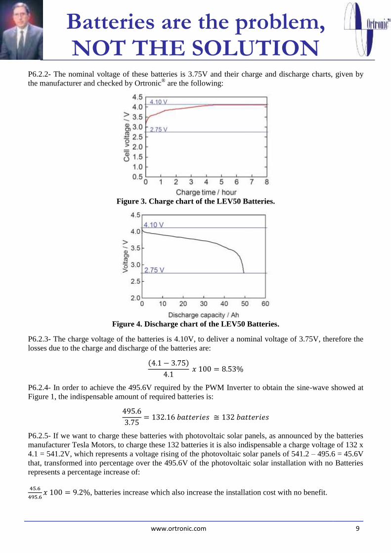
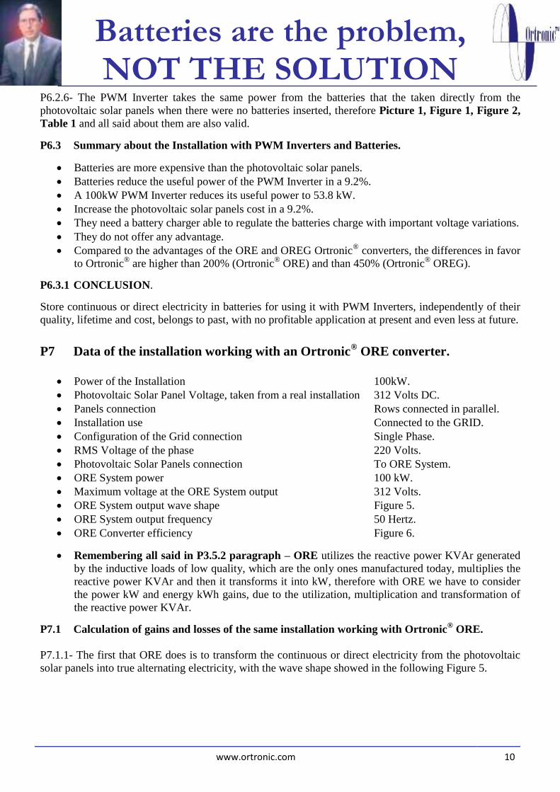
P6.2.2- The nominal voltage of these batteries is 3.75V and their charge and discharge charts, given by
the manufacturer and checked by Ortronic® are the following:
Figure 3. Charge chart of the LEV50 Batteries.
Figure 4. Discharge chart of the LEV50 Batteries.
P6.2.3- The charge voltage of the batteries is 4.10V, to deliver a nominal voltage of 3.75V, therefore the
losses due to the charge and discharge of the batteries are:
(4.1 − 3.75)
4.1 𝑥 100 = 8.53%
P6.2.4- In order to achieve the 495.6V required by the PWM Inverter to obtain the sine-wave showed at
Figure 1, the indispensable amount of required batteries is:
495.6
3.75= 132.16 𝑏𝑎𝑡𝑡𝑒𝑟𝑖𝑒𝑠 ≅ 132 𝑏𝑎𝑡𝑡𝑒𝑟𝑖𝑒𝑠
P6.2.5- If we want to charge these batteries with photovoltaic solar panels, as announced by the batteries
manufacturer Tesla Motors, to charge these 132 batteries it is also indispensable a charge voltage of 132 x
4.1 = 541.2V, which represents a voltage rising of the photovoltaic solar panels of 541.2 – 495.6 = 45.6V
that, transformed into percentage over the 495.6V of the photovoltaic solar installation with no Batteries
represents a percentage increase of:
45.6
495.6𝑥 100 = 9.2%, batteries increase which also increase the installation cost with no benefit.
Batteries are the problem, NOT THE SOLUTION
www.ortronic.com 10
P6.2.6- The PWM Inverter takes the same power from the batteries that the taken directly from the
photovoltaic solar panels when there were no batteries inserted, therefore Picture 1, Figure 1, Figure 2,
Table 1 and all said about them are also valid.
P6.3 Summary about the Installation with PWM Inverters and Batteries.
Batteries are more expensive than the photovoltaic solar panels.
Batteries reduce the useful power of the PWM Inverter in a 9.2%.
A 100kW PWM Inverter reduces its useful power to 53.8 kW.
Increase the photovoltaic solar panels cost in a 9.2%.
They need a battery charger able to regulate the batteries charge with important voltage variations.
They do not offer any advantage.
Compared to the advantages of the ORE and OREG Ortronic® converters, the differences in favor
to Ortronic® are higher than 200% (Ortronic
® ORE) and than 450% (Ortronic
® OREG).
P6.3.1 CONCLUSION.
Store continuous or direct electricity in batteries for using it with PWM Inverters, independently of their
quality, lifetime and cost, belongs to past, with no profitable application at present and even less at future.
P7 Data of the installation working with an Ortronic® ORE converter.
Power of the Installation 100kW.
Photovoltaic Solar Panel Voltage, taken from a real installation 312 Volts DC.
Panels connection Rows connected in parallel.
Installation use Connected to the GRID.
Configuration of the Grid connection Single Phase.
RMS Voltage of the phase 220 Volts.
Photovoltaic Solar Panels connection To ORE System.
ORE System power 100 kW.
Maximum voltage at the ORE System output 312 Volts.
ORE System output wave shape Figure 5.
ORE System output frequency 50 Hertz.
ORE Converter efficiency Figure 6.
Remembering all said in P3.5.2 paragraph – ORE utilizes the reactive power KVAr generated
by the inductive loads of low quality, which are the only ones manufactured today, multiplies the
reactive power KVAr and then it transforms it into kW, therefore with ORE we have to consider
the power kW and energy kWh gains, due to the utilization, multiplication and transformation of
the reactive power KVAr.
P7.1 Calculation of gains and losses of the same installation working with Ortronic® ORE.
P7.1.1- The first that ORE does is to transform the continuous or direct electricity from the photovoltaic
solar panels into true alternating electricity, with the wave shape showed in the following Figure 5.
Batteries are the problem, NOT THE SOLUTION
www.ortronic.com 11
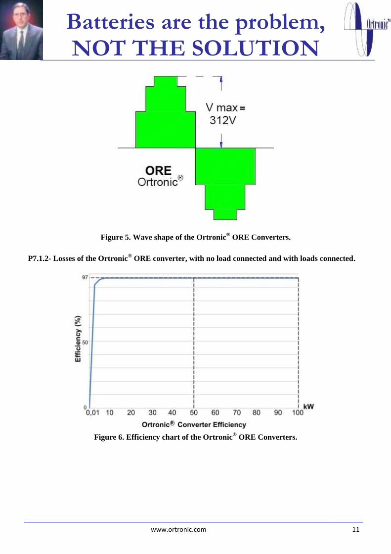
Figure 5. Wave shape of the Ortronic
® ORE Converters.
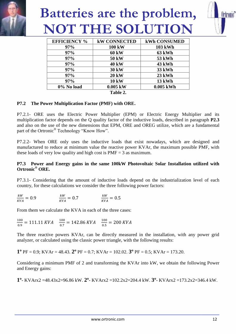
P7.1.2- Losses of the Ortronic® ORE converter, with no load connected and with loads connected.
Figure 6. Efficiency chart of the Ortronic
® ORE Converters.
Batteries are the problem, NOT THE SOLUTION
www.ortronic.com 12
EFFICIENCY % kW CONNECTED kWh CONSUMED
97% 100 kW 103 kWh
97% 60 kW 63 kWh
97% 50 kW 53 kWh
97% 40 kW 43 kWh
97% 30 kW 33 kWh
97% 20 kW 23 kWh
97% 10 kW 13 kWh
0% No load 0.005 kW 0.005 kWh
Table 2.
P7.2 The Power Multiplication Factor (PMF) with ORE.
P7.2.1- ORE uses the Electric Power Multiplier (EPM) or Electric Energy Multiplier and its
multiplication factor depends on the Q quality factor of the inductive loads, described in paragraph P2.3
and also on the use of the new dimensions that EPM, ORE and OREG utilize, which are a fundamental
part of the Ortronic® Technology “Know How”.
P7.2.2- When ORE only uses the inductive loads that exist nowadays, which are designed and
manufactured to reduce at minimum value the reactive power KVAr, the maximum possible PMF, with
these loads of very low quality and high cost is PMF = 3 as maximum.
P7.3 Power and Energy gains in the same 100kW Photovoltaic Solar Installation utilized with
Ortronic® ORE.
P7.3.1- Considering that the amount of inductive loads depend on the industrialization level of each
country, for these calculations we consider the three following power factors:
𝑘𝑊
𝐾𝑉𝐴= 0.9
𝑘𝑊
𝐾𝑉𝐴= 0.7
𝑘𝑊
𝐾𝑉𝐴= 0.5
From them we calculate the KVA in each of the three cases:
100
0.9= 111.11 𝐾𝑉𝐴
100
0.7= 142.86 𝐾𝑉𝐴
100
0.5= 200 𝐾𝑉𝐴
The three reactive powers KVAr, can be directly measured in the installation, with any power grid
analyzer, or calculated using the classic power triangle, with the following results:
1º PF = 0.9; KVAr = 48.43. 2º PF = 0.7; KVAr = 102.02. 3º PF = 0.5; KVAr = 173.20.
Considering a minimum PMF of 2 and transforming the KVAr into kW, we obtain the following Power
and Energy gains:
1º- KVArx2 =48.43x2=96.86 kW. 2º- KVArx2 =102.2x2=204.4 kW. 3º- KVArx2 =173.2x2=346.4 kW.
Batteries are the problem, NOT THE SOLUTION
www.ortronic.com 13
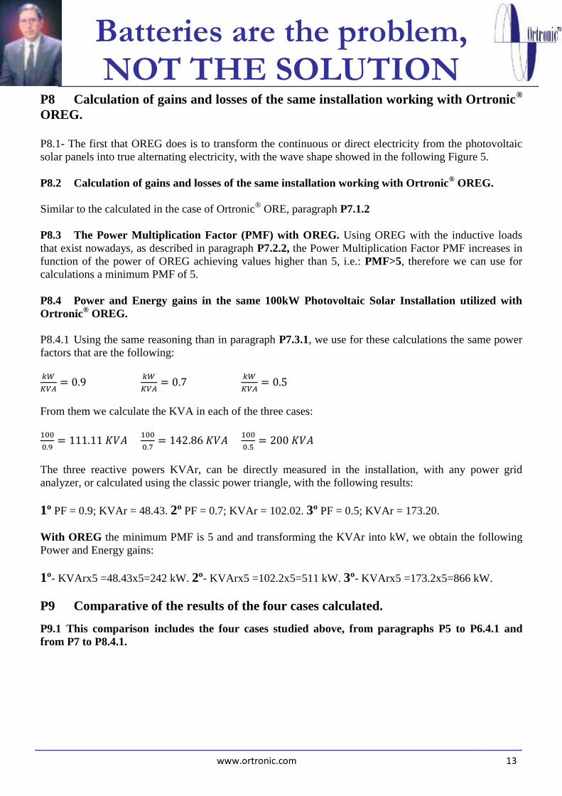
P8 Calculation of gains and losses of the same installation working with Ortronic®
OREG.
P8.1- The first that OREG does is to transform the continuous or direct electricity from the photovoltaic
solar panels into true alternating electricity, with the wave shape showed in the following Figure 5.
P8.2 Calculation of gains and losses of the same installation working with Ortronic® OREG.
Similar to the calculated in the case of Ortronic® ORE, paragraph P7.1.2
P8.3 The Power Multiplication Factor (PMF) with OREG. Using OREG with the inductive loads
that exist nowadays, as described in paragraph P7.2.2, the Power Multiplication Factor PMF increases in
function of the power of OREG achieving values higher than 5, i.e.: PMF>5, therefore we can use for
calculations a minimum PMF of 5.
P8.4 Power and Energy gains in the same 100kW Photovoltaic Solar Installation utilized with
Ortronic® OREG.
P8.4.1 Using the same reasoning than in paragraph P7.3.1, we use for these calculations the same power
factors that are the following:
𝑘𝑊
𝐾𝑉𝐴= 0.9
𝑘𝑊
𝐾𝑉𝐴= 0.7
𝑘𝑊
𝐾𝑉𝐴= 0.5
From them we calculate the KVA in each of the three cases:
100
0.9= 111.11 𝐾𝑉𝐴
100
0.7= 142.86 𝐾𝑉𝐴
100
0.5= 200 𝐾𝑉𝐴
The three reactive powers KVAr, can be directly measured in the installation, with any power grid
analyzer, or calculated using the classic power triangle, with the following results:
1º PF = 0.9; KVAr = 48.43. 2º PF = 0.7; KVAr = 102.02. 3º PF = 0.5; KVAr = 173.20.
With OREG the minimum PMF is 5 and and transforming the KVAr into kW, we obtain the following
Power and Energy gains:
1º- KVArx5 =48.43x5=242 kW. 2º- KVArx5 =102.2x5=511 kW. 3º- KVArx5 =173.2x5=866 kW.
P9 Comparative of the results of the four cases calculated.
P9.1 This comparison includes the four cases studied above, from paragraphs P5 to P6.4.1 and
from P7 to P8.4.1.

Batteries are the problem, NOT THE SOLUTION
www.ortronic.com 14
P9.2- Losses and gains, minimum, medium and maximum in a 100kW installation with a PWM
Inverter:
P9.2.1- LOSSES: PWM
Due to Voltage Difference: See P5.5.1 37 kW
Due to Efficiency: With No Load, See Figure 2 10 kW
At Full Load 8 kW
SUM With No Load 47kW
At Full Load 45 kW
_____________________________________________________________________________________
P9.2.2-GAINS:
Due to Reactive Power KVAr
With Power Factor = 0.9 0 kW
With Power Factor = 0.7 0 kW
With Power Factor = 0.5 0 kW
P9.3- Losses and gains, minimum, medium and maximum in a 100kW installation with a PWM
Inverter and BATTERIES:
P9.3.1-LOSSES: PWM
Due to Voltage Difference: See P5.5.1 37 kW
Due to batteries charge and discharge See P6.2 9.2 kW
Due to Efficiency: With No Load, See Figure 2 10 kW
At Full Load 8 kW
SUM With No Load 56.2 kW
At Full Load 54.2 kW
_____________________________________________________________________________________
P9.3.2-GAINS:
Due to Reactive Power KVAr
With Power Factor = 0.9 0 kW
With Power Factor = 0.7 0 kW
With Power Factor = 0.5 0 kW

Batteries are the problem, NOT THE SOLUTION
www.ortronic.com 15
P9.4- Losses and gains, minimum, medium and maximum in a 100kW installation with an
Ortronic® ORE Converter and with NO BATTERIES:
P9.4.1-LOSSES: ORE
Due to Voltage Difference: See P7 0 kW
Due to Efficiency: With No Load, See Figure 6 0.005 kW
At Full Load 3 kW
SUM With No Load 0.005 kW
At Full Load 3 kW
_____________________________________________________________________________________
P9.4.2-GAINS:
Due to Reactive Power KVAr
With Power Factor = 0.9 See P7.3 96.86 kW
With Power Factor = 0.7 See P7.3 204.4 kW
With Power Factor = 0.5 See P7.3 346.4 kW
P9.4.3-ORTRONIC® ORE vs. PWM Inv. NO Batteries PWM ORE
With No Load
Losses 47kW 0.005 kW
Difference 47kW – 0.005kW = 46.995 kW
At Full Load
Losses 45kW 3 kW
Difference 45kW – 3 kW = 42 kW
𝒌𝑾
𝑲𝑽𝑨= 𝟎. 𝟗 Gain = 42 kW+96.86 kW 0 kW 138.86 kW
𝒌𝑾
𝑲𝑽𝑨= 𝟎. 𝟕 Gain = 42 kW+ 204.4 kW 0 kW 246.4 kW
𝒌𝑾
𝑲𝑽𝑨= 𝟎. 𝟓 Gain = 42 kW+ 346.4 kW 0 kW 388.4 kW
IN PERCENTAGE OVER PWM
𝒌𝑾
𝑲𝑽𝑨= 𝟎. 𝟗
𝟏𝟑𝟖.𝟖𝟔𝑿𝟏𝟎𝟎
𝟏𝟎𝟎−𝟑𝟕=
𝟏𝟑𝟖.𝟖𝟔𝒙𝟏𝟎𝟎
𝟔𝟑 = 220.41%
𝒌𝑾
𝑲𝑽𝑨= 𝟎. 𝟕
𝟐𝟒𝟔.𝟒𝑿𝟏𝟎𝟎
𝟏𝟎𝟎−𝟑𝟕=
𝟐𝟒𝟔.𝟒𝒙𝟏𝟎𝟎
𝟔𝟑= 391.11%
𝒌𝑾
𝑲𝑽𝑨= 𝟎. 𝟓
𝟑𝟖𝟖.𝟒𝑿𝟏𝟎𝟎
𝟏𝟎𝟎−𝟑𝟕=
𝟑𝟖𝟖.𝟒𝒙𝟏𝟎𝟎
𝟔𝟑= 616.50%

Batteries are the problem, NOT THE SOLUTION
www.ortronic.com 16
PERCENTAGE OF ENERGY USED BY PWM OVER ORE
𝒌𝑾
𝑲𝑽𝑨= 𝟎. 𝟗
(𝟏𝟎𝟎−𝟑𝟕)𝑿𝟏𝟎𝟎
𝟏𝟑𝟖.𝟖𝟔=
𝟔𝟑𝒙𝟏𝟎𝟎
𝟏𝟑𝟖.𝟖𝟔 = 45.36%
𝒌𝑾
𝑲𝑽𝑨= 𝟎. 𝟕
(𝟏𝟎𝟎−𝟑𝟕)𝑿𝟏𝟎𝟎
𝟐𝟒𝟔.𝟒=
𝟔𝟑𝒙𝟏𝟎𝟎
𝟐𝟒𝟔.𝟒= 25.56%
𝒌𝑾
𝑲𝑽𝑨= 𝟎. 𝟓
(𝟏𝟎𝟎−𝟑𝟕)𝑿𝟏𝟎𝟎
𝟑𝟖𝟖.𝟒=
𝟔𝟑𝒙𝟏𝟎𝟎
𝟑𝟖𝟖.𝟒= 16.22%
P9.4.4-ORTRONIC® ORE vs. PWM Inv. + Batteries PWM ORE
With No Load
Losses 56.2kW 0.005 kW
Difference 56.2kW – 0.005kW = 56.195 kW
At Full Load
Losses 54.2kW 3 kW
Difference 54.2kW – 3 kW = 51.2 kW
𝒌𝑾
𝑲𝑽𝑨= 𝟎. 𝟗 Gain = 51.2 kW+ 96.86 kW 0 kW 148.06 kW
𝒌𝑾
𝑲𝑽𝑨= 𝟎. 𝟕 Gain = 51.2 kW+ 204.4 kW 0 kW 255.6 kW
𝒌𝑾
𝑲𝑽𝑨= 𝟎. 𝟓 Gain = 51.2 kW+ 346.4 kW 0 kW 397.6 kW
IN PERCENTAGE OVER PWM
𝒌𝑾
𝑲𝑽𝑨= 𝟎. 𝟗
𝟏𝟒𝟖.𝟎𝟔𝑿𝟏𝟎𝟎
𝟏𝟎𝟎−𝟒𝟔.𝟐=
𝟏𝟒𝟖.𝟎𝟔𝒙𝟏𝟎𝟎
𝟓𝟑.𝟖 = 275.20%
𝒌𝑾
𝑲𝑽𝑨= 𝟎. 𝟕
𝟐𝟓𝟓.𝟔𝑿𝟏𝟎𝟎
𝟏𝟎𝟎−𝟒𝟔.𝟐=
𝟐𝟓𝟓.𝟔𝒙𝟏𝟎𝟎
𝟓𝟑.𝟖= 475.09%
𝒌𝑾
𝑲𝑽𝑨= 𝟎. 𝟓
𝟑𝟗𝟕.𝟔𝑿𝟏𝟎𝟎
𝟏𝟎𝟎−𝟒𝟔.𝟐=
𝟑𝟗𝟕.𝟔𝒙𝟏𝟎𝟎
𝟓𝟑.𝟖= 739.03%
PERCENTAGE OF ENERGY USED BY PWM OVER ORE
𝒌𝑾
𝑲𝑽𝑨= 𝟎. 𝟗
(𝟏𝟎𝟎−𝟒𝟔.𝟐)𝑿𝟏𝟎𝟎
𝟏𝟒𝟖.𝟎𝟔=
𝟓𝟑.𝟖𝒙𝟏𝟎𝟎
𝟏𝟒𝟖.𝟎𝟔 = 36.33%
𝒌𝑾
𝑲𝑽𝑨= 𝟎. 𝟕
(𝟏𝟎𝟎−𝟒𝟔.𝟐)𝑿𝟏𝟎𝟎
𝟐𝟓𝟓.𝟔=
𝟓𝟑.𝟖𝒙𝟏𝟎𝟎
𝟐𝟓𝟓.𝟔= 21.04%
𝒌𝑾
𝑲𝑽𝑨= 𝟎. 𝟓
(𝟏𝟎𝟎−𝟒𝟔.𝟐)𝑿𝟏𝟎𝟎
𝟑𝟗𝟕.𝟔=
𝟓𝟑.𝟖𝒙𝟏𝟎𝟎
𝟑𝟗𝟕.𝟔= 13.53%
Batteries are the problem, NOT THE SOLUTION
www.ortronic.com 17
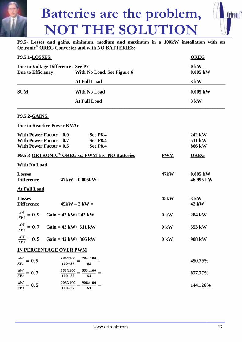
P9.5- Losses and gains, minimum, medium and maximum in a 100kW installation with an
Ortronic® OREG Converter and with NO BATTERIES:
P9.5.1-LOSSES: OREG
Due to Voltage Difference: See P7 0 kW
Due to Efficiency: With No Load, See Figure 6 0.005 kW
At Full Load 3 kW
SUM With No Load 0.005 kW
At Full Load 3 kW
_____________________________________________________________________________________
P9.5.2-GAINS:
Due to Reactive Power KVAr
With Power Factor = 0.9 See P8.4 242 kW
With Power Factor = 0.7 See P8.4 511 kW
With Power Factor = 0.5 See P8.4 866 kW
P9.5.3-ORTRONIC® OREG vs. PWM Inv. NO Batteries PWM OREG
With No Load
Losses 47kW 0.005 kW
Difference 47kW – 0.005kW = 46.995 kW
At Full Load
Losses 45kW 3 kW
Difference 45kW – 3 kW = 42 kW
𝒌𝑾
𝑲𝑽𝑨= 𝟎. 𝟗 Gain = 42 kW+242 kW 0 kW 284 kW
𝒌𝑾
𝑲𝑽𝑨= 𝟎. 𝟕 Gain = 42 kW+ 511 kW 0 kW 553 kW
𝒌𝑾
𝑲𝑽𝑨= 𝟎. 𝟓 Gain = 42 kW+ 866 kW 0 kW 908 kW
IN PERCENTAGE OVER PWM
𝒌𝑾
𝑲𝑽𝑨= 𝟎. 𝟗
𝟐𝟖𝟒𝑿𝟏𝟎𝟎
𝟏𝟎𝟎−𝟑𝟕=
𝟐𝟖𝟒𝒙𝟏𝟎𝟎
𝟔𝟑 = 450.79%
𝒌𝑾
𝑲𝑽𝑨= 𝟎. 𝟕
𝟓𝟓𝟑𝑿𝟏𝟎𝟎
𝟏𝟎𝟎−𝟑𝟕=
𝟓𝟓𝟑𝒙𝟏𝟎𝟎
𝟔𝟑= 877.77%
𝒌𝑾
𝑲𝑽𝑨= 𝟎. 𝟓
𝟗𝟎𝟖𝑿𝟏𝟎𝟎
𝟏𝟎𝟎−𝟑𝟕=
𝟗𝟎𝟖𝒙𝟏𝟎𝟎
𝟔𝟑= 1441.26%
Batteries are the problem, NOT THE SOLUTION
www.ortronic.com 18
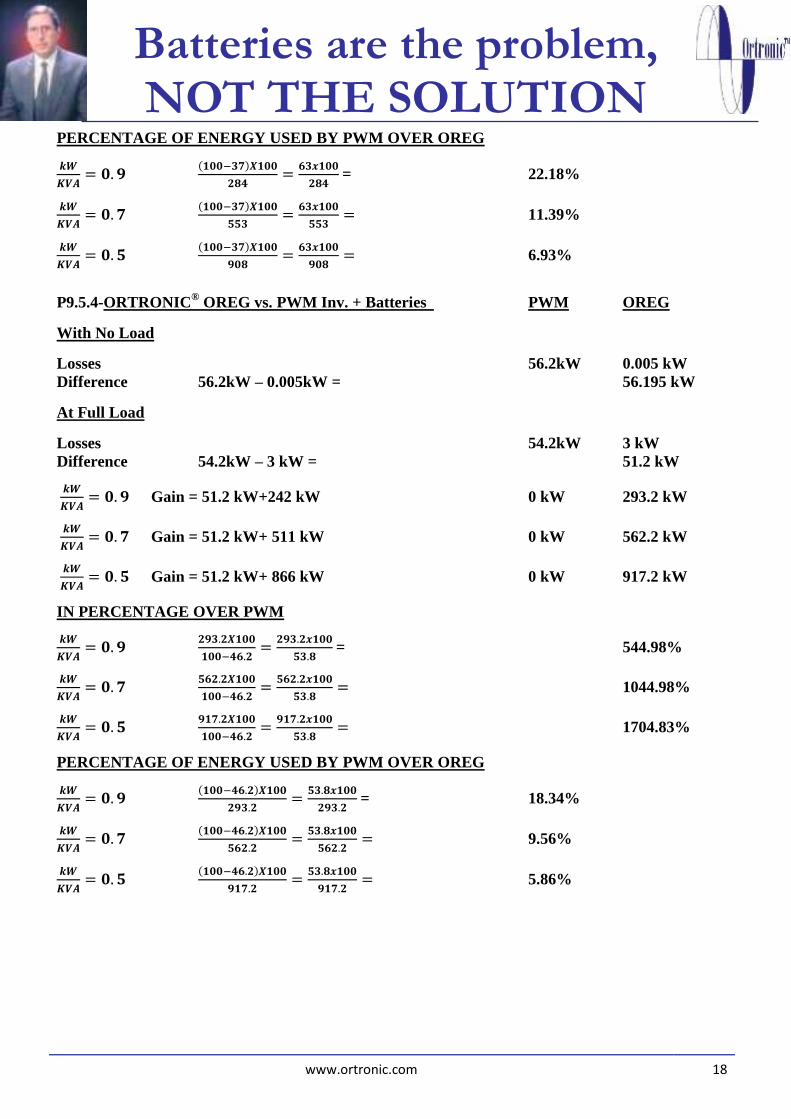
PERCENTAGE OF ENERGY USED BY PWM OVER OREG
𝒌𝑾
𝑲𝑽𝑨= 𝟎. 𝟗
(𝟏𝟎𝟎−𝟑𝟕)𝑿𝟏𝟎𝟎
𝟐𝟖𝟒=
𝟔𝟑𝒙𝟏𝟎𝟎
𝟐𝟖𝟒 = 22.18%
𝒌𝑾
𝑲𝑽𝑨= 𝟎. 𝟕
(𝟏𝟎𝟎−𝟑𝟕)𝑿𝟏𝟎𝟎
𝟓𝟓𝟑=
𝟔𝟑𝒙𝟏𝟎𝟎
𝟓𝟓𝟑= 11.39%
𝒌𝑾
𝑲𝑽𝑨= 𝟎. 𝟓
(𝟏𝟎𝟎−𝟑𝟕)𝑿𝟏𝟎𝟎
𝟗𝟎𝟖=
𝟔𝟑𝒙𝟏𝟎𝟎
𝟗𝟎𝟖= 6.93%
P9.5.4-ORTRONIC® OREG vs. PWM Inv. + Batteries PWM OREG
With No Load
Losses 56.2kW 0.005 kW
Difference 56.2kW – 0.005kW = 56.195 kW
At Full Load
Losses 54.2kW 3 kW
Difference 54.2kW – 3 kW = 51.2 kW
𝒌𝑾
𝑲𝑽𝑨= 𝟎. 𝟗 Gain = 51.2 kW+242 kW 0 kW 293.2 kW
𝒌𝑾
𝑲𝑽𝑨= 𝟎. 𝟕 Gain = 51.2 kW+ 511 kW 0 kW 562.2 kW
𝒌𝑾
𝑲𝑽𝑨= 𝟎. 𝟓 Gain = 51.2 kW+ 866 kW 0 kW 917.2 kW
IN PERCENTAGE OVER PWM
𝒌𝑾
𝑲𝑽𝑨= 𝟎. 𝟗
𝟐𝟗𝟑.𝟐𝑿𝟏𝟎𝟎
𝟏𝟎𝟎−𝟒𝟔.𝟐=
𝟐𝟗𝟑.𝟐𝒙𝟏𝟎𝟎
𝟓𝟑.𝟖 = 544.98%
𝒌𝑾
𝑲𝑽𝑨= 𝟎. 𝟕
𝟓𝟔𝟐.𝟐𝑿𝟏𝟎𝟎
𝟏𝟎𝟎−𝟒𝟔.𝟐=
𝟓𝟔𝟐.𝟐𝒙𝟏𝟎𝟎
𝟓𝟑.𝟖= 1044.98%
𝒌𝑾
𝑲𝑽𝑨= 𝟎. 𝟓
𝟗𝟏𝟕.𝟐𝑿𝟏𝟎𝟎
𝟏𝟎𝟎−𝟒𝟔.𝟐=
𝟗𝟏𝟕.𝟐𝒙𝟏𝟎𝟎
𝟓𝟑.𝟖= 1704.83%
PERCENTAGE OF ENERGY USED BY PWM OVER OREG
𝒌𝑾
𝑲𝑽𝑨= 𝟎. 𝟗
(𝟏𝟎𝟎−𝟒𝟔.𝟐)𝑿𝟏𝟎𝟎
𝟐𝟗𝟑.𝟐=
𝟓𝟑.𝟖𝒙𝟏𝟎𝟎
𝟐𝟗𝟑.𝟐 = 18.34%
𝒌𝑾
𝑲𝑽𝑨= 𝟎. 𝟕
(𝟏𝟎𝟎−𝟒𝟔.𝟐)𝑿𝟏𝟎𝟎
𝟓𝟔𝟐.𝟐=
𝟓𝟑.𝟖𝒙𝟏𝟎𝟎
𝟓𝟔𝟐.𝟐= 9.56%
𝒌𝑾
𝑲𝑽𝑨= 𝟎. 𝟓
(𝟏𝟎𝟎−𝟒𝟔.𝟐)𝑿𝟏𝟎𝟎
𝟗𝟏𝟕.𝟐=
𝟓𝟑.𝟖𝒙𝟏𝟎𝟎
𝟗𝟏𝟕.𝟐= 5.86%

Batteries are the problem, NOT THE SOLUTION
www.ortronic.com 19
P10.- As an addition to all said above I recommend to read the following documents: “ORE: Scientific
Foundations”, “Ortronic® Technology Vs. PWM Technology”, “Alternating Electricity and PWM
are Incompatible” and “The Electrical Grids go to their Self-Destruction due to Inverse Resonance”.
Documents that can be seen at the following links:
ORE: Scientific Foundations:
http://ortronic.com/ENGLISH/pdf/FCO.pdf
Ortronic® Technology Vs. PWM Technology:
http://ortronic.com/ENGLISH/pdf/TOVSTPWM.pdf
Alternating Electricity and PWM are Incompatible:
http://ortronic.com/ENGLISH/pdf/CA&PWM.pdf
The Electrical Grids go to their Self-Destruction due to Inverse Resonance: http://ortronic.com/ENGLISH/pdf/RRE.pdf
Madrid, June 1st, 2015.
Signed: Juan Ortigosa Garcia
Scientific, Inventor and Entrepreneur
Chairman & Technical Director of Ortronic Technology, S.L.
Company e-mail: [email protected]
Personal e-mail: [email protected]